HANDBOOK OF MAINTENANCE INSTRUCTIONS FOR MDHI 369D/E/FF-500/600N HELICOPTERS (ISSUED: 1990) - page 22
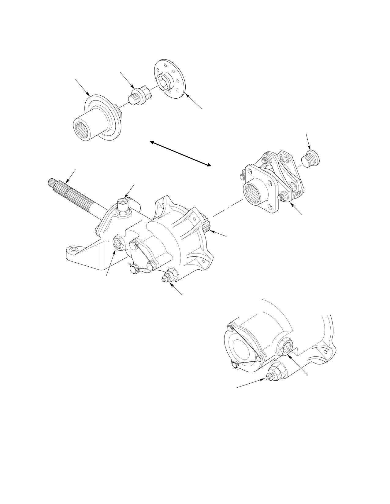
CSP-HMI-2
MD Helicopters, Inc.
MAINTENANCE MANUAL
TRANSMISSION
COUPLING (BENDIX)
FAILSAFE
(CAUTION: DO NOT LIFT
COUPLING BOLT
ASSEMBLY FROM FLANGE)
FAILSAFE
SOCKET
COUPLING BOLT
OUTPUT SHAFT
BREATHER FILLER
COUPLING
(KAMATIC)
INPUT SHAFT
LIQUID LEVEL
PLUG
CHIP DETECTOR
2-BLADED TAIL ROTOR TRANSMISSION
LIQUID LEVEL
PLUG
CHIP
DETECTOR
4-BLADED TAIL ROTOR TRANSMISSION
G63-2014
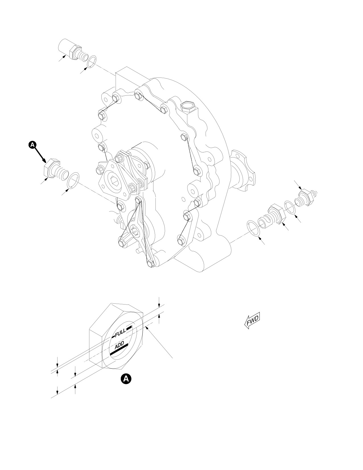
Figure 201. Tail Rotor Transmission − Stripping/Buildup
Page 202
Revision 20
63-25-10
MD Helicopters, Inc.
CSP-HMI-2
MAINTENANCE MANUAL
(b).
(369FF) Secure tail rotor transmis
to be 0.312-0.313 inch (7.9248-7.9502
sion to tailboom extension with four
mm) (Ref. CSP-COM-5 for bolt hole
bolts, eight washers and four nuts.
repair).
Torque nuts to 75 - 95 inch-pounds
(8.47 - 10.73 Nm) plus drag
(3). Check input shaft for:
torque.
(a). Axial play by moving shaft in and
(5). Apply torque stripe paint.
out; transmission must be cold. Axial
play is limited to 0.004 inch (0.102
(6). Between 2 and 10 hours of helicopter
mm) maximum.
operation (to allow parts to seat), check
the torque of each mounting nut as
(b). Measure runout; mark high and low
follows:
extremes on outer end of shaft with
grease pencil. Total indicated runout
(a). Using the drag torque previously
should be less than 0.002 inch (0.051
measured and noted, apply a torque
mm).
load of 75 - 95 inch-pounds (8.47 -
10.73 Nm) plus the noted drag
(4). Check output shaft for:
torque (noted for each individual
nut) to each mounting nut of the
(a). Axial play; no axial movement is
transmission.
permitted.
(b). Re-apply torque stripe paint.
(b). Measure runout; mark high and low
(7). Install tail rotor on tail rotor transmis
extremes on outer end of shaft with
sion (Ref. Sec. 64-20-00).
grease pencil. Total indicated runout
should be less than 0.0025 inch
(0.0635 mm).
(8). Connect chip detector wire. Torque nut
to 12 - 15 inch-pounds (1.36 - 1.69
Nm).
(5). While gently pulling out on input shaft,
check gearset backlash:
(9). Connect tail rotor drive shaft to main
transmission (Ref. Sec. 63-15-10).
(a). Two-bladed gearset backlash should
be 0.004-0.008 inch (0.102-0.203
(10). Drain residual preservative oil and
mm).
service transmission with lubricating
oil (Ref. Sec. 12-00-00).
(b). Four-bladed gearset backlash should
be 0.0025-0.0050 inch (0.0635-0.127
3. Tail Rotor Transmission Inspection
mm).
(Ref. Figure 201)
NOTE: Although not required, placing marks
on end of output shaft provides guides for
NOTE: If following inspections reveal damage,
subsequent installation of tail rotor assem
repair according to instructions in CSP-
bly in a manner that reduces chances of
COM-5.
high frequency vibrations and lessens possi
bility of requirement for tail rotor balanc
(1). Check transmission for leaks, cracks
ing.
and corrosion. To evaluate oil leakage,
refer to Fluid Leak Analysis (Ref. Sec.
(6). Inspect all scoring or scratching of
12-00-00).
output shaft to determine if marks
penetrate through cadmium plating
(2). Inspect Sta. 284 bellcrank hole for
and into steel shaft. Penetration of steel
elongation; if elongation is suspected,
shaft is allowable to maximum depth of
measure hole diameter. Hole diameter
0.010 inch (0.254 mm).
Page 203
63-25-10
Revision 40
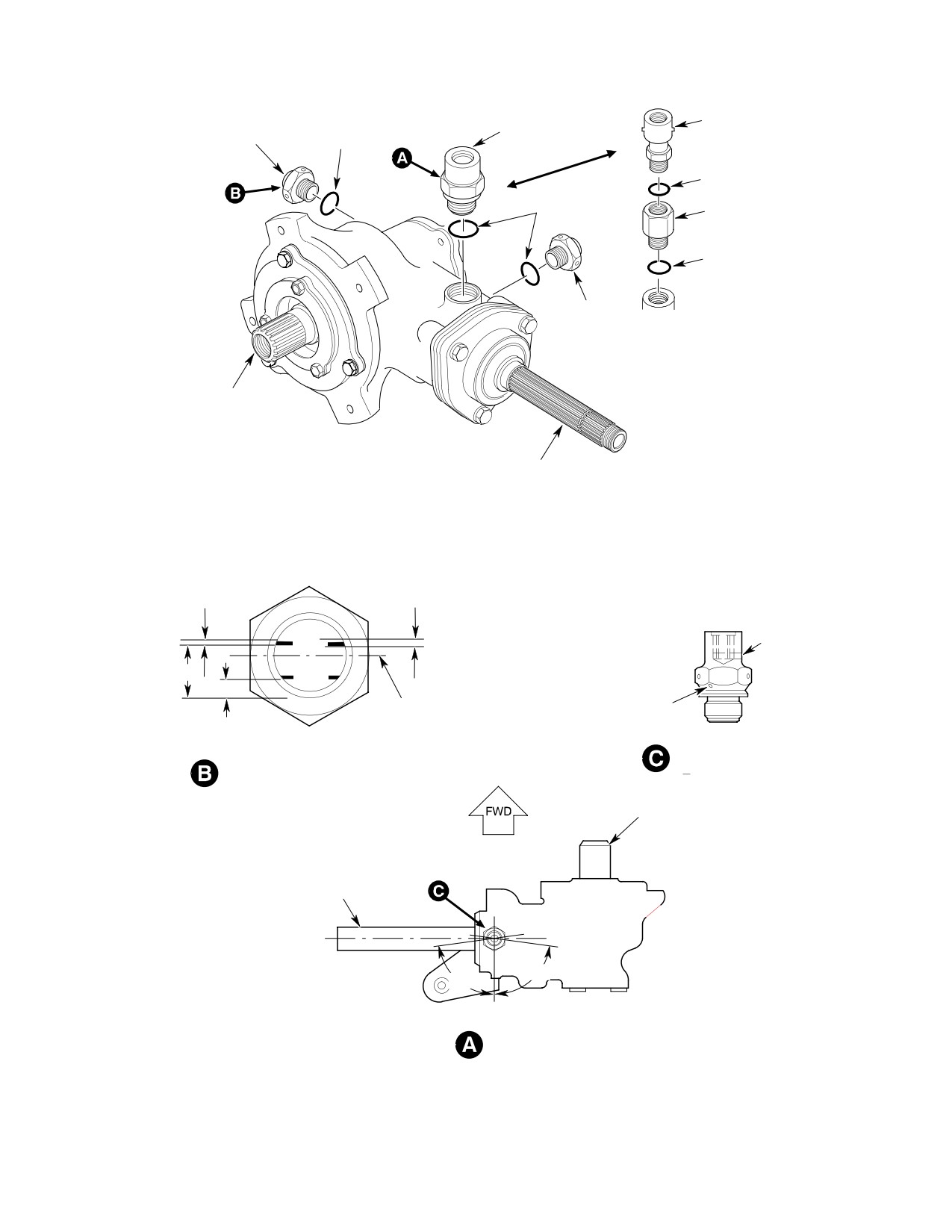
CSP-HMI-2
MD Helicopters, Inc.
MAINTENANCE MANUAL
BREATHER-FILLER
LIQUID LEVEL PLUG
BREATHER-FILLER
(4-BLADED T/R)
O-RING
O-RING
O-RING
ADAPTER
O-RING
LIQUID
LEVEL PLUG
(2-BLADED T/R)
INPUT SHAFT
OUTPUT SHAFT
0.046 IN. (1.1684 MM)
0.10 IN. (2.54 MM)
LINE-WIDTH (TYP)
LETTER HEIGHT (TYP)
FUL
DRAIN HOLE
L
0.406 IN. (10.3124 MM)
AD
D
BREATHER HOLE
AXIS OUTPUT SHAFT
0.06 IN.
(1.524 MM)
BREATHER-FILLE
LIQUID LEVEL PLUG
R
MARKINGS
INPUT
SHAFT
OUTPUT
SHAFT
85°
85°
BREATHER HOLE
ORIENTATION
G63-2016A
Figure 202. Replacement of Liquid Level Plug and Breather−Filler
Page 204
Revision 20
63-25-10
MD Helicopters, Inc.
CSP-HMI-2
MAINTENANCE MANUAL
4. Tail Rotor Transmission Stripping
6. Tail Rotor Transmission Parts
Replacement
(Ref. Figure 201) Stripping of the tail rotor
transmission is not required following its
(Ref. Figure 202)
removal from the helicopter. Perform the
following stripping procedure if in preparation
Consumable Materials
for transmission shipment or storage only.
(Ref. Section 91−00−00)
Item
Nomenclature
Consumable Materials
CM114
Petrolatum
(Ref. Section 91−00−00)
CM222
1,1,1-Trichloroethane
Item
Nomenclature
CM311
Coating, logo white / Thinner
CM208
Barrier material
CM702
Lockwire CRES
(1). Remove coupling bolt and coupling from
NOTE: Replace liquid level plug, chip detector
input shaft.
and breather-filler using torque values in
following paragraphs. Lubricate mating
NOTE: For tail rotor transmission replace
bores of O-rings with petrolatum (CM114)
ment, further stripping is not required. A re
to prevent damage to O-rings. Repair other
placement transmission is equipped with all
components or replace tail rotor transmis
other accessories.
sion oil seals (Ref. COM).
(2). Drain oil from transmission (Ref. Sec.
(1). Chip Detector Torque valve body 50 -
12-00-00). Residual operating lubri
60 inch-pounds (5.65 - 6.78 Nm);
cant is approved internal preservative
detector 40 - 50 inch-pounds (4.52 -
for shipping or storage.
5.65 Nm). Safety with lockwire
(CM702).
(3). Wrap transmission in barrier material
(CM208) to protect shaft splines and
(2). Liquid Level Plug Torque liquid level
chip detector stud during handling,
plug to 50 - 60 inch-pounds (5.65 -
shipping or storage.
6.78 Nm). If level-lines and lettering of
liquid level plug cannot be made
5. Tail Rotor Transmission Buildup
parallel with axis of transmission
output shaft when plug is torqued
(Ref. Figure 201)
within 50 - 60 inch-pound (5.65 - 6.78
Nm) range, clean glass by firmly
rubbing with soft cloth, then mix white
Consumable Materials
coating (CM311) with equal amount of
(Ref. Section 91−00−00)
thinner and apply lines and lettering.
Item
Nomenclature
Safety with lockwire.
CM111
Grease, aircraft
CM112
Anti-seize compound high temperature
NOTE: Some models use an adapter with an
additional O-ring. On those models, install
adapter with O-ring, then install breather-
(1). Coat coupling splines with grease
filler.
(CM111) and coupling bolt threads with
(3). Oil Breather-Filler Torque breather-
anti-seize compound (CM112) before
filler to 45 - 55 inch-pounds (5.08 -
re-assembly.
6.21 Nm). If equipped with a 369A5429
(2). Install coupling and bolt. Torque
breather, hole in breather filler must be
coupling bolt to 250 - 300 inch-
directed rearward at final torque.
pounds (28.25 - 33.90 Nm) plus drag
Locating vent at any angle aft of output
torque. Check coupling bolt for drag
shaft centerline (viewed from above)
torque serviceability of 25 inch-
adequately directs vent rearward. One
pounds (2.82 Nm) minimum, 200
or two washers may be added between
inch-pounds (22.60 Nm) maximum.
O-ring and breather flange (one
Page 205
63-25-10
Revision 20
CSP-HMI-2
MD Helicopters, Inc.
MAINTENANCE MANUAL
washer changes orientation by approxi
(3). If contact occurs, rework tail rotor
mately 100 degrees). Safety with
transmission housing as follows:
lockwire.
(a). Chamfer the web on transmission
NOTE: If oil breather-filler assembly becomes
housing to dimensions shown in
clogged, use light air pressure, approxi
Figure 204.
mately 5 psig (34 kPa) or a 0.125 inch (3.175
Do not remove material in
mm) dia. rod applied into the threaded end
WARNING
excess of specified dimen
to dislodge debris. Ultrasonically clean
sion.
breather in solvent (CM222) for ten min
utes.
(b). Blend chamfer into existing radius at
the bottom and radius it at the top.
7. Input and Output Gearshaft Cover Oil
Width of chamfer must be
Leak Repair
0.060-0.090 inch (1.524-2.286 mm).
Repair oil leaks at input and output gearshaft
(c). Apply surface touchup treatment
cover by installing a protective sleeve (Speedi-
(Ref. Sec. 20-30-00).
Sleeve) on the gearshaft area contacted by the
oil seal lip (Ref. COM).
(4). Record compliance of this rework in the
aircraft logbook.
8. Tail Rotor Transmission Housing
Assembly Rework (PN 369D25401)
AXIAL PLAY 0.005 IN.
(0.127 MM) MAX
(Ref. Figure 204) An interference condition
may exist between the tail rotor transmission
housing and the tail rotor control bellcrank
SIDE PLAY 0.004 IN.
with the tail rotor pedal at extreme right
(0.102 MM) MAX
position. The following procedure provides
inspection criteria and rework instructions, if
necessary, for the tail rotor transmission
housing to correct this condition should it
exist.
(1). With assistance, depress and hold right
tail rotor pedal to extreme right
position and inspect web area of tail
rotor transmission housing that comes
in close contact with tail rotor control
bellcrank. If adequate clearance exist
between transmission housing and
control bellcrank, no rework action is
necessary.
G63-2023A
(2). Sign off aircraft logbook to indicate
Figure 203. Tail Rotor Transmission Mount
completion of this inspection.
Stud Limits
Page 206
Revision 20
63-25-10
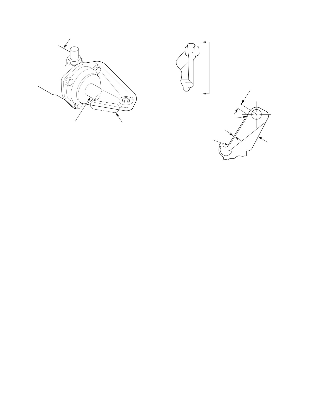
MD Helicopters, Inc.
CSP-HMI-2
MAINTENANCE MANUAL
TAIL ROTOR TRANSMISSION
A
0.350 IN. (8.89 MM) MIN.
A
REWORK AREA
(END VIEW)
0.500 IN.
(12.70 MM) R
OUTPUT SHAFT
REWORK AREA
0.060-0.090 IN.
(1.524-2.286 MM) X 45°
BLEND INTO
EXISTING RADIUS
TAIL ROTOR
HOUSING
ASSEMBLY
G63-2017A
Figure 204. Rework of Tail Rotor Transmission Housing Assembly
Page 207
63-25-10
Revision 20
CSP-HMI-2
MD Helicopters, Inc.
MAINTENANCE MANUAL
This Page Intentionally Left Blank
Page 208
Revision 44
63-25-10
MD Helicopters, Inc.
CSP-HMI-2
MAINTENANCE MANUAL
Section
63−25−30
NOTARr
Anti−Torque System
Fan Transmission
(500/600N)
MD Helicopters, Inc.
CSP-HMI-2
MAINTENANCE MANUAL
NOTAR® ANTI−TORQUE SYSTEM FAN TRANSMISSION
MAINTENANCE PRACTICES
1. Fan Transmission
B. Fan Transmission Installation
The function of the fan transmission is to step
(Ref. Figure 201)
up RPM from the main transmission output to
Do not carry or support trans
the fan via fan drive shaft, gears, and intercon
CAUTION
mission by coupling as damage
nect shaft. The transmission housing is made
can occur to coupling. During performance
of magnesium, and contains input and output
of maintenance on transmission, use extra
gear shafts, two angular contact bearings,
care to keep contaminants such as paint,
coupling, seals, packings, output cover assy,
dirt etc from areas around input and output
chip detector, sight glass, and oil breather
shaft seals.
assembly.
(1).
Install fan drive shaft (Ref. Sec.
2. Fan Transmission Replacement
63-15-30).
Remove and install fan transmission according
(2).
Locate and align transmission with
to the following procedures.
mounting holes on helicopter. Install
A. Fan Transmission Removal
four bolts and washers on transmission.
Torque bolts to 70 - 90 inch pounds
(Ref. Figure 201)
(7.90 - 10.17 Nm); torque-stripe bolts.
(1). Remove inlet screen, inlet fairing,
(3).
Connect previously identified chip
engine plenum access cover, and fan
detector wires.
hub transmission fairing (Ref. Sec.
53-30-30).
(4).
Remove cap and connect drain line on
elbow at bottom of transmission.
(2). Remove tailboom (Ref. Sec. 53-40-30).
(5).
Install fan interconnect shaft (Ref. Sec.
(3). Drain fan transmission of oil. Discon
63-15-30).
nect drain line and cap elbow at bottom
of transmission.
(6).
Install fan pitch control rod (Ref. Sec.
67-20-30).
(4). Remove fan drive shaft (Ref. Sec.
63-15-30).
(7).
Drain any residual preservative oil (if
new transmission) and service with
(5). Remove fan pitch control rod (Ref. Sec.
lubricating oil (Ref. Sec. 12-00-00).
67-20-30).
(8).
Install fan hub transmission fairing
(6). Remove fan interconnect shaft (Ref.
(Ref. Sec. 53-30-30).
Sec. 63-15-30).
NOTE: Identify chip detector wires for future
(9).
Install engine plenum access cover (Ref.
re-installation.
Sec. 53-30-30).
(7). Disconnect chip detector wires.
(10).
Install engine inlet fairing (Ref. Sec.
53-30-30).
(8). Remove four transmission mounting
bolts, washers, and transmission from
(11).
Install inlet screen (Ref. Sec.
helicopter.
53-30-30).
Page 201
63-25-30
Revision 36
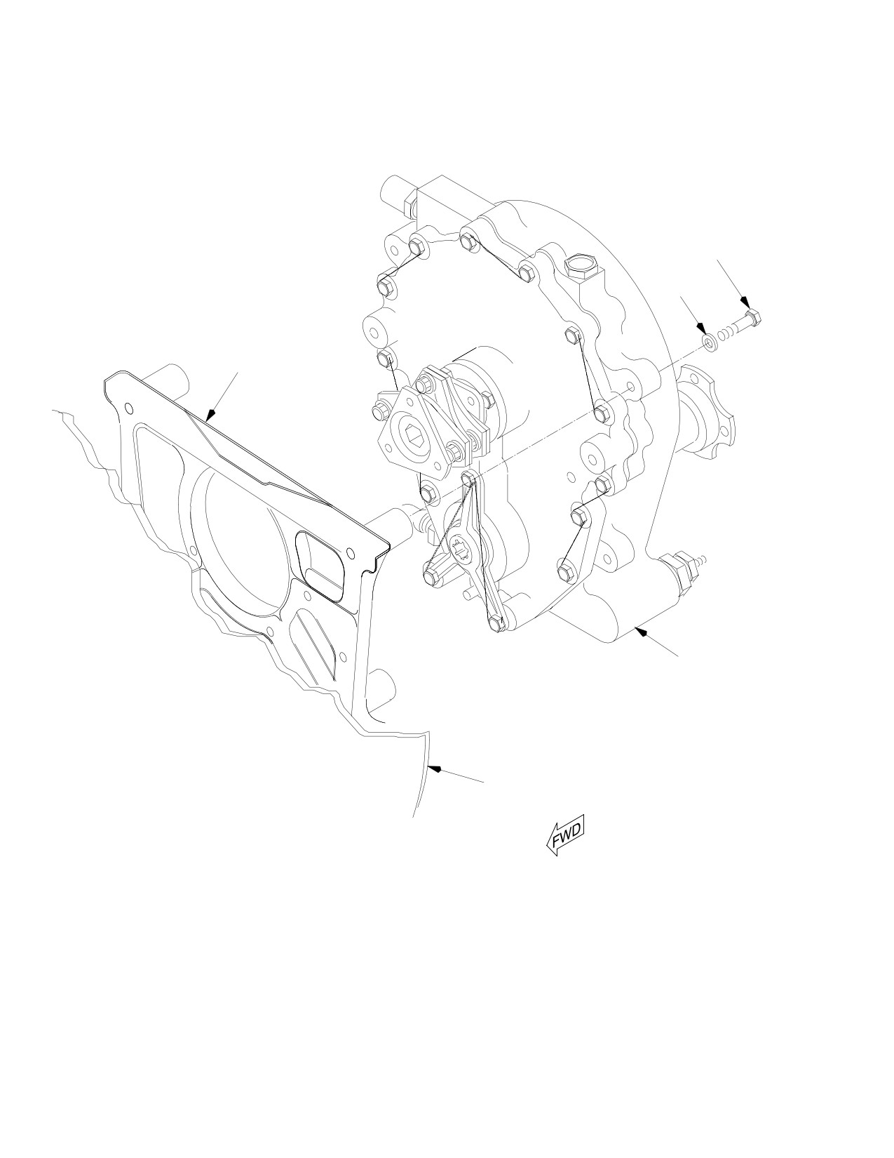
CSP-HMI-2
MD Helicopters, Inc.
MAINTENANCE MANUAL
BOLT
(4 PLS)
WASHER
(4 PLS)
FAN TRANSMISSION
SUPPORT ASSY
FAN TRANSMISSION
BULKHEAD
G63-2024
Figure 201. Fan Transmission Removal/Installation
Page 202
Revision 20
63-25-30
MD Helicopters, Inc.
CSP-HMI-2
MAINTENANCE MANUAL
3.
Fan Transmission Inspection
NOTE: Replace liquid level plug, chip detector,
and breather assy using torque values in the
(1). Check transmission for leaks, cracks,
following paragraphs. Lubricate O-rings
and corrosion. To evaluate oil leakage
with petrolatum (CM114) to prevent dam
refer to Component Fluid Leak Analy
age to O-rings. Repair other components or
sis (Ref. Sec. 12-00-00). For further
replace transmission oil seals if required
inspection criteria, please contact
(Ref. COM).
MDHC Customer Support Department.
4.
Tube Support Inspection
(1).
Chip Detector Torque valve body (large
hex) to 50 - 60 inch pounds (5.65 -
(1). Inspect mount bolts for security and
6.78 Nm) or 40 - 50 inch pounds
corrosion, lockwire intact.
(4.52 - 5.65 Nm) (smaller hex).
(2). Inspect tube support for dents,
(2).
Liquid Level Plug Torque liquid level
scratches, nicks, gouges and corrosion,
plug to 50 - 60 inch pounds (5.65 -
none allowed.
6.78 Nm). If level lines and lettering of
(3). Inspect for visible step in splined area.
liquid level plug cannot are not parallel
with axis of transmission output shaft
(4). If step is evident:
when torqued within 50 - 60 inch
(a). Measure between splines using
pound (5.65 - 6.78 Nm) range, clean
0.0864 in. (2.19456 mm) diameter
glass by firmly rubbing with soft cloth,
pins.
then mix white coating (CM311) with
equal amount of thinner and apply
(b). Maximum measurement between
lines and lettering. Safety with lockwire
pins is 0.390 in. (9.906 mm).
(CM702).
5.
Fan Transmission Parts Replacement
(3).
Oil Breather Assy Torque breather
(Ref. Figure 202)
assy to 45 - 55 inch pounds (5.08 -
6.21 Nm). Ensure breather hole is
facing up. Safety with lockwire
Consumable Materials
(CM702).
(Ref. Section 91−00−00)
Item
Nomenclature
NOTE: If oil breather assy becomes clogged,
CM114
Petrolatum
use light air pressure, approximately 5 psig
CM222
1,1,1-Trichloroethane
(34 kPa) or a 0.125 inch (3.175 mm) dia. rod
CM311
Coating, logo white / Thinner
applied into the threaded end to dislodge de
CM702
Lockwire CRES
bris. Ultrasonically clean breather in sol
vent (CM222) for ten minutes.
Page 203
63-25-30
Revision 33
CSP-HMI-2
MD Helicopters, Inc.
MAINTENANCE MANUAL
BREATHER
O-RING
CHIP
DETECTOR
VALVE
LIQUID
LEVEL
PLUG O-RING
O-RING
VALVE
O-RING
0.10 IN. (2.54 MM)
LETTER HEIGHT (TYP)
0.046 IN.
(1.1684 MM)
LINE WIDTH
(TYP)
AXIS OUTPUT SHAFT
0.406 IN.
ROTATED VIEW
(10.3124 MM)
0.060 IN.
LIQUID LEVEL PLUG MARKINGS
(1.524 MM)
G63-2025A
Figure 202. Fan Transmission Parts Replacement
Page 204
Revision 20
63-25-30
MD Helicopters, Inc.
CSP-HMI-2
MAINTENANCE MANUAL
Section
63−30−00
Main Rotor Static
Mast (369D/E/FF −
500/600N)
MD Helicopters, Inc.
CSP-HMI-2
MAINTENANCE MANUAL
MAIN ROTOR STATIC MAST
MAINTENANCE PRACTICES
1. Main Rotor Static Mast
(1).
Apply silicone sealant (CM430) on
bottom surface of mast tube and base at
(Ref. Figure 201) The main rotor mast provides
drive shaft opening to seal base to mast
support for the main rotor, main transmission
support structure at installation.
and drive shaft, and consists of an assembled
machined steel tube with a machined alumi
num forged base.
(2).
Position main rotor mast so that holes
in base align with holes in mast support
2. Main Rotor Static Mast Replacement
structure.
(369D25100 Transmission Installation)
(3).
Install holddown bolts, washers and
A. Main Rotor Static Mast Removal
mast mounting nuts; torque nuts to 700
(369D25100 Transmission Installation)
- 820 inch-pounds (79.09 - 92.65
(Ref. Figure 201)
Nm).
Main rotor mast is highly
CAUTION
stressed. Do not allow tools to
(4).
Check underside of mast support
strike mast or mast to strike any object. Any
structure at left aft stud hole location.
impact damage may require replacement of
Stud-to-pan doubler surface must be
mast.
clean to bare metal for electrical
bonding. Install main transmission
(1). Remove main rotor hub (Ref. Sec.
mounting studs, plate spacers and nuts.
62-20-00/60).
Torque studs to 160 - 190 inch-
pounds (18.08 - 21.47 Nm).
(2). Remove main rotor controls (Ref. Chap.
67).
(5).
Using 0.0010-0.0015 inch
(3). Remove main transmission (Ref. Sec.
(0.254-0.0381 mm) feeler gage, check
63-20-00/25).
for gap between self-locking nuts and
plate spacers. No gap is allowed.
(4). Remove four studs, washers and nuts.
NOTE: Nuts securing studs have left-hand
(6).
If gap exists, remove nut and replace
threads.
with new self-locking nut. Torque studs
into replacement nuts to 160 - 190
(5). Remove shaft support holddown nuts,
inch-pounds (18.08 - 21.47 Nm) and
washers and bolts.
repeat step (5). above. Continue until
each nut is flush against its spacer.
(6). Lift main rotor mast from helicopter.
Seal bare bond area with clear lacquer
B. Main Rotor Static Mast Installation
(CM306).
(369D25100 Transmission Installation)
(7).
Install main transmission (Ref. Sec.
(Ref. Figure 201)
63-20-00/25).
Consumable Materials
(Ref. Section 91−00−00)
(8).
Install main rotor controls (Ref. Chap.
Item
Nomenclature
67).
CM306
Lacquer, clear
CM430
Sealant, solvent resistant
(9).
Install main rotor hub (Ref. Sec.
62-20-00/60).
Page 201
63-30-00
Revision 20
CSP-HMI-2
MD Helicopters, Inc.
MAINTENANCE MANUAL
HUB SLEEVE BEARING
SURFACE
MAIN ROTOR MAST
NUT (LEFT-
PLATE
HAND
SPACER
THREADS)
TAPE
MAST BASE
RIVET
MAST SUPPORT
STRUCTURE PAN
NOTE 2
DRAIN
HOLE
MAST SUPPORT FITTING
MAST MOUNTING
NUT
MAIN TRANSMISSION
MOUNTING STUD
NOTE 1
AFT BULKHEAD
CHANNEL
TUNNEL BEAM WEB
TUNNEL BEAM
WATERLINE 34.00
SIDE-CHANNEL
WATERLINE 45.36
NOTES:
1.
THIS STUD REQUIRES ELECTRICAL BOND TO STRUCTURAL PAN.
2.
MAIN ROTOR MAST IS SEALED TO STRUCTURE PAN (INSIDE MAST
TUBE AT BASE) WITH SILICONE RUBBER (CM430).
G63-3000A
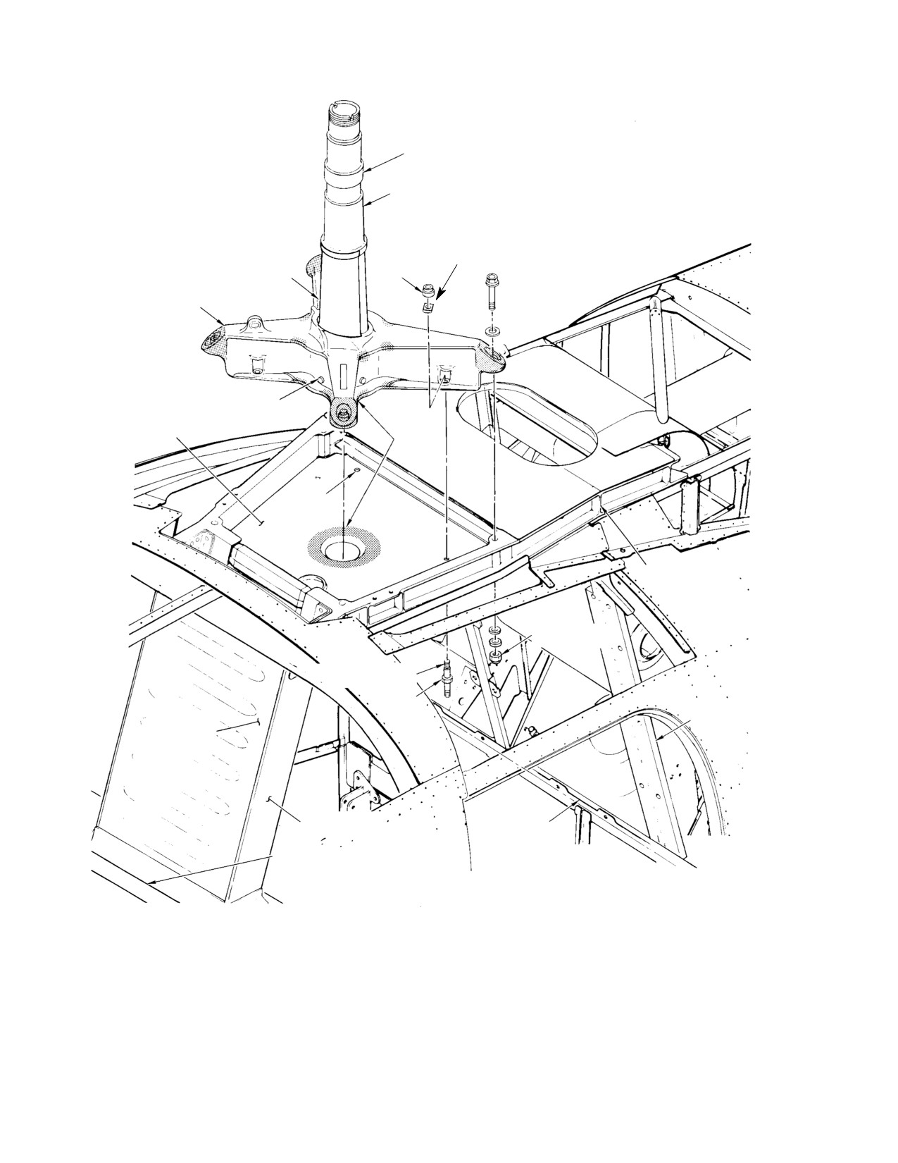
Figure 201. Main Rotor Mast and Support Structure (369D25100 Transmission Installation)
Page 202
Revision 20
63-30-00
MD Helicopters, Inc.
CSP-HMI-2
MAINTENANCE MANUAL
3. Main Rotor Static Mast Replacement
(4). Using 0.0010-0.0015 inch
(369F5100 Transmission Installation)
(0.0254-0.0381 mm) feeler gage, check
for gap between self-locking nuts and
(Ref. Figure 202)
plate spacers. No gap is allowed.
A. Main Rotor Static Mast Removal
(5). If gap exists, remove nut and replace
(369F5100 Transmission Installation)
with new self-locking nut. Torque bolts
into replacement nuts to 160 - 190
Main rotor mast is highly
inch-pounds (18.08 - 21.47 Nm) plus
CAUTION
stressed. Do not allow tools to
drag torque and repeat step e. above.
strike mast or mast to strike any object. Any
Continue until each nut is flush against
impact damage may require replacement of
its spacer. Seal bare bond area with
mast.
clear lacquer (CM306).
(6). Install main transmission (Ref. Sec.
(1). Remove main rotor hub (Ref. Sec.
63-25).
62-20).
(7). Install main rotor controls (Ref. Sec.
(2). Remove main rotor controls (Ref. Sec.
67-10).
67-10).
(8). Install main rotor hub (Ref. Sec.
(3). Remove main transmission (Ref. Sec.
62-20).
63-25).
4. Main Rotor Static Mast Inspection and
(4). Remove four bolts, washers and nuts.
Repair
(5). Lift main rotor mast from helicopter.
(Ref. Figure 203)
B. Main Rotor Static Mast Installation
(369F5100 Transmission Installation)
Consumable Materials
(Ref. Section 91−00−00)
Item
Nomenclature
Consumable Materials
CM115
Grease, oscillating bearing
(Ref. Section 91−00−00)
CM234
Solvent, dry-cleaning
Item
Nomenclature
CM235
Cleaner
CM306
Lacquer, clear
CM304
Enamel, epoxy
CM430
Sealant, solvent resistant
CM305
Lacquer, acrylic
CM318
Primer
(1). Apply silicone sealant (CM430) on
CM323
Primer
bottom surface of mast tube and base at
CM713
Tape, pressure sensitive
drive shaft opening to seal base to mast
CM802
Abrasive cloth, aluminum oxide
support structure at installation.
CM803
Crocus cloth
(2). Position main rotor mast so that holes
in base align with holes in mast support
(1). Inspect all areas of main rotor mast for
structure.
cracks, nicks, scratches and evidence of
impact damage.
(3). Check underside of mast support
structure at left aft stud hole location.
(2). Inspect bearing surfaces for scoring and
Stud-to-pan doubler surface must be
galling.
clean to bare metal for electrical
bonding. Install main transmission
(3). Inspect threads for damage.
mounting bolts, plate spacers and nuts.
Torque nuts to 160 - 190 inch-pounds
(4). Inspect rivets that secure base to mast
(18.08 - 21.47 Nm) plus drag torque.
tube for security.
Page 203
63-30-00
Revision 36
CSP-HMI-2
MD Helicopters, Inc.
MAINTENANCE MANUAL
(5). Check that tape (Ref. Figure 201) on
(b).
Remove main transmission (Ref. Sec.
forward edge of mast tube is secure and
63-20-00 or 63-20-25, Main Trans
undamaged; replace if defective.
mission Replacement).
(a). Peel defective tape from mast.
(c).
Remove static mast (Ref. Main Rotor
Static Mast Replacement).
(b). As required, polish area to remove
burrs and sharp areas with abrasive
(d).
Thoroughly clean interior tube with
cloth (CM802) or crocus cloth
Solvent (CM234).
(CM803).
(c). Clean mast thoroughly with cleaner
(e).
Inspect for any corrosion, none
(CM235) and allow to dry.
allowed.
(d). Apply primer (CM318) and paint
(f).
Remove paint from bad areas and
(CM305) to affected area.
lightly feather paint edge with crocus
cloth (CM803), remove any residue
(e). Apply pressure sensitive tape
from feathering.
(CM713) to mast.
NOTE: To inhibit corrosion of mast when oper
(g).
Apply primer (CM318), or (CM323),
ating in salt water environment, check tape
to repair areas.
at frequent intervals. Also, apply thin
grease film (CM115) to bearing journals.
(h).
Allow to cure per manufacturer's
instructions.
(6). Inspect internal bore for paint chipping,
orange peeling or flaking, none allowed.
(i).
Apply white paint (CM304) to
internal bore of mast.
NOTE: Chipping, orange peeling or flaking
paint will normally be at the base of the
(j).
Allow to cure per manufacturer's
static mast tube.
instructions.
(7). Re-apply finish to mast internal bore
(k).
Reinstall static mast.
as follows:
(a). Remove main rotor hub (Ref. Sec.
(l).
Reinstall main transmission.
62-20-00 or 62-20-60, Main Rotor
Hub Replacement).
(m).
Reinstall main rotor hub.
Page 204
Revision 36
63-30-00
MD Helicopters, Inc.
CSP-HMI-2
MAINTENANCE MANUAL
HUB SLEEVE
BEARING SURFACE
NUT
MAIN ROTOR MAST
PLATE SPACER
TAPE
MAST BASE
RIVET
DRAIN HOLE
NOTE 2
MAST SUPPORT
STRUCTURE PAN
MAST SUPPORT
FITTING
MAST MOUNT BOLT
(NOTE 1)
NOTES:
1.
THIS BOLT REQUIRES ELECTRICAL BOND TO STRUCTURAL PAN.
2.
MAIN ROTOR MAST IS SEALED TO STRUCTURE PAN (INSIDE MAST
TUBE AT BASE) WITH SILICONE RUBBER (CM430).
6G63-034
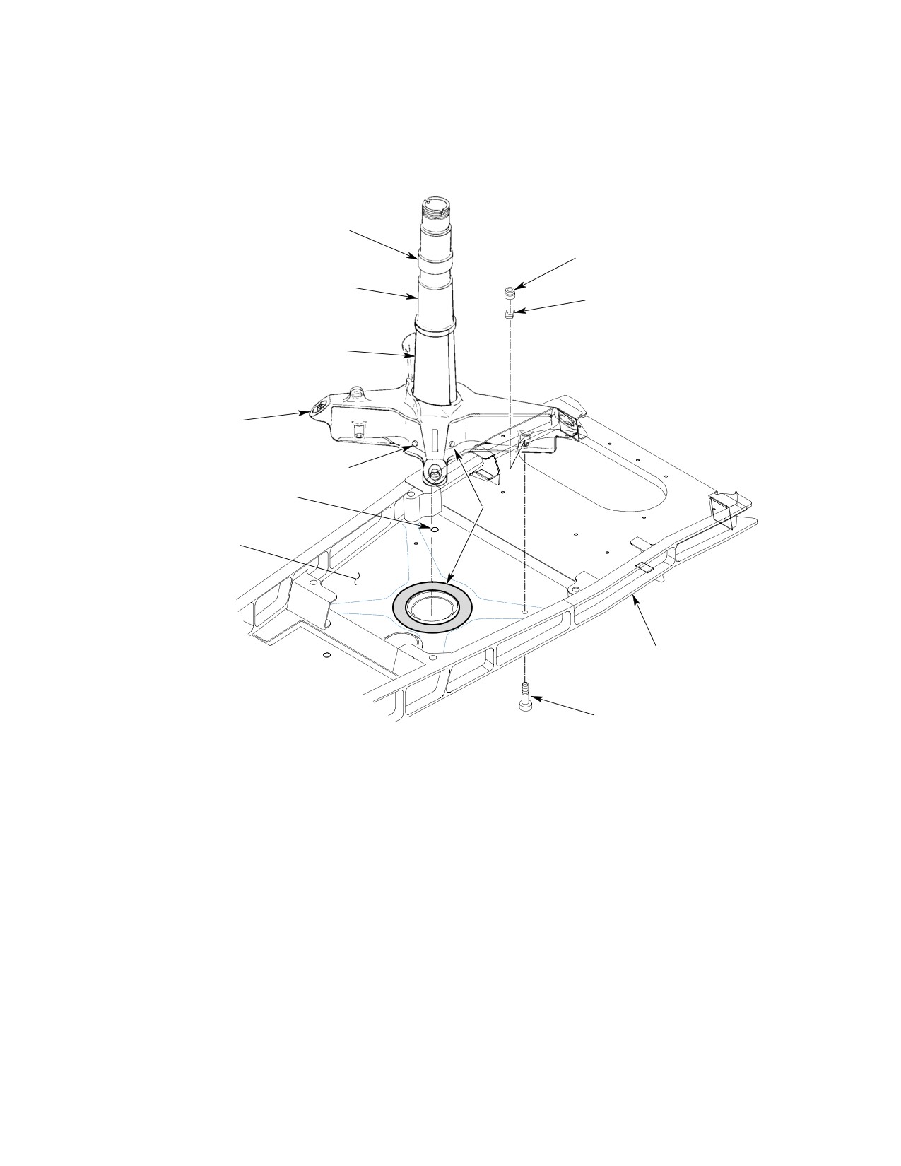
Figure 202. Main Rotor Mast and Support Structure (369F5100 Transmission Installation)
Page 205
63-30-00
Revision 29
CSP-HMI-2
MD Helicopters, Inc.
MAINTENANCE MANUAL
MAXIMUM REMOVAL
REPAIRABLE
AREA
OF
REPAIR PROCEDURE
DAMAGE
MATERIAL (DEPTH)
POLISH DEFECTIVE AREA SMOOTH WITH
CORROSION AND
0.010 IN.
ABRASIVE CLOTH (CM802 AND CM803) IF
SCRATCHES
(0.254 MM)
CADMIUM PLATING HAS BEEN PENE
TRATED. TREAT REWORKED AREA WITH
PRIMER (CM318).
CHIPPING OF CAD
THICKNESS OF CAD
POLISH AREA SMOOTH WITH ABRASIVE
MIUM PLATING (0.0035
CLOTH (CM802 AND CM803). TREAT RE
MIUM PLATING
IN. (0.0889 MM MAXI
WORKED AREA WITH PRIMER (CM318)
MUM)
AND LACQUER (CM306).
LONGITUDINAL
SCRATCHES THAT
DO NOT PENE
TRATE THROUGH
MUST NOT PENE
NICKEL PLATE.
TRATE NICKEL PLAT
SCRATCHES MUST
POLISH AREA WITH ABRASIVE CLOTH
ING, 0.003-0.007 IN.
BE A MINIMUM OF
(CM802 AND CM803) TO REMOVE BURRS
(0.076-0.178 MM)
0.25 IN. (6.35 MM)
AND SHARP EDGES ONLY.
THICK
APART. RADIAL
SCRATCHES ARE
NOT PERMITTED.
MUST NOT PENETRATE
THICKNESS OF SILVER
PLATING BY AN AREA
NO LARGER THAN 0.5
IN.2 (3.2258 CM2). NO
MORE THAN TWO
SUCH AREAS NO
WIPE AREA CLEAN USING CHEESE CLOTH
CORROSION AND
CLOSER THAN 1.5 IN.
(CM820) DAMPENED IN SOLVENT (CM222).
SCRATCHES
(3.81 CM) APART MAY
SPRAY UNIFORM COATING, 0.002-0.005 IN.
EXIST. IF WEAR EX
(0.051-0.127 MM) THICK, ON WORN AREA
CEEDS LIMITS, CON
WITH LUBRICANT (CM103).
TACT MDHS WARRAN
AREA EN
TY REPAIR DEPART
CLOSED
MENT FOR REWORK
BY MAST
DISPOSITION. ONLY
BASE
MDHS CAN PERFORM
PLATING REPAIRS.
REMOVE DEFECTIVE TAPE. POLISH DE
FECTIVE AREAS TO REMOVE BURRS AND
CORROSION AND
SHARP SURFACES WITH ABRASIVE
REPLACEMENT OF
0.010 IN.
CLOTH (CM802 AND CM803). TOUCH UP
TAPE.
(0.254 MM)
REWORKED AREAS WITH PRIMER (CM318)
AND LACQUER (CM305). REPLACE TAPE
(CM713).
NOTE: FOR MAGNETIC PARTICLE INSPECTION,
REMOVE PAINT FROM APPLICABLE SURFACE
G63-3001B
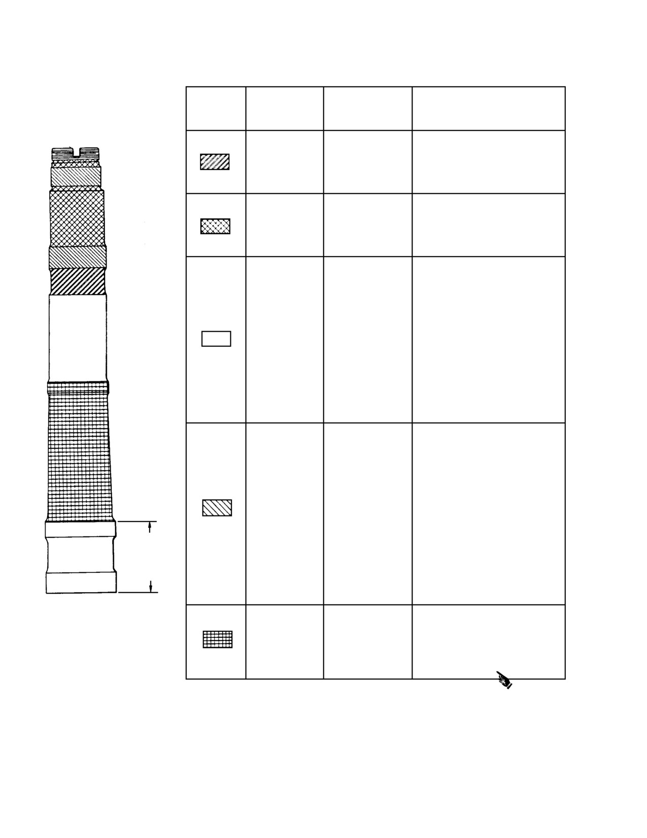
Figure 203. Main Rotor Mast − Inspection and Repair
Page 206
Revision 36
63-30-00

MD Helicopters, Inc.
CSP-HMI-2
MAINTENANCE MANUAL
Chapter
64
Anti−Torque
Assembly
MD Helicopters, Inc.
CSP−HMI−2
MAINTENANCE MANUAL
TABLE OF CONTENTS
Para/Figure/Table
Title
Page
64-00-00 Anti-Torque Assembly (369D/E/FF - 500/600N)
A
Fault Isolation
101
1. Tail Rotor Assembly
101
2. Anti-Torque Fan Assembly
101
Table 101. Troubleshooting Tail Rotor and Vibrations
101
64-00-05 Four-Bladed Tail Rotor Assembly Initial Installation (369D/E)
A
Initial Installation
901
1. Four-Bladed Tail Rotor Initial Installation
901
A. Tail Rotor and Transmission Initial Installation
901
B. Existing Tail Rotor and Transmission Removal
901
C. Four-Bladed Tail Rotor Transmission Build-Up
901
D. Drive Shaft, Tail Rotor Transmission and Tail Rotor Installation
901
Figure 901. Tail Rotor Index Stripe Requirements
902
E. Tail Rotor Control Over-Center Trim System Rework
903
F. Two-Bladed Over-Center Trim System Removal
903
G. Four-Bladed Over Center Trim System Initial Installation
903
Figure 902. Over Center Trim System Installation
904
H. Four-Bladed Tail Rotor Controls Rigging
906
I. Horizontal Stabilizer Tip Weight Removal
906
J. N2 and NR (Rotor) Tachometer Indicator Replacement
906
K. Four-Bladed Tail Rotor System Completion of Installation
906
L. Weight and Balance
907
Table 901. Weight and Balance Data
907
Figure 903. Bracket Installation - Sta. 78.50 Canted Wall
908
64-10-00 Tail Rotor Blades (369D/E/FF)
A
Maintenance Practices
201
1. Tail Rotor Blades
201
2. Tail Rotor Blade Inspection
201
3. Abrasion Strip Dye Penetrant and Tap Test Inspection
201
Figure 201. Tail Rotor Blade
202
Figure 202. Inspection of Tail Rotor Blade Abrasion Strip
203
4. Tail Rotor Blade Tip Cap Repair
204
Figure 203. Installation of Tip Cap-To-Tail Rotor Blade Rivets
205
5. Tail Rotor Blade Replacement Procedure
206
6. Tail Rotor Abrasion Strip Riveting
207
Figure 204. Tail Rotor Blade Abrasion Strip Riveting
208
Page i
64 Contents
Revision 42
CSP−HMI−2
MD Helicopters, Inc.
MAINTENANCE MANUAL
TABLE OF CONTENTS (Cont.)
Para/Figure/Table
Title
Page
7. Tail Rotor Blade Abrasion Strip Modification
209
8. Tail Rotor Blade Protective Tape Installation
210
Figure 205. Tail Rotor Blade Abrasion Strip Modification
211
9. Tail Rotor Blade Leading Edge Crack Inspection
212
A. Tail Rotor Blades with New-Style Abrasion Strips
212
B. Tail Rotor Blades with Old-Style Abrasion Strips
212
Figure 206. Tail Rotor Blade Leading Edge Crack Inspection
214
64-20-00 Tail Rotor Hub and Fork (369D/E/FF)
A
Maintenance Practices
201
1. Tail Rotor Hub and Fork
201
2. Tail Rotor Hub and Fork Replacement
201
A. Tail Rotor Hub and Fork Removal
201
Figure 201. Tail Rotor Hub and Strap Pack
202
B. Tail Rotor Hub and Fork Installation
203
Figure 202. Hub and Fork Assembly Installation (Two-Bladed)
204
Figure 203. Hub and Fork Assembly Installation (Four-Bladed)
205
3. Tail Rotor Hub and Fork Inspection
206
4. Conical Bearing Inspection
206
5. Elastomeric Fork Bearing Inspection
206
Figure 204. Blade Flapping Resistance Check
207
6. Elastomeric Bearing Care and Cleaning
207
64-25-30 Anti-Torque Fan (500/600N)
A
Removal/Installation
401
1. Anti-Torque Fan Assembly
401
2. Anti-Torque Fan Replacement
401
A. Anti-Torque Fan Removal
401
B. Anti-Torque Fan Installation
401
3. Anti-Torque Fan Blade Replacement
401
A. Anti-Torque Fan Blade Removal
401
B. Anti-Torque Fan Blade Installation
401
Figure 401. Anti-Torque Fan
402
4. Fan Blade Strap and Pitch Horn Replacement
403
A. Fan Blade Strap and Pitch Horn Disassembly
403
B. Fan Blade Strap and Pitch Horn Reassembly
403
Page ii
Revision 42
64 Contents
MD Helicopters, Inc.
CSP−HMI−2
MAINTENANCE MANUAL
TABLE OF CONTENTS (Cont.)
Para/Figure/Table
Title
Page
5. Retention Plate and Pitch Plate Replacement
404
A. Retention Plate and Pitch Plate Disassembly
404
B. Retention Plate and Pitch Plate Reassembly
404
6. Support Shaft Replacement
404
A. Support Shaft Disassembly
404
B. Support Shaft Reassembly
404
7. Fan Balance Stud Replacement
405
A. Fan Balance Stud Removal
405
B. Fan Balance Stud Installation
405
Figure 402. Anti-Torque Fan Support Shaft
406
8. Pitch Horn Counterweight Set Screw Replacement
407
Figure 403. Pitch Horn Counterweight Set Screw Replacement
407
Inspection/Check
601
1. Anti-Torque Fan Inspection
601
2. Support Shaft Inspection
601
3. Anti-Torque Fan Liner (Felt Metal Seal) Inspection
601
4. Fan Blade Inspection (100-Hour)
601
5. Fan Pitch Slider Inspection
602
Repairs
801
1. Anti-Torque Fan Liner (Felt Metal Seal) Replacement
801
A. Anti-Torque Fan Liner (Felt Metal Seal) Removal
801
B. Anti-Torque Fan Liner (Felt Metal Seal) Installation
801
C. Anti-Torque Fan Liner (Felt Metal Seal) Machining
801
Figure 801. Anti-Torque Fan Liner (Felt Metal Seal)
802
Figure 802. Anti-Torque Fan Liner Felt Metal Seal Machining
803
2. Anti-Torque Fan Bearing Regreasing
806
Figure 803. Fan Bearing Regreasing Procedure
806
Figure 804. Fan Bearing Regreasing Tool (ST614)
807
64-30-00 Tail Rotor Pitch Control Assembly (369D/E/FF)
A
Maintenance Practices
201
1. Tail Rotor Pitch Control Assembly
201
2. Tail Rotor Pitch Control Assembly Replacement
201
A. Tail Rotor Pitch Control Assembly Removal
201
Figure 201. Pitch Control Assembly - Wobble Check
201
Figure 202. Swashplate-to-Pitch Control Housing Clearance
202
B. Tail Rotor Pitch Control Assembly Installation
202
Page iii
64 Contents
Revision 42
CSP−HMI−2
MD Helicopters, Inc.
MAINTENANCE MANUAL
TABLE OF CONTENTS (Cont.)
Para/Figure/Table
Title
Page
3. Tail Rotor Pitch Control Link Replacement
202
Figure 203. Tail Rotor Pitch Control Assembly (Two-Bladed)
203
Figure 204. Tail Rotor Pitch Control Assembly (Four-Bladed)
204
4. Tail Rotor and Pitch Control Assembly Repair
205
5. Tail Rotor Pitch Control Assembly Inspection
205
6. Tail Rotor Blade Stop Inspection
206
7. Tail Rotor Pitch Control Link Inspection
206
8. Tail Rotor Conical Bearing Inspection
207
9. Tail Rotor Pitch Bearing Inspection
207
10. Tail Rotor Swashplate Bearing Regreasing
207
Figure 205. Tail Rotor Swashplate Bearing Regreasing
207
Figure 206. Tail Rotor Swashplate Bearing Regreasing Tool
208
Figure 207. Tail Rotor Swashplate Holding Block
209
Figure 208. Tang Washer Inspection and Application of Torque Stripe
210
Page iv
Revision 42
64 Contents
MD Helicopters, Inc.
CSP-HMI-2
MAINTENANCE MANUAL
Section
64−00−00
Anti−Torque
Assembly
(369D/E/FF −
500/600N)
MD Helicopters, Inc.
CSP-HMI-2
MAINTENANCE MANUAL
ANTI−TORQUE ASSEMBLY
FAULT ISOLATION
1. Tail Rotor Assembly
quick-release pins on top of pedal arms and
repositioning pedals.
The tail rotor, mounted on the tail rotor
transmission at the end of the tailboom,
The two-bladed tail rotor assembly consists
counteracts main rotor torque and controls
mainly of two tail rotor blades, a hub, drive
heading of the helicopter. The tail rotor control
fork, two pitch control links, and a pitch
system changes the pitch of the tail rotor
control assembly.
blades. The antitorque pedals move a system
of bellcranks and control rods routed through
The four-bladed tail rotor assembly consists
the fuselage and tailboom to a pitch control
of four tail rotor blades, two hubs, drive fork,
assembly which moves links that attach to
four pitch control links and a pitch control
blade-pitch arms on the blades.
assembly. The blades are held together on the
hub by a laminated tension-torsion strap pack
The pitch control assembly slides axially on
that permits the blades to rotate axially on the
the tail rotor transmission output shaft.
hub. The hub pivots in the drive fork. Control
Pushing forward on the left pedal changes
of blade pitch is from the pitch control assem
heading to the left; forward right pedal
bly through pitch control links that connect to
movement changes heading to the right.
pitch arms on the blade root fittings.
For two-bladed tail rotor system, blade pitch
2. Anti−Torque Fan Assembly
movement is -13 degrees to -15 degrees thrust
to the left and +27 degrees to +29 degrees to
The anti-torque fan is an axial fan with
the right.
thirteen variable pitch blades. The fan
For four-bladed tail rotor system, blade pitch
provides anti-torque by furnishing variable
movement is -13 degrees to -15 degrees thrust
flow of low pressure high volume air through
to the left, +31 degrees to +32 degrees thrust
the tailboom and thrusters.
to the right and +6.5 degrees to +8.5 degrees
thrust to the right at neutral.
During flight, pedal position and pressure
required to maintain a desired heading varies
During flight, pedal position and pressure
with main rotor torque variations, altitude and
required to maintain a desired heading varies
airspeed conditions. Control linkage includes a
with main rotor torque variations, altitude and
bungee spring that relieves left pedal forces in
airspeed conditions. Control linkage includes a
flight.
bungee spring that relieves left pedal forces in
flight.
When the helicopter is on the ground, pedal-
to-seat distance is adjusted by removing
When the helicopter is on the ground, pedal-
quick-release pins on top of pedal arms and
to-seat distance is adjusted by removing
repositioning pedals.
Table 101. Troubleshooting Tail Rotor and Vibrations
Symptom
Probable Trouble
Corrective Action
Heavy medium−frequency vibration
Tail rotor out of balance.
Rebalance tail rotor assembly (Ref.
in tail rotor assembly; vibration
Sec. 18−20−00).
sometimes felt in pedals as a
Runout of tail rotor transmission
Replace transmission if shaft runout
buzzing sensation.
output shaft excessive.
exceeds 0.0025 inch (0.0635 mm)
T.I.R. No axial play allowed. (Ref.
Sec. 63−25−10).
Page 101
64-00-00
Revision 21
CSP-HMI-2
MD Helicopters, Inc.
MAINTENANCE MANUAL
Table 101. Troubleshooting Tail Rotor and Vibrations
Symptom
Probable Trouble
Corrective Action
High frequency vibration, primarily
Tail rotor blades slightly out of
Rebalance tail rotor assembly (Ref.
in pedals as a buzzing sensation.
balance.
Sec. 18−20−00).
Tail rotor blade pitch bearings
Replace tail rotor pitch bearings (Ref.
worn.
COM).
Excessive wear in pitch control link
Replace pitch control link bearings
bearings.
(Ref. COM).
NOTE: High frequency vibrations in
Excessive wear of swashplate or
Replace swashplate or repair pitch
the helicopter can also be
large bearings in housing of pitch
control assembly (Ref. COM).
caused by components of other
control assembly.
systems (Ref. Sec. 18−20−00,
Excessive play in tail rotor fork
Replace fork bearings (Ref. COM).
53−40−00,
63−25−10 and
bearings.
Chap. 71).
Tail rotor hub−to−fork play.
Repair (Ref. COM).
Excessive dents in leading edge of
Replace blade(s) or tail rotor
blades.
assembly. (Ref. COM).
Insufficient torque on stabilizer
Retorque mount bolts (Ref. Chap.
mount bolts.
53).
Insufficient torque on tail rotor
Retorque retaining nut (Ref. Sec.
assembly retaining nut.
64−30−00).
Excessive play in pitch control link
Worn pitch control link bearings.
Replace pitch control link bearings
assemblies.
(Ref. COM).
High left pedal forces required in
Bungee spring (Sta. 63)
Reconnect or replace bungee spring
flight.
disconnected, broken or stretched.
(Ref. Sec. 67−20−00).
Pedals binding.
Excessive drag of pitch control
Clean swashplate bore and
swashplate on transmission shaft.
transmission shaft splines.
Re−lubricate splines.
Snapping noise heard in
Noise is normal action of strap
None required.
non−operating tail rotor when pitch
pack and caused by laminates
angle changed from one extreme
twisting and bending when blade is
to the other.
feathered without centrifugal load
present.
Page 102
Revision 34
64-00-00
MD Helicopters, Inc.
CSP-HMI-2
MAINTENANCE MANUAL
Section
64−00−05
Four−Bladed Tail
Rotor Assembly
Initial Installation
(369D/E)
MD Helicopters, Inc.
CSP-HMI-2
MAINTENANCE MANUAL
FOUR−BLADED TAIL ROTOR ASSEMBLY
INITIAL INSTALLATION
1. Four−Bladed Tail Rotor Initial Installation
(5). Remove existing station 284 bellcrank
and tail rotor control rod (Ref. Sta. 284
This section contains procedures for initial
Bellcrank Removal).
installation of four-bladed tail rotor kit, which
C. Four−Bladed Tail Rotor Transmission
includes tail rotor; tail rotor transmission; and
parts for modifying over-center trim system
Build−Up
controls and engine/rotor tachometer indicator.
(Ref. Figure 901) Build-up the four-bladed tail
This kit may be installed on all Model 500D
rotor transmission as follows.
and 500E helicopters at the owner's/operator's
discretion.
Consumable Materials
NOTE: Components of the four-bladed tail ro
(Ref. Section 91−00−00)
tor drive system kit are assembled and bal
Item
Nomenclature
anced at the factory. Prior to installation of
CM112
Anti-seize compound high temperature
the kit, some existing equipment must be re
CM305
Lacquer, acrylic
moved from the helicopter, and other equip
ment must be modified.
Do not lift transmission assem
A. Tail Rotor and Transmission Initial
CAUTION
bly by coupling flange.
Installation
(1). Install shims, coupling and coupling
Install the four-bladed tail rotor transmission
bolt. Coat threads of bolt with anti-
and tail rotor assembly according to the
seize compound (CM112). Torque bolt to
following procedures.
250 - 300 inch-pounds (28.25 - 33.90
Nm) plus drag torque.
B. Existing Tail Rotor and Transmission
Removal
(2). Add stripe of white paint (CM305)
approximately 0.0125 inch (3.175 mm)
Remove the following equipment from helicop
wide between ends of decal to allow for
ter before installing four-bladed tail rotor
indexing of aft end of drive shaft.
transmission and tail rotor assemblies.
NOTE:
To locate new coupling index, use flash
(1). Remove existing two-bladed tail rotor
light and look through control tube rod hole
(Ref. Sec. 64-20-00).
in aft tailboom fitting. Rotate output shaft
until index stripe on coupling is at six o'clock
(2). Remove tail rotor transmission and
position.
driveshaft (Ref. Sec. 63-25-10).
D. Drive Shaft, Tail Rotor Transmission and
Tail Rotor Installation
NOTE: Retain bolt for use when building up
four-bladed tail rotor transmission, cou
(Ref. Figure 901) Install drive shaft, transmis
pling is a limited-life item. If sufficient ser
sion and tail rotor on helicopter as a unit. Do
viceable life remains on coupling, it may be
not install with blades mounted.
reused with four-bladed tail rotor installa
tion. If not, discard and replace coupling
bolt.
Consumable Materials
(Ref. Section 91−00−00)
(3). Remove bolt, coupling and shims from
Item
Nomenclature
transmission output shaft (Ref. Sec.
CM305
Lacquer, acrylic
63-15-10).
(4). Remove index stripe on drive shaft at
(1). Install existing drive shaft on tail rotor
Sta. 137.5.
transmission (Ref. Sec. 63-15-10).
Page 901
64-00-05
Revision 21
CSP-HMI-2
MD Helicopters, Inc.
MAINTENANCE MANUAL
TAIL ROTOR
TRANSMISSION
DAMPER
COUPLING
TAIL ROTOR
DRIVESHAFT
STA. 137.50
COUPLING
TAIL ROTOR
TRANSMISSION
(4-BLADED)
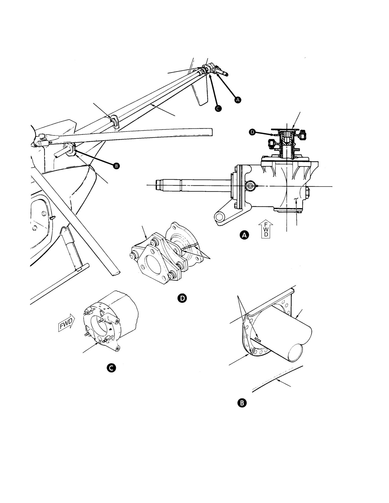
WHITE STRIPES 0.125 IN.
(3.175 MM) WIDE
WHITE STRIPES 0.125 IN.
(NEW CONFIGURATION)
(3.175 MM) WIDE
TAIL ROTOR
DRIVESHAFT
WHITE PAINT MARKING
AT 6 0'CLOCK
DOUBLER
STATION 137.50
RING
STA. 137.50
(LOOKING FORWARD)
NOTE: ADD STRIPE OF WHITE PAINT ON COUPLING AT LOCATION
SHOWN, APPROXIMATELY 0.125 IN. (3.175 MM) WIDTH AND
LENGTH, AND AT CONTROL ROD HOLE AT AFT SIDE OF HOUSING.
G64-0001A
Figure 901. Tail Rotor Index Stripe Requirements
Page 902
Revision 21
64-00-05
MD Helicopters, Inc.
CSP-HMI-2
MAINTENANCE MANUAL
(2).
Install assembled unit on helicopter
Install bungee installation
WARNING
(Ref. Sec. 63-15-10).
tool (ST508) before discon
necting any pilot's collective stick
(3).
Paint 0.125 inch (3.175 mm) wide and
hardware. There is strong bungee
0.125 inch (3.175 mm) long stripe
spring pressure present in stick link
(contrasting color to aft tailboom
age. If suddenly released, spring reac
fitting) at six o'clock position of control
tion in linkage can cause personal inju
rod in aft tailboom fitting to align stripe
ry or parts damage.
on coupling.
(3). Remove bellcranks and collective
(4).
Add white index stripe (CM305) on tail
bungee spring and bracket; disconnect
rotor drive shaft to match stripe on
and retract lateral cyclic trim actuator
doubler at Sta. 137.5.
assembly.
(5).
Install new tail rotor control rod.
Turn off electrical switches
WARNING
and disconnect any external
(6).
Attach new Sta. 284 bellcrank to new
power from helicopter prior to refuel
tail rotor pitch control assembly.
ing or defueling. Static discharge spark
in presence of fuel vapors can cause
(7).
Temporarily install bellcrank to new
fire or an explosion.
control rod assembly.
(8).
Install blades on hubs. Install inboard
(4). Drain all fuel from fuel cells; purge cells
blades first (Ref. Sec. 64-10-00).
with dry filtered compressed air.
E. Tail Rotor Control Over−Center Trim
(5). Fold and displace left fuel cell to permit
System Rework
bucking of rivets at aft side of canted
wall.
The tail rotor over-center trim system must be
reworked when four-bladed tail rotor is
G. Four−Bladed Over Center Trim System
installed. Necessary parts for this rework are
Initial Installation
included with four-bladed tail rotor kit.
(Ref. Figure 902)
F. Two−Bladed Over−Center Trim System
Removal
Special Tools
Prior to rework of over center trim system,
(Ref. Section 91−00−00)
following existing equipment must be removed
Item
Nomenclature
and preparations made.
ST508
Collective bungee installation tool
Special Tools
(Ref. Section 91−00−00)
(1). Locate and clamp fitting (1) and
Item
Nomenclature
serrated plate (2) together with serra
tions facing away from fitting. Drill one
ST508
Collective bungee installation tool
0.159 inch (4.0386 mm) diameter rivet
hole with a #21 bit and countersink
(1). Remove tail rotor bungee; disconnect
hole.
floor-routed tail rotor control rod and
remove and discard spring fitting from
(2). Locate serrated plate (3) and clamp to
rod. Remove tail rotor idler bellcrank
seat support structure (4). Ensure
under pilot seat.
serrations are facing away from seat
support structure. Mark rivet and
(2). Disconnect tunnel-routed tail rotor
screw holes on serrated plate (3) and
control rod and lateral mixer control
seat support structure. Remove ser
rod at lower rod end.
rated plate from seat support structure.
Page 903
64-00-05
Revision 21
CSP-HMI-2
MD Helicopters, Inc.
MAINTENANCE MANUAL
9
7
11
34
36
35
20
21
12
14
9
(NOTE 2)
13
23
15
2 (REF)
3 (REF)
21
NOTE 1
22
8
1.00 IN.
(NOTE 2)
24
1.00 IN.
(2.54 CM)
26
(2.54 CM)
19
25
26
32
0.612 IN.
0.612 IN.
2.50 IN.
(15.5448 MM)
(15.5448 MM)
(6.35 CM)
33
31
10
30
30
27
28
29
5
18
17
1
2
6
3
C
1.75 IN.
L
(4.445 CM)
1.00 IN.
2.00 IN.
4
(2.54 CM)
(5.08 CM)
16
3.31 IN.
(8.4074 CM)
PILOT'S FLOOR
(REF)
NOTES:
1.
REMOVE 0.12-0.14 IN. (3.048-3.556 MM) ON 369A7304 BRACKET.
2.
NOT REQUIRED WHEN 369D27304 BRACKET IS INSTALLED.
G64-0002A
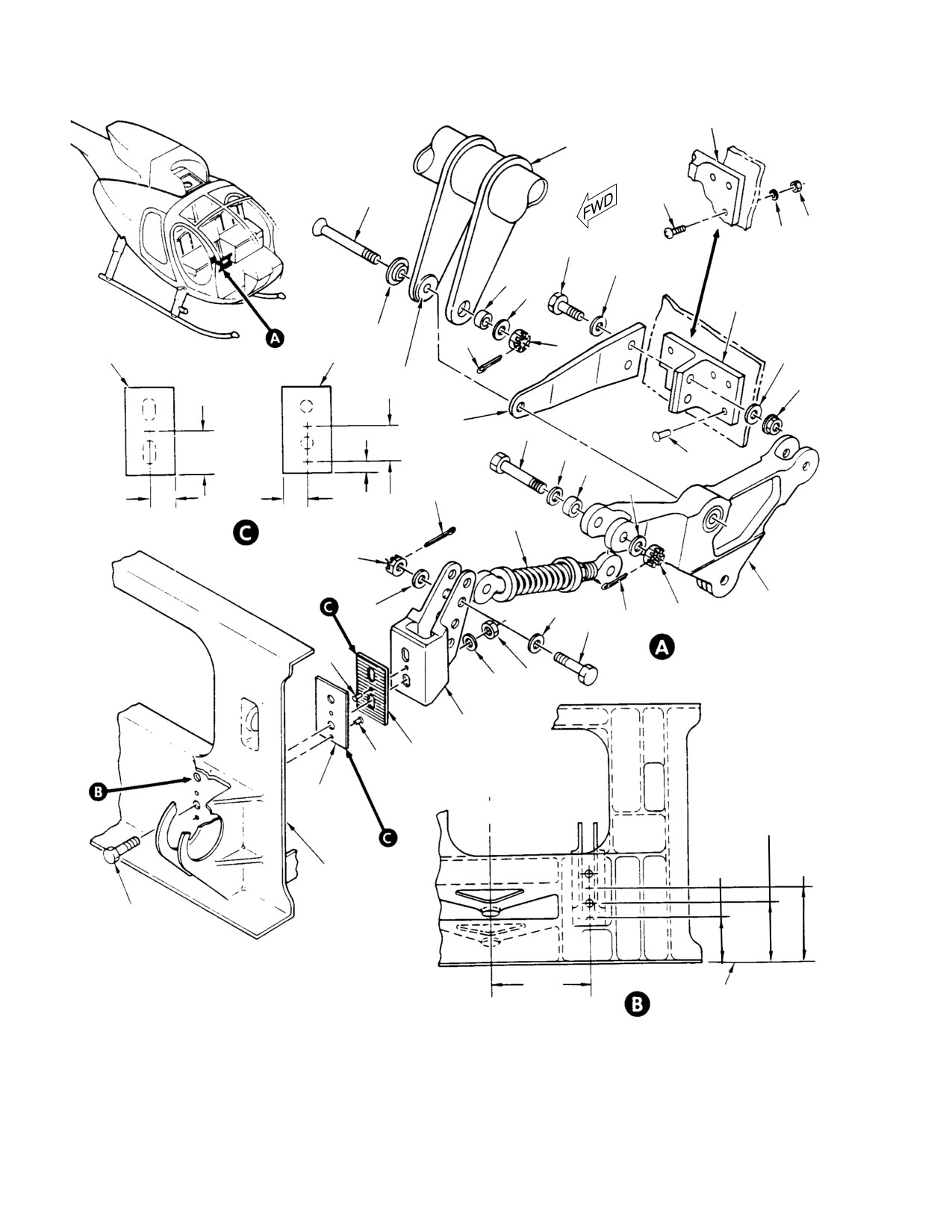
Figure 902. Over Center Trim System Installation
Page 904
Revision 21
64-00-05
MD Helicopters, Inc.
CSP-HMI-2
MAINTENANCE MANUAL
Legend (Ref. Figure 902)
1. FITTING
19. RIVET
2. SERRATED PLATE
20. BOLT
3. SERRATED PLATE
21. WASHER
4. SEAT SUPPORT STRUCTURE
22. NUT
5. RIVET
23. COTTER PIN
6. RIVET
24. BOLT
7. BRACKET
25. BUSHING
8. BRACE
26. WASHER
9. BRACKET
27. NUT
10. BELLCRANK
28. COTTER PIN
11. BOLT
29. BOLT
12. BUSHING
30. WASHER
13. WASHER
31. NUT
14. WASHER
32. COTTER PIN
15. NUT
33. TAIL ROTOR BUNGEE
16. BOLT
34. SCREW
17. WASHER
35. WASHER
18. NUT
36. NUT
NOTE: Head of rivets not to protrude past base
(8). Install fitting (1) on seat support
of serrations.
structure using bolts (16), washers (17)
and nuts (18).
(3). Attach fitting (1) and serrated plate (2)
NOTE: Shim -BSC bracket (9), as required, for
together with one rivet (5).
proper fit on canted wall. Shims are not re
quired for -3 bracket (9).
(4). Locate and drill two 0.250-0.254 inch
(6.35-6.4516 mm) diameter screw holes
(9).
Locate and clamp bracket (9). Drill five
and two 0.098 inch (2.4892 mm)
0.193-0.199 inch (4.9022-5.0546 mm)
diameter rivet holes using a #40 bit
diameter holes using existing rivet
through seat support structure to
pattern (Ref. Figure 903).
match previously marked locations
(step (2).). Countersink rivet holes.
(10).
Attach bracket (9) to canted wall using
five rivets (19) or alternate method of
(5). Drill two 0.098 inch (2.4892 mm)
five screws (34), washers (35) and nuts
diameter rivet holes with a #40 bit thru
(36).
serrated plate (with round bolt holes)
(11).
Grasp brace (8) and hold against
using previously marked locations (step
bracket (9). Mark mating holes on brace
(2).). Attach serrated plate (3) to seat
(8) with those on bracket (9).
support structure using two rivets (6).
(12).
Remove brace (8) from bellcrank (10)
NOTE: Check part number of bracket (7). If
and bracket (7). Drill two 0.250-0.254
bracket is a 369A7304, proceed with step
inch (6.35-6.4516 mm) diameter holes
(6). If 369D27304 bracket is installed, brace
at locations marked in step (11)..
(8) and bracket (9) are not required, proceed
(13).
Install brace (8) on bracket (9) with
to step (14).
bolts (20), washers (21) and nuts (22).
(6). Remove 0.12-0.14 inch (3.048-3.556
Align opposite end of brace (8) between
bracket (7) and bellcrank (10).
mm) maximum material, as required,
from bracket (7) boss lug to achieve a
(14).
Install bolt (11), bushing (12) and
snug fit between brace (8), bracket (7)
washers (13, 14) thru bracket (7) and
and bellcrank (10).
bellcrank (10). Install nut (15) and
cotter pin (23).
(7). Temporarily attach bellcrank (10),
brace (8) and bracket (7) with bolt (11),
(15).
Reinstall tunnel-routed control rods
bushing (12), washers (13, 14) and nut
and floor-routed control rods, with
(15) finger tight.
spring fitting removed.
Page 905
64-00-05
Revision 21
CSP-HMI-2
MD Helicopters, Inc.
MAINTENANCE MANUAL
Always use bungee installa
assembly of collective bungee. Coat
WARNING
tion tool (ST508) when re
parts with grease (CM111) as in
moving attaching hardware. Reaction
structed. Ensure that 0.120 inch (3.048
of spring when pressure is suddenly re
mm) of threads are visible between nut
leased can cause personal injury or
and rod end of bungee female bearing
parts damage.
assembly.
NOTE: Adjust tail rotor pedal force by tighten
Remove bungee installation
WARNING
ing or loosening the 0.120 inch (3.048 mm)
tool only as instructed.
thread adjustment on bungee female bear
There is strong bungee spring pressure
ing assembly. Tighten to maximum 0.120
present with four-bladed tail rotor
inch (3.048 mm) thread adjustment on bun
bungee installed. If suddenly released,
gee female bearing assembly increases ped
spring could cause personal injury
al force approximately five pounds; loosen
and/or parts damage.
ing decreases pedal force. Bungee spring
(2). Attach assembled bungee to fitting (1)
may be attached to any of four holes in fit
using attaching hardware (29 thru 32)
ting (1). If excessive left pedal force is re
and to bellcrank (10) using attaching
quired, position spring at lower hole.
hardware (24 thru 28). Ensure bushing
(25) extends 0.010-0.080 inch
H. Four−Bladed Tail Rotor Controls Rigging
(0.254-2.032 mm) beyond surface of
bungee rod end.
Consumable Materials
(Ref. Section 91−00−00)
I. Horizontal Stabilizer Tip Weight Removal
Item
Nomenclature
Tip weights installed in horizontal stabilizer
CM111
Grease, aircraft
for two-bladed tail rotor operation are not
used with four-bladed tail rotor system.
Special Tools
Remove and discard four screws securing tip
(Ref. Section 91−00−00)
plates and weights to horizontal stabilizer.
Item
Nomenclature
Reinstall tip plates using four new screws (P/N
NAS1403-15).
ST508
Collective bungee installation tool
ST510
Bungee spring compression tool rod and
J. N2 and NR (Rotor) Tachometer Indicator
channel
Replacement
ST606
T/R swashplate rigging tool
Remove and replace existing tach indicator
with indicator supplied in four-bladed tail
Rigging of four-bladed tail rotor controls is to
rotor kit (Ref. Sec. 95-30-00).
be done with tail rotor bungee spring removed.
K. Four−Bladed Tail Rotor System
Tail rotor pitch angles at 3/4 radius shall be:
Completion of Installation
Full right pedal
14° ±1°
Upon completion of kit installation, the
following actions must be completed.
Full left pedal
31° +1°−0°
Neutral pedal
7.5° ±1°
(1). Replace all components, access panels,
covers, etc. removed to gain access to
Rig tail rotor controls per Tail Rotor Controls
work area.
Rigging except use four-bladed tail rotor
(2). Check installation of four-bladed tail
control rigging tool (ST606). After rigging,
rotor control linkage for discrepancies.
reinstall tail rotor bungee and carefully
remove bungee installation tool (ST508) using
(3). Fill tail rotor transmission with oil (Ref.
bungee compression tool rod and channel
Sec. 12-00-00).
(ST510).
(4). Refuel helicopter and perform opera
(1). Assemble bungee using bungee installa
tional check of four-bladed tail rotor
tion tool (ST508) and instructions for
control system (Ref. PFM).
Page 906
Revision 21
64-00-05
MD Helicopters, Inc.
CSP-HMI-2
MAINTENANCE MANUAL
(5). Ensure that Pilot Flight Manual
L. Weight and Balance
Supplement is inserted in Section IX,
Rotorcraft Flight Manual.
Weight and balance changes resulting from
(6). Ensure that installation of four-bladed
installation of four-bladed tail rotor kit are
tail rotor kit and appropriate part
listed in Table 901. After kit installation,
numbers, serial numbers and limited-
incorporate changes in helicopter weight and
life data are recorded in helicopter log
balance record as instructed (Ref. Sec.
book.
08-10-00).
Table 901. Weight and Balance Data
Configuration
Weight
Arm
Moment
Pounds (kg)
inches (cm)
in−lb (kg cm)
Added
+9.4
(+4.2638)
257.2
(653.228)
+2417.68
(27854.574)
Removed
0.0
0.0
0.0
Net Change
+9.4
(+4.2638)
257.2
(653.228)
+2417.68
(27854.574)
Page 907
64-00-05
Revision 21
CSP-HMI-2
MD Helicopters, Inc.
MAINTENANCE MANUAL
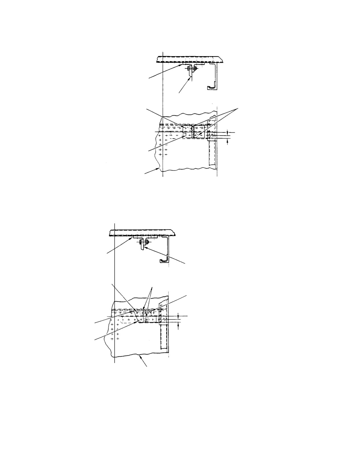
BL 0.00
BRACKET
BRACE
OK TO LEAVE
RIVET (5 REQ'D)
EXISTING RIVETS.
(USE EXISTING
(NOTE)
RIVET PATTERN)
WL 13.10
0.032 IN.
BRACKET
(0.8128 MM)
STATION 78.50
CANTED WALL
BL 0.00
BL 6.00 L.H.
-3
NOTE:
BL 0.00
OMIT THESE TWO RIVETS WHEN
INSTALLING 369D27003-5 ONLY.
BRACKET
BRACE
OK TO LEAVE
RIVET (4 REQ'D)
EXISTING RIVET
(USE EXISTING
RIVET PATTERN)
SHIM AS REQUIRED BETWEEN
BULKHEAD AND BRACKET
WL 13.10
BRACKET
0.032 IN.
SHIM AS REQUIRED BETWEEN
(0.8128 MM)
BULKHEAD AND BRACKET
BL 6.00 L.H.
BL 0.00
STATION 78.50
CANTED WALL
-BSC
G64-0003A
Figure 903. Bracket Installation − Sta. 78.50 Canted Wall
Page 908
Revision 21
64-00-05
MD Helicopters, Inc.
CSP-HMI-2
MAINTENANCE MANUAL
Section
64−10−00
Tail Rotor Blades
(369D/E/FF)
MD Helicopters, Inc.
CSP-HMI-2
MAINTENANCE MANUAL
TAIL ROTOR BLADES
MAINTENANCE PRACTICES
1. Tail Rotor Blades
Scratches that do not exceed 0.020 inch
(0.508 mm) depth are permissible if
Blades are cambered for high thrust to provide
repaired.
directional control at high altitude. Each
(4). Loose or missing tip weights and
consists of an aluminum honeycomb spar,
aluminum skin, riveted aluminum blade
attachment hardware.
fittings and an aluminum tip cap; all structur
(5). Clogged drain openings.
ally bonded together.
(6). Adhesive separation at exposed edges.
At manufacture, static balancing moments of
(7). Debonding of tip cap from tail rotor
all blades are within plus or minus 40 gram
blade (Ref. Tail Rotor Blade Tip Cap
inches of each other by use of a special
Repair).
balancing fixture and prebalancing with tip
weights. Although erosion or allowable repairs
(8). Tip cap rivets for installation and
may cause minor balance moment changes,
condition (Ref. Tail Rotor Blade Tip Cap
such changes are considered negligible enough
Repair).
to allow direct replacement of any used blade
(9). Tail rotor blade pitch bearings for a
with a new one and interchangeable use of
maximum 0.250 inch (6.350 mm) play
blades with remaining service life. In any case
measured at tip of blade.
of blade selection or use, inspection, repair and
serviceability requirements must be complied
3. Abrasion Strip Dye Penetrant and Tap
with. Retirement schedule and remaining
Test Inspection
service life of a used blade should always be
considered when making decision to replace a
(Ref. Figure 202)
single blade (Ref. Sec. 04-00-00).
Consumable Materials
2. Tail Rotor Blade Inspection
(Ref. Section 91−00−00)
Item
Nomenclature
(Ref. Figure 201) Perform balance check at
CM729
Tape, masking, pressure sensitive
intervals specified (Ref. Sec. 05-20-00). If any
of following conditions exist, perform appropri
CM801
Abrasive paper, silicon carbide
ate detailed inspections and allowable repairs
(Ref. COM).
(1). Using a 1/8 inch (3.175 mm) drill bit
and a pencil, fabricate a tapping
(1). Surface cracks, scratches, nicks,
hammer by taping drill bit to pencil.
gouges, dents, pits or corrosion.
Drill bit should be a minimum of six
(2). Leading edge erosion or dents. Visually
inches (15.24 cm) from end of pencil
check abrasion strip for paint cracking
that is to be held while tapping.
or chipping along abrasion strip/airfoil
NOTE: Voids are indicated by a dull, dead tone.
bond line. Use 10X glass to check
Slight tone changes will occur near the tip
abrasion strip/airfoil bond line for
cap and along the length of the strip. These
debonding between epoxy adhesive and
should not be mistaken for voids.
abrasion strip. If debonding has
occurred, remove blade from service.
(2). Using the fabricated tapping hammer,
tap test the entire abrasion strip. Hold
NOTE: If abrasion strip debonding is sus
end of pencil opposite drill bit and tap
pected, but cannot be confirmed by visual
with shank (rounded) end of drill bit. If
inspection, (Ref. Abrasion Strip Dye Pene
void indications are noted, remove
trant and Tap Test Inspection).
blade from service.
(3). Root fitting cracks, scratches, nicks and
(3). Mask area of blade around abrasion
gouges. No cracks are allowable.
strip with masking tape (CM729).
Page 201
64-10-00
Revision 34
CSP-HMI-2
MD Helicopters, Inc.
MAINTENANCE MANUAL
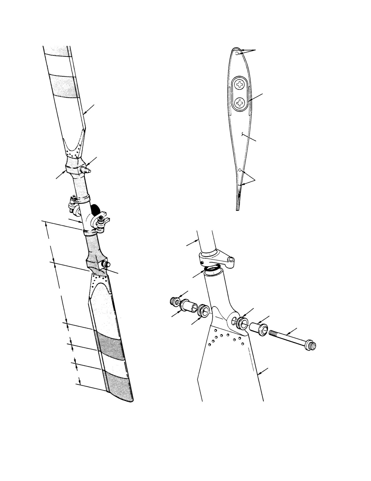
DRAIN OPENING
BALANCE WEIGHT
BLADE
TIP CAP
CLEAR LACQUER
ROOT FITTING
DRAIN OPENING
HUB
RED
TRUNNION
CLEAR LACQUER
O-RING
NUT
WHITE
CRUSH WASHER
BUSHING
BUSHING
CRUSH WASHER
BOLT
3.0 IN. (7.62 CM) RED
3.0 IN. (7.62 CM) WHITE
BLADE
3.0 IN. (7.62 CM) RED
G64-1000A
Figure 201. Tail Rotor Blade
Page 202
Revision 21
64-10-00
MD Helicopters, Inc.
CSP-HMI-2
MAINTENANCE MANUAL
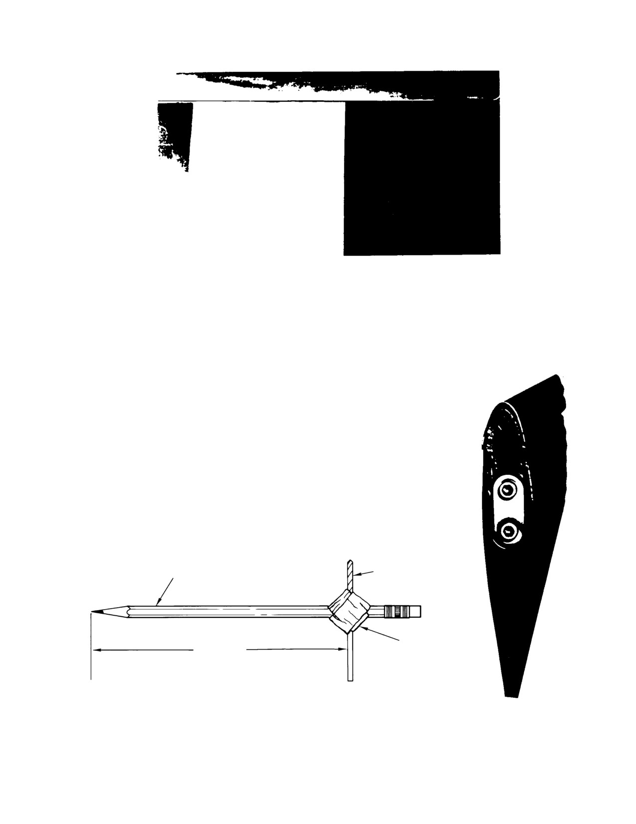
SHOWN ABOVE:
UNBONDING OF EPOXY ADHESIVE AND ABRASION STRIP
WITH SEPARATION BETWEEN ABRASION STRIP AND
AIRFOIL SURFACE, BLADE UNACCEPTABLE FOR SERVICE.
SHOWN RIGHT:
UNBONDED AND DISPLACED ABRASION STRIP AT
BLADE TIP; SEPARATION BETWEEN ABRASION
STRIP/AIRFOIL SURFACE ALONG BOND LINE,
BLADE UNACCEPTABLE FOR SERVICE.
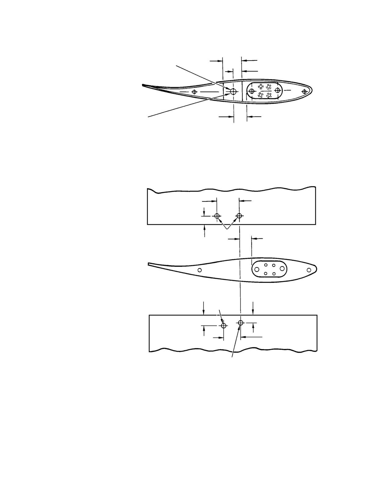
DRILL BIT, 1/8 IN.
PENCIL
(3.175 MM)
TAPE
MIN. 6.0 IN.
(15.24 CM)
TAPPING TOOL FOR FABRICATION
G64-1002A
Figure 202. Inspection of Tail Rotor Blade Abrasion Strip
Page 203
64-10-00
Revision 21
CSP-HMI-2
MD Helicopters, Inc.
MAINTENANCE MANUAL
Do not use chemical paint re
ure. Bond failure is indicated by penetrant
CAUTION
mover to remove paint from
bleedout from under the abrasion strip, and
abrasion strip. Chemicals can attack the
will appear as a line along the edge of the
abrasion strip to blade bonding agent.
strip. The 5X magnifying glass will aid dis
tinguishing between porosity voids and
(4). Using 220 grit abrasive paper (CM801),
bleedout from under the abrasion strip. It
sand dry, removing all paint from the
may be necessary to wipe off, then reapply
abrasion strip. Ensure abrasion to
the developer to distinguish between poros
airfoil bondline is exposed. Clean paint
ity voids and bond separations. The most
dust from blade.
positive indication of bond failure will nor
mally appear during the first one to seven
NOTE: Do not remove masking tape from blade
minutes following developer application.
until completion of dye penetrant inspec
tion.
(8). Using a 5X magnifying glass, examine
bond line to determine if penetrant dye
(5). Visually check abrasion strip to blade
is indicating a bond separation. If bond
bonding using a 10X magnifying glass.
separation is noted, remove blade from
If bond failure is obvious, remove blade
service.
from service.
(9). Remove masking tape from blade.
(6). Dye penetrant inspect, according to
manufacturer's instructions.
(10). Inspect blade for cleanliness and paint
damage. Clean and repair paint
(a). Inspect entire abrasion strip to blade
damage as necessary (Ref. Sec. 20-30).
bond line, including abrasion strip
bond in blade tip cap area.
NOTE: Do not repaint abrasion strip or abra
sion strip to blade bond line.
(b). Apply penetrant using a small brush
or swab to prevent damage to blade
(11). Check tail rotor balance (Ref. Sec.
paint, and to minimize clean-up.
18-20-00).
(c). Allow penetrant to remain on surface
(12). If blade is removed from service
of abrasion strip bondline for five
because of separation or voids, notify an
minutes minimum.
Approved MDHS Service Center or
Distributor for disposition. Those
(d). Use dry lint free cloth or paper towel
blades in which voids are found shall be
to remove excess penetrant.
sent to an approved repair station for
abrasion strip replacement.
(e). Apply remover to cloth or lint free
towel to remove remaining surface
4. Tail Rotor Blade Tip Cap Repair
penetrant.
(Ref. Figure 203)
NOTE: Never spray or flush area of inspection
with cleaner.
Consumable Materials
(f). Ensure thorough penetrant removal
(Ref. Section 91−00−00)
from surface before applying develop
Item
Nomenclature
er.
CM222
1,1,1-Trichloroethane
CM318
Primer
(7). Apply a light film of developer on the
area of examination.
CM411
Adhesive, epoxy
CM804
Emery cloth, fine
NOTE: The epoxy adhesive used to bond abra
sion strip to blade may have porosity voids.
The penetrant will form a circular pattern
(1). Remove tail rotor blade from helicopter
around voids resulting from porosity. These
(Ref. Tail Rotor Blade Replacement
circular patterns do not indicate bond fail
Procedure).
Page 204
Revision 21
64-10-00
MD Helicopters, Inc.
CSP-HMI-2
MAINTENANCE MANUAL
0.60 IN. (1.524 MM)
0.250 IN. (6.35 MM)
(NOTE 1)
DIA HOLE
0.30 IN. (0.762 MM)
AFTER REMOVAL OF DEBRIS, SEAL 0.250 IN.
0.390 ± 0.060 IN.
(6.35 MM) DIA. HOLE WITH 2 PLIES OF 120
(9.91 ±1.524 MM)
FIBERGLASS CLOTH & 3135 A & B EPOXY
RESIN (CREST PRODUCTS OR EQUIVALENT)
AS SHOWN.
HOLE LOCATION
SURFACE PREPARATION: ABRADE SURFACE
WITH EMERY CLOTH AND WIPE WITH 1, 1,
1-TRICHLOROETHANE SOLVENT. DO NOT
ALLOW RESIN TO BUILD UP IN 0.250 IN. (6.35
MM) DIA. HOLE.
0.690 IN. (17.53 MM)
ALONG BLADE CONTOUR
NOTE 2
0.380 IN.
0.250 IN.
(9.65 MM)
(6.35 MM)
0.30 IN.
0.250 IN.
(7.62 MM)
(6.35 MM)
NOTE 2
0.50 IN. (12.70 MM)
ALONG BLADE CONTOUR
(NOTE 2)
NAS 1739B4-2 RIVET
(4 PLACES)
NOTES:
1.
FIBERGLASS THIS AREA. DO NOT PLACE FIBERGLASS
CLOTH OVER OPENING FOR BALANCE WEIGHTS.
2.
USE NO.27 DRILL AND 1005 COUNTERSINK WITH NO. 30
PILOT. COUNTERSINK TO MAXIMUM 0.035 IN. (0.889 MM) DEPTH.
INSTALL NAS 1739B4-2 RIVET. SEAL RIVET WITH CLEAR
EPOXY (CM411).
G64-1001A
Figure 203. Installation of Tip Cap−To−Tail Rotor Blade Rivets
Page 205
64-10-00
Revision 21

CSP-HMI-2
MD Helicopters, Inc.
MAINTENANCE MANUAL
Handle blade carefully. Dents,
5. Tail Rotor Blade Replacement Procedure
CAUTION
nicks or scratches may cause
balance problems at reinstallation, or make
Consumable Materials
blade unserviceable.
(Ref. Section 91−00−00)
Item
Nomenclature
(2).
With blade on a clean hard surface,
CM318
Primer
measure and mark locations for rivet
holes.
NOTE: Always record number and location of
(3).
Using No. 27 drill, carefully drill holes
existing balance washers when replacing
at locations marked on outboard and
blade. This record aids in dynamic balance
inboard surfaces of blade.
troubleshooting.
(1). Remove cotter pin, nut, washer and
(4).
Using 100 ±1° countersink with No. 30
pitch arm bolt from outboard end of
pilot, countersink holes to 0.035 inch
pitch control link.
(0.889 mm) maximum depth.
Bolt, nut, washers and bushings
(5).
Apply primer (CM318) to holes and
CAUTION
may be reinstalled if service
install rivets while primer is wet.
able. If bushing and crush washers are to be
reused, they must be installed in the exact
(6).
Coat installed rivets with clear epoxy
location from which they were removed. If
(CM411).
either the blade or strap pack assembly from
which they were removed is replaced, re
(7).
Drill a 0.250 inch (6.35 mm) diameter
place crush washers and bushing. Bushings
hole through tip cap (Ref. Figure 203).
must be free of nicks and burrs.
Tip cap is 0.070 inch (1.778 mm) thick
NOTE: If same blade is to be reinstalled, retain
at point to be drilled.
intact for reuse. Note and record number
and type of balance washers and attach
(8).
Remove FOD from blade interior
ment hardware used on bolt at blade pitch
through hole.
arm.
Trichloroethane may damage
(2). Remove bolt that secures blade to
CAUTION
blade paint finish.
outboard strap pack shoes.
(3). Withdraw blade from hub trunnion.
(9). Abrade surface surrounding hole using
emery cloth (CM804); wipe clean using
Do not disassemble strap shoes
clean cloth dampened with trichloroe
CAUTION
from end of strap pack protrud
thane (CM222).
ing from trunnion. Strap pack parts are not
individually replaceable and must remain
Do not allow resin to build-up in
assembled. Avoid damaging strap pack.
CAUTION
hole.
Scratches or nicks on strap pack laminates
may make strap pack unserviceable.
(10). Bond two plies of 120 fiberglass cloth
over hole with 3135A and B epoxy resin
NOTE: No axial play is allowed in the strap as
or equivalent. Allow epoxy to cure
sembly shoes. Rotational movement is per
according to manufacturer's instruc
missible.
tions.
(4). If strap pack is to remain exposed for
any length of time, wrap exposed end of
(11). Reinstall tail rotor blade on helicopter
strap pack with wax paper or other
(Ref. Tail Rotor Blade Replacement
similar non-abrasive material to
Procedure).
protect from damage.
(12). Check and adjust tail rotor blade
(5). If blade being removed is to be rein
balance (Ref. Sec. 18-20-00).
stalled, do not remove blade tip screw,
Page 206
Revision 21
64-10-00
MD Helicopters, Inc.
CSP-HMI-2
MAINTENANCE MANUAL
any balance washers or weight from
(13). Install pitch control links (Ref. Sec.
blade.
64-30-00).
NOTE: Remove old primer from mating sur
NOTE: If same blade that was removed is being
faces and attaching hardware prior to reas
reinstalled, install same number of balance
sembly.
washers on pitch arm bolt that were present
prior to removal of blade. For different
(6).
To install blade, remove any protective
blade, install balance washers required for
covering from strap pack extending
static chordwise balance of assembled tail
from hub trunnion.
rotor which have been determined with a
balance fixture.
(7).
Install O-ring and slide blade on hub
with blade leading edge facing in
(14). Balance tail rotor (Ref. Sec. 18-20-00).
counterclockwise direction. Use care to
keep blade correctly aligned so that hub
6. Tail Rotor Abrasion Strip Riveting
trunnion slides into blade pitch bear
ings. Do not use force.
(Ref. Figure 204) The following procedure is for
(8).
Align bolt holes in root fitting with hole
adding rivets at the outboard ends of the
through bushing in outboard shoes of
abrasion strip to provide a secondary failsafe
strap pack.
method of attachment.
(9).
Coat contacting surfaces of bushings,
This procedure is effective on tail rotor blades:
washers, nuts and bolts with unthinned
369A1613-7, -503, -505,
primer (CM318) and immediately
369D21606-BSC,
perform following steps.
369D21613-11, -31, -41, -51,
369D21615-BSC, -21,
(10).
Assemble and install bolt, bushings and
421-088
washers in sequence (Ref. Figure 201).
Make certain that direction of bolt is
opposite to that of opposing blade. Do
Consumable Materials
not force bolt; it must have an easy but
(Ref. Section 91−00−00)
snug fit through blade, shoes and
Item
Nomenclature
bushings.
CM222
1,1,1-Trichloroethane
NOTE: It is recommended that the MS 21250
CM318
Primer
bolt be replaced with any of the alternate
CM804
Emery cloth, fine
bolts with the higher torque at the operators
N/A
Fiberglass cloth, No. 120
earliest convenience.
N/A
Epoxy resin, Spec. 3135A and B or any 2
(11). If an MS 21250 bolt is installed, install
part (1:1) clear epoxy resin
nut and torque to 600 - 650 inch-
pounds (67.79 - 73.44 Nm) while
Do not attempt to perform this
primer is wet. If an HS5482-6,
CAUTION
procedure with the tail rotor
HS4441-6, or an LWB22-6 bolt is
blades installed on the helicopter. Failure to
installed, torque nut to 750 - 775
comply with this caution may result in de
inch-pounds (84.74 - 87.56 Nm).
fective rivet installation and possible blade
After blade is secured to strap
damage.
CAUTION
pack assembly, do not allow
blade pitch travel from neutral to exceed 30
(1). Remove tail rotor blades from helicop
degrees in either direction. Rotating blade
ter (Ref. Tail Rotor Blade Replacement
to excessive pitch angles may result in unde
Procedure).
tected damage to strap assembly.
(2). Using a 10X magnifying glass, perform
(12). Check that bolthead is flat against
a visual inspection of the tail rotor
bushing. No gap is permitted. If gap is
blade abrasion strip bond lines for
found, replace bolt and bushing.
debonding.
Page 207
64-10-00
Revision 32
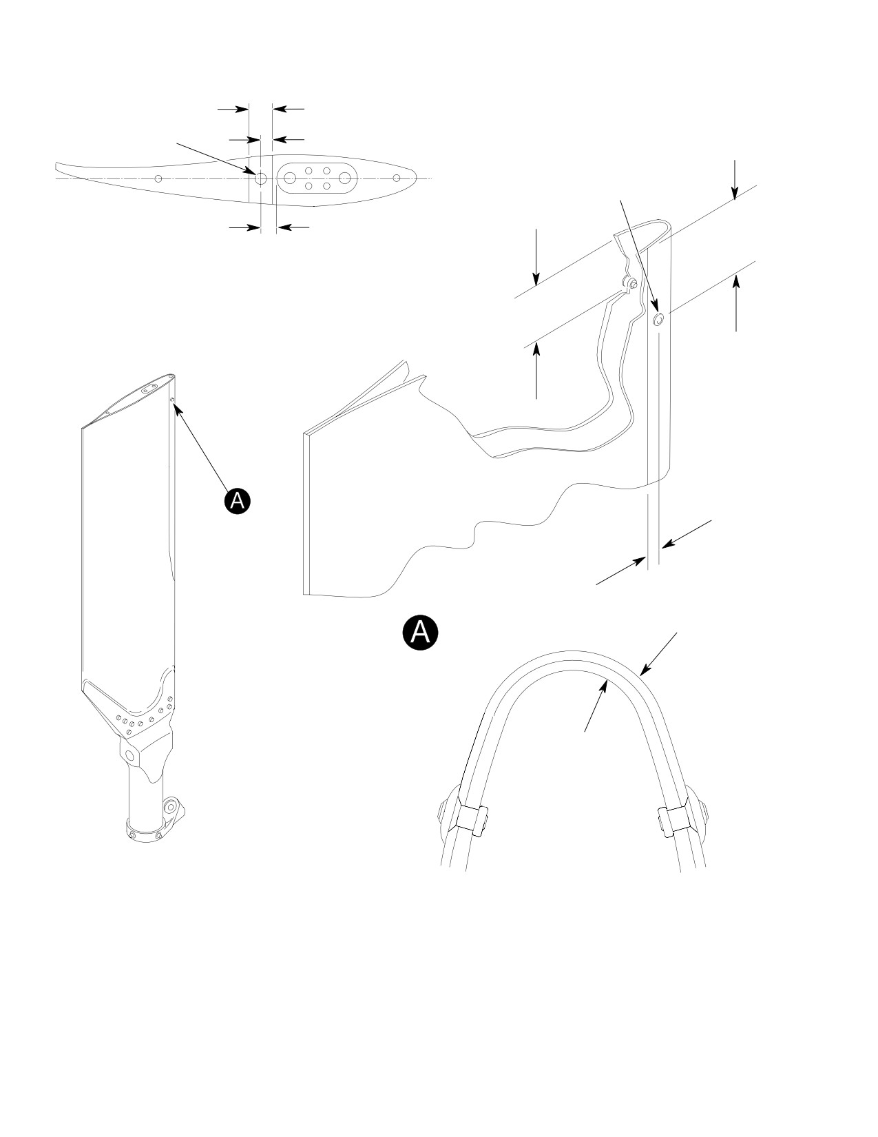
CSP-HMI-2
MD Helicopters, Inc.
MAINTENANCE MANUAL
0.60 IN. (1.524 MM)
(NOTE 1)
0.250 IN. (6.35 MM)
0.30 IN. (7.62 MM)
HOLE
L
NOTE 2
0.810 ±0.030 IN.
0.390 ±0.060 IN.
(20.57 ±0.762 MM)
(9.91 ±1.524 MM)
HOLE LOCATION
1.160 ±0.030 IN.
(29.464 ±0.762 MM)
0.280 ±0.030 IN. (7.110 ±0.762 MM)
ALONG CONTOUR (BOTH SIDES)
ABRASION STRIP
BLADE SKIN
VIEW LOOKING
DOWN
NOTE:
1.
FIBERGLASS THIS AREA. DO NOT PLACE FIBERGLASS CLOTH OVER OPENING
FOR BALANCE WEIGHTS.
2.
COUNTERSINK HOLE 100°, DEPTH 0.009-0.011 IN. (0.229-0.2794 MM).
G64-1005A
Figure 204. Tail Rotor Blade Abrasion Strip Riveting
Page 208
Revision 21
64-10-00

MD Helicopters, Inc.
CSP-HMI-2
MAINTENANCE MANUAL
(3). If abrasion strip debonding is suspected
(e). Inspect hole in abrasion strip.
but cannot be confirmed by visual
(11). Remove FOD from interior of blade as
inspection, perform Abrasion Strip Dye
follows:
Penetrant and Tap Test Inspection.
(a). Drill 0.250 inch (6.35 mm) hole
NOTE: Tail rotor blades removed for voids
through tip cap as shown.
must be removed in ship sets.
(b). Remove FOD from blade interior
(4). If voids are found in blade, remove and
through hole (there is space at tip cap
send to an authorized repair station for
end for debris to pass aft of spar).
repair.
(c). Install new rivet.
(5). Carefully secure tail rotor blade in a
suitable holding fixture.
(d). Abrade surface surrounding tip cap
hole using emery cloth (CM804); wipe
NOTE: When performing the following step,
clean using clean, lint-free cloth
use drill bit stop to prevent drilling through
dampened with 1,1,1-trichloroethane
both sides of blade.
(CM222).
(6). Using a No. 27 cobalt drill bit, drill
Do not allow resin to build up in
holes at locations shown (light center
CAUTION
hole.
punch prior to drilling is allowed).
(e). Bond two plies of fiberglass cloth over
(7). Deburr holes with a 100° countersink to
hole with epoxy resin.
a depth of not more than 0.011 inch
(0.2794 mm).
(12). Repeat inspection of abrasion strip.
(13). Reinstall tail rotor blades.
(8). Apply primer (CM318) to holes and
install CS2545-4-1 or CR3555-4-1
(14). Perform tail rotor balance (Ref. Sec.
rivets while primer is wet.
18-20-00, Tail Rotor Blade Balancing).
Installed rivet stems may be de
CAUTION
7. Tail Rotor Blade Abrasion Strip
burred using a file. Do not re
Modification
move material from locking collar.
(Ref. Figure 205) The following procedure is for
(9). Inspect installed rivets.
application of a 0.0027 inch (0.06858 mm).
thick strip of stainless steel tape over the
(10). If rivet installation is not satisfactory,
inboard end of the abrasion strip.
remove as follows:
This procedure is effective on tail rotor blades:
During removal of defective riv
CAUTION
369A1613-7, -503, -505, -509,
et, observe the following:
369D21606-BSC, -509,
Do not damage or enlarge hole.
369D21613-11, -31, -41, -51, -71,
Do not drive or force rivet stem from hole.
369D21615-BSC, -21, -41,
Do not remove rivets common to tip cap.
421-088
(a). Carefully grind off locking collar and
upper portion of rivet head.
Consumable Materials
(Ref. Section 91−00−00)
(b). Carefully push center stem through
Item
Nomenclature
rivet sleeve.
CM220
Naphtha aliphatic
(c). Using a drill stop, drill through rivet
CM801
Abrasive paper, silicon carbide
sleeve using care to prevent hole
enlargement.
NOTE: Abrasion strip must have rivets
(d). Push remaining rivet sleeve through
installed before applying stainless steel
hole.
tape.
Page 209
64-10-00
Revision 21
CSP-HMI-2
MD Helicopters, Inc.
MAINTENANCE MANUAL
(1). Using a 10X magnifying glass, perform
8. Tail Rotor Blade Protective Tape
a visual inspection of the tail rotor
Installation
blade abrasion strip bond lines for
debonding.
Consumable Materials
(Ref. Section 91−00−00)
(2). If abrasion strip debonding is suspected
Item
Nomenclature
but cannot be confirmed by visual
inspection, remove blades and perform
CM220
Naphtha aliphatic
Abrasion Strip Dye Penetrant and Tap
CM304
Enamel, epoxy
Test Inspection.
CM801
Abrasive paper, silicon carbide
N/A
3M aerosol primer MITO-0081
NOTE: Tail rotor blades removed for voids
N/A
3M mylar tape P/N Y8671-1
must be removed in ship sets.
(3). If voids are found in blade, remove and
NOTE: This installation is only approved on
send to an authorized repair station for
tail rotor blades equipped with the new
repair.
abrasion strips.
(4). Lightly abrade faying surface of tail
In an effort to reduce the amount of erosion in
rotor blade in area where tape is to be
the area inboard of the abrasion strip, MDHS
installed with 400-grit abrasive paper
has approved the installation of mylar tape to
(CM801).
the blade leading edge. Installation of the tape
is optional.
(5). Wipe abraded area with naphtha
(CM220) to eliminate grease and dirt
The length of the tape can vary, up to 2.0
film.
inches in length, but must be equal on both
blades.
NOTE: Do not allow temperature to exceed
120°F (49°C).
It is recommended to start with 1.5 inch (3.81
cm) length and increase the length as erosion
(6). Using a heat gun, or equivalent, heat
occurs by replacing the tape.
abraded area.
Do not cut or trim tape after
CAUTION
(7). Remove backing and apply stainless
installation on blade, damage to
steel tape to leading edge of tail rotor
blade will occur.
blade.
(1). Measure length of eroded area on blade
(a). Apply tape so it overlaps each side of
with the most erosion.
blade equally.
NOTE: Tape must be of equal length on both
blades to ensure proper balance.
(b). Tape should overlap the inboard end
of abrasion strip 0.50 ±0.03 inch
(2). Cut tape long enough to cover erosion
(12.70 ±0.762 mm) at the leading
plus approximately 0.50 inch (12.70
edge of blade.
mm) overlap on leading edge abrasion
strip.
NOTE: Abrasion tape must be free of surface
wrinkles or air bubbles.
(3). Round off square corners of tape to
reduce peeling.
(8). Smooth and press tape into place by
hand.
(4). Lightly abrade faying surface of tail
rotor blade in area where tape is to be
(9). Re-apply pressure by hand following
installed with 400 grit abrasive paper
initial installation to ensure proper
(CM801).
bonding.
(5). Wipe abraded area with naphtha
(10). Perform tail rotor balance (Ref. Sec.
(CM220) to eliminate grease and dirt
18-20-00, Tail Rotor Blade Balancing).
film.
Page 210
Revision 21
64-10-00
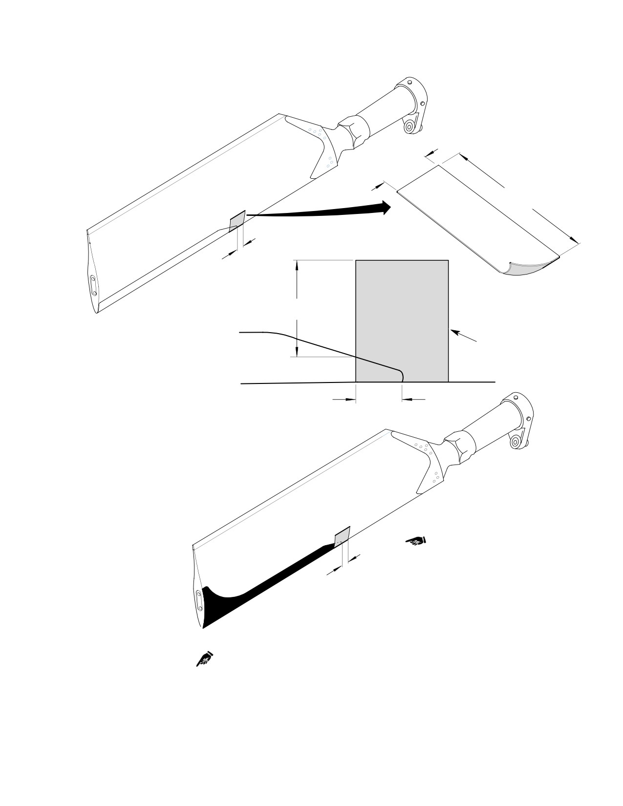
MD Helicopters, Inc.
CSP-HMI-2
MAINTENANCE MANUAL
1.00 IN.
(2.54 CM)
3.00 IN.
(7.62 CM)
0.50 IN.
(12.70 MM)
1.00 IN.
(2.54 CM)
OLD STYLE ABRASION STRIP
NOTES 1 AND 2
0.50 IN.
(12.70 MM)
0.50 IN.
(12.70 MM)
NEW ABRASION STRIP
NOTES:
1.
304 STAINLESS STEEL OR MYLAR TAPE SHALL BE APPLIED; 0.50 IN. (12.70 MM)
TO ABRASION STRIP AND 0.50 IN. (12.70 MM) TO TAIL ROTOR BLADE.
2.
APPLY TAPE EQUALLY TO BOTH SIDES OF BLADE.
G64-1006C
Figure 205. Tail Rotor Blade Abrasion Strip Modification
Page 211
64-10-00
Revision 22

CSP-HMI-2
MD Helicopters, Inc.
MAINTENANCE MANUAL
(6). Treat any bare metal with epoxy-type
(2). If cracks are suspected, perform a dye
paint (CM304).
penetrant inspection of the suspect area
as follows:
NOTE: Do not allow temperature to exceed
(a). Lightly abrade faying surface of tail
120°F.
rotor blade in area where tape is to
(7). Using a heat gun, or equivalent, heat
be installed with 400-grit abrasive
abraded area.
paper (CM801).
(b). Wipe abraded area with naphtha
(8). Apply aerosol primer to bonding area
(CM220) to eliminate grease and dirt
and allow to dry.
film.
(9). Remove backing and apply tape to
(c). Perform dye penetrant inspection on
leading edge of blade.
the suspected area per MIL-I-25135,
or equivalent.
(a). Apply tape so it overlaps each side of
blade equally.
(d). Tail rotor blades with evidence of
cracking must be removed from
(b). Tape should overlap the inboard end
service.
of abrasion strip 0.50 ±0.03 inch
(12.70 ±0.762 mm) at the leading
NOTE: Tail rotor blades with the new abrasion
edge of blade.
strip configuration cannot be intermixed
with tail rotor blades that have the old abra
NOTE: Tape must be free of surface wrinkles or
sion strip configuration.
air bubbles.
(e). If there is no evidence of cracking,
(10). Smooth and press tape into place by
the blade can be cleaned and touch-
hand.
up epoxy paint applied to the affected
area.
(11). Re-apply pressure by hand following
(3). To reduce erosion, apply protective tape
initial installation to ensure proper
to the blades (Ref. Tail Rotor Blade
bonding.
Protective Tape Installation).
(12). Perform tail rotor balance (Ref. Sec.
(4). Perform tail rotor balance (Ref. Sec.
18-20-00).
18-20-00, Tail Rotor Blade Balancing).
9. Tail Rotor Blade Leading Edge Crack
B. Tail Rotor Blades with Old−Style
Inspection
Abrasion Strips
(1). Remove stainless steel tape from the
(Ref. Figure 206)
leading edge at the inboard end of the
abrasion strip.
Consumable Materials
(2). Inspect that area for evidence of cracks;
(Ref. Section 91−00−00)
no cracks are allowed.
Item
Nomenclature
CM220
Naphtha aliphatic
(3). If cracks are suspected, perform a dye
penetrant inspection of the suspect area
CM801
Abrasive paper, silicon carbide
as follows:
(a). By lightly abrading the blade skin,
Do not use any chemicals to re
CAUTION
carefully remove the paint from the
move the paint and do not pene
suspected area.
trate the metal skin of the blade.
(b). Perform dye penetrant inspection on
A. Tail Rotor Blades with New−Style
the suspected area per MIL-I-25135,
Abrasion Strips
or equivalent.
(1). Inspect leading edge for any evidence of
(c). Tail rotor blades with evidence of
cracking in the area shown; no cracks
cracking must be removed from
are allowed.
service.
Page 212
Revision 22
64-10-00
MD Helicopters, Inc.
CSP-HMI-2
MAINTENANCE MANUAL
NOTE: Tail rotor blades with the new abrasion
(c). Using a heat gun, or equivalent, heat
strip configuration cannot be intermixed
abraded area.
with tail rotor blades that have the old abra
(d). Remove backing and apply stainless
sion strip configuration.
steel tape to leading edge of tail rotor
blade.
(d). If there is no evidence of cracking,
the blade can be cleaned and touch-
1). Apply tape so it overlaps each side
up epoxy paint applied to the affected
of blade equally.
area.
2). Tape should overlap the inboard
(4). Install new 0.0027 inch (0.06858 mm)
end of abrasion strip 0.50 ±0.03
thick stainless steel tape in the same
inch (12.70 ±0.762 mm) at the
location as follows (Ref. Figure 205):
leading edge of blade.
(a). Lightly abrade faying surface of tail
NOTE: Abrasion tape must be free of surface
rotor blade in area where tape is to
wrinkles or air bubbles.
be installed with 400-grit abrasive
(e). Smooth and press tape into place by
paper (CM801).
hand.
(b). Wipe abraded area with naphtha
(f). Re-apply pressure by hand following
(CM220) to eliminate grease and dirt
initial installation to ensure proper
film.
bonding.
NOTE: Do not allow temperature to exceed
(5). Perform tail rotor balance (Ref. Sec.
120°F (49°C).
18-20-00, Tail Rotor Blade Balancing).
Page 213
64-10-00
Revision 22
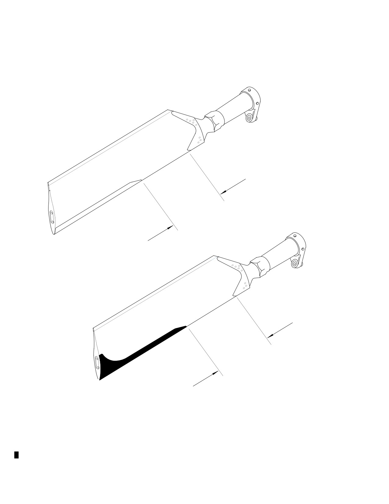
CSP-HMI-2
MD Helicopters, Inc.
MAINTENANCE MANUAL
PAY PARTICULAR
ATTENTION TO THIS
AREA FOR CRACKING
OLD STYLE ABRASION STRIP
PAY PARTICULAR
ATTENTION TO THIS
AREA FOR CRACKING
NEW STYLE ABRASION STRIP
88-754
Figure 206. Tail Rotor Blade Leading Edge Crack Inspection
Page 214
Revision 22
64-10-00
MD Helicopters, Inc.
CSP-HMI-2
MAINTENANCE MANUAL
Section
64−20−00
Tail Rotor Hub and
Fork (369D/E/FF)
MD Helicopters, Inc.
CSP-HMI-2
MAINTENANCE MANUAL
TAIL ROTOR HUB AND FORK
MAINTENANCE PRACTICES
1. Tail Rotor Hub and Fork
one inch in either direction. Unrestricted
rotation of blades on hub can excessively
(Ref. Figure 201) This section covers mainte
bend or stretch strap pack and cause un
nance of the hub, strap pack and fork as an
detected damage to strap pack and an
assembled unit. For all other maintenance
out-of-balance tail rotor when reas
instructions pertaining to hub and fork
sembled.
assembly, and the hub assembly, strap pack
D To prevent balance problems at reassemb
and fork assemblies as separately-maintain
ly of parts and hardware, mark exact
able components, Ref. COM.
number, locations and positions of all
items before removal for correct reinstal
When blades are removed from
CAUTION
lation.
hub, exposed ends of strap pack
should be protected with covering (Ref. Sec.
D On two-bladed tail rotor system do not
64-10-00). Hub and fork should be handled
remove hub-to-drive fork hinge bolt to
carefully to avoid damage to strap pack.
remove tail rotor assembly. On four-
bladed tail rotor system hub-to-drive
fork hinge bolt removal is required. This
2. Tail Rotor Hub and Fork Replacement
bolt should only be removed according to
instructions Ref. COM. Damage to strap
A. Tail Rotor Hub and Fork Removal
pack may occur if any other procedure is
used.
(Ref. Figure 202 and Figure 203)
(2). Disconnect pitch control links from
Special Tools
blade pitch control arms.
(Ref. Section 91−00−00)
Item
Nomenclature
(3). Pull rotating boot out of groove in fork.
ST607
Adapter, torque wrench
(4). On four-bladed tail rotor system
remove inboard and outboard blades
On four-bladed tail rotor
and hubs to access fork tang washer
WARNING
system, there is strong
and nut.
spring pressure in installed tail rotor
linkage. Disconnect the in-line bungee
NOTE: Helicopters Serial Nos. D0003 thru
before beginning disassembly. Failure
D1024 had a two-piece retaining nut and
to disconnect the bungee can result in
stop support. Helicopters subsequent to
personal injury and/or parts damage.
D1024 have a one-piece retaining nut and
stop support.
(1). On four-bladed tail rotor, disconnect
in-line bungee (Ref. Sec. 67-20-10) if
(5). Straighten tang of tang washer.
tail rotor is installed on helicopter.
(6). Using torque wrench adapter (ST607),
loosen retaining nut and slide tail rotor
CAUTION
outward on output shaft of tail rotor
D Whenever blades and hub are removed as
transmission to remove blade stop and
an assembly, or whenever pitch control
stop support.
links are disconnected, do not allow blade
pitch to exceed 30 degrees from neutral
(7). Remove nut, tang washer, tapered ring,
pitch position. This is equal to blade pitch
and split-ring halves that fit into recess
control arm movement of approximately
at inboard end of fork.
Page 201
64-20-00
Revision 21
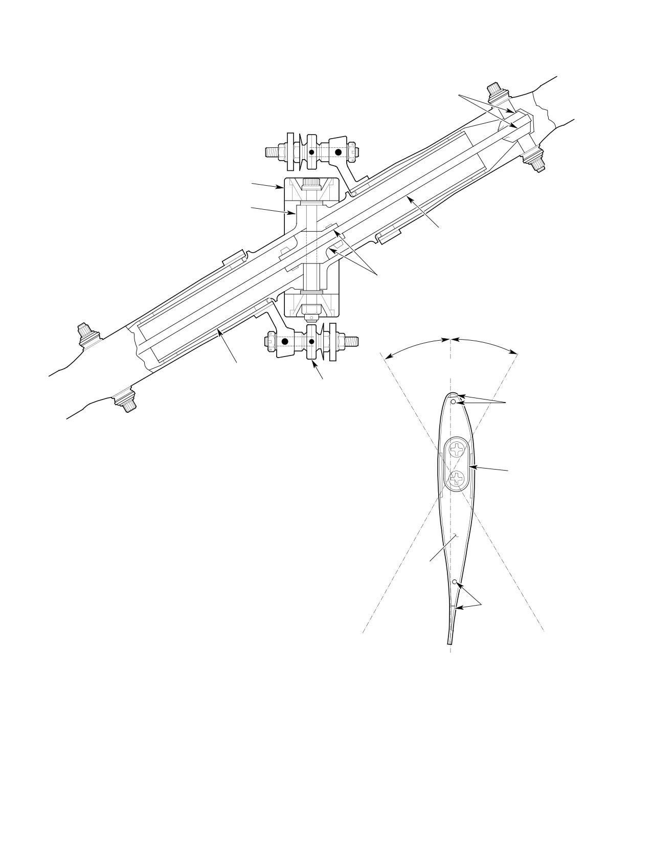
CSP-HMI-2
MD Helicopters, Inc.
MAINTENANCE MANUAL
OUTBOARD
STRAP SHOES
FORK
HUB
STRAP PACK
ASSEMBLY
INBOARD STRAP
SHOES
30°
30°
HUB TRUNNION
(SEE CAUTION)
PITCH CONTROL LINK
DRAIN
OPENING
BALANCE
WEIGHT
TIP CAP
DRAIN
OPENING
CHORDLINE AT
NEUTRAL PITCH
LOOKING AT BLADE
CAUTION:
END (TIP)
SHOES NOT TO BE REMOVED FROM STRAP PACK, AVOID DAMAGING
STRAP PACK; SCRATCHES OR NICKS ON STRAP LAMINATES MAY MAKE
G64-2000
STRAP PACK UNSERVICEABLE
Figure 201. Tail Rotor Hub and Strap Pack
Page 202
Revision 21
64-20-00

MD Helicopters, Inc.
CSP-HMI-2
MAINTENANCE MANUAL
Tail rotor tang washer must not
It is possible for pitch control
CAUTION
CAUTION
be reused.
swashplate to be misaligned by
one-half spline in relation to drive fork.
NOTE: Placing grease pencil mark on drive
Make sure drive fork, pitch links and swash
fork to key it to transmission output shaft
plate are in exact alignment with transmis
enables subsequent installation of tail rotor
sion shaft centerline. If incorrectly as
assembly at same position.
sembled, swashplate will be misaligned
approximately 10 degrees from drive fork.
Application of small painted matchmark
To correct this condition, remove tail rotor
next to centerline splined groove on both
assembly (leaving pitch control assembly in
pitch control assembly and tail rotor drive
stalled), rotate tail rotor assembly 180 de
fork aids reassembly at same position on
grees and reinstall it.
transmission shaft.
(3). Slide tail rotor assembly onto shaft
with drive fork-to-hub pivot bolt
One spline groove of fork is located directly
aligned with swashplate lugs. Position
on centerline passing through centers of the
tail rotor assembly on shaft so that
two fork bearings while, at opposite side of
approximately two threads at shaft end
spline bore, same centerline passes through
are exposed outboard of drive fork.
a spline tooth. A similar condition exists
with respect to swashplate splines, except
(4). Coat tapered ring with primer (CM318)
that reference centerline originates between
and install it on shaft, making certain
swashplate arms.
that tapered edge parallels chamfer in
fork. Perform the following steps while
For illustrations showing matchmarks and
primer is wet.
additional information, Ref. COM.
NOTE: Pre-assembly of tang washer, nut, stop
support and stop as a unit aids in their in
(8). Slide tail rotor assembly off output
stallation when performing steps (5). thru
shaft.
(7). below. Marking outer tang that is next to
inner key on tang washer, before assembly
B. Tail Rotor Hub and Fork Installation
of parts, simplifies alignment with keyway
on shaft. Teeter blades to start tang washer
(Ref. Figure 202 and Figure 203)
on shaft.
(5). Slip new tang washer over exposed
Consumable Materials
threads of shaft; key tang must face
(Ref. Section 91−00−00)
inboard toward gearbox. Install nut
Item
Nomenclature
approximately two full turns on shaft
threads to verify threads engaged.
CM115
Grease, oscillating bearing
CM318
Primer
(6). Slide tail rotor assembly outboard
against nut. Install stop support by
CM702
Lockwire CRES
inserting it in drive shaft end.
Special Tools
In next step do not force stop
CAUTION
(Ref. Section 91−00−00)
into position with screwdriver;
Item
Nomenclature
this can crack the stop.
ST607
Adapter, torque wrench
(7). Coat contacting surfaces of stop with
grease (CM115) and insert it in stop
support.
(1). Attach rotating boot; attach to pitch
(8). Install split ring halves in shaft groove
control assembly using safety wire
and slide fork inboard until ring halves
(CM702).
are secured by recess in fork.
(2). Install split ring on output shaft of
(9). Visually align a tang on tang washer
transmission.
with any convenient reference point.
Page 203
64-20-00
Revision 21
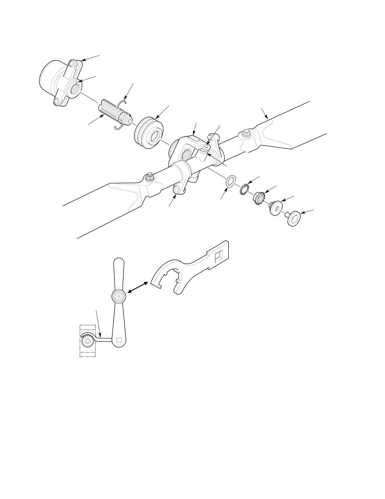
CSP-HMI-2
MD Helicopters, Inc.
MAINTENANCE MANUAL
PITCH CONTROL ASSEMBLY
SPLIT RING
NOTE 1
(WIRE SPRING)
TAIL ROTOR
ROTATING BOOT
ASSEMBLY
FORK
HINGE BOLT
TRANSMISSION
OUTPUT SHAFT
FORK BEARING
TANG WASHER
(NOTE 2)
RETAINING NUT
STOP SUPPORT
TAPERED RING
PITCH ARM
STOP
NOTE 3
NOTE 3
TORQUE WRENCH
AND ADAPTER
NOTES:
1.
CENTERLINE TOOTHSPACE MATCHMARK MUST ALIGN WITH
CENTERLINE TOOTH-SPACE MARK ON FORK WHEN ASSEMBLED ON
OUTPUT SHAFT.
2.
DISCARD USED TANG WASHER; BEND TWO TANGS TO SECURE NUT.
G64-2001E
3.
TOOL PN 369D29823 (ST607).
Figure 202. Hub and Fork Assembly Installation (Two−Bladed)
Page 204
TR12-001
64-20-00
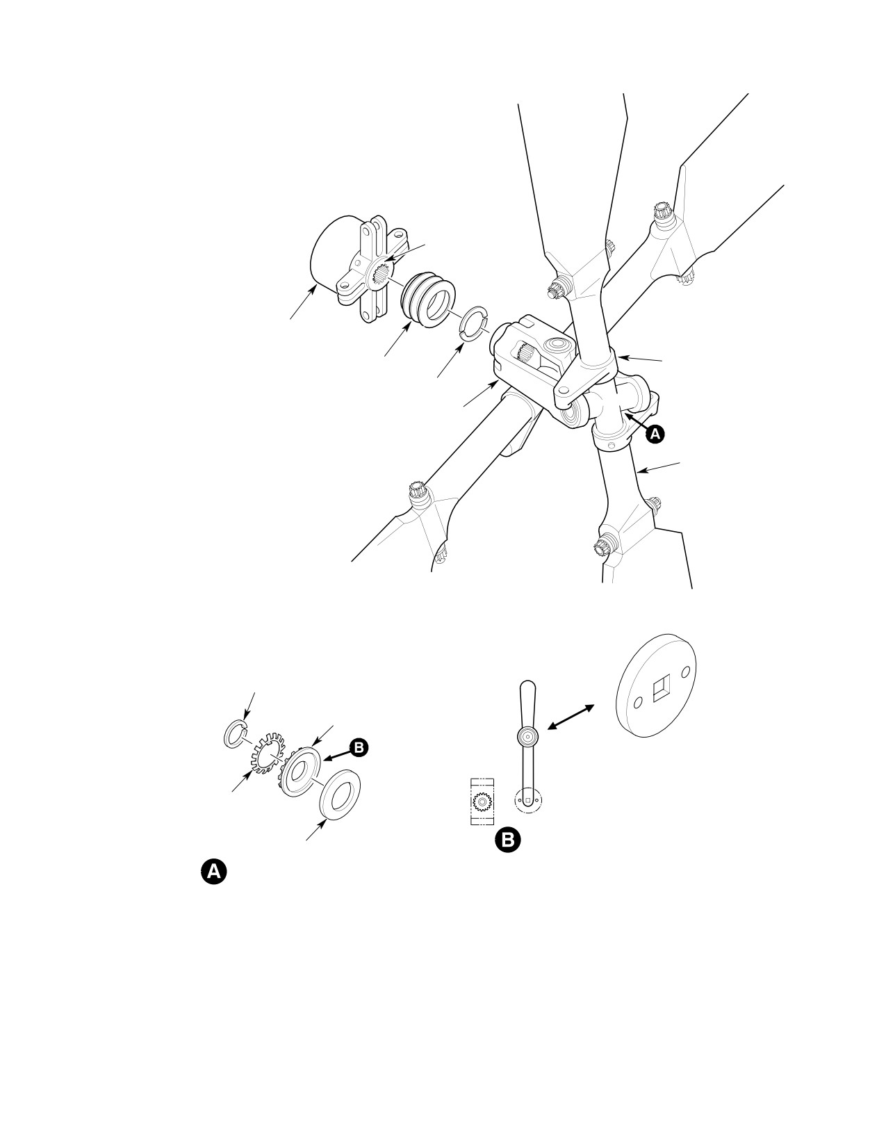
MD Helicopters, Inc.
CSP-HMI-2
MAINTENANCE MANUAL
NOTE 1
PITCH CONTROL
ROTATING BOOT
PITCH ARM
SPLIT RINGS
FORK
TAIL ROTOR ASSEMBLY
RING, FORK SUPPORT
NUT, STOP SUPPORT
NOTE 3
TANK WASHER
(NOTE 2)
INBOARD BLADE
STOP
TORQUE WRENCH AND
ADAPTER
NOTES:
1.
CENTERLINE TOOTHSPACE MATCHMARK MUST ALIGN WITH
CENTERLINE TOOTH-SPACE MARK ON FORK WHEN ASSEMBLED ON
OUTPUT SHAFT.
2.
DISCARD USED TANG WASHER; BEND TWO TANGS TO SECURE NUT.
G64-2002D
3
TOOL PN 369D29826 (ST607)
Figure 203. Hub and Fork Assembly Installation (Four−Bladed)
Page 205
64-20-00
TR12-001
CSP-HMI-2
MD Helicopters, Inc.
MAINTENANCE MANUAL
(10). Torque retaining nut, using torque
3. Tail Rotor Hub and Fork Inspection
wrench adapter (ST607), to:
(Ref. Figure 201) Hub inspection is accom
(a). Torque two-bladed retaining nut to
plished with tail rotor blades removed.
450 - 500 inch-pounds (50.84 -
(1).
Inspect areas on hub trunnions that
56.49 Nm).
mate with blade pitch bearings for
excessive wear and for damage.
(b). Torque four-bladed retaining nut to
550 - 600 inch-pounds (62.14 -
(2).
Check hub and fork for axial play or
67.79 Nm) and ensure wire-spring
bearing roughness when hub is pivoted
split ring halves are firmly imbedded
from one extreme to the other.
in fork recess.
(3).
Check torque of fork hinge bolt. Apply
NOTE: Tang washer movement of more than
125 inch-pounds (14.12 Nm) torque
one tang width is an indication that tang
to nut or bolt. If bolt or nut does not
washer inner key tang is sheared. This con
rotate, preload is correct. If bolt or nut
dition requires replacement of tang washer
rotates, retorque. (For repair limit,
and reassembly of parts according to initial
torquing requirements and replacement
installation procedure.
criteria, Ref. COM.)
(11).
Check that tang has not moved more
(4).
Check visible areas of strap pack for
than one tang width in relation to
nicks or scratches on strap laminates,
reference point noted in step (9).
cracked or kinked laminates and sharp
bends or permanent twists in lami
(12).
Measure clearance between tang
nates. Any one of these defects, except
washer and fork.
minor outer surface defects that can be
removed by abrasive polishing, requires
(13).
If clearance is less than 0.005 inch
replacement of strap pack. (For infor
(0.127 mm), replace tapered ring and/or
mation on allowable repairs, service
fork assembly.
ability requirements and replacement,
(14).
Bend two tangs on tang washer to lock
Ref. COM.)
retaining nut. When bending tangs, do
4. Conical Bearing Inspection
not force-form tang to match nut
contour; maintain natural bend radius
Visually inspect conical bearings installed in
that develops at tang root.
fork assembly, at intervals specified (Ref. Sec.
05-20-00).
(15).
Apply torque stripe paint across nut,
tang washer and fork assembly in
(1). Play is not permitted in conical drive
location that can be checked visually.
fork bearings.
(16).
Insert edge of rotating boot into groove
5. Elastomeric Fork Bearing Inspection
of drive fork.
Visually inspect elastomeric bearings installed
(17).
Install pitch control links (Ref. Sec.
in fork assembly, at intervals specified (Ref.
64-30-00).
Sec. 05-20-00) for damage and debonding
from fork as follows.
(18).
Position tail rotor pedals in neutral
position and recheck that drive fork,
Elastomeric materials can be
CAUTION
pitch links and swashplate are in exact
damaged by solvents, grease or
alignment with transmission shaft
oil. If cleaning is necessary, refer to Elasto
centerline.
meric Bearing - Care and Cleaning.
(1). Apply teetering force by hand to rotor
(19).
On four-bladed tail rotor system,
blades (stop-to-stop). Check for
reconnect bungee (Ref. Sec. 67-20-10).
fork-to-bearing bond failure. Failure is
(20).
Check rigging of tail rotor controls (Ref.
indicated by any motion between outer
Sec. 67-20-10).
Page 206
Revision 44
64-20-00