HANDBOOK OF MAINTENANCE INSTRUCTIONS FOR MDHI 369D/E/FF-500/600N HELICOPTERS (ISSUED: 1990) - page 21
MD Helicopters, Inc.
CSP-HMI-2
MAINTENANCE MANUAL
(5). Secure oil cooler outlet duct to oil cooler
replenish transmission with oil lost
with four bolts, washers and nuts.
(Ref. Sec. 12-00-00).
(6). Install tee (with drain cap), elbow and
10. Main Transmission Oil Pressure Sender
tubes that run from oil cooler to oil
Replacement
cooler bypass valve housing, applying
light coat of antiseize compound
(Ref. Figure 404) The main transmission oil
(CM112) to threads.
pressure sender provides a ground to cause the
XMSN OIL PRESS warning light to illumi
(7). Install oil drain tube and fitting on tee.
nate when oil Pressure is low. It also provides
a ground to the running-time meter. Sender's
(8). Install compressor cooling duct.
normally-closed contacts open when oil
pressure increases to 15 ±2 psi (103 ±14 kPa);
simultaneously the sender's normally-open
(9). Fill main transmission lubrication
contacts close.
system (Ref. Sec. 12-00-00).
9. Main Transmission Oil Temperature
Consumable Materials
Sender Replacement
(Ref. Section 91−00−00)
Item
Nomenclature
(Ref. Figure 404) The oil temperature sender
CM112
Anti-seize compound high temperature
for the main transmission lubrication system
CM726
Tape, teflon
is installed in a housing inserted in the 1/2
inch oil line to IN port of lubrication pump.
Switch contacts close when oil temperature
(1). Detach electrical wire or wires and
exceeds 240° ±l0°F (116° ±5°C).
using absorbent cloth, unscrew sender
from transmission.
Consumable Materials
(2). Apply light coat of antiseize compound
(Ref. Section 91−00−00)
(CM112) or wrap two or three turns of
Item
Nomenclature
teflon tape (CM726) on tapered threads
CM112
Anti-seize compound high temperature
of sender. Screw in sender; torque to 30
CM726
Tape, teflon
- 40 inch-pounds (3.39 - 4.52 Nm).
Connect wire; make sure that connec
tion is clean and tight. If three wires
are present, for information on connec
(1). Remove lockwire and detach electrical
tion of third wire refer to wiring
wire from sender terminal post.
diagram for running time meter.
Position container for draining trans
mission oil cooler line. Remove two set
screws securing sender within sender
11. Liquid Level Plug Replacement
housing. Unscrew sender and drain oil
(1). Drain oil from transmission until oil
in container. Plug housing to prevent oil
level is well below edge of plug port
drainage.
(Ref. Sec. 12-00-00).
(2). Apply a light coat of antiseize com
(2). Remove safetywire from plug.
pound (CM112) or tightly wrap two or
three turns of teflon tape (CM726) on
(3). Remove plug by unscrewing counter
tapered threads of sender. Screw
clockwise.
temperature sender into housing;
torque to 30 - 40 inch-pounds (3.39 -
(4). Remove and discard O-ring. Install
4.52 Nm). Install set screws until light
new O-ring on plug.
contact is made with sender. Lockwire
hex of sender to drilled head of ground
(5). Install plug by screwing clockwise.
wire screw in sender housing. Connect
Torque plug to 80 - 90 inch-pounds
electrical wire to sender terminal and
(9.04 - 10.17 Nm); install safetywire.
Page 407
63-21-00
Revision 20
CSP-HMI-2
MD Helicopters, Inc.
MAINTENANCE MANUAL
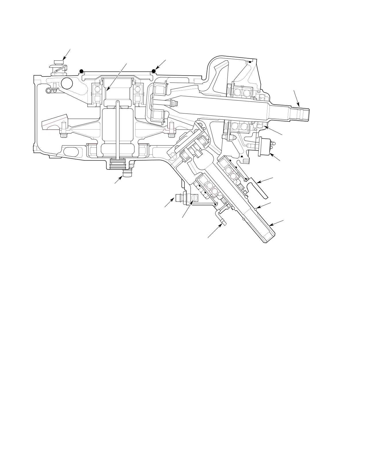
BREATHER-FILLER
SPLINES FOR
O-RING
MAIN ROTOR
(NOTE)
DRIVE SHAFT
OUTPUT SHAFT
(TAIL ROTOR)
OIL SEAL
OIL PRESSURE
SENDER
COOLING BLOWER
MOUNTING BRACKET
CHIP DETECTOR
AND SELF-CLOSING
DRAIN VALVE
COOLING BLOWER
PULLEY SPACER
CHIP DETECTOR
INPUT SHAFT
SELF-CLOSING
DRAIN VALVE
NOTE:
INPUT SHAFT SEAL
O-RING MUST BE CEMENTED IN PLACE
DRAIN CONNECTOR
BEFORE INSTALLING TRANSMISSION.
63-2001
Figure 404. Main Transmission − Cross−Section View
12. Chip Detector Replacement
belt. The blower exhausts air through the
engine oil cooler and the main transmission oil
(Ref. Figure 404) For removal and installation
cooler. Exhaust air from transmission and
instructions, refer to Draining Main Transmis
engine oil coolers is directed at various
sion (Ref. Sec. 12-00-00). For functional test
external portions of the engine and engine
information for detector circuit, refer to Sec.
accessories.
95-30-00.
B. Cooling Blower Removal
13. Cooling Blower Replacement
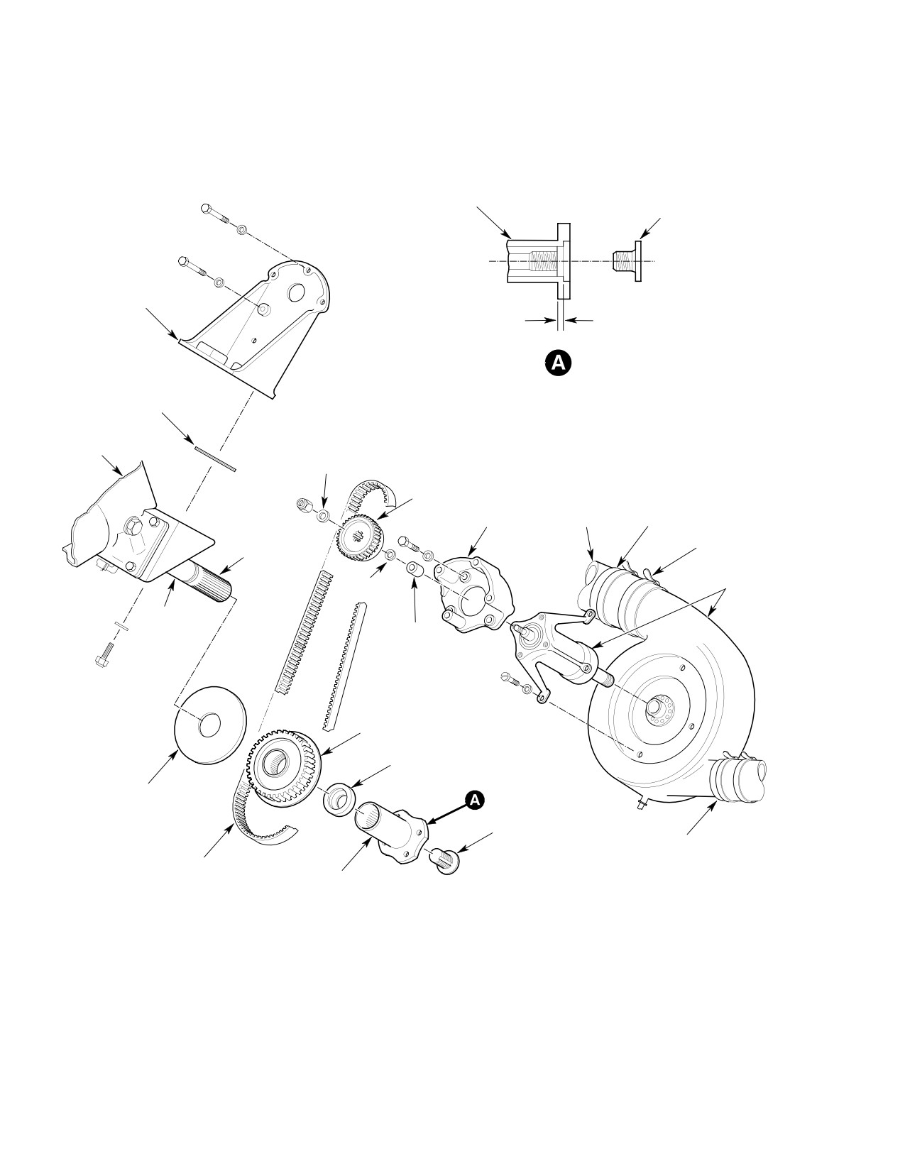
(Ref. Figure 405)
A. Cooling Blower
(1). Remove main transmission drive shaft
(Ref. Figure 405) The cooling blower is
and blower access door.
mounted to a bracket on the aft underside of
(2). Remove coupling bolt, coupling, shim(s)
the main transmission and coupled to the
and pulley from transmission input
transmission input shaft by a pulley-driven
shaft.
Page 408
Revision 42
63-21-00
MD Helicopters, Inc.
CSP-HMI-2
MAINTENANCE MANUAL
(3). Disconnect cooling blower drain tube.
In the following step do not use
CAUTION
Loosen tie-down straps on blower duct
levers or other tools on belt, or
rubber connectors and roll back
in any way force belt onto pulley.
connectors to disconnect ducts from
(5). Slide pulley onto transmission input
cooling blower.
shaft to engage belt in teeth of both
(4). Cut lockwire and remove four bolts
attaching mounting bracket to trans
pulleys.
mission. Remove two shims inserted
(6). Adjust belt tension.
between bracket and transmission pad.
NOTE: Instructions in step (7). below, apply
(5). Remove mounting bracket (with blower,
only when original shim(s) (same shim
pulley and belt) from helicopter.
thickness) are installed and drive shaft,
NOTE: For 369D25100 transmission installa
overrunning clutch and couplings remain
tion only; If equipped with 369D25626-11
unchanged. A distance of 0.010 inch (0.254
mount bracket, examine bolts securing
mm) between bolt seating surface on cou
mount bracket to cooling blower assembly. If
pling and transmission input shaft is re
safety wired, remove and discard bolts. Re
quired to ensure coupling bolt will not bot
place with NAS1224-1L self-locking bolts.
tom out shaft and to provide proper
(6). Disassemble cooling blower if required.
assembly clamp up. (Ref. Sec. 63-10-00).
C. Cooling Blower Installation (369D25100
The 0.010 inch (0.254 mm) mini
CAUTION
Transmission)
mum measurement between the
(Ref. Figure 405)
bolt seating surface and the input shaft
must be obtained to ensure proper clamp up.
(1). Install pulley guard on main transmis
Warped shims or foreign material could pro
sion input shaft.
(2). With belt looped around transmission
vide a false 0.010 inch (0.254 mm) minimum
input shaft, position mounting bracket
measurement and improper clamp up could
on main transmission pad and loosely
result during normal operation which may
install four bolts and washers. Before
damage the main transmission input shaft.
tightening bolts, insert two shims
(7). Install laminated shim and coupling on
between bracket and transmission pad.
transmission input shaft. Secure
Verify that blower scroll clears tail rotor
coupling with coupling bolt; torque to
drive shaft by at least 0.190 inch (4.83
mm). Torque bolts to 65 - 75 inch-
250 - 300 inch-pounds (28.25 - 33.90
pounds (7.34 - 8.47 Nm). Lockwire
Nm) plus drag torque.
bolt heads after belt tension is checked.
(3). Connect drain tube to cooling blower
(8). Make sure belt tracks correctly (Ref.
scroll fitting. Clamp tube to fitting with
Cooling Blower Belt Tracking).
two turns of lockwire.
(4). Roll exhaust duct rubber connectors
(9). Install main transmission drive shaft
onto scroll outlets and secure with
(.Ref Sec. 63-10-00).
tie-down straps (Transmission oil
cooler duct and engine oil cooler duct).
(10). Install access panels.
Page 409
63-21-00
Revision 42
CSP-HMI-2
MD Helicopters, Inc.
MAINTENANCE MANUAL
TRANSMISSION
INPUT COUPLING
INTERNAL
WRENCHING BOLT
MOUNTING
BRACKET
0.010 IN. (0.254 MM) MINIMUM
(BETWEEN END OF SHAFT AND
BOLT SEATING ON SURFACE
ON COUPLING)
SHIM
(TYP, 2 PLCS)
MAIN
TRANSMISSION
WASHER
DRIVEN
FAN
PULLEY
MOUNTING ENGINE OIL
RUBBER
BRACKET COOLER DUCT
CONNECTOR
INPUT SHAFT
TIE WRAP STRAP
(TYP)
COOLING
WASHER
BLOWER
COOLING
BLOWER
SPACER
PULLEY
SPACER
DRIVER PULLEY
LAMINATED
COUPLING SHIM
PULLEY GUARD
INTERNAL
WRENCHING BOLT
RUBBER
CONNECTOR
BELT
TRANSMISSION
INPUT COUPLING
G63-2000
Figure 405. Cooling Blower Installation (369D25100 Transmission)
Page 410
Revision 42
63-21-00

MD Helicopters, Inc.
CSP-HMI-2
MAINTENANCE MANUAL
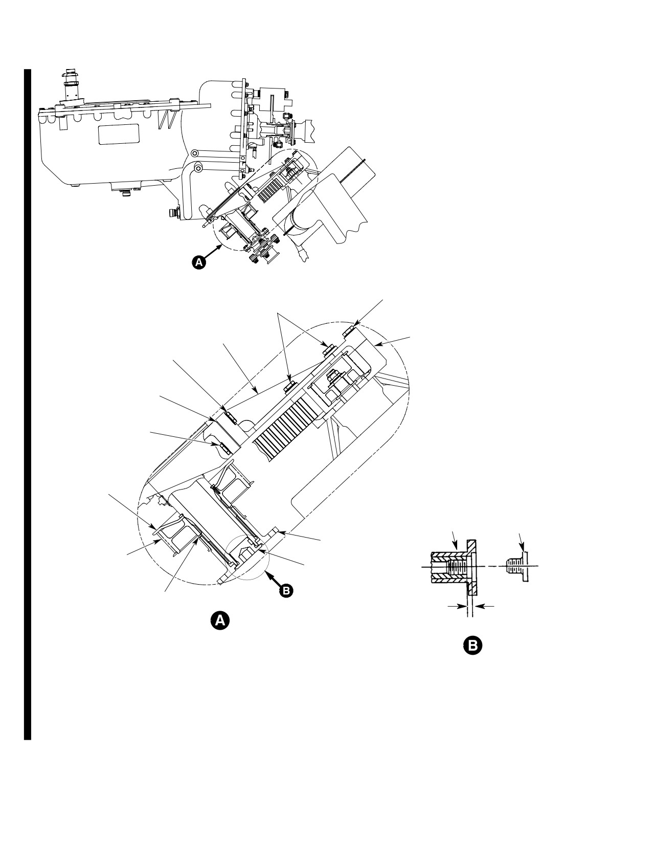
D. Cooling Blower Installation (369F5100
In the following step, do not use
CAUTION
Transmission)
levers or other tools on belt, or
in any way force belt onto pulley.
(Ref. Figure 406)
(6). Slide driver pulley onto transmission
Consumable Materials
input shaft to engage belt in teeth of
(Ref. Section 91−00−00)
both pulleys.
Item
Nomenclature
The minimum of 0.010 inch
CM111
Grease, aircraft
CAUTION
(0.254 mm) measurement be
CM112
Anti-seize compound high temperature
tween the bolt seating surface and the input
CM425
Sealing compound
shaft must be obtained to ensure proper
CM702
Lockwire CRES
clamp-up.
(1). With belt looped around driven pulley,
D Warped shims or foreign material could
install oil cooler fan bracket.
provide a false 0.010 inch (0.254 mm)
minimum measurement and improper
NOTE: NAS1304 series bolts may be used in
clamp-up could result, which during nor
place of NAS6604 series bolts.
mal operation, may damage the main
transmission input shaft.
(a). Install four bolts with washers
D Do not use clutch coupling shims under
through oil cooler mounting bracket
transmission input coupling. Inside diam
into fan bracket.
eter of clutch coupling shim is different
(b). Before tightening bolts, displace
than shim used on transmission input
cooler toward the transmission flange
coupling. Incorrect diameters can cause
to eliminate slack in that direction.
an improperly seated shim, misalignment
(c). Torque bolts to 70 - 90 inch-pounds
and cocked coupling.
(7.91 - 10.17 Nm) and safety with
(7). Torque bolts to 70 - 90 inch-pounds
lockwire (CM702).
(7.91 - 10.17 Nm).
(d). After bolts are torqued, seal around
(8). Coat threads of coupling bolt with
bolt heads with sealant (CM425).
anti-seize compound (CM112).
(9). Lubricate input shaft splines and
When installing pulley and
CAUTION
coupling splines with grease (CM111).
guard, make sure the spring pin
(10). Install input coupling shim and
in pulley is fully engaged inside hole in
coupling on transmission input shaft
pulley guard. If the spring pin does not align
with coupling bolt.
correctly with hole in pully guard, the
(11). Adjust belt tension (Ref. Cooling Blower
torque will be incorrect.
Belt Tension Check and Adjustment).
NOTE: Check coupling bolt for a minimum of
(2). Install pulley guard on main transmis
25 inch-pounds (2.82 Nm) drag torque.
sion input shaft.
(12). Torque coupling bolt to 315 - 365
(3). With belt looped around transmission
inch-pounds (35.59 - 41.24 Nm) plus
input shaft, position mounting bracket
drag torque.
on main transmission pad and loosely
(13).
369D, E, F, and 500N - Make sure belt
install two bolts with washers from the
tracks correctly (Ref. Cooling Blower
bottom of bracket and two bolts with
Belt Tracking).
washers from top of bracket.
(14). Connect drain tube to cooling blower
(4). Before tightening bolts, insert two
scroll fitting. Clamp tube to fitting with
shims between bracket and transmis
two turns of lockwire (CM702).
sion pad.
(15). Roll exhaust duct rubber connectors
(5). Verify that blower scroll clears anti-
onto scroll outlets (transmission oil
torque drive shaft by a minimum of
cooler duct and engine oil cooler duct)
0.190 inch (4.826 mm).
and secure with tie straps.
Page 411
63-21-00
Revision 43
CSP-HMI-2
MD Helicopters, Inc.
MAINTENANCE MANUAL
BOLT
BOLT
OIL COOLER FAN
BRACKET
FAN BRACKET
BOLT
SHIM
BOLT
PULLEY GUARD
TRANSMISSION
INTERNAL
INPUT COUPLING
WRENCHING BOLT
INPUT COUPLING
DRIVER PULLEY
BOLT
INPUT COUPLING SHIM
0.010 IN. (0.254 MM) MINIMUM
(BETWEEN END OF SHAFT AND BOLT
SEATING ON SURFACE ON COUPLING)
CSP102-012D
Figure 406. Oil Cooler Blower Installation (369F5100 Transmission)
Page 412
Revision 42
63-21-00
MD Helicopters, Inc.
CSP-HMI-2
MAINTENANCE MANUAL
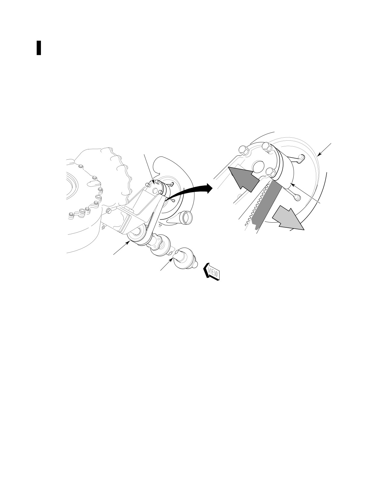
E. 369D, E, F, and 500N − Cooling Blower
(3). Rotate the lower driver pulley by hand
Belt Tracking
in a counter-clockwise direction. Make
sure the belt tracks axially towards the
(Ref. Figure 407)
blower on the upper driven pulley.
(1). Make sure the oil cooler belt tracks
correctly.
(4). If the oil cooler belt does not track
(2). Rotate the lower driver pulley with
correctly, replace with a serviceable
your hand in a clockwise direction (as
belt.
you look at the main rotor transmission
input). Make sure the belt tracks
axially away from the blower on the
upper driven pulley.
BLOWER
DRIVEN PULLEY
NOTE 1
DRIVEN PULLEY
NOTE 2
DRIVER PULLEY
(NOTES 1,2)
NOTES;
MAIN TRANSMISSION
DRIVE SHAFT
1. TURN DRIVER PULLEY CLOCKWISE.
VERIFY BELT TRACKS AWAY FROM BLOWER.
2. TURN DRIVER PULLEY COUNTER-CLOCKWISE.
VERIFY BELT TRACKS TOWARDS BLOWER.
63-2034
Figure 407. Cooling Blower Belt Tracking
Page 413
63-21-00
Revision 43
CSP-HMI-2
MD Helicopters, Inc.
MAINTENANCE MANUAL
This Page Intentionally Left Blank
Page 414
Revision 42
63-21-00
MD Helicopters, Inc.
CSP-HMI-2
MAINTENANCE MANUAL
MAIN TRANSMISSION LUBRICATION
AND COOLING SYSTEM
INSPECTION/CHECK
1. Lubrication System Inspection
(4). Examine scroll for cracks or breaks,
and for secure attachment to hub.
(Ref. Figure 601)
(5). Examine rubber connectors at engine
(1). Inspect plumbing and system compo
oil cooler duct and transmission oil
nents from oil cooler to lubrication
cooler duct where they attach to scroll.
pump for leaks, secure attachment and
Examine ducts for damage.
damage.
(6). Look through hub support legs and, to
(2). Inspect oil cooler, lubrication pump, oil
extent possible, inspect impeller for
filter, oil pressure switch, liquid level
damage. A crack, loose rivet or dis
plug, and chip detectors for leaks,
torted vane is cause for impeller
secure attachment and damage.
replacement. Inspect mount screws and
bolts for evidence of broken slippage
(3). Inspect electrical connections at oil
mark paint.
temperature switch, oil pressure
switch, and chip detectors for absence
(7). Examine scroll drain tube for damage,
of corrosion, secure attachment and
secure attachment and clear passage.
damage.
(8). Examine mounting bracket and fan
mounting bracket for secure attach
2. Cooling Blower Inspection
ment. Check for broken lockwire at bolt
heads securing mounting bracket
(Ref. Figure 405)
cooling blower assembly.
(1). Remove blower access door and inspect
belt for damage or excessive wear. Belt
3. Cooling Blower Inspection
should be fully seated in pulley grooves.
(Disassembled)
Limited cracking or separation of belt.
Consumable Materials
(a). Belt should be fully seated in pulley
(Ref. Section 91−00−00)
grooves.
Item
Nomenclature
(b). Limited cracking or separation of belt
CM206
Chemical coating
between pulley grooves is acceptable.
CM318
Primer
Visually monitor any propagation.
CM801
Abrasive paper, silicon carbide
Belt should be replaced if any one
separation exceeds three inches in
length or if total separation exceeds
(1). Examine belt for damage or excessive
50 percent of peripheral length of
wear (Ref. Figure 405).
belt. (For belt replacement schedule,
refer to Section 05-10-00).
(2). Examine driver pulley, spring pin,
pulley guard and driven pulley for
(2). Check belt tension.
damage or excessive wear.
(3). Hand-rotate main rotor to examine all
(3). Check driven pulley retaining nut for a
visible areas of driven pulley and driver
minimum of 160 inch-pounds (18.08
pulley for damage or excessive wear.
Nm) plus drag torque. If loss of
Listen for sounds of defective bearings
torque is indicated, remove pulley nut
or of impeller touching scroll while
and inspect washer for evidence of
rotor is turned.
elongation and wear.
Page 601
63-21-00
Revision 41
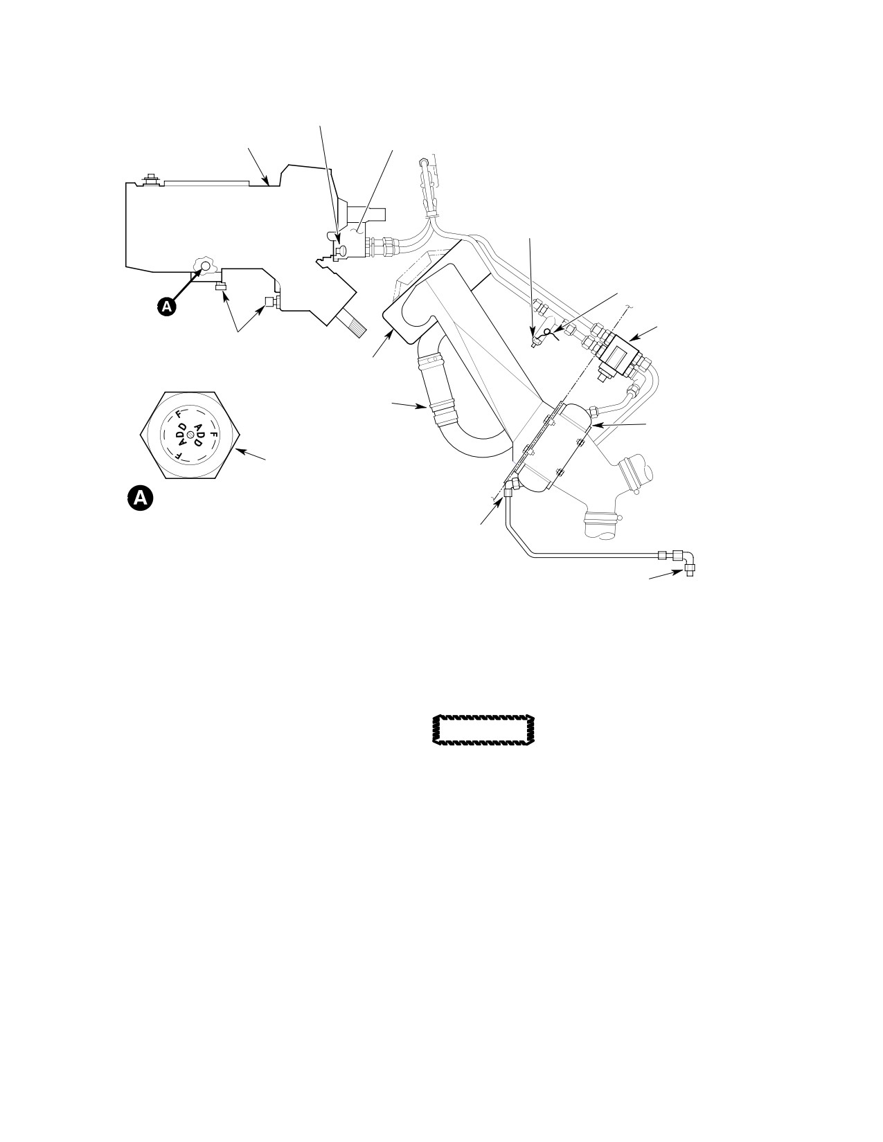
CSP-HMI-2
MD Helicopters, Inc.
MAINTENANCE MANUAL
OIL PRESSURE
SENDER
LUBRICATION PUMP
MAIN TRANSMISSION
AND OIL FILTER
OIL TEMPERATURE
SENDER
GROUND WIRE
OIL COOLER
BYPASS VALVE
CHIP DETECTORS
OIL COOLER BLOWER
TRANSMISSION OIL
COOLER DUCTS
OIL COOLER
OIL LEVEL PLUG
VIEWED FROM RH SIDE OF
MAIN TRANSMISSION
NOTE 1
NOTE:
DRAIN CAP
DRAIN CAP INSTALLED AT THIS LOCATION
(EARLY CONFIGURATION ONLY)
G63-2007A
Figure 601. Main Transmission Cooling Blower and Duct
(4). Check pulley shaft and splines for
(7). Examine scroll (Ref. Figure 801) for
condition. Replace damaged flat washer
cracks, breaks and distortion.
or ring washer with flat washer. Install
Handle impeller carefully to
and torque nut to 160 - 190 inch-
CAUTION
prevent damage that could
pounds (18.08 - 21.47 Nm) plus drag
cause imbalance and require replacement of
torque.
impeller.
(5). Examine mounting bracket and fan
(8). Visually (minimum 10X magnification)
mounting bracket for cracks and
examine impeller (Ref. Figure 801) for
breaks.
cracks, deformation and separation.
(6). Examine web of mounting bracket for
(a). Look for foreign material attached to
wear.
impeller. None is permitted.
(a). Remove nicks, scratches or grooves
(b). Check for loose rivets at hub.
leaving sharp impressions in web.
Minimum acceptable web thickness:
(c). Use electroprobe or gage of equiva
0.125 inch (3.175 mm).
lent accuracy to measure depth of
scratches or nicks.
(b). Replace mounting bracket if web does
not meet 0.125 inch (3.175 mm)
(d). Use penetrating dye to examine
minimum after repair.
suspected cracks.
Page 602
Revision 36
63-21-00
MD Helicopters, Inc.
CSP-HMI-2
MAINTENANCE MANUAL
(e). Scratches and nicks not exceeding
Kg). This load is to be applied at a right
0.006 inch (0.152 mm) depth are
angle to the outside face of the belt.
repairable by sanding with grade 320
Measure belt deflection without turning
abrasive paper (CM801) to blend
driven pulley, then turn driven pulley
defect into surrounding area.
1/2 turn and repeat belt deflection
measurement. Turn driven pulley an
1). Treat blended areas with chemical
additional 1/4 turn and measure belt
coating (CM206) and touch-up
deflection again.
with primer (CM318).
(a). If the tension is too high, greater
2). All other defects require replace
than 2.00 pounds (0.9072 Kg),
ment of impeller.
tension can be reduced by peeling off
a layer of the laminated shim, one at
(9). Examine shaft for damage or excessive
a time equally from both shims, until
wear. Discard seal (Ref. Figure 801).
tension falls into proper range.
4.
Cooling Blower Belt Tension Check and
(b). If the tension is too low: Add layers
Adjustment
from a spare shim in the same
manner as removed in step (2).(a).
(1). Check that laminated shims are in
above, until tension falls into proper
position between mounting bracket and
range.
transmission fan mount assembly.
Tighten the four mounting bolts. Rotate
(3). Make a final check of bolt torque:
pulley by hand a few turns to even out
belt tension.
For 369D25100 transmission installa
tion, 65 - 75 inch-pounds (7.34 - 8.47
(2). Measure belt deflection three times at
Nm), and then lockwire drilled heads.
approximate center of one of the spans.
The force required to deflect the belt
For 369F5100 transmission installa
0.170-0.200 inch (4.32-5.08 mm) must
tion, 70 - 90 inch-pounds (7.91 -
be 1.75-2.00 pounds (0.7938-0.9072
10.17 Nm).
Page 603
63-21-00
Revision 37
CSP-HMI-2
MD Helicopters, Inc.
MAINTENANCE MANUAL
This Page Intentionally Left Blank
Page 604
Revision 36
63-21-00
MD Helicopters, Inc.
CSP-HMI-2
MAINTENANCE MANUAL
MAIN TRANSMISSION LUBRICATION
AND COOLING SYSTEM
REPAIRS
1.
369D25630 Cooling Blower Disassembly
holding device meeting requirements of
caution above, and remove impeller
(Ref. Figure 801)
retaining nut and washer.
NOTE: Disassemble cooling blower only to ex
Be careful to prevent impeller
CAUTION
tent necessary to perform inspection, re
damage. Slight impeller defor
placement or repair of specific items. Re
mation or damage can cause imbalance.
place cooling blower bearings and belt per
Protect shaft threads and use nonmetallic
replacement schedule (Ref. Sec. 05-10-00).
mallet when performing step (8). below.
Bolts used to secure mount bracket to cool
ing blower must be self-locking type only.
(8).
Manually support impeller and sepa
rate impeller from shaft by carefully
Discard bolts if safety wired and replace
tapping end of shaft. Remove impeller,
with self-locking bolts (Ref. Figure 405).
scroll, key, spacer and any shimming
(1). Remove mounting bracket (Ref. Sec.
present.
63-20-00).
(9).
Remove bolt, retaining ring and spring
(2). Remove scroll cover.
washer from hub.
(3). Hold impeller retaining nut with socket
(10).
Use non-metallic mallet on splined end
wrench and remove driven-pulley
of shaft to drive impeller-end bearing,
retaining nut and washer.
seal, and portion of the shaft from hub.
Do not attempt to remove sleeves from
(4). Remove driven pulley. Do not forcefully
hub. Sleeves are line-reamed. If either
tap or pry; if necessary, use pulling
sleeve is defective, hub must be re
device.
placed. Remove inner retaining ring
from hub. Remove and discard O-ring
(5). Remove spacer from impeller shaft.
in upper sleeve if installed.
(6). Remove four screws and washers that
(11).
If necessary, use pulling device to
attach scroll to hub.
extract bearing and seal from shaft.
In following step, do not use
(12).
If remaining bearing cannot be driven
CAUTION
tools or other devices to hold im
from hub by tapping outer race from
peller. Tool damage can affect impeller bal
inside with nonferrous tube and mallet,
ance. Holding device must not damage shaft
re-insert shaft into bearing, drive
splines and must hold shaft with 250 - 300
bearing out and remove it from shaft as
inch-pounds (28.25 - 33.90 Nm) of torque
described in steps (10). and (11). above.
applied to impeller retaining nut.
(13).
Discard bearings. They are not to be
(7). Secure splined end of impeller shaft in
re-used.
Page 801
63-21-00
Revision 22
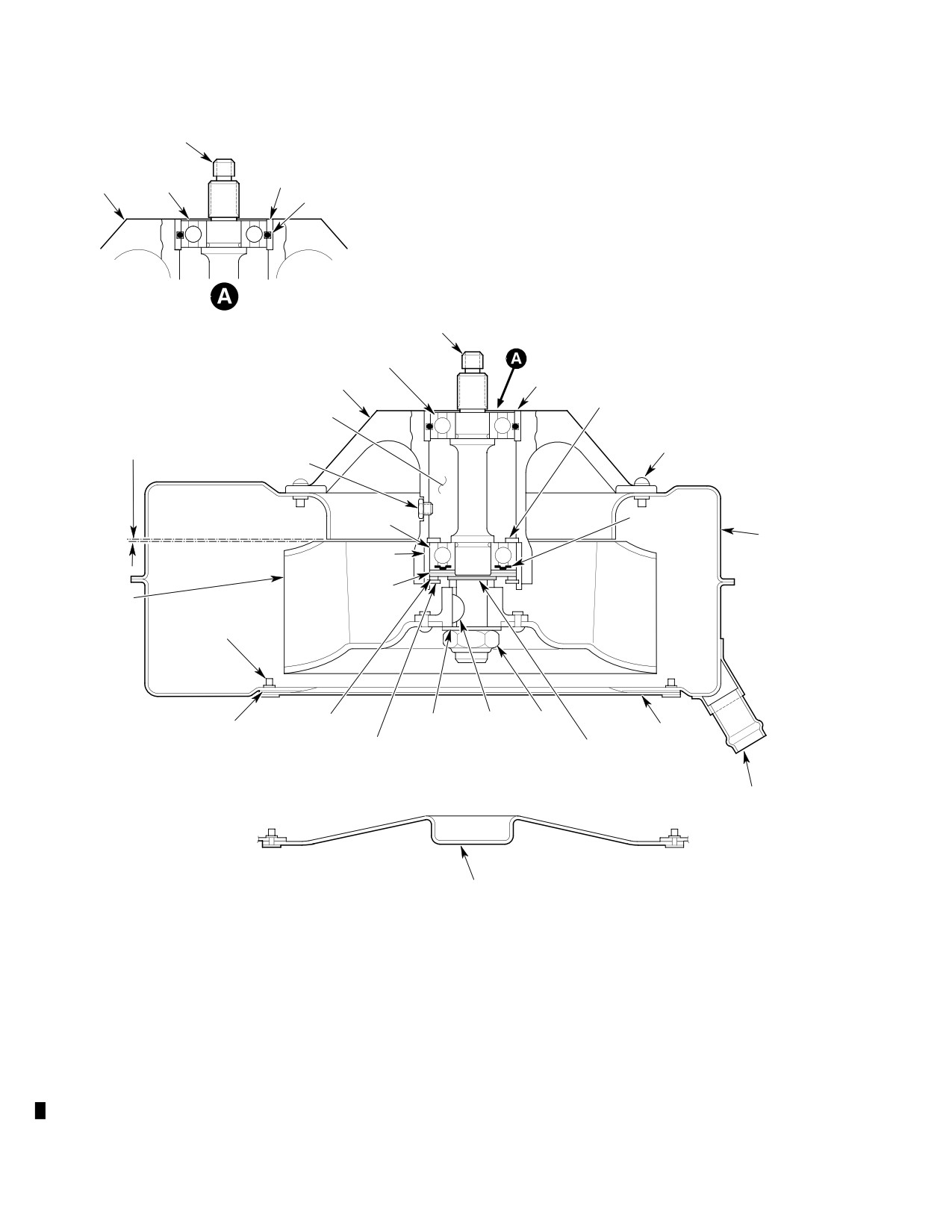
CSP-HMI-2
MD Helicopters, Inc.
MAINTENANCE MANUAL
SHAFT
SLEEVE
BEARING
(NOTE 1)
HUB
O-RING
SHAFT
BEARING
SLEEVE
(NOTE 2)
HUB
INNER RETAINER
RING
CAVITY FILLED
MINIMUM CLEARANCE
WITH GREASE
SCREWS AND WASHERS
TO PREVENT RUBBING
(4 PLCS)
(NOTE 3)
BOLT
SEAL (PART
BEARING
OF BEARING)
BLOWER
SCROLL
SLEEVE
SEAL
IMPELLER
SCREW AND WASHER (8
PLCS)
SPRING WASHER
WASHER KEY
NUT
SEALANT
COVER
OUTER RETAINING RING
LAMINATED
(NOTE 1)
SHIM
DRAIN TUBE
OUTLET
COVER
(NOTE 2)
NOTES:
1.
CURRENT CONFIGURATION.
2.
EARLY CONFIGURATION.
G63-2009-1
3
CLEARANCE SHALL BE 0 020-0 040 IN (0 508-1 016 MM) MINIMUM
Figure 801. 369D25630 Cooling Blower − Cross−Section View
Page 802
Revision 22
63-21-00
MD Helicopters, Inc.
CSP-HMI-2
MAINTENANCE MANUAL
2.
369D25630 Cooling Blower Reassembly
(7). Lightly grease (CM116) larger bearing
journal of shaft and bore of remaining
(Ref. Figure 801)
bearing.
On current configuration Cool
Consumable Materials
CAUTION
ing blowers, apply locking com
(Ref. Section 91−00−00)
pound (CM431) to outer race of lower bear
Item
Nomenclature
ing (impeller end) only. Do not apply locking
CM116
Grease, aircraft and instrument
compound to upper bearing (pulley end).
CM219
Methyl-ethyl-ketone
(8). Apply primer (CM321) and locking
CM220
Naphtha aliphatic
compound (CM431) to faying surfaces of
CM222
1,1,1-Trichloroethane
outer bearing race and sleeve according
CM321
Surface primer locking compound
to container instructions. Be careful to
CM425
Sealing compound
prevent compounds from entering
bearing.
CM431
Sealing, locking and retaining compound
NOTE: On newer style bearings, the metal
shield is replaced by a blue shield.
NOTE: Following procedure covers assembly of
completely disassembled cooling blower, to
(9). Insert bearing so that shield side (metal
gether with those items (belt, brackets, etc)
shield or blue disc) faces interior of hub
that form a complete unit. Use only applica
and seal side (rubber disc) faces
ble steps of procedure when disassembly is
impeller end of shaft.
less than complete. New bearings and new
seal are required; those removed are not to
(10). Arbor-press bearing simultaneously
be reused.
onto shaft journal and into sleeve.
Exert pressure equally on both races of
(1). Install inner retaining ring in hub and
bearing. At same time, exert equal
if removed at disassembly install new
pressure on splined end of shaft and
O-ring in upper bearing sleeve.
pulley end of hub casting. Bearing is to
firmly contact shaft shoulder and inner
(2). Lightly grease (CM116) smaller bearing
retaining ring.
journal of shaft, and bore of correspond
ing bearing.
MEK solvent is flammable.
WARNING
Use only in well-ventilated
NOTE: This bearing does not have a metal
area and away from heat and flame.
shield.
(11). Wipe away excess locking compound.
(3). Place bearing on shaft so that rubber
Use methyl ethyl keytone (CM219) if
seal of bearing faces splined end of
hardening begins. Leave assembled
shaft.
parts undisturbed to permit locking
compound to cure for two hours at
(4). Using tube that contacts only edge of
75°-100°F (24°-38°C), or for ten
inner race of bearing, arbor-press
minutes at 220° ±l0°F (105° ±5°C).
bearing onto journal until inner race
contacts shaft shoulder.
(12). Temporarily install lubrication fitting.
(5). Clean outer race of both bearings and
(13). Install new seal, spring washer and
faying surfaces of both hub sleeves with
outer retaining ring.
trichloroethane (CM222) and clean
(14). Fill hub cavity with grease (CM116)
cloth or paper towel.
through lubrication fitting until grease
(6). Arbor-press bearing (with shaft
seeps out around seal of bearing
installed) into sleeve. Exert pressure
nearest splined end of shaft. After
only on bearing outer race and on
lubrication, remove lubrication fitting
impeller-end of hub casting (no
and install screw and washer. Lockwire
pressure on impeller-end sleeve).
screwhead.
Page 803
63-21-00
Revision 37
CSP-HMI-2
MD Helicopters, Inc.
MAINTENANCE MANUAL
(15). Install hub on scroll with four screws
tightening bolts, fully displace bracket
and washers. Torque screws to 12 - 15
in direction that causes it to be closest
inch-pounds (1.36 - 1.69 Nm).
to main transmission drive shaft when
cooling blower is installed, then torque
(16). Install spacer and impeller on shaft.
bolts to 65 - 75 inch-pounds (7.34 -
8.47 Nm). Apply slippage mark paint.
(17). Install washer and locknut on end of
shaft. Using holding device on splined
(23).
(Ref. Figure 405) Install spacer, washer,
end of shaft, tighten locknut sufficiently
pulley, washer and nut on shaft. Hold
to remove all end clearance from
nut on impeller end of shaft with socket
stack-up of parts.
wrench and tighten pulley nut to 160 -
190 inch-pounds (18.08 - 21.47 Nm)
(18). Using feeler gage through an air outlet
plus drag torque.
port, measure minimum clearance
between impeller and scroll lip.
(24).
(Ref. Figure 405) Install belt on pulley
and secure mounting bracket to fan
NOTE: If minimum clearance is 0.020-0.040
mounting bracket with four bolts and
inch (0.508-1.016 mm), steps (19). and (20).
washers. Before tightening bolts, fully
below may be bypassed.
displace bracket in direction that
causes it to be closest to main transmis
(19).
If clearance is more than 0.040 inch
sion drive shaft when cooling blower is
(1.016 mm), remove impeller and
installed, then torque bolts to 65 - 75
spacer. Replace spacer with 369H5654
inch-pounds (7.34 - 8.47 Nm) and
shims as required between impeller and
lockwire drilled heads.
seal to obtain 0.020-0.040 inch
(0.508-1.016 mm) clearance. Reinstall
(25).
Clean faying surfaces of scroll and
impeller, washer and locknut. Tighten
cover with naphtha (CM220); apply
to remove all end clearance, and then
sealant (CM425) according to container
rotate impeller and check for rubbing. If
instructions before securing cover to
rubbing occurs, perform step (20).,
scroll with eight screws and washers.
otherwise proceed to step (21)..
3.
600N5630 Cooling Blower Disassembly
(20).
If clearance is less than 0.020 inch
(Ref. Figure 802)
(0.508 mm), or if rubbing occurs when
performing previous step, disassemble
NOTE: Disassemble cooling blower only to ex
and install shim(s) between seal and
tent necessary to perform inspection, re
spacer to ensure 0.020-0.040 inch
placement or repair of specific items. Re
(0.508-1.016 mm) minimum clearance
place cooling blower bearings and belt per
and prevent rubbing.
replacement schedule (Ref. Sec. 05-10-00).
(1). Remove mounting bracket (Ref. Sec.
(21).
When clearance is properly adjusted,
63-20-25).
remove impeller, install key, impeller,
washer and locknut. Torque locknut to
(2). Hold impeller retaining nut with socket
250 - 300 inch-pounds (28.25 - 33.90
wrench and remove driven-pulley
Nm). Use care to avoid placing stress
retaining nut and washer.
on impeller or scroll. Hold splined end
of shaft in suitable device.
(3). Remove driven pulley. Do not forcefully
tap or pry; if necessary, use pulling
NOTE: Install two self-locking bolts in place of
device.
safety-wired bolts if not previously in
(4). Remove spacer from impeller shaft.
stalled.
(5). Remove two screws and washers that
(22).
(Ref. Figure 405) Secure fan mounting
attach scroll to shroud.
bracket on hub with four bolts and
washers on early configurations, or two
(6). Remove four screws six washers, and
self-locking bolts, two screws and four
two nuts that attach hub to shroud and
washers on current versions. Before
scroll. Retain shim if installed.
Page 804
Revision 36
63-21-00
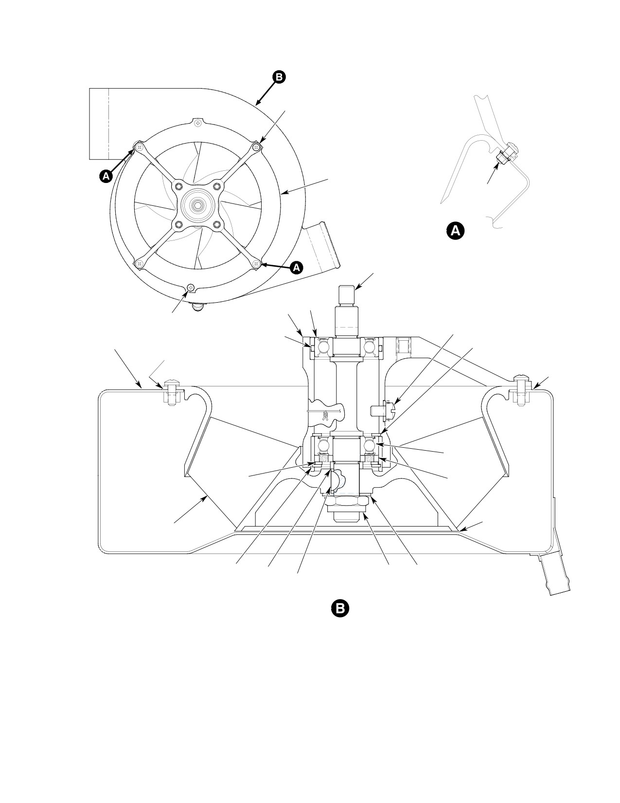
MD Helicopters, Inc.
CSP-HMI-2
MAINTENANCE MANUAL
SCREW
WASHER
SHROUD
NUT
WASHER
SHAFT
BEARING
HUB
SCREW
SCREW
WASHER
WASHER
LOCKWIRE
O-RING
SCROLL
RETAINING RING
SHIM
SHIM
(NOTE 3)
(NOTE 3)
BEARING
SPRING
SEAL
WASHER
(NOTE 2)
NOTE 3
IMPELLER
RETAINING RING
SHIM
NUT WASHER
(NOTE 1)
WOODRUFF KEY
NOTE:
1.
SHIM IMPELLER TO PROVIDE 0.020-0.030 IN. (0.508-0.762 MM) AVERAGE BLADE
TRAILING EDGE TIP CLEARANCE-TO-SHROUD, MEASURED PERPENDICULARLY TO
THE SHROUD FACE. THE BLADE TRAILING EDGE IS AT THE LARGEST BLADE
DIAMETER. SHIM PRIOR TO INSTALLING SCROLL.
2.
INSTALL SEAL WITH SMALL DIAMETER GAP IN RINGS FACING OUTSIDE OF HUB.
3.
SHIM HUB TO PROVIDE 0.020 IN. (0.508 MM) MINIMUM GAP BETWEEN SCROLL
G63-2009-2A
AND IMPELLER
Figure 802. 600N5630 Cooling Blower − Cross−Section View
Page 805
63-21-00
Revision 36
CSP-HMI-2
MD Helicopters, Inc.
MAINTENANCE MANUAL
In following step, do not use
4.
600N5630 Cooling Blower Reassembly
CAUTION
tools or other devices to hold im
(Ref. Figure 802)
peller. Tool damage can affect impeller bal
ance. Holding device must not damage shaft
splines and must hold shaft with 250 - 300
Consumable Materials
inch-pounds (28.25 - 33.90 Nm) of torque
(Ref. Section 91−00−00)
applied to impeller retaining nut.
Item
Nomenclature
CM116
Grease, aircraft and instrument
(7). Secure splined end of impeller shaft in
CM219
Methyl-ethyl-ketone
holding device meeting requirements of
CM220
Naphtha aliphatic
caution above, and remove impeller
CM222
1,1,1-Trichloroethane
retaining nut and washer.
CM321
Surface primer locking compound
CM425
Sealing compound
Be careful to prevent impeller
CAUTION
CM431
Sealing, locking and retaining compound
damage. Slight impeller defor
mation or damage can cause imbalance.
Protect shaft threads and use nonmetallic
NOTE: Following procedure covers assembly of
mallet when performing step (8). below.
completely disassembled cooling blower, to
gether with those items (belt, brackets, etc)
that form a complete unit. Use only applica
(8).
Manually support impeller and sepa
ble steps of procedure when disassembly is
rate impeller from shaft by carefully
less than complete. New bearings and new
tapping end of shaft. Remove impeller,
seal are required; those removed are not to
scroll, key, spacer and any shimming
be reused.
present.
(1). Install inner retaining ring in hub and
(9).
Remove bolt, retaining ring and spring
if removed at disassembly install new
washer from hub and shroud.
O-ring in upper bearing sleeve.
(2). Lightly grease (CM116) smaller bearing
(10).
Use non-metallic mallet on splined end
journal of shaft, and bore of correspond
of shaft to drive impeller-end bearing,
ing bearing.
seal, and portion of the shaft from hub.
NOTE: This bearing does not have a metal
Do not attempt to remove sleeves from
shield.
hub. Sleeves are line-reamed. If either
sleeve is defective, hub must be re
(3). Place bearing on shaft so that rubber
placed. Remove inner retaining ring
seal of bearing faces splined end of
from hub. Remove and discard O-ring
shaft.
in upper sleeve if installed.
(4). Using tube that contacts only edge of
inner race of bearing, arbor-press
(11).
If necessary, use pulling device to
bearing onto journal until inner race
extract bearing and seal from shaft.
contacts shaft shoulder.
(12).
If remaining bearing cannot be driven
(5). Clean outer race of both bearings and
from hub by tapping outer race from
faying surfaces of both hub sleeves with
inside with nonferrous tube and mallet,
trichloroethane (CM222) and clean
re-insert shaft into bearing, drive
cloth or paper towel.
bearing out and remove it from shaft as
(6). Arbor-press bearing (with shaft
described in steps (10). and (11). above.
installed) into sleeve. Exert pressure
only on bearing outer race and on
(13).
Discard bearings. They are not to be
impeller-end of hub casting (no
re-used.
pressure on impeller-end sleeve).
Page 806
Revision 37
63-21-00
MD Helicopters, Inc.
CSP-HMI-2
MAINTENANCE MANUAL
(7). Lightly grease (CM116) larger bearing
(15). Install shim on scroll.
journal of shaft and bore of remaining
(16). Install hub and shroud on scroll with
bearing.
six screws, eight washers and two nuts.
Torque screws to 12 - 15 inch-pounds
Apply locking compound
CAUTION
(1.36 - 1.69 Nm).
(CM431) to outer race of lower
bearing (impeller end) only. Do not apply
(17). Using feeler gage through an air outlet
locking compound to upper bearing (pulley
port, measure for 0.020 inch (0.508 mm)
end).
minimum gap between impeller and
scroll.
(8). Apply primer (CM321) and locking
compound (CM431) to faying surfaces of
(18). Check for proper thread protrusion of
outer bearing race and sleeve according
six screws through nutplates and nuts
to container instructions. Be careful to
on inside of scroll.
prevent compounds from entering
(19). Install spacer and impeller on shaft.
bearing.
(20). Install washer and locknut on end of
(9). Insert bearing so that shield side (metal
shaft. Using holding device on splined
disc) faces interior of hub and seal side
end of shaft, tighten locknut sufficiently
(rubber disc) faces impeller end of shaft.
to remove all end clearance from
(10). Arbor-press bearing simultaneously
stack-up of parts.
onto shaft journal and into sleeve.
(21). Using feeler gage through an air outlet
Exert pressure equally on both races of
port, measure minimum clearance
bearing. At same time, exert equal
between impeller and scroll lip.
pressure on splined end of shaft and
pulley end of hub casting. Bearing is to
NOTE: If minimum clearance is 0.020-0.030
firmly contact shaft shoulder and inner
inch (0.508-0.762 mm), steps (19). and (20).
retaining ring.
below may be bypassed.
MEK solvent is flammable.
(22).
If clearance is more than 0.030 inch
WARNING
Use only in well-ventilated
(0.762 mm), remove impeller and
area and away from heat and flame.
spacer. Replace spacer with 369H5654
shims as required between impeller and
(11). Wipe away excess locking compound.
seal to obtain 0.020-0.030 inch
Use methyl ethyl keytone (CM219) if
(0.508-0.762 mm) clearance. Reinstall
hardening begins. Leave assembled
impeller, washer and locknut. Tighten
parts undisturbed to permit locking
to remove all end clearance, and then
compound to cure for two hours at
rotate impeller and check for rubbing. If
75°-100°F (24°-38°C), or for ten
rubbing occurs, perform step (20).,
minutes at 220° ±l0°F (105° ±5°C).
otherwise proceed to step (21)..
(23).
If clearance is less than 0.020 inch
(12). Temporarily install lubrication fitting.
(0.508 mm), or if rubbing occurs when
NOTE: Install seal with small diameter gap in
performing previous step, disassemble
rings facing outside of hub.
and install shim(s) between seal and
spacer to ensure 0.020-0.030 inch
(13). Install new seal, spring washer and
(0.508-0.762 mm) minimum clearance
outer retaining ring.
and prevent rubbing.
(14). Fill hub cavity with grease (CM116)
(24).
When clearance is properly adjusted,
through lubrication fitting until grease
remove impeller, install key, impeller,
seeps out around seal of bearing
washer and locknut. Torque locknut to
nearest splined end of shaft. After
250 - 300 inch-pounds (28.25 - 33.90
lubrication, remove lubrication fitting
Nm). Use care to avoid placing stress
and install screw and washer. Lockwire
on impeller or scroll. Hold splined end
screwhead.
of shaft in suitable device.
Page 807
63-21-00
Revision 37
CSP-HMI-2
MD Helicopters, Inc.
MAINTENANCE MANUAL
(25).
(Ref. Figure 406) Secure fan mounting
6. Transmission and Cooling Blower Drain
bracket on hub with two self-locking
Tube Repair and Replacement
bolts, two screws and four washers.
Before tightening bolts, fully displace
Consumable Materials
bracket in direction that causes it to be
(Ref. Section 91−00−00)
closest to main transmission drive shaft
Item
Nomenclature
when cooling blower is installed, then
CM702
Lockwire CRES
torque bolts to 50 - 70 inch-pounds
CM717
Tape, pressure sensitive
(5.65 - 7.91 Nm) and screws to 65 - 75
inch-pounds (7.34 - 8.47 Nm). Apply
slippage mark paint.
(1). Disconnect drain tubes from transmis
sion cooling blower, and from drain
fittings and weld assemblies at firewall.
(26).
(Ref. Figure 406) Install spacer, washer,
Release supporting nylon straps and
pulley, washer and nut on shaft. Hold
remove drain tubes (Ref. Figure 601).
nut on impeller end of shaft with socket
wrench and tighten pulley nut to 160 -
(2). Inspect drain tubes, drain fittings, weld
190 inch-pounds (18.08 - 21.47 Nm)
assemblies and connectors for damage
plus drag torque.
and clear passage.
(3). Repair damaged flexible drain tubes
with tape (CM716).
(27).
(Ref. Figure 406) Install belt on pulley
and secure mounting bracket to fan
(4). Install drain tubes as follows:
mounting bracket with four bolts and
(a). Attach upper ends of drain tubes to
washers. Before tightening bolts, fully
transmission and cooling blower.
displace bracket in direction that
Secure with double wraps of lockwire
causes it to be closest to main transmis
(CM702).
sion drive shaft when cooling blower is
installed, then torque bolts to 65 - 75
(b). Route drain tubes and secure with
inch-pounds (7.34 - 8.47 Nm) and
nylon straps. Position tubes so that
lockwire drilled heads.
no drainage traps are formed.
(c). Secure lower ends of drain tubes to
fittings and weld assemblies with
(28).
Clean faying surfaces of scroll and
double wraps lockwire (CM702).
cover with naphtha (CM220); apply
sealant (CM425) according to container
(d). Insert lower end of metal drain tube
instructions before securing cover to
through grommet in skin and slip
scroll with eight screws and washers.
upper end of tube into weld assembly.
Wrap tube with one layer of 1 inch
(2.54 cm) wide tape (CM717) at
clamp-attach point, and install
5. Cooling Blower Cleaning (Disassembled)
clamp.
7. Installation of Heating System and Oil
Consumable Materials
Cooling Line Standoff Clamps (0003D −
(Ref. Section 91−00−00)
0539D)
Item
Nomenclature
(Ref. Figure 803) The following information
list a procedure for installing standoff clamps
CM234
Solvent, dry-cleaning
on the 369D292490 heating system hose and
on the 369D25710 main rotor transmission oil
cooling line to eliminate chafing between the
(1). Clean all usable metal parts with
oil cooling lines and chafing of the oil cooling
solvent spray (CM234). Remove
lines by the heating system hose. A protective
remnants of locking compound with
bushing is also installed to prevent chafing
loctite remover (CM216).
between the oil cooling lines.
Page 808
Revision 36
63-21-00
MD Helicopters, Inc.
CSP-HMI-2
MAINTENANCE MANUAL
(1). Remove aft compartment interior trim
(4). Check installation of standoff clamps to
panels and left Sta. 124.00 bulkhead
ensure adequate clearance between
access door to gain access to work area.
369D25709 and 369D25710 oil cooling
lines and between oil cooling lines and
NOTE: Inspect the 369D292490 heating sys
369D292490 heating system hose.
tem hose and 369D25709 and 369D25710
main transmission oil cooling lines for evi
NOTE:
dence of chafing, kinking or damage at area
of L/H aft section channel assembly.
D Later Model 369D helicopters have
369D26544-3 closure plate (with grom
(2). If not already installed, install
met) installed on L/H aft section channel.
NAS1713D30N clamp on heating
Remove plate from channel, if presently
system hose and NAS1713D8N clamp
installed, to preclude interference with oil
on 369D25710 oil cooling line. Connect
cooling lines.
clamps with screw, washer and nut.
D Later model 500D helicopters have
(3). If not already installed, install new
HS4194-6 standoff bracket installed on
C-SB-16-8 bushing snug against nut
channel with MS21919DG30 clamp to se
on 369D25709 oil cooling tube assembly
cure heating hose. Install standoff brack
(View A-A). Reposition clamp assembly
et and clamp, if not presently installed on
securing 369D25709 (lower) and
helicopter.
369D25710 (upper) oil cooling tube
assemblies to accommodate installation
(5). Reinstall bulkhead access door and
of bushing.
interior trim panels.
Page 809
63-21-00
Revision 36
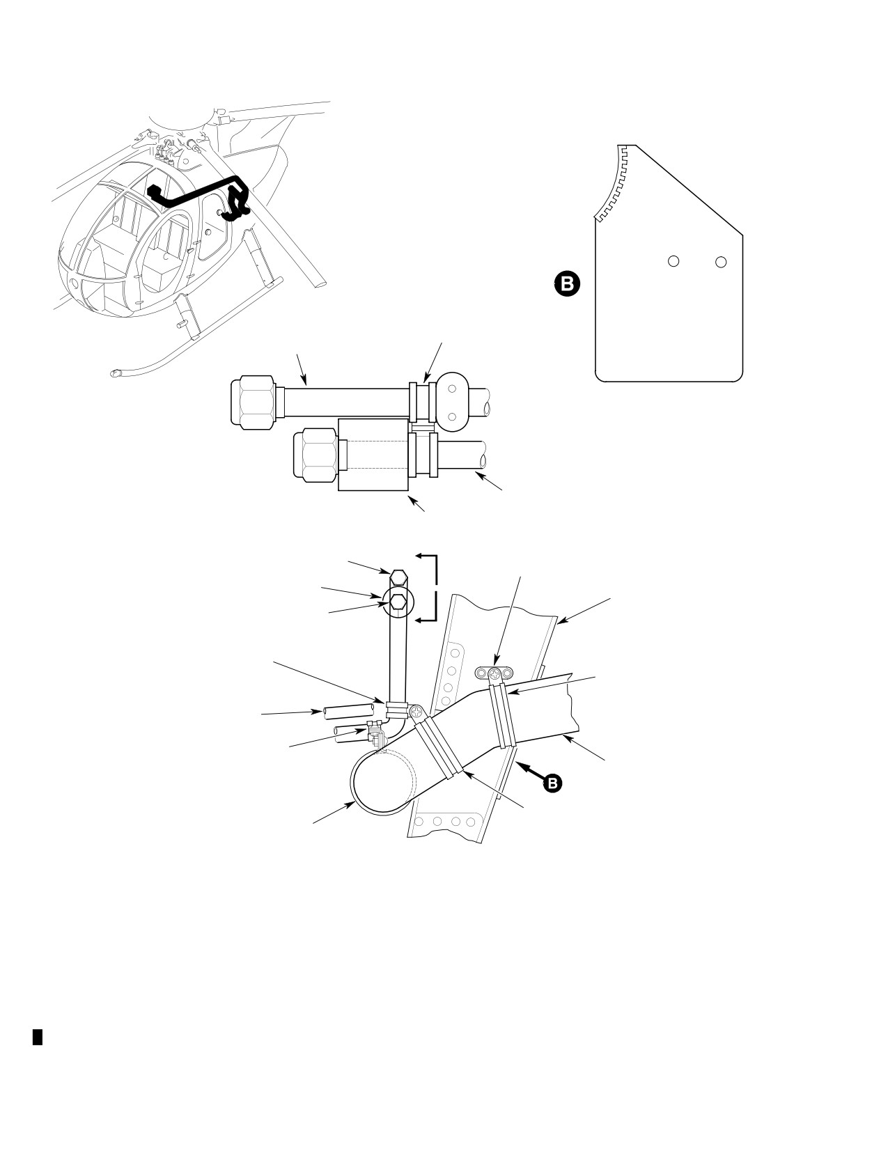
CSP-HMI-2
MD Helicopters, Inc.
MAINTENANCE MANUAL
CLAMP ASSY
369D25710 OIL COOLING
(RELOCATED)
TUBE ASSY
369D26544-3 CLOSURE PLATE
(REMOVE IF PRESENTLY INSTALLED
ON AFT SECTION CHANNEL)
(ROTATED)
369D25709 OIL COOLING
TUBE ASSY
VIEW A - A
C-5B-16-8 BUSHING
(NOTE 3)
A
369D25710 OIL COOLING
HS4194-6 STANDOFF (NOTE 1)
TUBE ASSY (REF)
MS20470AD3 RIVET (2)
C-5B-16-8 BUSHING
369D23024 AFT SECTION
CHANNEL ASSY
369D25709 OIL COOLING
(CANT. STA. 124.00)
TUBE ASSY
A
NAS1713D8N CLAMP (NOTE 2)
NAS1096-7 SCREW
MS21919DG30 CLAMP (NOTE 1)
AN960PD10L WASHER (2)
NAS1096-3-7 SCREW
MS21043-3 NUT
AN960PD10L WASHER
369D25709 OIL COOLING
TUBE ASSY
NAS1713D8N CLAMP (EXISTING)
AN743-12 BRACKET
369D292490 HEATING HOSE
NAS1096-3-7 SCREW (2)
MS21043-3 NUT (3)
AN960PD10L WASHER (4)
NAS1713D30N CLAMP
(NOTE 2)
NAS1713D30N CLAMP
(EXISTING)
NOTES:
1.
PRESENTLY INSTALLED ON LATE-MODEL HELICOPTERS.
2.
LOCATE NEW CLAMPS APPROXIMATELY AS SHOWN ON
COOLING TUBE AND HEATING HOSE ASSEMBLIES.
3.
AFTER INSTALLATION OF BUSHING, ROTATE BUSHING SO
G63-2026A
THAT SPLIT IN BUSHING IS FACING DOWN
Figure 803. Installation of Standoff Clamps − Heating and Oil Cooling Lines
Page 810
Revision 22
63-21-00
MD Helicopters, Inc.
CSP-HMI-2
MAINTENANCE MANUAL
Section
63−22−00
Rotor Brake
(369D/E/FF −
500/600N)
MD Helicopters, Inc.
CSP-HMI-2
MAINTENANCE MANUAL
ROTOR BRAKE
MAINTENANCE PRACTICES
When working with hydrau
pressure is produced; this pressure is trans
WARNING
lic systems, special care
mitted through the tubing to the caliper
must be taken to prevent entrance of
assembly where it acts on the pistons. This
dust, moisture or other foreign materi
causes the pucks to apply clamping pressure
al. System contamination can cause
(braking force) to the brake disc. System
malfunctions which could cause injury
pressure is held within safe limits, regardless
to personnel or equipment damage.
of the force applied to the brake handle, by
operation of the pressure-relief valve. When
1. Rotor Brake
hydraulic pressure exceeds 500 psig (3447
kPa), the pressure-relief valve opens, venting
The rotor brake enables the pilot to manually
excess pressure back to the master cylinder.
brake the rotor system to a stop by operating a
When application of force is discontinued,
single brake handle. The handle is installed on
caliper pistons (and the pucks) are retracted
the upper left (or upper right, depending on
by return springs in the caliper assembly.
helicopter seating configuration) side of the
Puck-to-disc clearance is maintained by
canted bulkhead 78.50 control tunnel in the
action of a self-adjusting mechanism in the
pilot's compartment. Operation of the brake
caliper assembly. The original equipment
handle actuates a master cylinder, causing
tachometer generator is replaced by a new unit
dual pucks to grip a brake disc installed on the
that is included in the rotor brake installation
tail rotor drive shaft. Braking force is trans
to provide clearance between the tachometer
mitted through the main transmission to the
generator and the brake disc. The original
main rotor. A friction clip secures the handle in
equipment electrical connector (P202),
an out-of-the-way position when the brake is
installed on the aft fuselage wiring harness
not in use.
near the main transmission, is replaced with a
new plug which mates with the receptacle on
The rotor brake installation includes:
the new tachometer generator.
(1). A master cylinder with an actuating
3. Rotor Brake Troubleshooting Procedure
handle mechanism (master cylinder
and linkage assembly).
(Ref. Table 201)
(2). A caliper assembly with dual opposing
4. Master Cylinder Servicing
pistons to which friction pads (brake
(Ref. Figure 401)
pucks) are attached.
(3). A brake disc installed on the tail rotor
Consumable Materials
drive shaft coupling at the aft end of
(Ref. Section 91−00−00)
the main transmission.
Item
Nomenclature
(4). A hydraulic pressure relief valve.
CM123
Hydraulic fluid
(5). A tachometer generator.
Rotor brake installation servicing includes
(6). Six stainless steel hydraulic tubing
adding hydraulic fluid (CM123) to the master
assemblies and associated fittings.
cylinder reservoir, and bleeding air from the
system.
(7). Attaching and mounting hardware.
(1). Remove interior trim to gain access to
(8). A trim panel assembly and installation.
master cylinder.
(2). Disconnect tube assembly from forward
2. Rotor Brake Operation
nipple and move end of tube assembly
When manual force is applied to the brake
carefully aside to permit removal of
handle (master cylinder piston), hydraulic
master cylinder cap.
Page 201
63-22-00
Revision 20
CSP-HMI-2
MD Helicopters, Inc.
MAINTENANCE MANUAL
(3). Remove attaching screws, cap with
NOTE: Hose material should be resistant to de
assembled hydraulic parts, and gasket
terioration from exposure to hydraulic fluid.
from master cylinder. Replace gasket.
A glass container should be used to catch
bleed screw outflow so that bubbles of escap
ing air are clearly visible. The following fill
(4). Fill master cylinder reservoir with
ing and bleeding procedure is best per
clean hydraulic fluid (CM123) within
formed by two persons, one to operate the
1/8 to 1/4 inch (3.175-6.35 mm) of the
brake handle, and one to open and close the
top. Install cap with assembled hydrau
bleed screws.
lic parts, new gasket, and attaching
screws. Do not tighten screws if
(3). Connect a length of 1/4 inch (6.35 mm)
hydraulic system is to be bled.
ID hose on reducer and insert free end
of hose in a container to catch any
hydraulic fluid that may be bypassed by
(5). If hydraulic system has been opened,
the relief valve. Connect a second
e.g. as for replacement of components,
length of 1/4 inch (6.35 mm) ID hose on
perform procedural steps to bleed the
one bleed screw on caliper assembly
hydraulic system.
and submerge free end of hose in clean
hydraulic fluid (CM123) in a glass
NOTE: It is not necessary to bleed the system if
container.
only a small amount of fluid is required to
fill the reservoir, and if the system has not
(4). Remove attaching screws and master
been opened.
cylinder cap. Fill reservoir with clean
hydraulic fluid (CM123) within 1/8 -
1/4 inch (3.175-6.35 mm) of top of
(6). Tighten attaching screws to secure cap
chamber. Replace cap, do not tighten
on master cylinder. Connect tube
attaching screws.
assembly to nipple.
NOTE: Verify that master cylinder reservoir is
kept full of fluid throughout the bleeding
(7). Reinstall components removed for
process.
access to the master cylinder assembly.
(5). Open one bleed screw and operate
brake handle slowly through a full
5. Rotor Brake Hydraulic System Bleeding
down stroke to force hydraulic fluid out
of master cylinder reservoir and into all
other parts of the system. Close bleed
Consumable Materials
screw and return handle to ”up”
(Ref. Section 91−00−00)
position. Remove cap, refill master
Item
Nomenclature
cylinder reservoir, and replace cap.
CM123
Hydraulic fluid
(6). Repeat step (5). several times to ensure
that entire hydraulic system is filled
with fluid, and that no air remains in
The rotor brake hydraulic system must be bled
system.
to remove entrapped air whenever the system
NOTE: The presence of bubbles in the bleed
has been opened for any reason.
screw outlet flow indicates air is being
forced out of the system and absence of
(1). Remove interior trim for access to the
bubbles indicates all air has been bled from
master cylinder assembly and bleed
the system.
screws on caliper assembly (if applica
ble).
(7). Remove bleeder hose from first bleed
screw and connect it on second bleed
screw.
(2). Disconnect tube assembly from reducer
in relief valve and nipple in master
(8). Repeat steps (5). and (6). until bleed
cylinder cap.
screw outlet flow is clear of bubbles.
Page 202
Revision 20
63-22-00
MD Helicopters, Inc.
CSP-HMI-2
MAINTENANCE MANUAL
(9). Remove fluid catch containers and
7. Master Cylinder Assembly Overhaul
hoses. Ensure both bleed screws are
tightly closed. Raise brake handle to
(1). Remove defective master cylinder
stowed position and engage in handle
assembly.
retainer assembly. Verify that caliper
pistons (and attached brake pucks) are
(2). Disassemble unit and replace defective
retracted when handle is raised.
parts with components of overhaul kit
(Vendor PN 12-8310), using manufac
(10). Make final check of fluid level in
turer's instructions supplied with kit.
master cylinder reservoir and replen
ish, if necessary. Secure gasket and cap
(3). Install overhauled master cylinder
with attaching screws.
assembly.
(11). Connect tube assembly to nipple in cap
and to reducer in relief valve and
8. Caliper Assembly Overhaul
tighten tube nuts.
(1). Remove defective caliper assembly.
6. Rotor Brake Component Repair
The master cylinder assembly or caliper
(2). Disassemble unit and replace defective
assembly may be overhauled as necessary.
parts with components of overhaul kit
Overhaul kits are available from MD Helicop
(Vendor PN 12-11780), using manufac
ters Inc. or an approved MD Helicopter service
turer's instructions supplied with kit.
center. Other parts must be replaced when
damaged or otherwise unserviceable.
(3). Install overhauled caliper assembly.
Page 203
63-22-00
Revision 42
CSP-HMI-2
MD Helicopters, Inc.
MAINTENANCE MANUAL
Table 201. Troubleshooting Rotor Brake Installation
Symptom
Isolating Step
Corrective Action
Brake actuating handle creeps
Defective master cylinder assembly.
Remove defective master cylinder
downward under sustained force,
assembly and replace with new unit,
with hydraulic fluid leakage from
or overhaul and reinstall old unit.
master cylinder assembly.
Brake actuating handle creeps
Defective caliper assembly.
Remove defective caliper assembly
downward under sustained force,
and replace with new unit, or
with hydraulic fluid leakage from
overhaul and reinstall old unit.
caliper assembly.
‘Spongy‘ feel at brake actuating
Air in hydraulic system.
Bleed air from hydraulic system.
handle when force is applied.
Hydraulic fluid at low level in master
Add fluid to master cylinder
cylinder reservoir.
assembly and bleed air from
hydraulic system.
Rotor brake system fails to slow
Any of above components or system
Follow applicable corrective action
rotor effectively.
faults.
procedures.
Brake pucks worn excessively.
Remove defective caliper assembly,
replace defective pucks and reinstall
repaired unit.
Brake pucks create noises, such
Glazed or worn brake pucks.
Remove defective caliper assembly,
as squeals or squeaks, when
replace defective pucks and reinstall
brakes are applied.
repaired unit.
Brake disc creates noises, such
Scored or damaged brake disc.
Remove defective brake disc and
as squeals or squeaks, when
replace with new disc.
brakes are applied.
Page 204
Revision 20
63-22-00
MD Helicopters, Inc.
CSP-HMI-2
MAINTENANCE MANUAL
ROTOR BRAKE
REMOVAL/INSTALLATION
When working with hydrau
nience panel cover assembly from
WARNING
lic systems, special care
convenience panel assembly.
must be taken to prevent entrance of
(4). Disconnect electrical wiring and
dust, moisture or other foreign materi
communications cables from compo
al. System contamination can cause
nents on back of convenience panel
malfunctions which could cause injury
assembly. If cabin heating option is
to personnel or equipment damage.
installed on aircraft, disconnect heated
air duct from panel-mounted diffuser.
1. Rotor Brake Component Access
Remove attaching screws and conve
The following items must be removed to gain
nience panel assembly from aft side of
access for removal of rotor brake components.
canted bulkhead 78.50 structure.
Removal should be limited to damaged or
(5). Remove transmission cover panel
defective parts for repair, overhaul or replace
assembly from fuselage structure.
ment, or to remove certain items for access to
other components.
(6). Cover exposed trim panels to prevent
damage and soiling.
The master cylinder assembly, linkage
assembly and hydraulic relief valve are
(7). Remove main transmission from
installed on or attached to the helicopter
aircraft (Ref. Sec. 63-20-00/25).
structure. Removal of these components
require access from the crew compartment.
(8). Remove tail rotor (Ref. Sec. 64-20-00),
Hydraulic tube assembly is not attached to the
tail rotor transmission (Ref. Sec.
helicopter structure. Access from the passen
63-25-10) and tail rotor drive shaft
ger/cargo compartment is required for removal
(Ref. Sec. 63-15-10).
of hydraulic tube assembly.
2. Master Cylinder Assembly Replacement
The caliper assembly and related hydraulic
(Ref. Figure 401 and Figure 402)
items, caliper mounting bracket, tachometer
generator, brake disc and tail rotor drive
A. Master Cylinder Assembly Removal
coupling are installed on the main transmis
sion. Removal of these components require
The master cylinder assembly is bolted to the
that certain access provisions be made and
bracket of the master cylinder linkage assem
that the main transmission, and attached rotor
bly and is connected hydraulically to the
brake components, be removed from the
caliper assembly. Remove master cylinder
aircraft.
assembly as follows:
NOTE: Component removal can be accom
(1). Remove trim panels to gain access to
plished with the doors in place. However, op
master cylinder.
erations are facilitated with the doors re
moved.
(2). Disconnect tube assembly from nipple,
and tube assembly from elbow, taking
(1). Remove both crew compartment and
special care to catch any hydraulic fluid
cargo/passenger compartment doors.
that drains or drips from tube assem
blies or fittings when the system is
(2). Remove crew compartment seats.
opened.
(3). Remove map case assembly from
NOTE: If old master cylinder assembly is to be
forward side of canted bulkhead 78.50
reinstalled, removal of tube assembly, nip
structure. Remove both (LH and RH)
ples, and elbow may not be necessary unless
upper forward panel assemblies from
the tube assembly or fittings are damaged
bulkhead structure. Remove conve
or defective.
Page 401
63-22-00
Revision 20
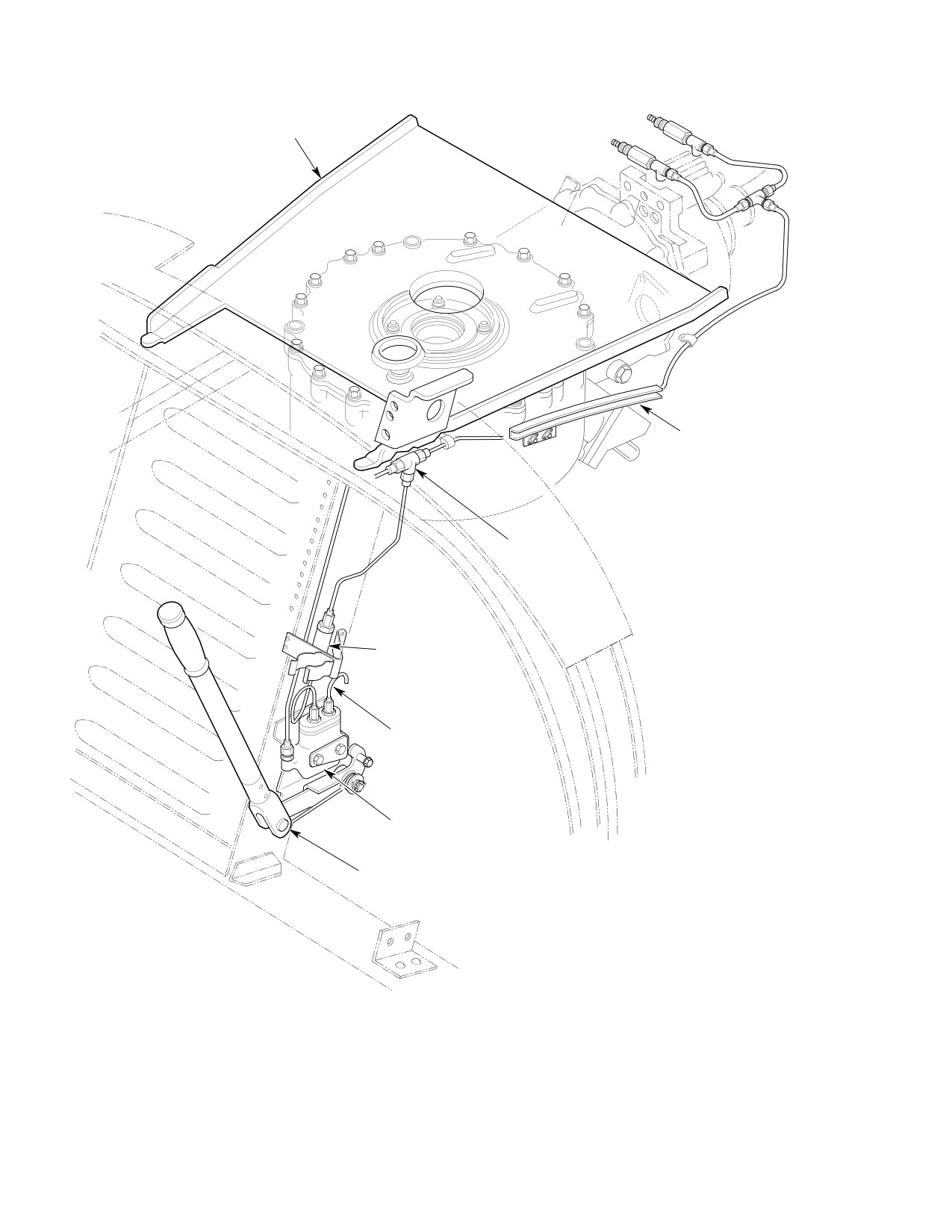
CSP-HMI-2
MD Helicopters, Inc.
MAINTENANCE MANUAL
MAST SUPPORT PAN
WINDOW SUPPORT
CHANNEL ASSEMBLY
TEE
PRESSURE RELIEF
VALVE
VENT
MASTER CYLINDER
ACTUATING LINKAGE
LEFT-HAND INSTALLATION SHOWN; RIGHT-HAND OPPOSITE
G63-2003A
Figure 401. Airframe−Mounted Rotor Brake Components
Page 402
Revision 20
63-22-00
MD Helicopters, Inc.
CSP-HMI-2
MAINTENANCE MANUAL
(3). Remove tube assembly from nipple.
NOTE: Mounting holes in bracket are elon
Remove nipples from cap, and elbow
gated to enable lateral position adjustment
from master cylinder.
of master cylinder assembly.
(4). Remove nuts, washers, bolts, stop, and
(6). With actuating handle in stowed
master cylinder assembly from bracket.
position, adjust position of master
Drain residual hydraulic fluid from
cylinder assembly so that clearance
master cylinder assembly.
(measured with a thickness gage)
between actuating lever (Ref.
(5). Install protective caps or plugs on open
Figure 905) and master cylinder piston
ends of disconnected tube assemblies,
is 0.020-0.040 inch (0.508-1.016 mm).
and open ports or fittings in master
cylinder assembly to prevent entry of
(7). Install tube assembly on aft nipple.
contaminants.
Connect tube assembly to forward
nipple and connect tube assembly to
B. Master Cylinder Assembly Installation
elbow.
Consumable Materials
(8). Fill and bleed the hydraulic system.
(Ref. Section 91−00−00)
Item
Nomenclature
(9). Reinstall components removed for
access to the master cylinder assembly.
CM434
Thread sealant
3. Master Cylinder Linkage Assembly
NOTE: Steps (1). thru (3). below apply only to
Replacement
installation of a new master cylinder assem
bly.
(Ref. Figure 402)
(1). Remove attaching screws and vendor-
A. Master Cylinder Linkage Assembly
supplied cap from master cylinder.
Removal
Vendor supplied cap is not used.
The bracket assembly of the master cylinder
(2). Rework vendor-supplied gasket (Ref.
linkage assembly is permanently installed on
Figure 906).
the canted bulkhead Sta. 78.50 vertical
member by four Jo-bolt blind fasteners. Once
(3). Replace reworked gasket and new cap
installed, the Jo-bolts cannot be removed
on master cylinder and secure with
except by destructive procedures. The master
attaching screws installed finger tight.
cylinder and linkage assembly may be disas
NOTE: Cap must be installed correctly with re
sembled, leaving the bracket assembly
spect to taper of threaded holes.
attached to the structure. Disassembly should
be limited to that necessary for removal of
(4). If new master cylinder assembly is
damaged or defective parts.
being installed, or if hydraulic fittings
have been removed from a usable unit,
(1). Remove master cylinder.
coat all but first two tapered pipe
threads of nipples and elbow with
When components are as
WARNING
thread sealant (CM434). Install nipples
sembled, spring force is con
in cap and elbow in master cylinder.
stantly exerted to inhibit inadvertent
brake application. Care must be exer
(5). Place one washer and stop on bolts and
cised as the spring is disengaged to
insert bolts through master cylinder.
prevent injury to personnel or equip
Place two washers on each bolt as
ment damage.
spacers. Position assembled parts on
bracket (Ref. Figure 402) and install
(2). Manually restrain movement of lever
one washer on each bolt. Install nuts
and attached parts. Carefully disengage
finger tight to hold master cylinder
end of spring from under head of clevis
assembly and stop in position.
pin. Release spring force carefully.
Page 403
63-22-00
Revision 20
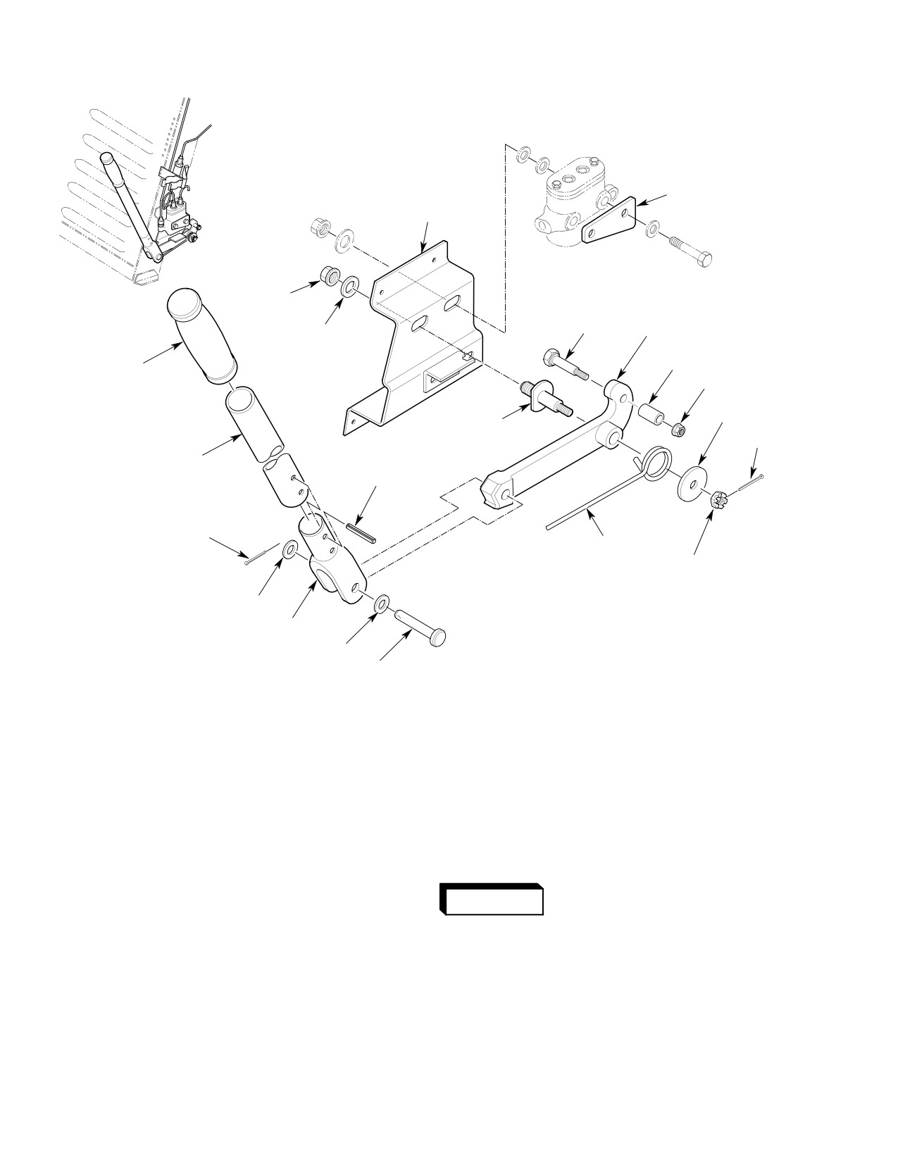
CSP-HMI-2
MD Helicopters, Inc.
MAINTENANCE MANUAL
STOP
BRACKET
ASSY
NUT
WASHER
BOLT
ACTUATING LEVER
GRIP
SPACER
NUT
WASHER
PIN
COTTER
PIN
HANDLE
ROLL PIN
COTTER PIN
SPRING
NUT
WASHER
FITTING
WASHER
CLEVIS PIN
G63-2006
Figure 402. Master Cylinder Linkage Assembly
(3). Remove cotter pin, nut, washer, spring,
B. Master Cylinder Linkage Assembly
and lever with assembled handle parts
Installation
from pin.
Installation of the master cylinder linkage
assembly will be limited to re-assembly of
(4). Remove cotter pin, washers, and clevis
components to the bracket assembly.
pin, and separate assembled handle
parts from lever. Remove nut, spacer,
When the unit is assembled,
and bolt from lever.
WARNING
the spring is under restraint
and, if accidentally or inadvertently re
leased, could cause injury to personnel
(5). Drive two spring pins out of fitting and
or equipment damage.
handle and separate parts. Remove grip
from handle.
(1). Re-assembly procedures are essentially
the reverse of disassembly procedures,
(6). Remove nut and washer from pin, and
with special care being given to steps
remove pin from bracket assembly.
involving spring.
Page 404
Revision 20
63-22-00
MD Helicopters, Inc.
CSP-HMI-2
MAINTENANCE MANUAL
(2). If cotter pins or spring pins have been
NOTE: If old caliper assembly is to be rein
removed, use new parts for reassembly.
stalled, it is not necessary to remove hy
draulic fittings except for replacement of de
fective or damaged parts.
4. Caliper Assembly, Brake Disc, and Drive
Coupling Replacement (369D25100
Transmission)
(4). Remove coupling bolt that is used to
secure drive coupling on transmission
(Ref. Figure 403)
output shaft so that disc/coupling unit
is free to slide on shaft splines.
A. Caliper Assembly, Brake Disc, and Drive
Coupling Removal (369D25100
(5). Note and record, for re-assembly
Transmission)
reference, placement of 18 washers
used as spacers between caliper
The caliper assembly is bolted to a mounting
assembly and mounting bracket, or
bracket which is installed on the main
under heads of attaching bolts.
transmission tail rotor cover. The brake disc is
bolted on the drive coupling which is installed
The caliper assembly consists of
on the transmission output shaft. For clarity,
CAUTION
two identical halves held togeth
the brake disc and drive coupling are consid
er by the attaching bolts. Care should be
ered as a single item (disc/coupling unit).
used to avoid dropping parts when bolts are
removed.
Although the caliper assembly and the
disc/coupling unit are not mechanically
connected, they are installed on the transmis
(6). Hold caliper assembly and unscrew
sion with the outer portion of the disc posi
attaching bolts out of mounting brack
tioned between the two halves of the caliper
et. Slide disc/coupling unit away from
assembly (Ref. Figure 404). This arrangement
transmission and remove caliper
makes it necessary to remove both units
assembly and attaching hardware.
(partially, at least) at the same time. Removal
operations require that the main transmission
(7). If caliper assembly is to be reused and
be removed from the aircraft with the rotor
some time will elapse before re-assemb
brake components installed. Proceed as
ly, remove disc/coupling unit, position
follows:
caliper assembly (and assembled parts)
on mounting bracket and screw bolts
(1). Remove main transmission and
into bracket to hold parts until time for
attached rotor brake components from
re-assembly.
aircraft (Ref. Sec. 63-20-00/25).
(8). If disc/coupling unit is to be reinstalled,
(2). Disconnect tube assembly from caliper
and some time will elapse before
mounted tees. Remove tube assembly
re-assembly, slide unit back on trans
and interconnect tee as a unit.
mission shaft and install coupling bolt
finger tight to hold parts until time for
NOTE:
re-assembly.
D It is not necessary to disconnect tube as
semblies from tee except for replacement
Axial position of the drive
of defective and damaged parts.
WARNING
coupling is critical as it con
D New bleed screws are included with the
trols the mechanical interface between
new caliper assembly.
the coupling and the tail rotor drive
shaft. Out-of-tolerance axial coupling
(3). If caliper assembly is to be replaced by
loads can contribute to coupling fail
a new unit, remove two bleed screws
ure which could result in injury to per
from adapters, remove adapters from
sonnel and equipment damage. Refer
tees, and remove tees from caliper
to Sec. 63-10-00 for coupling reinstalla
assembly.
tion.
Page 405
63-22-00
Revision 20
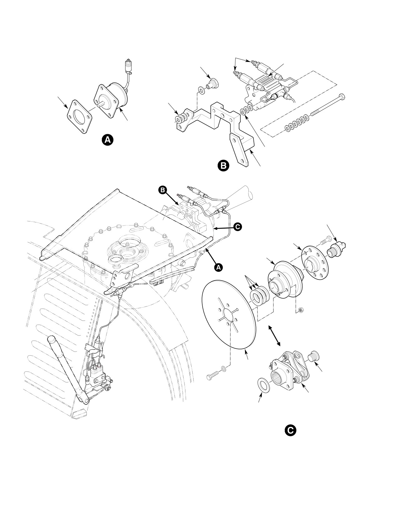
CSP-HMI-2
MD Helicopters, Inc.
MAINTENANCE MANUAL
BLEED-SCREWS
PISTON CALIPER
ASSEMBLY
SPECIAL NUT
GASKET
SPACER
WASHERS
ROTOR
TACHOMETER
GENERATOR
SHIM WASHERS
MOUNTING BRACKET
FAILSAFE COUPLING BOLT
TAIL ROTOR DRIVE
SHAFT COUPLING
COUPLING
SHIMS
EARLY CONFIGURATION
BRAKE DISC
COUPLING
BOLT
TRANSMISSION
COUPLING
COUPLING
SHIM
CURRENT CONFIGURATION
G63-2005A
Figure 403. Transmission−Mounted Rotor Brake Components
Page 406
Revision 20
63-22-00
MD Helicopters, Inc.
CSP-HMI-2
MAINTENANCE MANUAL
(9). If either disc or coupling is to be
Molykote metal protector
WARNING
replaced by a new part, slide disc/coup
contains perchloroethylene.
ling unit off shaft, leaving shim wash
It should be used in a well-ventilated
ers in place. Remove nuts, washers, and
area, and the precautions normally fol
bolts and separate disc and coupling. If
lowed when working with the chlori
coupling is being replaced, measure
nated solvent should be implemented.
(and record for re-assembly reference)
Solvents used to dilute this material, as
overall length of old coupling at three
well as metal-cleaning or alkali cleans
separate peripheral locations. Calculate
ers, should only be used with adequate
and record the average value.
ventilation. Follow handling precau
tions on the solvent's container label.
B. Caliper Assembly, Brake Disc and Drive
NOTE: Couplings should be treated with moly
Coupling Installation (369D25100
kote metal protector (CM202) after each
Transmission)
washing with any solvent or detergent.
(4). Spray molykote metal protector
Consumable Materials
(CM202) on the interior and exterior
(Ref. Section 91−00−00)
surfaces of Bendix coupling diaphragm
Item
Nomenclature
packs. Spray or dip flange in molykote
metal protector. Eliminate excess liquid
CM112
Anti-seize compound high temperature
by gently blowing with compressed air
CM117
Grease
(dilute to 10% perchloroethylene). Cure
for 8 hours at room temperature, or 15
CM202
Metal protector, aerosol
minutes at 150°F (65°C).
CM434
Thread sealant
(5). Coat, completely but sparingly, splines
CM702
Lockwire CRES
of transmission output shaft with
grease (CM117) and threads of coupling
bolt with anti-seize compound
(1). Position brake disc on drive coupling
(CM112), or equivalent. Start disc/coup
with raised center side of disc seated
ling unit on shaft.
firmly on shoulder of coupling, and with
bolt holes aligned. Insert four bolts
To ensure optimum brake opera
CAUTION
through disc and coupling flange,
tion and minimize equipment
install washers and nuts on bolts, and
damage, caliper-to-disc clearances on both
torque nuts (in an alternating se
sides of disc should be equal, or as nearly
quence) to 100 - 140 inch-pounds
equal as possible. Clearance adjustment is
(11.30 - 15.82 Nm).
accomplished by varying number of shim
washers, 0.032 inch (0.8128 mm) thick,
placed between the caliper assembly and its
The main transmission must
mounting bracket. Nine washers are pro
WARNING
be installed in the aircraft
vided for each attaching bolt; those not used
with special care to avoid damage to
as shims should be placed under bolt heads.
rotor brake components. Installation
Washer distribution should be the same for
damage could lead to system failure
both bolts.
which could result in injury to person
nel and equipment damage.
(6). Hold assembled parts with caliper
assembly over edge of disc, slide
disc/coupling unit on shaft, and move
(2). Install transmission in aircraft (Ref.
caliper assembly against mounting
Sec. 63-20-00/25).
bracket at the same time. Screw bolts
into bracket to hold caliper assembly
(3). Determine correct shimming for
firmly in position. Screw coupling bolt
coupling (Ref. Sec. 63-10-00).
into shaft to secure disc/coupling unit.
Page 407
63-22-00
Revision 20
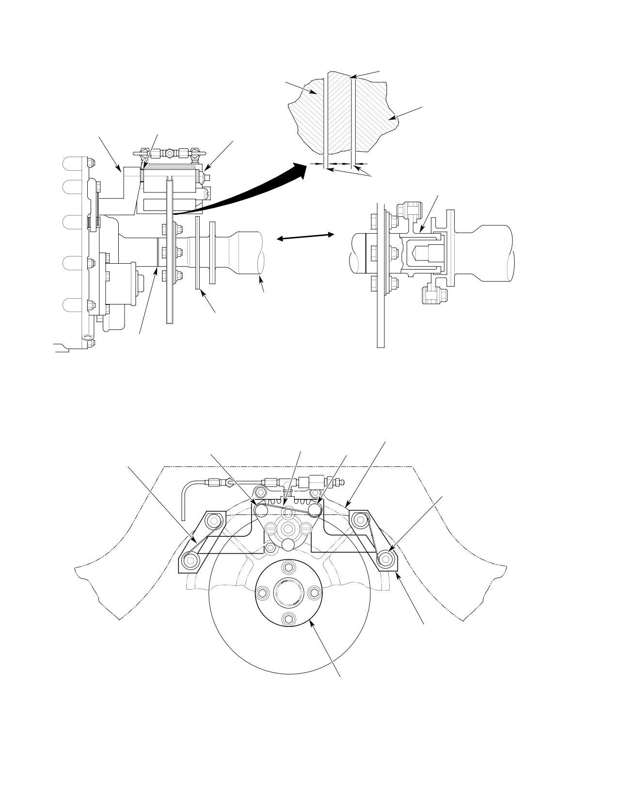
CSP-HMI-2
MD Helicopters, Inc.
MAINTENANCE MANUAL
DISC
CALIPER
CALIPER
MOUNTING
SHIM WASHERS
CALIPER
BRACKET
ASSEMBLY
NOTE
DRIVE SHAFT COUPLING
BRAKE DISC/BRAKE
(KAMATIC)
PUCK CLEARANCES
TAIL ROTOR
DRIVE SHAFT
DRIVE SHAFT COUPLING
(BENDIX)
COUPLING
SHIMS
MAIN TRANSMISSION
NOTE:
CLEARANCE TO BE EQUAL TO WITHIN 0.032 IN. (0.8128 MM).
G63-2010B
Figure 404. Caliper Assembly and Brake Disc Interface (369D25100 Transmission)
MAIN TRANSMISSION
LOCKWIRE
BOLT
BOLT
LOCKWIRE
SPECIAL NUT
CALIPER MOUNTING
BRACKET
DRIVE COUPLING
G63-2011
Figure 405. Lockwire Installation (369D25100 Transmission)
Page 408
Revision 20
63-22-00
MD Helicopters, Inc.
CSP-HMI-2
MAINTENANCE MANUAL
(7). Measure brake caliper housing-to-disc
NOTE: It is not necessary to remove washers
clearances on both sides of disc with a
used as spacers except for replacement.
thickness gage. If clearances are equal
Nuts may be replaced on studs until time for
within 0.032 inch (0.8128 mm), torque
re-assembly to prevent loss of parts.
attaching bolts to 160 - 190 inch-
B. Caliper Mounting Bracket Installation
pounds (18.0821.47 Nm) and secure
(369D25100 Transmission)
with corrosion-resistant lockwire
(CM702) (Ref. Figure 405). Torque
The following procedures assume that the
coupling bolt per Section 63-10-00.
transmission has been removed from the
aircraft for removal of the mounting bracket.
NOTE: Clearance differences greater than
0.032 inch (0.8128 mm) can be reduced by
Consumable Materials
rearranging washers on caliper attaching
(Ref. Section 91−00−00)
bolts.
Item
Nomenclature
(8). To adjust clearances, hold caliper
CM702
Lockwire CRES
assembly and unscrew bolts from
mounting bracket. Transpose washers
(1). Place three washers on each of the four
on bolts as required. Reassemble parts,
mounting studs (1, 2, 10, and 11 o'clock
and recheck clearances.
positions) as spacers. Position mounting
(9). If new caliper assembly was installed or
bracket on studs, install washers and
if hydraulic fittings were removed from
nuts, and torque nuts to 50 - 75
old unit, coat all but first two threads of
inch-pounds (5.65 - 8.47 Nm).
two bleed screws, tees, and plugs with
(2). Secure installation with lockwire
thread sealant (CM434) or equivalent.
(CM702) (Ref. Figure 405).
Install plugs and tees in caliper
assembly, screw adapters on tees, and
(3). Reinstall transmission as required (Ref.
install bleed screws in adapters.
Sec. 63-20-00/25).
(10). Connect tube assemblies and tee unit to
6. Caliper Assembly, Brake Disc, and Drive
tees.
Coupling Replacement (369F5100
Transmission)
5. Caliper Mounting Bracket Replacement
(Ref. Figure 406)
(369D25100 Transmission)
A. Caliper Assembly, Brake Disc, and Drive
(Ref. Figure 403)
Coupling Removal (369F5100
Transmission)
A. Caliper Mounting Bracket Removal
(369D25100 Transmission)
The caliper assembly is bolted to the main
transmission anti-torque cover. The brake disc
The caliper mounting bracket is attached to
is bolted on the drive coupling which is
the main transmission tail rotor cover by
installed on the transmission output shaft. For
special nuts installed on four of the studs used
clarity, the brake disc and drive coupling are
for installation of the cover. The caliper
considered as a single item (disc/coupling
assembly is bolted to the mounting bracket.
unit). Although the caliper assembly and the
Bracket removal requires that the main
disc/coupling unit are not mechanically
transmission be removed from the aircraft
connected, they are installed on the transmis
with the rotor brake components installed.
sion with the outer portion of the disc posi
tioned between the two halves of the caliper
(1). Remove main transmission (and
assembly. This arrangement makes it neces
attached rotor brake components) from
sary to remove both units (partially, at least)
aircraft (Ref. Sec. 63-20-00/25).
at the same time. Removal operations require
(2). Remove attaching nuts and washers,
that the main transmission be removed from
and remove mounting bracket from
the aircraft with the rotor brake components
studs.
installed.
Page 409
63-22-00
Revision 20
CSP-HMI-2
MD Helicopters, Inc.
MAINTENANCE MANUAL
(1). Remove main transmission (and
(8). If disc/coupling unit is to be reinstalled,
attached rotor brake components) from
and some time will elapse before
aircraft (Ref. Sec. 63-25).
re-assembly, slide unit back on trans
mission shaft and install coupling bolt
(2). Disconnect tube assembly from caliper
finger tight to hold parts until time for
mounted tees. Remove tube assembly
re-assembly.
and interconnect tee as a unit.
Axial position of the drive
NOTE: It is not necessary to disconnect tube
WARNING
coupling is critical as it con
assemblies from tee except for replacement
trols the mechanical interface between
of defective and damaged parts.
the coupling and the tail rotor drive
shaft. Out-of-tolerance axial coupling
(3). If caliper assembly is to be replaced by
loads can contribute to coupling fail
a new unit, remove two bleed screws
ure which could result in injury to per
from adapters, remove adapters from
sonnel and equipment damage. Refer
tees, and remove tees from caliper
to Sec. 63-15 for coupling reinstalla
assembly.
tion.
NOTE: If old caliper assembly is to be rein
(9). If either disc or coupling is to be
stalled, it is not necessary to remove hy
replaced by a new part, proceed as
draulic fittings except for replacement of de
follows:
fective or damaged parts.
(a). Slide disc/coupling unit off shaft,
(4). Remove coupling bolt that is used to
leaving shim washers in place.
secure drive coupling on transmission
output shaft so that disc/coupling unit
(b). Remove nuts, washers, and bolts and
is free to slide on shaft splines.
separate disc and coupling.
(5). Note and record, for re-assembly
(c). If coupling is being replaced, mea
reference, placement of 18 washers
sure (and record for re-assembly
used as spacers between caliper
reference) overall length of old
assembly and mounting bracket, or
coupling at three separate peripheral
under heads of attaching bolts.
locations.
The caliper assembly consists of
(d). Calculate and record the average
CAUTION
two identical halves held togeth
value.
er by the attaching bolts. Care should be
used to avoid dropping parts when bolts are
B. Caliper Assembly, Brake Disc and Drive
removed.
Coupling Installation (369F5100
Transmission)
(6). Hold caliper assembly and unscrew
attaching bolts. Slide disc/coupling unit
The following procedure is for installation of
away from transmission and remove
the rotor brake caliper assembly. The caliper
caliper assembly and attaching hard
assembly should be installed on the transmis
ware.
sion before the transmission is installed in the
helicopter.
(7). If caliper assembly is to be reused and
some time will elapse before re-assemb
ly, remove disc/coupling unit, position
Consumable Materials
caliper assembly (and assembled parts)
(Ref. Section 91−00−00)
on transmission and insert bolts to hold
Item
Nomenclature
parts until time for re-assembly.
CM434
Thread sealant
NOTE: New bleed screws are included with the
CM702
Lockwire CRES
new caliper assembly.
Page 410
Revision 20
63-22-00
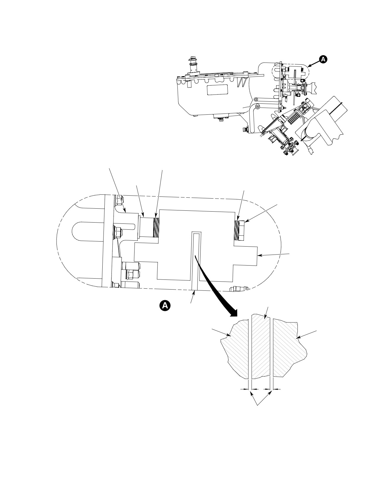
MD Helicopters, Inc.
CSP-HMI-2
MAINTENANCE MANUAL
AN960-616LL
CALIPER MOUNTING BOSS
WASHER
ON TRANSMISSION
(NOTE 1)
HS4620C19-29
AN960-616LL
BUSHING
WASHER
(NOTE 1)
NAS6606H52
BOLT
(NOTE 3)
CALIPER
ASSEMBLY
DISC
DISC
CALIPER
CALIPER
NOTES:
1.
CLEARANCE TO BE ADJUSTED BY VARYING WASHERS FROM EITHER SIDE
OF CALIPER ASSEMBLY.
NOTE 2
2.
CLEARANCE TO BE EQUAL WITHIN 0.032 IN. (0.8128 MM).
3.
TORQUE TO 160 - 190 INCH POUNDS (18.08 - 21.47 NM) AND SAFETY WITH
LOCKWIRE (CM702).
CSP102-010A
Figure 406. Rotor Brake Caliper Installation (369F5100 Transmission)
Page 411
63-22-00
Revision 20
CSP-HMI-2
MD Helicopters, Inc.
MAINTENANCE MANUAL
NOTE:
(5). Install plugs and tees in caliper
assembly, screw adapters on tees and
D AN960-616LL washers are to be used for
install bleed screws in adapters.
adjusting caliper-to-disc clearance.
(6). Connect tube assemblies and tee units
D Nine washers are used on each attaching
to tees.
bolt; those not used as shims should be
placed under bolt heads. Washer distribu
7. Hydraulic Relief Valve Replacement
tion should be the same for both bolts.
(Ref. Figure 401)
(1). Insert two bolts with equal number of
A. Hydraulic Relief Valve Removal
washers through the caliper (washers
can be on either side of caliper as
The hydraulic relief valve is attached by
needed) and install two bushings.
means of a clamp to the canted bulkhead 78.50
vertical member, and is connected hydraulical
NOTE: On the 369F5100 transmission, the
ly between the master cylinder assembly and
brake caliper bolts directly to the transmis
the caliper assembly. Remove the relief valve
sion.
as follows:
(1). Remove crew compartment hardware
(2). Mount the caliper assembly over disc
and fittings for access to hydraulic
and thread bolts into transmission.
relief valve assembly.
To ensure optimum brake opera
(2). Disconnect tube assembly from reducer
CAUTION
tion and minimize equipment
installed in relief valve. Disconnect
damage, caliper-to-disc clearances on both
tube assembly from relief valve, taking
sides of disc should be equal, or as nearly
special care to catch any hydraulic fluid
equal as possible. Clearance adjustment is
that drains or drips from tube assem
accomplished by varying number of 0.032
blies, reducer, or relief valve when the
inch (0.8128 mm) thick shim washers placed
system is opened. Remove reducer and
between the caliper assembly and transmis
O-ring packing from relief valve.
sion.
Discard O-ring packing.
(3). Measure brake caliper housing-to-disc
NOTE: Because of limited access, it may be
clearances on both sides of disc with a
more convenient to disconnect tube assem
feeler gage. If clearances are equal
bly from tee before removing tube assembly
within 0.032 inch (0.8128 mm), torque
from relief valve. If so, remove tube assem
attaching bolts to 160 - 190 inch-
bly from tee; remove relief valve and tube
pounds (18.08 - 21.47 Nm) and secure
assembly from helicopter; and remove tube
with lockwire (CM702).
from relief valve. Reinstall tube assembly on
tee finger tight for storage until required for
NOTE: Clearance differences greater than
replacement of relief valve.
0.032 inch (0.8128 mm) can be reduced by
(3). Remove screw, washer, and clamp, and
re-arranging washers on caliper attach
remove relief valve from canted bulk
bolts.
head 78.50 structure.
(4). To adjust clearances, hold caliper
(4). Install protective caps or plugs on open
assembly and unscrew bolts from
relief valve ports and open ends of
mounting bracket. Transpose washers
disconnected tube assembly to prevent
on bolts as required. Reassemble parts
entrance of contaminants.
and recheck clearances.
B. Hydraulic Relief Valve Installation
NOTE: If new caliper assembly was installed or
Installation procedures are essentially the
if hydraulic fittings were removed from old
reverse of removal procedures, with these
unit, coat all but first two threads of two
special considerations:
bleed screws, tees and plugs with thread
sealant (CM434) or equivalent.
(1). Install new O-ring packing on reducer.
Page 412
Revision 20
63-22-00
MD Helicopters, Inc.
CSP-HMI-2
MAINTENANCE MANUAL
(2). After relief valve is installed and
B. Hydraulic Tube Assembly Installation
connected into the hydraulic system, fill
Tube assembly installation is essentially the
and bleed the system.
reverse of removal procedures, with these
specific considerations.
(3). Reinstall components removed for
access to the hydraulic relief valve.
Consumable Materials
8. Hydraulic Tube Assembly Replacement
(Ref. Section 91−00−00)
Item
Nomenclature
(Ref. Figure 904)
CM418
Cement, epoxy
A. Hydraulic Tube Assembly Removal
(1). Make a straight radial cut into center
The hydraulic tube assembly is attached to the
hole of new grommet and install
main rotor mast pan and to the window
grommet on tube assembly. Position
channel by four clamps. It is connected
parts and bond grommet into slot in air
between tees. The assembly removal requires
baffle with epoxy cement (CM418).
access from the cargo/passenger compartment.
(2). Fill and bleed the hydraulic system.
(1).
Remove attaching screws and both (LH
(3). Reinstall components removed for
and RH) upper forward trim panel
access to the hydraulic tube assembly.
assemblies. Remove convenience panel
cover assembly. Remove attaching
9. Rotor Brake Forward Cover Assembly
screws and transmission cover panel
Installation
assembly.
(Ref. Figure 908)
(2).
Disconnect tube assembly from tees,
(1). Position cover assembly on map case
taking special care to catch any hydrau
assembly with rotor brake handle and
lic fluid that drains or drips from tube
handle retaining clip through cover
assembly or tees when system is
openings. Aft edge of cover must
opened.
overlap forward edge of convenience
panel cover assembly. Install attaching
(3).
Remove (and discard) grommet from
screw through cover assembly and map
tube assembly and air baffle.
case panel into isolation mount on
canted bulkhead 78.50 structure.
(4).
Remove nuts, washers, screws, clamps,
and tube assembly.
(2). On the 369D, secure cover assembly
and doublers to angle assembly with
(5).
If some time is to elapse before re-as
attaching screw. On the 369E/FF,
sembly, install protective caps on open
secure cover assembly to convenience
ends of tees to prevent entrance of
panel, using shims and attaching
contaminants.
screws.
Page 413
63-22-00
Revision 20
CSP-HMI-2
MD Helicopters, Inc.
MAINTENANCE MANUAL
This Page Intentionally Left Blank
Page 414
Revision 44
63-22-00
MD Helicopters, Inc.
CSP-HMI-2
MAINTENANCE MANUAL
ROTOR BRAKE
INSPECTION/CHECK
When working with hydrau
(5). Verify that clip (Ref. Figure 901) on
WARNING
lic systems, special care
handle retainer assembly holds brake
must be taken to prevent entrance of
handle securely in the stowed (raised)
dust, moisture. and other foreign mate
position.
rial. System contamination can cause
malfunctions that could result in inju
(6). Actuate brake handle to check that
ry to personnel and equipment dam
components of master cylinder linkage
age.
assembly (Ref. Figure 402) operate
freely without binding or excessive play
at pivot points. Verify that spring force
1. Rotor Brake Assembly Inspection
holds lever in BRAKE OFF position.
Consumable Materials
(7). Visually inspect friction surfaces of
(Ref. Section 91−00−00)
brake disc (Ref. Figure 403) for exces
Item
Nomenclature
sive wear, galling, scoring, cracking,
distortion, or other evidence of damage.
CM123
Hydraulic fluid
(8). Rotate the drive system and check that
caliper brake pucks are not dragging on
(1). Visually inspect rotor brake compo
the disc.
nents for general condition, security of
installation, and evidence of hydraulic
(9). Apply sufficient force on brake handle
fluid leakage.
to actuate master cylinder assembly to
pressurize hydraulic system.
NOTE: Excessively low fluid level indicates a
system fault that must be isolated and cor
NOTE: System pressurization (brake actua
rected.
tion) is indicated by the feel of firm resis
tance to handle movement. A cushioned
(2).
Disconnect tube assembly (Ref.
(spongy) feel indicates that the system con
Figure 902) from nipple installed in
tains air which must be removed (bled off)
master cylinder cap. Move end of tube
before proceeding with the inspection.
assembly carefully aside, remove
attaching screws and cap with gasket,
(10). Maintain force on brake handle and
and check that hydraulic fluid level is
verify that pistons in caliper assembly
1/8 - 1/4 inch (3.175-6.35 mm) from top
operate to force brake pucks against
of reservoir. If level is low, add hydrau
friction surfaces of brake disc. Visually
lic fluid (CM123). Take special care to
inspect brake pucks for extent of wear
avoid getting contaminants into the
and evidence of damage.
hydraulic system.
Do not apply a side load to brake
(3).
Visually inspect gasket for tears, cuts,
CAUTION
handle as damage to support
or other damage; replace gasket, if
bracketry may result.
defective. Visually inspect sealing
surfaces of cap and master cylinder
NOTE: Pucks must be extended to the BRAKE
body for nicks, cracks, scratches, or
ON position to permit adequate inspection.
other defects; repair minor damage or
If parting line between piston face and puck
replace defective parts.
is visible, puck is worn excessively and must
be replaced.
(4).
Replace cap and gasket on master
cylinder and secure with attaching
(11). Monitor feel of resistance and increase
screws. Connect tube assembly to
force applied to brake handle until
nipple and tighten tube nut securely.
hydraulic relief valve opens.
Page 601
63-22-00
Revision 20
CSP-HMI-2
MD Helicopters, Inc.
MAINTENANCE MANUAL
NOTE: When working properly, the hydraulic
(15). Raise brake handle to stowed position
relief valve opens and routes pressurized
and engage it in clip on handle retainer
hydraulic fluid back to the master cylinder
assembly.
reservoir when system pressure reaches 500
psig (3447 kPa). Valve opening can be de
2. Rotor Brake Operational Check
tected by a momentary decrease of resis
After rotor brake hydraulic system has been
tance to handle movement. If movement is
filled with fluid, an operational checkout of the
solidly resisted, regardless of force applied,
rotor brake installation must be performed.
the relief valve is defective and must be re
placed.
(1). Start engine, run up rotor to operating
speed, and then make a normal shut
(12). Maintain steady force (just short of that
down (refer to applicable Pilot's Flight
required to initiate relief valve opening)
Manual).
on brake handle and observe handle
movement. Check that actuating lever
Incorrect application of the ro
spacer and master cylinder stop do not
CAUTION
tor brake can result in sudden
contact.
stopping and kick-back of the main rotor, an
action which can cause damage to the rotor
Check for installation of master
CAUTION
blades and strap packs in the rotor hub. Col
cylinder stop to prevent over
lective pitch must never be applied to slow
travel of piston in master cylinder. If stop is
rotor rotation as this can cause damage to
not installed, damage to master cylinder
the rotor blades and strap packs. Applica
components may occur.
tion of a side load to brake handle may dam
NOTE: Continued handle movement indicates
age support bracketry.
the presence of an internal leak condition
(2). When rotor slows to approximately 205
which must be located and corrected.
or less rpm, disengage brake handle
(13). Release force on brake handle and
from retaining clip and pull handle
verify that caliper pistons (and attached
down to apply braking force. Make
brake pucks) are retracted.
certain that collective pitch stick is in
full down position, and that cyclic
NOTE: Failure of pistons to retract indicates
control stick is in neutral position.
that caliper assembly is defective and must
be overhauled or replaced.
(3). Release brake pressure during last
revolution of rotor.
(14). Reinstall components that were
removed for access to the rotor brake
(4). Raise brake handle to stowed position
system.
and engage it in handle retaining clip.
Page 602
Revision 20
63-22-00
MD Helicopters, Inc.
CSP-HMI-2
MAINTENANCE MANUAL
ROTOR BRAKE
INITIAL INSTALLATION
When working with hydrau
NOTE: A new design convenience panel cover
WARNING
lic systems, special care
assembly (Ref. Figure 908) must be in
must be taken to prevent entrance of
stalled to cover the aft portion of the brake
dust, moisture, or other foreign materi
master cylinder assembly.
al. Hydraulic system contamination
(4). Disconnect electrical wiring and
can cause malfunctions that could re
communications cables from compo
sult in injury to personnel or equip
nents on back of convenience panel
ment damage.
assembly. If cabin heating option is
installed on aircraft, disconnect heated
1. Rotor Brake Initial Installation
air duct from panel-mounted diffuser.
This section provides detailed instructions for
Remove attaching screws and conve
accomplishing initial installation of the rotor
nience panel assembly from aft side of
brake components into the aircraft. In general,
canted bulkhead 78.50 structure.
procedures are applicable to either left hand or
(5). Remove transmission cover panel
right hand command configurations. Where
assembly from fuselage structure.
pertinent, differences are specified.
(6). Cover exposed trim panels to prevent
Illustrations are included to provide data
damage and soiling.
pertinent to aircraft modifications required for
installation of the rotor brake components. All
(7). Remove main transmission from
items and tools required to install the rotor
aircraft (Ref. Sec. 63-20-00/25).
brake are standard and should be procured
locally. Alternate items of comparable charac
(8). Remove tail rotor (Ref. Sec. 64-20-00),
teristics and equal quality may be used.
tail rotor transmission (Ref. Sec.
63-25-10) and tail rotor drive shaft
A. Aircraft Preparation
(Ref. Sec. 63-15-10).
Preparation for installation of rotor brake
C. Removing Components to be Replaced
components include removal of certain original
Certain rotor brake and related components
equipment items to gain access, or for replace
are mounted on the main transmission, and
ment. Preparations also include permanent
are installed in the aircraft as a unit with the
installation of certain rotor brake components.
transmission. Some of these transmission-
B. Installation Access
mounted components replace similar item
counterparts that were used in the original
NOTE: The main transmission must be re
installation.
moved from the aircraft to permit installa
(1). The tail rotor drive coupling installed
tion of the transmission-mounted rotor
on the transmission output shaft must
brake components.
be replaced by a new drive coupling on
(1). Remove both crew compartment and
which the brake disc is mounted.
cargo/passenger compartment doors.
Remove coupling and failsafe device (if
used) from transmission output shaft
(2). Remove crew compartment seats.
(Ref. Sec. 63-15-10). Leave laminated
shim washers on output shaft and
(3). Remove map case assembly from
retain coupling bolt for reassembly use.
forward side of canted bulkhead 78.50
structure. Remove both (LH and RH)
(2). The tachometer generator installed on
upper forward panel assemblies from
the tail rotor cover assembly on main
bulkhead structure. Remove conve
transmission must be replaced by a new
nience panel cover assembly from
unit that provides clearance for the
convenience panel assembly.
rotor brake disc. Remove attaching nuts
Page 901
63-22-00
Revision 20
CSP-HMI-2
MD Helicopters, Inc.
MAINTENANCE MANUAL
and washers, tachometer generator and
(4). Attach angle assembly to shoulder
gasket from tail rotor cover assembly.
beam with blind rivets.
Retain nuts and washers for re-as
sembly use. Tachometer generator will
E. Master Cylinder Linkage Assembly and
not be reinstalled. Discard gasket.
Mount Bracket Installation
(3). The tail rotor cover assembly is in
(Ref. Figure 901) The master cylinder linkage
stalled on the main transmission
assembly bracket must be installed on canted
housing with nuts and washers in
bulkhead 78.50 vertical member as a means of
stalled on twelve studs. Four of the
attachment for the master cylinder assembly
studs, with special nuts and washers,
and the other components of the master
will be used for installing the rotor
cylinder linkage assembly.
brake caliper mounting bracket.
Remove four nuts and washers (at 1, 2,
Consumable Materials
10, and 11 o'clock positions). These nuts
(Ref. Section 91−00−00)
and washers will not be used at
Item
Nomenclature
reinstallation.
CM318
Primer
D. Angle Assembly Installation (500D)
(Ref. Figure 901) The angle assembly must be
NOTE: Because of its method of attachment, it
installed on canted bulkhead 78.50 shoulder
may be more convenient to install the link
beam as a means of attachment for the
age assembly bracket and then assemble
convenience panel cover assembly and the
the other components on the bracket. Al
rotor brake forward cover assembly.
though the procedures given in steps (1).
thru (3). below consider installation of the
assembly, they are also applicable for instal
Consumable Materials
lation of the bracket. Steps (4). thru (7). be
(Ref. Section 91−00−00)
low describe procedures for assembling com
Item
Nomenclature
ponents to the bracket.
CM318
Primer
(1).
Position master cylinder linkage
assembly on canted bulkhead 78.50
(1). Lay out and mark location for angle
vertical member. Hold assembly (with
assembly on portion of forward bulk
bracket) firmly in position as a guide
head aft panel assembly that covers
and use a No. 15 drill bit to line drill
canted bulkhead 78.50 shoulder beam.
four holes in vertical member, taking
care to prevent point of drill bit from
(2). Insert piece of cardboard (or similar
penetrating into vertical member more
material) under aft panel assembly to
than 1/4 inch (6.35 mm).
protect shoulder beam and use a sharp
knife to make panel cut out to accom
(2).
Line ream holes 0.199-0.202 inch
modate angle assembly, taking special
(5.0546-5.1308 mm) diameter. Remove
care not to cut outside marked area.
linkage assembly, deburr holes in both
parts, and touch up raw metal surfaces
(3). Position angle assembly on shoulder
with primer (CM318).
beam as a guide and drill two
0.128-0.132 inch (3.2512-3.3528 mm)
(3).
Attach bracket to vertical member with
diameter holes through angle assembly
Jo-bolt blind fasteners.
and one wall of shoulder beam, taking
care that point of drill bit does not
(4).
Secure pin (Ref. Figure 402) in bracket
penetrate into shoulder beam more
with nut and washer.
than 1/4 inch (6.35 mm). Deburr holes
in both parts and touch up raw metal
(5).
Install grip on handle. Install new roll
surfaces with primer (CM318).
pins through handle and fitting.
Page 902
Revision 20
63-22-00
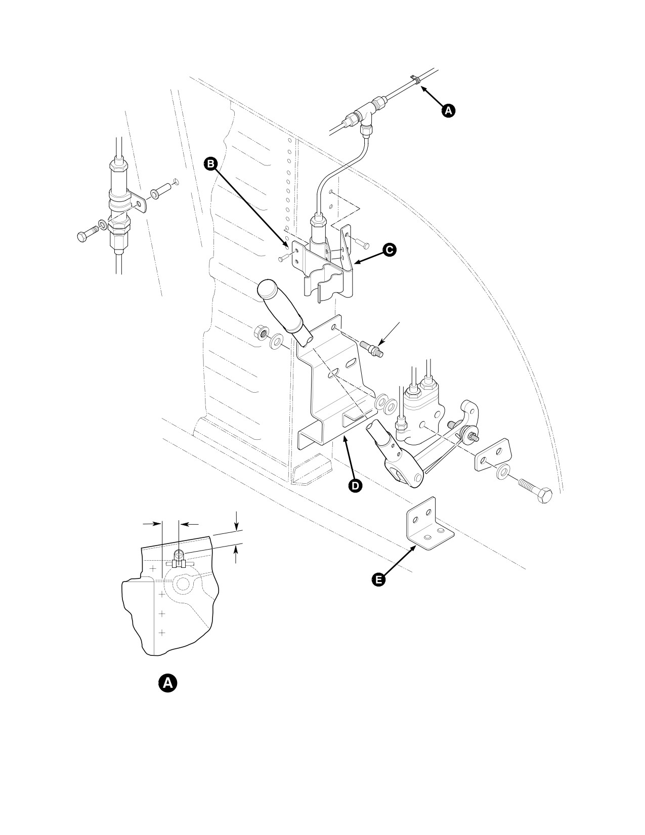
MD Helicopters, Inc.
CSP-HMI-2
MAINTENANCE MANUAL
RIGHT-HAND
INSTALLATION
JO-BOLT
0.75 IN.
(19.05 MM)
0.50 IN.
(12.70 MM)
NOTE:
LEFT-HAND INSTALLATION SHOWN, RIGHT-HAND
OPPOSITE EXCEPT WHERE NOTED.
G63-2012-1
Figure 901. Locating Permanently Installed Components (Sheet 1 of 2)
Page 903
63-22-00
Revision 20
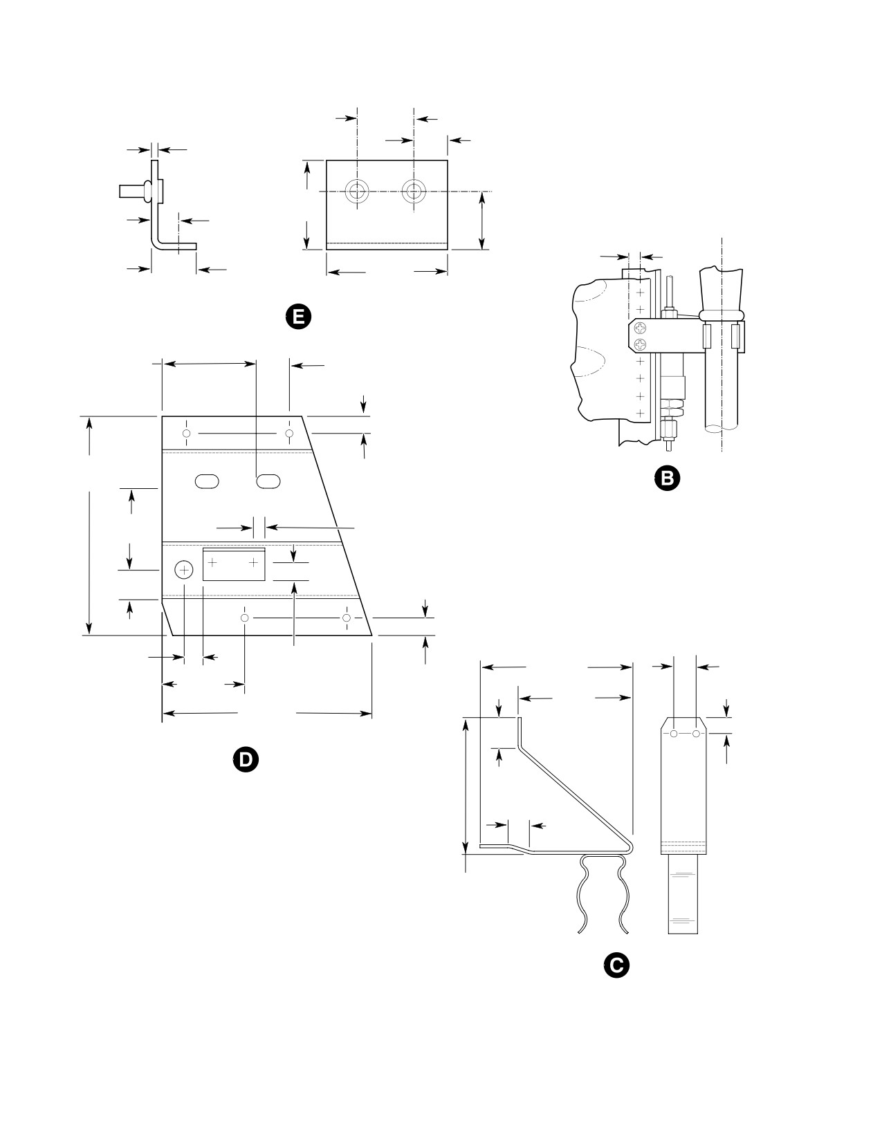
CSP-HMI-2
MD Helicopters, Inc.
MAINTENANCE MANUAL
1.00 IN.
(2.54 CM)
0.50 IN.
0.063 IN.
(1.6002 MM)
(12.70 MM)
(STOCK)
1.50 IN.
0.47 IN.
(3.81 CM)
1.00 IN.
(11.938 MM)
(2.54 CM)
0.31 IN.
0.75 IN.
(7.87 MM)
2.00 IN.
(19.05 MM)
(5.08 CM)
2.26 IN.
0.54 IN.
(5.7404 CM)
(13.716 MM)
4.80 IN.
0.38 IN.
(12.192 CM)
(9.652 MM)
1.80 IN.
0.25 IN.
(4.572 CM)
(TYP)
(6.35 MM)
0.70 IN.
(17.78 MM)
0.40 IN.
0.38 IN.
3.07 IN.
0.50 IN.
(10.16 MM)
(9.652 MM)
0.38 IN.
(7.7978 CM)
(12.70 MM)
0.50 IN.
(TYP)
(9.652 MM)
(12.7 MM)
2.38 IN.
4.57 IN.
(6.0452 CM)
(11.6078 CM)
0.32 IN.
0.62 IN.
(8.128 MM)
(15.748 MM)
0.50 IN.
(12.70 MM)
23.80 IN.
(60.452 CM)
HANDLE RETAINER ASSY
G63-2012-2
Figure 901. Locating Permanently Installed Components (Sheet 2 of 2)
Page 904
Revision 20
63-22-00

MD Helicopters, Inc.
CSP-HMI-2
MAINTENANCE MANUAL
(6). Install bolt, spacer, and nut on lever.
Remove retainer assembly and use a
Attach assembled handle parts to lever,
1/8 inch (3.175 mm) drill bit to drill out
with clevis pin, washers, and new cotter
marked rivets.
pin.
(3). Lay out hole patterns on handle
When parts are assembled,
retainer assembly to match drilled rivet
WARNING
spring force is constantly ex
holes. Use No. 30 drill bit to drill two
erted to inhibit inadvertent brake
holes in retainer.
application. Care must be taken as the
spring is engaged to prevent injury to
(4). Cleco retainer assembly in place. Use
personnel or equipment damage.
retainer as guide and use a No. 15 drill
bit to drill two holes into face of vertical
(7). Install lever with attached parts, and
member. Remove handle retainer
spring on pin and secure with washer,
assembly from vertical member.
nut, and new cotter pin. Engage free
end of spring under head of clevis pin.
(5). Deburr holes and touch up with primer
(CM318).
F. Handle Retainer Assembly Installation
(6). Attach handle retainer assembly to
(Ref. Figure 901) The handle retainer assem
vertical member with four blind rivets.
bly must be installed on canted bulkhead 78.50
vertical member to secure the rotor brake
G. Rivnut Installation
operating handle in the stowed (raised)
position.
(Ref. Figure 902) A rivnut must be installed in
the main rotor mast pan as an attachment
point for one of the clamps used to secure
Consumable Materials
hydraulic tube assembly. For R/H rotor brake
(Ref. Section 91−00−00)
installation, a rivnut must be installed in the
Item
Nomenclature
canted bulkhead 78.50 vertical member for
CM318
Primer
attachment of the hydraulic relief valve.
NOTE: The master cylinder linkage assembly
Consumable Materials
must be installed so that the handle retain
(Ref. Section 91−00−00)
er assembly can be positioned correctly.
Item
Nomenclature
CM318
Primer
(1). Position handle retainer assembly on
canted bulkhead 78.50 vertical member
so that when rotor brake operating
Care must be taken when drill
handle is in the stowed position,
CAUTION
ing the mast pan for rivnut in
retainer clip engages handle just below
stallation to prevent damage to wiring har
the rubber grip.
nesses which are installed on the upper side
of the pan, or to critical structure members
To prevent damage to compo
CAUTION
to which the pan is riveted. A drill stop or
nents, point of drill bit must not
other suitable means should be used to pre
be allowed to penetrate through wall of ver
vent point of drill from penetrating more
tical member more than 1/4 inch (6.35 mm).
than 1/4 inch (6.35 mm) into vertical mem
NOTE: The tunnel beam web is secured to the
ber.
vertical members by a series of rivets. Two
(1). Lay out location for hole in transmis
of these rivets must be removed and re
sion pan. Use 1/4 inch (6.35 mm) drill
placed by rivets that also attach the handle
retainer assembly.
bit to drill hole through pan, deburr
hole, and touch up raw metal surfaces
(2). Mark two rivets on front of vertical
with primer (CM318). Install rivnut in
member that most closely match
accordance with standard shop practice
position of handle retainer assembly.
and manufacturer's instructions.
Page 905
63-22-00
Revision 20
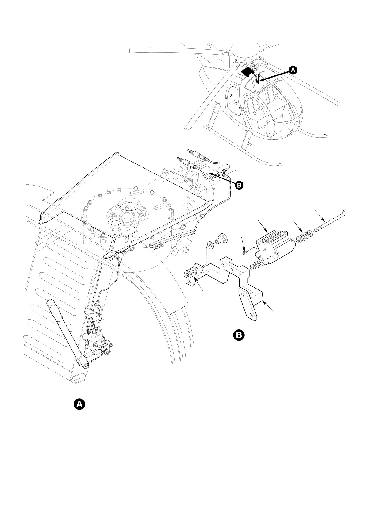
CSP-HMI-2
MD Helicopters, Inc.
MAINTENANCE MANUAL
BOLT
BRAKE CALIPER
WASHERS
BLEED
SCREW
WASHERS
MOUNTING BRACKET
(369D25100 TRANSMISSION)
BRAKE CALIPER INSTALLATION
(369D25100 TRANSMISSION
INSTALLATION SHOWN)
MASTER CYLINDER INSTALLATION
G63-2013-1B
Figure 902. Rotor Brake Installation (Sheet 1 of 2)
Page 906
Revision 20
63-22-00
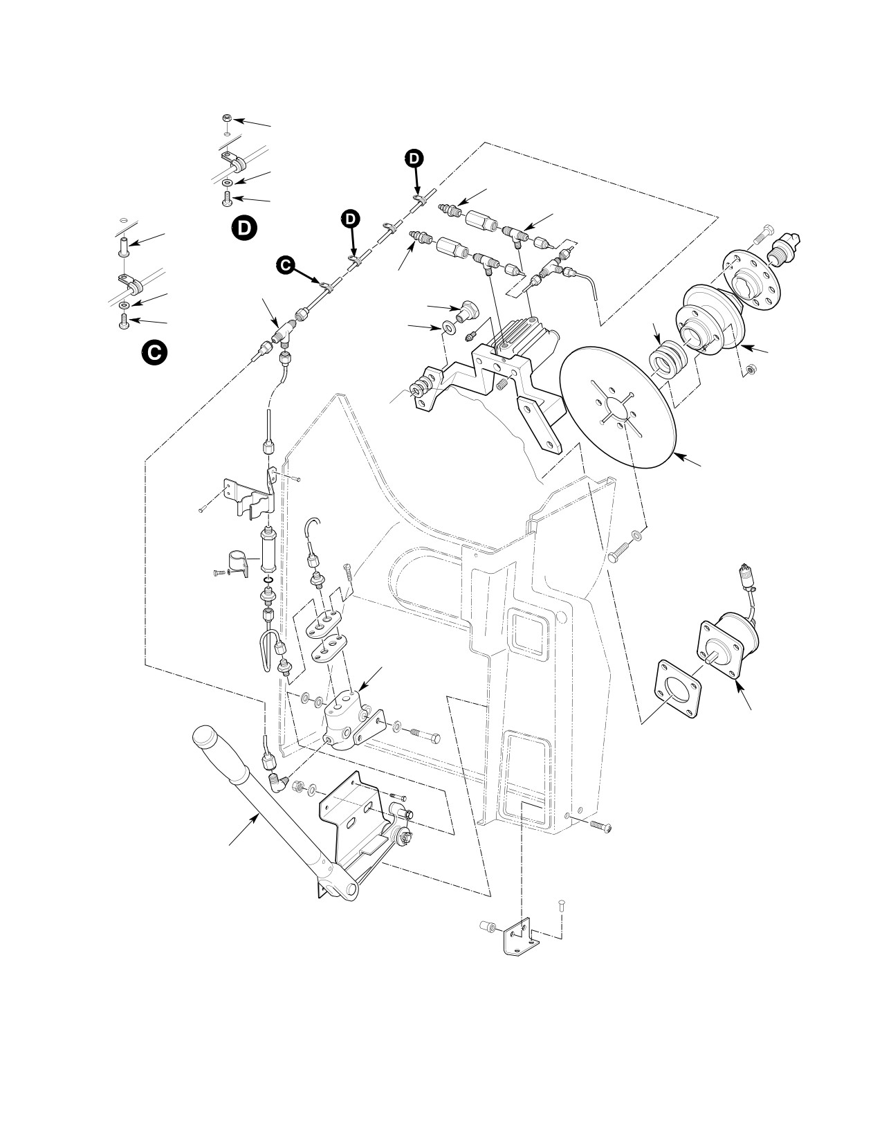
MD Helicopters, Inc.
CSP-HMI-2
MAINTENANCE MANUAL
NUT
CLAMP
BLEEDSCREW
SCREW
TEE
WASHER
RIVNUT
BLEEDSCREW
CLAMP
TEE
SPECIAL NUT
SHIM
SCREW
WASHER
WASHER
COUPLING
DISC
MASTER
CYLINDER
TACH
GENERATOR
HANDLE
ASSEMBLY
G63-2013-2A
Figure 902. Rotor Brake Installation (Sheet 2 of 2)
Page 907
63-22-00
Revision 20
CSP-HMI-2
MD Helicopters, Inc.
MAINTENANCE MANUAL
(2). Lay out location for hole in vertical
in tail rotor cover assembly for use as
member. Use 1/4 inch (6.35 mm) drill
spacers. Position caliper mounting
bit to drill hole through outer face of
bracket on studs and secure with
vertical member. Deburr hole and touch
washers and nuts. Torque nuts to 50 -
up raw metal surfaces with primer.
70 inch-pounds (5.65 - 7.91 Nm).
Install rivnut in accordance with
standard shop practice and manufac
(2). Secure installation with lockwire
turer's instructions.
(CM702).
H. Window Support Channel Modification
J. Caliper Assembly, Brake Disc and Drive
Coupling Installation
(Ref. Figure 903) Three clamps are used to
attach hydraulic tube assembly to the window
(Ref. Figure 902) The caliper assembly is
support channel. Modifications to the channel
bolted to a mounting bracket which is installed
are required to accommodate two of the
on the main transmission tail rotor cover. The
clamps.
brake disc is bolted on the drive coupling
which is installed on the transmission output
shaft. For clarity, the brake disc and drive
Consumable Materials
coupling are considered as a single item,
(Ref. Section 91−00−00)
herein referred to as the disc/coupling unit.
Item
Nomenclature
Although the caliper assembly and the
CM318
Primer
disc/coupling unit are not mechanically
connected, they are installed on the transmis
sion with the outer portion of the disc posi
(1). Use 1/8 inch (3.175 mm) drill bit to
tioned between the two halves of the caliper
remove one (3rd rivet from front) of the
assembly. This arrangement makes it neces
four rivets used to attach forward
sary to install both units at the same time.
nutplate angle clip to channel. Enlarge
hole to 0.188-0.218 inch (4.7752-5.5372
Consumable Materials
mm) with 3/16 inch (4.7625 mm) drill
(Ref. Section 91−00−00)
bit, deburr hole, and touch up raw
Item
Nomenclature
metal surfaces with primer (CM318).
CM113
Anti-seize compound low temperature
(2). Lay out location for hole in channel as
CM117
Grease
shown. Use 3/16 inch (4.7625 mm) drill
CM434
Thread sealant
to drill hole in channel, deburr hole,
and touch up raw metal surfaces with
CM702
Lockwire CRES
primer.
Axial positioning of the
I. Caliper Mounting Bracket Initial
WARNING
drive coupling is critical as
Installation
it controls the mechanical interface be
(Ref. Figure 902) The caliper mounting bracket
tween the coupling and the tail rotor
is installed on four of the twelve studs used to
drive shaft. Excessive axial loads can
secure the tail rotor cover assembly on the
contribute to coupling failure which
main transmission housing.
could result in injury to personnel or
equipment damage. Refer to Section
63-15-10 for shimming procedures for
Consumable Materials
installing coupling disc on shaft.
(Ref. Section 91−00−00)
Item
Nomenclature
NOTE: Before installing caliper, brake disc and
CM702
Lockwire CRES
drive coupling, install new tachometer gen
erator and gasket. Ensure that mechanical
drive components are correctly engaged and
(1). Place three washers on each of the four
electrical receptacle is at the 11 o'clock posi
studs (1, 2, 10, and 11 o'clock positions)
tion.
Page 908
Revision 20
63-22-00
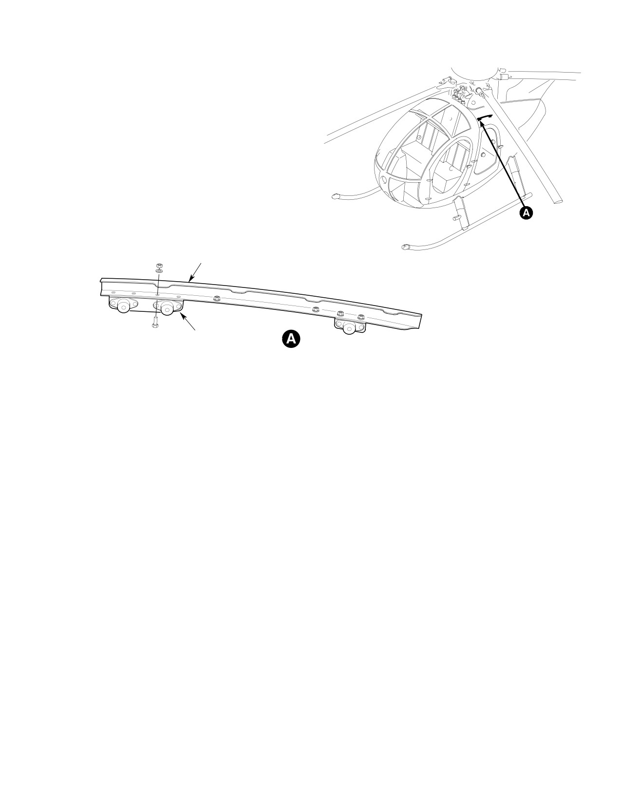
MD Helicopters, Inc.
CSP-HMI-2
MAINTENANCE MANUAL
369D23012-5 REF
369D23012-13 REF
G63-2019
Figure 903. Modifying Window Support Channel
(1).
Measure (with a micrometer) and
on tees, and install bleed screws in
record thickness of brake disc at four
adapters. Remove and discard hard
locations around the disc. Calculate and
ware used to hold caliper halves
record average of thickness measure
together.
ments.
NOTE: The caliper assembly consists of two
(2).
Position brake disc on tail rotor drive
identical halves. When received, the halves
coupling with raised center side of disc
are held together by commercial hardware.
seated firmly on shoulder of coupling
This hardware is replaced by qualified stan
and with bolt holes aligned. Secure disc
dard hardware which also secures the cali
to coupling with attaching hardware
per assembly on the mounting bracket.
and torque nuts (in an alternating
sequence) to 100 - 140 inch-pounds
(5). Insert bolts through one caliper half,
(11.30 - 15.82 Nm).
position assembled parts of mounting
bracket and screw bolts into bracket
(3).
Measure (with an inside micrometer)
finger tight to maintain alignment of
and record gap between brake puck
caliper half. Use a C-clamp or other
faces. Subtract brake disc thickness
suitable means to clamp caliper half
calculated in step (1). from gap mea
firm against bracket.
surement and divide the difference by
two to determine the optimum puck-to-
(6). Coat, completely but sparingly, splines
disc clearance.
of transmission output shaft with
(4).
Remove bleed screws from ports in ends
grease (CM117) and threads of coupling
of caliper assembly. Coat all but first
with anti-seize compound (CM113), or
two threads of bleed screws, tees, and
equivalent. Install coupling/disc unit on
plugs with thread sealant (CM434).
shaft and install bolt into end of shaft
Install plugs in bleed screw ports and
to ensure that coupling is seated firmly
tees in caliper bodies, install adapters
against shim washers on shaft.
Page 909
63-22-00
Revision 20
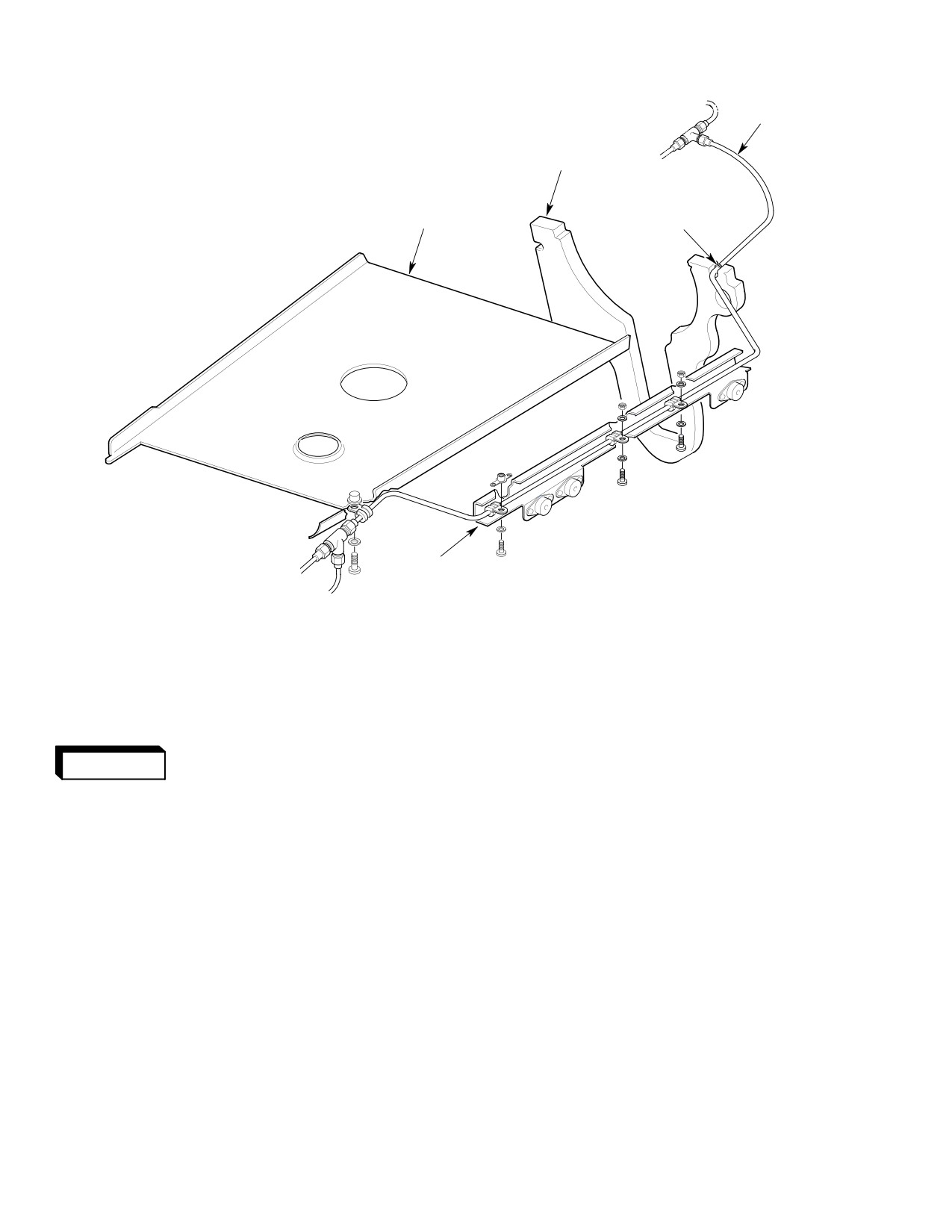
CSP-HMI-2
MD Helicopters, Inc.
MAINTENANCE MANUAL
TUBE ASSY
BAFFLE ASSY
MAST SUPPORT
PAN
GROMMET
NOTE:
CHANNEL ASSY
LEFT-HAND INSTALLATION
G63-2020
RIGHT-HAND OPPOSITE
Figure 904. Hydraulic Tube Installation
The caliper assembly must
NOTE: Fore-and-aft positioning of the caliper
WARNING
be installed so that caliper-
assembly, which determines the puck-to-
to-disc clearances on both sides of disc
disc clearance relationship, is established by
are approximately equal. Improper in
installing shim washers between the caliper
stallation can cause malfunctions
assembly and the mounting bracket. Nine
which could result in injury to person
washers are provided for each attaching
nel or equipment damage.
bolt; those not required for shimming must
be installed under the bolt heads.
(7). Measure gap between brake caliper
(8). Remove bolts and place the correct
housing and forward face of disc with a
number (nine less the number required
thickness gage. Subtract desired
for shimming) of washers on each bolt.
caliper-to-disc clearance calculated in
Insert bolts through caliper halves and
step (3). from this measurement to
screw one bolt finger tight into mount
determine amount of shimming (wash
ing bracket. Release clamped caliper
ers) to be installed between caliper
half and move it away from bracket,
assembly and mounting bracket. Divide
place required number of shim washers
the difference by 0.032 inch (0.8128
on second bolt as it is pushed through
mm) (washer thickness) to determine
caliper assembly, and screw bolt into
number of shim washers needed.
bracket a few turns. Repeat procedure
Page 910
Revision 20
63-22-00
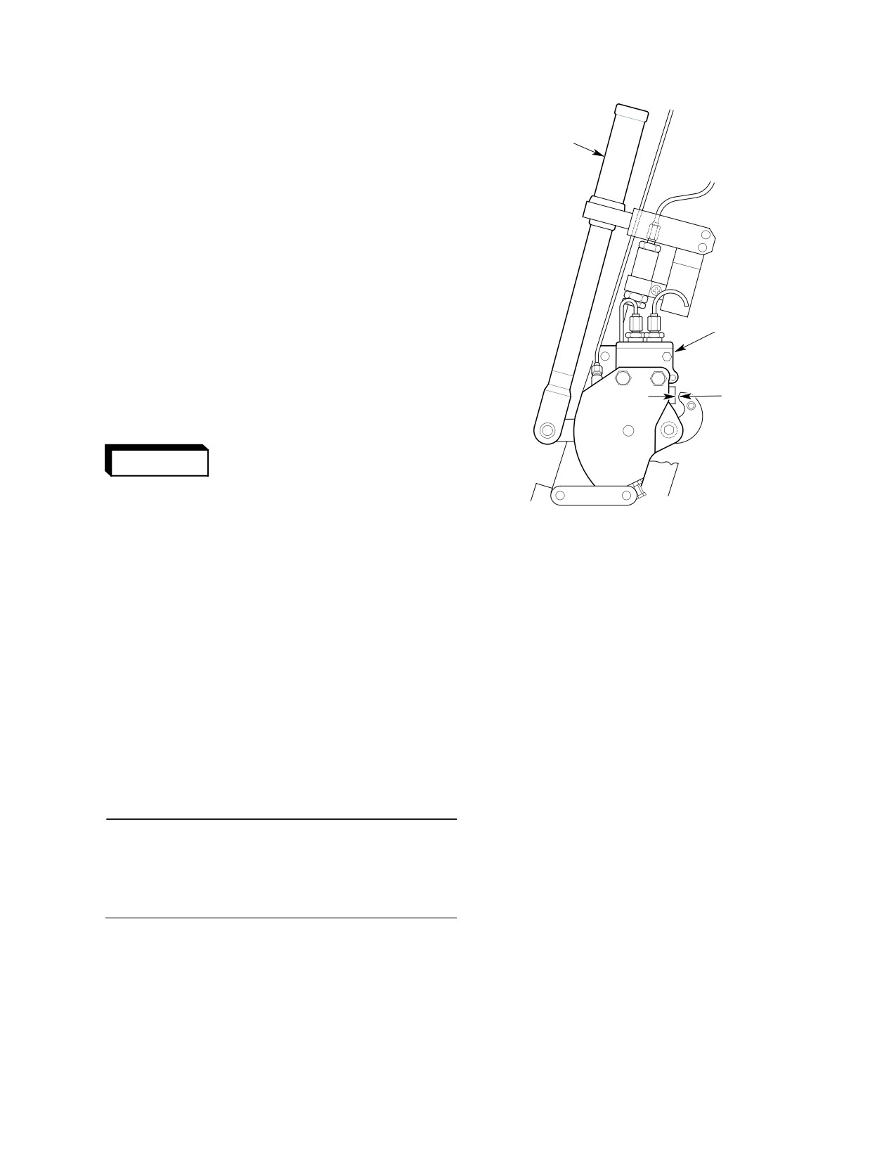
MD Helicopters, Inc.
CSP-HMI-2
MAINTENANCE MANUAL
to install shim washers on other bolt.
Tighten bolts firmly to secure installa
4389 GRIP
tion.
(1 REQD)
(9). Check caliper-to-disc clearances with a
thickness gage. If clearances are
approximately equal, torque mounting
bolts to 160 - 190 inch pounds (18.08
- 21.47 Nm) and secure with lockwire
(CM702). Torque coupling bolt to 250 -
300 inch-pounds (28.25 - 33.90 Nm)
plus drag torque.
MASTER
CYLINDER
(10). After the rotor brake components have
been installed on the main transmis
sion, the built-up unit must be in
stalled in the aircraft (Ref. Sec.
0.02 IN. (0.508 MM)
GAP
0.04 IN. (1.016 MM)
63-20-00/25).
The main transmission must
WARNING
be installed in the aircraft
with special care to avoid damage to
rotor brake components. Installation
G63-2022A
damage could lead to system failure
which could result in injury to person
Figure 905. Positioning Master Cylinder
nel or equipment damage.
(3). Install new cap and reworked gasket on
master cylinder with attaching screws
(11). If tachometer generator is installed on
transmission, connect electrical plug
installed finger tight.
(P202) on aircraft wiring harness to
(4). Coat all but first two tapered pipe
receptacle on tachometer generator.
threads of nipples and elbow with
thread sealant (CM434). Install nipples
K. Master Cylinder Assembly Initial
in cap and elbow in master cylinder.
Installation
(5). Place one washer on each bolt, place
(Ref. Figure 902) The master cylinder assem
stop on bolts and insert bolts through
bly is mounted on the master cylinder linkage
master cylinder. Place two washers on
assembly bracket.
each bolt as spacers. Position as
sembled parts on linkage assembly
bracket and secure installation with
Consumable Materials
washers and nuts. Tighten nuts only
(Ref. Section 91−00−00)
finger tight.
Item
Nomenclature
NOTE: Mounting holes in bracket are elon
CM434
Thread sealant
gated to enable lateral position adjustment
of master cylinder assembly.
(1). Remove attaching screws and vendor-
(6). With actuating handle in stowed
supplied cap from master cylinder.
position, adjust position of master
Vendor cap is not used.
cylinder assembly so that clearance
(measured with a thickness gage)
(2). Rework vendor-supplied gasket (Ref.
between actuating lever (Ref.
Figure 906).
Figure 905) and master cylinder piston
Page 911
63-22-00
Revision 20
CSP-HMI-2
MD Helicopters, Inc.
MAINTENANCE MANUAL
is 0.020-0.040 inch (0.508-1.016 mm).
ing hardware loosely to hold clamps
Tighten nuts to hold master cylinder
(and tube assembly) to pan and window
assembly firmly in position.
channel.
L. Hydraulic Relief Valve Initial Installation
(4). Connect tube assembly loosely to elbow
in master cylinder and to tee.
(Ref. Figure 902) The hydraulic relief valve is
attached by means of a clamp to the canted
(5). With all tube assemblies and fittings
bulkhead 78.50 vertical member, and is
connected, tighten nuts on tube assem
connected hydraulically, by means of tube
blies. Tighten attaching hardware for
assemblies, between the master cylinder
all clamps.
assembly and the caliper assembly.
NOTE: It is not necessary to tighten tube as
(1). Place new O-ring on reducer and screw
sembly nuts at this time. The tube assembly
reducer into relief valve. Connect relief
will have to be removed to permit filling the
valve to tube assembly and tighten tube
hydraulic system.
nut. Install clamp on relief valve.
(6). Connect tube assembly to nipple in
(2). Position assembled parts with relief
master cylinder cap and tighten tube
valve in ``V'' of handle retainer assem
nut.
bly. Install attaching hardware loosely
N. Rotor Brake Installation Servicing
to hold assembled parts on canted
bulkhead 78.50 vertical member.
After all operating components of the rotor
brake system have been installed, the hydrau
NOTE: Screw is threaded into nutplate for LH
lic system must be filled with hydraulic fluid
installation, and into rivnut for RH installa
and have all entrapped air bled off. Refer to
tion.
Rotor Brake Hydraulic System Bleeding.
M. Hydraulic Tube Assemblies Initial
Installation
0.50 IN. (12.70 MM) DIA.
0.56 IN.
0.56 IN.
(Ref. Figure 902) Two tube assemblies are
(14.224 MM)
(14.224 MM)
installed to connect the master cylinder
assembly and the caliper assembly.
Consumable Materials
(Ref. Section 91−00−00)
Item
Nomenclature
CM418
Cement, epoxy
(1). Connect tee loosely to tube assembly.
Make straight radial cut into center
hole of grommet and install grommet
and clamps on tube assembly.
(2). Position assembled parts on window
channel so that grommet can be
engaged in slot of air baffle. Connect
tube assembly loosely to tee on caliper
assembly and connect tee loosely to
EXISTING HOLES
tube assembly on hydraulic relief valve.
G63-2021A
(3). Bond grommet into air baffle slot with
Figure 906. Reworking Master Cylinder
epoxy cement (CM418). Install attach
Gasket
Page 912
Revision 20
63-22-00
MD Helicopters, Inc.
CSP-HMI-2
MAINTENANCE MANUAL
O. Installing Interior Furnishings
to be drilled on rotor brake forward
cover panel.
After the operating components of the rotor
brake installation have been checked out, the
(3). Use No. 42 drill bit to drill holes at
various items of interior furnishings (trim
marked location for attaching screws.
panels, cover assemblies, seats, etc.) and the
fuselage doors must be reinstalled. This
NOTE: It may be more convenient to remove
includes those items that are specific for the
convenience panel cover assembly while
rotor brake installation, and those that were
drilling hole.
removed to permit access for installing the
rotor brake components.
(4). On the 5000D, secure convenience
panel cover assembly with doublers to
P. Map Case Assembly Modification and
angle assembly with attaching screw.
Installation
On the others, the convenience panel
cover assembly will be permanently
(Ref. Figure 907) Before the map case assem
fastened down when mated with the
bly can be reinstalled, it must be modified to
rotor brake forward cover assembly.
accommodate the rotor brake forward cover
assembly.
R. Rotor Brake Forward Cover Assembly
Installation
(1). Mark map case panel for cutout. Use a
sharp knife to cut out marked area,
(Ref. Figure 908) The rotor brake forward
taking special care to avoid cutting
cover assembly mates with the convenience
outside of marked area.
panel cover assembly to enclose and protect
the rotor brake components (master cylinder,
(2). Install map case assembly on canted
etc.) installed on the canted bulkhead 78.50
bulkhead 78.50 structure with three
structure. It is installed over the forward
attaching screws.
portion of the master cylinder assembly and
incorporates cutouts to accommodate the
NOTE: A fourth screw will also be used to at
brakes handle and retaining clips.
tach the rotor brake forward cover assembly
(Ref. Figure 908).
(1). Position rotor brake forward cover
assembly on map case assembly with
Q. Convenience Panel Cover Assembly
aft edge overlapping forward edge of
Modification and Installation
convenience panel cover assembly and
(Ref. Figure 908) The convenience panel cover
with brake and retaining clips extend
assembly mates with the rotor brake forward
ing through cutouts.
cover assembly to enclose and protect the rotor
brake components installed on the canted
NOTE: If aircraft is equipped with optional
bulkhead 78.50 structure.
particle separator, it may be necessary to
trim the forward cover assembly for clear
(1). Position new convenience panel cover
ance.
assembly with the aft edge overlapping
the forward edge of the transmission
(2). On the 500D, mark location for hole in
cover panel. Install attaching screws to
upper corner of forward cover assembly
hold panels in position.
to line up with isolator mount, and in
lower corner to line up with nutplate in
(2). On the 500D, mark location for hole in
angle assembly on canted bulkhead
the forward corner of convenience panel
78.50 shoulder beam. On the others,
cover assembly to line up with nutplate
mark location for hole in upper corner
on angle assembly on canted bulkhead
of forward cover assembly to line up
78.50 shoulder beam. On the others,
with isolator mount and in upper and
mark location for holes in forward
lower outboard corners to line up
corner of convenience panel cover
parallel with holes previously drilled in
assembly to line up parallel with holes
the convenience panel cover assembly.
Page 913
63-22-00
Revision 20
CSP-HMI-2
MD Helicopters, Inc.
MAINTENANCE MANUAL
3.00 IN. (7.62 CM)
27.25 IN.
(69.22 CM)
23.38 IN.
(59.39 CM)
18.25 IN.
(46.36 CM)
369E/FF
15.00 IN.
(38.10 CM)
9.87 IN.
(25.07 CM)
369D
G63-2015A
Figure 907. Modifying Map Case Panel
Page 914
Revision 20
63-22-00
MD Helicopters, Inc.
CSP-HMI-2
MAINTENANCE MANUAL
0.220-0.226 IN. (5.588-5.7404 MM)
DIA. HOLE TO MATCH MAP CASE
ASSEMBLY AND ISOLATOR
MOUNT
DRILL 0.220-0.226 IN.
(5.588-5.7404 MM)
DIA. HOLE (2 PLCS)
SHIM
3.00
2.00 IN.
(50.80 MM)
SHIM
1.50 IN.
(38.10 MM)
DRILL 0.220-0.226 IN.
(5.588-5.7404 MM)
DIA. HOLE (2 PLCS)
369E/FF
G63-2018-1A
Figure 908. Modifying Rotor Brake Cover Panel Assemblies (Sheet 1 of 2)
Page 915
63-22-00
Revision 20
CSP-HMI-2
MD Helicopters, Inc.
MAINTENANCE MANUAL
DRILL 0.220-0.226 IN. (5.588-5.7404 MM)
DIA. HOLE TO MATCH NUTPLATE
DRILL 0.220-0.226 IN. (5.588-5.7404 MM)
DIA. HOLE TO MATCH MAP CASE
ASSEMBLY AND ISOLATOR MOUNT
NOTE:
LEFT-HAND ROTOR BRAKE INSTALLATION SHOWN,
RIGHT-HAND INSTALLATION OPPOSITE.
G63-2018-2A
Figure 908. Modifying Rotor Brake Cover Panel Assemblies (Sheet 2 of 2)
Page 916
Revision 20
63-22-00
MD Helicopters, Inc.
CSP-HMI-2
MAINTENANCE MANUAL
(3). Use No. 42 drill bit to drill holes at
the outboard edge of forward cover
marked locations for attaching screws.
assembly and convenience panel cover
assembly.
NOTE: It may be more convenient to remove
(5). Push panel boot aft on brake handle
forward cover panel assembly while drilling
approximately 2 inches (5.08 cm) and
holes.
secure boot fastener tape.
(4). Secure forward cover assembly and
S. Weight and Balance
map case panel assembly with attach
ing screws. On the 500D, install screw
(Ref. Table 901) After installing the rotor
through nutplate in angle assembly. On
brake, incorporate changes in helicopter
the others, install screws into shims on
weight and balance record.
Table 901. Weight and Balance Data
Configuration
Weight
Arm
Moment
lb
(kg)
in.
(cm)
in−lb (kg−cm)
500D (left side)
Added
+7.5 (+3.40)
106.6
(270.764)
+800 (9216.96)
Removed
0.0
−
0.0
Changed
+7.5 (+3.40)
106.6
(270.764)
+800 (9216.96)
500D (right side)
Added
+6.8 (3.08)
108.9
(276.606)
+741 (8537.21)
Removed
0.0
−
0.0
Changed
+6.8 (3.08)
108.9
(276.606)
+741 (8537.21)
369E/FF − 500N (left and right)
Added
+7.5 (+3.40)
106.5
(270.51)
+799 (9205.44)
Removed
0.0
−
0.0
Changed
+7.5 (+3.40)
106.5
(270.51)
+799 (9205.44)
600N (left and right)
Added
+7.6 (+3.45)
98.4
(294.44)
+748 (862.3)
Removed
0.0
−
0.0
Changed
+7.6 (+3.45)
98.4
(294.44)
+748 (862.3)
Page 917
63-22-00
Revision 20
CSP-HMI-2
MD Helicopters, Inc.
MAINTENANCE MANUAL
This Page Intentionally Left Blank
Page 918
Revision 44
63-22-00
MD Helicopters, Inc.
CSP-HMI-2
MAINTENANCE MANUAL
Section
63−25−10
Tail Rotor
Transmission (Two
and Four Blade)
(369D/E/FF)
MD Helicopters, Inc.
CSP-HMI-2
MAINTENANCE MANUAL
TAIL ROTOR TRANSMISSION (TWO AND FOUR BLADE)
MAINTENANCE PRACTICES
1. Tail Rotor Transmission
Do not carry or otherwise sup
CAUTION
port transmission by coupling,
(Ref. Figure 201) The tail rotor transmission is
as coupling diaphragm may be permanently
a right-angle transmission with a magnesium
distorted. During performance of all mainte
alloy housing. A magnetic chip detector is
nance on transmission, use extra care to
located on the aft end of the transmission, a
keep contaminants such as paint, dirt, etc
breather-filler is located on the top and a sight
from areas around input and output shaft
gage is mounted on the aft end (two-bladed) or
seals.
on the right side (four-bladed) of the transmis
sion.
(1). Install tail rotor drive shaft on tail rotor
transmission (Ref. Sec. 63-15-10).
2. Tail Rotor Transmission Replacement
(Ref. Figure 203) Ensure securi
CAUTION
A. Tail Rotor Transmission Removal
ty of tail rotor transmission
mount studs. Maximum allowable side play
(1). Disconnect tail rotor driveshaft from
at end of stud is 0.004 inch (0.102 mm),
transmission (Ref. Sec. 63-15-10).
maximum allowable axial play is 0.005 inch
(0.127 mm). For stud replacement, refer to
(2). Disconnect chip detector wire.
the Structural Repair Manual (SRM).
(3).
(369D/E) Remove four nuts and
NOTE: Ensure all paint and sealant is removed
washers from transmission mount
from mating surfaces. Remove excessive
studs.
sealant, as required, from transmission to
gain clean mounting surfaces. Ensure that
(4).
(369FF) Remove four bolts, eight
no gap in sealant coverage exists around the
washers and four nuts between trans
transmission bearing cover assembly.
mission and tailboom extension.
(2). Visually inspect mounting studs for
NOTE: Retain any shimming washers that
damage or deformation. Replace
may be between tail rotor transmission and
damaged or deformed stud (Ref. SRM).
tail boom for transmission installation.
(3). Apply primer (CM318) in holes and on
(5). With assistance, support transmission
the grip area of the mounting studs.
and shaft in line for minimum deflec
Install tail rotor transmission or
tion of coupling and remove tail rotor
tailboom extension while primer is still
drive shaft and transmission as a unit.
wet.
(6). Remove tail rotor from tail rotor
(4). With assistance, support transmission
transmission (Ref. Sec. 64-20-00).
and shaft in line for minimum deflec
tion of coupling and install tail rotor
(7). Remove tail rotor drive shaft from tail
drive shaft and transmission as a unit
rotor transmission (Ref. Sec.
(Ref. Sec. 63-15-10).
63-15-10).
NOTE: Note the drag torque for each nut and
B. Tail Rotor Transmission Installation
it's location on the transmission in the heli
copter for later use.
Consumable Materials
(a).
(369D/E) Secure tail rotor transmis
(Ref. Section 91−00−00)
sion to four tailboom mounting studs
Item
Nomenclature
with washers and nuts. Torque nuts
CM318
Primer
to 75 - 95 inch-pounds (8.47 -
10.73 Nm) plus drag torque.
Page 201
63-25-10
TR13-001