HANDBOOK OF MAINTENANCE INSTRUCTIONS FOR MDHI 369D/E/FF-500/600N HELICOPTERS (ISSUED: 1990) - page 19
MD Helicopters, Inc.
CSP-HMI-2
MAINTENANCE MANUAL
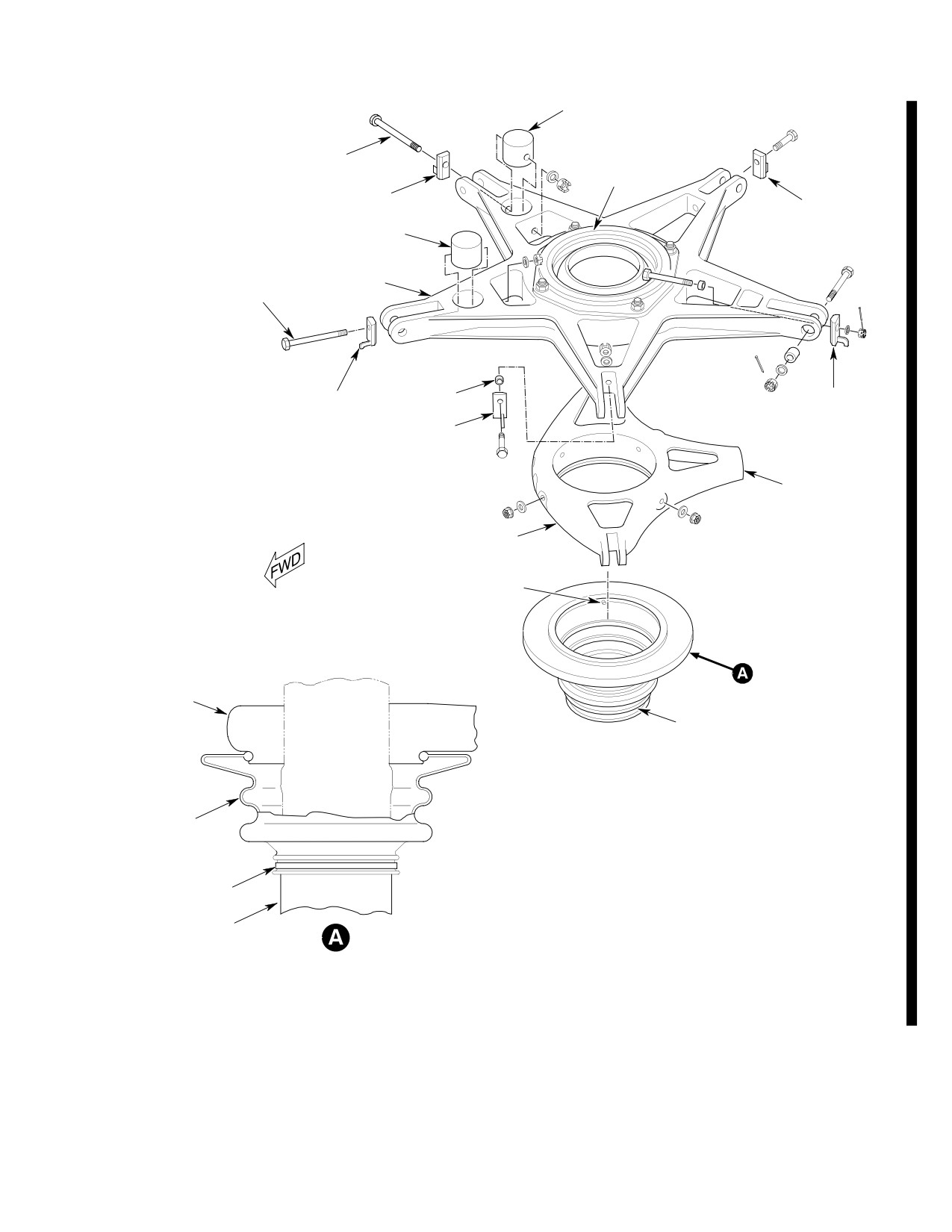
COUNTERWEIGHT
NOTE 2
BEARING
ASSEMBLY
INTERRUPTER
DOUBLE
(NOTE 3)
INTERRUPTER
COUNTERWEIGHT
(NOTE 4)
ROTATING
SWASHPLATE
NOTE 2
INTERRUPTER
SPACER
INTERRUPTER
(NOTE 3)
(NOTE 4)
INTERRUPTER
(NOTE 4)
STATIONARY
SWASHPLATE
DRAIN HOLES
(HIDDEN)
INDEX
PROTRUSIONS
STATIONARY
SWASHPLATE
GROOVE
DRAIN HOLES
(2 PLCS)
BOOT
NYLON STRAP
NOTES:
1.
COLOR CODED TO MATCH BLADES.
MAST
2.
IF COUNTERWEIGHTS ARE USED, COAT BOLT WITH
GREASE (CM116) BEFORE INSTALLATION.
BOOT INSTALLATION
3.
TORQUE NUT TO 30-60 IN-LBS.
4.
TORQUE NUT TO 15-20 IN-LBS.
G62-3001B
Figure 403. Main Rotor Swashplate
Page 407
62-30-00
Revision 44
CSP-HMI-2
MD Helicopters, Inc.
MAINTENANCE MANUAL
This Page Intentionally Left Blank
Page 408
Revision 35
62-30-00
MD Helicopters, Inc.
CSP-HMI-2
MAINTENANCE MANUAL
SWASHPLATE AND MIXER
INSPECTION/CHECK
1. Swashplate Inspection
(a). Maximum radial play between
sliding surface liner and stationary
mast is 0.020 inch (0.508 mm).
Consumable Materials
(Ref. Section 91−00−00)
(b). Maximum axial play between spheri
Item
Nomenclature
cal ball and teflon liner is 0.010 inch
(0.254 mm).
CM217
Isopropyl alcohol
(c). If play is suspected in double row ball
bearing, turn rotating swashplate
When cleaning swashplate for
until arms line up with those of
CAUTION
inspection, prevent solvent from
stationary swashplate and check
entering either spherical ball bearing or
motion between arms at control bolt
double row ball bearing. Use cloth moist
in stationary swashplate.
ened in alcohol (CM217) to wipe clean
(d). Maximum total vertical movement of
spherical ball, ball bore liner and exterior of
0.015 inch (0.381 mm) is allowable.
double row ball bearing.
(e). If movement limit is exceeded replace
NOTE:
double row ball bearing (Ref. COM).
D Stationary swashplate may be con
(5). Inspect swashplate spherical and
structed of either magnesium or alumi
double row ball bearings for condition.
num alloy. For corrosion control and iden
(a). Nicks and dents that do not deform
tification of magnesium and aluminum
ID chamfered edge of hard anodized
alloys (Ref. Sec. 20-40-00).
ball, and not more than 0.10 inch
D In the following inspection, the rotating
(0.254 mm) deep along spherical ball
and stationary swashplates must be dis
surface from edge are allowed.
connected (Ref. Swashplate and Mixer
(b). Scratches, any length, on OD of
Removal/Installation).
spherical ball are allowed if they are
no deeper than 0.010 inch (0.254
(1). Inspect swashplate bearing assembly
mm) or wider than 0.060 inch (1.524
(Ref. Figure 403 for evidence of binding
mm).
in either radial or axial movement.
(c). Not more than two scratches are
(2). Inspect teflon liners for condition.
permitted in a one inch wide area.
(6). Check existing preload on spherical
(3). Ensure that all flexible rubber seals
bearing.
enclosing ball bearing races are in
place; inspect for deterioration and
(a). Hook spring scale over one of the
indication of grease leakage. (For
bolts securing stationary swashplate
bearing maintenance information
to the bearing flange.
(including lubrication), Ref. COM).
(b). With stationary swashplate in
motion, drag should be no more than
NOTE: New swashplate bearing assembly nor
30 pounds (13.61 kg). (Use average
mally shows some signs of grease leakage
of four readings taken 90 degrees
for first 10-15 hours of operation after in
apart).
stallation.
(c). If readings are more than 30 pounds
(4). Inspect swashplate spherical ball and
(13.61 kg), clean spherical bearing
double row ball bearing for radial or
with isopropyl alcohol and recheck
axial play.
drag.
Page 601
62-30-00
Revision 32
CSP-HMI-2
MD Helicopters, Inc.
MAINTENANCE MANUAL
(d). Repair damage or replace bearings
mixer link for binding, play in link bore
(Ref. COM).
and wear. Wear limit is 0.008 inch
(0.203 mm) radially and 0.040 inch
(7). Check double row ball bearing for
(1.016 mm) axially. Replace complete
serviceability, with seals in place and
mixer link if bearings are faulty.
unbroken.
Inspect bearings in other linkage for
binding and looseness in mating bores.
(a). Check for correct operation and
lubrication.
3. Scissors Inspection
(b). Bearing must rotate smoothly,
(Ref. Figure 401)
without roughness. Binding or
catching should not exist when
Any evidence of failure,
bearings are rotated 360°.
WARNING
damage, or deformation of
crank or link is justification for re
(c). Replace defective double row ball
placement of either crank, link, or com
bearings (Ref. COM).
plete scissors assembly. Failure of any
(8). Perform careful visual inspection of
of these components in flight can result
stationary and rotating swashplate for
in failure of movable flight controls,
cracks, wear in bolt and bushing bores,
loss of helicopter, and possible injury
and fork inner surfaces; and for
or loss of life.
corrosion, nicks and dents.
(1). Inspect crank and link for evidence of
(9). Perform dye penetrant check on
impact damage and deformation. If
questionable areas.
condition is questionable, perform
fluorescent dye penetrant inspection.
(10). Check that counterweights are securely
bonded in rotating swashplate.
(2). Inspect bearings for binding, looseness
in bore and wear. Maximum wear limits
2. Mixer Controls Inspection
are 0.010 inch (0.254 mm) radial and
0.020 inch (0.508 mm) axial.
(Ref. Figure 402)
4. Pitch Control Rod Inspection
(1). Inspect all bushings for security of fit.
(Ref. Figure 401)
(2). Inspect longitudinal link, support
bracket, longitudinal control mixer link,
Ensure that rod end bearings
mixer links, longitudinal pitch idler,
CAUTION
are centered and do not contact
longitudinal pitch mixer bellcrank,
attach clevis.
lateral bellcrank and collective pitch
mixer bellcrank for scratches, cracks,
(1). Visually inspect upper and lower rod
corrosion and similar surface defects.
end bearings for evidence of excessive
For components that are questionable,
axial play, 0.040 inch (1.016 mm)
perform fluorescent dye penetrant
maximum; and for any extrusion,
inspection.
displacement or damage to the bearing
teflon liner.
(3). Inspect spherical, teflon (or equivalent)
lined, bearings in longitudinal link,
(2). Replace rod end bearing if discrepan
mixer link, and longitudinal control
cies are noted.
Page 602
Revision 32
62-30-00
MD Helicopters, Inc.
CSP-HMI-2
MAINTENANCE MANUAL
SWASHPLATE AND MIXER
REPAIRS
1. Swashplate Repairs
be restored on magnesium and alumi
num parts.
(Ref. Figure 403) Disassembly other than as
illustrated is considered a part of swashplate
(7). Replace defective bearings and bush
overhaul (Ref. COM). If tracking interrupters
ings, except swaged spherical bearings
are to be removed, mark them for reinstalla
in mixer links which require link
tion at original locations.
replacement. Remove bearings or
bushings by pressing them out. Install
2. Mixer Controls Repair
new bearing with surface primer and
grade A locking compound (CM321 and
(Ref. Figure 402)
CM431).
NOTE: Left-hand bearing in support bracket is
Consumable Materials
not supplied as part of bracket. This bearing
(Ref. Section 91−00−00)
is installed at time support bracket and lon
Item
Nomenclature
gitudinal pitch idler are assembled. Install
CM321
Surface primer locking compound
new bearing by seating flush with inner face
CM431
Sealing, locking and retaining compound
of support bracket flange.
CM802
Abrasive cloth, aluminum oxide
3. Scissors Bushing and Bearing
Replacement
NOTE: Following depth limits are total limits,
(Ref. Figure 401)
including effects of all previous repairs to
any given area.
Consumable Materials
(1).
Repair minor surface defects such as
(Ref. Section 91−00−00)
scratches, nicks and corrosion using
Item
Nomenclature
abrasive cloth, grade 400 - 600
CM103
Solid film lubricant
(CM802) to smooth out and blend in
CM222
1,1,1-Trichloroethane
such defects.
CM318
Primer
(2).
Cast and forged surfaces may be
CM321
Surface primer locking compound
reworked to depth of 0.020 inch (0.508
CM431
Sealing, locking and retaining compound
mm).
(3).
Flat machined surfaces, except clevis
(1). Remove cotter pin, nut, washer, and
inner ears, may be reworked to depth of
bolt that join link and crank.
0.015 inch (0.381 mm). Clevis inner ear
(2). Remove two bushings from link only if
surfaces may be reworked to depth of
replacement is necessary.
0.020 inch (0.508 mm).
(3). Do not remove bearing from link.
(4).
Machined holes may have 0.003 inch
Replace complete link if bearing is
(0.076 mm) removed from bore wall in
defective.
an area no greater than 15 percent of
circumference and 50 percent of depth.
(4). Remove slotted bushings and bearings
from crank, only if replacement is
(5).
All edges may have 0.030 inch (0.762
necessary.
mm) removed except around machined
holes which are limited to 0.010 inch
During cleaning, do not allow
CAUTION
(0.254 mm) chamfer.
solvent to enter bearings.
(6).
All rework must be smoothly blended
(5). Install new bushings using solid film
into adjacent surfaces and finish must
lubricant (CM103); do not use zinc
Page 801
62-30-00
Revision 20
CSP-HMI-2
MD Helicopters, Inc.
MAINTENANCE MANUAL
chromate. Press in bushing until end
scissors to 369D21002-21 configuration to
is flush with inside surface of crank
preclude shimming problems experienced with
inboard ears.
the early crank configuration. Field rework
consists primarily of relocating existing
(6). If bearings were removed from crank at
bushings in the crank outboard attach lugs to
disassembly, reinstall using the
the inboard lugs, and installing new flange
following procedure:
type bushings in the outboard lugs. The wall
thickness of the crank outboard attach lugs
NOTE: Do not allow sealant to enter bearing
must be reduced to accommodate installation
race.
of the flange bushings.
(a).
Clean bearing outer face, counterbore
and faying surfaces with trichloroe
Instructions are also provided for replacement
thane (CM222). Do not allow trichlo
of existing hardware for the crank assembly.
roethane to enter bearing.
Existing attach bolts may have insufficient
thread length which, in some cases, can cause
(b).
Coat the faying surfaces with surface
loosening of the bolt in service.
primer (CM321) as per manufactur
er's instructions.
It is to be noted that the field modification and
(c).
Apply locking compound (CM431) to
installation of the PN 369D21002-21 crank
faying surfaces.
assembly with new attach hardware also
upgrades the PN 369D21001 scissors assembly
(d).
Press bearing until outer face is
to PN 369D2101-501 configuration.
seated firmly against shoulder of
counterbore.
Consumable Materials
(e).
Remove excess sealant. Do not allow
(Ref. Section 91−00−00)
sealant to enter bearing race.
Item
Nomenclature
(f).
Apply a small fillet of sealant to the
CM206
Chemical coating
faying edges of bearing housing. Use
CM318
Primer
cellophane or masking tape to
exclude air and allow sealant to cure
for 24 hours at ambient temperature
or force cure by heating to
(1). Disconnect scissors crank from hub
140°-160°F (60°-72°C for one hour
lower shoe and scissors link.
prior to use of assembly.
(7). If bushings were removed from link at
(2). Remove existing HS626-S-4-500
disassembly, install new bushings.
bushings from outboard lugs of scissors
After installation, dimension between
crank.
outside faces of bushings should be
1.579-1.586 inches (4.0107-4.0284 cm).
(3). Using grinder or file, remove minimum
(8). Align bore of link with bore of crank;
0.063 inch (1.6002 mm) material from
install bolt, washer and nut. Torque nut
inner side of both outboard attach lugs,
to 30 - 40 inch-pounds (3.39 - 4.52
to obtain distance of 9.735 inches
Nm).
(24.7295 cm) between lugs. After
removal of material, wall thickness of
4.
Scissors Modification
lugs should not be less than 0.230 inch
(5.842 mm). Coat reworked area of lug
(Ref. Figure 801) The following procedure is for
with iridite (CM206) or equivalent
modification of 369D21002 main rotor hub
corrosion protective chemical film.
Page 802
Revision 20
62-30-00
MD Helicopters, Inc.
CSP-HMI-2
MAINTENANCE MANUAL
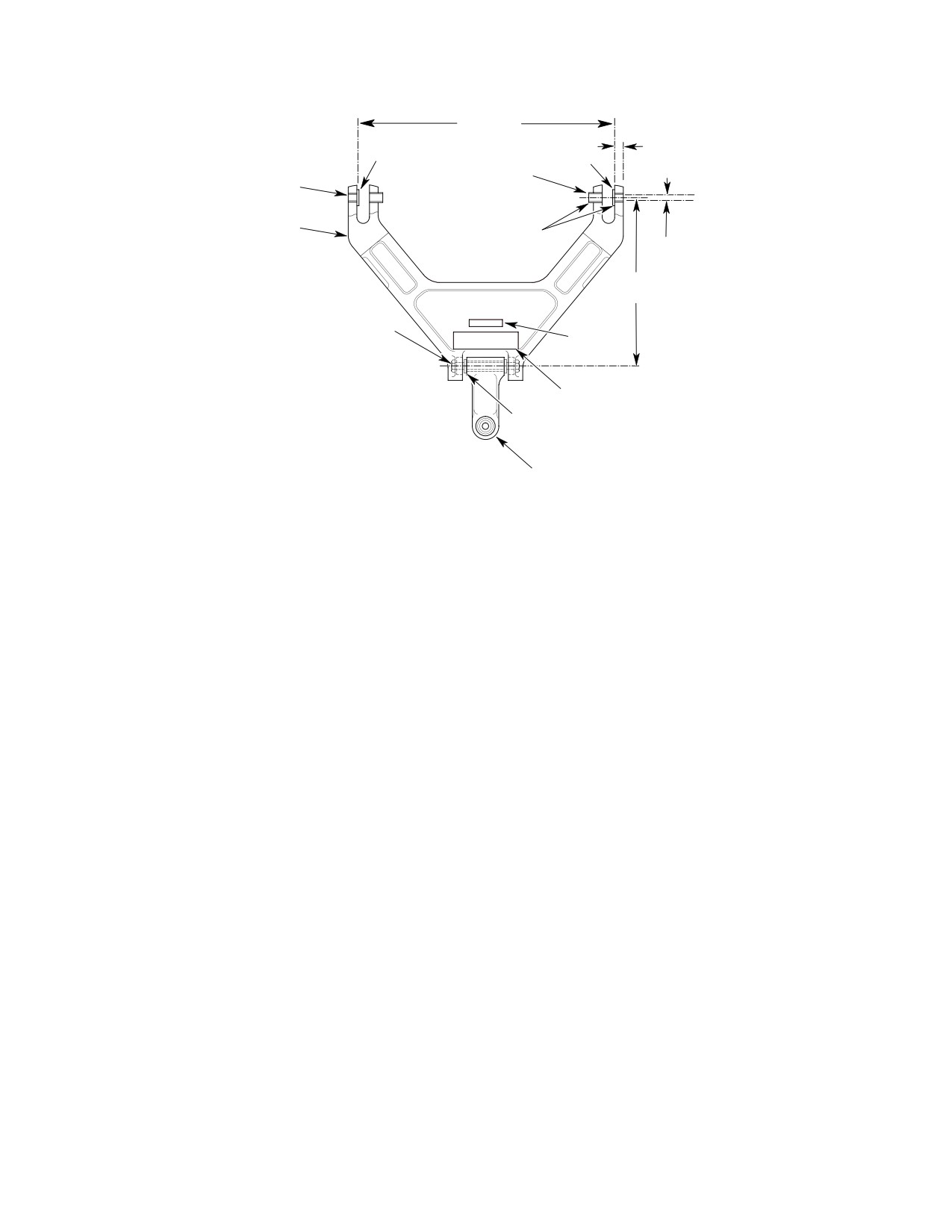
9.736 IN.
(24.7295 CM)
MINIMUM WALL 0.230 IN. (5.8420 MM) TYP.
NOTE 5
NOTE 5
MAXIMUM WALL 0.249 IN. (6.3246 MM) TYP.
HS626-S-4-500
BUSHING (2 REQ'D)
NAS77-4-23 BUSHING
(TYP. 2 PLCS)
369D21002-21 CRANK
0.020 IN. (0.508 MM) X 45°
ASSEMBLY
CHAMFER (4 PLCS)
0.3750 IN. (9.5250 MM)
DIA.
0.3755 IN. (9.5377 MM)
(NOTE 3)
6.421 IN.
16.3093 CM)
NAS6204-38D BOLT
AN960C416 WASHER
PLAT
E
2 REQ'D (NOTE 2)
MS17826-4 NUT (NOTE 1)
INSTALL THIS SIDE
TOWARD BLADES
NOTE 4
NOTES:
1.
TORQUE NUT 30 - 40 INCH-POUNDS (3.39 - 4.52 NM).
SCISSORS LINK
2.
ONE WASHER EACH UNDER BOLT HEAD AND NUT.
ASSEMBLY
3.
TWO HOLES IN LINE (TYP. 2 PLACES)
4.
FILL GAP WITH HS5079-2646 WASHERS. SHIM WASHERS
SHOULD BE EQUALLY SPACED.
5.
REMOVE MATERIAL EVENLY FROM INNER SIDE OF OUTBOARD
G62-3004B
Figure 801. Field Modification − 369D21002−11 Crank Assembly to 369D21002−21 Configuration
NOTE: Remove material only from inner side of
(a). Install scissors crank to hub lower
existing crank outboard attach lugs.
shoe with NAS6204-18D bolts,
AN960PD416L washers, MS17826-4
(4).
Using existing hole in outboard lug as
nuts and cotter pins (Ref.
guide, drill and ream 0.252 inch (6.4008
Figure 802).
mm) dia. hole in outboard lugs to
0.3750-0.3755 inch (9.5250-9.5377
(b). Install scissors link to scissors crank
mm) dia. for press fit of
assembly with NAS6204-38D bolt,
HS626-S-4-500 bushings.
AN960C416 washers, MS17826-4
nut and cotter pins (Ref. Figure 801).
(5).
Install HS626-S-4-500 bushings in
Torque nut to 30 - 40 inch-pounds
inboard lugs of scissors crank with
(3.39 - 4.52 Nm).
primer (CM318).
(10). Record upgrade of PN 369D21002 main
(6).
Install new NAS77-4-23 flanged
rotor hub scissors crank assembly to
bushings with primer (CM318) in
PN 369D21002-21 configuration per
outboard lugs.
DN-46.1 in Component Record of
Helicopter Log Book.
(7).
Re-identify crank assembly as PN
369D21002-21 on ID plate.
(11). Record upgrade of PN 369D21001 main
(8).
zinc chromate
rotor hub scissors assembly to PN
369D21001-501 configuration per
(9).
Reinstall scissors crank assembly using
DN-46.1 in Component Record of
new attach hardware as follows:
Helicopter Log Book.
Page 803
62-30-00
Revision 20
CSP-HMI-2
MD Helicopters, Inc.
MAINTENANCE MANUAL
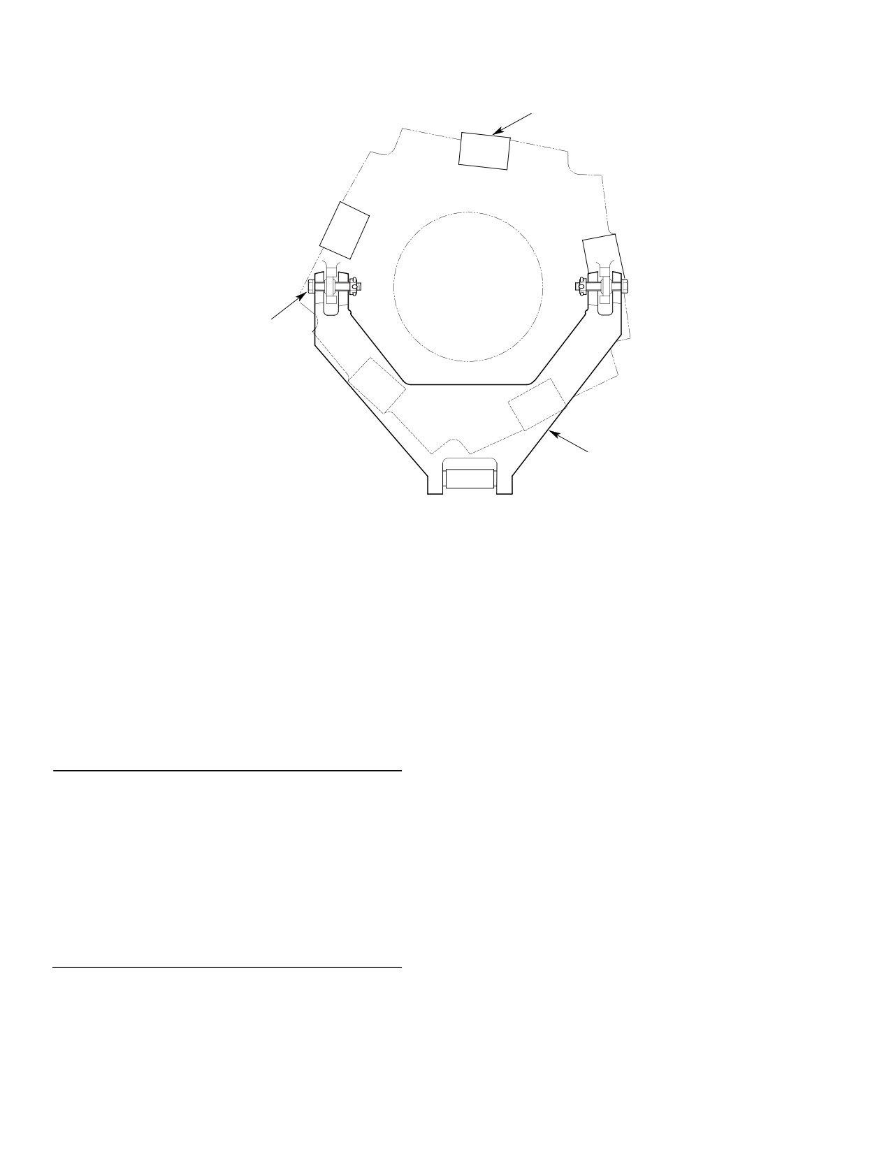
369D21204 LOWER SHOES
369H1001 BOOT
NAS6204-18D BOLT (2 REQD)
AN960PD416L WASHER (4 REQD)
MS17826-4 NUT (2 REQD) (NOTE)
MS24665-153 COTTER PIN (2 REQD)
369D21002-21 CRANK ASSEMBLY
NOTE:
TORQUE NUT 30 - 60 INCH-POUNDS (3.39 - 6.78 NM).
G63-3005A
Figure 802. Installation of 369D21002−21 Crank to Hub Lower Shoes
5. Mixer Controls Rework
(a). Chamfer 369D21002-3 scissors crank
and 369A1003 link assembly per
dimensions shown (Ref. Figure 803).
(Ref. Figure 803) The following lists
instructions and criteria for rework of the
(b). Touch up reworked area with chemi
mixer controls to preclude interference
cal film (CM206) and refinish with
between mixer components. Rework is
primer (CM318) and black paint
applicable to 369D helicopter, Serial No.
(CM305).
0001D thru 0129D only, unless already
(c). Using permanent ink stamp
accomplished, and is to be performed prior to
(CM312), reidentify scissors link part
rigging the main rotor controls.
number as 369A1003-501.
(d). Apply a coat of varnish (CM314) over
Consumable Materials
ink stamp.
(Ref. Section 91−00−00)
(2). Rework installed 369D27611 rotating
Item
Nomenclature
swashplate as follows:
CM206
Chemical coating
(a). Chamfer 369D27611 swashplate per
CM305
Lacquer, acrylic
dimensions shown (Ref. Figure 803).
CM312
Ink stamp, permanent
(b). Touch up reworked area with chemi
CM314
Varnish, moisture resistant
cal film and refinish with primer and
black paint.
CM318
Primer
(c). Using permanent ink stamp, reiden
tify rotating swashplate assembly
part number as 369A27611-501.
(1). Remove and rework the 369D21002-3
scissors crank assembly and scissors
(d). Apply a coat of varnish over ink
link assembly as follows:
stamp.
Page 804
Revision 20
62-30-00
MD Helicopters, Inc.
CSP-HMI-2
MAINTENANCE MANUAL
(3). Remove and rework 369N2664 collec
(d). Apply a coat of varnish over ink
tive mixer bellcrank and 369N2670
stamp.
lateral mixer bellcrank as follows:
(a). Chamfer collective and lateral
NOTE: The 369N2666-503 longitudinal mixer
bellcrank assemblies per dimensions
idler is compatible installed with the
shown (Ref. Figure 803).
369N2668 basic longitudinal mixer bell
crank only. If the 369N2666-505 idler is in
(b). Touch up reworked area with chemi
stalled, the 369N2668-503 bellcrank must
cal film and refinish with primer and
be used.
black paint.
(c). Using permanent ink stamp, re-iden
(4). Reinstall removed components.
tify collective bellcrank part number
as 369N2664-501; reidentify lateral
bellcrank part number as
(5). Perform rigging of main rotor controls
369N2670-501.
(Ref. Sec. 67-10-00).
Page 805
62-30-00
Revision 20
CSP-HMI-2
MD Helicopters, Inc.
MAINTENANCE MANUAL
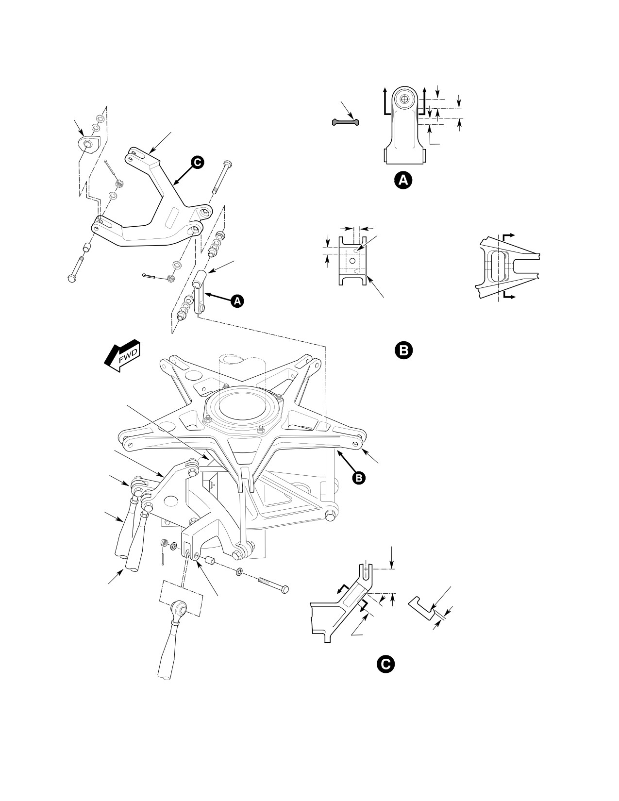
0.38 IN.
0.080 IN. (2.032 MM) X 45°
A
A
(9.652 MM)
ROTOR
CHAMFER AND BLEND
CHAMFERED ZONE
BOTH ENDS SMOOTHLY
HUB
(TYP 4 PLACES)
LOWER
369D21002
0.38 IN. (9.652 MM)
SHOE
SCISSORS
CRANK
SECTION A - A
0.20 IN. (5.08 MM)
0.25 IN. (6.35 MM)
(TYP 4 PLACES)
(TYP BOTH SIDES)
0.25 IN.
0.040 IN. (1.016 MM)
CHAMFER
(6.35 MM)
0.060 IN. (1.524 MM)
BLEND BOTH ENDS
B
369A1003
AT 0.25 IN. (6.35 MM)
SCISSORS
WIDTH SMOOTHLY
LINK
0.25 IN.
(6.35 MM)
B
SECTION B - B
(TYP BOTH SIDES)
LOF 0.625 IN.
0.040 IN. (1.016 MM)
X 45° CHAMFER
(15.875 MM)
0.060 IN. (1.524 MM)
SLOT
BLEND BOTH ENDS
SMOOTHLY
LONGITUDINAL
CONTROL
MIXER LINK
LONGITUDINAL
PITCH IDLER
COLLECTIVE PITCH
369D27611 ROTATING
MIXER BELLCRANK
SWASHPLATE
COLLECTIVE PITCH
CONTROL ROD
0.10 IN. (2.54 MM) X 30°
CHAMFER, BLEND
2.25 IN. (5.715 CM)
BOTH ENDS WITH
(TYP)
SMOOTH RADIUS TO
LONGITUDINAL PITCH
C
2.25 IN. (5.715 CM) DIM.
CONTROL ROD
LATERAL MIXER
0.10 IN. (2.54 MM)
BELLCRANK
(TYP BOTH SIDES
C
1.50 IN. (3.81 CM)
(TYP FAR SIDE)
SECTION C - C
G62-3006-1A
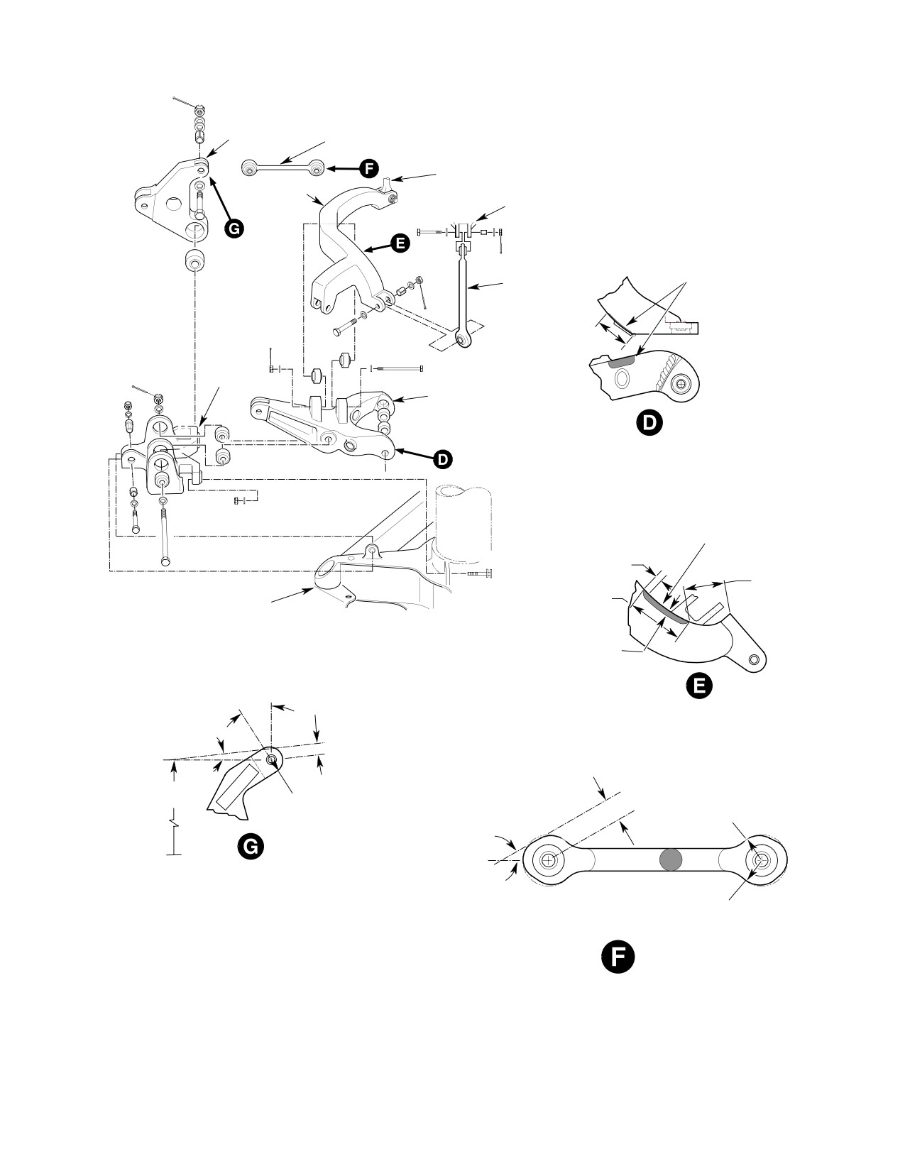
Figure 803. Rework of Main Rotor and Mixer Controls (Sheet 1 of 2)
Page 806
Revision 20
62-30-00
MD Helicopters, Inc.
CSP-HMI-2
MAINTENANCE MANUAL
369N2666 LONGITUDINAL
PITCH IDLER
369A7607 LONGITUDINAL
CONTROL MIXER
MIXER BELLCRANK
369N2670
STATIONARY
LATERAL MIXER
SWASHPLATE
BELLCRANK
CHAMFER
0.15 IN. (3.81 MM)
0.040 IN. (1.016 MM) X
0.20 IN. (5.08 MM)
BLEND BOTH ENDS
SMOOTHLY
MIXER LINK
1.50 IN. (3.81 CM)
1.68 IN. (4.2672 CM)
MIXER
SUPPORT
BRACKET
369N2664 COLLECTIVE
PITCH MIXER BELLCRANK
CHAMFER 0.080 IN. (2.032 MM)
MAX X 0.180 IN. (4.57 MM)
BLEND BOTH ENDS SMOOTHLY
0.25 IN. (6.35 MM)
(TYP)
1.62 IN. (4.1148 CM)
1.50 IN. (3.81 CM)
1.75 IN. (4.445 CM)
MAST BASE
1.75 IN. (4.445 CM)
0.180 IN.
(4.57 MM)
0.425 IN. (10.795 MM)
32°
0.440 IN. (11.176 MM)
6°
0.45 IN. (11.43 MM) (TYP 4
PLACES)
4.375 IN.
(11.1125 CM)
0.48 IN. (12.19 MM) R
0.48 IN. (12.19 MM) R (TYP 4
(TYP)
PLACES)
30°
(TYP 4 PLACES)
0.50 IN. (12.70 MM) R
G62-3006-2A
Figure 803. Rework of Main Rotor and Mixer Controls (Sheet 2 of 2)
Page 807
62-30-00
Revision 20
CSP-HMI-2
MD Helicopters, Inc.
MAINTENANCE MANUAL
This Page Intentionally Left Blank
Page 808
Revision 44
62-30-00
MD Helicopters, Inc.
CSP-HMI-2
MAINTENANCE MANUAL
Section
62−30−60
Swashplate and
Mixer (600N)
MD Helicopters, Inc.
CSP-HMI-2
MAINTENANCE MANUAL
SWASHPLATE AND MIXER
REMOVAL/INSTALLATION
1. Main Rotor Swashplate
Do not strike rotating swash
CAUTION
plate or bearing assembly (Ref.
Figure 403) with tools or in any way deface
(Ref. Figure 403) The main rotor swashplate
these components, the rotating swashplate
includes a rotating swashplate, stationary
is a stressed part. Use particular care to pro
swashplate, bearing and retainer and one
tect teflon liner in bearing bore. A damaged
counterweight. The rotating swashplate
swashplate bearing must not be retained in
converts movement from the stationary
service.
swashplate into rotating motion and transfers
it to the main rotor hub assembly for lift, and
(8). Lift swashplate carefully up and off of
longitudinal and lateral control of the helicop
mast.
ter.
(9). To remove boot from mast, remove
self-clinching nylon strap.
2. Swashplate Replacement
B. Swashplate Installation
A. Swashplate Removal
(1).
If swashplate lower boot was removed,
install boot on mast (Ref. Figure 403).
(1). Tag or color-identify six pitch control
(2).
Position swashplate over main rotor
rods (Ref. Figure 401) to simplify
mast and carefully lower into place.
replacement at same locations.
(3).
Engage upper end of boot in groove at
lower side of stationary swashplate.
Failure to reinstall pitch control
CAUTION
Secure boot with self-clinching nylon
rods at correct locations may re
strap (Ref. Figure 403).
sult in main rotor blades excessively out of
track.
(4).
Align longitudinal link with stationary
swashplate (Ref. Figure 402).
(2).
Disconnect pitch control rods from
(5).
Install flanged bushing, if removed,
rotating swashplate.
bolt, two washers, nut and cotter pin to
secure upper end of longitudinal link.
(3).
Remove scissors.
(6).
Align upper ends of mixer links with
stationary swashplate. Install slotted
(4).
Remove main rotor hub.
bushing (if removed), bolt, two washers,
nut and cotter pin to secure each link to
swashplate.
(5).
Disconnect longitudinal link (Ref.
Figure 402) from stationary swash
(7).
Install scissors.
plate.
(8).
Using color code, reinstall pitch control
rods at same locations from which
(6).
Disconnect right and left side mixer
removed.
links (Ref. Figure 402) from stationary
swashplate.
(9).
Check track of main rotor blades (Ref.
Sec. 18-10-60) following any mainte
(7).
Remove protective boot from groove in
nance activity that could result in a
lower side of stationary swashplate
dimensional variation affecting rigging
(Ref. Figure 403).
or tracking.
Page 401
62-30-60
Revision 20
CSP-HMI-2
MD Helicopters, Inc.
MAINTENANCE MANUAL
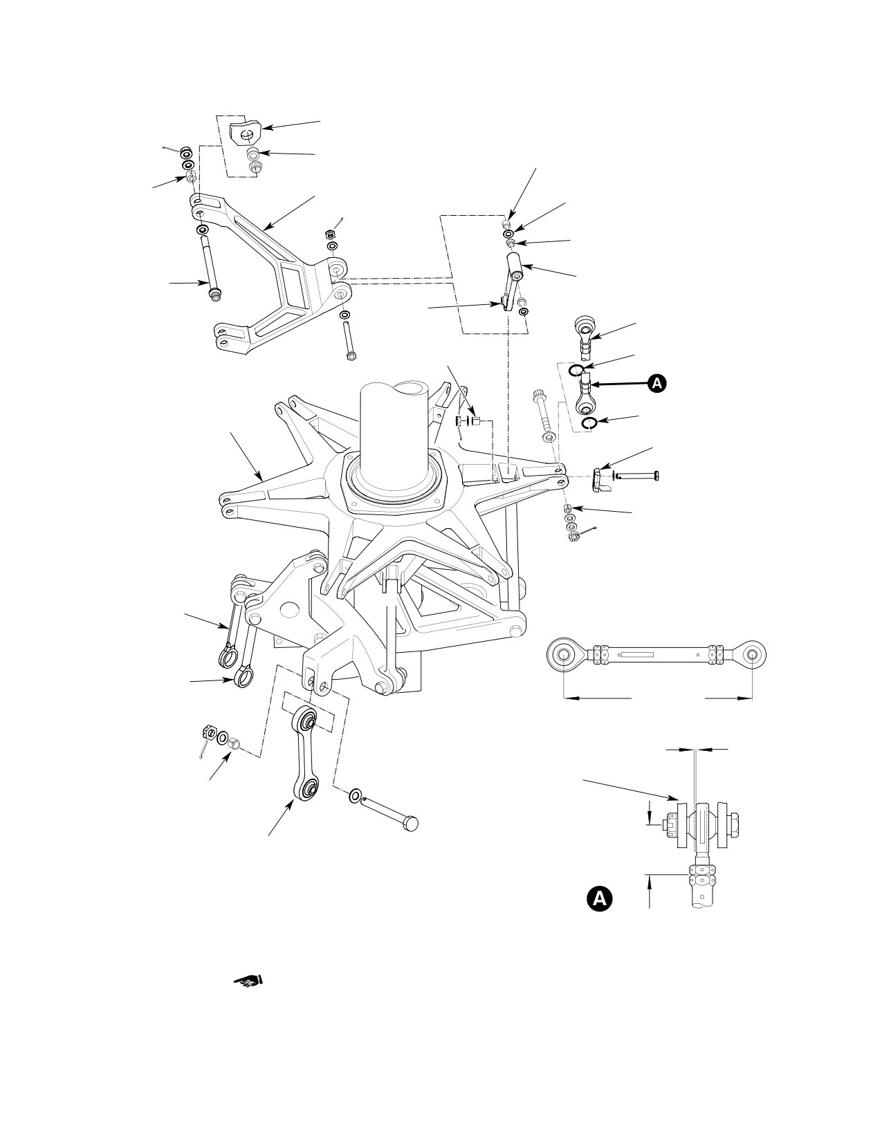
ROTOR HUB
LOWER SHOE
WASHERS
(NOTE 4)
BEARING
SLOTTED BUSHING
SCISSORS CRANK
WASHERS
(NOTE 1)
(NOTE 4)
BUSHING
CLOSE TOLERANCE
SCISSORS LINK
BOLT (NOTE 5)
BEARING
PITCH CONTROL
ROD (NOTE 2)
SLOTTED BUSHING
ELASTOMER RING
(NOTE 1)
ROTATING
ELASTOMER RING
SWASHPLATE
INTERRUPTER
SLOTTED BUSHING
(NOTE 1)
COLLECTIVE LINK
ASSEMBLY
LONGITUDINAL
LINK ASSEMBLY
6.25 IN.
(15.875 CM)
(NOTE 3)
0.040 IN. (1.016 MM) MAX
ALLOWABLE LOOSENESS
AT INSTALLATION, ROD
SLOTTED BUSHING
ENDS TO BE PARALLEL
(NOTE 1)
WITH MATING CLEVIS
LATERAL CONTROL
1.30 IN. (3.302 CM)
LINK ASSEMBLY
(TYP UPPER BEARING ONLY)
NOTES:
1.
END OF SLOTTED BUSHING MUST PROTRUDE MINIMUM OF
0.010 IN. (0.254 MM) TO MAXIMUM OF 0.060 IN. (1.524 MM) ABOVE
OUTSIDE SURFACE OF PART AFTER NUT IS TIGHTENED.
2.
COLOR CODED TO MATCH BLADE.
3.
OPTIMUM INITIAL SETTING (SIX PLACES).
4.
AS REQUIRED TO FILL GAP.
6G62-031B
Figure 401. Pitch Control Rods and Swashplate Scissors − Installation
Page 402
Revision 27
62-30-60
MD Helicopters, Inc.
CSP-HMI-2
MAINTENANCE MANUAL
3. Controls Mixer
(1). Position support bracket over forward
lug on mast base.
Controls mixer includes links, bellcranks,
idlers, support bracket and fasteners to secure
(2). Install two aft bolts and washers in
these components in place and to the control
support bracket and mast base. Install
rods and main rotor swashplate.
two thin washers and nuts; torque nuts
to 80 - 100 inch-pounds (9.04 - 11.30
4. Controls Mixer Replacement
Nm) plus drag torque.
A. Controls Mixer Removal
(3). Using ball hole gage and standard
micrometer, check that misalignment
(Ref. Figure 402)
between forward bolt hole bore in
(1). Remove air intake forward fairing for
support bracket and bore in mast base
access.
lug is 0.015 inch (0.381 mm) or less.
(2). Disconnect upper ends of collective,
NOTE: If necessary, loosen aft two bracket-to-
lateral and longitudinal control links
fitting nuts, position support bracket to
(Ref. Figure 401).
minimize misalignment and retighten nuts.
NOTE: Control links are attached by slightly
(4).
Install mixer support attaching bushing
different length bolts. Reinstall each bolt in
in bracket and mast base lug.
its bellcrank following control rod removal
to simplify reinstallation at correct loca
(5).
Check that sleeve bushing is in place;
tions.
then install bolt, two washers and nut.
Torque nut to 80 - 100 inch-pounds
(3). Remove mixer links. (Mixer link
(9.04 - 11.30 Nm).
bearings are not replaceable.)
(6).
Position longitudinal pitch idler and
(4). Disconnect longitudinal link from
collective pitch mixer bellcrank on
stationary swashplate.
support bracket. Position washer
between right side of longitudinal pitch
(5). Remove longitudinal control mixer link.
idler bearing and center bearing of
(6). Disconnect lateral mixer bellcrank from
mixer support bracket. Install left-
collective pitch mixer bellcrank.
hand bearing, with attaching hardware.
(7). Remove connecting hardware (includ
(7).
Position lateral bellcrank between
ing flanged bushing) from each side of
collective pitch mixer bellcrank bear
longitudinal pitch mixer bellcrank.
ings and install attaching hardware.
Carefully remove bellcrank. Retain any
shims that may be installed.
(8).
Position longitudinal pitch mixer
bellcrank with collective pitch mixer
(8). Remove bolt from hingeline of support
bellcrank; insert two flanged bushings.
bracket, longitudinal pitch idler and
Install two bolts.
collective pitch mixer bellcrank.
Separate the three parts.
(9).
Push longitudinal bellcrank to one side
and measure gap between bellcrank
(9). Remove mixer support bracket from
and bearings in collective pitch bell
mast base.
crank.
To prevent washing dirt into
CAUTION
(10).
Using HS5079-2646 laminated wash
bearings, or washing grease out
er(s), shim evenly to take up gap.
of bearings, do not permit solvent to enter
bearings when cleaning mixer control com
(11).
Insert flanged bushings, bolts, six
ponents.
washers (two under each nut) shims
and nuts. Torque nut to 30 - 40 inch-
B. Mixer Controls Installation
pounds (3.39 - 4.52 Nm) and install
(Ref. Figure 402)
cotter pin.
Page 403
62-30-60
Revision 31
CSP-HMI-2
MD Helicopters, Inc.
MAINTENANCE MANUAL
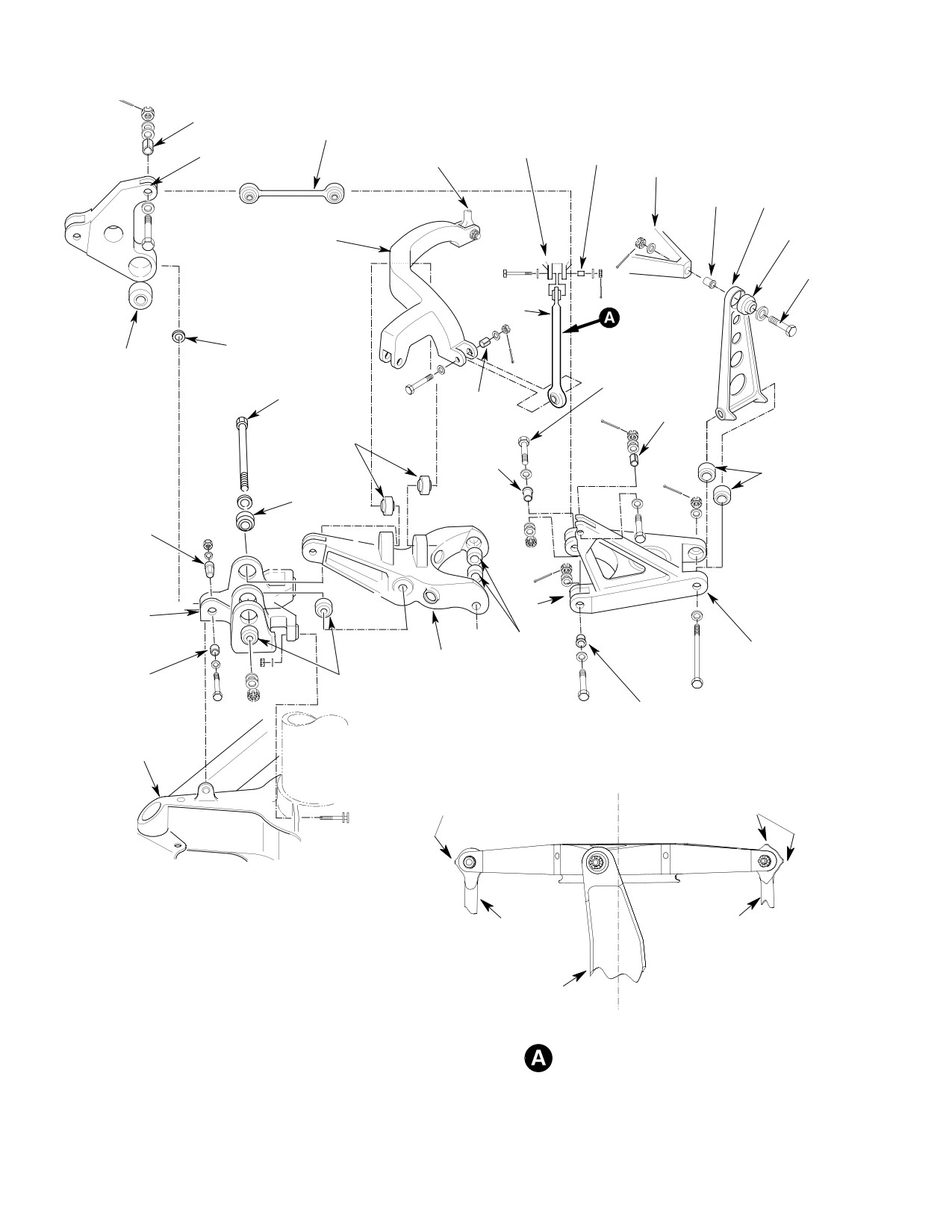
BUSHING LONGITUDINAL CONTROL
(NOTE 2)
MIXER LINK
STATIONARY
BUSHING
LONGITUDINAL
SWASHPLATE
STATIONARY
MIXER LINK
(NOTE 2)
PITCH IDLER
SWASHPLATE
LONGITUDINAL
FLANGED
LINK
BUSHING
(NOTE 3)
LATERAL MIXER
BEARING
BELLCRANK
(NOTE 5)
NOTE 1
MIXER
LINK
WASHER
BEARING
NOTE 1
NOTE 1
BUSHING
BUSHING
(NOTE 2)
(NOTE 2)
BEARING
FLANGED
BUSHING
(NOTE 4)
BEARING
MIXER
BEARING
SUPPORT
ATTACHING
BUSHING
(NOTE 6)
MIXER
SUPPORT
NOTE 7
BRACKET
BEARING
LONGITUDINAL
COLLECTIVE PITCH
PITCH MIXER
SLEEVE
MIXER BELLCRANK
BELLCRANK
BEARING
BUSHING
FLANGED BUSHING
(NOTE 4)
MAST BASE
TWO IDENTIFYING LOCATORS
ONE IDENTIFYING LOCATOR
(FACING UP AND OUT)
(FACING OUT) L/H SIDE ONLY
R/H SIDE ONLY
LEFT-HAND
RIGHT-HAND
NOTES:
1.
DIRECTION OF BOLT OPTIONAL.
MIXER LINK
MIXER LINK
(600N7636-1/-9)
(600N7636-3/-11)
2.
EDGE OF BUSHING MUST PROTRUDE MINIMUM OF 0.010 IN.
(0.254 MM) TO MAXIMUM OF 0.060 IN. (1.524 MM) ABOVE
OUTSIDE OF PART AFTER NUT IS TIGHTENED.
3.
LONGITUDINAL LINK DETAILS ROTATED FOR CLARITY.
LONGITUDINAL LINK
4.
MUST BE PULLED OUT FIRST TO REMOVE BELLCRANK.
5.
PART MAY BE EITHER MAGNESIUM OR ALUMINUM ALLOY.
MAST CL
(FOR ALLOY IDENTIFICATION AND CORROSION CONTROL,
REFER TO SECTION 20-40-00).
MIXER LINK IDENTIFICATION
6.
INSTALL BUSHING AFTER THE TWO AFT ATTACHING BOLTS
FOR PROPER INSTALLATION
6G62-032C
Figure 402. Controls Mixer − Assembly
Page 404
Revision 35
62-30-60
MD Helicopters, Inc.
CSP-HMI-2
MAINTENANCE MANUAL
(12). Position longitudinal control mixer link
(2). Remove cotter pin, nut, washer, and
between longitudinal pitch idler and
bolt from each leg of scissors crank.
longitudinal pitch mixer bellcrank;
Disconnect crank from hub lower shoe.
check that two slotted bushings are in
(3). Remove cotter pin, nut, washer, and
place. Install bolt, three washers (two
bolt connecting scissors link to swash
under each nut), nut and cotter pin at
plate; remove scissors.
each end of link.
B. Scissors Installation
(13). Position longitudinal link between
longitudinal pitch mixer bellcrank
(Ref. Figure 401)
bearings. Install attaching hardware.
(1). Place scissors link in mounting posi
tion, chamfered edge of link must face
NOTE: In the following step, ensure mixer
outboard.
links are not installed inverted and are
installed in the correct position (Ref.
(2). Check that slotted bushing is in
Figure 402, View A).
swashplate web and install attaching
hardware. Torque nut to 15 - 20
(14). Position mixer links in stationary
inch-pounds (1.69 - 2.26 Nm).
swashplate and lateral mixer bellcrank;
check that slotted bushings are in
Scissors crank must be posi
CAUTION
place. Install attaching hardware.
tioned (Ref. Figure 401) with de
cal up and proper direction towards lower
(15). Place collective, lateral longitudinal
side lugs.
control links (Ref. Figure 401) in
mounting position; check that slotted
NOTE: Ensure crank-to-hub lower shoe lugs
bushing is in place. Install attaching
are not preloaded.
hardware.
(3). Position scissors crank on hub lower
shoe lugs; install connecting hardware.
(16). Install air intake forward fairing.
Install bolts with bolt heads facing
inward and a washer under head of bolt
(17). Check rigging of collective and cyclic
(Ref. Figure 401). Torque nuts to 30 -
controls.
60 inch-pounds (3.39 - 6.78 Nm).
5. Scissors
NOTE: Shim washers may be required on
shouldered bushing side of clevis.
The scissors provide a movable connection
between the rotating swashplate and main
(4). Position elastomer rings and lower end
rotor hub.
of pitch control rod in swashplate lug
and install attaching hardware. (Nut is
6. Scissors Replacement
to be adjacent to bushing in swash
plate.) Torque nut to 30 - 60 inch-
A. Scissors Removal
pounds (3.39 - 6.78 Nm).
(Ref. Figure 401)
7. Scissors Link Replacement
Removal of all pitch control rods
CAUTION
Consumable Materials
is recommended prior to scissors
(Ref. Section 91−00−00)
removal. Failure to observe this precaution
Item
Nomenclature
could result in damage to pitch control rods,
CM103
Solid film lubricant
swashplate and/or hub. Ensure all rods are
color-coded or marked so they will be rein
stalled in the correct location.
(1). Remove cotter pin, nut, washer and bolt
that join link and crank.
(1). Disconnect lower end of pitch control
rod that is in line with scissors link in
(2). Remove two bushings from link only if
rotating swashplate.
replacement is necessary.
Page 405
62-30-60
Revision 35
CSP-HMI-2
MD Helicopters, Inc.
MAINTENANCE MANUAL
(3). Do not remove bearing from link,
(2). Remove pitch control rod and O-ring.
replace complete link if bearing is
B. Pitch Control Rod Installation
defective.
NOTE: Install new bushings using solid film lu
(Ref. Figure 401)
bricant (CM103); do not use zinc chro
At installation, install rod at
mate.
CAUTION
correct color code location. Cen
(4). If bushings were removed at disassem
ter bearing rodends between attach clevis. If
bly, install new bushings. After installa
rod length is changed, blades must be
tion, dimension between outer faces of
tracked.
bushings should be 1.579-1.586 inches
(1). If actual rod length is incorrect or
(4.011-4.028 cm).
either actual or required rod length is
(5). Align bore of link with bore of crank;
unknown, preset link length to opti
install bolt, washer and nut. Torque nut
mum length of 6.25 inches (15.88 cm).
to 30 - 40 inch-pounds (3.39 - 4.52
NOTE: Install both pitch change rod bolts in
Nm); install cotter pin.
direction of rotation.
8. Pitch Control Rods
(2). Install rod with elastomeric rings on
Six pitch control rods transfer pitch control
both sides of lower bearing.
from the rotating swashplate to the main rotor
blades.
NOTE: Add washers as required to align nut
with cotter pin hole.
9. Pitch Control Rod Replacement
(3). Torque upper nut to 100 - 130 inch-
A. Pitch Control Rod Removal
pounds (11.30 - 14.69 Nm).
(Ref. Figure 401)
NOTE: Bushing must project 0.010-0.060 inch
(0.254-1.524 mm) after nut is torqued.
NOTE:
D If rod is not to be reinstalled, but is to be
(4). Torque lower nut to 30 - 60 inch-
replaced, measure and record length of
pounds (3.39 - 6.78 Nm).
removed link. Optimum length may have
(5). Secure nuts with cotter pins.
been changed at previous rigging; pre-ad
just replacement link to length of link re
(6). Rotate pitch control rod assembly fore
moved.
and aft to ensure clearance exists
D Rods are color coded for reinstallation at
between rod end bearing and pitch
correct locations. If more than one rod is
housing clevis at both ends.
being removed and color coding is not vis
ible, identify each by color or similar
(7). If installation is final and tracking is
means to points of connection to simplify
not required, safetywire rod ends to rod;
reinstallation.
ensure rod ends are centered.
(1). Remove cotter pin, nut, washer and bolt
(8). As necessary, repeat above procedures
from each end of pitch control rod.
for remaining pitch control rods.
Page 406
Revision 35
62-30-60
MD Helicopters, Inc.
CSP-HMI-2
MAINTENANCE MANUAL
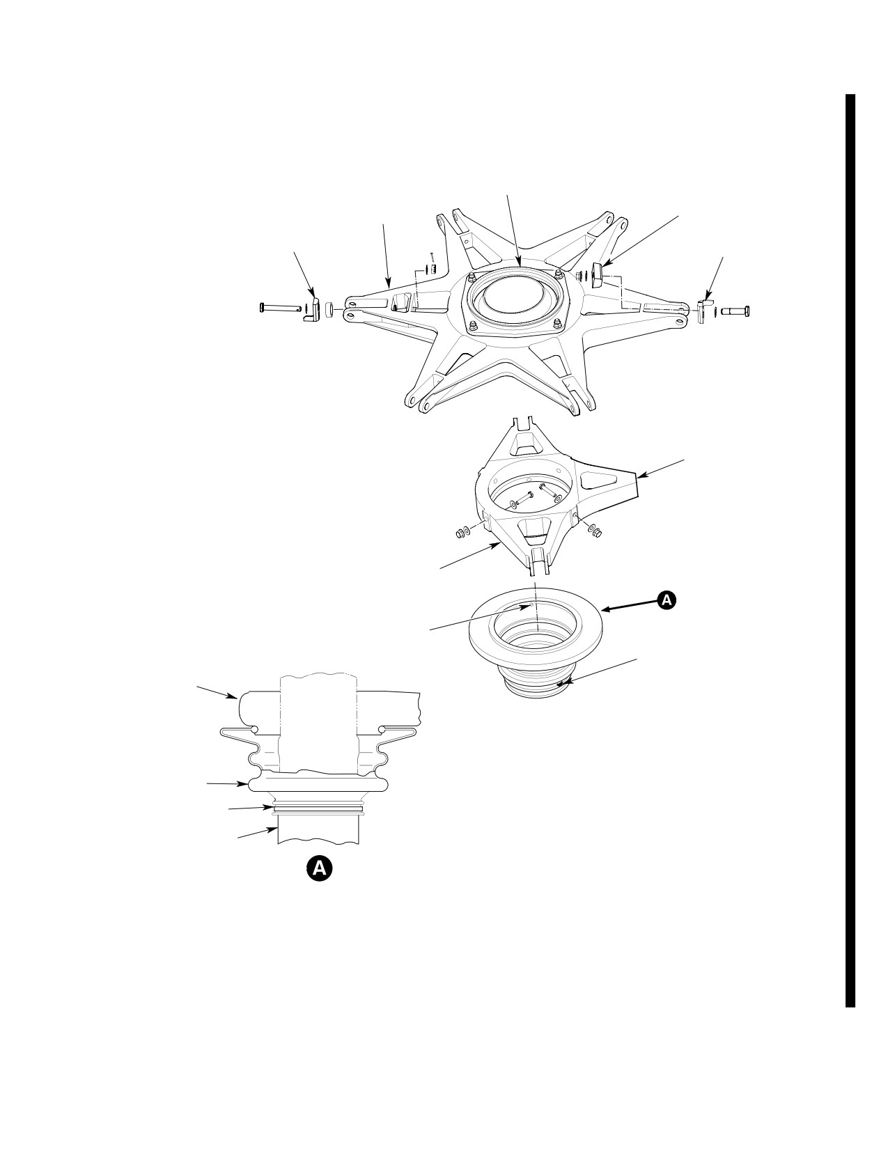
BEARING
ASSEMBLY
ROTATING
BALANCE
SWASHPLATE
WEIGHT
INTERRUPTER
INTERRUPTER
(NOTE 1)
(NOTE 2)
STATIONARY
SWASHPLATE
DRAIN HOLES
(HIDDEN)
INDEX
PROTRUSIONS
DRAIN HOLES
(2 PLCS)
STATIONARY
SWASHPLATE
GROOVE
BOOT
NYLON STRAP
MAST
NOTES:
1.
TORQUE NUT TO 15-20 IN-LBS.
2.
TORQUE NUT TO 50-60 IN-LBS.
6G62-033A
Figure 403. Main Rotor Swashplate
Page 407
62-30-60
Revision 44
CSP-HMI-2
MD Helicopters, Inc.
MAINTENANCE MANUAL
This Page Intentionally Left Blank
Page 408
Revision 44
62-30-60
MD Helicopters, Inc.
CSP-HMI-2
MAINTENANCE MANUAL
SWASHPLATE AND MIXER
INSPECTION/CHECK
1. Swashplate Inspection
(a). Maximum radial play between
sliding surface liner and stationary
mast is 0.020 inch (0.508 mm).
Consumable Materials
(Ref. Section 91−00−00)
(b). Maximum axial play between spheri
Item
Nomenclature
cal ball and teflon liner is 0.010 inch
(0.254 mm).
CM217
Isopropyl alcohol
(c). If play is suspected in double row ball
bearing, turn rotating swashplate
When cleaning swashplate for
until arms line up with those of
CAUTION
inspection, prevent solvent from
stationary swashplate and check
entering either spherical ball bearing or
motion between arms at control bolt
double row ball bearing. Use cloth moist
in stationary swashplate.
ened in alcohol (CM217) to wipe clean
(d). Maximum total vertical movement of
spherical ball, ball bore liner and exterior of
0.015 inch (0.381 mm) is allowable.
double row ball bearing.
(e). If movement limit is exceeded replace
NOTE:
double row ball bearing (Ref. COM).
D Stationary swashplate may be con
(5). Inspect swashplate spherical and
structed of either magnesium or alumi
double row ball bearings for condition.
num alloy. For corrosion control and iden
(a). Nicks and dents that do not deform
tification of magnesium and aluminum
ID chamfered edge of hard anodized
alloys (Ref. Sec. 20-40-00).
ball, and not more than 0.10 inch
D In the following inspection, the rotating
(0.254 mm) deep along spherical ball
and stationary swashplates must be dis
surface from edge are allowed.
connected (Ref. Swashplate and Mixer
(b). Scratches, any length, on OD of
Removal/Installation).
spherical ball are allowed if they are
no deeper than 0.010 inch (0.254
(1). Inspect swashplate bearing assembly
mm) or wider than 0.060 inch (1.524
(Ref. Figure 403 for evidence of binding
mm).
in either radial or axial movement.
(c). Not more than two scratches are
(2). Inspect teflon liners for condition.
permitted in a one inch wide area.
(6). Check existing preload on spherical
(3). Ensure that all flexible rubber seals
bearing.
enclosing ball bearing races are in
place; inspect for deterioration and
(a). Hook spring scale over one of the
indication of grease leakage. (For
bolts securing stationary swashplate
bearing maintenance information
to the bearing flange.
(including lubrication), Ref. COM).
(b). With stationary swashplate in
motion, drag should be no more than
NOTE: New swashplate bearing assembly nor
30 pounds (13.61 kg). (Use average
mally shows some signs of grease leakage
of four readings taken 90 degrees
for first 10-15 hours of operation after in
apart).
stallation.
(c). If readings are more than 30 pounds
(4). Inspect swashplate spherical ball and
(13.61 kg), clean spherical bearing
double row ball bearing for radial or
with isopropyl alcohol and recheck
axial play.
drag.
Page 601
62-30-60
Revision 32
CSP-HMI-2
MD Helicopters, Inc.
MAINTENANCE MANUAL
(d). Repair damage or replace bearings
mixer link for binding, play in link bore
(Ref. COM).
and wear. Wear limit is 0.008 inch
(0.203 mm) radially and 0.040 inch
(7). Check double row ball bearing for
(1.016 mm) axially. Replace complete
serviceability, with seals in place and
mixer link if bearings are faulty.
unbroken.
Inspect bearings in other linkage for
binding and looseness in mating bores.
(a). Check for correct operation and
lubrication.
3. Scissors Inspection
(b). Bearing must rotate smoothly,
(Ref. Figure 401)
without roughness. Binding or
catching should not exist when
Any evidence of failure,
bearings are rotated 360°.
WARNING
damage, or deformation of
crank or link is justification for re
(c). Replace defective double row ball
placement of either crank, link, or com
bearings (Ref. COM).
plete scissors assembly. Failure of any
(8). Perform careful visual inspection of
of these components in flight can result
stationary and rotating swashplate for
in failure of movable flight controls,
cracks, wear in bolt and bushing bores,
loss of helicopter, and possible injury
and fork inner surfaces; and for
or loss of life.
corrosion, nicks and dents.
(1). Inspect crank and link for evidence of
(9). Perform dye penetrant check on
impact damage and deformation. If
questionable areas.
condition is questionable, perform
fluorescent dye penetrant inspection.
(10). Check that counterweights are securely
bonded in rotating swashplate.
(2). Inspect bearings for binding, looseness
in bore and wear. Maximum wear limits
2. Mixer Controls Inspection
are 0.010 inch (0.254 mm) radial and
0.020 inch (0.508 mm) axial.
(Ref. Figure 402)
4. Pitch Control Rod Inspection
(1). Inspect all bushings for security of fit.
(Ref. Figure 401)
(2). Inspect longitudinal link, support
bracket, longitudinal control mixer link,
Ensure that rod end bearings
mixer links, longitudinal pitch idler,
CAUTION
are centered and do not contact
longitudinal pitch mixer bellcrank,
attach clevis.
lateral bellcrank and collective pitch
mixer bellcrank for scratches, cracks,
(1). Visually inspect upper and lower rod
corrosion and similar surface defects.
end bearings for evidence of excessive
For components that are questionable,
axial play, 0.040 inch (1.016 mm)
perform fluorescent dye penetrant
maximum; and for any extrusion,
inspection.
displacement or damage to the bearing
teflon liner.
(3). Inspect spherical, teflon (or equivalent)
lined, bearings in longitudinal link,
(2). Replace rod end bearing if discrepan
mixer link, and longitudinal control
cies are noted.
Page 602
Revision 32
62-30-60
MD Helicopters, Inc.
CSP-HMI-2
MAINTENANCE MANUAL
SWASHPLATE AND MIXER
REPAIRS
1. Swashplate Repairs
be restored on magnesium and alumi
num parts.
(Ref. Figure 403) Disassembly other than as
illustrated is considered a part of swashplate
(7). Replace defective bearings and bush
overhaul (Ref. COM). If tracking interrupters
ings, except swaged spherical bearings
are to be removed, mark them for reinstalla
in mixer links which require link
tion at original locations.
replacement. Remove bearings or
bushings by pressing them out. Install
2. Mixer Controls Repair
new bearing with surface primer and
grade A locking compound (CM321 and
(Ref. Figure 402)
CM431).
NOTE: Left-hand bearing in support bracket is
Consumable Materials
not supplied as part of bracket. This bearing
(Ref. Section 91−00−00)
is installed at time support bracket and lon
Item
Nomenclature
gitudinal pitch idler are assembled. Install
CM321
Surface primer locking compound
new bearing by seating flush with inner face
CM431
Sealing, locking and retaining compound
of support bracket flange.
CM802
Abrasive cloth, aluminum oxide
3. Scissors Bushing and Bearing
Replacement
NOTE: Following depth limits are total limits,
(Ref. Figure 401)
including effects of all previous repairs to
any given area.
Consumable Materials
(1).
Repair minor surface defects such as
(Ref. Section 91−00−00)
scratches, nicks and corrosion using
Item
Nomenclature
abrasive cloth (CM802), grade 400 -
CM103
Solid film lubricant
600 to smooth out and blend in such
CM222
1,1,1-Trichloroethane
defects.
CM318
Primer
(2).
Cast and forged surfaces may be
CM321
Surface primer locking compound
reworked to depth of 0.020 inch (0.508
CM431
Sealing, locking and retaining compound
mm).
(3).
Flat machined surfaces, except clevis
(1). Remove cotter pin, nut, washer, and
inner ears, may be reworked to depth of
bolt that join link and crank.
0.015 inch (0.381 mm). Clevis inner ear
(2). Remove two bushings from link only if
surfaces may be reworked to depth of
replacement is necessary.
0.020 inch (0.508 mm).
(3). Do not remove bearing from link.
(4).
Machined holes may have 0.003 inch
Replace complete link if bearing is
(0.076 mm) removed from bore wall in
defective.
an area no greater than 15 percent of
circumference and 50 percent of depth.
(4). Remove slotted bushings and bearings
from crank, only if replacement is
(5).
All edges may have 0.030 inch (0.762
necessary.
mm) removed except around machined
holes which are limited to 0.010 inch
During cleaning, do not allow
CAUTION
(0.254 mm) chamfer.
solvent to enter bearings.
(6).
All rework must be smoothly blended
(5). Install new bushings using solid film
into adjacent surfaces and finish must
lubricant (CM103); do not use zinc
Page 801
62-30-60
Revision 20
CSP-HMI-2
MD Helicopters, Inc.
MAINTENANCE MANUAL
chromate. Press in bushing until end
(e). Remove excess sealant. Do not allow
is flush with inside surface of crank
sealant to enter bearing race.
inboard ears.
(6). If bearings were removed from crank at
(f). Apply a small fillet of sealant to the
disassembly, reinstall using the
faying edges of bearing housing. Use
following procedure:
cellophane or masking tape to
exclude air and allow sealant to cure
NOTE: Do not allow sealant to enter bearing
for 24 hours at ambient temperature
race.
or force cure by heating to
140°-160°F (60°-72°C) for one hour
(a). Clean bearing outer face, counterbore
prior to use of assembly.
and faying surfaces with trichloroe
thane (CM222). Do not allow trichlo
roethane to enter bearing.
(7). If bushings were removed from link at
disassembly, install new bushings.
(b). Coat the faying surfaces with surface
After installation, dimension between
primer (CM321) as per manufactur
outside faces of bushings should be
er's instructions.
1.579-1.586 inches (4.0107-4.0284 cm).
(c). Apply locking compound (CM431) to
faying surfaces.
(8). Align bore of link with bore of crank;
(d). Press bearing until outer face is
install bolt, washer and nut. Torque nut
seated firmly against shoulder of
to 30 - 40 inch-pounds (3.39 - 4.52
counterbore.
Nm).
Page 802
Revision 20
62-30-60

MD Helicopters, Inc.
CSP-HMI-2
MAINTENANCE MANUAL
Chapter
63
Transmission and
Drive System
MD Helicopters, Inc.
CSP−HMI−2
MAINTENANCE MANUAL
TABLE OF CONTENTS
Para/Figure/Table
Title
Page
63-00-00 Transmission and Drive System (369D/E/FF - 500/600N)
A
Fault Isolation
101
1. Power Train System
101
2. Power Train System Troubleshooting
101
Table 101. Troubleshooting Power Train System
101
Figure 101. Power Train System
104
63-10-00 Drive Shafts / Clutches / Couplings (369D/E/FF - 500/600N)
A
Removal/Installation
401
1.
Main Rotor Drive Shaft
401
2.
Main Rotor drive Shaft Replacement
401
A. Main Rotor Drive Shaft Removal
401
B. Main Rotor Drive Shaft Installation
401
Figure 401. Main Rotor Drive Shaft Installation (Sheet 1 of 2)
402
3.
Main Transmission Drive Shaft
404
4.
Main Transmission Drive Shaft Replacement
404
A. Main Transmission Drive Shaft Removal (Bendix and Kamatic)
404
B. Main Transmission Drive Shaft Installation (Bendix and Kamatic)
404
Figure 402. Main Transmission Drive Shaft Installation
405
5.
Overrunning Clutch
406
6.
Overrunning Clutch Replacement
406
A. Overrunning Clutch Removal
406
B. Overrunning Clutch Installation
406
Figure 403. 369A5350 Overrunning Clutch Installation
407
Figure 404. 369F5450 Overrunning Clutch Installation
408
7.
Overrunning Clutch Subassembly Replacement
409
A. Overrunning Clutch Subassembly Removal
409
B. Overrunning Clutch Subassembly Installation
410
8.
Overrunning Clutch-to-Firewall Seal
410
9.
Overrunning Clutch-to-Firewall Seal Replacement
410
10. Main Transmission Drive Shaft Couplings
411
11. Main Transmission Drive Shaft Coupling Replacement
411
A. Main Transmission Drive Shaft Coupling Removal
411
B. Main Transmission Drive Shaft Coupling Installation
411
Page i
63 Contents
Revision 42
CSP−HMI−2
MD Helicopters, Inc.
MAINTENANCE MANUAL
TABLE OF CONTENTS (Cont.)
Para/Figure/Table
Title
Page
12. Tail Rotor Drive Shaft Coupling Replacement
412
A. Tail Rotor Drive Shaft Coupling Removal
412
B. Tail Rotor Drive Shaft Coupling Installation
412
Figure 405.
369F5468/5469 Bolt Removal Tool
413
Inspection/Check
601
1.
369D25510 Main Rotor Drive Shaft Inspection
601
2.
600N5510 and 369F5510 Main Rotor Drive Shaft Inspection
601
Figure 601. Main Rotor Drive Shaft Inspection
602
Figure 602. Main Rotor Drive Shaft Overtorque Verification Stripe
603
3. Main Transmission Drive Shaft Inspection (Bendix)
603
4. Main Transmission Drive Shaft Inspection (Kamatic)
604
5. Overrunning Clutch Inspection
605
6. Overrunning Clutch-to-Firewall Seal Inspection
605
7. Bendix Tail Rotor Drive Shaft Coupling Inspection
605
8. Kamatic Coupling Inspection
605
9. Main Rotor Drive Shaft Inspection (300 Hour)
605
Repairs
801
1. Main Rotor Drive Shaft Exterior Repair
801
2. Main Rotor Drive Shaft Corrosion Removal
802
3. Main Transmission Drive Shaft Repair (Bendix)
802
4. Main Transmission Drive Shaft Repair (Kamatic)
803
5. Overrunning Clutch Repair/Overhaul
803
6. Overrunning Clutch-to-Firewall Seal Repair
803
7. Main Transmission Drive Shaft Coupling Corrosion Removal
803
8. Bendix Coupling Repair
804
9. Kamatic Coupling Repair
804
Page ii
Revision 42
63 Contents
MD Helicopters, Inc.
CSP−HMI−2
MAINTENANCE MANUAL
TABLE OF CONTENTS (Cont.)
Para/Figure/Table
Title
Page
63-15-10 Tail Rotor Drive Shaft (369D/E/FF)
A
Removal/Installation
401
1. Tail Rotor Drive Shaft
401
2. Tail Rotor Drive Shaft Replacement
401
A. Tail Rotor Drive Shaft Removal
401
B. Tail Rotor Drive Shaft Installation with Bendix Couplings
401
Figure 401. Tail Rotor Drive Shaft Installation (369D/E/FF) (Sheet 1 of 3)
402
Figure 402. Tail Rotor Drive Shaft Installation (369FF)
407
C. Tail Rotor Drive Shaft Installation with Kamatic Couplings
408
3. Tail Rotor Drive Shaft Damper
409
4. Tail Rotor Drive Shaft Damper Replacement
409
Inspection/Check
601
1. Tail Rotor Drive Shaft Inspection
601
2. Tail Rotor Drive Shaft Twist Inspection
601
Figure 601. Tail Rotor Drive Shaft - Inspection Markings
602
Figure 602. Tail Rotor Drive Shaft - Inspection Markings (Extended Tailboom)
603
3. Tail Rotor Drive Shaft Damper Inspection
604
Figure 603. Tail Rotor Drive Shaft Damper - Inspection
605
Repairs
801
1. Tail Rotor Drive Shaft Repair Procedure
801
2. Tail Rotor Drive Shaft Index Stripe Application
801
63-15-30 NOTAR) Anti-Torque System Drive Shafts (500/600N)
A
Maintenance Practices
201
1. Anti-Torque System Drive Shafts
201
2. Fan Gearbox Drive Shaft Replacement
201
A. Fan Gearbox Drive Shaft Removal
201
B. Fan Gearbox Drive Shaft Installation
201
3. Fan Gearbox Drive Shaft Inspection
203
4. Fan Gearbox Drive Shaft Repair Procedure
203
Figure 201. Fan Gearbox and Inter-Connecting Drive Shafts
204
5. Fan Inter-Connect Drive Shaft Replacement
205
A. Fan Inter-Connect Drive Shaft Removal
205
B. Fan Inter-Connect Drive Shaft Installation
205
6. Inter-Connect Drive Shaft Inspection
205
7. Inter-Connect Drive Shaft Repair
206
8. Transmission and Fan Coupling Inspection
206
Page iii
63 Contents
Revision 42
CSP−HMI−2
MD Helicopters, Inc.
MAINTENANCE MANUAL
TABLE OF CONTENTS (Cont.)
Para/Figure/Table
Title
Page
9. Gearbox and Fan Coupling Repair
206
10. Transmission Coupling / Fan Coupling Replacement
207
A. Transmission Coupling / Fan Coupling Removal
207
B. Transmission Coupling / Fan Coupling Installation
207
Figure 202. Fan Interconnect Drive Shaft Coupling Installation
207
63-20-00 369D25100 Main Transmission (369D/E/FF - 500N)
A
Maintenance Practices
201
1. Main Transmission
201
2. Main Transmission Buildup and Replacement
201
A. Main Transmission Removal
201
Figure 201. 369D25100 Main Transmission Installation
202
B. Main Transmission Installation
203
3. Main Transmission Inspection Procedure
204
4. Main Transmission Repair Procedure
204
5. Input Drive Assembly - Oil Leakage Repair Procedure
204
Figure 202. Input Drive Assembly O-Ring Replacement
206
Figure 203. Assembly Aid Tool for Input Drive
207
63-20-25 369F5100 Main Transmission (369D/E/FF - 500/600N)
A
Maintenance Practices
201
1. Main Transmission
201
2. Main Transmission Replacement
201
A. Main Transmission Removal
201
B. Main Transmission Installation
201
Figure 201. 369F5100 Main Transmission Installation
202
3. Main Transmission Stripping
203
Figure 202. 369F5100 Main Transmission Build-Up
204
4. Main Transmission Build-Up
205
5. Main Transmission Inspection Procedure
205
6. Main Transmission Repair Procedure
205
7. Input Drive Assembly - Oil Leakage Repair Procedure
206
A. Input Pinion O-Ring Replacement
206
Figure 203. Drive Assembly O-Ring Replacement
207
B. Input Pinion Seal Replacement
208
8. Main Transmission Filter Replacement
209
9. Main Transmission Run-In Procedure
209
Page iv
Revision 42
63 Contents
MD Helicopters, Inc.
CSP−HMI−2
MAINTENANCE MANUAL
TABLE OF CONTENTS (Cont.)
Para/Figure/Table
Title
Page
63-21-00 Main Transmission Lubrication and Cooling System
(369D/E/FF - 500/600N)
A
Removal/Installation
401
1.
Main Transmission Lubrication System
401
2.
Main Transmission Lubrication Pump Replacement
(369D25100 Transmission)
401
A. Main Transmission Lubrication Pump Removal
(369D25100 Transmission)
401
B. Main Transmission Lubrication Pump Installation
(369D25100 Transmission)
401
3.
Main Transmission Lubrication Pump Replacement
(369F5100 Transmission)
401
A. Main Transmission Lubrication Pump Removal
(369F5100 Transmission)
401
B. Main Transmission Lubrication Pump Installation
(369F5100 Transmission)
401
Figure 401. Main Transmission Lubrication Pump
(369D25100 Transmission)
402
Figure 402. Main Transmission Lubrication Pump
(369F5100 Transmission)
403
4.
Main Transmission Filter Replacement (369D25100 Transmission)
404
5.
Main Transmission Filter Replacement (369F5100 Transmission)
404
6.
Main Transmission Scavenge Pump Replacement (369F5100 Transmission)
404
A. Main Transmission Scavenge Pump Removal (369F5100 Transmission)
404
B. Main Transmission Scavenge Pump Installation (369F5100 Transmission)
404
7.
Main Transmission Oil Cooler Bypass Valve Replacement
405
8.
Main Transmission Oil Cooler Replacement
405
A. Main Transmission Oil Cooler Removal
405
B. Main Transmission Oil Cooler Installation
405
Figure 403. Main Transmission Oil Cooler Installation
406
9.
Main Transmission Oil Temperature Sender Replacement
407
10. Main Transmission Oil Pressure Sender Replacement
407
11. Liquid Level Plug Replacement
407
Figure 404. Main Transmission - Cross-Section View
408
12. Chip Detector Replacement
408
Page v
63 Contents
Revision 42
CSP−HMI−2
MD Helicopters, Inc.
MAINTENANCE MANUAL
TABLE OF CONTENTS (Cont.)
Para/Figure/Table
Title
Page
13. Cooling Blower Replacement
408
A. Cooling Blower
408
B. Cooling Blower Removal
408
C. Cooling Blower Installation (369D25100 Transmission)
409
Figure 405. Cooling Blower Installation (369D25100 Transmission)
410
D. Cooling Blower Installation (369F5100 Transmission)
411
Figure 406. Oil Cooler Blower Installation (369F5100 Transmission)
412
E. 369D, E, F, and 500N - Cooling Blower Belt Tracking
413
Figure 407. Cooling Blower Belt Tracking
413
Inspection/Check
601
1. Lubrication System Inspection
601
2. Cooling Blower Inspection
601
3. Cooling Blower Inspection (Disassembled)
601
Figure 601. Main Transmission Cooling Blower and Duct
602
4. Cooling Blower Belt Tension Check and Adjustment
603
Repairs
801
1.
369D25630 Cooling Blower Disassembly
801
Figure 801. 369D25630 Cooling Blower - Cross-Section View
802
2.
369D25630 Cooling Blower Reassembly
803
3.
600N5630 Cooling Blower Disassembly
804
Figure 802. 600N5630 Cooling Blower - Cross-Section View
805
4.
600N5630 Cooling Blower Reassembly
806
5. Cooling Blower Cleaning (Disassembled)
808
6. Transmission and Cooling Blower Drain Tube Repair and Replacement
808
7. Installation of Heating System and Oil Cooling Line Standoff Clamps
(0003D - 0539D)
808
Figure 803. Installation of Standoff Clamps - Heating and Oil Cooling Lines
810
Page vi
Revision 42
63 Contents
MD Helicopters, Inc.
CSP−HMI−2
MAINTENANCE MANUAL
TABLE OF CONTENTS (Cont.)
Para/Figure/Table
Title
Page
63-22-00 Rotor Brake (369D/E/FF - 500/600N)
A
Maintenance Practices
201
1. Rotor Brake
201
2. Rotor Brake Operation
201
3. Rotor Brake Troubleshooting Procedure
201
4. Master Cylinder Servicing
201
5. Rotor Brake Hydraulic System Bleeding
202
6. Rotor Brake Component Repair
203
7. Master Cylinder Assembly Overhaul
203
8. Caliper Assembly Overhaul
203
Table 201. Troubleshooting Rotor Brake Installation
204
Removal/Installation
401
1.
Rotor Brake Component Access
401
2.
Master Cylinder Assembly Replacement
401
A. Master Cylinder Assembly Removal
401
Figure 401. Airframe-Mounted Rotor Brake Components
402
B. Master Cylinder Assembly Installation
403
3.
Master Cylinder Linkage Assembly Replacement
403
A. Master Cylinder Linkage Assembly Removal
403
Figure 402. Master Cylinder Linkage Assembly
404
B. Master Cylinder Linkage Assembly Installation
404
4.
Caliper Assembly, Brake Disc, and Drive Coupling Replacement
(369D25100 Transmission)
405
A. Caliper Assembly, Brake Disc, and Drive Coupling Removal
(369D25100 Transmission)
405
Figure 403. Transmission-Mounted Rotor Brake Components
406
B. Caliper Assembly, Brake Disc and Drive Coupling Installation
(369D25100 Transmission)
407
Figure 404. Caliper Assembly and Brake Disc Interface
(369D25100 Transmission)
408
Figure 405. Lockwire Installation (369D25100 Transmission)
408
5.
Caliper Mounting Bracket Replacement (369D25100 Transmission)
409
A. Caliper Mounting Bracket Removal (369D25100 Transmission)
409
B. Caliper Mounting Bracket Installation (369D25100 Transmission)
409
Page vii
63 Contents
Revision 42
CSP−HMI−2
MD Helicopters, Inc.
MAINTENANCE MANUAL
TABLE OF CONTENTS (Cont.)
Para/Figure/Table
Title
Page
6. Caliper Assembly, Brake Disc, and Drive Coupling Replacement
(369F5100 Transmission)
409
A. Caliper Assembly, Brake Disc, and Drive Coupling Removal
(369F5100 Transmission)
409
B. Caliper Assembly, Brake Disc and Drive Coupling Installation
(369F5100 Transmission)
410
Figure 406. Rotor Brake Caliper Installation (369F5100 Transmission)
411
7. Hydraulic Relief Valve Replacement
412
A. Hydraulic Relief Valve Removal
412
B. Hydraulic Relief Valve Installation
412
8. Hydraulic Tube Assembly Replacement
413
A. Hydraulic Tube Assembly Removal
413
B. Hydraulic Tube Assembly Installation
413
9. Rotor Brake Forward Cover Assembly Installation
413
Inspection/Check
601
1. Rotor Brake Assembly Inspection
601
2. Rotor Brake Operational Check
602
Initial Installation
901
1. Rotor Brake Initial Installation
901
A. Aircraft Preparation
901
B. Installation Access
901
C. Removing Components to be Replaced
901
D. Angle Assembly Installation (500D)
902
E. Master Cylinder Linkage Assembly and Mount Bracket Installation
902
Figure 901. Locating Permanently Installed Components (Sheet 1 of 2)
903
F. Handle Retainer Assembly Installation
905
G. Rivnut Installation
905
Figure 902. Rotor Brake Installation (Sheet 1 of 2)
906
H. Window Support Channel Modification
908
I. Caliper Mounting Bracket Initial Installation
908
J. Caliper Assembly, Brake Disc and Drive Coupling Installation
908
Figure 903. Modifying Window Support Channel
909
Figure 904. Hydraulic Tube Installation
910
Page viii
Revision 42
63 Contents
MD Helicopters, Inc.
CSP−HMI−2
MAINTENANCE MANUAL
TABLE OF CONTENTS (Cont.)
Para/Figure/Table
Title
Page
K. Master Cylinder Assembly Initial Installation
911
Figure 905. Positioning Master Cylinder
911
L. Hydraulic Relief Valve Initial Installation
912
M. Hydraulic Tube Assemblies Initial Installation
912
N. Rotor Brake Installation Servicing
912
Figure 906. Reworking Master Cylinder Gasket
912
O. Installing Interior Furnishings
913
P. Map Case Assembly Modification and Installation
913
Q. Convenience Panel Cover Assembly Modification and Installation
913
R. Rotor Brake Forward Cover Assembly Installation
913
Figure 907. Modifying Map Case Panel
914
Figure 908. Modifying Rotor Brake Cover Panel Assemblies (Sheet 1 of 2)
915
S. Weight and Balance
917
Table 901. Weight and Balance Data
917
63-25-10 Tail Rotor Transmission (Two and Four Blade) (369D/E/FF)
A
Maintenance Practices
201
1. Tail Rotor Transmission
201
2. Tail Rotor Transmission Replacement
201
A. Tail Rotor Transmission Removal
201
B. Tail Rotor Transmission Installation
201
Figure 201. Tail Rotor Transmission - Stripping/Buildup
202
3. Tail Rotor Transmission Inspection
203
Figure 202. Replacement of Liquid Level Plug and Breather-Filler
204
4. Tail Rotor Transmission Stripping
205
5. Tail Rotor Transmission Buildup
205
6. Tail Rotor Transmission Parts Replacement
205
7. Input and Output Gearshaft Cover Oil Leak Repair
206
8. Tail Rotor Transmission Housing Assembly Rework (PN 369D25401)
206
Figure 203. Tail Rotor Transmission Mount Stud Limits
206
Figure 204. Rework of Tail Rotor Transmission Housing Assembly
207
Page ix
63 Contents
Revision 42
CSP−HMI−2
MD Helicopters, Inc.
MAINTENANCE MANUAL
TABLE OF CONTENTS (Cont.)
Para/Figure/Table
Title
Page
63-25-30 NOTAR) Anti-Torque System Fan Transmission (500/600N)
A
Maintenance practices
201
1. Fan Transmission
201
2. Fan Transmission Replacement
201
A. Fan Transmission Removal
201
B. Fan Transmission Installation
201
Figure 201. Fan Transmission Removal/Installation
202
3. Fan Transmission Inspection
203
4. Tube Support Inspection
203
5. Fan Transmission Parts Replacement
203
Figure 202. Fan Transmission Parts Replacement
204
63-30-00 Main Rotor Static Mast (369D/E/FF - 500/600N)
A
Maintenance Practices
201
1. Main Rotor Static Mast
201
2. Main Rotor Static Mast Replacement (369D25100 Transmission Installation) . . .
201
A. Main Rotor Static Mast Removal (369D25100 Transmission Installation)
201
B. Main Rotor Static Mast Installation (369D25100 Transmission Installation) . .
201
Figure 201. Main Rotor Mast and Support Structure
(369D25100 Transmission Installation)
202
3. Main Rotor Static Mast Replacement (369F5100 Transmission Installation)
203
A. Main Rotor Static Mast Removal (369F5100 Transmission Installation)
203
B. Main Rotor Static Mast Installation (369F5100 Transmission Installation) . . .
203
4. Main Rotor Static Mast Inspection and Repair
203
Figure 202. Main Rotor Mast and Support Structure
(369F5100 Transmission Installation)
205
Figure 203. Main Rotor Mast - Inspection and Repair
206
Page x
Revision 42
63 Contents
MD Helicopters, Inc.
CSP-HMI-2
MAINTENANCE MANUAL
Section
63−00−00
Transmission and
Drive System
(369D/E/FF −
500/600N)
MD Helicopters, Inc.
CSP-HMI-2
MAINTENANCE MANUAL
TRANSMISSION AND DRIVE SYSTEM
FAULT ISOLATION
1. Power Train System
2. Power Train System Troubleshooting
(Ref. Figure 101) The power train system,
starting at the engine power takeoff pad,
(Ref. Table 101) Diagnose and repair power
consists primarily of the overrunning clutch,
train system malfunctions using procedures as
drive shafts, and transmissions.
follows.
Table 101. Troubleshooting Power Train System
Symptom
Probable Trouble
Corrective Action
Main drive shaft vibrates
Coupling flange bolts on main drive
Retorque bolts to 50 − 70
excessively. (For serviceability
shaft are loose.
inch−pounds (5.65 − 7.91 Nm).
limits, refer to Section 63−10−00).
Excessive noise or vibration in
Defective impeller or damaged
Replace impeller or scroll (Ref. Sec.
cooling blower.
scroll.
63−21−00).
Main drive shaft turns erratically or
Defective overrunning clutch.
Replace overrunning clutch (Ref.
not at all.
Sec. 63−10−00).
Main transmission requires
Leakage at main transmission input
If leakage is found at input shaft or
frequent addition of oil.
or output seals.
tail rotor shaft, replace seal
according to instructions (Ref. COM).
If leakage is at main rotor drive shaft,
replace transmission (Ref. Sec.
63−20−00).
Oil leak around accessory drive
Tighten cover or replace
cover.
transmission (Ref. Sec. 63−20−00).
Oil temperature warning light
Defective oil temperature sender.
Replace oil temperature sender (Ref.
comes on when oil temperature is
Sec. 63−21−00).
normal.
Oil temperature warning light
Defective cooling blower.
Repair or replace cooling blower
comes on when oil temperature is
(Ref. Sec. 63−21−00).
abnormally high.
Low or high oil level in
Establish correct oil level (Ref. Sec.
transmission.
12−00−00).
Defective lubrication pump.
Replace pump (Ref. COM).
Defective oil cooler bypass valve.
Replace valve. (Ref. Sec.
63−21−00).
Defective bearings or gears.
Replace transmission (Ref. Sec.
63−20−00).
Page 101
63-00-00
Revision 28
CSP-HMI-2
MD Helicopters, Inc.
MAINTENANCE MANUAL
Table 101. Troubleshooting Power Train System (Cont.)
Symptom
Probable Trouble
Corrective Action
NOTE: Noise that indicates a defective transmission should not be confused with normal gear backlash noise at
rundown or low rpm and power conditions.
Excessive noise in main
Inadequate oil supply.
Service main transmission (Ref. Sec.
transmission.
12−00−00).
Defective bearings or gears.
Replace transmission (Ref. Sec.
63−20−00).
Oil pressure warning light (low oil
Low oil in main transmission.
Service main transmission (Ref. Sec.
pressure) remains lighted at above
12−00−00).
55% N2.
Defective oil pressure switch.
Replace oil pressure switch (Ref.
Sec. 63−21−00).
Defective lube pump.
Replace lube pump (Sec.
63−20−00).
Filter clogged.
Replace filter (Ref. Sec. 63−21−00).
369F5100 Transmission impending
Filter clogged.
Reset indicator. On second pop−up,
bypass indicator popped.
replace filter (Ref. Sec. 63−21−00).
Defective differential pressure
Replace differential pressure
indicator.
indicator (Ref. COM).
369F5100 Transmission impending
Defective differential pressure
Replace differential pressure
bypass indicator popped in less
indicator.
indicator (Ref. COM).
than 100 hours since filter change.
Tail rotor drive shaft damper
Damper out of adjustment.
Adjust damper (Ref. Sec. 63−15−00).
vibrates.
Damper defective.
Replace damper (Ref. Sec.
63−15−00).
Tail rotor drive shaft bent or dented.
Replace defective drive shaft (Ref.
Sec. 63−15−00).
Tail rotor out of balance.
Adjust tail rotor balance (Ref. Sec.
18−10−00).
Tail rotor transmission output shaft
Worn or damaged bearing or gear
Replace tail rotor transmission (Ref.
vibrates.
in tail rotor transmission.
Sec. 63−25−10).
Excessive shaft wobble or end play
Replace tail rotor transmission (Ref.
(Ref. Sec. 63−15−10).
Sec. 63−25−10).
Excessive noise in tail rotor
Inadequate oil supply.
Service tail rotor transmission (Ref.
transmission.
Sec. 12−00−00).
Defective bearings or gears in tail
Replace tail rotor transmission (Ref.
rotor transmission.
Sec. 63−25−10).
Page 102
Revision 29
63-00-00
MD Helicopters, Inc.
CSP-HMI-2
MAINTENANCE MANUAL
Table 101. Troubleshooting Power Train System (Cont.)
Symptom
Probable Trouble
Corrective Action
Chip detector caution light on.
Metallic chips in either main
Inspect and clean chip detector
transmission, fan transmission or
magnetic plugs. If there are heavy
tail rotor transmission.
chip deposits (chips larger than 1/8
inch in any direction), replace
transmission. If chips are smaller,
drain and refill transmission with new
oil. Reinstall chip detector and check
after four hours of flight. If more
chips are found, replace
transmission (main − Sec. 63−20−00
or 63−20−25; tail rotor − Sec.
63−25−10; fan − 63−25−30).
Chip detector caution light is on,
Defective chip detector circuit
Troubleshoot chip detector circuit
but no chips are on detector.
components.
(Ref. CSP−HMI−3).
NOTE: High frequency vibrations in helicopter can also be caused by components in other systems.
High frequency vibrations.
Loose tail rotor drive shaft
Tighten coupling bolts (Ref. Sec.
coupling(s).
63−15−00).
Tail rotor drive shaft coupling
Shim correctly (Ref. Sec. 63−15−00).
shimmed improperly.
Loose, mismatched or bottomed
Tighten or install correct hardware
hardware retaining tail rotor drive
and be sure hardware is installed
shaft coupling to main
correctly (Ref. Sec. 63−15−00).
transmission.
Cooling blower impeller has cracks,
Replace impeller (Ref. Sec.
loose rivets, defective blades or
63−21−00).
other damage.
Tail rotor drive shaft damper out of
Adjust damper friction (Ref. Sec.
adjustment.
63−15−00).
Defective overrunning clutch.
Replace overrunning clutch (Ref.
Sec. 63−10−00).
Tail rotor drive shaft damaged.
Replace shaft (Ref. Sec. 63−15−00).
Abnormal drag in drive system.
Excessive drag in main
Replace transmission (Ref. Sec.
transmission.
63−20−00).
NOTE: Drag is excessive when force required to rotate transmission input shaft exceeds 25 inch−pounds (2.82
Nm) with all shafting disconnected and transmission temperature between 50°F (10°C) and 100°F (38°C).
Page 103
63-00-00
Revision 30
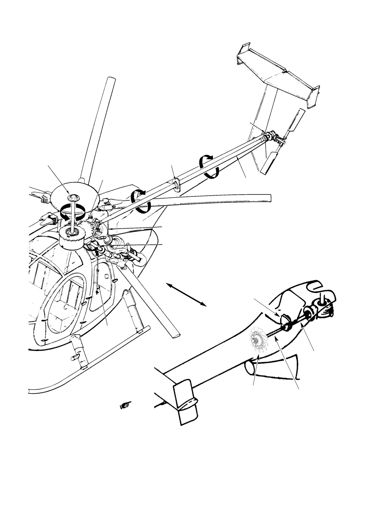
CSP-HMI-2
MD Helicopters, Inc.
MAINTENANCE MANUAL
TAIL ROTOR TRANSMISSION
TAIL ROTOR DRIVE
MAIN ROTOR DRIVE
SHAFT DAMPER
SHAFT
MAIN TRANSMISSION
TAIL ROTOR DRIVE SHAFT
COOLING BLOWER
MAIN TRANSMISSION
DRIVE SHAFT
FAN TRANSMISSION
DRAIN LINE
FAN GEARBOX
DRIVE SHAFT
ANTI-TORQUE FAN
FAN INTER-CONNECT
DRIVE SHAFT
G63-0000A
Figure 101. Power Train System
Page 104
Revision 28
63-00-00
MD Helicopters, Inc.
CSP-HMI-2
MAINTENANCE MANUAL
Section
63−10−00
Drive Shafts /
Clutches / Couplings
(369D/E/FF −
500/600N)

MD Helicopters, Inc.
CSP-HMI-2
MAINTENANCE MANUAL
DRIVE SHAFTS / CLUTCHES / COUPLINGS
REMOVAL/INSTALLATION
1. Main Rotor Drive Shaft
B. Main Rotor Drive Shaft Installation
The main rotor drive shaft is a shot-peened,
Special Tools
steel alloy forging having a nitrided spline at
(Ref. Section 91−00−00)
one end that mates with the transmission
Item
Nomenclature
output shaft, and a flanged opposite end that
attaches to the rotor hub with seven bolts and
ST704
Adapter, torque wrench
three eyebolts.
Damage to main rotor drive
2. Main Rotor drive Shaft Replacement
CAUTION
shaft or transmission splines
can occur during installation. Care should
(Ref. Figure 401)
be taken while meshing driveshaft splines
into transmission output splines to prevent
When removing or installing the
CAUTION
damage.
main rotor drive shaft external-
wrenching bolts or eyebolts, always hold
(1).
Slowly and carefully lower drive shaft
bolts stationary while installing or remov
through main rotor hub and mast until
ing nuts. Never turn external-wrenching
rotor shaft splines and transmission
bolts or eyebolts while inserting or removing
shaft splines engage.
from drive shaft holes.
(2).
Rotate hub to align holes in flange with
A. Main Rotor Drive Shaft Removal
holes in drive shaft.
Main rotor drive shaft is a high
(3).
Install three eyebolts, washers, and
CAUTION
ly stressed part. Do not allow
nuts. Using torque wrench adapter
tools to strike shaft, or shaft to strike any
(ST704), torque nuts to 120 - 140
object. Any impact damage may require re
inch-pounds (13.56 - 15.82 Nm).
placement of drive shaft.
(4).
With fairing support spacers and
(1). Remove main rotor fairing.
special washers in place, position main
rotor fairing support so that eyebolt
(2). Remove seven external-wrenching
shoulders are inserted in large holes in
bolts; and associated hardware. Lift off
fairing support. Make certain that
main rotor fairing support and remove
support extensions are between pitch
seven spacers.
housings.
Any time drive shaft is removed,
(5).
Install seven external-wrench bolts,
CAUTION
cover opening in top of main ro
seven washers and nuts as in step (3).
tor hub to prevent possible entry of foreign
above.
matter into hub, mast and transmission.
NOTE: Phillips screws, used to attach main ro
NOTE: If special washers between fairing sup
tor hub fairing, may be replaced with hex
port and drive shaft dome are not bonded to
head Phillips screws (PN NAS1096-3-10)
the underside of fairing support, remove
and washers (PN HS306-223). The hex
washers before proceeding.
head will make torquing the screws easier.
(3). Remove three eyebolts and associated
(6). Install main rotor fairing with five
hardware and lift drive shaft clear of
screws. Torque screws to 20 - 25
main rotor hub.
inch-pounds (2.26 - 2.82 Nm).
Page 401
63-10-00
Revision 20
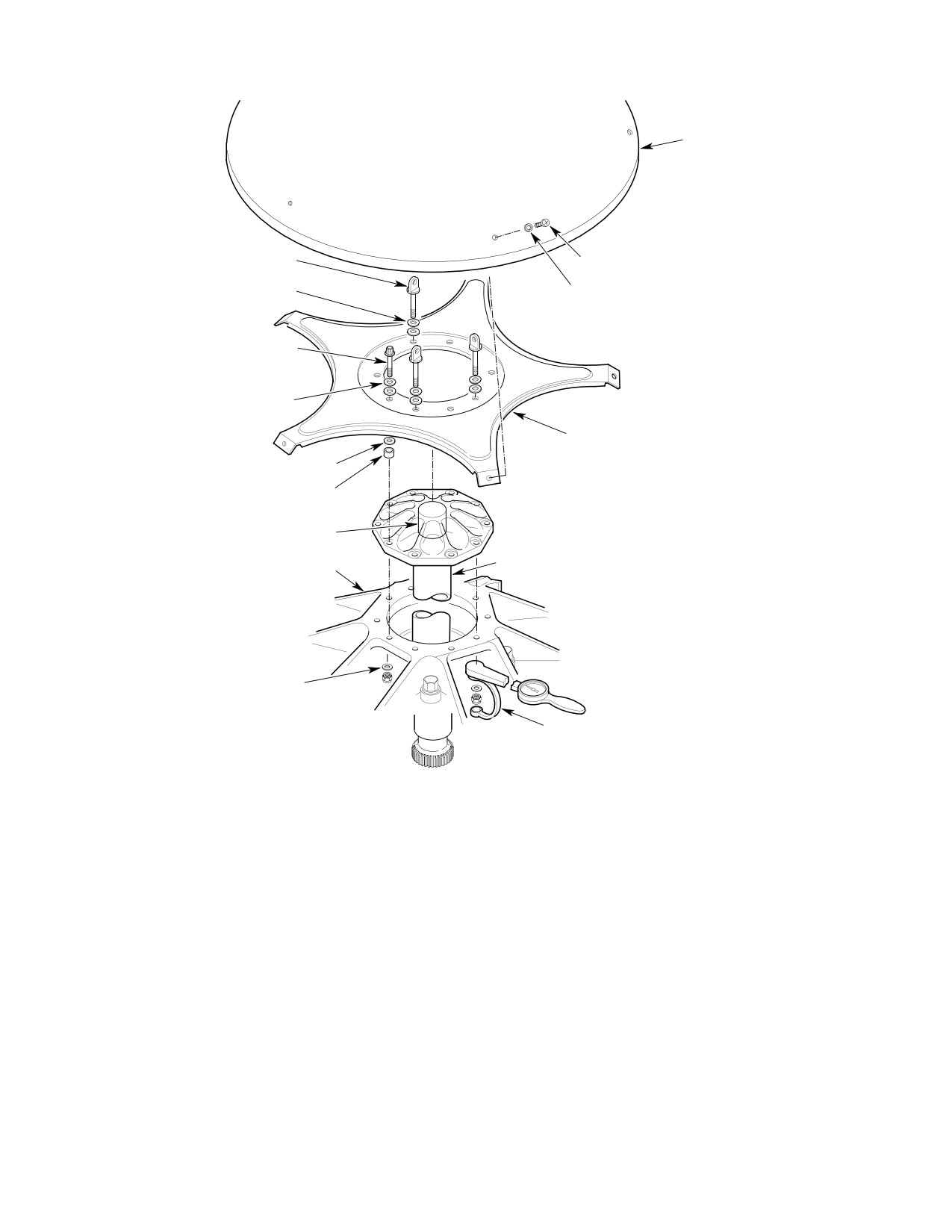
CSP-HMI-2
MD Helicopters, Inc.
MAINTENANCE MANUAL
HUB FAIRING
EYEBOLT (3 PLCS AS SHOWN)
SCREW
(NOTE 4)
(5 PLCS)
NOTE 1
WASHER
(5 PLCS)
EXTERNAL
WRENCHING BOLT
(7 PLCS)
NOTE 1
FAIRING SUPPORT
(NOTE 5)
NOTE 3
SPACER
(7 PLCS)
CORK
(NOTE 2)
DRIVE SHAFT
HUB
THIN WASHERS
(TYP, 10 PLACES)
TORQUE WRENCH
ADAPTER
369D/E/FF - 500N INSTALLATION
NOTES:
1.
INSTALLED WITH COUNTERSINK NEXT TO BOLT HEAD, WASHERS UNDER NUT ARE FLAT.
2.
INSTALLED WITH SEALING COMPOUND.
3.
MAY BE BONDED TO FAIRING SUPPORT.
4.
WHEN INSTALLING EYEBOLTS, ENSURE FAIRING SUPPORT ARMS ARE NOT POSITIONED OVER
PITCH HOUSINGS.
5.
THREE HOLES IN FAIRING SUPPORT ARE LARGER TO GO OVER EYEBOLTS AND TO AID IN FAIRING
G63-1001B
SUPPORT ALIGNMENT.
Figure 401. Main Rotor Drive Shaft Installation (Sheet 1 of 2)
Page 402
Revision 20
63-10-00
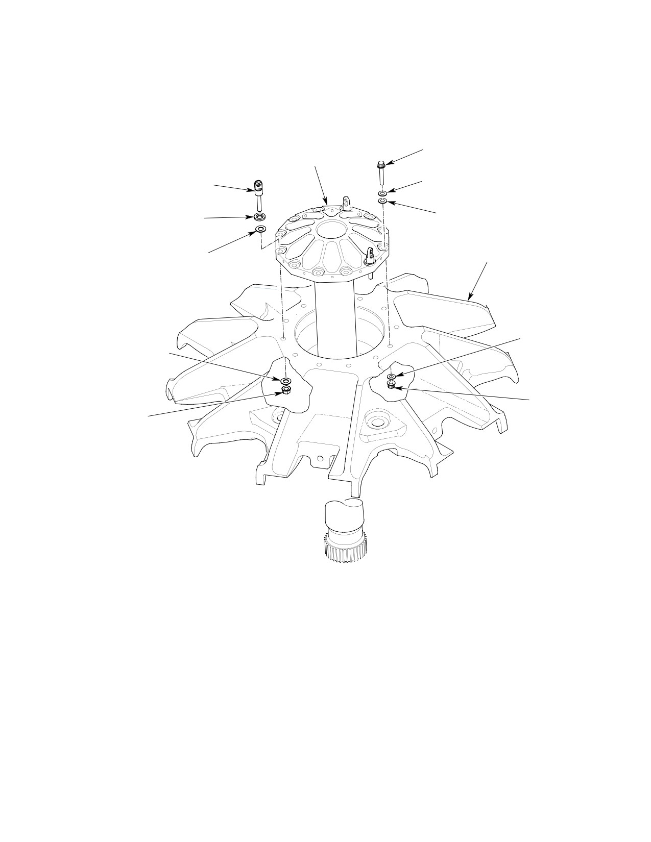
MD Helicopters, Inc.
CSP-HMI-2
MAINTENANCE MANUAL
BOLT
MAIN ROTOR
(9 PLACES)
DRIVE SHAFT
EYEBOLT
COUNTERSUNK WASHER
(3 PLACES)
(NOTE 2)
(NOTE 1)
COUNTERSUNK WASHER
FLAT WASHER
(NOTE 2)
FLAT WASHER
MAIN ROTOR HUB
WASHER
WASHER
NUT
NUT
600N INSTALLATION
NOTES:
1.
ALIGN HOLES IN EYE BOLTS TO MATCH HOISTING ADAPTER.
6G63-008
2.
COUNTERSINK IN WASHER TO FACE BOLT HEAD.
Figure 401. Main Rotor Drive Shaft Installation (Sheet 2 of 2)
Page 403
63-10-00
Revision 20
CSP-HMI-2
MD Helicopters, Inc.
MAINTENANCE MANUAL
3. Main Transmission Drive Shaft
less than 25 inch-pounds (2.82
Nm) before torquing bolt.
The main transmission drive shaft is equipped
with a flexible diaphragm-type joint and
(b). For 36F5450 clutch, actual drag
mounting flange (coupling) at each end. The
torque plus 315 - 365 inch-
shaft connects the overrunning clutch and the
pounds (35.59 - 41.24 Nm). If bolt
transmission input shaft.
is not seated and/or existing torque is
found to be less than 315 - 365
inch-pounds (35.59 - 41.24 Nm),
4. Main Transmission Drive Shaft
ensure self-locking drag torque is not
Replacement
less than 25 inch-pounds (2.82
Nm) before torquing bolt.
(Ref. Figure 402)
Compression of drive shaft dia
A. Main Transmission Drive Shaft Removal
CAUTION
phragms (static state) is limited
(Bendix and Kamatic)
to 0.020 inch (0.508 mm). Do not stress dia
phragms by forcing drive shaft into position
(1). Remove sound insulation and main
for installation in step (2). below.
transmission access cover over main
transmission drive shaft in cargo
NOTE: If original shaft and couplings are being
compartment.
reinstalled, a check of shimming as de
scribed below is not necessary. Install drive
(2). Remove eight bolts and washers that
shaft to clutch and transmission couplings
secure shaft to couplings.
as described in steps (1). above and (4). be
low.
(3). Remove drive shaft; use care to keep it
from striking any object.
(2). Position drive shaft alongside transmis
sion input and clutch couplings. If
NOTE: Clutch oil level should be checked any
compression is required to fit shaft
time engine or main drive shaft is removed
between couplings, continue with step
(Ref. Sec. 12-00-00).
(3). below. If there is a gap between
drive shaft flanges and coupling
B. Main Transmission Drive Shaft
flanges, continue with step (6). below.
Installation (Bendix and Kamatic)
NOTE: Removal or addition of shims should be
accomplished at transmission input cou
Consumable Materials
pling only. Shims at overrunning clutch cou
(Ref. Section 91−00−00)
pling are of predetermined thickness to pre
Item
Nomenclature
vent O-ring damage and oil leakage.
CM111
Grease, aircraft
(3). Remove coupling bolt that secures
CM112
Anti-seize compound high temperature
transmission input coupling; remove
coupling and shims.
(1). Check overrunning clutch for correct oil
level, indications of oil seepage, drive
CAUTION
shaft couplings for corrosion and that
coupling bolt securing clutch coupling is
D The 0.010 inch (0.254 mm) minimum
torqued to:
measurement between the bolt seating
surface and the input shaft must be ob
(a). For 369A5350 clutch, actual drag
tained to ensure proper clamp up. Warped
torque plus 250 - 300 inch-
shims or foreign material could provide a
pounds (28.25 - 33.90 Nm). If bolt
false 0.010 inch (0.254 mm) minimum
is not seated and/or existing torque is
measurement and improper clamp up
found to be less than 250 - 300
could result during normal operation
inch-pounds (28.25 - 33.90 Nm),
which may damage the main transmis
ensure self-locking drag torque is not
sion input shaft.
Page 404
Revision 36
63-10-00
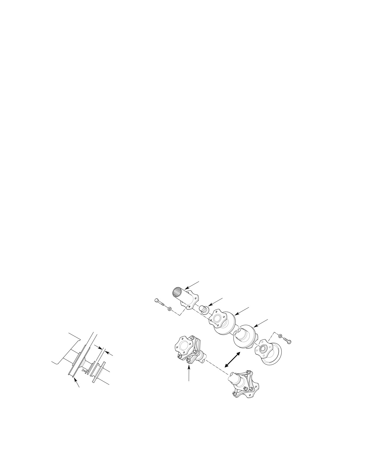
MD Helicopters, Inc.
CSP-HMI-2
MAINTENANCE MANUAL
D Do not use clutch coupling shims under
bolts to 50 - 70 inch-pounds (5.65 -
transmission input coupling. Inside diam
7.91 Nm).
eter of clutch coupling shims, 1.260-1.270
(7). Manually align drive shaft and trans
inches (3.2004-3.2258 cm), is approxi
mission input coupling flanges:
mately 0.070 inch (1.778 mm) larger than
inside diameter of shims used at trans
(8). Using feeler gage, measure gap be
mission coupling. Incorrect diameters can
tween flanges. Gap should be 0.010
cause an improperly seated shim, mis
inch (0.254 mm) gap to 0.020 inch
alignment and cocked coupling.
(0.508 mm) compression.
NOTE: Transmission input coupling shims are
(a). If gap is 0.010 inch (0.254 mm) or
laminated stock. Each lamination is 0.002
less, attach upper end of drive shaft
inch (0.051 mm) thick. Peel to thickness re
to transmission input coupling with
quired.
four bolts and washers. Torque bolts
to 50 - 70 inch-pounds (5.65 - 7.91
(4).
Add sufficient shims to get a measure
Nm).
ment of 0.010 inch (0.254 mm) mini
(b). If gap exceeds 0.010 inch (0.254 mm),
mum between bolt seating surface on
repeat step (3). thru (5). above,
coupling and transmission input shaft.
except install thickness of shims
equal to measured gap, plus thick
(5).
Lubricate input shaft splines with
ness that results in not more than
grease (CM111). Coat bolt threads with
0.010 inch (0.254 mm) gap between
anti-seize compound (CM112). Rein
coupling and drive shaft nor more
stall coupling and bolt. Check coupling
than 0.020 inch (0.508 mm) compres
bolt for minimum drag of 25 inch-
sion of flexible couplings. Install four
pounds (2.82 Nm). Torque bolt to 250
bolts and washers and torque bolts to
- 300 inch-pounds (28.25 - 33.90
50 - 70 inch-pounds (5.65 - 7.91
Nm) plus drag torque.
Nm).
(6).
Attach drive shaft to clutch coupling
(9). Install access door and sound insulation
with four bolts and washers. Torque
over main transmission drive shaft.
TRANSMISSION INPUT COUPLING
INTERNAL-WRENCHING BOLT
MAIN TRANSMISSION DRIVE SHAFT
(EARLY CONFIGURATION) (BENDIX)
DIAGRAM
0.010 IN. (0.254 MM)
MAXIMUM GAP
0.020 IN. (0.508 MM)
MAXIMUM COMPRESSION
MAIN TRANSMISSION DRIVE SHAFT
DRIVE
(CURRENT CONFIGURATION) (KAMATIC)
PULLEY
TRANSMISSION INPUT
COUPLING-TO-DRIVE SHAFT ATTACHMENT
G63-1002B
Figure 402. Main Transmission Drive Shaft Installation
Page 405
63-10-00
Revision 27
CSP-HMI-2
MD Helicopters, Inc.
MAINTENANCE MANUAL
5. Overrunning Clutch
(b). Insert a long 3/8 inch (9.525 mm) hex
wrench, approximately 10 inches
The overrunning clutch transmits power from
(25.4 cm) long, through tool and into
the engine to the main transmission drive
back of clutch assembly.
shaft. The clutch disengages the engine from
(c). While holding internal hex wrench
the remainder of the drive system in case of
[3/8 inch (9.525 mm)], turn external
engine failure and during autorotations.
hex wrench [1.00 inch (2.54 cm)]
The clutch contains a sprag unit that disen
counter-clockwise to remove bolt
gages automatically when N2 rpm is less than
from back of clutch.
corresponding main rotor rpm.
(5). Remove nuts and washers that secure
overrunning clutch; remove clutch.
Repair and overhaul information for the
overrunning clutch can be found in COM.
(6). If clutch is being replaced, install spare
coupling bolt and O-ring or suitable
6. Overrunning Clutch Replacement
plug in output shaft (clutch inner race
bore) to prevent contamination during
(Ref. Figure 403 or Figure 404)
clutch handling, shipping or storage.
A. Overrunning Clutch Removal
NOTE: Operating lubricant is an approved pre
servative for shipping or storage.
Consumable Materials
(7). Wrap clutch in barrier material
(Ref. Section 91−00−00)
(CM208) to protect splined areas of
Item
Nomenclature
shafts.
CM208
Barrier material
B. Overrunning Clutch Installation
Consumable Materials
NOTE: For removal of only the internal clutch
(Ref. Section 91−00−00)
subassembly as an alternative to complete
Item
Nomenclature
clutch removal, refer to Overrunning Clutch
Subassembly Removal.
CM111
Grease, aircraft
CM112
Anti-seize compound high temperature
(1). Remove engine.
CM125
Oil
CM126
Oil, turbine
(2). Remove bolts, washers, nuts and engine
shaft firewall seal from clutch.
(1). If clutch is new, (369A5350 clutch only)
NOTE: Removal of clutch coupling from clutch
drain preservative oil. Trapped oil can
is unnecessary unless clutch is being re
be removed by inverting clutch a
placed.
minimum of three times. Add lubricat
ing oil (CM125 or CM126) (Ref. Sec.
(3). Remove coupling bolt, packing, clutch
12-00-00). Temporarily install coupling
coupling and coupling shim(s). Keep
bolt and packing.
shim(s) with coupling for reuse.
Reinstall bolt and packing to prevent
NOTE: Relubricate splines on clutch input
spillage of lubricating oil from clutch
shaft and splines inside engine power and
housing during final steps of removal.
accessory gearbox with grease (CM111)
prior to reinstalling overrunning clutch.
(4). On 369F5450 clutch, remove output
shaft cover plate from back of engine
(2). Coat clutch splines and internal splines
accessory drive to gain access to clutch
of engine power accessory gearbox with
bolt.
lubricant (CM111). Insert overrunning
clutch outer-race spline into engine and
(a). Insert tool (Ref. Figure 405) to
install six washers and nuts.
engage bolt in back of clutch.
Deleted.
Page 406
Revision 42
63-10-00
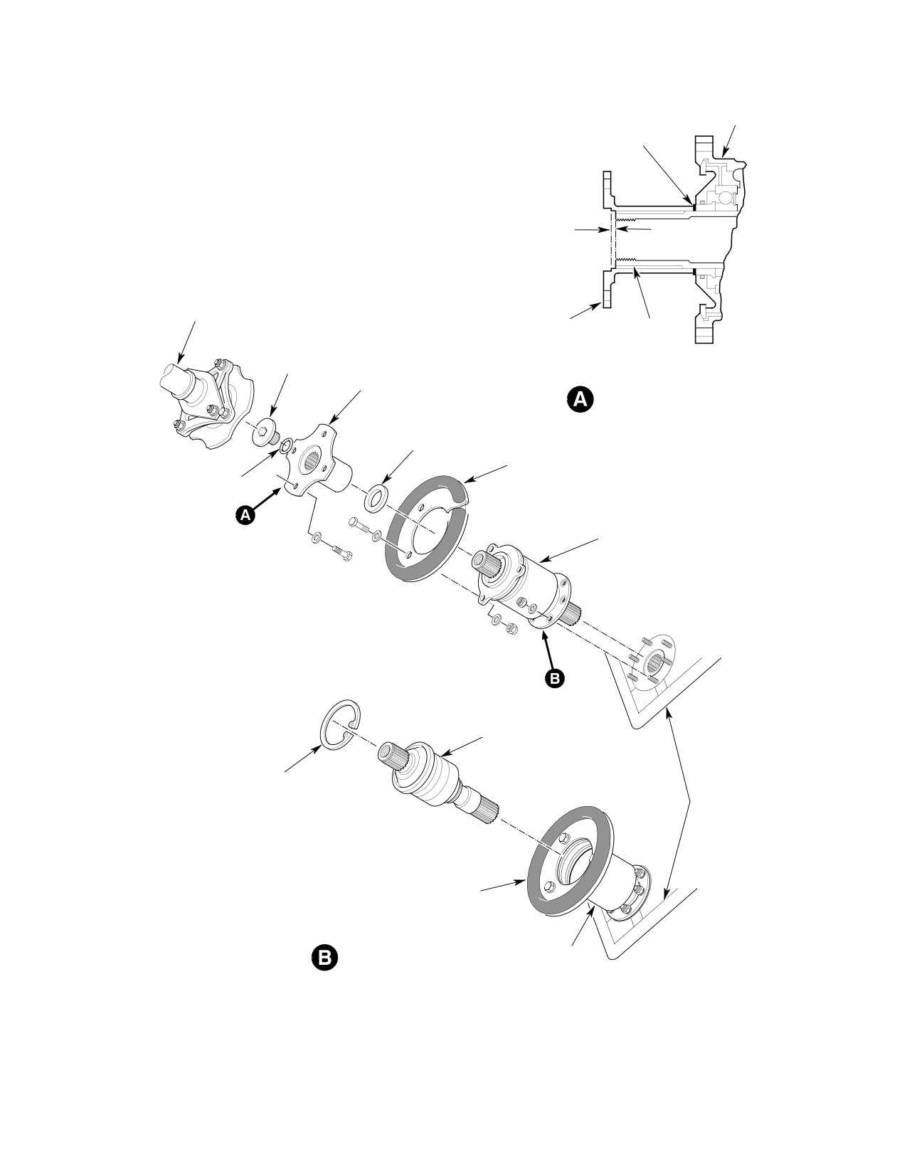
MD Helicopters, Inc.
CSP-HMI-2
MAINTENANCE MANUAL
CLUTCH
LAMINATED SHIM
GAP
0.035 IN. (0.889 MM)
0.055 IN. (1.397 MM)
MAIN DRIVE SHAFT
COUPLING
OVERRUNNING
CLUTCH SHAFT
COUPLING
BOLT
CLUTCH
COUPLING
COUPLING-TO-CLUTCH SHIMMING
LAMINATED
COUPLING SHIM
ENGINE SHAFT
FIREWALL SEAL
O-RING
OVERRUNNING
CLUTCH
REPLACEMENT OF COMPLETE CLUTCH
CLUTCH SUBASSEMBLY
RETAINING RING
(BEVELED SIDE OUTWARD)
ENGINE POWER AND
ACCESSORY GEARBOX
ENGINE SHAFT
FIREWALL SEAL
REPAIR BY REPLACEMENT
CLUTCH HOUSING
OF CLUTCH SUBASSEMBLY
G63-1003A
Figure 403. 369A5350 Overrunning Clutch Installation
Page 407
63-10-00
Revision 20
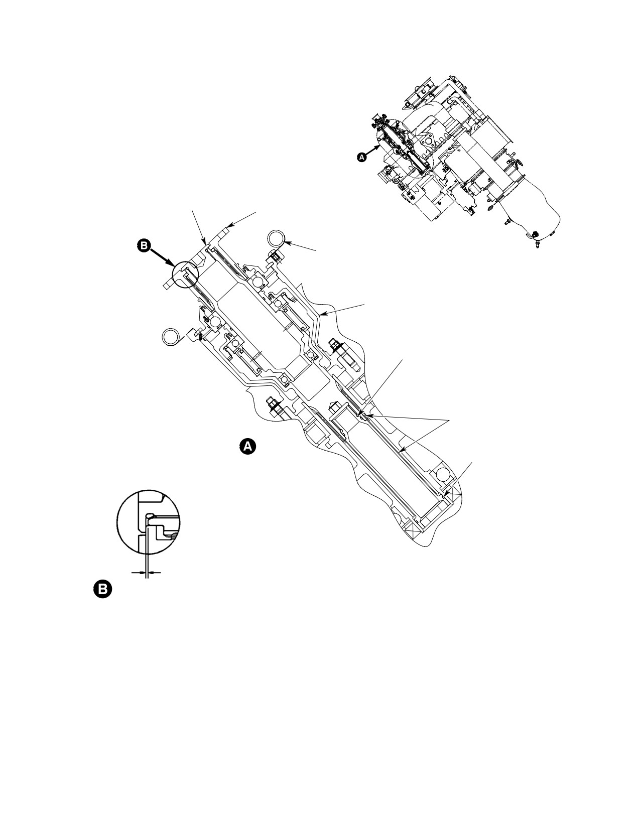
CSP-HMI-2
MD Helicopters, Inc.
MAINTENANCE MANUAL
369F5160
COUPLING BOLT
369F5133
COUPLING
369F5467-1 SEAL ASSEMBLY
3X MS51957-42 SCREW
3X NAS620A8L WASHER
369F5450-501
CLUTCH ASSEMBLY
369F5468-1 BOLT (C20 SERIES ENGINE)
369F5469-1 BOLT (C30/C47 ENGINE)
M83248/1-019 PACKING
NOTE
M83248/2-026 PACKING
0.010-0.030 IN.
(0.254-0.762 MM)
COUPLING SHIMMING
ROTATED
NOTE: LUBRICATE SPLINES BEFORE ASSEMBLY WITH GREASE
(CM111). PACK ALL VOIDS AND GAPS BETWEEN THE OUTSIDE
OF BOLT AND INSIDE OF ENGINE POWER OUTPUT SHAFT.
CSP102-013C
Figure 404. 369F5450 Overrunning Clutch Installation
Page 408
Revision 32
63-10-00
MD Helicopters, Inc.
CSP-HMI-2
MAINTENANCE MANUAL
(3). For 369F5450 clutch installation:
(b). Shim coupling to achieve 0.035-0.055
inch (0.889-1.397 mm) step above
(a). Remove power output shaft cover
clutch output shaft.
plate from back of engine (Ref. Sec.
01-00-00, Allison Engine Operation
When installing clutch coupling
CAUTION
and Maintenance Manual).
bolt, installation torque on the
bolt must be 250 - 300 inch-pounds (28.25
(b). Install O-rings on 369F5469
- 33.90 Nm) for the 369A5350 clutch or 315
(C30/C47 engine) or 369F5468 (C20
- 365 inch-pounds (35.59 - 41.24 Nm) for
series engines) bolt (Ref. Figure 404).
the 369F5450 clutch. Torquing to lower val
ue reduces clutch bearing clamp-up and can
NOTE: Fill all voids and gaps between the out
result in bearing race spinning.
side of bolt and inside of engine shaft with
(6). Coat clutch-to-coupling splines with
grease.
grease (CM111); install shim(s) and
(c).
Lubricate internal spline area of
clutch coupling. Coat coupling bolt
engine output shaft with grease
threads with anti-seize compound
(CM111).
(CM112); install bolt with new O-ring.
Check for bolt self-locking drag torque
(d).
Lubricate bolt threads with anti-
of 25 inch-pounds (2.82 Nm) mini
seize compound (CM112) and insert
mum to 200 inch-pounds (22.60
through engine into overrunning
Nm) maximum. Replace bolt if torque
clutch assembly.
values are exceeded.
(a). For 369A5350 clutch, torque coupling
(e).
Using bolt removal tool (Ref.
bolt to actual drag torque plus 250
Figure 405) either hold output
- 300 inch-pounds (28.25 - 33.90
coupling to prevent overrunning
Nm).
clutch from turning or insert hex
wrench through bolt to engage and
(b). For 36F5450 clutch, torque coupling
hold clutch.
bolt to actual drag torque plus 315
- 365 inch-pounds (35.59 - 41.24
(f).
Torque bolt to 250 - 300 inch-
Nm).
pounds (28.25 - 33.90 Nm) plus
drag torque.
(7). Install engine shaft firewall seal, bolts,
washers, and nuts.
(g).
Using existing hardware, reinstall
power output shaft cover plate on
(8). Reinstall engine.
back of engine (Ref. Sec. 01-00-00,
Allison Engine Operation and
7. Overrunning Clutch Subassembly
Maintenance Manual).
Replacement
(4). Shim coupling on 369F5450 clutch
(Ref. Figure 403 or Figure 404)
assembly as follows:
A. Overrunning Clutch Subassembly
Removal
(a). Remove output coupling bolt and
coupling.
(1). Remove main transmission drive shaft.
(b). Shim coupling to achieve 0.010-0.030
(2). For 369F5450 clutch installation:
inch (0.254-0.762 mm) step above
clutch output shaft.
(a). Remove power output shaft cover
plate from back of engine (Ref. Sec.
(5). Shim coupling on 369A5350 clutch
01-00-00, Allison Engine Operation
assembly as follows:
and Maintenance Manual).
(a). Remove output coupling bolt and
(b). Insert tool (Ref. Figure 405) to
coupling.
engage bolt in back of clutch.
Page 409
63-10-00
Revision 39
CSP-HMI-2
MD Helicopters, Inc.
MAINTENANCE MANUAL
(c). Insert a long 3/8 inch (9.525 mm) hex
(b). Install O-rings on 369F5469
wrench, approximately 10 inches
(C30/C47 engine) or 369F5468 (C20
(25.4 cm) long, through tool and into
series engines) bolt (Ref. Figure 404).
back of clutch assembly.
NOTE: Fill all voids and gaps between the out
(d). While holding internal hex wrench
side of bolt and inside of engine shaft with
[3/8 inch (9.525 mm)], turn external
grease.
hex wrench [1.00 inch (2.54 cm)]
(c).
Lubricate internal spline area of
counter-clockwise to remove bolt
engine output shaft with grease
from back of clutch.
(CM111).
(3). Remove coupling bolt, clutch coupling
(d).
Lubricate bolt threads with anti-
and shims.
seize compound (CM112) and insert
through engine into overrunning
(4). Remove retaining ring from clutch
clutch assembly.
housing. Then pull complete clutch
subassembly out of housing.
(e).
Using bolt removal tool (Ref.
Figure 405) either hold output
B. Overrunning Clutch Subassembly
coupling to prevent overrunning
Installation
clutch from turning or insert hex
wrench through bolt to engage and
hold clutch.
Consumable Materials
(Ref. Section 91−00−00)
(f).
Torque bolt to 250 - 300 inch-
Item
Nomenclature
pounds (28.25 - 33.90 Nm) plus
CM111
Grease, aircraft
drag torque.
CM125
Oil
(g).
Using existing hardware, reinstall
CM126
Oil, turbine
power output shaft cover plate on
back of engine (Ref. Sec. 01-00-00,
Allison Engine Operation and
(1). Remove shipping plug and O-ring from
Maintenance Manual).
end of shaft in replacement clutch
subassembly.
(h).
Lubricate coupling bolt threads with
anti-seize compound (CM112).
(2). Drain preservative oil from clutch
subassembly by inverting it several
(7). Install clutch coupling, shims and
times. Add lubricating oil (CM125 or
coupling bolt.
CM126) (Ref. Sec. 12-00-00).
(8). Install main transmission drive shaft.
(3). Coat clutch splines with grease
8. Overrunning Clutch−to−Firewall Seal
(CM111).
The overrunning clutch-to-firewall seal
(4). Using care to avoid oil spillage, insert
consists of a stamped steel backing and a seal
clutch subassembly into clutch housing
bonded to the cupped diameter of the backing.
and install retaining ring with beveled
side outward.
9. Overrunning Clutch−to−Firewall Seal
Replacement
(5). Check fluid level of clutch assembly
before installing clutch coupling (Ref.
(Ref. Figure 403)
Sec. 12-00-00).
(1). Remove engine.
(6). For 369F5450 clutch installation:
(2). Remove three bolts, six washers and
three nuts that attach firewall seal to
(a). Remove power output shaft cover
overrunning clutch.
plate from back of engine (Ref. Sec.
01-00-00, Allison Engine Operation
(3). Position replacement clutch-to-firewall
and Maintenance Manual).
seal assembly on flange of clutch with
Page 410
Revision 32
63-10-00
MD Helicopters, Inc.
CSP-HMI-2
MAINTENANCE MANUAL
seam orientated at the 6 o'clock position
D Do not use clutch coupling shims under
and secure with attaching hardware.
transmission input coupling. Inside diam
eter of clutch coupling shims, 1.260-1.270
10. Main Transmission Drive Shaft Couplings
inches (3.2004-3.2258 cm), is approxi
mately 0.070 inch (1.778 mm) larger than
The main transmission drive shaft couplings
inside diameter of shims used at trans
connect the overrunning clutch to the drive
mission coupling. Incorrect diameters can
shaft and the drive shaft to the main transmis
cause an improperly seated shim, mis
sion.
alignment and cocked coupling.
11. Main Transmission Drive Shaft Coupling
NOTE: Transmission input coupling shims are
Replacement
laminated stock. Each lamination is 0.002
inch (0.051 mm) thick. Peel to thickness re
(Ref. Figure 402)
quired.
A. Main Transmission Drive Shaft Coupling
(1). Install previously removed shims or
Removal
refer to Main Transmission Drive Shaft
Installation for shim thickness calcula
(1). Remove drive shaft; use care to keep it
tion.
from striking any object.
(2). Lubricate drive shaft splines with
(2). Remove coupling bolt from main
grease (CM111) and install in place.
transmission and overrunning clutch.
Coat bolt threads with anti-seize
Retain shim(s) with couplings for
compound (CM112) and install.
reinstallation.
(a). For 369D25100 transmission instal
B. Main Transmission Drive Shaft Coupling
lation, torque coupling bolt to actual
Installation
drag torque plus 250 - 300 inch-
pounds (28.25 - 33.90 Nm). If bolt
is not seated and/or existing torque is
Consumable Materials
found to be less than 250 - 300
(Ref. Section 91−00−00)
inch-pounds (28.25 - 33.90 Nm),
Item
Nomenclature
ensure self-locking drag torque is not
CM111
Grease, aircraft
less than 25 inch-pounds (2.82
CM112
Anti-seize compound high temperature
Nm) before torquing bolt.
(b). For 369F5100 transmission installa
tion, torque coupling bolt to actual
CAUTION
drag torque plus 315 - 365 inch-
pounds (35.59 - 41.24 Nm). If bolt
D The 0.010 inch (0.254 mm) minimum
is not seated and/or existing torque is
measurement between the bolt seating
found to be less than 315 - 365
surface and the input shaft must be ob
inch-pounds (35.59 - 41.24 Nm),
tained to ensure proper clamp up. Warped
ensure self-locking drag torque is not
shims or foreign material could provide a
less than 25 inch-pounds (2.82
false 0.010 inch (0.254 mm) minimum
Nm) before torquing bolt.
measurement and improper clamp up
could result during normal operation
(3). Reinstall main transmission drive
which may damage the main transmis
shaft, main transmission access cover
sion input shaft.
and sound insulation.
Page 411
63-10-00
Revision 34
CSP-HMI-2
MD Helicopters, Inc.
MAINTENANCE MANUAL
12. Tail Rotor Drive Shaft Coupling
Do not immerse Bendix flexible
CAUTION
Replacement
couplings in fluid or cleansers
such as magnetic particle, fluorescent pene
trant, visible dye etc. Do not apply corrosion
A. Tail Rotor Drive Shaft Coupling Removal
protection fluids unless coupling has been
cleaned with solvent or detergent. Apply
(1). Remove tail rotor drive shaft (Ref. Sec.
any corrosion protection very sparingly to
63-15-10).
outside only.
B. Tail Rotor Drive Shaft Coupling
NOTE: With Bendix coupling installed, remove
Installation
socket from main transmission coupling
only if visual inspection reveals signs of con
According to type of coupling installed, instal
tact between coupling bolt and socket.
lation of tail rotor shaft requires shimming of
couplings, and in some instances, tail rotor
(2). Remove couplings from main and tail
gearbox-to-tailboom shimming (Ref. Sec.
rotor transmissions. Retain shims with
63-15-10, Tail Rotor Drive Shaft Installa
couplings for reinstallation.
tion).
Page 412
Revision 32
63-10-00
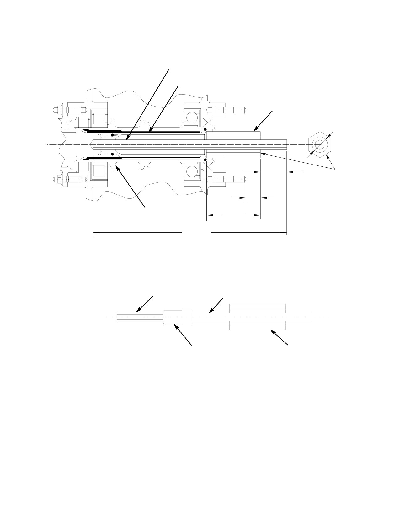
MD Helicopters, Inc.
CSP-HMI-2
MAINTENANCE MANUAL
0.375 IN. (9.53 MM) HEX BAR TO PICK UP 0.375 IN.
(9.53 MM) HEX SOCKET IN CLUTCH OUTER RACE
(NOTE 1)
OUTER RACE ENGINE BOLT TORQUED TO
250 - 300 INCH-POUNDS (28.25 - 33.90 NM)
1.00 IN. (2.54 CM) HEX BAR TO PICK UP
1.00 IN. (2.54 CM) HEX SOCKET IN
ENGINE BOLT (THRU HOLE IN CENTER)
0.72 IN.
(18.29 MM)
ÇÇÇÇÇÇ
ÇÇÇÇ
ÇÇÇÇ
ÇÇÇÇÇÇ
ÇÇÇÇ
1.23 IN.
(3.124 CM)
TOOL REQUIRED
(NOTE 3)
FOR BOLT REMOVAL
0.68 IN.
(17.27 MM)
2.50 IN.
ENGINE PTO SHAFT
(6.35 CM)
(NOTE 3)
9.00 IN.
(22.86 CM)
(NOTE 3)
369F5450 CLUTCH ASSEMBLY
0.375 IN. (9.53 MM) SQUARE
0.375 IN. (9.53 MM) HEX
DRIVE EXTENSION
ÇÇÇÇÇÇÇ
ÇÇÇÇÇÇÇ
STANDARD 3/8” SOCKET
1.00 IN. (2.54 CM) HEX
(NOTES 2, 3)
369F5468/5469 BOLT REMOVAL TOOL
NOTES:
1.
HOLD HEX BAR STEADY WHEN TORQUING BOLT.
2.
TOOL TO BE A MINIMUM OF 2.5 INCHES IN LENGTH
TO CLEAR STUDS ON ENGINE.
3.
THIS IS MINIMUM LENGTH, TOOL MAY BE MADE
LONGER FOR EASE OF MAINTENANCE.
G63-1024A
Figure 405. 369F5468/5469 Bolt Removal Tool
Page 413
63-10-00
Revision 32
CSP-HMI-2
MD Helicopters, Inc.
MAINTENANCE MANUAL
This Page Intentionally Left Blank
Page 414
Revision 32
63-10-00
MD Helicopters, Inc.
CSP-HMI-2
MAINTENANCE MANUAL
DRIVE SHAFTS / CLUTCHES / COUPLINGS
INSPECTION/CHECK
1.
369D25510 Main Rotor Drive Shaft
(a). Thoroughly clean shaft spline with
Inspection
dry cleaning solvent (CM234) to
remove oil, dirt and grease.
(Ref. Figure 601)
(b). Using magnifying glass and light,
inspect spline for cracks. Pay particu
Consumable Materials
lar attention to side of each tooth
(Ref. Section 91−00−00)
with large wear pattern (hairline
Item
Nomenclature
cracks appear crescent-shaped
usually at center bottom of tooth in
CM234
Solvent, dry-cleaning
root area).
CM425
Sealing compound
(c). Inspect neck of spline (area where
spline and shaft meet) for cracks.
(1).
Inspect all surfaces of drive shaft for
dents, nicks, scratches and evidence of
(7). Check shaft straightness. When rotated
deformation. No damage of any kind is
between centers, run-out must not
permissible in the area within two
exceed 0.040 inch (1.016 mm) TIR
inches of the spline. Dents less than
(allowable dents excluded).
0.050 inch (1.270 mm) deep and 0.050
inch (1.270 mm) diameter are permissi
2.
600N5510 and 369F5510 Main Rotor Drive
ble in other areas. A dent is defined as
Shaft Inspection
a smooth depression of surface with no
(Ref. Figure 601 and Figure 602)
sharp edges or abrupt changes in
contour. No nicks or scratches are
permitted.
Consumable Materials
(Ref. Section 91−00−00)
(2).
If shaft condition is questionable,
Item
Nomenclature
perform magnetic particle inspection
CM234
Solvent, dry-cleaning
according to Specification MIL-I-6868.
No surface or subsurface defects are
permissible.
Anytime main rotor drive shaft
CAUTION
is removed, cover opening at top
(3).
Inspect all external surfaces of shaft for
of main rotor hub to prevent entry of any
corrosion.
foreign material into hub, mast and trans
mission.
(4).
Remove cork plug and inspect shaft
interior for corrosion. Remove light
(1). Inspect overtorque verification stripe
surface corrosion and pitting which can
for straightness.
be removed without causing shaft ID to
exceed 1.655 inches (4.2037 cm).
(2). Inspect all surfaces of drive shaft for
dents, nicks, scratches and evidence of
(5).
Inspect splines on end of drive shaft for
deformation. No damage of any kind is
excessive wear by measuring distance
permissible in the area within two
across two 0.108 inch (2.7432 mm)
inches of the spline. Dents less than
diameter pins placed in opposite spline
0.050 inch (1.270 mm) deep and 0.050
grooves. Dimension should be 2.2625
inch (1.270 mm) diameter are permissi
inches (5.74675 cm) minimum.
ble in other areas. A dent is defined as
a smooth depression of surface with no
(6).
Inspect shaft spline for cracks-using
sharp edges or abrupt changes in
bright light and 5X to 10X magnifying
contour. No nicks or scratches are
glass.
permitted.
Page 601
63-10-00
Revision 26
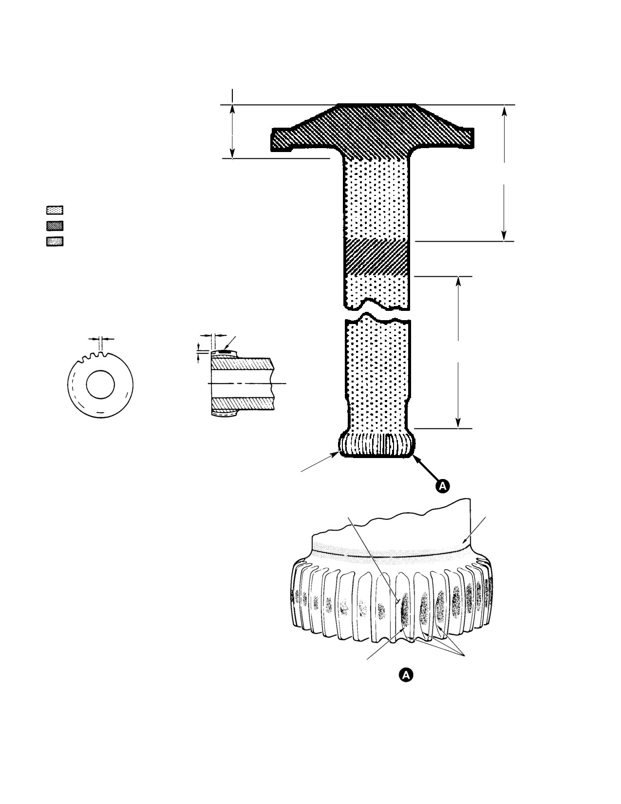
CSP-HMI-2
MD Helicopters, Inc.
MAINTENANCE MANUAL
1.70 IN.
(4.318 CM)
8.0 IN.
(20.32 CM)
AREA 1: MAX. PIT DEPTH 0.0012 IN. (0.03048 MM)
AREA 2: MAX. PIT DEPTH 0.0008 IN. (0.02032 MM)
AREA 3: MAX. PIT DEPTH 0.0020 IN. (0.0508 MM)
AREA 4: CHECK TEETH BY MEASURING ACROSS
TWO 0.108 IN. (2.7432 MM)-DIAMETER PINS
PLACED IN OPPOSITE INTER-TOOTH
GROOVES. MEASURED DIMENSION
SHOULD BE 2.2625 IN. (5.74675 CM) MIN.
TOOTH
0.010 IN.
0.050 IN. (1.270 MM)
CONTACT
(0.254 MM)
MAX
AREA
MAX. DEPTH
5.40 IN.
13.716 CM)
0.050 IN.
(1.270 MM)
MAX
AREA 4
AREA 4
ROOT AREA
(TYP)
SPLINE
NECK
LARGER WEAR
SIMULATED CRACKS
NOTE:
PATTERN (TYP)
SHOWN
PAY PARTICULAR ATTENTION TO ROOT AREA AT EACH
SPLINE TOOTH. SIMULATED CRACKS SHOWN. ALSO
CHECK SPLINE NECK (SHADED AREA) FOR CRACKS.
G63−1011A
Figure 601. Main Rotor Drive Shaft Inspection
Page 602
Revision 20
63-10-00
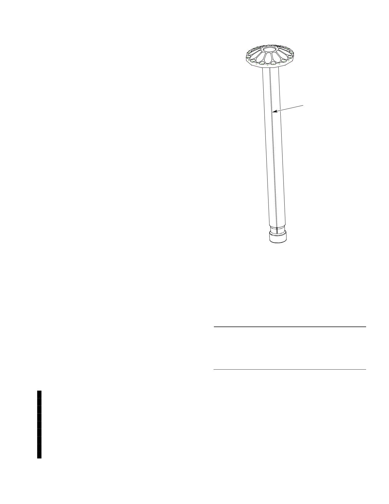
MD Helicopters, Inc.
CSP-HMI-2
MAINTENANCE MANUAL
(3).
If shaft condition is questionable,
perform magnetic particle inspection
according to Specification MIL-I-6868.
No surface or subsurface defects are
permissible.
(4).
Inspect all external surfaces of shaft for
corrosion.
OVERTORQUE
VERIFICATION STRIPE
(5).
Remove cork plug and inspect shaft
interior for corrosion. Remove light
surface corrosion and pitting which can
be removed without causing shaft ID to
exceed 1.655 inches (4.2037 cm).
(6).
Inspect splines on end of drive shaft for
excessive wear by measuring distance
across two 0.108 inch (2.7432 mm)
diameter pins placed in opposite spline
grooves. Dimension should be 2.2625
inches (5.74675 cm) minimum.
(7).
Inspect shaft spline for cracks-using
bright light and 5X to 10X magnifying
glass.
(a). Thoroughly clean shaft spline with
6G63-003
dry cleaning solvent (CM234) to
remove oil, dirt and grease.
Figure 602. Main Rotor Drive Shaft
Overtorque Verification Stripe
(b). Using magnifying glass and light,
inspect spline for cracks. Pay particu
lar attention to side of each tooth
3.
Main Transmission Drive Shaft Inspection
with large wear pattern (hairline
(Bendix)
cracks appear crescent-shaped
usually at center bottom of tooth in
(Ref. Figure 402)
root area).
(c). Inspect neck of spline (area where
Consumable Materials
spline and shaft meet) for cracks.
(Ref. Section 91−00−00)
Item
Nomenclature
(8). Check shaft straightness. When rotated
CM318
Primer
between centers, run-out must not
exceed 0.040 inch (1.016 mm) TIR
(allowable dents excluded).
(1). Inspect drive shaft diaphragms for
dents, cracks, scratches, nicks, rust
(9). Apply thin coat of sealing compound
spots and evidence of joint separation
(CM425), mixed according to container
from shaft or outside edges. Evidence of
instructions, to all cork plug surfaces;
any such defects on either diaphragm
press cork into drive shaft until top of
requires removal of shaft from service.
cork is flush with top of drive shaft.
Allow sealing compound to cure
according to container instructions.
(2). Inspect drive shaft tube between
Apply second coat of sealing compound
diaphragms for dents, scratches, cracks
to exposed surfaces of cork; allow to dry.
or corrosion pits.
Page 603
63-10-00
Revision 26
CSP-HMI-2
MD Helicopters, Inc.
MAINTENANCE MANUAL
(a). Measure depth and diameter of
4. Main Transmission Drive Shaft Inspection
dents. Dents that blend smoothly into
(Kamatic)
surrounding surface area with no
(Ref. Figure 402)
sharp change in contour and do not
exceed 0.015 inch (0.381 mm) depth
are acceptable. Dents not within
Consumable Materials
these limits require removal of shaft
(Ref. Section 91−00−00)
Item
Nomenclature
from service.
CM318
Primer
(b). Measure depth of cracks, nicks,
(1). Inspect drive shaft for dents, cracks,
corrosion pits, or scratches; length
scratches, nicks, rust spots and evi
and direction are not limited. Maxi
dence of joint separation from shaft or
mum depth allowed before rework is
outside edges.
0.003 inch (0.076 mm).
(2). Inspect drive shaft tube between
couplings for dents, scratches, cracks or
(c). Check suspected cracks using dye
corrosion pits.
penetrant. If crack indication ap
pears, remove black (phenolic com
(a).
Measure depth and diameter of
pound) coating from area.
dents. Dents that blend smoothly into
surrounding surface area with no
sharp change in contour and do not
NOTE: Drive shaft is coated with special phe
exceed 0.010 inch (0.254 mm) in
nolic thermosetting compound. It is a brittle
depth are acceptable. Dents not
coating that may indicate a crack that does
within these limits require removal
not penetrate tube.
of shaft from service.
(b).
Measure depth of cracks, nicks,
(d). Re-inspect suspected area using
corrosion pits or scratches; length
magnetic-particle or dye-penetrant
and direction are not limited. Maxi
methods. If crack does not reappear,
mum depth allowed before rework is
touch up cleaned area with primer
0.005 inch (0.127 mm).
coating (CM318) and return part to
(c).
Check suspected cracks using dye
service.
penetrant. If crack indication ap
pears, remove coating from surface.
NOTE: Perform inspection steps (3). and (4).
(d).
Re-inspect suspected area using
only if shaft damage is suspected.
magnetic particle or dye penetrant
methods. If crack does not reappear,
touch up cleaned area with primer
(3). Inspect shaft tube for out-of-round
coating (CM318) and return part to
condition, which shall not exceed 0.060
service. If shaft is found to be
inch (1.524 mm).
cracked, remove shaft from service.
Kamatic parts cannot be inter
(4). Inspect shaft for straightness. Shaft
CAUTION
changed between drive shafts.
shall be straight within 0.030 inch
(3). Inspect all attaching hardware for
(0.762 mm) at all locations relative to
serviceable condition. Discard and
centerlines of two flange mounting bolt
replace defective hardware.
patterns.
NOTE: Perform the following inspections if
shaft damage is suspected.
(5). Inspect all attaching hardware for
serviceable condition. Check nut plates
(4). Inspect shaft tube for out-of-round
for drag torque. Discard and replace
condition not to exceed 0.060 inch
defective hardware.
(1.524 mm).
Page 604
Revision 20
63-10-00
MD Helicopters, Inc.
CSP-HMI-2
MAINTENANCE MANUAL
(5). Inspect shaft for straightness. Shaft
(4). Inspect socket and main transmission
shall be straight within 0.030 inch
coupling bolt for signs of contact. If
(0.762 mm) at all locations relative to
signs of contact are noted, remove and
centerlines of two flange mounting bolt
reinstall coupling bolt and socket (Ref.
patterns.
Sec. 63-15-00). Reposition socket and
or bolt so maximum clearance between
5. Overrunning Clutch Inspection
bolt key and socket is obtained.
(Ref. Figure 403 and Figure 404) Perform the
8. Kamatic Coupling Inspection
following inspections any time the helicopter
(1). Inspect coupling springs for dents,
engine or overrunning clutch assembly is
cracks, nicks and rust spots.
removed from the helicopter. For further
inspection requirements, refer to Chapter 05
(2). Inspect coupling splined section and
and Component Overhaul Manual.
flange for scratches, nicks, dents,
cracks and corrosion pits. No cracks are
NOTE: Overrunning clutch subassembly can
allowed. Maximum depth of other
be replaced with engine installed.
defects allowed before rework is 0.005
inch (0.127 mm).
(1). Check clutch oil level (Ref. Sec.
12-00-00).
(3). Measure overall length of coupling at
three different points. If average of
(2). Remove grease and visually check
readings exceed 2.630 inch (6.6802 cm),
clutch input shaft splines for wear (Ref.
coupling must be replaced.
COM).
(4). Inspect drive shaft flange for signs of
NOTE: Component Overhaul Manual contains
contact. If signs of contact are noted,
information relative to inspection of over
remove coupling bolt, re-shim coupling
running clutch on helicopters equipped with
and reinstall coupling bolt (Ref. Sec.
any cargo hook.
63-15-00).
9. Main Rotor Drive Shaft Inspection (300
6. Overrunning Clutch−to−Firewall Seal
Hour)
Inspection
(Ref. Figure 601)
Inspect firewall seal and backing for cracks,
breaks, corrosion or other damage that may
prevent complete sealing of firewall opening.
Consumable Materials
(Ref. Section 91−00−00)
Item
Nomenclature
7. Bendix Tail Rotor Drive Shaft Coupling
Inspection
CM234
Solvent, dry-cleaning
(1). Inspect coupling diaphragms for dents,
Anytime main rotor drive shaft
cracks, nicks, rust spots and joint
CAUTION
is removed, cover opening at top
separation at weld junction.
of main rotor hub to prevent entry of any
(2). Inspect coupling splined section and
foreign material into hub, mast and trans
flange for scratches, nicks, dents,
mission.
cracks and corrosion pits. No cracks are
(1). Remove main rotor drive shaft (Ref.
allowed. Maximum depth of other
Main Rotor Drive Shaft Removal).
defects allowed before rework is 0.005
inch (0.127 mm).
(2). Perform a visual inspection of the shaft
spline as follows:
(3). Measure overall length of couplings at
three different points. If average of
(a). Thoroughly clean with cleaning
readings exceed 2.541 inches (6.45414
solvent (CM234) to remove oil, dirt,
cm), coupling must be replaced.
etc.
Page 605
63-10-00
Revision 20