HANDBOOK OF MAINTENANCE INSTRUCTIONS FOR MDHI 369D/E/FF-500/600N HELICOPTERS (ISSUED: 1990) - page 18
CSP-HMI-2
MD Helicopters, Inc.
MAINTENANCE MANUAL
WOODEN OR
PLASTIC IN
1
SPECTION
PHENOLIC
PROBE
TOOL
0.125 INCH
(3.175 MM)
LEAD LEG
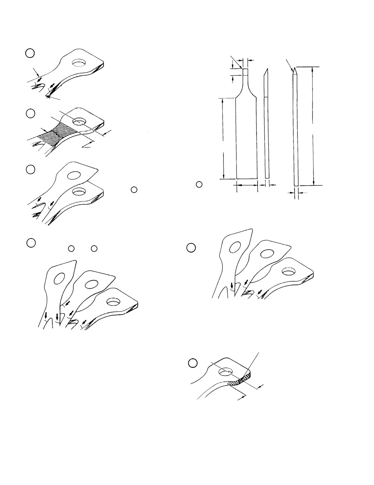
LAMINATE HAS FAILED IF CRACK OCCURS
ON BOTH LEAD AND LAG LEGS OF SAME
LAMINATE.
0.250 INCH
(6.35 MM)
LAG LEG
2
LAMINATE HAS FAILED IF CRACK OCCURS
IN TONGUE OF LAMINATE (SHADED AREA
TONGUE
SHOWN BEYOND JOINT OF STRAP PACK
6.00 INCH
LEGS).
(15.24 CM)
1.5 INCH
4.00 INCH
(3.81 CM)
10.16 CM)
(REF)
3
TWO LAMINATE FAILURES AS DEFINED IN 1
1.00 INCH
AND/OR 2 ARE ALLOWED IN EACH STRAP
(2.54 CM)
0.50 INCH
PACK ASSEMBLY. (TOTAL OF TEN LAMINATE
(12.7 MM)
FAILURES PER HUB ASSEMBLY.)
0.050-0.125 INCH
FIELD FABRICATION INSPECTION TOOLS
(1.27-3.175 MM)
ALUMINUM CHISEL NOT SHOWN
(REF. TABLE 601, NOTE 2)
STRAP PACK IS REJECTED IF THREE OR MORE
4
LAMINATES IN SAME PACK HAVE FAILED AS
DEFINED IN 1 AND/OR 2 ABOVE.
5
STRAP PACK IS REJECTED IF THREE OR MORE
LAMINATES IN SAME PACK ARE CRACKED IN
THE LEG (LEAD OR LAG).
FAILED LAMINATE IF CRACK IS
FOUND ON EITHER EDGE OF
LAMINATE. IF ONE LAMINATE
HAS FAILED IN THIS AREA, RE
PLACE HUB.
CAUTION:
DO NOT DISASSEMBLE STRAP PACK ASSEMBLY,
6
LAMINATIONS ARE SHOWN SEPARATED ONLY TO
DEPICT POSSIBLE CRACK LOCATIONS.
NOTE:
ANY CRACK IN LAMINATE IS CONSIDERED A BREAK.
THE LAMINATE HAS NOT FAILED HOWEVER, UNLESS
BOTH LEAD AND LAG LEGS ARE CRACKED, CRACK
1.50 INCH
IS LOCATED IN TONGUE AREA OF LAMINATE OR IS
(3.81 CM)
UNDER SHOES (SEE DETAIL 6).
G62-2007-2B
Figure 602. Strap Pack Lamination Inspection (Sheet 2 of 2)
Page 606
Revision 20
62-20-00
MD Helicopters, Inc.
CSP-HMI-2
MAINTENANCE MANUAL
Table 601. Strap Pack Inspection
Replace or Return
Inspect
Procedure (1)
For
Acceptable
Hub for Overhaul
Outboard end.
Visually. Use blunt nosed
Failed laminates
Two or less per
Three or more laminate
wooden or phenolic probe
(3).
pack.
failures in one pack.
(Figure 602). Probe at
upper and lower end of
pack. Failed laminate in
lead or lag leg will move
away from other
laminates.
Visually.
Gaps between
Single straight
More than one gap
laminates.
gap not exceed-
found; gap exceeds
ing 0.030 inch
acceptable limit.
(0.762 mm) within
pack or next to
either upper or
lower outer shoe.
Visually using light and
Cracks or breaks.
None.
Cracks or breaks are
mirror (2).
noted.
In area of and
Visually with light and
Cracks or breaks.
Two or less
Three or more laminate
within pitch
mirror (2).
laminate failures
failures (2) in a pack;
housing assem-
per strap pack (2).
three or more laminates
blies.
in pack with crack in
same leg (lead or lag).
Shims at each of
Visually with light and
Crack or break.
Inspect top
Top laminate is cracked
two attach
mirror.
laminate around
in area of cracked or
points.
shim (4).
broken shim.
NOTES:
(1) Conduct visual inspections indoors or in shaded area to eliminate glare of sun or bright outdoor light.
(2) Removal of teflon covering is required for visual inspection of laminate edges. Use aluminum chisel,
fabricated from stock 0.025 x 6.00 x 0.100 inch (0.635 x 152.4 x 25.4 mm) to carefully scrape excess
interlaminate teflon sheets from both sides of strap pack between top and bottom shoes at outboard
attachment bolt of all five strap packs. Remove excess teflon from a point 1/2 inch (12.70 mm) outboard of
bolt centerline to 1−1/2 inches (38.1 mm) inboard of bolt centerline. Field fabricate and use plastic tool
(Ref. Figure 602). Run plastic tool in both directions along each laminate feeling for cracked laminate. Use
of plastic tool will ensure that shreds of teflon still hanging free does not obscure small cracks.
(3) Laminate has failed if crack is found in tongue area or if crack is found in both legs (lead and lag).
(4) Pay particular attention to shim installed at upper side of lead leg of each strap pack assembly. Maximum
of two shims may have been installed on top side of lead leg of strap pack to accommodate tolerance
buildup during strap pack assembly. If more than one shim is installed, pay particular attention to lower
shim when checking for cracks or breaks.
Page 607
62-20-00
Revision 20
CSP-HMI-2
MD Helicopters, Inc.
MAINTENANCE MANUAL
NOTE: Laminate failures are defined in step
(1).
Install cyclic lateral rigging fixture
(6).
(ST506 or ST507), cyclic longitudinal
rigging fixture (ST504 or ST505), and
(9). Inspect upper, lower and center lami
collective rigging fixture (ST501 or
nates for cracks and breaks (Ref.
ST502).
Figure 601).
(2).
Rotate main rotor to position one blade
NOTE: Cracks, breaks or other noticeable dam
over tailboom.
age to the laminate/shims require main ro
(3).
Raise and support other four blades
tor hub overhaul/replacement.
until four corresponding droop stop
(10). Install main rotor blades.
rollers no longer contact their striker
plates.
(11). Perform tracking of main rotor blades
(4).
Place accurate propeller protractor on
(Ref. Sec. 18-20-00).
top of main rotor drive shaft. Adjust
The maximum allowable bal
protractor to zero setting.
CAUTION
ance weight per pitch case hous
(5).
Place protractor on machined surface of
ing on the main rotor hub assembly is 150
outboard end of blade pitch housing,
grams.
alongside lead-lag bolthead. Measure
and record static droop angle.
(12). Record location of all cracked/broken
laminates in helicopter Log Book
(6).
Repeat (2). thru (5). above for remain
including strap serial number, blade
ing blades.
color, leg, lead or lag, and laminate
position, if possible numbering from the
(7).
Maximum allowable static droop angle
top down.
is six degrees. If measured droop angle
exceeds six degrees, inspect striker
6. Main Rotor Hub Droop Angle Check
plate and roller for excessive wear and
adjust droop angle (Ref. Main Rotor
(Ref. Figure 805) Whenever new or replacement
Hub Droop Angle Adjustment).
main rotor hub is installed or whenever excessive
droop angle is suspected, measure static droop
7. Main Rotor Damper and Attachments
angle of all five rotor blades. Droop angle must be
Inspection
5.5 ±0.5 degrees.
Excessive lead-lag load applied
CAUTION
to the main rotor blades during
Special Tools
ground handling can result in damage to the
(Ref. Section 91−00−00)
elastomeric damper buns and failure of the
Item
Nomenclature
damper assembly. Operators and mainte
nance personnel should use extra caution to
Left−Hand Command:
avoid lead-lag loads in excess of 35 pounds
ST501
Collective rigging fixture
(155.68 N) at the tip of the main rotor
(LH command)
blades.
ST504
Longitudinal rigging fixture
(LH command)
(1). Inspect bearing in rotor blade and
bearing in the pitch housing for
ST506
Lateral rigging fixture
looseness around outer race. No degree
(LH command)
of radial or axial play is permitted.
Right−Hand Command
ST502
Collective rigging fixture
(2). Inspect pitch housing and blade
(RH command)
bearings for binding, galling, or scoring
in bore and for wear. No radial play is
ST505
Longitudinal rigging fixture
permitted. Maximum allowable axial
(RH command)
play is 0.015 inch (0.381 mm).
ST507
Lateral rigging fixture
(RH command)
(3). Inspect clevis bushings for wear and
looseness.
Page 608
Revision 37
62-20-00
MD Helicopters, Inc.
CSP-HMI-2
MAINTENANCE MANUAL
(4). Inspect damper flange bushing for wear
(2). Attach dial indicator or equivalent to
and play.
outer case of damper; position indicator
arm on center aluminum disc as shown.
(5). Inspect lower bolt hole in damper
flange for wear.
NOTE: Fabricate holding bar or fixture capable
of sustaining 100 pound (45.359 kg) static
(6). Inspect damper housing (including
load (Ref. Figure 603).
flanges) for damage.
(3). Attach damper end cap to holding bar
(7). Inspect damper turnbuckle, jamnuts
or fixture.
and safetywire for security. No end play
is permitted when manually tested.
NOTE: Perform weight loading and extension
check at ambient temperature of 70° ±l0°F
NOTE: When performing lead-lag of main ro
(21° ±5°C). Apply total 100 pound (45.359
tor blades, apply rotor brake (if installed) or
kg) weight load to damper at one time, not in
have assistant hold main rotor hub from
weight increments.
moving. A second assistant is recommended
to measure approximate damper extension
(4). Using hydraulic jack or equivalent,
and compression.
raise and attach 100 pound (45.359 kg)
weight load at damper clevis end.
(8). Lead-lag each main rotor blade in turn
Slowly lower jack to avoid shock
to provide approximately 0.10 inch
loading. After period of two minutes
(2.54 mm) extension and compression of
under load, measure damper extension
the damper elastomer.
on dial indicator.
(9). Visually check each damper in turn for
(5). If extension exceeds 0.056 inch (1.4224
cracks in elastomer or in elastomer-to-
mm) for M50452 damper, or 0.063 inch
metal bond at end face of damper: If
(1.6002 mm) for 369D21400-503
bonding or elastomer cracks are noted,
damper, replace the damper assembly.
measure depths of cracks, using depth
gage fabricated of shim stock or
(6). Reinstall existing damper; or as
equivalent having a 0.20 inch (5.08
required; install replacement damper of
mm) indication. If depth of crack
same type and part number (Ref. Main
exceeds 0.20 inch (5.08 mm), remove
Rotor Damper Installation). Do not
and check damper.
intermix PN 369D21400-503 damper
with any other part number damper
8. Main Rotor Damper Weight Loading and
assemblies.
Extension Check
NOTE: If replacement damper is installed, re
(Ref. Figure 603)
cord part number, serial number, and other
(1). Remove damper assembly (Ref. Main
pertinent information in Components Re
Rotor Damper Removal).
cord of helicopters Log Book.
Page 609
62-20-00
Revision 20
CSP-HMI-2
MD Helicopters, Inc.
MAINTENANCE MANUAL
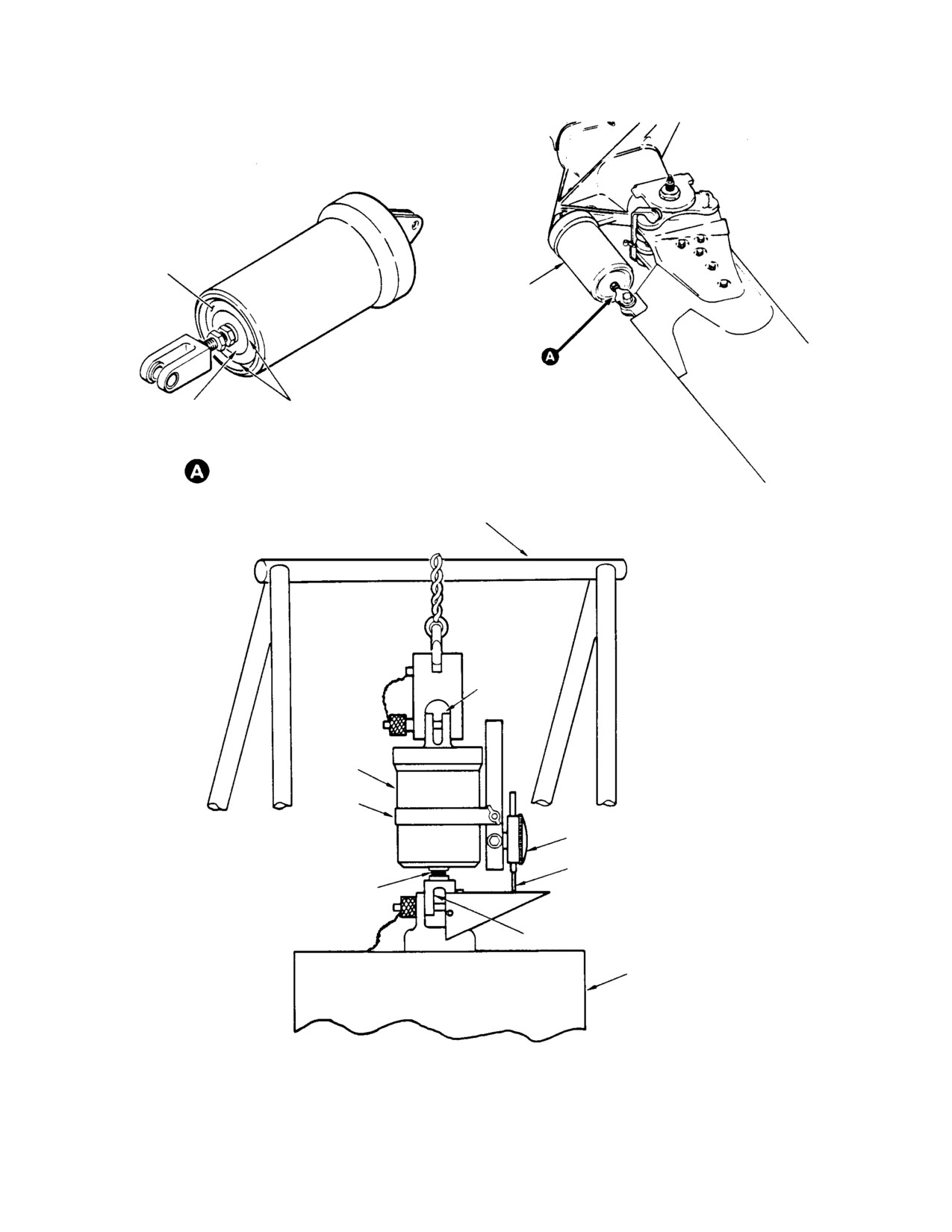
ELASTOMER
(NOTE)
MAIN ROTOR
DAMPER
ALUMINUM
ELASTOMER-TO-METAL
DISC
BOND (NOTE)
END FACE - MAIN ROTOR DAMPER
HOLDING BAR
OR FIXTURE
END CAP
DAMPER
CLAMP
INDICATOR
INDICATOR ARM
THREADED
SHAFT
CLEVIS
100 POUND (45.359 KG)
WEIGHT
NOTE:
CHECK ELASTOMER AND
ELASTOMER-TO-METAL
BOND FOR CRACKS
Figure 603. Periodic Check of Main Rotor Damper Assembly
Page 610
Revision 20
62-20-00

MD Helicopters, Inc.
CSP-HMI-2
MAINTENANCE MANUAL
MAIN ROTOR HUB
REPAIRS
1. Main Rotor Retention Strap Pack Repair
(2). After smoothing (removal of all sharp or
raised edges) repair depth must not
exceed 0.010 inch (0.254 mm) in any
Consumable Materials
area of housing except inner surfaces of
(Ref. Section 91−00−00)
arm clevis lugs.
Item
Nomenclature
CM234
Solvent, dry-cleaning
(3). Maximum repair depth of 0.050 inch
CM725
Tape, electrical, plastic
(1.27 mm) is acceptable in clevis lug
with sleeve bushing.
(Ref. Table 601) Where accessible, ends of
permissible cracks or broken laminates should
(4). On opposite clevis lug repair depth of
be taped to prevent scratching and damaging
0.030 inch (0.762 mm) is permissible in
adjacent laminates.
area of spot faces and maximum of
0.050 inch (1.27 mm) in area outside
Do not bend broken ends exces
spot faces.
CAUTION
sively and scratch adjacent
straps.
(5). Touch up repaired areas with chemical
film (CM206) followed by primer
(1). Carefully wipe ends of broken strap
(CM318) and remove main rotor hub for
with a clean soft cloth moistened with
pitch housing replacement.
solvent (CM234).
(2). Use mild blast of filtered air to dislodge
3. Unbushed Outboard Clevis Lug Hole
any foreign particles between broken
Repair
strap ends and adjacent strap.
(3). Carefully tape broken ends of strap
(Ref. Figure 801) Repair elongated outboard hole
with plastic electrical tape (CM725).
in unbushed side of clevis lug if inside diameter of
hole exceeds 0.3135 inch (7.9629 mm).
2. Pitch Housing Repair
(Ref. Figure 801)
Consumable Materials
(Ref. Section 91−00−00)
Item
Nomenclature
Consumable Materials
CM118
Grease
(Ref. Section 91−00−00)
Item
Nomenclature
CM318
Primer
CM206
Chemical coating
CM431
Sealing, locking and retaining compound
CM318
Primer
CM802
Abrasive cloth, aluminum oxide
(1). Remove existing bushing from inboard
lug.
During repair of pitch housing,
CAUTION
comply with precautions for cov
(2). Drill elongated hole in outboard lug to
ering engine air inlet fairing opening to pre
0.3680 inch (9.3472 mm). Use drill
vent entry of foreign objects into air intake.
bushing as guide.
(1). Use grade 320 abrasive cloth (CM802)
to smooth scratches, nicks and chafing
(3). Line ream hole to 0.3760-0.3770 inch
wear in pitch housing.
(9.5504-9.5758 mm) diameter.
Page 801
62-20-00
Revision 20
CSP-HMI-2
MD Helicopters, Inc.
MAINTENANCE MANUAL
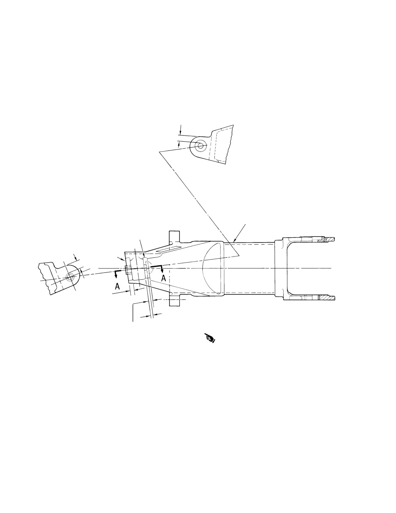
0.360 IN. (9.144 MM) MINI
MUM WALL WIDTH
AROUND LUG (NOTE 1)
OUTBOARD LUG
PITCH HOUSING
OUTBOARD LUG
0.250 IN. (6.35 MM)
MINIMUM LUG WIDTH
(NOTE 1)
INBOARD LUG
0.220 IN.
(5.588 MM)
MINIMUM LUG
INBOARD LUG
THICKNESS
(NOTE 1)
0.146 IN. (3.7084 MM) MINI
MUM LUG THICKNESS AT
0.20 IN. (5.08 MM)
SPOTFACE
LUG THICKNESS
(NOTE 1)
(NOTE 1)
NOTES:
1.
MAINTAIN MINIMUM WALL THICKNESS AROUND LUG AND MINIMUM
LUG THICKNESS FOR FIELD REPAIR OF CLEVIS LUG.
2.
NO PAINT OR PRIMER PERMISSIBLE IN THIS AREA.
3.
BRUSH CADMIUM PLATE GROUND SURFACE BEFORE INSTALLATION
IF POSSIBLE. IF NOT, COAT GROUND SURFACE THOROUGHLY WITH
PRIMER (CM318) AND INSTALL WHILE WET.
G62-2012-1B
Figure 801. Field Repair of Main Rotor Hub Pitch Control Lugs (Sheet 1 of 2)
Page 802
Revision 34
62-20-00
MD Helicopters, Inc.
CSP-HMI-2
MAINTENANCE MANUAL
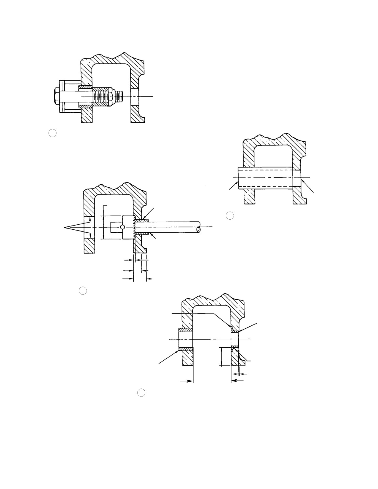
BUSHING 0.44 IN. (11.176 MM) O.D. X 0.25 IN. (6.35 MM) I.D. X 0.31 IN. (7.874 MM) LONG
BUSHING 0.75 IN. (19.05 MM) O.D. X 0.56 IN. (14.224 MM) I.D. X 0.31 IN. (7.874 MM) LONG
BOLT 0.25 IN. (6.35 MM) DIA X 1.38 IN. (3.5052 CM) LONG
WASHER 0.25 IN. (6.35 MM) I.D. X 0.75 IN. (19.05 MM) O.D. X 0.06 IN. (1.524 MM) THICK (2 EA.)
SECTION A - A
1
REMOVAL OF HS610 SP 5010 R 313 X 290 SOLID BUSHING
DRILL BUSHING
0.4990-0.4995 INCH
0.3775-0.3780 INCH
1.13 INCH
O.D. X
I.D. X
(12.6746-12.6873 MM)
(9.5885-9.6012 MM)
(2.8702 CM)LONG
0.3760-0.3770 INCH
REAMER
DIA
(9.5504-9.5758 MM)
0.3689 INCH
DRILL NO. U
DIA
(9.37006 MM)
DRILL BUSHING
DRILL THEN REAM
0.875 INCH
DRILL BUSHING
(22.225 MM)
0.375 X 0.250 X 0.31 IN.
(9.525 X6.35 X 7.874 MM) LONG
2
DRILL AND REAM OUTBOARD LUG
NOTE 2
BACK SPOTFACE
0.875 IN. (22.225 MM) DIA X
TREAT SPOTFACE SURFACE AND REAMED
0.250 IN. (6.35 MM) DIA SHAFT
HOLE WITH SEALING COMPOUND (CM431)
0.020-0.030 INCH
0.010-0.030 INCH
FILLET RADIUS
(0.508-0.762 MM)
(0.254-0.762 MM)
0.146 INCH (3.7084 MM) MIN.
0.20 INCH (5.08 MM) MIN.
3
BACK SPOTFACE OUTBOARD LUG
AFTER INSTALLATION OF BUSHING,
SEAL EDGES WITH PRIMER (CM318).
FLANGE TO BE FLUSH WITH SURFACE.
369D21309-3 BUSHING
GRIND OFF TO 0.000-0.015 IN. (0.000-0.381 MM)
BELOW 0.75 IN. (19.05 MM) DIA. SPOTFACE
SURFACE (NOTE 3)
INSTALL WITH LOCTITE.
0.015-0.025 INCH
369D21306 SPLIT BUSHING, COAT WITH
X 455 CHAMFER (TYP)
(0.381-0.635 MM)
LUBRIPLATE (CM118) AT INSTALLATION.
0.360 IN.
0.000-0.015 INCH
0.814-0.818 INCH
(9.144 MM) MIN.
(0.000-0.381 MM)
(20.6756-20.7772 MM)
4
INSTALLATION OF 369D21306 AND 369D21309-3 BUSHINGS
G62-2012-2B
Figure 801. Field Repair of Main Rotor Hub Pitch Control Lugs (Sheet 2 of 2)
Page 803
62-20-00
Revision 20
CSP-HMI-2
MD Helicopters, Inc.
MAINTENANCE MANUAL
NOTE: Check outboard lug two places for mini
4. Pitch Control Bearing Housing Assembly,
mum wall thickness of 0.146 inch (3.7084
Spacer or Striker Strip Replacement
mm) and 0.20 inch (5.08 mm).
(Ref. Figure 802)
(4). Back spotface inside surface of outboard
Consumable Materials
lug to 0.875 inch (22.225 mm) diameter
(Ref. Section 91−00−00)
and 0.020-0.030 inch (0.508-0.762 mm)
Item
Nomenclature
depth. Use drill bushing as guide for
spotface pilot. Add chamfer to clear
CM222
1,1,1-Trichloroethane
bushing two places.
CM425
Sealing compound
NOTE: Measure height of bushing and thick
(1). Support blade and pitch housing from
ness of lug prior to installation. Grind off
beneath. Remove nuts. washers, and
end surface of bushing as required to secure
bolts that secure bearing housing.
0.000-0.015 inch (0.000-0.381 mm) clear
If droop shim washers are in
ance. Brush cadmium plate ground end of
CAUTION
stalled between spacer and
bushing before installation. If equipment is
striker strip, they must be retained for rein
not available coat ground end thoroughly
stallation to establish correct static droop
with primer (CM318) and install while wet.
angle between pitch housing and hub.
If primer is used check for corrosion around
lug hole and bushing.
(2). Carefully remove spacer by sliding it
downward past striker strip. Retain
exact number of droop shim washers, if
(5). Install flanged bushing using loctite
installed.
(CM431). Use attach bolt or assembly
pin as guide to ensure proper align
(3). Slide bearing housing assembly off
ment. Seal edges with loctite.
pivot pin. Inspect pivot pin for grooving
or excessive wear.
(6). Install slotted bushing with grease
NOTE: Do not remove tetrafluoroethylene
(CM118) in inboard lug.
(TFE) debris which works out of pitch bear
ing edge. Debris is normal and helps lubri
cate bearing. Removal of debris increases
NOTE: Check outboard and inboard lugs of
bearing wear rate.
pitch control horn for interference with up
per jamnut on pitch control rod. Use file or
(4). Remove and discard pitch bearing if
portable grinder to carefully trim off interf
defective, total radial looseness of
ering corner of pitch housing lugs to provide
assembled ball and pivot pin must not
sufficient pitch control rod clearance. It is
exceed 0.010 inch (0.254 mm).
not necessary to trim to minimum wall
thickness. Do not exceed rework limitations.
(5). Replace striker strip if it is cracked or
Touch up reworked area with chemical film
lead-lag contact areas are worn
and primer. Paint with matching color.
through hard anodized surface.
(6). Remove sealant between pitch housing
(7). Reconnect pitch control rod assembly.
and striker strip. use care not to scratch
Check for proper clearance between
pitch housing. Remove striker strip
outboard lug and upper jamnut on pitch
from pitch housing.
control rod.
(7). Cut old striker strip to facilitate
removal from retention strap assembly.
Use care during removal of
Do not scratch strap assembly.
CAUTION
parts from around strap pack.
Any nicks or scratches on straps require
(8). Clean old sealant from pitch housing
scrapping of strap pack.
using 1,1,1, trichloroethane (CM222).
Page 804
Revision 20
62-20-00
MD Helicopters, Inc.
CSP-HMI-2
MAINTENANCE MANUAL
(9). Cut out area of new striker strip (Ref.
(1). Remove housing, striker plate and pitch
Figure 803). Deburr, smooth and radius
control bearing.
cut edges.
(2). Place housing on drill press, striker
(10). Apply sealant (CM425) to faying
surface down.
surfaces of the striker strip and pitch
housing.
(3). Drill rivet hole out to 0.192-0.198 inch
(4.8768-5.0292 mm) dia.
(11). Position pitch control bearing housing
on pivot pin (Ref. Figure 802).
(4). Using a 0.453 inch (11.5062 mm) dia.
counterbore, counterbore rivet hole
0.396 inch (10.0584 mm) deep.
If droop shim washers were re
CAUTION
moved from between spacer and
NOTE: The screw-held striker plate is dimen
striker strip, same exact thickness removed
sionally thicker.
must be reinstalled. There must be an equal
number of washers on each of all three bolts.
(5). Counterbore should have a 0.030 inch
These washers establish correct static droop
(0.762 mm) radius. Deburr counterbore.
between pitch housing and hub.
(6). Clean drilled and counterbored surfaces
(12). Slide spacer into position between
with solvent (CM234) and treat with
bearing housing assembly and striker
chemical film (CM206).
strip on pitch housing. Install exact
thickness of droop shim washers
(7). Prime and paint counterbored surface
removed at time of disassembly. Align
with primer (CM318) and black paint
holes for all three bolts.
(CM305).
(13). Install bolts, washers and nuts; torque
(8). Reinstall pitch control bearing and
to 50 - 70 inch-pounds (5.65 - 7.91
striker plate and reinstall housing.
Nm) and install safety wire.
6. Pitch Control Bearing Replacement
(14). Seal all parting lines (joints) of the
assembly with bead of sealing com
(Ref. Figure 802)
pound (CM425).
(15). Perform droop angle check (Ref. Main
Consumable Materials
Rotor Hub Droop Angle Adjustment).
(Ref. Section 91−00−00)
Item
Nomenclature
5. Pitch Control Bearing Housing
CM206
Chemical coating
Modification
CM219
Methyl-ethyl-ketone
CM318
Primer
(Ref. Figure 802) To replace riveted striker plate
with screw held striker plate, refer to following
CM425
Sealing compound
instructions.
CM803
Crocus cloth
Consumable Materials
(1). To remove striker plate, remove screw,
(Ref. Section 91−00−00)
nut and washer or drill out rivets as
Item
Nomenclature
required. Discard striker plate if
CM206
Chemical coating
brinnelling or pits exceed 0.030 inch
(0.762 mm) depth.
CM234
Solvent, dry-cleaning
CM305
Lacquer, acrylic
(2). Press bearing from housing bore. Clean
CM318
Primer
any residual primer from housing bore
with MEK solvent (CM219).
Page 805
62-20-00
Revision 20
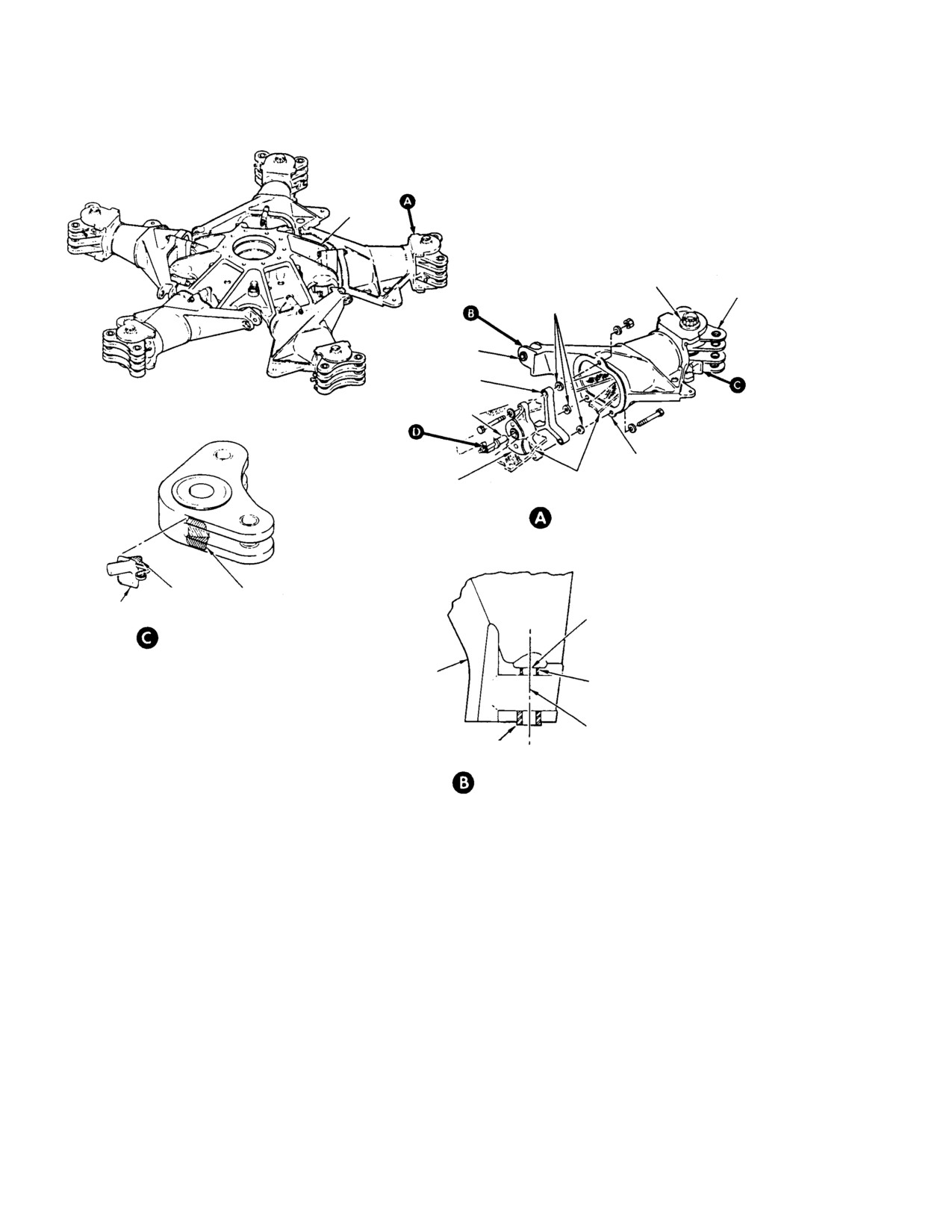
CSP-HMI-2
MD Helicopters, Inc.
MAINTENANCE MANUAL
CAUTION: WASHERS ARE INSTALLED BETWEEN SPACERS AND STRIKER
STRIP TO ESTABLISH CORRECT STATIC DROOP ANGLE BETWEEN HOUSING
AND HUB. EXACT NUMBER REMOVED MUST BE REINSTALLED. THREE PITCH
BEARING HOUSING BOLTS MUST EACH HAVE SAME NUMBER (THICKNESS) OF
WASHERS WHEN SHIMMING IS NECESSARY.
HUB
LEAD-LAG
BOLT
LEAD-LAG
DROOP SHIM WASHERS
LINKS
(SEE CAUTION)
SLEEVE
BUSHING
SPACER
PIVOT PIN
STRIKER STRIP
PITCH CONTROL BEAR
ING HOUSING AS
MAIN ROTOR
SEMBLY
STRAP PACK
PITCH BEARING HOUSING AND
SPACER - INSTALLATION (CUR
RENT CONFIGURATION)
ELONGATED HOLE LINE REAMED (USING
SLEEVE BUSHING AS GUIDE) TO PROVIDE 0.001
NOTE 1
NOTE 2
-0.0015 IN. (0.0254-0.0381 MM) INTERFERENCE
LEAD-LAG
FIT FOR 0.3675-0.3685 IN. (9.3345-9.3599 MM)
STOP
OUTSIDE DIAMETER REPAIR BUSHING
LEAD-LAG LINK AND STOP
PITCH HOUSING ARM
REPAIR BUSHING (2024-T3 OR 7075-T6
(CLEVIS LUG)
ALUMINUM PRESS FIT
PRESS-FITTED REPAIR BUSHING LINE
DRILLED AND LINE REAMED USING SLEEVE
SLEEVE
BUSHING AS GUIDE:
BUSHING
FINAL ID; 0.3125-0.3135 IN. (7.9375-7.9629 MM)
PITCH HOUSING BUSHINGS - REPAIR
NOTES:
NOTES: (CONT)
1.
FOR REMOVAL, WOOD DOWEL PLACED HERE AND
7.
COUNTERSUNK RIVET HEAD OR SCREW HEAD MUST BE
STRUCK SHARPLY WITH HAMMER TO BREAK STOP BOND.
FLUSH WITH HOUSING. UPSET END MUST BE FLUSH
2.
ALL STOP-TO-LINK SHADED CONTACT SURFACES
WITH PLATE.
BONDED WITH ADHESIVE (CM405 OR CM410).
8.
UPSET END MUST BE FLUSH WITH PLATE.
3.
INSTALL WITH WET PRIMER (CM318).
9.
MANUFACTURED RIVET HEAD MUST BE FLUSH WITH
4.
WET PRIMER (CM318) ON WASHER AND MATING SURFACES
PLATE IN ALTERNATE RIVET INSTALLATION.
BEFORE INSTALLATION.
10. REPLACEMENT HOUSING FOR BOTH VERSIONS
5.
NUT RETAINING BRACKET IS BONDED TO HUB.
ATTACHED TO STRIKER PLATE WITH SCREW, WASHER
6.
EARLY CONFIGURATION MODIFIED BY HUGHES SERVICE
AND NUT FOR EASE OF REMOVAL.
NOTICE DN-3.
G62 2013 1A
Figure 802. Main Rotor Hub Components − Repair and Installation (Sheet 1 of 2)
Page 806
Revision 20
62-20-00
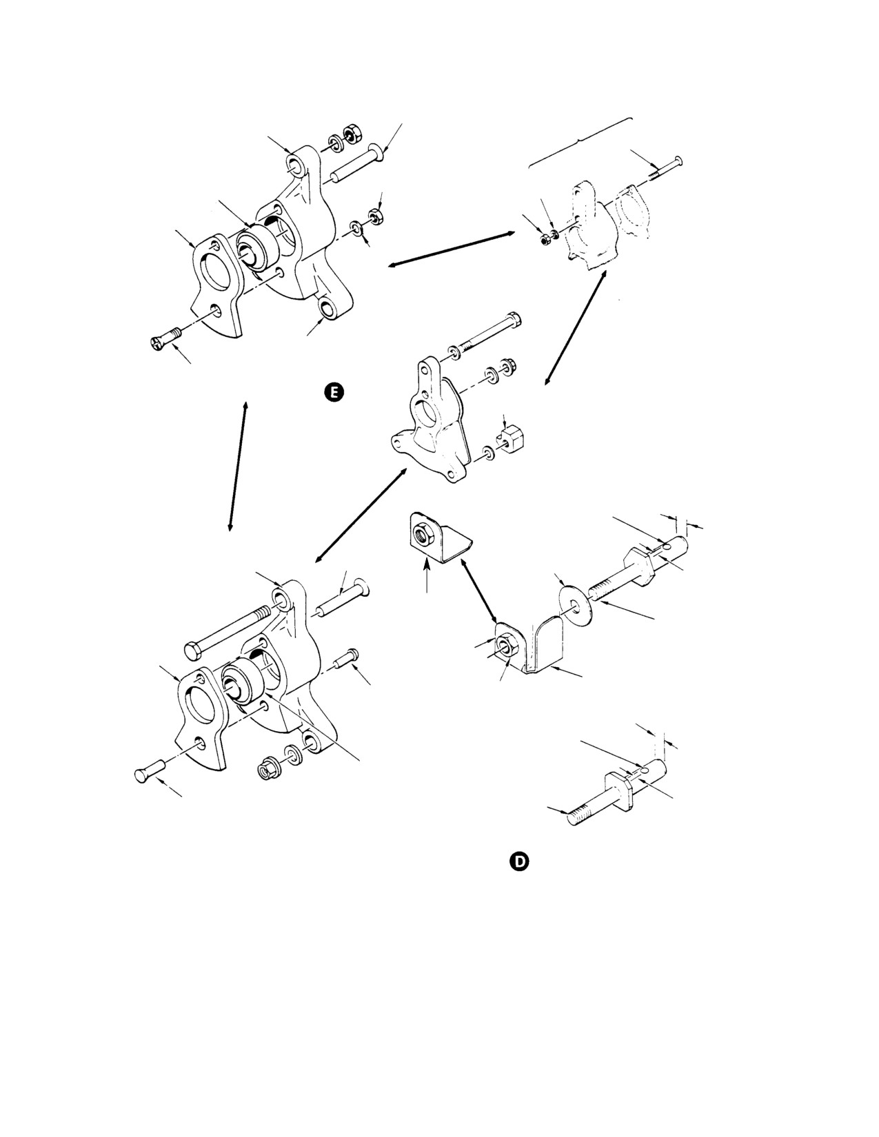
MD Helicopters, Inc.
CSP-HMI-2
MAINTENANCE MANUAL
NOTE 7
HOUSING
NOTE 10
SCREW
NUT
WASHER
PITCH BEARING
NUT
STRIKER
PLATE
WASHER
THREADED
(2 PLACES)
COUNTERSUNK
HEAD SCREW
SUPPORT NUT
PITCH BEARING -
MODIFIED CONFIGURATION (RO
INSTALLATION
TATED) (NOTE 6)
MAXIMUM ALLOWABLE WEAR IS 90%
CIRCUMFERENCE OF 0.4328 INCH
0.4328 INCH
(10.99312 MM) MINIMUM DIAMETER
(10.99312 MM)
MINIMUM DIA.
SPECIAL WASHER
NOTE 7
(NOTE 4)
HOUSING
0.125 INCH (3.175 MM)
MAXIMUM WEAR
NUT RETAINING
PITCH PIVOT PIN
BRACKET (NOTE 5)
(CURRENT CONFIGURATION)
CURRENT CONFIGURATION
(NOTE 3)
HUB
STRIKER
RETAINING NUT
PLATE
BRACKET (NOTE 5)
ROUND HEAD RIV
CAPTIVE NUT
EARLY CONFIGURATION
ET (NOTE 8)
MAXIMUM ALLOWABLE WEAR IS 90%
CIRCUMFERENCE OF 0.4328 INCH
0.4328 INCH
(10.99312 MM) MINIMUM DIAMETER
(10.99312 MM)
PITCH
MINIMUM DIA.
BEARING
PITCH PIVOT PIN
0.125 INCH (3.175 MM)
COUNTERSUNK HEAD RIVET
(EARLY CONFIGURATION)
MAXIMUM WEAR
(ALTERNATE) (NOTE 9)
(NOTE 3)
EARLY CONFIGURATION
PIVOT PITCH PIN - INSTALLATION
62-2013-2A
Figure 802. Main Rotor Hub Components − Repair and Installation (Sheet 2 of 2)
Page 807
62-20-00
Revision 20
CSP-HMI-2
MD Helicopters, Inc.
MAINTENANCE MANUAL
NOTE: Diameter of bearing bore, after cleanup,
(1).
Provide a backup support for link
should not exceed 1.1880 inch (3.01752 cm).
assembly. Use 0.5 inch (12.7 mm) wood
Localized areas of clean up should not ex
dowel and hammer to drive stop from
ceed 0.003 inch (0.0762 mm) within an area
link. Strike dowel sharply to break
of 25% of the circumference.
adhesive bond.
(3). Rework minor surface abrasion in
housing bore by polishing with crocus
(2).
Using sharp-edge metal scraper,
cloth (CM803). Restore chemical film
carefully scrape any adhesive residue
(CM206), where removed.
from link. If scraper penetrates through
paint and chemical surface film, surface
(4). Press bearing into bore using wet
must be refinished. Depth of gouges or
primer (CM318). Wipe away any excess
nicks is limited to 0.010 inch (0.254
primer using care to keep it out of
mm) maximum after rework. Rework
bearing. Check teflon linings of bearing
by smooth blending into surrounding
after installation to determine that no
area with grade 320 abrasive cloth
damage occurred from pressing opera
(CM802). Final polish with crocus cloth
tion.
(CM803). Restore chemical film protec
tion (CM206).
NOTE: Ensure bearing is seated completely in
bore of housing and striker plate fits flush
on housing.
(3).
Clean bond area of all contact surfaces
by wiping with cleaner (CM228).
(5). Apply sealant (CM425) to faying
Flush-wipe cleaned surface four times
surfaces and install striker plate with
with mixture of equal parts of distilled
screw, washer and nut or rivets. Head
water and isopropyl alcohol (CM217) to
of countersunk screw or rivet must be
remove all traces of phosphoric acid.
completely flush.
Rinse cleaned surface with tap water,
followed by a rinse of distilled water
7. Lead−Lag Link Blade Stop Replacement
until surface is ”water break” free. Dry
for 30 minutes minimum at 150°F
(Ref. Figure 802) Replace blade stop if it is
(66°C).
broken, cracked, has broken spring, or if there
are visible bond line cracks.
(4).
Check fit of stop in link. Flange and
radius contact surfaces of stop must
Consumable Materials
mate with link within 0.010 inch (0.254
(Ref. Section 91−00−00)
mm). Maximum clearance between stop
Item
Nomenclature
and inside surfaces of link ears is
CM206
Chemical coating
limited to 0.020 inch (0.508 mm). This
tolerance applies to both sides of stop.
CM217
Isopropyl alcohol
CM228
Surface cleaner
CM411
Adhesive, epoxy
(5).
Prepare mixture of epoxy adhesive
CM802
Abrasive cloth, aluminum oxide
(CM411). Apply uniform coating of
mixed adhesive to all contact surfaces.
CM803
Crocus cloth
Hand press stop into place between link
ears until all mating surfaces are in
Lead-lag link assembly must
firm contact. Apply a clamping device
CAUTION
not be removed from pitch con
so that contact is maintained. Cure for
trol housing for this repair, since retention
minimum of eight hours at room
bolt cannot be retorqued without special
temperature, or two hours at 150°F
adapter.
(66°C).
Page 808
Revision 20
62-20-00
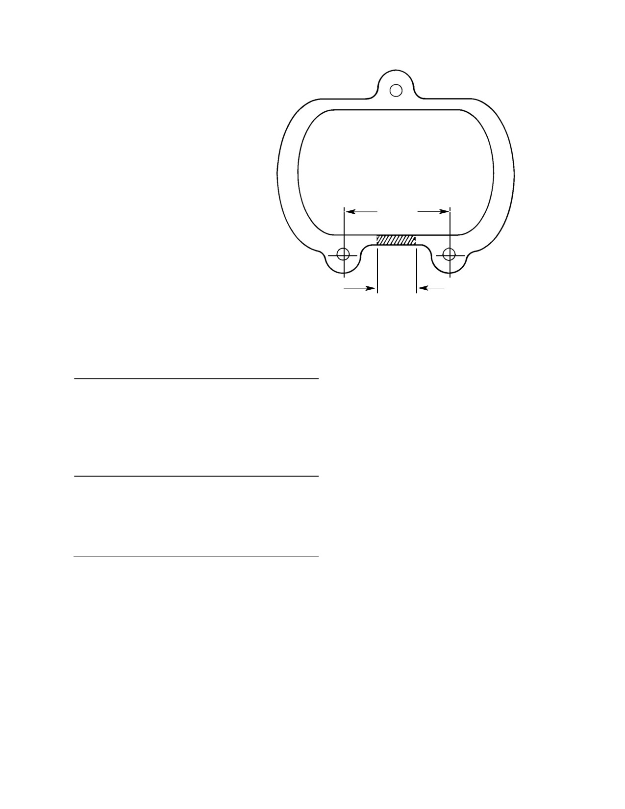
MD Helicopters, Inc.
CSP-HMI-2
MAINTENANCE MANUAL
2.50 INCH
(6.35 CM)
CAUTION:
DO NOT SCRATCH STRAP PACK WHEN INSTALLING
THROUGH STRAP ASSY.
NOTE:
CUT OUT 0.25-0.50 IN. (6.35-12.70 MM) PIECE OF THE
0.25-0.50 IN.
STRIKER STRIP BETWEEN LOWER BOLT HOLES.
(6.35-12.70 MM)
DEBURR AND RADIUS-CUT EDGES.
(NOTE)
G62-2009A
Figure 803. Striker Strip Replacement
8. Damper Attach Lug Bearing Replacement
(4).
Using 10-power magnifying glass,
inspect fitting bore for cracks. No
cracks are permitted.
Consumable Materials
(Ref. Section 91−00−00)
(5).
Measure fitting bore diameter. Accept
Item
Nomenclature
able limits are 0.6548-0.6552 inch
CM216
Loctite remover
(16.63192-16.64208 mm).
CM219
Methyl-ethyl-ketone
CM318
Primer
(6).
Apply thin coat of primer (CM318) to
fitting bore.
Special Tools
(7).
Press bearing into fitting with arbor
(Ref. Section 91−00−00)
press and fixture (ST706). Wipe away
Item
Nomenclature
excess primer.
ST706
Arbor press fixture
ST707
Staking tool
(8).
Stake bearing at both sides of fitting
with staking tool (ST707) in hydraulic
press with 6000-8000 pounds
(1). Use fly or circle cutter with 0.25 inch
(26688-35584 N) of force. When staked,
(6.35 mm) pilot to remove staked lip
outer race of bearing shall be flush to
from one side of bearing without
not more than 0.010 inch (0.254 mm)
removing any material from fitting. If
above fitting surface (both sides). Gap
fitting is damaged by cutter, blade must
between staked lip of bearing race and
be replaced.
chamfered surface of fitting bore shall
not exceed 0.002 inch (0.0508 mm) as
(2). Use an arbor press to press bearing
checked with feeler gage. Staking
from fitting.
operation shall produce no cracks in
(3). Clean primer residue from fitting bore
fitting or bearing.
with MEK (CM219). Remove locking
compound residue (if any) with locking
(9).
Fill staking gap (if any) with primer
compound remover (CM216).
(CM318).
Page 809
62-20-00
Revision 20

CSP-HMI-2
MD Helicopters, Inc.
MAINTENANCE MANUAL
9. Lead−Lag Bolt Corrosion Control
NOTE: Torque pivot pin to 70 - 80 inch-
pounds (7.91 - 9.04 Nm), then use 0.002
inch (0.0508 mm) feeler gage and check for
Consumable Materials
gap between pin flange and washer on
(Ref. Section 91−00−00)
mounting lug surface. No gap is allowed.
Item
Nomenclature
CM219
Methyl-ethyl-ketone
(3). Install pivot pin in mounting lug with
washer (Ref. Figure 802). Torque pivot
CM318
Primer
pin to 250 - 280 inch-pounds (28.25 -
CM425
Sealing compound
31.64 Nm). Apply sealant (CM420) at
CM802
Abrasive cloth, aluminum oxide
junctures of pivot pin flange, washer
and hub.
Do not disturb torque on lead-
CAUTION
11. Droop Stop Roller Repair or Replacement
lag bolts. Special adapter is
needed to retorque lead-lag bolts.
(Ref. Figure 804) Replace defective droop stop
roller if clearance between roller bearing liner
(1). Remove and tag or color-code each set
and shaft is more than 0.015 inch (0.381 mm).
of balance hardware that is installed.
Roller shaft outside diameter must not be less
(2). Remove corrosion with grade 180
than 0.4370 inch (11.0998 mm).
abrasive cloth (CM802) and finish with
grade 400 abrasive cloth.
Consumable Materials
(Ref. Section 91−00−00)
(3). Swab cleaned surface with MEK
Item
Nomenclature
(CM219) and apply unthinned zinc
chromate primer (CM318).
CM217
Isopropyl alcohol
(4). Reinstall original balance hardware
that was removed. Using sealant
(1). Remove pitch control bearing housing
(CM425), reseal balance hardware.
that contacts lower shoe roller to be
removed.
10. Pitch Control Bearing Pivot Pin Repair or
NOTE: Only one roller can be removed at one
Replacement
time. Two opposing droop stop followers
(Ref. Figure 802) Minimum allowable pin
must be pressed against droop stop ring to
diameter is 0.4328 inch (10.99312 mm). Pivot
force opposite follower out and expose roller
pin grooving or excessive side wear may be
shaft for removal. Same condition exists at
polished to original finish as long as minimum
installation.
allowable pin diameter, 0.4328 inch (10.99312
(2). Press down on pitch housing that is
mm), remains after rework. Replace any pin
opposite roller that is to be removed.
requiring more rework as follows.
Remove cotter pin and shaft.
Consumable Materials
(3). Remove droop stop roller.
(Ref. Section 91−00−00)
(4). Wet down and clean plunger and
Item
Nomenclature
mating shoe bushing with isopropyl
CM318
Primer
alcohol (CM217).
CM420
Sealant
(5). To install replacement roller, press
down on pitch housings at opposite
(1). Remove pivot pin.
sides of hub from roller to be installed.
Install roller, shaft and new cotter pin.
(2). Install replacement pivot pin wet with
primer (CM318).
(6). Install pitch control bearing housing.
Page 810
Revision 20
62-20-00
MD Helicopters, Inc.
CSP-HMI-2
MAINTENANCE MANUAL
12. Droop Stop Ring Repair
When T-head is free of ring channel,
turn it perpendicular (vertical) to
(Ref. Figure 804)
channel.
NOTE: Followers can be easily rotated by use of
Consumable Materials
nonmetallic drift in hole for droop stop roller
(Ref. Section 91−00−00)
shaft.
Item
Nomenclature
(6). Push droop stop ring toward number 4
CM103
Solid film lubricant
and 5 followers. Pull number 2 follower
T-head from droop stop ring channel.
(1). Repair depth limit for corrosion, nicks
When T-head is free of channel, turn it
or scratches in droop stop ring is 0.007
perpendicular to channel.
inch (0.1778 mm) for all surfaces except
(7). Push droop stop ring toward number 1
outer edges of ring outer flanges. Depth
and 5 followers. Pull number 3 follower
limit is 0.030 inch (0.762 mm). All
T-head from droop stop ring channel.
reworked areas must be blended
When T-head is free of channel, turn in
smoothly with 15 to 1 ratio into sur
perpendicular to channel.
rounding area.
(8). Tilt ring up on number 1, 2, and 3
(2). Spray repaired areas of rings with solid
T-heads as far as possible.
film lubricant (CM103).
(9). While pulling upward on ring, rotate (in
(3). Replace droop stop ring if repair limits
succession) number 1, 2, and 3 T-heads
are exceeded.
so that they are out of, and below, droop
stop ring.
13. Droop Stop Ring Replacement
(10). Withdraw number 4 and 5 T-heads
(Ref. Figure 804)
from droop stop ring channel and
remove ring.
(1).
With hub upside down, support hub so
When installing droop stop ring,
that pitch housings unload cam follow
CAUTION
droop stop followers T-Heads
ers and provide maximum clearance
must be offset away from lower shoe to pre
between striker plates and droop stop
vent damage to lower shoe.
rollers.
(11). Install replacement droop stop ring by
(2).
Release retaining (snap) ring of each
reversing removal procedure, steps (1).
droop stop restrainer from its groove.
through (10)., making certain to
Move retaining ring flush against droop
reinstall followers according to mark
stop follower (T-head) to provide
ings placed thereon prior to removal.
additional clearance and reduce spring
tension.
(12). Compress follower spring and install
retaining (snap) ring in its groove on
(3).
Remove five droop stop rollers.
each follower.
(4).
Starting from either scissors crank
(13). Reinstall droop stop rollers.
attach lug, number all five droop stop
14. Droop Stop Follower (T−Head)
follower assemblies in clockwise
Replacement
direction for location identification at
replacement. This number code should
(Ref. Figure 804) Replace the droop stop
be placed on outer, upper end of plunger
follower (T-head) if it is worn, scored or is
and on adjacent area of lower shoe.
causing damage to the droop stop ring. After
Make sure codes are not accidentally
the droop stop ring has been removed, the
removed during remaining steps.
droop stop follower assemblies may be
removed from hub.
(5).
Push droop stop ring toward number 3
and 4 followers. Pull number 1 follower
(1). Remove droop stop follower assembly
T-head from droop stop ring channel.
from hub.
Page 811
62-20-00
Revision 37
CSP-HMI-2
MD Helicopters, Inc.
MAINTENANCE MANUAL
(2). Remove pins that secure follower to
(c). The maximum wear condition may
plunger.
exist in one spot or in several spots
totaling 2.1 square inches (13.55
Droop stop followers T-Heads
cm2).
CAUTION
must be offset away from lower
shoe to prevent droop stop ring from damag
(6). Wet down and clean plunger and
mating shoe bushing with isopropyl
ing lower shoe.
alcohol (CM217).
(3). Insert new follower. T-head must be at
(7). Install droop stop plunger into lower
right angle to roller shaft in plunger.
shoe.
(4). Drill two 0.156-0.158 inch
(8). Install roller, shaft and new cotter pin.
(3.9624-4.0132 mm) diameter holes
through follower in line with holes in
(9). Complete droop stop ring installation.
plunger.
16. Main Rotor Hub Droop Angle Adjustment
(5). Insert pins and stake ends. No burrs or
(Ref. Figure 802) If static droop angle exceeds
roughness permissible after staking.
six degrees, adjust as follows.
(6). Install follower assembly in hub.
(1). Remove main rotor blade.
(7). Reinstall droop stop ring.
(2). Use flat washers of thickness required
to adjust spacing between spacer and
15. Droop Stop Plunger Removal, Inspection
striker strip. Any one type, or combina
and Installation
tion, of correct part number washers
(IPC) may be used; however, an identi
(Ref. Figure 804)
cal washer selection must be installed
on each of three bolts that secure pitch
Consumable Materials
control bearing assembly to pitch
(Ref. Section 91−00−00)
housing.
Item
Nomenclature
(3). Remove nuts and washers and separate
CM217
Isopropyl alcohol
spacer from striker strip. The use of one
0.016 inch washer raises static droop
angle approximately one-half degree.
(1). Remove droop stop ring.
Add sufficient washers to adjust droop
(2). Remove pitch control bearing housing
angle within range of 5.5 ±0.5 degrees.
assembly that contacts the lower shoe
Reinstall nuts and washers.
roller.
(4). If more than 0.063 inch (1.6002 mm)
spacing is required (above factory
(3). Remove cotter pin and shaft from droop
spacing), inspect striker plate and
stop follower assembly.
droop stop roller or follower and droop
(4). Remove droop stop roller.
stop ring for excessive wear. Replace as
required.
(5). Check droop stop plunger for wear by
NOTE: The average factory spacing on new and
using the following criteria:
rebuilt hubs is 0.063 inch (1.6002 mm).
(a). The minimum acceptable diameter
(5). Reinstall blade. Repeat measurement of
after wearing in service should be
static droop angle.
0.996 inch (25.2984 mm).
(6). As required, repeat above procedures
(b). The acceptable amount of wear
for remaining blades.
though the anodized coating shall not
exceed 40% or 2.1 square inches
(7). Following reinstallation or replacement
(13.55 cm2) of the total sliding
of parts, check track of main rotor
surface area of the cylinder.
blades.
Page 812
Revision 37
62-20-00
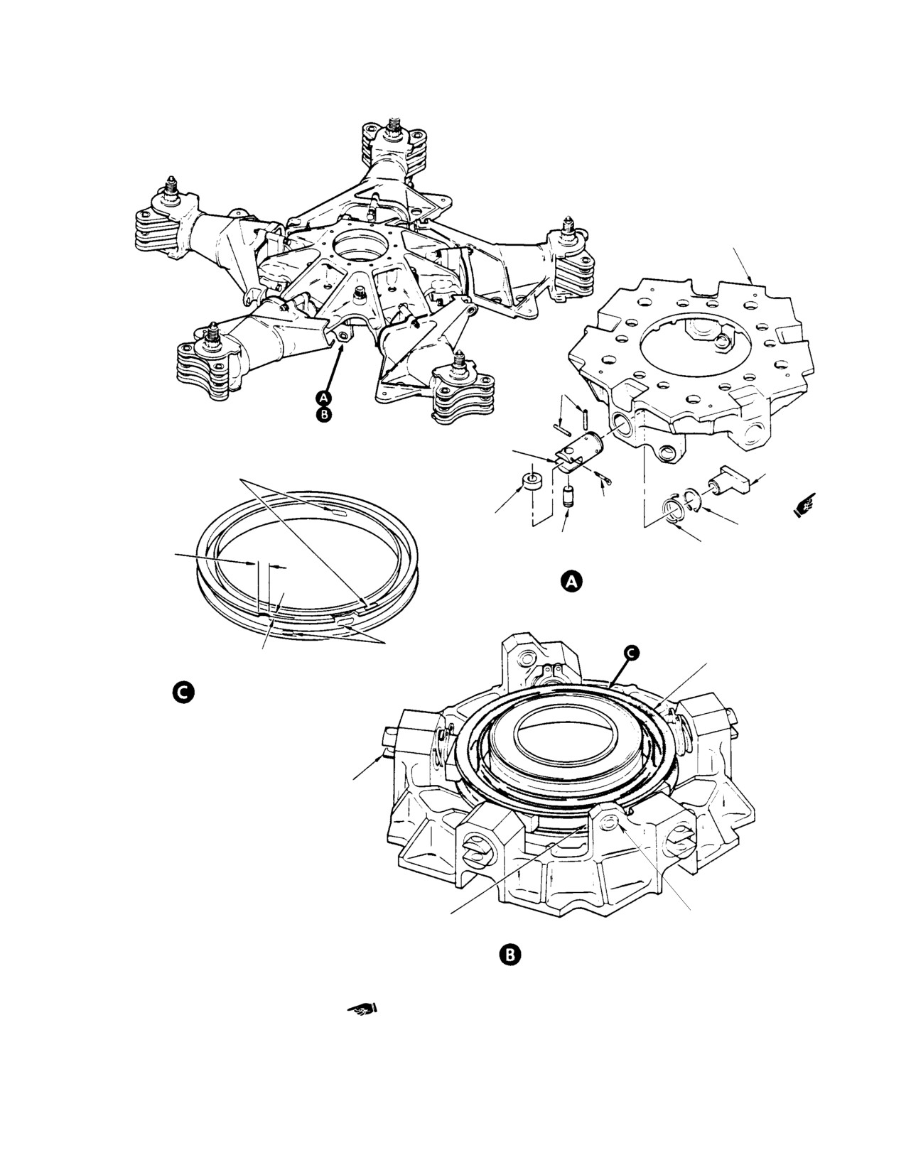
MD Helicopters, Inc.
CSP-HMI-2
MAINTENANCE MANUAL
LOWER
SHOE
PINS
DROOP STOP
0.007 INCH (0.1778 MM)
PLUNGER
DROOP STOP
MAX. DEPTH (15 TO 1
FOLLOWER
RADIUS) AFTER REWORK
(T-HEAD) (NOTE)
COTTER
DROOP STOP
PIN
SNAP RING
ROLLER
15 TO 1
SHAFT
SPRING
RADIUS
DROOP STOP FOLLOWER - INSTALLATION
0.007 INCH (0.1778 MM)
MAX. DEPTH (15 TO 1
0.030 IN. MAX.
RADIUS) AFTER
DROOP STOP RING
AFTER REWORK
REWORK
DROOP STOP RING - REPAIR LIMITS
DROOP STOP FOLLOWER
ASSEMBLY (5 PLCS)
SCISSORS CRANK
BEARING ROTATIONAL DRAG
ATTACH LUG
1.0 - 2.0 IN-LBS
(0.113 - 0.226 NM)
LOWER SHOE - INVERTED
NOTE: DROOP STOP FOLLOWER T-HEADS TO
G62 2011C
Figure 804. Main Rotor Hub Assembly − Repair
Page 813
62-20-00
Revision 37

CSP-HMI-2
MD Helicopters, Inc.
MAINTENANCE MANUAL
17. Main Rotor Hub Tapered Bearing Grease
(4). Check bearing cup hub bore for scoring.
Repack, Inspection and Replacement
Smooth out any roughness with grade
400-600 abrasive cloth (CM802).
(Ref. Figure 805) Replace tapered roller
Restore chemical film protection where
bearing cup or cone if it has any flat spots,
removed. Maximum diameter of hub
scoring, pitting, grooving, discoloration (blue)
bore for upper bearing cup (Ref.
or if it feels rough when rotated.
Figure 805) is 4.4335 inch (11.26109
cm), measured in any direction.
Maximum diameter of hub bore for
Consumable Materials
lower bearing cup is 4.3095 inch
(Ref. Section 91−00−00)
(10.94613 cm), measured in any
Item
Nomenclature
direction.
CM111
Grease, aircraft
CM121
Preservation oil
(5). Check upper seal retainer. No cracks,
sharp nicks or burrs are allowed. Minor
CM234
Solvent, dry-cleaning
corrosion or other surface defects may
CM802
Abrasive cloth, aluminum oxide
be polished out using crocus cloth
CM803
Crocus cloth
(CM803). Grooving on seal contact
surfaces must not exceed 0.004 inch
Special Tools
(0.1016 mm) depth after polishing.
(Ref. Section 91−00−00)
Bearing cups are installed in
Item
Nomenclature
WARNING
hub by differential tempera
ST701
Main rotor wrench assembly
ture (shrink-fit) method. Take appro
priate precautions to prevent burns
when handling parts that are cooled to
Do not intermix Timken or NTN
CAUTION
sub-zero temperatures.
bearing cups and cones at upper
and lower tapered roller bearing locations of
(6).
Place bearing cups in closed container
main rotor hub.
of dry ice and cool for not less than 20
minutes to -40°F (-40°C).
NOTE:
(7).
Coat bore of hub with grease (CM111).
D Roller bearing cones and cups should al
Use care to maintain cup-to-hub bore
ways be replaced as a set.
alignment and press cup into bore,
D Replace tapered roller bearing cup and
using tools D and E (Ref. Figure 806),
cone if it has any flat spots, scoring, pit
until cup is seated.
ting, grooving, discoloration (blue) or if it
(8).
Apply film of grease to sleeve bushing.
feels rough when rotated.
Use pressing tool equivalent to tool C,
(1). Use pressing tools equivalent to items
and press bearing cone onto sleeve
A and B (Ref. Figure 806) to press
bushing.
upper and lower bearing cups from hub.
(9).
With lip on center seal up, hand press it
A press ram of one to two tons is
into hub (Ref. Figure 805).
sufficient for removal.
(10).
Apply film of grease on mast. Install
(2). Press lower bearing cone from sleeve
preassembled sleeve bearing and
bushing.
bearing cone on mast. Do not apply any
additional lubricant to roller bearing
In next step, do not spin reus
CAUTION
set. Wipe any excess preservative oil
able bearings while cleaning.
from bearing cone and cup.
Coat bearings lightly with oil (CM121) after
cleaning.
(11).
Place assembled hub over mast and
seat on lower roller bearing cone.
(3). Clean hub bore, sleeve bushing, seal
retainer and reusable bearings using
(12).
Install lead spacer 369A1224-5 (thick
filtered solvent (CM234) spray.
ness gage substitute for recessed
Page 814
Revision 21
62-20-00
MD Helicopters, Inc.
CSP-HMI-2
MAINTENANCE MANUAL
spacer) over mast. Rest spacer on top of
pounds (1.13 - 1.69 Nm). This will be
sleeve bushing.
1.5 - 3 pounds (0.681 - 1.362 kg) on
spring scale used as in step (15). above.
NOTE: If lead spacer is not available, fabricate
its equivalent from lead sheet. Spacer di
(18). Remove hub and sleeve bushing with
mensions are; 2.96 inch (7.5184 cm) outside
lower bearing cone from mast.
diameter;
2.68 inch
(608072 cm) ID;
(19). Position hub upside-down. Hand-pack
0.075-0.085 inch (1.905-2.159 mm) thick.
lower hub cavity (Ref. Figure 805) and
bearing cone on sleeve bushing with
(13). Install upper bearing cone into hub and
grease.
on top of lead spacer.
(20). Install sleeve bushing with bearing
(14). Install steel ring washer, equivalent to
cone in hub. Hand-pack cavity between
tool F (Ref. Figure 806), as substitute
bearing and hub liner with grease; then
for seal retainer (Ref. Figure 805).
press in lower seal with seal lip toward
top of hub. Wipe off excess grease.
NOTE: Step (14). is not required. However, use
of substitute washer for retainer prevents
(21). Turn hub assembly right side up.
unnecessary scoring of retainer. Several
(22). Complete reassembly of hub by install
tightening and loosening actions may be re
ing recessed spacer, upper bearing cone,
quired to get correct rotational drag on hub
upper seal and seal retainer in hub at
bearings.
installation of hub on mast.
(15). Install mast nut on mast using mast
18. Main Rotor Hub Scissors Attach Lug
nut wrench (ST701), tighten until
Bearing Replacement
bearings are preloaded to 10 - 12
inch-pounds (1.13 - 1.36 Nm) of
rotational drag. Measure rotational
Consumable Materials
drag using 0 - 10 pound (0 - 4.536 kg)
(Ref. Section 91−00−00)
spring scale hooked over one of hub
Item
Nomenclature
support web bosses, 6.5 inch (16.51 cm)
CM206
Chemical coating
from hub centerline). A 1.50 - 1.75
CM216
Loctite remover
pound (0.681 - 0.7945 kg) pull with hub
CM304
Enamel, epoxy
in motion indicates correct rotational
CM321
Surface primer locking compound
drag.
CM431
Sealing, locking and retaining compound
(16). Remove mast nut, tool F (Ref.
Figure 806), (or seal retainer), and
(1). Remove main rotor hub (Ref. Main
upper bearing cone. Remove lead spacer
Rotor Hub Replacement).
and measure compressed thickness.
Obtain serviceable recessed spacer of
(2). Invert hub and place on work bench.
same thickness, or grind new recessed
(3). Remove droop stop ring (Ref. Droop
spacer to required dimension. Discard
Stop Ring Replacement).
lead spacer after recessed spacer is
correctly ground.
(4). Press bearing from hub lug.
NOTE: To insure that hub is seated onto mast
(5). Clean bearing bore with Loctite
properly before torquing, 2 - 4 threads
remover (CM216).
should be showing above the mast nut with
(6). Inspect bearing bore for nicks,
nut installed finger tight.
scratches and grooves.
(17). Install recessed spacer, recess down, on
(7). Inspect bore for diameter of
top of sleeve bushing. Reinstall upper
0.6551-0.6556 inch (16.63954-16.65224
bearing cone, seal retainer and mast
mm).
nut. Torque nut to 200 - 250 foot-
pounds (271 - 339 Nm) and check for
(8). Touch up bearing bore with chemical
rotational drag of 10 - 15 inch-
coating (CM206).
Page 815
62-20-00
Revision 35
CSP-HMI-2
MD Helicopters, Inc.
MAINTENANCE MANUAL
(9). Apply surface primer (CM321) to
room temperature or heat to 140° -
mating surfaces of bearing and bores
160°F (60° - 72°C) for one hour.
per manufacturer's instructions.
(13). As required, touch up bearing lug with
NOTE: Do not allow primer to enter bearing.
paint (CM304).
(10). Apply locking compound (CM431) to
(14). Check bearing for a no-load rotational
faying surfaces of bearing and bore,
drag of 1.0 - 2.0 inch-pounds (0.113 -
press bearing into bore while locking
0.226 Nm).
compound is wet.
(15). Reinstall droop stop ring (Ref. Droop
(11). Remove excess sealant, do not allow
Stop Ring Replacement).
sealant to enter bearing.
(12). Apply a small fillet of sealant around
(16). Reinstall main rotor hub (Ref. Main
bearing and allow to dry for 24 hours at
Rotor Hub Replacement).
Page 816
Revision 34
62-20-00
MD Helicopters, Inc.
CSP-HMI-2
MAINTENANCE MANUAL
STRIKER
STRIP
SEALANT
(NOTE 2)
PITCH BEARING
(NOTE 1)
PITCH
(NOTE 1)
HOUSING
DROOP SHIM
WASHER (NOTE 9)
SPACER
LAMINATED
STRAP PACK
SEALANT
STRIKER
(NOTE 2)
PLATE
PITCH CONTROL
DROOP RESTRAINER
BEARING HOUSING
AND ROLLER
SEAL
UPPER BEARING CUP
(NOTE 4)
(NOTE 10)
UPPER BEARING CONE
HUB
(NOTE 10)
SEAL
RECESSED SPACER
RETAINER
(NOTE 3)
SEAL
(NOTE 4)
PIVOT PIN
SEALANT
(NOTE 2)
LOWER
SHOE
NOTE 1
NOTE 11
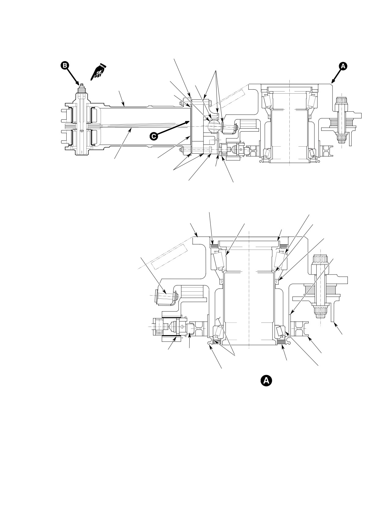
NOTES:
DROOP STOP
1.
HEAVY LINES INDICATE REINFORCED
NOTE 5
RING
SEAL
TEFLON BEARINGS (TYPICAL)
(NOTE 4)
2.
SEALANT (CM425) APPLIED TO LOCATIONS SHOWN.
HUB OUTER
LOWER BEARING CUP
3.
RECESSED SPACER SPECIALLY GROUND TO ESTABLISH CORRECT
LINER
(NOTE 10)
ROTATIONAL DRAG ON TAPERED BEARINGS, INSTALLED RECESS
DOWN ON TOP OF SLEEVE BUSHING.
4.
SEAL TO BE UPWARD.
5.
BEARING AND CAVITY TO BE FILLED WITH GREASE (CM111).
6.
EARLY CONFIGURATION MODIFIED BY HUGHES SERVICE NOTICE DN-3.
7.
ON CURRENT CONFIGURATION, RIVET IS REPLACED BY SCREW, WASHER, AND NUT.
8.
SEALANT (CM420) APPLIED TO SURFACES SHOWN.
9.
DROOP SHIM WASHERS ARE INSTALLED AS REQUIRED TO OBTAIN PROPER ROTOR
DROOP ANGLE.
10. DO NOT INTERMIX TIMKEN AND NTN BEARING CUPS AND CONES AT UPPER AND LOWER
TAPERED BEARING LOCATIONS.
11. DROOP STOP FOLLOWER T-HEAD TO BE OFFSET AWAY FROM LOWER SHOE.
G62-2014-1B
Figure 805. Main Rotor Hub − Cross Section (Sheet 1 of 2)
Page 817
62-20-00
Revision 40
CSP-HMI-2
MD Helicopters, Inc.
MAINTENANCE MANUAL
LEAD-LAG
PIVOT BOLT
LEAD-LAG
SEALANT
LINKS
(NOTE 2)
NOTE 2
NOTE 2
NOTE 1
COTTER PIN
NOTE 7
RIVET
(NOTE 7)
EARLY CONFIGURATION
MS21042L08
NOTE 8
LOCKNUT
MS21042L3
SUPPORT
LOCKNUT
NOTE 8
NUT
CURRENT CONFIGURATION
WASHERS FOR
BALANCE AS
REQUIRED
STEP
WASHER
WASHER
WASHER
WASHER
LEAD LAG
PIVOT BOLT
SCREW
SCREW
CURRENT CONFIGURATION
EARLY CONFIGURATION
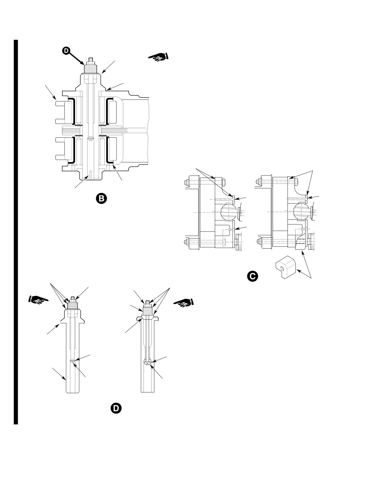
SERIAL NO. 0260D AND SUBS
SERIAL NO. 003D THRU 0259D
G62-2014-2A
Figure 805. Main Rotor Hub − Cross Section (Sheet 2 of 2)
Page 818
Revision 40
62-20-00
MD Helicopters, Inc.
CSP-HMI-2
MAINTENANCE MANUAL
A
A
2.875 IN. (7.3025 CM)
CUT OUT AFTER
0.50 IN.
OUTSIDE DIAMETER
BEVELING
(12.7 MM)
3.50 IN. (8.89 CM)
OUTSIDE DIAMETER
3.875 IN.
(9.8425 CM)
11.0 IN.
53
(27.94 CM)
°
5.75 IN.
3.375 IN.
(14.605 CM)
0.375 IN.
(8.5725 CM)
(9.525 MM)
0.1875 IN. (4.7625 MM)
0.203125 IN. (5.159375 MM)
4130 STEEL PLATE
WALL STEEL PIPE
WALL STEEL PIPE
A
B
C
4.40 IN.
4.30 IN.
(11.176 CM)
(10.922 CM)
2.58 IN.
0.30 IN.
(6.5532 CM)
(7.62 MM)
3.50 IN.
(8.89 CM)
2.0 IN.
2.0 IN.
(5.08 CM)
(5.08 CM)
ALUMINUM ALLOY
ALUMINUM ALLOY
STEEL RING WASHER
D
E
F
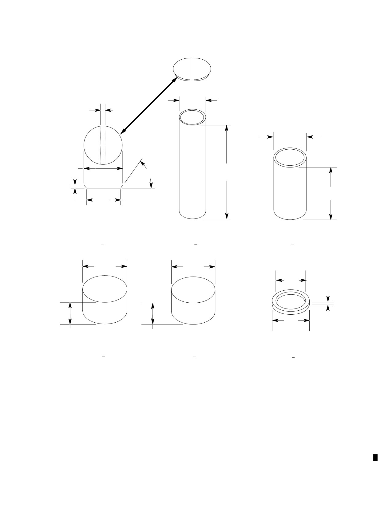
TOOL USE:
A & B - PRESS BEARING CUPS OUT OF HUB
C - PRESS LOWER BEARING CONE ON SLEEVE BUSHING
D - PRESS UPPER BEARING CUP INTO HUB
E - PRESS LOWER BEARING CUP ONTO HUB
F - IN PLACE OF UPPER SEAL RETAINER WHILE ADJUSTING ROTATIONAL DRAG
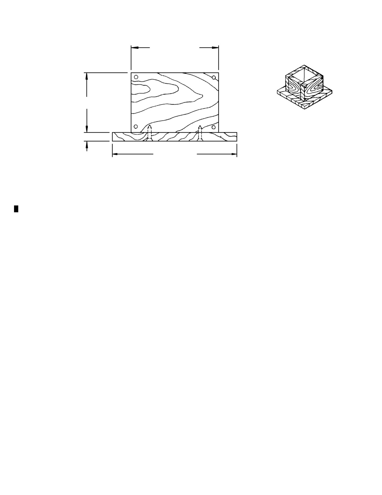
G - HUB BEARING REMOVAL - FABRICATION
G62-2010-1
Figure 806. Tapered Bearing Tools − Main Rotor Hub (Sheet 1 of 2)
Page 819
62-20-00
Revision 37
CSP-HMI-2
MD Helicopters, Inc.
MAINTENANCE MANUAL
7.0 INCH (17.78 CM)
SQUARED
4.75 INCH
(12.065 CM)
10.0 INCH (25.40 CM)
0.75 INCH
MATERIAL: WOOD
SQUARED
(19.05 MM)
H62-2010-2A
Figure 806. Tapered Bearing Tools − Main Rotor Hub (Sheet 2 of 2)
Page 820
Revision 37
62-20-00
MD Helicopters, Inc.
CSP-HMI-2
MAINTENANCE MANUAL
Section
62−20−60
Main Rotor Hub
(600N)
MD Helicopters, Inc.
CSP-HMI-2
MAINTENANCE MANUAL
MAIN ROTOR HUB
REMOVAL/INSTALLATION
1. Main Rotor Hub − General
(3). Remove lockwire and disconnect
flexible boot from lower end of hub
(Ref. Figure 402) The main rotor hub consists
liner.
of a central hub, six identical pitch housings
(4). Disconnect each pitch control rod from
spaced 60 degrees apart horizontally around
pitch housing.
the hub with associated mechanisms and
linkages. Lead-lag links, a lead-lag damper, a
(5). Disconnect scissors crank from main
droop stop striker strip and spacer, and a pitch
rotor hub or scissors link.
control bearing with each pitch housing
produce the pivoting axis, blade flapping stop
NOTE: To facilitate assembly, color code each
contact surfaces and lead-lag hinge function
pitch control rod to match pitch housing to
for the rotor blades. Six laminated retention
which it is attached.
strap assemblies that are flexible both
(6). Remove two screws securing retainer to
vertically and torsionally extend through the
main rotor hub nut.
pitch housings and connect to the lead-lag
links. A lower shoe, attached to the central
(7). Remove nut retainer.
hub, contains a droop stop ring and droop
restrainers that support the blades at rest and
(8). Using main rotor mast nut wrench
distribute droop loads at low blade rpm. The
(ST701), remove nut from mast.
following instructions provide field mainte
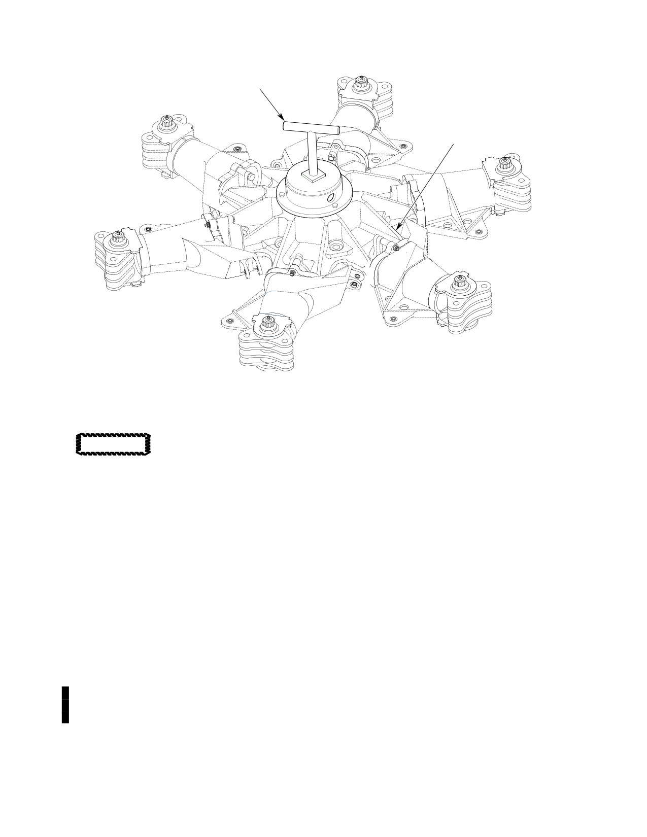
(9). Using hub puller (ST702), break loose
nance and repair procedures for the main rotor
main rotor hub. Remove hub puller.
hub.
(10). Attach hoisting adapter (ST201), to
2. Main Rotor Hub Replacement
eyebolts and hoist hub from mast.
B. Main Rotor Hub Installation
A. Main Rotor Hub Removal
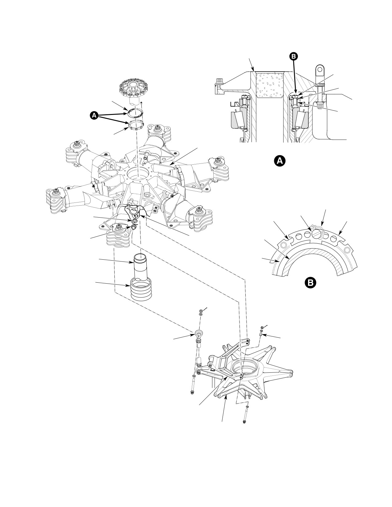
(Ref. Figure 402)
(Ref. Figure 401)
Consumable Materials
Special Tools
(Ref. Section 91−00−00)
(Ref. Section 91−00−00)
Item
Nomenclature
Item
Nomenclature
CM111
Grease, aircraft
ST201
Hoisting adapter
CM115
Grease, oscillating bearing
ST701
Main rotor wrench assembly
CM204
Compound, corrosion preventative
ST702
Hub puller
CM702
Lockwire CRES
Special Tools
(1). Remove main rotor blades.
(Ref. Section 91−00−00)
Item
Nomenclature
(2). Remove main rotor drive shaft; then
ST201
Hoisting adapter
reinstall hoisting eyebolts, washers and
nuts in rotor hub. Locate them to
ST701
Main rotor wrench assembly
correspond with lugs of hoisting
ST703
Main rotor hub driver
adapter (ST201).
Page 401
62-20-60
Revision 36
CSP-HMI-2
MD Helicopters, Inc.
MAINTENANCE MANUAL
Main rotor hub is a highly
(5). Hand-pack hub cavity, between sleeve
CAUTION
stressed component. Use ex
bushing and hub, with grease (CM111).
treme care to prevent it from striking any
(6). Place recessed spacer, recess down, on
object. Any impact damage may require re
top of sleeve bushing.
placement of hub.
(7). Hand-pack upper bearing cup and cone
NOTE:
with grease; then install cone on mast
D Removal of recessed spacer, upper bear
and use hub driver (ST703), to fully
ing cone, upper seal and seal retainer is
seat cone.
not mandatory for installation of the
main rotor hub. If these items are in
(8). Fill remaining cavity to upper seal with
stalled, perform steps (1). thru (4). and
grease.
(11). thru (22). Caution should be used
(9). Position upper seal in seal retainer
when installing hub to prevent damage to
with lip up; then press seal and retain
these parts.
er in hub counterbore.
D If recessed spacer, upper bearing cone,
upper seal and seal retainer have been re
(10). Using a soft drift, carefully tap seal
moved, these parts should not be as
outer ring to seat in counterbore. Wipe
sembled in hub before installation of hub
away any excess grease.
on helicopter. These items are reas
(11). Apply grease (CM111) to exposed
sembled in hub after seating hub on mast.
threads on mast.
Prior to installing main rotor hub, insure
that all bearings are adequately serviced
Ensure that seal is properly po
CAUTION
with grease (CM111).
sitioned against seal retainer
and that seal retainer does not pinch seal.
D Replacement main rotor hubs do not come
Check by inserting a loop of approximately
balanced from MDHS. If installing a re
0.050 inch (1.27 mm) diameter lockwire,
placement hub, perform a main rotor sys
tem balance (Ref. Sec. 18-10-60, Main
round feeler gage or other suitable tool with
Rotor System Balance Procedure).
out sharp edges between seal lip and retain
er.
(1). Attach hoisting adapter (ST201) to
NOTE: To insure that hub is seated onto mast
eyebolts in main rotor hub and connect
properly before torquing, two to four threads
suitable hoist.
should be showing above the mast nut with
If hub assembly (with sleeve
nut installed finger tight.
CAUTION
bushing, spacer, upper bearing
(12). Install mast nut, using wrench (ST701);
and seal retainer installed) does not seat
torque nut to 200 foot-pounds (271
properly onto mast, do not attempt to force it
Nm). Apply coat of corrosion preventive
into position. Remove hub assembly from
compound (CM204) to screw holes in
mast and determine cause of hub not seat
mast nut.
ing, correct the problem and follow the pro
cedures for reinstallation.
(13). Place retainer on nut and check
retainer-to-nut screw hole alignment.
(2). Check that rotor mast is clean. Hoist
main rotor hub and position over mast;
(14). Increase nut torque to not more than
then lower hub onto mast.
250 foot-pounds (339 Nm) to align
holes in retainer and nut.
NOTE: To inhibit mast corrosion when operat
ing in salt water environment, lightly coat
NOTE: If holes cannot be aligned in 200 - 250
bearing journals of mast with grease
foot-pound (271 - 339 Nm) torque range,
(CM115).
remove and invert nut and repeat proce
dures in (12). thru (14). to align holes.
(3). Remove adapter, hoist and eyebolts.
(15). Secure retainer to nut with two screws;
(4). Check that hub is fully seated on mast.
safety screws with lockwire (CM702).
Page 402
Revision 20
62-20-60
MD Helicopters, Inc.
CSP-HMI-2
MAINTENANCE MANUAL
MAIN ROTOR
PULLER
ROTOR HUB
6G62-009A
Figure 401. Pulling Hub Assembly
Ensure that no washers are
(21). Install main rotor blades.
CAUTION
used under screw heads and
that screw heads are free of burrs.
(22). Perform main rotor blade droop angle
check if hub is new or replacement.
(16). Verify that screwheads do not project
more than 0.020 inch (0.508 mm) above
hub upper surface, for adequate
(23). Perform main rotor system balance
clearance between screw heads and
(Ref. Sec. 18-10-60, Main Rotor System
driveshaft flange.
Balance Procedure) if a new or rebuilt
hub is installed.
(17). Connect scissors crank to main rotor
hub lower shoe and/or to scissors link.
3. Main Rotor Damper
NOTE: Ensure pitch control rods are installed
at same locations from which removed.
(Ref. Figure 603) A main rotor damper is
(18). Install pitch control rods to pitch
attached to each pitch housing of the rotor
housings (Ref. Sec. 62-30-60, Pitch
hub. The damper is connected to the inboard
Control Rod Replacement).
trailing edge of the associated main rotor blade
by an adjustable clevis to prevent lateral
(19). Connect flexible boot to lower end of
vibrations from occurring in main rotor blades.
rotor hub liner and secure with lock
Neither damper travel nor stiffness is adjust
wire (CM702).
able on the helicopter. Phasing of rotor blades
is affected by turnbuckle adjustment. Any
(20). Install main rotor drive shaft (Ref. Sec.
phasing problem caused by a defective damper
63-10-00).
should be corrected by replacing damper.
Page 403
62-20-60
Revision 36
CSP-HMI-2
MD Helicopters, Inc.
MAINTENANCE MANUAL
Excessive lead-lag load applied
NOTE: Ensure that bushing is installed in
CAUTION
to the main rotor blades during
large hole of damper ears.
ground handling can result in damage to the
(2). With damper rotational direction decal
elastomeric damper buns and failure of the
facing outboard so it can be read, attach
damper assembly. Operators and mainte
damper ears to pitch housing lug with
nance personnel should use extra caution to
bolt (head up), washers, and nut.
avoid lead-lag loads in excess of 35 pounds
Torque nut to 30 - 60 inch-pounds
(155.68 N) at the tip of the main rotor
(3.39 - 6.78 Nm) and install cotter pin.
blades.
NOTE: If one or more main rotor blades strike
(3). Adjust main rotor blade phasing for
an object while rotating or the drive system
associated main rotor blade.
has been subjected to sudden stop, inspect
(4). After final phasing adjustments, torque
damper.
jamnuts to 95 - 110 inch-pounds
(10.73 - 12.43 Nm). Safety jamnuts to
4. Main Rotor Damper Replacement
turnbuckle with new lockwire. Lock
A. Main Rotor Damper Removal
wire must be located out-board, away
from pitch housing.
(1). Note and record location from which
damper is to be removed from main
NOTE: Threaded end of damper turnbuckle
rotor hub.
shaft must protrude through clevis base a
minimum of two full threads and must clear
NOTE: At reinstallation, if damper is not rein
blade damper attach fitting.
stalled at same location, a check of and/or
blade phasing is required.
(5). Connect damper to blade.
(2). Support blade parallel to ground.
(6). Remove blade support.
(3). Remove damper.
5. Main Rotor Damper Nominal Adjustment
NOTE: If damper is to be reinstalled at same lo
(1). Remove main rotor blade dampers from
cation, do not disturb damper clevis, jam
helicopter if installed.
nuts or turnbuckle setting. Otherwise, blade
phasing is required at reinstallation of
(2). Store all dampers together in horizontal
damper.
position for minimum of six hours.
(4). If damper is not to be reinstalled,
Preferred ambient temperature during
remove bushing from damper ear and
storage is 55° to 85°F (13° to 30°C).
retain with hub.
(3). Set damper length, centerline-to-cent
B. Main Rotor Damper Installation
erline of bolt attach holes, for initial
installation.
(1). Check, and if necessary, preset main
600N
rotor damper length (Ref. Nominal
8.132 ±0.005 inch (206.553 ±0.127 mm.
Damper Adjustment Procedure). Leave
jamnuts fingertight.
(4). Install dampers on helicopter.
Page 404
Revision 36
62-20-60
MD Helicopters, Inc.
CSP-HMI-2
MAINTENANCE MANUAL
DRIVE SHAFT
SCREW AND
LOCKWIRE
RETAINER
RETAINER
LOCKNUT
LOCKNUT
MAIN ROTOR
HUB
LOCKNUT AND SEAL
INSTALLATION
LOCKWIRE
SHIMS/
SCREW
SHIM WASHERS
LOCKNUT
RETAINER
(NOTE 2)
SHOULDERED
LOWER SHOE
DRIVE
BUSHING
SHAFT
MAIN ROTOR
MAST
MAST
FLEXIBLE
SAFETYING
BOOT
PITCH CONTROL
NOTE 1
ROD
SCISSORS
NOTES:
CRANK
1.
EDGE OF BUSHING MUST PROTRUDE A MINIMUM
OF 0.010 INCH (0.254 MM) TO A MAXIMUM OF
0.060 INCH (1.524 MM) ABOVE OUTSIDE SURFACE
ROTATING
OF PART AFTER NUT IS TIGHTENED
SWASHPLATE
Figure 402. Main Rotor Hub Installation
Page 405
62-20-60
Revision 20
CSP-HMI-2
MD Helicopters, Inc.
MAINTENANCE MANUAL
This Page Intentionally Left Blank
Page 406
Revision 44
62-20-60
MD Helicopters, Inc.
CSP-HMI-2
MAINTENANCE MANUAL
MAIN ROTOR HUB
INSPECTION/CHECK
1. Main Rotor System Balancing − General
(3). Inspect droop stop ring for corrosion,
dents and scratches. If defects are
Main rotor system balancing is accomplished
found, repair or replace.
by adding or removing weight (flat washers) as
NOTE: To inhibit corrosion, spray droop stop
required at the lead-lag bolts. Analysis of
ring, rollers and pitch bearings with spray
main rotor system balance is accomplished
lubricant (CM104).
using instrumentation that measures and
localizes vibrations due to main rotor system
(4). Inspect droop stop roller for flat spots,
imbalance. Data provided by the instrumenta
pit marks and looseness on roller shaft.
tion is plotted on a chart designed to indicate
(5). Inspect striker plate for dents and pit
how much weight must be added or removed
marks that exceed 0.030 inch (0.762
from the lead-lag bolt. No other means of
mm) depth. Damage exceeding this
balancing is to be used. If there is ground
limit requires replacement of striker
rocking, or if one-per-rev lateral (main rotor)
plate.
vibration occurs during flight refer to Sec.
18-10-60, Main Rotor System Balance
(6). Press each pitch housing downward
Procedure.
several times and check for evidence of
binding pitch bearing or droop restrain
er follower. Inspect visible portion of
2. Main Rotor Hub Inspection
droop restrainer for cracks and follower
spring for breaks.
Consumable Materials
NOTE: Do not remove tetrafluoroethylene
(Ref. Section 91−00−00)
(TFE) debris which works out of pitch bear
Item
Nomenclature
ing edge. Debris is normal and helps lubri
CM104
Lubricant, spray
cate bearing. Removal of debris increases
bearing wear rate.
(7). Use bright light and 5-power magnify
(1).
Inspect pitch housing for scratches,
ing glass to inspect all main rotor hub
nicks and cracks. No cracks are permis
lead-lag links (Ref. Figure 805) for
sible. Scratches and nicks must be
discoloration, pitting, intergranular
cleaned up before measuring depth of
cracks or stress corrosion cracks. Any
damage to determine housing service
discoloration or pitting is evidence of
ability.
more than superficial corrosion and
main rotor hub must be removed for
(2).
Inspect sleeve bushing (Ref. Figure 805)
replacement of lead-lag links.
for snug fit in pitch housing arm clevis
lug; if bushings are loose, remove and
NOTE: Normal or premature overhaul requires
inspect. Inspect lug for evidence of wear
visual inspection plus dye-penetrant in
caused by bushing movement. Maxi
spection of links for same conditions.
mum allowable diameter for hole in
each lug is 0.4380 inch (11.13 mm).
(8). Inspect lead-lag link stop for broken
Inspect inner surfaces of all pitch
spring, cracks, breaks or visible bond
housing arm clevis lugs for chafing
line cracks.
caused by misaligned pitch control rod
(9). Inspect interiors of lead-lag bolts using
end bearings. Chafing is in form of
bright light and 5X glass for cracks or
crescent-shaped grooves. If chafing
corrosion per Lead-Lag Bolt Inspection.
wear exists, repair or replace. Chafed
area must be cleaned up before measur
(10). Inspect each striker strip for cracks,
ing depth of damage to determine
deformation and badly worn contact
housing serviceability.
surfaces.
Page 601
62-20-60
Revision 20
CSP-HMI-2
MD Helicopters, Inc.
MAINTENANCE MANUAL
DAMAGED AREA
CUSHIONING
LAMINATE
CUSHIONING
LAMINATE
CUSHIONING
LAMINATE
6G62-027
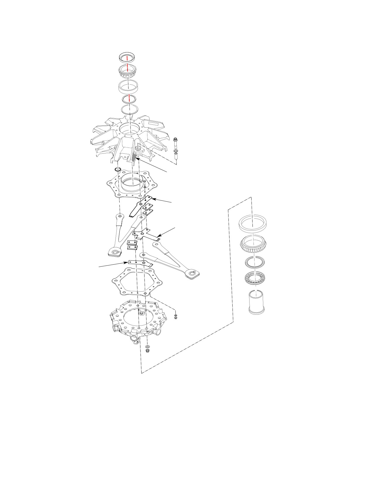
Figure 601. Strap Pack Lamination − Exploded View
Page 602
Revision 20
62-20-60
MD Helicopters, Inc.
CSP-HMI-2
MAINTENANCE MANUAL
(11). Inspect all parts of main rotor hub for
NOTE: Excessive amount of sealant can unbal
cracks, breaks, scratches and nicks.
ance rotor system. Apply light but thorough
(Refer all questionable damage to
coat of sealant.
MDHI for disposition.)
(f). Install new cotter pin to secure nut to
(12). Inspect lower shoe scissors attach
lead-lag bolt.
bearings for binding, looseness in bore
and wear. Maximum wear limits are
4. Main Rotor Strap Pack Lamination
0.010 inch (0.254 mm) radial and 0.020
Inspection
inch (0.508 mm) axial.
(13). Inspect each of six main rotor retention
CAUTION
strap packs (Ref. Main Rotor Strap
Pack Lamination Inspection) at
D Figure 601 and Figure 602 depict the
specified intervals (Ref. Section 05-10).
main rotor hub and strap pack assembly
disassembled for clarity of location and
3. Lead−Lag Bolt Inspection
area to be inspected for cracks. Under no
circumstances should the strap pack or
Consumable Materials
main rotor hub assembly ever be disas
(Ref. Section 91−00−00)
sembled in the field. MDHI and MDHI
Item
Nomenclature
Approved Licensees are the only ap
proved repair stations for main rotor hub
CM318
Primer
assembly overhaul.
CM425
Sealing compound
D If a hub assembly or strap pack assembly
(other than new parts in storage) are sub
(1). Inspect interiors of lead-lag bolts using
jected to extended periods of non-use,
bright light and 5X glass for cracks or
whether installed on the helicopter or not,
corrosion.
the strap assembly should be inspected
critically for corrosion and pitting before
(a).
Remove cotter pin securing nut to
return to service. If corrosion is found on
lower end of lead-lag bolt. Do not
the strap pack assemblies, contact MDHI
disturb torque on nut or remove nut.
for disposition.
(b).
Remove screw, nut, washers and
D It is acceptable to operate a helicopter
balance hardware, if installed, from
with a hub assembly having a strap pack
lead-lag bolt.
with one failed laminate in any one leg of
the strap assembly. When a laminate in
(c).
Inspect bolt interior. Treat minor
the strap assembly fails, the remaining
surface corrosion if noted (Ref.
laminates pick up and carry the load. This
Lead-Lag Bolt Corrosion Control). If
increased load causes slightly more elon
corrosion pitting or cracks are noted
gation in the remaining laminates of that
remove and replace hub.
leg thus shifting the mass of the rotor sys
tem. Any time a vibration develops or
(d).
Swab entire ID of bolt with primer
there is an increase in vibration level over
(CM318).
a short period of time, the main rotor
(e).
Reinstall screw, nut, washers and
strap pack assembly should be inspected
balance hardware removed in step 2.
for cracked or failed laminates.
Ensure hardware is installed exactly
as removed. Torque MS21042L08
NOTE: Conduct inspection indoors, if possible,
locknut on screw to 20 - 35 inch-
or in a shaded area to eliminate glare of sun
pounds (2.26 - 2.82 Nm). Torque
or bright outdoor light. To facilitate inspec
MS21042L3 locknut on screw to 30 -
tion, field fabricate and use plastic inspec
60 inch-pounds (3.39 - 6.78 Nm).
tion tool and wooden probe (Ref Figure 602).
Coat exposed screw threads, washers
and nut with sealant (CM425).
(1). Remove main rotor blades.
Page 603
62-20-60
Revision 33
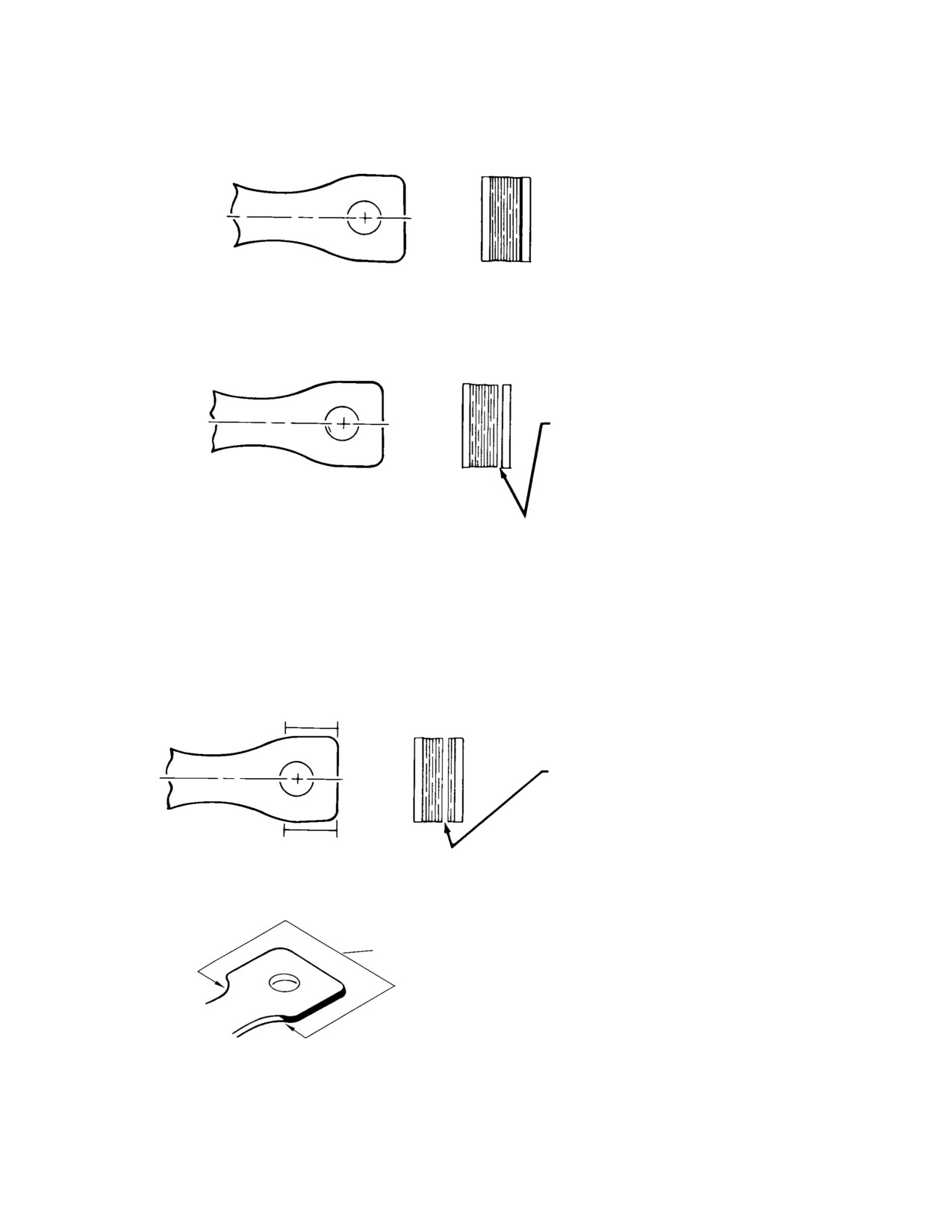
CSP-HMI-2
MD Helicopters, Inc.
MAINTENANCE MANUAL
ALL LAMINATES STRAIGHT,
NO GAPS.
DETAIL 1 ACCEPTABLE
ALL LAMINATES STRAIGHT. SINGLE GAP
EXISTING ADJACENT TO EITHER SHOE.
DETAIL 2 ACCEPTABLE
NOTE:
WHILE TEFLON MAY APPEAR WRINKLED AND EXTEND PAST END OF LAMINATES,
PREVENTING CLEAR VIEW OF LAMINATES. WHEN THIS OCCURS, LOOK ALONG
EITHER SIDE IN AREA A-A OR B-B (DETAIL 3).
A
A
ALL LAMINATES STRAIGHT. SINGLE GAP
EXISTING ANYPLACE WITHIN LAMINATES.
B
B
DETAIL 3 ACCEPTABLE
REMOVE EXCESS TEFLON IN THIS AREA
6G62-078-1
Figure 602. Strap Pack Lamination Inspection (Sheet 1 of 2)
Page 604
Revision 20
62-20-60
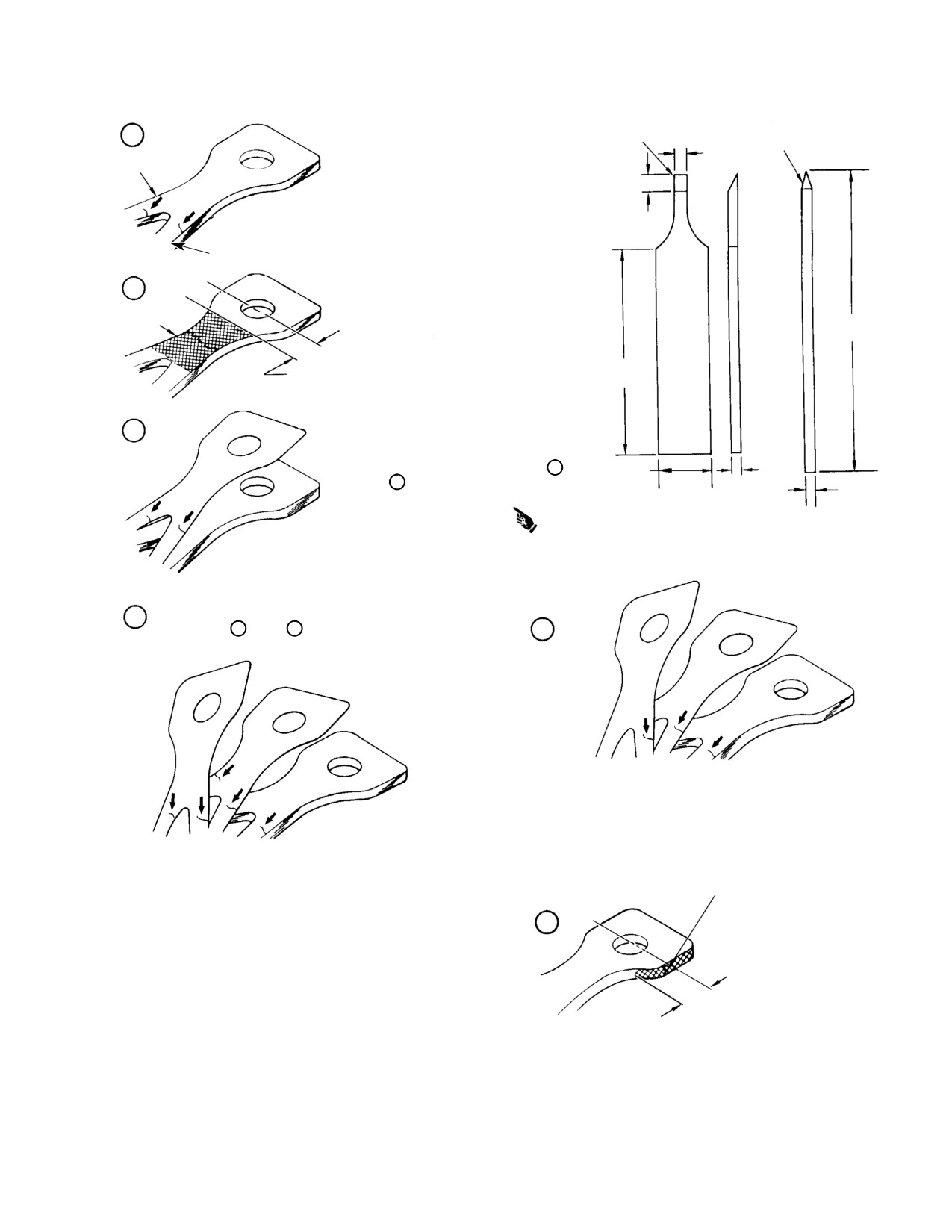
MD Helicopters, Inc.
CSP-HMI-2
MAINTENANCE MANUAL
PLASTIC
WOODEN OR
1
INSPECTION TOOL
PHENOLIC PROBE
0.125 INCH
(3.175 MM)
LEAD LEG
LAMINATE HAS FAILED IF CRACK OCCURS
ON BOTH LEAD AND LAG LEGS OF SAME
LAMINATE.
0.250 INCH
(6.35 MM)
LAG LEG
2
LAMINATE HAS FAILED IF CRACK OCCURS
IN TONGUE OF LAMINATE (SHADED AREA
TONGUE
SHOWN BEYOND JOINT OF STRAP PACK
6.00 INCH
LEGS).
(15.24 CM)
4.00 INCH
1.5 INCH
10.16 CM)
(3.81 CM)
(REF)
3
ONE LAMINATE FAILURE AS DEFINED IN 1
1.00 INCH
AND/OR 2 ARE ALLOWED IN EACH STRAP
0.50 INCH
(2.54 CM)
PACK ASSEMBLY. (TOTAL OF SIX LAMINATE
(12.7 MM)
FAILURES PER HUB ASSEMBLY.)
0.050-0.125 INCH
(1.27-3.175 MM)
FIELD FABRICATION INSPECTION TOOLS
ALUMINUM CHISEL NOT SHOWN
(REF. TABLE 601, NOTE 2)
STRAP PACK IS REJECTED IF TWO OR MORE
4
LAMINATES IN SAME PACK HAVE FAILED AS
DEFINED IN 1 AND/OR 2 ABOVE.
5
STRAP PACK IS REJECTED IF THREE OR MORE
LAMINATES IN SAME PACK ARE CRACKED IN
THE LEG (LEAD OR LAG).
FAILED LAMINATE IF CRACK IS
FOUND ON EITHER EDGE OF
LAMINATE. IF ONE LAMINATE
HAS FAILED IN THIS AREA,
REPLACE HUB.
6
CAUTION:
DO NOT DISASSEMBLE STRAP PACK ASSEMBLY,
LAMINATIONS ARE SHOWN SEPARATED ONLY TO
DEPICT POSSIBLE CRACK LOCATIONS.
NOTE:
ANY CRACK IN LAMINATE IS CONSIDERED A BREAK.
1.50 INCH
THE LAMINATE HAS NOT FAILED HOWEVER, UNLESS
(3.81 CM)
BOTH LEAD AND LAG LEGS ARE CRACKED, CRACK
IS LOCATED IN TONGUE AREA OF LAMINATE OR IS
UNDER SHOES (SEE DETAIL 6).
6G62−078−2B
Figure 602. Strap Pack Lamination Inspection (Sheet 2 of 2)
Page 605
62-20-60
Revision 34
CSP-HMI-2
MD Helicopters, Inc.
MAINTENANCE MANUAL
Table 601. Strap Pack Inspection
Replace or Return
Inspect
Procedure (1)
For
Acceptable
Hub for Overhaul
Outboard end.
Visually. Use blunt nosed
Failed laminates
One or less per
Two or more laminate
wooden or phenolic probe
(3).
pack.
failures in one pack.
(Figure 602). Probe at
upper and lower end of
pack. Failed laminate in
lead or lag leg will move
away from other
laminates.
Visually.
Gaps between
Single straight
More than one gap
laminates.
gap not exceed-
found; gap exceeds
ing 0.03 inch
acceptable limit.
(0.762 mm) within
pack or next to
either upper or
lower outer shoe.
Visually using light and
Cracks or breaks.
None.
Cracks or breaks are
mirror (2).
noted.
In area of and
Visually with light and
Cracks or breaks.
One or less
Two or more laminate
within pitch
mirror (2).
laminate failures
failures (2) in a pack;
housing assem-
per strap pack (2).
two or more laminates
blies.
in pack with crack in
same leg (lead or lag).
Cushioning
Visually with light and
Crack or break.
None
Cracks or breaks are
laminates at
mirror.
noted.
each of two
attach points.
NOTES:
(1) Conduct visual inspections indoors or in shaded area to eliminate glare of sun or bright outdoor light.
(2) Removal of teflon covering is required for visual inspection of laminate edges. Use aluminum chisel,
fabricated from stock 0.025 x 6.00 x 0.100 (6.35 x 152.4 x 25.4 mm) to carefully scrape excess
interlaminate teflon sheets from both sides of strap pack between top and bottom shoes at outboard
attachment bolt of all six strap packs. Remove excess teflon from a point 0.50 inch (12.7 mm) outboard of
bolt centerline to 1.50 inches (38.1 mm) inboard of bolt centerline. Field fabricate and use plastic tool (Ref.
Figure 602). Run plastic tool in both directions along each laminate feeling for cracked laminate. Use of
plastic tool will ensure that shreds of teflon still hanging free does not obscure small cracks.
(3) Laminate has failed if crack is found in tongue area or if crack is found in both legs (lead and lag).
Page 606
Revision 33
62-20-60
MD Helicopters, Inc.
CSP-HMI-2
MAINTENANCE MANUAL
(2). If required, trim teflon from edges of
(6). Use the following as acceptance/rejec
laminates using a aluminum chisel.
tion criteria for laminate inspection:
Fabricate chisel from stock, 0.250 x 6.00
(a). A laminate has failed if cracked in
x 0.100 inch (6.35 x 152.4 x 25.4 mm).
tongue area or in lead and lag legs of
Carefully scrape excess interlaminate
the same laminate.
teflon sheets from both sides of strap
pack between top and bottom shoes at
(b). Reject strap pack and return hub
outboard attachment bolt of all six
for overhaul when:
strap packs.
1). Two or more laminates in a single
NOTE:
strap pack have failed.
D Do not pry at strap pack assemblies with
sharp or hard edged tools. If edges become
2). Two or more laminates in a single
nicked or laminates get scratched, addi
strap pack are cracked in the same
tional cracking can occur thus causing
lead or lag leg.
hub replacement.
3). One laminate is cracked at the
D Where accessible, ends of acceptable
outboard end in the area between
cracked or broken laminates should be
outboard shoes (Ref. Figure 602).
taped to prevent scratching and damag
ing of adjacent laminates.
4). There are two or more gaps in the
same strap pack. A single gap in
(3).
(Ref. Figure 602 for field fabricate
any one strap pack assembly is
plastic tool) Run plastic inspection tool
allowed.
in both directions along each laminate,
feeling for a ``catch'' from a crack on a
(7).
Visually inspect strap pack assemblies
single laminate. Use the wooden or
for evidence of corrosion. If corrosion is
phenolic probe and probe at upper and
found on strap pack laminates contact
lower end of pack. Failed laminate in
MDHI service department for disposi
lead or lag will move away from the
tion.
other laminates. If the adjacent upper
and lower laminates remain in tension
(8).
Inspect upper, lower and center cush
under the probing operation, no
ioning laminates for cracks and breaks
laminate failures have occurred.
(Ref. Figure 601).
(4).
Using a light and mirror, visually
NOTE: Cracks, breaks or other noticeable dam
inspect each of the main rotor strap
age to the cushioning laminates require
pack assemblies for evidence of cracks
main rotor hub overhaul/replacement.
or breaks in strap pack laminates in the
areas of the outboard shoes and pitch
(9). Record location of all cracked/broken
housing assemblies.
laminates in Helicopter Log Book
including strap serial number, blade
(5).
Using a 10X magnifying glass, visually
color, leg (lead or lag) and laminate
inspect the edge of strap pack lami
position, if possible, numbering from
nates on both sides at outboard end of
the top down.
blade pitch housing (area between
outboard shoes).
(10). Install main rotor blades.
Page 607
62-20-60
Revision 33
CSP-HMI-2
MD Helicopters, Inc.
MAINTENANCE MANUAL
5. Main Rotor Hub Droop Angle Check
(7). Maximum allowable static droop angle
is six degrees. If measured droop angle
(Ref. Figure 805) Whenever new or replacement
exceeds six degrees, inspect striker
main rotor hub is installed or whenever excessive
plate and roller for excessive wear and
droop angle is suspected, measure static droop
adjust droop angle (Ref. Main Rotor
angle of all six rotor blades. Droop angle must be
Hub Droop Angle Adjustment).
5.5 ±0.5 degrees.
6. Main Rotor Damper and Attachments
Inspection
Special Tools
(Ref. Section 91−00−00)
Excessive lead-lag load applied
CAUTION
Item
Nomenclature
to the main rotor blades during
ground handling can result in damage to the
ST206
Prop protractor
elastomeric damper buns and failure of the
Left−Hand Command:
damper assembly. Operators and mainte
ST501
Collective rigging fixture
nance personnel should use extra caution to
(LH command)
avoid lead-lag loads in excess of 35 pounds
ST504
Longitudinal rigging fixture
(155.68 N) at the tip of the main rotor
(LH command)
blades.
ST506
Lateral rigging fixture
(1). Inspect bearing in rotor blade and
(LH command)
bearing in the pitch housing for
Right−Hand Command
looseness around outer race. No degree
ST502
Collective rigging fixture
of radial or axial play is permitted.
(RH command)
(2). Inspect pitch housing and blade
ST505
Longitudinal rigging fixture
bearings for binding, galling, or scoring
(RH command)
in bore and for wear. No radial play is
ST507
Lateral rigging fixture
permitted. Maximum allowable axial
(RH command)
play is 0.015 inch (0.381 mm).
(3). Inspect clevis bushings for wear and
(1).
Install cyclic lateral rigging fixture
looseness.
(ST506 or ST507), cyclic longitudinal
rigging fixture (ST504 or ST505), and
(4). Inspect damper flange bushing for wear
collective rigging fixture (ST501 or
and play.
ST502).
(5). Inspect lower bolt hole in damper
flange for wear.
(2).
Rotate main rotor to position one blade
over tailboom.
(6). Inspect damper housing (including
flanges) for damage.
(3).
Raise and support other five blades
until five corresponding droop stop
(7). Inspect damper turnbuckle, jamnuts
rollers no longer contact their striker
and safetywire for security. No end play
plates.
is permitted when manually tested.
(4).
Place accurate prop protractor (ST206)
NOTE: When performing lead-lag of main ro
on top of main rotor drive shaft. Adjust
tor blades, apply rotor brake (if installed) or
protractor to zero setting.
have assistant hold main rotor hub from
moving. A second assistant is recommended
(5).
Place protractor on machined surface of
to measure approximate damper extension
outboard end of blade pitch housing,
and compression.
alongside lead-lag bolthead. Measure
and record static droop angle.
(8). Lead-lag each main rotor blade in turn
to provide approximately 0.10 inch
(6).
Repeat (2). thru (5). above for remain
(2.54 mm) extension and compression of
ing blades.
the damper elastomer.
Page 608
Revision 20
62-20-60
MD Helicopters, Inc.
CSP-HMI-2
MAINTENANCE MANUAL
(9). Visually check each damper in turn for
(3). Attach damper end cap to holding bar
cracks in elastomer or in elastomer-to-
or fixture.
metal bond at end face of damper: If
NOTE: Perform weight loading and extension
bonding or elastomer cracks are noted,
check at ambient temperature of 70° ±l0°F
measure depths of cracks, using depth
(21° ±5°C). Apply total 100 pound (45.359
gage fabricated of shim stock or
kg) weight load to damper at one time, not in
equivalent having a 0.20 inch (5.08
weight increments.
mm) indication. If depth of crack
exceeds 0.20 inch (5.08 mm), remove
(4). Using hydraulic jack or equivalent,
and check damper.
raise and attach 100 pound (45.359 kg)
weight load at damper clevis end.
7. Main Rotor Damper Weight Loading and
Slowly lower jack to avoid shock
Extension Check
loading. After period of two minutes
under load, measure damper extension
(Ref. Figure 603)
on dial indicator.
(1). Remove damper assembly (Ref. Main
(5). If extension exceeds 0.063 inch (1.6002
Rotor Damper Removal).
mm), replace the damper assembly.
(2). Attach dial indicator or equivalent to
(6). Reinstall existing damper; or as
outer case of damper; position indicator
required; install replacement damper.
arm on center aluminum disc as shown.
NOTE: If replacement damper is installed, re
NOTE: Fabricate holding bar or fixture capable
cord part number, serial number, and other
of sustaining 100 pound (45.359 kg) static
pertinent information in Components Re
load (Ref. Figure 603).
cord of helicopters Log Book.
Page 609
62-20-60
Revision 25
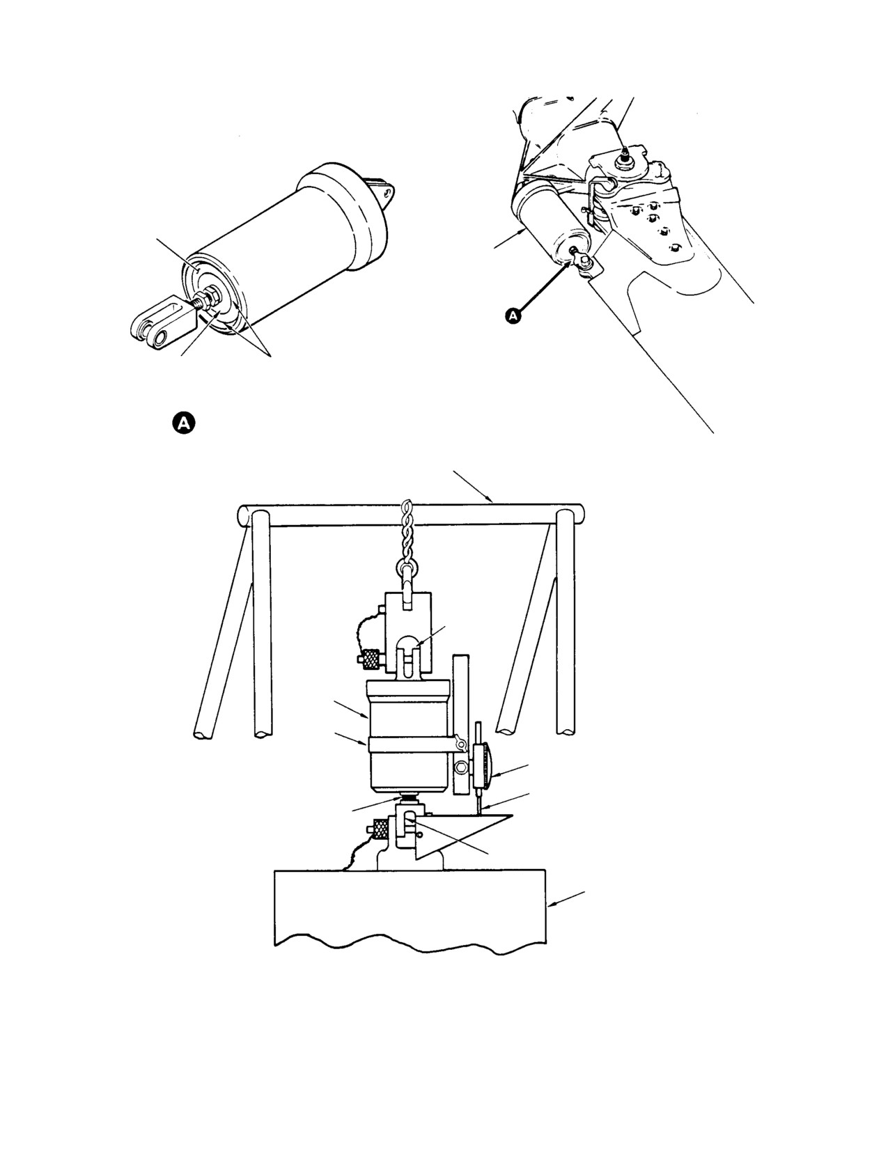
CSP-HMI-2
MD Helicopters, Inc.
MAINTENANCE MANUAL
ELASTOMER
(NOTE)
MAIN ROTOR
DAMPER
ALUMINUM
ELASTOMER-TO-METAL
DISC
BOND (NOTE)
END FACE - MAIN ROTOR DAMPER
HOLDING BAR
OR FIXTURE
END CAP
DAMPER
CLAMP
INDICATOR
INDICATOR ARM
THREADED
SHAFT
CLEVIS
100 POUND (45.359 KG)
WEIGHT
NOTE:
CHECK ELASTOMER AND
ELASTOMER-TO-METAL
BOND FOR CRACKS.
G62-2008A
Figure 603. Periodic Check of Main Rotor Damper Assembly
Page 610
Revision 20
62-20-60
MD Helicopters, Inc.
CSP-HMI-2
MAINTENANCE MANUAL
MAIN ROTOR HUB
REPAIRS
1. Main Rotor Retention Strap Pack Repair
If droop shim washers are in
CAUTION
stalled between spacer and
Where accessible, ends of permissible cracks or
striker strip, they must be retained for rein
broken laminates (Ref. Table 601) should be
stallation to establish correct static droop
taped to prevent scratching and damaging
angle between pitch housing and hub.
adjacent laminates.
(2). Carefully remove spacer by sliding it
downward past striker strip. Retain
Consumable Materials
exact number of droop shim washers, if
(Ref. Section 91−00−00)
installed.
Item
Nomenclature
(3). Slide bearing housing assembly off
CM234
Solvent, dry-cleaning
pivot pin. Inspect pivot pin for grooving
CM725
Tape, electrical, plastic
or excessive wear.
NOTE: Do not remove tetrafluoroethylene
Do not bend broken ends exces
(TFE) debris which works out of pitch bear
CAUTION
sively and scratch adjacent
ing edge. Debris is normal and helps lubri
straps.
cate bearing. Removal of debris increases
bearing wear rate.
(1). Carefully wipe ends of broken strap
with a clean soft cloth moistened with
(4).
Remove and discard pitch bearing if
solvent (CM234).
defective, total radial looseness of
assembled ball and pivot pin must not
(2). Use mild blast of filtered air to dislodge
exceed 0.010 inch (0.254 mm).
any foreign particles between broken
(5).
Replace striker strip if it is cracked or
strap ends and adjacent strap.
lead-lag contact areas are worn
through hard anodized surface.
(3). Carefully tape broken ends of strap
with plastic electrical tape (CM725).
(6).
Remove sealant between pitch housing
and striker strip. use care not to scratch
2. Pitch Control Bearing Housing Assembly,
pitch housing. Remove striker strip
Spacer or Striker Strip Replacement
from pitch housing.
(Ref. Figure 801)
(7).
Cut old striker strip to facilitate
removal from retention strap assembly.
Consumable Materials
Do not scratch strap assembly.
(Ref. Section 91−00−00)
Item
Nomenclature
(8).
Clean old sealant from pitch housing
using 1,1,1, trichloroethane (CM222).
CM222
1,1,1-Trichloroethane
CM425
Sealing compound
(9).
Cut out area of new striker strip.
Deburr, smooth and radius cut edges.
(1). Support blade and pitch housing from
(10).
Apply sealant (CM425) to faying
beneath. Remove nuts. washers, and
surfaces of the striker strip and pitch
bolts that secure bearing housing.
housing.
Page 801
62-20-60
Revision 20
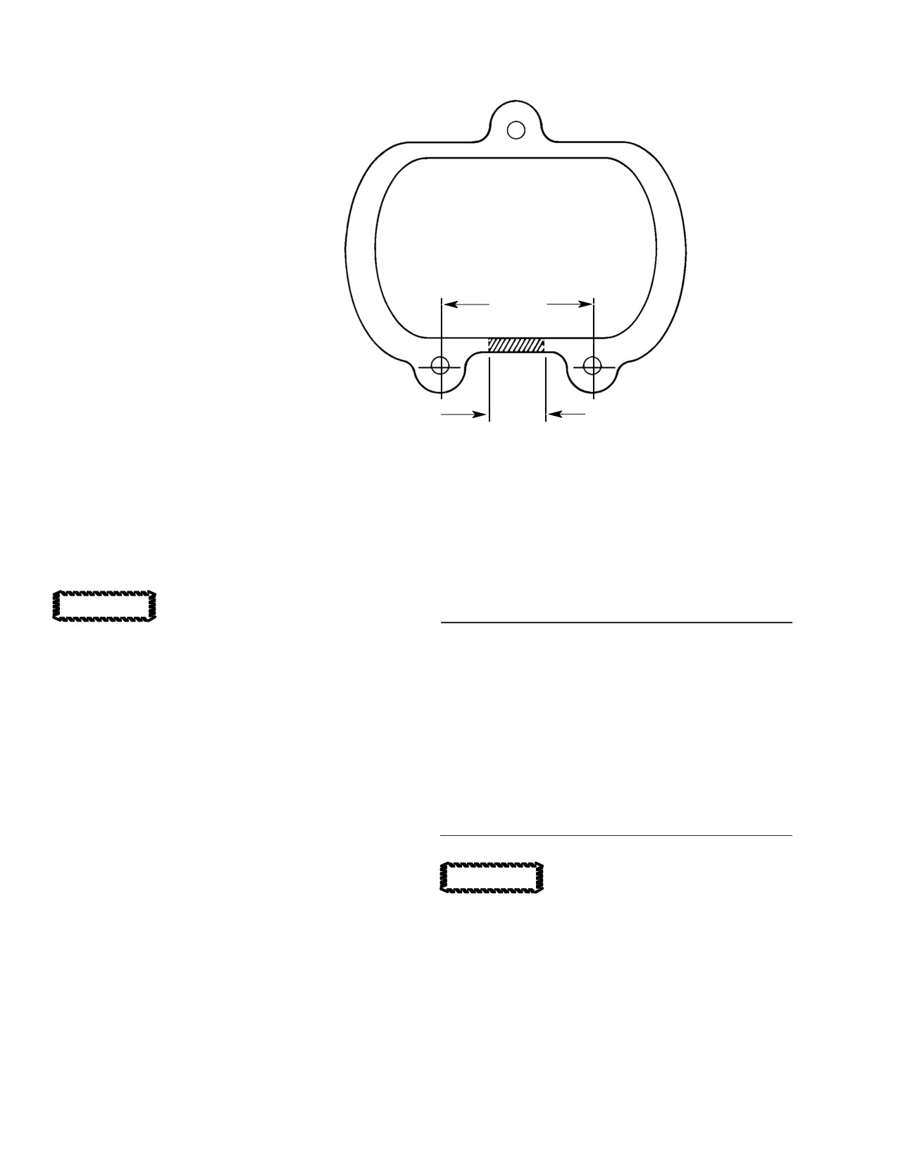
CSP-HMI-2
MD Helicopters, Inc.
MAINTENANCE MANUAL
2.50 INCH
(6.35 CM)
CAUTION:
DO NOT SCRATCH STRAP PACK WHEN INSTALLING
THROUGH STRAP ASSY.
NOTE:
CUT OUT 0.25-0.50 IN. (6.35-12.70 MM) PIECE OF THE
0.25-0.50 IN.
STRIKER STRIP BETWEEN LOWER BOLT HOLES.
(6.35-12.70 MM)
DEBURR AND RADIUS-CUT EDGES.
(NOTE)
G62-2009A
Figure 801. Striker Strip Replacement
(11). Position pitch control bearing housing
3. Lead−Lag Link Blade Stop Replacement
on pivot pin (Ref. Figure 802).
Replace blade stop if it is broken, cracked, has bro
ken spring, or if there are visible bond line cracks
If droop shim washers were re
(Ref. Figure 802).
CAUTION
moved from between spacer and
striker strip, same exact thickness removed
Consumable Materials
must be reinstalled. There must be an equal
(Ref. Section 91−00−00)
number of washers on each of all three bolts.
Item
Nomenclature
These washers establish correct static droop
between pitch housing and hub.
CM206
Chemical coating
CM217
Isopropyl alcohol
(12). Slide spacer into position between
CM228
Surface cleaner
bearing housing assembly and striker
CM411
Adhesive, epoxy
strip on pitch housing. Install exact
CM802
Abrasive cloth, aluminum oxide
thickness of droop shim washers
removed at time of disassembly. Align
CM803
Crocus cloth
holes for all three bolts.
Lead-lag link assembly must
(13). Install bolts, washers and nuts; torque
CAUTION
not be removed from pitch con
to 50 - 70 inch-pounds (5.65 - 7.91
trol housing for this repair, since retention
Nm) and install safety wire.
bolt cannot be retorqued without special
adapter.
(14). Seal all parting lines (joints) of the
assembly with bead of sealing com
(1). Provide a backup support for link
pound (CM425).
assembly. Use 1/2 inch (12.7 mm) wood
dowel and hammer to drive stop from
(15). Perform droop angle check (Ref. Main
link. Strike dowel sharply to break
Rotor Hub Droop Angle Adjustment).
adhesive bond.
Page 802
Revision 20
62-20-60
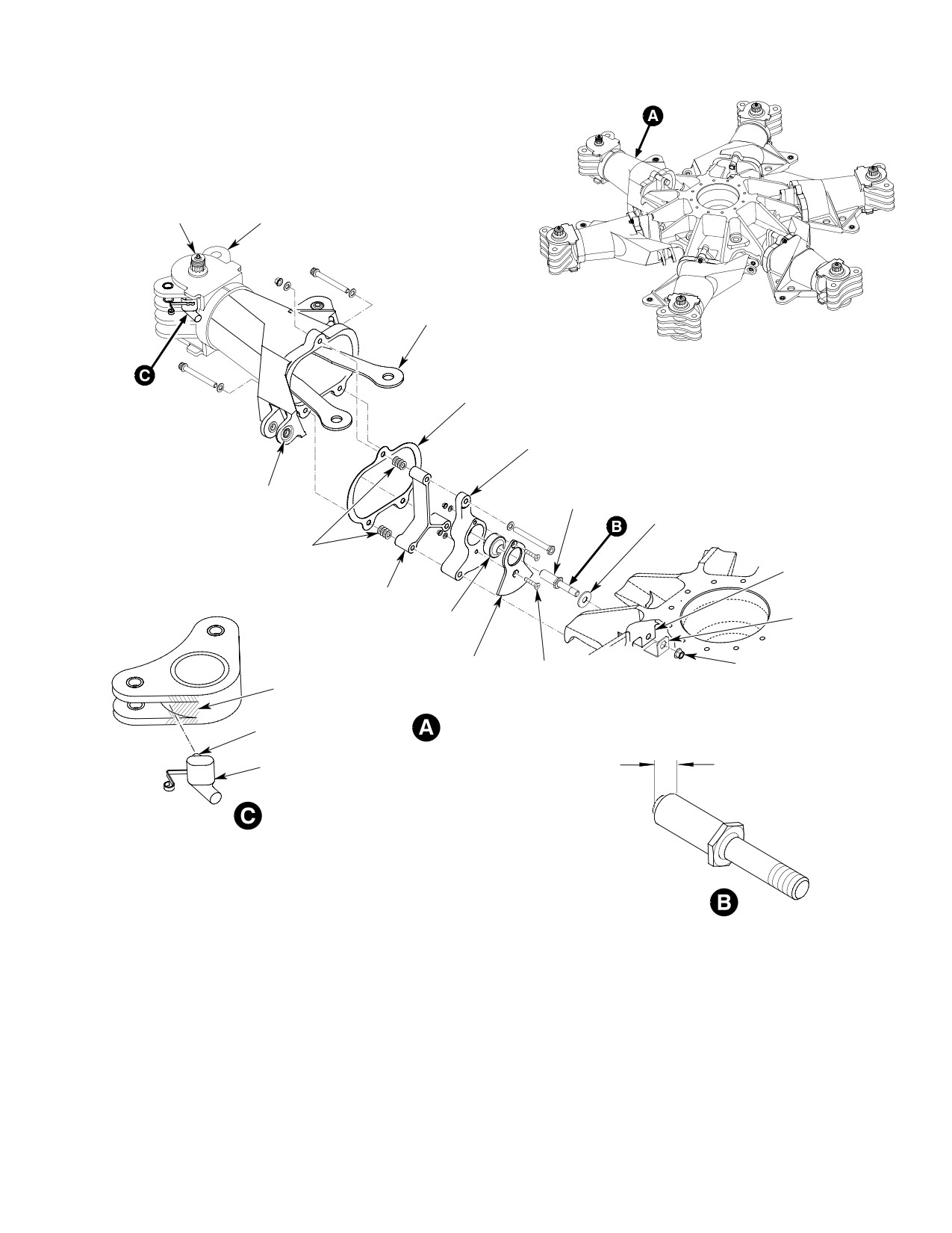
MD Helicopters, Inc.
CSP-HMI-2
MAINTENANCE MANUAL
LEAD-LAG
BOLT
LEAD-LAG LINKS
MAIN ROTOR
STRAP PACK
STRIKER STRIP
PITCH CONTROL BEARING
HOUSING ASSEMBLY
PITCH PIVOT PIN
SLEEVE
(NOTE 3)
BUSHING
SPECIAL WASHER
(NOTE 4)
DROOP SHIM WASHERS
(CAUTION)
HUB
SPACE
NUT RETAINING
R
PITCH
BRACKET
BEARING
(NOTE 5)
STRIKER
NUT
COUNTERSUNK
PLATE
NOTE 2
HEAD SCREW
PITCH BEARING HOUSING AND
NOTE 1
SPACER - INSTALLATION
0.4328 IN.
LEAD-LAG
(1.03872 MM)
STOP
DIA. MIN.
LEAD-LAG LINK AND STOP
CAUTION:
WASHERS ARE INSTALLED BETWEEN SPACERS AND STRIKER STRIP TO ESTABLISH
CORRECT STATIC DROOP ANGLE BETWEEN HOUSING AND HUB. EXACT NUMBER
REMOVED MUST BE REINSTALLED. THREE PITCH BEARING HOUSING BOLTS MUST EACH
HAVE SAME NUMBER (THICKNESS) OF WASHERS WHEN SHIMMING IS NECESSARY.
NOTES:
1.
FOR REMOVAL, WOOD DOWEL PLACED HERE AND STRUCK SHARPLY WITH
HAMMER TO BREAK STOP BOND.
2.
ALL STOP-TO-LINK SHADED CONTACT SURFACES BONDED WITH ADHESIVE.
3.
THREADED SHANK LIGHTLY LUBRICATED WITH GREASE BEFORE INSTALLATION.
4.
WET PRIMER ON WASHER AND MATING SURFACES BEFORE INSTALLATION.
5.
NUT RETAINING BRACKET IS BONDED TO HUB.
6G62-029A
Figure 802. Main Rotor Hub Components Repair and Installation
Page 803
62-20-60
Revision 20
CSP-HMI-2
MD Helicopters, Inc.
MAINTENANCE MANUAL
(2).
Using sharp-edge metal scraper,
Do not disturb torque on lead-
CAUTION
carefully scrape any adhesive residue
lag bolts. Special adapter is
from link. If scraper penetrates through
needed to retorque lead-lag bolts.
paint and chemical surface film, surface
(1). Remove and tag or color-code each set
must be refinished. Depth of gouges or
of balance hardware that is installed.
nicks is limited to 0.010 inch (0.254
mm) maximum after rework. Rework
(2). Remove corrosion with grade 180
by smooth blending into surrounding
abrasive cloth (CM802) and finish with
area with grade 320 abrasive cloth
grade 400 abrasive cloth.
(CM802). Final polish with crocus cloth
(3). Swab cleaned surface with MEK
(CM803). Restore chemical film protec
(CM219) and apply unthinned primer
tion (CM206).
(CM318).
(3).
Clean bond area of all contact surfaces
(4). Reinstall original balance hardware
by wiping with cleaner (CM228).
that was removed. Using sealant
Flush-wipe cleaned surface four times
(CM425), reseal balance hardware.
with mixture of equal parts of distilled
water and isopropyl alcohol (CM217) to
5. Pitch Control Bearing Pivot Pin Repair or
remove all traces of phosphoric acid.
Replacement
Rinse cleaned surface with tap water,
(Ref. Figure 802) Minimum allowable pin diame
followed by a rinse of distilled water
ter is 0.4328 inch (10.993 mm). Pivot pin grooving
until surface is ``water break'' free. Dry
or excessive side wear may be polished to original
for 30 minutes minimum at 150°F
finish as long as minimum allowable pin diameter
(66°C).
remains after rework. Replace any pin requiring
more rework as follows.
(4).
Check fit of stop in link. Flange and
radius contact surfaces of stop must
Consumable Materials
mate with link within 0.010 inch (0.254
(Ref. Section 91−00−00)
mm). Maximum clearance between stop
Item
Nomenclature
and inside surfaces of link ears is
limited to 0.020 inch (0.508 mm). This
CM115
Grease, oscillating bearing
tolerance applies to both sides of stop.
CM420
Sealant
(5).
Prepare mixture of epoxy adhesive
(CM411). Apply uniform coating of
(1). Remove pivot pin.
mixed adhesive to all contact surfaces.
(2). Lightly lubricate shank of replacement
Hand press stop into place between link
pivot pin with grease (CM115).
ears until all mating surfaces are in
firm contact. Apply a clamping device
NOTE: Torque pivot pin to 70 - 80 inch-
so that contact is maintained. Cure for
pounds (7.91 - 9.04 Nm), then use 0.002
minimum of eight hours at room
inch (0.0508 mm) feeler gage and check for
temperature, or two hours at 150°F
gap between pin flange and washer on
(66°C).
mounting lug surface. No gap is allowed.
(3). Install pivot pin in mounting lug with
4.
Lead−Lag Bolt Corrosion Control
washer. Torque pivot pin to 250 - 280
inch-pounds (28.25 - 31.64 Nm).
Consumable Materials
Apply sealant (CM420) at junctures of
(Ref. Section 91−00−00)
pivot pin flange, washer and hub.
Item
Nomenclature
6. Droop Stop Roller Repair or Replacement
CM219
Methyl-ethyl-ketone
(Ref. Figure 803) Replace defective droop stop roll
CM318
Primer
er if clearance between roller bearing liner and
CM425
Sealing compound
shaft is more than 0.015 inch (0.381 mm). Roller
CM802
Abrasive cloth, aluminum oxide
shaft outside diameter must not be less than
0.4370 inch (11.0998).
Page 804
Revision 20
62-20-60
MD Helicopters, Inc.
CSP-HMI-2
MAINTENANCE MANUAL
clearance between striker plates and
Consumable Materials
droop stop rollers.
(Ref. Section 91−00−00)
Item
Nomenclature
(2).
If necessary, release retaining (snap)
ring of each droop stop restrainer from
CM217
Isopropyl alcohol
its groove. Move retaining ring flush
against droop stop follower (T-head) to
(1). Move pitch control bearing housing out
provide additional clearance and reduce
of the way that contacts lower shoe
spring tension.
roller to be removed.
(3).
Remove six droop stop rollers.
NOTE: It may be easier if only one roller is re
(4).
Starting from either scissors crank
moved at one time. The opposing pitch hous
attach lug, number, or color code, all six
ing may be pressed against it's follower to
droop stop follower assemblies in
force opposite follower out and expose roller
clockwise direction for location identifi
shaft for removal. Same condition exists at
cation at replacement. This number
installation.
code should be placed on outer, upper
(2). Remove droop stop roller.
end of plunger and on adjacent area of
lower shoe. Ensure codes are not
(3). Wet down and clean plunger and
accidentally removed during remaining
mating shoe bushing with isopropyl
steps.
alcohol (CM217).
(5).
Compress each droop stop follower and
(4). Install roller, shaft and new cotter pin.
insert a small wedge from the back side
(5). Install pitch control bearing housing.
to hold follower away from droop ring.
(6).
After all followers are compressed,
7. Droop Stop Ring Repair
remove droop stop ring.
(Ref. Figure 803)
When installing droop stop ring,
CAUTION
Consumable Materials
droop stop followers T-Heads
(Ref. Section 91−00−00)
must be offset away from lower shoe to pre
Item
Nomenclature
vent damage to lower shoe.
CM103
Solid film lubricant
(7). Install replacement droop stop ring by
reversing removal procedure, steps (1).
(1). Repair depth limit for corrosion, nicks
thru (6)., making certain to reinstall
or scratches in droop stop ring is 0.007
followers according to markings placed
inch (0.1778 mm) for all surfaces except
thereon prior to removal.
outer edges of ring outer flanges where
(8). Compress follower spring and install
the depth limit is 0.030 inch (0.762
retaining (snap) ring, if removed, in its
mm). All reworked areas must be
groove on each follower.
blended smoothly with 15 to 1 ratio into
surrounding area.
(9). Reinstall droop stop rollers, shafts and
cotter pins.
(2). Spray repaired areas of rings with solid
film lubricant (CM103).
9. Droop Stop Follower (T−Head)
(3). Replace droop stop ring if repair limits
Replacement
are exceeded.
(Ref. Figure 803) Replace the droop stop follower
(T-head) if it is worn, scored or is causing damage
8. Droop Stop Ring Replacement
to the droop stop ring. After the droop stop ring
(Ref. Figure 803)
has been removed, the droop stop follower assem
blies may be removed from hub.
(1). With hub upside down, support hub so
that pitch housings unload droop stop
(1). Remove droop stop follower assembly
followers and provide maximum
from hub.
Page 805
62-20-60
Revision 37
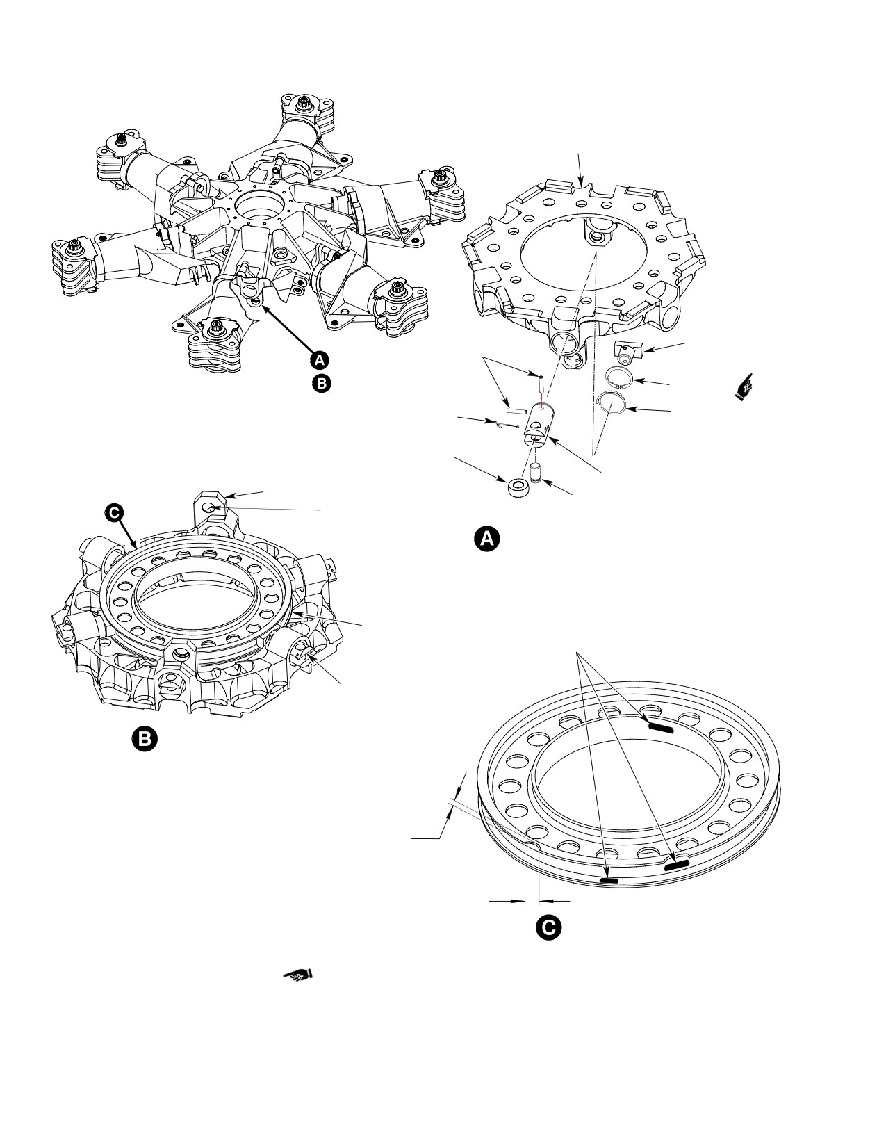
CSP-HMI-2
MD Helicopters, Inc.
MAINTENANCE MANUAL
LOWER SHOE
DROOP STOP
PINS
FOLLOWER
(T-HEAD) (NOTE)
SNAP RING
SPRING
COTTER PIN
DROOP STOP
ROLLER
DROOP STOP PLUNGER
SCISSORS CRANK
SHAFT
ATTACH LUG
BEARING ROTATIONAL DRAG
1.0 - 2.0 IN-LBS
(0.113 - 0.226 NM)
DROOP STOP FOLLOWER - INSTALLATION
DROOP STOP
0.007 IN. (0.178 MM) MAX. DEPTH
RING
(15 TO 1 RADIUS) AFTER REWORK
DROOP STOP FOLLOWER
ASSEMBLY (6 PLACES)
LOWER SHOE - INVERTED
0.030 IN. (0.762 MM)
MAX. AFTER REWORK
15 TO 1 RADIUS
DROOP STOP RING - REPAIR LIMITS
NOTE: DROOP STOP FOLLOWER T-HEADS TO
BE OFFSET AWAY FROM LOWER SHOE.
6G62-028C
Figure 803. Droop Stop Ring Replacement and Repair
Page 806
Revision 37
62-20-60
MD Helicopters, Inc.
CSP-HMI-2
MAINTENANCE MANUAL
(2). Remove pins that secure follower to
(3). Wet down and clean plunger and
plunger.
mating shoe bushing with isopropyl
alcohol (CM217).
Droop stop followers T-Heads
CAUTION
(4). Install droop stop plunger into lower
must be offset away from lower
shoe.
shoe to prevent droop stop ring from damag
ing lower shoe.
(5). Complete droop stop ring installation.
(3). Insert new follower. T-head must be at
(6). Install roller, shaft and new cotter pin.
right angle to roller shaft in plunger.
11. Main Rotor Hub Droop Angle Adjustment
(4). Drill two 0.156-0.158 inch (3.962-4.013
(Ref. Figure 802) If static droop angle exceeds six
mm) diameter holes through follower in
degrees, adjust as follows.
line with holes in plunger.
(1).
Remove main rotor blade.
(2).
Use flat washers of thickness required
(5). Insert pins and stake ends. No burrs or
to adjust spacing between spacer and
roughness permissible after staking.
striker strip. Any one type, or combina
(6). Install follower assembly in hub.
tion, of correct part number washers
(IPC) may be used; however, an identi
(7). Reinstall droop stop ring.
cal washer selection must be installed
on each of three bolts that secure pitch
control bearing assembly to pitch
10. Droop Stop Plunger Removal, Inspection
housing.
and Installation
(Ref. Figure 803)
(3).
Remove nuts, washers and bolts, and
separate spacer from striker strip. The
Consumable Materials
use of one 0.016 inch (0.406 mm)
(Ref. Section 91−00−00)
washer raises static droop angle
Item
Nomenclature
approximately one-half degree. Add
sufficient washers to adjust droop angle
CM217
Isopropyl alcohol
within range of 5.5 ±0.5 degrees.
Reinstall nuts, washers and bolts.
(1). Remove droop stop ring (Ref. Droop
(4).
If more than 0.063 inch (1.6 mm)
Stop Ring Replacement).
spacing is required (above factory
spacing), inspect striker plate and
(2). Check droop stop plunger for wear by
droop stop roller or follower and droop
using the following criteria:
stop ring for excessive wear. Replace as
required.
NOTE: The minimum acceptable diameter af
ter wearing in service should be 0.996 inch
(5).
Reinstall blade. Repeat measurement of
(25.298 mm). The acceptable amount of
static droop angle.
wear though the anodized coating shall not
(6).
As required, repeat above procedures
exceed 40% or 2.1 square inches (28.45
for remaining blades.
square cm) of the total sliding surface area
of the cylinder. The maximum wear condi
(7).
Following reinstallation or replacement
tion may exist in one spot or in several spots
of parts, check track of main rotor
totaling 2.1 inches (28.45 square cm).
blades.
Page 807
62-20-60
Revision 37

CSP-HMI-2
MD Helicopters, Inc.
MAINTENANCE MANUAL
12. Main Rotor Hub Tapered Bearing Grease
(b). Restore chemical film protection
Repack, Inspection and Replacement
where removed.
(Ref. Figure 805)
(c). Maximum diameter of hub bore for
upper bearing cup (Ref. Figure 805)
Consumable Materials
is 4.4335 inches (11.25 cm), measured
(Ref. Section 91−00−00)
in any direction.
Item
Nomenclature
CM111
Grease, aircraft
(d). Maximum diameter of hub bore for
lower bearing cup is 4.3095 inches
CM121
Preservation oil
(10.95 cm), measured in any direc
CM234
Solvent, dry-cleaning
tion.
CM802
Abrasive cloth, aluminum oxide
CM803
Crocus cloth
(5). Check upper seal retainer:
(a). No cracks, sharp nicks or burrs are
Special Tools
allowed.
(Ref. Section 91−00−00)
Item
Nomenclature
(b). Minor corrosion or other surface
ST701
Main rotor wrench assembly
defects may be polished out using
crocus cloth (CM803).
Do not intermix Timken or NTN
(c). Grooving on seal contact surfaces
CAUTION
bearing cups and cones at upper
must not exceed 0.004 inch (0.10 mm)
and lower tapered roller bearing locations of
depth after polishing.
main rotor hub.
Bearing cups are installed in
NOTE:
WARNING
hub by differential tempera
D Roller bearing cones and cups should al
ture (shrink-fit) method. Take appro
ways be replaced as a set.
priate precautions to prevent burns
when handling parts that are cooled to
D Replace tapered roller bearing cup and
sub-zero temperatures.
cone if it has any flat spots, scoring, pit
ting, grooving, discoloration (blue) or if it
(6).
Place bearing cups in closed container
feels rough when rotated.
of dry ice and cool for not less than 20
minutes to -40°F (-40°C).
(1). Use pressing tools equivalent to items
A and B (Ref. Figure 804) to press
(7).
Coat bores of hub with grease (CM111).
upper and lower bearing cups from hub.
A press ram of one to two tons is
(8).
Use care to maintain cup-to-hub bore
sufficient for removal.
alignment and press cup into bore,
using tools D and E (Ref. Figure 804),
(2). Press lower bearing cone from sleeve
until cup is seated.
bushing.
(9).
Apply film of grease (CM111) to sleeve
In next step, do not spin reus
CAUTION
bushing. Use pressing tool equivalent to
able bearings while cleaning.
tool C, and press bearing cone onto
Coat bearings lightly with oil (CM121) after
sleeve bushing.
cleaning.
(10).
With lip on center seal up, hand press it
(3). Clean hub bore, sleeve bushing, seal
into hub (Ref. Figure 805).
retainer and reusable bearings using
filtered solvent (CM234) spray.
(11).
Apply film of grease (CM111) on mast.
Install preassembled sleeve bearing
(4). Check bearing cup hub bore for scoring:
and bearing cone on mast. Do not apply
(a). Smooth out any roughness with
any additional lubricant to roller
grade 400-600 abrasive cloth
bearing set. Wipe any excess preserva
(CM802).
tive oil from bearing cone and cup.
Page 808
Revision 37
62-20-60
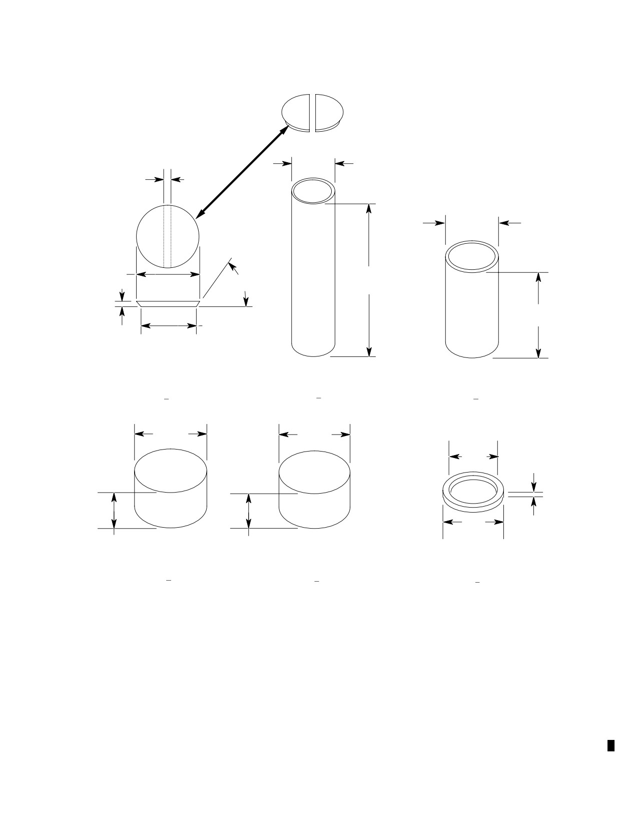
MD Helicopters, Inc.
CSP-HMI-2
MAINTENANCE MANUAL
A
A
2.875 IN. (7.3025 CM)
CUT OUT AFTER
0.50 IN.
OUTSIDE DIAMETER
BEVELING
(12.7 MM)
3.50 IN. (8.89 CM)
OUTSIDE DIAMETER
3.875 IN.
(9.8425 CM)
11.0 IN.
53
(27.94 CM)
°
5.75 IN.
3.375 IN.
(14.605 CM)
0.375 IN.
(8.5725 CM)
(9.525 MM)
0.1875 IN. (4.7625 MM)
0.203125 IN. (5.159375 MM)
4130 STEEL PLATE
WALL STEEL PIPE
WALL STEEL PIPE
A
B
C
4.40 IN.
4.30 IN.
(11.176 CM)
(10.922 CM)
2.58 IN.
0.30 IN.
(6.5532 CM)
(7.62 MM)
3.50 IN.
(8.89 CM)
2.0 IN.
2.0 IN.
(5.08 CM)
(5.08 CM)
ALUMINUM ALLOY
ALUMINUM ALLOY
STEEL RING WASHER
D
E
F
TOOL USE:
A & B - PRESS BEARING CUPS OUT OF HUB
C - PRESS LOWER BEARING CONE ON SLEEVE BUSHING
D - PRESS UPPER BEARING CUP INTO HUB
E - PRESS LOWER BEARING CUP ONTO HUB
F - IN PLACE OF UPPER SEAL RETAINER WHILE ADJUSTING ROTATIONAL DRAG
G - HUB BEARING REMOVAL - FABRICATION
G62-2010-1
Figure 804. Tapered Bearing Tools − Main Rotor Hub (Sheet 1 of 2)
Page 809
62-20-60
Revision 22
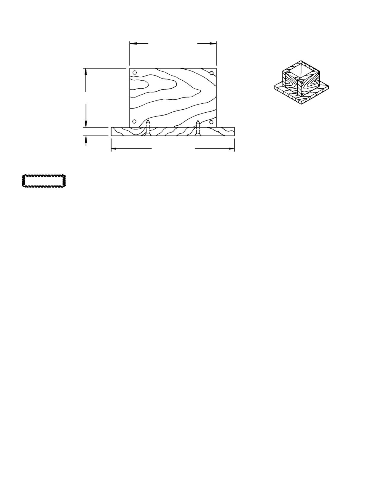
CSP-HMI-2
MD Helicopters, Inc.
MAINTENANCE MANUAL
7.0 INCH (17.78 CM)
SQUARED
4.75 INCH
(12.065 CM)
10.0 INCH (25.40 CM)
0.75 INCH
MATERIAL: WOOD
SQUARED
(19.05 MM)
H62-2010-2A
Figure 804. Tapered Bearing Tools − Main Rotor Hub (Sheet 2 of 2)
If hub assembly does not seat
NOTE: When determining spacer thickness,
CAUTION
properly onto mast, do not at
start with thick spacer and work down to
tempt to force it into position. Remove hub
thinner spacer.
assembly from mast and determine cause of
hub not seating, correct the problem and fol
(a). Install subsequently thinner spacers,
low the procedures for reinstallation.
from kit K-600N-1200A, starting
with a thick spacer, along with cone,
(12). Place assembled hub over mast and
substitute washer for retainer and
seat on lower roller bearing cone.
locknut.
(13). Install upper bearing cone into hub.
(b). Torque nut to to 200 - 250 foot-
NOTE: Use of substitute steel ring washer for
pounds (271 - 339 Nm) until 10 -
retainer prevents unnecessary scoring of re
15 inch-pounds (1.13 - 1.69 Nm)
tainer. Several tightening and loosening ac
of rotational drag (not break-
tions may be required to get rotational drag
away torque) is obtained on hub.
on hub bearings.
(18). When proper torque has been reached,
(14). Install steel ring washer, equivalent to
disassemble and remove steel ring
tool F (Ref. Figure 804), as substitute
washer.
for seal retainer (Ref. Figure 805)
(19). Alternative method for determining
(15). Install mast nut on mast using mast
thickness required for spacer:
nut wrench (ST701), tighten until
bearings are preloaded to 10 - 12
(a). Install 369A1224-5 lead spacer in
inch-pounds (1.13 - 1.36 Nm) of
place of the 369A1224-3 spacer.
rotational drag. Measure rotational
drag using 0 - 10 pound (0 - 4.536 kg)
(b). Place steel ring washer for retainer
spring scale hooked over one of hub
and locknut on the mast and gradual
support web bosses, 6.5 inch (16.51 cm)
ly tighten the retaining nut until
from hub centerline). A 1.50 - 1.75
rolling torque of 10 - 15 inch-
pound (0.681 - 0.795 kg) pull with
pounds (1.13 - 1.69 Nm) of rota
hub in motion indicates correct rota
tional drag (not break-away
tional drag.
torque) is obtained on hub. If the 10
- 15 inch-pounds (1.13 - 1.69 Nm)
(16). Remove locknut, washer and cone.
of rotational drag is exceeded,
(17). To determine thickness required for
discard the lead washer, install new
spacer:
washer and continue.
Page 810
Revision 37
62-20-60

MD Helicopters, Inc.
CSP-HMI-2
MAINTENANCE MANUAL
(c). When proper torque has been
reached, disassemble and measure
Consumable Materials
thickness of the lead washer in the
(Ref. Section 91−00−00)
bearing seat area. Grind the
Item
Nomenclature
369A1224-3 spacer to the same
CM111
Grease, aircraft
thickness as measured on the lead
CM204
Compound, corrosion preventative
washer. Check thickness of ground
CM121
Preservation oil
washer at six locations to ensure
CM234
Solvent, dry-cleaning
thickness does not vary by more than
CM702
Lockwire CRES
0.0005 inch (0.0127 mm).
CM802
Abrasive cloth, aluminum oxide
(d). Re-assemble with the ground steel
Special Tools
washer, steel ring washer and
(Ref. Section 91−00−00)
locknut and torque to 200 - 250
Item
Nomenclature
foot-pounds (271 - 339 Nm) until
ST701
Main rotor wrench assembly
10 - 15 inch-pounds (1.13 - 1.69
ST703
Main rotor hub driver
Nm) of rotational drag (not
break-away torque) is obtained on
hub.
(1). Remove main rotor hub assembly (Ref.
Main Rotor Hub Removal) and place on
bench.
(20).
Remove hub and sleeve bushing with
(2). Remove upper bearing cone.
lower bearing cone from mast.
Do not intermix Timken or NTN
CAUTION
bearing cups and cones at upper
(21).
Position hub upside-down. Hand-pack
and lower tapered roller bearing locations of
lower hub cavity (Ref. Figure 805) and
main rotor hub.
bearing cone on sleeve bushing with
NOTE:
grease (CM111).
D Roller bearing cones and cups should al
ways be replaced as a set.
(22).
Install sleeve bushing with bearing
D Replace tapered roller bearing cup and
cone in hub. Hand-pack cavity between
cone if it has any flat spots, scoring, pit
bearing and hub liner with grease
ting, grooving, discoloration (blue) or if it
(CM111); then press in lower seal with
feels rough when rotated.
seal lip toward top of hub. Wipe off
excess grease.
(3). Use pressing tools equivalent to items
A and B (Ref. Figure 804) to press
upper bearing cup from hub. A press
(23).
Turn hub assembly right side up.
ram of one to two tons is sufficient for
removal.
In next step, do not spin reus
(24).
Complete reassembly of hub by install
CAUTION
able bearing while cleaning.
ing recessed spacer, upper bearing cone,
Coat bearings lightly with oil (CM121) after
upper seal and seal retainer in hub at
cleaning.
installation of hub on mast.
(4). Clean hub bore, sleeve bushing, seal
retainer and reusable bearing using
filtered solvent (CM234) spray.
13. Main Rotor Hub Upper Bearing Grease
Repack, Inspection and Replacement
(5). Check bearing cup hub bore for scoring:
The following procedure is for greasing, inspection
(a). Smooth out any roughness with
and replacement of the main rotor hub upper
grade 400-600 abrasive cloth
bearing only.
(CM802).
Page 811
62-20-60
Revision 22
CSP-HMI-2
MD Helicopters, Inc.
MAINTENANCE MANUAL
(b). Restore chemical film protection
(13). Hand-pack hub cavity, between sleeve
where removed.
bushing and hub, with grease (CM111).
(c). Maximum diameter of hub bore for
(14). Apply film of grease (CM111) on upper
upper bearing cup (Ref. Figure 805)
bearing cone and place into hub.
is 4.4335 inches (11.25 cm), measured
in any direction.
NOTE: Use of substitute steel ring washer for
retainer prevents unnecessary scoring of re
(6). Check upper seal retainer.
tainer. Several tightening and loosening ac
tions may be required to get rotational drag
(a). No cracks, sharp nicks or burrs are
on hub bearings.
allowed.
(15). Install steel ring washer, equivalent to
(b). Minor corrosion or other surface
tool F (Ref. Figure 804), as substitute
defects may be polished out using
for seal retainer (Ref. Figure 805)
crocus cloth (CM803).
(16). Install mast nut on mast using mast
(c). Grooving on seal contact surfaces
nut wrench (ST701), tighten until
must not exceed 0.004 inch (0.10 mm)
bearings are preloaded to 10 - 12
depth after polishing.
inch-pounds (1.13 - 1.36 Nm) of
Bearing cups are installed in
rotational drag. Measure rotational
WARNING
hub by differential tempera
drag using 0 - 10 pound (0 - 4.536 kg)
ture (shrink-fit) method. Take appro
spring scale hooked over one of hub
priate precautions to prevent burns
support web bosses, 6.5 inch (16.51 cm)
when handling parts that are cooled to
from hub centerline). A 1.50 - 1.75
sub-zero temperatures.
pound (0.681 - 0.795 kg) pull with
hub in motion indicates correct rota
(7). Place bearing cup in closed container of
tional drag.
dry ice and cool for not less than 20
minutes to -40°F (-40°C).
(17). Remove locknut, washer and cone.
(8). Coat bore of hub with grease (CM111).
(18). To determine thickness required for
spacer:
(9). Use care to maintain cup-to-hub bore
alignment and press cup into bore,
NOTE: When determining spacer thickness,
using tools D and E (Ref. Figure 804),
start with thick spacer and work down to
until cup is seated.
thinner spacer.
If hub assembly does not seat
CAUTION
(a). Install subsequently thinner spacers,
properly onto mast, do not at
from kit K-600N-1200A, starting
tempt to force it into position. Remove hub
with a thick spacer, along with cone,
assembly from mast and determine cause of
steel ring washer for retainer and
hub not seating, correct the problem and fol
locknut.
low the procedures for reinstallation.
(b). Torque nut to to 200 - 250 foot-
(10). Check that rotor mast is clean. Hoist
pounds (271 - 339 Nm) until 10 -
main rotor hub and position over mast;
15 inch-pounds (1.13 - 1.69 Nm)
then lower hub onto mast.
of rotational drag (not break-
NOTE: To inhibit mast corrosion when operat
away torque) is obtained on hub.
ing in salt water environment, lightly coat
(19). When proper torque has been reached,
bearing journals of mast with grease
disassemble and remove steel ring
(CM111).
washer.
(11). Remove adapter, hoist and eyebolts.
(20). Alternative method for determining
(12). Check that hub is fully seated on mast.
thickness required for spacer:
Page 812
Revision 34
62-20-60
MD Helicopters, Inc.
CSP-HMI-2
MAINTENANCE MANUAL
(a).
Install 369A1224-5 lead spacer in
(1).
Remove main rotor hub (Ref. Main
place of the 369A1224-3 spacer.
Rotor Hub Replacement).
(b).
Place steel ring washer for retainer
(2).
Invert hub and place on work bench.
and locknut on the mast and gradual
ly tighten the retaining nut until
(3).
Remove droop stop ring (Ref. Droop
rolling torque of 10 - 15 inch-
Stop Ring Replacement).
pounds (1.13 - 1.69 Nm) of rota
tional drag (not break-away
(4).
Press bearing from hub lug.
torque) is obtained on hub. If the 10
- 15 inch-pounds (1.13 - 1.69 Nm)
(5).
Clean bearing bore with locktite
of rotational drag is exceeded,
remover (CM216).
discard the lead washer, install new
washer and continue.
(6).
Inspect bearing bore for nicks,
scratches and grooves.
(c).
When proper torque has been
reached, disassemble and measure
(7).
Inspect bore for diameter of
thickness of the lead washer in the
0.6551-0.6556 inch (16.63954-16.65224
bearing seat area. Grind the
mm).
369A1224-3 spacer to the same
thickness as measured on the lead
(8).
Touch up bearing bore with chemical
washer. Check thickness of ground
coating (CM206).
washer at six locations to ensure
thickness does not vary by more than
(9).
Apply surface primer (CM321) to
0.0005 inch (0.0127 mm).
mating surfaces of bearing and boreas
per manufacturer's instructions.
(d).
Re-assemble with the ground steel
washer, steel ring washer and
NOTE: Do not allow primer to enter bearing.
locknut and torque to 200 - 250
foot-pounds (271 - 339 Nm) until
(10).
Apply locking compound (CM431) to
10 - 15 inch-pounds (1.13 - 1.69
faying surfaces of bearing and bore,
Nm) of rotational drag (not
press bearing into bore while locking
break-away torque) is obtained on
compound is wet.
hub.
(11).
Remove excess sealant, do not allow
(21). Complete reinstallation of main rotor
sealant to enter bearing.
hub assembly (Ref. Main Rotor Hub
Installation).
(12).
Apply a small fillet of sealant around
bearing and allow to dry for 24 hours at
room temperature or heat to 140° -
14. Main Rotor Hub Scissors Attach Lug
160°F (60° - 72°C) for one hour.
Bearing Replacement
(13).
As required, touch up bearing lug with
paint (CM304).
Consumable Materials
(Ref. Section 91−00−00)
(14).
Check bearing for a no-load rotational
Item
Nomenclature
drag of 1.0 - 2.0 inch-pounds (0.113 -
CM206
Chemical coating
0.226 Nm).
CM216
Loctite remover
(15).
Reinstall droop stop ring (Ref. Droop
CM304
Enamel, epoxy
Stop Ring Replacement).
CM321
Surface primer locking compound
CM431
Sealing, locking and retaining compound
(16).
Reinstall main rotor hub (Ref. Main
Rotor Hub Replacement).
Page 813
62-20-60
Revision 34
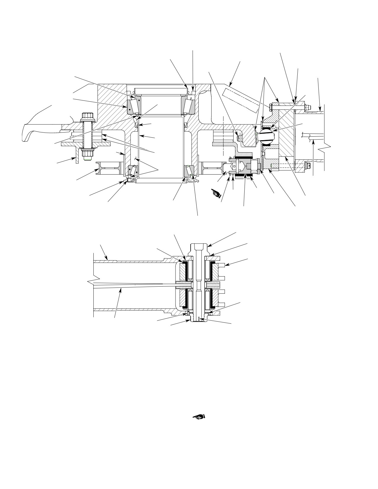
CSP-HMI-2
MD Helicopters, Inc.
MAINTENANCE MANUAL
SEAL
DROOP SHIM WASHER
(NOTE 4)
(NOTE 6)
SEAL RETAINER
HUB
STRIKER
STRIP
PIVOT PIN
SEALANT
PITCH
UPPER BEARING CONE
HOUSING
(NOTE 2)
(NOTE 7)
NOTE 1
UPPER BEARING CUP
(NOTE 7)
(NOTE 5)
SEAL
PITCH
(NOTE 4)
BEARING
SLEEVE
RECESSED
BUSHING
SPACER
SEALANT
STRAP
(NOTE 3)
(NOTE 2)
PACKS
LOWER SHOE
NOTE 5
STRAP
DROOP STOP RING
NOTE 8
ASSEMBLY
NOTE 1
SPRING
HUB OUTER LINER
ROLLER
SPACER
LOWER BEARING CONE
ASSEMBLY
SEAL
RETAINING
(NOTE 7)
FOLLOWER
PITCH CONTROL
(NOTE 4)
CLIP
ASSEMBLY
BEARING HOUSING
LOWER BEARING CUP
(NOTE 7)
BUSHING
LEAD-LAG PIVOT BOLT
PITCH HOUSING
SEALANT
BEARING
(NOTE 2)
(NOTE 1)
LEAD-LAG
LINKS
SHIM
STRAP ASSEMBLY
BUSHING
COTTER PIN
NUT
NOTES:
1.
HEAVY LINES INDICATE REINFORCED TEFLON BEARING LININGS (TYPICAL).
2.
SEALANT APPLIED TO LOCATIONS SHOWN.
3.
RECESSED SPACER SPECIALLY GROUND TO ESTABLISH CORRECT ROTATIONAL
DRAG ON TAPERED BEARINGS. INSTALL RECESS DOWN ON TOP OF SLEEVE BUSHING.
4.
SEAL TO BE UPWARD.
5.
BEARING AND CAVITY TO BE FILLED WITH GREASE.
6.
DROOP SHIM WASHERS ARE INSTALLED, AS REQUIRED, TO OBTAIN PROPER
ROTOR DROOP ANGLE.
7.
DO NOT INTERMIX TIMKEN AND NTN BEARING CUPS AND CONES AT UPPER AND
LOWER TAPERED BEARING LOCATIONS.
8.
DROOP STOP FOLLOWER T-HEAD TO BE OFFSET AWAY FROM LOWER SHOE.
6G62-030A
Figure 805. Main Rotor Hub − Cross Section
Page 814
Revision 37
62-20-60
MD Helicopters, Inc.
CSP-HMI-2
MAINTENANCE MANUAL
Section
62−30−00
Swashplate and
Mixer (369D/E/FF −
500N)
MD Helicopters, Inc.
CSP-HMI-2
MAINTENANCE MANUAL
SWASHPLATE AND MIXER
REMOVAL/INSTALLATION
1. Main Rotor Swashplate
B. Swashplate Installation
(Ref. Figure 403) The main rotor swashplate
(1).
If swashplate lower boot was removed,
includes a rotating swashplate, stationary
install boot on mast (Ref. Figure 403).
swashplate, bearing and retainer and two
(2).
Position swashplate over main rotor
counterweights.
mast and carefully lower into place.
2. Swashplate Replacement
(3).
Engage upper end of boot in groove at
lower side of stationary swashplate.
A. Swashplate Removal
Secure boot with self-clinching nylon
strap (Ref. Figure 403).
(1). Tag or color-identify five pitch control
rods (Ref. Figure 401) to simplify
(4).
Align longitudinal link with stationary
replacement at same locations.
swashplate (Ref. Figure 402).
Failure to reinstall pitch control
CAUTION
(5).
Install flanged bushing, if removed,
rods at correct locations prob
bolt, two washers, nut and cotter pin to
ably will result in main rotor blades exces
secure upper end of longitudinal link.
sively out of track.
(6).
Align upper ends of mixer links with
(2). Disconnect pitch control rods from
stationary swashplate. Install slotted
rotating swashplate.
bushing (if removed), bolt, two washers,
nut and cotter pin to secure each link to
(3). Remove scissors.
swashplate.
(4). Remove main rotor hub.
(7).
Install scissors.
(5). Disconnect longitudinal link (Ref.
(8).
Using color code, reinstall pitch control
Figure 402) from stationary swash
rods at same locations from which
plate.
removed.
(6). Disconnect right and left side mixer
(9).
Check track of main rotor blades (Ref.
links (Ref. Figure 402) from stationary
Chap. 18) following any maintenance
swashplate.
activity that could result in a dimen
sional variation affecting rigging or
(7). Remove protective boot from groove in
tracking.
lower side of stationary swashplate
(Ref. Figure 403).
3. Mixer Controls
Do not strike rotating swash
CAUTION
Mixer controls consist of various links,
plate or bearing assembly (Ref.
bellcranks, idlers, support bracket and
Figure 403) with tools or in any way deface
associated fasteners that secure these compo
these components. Rotating swashplate is a
nents in place and to the control rods and main
stressed part; all surfaces are shot peened.
rotor swashplate.
Use particular care to protect teflon liner in
bearing bore. A damaged swashplate bear
4. Mixer Controls Replacement
ing must not be retained in service.
A. Mixer Controls Removal
(8). Lift swashplate carefully up and off of
mast.
(Ref. Figure 402)
(9). To remove boot from mast, remove
(1). Remove air intake forward fairing for
self-clinching nylon strap.
access.
Page 401
62-30-00
Revision 20
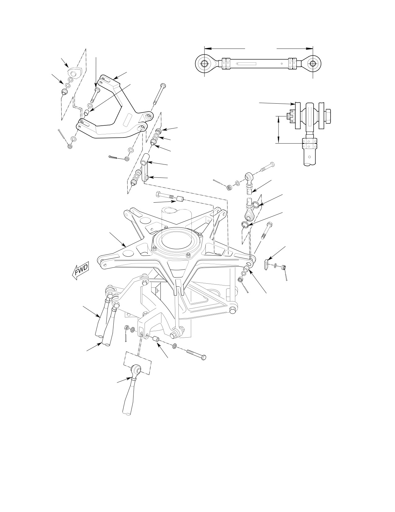
CSP-HMI-2
MD Helicopters, Inc.
MAINTENANCE MANUAL
ROTOR HUB
6.25 IN.
CLOSE TOLERANCE
LOWER SHOE
(15.875 CM)
BOLT
WASHERS
SCISSORS CRANK
(NOTE 4)
PITCH CONTROL ROD - LENGTH
SLOTTED BUSHING
(NOTE 3)
(NOTE 1)
MAXIMUM ALLOWABLE LOOSENESS
0.040 IN. (1.016 MM)
AT INSTALLATION, ROD ENDS
TO BE PARALLEL WITH
MATING CLEVIS
BEARING
1.30 IN. (3.302 CM) TYPICAL
(UPPER BEARING ONLY)
WASHERS
(NOTE 4)
BUSHING
SCISSORS LINK
BEARING
PITCH CONTROL ROD
(NOTE 2)
ELASTOMER RING
SLOTTED BUSHING
(NOTE 6)
(NOTE 1)
ELASTOMER RING
(NOTE 5)
ROTATING
SWASHPLATE
INTERRUPTER
SLOTTED BUSHING
COLLECTIVE PITCH
(NOTE 1)
CONTROL ROD
LONGITUDINAL PITCH
CONTROL ROD
SLOTTED BUSHING
(NOTE 1)
LATERAL PITCH
CONTROL ROD
NOTES:
1.
END OF SLOTTED BUSHING MUST PROTRUDE MINIMUM OF
0.010 IN. (0.254 MM) TO MAXIMUM OF 0.060 IN. (1.524 MM) ABOVE
OUTSIDE SURFACE OF PART AFTER NUT IS TIGHTENED.
2.
COLOR CODED TO MATCH BLADE.
3.
OPTIMUM INITIAL SETTING (FIVE PLACES).
4.
AS REQUIRED TO FILL GAP.
5.
THIS SIDE ONLY ON EARLY CONFIGURATION.
6.
BOTH SIDES ON CURRENT CONFIGURATION.
7.
DELETED
G62-3000D
Figure 401. Pitch Control Rods and Swashplate Scissors − Installation
Page 402
Revision 36
62-30-00
MD Helicopters, Inc.
CSP-HMI-2
MAINTENANCE MANUAL
(2). Disconnect upper ends of collective
support bracket and bore in mast base
mixer, lateral mixer and longitudinal
lug is 0.015 inch (0.381 mm) or less.
mixer control rods (Ref. Figure 401).
NOTE: If necessary, loosen aft two bracket-to-
NOTE: Control rods are attached by slightly
fitting nuts, position support bracket to
different length bolts. Reinstall each bolt in
minimize misalignment and retighten nuts.
its bellcrank following control rod removal
(4).
Install mixer support attaching bushing
to simplify reinstallation at correct loca
in bracket and mast base lug.
tions.
(5).
Check that sleeve bushing is in place;
(3). Remove mixer links. (Mixer link
then install bolt, two washers and nut.
bearings are not replaceable.)
Torque nut to 80 - 100 inch-pounds
(4). Disconnect longitudinal link from
(9.04 - 11.30 Nm).
stationary swashplate.
(6).
Position longitudinal pitch idler and
(5). Remove longitudinal control mixer link.
collective pitch mixer bellcrank on
support bracket. Position washer
(6). Disconnect lateral bellcrank from
between right side of longitudinal pitch
collective pitch mixer bellcrank.
idler bearing and center bearing of
mixer support bracket. Install left-
(7). Remove connecting hardware (includ
hand bearing, with attaching hardware.
ing flanged bushing) from each side of
longitudinal pitch mixer bellcrank.
(7).
Position lateral bellcrank between
Carefully remove bellcrank. Retain any
collective pitch mixer bellcrank bear
shims that may be installed.
ings and install attaching hardware.
(8). Remove bolt from hingeline of support
(8).
Position longitudinal pitch mixer
bracket, longitudinal pitch idler and
bellcrank with collective pitch mixer
collective pitch mixer bellcrank.
bellcrank; insert two flanged bushings.
Separate the three parts.
Install two bolts.
(9). Remove mixer support bracket from
(9).
Push longitudinal bellcrank to one side
mast base.
and measure gap between bellcrank
and bearings in collective pitch bell
To prevent washing dirt into
crank.
CAUTION
bearings, or washing grease out
(10).
Using HS5079-2646 laminated wash
of bearings, do not permit solvent to enter
er(s), shim evenly to take up gap.
bearings when cleaning mixer control com
ponents.
(11).
Insert flanged bushings, bolts, six
washers (two under each nut) shims
B. Mixer Controls Installation
and nuts. Torque nut to 30 - 40 inch-
(Ref. Figure 402)
pounds (3.39 - 4.52 Nm) and install
cotter pin.
(1). Position support bracket over forward
lug on mast base.
(12).
Position longitudinal control mixer link
between longitudinal pitch idler and
(2). Install two aft bolts and washers in
longitudinal pitch mixer bellcrank;
support bracket and mast base. Install
check that two slotted bushings are in
two thin washers and nuts; torque nuts
place. Install bolt, three washers (two
to 80 - 100 inch-pounds (9.04 - 11.30
under each nut), nut and cotter pin at
Nm) above drag torque.
each end of link.
(3). Using ball hole gage and standard
(13).
Position longitudinal link between
micrometer, check that misalignment
longitudinal pitch mixer bellcrank
between forward bolt hole bore in
bearings. Install attaching hardware.
Page 403
62-30-00
Revision 31
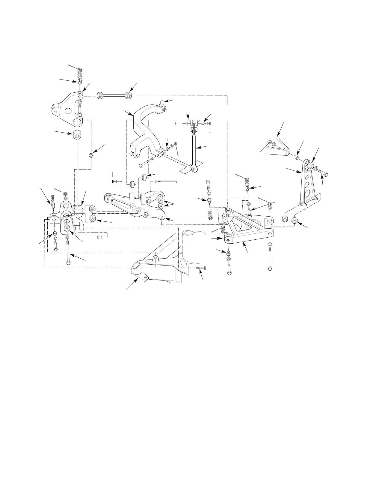
CSP-HMI-2
MD Helicopters, Inc.
MAINTENANCE MANUAL
LONGITUDINAL
LONGITUDINAL
BUSHING
PITCH IDLER
CONTROL MIXER LINK
(NOTE 2)
MIXER LINK
*LATERAL MIXER
STATIONARY
BELLCRANK
BUSHING
SWASHPLATE
STATIONARY
(NOTE 2)
SWASHPLATE
BEARING
BUSHING
FLANGED
(NOTE 2)
BUSHING
WASHER
MIXER
BEARING
LINK
MIXER
LONGITUDINAL
SUPPORT
LINK (NOTE 3)
BEARING
ATTACHING
MIXER
BUSHING
SUPPORT
FLANGED
BUSHING
(NOTE 6)
BRACKET
NOTE 1
BUSHING
(NOTE 2)
(NOTE 4)
NOTE 1
BEARING
*COLLECTIVE
PITCH MIXER
BEARING
BELLCRANK
BEARING
NOTE 7
BEARING
SLEEVE
FLANGED
BUSHING
BUSHING
*LONGITUDINAL
NOTE 1
(NOTE 4)
PITCH MIXER
BELLCRANK
2
PLS
MAST
BASE
NOTES:
1.
DIRECTION OF BOLT OPTIONAL.
2.
EDGE OF BUSHING MUST PROTRUDE MINIMUM OF 0.010 IN. (0.254 MM) TO MAXIMUM OF
0.060 IN. (1.524 MM) ABOVE OUTSIDE OF PART AFTER NUT IS TIGHTENED.
3.
LONGITUDINAL LINK DETAILS ROTATED FOR CLARITY.
4.
MUST BE PULLED OUT FIRST TO REMOVE BELLCRANK.
5.
ASTERISK ( * ) INDICATES PART THAT MAY BE EITHER MAGNESIUM OR ALUMINUM ALLOY.
(FOR ALLOY IDENTIFICATION AND CORROSION CONTROL, REF. SEC. 20-40-00).
6.
INSTALL BUSHING AFTER THE TWO AFT ATTACHING BOLTS WITHOUT EXCESSIVE
G62-3003C
MISALIGNMENT 0 015 IN (0 381 MM)
Figure 402. Mixer Controls − Assembly
Page 404
Revision 31
62-30-00
MD Helicopters, Inc.
CSP-HMI-2
MAINTENANCE MANUAL
(14). Position mixer links in stationary
Scissors crank must be posi
CAUTION
swashplate and lateral bellcrank; check
tioned (Ref. Figure 401) with de
that slotted bushings are in place.
cal up and proper direction towards lower
Install attaching hardware.
side lugs.
(15). Place collective mixer, lateral mixer
NOTE: Ensure crank-to-hub lower shoe lugs
longitudinal mixer control rods (Ref.
are not preloaded.
Figure 401) in mounting position; check
that slotted bushing in place. Install
(3). Position scissors crank on hub lower
attaching hardware.
shoe lugs; install connecting hardware
(Ref. Figure 401). Torque nuts to 30 -
(16). Install air intake forward fairing.
60 inch-pounds (3.39 - 6.78 Nm);
install cotter pin.
(17). Check rigging of collective and cyclic
controls.
NOTE: Shim washers may be required on
shouldered bushing side of clevis.
5. Scissors
(4). Position elastomer rings and lower end
The scissors provide a movable connection
of pitch control rod in swashplate lug
between the rotating swashplate and main
and install attaching hardware. (Nut is
rotor hub.
to be adjacent to bushing in swash
plate.) Torque nut to 30 - 60 inch-
6. Scissors Replacement
pounds (3.39 - 6.78 Nm).
A. Scissors Removal
7. Scissors Link Replacement
(Ref. Figure 401)
Consumable Materials
Removal of all pitch control rods
CAUTION
(Ref. Section 91−00−00)
is recommended prior to scissors
Item
Nomenclature
removal. Failure to observe this precaution
CM103
Solid film lubricant
could result in damage to pitch control rods,
swashplate and/or hub.
(1). Remove cotter pin, nut, washer and bolt
(1). Disconnect lower end of pitch control
that join link and crank.
rod that is in line with scissors link in
rotating swashplate.
(2). Remove two bushings from link only if
replacement is necessary.
(2). Remove cotter pin, nut, washer, and
bolt from each leg of scissors crank.
(3). Do not remove bearing from link,
Disconnect crank from hub lower shoe.
replace complete link if bearing is
defective.
(3). Remove cotter pin, nut, washer, and
bolt connecting scissors link to swash
NOTE: Install new bushings using solid film lu
plate; remove scissors.
bricant (CM103); do not use zinc chro
mate.
B. Scissors Installation
(Ref. Figure 401)
(4). If bushings were removed at disassem
bly, install new bushings. After installa
(1). Place scissors link in mounting posi
tion, dimension between outer faces of
tion, chamfered edge of link must face
bushings should be 1.579-1.586 inches
outboard.
(4.0107-4.0284 cm).
(2). Check that slotted bushing is in
(5). Align bore of link with bore of crank;
swashplate web and install attaching
install bolt, washer and nut. Torque nut
hardware. Torque nut to 15 - 20
to 30 - 40 inch-pounds (3.39 - 4.52
inch-pounds (1.69 - 2.26 Nm).
Nm), install cotter pin.
Page 405
62-30-00
Revision 36
CSP-HMI-2
MD Helicopters, Inc.
MAINTENANCE MANUAL
8. Pitch Control Rods
NOTE: Bushing must project 0.010-0.060 inch
(0.254-1.524 mm) after nut is torqued.
Five pitch control rods transfer pitch control
(4). Torque lower nut to 30 - 60 inch-
from the rotating swashplate to the main rotor
pounds (3.39 - 6.78 Nm).
blades.
(5). Secure nuts with cotter pins.
9. Pitch Control Rod Replacement
(6). Rotate pitch change rod assembly fore
A. Pitch Control Rod Removal
and aft to ensure clearance exists
between rod end bearing and pitch
(Ref. Figure 401)
housing clevis at both ends.
NOTE:
(7). If installation is final and tracking is
not required, safetywire rod ends to rod;
D If rod is not to be reinstalled, but is to be
ensure rod ends are centered.
replaced, measure and record length of
removed rod. Optimum length may have
(8). As necessary, repeat above procedures
been changed at previous rigging; pre-ad
for remaining pitch control rods.
just replacement rod to length of rod re
moved.
10. Counterweight and Interrupter Installation
D Rods are color coded for reinstallation at
correct locations. If more than one rod is
Consumable Materials
being removed and color coding is not vis
(Ref. Section 91−00−00)
ible, identify each by color or similar
Item
Nomenclature
means to points of connection to simplify
CM111
Grease, aircraft
reinstallation.
CM409
Adhesive, epoxy
(1). Remove cotter pin, nut, washer and bolt
from each end of pitch control rod.
NOTE: If counterweights are to be added, one
thick and one thin (any position) is recom
(2). Remove pitch control rod and O-ring.
mended for ease of balancing; Hub must be
re-balanced.
B. Pitch Control Rod Installation
(1). Apply coat of adhesive (CM409) to
(Ref. Figure 401)
counterweight OD. Reinstall weight
with smaller hole outboard, using
At installation, install rod at
dummy bolt to align weight to rotating
CAUTION
correct color code location. Cen
swashplate. Remove bolt and allow
ter bearing rodends between attach clevis. If
adhesive to cure according to container
rod length is changed, blades must be
instructions.
tracked.
NOTE: Ensure interrupters are installed with
(1). If actual rod length is incorrect or
same type and number of washers removed
either actual or required rod length is
at disassembly, and that correct part num
unknown, preset rod length to optimum
ber interrupter is installed in each swash
length of 6.25 inches (15.875 cm).
plate arm. (Ref. CSP-IPC-4 for correct part
numbers and corresponding locations).
NOTE: Install both pitch change rod bolts in
direction of rotation.
(2). Install interrupters, beveled edges
inboard, with bolts, washers, nuts and
(2). Install rod with elastomeric rings on
new cotter pins. Coat bolts with grease
both sides of lower bearing.
(CM111) prior to installation. Torque
nuts to 30 - 60 inch-pounds (3.39 -
NOTE: Add washers as required to align nut
6.79 Nm).
with cotter pin hole.
(3). Install interrupters using bolts,
(3). Torque upper nut to 100 - 130 inch-
washers and nuts; torque nuts to 15 -
pounds (11.30 - 14.69 Nm).
20 inch-pounds (1.69 - 2.26 Nm).
Page 406
Revision 27
62-30-00