HANDBOOK OF MAINTENANCE INSTRUCTIONS FOR MDHI 369D/E/FF-500/600N HELICOPTERS (ISSUED: 1990) - page 16
MD Helicopters, Inc.
CSP-HMI-2
MAINTENANCE MANUAL
B. Fan Hub and Transmission Cover
(2). Install hardware attaching plenum
Installation
cover to structure.
(1). Inspect fairing for cracks and general
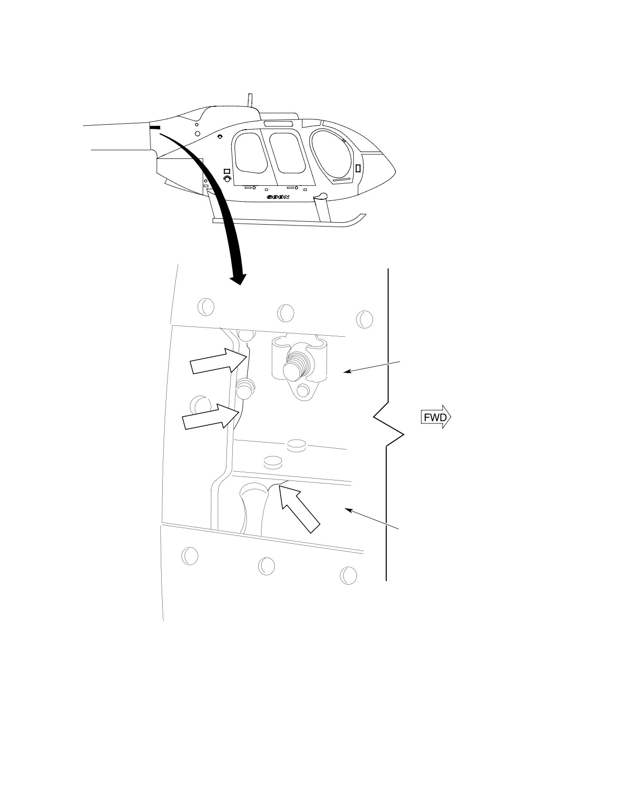
9. Tailboom Attach Fitting Inspection
condition.
(2). Install attaching hardware.
(Ref. Figure 203) Inspect the upper left-hand
and right-hand tailboom attach fittings,
(3). Check for minimum run-on torque of
angles and nutplates as follows:
attaching screws, 2 inch-pounds
(0.226 Nm) minimum.
(1). Remove button plug from attach fitting
access cover.
8. Engine Plenum Access Cover
Replacement
(2). Using a bright light, inspect fitting and
Avoid FOD, Cover compressor
angle:
CAUTION
inlet prior to working in plenum
chamber area. Vacuum all FOD debris out of
(a). Inspect attach fittings for cracks.
the plenum chamber before removing the
protective cover from the inlet bell. Severe
NOTE: Pay particular attention to area around
damage to the engine may result from entry
aft rivet holes. No cracks are allowed.
of foreign objects.
(b). Inspect angle for cracks.
A. Engine Plenum Access Cover Removal
(c). If any cracks are found in attach
NOTE: If particle separator is installed, ejector
fitting or angle, contact MDHI Field
ducting is not removed with plenum access
Service Dept. for replacement
cover.
instructions.
(1). Remove hardware that attaches engine
plenum access cover to supporting
(3). Inspect nutplate for thread damage and
structure.
cracks.
(2). Remove plenum cover.
NOTE: Cracks would appear from top of self-
locking nut split to base of nut.
B. Engine Plenum Access Cover Installation
(1). Position engine plenum access cover to
(a). Replace nutplate if threads are
align with mounting holes in fuselage.
damaged or cracked.
Page 205
53-30-30
Revision 34
CSP-HMI-2
MD Helicopters, Inc.
MAINTENANCE MANUAL
50N3422 TAILBOOM ATTACH FITTING
(RIGHT SIDE SHOWN)
500N3429-6 ANGLE
(RIGHT SIDE SHOWN)
6G53-103
Figure 203. Tailboom Attach Fitting Inspection
Page 206
Revision 34
53-30-30
MD Helicopters, Inc.
CSP-HMI-2
MAINTENANCE MANUAL
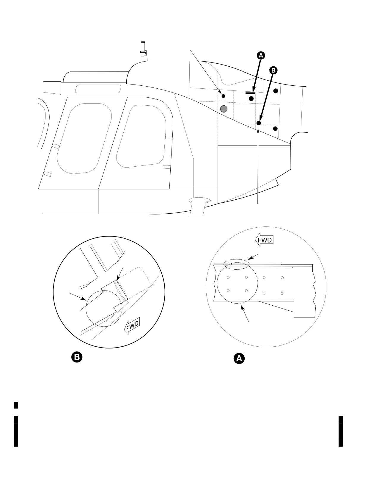
10. Lower Longeron Inspection (L158, R158)
11. Forward Upper Longeron Inspection
(L137, R137)
(Ref. Figure 204) Inspect the lower left-hand
and right-hand longerons as follows:
(Ref. Figure 204) Inspect the foreword upper
left-hand and right-hand longerons as follows:
Consumable Materials
(Ref. Section 91−00−00)
Consumable Materials
Item
Nomenclature
(Ref. Section 91−00−00)
CM425
Sealing compound
Item
Nomenclature
CM425
Sealing compound
(1). Remove button plugs (L158, R158) from
side of helicopter.
(1). Remove button plugs (L137, R137) from
(2). Using bright light and mirror, or
side of helicopter.
borescope, inspect the longeron, Sta.
(2). Using a borescope, inspect the longeron
155.75 frame and Cant. Sta. 159.97
and Sta. 137.50 frame for cracks.
frame for cracks.
(3). If any cracks are found, contact MDHI
(3). If any cracks are found, contact MDHI
Field Service Dept. for repair instruc
Field Service Dept. for repair instruc
tions.
tions.
(4). Install button plugs in inspection hole
(4). Install button plugs in inspection hole
and seal with sealing compound
and seal with sealing compound
(CM425).
(CM425).
Page 207
53-30-30
Revision 34
CSP-HMI-2
MD Helicopters, Inc.
MAINTENANCE MANUAL
UPPER LONGERON, FWD
(L137, R137)
LOWER LONGERON
(L158, R158)
0.75 IN. (19.05 MM)
HOLE IN
HOLE IN SKIN
STA. 146.62
NOTE
NOTE
LOWER LONGERON (VIEW
UPPER LONGERON
LOOKING DOWN)
(VIEW LOOKING UP)
NOTE:
AREAS WHERE CRACKS ARE MOST LIKELY TO APPEAR.
G53-3013A
Figure 204. Inspection Hole Locations
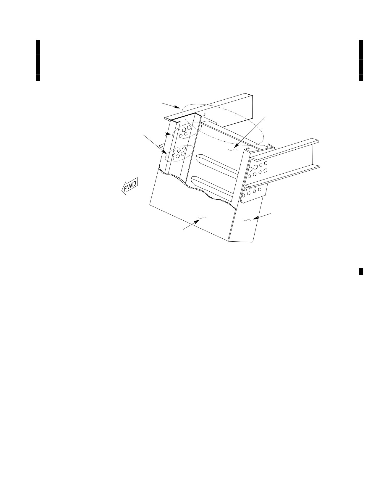
12. Control Tunnel (FS 78.50) Beam
(1). Remove Ty-Raps securing boots to
Inspection
control tubes and shelf assembly.
(Ref. Figure 205)
(2). Slide boots up to top of tubes.
Page 208
Revision 34
53-30-30
MD Helicopters, Inc.
CSP-HMI-2
MAINTENANCE MANUAL
(3). Using a mirror and bright light, inspect
service department for repair instruc
tunnel beams, both sides, for cracks in
tions.
the rivet area; no cracks allowed.
(4). Slide boots down over shelf assembly
and secure top and bottom of boots with
If cracks are found, contact MDHI field
Ty-Raps.
NOTE 2
369D 22508-7 WEB
NOTE 1
369H2564 TUNNEL BEAM
369D22508-5 WEB
NOTE:
1.
INSPECT THESE AREAS FOR CRACKS (BOTH SIDES OF TUNNEL).
2.
REMOVE CONTROL TUBE BOOTS TO GAIN ACCESS FOR INSPECTION.
G53-3014
Figure 205. Control Tunnel (FS 78.50) Beam Inspection
Page 209
53-30-30
Revision 34
CSP-HMI-2
MD Helicopters, Inc.
MAINTENANCE MANUAL
This Page Intentionally Left Blank
Page 210
Revision 34
53-30-30
MD Helicopters, Inc.
CSP-HMI-2
MAINTENANCE MANUAL
Section
53−40−00
Tailboom
(369D/E/FF)

MD Helicopters, Inc.
CSP-HMI-2
MAINTENANCE MANUAL
TAILBOOM
MAINTENANCE PRACTICES
1. Tailboom − General
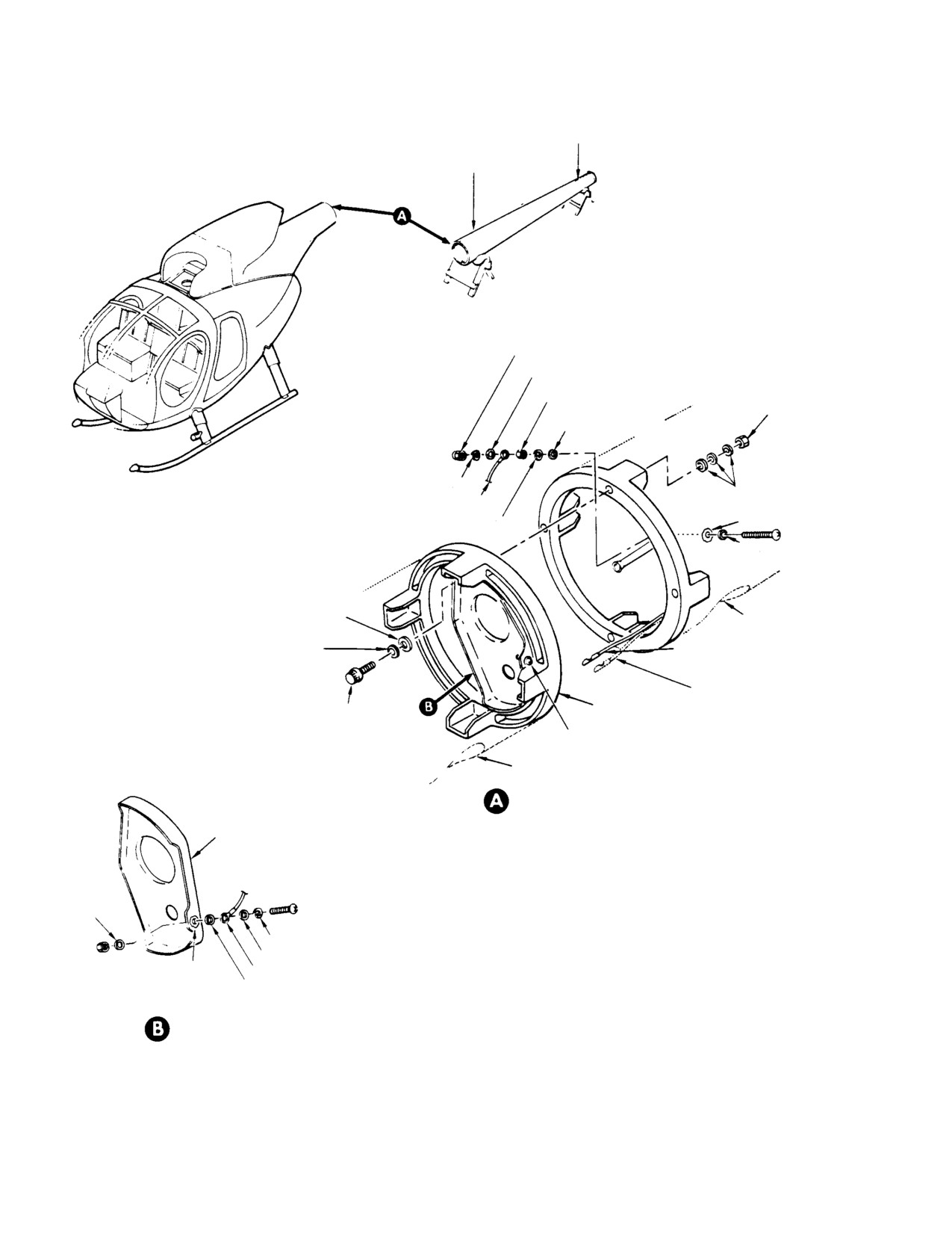
(8). Remove nuts and washers from bolts
that attach boom to fuselage. Remove
(Ref. Figure 201) The tailboom assembly, a
lower bolts first and top bolt last; then
monocoque structure of aluminum skin over
remove boom.
forged aluminum frames, houses the tail rotor
drive shaft and tail rotor control rod, and
B. Tailboom Installation
supports the horizontal and vertical stabiliz
ers.
Consumable Materials
(Ref. Section 91−00−00)
2. Tailboom Replacement
Item
Nomenclature
CM103
Solid film lubricant
A. Tailboom Removal
Special Tools
Special Tools
(Ref. Section 91−00−00)
(Ref. Section 91−00−00)
Item
Nomenclature
Item
Nomenclature
ST2010
Adapter, torque wrench
ST1005
Insertion/extraction tool
ST1006
Insertion/extraction tool
(1). Support tailboom so that mating
bulkheads are flush.
(1). Remove vertical stabilizer (Ref. Sec.
NOTE: Prior to tailboom installation, coat
53-50-10).
threads of external wrenching bolts and at
(2). Remove tail rotor transmission and tail
taching nuts with lubricant (CM103).
rotor drive shaft as a unit (Ref. Sec.
(2). Slide countersunk washers on external
63-15-00).
wrenching bolts with countersunk side
facing bolt heads.
(3). Remove tail rotor control rod (Ref. Sec.
67-20-10).
If washers are installed back
CAUTION
wards, structural failure may
(4).
(369FF Model Only) Remove tailboom
result due to insufficient surface in bearing
extension (Ref. Tailboom Extension
that can cause spreading or cracking of
Replacement).
washers and result in loss of clamp-up
(5). Position suitable cradles under tail
torque.
boom at Cant. Sta. 209.78 frame fitting
(3). Install bolts through aft section
and the forward stabilizer boom
fuselage frame into boom frame and
mounting frame (Cant. Sta. 273.00)
place flat washer(s) on each bolt as
(Ref. Figure 202).
required for correct bolt grip. Use no
more than three flat washers under
To avoid damage, ensure that
CAUTION
each nut. Install nuts and torque only
boom is properly supported be
the nuts to 380 - 410 inch-pounds
fore removing boom attach bolts.
(42.93 - 46.32 Nm).
(6). Open boom bolts access doors and
NOTE: Bolts may be reversed for access to
remove bond jumper from boom.
torque nuts. Torque wrench adapter
(7). Disconnect connector of chip detector
(ST2010) or a thin-walled deep socket is
wiring and night lighting system
used for torquing.
wiring. Disconnect knife splice by hand
(4). Install vertical stabilizer.
or use appropriate connector insertion/
extraction tool (ST1005 or ST1006) for
(5).
(369FF Model Only) Install tailboom
wire mate type connector.
extension.
Page 201
53-40-00
Revision 19
CSP-HMI-2
MD Helicopters, Inc.
MAINTENANCE MANUAL
STABILIZER MOUNTING
FITTINGS
GROMMET
GEARBOX AND STABILIZER
WIRING CONDUIT
MOUNT FRAME
GROMMET
FORWARD STABILIZER BOOM
RIGHT SKIN PANEL
MOUNTING FRAME
GROMMET
STA. 264.32
CANT. FRAME
STA. 209.78
CANT. FRAME
STA. 242.14
CANT. FRAME
NUT
WASHER
LEFT SKIN PANEL
STA. 219.96
CANT. FRAME
FORWARD STABILIZER
TAILBOOM
BOOM MOUNTING FRAME
EXTENSION
STA. 197.78 CANT.
GEARBOX AND STABILIZER
FRAME FITTING
MOUNT FRAME
369FF ONLY
G53-4000
Figure 201. Tailboom Assembly and Tailboom Extension
(6).
Install tail rotor transmission and tail
(3). Remove tailboom extension from
rotor drive shaft as a unit.
tailboom assembly.
(7).
Install control rod.
(4). Apply primer (CM318) in holes, on
faying surfaces and on the grip area of
(8).
Perform tail rotor control rigging (Ref.
the mounting studs and install tail
Sec. 67-20-10).
boom extension while primer is still
wet.
(9).
Install bond jumper to boom and
connect chip detector wiring. Connect
NOTE:
night lighting wiring.
D Note the drag torque for each nut and it's
location on the extension, in the helicop
3.
Tailboom Extension Replacement (369FF)
ter for later use.
(Ref. Figure 201)
D Torque nuts while primer is still wet.
(5). Install tailboom extension on tailboom
Consumable Materials
assembly and secure with four washers
(Ref. Section 91−00−00)
and four nuts.
Item
Nomenclature
CM318
Primer
(6). Torque nuts to 75 - 95 inch-pounds
(8.47 - 10.73 Nm) plus drag torque.
(1). Remove tail rotor transmission and tail
(7). Apply torque stripe paint.
rotor drive shaft as a unit (Ref. Sec.
63-15-00).
(8). Between 2 and 10 hours of helicopter
operation (to allow parts to seat), check
(2). Remove four nuts and four washers
the torque of each mounting nut as
from tailboom assembly.
follows:
Page 202
Revision 19
53-40-00
MD Helicopters, Inc.
CSP-HMI-2
MAINTENANCE MANUAL
(a). Using the drag torque previously
(4). Inspect bond jumper for security and
measured and noted, apply a torque
corrosion.
load of 95 ±3 inch-pounds (10.73
±0.34 Nm) plus the noted drag
(5). Inspect boom exterior for loose or
torque (noted at each individual
missing rivets.
nut) to each mounting nut of the
extension.
(6). Inspect boom and gearbox stabilizer
mounting frames for cracks, security of
(b). Re-apply torque stripe paint.
attachment, elongated holes or condi
tion of mounting studs.
(9). Install tail rotor driveshaft and tail
rotor transmission as a unit.
(7). Replace damaged or deformed studs
(Ref. CSP-SRM-6, Structural Repair
4. Tailboom Inspection
Manual).
(Ref. Figure 201)
5. Tailboom Repair
(1). Inspect boom interior skin and frames
for corrosion and cracks.
There is no damage that can be
CAUTION
considered negligible. All dam
(2). Check attaching nuts and bolts in boom
age must be repaired upon detection (Ref.
Cant. Sta. 197.78 frame fitting for
CSP-SRM-6, Structural Repair Manual).
security.
(3). Inspect tail rotor control rod grommets
NOTE: The skins forming the monocoque boom
in boom frames for evidence of deterio
assembly are highly stressed
(Ref.
ration.
Figure 201).
Page 203
53-40-00
Revision 19
CSP-HMI-2
MD Helicopters, Inc.
MAINTENANCE MANUAL
FORWARD STABILIZER
BOOM MOUNTING FRAME
(CANTED STA 273.00)
CANT. STA 209.78
SELF-LOCKING NUT
FLAT WASHER (CRES)
NUT
PLAIN HEX NUT
(NOTE 4)
FLAT WASHER (AL-ALY
UNTREATED)
SPRING LOCKWASHER
FLAT WASHER(S)
BOND JUMPER
(NOTE 2)
SPRING LOCKWASHER
(NOTE 1)
FLAT WASHER
(AL-ALY UNTREATED)
FLAT WASHER
(NOTE 2)
ACCESS HOLE
COUNTERSUNK WASHER
CHIP DETECTOR WIRING
TAIL LIGHT WIRING
BOOM FITTING
EXTERNAL WRENCHING BOLT (NOTE
4)
JUMPER CONNECTION
ACCESS HOLE
TAILBOOM ATTACHMENT
BRACKET
FLAT
NOTES:
WASHER
1.
ENSURE THAT GROUND CONTACT SURFACE IS CLEAN
BEFORE BOND JUMPER INSTALLATION. AFTER
SPRING LOCKWASHER
INSTALLATION, COAT EXPOSED BARE METAL GROUNDED
FLAT WASHER (CRES)
AREA WITH LACQUER (CM306).
(NOTE 1)
BOND JUMPER
2.
THREE FLAT WASHERS MAXIMUM UNDER NUT. WASHERS
FLAT WASHER
ADDED UNDER BOLT HEAD. COUNTERSUNK WASHER IS
(AL-ALY UNTREATED)
REQUIRED.
BOOM FITTING BRACKET AND
3.
CRES-CORROSION RESISTANT STAINLESS STEEL.
JUMPER-INSTALLATION
4.
PRIOR TO INSTALLATION, COAT THREADS
WITH LUBRICANT (CM103).
G53-4001A
Figure 202. Tailboom Installation and Removal
Page 204
Revision 19
53-40-00
MD Helicopters, Inc.
CSP-HMI-2
MAINTENANCE MANUAL
Section
53−40−30
Tailboom (500/600N)
MD Helicopters, Inc.
CSP-HMI-2
MAINTENANCE MANUAL
TAILBOOM (500/600N)
MAINTENANCE PRACTICES
1. Tailboom Description
(8). A Strake, a composite strip bonded to
the left side of the tailboom, breaks up
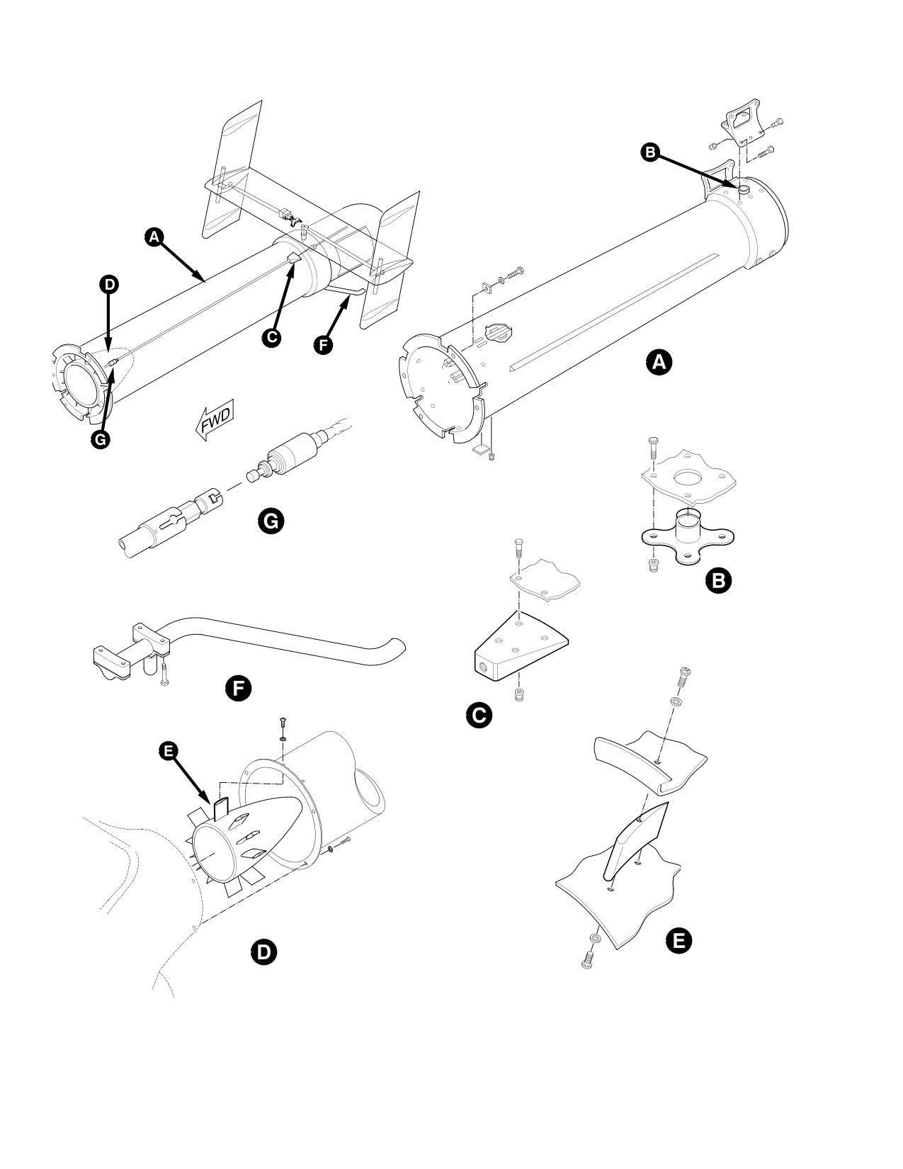
(Ref. Figure 201) The tailboom assembly is a
airflow on the left side of the boom for
fully monocoque construction of graphite
hovering stability.
composites, it provides directional control for
the helicopter.
(9). A Stator located directly behind the fan
and mounted inside the tailboom
The tailboom for the Model 600N helicopter is
straightens low pressure air flowing
a similar version to that on the Model 500N
through the boom. The stator has
helicopter. One of the obvious differences is the
eleven composite removable blades, and
length, approximately 28 inches (71.12 cm)
is accessible by removing the tailboom.
longer on the 600N. Also, two of the four
mounting bolts that hold the boom to the
(10). A tail skid mounted bottom aft on the
fuselage are a larger diameter. These two
tailboom is constructed of aluminum
points have been reinforced both on the boom
tubing.
and on the fuselage for added strength.
(11). A jack pad is located on the tailboom
(1).
The tailboom converts energy from the
underside. The jackpad can be accessed
main rotor downwash to an anti-torque
by removing the tail skid.
force. In order to accomplish this, a
variable pitch fan pushes low pressure
(12). The tailboom provides for the mounting
air through two longitudinal slots on
of the horizontal stabilizer and a control
the right side of the tailboom and two
cable conduit for the flight controls.
thrusters ports at the end of the
tailboom. These slots located at 130°
2. Tailboom Replacement
and 76° degrees, direct low pressure air
(Ref. Figure 201)
downward over the tailboom surface.
NOTE: When removing tailboom as an assem
(2).
Slot air flow mixes with main rotor
bly with the horizontal and vertical stabiliz
downwash air, delaying its separation
ers installed, precaution should be taken to
at the bottom of the tailboom and
adequately support and balance the tail
effectively creating a lifting force.
boom assembly equally due to the mass of
(3).
Air from the main rotor passing over
the stabilizers.
the boom provides directional control to
neutralize the main rotor torque.
A. Tailboom Removal
(4).
Approximately 60% of the anti-torque
(1). Remove tailboom fairing.
force required in a hover, is provided by
(2). Disconnect the forward end of the
the tailboom lift, the remaining 40% is
anti-torque control cable by turning
by metered air flowing out the end of
outside collar sleeve counter-clockwise
the tailboom rotating thruster cone.
and back to expose the inner cable.
(5).
A stationary thruster cone port directs
Apply sufficient right pedal to expose
air flow to the left or to the right.
engagement pin and pull collar sleeve
outward.
(6).
The rotating thruster cone (a can-
shaped structure) meters exit air for
(3). Disconnect electrical connector.
left or right directional control.
(4). Have assistants support tailboom.
(7).
Pedal movement opens and closes the
thruster cone ports and changes fan
(5). Remove four mounting bolts and
blade pitch angle for engine power
washers and remove tailboom. Inspect
changes.
bolts for corrosion.
Page 201
53-40-30
Revision 36
CSP-HMI-2
MD Helicopters, Inc.
MAINTENANCE MANUAL
500N TAILBOOM SHOWN
G53-4002-1A
Figure 201. Tailboom Assembly (Sheet 1 of 3)
Page 202
Revision 19
53-40-30
MD Helicopters, Inc.
CSP-HMI-2
MAINTENANCE MANUAL
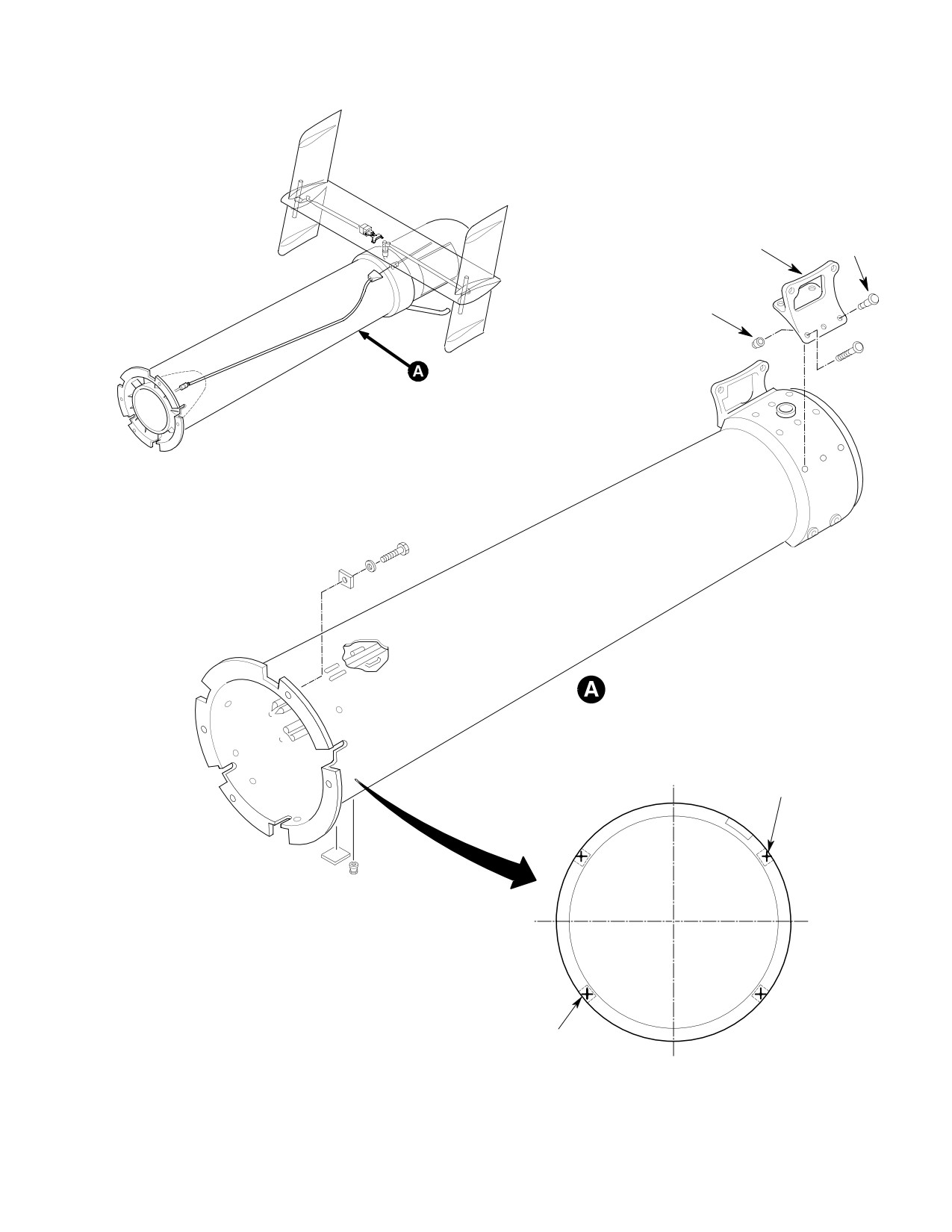
FITTING
PIN
COLLAR
LARGER DIAMETER
MOUNTING HOLE
600N TAILBOOM SHOWN
LARGER DIAMETER
MOUNTING HOLE
G53-4002-2C
Figure 201 Tailboom Assembly (Sheet 2 of 3)
Page 203
53-40-30
Revision 22
CSP-HMI-2
MD Helicopters, Inc.
MAINTENANCE MANUAL
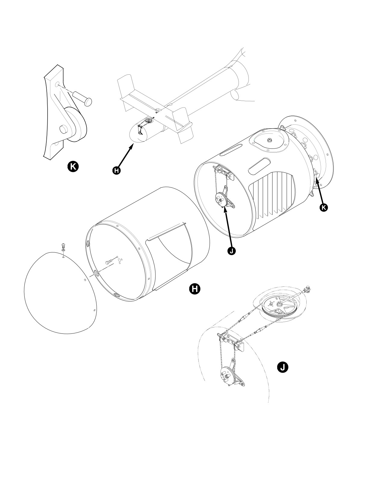
500N THRUSTER SHOWN
G53 4002 3
Figure 201 Tailboom Assembly (Sheet 3 of 3)
Page 204
Revision 19
53-40-30

MD Helicopters, Inc.
CSP-HMI-2
MAINTENANCE MANUAL
B. Tailboom Installation
- 150 inch-pounds (14.68 - 16.94
Nm) plus drag torque and the two
Before tailboom installation, in
larger diameter bolts to 180 - 220
CAUTION
spect radius blocks for brinnel
inch-pounds (20.33 - 24.85 Nm)
ing, corrosion, cracks and indication of in
plus drag torque. Safety bolts.
dent on face; none allowed.
RN003 - RN059 with TB600N-007
NOTE: If installing a new tailboom, the
complied with and RN060 & subs;
500N3500-5 cover will have to be installed
torque bolts to 180 - 220 inch-
after internal tailboom components are
pounds (20.33 - 24.85 Nm) plus
installed (Ref. 500N3500-5 Cover Installa
drag torque. Safety bolts.
tion).
(5). Check for a minimum of two threads
protruding from nutplates.
(1). Support tailboom so that the mating
bulkhead surfaces are flush.
(6). Using a 0.002 inch (0.051 mm) feeler
gauge, check for gap between tailboom
(2). Slide countersunk/chamfered washers
and fuselage flange within 0.60 inch
on external wrenching bolts with
(15.3 mm) of centerline of each of the
countersunk side facing bolt head.
four attach bolts; no gap allowed.
If washers are installed back
(7). Re-connect electrical connectors.
CAUTION
wards, structural failure may
(8). Re-connect control cable assembly.
result due to insufficient surface in load
(9). Install tailboom fairing.
bearing area that can cause spreading or
cracking of washers and result in loss of
3. Tailboom Inspection
clamp-up torque.
(Ref. Figure 201)
(3).
600N:
(1). Inspect tailboom exterior as follows:
(a). Inspect tailboom fairing for cracks
Install washer on bolt after the counter
and delaminations.
sunk washer.
(b). Inspect tailboom flange and mount
(a). Install either an AN960C516 or
ing bolt holes attachment area for
NAS1149C0563R washer on -5 bolts.
cracks at Sta. 168.20.
(b). Install either an AN960C616 or
(c). Inspect radius blocks for brinneling,
NAS1149C0663R washer on -6 bolts.
corrosion and indication of indent on
face; none allowed. If found, scrap
Do not lubricate tailboom attach
radius block and install new radius
CAUTION
bolts or nutplates, this will
block.
cause a false torque reading and lead to bolt
(d). Inspect strake for cracks, delamina
loosening.
tions, debonding, dents, nicks and
(4). With the tailboom supported in place,
separation.
install four bolts with washers.
NOTE: Damage to slots can cause significant
degradation of aircraft performance in a
(a).
500N:
hover.
Torque bolts to 130 - 150 inch-
(e). Inspect tailboom surface area and
pounds (14.69 - 16.95 Nm) plus
tailboom circulation control slots
drag torque. Verify minimum run
surface area for cracks, voids, dents,
on torque of 6.5 inch-pounds (0.73
holes, scratches, separation, delami
Nm).
nations at tailboom and security.
1). Using a bright light, inspect fore
(b).
600N:
and aft radii of the lower portion of
RN003 - RN059 without
the three upper slot bridges for
TB600N-007 complied with; torque
cracks, illuminate area under the
the two smaller diameter bolts to 130
flap.
Page 205
53-40-30
Revision 39
CSP-HMI-2
MD Helicopters, Inc.
MAINTENANCE MANUAL
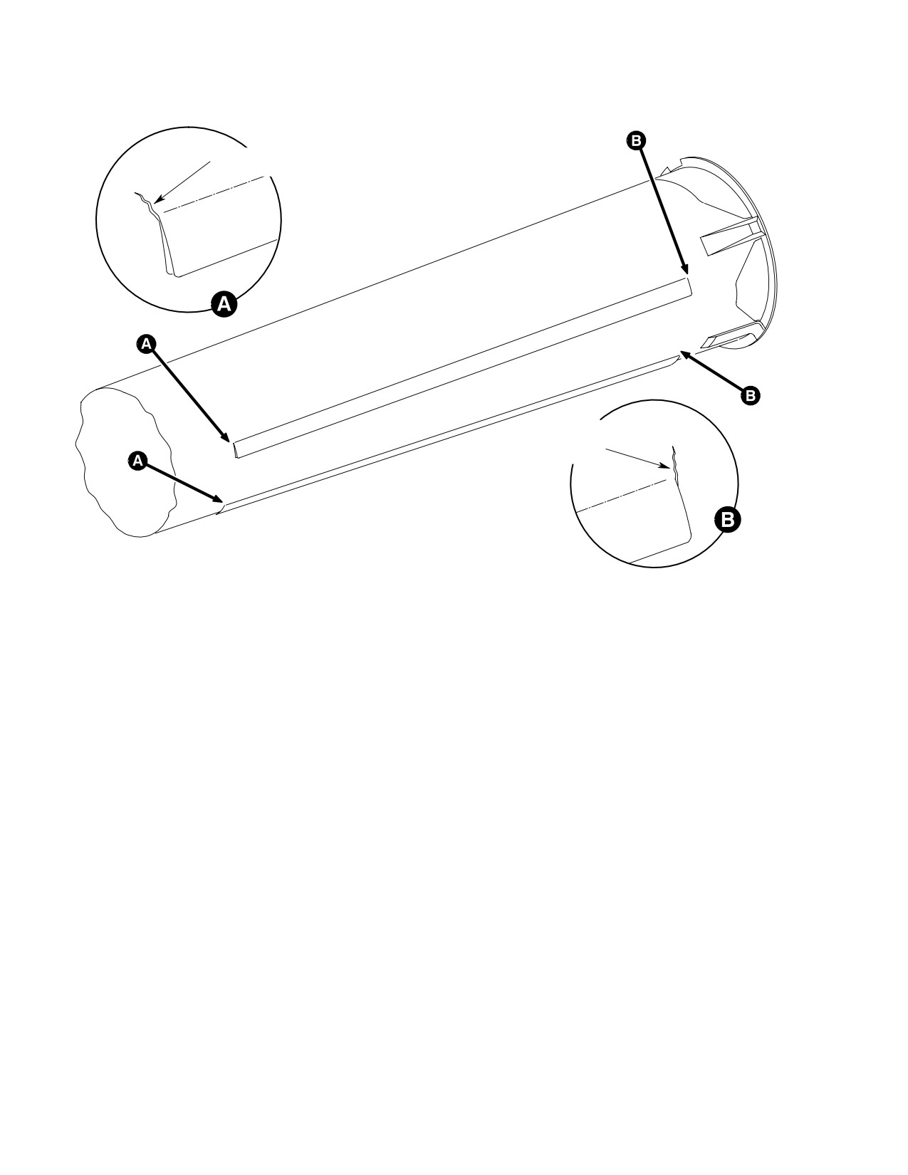
1.25 IN. (3.175 CM) CRACK
LENGTH PERMISSIBLE
1.25 IN. (3.175 CM) CRACK
LENGTH PERMISSIBLE
6G53-102A
Figure 202. Tailboom Flap Inspection
NOTE: The flap may be raised slightly, using
to the forward inboard legs) and
finger pressure only, to aid in checking this
attachment fittings for cracks, voids,
area.
separation and delamination.
(h). Inspect stabilizers (Ref. Sec.
(f). Inspect flaps for cracking and
53-50-30).
debonding (Ref. Figure 202):
(i). Inspect (tail-skid) for cracks, dents,
1). A crack of any length, in line with
holes and delamination.
aft edge of flap, is permissible at
interface between flap and tail
(j). Inspect rotating thruster cone for
boom.
freedom of operation, cracks, holes,
separation and delamination.
2). A crack of 1.25 inch (3.175 cm)
maximum length, in line with the
(k). Inspect tailboom grommets (2) places
forward edge of flap, is permissible
for cracks and proper fit.
at interface between flap and
(2). Inspect tailboom interior as follows:
tailboom.
(a). Check stator vanes and stator
NOTE: If crack in forward edge of flap is longer
diffuser cone for cracks, delamina
than 1.25 inch (3.175 cm), contact your local
tions and separation.
MDHI Field Service Representative for dis
position.
1). Maximum allowable cracks found
emanating from stator vane inserts
(g). Inspect horizontal stabilizer mount
should not exceed 0.10 inch (2.54
ing brackets (pay particular attention
mm) span-wise.
Page 206
Revision 39
53-40-30
MD Helicopters, Inc.
CSP-HMI-2
MAINTENANCE MANUAL
2). No cracks allowed running cord-
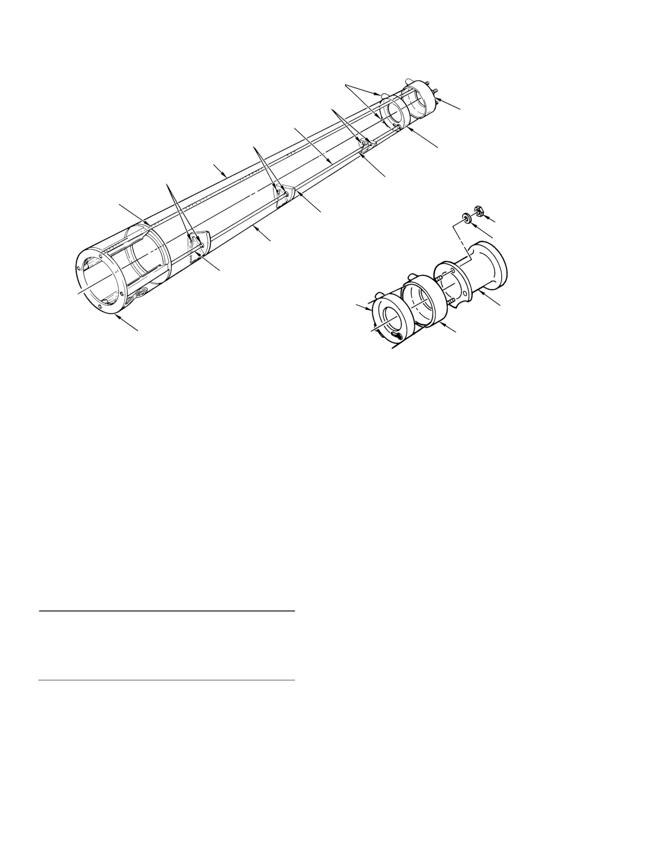
6. Stator Blade Replacement
wise towards leading or trailing
(Ref. Figure 201, View E)
edge
(1). Stator Blade Removal: Remove two
(b). Inspect slot air foils for cracks,
self-locking screws and two surface
delamination and separation from
washers.
boom.
(2). Stator Blade Installation: Install two
(c). Inspect control cable assembly
surface washers and two self-locking
attachment points for looseness,
screws. Torque screws to 3 - 6 inch-
cracks and condition.
pounds (0.34 - 0.68 Nm) plus drag
torque. Total torque should not exceed
(d). Inspect cable conduit for cracks,
15 inch-pounds (1069 Nm) total
separation and delamination.
torque.
(e). Inspect air circulation area for FOD
7. Rotating Thruster Cone Replacement
and cleanliness. If necessary, clean
with mild soap and water.
(Ref. Figure 201, View H)
(3). Inspect rotating thruster cone collar
A. Rotating Thruster Cone Removal
strap ring rivets for looseness, strap for
(1). Remove cone tip cap by removing eight
cracks and condition.
screws and washers.
4.
Tailboom Repair
(2). Support rotating thruster cone and
remove three bolts and washers that
Minor repair procedures for the tailboom are
attach the rotating thruster cone,
in the Repair section (Ref. Sec. 53-40-30).
carefully slide rotating cone aft to clear
stationary cone, bearings and followers
5. Stator Replacement
and the cable and drum assembly.
(Ref. Figure 201, View D)
B. Rotating Thruster Cone Installation
A. Stator Removal
(1). Carefully slide rotating thruster cone
over stationary cone, bearings, rollers
(1). Remove tailboom.
and followers.
(2). Note or index top of stator for reas
(2). With the thruster supported in place,
semble. Support stator and remove
install three bolts with washers
seven exterior screws and washers
attaching the rotating thruster to
mounted around the forward part of the
thruster gear box. Torque bolts 70 - 90
tailboom.
inch-pounds (7.91 - 10.17 Nm).
Safety wire bolts.
B. Stator Installation
(3). Install cone tip cap with eight screws
(1). Support stator and align stator vanes in
and washers, torque screws per general
tailboom, install seven screws and
aircraft practices.
washers, torque screws to 3 - 6 inch-
pounds (0.34 - 0.68 Nm) plus drag
8. Rotating Thruster Cone Inspection
torque. Total torque should not exceed
(1). Inspect for cracks and separation of
15 inch-pounds (1069 Nm) total
composite laminates.
torque.
(2). Check for freedom of rotational move
(2). Install tailboom.
ment within the control range of
thruster.
(3). Verify that stator does not rub against
the fan and for clearance of 0.020-0.080
(3). When the thruster is removed from
inch (0.508-2.032 mm) between stator
helicopter, check roller surface area
and fan.
(strap) for cracks and condition.
Page 207
53-40-30
Revision 44
CSP-HMI-2
MD Helicopters, Inc.
MAINTENANCE MANUAL
NOTE: Refer to MD Helicopters Inc. Represen
washer and bolt, torque bolt per
tative for structural repairs, cracks, etc.
standard aircraft torque values and
safety wire.
9. Stationary Thruster Cone Replacement
(4). Install thruster cone fairings.
(Ref. Figure 201)
(5). Install rotating thruster (Ref. Rotating
A. Stationary Thruster Cone Removal
Thruster Cone Installation).
(1). Remove rotating thruster cone (Ref.
10. Stationary Thruster Cone Inspection
Rotating Thruster Cone Removal).
(1).
Inspect for cracks and delamination of
(2). Remove eight off wing screws from pan
composites structure for the following:
cover, remove cotter pin, nut and
Internal ducts, air foil supports, pan
washer from sector input shaft and
cover and pan (hat section).
remove pan cover. Remove washer and
bushing from sector bellcrank input
(2).
Inspect rollers and bearings for condi
shaft.
tion and freedom of rotation. Inspect for
cleanliness.
(3). Remove bolt, washer and bushing from
thruster input sector bellcrank clevis
(3).
Inspect sector bellcrank, cable assem
(Ref. View J).
blies, pulleys and support brackets for
condition, inspect of cleanliness.
(4). Remove thruster cone fairings.
(4).
Inspect upper input shaft for damage
(5). Support stationary thruster cone and
and wear. Check for play in mounting
remove eight bolts and washers, with
pins. If mounting pins are found to
cable assembly attached to cone,
have play, replace with new pins and
carefully lift cone off tailboom so that
collars.
the control rod passes through the
(5).
Inspect thruster aft support shaft for
thruster cone cutout.
damage and wear. Check for play in
B. Stationary Thruster Cone Installation
mounting hardware. If top bolt is found
to be loose, retorque to 10 - 15 inch-
(1). Support stationary thruster cone to
pounds (1.13 - 1.69 Nm). If bottom
tailboom so that the control rod passes
mounting pins are found to be loose,
through the cutout of the stationary
replace with new pins and collars.
cone, and that the mating surfaces are
flush to the tailboom. Slide counter
11. Conduit and Support Strap Rebonding
sunk/chamber washers on external
wrenching bolts with countersunk side
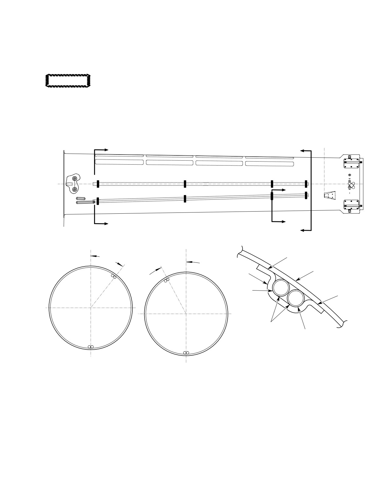
(Ref. Figure 203) The following procedure is for
facing bolt head.
rebonding of the conduit supports.
If washers are installed back
CAUTION
Consumable Materials
wards, structural failure may
(Ref. Section 91−00−00)
result due to insufficient surface clamp-up
Item
Nomenclature
in load bearing areas that can cause spread
ing or cracking, resulting in loss of clamp-
CM217
Isopropyl alcohol
up torque.
CM402
Adhesive
(2). With the stationary thruster cone
support in place, install eight bolts and
(1). Lightly abrade faying surfaces with
washers. Torque bolts 30 - 40 inch-
Scotchbrite until surface gloss of the
pounds (3.39 - 4.52 Nm) plus drag
laminate is gone.
torque.
(2). Solvent-wipe parts using a clean
(3). Connect control rod to input sector
lint-free cloth dampened with isopropyl
bellcrank clevis and install bushing,
alcohol (CM217).
Page 208
Revision 39
53-40-30
MD Helicopters, Inc.
CSP-HMI-2
MAINTENANCE MANUAL
(3). Wipe dry using a clean, lint-free, dry
NOTE: Adhesive must be applied within 2
cloth and allow to air dry for 15 min
hours of preparation. If more than 2 hours
utes at ambient temperature.
elapse before adhesive application, re-pre
pare surfaces.
Do not heat conduit to more
CAUTION
than 170°F (77°C). Conduit and
(5). Mix adhesive (CM402) according to
tailboom can be damaged from too much
manufacturer's instructions and apply
heat.
to faying surfaces.
(4). If conduit is bent away from tailboom,
(6). Secure parts together with light
heat conduit to make more flexible for
pressure and allow to cure for 24 hours
re-bonding.
at ambient temperature.
CANT
A
C
B
B
A
FS 168.200
C
CANT
BL
BL
0.000
0.000
38° 28′
APPLY ADHESIVE HERE
28° 20′
TAILBOOM
SUPPORT
APPLY
ADHESIVE
APPLY
HERE
ADHESIVE
HERE
CONDUIT
APPLY
ADHESIVE
HERE
SECTION B-B
SECTION A-A
LOOKING AFT
SECTION C-C
LOOKING FORWARD
500N TAILBOOM SHOWN
G53-4004A
Figure 203. Conduit and Support Strap Rebonding
Page 209
53-40-30
Revision 39
CSP-HMI-2
MD Helicopters, Inc.
MAINTENANCE MANUAL
12. Horizontal Stabilizer Mount Fitting
(8). Locate new fitting on tailboom.
Replacement
(9). Back-drill fittings to 0.186-0.188 inch
(Ref. Figure 201)
(4.724-4.775 mm).
(10). Remove fitting and deburr rivet holes.
Empennage Fitting
Part No.
(11). Touch up rivet holes with solid film
L/H, Aluminum
500N3530−3, −7
lubricant (CM101) for steel fittings or
R/H, Aluminum
500N3530−4, −8
chemical coating (CM206) for alumi
L/H, CRES
500N3530−9
num fittings.
R/H, CRES
500N3530−10
(12). Steel fittings only:
(a). Using abrasive paper (CM801),
Consumable Materials
lightly abrade tailboom where fitting
(Ref. Section 91−00−00)
is to be mounted.
Item
Nomenclature
(b). Clean fitting and tailboom abraded
CM101
Solid film lubricant
area with 1,1,1-Trichloroethane
CM206
Chemical coating
(CM222).
CM222
1,1,1-Trichloroethane
CM304
Enamel, epoxy
(c). Prime fitting with adhesive primer
(CM315).
CM315
Adhesive primer
CM318
Primer
(d). Apply a thin layer of cement (CM418)
CM418
Cement, epoxy
between fitting and tailboom.
CM425
Sealing compound
NOTE:
CM801
Abrasive paper, silicon carbide
D Use HTS12-6-4/-5 pin rivets with
HTS1176DU-6AWU collars or alternate
HTS48-6-4/-5 pin rivets with
(1). Remove horizontal stabilizer (Ref. Sec.
HST2000-6AW collars.
53-50-30, Horizontal Stabilizer
Replacement).
D Gage rivet holes to ensure proper length
pin rivets.
(2). Remove rotating thruster cone (Ref.
Rotating Thruster Cone Replacement).
(13).
Relocate fitting on tailboom and install
with pin rivets wet with primer
(3). Remove stationary thruster cone (Ref.
(CM318).
Stationary Thruster Cone
(14).
Seal edges around fittings with sealing
Replacement).
compound (CM425).
(4). Remove collars from pins in mount
(15).
If installing steel fittings, prime with
fittings.
adhesive primer (CM315).
(5). Drive pins out of fittings.
(16).
Touch up with paint (CM304).
Do not allow fittings to reach
(17).
Reinstall stationary thruster cone (Ref.
CAUTION
200°F (94°C), damage to tail
Stationary Thruster Cone
boom composite material will occur.
Replacement).
NOTE: Heating the fitting to 150°F (66°C) may
(18).
Reinstall rotating thruster cone (Ref.
assist in removing them from tailboom.
Rotating Thruster Cone Replacement).
(6). Carefully pop fittings loose from
(19).
Reinstall horizontal stabilizer (Ref. Sec.
tailboom while not damaging fiberglass
53-50-30, Horizontal Stabilizer
sheets under fitting.
Replacement).
(7). Clean area with 1,1,1-Trichloroethane
(20).
Check rigging of thruster (Ref. Sec.
(CM222).
67-20-30).
Page 210
Revision 39
53-40-30
MD Helicopters, Inc.
CSP-HMI-2
MAINTENANCE MANUAL
(21). Check rigging of vertical stabilizers
(a). If tailboom is not previously marked,
(Ref. Sec. 67-20-30).
place a mark every 2.0 inches (50.8
mm) around cover and tailboom.
13. 500N3500−5 Cover Installation
(b). Do not bond the bottom 8.0 inches
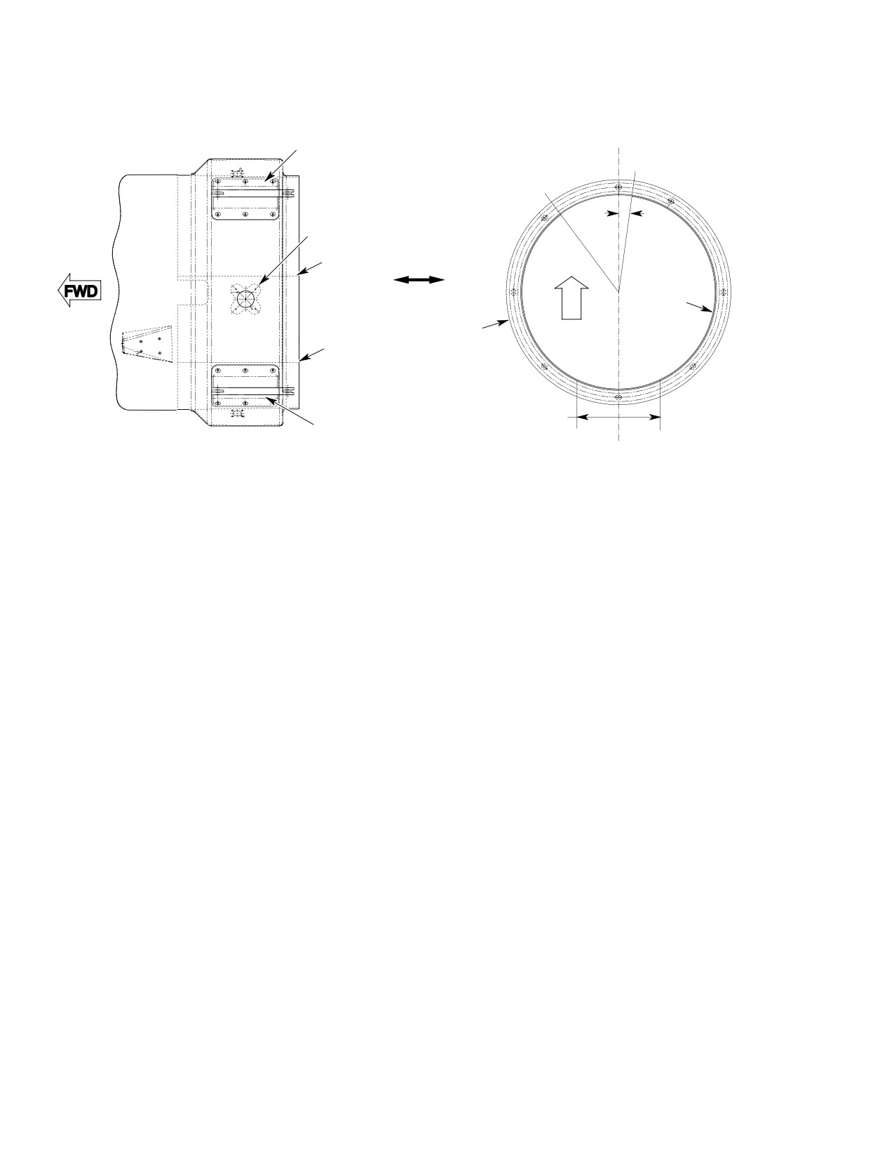
(Ref. Figure 204) New tailbooms come with the
(203.2 mm) on aft end of cover.
500N3500-5 cover separate. This cover must
be bonded in place after the wiring and cables
(4). Abrade around the cover mating
are installed.
surface with 240 grit abrasive cloth
(CM802) to remove gloss.
Consumable Materials
NOTE:
(Ref. Section 91−00−00)
Item
Nomenclature
D Use care to avoid damage to the fiber re
CM222
1,1,1-Trichloroethane
inforcement.
CM410
Adhesive, epoxy (parts A & B)
D Metallic faying surfaces do not require
CM802
Abrasive cloth, aluminum oxide
abrading.
CM819
Kimwipe
(5). Using 240 grit abrasive cloth (CM802),
lightly abrade spots, where marked,
(1). With cutout facing down and forward,
around the tailboom until the surface
gently role cover to shape of tailboom
gloss is removed.
and position inside aft end of tailboom.
Slide cover in until aft end is flush with
(6). Wipe abraded surfaces with kimwipes
tailboom.
(CM819) dampened with
1,1,1-Trichloroethane (CM222). Allow
NOTE: Right edge of cover should be just to the
to air dry for 15 minutes.
right of the torque tube housing (8° to the
right of centerline). Left edge should be un
(7). Mix adhesive according to manufactur
der the left horizontal stabilizer empennage
er's instructions.
fitting.
NOTE: Adhesive must be applied within two
(2). Check holes in cover to ensure they line
hours of cleaning. Repeat solvent prep if
up with electrical connectors on
more than two hours elapses before bond
tailboom.
ing.
(3). If holes do not line up with electrical
(8). Apply adhesive to abraded areas and
connectors, remove cover, role 180° and
position cover in tailboom. Clean up
reposition in tailboom.
excessive adhesive.
NOTE: Tailboom is manufactured with 1.0 x 1.0
inch (25.4 x 25.4 mm) spots marked for
(9). Allow to cure per manufacturer's
abrasion.
instructions.
Page 211
53-40-30
Revision 39
CSP-HMI-2
MD Helicopters, Inc.
MAINTENANCE MANUAL
R/H HORIZONTAL
C
L
EMPENNAGE FITTING
RIGHT EDGE OF
-5 COVER
LEFT EDGE OF
-5 COVER
8°
TORQUE TUBE
HOUSING
RIGHT EDGE OF
-5 COVER
U
-5 COVER
P
TAILBOOM
LEFT EDGE OF
-5 COVER
8.0 IN. (203.2 MM)
L/H HORIZONTAL
DO NOT BOND
EMPENNAGE FITTING
THIS AREA
VIEW LOOKING DOWN
VIEW LOOKING FORWARD
G53-4005
Figure 204. 500N3500−5 Cover Installation
14. Tail Skid Replacement
(a). Insert removed shims and install two
bolts and washers.
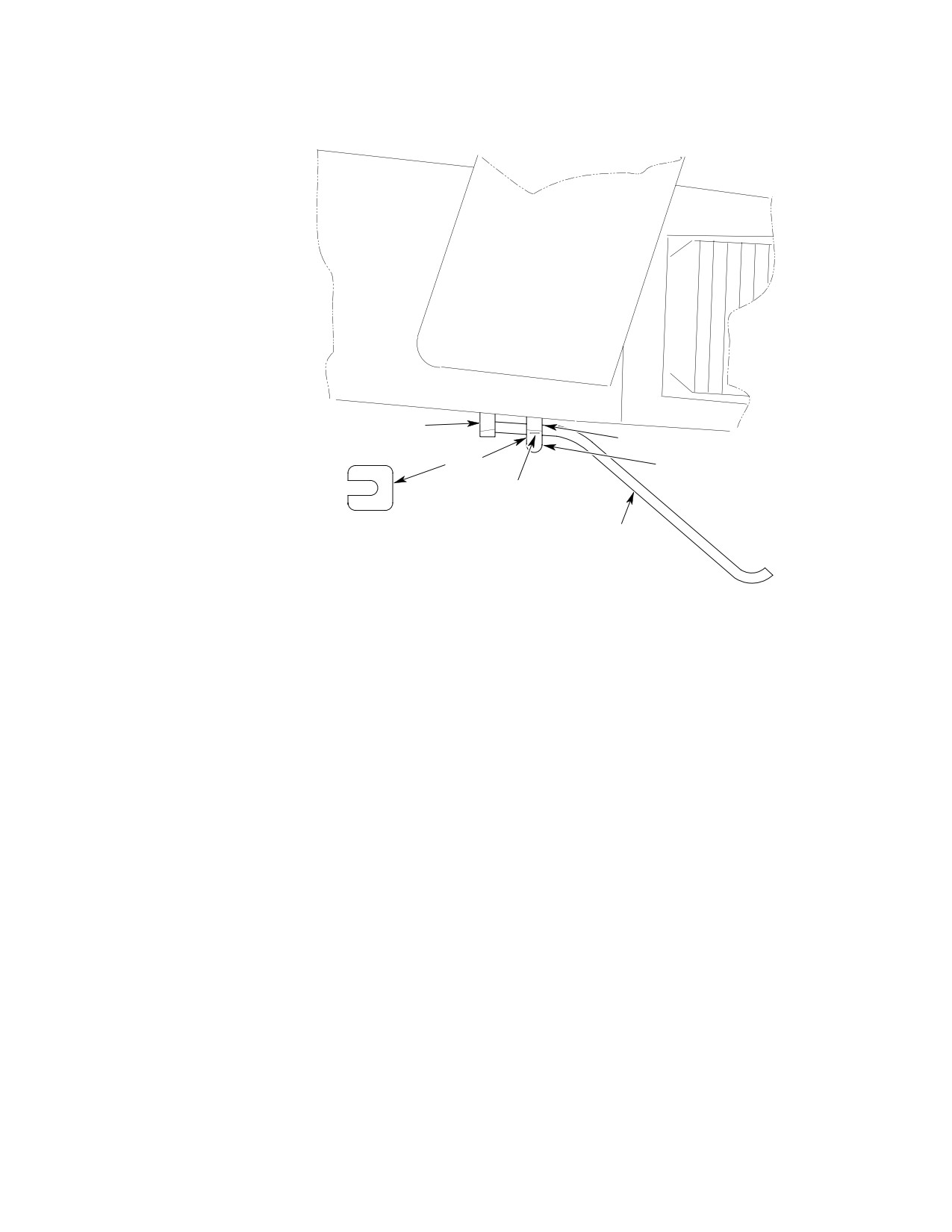
(Ref. Figure 205)
(b). Torque bolts to 36 - 40 Inch-pounds
A. Tail Skid Removal
(3.95 - 4.52 Nm) plus drag torque.
(1). Remove two bolts with washers from aft
(4). If installing a new tail skid:
tail skid brace.
(2). Retain shims between base and brace if
(a). Install bolts finger tight, ensure gap
same tail skid is to be reinstalled.
is even on both sides.
(3). Slide tail skid from forward bracket
(b). Measure gap between brace and
assembly.
base.
B. Tail Skid Installation
(c). Subtract 0.010 in. (0.254 mm) and
peel shims to that thickness.
(1). Slide tail skid into forward bracket
assembly.
(d). Insert shims between brace and base
and torque bolts to 36 - 40 Inch-
(2). Install aft brace onto aft base.
pounds (3.95 - 4.52 Nm) plus drag
(3). If reinstalling the same tail skid:
torque.
Page 212
Revision 39
53-40-30
MD Helicopters, Inc.
CSP-HMI-2
MAINTENANCE MANUAL
FORWARD BRACKET
ASSEMBLY
AFT BASE
SHIM
AFT BRACE
BOLT
WASHER
TAIL SKID
G53-4006
Figure 205. Tail Skid Installation
Page 213
53-40-30
Revision 39
CSP-HMI-2
MD Helicopters, Inc.
MAINTENANCE MANUAL
This Page Intentionally Left Blank
Page 214
Revision 39
53-40-30
MD Helicopters, Inc.
CSP−HMI−2
MAINTENANCE MANUAL
TAILBOOM (500/600N)
REPAIRS
1. Rotating Thruster Cone Strap Repair
A. Rotating Thruster Cone Strap Removal
For minor repairs not described in this section,
(1). Remove the rotating thruster cone
refer to MDHI Field Service Representative.
assembly. (Ref. Sec. 53-40-30).
(Ref. Figure 801)
(2). Remove rivets (2) from rotating
thruster cone (1).
Consumable Materials
(3). Remove strap (3) from rotating thruster
(Ref. Section 91−00−00)
cone.
Item
Nomenclature
CM235
Cleaner
(4). Remove any adhesive residue from
rotating thruster cone strap bonding
CM214
Releasing agent
area.
CM409
Adhesive, epoxy
CM441
Sealing compound, corrosion inhibiting
(5). Clean the bonding area with cleaner
(CM235).
3
2 (24 PL)
1
G53-4007
Figure 801. Rotating Thruster Cone
Legend (Ref. Figure 801)
1. ROTATING THRUSTER CONE
3. STRAP
2. RIVET
Page 801
53-40-30
Revision 44
CSP−HMI−2
MD Helicopters, Inc.
MAINTENANCE MANUAL
B. Rotating Thruster Cone Strap Installation
(9). Install the strap in the rotating
thruster cone.
NOTE: The rotating thruster cone strap bond
ing area must be smooth. Small surface de
(10). Apply releasing agent (CM214) to cleco
fects in the bonding area can be filled with
fasteners.
adhesive (CM409) before bonding. Do not let
excess adhesive change the contour of the
(11). Use cleco fasteners to align the rotating
bonding area.
thruster cone and strap rivet holes.
(1). Put the rotating thruster cone strap (3)
(12). Remove excess adhesive from rotating
in position on the rotating thruster cone
thruster cone strap and bonding area.
(1) bonding area.
(2). Transfer the 24 rivet hole locations in
Make sure the strap is not de
CAUTION
the rotating thruster cone to the strap.
formed or out-of-round when
installed in the rotating thruster cone. An
(3). Match drill the strap for the rivets (2).
out-of-round contour can cause the rotat
ing thruster cone to bind during operation.
(4). Remove the strap from the rotating
thruster cone.
(13). Cure adhesive for 24 hours at ambient
(5). Clean and deburr the rivet holes in the
temperature or heat to 170° to 190° F
strap.
(76.7 to 87.7° C) for 90 minutes.
(6). Inspect the rotating thruster cone strap
(14). Remove cleco fasteners from rivet holes.
bonding area for any surface defects.
(15). Wet install rivets with sealing com
(7). If necessary, fill bonding area surface
pound (CM441).
defects with adhesive (CM409).
(8). Apply adhesive (CM409) to the rotating
(16). Paint exterior of rotating thruster cone
thruster cone strap bonding area.
as required (Ref. Sec. 20-30-00).
Page 802
Revision 44
53-40-30
MD Helicopters, Inc.
CSP-HMI-2
MAINTENANCE MANUAL
Section
53−50−10
Stabilizer (T−Tail)
(369D/E/FF)
MD Helicopters, Inc.
CSP-HMI-2
MAINTENANCE MANUAL
STABILIZER (T−TAIL) (369D/E/FF)
MAINTENANCE PRACTICES
1. Stabilizer − General
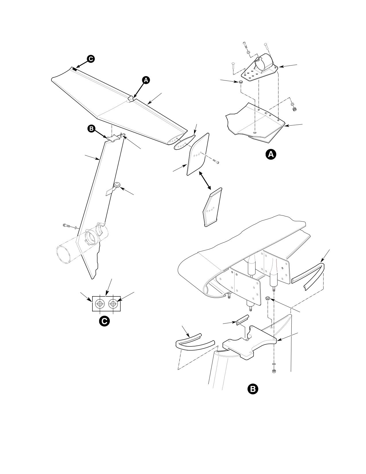
(1). Remove four screws securing tip plate
and tip weight (if applicable, right and
(Ref. Figure 201) The tail surfaces (empen
left tip plates and/or tip weights are
nage) stabilize the helicopter and maintain it
interchangeable) to horizontal stabiliz
in a relatively level attitude during high speed
er.
forward flight. The tail surfaces consist of a
vertical and horizontal stabilizer attached to
(2). Remove nuts and washers securing
the aft end of the tailboom.
horizontal stabilizer to vertical stabiliz
er fitting.
The horizontal stabilizer mounts atop of the
vertical stabilizer in a T-shaped arrangement.
(3). Disconnect position light electrical
Tip plates are attached to ends of the horizon
connection and bond jumper.
tal stabilizer with a steel tip weight between
each tip plate and the stabilizer. The horizon
NOTE: MDHI Notice DN-63 contains informa
tal stabilizer is constructed of aluminum alloy
tion relative to adding drain holes and seal
skins riveted to formed ribs and spars.
ing doubler edges on some 369D helicopters.
MDHI Notice DN-44.1 contains informa
The vertical stabilizer is constructed of
tion relative to replacement of trailing edge
aluminum alloy skins bonded to formed spars.
tabs, relocation of static pressure tube and
adding doublers to some 369D helicopters.
The vertical stabilizer includes fittings,
honeycomb core, and non-structural leading
(4). Inspect horizontal tip plates and
and trailing edges. The tip plates are con
stabilizer (Ref. Horizontal Stabilizer
structed of aluminum alloy skins bonded over
and Tip Plate Inspection).
a honeycomb core. The vertical stabilizer is
mounted aft right of the tail boom and is
B. Horizontal Stabilizer and Tip Plate
bolted to the gearbox and stabilizer mount
Installation
frame and a upper and lower mount fitting.
The vertical stabilizer fitting supports the
Consumable Materials
horizontal stabilizer. The lower end of the
(Ref. Section 91−00−00)
vertical stabilizer incorporates a tail skid
Item
Nomenclature
assembly.
CM425
Sealing compound
Lighting provisions are provided on both
vertical and horizontal stabilizers. (Ref. Sec.
(1). Support helicopter at rear jackpoint
96-40 contains information on exterior lights.)
(Ref. Sec. 07-00-00) when installing
A. Stabilizer Troubleshooting
horizontal stabilizer to ensure that
helicopter angle of incidence does not
(Ref. Table 201)
change during measurements.
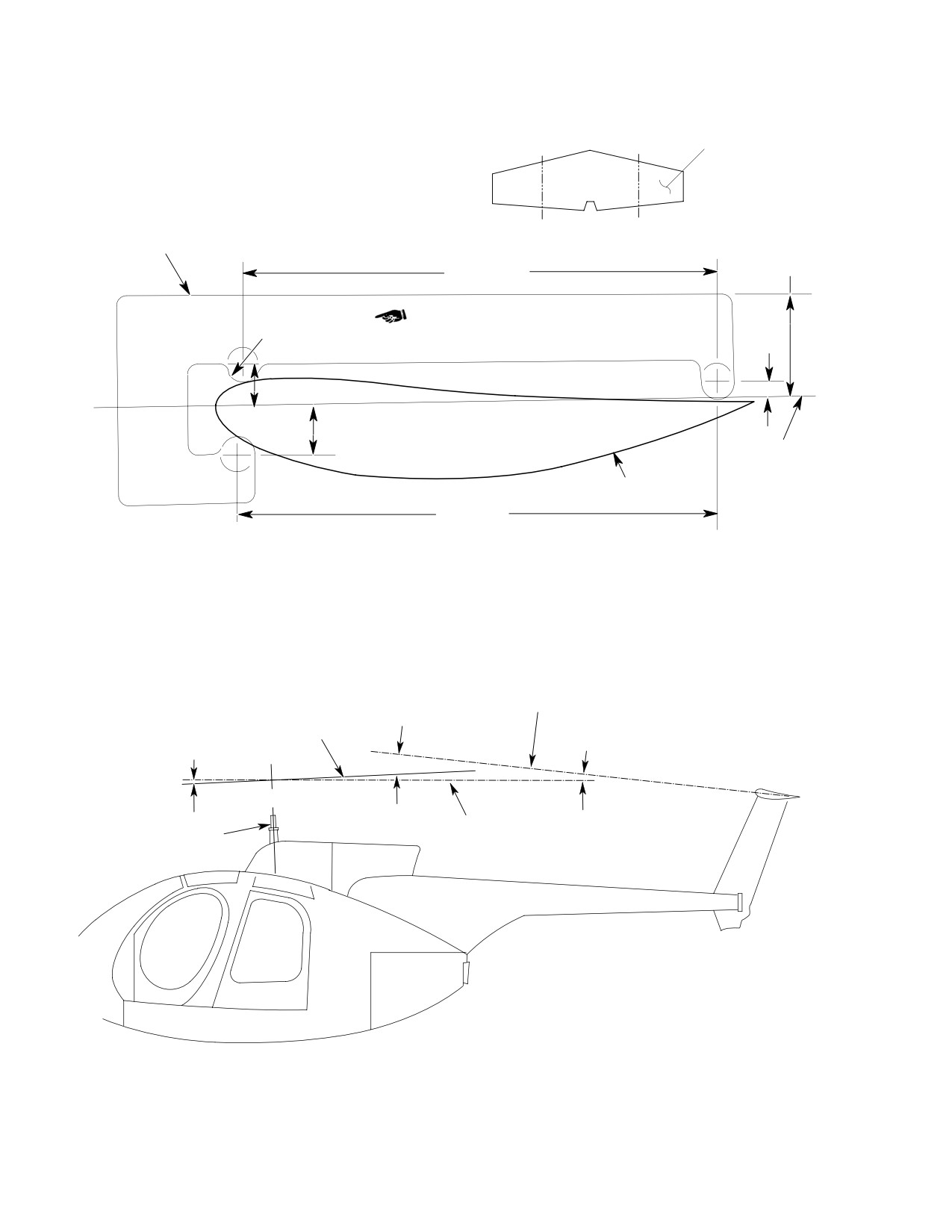
(2). Measure inclination angle of horizontal
2. Horizontal Stabilizer and Tip Plate
stabilizer at B.L. 10.66 inches (27.076
Replacement
cm) to right (S RIGHT) and left (S
A. Horizontal Stabilizer and Tip Plate
LEFT) of horizontal stabilizer center
Removal
line (Ref. Figure 202). If angles S
RIGHT and S LEFT differ by more than
(Ref. Figure 201)
one degree, replace horizontal stabiliz
er.
NOTE: Tip weights are installed at manufac
turing and are only required to reduce T-
(3). For aircraft 0003D - 0286D (Ref.
Tail vibration.
Figure 204);
Page 201
53-50-10
Revision 19
CSP-HMI-2
MD Helicopters, Inc.
MAINTENANCE MANUAL
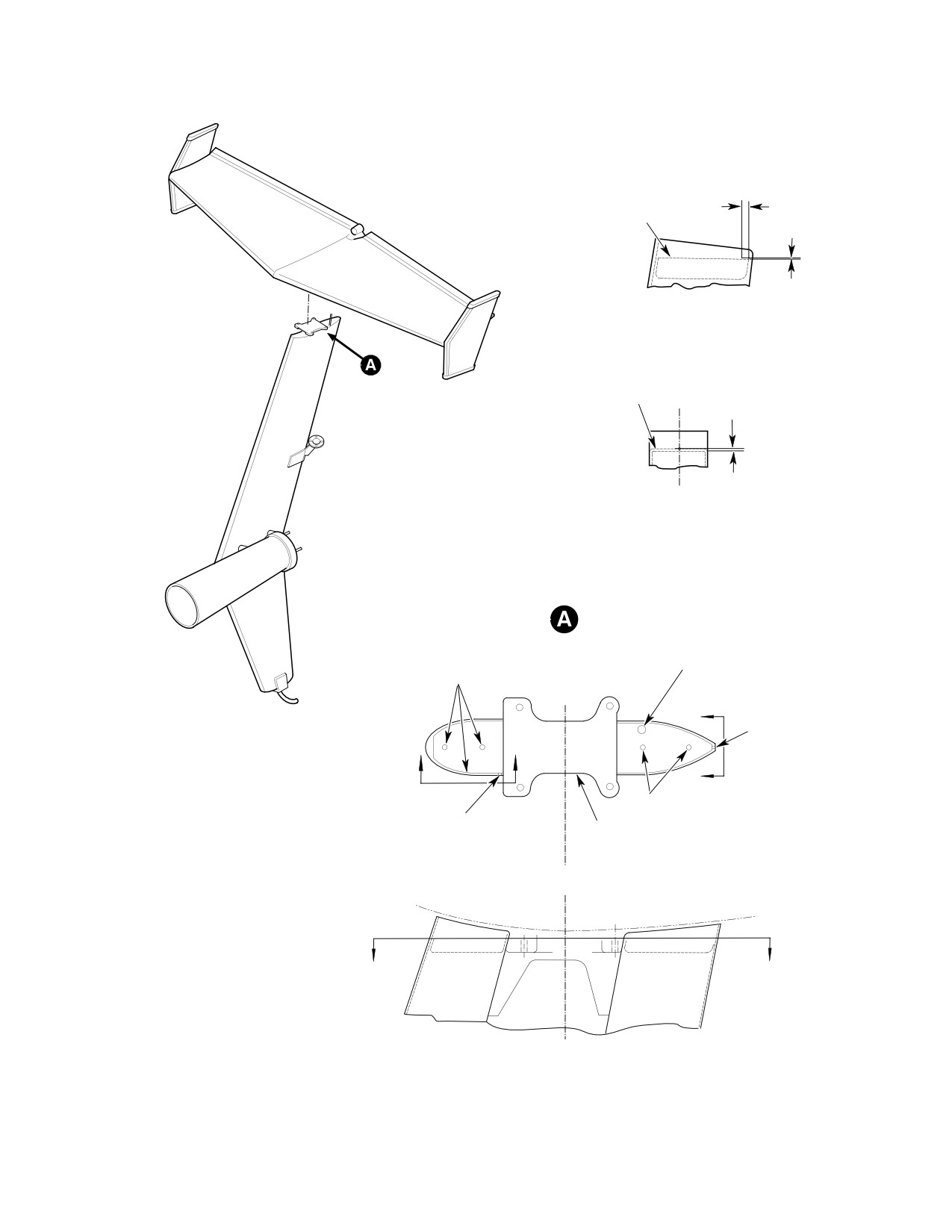
(a). Apply a 0.030 - 0.040 inch (0.762 -
(2). Torque bolts 190 - 220 inch-pounds
1.016 mm) bead of sealant (CM425)
(21.47 - 24.86 Nm); then lockwire bolts
around perimeter of top rib assem
in pairs.
blies and at attach fitting.
(3). Connect anti-collision light electrical
NOTE: Do not seal drain holes.
connection.
(b). Apply sealant around electrical
(4). Install horizontal stabilizer, refer to
conduit and seal over tooling holes.
(Ref. Horizontal Stabilizer and Tip
(4). Position horizontal stabilizer on vertical
Plate Installation).
stabilizer fitting (Ref. Figure 201).
4. Horizontal Stabilizer and Tip Plate
(5). Connect position light electrical
Inspection
connection and bond jumper.
(1).
Inspect metal skin for holes, cracks,
(6). Install nuts and washers. Torque nuts
loose rivets or corrosion. Any crack is to
to 90 - 110 inch-pounds (10.17 -
be stop drilled or patched.
12.43 Nm).
(2).
Inspect attach fittings and light
(7). Check angle of incidence (Ref. Angle of
mounting bracket for cracks, loose
Incidence Measurement).
rivets or corrosion.
(8). Install tip plates with tip weight
between tip plate and horizontal
(3).
Inspect attach studs and mating holes
stabilizer, using four screws.
for evidence of wear caused by loose
ness in service. Inspect questionable
(9). Remove support from rear jackpoint.
studs by dye-penetrant or magnetic
particle method, as applicable.
3. Vertical Stabilizer Replacement
(4).
Inspect drain holes on lower surface.
A. Vertical Stabilizer Removal
Ensure they are not blocked or clogged
(Ref. Figure 201)
with debris.
(1). Remove horizontal stabilizer (Ref.
(5).
Inspect seal around upper and lower
Horizontal Stabilizer and Tip Plates
doublers. Ensure all gaps/edges
Removal).
between doublers and stabilizer skin
are sealed.
(2). Disconnect anti-collision light electrical
connection.
(6).
Repair horizontal stabilizer and tip
(3). Remove bolts and washers securing
plates (Ref. Horizontal Stabilizer and
stabilizer to tailboom.
Tip Plates Repair).
(4). Inspect vertical stabilizer (Ref. Vertical
5. Vertical Stabilizer Inspection
Stabilizer Inspection).
(1). Inspect skin for holes, cracks, bonding
B. Vertical Stabilizer Installation
separation or corrosion.
(Ref. Figure 201)
(2). Inspect attach fitting for cracks, loose
rivets or corrosion.
Consumable Materials
(Ref. Section 91−00−00)
(3). Inspect tail skid for cracks, deformation
Item
Nomenclature
and loose or missing rivets.
CM109
Molybdenum disulfide powder lubricant
(4). Inspect anti-collision light bracket for
cracks, loose rivets or screws and
(1). Align stabilizer with mounting holes on
corrosion.
the tailboom fitting. Spray bolt threads
with lubricant (CM109) and install.
(5). Check condition of grommets.
Page 202
Revision 19
53-50-10
MD Helicopters, Inc.
CSP-HMI-2
MAINTENANCE MANUAL
POSITION LIGHT
BRACKET
GROMMET
HORIZONTAL
STABILIZER
TIP WEIGHT
(NOTE 1)
HORIZONTAL
STABILIZER
VERTICAL
ELECTRICAL
STABILIZER
LEAD
POSITION LIGHT
BRACKET - ATTACHMENT
TIP PLATE
ANTI-COLLISION
LIGHT SUPPORT
SEAL
0.1 X 0.75 X 2.0 INCH
(2.54 X 19.05 X 50.8 MM)
1 OZ (28.35 G)
MS20470AD4 RIVET
LEAD WEIGHT
(2 REQD)
(NOTES 2, 3, 4)
HS306-318 WASHER
(2 REQD) (NOTE 3)
GROMMET
FORWARD
SEAL
SEAL
VERTICAL
HORIZONTAL STABILIZER TAB
STABILIZER
WEIGHT INSTALLATION
FITTING
(421-087-505 STABILIZER ONLY)
NOTE:
1.
TIP WEIGHTS ARE INSTALLED AT MANUFACTURING AND
ARE ONLY REQUIRED TO REDUCE T-TAIL VIBRATION.
2.
COMMERCIAL 1 OZ (28.35 G). LEAD AUTOMOBILE
ALLOY WHEEL BALANCE WEIGHT.
3.
INSTALL WEIGHT, RIVETS AND WASHERS WITH PRIMER
HORIZONTAL STABILIZER/VERTICAL
STABILIZER - ATTACHMENT
4.
SEAL EDGES WITH SEALANT AFTER INSTALLATION.
G53-5000B
Figure 201. Stabilizer T−Tail Removal and Installation
Page 203
53-50-10
Revision 22

CSP-HMI-2
MD Helicopters, Inc.
MAINTENANCE MANUAL
(6). Check mount holes for elongation.
Special Tools
(7). For repair (Ref. Vertical Stabilizer
(Ref. Section 91−00−00)
Repair).
Item
Nomenclature
ST2014
Angle measuring tool
6. Horizontal Stabilizer and Tip Plate Repair
Consumable Materials
Table 201. Horizontal Stabilizer Angle of
(Ref. Section 91−00−00)
Incidence
Item
Nomenclature
Angle
Model
CM220
Naphtha aliphatic
8° 55’ − 9° 25’
369D
CM425
Sealing compound
8° 55’ − 9° 25’
369E
7° 30’ − 8° 00’
369FF
(1). Seal gaps/edges between doublers and
NOTE: It is not necessary to level helicopter
stabilizer skin with sealant (CM425).
when establishing horizontal stabilizer
Remove excess sealant with naphtha
angle of incidence.
(CM220).
D If the mast is tilted forward of 0°, add “H”
(2). Repaint sealed areas.
to “S”.
(3). Make other horizontal stabilizer repairs
D If the mast is tilted aft of 0°, subtract “H”
according to applicable instructions in
from “S”.
Structural Repair Manual.
(1).
Remove hub fairing from main rotor
NOTE: Support helicopter at rear jackpoint
hub assembly.
when installing horizontal stabilizer.
(2).
Measure incidence angle of horizontal
(4). Install horizontal stabilizer (Ref.
stabilizer (Ref. Figure 202) using angle
Horizontal Stabilizer and Tip Plate
measurement tool (ST2014) at B.L.
Installation).
10.66 inches (27.076 cm) to right (S
RIGHT) and left (S LEFT) of horizontal
7. Vertical Stabilizer Repair
stabilizer centerline. If angles S RIGHT
and S LEFT differ by more than one
degree, replace horizontal stabilizer.
Consumable Materials
(Ref. Section 91−00−00)
(3).
Measure inclination of top of main rotor
Item
Nomenclature
hub (Ref. Figure 203). Record as angle
CM418
Cement, epoxy
H.
(4).
Compute average of angles S RIGHT
and S LEFT. Record results as angle S.
(1). For allowable repairs and additional
inspection criteria, Ref. Structural
(5).
(D/E Only) Determine incidence of
Repair Manual.
stabilizer by adding angles H and S. If
H plus S is between 8 degrees 55
(2). Replace damaged or worn seals; bond
minutes and 9 degrees 25 minutes,
replacement seal with cement (CM418).
angle of incidence is correct.
(3). Replace damaged, worn or missing
(6).
(FF Only) Determine incidence of
grommets.
stabilizer by adding angles H and S. If
(4). Install vertical stabilizer (Ref. Vertical
H plus S is between 7 degrees 30
Stabilizer Installation).
minutes and 8 degrees 00 minutes,
angle of incidence is correct.
8. Angle of Incidence Measurement
(7).
If angle of incidence is not acceptable
(Ref. Figure 202 and Figure 203)
(Ref. Angle of Incidence Adjustment).
Page 204
Revision 37
53-50-10

MD Helicopters, Inc.
CSP-HMI-2
MAINTENANCE MANUAL
(8). Install hub fairing onto main rotor hub
(1). Temporarily apply one ounce tab weight
assembly.
to upper right trailing edge of the right
tab using tape.
9. Angle of Incidence Adjustment
(2). Locate weight spanwise to the point of
(1). Remove bolts and washers attaching
observed maximum amplitude vibra
horizontal stabilizer to vertical stabiliz
tion.
er fitting.
NOTE: Tab weight can be made from commer
Do not add more than two wash
cial automobile alloy wheel balance weight
CAUTION
ers under each boss.
(0.100 x 0.75 x 2.00 inch).
(2). Lift horizontal stabilizer and add equal
(3). Run engine at 102% - 105% N2 and
number of AN960PD416L washers
observe horizontal stabilizer tab,
under each of two front, or each of two
weight may be moved inboard or
rear bosses.
outboard on tab depending on response.
(3). Install horizontal stabilizer with
(4). If needed, a one ounce weight may also
washers and bolts.
be installed on left tab.
(4). Torque bolts to 90 - 110 inch-pounds
(5). A maximum of two ounces may be
(10.17 - 12.43 Nm).
installed on each tab.
(5). Repeat angle of incidence measurement
(6). Once correct position and amount of
(Ref. Angle of Incidence Measurement).
weight has been established, install
weight(s) as follows:
10. Horizontal Stabilizer Tab Weight
Installation
(a). Cleco weight in place on stabilizer.
(b). Drill two #31 holes through each
Consumable Materials
weight and stabilizer.
(Ref. Section 91−00−00)
Item
Nomenclature
(c). Remove weight and deburr holes;
CM318
Primer
touch up stabilizer holes with primer
CM425
Sealing compound
(CM318).
(d). Install weight, rivets and washers
(Ref. Figure 201) Installation of tab weight is
with wet primer.
optional on the 421-087 -505 horizontal
stabilizer if difficulty in tail rotor balance and
(e). Seal mating edges of weight with
horizontal stabilizer tab resonance vibration is
sealing compound (CM425).
encountered (Ref. Sec. 18-20-00, Horizontal
Stabilizer Tuning).
(7). Touch up with paint to match.
Table 202. Troubleshooting Tailboom and Tail Surfaces
Symptom
Probable Trouble
Corrective Action
High frequency vibration.
Loose vertical stabilizer.
Retorque bolts to 190 − 220
inch−pounds (21.47 − 24.86 Nm).
NOTE: High frequency vibrations in
Loose horizontal stabilizer.
Retorque nuts to 90 − 110
helicopter can be caused by
inch−pounds (10.17 - 12.43 Nm).
components in other systems (Ref.
Chap. 63, 64 and 71).
Check angle of incidence, (Ref. Angle
of Incidence Measurement).
Page 205
53-50-10
Revision 37
CSP-HMI-2
MD Helicopters, Inc.
MAINTENANCE MANUAL
S LEFT
S RIGHT
HORIZONTAL
STABILIZER
B.L. 10.66 INCH
B.L. 10.66 INCH
(27.076 CM)
(27.076 CM)
NOTE
2.030 INCH
13.850 INCH
(5.1562 CM)
(35.179 CM)
0.50 INCH (12.7 MM)
0.50 INCH
RADIUS (3 PLACES)
(12.7 MM)
1.090 INCH (2.769 CM)
1.575 INCH (4.0005 CM)
CHORD PLANE
OML SKIN AT
14.015 INCH
STABILIZER STA. 10.66
(35.598 CM)
NOTE:
TOOL FUNCTION - TO CHECK STABILIZER INCIDENCE.
G53-5001B
Figure 202. Horizontal Stabilizer Incidence Angle Measuring Tool
HORIZONTAL STAB.
STAB. INCIDENCE
CHORD PLANE
TOP OF M/R
ANGLE ``I''
AVERAGE STAB. INCLINATION
HUB PLANE
ANGLE ``S'' AVERAGE
HUB INCLINATION ANGLE ``H''
C
L
GROUND LEVEL PLANE
MAST
G53-5002
Figure 203. Establishing Horizontal Stabilizer Angle of Incidence
Page 206
Revision 40
53-50-10
MD Helicopters, Inc.
CSP-HMI-2
MAINTENANCE MANUAL
TOP OF RIB
0.250 INCH
369D23608
(6.35 MM)
-0.000
0.030 INCH
+0.010
(-0.000)
(0.762 MM)
B-B
(+0.254)
VIEW
TOP OF RIB
369D23609
C
L
-0.000
0.030 INCH
+0.010
(-0.000)
(0.762 MM)
VIEWC-C
(+0.254)
SEALANT TO BE APPLIED
AROUND ELECTRICAL
SEALANT (NON-HARDENING), EDGES AND
CONDUIT
TOOLING HOLES, EXCEPT DRAIN HOLES RTV
DRAIN HOLE 0.60 INCH
C
(1.524 MM) DIAMETER
THRU SEALANT SHOULD
B
B
NOT COVER DRAIN HOLE
C
TOOLING HOLES
DRAIN HOLE 0.60 INCH (1.524 MM)
369D23600 VERTICAL
DIAMETER THRU SEALANT SHOULD
STABILIZER ASSEMBLY
NOT COVER DRAIN HOLE
VIEWA-A
A
A
Figure 204. Sealing − Vertical Stabilizer (0003D − 0286D)
Page 207
53-50-10
Revision 19
CSP-HMI-2
MD Helicopters, Inc.
MAINTENANCE MANUAL
This Page Intentionally Left Blank
Page 208
Revision 44
53-50-10
MD Helicopters, Inc.
CSP-HMI-2
MAINTENANCE MANUAL
Section
53−50−30
Stabilizer (500/600N)
MD Helicopters, Inc.
CSP-HMI-2
MAINTENANCE MANUAL
STABILIZER
MAINTENANCE PRACTICES
1. Stabilizers Description
a hollow core spar, retainer fittings and
nonstructural leading and trailing edges.
The tail surfaces consist of two verticals and a
horizontal stabilizer. The tail surfaces (empen
The differences on the 600N are that the
nage) stabilize the helicopter and maintain it
vertical stabilizers are slightly longer, the skin
in a relatively contain level attitude and
is thicker and on standard 600N helicopters,
heading during autorotation and forward
are both controlled by the directional control
flight.
pedals. The lower vertical stabilizer angle of
attack is eight degrees clockwise relative to the
A. Horizontal Stabilizer Description
upper vertical stabilizer. Refer to Section
67-20-30 for flight controls linkage details.
The horizontal stabilizer is constructed of
laminated fiber glass composite ribs and skin,
The left vertical stabilizer is mounted to the
bonded to a formed graphite composite spar.
horizontal on a torque tube fitting assembly
The horizontal stabilizer includes a non-struc
and has approximately 6.5 inches (16.51 cm) of
tural leading and trailing edges. hollow core
travel.
spar, sparbox fittings, access panels, torque
On the 500N and S.A.S. equipped 600N, the
tubes, bellcranks and control rods.
right vertical stabilizer, also mounted on a
On the 500N and optional on the 600N, a
torque tube, is controlled by the stability
stability augmentation system (S.A.S.) is
augmentation system. From the fully extended
attached to the right-hand vertical stabilizer,
to the fully retracted position on the S.A.S.
the early 600N does not have a S.A.S system.
actuator, the tip of the right vertical stabilizer
trailing edge will travel a minimum of 2.70
The horizontal stabilizer mounts atop the
inches (6.86 cm). The amount of travel is
tailboom. Four eye bolts from the horizontal
determine by the S.A.S. computer and gyro.
attach to clevis attachment points on the
NOTE: The anti-torque control system must be
tailboom. Access plates are attached to the
re-rigged immediately after removal or re
ends caps of the horizontal stabilizer and at
placement of control rods, linkages, and
center line for access to the control rods, S.A.S.
components or if helicopter operation re
and bellcranks. Two control rods, S.A.S. and
veals a rigging deficiency.
bellcranks are routed in the center aft of the
sparbox. The angle of incidence of the horizon
2. Vertical Stabilizer Replacement
tal stabilizer is preset at -2°. An anti-collision
light is mounted in the top center of the
(Ref. Figure 201, Figure 202)
stabilizer. Position lighting provisions are
provided on both ends of the stabilizers.
A. Vertical Upper and Lower Stabilizer
Removal
On the 600N without S.A.S., gurney flaps were
(1). Remove nuts, washers, and bolts.
added to the trailing edge of the horizontal for
Remove by lifting vertical stabilizer off
the purpose of increasing lift without increas
torque tube.
ing the stabilizer area or weight.
B. Vertical Upper and Lower Stabilizer
Refer to Section 96-40-00 for information on
Installation
exterior lights and Section 67-20-30 for
rigging requirements.
(1). Installation with Standard Hardware:
B. Vertical Stabilizers Description
Do not over-torque nut. Over-
CAUTION
torquing nut can crack vertical
The vertical stabilizers (upper and lower) are
stabilizer fitting.
constructed of laminated fiber glass composite
ribs and skin, bonded to a formed fiberglass
(a). Install stabilizer onto torque tube
composite spar. The vertical stabilizers include
fittings.
Page 201
53-50-30
Revision 42
CSP-HMI-2
MD Helicopters, Inc.
MAINTENANCE MANUAL
(b). Install bolts, washers and nuts.
NOTE: Horizontal stabilizer can be removed
Torque to 30 - 40 inch-pounds
with vertical stabilizers installed. Support
(3.39 - 4.52 Nm) plus drag torque.
stabilizer during removal.
(2). Installation with Expandable Bolts:
A. Horizontal Stabilizer Removal
(1). Remove seven screws securing center
Do not over-torque nut. Over-
CAUTION
access plate to horizontal stabilizer.
torquing nut can crack vertical
stabilizer fitting.
(2). Disconnect position light electrical
interconnect.
(a). Install bolt with washer under bolt
head and thick washer under nut.
(3). On 500N, disconnect S.A.S. electrical
interconnect.
NOTE:
(4). Remove cotter pin, nut, washer and bolt
D Do not remove any expanding elements
from center bellcrank shaft. Index mark
from bolt.
bellcrank with grease pencil in relation
D If 600N2012-5 spacers are not present,
ship to shaft. Disconnect bellcrank.
up to two spacers may be added to achieve
(5). Remove nuts, washers and expandable
proper installation.
bolts securing horizontal stabilizer to
(b). Remove one (1) or two (2)
tailboom attachment clevis fittings.
600N2012-5 spacers, as required) to
Remove horizontal stabilizer.
obtain 0.005-0.035 inch (0.127-0.889
B. Horizontal Stabilizer Installation
mm) gap between the washers and
the vertical stabilizer, equal on each
NOTE: When installing horizontal stabilizer it
side.
may be necessary to loosen eye bolts and
nuts to align with clevises, if so, install
(c). Install nut and note drag torque.
mounting expandable bolts first and torque
per step (2). below, then torque clevis nuts to
(d). Perform a break in cycle by torquing
80 - 120 inch-pounds (9.04 - 13.56 Nm).
the nut to 20 - 25 inch-pounds
(2.26 - 2.82 Nm) plus drag torque.
(1). Position horizontal stabilizer on
tailboom attach fittings.
(e). Back off nut until bolt moves freely
in hole.
(2). Install expandable bolts, washers and
nut. Torque to 30 - 40 inch-pounds
(f). Torque nut to 20 inch-pounds (2.26
(3.39 - 4.52 Nm). Install cotter pin.
Nm) plus drag torque.
(3). Connect position light/strobe light
(g). Check for equal gap of 0.005-0.035
electrical connector.
inch (0.127-0.889 mm) between the
(4). On 500N, connect S.A.S. electrical
washers and the vertical stabilizer.
interconnect.
NOTE: NAS1149C0332R or NAS1149C0363R
When installing bellcrank on
washers may be added under the nut for ad
CAUTION
center bellcrank shaft it is possi
equate cotter pin engagement.
ble to be one spline tooth off in either direc
tion, install bellcrank centered on shaft
(h). If necessary, tighten nut until cotter
(Ref. Sec. 67-20 -30).
pin hole aligns with castillation in
nut.
(5). Connect bellcrank to center bellcrank
shaft and install bolt, washers and nut.
(i). Install cotter pin.
Torque nut to 30 - 40 inch-pounds
(3.39 - 4.52 Nm) and install cotter pin.
3. Horizontal Stabilizer Replacement
(6). Install center access plate with seven
(Ref. Figure 201 and Figure 202)
screws and washers.
Page 202
Revision 42
53-50-30
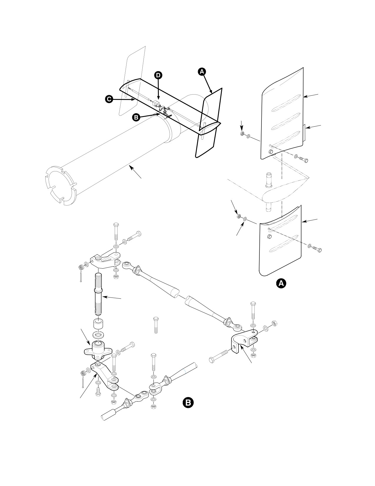
MD Helicopters, Inc.
CSP-HMI-2
MAINTENANCE MANUAL
VERTICAL
STABILIZER
(UPPER)
NUT
(NOTE 2)
TRIM TAB
(NOTE 1)
500N TAILBOOM
SHOWN
NUT
(NOTE 2)
VERTICAL
STABILIZER
(LOWER)
WASHER
WASHER
BOLT
CENTER
BELLCRANK
SHAFT
TORQUE TUBE
HOUSING
NOTE 4
HORIZONTAL STABILIZER
BELLCRANK
CENTER BELLCRANK SHAFT
Figure 201. Stabilizer Installation with YSAS (Sheet 1 of 2)
Page 203
53-50-30
Revision 33
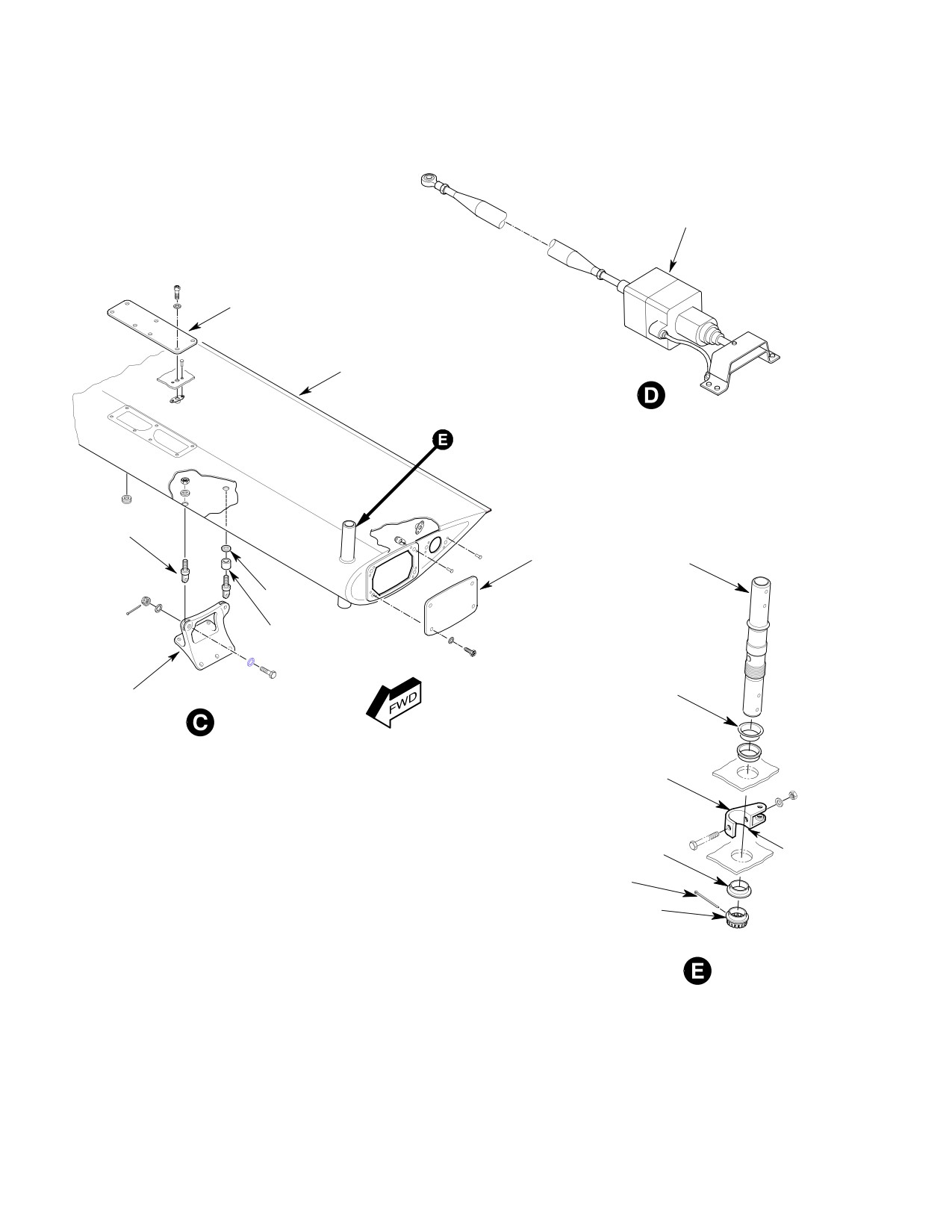
CSP-HMI-2
MD Helicopters, Inc.
MAINTENANCE MANUAL
YSAS ACTUATOR
(500N, AND 600N WITH YSAS)
CENTER ACCESS
PLATE
HORIZONTAL
STABILIZER
END TIP
EYEBOLT
ACCESS
COVER
TORQUE
TUBE
WASHER
SPACER
(NOTE 3)
TAILBOOM
BEARING RACE
ATTACH
FITTING
BELLCRANK
BUSHING
NOTE 4
COTTER PIN
NUT
NOTES:
1.
TYPICAL LEFT AND RIGHT STABILIZERS (500/600N).
2.
TORQUE 30 - 40 INCH-POUNDS (3.39 - 4.52 NM) PLUS DRAG TORQUE.
3.
SPACERS INSTALLED ON AFT BOSS ONLY.
4.
OPENING IN BELLCRANK ALWAYS FACES OUTBOARD (LH AND RH SIDES).
G53-5003-2F
Figure 201. Stabilizer Installation with YSAS (Sheet 2 of 2)
Page 204
Revision 33
53-50-30
MD Helicopters, Inc.
CSP-HMI-2
MAINTENANCE MANUAL
4. Horizontal Stabilizer Eye Bolt
(2). Install control tubes and bellcranks as
Replacement
required, safety wire or cotter pin.
A. Horizontal Stabilizer Eye Bolt Removal
(3). Install center access plate with seven
screws and washers.
(1). Remove horizontal stabilizer.
6. Vertical Stabilizer Inspection
(2). Remove eye bolts by holding the flat
(Ref. Figure 201 and Figure 202)
surface of eye bolt with a wrench and
removing nut.
(1). Inspect skin for cracks, bonding
separation, delamanation and obvious
B. Horizontal Stabilizer Eye Bolt Installation
damage.
(1). Install eye bolts in horizontal stabilizer,
(2). Inspect stabilizer for freedom of
the short eye bolts in the forward holes
movement through pedal travel range,
and the longer eye bolts with spacer to
check for clearance between vertical to
the aft holes of horizontal stabilizer.
horizontal.
(2). Torque eye bolts to 80 - 120 inch-
(3). Check mounting fitting holes for
pounds (9.04 - 13.56 Nm) plus drag
elongation.
torque.
NOTE: Internal stabilizer fitting may display
cracking after installation of expandable
(3). Install horizontal stabilizer.
bolts. This cracking, internal fitting only, is
acceptable for continued service. Cracking
5. Horizontal/Vertical Stabilizer Control Tube
of the external skin from the mounting bolt
and Bellcrank Replacement
holes is unacceptable and stabilizer must be
removed from service and scrapped.
(Ref. Figure 201 and Figure 202)
7. Vertical Stabilizer Repair
A. Horizontal/Vertical Stabilizer Control Tube
and Bellcrank Removal
Refer to MDHI Field Service Representative.
(1). Remove horizontal stabilizer end tip
8. Horizontal Stabilizer Inspection
covers and center access cover for
access to bellcranks and control tubes.
(1). Inspect skin for cracks, bonding
separation, delamination and obvious
(2). Remove cotter pin, nut, washer and bolt
damage.
from center bellcrank shaft. Index mark
(2). Inspect mounting fitting and attach
bellcrank with grease pencil in relation
ship to shaft. Disconnect bellcrank.
ment hardware for condition.
(3). Inspect center access panel and nut
(3). Disconnect control tube from vertical
plate fasteners for condition, end tip
stabilizer torque tube bellcrank.
plate access covers and position lights
Remove controls from horizontal
for condition.
stabilizer as required for maintenance.
(4). Inspect vertical stabilizer torques tubes
B. Horizontal/Vertical Stabilizer Control Tube
for excessive axial and radial move
and Bellcrank Installation
ment, 0.010 inch (0.254 mm) axial end
play maximum allowable.
Refer to adjustment and test control rigging
during installation.
(5). Inspect torque tube bushings for wear
and security.
(1). Connect bellcrank to center bellcrank
shaft and install bolt, washers and nut.
(6). If the bushings are not bonded to the
Torque bolt to standard aircraft torque
horizontal stabilizer, rework Vertical
values and install cotter pin.
Stabilizer Torque Tube Bushings.
Page 205
53-50-30
Revision 40