HANDBOOK OF MAINTENANCE INSTRUCTIONS FOR MDHI 369D/E/FF-500/600N HELICOPTERS (ISSUED: 1990) - page 15
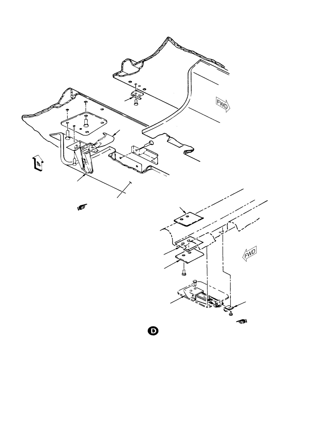
CSP-HMI-2
MD Helicopters, Inc.
MAINTENANCE MANUAL
CATCH
HOOK
LEVER
C30/C47 FAIRING
RETAINER
ABRASION
STRIP
RETAINER
CATCH
LEVER
C20/C20R2 FAIRING
AFT LOWER LOCKING ASSEMBLY
G52−4000−2A
Figure 201. Engine Access Doors (Sheet 2 of 3)
Page 204
Revision 18
52-40-00
MD Helicopters, Inc.
CSP-HMI-2
MAINTENANCE MANUAL
FUSELAGE STRUCTURE
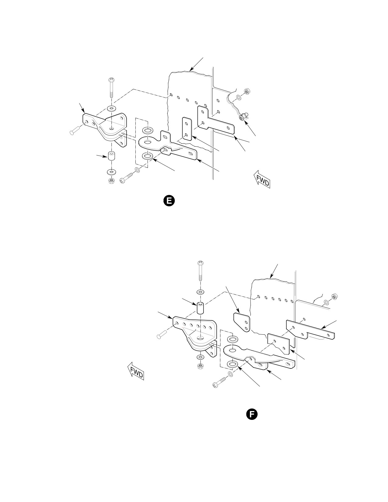
FORWARD HALF
RIVNUT
STEEL SPACER
PLATE
SHIM
NYLON WASHERS
AFT HALF
LOWER HINGE
FUSELAGE STRUCTURE
SHIM
STEEL SPACER
FORWARD HALF
SHIM
PLATE
AFT HALF
NYLON WASHERS
UPPER HINGE
Figure 201. Engine Access Doors (Sheet 3 of 3)
Page 205
52-40-00
Revision 18
CSP-HMI-2
MD Helicopters, Inc.
MAINTENANCE MANUAL
This Page Intentionally Left Blank
Page 206
Revision 44
52-40-00
MD Helicopters, Inc.
CSP-HMI-2
MAINTENANCE MANUAL
Section
52−50−00
Miscellaneous
Access Doors
MD Helicopters, Inc.
CSP-HMI-2
MAINTENANCE MANUAL
MISCELLANEOUS ACCESS DOORS
MAINTENANCE PRACTICES
1. Access and Inspection Provisions
(3). Inspect doors for corrosion, distortion,
breaks and cracks.
Any time maintenance work is
CAUTION
to be performed near engine air
3. Pilot Compartment Floor Access Doors
and engine cooling air inlets, use care to pre
vent entry of foreign objects that might later
Each of the two pilot's compartment floor
be sucked into compressor or cooling air
access doors are formed by two hinged panels,
blower. Tape covers of cardboard or other
hinged at the forward edge to the pilot's
suitable material in place over engine cool
compartment floor.
ing air screens. Covers should not be re
moved until work is completed and debris is
A latch at the rear, secures each door in place.
thoroughly cleaned out of the area.
Two stainless steel heel strips are hinged and
held in place over each door by a spring.
Removable access doors and covers are
provided in the helicopter for servicing,
NOTE: Remove heel strips for better access.
inspection, removal, installation and adjust
Detach springs from clips on underside of
ment of components.
strips. Remove hinge pins attaching forward
ends of strips to natatorium pedal mounting
Locations of access and inspections provisions
bracket.
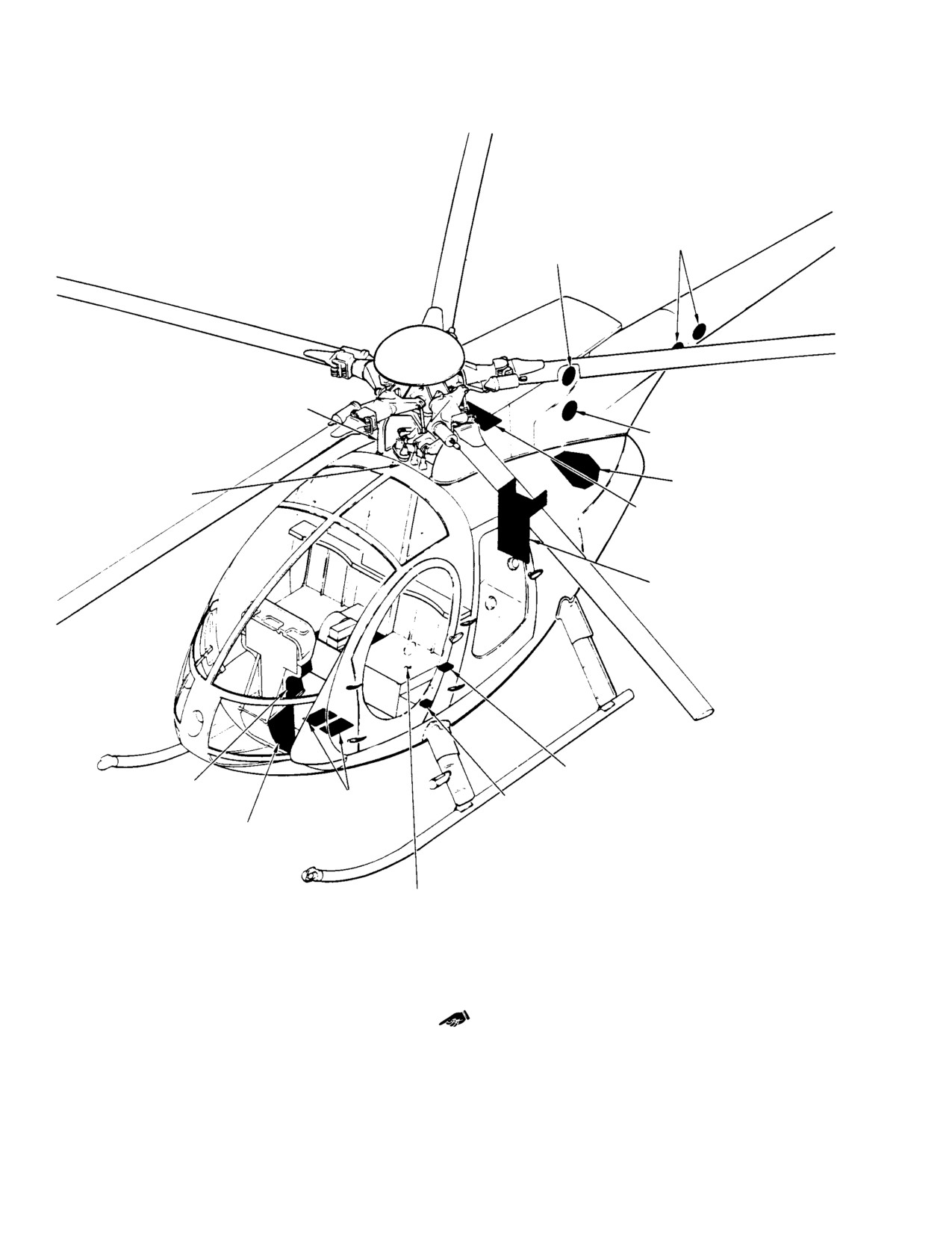
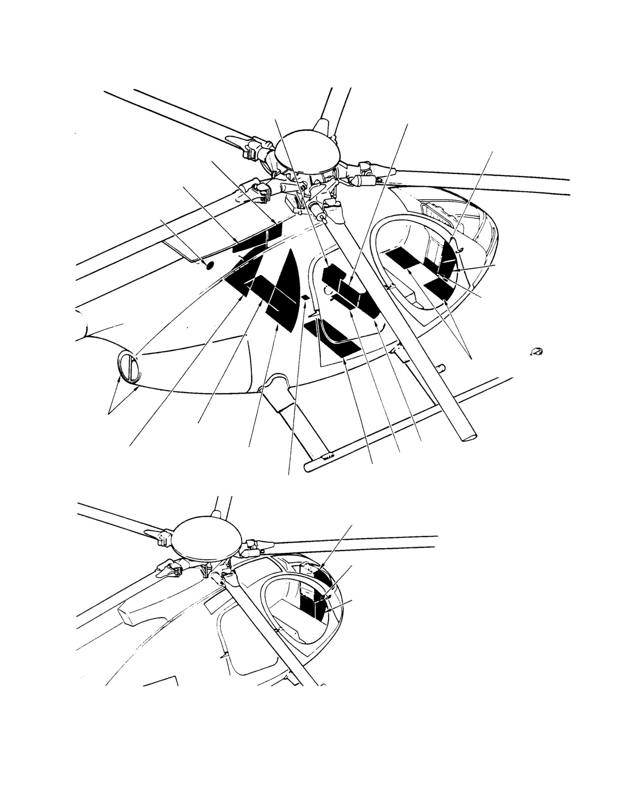
are shown in Figure 201 for 369D/E/FF,
Figure 202 for 500N and Figure 203 for 600N
4. Pilot Compartment Floor Access Door
helicopters.
Replacement
Areas, components and items accessible
A. Pilot Compartment Floor Access Door
through locations shown in the figures are in
Removal
Table 201. Screws are used to secure access
doors in stress areas.
(1). Remove floor access doors by releasing
latch at rear of door.
Liquid level sight gages allow inspection of
lubricant levels for main transmission, engine
(2). Raise and hold up rear of heel strips for
oil tank and tail rotor transmission (369
access to hinge pins at forward end of
D/E/FF) or fan transmission (500/600N).
door.
Methods for removal and installation are
(3). Remove hinge pin securing forward
obvious for most doors and covers.
edge of door to pilot's compartment floor
and remove door.
For information on access doors and covers
that are also used for interior trim, Refer to
B. Pilot Compartment Floor Access Door
Sections 25-30-00 and 25-40-00.
Installation
2. General Access Doors Inspection
(1). Position door and secure forward edge
(1). Check door hinges, door-attaching
to floor using hinge pin.
hardware and latches for looseness,
(2). If removed, heel strips are reinstalled
cracks and damage.
by inserting hinge pins through
(2). Check outside edge of door for security
brackets on forward end of strip and
of bonding between outer and inner
anti-torque pedal mounting bracket
skin. Any separation requires repair,
and connecting springs to clips on
refer to Structural Repair Manual.
underside of heel strips.
Page 201
52-50-00
Revision 18
CSP-HMI-2
MD Helicopters, Inc.
MAINTENANCE MANUAL
Table 201. Access and Inspection Provisions Information
Door, Cover or Access Provision
Provides Access To
Air inlet forward fairings
Main rotor mixer controls, main rotor mast base and supporting
structure.
Collective stick cover
Aft end of collective stick and associated electrical wiring.
Wiring cover
Electrical wiring at seat structure and auxiliary power receptacle.
Pilot’s seat cover or inboard collective
Underseat controls for engine and flight control systems.
pitch stick cover
Plenum chamber access door (air inlet
Interior of engine air inlet aft fairing.
bypass door)
Tail rotor drive shaft access door
Tail rotor drive shaft and interior of air inlet forward fairing.
Pilot’s compartment floor access door
Left door − battery.
Right door − optional avionics equipment and controls linkage.
Aft bulkhead access covers
Right side − oil tank, oil cooler and oil system drain valve.
Left side − components of optional cabin heating installation and main
transmission oil cooler.
Footwell fairing
Forward landing gear struts and dampers, controls of engine and flight
control systems and electrical wiring. Outboard windows allow
inspections of forward landing gear dampers.
Control access door (1)
Lower end of tunnel−routed flight control rods and other control
components in underseat area.
Fuel vent cover
Fuel cells vent system crossover fitting.
Tail rotor control bellcrank access
Bellcrank connecting tail rotor control rod to tailboom control rod.
fitting
Boom bolts access covers
Bolts that secure tailboom to fuselage aft section, tail rotor drive shaft,
tailboom control rod, and damper for tail rotor drive shaft.
Engine access doors
Engine, transmission oil cooler, and components in engine
compartment.
Fuel cell access covers (1)
Left door − fuel quantity transmitter, fuel shutoff valve, fuel cell cover
(for access to engine starting pump), and left fuel cell.
Right door − right fuel cell.
Tail rotor drive access hole (below
Forward end of tail rotor drive shaft and limited access to aft end of
engine cooling air inlet screen)
main transmission.
Instrument panel lower section front
Electrical and avionics wiring at lower forward area of instrument panel.
panel
Page 202
Revision 18
52-50-00

MD Helicopters, Inc.
CSP-HMI-2
MAINTENANCE MANUAL
Table 201. Access and Inspection Provisions Information
Door, Cover or Access Provision
Provides Access To
Instrument panel lower section side
Wiring, tubing, fuel shutoff control cable, and anti−torque control torque
panels
tube.
Right side cover is mounting surface for landing light relay.
Left side cover mounting running time meter.
Cargo hook access cover
Mount fitting and electrical connectors for optional cargo hook
installation.
Convenience trim panel and main
Sight gage to check main transmission oil level. Chip detectors and
transmission trim panel (Ref. Sec.
main transmission drain valve.
25−00)
Blower access door
Main transmission, air cooler blower, and engine−to transmission drive
shaft.
Instrument panel fairings
Avionics, gages and electrical wiring.
Engine oil filter access panel
Gain access for replacement of engine oil filter. (369FF − 600N)
Access Provisions Unique to 500/600N
Air inlet forward fairings
Main rotor mixer controls, main rotor mast base and supporting
structure.
Anti−torque splitter assembly, forward, intermediate and aft control
tube.
Engine plenum access fairing
Inner area of air inlet aft fairing.
Fan inlet screen
Fan blades and fan/gearbox access cover.
Fan gearbox access cover
Fan gearbox and forward driveshaft.
Driveshaft door
Forward driveshaft rear coupling.
Pressure relief screens
Fan gearbox oil level sight gauge (L/H side).
Tailboom fairing (1)
Tailboom attach bolts.
Anti−torque control cable quick disconnect and electrical connectors.
Horizontal stabilizer end plates (1)
Vertical stabilator controls and YSAS actuator (R/H side).
Horizontal stabilizer access panel (1)
Vertical stabilator controls.
Thruster fairing
Rotating thruster attachment.
Access Provisions Unique to 600N
Forward floor access covers
Fuel cell components.
Engine air bypass door
Interior of engine.
NOTE:
(1) Items are stressed and must be installed prior to helicopter flight.
Page 203
52-50-00
Revision 18
CSP-HMI-2
MD Helicopters, Inc.
MAINTENANCE MANUAL
# $ TAILBOOM MOUNTING
PLENUM ACCESS
BOLTS ACCESS DOORS
COVER
# AIR INLET FOR
WARD FAIRING
# TAIL ROTOR CONTROL BELL
CRANK ACCESS COVER
# * ENGINE OIL FILTER
CONTROLS TUNNEL
ACCESS DOOR
COVER
# $ TAIL ROTOR DRIVE ACCESS
HOLE (UNDER ENGINE COOLING
AIR INLET SCREEN)
# $ BLOWER ACCESS DOOR
# COLLECTIVE STICK COVER
INSTRUMENT PANEL
FAIRING-LEFT SIDE
# TRIM MOTOR AC
# WIRING COVER
CESS PANELS
# INSTRUMENT PANEL LOWER
SECTION SIDE PANEL
PILOT'S SEAT COVER
CAUTION:
ITEMS PREFIXED WITH AN ASTERISK ( * ) ARE STRESSED AND MUST BE
INSTALLED PRIOR TO HELICOPTER FLIGHT.
NOTES:
# ITEMS TO BE REMOVED FOR 100-HOUR OR ANNUAL INSPECTIONS.
$ ITEMS TO BE REMOVED FOR 300-HOUR INSPECTIONS.
G52 5000 1B
Figure 201. Access and Inspection Provisions and Locations (369D/E/FF) (Sheet 1 of 3)
Page 204
Revision 18
52-50-00
MD Helicopters, Inc.
CSP-HMI-2
MAINTENANCE MANUAL
# FOOTWELL
# $ * CONTROLS
FAIRING
ACCESS DOOR
INSTRUMENT PANEL
TAIL ROTOR DRIVE
FAIRING-RIGHT SIDE
SHAFT ACCESS DOOR
PLENUM CHAMBER AC
CESS DOOR
# TAIL ROTOR CONTROL
BELLCRANK ACCESS COVER
# INSTRUMENT PANEL
LOWER SECTION SIDE
PANEL
# INSTRUMENT PANEL LOWER
SECTION FRONT PANEL
PILOT'S COMPARTMENNT
FOOR ACCESS DOOR
ENGINE ACCESS
DOORS
# * FUEL CELL AC
CESS DOOR
# FOOTWELL FAIRING
# AFT BULKHEAD AC
# AFT BULKHEAD AC
# FUEL VENT COVER
CESS COVER
CESS COVER
# * FUEL CELL AC
CARGO HOOK COVER (FUSE
CESS DOOR
LAGE UNDERSIDE)
INSTRUMENT PAN
EL FAIRING
# INSTRUMENT PANEL LOWER
SECTION SIDE PANEL
# INSTRUMENT PANEL LOWER SEC
TION FRONT PANEL
G52-5000-2A
Figure 201. Access and Inspection Provisions and Locations (369D/E/FF) (Sheet 2 of 3)
Page 205
52-50-00
Revision 18
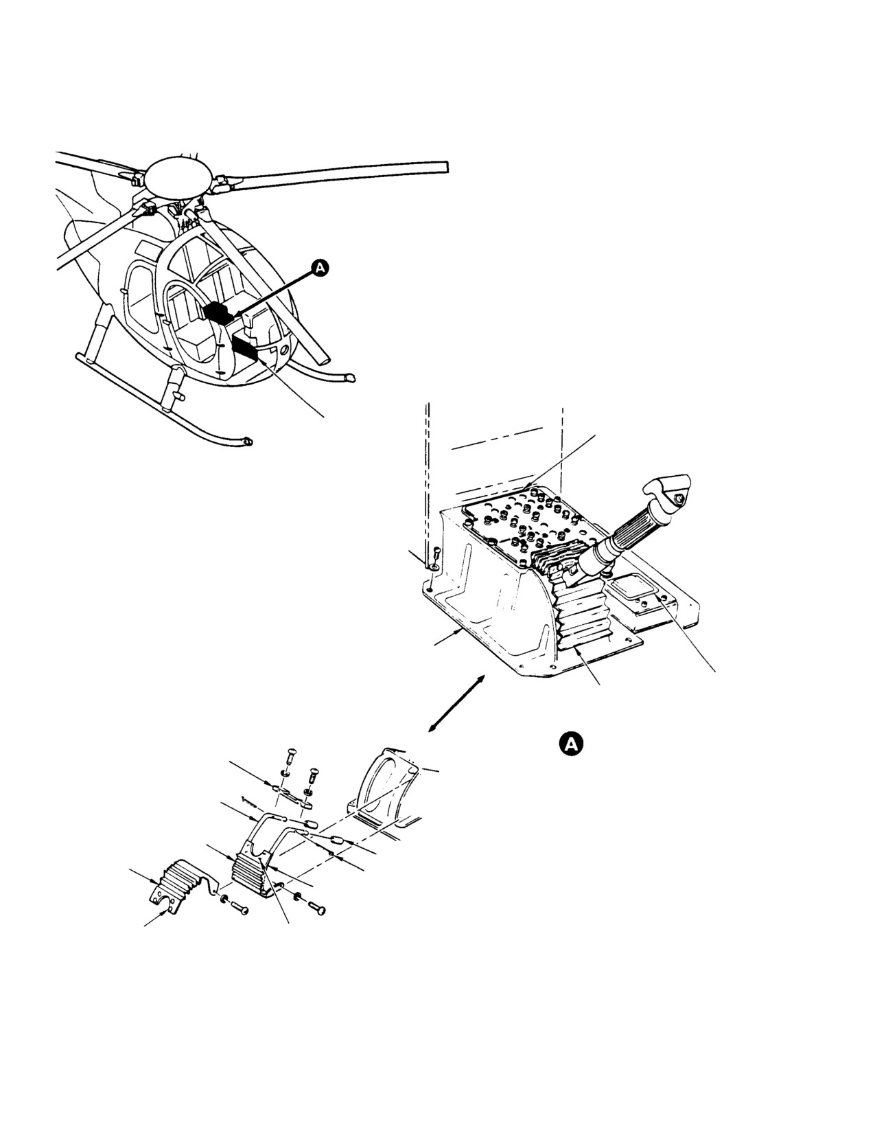
CSP-HMI-2
MD Helicopters, Inc.
MAINTENANCE MANUAL
# 500MD ELECTRICAL
500MD CIRCUIT
CONSOLE
BREAKER PANEL
# PILOT'S COLLECTIVE PITCH
STICK COVER ASSEMBLY
500MD ASH RECEIVER AND
FLEXIBLE CLOSURE AS CIGARETTE LIGHTER PANEL
SEMBLY
INBOARD COLLECTIVE PITCH
SUPPORT TUBE
STICK COVER (500MD)
CLAMP
SUPPORT TUBE
ASSEMBLY
LOWER CURTAIN
CURTAIN STOP
UPPER
CURTAIN
COTTER PIN
SLIDER
FASTENER
FASTENER STUD
BUTTON
EXPLODED VIEW (ROTATED)
G52 5000 3A
Figure 201. Access and Inspection Provisions and Locations (369D/E/FF) (Sheet 3 of 3)
Page 206
Revision 18
52-50-00
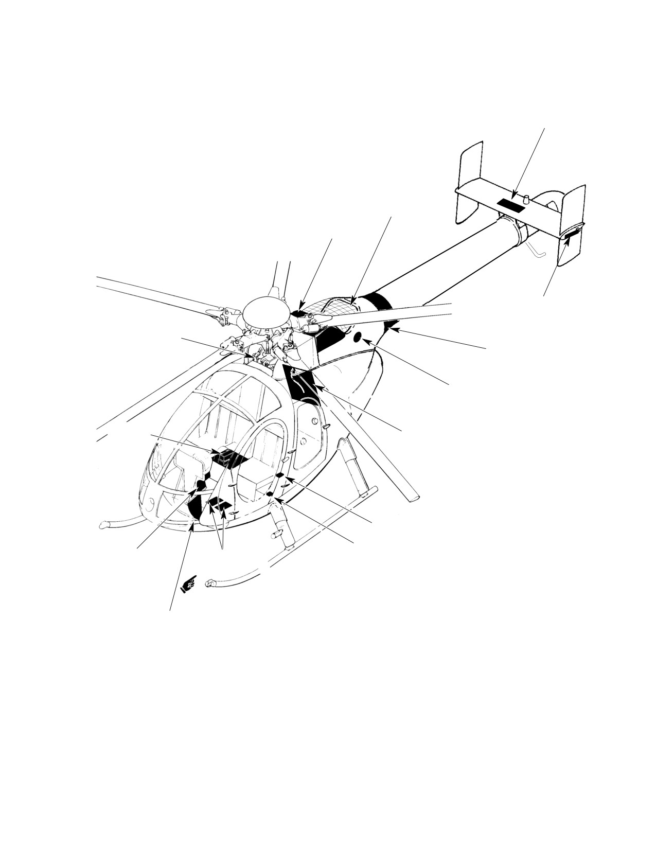
MD Helicopters, Inc.
CSP-HMI-2
MAINTENANCE MANUAL
# $ HORIZONTAL STABILIZER
ACCESS PANEL
# $ FAN INLET
SCREEN
# ENGINE PLENUM
ACCESS FAIRING
# $ HORIZONTAL STABILIZER
END PLATE (2 PLACES)
# AIR INLET FOR
WARD FAIRINGS
# $ TAILBOOM FAIRING
PRESSURE RELIEF
SCREEN (2 PLACES)
# CONTROL
# $ BLOWER ACCESS COVER
ACCESS
COVER
# COLLECTIVE STICK COVER
# WIRING COVER
INSTRUMENT PANEL
# TRIM MOTOR
FAIRING - LEFT SIDE
ACCESS PANEL
# INSTRUMENT PANEL LOWER
SECTION SIDE PANEL
CAUTION:
ITEMS PREFIXED WITH AN ASTERISK ( * ) ARE STRESSED AND MUST BE
INSTALLED PRIOR TO HELICOPTER FLIGHT.
NOTES:
# ITEMS TO BE REMOVED FOR 100-HOUR OR ANNUAL INSPECTIONS.
$ ITEMS TO BE REMOVED FOR 300-HOUR INSPECTIONS.
G52 5001 1B
Figure 202. Access and Inspection Provisions and Locations (500N) (Sheet 1 of 2)
Page 207
52-50-00
Revision 31
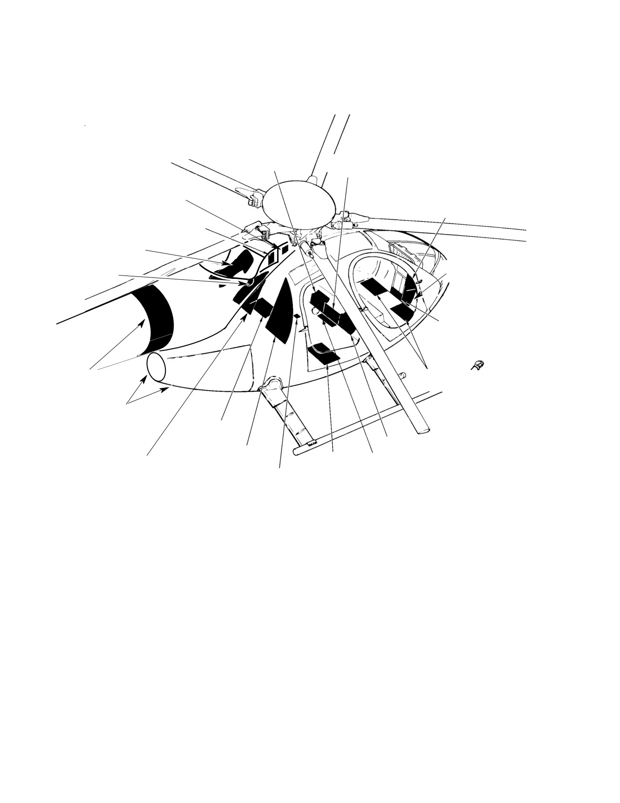
CSP-HMI-2
MD Helicopters, Inc.
MAINTENANCE MANUAL
# FOOTWELL
# $ CONTROLS
FAIRING
ACCESS DOOR
INLET ACCESS PANEL
INSTRUMENT PANEL
FAIRING - RIGHT SIDE
ENGINE PLENUM
BYPASS DOOR
# FAN GEARBOX
ACCESS COVER
# INSTRUMENT PANEL L
PRESSURE RE
SECTION SIDE PANEL
LIEF SCREEN
# INSTRUMENT PANEL LOW
SECTION FRONT PANEL
# $ TAILBOOM
PILOT'S COMPARTMENT
FAIRING
FLOOR ACCESS DOOR
ENGINE ACCESS
DOORS
# * FUEL CELL
ACCESS COVER
# FOOTWELL FAIRING
# AFT BULKHEAD
ACCESS COVER
# * FUEL CELL
# FUEL VENT COVER
# AFT BULKHEAD
ACCESS COVER
ACCESS COVER
CARGO HOOK COVER (FU
SELAGE UNDERSIDE)
Figure 202. Access and Inspection Provisions and Locations (500N) (Sheet 2 of 2)
Page 208
Revision 18
52-50-00
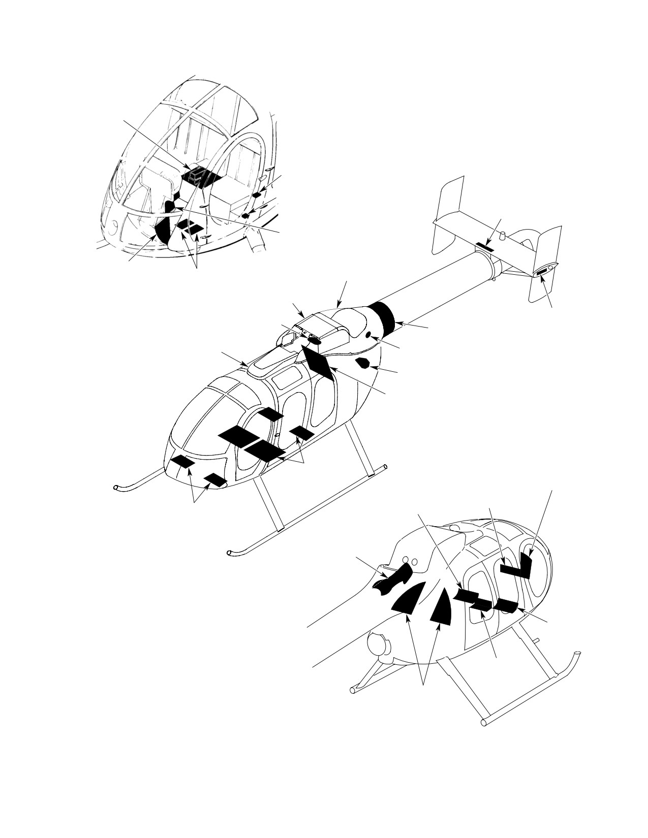
MD Helicopters, Inc.
CSP-HMI-2
MAINTENANCE MANUAL
# CONTROL AC
CESS COVER
# COLLECTIVE
STICK COVER
# WIRING COVER
# $ HORIZONTAL STABILIZER
ACCESS PANEL
INSTRUMENT PANEL
FAIRING-LEFT SIDE
# INSTRUMENT PAN
EL LOWER SECTION
# $ TRIM MOTOR
# $ FAN INLET SCREEN
SIDE PANEL
ACCESS PANEL
# ENGINE PLENUM
ACCESS FAIRING
# $ HORIZONTAL STABILIZER
BYPASS DOOR ASSY
END PLATE (2 PL)
# $ TAILBOOM FAIRING
PRESSURE RELIEF
# $ CONTROLS FAIRING
SCREEN (2 PL)
# * ENGINE OIL FILTER
ACCESS DOOR
# $ BLOWER ACCESS COVER
* FUEL CELL AC
CESS COVER
INSTRUMENT PANEL
FAIRING-RIGHT SIDE
# $ CONTROLS
# FOOTWELL
ACCESS DOOR
PILOT'S COMPARTMENT
FAIRING
FLOOR ACCESS DOOR
# FAN GEARBOX
ACCESS COVER
# FOOTWELL
FAIRING
# FUEL VENT
CAUTION:
COVER
ITEMS PREFIXED WITH AN ASTERISK ( * ) ARE STRESSED AND MUST BE
INSTALLED PRIOR TO HELICOPTER FLIGHT.
# AFT BULKHEAD
NOTES:
ACCESS COVER
# ITEMS TO BE REMOVED FOR 100-HOUR OR ANNUAL INSPECTIONS.
$ ITEMS TO BE REMOVED FOR 300-HOUR INSPECTIONS.
6G52-096
Figure 203. Access and Inspection Provisions and Locations (600N)
Page 209
52-50-00
Revision 18
CSP-HMI-2
MD Helicopters, Inc.
MAINTENANCE MANUAL
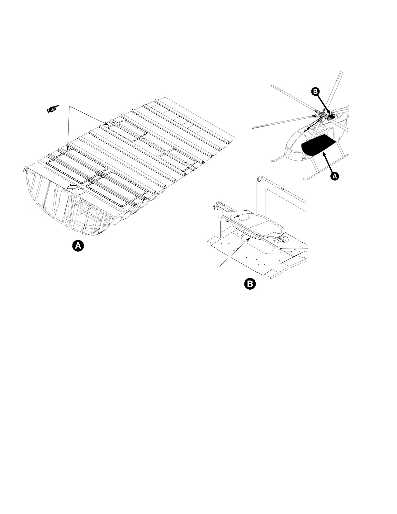
FLOOR ACCESS COVERS
(4 PL)
BYPASS DOOR ASSY
6G52-089A
Figure 204. Floor Access Covers and Engine Bypass Door (600N)
Page 210
Revision 18
52-50-00

MD Helicopters, Inc.
CSP-HMI-2
MAINTENANCE MANUAL
Chapter
53
Fuselage
MD Helicopters, Inc.
CSP−HMI−2
MAINTENANCE MANUAL
TABLE OF CONTENTS
Para/Figure/Table
Title
Page
53-00-00 Fuselage
A
Maintenance Practices
201
1. Fuselage - General
201
2. Stressed Sheet Metal Panels
201
3. Stressed Sheet Metal Panel Inspection
201
4. Non-Stressed Sheet Metal Panels
201
5. Negligible Damage Inspection
201
Table 201. Negligible Damage Inspection - Fuselage
202
Figure 201. Fuselage - Major Sections
203
Figure 202. Fuselage - Model 600N
204
53-10-00 Windshields and Aft Section Windows
A
Maintenance Practices
201
1. Windshields
201
2. Aft Section Windows
201
3. Aft Section Windows Replacement
201
A. Aft Section Windows Removal
201
B. Aft Section Windows Installation
201
4. Windshield Frame Replacement
201
A. New-Style Windshield Installation
201
5. Windshield Inspection
201
6. Windshield Repair
201
7. Water Leak Prevention
202
8. Geon Strips Repair
202
Table 201. Negligible Damage of Canopy/Windshield
202
Figure 201. (Round Nose) Windshields and Aft Section Windows
203
Figure 202. (Extended Nose) Windshield and Aft Section Windows
204
Figure 203. Windshield Installation (New Style)
205
Figure 204. (Extended Nose) Windshields and Aft Section Windows
(New Style)
206
53-20-00 Lower Center Fuselage
A
Maintenance Practices
201
1. Lower Center Fuselage - General
201
2. Lower Center Fuselage Inspection
201
3. Fuel Tank Support Skin Inspection (Fuel Cells Removed)
201
Page i
53 Contents
Revision 44
CSP−HMI−2
MD Helicopters, Inc.
MAINTENANCE MANUAL
TABLE OF CONTENTS (Cont.)
Para/Figure/Table
Title
Page
4. Fuel Tank Support Skins Repair (Fuel Cells Removed)
201
Figure 201. Lower Center Fuselage (369D/E/FF - 500N)
202
Figure 202. Lower Center Fuselage (Model 600N)
203
53-30-00 Upper Aft Section Fuselage (369D/E/FF)
A
Maintenance Practices
201
1.
Upper Firewall Replacement
201
2.
Firewall and Plenum Chamber Panels Replacement
201
Figure 201. Soundproofing Insulation - Firewall and Plenum Chamber
(Sheet 1 of 2)
202
A. Mast Support Structure
204
3.
Mast Support Structure Inspection
204
A. Firewalls
204
4.
Firewalls Inspection
204
Figure 202. Firewall and Aft Section
205
A. Firewall, Station 124.00 Insulation and Soundproofing
205
5.
Firewall and Plenum Chamber Soundproofing Panel Inspection
205
A. Engine Air Inlet Fairing
205
6.
Engine Air Inlet (Plenum Chamber) Inspection
206
A. Upper Aft Section General Repair
206
B. Aft Fuselage Fittings
206
C. Aft Fuselage Fittings General Repair
206
7.
Aft Section Strut Repair
206
8.
Silver Brazing Procedure - Upper Firewall Shell Patch
206
Figure 203. Major Bulkheads and Structural Members - Aft Fuselage
207
9.
Plenum Chamber Hole Sealing
208
10. Forward Fuselage Section Structure Rework
208
11. Transmission Compartment Air Baffle, Seal and Cover Initial Installation
209
Table 201. Weight and Balance Data
210
Figure 204. Forward Fuselage Section Structure Rework
211
Figure 205. Installation of Air Baffle, Seal and Cover Assemblies
(Sheet 1 of 2)
212
53-30-30 Upper Aft Section Fuselage (500/600N)
A
Maintenance Practices
201
1. Engine/Anti-Torque Air Inlet Fan Fairings
201
2. Engine Air and Fan Inlet (Plenum Chamber Area) Inspection
201
Figure 201. Upper Aft Section (500N)
202
Figure 202. Upper Aft Section Fuselage (600N)
203
Page ii
Revision 44
53 Contents
MD Helicopters, Inc.
CSP−HMI−2
MAINTENANCE MANUAL
TABLE OF CONTENTS (Cont.)
Para/Figure/Table
Title
Page
A. Upper Aft Section General Repair
204
3.
Upper Fuselage Controls Fairing (600N)
204
4.
Upper Fuselage Controls Fairing Replacement (600N)
204
A. Upper Fuselage Controls Fairing Removal
204
B. Upper Fuselage Controls Fairing Installation
204
5.
Engine Inlet Fairings Replacement
204
A. Engine Inlet Fairing Removal
204
B. Engine Inlet Fairing Installation
204
6.
Anti-Torque Fan Air Inlet Screen Replacement
204
A. Fan Air Inlet Screen Removal
204
B. Fan Air Inlet Screen Installation
204
7.
Fan Hub and Transmission Cover Fairing Replacement
204
A. Fan Hub and Transmission Cover Removal
204
B. Fan Hub and Transmission Cover Installation
205
8.
Engine Plenum Access Cover Replacement
205
A. Engine Plenum Access Cover Removal
205
B. Engine Plenum Access Cover Installation
205
9.
Tailboom Attach Fitting Inspection
205
Figure 203. Tailboom Attach Fitting Inspection
206
10. Lower Longeron Inspection (L158, R158)
207
11. Forward Upper Longeron Inspection (L137, R137)
207
Figure 204. Inspection Hole Locations
208
12. Control Tunnel (FS 78.50) Beam Inspection
208
Figure 205. Control Tunnel (FS 78.50) Beam Inspection
209
53-40-00 Tailboom (369D/E/FF)
A
Maintenance Practices
201
1. Tailboom - General
201
2. Tailboom Replacement
201
A. Tailboom Removal
201
B. Tailboom Installation
201
Figure 201. Tailboom Assembly and Tailboom Extension
202
3. Tailboom Extension Replacement (369FF)
202
4. Tailboom Inspection
203
5. Tailboom Repair
203
Figure 202. Tailboom Installation and Removal
204
Page iii
53 Contents
Revision 44
CSP−HMI−2
MD Helicopters, Inc.
MAINTENANCE MANUAL
TABLE OF CONTENTS (Cont.)
Para/Figure/Table
Title
Page
53-40-30 Tailboom (500/600N)
A
Maintenance Practices
201
1.
Tailboom Description
201
2.
Tailboom Replacement
201
A. Tailboom Removal
201
Figure 201. Tailboom Assembly (Sheet 1 of 3)
202
B. Tailboom Installation
205
3.
Tailboom Inspection
205
Figure 202. Tailboom Flap Inspection
206
4.
Tailboom Repair
207
5.
Stator Replacement
207
A. Stator Removal
207
B. Stator Installation
207
6.
Stator Blade Replacement
207
7.
Rotating Thruster Cone Replacement
207
A. Rotating Thruster Cone Removal
207
B. Rotating Thruster Cone Installation
207
8.
Rotating Thruster Cone Inspection
207
9.
Stationary Thruster Cone Replacement
208
A. Stationary Thruster Cone Removal
208
B. Stationary Thruster Cone Installation
208
10. Stationary Thruster Cone Inspection
208
11. Conduit and Support Strap Rebonding
208
Figure 203. Conduit and Support Strap Rebonding
209
12. Horizontal Stabilizer Mount Fitting Replacement
210
13. 500N3500-5 Cover Installation
211
Figure 204. 500N3500-5 Cover Installation
212
14. Tail Skid Replacement
212
A. Tail Skid Removal
212
B. Tail Skid Installation
212
Figure 205. Tail Skid Installation
213
Repairs
801
1. Rotating Thruster Cone Strap Repair
801
A. Rotating Thruster Cone Strap Removal
801
Figure 801. Rotating Thruster Cone
801
B. Rotating Thruster Cone Strap Installation
802
Page iv
Revision 44
53 Contents
MD Helicopters, Inc.
CSP−HMI−2
MAINTENANCE MANUAL
TABLE OF CONTENTS (Cont.)
Para/Figure/Table
Title
Page
53-50-10 Stabilizer (T-Tail) (369D/E/FF)
A
Maintenance Practices
201
1. Stabilizer - General
201
A. Stabilizer Troubleshooting
201
2. Horizontal Stabilizer and Tip Plate Replacement
201
A. Horizontal Stabilizer and Tip Plate Removal
201
B. Horizontal Stabilizer and Tip Plate Installation
201
3. Vertical Stabilizer Replacement
202
A. Vertical Stabilizer Removal
202
B. Vertical Stabilizer Installation
202
4. Horizontal Stabilizer and Tip Plate Inspection
202
5. Vertical Stabilizer Inspection
202
Figure 201. Stabilizer T-Tail Removal and Installation
203
6. Horizontal Stabilizer and Tip Plate Repair
204
7. Vertical Stabilizer Repair
204
8. Angle of Incidence Measurement
204
Table 201. Horizontal Stabilizer Angle of Incidence
204
9. Angle of Incidence Adjustment
205
10. Horizontal Stabilizer Tab Weight Installation
205
Table 202. Troubleshooting Tailboom and Tail Surfaces
205
Figure 202. Horizontal Stabilizer Incidence Angle Measuring Tool
206
Figure 203. Establishing Horizontal Stabilizer Angle of Incidence
206
Figure 204. Sealing - Vertical Stabilizer (0003D - 0286D)
207
53-50-30 Stabilizer (500/600N)
A
Maintenance Practices
201
1. Stabilizers Description
201
A. Horizontal Stabilizer Description
201
B. Vertical Stabilizers Description
201
2. Vertical Stabilizer Replacement
201
A. Vertical Upper and Lower Stabilizer Removal
201
B. Vertical Upper and Lower Stabilizer Installation
201
3. Horizontal Stabilizer Replacement
202
A. Horizontal Stabilizer Removal
202
B. Horizontal Stabilizer Installation
202
Figure 201. Stabilizer Installation with YSAS (Sheet 1 of 2)
203
Page v
53 Contents
Revision 44
CSP−HMI−2
MD Helicopters, Inc.
MAINTENANCE MANUAL
TABLE OF CONTENTS (Cont.)
Para/Figure/Table
Title
Page
4. Horizontal Stabilizer Eye Bolt Replacement
205
A. Horizontal Stabilizer Eye Bolt Removal
205
B. Horizontal Stabilizer Eye Bolt Installation
205
5. Horizontal/Vertical Stabilizer Control Tube and Bellcrank Replacement
205
A. Horizontal/Vertical Stabilizer Control Tube and Bellcrank Removal
205
B. Horizontal/Vertical Stabilizer Control Tube and Bellcrank Installation
205
6. Vertical Stabilizer Inspection
205
7. Vertical Stabilizer Repair
205
8. Horizontal Stabilizer Inspection
205
9. Vertical Stabilizer Torque Tube Replacement
206
A. Vertical Stabilizer Torque Tube Removal
206
B. Vertical Stabilizer Torque Tube Installation
206
Figure 202. Stabilizer Installation without YSAS
207
Figure 203. Vertical Stabilizer Installation with Expandable Bolts
208
10. Horizontal Stabilizer Repair
209
11. Vertical Stabilizer Torque Tube and/or Bushing Replacement
(Non-Bonded Bushings)
209
12. Vertical Stabilizer Torque Tube and/or Bushing Replacement
(Bonded Bushings)
209
13. Vertical Stabilizer Torque Tube Bushing Rework
(Non-Bonded Bushings to Bonded Bushings)
210
14. Vertical Stabilizer Torque Tube Bearing Race Replacement
211
15. Stabilizer Troubleshooting
212
Table 201. Troubleshooting Tailboom and Tail Surfaces
212
Page vi
Revision 44
53 Contents
MD Helicopters, Inc.
CSP-HMI-2
MAINTENANCE MANUAL
Section
53−00−00
Fuselage
MD Helicopters, Inc.
CSP-HMI-2
MAINTENANCE MANUAL
FUSELAGE
MAINTENANCE PRACTICES
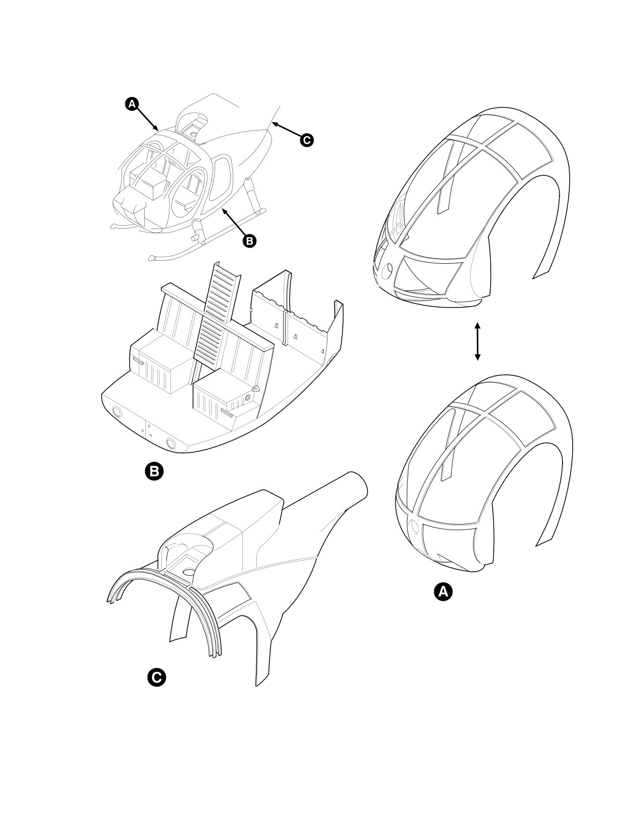
1. Fuselage − General
webs. The most-highly-stressed skin sections
are those that form the cylindrically-tapered
(Ref. Figure 201) The helicopter fuselage
tailboom assembly (Ref. Sec. 53-40).
consists of three major structural sections; the
forward, lower and aft fuselage sections. For
NOTE: No damage can be considered negligi
classification and definition of types of
ble. All damage shall be repaired upon de
negligible damage, and for guidelines defining
tection.
extent of damage requiring repair or replace
3. Stressed Sheet Metal Panel Inspection
ment, (Ref. Stressed Sheet Metal Panels,
Non-Stressed Sheet Metal Panels and
Cracks, tears or punctures in stressed sheet
Table 201).
metal panels that do not exceed 0.20 inch (5.08
mm) diameter and can be removed by drilling
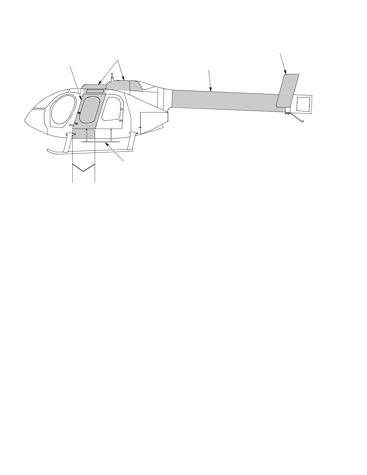
(Ref. Figure 202) The fuselage of the 600N
out with 1/4 inch (6.35 mm) or smaller
helicopter is a stretched version of the 500N
diameter drill do not require structural
Series helicopter with numerous upgrades and
doublers. If cracks, tears or punctures exceed
improvements. (shaded areas indicate new
0.20 inch (5.08 mm) diameter, they are to be
sections to fuselage) The longer cabin area of
repaired or the panel must be replaced per
the 600N greatly increases passenger and/or
instructions in FAA AC 43.13-1B and FAA AC
cargo carrying capacity. Upper deck area
43.13-2B Inspection and Repair for Standard
fairings and covers were added or modified to
Sheet Metal Repair and Alterations and
accommodate control surfaces or air inlet
Structural Repair Manual.
passages.
4. Non−Stressed Sheet Metal Panels
The tailboom on the 600N helicopter is
essentially the same as the 500N Series, only
Non-stressed sheet metal members consist
longer. The vertical stabilizers or endplates are
primarily of hinged covers and doors, except
longer than on the 500N model, providing an
fuel cell access and controls access doors,
increased control surface area.
which are stressed (Ref. Stressed Sheet Metal
Panels).
An extended passenger step alongside the
passenger/cargo compartment allows for easy
5. Negligible Damage Inspection
entrance and exit through either mid or aft
cabin doors.
(Ref. Table 201) Panels damaged in excess of
negligible damage limits (Ref. Table 201)
2. Stressed Sheet Metal Panels
should be repaired, or damaged panel should
be replaced per instructions in FAA AC
Stressed sheet metal panels consist primarily
43.13-1A & 2A and CSP-SRM-6 (Structural
of helicopter fuselage skins and bulkhead
Repair Manual).
Page 201
53-00-00
Revision 44

CSP-HMI-2
MD Helicopters, Inc.
MAINTENANCE MANUAL
Table 201. Negligible Damage Inspection − Fuselage
Maximum
Maximum Length
Area
*Damage
Depth
or Surface
Remarks
Stressed sheet
No unrepaired damage
metal panels.
allowed.
(For tailboom, Ref. Sec.
53−40).
Non−stressed sheet
Dents.
Small dents allowed.**
metal panels.
Scratches/nicks.
Minor scratches/nicks
allowed.**
Cracks.
Smaller of 0.250
Must be one inch or more
inch (6.35 mm) or
from any attachment fitting
one−fourth panel
and/or panel edge.
width.
Main rotor mast.
No unrepaired damage
allowed (Ref. Figure 201)
Firewalls.
No unrepaired damage
allowed.
Fuselage fittings.
Longitudinal
0.010 inch
15% of fitting
After polishing or repair.
scratches, dents, and
(0.254 mm)
length.
nicks.
Transverse scratches,
0.010 inch
10% of fitting
After polishing or repair.
dents, and nicks.
(0.254 mm)
thickness.
NOTES:
* All damage to fuselage exceeding limits given requires repair or replacement of effected panel or
component.
** Dents, scratches and nicks that penetrate aluminum protective coating (4% of panel thickness with paint or
other surface finishes removed) will allow corrosion of aluminum panel, and should be repaired.
Page 202
Revision 37
53-00-00
MD Helicopters, Inc.
CSP-HMI-2
MAINTENANCE MANUAL
LOWER FUSELAGE
FORWARD FUSELAGE
AFT FUSELAGE
Figure 201. Fuselage − Major Sections
Page 203
53-00-00
Revision 19
CSP-HMI-2
MD Helicopters, Inc.
MAINTENANCE MANUAL
VERTICAL STABILIZER-
ENDPLATES
FAIRINGS AND COVERS
EXTENDED FUSELAGE
TAILBOOM
EXTENDED PASSENGER STEP
STA
78.50
P. STA
P. STA
0.00
30.00
6G53 052B
Figure 202. Fuselage − Model 600N
Page 204
Revision 20
53-00-00
MD Helicopters, Inc.
CSP-HMI-2
MAINTENANCE MANUAL
Section
53−10−00
Windshields and Aft
Section Windows
MD Helicopters, Inc.
CSP-HMI-2
MAINTENANCE MANUAL
WINDSHIELDS AND AFT SECTION WINDOWS
MAINTENANCE PRACTICES
1. Windshields
(2). Using a blunt plastic spatula or probe,
gradually work edge of window under
Center and lower windshield panels are
flap surface of window seal.
clearest acrylic (Ref. Figure 201 and
(3). Maintain pressure on window until
Figure 202). Upper windshield panels are
entire perimeter of window is under
smoke-grey-tinted cast acrylic. The center
seal.
windshield panels are approximately 0.100
inch (2.540 mm) thick.
(4). Apply an even amount of sealing
compound (CM425) to form a water
2. Aft Section Windows
tight seal around window seal to
fuselage and from window seal to
For repair of plastics, Ref. FAA AC 43.13-1B.
window.
Replace aft section window if it is damaged
beyond practical repair, according to applicable
4. Windshield Frame Replacement
instructions in Structural Repair Manual.
Consumable Materials
(Ref. Figure 204) On the 600N helicopter the
(Ref. Section 91−00−00)
”Aft Section Windows” refer to the upper mid
Item
Nomenclature
section windows located above the mid
passenger/cargo doors. On the 500 Series
CM305
Lacquer, acrylic
helicopters this area was referred to as the
CM425
Sealing compound
”Aft Section”.
For older model helicopters with riveted-in
3. Aft Section Windows Replacement
windshields, remove or replace windshield
according to applicable instructions in the
(Ref. Figure 204)
Structural Repair Manual.
A. Aft Section Windows Removal
A. New−Style Windshield Installation
(1). Remove old sealing compound from
(1). Install windshields in place and install
around edge of window and window
hardware (Ref. Figure 203 and
seal.
Figure 204).
(2). After normal installation of windshield,
(2). Using a blunt plastic spatula or probe,
grind two screws flush with nuts (Ref.
pull back flap of window seal and
Figure 203).
gradually work window out from under
flap of seal.
(3). Touch-up with lacquer (CM305).
(3). Remove seal and clean for re-installa
(4). Seal all windshield seams with sealing
tion of window.
compound (CM425).
5. Windshield Inspection
Consumable Materials
Minor defects or imperfections that do not
(Ref. Section 91−00−00)
impair pilot's critical visibility, or that obvious
Item
Nomenclature
ly are not signs of impending structural failure
CM425
Sealing compound
may be considered as negligible. (For allowable
damage limits, Refer to Table 201.)
B. Aft Section Windows Installation
6. Windshield Repair
(1). Install window seal around periphery of
For repair of plastics, Ref. FAA AC 43.13-1B.
window opening in fuselage.
Replace windshields if damage beyond
Page 201
53-10-00
Revision 44

CSP-HMI-2
MD Helicopters, Inc.
MAINTENANCE MANUAL
practical repair, according to applicable
having less than 0.125 inch (3.175 mm)
instructions in Structural Repair Manual.
insertion. Replace parts with debonding
areas over 8 inches (20.32 cm) in
7. Water Leak Prevention
length.
(2). Mask the geon weatherstrip and
Consumable Materials
windshield on both sides with tape
(Ref. Section 91−00−00)
(CM722).
Item
Nomenclature
CM425
Sealing compound
(3). Wipe all faying surfaces with aliphatic
naphtha (CM220) and dry for a mini
mum of 15 minutes.
If water leakage through geon strips of the
forward canopy occurs, remove any existing
(4). For small voids:
sealant using a plastic or other non-metallic
scraper which will not scratch the canopy
(a). Apply adhesive (CM414) to all faying
glass. Apply 0.060 inch (1.524 mm) bead of
surfaces using syringe if necessary.
sealant (CM425) along gaps between geon
strips. Apply sealant as directed by sealant
(b). Use light pressure to hold the joint
manufacturer.
closed for a minimum of 2 minutes.
8. Geon Strips Repair
(5). For large voids:
(a). Apply accelerator to the acrylic
Consumable Materials
transparency and air dry for a
(Ref. Section 91−00−00)
minimum of 2 minutes.
Item
Nomenclature
CM220
Naphtha aliphatic
(b). Apply adhesive to the geon weather
CM414
Adhesive, cyanoacrylic / Accelerator
strip only.
CM722
Tape, polyethylene
(c). Apply local pressure to insure
complete contact between adherents
Fill voids between geon strips and transparen
and maintain pressure for a mini
cies as follows:
mum of 30 seconds.
(1). Measure the insertion depth of acrylic
(d). Remove tape and remove excess
windshield into geon slot, reject parts
residue with aliphatic naphtha.
Table 201. Negligible Damage of Canopy/Windshield
Maximum
Maximum
Length or
Area
Damage
Depth
Surface Area
Remarks
Canopy and Windshield.
Nicks
0.010 inch
0.250 inch
One per square foot
(0.254 mm)
(6.35 mm)
only.
Scratches
0.010 inch
5.000 inch
(0.254 mm)
(12.7 cm)
Spots or stains
If removable by light
polishing.
Panels (not windshields or Punctures
0.200 inch
windows).
(5.08 mm) dia
Windshield.
Polarization faults
Small area near edges.
(distortion)
Page 202
Revision 19
53-10-00
MD Helicopters, Inc.
CSP-HMI-2
MAINTENANCE MANUAL
Table 201. Negligible Damage of Canopy/Windshield (Cont.)
Maximum
Maximum
Length or
Area
Damage
Depth
Surface Area
Remarks
Doublers or stiffeners.
Delamination
No more than one area
within each square foot
of windshield.
Grazing around
0.010 inch
delamination
(0.254 mm)
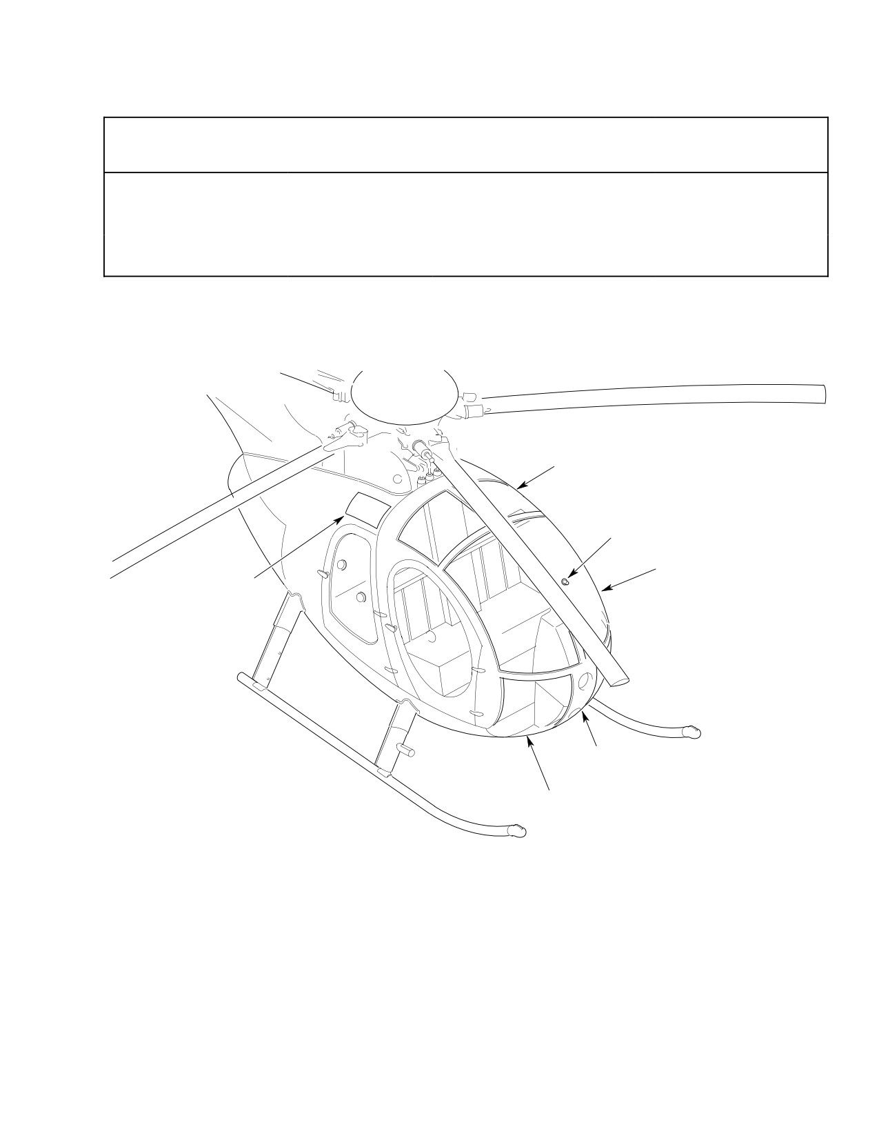
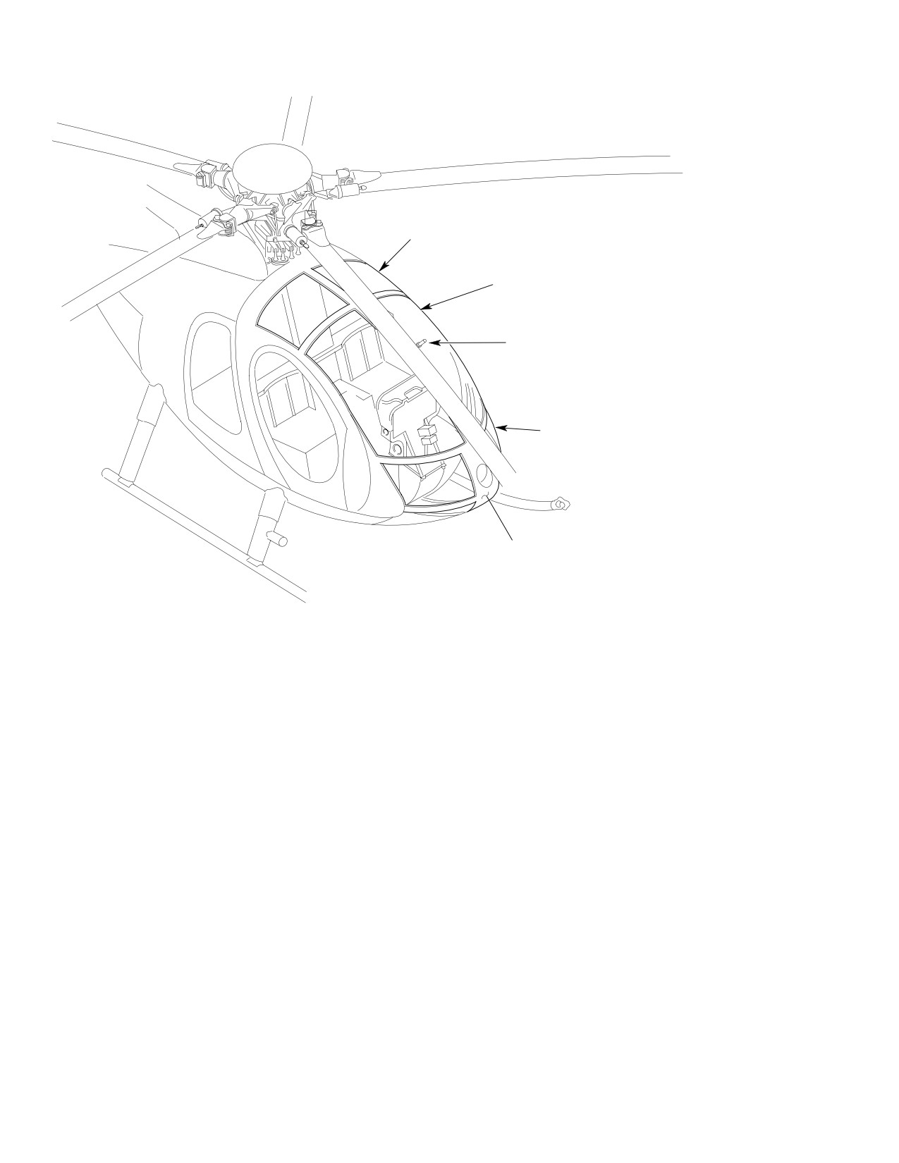
UPPER CANOPY WINDSHIELD
(TWO SECTIONS)
OUTSIDE AIR TEMPERATURE
INDICATOR
CENTER CANOPY WINDSHIELD
(TWO SECTIONS)
FUSELAGE AFT SECTION
WINDOWS (BOTH SIDES)
(NOTE)
CABIN VENTILATION PANEL
(FIBERGLASS)
LOWER CANOPY WINDSHIELD
(TWO SECTIONS)
NOTE:
FUSELAGE AFT SECTION WINDOWS ARE UNIQUE TO
G53-1000
ROUND-NOSE HELICOPTERS ONLY.
Figure 201. (Round Nose) Windshields and Aft Section Windows
Page 203
53-10-00
Revision 19
CSP-HMI-2
MD Helicopters, Inc.
MAINTENANCE MANUAL
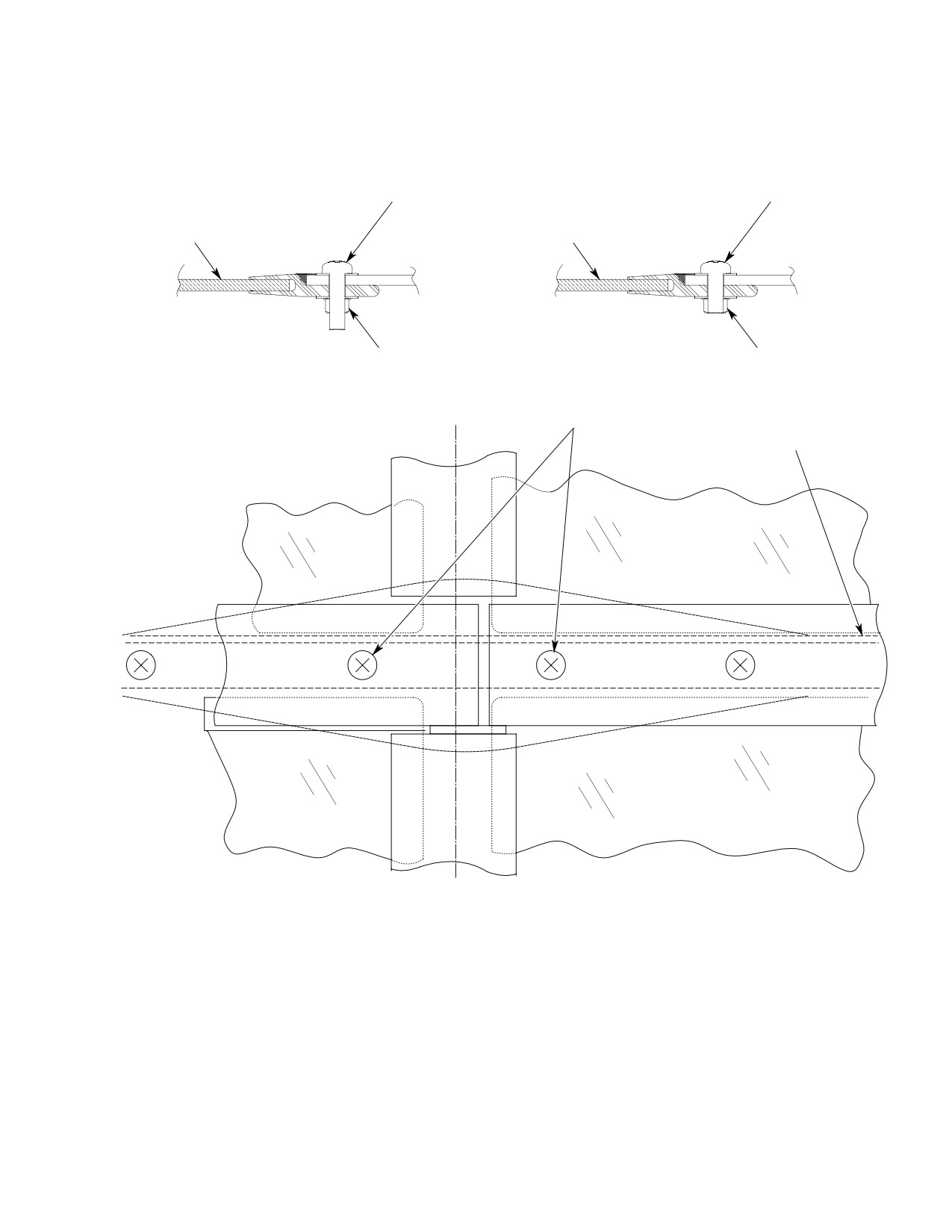
UPPER CANOPY WINDSHIELD
(TWO SECTIONS)
CENTER CANOPY WINDSHIELD
(TWO SECTIONS)
OUTSIDE AIR TEMPERATURE
INDICATOR
LOWER CANOPY WINDSHIELD
(TWO SECTIONS)
CABIN VENTILATION PANEL
(FIBERGLASS)
G53-1001A
Figure 202. (Extended Nose) Windshield and Aft Section Windows
Page 204
Revision 19
53-10-00
MD Helicopters, Inc.
CSP-HMI-2
MAINTENANCE MANUAL
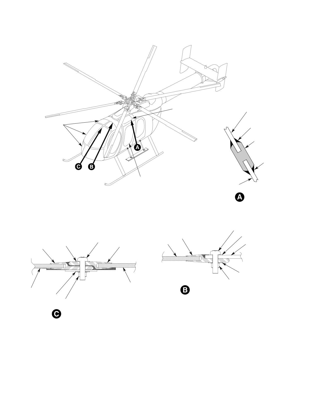
SCREW
SCREW
WINDSHIELD
WINDSHIELD
NUT
NUT
BEFORE
AFTER
CL FUSELAGE
2X ONLY
BL 0.0
(SEE NOTE)
STA 75.24
NOTE:
SCREW LENGTH INTERFERES WITH INSTALLATION
600n6501--010101
OF AIR DUCT INSIDE COCKPIT.
6G53-087
Figure 203. Windshield Installation (New Style)
Page 205
53-10-00
Revision 19
CSP-HMI-2
MD Helicopters, Inc.
MAINTENANCE MANUAL
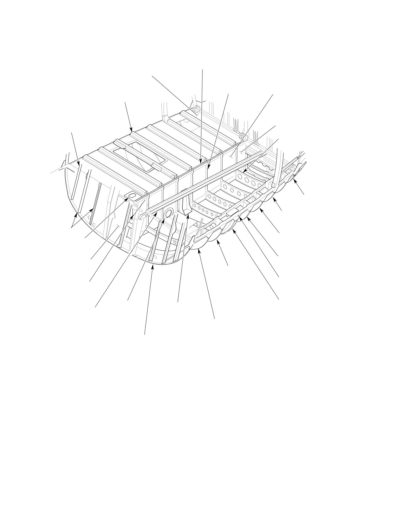
AFT SECTION WINDOW
(RH SIDE IS TYPICAL)
WINDOW
WINDSHIELDS
SEALANT
(EXTENDED NOSE)
WINDOW SEAL
SEALANT
MID DOOR
FUSELAGE
LOOKING AFT
SCREW
RETAINER
WASHER
SCREW
WINDSHIELD
WASHER
RETAINER
FUSELAGE
RETAINER
WASHER
NUT
WINDSHIELD
WINDOW-TO-STRUCTURE INSTALLATION
WINDSHIELD
LOOKING INBD
WASHER
NUT
WINDOW-TO-WINDOW INSTALLATION
LOOKING AFT
600n6501--010101
6G53-053
Figure 204. (Extended Nose) Windshields and Aft Section Windows (New Style)
Page 206
Revision 19
53-10-00
MD Helicopters, Inc.
CSP-HMI-2
MAINTENANCE MANUAL
Section
53−20−00
Lower Center
Fuselage
MD Helicopters, Inc.
CSP-HMI-2
MAINTENANCE MANUAL
LOWER CENTER FUSELAGE
MAINTENANCE PRACTICES
1. Lower Center Fuselage − General
(4). Perform repair (Ref. Fuel Tank Support
Skins Repair (Fuel Cells Removed)).
(Ref. Figure 201) Lower center fuselage is
those areas below fuselage floor level (WL
3. Fuel Tank Support Skin Inspection (Fuel
13.10) on both sides of the center beam and
Cells Removed)
between Sta. 78.50 and Sta. 124.00.
(1). Check security of fiberglass skin
attachment to support angles and
(Ref. Figure 202) The Lower Center Fuselage
brackets.
for the Model 600N helicopter is similar to that
of the 500 Series helicopters except for the
(2). Inspect anti-abrasion tape for security
additional stretched or extended fuselage
of adhesion over rivet heads, all sharp
IplugI station. The extended lower center
edges and lap joints.
fuselage section is located at Sta. 78.50
(designated P. Sta. 0.00 thru 30.00) (Ref.
(3). Negligible damage (Ref. Table 201,
Section 06-00-00). Additional floor access
53-00-00).
covers for the fuel cell are also contained
within this section of fuselage.
4. Fuel Tank Support Skins Repair (Fuel
Cells Removed)
2. Lower Center Fuselage Inspection
Consumable Materials
(1). Ref. FAA AC 43.13-1B Aircraft Inspec
(Ref. Section 91−00−00)
tion and Repair for Standard Sheet
Item
Nomenclature
Metal Repair and Structural Repair
CM711
Tape, pressure sensitive
Manual for standard sheet metal
repair.
(1). Repair fuel tank support skins accord
(2). Inspect electrical harnesses and wiring
ing to applicable instructions in FAA
for frayed insulation and grounding
AC 43.13-1A & 2A or Structural Repair
terminals for corrosion.
Manual.
(3). If cargo floor is bent or punctured,
(2). Cover exposed rivet heads with 10 mil
remove appropriate fuel cell access
by 1 inch (2.54 cm) tape (CM711) to
cover and inspect fuel cell.
prevent chafing fuel cell fabric.
Page 201
53-20-00
Revision 44
CSP-HMI-2
MD Helicopters, Inc.
MAINTENANCE MANUAL
FLOOR WEB
CENTER BEAM
(0.016 IN. (0.4064 MM)
2024-T3 AL ALY)
STIFFENER
(0.020 IN. (0.508 MM)
STIFFENERS
7075-T6 AL ALY)
(0.032 IN. (0.8128 MM)
WEB
(TYPICAL 8 PLCS)
7075-T6 AL ALY)
(0.016 IN. (0.4064 MM)
(TYPICAL 7 PLCS)
7075-T6 AL ALY)
DOUBLER
STIFFENER
(0.032 IN. (0.8128 MM)
(0.032 IN. (0.8128 MM)
7075-T6 AL ALY)
7075-T6 AL ALY)
STA 119.67 RIB
(0.025 IN. (0.635 MM)
7075-T6 AL ALY)
WL 13.10
124.00 LOWER FRAME
(0.020 IN. (0.508 MM)
15-7 CRES)
STA 113.85 RIB
STIFFENERS
(0.025 IN. (0.635 MM)
(0.020 IN. (0.508 MM)
7075-T6 AL ALY)
2024-T3 AL ALY)
STA 108.04 RIB
DOUBLER
(0.025 IN. (0.635 MM)
(0.025 IN. (0.635 MM)
7075-T6 AL ALY)
2024-T3 AL ALY)
STA 102.23 RIB
WEB
(0.025 IN. (0.635 MM)
(0.016 IN. (0.4064 MM)
STA 90.61 RIB
7075-T6 AL ALY)
2024-T3 AL ALY)
(0.040 IN. (1.016 MM)
7075-T6 AL ALY)
JACK FITTING
DOUBLER
(PART OF STA 96.42 RIB)
(0.050 IN. (1.270 MM)
7075-T6 AL ALY)
STA 96.42 RIB ASSY
DOUBLER
CARGO HOOK FITTING
STIFFENER
(0.050 IN. (1.270 MM)
(0.050 IN. (1.270 MM)
(IF APPLICABLE)
(0.032 IN. (0.8128 MM)
7075-T6 AL ALY)
7075-T6 AL ALY)
7075-T6 AL ALY)
STA 84.70 RIB
(0.032 IN. (0.8128 MM)
7075-T6 AL ALY)
CANT STA 78.50
LOWER FRAME
G53-2002A
(0 040 IN (1 016 MM)
Figure 201. Lower Center Fuselage (369D/E/FF − 500N)
Page 202
Revision 19
53-20-00
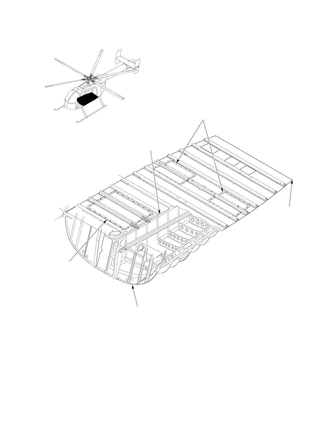
MD Helicopters, Inc.
CSP-HMI-2
MAINTENANCE MANUAL
FLOOR ACCESS
COVER, FUEL CELL
CENTER BEAM
P STA
30.00
P STA
0.00
STA 124.00
LOWER FRAME
FLOOR ACCESS
COVER, FUEL CELL
(2 PL)
CANTED STA 78 50
Figure 202. Lower Center Fuselage (Model 600N)
Page 203
53-20-00
Revision 19
CSP-HMI-2
MD Helicopters, Inc.
MAINTENANCE MANUAL
This Page Intentionally Left Blank
Page 204
Revision 44
53-20-00
MD Helicopters, Inc.
CSP-HMI-2
MAINTENANCE MANUAL
Section
53−30−00
Upper Aft Section
Fuselage
(369D/E/FF)
MD Helicopters, Inc.
CSP-HMI-2
MAINTENANCE MANUAL
UPPER AFT SECTION FUSELAGE (369D/E/FF)
MAINTENANCE PRACTICES
1. Upper Firewall Replacement
(9). Using solvent (CM234), clean forward
flanges, lower flanges and surface
where tape routing covers fasteners;
Consumable Materials
then apply tape (CM721).
(Ref. Section 91−00−00)
Item
Nomenclature
(10). Install compressor cooling air duct
support bracket.
CM234
Solvent, dry-cleaning
CM721
Tape, aluminum foil
(11). Install tailpipes.
2. Firewall and Plenum Chamber Panels
Use care when working on or
Replacement
CAUTION
around firewall shell because of
its light-weight construction.
Consumable Materials
(Ref. Section 91−00−00)
(1).
Remove tailpipes (Ref. Chap. 78,
Item
Nomenclature
Exhaust System Replacement).
CM234
Solvent, dry-cleaning
(2).
Remove tape covering fasteners and
CM419
Sealer
firewall edges.
(3).
Detach compressor cooling air duct
Replace all defective, torn or fraying sound
support bracket (Ref. Chap. 71, Engine
proofing panels. Loose panels may be pressed
Cooling System Repair and Replace
back in place. (For part number identification
ment). Remove firewall shell by pulling
of individual panels, refer to the IPC.)
out button head fasteners (Ref.
(1). Open engine compartment access doors.
Figure 202).
(2). Remove individual panels (Ref.
(4).
If burn marks are detected on firewall
Figure 201, Sheet 1 of 2) by pulling
shell or button head fasteners, inspect
away from structure.
airframe above burn marks for damage.
(3).
(If applicable) Remove individual
(5).
Replace damaged or corroded fasteners.
panels (Ref. Figure 201, Sheet 2 of 2) by
removing fasteners.
(6).
Replace aft firewall shell if damaged
beyond practical repair. Trim replace
NOTE: Panels have pressure-sensitive tape
ment shell to fit installation. Allow
backing.
sufficient trim excess for folding back to
(4). Prior to installing replacement panel,
provide double thickness at attach
clean surfaces with solvent (1, Table
points.
201, 91-00).
(7).
Pierce fastener holes in new firewall
(5). Install replacement panel in place and
shell to align holes in surrounding
trim edges as necessary. Press panel in
fuselage rings and waterline 34.96 rib.
place to secure.
(8).
Place firewall shell in position and
(6). Seal edges of replacement panel with
secure in place by pressing fasteners
sealer (130).
into holes. Attach compressor cooling
air duct support bracket to hoist fitting
(7). Reinstall trim (Ref. Sec. 25-30, Interior
(Ref. Chap. 75, Engine Cooling System
Trim Replacement) and close engine
Repair and Replacement).
access doors.
Page 201
53-30-00
Revision 35
CSP-HMI-2
MD Helicopters, Inc.
MAINTENANCE MANUAL
-3 PANEL
-5 PANEL
-7 PANEL
-39 PANEL
SOUNDPROOFING PANELS
(FIREWALL AND PLENUM
AFT SECTION AND CANTED
CHAMBER)
FORWARD FIREWALL
-37
-29
-11
-45
-35
-33
-31
-9
-43
-15
-17
-18
-16
-21
-23
-22
SOUNDPROOFING PANELS
(ON AFT SIDE OF ACCESS
-13
-19
-14
DOORS) (NOTE 1)
-20
-27
-25
-28
NOTES:
1.
RIGHT PANEL SHOWN. OPPOSITE
SIDE LEFT PANEL (-41) IS SAME;
SOUNDPROOFING PANELS
EXCEPT MIRROR IMAGE AND A
(ENGINE COMPARTMENT
SOLID PANEL.
SIDE OF FIREWALL)
2.
ALL DASH NUMBERS SHOWN
APPLY TO BASIC PART NO.
369H2008. (EXAMPLE: -25
G53-3003-1
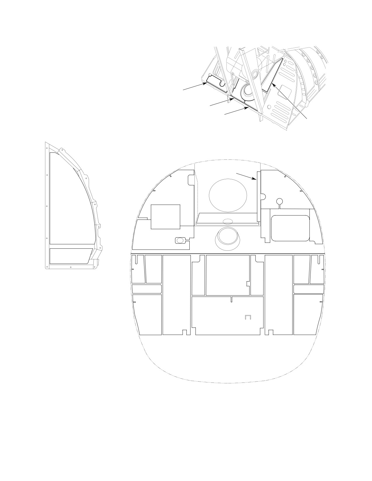
Figure 201. Soundproofing Insulation − Firewall and Plenum Chamber (Sheet 1 of 2)
Page 202
Revision 19
53-30-00
MD Helicopters, Inc.
CSP-HMI-2
MAINTENANCE MANUAL
TRANSMISSION
PANEL
CURRENT CONFIGURATION
QUARTER
PANEL
TRANSMISSION
PANEL
EARLY CONFIGURATION
QUARTER
PANEL
G53-3003-2
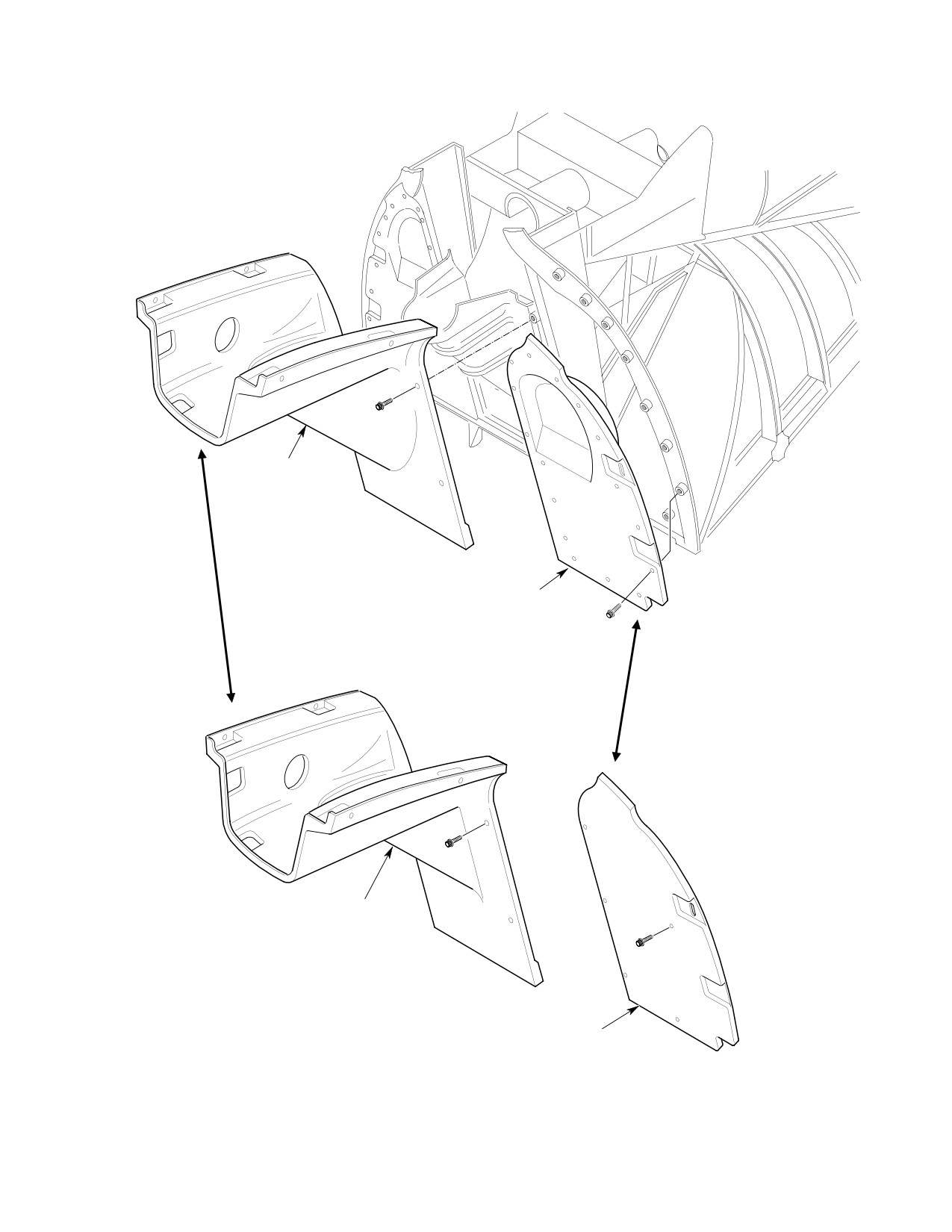
Figure 201. Soundproofing/Insulation − Firewall and Plenum Chamber (Sheet 2 of 2)
Page 203
53-30-00
Revision 19
CSP-HMI-2
MD Helicopters, Inc.
MAINTENANCE MANUAL
A. Mast Support Structure
(7). Clean and inspect any suspected area;
use dye-penetrant to determine if a
The mast support structure is part of the
crack does exist. If a crack is found,
fuselage structure and is composed of two
part must be replaced.
longitudinal forged fittings, a lower pan and
an aft pan. The mast support structure
(8). Inspect mast support structure for
supports and mounts the main rotor mast.
corrosion, loose bolts and rivets and
general condition of finish.
NOTE: The main rotor static mast has been re
moved, in it's entirety, from this section be
(9). Check that mast support structure pan
cause of duplicate information in Section
drain hole is open.
63-30-00. Refer to Section 63-30-00 for all
information concerning the main rotor stat
(10). Reinstall controls tunnel cover.
ic mast.
(11). Reinstall left and right forward sections
of air inlet fairing (Ref. Engine Inlet
3. Mast Support Structure Inspection
Fairing Replacement).
Accomplish the following inspection at
(12). Reinstall main gearbox access cover
specified intervals (Ref. Chap. 05).
and trim.
When working near or around
CAUTION
A. Firewalls
engine air and cooling inlets,
use care to prevent entry of foreign objects
(Ref. Figure 202) A shell-like aft section upper
(Ref. Sec. 71).
firewall surrounds the upper portion of engine
combustion chamber and exhaust pipe
(1). Remove left and right sections of air
assembly. The design contains engine heat as
inlet forward fairing (Ref. Engine Inlet
well as any fire that might develop within the
Fairing Replacement).
engine compartment. Upper firewall is thin,
(2). Remove interior trim (Ref. Sec. 25-30,
0.0015 inch (0.0381 mm) thick sheet, rigidized
Interior Trim Replacement) and main
CRES sheet covered with double thickness of
gearbox access cover (same section).
nonflammable ceramic fiber blanket.
(3). Detach control tunnel cover from
4. Firewalls Inspection
structure and slide out of way.
No unrepaired damage is permissible. (For
NOTE: Use bright light and 5-power magnify
repairs to forward firewall, Ref. FAA AC
ing glass to carefully inspect areas described
43-13-1A & 2A or Structural Repair Manual.)
in steps below for evidence of cracks.
For repairs of the upper firewall (Ref. Silver
Brazing Upper Firewall Shelf Patch).
(4). Inspect visible areas of mast support
fitting, mast base and mast tube, with
(1). Inspect forward firewall for punctures
particular attention to base attachment
and corrosion.
areas and shaded areas.
(2). Inspect upper firewall for punctures,
(5). Inspect both side of channels on aft
corrosion and evidence of contact with
canted bulkhead from mast support
discoloration. If contact with discolor
fitting down to waterline 34.00 with
ation is observed on the firewall
particular attention to points of
attachment button heads, remove the
attachment.
upper firewall and inspect the attach
frames for discoloration or damage;
(6). Inspect side channels and fore and aft
contact MDHI for further directions.
webs of controls tunnel, from mast
support fitting down to top of pilot's
(3). Inspect for complete seal around
seatback (canted bulkhead waterline
openings for overrunning clutch, engine
45.36).
compressor air inlet and oil cooler.
Page 204
Revision 38
53-30-00
MD Helicopters, Inc.
CSP-HMI-2
MAINTENANCE MANUAL
TAIL ROTOR DRIVE SHAFT FAIRING
REMOVABLE PANEL
CANTED STA. 124.00
CHANNEL
ENGINE AIR INLET
WATERLINE 34.96 RIB
INSTALLATION
(PLENUM CHAMBER)
AFT SECTION UPPER FIREWALL
(NOTE)
FORWARD ENGINE
AIR INLET PANEL
ENGINE AIR INLET SIDE PAN
DRAIN FITTING
ENGINE AIR
AFT SECTION FORWARD FIREWALL
INLET PAN
(NOTE)
369D/E/FF SHOWN
NOTE:
AFT SECTION FIREWALL IS A REMOVABLE ASSEMBLY. BOTTONHEAD FASTENERS
G53-3008A
ARE WITHDRAWN FROM INSIDE SURFACE OF FIREWALL SHELL TO REMOVE
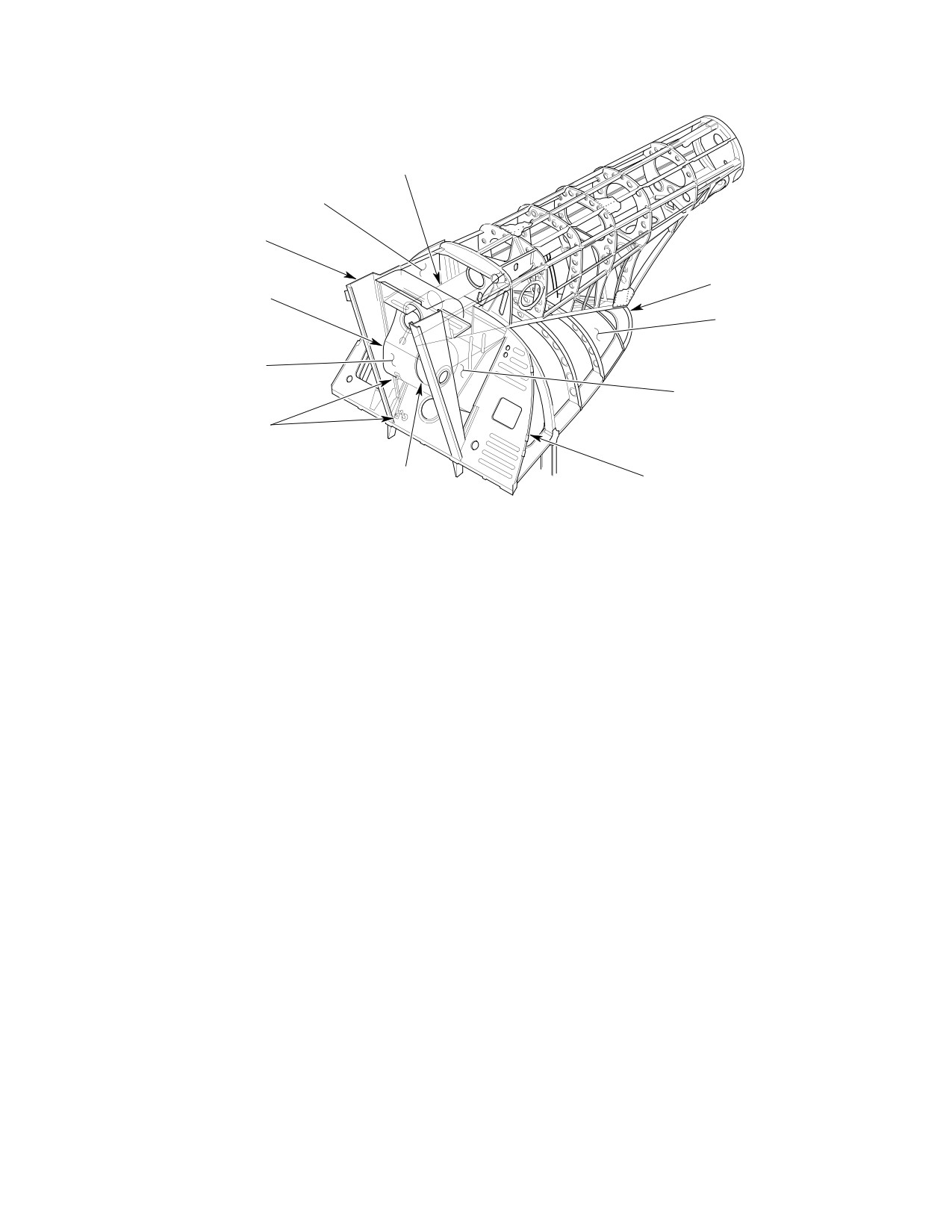
Figure 202. Firewall and Aft Section
A. Firewall, Station 124.00 Insulation and
(4). Check that all individual panels are
Soundproofing
securely attached to firewall and
plenum areas with no loose edges.
(Ref. Figure 201, Sheet 1 of 2) Engine compart
ment forward firewall is insulated and
(5). Check panels in passenger compart
soundproofed for heat and noise reduction in
ment of defects, tears, looseness, or
passenger/cargo compartment.
missing panels.
5. Firewall and Plenum Chamber
Soundproofing Panel Inspection
(6). For applicable repairs refer to Plenum
Chamber Hole Sealing reference.
(Ref. Figure 201, Sheet 1 of 2 and Figure 202)
(1). Remove trim (Ref. Sec. 25-30-00,
A. Engine Air Inlet Fairing
Interior Trim Replacement) for access
to passenger/cargo compartment
The engine air inlet fairing on top of the
firewall areas. Open engine access
fuselage structure directs ambient outside air
doors to inspect engine compartment
to the engine air inlet and oil cooler blower.
panels.
The fairing installation consists of a forward
(2). Check for defective, torn, loose or
fairing section and an aft fairing section. Right
missing panels.
and left halves of forward fairing are remov
able. The aft fairing is riveted to fuselage
(3). Inspect aft firewall for security, punc
structure. A UHF/VHF antenna is bonded to
tures and corrosion.
the aft vertical face and is part of aft fairing.
Page 205
53-30-00
Revision 38
CSP-HMI-2
MD Helicopters, Inc.
MAINTENANCE MANUAL
6.
Engine Air Inlet (Plenum Chamber)
(1). Negligible Damage (Ref. Table 201,
Inspection
53-00-00).
(1).
For access, open bypass door on right
(2). Replacement. Replace fittings according
side of engine air inlet and engine
to Structural Repair Manual.
compartment access doors for view of
rear side of plenum (Ref. Figure 202).
7. Aft Section Strut Repair
(2).
Inspect all panels for evidence of
Repair of strut is limited to smoothing out
corrosion, security of rivets and punc
minor dents, scratches or nicks. Replace strut
tures.
if it is badly damaged according to Structural
Repair Manual.
(3).
Inspect engine air shield mounting clips
for secure attachment.
8. Silver Brazing Procedure − Upper Firewall
Shell Patch
(4).
Inspect aft section strut for rivet
corrosion and edge clearance where it
(Ref. Figure 203)
passes through cutout in forward panel.
For applicable repairs (Ref. Aft Section
Consumable Materials
Strut Repair).
(Ref. Section 91−00−00)
Item
Nomenclature
(5).
Ensure that removable forward panels
are secure. Inspect rubber seals for
CM234
Solvent, dry-cleaning
security and partial compression.
CM721
Tape, aluminum foil
(6).
Inspect drive shaft tube fairing for
CM817
Brazing flux
dents, buckled or wrinkled areas and
CM818
Brazing alloy
signs of corrosion.
(7).
Close engine compartment access doors
(1). Remove aft section upper firewall (Ref.
and two air inlet access doors.
Upper Firewall Replacement).
A. Upper Aft Section General Repair
(2). Remove tape and ceramic fiber blankets
from firewall shell.
Ref. FAA AC 43.13-1B and FAA AC 43.13-2B
Inspection and Repair for Standard Sheet
(3). Clean firewall shell with stiff bristle
Metal Repair and Alterations and Structural
brush moistened with solvent (CM234)
Repair Manual for additional repair proce
and wipe dry with clean, dry cloth.
dures.
(4). Smooth out rigidized pattern in area on
B. Aft Fuselage Fittings
which patch will be brazed.
Mast support structure fitting and fuselage
boom fairing frame fitting are critical fatigue-
(5). Cut suitable repair patch for Type 321
loaded parts. Any damage in excess of negligi
stainless steel sheet in thickness range
ble limits specified in (Ref. Aft Section Strut
of 0.0015-0.0018 inch (0.0381-0.04572
Repair) requires replacement of part.
mm).
C. Aft Fuselage Fittings General Repair
(6). Contour patch to match contour of
firewall shell repair area.
Repair of cast and forged fittings should only
be temporary and be performed only when
Use only stainless steel wire
replacement components are not immediately
CAUTION
brush in next step. Particles
available. Replacement of bushings or inserts
from bristles of other metals can contami
that become part of fitting assembly are
nate the patch area and cause brazing to
considered insertion repairs. (Insertion repairs
fail.
are described in FAA AC 43.13-1B and FAA
AC 43.13-2B Inspection and Repair for
(7). Use stainless steel wire brush to clean
Standard Sheet Metal Repair and Alterations
and abrade inner and outer surfaces of
and Structural Repair Manual.)
stainless steel patch and firewall.
Page 206
Revision 44
53-30-00
MD Helicopters, Inc.
CSP-HMI-2
MAINTENANCE MANUAL
STA. 197.78 BOOM FAIRING
CANTED FRAME FITTING
BOOM FAIRING RING
AFT SECTION STRUT
AFT SECTION
UPPER FIREWALL
ENGINE AIR INLET
INSTALLATION
(PLENUM CHAMBER)
G53-3006
Figure 203. Major Bulkheads and Structural Members − Aft Fuselage
(8). Rinse patch and firewall shell thor
Use extreme care not to over
CAUTION
oughly with clean water and allow to
heat and burn through firewall
air dry.
shell.
(11). Braze patch in place with Class 8 silver
(9). Coat surfaces to be joined with a thin
brazing alloy (CM818), using suitable
even coating of silver alloy brazing flux
torch to heat patch area to temperature
(CM817).
moderately above 1295°F (707°C) flow
point of brazing alloy.
(10). Use clamp or other suitable device to
(12). Allow joint to cool for at least 60
hold patch in place during brazing
seconds before removing clamping
operation.
device.
Page 207
53-30-00
Revision 38
CSP-HMI-2
MD Helicopters, Inc.
MAINTENANCE MANUAL
(13). Remove flux by immersing repaired
area in water at 160°-212°F
Consumable Materials
(72°-101°C) for 40 minutes.
(Ref. Section 91−00−00)
Item
Nomenclature
(14). Thoroughly rinse in clear, running
CM318
Primer
water; air dry, or wipe dry with clean,
dry cloth.
(1). Remove engine inlet forward fairing
(15). Install ceramic blanket on outer surface
assemblies from helicopter (Ref. Engine
of firewall shell.
Inlet Fairing Replacement).
(16). Install aft section upper firewall shell
(2). Remove interior trim panels and wire
(Ref. Upper Firewall Replacement).
harnesses, as applicable, to gain access
to work area at forward area at forward
(17). Install tape (CM721) on flanges of
attach nutplate assembly for L/H and
firewall shell.
R/H engine inlet forward fairings.
9. Plenum Chamber Hole Sealing
(3). Remove existing forward nutplate (for
both L/H and R/H fairing assemblies)
(Ref. Figure 203)
from fuselage frame structure.
(4). Inspect upper fuselage skin for cracks
Consumable Materials
or damage at area of forward nutplate
(Ref. Section 91−00−00)
attachment holes. Also inspect repair
Item
Nomenclature
doublers if, previously installed, on
CM418
Cement, epoxy
upper fuselage skin.
CM424
Sealing compound
CM713
Tape, pressure sensitive
NOTE: If cracking or damage to fuselage skin
or repair doublers is noted, perform the fol
lowing:
All tape must be applied to out
CAUTION
side of inlet surfaces, so that
(a). Stop drill all cracks or remove
any subsequently loosened tape cannot en
damaged skin area or damaged
ter plenum chamber to cause engine dam
repair doublers prior to rework.
age.
Perform all work in accordance with
FAA AC 43.13-1B and FAA AC
(1). Using 10 mil by 1 inch (2.54 cm)
43.13-2B Inspection and Repair for
pressure-sensitive tape (CM713), tape
Standard Sheet Metal Repair and
all 0.130 inch (3.302 mm) diameter or
Alterations and Structural Repair
larger holes.
Manual.
(2). Using sealant (CM424), seal all holes
(b). Field fabricate and install doublers
less than 0.130 inch (3.302 mm)
on outer fuselage skin. Drill
diameter.
0.196-0.204 inch (4.978-5.182 mm)
diameter hole in each doubler to
(3). Rebond loose rubber seals with adhe
match existing hole in fuselage skin
sive (CM418) according to container
for fairing attach screw. Use existing
instructions.
rivet pattern as shown; install
MS20470AD3 rivets with primer
10. Forward Fuselage Section Structure
(CM318).
Rework
(c). Prime and paint double to match
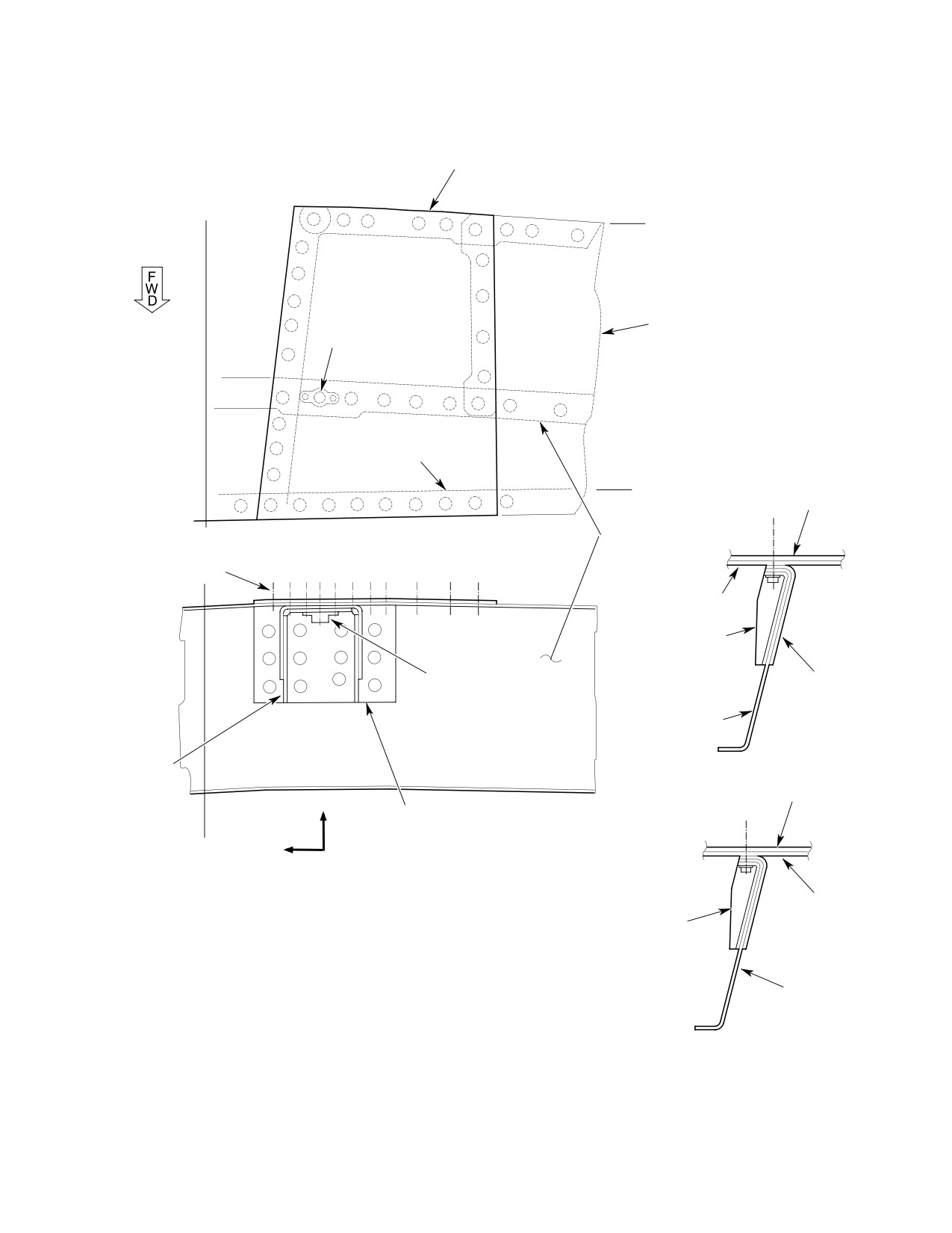
(Ref. Figure 204) The following information is
finish color of helicopter.
a procedure for installing support assemblies
to the fuselage frame structure to provide
(5). Inspect fuselage frame structure
reinforcement at the forward attach points for
(channel) for cracks or damage at
the engine inlet fairing assemblies.
forward nutplate attach areas.
Page 208
Revision 44
53-30-00
MD Helicopters, Inc.
CSP-HMI-2
MAINTENANCE MANUAL
NOTE: If no cracking or damage to fuselage
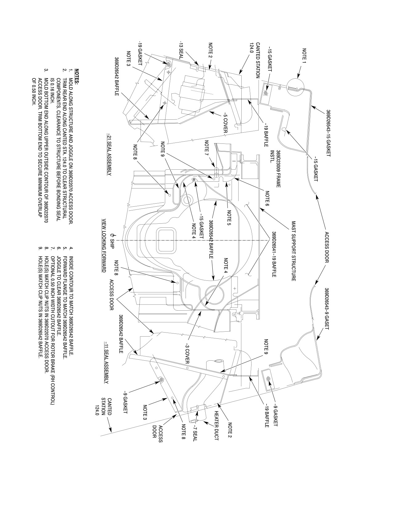
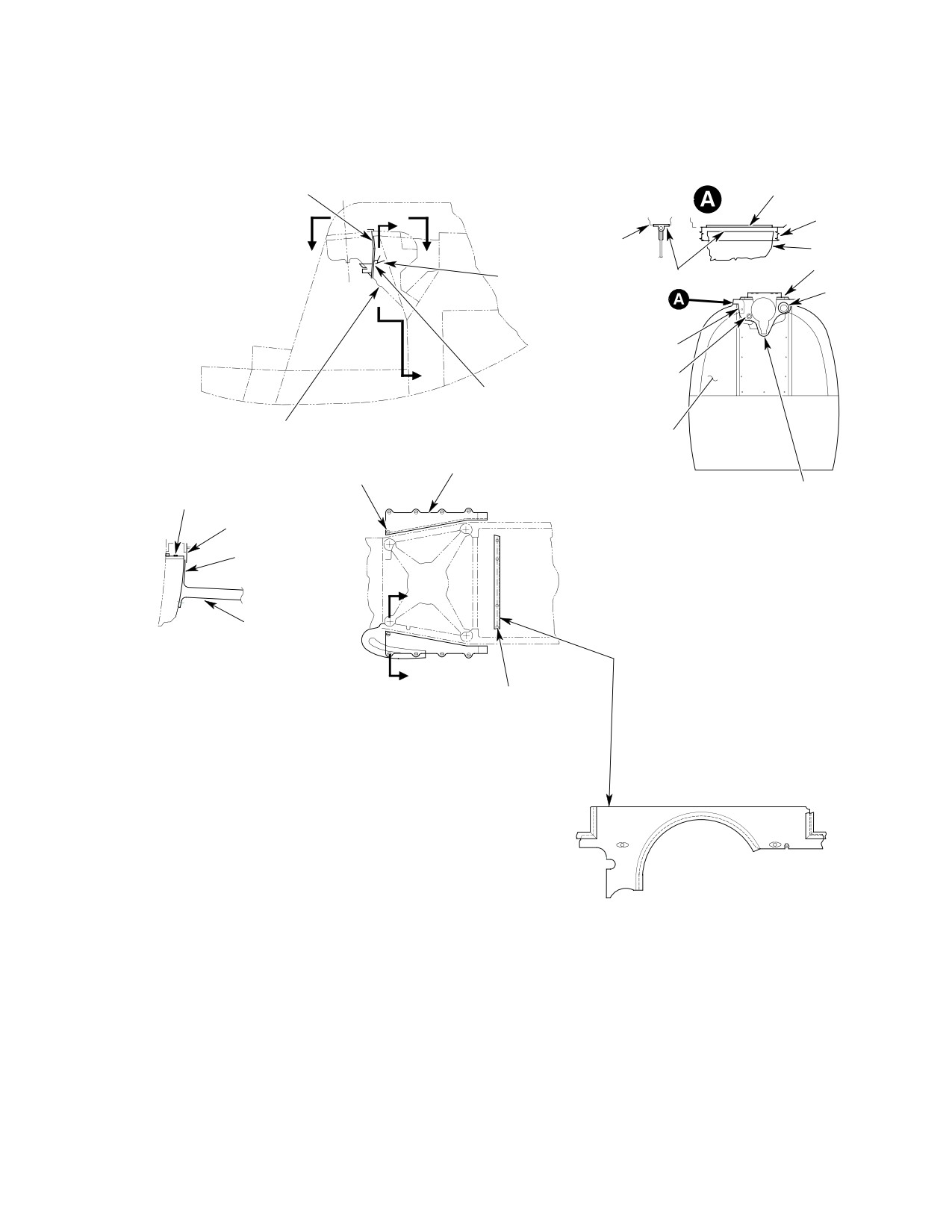
11. Transmission Compartment Air Baffle,
frame is noted, install 80-369D22400-3 and
Seal and Cover Initial Installation
-4 support assemblies at FWD side of frame
(Ref. Figure 205) (Serial No. 0003D thru
structure using rivets. Drill holes in support
0333D only)
assemblies for nutplates and for conduit
clearances as required. Install nutplate
Consumable Materials
rivets (MS20470AD3) through support,
(Ref. Section 91−00−00)
frame, upper skin and doubler, if installed.
Item
Nomenclature
N/A
Calking compound
CM425
Sealing compound
(6). If cracking or damage to fuselage frame
CM712
Tape, pressure sensitive
is noted, perform the following:
(1). Remove engine air inlet forward
(a).
Stop drill all cracks or remove
fairings.
damaged area prior to installation of
(2). Remove cooling fan inlet screen.
repair angles and support assem
blies. Perform all work in accordance
(3). Remove aft compartment interior trim
panels and blower access door.
with FAA AC 43.13-1B and FAA AC
43.13-2B Inspection and Repair for
(4). Install PN 369D26541-19 upper baffle
Standard Sheet Metal Repair and
assembly as follows;
Alterations and Structural Repair
(a). Position baffle between main trans
Manual.
mission and mast support structure.
Align four attach holes in baffle with
existing holes in structure.
(b).
Field fabricate and install repair
angles at AFT side of fuselage frame
(b). Install baffle with screws, washers
structure (channel) and install
and nuts. Seal screw heads with
sealant (CM425).
80-369D22400-3 and -4 support
assemblies at FORWARD side of
(5). Install PN 369D26542 lower baffle to
frame structure using MS20470AD3
upper baffle with two screws and
rivets. Drill 0.096 inch (2.4384 mm)
washers at matching nutplates in upper
diameter holes in angles to match
baffle.
support assemblies.
(6). Disconnect 5/8 inch (15.875 mm)
diameter drain tube at mast support
base and insert tube though hole in
(c).
Drill holes in support assemblies and
baffle. Safetywire drain tube to struc
repair angles for nutplates and for
ture.
conduit clearance as required. Install
(7). Reinstall blower access door.
nutplate rivets through support,
frame, angle, upper skin and doubler,
(8). Position and install PN 369D26543-11
if installed.
and -12 seal assemblies at lower baffle
and blower access door as shown.
Install seal assemblies with screws and
(7). Check installation of 80-369D22400-3
washers at matching clipnuts on lower
baffle and on blower.
and -4 assemblies and repair angles
and doublers, if installed, for discrepan
NOTE: If excessive gap, 0.060 inch (1.524 mm)
cies.
or more, exists between structure and rub
ber extrusion on seals, fill gap by bonding
strip of adhesive-backed gasket to struc
(8). Reinstall removed components.
ture.
Page 209
53-30-00
Revision 44

CSP-HMI-2
MD Helicopters, Inc.
MAINTENANCE MANUAL
(9).
Position PN 369D26545-11 and -21
NOTE: Not applicable if modified rotor brake
cover assemblies as shown; align cover
handle trim cover panel has already been in
attach holes with existing fairing attach
stalled.
nutplates. Temporarily secure cover
(a). Carefully trim modified trim cover
assemblies with screws and washers, 5
panel assembly (for LH or RH rotor
places each.
brake handle assembly). Locate and
drill screw attach holes in modified
(10).
Using caulking compound, seal all gaps
panel.
between fuselage structure and baffle;
seal and cover assemblies.
(b). Slide modified trim panel boot over
brake handle. Align screw holes and
check panel for fit. Remove panel and
(11).
Remove screws securing cover assem
make minor trim adjustments as
blies. Reinstall engine air inlet forward
required.
fairings.
(c). Install panel if removed and secure
panel with attaching hardware.
(12).
Reinstall aft compartment trim.
(d). Push panel boot aft on brake handle
(13).
For helicopters equipped with Rotor
approximately two inches and secure
Brake Kit, perform the following;
with fastener tape.
Table 201. Weight and Balance Data
Weight
Arm
Moment
lbs
(kg)
inches
(cm)
in−lbs
(kg−mm)
+1.5
(+0.681)
110.2
(279.908)
+169
(+1947.0828)
Page 210
Revision 38
53-30-00
MD Helicopters, Inc.
CSP-HMI-2
MAINTENANCE MANUAL
DOUBLER (NOTE 1)
0.030 INCH (0.762 MM)
2024-T3 AL ALY SHEET
BL
6.00
LH
CANTED
STA 78.50
0.196-0.204 INCH
(4.978-5.182 MM) HOLE
OUTER SKIN
TO MATCH EXISTING
SCREW HOLE
369A2400-5 ANGLE
STA.
89.39
DOUBLER
A
369H2508 FRAME
VIEW
3 RIVETS EACH SIDE
OF DAMAGE (AD3)
SKIN
80-369D22400-3, -4
SUPPORT FORWARD
SIDE OF FRAME
NUTPLATE
(NOTE 3)
ANGLE 0.020 INCH
(NOTE 5)
(0.508 MM) AFT
SIDE OF FRAME
FRAME
(NOTES 2, 3)
SUPPORT
(LH SHOWN)
DOUBLER
UP
ANGLE
B
VIEW
(NOTES 2, 3)
INBOARD
SKIN
80-369D22400-3, -4
SUPPORT FORWARD
SIDE OF FRAME
(NOTE 3)
NOTES:
1.
DOUBLER ON OUTER SKIN TO PICK UP EXISTING RIVETS.
FRAME
2.
REPAIR ANGLE INSTALLED ONLY IF FRAME DAMAGE IS NOTED.
3.
DRILL HOLES IN SUPPORT/ANGLE AS REQUIRED FOR CONDUIT
CLEARANCES.
4.
STOP DRILL ALL CRACKS OR REMOVE DAMAGED AREA.
VIEW
5.
INSTALL NUTPLATE RIVETS THRU SUPPORT, FRAME, ANGLE
G53-3007A
(IF INSTALLED) SKIN AND DOUBLER
Figure 204. Forward Fuselage Section Structure Rework
Page 211
53-30-00
Revision 38
CSP-HMI-2
MD Helicopters, Inc.
MAINTENANCE MANUAL
G53-3009-1
Figure 205. Installation of Air Baffle, Seal and Cover Assemblies (Sheet 1 of 2)
Page 212
Revision 38
53-30-00
MD Helicopters, Inc.
CSP-HMI-2
MAINTENANCE MANUAL
369D26541-19 BAFFLE
SHIP STRUCTURE
B
RUBBER
EXTRUSION
GASKET
369D26543 SEAL
C
C
369D26541-19
369D26543-11 SEAL
GAP (NOTE 3)
BAFFLE
(LH SHOWN)
NOTE 1
369D26543-21 SEAL
NAS603-8 SCREW (4)
AN960PD10L WASHER (4)
(LH SHOWN)
B
NOTE 2
369D26542
BAFFLE
369D22070
ACCESS DOOR
369D22070
369D26545-21 COVER
ACCESS DOOR
NAS608-3 SCREW
(-11 OPPOSITE)
AN960PD10L WASHER
369D26542 BAFFLE
369D26543-11 SEAL
NAS602-8 SCREW (2)
369D22025-3 FAIRING PLATE
AN960PD10L WASHER (2)
(NOTE 5)
VIEW B-B
NOTE 4
D
369D22025 FAIRING
VIEW D-D
(TYP BOTH SIDES)
369D26541-19 BAFFLE
D
NAS603-8 SCREW (4)
VIEW C-C
AN960PD10L WASHER (4)
MS21043L3 NUT (4)
NOTES:
1.
DURING INSTALLATION OF 369D26542 BAFFLE, DISCONNECT
AND INSERT HEATER DUCT THRU HOLE IN BAFFLE.
2.
AFTER 369D26542 BAFFLE IS INSTALLED, DISCONNECT AND
ROUTE DRAIN TUBE THRU HOLE IN BAFFLE.
3.
IF EXCESSIVE GAP (0.06 X 1.00 OR MORE)EXISTS BETWEEN
STRUCTURE AND RUBBER EXTENSION ON SEALS, FILL GAP BY
BONDING STRIP OF ADHESIVE-BACKED GASKET TO STRUCTURE.
4.
NO. 10 SCREW HOLE IN FAIRING ON SHIPS. DO NOT USE THIS
G53-3009-2
HOLE TO INSTALL COVER OR FAIRING.
5.
TRIM PLATE, AS REQUIRED, TO CLEAR SCREW HEAD.
Figure 205. Installation of Air Baffle, Seal and Cover Assemblies (Sheet 2 of 2)
Page 213
53-30-00
Revision 38
CSP-HMI-2
MD Helicopters, Inc.
MAINTENANCE MANUAL
This Page Intentionally Left Blank
Page 214
Revision 38
53-30-00
MD Helicopters, Inc.
CSP-HMI-2
MAINTENANCE MANUAL
Section
53−30−30
Upper Aft Section
Fuselage (500/600N)
MD Helicopters, Inc.
CSP-HMI-2
MAINTENANCE MANUAL
UPPER AFT SECTION FUSELAGE (500/600N)
MAINTENANCE PRACTICES
NOTE: For all the following items, refer to Sec.
the engine plenum chamber area. With the
53-30-00.
installation of a particle separator, ejector
Upper Firewall
outlets are positioned on each side of the
Firewall and Plenum Chamber Panels
plenum cover.
General Inspection
On the 500N, the R/H side of the aft fairing is
Mast Support Structure
the inlet bypass door which remains on the
Main Rotor Mast
fuselage when the aft fairing is removed.
Firewalls
Firewall Insulation and Soundproofing
On the 600N, the inlet bypass door is just aft
of the mast assembly and just forward of the
1. Engine/Anti−Torque Air Inlet Fan Fairings
engine plenum access cover.
When working near or around
A removable fan hub and transmission gear
CAUTION
engine air and cooling inlets,
box fairing is also located in the fan plenum
use care to prevent entry of foreign objects.
chamber.
(Ref. Figure 201) On the 500N, the engine air
For general maintenance practices for the
inlet fairing on top of the fuselage structure
upper aft section (Ref. Sec. 53-30-00).
directs ambient outside air to the engine air
inlet and the oil cooler blower. The fairing
2. Engine Air and Fan Inlet (Plenum
installation consists of a forward fairing
Chamber Area) Inspection
section and an aft fairing section. Right and
left halves of forward fairing are removable.
(Ref. Figure 201 and Figure 202)
(Ref. Figure 202) On the 600N, the engine air
Avoid FOD, Cover compressor
CAUTION
inlet fairing on top of the fuselage structure
inlet prior to working in plenum
chamber area. Vacuum all FOD debris out of
directs ambient outside air to the engine air
the plenum chamber before removing the
inlet bypass door and the oil cooler blower. The
protective cover from the inlet bell. Severe
fairing installation consists of a forward inlet
damage to the engine may result from entry
fairing sections and an aft fairing section. The
of foreign objects.
controls cover and right and left halves of
forward fairing are removable.
(1). Open the plenum chamber bypass door
by pulling the handle located in the
On the 600N, the engine inlet or particle
cockpit. Open the engine access doors to
separator is mounted aft of the inlet fairings
inspect the rear side of the plenum
and wraps around the engine plenum for
panels.
increased air flow due to the larger engine
installation.
(2). For access, remove the fan air inlet
screen and engine plenum fairing
The aft section consists of an air inlet screen
assemblies.
on top of the fuselage structure which directs
ambient air to the anti-torque fan assembly.
(3). Inspect all panels for evidence of
The engine plenum access cover bolted to the
corrosion, punctures and security of
fuselage and is removable to provide access to
rivets and fasteners.
the engine plenum, particle separator and mist
eliminator (optional equipment) if installed.
(4). Inspect the engine air inlet bypass door
attaching hardware and installation
The engine plenum access cover on the 600N
(Ref. Sec. 71-10-10, Engine Air Intake
helicopter mounts to the aft end of the particle
System).
separator/bypass door frame. The plenum
cover directs air downward for the engine air
(5). Inspect engine air shield mounting for
intake and when removed provides access to
secure attachment.
Page 201
53-30-30
Revision 26
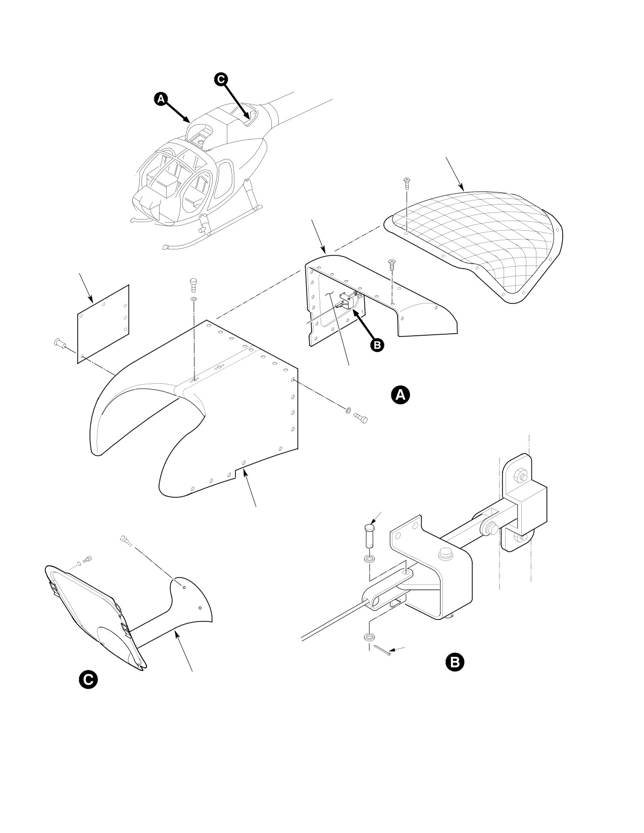
CSP-HMI-2
MD Helicopters, Inc.
MAINTENANCE MANUAL
FAN AIR INLET
SCREEN
ENGINE PLENUM
ACCESS COVER
INTAKE FAIRING
ACCESS DOOR
BYPASS DOOR
PIN
INTAKE
FAIRINGS
COTTER
PIN
BYPASS DOOR
LATCH ASSEMBLY
FAN HUB FAIRING AND
TRANSMISSION COVER
G53-3005A
Figure 201. Upper Aft Section (500N)
Page 202
Revision 34
53-30-30
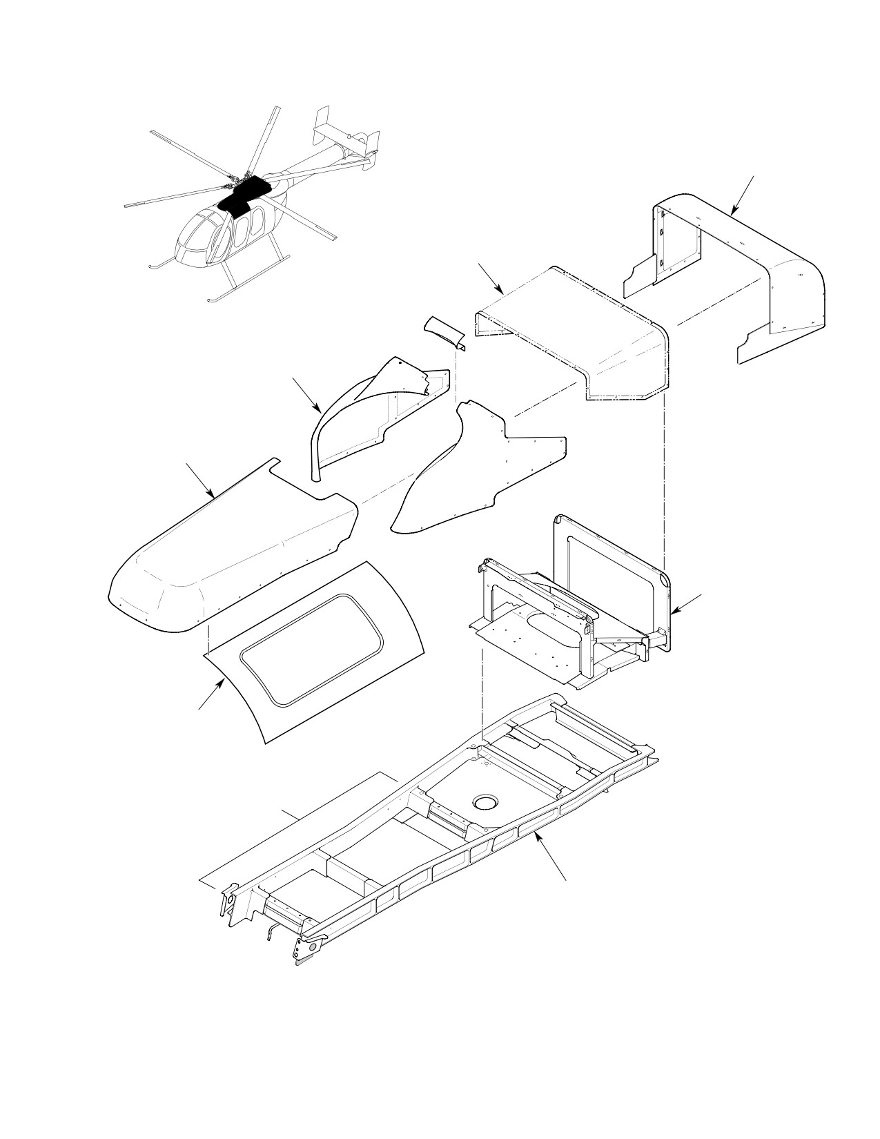
MD Helicopters, Inc.
CSP-HMI-2
MAINTENANCE MANUAL
ENGINE PLENUM
ACCESS COVER
ENGINE INLET SCREEN OR
PARTICLE SEPARATOR
FORWARD INLET
FAIRINGS
CONTROLS FAIRING
PARTICLE SEPARATOR/
BYPASS DOOR FRAME
MID UPPER
STRUCTURE
EXTENDED FUSELAGE
ROOF BEAMS OF 600N
MAST SUPPORT STRUCTURE
3040--010101
3011--010303
6G53-055
Figure 202. Upper Aft Section Fuselage (600N)
Page 203
53-30-30
Revision 34
CSP-HMI-2
MD Helicopters, Inc.
MAINTENANCE MANUAL
(6).
Inspect aft section strut for rivets
B. Upper Fuselage Controls Fairing
corrosion and edge clearance where it
Installation
passes though cutout in forward panel.
(1). Inspect upper fuselage controls fairing
(7).
Inspect engine air cooling inlet screen
for cracks, delaminations and overall
for damage, seal deterioration and
general condition.
security.
(2). Position controls fairing to align with
(8).
Inspect fan transmission driveshaft
holes in mounting surfaces.
tube fairing and access panel for dents,
(3). Install attaching hardware.
buckled or wrinkled areas and signs of
corrosion.
5. Engine Inlet Fairings Replacement
(9).
Inspect the fan inlet screen mesh for
The R/H and L/H engine inlet fairings are
condition and security.
made of a lightweight Kevlar fabric and are
used on the 500/600N installation only.
(10).
If fan inlet screen needs repair, re
welded using 0.063 inch (1.600 mm)
A. Engine Inlet Fairing Removal
annealed cres 302 or 304 wire per
(1). Remove hardware from left-hand inlet
AMS5336 or AMS5639.
fairing and remove fairing.
(11).
Visually inspect through the fan inlet
(2). Remove hardware from right-hand
screen for security of the transmission
inlet fairing and remove fairing.
fairing and FOD.
B. Engine Inlet Fairing Installation
(12).
Ensure that forward removable inlet
fairings and engine access doors are
(1). Inspect fairings for cracks, delamina
secure.
tions and condition of pressure sensi
tive tape.
A. Upper Aft Section General Repair
(2). Install right-hand inlet fairing and
(Ref. FAA AC 43.13-1B and FAA AC 43.13-2B
attaching hardware.
Inspection and Repair for Standard Sheet
Metal Repair and Alterations and Structural
(3). Install left-hand inlet fairing and
Repair Manual for additional repair proce
attaching hardware.
dures.
(4). Ensure that 1-1/2 threads protrude
3. Upper Fuselage Controls Fairing (600N)
through nutplates.
6. Anti−Torque Fan Air Inlet Screen
The Upper Fuselage Controls Fairing covers
the flight control rods that travel longitudinal
Replacement
ly aft along the roof of the fuselage for the
A. Fan Air Inlet Screen Removal
rotor collective and cyclic controls.
(1). Remove attaching hardware and
4. Upper Fuselage Controls Fairing
remove air inlet screen.
Replacement (600N)
B. Fan Air Inlet Screen Installation
The Upper Fuselage Controls Fairing is made
of a lightweight Kevlar fabric and is used on
(1). Install air screen and attaching
the 600N installation only.
hardware.
A. Upper Fuselage Controls Fairing
7. Fan Hub and Transmission Cover Fairing
Removal
Replacement
(1). Remove hardware that attaches upper
A. Fan Hub and Transmission Cover
fuselage controls fairing to mounting
Removal
surfaces.
(1). Remove attaching hardware on the fan
(2). Remove controls fairing.
hub transmission fairing.
Page 204
Revision 44
53-30-30