HANDBOOK OF MAINTENANCE INSTRUCTIONS FOR MDHI 369D/E/FF-500/600N HELICOPTERS (ISSUED: 1990) - page 14
MD Helicopters, Inc.
CSP-HMI-2
MAINTENANCE MANUAL
5.98 INCH
3.92 INCH
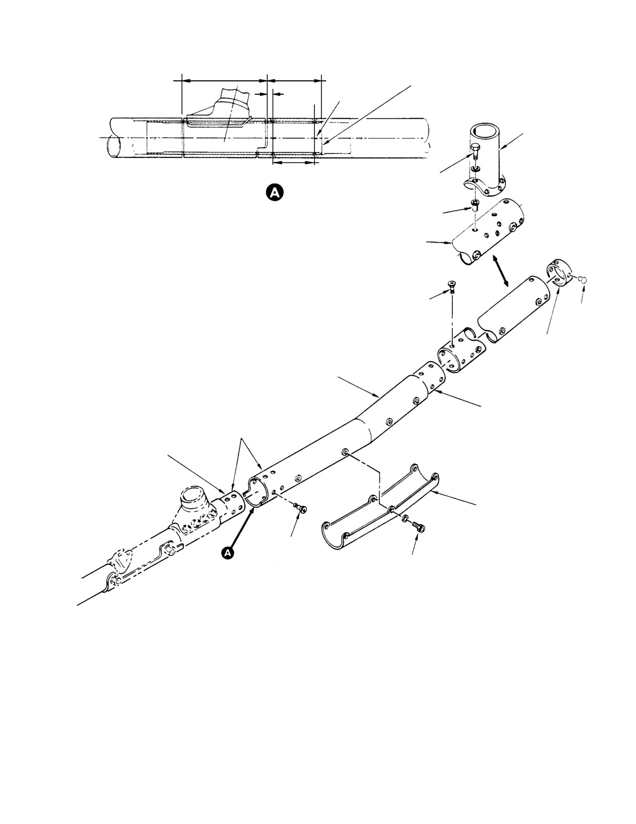
369D26012-5 SLEEVE
(15.189 CM)
(9.957 CM)
0.40 INCH
(REF)
(10.16 MM)
NOTE 1
SUPPORT ASSEMBLY
(NOTES 3 & 4)
2.90 INCH
BOLT
(7.37 CM)
(NOTE 2)
RIVNUT
(NOTE 2)
COMPONENT OF 369D292808-17 AND -18
(FOR UTILITY FLOATS ONLY)
VISU-LOK
(8 PLS) (NOTE 2)
RIVET
(NOTE 2)
PLUG
(NOTES 3 & 4)
EXTENSION TUBE
(NOTES 3 & 5)
(NOTES 3 & 5)
369D26012-5
ADAPTER SLEEVE
ABRASION STRIP
(NOTES 3 & 4)
VISU-LOK
(8 PLS) (NOTE 2)
BOLT
(NOTE 2)
NOTES:
1.
MATCH-DRILL 8 - 0.1945/0.1965 INCH (4.9403/4.9911 MM) DIAMETER HOLES THRU
BOTH TUBES AND CSK, 1005 X 0.378/0.385 INCH (9.6012/9.779 MM) DIAMETER.
APPLY PRIMER TO BARE METAL SURFACES.
2.
COAT ATTACHING HARDWARE WITH PRIMER.
3.
COAT MATING SURFACES WITH ZINC CHROMATE PUTTY.
4.
SEAL MATING EDGES WITH SEALING COMPOUND.
5.
SEAL MATING EDGES WITH SEALING COMPOUND.
G32-8010
Figure 903. Skid Tube Extension Installation
Page 905
32-81-00
Revision 19
CSP-HMI-2
MD Helicopters, Inc.
MAINTENANCE MANUAL
(d). Reinstall skid tube extensions on to
E. Utility Float to Landing Gear Assembly
-5 adapter sleeve using a thin coat of
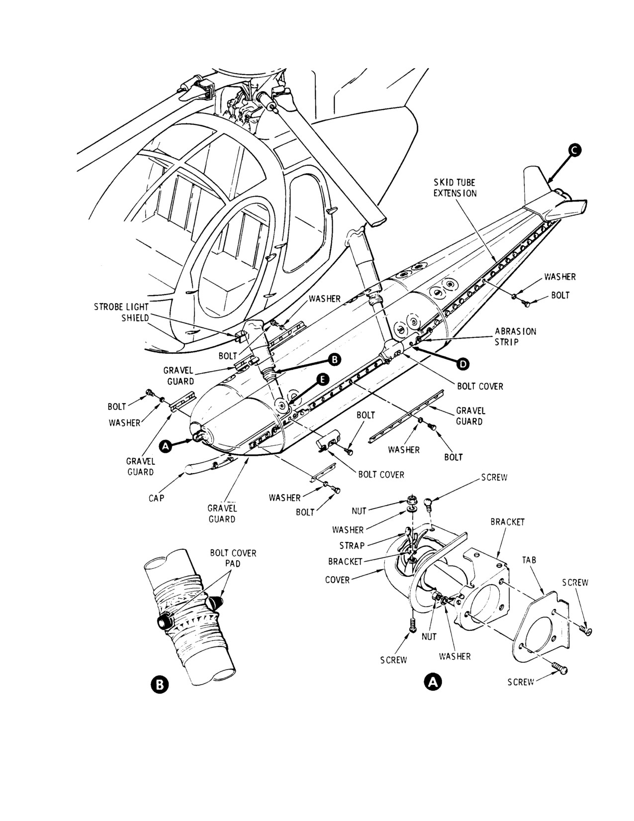
(Ref. Figure 904) The Utility Float Kit is shipped
sealing compound on mating sur
with as many parts assembled as practical;
faces. Seal with sealing compound.
however, certain items require assembly at
Secure with eight visu-lok fasteners
installation.
coated with primer.
(e). Install abrasion strip to each exten
Consumable Materials
sion tube with bolts and washers.
(Ref. Section 91−00−00)
Coat attaching hardware with
Item
Nomenclature
primer. Coat mating surfaces with
CM209
Zinc chromate putty
zinc chromate putty and seal mating
CM318
Primer
edges with approximately 0.060 inch
CM425
Sealing compound
(1.524 mm) bead of sealing compound
CM717
Tape, pressure sensitive
to insure watertight fit.
(3). Assembly of landing gear skid exten
NOTE: Prior to installation, apply primer
sion - On current configuration ex
(CM318) to all attaching hardware.
tended landing gear:
(1).
On early configuration extended
landing gear, coat abrasion strip with
(a). Insert float kit extension tube over
zinc chromate putty (CM209) and
adapter sleeve.
install with screws (view D).
(b). Align extension tube and sleeve
(2).
Install bolt cover pads using existing
holes, attach tube to skid with bolt
screws and wrap with two overlapping
spacer and nut.
layers of tape (CM717) (view B).
(3).
Coat mating surfaces of cap with
(4). Assembly of landing gear skid exten
sealing compound (CM425) and install
sion - On early configuration extended
using position light attaching screws.
landing gear:
(4).
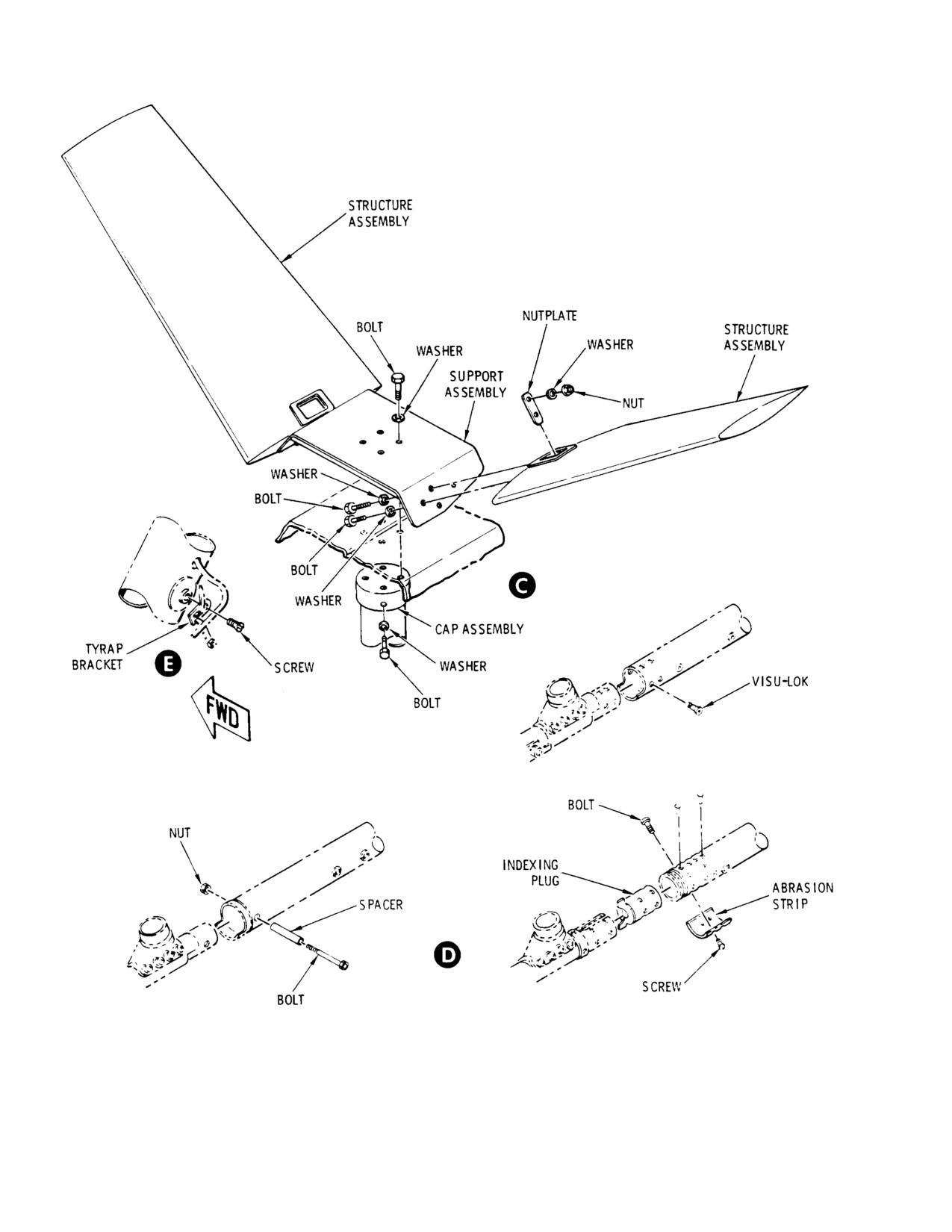
Temporarily install tyrap bracket with
(a). Seal all edges of skid plug with
screw (view E).
sealing compound; install in tube by
(5).
Position utility floats over landing gear
using using rivets.
skids.
(b). Coat all surfaces of indexing plug and
(6).
Align bolt holes in floats with bolt holes
sleeve with sealing compound.
in skid assembly. Position gravel
guards, coat bolts and washers with
(c). Insert sleeve adapter in tube and
primer (CM318); attach floats, gravel
install using rivets.
guards and abrasion strip using bolts
and washers. Torque bolts to 25 - 35
(d). Install packing and indexing plug in
inch-pounds (2.82 - 3.95 Nm).
tube; align holes in sleeve, plug
(7).
Position cap assembly (view C) on skid
assembly and tube with skid assem
tube extension. Coat mating surfaces
bly. Install rivets and bolts with
with sealing compound and secure with
primer (4).
bolts and washers.
(e). Coat mating surfaces of abrasion
(8).
Assemble structure assembly and
strip with zinc chromate putty (71).
support assembly (view C). Coat mating
Install abrasion strips with screws
surfaces with sealing compound and
and primer (4). Seal all edges with
secure with bolts, washers, nuts and
approximately 0.06 in. bead of
plate. Secure assembled stabilizer
sealant (3).
assembly using bolts and washers.
Page 906
Revision 19
32-81-00
MD Helicopters, Inc.
CSP-HMI-2
MAINTENANCE MANUAL
F. Utility Floats/Landing Gear Installation
If a preload condition prevents alignment,
disconnect one brace from strut assembly to
(Ref. Figure 902 and Figure 904)
eliminate preload (Ref. Sec. 32-10-00).
(4).
Secure new wire to forward foot using
Consumable Materials
tyrap bracket and screw (view E). Route
(Ref. Section 91−00−00)
wire to position light location through
Item
Nomenclature
tunnel provided in float. Use tie strap
CM318
Primer
as required. Attach wire to position
light.
CM425
Sealing compound
CM430
Sealant, solvent resistant
(5).
Install bracket using screws. Secure tab
CM717
Tape, pressure sensitive
and position light to bracket using
screws, washers and nuts. Install cover
using screws (view A).
(1).
At forward strut, install approximately
(6).
Install bolt cover pads using tape
3 feet (92 cm) of wire to position light
(CM717) (view B).
electrical harness using splice and
silicone tube. Apply sealant (CM430) to
(7).
Locate strobe light (Ref. Figure 901
ends of splice. Route wire through
view A). Remove attaching hardware
nutplate hole in forward foot (Ref.
and disconnect wire harness. Remove
Figure 902, view A) and seal gaps and
strobe light and doubler. Retain
holes with sealing compound (CM425).
attaching hardware and strobe light.
(2).
Connect wire harness to position light
(8).
Position shield and strobe light (Ref.
using bracket, screw, washer and nut
Figure 904). Connect wire harness to
(Ref. Figure 904, view A). Secure wire
strobe light and install shield and
harness to bracket with strap. Seal
strobe light using hardware retained
connection with sealant (CM430).
from removal.
(3).
Apply sealing compound (CM425) to
(9).
Install landing gear fairings (Ref. Sec.
mating surfaces of foot and strut
32-10-00).
assemblies. Insert forward and aft foot
assemblies into strut assemblies. Align
G. Weight and Balance
bolt holes, apply thin coat of primer
Weight and balance changes that result from in
(CM318) to ABC bolts and install bolts
stallation of utility floats are listed in Table 901.
while primer is still wet. Torque bolts to
After installation of utility floats, incorporate
40 - 60 inch-pounds (4.52 - 6.78
changes to helicopter weight and balance record
Nm).
as instructed in Section 08-10-00.
Table 901. Weight and Balance Data
Weight
Arm
Moment
Configuration
lbs (kg)
in.
(cm)
in.−lb/100 (kg mm/100)
369D290086−Basic
Added
+131.8
(59.783)
122.2
(310.39)
+161.06
(1855.60)
Removed
−9.5
(4.309)
103.9
(263.91)
−9.87
(113.71)
Change
+122.3
(55.474)
123.6
(313.94)
+151.19
(1741.89)
369D290086−501
Added
+143.1
(64.909)
125.5
(318.77)
+179.59
(2069.09)
Removed
−8.1
(3.674)
99.8
253.49)
−8.08
(93.09)
Page 907
32-81-00
Revision 19
CSP-HMI-2
MD Helicopters, Inc.
MAINTENANCE MANUAL
Table 901. Weight and Balance Data
Configuration
lbs (kg)
in.
(cm)
in.−lb/100 (kg mm/100)
Change
+135.0
(61.235)
127.0
(322.58)
+171.51
(1976.00)
369D290086−503
Same as −501 except delete:
−143.1
(64.909)
125.5
(318.77)
−179.59
(2069.09)
369D292035−3
−71.5
(32.432)
125.5
(318.77)
−8.97
(103.35)
369D292035−4
−71.5
(32.432)
125.5
(318.77)
−8.97
(103.35)
and install:
369D292035−5
+25.7
(11.657)
162.0
(411.48)
+4.16
(47.93)
369D292035−6
+25.7
(11.657)
162.0
(411.48)
+4.16
(47.93)
Change
+51.5
(23.360)
161.9
(411.23)
+8.33
(95.97)
Page 908
Revision 19
32-81-00
MD Helicopters, Inc.
CSP-HMI-2
MAINTENANCE MANUAL
G32−8011−1
Figure 904. Utility Float Buildup (Sheet 1 of 2)
Page 909
32-81-00
Revision 19
CSP-HMI-2
MD Helicopters, Inc.
MAINTENANCE MANUAL
G32−8011−2
Figure 905. Utility Float Buildup (Sheet 2 of 2)
Page 910
Revision 19
32-81-00
MD Helicopters, Inc.
CSP-HMI-2
MAINTENANCE MANUAL
Section
32−82−00
Emergency Float
System
(369D/E/FF − 500N)
MD Helicopters, Inc.
CSP-HMI-2
MAINTENANCE MANUAL
EMERGENCY FLOAT SYSTEM
MAINTENANCE PRACTICES
1. Emergency Float System Description and
(2).
Flotation Equipment Emergency
Operation
flotation equipment consist of two
inflatable emergency floats, electroni
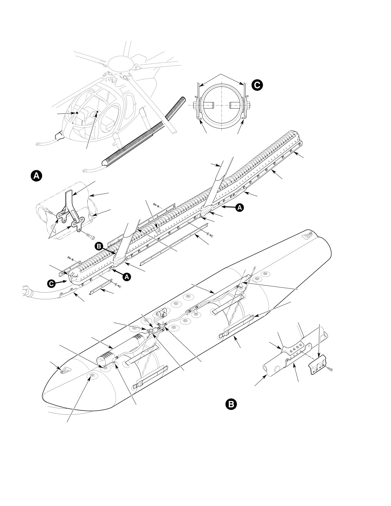
A collapsed emergency float with an emergen
cally controlled inflation equipment,
cy inflation system (stowed condition) is
four landing gear fairings and landing
attached to each landing gear skid. The floats
gear skid tube extensions. Nutplates on
may be fully inflated during flight in approxi
each skid tube and extension provide
mately five seconds. The electrically controlled
for float attachment. A cabin entry step
inflation system includes a self-test capability
may be used with the landing gear
to provide the pilot with a visual indication of
without interference with the floats.
the electrical circuit reliability. Landing on
water or land is permitted when emergency
(3).
Inflatable Emergency Floats Each of
floats are inflated.
the two inflatable neoprene emergency
floats consists of sealed airtight
Emergency flotation equipment in the stowed
chambers separated by internal walls
condition does not restrict normal land
that provide five individual watertight
operation of the helicopter. When inflated, the
compartments. Skid attachment strips
floats will support the helicopter on water at
(girts), bonded to the underside of the
maximum gross weight. After emergency
floats, are bolted to the landing gear
inflation, the inflation system may be serviced
skids. In addition, fore and aft web
with fully charged dry air or nitrogen pressure
support straps secure the floats to the
vessels, and the floats repackaged to a
skids. The floats are inflated to a
streamlined stowed condition.
nominal operating pressure of 4.0 psig
(28 kPa) by the emergency inflation
A. Emergency Float Description
system upon pilot activation of the
inflation system electrical control
(1).
Electrical System The emergency float
equipment. Relief valves provide for air
electrical installation assumes prior
pressure release at a compartment
incorporation of the 369H90129-31,
pressure of 4.5 psi (31 kPa) or above.
369H90129-505 or 369H90129-511
pilot's cyclic stick grip kit. The emer
A snap-on containment cover with
gency float electrical system includes a
lacing restrains the float in the stowed
circuit breaker, visual indicator switch
configuration until the emergency
for testing circuit operation reliability,
inflation system inflates the float. The
and a relay. The pilot's cyclic stick grip
containment cover inboard side auto
is equipped with an EMERG/FLOAT
matically unsnaps and is pushed
push-button switch. When the pilot's
outboard as the float inflates. After
grip switch is actuated, the electrical
emergency float use, deflation, pressure
system energizes and provides electrical
vessel recharging and folding, the cover
power for simultaneous operation of the
is again snapped in place over the float
left and right emergency float inflation
and replaced for subsequent reuse.
system. The float inflation system
consists of an electrically operated
A mooring ring atop each end of the
solenoid valve, or squib valve, attached
float is furnished for towing and
to a compressed dry air or dry nitrogen
mooring. An extended landing gear skid
pressure vessel. When the solenoid is
tube extension supports the float aft
energized or the squib is actuated, the
section on the landing gear. Forward
pressure vessel valve opens and
and aft restraining straps are provided
releases compressed dry air or dry
at landing gear strut and fairing
nitrogen into compartments of each
locations. Gap covers close off the
float.
inboard cutouts for the strut fairings.
Page 201
32-82-00
Revision 19
CSP-HMI-2
MD Helicopters, Inc.
MAINTENANCE MANUAL
(4).
Emergency Inflation System The
(2). Check girt to skid attaching hardware
emergency inflation system consists of
for condition and corrosion.
a charged compressed pressure vessel,
air hoses, valves and associated
(3). Check float cover fasteners and lacing
components for inflation of the emer
for security.
gence floats. A complete emergency
(4). Examine float stowage cover for
inflation system is installed on and is
abrasive damage that may have
part of each float.
disturbed package float.
When actuated by inflation system
(5). Perform an operational check of float
electrical control equipment, a solenoid
inflation system electrical control
valve or squib valve attached to the
equipment.
pressure vessel releases compressed dry
air or dry nitrogen for distribution
4. Emergency Float Inspection
through the air hoses and inlet check
valves for the five float compartments.
NOTE: To be performed every six months or as
A relief valve on each float compart
necessary.
ment opens if compartment pressure
exceeds 5 ±0.5 psi (34.5 ±3.5 kPa).
(1). Check for proper air pressure indication
on pressure gage.
The pressure vessel operating pressure
is 3000 - 3575 psig (20684 - 24649 kPa)
(2). If float is stowed, unsnap containment
at 65 - 85°F (18 - 30°C); 3500 ±75 psig
cover and loosen restraining lacing for
(24132 ±517 kPa) at 65 - 85°F (18 -
access to emergency inflation system
30°C) is preferred. The manifold is
components.
attached to the pressure vessel along
with an indicating pressure gage, filler
(3). Remove pressure vessel, inspect for
valve and a pressure relief valve. The
damage and scratched, nicked or
pressure vessel relief valve operates at
otherwise damaged paint coating.
and above 4250 ±250 psig (29303 ±1724
NOTE: Superficial paint coating damage
kPa). Detachable rubber boots cover the
should be repaired by paint touchup.
filler and pressure relief valves for
protection against chafing. The pres
(4). Inspect valves, air hoses and other air
sure vessel may be detached from the
distribution components for damage,
float for servicing.
deformity, strain, chafing or corrosion.
2.
Certification and Shelf/Service Life
NOTE: Corrosion of the electrically operated
solenoid/squib valve may occur as a result of
The Federal Aviation Administration (FAA)
improper charging of the pressure vessel.
has granted Squib PN 5003527-1 of the
Ensure that only dry air or dry nitrogen is
squib-actuated emergency float valve a
used to charge the pressure vessel.
provisional five-year life limit. This life limit
(5). Perform an inflation system electrical
is established by date of manufacture, which is
control equipment operational check to
ink-stamped on the body of the squib (Ref.
ensure electrical continuity and
Sec. 04-00-00).
connection of solenoid/squib valve.
3. Emergency Float Inspection (Stowed
Ensure that pressure vessel
Configuration)
CAUTION
gage is visible through inspec
tion window.
NOTE: The following inspections must be per
formed daily and before each flight.
(6). Tighten and re-tie the lacing and snap
the containment cover in place if not
(1). Observe vessel pressure through
continuing to Float Compartment
inspection window.
Pressure Test.
Page 202
Revision 19
32-82-00

MD Helicopters, Inc.
CSP-HMI-2
MAINTENANCE MANUAL
Table 201. Troubleshooting Emergency Flotation Equipment
Symptom
Probable Trouble
Corrective Action
A charged float pressure vessel must be discharged before the associated float valve is removed
CAUTION
from the pressure vessel. Use care to prevent accidental float inflation.
No reliability light indication,
Burned−out lamp.
Replace lamp.
either left or right.
Defective connection or wiring.
Repair connection or wiring.
Open circuit to solenoid float valve.
Replace float valve.
No reliability light indication,
Defective connection or wiring.
Repair connection or wiring.
both left and right.
Reliability light indication for
Defective actuating switch.
Replace actuating switch.
both floats; neither float
Defective actuating switch wiring.
Repair wiring.
inflates.
Float leaks air.
Damaged float.
Repair float.
5. Emergency Float Compartment Pressure
6. Emergency Float Inspection (After
Test
Inflation)
To be performed every 6 months or after 5
Consumable Materials
inflations (Ref. Sec. 04-00-00).
(Ref. Section 91−00−00)
Item
Nomenclature
(1). Inflate all float compartments at the fill
valves to 4.5 psi (31 kPa) for one hour.
CM220
Naphtha aliphatic
Check for leaks and condition.
(1). Clean float as follows:
(2). Continue inflation to 5.5 psi (38 kPa)
and check that chamber pressure relief
(a). Clean away any oil or grease with
valves operate.
naptha (CM220).
(3). Lower pressure in all five float com
(b). Wash down with soapy water; flush
partments to 2.0 psi (14 kPa) and let
with clear fresh water and allow to
stand for 24 hours.
air dry.
(c). Clean air pressure gage inspection
NOTE: Changes in atmospheric pressure and
window with a clean cloth and fresh
temperature during pressure test of float
water.
compartments will affect pressure gage
readings. A temperature change of 1 degree
(d). After inspection is complete, dust
equals 0.032 psig (0.2206 kPa).
with talc.
(4). Check the pressure drop with a pres
(2). Recharge pressure vessel to 3500 psig
sure gage that indicates 0 - 15 psi (0 -
(24132 kPa) at 75°F (24°C).
103 kPa), graduated in 0.5 psi (5 kPa)
increments. The maximum allowable
(3). Inspect float bags for abrasion and
pressure drop in 24 hours is limited to
chafing.
0.5 psi (5 kPa) per compartment.
(4). Inspect pressure relief valves for
condition and closure.
(5). If a pressure drop occurs, check floats
for soundness.
(5). Inspect check valves for condition.
(6). Tighten and re-tie the lacing and snap
(6). Inspect all hoses and connectors for
the containment cover in place.
condition and security.
Page 203
32-82-00
Revision 19
CSP-HMI-2
MD Helicopters, Inc.
MAINTENANCE MANUAL
(7). Check float girts, web support and
NOTE: Changes in atmospheric pressure and
restraining straps for condition and
temperature during pressure test of float
secure attachment to skid tube.
compartments will affect pressure gage
readings. A temperature change of 1 degree
(8). Check all release snaps and fasteners
equals 0.032 psig (0.2206 kPa).
for condition and serviceability.
(2). Check the pressure drop with a pres
(9). Check that pressure vessel relief valve
sure gage that indicates 0 - 15 psi (0 -
and filler valve boots are installed.
103 kPa), graduated in 0.5 psi (5 kPa)
increments. The maximum allowable
(10). Repack floats.
pressure drop in 24 hours is limited to
0.5 psi (5 kPa) per compartment.
7. Emergency Float Test
(3). If a pressure drop occurs, check floats
The squib is an electrically
for soundness.
WARNING
fired explosive device. Keep
9. Emergency Float Repair
squibs away from all sources of heat,
open flame, sparks and electrical con
Contact MDHS Field Service Department for
tacts. Squib plugs are to be in place un
repair information.
til squibs are installed in aircraft.
10. Solenoid−to−Squib Rework Procedure
(1). Perform inflation operational reliability
The following is a procedure to replace the
test of float inflation electrical system
solenoid, which is no longer manufactured, to
as follows:
the squib valve.
(a). Press LH/FLT and RH/FLT combi
(1). Turn off electrical power.
nation press-to-test switch located
(2). Unpack emergency floats.
below the lower switch and circuit
breaker panel on the sllmline instru
(3). Remove valve protector and unlace
ment panel and at the top-center of
cylinder sling lacing cords (Ref.
the ”T” panel, to test float inflation
Figure 402).
electrical circuit reliability.
(4). Disconnect solenoid valve electrical
wiring knife splice at (SP4, SP5, SP9
NOTE: Pressing the press-to-test switch ap
and SP10) solenoid.
plies low voltage (insufficient to energize/
actuate the pressure vessel valve solenoid/
(5). Loosen nut at outlet port of solenoid
squib) to the emergency float circuit.
valve. Disconnect valve assembly from
Internal light bulbs in the switch will illu
union by unscrewing cylinder and valve
minate if the circuit is operational.
assembly in counterclockwise direction.
Remove cylinder and valve assembly.
(b). Observe that each switch faceplate is
(6). If cylinder is not empty, discharge as
illuminated when pressed and goes
follows:
out when switch is released.
Exercise care when dis
NOTE: Failure to illuminate indicates a bur
WARNING
charging cylinder. Person
ned-out light bulb in the switch or a defec
nel can be injured by high pressure air
tive circuit. Extreme brightness indicates a
or flying debris.
defective circuit.
(a). Secure cylinder in chain vise or
(2). Check each pressure vessel for proper
equivalent. Point filler valve outlet in
(normal) air pressure, 3500 psig (24132
safe direction.
kPa) at 70°F (24°C).
(b). Use two open end wrenches, one on
filler valve body and one on nut. Turn
8. Float Compartments Pressure Test
nut slowly counterclockwise 2-1/4
(1). Inflate all five float compartments to
turns and allow all pressure to
2.0 psi (14 kPa) and let stand for 24
escape. Check gage to verify that no
hours.
pressure remains in cylinder.
Page 204
Revision 19
32-82-00
MD Helicopters, Inc.
CSP-HMI-2
MAINTENANCE MANUAL
(7). Remove solenoid valve from cylinder.
3).
Install one lead of 0.5 ohm ±5%,
Discard solenoid valve and packing.
10W resistor in pin A of left-hand
connector (P101). Connect one test
(8). Install new squib valve (PN 23111380-3
lead of ammeter (VOM) to other
LH float, PN 23111380-4 RH float) with
lead of resistor. Connect other test
PN MS28778-12 packing on cylinder.
lead of ammeter (VOM) to pin D of
Torque to 360 - 504 inch pounds
connector (P101).
(40.67 - 56.95 Nm) (Ref. Figure 403).
4).
Close emergency float circuit
(9). Install fitting with PN MS28778-6
breaker (CB121).
packing on existing union.
5).
Press PRESS-TO-TEST switch
and observe current reading on
(10). Recharge cylinder and test for air leaks.
ammeter and brilliance of lamps.
(11). Install charge cylinder and squib valve
Current should be 75 MA mini
assembly with PN MS28778-6 packing
mum and brilliancy of lamps
on fitting.
should be fairly bright.
6).
Open emergency float circuit
(12). Revise emergency float electrical
breaker (CB121).
system as follows:
7).
Remove meter and resistor from
(a). Remove access panels and/or covers
connector (P101).
as necessary to expose emergency
float wiring.
8).
Repeat steps 3). through 7). for
right-hand connector (P102).
(b). Remove all emergency float wiring
except as noted in Figure 903.
(b). System check;
1).
Ensure that circuit breaker
(c). Remove and discard relay installa
(CB121) is open and connectors
tion, doubler and attaching hardware
(P101 and P102) are disconnected.
located on pilot's floor support, left
bulkhead.
2).
Install one lead of 40 ohm ±1%,
20W resistor in pin A of left-hand
(d). Remove emergency float switch light
connector (P101) and install other
assembly and install new switch light
lead of resistor in pin D of connec
assembly.
tor (P101).
(e). Install wiring as shown in
3).
Connect test leads of voltmeter
Figure 902. Do not plug in electrical
(VOM) across resistor.
connectors (P101 and P102) until
after electrical system check.
4).
Close emergency float circuit
breaker (CB121).
(f). Reinstall access panels and/or covers.
5).
Press firing switch on pilot's grip
(13). Turn on electrical power.
and observe voltage on meter.
Voltage should be 25.5 Vdc mini
(14). Perform inflation system electrical
mum.
control equipment operational check as
6).
Open circuit breaker (CB121).
follows:
7).
Remove meter and resistor from
(a). Test light check;
connector (P101).
1). Check ship voltage with VOM.
8).
Repeat steps 2). through 7). for
Voltage should be 27.5 Vdc.
right-hand connector (P102).
2). Open emergency float circuit
(c). Connect connectors (P101 and P102)
breaker (CB121).
to squib valves.
Page 205
32-82-00
Revision 19
CSP-HMI-2
MD Helicopters, Inc.
MAINTENANCE MANUAL
(d). Close emergency float circuit breaker
(16). Repack emergency floats (Ref.
(CB121).
Figure 404).
(e). Press PRESS-TO-TEST switch and
observe that lamps light.
(17). Remove existing VNE cards (solenoid
valve, floats stowed (3) and solenoid
(f). Open circuit breaker (CB121).
valve, floats inflated (1)).
(15). Ensure that cylinder is positioned so
that pressure gage is visible through
(18). Install PN 369D292574-49, -51 and
inspection window when floats are
-53 VNE cards (squib valve, floats
stowed, pressure gage axis inclined
stowed) and PN 369D292573-19 VNE
outboard approximately 40°.
card (squib valve, floats inflated).
Page 206
Revision 19
32-82-00
MD Helicopters, Inc.
CSP-HMI-2
MAINTENANCE MANUAL
EMERGENCY FLOAT SYSTEM
REMOVAL/INSTALLATION
1. Emergency Float Replacement
NOTE: If extension tubes are not installed on
helicopter, refer to Skid Tube Extension Re
A. Emergency Float Removal
placement.
(Ref. Figure 401)
(2).
Position float girts over skid tube
attach points.
(1). If float is in stowed configuration,
release fasteners to gain access to float
(3).
Temporarily attach float web support
package.
strap fittings at forward location;
Secure strap fitting at aft attach
(2). Detach lower restraining strap and gap
location with bolts and washers.
cover at forward and aft struts.
(4).
Place gravel guards over float girts and
(3). Disconnect solenoid valve electrical
secure with bolts and washers. Torque
wiring at knife splice at solenoid valve
all bolts securing float girts to skid
or disconnect squib valve electrical
tubes to 25 - 35 inch-pounds (2.82 -
connector at squib and install shunt.
3.95 Nm).
(4). Remove strut fairing, insulate strut
(5).
Apply zinc chromate putty (CM209) to
wire end knife splices, attach wiring to
contact surfaces of previously removed
strut in a stowed position and reinstall
abrasion strips, and skid extension
fairing.
abrasion strips to ensure watertight fit
on landing gear skids.
(5). Remove bolts and washers attaching for
and aft web support strap fittings to
(6).
Loosen float forward web strap fitting
skid tube.
and position abrasion strip on skid
below strut; position web strap fitting
(6). Remove bolts and washers attaching
over forward attach hole on abrasion
float girts to skid tube extension;
strip and secure strip to skid with bolts
remove float assembly.
and washers. Install remaining abra
sion strips; remove excess zinc chro
B. Emergency Float Installation
mate putty.
(Ref. Figure 401)
(7).
Install remainder of bolts and washers
securing float girts to skid tube exten
Consumable Materials
sion.
(Ref. Section 91−00−00)
(8).
Adjust and secure float landing gear
Item
Nomenclature
strut cutout restraining straps.
CM209
Zinc chromate putty
(9).
Unsnap float containment cover and
loosen restraining lacing to gain access
NOTE: The float assembly must be removed
to emergency inflation system compo
from the stowage envelope for installation.
nents.
(1). Open float package and release re
(10).
Connect squib valve electrical connector
straining straps.
at squib.
Page 401
32-82-00
Revision 19
CSP-HMI-2
MD Helicopters, Inc.
MAINTENANCE MANUAL
FLOAT GIRTS
FLOAT ATTACHMENT
CONTROL
SWITCHES
STOWED FLOAT
GRAVEL GUARDS
CIRCUIT
BREAKERS
AFT LANDING GEAR STRUT
SKID TUBE
NARROW FAIRING
EXTENSION
WEB
ATTACHMENT
WEB SUPPORT
GIRT
STRAP
COVER
PRESSURE GAGE
INSPECTION WINDOW
ABRASION STRIP
SKID
COVER
ABRASION STRIP
INFLATED FLOAT
FITTING
GRAVEL GUARD
(NOTE)
FORWARD LANDING GEAR
CONTAINMENT
STRUT NARROW FAIRING
COVER
ABRASION STRIP
SUPPORT TUBE
AIR HOSE (TYP)
GRAVEL GUARD
RETAINING STRAP
ABRASION STRIP
(TYP)
SOLENOID
STRUT-TO-SKID
PRESSURE RELIEF VALVE
COVER
AND FILLER VALVE
PRESSURE VESSEL
FOOT
FILL VALVE
GAP COVER
(TYP)
MOORING
RING
MANIFOLD
PRESSURE
GAGE
ABRASION
SKID TUBE
STRIP
FORWARD FOOT - OUTBOARD SIDE
INLET CHECK VALVE
(TYP)
NOTE:
FORWARD FITTINGS ATTACHED AT FIRST NUTPLATE
PRESSURE RELIEF
FORWARD OF STRUT FOOT. REAR FITTINGS ATTACHED
VALVE (TYP)
AT FIRST NUTPLATE AFT OF STRUT FOOT.
G32-8002
Figure 401. Emergency Float Installation
Page 402
Revision 19
32-82-00
MD Helicopters, Inc.
CSP-HMI-2
MAINTENANCE MANUAL
2. Emergency Float Pressure Vessel
D Squib valve: If actuated, replace with a
Servicing and Replacement
serviceable valve. Install valve on pres
420
sure vessel and torque to 380 -
(Ref. Figure 401) Maximum allowable temper
inch-pounds (42.93 - 47.45 Nm).
ature during charging is 165°F (75°C).
Detaching the pressure vessel from the float
during charging is the preferred procedure.
(5). Detach restraining lacing and remove
Maximum pressure vessel pressure is 3500
pressure vessel from float.
psig (24132 kPa) at room temperature, 70°F
(21°C). As outside air temperature will affect
(6). Recharge pressure vessel with dry
the day-to-day gage reading, temperature
nitrogen or compressed dry air to 3000
versus pressure readings are important during
- 3500 psi (20684 - 24132 kPa) at 75°F
servicing or inspection of the pressure vessel
(24°C); 3500 psig (24132 kPa) at 75°F
air pressure. The indicated pressure on the
(24°C) is preferred. Cool cylinder with
gage will increase or decrease 6.6 psig (45.5
water and charge slowly to maintain
kPa) per 1°F (0.4°C) increase or decrease,
vessel surface temperature below 250°F
respectively, in vessel air temperature. Slow
(122°C).
variations in ambient air temperature will be
reflected in the vessel air temperature;
however, it must be considered that direct or
NOTE: The pressure vessel may also be serv
reflected solar radiation will result in higher
iced by weight. When servicing by weight,
pressure than would be anticipated for the
use a scale and weigh the empty vessel with
existing ambient air temperature.
attaching hardware installed. Charge the
empty vessel until a weight increase of 3.7 -
4.4 pounds (1.68 - 2.0 kg) is obtained; 4.4
Consumable Materials
±0.1 pounds (2.0 ±0.05 kg) is preferred.
(Ref. Section 91−00−00)
When charging by weight, air temperature
Item
Nomenclature
variation will have no affect. Observe vessel
CM810
Leak detector, liquid
cooling precaution.
(1). If float is stowed, unsnap containment
(7).
Test for air leaks by applying liquid
cover to extent required for access to
leak detector (CM810) to the valve-
pressure vessel.
pressure vessel interface. No air
bubbles are permitted.
(2). Open manifold change valve to verify
that there is no pressure remaining in
pressure vessel.
(8).
Dry with clean lint-free cloth and then
allow to air-dry completely.
(3). Remove the three air hoses at air
manifold. Do not allow the manifold to
turn when disconnecting the hoses.
(9).
Inspect the emergency inflation system.
(4). Disconnect solenoid valve electrical
wiring knife splice at solenoid or
(10).
Cover vessel with bag and tie closure
disconnect squib valve electrical
lacing.
connector at squib and install plug.
Use a wide-strap wrench, 2 inch
(11).
Reinstall vessel and bag on float;
CAUTION
(5 cm) minimum width, to apply
re-connect air hose fittings and
torque on the pressure vessel, taking care
solenoid/squib valve electrical wiring
not to damage it. Use crowfoot adapter on
knife splice/squib valve electrical
the torque wrench at the valve body.
connectors. The pressure vessel must be
positioned so that air hose connections
NOTE:
place no strain on the solenoid/squib
D Solenoid valve: Do not remove solenoid
and the pressure gage is visible through
and relief valve assembly from pressure
the pressure gage inspection window
vessel.
when the floats are stowed.
Page 403
32-82-00
Revision 19
CSP-HMI-2
MD Helicopters, Inc.
MAINTENANCE MANUAL
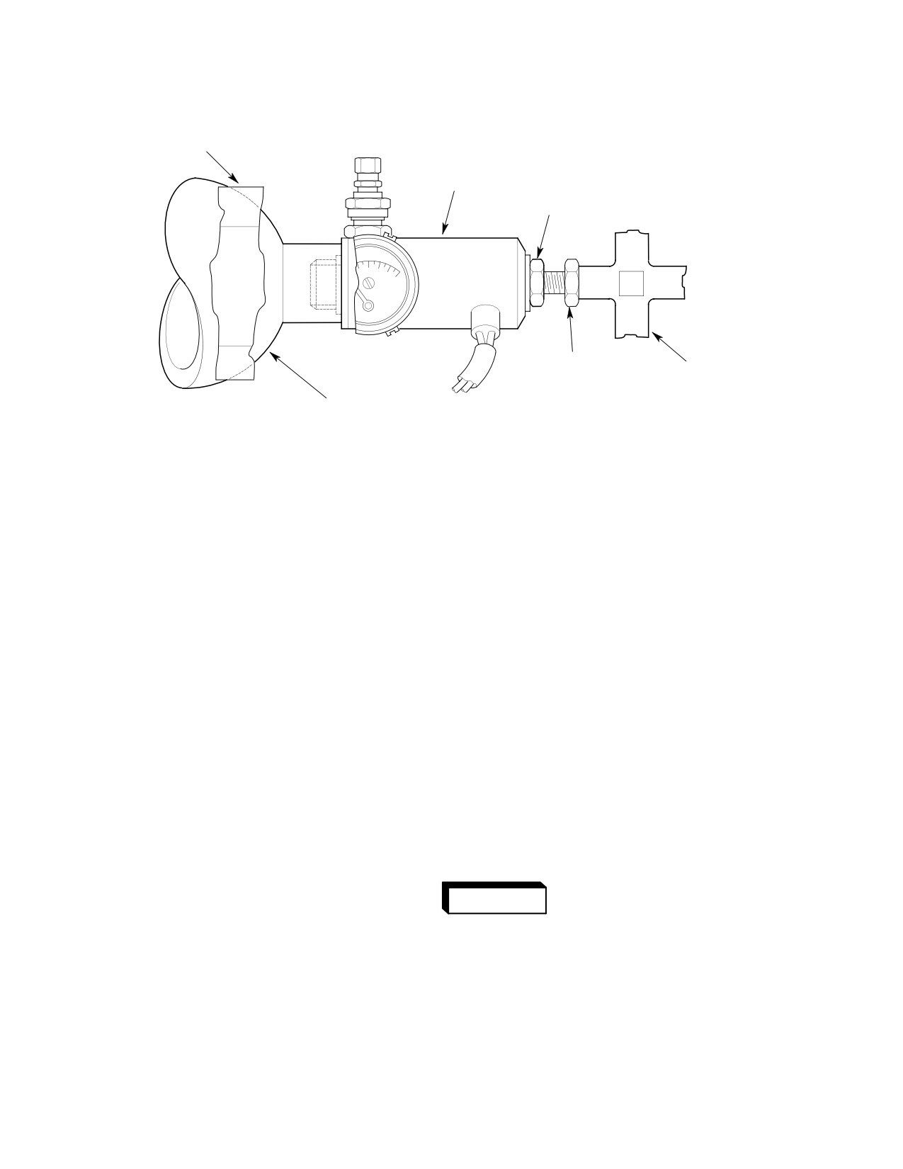
VALVE PROTECTOR
SOLENOID VALVE PROTECTOR
NUT
UNION
CROSS
PRESSURE VESSEL
G32-8003
Figure 402. Solenoid Valve Assembly
(12). Reinstall manifold cover.
(4). Spread plastic cover at it's parting line
until small round end of white plastic
(13). Perform an inflation system electrical
buttons pull through the black plastic
control equipment reliability test.
and over the squib connector, allowing
access to four screws that retain the
actuating valve body.
3. Squib and Squib Actuated Valve
Replacement
(5). Using Allen wrench, remove four
(Ref. Figure 402 and Figure 403) Each time
screws near the outlet port retaining
the emergency floats are inflated using the
the actuated valve body. Retain screws
emergency float inflation system, the squib
for installation of new valve.
and squib actuating valve must be replaced.
(6). Pull spent valve and squib off vessel.
NOTE: Solenoid valves used in the emergency
Discard activated valve and squib.
float system are no longer available from the
manufacturer. Emergency float systems
(7). Lightly lubricate O-ring on new valve
equipped with the solenoid valve must be
with MIL-G-4343 or equivalent
converted to the squib valve system when
pneumatic grease.
the service life of the solenoid valve is ex
ceeded.
The squib is an electrically
WARNING
fired explosive. Ensure con
(1). Open manifold change valve to verify
nector plug is installed in connector
that there is no pressure remaining in
pressure vessel.
prior to installation.
(2). Remove pressure vessel with squib
(8). Maintain squib orientation noted in
valve assembly attached.
step (3).. Install squib actuated valve,
with squib installed, into manifold.
(3). Note orientation of squib with respect
Squib actuated valve must bottom
to pressure gage.
metal-to-metal on face of manifold.
Page 404
Revision 19
32-82-00
MD Helicopters, Inc.
CSP-HMI-2
MAINTENANCE MANUAL
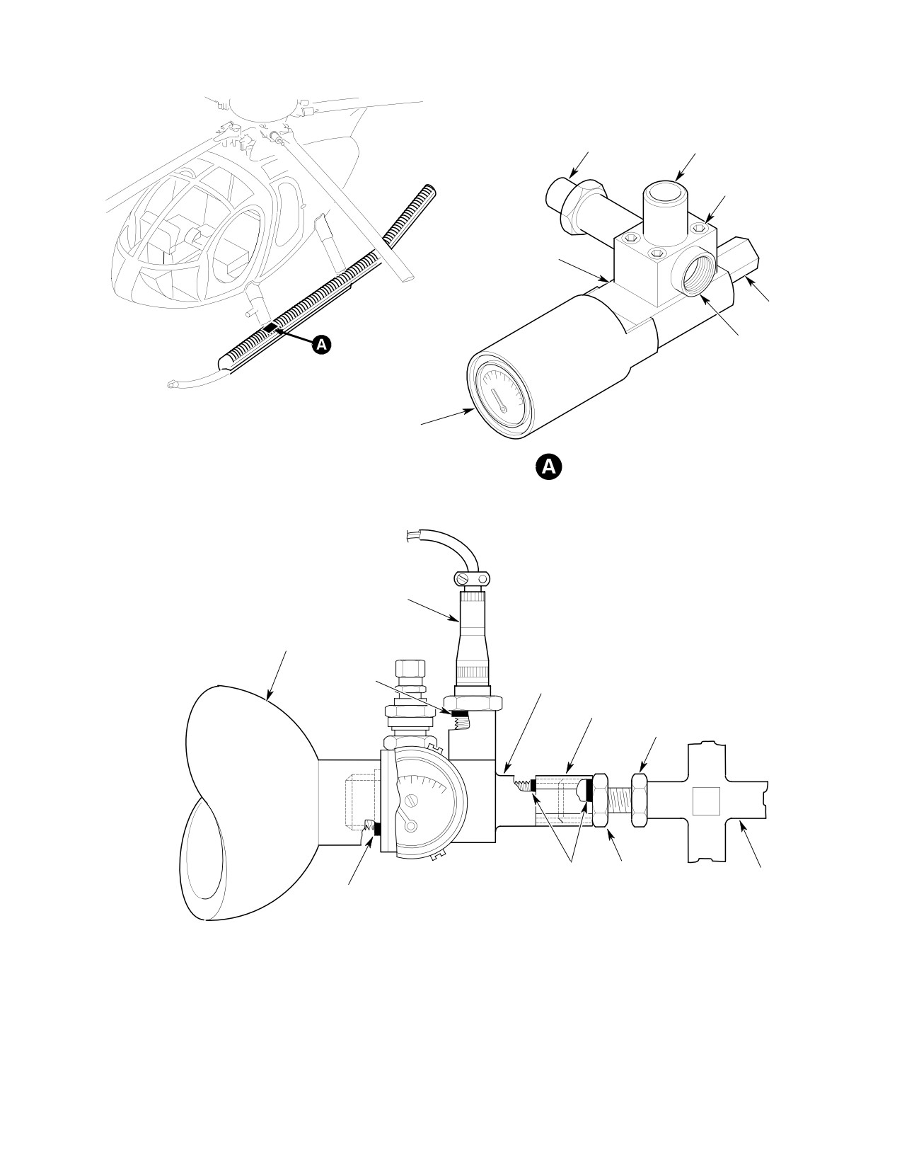
SQUIB
OUTLET
SCREW
VALVE BODY-TO-
MANIFOLD JOINT
TAVCO
FITTING
PRESSURE VESSEL
ATTACHMENT
PRESSURE GAGE
SQUIB VALVE
CONNECTOR
BENDIX
PRESSURE
VESSEL
SQUIB VALVE ASSY (LH)
PACKING
SQUIB VALVE ASSY (RH)
FITTING
NUT
PACKING
UNION
CROSS
PACKING
SQUIB VALVE ROTATED AND INSTALLED IN PRESSURE VESSEL
Figure 403. Squib Valve Assembly
Page 405
32-82-00
Revision 19
CSP-HMI-2
MD Helicopters, Inc.
MAINTENANCE MANUAL
(9). Install four screws removed in step e.
cover, all snaps must be closed and the
hand tight until locking thread of
pressure vessel pressure gage must be
helicoil insert in manifold is engaged.
visible in the inspection window.
Special attention should be paid to the
(10). Using Allen wrench, tighten the four
following information which is pres
screws evenly until bottomed. Torque
ented as an aid in establishing a final
screws to 38 - 43 inch-pounds (4.29 -
float folding technique.
4.86 Nm).
(a). Accomplish float folding in two
(11). Remove plug from squib connector.
stages, first performing float arrange
Note that plug only fits one way.
ment (pre-folding) to the extent
Realign black plastic cover and pull it
necessary to position the float and
back over the squib connector. Replace
float components in approximate
squib connector plug.
required positions and then proceed
ing with the final folding.
(12). Snap white plastic buttons back
through holes in black plastic cover.
NOTE: Partial inflation of float compartments
Check plug in squib connector to ensure
is required to enable float arrangement dur
it is bottomed.
ing initial pre-folding.
(13). Charge pressure vessel and reinstall on
(b).
During pre-folding and before air
emergency float assembly.
evacuation of the forward compart
4. Emergency Float Folding
ments (cells) as outlined in step 4, do
the following. Gather and compress
(Ref. Figure 404) Folding instructions con
the float fabric tightly against the
tained in this procedure are provided as a
vessel and pull the cover over the
general guide for float packing. Float folding
inboard-facing pressure gage to
will require the aid of an assistant and
estimate final cover window-to-gage
considerable care in preparing the smallest
relationship. This fabric bunching/
float package possible during the initial folding
cover pulling action may be required
steps. A minimum amount of wrinkles and
several times before an approxima
complete air evacuation is essential to final
tion (best guess) of final window
closure of cover snap fasteners.
position is established. When cover
position appears good, evacuate all
(1). Position deflated float (five fill valves
air from the forward cells and
OPEN).
recheck the window-to-gage rela
NOTE: The float assembly must be removed
tionship.
from the stowage envelope for installation.
(c).
As soon as a float chamber is ar
Do not attempt to position the float for pack
ranged in the desired position, hold
aging with the float chambers fully col
the components in place, flatten as
lapsed.
many wrinkles as possible and
(2). Fold the float as outlined in the figure.
evacuate air from the float chamber.
On completion, the folded float must be
While the vacuum is still being
contained within the float stowage
applied, close the fill valves.
Page 406
Revision 19
32-82-00
MD Helicopters, Inc.
CSP-HMI-2
MAINTENANCE MANUAL
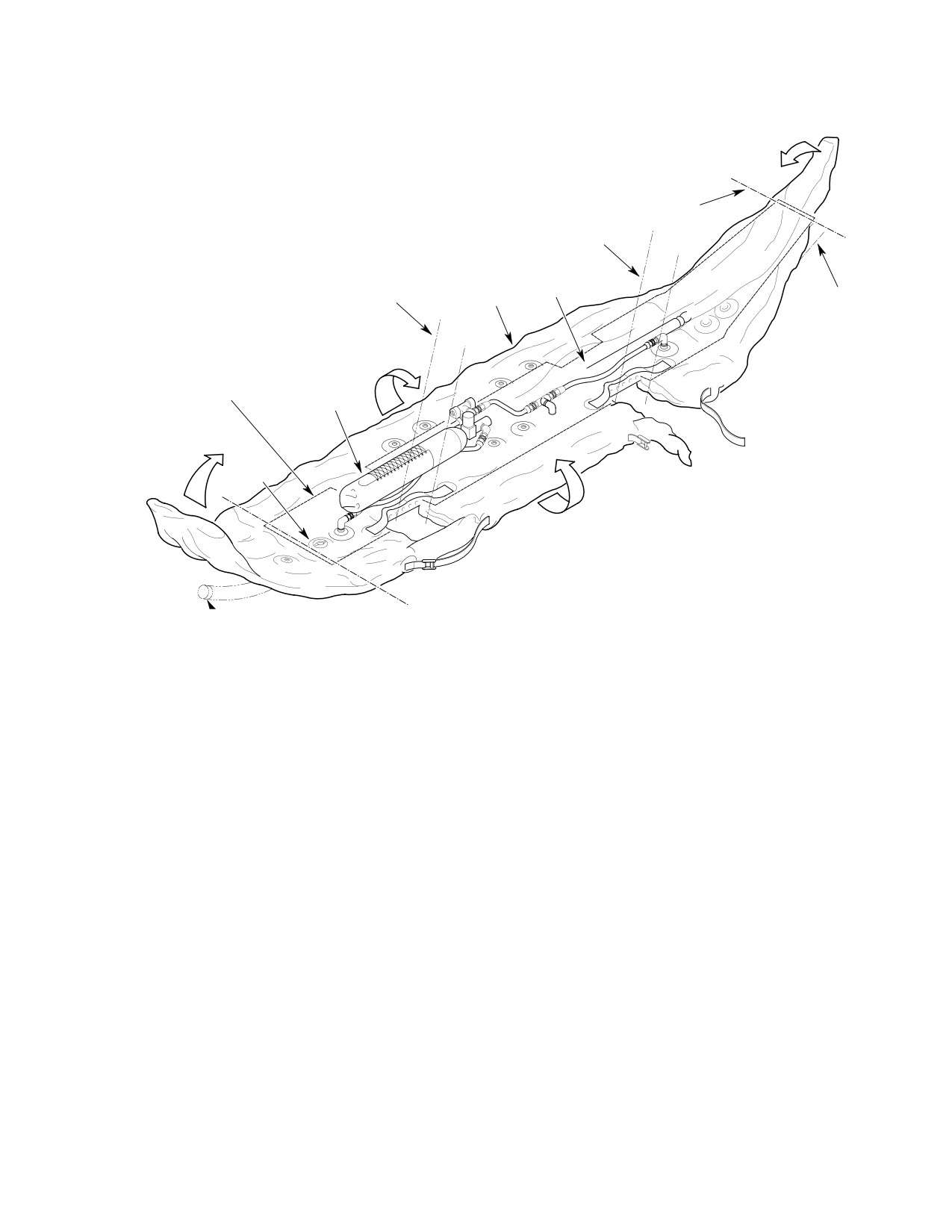
STEP 7
FOLD HERE
STEP 2
LANDING GEAR AFT
STRUT (REF)
LANDING GEAR
FORWARD STRUT
STEP 3
(REF)
STEP 5
SKID TUBE
EXTENSION
(REF)
STEP 8
STEP 10 AND 11
STEP 4
STEP 6
STEP 1
STEP 9
O
STEP 1
OPEN ALL FILL VALVES OF INFLATED FLOAT AND COMPRESS CELLS LIGHTLY BY HAND SO THAT FLOAT IS FLAT
AND AS SMOOTH AS POSSIBLE.
STEP 2
PLACE FOLD AT AFT END OF SKID EXTENSION THEN EVACUATE AFT OUTBOARD AIR COMPARTMENT (CELL)
UNTIL FOLD IS FIRM AND SHARP. CLOSE FILL VALVE.
STEP 3
WHILE COMPRESSING SUPPORT TUBE AND HOLDING FLOAT CENTER FORWARD AND DOWN, PLACE A FOLD IN
INBOARD CENTER CELL BETWEEN INLET CHECK VALVE AND FILL VALVE. REARRANGE AIR HOSE AS REQUIRED.
CONTINUE HOLDING PRESSURE ON SUPPORT TUBE. EVACUATE CENTER CELL THEN AFT INBOARD CELL UNTIL
FOLDS ARE SHARP AND SUPPORT TUBE IS FIRMLY HELD FROM MOVING AFT. CLOSE FILL VALVE.
STEP 4
POSITION PRESSURE VESSEL SNUG AGAINST OUTBOARD SIDE OF FORWARD STRUT. WHILE HOLDING VESSEL IN
POSITION, EVACUATE FORWARD OUTBOARD CELL THEN FORWARD INBOARD CELL UNTIL CREASES ARE FIRM
AND SHARP. CLOSE FILL VALVE.
STEP 5
RECHECK FLOAT. CHECK THAT FLOAT IS AS FLAT AS POSSIBLE AND FREE OF ALL AIR POCKETS. DOUBLE CHECK
FIRMNESS OF ALL CREASES AND RE−EVACUATE CELLS AS NECESSARY.
NOTE: ANY REMAINING AIR MIGHT CAUSE FLOAT OPENING AT ALTITUDE AND DIFFICULTY IN PACKING.
STEP 6
FOLD FLOAT AFT AT FORWARD END. REPOSITION HOSES AS REQUIRED. STOWAGE COVER MUST BE OUTSIDE
OF FOLD LINE.
STEP 7
FOLD FLOAT FORWARD AT AFT END. REPOSITION AIR HOSES AS REQUIRED. STOWAGE COVER MUST BE
OUTSIDE OF FOLD LINE.
STEP 8
ROLL AND FOLD LENGTH OF FLOAT TOWARDS CENTER. DO NOT COVER PRESSURE GAGE.
STEP 9
ROLL AND FOLD LENGTH OF FLOAT TOWARDS CENTER. FASTEN SNAPS STARTING AT FORWARD END. ENSURE
THAT PRESSURE GAGE IS VISIBLE IN INSPECTION WINDOW. DO NOT FASTEN END COVER SNAPS.
STEP 10
TIGHTEN LACING. ENSURE THAT SNAP FASTENERS REMAIN CLOSED.
STEP 11
SECURE END COVER SNAPS. ALL SNAP FASTENERS MUST BE USED.
Figure 404. Emergency Float Folding
Page 407
32-82-00
Revision 19
CSP-HMI-2
MD Helicopters, Inc.
MAINTENANCE MANUAL
This Page Intentionally Left Blank
Page 408
Revision 44
32-82-00
MD Helicopters, Inc.
CSP-HMI-2
MAINTENANCE MANUAL
EMERGENCY FLOAT SYSTEM
INITIAL INSTALLATION
1. Emergency Float System Initial
(a). Ensure that all flight compartment
Installation
switches are in OFF position.
Make certain BATT-OFF-EXT
A. General
CAUTION
switch is in OFF position.
Procedures in this section may be performed at
(2). Remove landing gear strut fillets and
the operator's discretion. Instructions are
fairings (Ref. Sec. 32-10-00). Retain all
provided for installation of emergency float kit
doublers, guides, pins and springs for
on either the current or early configurations of
reinstallation.
the extended landing gear. Subsequent
installation instructions for the emergency
(3). On current configuration landing gear,
floats and the float electrical control system
remove forward nut, bolt and spacer
are identical for the current and early ex
attaching existing extension to aft end
tended landing gear configurations. Equip
of skid tube; retain nut for reinstalla
ment removal and modification differences
tion.
between the current and early configurations
are noted in the subsequent instructions.
(4). On early configuration landing gear,
remove abrasion strip attached to
The emergency float kits are provided with as
existing skid tube extension (Ref. Sec.
many assembled parts as practicable to
32-10-00).
facilitate initial installation on the helicopter.
Installation of electrical equipment assumes
(5). Remove screws and bolts securing skid
prior incorporation of pilot's cyclic stick grip
tube extension; retain early configura
kit (369D90129-507 or 369D90129-511).
tion indexing plugs for reinstallation.
(6). Remove skid abrasion strips below for
B. Initial Preparation
and aft fairings; retain abrasion strips
for reinstallation.
Instructions in the following paragraphs are
applicable to both left and right landing gear
D. Landing Gear Skid Extension Assembly
assemblies. Prepare the aircraft for installa
tion of emergency floats as follows:
(Ref. Sec. 32-81-00)
NOTE: When installing emergency floats, the
E. Emergency Float System Electrical
VNE cards must be replaced with the cards
Equipment Installation
that come with the floats (Ref. appropriate
PFM).
(Ref. Figure 901)
(1). Remove attaching hardware and
(1). Identify all components, including
separate lower switch and circuit
attaching hardware, and components
breaker panel from instrument panel
removed for access to work areas.
structure.
Protect components from damage and
contamination until installed.
(2). Remove covers from emergency float
press-to-test switch and circuit
(2). Raise aircraft clear of ground; Use
breaker cutouts from lower switch and
authorized hoisting or jacking methods
circuit breaker panel.
(Ref. Sec. 07-00-00). Place support
beneath skid tubes at strut locations.
(3). Install emergency float circuit breaker
in panel.
C. Existing Equipment Removal
NOTE: Press-to-test switch is installed during
(1). Remove Battery (Ref. Sec. 96-05-00).
subsequent wiring installation procedure.
Page 901
32-82-00
Revision 19
CSP-HMI-2
MD Helicopters, Inc.
MAINTENANCE MANUAL
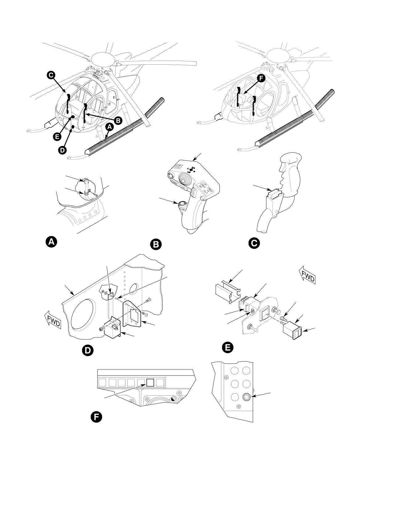
PILOT'S CYCLIC
STICK GRIP
GROMMET
FLOAT
CLIP
SWITCH
FLOAT
SWITCH
FORWARD STRUT
STANDARD GRIP
OPTIONAL ``T'' GRIP
DOUBLER
MOUNTING
SLEEVE
PILOT'S FLOOR SUPPORT
EXISTING
SWITCH
FORWARD LEFT BULKHEAD
HOLE
HOUSING
LAMP (4)
INDICATOR
LOCKING
MODULE
CAM
LEGEND
RELAY
LOCKING CAM
FACE
BRACKET
SCREW (2)
RELAY
SWITCH INSTALLATION
PILOT'S FLOOR SUPPORT
(SLIMLINE PANEL)
FORWARD LEFT BULKHEAD
1 NAV 2
ADF
XPDR
HOOK
FLOATS
CIRCUIT
FLOAT
BREAKER
PRESS-TO-TEST
INSTRUMENT PANEL (COMM. ``T'' PNL.)
VIEW LOOKING FORWARD
Figure 901. Emergency Float Kit − Electrical Installation
Page 902
Revision 19
32-82-00
MD Helicopters, Inc.
CSP-HMI-2
MAINTENANCE MANUAL
F. Emergency Float System Electrical
(6). Install wiring through landing gear
Wiring Installation
struts as follows:
(Ref. Figure 902 thru Figure 905)
(a).
Drill 0.442 inch (11.2268 mm) hole
centered on outboard side of forward
struts located five inches (12.7 cm)
Consumable Materials
above centerline of skid tube; deburr
(Ref. Section 91−00−00)
holes internally and externally.
Item
Nomenclature
(b).
Coat bare metal in holes with primer
CM318
Primer
(CM318); allow primer to dry.
CM601
Insulation sleeving, electrical
(c).
Remove left and right foot support
fairing in passenger compartment for
(1).
Identify wires as required and form
access to landing gear forward struts.
wire bundle of applicable wires to
emergency float circuit breaker and
(d).
Install insulation sleeving on float
press-to-test switch on lower switch
valve squib wires.
and circuit breaker panel.
(e).
Locate position light wire bundle exit
(2).
From battery compartment area, route
holes on top inboard portion of left
and right landing gear struts; Insert
wire bundle forward and up through
respective float squib wire bundles
instrument panel support structure;
through position light wire bundle
route wire bundle with existing bundles
exit holes. Locate wires through
where possible.
previously drilled wire exit hole at
(3).
Install insulation sleeving (CM601) and
bottom of each strut. Carefully pull
connect applicable wires to contacts on
wires through holes allowing suffi
press-to-test switch and circuit
cient length for connections at either
breaker; assemble and secure press-to-
end.
test switch to panel.
(f).
Slide grommet over wire bundle on
(4).
Adjust wire bundle and allow sufficient
both struts; Install grommet in
slack for maintenance; strap and string
previously drilled wire exit holes.
tie bundle to form smooth flow of wires
(g).
Attach clip (Ref. Figure 901, view G).
to battery compartment area.
(h).
Coil and stow wires to avoid damage
(5).
Ensure all switch and circuit breaker
during float equipment installation.
contacts are secure and that sleeving is
properly installed; remove paint from
(7). Complete balance of all wiring. Install
panel and console in upper screw area
insulation sleeving as required to
to ensure good ground contact. Install
prevent shorting and chafing through
panel on console.
out circuit wiring.
Page 903
32-82-00
Revision 19
CSP-HMI-2
MD Helicopters, Inc.
MAINTENANCE MANUAL
G. Emergency Float Electrical System
Ensure that the BATT-OFF-
CAUTION
Inspection
EXT switch is in the OFF posi
tion.
Before connecting battery plug, the following
H. Emergency Float System Strut Fairing
wiring installation inspection must be per
Installation
formed.
(Ref. Figure 906)
(1).
Inspect all wiring connections for
security and insulation.
Consumable Materials
(Ref. Section 91−00−00)
(2).
Inspect all wiring for interference with
Item
Nomenclature
moving parts and for areas where
chafing could occur.
CM209
Zinc chromate putty
(3).
Inspect all wiring for conformance with
The following installation instructions are
wiring diagrams.
typical for all four strut fairing assemblies.
Where riveting is required, Refer to referenced
(4).
Install all access panels, doors and
instructions for proper rivet types.
access covers previously removed.
(1).
Install center fairing, fillet and lower
(5).
Remove insulation and temporarily
fairing in respective order, and general
connect each set of float squib wires.
ly in accordance with instructions (Ref.
Sec. 32-10-00).
(6).
Install battery, connect battery plug
and place BATT-OFF-EXT switch in
(2).
During installation of fairings, ensure
BATT position.
that doublers, removed during disas
sembly, are installed between fairings
(7).
Momentarily press emergency float
and fillers at screw attach points.
press-to-test switch to verify proper
(3).
Ensure blocks are installed at lower
wiring continuity; all four switch lamps
trailing edge of fillets to ensure free
should illuminate.
action of fillet with strut movement.
(8).
Separate float squib wires at base of
(4).
Ensure that float solenoid/squib wire
struts.
bundles are free at bottom of lower
fairings on forward struts.
(9).
Actuate EMERG/FLOAT switch on
pilot's cyclic stick grip; use voltmeter to
(5).
Install bolt covers over inboard bolt
check for proper voltage and continuity
heads on strut foot/skid attach point.
through float squib valve circuits.
Apply sufficient zinc chromate putty
(CM209) to fill all voids between cover
(10).
Pull out emergency float circuit breaker
and bolt head area; secure forward
to remove power and release relay;
strut bolt covers with existing nylon
push circuit breaker in again to prepare
hardware. Torque screws to 25 - 35
circuit for emergency use.
inch-pounds (2.82 - 3.95 Nm).
Page 910
Revision 19
32-82-00
MD Helicopters, Inc.
CSP-HMI-2
MAINTENANCE MANUAL
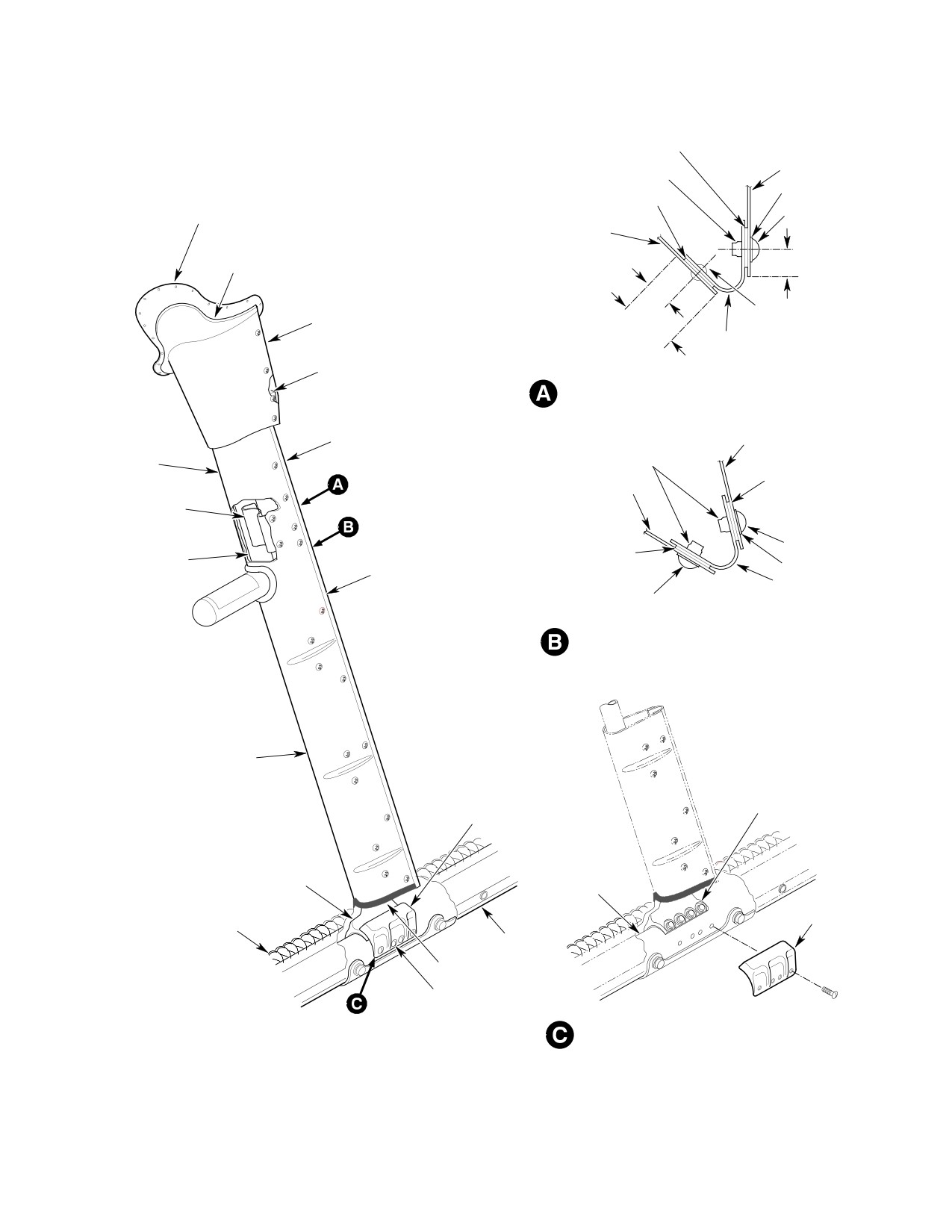
DOUBLER
FAIRING
NUTPLATE
WASHER
CHAFING PAD
DOUBLER
SCREW
(FORWARD FAIRING)
FAIRING
TEFLON STRIP
0.50 IN.
0.50 IN.
(FORWARD FAIRING)
RIVET
FILLET
1.25 IN.
FILLER
BLOCK
FILLER-TO-FAIRING
ATTACHMENT (TYP)
CENTER FILLER
FAIRING
CENTER
NUTPLATE
FAIRING
DOUBLER
FAIRING
FAIRING
MOUNTING
BRACKET
LANDING
SCREW
DOUBLER
GEAR
WASHER
LOWER FAIRING
STRUT
FILLER
SCREW
CENTER-TO-LOWER FAIRING
FILLER ATTACHMENT
LOWER FAIRING
STRUT-TO-SKID
STRUT FOOT
BOLT COVER
STRUT FOOT
SKID TUBE
FOOT
STRUT-TO-SKID
CONTAINMENT
BOLT COVER
COVER
SKID
SEAL
NYLON SCREW
BOLT COVER INSTALLATION
Figure 906. Emergency Float System Strut Fairing Installation
Page 911
32-82-00
Revision 19
CSP-HMI-2
MD Helicopters, Inc.
MAINTENANCE MANUAL
I. Emergency Float Installation
(6).
Loosen float forward web strap fittings
and position abrasion strip on skid
below strut; position web strap fitting
Consumable Materials
over forward attach hole on abrasion
(Ref. Section 91−00−00)
strip and secure strip to skid with bolts
Item
Nomenclature
and washers. Install remaining abra
CM209
Zinc chromate putty
sion strips; remove excess zinc chro
mate putty.
Installation of the left and right emergency
(7).
Install balance of bolts and washers
floats is identical except for opposite positions.
securing float girts to skid tube exten
(1). Open float package and release re
sions. Torque all bolts to 25 - 35
straining straps.
inch-pounds (2.82 - 3.95 Nm).
(2). Position float girts over skid tube
(8).
Adjust and secure float landing gear
attach points.
strut cutout restraining straps.
(3). Temporarily attach float web support
strap fittings at forward location;
(9).
Unsnap float containment cover and
secure strap fitting at aft attach
loosen restraining lacing to gain access
location with bolts and washers.
to emergency inflation system compo
nents.
(4). Place gravel guards over float girts and
secure with bolts and washers.
(10).
Connect squib valve electrical connector
(5). Apply zinc chromate putty (CM209) to
at squib.
contact surfaces of previously removed
abrasion strips, and skid extension
(11).
Perform inspection of emergency float
abrasion strips, to ensure watertight fit
inflation system (Ref. Emergency Float
on landing gear skids.
Inspection - Stowed Configuration).
Table 901. Weight and Balance Data
Configuration
Weight
Arm
Moment
lbs (kg)
in.
(cm)
in.−lb/100 (kgmm/100)
−501
+151.7
(+68.872)
95.9
(243.59)
+145
(+1670.57)
−505
+150.8
(+68.463)
96.0
(243.84)
+145
(+1670.57)
−515
+129.1
(+58.611)
99.1
(251.71)
+128
(+1474.71)
−517
+127.7
(+57.976)
98.9
(251.21)
+126
(+1451.67)
−519
+152.7
(+69.326)
96.4
(244.86)
+147
(+1693.62)
−521
+152.6
(+69.280)
96.5
(245.11)
+147
(+1693.62)
−523
+152.5
(+69.235)
96.5
(245.11)
+147
(+1693.62)
−525
+127.5
(+57.885)
99.0
(251.46)
+126
(+1451.67)
−527
+152.5
(+69.235)
96.5
(245.11)
+147
(+1693.62)
−529
+152.5
(+69.235)
96.5
(245.11)
+147
(+1693.62)
−531
+152.5
(+69.235)
96.5
(245.11)
+147
(+1693.62)
Page 912
Revision 19
32-82-00

MD Helicopters, Inc.
CSP-HMI-2
MAINTENANCE MANUAL
Chapter
52
Doors
MD Helicopters, Inc.
CSP-HMI-2
MAINTENANCE MANUAL
TABLE OF CONTENTS
Para/Figure/Table
Title
Page
52-10-00 Crew, Passenger, Cargo Doors and Windows
A
Maintenance Practices
201
1.
Crew and Passenger/Cargo Door Description and Operation
201
A. Early Door-Latching System
201
B. Current Door Latching System (Hook-Latch)
201
2.
Hook-Latch Automatic Door Latching System Troubleshooting
202
Table 201. Hook-Latch Automatic Door Latching System Troubleshooting
202
3.
Crew Compartment Door Replacement (369D/E/FF - 500/600N)
203
A. Crew Compartment Door Removal (369D/E/FF - 500/600N)
203
B. Crew Compartment Door Installation (369D/E/FF - 500/600N)
203
4.
Passenger/Cargo Compartment Door Replacement (369D/E/FF - 500N)
203
A. Passenger/Cargo Compartment Door Removal (369D/E/FF - 500N)
203
B. Passenger/Cargo Compartment Door Installation (369D/E/FF - 500N)
203
5.
Mid and Aft Door Replacement (600N)
203
A. Mid and Aft Door Removal (600N)
203
B. Mid and Aft Door Installation (600N)
203
6.
Door Seal Compression Check
203
Figure 201. Crew and Passenger/Cargo Door Installation (Sheet 1 of 2)
204
7.
Mid and Aft Door Strut Replacement (600N)
206
A. Mid and Aft Door Strut Removal (600N)
206
B. Mid and Aft Door Strut Installation (600N)
206
8.
Snapvent Replacement
206
A. Snapvent Removal
206
B. Snapvent Installation
206
9.
Outside Handle or Spindle Replacement
206
A. Outside Handle or Spindle Removal
206
B. Outside Handle or Spindle Installation
206
10. Automatic Latch Block Assembly Replacement
206
A. Automatic Latch Block Removal
206
B. Automatic Latch Block Installation
207
11. Cam Lock Replacement
207
A. Cam Lock Removal
207
B. Cam Lock Installation
207
12. Latch Assembly or Striker Adjustment
207
A. Door Seal Compression Adjustment
207
Figure 202. Door Latching System Installation (Sheet 1 of 2)
208
Page i
52 Contents
Revision 36
CSP-HMI-2
MD Helicopters, Inc.
MAINTENANCE MANUAL
TABLE OF CONTENTS (Cont.)
Para/Figure/Table
Title
Page
B. Engagement Depth of Latch Bolts with Striker Adjustment
210
C. Connector Rod Adjustment
210
D. Latch Compression Adjustment (Early System)
210
13. Latching Mechanism Operational Check (Early System)
210
14. Hook-Latch Door Latching System Operational Check
210
Figure 203. Door Handle Positions and Latch Engagement (Sheet 1 of 3)
211
15. Autolatching Pilot and Cargo Doors Operational Check
213
16. Door-Latching Mechanism Inspection (All Systems)
214
17. Anti-Chafing Tape on Door Frame Repair
214
18. Window Replacement
214
A. Early Style Window Replacement
214
B. Current Style Window Replacement
215
19. Hinge Replacement
215
A. Preload Spring Replacement
216
Figure 204. Door Hinge Replacement
216
Figure 205. Window and Hinge Repair
217
Figure 206. Current Style Window Installation
218
B. Rubber Stop Replacement
218
20. Automatic Latch Block Assembly Repair
219
21. Strike Pin Repair
219
22. Litter Door Inspection (50 Hour)
219
Figure 207. Automatic Latch Block and Striker Repairs (Sheet 1 of 2)
220
Figure 208. Door Seal Repair
222
23. Pilot and Cargo Door Repair
223
A. Seal Repair
223
B. Partially-Separated Seal Repair
223
24. Improved Door Seal Installation
223
Figure 209. Improved Door Seal Installation
224
52-40-00 Engine Access Doors
A
Maintenance Practices
201
1. Engine Access Door - General
201
2. Engine Access Door Replacement
201
A. Engine Access Door Removal
201
B. Engine Access Door Installation
201
3. Engine Access Door Inspection
201
4. Engine Access Door Repair
201
A. Sheet Metal Repair
201
Page ii
Revision 36
52 Contents
MD Helicopters, Inc.
CSP-HMI-2
MAINTENANCE MANUAL
TABLE OF CONTENTS (Cont.)
Para/Figure/Table
Title
Page
B. Abrasion Strip Replacement
201
C. Hinge Replacement
202
D. Catch/Latch Hook Replacement
202
5. Engine Access Door Adjustment
202
Figure 201. Engine Access Doors (Sheet 1 of 3)
203
52-50-00 Miscellaneous Access Doors
A
Maintenance Practices
201
1. Access and Inspection Provisions
201
2. General Access Doors Inspection
201
3. Pilot Compartment Floor Access Doors
201
4. Pilot Compartment Floor Access Door Replacement
201
A. Pilot Compartment Floor Access Door Removal
201
B. Pilot Compartment Floor Access Door Installation
201
Table 201. Access and Inspection Provisions Information
202
Figure 201. Access and Inspection Provisions and Locations (369D/E/FF)
(Sheet 1 of 3)
204
Figure 202. Access and Inspection Provisions and Locations (500N)
(Sheet 1 of 2)
207
Figure 203. Access and Inspection Provisions and Locations (600N)
209
Figure 204. Floor Access Covers and Engine Bypass Door (600N)
210
Page iii
52 Contents
Revision 36
CSP-HMI-2
MD Helicopters, Inc.
MAINTENANCE MANUAL
TABLE OF CONTENTS (Cont.)
Para/Figure/Table
Title
Page
This Page Intentionally Left Blank
Page iv
Revision 36
52 Contents
MD Helicopters, Inc.
CSP-HMI-2
MAINTENANCE MANUAL
Section
52−10−00
Crew, Passenger,
Cargo Doors and
Windows
MD Helicopters, Inc.
CSP-HMI-2
MAINTENANCE MANUAL
CREW, PASSENGER, CARGO DOORS AND WINDOWS
MAINTENANCE PRACTICES
1. Crew and Passenger/Cargo Door
The latch sliders are interconnected to rods
Description and Operation
and clevis devices and are moved by turning
inside or outside door handle.
The pilot and passenger/cargo doors are
bonded aluminum alloy frames containing
Movement of either handle into safelock
large smoke-grey-tinted cast acrylic windows.
position is prevented until door is closed and
safelock position is prevented until door is
Plastic snapvents are installed in each door
closed and safelock triggers are actuated by
window. An acrylic stop, bonded to the doubler,
the strikes. This actuation causes the safelock
prevents normal airflow from pulling the
triggers to clear notches on latch sliders,
snapvent from the window during flight. These
allowing the latch sliders and linkage to move
units may be rotated for intake or exhaust of
into safelock position.
ventilating air and may be pulled inward for
complete closure. Damaged snapvents should
B. Current Door Latching System
be replaced, (Ref. Snapvent Replacement);
(Hook−Latch)
repair is not practical.
Pilot and passenger/cargo doors are equipped
Current door latching mechanisms used on
with an automatic latching mechanism. Two
pilot and passenger/cargo compartment doors
door hinges on each door are provided with
consist of four hook type latches mounted on
quick-removal type ball-lock hinge pins.
the door frame. The four latches are actuated
by latch sliders which are synchronized and
Pilot and passenger/cargo doors are equipped
connected by steel connector rods to the door
with automatic latching mechanisms. The
handle.
latching mechanisms permit the door to be
closed and safelocked from inside or outside.
With the door handle at the rest position, the
Each installation contains a key-operated cam
door may be firmly shut and the hooks will
lock, actuated from outside. Opening door from
ride up over and engage their striker pins.
inside overrides key-operated cam lock. Pilot
Safelocking is accomplished by moving the
and cargo door latching mechanisms are
door handle to the lock position, which causes
essentially the same except for length of
the latch slider that operates each hook latch
interconnecting rods.
to engage a pin within the latch block,
preventing further movement until the handle
A. Early Door−Latching System
is moved to the open position. When the
Early mechanisms, installed within the door
handle is moved to the open position, the latch
panel, consist of four latch blocks that house
sliders fully extend the latch hooks from their
spring-loaded latch bolts and safelock triggers
latch blocks, disengaging them from their
together with latch sliders.
striker pins and allowing the door to open.
Page 201
52-10-00
Revision 25
CSP-HMI-2
MD Helicopters, Inc.
MAINTENANCE MANUAL
2. Hook−Latch Automatic Door Latching
System Troubleshooting
Table 201. Hook−Latch Automatic Door Latching System Troubleshooting
Problem
Probable Cause
Repair
Hooks fail to engage striker
Door seal swollen or bonding
Repair seal (Ref. Door Seal Repair).
pin, or more than 0.050 inch
to door frame failed.
(1.27 mm) gap between latch
Striker assembly mounted too
Loosen striker assembly mounting screws and
hook and striker pin (Latch
far inboard or outboard on
adjust striker assembly position.
hooks extend normally).
door frame.
Latch block assembly too far
Add or remove 0.063 inch (1.60 mm) and
from striker pin.
0.032 inch (0.81 mm) washers as shims under
latch block mounting screws, as required (1).
Remove or add shims under striker assembly,
as required.
Striker assembly hitting or
Route out waffle enough to clear.
rubbing on door waffle.
Striker assembly hitting latch
Check latch covers for dents or chipped paint
cover (2).
that indicates contact between latch cover and
striker assembly. Remove material from latch
cover to allow striker assembly clearance.
Latches fail to extend from
Latch hooks or latch sliders
Lubricate latch block moving parts.
latch block when handle
sticking in latch block.
moved to open position.
Connector rod(s) improperly
Adjust connector rod(s) by removing clevis
adjusted.
from sliding cam and raising or lowering
threaded connector as required on threaded
portion of rod. Threads of rod and connector
must be engaged through solid portion of
connector. Rod end may be flush with or
extend beyond bottom, of solid part of
connector.
Connector rod bent or
Check connector rods and clevis. Replace
damaged.
damaged part.
Door does not safelock when
Connector rod(s) improperly
Check witness hole in latch blocks.
door handle is moved to lock
adjusted.
Semi−circle cutout in each latch slider must be
position.
fully seated around pin when safe locking is
engaged. Adjust connector rods until correct
pin engagement is achieved for each latch
slider.
NOTES:
(1) If latch block protrudes beyond middle line or door after shimming, slot mounting holes in latch block
cover 0.20 inch (5.08 mm) downward from center of existing hole to allow cover to shift up above middle
line of door waffle.
(2) Door should be closed from inside helicopter to determine if striker pin assembly is hitting or rubbing latch
cover. Enough force can be applied when closing door from outside to prevent detection of contact
between striker pin assembly and latch cover.
Page 202
Revision 25
52-10-00
MD Helicopters, Inc.
CSP-HMI-2
MAINTENANCE MANUAL
3. Crew Compartment Door Replacement
(4). Re-safety from top hinge pin.
(369D/E/FF − 500/600N)
(5). Install interior trim covers.
(Ref. Figure 201)
5. Mid and Aft Door Replacement (600N)
A. Crew Compartment Door Removal
A. Mid and Aft Door Removal (600N)
(369D/E/FF − 500/600N)
(1). Remove nuts and washers from door
(1). Remove cover plates from interior trim
hinge bolts.
forward of crew doors.
(2). While supporting door, slide bottom
(2). While supporting door, turn hinge pins
bolt, and then top bolt from hinges.
to unlock the tabs.
(3). Remove door from helicopter.
(3). Remove lower pin, then remove top pin.
B. Mid and Aft Door Installation (600N)
(4). Remove door from helicopter.
(1). Position door so door-mounted hinge
B. Crew Compartment Door Installation
aligns with airframe-mounted hinge.
(369D/E/FF − 500/600N)
(2). Insert bolt, with washer, into each
hinge.
(1). Slide door hinges into slots on side of
airframe.
(3). Install washer and nut on bolt and
torque to 50 - 70 inch-pounds (5.65 -
(2). Insert pins, from inside the aircraft,
7.91 Nm).
into airframe holes and though hinges.
6. Door Seal Compression Check
(3). Turn hinge pins to lock tabs into slots
in airframe.
(Ref. Figure 208) Inspect rubber weatherstrip
compression seal for tight compression
(4). Install interior trim covers.
between the door and frame as follows:
4. Passenger/Cargo Compartment Door
(1). Open door.
Replacement (369D/E/FF − 500N)
(2). Hold a strip of heavy paper against
A. Passenger/Cargo Compartment Door
door seal so that strip extends approxi
Removal (369D/E/FF − 500N)
mately 1/4 inch (6.35 mm) beyond seal
toward outside of doorway.
(1). Remove cover plates from interior trim
aft of crew doors.
(3). While holding paper strip in place, close
door.
(2). Remove safety from top hinge pin.
(4). Attempt to pull paper strip from
(3). While supporting door, turn hinge pins
between door frame and seal. Strip
to unlock the tabs.
should not pull out unless a moderately
heavy pull is exerted.
(4). Remove lower pin, then remove top pin.
NOTE: Correct fit is indicated by an approxi
(5). Remove door from helicopter.
mate 0.060 inch (1.524 mm) interference fit
between door seal and bumper. Where strip
B. Passenger/Cargo Compartment Door
can be withdrawn with a light pull, fit of
Installation (369D/E/FF − 500N)
door against frame is not sufficiently tight
(1). Slide door hinges into slots on side of
to provide an adequate seal. This condition
airframe.
may be due to deterioration of weatherstrip
compression seal, deformation of door
(2). Insert pins, from inside the aircraft,
frame, worn hinges or improper latching.
into airframe holes and though hinges.
(5). Repeat this procedure at approximately
(3). Turn hinge pins to lock tabs into slots
1 foot (30 cm) increments along length
in airframe.
of door seal.
Page 203
52-10-00
Revision 25
CSP-HMI-2
MD Helicopters, Inc.
MAINTENANCE MANUAL
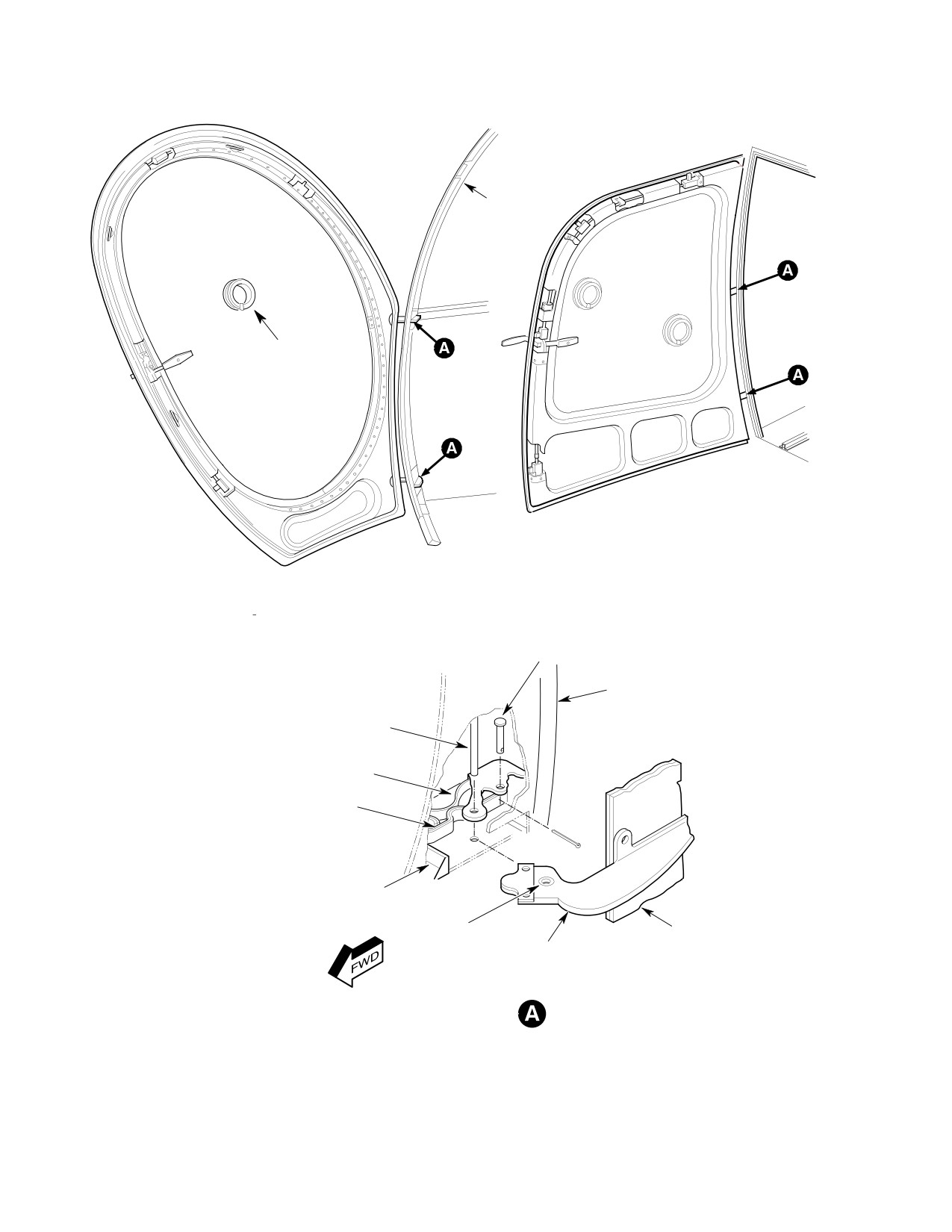
FUSELAGE
DOOR FRAME
SNAPVENT
PASSENGER/CARGO DOOR
(369D/E/FF - 500N)
PILOT'S DOOR
(369D/E/FF - 500/600N)
CLEVIS PIN
FUSELAGE STRUCTURE
HINGE PIN
PRELOAD SPRING
DOOR SPRING
RUBBER STOP
BUSHING
DOOR STRUCTURE
DOOR HINGE HALF
G52-1001-1
Figure 201. Crew and Passenger/Cargo Door Installation (Sheet 1 of 2)
Page 204
Revision 25
52-10-00
MD Helicopters, Inc.
CSP-HMI-2
MAINTENANCE MANUAL
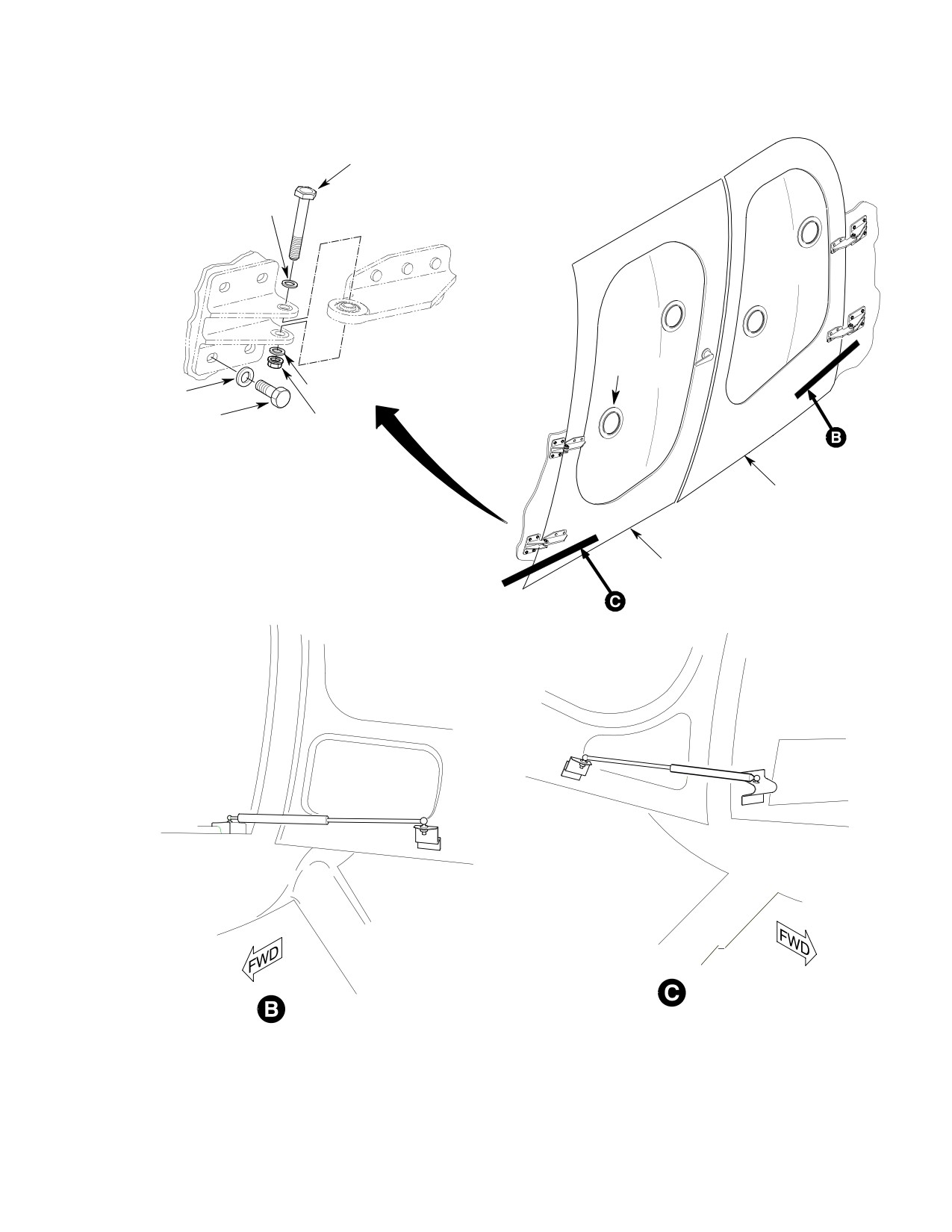
BOLT
WASHER
SNAPVENT
WASHER
WASHER
BOLT
NUT
DOOR/HINGE ATTACHMENT
(TYP)
AFT DOOR
MID DOOR
MID DOOR (600N)
AFT DOOR (600N)
G52-1001-2
Figure 201. Crew and Passenger/Cargo Door Installation (Sheet 2 of 2)
Page 205
52-10-00
Revision 25
CSP-HMI-2
MD Helicopters, Inc.
MAINTENANCE MANUAL
7. Mid and Aft Door Strut Replacement
(2). Slip snapvent flange into window hole
(600N)
at an angle of about 30° degrees to
window surface.
(Ref. Figure 201)
(3). Be sure that ends of wire stiffener are
A. Mid and Aft Door Strut Removal (600N)
inside window hole.
(1). Remove nut and washer that secures
9. Outside Handle or Spindle Replacement
gas strut pivot post ball to door fitting.
(Ref. Figure 202)
(2). Remove nut and washer that secures
A. Outside Handle or Spindle Removal
gas strut pivot post ball to airframe
fitting.
(1). Remove three screws and washers
securing escutcheon to door exterior.
(3). With door in open position, pull gas
strut up away from fittings to remove.
(2). Drive spring pin from handle and slide
handle from spindle.
B. Mid and Aft Door Strut Installation (600N)
B. Outside Handle or Spindle Installation
(1). Insert pivot post ball fitting, at shaft
(1). Attach replacement handle to escutch
end of strut, into outboard hole in
eon with handle washers. Use maxi
airframe fitting and install washer and
mum number of handle washers
nut.
possible without impeding free move
ment between handle and escutcheon.
(2). Insert pivot post ball fitting, at tube
end of strut, into hole in door fitting
(2). Slide handle on spindle and secure
and install washer and nut.
escutcheon to door with washers and
screws.
(3). While holding pivot post ball fitting to
prevent rotation, torque nuts to 60 - 85
10. Automatic Latch Block Assembly
inch-pounds (6.78 - 9.60 Nm).
Replacement
(4). Adjust strut pressure after installation
(Ref. Figure 202)
by carefully loosening screw at end of
strut and releasing pressure until door
A. Automatic Latch Block Removal
opens fully and operates smoothly
(1). Perform this procedure with door in
through full range of travel.
open position and handles at latched
rest position.
8. Snapvent Replacement
(2). Remove screws securing latch cover.
(Ref. Figure 201)
(3). Mark lockplate/nutplate so that
A. Snapvent Removal
replacement latch block can be installed
at approximately same position as latch
(1). Push snapvent outward in window
that is to be removed.
(open position).
(4). Remove four screws and washers
(2). Grasp open side of snapvent and gently
securing latch block to lockplate/nut
squeeze it into an elliptical shape.
plate. Note any washers found between
latch block and lockplate/nutplate.
(3). Slip snapvent out of window hole at
These are adjustment shims and should
about a 30° degree angle to surface of
be reinstalled at same location and
window.
position at reinstallation of latch block.
B. Snapvent Installation
(5). Remove cotter pin, washer and pin
securing rod end clevis to latch block.
(1). Grasp open end of snapvent and gently
squeeze it into an elliptical shape.
(6). Remove latch block from door.
Page 206
Revision 25
52-10-00
MD Helicopters, Inc.
CSP-HMI-2
MAINTENANCE MANUAL
(7). Lubricate moving parts of latch block
B. Cam Lock Installation
(Ref. Automatic Latch Block Assembly
Repair).
NOTE: Currently available cam lock is longer
than early cam lock and requires a spacer
B. Automatic Latch Block Installation
between lock flange and outside surface of
door skin.
(1). Reconnect link and connector rod end to
(1). Position lock boss, torsion spring,
handle arm with cotter pin and washer.
washer and replacement handle into
position and insert spindle.
NOTE: Cotter pin and washer are to be in
stalled on outboard side of connector rod end
(2). Install spindle washers and screw to
to eliminate possibility of interference. To
secure spindle in lock plate.
eliminate excess play, use extra washers for
shimming.
(3). Attach one spring hook in hole of lock
boss and attach other spring hook at
(2). Secure latch block to lock plate with
notch in lock plate. Use wire to pull
four screws and washers.
spring hook into place.
(3). Check door latching and safelocking
(4). Install outside handle.
operation and make any necessary
adjustment.
(5). Check door latching and safelocking
operation and make any necessary
11. Cam Lock Replacement
adjustment.
(Ref. Figure 202)
12. Latch Assembly or Striker Adjustment
A. Cam Lock Removal
(Ref. Figure 203)
(1). Remove outside handle.
Consumable Materials
(Ref. Section 91−00−00)
(2). Remove latch block.
Item
Nomenclature
CM425
Sealing compound
(3). Note position of lock boss and handle
torsion spring to aid at reinstallation.
(1). Adjust latch assemblies and strike as
(4). Hold handle, lock boss and torsion
necessary to ensure proper door
spring in position and withdraw
latching, safelocking and keylocking
spindle. Then slide handle lock boss
functions.
and torsion spring out of lock plate.
(2). After adjustments are made, perform a
(5). Remove handle grip from handle arm
final inspection of all latching and
by loosening setscrew and sliding grip
locking functions, then install latch
from arm.
covers.
NOTE: When lock is set to locked position, be
(3). Fill in gaps and fair-in area between
sure that cam actuates hinged lock bar.
strikes and bumper stripes at each
When lock is in correct position, secure it in
position with sealant (CM425).
place by center-punching surface of lock
plate assembly close to flat on hexagonal
A. Door Seal Compression Adjustment
locking nut.
To adjust door seal compression, remove latch
(6). Replace key-operated cam lock by
covers. Move strikes as necessary in their
unscrewing hexagonal nut.
slotted mounting holes.
Page 207
52-10-00
Revision 25
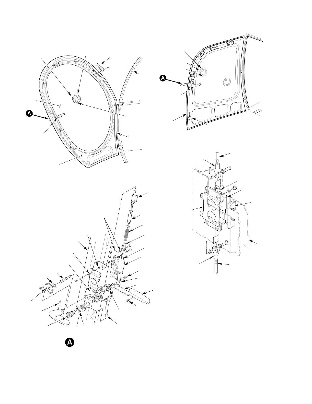
CSP-HMI-2
MD Helicopters, Inc.
MAINTENANCE MANUAL
SNAPVENT
SNAPVENT
LATCH COVER
DOUBLER
(TYP)
DOUBLER
STOP
AUTOMATIC
DOOR LATCH
WINDOW
MECHANISM
STOP
DOOR SEAL
LATCH COVER
(TYP) (4 PLCS)
AUTOMATIC
DOOR SEAL
PASSENGER/CARGO DOOR
DOOR LATCH
(369D/E/FF - 500N)
MECHANISM
CONNECTOR
CLEVIS
ROD
DOOR PANEL
PILOT'S DOOR
LATCH SLIDER
(369D/E/FF - 500/600N)
LATCH BLOCK
ROD MOUNTING
BRACKET
STRIKER
ASSEMBLY
LATCH BLOCK
SPACER
NOTE 2
MOUNTING
BRACKET
SPRING
SHIM WASHER
(NOTE 3)
CLEVIS
DOOR PANEL
(NOTE 1)
(NOTE 2)
DOOR
LATCH SLIDER
FRAME
LOCKPLATE ASSEMBLY
LATCH BLOCK ASSEMBLY
(NOTE 4)
SPRING HOOK NOTCH
SPRING
CONNECTOR ROD
CLEVIS
SPINDLE
LINK PIN
SHIM
LINK
ARM
LATCH BLOCK ASSEMBLY
GRIP
NOTES:
ESCUTCHEON
SET SCREW
1.
FOR ADJUSTMENT INFORMATION, REFER TO
SPRING PIN
LOCK BOSS
ADJUSTING LATCH COMPRESSION.
2.
INSTALL OUTBOARD TO ELIMINATE POSSIBILITY
OF INTERFERENCE.
SPACER
CONNECTOR
3.
AS REQUIRED, FOR LATCH ADJUSTMENT, NOT
CAM LOCK
(NOTE 5)
ROD END
ON ALL WINDOWS.
(KEY OPERATED)
4.
IDENTIFIED AS NUTPLATE AT OTHER LOCATIONS.
LATCH ASSEMBLY - EXPLODED VIEW
5.
SPACER REQUIRED ON NEW LOCKS WHICH ARE
EARLY SYSTEM
LONGER THAN EARLY MODEL CAM LOCKS.
G52-1002-1
Figure 202. Door Latching System Installation (Sheet 1 of 2)
Page 208
Revision 25
52-10-00
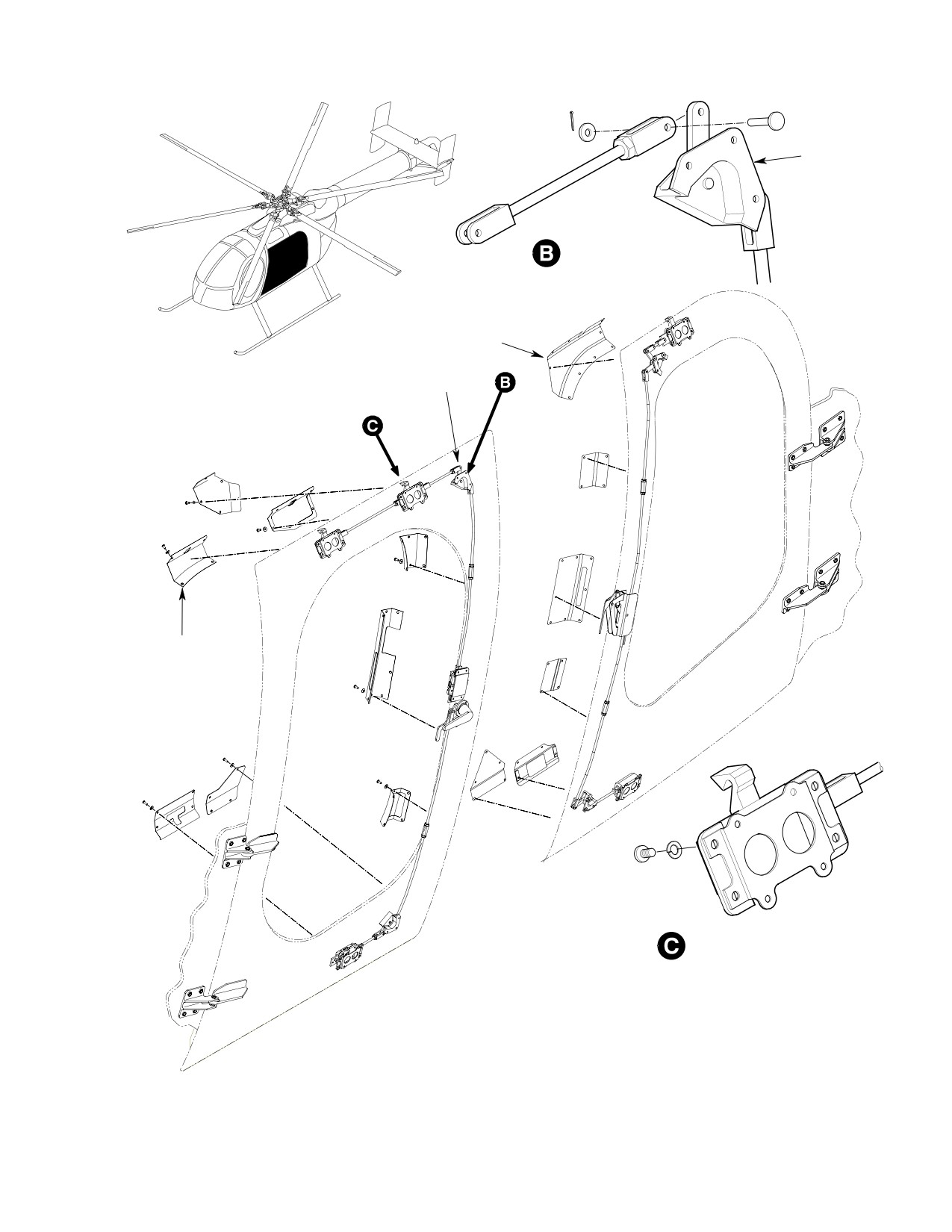
MD Helicopters, Inc.
CSP-HMI-2
MAINTENANCE MANUAL
CORNER CRANK
ASSEMBLY
PUSH/PULLROD ATTACHMENT
(TYP)
LATCH COVERS
(6 PL)
NOTE 6
LATCH COVERS
(8 PL)
LATCH BLOCK ATTACHMENT
(TYP)
NOTES: (CONT.)
6.
SHIM AS REQUIRED (MAX. 2 WASHERS AT EACH RIVET
LOCATION) BETWEEN DOOR STRUCTURE AND CORNER
CRANK ASSY. MAXIMUM GAP AT RIVET NOT TO EXCEED.
G52-1002-2
Figure 202. Door Latching System Installation (Sheet 2 of 2)
Page 209
52-10-00
Revision 25
CSP-HMI-2
MD Helicopters, Inc.
MAINTENANCE MANUAL
B. Engagement Depth of Latch Bolts with
modifying as required to compress
Striker Adjustment
spring 0.060 - 0.080 inch (1.524 - 2.032
mm) when mechanism is at safelocked
Adjust engagement depth of latch bolts with
position.
strikes by removing latch covers and moving
latch assemblies as necessary in their slotted
(2). Fill gaps and fair-in area between latch
mounting holes or by adding shims under
strikes and bumper strips at each
strikes.
position, using sealant (CM425).
NOTE: Complete safelocking exists when latch
13. Latching Mechanism Operational Check
bolt extension is at maximum and roller on
(Early System)
safelock trigger is engaged in safelock slot in
latch slider. At this condition, safelock trig
(1). Check inside and outside door handle at
ger retracts when latch slider is moved
all positions for function.
slightly in unlatch direction.
(2). Close door from inside. Entire beveled
C. Connector Rod Adjustment
face of each bolt must make contact
with strike and must hold door firmly
(1). Open door or remove from helicopter.
against door seals. Bolts must be
(2). Remove latch cover.
positioned on strike such that there is
sufficient space for bolt to extend an
(3). Press all safelock triggers and rotate
additional minimum 0.125 inch (3.175
handle to safelock position. Remove
mm) into strike for safelocking latches
clevis pin from connector rod or latch
(Ref. Figure 203).
being adjusted.
(3). Check that each latch bolt makes
(4). Move latch slider manually to complete
contact with mating strike. Unequal
safelock position. Adjust connector rod
striking and latching indicates latch
length so that clevis pin can be in
assembly or strike require adjustment
stalled easily.
or shimming.
NOTE: Position of fourth and first latches can
(4). Safelock door and observe that door is
be individually adjusted without disturbing
forced inward for seal compression at
adjustment of other latches. If position of
each latch position. Unequal safelock
second or third latches is adjusted, then all
ing may indicate that connector rods
should be checked. When adjusting all four,
are not properly adjusted for complete
start with third latch, and proceed to sec
extension of latch bolts.
ond, first and then fourth.
D. Latch Compression Adjustment (Early
14. Hook−Latch Door Latching System
System)
Operational Check
Latch compression spring adjustment may be
(Ref. Figure 203)
necessary and should be checked if part
replacement, particularly in stack-up between
Perform following operational check of
upper clevis on third latch and first mounting
hook-latch door-latching system. If malfunc
bracket or change in position of clevis has been
tion is noted, refer to Table 201 for trouble
made.
shooting and repair information.
(1). Check inside and outside door handle at
Consumable Materials
all positions for function. From open
(Ref. Section 91−00−00)
and lock positions door handle should
Item
Nomenclature
spring back to rest position when
CM425
Sealing compound
released.
(2). Move handle to open position. Ensure
(1). Readjust spring load using shorter or
all four latch hooks are fully extended
longer spring compressor spacer and by
from their latch blocks.
Page 210
Revision 25
52-10-00
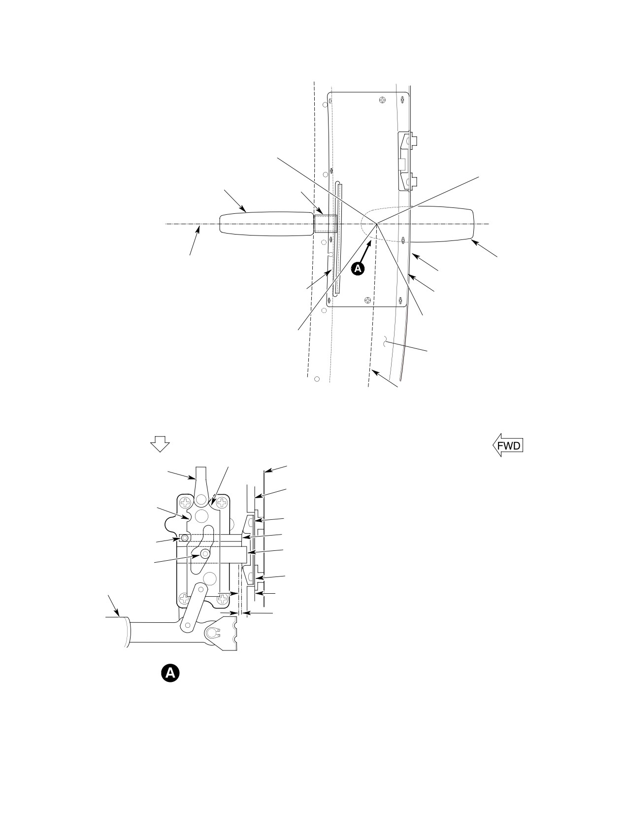
MD Helicopters, Inc.
CSP-HMI-2
MAINTENANCE MANUAL
INSIDE HANDLE UNLATCH
ACTION POSITION
OUTSIDE HANDLE SAFELOCK
ACTION POSITION
INSIDE HANDLE
TUBING
OUTSIDE HANDLE SAFE
LOCKED POSITION
INSIDE HANDLE LATCHED
OUTSIDE HANDLE
REST POSITION (NOTE 2)
DOOR FRAME STRUCTURE
CHANNEL STRIP
LATCH COVER
OUTSIDE HANDLE LATCHED
REST POSITION (NOTE 2)
INSIDE HANDLE
SAFELOCKED POSITION
DOOR PANEL
OUTSIDE HANDLE UNLATCH AC
TION POSITION
HANDLE POSITIONS
SAFELOCK ACTION
(RIGHT DOOR INSIDE VIEW)
LATCH SLIDER
DOOR FRAME
CLEVIS
BUMPER
SAFELOCK SLOT
SHIM
SAFELOCK TRIGGER
LATCH BOLT
LATCH BOLT
ROLLER
STRIKER PLATE
INSIDE
HANDLE
0.88 INCH (22.35 MM)
UNLATCH ACTION
NOTE 1
NOTES:
1.
WHEN LATCH IS COMPLETELY SAFELOCKED,
MINIMUM OF 0.125 INCH (3.175 MM) OF FLAT
SURFACE (BEYOND ANGLED LEADING EDGE )
OF LATCH BOLT MUST BE ENGAGED WITH
LATCH ENGAGEMENT
STRIKER PLATE.
(THIRD LATCH INTERIOR
2.
LATCHED REST POSITION APPLIES WITH DOOR
SHOWN FOR CLARITY)
OPEN OR CLOSED.
G52-1003-1
Figure 203. Door Handle Positions and Latch Engagement (Sheet 1 of 3)
Page 211
52-10-00
Revision 25
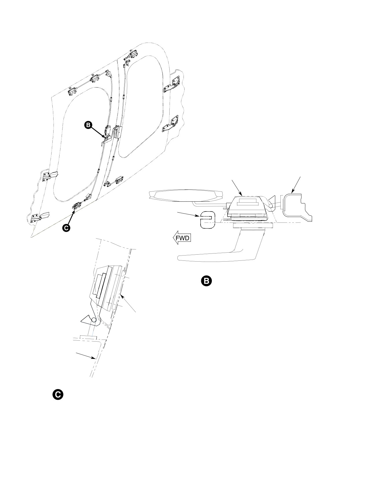
CSP-HMI-2
MD Helicopters, Inc.
MAINTENANCE MANUAL
AFT DOOR ASSY
MID DOOR ASSY
WINDOW SEAL
VIEW LOOKING DOWN
DOOR
DOOR FRAME
LATCH BLOCK ENGAGEMENT
(TYP)
G52-1003-2
Figure 203. Door Handle Positions and Latch Engagement (Sheet 2 of 3)
Page 212
Revision 25
52-10-00
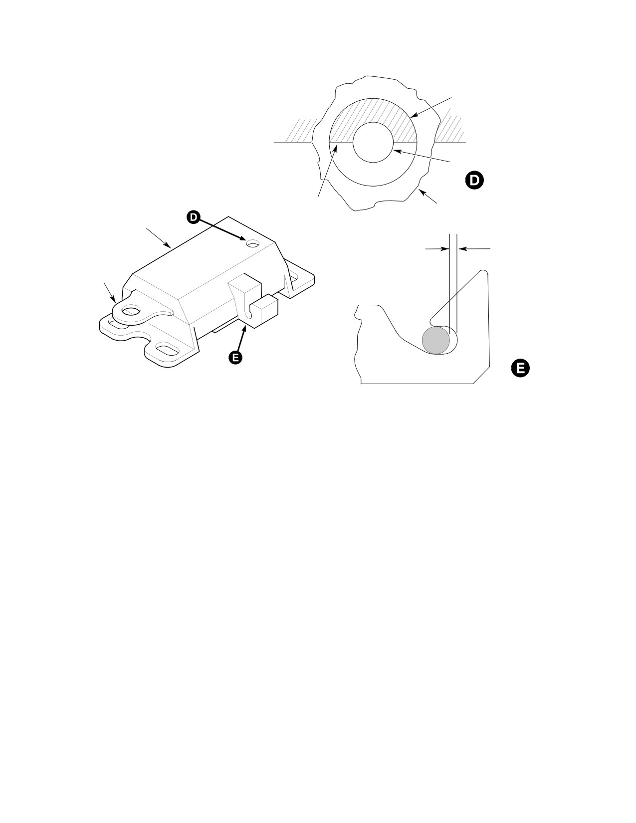
MD Helicopters, Inc.
CSP-HMI-2
MAINTENANCE MANUAL
WITNESS HOLE
PIN
LATCH
LATCH
SLIDER
LATCH BLOCK
HOUSING
ASSEMBLY
0.050 INCH (1.27 MM) MAX
GAP BETWEEN DOOR
STRIKER PIN AND HOOK
LATCH WHEN DOOR
LATCH
CLOSED AND LATCH IN
SLIDER
REST POSITION.
G52-1003-3A
Figure 203. Door Handle Positions and Latch Engagement (Sheet 3 of 3)
(3). Check latch blocks, latch sliders, door
that semi-circle cutout on latch slider is
waffle and striker pin assemblies for
fully seated around pin on latch block.
any nicks, dents, scratches, chipped
(7). Move handle to open. Note that all four
paint or other evidence of contact
latch hooks extend fully from their
caused by misalignment of door latches
latch blocks and fully disengage their
or striker pin assemblies.
striker pins, allowing the door to open.
Handle should spring back to rest
NOTE: Extreme temperatures may cause door
position when released.
seal to swell or door seal-to-door frame
bonding failure. Door seal protrusions
15. Autolatching Pilot and Cargo Doors
caused by swelling or bonding failure may
Operational Check
interfere with latching function.
NOTE: When opening door, apply light inward
(4). Check door seal and repair as required.
force on door. This reduces wear of latching
mechanism by overcoming door seal pres
sure.
(5). Close door firmly from inside helicopter.
Check that all four latch hooks engage
(1). Open and close door to check for smooth
their striker pins and that there is not
operation of handles and latch mecha
more than 0.050 inch (1.27 mm)
nism. Check operation of door stop.
between each hook and striker pin.
(2). Close door from inside. Check all inside
(6). Move handle to lock (full down). With
latches for correct engagement at latch
door locked, use flashlight to check
and safelock positions of interior and
witness hole on each latch block. Note
exterior handle. (Ref. Figure 203).
Page 213
52-10-00
Revision 25
CSP-HMI-2
MD Helicopters, Inc.
MAINTENANCE MANUAL
(3). Check that setting interior and exterior
handles to safelock position pulls door
Consumable Materials
inward for proper closure and sealing.
(Ref. Section 91−00−00)
Item
Nomenclature
(4). Check that key locks and unlocks door
CM219
Methyl-ethyl-ketone
handle.
CM717
Tape, pressure sensitive
16. Door−Latching Mechanism Inspection (All
Systems)
18. Window Replacement
(Ref. Figure 202 and Figure 203)
A. Early Style Window Replacement
Make following checks with magnification
(Ref. Figure 205) For repair of plastics refer to
glass and strong light:
FAA AC 43.13-1B. Replace window as follows:
(1).
All parts for excessive wear, nicks,
cracks and corrosion.
Consumable Materials
(Ref. Section 91−00−00)
(2).
Threaded parts for worn, crossed or
Item
Nomenclature
otherwise damaged threads.
CM415
Cement
(3).
Early latch block assemblies for broken
CM418
Cement, epoxy
springs and wear on strike contact
CM425
Sealing compound
surfaces of latching bolts; and for undue
CM432
Dichloromethane
wear of latch sliders, bolts and bolt
CM433
Ethylene chloride
rollers. Current latch block assemblies
CM717
Tape, pressure sensitive
for wear, damage or distortion of latch
sliders and latch hook.
(1).
Remove snapvent from window (Ref.
(4).
Cam lock for jamming when key is
Snapvent Replacement).
operated.
(2).
Drill out rivets attaching window
(5).
Link for wear or distortion.
retainers to door structure and remove
window. Remove two screws, washers
(6).
Handles for distortion, worn pivot holes
and nuts from door hinge doubler.
and worn finish.
(3).
If door frame or window is to be reused,
(7).
Escutcheon and handle for looseness,
carefully scrape off sealant around edge
distortion, thread damage and break
of door or window frame using a
age.
wooden, plastic or other suitable
nonmetallic scraper.
(8).
Lockplate assembly for wear, distortion,
thread damage and breakage.
(4).
Repair retainer-to-window bond, if
applicable, with dichloromethane
(9).
Latch block nutplates for thread
(CM432) or ethylene chloride (CM433);
damage and loose rivets.
or use PS-18 or S147 cement (CM415).
(10).
Rods and clevis for wear in clevis pin
(5).
Trim retainer as required to provide
holes, thread damage, and distortion.
clearance for door handle and end butt
joint.
17. Anti−Chafing Tape on Door Frame Repair
(6).
Place window in position and check for
(Ref. Figure 208) Inspect condition of anti-
0.380 inch (9.652 mm) minimum
chafing tape installed on pilot's and cargo
engagement and flush fit with window
compartment door frames. For minor repair,
frame. Trim excess if required.
remove defective tape where necessary. Clean
frame surface with MEK (CM219). Replace
(7).
Use 1/2 inch (12.70 mm) pressure-sen
with polyurethane pressure-sensitive tape
sitive tape (CM717) on edge of window.
(CM717).
Bond seals to retainer and to door
Page 214
Revision 44
52-10-00
MD Helicopters, Inc.
CSP-HMI-2
MAINTENANCE MANUAL
frame using cement, epoxy (CM418);
(6). Apply 0.250 inch (6.35 mm) tape
bond inside of seals to window using
around outside of drawn line.
sealant (CM425). Do not stretch seals
(7). Trim glass to the outside of applied
when bonding.
0.250 inch (6.35 mm) tape.
(8).
With retainer and window in position
(8). Remove tape and gently smooth the
on door frame, press down firmly and
edges.
evenly on retainer so that seals are
compressed tightly against window
NOTE:
around full circumference of door
D It is best to have ends of seal on aft side of
frame.
window to help keep moisture out while
in flight.
(9).
Locate existing holes in door-reinforc
ing frame. Mark and drill holes in
D Ensure seal is firmly worked onto door to
retainer. It is permissible to install new
prevent seal from being cut too short.
rivets between existing holes in rivet
(9). Install window seal around periphery of
pattern.
window opening with groove for glass to
(10).
Rivet window to door using rivets of
the inside. Cut seal to size if new.
correct length. Blind rivets are used for
(10). Gently trim seal, where needed, around
retainers riveted to door reinforcing
top door hinges.
frame.
Do not use any tools with sharp
(11).
Install doubler over retainer at hinge
CAUTION
edges to aid in installing glass
area with two screws, washers and
into seal, glass is easily damaged.
nuts. Drill (No. 21 drill) and ream to
0.166 inch (4.216 mm) diameter window
NOTE: To aid in installation of glass into seal,
panel for screws, using slow speed drill
use a mild mixture of soapy water liberally
(700-800 rpm).
applied to the edge of the glass and into
groove in seal. Do not use any lubricants.
(12).
Install snapvent (Ref. Snapvent
Replacement).
(11). Install glass from inside by sliding up
into the seal.
(13).
Remove protective covering and clean
window (Ref. Sec. 20-20-00).
(12). With hands on either side of glass, work
glass firmly into seal.
B. Current Style Window Replacement
(13). Using a blunt plastic spatula or probe,
(Ref. Figure 206)
gradually work edge of window into
groove of window seal.
(1). Using a blunt plastic spatula or probe,
pull back edge of window seal and
(14). If there is a gap at the seal ends, use
gradually work window out from groove
commercially available clear silicone
in seal.
seal to fill gap.
(2). Remove seal and clean for re-installa
19. Hinge Replacement
tion of window, discard if not pliable.
(Ref. Figure 204)
(3). Mask around new glass for marking.
(1). Remove door and drill out hinge-at
(4). Place new glass against door and center
taching rivets.
over the window opening.
(2). Install replacement hinges at body
(5). Trace line on glass from window
attach points with door hinge pins.
opening in door.
(3). With damaged hinges removed, install
NOTE: The following step is to ensure the glass
doors in closed position. Have an
is larger than the door opening so glass will
assistant retain door in place by
not blow out in flight.
actuating door handle locking levers.
Page 215
52-10-00
Revision 36
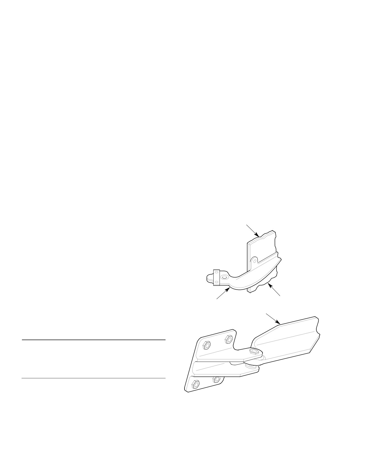
CSP-HMI-2
MD Helicopters, Inc.
MAINTENANCE MANUAL
(4).
If required for door fit, use one-piece
(3). Replace preload spring; with longest
solid aluminum alloy shim, up to 0.040
flat area outboard and aft in hinge body
inch (1.016 mm) maximum thickness
recess.
trimmed flush with hinge outer edges,
under upper or lower hinge (between
(4). Replace door spring; with longest flat
hinge and door exterior).
area also outboard and aft in body
hinge recess.
(5).
Mark hinge rivet attach locations
through existing holes in door. Locate
NOTE: Forward curved area of door hinge pres
and mark blind rivet attach points
ses against preload spring inboard curved
(cargo door only).
area, at installed position.
(6).
Remove door hinges and check for
(5). Install hinge pins and cotter pins. Pins
proper edge distance.
may be installed upward if interference
does not permit installation with cotter
(7).
Drill holes with a No. 28 drill at pilot's
pin hole down.
door upper and lower hinge aft attach
points. Use a No. 21 drill at all other
(6). Cover exposed sharp edges of cotter
pilot and cargo door attach points.
pins and pins with sealer (CM424).
(8).
On pilot's door upper hinge, install
rivets with washers under bucked
(7). Install doors and perform operational
heads.
check (Ref. Automatic Latching Mecha
nism (Early System) Operational
(9).
Install rivets at remaining pilot's door
Check.
attach points.
SHIM AS REQUIRED
(10).
Install two mechanically-expanding
(NOTE)
rivets at aft cargo door hinge attach
points.
(11).
Install four rivets at remaining attach
points.
(12).
Paint as required.
(13).
Install doors and perform an operation
al check (Ref. Automatic Latching
Mechanism (Early System) Operational
DOOR STRUCTURE
Check).
DOOR HINGE HALF
SHIM AS REQUIRED
A. Preload Spring Replacement
(NOTE)
(Ref. Figure 205)
Consumable Materials
(Ref. Section 91−00−00)
Item
Nomenclature
CM424
Sealing compound
NOTE: The following procedures apply to both
upper and lower hinges.
NOTE: SHIM AS REQUIRED UNDER HINGE WITH ONE PIECE
OF 2024-T3 ALUMINUM, 0.050 IN. (1.270 MM) MAXIMUM. TRIM
(1). Remove two cotter pins and clevis pins.
TO OUTER PERIPHERY OF HINGE.
G52-1004
(2). Remove door spring first; then remove
preload spring.
Figure 204. Door Hinge Replacement
Page 216
Revision 36
52-10-00
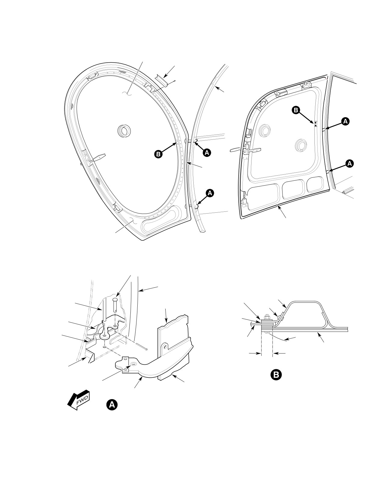
MD Helicopters, Inc.
CSP-HMI-2
MAINTENANCE MANUAL
WINDOW
LATCH COVER
(TYPICAL)
FUSELAGE
DOOR FRAME
DOOR SEAL
DOOR SEAL
DOOR PANEL
PILOT'S DOOR
CARGO DOOR
(369D/E/FF - 500/600N)
(369D/E/FF - 500N)
CLEVIS PIN
FUSELAGE STRUCTURE
SHIM
DOOR HINGE
RETAINER
HINGE PIN
(AS REQUIRED)
DOUBLER
(NOTE)
RIVET
PRELOAD
PRESSURE
SPRING
SENSITIVE TAPE
DOOR
SPRING
HINGE
WINDOW
DOOR PANEL
WINDOW ENGAGEMENT
0.380 INCH (9.652 MM) MINIMUM
RUBBER
STOP
WINDOW REPAIR
BUSHING
DOOR STRUCTURE
DOOR HINGE HALF
HINGE REPAIR
NOTE:
FILL GAP WITH SEALANT.
G52-1001-3A
Figure 205. Window and Hinge Repair
Page 217
52-10-00
Revision 25
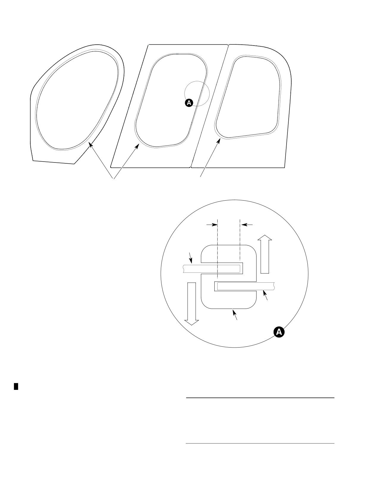
CSP-HMI-2
MD Helicopters, Inc.
MAINTENANCE MANUAL
SEAL
SEAL
0.25 IN.
(6.35 MM)
I
WINDOW
N
B
R
D
O
U
T
B
DOOR FRAME
R
D
SEAL
NOTE:
600N SHOWN, TYPICAL OF ALL HELICOPTERS.
G52-1001-4
Figure 206. Current Style Window Installation
B. Rubber Stop Replacement
Consumable Materials
(Ref. Figure 205) Replace rubber door stop if
(Ref. Section 91−00−00)
damaged or partially separated. Remove door
Item
Nomenclature
stops by carefully prying bonded rubber out of
CM411
Adhesive, epoxy
hinge recess. Bond new stop to forward end of
hinge recess with adhesive (CM411).
Page 218
Revision 36
52-10-00
MD Helicopters, Inc.
CSP-HMI-2
MAINTENANCE MANUAL
20. Automatic Latch Block Assembly Repair
(2). Replace anti-chafing tape if damaged.
(Ref. Figure 201 and Figure 207, Sheet 1 of 2)
(3). Install washer (if applicable), shims,
Replace worn or damaged parts as necessary.
dam (if applicable), strike pin and
Disassemble only to extent required for
secure with screws.
replacement of parts. Perform following steps
as required:
22. Litter Door Inspection (50 Hour)
The following is a procedure for inspecting the
Consumable Materials
litter door installation for proper condition and
(Ref. Section 91−00−00)
security of the quick-release fastener assem
Item
Nomenclature
blies and the rubber seal (gasket) installed
between the window glass and door frame. The
CM108
Graphite, powdered
visual inspection is applicable to the PN
CM118
Grease
369H92733-1 / -2 bubble window assemblies
CM234
Solvent, dry-cleaning
(or PN 369H92731-1 / -2 flat window assem
CM307
Lacquer, acrylic semi-gloss
blies, if installed) in the PN 369H90085 litter
door installation.
(1). Lubricate all moving parts except lock,
(1). Remove quick-release fasteners
with grease (CM118) to prevent
securing bubble (or flat) windows to
binding.
litter doors.
(2). Lubricate lock with powdered graphite
(2). Visually inspect each fastener for
(CM108).
condition, and each anchor receptacle in
door structure for condition and
(3). At time of disassembly clean reusable
security of attachment.
parts except locks, using soft bristle
brush dipped in solvent (CM234).
(a). Replace each fastener if stud is loose
or worn.
(4). Dry parts using clean, lint-free cloth or
dry compressed air at 20 psi maximum.
(b). Replace anchor receptacle and/or
rivets as required.
(5). Clean key-operated cam locks, using
dry compressed air at 20 psi maximum.
(3). Visually inspect rubber seal (gasket) on
window assemblies for condition. Seal
(6). Touchup handles with semigloss black
must be fully intact; rebond seal to door
acrylic lacquer (CM307).
structure as required.
(7). Eliminate binding by lubricating
(a). Replace seal if worn, cracked or hard.
moving parts.
(4). Reinstall window assemblies to litter
21. Strike Pin Repair
doors using quick-release fasteners.
(Ref. Figure 207)
(5). Check for gaps between window glass,
rubber seal and door structure.
NOTE: The 369 model has three different con
figurations. Select the configuration that
(6). Replace seal and/or use shorter length
pertains to your specific application.
studs if any gap is noted.
(1). Remove screws, strike pin, dam (if
(7). If seal is extruded, use longer length
applicable), shim and washers (if
studs; replace seal if extrusion still
applicable) from door frame.
exists.
Page 219
52-10-00
Revision 36
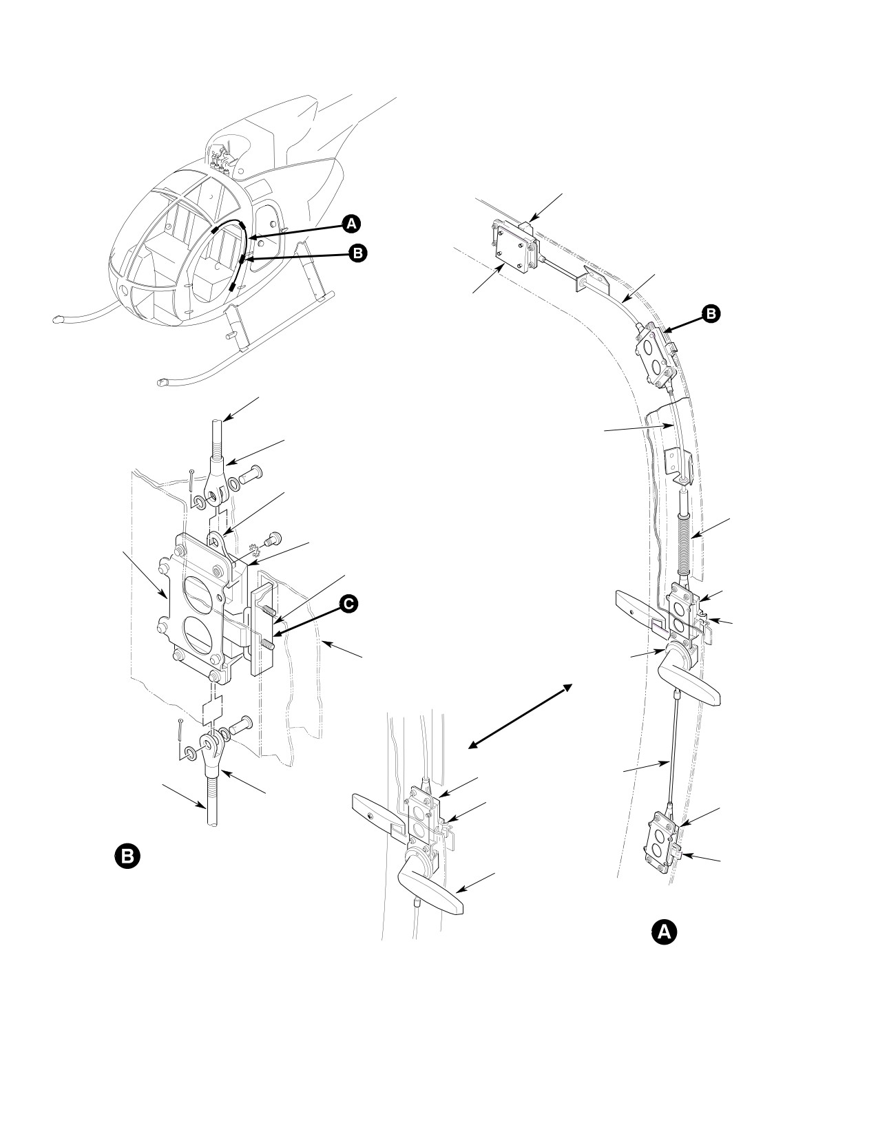
CSP-HMI-2
MD Helicopters, Inc.
MAINTENANCE MANUAL
LATCH HOOK
CONNECTOR ROD
LATCH
BLOCK
CONNECTOR ROD
CONNECTOR ROD
CLEVIS
LATCH SLIDE
NOTE
LATCH BLOCK
LATCH BLOCK
MOUNTING
BRACKET
STRIKER ASSEMBLY
LATCH
BLOCK
LATCH
HOOK
HANDLE
DOOR FRAME
ASSEMBLY
LATCH
CONNECTOR
CONNECTOR ROD
BLOCK
ROD
CLEVIS
LATCH
LATCH
HOOK
BLOCK
LATCH BLOCK ASSEMBLY
HANDLE
LATCH
ASSEMBLY
HOOK
NOTE:
1.
SPRING USED WITH EARLY SYSTEMS ONLY.
CURRENT SYSTEM
SOLID ROD USED ON CURRENT SYSTEM.
CONFIGURATION
G52-1005-1A
Figure 207. Automatic Latch Block and Striker Repairs (Sheet 1 of 2)
Page 220
Revision 36
52-10-00
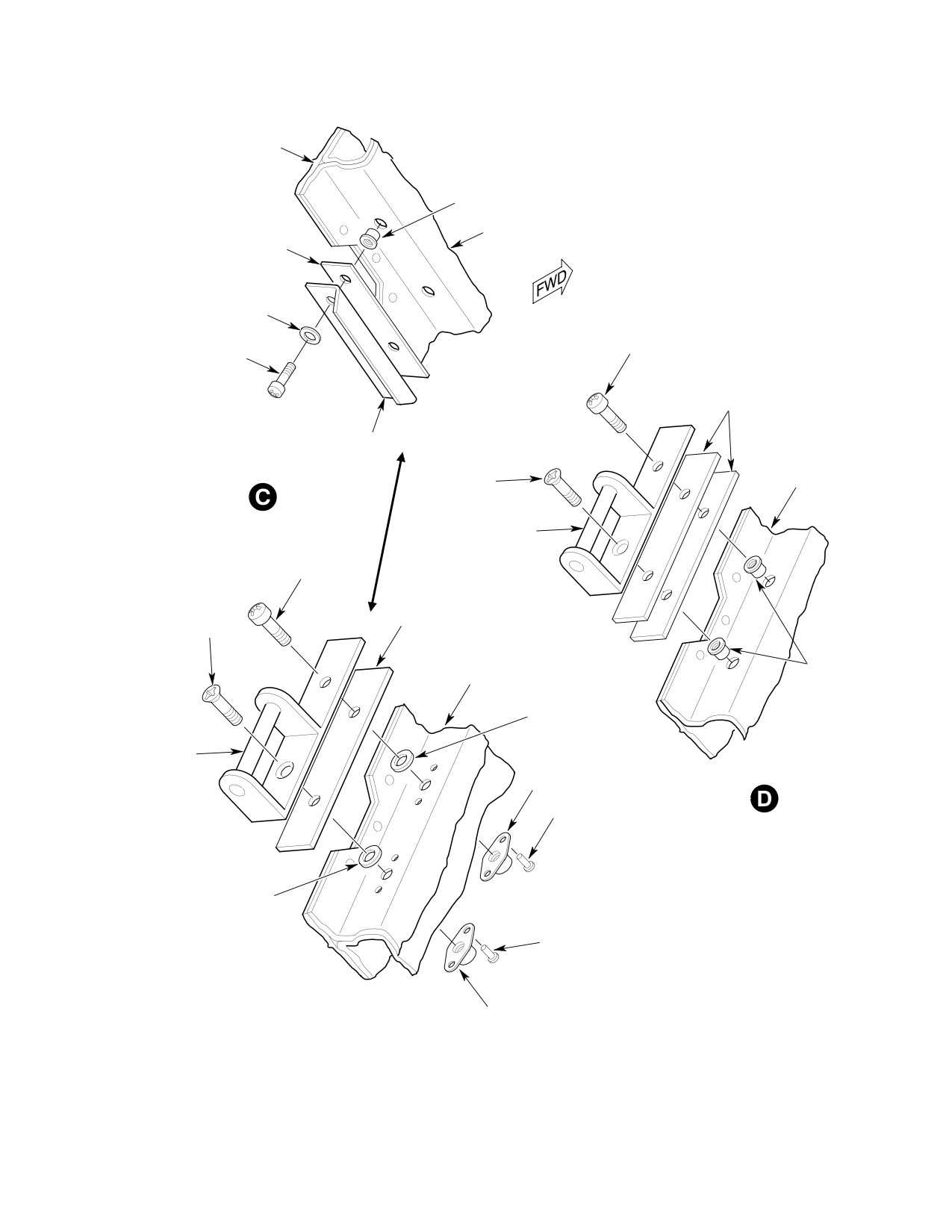
MD Helicopters, Inc.
CSP-HMI-2
MAINTENANCE MANUAL
DOOR FRAME
(CARGO DOOR
FRAME SHOWN)
RIVNUT
ANTI-CHAFING TAPE
SHIM
WASHER
SCREW
SCREW
SHIM
STRIKER
SCREW
DOOR FRAME
STRIKER PIN
SCREW
SHIM
SCREW
RIVNUT
DOOR FRAME
WASHER
STRIKER PIN
NUTPLATE
RIVET
WASHER
RIVET
NUTPLATE
G52-1005-2A
Figure 207. Automatic Latch Block and Striker Repairs (Sheet 2 of 2)
Page 221
52-10-00
Revision 36
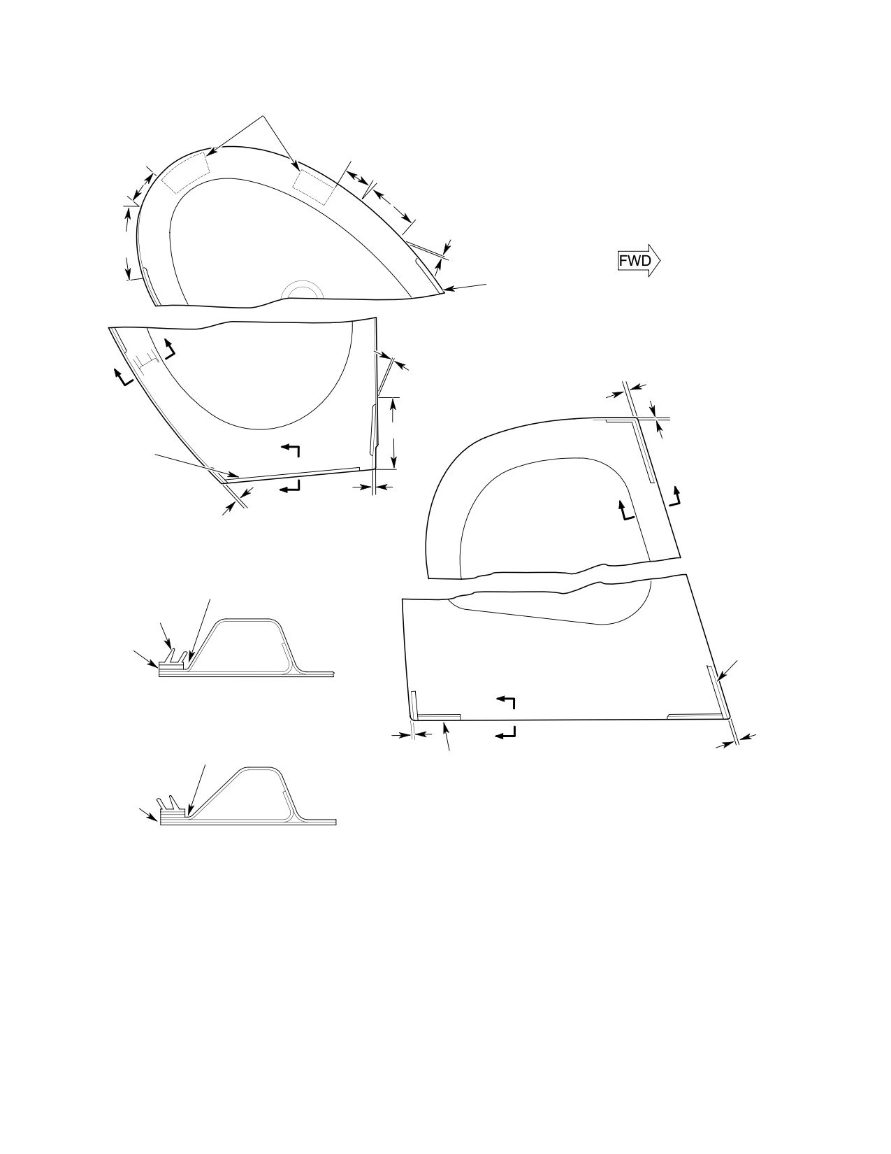
CSP-HMI-2
MD Helicopters, Inc.
MAINTENANCE MANUAL
UPPER LATCHES
3.50 INCH
3.50 INCH (8.89 CM)
(8.89 CM)
8.00 INCH (20.32 CM) BLENDED FROM 0.12 INCH (3.05 MM)
DIMENSION TO EDGE OF DOOR (2 PLACES)
8.00 INCH
0.12 INCH (3.05 MM)
(20.32 CM)
SEAL
A
0.12 INCH (3.05 MM)
A
0.25 INCH (6.35 MM)
8.00 INCH (20.32 CM)
SEAL
0.12 INCH (3.05 MM)
(FLUSH WITH
B
EDGE OF DOOR
A
AT BOTTOM)
B
0.35 INCH
A
0.12 INCH
(8.89 MM)
(3.05 MM)
PILOT'S DOOR
(LEFT DOOR SHOWN)
(NOTE 1)
FINGER TYPE SEAL
(NOTE 2, 3)
SEAL
SECTION
A - A
A
DOOR REINFORCING
0.12 INCH
FRAME
A
(3.05 MM)
0.025 INCH
(NOTE 1)
CARGO DOOR
SEAL (FLUSH WITH
(6.35 MM)
EDGE OF DOOR AT
(LEFT DOOR SHOWN)
BOTTOM)
(NOTE 2, 3)
SECTION
B - B
(BOTTOM SEAL FINGERS DOWNWARD;
PILOT'S DOOR ONLY)
NOTES:
1.
SEAL NOT TO BE LOCATED ON RADIUS OF
REINFORCED FRAME.
2.
SEAL INSTALLED USING ADHESIVE ACCORDING
TO CONTAINER INSTRUCTIONS.
3.
SHIM AS REQUIRED UNDER SEAL USING TAPE
BONDED WITH ADHESIVE.
G52-1000A
Figure 208. Door Seal Repair
Page 222
Revision 36
52-10-00
MD Helicopters, Inc.
CSP-HMI-2
MAINTENANCE MANUAL
23. Pilot and Cargo Door Repair
24. Improved Door Seal Installation
(Ref. Figure 209) The following procedure is for
A. Seal Repair
installation of QGR2178 door seals on the
cargo/passenger doors.
(Ref. Figure 208)
Consumable Materials
Consumable Materials
(Ref. Section 91−00−00)
(Ref. Section 91−00−00)
Item
Nomenclature
Item
Nomenclature
CM220
Naphtha aliphatic
CM418
Cement, epoxy
CM235
Cleaner
CM322
Primer, Silicone, Red
CM414
Adhesive, cyanoacrylic / Accelerator
(1). Carefully pull or scrape away damaged
CM439
Adhesive
seal.
(2). Restore chemical film protection to any
(1). Remove existing door seals using
base metal exposed during cleaning
Desoclean 45 (CM235) or naphtha
process (Ref. Sec. 20-20-00).
aliphatic (CM220). Ensure that all
surfaces are clean to allow proper
(3). Clean seal contact area on metal and
adhesion of new seal material. Allow
rubber seal.
surface to air-dry a minimum of 15
minutes.
(4). Carefully align and bond seal to
NOTE:
mounting surface with cement, epoxy
(CM418) according to container instruc
D On the 369D/E/FF - 500N helicopters,
tions.
seals are to be installed around the entire
circumference of the aft doors.
NOTE: Correct seal mounting position results
D On the 600N helicopters, seals are to be
in an approximately 0.060 inch (1.52 mm)
installed around the entire circumference
interference fit between door seal and bum
of the mid doors. Seals are to the applied
per.
to the top, bottom and aft edges of the
aft-cabin doors.
B. Partially−Separated Seal Repair
(2). Prime seal faying surface with red
silicone primer (CM321) and allow to
(Ref. Figure 208)
air-dry a minimum of 15 minutes.
(3). Apply a thin uniform coat of adhesive
Consumable Materials
(CM439) to faying surface of door and
(Ref. Section 91−00−00)
seal. Allow to air-dry a minimum of
Item
Nomenclature
five minutes.
CM220
Naphtha aliphatic
(4). Apply a second thin uniform coat of
CM418
Cement, epoxy
adhesive to faying surface of door and
seal. Allow to air-dry a minimum of
five minutes.
(1). Clean separated area with naphtha
(CM220) and allow to dry for minimum
(5). Test glue with clean knuckle. If adhe
of 20 minutes.
sive does not transfer to knuckle, press
the seal into place.
(2). Apply one uniform brush coat of
(6). Butt joints at forward and aft lower
cement, epoxy (CM418) to rubber seal
locations.
and mating surface contact area. Allow
to dry for 5 minutes and press mating
(7). Maximum gap of 0.030 inch (0.762 mm)
surfaces together.
at butt joints.
Page 223
52-10-00
Revision 36
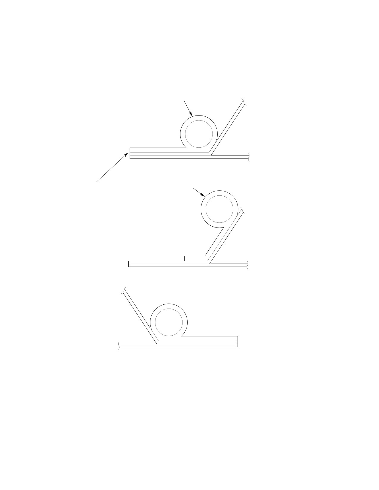
CSP-HMI-2
MD Helicopters, Inc.
MAINTENANCE MANUAL
(8). Miter joints at upper locations.
NOTE: Use glue very sparingly to achieve best
bond.
(9). Bond mitered joints with adhesive
(CM414).
(10). Trim seal flush with edge of door.
QGR2178 SEAL
SEAL MAY BE LOCATED FROM
EDGE TO INCLINE AS SHOWN
TRIM SEAL FLUSH WITH
AND AS REQUIRED TO ENSURE
EDGE OF DOOR.
PROPER SEAL OPERATION.
POSITION OF SEAL ALONG HINGE SIDE
TYPICAL SEAL POSITION;
SEAL MAY BE RELOCATED AS REQUIRED TO ACHIEVE
PROPER SEAL BETWEEN DOOR AND JAMB.
88-759
Figure 209. Improved Door Seal Installation
Page 224
Revision 36
52-10-00
MD Helicopters, Inc.
CSP-HMI-2
MAINTENANCE MANUAL
Section
52−40−00
Engine Access
Doors
MD Helicopters, Inc.
CSP-HMI-2
MAINTENANCE MANUAL
ENGINE ACCESS DOORS
MAINTENANCE PRACTICES
1. Engine Access Door − General
3. Engine Access Door Inspection
(Ref. Figure 201) Engine access doors have
(1). Check door hinges, door-attaching
upper and lower door hinges that allow door fit
hardware and latches for looseness,
adjustment. Fore and aft adjustment and fit of
cracks and damage.
doors is made possible by slotted holes in
(2). Check outside edge of door for security
hinges and serrated mating surfaces between
of bonding between outer and inner
hinges and doors. Lateral adjustment is
skin. Any separation requires repair.
obtained with laminated shims under door
hinges. Closed-door alignment is provided by
(3). Inspect doors for corrosion, distortion,
spring-type retainers on door frames at the
breaks or cracks and condition of
lower latch, and two locating pins that engage
abrasion strip tape along upper inside
holes in lower fuselage structure.
door edge and under retainers.
2. Engine Access Door Replacement
(4). For repairs (Ref. Engine Access Doors
Repairs).
A. Engine Access Door Removal
4. Engine Access Door Repair
(1). Release three latches to open access
doors. Index mark hinge, shim and
A. Sheet Metal Repair
serrated plate to door structure.
(Ref. CSP-SRM-6, Structural Repair Manual)
Remove three engine access door hinge
Abrasion strip tape along upper inside door edge
attachment screws with washers.
and on area that mates with retainers must be
Forward screws are attached with nuts
replaced when worn.
and aft screws attach to rivnuts.
B. Abrasion Strip Replacement
(2). For inspection (Ref. Engine Access Door
Inspection).
Consumable Materials
B. Engine Access Door Installation
(Ref. Section 91-00-00)
Item
Nomenclature
Consumable Materials
CM220
Naphtha aliphatic
(Ref. Section 91-00-00)
CM710
Tape, high temperature
Item
Nomenclature
CM717
Tape, pressure sensitive
CM425
Sealing compound
(1).
Replace worn abrasion strip tape along
upper inside door edge by cleaning
(1). Position door and temporarily install
contact area with naphtha (CM220);
shim, serrated plate and attachment
allow to air-dry a minimum of 30
hardware.
minutes. Install 0.50 x 40.0 inch (1.27 x
101.60 cm) strip of polyurethane tape
(2). Align indexing marks on shim, serrated
(CM717) to clean, dry surface. Apply
plate and hinge with those on door and
hand pressure to ensure firm contact
then tighten screws.
and trim as required.
(3). Close and latch doors and check for
(2).
Replace worn abrasion strip on area
firm fit with no deflections.
that mates with retainers by cleaning
retainers with naphtha (CM220).
(4). Apply sealing compound (CM425) to all
Install high temperature tape (CM710)
cotter pins.
to clean, dry surface. Apply hand
(5). For adjustment (Ref. Engine Access
pressure to ensure firm contact. Trim as
Door Adjustment).
required.
Page 201
52-40-00
Revision 18
CSP-HMI-2
MD Helicopters, Inc.
MAINTENANCE MANUAL
C. Hinge Replacement
(1). Carefully drill out rivets and remove
defective latch hook or catch from
Replace door hinges as follows:
engine access door or fuselage structure
Replace defective stops or serrated
adjustment plates, if required, by
Consumable Materials
drilling out attaching rivets.
(Ref. Section 91-00-00)
Item
Nomenclature
(2). Locate existing rivet holes and install
CM318
Primer
replacement latch, catch, door stop or
adjustment plate. Secure with replace
(1).
Remove door from fuselage structure
ment rivets.
(Ref. Engine Access Door Removal).
(3). Adjust latches as required for proper
(2).
Remove nut, washers and hinge pivot
tension of latch lever to catch without
screw.
deflecting door (Ref. Engine Access
Door Adjustment).
(3).
Carefully press out hinge pivot point
spacer and separate hinge halves.
(4). Refinish area (except latch lever
Retain two nylon washers.
assembly) as required (Ref. Sec.
20-30-00).
(4).
Carefully drill out rivets that secure
defective hinge half to fuselage struc
5. Engine Access Door Adjustment
ture.
Door alignment is provided by means of
(5).
Transfer existing hole pattern in
spring-type retainers riveted in door frames
fuselage structure to replacement
adjacent to lower latch.
fuselage hinge half and drill out holes.
Install hinge and shim on fuselage
structure and secure with replacement
Consumable Materials
rivets.
(Ref. Section 91-00-00)
Item
Nomenclature
(6).
Assemble hinge halves with nylon
washers as shown. Press steel pivot
CM702
Lockwire CRES
spacer coated with primer (CM318)
through mating holes. Install pivot
(1). Remove lockwire from threaded
screw with washer and nut.
(adjustment) end of hooks.
NOTE: Install shims under door hinge to obtain
(2). Loosen all hooks until spring type
firm fit without binding at door-to-fuselage
retainers engage in light contact with
contact surfaces when door is closed. Use
no door deflection when hooks are
slotted holes in hinge and serrated surfaces
latched.
to obtain forward and aft adjustment. When
adjustments are complete, tighten screws
(3). Unlatch doors and tighten all hooks
that secure hinge to access door.
four to five turns. Check door latching
and make additional minor adjust
(7). Refinish repaired area (Ref. Sec.
ments as required.
20-30-00).
(4). Install lockwire (CM702) in hook
D. Catch/Latch Hook Replacement
threaded end in a manner to allow
Replace defective catches or latch hooks as
latching and unlatching without
follows:
interference.
Page 202
Revision 18
52-40-00
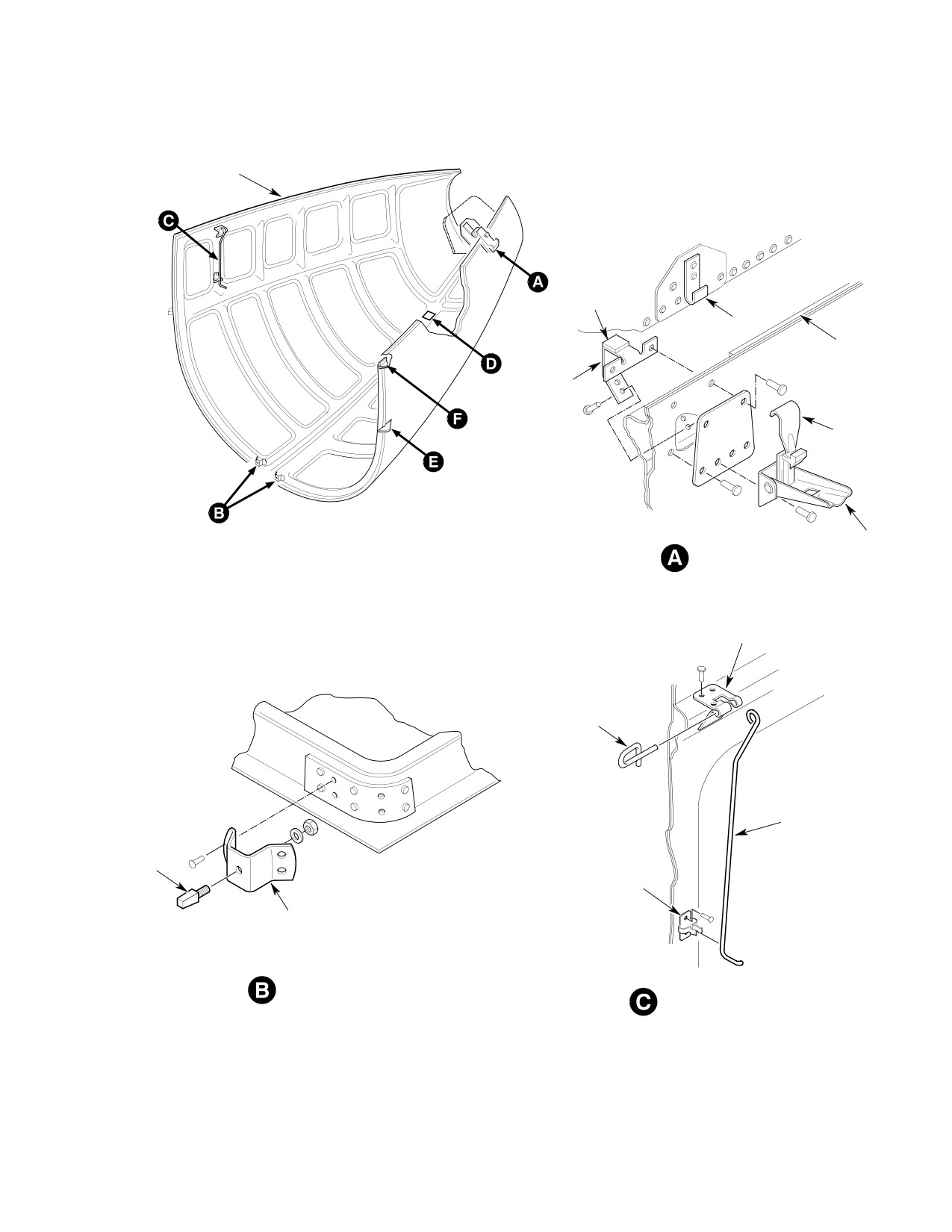
MD Helicopters, Inc.
CSP-HMI-2
MAINTENANCE MANUAL
ABRASION
STRIP TAPE
PLATE
CATCH
ABRASION
STRIP
STOP
HOOK
LEVER
AFT LATCHING
BRACKET
PIN
HOOK
PIN
BRACKET
BRACKET
LOWER BRACKET
INSTALLATION
DOOR HOLD-UP HOOK
Figure 201. Engine Access Doors (Sheet 1 of 3)
Page 203
52-40-00
Revision 18