HANDBOOK OF MAINTENANCE INSTRUCTIONS FOR MDHI 369D/E/FF-500/600N HELICOPTERS (ISSUED: 1990) - page 12
MD Helicopters, Inc.
CSP-HMI-2
MAINTENANCE MANUAL
NOTE: Determine cement adhesive tack with a
Plates must be larger than cemented
test specimen. Apply cement to a piece of
repair area.
buffed, scrap patch material each time ce
ment is spread on cell and repair patch.
Excessive clamp pressure may
CAUTION
deform cell and, or squeeze ce
(12). Coat patch, test specimen, and fuel cell,
ment out of joint.
including edges of damage, with EC678
cement (CM607). Allow cement to dry
(a). Cover both sides of repair with sheet
15 minutes before application of a
polyethylene plastic or oiled paper
second coat. Allow second coat to dry 15
large enough to cover entire cem
minutes.
ented area.
NOTE: Do not include opposite cell wall in
(13). Press a bare knuckle into cement on
clamp up. Work through cell access opening
test specimen. Cement that tears away
and arrange cell as necessary to clamp only
from skin leaving a rough, finely
the wall with the patch installation.
peaked imprint without transferring to
knuckle, is ready for patch installation.
(b). Sandwich repair area and barrier
material between pressure plates.
NOTE: Wipe cement with cheesecloth moist
Install at least two C-clamps over
ened with solvent to reactivate adhesive
pressure plates. Equalize clamp
when required.
pressure.
(14). A brayer or similar tool is required to
(16). Do not disturb cell. Maintain pressure
systematically roll patch into contact
for six hours, minimum, after which cell
with cell. Apply patch as follows:
is ready for internal patch installation.
(a). Center patch on repair area. Stick
(17). Remove clamps and plates.
one edge down and double check
patch alignment. If required, release
(18). Clean patch and cell internal repair
adhesive by flooding joint with
area with MEK saturated cheesecloth
solvent. Check adhesive tack again
swabs.
before proceeding with patch installa
tion.
(a). Apply two coats of cement, allowing
15 minutes drying time between
NOTE: The object of the next step is to get the
coats. Allow 15 minutes for second
patch down without trapping any air under
coat to set.
it.
(b). Install and roll out patch.
(b). Hold free edge of patch off cell.
Follow one line and roll tool back-
(19). Position a barrier sheet under each
and-forth over patch. Advance
pressure plate. Clamp and cure instal
toward loose end, 1/4 inch (6.35 mm)
lation for a minimum of 24 hours at 60
per pass until patch is down and free
- 80°F (16 - 27°C) before leak testing
of trapped air.
and returning cell to service.
(c). An alternate technique is to lay
7. Loose Edge and Lap Seam Repairs
prepared patch on a perfectly clean
sheet of polyethylene plastic about
Loose lap seams should be re
CAUTION
twice the size of the patch. Locate
paired as soon as possible after
plastic sheet and patch over cell
discovery.
repair area; then, slip sheet from
under patch as patch is rolled down,
NOTE: Loose lap seam edges not more than two
1/4 inch (6.35 mm) at a time.
inches long on cell interior or exterior sur
faces may be repaired. Seam separation re
(15). Fabricate two smooth, flat, rigid, metal
pairs require buffing, cementing and a
plates with no sharp edges or corners.
patch installation.
Page 803
28-00-60
Revision 19
CSP-HMI-2
MD Helicopters, Inc.
MAINTENANCE MANUAL
(1). Lift seam separation and buff flap and
(f). Cover repair with a sheet of polyeth
cell faying surfaces with emery cloth
ylene plastic or oiled paper large
(CM804).
enough to cover entire cemented
area.
(a). Buff an area on exterior surface
extending 2 inches (5.08 cm) in all
(2). Fabricate two smooth, flat, rigid, metal
directions from seam separation.
plates with no sharp edges or corners.
Plates must be larger than cemented
repair area.
CAUTION
Excessive clamp pressure may
D Fuel cell and patch contact surfaces must
CAUTION
deform cell and, or squeeze ce
be perfectly clean and dry prior to adhe
ment out of joint.
sive and patch application. Rubber and
fabric particles, moisture, and fuel or oil
(a). Cover both sides of repair with
from fingers will prevent proper patch/
polyethylene plastic or oiled paper
cell adhesive seal and may subsequently
sheets large enough to cover entire
provide a leak path. Wear clean, lint free
cemented area.
gloves to handle patch and cell after pre
NOTE: Do not include opposite cell wall in
paring surfaces for cement and patch
clamp up. Work through cell access opening
application.
and arrange cell as necessary to clamp only
D Careless application of compressed air be
the wall containing the seam repair.
tween lap joints may separate seam fur
ther.
(3). Sandwich cell wall repair area and
barrier material between pressure
(b). Either air-vacuum or blow buffing
plates. Install at least two C-clamps
dust out of separation with dry, low
over pressure plates. Equalize clamp
pressure, compressed air.
pressure.
(c). Wipe inside and outside of repair
(4). Do not disturb cell. Maintain pressure
area clean with cheesecloth (CM820)
for six hours, minimum, after which cell
moistened with MEK (CM219).
is ready for patch installation.
Continue wiping with fresh solvent
(a). Remove clamps and plates.
dampened cheesecloth as required
until no stain or particle appears on
(5). Use #5200/5187/5194 sandwich patch
the swab after the last wipe. Allow
material on cell interiors.
area to dry.
(6). Use #5218 patch material on cell
Use cement sparingly. Two thin,
exterior surfaces.
CAUTION
even coats provide better adhe
(7). Prepare cell wall and patch for installa
sion than one thick coat.
tion per (Ref. Patch Installation):
NOTE: Determine cement adhesive tack with a
Install patch.
test specimen. Apply cement to a piece of
8. Blister Repair
buffed, scrap patch material each time ce
ment is spread on cell and repair patch.
Blisters can occur on cell interior and exterior
surfaces. blisters are caused by a separation of
(d). Apply two coats of EC678 cement
the cell laminates and may contain air or a
(CM607) allowing 15 minutes be
combination of air and fuel.
tween applications. Allow second coat
to dry 15 minutes.
NOTE: Exterior blisters that contain fuel indi
cate that the barrier has been penetrated.
(e). Roll separation together starting
Blisters inside cell measuring under one
from the bottom of the pocket toward
inch diameter are acceptable and need not
the open end, 1/4 inch (6.35 mm) per
be disturbed.
pass. Ensure no air is trapped
underneath.
(1). Repair blisters as follows:
Page 804
Revision 19
28-00-60
MD Helicopters, Inc.
CSP-HMI-2
MAINTENANCE MANUAL
(a). Buff surface of blister and area
(2). Fabricate two smooth, flat, rigid, metal
extending two inches (5.08 cm) in all
plates with no sharp edges or corners.
directions from its edge.
Plates must be larger than cemented
repair area.
Avoid damaging nylon barrier
CAUTION
membrane. Do not probe, cut, or
Excessive clamp pressure may
CAUTION
puncture blisters with tool perpendicular to
deform cell and, or squeeze ce
cell wall.
ment out of joint.
(a). Cover both sides of repair with
(b). Slit blister open with an X cut to
polyethylene plastic or oiled paper
expose all of the delaminated surface.
sheets large enough to cover entire
Lift flaps and mop interior with clean
cemented area.
cheesecloth (CM820) and MEK
(CM219). Buff underlying cell surface
NOTE: Do not include opposite cell wall in
and blister flaps with emery cloth
clamp up. Work through cell access opening
(CM804). Air-vacuum or blow away
and arrange cell as necessary to clamp only
all traces of buffing dust.
the wall containing the blister repair.
(c). Wipe inside and outside of repair
(3).
Sandwich cell wall repair area and
area clean with cheesecloth moist
barrier material between pressure
ened with solvent or MEK. Continue
plates. Install at least two C-clamps
wiping with fresh solvent dampened
over pressure plates. Equalize clamp
cheesecloth as required until no stain
pressure.
or particle appears on the swab after
(4).
Do not disturb cell. Maintain pressure
the last wipe. Allow area to dry.
for six hours, minimum, after which cell
Use cement sparingly. Two,
is ready for patch installation; remove
CAUTION
thin, even coats provide better
clamps and plates.
adhesion than one thick coat.
(5).
Use #5200/5187/5194 sandwich patch
material on cell interiors.
NOTE: Determine cement adhesive tack with a
test specimen. Apply cement to a piece of
(6).
Use #5218 patch material on non-self-
buffed, scrap patch material each time ce
sealing cell exterior surfaces.
ment is spread on cell and repair patch.
(7).
Prepare cell wall and patch for installa
(d). Apply two coats of EC678 cement
tion per instructions for Patch Installa
allowing 15 minutes between applica
tion. Install patch.
tions. Allow second coat to dry 15
minutes.
(8).
Heat soak transmitter assembly in an
oven set at 100°F (38°C), maximum for
(e). Roll blister together starting from the
one hour to vaporize trapped volatiles.
bottom of each flap pocket toward the
A heat gun may be used as an alternate
open end, 1/4 inch (6.35 mm) per
drying method. Pot transmitter electri
pass. Ensure no air is trapped
cal connections with sealing compound
underneath.
MIL-S-8802 (CM425).
Page 805
28-00-60
Revision 19
CSP-HMI-2
MD Helicopters, Inc.
MAINTENANCE MANUAL
This Page Intentionally Left Blank
Page 806
Revision 44
28-00-60
MD Helicopters, Inc.
CSP-HMI-2
MAINTENANCE MANUAL
Section
28−25−00
Anti−Ice / Airframe
Fuel Filter (369D/E −
500/600N)
CSP-HMI-2
MD Helicopters, Inc.
MAINTENANCE MANUAL
This Page Intentionally Left Blank
MD Helicopters, Inc.
CSP-HMI-2
MAINTENANCE MANUAL
ANTI−ICE/AIRFRAME FUEL FILTER
DESCRIPTION AND OPERATION
Table 1. Anti−Ice/Airframe Fuel Filter Effectivity
Installation
Model & Production Number
Features
369H90022−BSC
369D, 003 and subsequent
Helicopters equipped with slimline instrument panel.
369H90022−503
369E, 001 and subsequent
Helicopters equipped with T−instrument panel.
369H90022−503
500N, 001 and subsequent
Helicopters equipped with T−instrument panel.
600N98110−501
600N, 003 and subsequent
Helicopters equipped with T−instrument panel.
NOTE: Anti−ice / airframe fuel filter is not certified for installation on C30 engine installation.
NOTE: On the 600N helicopter, the airframe
pilot of an impending or total fuel filter
fuel filter is not certified as an anti-ice fuel
blockage by lighting the AIRFRAME
filter. Throughout this section, the airframe
FILTER caution lamp in the caution/
fuel filter will be refered to as an anti-ice
warning panel. The pilot must manual
fuel filter.
ly set the START PUMP switch ON to
pressurize the fuel system.
1.
Description
(4).
On all installations, total filter blockage
(1). The airframe mounted anti-ice fuel
forces a filter bypass valve in the filter
filter is installed on the aft face of the
body open to second supply unfiltered
firewall upstream of the engine fuel
fuel to the engine.
pump filter. The 10 micron, 500 square
inch disposable filter element strips ice
(5).
Pressing the FUEL FILTER caution
and other solids from the fuel before it
light/switch supplied with
enters the engine fuel system.
369H90022-BSC installations resets
relay K254 and the time delay relay,
Operation
2.
shuts down the start pump and START
PUMP ON light and switches off the
(1). A flow pressure sensing switch in the
FUEL FILTER caution light.
filter body furnished with all installa
tions closes when flow differential
(6).
The caution light dimmer switch on the
pressure across the filter drops to a
lower left control panel of -BSC
preset level.
installations controls only FUEL
FILTER caution light intensity with
(2). On the 369H90022-BSC installation,
DIM or BRT positions. FUEL FILTER
pressure switch contact closure directs
caution lamp test is executed with the
28Vdc current across the S2 contacts of
PRESS TO TST WARN LT switch on
the FUEL FILTER relay K254 to
the caution/warning light panel.
activate the RT170-277 time delay
relay (TDR). The TDR energizes relay
(7).
On -503, -505 and -501 installations,
K254 after a two to five second delay,
caution light intensities, including the
closing switches S1, S2, and S3;
AIRFRAME FILTER light are
energizing the FUEL FILTER caution
controlled through the WARN LT DIM
light, start pump and START PUMP
potentiometer on the pedestal switch
ON light.
panel.
(3). On 369H90022-503, -505 and
(8).
Circuit protection is provided by the 7.5
600N98110-501 fuel filter installations,
ampere anti-ice FUEL FILTER circuit
pressure switch closure only advises the
breaker on the anti-ice fuel filter panel.
Page 1
28-25-00
Revision 39
CSP-HMI-2
MD Helicopters, Inc.
MAINTENANCE MANUAL
Determine why a circuit break
Air in the fuel system will
CAUTION
WARNING
er popped before pushing the re
cause a power reduction or
set button (Ref. Table 101).
flameout. Do a fuel system vacuum leak
check and system air bleed after open
(9). A press-to-test button located on top of
ing fuel system to atmosphere and
the filter body is featured in all installa
prior to releasing helicopter for flight.
tions. Pressing the button simulates a
Ensure start/boost pump is operating
blocked filter condition for power-on
before taking fuel samples from system
ground test.
drain valves.
(10). On all installations, a filter bowl drain
valve plumbed into the drain manifold
provides for filter draining and fuel
(11). Refer to Table 101 for anti-ice fuel filter
sampling.
fault isolation information.
Page 2
Revision 20
28-25-00
MD Helicopters, Inc.
CSP-HMI-2
MAINTENANCE MANUAL
ANTI−ICE/AIRFRAME FUEL FILTER
FAULT ISOLATION
NOTE: On the 600N helicopter, the airframe
fuel filter is not certified as an anti-ice fuel
filter. Throughout this section, the airframe
fuel filter will be refered to as an anti-ice
fuel filter.
1. Anti−Ice Fuel Filter System Fault Isolation
Table 101. Anti−Ice Fuel Filter System Fault Isolation
Symptom
Probable Trouble
Corrective Action
FUEL FILTER caution lamp
No power. Battery switch OFF.
Supply power. Set battery switch to BATT or
does not light.
EXT PWR position.
Circuit breaker reset button
Press circuit breaker reset button.
pulled out. (369D/E − 500N)
Defective wiring or connection. Locate circuit defect and repair as required.
FUEL FILTER caution light on. System not reset.
Press FUEL FILTER caution light to reset.
Clogged fuel filter.
Drain filter bowl into a suitable container.
Inspect sample for foreign substances.
Remove and replace filter element.
Defective wiring.
Locate circuit defect and repair as required.
START PUMP ON lamp fails
No power. Battery switch OFF.
Supply power. Set battery switch to BATT or
to light.
EXT PWR.
Circuit breaker reset button
Press circuit breaker reset button.
pulled out. (369D/E − 500N)
Defective lamp.
Replace lamp.
Defective wiring.
Locate circuit defect and repair as required.
Page 101
28-25-00
Revision 20
CSP-HMI-2
MD Helicopters, Inc.
MAINTENANCE MANUAL
This Page Intentionally Left Blank
Page 102
Revision 44
28-25-00
MD Helicopters, Inc.
CSP-HMI-2
MAINTENANCE MANUAL
ANTI−ICE/AIRFRAME FUEL FILTER
MAINTENANCE PRACTICES
NOTE: On the 600N helicopter, the airframe
B. Anti−Ice Fuel Filter Installation
fuel filter is not certified as an anti-ice fuel
filter. Throughout this section, the airframe
Consumable Materials
fuel filter will be refered to as an anti-ice
(Ref. Section 91−00−00)
fuel filter.
Item
Nomenclature
CM113
Anti-seize compound low temperature
1. Anti−Ice Fuel Filter Replacement
(Ref. Figure 201)
(1). Attach assembled filter to bracket with
bolts, washers and spacers. Torque
A. Anti−Ice Fuel Filter Removal
bolts 50 - 70 inch-pounds (5.65 - 7.91
Nm). Install lockwire.
Prevent fuel vapor ignition.
WARNING
(a). Apply a thin coat of anti-seize
Turn OFF and disconnect all
compound (CM113) to all male fuel
electrical power. Electrically ground
line fittings.
helicopter before opening fuel system.
Do not twist hoses while torqu
(1). Disconnect battery and external power
CAUTION
ing hose nuts. Use a backup
(Ref. Sec. 96-05-10).
wrench to stabilize hose.
(a).
Pull FUEL VALVE knob to close fuel
(b). Install hose between filter and
shut off valve.
engine. Install hose between filter
and firewall fitting. Torque hose nuts
(b).
Open engine access doors.
230 - 260 inch-pounds (25.99 -
29.38 Nm).
(c).
Drain fuel from filter bowl and
(c). Connect wire harness connector to
supply line drain valves.
fuel filter plug.
(d).
Unclamp and disconnect filter drain
(d). Connect drain tube to filter drain
tube.
valve. Clamp tube to valve with
lockwire.
(e).
Remove fuel supply hose between
engine driven fuel pump and anti-ice
Air in the fuel system will
WARNING
filter. Cap hose ends and fittings.
cause a power reduction or
flameout. Do a fuel system vacuum leak
check and system air bleed after open
(f).
Remove hose assembly between
ing fuel system to atmosphere and
anti-ice filter and firewall fitting.
prior to releasing helicopter for flight.
Cap hose ends and fittings.
Ensure start pump is operating before
taking fuel samples from system drain
(g).
Remove anti-ice filter electrical
valves.
connector.
(e). Perform a fuel system vacuum leak
(h).
Unbolt and remove filter body
check (Ref. Fuel System Vacuum
assembly.
Leak Check).
(i).
Unscrew filter bowl from body, as
(f). Bleed fuel system (Ref. Fuel System
required.
Air Bleed).
Page 201
28-25-00
Revision 20
CSP-HMI-2
MD Helicopters, Inc.
MAINTENANCE MANUAL
2. Fuel System Air Bleed
(d). Set helicopter master switch to
BATT.
Prevent fuel vapor accumu
WARNING
lation, ignition and fire. Per
(e). Set START PUMP switch ON to
form work in an open, well ventilated
pressurize fuel system. Check start
area away from all potential ignition
pump for operation.
sources. Attach helicopter to an ap
(f). Loosen engine filter bowl plug. Let
proved electrical ground. Wear ap
fuel flow until a steady, bubble free,
proved eye protection.
uninterrupted fuel stream emerges
without any evidence of trapped air.
Do not operate start pump in an
CAUTION
Tighten plug.
empty fuel tank.
(2). Refer to applicable Allison Engine
NOTE: The object of fuel system bleeding is to
Operation and Maintenance Manual for
remove all air trapped in the fuel supply
specific engine fuel system air bleed
system.
information.
(1). Refuel helicopter as required.
(a). Purge air from engine fuel system
per Allison Engine Operation and
(a). Connect battery.
Maintenance Manual.
(b). Open engine access doors.
(3). Set START PUMP and battery
switches OFF.
(c). In crew compartment; push FUEL
shutoff valve knob in to open shutoff
(4). Reassemble drain system as required
valve.
and install lockwire.
Page 202
Revision 20
28-25-00
MD Helicopters, Inc.
CSP-HMI-2
MAINTENANCE MANUAL
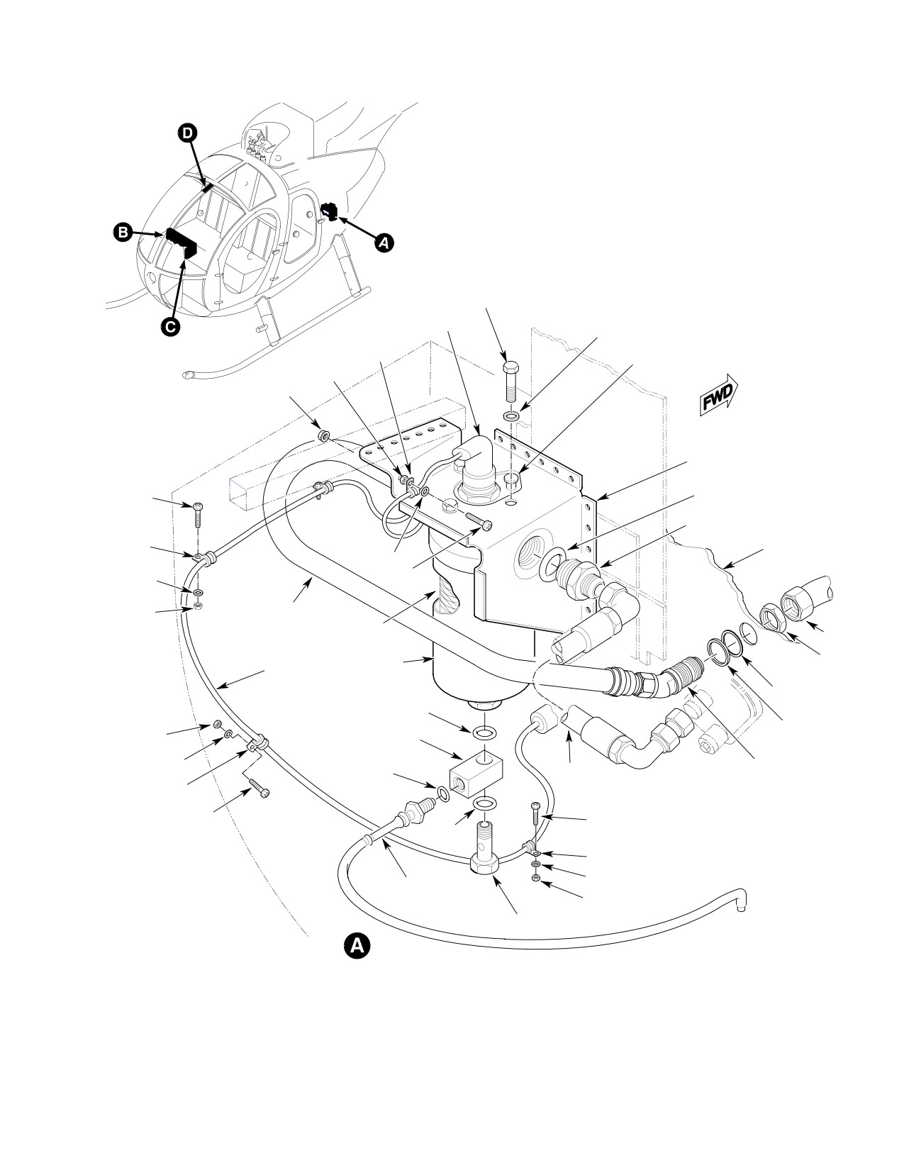
BOLT
CONNECTOR
WASHER
TEST
CLAMP
BUTTON
NUT
NUT
BRACKET
O-RING
SCREW
REDUCER
CLAMP
FIREWALL
WASHER
SCREW
WASHER
NUT
HOSE
FILTER
TUBE
ELEMENT
NUT
WIRE
BOWL
HARNESS
SHIM WASHER
(AS REQ'D)
GASKET
WASHER
NUT
FITTING
WASHER
HOSE
O-RING
HOSE
ELBOW
CLAMP
SCREW
SCREW
GASKET
CLAMP
WASHER
ANTI-ICE
DRAIN VALVE
NUT
BOLT
EFFECTIVITY: 369D/E - 500N
G28-2000-1B
Figure 201. Anti−Ice Fuel Filter (Sheet 1 of 3)
Page 203
28-25-00
Revision 19
CSP-HMI-2
MD Helicopters, Inc.
MAINTENANCE MANUAL
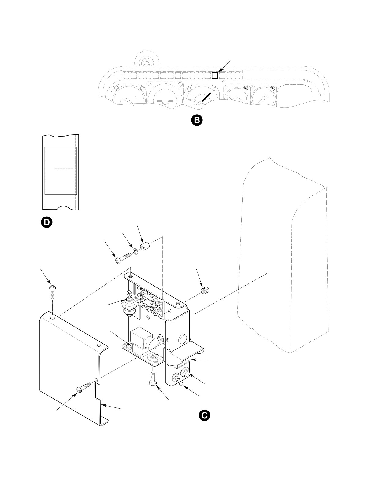
CAUTION LIGHT
T-PEDESTAL
(369H90022-503, -505)
ANTI - ICE
FUEL FILTER
INSTL
FOR
PLACARD
SPACER
WASHER
SCREW
SCREW
RIVNUT
DIODE CR26
TIME-DELAY
RELAY
CAUTION LIGHT/
RELAY K254
CIRCUIT BREAKER
DIMMER SWITCH
SCREW
COVER
SCREW
SLIMLINE PEDESTAL
(369H90022-BSC)
EFFECTIVITY: 369D/E - 500N
G28-2000-2A
Figure 201. Anti−Ice Fuel Filter (Sheet 2 of 3)
Page 204
Revision 19
28-25-00
MD Helicopters, Inc.
CSP-HMI-2
MAINTENANCE MANUAL
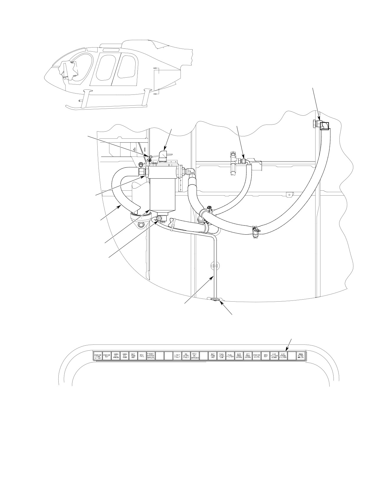
B
A
B
FUEL HOSE
TO ENGINE
A
FUEL HOSE FROM
ENGINE-TO-TANK
CONNECTOR
+
CLAMP
SCREW
WASHER
NUT
REDUCER
O-RING
FUEL HOSE
FROM TANK
FILTER
DRAIN VALVE
FUEL FILTER
DRAIN HOSE
VIEW A - AGROMMET
AIRFRAME FILTER
CAUTION LIGHT
VIEW B - B
EFFECTIVITY: 600N
G28-2000-3
Figure 201. Anti−Ice Fuel Filter (Sheet 3 of 3)
Page 205
28-25-00
Revision 19
CSP-HMI-2
MD Helicopters, Inc.
MAINTENANCE MANUAL
This Page Intentionally Left Blank
Page 206
Revision 44
28-25-00
MD Helicopters, Inc.
CSP-HMI-2
MAINTENANCE MANUAL
ANTI−ICE/AIRFRAME FUEL FILTER
INSPECTION/CHECK
NOTE: On the 600N helicopter, the airframe
(g). Do an anti-ice fuel filter functional
fuel filter is not certified as an anti-ice fuel
check (Ref. Anti-Ice Fuel Filter
filter. Throughout this section, the airframe
Installation Operational Check:
fuel filter will be refered to as an anti-ice
369H90022-BSC).
fuel filter.
(2). Inspect wiring for damage and security.
Repair or replace damaged components.
1. Anti−Ice Fuel Filter System Inspection
Air in the fuel system will
A one time diode inspection and
WARNING
CAUTION
cause a power reduction or
polarity check is mandatory for
flameout. Do a fuel system vacuum leak
helicopters
equipped
with
a
check and system air bleed after open
369H90022-BSC anti-ice fuel filter instal
ing fuel system to atmosphere and
lation and, or 369H90118 auto-reignition
prior to releasing helicopter for flight.
installation on helicopters delivered in
Ensure start pump is operating before
1979. The following procedures address only
taking fuel samples from system drain
the anti-ice fuel filter installation.
valves.
(3). Inspect fuel system as follows:
Special Tools
(Ref. Section 91−00−00)
(a). Apply external power to the helicop
Item
Nomenclature
ter.
N/A
Ohmmeter
(b). Open the engine compartment doors.
N/A
Voltmeter
(c). Set battery switch to EXT PWR.
(d). Push FUEL VALVE knob in to open
(1). Determine ohmmeter lead polarity with
fuel shutoff valve.
voltmeter.
(e). Set START PUMP switch; ON.
(a). In crew compartment; remove cover
Check start pump operation.
from anti-ice caution/warning light
panel.
NOTE: Failure to drain in freezing tempera
tures may be due to ice buildup.
(b). Find part number stamped on diode
C26 (Ref. Figure 201).
(f). Drain several ounces of fuel from
filter bowl into a suitable container.
(c). Diodes, part numbers 1N3210 do not
Inspect sample for solids and water
require a polarity check.
contamination. Dismantle and clean
filter bowl as required. Replace filter
(d). Replace diodes, part number
element.
1N3210R with a new part number
1N3210 diode.
(g). Inspect hose assemblies for evidence
of leakage, swelling or dampness,
(e). If the diode is unidentifiable, test
kinks, cuts, twists, tears and fraying.
diode to determine polarity.
Check hose nut threads for damage.
Replace damaged parts.
1). Check for low forward resistance
with ohmmeter positive lead
(h). Disconnect drain tubes from drain
attached to terminal end and
valves. Check each drain valve for
negative lead attached to stud end.
leakage. Replace damaged drain
Reverse leads and check for very
valves.
high resistance.
(i). Inspect filter fuel line fittings for
(f). Replace diode with a new 1N3210
leakage. Repair or replace parts as
unit if polarity is reversed.
required.
Page 601
28-25-00
Revision 20
CSP-HMI-2
MD Helicopters, Inc.
MAINTENANCE MANUAL
(j). Connect drain tubes to drain valves.
(c). Start pump stops running.
Inspect drain tubes for security and
(5). Inspect fuel system for leakage.
correct routing without fluid traps or
kinks.
3. Anti−Ice Fuel Filter Installation
Operational Check: 369H90022−503, −505
(k). Inspect fuel filter press-to-test
and 600N98110−501
button for security.
(1). Apply external power to the helicopter.
2. Anti−Ice Fuel Filter Installation
Set battery switch to EXT PWR.
Operational Check: 369H90022−BSC
(a). Reset PNL LT circuit breaker.
NOTE: The system may be operated with a ful
(b). Press PRESS TO TST WRN LT on
ly charged battery that can provide more
the caution/warning light panel.
than the 23.8 Vdc required to actuate sys
Check entire caution/warning light
tem solenoids. If battery state is an un
array. Replace lamps as required.
known, use external power.
(c). Push FUEL VALVE knob in to open
fuel shutoff valve.
(1). Apply external power to the helicopter.
Set battery switch to EXT PWR.
(2). Set START PUMP switch ON.
(a). Reset PNL LT and FUEL ANTI-
(a). START PUMP ON indicator light
ICE circuit breakers.
comes on and start pump pressurizes
fuel system.
(b). Press PRESS TO TST WRN LT on
(3). Open the engine compartment doors.
the caution/warning light panel.
Check entire caution/warning light
(4). Press the red press-to-test button on
array. Replace lamps as required.
top of airframe filter body. Result shall
be:
(c). Push FUEL VALVE knob in to open
(a). AIRFRAME FILTER caution light
fuel shutoff valve.
comes on.
(d). Open the engine compartment doors.
(5). Release the press-to-test button.
(2). Press the red press-to-test button on
(a). AIRFRAME FILTER caution light
top of the filter body for five or more
goes out.
seconds. Test results shall be as follows:
(6). Set START PUMP switch OFF.
(a). FUEL FILTER caution light comes
(7). Inspect fuel system for leaks.
on.
4. Fuel System Vacuum Leak Check
(b). START PUMP ON indicator light
(1). Fuel is drawn out of the tank by the
comes on and start pump pressurizes
engine driven fuel pump when the start
fuel system.
pump is switched off. Water, ice, dirt,
fungus, trapped air or a few pinhole
(3). Release the press-to-test button.
leaks in the supply system between the
(a). FUEL FILTER and START PUMP
fuel tank sump pickup and engine
ON lights remain on and start pump
combustion chamber nozzles may cause
continues to operate.
power surges, deceleration and, or
flameout. A vacuum leak inspection will
(4). Press FUEL FILTER caution light to
determine whether or not air can be
reset system. Result shall be:
drawn into the fuel system by the
engine driven fuel pump.
(a). FUEL FILTER caution light goes
out.
(2). An automotive vacuum test pump and
hardware that will provide 8 Hg
(b). START PUMP ON indicator light
vacuum or better is required to do the
goes out.
vacuum leak check.
Page 602
Revision 20
28-25-00
MD Helicopters, Inc.
CSP-HMI-2
MAINTENANCE MANUAL
(3). Assemble vacuum pump, hoses, filter
(b). Fuel system shall hold vacuum
port adapter, shutoff valve and vacuum
between 8 and 7.5 Hg for two min
gage as follows:
utes.
(a).
Insert a vacuum gage in the vacuum
(c). If test is satisfactory, remove test
hose between the engine fuel filter
apparatus. Inspect and replace filter
port adapter and vacuum shutoff
plug O-ring as required. Install filter
valve. Attach the vacuum pump to
plug.
the vacuum hose above the shutoff
valve.
(6). Vacuum loss exceeding 0.5 Hg in two
minutes indicates a leak somewhere in
(b).
Plug vacuum hose and pull 5 - 10 Hg
the system between the fuel shutoff
vacuum. Apparatus should hold the
valve and engine.
selected pressure indefinitely. Repair
leaky equipment before proceeding
(a). Torque fuel line connections (Ref.
with fuel system test.
Table 601). Repeat vacuum test.
(c).
Open engine access doors.
(b). If system continues to leak, discon
(d).
Remove left fuel cell floor access
nect and install airtight caps or plugs
panel.
in tubes, hoses and fitting ports in a
progressive sequence from fuel
(e).
In crew compartment; pull FUEL
shutoff valve toward engine. The fuel
shutoff valve knob out to stop. Verify
shutoff and drain valve installations
that fuel shutoff valve lever on left
should be especially suspect. Apply
fuel cell access cover is hard against
vacuum at each stage until leak has
its OFF stop. Rig control cable as
been isolated. Replace parts as
required.
required.
(f).
In engine compartment; remove the
upper drain plug from the fuel pump
(c). Apply a torque stripe to all effected
filter bowl.
fuel line fittings and nuts.
(4). Disconnect the fuel bleed return line at
(d). If the airframe system vacuum held
Sta. 124.00 (if equipped) and cap off.
at 7.5 Hg or better, system seal is
satisfactory and malfunction is
(5). Attach vacuum test apparatus to
probably due to an engine system
engine fuel filter upper drain port.
leak. Refer to the applicable Allison
(a). Apply 8 Hg vacuum. Close vacuum
and Bendix manuals for additional
line shutoff valve.
information.
Table 601. Fuel Supply System Torque Values
Torque Range
Item & Location
Inch−Pounds (Nm)
Tube end−nuts; fuel shutoff valve; Sta. 124.00 Blkhd elbow
230 − 260 (25.99 − 29.38)
Blkhd elbow jamnut; Sta. 124.00
145 − 155 (16.38 − 17.51)
Three−port elbow jamnuts
145 − 155 (16.38 − 17.51)
Anti−ice filter drain fitting bolt
185 − 200 (20.90 − 22.60)
Anti−ice filter in/out reducers
550 − 600 (62.14 − 67.79)
Hose end−nuts; firewall/filter
230 − 260 (25.99 − 29.38)
Hose end−nuts; filter/engine
230 − 260 (25.99 − 29.38)
Drain valves (all)
95 − 105 (10.73 − 11.86)
Page 603
28-25-00
Revision 19
CSP-HMI-2
MD Helicopters, Inc.
MAINTENANCE MANUAL
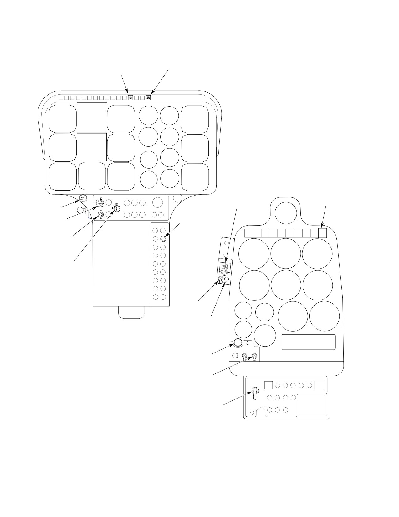
AIRFRAME FILTER
CAUTION LIGHT
CAUTION LIGHT
TEST
CAUTION LIGHT
CAUTION LIGHT
RESET SWITCH
TEST
FUEL SHUTOFF
PNL LT CIRCUIT
BATTERY
BREAKER
SWITCH
PRESS
TO
TEST
START PUMP
SWITCH
DIMMER
POT
DIMMER
SWITCH
CIRCUIT
BREAKER
369H90022-503, -505
PULL
P
TO
CLOSE
U
ON
SH
START
PUMP
FUEL SHUTOFF
START PUMP
BATTERY
SWITCH
O
F
F
BATTERY
SWITCH
369H90022-BSC
G28-2004-1
Figure 601. Anti−Ice Fuel Filter Controls (Sheet 1 of 2)
Page 604
Revision 19
28-25-00
MD Helicopters, Inc.
CSP-HMI-2
MAINTENANCE MANUAL
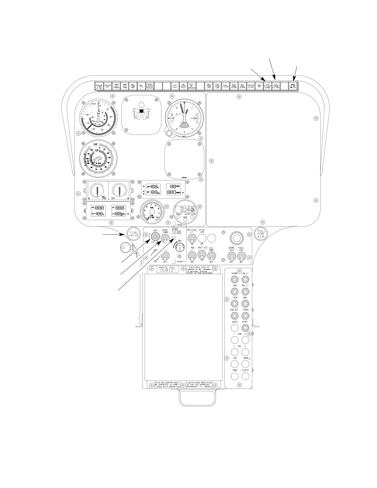
AIR FRAME FILTER
(DS21)
CAUTION LIGHT
AIR FILTER CLOGGED
TEST
(DS22)
FUEL SHUTOFF
BATTERY SWITCH
FUEL PUMP SWITCH
(CB118)
FUEL PUMP LIGHT
(XDS7)
600N98110-501
G28-2004-2
Figure 601. Anti−Ice Fuel Filter Controls (Sheet 2 of 2)
Page 605
28-25-00
Revision 19
CSP-HMI-2
MD Helicopters, Inc.
MAINTENANCE MANUAL
This Page Intentionally Left Blank
Page 606
Revision 44
28-25-00
MD Helicopters, Inc.
CSP-HMI-2
MAINTENANCE MANUAL
ANTI−ICE/AIRFRAME FUEL FILTER
INITIAL INSTALLATION
NOTE: On the 600N helicopter, the airframe
tal and drill three 0.219 inch (5.56 mm)
fuel filter is not certified as an anti-ice fuel
diameter holes in pedestal.
filter. Throughout this section, the airframe
(3). Make cutout shown in instrument
fuel filter will be refered to as an anti-ice
pedestal fairing.
fuel filter.
(4). Deburr holes and cutout edges. Remove
1. Anti−Ice Fuel Filter Initial Installation
debris.
A. Preparations for Installation
(5). Install rivnut and attach anti-ice fuel
filter panel to instrument pedestal with
Prevent fuel vapor ignition.
screws, washers and spacers.
WARNING
Turn OFF and disconnect all
electrical power. Attach helicopter to
(6). Connect wires (Ref. Figure 903).
approved grounding points before
(7). Install cover and screws.
opening fuel system.
(8). Install ANTI-ICE FUEL FILTER
(1). Disconnect external power and battery.
INSTALLATION placard decal on
heater duct three inches (7.62 cm)
(2). Remove aft compartment seats.
above standby compass bracket. Roll
(3). Remove aft upper left bulkhead panel.
placard edges to follow duct contour.
(9). Seal both ends of electrical conduit with
(4). Remove lower aft bulkhead panel.
silicone adhesive/sealant (CM430).
(5). Remove pilot compartment left floor
C. Anti−Ice Fuel Filter Control Panel
access door.
Installation: 369H90022−503, and −505
(6). Remove instrument panel hood and left
fairing.
Consumable Materials
(Ref. Section 91-00-00)
(7). Pull FUEL VALVE knob to close fuel
Item
Nomenclature
shut off valve.
CM430
Sealant, solvent resistant
B. Anti−Ice Fuel Filter Control Panel
Installation: 369H90022−BSC
(1). Pull fuel filter wire harness forward
through conduit and along an existing
wire bundle to instrument pedestal.
Consumable Materials
(Ref. Section 91−00−00)
(2). Secure wire to engine compartment
Item
Nomenclature
airframe with clamps, screws, washers
CM430
Sealant, solvent resistant
and nuts and to wire bundle with
ty-raps (Ref. Figure 901).
(1). Pull filter wire harness forward
(3). Install 20 gage bus wire and insulating
through conduit and along an existing
sleeve on back side of caution light
wire bundle to instrument pedestal.
DS31 (Ref. Figure 904).
Secure to engine compartment airframe
(4). Remove fourth plug from the right on
with clamps, screws, washers and nuts
caution/warning light panel.
and to wire bundle with ty-raps (Ref.
Figure 901).
(5). Wire and connect electrical system (Ref.
Figure 904).
(2). Use anti-ice fuel filter subpanel as a
template on left side of slimline pedes
(6). Install caution light in panel.
Page 901
28-25-00
Revision 20
CSP-HMI-2
MD Helicopters, Inc.
MAINTENANCE MANUAL
(7). Install ANTI-ICE FUEL FILTER
E. Firewall Modifications and Bracket
INSTALLATION placard decal on
Installation
heater duct three inches (7.62 cm)
(Ref. Figure 901 for 369H90022-BSC, -503
above standby compass bracket. Roll
and -505)
placard edges to follow duct contour.
(Ref. Figure 902 for 600N96110-501)
(8). Seal both ends of electrical conduit with
silicone adhesive/sealant (CM430).
Consumable Materials
D. Anti−Ice Fuel Filter Control Panel
(Ref. Section 91−00−00)
Installation: 600N98110−501
Item
Nomenclature
CM318
Primer
(Ref. Figure 601)
(1). To install caution/warning light:
(1). Open engine access doors.
(a). Remove third plug from the right on
(2). Drain fuel from supply lines into a
caution/warning light panel.
suitable container.
(b). Install caution light in panel.
(3). Remove fuel supply hose between
engine driven fuel pump and firewall
(c). Install 22 gage jumper wire on back
fitting elbow. Cap hose ends, firewall
side of caution lights between DS21C
elbow and fuel pump port.
and DS22C.
(4). Reposition firewall elbow 18 - 22°
(d). Run O506D22 wire from DS21-2 to
clockwise (Ref. view A).
P12-14 and secure to existing wires.
Do not score, scratch or gouge
(2). To install fuel pump switch and light:
CAUTION
firewall surface when trimming
insulation blanket.
(a). Remove edge-lighted switch panel.
(5).
Lay out and remove insulation strips
(b). Remove tape from start pump switch
from firewall to eliminate interference
and light holes in instrument panel.
with filter support bracket installation.
(c). Install CB118 in panel.
(6).
Position doubler on Sta. 124.00 firewall.
Identify, mark and drill-out existing
(d). Run 22 gage jumper wire from
rivets used in doubler installation. Do
CB115-1 to CB118-1.
not enlarge rivet holes.
(e). Run Q1169A22 wire from CB118-2 to
(7).
Locate doubler on firewall forward
TB503-2-2.
surface. Drill doubler through existing
rivet holes.
(f). Install light (XDS7) from back side of
panel.
(8).
Deburr holes and remove debris.
(g). Run E1181A22 wire from P13-46 to
(9).
Cleco doubler to firewall.
XDS7.
(10).
Apply primer (CM318) to rivet holes
(h). Run E1181B22N wire from XDS7 to
and rivets.
E31-E.
(11).
Install rivets while primer is wet.
(i). Reinstall edge-lighted switch panel.
(12).
Use filter support bracket as a tem
plate. Mark and drill filter bracket rivet
(3). Install ANTI-ICE FUEL FILTER
holes.
INSTALLATION placard decal on
heater duct three inches (7.62 cm)
(13).
Deburr holes and remove debris.
above standby compass bracket. Roll
placard edges to follow duct contour.
(14).
Cleco bracket in position.
Page 902
Revision 20
28-25-00
MD Helicopters, Inc.
CSP-HMI-2
MAINTENANCE MANUAL
(15). Apply primer to rivet holes and rivets.
(4). Apply a thin coat of anti-seize com
pound (CM113) to fitting-bolt threads.
(16). Rivet bracket in place while primer is
Stack fitting and gaskets on bottom of
wet.
filter. Install and torque bolt 185 - 200
inch-pounds (20.90 - 22.60 Nm).
(17). Install electrical bonding jumper
between bracket and airframe.
(5). Lubricate drain valve O-ring packing
with clean jet fuel and install on drain
(18). Position double aft of Sta. 124.00
valve. Apply a thin coat of anti-seize
between LBL 4.250 and LBL 8.450.
compound to drain valve threads.
Drill rivet holes and cleco in place.
(6). Install drain valve with O-ring packing
(19). Drill hole for drain hose.
on fuel filter drain fitting. Torque drain
valve 95 - 105 inch-pounds (10.73 -
(20). Remove doubler , deburr and remove
11.86 Nm).
debris.
(7). Install and clamp drain tube to drain
(21). Apply primer (CM318) to rivet and
valve with lockwire.
drain holes.
NOTE: Provide enough slack in drain tubes to
(22). Install doubler while rivets are still
allow unrestrained drain valve operation.
wet.
(8). On 600N96110-501 installation, install
F. Fuel Filter Installation
mount to firewall using adhesive
(CM438).
Air in the fuel system will
WARNING
(9). Clamp tube to bulkhead frame or
cause a power reduction or
mount at LBL 8.45 with TY-25M
flameout. Do a fuel system vacuum leak
TYRAP.
check and system air bleed after open
ing fuel system to atmosphere and
(10). Lubricate the two reducer O-rings with
prior to releasing helicopter for flight.
clean jet fuel. Install O-rings on large
Ensure start pump is operating before
ends of reducers. Apply a thin coat of
taking fuel samples from system drain
anti-seize compound to reducer
valves.
threads.
(Ref. Figure 901 for 369H90022-BSC, -503
(11). Install reducers with O-rings in filter
and -505)
inlet and outlet ports. Torque reducers
to 550 - 600 inch-pounds (62.14 -
(Ref. Figure 902 for 600N96110-501)
67.79 Nm).
Do not allow hose to twist when
Consumable Materials
CAUTION
torquing hose nuts. Use a back
(Ref. Section 91−00−00)
up wrench to stabilize hose.
Item
Nomenclature
(12). Connect hose between filter outlet port
CM113
Anti-seize compound low temperature
and engine fuel pump filter inlet port.
CM438
Adhesive, epoxy
Torque hose nuts 230 - 260 inch-
pounds (25.99 - 29.38 Nm).
(1). Remove engine gearcase cooling duct
(13). Install hose between filter inlet port
clip and attaching hardware.
and firewall fitting elbow. Torque hose
nuts 230 - 260 inch-pounds (25.99 -
(2). Drill a 0.250 inch (6.35 mm) diameter
29.38 Nm).
hole and relocate clip.
(14). Secure hoses with clamps, screws,
(3). Install filter assembly on bracket with
washers and nuts.
bolts, washers and spacers. Torque
bolts 50 - 70 inch-pounds (5.65 - 7.91
(15). Install wire connector plug on filter
Nm). Install lockwire.
receptacle.
Page 903
28-25-00
Revision 28
CSP-HMI-2
MD Helicopters, Inc.
MAINTENANCE MANUAL
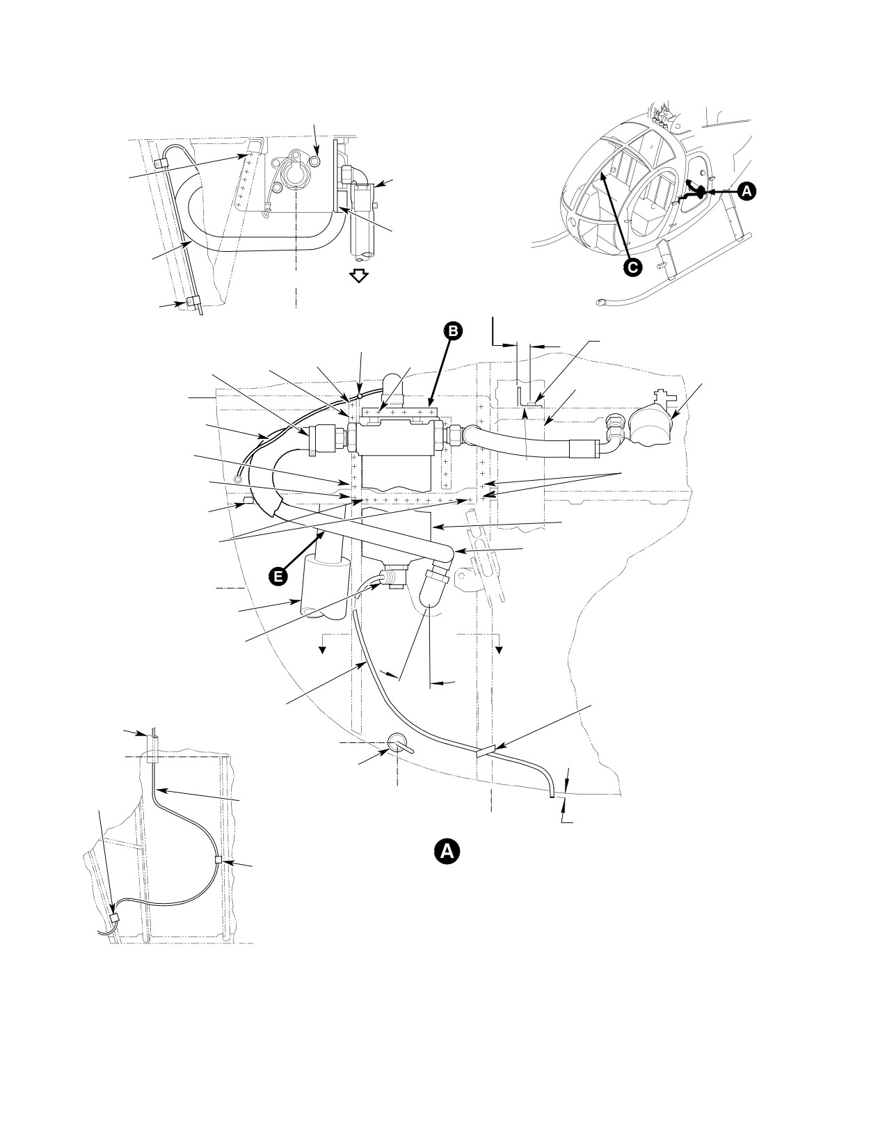
BOLT, WASHER,
LOCKWIRE
RIVET
HOSE
(7 PLCS)
(NOTE 1)
BRACKET
(NOTE 2)
HOSE
(TANK TO FILTER)
LOOKING DOWN
CLAMP, SCREW,
0.75 INCH
WASHER, NUT
(17.05 MM)
CLAMP, SCREW
(NOTE 10)
WASHER, (2 REQD)
0.260 INCH (6060 MM)
RIVET
NUT
DIA HOLE
RIVET
RIVET
(NOTE 9)
(NOTE 8)
CLAMP
(NOTE 8)
ENGINE FUEL
(2 PLCS)
DUCT (REF)
PUMP (REF)
WL 22.85
WIRE HARNESS
RIVET
(NOTE 8)
CLIP (NOTE 3)
RIVET
RIVET
(NOTE 1)
(NOTES 8, 9)
INSULATION
FILTER ASSY
(REF)
RIVET
ELBOW
(NOTE 8)
(NOTE 4)
WL 13.10
LANDING GEAR DAMPER
(REF)
FITTING, BOLT
TORQUE TO 185-200 IN-LBS
(20.90-22.60 NM)
A
A
18°
GASKET (2 REQD) (NOTE 7)
20°
TUBE
TY-25N TY-RAP
(NOTE 5)
CONDUIT
(REF)
WL 5.14
STA 124.0
CONDUIT (REF)
CLAMP, SCREW,
(NOTE 6)
WASHER, NUT
LBL 13.23
(NOTE 10)
WIRE HARNESS ASSY
0.00-0.12 INCH
LBL 8.45
(0.00-3.05 MM)
(NOTE 15)
LOOKING FORWARD
SCREW, CLAMP,
WASHER, NUT
(NOTE 10)
STA 137.50
VIEW A-A
EFFECTIVITY: 369D/E - 500N
G28-2003-1D
Figure 901. Anti−Ice Fuel Filter Modifications and Installation (369D/E − 500N) (Sheet 1 of 2)
Page 904
Revision 19
28-25-00
MD Helicopters, Inc.
CSP-HMI-2
MAINTENANCE MANUAL
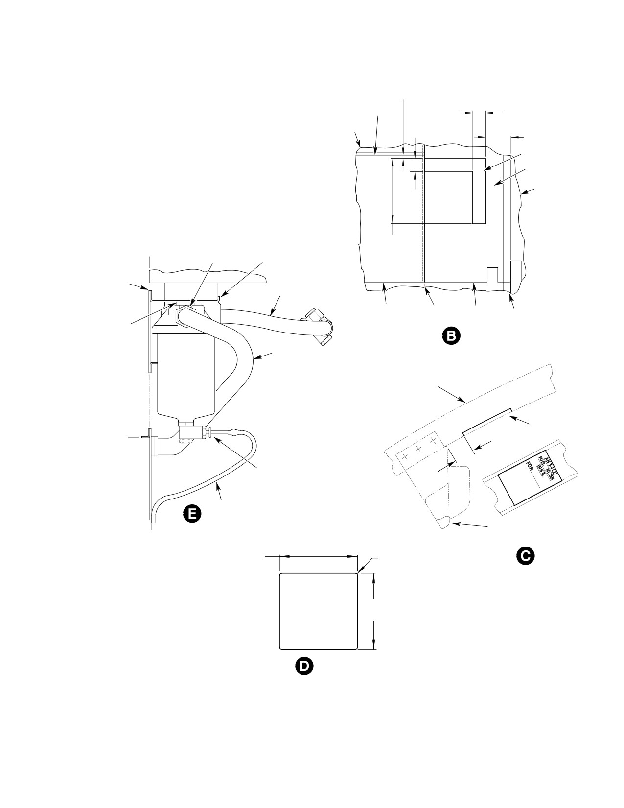
0.25 INCH
(6.35 MM)
STIFFENER
1.00 INCH
(2.54 CM)
1.00 INCH
PANEL
(2.54 CM)
1.75 INCH
(4.445 CM)
NOTE 13
INSULATION
PANEL
REDUCER (2 REQD)
5.00 INCH
STA 124.0
PACKING (2 REQD)
(12.70 CM)
(NOTE 12)
BRACKET
DOUBLER
(NOTE 14)
HOSE ASSY
PANEL
STIFFENER PANEL
STIFFENER
SPACER
(3 REQD)
HOSE ASSY
DUCT
PLACARD
(NOTE 11)
WL 13.10
3.00 INCH
(7.62 CM)
VALVE PACKING
(NOTE 12)
TUBE
COMPASS BRACKET
(REF)
7.25 INCH
0.12 R
(18.415 CM)
(TYP)
5.50 INCH
(13.97 CM)
DOUBLER
EFFECTIVITY: 369D/E - 500N
G28-2003-2D
Figure 901. Anti−Ice Fuel Filter Modifications and Installation (369D/E − 500N) (Sheet 2 of 2)
Page 905
28-25-00
Revision 19
CSP-HMI-2
MD Helicopters, Inc.
MAINTENANCE MANUAL
NOTE:
(1)
Pick up existing rivet locations, seven places. Install MS29615−4M rivets or NAS1738 M4 alternates. Install
rivets in wet MIL−P−23377 Type 1, Class 1, epoxy primer or, MIL−P−8585 primer.
(2)
Electrically bond bracket to firewall with an approved bonding jumper installed per requirements of FAA
publication EA−AC43.13−1A and 2A.
(3)
Reposition clip 0.75 inch (19.05 mm) inboard.
(4)
Shim elbow to 18−22 degrees clockwise.
(5)
Route filter drain tube to clear landing gear damper while allowing unrestrained drain valve operation.
(6)
Seal both ends of conduit with RTV 732 sealant/adhesive after wire harness installation.
(7)
Apply low temperature anti−seize compound, MIL−T−5544B Thread Lube or equivalent to assembly
threads prior to installation. Torque bolt 185 − 200 inch−pounds (20.90 − 22.60 Nm).
(8)
Install MS20615−3M rivets in wet MIL−P−23377, Type 1, Class 1, epoxy primer or, MIL−P−8585 primer.
(9)
Install MS20615−4M or alternate NAS−1738M4 rivets in wet MIL−P−23377, Type 1, Class, 1 epoxy primer
or, MIL−P−8585 primer.
(10)
Clamp wire harness in place as shown using existing tool holes.
(11)
Roll placard edges to follow heater duct contour.
(12)
Apply MIL−T−5544B low temperature anti−seize compound to threads prior to assembly.
(13)
Cut away insulation blanket per dimensions shown for bracket installation. Remove blanket debris. Do not
scratch firewall surface.
(14)
Install doubler on forward firewall surface as shown. Pick up all existing rivet holes in doubler installation.
(15)
Trim drain tube protrusion flush to 0.12 inch (3.048 mm) below grommet surface.
Page 906
Revision 19
28-25-00
MD Helicopters, Inc.
CSP-HMI-2
MAINTENANCE MANUAL
ENGINE INSTALLATION
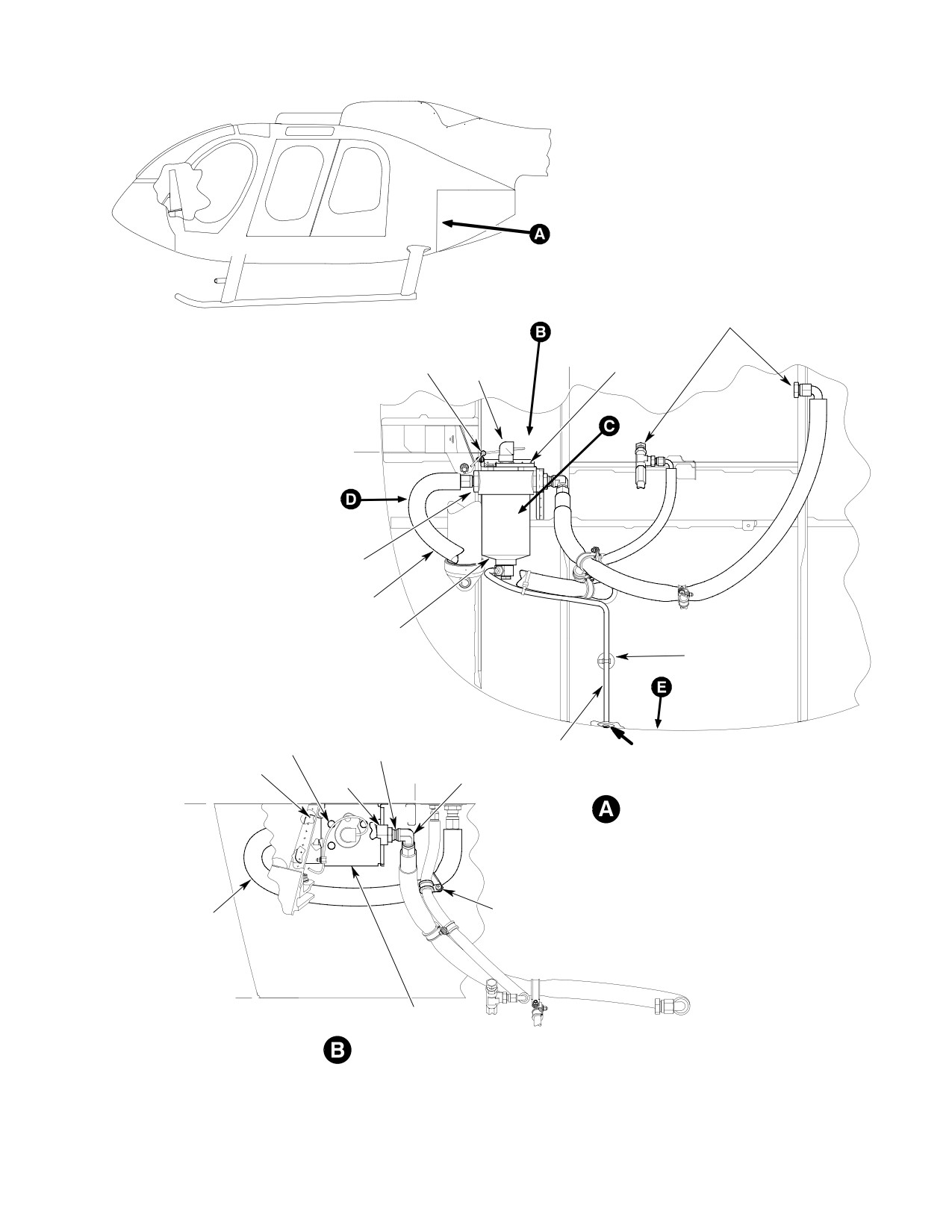
CLAMP, SCREW
WASHER (2 REQD)
LBL
RIVET
NUT
8.450
(NOTE 6)
(NOTE 8)
CONNECTOR
WL
22.850
REDUCER
O-RING
(NOTE 9)
HOSE
FILTER
MOUNT
(NOTE 4)
BOLT
NUT
WASHER
HOSE
0.00-0.12 INCH
O-RING
LBL
(NOTE 3)
(0.00-3.05 CM)
RIVET (7 PL)
BUSHING
8.450
(NOTE 12)
(NOTE 1)
O-RING
BULKHEAD ELBOW
FS
124.000
LOOKING FORWARD
CLAMPS,
HOSE
SCREW
(TANK-TO-FILTER)
WASHERS,
NUT
FS
137.500
BRACKET
(NOTE 2)
LOOKING DOWN
EFFECTIVITY: 600N
G28-2009-1
Figure 902. Anti−Ice Fuel Filter Modifications and Installation (600N) (Sheet 1 of 2)
Page 907
28-25-00
Revision 19
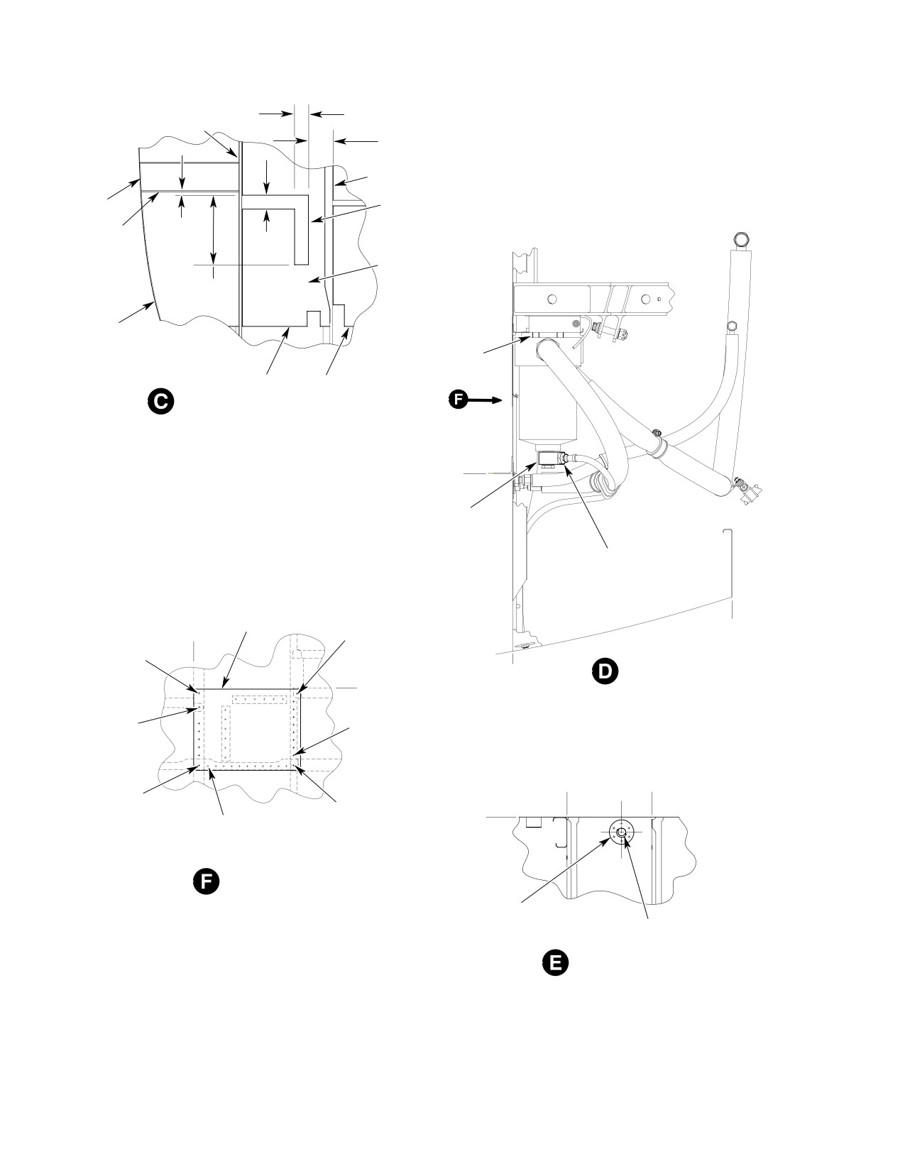
CSP-HMI-2
MD Helicopters, Inc.
MAINTENANCE MANUAL
1.00 INCH
STIFFENER
(2.54 CM)
1.75 INCH
(4.45 CM)
STIFFENER
PANEL
NOTE 10
STIFFENER
0.25 INCH
(6.35 MM)
1.00 INCH
(2.54 CM)
INSULATION
5.00 INCH
(12.70 CM)
PANEL
SPACER
(3 REQD)
PANEL
PANEL
LOOKING FORWARD
WL
13.100
FITTING, BOLT
TORQUE TO 185 - 200 INCH-POUNDS
(20.90 - 22.60 NM)
GASKET (2 REQD) (NOTE 5)
DRAIN VALVE O-RING
(NOTE 9)
DOUBLER
LBL
RIVET
(NOTE 11)
FS
8.450
(NOTE 1)
137.000
RIVET
(NOTE 7)
LOOKING INBOARD
FS
LEFT SIDE
WL
124.000
22.850
RIVET
RIVET
(NOTE 6)
(NOTE 1)
LBL
LBL
8.450
4.250
RIVET
(NOTE 6, 7)
RIVET
FS
RIVET
(NOTE 1)
124.000
(NOTE 6)
LOOKING AFT
DOUBLER
RIVET
GROMMET
LOOKING DOWN
EFFECTIVITY: 600N
G28-2009-2
Figure 902. Anti−Ice Fuel Filter Modifications and Installation (600N) (Sheet 2 of 2)
Page 908
Revision 19
28-25-00
MD Helicopters, Inc.
CSP-HMI-2
MAINTENANCE MANUAL
NOTE:
(1) Pick up existing rivet locations, seven places. Install MS29615−4M rivets or NAS1738 M4 alternates. Install
rivets in wet MIL−P−23377 Type 1, Class 1, epoxy primer or, MIL−P−8585 primer.
(2) Electrically bond bracket to firewall with an approved bonding jumper installed per requirements of FAA
publication EA−AC43.13−1A and 2A.
(3) Route filter drain tube to clear landing gear damper while allowing unrestrained drain valve operation.
(4) Install with adhesive CM438.
(5) Apply low temperature anti−seize compound, MIL−T−5544B Thread Lube or equivalent to assembly
threads prior to installation. Torque bolt 185 − 200 inch−pounds (20.90 − 22.60 Nm).
(6) Install MS20615−3M rivets in wet MIL−P−23377, Type 1, Class 1, epoxy primer or, MIL−P−8585 primer.
(7) Install MS20615−4M or alternate NAS−1738M4 rivets in wet MIL−P−23377, Type 1, Class, 1 epoxy primer
or, MIL−P−8585 primer.
(8) Clamp wire harness in place as shown using existing tool holes.
(9) Apply MIL−T−5544B low temperature anti−seize compound to threads prior to assembly.
(10) Cut away insulation blanket per dimensions shown for bracket installation. Remove blanket debris. Do not
scratch firewall surface.
(11) Install doubler on forward firewall surface as shown. Pick up all existing rivet holes in doubler installation.
(12) Trim drain tube protrusion flush to 0.12 inch (3.048 mm) below grommet surface.
Page 909
28-25-00
Revision 19
CSP-HMI-2
MD Helicopters, Inc.
MAINTENANCE MANUAL
(16). Measure electrical resistance between
Prevent fuel system contamina
CAUTION
filter bowl and firewall. Resistance
tion. Install caps on the ends of
shall not be more than 0.003 ohms.
hoses, tubes and fittings as the parts are re
moved. Bag and identify small parts to pre
G. Post−Installation Inspection
vent loss or damage.
(1). Ensure that all installation debris has
(1). Defuel helicopter (Ref. Sec. 12-00-00).
been removed.
Drain remaining fuel from tank sump
drain valve into a suitable container.
(2). Check all electrical connections for
(2). Disconnect electrical power.
correct routing and security.
A. Fuel Cell Cover Removal
(3). Ensure that all hardware, tubes, and
(1). To remove left aft fuel cell access cover:
hoses are properly secured.
(a).
Remove left aft fuel cell access panel
(4). Ensure that no fuel can be trapped by
from passenger/cargo compartment
the drain system.
floor.
H. Furnishings, Panels and Equipment
(b).
Unclamp and disconnect control
Installation
cable from fuel shutoff valve.
(c).
Disconnect engine feed fuel supply
(1). Install instrument panel hood and
hose assembly between fuel shutoff
instrument panel left side fairing.
valve and Sta. 124.00 bulkhead. Use
(2). Install pilot's compartment left floor
backup wrench on fuel shutoff valve
access panel.
so it will not rotate.
(d).
Disconnect motive flow fuel hose
(3). Install upper left aft bulkhead panel
assembly between Sta 124.00 bulk
and lower aft bulkhead panel.
head and fuel cell access cover.
(4). Install aft compartment seats.
(e).
Disconnect fuel quantity probe wire
harness connector from fuel cell cover
(5). Close engine access doors.
receptacle.
(6). Connect battery.
(f).
Unfasten and remove Sta. 91.00 and
102.00 left aft fuel cell cover support
2. Anti−Ice Fuel Pump Initial Installation
brackets.
(600N98110−501 Installation)
(g).
Remove cover bolts and washers.
(Ref. Figure 907)
Prop cover open with suitably padded
blocks.
Consumable Materials
(h).
Using a backup wrench on valve,
(Ref. Section 91−00−00)
separate engine feed fuel cell supply
Item
Nomenclature
hose from fuel shutoff valve and fuel
CM114
Petrolatum
inlet from fuel cell access cover.
CM124
Kerosene
(i).
Disconnect submerged motive flow
CM702
Lockwire CRES
fuel hose assembly between fuel
check valve and ejector pump from
fuel cell access cover.
Avoid fuel vapor ignition
WARNING
(j).
Disconnect fuel cell scavenge hose
and fire. Use only nonspark
assembly from bottom of fuel cell
ing tools and explosion proof work
access cover bracket assembly to
lights. Attach helicopter to an ap
ejector pump.
proved electrical ground. Switch OFF
all electrical power. Disconnect exter
(k).
Cut safety wire from fuel probe
nal power and battery before opening
electrical connector base nut and
fuel system. Ensure work area is ade
remove connector from fuel cell
quately ventilated.
access cover.
Page 916
Revision 19
28-25-00
MD Helicopters, Inc.
CSP-HMI-2
MAINTENANCE MANUAL
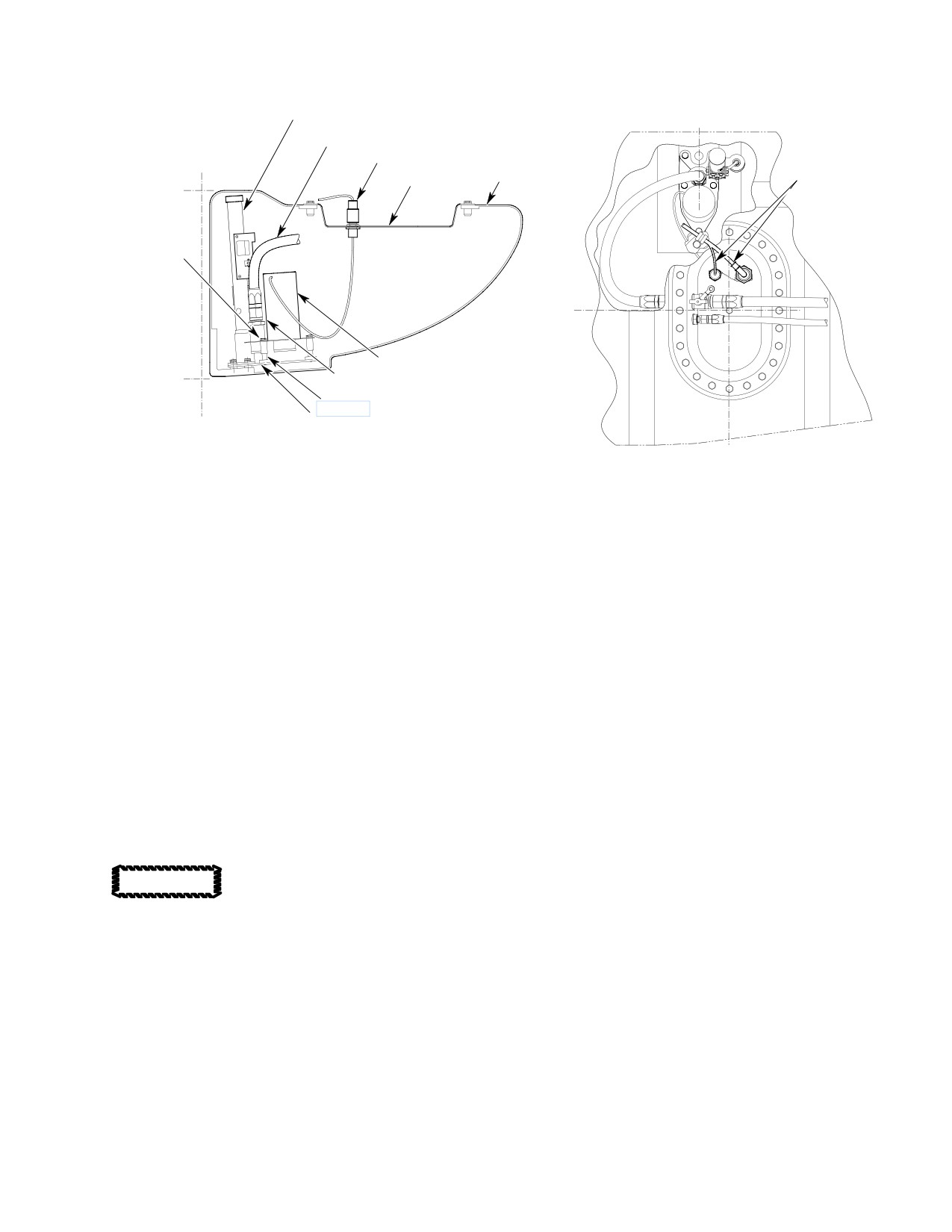
FS
FUEL PROBE
93.15
HOSE
BL
P250 WIRE HARNESS
0.00
FUEL CELL
WIRE HARNESS
COVER
WL 13.10
BOLT
WASHER
LBL 13.00
PUMP
WL 0.00
UNION
O-RING
SPACER
BRACKET
VIEW LOOKING AFT
FS
95.628
VIEW LOOKING DOWN
G28-2007
Figure 907. Fuel Pump Initial Installation (600N)
(l). Remove fuel cell scavenge hose
(5). Attach fuel supply hose to pump
bracket assembly, bulkhead union
pressure port union. Torque hose nut to
and fuel shutoff valve from fuel cell
230 - 260 inch-pounds (25.99 - 29.38
cover.
Nm).
(2). Remove unused bulkhead union from
C. Fuel Cell Cover Installation
cover.
(1). Wipe fuel cell and cover sealing sur
B. Pump Installation
faces clean with kerosene (CM124) on a
(1). Disconnect fuel feed hose from fuel inlet
clean lint free cloth.
plate and remove plate.
(2). Inspect fuel cell cover seals for debond
(2). Clean pump and sump plate mount
ing, nicks or cuts and any other damage
contact surfaces to establish an electri
having a leak producing potential.
cal bond.
Replace covers or left aft cover as
required.
Do not mark torque alignment
CAUTION
stripes on fuel cell internal
(3). Install left aft fuel cell access cover as
hardware.
follows:
(3). Install pump on sump plate with bolts,
washers and spacers. Torque bolts to 36
(a). Apply a coating of petrolatum
- 46 inch-pounds (4.07 - 5.20 Nm).
(CM114) to a new fuel shutoff valve/
cover sealwasher. Install valve on cell
(4). Apply a thin coat of petrolatum
cover with sealwasher next to valve
(CM114) to a new O-ring and pump
body and valve properly aligned to
pressure port union threads. Install
make connection with valve control
O-ring on union. Install union in pump
cable. Torque valve jamnut to 240 -
pressure port and torque to 280 - 305
280 inch-pounds (27.12 - 31.64
inch-pounds (31.64 - 34.46 Nm).
Nm).
Page 917
28-25-00
Revision 19
CSP-HMI-2
MD Helicopters, Inc.
MAINTENANCE MANUAL
(b). Apply a coating of petrolatum to
(9).
Install three support brackets on Sta.
sealwasher. Install check valve and
91.00 and 102.00 floor cross-members
sealwasher to inside cover and a
with washers and screws. Torque
plain washer outside. Torque jamnut
screws to 20 - 25 inch-pounds (2.26 -
to 85 - 105 inch-pounds (9.6 -
2.82 Nm).
11.86 Nm).
(10).
Install cover bolts and washers. In a
(c). Install bulkhead elbow to support
cross pattern, progressively torque
bracket. with washer and nut. Torque
cover bolts to 70 - 90 inch-pounds
jamnut to 240 - 280 inch-pounds
(7.91 - 10.17 Nm).
(27.12 - 31.64 Nm).
(11).
Connect engine feed fuel supply hose to
(d). Install support bracket to cover with
fuel shutoff valve. Torque hose nut to
bolts, washer, and sealwashers.
230 - 260 inch-pounds (25.99 - 29.38
Apply a coating of petrolatum to
Nm).
sealwasher. Torque bolts to 36 - 46
inch-pounds (4.06 - 5.19 Nm).
(12).
Connect fuel motive flow hose to access
cover/check valve. Torque hose nut (50
(4). Place left aft fuel cell access cover into
- 65 inch-pounds (5.65 - 7.34 Nm).
position on fuel cell.
(13).
Connect fuel quantity probe and pump
NOTE: Install new seal washer, AS3578-024,
connectors to wire harness receptacles.
on wire harness connector.
(14).
Slip control cable through hole in fuel
(5). Connect fuel quantity probe and pump
shutoff valve lever swivel.
wire harness connectors to cell cover.
Torque connector jamnuts and safety
(15).
Rig cable control system. (Ref. Sec.
wire to bulkhead union with lockwire
28-00-60, Fuel Shutoff Valve Control
(CM702).
Cable Installation).
(6). Install fuel cell inlet hose assembly to
(16).
Apply a torque alignment stripe to fuel
access cover fuel shutoff valve. Torque
line tube, hose and fitting fasteners.
hose assembly 230 - 260 inch-pounds
(25.99 - 29.38 Nm).
(17).
Install access panels on passenger
cargo compartment floor.
(7). Install submerged motive flow hose
assembly to access cover check valve.
Torque hose assembly 50 - 65 inch-
3. Anti−Ice Fuel Filter Installation Weight
pounds (5.65 - 7.34 Nm).
and Balance
(8). Install scavenge fuel cell hose assembly
(1). After installation of the anti-ice fuel
to access cover bulkhead elbow. Torque
filter, incorporate changes to helicopter
hose assembly 230 - 260 inch-pounds
weight and balance record (Ref. Sec.
(25.99 - 29.38 Nm).
Section 08-10-00).
Table 901. Weight and Balance Data
Configuration
Weight
Arm
Moment
Pounds (kg)
inches (cm)
in.−lb
(kg cm)
369H90022−BSC
+6.6
(+2.996)
107.8
(273.81)
+711.48
(+819.710)
369H90022−503
+5.3
(+2.406)
122.7
(311.66)
+650.31
(+749.235)
369H90022−505
+5.3
(+2.406)
122.7
(311.66)
+650.31
(+749.235)
600N98110−501
+7.3
(+3.311)
112.7
(286.26)
+822.7
(+947.807)
Page 918
Revision 19
28-25-00

MD Helicopters, Inc.
CSP-HMI-2
MAINTENANCE MANUAL
Chapter
32
Landing Gear
MD Helicopters, Inc.
CSP-HMI-2
MAINTENANCE MANUAL
TABLE OF CONTENTS
Para/Figure/Table
Title
Page
32-10-00 Landing Gear System (369D/E/FF - 500N)
A
Description and Operation
1
1. Landing Gear
1
A. Skid
1
B. Strut
1
C. Damper
1
D. Entry Step
1
E. Fairing
1
Servicing
301
1. Landing Gear Damper Nitrogen Servicing
301
Figure 301. Landing Gear Damper Nitrogen Servicing - On Helicopter
302
Table 301. Nitrogen Service Schrader Valve Equipped 369D26301 Extended
Landing Gear Dampers - on Helicopter
303
Table 302. Nitrogen Service Schrader Valve Equipped 369D26300 Standard
Landing Gear Dampers - on Helicopter
306
Removal/Installation
401
1. Landing Gear Replacement
401
A. Landing Gear Removal
401
B. Landing Gear Installation
401
Figure 401. Landing Gear and Damper Installation
402
2. Landing Gear Damper Replacement
403
A. Landing Gear Damper Removal
403
B. Landing Gear Damper Installation
403
3. Landing Gear Skid Replacement
403
A. Landing Gear Skid Removal
403
B. Landing Gear Skid Installation
403
4. Landing Gear Fairing Replacement
404
A. Landing Gear Fairing Removal
404
B. Landing Gear Fairing Installation
404
Figure 402. Fairing Installation
405
5. Cabin Entry Step Replacement
407
A. Cabin Entry Step Removal
407
B. Cabin Entry Step Installation
407
Inspection/Check
601
1. Landing Gear Inspection
601
2. Landing Gear Skid Inspection
601
3. Landing Gear Strut Inspection
602
Page i
32 Contents
Revision 19
CSP-HMI-2
MD Helicopters, Inc.
MAINTENANCE MANUAL
TABLE OF CONTENTS (Cont.)
Para/Figure/Table
Title
Page
Figure 601. Landing Gear Strut Inspection
603
4. Landing Gear Damper Inspection
604
5. Cabin Entry Step Inspection
605
6. Landing Gear Fairing Inspection
605
Table 601. Minimum Damper Extension
605
Table 602. Landing Gear Damper Bench Test Requirements
605
Repairs
801
1. Landing Gear System Repairs
801
2. Skid Adapter Sleeve Replacement
801
3. Abrasion Strip Replacement
801
Table 801. Maximum Damage Limits - Landing Gear Components
802
Figure 801. Landing Gear Repairs (Sheet 1 of 2)
803
4. Ground Handling Fitting Replacement
805
5. Safety Walk Tape Replacement
805
6. Landing Gear Fairing Repair
805
7. Landing Gear Fairing Fillet Modification
805
8. Landing Gear Strut Drag Brace Hole Repair
806
A. Landing Gear Strut with Bushing Installed
806
B. Landing Gear Strut with No Bushing Installed
806
Figure 802. Landing Gear Fairing Repairs
807
Initial Installation
901
1. Extended Landing Gear Initial Installation
901
A. Standard Landing Gear Removal
901
B. Standard Landing Gear Disassembly
901
C. Extended Landing Gear Assembly
901
Figure 901. Extended Landing Gear Assembly (Early Configuration)
902
Figure 902. Extended Landing Gear Assembly (Current Configuration)
904
D. Early Configuration Extended Landing Gear Assembly Buildup
906
E. Current Configuration Extended Landing Gear Skid Tube Assembly
Buildup
906
F. Extended Landing Gear Installation
907
G. Weight and Balance
907
Table 901. Weight and Balance Data
907
Figure 903. Extended Landing Gear
908
32-10-60 Landing Gear System (600N)
A
Description and Operation
1
1. Landing Gear System
1
Page ii
Revision 26
32 Contents
MD Helicopters, Inc.
CSP-HMI-2
MAINTENANCE MANUAL
TABLE OF CONTENTS (Cont.)
Para/Figure/Table
Title
Page
A. Skid
1
B. Strut
1
C. Damper
1
D. Entry Step
1
E. Fairing
1
Servicing
301
1. Landing Gear Damper Nitrogen Servicing
301
Figure 301. Landing Gear Damper Nitrogen Servicing - On Helicopter
302
Table 301. Nitrogen Recharge Pressure
303
Removal/Installation
401
1. Landing Gear Strut Replacement
401
A. Landing Gear Strut Removal
401
B. Landing Gear Strut Installation
401
2. Landing Gear Damper Replacement
402
A. Landing Gear Damper Removal
402
B. Landing Gear Damper Installation
402
Figure 401. Landing Gear and Damper Installation
403
3. Landing Gear Skid Replacement
404
A. Landing Gear Skid Removal
404
B. Landing Gear Skid Installation
404
4. Landing Gear Fairing Replacement
404
A. Landing Gear Fairing Removal
404
B. Landing Gear Fairing Installation
404
Figure 402. Fairing Installation
406
Figure 403. Landing Gear Rubber Washer Locations
407
Inspection/Check
601
1. Landing Gear Inspection
601
2. Landing Gear Skid Inspection
601
3. Landing Gear Strut Inspection
601
4. Landing Gear Damper Inspection
602
5. Forward Cabin Entry Step Inspection
602
6. Landing Gear Fairing Inspection
602
Table 601. Minimum Damper Extension
603
Repairs
801
1. Landing Gear System Repairs
801
2. Abrasion Strip Replacement
801
Page iii
32 Contents
Revision 26
CSP-HMI-2
MD Helicopters, Inc.
MAINTENANCE MANUAL
TABLE OF CONTENTS (Cont.)
Para/Figure/Table
Title
Page
3. Ground Handling Bolt Replacement
801
4. Safety Walk Tape Replacement
801
5. Landing Gear Fairing Repair
802
Table 801. Maximum Damage Limits - Landing Gear Components
802
32-40-00 Ground Handling Wheels (369D/E/FF - 500N)
A
Maintenance Practices
201
1. Ground Handling Wheel Assembly
201
A. Ground Handling Wheel Description and Operation
201
2. Standard Ground Handling Wheel Installation and Use
201
3. Special Ground Handling Wheel Installation and Use
201
Figure 201. Ground Handling Wheel Assembly (Standard)
202
4. Standard Ground Handling Wheel Disassembly (Early Configuration)
202
5. Standard Ground Handling Wheel Re-assembly (Early Configuration)
202
Figure 202. Ground Handling Wheel Assembly/Disassembly
203
6. Standard Ground Handling Wheel Disassembly (Current Configuration)
204
7. Standard Ground Handling Wheel Re-assembly (Current Configuration)
204
8. Standard Ground Handling Wheel Servicing
204
9. Special Ground Handling Wheel Disassembly
204
10. Special Ground Handling Wheel Re-assembly
204
11. Special Ground Handling Wheel Servicing
205
Figure 203. Special Ground Handling Wheel Assembly (Float Type)
205
Figure 204. Special Ground Handling Wheel Assembly/Disassembly
206
32-40-60 Ground Handling Wheels (600N)
A
Maintenance Practices
201
1. Ground Handling Wheel Assembly
201
A. Ground Handling Wheel Assembly Description and Operation
201
2. Ground Handling Wheel Assembly Maintenance
201
Figure 201. Ground Handling Wheel Assembly
202
32-81-00 Utility Float System (369D/E)
A
Maintenance Practices
201
1. Utility Float Description and Operation
201
A. Utility Float Operational Check
201
2. Utility Float Inspection
201
A. Skid Tube and Extension Assembly Inspection
201
B. Utility Float Repair
201
3. Utility Float Troubleshooting
201
Page iv
Revision 26
32 Contents
MD Helicopters, Inc.
CSP-HMI-2
MAINTENANCE MANUAL
TABLE OF CONTENTS (Cont.)
Para/Figure/Table
Title
Page
Table 201. Troubleshooting Utility Floats
202
4. Utility Float Replacement
202
A. Utility Float Removal
202
B. Utility Float Installation
202
5. Skid Tube Extension Replacement
203
A. Skid Tube Extension Removal
203
B. Skid Tube Extension Installation
203
Figure 201. Utility Float Installation
204
Initial Installation
901
1. Utility Float Initial Installation
901
A. Preparation for Installation
901
B. Disassembly of Extended Landing Gear
901
Figure 901. Extended Landing Gear - Disassembly
902
C. Landing Gear Strut Modification
903
D. Landing Gear Skid Extension Assembly
903
Figure 902. Extended Landing Gear Modification
904
Figure 903. Skid Tube Extension Installation
905
E. Utility Float to Landing Gear Assembly
906
F. Utility Floats/Landing Gear Installation
907
G. Weight and Balance
907
Table 901. Weight and Balance Data
907
Figure 904. Utility Float Buildup (Sheet 1 of 2)
909
32-82-00 Emergency Float System
(369D/E/FF - 500N)
A
Maintenance Practices
201
1. Emergency Float System Description and Operation
201
A. Emergency Float Description
201
2. Certification and Shelf/Service Life
202
3. Emergency Float Inspection (Stowed Configuration)
202
4. Emergency Float Inspection
202
Table 201. Troubleshooting Emergency Flotation Equipment
203
5. Emergency Float Compartment Pressure Test
203
6. Emergency Float Inspection (After Inflation)
203
7. Emergency Float Test
204
8. Float Compartments Pressure Test
204
9. Emergency Float Repair
204
10. Solenoid-to-Squib Rework Procedure
204
Removal/Installation
401
1. Emergency Float Replacement
401
Page v
32 Contents
Revision 26
CSP-HMI-2
MD Helicopters, Inc.
MAINTENANCE MANUAL
TABLE OF CONTENTS (Cont.)
Para/Figure/Table
Title
Page
A. Emergency Float Removal
401
B. Emergency Float Installation
401
Figure 401. Emergency Float Installation
402
2. Emergency Float Pressure Vessel Servicing and Replacement
403
Figure 402. Solenoid Valve Assembly
404
3. Squib and Squib Actuated Valve Replacement
404
Figure 403. Squib Valve Assembly
405
4. Emergency Float Folding
406
Figure 404. Emergency Float Folding
407
Initial Installation
901
1.
Emergency Float System Initial Installation
901
A. General
901
B. Initial Preparation
901
C. Existing Equipment Removal
901
D. Landing Gear Skid Extension Assembly
901
E. Emergency Float System Electrical Equipment Installation
901
Figure 901. Emergency Float Kit - Electrical Installation
902
F. Emergency Float System Electrical Wiring Installation
903
Figure 902. Emergency Float Inflation System Wiring Diagram
(369D290121-501 and -505)
904
Figure 903. Emergency Float Inflation System Wiring Diagram
(369D290121-515, -517 and -519) (Sheet 1 of 2)
905
Figure 904. Emergency Float Inflation System Wiring Diagram
(369D290121-521, -523, -525 and -527) (Sheet 1 of 2)
907
Figure 905. Emergency Float Installation with Generic Wire Harness
909
G. Emergency Float Electrical System Inspection
910
H. Emergency Float System Strut Fairing Installation
910
Figure 906. Emergency Float System Strut Fairing Installation
911
I. Emergency Float Installation
912
Table 901. Weight and Balance Data
912
Page vi
Revision 26
32 Contents
MD Helicopters, Inc.
CSP-HMI-2
MAINTENANCE MANUAL
Section
32−10−00
Landing Gear
System
(369D/E/FF − 500N)
MD Helicopters, Inc.
CSP-HMI-2
MAINTENANCE MANUAL
LANDING GEAR SYSTEM
DESCRIPTION AND OPERATION
1. Landing Gear
compartment seat structure. Aft damper
assemblies are attached to oleo support fittings
The landing gear consists of two strut-
in the engine compartment.
mounted, shock-dampened skids aligned
longitudinally along the helicopter fuselage.
The damper assemblies are approximately
Both right and left skids pivot as the damper
12.21 inches (31.01 cm) long when extended
assemblies extend and retract. Replaceable
and 8.96 inches (22.76 cm) long when com
abrasion strips are installed on each skid to
pressed. The dampers are poppet-type and
retard wear on hard surfaces.
consist of a barrel, upper and lower mounting
cap, main poppet, rebound poppet and a
A. Skid
piston. Damper exterior surfaces are painted
white for surface protection and as an aid to
Landing gear skids provide helicopter rest
identification.
mounts. Skid tubes are constructed from
seamless, extruded aluminum alloy tubing.
A damper must be replaced if damaged, or if
Abrasion strips attached to undersides of skid
loss of pneumatic pressure (nitrogen gas) or
tubes retard wear and damage. Ground
hydraulic oil occurs.
handling fittings riveted to skid tubes are the
ground handling attach points. Forward end of
D. Entry Step
skid contains provisions for night lighting
Entry steps mounted on the landing gear
equipment. An adapter sleeve at the aft end of
struts allow for easy access into cabin. The
skid tube provides a nonrigid mount for the aft
landing gear step is covered with non-skid
foot bearing and skid extension.
tape and attached to the landing gear strut
B. Strut
with lockbolts.
E. Fairing
The landing gear struts attach to the fuselage
center beam. Landing gear braces between the
Fiberglass/aluminum fairings on each strut
landing gear strut and fuselage center beam
reduce aerodynamic drag during flight. The
prevent shearing of the strut and keep the
fairings extend from the fuselage to the skids
strut in alignment with the landing gear. At
to form streamlined enclosures for the landing
the lower ends of the struts, foot-shaped
gear struts. Each fairing assembly is con
components attach the landing gear skids to
structed of three main parts: a fillet, an upper,
the struts. Feet for the aft strut are bearing-
and lower two-piece fairing. The fillet is
mounted to provide a nonrigid and pivotal
spring-loaded to remain in firm contact with a
mount.
fiberglass rubbing plate that is bonded and
riveted to the fuselage. The fairing is secured
C. Damper
to the landing gear and telescopes up inside
Landing gear assemblies are equipped with
the fillet to allow movement of the strut as the
front and rear damper assemblies. Dampers
landing gear dampers compress or extend. A
absorb vertical shock to landing gear struts
seal on the bottom edge of the fairing forms a
during helicopter landings. Front damper
fillet between the fairing and the skid tube.
assemblies are attached to oleo attachment
Fairings also have openings for cabin entry
fittings on the outboard side of the pilot's
steps.
Page 1
32-10-00
Revision 19
CSP-HMI-2
MD Helicopters, Inc.
MAINTENANCE MANUAL
This Page Intentionally Left Blank
Page 2
Revision 44
32-10-00
MD Helicopters, Inc.
CSP-HMI-2
MAINTENANCE MANUAL
LANDING GEAR SYSTEM
SERVICING
1. Landing Gear Damper Nitrogen Servicing
servicing hose-schrader valve connec
tion.
(Ref. Figure 301) Service landing gear damp
ers equipped with schrader valve according to
(6). Tighten servicing hose while nitrogen is
the following steps.
flowing. Allow nitrogen pressure to
build to the valve according to dash
Do not recharge a damper if
number and part number of damper
CAUTION
there is evidence of fluid leak
(Ref. Table 301 or Table 302).
age. Recharging of damper will cause fur
ther leakage of both gas and damper fluid,
To prevent damage to damper or
CAUTION
posing a danger to the helicopter.
loss of damper fluid do not open
schrader valve without pressurizing the
(1). Place helicopter on jacks or hoist.
servicing line. If fluid loss occurs, damper
will require overhaul.
NOTE: A minimum of two dampers shall be re
charged; either the two forward dampers,
(7). Once pressure level is reached open
two aft dampers, or both forward and aft
schrader valve by turning outside nut
dampers.
counter clockwise, allowing system and
damper pressure to equalize for a
(2). For forward damper servicing, remove
minimum of 2 minutes. If slightly over
footwell panel located in passenger
pressurized, bleed off excess very
compartment (Ref. Sec. 25-30-00). For
slowly.
aft damper servicing, open engine
access doors.
(8). Close schrader valve by turning the
outside nut clockwise. Torque nut to 60
(3). Remove cap from schrader valve and
inch pounds (6.78 Nm) and safety
connect servicing hose, but do not
wire.
tighten.
(9). Reduce charge pressure to zero, and
(4). Ensure low side of nitrogen pressure
remove servicing hose. Install cap on
regulator is backed off to the unpres
schrader valve.
surized position. Slowly open the high
(10). Inspect damper for leakage approxi
pressure nitrogen bottle valve.
mately two hours after servicing. Check
(5). Slowly turn regulator control until
damper extension according to
nitrogen begins to flow at the loose
Table 601 of this section.
Page 301
32-10-00
Revision 19
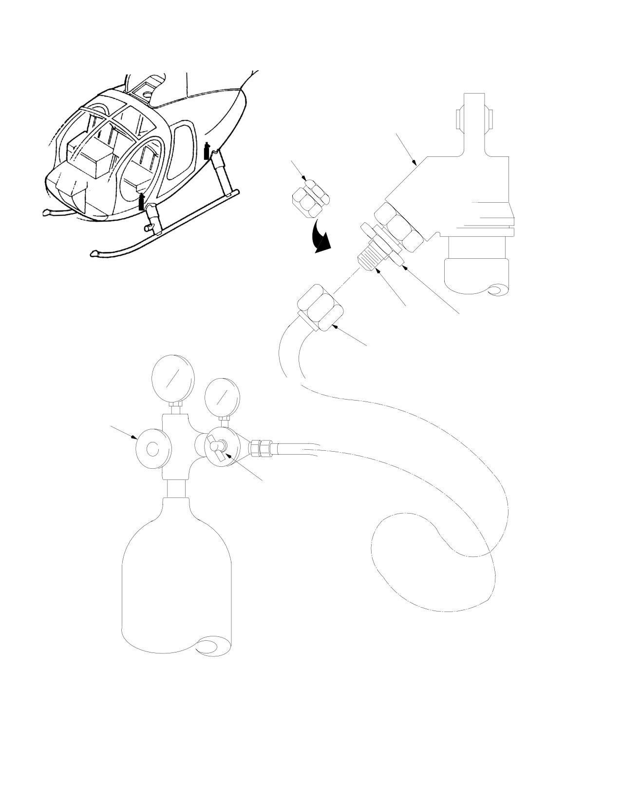
CSP-HMI-2
MD Helicopters, Inc.
MAINTENANCE MANUAL
DAMPER
CAP
SCHRADER
OUTSIDE NUT
VALVE
SERVICING HOSE
HIGH PRESSURE
VALVE
REGULATOR
CONTROL
Figure 301. Landing Gear Damper Nitrogen Servicing − On Helicopter
Page 302
Revision 19
32-10-00

MD Helicopters, Inc.
CSP-HMI-2
MAINTENANCE MANUAL
Table 301. Nitrogen Service Schrader Valve Equipped 369D26301 Extended Landing Gear
Dampers − on Helicopter
Degrees
Winterized Recharge
Mid−Temp Recharge
Ambient Recharge
Pressure (1)
Pressure (2)
Pressure (3)
°F
°C
psi
kPa
psi
kPa
psi
kPa
−40
−40
1,262
8,702
−38
−39
1,264
8,715
−36
−38
1,266
8,728
−34
−37
1,268
8,740
−32
−36
1,270
8,753
−30
−34
1,271
8,766
−28
−33
1,273
8,778
−26
−32
1,275
8,791
1,051
7,247
−24
−31
1,277
8,804
1,052
7,255
−22
−30
1,279
8,816
1,053
7,262
−20
−29
1,281
8,829
1,054
7,270
−18
−28
1,282
8,842
1,056
7,278
−16
−27
1,284
8,855
1,057
7,286
−14
−26
1,286
8,867
1,058
7,293
−12
−24
1,288
8,880
1,059
7,301
−10
−23
1,290
8,893
1,060
7,309
−8
−22
1,292
8,905
1,061
7,316
−6
−21
1,293
8,918
1,062
7,324
−4
−20
1,295
8,931
1,063
7,332
−2
−19
1,297
8,943
1,065
7,340
0
−18
1,299
8,956
1,066
7,347
2
−17
1,301
8,969
1,067
7,355
4
−16
1,303
8,981
1,068
7,363
6
−14
1,305
8,994
1,069
7,371
8
−13
1,306
9,007
1,070
7,378
10
−12
1,308
9,019
1,071
7,386
1,145
7,891
12
−11
1,310
9,032
1,072
7,394
1,146
7,900
14
−10
1,312
9,045
1,074
7,401
1,147
7,908
16
−9
1,314
9,057
1,075
7,409
1,148
7,917
18
−8
1,316
9,070
1,076
7,417
1,150
7,925
20
−7
1,317
9,083
1,077
7,425
1,151
7,934
22
−6
1,319
9,096
1,078
7,432
1,152
7,943
24
−4
1,321
9,108
1,079
7,440
1,153
7,951
Page 303
32-10-00
Revision 19
CSP-HMI-2
MD Helicopters, Inc.
MAINTENANCE MANUAL
Table 301. Nitrogen Service Schrader Valve Equipped 369D26301 Extended Landing Gear
Dampers − on Helicopter
Degrees
Winterized Recharge
Mid−Temp Recharge
Ambient Recharge
Pressure (1)
Pressure (2)
Pressure (3)
°F
°C
psi
kPa
psi
kPa
psi
kPa
26
−3
1,323
9,121
1,080
7,448
1,154
7,960
28
−2
1,325
9,134
1,081
7,455
1,156
7,968
30
−1
1,327
9,146
1,082
7,463
1,157
7,977
32
0
1,328
9,159
1,084
7,471
1,158
7,985
34
1
1,330
9,172
1,085
7,479
1,159
7,994
36
2
1,332
9,184
1,086
7,486
1,161
8,002
38
3
1,334
9,197
1,087
7,494
1,162
8,011
40
4
1,336
9,210
1,088
7,502
1,163
8,019
42
6
1,338
9,222
1,089
7,510
1,164
8,028
44
7
1,339
9,235
1,090
7,517
1,166
8,037
46
8
1,341
9,248
1,092
7,525
1,167
8,045
48
9
1,343
9,260
1,093
7,533
1,168
8,054
50
10
1,345
9,273
1,094
7,540
1,169
8,062
52
11
1,347
9,286
1,095
7,548
1,171
8,071
54
12
1,349
9,299
1,096
7,556
1,172
8,079
56
13
1,351
9,311
1,097
7,564
1,173
8,088
58
14
1,352
9,324
1,098
7,571
1,174
8,096
60
16
1,354
9,337
1,099
7,579
1,176
8,105
62
17
1,356
9,349
1,100
7,587
1,177
8,113
64
18
1,358
9,362
1,102
7,594
1,178
8,122
66
19
1,360
9,375
1,103
7,602
1,179
8,131
68
20
1,362
9,387
1,104
7,610
1,181
8,139
70
21
1,363
9,400
1,105
7,618
1,182
8,148
72
22
1,365
9,413
1,106
7,625
1,183
8,156
74
23
1,367
9,425
1,107
7,633
1,184
8,165
76
24
1,369
9,438
1,108
7,641
1,185
8,173
78
26
1,109
7,649
1,187
8,182
80
27
1,110
7,656
1,188
8,190
82
28
1,112
7,664
1,189
8,199
84
29
1,113
7,672
1,190
8,208
86
30
1,114
7,679
1,192
8,216
88
31
1,115
7,687
1,193
8,225
90
32
1,116
7,695
1,194
8,233
Page 304
Revision 19
32-10-00

MD Helicopters, Inc.
CSP-HMI-2
MAINTENANCE MANUAL
Table 301. Nitrogen Service Schrader Valve Equipped 369D26301 Extended Landing Gear
Dampers − on Helicopter
Degrees
Winterized Recharge
Mid−Temp Recharge
Ambient Recharge
Pressure (1)
Pressure (2)
Pressure (3)
°F
°C
psi
kPa
psi
kPa
psi
kPa
92
33
1,195
8,242
94
34
1,197
8,250
96
36
1,198
8,259
98
37
1,199
8,267
100
38
1,200
8,276
102
39
1,202
8,284
104
40
1,203
8,293
106
41
1,204
8,302
108
42
1,205
8,310
110
43
1,207
8,319
112
44
1,208
8,327
114
46
1,209
8,336
116
47
1,210
8,344
118
48
1,212
8,353
120
49
1,213
8,361
122
50
1,214
8,370
124
51
1,215
8,379
126
52
1,216
8,387
NOTES:
(1) For 369D26301−221, and −231 extended landing gear dampers.
(2) For 369D26301−241, and −251 extended landing gear dampers.
(3) For 369D26301−211 extended landing gear dampers.
Page 305
32-10-00
Revision 19

CSP-HMI-2
MD Helicopters, Inc.
MAINTENANCE MANUAL
Table 302. Nitrogen Service Schrader Valve Equipped 369D26300 Standard Landing Gear
Dampers − on Helicopter
Degrees
Winterized Recharge
Mid−Temp Recharge
Ambient Recharge
Pressure (1)
Pressure (2)
Pressure (3)
°F
°C
psi
kPa
psi
kPa
psi
kPa
−40
−40
704
4,854
−38
−39
705
4,864
−36
−38
707
4,873
−34
−37
708
4,882
−32
−36
709
4,891
−30
−34
711
4,901
−28
−33
712
4,910
−26
−32
714
4,919
704
4,855
−24
−31
715
4,929
705
4,862
−22
−30
716
4,938
706
4,869
−20
−29
718
4,947
707
4,876
−18
−28
719
4,956
708
4,883
−16
−27
720
4,966
709
4,889
−14
−26
722
4,975
710
4,896
−12
−24
723
4,984
711
4,903
−10
−23
724
4,994
712
4,910
−8
−22
726
5,003
713
4,916
−6
−21
727
5,012
714
4,923
−4
−20
728
5,021
715
4,929
−2
−19
730
5,031
715
4,936
0
−18
731
5,040
716
4,942
2
−17
732
5,049
717
4,949
4
−16
734
5,058
718
4,955
6
−14
735
5,068
719
4,962
8
−13
736
5,077
720
4,968
10
−12
738
5,086
721
4,974
637
4,392
12
−11
739
5,096
722
4,980
638
4,397
14
−10
740
5,005
723
4,987
639
4,403
16
−9
742
5,114
724
4,993
639
4,409
18
−8
743
5,123
725
4,999
640
4,415
20
−7
744
5,133
725
5,005
641
4,420
22
−6
746
5,142
726
5,011
642
4,426
24
−4
747
5,151
727
5,017
643
4,432
Page 306
Revision 19
32-10-00
MD Helicopters, Inc.
CSP-HMI-2
MAINTENANCE MANUAL
Table 302. Nitrogen Service Schrader Valve Equipped 369D26300 Standard Landing Gear
Dampers − on Helicopter
Degrees
Winterized Recharge
Mid−Temp Recharge
Ambient Recharge
Pressure (1)
Pressure (2)
Pressure (3)
°F
°C
psi
kPa
psi
kPa
psi
kPa
26
−3
748
5,160
728
5,023
644
4,438
28
−2
750
5,170
729
5,029
645
4,444
30
−1
751
5,179
730
5,035
645
4,449
32
0
753
5,188
731
5,041
646
4,455
34
1
754
5,198
732
5,047
647
4,461
36
2
755
5,207
732
5,052
648
4,467
38
3
757
5,216
733
5,058
649
4,473
40
4
758
5,225
734
5,064
650
4,478
42
6
759
5,235
735
5,070
650
4,484
44
7
761
5,244
736
5,075
651
4,490
46
8
762
5,253
737
5,081
652
4,496
48
9
763
5,263
737
5,087
653
4,502
50
10
765
5,272
738
5,092
654
4,507
52
11
766
5,281
739
5,098
655
4,513
54
12
767
5,290
740
5,103
655
4,519
56
13
769
5,300
741
5,109
656
4,525
58
14
770
5,309
741
5,114
657
4,531
60
16
771
5,318
742
5,120
658
4,536
62
17
773
5,327
743
5,125
659
4,542
64
18
774
5,337
744
5,130
660
4,548
66
19
775
5,346
744
5,136
660
4,554
68
20
777
5,355
745
5,141
661
4,559
70
21
778
5,365
746
5,146
662
4,565
72
22
779
5,374
747
5,152
663
4,571
74
23
781
5,383
747
5,157
664
4,577
76
24
782
5,392
748
5,162
665
4,583
78
26
749
5,167
666
4,588
80
27
750
5,172
666
4,594
82
28
750
5,177
667
4,600
84
29
751
5,182
668
4,606
86
30
752
5,188
669
4,612
88
31
753
5,193
670
4,617
90
32
753
5,198
671
4,623
Page 307
32-10-00
Revision 19

CSP-HMI-2
MD Helicopters, Inc.
MAINTENANCE MANUAL
Table 302. Nitrogen Service Schrader Valve Equipped 369D26300 Standard Landing Gear
Dampers − on Helicopter
Degrees
Winterized Recharge
Mid−Temp Recharge
Ambient Recharge
Pressure (1)
Pressure (2)
Pressure (3)
°F
°C
psi
kPa
psi
kPa
psi
kPa
92
33
671
4,629
94
34
672
4,635
96
36
673
4,641
98
37
674
4,646
100
38
675
4,652
102
39
676
4,658
104
40
676
4,664
106
41
677
4,670
108
42
678
4,675
110
43
679
4,681
112
44
680
4,687
114
46
681
4,693
116
47
681
4,698
118
48
682
4,704
120
49
683
4,710
122
50
684
4,716
124
51
685
4,722
126
52
686
4,727
NOTES:
(1) For 369D26300−221, and −231 standard landing gear dampers.
(2) For 369D26300−241, and −251 standard landing gear dampers.
(3) For 369D26300−211 standard landing gear dampers.
Page 308
Revision 19
32-10-00
MD Helicopters, Inc.
CSP-HMI-2
MAINTENANCE MANUAL
LANDING GEAR SYSTEM
REMOVAL/INSTALLATION
1. Landing Gear Replacement
doors, engine access doors and foot
supporting fairings.
(Ref. Figure 401)
(2). With helicopter supported by jacks,
A. Landing Gear Removal
position landing gear to align struts
with openings in fuselage structure.
Consumable Materials
NOTE: Check that fairing fillet guide pins en
(Ref. Section 91−00−00)
gage fairing guide holes before positioning
Item
Nomenclature
struts for attachment to structure.
CM729
Tape, masking, pressure sensitive
(3). Lift and carefully position landing gear;
then place supports beneath landing
NOTE: Following procedures apply to removal
gear to hold it in place.
of entire right or left landing gear assembly.
NOTE: Install left forward damper upper bolt
For component disassembly, refer to appli
with bolt head aft. Bolt direction on right
cable section. For removal, two persons are
side is optional.
needed.
(4). Be sure that slotted bushing (view C) is
(1).
Jack up helicopter until landing gear
in place. Align lower bearing of damper
dampers are fully extended (Ref. Sec.
with mating holes in strut and install
07-00-00). Place support beneath skid
attaching hardware.
tubes at strut locations.
(5). Align struts with mating bearings in
(2).
Pull strut fairing fillet downward
fuselage support fittings. Install bolt,
against spring tension and secure with
slotted bushing, two washers, nut and
tape (CM729).
cotter pin.
(3).
Open compartment access doors for
(6). Align inboard end of each brace with
access to forward brace, strut and
mating bearing in fuselage supporting
damper. Disconnect brace, strut and
fitting. Install slotted bushing and
damper from attachment points.
attaching hardware.
(4).
For access to aft landing gear attach
(7). Secure electrical bonding jumper with
ment points, open engine access doors.
clamp and attaching hardware to aft
Disconnect aft brace, strut and damper
strut.
from attachment points.
Do not over-tighten brace-to-
CAUTION
(5).
Remove clamp attaching electrical
strut hardware. Maximum per
bonding jumper to aft strut.
missible nut torque is finger-tight; then
backed off to nearest cancellation for instal
(6).
Disconnect electrical wiring connections
lation of cotter pin.
at upper area forward strut.
(8). If brace is detached from strut, align
(7).
Remove supports from below skid and
outboard end of each brace with mating
carefully remove struts, skid and
holes in strut. Attach brace to strut
fairings as an assembled unit.
with attaching hardware. Torque nut to
5 inch-pounds (0.56 Nm) maximum.
B. Landing Gear Installation
(9). Connect wiring at forward strut.
NOTE: Following procedures apply to installa
tion of right or left landing gear assemblies.
(10). Remove skid supports, lower helicopter,
and remove jacks.
(1). For access to landing gear attachment
points, open or remove fuselage access
(11). Close or replace all access doors.
Page 401
32-10-00
Revision 19
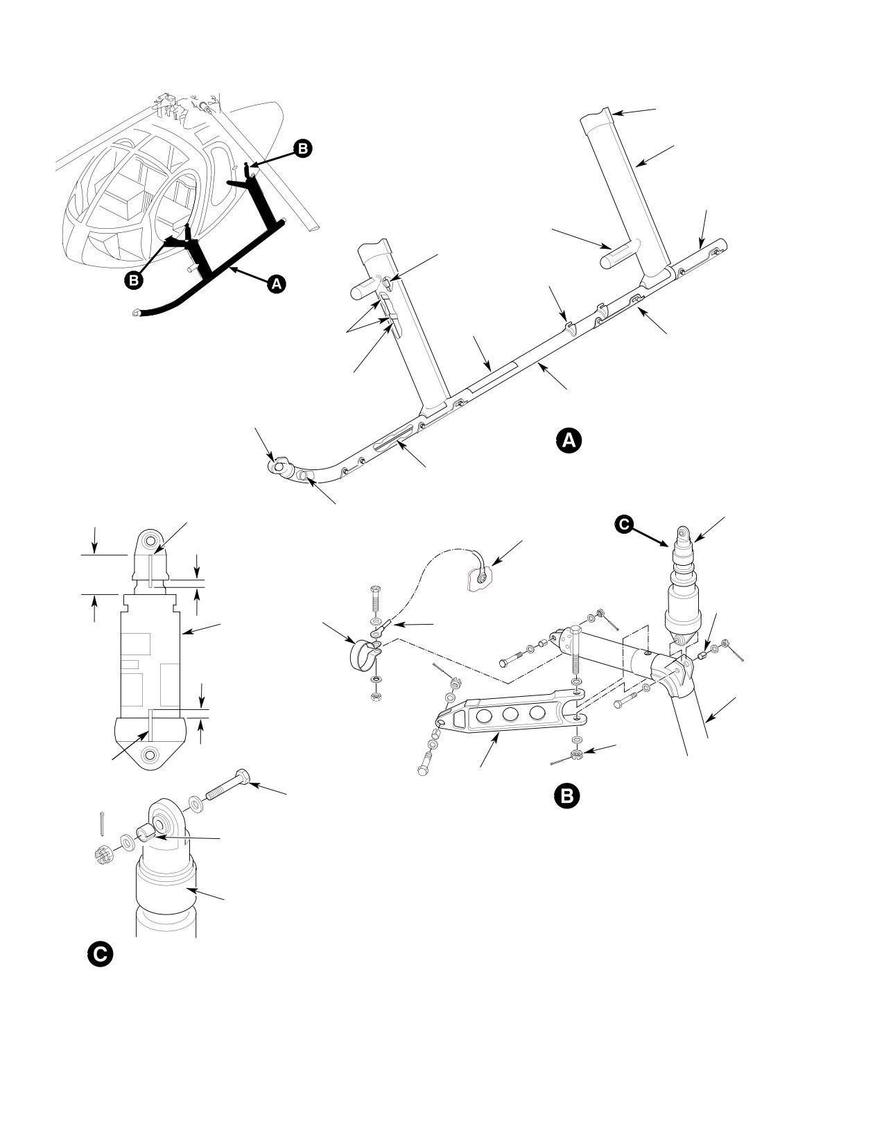
CSP-HMI-2
MD Helicopters, Inc.
MAINTENANCE MANUAL
FILLET
FAIRING
SKID
EXTENSION
CABIN ENTRY STEP
KNIFE SPLICE
GROUND HANDLING
FITTINGS
SAFETY
WALK TAPE
ABC BOLTS
ABRASION STRIP
SEALING COMPOUND
LANDING GEAR SKID
POSITION LIGHT
ELECTRICAL HARNESS
TORQUE STRIPE
SERVICE LOOP
DAMPER
(NOTE 3)
0.37-0.62 INCH
CENTER BEAM
(9.398-15.748 MM)
DIMENSION
A
SLOTTED
BUSHING
(NOTE 1)
CLAMP
BARREL
BONDING
JUMPER
0.37-0.62 INCH
(9.398-15.748 MM)
STRUT
5 IN.-LB.
(0.56 NM)
TORQUE
MAXIMUM
BRACE
STRIPE
(NOTE 3)
NOTE 2
STRUT AND BRACE ATTACHMENT
BUSHING
(NOTE 1)
NOTES:
1.
EDGE OF BUSHING MUST PROTRUDE A MINIMUM OF 0.010 INCH
0.030 INCH (0.762 MM)
(0.254 MM) TO A MAXIMUM OF 0.060 INCH (1.524 MM) ABOVE
MAXIMUM DEFECT
OUTSIDE SURFACE OF PART AFTER NUT IS TIGHTENED.
DEPTH (TYPICAL)
2.
LEFT FORWARD DAMPER ATTACHING BOLT HEAD AFT FOR
REMOVAL CLEARANCE.
DAMPER UPPER ATTACHMENT
3.
TORQUE STRIPES PAINTED CONTRASTING BLACK OR WHITE,
AS APPLICABLE.
G32-1000B
Figure 401. Landing Gear and Damper Installation
Page 402
Revision 19
32-10-00
MD Helicopters, Inc.
CSP-HMI-2
MAINTENANCE MANUAL
2. Landing Gear Damper Replacement
3. Landing Gear Skid Replacement
(Ref. Figure 401)
(Ref. Figure 401)
A. Landing Gear Skid Removal
A. Landing Gear Damper Removal
(1). If landing gear assembly is attached to
(1). Jack up or hoist helicopter on level
helicopter, jack up helicopter until
surface until landing gear skids just
dampers are fully extended (Ref. Sec.
clear resting surface.
07-00-00). Place supports beneath skid
tubes at strut locations.
(2). For forward damper removal, remove
foot well fairings located in passenger
(2). Remove lower fairing from two-piece
compartment. For access for aft damper
fairing assembly.
removal, open engine access doors.
(3). Remove bolts attaching forward
(3). Remove hardware (except bushings)
skid-to-foot assembly.
attaching forward damper assemblies
to fuselage attachment fittings and
(4). Disconnect electrical connections at
landing gear struts.
forward strut.
(5). Remove bolts attaching extension to
(4). Remove hardware from damper
skid adapter sleeve. Remove extension,
attachment points.
index plug and bearing from skid.
B. Landing Gear Damper Installation
B. Landing Gear Skid Installation
(1). Jack up helicopter on level surface until
landing gear skids (Ref. Sec. 07-00-00)
Consumable Materials
just clear resting surface.
(Ref. Section 91−00−00)
Item
Nomenclature
NOTE:
CM318
Primer
D Always be sure that replacement damper
CM420
Sealant
is correct for the helicopter. Ensure that
CM425
Sealing compound
cap torque stripes will be visible for in
spection after installation.
NOTE: Left or right replacement skids are in
D If installing schrader valve equipped
terchangeable by using or removing nylon
dampers, ensure fwd damper is installed
screws from side of skid at forward strut.
with schrader valve facing forward and
aft damper with schrader valve facing aft.
(1). Position skid in place with aft foot
bearing installed over skid adapter
(2). Install replacement damper in upper
sleeve. Connect electrical connections
and lower mounting position with
for skid position light at forward strut.
attaching hardware. Ensure bushings
are in place.
(2). Apply thin coating of primer (CM318) to
forward strut and skid tube mating
NOTE: Left forward damper upper bolt must be
surfaces.
installed with bolt head aft. Bolt direction
on right side is optional.
(3). Align mating parts and install bolts
with wet coating of zinc chromate
(3). Torque nuts to 48 - 55 inch-pounds
primer. Torque bolts 40 - 60 inch-
(5.42 - 6.21 Nm) and cotter pin.
pounds (4.52 - 6.78 Nm). Apply
sealant (CM420) to head of bolt and to
(4). Check installation for proper alignment
nuts.
of torque stripes.
(4). Align skid extension with skid tube
(5). Install foot support fairings and close
adapter sleeve. Coat attaching bolts
engine access doors.
with primer and install while wet.
Page 403
32-10-00
Revision 26
CSP-HMI-2
MD Helicopters, Inc.
MAINTENANCE MANUAL
(5). Seal edges of all rigid parts on skid
(e). Carefully spread fillet at trailing
with an approximate 0.060 inch (1.524
edge and remove in forward direc
mm) fillet of sealing compound
tion.
(CM425).
(3). Remove upper part of fairing as follows.
(6). Install lower fairing.
(a). Remove rivets that secure trailing
edge of fairing.
4. Landing Gear Fairing Replacement
(b). Remove rivets that secure fairing to
(Ref. Figure 402)
strut bracket.
A. Landing Gear Fairing Removal
(c). Use putty knife or similar thin-
bladed tool to carefully pry apart
The following instructions are typical for and
bonding and separate upper 5 inches
apply to all four fairing assemblies.
of trailing edge; then separate fairing
from flange of lower guide.
(1). Remove lower fairing from fairing
assembly as follows.
(d). Carefully spread trailing edge of
fairing and remove in forward
(a). Remove attaching hardware that
direction.
secures lower fairing to two strut
brackets, and that secures trailing
B. Landing Gear Fairing Installation
edge of lower fairing.
The following instructions apply to all four
(b). Carefully spread trailing edge of
fairing assemblies. Where riveting is required,
lower fairing and remove in forward
use rivets of type shown in Figure 802.
direction.
NOTE: Ensure that doublers between lamina
Consumable Materials
tions at trailing edge are retained for reuse.
(Ref. Section 91−00−00)
Item
Nomenclature
(2). Remove fillet from upper part of fairing
CM318
Primer
assembly as follows.
CM411
Adhesive, epoxy
(a). Remove rivets from trailing edge of
fillet.
(1). Install upper part of the fairing as
follows.
(b). Drill out one of the rivets securing
fillet to upper guide. Replace rivet
(a). Assemble upper guide, pin assembly,
with sheet metal hole fastener (Cleco,
inner guide half, outer guide half,
or equivalent). Repeat this step on
springs and lower guide on landing
other rivets.
gear strut. Install rivets with wet
primer (CM318) to secure lower
(c). Open underfloor compartment or
guide to strut.
engine compartment doors for access
to strut cutout in fuselage skin. Have
(b). Push guide pins into matching holes
an assistant push down on upper
of lower guide. Wedge temporary
guide with suitable tool (wood dowel
holding device between upper guide
or equivalent), to relieve spring
and strut to keep pins engaged.
tension.
NOTE: Use two small wood blocks or any simi
(d). With spring tension off guide, remove
lar suitable means to keep springs com
fasteners. Slowly relax dowel pres
pressed. Device used must be small enough
sure on guide until springs fully
to be removed through strut cutout in skin
expand.
after fillet is assembled.
Page 404
Revision 26
32-10-00
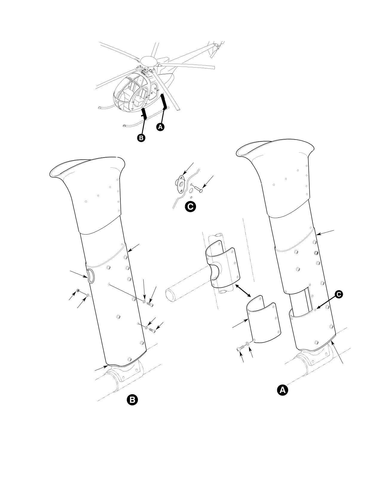
MD Helicopters, Inc.
CSP-HMI-2
MAINTENANCE MANUAL
NUTPLATE
RIVET
FAIRING
ASSY
FAIRING ASSY
SEAL
WASHER
SCREW
NUT
WASHER
WASHER
SCREW
COVER (EXTENDED
LANDING GEAR ONLY)
WASHER
SCREW
SEAL
SEAL
Figure 402. Fairing Installation
Page 405
32-10-00
Revision 19
CSP-HMI-2
MD Helicopters, Inc.
MAINTENANCE MANUAL
(c).
Install blind hole transfer punches
(b).
Carefully spread trailing edge of fillet
(two or four places, as applicable) or
and position about upper guide.
fabricate suitable tools as shown
Clamp lower end of fillet trailing
(Ref. Figure 802). Install tool(s)
edge to upper end of fairing trailing
edge. Clamping prevents fillet
between opposing holes in strut
movement when fillet rivets are
bracket(s).
installed. Have an assistant remove
temporary holding device and push
down on upper guide with suitable
(d).
Carefully spread trailing edge of
tool (wood dowel, etc). Have guide
fairing and position fairing on strut
pushed down where a pencil line
bracket(s) and lower guide. Have an
drawn on guide flange is visible
assistant hold fairing in this position.
through one #40 hole in fillet. Match-
drill guide and secure fillet and guide
with hole fastener (Cleco, or equiva
(e).
Back up fairing with a fiber block at
lent). Repeat procedure for all rivet
transfer punch location. Using plastic
locations. Remove pushing tool from
hammer, carefully strike opposite
strut opening.
side of fairing to transfer hole
centers.
(c).
Remove one fastener at a time, and
install screws and washers (Ref.
Landing Gear Fairing Fillet Modifi
(f).
Remove fairing and check that all
cation).
transfer marks appear within outline
(d).
Install screws, washers and nuts to
of small laminated doublers. Drill out
secure fillet trailing edge together.
located holes.
(e).
Check for smooth telescoping action
of fairing into fillet by manually
(g).
Carefully bond fairing to lower guide
sliding fillet up and down several
(Ref. Figure 802). Use adhesive
times.
(CM411) according to container
instructions.
(f).
Close access doors.
(3). Install lower part of two-piece fairing
(h).
Install rivets to secure fairing to
as follows.
strut bracket(s).
(a). Carefully spread trailing edge of
fairing and position on upper fairing
(i).
Install rivets to secure trailing edge
and lower strut bracket; at correct
position there should be 0.020 -
of fairing.
0.080 inch (0.508 - 2.032 mm)
compression of fairing seal against
skid tube. Have an assistant hold
(j).
Using soft lead pencil, draw a
fairing at this position.
continuous line along horizontal
center of upper guide flange.
(b). Back up fairing with fiber block at
transfer punch location. Using plastic
hammer, carefully strike opposite
(2). Install fillet as follows.
side of fairing to transfer hole
centers.
(a). Drill a #40 hole in center of each 3/8
(c). Remove fairing and check that all
inch (9.525 mm) square doubler in
transfer marks appear within outline
fillet. (There are six doublers in the
of small laminated doublers. Drill out
fiberglass fairings.)
located holes.
Page 406
Revision 26
32-10-00
MD Helicopters, Inc.
CSP-HMI-2
MAINTENANCE MANUAL
(d). Reinstall fairing in mounting position
B. Cabin Entry Step Installation
and secure to upper and lower strut
brackets with screws and washers.
Consumable Materials
(Ref. Section 91−00−00)
(e). Secure fairing trailing edge with
Item
Nomenclature
attaching hardware.
CM318
Primer
NOTE: Be sure doublers are installed between
(1). Install replacement step on forward
laminations at trailing edge.
landing gear strut, using four lockbolts
with wet primer (CM318). Four holes in
step collar must be drilled out to 0.164
5. Cabin Entry Step Replacement
- 0.167 inch (4.166 - 4.242 mm) for
installation of lockbolts. If holes are
elongated, use next size larger lock
(Ref. Figure 801)
bolts.
A. Cabin Entry Step Removal
NOTE: At strut replacement, locate step by us
ing skid centerline-to-step centerline mea
surement of 11.78 inches (29.92 cm).
(1). Remove landing gear fairing.
(2). Install step on aft landing gear strut,
using two bolts, washers and nuts with
(2). Remove four lockbolts and step from
wet primer. Torque nuts to 60 - 85
forward landing gear strut, or two bolts,
inch-pounds 6.78 - 9.60 Nm).
washers and nuts from aft landing gear
strut (extended gear only).
(3). Install lower fairing on strut.
Page 407
32-10-00
Revision 26
CSP-HMI-2
MD Helicopters, Inc.
MAINTENANCE MANUAL
This Page Intentionally Left Blank
Page 408
Revision 44
32-10-00
MD Helicopters, Inc.
CSP-HMI-2
MAINTENANCE MANUAL
LANDING GEAR SYSTEM
INSPECTION/CHECK
1. Landing Gear Inspection
(1).
Jack helicopter until landing gear
dampers are fully extended.
(Ref. Figure 801)
(2).
Remove lower fairing from two-piece
NOTE: Inspection should be performed with
fairing assembly.
helicopter skids clear of ground.
(3).
Inspect for dents. If dents exceed a
(1). Inspect skids, skid abrasion strips,
depth of 0.20 inch (5.08 mm), they will
struts, feet, braces and fairings for
require repair.
dents, cracks, loose components or
(4).
Inspect for punctures and cracks.
rivets, loose nuts and for missing
hardware.
(5).
Perform fluorescent-penetrant inspec
tion of all crack areas, and of those
(2). Inspect skid-to-foot and foot-to-strut
areas adjacent to all punctures. These
attachments for loose bolts. Check aft
areas will require repair.
foot-to-bearing rivet installation for
security.
(6).
Inspect from aft end of tube to a point
10 inches (25.40 cm) forward of aft strut
NOTE: Loose or defective bolts at forward foot-
for scratches and nicks. If scratches and
to-skid locations requires replacement of
nicks exceed a length of 0.25 inch (6.35
nutplates.
mm) and a depth of 0.015 inch (0.381
mm), they will require repair.
(3). Using 10X glass and bright light,
visually inspect area at, around and
(7).
Inspect from forward end of tube to 10
between foot-to-strut attach bolts not
inches (25.40 cm) forward of aft strut
covered by sealant for cracks and
for scratches and nicks. If scratches and
corrosion.
nicks exceed a length of 0.25 inch (6.35
mm) and a depth of 0.020 inch (0.508
NOTE: If cracks or corrosion other than light
mm), they will require repair.
surface corrosion is found, replace affected
(8).
Inspect ground handling fittings for
part.
cracks, loose rivets, corrosion and other
(4). Inspect keel beam areas where the
damage.
strut assemblies attach for loose
(9).
Inspect abrasion strips for damage,
bearings, condition of hardware and
excessive wear, and for loose bolts and
strut adapters.
screws.
(5). Check condition of beaded seal around
(10).
Check skid adapter sleeve rivet attach
edges of all rigid-mounted skid tube
ment for security. On early configura
components.
tions, check sleeve slots for wear and
damage.
2. Landing Gear Skid Inspection
(11).
Check condition of plug installed in
(Ref. Figure 801)
skid adapter sleeve.
NOTE: If landing gear assembly has not been
(12).
Check aft foot bearing and extension for
removed from helicopter, perform following
wear, damage and corrosion. On early
steps (1). and (2). before proceeding with in
configurations, check condition of
spection.
extension packing.
Page 601
32-10-00
Revision 31

CSP-HMI-2
MD Helicopters, Inc.
MAINTENANCE MANUAL
3. Landing Gear Strut Inspection
a). Diameter of top hole (DIM. A)
should be 0.5313 inch (13.495
(Ref. Table 801 and Figure 601)
mm) maximum in any direction.
b). Diameter of bottom hole (DIM.
Consumable Materials
B) should be 0.50 inch (12.70
(Ref. Section 91−00−00)
mm) maximum in any direction.
Item
Nomenclature
CM318
Primer
4). If no cracks are found around drag
brace attach hole in strut and hole
is not elongated, install new
(1).
Check landing gear dampers for correct
bushing in hole with wet primer
servicing by observing stance of
(CM318).
helicopter. Check rear dampers for
correct extension and signs of leakage.
5). If either hole is oversized or
cracking is noted, rework strut
(2).
Remove foot support fairings in passen
(Ref. Landing Gear Strut Drag
ger/cargo compartment and open engine
Brace Hole Repair).
access doors.
(b). If no bushing is installed in drag
(3).
Visually inspect strut attachment
brace attach hole in strut, proceed as
points and pivot bearing for signs of
follows:
fretting, wear and damage. Fretting
will be evident by gray or black materi
1). Using 10X glass and bright light,
al around bearing, rivets or seams.
inspect strut around drag brace
attach holes (top and bottom
(4).
Jack helicopter until landing gear
surfaces) for cracks. If any cracks
dampers are fully extended.
longer than 0.030 inch (0.762 mm)
in length are noted, strut must be
(5).
Shake landing gear assemblies and
scrapped and serviceable strut
note any play or looseness at pivot
installed.
bearings, inboard strut assembly
fittings and drag brace holes.
2). Check drag brace attach holes in
strut for elongation.
(6).
If any play or looseness is noted,
remove landing gear (Ref. Landing
3). If any cracks, 0.030 inch (0.762
Gear Removal) and inspect drag brace
mm) in length or less, are noted or
and strut.
hole is elongated, rework strut
(Ref. Landing Gear Strut Drag
(7).
Inspect strut bolt hole where drag brace
Brace Hole Repair).
attaches as follows:
(8). Reinstall landing gear (Ref. Landing
(a). If bushing is installed in drag brace
Gear Installation).
attach hole in strut, proceed as
follows:
(9). Inspect strut for cracks or dents.
1). Check bushing for looseness then
(a). If strut is cracked, scrap strut and
remove bushing.
replace with serviceable strut.
2). Using 10X glass and bright light,
(b). If dents in strut exceed 0.060 inch
inspect strut around drag brace
(1.524 mm) depth; or, if scratches and
attach holes (top and bottom
repair area depth would exceed 0.010
surfaces) for cracks.
inch (0.254 mm) when measured to
surrounding unrepaired surface strut
3). Check drag brace attach holes in
must be scrapped and serviceable
strut for elongation.
strut installed.
Page 602
Revision 26
32-10-00
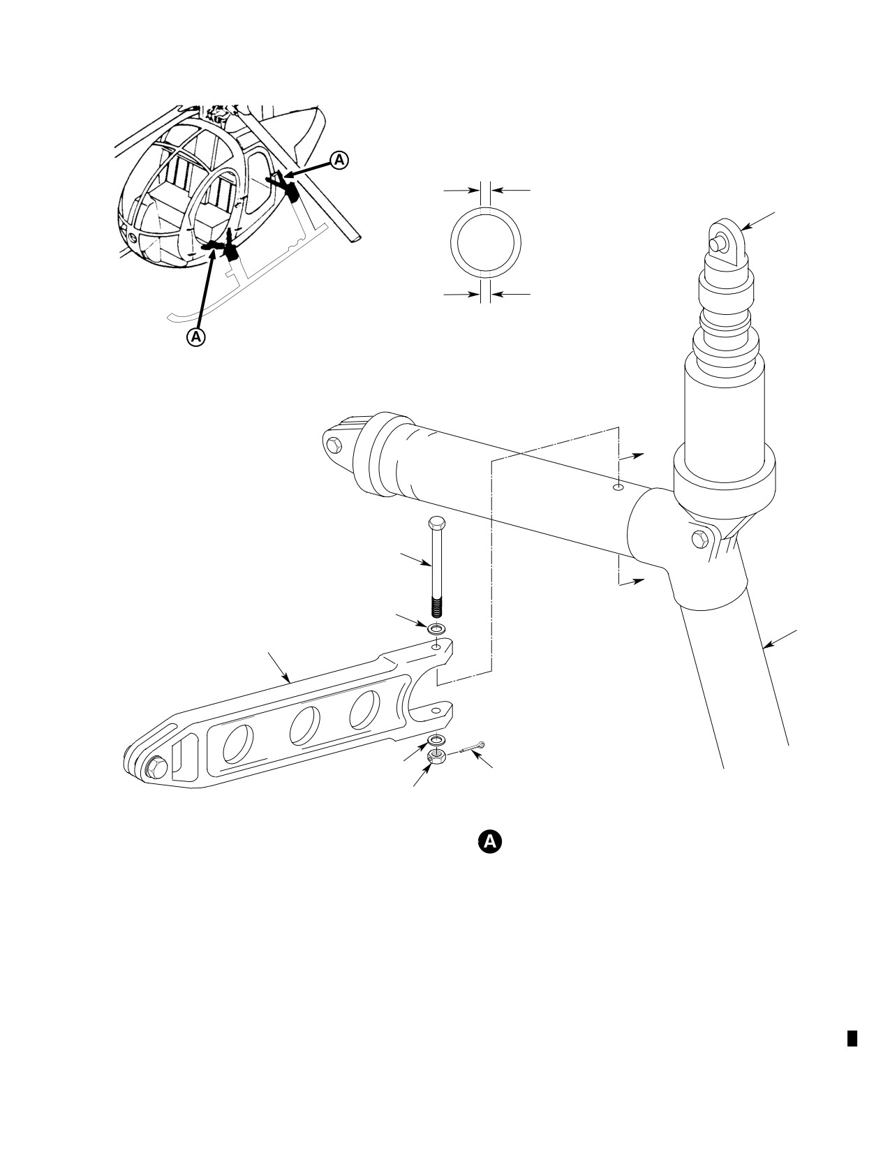
MD Helicopters, Inc.
CSP-HMI-2
MAINTENANCE MANUAL
DIM. A
(TOP HOLE)
DAMPER
( REF )
DIM. B
(BOTTOM HOLE)
SECT B-B
B
BOLT
B
WASHER
DRAG
STRUT
BRACE
WASHER
COTTER PIN
NUT
STRUT AND BRACE ATTACHMENT
88-779a
Figure 601. Landing Gear Strut Inspection
Page 603
32-10-00
Revision 26