HANDBOOK OF MAINTENANCE INSTRUCTIONS FOR MDHI 369D/E/FF-500/600N HELICOPTERS (ISSUED: 1990) - page 11
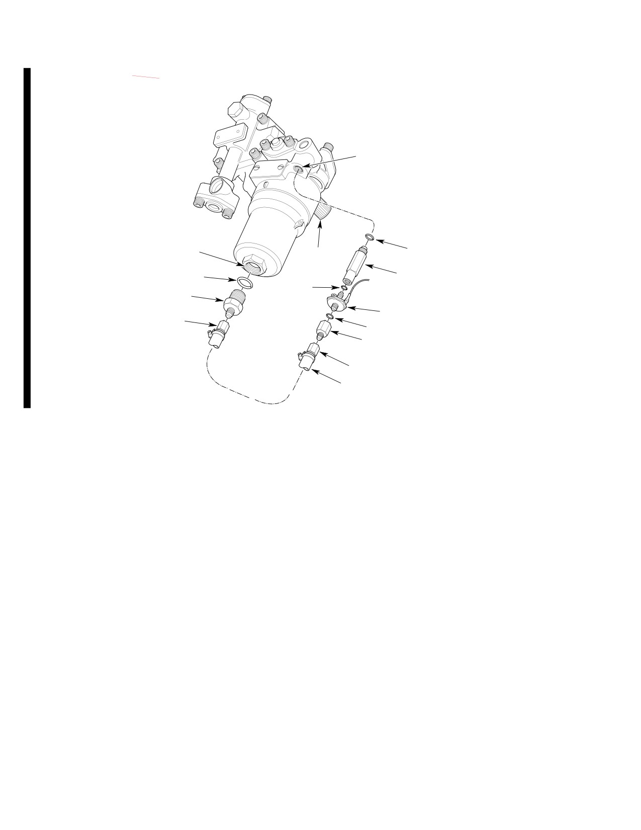
CSP-HMI-2
MD Helicopters, Inc.
MAINTENANCE MANUAL
AFTER FILTER
PRESSURE TAP
O-RING
BEFORE FILTER
FUEL PUMP
PRESSURE TAP
SEAL DRAIN
FITTING, TORQUE; 65-75 IN. LB
O-RING
(7.34-8.47 NM)
O-RING
REDUCER, TORQUE; 95-105 IN. LB
(10.73-11.86 NM)
FUEL FILTER PRESSURE SWITCH,
TORQUE 75-85 IN. LB
TORQUE; 60-75 IN. LB (6.78-8.47 NM)
O-RING
(8.47-9.60 NM)
BUSHING, TORQUE; 90-100 IN. LB
(10.16-11.30 NM)
TORQUE; 75-85 IN. LB
(8.47-9.60 NM)
HOSE
G28-0027C
Figure 505. Fuel Filter Caution Light Pressure Switch (C20R/2 Engines with CECO Pump)
Page 510
Revision 44
28-00-00
MD Helicopters, Inc.
CSP-HMI-2
MAINTENANCE MANUAL
FUEL SYSTEM
INSPECTION/CHECK
WARNING
Consumable Materials
(Ref. Section 91−00−00)
D Avoid fuel vapor ignition and fire.
Item
Nomenclature
Use only nonsparking tools and ex
plosion proof work lights. Attach he
CM309
Lacquer, green
licopter to an approved electrical
N/A
Lockwire CRES
ground. Switch OFF all electrical
CM714
Tape, pressure sensitive
power. Disconnect external power
and battery before opening fuel sys
tem. Ensure work area is adequately
(1). Remove left instrument panel fairing.
ventilated.
Check for control cables marked (Jairen
D Air entering the airframe fuel supply
Inc. 16722 PN 110262-15N) with a date
lines may cause a power reduction or
of (5/18) or later, and having a swage
flameout. Fuel system vacuum leak
less than 0.50 inch (12.70 mm) in
check and fuel air bleed procedures
length. These cables are MDHS part
must be performed after opening fuel
numbers 369A8137-503 and -603.
the supply system for any reason,
prior to releasing helicopter for
(a). Inspect cable casing for a green
flight.
stripe. The green stripe indicates
that cable has been previously pull
1.
Fuel System General Inspection
tested.
(1). Remove right and left fuel tank floor
(2). Unpainted control cables, P/N
access panels.
369A8137-503 and -603 fitting the
preceding description require a manda
(2). Inspect fuselage bottom skin for
tory 50 pound (222.4 N) pull test to
evidence of fuel leakage. No leaks
determine cable swage integrity.
allowed. Determine source and repair
as required.
(a). Unclamp cable from canopy or
(3). Inspect fuel lines, fittings, cell access
instrument panel support structure
covers, fuel quantity unit, clamps and
(Ref. Figure 401).
attaching hardware for leakage,
corrosion and security. Inspect fire
(b). Behind instrument panel; back cable
sleeves for cuts, tears and punctures.
retaining nut completely off threaded
No leakage allowed. Repair or replace
portion of casing.
components as required.
(c). Wrap a 12 inch (30.48 cm) length of
(4). Inspect electrical wiring and connectors
two inch 5.08 cm) wide duct tape or
for corrosion and security. Replace or
equivalent around cable casing about
repair wiring as required.
0.50 inch (12.70 mm) behind casing
swage or instrument panel, whichev
(5). If start pump wire is ty-rapped to start
er is furthest from front of instru
pump line, inspect security and condi
ment panel.
tion of ty-raps.
2.
Fuel Shutoff Valve Control Cable Swage
(d). Wrap one end of 0.042 lockwire
Test (369D/E)
around cable and attach the other
end to the spring scale (Ref.
(Ref. Figure 601)
Figure 601).
Page 601
28-00-00
Revision 19
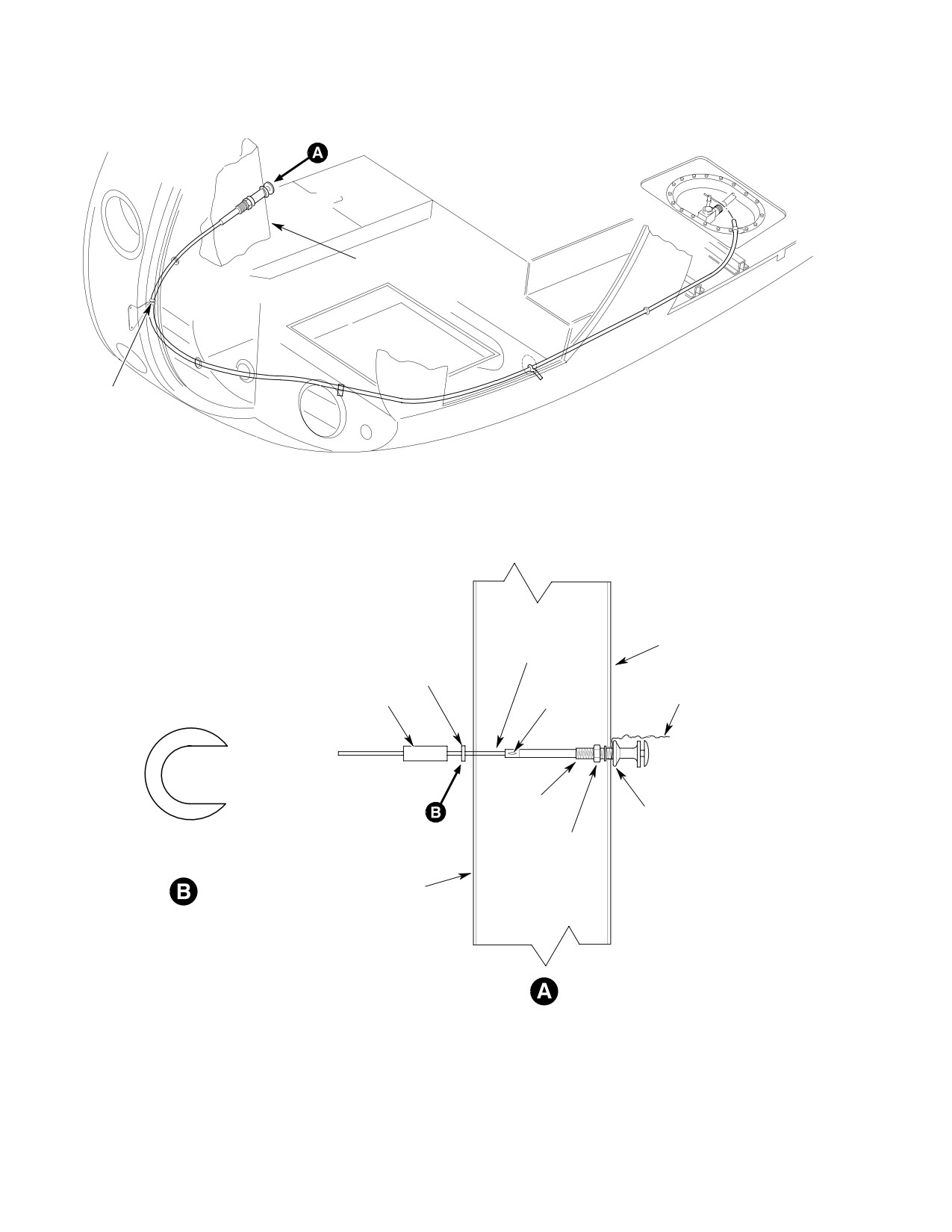
CSP-HMI-2
MD Helicopters, Inc.
MAINTENANCE MANUAL
INSTRUMENT PANEL
CLAMP
FRONT OF INSTRUMENT
CABLE CASING
PANEL
NOTCHED WASHER
TAPE
LOCKWIRE
SWAGE
0.265 INCH (6.731 MM)
THREADS
FLANGE
NUT
NOTCHED WASHER TO SLIP
OVER CABLE CASING
BACK OF INSTRUMENT
PANEL
G28-0011B
Figure 601. Fuel Shut−Off Control Cable, PN 369A8137−503 Pull Test
Page 602
Revision 19
28-00-00
MD Helicopters, Inc.
CSP-HMI-2
MAINTENANCE MANUAL
(e). Notch a 0.265 ID x 0.063 inch (6.73
(5).
Ensure shutoff valve control knob is
ID x 1.60 mm) thick washer and
pushed in. Valve ball must be wide
position over cable between tape and
open.
back of instrument panel.
(6).
Pull control knob out to stop. Valve ball
Sudden cable separation
should be closed.
WARNING
may cause serious personal
(7).
Valves that can not be fully closed or
injury. Be properly braced while pull
opened must be overhauled or replaced
ing on the cable.
prior to further flight.
(f). Apply a steady tension through the
spring scale up to 50 pounds (222.4
(8).
Disconnect control cable from valve.
N). Relax the tension.
(9).
Inspect shutoff valve lever and cable
(g). Inspect cable casing swage for
swivel hardware for corrosion and wear.
separation.
Check lever for smooth movement from
closed to open stops.
(h). Replace separated/unserviceable
cable assemblies.
(10).
Use a spring scale to check tension
required to move valve lever from full
(i). If the swage held without apparent
open to closed. Design force require
damage, paint a green lacquer
ment is 1.5 - 3.5 pounds (6.7 - 15.6 N)
(CM309) stripe around the swage/
maximum.
casing joint.
(11).
Inspect valve for evidence of external
(3). Install and secure cable hardware.
leakage. External leakage not allowed.
(4). Perform the following inspections and
(12).
Check that lever detents at open and
checks on all model helicopters.
closed positions. Repair or replace valve
as required.
(a). Remove left fuel cell floor access
panel.
(13).
Connect and rig valve control cable.
Install cotter pin on cable swivel.
(b). Inspect fuel shutoff cable, nylon
grommets and attaching hardware
4. Fuel Quantity Transmitter Inspection
for condition and security.
(1). Remove left fuel cell floor access panel.
(c). Operate cable and check for binding.
Cable bend radius to be 3.5 inches,
(2). Check 369D helicopters for potting
minimum.
compound on top of transmitter. Apply
missing potting compound per repair
(d). Push knob in and check for 0.090 -
instructions. Check transmitter
0.150 inch (2.286 - 3.81 mm) gap
electrical terminals and wire harness
between bottom of plunger and top of
where exposed for security and condi
plunger housing (Ref. Figure 401).
tion.
3.
Fuel Shutoff Valve Inspection
(3). Where potting compound has been
installed, use a pointed probe and
(1). Shut down and disconnect all electrical
bright light to inspect interface between
power.
potting compound and flange plate for
(2). In cargo/passenger compartment, open
voids, debonding and separations.
left fuel cell access panel.
Inspect area around terminal fasteners
for voids. No separations or voids are
(3). Disconnect fuel supply tube from fuel
allowed.
shutoff valve.
(4). Remove and test unit as required.
(4). Use an inspection mirror and flashlight
to check shutoff valve ball position.
(5). Repair or replace potting compound.
Page 603
28-00-00
TR13-001

CSP-HMI-2
MD Helicopters, Inc.
MAINTENANCE MANUAL
5.
Tank Vent System Inspection
Reconnect hose P/N 369D281071 at the
forward vent crossover fitting.
(1).
Remove the controls access door,
forward fuel vent crossover cover, right
(9). Check lower and side overboard vent
hand fuel compartment access door and
fairing passages for obstructions and
the compartment beneath the right
condition. Repair or replace fairings as
hand flight crew member's structural
required (Ref. Sec. 53-20-00).
seat.
(10). Emergency rollover valve part numbers
(2).
Inspect visible portions of the vent
OTHER than 369H8108M,
system hoses for deterioration and look
369H8108501M, 369H8108503M
for surface cracks. Replace hoses if
369H8108505 and 369D281081 are
cracks are apparent.
subject to the functional check in step
(a). below.
(3).
Inspect visible portions of the vent
tubes and crossover fittings for dents,
(a). With vent tube removed, inspect vent
cracks, deformation or corrosion.
tube emergency shutoff valve for
Smooth nonrestrictive dents are
condition. Valve should remain open
permissible.
when held vertical. Valve should be
closed when held in the 45° from
(4).
Inspect visible portions of the emer
vertical position. While held in the
gency shutoff valve for dents, cracks,
45° position, blow in the valve
deformation or corrosion. None allowed.
assembly and check that valve is
closed (do not use compressed air).
(5).
Disconnect hose P/N 369D28107-1 from
Valve shall open when returned to
the forward crossover fitting and plug
the 25° position. If obstructed,
the hose end.
replace valve.
(6).
Open the fuel filler port. Blow low-
(11). Reinstall the controls access door, the
pressure compressed air (less than 2.0
forward fuel vent crossover cover, the
psig) into the open end of the forward
right hand fuel compartment access
vent crossover fitting and listen for air
door and the compartment beneath the
passing through the tank vent to verify
right hand flight crew member's
the passage is clear and unobstructed.
structural seat.
(7).
Plug the side overboard vent fairing
openings and blow low pressure
6. Fuel System Vacuum Leak Inspection
compressed air (less than 2.0 psig) into
the lower overboard vent fairing. Listen
Fuel is drawn out of the tank by the engine
driven fuel pump when the START PUMP is
for air passage thru the fuel tank at the
switched OFF on Model 250-C20 Series
filler port. This verifies the aft vent
engine installations and at all times in Model
system and emergency shutoff valve
250-C30 engine installations. Water, ice, dirt,
will pass air and system is clear and
fungus or a few pinhole leaks in the supply
unobstructed. Unplug the side over
board vent fairing openings, plug the
system between the fuel tank sump pickup and
lower overboard vent fairing openings
engine driven fuel pump may cause power
and blow low pressure compressed air
surges, deceleration and, or flameout. A
into the side overboard vent fairing.
vacuum leak inspection will determine
Verify unobstructed airflow.
whether or not air is being drawn into the
engine fuel supply system.
(8).
Unplug hose P/N 369D281071 and
blow low pressure air (less than 2.0
Special Tools
psig) into the side overboard vent
(Ref. Section 91−00−00)
fairing. Feel for air coming out of the
Item
Nomenclature
open end of the hose, verifying unob
structed airflow. Unplug the lower
ST801
Hand operated vacuum pump kit
overboard vent fairing openings.
Page 604
TR13-001
28-00-00
MD Helicopters, Inc.
CSP-HMI-2
MAINTENANCE MANUAL
Air entering the airframe
(12). If system continues to leak, disconnect
WARNING
fuel supply lines may cause
and install airtight caps on lines and
a power reduction or flameout. Fuel
fitting ports in a progressive sequence
system vacuum leak check and fuel air
from fuel shutoff valve toward engine.
bleed procedures must be performed
The fuel shutoff and drain valve
after opening the fuel supply system
installations should be especially
for any reason, prior to releasing heli
suspect. Apply vacuum at each stage
copter for flight.
until leak has been isolated. Replace
parts as required.
(1).
Remove left fuel cell floor access panel.
NOTE: If the vacuum held at 7.5 Hg or better,
(2).
Pull FUEL shutoff valve knob out to
airframe system seal is satisfactory and
stop. Verify that fuel shutoff valve lever
leak is due to an engine fuel system prob
is hard against its OFF stop.
lem. Refer to the applicable Allison and Ben
dix manuals for additional information.
(3).
In engine compartment; remove the
upper drain plug from the fuel pump
(13). Apply a torque stripe to all effected fuel
filter bowl.
line fittings and nuts.
(4).
On C30 and C20R installations, remove
and plug the fuel vapor return line.
7. Start Pump Operational Check (Model
250−C20 Series Engines or 250−C30 Engine
(5).
Assemble vacuum pump (ST801) hoses,
With Optional Maintenance Fuel Pump)
filter port adapter, shutoff valve and
vacuum gauge.
(1). Remove fuel cell floor access panels.
(6).
Install the vacuum gauge in the line
Do not operate start pump in an
between the filter port adapter and
CAUTION
empty fuel tank.
shutoff valve. Attach the vacuum pump
above the shutoff valve.
(2). Refuel helicopter.
(7).
Attach vacuum test vacuum pump to
engine fuel filter upper drain port.
(3). Connect battery and external power.
Apply 8.0 Hg vacuum. Close vacuum
line shutoff valve.
(4). Set battery switch to EXT PWR.
(8).
Fuel system shall hold vacuum between
(5). Push FUEL shutoff valve knob in to
8.0 and 7.5 Hg for two minutes.
open shutoff valve.
NOTE: Vacuum loss exceeding 0.5 Hg in two
(6). Set START PUMP switch ON to
minutes indicates a leak in the system be
pressurize fuel system.
tween, and including, the fuel shutoff valve
and engine.
(7). Inspect all line connections for leaks.
(9). If test is satisfactory, remove test
vacuum. Inspect and replace filter plug
(8). Shut down start pump.
O-ring as required. Install filter plug.
(a). Repair leaks as required.
(10). On C30 and C20R installations,
reconnect and torque the fuel vapor
8. Drain Valve Inspection
return line.
(11). Retorque fuel line connections (Ref.
(1). Inspect tank sump drain valve for
Table 401) and where installed, anti-ice
leakage and security. No leakage
(airframe) fuel filter fittings and line
allowed.
nuts (Ref. Sec. 28-25-00). Repeat
vacuum test.
(2). Replace valve as required.
Page 605
28-00-00
TR13-001
CSP-HMI-2
MD Helicopters, Inc.
MAINTENANCE MANUAL
9. Fuel Cell Inspection
10. Fuel Cell Leak Inspection
Consumable Materials
CAUTION
(Ref. Section 91−00−00)
Item
Nomenclature
N/A
Ammonia
D Do not work on Uniroyal fuel cell in ambi
N/A
Cloth, cotton flannel
ent temperatures below 50°F (10°C).
N/A
Phenolphthalein, crystalline
D Do not work on Engineering Fabric Corp.
CM218
Alcohol, denatured
fuel cell in ambient temperatures below
CM810
Leak detector, liquid
70°F (21°C).
CM820
Cheesecloth
D Do not remove fuel cells unless absolutely
required.
Any one of three techniques can be used to find
leaks in non-self-sealing and self-sealing fuel
cells. The methods are listed in ascending
D The barrier can be invisibly torn, punc
order of effectiveness and complexity in terms
tured or cracked by careless handling.
of required equipment, materials, time, and
effort.
D Do not carry or move cell by its metal fit
tings.
Soap bubble leak inspection.
D Never probe cell material with sharp
Phenolphthalein stain inspection.
edged or pointed tools.
Liquid stand inspection.
NOTE: The soap bubble and phenolphthalein
NOTE:
inspections require the cell to be inflated
with air.
D Non-self-sealing and self-sealing cells
are primarily a 0.002 inch (0.051 mm)
(1). Manufacture or supply the following
thick nylon barrier membrane sand
equipment necessary to do soap bubble
or phenolphthalein inspections:
wiched between lightweight construc
tions of either rubberized (Uniroyal) or
(a). Rigid, airtight closures or plugs to
plasticized (Engineered Fabrics Corp.)
seal all cell openings. Fit one cover
nylon fabric that protects and strength
plate with:
ens the barrier.
(b). An air pressurization inlet fitting.
D Self-sealing cells may have one or more
(c). A manometer or an extremely
thin layers of natural rubber sandwiched
accurate and sensitive low pressure
between the barrier and fabric plies.
air gauge.
A. Soap Bubble Leak Test Procedures
(1). Apply protective tape to all machined
metal fittings.
NOTE: Soap bubble test reliability is good for
bladder type non-self-sealing cells.
(1). Remove cell from helicopter.
(2). Perform cell inspection on a padded,
clean, craft paper covered surface.
(2). Lay cell out on a padded table. Install
cell closures.
(3). Inspect fuel cells per applicable man
(3). Inflate cell to 1/4 psi (1.7 kPa), maxi
ufacturers requirements.
mum.
Page 606
TR13-001
28-00-00
MD Helicopters, Inc.
CSP-HMI-2
MAINTENANCE MANUAL
(4). Unless leak is immediately evident,
(e). A red spot will appear on the cloth
maintain 1/4 psi (1.7 kPa) pressure for
where there is a leak in the cell wall.
two hours to allow any air trapped in
Mark each leak.
cell exterior laps and seams to escape.
(f). Inspect the entire exterior surface of
(5). Run soap solution around all patches,
the cell.
lap joints, seams, fittings, creases,
abrasions and any other suspicious
(5). Repair cell as required.
areas. Bubbles will appear over a leak.
(6). Mark leak areas with a white or yellow
C. Liquid Stand Inspection
crayon.
NOTE:
(7). Repair cell as required.
D Engineered Fabrics Corp. recommends
B. Phenolphthalein Stain Inspection
VITHANE\R cells be supported in a fix
Procedures
ture for the liquid stand inspection.
(1). Remove cell from helicopter.
D Uniroyal rubberized fabric cells do not re
(2). Lay cell out on a padded table. Install
quire support for this test.
all but one of the cell closures.
(1). Remove cell from helicopter and place
(3). Make phenolphthalein solution as
on a clean, padded, kraft paper covered
follows:
table.
(a). Add 40 grams phenolphthalein
crystals to 1/2 gallon (1.9 L) of
(2). Fabricate closure plates for each cell
denatured alcohol (CM218) and stir.
opening as follows:
(b). Add 1/2 gallon (1.9 L) of water. Allow
(a). The object is to completely fill the cell
to stand 30 minutes. Stir before
and eliminate all air pockets.
using.
(4). Pour commercial ammonia on an
(b). Equip one of the plates with liquid
absorbent cloth in a ratio of one
filler and vent stand pipes at least six
teaspoon (3 ml) per cubic foot of cell
inches (15 cm) tall.
capacity (minimum of 10 ml or 3.3
teaspoons).
(3). Fill the cell with Stoddard solvent,
Stanisol or Varsoline.
(a). Place the ammonia saturated cloth
inside the cell and install the remain
(4). Permit cell to stand undisturbed for 24
ing cover.
hours.
(b). Inflate cell with air to 1/4 psi (1.7
kPa) maximum. Maintain 1/4 psi (1.7
(5). Inspect paper to determine where cell is
kPa) pressure for 15 minutes mini
leaking.
mum, before proceeding.
(6). Change paper as required. Drain, turn
(c). Soak a large white cloth in the
over, refill and let cell stand for another
phenolphthalein solution. Thoroughly
24 hours to ensure liquid has contacted
wring cloth out.
all cell surfaces.
(d). Spread and smooth cloth onto cell. Do
not let cloth dry out.
(7). Repair cell as required.
Page 607
28-00-00
TR13-001
CSP-HMI-2
MD Helicopters, Inc.
MAINTENANCE MANUAL
11. Fuel Tank Pressure Leak Test
forces trapped air from between fuel
cells and helicopter structure. If
Check installed fuel tanks and plumbing for
necessary, repeat until cells adjust to
leaks as follows:
contour of cell bay.
Special Tools
(5). Apply 2 psi (14 kPa) air pressure for 15
(Ref. Section 91−00−00)
minutes with no visible, less than 1/4
Item
Nomenclature
inch (6.35 mm) drop on manometer.
N/A
Manometer
NOTE: If pressure drop occurs, check all vent
plugs, fittings and re-test cells.
(1). Plug vent system.
(6). Repair or replace parts as necessary to
(2). Remove left and right cell floor access
eliminate pressure drop.
panels.
(7). Unplug vent system. Remove manome
(3). Install manometer and air pressuriza
ter and pressurization equipment.
tion equipment.
(4). Apply 2 psi (14 kPa) air pressure for 10
(8). Install left and right cell floor access
minutes to precondition cells. This
panels.
Page 608
TR13-001
28-00-00
MD Helicopters, Inc.
CSP-HMI-2
MAINTENANCE MANUAL
FUEL SYSTEM
REPAIRS
1. Fuel Shutoff Valve Control Cable Repair
(a). Only personnel specifically trained to
inspect and repair the fuel cells
installed in 369/500 series helicopters
Consumable Materials
perform the work.
(Ref. Section 91−00−00)
Item
Nomenclature
(b). Customers planning to do their own
CM118
Grease
fuel cell repairs order manuals from
the applicable cell manufacturer
before beginning repair tasks (Ref.
NOTE: Worn fuel shutoff valve control cables
Sec. 01-00-00).
are normally replaced as an assembly.
(c). Cell inspections, maintenance and
(1). The only authorized repair is replace
repair be only per the cell manufac
ment of a missing detent ball, as
turers advice and instructions.
follows:
(2). Bladder or self sealing fuel cells are
(a). Disconnect cable from fuel shutoff
supplied to MDHS by Uniroyal, Inc.,
valve lever swivel.
and Engineered Fabrics Corporation.
(b). Pull plunger out until detent ball
Engineered Fabrics Corp., and
CAUTION
hole is visible. Insert detent release
Uniroyal fuel cell construction
rod in plunger. Align notch in detent
materials, inspection requirements, repair
release rod with plunger detent ball
methods and requirements, supplies and
hole.
materials are not compatible or inter
changeable.
(c). Apply grease (CM118) between
plunger and plunger housing.
(3). Cells manufactured by Uniroyal are an
assembly of nitrile rubber impregnated
(d). Insert detent ball in plunger hole.
woven nylon inner and outer coverings
Push release rod and plunger to full
with an impervious 0.002 inch (0.051
open position.
mm) thick, nylon barrier membrane
sandwiched between the coverings.
(e). Rig fuel shutoff valve cable.
(4). Fuel cells produced by Engineered
2.
Fuel Shutoff Valve Repair
Fabrics Corp. are constructed of
VITHANE/R polyurethane plastic
(1). Overhaul Dukes Inc. valves with repair
impregnated fabric.
kit, part No. 1595-1000. No other
repairs are authorized.
4. Uniroyal Self−Sealing and
Non−Self−Sealing Cell Repairs
(2). Electric pencil the letter M at the end of
the part number, i.e., 369A8104-5M.
Procedures in this section cover Uniroyal
self-sealing and non-self-sealing fuel cell
Fuel Cell Repair
3.
repairs as follows:
(1). MDHS cannot guarantee the currency,
D Scuff Mark Repairs.
completeness or technical accuracy of
fuel cell repair procedures provided
D Reinforcements, Hangers and Splice
herein. Since cell repair materials,
Repairs.
techniques, and procedures may be
D Loose Patch Repair.
changed or deleted by the cell manufac
turers without notice to MDHS light
D Patch Installation.
helicopter publications; we strongly
recommend that:
D Loose Edges and Lap Seam Repair.
Page 801
28-00-00
Revision 19
CSP-HMI-2
MD Helicopters, Inc.
MAINTENANCE MANUAL
D Blister Repairs.
A. Scuff Mark Repair
(1). Fabric exposed by a scuff mark may be
Fuel cells are fragile. Do not at
buffed, cleaned, coated with cement and
CAUTION
tempt to fold/unfold or handle
allowed to air-dry for 8 hours.
cells in temperatures below 50°F (10°C).
Cell material is easily cut, torn or punc
(2). No patch is required unless fabric is
tured. Never use sharp edged or pointed
torn.
tools to probe damage or to puncture blis
(3). Install patches where required (Ref.
ters. Puncturing the 0.002 inch (0.051 mm)
Patch Installation).
thick nylon fuel barrier of a non-self-seal
ing cell will cause the cell to leak. Punctur
B. Reinforcements, Hangers and Splice
ing the nylon barrier of a self-sealing cell
Repairs
will allow fuel to activate the rubber sealing
(1). Loose reinforcement edges, hangers or
agent that will swell over time and possibly
lap splices must be lifted, buffed,
rupture the cell. In any case, cells with acti
cleaned, cemented and cured under
vated seal compound are not repairable.
pressure per applicable instructions
Barrier membrane can be invisibly torn by
provided (Ref. Patch Installation).
rough handling or impact. Handle cells with
care and no more than necessary. Protect
C. Loose Patch Repair
metal fittings from damage.
(1). Replace loose patches with new patch
installations (Ref. Patch Installation).
NOTE: Accomplish fuel cell repair work in tem
peratures ranging from 60 - 80°F (16 -
(2). Where two opposing patches have been
27°C) and in less than 50% humidity.
installed over cell wall damage, unless
otherwise indicated by inspection,
replace only the loose patch.
Consumable Materials
D. Patch Installation
(Ref. Section 91−00−00)
Item
Nomenclature
(1). Drain, remove and thoroughly dry cell
as soon as possible after determining
N/A
Polyethylene plastic, sheet or roll
cell repair is required. Drying time may
CM211
Solvent
be accelerated by keeping cell at 80°F
CM219
Methyl-ethyl-ketone
(27°C) and ventilating interior with dry,
low pressure air.
CM603
Patching material
CM604
Patching material
(2). Inspect fuel cell.
CM605
Fuel cell repair kit
CAUTION
CM607
Cement
CM608
Cement
D Do not repair tears or holes over two in
ches long using cold patch repair. Do not
CM609
Repair kit
attempt to repair bonded fittings or cor
CM804
Emery cloth, fine
ners. Contact Uniroyal, Inc. when corner
CM820
Cheesecloth
or fitting damage is discovered or when
cell wall damage exceeds two inch (5.08
cm) length limit.
Special Tools
D Never expose a dry cell to high tempera
(Ref. Section 91−00−00)
tures and, or direct sunlight for long peri
Item
Nomenclature
ods of time. If repairs will not be started
N/A
C-Clamp, 8 - 12 inch
within ten days, prepare cell for storage.
N/A
Patch pressure plates, 1/2 inch thick
NOTE: Damp air, especially in combination
aluminum stock
with low temperatures, will cause water to
N/A
Brayer
condense on cement applications. Water in
hibits patch adhesion.
Page 802
Revision 19
28-00-00
MD Helicopters, Inc.
CSP-HMI-2
MAINTENANCE MANUAL
(3).
Both sides of a cell must be patched to
(12). Continue to wipe cell and patch,
repair any one hole or tear.
changing cheesecloth and applying
clean solvent as required, until no stain
(4).
Thoroughly clean cell internal and
or particles appear on cheesecloth pad
external repair areas with cheese cloth
after the last wipe.
(CM820) dampened with solvent
Use cement sparingly. Two,
(CM211) or MEK (CM219).
CAUTION
thin, even coats provide better
(5).
Collapse cell and expose external
adhesion than one thick coat.
damage area on a clean, flat working
(13). Position a sheet of polyethylene plastic
surface.
beneath cell damage to keep cement off
(6).
Use a greaseless silver pencil to outline
opposite cell wall.
patch installation area two inches
NOTE: Determine cement adhesive tack with a
beyond damage in all directions.
test specimen. Apply cement to a piece of
buffed, scrap patch material each time ce
(7).
Hand-buff an area 1/2 inch (12.7 mm)
ment is spread on cell and repair patch.
larger than space occupied by patch
with fine emery cloth (CM804) to
(14). Coat patch, test specimen, and fuel cell,
provide a roughened substrate for
including edges of damage, with EC678
cement application. Do not cut through
cement (CM607) or Uniroyal #3230
cell fabric.
cement (CM608). Allow cement to dry
15 minutes before application of a
(8).
Select a patch (CM604) of #5218
second coat. Allow second coat to dry 15
material for non-self-sealing cell
minutes.
exterior, or Uniroyal #5241/5241
sandwich material for self-sealing cells.
(15). Press a bare knuckle into cement on
Trim patch to extend two inches (5.08
test specimen. Cement that tears away
cm) beyond edges and ends of damage
from skin leaving a rough, finely
in all directions. Tilt scissors to bevel
peaked imprint without transferring to
patch edges away from cell surface.
knuckle, is ready for patch installation.
Radius all patch corners.
(16). Wipe cement with cheesecloth moist
ened with solvent to reactivate adhesive
(9).
Hand-buff patch gummed surface with
when required.
fine emery cloth. Ensure entire patch
joint surface has been abraded.
NOTE: A brayer or similar tool is required to
systematically roll patch into contact with
(10).
Repeat buffing procedures on cell
cell. Apply patch as follows:
interior surface. Buff internal patch
(CM603) trimmed from Uniroyal
(17). Center patch on repair area. Stick one
#5200/5187/5194 sandwich material.
edge down and double check patch
alignment. If required, release adhesive
Fuel cell and patch contact sur
by flooding joint with solvent. Check
CAUTION
faces must be perfectly clean
adhesive tack again before proceeding
and dry prior to adhesive and patch applica
with patch installation.
tion. Rubber and fabric particles, moisture,
NOTE: The object of the next step is to get the
and fuel or oil from fingers will prevent
patch down without trapping any air under
proper patch/cell adhesive cure and may
it.
subsequently provide a leak path. Wear
clean, lint free gloves to handle patch and
(18). Hold free edge of patch off cell. Follow
cell after preparing surfaces for cement and
one line and roll tool back and forth
patch application.
over patch. Advance toward loose end,
1/4 inch (6.35 mm) per pass until patch
(11). Install exterior patch first. Wipe cell
is down and free of trapped air.
exterior and patch faying surfaces with
clean cheesecloth dampened with
(19). An alternate technique is to lay
Uniroyal #3339 solvent or MEK.
prepared patch on a perfectly clean
Page 803
28-00-00
Revision 19

CSP-HMI-2
MD Helicopters, Inc.
MAINTENANCE MANUAL
sheet of polyethylene plastic about
E. Loose Edge and Lap Seam Repairs
twice the size of the patch. Locate
Loose lap seams should be re
plastic sheet and patch over cell repair
CAUTION
paired as soon as possible after
area; then, slip sheet from under patch
discovery.
as patch is rolled down, 1/4 inch (6.35
mm) at a time.
NOTE: Loose lap seam edges not more than two
inches long on cell interior or exterior sur
faces may be repaired. Contact Uniroyal,
(20). Fabricate two smooth, flat, rigid, metal
Inc. for repair data addressing lap seam sep
plates with no sharp edges or corners.
arations exceeding two inch (5.08 cm) length
Plates must be larger than cemented
limit. Seam separation repairs require buff
repair area.
ing, cementing and a patch installation.
Excessive clamp pressure may
(1). Lift seam separation and buff flap and
CAUTION
deform cell and, or squeeze ce
cell faying surfaces with emery cloth
ment out of joint.
(CM804).
(2). Buff an area on exterior surface
(21). Cover both sides of repair with sheet
extending 2 inch (5.08 cm) in all
polyethylene plastic or oiled paper large
directions from seam separation.
enough to cover entire cemented area.
CAUTION
NOTE: Do not include opposite cell wall in
D Fuel cell and patch contact surfaces must
clamp up. Work through cell access opening
be perfectly clean and dry prior to adhe
and arrange cell as necessary to clamp only
sive and patch application. Rubber and
the wall with the patch installation.
fabric particles, moisture, and fuel or oil
from fingers will prevent proper patch/
(22).
Sandwich repair area and barrier
cell adhesive seal and may subsequently
material between pressure plates.
provide a leak path. Wear clean, lint free
Install at least two C-clamps over
gloves to handle patch and cell after pre
pressure plates. Equalize clamp
paring surfaces for cement and patch
pressure.
application.
D Careless application of compressed air be
(23).
Do not disturb cell. Maintain pressure
tween lap joints may separate seam fur
for six hours, minimum, after which cell
ther.
is ready for internal patch installation.
(3). Either air-vacuum or blow buffing dust
out of separation with dry, low pressure
(24).
Remove clamps and plates.
compressed air.
(25).
Clean patch and cell internal repair
(4). Wipe inside and outside of repair area
area with solvent or MEK saturated
clean with cheesecloth (CM820)
cheesecloth swabs.
moistened with solvent (CM211) or
MEK (CM219). Continue wiping with
fresh solvent dampened cheesecloth as
(26).
Apply two coats of cement, allowing 15
required until no stain or particle
minutes drying time between coats.
appears on the swab after the last wipe.
Allow 15 minutes for second coat to set.
Allow area to dry.
Use cement sparingly. Two,
(27).
Install and roll out patch.
CAUTION
thin, even coats provide better
adhesion than one thick coat.
(28).
Position a barrier sheet under each
pressure plate. Clamp and cure instal
NOTE: Determine cement adhesive tack with a
lation for a minimum of 24 hours at 60
test specimen. Apply cement to a piece of
- 80°F (16 - 27°C) before leak testing
buffed, scrap patch material each time ce
and returning cell to service.
ment is spread on cell and repair patch.
Page 804
Revision 19
28-00-00
MD Helicopters, Inc.
CSP-HMI-2
MAINTENANCE MANUAL
(5). Apply two coats of EC678 cement
(15). Prepare cell wall and patch for installa
(CM607) or Uniroyal #3230 (CM608)
tion (Ref. Patch Installation). Install
allowing 15 minutes between applica
patch.
tions. Allow second coat to dry 15
F. Blister Repair
minutes.
(1). Blisters can occur on cell interior and
(6). Roll separation together starting from
exterior surfaces. blisters are caused by
the bottom of the pocket toward the
a separation of the cell laminates and
open end, 1/4 inch (6.35 mm) per pass.
may contain air or a combination of air
Ensure no air is trapped underneath.
and fuel.
NOTE: Exterior blisters that contain fuel indi
(7). Cover repair with a sheet of polyethyl
cate that the barrier has been penetrated.
ene plastic or oiled paper large enough
to cover entire cemented area.
Contact Uniroyal for repair information be
fore proceeding. Blisters inside cell measur
(8). Fabricate two smooth, flat, rigid, metal
ing under one inch (2.54 cm) diameter are
plates with no sharp edges or corners.
acceptable and need not be disturbed.
Plates must be larger than cemented
(2). Buff surface of blister and area extend
repair area.
ing two inch (5.08 cm) in all directions
from its edge.
Excessive clamp pressure may
CAUTION
deform cell and, or squeeze ce
Avoid damaging nylon barrier
CAUTION
ment out of joint.
membrane. Do not probe, cut, or
puncture blisters with tool perpendicular to
(9). Cover both sides of repair with polyeth
cell wall.
ylene plastic or oiled paper sheets large
(3). Slit blister open with an X cut to expose
enough to cover entire cemented area.
all of the delaminated surface. Lift flaps
and mop interior with clean cheesecloth
NOTE: Do not include opposite cell wall in
(CM820) and solvent (CM211) or MEK
clamp up. Work through cell access opening
(CM219). Buff underlying cell surface
and arrange cell as necessary to clamp only
and blister flaps with emery cloth
the wall containing the seam repair.
(CM804). Air-vacuum or blow away all
traces of buffing dust.
(10).
Sandwich cell wall repair area and
barrier material between pressure
(4). Wipe inside and outside of repair area
plates. Install at least two C-clamps
clean with cheesecloth moistened with
over pressure plates. Equalize clamp
solvent or MEK. Continue wiping with
pressure.
fresh solvent dampened cheesecloth as
required until no stain or particle
(11).
Do not disturb cell. Maintain pressure
appears on the swab after the last wipe.
for six hours, minimum, after which cell
Allow area to dry.
is ready for patch installation.
Use cement sparingly. Two,
CAUTION
(12).
Remove clamps and plates.
thin, even coats provide better
adhesion than one thick coat.
(13).
Use Uniroyal #5200/5187/5194 sand
NOTE: Determine cement adhesive tack with a
wich patch material (CM603) on
test specimen. Apply cement to a piece of
non-self-sealing and self-sealing cell
buffed, scrap patch material each time ce
interiors.
ment is spread on cell and repair patch.
(14).
Use Uniroyal #5241/5241 sandwich
(5). Apply two coats of EC678 cement
patch material (CM604) on self-sealing
(CM607) or Uniroyal #3230 (CM608)
cell exterior surfaces or Uniroyal #5218
allowing 15 minutes between applica
patch material on non-self-sealing cell
tions. Allow second coat to dry 15
exterior surfaces.
minutes.
Page 805
28-00-00
Revision 19
CSP-HMI-2
MD Helicopters, Inc.
MAINTENANCE MANUAL
(6). Roll blister together starting from the
5. Fuel Quantity Transmitter Repair
bottom of each flap pocket toward the
open end, 1/4 inch (6.35 mm) per pass.
Consumable Materials
Ensure no air is trapped underneath.
(Ref. Section 91−00−00)
Item
Nomenclature
(7). Fabricate two smooth, flat, rigid, metal
CM220
Naphtha aliphatic
plates with no sharp edges or corners.
CM425
Sealing compound
Plates must be larger than cemented
CM815
Solder
repair area.
Special Tools
(Ref. Section 91−00−00)
Excessive clamp pressure may
CAUTION
Item
Nomenclature
deform cell and, or squeeze ce
N/A
Solder gun
ment out of joint.
A. Resistor installation, Transmitters
(8). Cover both sides of repair with polyeth
PN 369D296303, 369D296303−701 and
ylene plastic or oiled paper sheets large
369A4245
enough to cover entire cemented area.
(1). Remove transmitter from helicopter.
NOTE: Do not include opposite cell wall in
(2). Remove potting compound from top of
clamp up. Work through cell access opening
transmitter to expose terminals and
and arrange cell as necessary to clamp only
circuit board.
the wall containing the blister repair.
(3). Solder resistor to transmitter circuit
with tin alloy solder (Ref. Figure 501).
(9).
Sandwich cell wall repair area and
(4). Perform FUEL LEVEL LOW Caution
barrier material between pressure
Light System Test and Fuel Quantity
plates. Install at least two C-clamps
Transmitter Calibration and Adjust
over pressure plates. Equalize clamp
ment procedures.
pressure.
Naptha is a fire hazard. Per
WARNING
form work in a well venti
(10).
Do not disturb cell. Maintain pressure
lated area away from potential sources
for six hours, minimum, after which cell
of ignition.
is ready for patch installation; remove
NOTE: All transmitters with exposed wire ter
clamps and plates.
minals and, or circuit boards must be sealed
(potted) before they can be returned to ser
(11).
Use #5200/5187/5194 sandwich patch
vice.
material (CM603) on non-self-sealing
(5). Remove all grime and oily residue from
and self-sealing cell interiors.
sealing compound application area with
naptha (CM220) and a soft bristle
brush. Blow away excess solvent with
(12).
Use Uniroyal #5241/5241 sandwich
dry low pressure compressed air.
patch material (CM604) on self-sealing
cell exterior surfaces or Uniroyal #5218
(6). Ensure transmitter terminal connec
patch material (51) on non-self-sealing
tions are clean, tight, free of corrosion
cell exterior surfaces.
and dry.
(7). Heat soak transmitter assembly in an
(13).
Prepare cell wall and patch for installa
oven set at 100°F (38°C), maximum for
tion per instructions (Ref. Patch
one hour to vaporize trapped volatiles.
Installation). Install patch.
A heat gun may be used as an alternate
Page 806
Revision 19
28-00-00
MD Helicopters, Inc.
CSP-HMI-2
MAINTENANCE MANUAL
drying method. Pot transmitter electri
pound components per manufacturers
cal connections with sealing compound
instructions.
(CM425).
(2). Apply to top of transmitter (Ref.
Figure 501).
B. MIL−S−8802 Application
(3). Cure material per instructions before
(1). Combine MIL-S-8802 sealing com
returning transmitter to service.
Page 807
28-00-00
Revision 19
CSP-HMI-2
MD Helicopters, Inc.
MAINTENANCE MANUAL
This Page Intentionally Left Blank
Page 808
Revision 44
28-00-00
MD Helicopters, Inc.
CSP-HMI-2
MAINTENANCE MANUAL
Section
28−00−60
Fuel System (600N)
CSP-HMI-2
MD Helicopters, Inc.
MAINTENANCE MANUAL
This Page Intentionally Left Blank
MD Helicopters, Inc.
CSP-HMI-2
MAINTENANCE MANUAL
FUEL SYSTEM
DESCRIPTION AND OPERATION
1.
Engine Fuel System
(8). A check valve attaches to the filler neck
fitting. The check valve located within
(1). Engine fuel system operational infor
the fuel cell. opens when the fuel cap is
mation is provided in the applicable
removed by pulling a lanyard for
Allison Engine Operation and Mainte
refueling and defueling operations. The
nance Manuals (Ref. Sec. 01-00-00).
valve closes when the fuel cap is
secured to the filler neck fitting pre
2.
Fuel Cells
venting fuel leakage.
(9). The left-rear cell cover supports the
(1).
The MDHS helicopter standard fuel cell
manually actuated fuel shutoff valve,
consists of two interconnected crash-re
fuel supply hose, motive flow hose, fuel
sistant non-self-sealing bladder type
quantity probe wire harness and
cells having a total capacity of 116.2
attaching hardware.
U.S. gallons (439.9 Liter), with 114.6
U.S. gallons (433.8 Liter) usable.
3. Fuel Distribution
(2).
Bladder crash-resistant non-self
(1). The fuel distribution system supplies
sealing fuel cells are supplied by
fuel to the engine. The engine driven
Engineered Fabrics Corporation (Ref.
fuel pump sucks fuel from the fuel cell.
Sec. 01-00-00).
(2). Fuel is supplied from the fuel cell
through supply lines located under the
(3).
Cells are located in separate fiberglass
passenger/cargo compartment floor and
lined bays below the passenger com
within the fuel cell.
partment floor. Both cells are supported
by a system of airframe brackets,
(3). The ejector pump is driven by pressur
hangers, grommets and nylon suspen
ized fuel (motive flow) returning from
sion cords.
the engine driven fuel pump.
(4).
Each fuel cell is equipped with two
(4). The ejector pump scavenges fuel from
access covers, forward fuel vent aft fuel
the forward portion of fuel cell and
vent forward vent crossover fittings and
transfer fuel to the aft portion of the
fuel interconnect fittings.
cell, thus motive flow.
(5).
Each fuel cell contains two sump plates
4. Fuel Vent System
and two fuel drain valves
(1). Fuel cells are vented to the atmosphere
through the bottom and side fuselage
(6).
Each fuel cell is divided by an internal
ports by a system of interconnected
lateral baffle which reduces fuel
hoses and tubes attached to the forward
sloshing during changes in flight
inboard and aft inboard ends of each
attitudes. The baffles have openings
fuel cell.
across their face to allow fuel to pass
through them. This reduces the load on
(2). The fuel vent float/rollover valves are
the baffles and provides even fuel
located internally at each inboard
distribution within the cell.
upper corner of the fuel cell. The vent
float/rollover valve allows the fuel cell
(7).
Fuel tank servicing is through the cell
to vent to the atmosphere during
filler neck on the right side of the
aircraft fueling/defueling.
fuselage. The right side fuel cell
contains the gravity filler port, filler
(3). Each vent float/rollover valve is
check valve, neck, cap and attachment
designed so that when not submerged
hardware.
in fuel and with airflow through the
Page 1
28-00-60
Revision 19
CSP-HMI-2
MD Helicopters, Inc.
MAINTENANCE MANUAL
valve between zero and the rated flow,
the instrument panel face. The flexible
the valve remain open within 25°
cable and housing is routed aft under
conical angle from vertical.
the floor to the shutoff valve lever on
the left fuel cell access cover.
(4). The valve automatically closes when
the fuel level is at or above the float
7. Fuel Shutoff Valve
actuation level to prevent fuel loss
through the vent system. The valve will
(1). The cable actuated, mechanically
detented fuel shutoff valve is located on
also close with changes in aircraft
the left fuel cell access cover. Valve
ground attitudes from 25° to 180° with
lever arm travel from full open to closed
fuel present.
is 90°.
(5). Flame arrestors located in the outlet
vent tube or standpipe prevents any
8. Fuel Filter Caution Light Pressure Switch
potential flames from reaching the vent
(1). A differential pressure switch is
float/rollover valves and fuel cell.
installed across the engine fuel pump
filter pressure AF (after filter) and BF
5.
Fuel Quantity System
(before filter) ports just upstream of the
engine fuel pump. The switch is
(1).
The fuel quantity system is powered by
sensitive to a preset differential
24 - 28 Vdc current and consists of an
pressure. An increase in BF pressure
electromechanical fuel quantity
with a concurrent decrease in AF
indicator, a signal conditioner, two
pressure due to partial or complete
capacitance type fuel quantity probes
filter blockage may intermittently or
mounted in the left fuel cell, a float
completely close the switch depending
switch located on the aft fuel quantity
on the nature of the filtered material.
probes, a FUEL LEVEL LOW caution
Switch contacts complete an electrical
light on the instrument console and
circuit through a case ground that
interconnecting wire harness.
switches on the FUEL FILTER
caution lamp, a part of the instrument
(2).
The system is protected by a 5 ampere
console caution and warning light
circuit breaker. Power is supplied to the
array.
system from the DC bus, through a
circuit breaker.
9. Drain System and Drain Valves
(3).
The float switch provides a electrical
(1). Two spring loaded plunger tank sump
signal to the FUEL LEVEL LOW
drain valve are installed in each cell
caution light panel located on the
sump mount plate on the bottom of the
instrument panel. Refueling breaks the
left and right fuel cell. The valve is
float switch circuit and switches off the
accessed from under the helicopter.
FUEL LEVEL LOW caution lamp. The
switch is fixed to the aft fuel quantity
10. Fuel Supply Lines
probe and is not adjustable.
(1). The engine fuel supply lines consist of:
(4).
Calibrating of the fuel system is
accomplished on the fuel quantity
(a). A fuel inlet hose between the inlet
indicator calibration switch. By holding
screen to the fuel shutoff valve.
the switch in the empty or full calibra
(b). A engine feed hose between the fuel
tion positions a resistance is stored in
shutoff valve and firewall fitting.
the gauge memory circuit.
(c). A hose from the firewall fitting to the
6.
Fuel Shutoff Valve Control
engine filter inlet port.
(1). A red fuel shutoff control knob labeled
(d). A return flow hose from engine to the
FUEL, PULL TO CLOSE is located on
firewall fitting.
Page 2
Revision 19
28-00-60
MD Helicopters, Inc.
CSP-HMI-2
MAINTENANCE MANUAL
(e). A motive flow hose assembly between
(g). A scavenge fuel cell hose from the
the firewall fitting and a flow check
ejector pump to the bottom of aft cell
valve on the left aft cell cover.
cover.
(f). A submerged motive flow hole from
(h). Associated elbows, fittings and
aft cell cover to the ejector pump.
unions.
Page 3
28-00-60
Revision 19
CSP-HMI-2
MD Helicopters, Inc.
MAINTENANCE MANUAL
This Page Intentionally Left Blank
Page 4
Revision 44
28-00-60
MD Helicopters, Inc.
CSP-HMI-2
MAINTENANCE MANUAL
FUEL SYSTEM
FAULT ISOLATION
1. Fuel System Fault Isolation
Table 101. Fuel Supply System Fault Isolation
Symptom
Probable Trouble
Corrective Action
Insufficient or no fuel to engine.
Fuel tank empty.
Refuel helicopter.
Disconnected or ruptured fuel line.
Check all fuel lines for security and
condition. Repair or replace parts as
required.
Clogged fuel line.
Repair as required.
Clogged fuel cell and start pump
Clean as required.
inlet screens.
Twisted or kinked fuel supply hose.
Repair as required.
Defective fuel shutoff valve.
Repair or replace fuel shutoff valve.
Fuel shutoff valve control cable
Repair or replace control cable.
failed or disconnected.
FUEL FILTER warning light on.
Clogged engine fuel filters.
Replace pump and gas producer fuel
control filters. Clean fuel control
pneumatic (air) circuits (refer to
Allison Engine Operation and
Maintenance Manual). When
installed, replace anti−ice (airframe)
filter (Ref. Sec. 28−25−00). Bench
check FUEL FILTER caution light
pressure switch.
Fuel contamination.
Inspect and clean the fuel cell and
start pump inlet screens if large
amounts of foreign material are
found in the engine driven fuel pump
filter (or the optional airframe fuel
filter if installed).
Defective fuel filter pressure switch.
Replace pressure switch.
Wiring fault.
Repair wiring.
Engine power surge or flameout.
Water/ice in fuel system.
Drain water out of tank and fuel
supply system.
Air in fuel system.
Bleed fuel system.
Air leaking into system.
Vacuum leak check fuel supply
system.
Page 101
28-00-60
Revision 29
CSP-HMI-2
MD Helicopters, Inc.
MAINTENANCE MANUAL
Table 101. Fuel Supply System Fault Isolation (Cont)
Symptom
Probable Trouble
Corrective Action
Bottom of fuselage stays wet with
Loose or broken lines or fittings.
Inspect and repair as required.
fuel.
Fuel cell leak.
Remove, test and repair, or replace
cells.
Fuel cell interconnects leak
Replace cell interconnect O−rings.
FUEL LEVEL LOW caution light
Defective aft fuel quantity probe
Replace fuel quantity probe.
stays on, glows or flickers with
low level switch.
known quantity above low level.
Erroneous fuel quantity gauge
Loose or defective wiring or
Inspect wiring and repair.
readings.
connections.
Loose or incorrect wiring at the fuel Inspect wiring and repair.
quantity probes.
Defective gauge.
Remove, test and replace a defective
gauge.
Defective forward or aft fuel
Remove, test, calibrate and repair or
quantity probe.
replace probe.
Page 102
Revision 19
28-00-60
MD Helicopters, Inc.
CSP-HMI-2
MAINTENANCE MANUAL
Table 102. Fuel Quantity System Wire Data List
Wire No.
From
Termination
To
Termination
Specification
FQ1A22−WHT
J251−1
HSD4123−915
600N8107−7−1
87F5544
M27500−22SP2T23
FQ1A22−BLU
J251−2
HSD4123−915
600N8107−7−2
87F5544
M27500−22SP2T23
FQ2A22−WHT
J251−3
HSD4123−915
600N8107−7−S
87F5547
M27500−22SP2T23
FQ3A22−WHT
600N8107−9−S
87F5547
600N8107−7−S
87F5547
M27500−22SP3T23
FQ2A22−BLU
J251−4
HSD4123−915
600N8107−7−R
87F5546
M27500−22SP2T23
FQ3A22−BLU
600N8107−9−R
87F5546
600N8107−7−R
87F5546
M27500−22SP3T23
FQ2A22−ORN
J251−5
HSD4123−915
600N8107−7−L
87F5548
M27500−22SP2T23
FQ3A22−ORN
600N8107−9−L
87F5548
600N8107−7−L
87F5548
M27500−22SP3T23
JMPR
J251−6
HSD4123−915
OUTER SHLD
FQ4A22N
OUTER SHLD
OVERBRAID
600N8107−7
NOTE
M27500−22SP2T23
FQ5A22N
OUTER SHLD
OVERBRAID
600N8107−9
NOTE
M27500−22SP2T23
JMPR
J251−2 SHLD
HSD4123−830
J251−5 SHLD
HDS4123−915
JMPR
J251−5 SHLD
HSD4123−830
J251−7 SHLD
HDS4123−817
JMPR
P1A22 SHLD
HSD4123−830
P2A22 SHLD
HDS4123−817
J251−8
SPARE
J251−9
SPARE
J251−10
SPARE
J251−11
SPARE
J251−12
SPARE
J251−13
SPARE
NOTE: To −3 probe flange mount bolt.
OUTER
MS27474P10F35
SHIELD BRAID
OUTER
P
SHIELD BRAID
J25
WHT
11
TO LOW LEVEL SWITCH TERM.. 1 (#4 LUG)
FQ1A2
BLU
2
TO LOW LEVEL SWITCH TERM.. 2 (#4 LUG)
WHT
2
3
TO PROBE TERM.. S (#8 LUG)
4
BLU
AFT PROBE
FQ2A2
TO PROBE TERM.. R (#6 LUG)
5
ORN
2
8
TO PROBE TERM.. L (#10 LUG)
7
10
11
FQ4A2
TO AFT PROBE FLANGE MOUNTING BOLT
12
2
13
OUTER SHIELD
6
BRAID
9
ORN
TO PROBE TERM.. L (#10 LUG)
BLU
FQ3A2
TO PROBE TERM.. R (#6 LUG)
FORWARD PROBE
WHT
2
TO PROBE TERM.. S (#8 LUG)
FQ5A2
TO FORWARD PROBE FLANGE MOUNTING BOLT
2
6G28 020A
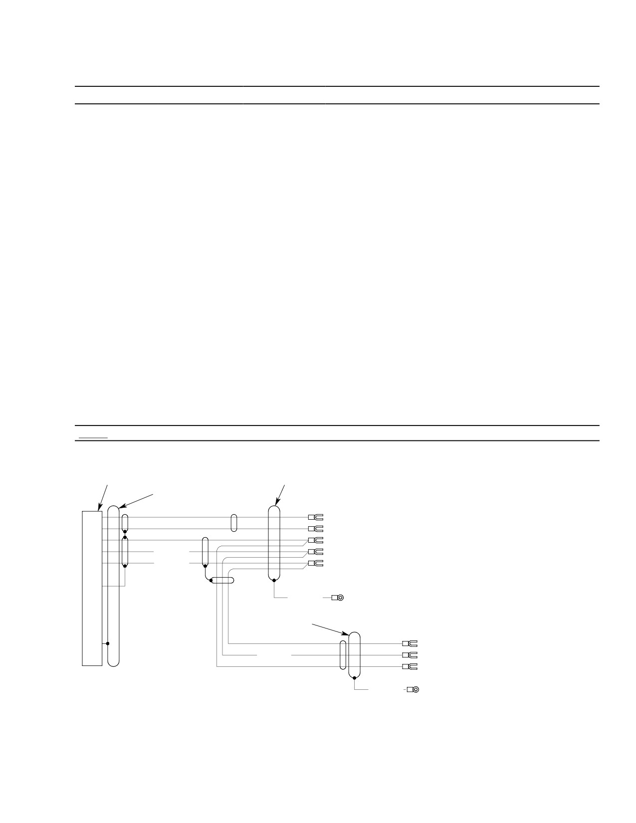
Figure 101. Fuel Quantity System Wiring Diagram
Page 103
28-00-60
Revision 21
CSP-HMI-2
MD Helicopters, Inc.
MAINTENANCE MANUAL
This Page Intentionally Left Blank
Page 104
Revision 44
28-00-60

MD Helicopters, Inc.
CSP-HMI-2
MAINTENANCE MANUAL
FUEL SYSTEM
MAINTENANCE PRACTICES
1.
Fuel Cell Cleaning − General
(2). If a fuel cell that has previously
contained fuel is to be stored for longer
(1). Fuel cells are susceptible to fungus
than three days, coat inside of cell with
growth after contact with contaminated
a light coating of #10 weight, non-syn
fuel. Fungus trapped in the fuel filters
thetic engine oil.
indicates fuel tank contamination.
Remove, inspect, clean or replace filter
CAUTION
elements per applicable Allison Engine
Operation and Maintenance Manual.
D Engineered Fabrics Corp. cells removed
Where installed, service anti-ice
from service must not be left dry for more
(airframe) filter (Ref. Sec. 28-25-00).
than 3 days without the application of oil
as a plasticizing agent. The cell liner will
(2). Periodic incorporation of an FAA
loose pliability if left dry for extended pe
approved anti-fungal fuel additive will
riods and subsequent flexing may cause
kill and prevent new fungus growth.
the material to crack.
D Do not work on fuel cell in ambient tem
2.
Engineered Fabrics Corp. Fuel Cell
peratures below 70°F (21°C).
Cleaning
(a). Fold cell over protective wadding as
Do not steam clean Engineered
loosely as possible and with a mini
CAUTION
Fabrics Corp. fuel cells. Steam
mum number of folds.
cleaning may cause irreparable damage.
(b). Wrap the cell in a protective cover.
(1). Clean cell exterior and interior surfaces
(c). Put cell in a suitable storage/ship
with warm soapy water and clean lint
ping container. Use wadding as
free cloth. Rinse away all soap residue
required to prevent movement. Do
and wipe dry.
not stuff cell into an undersized
container.
3. Fuel Cell Handling, Storage and Shipping
(d). Store cell at 70°F (21°C) away from
Do not use cell fittings as hand
sunlight and moisture.
CAUTION
holds. Do not store fuel cells un
5.
Fuel System Air Bleed (Model 250−C47
crated or exposed to direct sunlight, ozone,
Engine Installation)
dirt, moisture, solvents, chemicals, or ex
tremes of heat and humidity.
Fuel/air vapor discharged
WARNING
during bleeding is a fire haz
(1). Store and ship cells in a suitable
ard. Prevent fuel vapor accumulation,
protective container.
ignition and fire. Perform work in an
open, well ventilated area away from
(a). Apply protective tape over all cell
all potential ignition sources. Attach
machined fittings.
helicopter to an approved electrical
ground. Wear approved eye protection.
(b). Use packing material to keep the cell
from shifting in transit.
(1). Helicopters with C47 engines and
standard fuel supply systems are not
(c). Suspended self-sealing cells to
equipped with a start pump.
maintain cell shape.
(2). Helicopters equipped with an airframe
4. Fuel Cell Preservation and Storage
mounted fuel filter are equipped with
(Engineered Fabrics Corp. Cells)
an airframe mounted fuel pump inside
the left fuel cell and can be primed
(1). Thoroughly clean cell with warm soapy
using the same procedure as helicopters
water. Wipe completely dry.
with the 250-C20 Series engines.
Page 201
28-00-60
Revision 32
CSP-HMI-2
MD Helicopters, Inc.
MAINTENANCE MANUAL
(3). The standard helicopter fuel system
(e). Open fuel shutoff valve.
only has an engine driven self priming
(f). Open throttle to ground idle position.
pump that will fill the fuel system when
the engine is motored with the starter.
(g). Squeeze primer bulb until fuel comes
Motor engine per the appropriate Pilot's
out of fuel line.
Flight Manual.
NOTE: When reinstalling fuel lines, refer to ap
(4). Bleed air out of helicopter engine fuel
propriate Rolls-Royce Operation and Main
controls per Rolls-Royce Engine
tenance Manual for proper torques.
Operation and Maintenance Manual.
(h). Remove primer bulb assembly from
(5). If fuel system fails to bleed properly,
fuel line and reconnect fuel line to
proceed as follows:
HMU.
(a). Field fabricate a primer bulb assem
(i). Crank engine for approximately 15
bly (Ref. Figure 201).
seconds to verify fuel to fuel nozzle is
free of air in the system.
(b). Disconnect fuel line between CEFA
and HMU at HMU side.
(j). Repeat above procedure as required.
(c). Disconnect fuel line from fuel nozzle.
(k). Reinstall fuel line to fuel nozzle.
(d). Install primer bulb assembly in line
(l). Close throttle.
between HMU GEAR INLET and the
CEFA.
(m). Close fuel shutoff valve.
CLAMPS
BULB PRIMER 5/16
AN807-8 ADAPTER
SEASIDE #73800
AN818-8 NUT
TYGON-TYPE TUBING
(FUEL RESISTANT)
FUEL SYSTEM BLEEDING TOOL
(FIELD FABRICATE)
6G28-076
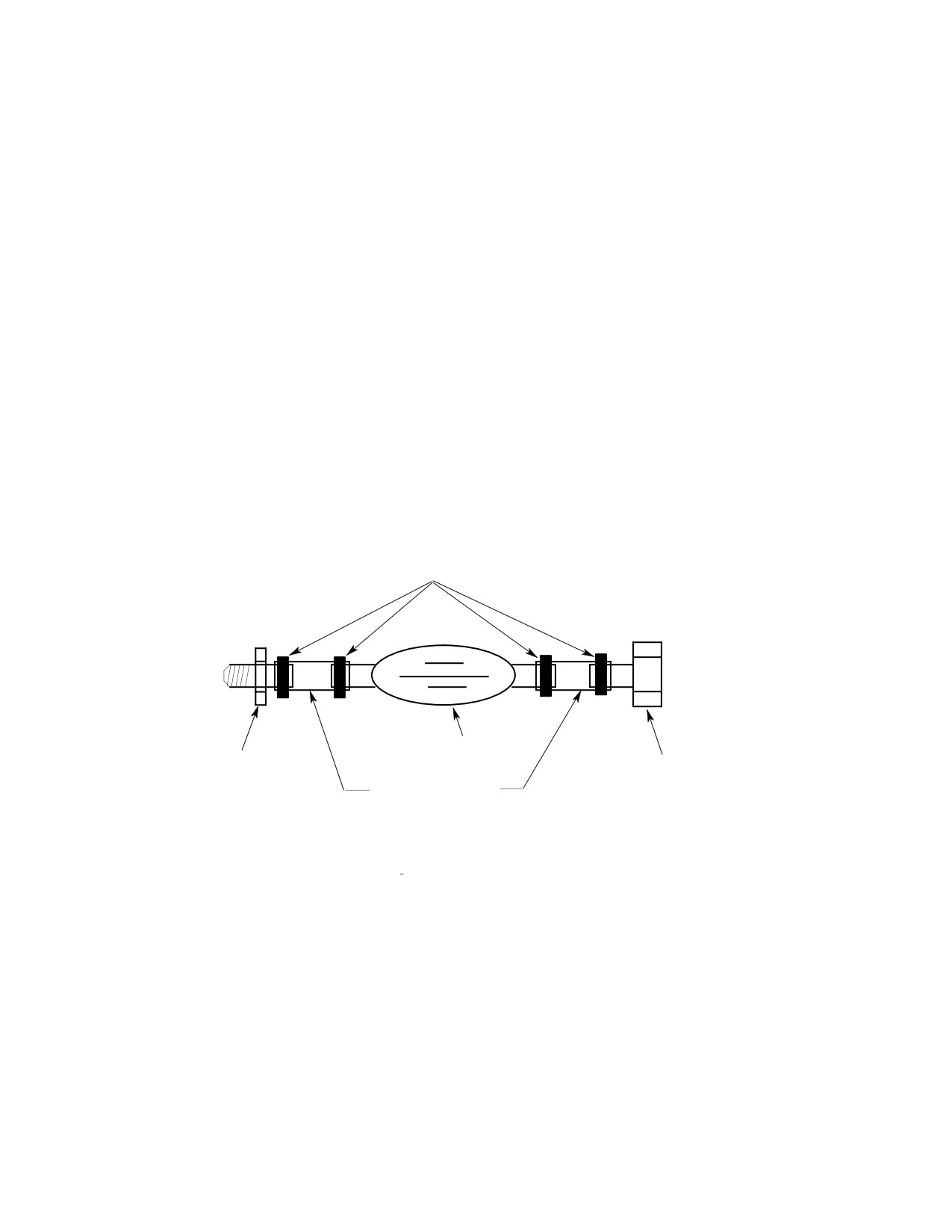
Figure 201. Field Fabricated Fuel System Bleeding Tool
Page 202
Revision 39
28-00-60
MD Helicopters, Inc.
CSP-HMI-2
MAINTENANCE MANUAL
FUEL SYSTEM
REMOVAL/INSTALLATION
1. Fuel Shutoff Valve Control Cable
and grommets to fuel shutoff valve.
Replacement
Maintain a cable bend radius greater
than 3.5 inches (8.89 cm).
A. Fuel Shutoff Valve Control Cable
Removal
(2). Secure forward end of cable in instru
ment panel with lockwasher and
(Ref. Figure 401)
jamnut.
(1). Remove left aft access panel from
(3). Slip control cable wire through fuel
passenger/cargo compartment floor.
shutoff valve lever swivel.
(2). Disconnect control cable from fuel
shutoff valve swivel.
(4). Secure end of cable housing to cell cover
with a clamp, washer and screw.
(3). Remove control cable ty-raps and
clamps.
(5). Install remaining clamps and ty-raps.
(4). Remove instrument panel left fairing
(6). Rig cable with shutoff valve lever hard
and lower cover panels.
against open stop. Adjust cable to get a
0.090 - 0.150 inch (2.29 - 3.81 mm) gap
(5). Completely back jamnut away from
between bottom of control knob and
cable plunger housing (Ref. Figure 401,
cable housing end fitting. Tighten cable
view A).
swivel pinch nut. Install cotter pin.
NOTE: Attach a trace wire or cord to the valve
Control action must move valve
end of the cable before pulling assembly out
CAUTION
to full open against mechanical
of the instrument panel. Trace will guide re
stop without bottoming control knob on
placement cable into correct position.
cable housing. Control cable operation shall
(6). Pull cable assembly out through
be smooth with no binding.
washer, jamnut and instrument panel.
(7). Pull valve control knob out with a
B. Fuel Shutoff Valve Control Cable
spring scale. Required valve actuation
Installation
force not to be more than 12 pounds
(5.443 kg).
(Ref. Figure 401)
(8). Repair, adjust or replace valve control
Pulling detent knob out of cable
CAUTION
system components to meet force limit.
housing two or more inches may
result in loss of the detent ball.
(9). Install left aft fuel cell access panel
(1). Thread cable assembly aft through
from passenger/cargo compartment
instrument panel, lockwasher, jamnut
floor.
Page 401
28-00-60
Revision 19
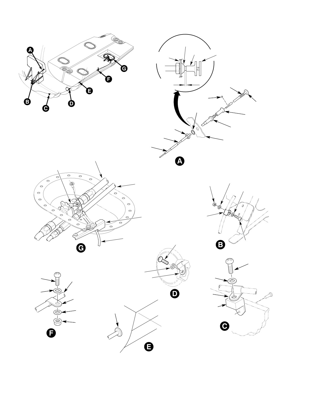
CSP-HMI-2
MD Helicopters, Inc.
MAINTENANCE MANUAL
PLUNGER
HOUSING
CABLE
PLUNGER
DETENT
INSTRUMENT
RELEASE
PANEL
0.090-0.150 INCH
(2.29-3.81 MM)
SPRING
DETENT
BALL
DETENT
RELEASE
LOCKWASHER
CABLE
PLUNGER
PLUNGER
NUT
HOUSING
HOL
INSTRUMENT
E
PANEL
CABLE
HOUSING
ENGINE FEED HOSE SHUTOFF
VALVE TO FIREWALL
CONTROL KNOB ASSEMBLY
FUEL SHUTOFF
VALVE
MOTIVE FLOW HOSE
WASHER
NUT
FIREWALL TO FUEL CELL
WASHER
SUPPORT
CLAMP
BRACKET
FUEL SHUTOFF
CABLE
SCREW
SCREW
SCREW
WASHER
SCREW
CABLE
CLAMP
WASHER
HOUSING
WASHER
CLAMP
CLAMP
BRACKET
WASHER
GROMMET
NUT
PLUG STA
0.000
6G28-021A
Figure 401. Fuel Shutoff Valve Cable Installation
Page 402
Revision 19
28-00-60
MD Helicopters, Inc.
CSP-HMI-2
MAINTENANCE MANUAL
2. Fuel Shutoff Valve Replacement
(6). Unclamp and disconnect control cable
from fuel shutoff valve (Ref. Fuel
Avoid fuel vapor ignition
Shutoff Valve Control Cable Replace
WARNING
and fire. Use only nonspark
ment).
ing tools and explosion proof work
lights. Attach helicopter to an ap
Handle fuel cell cover with care.
CAUTION
proved electrical ground. Switch OFF
Prying cover from cell opening
all electrical power. Disconnect exter
or rough handling may damage seal or cell
nal power and battery before opening
fitting.
fuel system. Ensure work area is ade
(7). Unbolt cell access cover. Prop cover
quately ventilated.
open with suitably padded blocks.
CAUTION
(8). Using a backup wrench on valve,
separate engine feed fuel cell supply
D Air in fuel system may cause power
hose from fuel shutoff valve.
surges or flameout. Bleed off trapped air
after opening system at any point be
(9). Remove fuel shutoff valve attaching
tween fuel tank and engine fuel nozzle.
hardware.
D Prevent fuel system contamination. In
B. Fuel Shutoff Valve Installation
stall caps on the ends of hoses, tubes and
fittings as parts are removed. Bag and
(Ref. Figure 402)
identify small parts to prevent loss or
damage.
Consumable Materials
(1). Defuel helicopter. Drain remaining fuel
(Ref. Section 91−00−00)
from cell sump drain valve into a
Item
Nomenclature
suitable container.
CM114
Petrolatum
(2). Disconnect electrical power.
(1).
Apply a coating of petrolatum (CM114)
A. Fuel Shutoff Valve Removal
to a new fuel shutoff valve/cover
(Ref. Figure 402)
sealwasher.
(1). Remove left aft fuel cell access panel
(2).
Install fuel shutoff valve with seal
from passenger/cargo compartment
washer and nut. Use a backup wrench
floor.
on shutoff valve so it will not rotate.
Torque nut 240 - 280 inch-pounds
(2). Disconnect fuel quantity probe wire
(27.12 - 31.64 Nm).
harness connector from cell cover
receptacle.
(3).
Connect engine feed fuel supply hose to
fuel shutoff valve. Using a backup
(3). Unfasten and remove Sta. 91.00 and
wrench on valve, torque fuel supply
102.00 left aft fuel cell cover support
hose 230 - 260 inch-pounds (25.99 -
brackets.
29.38 Nm).
(4). Disconnect motive flow fuel hose
(4).
Start bolts onto aft fuel cell access
assembly between Sta 124.00 bulkhead
cover.
and fuel cell access cover. Use backup
wrench on check valve so it will not
(5).
Install and fasten Sta. 91.00 and 102.00
rotate.
left fuel cell cover support brackets.
(5). Disconnect engine feed fuel supply hose
(6).
Connect engine feed fuel supply hose
assembly between fuel shutoff valve
assembly between fuel shutoff valve
and Sta. 124.00 bulkhead. Use backup
and Sta. 124.00 bulkhead. Torque hose
wrench on fuel shutoff valve so it will
assembly 230 - 260 inch-pounds
not rotate.
(25.99 - 29.38 Nm).
Page 403
28-00-60
Revision 19
CSP-HMI-2
MD Helicopters, Inc.
MAINTENANCE MANUAL
CAP
ENGINE FEED HOSE
SHUTOFF
SHUTOFF VALVE TO FIREWALL
BULKHEAD
VALVE
UNION
MOTIVE FLOW HOSE
FIREWALL TO FUEL CELL
BOL
SEALING
SEALING
T
WASHER
WASHER
WASHER
SCREW
SCREW
WASHER
WASHER
REF.
REF.
NUT
CARGO FLOOR
CARGO FLOOR
STRUCTURE
STRUCTURE
WASHER
BRACKET
BRACKET
ASSEMBLY
ASSEMBLY
BOLT
WIRE
WASHER
HARNESS
RECEPTACLE
NUT
ACCESS COVER
FUEL INLET
BOLT
HOSE ASSEMBLY
WASHER
WASHER
SEALING WASHER
NUT
SUBMERGED
SEALING
MOTIVE FLOW
WASHER
BULKHEAD
HOSE ASSEMBLY
ELBOW
REF. CARGO
FLOOR STRUCTURE
CHECK
VALVE
BOLT
WASHERS
BRACKET
ASSEMBLY
WASHER
NUT
FUEL CELL SCAVENGE
BRACKET ASSEMBLY
HOSE ASSEMBLY
6G28-022
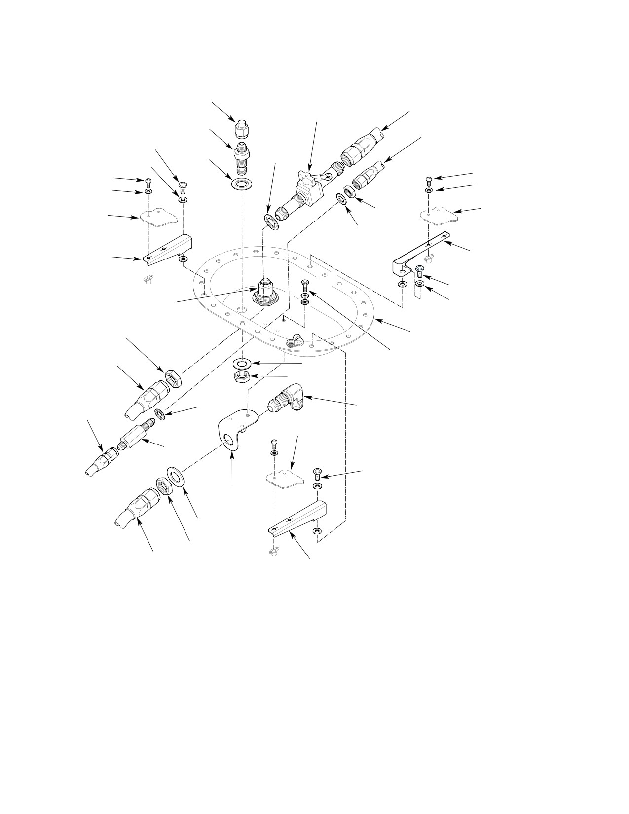
Figure 402. Fuel Shutoff Valve and Fuel Cell Cover Installation
Page 404
Revision 19
28-00-60
MD Helicopters, Inc.
CSP-HMI-2
MAINTENANCE MANUAL
(7). Connect motive flow fuel hose assembly
(a). Remove right side floor panels from
between Sta 124.00 bulkhead and fuel
passenger/cargo compartment floor.
tank access cover. Torque hose assem
(b). Remove bonding jumpers then
bly 55 - 65 inch-pounds (6.21 - 7.34
remove fuel cell access cover bolts
Nm).
and washers.
(8). Connect fuel quantity transmitter
(2). To remove left aft fuel cell access cover
connector from cell cover receptacle.
(Ref. Figure 402):
(9). Progressively torque fuel cell cover
(a).
Remove left aft fuel cell access panel
bolts to 70 - 90 inch-pounds (7.91 -
from passenger/cargo compartment
10.17 Nm) in a cross pattern.
floor.
(10). Clamp and connect control cable to fuel
(b).
Unclamp and disconnect control
shutoff valve. Rig fuel shutoff valve
cable from fuel shutoff valve (Ref.
control cable (Ref. Fuel Shutoff Valve
Figure 401).
Control Cable Replacement).
(c).
Disconnect engine feed fuel supply
(11). Install left aft access passenger/cargo
hose assembly between fuel shutoff
compartment floor panel.
valve and Sta. 124.00 bulkhead. Use
backup wrench on fuel shutoff valve
so it will not rotate.
3. Fuel Cell Cover Replacement
(d).
Disconnect motive flow fuel hose
Avoid fuel vapor ignition
WARNING
assembly between Sta 124.00 bulk
and fire. Use only nonspark
head and fuel cell access cover.
ing tools and explosion proof work
lights. Attach helicopter to an ap
(e).
Disconnect fuel quantity probe wire
proved electrical ground. Switch OFF
harness connector from fuel cell cover
all electrical power. Disconnect exter
receptacle.
nal power and battery before opening
fuel system. Ensure work area is ade
(f).
Unfasten and remove Sta. 91.00 and
quately ventilated.
102.00 left aft fuel cell cover support
brackets.
CAUTION
(g).
Remove cover bolts and washers.
Prop cover open with suitably padded
D Air in fuel system may cause power
blocks.
surges or flameout. Bleed off trapped air
after opening system at any point be
(h).
Using a backup wrench on valve,
tween fuel tank and engine fuel nozzle.
separate engine feed fuel cell supply
hose from fuel shutoff valve and fuel
D Prevent fuel system contamination. In
inlet from fuel cell access cover.
stall caps on the ends of hoses, tubes and
fittings as parts are removed. Bag and
(i).
Disconnect submerged motive flow
identify small parts to prevent loss or
fuel hose assembly between fuel
damage.
check valve and ejector pump from
fuel cell access cover.
(1). Defuel helicopter. Drain remaining fuel
from cell sump drain valve into a
(j).
Disconnect fuel cell scavenge hose
suitable container.
assembly from bottom of fuel cell
access cover bracket assembly to
(2). Disconnect electrical power.
ejector pump (Ref. Figure 404).
A. Fuel Cell Cover Removal
(k).
Cut safety wire from fuel probe
electrical connector base nut and
(1). To remove right side fuel cell access
remove connector from fuel cell
covers (Ref. Figure 406).
access cover.
Page 405
28-00-60
Revision 19
CSP-HMI-2
MD Helicopters, Inc.
MAINTENANCE MANUAL
(l). If applicable, remove fuel cell scav
jamnut to 240 - 280 inch-pounds
enge hose bracket assembly,bulkhead
(27.12 - 31.64 Nm).
union and fuel shutoff valve from fuel
(d). Install support bracket to cover with
cell cover.
bolts, washer, and sealwashers.
Apply a coating of petrolatum
B. Fuel Cell Cover Installation
(CM114) to sealwasher. Torque bolts
36 - 46 inch-pounds (4.06 - 5.19
Consumable Materials
Nm).
(Ref. Section 91−00−00)
(e). Install bulkhead union to cover with
Item
Nomenclature
sealwasher next to union. Apply a
CM114
Petrolatum
coating of petrolatum (CM114) to
sealwasher. Install washer and
CM124
Kerosene
jamnut. Torque jamnut to 120 - 150
CM702
Lockwire CRES
inch-pounds (13.56 - 16.95 Nm).
Install cap outside of cell. Torque cap
to 110 - 130 inch-pounds (12.43 -
(1). Wipe fuel cell and cover sealing sur
14.69 Nm).
faces clean with kerosene (CM124) on a
clean lint free cloth.
(5). Place left forward fuel cell access cover
into position on fuel cell.
(2). Inspect fuel cell cover seals for debond
(6). Connect fuel quantity probe wire
ing, nicks or cuts and any other damage
harness connector to cell cover. Torque
having a leak producing potential.
connector jamnut and safetywire to
Replace covers or left aft cover as
bulkhead union with (CM702) lockwire.
required.
CAUTION
(3). Install bonding jumper with right cell
access covers, bolts and washers (Ref.
D On early aircraft, the fuel inlet hose and
Figure 406). Progressively torque cover
the fuel cell scavenge hose have the same
bolts to 70 - 90 inch-pounds (7.91 -
size end fitting. Care must be taken to not
10.17 Nm) in a cross pattern.
misconnect these two hoses
(Ref.
Figure 404).
(4). To install left aft fuel cell access cover
D The fuel inlet hose is the hose that runs
(Ref. Figure 402):
from the fuel inlet fitting at the bottom of
the fuel cell aft of the fuel cell baffle.
(a). Apply a coating of petrolatum
(CM114) to a new fuel shutoff valve/
D The fuel cell scavenge hose is the hose
cover sealwasher. Install valve on cell
that runs forward over the fuel cell baffle.
cover with sealwasher next to valve
(7). Install left hand fuel inlet hose assem
body and valve properly aligned to
bly to access cover fuel shutoff valve.
make connection with valve control
Torque hose assembly 230 - 260
cable. Install and torque valve
inch-pounds (25.99 - 29.38 Nm).
jamnut to 240 - 280 inch-pounds
(27.12 - 31.64 Nm).
(8). Install submerged motive flow hose
assembly to access cover check valve.
(b). Apply a coating of petrolatum
Torque hose assembly 50 - 65 inch-
(CM114) to sealwasher. Install check
pounds (5.65 - 7.34 Nm).
valve and sealwasher to inside cover
(9). Install scavenge fuel cell hose assembly
and a plain washer outside. Install
to access cover bulkhead elbow. Torque
jamnut and torque to 85 - 105
hose assembly 230 - 260 inch-pounds
inch-pounds (9.6 - 11.86 Nm).
(25.99 - 29.38 Nm).
(c). Install bulkhead elbow to support
(10). Install three support brackets on Sta.
bracket. with washer and nut. Torque
91.00 and 102.00 floor cross-members
Page 406
Revision 34
28-00-60
MD Helicopters, Inc.
CSP-HMI-2
MAINTENANCE MANUAL
with washers and screws. Torque
(1). Defuel helicopter. Drain remaining fuel
screws to 20 - 25 inch-pounds (2.26 -
from tank sump drain valve into a
2.82 Nm).
suitable container.
(11).
Install cover bolts and washers.
(2). Cap fittings and lines as required.
Progressively torque cover bolts to 70 -
A. Fuel Supply Lines Removal
90 inch-pounds (7.91 - 10.17 Nm) in
a cross pattern.
(Ref. Figure 402, Figure 403 and Figure 404)
(12).
Connect engine feed fuel supply hose to
(1). Remove left aft fuel cell access panel
fuel shutoff valve. Torque hose nut to
from passenger/cargo compartment
230 - 260 inch-pounds (25.99 - 29.38
floor.
Nm).
(2). Disconnect motive flow fuel hose
assembly between Sta 124.00 bulkhead
(13).
Connect fuel motive flow hose to access
and fuel cell access cover. Use backup
cover/check valve. Torque hose nut (50
wrench so fittings will not rotate.
- 65 inch-pounds (5.65 - 7.34 Nm).
(3). Disconnect engine feed fuel supply hose
(14).
Connect fuel quantity probe connector
assembly between fuel shutoff valve
to wire harness receptacle.
and Sta. 124.00 bulkhead. Use backup
(15).
Slip control cable through hole in fuel
wrench on fittings so they will not
shutoff valve lever swivel.
rotate.
(4). Remove Sta. 91.00 and Sta.102.00 fuel
(16).
Rig cable control system (Ref. Fuel
cell cover support brackets.
Shutoff Valve Control Cable Replace
ment).
(5). Remove clamps and attaching hard
ware from passenger/cargo compart
(17).
Apply a torque alignment stripe to fuel
ment floor.
line tube, hose and fitting fasteners.
(6). Remove engine feed fuel supply hose
(18).
Install access panels on passenger
and motive flow fuel hose assemblies.
cargo compartment floor.
(7). Remove Sta. 124.00 bulkhead unions.
4. Fuel Supply Lines Replacement
B. Fuel Supply Lines Installation
Avoid fuel vapor ignition
WARNING
(Ref. Figure 402, Figure 403 and Figure 404)
and fire. Use only nonspark
ing tools and explosion proof work
(1). Install Sta. 124.00 firewall bulkhead
lights. Attach helicopter to an ap
unions, with washer and jam nut on
proved electrical ground. Switch OFF
forward side of firewall. Torque engine
all electrical power. Disconnect exter
feed fuel supply union nut to 240 - 280
nal power and battery before opening
inch-pounds (27.12 - 31.64 Nm).
fuel system. Ensure work area is ade
Torque fuel return by-pass union to 85
quately ventilated.
- 105 inch-pounds (9.60- 11.86 Nm).
(2). Connect fuel cell engine feed supply
CAUTION
hose to fuel shutoff valve and bulkhead
union. Use a backup wrench on valve
D Air in fuel system may cause power
and bulkhead union. Torque fuel supply
surges or flameout. Bleed off trapped air
hose 230 - 260 inch-pounds (25.99 -
after opening system at any point be
29.38 Nm).
tween fuel tank and engine fuel nozzle.
D Prevent fuel system contamination. In
(3). Connect motive flow fuel hose assembly
stall caps on the ends of hoses, tubes and
between Sta 124.00 bulkhead and fuel
fittings as parts are removed. Bag and
tank access cover. Torque hose assem
identify small parts to prevent loss or
bly 50 - 65 inch-pounds (5.65 - 7.34
damage.
Nm).
Page 407
28-00-60
Revision 34
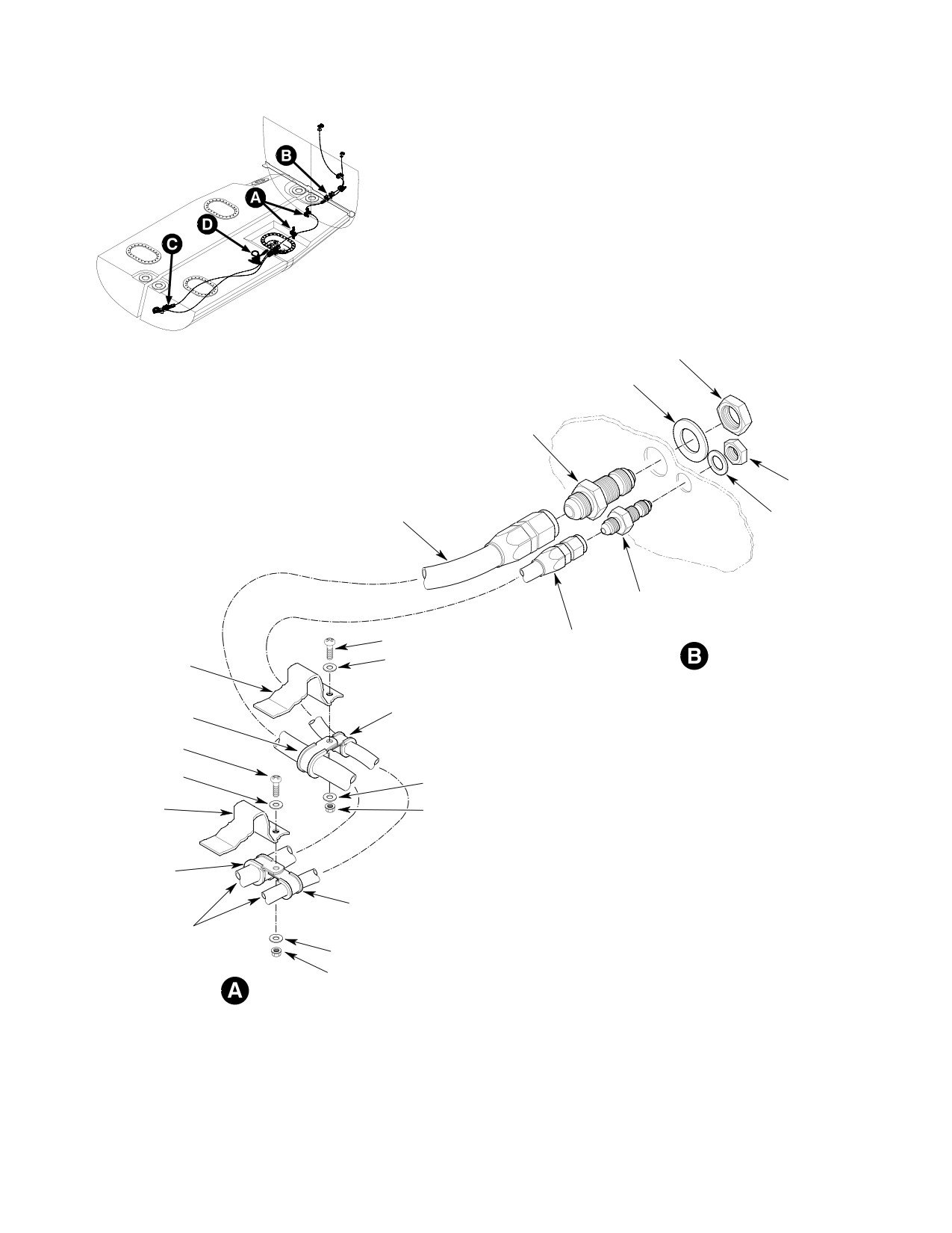
CSP-HMI-2
MD Helicopters, Inc.
MAINTENANCE MANUAL
NUT
WASHER
BULKHEAD
UNION
NUT
ENGINE FEED HOSE
SHUTOFF VALVE TO FIREWALL
WASHER
BULKHEAD
UNION
SCREW
MOTIVE FLOW HOSE
REF. STA 113.85
FIREWALL TO FUEL CELL
WASHER
CARGO FLOOR
CLAMP
CLAMP
SCREW
WASHER
WASHER
REF. STA 102.23
CARGO FLOOR
NUT
CLAMP
CLAMP
REF. TO FUEL CELL
COVER
WASHER
NUT
6G28-024-1
Figure 403. Fuel Lines Installation
Page 408
Revision 19
28-00-60
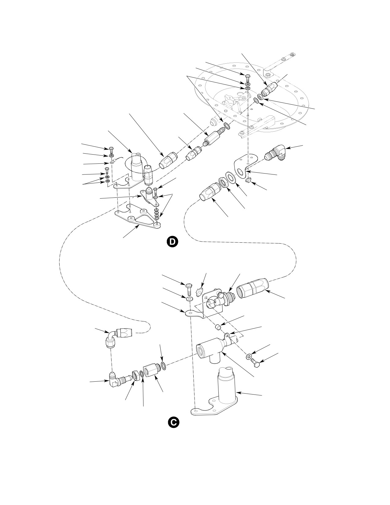
MD Helicopters, Inc.
CSP-HMI-2
MAINTENANCE MANUAL
HOSE ASSEMBLY
BOLT
WASHER
SEALING WASHER
FUEL INLET
SUPPLY HOSE
CHECK
ASSEMBLY
VALVE
NUT
AFT FUEL
SUBMERGED
PROBE
MOTIVE FLOW
WASHER
HOSE ASSEMBLY
BOLT
BULKHEAD ELBOW
WASHER
BONDING
JUMPER
BOLT
BOLT
BRACKET
ASSEMBLY
WASHER
FUEL INLET
WASHERS
NUTPLATE
WASHER
FITTING ASSEMBLY
NUT
FUEL CELL SCAVENGE
HOSE ASSEMBLY
BRACKET ASSEMBLY
EJECTOR
NUTPLATE
PUMP
BOLT
WASHER
EJECTOR
FUEL CELL
BRACKET ASSEMBLY
SCAVENGE
HOSE ASSEMBLY
SPACER
SUBMERGED
MOTIVE FLOW
CLAMP
HOSE ASSEMBLY
O-RING
WASHER
BOLT
EJECTOR PUMP
ELBOW
REDUCER
FORWARD
BUSHING
FUEL PROBE
NUT
O-RING
6G28-024-2
Figure 404. Ejector Pump and Fuel Lines Installation
Page 409
28-00-60
Revision 19
CSP-HMI-2
MD Helicopters, Inc.
MAINTENANCE MANUAL
(4). Apply a torque alignment stripe to fuel
A. Fuel Cell Vent System Components
line tube, hose and fitting fasteners.
Removal
(Ref. Figure 405)
(5). Apply chaffing tape between hose
assemblies and fuel cell cover assembly
(1).
Remove fuel vent cross over tube access
to prevent chaffing.
cover and Sta.78.50 chanted bulkhead
stress panel.
(6). Secure engine feed hose assembly and
motive flow hose assembly underneath
(2).
Remove flame arrestor/tube assembly
passenger/cargo floor with clamps and
with clamps and attaching hardware.
attaching hardware.
(3).
Disconnect hoses from vent cross-over-
(7). Secure fuel cell to Sta. 91.00 and
tube and attaching hardware and
Sta.102.00 cell cover support brackets.
remove crossover tube.
(8). Install aft fuel cell access panel from
(4).
Remove passenger/cargo compartment
passenger/cargo compartment floor.
floor fuel cell access panels.
(5).
Disconnect hoses from aft fuel vent
5. Fuel Cell Vent System Components
valves, remove bonding jumper and
Replacement
attaching hardware from vent tubes
and remove fuel vent tubes from under
Avoid fuel vapor ignition
cargo floor.
WARNING
and fire. Use only nonspark
ing tools and explosion proof work
(6).
Remove bonding jumper and fell cell
lights. Attach helicopter to an ap
access covers as required.
proved electrical ground. Switch OFF
all electrical power. Disconnect exter
(7).
Remove retaining ring and spring from
nal power and battery before opening
fuel vent valve and remove fuel vent
fuel system. Ensure work area is ade
valve from inside of fuel cell.
quately ventilated.
B. Fuel Cell Vent System Components
Prevent fuel system contamina
Installation
CAUTION
tion. Install caps on the ends of
(Ref. Figure 405)
hoses, tubes and fittings as parts are re
moved. Bag and identify small parts to pre
vent loss or damage.
Consumable Materials
(Ref. Section 91−00−00)
(1). Defuel helicopter. Drain remaining fuel
Item
Nomenclature
from tank sump drain valve into a
CM114
Petrolatum
suitable container.
CM411
Adhesive, epoxy
(2). Disconnect electrical power.
CM702
Lockwire CRES
Prevent spontaneous com
(1). Coat O-rings with (CM114) lubricant
WARNING
bustion or explosion. Never
and install on vent valves.
use oxygen to purge or ventilate fuel
tank or fuel system components. Fuel,
(2). Insert vent valves thru cell from inside
either vapor or liquid, will violently
and secure using springs and retainers.
react with an oxygen rich atmosphere.
(3). Bond prep aft vent fittings at bond
(3). Ventilate fuel tank with an inert gas,
jumper location.
such as nitrogen, or low pressure
compressed air applied through filler
(4). Coat O-rings with lubricant (CM114)
neck.
and install on vent fittings.
Page 410
Revision 19
28-00-60
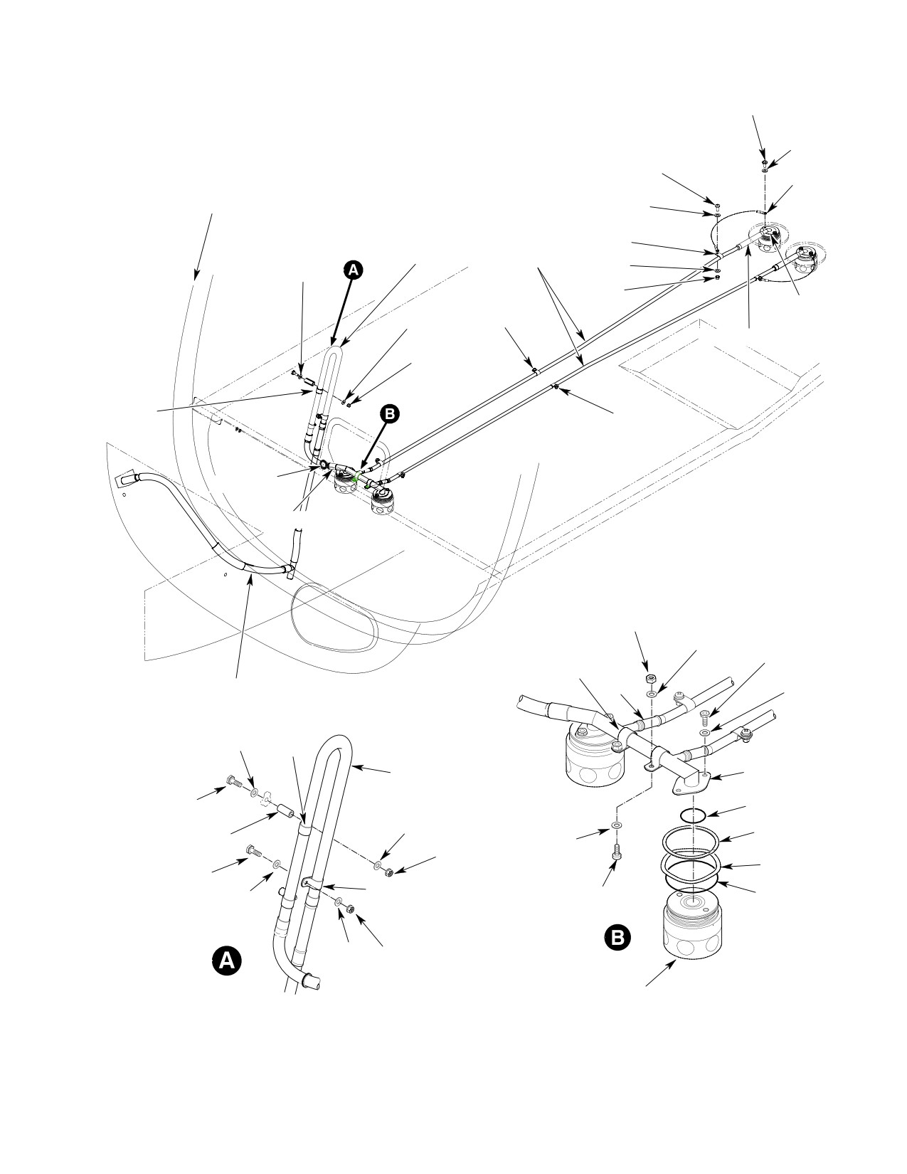
MD Helicopters, Inc.
CSP-HMI-2
MAINTENANCE MANUAL
BOLT
WASHER
SCREW
BONDING
REF. FS 78.50
JUMPER
CANTED BULKHEAD
WASHER
FLAME
CLAMP
BOLT
VENT
WASHER
ARRESTOR
TUBE
WASHER
(3 PLCS)
CLAMP
SCREW
NUT
WASHER
VENT
WASHER
NUT
FITTING
(3 PLCS)
TUBE ASSEMBLY
NUT
(3 PLCS)
CLAMP
CLAMP
SCREW
(3 PLCS)
WASHER
NUT
GROMMET
CONNECTOR
NUT
(2 PLCS)
WASHER
(2 PLCS)
BOLT
CLAMP
(2 PLCS)
(2 PLCS)
HOSE
WASHER
(2 PLCS)
(2 PLCS)
TUBE ASSEMBLY
WASHER
CLAMP
(2 PLCS)
(2 PLCS)
FLAME
ARRESTOR
CROSSOVER
(2 PLCS)
ASSY
BOLT (2 PLCS)
0-RING
WASHER
(2 PLCS)
RETAINING
SPACER
NUT
RING (2 PLCS)
WASHER
(2 PLCS)
(2 PLCS)
(2 PLCS)
SPRING
BOLT
RETAINER
CLAMP
0-RING
WASHER
PIN (2 PLCS)
WASHER
NUT
VENT VALVE
(2 PLCS)
Figure 405. Fuel Cell Vent System Components
Page 411
28-00-60
Revision 19
CSP-HMI-2
MD Helicopters, Inc.
MAINTENANCE MANUAL
(5).
Install aft vent fittings and bond
(21). Safety connector to cross-over tube
jumpers to vent valves with hardware.
with lockwire (CM702).
Torque bolts to 36 - 46 inch-pounds
(22). Tie-rap tube assembly to forward
(4.0 - 5.2 Nm).
bulkhead of Sta. 78.50.
(6).
Bond prep six vent tube clamp screw
(23). Route tube assembly to vent fairing and
holes on cargo deck.
bond using sealant (CM425).
(7).
Install hoses to aft vent fittings with
(24). Bond prep fuel cell access covers.
lockwire (CM702), two wrap around
turns minimum.
(25). Install bonding jumpers and fell cell
access covers. Torque bolts 70 - 90
(8).
Slide vent tubes under cargo floor and
inch-pounds (7.91 - 10.17 Nm).
connect to hoses with lockwire
Install fuel vent access cover.
(CM702), two wrap around turns
minimum.
(26). Install passenger/cargo compartment
floor access panels.
(9).
Attach forward end of tube to cargo
floor with clamps.
6. Fuel Cell Replacement
Avoid fuel vapor ignition
(10).
Install bonding jumpers at aft clamps.
WARNING
and fire. Use only nonspark
(11).
Install hoses on forward ends of vent
ing tools and explosion proof work
tubes and safety using lockwire
lights. Attach helicopter to an ap
(CM702), two wrap around turns
proved electrical ground. Switch OFF
minimum.
all electrical power. Disconnect exter
nal power and battery before opening
(12).
Coat O-rings with lubricant (CM114)
fuel system. Ensure work area is ade
and install on cross-over tube.
quately ventilated.
(13).
Attach vent cross-over tube with
CAUTION
hardware to tops of vent valves. Torque
bolts to 36 - 46 inch-pounds (4.06 -
D Do not work on cell in ambient tempera
5.19 Nm).
tures below 70°F (21°C).
(14).
Bond prep two nutplate holes for
D Prevent fuel system contamination. In
attaching cross-over tube.
stall caps on the ends of hoses, tubes and
fittings as parts are removed. Bag and
(15).
Install clamps on cross-over tube and
identify small parts to prevent loss or
attach to airframe.
damage.
(16).
Install grommet in Sta. 78.50 skin at
(1). Defuel helicopter. Drain remaining fuel
vent outlet using epoxy adhesive
from tank sump drain valve into a
(CM411).
suitable container.
(2). Disconnect electrical power.
(17).
Attach connector to the flame arrestor
and safety with lockwire (CM702), two
A. Fuel Cell Removal
wrap around turns minimum.
(Ref. Figure 406)
(18).
Attach tube to flame arrestor and
safety with lockwire (CM702) two wrap
NOTE: The following procedures are required
around turns minimum.
to access and separate the fuel cell intercon
nect fitting, vent system and gravity fill port
(19).
Bond prep one of the three attaching
before either cell can be removed from its
screw holes for the flame arrestor.
bay.
(20).
Install flame arrestor/tube assembly
(1). Remove forward fuel vent crossover
with clamps.
tube cover, right and left fuel cell access
Page 412
Revision 19
28-00-60
MD Helicopters, Inc.
CSP-HMI-2
MAINTENANCE MANUAL
panels from passenger/cargo compart
(11). Disconnect submerged fuel cell scav
ment floor.
enge hose assembly from bottom of fuel
cell access cover bracket assembly to
(2).
Disconnect fuel quantity probe wire
ejector pump (Ref. Figure 404).
harness connector from fuel cell access
(12). Cut safety wire from fuel probe electri
cover receptacle.
cal connector base nut and remove
connector from fuel cell access cover.
(3).
Unclamp and disconnect control cable
from fuel shutoff valve.
(13). Unbolt and remove right hand fuel cell
access cover(s) and bonding jumpers.
(4).
Unfasten and remove Sta. 91.00 and
Remove left hand forward fuel cell
102.00 left fuel cell cover support
access cover.
brackets from passenger/cargo floor
structure (Ref. Figure 402).
Prevent spontaneous com
WARNING
bustion or explosion. Never
(5).
Remove attaching hardware from Sta
use oxygen to purge or ventilate fuel
102.230 and Sta 113.850 passenger/car
tank or fuel system components. Fuel,
go compartment floor structure that
either vapor or liquid, will violently
secures engine feed fuel supply hose
react with an oxygen rich atmosphere.
and motive flow firewall to fuel cell
(14). Mop up any remaining fuel in both cells
hose to bottom of floor (Ref.
with clean lint free cloth. Purge fuel
Figure 403).
cells with dry, forced air or inert gas
such as nitrogen through filler neck.
(6).
Disconnect engine feed fuel supply hose
between fuel shutoff valve and firewall
(15). Disconnect wire harness from forward
Sta. 124.00 bulkhead union. Using a
and aft fuel quantity probe and remove
backup wrench on bulkhead union so it
wire harness (Ref. Fuel Quantity Probe
will not rotate, disconnect and remove
Replacement).
engine feed fuel supply hose assembly
(Ref. Fuel Supply Line Replacement).
(16). Remove aft fuel quantity probes, fuel
inlet with fuel supply hose and bracket
(7).
Disconnect motive flow fuel hose
assembly, forward fuel quantity probe,
assembly between fuel cell access cover
ejector pump with submerged motive
and Sta 124.00 bulkhead. Using a
flow fuel hose assembly and fuel cell
backup wrench on bulkhead union so it
scavenge hose as a subassembly (Ref.
will not rotate, disconnect and remove
Figure 404 and Figure 407).
motive flow fuel hose assembly.
(17). Disconnect and remove fuel vent
Handle fuel cell covers with
system components necessary to
CAUTION
care. Prying covers from cell
remove fuel cell (Ref. Fuel Cell Vent
openings or rough handling may damage
System Component Replacement).
the cover seal or cell fitting.
NOTE: At this point either cell may be re
moved, as required.
(8). Unbolt and prop left aft fuel cell access
cover open with suitably padded blocks.
(18). Remove sump drain valve.
(9). Disconnect fuel inlet supply hose
(19). Remove retaining ring and spring from
between fuel shutoff valve fuel cell
fuel cell interconnect fittings (Ref.
access cover and fuel inlet support
Figure 406).
bracket (Ref. Figure 402 and
(20). Remove cell suspension cords.
Figure 404).
(21). For right fuel cell removal:
(10). Disconnect submerged motive flow fuel
hose assembly between fuel check valve
(a). Remove fuel filler neck fairing from
fuel cell access cover and ejector pump.
passenger/cargo compartment floor.
Page 413
28-00-60
Revision 19
CSP-HMI-2
MD Helicopters, Inc.
MAINTENANCE MANUAL
(b). Unclamp fuel gravity filler port from
cell. Coat O-rings with lubricant
fill valve, remove hose from fill valve
(CM114) and install O-ring, spring and
and disconnect lanyard.
retaining ring.
Cells are thin-walled and frag
Cells are thin-walled and frag
CAUTION
CAUTION
ile. Avoid snagging or dragging
ile. Avoid snagging or dragging
cell over pointed or sharp edges. Do not
cell over pointed or sharp edges. Do not
scratch or nick any of the cell's metal fit
scratch or nick any of the cell's metal fit
tings.
tings. Avoid hard contact between cell and
fuselage structure when inserting.
(22). Collapse and fold cell lengthwise and
(4). Fold cells lengthwise and position in
remove through floor access opening.
bay through floor opening. Unfold cell
B. Fuel Cell Installation
and smooth out all creases.
(Ref. Figure 406)
(5). Align cell openings with airframe
openings. Hook up fuel cell cross over
Consumable Materials
interconnects into right fuel cell. Coat
(Ref. Section 91−00−00)
O-rings with lubricant (CM114) and
Item
Nomenclature
install O-ring, spring and retaining
CM114
Petrolatum
ring.
CM220
Naphtha aliphatic
(6). Install a new O-ring on sump drain
CM702
Lockwire CRES
valve. Install valve and torque to 95 -
105 inch-pounds (10.73 - 11.86 Nm).
CM809
Nylon cord
Safety wire drain valve with lockwire
(CM702).
Avoid fuel vapor ignition
WARNING
(7). For right fuel cell installation:
and fire. Use only nonspark
ing tools and explosion proof work
(a). Install rubber hose to fill valve and
lights. Attach helicopter to an ap
filler neck, hose should be approxi
proved electrical ground. Switch OFF
mately six an one half inches (16.5
all electrical power. Disconnect exter
cm) long. Secure hose to fill valve and
nal power and battery before opening
filler neck with clamps.
fuel system. Ensure work area is ade
(b). Insure lanyard on filler valve is
quately ventilated.
accessible with fill cap removed. Slip
NOTE: Discard used O-rings and sealwashers.
lanyard on fuel cap onto ring of fill
Apply a thin coat of petrolatum (CM114) to
valve. Install fuel cap.
all new O-rings except cell vent system
(c). Connect lanyard of fill valve to
sealwashers.
gravity filler port. Install hose and
(1). Air-vacuum all debris from cell bays.
clamp.
Ensure compartment liner will protect
(8). Connect engine feed fuel supply hose
cell from airframe points and edges.
and motive flow fuel hose assembly to
Repair liner as required.
Sta. 124.00 bulkhead union (Ref. Fuel
Supply Line Replacement).
(2). Bond prep fill valve with fuel cell
fitting. Coat O-rings with lubricant
(9). Install fuel vent system components
(CM114) and install fill valve into right
(Ref. Fuel Vent System Components
fuel cell with O-ring, spring and
Replacement).
retaining ring. Ensure clocking of fill
(10). Route suspension nylon cord (CM809)
valve with flat at top lines up with
thru grommet of fuel cell and thru
shoulder on fuel cell fitting.
eyelets of fuselage. Tighten and tie cord
(3). Hook up fuel cell interconnect fittings
using a bowline knot. Cut excess cord
into left fuel cell. Ensure short end of
after knot to approximately 3 to 4
interconnects are facing into left fuel
inches (7.6 cm to 10.2 cm) in length.
Page 414
Revision 43
28-00-60
MD Helicopters, Inc.
CSP-HMI-2
MAINTENANCE MANUAL
(11). Secure opposite end of cord using a
(13). Aft fuel probe and fuel supply inlet hose
trucker's slip knot. Cut excess cord
installation (Ref. Ejector Pump and
after knot to approximately 3 to 4
Fuel Line Installation):
inches (7.6 cm to 10.2 cm) in length.
(a). Bond attachment holes on fuel cell
(12). Forward fuel probe and ejector pump
aft sump fitting assembly, bracket
subassembly installation (Ref. Ejector
assembly, aft fuel probe attachment
Pump and Fuel Line Installation):
holes and fuel inlet fitting assembly.
(a).
Bond prep ejector pump bracket
(b). Install fuel inlet fitting assembly to
assembly with forward fuel probe and
bracket assembly with four washers
ejector pump assembly.
each between fuel inlet fitting and
bracket assembly.
(b).
Coat O-rings with lubricant (CM114)
and install reducer bushing with
(c). Install aft fuel probe to bracket
O-rings into ejector pump. Torque to
assembly and fuel cell aft sump
50 - 65 inch-pounds (5.65 - 7.34
fitting with bolts and two washers
Nm).
under the head of each bolt, except
bolt with ground wire, only one
(c).
Coat O-rings with lubricant (CM114)
washer is required.
and install jamnut, bulkhead elbow
to reducer bushing. Torque jamnut to
(d). Connect wire harness to aft fuel
85 - 105 inch-pounds (9.60 - 11.86
probe. Attach bonding jumper to
Nm).
outboard bolt of probe. Torque bolts
to 36 - 46 inch-pounds (4.06 - 5.19
(d).
Install fuel cell scavenge hose to
Nm) (Ref. Fuel Quantity Probe
ejector pump. Torque hose nut to 230
Replacement).
- 260 inch-pounds (25.99 - 28.81
Nm).
(14).
Install attaching hardware from Sta
102.230 and Sta 113.850 passenger/car
(e).
Install submerged motive flow fuel
go compartment floor structure that
hose assembly to elbow and torque to
secures engine feed fuel supply hose
50 - 65 inch-pounds (5.65 - 7.34
and motive flow firewall to fuel cell
Nm).
hose to bottom of floor (Ref.
Figure 403).
(f).
Bond prep ejector pump in area of
clamp up and install forward fuel
(15).
Install right hand fuel cell access
quantity probe, ejector pump with
covers, left hand forward and left hand
submerged motive flow hose assem
aft access cover (Ref. Fuel Cell Cover
bly and fuel cell scavenge hose
Replacement).
assembly as a subassembly.
(16).
Connect fuel quantity probe wire
(g).
Install ejector pump subassembly to
harness connector from fuel cell access
bracket assembly with clamps, bolts
cover receptacle.
and washers. Torque bolts to 36 - 46
inch-pounds (4.06 - 5.19 Nm).
(17).
Connect and clamp control cable from
(h).
Connect wire harness to forward fuel
fuel shutoff valve (Ref. Fuel Shutoff
probe. Route submerged motive flow
Valve Control Cable Replacement).
fuel hose assembly, fuel cell scavenge
hose assembly and wire harness thru
(18).
Install forward fuel vent crossover tube
fuel cell fabric retaining loops and
cover, right and fuel cell access panels
baffle (Ref. Fuel Quantity Probe
from passenger/cargo compartment
Replacement).
floor.
Page 415
28-00-60
Revision 43
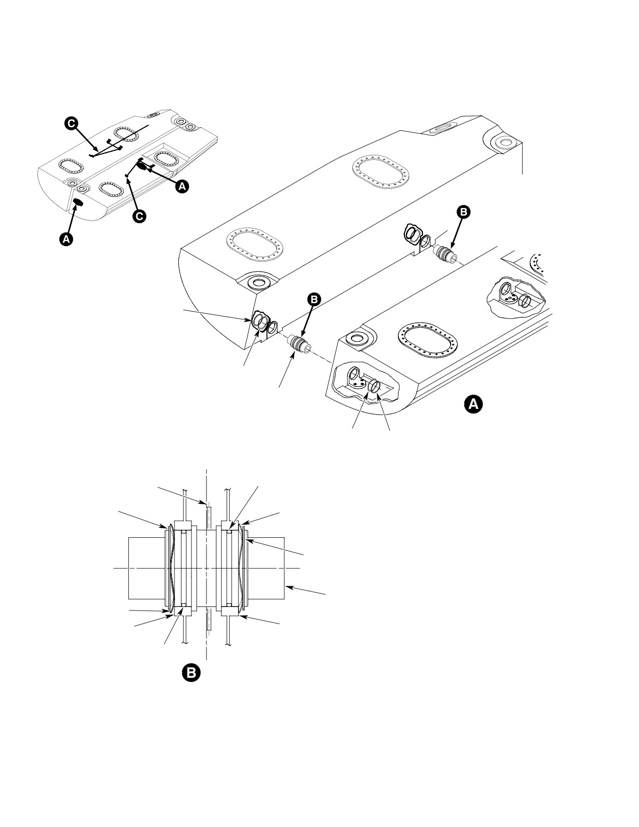
CSP-HMI-2
MD Helicopters, Inc.
MAINTENANCE MANUAL
RETAINING
RING
SPRING
INTERCONNECT
SPRING
RETAINING
RING
BL
0.000
CENTER BEAM
O-RING
ASSEMBLY
RETAINING
RING
SPRING
RETAINING
RING
INTERCONNECT
SPRING
RIGHT
LEFT
FUEL CELL
FUEL CELL
O-RING
VIEW LOOKING FORWARD
6G28-025-1
Figure 406. Fuel Cell Interconnect and Support Lacing (Sheet 1 of 3)
Page 416
Revision 19
28-00-60
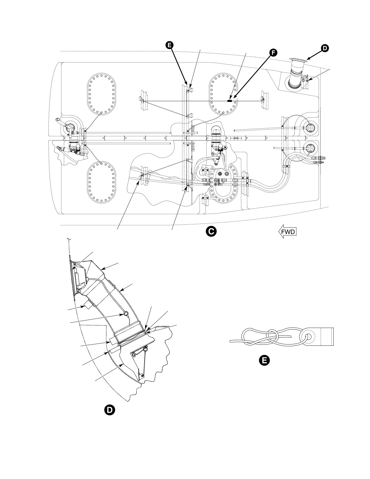
MD Helicopters, Inc.
CSP-HMI-2
MAINTENANCE MANUAL
START HERE
END HERE
BOWLINE KNOT
TRUCKER SLIPKNOT
BONDING
JUMPER
END HERE
START HERE
TRUCKER SLIPKNOT
BOWLINE KNOT
FUEL CAP
FILL PORT
HOS
E
RETAINING
RING
CLAMP
SPRING
LANYARD
O-RING
CLAMP
BOWLINE KNOT
RIGHT
FUEL CELL
FILL
VALVE
VIEW LOOKING AFT
AT VALVE INLET
6G28-025-2
Figure 406. Fuel Cell Interconnect and Support Lacing (Sheet 2 of 3)
Page 417
28-00-60
Revision 19
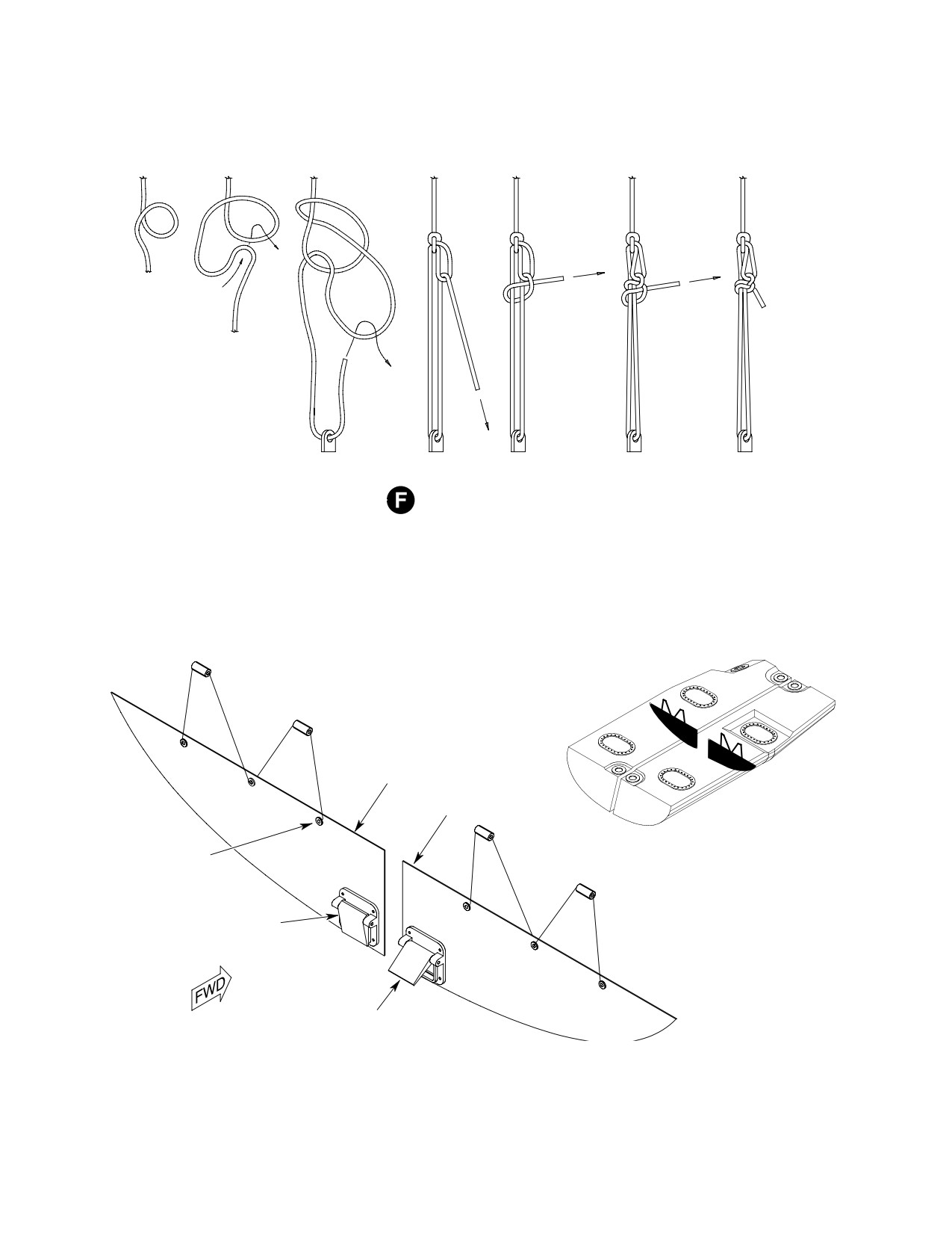
CSP-HMI-2
MD Helicopters, Inc.
MAINTENANCE MANUAL
TRUCKER SLIPKNOT
6G28-025-3
LEFT
BAFFLE
RIGHT
BAFFLE
GROMMET
(6 PLCS)
FLAPPER CHECK VALVE
IN CLOSED POSITION
FLAPPER CHECK VALVE
VIEW LOOKING FORWARD
IN OPEN POSITION
Figure 406. Fuel Cell Interconnect and Support Lacing (Sheet 3 of 3)
Page 418
Revision 19
28-00-60
MD Helicopters, Inc.
CSP-HMI-2
MAINTENANCE MANUAL
7. Fuel Filler Neck Gravity Fill Port
(4). Insure lanyard on filler valve is
Replacement
accessible with fill cap removed. Slip
lanyard on fuel cap onto ring of fill
(Ref. Figure 406)
valve. Install fuel cap.
Avoid fuel vapor ignition
(5). Connect lanyard of fill valve to gravity
WARNING
and fire. Use only nonspark
filler port. Install hose and clamp.
ing tools and explosion proof work
8. Fuel System Drain Valve Replacement
lights. Attach helicopter to an ap
proved electrical ground. Switch OFF
Avoid fuel vapor ignition
all electrical power. Disconnect exter
WARNING
and fire. Use only nonspark
nal power and battery before opening
ing tools and explosion proof work
fuel system. Ensure work area is ade
lights. Attach helicopter to an ap
quately ventilated.
proved electrical ground. Switch OFF
all electrical power. Disconnect exter
Helicopter must be defueled and
CAUTION
nal power and battery before opening
drained prior to removing grav
fuel system. Ensure work area is ade
ity fill port.
quately ventilated.
(1). Defuel helicopter. Drain remaining fuel
Helicopter must be defueled and
from cell sump drain valve into a
CAUTION
drained prior to removing tank
suitable container.
sump drain valve.
(2). Disconnect electrical power.
(1). Defuel helicopter, as required. Drain
remaining fuel from tank sump drain
A. Fuel Filler Neck Gravity Fill Port Removal
valve into a suitable container.
(1). Remove fuel filler neck fairing from
(2). Disconnect electrical power.
passenger/cargo compartment floor.
A. Fuel System Drain Valve Removal
(2). Unclamp fuel gravity filler port from fill
(1). Remove lockwire from tank sump drain
valve, remove hose from fill valve and
valve.
disconnect lanyard.
(2). Using appropriate socket or wrench,
(3). Remove bolts and washers from filler
remove drain valve.
neck mounting flange and remove
B. Fuel System Drain Valve Installation
gravity fill port.
B. Fuel Filler Neck Gravity Fill Port
Consumable Materials
Installation
(Ref. Section 91−00−00)
Item
Nomenclature
(1). Bond prep attach points for bonding
CM114
Petrolatum
jumper near fuel fill area. Attach
bonding jumper to fuel cell with screw
CM124
Kerosene
and washer. Attach opposite end of
CM702
Lockwire CRES
bonding jumper to passenger/cargo
compartment flooring with screw,
(1). Replace drain valve O-ring packings.
washers and nut.
Lubricate packings with kerosene
(CM124), petrolatum (CM114) or jet
(2). Install bolts and washers from filler
fuel.
neck mounting flange and install
gravity fill port.
(2). Install and torque sump drain valve to
95 - 105 inch-pounds (10.73 - 11.86
(3). Install rubber hose to fill valve and
Nm). Safety valve with lockwire
filler neck. Note, hose should be
(CM702).
approximately six an one half inches
long. Secure hose to fill valve and filler
(3). Apply a torque alignment stripe to fuel
neck with clamps.
line tube, hose and fitting fasteners.
Page 419
28-00-60
Revision 19
CSP-HMI-2
MD Helicopters, Inc.
MAINTENANCE MANUAL
(4). Refuel helicopter.
B. Forward Fuel Quantity Probe Installation
(5). Check drain valve for leakage.
(Ref. Figure 407)
9. Fuel Quantity Probe Replacement
(1). Install fuel quantity probe ground wire
and attaching hardware. Torque bolts
Avoid fuel vapor ignition
to 36 - 46 inch-pounds (4.06 - 5.19
WARNING
and fire. Use only nonspark
Nm).
ing tools and explosion proof work
lights. Attach helicopter to an ap
(2). Connect wire harness connector ends to
proved electrical ground. Switch OFF
forward fuel probe in the same locations
all electrical power. Disconnect exter
as removed.
nal power and battery before opening
fuel system. Ensure work area is ade
(3). Bond prep fuel cell access cover.
quately ventilated.
(4). Install left forward fuel cell access
(1). Defuel helicopter. Drain remaining fuel
cover. Install bonding jumper to fuel
from tank sump drain valve into a
cell access cover. Torque bolts to 70 - 90
suitable container.
inch pounds (7.91 - 10.17 Nm).
(2). Disconnect electrical power.
(5). Install left forward fuel cell access
Prevent spontaneous com
panel from passenger/cargo compart
WARNING
bustion or explosion. Never
ment floor.
use oxygen to purge or ventilate fuel
tank or fuel system components. Fuel,
C. Aft Fuel Quantity Probe Removal
either vapor or liquid, will violently
react with an oxygen rich atmosphere.
(Ref. Figure 407)
(3). Ventilate fuel tank with an inert gas
(1). Remove left aft fuel cell access panel
such as nitrogen or low pressure
from passenger/cargo compartment
compressed air applied through filler
floor.
neck.
(2). Remove left aft fuel cell access cover
A. Forward Fuel Quantity Probe Removal
(Ref. Fuel Cell Cover Replacement).
(Ref. Figure 407)
(3). Disconnect wire harness connector ends
from aft fuel probe.
(1). Remove left forward fuel cell access
panel from passenger/cargo compart
(a). Remove ORANGE wire from termi
ment floor.
nal L.
(2). Remove left forward fuel cell access
cover.
(b). Remove BLUE wire from terminal R.
(3). Disconnect wire harness connector ends
(c). Remove WHITE wire from terminal
from forward fuel probe.
S.
(a). Remove ORANGE wire from termi
(d). Remove low level switch WHITE wire
nal L.
from terminal 1.
(b). Remove BLUE wire from terminal R.
(e). Remove low level switch BLUE wire
(c). Remove WHITE wire from terminal
from terminal 2.
S.
(f). Remove GROUND wire from probe
(4). Remove GROUND wire from probe
mount flange, remove remaining
mount flange, remaining attachment
attachment hardware and remove
hardware and remove probe.
probe.
Page 420
Revision 19
28-00-60
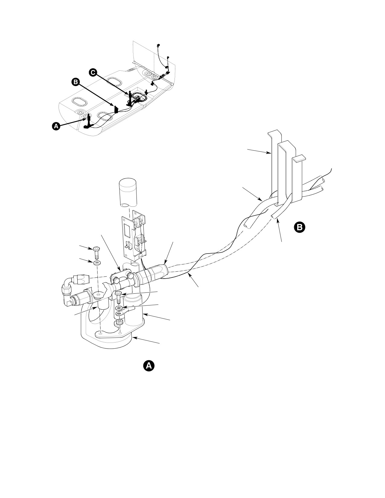
MD Helicopters, Inc.
CSP-HMI-2
MAINTENANCE MANUAL
REF. FUEL CELL
FABRIC LOOPS
FUEL CELL SCAVENGE
HOSE ASSEMBLY
EJECTOR
BRACKET
ASSEMBLY
SCAVENGE
HOSE ASSEMBLY
BOL
SUBMERGED MOTIVE
T
FLOW HOSE
WASHER
WIRE HARNESS
BOL
T
WASHER
EJECTOR
FORWARD
PUMP
FUEL PROBE
FUEL CELL FITTING
FORWARD FUEL PROBE
6G28-051-1A
Figure 407. Fuel Quantity Probes (Sheet 1 of 2)
Page 421
28-00-60
Revision 19
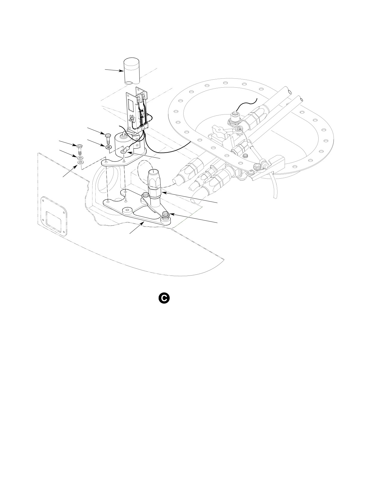
CSP-HMI-2
MD Helicopters, Inc.
MAINTENANCE MANUAL
AFT FUEL PROBE
BOL
T
WASHER
BOL
T
WASHER
GROUND
JUMPER
WASHER
FUEL INLET SUPPLY
HOSE ASSEMBLY
FUEL INLET FITTING ASSEMBLY
BRACKET
ASSEMBLY
AFT FUEL PROBE
6G28-051-2
Figure 407. Fuel Quantity Probes (Sheet 2 of 2)
D. Aft Fuel Quantity Probe Installation
(2). Connect wire harness connector ends to
forward fuel probe in the same locations
as removed.
(Ref. Figure 407)
(3). Install left aft fuel cell access cover
(Ref. Fuel Cell Cover Replacement).
(1). Install fuel quantity probe ground wire
and attaching hardware. Torque bolts
(4). Install left forward fuel cell access
to 36 - 46 inch-pounds (4.06 - 5.19
panel from passenger/cargo compart
Nm).
ment floor.
Page 422
Revision 19
28-00-60
MD Helicopters, Inc.
CSP-HMI-2
MAINTENANCE MANUAL
FUEL SYSTEM
ADJUSTMENT/TEST
1. Fuel Level Low Light/Fuel Quantity
(5). Level the helicopter laterally across the
Indicator System Test and Calibration
passenger/cargo compartment floor.
(6). Plug in and switch on 27.5 ±0.5 Vdc
The following procedure is for calibrating the
external power. Set BAT master switch
fuel quantity system when the fuel cell, fuel
to EXT PWR. Make sure the INST and
probes or fuel quantity indicator have been
PNL LT circuit breakers are pushed in.
replaced.
NOTE: All readings are taken from the center
line of the fuel quantity indicator pointer.
Special Tools
(Ref. Section 91−00−00)
(7). Verify the FUEL LEVEL LOW light is
Item
Nomenclature
illuminated.
ST203
Hydraulic jack: 1-5 ton (900-4500 kg)
(8). Add 1.3 gals (4.92 Liter) of fuel from a
ST205
Inclinometer
calibrated delivery system to the fuel
cell. This amount of fuel is trapped fuel
or unusable fuel. Calibrate empty.
Prevent fuel vapor accumu
WARNING
lation, ignition and fire. At
(a). Calibrate zero on the fuel quantity
tach helicopter to an approved electri
indicator by holding the fuel quantity
cal ground. Switch OFF and disconnect
gauging system calibration switch in
external power and battery before
the empty calibration position (down)
opening fuel system. Perform work in
for a minimum of 5 - 10 seconds.
an open, well ventilated area away
from all potential ignition sources. Use
(b). Verify the the fuel quantity indicator
only nonsparking tools and explosion
now reads empty. Empty is the E
proof work lights.
with the pointer centerline between
the outer and inner edge of the E
(1). Attach helicopter to a approved electri
graduation mark.
cal ground.
(9). Add 11.4 gals (44.3 Liter) of fuel from a
calibrated delivery system to the fuel
(2). Defuel and drain fuel cell sumps of all
cell.
fuel from all four sump drains with the
helicopter at normal ground attitude.
(10). Verify the FUEL LEVEL LOW light is
not illuminated.
(3). Place an aircraft jack (ST203) under the
aft jacking point.
(11). Wait 15 minutes and verify the FUEL
LEVEL LOW light is not illuminated. If
Do not apply more than 500 lb.
light illuminates:
CAUTION
(227 kg) pressure on aft jacking
(a). Inspect baffles for damage, tears,
point, damage to tailboom and attachment
punctures or delamination.
points will occur.
(b). Inspect flappers for proper seating.
(4). Locate a inclinometer (ST205) on the
Flappers should seat flush with
passenger/cargo compartment floor at
gravity or very light finger pressure
approximately fuselage Sta. 100.00 -
and should move freely.
104.00. Raise the helicopter at Sta.
(12). Fill the fuel cell and secure the fuel
303.03 with jack (ST204) and P.Sta.
filler cap.
18.76 with jacks (ST203) to obtain a 3
degree nose down simulated flight
(a). Calibrate full on the fuel quantity
attitude as observed on the inclinome
indicator by holding the fuel quantity
ter scale.
gauging system calibration switch in
Page 501
28-00-60
Revision 22
CSP-HMI-2
MD Helicopters, Inc.
MAINTENANCE MANUAL
the full calibration position (up) for a
(6). With reducer bushing removed from tee
minimum of 5 seconds.
fitting, install an O-ring on a suitable
airtight plug and tighten into tee
(b). Verify the the fuel quantity indicator
fitting.
now reads approximately 759 pounds
(344.28 kg).
(7). Bench test 600N8131 bypass pressure
switch as follows (denoted by six
(13). Place the BAT master switch to OFF
housing screws):
position. Disconnect external power.
(a). Assemble test equipment shown in
2. Fuel Filter (Bypass) Caution Light
Figure 501. Connect tester to pres
Pressure Switch Test
sure switch lead and connect ground
test lead to one of three screws on the
(Ref. Figure 501)
housing body.
Air in the fuel system will
(b). Remove reducer bushing and O-ring
WARNING
cause a power reduction or
from switch. Wipe switch completely
flameout. Do a fuel system vacuum leak
dry so any leakage can be detected
check and system air bleed after open
during the test.
ing fuel system to atmosphere and
(c). Apply 2.0 to 3.0 psig (13.8 - 20.68
prior to releasing helicopter for flight.
Kpa) at port ``A'' .
NOTE: For all torques in the following proce
1). There shall be no evidence of
dures, refer to Engine Build-Up, Section
leakage. Replace a leaky switch.
71-00-47.
2). When air pressure is applied,
(1). Set all switches; OFF. Disconnect
switch shall be close when pres
external electrical power. Disconnect
sure at port ``A'' is 2.1 - 2.9 psid,
battery.
pound per square inch differential
(2). Open engine access doors.
(4.3 - 5.9 in. Hg, inch of mercury).
3). When air pressure is bled off,
(3). Locate pressure switch on engine fuel
switch shall be open when pres
pump filter. Disconnect bypass switch
sure at port ``A'' is 1.0 psid (2.0 in.
wire knife splice.
Hg).
CAUTION
(d). Remove test equipment.
D Pressure switch is easily damaged. A
(8). Remove plug from tee fitting. Install
slight shearing force applied to half the
reducer bushing and bypass switch
pressure switch can cause leakage and, or
assembly with new O-rings on reducer
operational failure. Always grip both
bushing and bypass switch. Torque
halves of pressure switch hex flats with
switch assembly.
wrench when loosening or torquing at
(9). Remove plug from bypass hose. Attach
taching hardware.
hose to switch bushing. Torque hose
D Bypass pressure switch is not field repair
nut.
able. Do not disassemble switch. Return
faulty switches to vender for repair (Ref.
(10). Install insulating sleeve and connect
Sec. 01-00-00).
switch wire knife splice.
(4). Disconnect hose from fuel filter pres
(11). Bleed fuel system.
sure switch. Install an airtight plug to
hose.
(12). Operate engine per Pilot's Flight
Manual and check fuel system for
(5). Remove fuel pressure switch with
correct operation. Shut down engine.
reducer bushing.
Inspect fuel system for leaks.
Page 502
Revision 22
28-00-60
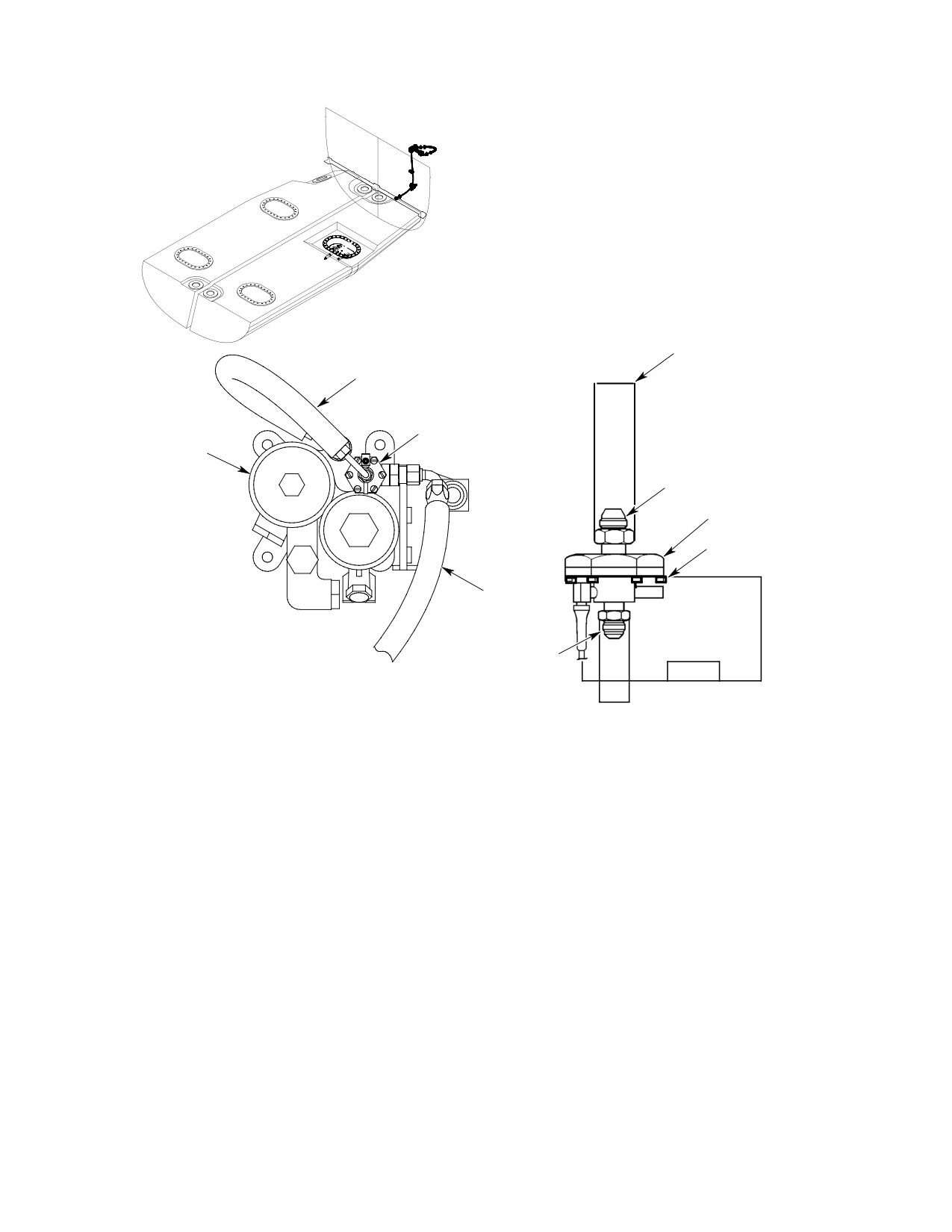
MD Helicopters, Inc.
CSP-HMI-2
MAINTENANCE MANUAL
PRESSURE METHOD:
APPLY 2-3 PSIG (4.3 TO 5.9 IN HG) TO
PORT ``A'' THE SWITCH SHALL CLOSE.
BLEED OFF 1 PSIG (2.0 IN HG) THE
SWITCH SHALL OPEN.
HOSE
FUEL SWITCH
CEFA FILTER
PORT A
FUEL FILTER
PRESSURE SWITCH
NOTE
HOSE
OHMMETER
LOOKING FORWARD
OR
CONTINUITY TESTER
PORT B
NOTE:
CONNECT GROUND TEST LEAD TO ONE OF SIX SCREW
6G28-075
HEADS ON THE HOUSING BODY.
Figure 501. Fuel Filter Caution Light Pressure Switch Test Apparatus (C47 Engine)
Page 503
28-00-60
Revision 21
CSP-HMI-2
MD Helicopters, Inc.
MAINTENANCE MANUAL
This Page Intentionally Left Blank
Page 504
Revision 44
28-00-60
MD Helicopters, Inc.
CSP-HMI-2
MAINTENANCE MANUAL
FUEL SYSTEM
INSPECTION/CHECK
2. Fuel Shutoff Valve Inspection
WARNING
(1). Shut down and disconnect all electrical
D Avoid fuel vapor ignition and fire.
power.
Use only nonsparking tools and ex
(a). In cargo/passenger compartment,
plosion proof work lights. Attach he
open left aft fuel cell access panel.
licopter to an approved electrical
ground. Switch OFF all electrical
(b). Disconnect fuel supply tube from fuel
power. Disconnect external power
shutoff valve.
and battery before opening fuel sys
(c). Use an inspection mirror and flash
tem. Ensure work area is adequately
light to check shutoff valve ball
ventilated.
position.
D Air entering the airframe fuel supply
(d). Ensure shutoff valve control knob is
lines may cause a power reduction or
pushed in. Valve ball must be wide
flameout. Fuel system vacuum leak
open.
check and fuel air bleed procedures
must be performed after opening fuel
(e). Pull control knob out to stop. Valve
the supply system for any reason,
ball should be closed.
prior to releasing helicopter for
(2). Valves that can not be fully closed or
flight.
opened must be overhauled or replaced
prior to further flight.
1.
Fuel System General Inspection
(3). Disconnect control cable from valve.
(1). Remove all fuel tank floor access
(a). Inspect shutoff valve lever and cable
panels.
swivel hardware for corrosion and
wear. Check lever for smooth move
(2). Inspect fuselage bottom skin for
ment from closed to open stops.
evidence of fuel leakage. No leaks
(b). Use a spring scale to check tension
allowed. Determine source and repair
required to move valve lever from full
as required.
open to closed. Design force require
ment is 1.5 - 3.5 pounds (6.7 - 15.6
(3). Inspect fuel lines, fittings, cell access
N) maximum.
covers, fuel quantity unit, clamps and
attaching hardware for leakage,
(c). Inspect valve for evidence of external
corrosion and security. Inspect fire
leakage. External leakage not
sleeves for cuts, tears and punctures.
allowed.
No leakage allowed. Repair or replace
(d). Check that lever detents at open and
components as required.
closed positions. Repair or replace
valve as required.
(4). Inspect electrical wiring and connectors
for corrosion and security. Replace or
(4). Connect and rig valve control cable.
repair wiring as required.
Install cotter pin on cable swivel.
Page 601
28-00-60
Revision 19
CSP-HMI-2
MD Helicopters, Inc.
MAINTENANCE MANUAL
3. Tank Vent System Inspection
hardware. Repair or replace vent
float/rollover valve as required.
Avoid fuel vapor ignition
WARNING
and fire. Use only nonspark
4. Fuel Quantity Probe Inspection
ing tools and explosion proof work
lights. Attach helicopter to an ap
(1). Inspect probe wire harness electrical
proved electrical ground. Switch OFF
connector for serviceable conditional.
all electrical power. Disconnect exter
nal power and battery before opening
(2). Inspect for bent or broken pins, frayed
fuel system. Ensure work area is ade
or broken wires. Repair or replace as
quately ventilated.
required,
Prevent fuel system contamina
5. Fuel System Vacuum Leak Inspection
CAUTION
tion. Install caps on the ends of
hoses, tubes and fittings as parts are re
(Ref. Figure 601) Water, ice, dirt, fungus or a
moved. Bag and identify small parts to pre
few pinhole leaks in the supply system
vent loss or damage.
between the fuel tank sump pickup and engine
driven fuel pump may cause power surges,
(1).
Defuel helicopter. Drain remaining fuel
deceleration and, or flameout. A vacuum leak
from tank sump drain valve into a
inspection will determine whether or not air is
suitable container.
being drawn into the engine fuel supply
system.
(2).
Disconnect electrical power.
(3).
Remove all four passenger/cargo access
Special Tools
panels.
(Ref. Section 91−00−00)
Item
Nomenclature
(4).
Remove fuel vent cross over tube access
ST801
Hand operated vacuum pump kit
cover and disconnect hoses from
forward vent crossover tubes.
Air entering the airframe
(5).
Blow low-pressure compressed air
WARNING
fuel supply lines may cause
through vent system to verify passages
a power reduction or flameout. Fuel
are clear.
system vacuum leak check and fuel air
(6).
Check vent fairing passages for obstruc
bleed procedures must be performed
tions and condition. Repair or replace
after opening the fuel supply system
fairings as required.
for any reason, prior to releasing heli
copter for flight.
(7).
Inspect vent system hoses for deteriora
tion. Pinch or bend hoses and look for
(1). Remove left fuel cell floor access panel.
surface cracks. Replace hose if cracks
are apparent.
(2). Pull FUEL shutoff valve knob out to
stop. Verify that fuel shutoff valve lever
(8).
Inspect vent tubes for dents, cracks,
is hard against its OFF stop.
deformation or corrosion. Smooth
nonrestrictive dents are permissible
(3). In engine compartment; remove and
except at lower vent end which must fit
plug the motive fuel line at the CEFA.
flush within vent fairing flared riser.
(4). Assemble vacuum pump (ST801) hoses,
(9).
Inspect crossover fittings for cracks,
filter port adapter, shutoff valve and
dents or corrosion. Smooth nonrestric
vacuum gauge.
tive dents are permissible.
(a). Install the vacuum gauge in the line
(10).
Inspect fuel vent float/rollover valves
between the filter port adapter and
for serviceable condition, leakage and
shutoff valve. Attach the vacuum
corrosion. Inspect for loose or missing
pump above the shutoff valve.
Page 602
Revision 31
28-00-60
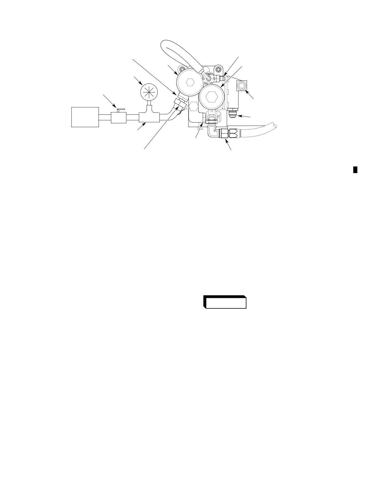
MD Helicopters, Inc.
CSP-HMI-2
MAINTENANCE MANUAL
MOTIVE FUEL LINE
FUEL FILTER UPPER
DRAIN PORT
FUEL FILTER
OIL FILTER
VACUUM GAGE
SHUT-OFF VALVE
FUEL IN PORT
VACUUM
OIL OUT PORT
PUMP
TEE FITTING
FUEL OUT PORT
FILTER PORT ADAPTER
OIL IN PORT
6G28-077
Figure 601. Fuel System Vacuum Leak Inspection
(5).
Attach vacuum test pump to engine fuel
The fuel shutoff and drain valve
filter upper drain port. Apply 8.0 Hg
installations should be especially
vacuum. Close vacuum line shutoff
suspect. Apply vacuum at each stage
valve.
until leak has been isolated. Replace
parts as required.
(6).
Fuel system shall hold vacuum between
8.0 and 7.5 Hg for two minutes.
NOTE: If the vacuum held at 7.5 Hg or better,
airframe system seal is satisfactory and
(7).
If test is satisfactory, remove test
leak is due to an engine fuel system prob
vacuum.
lem. Refer to the applicable Allison and Ben
dix manuals for additional information.
(8).
Reconnect and torque the fuel vapor
return line.
(11). Apply a torque stripe to all effected fuel
NOTE: Vacuum loss exceeding 0.5 Hg in two
line fittings and nuts.
minutes indicates a leak in the system be
tween, and including, the fuel shutoff valve
6. Drain Valve Inspection
and engine.
Air in the fuel system will
WARNING
(9). Retorque fuel line connections and
cause a power reduction or
where installed, anti-ice (airframe) fuel
flameout. Do a fuel system vacuum leak
filter fittings and line nuts (Ref. Sec.
check and fuel system air bleed after
28-25-00). Repeat vacuum test.
opening fuel system to atmosphere and
prior to releasing helicopter for flight.
(10). If system continues to leak, disconnect
and install airtight caps on lines and
(1). Inspect tank sump drain valves for
fitting ports in a progressive sequence
leakage and security. No leakage
from fuel shutoff valve toward engine.
allowed. Replace valve as required.
Page 603
28-00-60
Revision 31
CSP-HMI-2
MD Helicopters, Inc.
MAINTENANCE MANUAL
7. Fuel Cell Inspection
8. Fuel Cell Leak Inspection
Consumable Materials
(Ref. Section 91−00−00)
CAUTION
Item
Nomenclature
N/A
Ammonia
D Do not work on Engineered Fabric Corp.
N/A
Cloth, cotton flannel
fuel cell in ambient temperatures below
N/A
Phenolphthalein, crystalline
70°F (21°C).
CM218
Alcohol, denatured
CM810
Leak detector, liquid
D Do not remove fuel cells unless absolutely
required.
CM820
Cheesecloth
D The barrier can be invisibly torn, punc
Any one of three techniques can be used to find
tured or cracked by careless handling.
leaks in non-self-sealing and self-sealing fuel
cells. The methods are listed in ascending
D Do not carry or move cell by its metal fit
order of effectiveness and complexity in terms
tings.
of required equipment, materials, time, and
effort.
D Never probe cell material with sharp
Soap bubble leak inspection.
edged or pointed tools.
Phenolphthalein stain inspection.
NOTE:
Liquid stand inspection.
NOTE: The soap bubble and phenolphthalein
D Non-self-sealing and self-sealing cells
inspections require the cell to be inflated
are primarily a 0.002 inch (0.051 mm)
with air.
thick nylon barrier membrane sand
wiched between lightweight construc
(1). Manufacture or supply the following
tions of either rubberized (Uniroyal) or
equipment necessary to do soap bubble
or phenolphthalein inspections:
plasticized (Engineered Fabrics Corp.)
nylon fabric that protects and strength
(a). Rigid, airtight closures or plugs to
ens the barrier.
seal all cell openings. Fit one cover
plate with:
D Self-sealing cells may have one or more
(b). An air pressurization inlet fitting.
thin layers of natural rubber sandwiched
between the barrier and fabric plies.
(c). A manometer or an extremely
accurate and sensitive low pressure
air gauge.
(1). Apply protective tape to all machined
A. Soap Bubble Leak Test Procedures
metal fittings.
NOTE: Soap bubble test reliability is good for
bladder type non-self-sealing cells.
(2). Perform cell inspection on a padded,
clean, craft paper covered surface.
(1). Remove cell from helicopter.
(2). Lay cell out on a padded table. Install
cell closures.
(3). Inspect fuel cells per applicable man
ufacturers requirements (Ref. Sec.
(3). Inflate cell to 1/4 psi (1.7 kPa), maxi
01-00-00).
mum.
Page 604
Revision 31
28-00-60
MD Helicopters, Inc.
CSP-HMI-2
MAINTENANCE MANUAL
(4). Unless leak is immediately evident,
(f). Inspect the entire exterior surface of
maintain 1/4 psi (1.7 kPa) pressure for
the cell.
two hours to allow any air trapped in
(5). Repair cell as required.
cell exterior laps and seams to escape.
C. Liquid Stand Inspection
(5). Run soap solution around all patches,
lap joints, seams, fittings, creases,
(1). Remove cell from helicopter and place
abrasions and any other suspicious
on a clean, padded, kraft paper covered
areas. Bubbles will appear over a leak.
table.
(6). Mark leak areas with a white or yellow
(2). Fabricate closure plates for each cell
crayon.
opening.
(7). Repair cell as required.
(a). The object is to completely fill the cell
and eliminate all air pockets. Equip
B. Phenolphthalein Stain Inspection
one of the plates with liquid filler and
Procedures
vent stand pipes at least six inches
(1). Remove cell from helicopter.
(15 cm) tall.
(b). Fill the cell with Stoddard solvent,
(2). Lay cell out on a padded table. Install
Stanisol or Varsoline.
all but one of the cell closures.
(c). Permit cell to stand undisturbed for
(3). Make phenolphthalein solution as
24 hours.
follows:
(d). Inspect paper to determine where cell
(a). Add 40 grams phenolphthalein
is leaking.
crystals to 1/2 gallon (1.9 L) of
denatured alcohol (CM218) and stir.
(e). Change paper as required. Drain,
turn over, refill and let cell stand for
(b). Add 1/2 gallon (1.9 L) of water. Allow
another 24 hours to ensure liquid has
to stand 30 minutes. Stir before
contacted all cell surfaces.
using.
(f). Repair cell as required.
(4). Pour commercial ammonia on an
absorbent cloth in a ratio of one
9.
Fuel Tank Pressure Leak Test
teaspoon (3 ml) per cubic foot of cell
capacity (minimum of 10 ml or 3.3
teaspoons).
Special Tools
(Ref. Section 91−00−00)
(a). Place the ammonia saturated cloth
Item
Nomenclature
inside the cell and install the remain
N/A
Manometer
ing cover.
(b). Inflate cell with air to 1/4 psi (1.7
NOTE: Always test and inspect a repaired fuel
kPa) maximum. Maintain 1/4 psi (1.7
cell for leaks using soap bubble, phenolph
kPa) pressure for 15 minutes mini
thalein or liquid stand method before in
mum, before proceeding.
stalling the cell in the helicopter.
(c). Soak a large white cloth in the
(1). Use the following procedures to check
phenolphthalein solution. Thoroughly
installed fuel tanks and plumbing for
wring cloth out.
leaks.
(d). Spread and smooth cloth onto cell. Do
(a). Plug vent system.
not let cloth dry out.
(b). Remove cell floor access panels.
(e). A red spot will appear on the cloth
where there is a leak in the cell wall.
(c). Install manometer and air pressur
Mark each leak.
ization equipment.
Page 605
28-00-60
Revision 31
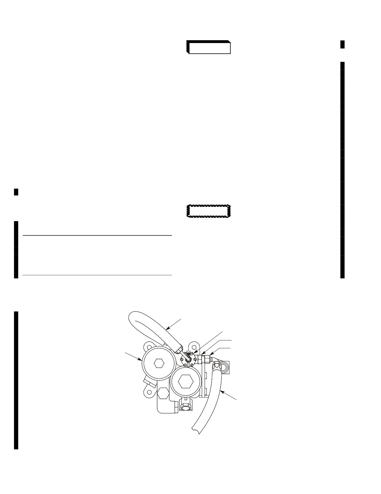
CSP-HMI-2
MD Helicopters, Inc.
MAINTENANCE MANUAL
(d). Apply 2 psi (14 kPa) air pressure for
WARNING
10 minutes to precondition cells. This
forces trapped air from between fuel
cells and helicopter structure. If
D Avoid fuel vapor ignition and fire.
necessary, repeat until cells adjust to
Use only nonsparking tools and ex
contour of cell bay.
plosion proof work lights. Attach he
licopter to an approved electrical
(e). Apply 2 psi (14 kPa) air pressure for
ground. Switch OFF all electrical
15 minutes with no visible, less than
power. Disconnect external power
1/4 inch (6.35 mm), drop on manome
and battery before opening fuel sys
ter. If pressure drop occurs, check all
tem. Ensure work area is adequately
vent plugs, fittings and re-test cells.
ventilated.
Repair or replace parts as necessary
to eliminate pressure drop.
D Engine operation or helicopter flight
(f). Unplug vent system. Remove ma
must be accomplished in accordance
nometer and pressurization equip
with requirements and limitations
ment.
specified in the 600N Rotorcraft
(g). Install cell floor access panels.
Flight Manual and applicable sup
plements.
10. Fuel Transfer System Functional Check
NOTE: This check is only done on aircraft
Prevent fuel system contamina
without the airframe fuel filter option.
CAUTION
tion. Install caps on the ends of
(Ref. Figure 602)
hoses, tubes and fittings as parts are re
moved. Bag and identify small parts to pre
vent loss or damage.
Special Tools
(Ref. Section 91−00−00)
Item
Nomenclature
NOTE: Gross weight, fuel load and ambient
ST803
Fuel Transfer System Functional Tester
conditions are optional for this functional
check.
FUEL PRESSURE
SWITCH HOSE
FUEL PRESSURE SWITCH
UNION
CEFA BEFORE FILTER
CEFA
PORT
MOTIVE FLOW
SUPPLY HOSE
LOOKING FORWARD
6G28-078
Figure 602. Fuel Transfer System Functional Check
Page 606
Revision 43
28-00-60
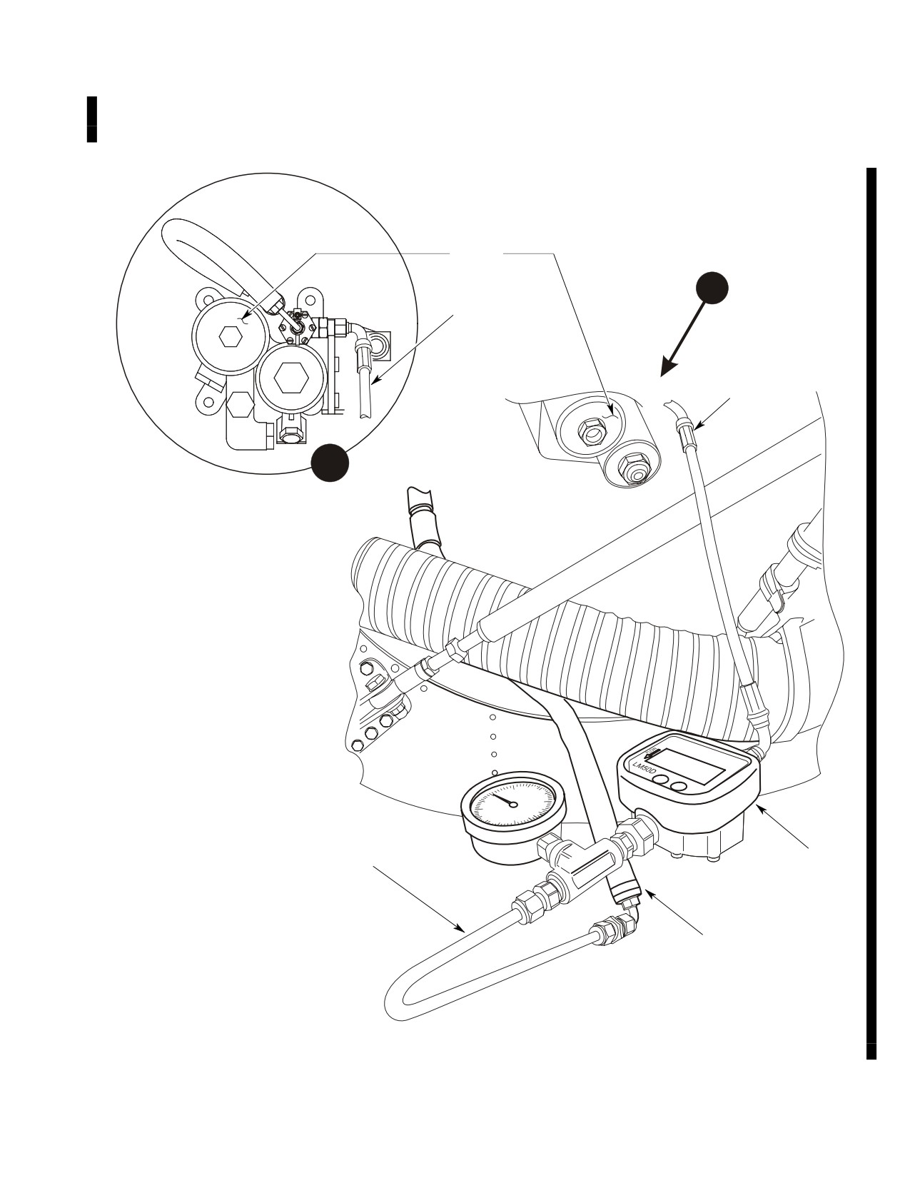
MD Helicopters, Inc.
CSP-HMI-2
MAINTENANCE MANUAL
A. Test Setup
(Ref. Figure 602 and Figure 603)
CEFA
A
TESTER INLET
LINE
TESTER INLET
LINE
A
TESTER OUTLET
LINE
FLOW METER
MOTIVE FLOW
SUPPLY HOSE
6G28-079
Figure 603. Fuel Transfer Test Setup
Page 607
28-00-60
Revision 43
CSP-HMI-2
MD Helicopters, Inc.
MAINTENANCE MANUAL
(1). Make sure fuel transfer system tester
lective to increase N1 speed. Reduce throttle
calibration is current.
twist grip to decrease N1 speed.
(2). Disconnect motive flow supply hose
(5). Record N1, pressure altitude, outside
from CEFA before filter port union.
air temperature, motive flow rate and
motive flow pressure.
(3). Connect inlet line of tester to CEFA
(6). Use the calibration chart provided with
before filter port union.
the fuel transfer system tester and
(4). Torque tester fitting to 50 - 65 inch-
calculate the calibrated motive flow
pounds (5.64 - 7.34 Nm).
rate.
(7). The minimum calibrated motive flow
(5). Connect motive flow supply hose to
rate shall be 0.18 GPM.
outlet line of tester.
(8). If the calibrated motive flow rate is less
(6). Torque motive flow supply hose fitting
than 0.18 GPM, check the following
to 50 - 65 inch-pounds (5.64 - 7.34
components for correct operation.
Nm).
(a). Check valve
B. Check Procedures
(b). Jet (ejector) pump
(Ref. Figure 602 and Figure 603)
(c). Motive flow hoses
(1). Make sure test setup is complete.
(9). Shut down engine ground run in
(2). Ground run engine in accordance with
accordance with Rotorcraft Flight
Rotorcraft Flight Manual.
Manual.
(10). Disconnect motive flow supply hose
(3). Operate the helicopter on the ground at
from outlet line of tester.
100 percent main rotor speed (Nr) with
collective down.
(11). Disconnect inlet line of tester from
CEFA before filter port union.
(4). Stabilize motive flow pressure from
42.0 PSIG minimum to 44.0 PSIG
(12). Connect motive flow supply hose to
maximum. N1 at approximately 81
CEFA before filter port union.
percent.
(13). Torque motive flow supply hose fitting
NOTE: Motive flow pressure increases or de
to 50 - 65 inch-pounds (5.64 - 7.34
creases with engine N1 speed. Increase col
Nm).
Page 608
Revision 43
28-00-60
MD Helicopters, Inc.
CSP-HMI-2
MAINTENANCE MANUAL
FUEL SYSTEM
REPAIRS
1. Fuel Shutoff Valve Control Cable Repair
NOTE: MDHS cannot guarantee the currency,
completeness or technical accuracy of fuel
cell repair procedures provided herein.
Consumable Materials
Since cell repair materials, techniques, and
(Ref. Section 91−00−00)
procedures may be changed or deleted by
Item
Nomenclature
the cell manufacturers without notice to
CM118
Grease
MDHS light helicopter publications; we
strongly recommend that:
NOTE: Worn fuel shutoff valve control cables
(1). Only specially trained personnel are
are normally replaced as an assembly.
allowed to inspect and repair the fuel
cells installed in 369/500/600 series
(1). The only authorized repair is replace
helicopters.
ment of a missing detent ball, as
(2). Customers planning to do their own
follows:
fuel cell repairs must order any re
quired manuals from the applicable cell
(a). Disconnect cable from fuel shutoff
manufacturer before beginning repair
valve lever swivel.
tasks (Ref. Sec. 01-00-00).
(b). Pull plunger out until detent ball
(a). Cell inspections, maintenance and
hole is visible. Insert detent release
repair must be per the cell manufac
rod in plunger. Align notch in detent
turers advice and instructions.
release rod with plunger detent ball
hole.
(3). Bladder or self sealing fuel cells are
supplied to MDHS by Engineered
(c). Apply grease (CM118) between
Fabrics Corporation.
plunger and plunger housing.
Use only approved inspection
CAUTION
(d). Insert detent ball in plunger hole.
requirements, repair methods,
Push release rod and plunger to full
materials and supplies designed for Engine
open position.
ered Fabrics Corp.
(4). Fuel cells produced by Engineered
(e). Rig fuel shutoff valve cable.
Fabrics Corp. are constructed of Nitrile
polyurethane plastic impregnated
2.
Fuel Cell Repair
fabric.
3. Scuff Mark Repair
Consumable Materials
(Ref. Section 91−00−00)
Fabric exposed by a scuff mark may be buffed,
Item
Nomenclature
cleaned, coated with cement and allowed to
CM219
Methyl-ethyl-ketone
air-dry for 8 hours. No patch is required
CM603
Patching material
unless fabric is torn. Install patches where
required (Ref. Patch Installation).
CM604
Patching material
CM605
Fuel cell repair kit
4. Reinforcements, Hangers and Splice
CM607
Cement
Repairs
CM804
Emery cloth, fine
Loose reinforcement edges, hangers or lap
CM820
Cheesecloth
splices must be lifted, buffed, cleaned, cem
N/A
Polyethylene plastic, sheet or roll
ented and cured under pressure per applicable
instructions (Ref. Patch Installation).
Page 801
28-00-60
Revision 19

CSP-HMI-2
MD Helicopters, Inc.
MAINTENANCE MANUAL
5. Loose Patch Repair
(b). Use a greaseless silver pencil to
outline patch installation area two
Replace loose patches with new patch installa
inches beyond damage in all direc
tions (Ref. Patch Installation). Where two
tions.
opposing patches have been installed over cell
(6). Hand-buff an area 1/2 inch (12.7 mm)
wall damage, unless otherwise indicated by
larger than space occupied by patch
inspection, replace only the loose patch.
with fine emery cloth (CM804) to
provide a roughened substrate for
6. Patch Installation
cement application. Do not cut through
cell fabric.
(1). Drain, remove and thoroughly dry cell
as soon as possible after determining
(7). Select a patch of #5218 material
cell repair is required. Drying time may
(CM604) for cell exterior. Trim patch to
be accelerated by keeping cell at 80°F
extend two inches beyond edges and
(27°C) and ventilating interior with dry,
ends of damage in all directions. Tilt
low pressure air.
scissors to bevel patch edges away from
cell surface. Radius all patch corners.
(2). Inspect fuel cell.
(8). Hand-buff patch gummed surface with
fine emery cloth. Ensure entire patch
Do not repair tears or holes over
CAUTION
joint surface has been abraded.
two inches (5.08 cm) long using
cold patch repair. Do not attempt to repair
(9). Repeat buffing procedures on cell
bonded fittings or corners. Contact Engine
interior surface. Buff internal patch
ered Fabrics Corporation when corner or fit
(CM603) trimmed from
ting damage is discovered or when cell wall
#5200/5187/5194 sandwich material.
damage exceeds two inch length limit.
Fuel cell and patch contact sur
(3). Accomplish fuel cell repair work in
CAUTION
faces must be perfectly clean
temperatures ranging from 60 - 80°F
and dry prior to adhesive and patch applica
(16 - 27°C) and in less than 50%
tion. Rubber and fabric particles, moisture,
humidity.
and fuel or oil from fingers will prevent
proper patch/cell adhesive cure and may
NOTE: Damp air, especially in combination
subsequently provide a leak path. Wear
with low temperatures, will cause water to
clean, lint free gloves to handle patch and
condense on cement applications. Water in
cell after preparing surfaces for cement and
hibits patch adhesion.
patch application.
Never expose a dry cell to high
(10). Install exterior patch first. Wipe cell
CAUTION
temperatures and, or direct sun
exterior and patch faying surfaces with
light for long periods of time. If repairs will
clean cheesecloth (CM820) dampened
not be started within ten days, prepare cell
with MEK (CM219).
for storage.
(a). Continue to wipe cell and patch,
changing cheesecloth and applying
(4). Both sides of a cell must be patched to
clean solvent as required, until no
repair any one hole or tear.
stain or particles appear on cheese
cloth pad after the last wipe.
(5). Thoroughly clean cell internal and
external repair areas with cheese cloth
Use cement sparingly. Two,
(CM820) dampened with solvent MEK
CAUTION
thin, even coats provide better
(CM219).
adhesion than one thick coat.
(a). Collapse cell and expose external
(11). Position a sheet of polyethylene plastic
damage area on a clean, flat working
beneath cell damage to keep cement off
surface.
opposite cell wall.
Page 802
Revision 19
28-00-60