HANDBOOK OF MAINTENANCE INSTRUCTIONS FOR MDHI 369D/E/FF-500/600N HELICOPTERS (ISSUED: 1990) - page 9
MD Helicopters, Inc.
CSP-HMI-2
MAINTENANCE MANUAL
MISCELLANEOUS FURNISHINGS
MAINTENANCE PRACTICES
1. Crew Compartment Miscellaneous
between foot rest and bulkhead for correct
Furnishings Replacement
four-point contact.
Methods for removal and installation are
D. Ash Receiver and Cigarette Lighter Panel
obvious for most miscellaneous furnishing
(1). The cigarette lighter panel may be
items. Some maintenance instructions are
removed by releasing four turnlock
provided in the following procedures.
fasteners.
Crew compartment furnishings for the 600N
(2). Disassembly of the cigarette lighter and
Helicopter are the same as for the 369D/E/FF
panel for maintenance purposes is
- 500N Helicopters.
shown in the figure.
A. Stowage Box
2. Passenger Compartment Miscellaneous
Furnishings Replacement
Access to stowage box is thru crew compart
ment right side floor access door (Ref. Sec.
Methods for removal and installation are
52-50-00).
obvious for most miscellaneous furnishing
items. Some maintenance instructions are
Consumable Materials
provided in the following procedures.
(Ref. Section 91−00−00)
Passenger compartment furnishings for the
Item
Nomenclature
600N Helicopter are the same as for the
CM117
Grease
369D/E/FF - 500N Helicopters except, where
applicable, panels and ducting is 30 inches
longer.
NOTE: Helicopters equipped with certain op
tional communications and avionics instal
A. Convenience Panel Replacement (R/H
lations do not have stowage box installed.
Command)
When installing replacement stowage box,
(1). Remove attachment screws. Lower
cover screwheads with tape (CM717).
panel and disconnect any wiring and
heat valve connectors before removing
B. Heat Duct
panel.
The heat duct consists of an upper and lower
(2). Reinstall using reverse procedure.
section with a magnetic compass mounted on
the lower section just above the instrument
3. Passenger Step Assembly Description
panel. The anti-icing control (Ref. Sec.
75-10-00) and cabin heat control (Ref. Sec.
(Ref. Figure 203) Due to the extended fuselage
21-40-00) mount on the upper section of the
of the 600N Helicopter, the addition of an
heat duct. Removal of magnetic compass is not
elongated passenger step is unique to this
required for removal of heat duct. However,
aircraft. The step is secured at two positions
wiring to the light must be disconnected at the
on each side of the fuselage, as compared to
splices.
one position on the 369D/E/FF - 500N
Helicopters. The step is available in either a
C. Foot Rest (L/H Command)
high or low step configuration depending on
the landing gear option installed.
For access to foot rest attaching hardware,
remove stowage box. Position replacement foot
4. Passenger Step Assembly Inspection
rest on floor support bulkhead and install
attaching hardware. When necessary, use
(1). Inspect step attach point(s) for security
additional thin aluminum washers to shim
of installation and general condition.
Page 201
25-40-00
Revision 23
CSP-HMI-2
MD Helicopters, Inc.
MAINTENANCE MANUAL
(2). Inspect ”no skid” surface of step for
(1). To replace worn or lost safety-walk
general condition. Replace or reattach if
tape, carefully scrape away damaged
worn excessively.
tape. Remove all residual adhesive by
wiping with naphtha (CM220) wetted
5. Passenger Step Assembly Replacement
cloth.
A. Passenger Step Assembly Removal
(2). Install new tape (CM724) and press
(1). Gain access to passenger step assembly
firmly into place. Expel air bubbles by
attaching hardware under floor cover
pressing down tape from center out to
ing of passenger/cargo compartment.
the edges.
(2). Remove quick release pin(s) that secure
step assembly in mounting hole(s).
7. Miscellaneous Furnishings Inspection
(3). Remove step assembly.
(1). Inspect for cracks, breaks or other
B. Passenger Step Assembly Installation
unserviceable condition.
(1). Align and insert passenger step
assembly into mounting hole(s) in
(2). Inspect helicopter checklist and
fuselage.
magnetic compass card for condition
(2). Insert quick release pin(s) to secure
and legibility.
step assembly.
(3). Inspect for loose, damaged or missing
(3). Secure floor covering in passenger/cargo
rivnuts and other attaching hardware
compartment.
as applicable.
6. Passenger Step Assembly Repair
The passenger step has black, non-slip,
8. Miscellaneous Furnishings Repair
pressure-sensitive, safety-walk tape applied
to the upper surface of the step plate.
(1). Repair cracks or breaks in thermoplas
tic material (Ref. Sec. 20-30-00,
Consumable Materials
Boltaron Trim Panels Repair).
(Ref. Section 91−00−00)
Item
Nomenclature
(2). Perform minor weld and rivet repairs
CM220
Naphtha aliphatic
according to FAA AC 43.13-1B Inspec
CM724
Tape, non-slip
tion and Repair for Standard Sheet
Metal Repair.
Page 202
Revision 44
25-40-00
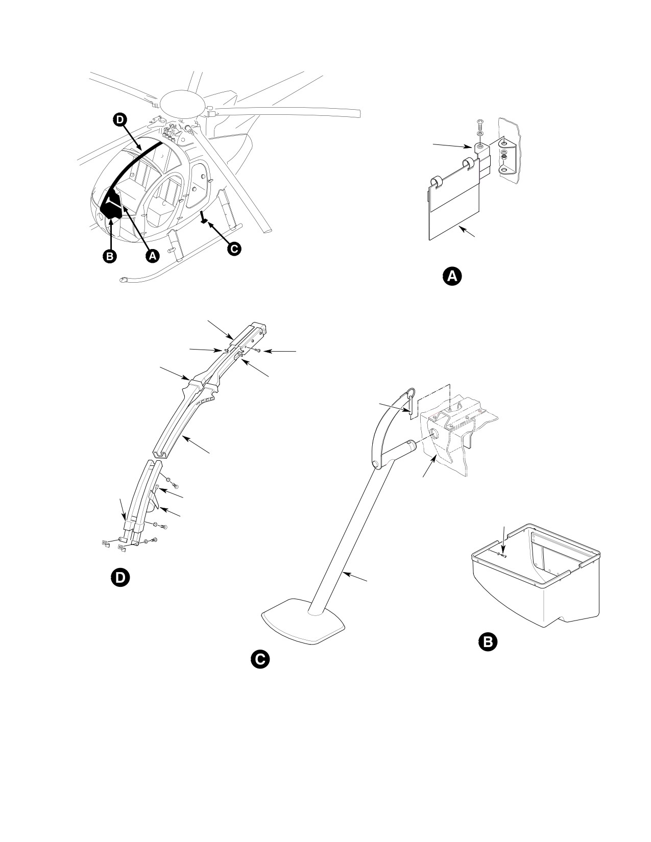
MD Helicopters, Inc.
CSP-HMI-2
MAINTENANCE MANUAL
SWIVEL BRACKET
VNE CARD
VNE CARD HOLDER
OUTER BOX
ANTI-ICING CONTROL
6 PLCS
UPPER SECTION
CABIN HEAT CONTROL
(NOTE 1)
LOCKING PIN
LOWER SECTION
JACKING
END CAP
FITTING
4 PLCS
MAGNETIC COMPASS
10 PLCS
HEAT DUCT AND
MAGNETIC COMPASS
STEP SUPPORT SHAFT
CREW COMPARTMENT
STOWAGE BOX
PASSENGER COMPARTMENT STEP
NOTES:
1.
OPTIONAL EQUIPMENT, (REFER TO
APPLICABLE OPT EQPT MANUAL.)
G25-4001-1A
Figure 201. Miscellaneous Furnishings (369D) (Sheet 1 of 2)
Page 203
25-40-00
Revision 23
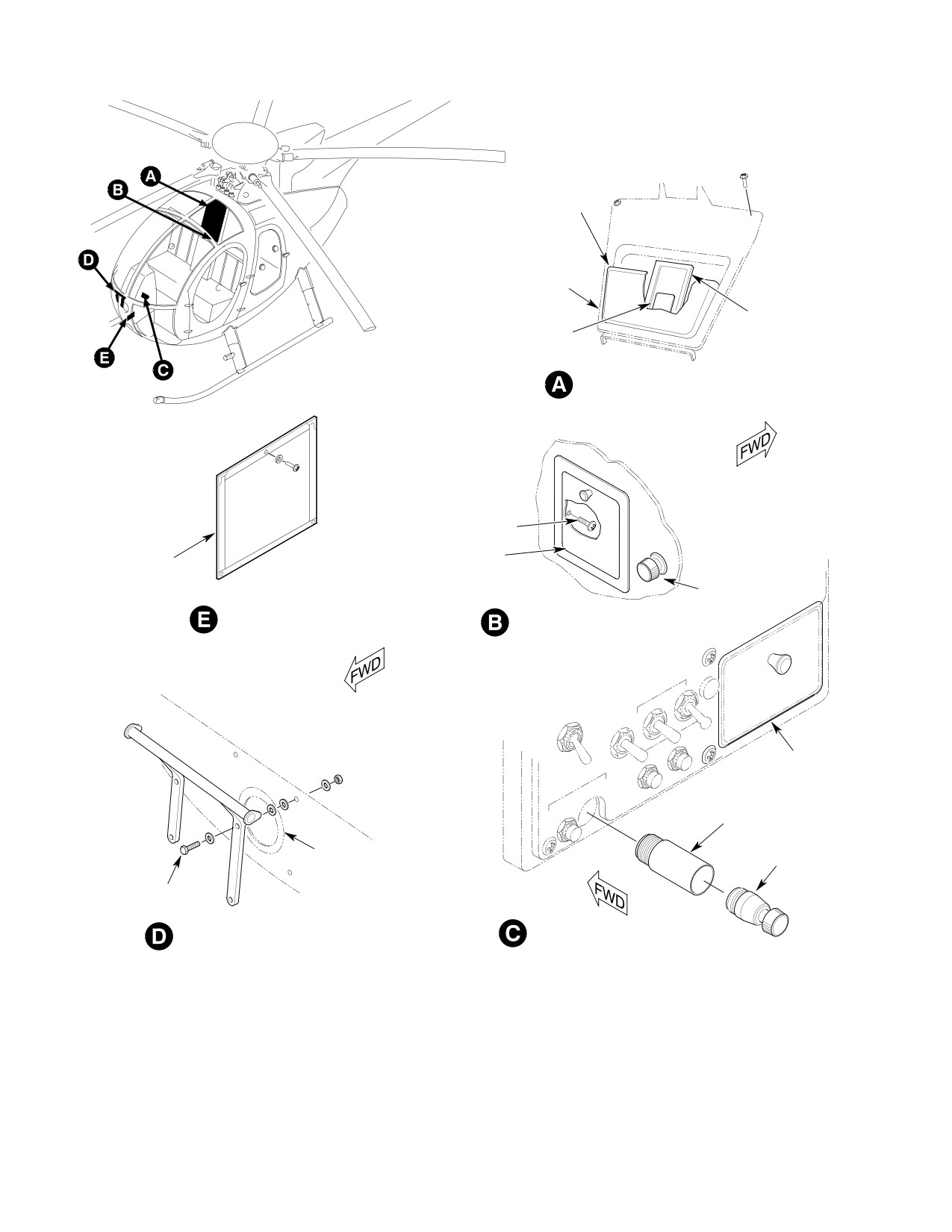
CSP-HMI-2
MD Helicopters, Inc.
MAINTENANCE MANUAL
MAP POCKET
MAP CASE TRIM
COVER
HELICOPTER
MAGNETIC
CHECK LIST
COMPASS CARD
COMPASS CARD AND CHECK LIST
2 PLCS
ASHTRAY
BONDED
(2 PLCS)
CIGARETTE LIGHTER
RECORD HOLDER
ASHTRAY PASSENGER COMPARTMENT
FLOOR SUPPORT
BULKHEAD
ASHTRAY
HOLDER
BULKHEAD COVER
LIGHTER
(NOTE 2)
4 PLCS
ASHTRAY CREW COMPARTMENT
FOOT REST
NOTES: (CONT)
2.
NOTE USED WHEN STROBE LIGHTS
POWER SUPPLY OF NIGHT LIGHTING
G25-4001-2A
SYSTEM IS INSTALLED
Figure 201. Miscellaneous Furnishings (369D) (Sheet 2 of 2)
Page 204
Revision 23
25-40-00
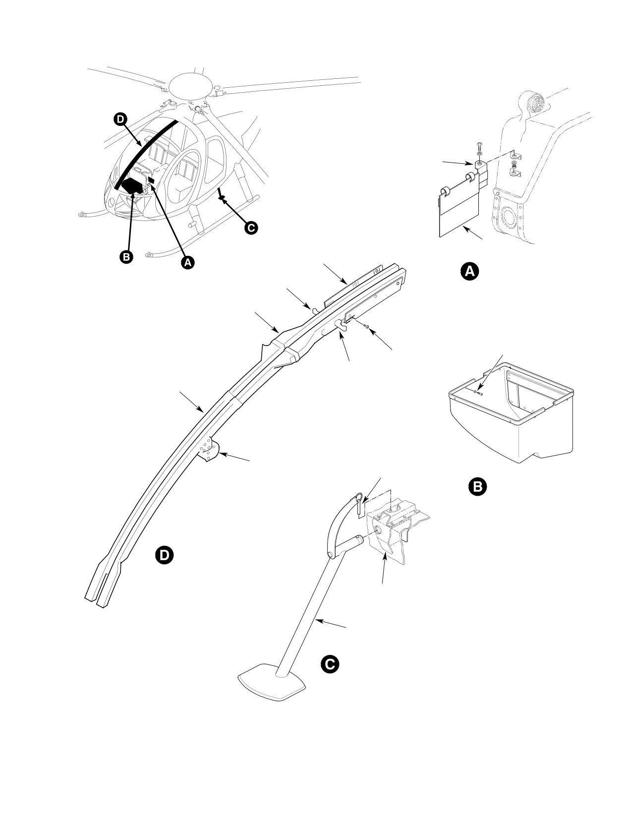
MD Helicopters, Inc.
CSP-HMI-2
MAINTENANCE MANUAL
SWIVEL BRACKET
VNE CARD
COVER
VNE CARD HOLDER
ANTI-ICING CONTROL
UPPER SECTION
10 PLCS
6 PLCS
CABIN HEAT
CONTROL
LOWER SECTION
MAGNETIC COMPASS
LOCKING PIN
CREW COMPARTMENT
STOWAGE BOX
HEAT DUCT AND
MAGNETIC COMPASS
JACKING
FITTING
STEP SUPPORT SHAFT
PASSENGER COMPARTMENT STEP
(369D/E/FF - 500N)
NOTE:
INTERIOR
FURNISHINGS COMMON TO 369D/E/FF -
500/600N HELICOPTERS EXCEPT WHERE
G25-4002-1A
Figure 202. Miscellaneous Furnishings (369E/FF − 500/600N) (Sheet 1 of 2)
Page 205
25-40-00
Revision 23
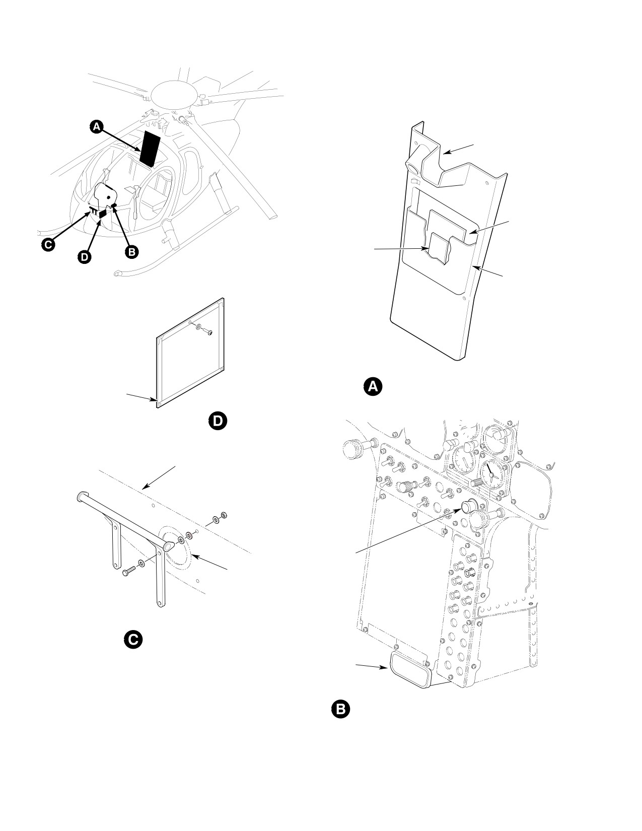
CSP-HMI-2
MD Helicopters, Inc.
MAINTENANCE MANUAL
MAP CASE TRIM
COVER
HELICOPTER
CHECK LIST
MAGNETIC COMPASS CARD
MAP POCKET
BONDED
COMPASS CARD AND CHECK LIST
(2 PLCS)
RECORD HOLDER
FLOOR SUPPORT BULKHEAD
LIGHTER
BULKHEAD COVER
(NOTE)
FOOT REST
ASHTRAY
NOTE:
NOT USED WHEN
ASHTRAY CREW COMPARTMENT
STROBE LIGHTS POWER SUPPLY OF
NIGHT LIGHTING SYSTEM IS INSTALLED.
G25-4002-2A
Figure 202. Miscellaneous Furnishings (369E/FF − 500/600N) (Sheet 2 of 2)
Page 206
Revision 23
25-40-00
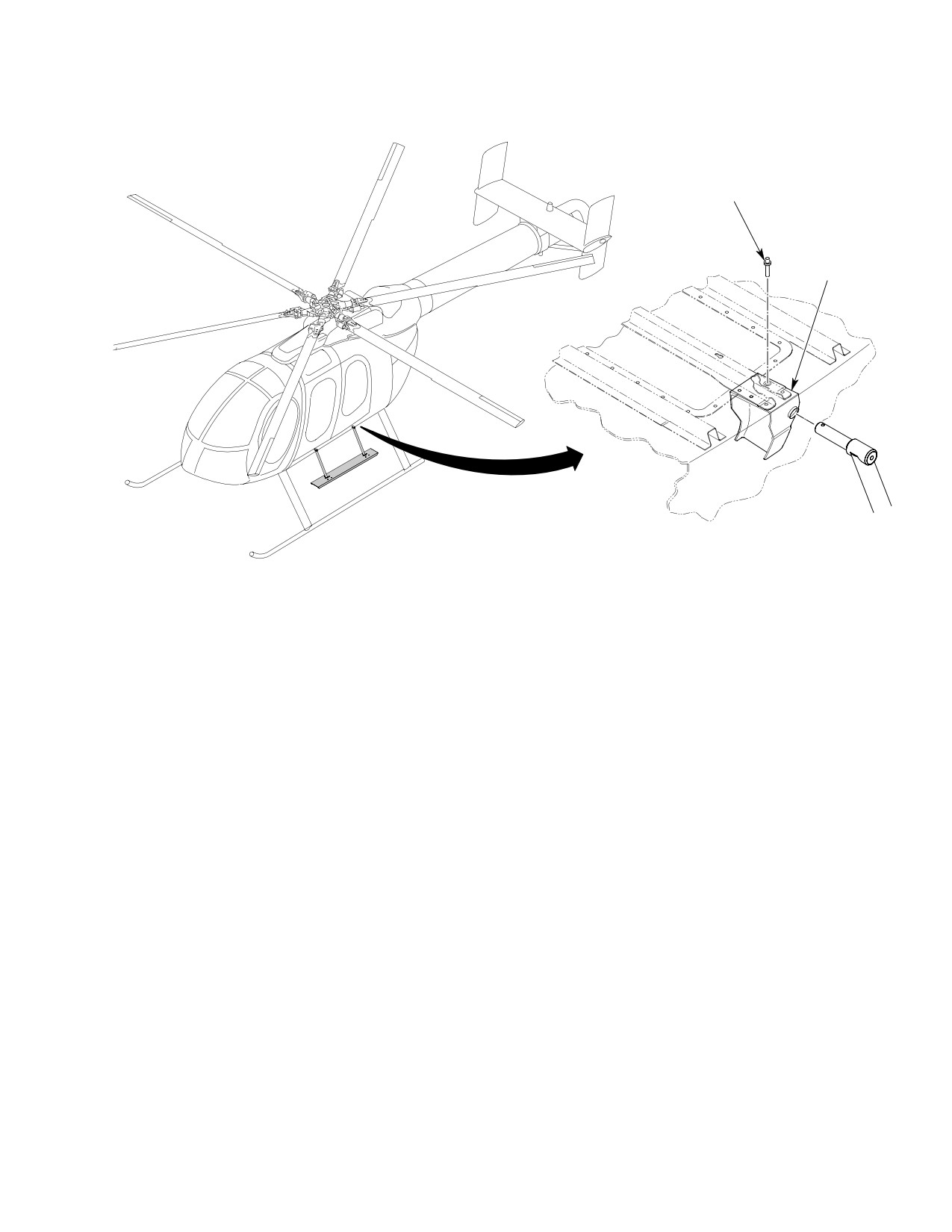
MD Helicopters, Inc.
CSP-HMI-2
MAINTENANCE MANUAL
QUICK
RELEASE PIN
4 PLCS
(TYP)
6G25-080
Figure 203. Passenger Step Assembly (600N)
Page 207
25-40-00
Revision 23
CSP-HMI-2
MD Helicopters, Inc.
MAINTENANCE MANUAL
This Page Intentionally Left Blank
Page 208
Revision 44
25-40-00
MD Helicopters, Inc.
CSP-HMI-2
MAINTENANCE MANUAL
Section
25−50−00
Cargo Hook
MD Helicopters, Inc.
CSP-HMI-2
MAINTENANCE MANUAL
CARGO HOOK
FAULT ISOLATION
1. Cargo Hook Description
located on the left side of the hook body.
Regardless of the method used to release the
The cargo hook provides a means of transport
hook, the hook will return to the closed
ing external cargo. The cargo hook installation
(retracted) position.
consists of a cargo hook assembly, electrical
hook release equipment and backup emergen
3. Cargo Hook Fault Isolation
cy manual release equipment. The cargo hook
(Ref. Table 101) Cargo hook system malfunc
assembly is externally attached to the center
tions might be caused by any one of several
beam of the helicopter at Station 99.325. The
general conditions which are easily corrected.
cargo hook operational rating (external load
Before starting specific troubleshooting
limit) is 2000 pounds.
procedures, make the following checks and
The cargo hook and swivel assembly are
take indicated action for troubleshooting
mounted on the helicopter center beam by four
procedures.
bolts at Station 99.325. The swivel assembly
(1). Refer to applicable wiring diagram and
allows the cargo hook to swing in any direction
check for loose or damaged wires and/or
through a 30-degree arc.
terminals and connectors; reconnect or
replace as required.
2. Cargo Hook Operation
(2). Check for damaged interconnect wires
The cargo hook is normally operated electrical
and/or equipment (Ref. Chap. 96).
ly by pressing the CARGO HOOK switch on
the pilot's cyclic stick grip (Ref. Figure 403).
(3). Check for loose or defective terminal
Actuation of the CARGO HOOK switch
board connections; repair or replace as
energizes a solenoid in the cargo hook. The
required.
maximum electrical current required to
operate the cargo hook solenoid is 14 amperes
(4). Check for loose ground wires.
at 28 Vdc. however, the solenoid is designed to
(5). Make certain circuit breaker is pushed
operate with voltage as low as 23 Vdc. Actua
to full in (closed) position.
tion of the cargo hook solenoid releases the
hook (load beam).
(6). Check system power source.
In the event of an electrical malfunction, the
4. Wiring Diagrams
hook can be released (opened) by pulling a
manual release cable lever attached to the
(Ref. Figure 101) Wiring diagrams of the
pilot's cyclic stick (Ref. Figure 401). The
various cargo hook electrical system circuits
manual release cable releases (opens) the
have been illustrated. Wire charts are provided
cargo hook in the same manner as the electri
in Table 102 and Table 103. For helicopter
cally operated solenoid. The hook can be
electrical system interface information refer to
released for testing or by cargo personnel by
DC Electrical Load Distribution (Ref. Chap.
turning (clockwise) a cargo hook release knob
96).
Page 101
25-50-00
Revision 23

CSP-HMI-2
MD Helicopters, Inc.
MAINTENANCE MANUAL
Table 101. Troubleshooting − Cargo Hook Installation
Symptom
Probable Cause
Corrective Action
NOTE: Following procedures are to be performed with electrical system power on and CARGO HOOK circuit
breaker (CB603) closed.
Hook release operates manually (by
Defective hook ground
Replace hook assembly.
lever) but fails to operate electrically
Defective ground
Secure ground wire.
(by HOOK RELEASE switch).
Defective HOOK RELEASE switch Replace switch.
Defective CARGO HOOK circuit
Replace circuit breaker (CB603).
breaker (CB603)
Hook release operates electrically
Manual release cable housing
Reset adjustment nut at lever−end
(by HOOK RELEASE switch) but
adjusted incorrectly at lever.
of cable housing.
fails to operate manually (by lever).
Defective hook assembly
Replace hook assembly.
Table 102. Wire Chart, 369D/E/FF Right or Left Hand Command.
From
To
Wire No.*
Terminal
Termination
Terminal
Termination
M532A20
TB1−18D
MPCM20M−H2**
K104−X1
Solder
TB1−19B
MPCM20M−H2**
K104−X1
Solder
M531A16
TB3−1D
AYH11−H1**
K104−D2
Solder
M523A20N
J104−X2***
Solder
E24
MS25036−103
M522C16
K104−D1***
Solder
TB3−4A
AYH14−H1**
M520AA16
SP92−B
32447
TB3−1C
AYH14−H1**
J616−q
Crimp
TB3−1C
AYH14−H1**
M520A16
CB603−2
MS25036−106
SP92−A
32447
CB603−2
MS25036−106
P616−q
− −
M520B20
TB1−18C
MPCM20M−H2**
TB3−1D
AYH14−H1**
TB1−18A
MPCM20M−H2**
TB3−1D
AYH14−H1**
TB1−19A
MPCM20M−H2**
TB3−1D
AYH14−H1**
*(Ref. Figure 101 sheets 1 & 2) for applicable wiring diagrams.
**Burndy Corp., Norwalk, Conn.
***K312−X2, _D1 for helicopters equipped with 369D24153 ‘‘Tee’’ console.
Page 102
Revision 23
25-50-00
MD Helicopters, Inc.
CSP-HMI-2
MAINTENANCE MANUAL
Table 103. Wire Chart, 369E/FF T−Panel with Center Electrical Console, R/H Command.
From
To
Wire No.*
Terminal
Termination
Terminal
Termination
M520AA16
K104−X2
Solder
E24
MS25036−103
M532A20
K104−X1
Solder
TB1−8F
M39029/22−192
M531A16
K104−D2
Solder
TB3−1C
M39029/22−193
M531B16
K104−D1
Solder
TB3−8B
M39029/22−193
M520B20
TB3−1E
M39029/22−193
TB1−8E
M39029/22−192
M523C20N
J605−C
MS3193A16−16A
E20
M7928/1−24
M520A16
CB118−2
M7928/1−41
P616− Q
M39029/31−228
M520AA16
J616− Q
M39029/32−247
TB3−1
M39029/22−193
*(Ref. Figure 101 sheet 3) for applicable wiring diagram.
Page 103
25-50-00
Revision 23
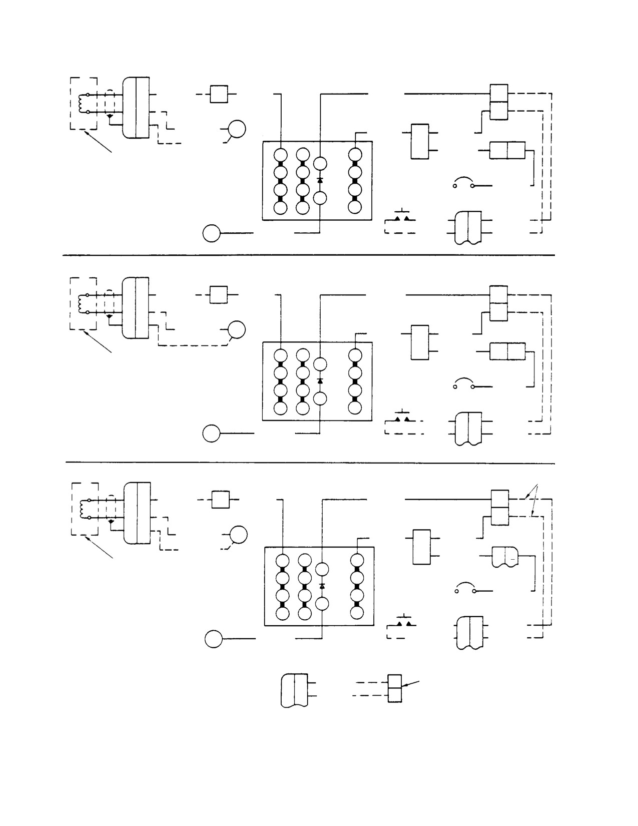
CSP-HMI-2
MD Helicopters, Inc.
MAINTENANCE MANUAL
P605J
TB3-4
TB1-18
A
M522D16
A
M522C16
M523A20
D
B
C
TB3-1
C
M523B16N
E20
M531A16
D
M520B20
K104
SP92
M523BB20
C
M520AA16
B A
CARGO HOOK
D1
D3
D2
X1
C1
C3
C2
CB603
CR3
1
2
369D STANDARD CYCLIC STICK GRIP
M520A16
B1
B3
B2
HOOK RELEASE
15A
3-1149, 1151-1184
X2
SWITCH (S114)
A1
A3
A2
P130J
10-20
A
M522A20
E24
M523A20N
9-20
B
M521E20
P605J
TB3-4
TB1-18
A
M522D16
A
M522C16
M523A20
D
B
A
TB3-1
C
M523B16N E20
K104
M531A16
D
M520B20
SP92
C M520AA16
B A
CARGO HOOK
D1
D3
D2
X1
C1
C3
C2
CB603
CR3
1
2
B1
B3
B2
M520A16
369D OPTIONAL CYCLIC STICK GRIP
HOOK RELEASE
15A
RIGHT OF LEFT HAND COMMAND
X2
SWITCH (S4)
A1
A3
A2
P130J
10-20
E
M520C20
E24
M523A20N
9-20
A
M522A20
P605J
NOTE 1
TB3-4
TB1-19
A
M522D16
A
M522C16
M523A20
B
B
A
TB3-1
C
M523B16N
E20
M531A16
D
M520B20
K104
J616P
M523BB20
C M520AA16
q
CARGO HOOK
D1
D3
D2
X1
C1
C3
C2
CB603
CR3
1
2
369D RIGHT HAND COMMAND
M520A16
B1
B3
B2
HOOK RELEASE
15A
CYCLIC STICK GRIP
X2
SWITCH
3-1149, 1151-1184
A1
A3
A2
P109J
WHT/VIO
OR BLUE
D
M521F20
E24
M523A20N
WHT/GRAY
E
M520F20
NOTES:
OR GRAY
1.
369D294402 CENTER ELECTRICAL CONSOLE:
P109J
TB1-19
-703 WITH ARMAMENT PANEL
-701 WITHOUT ARMAMENT PANEL
B
M521F20
C
NOTE 2
2.
369D294500 CENTER ELECTRICAL CONSOLE
A
M520F20
D
WITH VHF-FM RADIO SET AND ASW EQUIPPED
HELICOPTERS.
G25-5005-1
Figure 101. Cargo Hook − Wiring Diagrams (Sheet 1 of 4)
Page 104
Revision 23
25-50-00
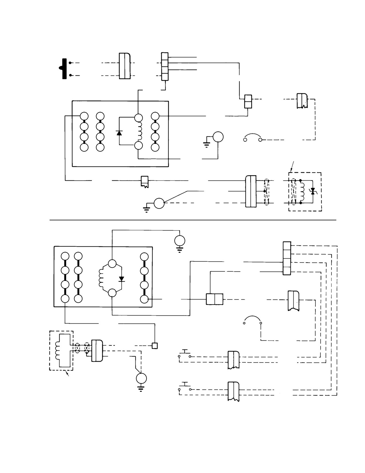
MD Helicopters, Inc.
CSP-HMI-2
MAINTENANCE MANUAL
CARGO HOOK RE
J130P
TB1-12
LEASE SWITCH
A
J109-A (REF)
10 OR BLU
A
M522A20
B
C
J109-B (REF)
S4
9 OR GRY
B
M521E20
D
M520B20
M532A20
TB3-1
J9P
K104
C
M520AA16
l
D
D1
D3
X1
D2
M531A16
C1
C3
C2
CR3
CB603
B1
B3
B2
E24
1
2
M520A16
15A
A1
A3
X2
A2
M523A20N
CARGO HOOK RELEASE
TB3-4
P605J
M522C16
A
M522D16
A
BLK
M523BB20N
C
369D CYCLIC STICK GRIP
LEFT OR RIGHT HAND COMMAND
E20
M523B16N
B
WHT
1150, 1185-1204
TB1-12
E24
K312
C
A1
A3
A2
A
X2
M523A20
D
B1
B3
B2
B
M520B20
CR3
C1
C3
C2
J9P
X1
D1
D3
D2
M531A16
D C
M520AA16
l
TB3-1
CB603
1
2
M531B16
15A
J605P
HOOK RELEASE
SWITCH (PILOT'S)
M520A16
A
M522D16
A
S4
J130P
B
TB3-4
C
M523C20N
A
M522A20
B
M521E20
HOOK RELEASE
SWITCH (CO-PILOT'S)
CARGO HOOK
E20
S4
J109P
ASSEMBLY
A
M522C20
369E/FF CYCLIC STICK GRIP
B
M521G20
LEFT OR RIGHT HAND COMMAND
G25-5005-2
Figure 101. Cargo Hook − Wiring Diagrams (Sheet 2 of 4)
Page 105
25-50-00
Revision 23
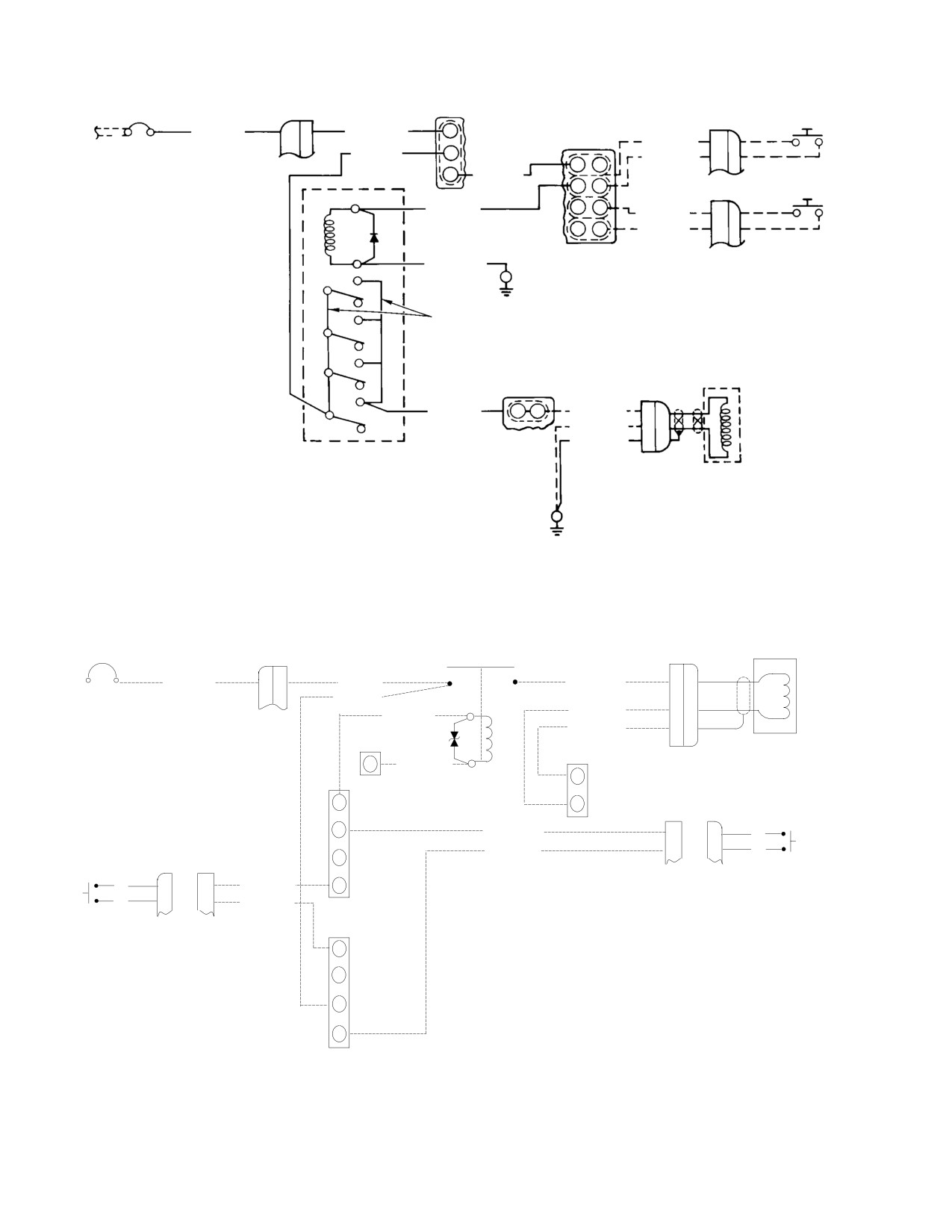
CSP-HMI-2
MD Helicopters, Inc.
MAINTENANCE MANUAL
TB3-1
PILOT
CB118
P616J
J109P
S4
REF
M520A16
Q
M520AA16
A
1
2
15A
TB1-8
M522C20
A
M531A16
C
M521G20
B
E
B
E M520B20
CO-PILOT
F
C
J130P
S4
X1
M532A20
L
H
M522A20
A
M J
M521E20
B
CR3
X2
M523A20N
A1
E24
A2
A3
B1
16 AWG BUS WIRE
B2
B3
C1
C2
C3
TB3-8
J605P
D1
M531B16
B A
M522D16
A
D2
D3
M523B16N
B
M523C20N
C
K104
HOOK
369E/FF RIGHT HAND COM
MAND CONFIGURATION
E20
G25-5005-3
Figure 101. Cargo Hook − Wiring Diagrams (Sheet 3 of 4)
HOOK ASSY
CB603
P/J1202
J/P605
15A
M1015A16
C
M1015B16
M1015C16
A
1
2
M1105A22
M1107A22
M1020A16N
B
X1
M1021A20N
C
K201
HOOK RELAY
X2
E36
M1179A22N
B
E37
B
Y
D
J109
P109
Z
2M1106B22
B
B
9
S4
HOOK
2M1106A22
A
A
10
W
P130
J130
(RIGHT COLLECTIVE GRIP)
S4
9
B
B
1M1106B22
T
HOOK
10
A
A
1M1106A22
TB200-4
(LEFT COLLECTIVE GRIP)
N
P
R
EFFECTIVE 369E 384 & SUBS
S
AND 369FF 076 & SUBS
TB200-4
G25-5005-4
Figure 101. Cargo Hook − Wiring Diagrams (Sheet 4 of 4)
Page 106
Revision 23
25-50-00
MD Helicopters, Inc.
CSP-HMI-2
MAINTENANCE MANUAL
CARGO HOOK
REMOVAL/INSTALLATION
1. Cargo Hook Replacement
cable, installation and adjustment of the
manual release lever as follows:
A. Cargo Hook Removal
(1).
Secure base of cargo hook assembly
Remove the cargo hook assembly including the
(Ref. Figure 404) to fuselage underside
cargo hook manual release cable and electri
with bolts and washers.
cal harness as follows:
(2).
Remove protective cap from cargo hook
electrical receptacle (J605); check that
(1).
Remove cotter pin (Ref. Figure 405),
BATTERY switch is in OFF position
washer, and slotted bushing from
and connect plug (P605) to receptacle.
manual release lever on pilot's cyclic
stick.
(3).
Insert free end of hook manual release
cable through elongated hole adjacent
(2).
Loosen locking nut securing adjustment
to electrical receptacle (Ref.
nut shaft to release lever bracket.
Figure 402). Push manual release cable
up into fuselage and insert cable
(3).
Remove screws (Ref. Figure 401), nuts,
through hole in pilot's floor.
washers, and clamps securing manual
release cable to cyclic stick.
(4).
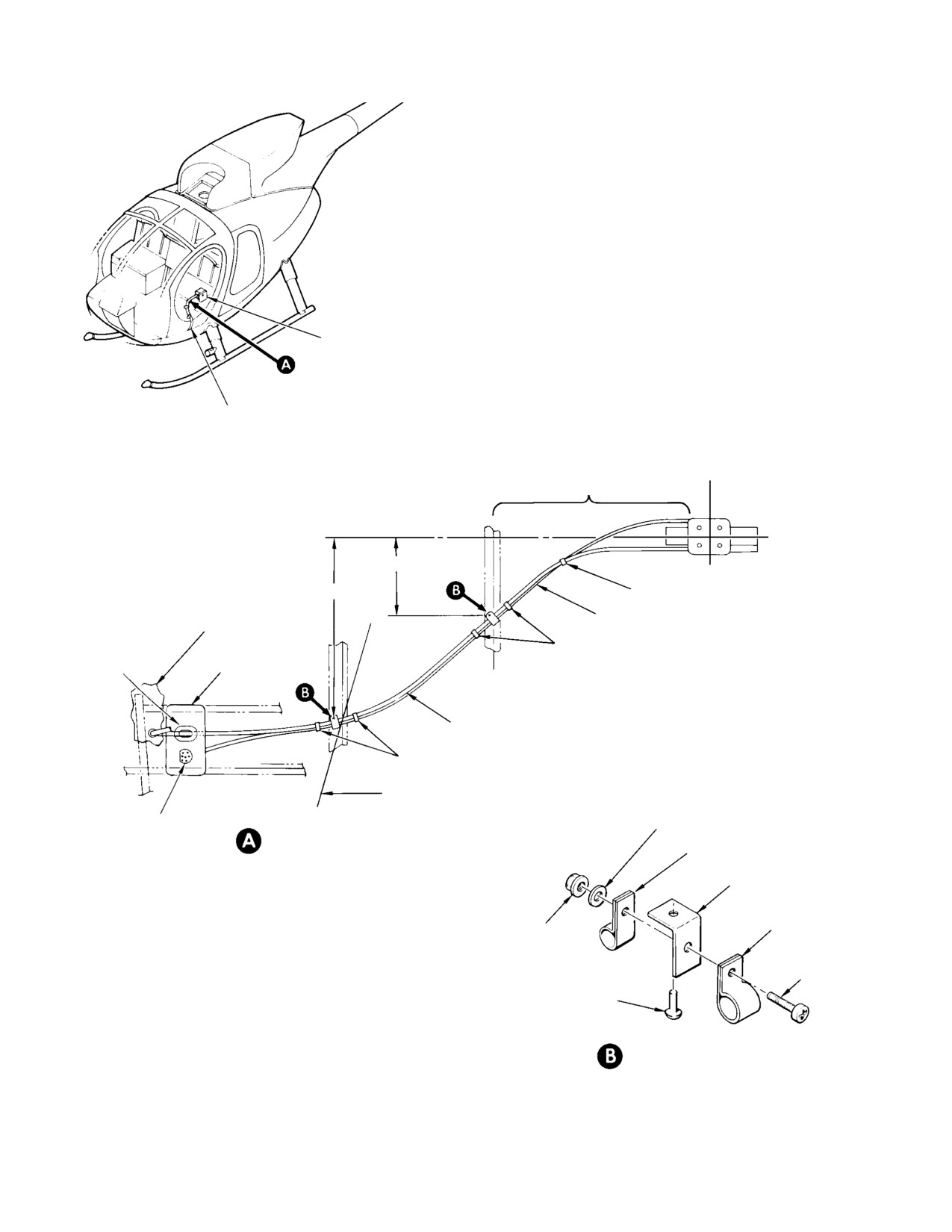
Loosely attach harness and manual
release cable using clamps (Ref.
(4).
Remove adjustment nut shaft (Ref.
Figure 402) screws, washers, and nuts.
Figure 405) from release lever bracket.
Adjust harness and cable to allow
sufficient slack for hook to swing 30
(5).
Loosen dust cover from pilot's cyclic
degrees conically from centerline
stick control trim cover (Ref. Sec.
without creating strain on harness and
25-30-00).
cable. Arrange harness and cable to
(6).
Remove passenger/cargo compartment
form smooth flow to cutouts in fuselage
left foot fairing trim (Ref. Sec.
skin; tighten clamps. Install tie straps
25-30-00).
approximately as shown (Ref.
Figure 402).
(7).
Carefully push manual release cable
NOTE: The 600N helicopters equipped with
(Ref. Figure 401) down through grom
emergency floats require the manual re
mets in pilot's floor and fuselage skin.
lease handle to be mounted on the collective
Do not pull on cable housing.
stick (Ref. Figure 406).
(8).
Remove cargo hook electrical harness
(5). Loosely attach manual release cable to
plug from receptacle in fuselage; install
cyclic stick with clamps, screws,
protective caps on receptacle and plug.
washers, and nuts (Ref. Figure 401).
(9).
Remove clamps (Ref. Figure 402)
(6). Engage approximately half of the
securing cable and harness to clips on
threads on the manual release cable
fuselage underside.
adjustment nut shaft into the bracket
portion of the manual release lever
(10).
Remove four bolts (Ref. Figure 404)
assembly (Ref. Figure 405).
securing cargo hook base to attach
holes in fuselage keel.
(7). Engage swaged ball on release cable in
lever bushing (Ref. Figure 405). Secure
B. Cargo Hook Installation
bushing with washer and cotter pin.
Installation of the cargo hook kit consists of
(8). Attach manual release lever assembly
attaching the hook, and electrical/manual
to cyclic stick with clamp and screws.
release cables on the underside of the helicop
Adjust cable and/or release lever as
ter, routing and securing the manual release
shown (Ref. Figure 405).
Page 401
25-50-00
Revision 23
CSP-HMI-2
MD Helicopters, Inc.
MAINTENANCE MANUAL
(9). Tighten three sets of clamps securing
(12). Install grommet (Ref. Figure 401) in
release cable to cyclic stick.
crew compartment floor cutout.
(10). Perform adjustment/test of cargo hook
(13). Install grommet (Ref. Figure 402) in
installation.
elongated hole in fuselage lower skin
(11). Readjust cable lever (Ref. Figure 405)
and doubler.
as required to obtain smooth consistent
(14). Safetywire manual release lever clamp
release of hook.
screws with lockwire (Ref. Figure 405).
NOTE: The manual release lever clamp may be
loosened and the lever assembly moved on
cyclic stick to simplify adjustment, provid
ing the 2.250 ±0.250 inch (5.715 ±0.635 cm)
dimension limit is maintained
(Ref.
Figure 405).
Page 402
Revision 23
25-50-00
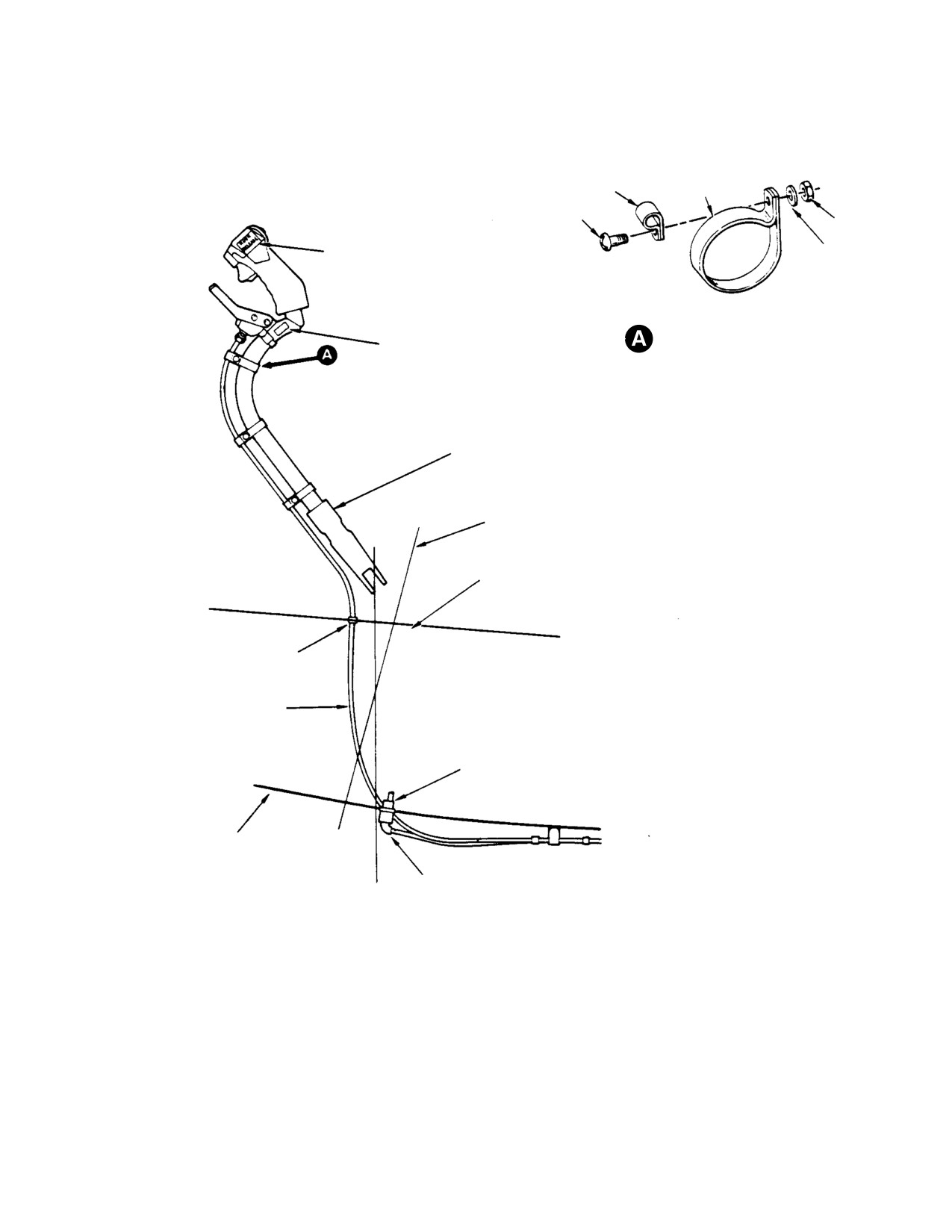
MD Helicopters, Inc.
CSP-HMI-2
MAINTENANCE MANUAL
CLAMP
CLAMP
SCREW
NUT
HOOK RELEASE DECAL (NOT REQUIRED
WASHER
WITH OPTIONAL EQUIPMENT GRIP)
CARGO HOOK
CLAMP INSTALLATION
EMERGENCY RE
(TYP - THREE PLACES)
LEASE DECAL
PILOT'S CYCLIC STICK
CANTED STATION 64.365
CREW COMPARTMENT FLOOR
GROMMET
MANUAL RELEASE CABLE
ELECTRICAL RECEPTACLE (J605)
FUSELAGE SKIN LINE
ELECTRICAL PLUG (P605)
STA 63
G25-5000
Figure 401. Manual Release Cable Routing − Interior
Page 403
25-50-00
Revision 23
CSP-HMI-2
MD Helicopters, Inc.
MAINTENANCE MANUAL
CARGO HOOK
MANUAL RELEASE CABLE
AND ELECTRICAL HARNESS
STATION
99.325
NOTE 4
BUTT LINE 00
(CENTERLINE)
5.5 ±0.5 INCHES
11.5 ±0.5 INCHES
STRAP (NOTE 3)
CREW COMPARTMENT
ELECTRICAL WIRE HARNESS
FLOOR
STRAP
FUSELAGE
GROMMET
SKIN LINE
STATION
84.79
MANUAL RELEASE CABLE
STRAP
CANTED STATION 78.50
ELECTRICAL
EXTERIOR ATTACHMENT OF MANUAL
WASHER
RECEPTACLE
RELEASE CABLE AND ELECTRICAL
WIRE HARNESS
CLAMP (ELECTRICAL)
CLIP
NOTES:
1.
LEFT HAND COMMAND ILLUSTRATED. RIGHT HAND COMMAND
CLAMP
DIMENSIONS THE SAME EXCEPT ON OPPOSITE SIDE.
NUT
(MANUAL)
2.
EXISTING RIVET LOCATION AT STATION 84.79.
3.
P4 HUCK RIVET MAY BE USED INSTEAD AT STATION 84.79.
SCREW
4.
HARNESS AND CABLE TIED TOGETHER MIDWAY BETWEEN
STATION 84.79 AND HOOK ASSEMBLY.
RIVET (NOTES 1, 2)
5.
MAINTAIN SUFFICIENT SLACK IN NOTED SECTION OF CABLE
AND HARNESS TO ALLOW HOOK TO SWING 30 DEGREES
CONICALLY FROM CENTERLINE WITHOUT CREATING STRAIN
CLAMP ATTACHMENT
ON CABLE AND HARNESS.
(TYPICAL)
G25-5001
Figure 402. Manual Release Cable and Electrical Wire Harness Routing − Exterior
Page 404
Revision 23
25-50-00
MD Helicopters, Inc.
CSP-HMI-2
MAINTENANCE MANUAL
CARGO HOOK RELEASE
CIRCUIT BREAKER
369D LEFT-HAND
COMMAND CONFIGURATION
CARGO HOOK RELEASE
CIRCUIT BREAKER
369E/FF ”TEE” PANEL
LEFT-HAND COMMAND CONFIGURATION
CIRCUIT BREAKER PANEL
HOOK RELEASE DECAL
CARGO HOOK RE
LEASE SWITCH
CARGO HOOK RELEASE
RIGHT-HAND COMMAND
CIRCUIT BREAKER
WITH CENTER ELECTRICAL
CONSOLE CONFIGURATION
REMOVE PLUG BUTTON
AND INSTALL CARGO
HOOK RELEASE SWITCH
STANDARD GRIP
HOOK RELEASE DECAL
CARGO HOOK RE
OPTIONAL
LEASE SWITCH
”T” GRIP
HOOK RELEASE SWITCH
OPTIONAL
EQUIPMENT
GRIP
PILOT'S CYCLIC STICK GRIP
G25-5002
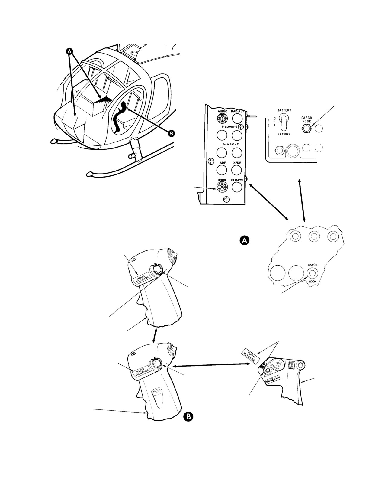
Figure 403. Cargo Hook Electrical Equipment Installation
Page 405
25-50-00
Revision 23
CSP-HMI-2
MD Helicopters, Inc.
MAINTENANCE MANUAL
DECAL
DECAL
FUSELAGE LOWER
SKIN SURFACE
NEOPRENE PAD
0.090 X 1.75 X 4.0 IN.
(0.229 X 4.445 X
10.16 CM) (NOTE)
NEOPRENE PAD
0.090 X 1.75 X 1.75
WASHER (4 PLACES)
IN. (0.229 X 4.445 X
4.445 CM) (NOTE)
BOLT (4 PLACES)
EXTERNAL RELEASE
(TURN CLOCKWISE)
ELECTRICAL WIRE
HARNESS
SWIVEL
STA 99.325
KEEPER
1.62 ±0.12 IN.
(4.1148 ±0.3048 CM)
1.12 ±0.12 IN.
MANUAL RELEASE CABLE
(2.8448 ±0.3048 CM)
HOOK (LOAD BEAM)
1.00 ±0.12 IN.
(2.54 ±0.3048 CM)
LONGITUDINAL
CENTERLINE OF
FWD
4-HOLE LAYOUT
1.88 ±0.12 IN. (4.7752 ±0.3048 CM)
2.00 ±0.12 IN.
(5.08 ±0.3048 CM)
3.75 ±0.12 IN.
(9.525 ±0.3048 CM)
(2 PLCS)
LATERAL CENTERLINE
NOTE:
OF 4-HOLE LAYOUT
PADS PREVENT FUSELAGE SKIN DAM
AGE AT HOOK CONTACT POINTS.
G25-5003A
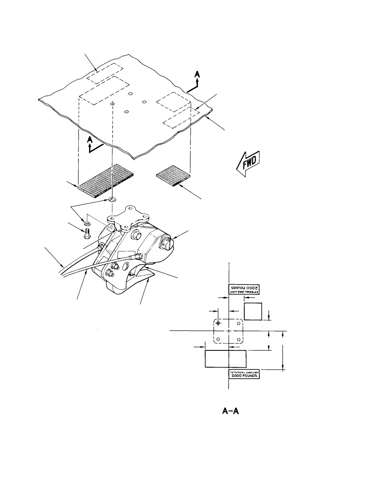
Figure 404. Hook and Pad − Installation
Page 406
Revision 23
25-50-00
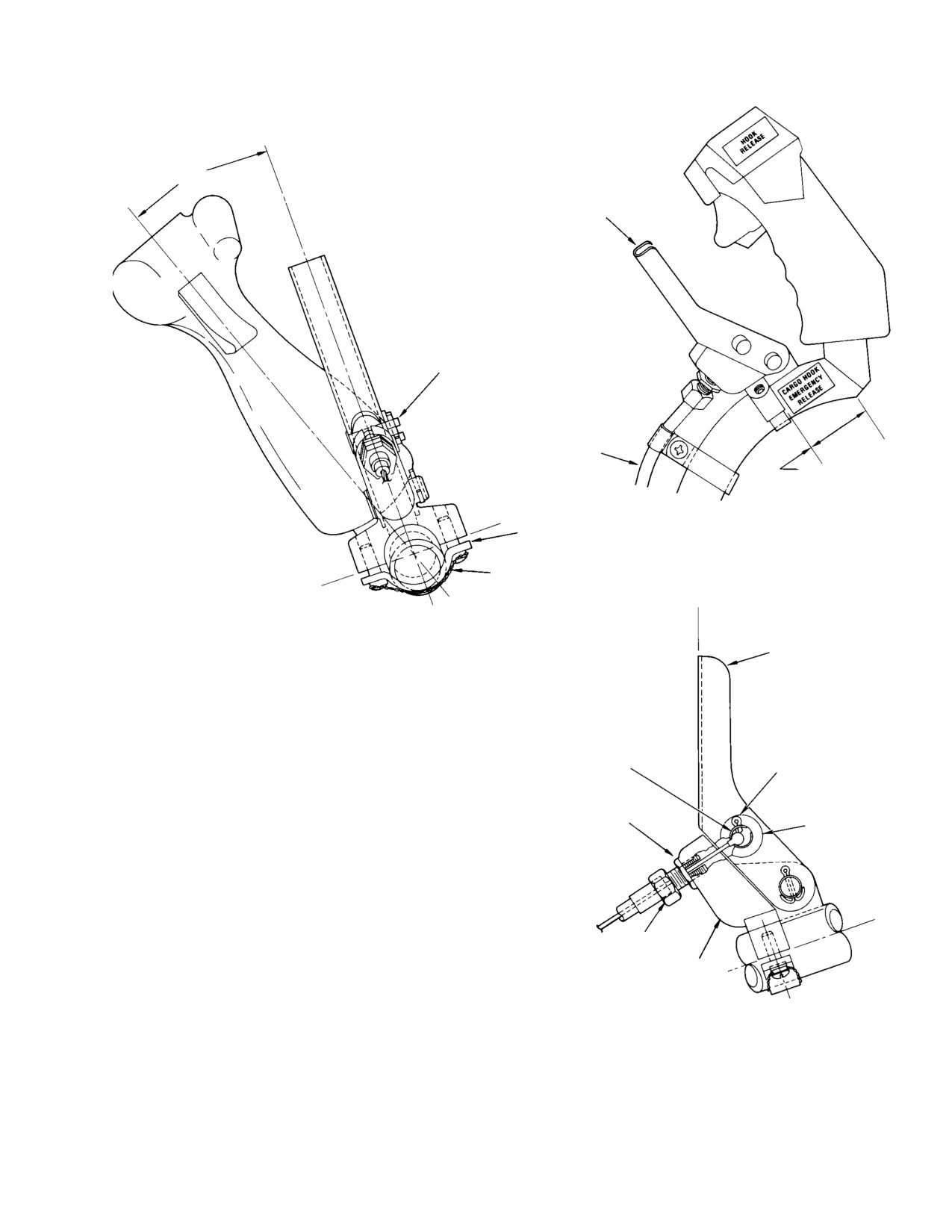
MD Helicopters, Inc.
CSP-HMI-2
MAINTENANCE MANUAL
20° (NOTE 2)
CARGO HOOK MANUAL RE
LEASE LEVER ASSEMBLY
SLOTTED BUSHING
(NOTE 5)
CARGO HOOK
RELEASE CABLE
2.250 ±0.250
INCHES
POSITIONING LEVER ON STICK
CLAMP
LOCKWIRE
HOOK-ENGAGED LEVER
POSITION (NOTES 3, 6)
LOOKING AFT AND DOWN
CARGO HOOK
RELEASE LEVER
BALL TERMINAL
COTTER PIN
(NOTE 1)
LOCKING NUT
(NOTE 4)
WASHER
NOTES:
1.
CABLE BALL TERMINAL RETAINED IN SLOTTED BUSHING OF RELEASE LEVER.
2.
APPROXIMATE ANGULAR POSITION OF LEVER REQUIRED FOR
CONVENIENCE AND RELEASE OF CARGO HOOK.
3.
CABLE BALL TERMINAL AFT TRAVEL SHOULD BE APPROXIMATELY
ADJUSTMENT
1/2 INCH TO RELEASE HOOK.
NUT (NOTE 4)
4.
WITH LOCKING NUT LOOSENED, TURN ADJUSTMENT NUT TO PULL RELEASE
RELEASE
LEVER TO FULL FORWARD (HOOK ENGAGED) POSITION WITH SLIGHT
BRACKET
TENSION ON CABLE; TIGHTEN LOCKING NUT. IF REQUIRED, ADJUST
POSITION OF LEVER ASSEMBLY ON CYCLIC STICK.
LOOKING INBOARD FROM
5.
BUSHING 369H92631 MAY BE USED AS ALTERNATE.
LEFT SIDE OF HELICOPTER
6.
LEVER SHOULD NOT MOVE FROM HOOK-ENGAGED POSITION WHEN
CYCLIC STICK IS MOVED THROUGH FULL TRAVEL IN ALL DIRECTIONS.
G25-5004
Figure 405. Cargo Hook Manual Release Lever − Installation
Page 407
25-50-00
Revision 23
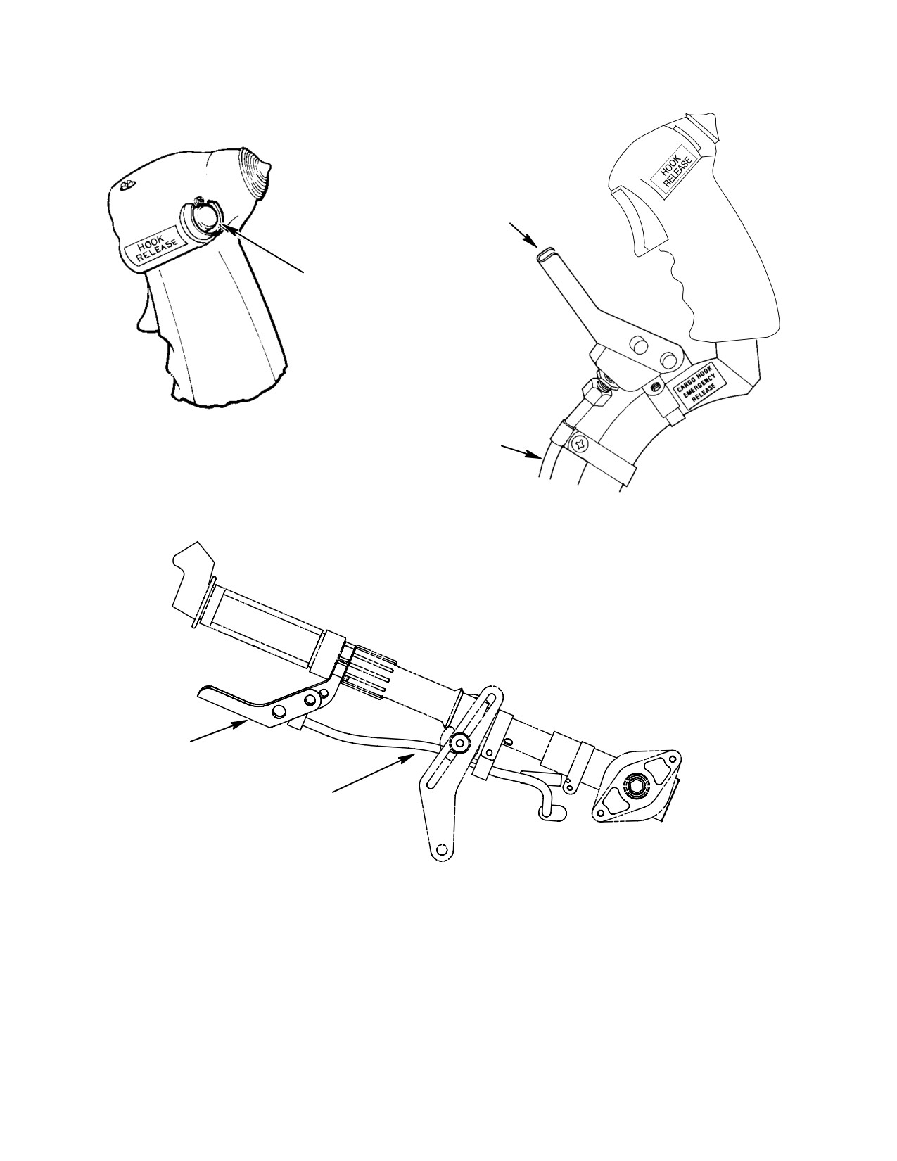
CSP-HMI-2
MD Helicopters, Inc.
MAINTENANCE MANUAL
CARGO HOOK MECHANI
CAL RELEASE
CARGO HOOK ELEC
TRICAL RELEASE
CYCLIC-MOUNTED electrical hook release
CARGO HOOK
RELEASE CABLE
STANDARD CYCLIC-MOUNTED mechanical hook release
CARGO HOOK MECHANICAL RELEASE
CARGO HOOK RELEASE CABLE
collective-MOUNTED mechanical hook release (note)
NOTE: for 600N MODEL helicopters equipped with the optional emer
gency float installation, stc# sr00471la.
60-052-1
Figure 406. Cargo Hook Release for 600N Helicopters
Page 408
Revision 23
25-50-00
MD Helicopters, Inc.
CSP-HMI-2
MAINTENANCE MANUAL
CARGO HOOK
INSPECTION/CHECK
1. Cargo Hook Operational Check
Cargo hook must remain
WARNING
closed while moving
Perform the following operational check
through all positions of extreme travel
procedure whenever it is necessary to verify
fore and aft as well as side-to-side.
that the cargo hook system is operating
(8). Grasp load ring and pull downward
properly:
while moving cargo hook manually full
travel side-to-side. Ensure hook (load
(1). Place battery switch in BATTERY
beam) remains in locked position.
position.
2. Adjustment
(2). Check that CARGO HOOK/HOOK
Adjust the manual release cable so that the
circuit breaker is pressed to full in
2.250 ±0.250 inch (5.715 ±0.635 cm) dimension
position (Ref. Figure 402).
shown (Ref. Figure 405) is maintained.
NOTE: Cargo load rings (or equivalent check
3. Exterior Components Inspection
tool) with a maximum cross-section thick
On cargo hooks, manufac
ness of 3/4 inch can be used for testing or for
WARNING
tured by Breeze-Eastern,
cargo transport operations.
Model 2A20B, P/N 17149-1 thru -5, en
sure Warning Plate P/N 13830-1 is at
(3).
Push cargo load ring forward into hook
tached to the manual release side of the
throat (Ref. Figure 404); keeper should
cargo hook. If Warning Plate is not
permit easy entrance to hook throat.
installed, contact Breeze-Eastern for
Warning Plate and installation instruc
(4).
Pull aft and downward on load ring;
tions.
hook must remain in locked position.
(1).
Make certain that neoprene pads (Ref.
Figure 404) are securely bonded to skin.
(5).
Rotate external release knob located on
Check pads for excessive wear.
left side of cargo hook body, while
pulling downward on load ring; hook
(2).
Verify security of four bolts attaching
(load beam) bar should drop and release
hook assembly to fuselage (Ref.
load ring.
Figure 404); examine hook assembly for
damage or excessive wear. Check that
(6).
Reinsert load ring in hook throat. Pull
hook body swivels freely in all direc
CARGO HOOK EMERGENCY RE
tions.
LEASE (manual release) lever on pilot's
(3).
Verify security of clips and clamps
cyclic stick while load ring is being
attaching electrical wire harness and
pulled downward; hook (load beam)
manual release cable housing to
should release load ring. Reinsert load
fuselage (Ref. Figure 402).
ring and move pilot's cyclic stick to all
extreme positions; CARGO HOOK
(4).
Verify presence and security of grom
EMERGENCY RELEASE lever must
met (Ref. Figure 401) through which
not move from hook-engaged position
manual release cable passes at fuselage
and hook load beam must remain in
skin.
locked position.
(5).
Check electrical wire harness for cuts,
wear, and skinned insulation.
(7).
Press CARGO HOOK switch on pilot's
cyclic stick grip (Ref. Figure 403) while
(6).
Examine manual release cable housing
load ring is being pulled downward;
for nicks, cuts, kinks, dents, or general
hook load beam should release load
damage that would restrict movement
ring.
of cable within housing.
Page 601
25-50-00
Revision 23
CSP-HMI-2
MD Helicopters, Inc.
MAINTENANCE MANUAL
4.
Interior Components Inspection
NOTE: The 600N helicopters equipped with
emergency floats require the manual re
lease handle to be mounted on the collective
(1). Verify security of electrical receptacle
stick (Ref. Figure 406)
(J605) at fuselage connection (Ref.
Figure 401).
(6). Verify security of clamps attaching
manual release cable housing to pilot's
cyclic stick (Ref. Figure 401); check for
(2). Examine electrical wire harness for
damage to manual release cable
cuts, wear, or skinned insulation.
housing that might restrict movement
of cable.
(3). Check manual release cable housing for
nicks, cuts, kinks, dents, or general
(7). Check security of manual release lever
damage that would restrict movement
attachment to pilot's cyclic stick (Ref.
of cable within housing.
Figure 405).
(8). Examine decals (Ref. Figure 403) for
(4). Verify presence and security of grom
secure attachment and legibility.
met where manual release cable passes
through pilot's floor (Ref. Figure 401).
(9). Examine cargo hook circuit wiring for
damage and/or loose connections.
(5). Check security of manual release cable
(10). Verify secure installation of CARGO
housing adjustment nut; verify that
HOOK circuit breaker and HOOK
release lever freely returns to hook-en
RELEASE push-button switch (Ref.
gaged position (Ref. Figure 405).
Figure 403).
Page 602
Revision 23
25-50-00
MD Helicopters, Inc.
CSP-HMI-2
MAINTENANCE MANUAL
CARGO HOOK
INITIAL INSTALLATION
1. Cargo Hook Initial Installation
NOTE: Fuselage cutouts for left and right hand
command are as illustrated
(Ref.
Procedures in this section may be performed at
Figure 901). Use applicable dimensions ac
the operator's discretion and are applicable to
cording to the model helicopter being modi
369D/E/FF - 500N helicopters. These instruc
fied.
tions provide for the installation of the cargo
hook assembly.
(1). Make cutouts in three places as
illustrated (Ref. Figure 901).
A. Preparation for Installation
Consumable Materials
Preparation for installation of the cargo hook
(Ref. Section 91−00−00)
assembly includes the following:
Item
Nomenclature
(1). Identify all components, including
CM318
Primer
attaching hardware, or components to
be removed for access to work areas.
(2). Deburr cutouts and apply thin coat of
Protect components from damage and
primer (CM318) to exposed bare metal.
contamination until installed.
D. Cargo Hook Provisions Installation
(2). Check that all electrical switches are in
OFF position.
(Ref. Figure 404) The following procedure
involves installation of the cargo hook provi
(3). Make certain BATT-OFF-EXT switch
sions exclusive of the cargo hook assembly kit.
is in OFF position.
To complete installation of the cargo hook
system, both cargo hook provisions, and the
B. Helicopter Equipment Removal
cargo hook assembly kit installations must be
(Ref. Figure 404) Prior to installing the cargo
accomplished. Hook provision equipment
hook, a limited number of items must be
omitted in the following procedure is included
removed from the helicopter to accommodate
in the cargo hook installation procedure.
cargo hook installation.
Install cargo hook provisions as follows:
(1). Remove plug button from cargo switch
Consumable Materials
hole in stick grip; discard plug button.
(Ref. Section 91−00−00)
Item
Nomenclature
(2). Remove passenger/cargo compartment
left support fairing.
CM206
Chemical coating
CM228
Surface cleaner
(3). Remove passenger/cargo compartment
CM230
Paint remover
seat.
CM318
Primer
(4). Remove cyclic stick control cover.
CM418
Cement, epoxy
(5). Remove pilot's floor left covering.
NOTE: The cargo hook and provision kits are
(6). Remove pilot's floor left access door.
supplied with as many parts assembled as
practical, however, some parts might re
C. Modification of Helicopter
quire assembly at installation. The operator
should omit those steps which may have al
Modification of the helicopter consists of
ready been accomplished.
cutouts in the pilot's floor and fuselage lower
skin to accommodate routing of the cargo hook
(1). Install cargo hook neoprene pads as
manual control cable and electrical harness.
follows:
Page 901
25-50-00
Revision 23
CSP-HMI-2
MD Helicopters, Inc.
MAINTENANCE MANUAL
(a). Remove paint from fuselage skin in
E. Electrical Components and Wiring
pad installation areas as shown; use
Installation (Left and Right Hand
paint remover (CM230).
Command)
(b). Clean metal in areas where paint as
Consumable Materials
removed; use surface cleaner
(Ref. Section 91−00−00)
(CM228).
Item
Nomenclature
CM404
Adhesive, epoxy
(c). Bond neoprene pads to skin at
CM614
Sleeving, heat-shrink
locations shown; use adhesive
CM704
Tie strap, nylon
(CM418).
NOTE: The order and manner of installation
(2). Prime and touch-up border areas
for left or right hand command is the same.
around pads as follows:
Refer to dimensions given in applicable fig
ures, for model of helicopter being modified.
(a). Wash affected area with solution of
(1). Make certain BATTERY switch is in
mild soap and fresh water. Rinse
OFF position.
area with clean water and wipe dry
with clean lint-free cloth.
(2). Disconnect battery connector.
(3). Connect cargo hook switch to existing
(b). Using swab, liberally apply chemical
wires according to stick grip and model
film (CM206).
helicopter being modified. Insulate
wires and contacts on switch with
(c). Allow solution to remain on surface
sleeving (CM614). Ref. Table 901 and
for 1 to 3 minutes, or until surface
applicable wiring diagrams (Ref.
becomes amber to brown in color.
Figure 101).
(4). Install switch guard on switch. Apply
NOTE: Avoid letting chemical mixture dry on
small amount of adhesive (CM404) to
surface. If it has dried, re-wet surface with
O.D. of switch.
solution.
(5). Install switch in grip. Allow minimum
(d). Rinse treated surface with clean
cure time of 24 hours ±30 minutes.
water. After rinsing, wipe off excess
(6). Install relay on bracket with screws,
moisture with clean lint-free cloth.
washers, and nuts (Ref. Figure 902).
Allow area to dry completely at room
temperature for 1 hour.
Table 901. Cargo Hook Relay Installation
Relay Model Location
Remarks
(e). Wipe surface clean with thinner and
dry off immediately.
K104
D
369A2519
Slim console
Bulkhead
(f). Apply primer (CM318) and allow to
K312
E/FF
369H2500
T−Panel
dry for 30 minutes.
Bulkhead
(g). Apply lacquer to match original
(7). Locate existing mounting holes accord
factory finish color.
ing to model of helicopter being modi
fied. (Ref. Table 902 and Figure 902).
NOTE: Installation of the cargo hook manual
Using relay bracket as a template,
release lever assembly and clamp assem
mark and drill attachment hole(s)
blies is accomplished during installation of
0.165-0.177 inch (4.191-4.4958 mm) in
the cargo hook kit.
bulkhead as required.
Page 902
Revision 23
25-50-00
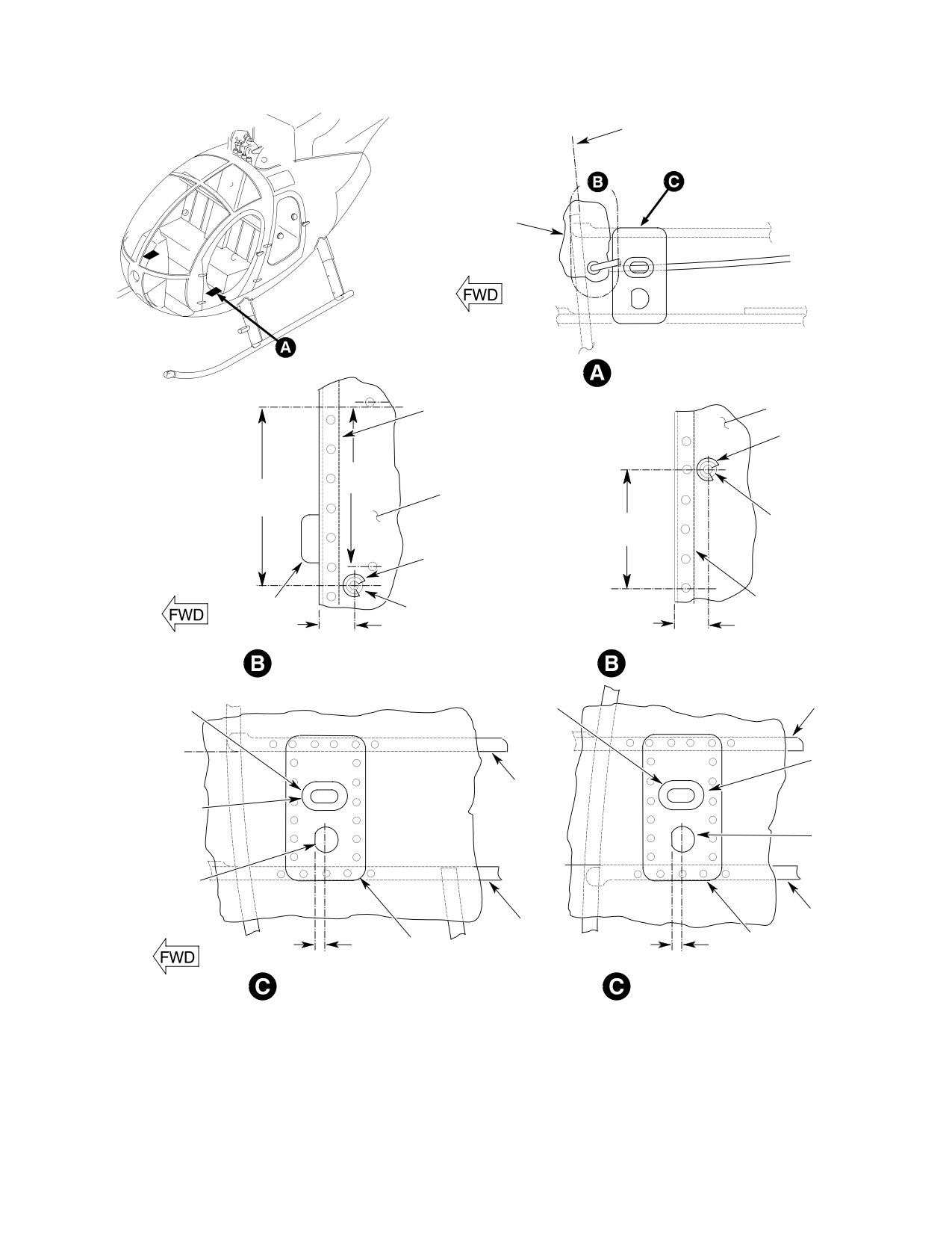
MD Helicopters, Inc.
CSP-HMI-2
MAINTENANCE MANUAL
STA. 64.365
CREW COMPARTMENT
DOOR
10.00 LBL
CHANNEL
PILOT'S FLOOR
GROMMET
4.25 IN.
5.00 ±0.25 IN.
(10.795 CM)
PILOT'S FLOOR
(12.7 ±0.635 CM)
0.555-0.562 IN.
3.00 ±0.25 IN.
(14.0970-14.2748 MM)
(7.62 ±0.625 CM)
HOLE
GROMMET
10.00 RBL
CLIP
0.555-0.562 IN.
CHANNEL
(14.0970-14.2748 MM)
0.88 IN.
0.88 IN.
(22.352 MM)
(22.352 MM)
HOLE
CREW COMPARTMENT FLOOR CUTOUT
CREW COMPARTMENT FLOOR CUTOUT
(LEFT-HAND COMMAND)
(RIGHT-HAND COMMAND)
LONGERON
GROMMET
GROMMET
12.05 LBL
0.68 X 1.18 IN.
(17.272 X
STIFFENER
29.972 MM)
0.68 X 1.18 IN.
(NOTE 1)
(17.272 X
29.972 MM)
0.890-0.901 IN.
(NOTE 1)
(22.606-
12.05 RBL
22.8854 MM)
(NOTE 2)
0.890-0.901 IN.
(22.606-
22.8854 MM)
(NOTE 2)
LONGERON
STIFFENER
0.38 IN.
DOUBLER
0.38 IN.
DOUBLER
(9.652 MM)
(9.652 MM)
DOUBLER INSTALLATION
DOUBLER INSTALLATION
(LEFT-HAND COMMAND)
(RIGHT-HAND COMMAND)
NOTES:
1.
SLOT IN SKIN TO MATCH SLOT IN DOUBLER.
2.
HOLE IN SKIN TO MATCH HOLE IN DOUBLER.
G25-5006A
Figure 901. Fuselage Skin Cutouts
Page 903
25-50-00
Revision 23
CSP-HMI-2
MD Helicopters, Inc.
MAINTENANCE MANUAL
(8).
Attach relay bracket to bulkhead with
manual release cables on the underside of the
screws, washers and nuts. Identify
helicopter, routing and securing the manual
relay as indicated (Ref. Table 902),
release cable, and installation and adjustment
using a suitable contrasting permanent
of the manual release lever.
ink.
(1).
Secure base of cargo hook assembly to
(9).
On left hand command helicopters,
fuselage underside with bolts and
remove edgelighted panel from lower
washers (Ref. Figure 404).
switch and circuit breaker panel: loosen
lower circuit breaker panel. Remove
(2).
If installed, remove protective cap from
hole cover button; install circuit
cargo hook electrical receptacle (J605);
breaker (CB603) (Ref. Figure 402).
check that BATTERY switch is in OFF
position and connect plug (P605) to
(10).
On right hand command helicopters
receptacle.
with center electrical console, remove
edgelighted panel from circuit breaker
(3).
Insert free end of hook manual release
panel located on the pilot's collective
cable through elongated hole adjacent
pitch stick cover; loosen circuit breaker
to electrical receptacle; push manual
panel remove hole cover button; install
release cable up into fuselage and
circuit breaker (Ref. Figure 402).
insert cable through hole in pilot's floor
(Ref. Figure 401).
(11).
On right or left hand command helicop
ters with standard cyclic stick grip,
(4).
Install electrical harness and manual
install module and cover on TB3.
release cable clamp (provision) clips
with rivets (Ref. Figure 402).
(12).
Install cargo hook circuit wiring; see
applicable wiring diagram (Ref.
(5).
Loosely attach harness and cable
Figure 101). For wire termination and
clamps with screws, washers and nuts;
terminal hardware, refer to Table 102.
adjust harness and cable to allow
(13).
Install cargo hook electrical connector
sufficient slack for hook to swing 30
with washer and connector nut. Install
degrees conically from centerline
protective cap on receptacle if cargo
without creating strain on harness and
hook kit is not being installed concur
cable. Arrange harness and cable to
rent with provisions.
form smooth flow to cutouts in fuselage
skin; tighten clamps. Install tie straps
(14).
Secure cargo hook circuit wiring with
(CM704) approximately as shown (Ref.
tie-straps (CM704) as required. Check
Figure 402).
that wires and terminals are not
stressed.
(6).
Loosely attach manual release cable to
cyclic stick with clamps, screws,
(15).
Check all wiring for correct installation
washers, and nuts (Ref. Figure 401).
and security of attachment.
(7).
Engage swaged ball on release cable in
(16).
Connect battery connector.
lever bushing; secure bushing with
F. Cargo Hook Installation
washer and cotter pin (Ref. Figure 405).
(8).
Attach manual release lever assembly
Consumable Materials
to cyclic stick with clamp and screws;
(Ref. Section 91−00−00)
adjust cable and/or release lever as
Item
Nomenclature
shown (Ref. Figure 401).
CM429
Sealing compound, silicone
CM702
Lockwire CRES
(9).
Tighten three sets of clamps securing
release cable to cyclic stick.
CM704
Tie strap, nylon
(10).
Check that hook does not release when
The cargo hook installation consists of
cyclic stick is moved to extremes in all
attaching the hook and emergency electrical/
directions.
Page 904
Revision 23
25-50-00
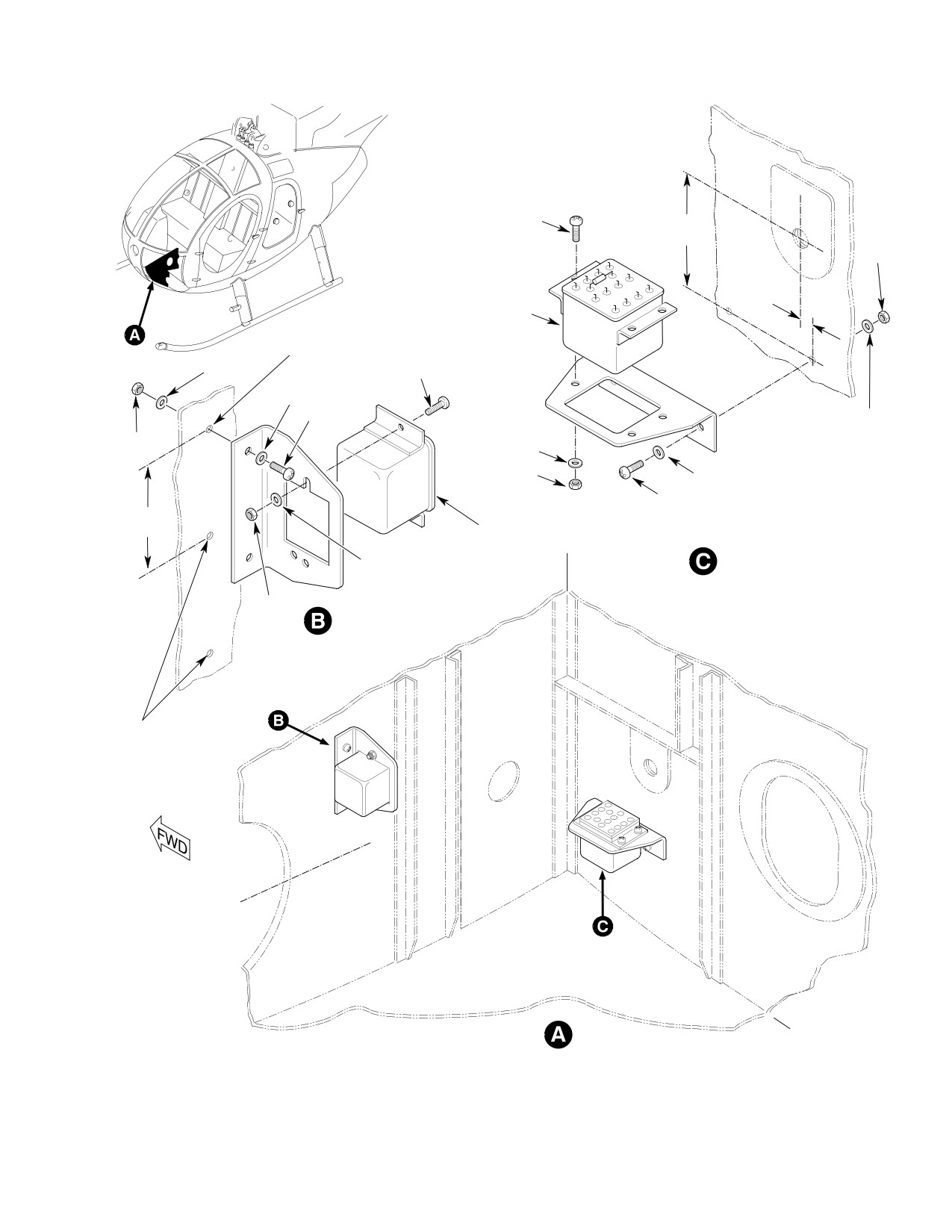
MD Helicopters, Inc.
CSP-HMI-2
MAINTENANCE MANUAL
SCREW
2.25-2.50 IN.
(5.715-6.35 CM)
NUT
0.25 IN.
(6.35 MM)
RELAY
0.165-0.177 IN.
(4.191-4.4958 MM)
HOLE
WASHER
SCREW
WASHER
SCREW
WASHER
NUT
WASHER
NUT
WASHER
SCREW
2.03 IN.
(5.1562 CM)
RELAY
STA. 44.65
K312 RELAY INSTALLATION
WASHER
(369E/FF - 500N)
NUT
K104 RELAY INSTALLATION
(369D)
EXISTING
HOLES
WL 10.00
BL 10.00
G25-5007A
Figure 902. Relay and Bracket Installation Pilots Floor (369D/E/FF)
Page 905
25-50-00
Revision 23

CSP-HMI-2
MD Helicopters, Inc.
MAINTENANCE MANUAL
(11). Pull manual release lever; check that
(16). Install HOOK RELEASE decal on left
hook load beam opens. Repeat opera
or right hand cyclic stick grip (Ref.
tion several times to ensure proper
Figure 403).
release of hook.
(17). Install CARGO HOOK EMERGENCY
RELEASE decal on cyclic stick (Ref.
(12). Re-adjust cable/lever as required to
Figure 405).
obtain smooth consistent release of
hook.
(18). Install EXTERNAL LOAD LIMIT 2000
POUNDS decal (Ref. Figure 404).
NOTE: The manual release lever clamp may be
loosened and the lever assembly moved on
Table 902. VNE Card Installation
cyclic stick to simplify adjustment, provid
Part Number
Model
Effectivity
ing the 2.250 ±0.250 inch (5.715 ±0.635 cm)
dimension limit is maintained
(Ref.
369D29571
D
003 − 523
Figure 405).
−17, −19
−21, −23
D/E
D 524 & Subs
(13). Install grommet in crew compartment
E 001 & Subs
floor cutout (Ref. Figure 401). Fill any
voids between grommet and cable. Use
369D292588
FF
001 & Subs
sealant (CM429).
(19). Replace VNE
card on instrument panel
(14). Install grommet in elongated hole in
as applicable (Ref. to Table 903).
fuselage lower skin and doubler (Ref.
Figure 402). Fill any voids between
G. Helicopter Equipment Installation
grommet and manual release cable. Use
Reinstall equipment initially removed in
sealant (CM429).
reverse order of removal.
(15). Safety manual release lever clamp
NOTE: At completion of installation, perform
screws with lockwire (CM702), (Ref.
an operational check of cargo hook installa
Figure 405).
tion.
Table 903. Cargo Hook Switch Installations − Stick Grip
Part Number
Model
Remarks
369H90153−BSC
D/E/FF
For models equipped with emergency floats, left or right hand
command (Ref. Figure 403).
−3
D/E/FF
For models equipped with hoist, left or right hand command
(Ref. Figure 403).
369D27133
D/E/FF
Standard grip, left hand command (Ref. Figure 403).
369D297846−BSC
D
Center electrical console, ‘‘T’’ grip right hand command (Ref.
Figure 403).
−3
D
Center electrical console, ‘‘T’’ grip right hand command (Ref.
Figure 403).
369H92805
D
Center electrical console, ‘‘T’’ grip right hand command (Ref.
Figure 403).
Page 906
Revision 23
25-50-00
MD Helicopters, Inc.
CSP-HMI-2
MAINTENANCE MANUAL
H. Weight and Balance Data
Table 904. After installation of the cargo hook
incorporate changes in helicopter weight and
Weight and balance changes resulting from
balance record as instructed.
installation of the cargo hook are listed in
Table 904. Weight and Balance Data
Weight
Arm
Moment
Pounds (kg)
Inches (cm)
in−lb (kg cm)
Added
+6.3
(+2.858)
+87.0
(+220.98)
+548.1
(+631.48)
Page 907
25-50-00
Revision 23
CSP-HMI-2
MD Helicopters, Inc.
MAINTENANCE MANUAL
This Page Intentionally Left Blank
Page 908
Revision 44
25-50-00
MD Helicopters, Inc.
CSP-HMI-2
MAINTENANCE MANUAL
Section
25−60−00
Emergency First Aid
Kit
MD Helicopters, Inc.
CSP-HMI-2
MAINTENANCE MANUAL
EMERGENCY FIRST AID KIT
MAINTENANCE PRACTICES
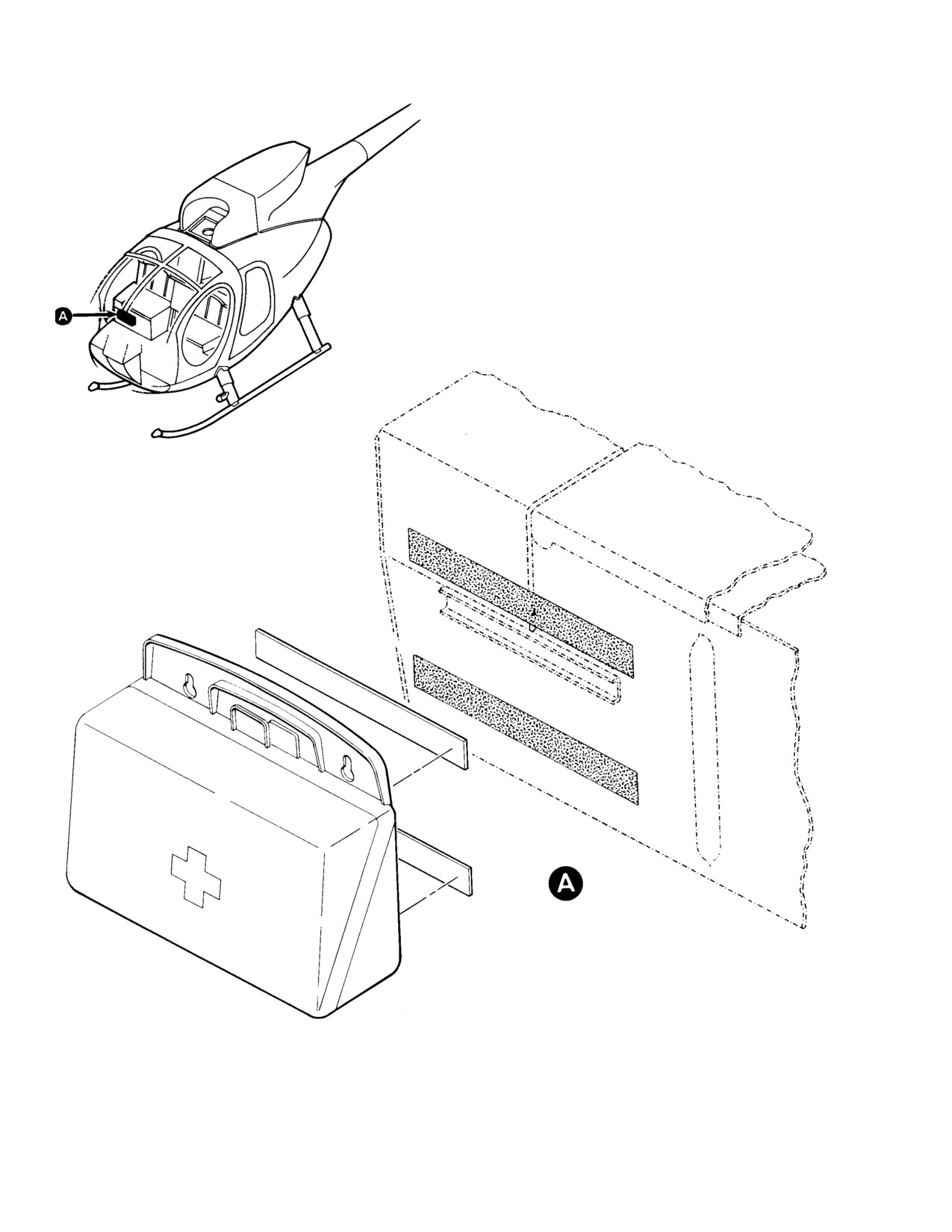
1. Emergency First Aid Kit
(3). Kit contents include a direction sheet
and the following eight packaged items:
(Ref. Figure 201)
adhesive and plain bandage compres
ses, iodine, swabs, ammonia inhalants,
(1). The Emergency First Aid Kit uses a
burn ointment, tourniquet, forceps, and
plastic case that meets Federal Aviation
scissors. The contents of the kit meet or
Regulation (FAR) 27.8530 requirements
exceed the requirements of Federal
for fire protection. The kit is installed
Aviation Authority (FAA) Specification
on the lower right front of the seat
121, Appendix A for aircraft with a
structure in the crew compartment and
passenger capacity of five persons or
centered at right buttline 20.75 just
less.
above the pilot's floor mold line. It
attaches to the station bulkhead with
two parallel velcro pile strips, 1 x 8
2. Emergency First Aid Kit Contents Check
inches (2.54 x 20.32 cm), bonded two
Periodically check kit contents to ensure an
inches (5.08 cm) apart in the horizontal
adequate supply of medical items. Purchase
position. Two matching velcro hook
individual items locally. To purchase a
strips are bonded across the width of
replacement kit, contact:
the case back.
(2). The kit is easily detached from its
MD Helicopters Inc.,
velcro tape mount by a firm pull on the
5000 East McDowell Road,
handle. The case is opened by off-set
Mesa, AZ 85205,
ting the snap fastener.
Att: New Parts Sales.
Page 201
25-60-00
Revision 23
CSP-HMI-2
MD Helicopters, Inc.
MAINTENANCE MANUAL
G25-6010
Figure 201. Emergency First Aid Kit
Page 202
Revision 23
25-60-00
MD Helicopters, Inc.
CSP-HMI-2
MAINTENANCE MANUAL
Section
25−63−00
Hoist
Passenger/Cargo
MD Helicopters, Inc.
CSP-HMI-2
MAINTENANCE MANUAL
HOIST PASSENGER/CARGO
MAINTENANCE PRACTICES
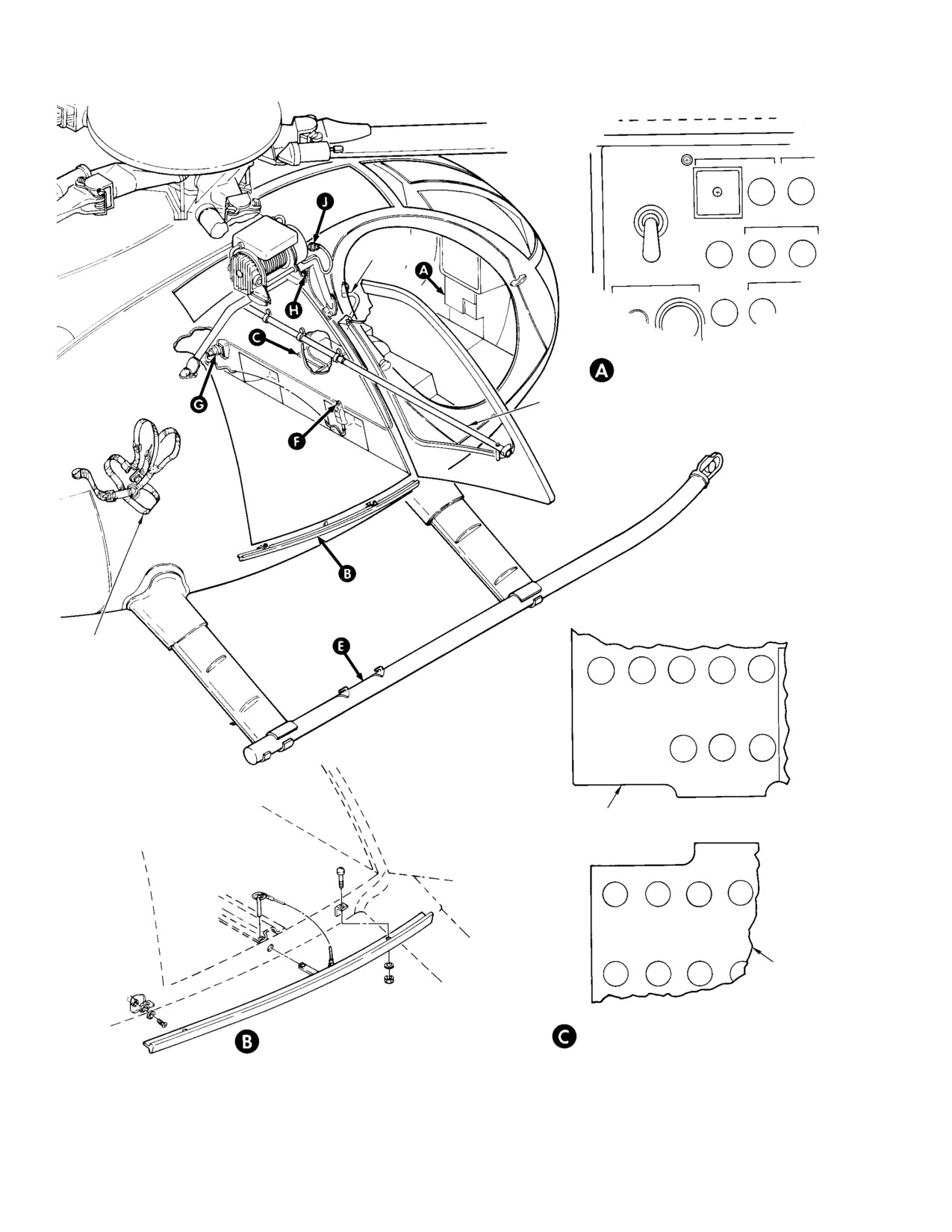
1. Hoist Passenger/Cargo
mounted on a support tube attached
with quick-release pins to three fittings
located on the exterior of the fuselage
(Ref. Figure 201)
on either side and above the passenger/
cargo door. The support tube positions
(1).
The hoist configuration is installed on
the winch to allow raising and lowering
the right side of L/H command helicop
the cable between the side of the
ters. The configuration for R/H com
fuselage and landing gear skid. Two
mand is identical except that the hoist
modified mounting brackets are used to
is installed on the opposite (left) side of
accommodate installation of the winch
the helicopter. The passenger/cargo
on the support tube. The winch incorpo
hoist assembly consists of an electrical
rates a disc-type brake, housed on the
ly-operated winch mounted on a
end of the hoist drum, which consists of
support tube, a hoist operator's safety
spring-loaded friction plates and an
harness, a passenger door (hold open)
actuating solenoid. The solenoid is
retainer assembly, a passenger door sill
energized to release the brake at the
antichafing bar assembly, a control
same time the motor is energized. Once
pendant, and associated electrical
the control pendant switch is released
equipment. The hoist provides a means
to the off position, the brake solenoid is
for lifting and lowering personnel or
deenergized and the brake sets,
objects weighing up to 300 pounds (136
preventing any possibility of uncon
kg). The hoist system employs light
trolled cable payout. Cable up (full-in)
weight, readily-attachable and -de
and down (full out) limit switches are
tachable exterior-mounted equipment
incorporated in the winch brake
without using passenger or cargo space
system. When either limit switch is in
in the helicopter. For safety purposes, a
the closed position, the brake solenoid
guillotine-type cable cutting device is
is energized, releasing the brake discs
incorporated in the hoist winch assem
and allowing the winch drum to rotate.
bly. The hoist function is identical when
Conversely, when either limit switch is
operated from either side of the helicop
in the open position the brake solenoid
ter.
is deenergized and the winch brake
automatically sets and stops the winch.
NOTE: When the hoist is installed on L/H com
mand helicopters equipped with emergency
floats, the floats must be in a stowed condi
(3).
(Ref. Figure 203) The passenger/cargo
tion during hoisting operations. Emergency
door retainer assembly consists of a
floats must be removed from R/H command
tubular housing attached with four
before conducting hoisting operations.
clamps securing the housing horizontal
ly across the canted bulkhead in the
(2).
(Ref. Figure 202) The weatherproof
passenger/cargo compartment. With the
winch consists of a 28 Vdc motor that
passenger/cargo door in full open
drives a cable drum to which a 110 foot
position, a smaller tube stowed inside
(33.5 M) stainless steel cable with a
the tubular housing extends in a
swivel hook is attached. The winch is
telescoping effect and engages a bracket
equipped with an automatic brake
located on the outboard frame of the
system; up (full-in) and down (full out)
door, thus retaining the door in an open
limit stop switches; and an explosive,
position. The telescoping tube can be
electrically-activated guillotine-type
used in either end of the tubular
cable cutter for cutting the cable in an
housing to hold the left or right passen
emergency. The hoist assembly is
ger/cargo door open as required.
Page 201
25-63-00
Revision 23
CSP-HMI-2
MD Helicopters, Inc.
MAINTENANCE MANUAL
HOIST
PWR CTR
CYCLIC
STICK
GRIP
LEFT-HAND COMMAND HELICOPTERS
SWITCH AND CIRCUIT BREAKER PANEL
DOOR RETAINER
SAFETY
HARNESS
HOIST CTR
369D294566 PANEL
HOIST
CTR PWR
369H92143
PANEL
RIGHT-HAND COMMAND HELICOPTERS
HOIST CABLE ANTI-CHAFING BAR
CICUIT BREAKER PANELS
G25-6001-1
Figure 201. Hoist System Components (Sheet 1 of 3)
Page 202
Revision 23
25-63-00
MD Helicopters, Inc.
CSP-HMI-2
MAINTENANCE MANUAL
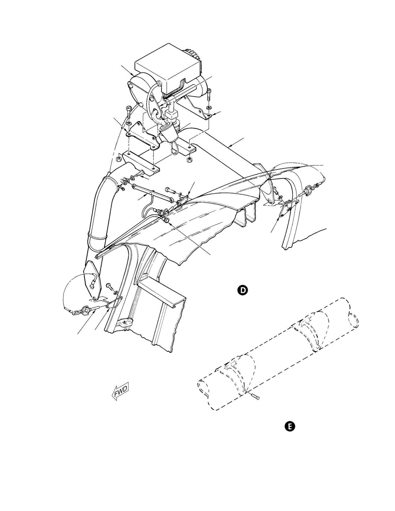
WINCH
HANGER
AFT BRACKET
FWD BRACKT
HOOK
WINCH SUPPORT
TUBE
FITTING
BEARING PIN
LINK ASSY
FITTING
ELECTRICAL PLUG
HOIST SUPPORT AND ATTACHMENTS
(ROTATED)
FITTING
SAFETY PIN
CABLE ANTI-SNAG PROVISIONS
(ROTATED)
G25-6001-2
Figure 201. Hoist System Components (Sheet 2 of 3)
Page 203
25-63-00
Revision 23
CSP-HMI-2
MD Helicopters, Inc.
MAINTENANCE MANUAL
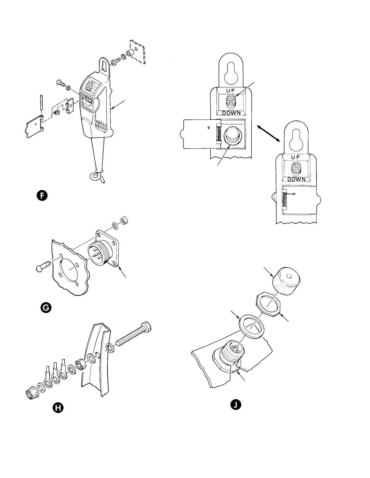
WINCH CONTROL
SWITCH
PENDANT
CABLE CUTTER
SWITCH
WARNING
CONTROL PENDANT CABLE CUTTER
SWITCH ACCESS DOOR ASSEMBLY
HOIST
CABLE
CUTTER
SWITCH
UNDER
COVER
PROTECTIVE CAP
RECEPTACLE
(XJ2)
PENDANT CONTROL CONNECTOR
WASHER
NUT
RECEPTACLE
(J28)
ELECTRICAL GROUNDING STUD
HOIST CONNECTOR
(TYP)
G25-6001-3
Figure 201. Hoist System Components (Sheet 3 of 3)
Page 204
Revision 23
25-63-00
MD Helicopters, Inc.
CSP-HMI-2
MAINTENANCE MANUAL
(4).
(Ref. Figure 201) An antichafing bar,
2. Preparation for Hoisting Operations
installed just below the passenger/cargo
To avoid inadvertent firing of
door sill, prevents the hoist cable from
CAUTION
cable cutter, ensure cable cutter
cutting the door frame during hoisting
electrical circuits are not energized.
operations. A hoist operator's safety
harness. provided with the hoist, is
(1).
Connect external electrical power to
connected to the seat belt anchor fitting
helicopter.
on the side of the passenger/cargo
compartment opposite the side where
(2).
Place BATTERY switch in EXT posi
the hoist is installed.
tion.
(3).
Open passenger/cargo door; extend and
(5).
The hoist system electrical equipment
secure door (hold-open) retainer tube.
consists of a hand held electrical
pendant control for use in the passen
(4).
Using hoist system control pendant,
exercise winch by paying out 3 or 4 feet
ger/cargo or crew compartments to
of cable under approximately 15 pounds
operate the winch, an emergency cable
(6.8 kg) tension, pulling cable straight
cutter switch on the pilot's cyclic stick,
down to avoid rubbing cable on cable
circuit breaker equipment, and asso
bellmouth. Reverse control and reel
ciated electrical wiring. The pendant
cable in. Check that cable winds on
control contains a three position switch,
winch drum evenly and that winch
spring loaded to the off position, for
operation is smooth and consistent.
raising and lowering the swivel hook,
Make certain winch stops automatically
and a guarded switch for cutting the
when top of swivel hook pushes against
cable at the winch in an emergency. The
winch bumper pad.
pilot's cyclic stick cable cutter switch
allows the pilot to cut the hoist cable
(5).
If installed, remove cable cutter jumper
independent of the pendant control. The
wire (Ref. Figure 202).
circuit breakers are mounted on the
Cable cutter jumper wire
lower switch and circuit breaker panel
WARNING
must be removed to allow
in L/H command, and on the circuit
cable cutter electrical circuit to be
breaker panel located aft of the pilot's
completed by switch control, providing
collective stick on R/H command. The
instantaneous in-flight cable cutting
cable cutter circuits are independently
capability should such emergency ac
protected by a separate lower-amper
tion be required.
age circuit breaker located adjacent to
the hoist power circuit breaker. Electri
(6). If winch has not been used for an
cal wiring, plugs, receptacles, and
extended period of time, or if cable has
terminals interconnect the various
been replaced, perform an operational
electrical components.
check (Ref. Hoist System Operational
Check).
(7). Check that winch support tube attach
(6).
Differences in hoist installations and
safety pins are secure and fully seated.
electrical circuitry for L/H and R/H
command is described in subsequent
(8). Check that winch electrical connector
text and illustrations. Refer to man
plug is secure on receptacle on side of
ufacturer's publications (Ref. Table 201,
fuselage.
Sec. 01-00-00, BL-16600 Series 300 Lb
Capacity Hoist Operating lnstructions -
(9). Connect hoist system operator's safety
Hoist Winch Assembly, Breeze Corpora
harness to seat belt fitting on opposite
tion, Inc)) for additional hoist, hook,
side of passenger/cargo compartment
cable, and parts information.
from where winch is installed.
Page 205
25-63-00
Revision 23
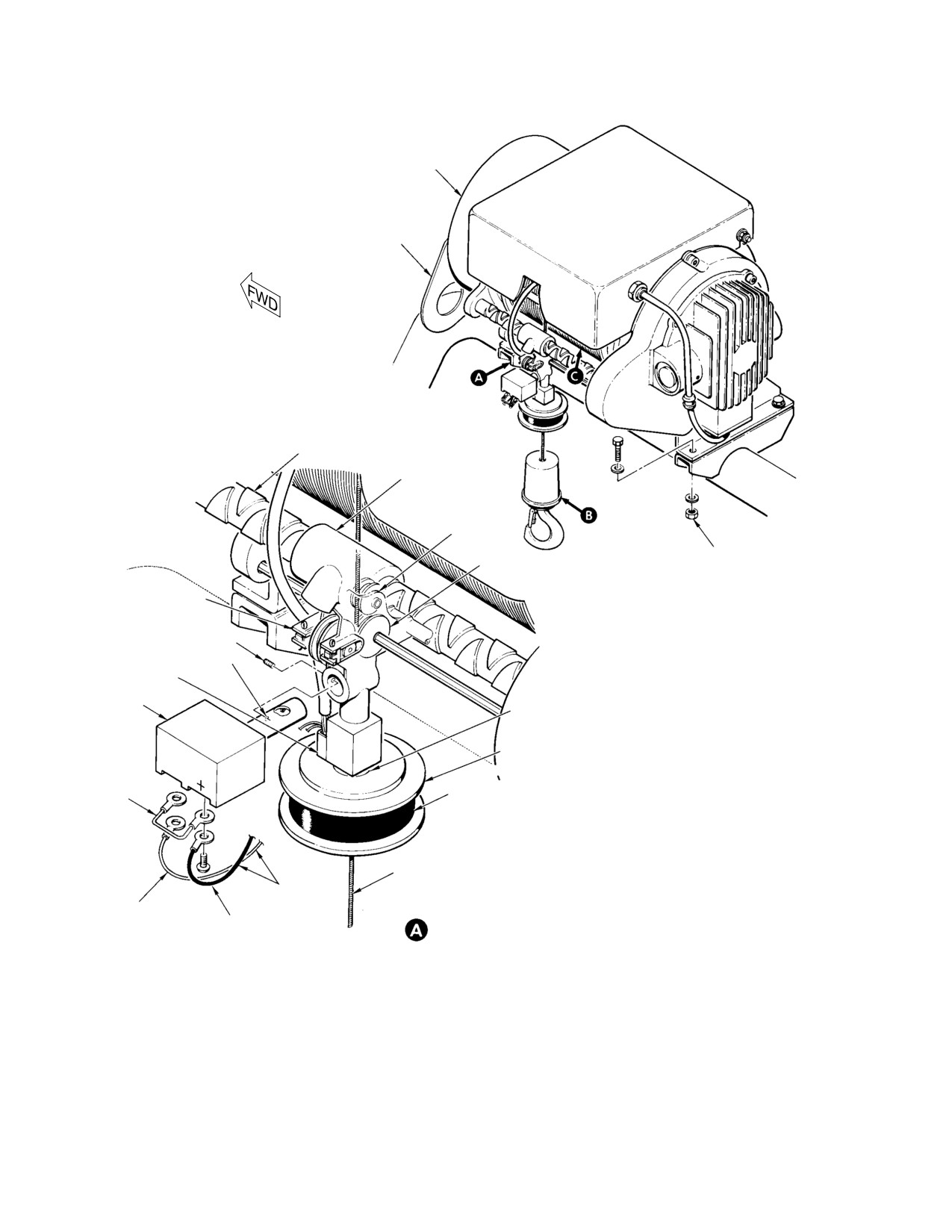
CSP-HMI-2
MD Helicopters, Inc.
MAINTENANCE MANUAL
WINCH
HOIST SUPPORT
TUBE
DOUBLE HELICAL
SCREW SHAFT
CABLE GUIDE
ASSEMBLY
IDLER GUIDE
ROLLER
TORQUE NUT TO
TRACTION ROLLER
70 - 100 INCH-POUNDS
(7.91 - 11.30 NM)
PRESSURE ROLLER
ALLEN HEAD SET SCREW
INDENT
FILL-IN (UP)
LIMIT SWITCH
CABLE CUTTER
BELLMOUTH
(GUILLOTINE)
BUMPER RING
PROTECTIVE
ELECTRICAL
RUBBER BUMPER
JUMPER
PAD
(REF. WARN
ING)
WARNING: REMOVE JUMPER WIRE AFTER
1/8 IN. (3.175 MM)
DIA. CABLE
SYSTEM INSTALLATION OR MAINTENANCE
ELECTRICAL
(REFER TO TEXT)
GROUND WIRE
WIRING
(WHITE, BLUE
POSITIVE WIRE (BLACK,
CABLE CUTTER
CAUTION: CONNECT POSITIVE WIRE ONLY
OR WHITE/BLUE)
REPLACEMENT
GREEN, OR WHITE/GREEN)
(BLACK, GREEN, OR WHITE/GREEN) TO POS
(REF. CAUTION)
ITIVE (+) POST OF CABLE CUTTER.
G25-6002-1A
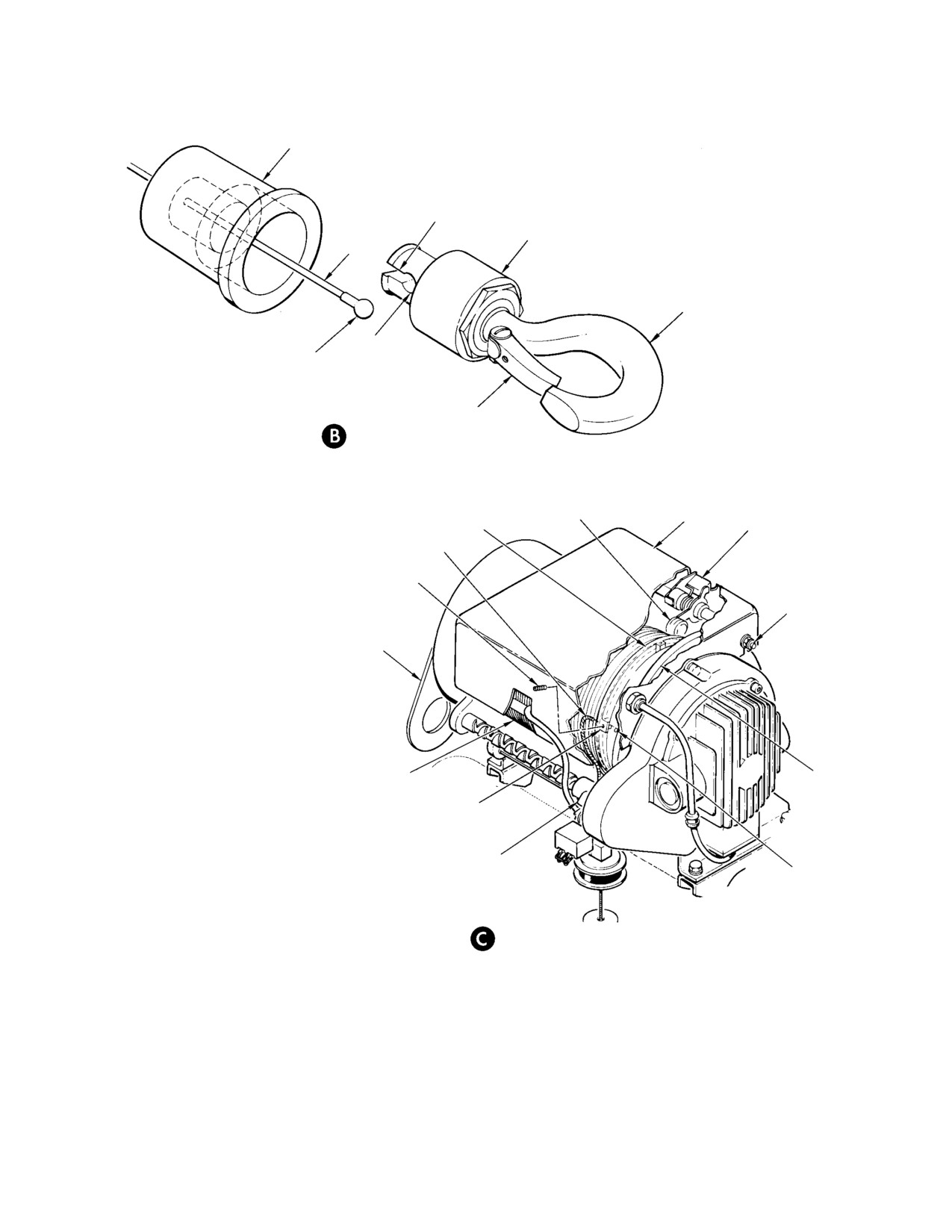
Figure 202. Winch Cable, Cable Cutter, and Swivel Hook Replacement (Sheet 1 of 2)
Page 206
Revision 23
25-63-00
MD Helicopters, Inc.
CSP-HMI-2
MAINTENANCE MANUAL
RUBBER BUMPER
KEYWAY
HOOK HOUSING
CABLE
SWIVEL HOOK
SOCKET
SWAGED BALL
END FITTING
SAFETY KEEPER
CABLE-TO-HOOK
ATTACHMENT
ROLLER WHEEL
TOP COVER
FIRST DRUM GROOVE
FULL-OUT (DOWN
LIMIT SWITCH)
CABLE END
(NOTE 1)
ALLEN HEAD SETSCREW
NUT, WASHER
(4 PLCS) (NOTE 1)
HOOK HANGER
(NOTE 2)
CABLE WINDING
DRUM
(ON DRUM)
CABLE DRUM FLANGE
CABLE GUIDE ASSEMBLY
DRUM CABLE END
ANCHOR HOLE
CABLE-TO-DRUM
ATTACHMENT
NOTES:
1.
EXCESSIVE TIGHTENING MAY AFFECT
FULL-OUT SWITCH SETTING.
2.
USED FOR HOOK STOWAGE.
G25-6002-2
Figure 202. Winch Cable, Cable Cutter, and Swivel Hook Replacement (Sheet 2 of 2)
Page 207
25-63-00
Revision 23
CSP-HMI-2
MD Helicopters, Inc.
MAINTENANCE MANUAL
(10). Place BATTERY switch in OFF posi
NOTE: If support tube fittings are to be re
tion.
moved from fuselage, make certain nylon
screws are installed in attachment holes.
(11). Remove external electrical power from
helicopter.
(8). Remove bolts securing winch to support
tube brackets.
3. Hoist System Troubleshooting
B. Hoist Assembly Installation
(Ref. Table 201) Wiring diagrams are provided
for the hoist systems used on L/H command
Consumable Materials
(Ref. Figure 204) and R/H command helicop
(Ref. Section 91−00−00)
ters (Ref. Figure 205). A schematic diagram of
Item
Nomenclature
the winch is also provided (Ref. Figure 206).
CM703
Tie strap
(Ref. Chap. 96 for interfacing schematics and
wiring diagrams)
NOTE: If support tube fittings
(Ref.
Figure 201) were removed from fuselage, re
4. Cyclic Stick Grip and Cyclic Stick Cable
move nylon screws installed in support fit
Cutter Switch (S600) Replacement
ting attachment holes on fuselage.
(Ref. Sec. 67-10-20)
(1). If required, install winch support tube
attach fittings on fuselage using screws
5. Hoist Assembly Replacement
and washers.
A. Hoist Assembly Removal
(2). Attach winch to support tube using
bolts, washers, and nuts. Torque bolts
(1). Check that cable is fully retracted on
to 70 - 100 inch-pounds (7.91 - 11.30
winch drum.
Nm).
(2). Check that BATTERY switch is in OFF
(3). Attach link assembly to support tube
position.
using bearing pin, washer, and cotter
pin.
(3). Install safety jumper wire on cable
cutter electrical terminals (Ref.
(4). Attach winch support tube to fuselage
Figure 202).
fittings using quick-disconnect pins.
Protective jumper wire should
NOTE: Install pins in positions shown.
CAUTION
remain on cable cutter electrical
terminals until winch is reinstalled for use.
Check that all electrical power
CAUTION
is OFF to eliminate possibility
(4). Disconnect winch electrical plug (Ref.
of inadvertent firing of cable cutter.
Figure 201) from receptacle on fuselage;
install protective cap on receptacle.
(5). Remove protective cap from electrical
receptacle on side of fuselage. Connect
(5). Support winch; remove three quick-dis
winch electrical plug to fuselage
connect safety pins securing winch
receptacle. Secure wire harness to
support tube to fittings on fuselage.
support tube using tie-straps (CM703).
(6). Remove winch and support tube from
Remove protective electri
WARNING
fuselage.
cal jumper wire
(Ref.
Figure 202) from cable cutter whenev
(7). Remove cotter pin, washer, and bearing
er winch is installed on helicopter.
pin securing link assembly to winch
Jumper wire will prevent operation of
support tube.
cable cutter in an in-flight emergency.
Page 208
Revision 23
25-63-00
MD Helicopters, Inc.
CSP-HMI-2
MAINTENANCE MANUAL
BRACKET ASSY
(RH)
TUBE
TUBE
RIGHT DOOR BRACKET
(ROTATED)
STRUCTURAL RE
CLAMP
INFORCEMENT
DOUBLER ANGLE
BRACKET
CLAMP
RIGHT INBOARD
TUBE CLAMP
RIGHT OUTBOARD
TUBE CLAMP
G25-6003
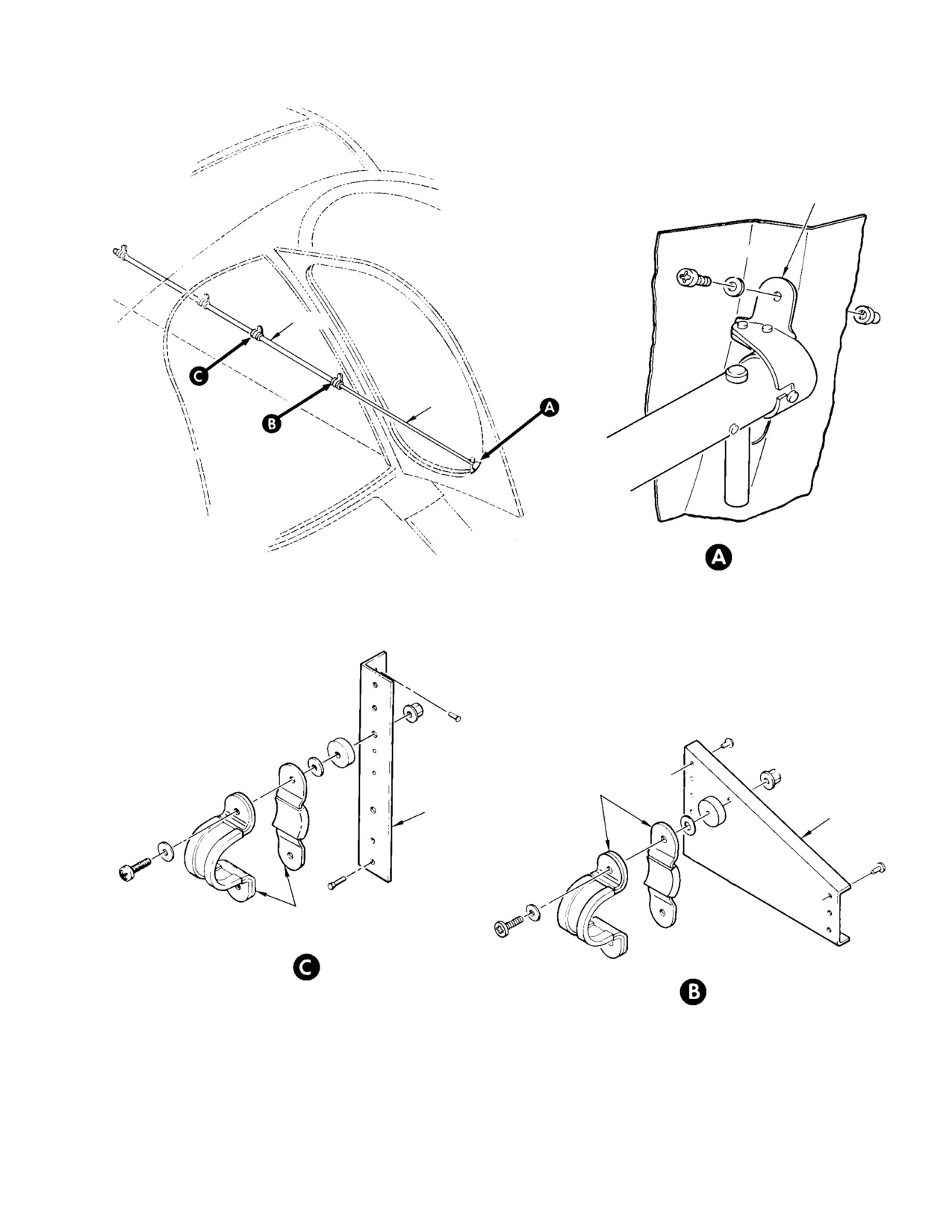
Figure 203. Passenger/Cargo Door Retainer Installation
Page 209
25-63-00
Revision 23
CSP-HMI-2
MD Helicopters, Inc.
MAINTENANCE MANUAL
6. Winch Components Replacement
(c). Continue unwinding cable until down
(full-out) limit switch (Ref.
A. Winch Cable Replacement
Figure 202) activates (opens) and
allows brake to engage, thus stopping
(Ref. Replacement of the winch cable (Ref.
cable payout.
Figure 202) is required if cable is damaged,
NOTE: Three turns of cable will remain on
worn excessively, or cable cutter has been fired
winch drum when down limit switch opens.
(Ref. Hoist Equipment Inspection for inspec
(d). Remove winch cable drum cover.
tion requirements and for cable replacement
criteria).
(e). Manually raise roller wheel, at top
right rear of winch drum, to close the
(1). Install hoist and support on helicopter
down limit switch (release brake) and
(Ref. Hoist Assembly Installation).
allow remaining cable to be reeled off
cable drum.
When electrical power is pres
(f). Using control pendant, finish un
CAUTION
ent, make certain cable cutter
winding cable. Stop winch when
electrical circuits remain deenergized to
cable is fully unwound from drum.
eliminate the possibility of inadvertent ac
(5). Remove winch cable from drum as
tuation of cable cutter. To avoid possibility of
follows:
cutting cable, install jumper wire between
cable cutter electrical terminals.
(a). Loosen Allen head setscrew securing
cable end in drum anchor hole.
NOTE: An external power source should be
Remove cable end from winch by
connected to the helicopter to prevent exces
pulling cable down through cable
sive battery discharge. Hoist uses up to 40
guide, cable cutter, and bumper
amperes electrical current during operation.
guide.
Anchor hole setscrew should be
(2). Connect external electrical power
CAUTION
temporarily tightened to pre
source to helicopter.
vent fouling winch mechanism if winch is
inadvertently operated.
(3). Place BATTERY switch in EXT posi
(b). Retighten setscrew in anchor hole.
tion.
(6). Remove swivel hook from cable (Ref.
(4). Using hoist pendant control (Ref.
Swivel Hook Replacement).
Figure 201), reel off all cable from
NOTE: Replacement cable must be 0.125 inch
winch drum as follows:
(3.175 mm) diameter stainless steel, 19 by 7
cable strand, extra strength, antispin cable
NOTE: Two persons can facilitate cable remov
with a minimum breaking strength of 1800
al; one person to operate winch and a second
pounds. Make certain any replacement
person to handle and coil cable.
cable, other than cable supplied by winch
manufacturer, is approximately 113 feet
(a). Operate winch and start reeling cable
(34.442 M) long, is equipped with a swaged
off winch drum.
ball fitting, and is proof-tested to a mini
mum load of 1850 pounds (840 kg).
To prevent bellmouth wear,
(7). Install swivel hook on replacement
CAUTION
cable should not be pulled
cable (Ref. Swivel Hook Replacement).
against side of bellmouth on cable guide.
(8). Attach new replacement cable to winch
as follows:
(b). As cable unwinds, maintain straight
downward tension, approximately 15
(a). Insert free end of replacement cable
pounds (6.8 kg); lay or coil cable in a
up through bumper pad guide center,
clean clear area. Position cable so
bellmouth, switch, cable cutter, and
that cable will not kink or tangle, to
between cable rollers in the cable
facilitate rewinding.
guide assembly (Ref. Figure 202).
Page 210
Revision 23
25-63-00
MD Helicopters, Inc.
CSP-HMI-2
MAINTENANCE MANUAL
(b). Ensure cable guide assembly is
NOTE: The up limit switch should actuate be
centered and aligned with first
fore excessive cable pressure is applied to
groove on double helical screw shaft.
vertically compress bumper pad. Permanent
damage can result if rubber bumper pad is
Facing cable guide mechanism, check
stowed in a compressed state over an ex
that guide will travel from right to
tended period of time; rubber bumper will
left when winding cable on drum.
remain in a compressed (set) state.
(d). Install cover on winch.
(c). Secure cable to drum by loosening set
screw and inserting cable end into
(10). Perform an operational check of hoist
drum cable anchor hole until cable
system (Ref. Hoist System Operational
end bottoms, approximately 3/8 inch
Check).
(9.525 mm); tighten setscrew.
B. Swivel Hook Replacement
(d). Check that replacement cable is
(Ref. Figure 202)
positioned in first drum groove at
right when facing cable guide mecha
Consumable Materials
nism.
(Ref. Section 91−00−00)
Item
Nomenclature
(9). Operate hoist and wind replacement
CM114
Petrolatum
cable on winch as follows:
(1). Remove swivel hook assembly from
cable as follows:
(a).
Deactivate down limit switch by
manually raising teflon roller wheel
(a). Remove rubber bumper covering
at top right rear of winch drum; use
swivel hook housing by pulling
control pendant to wind replacement
bumper upward off top of hook
cable on winch. Release the down
housing.
limit switch after three turns of cable
are on drum.
(b). Remove cable swaged ball end fitting
from hook housing socket: pull cable
swaged ball fitting through rubber
(b).
Maintain sufficient tension, approxi
bumper.
mately 15 pounds (6.8 kg) on cable
while winding cable on drum; check
(2). Install swivel hook on cable as follows:
that cable winds straight, smooth,
and snug, without kinking against
(a). Lubricate cable swaged ball end
cable windings on drum. Avoid cable
fitting with petrolatum (CM114).
rubbing on side of bellmouth during
(b). Insert cable through top of rubber
cable winding.
bumper.
(c). Insert cable ball fitting in hook
(c).
Continue winding operation until
housing keyway and socket.
entire cable is wound on drum: check
that winch stops automatically when
Ensure hook rubber bumper
top of swivel hook pushes against
CAUTION
completely covers hook housing.
winch rubber bumper pad. (Bumper
pad upward movement actuates
(d). Secure cable ball fitting in housing
(opens) full-in (up) limit switch at
socket by sliding rubber bumper
cable guide base.
down over hook housing.
Page 211
25-63-00
Revision 23

CSP-HMI-2
MD Helicopters, Inc.
MAINTENANCE MANUAL
NOTE: Hook rubber bumper should completely
Setscrew mates with indent on cable
cover housing, and bumper base will overlap
cutter.
inward around housing base by approxi
(6). Connect one electrical terminal lug to
mately 1/16 inch when fully seated on hous
cable cutter terminal, leaving protective
ing.
short-circuiting jumper installed on
C. Cable Cutter Replacement
cable cutter. Then connect second wire
(Guillotine−Type)
to remaining cable cutter terminal in
the same way.
(Ref. Figure 202)
Protective jumper wire should
CAUTION
remain connected to cable cutter
Consumable Materials
electrical terminals until hoist is to be used.
(Ref. Section 91−00−00)
Item
Nomenclature
(7). Cover exposed electrical terminal areas
CM425
Sealing compound
with sealing compound (CM425).
7. Hoist System Operational Check
Cable must be removed from winch (Ref.
The following procedure is used to verify the
Winch Cable Replacement) before guillotine-
capability of the hoist system to function
type cable cutter can be replaced. Replace a
correctly. The procedure should be performed
spent cable cutter guillotine on winch as
any time a malfunction is suspected, and prior
follows:
to normal use after repair.
The cable cutter contains an
WARNING
Remove protective electri
explosive squib that is elec
WARNING
cal jumper wire
(Ref.
trically fired. A protective short-cir
Figure 202) from cable cutter whenev
cuiting electrical jumper should re
er winch is installed on helicopter.
main connected to cable cutter, not
Jumper wire will prevent operation of
installed on the winch, to eliminate
cable cutter in an in-flight emergency.
possibility of inadvertent accidental
firing.
(1). Open applicable passenger/cargo door;
extend door retainer tube to hold door
(1). Disconnect two electrical wire terminal
in full open position.
lugs from spent cable cutter.
Avoid inadvertent operation of
(2). Loosen two Allen head setscrews at side
CAUTION
cable cutter. Make certain cable
of movable cable guide and remove
cutter switches are not actuated when hoist
spent cable cutter from guide.
system circuits are energized.
(3). Check that all electrical power is OFF.
(2). Energize helicopter electrical system;
check that both HOIST PWR (power)
Do not use an ohmmeter or
WARNING
and CBL CTR (cable cutter) circuit
any other device containing
breakers are in closed position (Ref.
an internal voltage source which could
Figure 201).
fire cable cutter.
(3). Using hoist system control pendant,
(4). Using a voltmeter, check for zero
exercise hoist winch by paying out 3 to
voltage between electrical wiring
4 feet (1.2 M) of cable under approxi
terminal lugs; also check for zero
mately 15 pounds (6.8 kg) tension; pull
current between lugs with a milliamme
cable straight down to avoid cable
ter.
rubbing on cable bellmouth. Reverse
(5). Insert cylindrical end of new cable
control and reel cable in. Check that
cutter into winch movable cable guide,
cable winds on winch drum evenly and
with shorting jumper positioned
that winch operation is smooth and
downward, and secure cable cutter to
consistent. Check that winch stops
guide with two Allen head setscrews.
automatically when top of swivel hook
Page 212
Revision 23
25-63-00
MD Helicopters, Inc.
CSP-HMI-2
MAINTENANCE MANUAL
rubber bumper pushes against winch
(6). Stow door retainer tube; close passen
bumper pad.
ger/cargo door.
(4). Test hoist lifting capability with 300
8. Hoist Equipment Inspection
pound weight. Check that hoist oper
ates smoothly throughout hoisting and
General inspection procedure for the hoist
lowering operations.
system is as follows:
NOTE: Cable retraction rate should be approxi
(1). Inspect components for security of
mately 55-60 feet (16.8-18.3 M) per minute.
attachment, damage, deformation,
The full usable cable length should unwind
cracks, and excessive wear.
in approximately 95 seconds and rewind in
approximately 103 seconds.
WARNING
(a).
With helicopter hovering approxi
mately 100 feet (45.4 M) above test
D Human life might depend on cable
weight, lower hoist hook between
condition. Inspect full length of cable
fuselage and landing gear skid.
carefully and thoroughly.
Continue lowering hook until hook
D Use heavy leather gloves to protect
can be connected to test weight.
hands from injury due to broken
cable strands.
(b).
Gradually maneuver helicopter to
remove cable slack and to center
Keep cable clean. Provide a
hoist over test weight.
CAUTION
clean area to coil cable during
inspection. Dirt and oil grime will create an
(c).
Slowly elevate helicopter to raise test
abrasive wear on cable and winch compo
weight approximately 20 feet (6.1 M)
nents.
from ground.
(2). Inspect cable for fraying, corrosion,
(d).
Using pendant control, payout full
broken strands, and security of attach
usable length of cable. Check that
ment to winch drum and cable ball
hoist down limit switch stops winch
swivel hook attachment. General
with three turns of cable on winch
criteria for cable replacement are as
drum. If required, adjust position at
follows:
which down limit switch activates.
(a). Any single broken strand (cluster of 7
(e).
Reverse pendant control. Lift test
individual wires) requires cable
weight to within approximately 10
replacement.
feet (3.0 M) of helicopter skid.
(b). Both ends of individual broken wires
(f).
Lower helicopter and remove hoist
should be tucked into cable to
hook from test weight; raise hoist
prevent fouling when cable travels
hook and check that hoist winch
through cable guides and nonfouling
automatically stops when top of
mechanisms. Breaks of individual
swivel hook rubber bumper pushes
wires are allowable, unless the
up against hoist bumper pad.
number is excessive as defined in
NOTE: Up limit switch should actuate before
next criterion.
excessive cable pressure is applied to verti
cally compress bumper pad
(Ref.
(c). Generally, one individual broken wire
Figure 202).
(two ends) for each foot of cable is
permissible, up to a total of 20
(g). Land helicopter; deenergize electrical
individual wire breaks for each 100
system.
foot (30.5 M) length of cable. A
greater number of breaks requires
(5). Stow pendant control.
cable replacement.
Page 213
25-63-00
Revision 23
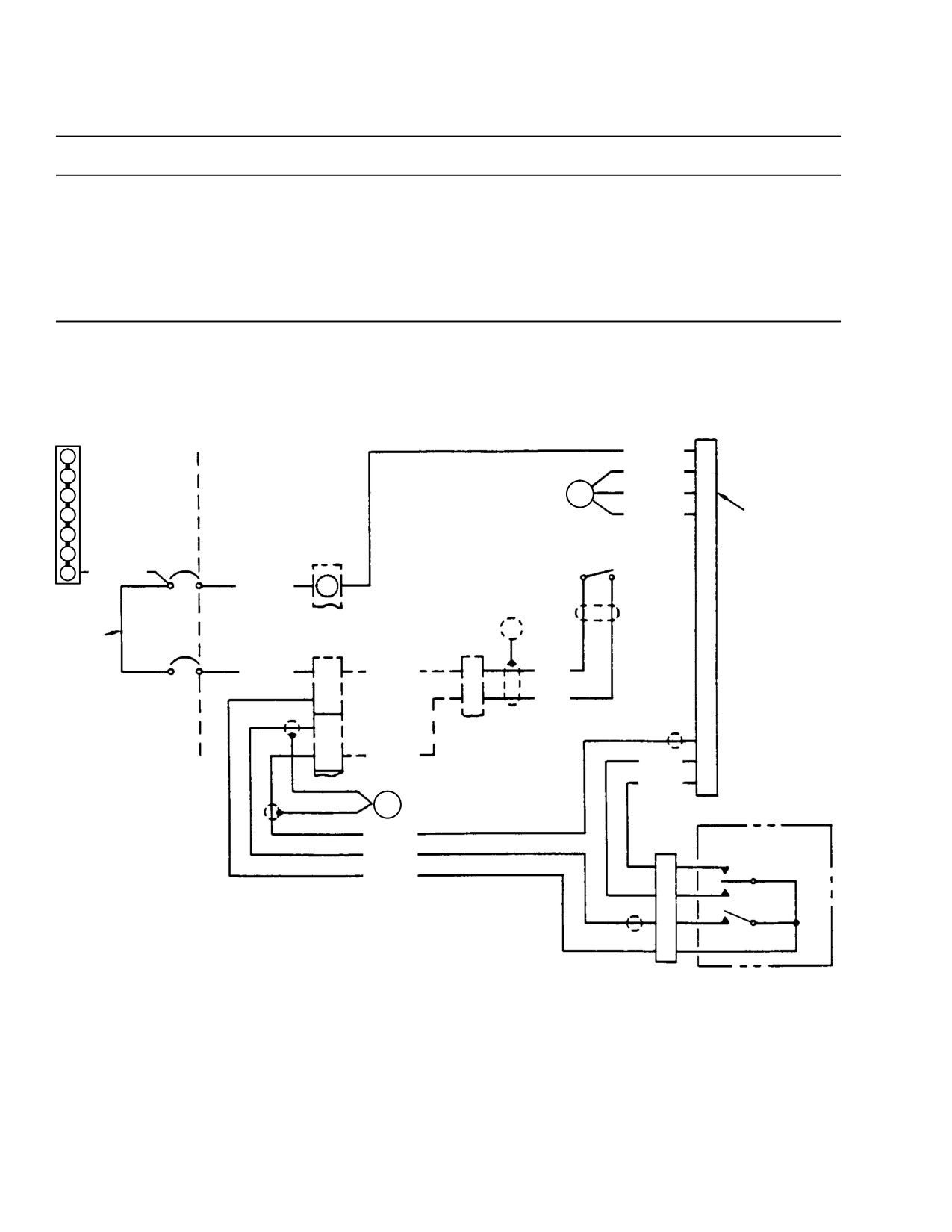
CSP-HMI-2
MD Helicopters, Inc.
MAINTENANCE MANUAL
Table 201. Troubleshooting Hoist System
Symptom
Probable Trouble
Corrective Action
Winch will not raise or lower cable.
Tripped circuit breaker.
Reset circuit breaker.
Defective pendant control.
Repair pendant control.
Defective winch assembly.
Repair winch assembly.
Improper lower cable travel limit.
Down (full−out) limit switch out of
Reset lower limit adjustment.
adjustment.
W3 BUS
A526A12
C
1
A527G12N
G
2
3
E19
A527H20N
A
P107C14-8S
RECEPTACLE
4
A527J20N
B
(MATES WITH
5
CYCLIC STICK
PT06P14-8P
CABLE CUTTER
WINCH PLUG)
6
CB600
TB10
SWITCH S600
(NOTE 4)
7
P506AH12
1
2
M535A12
1
40A
E5
JUMPER
AWG 20
CB601
TB1-16
P130
1
2
M503B20
A
M503F20
F
13-20
7.5A
B
C
14-20
SPARE
H
D
D
C
M504H20
CC8A20
E
CC9A20
F
E24
PENDENT CONTROL
CC10A20
XJ2
CC2AA20
UP
A
HOIST
CC1AA20
B
NOTES:
DOWN
1.
THIS DIAGRAM IS TO BE USED WITH ELECTRICAL SYSTEM WIRING
D
CUTTER
DIAGRAMS IN CHAP. 96 FOR COMPLETE CIRCUIT IDENTIFICATION.
C
2.
DASHED LINE ( - - ) ITEMS ARE PART OF HELICOPTER BASIC
MS3101E16S-1S
ELECTRICAL SYSTEM.
RECEPTACLE
3.
COMPONENT TERMINAL NUMBERS ARE FOR REFERENCE AND MAY
NOT BE SHOWN ON COMPONENT.
4.
REFER TO WINCH SCHEMATIC DIAGRAM FOR INTERNAL CONNECTIONS.
G25-6009
Figure 204. Wiring Diagram − Hoist System (L/H Command)
Page 214
Revision 23
25-63-00
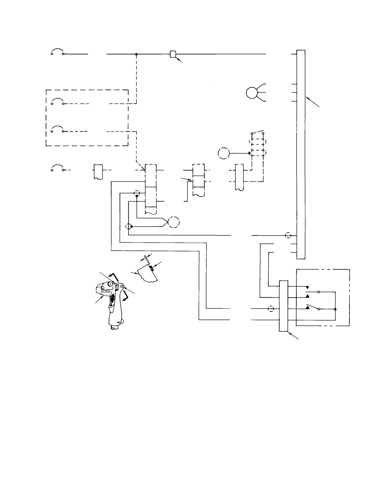
MD Helicopters, Inc.
CSP-HMI-2
MAINTENANCE MANUAL
CB600
J28
1
2
A526A12
A526A12
C
40A
SPLICING PERMISSIBLE
A527G12N
G
HOIST (PWR) OR (ORD)
A527H20N
A
CB133
1
2
A527J20N
B
PT07C14-8S
A526A12
40A
RECEPTACLE
(MATES WITH
HOIST CUT (CTR)
CYCLIC STICK
PT06P14-8P
CB134
CABLE CUTTER
WINCH PLUG)
1
SWITCH S600
2
(NOTE 4)
M503A20
7.5A
SLAE ONLY
E9
CB601
P616
TB1-40
TB1-19
P109
1
2
M503A20
F
M503AA20
A
M504K20
B
M521F20
D
7.5A
(NOTE 5)
NOTE 6
B
A
M520F20
E
C
D
K504M20
H
SPARE
E24
CC10A20
D
CC8A20
E
CC9A20
F
CABLE CUTTER
0.040 IN. (1.016 MM)
SWITCH BUTTON
PENDANT CONTROL
369H90070-67 DECAL
GRIP
UP
A
HOIST
CABLE CUTTER SWITCH
B
DOWN
GRIP
CC2AA20
D
CUTTER
CC1AA20
C
CYCLIC GRIP REWORK
MS3101E16S-1S
RECEPTACLE
NOTES:
1.
THIS DIAGRAM IS TO BE USED WITH ELECTRICAL SYSTEM WIRING DIAGRAM
IN CHAP. 96 FOR COMPLETE CIRCUIT IDENTIFICATION.
2.
DASHED LINE ( - - ) ITEMS ARE PART OF HELICOPTER BASIC ELECTRICAL
SYSTEM.
3.
COMPONENT TERMINAL NUMBERS ARE FOR REFERENCE AND MAY NOT BE
SHOWN ON COMPONENT.
4.
REFER TO WINCH DIAGRAM FOR INTERNAL CONNECTIONS.
5.
EXISTING WIRE, RELOCATED TO TB1-40A.
6.
REMOVE EXISTING WIRE M520B20.
G25-6004A
Figure 205. Wiring Diagram − Hoist System (R/H Command)
Page 215
25-63-00
Revision 23
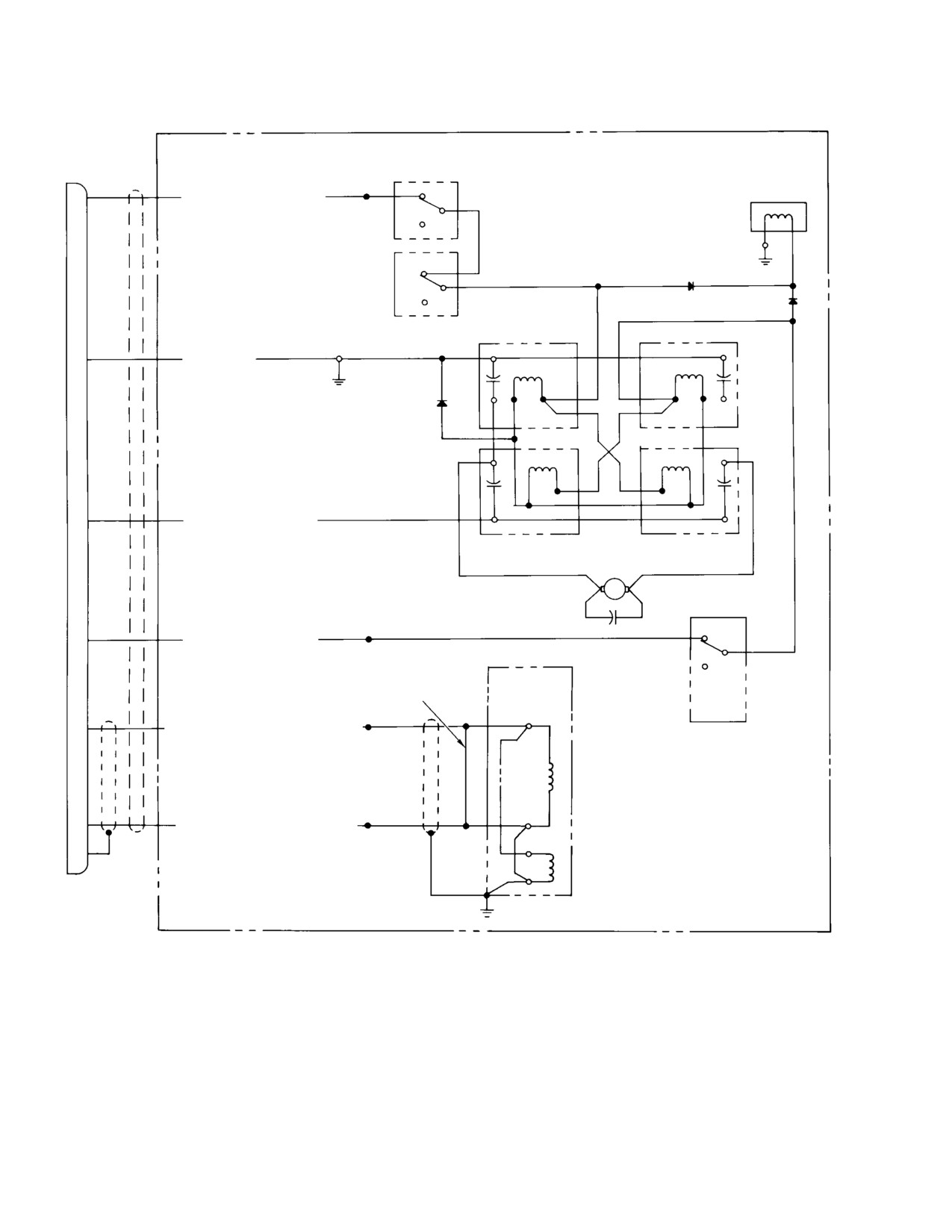
CSP-HMI-2
MD Helicopters, Inc.
MAINTENANCE MANUAL
P28
FULL-IN
LIMIT SWITCHES
(NOTE)
F
AWG 20 ORG OR WHT/ORG
BRAKE
UP
DOWN
G
AWG 12 WHT
C
AWG 12 RED OR WHT/RED
DOWN
UP
MOTOR
FULL-OUT
LIMIT SWITCH
E
AWG 20 YEL OR WHT/YEL
CABLE CUTTER
SAFETY JUMPER WIRE
(REF. WARNING)
+
AWG 20 GREEN OR WHT/GRN OR BLK
-
B
AWG 20 BLU OR WHT/BLU OR WHT
A
NOTE: REFER TO HOIST SYSTEM INTERCONNECT WIRING
DIAGRAMS (REF CHAP. 96) FOR EXTERNAL CONNECTION.
WARNING: REMOVE JUMPER WIRE AFTER INSTALLATION
OR MAINTENANCE (REF. TEXT).
G25-6005
Figure 206. Schematic Diagram − Hoist System Winch
Page 216
Revision 23
25-63-00
MD Helicopters, Inc.
CSP-HMI-2
MAINTENANCE MANUAL
HOIST PASSENGER/CARGO
INITIAL INSTALLATION
1. Hoist Passenger/Cargo Initial Installation
(2). Remove left and right foot support
fairings in passenger/cargo compart
The passenger/cargo hoist can be installed on
ment.
any L/H command or R/H command Model
(3). Remove passenger/cargo compartment
369D helicopter. On L/H command, the hoist
forward bulkhead trim panel (L/H
winch is installed on the right side of the
command) and controls access door.
fuselage. On R/H command, the hoist winch is
installed on the left side of the fuselage.
(4). Remove fuel cell forward vent from
Subsequent procedures provide separate
control tunnel (Ref. Sec. 28-00-00).
instructions for electrical installations in L/H
command and R/H command to accommodate
NOTE: Fuel vent must be removed to avoid
differences in component location and wire
damage during structural modification hole
routing.
drilling operations.
(5). Remove crew compartment seat and
Installation instructions include procedures for
back cushions.
installing a passenger/cargo door retainer
assembly, a door sill antichafing bar assembly,
(6). Remove left (outboard) collective stick
a winch and winch support tube assembly, and
cover.
the electrical wiring and components required
for operation of the hoist system.
(7). Remove crew compartment lower aft
trim panels (left and right).
The hoist passenger/cargo installations may be
(8). Remove crew compartment left or right
performed at the discretion of the operator, or
bulkhead panel and lower portion of
the helicopter may be returned to the factory
right upper side panel.
for modification. The instructions which follow
are for the 369H90070-521 and -522 installa
(9). Remove edgelighted panel face from
tions only.
lower switch and circuit breaker panel
(Ref. Chap. 96). Loosen lower switch
A. Preparation for Installation
and circuit breaker panel to accommo
date installation of additional circuit
Instructions in the following paragraphs are
breakers.
applicable to both left and right hoist installa
tions, except as noted.
C. Helicopter Modification
(1). Identify all components that are to be
(Ref. Figure 901) Modification of the helicopter
installed, along with those removed to
involves cutting a hole in the fuselage skin to
gain access to work areas. Protect
facilitate installation of an electrical receptacle
components from damage and contami
(J28) to receive a winch electrical plug, and a
nation.
hole in the lower left area of the canted
bulkhead and forward bulkhead trim panel to
(2). Check that all electrical switches are in
facilitate installation of an electrical receptacle
OFF position.
(XJ2) to receive a control pendant plug.
Ensure BATTERY switch is in
CAUTION
Consumable Materials
OFF position.
(Ref. Section 91−00−00)
B. Helicopter Equipment Removal
Item
Nomenclature
CM318
Primer
Remove following panels, access doors, and
equipment as applicable to accommodate
installation of the hoist system components:
(1). Cut and deburr holes, remove chips,
and apply a thin coat of primer
(1). Remove battery (Ref. Chap. 96).
(CM318) to exposed metal surfaces.
Page 901
25-63-00
Revision 23
CSP-HMI-2
MD Helicopters, Inc.
MAINTENANCE MANUAL
(2). Fit forward bulkhead trim panel to
(Ref. Figure 201) and receptacle nut
canted bulkhead; locate and cut hole in
externally to retain J28 receptacle in
trim panel to match XJ2 receptacle hole
place.
in bulkhead. Remove trim panel to
accommodate installation of door
NOTE: The J28 receptacle is temporarily in
retainer assembly.
stalled to provide a means of determining
wire length to receptacle.
NOTE: Hoist electrical connector (J28) doubler
is located in the crew compartment, below
(3).
Install circuit breakers in positions
the aft lower corner of the upper canopy
CB60l and CB600 respectively, on lower
windshield, and immediately forward of the
switch and circuit breaker panel (Ref.
canted frame (Sta. 78.50) for either right
View A).
side (L/H command) or left side (R/H com
mand) hoist winch installation.
(4).
(Ref. Figure 204) Install terminal on
circuit breaker jumper wire; install
D. Electrical Equipment Installation (L/H
jumper wire on contact 1 of CB60l.
Command)
(5).
Install terminal on wire P506AH12 and
Install hoist kit electrical wire harness
install on contact 1 of CB600 together
assembly, general wiring, and components on
with jumper wire fabricated in previous
L/H command as follows:
step. Route wire P506AH12 to contact 7
of BUSS W3; cut wire to length and
install terminal. Connect wire
Consumable Materials
P506AH12 to contact 7 of BUSS W3.
(Ref. Section 91−00−00)
Item
Nomenclature
(6).
Install terminal on wire M535A12 and
CM614
Sleeving, heat-shrink
connect wire to contact 1 of TB10.
CM703
Tie strap
Route wire M535A12 to contact 2 of
CM807
Twine, nylon
CB600 and install terminal. Connect
wire M535A12 to contact 2 of CB600.
CM815
Solder
(7).
Install terminal on wire M503B20 and
connect to contact 2 of CB601. Route
Ensure wires and/or wire
CAUTION
opposite end of wire M503B20 to
bundles do not chafe or bind
TB1-16, install pin and insert pin in
control mechanisms.
TB1-16, contact A.
NOTE: When providing ground contact for elec
trical components, clean the contacting sur
(8).
Connect terminal of wire A526A12 to
faces to bare metal (Ref. Chap. 96). Route
TB10, contact 1, and route wire below
wire and wire bundles with existing wires
floor through center beam, below crew
and bundles. Temporarily tie wires in place
compartment right seat and up right
with existing bundles until installation is
side aft of door frame to J28 receptacle.
complete, then secure wires with nylon
twine (CM807), tie-straps (CM703), or
NOTE: Temporarily tie wires in place. Do not
clamps as required.
cut wires until all wires are adjusted and
tied in place.
(1). Install cyclic stick grip (Ref. Figure 201
and Sec. 67-10-20).
(9). Insert pin of wire CC10A20 in TB1-16,
contact C. Connect terminal on shield
(2). From inside crew compartment,
ing of wire CC10A20 to ground stud
temporarily install J28 receptacle
E24. Do not tighten ground stud nut.
through hole provided in right side of
Route wire CC10A20 to J28 receptacle
ship (Ref. Figure 901). Install washer
and tie in place.
Page 902
Revision 23
25-63-00
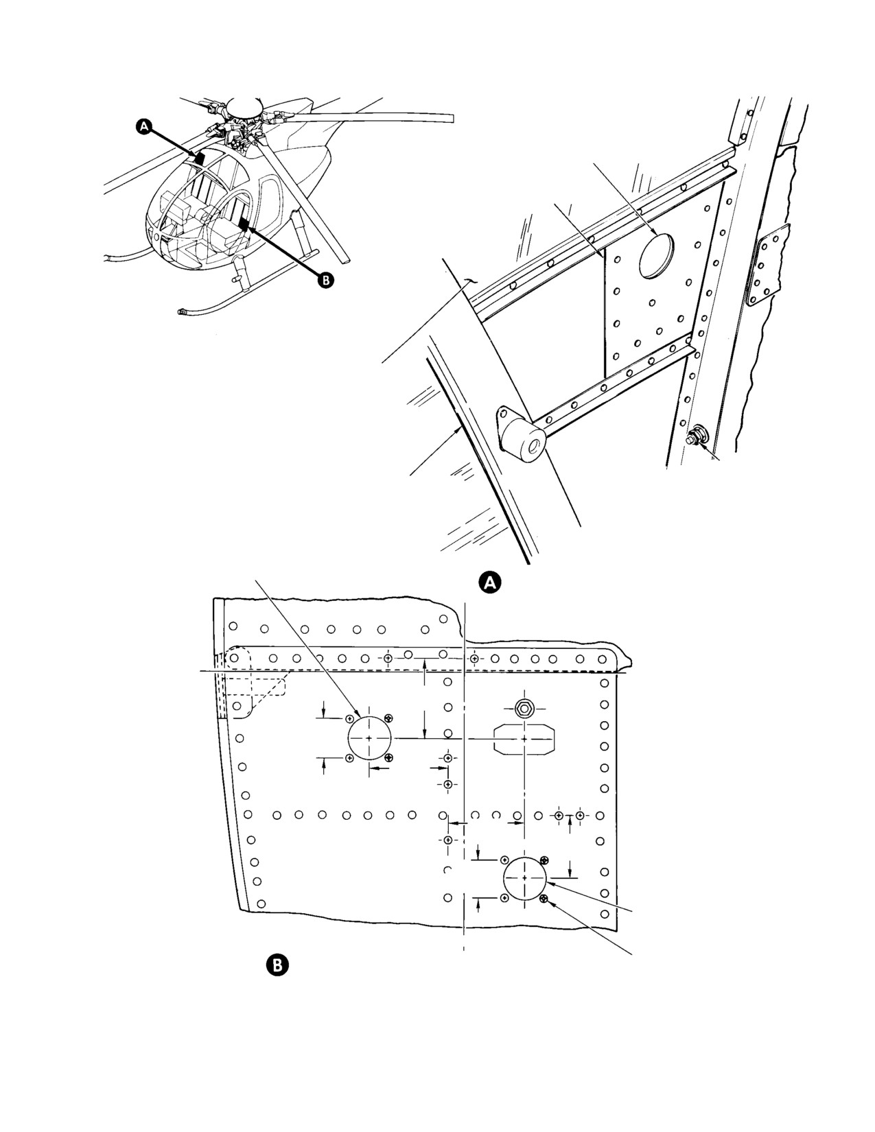
MD Helicopters, Inc.
CSP-HMI-2
MAINTENANCE MANUAL
CUT HOLE IN SKIN TO
MATCH HOLE IN DOUBLER
HOIST ELECTRICAL CON
NECTOR DOUBLER
UPPER CANOPY
WINDSHIELD
E19
CREW COMPARTMENT
RIGHT DOOR FRAME
NOTE: LH COMMAND VERSION SHOWN. RH
COMMAND VERSION IS INSTALLED AT SAME
LOCATION OR LEFT SIDE OF HELICOPTER.
LH COMMAND HELICOPTER
CONFIGURATION, CUT
1.00 IN. (2.54 CM) HOLE IN SKIN
WINCH ELECTRICAL RECEPTACLE
(J28) CUTOUT LOCATION
(NOTE)
WL 21.50
2.00 IN.
XJ2
(5.08 CM)
0.970 IN.
(24.638 MM)
(TYP)
2.00 IN.
(5.08 CM)
2.00 IN.
(5.08 CM)
1.50 IN.
XJ2
(3.81 CM)
0.970 IN.
(24.638 MM)
(TYP)
RH COMMAND HELICOPTER CON
FIGURATION, CUT
VIEW LOOKING FORWARD, LOWER LEFT
1.00 IN. (2.54 CM) HOLE IN SKIN
CORNER OF CANTED BULKHEAD STA. 78.50
0.121-0.135 IN.
PENDANT CONTROL ELECTRICAL
(3.0734-3.429 MM)
RECEPTACLE - CUTOUT LOCATION
HOLE (4 PLCS)
G25-6006A
Figure 901. Helicopter Modification
Page 903
25-63-00
Revision 23
CSP-HMI-2
MD Helicopters, Inc.
MAINTENANCE MANUAL
(10). Install XJ2 receptacle.
connect wires A526A12, A527G12N,
A527H20N, A527J20N, CCl0A20,
(a). Insert XJ2 receptacle (Ref.
CC8A20, and CC9A20 to J28 receptacle
Figure 201) in hole provided in lower
contacts as indicated (Ref. Figure 203).
left corner of canted bulkhead (Ref.
Figure 901). Using XJ2 receptacle
(15). Install J28 receptacle and secure with
bracket as a template, mark and drill
washer and nut. Install protective cap
four 0.121-0.133 inch (3.0734-3.3782
(Ref. Figure 201).
mm) attach holes. Protect attached
(16). Install ground stud on forward side of
wires during drilling operation.
canted bulkhead frame (Ref.
(b). Install XJ2 receptacle (Ref.
Figure 901). Identify ground stud as
Figure 201) from forward side of
E19.
canted bulkhead, with screws,
(17). Install wires A527G12N, A527H20N,
washers, and nuts.
and A527J20N, from J28 receptacle, on
(11). Route wires CC1AA20 and CC2AA20
ground stud E19. Adjust and trim
(Ref. Figure 203) from XJ2 receptacle to
insulation tubing (CM614) to accommo
TB1-16; install pin of wire CC1AA20 in
date ground wire connection as re
contact B and pin of wire CC2AA20 in
quired; heat shrink tubing.
contact D. Connect terminal on shield
(18). Replace existing cyclic stick grip with
ing of wire CC2AA20 to ground stud
part number 369H90129-505 (Ref. Sec.
E24; tighten ground stud nut.
67-10-20). Wire cyclic stick cable cutter
(12). Route wires CC8A20 and CC9A20 to
switch S600 as shown (Ref. Figure 204).
J28 receptacle and tie in place.
E. Electrical Equipment Installation (R/H
(13). Wire J28 receptacle.
Command)
(a). Cut and strip wires at J28 receptacle.
Install hoist kit electrical wire harness
Ensure sufficient wire length to
assembly, general wiring, and components on
provide a smooth right angle wire
R/H command helicopters, as follows:
flow to J28 receptacle.
Consumable Materials
(b). Install approximately 6 inches (15.24
(Ref. Section 91−00−00)
cm) of 0.50 inch (12.7 mm) insulation
Item
Nomenclature
tubing (CM614) on wire bundle to
cover all wires extending from J28
CM614
Sleeving, heat-shrink
receptacle.
CM703
Tie strap
CM725
Tape, electrical, plastic
(c). Ensure that all electrical contact
CM807
Twine, nylon
installations are correct and secure.
CM815
Solder
(d). Adjust wires at J28 receptacle and
make certain sufficient wire slack
Ensure wires and/or wire
remains to avoid stress on terminals
CAUTION
bundles do not chafe or bind
and contacts below floor and seat
control mechanisms.
areas. Use twine (CM807) and
tie-straps (CM703) to secure wires in
NOTE: When providing ground contact for elec
place.
trical components, clean the contacting sur
faces to bare metal (Ref. Chap. 96). Route
Ensure wires do not chafe or
CAUTION
wire and wire bundles with existing wires
bind throughout full travel of
and bundles. Temporarily tie wires in place
any control mechanism.
with existing bundles until installation is
(14). Remove J28 receptacle from side of
complete, then secure wires with nylon
ship. Install insulation sleeving
twine (CM807), tie-straps (CM703), or
(CM614) and, using solder (CM815),
clamps as required.
Page 904
Revision 23
25-63-00
MD Helicopters, Inc.
CSP-HMI-2
MAINTENANCE MANUAL
(1). From inside crew compartment,
Install pin and insert pin in contact A of
temporarily install J28 electrical
TB1-40.
receptacle (Ref. Figure 201) through
(8). Remove existing wire M520B20 from
hole provided in left side of ship (Ref.
TB1-19A. Wire end is left open insu
Figure 901). Install washer (Ref.
lated with tape (CM725), and secured to
Figure 201) and receptacle nut exter
basic electrical system tie-strap
nally to retain J28 receptacle in place.
(CM703). Install pin on wire K504M20
NOTE: The J28 receptacle is temporarily in
and insert in contact A of TB1-19.
stalled to provide a means of determining
Route wire K504M20 to TB1-40, install
proper length of wires to be connected to re
pin, and insert pin in contact C of
ceptacle.
TB1-40.
(9). Insert pin of wire CC10A20 in contact C
(2).
On standard R/H command equipped
of TB1-40, route wire to J28 receptacle,
with 369H92143 circuit breaker panel,
and temporarily tie in place. Connect
install circuit breaker CB600 (Ref. View
terminal on shielding of wire CC10A20
B), and a circuit breaker CB601 in
to ground stud E24. Do not tighten
circuit breaker panel located on the
ground stud nut.
pilot's collective pitch stick cover. Make
certain circuit breaker connections to
(10). Install XJ2 receptacle.
buss bar are secure.
(a). Insert XJ2 receptacle in hole pro
(3).
On SLAE-equipped R/H command with
vided in lower left corner of canted
369D294566 circuit breaker panel,
bulkhead (Ref. Figure 901). Using
install circuit breaker CB133 and
XJ2 receptacle bracket as a template,
circuit breaker CB134 in circuit breaker
mark and drill four 0.121-0.133 inch
panel located on the pilot's collective
(3.0734-3.3782 mm) attach holes.
pitch stick cover. Make certain circuit
breaker connections to buss bar are
(b). Install XJ2 receptacle (Ref.
secure.
Figure 201) from forward side of
canted bulkhead, using screws,
(4).
(Ref. Figure 205) Install terminal on
washers, and nuts.
wire A526A12 and connect to contact 2
of CB600 on standard R/H command, or
(11). Route wires CC1AA20 and CC2AA20
to contact 2 of CB133 on SLAE-
(Ref. Figure 205) from XJ2 receptacle to
equipped R/H command. Route opposite
TB1-40, install pin of wire CC1AA20 in
end of wire A526A12 with existing wire
contact B, and pin of wire CC2AA20 in
contact D. Contact terminal on shield
bundles to J28 receptacle and tempo
ing of wire CC2AA20 to ground stud
rarily tie in place.
E24; tighten ground stud nut.
(5).
On standard R/H command, locate
(12). Route wires CC8A20 and CC9A20 to
existing wire M503A20, install terminal
J28 receptacle and temporarily tie in
on wire M503A20, and connect to
place.
contact 2 of CB601. Locate existing wire
M503AA20, remove from TB16 contact
(13). Wire J28 receptacle.
A, and relocate to TB1-40, contact A.
(a). Cut and strip wires at J28 receptacle.
(6).
On SLAE-equipped R/H command,
Ensure sufficient wire length to form
install pin on wire M503A20, insert pin
a smooth right angle wire flow to J28
in contact A of TB1-40. Route wire
receptacle.
M503A20 to CB134; install terminal
and connect to contact 2 of CB134.
(b). Install approximately 6 inches (15.24
cm) of 0.50 inch (12.7 mm) insulation
(7).
Install pin on wire M504K20, insert in
tubing (CM614) on wire bundle to
contact B of TB1-19, and route opposite
cover all wires extending from J28
end of wire M504K20 to TB1-40.
receptacle.
Page 905
25-63-00
Revision 23
CSP-HMI-2
MD Helicopters, Inc.
MAINTENANCE MANUAL
(c). Ensure that all hoist system electri
F. Passenger/Cargo Door Retainer
cal installations are correct and
Installation
secure.
The passenger/cargo door retainer installation
(d). Adjust wires at J28 receptacle and
consists of a tubular assembly attached to the
make certain sufficient wire slack
aft side of Sta. 78.50 canted bulkhead with
remains to avoid stress on terminals
four clamps. With the passenger/cargo doors in
and contacts below floor seat areas.
the open position, a telescoping tube slides out
Use twine (CM807) and tie straps
of the tubular assembly to engage a bracket
(CM703) to secure wires in place.
attached to the door frame, and thus retains
the door in an open position. Install the
Ensure wires do not chafe or
passenger/cargo door retainer as follows:
CAUTION
bind throughout full travel of
any control mechanism.
(1). Install doubler angles.
(14).
Remove J28 receptacle from side of
(a). Locate doubler angles (Ref.
ship. Install insulation sleeving
Figure 203) on forward side of Sta.
(CM614) and, using solder (CM815),
78.50 canted bulkhead, using two
connect wires A526A12, A527G12N,
existing 0.070 inch (1.778 mm)
A527H20N, A527J20N, CC10A20,
tooling holes (Ref. Figure 902). Use
CC8A20, CC9A20 to J28 receptacle
angles (Ref. Figure 203) as templates
contacts as indicated (Ref. Figure 205).
and determine rivet hole locations on
Sta. 78.50 bulkhead.
(15).
Install J28 receptacle and secure with
washer (Ref. Figure 201) and nut.
(b). Drill rivet attach holes, 0.069-0.074
Install protective cap.
inch (1.7526-1.8796 mm).
(16).
Install ground stud on forward side of
(c). Attach angles to Sta. 78.50 bulkhead
canted bulkhead frame (Ref.
using rivets.
Figure 901). Identify stud as E19.
(17).
Install wires A527G12N, A527H20N,
(2). Install structural reinforcement
and A527J20N from J28 receptacle on
brackets.
ground stud E19. Adjust and trim
insulation tubing (CM614) to accommo
(a). Position structural reinforcement
date ground wire connection as re
brackets on forward side of Sta. 78.50
quired; heat shrink tubing.
canted bulkhead as shown (Ref.
Figure 902). Locate nine existing
(18).
(Ref. Figure 205) Check switch
rivets which must be removed prior
MS25089-4AR (S600) on cyclic stick
to installation of reinforcement
grip to verify that button is flush with
brackets. Remove rivets using drill
guard. If it is not, the switch must be
motor and appropriate drill bit.
reworked, as follows:
(b). Use brackets as templates and
(a). Remove switch from grip (unsolder
determine rivet hole locations on Sta.
wiring).
78.50 bulkhead. Drill rivet attach
holes, 0.069-0.074 inch
(b). Grind off end of switch button as
(1.7526-1.8796 mm).
shown.
(c). Attach brackets to Sta. 78.50 canted
Do not allow file chips to get into
CAUTION
bulkhead using rivets.
switch base.
(3). Drill eight 0.190-0.199 inch
(c). Install modified switch in grip and
(4.826-5.0546 mm) holes through Sta.
resolder wiring as shown.
78.50 canted bulkhead and structural
(d). Install decal 369H90070-67 to grip
reinforcement angles and brackets at
as shown.
locations shown (Ref. Figure 902).
Page 906
Revision 23
25-63-00
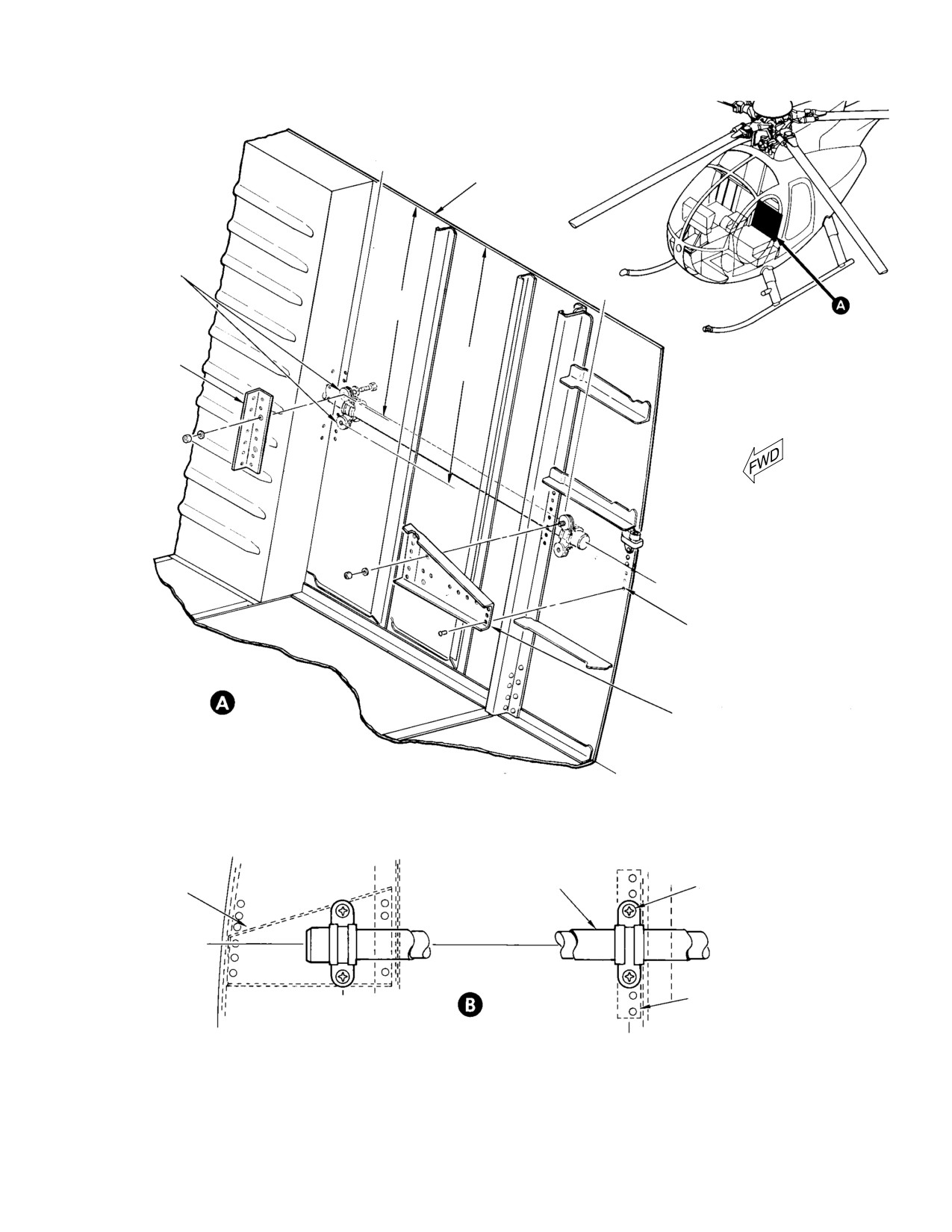
MD Helicopters, Inc.
CSP-HMI-2
MAINTENANCE MANUAL
BL
6.50
CANTED BULKHEAD
(STA. 78.50)
EXISTING
TOOLING
BL
HOLES
9.375 IN.
22.60
(23.8125 CM)
DOUBLER
11.44 IN.
ANGLE
(29.0576 CM)
WL 34.36
REMOVE EXISTING
RIVETS (9 PLCS)
REINFORCEMENT
STRUCTURAL REINFORCEMENT LOCATION
BRACKET
WL 21.50
PASSENGER/CARGO
0.190-0.199 IN.
REINFORCEMENT
DOOR RETAINER TUBE
(4.826-5.0546 MM)
BRACKET
HOLE (8 PLCS)
WL 34.36
DOUBLER
BL
ANGLE
22.60
PASSENGER/CARGO DOOR RETAINER
TUBE ALIGNMENT AND ATTACHMENT
BL
(VIEW LOOKING FORWARD - LEFT SIDE)
6.50
G25-6007A
Figure 902. Passenger/Cargo Door Retainer Tube Installation
Page 907
25-63-00
Revision 23
CSP-HMI-2
MD Helicopters, Inc.
MAINTENANCE MANUAL
NOTE: Drill retainer tube outboard clamp
(1). Remove nylon screws installed in
holes first; install retainer tube and out
support fitting attachment holes on
board clamps to ensure proper alignment for
fuselage.
marking and drilling inboard clamp holes.
(2). Install support tube attachment fittings
(Ref. Figure 201) on fuselage using
(4). Install the retainer assembly (Ref.
screws and washers.
Figure 203) on Sta. 78.50 canted
bulkhead, using clamps, washers,
(3). Attach winch to support tube, using
spacers, screws, and nuts.
bolts, washers, and nuts. Torque bolts
to 70 - 100 inch-pounds (7.91 - 11.30
(5). Locate bracket on applicable passenger/
Nm).
cargo door in such a manner as to allow
(4). Attach link assembly to support tube
tube to engage bracket when door is in
using bearing pin, washer, and cotter
open position. Install bracket on
pin.
passenger/cargo door frame using
rivnuts, washers, and screws.
(5). Attach winch support tube to fuselage
fittings, using quick-disconnect pins.
G. Hoist Assembly
NOTE:
Install pins in position shown (Ref.
Figure 201).
(Ref. Figure 201) The hoist assembly consists
of a winch assembly, pendant control assembly,
Ensure all electrical power is
hook, hanger, and two attach brackets. To
CAUTION
off, eliminating possibility of in
assemble the hoist, proceed as follows:
advertent firing of cable cutter.
NOTE: Pendant assembly is shipped as
(6). Remove protective cap from electrical
sembled with no additional assembly re
receptacle on side of fuselage. Connect
quired.
winch electrical plug to fuselage
receptacle. Secure wire harness to
(1). Install hanger on winch, using screws,
support tube, using tie-straps (CM703).
lockwashers, and washers.
Remove protective electri
WARNING
cal jumper wire
(Ref.
(2). Remove existing attach brackets from
Figure 202) from cable cutter whenev
winch. Install replacement brackets on
er winch is installed on helicopter.
winch frame, using existing hardware.
Jumper wire will prevent operation of
cable cutter in an emergency.
H. Hoist Installation
(7). Install the hoist operator's body
The hoist system winch is mounted on a
harness (Ref. Figure 201).
support tube and attached with quick-release
(8). Install flush rivets in wheel fittings
safety pins to three fittings installed on either
after removing existing rivets from
side and above the passenger/cargo compart
locations shown (Ref. Figure 903).
ment door. The support tube positions the
winch to raise and lower the cable between the
NOTE: Do not install rivets if wheel fittings
side of the fuselage and the landing gear skid.
have been previously equipped with flush
The winch and support can be installed for use
rivets.
on either the left or right side of the helicopter
(9). Install rivnuts at locations shown (Ref.
as applicable. Install the hoist system as
Figure 903). Secure clips (Ref.
follows:
Figure 201) to fuselage, using screws
and washers. Install bar assembly,
Consumable Materials
using screws, washers, and nuts.
(Ref. Section 91−00−00)
(10). On R/H command, install landing gear
Item
Nomenclature
skid chafing bar assembly
CM703
Tie strap
(369D292556) as follows (Ref.
Figure 903):
Page 908
Revision 23
25-63-00