HANDBOOK OF MAINTENANCE INSTRUCTIONS FOR MDHI 369D/E/FF-500/600N HELICOPTERS (ISSUED: 1990) - page 7
CSP-HMI-2
MD Helicopters, Inc.
MAINTENANCE MANUAL
(b). Probes - Must be correct for the part
(4). Standardization
shape, depth of penetration, and
(a). Standardization must be done in
frequency range for material ex
accordance with the manufacture
amined, and sensitivity to sense the
recommendations.
defect. Test probes must not give
interference during movement.
(b). Calibration scan must be done
Probes must be identified with the
before, during and after the inspec
manufacturer's part number and
tion. If the after calibration shows
frequency range.
test equipment is not accurate, do a
calibration of the equipment and do
(c). Standards - Reference calibration
another inspection on all components
standards can be actual parts (with
examined since last acceptable
natural defects) or from test blocks.
calibration.
All calibration standards must be
calibrated and certified.
1). Reference standards must be of an
(5). Regulatory Requirements
alloy of the same base material
The Eddy Current Inspection of
and temper or approximately the
components must be done with the
same electrical conductivity,
test facilities local aviation regulato
surface texture, shape, and defect
ry authority and approved proce
location as the part to be in
dures.
spected.
(6). Test Facilities
2). Only the reference standards
calibrated and certified must be
(a). Approved facilities must use the
used for the specific component
same or equivalent equipment.
examined. All calibration stan
(b). Analysis of all indications must be
dards must be kept to a national
made in accordance with the test
standard. Records must be kept
facilities approved procedures and
and made available when reques
with defects.
ted.
(c). Parts with defects must be removed
(3).
Surface preparation - All surface
from service in accordance with the
contamination that could cause an
facilities approved procedures.
interference with the inspection must
be removed. Methods of cleaning must
(d). Records must be completed in
not damage surface finish or damage to
accordance with the facilities ap
the part.
proved procedures.
Page 204
Revision 40
20-90-00

MD Helicopters, Inc.
CSP-HMI-2
MAINTENANCE MANUAL
Chapter
21
Environmental
Control System
MD Helicopters, Inc.
CSP-HMI-2
MAINTENANCE MANUAL
TABLE OF CONTENTS
Para/Figure/Table
Title
Page
21-10-00 Ventilation Systems
A
Maintenance Practices
201
1. Environmental Systems
201
2. Cabin Vent Control Cable Replacement
201
A. Cabin Vent Control Cable Removal
201
B. Cabin Vent Control Cable Installation
201
3. Cabin Ventilating Valve Replacement
201
A. Cabin Ventilating Valve Removal
201
B. Cabin Ventilation Valve Installation
202
4. Cabin Ventilation Valve Disassembly
202
5. Cabin Ventilating Valve Reassembly
202
6. Cabin Ventilating Valve Inspection
202
7. Cabin Ventilating Valve Repair
202
8. Snap-Vent Replacement
202
A. Snap-Vent Removal
202
B. Snap-Vent Installation
203
Figure 201. Ventilating System Pointed Nose
203
Figure 202. Ventilating System Round Nose
204
21-40-00 Heating System
A
Description and Operation
201
1. Heating System Description and Operation
201
2. Heating System Fault Isolation
202
Table 201. Troubleshooting Heating System
202
3. Heat Control Valve Replacement
202
A. Heat Control Valve Removal
202
Figure 201. Heating Valve and Cable Installation
203
B. Heat Control Valve Installation
204
4. Heat Control Valve Cable Replacement
204
A. Heat Control Valve Cable Removal
204
B. Heat Control Valve Cable - Installation
204
Figure 202. Cabin Heat Control Handle and Diffuser Installation
205
5. Heating System Inspection
205
A. Heat Control Valve Inspection
205
B. Heat Control Valve Cable Inspection
206
6. Heating System Operational Check
206
7. Heat Control Valve Disassembly
206
Page i
21 Contents
Revision 23
CSP-HMI-2
MD Helicopters, Inc.
MAINTENANCE MANUAL
TABLE OF CONTENTS (Cont.)
Para/Figure/Table
Title
Page
8. Heat Control Valve Repair
206
Figure 203. Heater Control Valve Assembly
207
Figure 204. Control Valve Shim Thickness Determination
208
9. Heating System Muffler and Ducts Repair
209
Figure 205. Hose and Ducting Installation
210
Initial Installation
901
1. Heating System Initial Installation
901
A. Preparation for Installation
901
B. Heating Valve Initial Installation
901
C. Ducting Installation (-517)
901
D. Ducting Installation (-519)
902
Figure 901. Outlet Installation and Convenience Panel Modification
902
E. Modification of Existing -517 to -519 Configuration
903
F. Ducting Installation (-521)
903
G. Cabin Heat Control Cable Initial Installation
903
H. Weight and Balance
904
Table 901. Weight and Balance Data
904
Figure 902. Engine Air Bleed Line Installation (250-C20B)
905
Figure 903. Engine Air Bleed Line Installation (250-C20R/2)
906
Figure 904. Engine Air Bleed Line Installation (250-C30)
907
Figure 905. Heating Valve Installation
908
Figure 906. Duct, Hose and Convenience Panel Installation (Sheet 1 of 2)
909
Page ii
Revision 23
21 Contents
MD Helicopters, Inc.
CSP-HMI-2
MAINTENANCE MANUAL
Section
21−10−00
Ventilation Systems
MD Helicopters, Inc.
CSP-HMI-2
MAINTENANCE MANUAL
VENTILATION SYSTEMS
MAINTENANCE PRACTICES
1. Environmental Systems
(4). Remove control cable nut from plunger
housing and pull entire control cable
The cabin ventilation system consists of a
out aft through instrument panel
ventilation valve, control cable and snapvents
mounting hole.
installed in the door windows. The ventilation
B. Cabin Vent Control Cable Installation
valve contains a moveable vane operated by a
push-pull cable mounted in the right center of
(1).
Route replacement control cable
the instrument panel. The control cable locks
through instrument panel and secure in
the vane in any selected position, controlling
place using lockwasher and control
airflow. Fresh air forced through an opening in
cable nut.
the lower front canopy passes through the
valve and is directed into the cabin.
(2).
Secure control cable sleeve to valve
bracket with clip.
Adjustable snapvents are installed in each
(3).
Position shaft arm so that vane assem
door window. The snapvents can be opened
bly is fully closed.
and rotated to face the airstream to supple
ment fresh air intake, or in the trail position,
(4).
Insert control cable wire through hole
provide a vent-air exhaust outlet.
in swivel and move control knob to fully
closed position.
Before high speed flight; ensure
CAUTION
that all snapvents are posi
(5).
Tighten swivel on control cable wire
tioned up, aft or down with outs in the trail
and install cotter pin.
position. Door damage and vibrations could
(6).
Check swivel for free rotation by
occur if vent cutouts face the airstream.
actuating control knob through full
stroke. Inspect valve assembly for
NOTE:
complete closure of inlet opening when
D The following maintenance procedures
control knob is pushed forward against
cover round or pointed nose helicopters.
cable panel fitting stop. Check valve
Whenever reference is given to diffuser
door for looseness on shaft and defor
type valve this is for round nose military
mation; valve door must be flat; a firm,
D model, and likewise the “Y” type is for
snug fit is required in the inlet.
civil models.
(7).
Reinstall right side fairing on instru
D For round nose model with diffuser or “Y”
ment panel.
type valve, refer to Figure 202. For
pointed nose “Y” type valve, refer to
3. Cabin Ventilating Valve Replacement
Figure 201.
A. Cabin Ventilating Valve Removal
2. Cabin Vent Control Cable Replacement
(1). Remove left and right side fairing from
instrument panel; then remove ducts
A. Cabin Vent Control Cable Removal
from rear of ventilating valve.
(2). Actuate control cable to full open
(1). Ensure that electrical power is OFF.
position.
(2). Remove right side fairing from instru
(3). Remove control cable clip and discon
ment panel.
nect control cable from swivel on valve
shaft.
(3). Disconnect control cable from swivel in
valve shaft. Remove clip and separate
(4). Drill out rivets and remove valve
control cable from support bracket.
assembly from helicopter canopy panel.
Page 201
21-10-00
Revision 23
CSP-HMI-2
MD Helicopters, Inc.
MAINTENANCE MANUAL
B. Cabin Ventilation Valve Installation
(3). Position vane assembly on shaft and
secure with screws using loctite
(1). Position ventilating valve on canopy
(CM431).
panel and align rivet holes. Attach
valve to canopy panel with rivets
(4). Install washer on end of shaft and
spaced at 90 degrees.
insert cotter pin.
NOTE: If rivet holes are elongated or oversize,
(5). Operate valve several times to assure
install next larger rivets.
freedom of operation and positive
closing.
(2). Secure control cable sleeve to valve
bracket with clip.
6. Cabin Ventilating Valve Inspection
(3). Install swivel assembly loosely in arm
(1). Inspect for cracks, secure attachment to
of shaft.
canopy panel and separation of bonded
joints.
(4). Position shaft arm so that vane assem
bly is fully closed.
NOTE: Very small, widely separated spots or
voids in plastic joints are not separation but
(5). Insert control cable wire into swivel
air pockets produced during solvent bonding
assembly and move control knob to
at manufacture.
fully closed position.
(2). Inspect for bent shaft or vane assembly
(6). Tighten swivel assembly on control
and excessive shaft wear in pivot areas.
cable wire; install cotter pin.
(3). Inspect seal on vane assembly for wear.
(7). Operate valve through several open-
close cycles to assure ease of operation
7. Cabin Ventilating Valve Repair
and to determine that valve locks in
any position when control knob is
released.
Consumable Materials
(Ref. Section 91−00−00)
(8). Install ducts on rear of valve; then
Item
Nomenclature
install instrument panel left and right
CM418
Cement, epoxy
side fairings.
4.
Cabin Ventilation Valve Disassembly
(1). Patch polycarbonate valve body cracks
and repair seam separations according
(1). Remove screws and separate vane
to repair methods specified for polycar
assembly from shaft.
bonate plastic (Ref. Sec. 20-30-00).
(2). Remove cotter pins and slide shaft from
(2). Replace unserviceable seal if installed,
valve body.
using cement (CM418) according to
container instructions.
5.
Cabin Ventilating Valve Reassembly
8. Snap−Vent Replacement
Consumable Materials
A. Snap−Vent Removal
(Ref. Section 91−00−00)
Item
Nomenclature
(1). Push snapvent outward in window
CM431
Sealing, locking and retaining compound
(open position).
(2). Grasp open side of snapvent and gently
(1). Install cotter pin in hole at control arm
squeeze it into an elliptical shape.
end of shaft. Install washer on shaft to
(3). Slip snapvent out of window hole at
bear on cotter pin.
about a 30 degree angle to surface of
(2). Insert shaft in body of valve.
window.
Page 202
Revision 23
21-10-00

MD Helicopters, Inc.
CSP-HMI-2
MAINTENANCE MANUAL
B. Snap−Vent Installation
(2). Slip snapvent flange into window hole
at an angle of about 30 degrees to
(1). Hold open end of replacement snapvent
surface of window. Be sure ends of wire
and gently squeeze it into an elliptical
stiffener are inside window pole.
shape.
CONTROL KNOB
INSTRUMENT PANEL
CONTROL CABLE NUT
VENT VALVE CONTROL
AIR DUCT
CABLE
DOOR WINDOW
SNAP VANT
CABIN VENT VALVE
K
BRACKET
CANOPY PANEL
CLIP
SHAFT
OUTSIDE (RAM) AIR IN
SIDE (EXAUST) AIR
RIVET
VANE
SEAL
SWIVEL ASSEMBLY
VANE ASSEMBLY
VENTILATING VALE
G21-1001
Figure 201. Ventilating System Pointed Nose
Page 203
21-10-00
Revision 23

CSP-HMI-2
MD Helicopters, Inc.
MAINTENANCE MANUAL
OUTSIDE (RAM) AIR
INSIDE (EXHAUST) AIR
DOOR WINDOW
SNAP VANT
CONTROL KNOB
NOTE
CONTROL CABLE NUT
VENT VALVE CONTROL
CABLE
CLIP
AIR DUCT
SWIVEL
ASSEMBLY
INSTRUMENT
PANEL
SHAFT
BRACKET
CANOPY PANEL
RIVET
SEAL VANE
CABIN VENT VALVE
VANE ASSEMBLY
JAM NUT AND SPRING
LOCKWASHER
CONTROL KNOB
CLIP
CONTROL CABLE
SWIVEL
ASSEMBLY
VALVE ASSEMBLY
NOTE:
SPRING PIN
DEFFUSOR
369D INSTRUMENT PANEL SHOWN,
500MD CONFIGURATION VALVE IS
SHAFT
INSTALLED WITH A T-SHAPED
OPEN PANEL.
CANOPY PANEL
COLLAR
VALVE PLATE
RIVET
TUBE
G21-1002
Figure 202. Ventilating System Round Nose
Page 204
Revision 23
21-10-00
MD Helicopters, Inc.
CSP-HMI-2
MAINTENANCE MANUAL
Section
21−40−00
Heating System
MD Helicopters, Inc.
CSP-HMI-2
MAINTENANCE MANUAL
HEATING SYSTEM
DESCRIPTION AND OPERATION
1.
Heating System Description and
enclosed behind the heating system
Operation
access cover. Air is Ducted overhead
from the muffler into the cargo/pas
(1).
The heating system mixes cold air
senger and crew compartments. Six
supplied by the oil cooler blower and
fan-shaped diffusers distribute air
hot air extracted from the engine
throughout the cabin.
compressor scroll. Cabin air tempera
ture is mechanically controlled with a
(4). The muffler consists of a laminated
handle in the crew compartment that
fiberglass housing, perforated alumi
positions a cable operated mixing valve.
num core, and a one inch layer of
The system distributes temperature
fiberglass wool around the core.
controlled air via a muffler and ducts to
(5). Air outlets are also provided for the
strategically located cabin outlets.
cargo/passenger compartment through
an overhead duct diffuser valve
(2).
The heat control valve is mounted on
mounted in the passenger convenience
the forward left side of the firewall
panel. Diffuser valve airflow can be
bulkhead. The valve consists of a
adjusted as required.
housing that contains air control ports
for mixing hot and cold air. A 90° inlet
(a). The -519 heating system adds
elbow attaches the valve to the com
ducting to provide two floor-heated
pressor bleed air tube through the
air outlets.
firewall bulkhead. The valve housing
inlet contains a stainless steel bleed air
(b). The -521 heating system provides
flow control ball valve that is rotated by
ducting for one floor-heated air
an attached drive pulley. A nozzle on
outlet.
the inlet body injects hot air down
(6). The control handle, control cable and
stream of cold air. A fitting supports the
conduit assembly are incorporated in
cold air control vane and drive pulley
the left side of the duct attached to the
that is rotated by a drive belt. Hot air is
overhead canopy structure. Moving the
mixed with cold air at a variable ratio.
Because engine bleed air temperature
control handle forward opens the heat
is approximately 500°F (260°C), cold air
control valve. Control handle travel is
is never completely shut off while the
approximately 2-3/4 inches (6.985 cm)
system is in use.
from open to closed. Cable routing is
along the left side of the main rotor
(3).
The duct system and the direct air flow
mast support structure and down to the
muffler are forward of the firewall and
firewall mounted control valve.
Page 201
21-40-00
Revision 23
CSP-HMI-2
MD Helicopters, Inc.
MAINTENANCE MANUAL
2. Heating System Fault Isolation
(Ref. Table 201)
Table 201. Troubleshooting Heating System
Symptom
Probable Trouble
Corrective Action
Actuation of heat valve control
Control valve pulley drive belt
Replace faulty parts and adjust
lever produces no heated air at
broken
valve.
outlets
Pulley shaft retaining pin sheared
Replace faulty parts and adjust
or control cable spring pin sheared
valve.
Heat valve ball binding in housing
Shim between valve housing and
elbow fitting.
Heat control valve internally
Replace valve.
defective
Heat control clevis improperly
Adjust control cable clevis.
adjusted for length
Cracked, broken or disconnected
Replace defective ducts.
ducting in system
Movement of heat valve does not
Same troubles as above
Replace faulty parts and adjust
shut off hot air
valve.
Movement of heat valve control
Control cable crushed or one or
Check cable operation with clevis
lever very difficult
more routing bend radii less than 3
detached from pulley arm.
inch (7.62 cm) minimum
Heat valve control lever does not
Cable sleeve (sheath) damage
Replace defective parts.
remain in selected position
causing preload spring−back
Air excessively hot at diffusers (*)
Improper cold air mixing
Adjust valve.
(*) CAUTION: Do not operate engine until this condition is corrected. Canopy plastic or ducting may be badly
damaged if operation is continued.
3. Heat Control Valve Replacement
(4). In left side of engine compartment,
disconnect the hot bleed air line at the
heat control valve elbow fitting.
(Ref. Figure 201)
(5). Loosen the elbow tube nut and remove
A. Heat Control Valve Removal
elbow fitting and gasket.
(1). Remove interior trim and left aft
(6). Remove hardware attaching the upper
bulkhead access cover.
and lower end of control valve assembly
to the canted firewall.
(2). Remove cotter pin, washer, and pin
attaching clevis to heat control valve.
(7). Remove clamp securing cool air duct to
valve.
(3). If particle separator is installed, loosen
and back off tube coupling nut of
(8). Remove attaching hardware connecting
369H90149-51 tube assembly at end
the muffler and valve. Remove heat
connected to elbow assembly.
control valve and gasket.
Page 202
Revision 23
21-40-00

MD Helicopters, Inc.
CSP-HMI-2
MAINTENANCE MANUAL
STRAP
(TYP)
GROMMET
CABLE
AFT AIR DUCTS
FWD AIR DUCTS
AIR DIFFUSERS
AIR DIFFUSERS
MUFFLER
BOLT
COLD AIR
CONNECTOR HOSE
INDEX FOR COLD AIR
VANE ALIGNMENT IN
CLAMP
CABLE ASSEMBLY
OPEN POSITION
WASHER
NUT
CLAMP
GASKET
SPACER
NUT
CONTROL VALVE
ASSEMBLY
WASHER
ROTATED
BOLT
NOTE
1/8 IN. (3.175MM) DRILL
JAM NUT
RIGGING PIN HOLES
COTTER
(OPEN POSITION)
NOTE:
PIN
GASKET
INSTALLED ON AIRCRAFT WITH
AIR PARTICLE SEPARATOR.
NUT
CLEVIS
NUT
PIN
BLEED AIR
BLEED AIR LINE
WASHER
FITTING
BOLT
ELBOW
G21-4001A
Figure 201. Heating Valve and Cable Installation
Page 203
21-40-00
Revision 23
CSP-HMI-2
MD Helicopters, Inc.
MAINTENANCE MANUAL
B. Heat Control Valve Installation
4. Heat Control Valve Cable Replacement
(Ref. Figure 202)
Consumable Materials
(Ref. Section 91−00−00)
A. Heat Control Valve Cable Removal
Item
Nomenclature
(1). Remove left half of engine air inlet
CM113
Anti-seize compound low temperature
forward fairing, interior trim and left
aft bulkhead access cover.
(1). Install control valve assembly on
(2). Remove seven screws attaching heat
forward left side of firewall with bolts,
duct outer box to heat duct and canopy
washers and nuts, but do not tighten.
frame.
NOTE: Use anti-seize compound (CM113) on
(3). Remove clamps, straps, and grommets
threaded fittings.
that attach cable to structure along its
full length. Remove cotter pin and
(2).
For helicopters equipped with particle
clevis pin from clevis at heater control
separator kit, re-engage tube coupling
valve arm.
nut of the 369H90149-51 tube assem
B. Heat Control Valve Cable − Installation
bly with elbow assembly, and tighten
fasteners.
Consumable Materials
(3).
In left side of engine compartment,
(Ref. Section 91−00−00)
install elbow, nut and new gasket.
Item
Nomenclature
Tighten retaining hardware on heating
CM430
Sealant, solvent resistant
valve.
(4).
Connect control valve flange to muffler,
(1). Route the cable assembly into position.
using new gasket and four nuts,
Check that grommet is in place on
washers, and bolts.
cable.
(5).
Install cool air connector hose on
(2). Install clamps and straps that attach
control valve inlet and secure with
cable to structure. Install grommet at
clamps.
structure fairing that cable passes
through using adhesive (CM430).
(6).
Position control handle fully forward.
Position lever on control valve to open,
NOTE: The clamp nearest to the valve should
and insert a 1/8 inch (3.175 mm)
not be tightened until after travel is
rigging pin through lever and into valve
checked.
boss.
(3). Attach heat duct outer box to heat duct
and canopy frame with seven screws.
(7).
Loosen jam nut on control cable and
adjust clevis so attach holes align with
(4). For adjustment of clevis refer to initial
hole in valve lever. Install pin through
installation.
clevis and valve lever, and safety with
cotter pin.
(5). When assured that cable will operate
the valve freely through full range of
(8).
Tighten clevis jam nut. Remove rigging
travel, tighten the clamp nearest the
pin from valve lever.
valve.
(9).
Move control handle full aft and
(6). Reinstall aft bulkhead access cover,
forward several times to check ease of
interior trim, and left half of engine
heat control operation.
inlet fairing.
(10).
Reinstall left aft bulkhead cover and
(7). After installation, adjust handle to be
interior trim.
parallel to windshield glass.
Page 204
Revision 23
21-40-00

MD Helicopters, Inc.
CSP-HMI-2
MAINTENANCE MANUAL
CANOPY FRAME
RIGID TUBING
CANOPY CENTER
FRAME TRIM AND
SPRING PLUNGER
HEAT DUCT - LOWER
CABLE SUPPORT BLOCK
(3 PLCS) (NOTE)
2 PLCS
SET SCREW
WASHER
CONTROL HANDLE
(NOTE)
HANDLE SHAFT
OUTER BOX
HEAT DUCT/TRIM
6 PLCS
CANOPY CLIP
INCREASE HEAT
DIFFUSER
ASSEMBLY
HEAT DUCT MOUNTING
SCREW
CONTROL HANDLE
DIFFUSER ASSEMBLY
INSTALLATION
INSTALLATION
NOTE:
INSTALL WASHERS AS REQUIRED TO
OBTAIN DIFFUSER-TO-DUCT FIT
G21-4002
Figure 202. Cabin Heat Control Handle and Diffuser Installation
5. Heating System Inspection
(f). Inspect rubber hose for tears and
evidence of deterioration.
(Ref. Figure 202)
(g). Inspect all ducts and muffler for
(1). With the helicopter on the ground,
security of attachment and coupling
perform the following:
hardware and any duct section or
muffler damage that would allow
(a). Inspect heat valve control lever and
heated air leaks. Inspect diffuser
cable for freedom of operation.
outlets for condition of cemented
joints or distribution ducts.
(b). Remove interior trim and left aft
bulkhead access cover in cargo
(h). In engine compartment, inspect tube
compartment. Inspect cable for
connecting engine air bleed fitting to
condition and security.
control valve for cracks and security
of hex nuts.
(c). Inspect cable clevis for security of
(2). Perform an operational check (Ref.
jam nut and cotter pin.
Heating System Operational Check).
(d). Inspect security of heat control valve
A. Heat Control Valve Inspection
to firewall; check pulley belt for
condition.
(1). Inspect timing belt for deterioration,
stretching, worn teeth, or evidence of
(e). Inspect flexible fiberglass hose for
slipping.
tears and deformation due to failure
of inner supporting wire or short
(2). Inspect valve housing for deep dents
radius bends.
and cracks, mating flanges and connect
Page 205
21-40-00
Revision 23
CSP-HMI-2
MD Helicopters, Inc.
MAINTENANCE MANUAL
ing area for bends or dents which would
(2).
Remove hardware (nut, washer, bolt)
prevent tight connections, bearing
attaching elbow to valve housing and
bosses for galling and excessive wear,
remove elbow and shims if installed.
and interior seat and ball valve for
galling.
(3).
The O-ring, wave washer, retainer, ball
valve and coupling are now free for
(3). Inspect pulley shafts for galling and
removal.
evidence of wear.
(4).
Cut lockwire and remove three screws
(4). Inspect ball valve and retainer for
from valve lever and drive pulley.
cracks, galling and evidence of wear;
Remove timing belt.
cold air vane for flatness and evidence
of excessive edge wear.
(5).
Remove pin from drive pulley. Remove
B. Heat Control Valve Cable Inspection
shaft from valve housing; inner and
outer washers will fall free.
(1). Inspect cables for kinks, crushed sleeve,
and corrosion.
(6).
Remove screws attaching cold air valve
vane to shaft. Remove plate spring and
(2). Clean all corrosion from cable.
spacers. Remove vane.
(3). If cable is kinked or crushed, locate
(7).
Remove pulley, shaft, and washers from
problem and repair or replace cable as
valve housing.
required.
(8).
Remove pin from driven pulley to
6.
Heating System Operational Check
complete disassembly.
(1). Perform an operational check of the
heating system as follows:
8. Heat Control Valve Repair
(2). Move CABIN HEAT control handle full
(1). Repair small dents in valve housing by
forward to open heat valve. Control
bumping out and burnishing. Repair
handle should not creep away from ON
warped flanges by straightening on a
position.
surface plate. No weld repairs are
(3). Remove left aft bulkhead access cover.
permitted.
(4). Check that valve is full open position by
(2). No repairs are permitted on moving
inserting a 1/8 inch (3.175 mm) drill
parts, ball valve, retainer, coupling, or
shank (or rod) into the drive pulley
shafts which are cracked, bent or badly
alignment hole (Ref. Figure 201). The
worn.
drill shank should pass through the
pulley and enter a mating alignment
(3). Place valve housing upside down on a
hole in the valve housing inlet body.
suitable workbench (Ref. Figure 204).
Find the thickness of shims required
(5). Check the cold air vane drive pulley
between valve body and elbow fittings
alignment mark. The mark should align
as follows.
with a similar mark on the cold air
vane housing.
(a). Measure diameter of the ball valve
using an outside micrometer. Record
7.
Heat Control Valve Disassembly
as dimension A.
(Ref. Figure 203)
(b). Place ball valve in housing and use a
(1). Rotate ball valve lever fully counter
depth micrometer to measure dis
clockwise to position the ball valve
tance from housing flange to top of
open.
ball. Record as dimension B.
Page 206
Revision 23
21-40-00

MD Helicopters, Inc.
CSP-HMI-2
MAINTENANCE MANUAL
VANE
SCREW
SPACER
SPRING
SHAFT
HOUSING
WASHER
PIN
BOLT
DRIVEN PULLEY
WASHER
WASHER
DRIVE PULLEY
BELT
BLEED AIR
FITTING
SHIM (AR)
ROTATED
SCREW
(NOTE)
PIN
RETAINER
BALL
LEVER
WASHER
O-RING
WASHER
COUPLING
SHAFT
NUT
WASHER
NOTE:
ELBOW
USED ON AIRCRAFT WITH
PARTICLE SEPARATOR.
G21-4003
Figure 203. Heater Control Valve Assembly
Page 207
21-40-00
Revision 23

CSP-HMI-2
MD Helicopters, Inc.
MAINTENANCE MANUAL
(c).
Multiply dimension A by 0.933; then
position ball valve in housing to engage
subtract the result from 1.627 in.
coupling (ball valve in open position).
(4.1356 cm). Record as dimension C.
(6). Install new O-ring in elbow flange
Example:
groove.
Ball dia. A = 1.441 in. (3.6601 cm)
(7). Install retainer and washer in housing
1.441 in. (3.6601 cm) x 0.933 = 1.344
on ball valve.
in. (3.4138 cm)
NOTE: A 1/2 inch (12.7 mm) wood dowel may
1.627 - 1.344 in. (3.4138 cm) = 0.283
be inserted through top of assembly to tem
in. (7.1882 mm) (dim. C)
porarily hold these parts in position.
(d).
Compare dimension B with dimen
(8). Install shim(s) of thickness determined
sion C. If B is greater than C, no
in above steps; then install elbow on
shims are required. If C is greater
valve housing flange with four bolts
than B, add shims 369H8007 until B
and nuts. Washers are installed under
is equal to or greater, 0.010 in. (0.254
both the bolt head and the nut. Use
mm) max., than C.
care to avoid nicking or cutting the
Example:
O-ring during mating.
B = 0.270 in. (6.858 mm) and C =
The flanges of the valve housing
CAUTION
0.283 in. (7.1882 mm)
and elbow should mate without
the use of undue force. If flanges do not mate
(e).
Add a 0.015 in. (0.381 mm) shim to
easily, the internal parts of the valve may be
dimension B. B now equals 0.285 in.
misaligned. Investigate before tightening
(7.239 mm), or 0.002 in. (0.0508 mm)
bolts.
more than dimension C, and is a
correct total shim thickness for use.
(9). Install washer and ball valve so that
rigging pin holes in pulley and in valve
(4). Install washer (Ref. Figure 203) on ball
housing boss are aligned (ball valve in
valve shaft; then insert this assembly
open position).
into valve housing boss.
(5). Install coupling on shaft (check that the
(10). Install pin through ball valve pulley
ball drive lug is chamfered); then
and shaft.
DEPTH MICROMETER
DIMENSION B (FLANGE-TO-BALL)
VALVE HOUSING
DIMENSION A (BALL DIAMETER)
NOTE:
FIND DIMENSION C AS FOLLOWS:
C = 1.627 IN. (4.1356 CM) - A X 0.993).
REFER TO TEXT FOR USAGE.
BALL VALVE
BALL VALVE SUPPORT
G21-4004A
Figure 204. Control Valve Shim Thickness Determination
Page 208
Revision 27
21-40-00
MD Helicopters, Inc.
CSP-HMI-2
MAINTENANCE MANUAL
(11).
Remove wood dowel if used to align
(20). Reinstall and actuator belt pulley on
internal parts; then rotate pulley
ball valve using three screws (Ref.
through full travel several times to
Figure 201). Note that the screw
assure ease of operation and positive
located 180 degrees from the rigging
closing of ball valve. A valve torque
pinhole is 1/8 inch (3.175 mm) longer
check, step (18). below, is made after
than the others. Remove rigging pin
the timing belt is installed.
installed in step (10). above. Safety
screws to each other with lockwire.
(12).
Install cold air pulley and washer on
shaft.
9. Heating System Muffler and Ducts Repair
(13).
Install cold air pulley and shaft assem
Consumable Materials
bly into valve housing.
(Ref. Section 91−00−00)
(14).
Attach cold air vane to shaft using two
Item
Nomenclature
screws.
CM432
Dichloromethane
CM433
Ethylene chloride
(15).
Rotate ball valve pulley fully counter
clockwise to full stop.
Repair of heat system ducting will depend
(16).
Rotate cold air pulley so that the vane
upon the type of material used in the section
is 45 degrees from fully closed, or align
that requires repair. Rubber hose or flexible
yellow rigging marks, if present.
fiberglass hose that is torn, flattened, or
deteriorated must be replaced. When removing
(17).
Install a serviceable timing belt
ducting for repair or replacement, use illustra
between pulleys while maintaining
tion as a guide (Ref. Figure 205).
valve position located in steps (15).and
(16). above.
(1). Repair rigid fiberglass or muffler
according to the fiberglass repair
(18).
Check valve operation by applying 6 -
procedures outlined in the SRM, except
11 inch-ounces (0.0423 - 0.0777 Nm)
use fire-retardant resin.
of torque on the ball valve shaft. If the
ball valve does not operate within this
(2). Repair rigid polycarbonate plastic
range, change thickness of shims
sections by bonding a patch according
between the valve elbow and housing as
to the criteria and methods specified for
required. Shims are provided inch 0.015
acrylic plastic in FAA AC 43.13-1B,
inch (0.381 mm), 0.010 in. (0.254 mm),
Aircraft Inspection and Repair for
and 0.005 inch (0.127 mm) thicknesses.
Standard Sheet Metal Repair. Use
dichloromethane (CM432) or ethylene
NOTE: Final total shim thickness should not
dichloride (CM433) as the bonding
exceed dimension C (step (c).) by more than
agent.
0.10 inch (2.54 mm).
(3). Repair small areas of rib or seam
(19). If rigging marks have not been applied,
separation in plastic sections by
paint a yellow index mark, 1/16 inch
injecting ethylene dichloride (CM433)
(1.59 mm) wide, on pulley and housing
into the void area and clamping
(Ref. Figure 201).
together under light pressure.
Page 209
21-40-00
Revision 44

CSP-HMI-2
MD Helicopters, Inc.
MAINTENANCE MANUAL
NOTES:
1.
REMOVE ADHESIVE BACKING COVER AND INSTALL PADS
WHERE INTERFERENCE MAY EXIST BETWEEN HOSE
AND STRUCTURE.
2.
INSURE THAT HEATER HOSE DOES NOT CONTACT OIL
DIFFUSER
FLEX LINES OR STRUCTURE.
ASSEMBLY
GROMMET
SCOTCH FOAM PAD
OIL FLEX LINE
(NOTE 2)
HOSE
DUCT
GROMMET
STANDOFF
CLAMP
CLAMP
DUCT ASSEMBLY
MUFFLER
COLD AIR MANIFOLD
COLD AIR HOSE
CONVENIENCE PANEL
CLAMP
HEATING VALVE
DUCTING INSTALLATION
G21-4005
Figure 205. Hose and Ducting Installation
Page 210
Revision 23
21-40-00
MD Helicopters, Inc.
CSP-HMI-2
MAINTENANCE MANUAL
HEATING SYSTEM
INITIAL INSTALLATION
1. Heating System Initial Installation
assembly (Sta. 31.50); retain washers
for use when installing diffuser assem
Procedures in this section may be performed at
blies.
the operator's discretion and are applicable to
369D/E/FF model helicopters.
(4). Remove attaching hardware and outer
box from heat duct and canopy frame.
A. Preparation for Installation
(5). Remove rubber plug from left side of
convenience panel.
Consumable Materials
(Ref. Section 91−00−00)
(6). Remove cap from cool air manifold duct.
Item
Nomenclature
B. Heating Valve Initial Installation
CM702
Lockwire CRES
(1). Using hardware, install heating valve,
but do not tighten.
(1). Remove engine (Ref. Chap. 71).
(2). On aircraft equipped with engine air
(a).
250-C20B - 250-C20R/2: (Ref.
particle separator only, engage tube
Figure 902 or Figure 903)
coupling nut of 369H90149-51 tube
assembly and tighten fasteners.
1). Remove existing plugs and install
tee and elbow.
(3). Install elbow, nut and gasket from aft
side of firewall. Tighten heating valve
Tee and elbow must be installed
CAUTION
attaching hardware.
so that no interference will exist
between hose assembly and existing bleed
(4). Reinstall engine (Ref. Chap. 71).
air tube.
(a).
250-C20B - 250-C20R/2: (Ref.
2). Install hose assembly and tube
Figure 902 or Figure 903)
assembly. Do not reinstall engine
at this time.
1). Connect tube assembly to elbow
using nut and gasket. Torque both
(b).
250-C30: (Ref. Figure 904)
connecting nuts onto tube assem
bly to 350 inch-pounds (39.54
1). Remove existing plate and install
Nm).
fitting, using engine supplied
washers and bolts. Safety with
(b).
250-C30: (Ref. Figure 904)
lockwire (CM702).
1). Connect engine bleed assembly to
2). Install engine bleed assembly to
elbow. Torque connecting nut to
fitting, and secure tube assembly
350 inch-pounds (39.54 Nm).
by connecting one end of the strap
to the inlet bell with bolt, nut and
C. Ducting Installation (−517)
washers, but do not tighten. Attach
(Ref. Figure 906)
clamp to bleed assembly. Secure to
strap with attaching hardware.
Tighten nut.
Consumable Materials
(Ref. Section 91−00−00)
(2). Remove interior trim panels and aft
Item
Nomenclature
bulkhead access.
CM411
Adhesive, epoxy
(3). Remove left and right hand guide
CM821
Gasket material
assemblies from forward end of duct
Page 901
21-40-00
Revision 23

CSP-HMI-2
MD Helicopters, Inc.
MAINTENANCE MANUAL
(1).
Using clamps, install air hose between
NOTE: Ensure that heater hose does not con
heating valve and cold air manifold
tact transmission oil lines or structure.
duct (Ref. Figure 905).
(8). Install aft valve assembly (23) in
(2).
Install muffler assembly with gasket
convenience panel (24) and connect
and hardware; attach hose to muffler
valve to duct (3) with hose (25) and
with clamp.
clamps (26).
(3).
Remove protective cap from existing
(9). Install diffuser assemblies (Ref.
duct assembly (1). Install grommets (2)
Figure 202); add washers as necessary
with cement (CM411) to prevent
to obtain diffuser to duct fit.
chafing.
D. Ducting Installation (−519)
(4).
Route heater hose (9) and secure to oil
flex line (10) with clamps (11, 12),
(Ref. Figure 906)
bracket (13), and attaching hardware
(14, 15, and 16).
Consumable Materials
(5).
Position standoff (17) on inboard side of
(Ref. Section 91−00−00)
channel (18) as shown. Drill two #40
Item
Nomenclature
holes and deburr. Attach standoff to
CM318
Primer
channel using two rivets (19).
CM702
Lockwire CRES
(6).
Install clamp (20) around hose and
secure to standoff, using attaching
hardware (21 and 22). Install Scotch
(1). Perform installation as described (Ref.
Foam (CM821) as required to prevent
Ducting Installation (-517), steps (1).
chafing.
thru (4). and (6).) except that duct (27),
replaces duct (3) and that hose (5) is not
(7).
Connect duct (3) to duct assembly (1),
secured to duct (27) at this time.
and hose (5). Attach duct (3) to bulk
head using attaching hardware (6, 7,
(2). Install splitter duct (28) with attaching
and 8). Attach hose (5) to duct with
hardware (29, 30) and valve (23) into
clamp (4).
convenience panel (24).
369D292479-1 OUTLET
INSTALLATION SAME
FOR 369D292479-2
0.188 IN. (4.7752 MM)
HOLE IN PANEL
REIDENTIFY AS 369H90020-5
369A2544-3
NAS1402-2 SCREW
CONVENIENCE PANEL, TO BE
NAS1329A08-75 RIVNUT
FITTING
AN960-8 WASHER
MADE FROM 369D26553-21 PANEL
NAS1402-2 SCREW
AN960-8 WASHER
(OPPOSITE SIDE)
PICK UP EXISTING RIVET
0.40 IN. (10.16 MM)
1.00 IN.
LOCATION
TRUE HOLE LOCATION
(2.54 CM)
0.30 IN.
1.38 IN. (3.5052 CM)
(7.62 MM)
2.75 IN. (6.985 CM)
369D292480
DRILL 0.020-0.023 IN.
SPLITTER DUCT
(0.508-0.584 MM) HOLE
NAS1303-4 BOLT
MS21042-3 NUT
AN960KD10 WASHER
PICK UP EXISTING
RIVET LOCATION
G21-4006A
Figure 901. Outlet Installation and Convenience Panel Modification
Page 902
Revision 23
21-40-00
MD Helicopters, Inc.
CSP-HMI-2
MAINTENANCE MANUAL
(3).
Attach hose (25) to valve (23) with
F. Ducting Installation (−521)
clamp (26), and hose (31) to splitter
(Ref. Figure 906)
duct (28) with lockwire (CM702).
(4).
Attach hose (25) to lower outlet on duct
Consumable Materials
(27) with clamp (26), and second hose
(Ref. Section 91−00−00)
(31) to upper outlet on duct (27) with
Item
Nomenclature
lockwire.
CM318
Primer
(5).
Mount convenience panel (24) with
attached duct, valve, and hose to
(1). Perform installation as described (Ref.
bulkhead with with attaching hardware
Ducting Installation (-519), steps (1).
(32, 33).
thru (5). except replace splitter duct
(28) with duct (43) (Ref. Figure 905).
(6).
Measure distance between splitter duct
(2). Position duct (35) and outlet duct (36)
outlets. Using this dimension, position
on bulkhead. Match drill three
ducts (34, 35) and outlet ducts (36)
0.221-0.226 inch (5.6134-5.7404 mm)
parallel to each other on bulkhead.
holes common to clips into bulkhead.
Match drill six 0.221-0.226 inch
Remove outlet duct (36) and duct (35).
(5.6134-5.7404 mm) holes common to
Deburr and apply primer (CM318) to
duct clips to bulkhead. Remove ducts.
bare metal surfaces. Install rivnuts
Deburr and apply primer (CM318) to
(37).
bare metal surfaces. Install rivnuts
(37). Reconnect ducts (34, 35) to splitter
(3). Connect duct (43) to duct (35) and
duct (28) and attach ducts to bulkhead
secure to bulkhead and convenience
with screws (38) and washers (39).
panel with attaching hardware (29, 30,
38, 39, 40, 41, and 42).
(7).
Install outlets (36) on ducts (34, 35).
Match drill holes through outlet duct
(4). Attach hose (5) to duct (27) with clamp
clips into bulkhead (Ref. Figure 901).
(4).
Remove outlets. Deburr and apply
G. Cabin Heat Control Cable Initial
primer to bare metal. Install rivnuts
Installation
(37) were applicable. Install outlets
with attaching hardware (38, 39, 40, 41,
(Ref. Figure 201)
and 42).
(8).
Attach hose (5) to duct (27) with clamp
Consumable Materials
(4).
(Ref. Section 91−00−00)
Item
Nomenclature
E. Modification of Existing −517 to −519
CM425
Sealing compound
Configuration
(1). Remove clevis and jam nut assembly;
(Ref. Figure 906)
install grommet on cable, remove
existing plug button in canted frame
(1). The -517 heating system may be
structure, and route cable through hole
modified by replacing duct (3) with duct
in structure and hole in structure
(27), modifying the convenience panel,
fairing.
as illustrated, and by installing addi
tional hose (31), splitter duct (28), ducts
(2). Remove clamps from duct assembly and
(34 and 35), outlets (36), and associated
secure control handle and rigid portion
hardware.
of control cable assembly with clamps.
(2). Follow installation instructions (Ref.
(3). Tie control cable to existing tubing and
Ducting Installation (-519).
cables with straps.
Page 903
21-40-00
Revision 23
CSP-HMI-2
MD Helicopters, Inc.
MAINTENANCE MANUAL
(4). Secure grommet in structure and seal
(c). Tighten clevis jam nut. Remove
hole at structure fairing that cable
rigging pin from valve lever.
passes through, using adhesive
(CM425).
(d). Move pilot's heat control handle full
aft and forward several times to
(5). Secure lower end of cable assembly to
check ease of heat control operation.
structure with clamp and attaching
hardware.
(e). Tighten clamp nearest clevis end of
NOTE: Do not tighten clamp until after travel
control cable.
is checked.
(f). Reinstall aft bulkhead access cover,
(6). Install heat duct outer box to heat duct
interior trim, and left half of engine
and canopy frame with seven screws.
inlet fairing.
(7). Install jam nut and clevis as follows;
(g). After installation, adjust control
(a). Position heat control handle full
handle to be parallel with windshield
forward. Position lever on heat
glass.
control valve to open and insert a 1/8
inch (0.125 mm) rigging pin through
H. Weight and Balance
lever and valve boss.
(b). Loosen jam nut on control cable and
Weight and balance changes resulting from
adjust clevis so attach holes align
installation of heating system equipment are
with hole in valve lever. Install pin
listed in Table 901. After installation of
through clevis and valve lever. Install
heating system equipment, incorporate
washer and secure pin with cotter
changes in helicopter weight and balance
pin.
record (Ref. Sec. 08-10-00).
Table 901. Weight and Balance Data
Weight
Arm
Moment
Configuration
Pounds (kg)
Inches (cm)
in−lb (kg cm)
369H90020−517
Added
+8.2
(+3.719)
106.7
(271.02)
+874.9
(+1007.990)
Removed
0.0
−
−
Change
+8.2
(+3.719)
106.7
(271.02)
+874.9
(+1007.990)
369H90020−519
Added
+8.6
(+3.901)
110.1
(279−65)
+946.9
(+1090.942)
Removed
0.0
−
−
Change
+8.6
(+3.901)
110.1
(279−65)
+946.9
(+1090.942)
Page 904
Revision 23
21-40-00
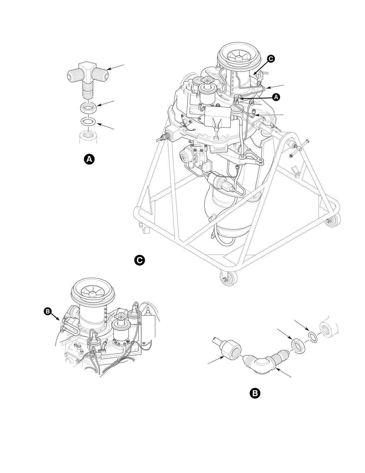
MD Helicopters, Inc.
CSP-HMI-2
MAINTENANCE MANUAL
TEE
(NOTE)
HOSE ASSEMBLY
NUT
TUBE ASSEMBLY
GASKET
ROTATED
GASKET
NUT
HOSE ASSEMBLY
ELBOW
(NOTE)
NOTE:
INSTALL TEE AND ELBOW SO NO INTERFERENCE
OCCURS BETWEEN HOSE ASSEMBLY AND EXISTING
ENGINE BLEED AIR TUBE.
G21-4007
Figure 902. Engine Air Bleed Line Installation (250−C20B)
Page 905
21-40-00
Revision 23
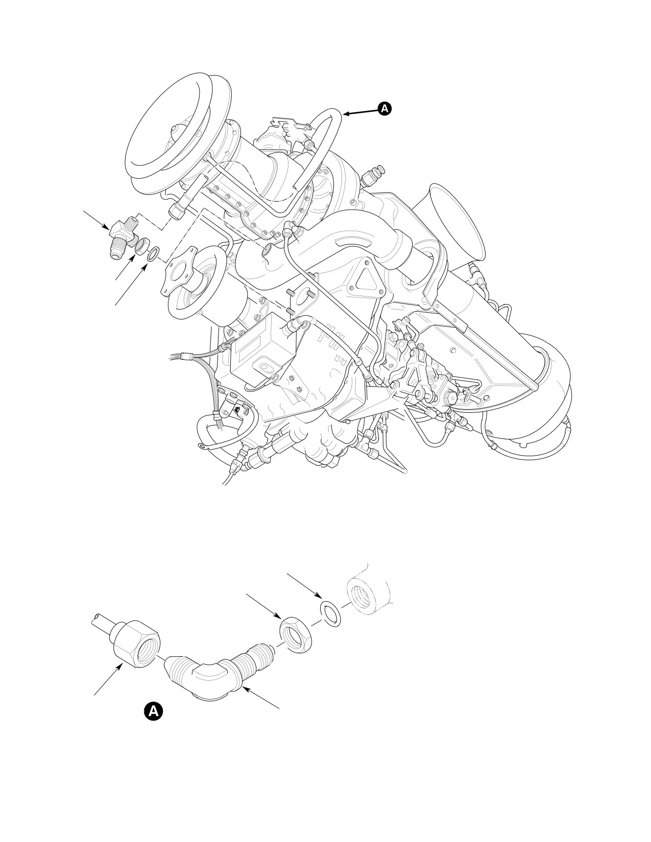
CSP-HMI-2
MD Helicopters, Inc.
MAINTENANCE MANUAL
TEE
NUT
GASKET
GASKET
NUT
NOTE:
INSTALL TEE AND ELBOW SO NO INTERFERENCE
OCCURS BETWEEN HOSE ASSEMBLY AND EXISTING
ENGINE BLEED AIR TUBE.
HOSE ASSEMBLY
ELBOW
(NOTE)
G21-4008
Figure 903. Engine Air Bleed Line Installation (250−C20R/2)
Page 906
Revision 23
21-40-00
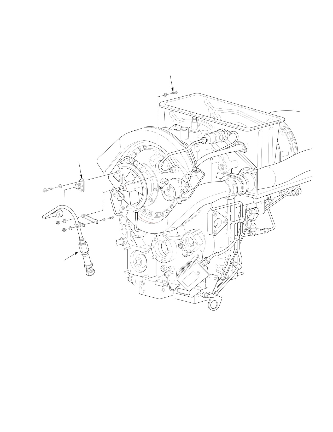
MD Helicopters, Inc.
CSP-HMI-2
MAINTENANCE MANUAL
BOLT
(NOTE)
FITTING
ENGINE BLEED
ASSEMBLY
NOTE:
REPLACE EXISTING NUT AND BOLT WITH
NAS1351C08-10 BOLT,
MS21043-C8 NUT AND
G21-4009
AN960 8L WASHER (2 REQD)
Figure 904. Engine Air Bleed Line Installation (250−C30)
Page 907
21-40-00
Revision 23
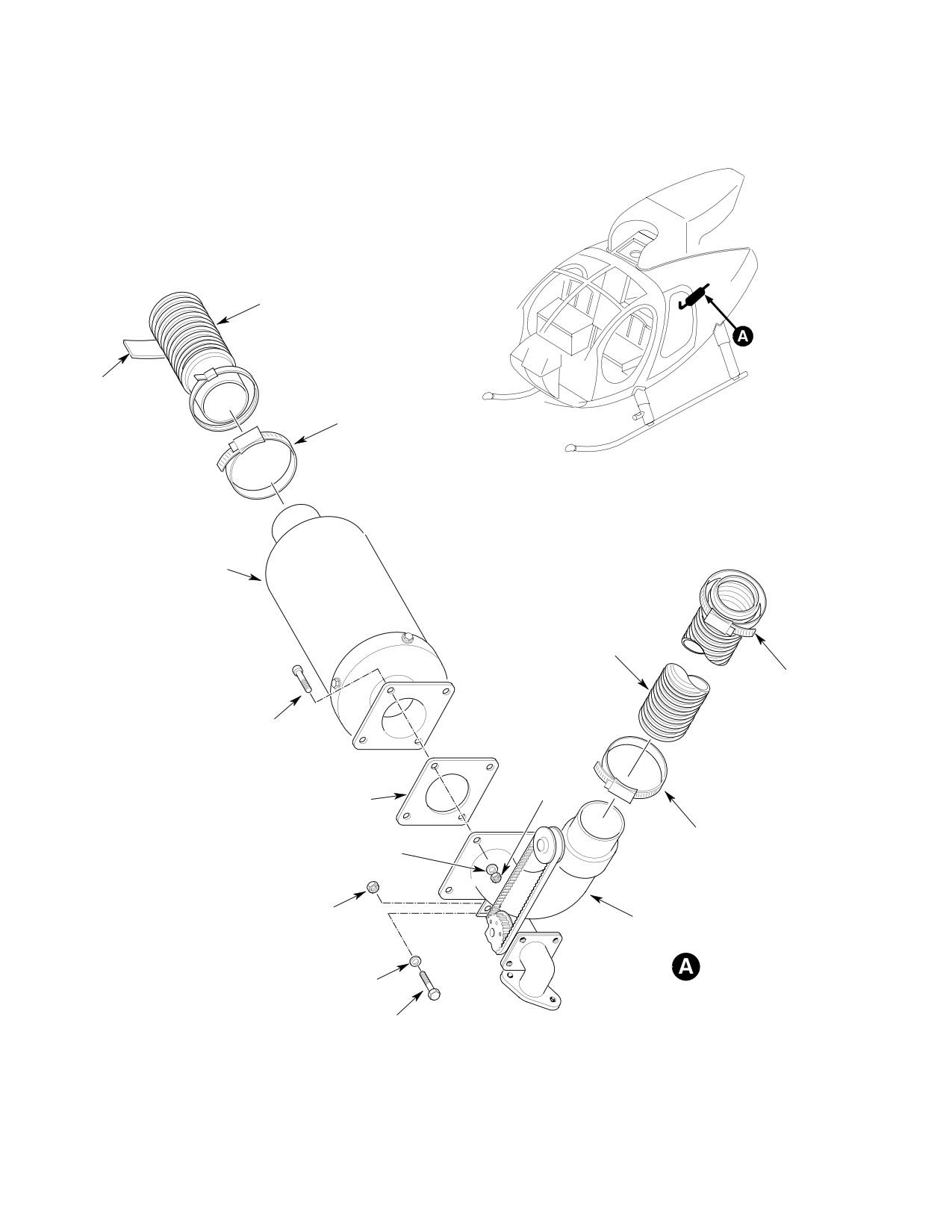
CSP-HMI-2
MD Helicopters, Inc.
MAINTENANCE MANUAL
HOSE
GROMMET
CLAMP
MUFFLER
COLD AIR HOSE
CLAMP
BOLT
NUT
GASKET
CLAMP
WASHER
NUT
HEATING VALVE
WASHER
BOLT
G21-4010
Figure 905. Heating Valve Installation
Page 908
Revision 23
21-40-00
MD Helicopters, Inc.
CSP-HMI-2
MAINTENANCE MANUAL
2
1
8
5
7
4
3
7
6
-517 (REF)
27
14
11
15
21
22
15
10
16
15
14
13
9
20
19
17
16
15
SCOTCH FOAM
12
18
G21-4011
Figure 906. Duct, Hose and Convenience Panel Installation (Sheet 1 of 2)
Page 909
21-40-00
Revision 23
CSP-HMI-2
MD Helicopters, Inc.
MAINTENANCE MANUAL
3
32
33
31
27
28
25
26
37
26
24
43
23
42
41
34
30
42
41
29
39
38
42
35
41
37
40
36
39
38
36
41
36
40
G27-4012
Figure 906. Duct, Hose and Convenience Panel Installation (Sheet 2 of 2)
Page 910
Revision 23
21-40-00
MD Helicopters, Inc.
CSP-HMI-2
MAINTENANCE MANUAL
Legend (Ref. Figure 906)
1. DUCT ASSEMBLY
23. AFT VALVE ASSEMBLY
2. GROMMET
24. CONVENIENCE PANEL
3. DUCT
25. HOSE
4. CLAMP
26. CLAMP
5. HOSE
27. DUCT
6. BOLT
28. SPLITTER DUCT
7. WASHER
29. SCREW
8. NUT
30. WASHER
9. HEATER HOSE
31. HOSE
10. OIL FLEX LINE
32. SCREW
11. CLAMP
33. WASHER
12. CLAMP
34. DUCT
13. BRACKET
35. DUCT
14. BOLT
36. OUTLET
15. WASHER
37. RIVNUT
16. NUT
17. STANDOFF
38. SCREW
18. CHANNEL
39. WASHER
19. RIVET
40. BOLT
20. CLAMP
41. WASHER
21. BOLT
42. NUT
22. WASHER
43. DUCT
Page 911
21-40-00
Revision 23
CSP-HMI-2
MD Helicopters, Inc.
MAINTENANCE MANUAL
This Page Intentionally Left Blank
Page 912
Revision 44
21-40-00

MD Helicopters, Inc.
CSP-HMI-2
MAINTENANCE MANUAL
Chapter
25
Equipment/
Furnishings
MD Helicopters, Inc.
CSP-HMI-2
MAINTENANCE MANUAL
TABLE OF CONTENTS
Para/Figure/Table
Title
Page
25-00-00 Equipment/ Furnishings
A
Description and Operation
1
1. Interior Furnishings Description
1
A. Upholstered Seat Furnishings Configuration
1
B. Mesh Seat Furnishings Configuration
1
C. Crew Upholstered Seating
1
D. Crew Mesh Seating
1
E. Passenger Upholstered Bench Seating
1
F. Mid Bench Seat (600N)
1
G. Upholstered Passenger Individual Seat
1
H. Passenger Mesh Seating
1
I. Seat Belts and Shoulder Harnesses (369D/E/FF - 500N)
2
J. Seat Belts and Shoulder Harness (600N)
2
K. Interior Trim
2
L. Floor Trim and Covering
2
M. Miscellaneous Furnishings
2
25-10-00 Upholstered Seats
A
Maintenance Practices
201
1.
Upholstered Crew Seat Replacement
201
2.
Upholstered Passenger Aft Bench Seat Replacement
201
3.
Mid Bench Seat Assembly Replacement (600N)
201
A. Mid Bench Seat Removal
201
B. Mid Bench Seat Installation
201
4.
Upholstered Passenger Individual Seat Replacement
201
5.
Upholstered Seat Inspection
201
A. Upholstered Seat Cleaning
201
6.
Upholstered Seat Repair
202
7.
Optional Mid Business Seat Replacement (600N)
202
A. Business Seat Removal
202
B. Business Seat Installation
202
Figure 201. Upholstered Seat Installation (369D)
203
Figure 202. Upholstered Seat Installation (369E/FF - 500/600N)
204
Figure 203. Mid and Aft Seating Configuration (600N)
205
Figure 204. Mid and Aft Bench Seat Assembly Installation (600N)
206
Figure 205. Upholstered Passenger Individual Seat Installation (369D)
207
Figure 206. Mid-Cabin Business Seat Installation (600N)
208
Page i
25 Contents
Revision 24
CSP-HMI-2
MD Helicopters, Inc.
MAINTENANCE MANUAL
TABLE OF CONTENTS (Cont.)
Para/Figure/Table
Title
Page
25-15-00 Mesh Seats
A
Maintenance Practices
201
1. Crew/Passenger Mesh Seats
201
2. Crew Mesh Seat Replacement
201
3. Passenger Mesh Seat Replacement
201
4. Passenger Mesh Seat Adjustment
201
5. Crew Mesh Seat Inspection
201
6. Passenger Mesh Seat Inspection
201
Figure 201. Mesh Seat Installation
202
Figure 202. Passenger Individual Mesh Seat Adjustment and Storage
203
7. Mesh Seats Cleaning
204
8. Mesh Seats Repair
204
Figure 203. Passenger Bench Mesh Seat Adjustment
204
Initial Installation
901
1. Mesh Seat Initial Installation
901
A. Model Applicability
901
B. Preparation for Installation
901
C. Helicopter Equipment Removal
901
D. Passenger Compartment Bench Seat Installation
901
E. Passenger Compartment Individual Seat Installation
901
F. Crew Compartment Mesh Seat Installation
901
G. Helicopter Equipment Installation
902
H. Weight and Balance Data
902
Table 901. Weight and Balance Data
902
25-20-00 Seat Belts/Inertia Reel
A
Maintenance Practices
201
1. Seat Belts/Inertia Reel Description and Operation (369D/E/FF - 500N)
201
2. Seat Belts/Inertia Reel Description and Operation (600N)
201
3. Crew Seat Belt/Harness Cleaning
201
4. Seat Belt/Inertia Reel Replacement (369D/E/FF - 500N)
201
Figure 201. Seat Belt/Inertia Reel Installation (Sam Browne Style)
(369D)
202
Figure 202. Seat Belt/Inertia Reel Installation (Yoke Style) (369D)
203
Figure 203. Seat Belt/Inertia Reel Installation (Yoke Style)
(369E/FF - 500N)
204
5. Crew Seat Belt/Harness Replacement With Manual Lock Option
(369D/E/FF - 500N)
205
Page ii
Revision 23
25 Contents
MD Helicopters, Inc.
CSP-HMI-2
MAINTENANCE MANUAL
TABLE OF CONTENTS (Cont.)
Para/Figure/Table
Title
Page
Figure 204. Webbed Shoulder Harness and Seat Belt Installation with Manual
Inertia Reel Lock (369D)
205
Figure 205. Crew Inertia Reel Installation with Manual Inertia Reel Lock
(369D/E/FF - 500N)
206
6. Seat Belt/Inertia Reel Testing
206
7. Seat Belt/Inertia Reel Inspection
206
8. Seat Belt/Inertia Reel Repair
207
9. Seat Belt/Restraint Harness, Crew Seat, Replacement (600N)
207
A. Seat Belt/Restraint Harness Removal
207
B. Seat Belt/Restraint Harness Installation
207
Figure 206. Seat Belt/Restraint Harness Installation, Crew Seat (600N)
207
10. Seat Belt/Restraint Harness, Mid Passenger Seat, Replacement (600N)
208
A. Seat Belt/Restraint Harness Removal
208
B. Seat Belt/Restraint Harness Installation
208
11. Seat Belt/Restraint Harness, Aft Passenger Seat, Replacement (600N)
208
A. Seat Belt/Restraint Harness Removal
208
B. Seat Belt/Restraint Harness Installation
208
Figure 207. Seat Belt/Restraint Harness Installation, Passenger
Seats (600N)
209
12. Comfort Clip Installation and Decal Application (369D/E/FF - 500N)
210
Figure 208. Comfort Clip Installation and Crew Compartment Decal
Application (369D/E/FF - 500N)
210
Figure 209. Comfort Clip Decal Application - Passenger Compartment
(369D/E/FF - 500N)
211
25-21-00 Seating/Belts (Four on the Floor)
A
Maintenance Practices
201
1. General
201
2. Seating/Belt Replacement
201
A. Seating/Belt Removal
201
B. Seating/Belt Installation
201
3. Seating/Belt Inspection
201
4. Seating/Belt Cleaning
201
5. Seating/Belt Repair
201
Initial Installation
901
1. Seating/Belts (Four on the Floor) Initial Installation
901
A. Preparation for Installation
901
B. Removal of Existing Equipment
901
C. Seating and Belts Installation - General
901
Page iii
25 Contents
Revision 23
CSP-HMI-2
MD Helicopters, Inc.
MAINTENANCE MANUAL
TABLE OF CONTENTS (Cont.)
Para/Figure/Table
Title
Page
D. Cant. Sta. 78.50 Brackets, Fittings and Restraint Panels Installation
901
Figure 901. Restraint Panel Assemblies and Hardware Installation
(369D)
902
Figure 902. Restraint Panel Assemblies and Hardware Installation
(369E/FF - 500N)
903
E. Seat Assemblies Installation
905
F. Aft Seat Belt Assemblies and Shoulder Straps Installation
905
G. Forward Seat Belt Assemblies and Shoulder Straps Installation
905
H. Weight and Balance Data
906
Table 901. Weight and Balance Data
906
Figure 903. Seat Belt and Seat Assemblies Installation
(369D/E/FF - 500N)
907
Figure 904. Shoulder Straps and Fittings Installation
(369D/E/FF - 500N)
908
25-30-00 Interior Trim
A
Maintenance Practices
201
1.
Interior Trim
201
A. Cyclic Stick Control Cover
201
B. Copilot's Inboard Collective Pitch Stick Cover
201
2.
Interior Trim Replacement
201
A. Cyclic Stick Control Cover Replacement (L/H Command)
201
B. Copilot's Collective Pitch Stick Cover Replacement (L/H Command)
201
Figure 201. Crew Compartment Interior Trim (Sheet 1 of 2)
202
Figure 202. Passenger Compartment Interior Trim (Sheet 1 of 2)
204
C. Inboard Collective Pitch Stick Cover Replacement (R/H Command)
206
D. Transmission Panel
206
E. Log Book Holder (Optional for R/H Command)
206
F. Carpeting
206
3.
Interior Trim Inspection
206
A. Interior Trim Cleaning
206
Figure 203. Crew and Passenger Compartment Interior Trim - R/H Command
(Sheet 1 of 2)
207
4.
Interior Trim and Carpeting General Repair
209
5.
Boltaron Trim Panels Repair
209
A. Fiberglass Patch Method
209
Figure 204. Floor Trim and Covering
210
B. Solvent Bonding Patch Method
211
C. Epoxy Adhesive Patch Method
211
Page iv
Revision 23
25 Contents
MD Helicopters, Inc.
CSP-HMI-2
MAINTENANCE MANUAL
TABLE OF CONTENTS (Cont.)
Para/Figure/Table
Title
Page
Figure 205. Boltaron Panel Repair
212
D. Bond and Rivet Patch Method
213
25-40-00 Miscellaneous Furnishings
A
Maintenance Practices
201
1. Crew Compartment Miscellaneous Furnishings Replacement
201
A. Stowage Box
201
B. Heat Duct
201
C. Foot Rest (L/H Command)
201
D. Ash Receiver and Cigarette Lighter Panel
201
2. Passenger Compartment Miscellaneous Furnishings Replacement
201
A. Convenience Panel Replacement (R/H Command)
201
3. Passenger Step Assembly Description
201
4. Passenger Step Assembly Inspection
201
5. Passenger Step Assembly Replacement
202
A. Passenger Step Assembly Removal
202
B. Passenger Step Assembly Installation
202
6. Passenger Step Assembly Repair
202
7. Miscellaneous Furnishings Inspection
202
8. Miscellaneous Furnishings Repair
202
Figure 201. Miscellaneous Furnishings (369D) (Sheet 1 of 2)
203
Figure 202. Miscellaneous Furnishings (369E/FF - 500/600N)
(Sheet 1 of 2)
205
Figure 203. Passenger Step Assembly (600N)
207
25-50-00 Cargo Hook
A
Fault Isolation
101
1. Cargo Hook Description
101
2. Cargo Hook Operation
101
3. Cargo Hook Fault Isolation
101
4. Wiring Diagrams
101
Table 101. Troubleshooting - Cargo Hook Installation
102
Table 102. Wire Chart, 369D/E/FF Right or Left Hand Command
102
Table 103. Wire Chart, 369E/FF T-Panel with Center Electrical Console,
R/H Command
103
Figure 101. Cargo Hook - Wiring Diagrams (Sheet 1 of 4)
104
Removal/Installation
401
1. Cargo Hook Replacement
401
A. Cargo Hook Removal
401
Page v
25 Contents
Revision 23
CSP-HMI-2
MD Helicopters, Inc.
MAINTENANCE MANUAL
TABLE OF CONTENTS (Cont.)
Para/Figure/Table
Title
Page
B. Cargo Hook Installation
401
Figure 401. Manual Release Cable Routing - Interior
403
Figure 402. Manual Release Cable and Electrical Wire Harness Routing -
Exterior
404
Figure 403. Cargo Hook Electrical Equipment Installation
405
Figure 404. Hook and Pad - Installation
406
Figure 405. Cargo Hook Manual Release Lever - Installation
407
Figure 406. Cargo Hook Release for 600N Helicopters
408
Inspection/Check
601
1. Cargo Hook Operational Check
601
2. Adjustment
601
3. Exterior Components Inspection
601
4. Interior Components Inspection
602
Initial Installation
901
1. Cargo Hook Initial Installation
901
A. Preparation for Installation
901
B. Helicopter Equipment Removal
901
C. Modification of Helicopter
901
D. Cargo Hook Provisions Installation
901
E. Electrical Components and Wiring Installation (Left and Right Hand
Command)
902
Table 901. Cargo Hook Relay Installation
902
Figure 901. Fuselage Skin Cutouts
903
F. Cargo Hook Installation
904
Figure 902. Relay and Bracket Installation Pilots Floor (369D/E/FF)
905
Table 902. VNE Card Installation
906
G. Helicopter Equipment Installation
906
Table 903. Cargo Hook Switch Installations - Stick Grip
906
H. Weight and Balance Data
907
Table 904. Weight and Balance Data
907
25-60-00 Emergency First Aid Kit
A
Maintenance Practices
201
1. Emergency First Aid Kit
201
2. Emergency First Aid Kit Contents Check
201
Figure 201. Emergency First Aid Kit
202
25-63-00 Hoist Passenger/Cargo
A
Maintenance Practices
201
1. Hoist Passenger/Cargo
201
Page vi
Revision 23
25 Contents
MD Helicopters, Inc.
CSP-HMI-2
MAINTENANCE MANUAL
TABLE OF CONTENTS (Cont.)
Para/Figure/Table
Title
Page
Figure 201. Hoist System Components (Sheet 1 of 3)
202
2.
Preparation for Hoisting Operations
205
Figure 202. Winch Cable, Cable Cutter, and Swivel Hook Replacement
(Sheet 1 of 2)
206
3.
Hoist System Troubleshooting
208
4.
Cyclic Stick Grip and Cyclic Stick Cable Cutter Switch (S600) Replacement
208
5.
Hoist Assembly Replacement
208
A. Hoist Assembly Removal
208
B. Hoist Assembly Installation
208
Figure 203. Passenger/Cargo Door Retainer Installation
209
6.
Winch Components Replacement
210
A. Winch Cable Replacement
210
B. Swivel Hook Replacement
211
C. Cable Cutter Replacement (Guillotine-Type)
212
7.
Hoist System Operational Check
212
8.
Hoist Equipment Inspection
213
Table 201. Troubleshooting Hoist System
214
Figure 204. Wiring Diagram - Hoist System (L/H Command)
214
Figure 205. Wiring Diagram - Hoist System (R/H Command)
215
Figure 206. Schematic Diagram - Hoist System Winch
216
Initial Installation
901
1. Hoist Passenger/Cargo Initial Installation
901
A. Preparation for Installation
901
B. Helicopter Equipment Removal
901
C. Helicopter Modification
901
D. Electrical Equipment Installation (L/H Command)
902
Figure 901. Helicopter Modification
903
E. Electrical Equipment Installation (R/H Command)
904
F. Passenger/Cargo Door Retainer Installation
906
Figure 902. Passenger/Cargo Door Retainer Tube Installation
907
G. Hoist Assembly
908
H. Hoist Installation
908
I. Helicopter Equipment Installation
909
J. Weight and Balance Data
909
Table 901. Weight and Balance Data
909
Figure 903. Cable Antichafing Bar Installation
910
Page vii
25 Contents
Revision 23
CSP-HMI-2
MD Helicopters, Inc.
MAINTENANCE MANUAL
TABLE OF CONTENTS (Cont.)
Para/Figure/Table
Title
Page
This Page Intentionally Left Blank
Page viii
Revision 43
25 Contents
MD Helicopters, Inc.
CSP-HMI-2
MAINTENANCE MANUAL
Section
25−00−00
Equipment/
Furnishings
MD Helicopters, Inc.
CSP-HMI-2
MAINTENANCE MANUAL
EQUIPMENT/FURNISHINGS
DESCRIPTION AND OPERATION
1. Interior Furnishings Description
D. Crew Mesh Seating
The crew compartment is equipped with
Standard furnishings on the 369D/E/FF -
two-part seats. Each two-part seat consists of
500/600N Helicopters include seats in the crew
a seat back and a seat bottom constructed of
and passenger compartments, seat belts,
aluminum tubing frames with a nylon mesh
interior trim, floor trim and covering, and
covering and rubber pads cemented to the
other miscellaneous furnishing items.
frame mounting plates. The seat backs are
mounted on the Station 78.50 canted frame.
A. Upholstered Seat Furnishings
Seat bottoms are secured on top of the pilot's
Configuration
seat structure.
The helicopters are equipped with the basic
E. Passenger Upholstered Bench Seating
interior furnishings configuration. This
Passenger compartment seating is provided by
includes upholstered seats with a bench type
a bench type tubular steel structure furnished
in the passenger compartment and three
with upholstered cushions. The bench seat is
individual seats in the crew compartment. The
adjustable fore and aft as well as up and down,
center crew seat is removed for the dual
and may be folded or quickly removed when
controls option. Seat belts are provided at all
cargo space is required. All seat cushions are
seat locations. Interior trim finish is provided
either upholstered and trimmed with vinyl, or
throughout interior cabin enclosure.
may be all vinyl. Velcro strip fasteners secure
seat cushions in place.
The 600N helicopter comes equipped with a
mid position bench seat. At this position in the
F. Mid Bench Seat (600N)
passenger compartment, the mid seat can be
The mid bench seat provides additional three
positioned in either the forward or aft facing
abreast seating in the passenger area. This
configuration.
seat can be positioned in either the forward or
aft facing configuration. The seat belt/harness
B. Mesh Seat Furnishings Configuration
system is completely attached to the seat
structure for quick removal and installation of
The helicopters are equipped with a basic
the entire bench seat assembly.
interior furnishings configuration. This
includes two mesh seats and seat backs in the
G. Upholstered Passenger Individual Seat
crew compartment and two stowable mesh
seats in the passenger/cargo compartment.
Individual seat installations are also available
Seat belts are provided at all seat locations.
for the passenger compartment. The seat
Interior trim is provided for the passenger
frames are secured to the bulkhead attach
convenience panel, transmission, passenger aft
fittings with ball-lock pins. When each seat is
bulkhead, inboard collective pitch stick, and
folded, the flat surface of the seat back serves
cyclic controls.
as a barrier for cargo. Ref. P/N 369D290037 in
the optional equipment list for a further
C. Crew Upholstered Seating
description of individual passenger seat
installations (Ref. Table 202, Sec. 01-00).
The crew compartment on all models with
H. Passenger Mesh Seating
single controls has a three-place seating
arrangement. A two-place seating arrange
Two passenger seats are installed in the aft
ment is provided for optional dual controls.
compartment of the helicopter. The seats are of
Crew compartment seats consist of left and
welded tubular aluminum structure with
right side seat cushions and, if applicable, a
nylon mesh covers. The seats may be folded for
center seat cushion. Each seat has a seat back
clear cargo space and, if desired, are easily
cushion. Crew compartment seat structure is
removed by means of quick disconnect
an integral part of the helicopter fuselage.
attachments.
Page 1
25-00-00
Revision 23
CSP-HMI-2
MD Helicopters, Inc.
MAINTENANCE MANUAL
I. Seat Belts and Shoulder Harnesses
K. Interior Trim
(369D/E/FF − 500N)
Interior trim used in the crew compartment
In the standard installation, Sam Browne type
and the passenger compartment is of thermo
seat belts with shoulder harness straps are
plastic material contoured to cover interior
installed at each seat position. Seat belts and
structure. Trim panels and covers provide
shoulder straps are fabricated from nylon
interior finish, compartment insulation and
webbing with sewn-in buckles and attach
mounting surfaces for convenience items, and
fittings. Lengths of seat belts and shoulder
certain optional equipment. Trim panels and
straps are not adjustable. Inertia reels are
covers are attached with Velcro fasteners and
provided to take up slack and allow free
with upholstery screws with rivnuts or isolator
movement of the seat occupant.
nut mounts on the fuselage structure.
Comfort clips are available for helicopters
L. Floor Trim and Covering
equipped with Sam Browne type seat belt
assemblies. The comfort clip is designed to
maintain proper strap tension and relieve
Interior floor trim and covering consists of
excessive pressure of the inertia reel shoulder
fire-resistant carpeting and two foot fairing
harness on the crew or passengers during
trim assemblies. The lower part of Sta. 78.50
flight.
bulkhead and access doors are also covered
with fire-resistant carpeting.
After each seat belt and shoulder harness
assembly is fastened and adjusted for individu
M. Miscellaneous Furnishings
al comfort and safety, the comfort clip is moved
from its original position next to the buckle
Miscellaneous furnishings include a stowage
and relocated by sliding up on the harness
compartment, heat duct, VNE card holder, foot
strap as close as possible to the inertia reel.
rest assembly, helicopter checklist, operational
The clip prevents any further retraction of the
record holder, ashtrays, and LH/RH passenger
strap into the inertia reel, thus keeping a
step assemblies. The stowage compartment is
constant yet comfortable tension of the
under the right floor access door (Ref. Sec.
harness strap against the user. After each
52-50). The compartment has a uniformly-dis
flight, the comfort clip is to be returned to its
tributed load capacity of 50 pounds maximum
original location.
when optional avionics equipment is not
installed in the crew area underfloor compart
J. Seat Belts and Shoulder Harness (600N)
ment. The heat duct provides interior trim for
The crew seats in the helicopter utilize a
the canopy frame and mounting surface for the
four-point restraint harness that combines the
magnetic compass (Ref. Sec. 95-20). The VNE
lap seat belts with double shoulder straps for
card holder is located on the left side of the
greater occupant security and comfort. Both
instrument panel. The helicopter checklist is
mid and aft passenger seats are equipped with
stored with the magnetic compass card in the
a three-point restraint system. The lap seat
map case. The operational record holder is
belt and shoulder strap are joined at the end
attached to the outboard side of the right
into a single unit for ease of attachment and
instrument panel fairing. Ashtrays and
convenience. In one motion, the lap and
cigarette lighters are provided in the lower
shoulder belts together can be attached to the
portion of the instrument panel and on the
seat buckle. All seat belt/harness systems are
back side of the station 78.50 canted bulkhead.
equipped with an automatic locking inertia
The removable passenger steps are attached to
reel mechanism.
the helicopter side jacking points.
Page 2
Revision 23
25-00-00
MD Helicopters, Inc.
CSP-HMI-2
MAINTENANCE MANUAL
Section
25−10−00
Upholstered Seats
MD Helicopters, Inc.
CSP-HMI-2
MAINTENANCE MANUAL
UPHOLSTERED SEATS
MAINTENANCE PRACTICES
1. Upholstered Crew Seat Replacement
A. Mid Bench Seat Removal
(1). Remove quick release pins that attach
(Ref. Figure 201, Figure 202 and Figure 204)
seat support fittings to floor rails.
Upholstered Seats for the 369D/E/FF -
500/600N Helicopters are the same. The
(2). Remove seat assembly.
addition of the mid position bench seat is
unique to the Model 600N.
B. Mid Bench Seat Installation
(1). Clear seats of seat belts and shoulder
(1). Install seat assembly in aircraft.
straps.
(2). Align seat support fittings with floor
rails.
(2). Lift seat cushions away from fuselage
seat structure to release Velcro strip
(3). Install quick release pins to secure seat
and fasteners.
assembly to floor.
(3). To replace, position seat cushions so
4. Upholstered Passenger Individual Seat
that Velcro fastener strips mate. Apply
Replacement
slight pressure to secure seat cushions
in place.
(Ref. Figure 205)
(1). Clear seat of seat belts and shoulder
2. Upholstered Passenger Aft Bench Seat
straps.
Replacement
(2). Remove ball-lock pins from bulkhead
(Ref. Figure 201 or Figure 202)
attach fittings.
(1). Clear seats of seat belts and shoulder
(3). To replace, position seats so that
straps.
quick-disconnect pins align with
bulkhead attach points and lock seats
(2). Release seat quick-disconnect fittings
in place.
at bulkhead, then at floor points.
5. Upholstered Seat Inspection
NOTE: For height adjustment, install ball-lock
(Ref. Figure 201, Figure 202 and Figure 204)
pins in desired position at support legs and
bulkhead fittings. For fore and aft adjust
(1). Inspect upholstery material for cuts,
ment, move and secure seat back at desired
loose stitching or other unserviceable
position on lower frame.
condition.
(3). To replace, position bench seat so that
(2). Inspect Velcro fastener strips for
quick-disconnect fittings align with
security of attachment and condition.
floor and bulkhead attach points.
(3). On passenger seat structure, inspect
quick-disconnect mechanisms for
(4). Lock seat in place, first at floor fittings
proper operation or damage that may
then at bulkhead fittings.
prevent positive locking.
3. Mid Bench Seat Assembly Replacement
A. Upholstered Seat Cleaning
(600N)
(Ref. Sec. 20-20-00, Fuselage Interior Trim
(Ref. Figure 204)
and Upholstery Cleaning)
Page 201
25-10-00
Revision 23
CSP-HMI-2
MD Helicopters, Inc.
MAINTENANCE MANUAL
6. Upholstered Seat Repair
adjustable seats attached through four seat
tracks that allow seat location adjustment over
a 10 inch span when seats are facing forward.
Consumable Materials
(Ref. Section 91−00−00)
NOTE:
Item
Nomenclature
D With the seats in the full aft position and
CM219
Methyl-ethyl-ketone
facing forward, the rear passenger seats
CM405
Adhesive
become unusable for passenger seating.
D The seats are removable and may be
(1). Lapstitch frayed or worn upholstery.
placed in the aft facing position.
MEK solvent is flammable.
D In the aft facing position, only two seat
WARNING
Use only in well-ventilated
locations are available.
area and away from heat and flame.
A. Business Seat Removal
NOTE: Loosened Velcro strips may be reacti
vated for adhesion by wiping original adhe
(1). Remove quick release pins that attach
sive film with MEK (CM219).
seat support fittings to floor rails.
(2). Replace unserviceable Velcro fastener
(2). Remove seat assembly.
strips. Install new Velcro strips to mate.
Bond in place with adhesive (CM405).
B. Business Seat Installation
(3). Make minor welded or riveted sleeve-
(1). Install seat on tracks with forward
type repairs on tubular structure
guide pin in track cutout first.
according to FAA AC 43.13-1B Inspec
tion and Repair for Standard Sheet
(2). Once seat guide pin is in track, slide
Metal Repair.
seat forward until 2 rear guide pins are
in the track cutouts.
7. Optional Mid Business Seat Replacement
(600N)
(3). When installing seat facing aft, tilt
(Ref. Figure 206) This option replaces the
seat-back full forward during
standard mid bench seat with two fore and aft
installation.
Page 202
Revision 44
25-10-00
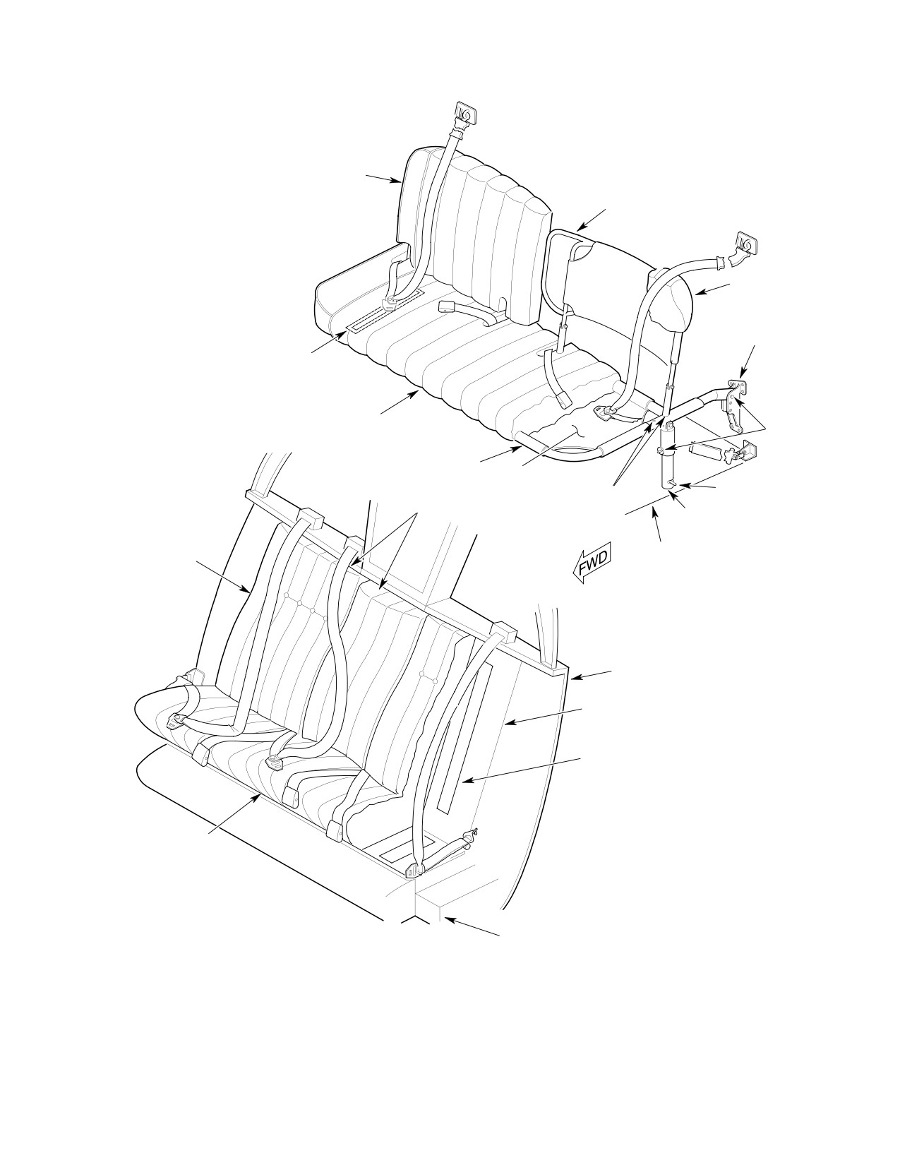
MD Helicopters, Inc.
CSP-HMI-2
MAINTENANCE MANUAL
SEAT BACK CUSHION
SEAT BACK
NOTE 1
AFT SUPPORT
FITTING AND HEIGHT
ADJUSTMENT
VELCRO STRIP FASTENER
(TYP)
PASSENGER COMPARTMENT
SEAT BOTTOM
CUSHION
PIP PINS
LOWER FRAME
NYLON
MESH
RELEASE PIN
FORE AND AFT
NOTE 2
ADJUSTMENT
SUPPORT LEG AND
HOLES
HEIGHT ADJUSTMENT
SEAT BACK
FLOOR STRUCTURE
CUSHION
HIGH SHOULDER BEAM
NOTE 1
VELCRO STRIP FASTENER
(TYP)
NOTES:
1.
SHOWN WITHOUT CUSHION
SEAT BOTTOM
FOR CLARITY.
CUSHION
2.
CENTER CUSHIONS AND SEAT
BELTS ONLY FOR 3-PLACE
SEATING.
CREW COMPARTMENT
SEAT STRUCTURE
G25-1000
Figure 201. Upholstered Seat Installation (369D)
Page 203
25-10-00
Revision 23
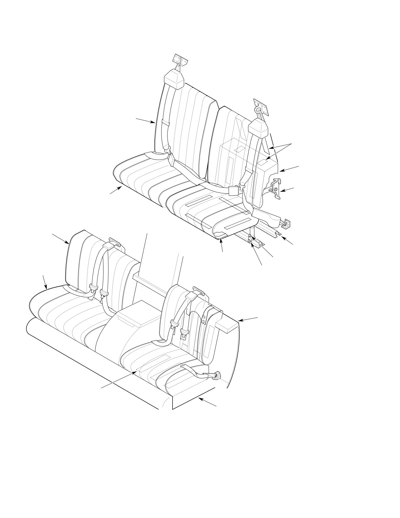
CSP-HMI-2
MD Helicopters, Inc.
MAINTENANCE MANUAL
SEAT BACK CUSHION
VELCRO STRIP FASTENER
(TYP)
CUSHION SUPPORT
AFT SUPPORT FITTING
AND HEIGHT ADJUSTMENT
SEAT BOTTOM CUSHION
PASSENGER COMPARTMENT
SEAT BACK
CUSHION
FLOOR STRUCTURE
LOWER FRAME
LOCKPIN
SEAT BOTTOM
RELEASE PIN
CUSHION
SUPPORT LEG AND
HEIGHT ADJUSTMENT
LOW SHOULDER BEAM
VELCRO STRIP FASTENER
(TYP)
SEAT STRUCTURE
CREW COMPARTMENT
G25-1001
Figure 202. Upholstered Seat Installation (369E/FF − 500/600N)
Page 204
Revision 23
25-10-00
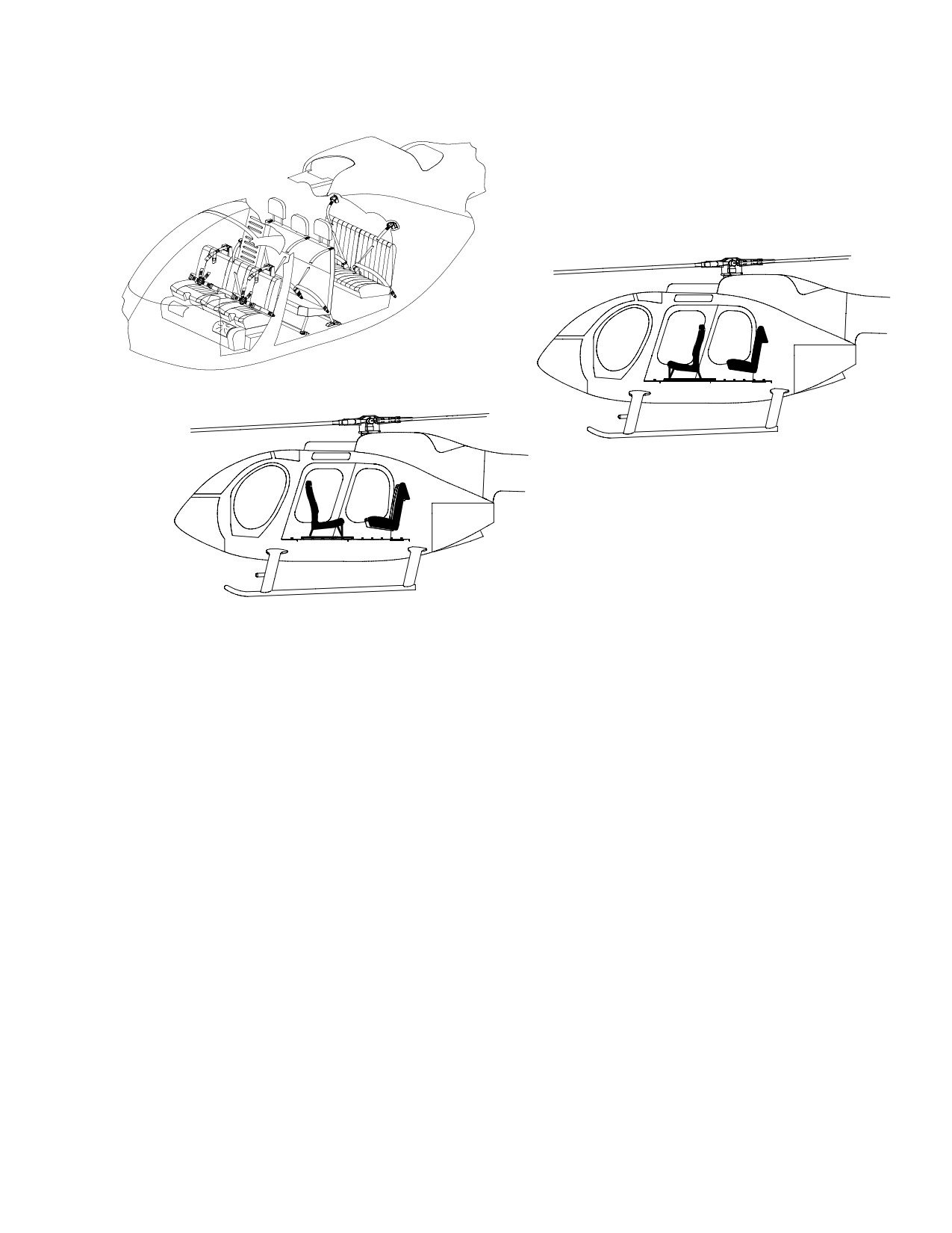
MD Helicopters, Inc.
CSP-HMI-2
MAINTENANCE MANUAL
FWD FACING
AFT FACING
OPTIONAL MID-CABIN BENCH SEAT ORIENTATION
6G25-069
Figure 203. Mid and Aft Seating Configuration (600N)
Page 205
25-10-00
Revision 23
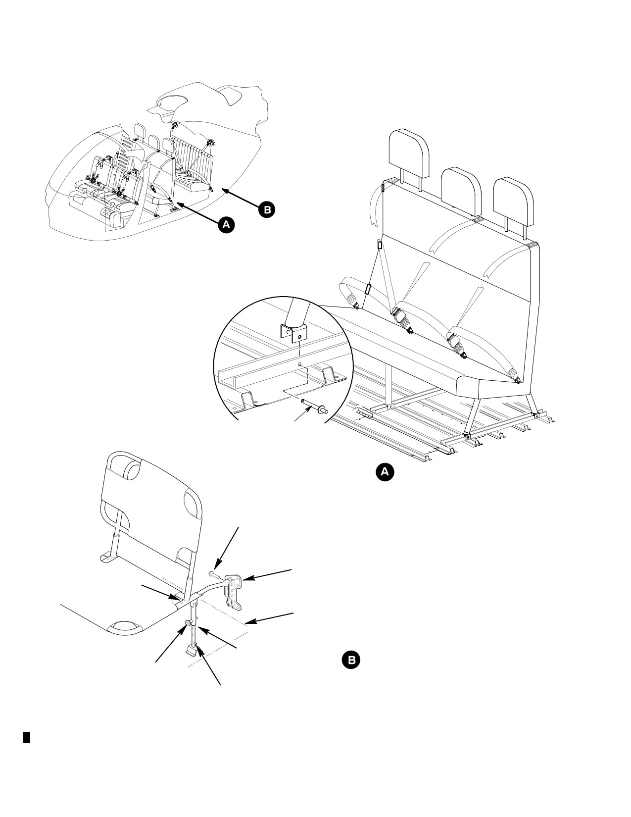
CSP-HMI-2
MD Helicopters, Inc.
MAINTENANCE MANUAL
QUICK RELEASE PIN
WITH LANYARD (6 PLCS)
FORWARD, MID AND AFT
ATTACHMENTS ARE TYPICAL
MID BENCH SEAT ADJUSTMENT
BALL LOCK PIN
AFT SUPPORT FITTING AND
HEIGHT ADJUSTMENT
FORE AND AFT
ADJUSTMENT HOLES
FLOOR STRUCTURE
SUPPORT LEG AND HEIGHT
ADJUSTMENT
AFT BENCH SEAT ADJUSTMENT
BALL LOCK PIN
RELEASE PIN
NOTE: SEAT SHOWN WITH CUSHIONS REMOVED
6G25-061
Figure 204. Mid and Aft Bench Seat Assembly Installation (600N)
Page 206
Revision 24
25-10-00
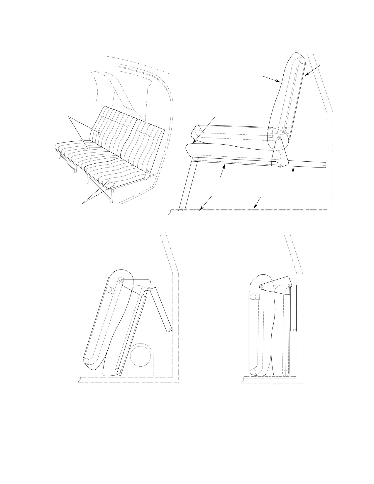
MD Helicopters, Inc.
CSP-HMI-2
MAINTENANCE MANUAL
SEAT BACK
ASSY
SEAT BACK CUSHION
VINYL END PIECES
(TYP)
FABRIC
SEAT BOTTOM CUSHION
SEAT BOTTOM
SEAT STRUCTURE
ASSY
UPPER SURFACE
TOP OF CARPET
OF FLOOR
VINYL END PIECES
(TYP)
SEATS-ERECTED POSITION
SEAT FOLDED POSITION
SEAT FOLDED POSITION
RH. SIDE
L.H. SIDE
G25-1002
Figure 205. Upholstered Passenger Individual Seat Installation (369D)
Page 207
25-10-00
Revision 23
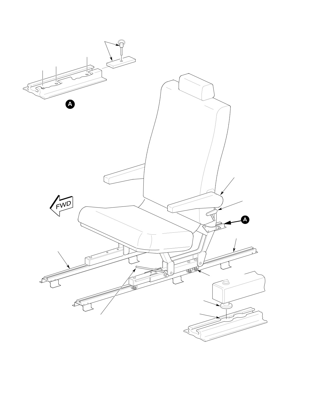
CSP-HMI-2
MD Helicopters, Inc.
MAINTENANCE MANUAL
RELEASE PIN AND
SEAT TRACK STOP
AFT
MID
FWD
NOTE: PASSENGER
RESTRAINT NOT SHOWN
RELEASE PIN AND SEAT
TRACK STOP POSITION
FORWARD FACING SEAT
MID: NORMAL POSITION FOR FWD FACING SEAT.
AFT: USED WHEN THE REAR-MOST SEAT POSITION IS DESIRED.
AFT FACING SEAT
FWD: NORMAL POSITION FOR AFT FACING SEAT.
FOLD-UP
ARM REST
SEAT BACK
ADJUSTMENT
HANDLE
OUTER SEAT TRACK
INNER SEAT TRACK
REAR GUIDE PINS
FORWARD GUIDE PIN
TRACK CUTOUT
FORE AND AFT SEAT
ADJUSTMENT HANDLE
(HANDLE SHOWN RAISED)
G25-1006
Figure 206. Mid−Cabin Business Seat Installation (600N)
Page 208
Revision 23
25-10-00
MD Helicopters, Inc.
CSP-HMI-2
MAINTENANCE MANUAL
Section
25−15−00
Mesh Seats
MD Helicopters, Inc.
CSP-HMI-2
MAINTENANCE MANUAL
MESH SEATS
MAINTENANCE PRACTICES
1. Crew/Passenger Mesh Seats
(5). Insert vertical legs into floor structure
and secure.
(Ref. Figure 201 thru Figure 203) The typical
mesh seat installation consists of lightweight
(6). If removed, reinstall seat belts and
nylon mesh-covered seats installed in the crew
shoulder harness.
and passenger compartments. For description
4. Passenger Mesh Seat Adjustment
of the various installations, consult the
Optional Equipment List (Ref. Table 202,
(1).
(Ref. Figure 203) The height of the
01-00-00). Some installations have a bench-
bench seat may be adjusted by install
type passenger seat, some have individual
ing the ball lock pins in any of the three
passenger seats, and others have no passenger
holes in the vertical support legs, and
seats at all. Installations differ depending on
by installing the ball lock pins that
whether the helicopter has a high shoulder
support the horizontal legs in any of the
beam or a low shoulder beam, and various seat
three holes in each aft support fitting.
colors.
(2).
For the fore and aft adjustment of the
2. Crew Mesh Seat Replacement
bench seat, insert the seat back legs
into either pair of holes in the seat
(Ref. Figure 201)
frame.
NOTE: Identify and retain all components and
(3).
(Ref. Figure 202) The height of the
hardware removed from the helicopter.
individual seats may be adjusted by
inserting lock pins into any of three
(1). Remove or clear area of seat belts and
pairs of holes in the aft support fittings
shoulder straps.
to secure the horizontal legs of the seat.
(2). Remove installing hardware and lift
(4).
The individual seats may be folded up
seat bottoms and seat backs from the
out of the way to permit cargo storage
helicopter.
by first releasing the quick-disconnects
at the forward legs and folding the legs
(3). To replace, install seat backs and seat
aft. The seat back is then folded
bottoms with attaching hardware.
forward at the upper hinge point. As
the seat is swung up at the aft fitting,
(4). When removed, reinstall seat belt and
the seat back and the seat bottom are
shoulder harness.
rotated forward and down at the lower
hinge point.
3. Passenger Mesh Seat Replacement
5. Crew Mesh Seat Inspection
(Ref. Figure 202 or Figure 203)
(1). Inspect upholstery material for cuts or
NOTE: Identify and retain all components and
other unserviceable conditions.
hardware removed from helicopter.
(2). Check rubber pads cemented to each
(1). Remove or clear area of seat belts and
mounting plate.
shoulder straps.
6. Passenger Mesh Seat Inspection
(2). Release seat quick-disconnects at aft
fittings, then at floor points.
(1). Inspect upholstery material for cuts or
other unserviceable conditions.
(3). Lift seats from helicopter.
(2). Inspect quick-disconnect mechanisms
(4). To replace, attach horizontal support
for proper operation and for damage
legs to aft attach fittings with lockpins.
that may prevent positive locking.
Page 201
25-15-00
Revision 23
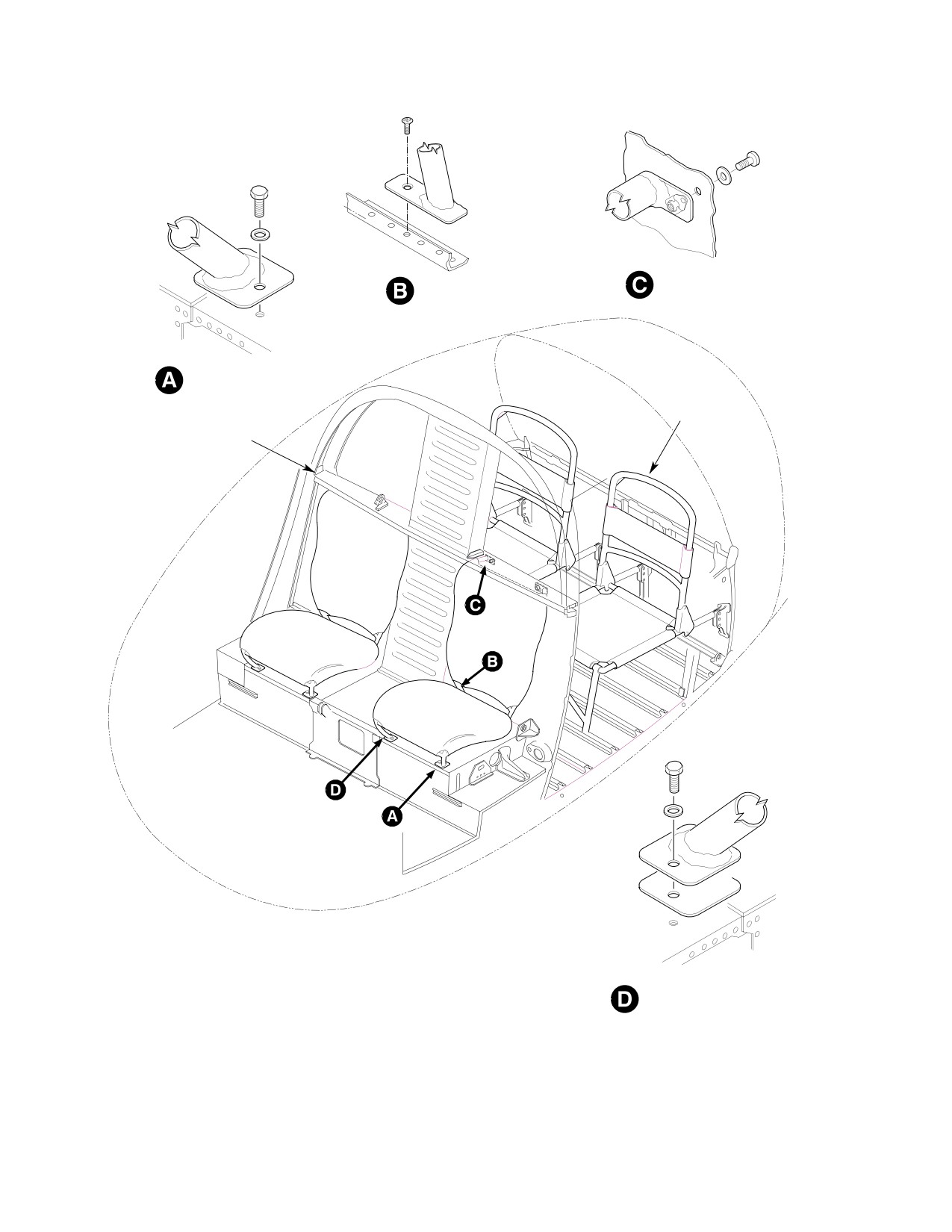
CSP-HMI-2
MD Helicopters, Inc.
MAINTENANCE MANUAL
CREW SEATS BACK UPPER
CREW SEATS BACK
LEGS, HIGH SHOULDER BEAM
LOWER LEGS
(NOTE)
CREW SEATS FORWARD
LOWER LEGS
INDIVIDUAL
PASSENGER
SEATS
HIGH SHOULDER BEAM
MODEL 369D WITH HIGH SHOULDER BEAM SHOWN
CREW SEAT FORWARD
LOWER INBOARD LEG
(LEFT)
NOTE:
FASTENER ORIENTATION IS
VERTICAL FOR LOW SHOULDER BEAM
INSTALLATION.
G25-1003
Figure 201. Mesh Seat Installation
Page 202
Revision 23
25-15-00
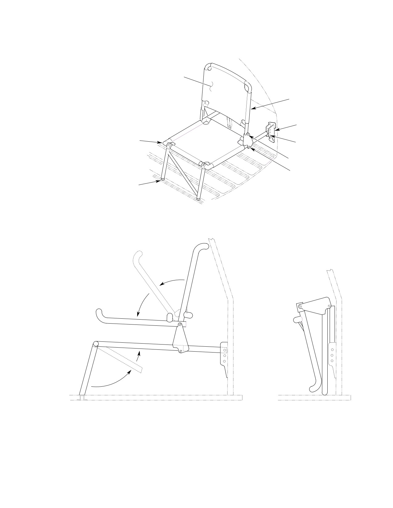
MD Helicopters, Inc.
CSP-HMI-2
MAINTENANCE MANUAL
NYLON MESH
SEAT BACK
(FOLDS FORWARD)
AFT SEAT
SEAT BOTTOM
(FOLDS FOR STOWAGE)
SEAT FITTING AND
HEIGHT ADJUSTMENT
UPPER HINGE POINT
LOWER HINGE POINT
QUICK DISCONNECT
(AT REAR OF LEGS)
PASSENGER INDIVIDUAL MESH SEAT HEIGHT ADJUSTMENT
FOLDING SEAT BACK AND LEGS
SEAT STOWAGE
G25-1004
Figure 202. Passenger Individual Mesh Seat Adjustment and Storage
Page 203
25-15-00
Revision 23
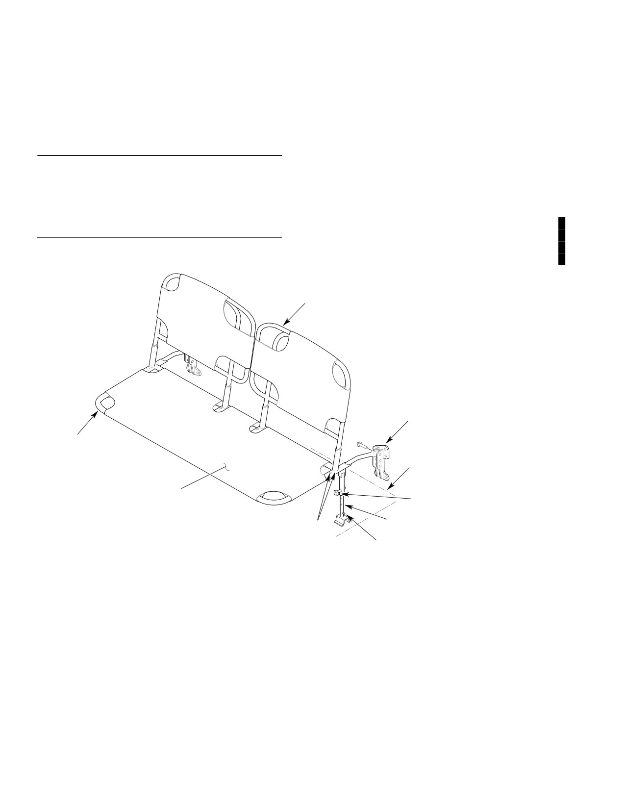
CSP-HMI-2
MD Helicopters, Inc.
MAINTENANCE MANUAL
7. Mesh Seats Cleaning
(1). Lap stitch frayed or torn nylon web
bing, or replace if damaged beyond
(Ref. Sec. 20-20-00, Fuselage Interior Trim
repair.
and Upholstery Cleaning)
(2). Install new rubber pads.
8. Mesh Seats Repair
(3). Clean seat mounting plate with clean
cloth dampened with solvent (CM234).
Consumable Materials
(4). Apply cement (CM405) and attach pad
(Ref. Section 91−00−00)
to seat mounting plate.
Item
Nomenclature
(5). Replace damaged nutplates.
CM234
Solvent, dry-cleaning
CM405
Adhesive
(6). Minor weld repairs may be performed
according to FAA AC 43.13-1B Inspec
tion and Repair for Standard Sheet
Repair of seats is limited to the following:
Metal Repair.
SEAT BACK
AFT SUPPORT FITTING AND
HEIGHT ADJUSTMENT
FRAME
FLOOR STRUCTURE
NYLON MESH
BALL-LOCK PIN
SUPPORT LEG AND
FORE AND AFT
HEIGHT ADJUSTMENT
ADJUSTMENT HOLES
RELEASE PIN
G25-1005
Figure 203. Passenger Bench Mesh Seat Adjustment
Page 204
Revision 44
25-15-00