HANDBOOK OF MAINTENANCE INSTRUCTIONS FOR MDHI 369D/E/FF-500/600N HELICOPTERS (ISSUED: 1990) - page 6
MD Helicopters, Inc.
CSP-HMI-2
MAINTENANCE MANUAL
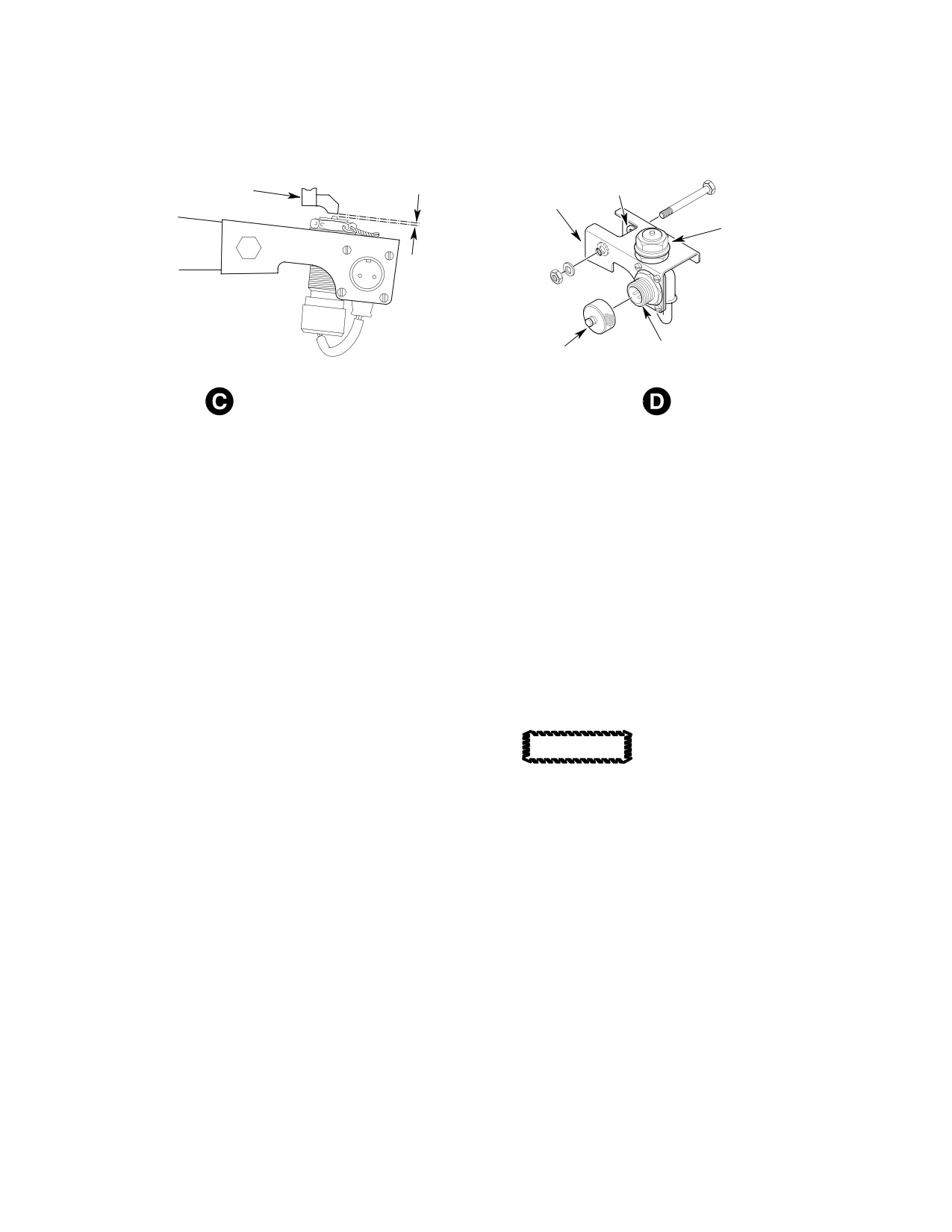
0.030-0.070 IN.
(0.762-1.778 MM)
INTERRUPTER
GAP (TYP)
SUPPORT
NOTE 2
(NOTE 3)
BRACKET
ADJUSTMENT
JAMNUT
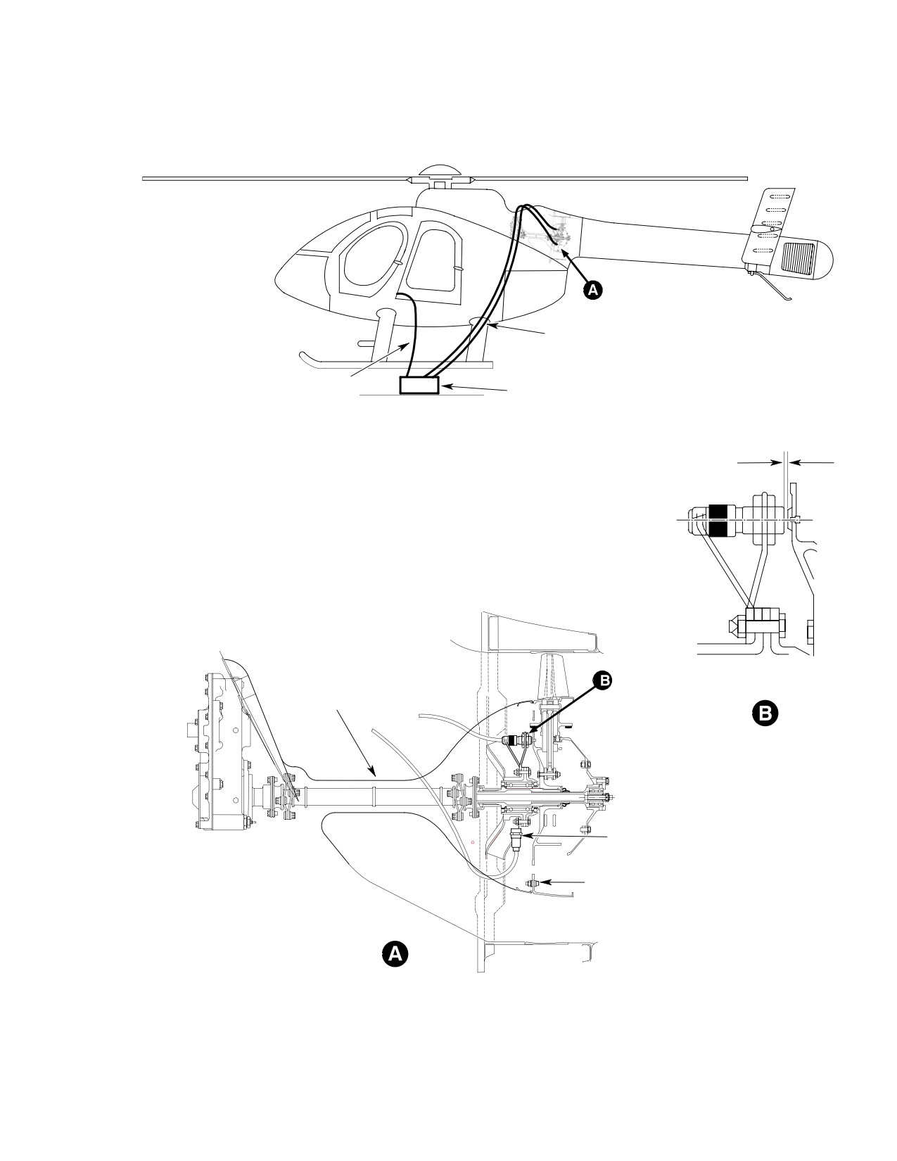
TEST EQUIPMENT
PROTECTIVE CAP
CABLE RECEPTACLE
INTERRUPTER-TO-MAGNETIC PICKUP GAP
PICKUP INSTALLATION
6G18-014-2
Figure 401. Blade Tracking Equipment − Main Rotor Components (Sheet 2 of 2)
C. Tracking Tip Cap Installation
D. Main Rotor System Balancing Equipment
Installation
(1). The helicopter is originally equipped
with six tip caps that must be removed
and replaced with six tracking tip caps
Refer to Chadwick-Helmuth Operation and
(ST901).
Service Instruction Handbook to install that
(2). When blade tracking has been accom
portion of the balancing equipment (ST903)
plished or verified, the tracking tip caps
needed to balance the main rotor.
must be removed and original tip caps
installed.
When working near engine air
(3). Torque the screws that secures the tip
CAUTION
inlet, comply with precautions
cap to 15 - 20 inch-pounds (1.69 -
to prevent entry of foreign material. During
2.26 Nm).
main rotor balancing the helicopter will be
NOTE: Position interrupter over magnetic
airborne. Carefully observe precautions in
pickup. The blade positioned forward is
the Tracking and Balancing Manual relat
number 6. By rotating rotor head in operat
ing to the placement and security of equip
ing direction, the next blade pointing for
ment (especially cables) fastened to the ex
ward will be 5 then 4, 3, 2 and 1.
terior of the helicopter.
Page 403
18-10-60
Revision 23
CSP-HMI-2
MD Helicopters, Inc.
MAINTENANCE MANUAL
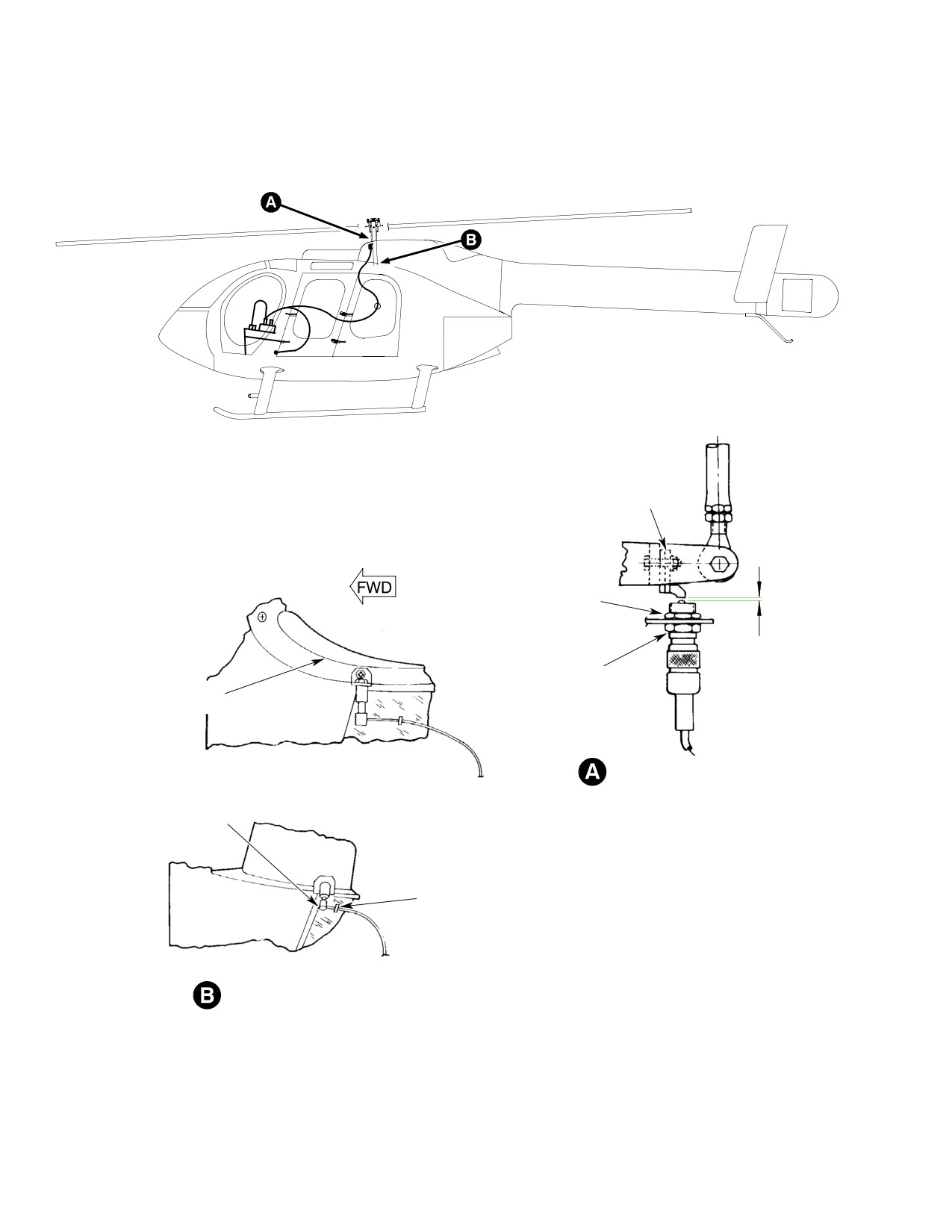
INTERRUPTER
(TYP)
TORQUE NUT AFTER
SECURING GAP AND
VIEW LOOKING DOWN
SAFETY WIRE
0.030-0.070 IN.
(0.762-1.778 MM)
MAGNETIC
GAP (TYP)
PICKUP
ENGINE AIR INLET FAIRING
(LEFT HAND SIDE)
MAGNETIC PICKUP INSTALLATION
ACCELEROMETER/VELOMETER
LOCATION FOR MAIN ROTOR
BALANCING
VIEW LOOKING
INBOARD
TAPE
ACCELEROMETER INSTALLATION
Figure 402. Main Rotor Balancing Equipment Installation
Page 404
Revision 23
18-10-60
MD Helicopters, Inc.
CSP-HMI-2
MAINTENANCE MANUAL
MAIN ROTOR TRACK AND BALANCE (600N)
ADJUSTMENT/TEST
1. Blade Tracking Procedure
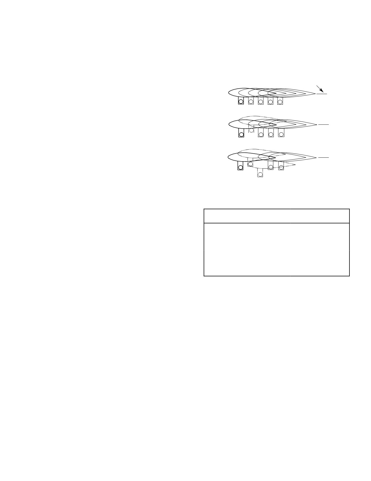
TIP PATH PLANE
Table 501 is a summary of the sequence of
required procedures for blade tracking.
1
2
3
4
5
(1). Install strobe light, blade tip cap
IMAGE A:
ALL BLADES
reflectors and related equipment.
IN TRACK
(2). Use 1/2 inch (12.7 mm) diameter
2
tracking tip cap reflector as a guide for
1
3
4
5
estimating track accuracy. For example:
IMAGE B:
ONE BLADE APPROX. 1/2 IN. (12.7
MM) HIGH
(a). A tip cap reflector image displace
ment of 1/2 diameter up, or down,
2
indicates blade tip is approximately
1
4
5
1/4 inch (6.35 mm) out of track.
3
IMAGE C:
ONE BLADE APPROX. 1/2 IN. (12.7
(b). One full reflector diameter indicates
MM) HIGH
1/2 inch (12.7 mm) out of track.
ONE BLADE APPROX. 1 IN. (25.4
6G18-016A
CORRECTIVE ACTION
NOTE: Rocking or stick shake caused by a cor
HIGH RPM AND
rectly tracking rotor indicates improper
CONDITION
GROUND IDLE RPM
FWD FLIGHT
blade phasing.
IMAGE A
NONE REQUIRED
NONE REQUIRED
IMAGE B
SHORTEN PITCH CONTROL MOVE TAB DOWNWARD
(3). Accomplish blade phasing (Ref. Sec.
ROD (2ND BLADE)
(2ND BLADE) MOVE TAB
62-20-60) when installing new rotor
UPWARD (3RD BLADE)
blades or if ground rock or stick shake
IMAGE C
SHORTEN PITCH CONTROL
MOVE TAB DOWNWARD
is noted. This must be accomplished
ROD (2ND BLADE):
(2ND BLADE): MOVE TAB
prior to starting tracking procedure.
LENGTHEN CONTROL ROD
UPWARD (3RD BLADE)
(3RD BLADE)
NOTE: Final rotor system balance cannot be
accomplished until blades are in track.
NOTE: Chordwise spacing of tracking images
are not an accurate indication of blade phas
(4). Ground tracking is basically track-ob
ing. Do not adjust blade phasing in an at
servation and adjustment of idle and
tempt to equalize spacing. Slight tilting of
flight rpm. Improper track at idle rpm
magnetic interrupters or balance of the
is corrected by adjusting length of pitch
main rotor system can move the image
control links connecting rotating
Figure 501. Typical Track Conditions and
swashplate and blade pitch housing.
Adjustments
Ground track at flat pitch and flight
rpm is corrected by blade tab adjust
(6). Forward flight track is corrected only
ment.
by making blade tab adjustments.
Forward flight tracking requires track
(5). Hover track verification is essentially
observation during following airspeeds
an observation to check for track
and maneuvers: Flight at 0-100 knots.
variations between high rpm (flat pitch)
Forty-five degree banked turns at
ground track check and hovering.
80-100 knots. Flight at 100-155 knots.
NOTE: Track adjustments are not made on ba
(7). Check for proper balance of rotor
sis of track observations during hovering.
system prior to checking autorotation.
However, track variations should be noted
and recorded for use during check of track in
(8). Obtaining correct autorotation rpm
forward flight.
consists of checking main rotor rpm
Page 501
18-10-60
Revision 23
CSP-HMI-2
MD Helicopters, Inc.
MAINTENANCE MANUAL
during stabilized autorotation flight
sometimes E, are used for tracking at higher
and adjusting rpm to specified limits as
airspeeds. Zone B is used to supplement zone
necessary. Autorotation rpm check
A track correction when maximum tab (5
must be accomplished to ensure that
degrees) has been applied to zone A; if
track adjustments do not alter rotor
necessary, zone B may also be used for
performance necessary for safe power-
correction in 0-110 knot airspeed range.
off landings.
Special Tools
A. Blade Track Adjustment
(Ref. Section 91−00−00)
Although adjustment of pitch control links
Item
Nomenclature
affects blade track at all rotor speeds, they
ST902
Main rotor blade fixture and tab bending
should be adjusted only when necessary to
tool
establish acceptable track at ground idle
speed; blade tabs are used for all other track
Minimize bending and restrict
corrections.
CAUTION
adjustments to very small incre
ments so that bonded trailing edge joint be
NOTE: Blade tab and/or track can make the
tween upper and lower skins is not dam
collective heavy or light.
aged. Tabs must never be displaced more
than five degrees above or below neutral po
B. Pitch Control Link Adjustment
sition (parallel to chordline).
Repeat this adjustment procedure as necessary
(1). To lower blade tip that tends to climb
to establish ground idle track:
during ground tracking at high rpm or
(1). To lower a blade tip, shorten pitch
during forward flight, bend appropriate
control link assembly. To raise a blade
tab section slightly downward; to raise
tip, lengthen pitch control link assem
tip of blade that tends to descend, bend
bly. One-sixth of a turn of link (one flat)
tab slightly upward. If only slight track
raises or lowers blade tip approximately
correction is necessary, limit tab
1/4 inch (6.35 mm).
bending to width of bending tool. If
more correction is necessary, bend a
Center each rod end or pitch
slightly wider section of tab. Use small
CAUTION
case and/or swashplate wear
adjustments to avoid excessive rebend
will result. Ensure there is no binding in full
ing of tabs.
up travel position.
NOTE: Tab zones on same blade can require
(2). After adjusting pitch control link
bending in opposite directions. For example,
length, center each rod end in its fitting
after bending tab zone A downward to get
and hold while tightening jam nuts;
good tracking at 60-90 knots, it might be
safety with lockwire.
come necessary to bend tab zone D or E (Ref.
Figure 502) upward to correct track at red
C. Blade Tab Adjustment
line airspeed. In any case, do not use larger
tab corrections than are actually necessary.
(Ref. Figure 502) Once ground idle track is
obtained, all remaining tracking correction is
(2). Each time blade tabs are adjusted,
accomplished by very slight bending of various
recheck ground idle track and readjust
blade tab zones with tab bending tool (ST902).
if necessary.
Different zones of tabs are used to adjust blade
track at different airspeeds. In general, tab
(3). After completion of forward flight
zone A is used for high-rpm, flat pitch ground
tracking, balance and check autorota
tracking (100% N2) and zones C, D, and
tion rpm.
Page 502
Revision 34
18-10-60
MD Helicopters, Inc.
CSP-HMI-2
MAINTENANCE MANUAL
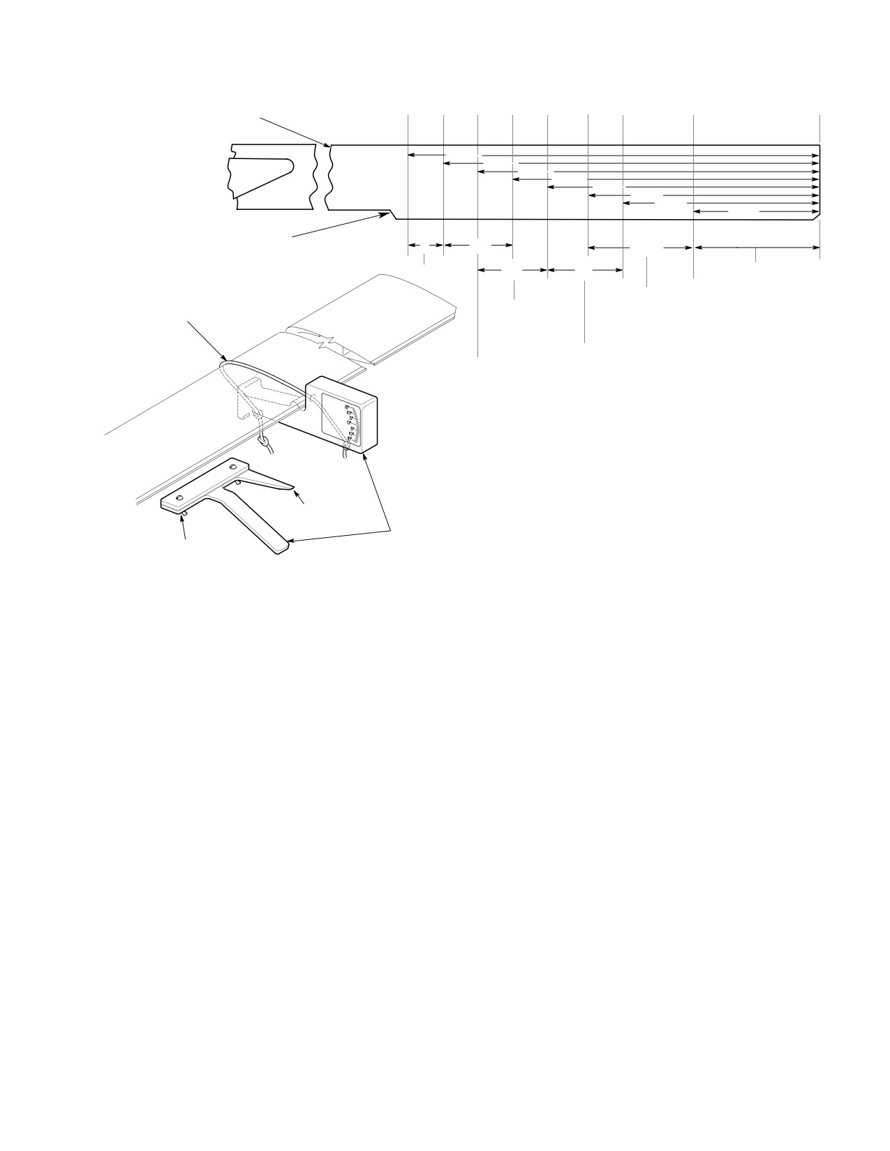
BLADE STATIONS
93
99
105
111
117
124
130
148
164
MAIN ROTOR BLADE
(TOP VIEW)
71 IN.
(180 CM)
65 IN.
(165 CM)
59 IN.
(150 CM)
53 IN.
(135 CM)
47 IN.
(119 CM)
40 IN.
(102 CM
34 IN.
(86 CM)
16 IN.
(41 CM)
NOT USED
(NOTE 1)
TAB ZONES
E
D
A
C
B
TO END OF
NOTE 2
BLADE NOT USED
SHOCK CORD
HIGH RPM GROUND
(NOTE 1)
MEDIUM SPEED
TRACKING AND UP TO
(OR EQUIVALENT)
FLIGHT TRACKING
110 KNOTS IN FLIGHT
130-145 KNOTS
(100% N2)
110-130 KNOTS
HIGH SPEED
IN FLIGHT
FLIGHT TRACKING
(100% N2)
145-152 KNOTS
(100% N2)
NOTES:
1.
UNUSED TAB ZONES MUST BE MAINTAINED
STRAIGHT, NEUTRAL AND PARALLEL.
2.
USE ONLY AS NECESSARY TO SUPPLEMENT
ZONE D TO AVOID EXCESSIVE TAB BENDING
POINTER
IN ZONE D.
TAB BENDING TOOLS
BENDER
6G18-017A
Figure 502. Adjustment − Main Rotor Blade Tab
D. Main Rotor Ground Tracking
NOTE: On new (untracked) blades, check that
all tab areas are straight and in neutral po
sition (centered on chordline 0.0° ±0.5°).
For best results, tracking should be performed
under calm air conditions. Wind velocity
(2). Load helicopter to a gross weight of
should not exceed six knots during adjust
approximately 2350 pounds (1066.9 kg);
ments. Accurate adjustment of initial ground
then ground idle (approximately
track is very important. In most instances,
64-65% N1) with collective pitch stick
forward flight tracking problems can be
full down.
avoided or greatly reduced by setting initial
(3). Observe tracking tip cap reflector image
track as nearly perfect as possible. Tolerances
by directing strobe light beam toward
specified in following instructions should be
blade tip path and sweeping beam
considered maximum permissible deviation
slowly back and forth until reflector
rather than desired goal.
images are clearly seen. Tracking image
should appear directly in front of
NOTE: If main rotor hub or a pitch control rod
helicopter or slightly off helicopter
end bearing has been replaced, adjust pitch
centerline.
control link(s) before proceeding with
(4). If blades are in track, tip cap reflector
ground tracking.
image pattern should resemble image
A, (Ref. Figure 501) (no blade tip more
(1). Before tracking blades that are not new,
than 1/4 of one tracking reflector
check that normally straight (not to be
diameter, 1/8 inch (3.175 mm), above or
used) tab areas are in neutral position
below adjacent reflectors). If blades are
(centered on chordline) and straight.
in track, proceed with step (5). below. If
Page 503
18-10-60
Revision 23
CSP-HMI-2
MD Helicopters, Inc.
MAINTENANCE MANUAL
blades are out of track, adjust pitch
Use of the tracking strobe
WARNING
control links and repeat step (3). above.
light in night flight is not
recommended. Such use can result in
(5). With collective pitch stick full down,
pilot disorientation or loss of vision
increase engine speed to 100% N2 and
with resultant damage to the helicop
observe tip cap reflector image to see if
ter and personal injury.
blade track is changed from ground idle
F. Forward Flight Tracking
track. When all six blades are in track
within 1/4 of one reflector diameter,
(Ref. Figure 502 and Figure 506 thru
ground track is correct; proceed with
Figure 508) Forward flight tracking should be
hover verification. When a blade is out
performed whenever vertical flight vibrations
of track, adjust blade tab zone A until
indicate that blades may be out of track.
high rpm ground track is within
tolerance.
(1). Verify helicopter gross weight of
2000-2500 pounds (908-1135 kg).
E. Hover Track Verification
NOTE: When bending trim tabs, do not bend
(Ref. Figure 504)
more than 1.5° between six inch sections.
(1). Hover track verification must be
(2). Perform flight tracking from hover up
performed after ground tracking and
to 110 knots at 100% N2. If flight track
before forward flight tracking. Verifica
varies from hover track more than 1/2
tion is only a check of hover track. Do
inch (12.7 mm), bend tab zone A (five
not adjust pitch control links or blade
degrees maximum) to limit variation to
tabs because of track images observed
tab zone B (five degrees maximum).
during hovering. Tab adjustments often
(3). Check autorotation percentage; per
cause variation between ground track
centage must not be less than 480
and hovering track. A large track
(90%).
variation may indicate that one or more
blades is beyond its chordwise balance
Do not attempt to adjust chord
tolerance, but this can only be deter
CAUTION
wise balance of a blade found to
mined during forward flight tracking.
be faulty when performing banked turns.
Perform hover track verification as
Chordwise balance corrections must be ac
follows.
complished by manufacturer (MDHI).
NOTE: Collective pitch stick may be ``heavy” af
(4). Perform a series of 45 degree banked
ter tracking reflectors are mounted on blade
turns at 100 knots and observe track
tips. This condition is not unusual and may
change from level flight. If any blade
be disregarded.
climbs or dives more than one inch
(2.54 cm) out of track with others,
(2). Verify helicopter gross weight of
chordwise balance (center of gravity) of
2000-2500 pounds (908-1135 kg).
that blade is beyond its tolerance and
blade must be replaced or balanced by
(3). With collective pitch stick full down,
an MDHI Field Representative. (Hover
increase N2 to 100%.
track variations of this type that do not
(4). Observe tracking reflector images to
repeat during banked-turn maneuver
verify that ground track is within
may be disregarded.)
limits.
(5). Perform flight tracking at 100% N2. If
necessary, adjust tab zone B (five
(5). With helicopter in a stable hover,
degrees maximum) to limit track
observe reflector images. If one or more
blades are out of track, record condi
variation to 1/2 inch (12.7 mm) or less
tion(s) for reference during forward
and to minimize excessive vertical
flight tracking.
(one-per revolution) vibration. If
variation is excessive, bend tab zone C
(6). Proceed with forward flight tracking.
or D (five degrees maximum).
Page 504
Revision 23
18-10-60
MD Helicopters, Inc.
CSP-HMI-2
MAINTENANCE MANUAL
NOTE: When determining whether blade track
D All autorotation percentage adjustments
is acceptable, overall vibration level of heli
shall be made at the main rotor pitch con
copter should be determining factor. Some
trol links only. Do not re-adjust mixer
combinations of rotor blades might produce
control rods after rigging is accomplished.
higher six-per-revolution vibration as
Failure to observe this precaution may re
blade tips are brought into close track; in
sult in serious damage to rotor system
such cases, lowest vibration level is pre
and controls. Do not adjust control rod
ferred, even though observed blade track
end beyond witness hole.
may be beyond specified tolerances.
D Tracking targets reduce blade to tailboom
clearance, performing autorotations to
(6). After flight tracking is completed,
the ground could result in boom strikes.
perform a Main Rotor System Balance
Procedure and Main Rotor Autorotation
RPM Check.
NOTE: Change length of all six pitch control
links as necessary to adjust autorotation
percentage. Be sure to lengthen or shorten
2. Main Rotor System Balance Procedure
all six links exactly same amount or blade
track is changed. One flat (1/6-turn) of con
Balance the main rotor system according to
trol link body causes approximately one per
instructions in the Chadwick-Helmuth
cent change in autorotation percent.
Operation and Service Instruction Handbook.
(1).
Autorotation Percentage Check (Ref.
The maximum allowable bal
CAUTION
Table 502) Load helicopter to a gross
ance weight per lead-lag bolt on
weight of 2800 ±25 pounds (1270 ±11
the main rotor hub assembly is 143 grams.
kg). Perform a practice autorotative
descent (Ref. RFM), taking care not to
3. Main Rotor Autorotation Percentage
allow percentage to exceed rotor speed
Check
limitations. During autorotation, take
careful note of stabilized autorotation
(Ref. Table 502) An autorotation percentage
percentage at one of the gross weight/
check is required after each blade tracking
density altitude combinations. After
operation and whenever rpm is outside limits
landing, compare observed percentage
listed. Check rotor rpm and make adjustments
with values. If observed percentage is
as follows.
within limits in table, percentage
setting is correct. If limits were exceed
ed, make corrective adjustments
CAUTION
according to Autorotation Percentage
Adjustment, until percentage is within
D Autorotation rpm is critical to a success
limits.
ful autorotation landing. When full main
rotor rpm is not available, autorotation
(2).
Autorotation Percentage Adjustment:
function is decreased. At high gross
Change length of all six pitch control
weights and/or density altitudes, the
links as required to adjust autorotation
main rotor rpm will try to overspeed. The
percentage. Make certain all six links
pilot must increase collective pitch to
are shortened or lengthened exactly the
keep main rotor rpm within limits. At
same amount or blade track will be
lower gross weights and/or density alti
altered.
tudes, the main rotor rpm will be under
speed. The pilot has less rotor energy
available to do the autorotation landing.
NOTE: After autorotation percentage adjust
Set the autorotation rpm within the lim
ments are satisfactorily accomplished, re
its of the Autorotation Percentage Chart
move tracking equipment before returning
to make sure sufficient autorotation rpm
helicopter to service. Be sure to correctly
is available at the helicopter minimum
tighten and safety all bolts after they are re
gross weight.
installed.
Page 505
18-10-60
TR12-001

CSP-HMI-2
MD Helicopters, Inc.
MAINTENANCE MANUAL
Table 501. Summary Procedure for Blade Tracking
Satisfactory Unsatisfactory
Step
Result
Result
Corrective Action
(1) Observe ground track.
Go to step (2). Ref. Corrective Adjust pitch control rods and blade tabs
Action.
as required. Repeat track observation.
(2) Perform hover verification.
Go to step (3). Ref. Corrective Record track verification and proceed with
Action.
forward flight tracking.
(3) Perform forward flight
Go to step (4). Ref. Corrective Adjust blade tabs and repeat forward
tracking.
Action.
flight tracking.
(4) Perform autorotation
Go to step (5). Ref. Corrective Adjust autorotation percentage and
percentage check.
Action.
repeat percentage check.
(5) Remove tracking equipment
and return helicopter to service.
NOTE: Ground rock or stick shake with rotor blades in track during ground track indicates rotor blades are not
properly phased.
Table 502. Autorotation Percentage Chart
Stabilized Autorotation Percentage at Density Altitude
Gross Wt
1000 Ft
2000 Ft
3000 Ft
4000 Ft
5000 Ft
lb/kg
Sea Level
(305 M)
(610 M)
(915 M)
(1220 M)
(1525 M)
2500/1134
93.8 − 95.8
94.6 − 96.6
95.4 − 97.4
96.3 − 98.3
97.1 − 99.1
98.0 − 100.0
2600/1179
95.6 − 97.6
96.4 − 98.4
97.3 − 99.3
98.1 − 100.1
99.0 − 101.0
99.9 − 101.9
2700/1224
97.4 − 99.4
98.2 − 100.2
99.1 − 101.1
100.0 − 102.0
100.9 − 102.9
101.8 − 103.8
2800/1270
99.2 − 101.2
100.0 − 102.0
100.9 − 102.9
101.8 − 103.8
102.7 − 104.7
103.6 − 105.6
2900/1315
101.0 − 103.0
101.8 − 103.8
102.7 − 104.7
103.6 − 105.6
104.6 − 106.4
3000/1361
102.7 − 104.7
103.6 − 105.6
104.5 − 106.4
105.4 − 106.4
NOTE: Perform autorotation percentage checks at gross weight/density altitude combinations for which percent-
age values are given. Blank spaces indicate that application of collective pitch may be necessary to avoid rotor
overspeed.
Page 506
Revision 23
18-10-60
MD Helicopters, Inc.
CSP-HMI-2
MAINTENANCE MANUAL
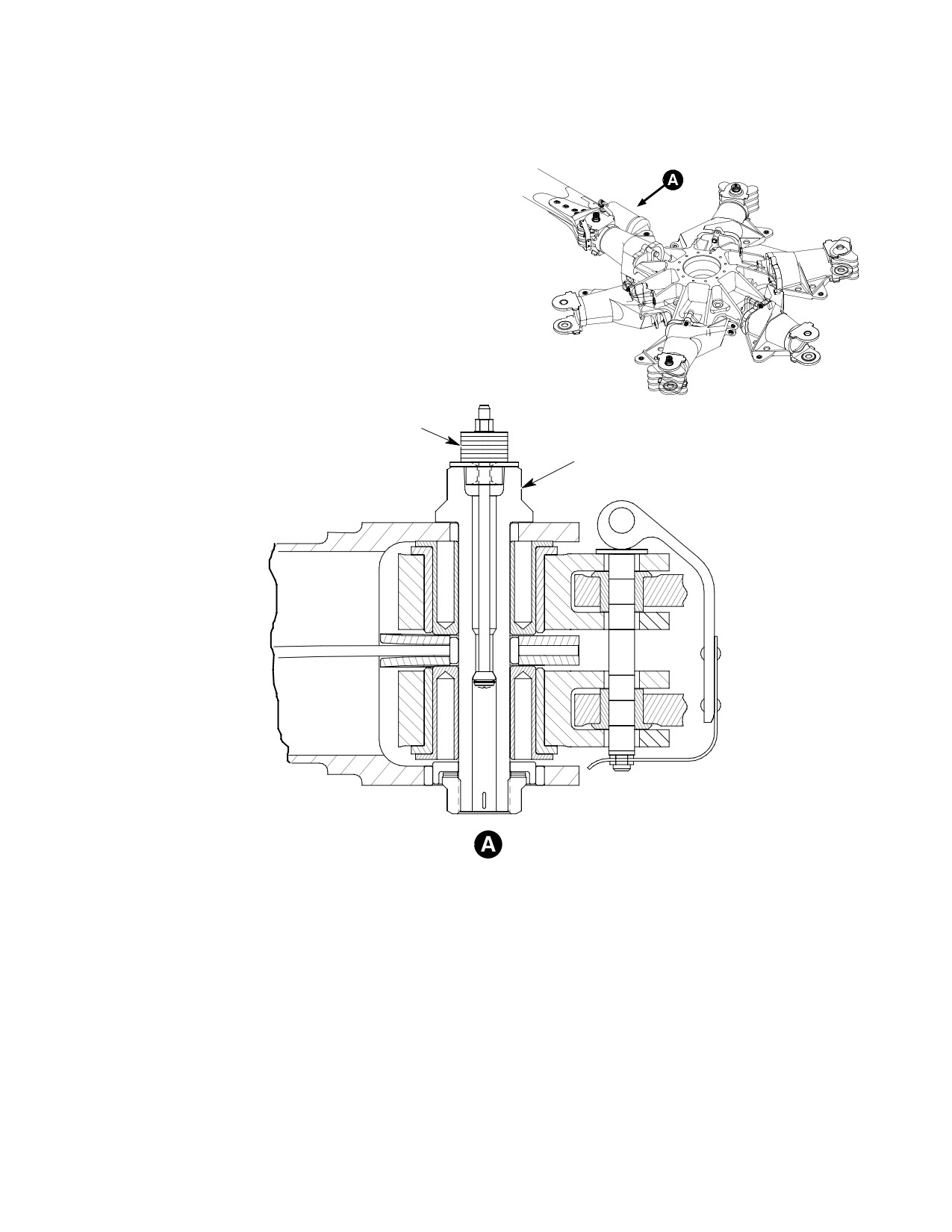
MAIN ROTOR
BALANCE WEIGHTS
(NOTE)
MAIN ROTOR
LEAD-LAG BOLT
NOTE:
THE MAXIMUM ALLOWABLE BALANCE WEIGHT
PER LEAD-LAG BOLT ON THE MAIN ROTOR HUB
ASSEMBLY IS 143 GRAMS.
6G18-019A
Figure 503. Main Rotor System Balancing
Page 507
18-10-60
Revision 23
CSP-HMI-2
MD Helicopters, Inc.
MAINTENANCE MANUAL
ROTATION
BLUE
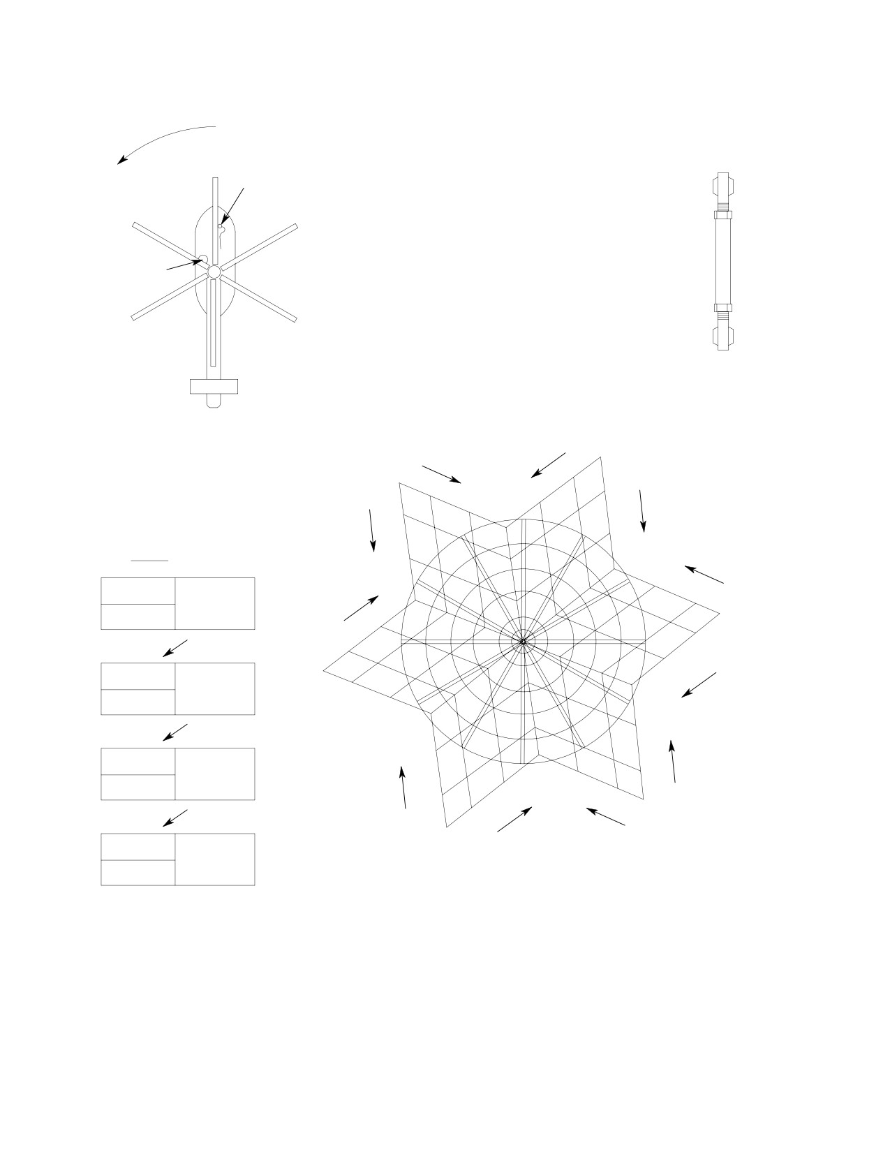
MD600N HOVER PITCH LINK ADJUSTMENT
VELO.
1.
TAKE READINGS AT IGE HOVER USING VERTICAL
WHITE
YELLOW
VELOCIMETER ON CONSOLE.
2.
ADJUST PITCH CHANGE LINK IN FLATS. 1 FLAT=1/6 TURN
OF PITCH CHANGE BARREL.
3.
BLADE SEQUENCE IS SHOWN WITH SINGLE INTERRUPTER
MAG P/U
ATTACHED TO DRIVE LINK OF ROTATING SWASHPLATE.
4.
TAKE READINGS FROM VERTICAL VELOCIMETER MOUNTED
RED
ON INSTRUMENT PEDESTAL POINTING DOWN.
5.
ADJUST PITCH CHANGE LINK BEFORE BALANCING AT HOVER.
GREEN
BLACK
ADJUSTMENT IN FLATS
OF PITCH LINKS
BLADE ORIENTATION WITH
DRIVE LINK INTERRUPTER
MOVE
MOVE
RED
GREEN
UP
UP
MOVE
3
AIRCRAFT VIEWED FROM ABOVE
3
3
BLACK
1 1/2
1 1/2
UP
12:00
MOVE
3
O
11:00
1:00
BLACK
1 1/2
UP
MOVE
IPS
1 1/2
YELLOW
ADJUST
.8
O
CLOCK
2:00
UP
10:00
.6
1 1/2
MOVE
O
.4
3
WHITE
.2
1 1/2
.8
UP
.6
.4
.2
3
9:00
3:00
3
MOVE
1 1/2
GREEN
UP
3
0
1 1/2
4:00
8:00
0
1 1/2
1 1/2
MOVE
7:00
5:00
BLUE
6:00
0
3
MOVE
1 1/2
UP
BLUE
3
1 1/2
3
UP
MOVE
3
YELLOW
MOVE
UP
WHITE
UP
NOTES:
1.
ARROWS INDICATE DIRECTION POINT SHOULD GO WHEN
ADJUSTMENT TO NOTED BLADE IS MADE.
2.
MOVE TO OPPOSITE BLADE IN OPPOSITE DIRECTION HAS
SAME EFFECT.
6G18-099
Figure 504. Main Rotor Track at Hover (Pitch Change Link Adjustment)
Page 508
Revision 23
18-10-60
MD Helicopters, Inc.
CSP-HMI-2
MAINTENANCE MANUAL
ROTATION
BLUE
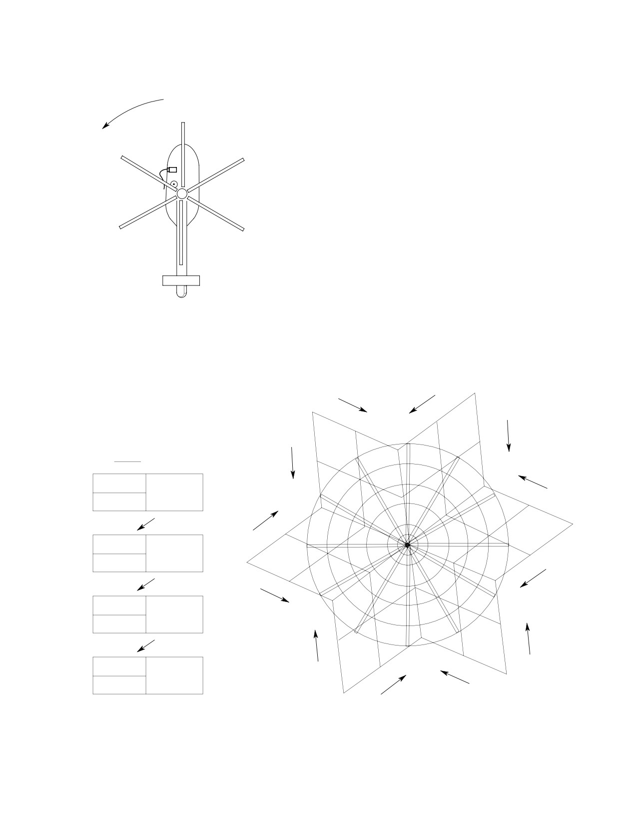
MD600N HOVER BALANCE CHART
WHITE
YELLOW
1.
TAKE READINGS AT IGE HOVER AFTER PCL TRACK.
2.
USE WEIGHT, IN GRAMS, AT HUB LOCATION.
3.
BLADE SEQUENCE IS SHOWN WITH SINGLE INTERRUPTER
ATTACHED TO DRIVE LINK OF ROTATING SWASHPLATE.
4.
LATERAL VELOCIMETER READINGS USING VELOCIMETER
AT LEADING SIDE OF CONTROLS COVER POINTING TO
LEFT OF AIRCRAFT.
GREEN
RED
BLACK
BLADE ORIENTATION WITH
DRIVE LINK INTERRUPTER
OVER MAGNETIC PICKUP
AIRCRAFT VIEWED FROM ABOVE
ADD TO
ADD TO
200
BLACK
YELLOW
200
200
200
100
100
ADD TO
0
12.00
100
GREEN
1.00
IPS
ADD TO
11.00
ADJUST
100
CLOCK
GREEN
ADD TO
0
BLUE
2.00
10.00
100
0
.5
ADD TO
.4
200
RED
100
200
.1
.2
.3
3.00
9.00
.2
200
.3
100
200
.4
.5
ADD TO
0
100
YELLOW
ADD TO
8.00
4.00
BLACK
0
100
7.00
5.00
ADD TO
100
WHITE
ADD TO
6.00
0
WHITE
100
200
100
200
200
ADD TO
200
ADD TO
BLUE
RED
G18-1007
Figure 505. Main Rotor System Balance Chart
Page 509
18-10-60
Revision 23
CSP-HMI-2
MD Helicopters, Inc.
MAINTENANCE MANUAL
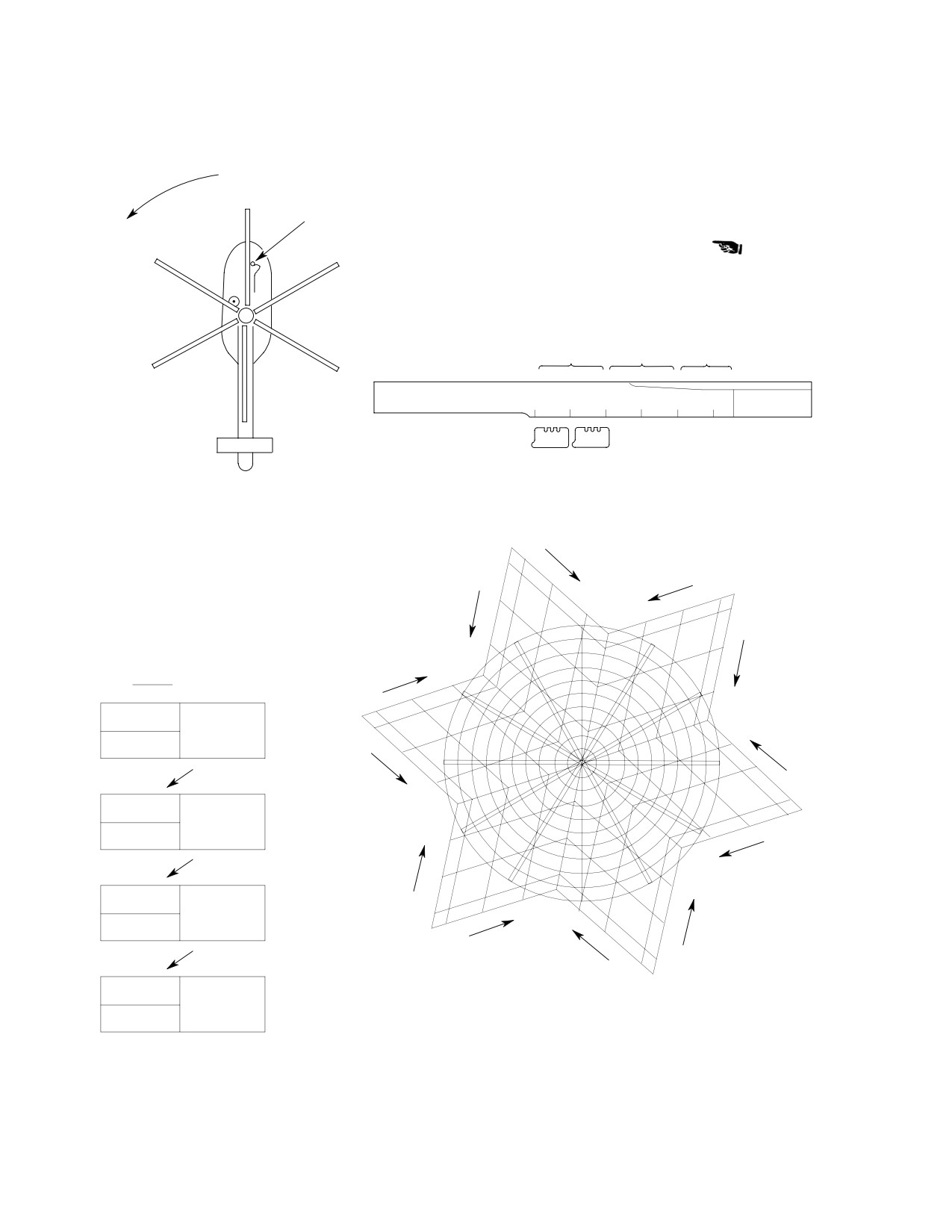
MD600N VERTICAL TAB CHART 100-130 KIAS
ROTATION
1.
TAKE READINGS AT 100-130 KIAS.
2.
TAB MEASUREMENTS ARE IN 0.001 IN. (0.0254 MM).
BLUE
3.
BLADE SEQUENCE IS SHOWN WITH SINGLE INTERRUPTER
VELO.
ATTACHED TO DRIVE LINK OF ROTATING SWASHPLATE.
4.
TAKE READINGS FROM VERTICAL VELOCIMETER MOUNTED ON
WHITE
INSTRUMENT PEDESTAL POINTING DOWN.
YELLOW
1
2
3
GREEN
RED
NO BEND
BLACK
AREA
1.
INNER TAB TWO WIDTHS OF BENDER (STA. 97 - 111)
2.
MIDDLE TAB TWO WIDTHS OF BENDER (STA. 111 - 130)
BLADE ORIENTATION WITH
3.
OUTER TAB ONE WIDTH OF BENDER (STA. 130 - 142)
DRIVE LINK INTERRUPTER
OVER MAGNETIC PICKUP
MOVE
AIRCRAFT VIEWED FROM ABOVE
6
6
WHITE UP
MOVE
4
BLACK UP
6
MOVE
4
4
2
6
RED UP
2
12.00
0
11.00
2
1.00
4
MOVE
MOVE
0
IPS
RED UP
BLUE UP
2
ADJUST
2.00
CLOCK
4
10.00
2
6
5
0
6
MOVE
2
GREEN UP
4
9.00
3.00
4
MOVE
WHITE UP
2
6
0
6
8.00
4.00
4
2
2
0
MOVE
MOVE
BLACK UP
YELLOW UP
4
7.00
2
5.00
2
0
6.00
6
4
2
MOVE
4
6
MOVE
4
YELLOW UP
BLUE UP
MOVE
6
GREEN UP
6
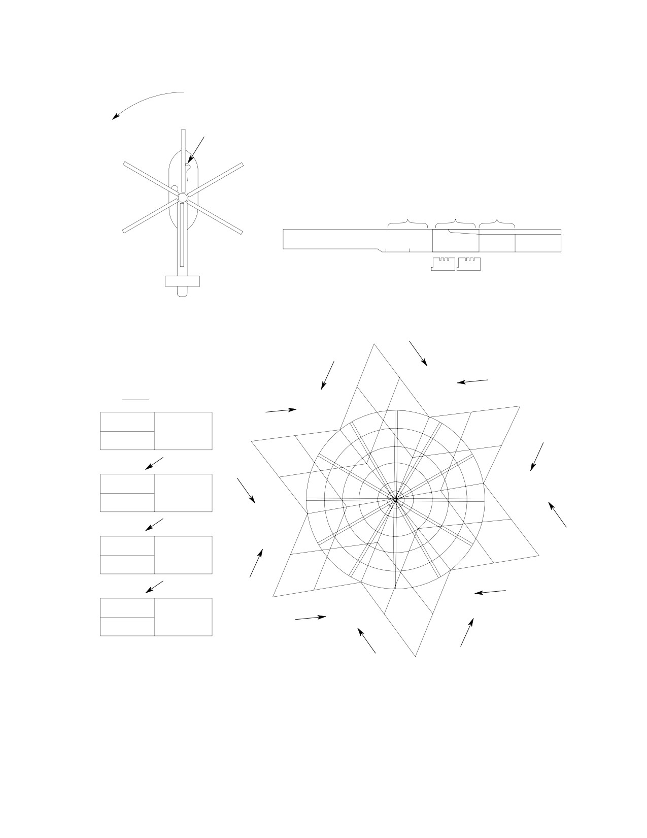
NOTE:
ARROWS INDICATE DIRECTION POINT SHOULD GO
WHEN ADJUSTMENT TO NOTED BLADE IS MADE.
G18-1006A
Figure 506. Main Rotor Tracking at 100 − 130 KIAS (Inner Tab Adjustment)
Page 510
Revision 37
18-10-60
MD Helicopters, Inc.
CSP-HMI-2
MAINTENANCE MANUAL
ROTATION
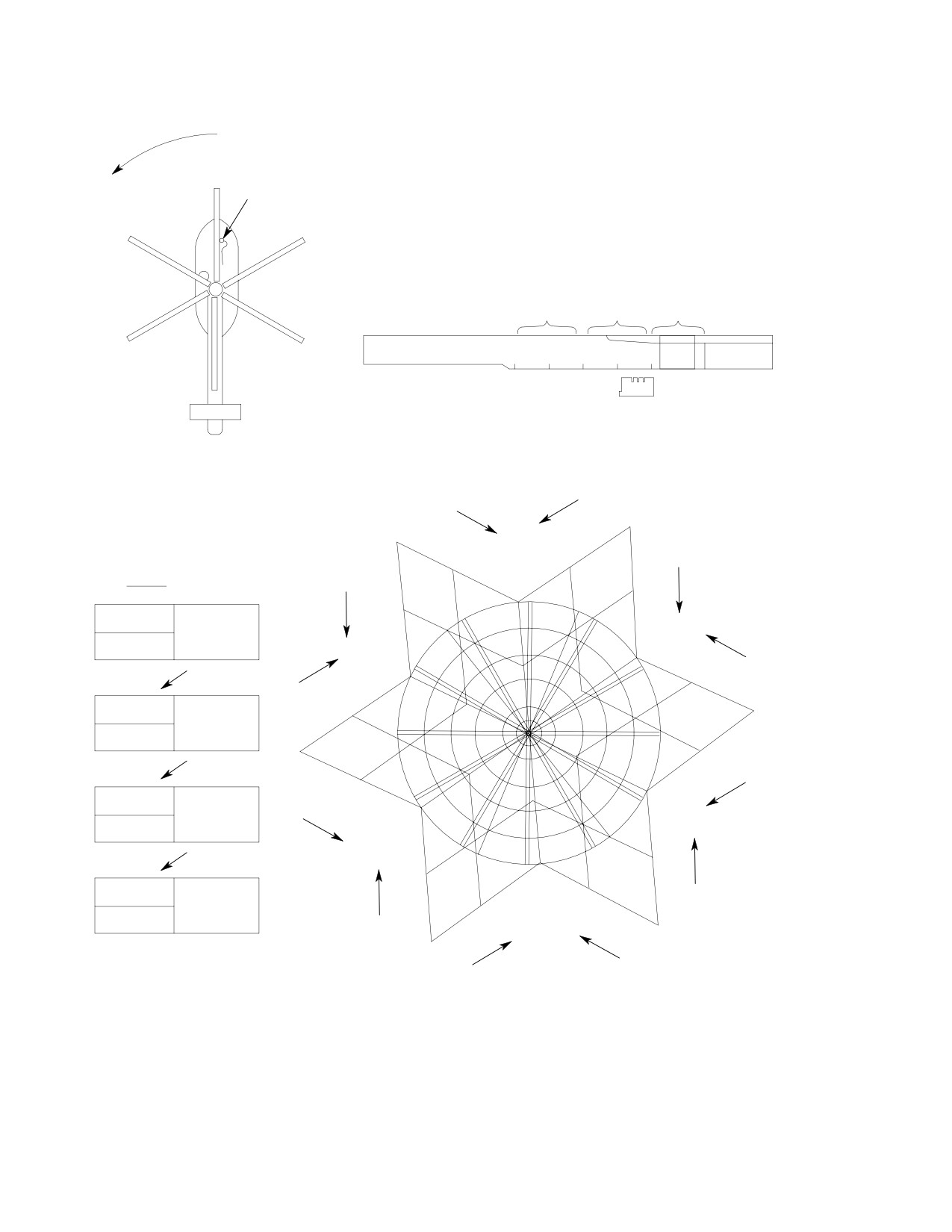
MD600N VERTICAL TAB CHART 100-130 KIAS
BLUE
1.
TAKE READINGS AT 100-130 KIAS.
VELO.
2.
TAB MEASUREMENTS ARE IN .001 INCH.
3.
BLADE SEQUENCE IS SHOWN WITH SINGLE INTERRUPTER
WHITE
YELLOW
ATTACHED TO DRIVE LINK OF ROTATING SWASHPLATE.
4.
TAKE READINGS FROM VERTICAL VELOCIMETER MOUNTED ON
INSTRUMENT PEDESTAL POINTING DOWN.
1
2
3
RED
GREEN
ÉÉÉÉ
NO BEND
AREA
ÉÉÉÉ
BLACK
TAB BENDER TWO WIDTHS
1.
UNDER TAB TWO WIDTHS OF BENDER (STA 97 - 111)
2.
MIDDLE TAB TWO WIDTHS OF BENDER (STA 111 - 130)
3.
OUTER TAB ONE WIDTH OF BENDER (STA 130 - 142)
BLADE ORIENTATION WITH
DRIVE LINK INTERRUPTER
OVER MAGNETIC PICKUP
.010
WHITE
AIRCRAFT VIEWED FROM ABOVE
RED
.005
BLACK
.005
IPS
ADJUST
.010
CLOCK
1.0 IPS
12:00
.005
BLUE
0
11:00
1:00
0
.8
.005
RED
.010
.6
.005
10:00
2:00
.4
WHITE
.005
.2
0
9:00
.2
0
.4
.6
.8
.005
1.0 IPS
GREEN
8:00
4:00
.005
.010
.005
0
YELLOW
7:00
5:00
0
BLACK
.005
6:00
.010
BLUE
.005
.005
YELLOW
GREEN
.010
6G18-100
Figure 507. Main Rotor Tracking at 100 − 130 KIAS (Mid Tab Adjustment)
Page 511
18-10-60
Revision 23
CSP-HMI-2
MD Helicopters, Inc.
MAINTENANCE MANUAL
ROTATION
MD600N VERTICAL TAB CHART 100-130 KIAS
BLUE
VELO.
1.
TAKE READINGS AT 100-130 KIAS.
WHITE
2.
TAB MEASUREMENTS ARE IN .001 INCH
YELLOW
3.
BLADE SEQUENCE IS SHOWN WITH SINGLE INTERRUPTER
ATTACHED TO DRIVE LINK OF ROTATING SWASHPLATE.
4.
TAKE READINGS FROM VERTICAL VELOCIMETER MOUNTED ON
INSTRUMENT PEDESTAL POINTING DOWN.
RED
NO BEND
GREEN
ÉÉÉ
AREA
ÉÉÉ
BLACK
ONE WIDTH OF TOOL
1.
UNDER TAB TWO WIDTHS OF BENDER
(STA. 97 TO 111)
BLADE ORIENTATION WITH
2.
MIDDLE TAB TWO WIDTHS OF BENDER
DRIVE LINK INTERRUPTER
(STA. 111 TO 130)
OVER MAGNETIC PICKUP
3.
OUTER TAB ONE WIDTH OF BENDER
(STA. 130 TO 142)
BLACK
AIRCRAFT VIEWED FROM ABOVE
WHITE
UP
UP
.016
.016
RED
.008
.008
UP
RED
IPS
UP
0
ADJUST
.008
CLOCK
12:00
.008
11:00
1:00
0
10:00
2:00
GREEN
0
.008
UP
1.0 IPS
BLUE
.8
UP
.6
.8
0
.008
1.0 IPS
.016
.4
.4
.6
.2
.2
9:00
3:00
.016
.008
1.0 IPS
BLACK
.008
UP
0
8:00
WHITE
4:00
0
UP
0
7:00
5:00
.008
0
0
.008
6:00
YELLOW
.008
UP
.008
YELLOW
UP
.016
.016
GREEN
BLUE
UP
UP
Figure 508. Main Rotor Tracking at 100 − 130 KIAS (Outer Tab Adjustment)
Page 512
Revision 23
18-10-60
MD Helicopters, Inc.
CSP-HMI-2
MAINTENANCE MANUAL
Section
18−20−00
Tail Rotor Balance
MD Helicopters, Inc.
CSP-HMI-2
MAINTENANCE MANUAL
TAIL ROTOR BALANCE
MAINTENANCE PRACTICES
1. Tail Rotor Balancing
procedure. Tail rotor balance spare kit
contains extra tip weights and screws.
Special Tools
(2). Install combination of weights required.
(Ref. Section 91−00−00)
Maximum weight permitted is thirty-
Item
Nomenclature
four grams at each tip (Ref. Table 201).
Torque screws to 21 - 24 inch-pounds
ST903
Balancer/analyzer instrument kit
(2.37 - 2.71 Nm).
B. Balance at Blade Pitch Arm
Balancing is accomplished by use of a balanc
ing kit (ST903). The carrying case of this kit
(Ref. Figure 201) Weight increase at light pitch
contains all instrumentation, balance charts
arm may be obtained by removal of equivalent
and miscellaneous items needed to balance the
washer weight from opposite pitch arm.
tail rotor. Also included is a track and balance
Always remove washers from opposite pitch
handbook for use with the equipment to
arm, if installed, and subtract from weight to
correct balance when such can be obtained by
be added before adding more weight. For
addition or subtraction of weight at pitch-arm
washer data, refer to Table 201. Main rotor
studs or at blade tips.
and tail rotor balancing spare kit contains
extra washers. Maximum washer weight
Since vibration reduction by weight adjust
allowed at either pitch arm bolt is 26.91 grams
ment is dependent on proper mechanical
(23 washers).
condition of the tail rotor and tail rotor drive
system, troubleshooting information (Ref.
NOTE:
Chap. 64) should be used with balancing kit
D A tail rotor out-of-balance condition that
instructions. Acceptance criteria for balance
cannot be corrected by standard balanc
and vibration are contained in the balancing
ing procedures may be an indication of ex
kit and on each balance chart. Main rotor and
cessive play in tail rotor hub components.
tail rotor balancing spare kit contains spare
D There is possibility of slight weight varia
screws, washers and tip weights.
tion between pitch control links.
NOTE: If tail rotor balance is difficult to
(1). If tail rotor has maximum balance
achieve and horizontal stabilizer resonance
washer weight allowed on one pitch
is noted refer to 421-087-505 Horizontal
arm, compare the two links.
Stabilizer Tab Weight Installation.
(2). If pitch link opposite the weight
A. Balance at Blade Tip
requirement appears larger, exchange
one link for the other and repeat
When balancing procedures indicate that
vibration analysis.
weight should be added to a tip, it is prefer
able, if possible, to instead remove an equiva
(3). If, as a result of parts peculiarity,
lent amount from the opposite tip to keep
maximum allowable weight at one pitch
overall weight to a minimum. Installation of
arm does not correct assembly balance,
tip weights is not mandatory. However, open
tail rotor hub may be shifted in fork
screw holes are not permitted; screws must be
and hub-to-fork shimming adjusted, if
installed. Shorter than normal screws may be
maximum allowable play in fork
used for balance if minimal thread engage
bearings is not exceeded. This is done
ment of 5/16 inch (7.9375 mm) exists.
by transferring fork-to-hub spacing
shims from balance weighted side to
(1). Remove tip-weight screws and weights
opposite side of hub, according to hub
(Ref. Figure 201). Select balancing
and fork assembly procedures (Ref.
hardware indicated by balancing
COM).
Page 201
18-20-00
Revision 34
CSP-HMI-2
MD Helicopters, Inc.
MAINTENANCE MANUAL
(a). Chordwise weight shift resulting
(6). Initially balance the tail rotor until
from each 0.001 inch (0.0254 mm) of
vibration level is 0.1 IPS (0.85 MIL) or
spacing thickness transferred
less as follows:
reduces weight requirement at
(a). Add weights to blade tips only. For
weighted pitch arm by one
four-bladed tail rotor, divide weights
HS306-227L balance washer.
as necessary between the two lower
blades to make the total weight
(b). Transferring one 369A1717-53
vector in the downward direction.
spacing shim, 0.010 inch (0.254 mm)
thickness, allows initial removal of
NOTE: If more than 15 grams of tip weight (in
10 thin washers from pitch arm and
cluding screw) is necessary on any one
thereby allows more flexibility for
blade, use the ``long method'' balance proce
further balance correction during
dure.
vibration analysis.
(7). After initial balance, reset RPM TUNE
(4). It should be noted that spanwise
dial, according to Chadwick-Helmuth
balance is probably affected by any
Handbook for final balancing. Direct
chordwise shift of fork.
strobe at tail rotor and adjust per
Chadwick-Helmuth instructions for
(5). If maximum allowable play in fork
VERIFY TUNE. Apply the same
bearings is exceeded, bearings must be
method used for initial balance to
replaced (Ref. COM).
balance until vibration level is 0.1 IPS
(0.85 MIL) or less.
(6). Replacement or adjustment of parts
requires balancing of tail rotor follow
D. Long Method Balance Check
ing re-assembly.
(Four−Bladed Tail Rotor)
C. Short Method Balance Check
(Ref. Figure 203 and Figure 204) A long
method balance check must be accomplished
(Ref. Figure 201 and Figure 202) Use tail rotor
each time hubs and fork of four-bladed tail
vibration analyzer (ST903) throughout this
rotor are reassembled. Use tail rotor vibration
procedure.
analyzer (ST903) throughout the procedure.
First runup of tail rotor assem
(1). Mount accelerometer into tail rotor
CAUTION
bly should be accomplished in a
gearbox breather plug as noted in
cautious manner, increasing tail rotor rpm
Chadwick-Helmuth Operation and
slowly so that vibrations from out-of-ba
Service Handbook.
lance tail rotor assembly will not cause dam
age.
(2). Connect accelerometer and balancer DC
power cables as noted in the Chadwick-
NOTE: Prior to performing long method bal
Helmuth Operation and Service
ance check, ensure hub is centered on fork
Handbook.
and elastomeric bearings are preloaded cor
rectly.
(3). Apply a retro-reflective target material
on blade root fitting. For four-bladed
(1). With outboard blade removed, balance
tail rotor, one blade of the outboard tail
inboard blade by adjusting tip weights
rotor assembly.
and washers at pitch arm bolt to
achieve 0.10 IPS (0.85 MIL) or less
(4). Connect cables and instruments and
vibration level at 2100 rpm (input shaft
adjust settings as noted in Chadwick-
of transmission). This corresponds to
Helmuth Handbook.
tail rotor rpm of 2168.
(5). Direct strobe at tail rotor and adjust
(2). Install outboard blade and hub assem
per Chadwick-Helmuth instructions for
bly; check balance of outboard blades by
VERIFY TUNE.
adjusting weights to obtain 0.10 IPS
Page 202
Revision 23
18-20-00
MD Helicopters, Inc.
CSP-HMI-2
MAINTENANCE MANUAL
(0.85 MIL) vibration or less, using same
assembly and balance the tail rotor
method as used for inboard blade
assembly.
balancing, except as shown in
(3). After balancing the tail rotor assembly,
Figure 204.
reinstall the horizontal stabilizer.
2. Horizontal Stabilizer Tuning
(4). Run engine at 102%-105% N2 and
observe horizontal stabilizer tab.
Installation of tab weight is optional on the
(5). If tab resonance occurs and tail rotor
421-087 -505 horizontal stabilizer if difficulty
balance is no longer acceptable, install
in tail rotor balance and horizontal stabilizer
tab weight to horizontal stabilizer right
tab resonance vibration is encountered.
tab (Ref. Sec. 53-50-10, Horizontal
Stabilizer Tab Weight Installation).
(1). With helicopter on flat smooth surface,
operate engine at 102%-105% N2 and
(6). If needed, a one ounce weight may also
observe horizontal stabilizer tab.
be installed on left tab.
(2). If tab resonance vibration occurs,
(7). A maximum of two ounces may be
remove the horizontal stabilizer
installed on each tab.
Page 203
18-20-00
Revision 23
CSP-HMI-2
MD Helicopters, Inc.
MAINTENANCE MANUAL
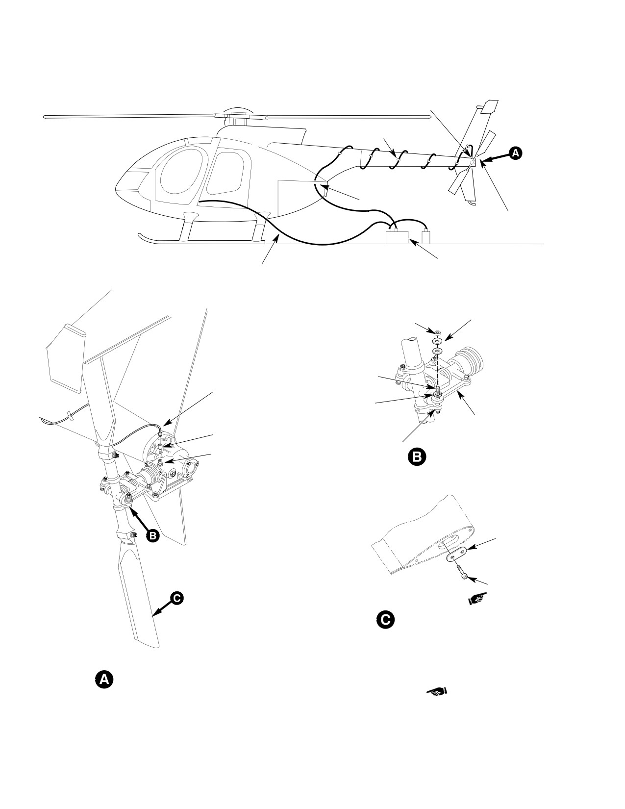
ACCELEROMETER/VELOMETER
FOR TAIL ROTOR BALANCING.
INSTALL ON BREATHER PLUG
OF TAIL ROTOR GEAR BOX
TAPE
SECURE UNDER LATCH
REFLECTIVE
TAPE
KIT LOCATION FOR TAIL
28VDC POWER CABLE
ROTOR BALANCING
TO AUXILIARY OUTPUT
RECEPTACLE
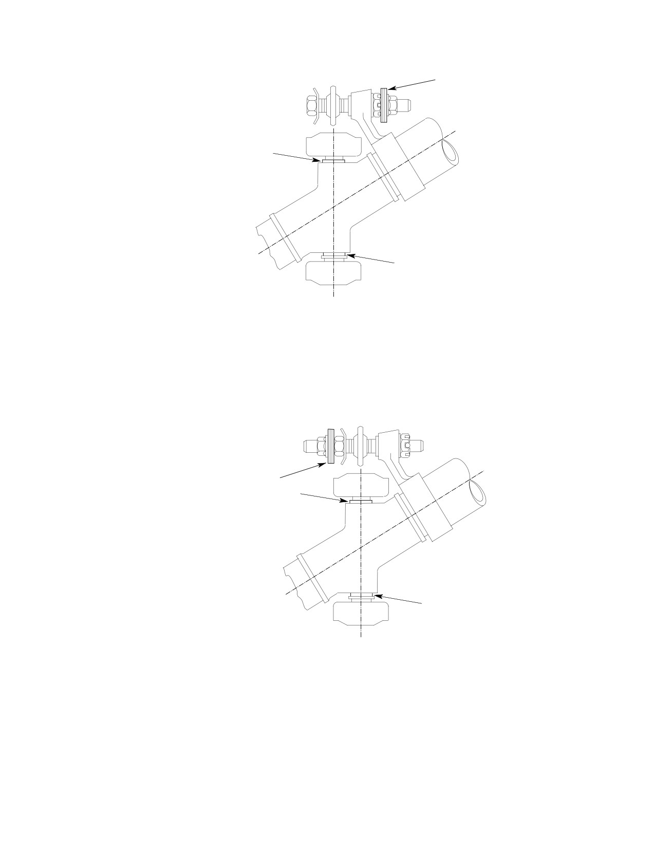
BALANCE WASHERS
RETAINING NUT
PITCH ARM BOLT
CABLE
SPRING WASHER
PITCH CONTROL
ACCELEROMETER/VELOMETER
LINK
(NOTE 1)
PITCH ARM
BREATHER/FILLER
BALANCE WASHER
INSTALLATION
TIP WEIGHT
NOTE 3
WEIGHT INSTALLATION
ROTATED
NOTES:
1.
INSTALLED ONLY FINGER TIGHT.
2.
FOR INFORMATION ON MAXIMUM WEIGHT, NUMBERS, TYPES AND
EXACT LOCATIONS OF BALANCING HARDWARE TO BE USED,
REFER TO ASSOCIATED TEXT AND TABLES.
3.
TORQUE SCREWS TO 21 - 24 INCH-POUNDS (2.37 - 2.71 NM).
G18-2000B
Figure 201. Tail Rotor Assembly Balancing (Two−Bladed Tail Rotor)
Page 204
Revision 34
18-20-00
MD Helicopters, Inc.
CSP-HMI-2
MAINTENANCE MANUAL
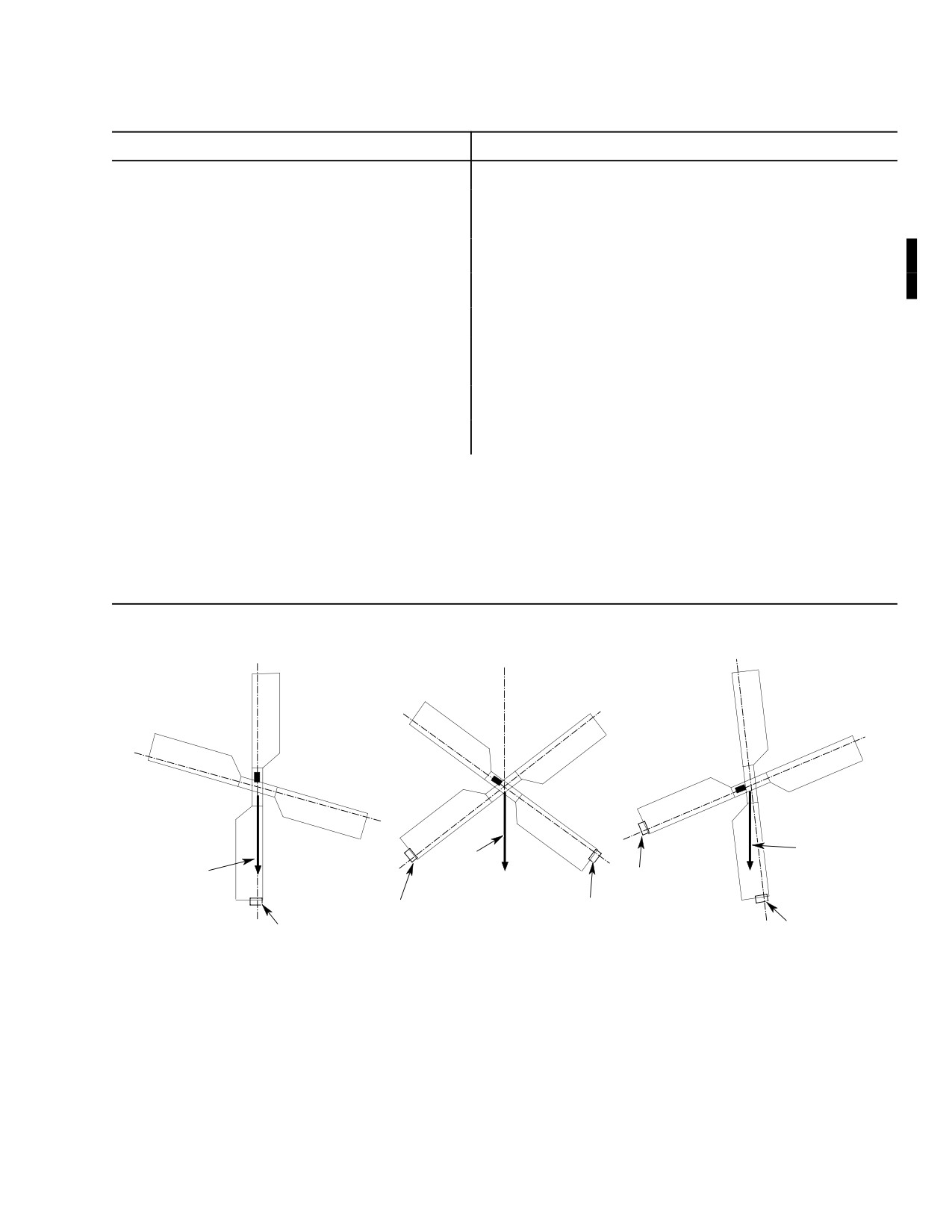
Table 201. Tail Rotor Balance Weight − Value Chart
At Blade Tip (4)
At Blade Pitch Arm (3)
Screw (5)
Washer (1)(2)
Length
Weight
Thickness
Weight
OD
Part Number
(in./mm)
(Grams)
Part Number
(in./mm)
(Grams)
(in./mm)
NAS1352−08−12P
0.75/19.05
2.22
HS306−227L
0.016/0.4064
1.17
0.800/20.32
NAS1352−08−14P
0.875/22.23
2.44
Weight
Thickness
Weight
(In./mm)
(Grams)
369A1622−3
0.016/0.4064
0.29
369A1622−5
0.036/0.9144
1.76
NOTES:
(1) Used on balance bolt.
(2) Maximum of 23 washers is permitted on each balance bolt.
(3) Minimum of two threads must extend past nut securing balance washers on balance bolt.
(4) Maximum weight, including screws, is 34 grams.
(5) Minimum screw thread engagement is 5/16 inch (7.9375 mm).
TOTAL
TOTAL
WEIGHT
TOTAL
WEIGHT
SMALLER
VECTOR
WEIGHT
VECTOR
WEIGHT
VECTOR
EQUAL
EQUAL
WEIGHT
WEIGHT
LARGE WEIGHT
WEIGHT
OR
OR
NOTE:
IF, WHEN ADDING WEIGHTS, OUT-OF-BALANCE VIBRATION
LEVEL INCREASES, ADD WEIGHTS TO THE TOP BLADE(S).
G18-2001
Figure 202. Short Method Tail Rotor Balancing (Four−Bladed Tail Rotor)
Page 205
18-20-00
Revision 39
CSP-HMI-2
MD Helicopters, Inc.
MAINTENANCE MANUAL
BALANCE WASHERS
(NOTE 1)
SHIMS
(NOTE 2)
NOTES:
SHIM
1.
MAXIMUM ALLOWABLE NUMBER OF WASHERS AT
PITCH ARM BOLT IS 23. WHENEVER THIS LIMIT IS
REACHED AND REQUIRED BALANCE CANNOT BE
MET, SHIFT THE CENTER OF THE HUB BY
TRANSFERRING SHIMS, THICKNESS OF 0.010 IN.
(0.254 MM), FROM WEIGHTED PITCH ARM SIDE TO
THE OPPOSITE SIDE AS SHOWN AND RE-CHECK
BALANCE, STARTING FROM ZERO WASHERS.
2.
REMOVE 0.010 IN. (0.254 MM) THICK SHIM FROM
G18-2002A
PITCH ARM SIDES AND TRANSFER THE SHIM TO
Figure 203. Long Method Tail Rotor Balancing (Inboard Blade)
BALANCE WASHERS
(MAX. 23)
SHIMS
(NOTE 2)
SHIM
NOTES:
1.
REMOVE 0.010 IN. (0.254 MM) THICK SHIM
FROM WEIGHTED PITCH ARM SIDE AND
TRANSFER THE SHIM TO THE OPPOSITE SIDE.
2.
DURING BALANCE OF OUTBOARD BLADES,
WEIGHTS ON INBOARD BLADES MUST NOT
G18-2003A
Figure 204. Long Method Tail Rotor Balancing (Outboard Blade)
Page 206
Revision 23
18-20-00
MD Helicopters, Inc.
CSP-HMI-2
MAINTENANCE MANUAL
Section
18−20−30
NOTARr
Anti−Torque System
Fan Balance
MD Helicopters, Inc.
CSP-HMI-2
MAINTENANCE MANUAL
NOTARR ANTI−TORQUE SYSTEM FAN BALANCE
MAINTENANCE PRACTICES
1. Fan Balancing
(4). Install velometer on bracket located at
the 6:00 o'clock position (Ref.
The NOTARr anti-torque system uses a
Figure 203).
fan-driven air circulation system within the
(5). Install magnetic pick-up and velometer
tailboom to control the directional heading of
wiring (Ref. Figure 203).
the helicopter. The rudder pedals in the cockpit
control the blade angle of the fan assembly.
Wiring must be secured to pre
The fan assembly operates at a constant speed
CAUTION
vent them from being ingested
of 5388 RPM at 100% N2.
into the fan assembly during run-up.
Balancing is accomplished by use of a balanc
(6). Position the anti-torque pedals at
ing kit. The carrying case of this kit contains
neutral during fan balancing.
all instrumentation, balance charts and
miscellaneous items needed to balance the fan
NOTE: The neutral position is 62% from full
assembly. Also included is a track and balance
left or approximately one inch of right pedal
handbook for use with the equipment to
from pedals centered. This pedal position
correct balance when such can be obtained by
produces minimum fan pitch and closes the
addition or subtraction of weight at studs on
thruster.
the fan assembly.
WARNING
Since vibration reduction by weight adjust
ment is dependent on proper mechanical
D Damage could occur if the anti-
condition of fan drive system, troubleshooting
torque pedals are not kept at neutral
information (Ref. Chap. 64) should be used
while the helicopter is operating
with balancing kit instructions. Acceptance
with the fan/hub transmission fair
criteria for balance and vibration are con
ing removed.
tained in the balancing kit and on each
D Operators and authorized observers
balance chart.
should remain in the designated
areas during balancing operations.
2. Fan Balance Check
D Wearing loose clothing or having ma
terials in shirt pockets during opera
(Ref. Figure 201)
tions can result in injury to person
nel and/or damage to aircraft.
Special Tools
(7). Run helicopter to establish N2 speed of
(Ref. Section 91−00−00)
100% percent.
Item
Nomenclature
ST903
Balancer/analyzer instrument kit
(8). Observe vibration reading.
(a). If vibration reading is greater than
0.2 ips, shut down helicopter and
NOTE: Use the vibration analyzer (ST903)
proceed with step (9).
throughout this procedure.
(b). If vibration level is 0.2 ips or less,
(1). Remove fan inlet screen.
proceed with step (11).
(2). Remove upper portion of the fan/hub
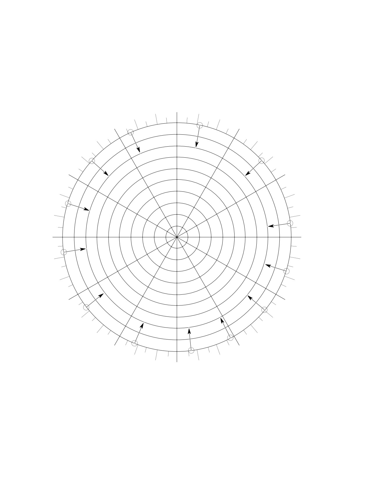
(9). Add hardware to the balancing studs in
transmission fairing.
any combination as required using
Table 201 and Figure 202. Torque nuts
(3). Number balancing studs as shown in
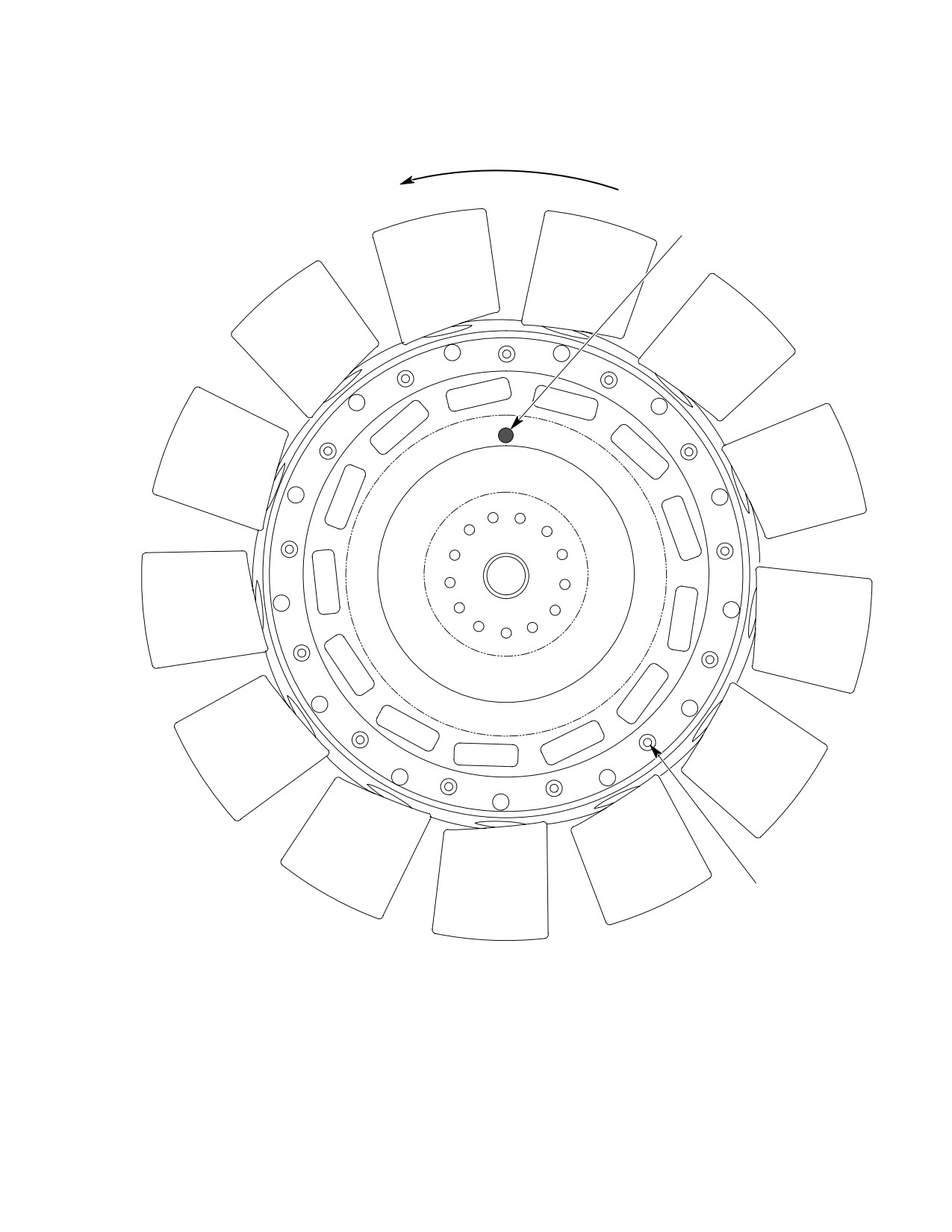
on studs to 30 - 40 inch pounds (3.39
Figure 201 using a permanent marker.
- 4.52 Nm).
Page 201
18-20-30
Revision 23
CSP-HMI-2
MD Helicopters, Inc.
MAINTENANCE MANUAL
Do not over torque the nuts on
(11). Remove balancing equipment wiring
CAUTION
the balancing studs. An over-
and attachments.
torqued nut may cause the stud locking col
(12). Install the fan/hub transmission fairing
lar to become loose the next time the nut is
and fan inlet screen.
removed.
(10). Repeat steps (6). thru (9). until fan
dynamic balance is 0.2 ips or less.
Table 201. Preferred Hardware for Balancing Fan Assembly
Washer
Weight (grams)
Stainless
Thickness
ID
OD
Stainless
Aluminum
Steel
(in/mm)
(in/mm)
(in/mm)
Aluminum
Steel
AN960KD416L
0.016 / 0.406
0.265 / 6.731
0.500 / 12.700
0.103
AN960C416L
0.016 / 0.406
0.265 / 6.731
0.500 / 12.700
0.572
AN960KD416
AN960C416
0.063 /1.600
0.265 / 6.731
0.500 / 12.700
0.407
1.144
HS306−325L
HS306−225L
0.016 / 0.406
0.263 / 6.680
0.528 / 13.411
0.121
0.339
HS306−325
HS306−225
0.032 / 0.813
0.263 / 6.680
0.528 / 13.411
0.241
0.677
HS306−325H
HS306−225H
0.063 / 1.600
0.263 / 6.680
0.528 / 13.411
0.482
1.355
HS306−326L
HS306−226L
0.016 / 0.406
0.263 / 6.680
0.619 / 15.723
0.181
0.507
HS306−326
HS306−226
0.032 / 0.813
0.263 / 6.680
0.619 / 15.723
0.361
1.015
HS306−326H
HS306−226H
0.063 / 1.600
0.263 / 6.680
0.619 / 15.723
0.723
2.029
HS306−327L
HS306−227L
0.016 / 0.406
0.263 / 6.680
0.800 / 20.320
0.329
0.922
HS306−327
HS306−227
0.032 / 0.813
0.263 / 6.680
0.800 / 20.320
0.657
1.844
HS306−327H
HS306−227H
0.063 / 1.600
0.263 / 6.680
0.800 / 20.320
1.314
3.689
NOTE: Maximum washer stack−up thickness = 0.20 inch (5.08 mm).
Page 202
Revision 23
18-20-30
MD Helicopters, Inc.
CSP-HMI-2
MAINTENANCE MANUAL
FAN ROTATION
MAGNETIC PICKUP
INTERRUPTER
1
13
2
12
3
11
4
10
5
9
6
8
7
BALANCING STUD
(13 PLCS)
VIEW LOOKING AFT
G18-2006
Figure 201. Fan Balancing Stud Numbering
Page 203
18-20-30
Revision 23
CSP-HMI-2
MD Helicopters, Inc.
MAINTENANCE MANUAL
12
360°
350°
10°
IPS
GRAMS
11
20°
340°
1
1.0
5.60
330°
30°
.9
5.04
# 3
# 4
320°
40°
.8
4.48
310°
.7
3.92
50°
# 5
# 2
.6
3.36
10
2
300°
60°
.5
2.80
.4
2.24
290°
70°
.3
1.68
# 6
.2
1.12
280°
80°
# 1
.1
.56
9
270°
90°
3
# 7
260°
100°
# 13
110°
250°
# 8
240°
# 12
8
120° 4
230°
130°
# 11
220°
# 9
140°
# 10
210°
150°
7
200°
160°
5
190°
170°
180°
6
G18-2007
Figure 202. Fan Balance Chart
Page 204
Revision 23
18-20-30
MD Helicopters, Inc.
CSP-HMI-2
MAINTENANCE MANUAL
MAGNETIC PICK-UP/
VELOMETER CABLES
28 VDC POWER CABLE
KIT LOCATION FOR
TO AUXILIARY OUTPUT
FAN BALANCING
RECEPTACLE
GAP 0.060 IN. (1.524 MM)
FAN / HUB
MAGNETIC PICK-UP
TRANSMISSION
FAIRING
VELOMETER
BALANCING STUD
(13 PLCS)
G18-2008A
Figure 203. Fan Balancing Equipment Installation
Page 205
18-20-30
Revision 23
CSP-HMI-2
MD Helicopters, Inc.
MAINTENANCE MANUAL
This Page Intentionally Left Blank
Page 206
Revision 44
18-20-30

MD Helicopters, Inc.
CSP-HMI-2
MAINTENANCE MANUAL
Chapter
20
Standard Practices
MD Helicopters, Inc.
CSP-HMI-2
MAINTENANCE MANUAL
TABLE OF CONTENTS
Para/Figure/Table
Title
Page
20-10-00 Torque
A
Maintenance Practices
201
1. Torque Wrenches
201
2. Application of Torque Wrench Loads
201
3. Bearings Installation, Staking or Swaging Force
201
4. Control Tube Jam Nut Torquing
202
5. Standard Hardware Torque Values
202
Table 201. Recommended Standard Torques for Tension-Type Fasteners
203
Table 202. Recommended Standard Torques for Shear-Type Fasteners
204
Table 203. Locking (Drag) Torque for Self-Locking Fasteners
205
20-20-00 Cleaning
A
Maintenance Practices
201
1. Cleaning
201
2. Fuselage Interior Trim and Upholstery Cleaning
201
3. Airframe Exterior and Rotor Blades Cleaning
201
4. Transparent Plastic Cleaning
201
5. Engine Compressor Contamination Removal
202
6. Cleaning Of Engine Air Inlet Screens
202
20-30-00 Painting
A
Maintenance Practices
201
1. Paint Finish
201
2. Paint Removal
201
3. Paint Touchup
201
A. Touchup - Small Sanded Areas
201
B. Touchup - Flaking or Dried Paint or Primer
201
C. Touchup - Primer Not Adhering to Metal Finish
201
D. Touchup - Glass Fiber Laminate Parts
202
E. Touchup - Polycarbonate Plastic Parts
202
F. Touchup - ABS Thermoplastic Parts
202
4. Main Rotor Blade Paint
203
A. Main Rotor Blade Paint Removal
203
B. Main Rotor Blade Paint Application
203
5. Tail Rotor Blade Paint
204
A. Tail Rotor Blade Paint Removal
204
B. Tail Rotor Blade Paint Application
204
20-40-00 Corrosion Prevention
A
Maintenance Practices
201
1. Corrosion Control
201
Page i
20 Contents
Revision 41
CSP-HMI-2
MD Helicopters, Inc.
MAINTENANCE MANUAL
TABLE OF CONTENTS (Cont.)
Para/Figure/Table
Title
Page
2. Magnesium Alloys - Insulation Against Corrosion
201
3. Sealing Compound Application
201
4. Main Rotor Hub Corrosion Prevention (Tri-Flow Wash Procedure)
201
5. Main Rotor Blades Corrosion Arresting
202
A. Main Rotor Blade and Damper Attach Pins - Corrosion Prevention
202
6. Magnesium Alloy Exterior Surface Touchup Treatment
203
7. Aluminum Alloy Exterior Surface Touchup Treatment
203
8. Steel Alloy Exterior Surface Touchup Treatment
203
9. Splitter Bungee Spring Corrosion Control (500N)
204
Table 201. Anti-Corrosion Chemical Finishes - Aluminum
204
20-90-00 Nondestructive Inspection
A
Maintenance Practices
201
1. Nondestructive Inspection Methods
201
A. Visual Inspection
201
Figure 201. Visual Inspection Technique
201
B. Dye Penetrant Inspection
202
C. Coin Tap Inspection
202
D. Fluorescent Penetrant Inspection
202
E. Magnetic Particle Inspection
202
Figure 202. Coin Tap Inspection
203
F. Eddy Current Inspection - General
203
Page ii
Revision 41
20 Contents
MD Helicopters, Inc.
CSP-HMI-2
MAINTENANCE MANUAL
Section
20−10−00
Torque
MD Helicopters, Inc.
CSP-HMI-2
MAINTENANCE MANUAL
TORQUE
MAINTENANCE PRACTICES
1. Torque Wrenches
(5). Torque values specified in this manual
are special torque values that apply
Torque wrenches should be of good quality and
instead of those listed.
calibration should be verified at regular
intervals to verify accuracy. Torque wrench
(6). If adapters are used such that adapter
accuracy at room temperature, 70°F (22 °C)
and torque wrench are not at right
must be within following limits.
angles (90 degrees) to each other,
wrench or indicator reading must be
(1). From zero through 19 percent of torque
corrected.
wrench range, error may not exceed ±7
percent of load applied.
(7). Any re-use of self-locking nuts over 3/8
inch is governed by values listed in
(2). From 20 thru 79 percent of torque
Table 203.
wrench range, error may not exceed ±4
(8). Castellated nuts aretorqued to the
percent load applied.
minimum side of the recommended
(3). From 80 to 100 percent of torque
torque range. Continue to tighten the
wrench range, error may not exceed ±5
nut until the hole of the cotter pin lines
percent of load applied.
up with the castellation without
exceeding the maximum specified
torque.
2. Application of Torque Wrench Loads
(9). Bolt must not be rotated during
(Ref. Table 201 thru Table 203) Recommended
application of torque to mating nut.
tightening torque values and minimum drag
torque values for fine and coarse thread nuts,
3. Bearings Installation, Staking or Swaging
and minimum breakaway torque for used
Force
self-locking bolts or screws are listed in
Table 201 and Table 202. Requirements
The following procedure explains how to
governing application of torque loads follow.
convert from a given `Force` which is required
These requirements apply throughout this
to perform a task to a proper hydraulic
manual except where otherwise specifically
pressure reading.
indicated.
(1). Determine the diameter of the ram
(1). Values apply to cadmium-plated bolts,
(staking or swaging contact surface) on
cadmium-plated nuts coated with
the hydraulic press to be used.
molybdenum disulfide (MoS2).
NOTE: The hydraulic press to be used must
(2). Manufacturer applied lubricant must
have a pressure gauge.
not be removed nor additional lubricant
added.
(2). Divide the ram diameter by two to get
the radius.
(3). Bolts, nuts and surfaces they bear on
must be clean, dry and free of lubricant
(3). Multiply 3.14159 (pi) times the Radius
except as stated in requirement above.
squared (R2). This will give the area of
the ram.
(4). Turning (drag) torque required to
install self-locking nut or bolt up to
(4). Divide the force required for the task by
point of final tightening must always be
the area of the ram. This gives the
added to final torque value specified or
actual PSI reading for the hydraulic
the maintenance instruction, as
press pressure gauge needed to perform
applicable.
the task.
Page 201
20-10-00
Revision 38
CSP-HMI-2
MD Helicopters, Inc.
MAINTENANCE MANUAL
EXAMPLE:
5. Standard Hardware Torque Values
Ram Diameter = 2.65 in. (6.731 cm)
The following tables list torque values for
standard hardware by part number.
Ram Radius (R) = 1.325 in. (3.366 cm)
Radius squared (R2) = 1.756 in.2 (8.548 cm2)
NOTE: If unsure of hardware type, refer to
CSP-IPC-4.
R2 X 3.1416 = 5.517 in. (26.854 cm) (Area of
ram)
(1). Table 201 lists self-locking tension-
type fastener torque values.
Force required = 7500-8500 lbs. (3402-3856
kg) (variable)
(2). Table 202 lists shear-type fastener
7500-8500 lbs. (3402-3856 kg) / 5.517 in.
torque values.
(26.854 cm) = 1359-1540 PSI (9370-10618
kPa)
(3). Table 203 lists maximum and minimum
self-locking fastener drag (run-on)
PSI required =1359 PSI (9370 kPa) Min.
torque values.
1540 PSI (10618 kPa) Max.
Force needed/(R2) X 3.1416 = Pressure Gauge
Table 203 lists self-locking
CAUTION
Reading
(run-on) torque values, i.e.;
torque required to overcome the friction of
4. Control Tube Jam Nut Torquing
the self-locking feature of fastener threads
prior to clamp-up and final tightening. Any
(1). Tighten jam nuts against control rods
self-locking fastener that can be run down
by holding rodend with wrench.
with the fingers after the locking feature en
gages must be replaced. Determine final
NOTE: Do not tighten with rodend against fit
torque value by adding the run-on torque to
ting.
the specified final clamping torque. Final
(2). Ensure rodends are not preloaded after
clamping torque values are listed in
torquing jam nuts.
Table 201 and Table 202.
Page 202
Revision 38
20-10-00

MD Helicopters, Inc.
CSP-HMI-2
MAINTENANCE MANUAL
Table 201. Recommended Standard Torques for Tension−Type Fasteners
Diameter
Thread
Recommended
Maximum
Thread
Recommended
Maximum
inch
Size
Torque
Allowable
Size
Torque
Allowable
(mm)
(Fine)
in. lb (Nm)
in. lb (Nm)
(Coarse)
in. lb (Nm)
in. lb (Nm)
0.1640
12 − 15
20
12 − 15
20
8 − 36
8 − 32
(4.1656)
(1.13 − 1.36)
(2.26)
(1.36 − 1.69)
(2.26)
0.1900
20 − 25
40
20 − 25
35
10 − 32
10 − 24
(4.8260)
(2.26 − 2.82)
(4.52)
(2.26 − 2.82)
(3.95)
0.250
50 − 70
100
40 − 50
75
1/4 − 28
1/4 − 20
(6.350)
(5.65 − 7.91)
(11.30)
(4.52 − 5.65)
(8.47)
0.3125
100 − 140
225
80 − 90
160
5/16 − 24
5/16 − 18
(7.9375)
(11.30 − 15.82)
(25.42)
(9.04 − 10.17)
(18.08)
0.3750
160 − 190
390
160 − 185
275
3/8 − 24
3/8 − 16
(9.5250)
(18.08 − 21.47)
(44.06)
(18.08 − 20.90)
(31.07)
0.4375
450 − 500
840
235 − 255
475
7/16 − 20
7/16 − 14
(11.1125)
(50.84 − 56.49)
(94.91)
(26.55 − 28.81)
(53.67)
0.50
480 − 690
1100
400 − 480
880
1/2 − 20
1/2 − 13
(12.70)
(54.23 − 77.96)
(124.3)
(45.19 − 54.23)
(90.39)
0.5625
800 − 1000
1600
500 − 700
1100
9/16 − 18
9/16 − 12
(14.2875)
(90.39 − 112.98)
(180.8)
(56.49 − 79.09)
(124.3)
0.6250
1100 − 1300
2400
700 − 900
1500
5/8 − 18
5/8 − 11
(15.8750)
(124.3 − 146.9)
(271.2)
(79.09 − 101.69)
(169.5)
0.750
2300 − 2500
5000
1150 − 1600
2500
3/4 − 16
3/4 − 10
(19.050)
(259.9 − 282.5)
(565.0)
(129.95 − 180.8)
(282.5)
0.8750
2500 − 3000
7000
2200 − 3000
4600
7/8 − 14
7/8 − 9
(22.2250)
(282.5 − 339.0)
(791.0)
(248.6 − 339.0)
(542.4)
1.00
3700 − 5500
10000
3700 − 5000
7600
1 − 12
1 − 8
(25.40)
(418.1 − 621.5)
(1130.0)
(418.1 − 565.0)
(858.8)
1.1250
5000 − 7000
15000
5500 − 6500
12000
1−1/8 − 12
1−1/8 − 8
(28.5750)
(565.0 − 791.0)
(1695.0)
(621.5 − 734.5)
(1356.0)
1.250
9000 − 11000
25000
6500 − 8000
16000
1−1/4 − 12
1−1/4 − 8
(31.750)
(1017.0 − 1243.0)
(2825.0)
(734.5 − 904.0)
(1469.0)
Page 203
20-10-00
Revision 38

CSP-HMI-2
MD Helicopters, Inc.
MAINTENANCE MANUAL
Table 202. Recommended Standard Torques for Shear−Type Fasteners
Diameter
Thread
Recommended
Maximum
Thread
Recommended
Maximum
inch
Size
Torque
Allowable
Size
Torque
Allowable
(mm)
(Fine)
in. lb (Nm)
in. lb (Nm)
(Coarse)
in. lb (Nm)
in. lb (Nm)
0.1640
7 − 9
12
7 − 9
12
8 − 36
8 − 32
(4.1656)
(0.79 − 1.02)
(1.36)
(0.79 − 1.02)
(1.36)
0.1900
12 − 15
25
12 − 15
21
10 − 32
10 − 24
(4.8260)
(1.36 − 1.69)
(2.82)
(1.36 − 1.69)
(2.37)
0.250
30 − 40
60
25 − 30
45
1/4 − 28
1/4 − 20
(6.350)
(3.39 − 4.52)
(6.78)
(2.82 − 3.39)
(5.08)
0.3125
60 − 85
140
48 − 55
100
5/16 − 24
5/16 − 18
(7.9375)
(6.78 − 9.60)
(15.82)
(5.42 − 6.21)
(11.30)
0.3750
95 − 110
240
95 − 110
170
3/8 − 24
3/8 − 16
(9.5250)
(10.73 − 12.43)
(27.12)
(10.73 − 12.43)
(19.21)
0.4375
270 − 300
500
140 − 155
280
7/16 − 20
7/16 − 14
(11.1125)
(30.51 − 33.90)
(56.49)
(15.82 − 17.51)
(31.64)
0.50
290 − 410
660
240 − 290
520
1/2 − 20
1/2 − 13
(12.70)
(32.77 − 46.32)
74.57)
(27.12 − 32.77)
(58.75)
0.5625
480 − 600
960
300 − 420
650
9/16 − 18
9/16 − 12
(14.2875)
(54.23 − 67.79)
(108.47)
(33.90 − 47.45)
(73.44)
0.6250
660 − 780
1400
420 − 540
900
5/8 − 18
5/8 − 11
(15.8750)
(74.57 − 88.13)
(158.2)
(47.45 − 61.01)
(101.69)
0.750
1300 − 1500
3000
700 − 950
1500
3/4 − 16
3/4 − 10
(19.050)
(146.9 − 169.5)
(339.0)
(79.09 − 107.34)
(169.5)
0.8750
1500 − 1800
4200
1300 − 1800
2700
7/8 − 14
7/8 − 9
(22.2250)
(169.5 − 203.4)
(474.6)
(146.9 − 203.4)
(305.1)
1.00
2200 − 3300
6000
2200 − 3000
4500
1 − 12
1 − 8
(25.40)
(248.6 − 372.9)
(678.0)
(248.6 − 339.0)
(508.5)
1.1250
3000 − 4200
9000
3300 − 4000
7200
1−1/8 − 12
1−1/8 − 8
(28.5750)
(339.0 − 474.6)
(1017.0)
(372.9 − 452.0)
(813.6)
1.250
5400 − 6600
15000
4000 − 5000
10000
1−1/4 − 12
1−1/4 − 8
(31.750)
(610.2 − 745.8)
(1695.0)
(452.0 − 565.0)
(1130.0)
Page 204
Revision 38
20-10-00

MD Helicopters, Inc.
CSP-HMI-2
MAINTENANCE MANUAL
Table 203. Locking (Drag) Torque for Self−Locking Fasteners
Diameter
Thread
Maximum
Minimum
Thread
Maximum
Minimum
inch
Size
in. lb
in. lb
Size
in. lb
in. lb
(mm)
(Fine)
(Nm)
(Nm)
(Coarse)
(Nm)
(Nm)
0.1640
15
1.50
15
1.50
8−36
8 − 32
(4.1656)
(1.7)
(0.17)
(1.7)
(0.17)
0.1900
18
2.0
18
2.0
10 − 32
10 − 24
(4.8260)
(2.03)
(0.23)
(2.03)
(0.23)
0.250
30
3.50
30
4.50
1/4 − 28
1/4 − 20
(6.350)
(3.39)
(0.40)
(3.39)
(0.51)
0.3125
60
6.50
60
7.50
5/16 − 24
5/16 − 18
(7.9375)
(6.78)
(0.73)
(6.78)
(0.85)
0.3750
80
9.50
80
12.0
3/8 − 24
3/8 − 18
(9.5250)
(9.04)
(1.07)
(9.04)
(1.36)
0.4375
100
14.0
100
16.50
7/16 − 20
7/16 − 14
(11.1125)
(11.3)
(1.58)
(11.3)
(1.86)
0.50
150
18.0
150
24.0
1/2 − 20
1/2 − 13
(12.70)
(16.95)
(2.03)
(16.95)
(2.71)
0.5625
200
24.0
200
30.0
9/16 − 18
9/16 − 12
(14.2875)
(22.60)
(2.71)
(22.60)
(3.39)
0.6250
300
32.0
300
40.0
5/8 − 18
5/8 − 11
(15.8750)
(33.90)
(3.62)
(33.90)
(4.52)
0.750
400
50.0
400
60.0
3/4 − 16
3/4 − 10
(19.050)
(45.19)
(5.65)
(45.19)
(6.78)
0.8750
600
70.0
600
82.0
7/8 − 14
7/8 − 9
(22.2250)
(67.79)
(7.91)
(67.79)
(9.27)
1.00
800
90.0
800
110.0
1 − 12
1 − 8
(25.40)
(90.39)
(10.17)
(90.39)
(12.43)
1.1250
900
117.0
1−1/8 − 12
(28.5750)
(101.69)
(13.22)
1.250
1000
143.0
1−1/4 − 12
(31.750)
(112.98)
(16.16)
Page 205
20-10-00
Revision 38
CSP-HMI-2
MD Helicopters, Inc.
MAINTENANCE MANUAL
This Page Intentionally Left Blank
Page 206
Revision 38
20-10-00
MD Helicopters, Inc.
CSP-HMI-2
MAINTENANCE MANUAL
Section
20−20−00
Cleaning

MD Helicopters, Inc.
CSP-HMI-2
MAINTENANCE MANUAL
CLEANING
MAINTENANCE PRACTICES
1. Cleaning
3. Airframe Exterior and Rotor Blades
Cleaning
Consumable Materials
(Ref. Section 91−00−00)
Consumable Materials
Item
Nomenclature
(Ref. Section 91−00−00)
Item
Nomenclature
CM234
Solvent, dry-cleaning
CM234
Solvent, dry-cleaning
General cleaning of oil and dirt deposits from
Use care to prevent scratching
the helicopter and its components must be
CAUTION
of aluminum skin when clean
accomplished by using dry-cleaning solvent
ing main rotor blades. Never use volatile
(CM234), standard commercial grade kerosene
solvents or abrasive materials. Never apply
or a solution of detergent soap and water.
bending loads to blades or blade tabs during
Exceptions that must be observed are specified
cleaning.
in the following cleaning paragraphs.
NOTE: Avoid directing soapy or clean water
concentrations toward engine air intake
Some commercial cleaning
area and instrument static source ports in
CAUTION
agents, such as readily avail
aft fairing.
able household cleaners, contain chemicals
(1). Wash helicopter exterior, including
that can cause corrosive action and/or leave
fiberglass components and rotor blades,
residue that can result in corrosion. Exam
when necessary, using solution of clean
ples of cleaning agents that are not to be
water and mild soap.
used are ``Fantastic” and ``409” type clean
ers, or locally made strong soap cleaners.
(2). Clean surfaces stained with fuel or oil
by wiping with soft cloth dampened by
2.
Fuselage Interior Trim and Upholstery
solvent (CM234), followed by washing
Cleaning
with clean water and mild soap.
(3). Rinse washed areas with water and dry
(1). Clean dirt or dust accumulations from
with soft cloth.
floors and other metal surfaces with
vacuum cleaner or small hand brush.
4. Transparent Plastic Cleaning
(2). Sponge soiled upholstery and trim
(1). Clean outside surfaces of plastic panels
panels with a mild soap and lukewarm
by rinsing with clean water and
water solution. Avoid complete soaking
rubbing lightly with palm of hand.
of upholstery and trim panels. Wipe
(2). Use mild soap and water solution or
solution residue from upholstery with
aircraft type plastic cleaner to remove
cloth dampened by clean water.
oil spots and similar residue.
(3). Remove imbedded grease or dirt from
Never attempt to dry plastic
upholstery and carpeting by sponging
CAUTION
panels with cloth. To do so
or wiping with an upholstery cleaning
causes any abrasive particles lying on plas
solvent recommended for the ``applica
tic to scratch or dull surface. Wiping with
ble” fabric (nylon, vinyl, leather, etc).
dry cloth also builds up an electrostatic
charge that attracts dust particles from air.
NOTE: If necessary, seat upholstery may be
thoroughly dry-cleaned with solvent. When
(3). After dirt is removed from surface of
complete dry-cleaning is performed, uphol
plastic, rinse with clean water and let
stery must be re-flameproofed.
air-dry or dry with soft, damp chamois.
Page 201
20-20-00
Revision 23
CSP-HMI-2
MD Helicopters, Inc.
MAINTENANCE MANUAL
(4). Clean inside surfaces of plastic panels
6. Cleaning Of Engine Air Inlet Screens
by using aircraft type plastic cleaner
(1). Remove engine air inlet and engine
and tissue quality paper wipers.
cooling air screen (Ref. Chap. 71).
(2). Clean screens with soft brush to remove
5. Engine Compressor Contamination
dirt accumulations.
Removal
(3). Immerse screen in solution of detergent
(Ref. Chap. 71 and the applicable Allison
and allow to soak approximately 15
Engine Operation and Maintenance Manual,
minutes. Flush out clear water. Allow
Table 201, Sec. 01-00-00)
screen to drain and air-dry thoroughly.
Page 202
Revision 23
20-20-00
MD Helicopters, Inc.
CSP-HMI-2
MAINTENANCE MANUAL
Section
20−30−00
Painting

MD Helicopters, Inc.
CSP-HMI-2
MAINTENANCE MANUAL
PAINTING
MAINTENANCE PRACTICES
1. Paint Finish
Consumable Materials
Polyurethane paint is used for the helicopter
(Ref. Section 91−00−00)
exterior finish. The primary interior finish is
Item
Nomenclature
acrylic paint. A base coat of primer is used on
CM305
Lacquer, acrylic
most helicopter structure.
CM318
Primer
CM320
Thinner, lacquer
2. Paint Removal
(1). Apply applicable chemical surface
Consumable Materials
treatment (Ref. Sec. 20-40-00) if metal
(Ref. Section 91−00−00)
protection is not adequate. If chemical
Item
Nomenclature
surface treatment is undamaged, or has
CM229
Paint remover
already been applied, wipe surface
clean with thinner (CM320) and wipe
CM230
Paint remover
dry immediately.
CM236
Paint remover
(2). Apply coat of primer (CM318). Feather
primer coating onto surrounding color
Use paint remover (CM229, CM230 or CM236)
coat. Allow primer to air-dry for 30
when it becomes necessary to remove finish
minutes.
paint coatings. Ordinarily, use of paint
(3). Apply lacquer (CM305) color coats to
remover should be limited to stripping of paint
match original finish color.
from parts that require magnetic-particle or
fluorescent-penetrant inspection and to parts
B. Touchup − Flaking or Dried Paint or
that require removal of excessive paint
Primer
buildup. When possible, use high-pressure
water spray to rinse off paint remover and
Consumable Materials
paint particles and to neutralize paint
(Ref. Section 91−00−00)
remover. Solvent type paint remover usually
Item
Nomenclature
does not remove primer coating; acid type
CM801
Abrasive paper, silicon carbide
solvent removes primer.
If paint remover is used in vicin
(1). Sand non-adherent surface to smooth
CAUTION
ity of drive shaft couplings, be
featheredge with surrounding area,
sure couplings are completely masked and
using 320-grit or finer abrasive paper
covered. If paint remover contacts coupling
(CM801), and wet or dry sanding
diaphragms, rust spots will develop and cou
method. Do not sand beyond point
pling replacement is required. If acid type
where chemical film protection begins
paint remover is used, comply with all spe
to show through primer.
cial safety precautions listed on container.
(2). Touchup sanded area [Ref. Touchup -
Small Sanded Area).
3. Paint Touchup
C. Touchup − Primer Not Adhering to Metal
Following procedures apply to application of
Finish
both polyurethane and acrylic paints.
Consumable Materials
A. Touchup − Small Sanded Areas
(Ref. Section 91−00−00)
Item
Nomenclature
The following procedure is for rework of
scratches, nicks, gouges and other small
CM801
Abrasive paper, silicon carbide
blemishes.
Page 201
20-30-00
TR12-001
CSP-HMI-2
MD Helicopters, Inc.
MAINTENANCE MANUAL
(1). Use 320-grit or finer abrasive paper
(4). Lightly sand surface with 320-grit
(CM801) and wet or dry sanding
abrasive paper (CM801). Normal grain
method to sand through chemical film
appearance does not require further
to bare metal. Feather surrounding
filling or sanding.
surface with bare surface.
(5). Apply primer and color finish (CM305)
(2). Re-treat bare metal with applicable
[Ref. Touchup - Small Sanded Areas).
chemical film (Ref. Sec. 20-40-00)
using brush application.
E. Touchup − Polycarbonate Plastic Parts
(3). Touchup re-treated surface [Ref.
Touchup - Small Sanded Areas).
Consumable Materials
(Ref. Section 91−00−00)
D. Touchup − Glass Fiber Laminate Parts
Item
Nomenclature
CM220
Naphtha aliphatic
Consumable Materials
CM217
Isopropyl alcohol
(Ref. Section 91−00−00)
CM305
Lacquer, acrylic
Item
Nomenclature
CM317
Resin primer / Thinner
CM217
Isopropyl alcohol
CM219
Methyl-ethyl-ketone
CM305
Lacquer, acrylic
(1). Wipe surface clean with a 1:1 mixture
CM316
Epoxy coating / Thinner
of naphtha (CM220) and isopropyl
CM801
Abrasive paper, silicon carbide
alcohol (CM217). Mix equal parts (1:1)
of primer resin (CM317) and thinner.
Apply one coat to surface and allow to
(1). Remove all gloss from area requiring
air-dry minimum of 3 hours. Apply
finish with 100-grit or coarser abrasive
epoxy primer and color finish (CM305)
paper (CM801) until there is a uniform
[Ref. Touchup - Small Sanded Areas).
dull condition.
F. Touchup − ABS Thermoplastic Parts
MEK solvent is flammable.
WARNING
Use only in well-ventilated
area and away from heat and flame.
Consumable Materials
(Ref. Section 91−00−00)
(2). Wipe surface clean with 1:1 mixture of
Item
Nomenclature
MEK (CM219) and isopropyl alcohol
(CM217).
CM305
Lacquer, acrylic
(3). Squeeze one coat of Poly-EP (CM316),
thinned as required with thinner, into
Clean surface with mild soap and water. Dry
fiberglass pores until surface of fibers is
thoroughly. Apply one coat of lacquer (CM305)
smooth.
[Ref. Touchup - Small Sanded Areas).
Page 202
Revision 23
20-30-00

MD Helicopters, Inc.
CSP-HMI-2
MAINTENANCE MANUAL
4. Main Rotor Blade Paint
CAUTION
The following procedures is to be used whenev
D When sanding paint from the main rotor
er the main rotor blades require either
blade, take care to not damage rivet heads
repainting or paint touch-up.
and sealant.
D Do not sand through the paint and primer
NOTE:
into the base metal.
D Repaint main rotor blades only in sets to
(4). Using 320 grit, or finer, abrasive paper
maintain rotor balance. Never completely
(CM801) and wet or dry sanding
repaint only one main rotor blade
method, sand areas that require
installed on helicopter.
painting.
D New main rotor blades have the inboard
(5). Using a soft cloth, dampened in
24 inches (610 mm) painted gloss white.
isopropyl alcohol (CM217), thoroughly
This aids in inspection of the blade.
clean main rotor blade.
D At owner-operators convenience, in-ser
(6). Inspect sanded areas for damage.
vice main rotor blades may have the in
board 24 inches (610 mm) painted gloss
B. Main Rotor Blade Paint Application
white.
NOTE: If inboard 24 inches (610 mm) of main
rotor blade is to be painted white, paint is to
be applied to the entire circumference of the
Consumable Materials
blade. There is to be no ridges in the paint
(Ref. Section 91−00−00)
when completed.
Item
Nomenclature
CM206
Chemical coating
(1). Inspect main rotor blade (Ref. Sec.
62-10-00, Main Rotor Blade Inspec
CM217
Isopropyl alcohol
tion).
CM304
Enamel, epoxy
(2). Ensure all bushings, bearing, data
CM318
Primer
plates and the abrasion strip are
CM729
Tape, masking, pressure sensitive
protected from paint with tape
CM801
Abrasive paper, silicon carbide
(CM729).
(3). Using a soft cloth, dampened in
isopropyl alcohol (CM217), thoroughly
A. Main Rotor Blade Paint Removal
clean main rotor blade.
(1). Position main rotor blade on a bench of
(4). Treat any bare metal areas of main
sufficient length to provide support.
rotor blade with chemical coating
(CM206).
(2). Inspect main rotor blade (Ref. Sec.
NOTE: Mix primer (CM318) according to
62-10-00, Main Rotor Blade Inspec
manufacturer's recommendations.
tion).
(5). Allow mixed primer to stand for 15 to
30 minutes prior to use.
When removing paint from
CAUTION
main rotor blade, do not use any
NOTE:
paint remover. Bonding agents used in
D Working life of mixed primer is four hours
manufacture of the blade may be damaged
maximum.
by the chemicals causing the blade to be un
serviceable.
D Primer allowed to stand for more than
two hours must be stirred or shaken be
fore use.
(3). Apply tape (CM729) to all bushings,
bearing, data plates and the abrasion
D Addition of freshly mixed primer to re
strip.
plenish an older mixture is not permitted.
Page 203
20-30-00
Revision 34

CSP-HMI-2
MD Helicopters, Inc.
MAINTENANCE MANUAL
(6). Apply primer (CM318) to sanded areas,
When removing paint from tail
CAUTION
feather into surrounding color coat.
rotor blade, do not use any paint
remover. Bonding agents used in manufac
(7). Allow to air-dry for one hour minimum.
ture of the blade may be damaged by the
chemicals causing the blade to be unservice
NOTE: Mix paint
(CM304) according to
able.
manufacturer's recommendations.
(2). Apply tape (CM729) to all bushings,
(8). Allow mixed paint to stand for 20
data plates and the abrasion strip.
minutes minimum prior to use.
(3). Plug root end of tail rotor blade to
NOTE:
ensure no paint enters.
D Working life of mixed paint is four hours
maximum.
CAUTION
D Addition of freshly mixed primer to re
plenish an older mixture is not permitted.
D When sanding paint from the tail rotor
blade, take care to not damage rivet heads
(9). Apply paint (CM318) to primed areas.
and sealant.
Feather-edge paint while applying.
D Do not sand through the paint and primer
(10). Allow to air-dry for eight hours
into the base metal.
minimum.
(4). Using 320 grit, or finer, abrasive paper
(11). Remove protective tape from main rotor
(CM801) and wet or dry sanding
blade.
method, sand areas that require
painting.
NOTE: Main rotor assembly may need to be re-
balanced after painting.
(5). Using a soft cloth, dampened in
isopropyl alcohol (CM217), thoroughly
5. Tail Rotor Blade Paint
clean tail rotor blade.
The following procedures is to be used whenev
(6). Inspect sanded areas for damage.
er the tail rotor blades require either repaint
ing or paint touch-up.
B. Tail Rotor Blade Paint Application
NOTE: Repaint tail rotor blades only in sets to
(1). Inspect tail rotor blade (Ref. Sec.
maintain rotor balance. Never completely
64-10-00, Tail Rotor Blade Inspection).
repaint only one tail rotor blade installed on
helicopter.
(2). Ensure all bushings, data plates and
the abrasion strip are protected from
paint with tape (CM729).
Consumable Materials
(Ref. Section 91−00−00)
(3). Ensure root end of tail rotor blade is
Item
Nomenclature
plugged to prevent entry of paint.
CM206
Chemical coating
(4). Using a soft cloth, dampened in
CM217
Isopropyl alcohol
isopropyl alcohol (CM217), thoroughly
CM304
Enamel, epoxy
clean tail rotor blade.
CM318
Primer
CM729
Tape, masking, pressure sensitive
(5). Treat any bare metal areas of tail rotor
blade with chemical coating (CM206).
CM801
Abrasive paper, silicon carbide
NOTE: Mix primer (CM318) according to
A. Tail Rotor Blade Paint Removal
manufacturer's recommendations.
(1). Inspect tail rotor blade (Ref. Sec.
(6). Allow mixed primer to stand for 15 to
64-10-00, Tail Rotor Blade Inspection).
30 minutes prior to use.
Page 204
Revision 34
20-30-00
MD Helicopters, Inc.
CSP-HMI-2
MAINTENANCE MANUAL
NOTE:
NOTE:
D Working life of mixed primer is four hours
D Working life of mixed paint is four hours
maximum.
maximum.
D Primer allowed to stand for more than
D Addition of freshly mixed primer to re
two hours must be stirred or shaken be
plenish an older mixture is not permitted.
fore use.
D Addition of freshly mixed primer to re
(10). Apply paint (CM318) to primed areas.
plenish an older mixture is not permitted.
Feather-edge paint while applying.
(7). Apply primer (CM318) to sanded areas,
(11). Allow to air-dry for eight hours
feather into surrounding color coat.
minimum.
(8). Allow to air-dry for one hour minimum.
(12). Remove protective tape from tail rotor
NOTE: Mix paint
(CM304) according to
blade.
manufacturer's recommendations.
(9). Allow mixed paint to stand for 20
NOTE: Tail rotor assembly may need to be re-
minutes minimum prior to use.
balanced after painting.
Page 205
20-30-00
Revision 34
CSP-HMI-2
MD Helicopters, Inc.
MAINTENANCE MANUAL
This Page Intentionally Left Blank
Page 206
Revision 34
20-30-00
MD Helicopters, Inc.
CSP-HMI-2
MAINTENANCE MANUAL
Section
20−40−00
Corrosion
Prevention

MD Helicopters, Inc.
CSP-HMI-2
MAINTENANCE MANUAL
CORROSION PREVENTION
MAINTENANCE PRACTICES
1. Corrosion Control
(1). Coat contacting surfaces with layer of
sealing compound (CM425), in addition
The airframe is fabricated primarily of
to primer (CM318).
aluminum and some magnesium alloys, with
Do not use steel washers.
selective use of stainless steel and titanium,
CAUTION
and should be checked regularly for any signs
of corrosion, especially at points of dissimilar
(2). Use 5056S aluminum alloy washers
and overlapping metal contact. Corrosion of
under boltheads and nuts that would
dissimilar metals is the result of several
otherwise contact magnesium. If 5056S
conditions; lack of sufficient insulation in
aluminum is not available, use 5052S
areas of metal contact, tears or punctures in
alloy washers.
metal itself, and areas where protective
(3). Apply primer on attaching hardware
finishes have been scuffed, scratched, chipped
before installation.
or worn away. Perform corrosion control
according to MDHI Corrosion Control Manual
3. Sealing Compound Application
(CSP-A-3) and instructions in the following
paragraphs.
Use sealing compound (CM425) to replace
loose or missing sealant on exterior surfaces.
Do not apply potassium hydrox
Sealant is used to fill seams and joints that
CAUTION
ide to or near bolts, fasteners,
might trap water. Apply sealant as follows:
seams, or faying surfaces. Immediately af
ter completing the magnesium and alumi
Consumable Materials
num test (Ref. NOTE below), wash the
(Ref. Section 91−00−00)
tested area with water to prevent burns and
Item
Nomenclature
continued action on the material.
CM425
Sealing compound
NOTE: To differentiate between aluminum and
magnesium alloy, apply one drop of ordinary
(1). Check that seam or joint is clean and
potassium hydroxide (dropped from a glass
free of foreign matter and moisture.
rod) to the surface of the metal being tested.
(2). Apply sealant with putty knife or
If the alloy is aluminum, a foaming or boil
similar tool.
ing action of the liquid, accompanied by a
black discoloration of the metal, will imme
(3). Force sealant well down into seam to
diately occur. If the alloy is magnesium, no
eliminate any air pockets.
reaction will be evidenced.
(4). Fillet sealant to give joint or seam a
smooth appearance.
2. Magnesium Alloys − Insulation Against
Corrosion
4. Main Rotor Hub Corrosion Prevention
(Tri−Flow Wash Procedure)
To prevent galvanic corrosion between
The following procedure will help prevent
magnesium and any dissimilar metals:
corrosion of main rotor hub components,
especially on helicopters operated in marine
Consumable Materials
environments. The procedure should be
(Ref. Section 91−00−00)
accomplished following the last flight each day
Item
Nomenclature
for helicopters operated in marine or other
corrosive environments, and at each 25-hour
CM318
Primer
inspection (Ref. Chap. 05), or more often if
CM425
Sealing compound
desired, for helicopters not operated in
corrosive environments.
Page 201
20-40-00
Revision 23
CSP-HMI-2
MD Helicopters, Inc.
MAINTENANCE MANUAL
(5). Wash remainder of helicopter exterior
Consumable Materials
using fresh water spray.
(Ref. Section 91−00−00)
Item
Nomenclature
(6). Wash main rotor blades with Zip Wax
(CM227) or equivalent, mixed per
CM104
Lubricant, spray
manufacturer's instructions.
CM227
Washing compound with wax
5. Main Rotor Blades Corrosion Arresting
Use care when working
The following procedure will help prevent
WARNING
around turning rotor blades.
corrosion of main rotor blades. The procedure
Stay low. Remain on right side of heli
should be accomplished following the last
copter to avoid tail rotor blades.
flight each day on helicopters operated in
marine or other corrosive environments, and
NOTE: Perform the first step below prior to en
weekly for helicopters not operated in corrosive
gine shutdown, following the last flight of
environments.
the day if possible. When the rotor stops
turning, the laminates of the strap-pack
Consumable Materials
spread apart slightly. Contaminates col
(Ref. Section 91−00−00)
lected on the edges of the strap-pack assem
Item
Nomenclature
bly can enter the area between the lami
nates as they spread apart. If the rotor
CM227
Washing compound with wax
continues turning until the contaminants
CM228
Surface cleaner
are washed away, centrifugal force will keep
the laminates compressed and not allow the
corrosive substances to enter the area be
Wear rubber gloves when us
tween the laminates.
WARNING
ing phosphoric solution in
next step.
(1). Bring engine to ground idle (64-65 %
Nl); set SCAV AIR to ON (Ref. applica
(1). Wipe down main rotor blades with
ble PFM, Table 201, Sec. 01-00-00).
surface cleaner (CM228).
Perform the following:
(2). Rinse main rotor blades immediately
with water and dry. (Ref. Sec. 20-20-00
(a). Spray fine fresh water mist on main
for additional information on cleaning
rotor blades.
main rotor blades.)
(b). Direct a strong stream of fresh water
(3). Wax main rotor blades with Zip Wax
into main rotor hub and control
(CM227) or equivalent, mixed per
system at main rotor hub.
manufacturer's instructions.
(c). Spray entire rotor hub with lubricant
A. Main Rotor Blade and Damper Attach
(CM104).
Pins − Corrosion Prevention
(2). Shut down engine and allow rotor
If helicopter is subject to salt-laden atmo
blades stop turning.
sphere, lubricate mating surfaces of barrel nut
and cam handle at each periodic inspection,
NOTE: In the next step, spray directly between
using corrosion preventive oil (CM120) (Ref.
individual laminates.
Chap. 62).
(3). Lift main rotor blades to separate strap
Consumable Materials
pack laminates and spray strap-packs
(Ref. Section 91−00−00)
with lubricant.
Item
Nomenclature
(4). Perform engine water wash (Ref. Chap.
CM120
Oil, corrosion preventive
71).
Page 202
Revision 23
20-40-00
MD Helicopters, Inc.
CSP-HMI-2
MAINTENANCE MANUAL
6. Magnesium Alloy Exterior Surface
(2). Using swab, liberally apply chemical
Touchup Treatment
film (CM206). Allow solution to remain
on surface for 1 to 3 minutes, or until
surface becomes amber to brown in
Consumable Materials
color.
(Ref. Section 91−00−00)
Item
Nomenclature
(3). Rinse treated surface thoroughly with
CM207
Chromic acid solution
clean water. After rinsing, wipe off
CM320
Thinner, lacquer
excess moisture with clean lint-free
cloth. If dry compressed air is available,
blow any moisture from joints or
(1). Wash affected area with solution of
crevices and allow to dry completely at
mild soap and clean fresh water. Rinse
room temperature for approximately 1
area with clean water and wipe dry
hour.
using clean soft lint-free cloth.
(4). Apply paint finish touchup (Ref. Sec.
(2). Use thinner (CM320) on damaged area
20-30-00).
to remove any grease and old paint.
8. Steel Alloy Exterior Surface Touchup
(3). Apply chromic acid solution (CM207) by
Treatment
swabbing exposed area for 10 to 30
minutes.
Consumable Materials
(4). Using clean cloth soaked in clean, fresh
(Ref. Section 91−00−00)
water, thoroughly rinse area where
Item
Nomenclature
solution was applied. Allow area to
thoroughly dry.
CM228
Surface cleaner
CM801
Abrasive paper, silicon carbide
(5). Apply paint finish touchup (Ref. Sec.
20-30-00).
(1).
Remove loose paint and corrosion
7.
Aluminum Alloy Exterior Surface Touchup
products by scraping area with sharp
Treatment
phenolic scraper, brushing with heavy
fiber brush and light sanding with
320-grit or finer abrasive paper
Consumable Materials
(CM801).
(Ref. Section 91−00−00)
Item
Nomenclature
(2).
Wash off area with mild soap and clean
CM206
Chemical coating
fresh water; rinse thoroughly.
(3).
Treat surface with surface cleaner
NOTE: If there is any question of whether or
(CM228).
not the protective coating is removed, it
should always be assumed that bare metal
(4).
Allow solution to remain on surface for
is exposed.
approximately 5 minutes. Keep sur
faces wet.
(1). Wash affected area with solution of
mild soap and fresh water. Rinse area
(5).
Rinse thoroughly with clean water. Dry
with clean water and wipe dry with
with clean lint-free cloth and then
clean soft lint-free cloth.
allow to air-dry completely.
NOTE: Avoid letting chemical mixture dry on
surface in next step. If it has dried, re-wet
(6).
Apply paint finish touchup (Ref. Sec.
surface with solution.
20-30-00).
Page 203
20-40-00
Revision 23

CSP-HMI-2
MD Helicopters, Inc.
MAINTENANCE MANUAL
9. Splitter Bungee Spring Corrosion Control
(1). After helicopter shut-down, insert
(500N)
absorbent cloth into area around
splitter bungee spring.
It is recommended that after shutdown from
the last flight of the day, for helicopters
operating in a corrosive environment, the
(2). Liberally spray spring with lubricant
splitter bungee spring be sprayed with
(CM104) until spring inner coils are
Tri-Flow.
coated.
Consumable Materials
(3). Remove absorbant cloth from around
(Ref. Section 91−00−00)
spring.
Item
Nomenclature
CM104
Lubricant, spray
(4). Wipe excess spray from aircraft.
Table 201. Anti−Corrosion Chemical Finishes − Aluminum
Process
Applicable Specification
Normal Coating Thickness and Color
Dow #1 (Chrome Pickel)
MIL−M−3171, Type I
Removes metal. Iridescent yellow or red;
gray coatings are unacceptable.
Dow #7 (Dichromate
MIL−M−3171, Type III
No dimensional change. Wrought or
Treatment)
extruded parts − chestnut brown; castings
− light brown to black; AZ91C−T6 and
AZ92A−T6 alloys − gray.
Dow #17 (Anodize)
MIL−M−45202, Type I − light coat Class C: 0.0002−0.0003 inch
(0.00508−0.00762 mm); light green.
Type II − heavy coat
Class D: 0.0002−0.0035 inch
(0.00508−0.08890 mm); dark green.
Dow #19 (Chromic Acid
MIL−M−3171, Type VI
No dimensional change; gray to black.
Brush−on Treatment)
Page 204
Revision 23
20-40-00
MD Helicopters, Inc.
CSP-HMI-2
MAINTENANCE MANUAL
Section
20−90−00
Nondestructive
Inspection
CSP-HMI-2
MD Helicopters, Inc.
MAINTENANCE MANUAL
This Page Intentionally Left Blank
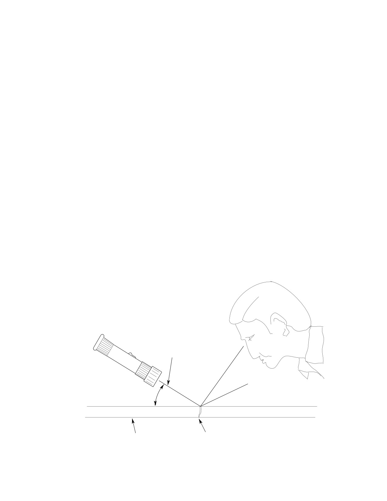
MD Helicopters, Inc.
CSP-HMI-2
MAINTENANCE MANUAL
NONDESTRUCTIVE INSPECTION
MAINTENANCE PRACTICES
1. Nondestructive Inspection Methods
missing fasteners, security of parts,
corrosion, and damage.
A. Visual Inspection
(3). Treat any corrosion found during
(Ref. Figure 201)
preliminary inspection.
(1). Select applicable visual inspection aids
(4). Clean the areas or surface of parts to be
from the following list:
inspected.
(a). A flashlight with the correct explo
(a). Remove any contaminates that
sive atmosphere rating, beam spread,
might hinder surface indications.
efficiency, and brightness for the
inspection being performed.
(b). Do not remove protective finishes.
(b). An inspection mirror on a ball joint
(5). Using optical aids as required, inspect
for use in viewing an area that is not
area as follows:
in the normal line of sight.
(a). Examine surface for cracks using a
(c). A 2-10 power magnifying glass to
flashlight, and confirm with a
expose defects that cannot be seen by
magnifying glass.
the unaided eye.
(b). Examine surface for other disconti
(d). A borescope to allow remote visual
nuities, such as: discoloration from
inspection of internal surfaces or
overheating; buckled, bulging, dented
otherwise inaccessible areas.
skin; cracked, chafed, split, or dented
(2). Perform a preliminary inspection of
tubing; chafed electrical wiring;
overall general area for cleanliness,
delaminating of composites; and
presence of foreign objects, deformed or
damaged protective finishes.
EYE ABOVE REFLECTED
LIGHT BEAM
INCANDESCENT
LIGHT BEAM
LINE OF SIGHT
REFLECTED LIGHT BEAM
5° TO 45°
FAYING SURFACES
CRACK OPEN TO SURFACE
G20-0001
Figure 201. Visual Inspection Technique
Page 201
20-90-00
Revision 38
CSP-HMI-2
MD Helicopters, Inc.
MAINTENANCE MANUAL
B. Dye Penetrant Inspection
Consumable Materials
(Ref. Section 91−00−00)
Consumable Materials
Item
Nomenclature
(Ref. Section 91−00−00)
CM234
Solvent, dry-cleaning
Item
Nomenclature
CM234
Solvent, dry-cleaning
The coin tap method of inspection is used
CM805
Dye penetrant kit
evaluate composite structures. The coin tap is
limited to detecting shallow defects.
When inspecting cored structure, two sided
(1). Using cleaning solvent (CM234), clean
access is required. When multiple laminates
area to be inspected.
are installed over core, the core bond-line
cannot be evaluated.
NOTE:
The sound of an acceptable part can vary
D Manufacturers instructions on Dye Pene
considerably and the entire area must be
trant Kit take precedence over the follow
tapped in order to detect any variance.
ing steps.
Compare the sound of the suspected area with
D Parts to be inspected must be dry and
the sound of a known acceptable area.
heated to at least 70°F (21.1°C) but not
An acceptable area will have a slightly sharper
over 130°F (54.4°C).
or crisper sounding response. A dead or flat
sound is unacceptable, and requires a more
(2).
Apply penetrant from dye penetrant kit
thorough type of NDI.
(CM805) by brushing, spraying or by
dipping. Allow to stand for a minimum
Any suspect areas must be in
CAUTION
of 2 minutes.
spected by person(s) qualified in
the appropriate NDI. Contact MDHI cogni
zant engineering for recommended NDI pro
(3).
Remove excess penetrant with remover
cedures and applications.
(available with dye penetrant kit
(CM805)), or by cleaning with plain
(1). Thoroughly clean area to be inspected
water. Allow part to dry.
with cleaning solvent (CM234).
(4).
Apply a light even layer of developer
(2). Perform a visual inspection for any
from dye penetrant kit (CM805) by
raised or blistered appearing areas.
brushing, spraying or by dipping. When
NOTE: Tap the entire area to be inspected in
dipping, avoid excess quantity.
cluding any surrounding area of like
construction.
(5).
Penetrant, which has penetrated into
cracks (or other openings) in the surface
(3). Using a coin, light hammer, or other
of the part will be drawn out by the
suitable blunt object, lightly tap the
developer resulting in a bright red
surface of the part to be inspected.
indication.
D. Fluorescent Penetrant Inspection
(6).
If part is serviceable or repairable,
Refer to the appropriate manufacturer's
clean part free of penetrant and
related instructions for type of equipment and
developer with cleaning solvent
materials being used.
(CM234).
E. Magnetic Particle Inspection
C. Coin Tap Inspection
Refer to the appropriate manufacturer's
related instructions for type of equipment and
(Ref. Figure 202)
materials being used.
Page 202
Revision 40
20-90-00

MD Helicopters, Inc.
CSP-HMI-2
MAINTENANCE MANUAL
0.25 INCH
(6.35 MM)
2.00 INCH
(50.8 MM)
0.375 INCH
(9.52 MM)
DIA BALL
MATERIAL: MILD STEEL OR BRASS
G20-0002
Figure 202. Coin Tap Inspection
F. Eddy Current Inspection − General
(a). Personnel doing nondestructive tests
must be qualified and certified in of
This procedure includes general information
NAS 410 or ASNT SNT-TC-1A or
on material, equipment and procedures for the
equivalent. Personnel making must
detection of surface cracks.
be certified to Level 2 minimum.
The Eddy Current test instruments induce an
(b). The test facilities written procedure
Eddy Current into a conductive medium and
approved by the Level 3 technician
detect the change in the induced eddy current
must be followed.
field which is produced by a defect.
(2). Equipment
Related Publications
(Ref. Section 01−00−00 (Table 201)
Specification
Publication Title
Refer to equipment manufacturer's
instructions for type of material
NAS−410
inspected.
Nondestructive Testing Personnel
Qualification and Certification
ASNT−SNT−TC−1
(a). Electronic - Electronic - All electron
Nondestructive Testing Personnel
ic equipment must be calibrated
Qualification and Certification
annually or after repair. Records
must be kept and made available
ASTM E 1316
when requested. All calibration must
Standard Terminology for Non−destructive
be made to a national standard. The
Examinations
equipment must be approved for the
type of part examined. Maintain a
(1). Personnel Qualification and Certifica
3:1 signal to noise ratio during
tion.
inspection.
Page 203
20-90-00
Revision 40