HANDBOOK OF MAINTENANCE INSTRUCTIONS FOR MDHI 369D/E/FF-500/600N HELICOPTERS (ISSUED: 1990) - page 5
MD Helicopters, Inc.
CSP-HMI-2
MAINTENANCE MANUAL
PLACARDS AND MARKINGS
MAINTENANCE PRACTICES
1. General
be cut out to provide proper draining or
ease of opening or removing of doors,
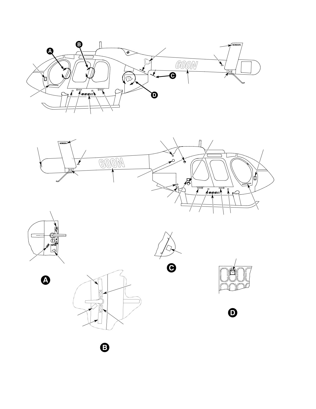
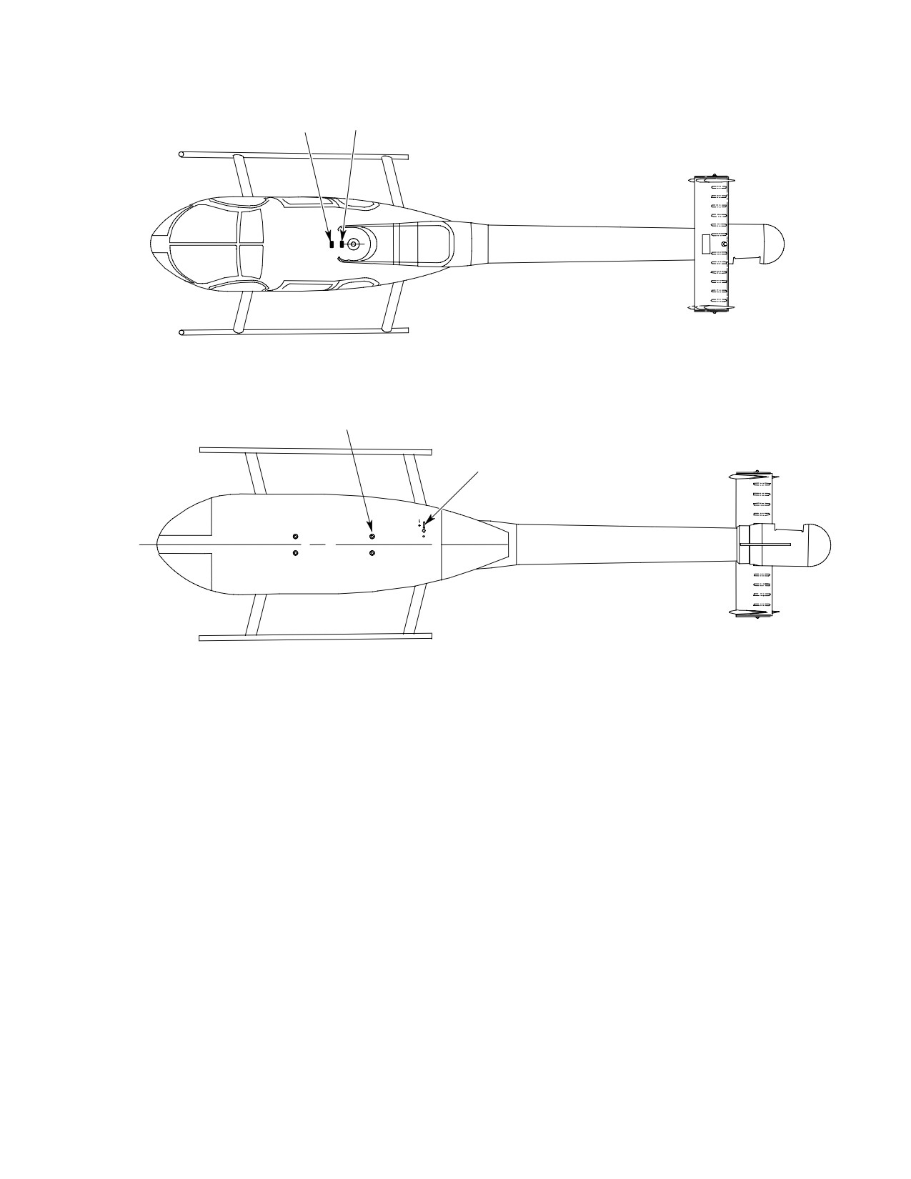
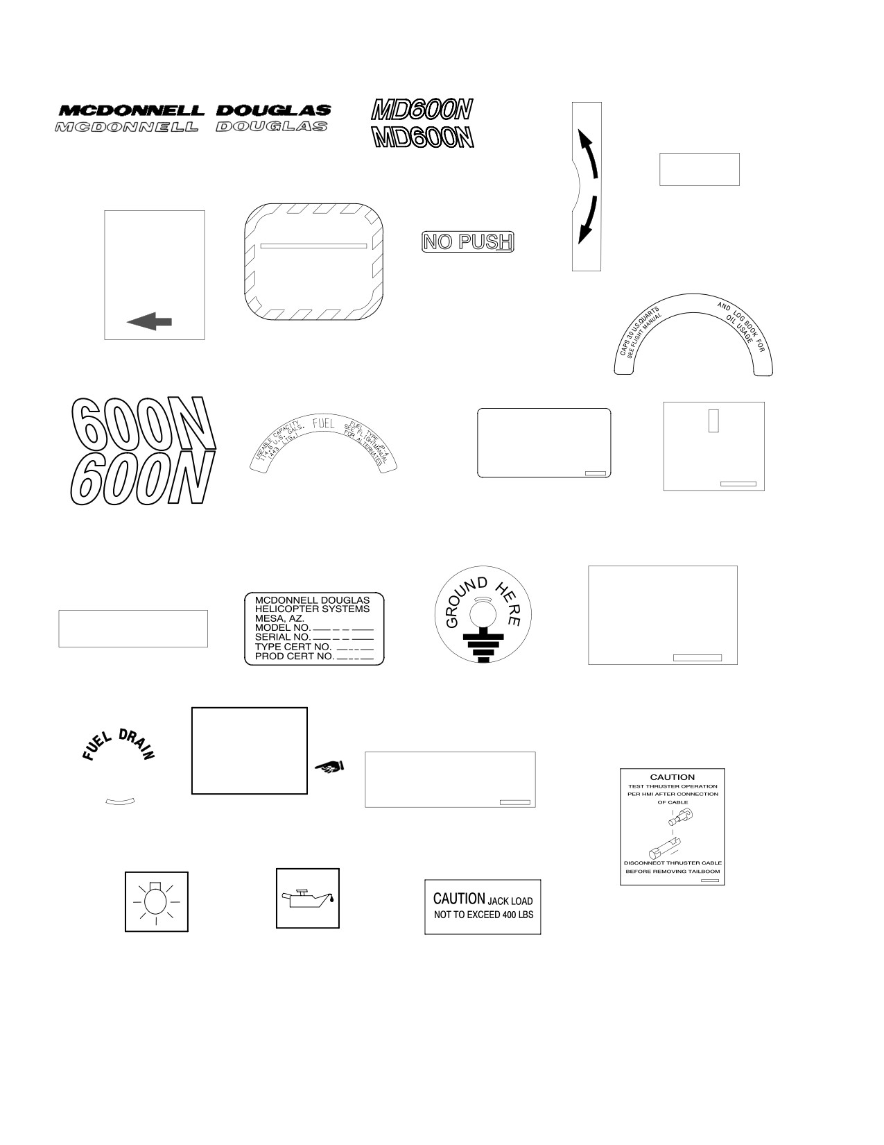
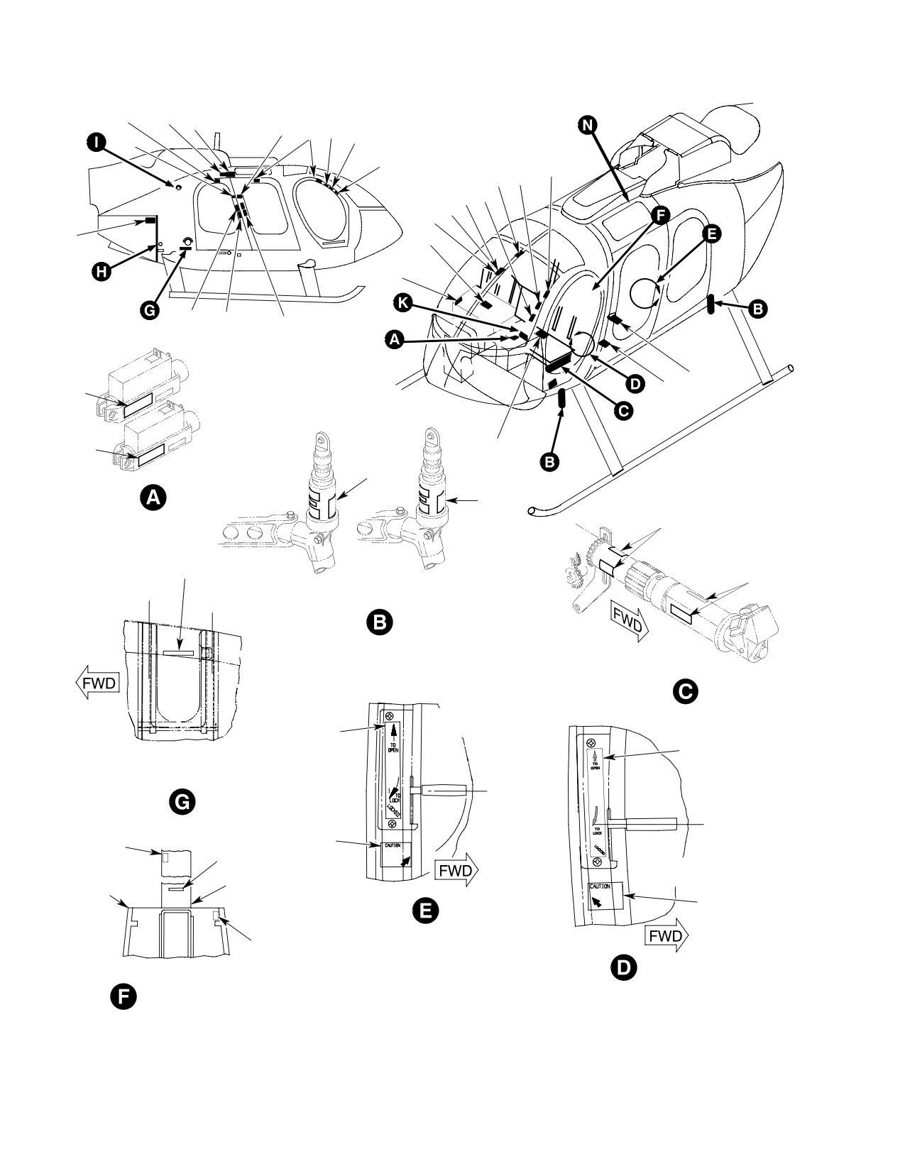
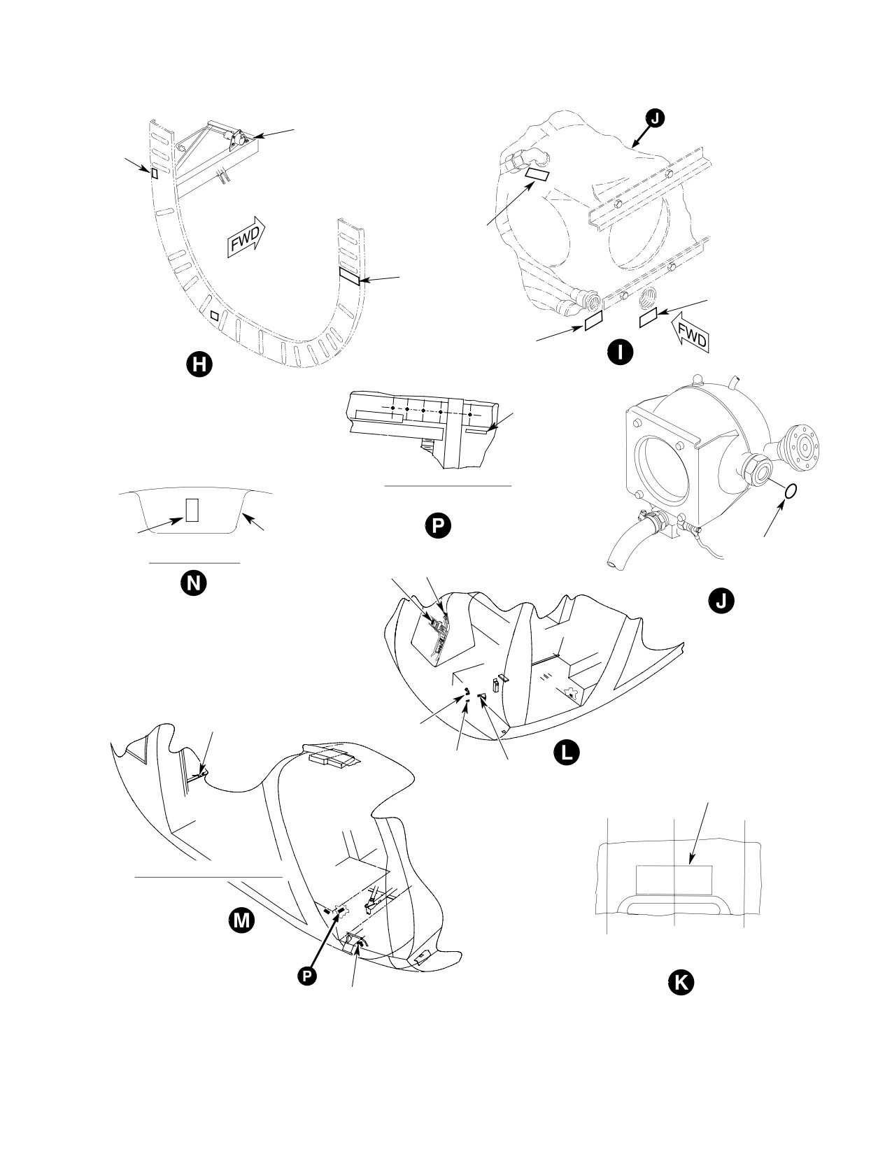
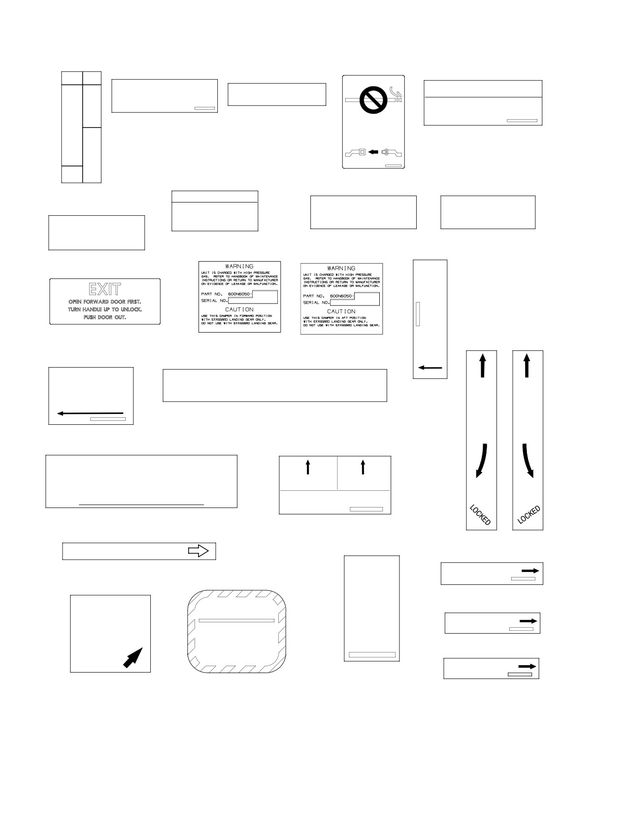
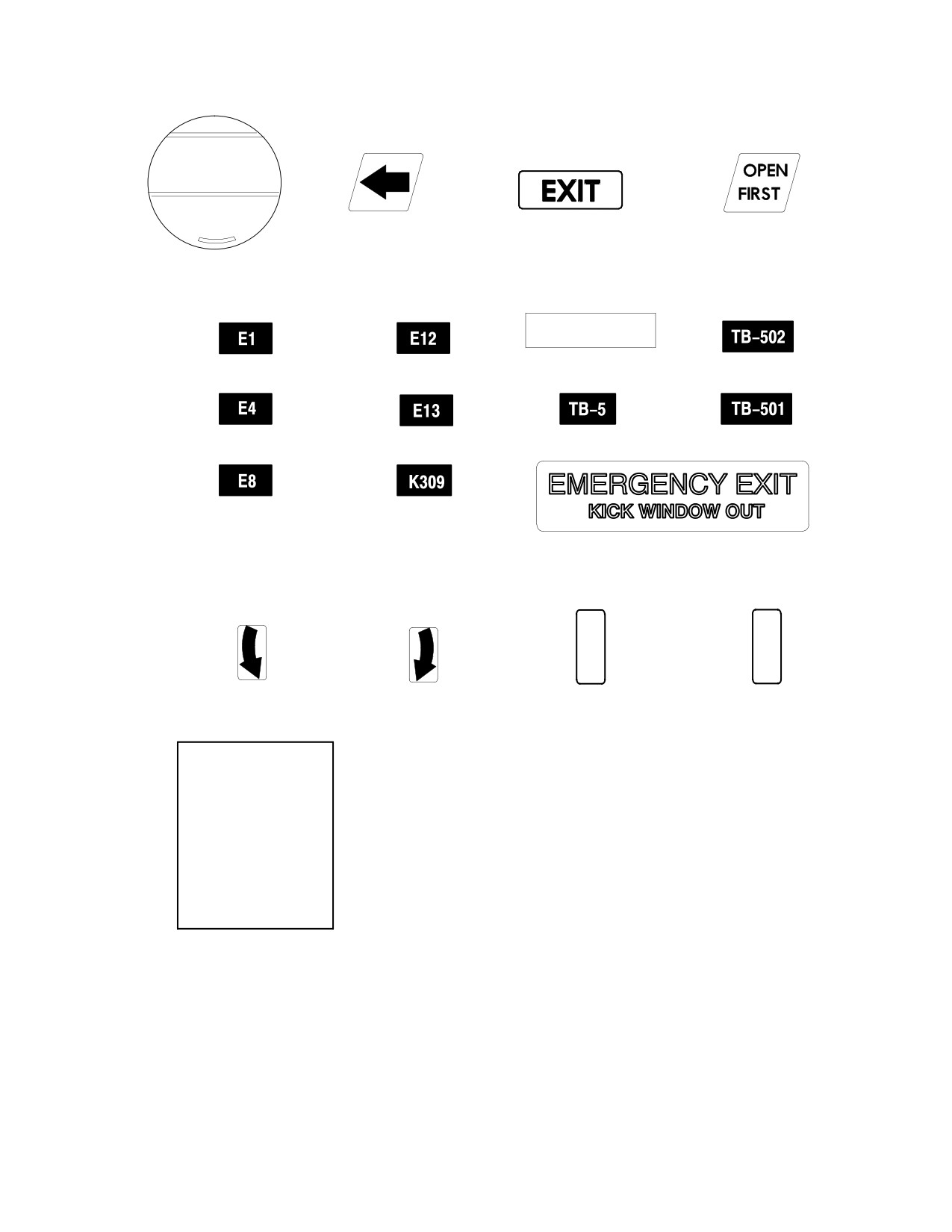
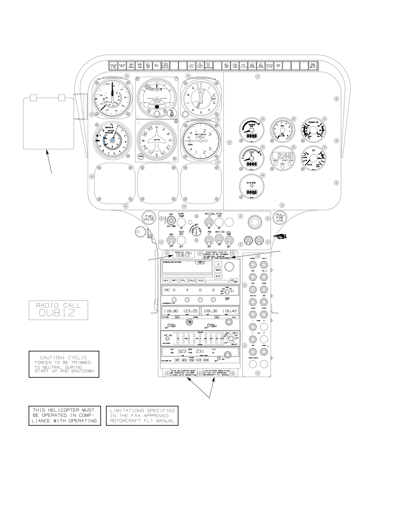
(Ref. Figure 201 thru Figure 203 for placards
plates, etc.
and markings most common to Model 600N
helicopters). Nomenclature corresponds to that
used in the IPC. (Ref. Illustrated Parts Catalog
(2). Where a decal is applied over a skin lap
for each decal part number and the quantity
(one skin overlapping another), the
required.)
decal must be cut so that it lies flat and
The following illustrations cover different
makes a positive bond.
areas of decal placement on the helicopter:
(1). Exterior - Figure 201.
(3). Seal edges of all exterior decals, and
(2). Interior - Figure 202.
only those interior decals in the engine
compartment and cargo compartment
(3). Instrument panels - Figure 203.
aft of the transmission, with epoxy
adhesive. Edge sealing to be a mini
2. Decal Application
mum of 1/32 inch (0.8mm) and a
(1). Where a decal overlaps or covers drain
maximum of 1/8 inch (3mm) around
holes, access doors, etc., the decal shall
perimeter of decal.
Page 201
11-40-00
Revision 23
CSP-HMI-2
MD Helicopters, Inc.
MAINTENANCE MANUAL
2
2
1
8
3
1
2
4
10
1
1
1
1
1
1
3
4
3
4
0
9
2
2
1
2
1
7
8
3
1
2
2
4
3
10
1
6
1
5
1
3
2
1
1
1
1
1
1
4
3
0
4
3
2
6
0
4
LOOKING
5
INBOARD
(LH SHOWN, RH OPP)
2
7
2
6
INSIDE ENGINE DOOR
(LH SHOWN, RH OPP)
2
9
2
2
5
8
LOOKING INBOARD
(LH SHOWN, RH OPP)
6G11-010-1B
Figure 201. Exterior Placards and Markings (Sheet 1 of 4)
Page 202
Revision 23
11-40-00
MD Helicopters, Inc.
CSP-HMI-2
MAINTENANCE MANUAL
1
1
9
7
TOP VIEW
18 (4 PLCS)
3
0
BOTTOM VIEW
6G11-010-2
Figure 201. Exterior Placards and Markings (Sheet 2 of 4)
Page 203
11-40-00
Revision 23
CSP-HMI-2
MD Helicopters, Inc.
MAINTENANCE MANUAL
TO
LOCK
1.
MCDONNELL DOUGLAS LOGO
2.
600N IDENTIFICATION
LOCKED
4.
LOCKED
CAUTION
WARNING
SAFELOCK
TO
INNER HANDLE
FAILURE TO PROPERLY INSTALL,ALIGN
OPEN
AND TORQUE,FUEL,OIL AND AIR TUBES
7.
NO PUSH
IN POSITION
AND FITTINGS COULD RESULT IN AN
ENGINE FAILURE.REFER TO THE APPLI
SHOWN BEFORE
3.
DOOR
CABLE MANUAL FOR PROPER INSTAL4
FLIGHT
ATION AND TORQUE PROCEDURES
INSTRUCTIONS
OIL
PUSH
6.
WARNING
8.
PUSH
5.
LOCK BEFORE FLIGHT
LEFT AND RIGHT HAND SIDES
9.
OIL
DURING OPERATIONS IN TEMPERATURES OF 40 _F (4 _C)
OR COLDER, FUEL ADDED TO THE TANK MUST CONTAIN
EITHER ANTI-ICING ADDITIVE PFA-55MB OR ANTI-ICING
ADDITIVE PER MIL-I-27868 OR MIL-I-85470 WITH A
MINIMUM CONCENTRATION OF .06% BY VOLUME
JIG POINT
AND A MAXIMUM CONCENTRATION OF .15% BY VOLUME.
SEE FLIGHT MANUAL FOR MIXING PROCEDURES.
STA 92.64
11. DECAL, FUEL
12. DECAL, ANTI-ICE ADDITIVE
13. JIG POINT
10. REGISTRATION NUMBER
CAP. 12.0 U.S. PTS.
SEE FLT MANUAL
AND LOG BOOK FOR
ATTACH JACK PAD
OIL USAGE
14. ATTACH JACK PAD
15. PLATE IDENTIFICATION
16. GROUND SYMBOL
17. MAIN ROTOR
TRANSMISSION OIL
SERVICED
WITH
MOBIL
CAUTION
AGL
DISCONNECT ELECTRICAL WIRING
BEFORE REMOVING BOOM
19. OIL USAGE
18. FUEL DRAIN
20. ELECTRICAL DISCONNECT
CAUTION
21. CAUTION - CABLE
22. LIGHT ACCESS
23. TRANSMISSION CHECK
24. CAUTION-JACK LOAD
6G11-010-3B
Figure 201. Exterior Placards and Markings (Sheet 3 of 4)
Page 204
TR12-001
11-40-00
MD Helicopters, Inc.
CSP-HMI-2
MAINTENANCE MANUAL
L
O
O
P
C
E
K
N
25. DECAL ARROW
26. DECAL ARROW
27. DECAL, LOCK
28. DECAL, OPEN
STATIC PORT
KEEP HOLES AND
SURFACE CLEAN
LOCKED
ENGINE VENT
29. DECAL, LOCKED
30. DECAL, ENGINE VENT
31. DECAL, STATIC PORT
6G11-010-4A
Figure 201. Exterior Placards and Markings (Sheet 4 of 4)
Page 205
11-40-00
Revision 23
CSP-HMI-2
MD Helicopters, Inc.
MAINTENANCE MANUAL
4
1
1
0
2
4
2
5
0
1
2
9
0
8
5
7
1
2
6
1
1
8
6
1
4
4
5
7
3
8
2
2
0
3
4
4
43 (4 PLCS)
5
6
44 (OPP)
7 (4 PLCS)
6
8
5
9
1
1
1
2
1
4
1
FS
1
9
FORWARD
AFT
113.85
FS
DAMPER
3
DAMPER
119.67
VIEW ROTATED
LOOKING
OUTBOARD
1
7
1
LOOKING DOWN
7
PLAN VIEW OF CARGO FLOOR
1
4
8
1
LOOKING
6
CONVENIENCE
OUTBOARD
INTERIOR
PANEL
PANEL
1
8
4
VIEW LOOKING FORWARD
FROM CABIN INTERIOR
6G11-011-1B
Figure 202. Interior Placards and Markings (Sheet 1 of 4)
Page 206
Revision 23
11-40-00
MD Helicopters, Inc.
CSP-HMI-2
MAINTENANCE MANUAL
3
6
2
1
2
5
2
2
2
3
2
4
37
VIEW LOOKING OUTBOARD
(UNDER CO-PILOTS SEAT)
4
TRANSMISSION
2
COVER
VIEW LOOKING AFT
6
42
41
VIEW ROTATED
35
32
34
39
LBL
5
RBL
6.00
L
6.00
RIGHT FORWARD LOOKING AFT
VIEW LOOKING FWD AT
CANT STA 78.50
33
6G11-011-2A
Figure 202. Interior Placards and Markings (Sheet 2 of 4)
Page 207
11-40-00
Revision 23
CSP-HMI-2
MD Helicopters, Inc.
MAINTENANCE MANUAL
OFF
CLOSE
IF MOISTURE VISIBLE
CONTROLS ACCESS DOOR
BYP
AND O.A.T. BELOW 5o C
24 VOLT DC
DOOR
USE ANTI-ICE
WARNING
3.
24 VOLT DC
REPLACE DOOR BEFORE FLIGHT
CABIN
2.
OUTSIDE AIR
HEAT
TEMPERATURE
OPEN
5.
CONTROLS ACCESS DOOR
WARNING-REPLACE DOOR
BEFORE FLIGHT
ON
4.
NO SMOKING/SEAT BELT
1.
CABIN HEAT AND
FUEL ACCESS DOOR
ENGINE ANTI-ICE
WARNING
REPLACE DOOR BEFORE FLIGHT
LONG TRIM
LAT TRIM
AND JACKING AIRCRAFT
LEVEL HERE
8.
LONGITUDINAL TRIM
7.
FUEL ACCESS DOOR
9.
LATERAL TRIM
6.
LEVEL HERE
T
H
R
O
T
T
10. EXIT INSTRUCTIONS
L
11. FORWARD DAMPER
12. AFT DAMPER
E
WARNING
WARNING
OPEN
CAUTION - TO ASSURE PROPER RESTRAINT. ADJUST SHOULDER
FRICTION
HARNESS SLIDE SO HARNESS IS SNUG AGAINST TORSO
13.
THROTTLE
TO
TO
WHILE SEATED UPRIGHT. FULL BACK IN THE SEAT
OPEN
OPEN
OPEN
INCREASE
16. CAUTION SHOULDER HARNESS
14. FRICTION INCREASE
DANGER
WHEN EXITING, WALK AWAY FROM THE
TANK
COOLER
TO
TO
HELICOPTER, KEEP HANDS AND HEAD LOW,
LOCK
LOCK
DO NOT WALK TO THE REAR.
ENGINE OIL DRAINS
15. EXIT
22. ENGINE OIL DRAINS
17. DOOR
INSTRUCTIONS
LONG RANGE TANK CONN
19. LONG RANGE TANK CONNECTION
M/R
OIL TANK OUTLET
XMSN
23. OIL TANK OUTLET
OIL
CAUTION
WARNING
COOLER
SAFELOCK
DRAIN
OIL TANK VENT
HANDLE IN
FAILURE TO PROPERLY INSTALL,ALIGN
AND TORQUE,FUEL,OIL AND AIR TUBES
POSITION
AND FITTINGS COULD RESULT IN AN
24. OIL TANK VENT
SHOWN BEFORE
ENGINE FAILURE.REFER TO THE APPLI
CABLE MANUAL FOR PROPER INSTAL4
FLIGHT
ATION AND TORQUE PROCEDURES
OIL TANK INLET
21. MAIN ROTOR
TRANSMISSION OIL
18. LOCK BEFORE EXIT
20. WARNING
COOLER DRAIN
25. OIL TANK INLET
6G11-011-3
Figure 202. Interior Placards and Markings (Sheet 3 of 4)
Page 208
Revision 23
11-40-00
MD Helicopters, Inc.
CSP-HMI-2
MAINTENANCE MANUAL
FULL
ADD 1 PINT
27. ARROW
28. EXIT COCKPIT
29. OPEN FIRST
26. OIL LEVEL
AIRCRAFT LIMITATIONS
XXXXXXXXXXXXXXXXX
32. DECAL, E1
35. DECAL, E12
47. DECAL, AIRCRAFT LIMITATIONS
41. DECAL, TB-502
33. DECAL, E4
39. DECAL, TB-5
42. DECAL, TB-501
36. DECAL, E13
34. DECAL, E8
37. DECAL, K309
40. DECAL, EMERGENCY EXIT
O
L
P
O
E
C
N
K
43. DECAL ARROW
44. DECAL ARROW
45. OPEN DECAL
46. LOCK DECAL
AIRFRAME
FUEL FILTER
INSTL
20,000 FT MAX ALT
WHEN USING JET A,
JET A-1, JP-5,
OR JP-8
14,000 FT MAX ALT
WHEN USING JET B
OR JP-4
600N98113-1
47. AIRFRAME FUEL FILTER
6G11-011-4B
Figure 202. Interior Placards and Markings (Sheet 4 of 4)
Page 209
11-40-00
Revision 23
CSP-HMI-2
MD Helicopters, Inc.
MAINTENANCE MANUAL
VNE CARD HOLDER
OVSPD
FAULT
TEST
TEST
OFF
OFF
2
1
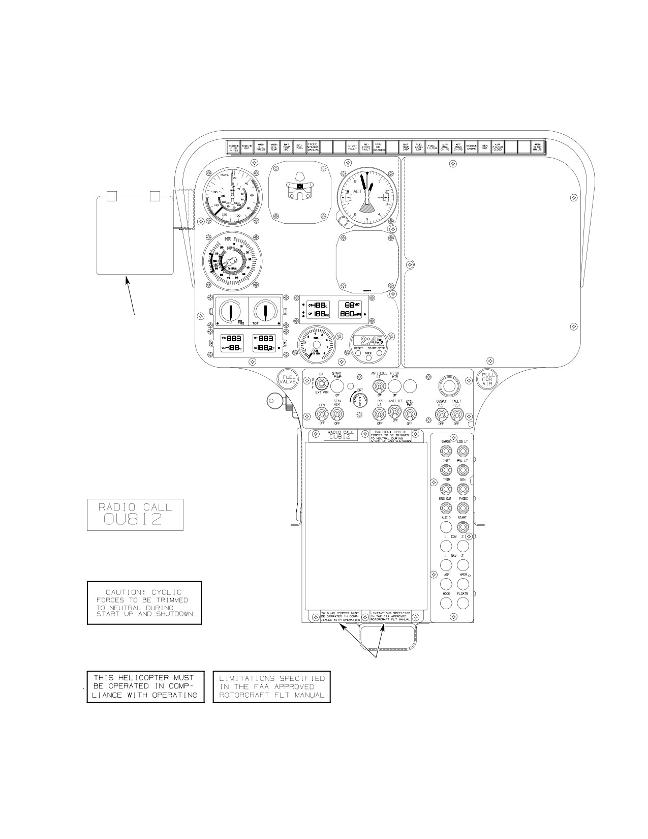
1. RADIO CALL
2. CYCLIC FORCES
3
3. HELICOPTER LIMITATIONS
6G11-012-1
Figure 203. Instrument Panel Placards and Markings (Sheet 1 of 2)
Page 210
Revision 23
11-40-00
MD Helicopters, Inc.
CSP-HMI-2
MAINTENANCE MANUAL
VNE CARD HOLDER
1. RADIO CALL
2. CYCLIC FORCES
3
3. HELICOPTER LIMITATIONS
6G11-012-2
Figure 203. Instrument Panel Placards and Markings (Sheet 2 of 2)
Page 211
11-40-00
Revision 23
CSP-HMI-2
MD Helicopters, Inc.
MAINTENANCE MANUAL
This Page Intentionally Left Blank
Page 212
Revision 44
11-40-00

MD Helicopters, Inc.
CSP-HMI-2
MAINTENANCE MANUAL
Chapter
12
Servicing
MD Helicopters, Inc.
CSP-HMI-2
MAINTENANCE MANUAL
TABLE OF CONTENTS
Para/Figure/Table
Title
Page
12-00-00 Helicopter Servicing
A
Servicing
301
1.
Servicing (General)
301
2.
Servicing (Special)
301
A. Main Rotor Hub Wash Procedure
301
B. Main Rotor Blades Washing and Waxing
301
C. Engine Compressor Wash
301
3.
Fuel System Servicing
301
A. Fuel System Servicing Precautions
301
B. Approved Fuels
301
C. Fuel System Filling
301
D. Fuel System Draining
302
E. Fuel System Bleeding
302
F. Engine Fuel Filter Replacement
302
4.
Engine Oil System Servicing
302
A. Approved Lubricants
302
B. Engine Oil Changing
302
C. Engine Oil System Filling
302
D. Engine Oil System Draining (Helicopters With Sta. 137.50 Bulkhead Drain
Ports Installed)
302
E. Engine Oil System Draining (Helicopters with Drain Valve Installed)
303
F. Engine Oil System Flushing
303
5.
Main Rotor Transmission Servicing
303
A. Main Rotor Transmission Filling
303
Figure 301. Servicing Points - Standard Equipment
304
Figure 302. Servicing Points - Optional Equipment
305
B. Main Rotor Transmission Draining
306
C. Main Rotor Transmission Oil System Flushing
306
6.
Tail Rotor Transmission Servicing
306
A. Tail Rotor Transmission Filling
306
B. Tail Rotor Transmission Draining
306
C. Tail Rotor Transmission Flushing
306
7.
Anti-Torque Fan Transmission Servicing
307
A. Anti-Torque Fan Transmission Filling
307
B. Anti-Torque Fan Transmission Draining
307
C. Anti-Torque Fan Transmission Flushing
307
Page i
12 Contents
Revision 23
CSP-HMI-2
MD Helicopters, Inc.
MAINTENANCE MANUAL
TABLE OF CONTENTS (Cont.)
Para/Figure/Table
Title
Page
8. One-Way Lock Control System Servicing
307
9. Overrunning Clutch Servicing and Oil Leak Analysis
307
Figure 303. Checking Oil Level - Overrunning Clutch
309
10. Miscellaneous Component Servicing
310
A. Rotor Brake Servicing
310
B. Landing Gear Damper Servicing
310
C. Component Lubrication Chart
310
D. Tail Rotor Swashplate Dual Bearings Repack
310
E. Main Rotor Swashplate Bearing Repack
310
F. Main Rotor Hub Tapered Bearings
310
G. Ground Handling Wheels Bearing Repack
310
11. Overrunning Clutch Subassembly Bearing Repack
310
12. Component Fluid Leak Analysis
311
A. Main Rotor Transmission or Anti-Torque Transmission Oil Leaks
311
B. Engine Oil Leaks
311
C. Landing Gear Damper Hydraulic Fluid Leak
311
D. One-Way Lock Hydraulic Fluid Leak
311
Figure 304. Lubrication Chart
312
Page ii
Revision 32
12 Contents
MD Helicopters, Inc.
CSP-HMI-2
MAINTENANCE MANUAL
Section
12−00−00
Helicopter Servicing
MD Helicopters, Inc.
CSP-HMI-2
MAINTENANCE MANUAL
HELICOPTER SERVICING
SERVICING
1. Servicing (General)
Fuel Cell Capacities 600N
Total Fuel
116.2 U.S. Gal. (440 Liters)
Servicing of helicopter includes replenishment
of fuel, changing or replenishment of oil and
Usable Fuel
114.6 U.S. Gal. (434 Liters)
other such maintenance functions.
A. Fuel System Servicing Precautions
For locations of servicing points of standard
Comply with following precautions when
equipment Refer to Figure 301. For optional
servicing fuel system.
equipment servicing points Refer to
Figure 302. For lubrication points Refer to
Turn off electrical switches
Figure 304.
WARNING
and disconnect any external
power from helicopter. Electrically
NOTE: The servicing intervals designated
ground helicopter prior to refueling or
herein are the maximum allowable and
defueling. Static discharge spark in
should not be exceeded. When unusual local
presence of fuel vapors can cause fire
conditions such as environmental condi
or an explosion.
tions, utilization, etc., dictate, it is the pre
rogative and responsibility of the operator to
(1). Refueling vehicle should be parked a
increase the scope and frequency of the in
minimum of 20 ft. (6 M) from helicopter
spections as necessary to ensure safe opera
during fueling operation.
tion.
(2). Before starting fueling operation,
always ground fueling nozzle or fuel
2. Servicing (Special)
truck to GROUND HERE receptacle or
Whenever helicopter operation has taken place
to another bare metal location.
over or around salt water environments and
B. Approved Fuels
other environments found to be corrosive, the
following wash procedures must be performed.
Service the helicopter with one of the autho
rized fuels listed in the applicable Allison
A. Main Rotor Hub Wash Procedure
Engine Operation and Maintenance Manual
(Ref. Table 201, Sec. 01-00-00). For operation
(Ref. Main Rotor Hub Corrosion Prevention
under emergency conditions where authorized
Tri-Flow Wash Procedure, Sec. 20-40-00)
fuel is not available, or for operation under
cold weather conditions, refer to same manual.
B. Main Rotor Blades Washing and Waxing
C. Fuel System Filling
(Ref. Main Rotor Blades Corrosion Arresting,
Sec. 20-40-00)
The fuel system has two fuel cells that are
interconnected for simultaneous flow and
C. Engine Compressor Wash
venting. Fuel system filler is on right side of
helicopter.
(Ref. Chap. 71 and applicable Allison Engine
Operation and Maintenance Manual, Table
(1). Refuel helicopter with correct fuel as
201, Sec. 01-00-00)
soon after landing as possible to
prevent moisture condensation and to
3. Fuel System Servicing
keep helicopter as heavy as possible in
case of winds.
Fuel Cell Capacities 369D/E/FF − 500N
Nonself−Sealing
64.0 U.S. Gal. (242 Liters)
(2). Keep fueling nozzle free of all foreign
Usable Fuel
62.7U.S. Gal. (237 Liters)
matter.
Self−Sealing
62.0 U.S. Gal. (234 Liters)
(3). Check filler cap for security after
Usable Fuel
60.7 U.S. Gal. (229 Liters)
fueling.
Page 301
12-00-00
Revision 23
CSP-HMI-2
MD Helicopters, Inc.
MAINTENANCE MANUAL
D. Fuel System Draining
NOTE: If the type of engine oil or the oil group
is changed, remove and inspect the oil filter
Fuel draining should be accomplished with
each 25 hours of engine operation (Ref.
helicopter as level as possible.
applicable Allison Engine Operation and
Maintenance Manual for further informa
(1). Fuel system may be defueled in either
tion).
of two ways:
B. Engine Oil Changing
To avoid possible damage to fuel
(Ref. Applicable Allison Engine Operation and
CAUTION
pump, do not operate fuel pump
Maintenance Manual, Table 201, Sec.
with fuel tanks drained.
01-00-00)
C. Engine Oil System Filling
(a). Defuel through filler port using a
pump.
The engine oil tank filler is on the right side of
the helicopter. A liquid level sight gauge for
(b). Open system drain valves on fuselage
checking oil level in tank is visible through a
underside and in engine compart
transparent window near the filler.
ment.
NOTE:
D Before adding oil, the oil container must
(2). Fuel supply line drain valves are spring
be shaken to ensure proper mixture of the
loaded type and open by pushing valve
anti-foaming additive.
and attached drain line.
D If sight gauge does not permit positive de
(3). Fuel cells drain valve is spring-loaded
termination, remove filler cap and visual
closed and is opened by pressing
ly check the oil level.
internal plunger.
(1). Check oil level within 15 minutes of
engine shutdown; replenish if low.
E. Fuel System Bleeding
(2). If engine oil level is low after helicopter
(Ref. Chap. 28 and applicable Allison Engine
has set for more than 15 minutes;
Operation and Maintenance Manual, Table
(a). Run engine for at least 1 minute at
201, Sec. 01-00-00) Purge entrapped air from
ground idle.
the fuel system, if necessary.
Ensure engine oil pressure is at
CAUTION
F. Engine Fuel Filter Replacement
tained when starting engine
(Ref. applicable Pilot's Flight Manual).
(Ref. Applicable Allison Engine Operation and
(b). Shut down engine, check oil level,
Maintenance Manual, Table 201, Sec.
replenish if low.
01-00-00)
NOTE:
4. Engine Oil System Servicing
D Motoring engine can draw oil from the oil
tank to the gearbox, giving low oil level
Oil Tank Capacity
3.0 U.S. Qt. (2.84 Liter)
indications.
D If engine oil level indicates a low condi
A. Approved Lubricants
tion after setting overnight, engine check
valve may be leaking oil from tank to en
Service the helicopter with one of the autho
gine gearcase.
rized oils listed.
(3). Ensure oil tank filler cap is securely
For operation under emergency conditions
tightened immediately after servicing.
where different oils must be mixed, or for
D. Engine Oil System Draining (Helicopters
operation under cold weather conditions, use
With Sta. 137.50 Bulkhead Drain Ports
alternate lubricants (Ref. applicable Allison
Installed)
Engine Operation and Maintenance Manual,
Table 201, Sec. 01-00-00).
(1). Open engine access doors.
Page 302
Revision 23
12-00-00
MD Helicopters, Inc.
CSP-HMI-2
MAINTENANCE MANUAL
(2). Place suitable container under engine
(1). Drain oil from engine, oil tank and oil
oil tank drain and remove engine oil
cooler (Ref. Engine Oil System Drain
tank filler cap.
ing).
(3). Remove engine oil tank drain cap.
(2). Replace engine oil filter(s) (Ref. Appli
cable Allison Operation and Mainte
(4). After draining oil from tank, reinstall
nance Manual).
engine oil tank drain cap and filler cap.
(3). Refill engine oil system (Ref. Engine Oil
(5). To drain residual oil from engine
System Filling).
accessory gearbox drain, remove wire
lead and lower chip detector. Use
(4). Operate engine for five minutes and
suitable container to catch oil. Check
repeat above procedures.
that detector O-ring is serviceable
5. Main Rotor Transmission Servicing
(replace as required); reinstall detector;
torque to 50 - 60 inch-pounds (5.65 -
Service the helicopter with one of the autho
6.78 Nm); lockwire and reconnect wire
rized oils listed (Ref. Sec. 91-00-00).
lead.
NOTE: Mobil oil AGL can be formulated such
E. Engine Oil System Draining (Helicopters
that it may have two different colors. The oil
with Drain Valve Installed)
can still be mixed with no adverse affects.
(1).
Remove interior trim and aft bulkhead
Main Transmission Capacities
right access cover.
369D25100
12.0 U.S. Pt. (5.67 Liter)
369F5100
14.0 U.S. Pt. (6.62 Liter)
(2).
Place a suitable container under
overboard oil drain line where it exits
A. Main Rotor Transmission Filling
fuselage underside at firewall.
Transmission (gearbox) oil should be replaced
(3).
Remove cap from engine oil tank filler.
with new oil whenever it is drained. A liquid
Pull out knurled spring-loaded button
level sight gauge for checking main rotor
to open valve in engine oil drain line
transmission oil level is located on the
just below engine oil cooler (Ref.
right-hand side and visible through the clear
Figure 301). Rotate button and valve
panel of the main transmission interior cover.
poppet so that locking pin rests on
NOTE:
shoulders of pin slot.
D Replacement of oil pump filter (Ref. Sec.
(4).
After draining oil from tank, reinstall
63-21-00) is required after oil is drained
filler cap and close oil drain valve;
from main rotor transmission and at in
ensure that poppet pin is in stop slot.
tervals specified (Ref. Sec. 05-20-20).
(5).
Reinstall access cover and interior trim.
D If oil was drained from transmission cool
er, ground-operate helicopter for 15 min
(6).
To drain residual oil from engine
utes after replenishing oil (Ref. applicable
accessory gearbox drain, remove wire
PFM, Table 201, Sec. 01-00-00). Recheck
lead and lower chip detector (Ref. Sec.
oil level at liquid level sight gauge and re
79-00-00). Use suitable container to
plenish as necessary. This purges air from
catch oil. Check that detector O-ring is
oil cooling system and ensures that entire
serviceable (replace as required);
oil cooling system is full.
reinstall detector, torque to 50 - 60
inch-pounds (5.65 - 6.78 Nm) and
(1). Replenish with correct oil until oil level
reconnect wire lead.
is at FULL on sight gauge by lifting
breather-filler cap and inserting spout
F. Engine Oil System Flushing
of oil can into opening.
The following procedure is for flushing oil that
(2). Check that spring-loaded cap closes
has been contaminated or when changing the
when oil can spout is removed. Replace
type of oil.
trim cover.
Page 303
12-00-00
TR12-001
CSP-HMI-2
MD Helicopters, Inc.
MAINTENANCE MANUAL
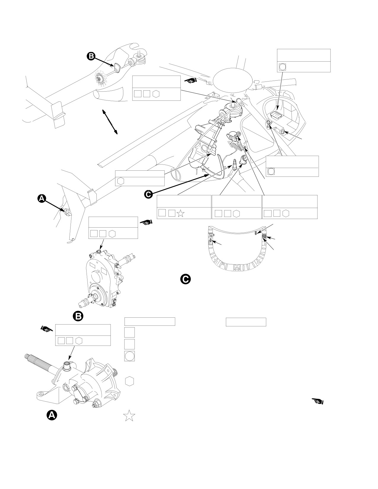
BATTERY ELECTROLYTE
WATER
MAIN XMSN FILLER
MIL-L-23699/MOBIL AGL
PF
NOTE 1
EXTERNAL POWER
RECEPTACLE
ONE-WAY LOCK
RESERVOIR MIL-H-5606
FUEL FILTER 5 MICRON
FUEL CELL SUMP DRAIN
L/G DAMPERS, 4 PLACES
FUEL SYSTEM FILLER
ENGINE OIL TANK FILLER
NITROGEN/MIL-H-5606
JP4/JP5
MIL-L-23699
PF
PF
NOTE 2
PF
NOTES 1, 2
FAN XMSN FILLER
FAN GEARBOX
MIL-L-23699/MOBIL AGL
DRAIN (500/600N)
PF
NOTE 1
ENGINE OIL
TRANS. OIL
COOLER DRAIN
COOLER DRAIN
ENGINE OIL
TANK DRAIN
OIL DRAINS FOR MAIN TRANSMISSION, ENGINE OIL COOLERS,
NOTES:
ENGINE OIL TANK AND FAN GEARBOX
1.
DO NOT MIX OILS.
2.
REFER TO APPLICABLE ALLISON OPERATION MAINTENANCE
MANUAL FOR FREQUENCY OF OIL CHANGE, AUTHORIZED
FUELS AND OILS AND SERVICE CHECKS.
FAN TRANSMISSION
FREQUENCY SYMBOL
REQUIREMENTS
BREATHER FILLER
MIL-L-23699/MOBIL AGL
DAILY
1.
INSPECT PRIOR TO FIRST FLIGHT OF THE DAY
PF
NOTE 1
PF
PREFLIGHT
1.
INSPECT PRIOR TO EACH FLIGHT
100 HOURS
1.
REMOVE BATTERY AND SERVICE PER THE MANUFACTURER'S
MAINTENANCE MANUAL
2.
INSPECT AND REPLENISH ONE-WAY LOCK RESERVOIR AS
APPLICABLE
YEARLY
1.
DRAIN AND REFILL T/R GEARBOX, FAN TRANSMISSION
300 HRS / YEARLY . . 2.
DRAIN AND REFILL 369D25100 M/R G/B SERVICED WITH
MIL-L-23699;
REPLACE OIL FILTER ELEMENT
600HRS / YEARLY . . 3.
DRAIN AND REFILL 369D25100 M/R G/B SERVICED WITH MOBIL
AGL
TAIL ROTOR
OR 369F5100 M/R G/B; REPLACE OIL FILTER ELEMENT
TRANSMISSION
3.
REPLACE ENGINE FUEL FILTER (5 MICRON)
G12-0001D
ON CONDITION
1
ON CONDITION OR EVERY 9 MONTHS IF ON SHELF
Figure 301. Servicing Points − Standard Equipment
Page 304
TR12-001
12-00-00
MD Helicopters, Inc.
CSP-HMI-2
MAINTENANCE MANUAL
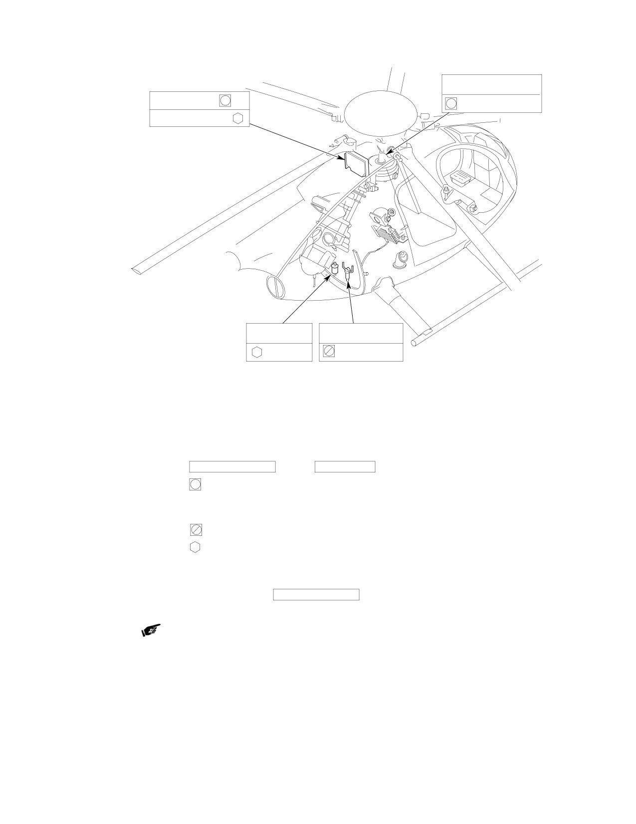
ROTOR BRAKE RESERVOIR
MIL-H-5606
MIST ELIMINATOR
PARTICLE SEPARATOR
ANTI-ICE FILTER
SCAVENGE OIL FILTER
NOTE
NOTE:
APPLICABLE TO ALL ALLISON 250C20R/2 AND C47 ENGINES.
OPTIONAL EQUIPMENT FOR ALLISON 250C20B, C30 ENGINES.
REFER TO ALLISON OPERATION AND MAINTENANCE MANUAL
FOR FILTER ELEMENT REPLACEMENT SCHEDULE.
FREQUENCY SYMBOL
REQUIREMENT
100 HOURS
1.
CHECK ROTOR BRAKE RESERVOIR
FOR
PROPER LEVEL; REPLENISH IF LOW.
2.
REMOVE AND CLEAN THE MIST
ELIMINATOR.
NOTE
3.
REPLACE SCAVENGE OIL FILTER
ELEMENT.
300 HOURS
4.
REPLACE ANTI-ICE FILTER ELEMENT.
SERVICING MATERIAL
5.
REMOVE AND CLEAN PARTICLE
SPEC:
MATERIAL:
SEPARATOR ASSEMBLY.
REF:
MIL-L-23699
LUBRICATING OILS
TABLE 1, 91-00-00
MOBIL AGL
ITEMS CM125 & CM126
JET A/JP4/JP5/JP8
ENGINE FUEL, TURBINE
TABLE 201, 01-00-00
ALLISON OPERATION AND MAINTENANCE MANUAL
G12-0002C
Figure 302. Servicing Points − Optional Equipment
Page 305
12-00-00
TR12-001
CSP-HMI-2
MD Helicopters, Inc.
MAINTENANCE MANUAL
B. Main Rotor Transmission Draining
6. Tail Rotor Transmission Servicing
Service the helicopter with one of the autho
Special Tools
rized oils listed (Ref. Table 1, Sec. 91-00-00).
(Ref. Section 91−00−00)
NOTE: Mobil oil AGL can be formulated such
Item
Nomenclature
that it may have two different colors. The oil
ST301
Main transmission drain hose
can still be mixed with no adverse affects.
Tail Rotor Transmission Capacity
369D25300
0.530 U.S. Pt. (0.250 Liter)
(1).
Remove main rotor transmission cooler
369D25400
0.530 U.S. Pt. (0.250 Liter)
drain cap and drain oil into suitable
container.
A. Tail Rotor Transmission Filling
Tail rotor transmission oil should be replaced
(2).
Remove main rotor transmission drain
with new oil whenever it is drained. A liquid
access covers, wire leads and chip
level sight gauge for checking oil level is
detectors.
located on the transmission housing.
(3).
Using main rotor transmission drain
(1). Check oil level.
hose (ST301), drain oil into suitable
(2). Remove lockwire and unscrew brea
container.
ther-filler cap.
(4).
If damaged, replace O-rings used with
(3). Fill with proper oil by pouring oil into
chip detectors and self-closing valves.
transmission until oil level shows
FULL on sight gauge.
(5).
If removed, reinstall self-closing valve.
(4). Check that filler O-ring is serviceable
Torque valve to 50 - 60 inch-pounds
(replace if necessary). Reinstall brea
(5.65 - 6.78 Nm) and chip detector to
ther-filler and torque to 45 - 55
40 - 50 inch-pounds (4.52 - 5.65
inch-pounds (5.08 - 6.21 Nm) with
Nm). Lockwire valve to gearbox and
breather hole aft (Ref. Sec. 63-25-10)
detector to valve. Reconnect wire leads.
at completion of torquing. Secure with
lockwire.
(6).
Reinstall main rotor transmission
access covers.
B. Tail Rotor Transmission Draining
(1). Position suitable container under tail
C. Main Rotor Transmission Oil System
rotor transmission drain.
Flushing
(2). Remove wire lead, lockwire, chip
The following procedure is for flushing oil that
detector and self-closing valve (Ref.
has been contaminated or when changing the
Sec. 63-25-10).
type of oil.
(3). If damaged, replace O-rings used with
chip detector and self-closing valve.
(1). Drain oil from transmission and oil
cooler (Ref. Main Rotor Transmission
(4). After oil drains, install self-closing
Draining).
valve. Torque valve to 50 - 60 inch-
pounds (5.65 - 6.78 Nm) and chip
(2). Replace transmission oil filter (Ref. Sec.
detector to 40 - 50 inch-pounds (4.52
63-21-00, Main Transmission Filter
- 5.65 Nm). Lockwire valve to gearbox
Replacement).
and detector to valve; reconnect wire
leads.
(3). Refill transmission oil system (Ref.
C. Tail Rotor Transmission Flushing
Main Rotor Transmission Filling).
The following procedure is for flushing oil that
(4). Operate aircraft for five minutes, shut
has been contaminated or when changing the
down and repeat steps (1). thru (3).
type of oil.
Page 306
TR12-001
12-00-00
MD Helicopters, Inc.
CSP-HMI-2
MAINTENANCE MANUAL
(1). Drain oil from tail rotor transmission
transmission drain and remove cap.
(Ref. Tail Rotor Transmission Drain
(Ref. Figure 301).
ing).
(4). After draining oil from transmission,
(2). Refill tail rotor transmission (Ref. Tail
reinstall drain cap.
Rotor Rotor Transmission Filling).
C. Anti−Torque Fan Transmission Flushing
(3). Operate aircraft for five minutes, shut
The following procedure is for flushing oil that
down and repeat steps (1). and (2).
has been contaminated or when changing the
type of oil.
7. Anti−Torque Fan Transmission Servicing
(1). Drain oil from fan transmission (Ref.
Service the helicopter with one of the autho
Anti-Torque Fan Transmission Drain
rized oils listed (Ref. Sec. 91-00-00).
ing).
NOTE: Mobil oil AGL can be formulated such
(2). Refill fan transmission (Ref. Anti-
that it may have two different colors. The oil
Torque Fan Transmission Filling).
can still be mixed with no adverse affects.
(3). Operate aircraft for five minutes, shut
Fan Transmission Capacity
8 U.S. Oz. (236 cc)
down and repeat steps (1). and (2).
A. Anti−Torque Fan Transmission Filling
8. One−Way Lock Control System Servicing
Anti-torque fan transmission oil should be
Service the helicopter with one of the autho
replaced with new oil whenever it is drained. A
rized hydraulic oils listed (Ref. Sec. 91-00-00).
liquid level sight gage for checking oil level is
located on the transmission housing.
One−Way Lock Capacity
0.67 U.S. Oz. (20 cc)
(1). To check oil level, remove control access
(1). Check oil level.
cover.
(2). If servicing is required, remove fan
NOTE: Reservoir should be 1/2 to 3/4 full.
inlet screen and fan hub transmission
fairing.
(2). If oil level in reservoir is low, lift filler
cap and add oil as needed.
(3). Remove lockwire and remove filler
plug.
(3). Reinstall pilot's seat cover.
(4). Fill by pouring oil into transmission
NOTE: If oil level is consistently low, one-way
filler plug hole, until oil level shows
lock should be repaired to stop oil leakage
FULL on sight gauge.
(Ref. Component Overhaul Manual).
(5). Check that plug O-ring is serviceable
9. Overrunning Clutch Servicing and Oil
(replace as required). Reinstall filler
Leak Analysis
plug and torque to 45 - 55 inch-
pounds (5.08 - 6.21 Nm). Secure with
(Ref. Figure 303) When oil leakage or seepage
lockwire.
is noticed at oil seals or assembly joint lines of
overrunning clutch, clutch requires further
B. Anti−Torque Fan Transmission Draining
inspection and investigation as follows.
(1). Remove fan inlet screen and transmis
NOTE: Mobil oil AGL can be formulated such
sion fairing.
that it may have two different colors. The oil
can still be mixed with no adverse affects.
(2). Cut lockwire and remove fan transmis
Overrunning Clutch Capacities
sion filler plug.
369A5350−11, −21, −31
1.52 U.S. Oz. (45cc)
(3). Open engine access doors and place
369A5350−41, −51
1.01 U.S. Oz. (30 cc)
suitable container under the fan
369F5450
3.64 U.S. Oz. (110 cc)
Page 307
12-00-00
TR12-001

CSP-HMI-2
MD Helicopters, Inc.
MAINTENANCE MANUAL
(b). Read scale to determine oil level and
Consumable Materials
servicing required. Full oil level is
(Ref. Section 91−00−00)
indicated by oil level of 2 7/8 inches
Item
Nomenclature
(7.30 cm) on scale. Minimum allow
able quantity (13 cc) is 7/8 inch
CM112
Anti-seize compound high temperature
(22.23 mm) on scale. Recheck reading
CM125
Oil
a minimum of three times.
CM126
Oil, turbine
If oil quantity is less than 7/8
CAUTION
inch (22.23 cm) on scale, the
CAUTION
clutch subassembly must be removed and
inspected for evidence of overheating (Ref.
D Checking clutch oil level requires removal
CSP-DEF-5).
of main rotor transmission drive shaft.
Use care not to stress drive shaft dia
(6). For a 369F5450 clutch, there is two
phragms (early type) or flexible couplings
methods for checking the oil level:
(current type) during removal and instal
lation. Deflection in these areas are lim
ited due to material hardness.
(a). First Method: Full oil level is indi
cated by oil level of 3 1/8 inches (9.84
D The 369F5450 clutch is only to be serviced
cm) on a 6 inch (15 cm) machinists
with Mobil AGL oil (CM125).
scale, 1/2 inch (12.7 mm) width,
inserted into clutch exactly 5 inches
D The 369A5350 clutch is only to be ser
(12.7 cm). Minimum allowable
viced with MIL-L-23699 oil (CM126).
quantity (60 cc) is 5/8 inch (15.88
mm) on scale. Recheck reading a
(1). Remove trim and blower access door.
minimum of three times.
(2). Remove main rotor transmission drive
shaft (Ref. Sec. 63-10-00). Carefully
(b). Second Method: Full oil level is
slide shaft from drive couplings; do not
indicated by oil level of 4 5/8 inches
strike shaft against any object.
(11.77 cm) on a 12 inch (30 cm)
machinists scale, 1/2 inch (12.7 mm)
(3). Remove coupling bolt and O-ring from
width, inserted to bottom of inner
end of clutch.
race. Minimum allowable quantity
(60 cc) is 2 1/8 inch (5.40 cm) on
(4). Check that the three drain holes in
scale. Recheck reading a minimum of
clutch housing are clean and free of
three times.
obstruction. Oil leakage may indicate
engine power output seal leakage if
If oil quantity is less than 5/8
clutch oil level is checked and within
CAUTION
inch (15.88 mm) on scale for the
limits.
first method or 2 1/8 inches (5.40 cm) for the
second method, the clutch subassembly
(5). For a 369A5350 Clutch:
must be removed and inspected for evidence
of overheating.
(a). Using a clean 6 inch (15 cm) machi
nists scale, 1/2 inch (12.7 mm) width,
(7). Service clutch with lubricating oil
slowly insert scale into center of
(CM125 or CM126). If oil level readings
clutch output shaft until scale
indicate less than full level. Do not
bottoms. Scale must be inserted 4 7/8
overfill. Recheck oil level as in previous
inches (12.38 cm).
step.
NOTE: Trim edge of scale as required to reduce
width of scale and allow scale to bottom in
NOTE: Always check oil level after installing
clutch.
clutch in the helicopter.
Page 308
TR12-001
12-00-00
MD Helicopters, Inc.
CSP-HMI-2
MAINTENANCE MANUAL
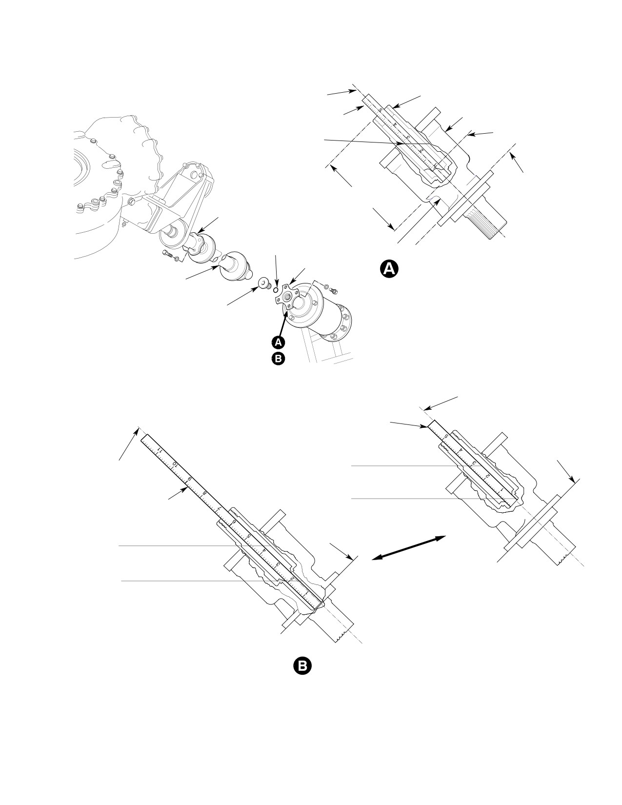
CLUTCH CENTERLINE
CLUTCH OUTPUT SHAFT
SCALE
CLUTCH
MINIMUM OIL LEVEL
FULL OIL LEVEL
7/8 IN. (22.23 MM)
2-7/8 IN. (7.30 CM)
ENGINE
4-7/8 IN. (12.38 CM)
SCALE BOTTOMED
COUPLING
DRAIN HOLES
O-RING
COUPLING
369A5350 CLUTCH OIL
MAIN TRANSMISSION
LEVELS - SCALE INDICATIONS
DRIVE SHAFT
COUPLING BOLT
CLUTCH CENTERLINE
SCALE
ENGINE
3 1/8 IN.
“FULL” OIL LEVEL
CLUTCH
(9.84 CM)
110 CC
CENTERLINE
5/8 IN.
MINIMUM OIL LEVEL
SCALE
(15.88 MM)
60 CC
4 5/8 IN.
“FULL” OIL LEVEL
ENGINE
(11.77 CM)
110 CC
2 1/8 IN.
MINIMUM OIL LEVEL
6 INCH (15 CM) SCALE METHOD
(5.40 CM)
60 CC
12 INCH (30 CM) SCALE METHOD
369F5450 CLUTCH
OIL LEVELS - SCALE INDICATIONS
G12-3001B
Figure 303. Checking Oil Level − Overrunning Clutch
Page 309
12-00-00
Revision 23
CSP-HMI-2
MD Helicopters, Inc.
MAINTENANCE MANUAL
(8). If coupling shimming was disturbed,
C. Component Lubrication Chart
shim coupling so that there is
(Ref. Figure 304 for required lubrication
0.035-0.055 inch (0.889-1.397 mm)
points, lubricants to be used, and lubrication
O-ring gap. (Ref. Sec. 63-10-00 for
intervals.)
clutch installation and shimming
requirement details.)
Use extreme care when apply
CAUTION
ing any type of lubrication
When installing clutch coupling
(grease, oil, dry-film, etc) in vicinity of te
CAUTION
bolt in next step, installation
flon bearings. Most lubricants allow a dirt-
torque on the bolt must not be less than 250
retaining film to form or have other detri
- 300 inch-pounds (28.25 - 33.90 Nm)
mental effects that can cause rapid
plus drag torque. Torquing to lower value
deterioration of bearing surface.
reduces clutch bearing clamp-up and may
result in bearing race spinning.
D. Tail Rotor Swashplate Dual Bearings
Repack
(9). Coat bolt threads with oil (CM112).
Check ball bearing for excessive loss of grease
Install coupling bolt and O-ring (Drag
and serviceability and relubricate (repack)
torque for bolt self-locking serviceabili
(Ref. Sec. 64-30-00).
ty is 25 inch-pounds (2.82 Nm)
minimum, 200 inch-pounds (22.60
E. Main Rotor Swashplate Bearing Repack
Nm) maximum). Torque bolt to 250 -
300 inch-pounds (28.25 - 33.90 Nm)
Check seals for evidence of deterioration and
plus actual drag torque.
grease leakage. Inspect bearing assembly for
serviceability and repack (Ref. COM, Sec.
(10). Position main rotor transmission drive
62-30-10).
shaft between drive couplings. Install
F. Main Rotor Hub Tapered Bearings
four bolts and washers each end of
drive shaft and torque bolts to 50 - 75
Clean, inspect, and relubricate (repack). (Ref.
inch-pounds (5.65 - 8.47 Nm).
Sec. 62-20--00).
(11). Reinstall blower access door and trim.
G. Ground Handling Wheels Bearing Repack
10. Miscellaneous Component Servicing
Consumable Materials
(Ref. Section 91−00−00)
A. Rotor Brake Servicing
Item
Nomenclature
CM111
Grease, aircraft
(Ref. Sec. 63-22-00 for information on adding
hydraulic fluid to the rotor brake master
cylinder and bleeding the hydraulic system.)
At regular intervals, repack wheel bearings
with grease (CM111).
B. Landing Gear Damper Servicing
11. Overrunning Clutch Subassembly Bearing
Repack
Servicing of the landing gear damper is
performed by overhauling the damper assem
For 369A5350 overrunning clutch, repack
bly, or if equipped with schrader valve,
bearing per CSP-COM-5, Sec. 63-10-10.
servicing with nitrogen if it does not meet the
minimum extension requirements (Ref.
For 369F5450 overrunning clutch, repack
32-10-00).
bearing per CSP-COM-5, Sec. 63-10-15.
Page 310
Revision 32
12-00-00
MD Helicopters, Inc.
CSP-HMI-2
MAINTENANCE MANUAL
12. Component Fluid Leak Analysis
01-00-00) for definition of permissible engine
oil leakage.
A. Main Rotor Transmission or Anti−Torque
Transmission Oil Leaks
C. Landing Gear Damper Hydraulic Fluid
Leak
Oil leakage, seepage, or capillary wetting at oil
seals or assembly joint lines of main or
Hydraulic fluid leakage from any of landing
anti-torque transmissions are permissible if
gear dampers is not permissible. If leakage is
leakage rate does not exceed 2 cc per hour (one
present, damper assembly should be over
drop per minute). An acceptable alternate rate
hauled (Ref. Component Overhaul Manual) as
of leakage from either transmission is, if oil
required and a serviceable unit installed. If
loss is not more than from the full to the add
leaking landing gear damper is not replaced
mark on the sight gauge within 25 flight hours
when leakage is noticed, continuation of
(Repair leaks according to instructions in
damper in service can result in unequal and/or
Component Overhaul Manual).
unacceptable dampening and/or ground
resonance.
NOTE:
D On gearbox oil seals with less than 2
NOTE: It is normal for a thin hydraulic oil film
hours of operation, some seepage or wet
to remain on damper piston as a result of
ting of adjacent surfaces is normal until
wiping contact with piston seal. Newly in
seal is wetted and worn-in (seated). If
stalled dampers may also have slight oil
seepage continues at rate of one drop per
seepage from oil trapped in end cap threads
minute or less, seal may be continued in
during damper assembly. Neither of these
service. Check transmission oil level and
should be considered damper leakage or
observe seepage rate after every 2 hours
cause for damper replacement.
of operation. Shorter inspection periods
may be required if seal leakage appears to
D. One−Way Lock Hydraulic Fluid Leak
be increasing.
Hydraulic fluid leakage from any part of
D If excessive gearbox oil seepage occurs,
one-way lock is not permissible. When leakage
check breather filler for proper installa
is observed, assembly should be overhauled
tion and operation (Ref. Component Over
(Ref. Component Overhaul Manual) as
haul Manual for cleaning procedures).
required and a serviceable unit installed. If
leaking one-way lock is not replaced when
B. Engine Oil Leaks
leakage occurs, continuation in service may
(Ref. Applicable Allison Engine Operation and
result in mechanical malfunction that could be
Maintenance Manual (Ref. Table 201, Sec.
hazardous to flight safety.
Page 311
12-00-00
Revision 32
CSP-HMI-2
MD Helicopters, Inc.
MAINTENANCE MANUAL
NOTE 2
NOTE 5
+
NOTE 3
NOTE 4
NOTE 3
NOTE 1
SYMBOL
SPECIFICATION
300 HOURS
1200 HOURS
NOTES:
1.
T/R SWASHPLATE DUPLEX BEARINGS
2770 HOURS OR 2 YEARS
2.
M/R SWASHPLATE BEARING
3.
M/R HUB TAPERED BEARINGS
4.
OVERRUNNING CLUTCH ASSEMBLY UPPER BEARINGS
HAND PACK
5.
YSAS ACTUATOR
G12-0003A
Figure 304. Lubrication Chart
Page 312
Revision 23
12-00-00

MD Helicopters, Inc.
CSP-HMI-2
MAINTENANCE MANUAL
Chapter
18
Vibration and Noise
Analysis
MD Helicopters, Inc.
CSP-HMI-2
MAINTENANCE MANUAL
TABLE OF CONTENTS
Para/Figure/Table
Title
Page
18-10-00 Main Rotor Track and Balance
A
Maintenance Practices
201
1. Main Rotor Blade Tracking
201
A. Main Rotor Hub Balancing
201
B. Main Rotor System Balancing
201
C. Balancing Equipment and Balance Spare Kit
202
Table 201. Isolating Tracking Problems
202
Removal/Installation
401
1. Main Rotor System Tracking Equipment Installation
401
A. Interrupter Installation
401
B. Magnetic Pickup Installation
402
C. Tracking Tip Cap Installation
402
D. Main Rotor System Balancing Equipment Installation
402
Figure 401. Blade Tracking Equipment
403
Figure 402. Main Rotor Balancing Equipment Installation
404
Adjustment/Test
501
1. Blade Tracking Procedure
501
Figure 501. Typical Track Conditions and Adjustments
501
A. Blade Track Adjustment
502
B. Pitch Control Link Adjustment
502
C. Blade Tab Adjustment
502
D. Main Rotor Ground Tracking
502
E. Hover Track Verification
503
Figure 502. Main Rotor Blade Tab Adjustment
504
F. Forward Flight Tracking
505
2. Main Rotor Blade Tab Adjustment
505
3. Main Rotor System Balance Procedure
505
4. Main Rotor Autorotation RPM Check
505
5. Main Rotor Hub Balancing Procedure
506
Table 501. Summary Procedure for Blade Tracking
507
Table 502. Autorotation Rpm Chart (369D/E)
508
Table 503. Autorotation Rpm Chart (369FF/500N)
508
Figure 503. Main Rotor Hub Balancing Chart
509
Figure 504. Main Rotor Hub Balancing
510
18-10-60 Main Rotor Track and Balance (600N)
A
Maintenance Practices
201
1. Main Rotor Blade Tracking
201
Page i
18 Contents
Revision 23
CSP-HMI-2
MD Helicopters, Inc.
MAINTENANCE MANUAL
TABLE OF CONTENTS (Cont.)
Para/Figure/Table
Title
Page
2. Main Rotor System Balancing
201
3. Balancing Equipment and Balance Spare Kit
201
Table 201. Isolating Tracking Problems
202
Removal/Installation
401
1. Main Rotor System Tracking Equipment Installation
401
A. Interrupter Installation
401
B. Magnetic Pickup Installation
401
Figure 401. Blade Tracking Equipment - Main Rotor Components
(Sheet 1 of 2)
402
C. Tracking Tip Cap Installation
403
D. Main Rotor System Balancing Equipment Installation
403
Figure 402. Main Rotor Balancing Equipment Installation
404
Adjustment/Test
501
1.
Blade Tracking Procedure
501
Figure 501. Typical Track Conditions and Adjustments
501
A. Blade Track Adjustment
502
B. Pitch Control Link Adjustment
502
C. Blade Tab Adjustment
502
Figure 502. Adjustment - Main Rotor Blade Tab
503
D. Main Rotor Ground Tracking
503
E. Hover Track Verification
504
F. Forward Flight Tracking
504
2.
Main Rotor System Balance Procedure
505
3.
Main Rotor Autorotation Percentage Check
505
Table 501. Summary Procedure for Blade Tracking
506
Table 502. Autorotation Percentage Chart
506
Figure 503. Main Rotor System Balancing
507
Figure 504. Main Rotor Track at Hover (Pitch Change Link Adjustment)
508
Figure 505. Main Rotor System Balance Chart
509
Figure 506. Main Rotor Tracking at 100 - 130 KIAS
(Inner Tab Adjustment)
510
Figure 507. Main Rotor Tracking at 100 - 130 KIAS
(Mid Tab Adjustment)
511
Figure 508. Main Rotor Tracking at 100 - 130 KIAS
(Outer Tab Adjustment)
512
18-20-00 Tail Rotor Balance
A
Maintenance Practices
201
1. Tail Rotor Balancing
201
Page ii
Revision 23
18 Contents
MD Helicopters, Inc.
CSP-HMI-2
MAINTENANCE MANUAL
TABLE OF CONTENTS (Cont.)
Para/Figure/Table
Title
Page
A. Balance at Blade Tip
201
B. Balance at Blade Pitch Arm
201
C. Short Method Balance Check
202
D. Long Method Balance Check (Four-Bladed Tail Rotor)
202
2. Horizontal Stabilizer Tuning
203
Figure 201. Tail Rotor Assembly Balancing (Two-Bladed Tail Rotor)
204
Table 201. Tail Rotor Balance Weight - Value Chart
205
Figure 202. Short Method Tail Rotor Balancing (Four-Bladed Tail Rotor)
205
Figure 203. Long Method Tail Rotor Balancing (Inboard Blade)
206
Figure 204. Long Method Tail Rotor Balancing (Outboard Blade)
206
18-20-30 NOTARr Anti-Torque System Fan Balance
A
Maintenance Practices
201
1. Fan Balancing
201
2. Fan Balance Check
201
Table 201. Preferred Hardware for Balancing Fan Assembly
202
Figure 201. Fan Balancing Stud Numbering
203
Figure 202. Fan Balance Chart
204
Figure 203. Fan Balancing Equipment Installation
205
Page iii
18 Contents
Revision 23
CSP-HMI-2
MD Helicopters, Inc.
MAINTENANCE MANUAL
TABLE OF CONTENTS (Cont.)
Para/Figure/Table
Title
Page
This Page Intentionally Left Blank
Page iv
Revision 43
18 Contents
MD Helicopters, Inc.
CSP-HMI-2
MAINTENANCE MANUAL
Section
18−10−00
Main Rotor Track
and Balance
MD Helicopters, Inc.
CSP-HMI-2
MAINTENANCE MANUAL
MAIN ROTOR TRACK AND BALANCE
MAINTENANCE PRACTICES
1. Main Rotor Blade Tracking
(e). Forward flight tracking (Ref. For
ward Flight Tracking).
Main rotor blade track is observed by means of
(f). Autorotation rpm adjustment (Ref.
reflective tip caps temporarily installed on
Main Rotor Autorotation RPM
each blade and a high-intensity strobe light.
Check).
Blade track is determined by observing the
apparent tip cap pattern created by strobe
(2). No attempt should be made to verify or
light pulses synchronized with the rotating
adjust blade track without first check
blades. Strobe light electrical power is supplied
ing and adjusting blade phasing, a
by the helicopter electrical system.
function of main rotor damper adjust
ment (Ref. Sec. 62-20-00).
Immediately investigate the
WARNING
Understand the blade tracking
cause of a sudden onset of
CAUTION
sequence and related adjust
excessive or unusual main rotor vibra
ments before attempting blade track proce
tion prior to continued flight. Under no
dures.
circumstance should main rotor track
ing be attempted to correct the prob
If main rotor hub balance is suspect, balance ro
lem until a thorough inspection of the
tor hub prior to performing blade track.
main rotor blades, hub assembly and
A. Main Rotor Hub Balancing
strap pack assembly has been per
formed.
Main rotor hub balancing is accomplished by
adding or removing weight (flat washers) as
When working near engine air
required at the lead-lag bolts (Ref. Main Rotor
CAUTION
inlet, comply with all precau
Hub Balancing Procedure). Analysis of main
tions to prevent entry of foreign material.
rotor hub balance is accomplished using
Carefully observe precautions in the Track
instrumentation that measures and localizes
ing and Balancing Manual relating to the
vibrations due to main rotor hub imbalance.
placement and security of equipment (espe
Data provided by the instrumentation is
cially cables) fastened to the exterior of the
plotted on a chart designed to indicate how
helicopter.
much weight must be added or removed from
the lead-lag bolt. No other means of balancing
NOTE: Refer to Table 201 to isolate ground or
is to be used.
in-flight blade tracking problems.
B. Main Rotor System Balancing
(1). Tracking must be accomplished in the
Main rotor system balancing is accomplished
following sequence of six steps:
by adjusting the turnbuckle on the elastomeric
damper. Analysis of main rotor system balance
(a). Verification of proper blade phasing
is accomplished using instrumentation that
(Ref. Main Rotor Blade Phasing
measures and localizes vibrations due to main
Check and/or Adjustment, Sec.
rotor imbalance (Ref. Main Rotor System
62-20-00).
Balance Procedure). Data provided by the
instrumentation is plotted on a chart designed
(b). Ground tracking (Ref. Main Rotor
to indicate how much rotor blade shall be
Ground Tracking).
shifted in leading or lagging direction by
adjusting turnbuckle. No other means of
(c). Verification of proper rotor balance
balancing is to be used. Never add weight to,
(Ref. Main Rotor System Balance
subtract weight from or redistribute weight on
Procedure).
the main rotor blades. Do not attempt the
blade balancing procedure without first
(d). Hover verification (Ref. Hover Track
tracking the blades (Ref. Blade Tracking
Verification).
Procedure).
Page 201
18-10-00
Revision 23
CSP-HMI-2
MD Helicopters, Inc.
MAINTENANCE MANUAL
C. Balancing Equipment and Balance Spare
Kit
The balancing equipment contains all equip
ment needed to analyze main rotor balance.
Table 201. Isolating Tracking Problems
Symptom
Probable Cause
Corrective Action
GROUND TRACKING
Rotor does not follow adjustments.
Turning turnbuckle wrong direction.
Adjust correctly.
Pitch link bearing worn. Trim tab
Replace bearing. Zero trim tabs.
bent excessively.
Excessive diving or climbing of
Trim tab bent excessively.
Zero trim tabs.
blade from low speed ground track
Pitch link control not coordinated
Set pitch link to 6.25 in. (15.875 cm)
to high speed ground track.
with trim tab bend (Intermixing
nominal and zero trim tabs.
control input).
Damage to blade or tabs.
Inspect for damage.
Excessive torque and erratic high
Pitch change links too long.
Set to nominal 6.25 in. (15.875 cm).
speed ground tracking.
IN−FLIGHT TRACKING
Blade track changes with power
Worn pitch bearing housing
Replace bearings.
and control changes.
bearings.
Missing pitch bearing liner.
Replace bearing.
Broken or loose feathering studs.
Repair or replace studs.
Binding rotating scissor crank at
Repair or replace crank.
lower main rotor hub shoe.
Play between longitudinal pitch
Re−bond collective pitch mixer
mixer bellcrank and collective pitch
bearings and install shims between
mixer bellcrank.
longitudinal pitch mixer bellcrank and
collective pitch mixer bellcrank
bearings (Ref. Sec. 62−30−00).
Helicopter has rough feeling with
Tilted tracking images, no blade in
Retrack blades.
some vibration while appearing to
track.
be in track.
Pitch link control not coordinated
Set pitch link to nominal 6.25 in.
with trim tab bend (intermixing
(15.875 cm) and zero trim tabs.
control input), with climbing or
diving blades within acceptable
track limits.
Page 202
Revision 31
18-10-00
MD Helicopters, Inc.
CSP-HMI-2
MAINTENANCE MANUAL
Table 201. Isolating Tracking Problems (Cont.)
Symptom
Probable Cause
Corrective Action
Blades very erratic in response to
Tab bent too much in wrong area.
Correct by limiting bending.
tab bends.
Blade erosion, but within chordwise
Track erratic blade to other blades.
limits.
Tab bent too many degrees in one
Limit tab bending to smaller degree
area.
over larger area.
Blades climb or dive excessively at
Too much tab bending in outboard
Remove outboard bending and
high speeds.
tab areas.
increase inboard bending.
Ground track off at low speed and
Excessive tab bending and pitch
Zero trim tabs and set pitch links to
stick shake at 103% N2.
link control not coordinated with tab
nominal 6.25 in. (15.875 cm)
bend (intermixing control input).
Helicopter in track but has stick
Blade out of phase.
Check phasing.
shake.
Feedback in collective control.
Main rotor hub out of balance.
Balance hub.
Loose or binding rotating scissors.
Check and repair as required.
Heavy collective stick − climb and
Overcenter adjustment set too low.
Adjust.
cruise.
Trim tab bent down excessively.
Adjust.
Light collective stick − climb and
Overcenter adjustment set too
Adjust.
cruise.
high.
Trim tabs bent up excessively.
Adjust.
Heavy collective lift-off − light flight.
Bungee spring adjusted too short.
Adjust to nominal.
Light collective lift-off − heavy flight.
Bungee spring adjusted too long.
Adjust to nominal.
Page 203
18-10-00
Revision 37
CSP-HMI-2
MD Helicopters, Inc.
MAINTENANCE MANUAL
This Page Intentionally Left Blank
Page 204
Revision 37
18-10-00
MD Helicopters, Inc.
CSP-HMI-2
MAINTENANCE MANUAL
MAIN ROTOR TRACK AND BALANCE
REMOVAL/INSTALLATION
1. Main Rotor System Tracking Equipment
A. Interrupter Installation
Installation
(Ref. Figure 401)
(Ref. Figure 401 and Figure 402) Equipment
(1).
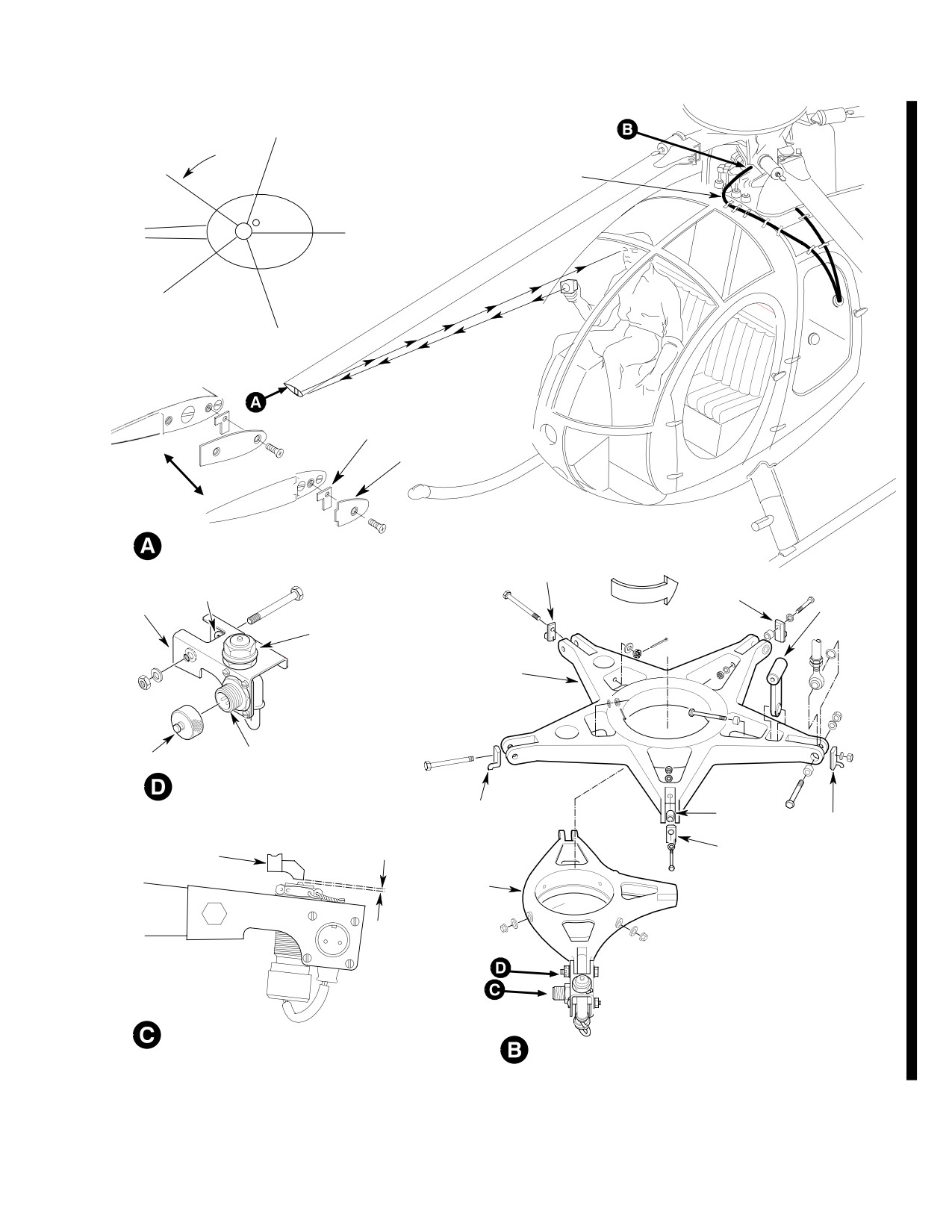
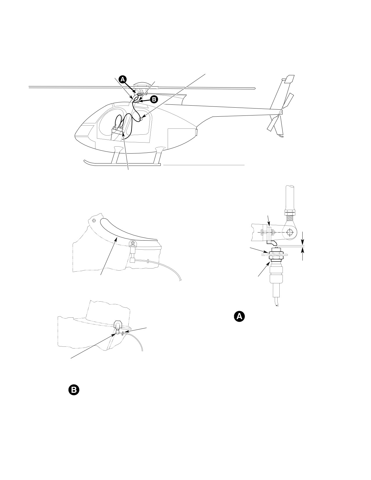
The helicopter is equipped with five
needed to track main rotor blades consists of
main rotor blade tracking interrupters
the main rotor tracking and tail rotor vibration
located immediately inboard of each
analyzer equipment, tracking and balancing
pitch control link attach clevis on the
equipment and the tip cap assembly. Instruc
rotating swashplate.
tions for equipment installation are contained
in Chadwick-Helmuth Operation and Service
(2).
The interrupter installation incorpo
Instruction Handbook.
rates a double interrupter which may
be used for both tracking and balanc
ing.
When working near engine air
CAUTION
inlet, comply with precautions
(3).
Each interrupter insert is attached to
to prevent entry of foreign material. During
the interrupter body at a different
main rotor balancing the helicopter will be
position (left, center, or right). The
airborne. Carefully observe precautions in
interrupters create five equally spaced
the Tracking and Balancing Manual relat
horizontal reflective images, as viewed
ing to the placement and security of equip
by the technician, when the main rotor
ment (especially cables) fastened to the ex
blade tips are illuminated with the test
terior of the helicopter.
strobe light.
(4).
Interrupter blade spacing separates the
NOTE: Main rotor tracking tip caps manufac
tured by the same firm that manufactures
image of each main rotor blade tip cap
the tracking and balance equipment, are
by approximately 0.25 inch (6.35 mm).
components of the tracking and balancing
This staggered relationship allows the
equipment and may be used instead of tip
technician to view the stopped image of
cap assembly. In procedures that follow, use
each blade in order of rotation.
of tip cap assembly is presumed. If tip caps
from the balancing equipment are used, re
(5).
The number one blade is seen on the
fer to the Tracking and Balancing Manual
extreme left, number two blade is seen
for tip cap data.
second from left, and so on through
number five which is seen on the
extreme right.
Special Tools
(6).
On current configuration helicopters,
(Ref. Section 91−00−00)
the pulse of the double interrupter is so
Item
Nomenclature
short that it appears as a single pulse
ST901
Tip cap assembly
to the strobe light amplifier. The second
pulse created by the double interrupter
ST903
Balancer/analyzer instrument kit
is used during main rotor balancing.
Consumable Materials
(7).
If counterweights are installed, coat the
(Ref. Section 91−00−00)
two interrupter bolts passing through
Item
Nomenclature
the swashplate counterweights with
grease (CM116) before installation.
CM116
Grease, aircraft and instrument
Torque nuts to 30 - 60 inch-pounds
(3.39 - 6.78 Nm).
Page 401
18-10-00
Revision 44
CSP-HMI-2
MD Helicopters, Inc.
MAINTENANCE MANUAL
(8). Torque the three remaining interrupter
(6). Ensure the interrupter passing closest
nuts to 15 - 20 inch-pounds (1.69 -
over either early or current configura
2.26 Nm).
tion magnetic pickup, clears pickup by
not less than 0.030 inch (0.762 mm).
B. Magnetic Pickup Installation
C. Tracking Tip Cap Installation
(Ref. Figure 401)
(Ref. Figure 401)
(1).
The helicopter is originally equipped
with a magnetic pickup support bracket
(1). The helicopter is originally equipped
installed with shim washers to prevent
with five tip caps that must be removed
distortion of the bracket when the nut
and replaced with five tracking tip caps
on the bolt that secures the link bearing
(ST901).
is torqued to 30 - 60 inch-pounds
(3.39 - 6.78 Nm).
(2). When blade tracking has been accom
plished or verified, the tracking tip caps
(2).
To preclude rocking movement of
must be removed and original tip caps
magnetic pickup support bracket when
installed.
installed on stationary swashplate,
check clearance between swashplate
(3). Torque the screw that secures the tip
and lower flange of bracket. If gap
cap to 15 - 20 inch-pounds (1.69 -
exists, tap bent tip of lower flange
2.26 Nm).
(typical both sides of bracket) until bent
tip touches swashplate.
NOTE: When installing tip cap targets, posi
(3).
Reinstall by forcing bracket until
tion double interrupter over magnetic pick
elongated bracket holes align with hole
up. The blade positioned forward is number
in stationary swashplate.
5. By rotating rotor head in operating direc
tion, the next blade pointing forward will be
(4).
Install the magnetic pickup and cable
4, then 3, 2 and 1.
as instructed in the Chadwick-Hel
muth Operation and Service Instruc
D. Main Rotor System Balancing Equipment
tion Handbook.
Installation
(5).
After final adjustment, torque the
(Ref. Figure 401 and Figure 402) and Chad
adjustment nut to 15 - 20 inch-
wick-Helmuth Operation and Service Instruc
pounds (1.69 - 2.26 Nm) and ensure
tion Handbook to install that portion of the
the cable is routed and tied down in
balancing equipment (ST903) needed to
such a manner as not to be dislodged or
balance the main rotor.
interfere with control components at
their extremes of travel.
Page 402
Revision 44
18-10-00
MD Helicopters, Inc.
CSP-HMI-2
MAINTENANCE MANUAL
1
ROTATION
PLACE DOUBLE INTERRUPTER
OVER MAGNETIC PICKUP AND
2
THEN ATTACH TIP TARGET
TAPE
NUMBERS EXACTLY AS SHOWN
5
3
4
TRACKING TARGET
(NOTE 1)
TIP CAP
INTERRUPTER
TRACKING TIP CAP INSTALLATION
(NOTE 4)
DOUBLE
ROTATION OF
(NOTE 5)
INTERRUPTER
HUB
(NOTE 4)
SUPPORT
NOTE 2
(NOTE 6)
SCISSORS
BRACKET
LINK
ADJUSTMENT
JAMNUT
ROTATING
SWASHPLATE
TEST EQUIPMENT
PROTECTIVE CAP
CABLE RECEPTACLE
PICKUP INSTALLATION (ROTATED)
INTERRUPTER
SPACER
INTERRUPTER
(NOTE 4)
(NOTE 4)
INTERRUPTER
(NOTE 5)
INTERRUPTER
(NOTE 6)
(NOTE 3)
(NOTE 4)
STATIONARY
(NOTE 6)
SWASHPLATE
NOTES:
1.
ALWAYS REMOVE TARGETS
0.030-0.070 IN.
AFTER TRACKING.
(0.762-1.778 MM)
2.
INSTALL WASHERS BETWEEN
GAP TYP.
BRACKET AND SWASHPLATE
TO FILL GAP.
3.
ADJUST AS REQUIRED FOR
GAP INDICATED.
4.
REFER TO CSP-IPC-4 FOR
INTERRUPTER-TO-MAGNETIC PICKUP GAP
PART NO.
MAGNETIC PICKUP
5.
TORQUE NUT TO 30-60 IN-LBS.
G18-1000C
6
TORQUE NUT TO 15-20 IN-LBS
Figure 401. Blade Tracking Equipment
Page 403
18-10-00
Revision 44
CSP-HMI-2
MD Helicopters, Inc.
MAINTENANCE MANUAL
TAPE CABLE TO RIGHT HAND INBOARD
MAGNETIC PICKUP CABLE AND
SIDE OF INLET HOUSING AND ROUTE
VELOMETER/ACCELEROMETER
VELOMETER/ACCELEROMETER
FORWARD ALONG FUSELAGE AS
LOCATION FOR MAIN ROTOR
CABLE MAY BE ROUTED
SHOWN. CABLE MUST CLEAR AL
BALANCING
THROUGH VENT DOOR
EXTREME MOVEMENTS OF CONTROLS.
KIT LOCATION
FOR MAIN ROTOR
BALANCING
INTERRUPTER
(TYP)
TORQUE NUT AFTER
SECURING GAP AND
SAFETY WIRE
0.030-0.070 IN.
(0.762-1.778 MM)
GAP (TYP)
ENGINE AIR INLET
MAGNETIC PICKUP
FAIRING (LEFT
HAND SIDE)
VIEW LOOKING DOWN
MAGNETIC PICKUP INSTALLATION
TAPE
VELOMETER/ACCELEROMETER
VIEW LOOKING INBOARD
LOCATION FOR MAIN ROTOR
BALANCING
ACCELEROMETER INSTALLATION
G18-2005
Figure 402. Main Rotor Balancing Equipment Installation
Page 404
Revision 23
18-10-00
MD Helicopters, Inc.
CSP-HMI-2
MAINTENANCE MANUAL
MAIN ROTOR TRACK AND BALANCE
ADJUSTMENT/TEST
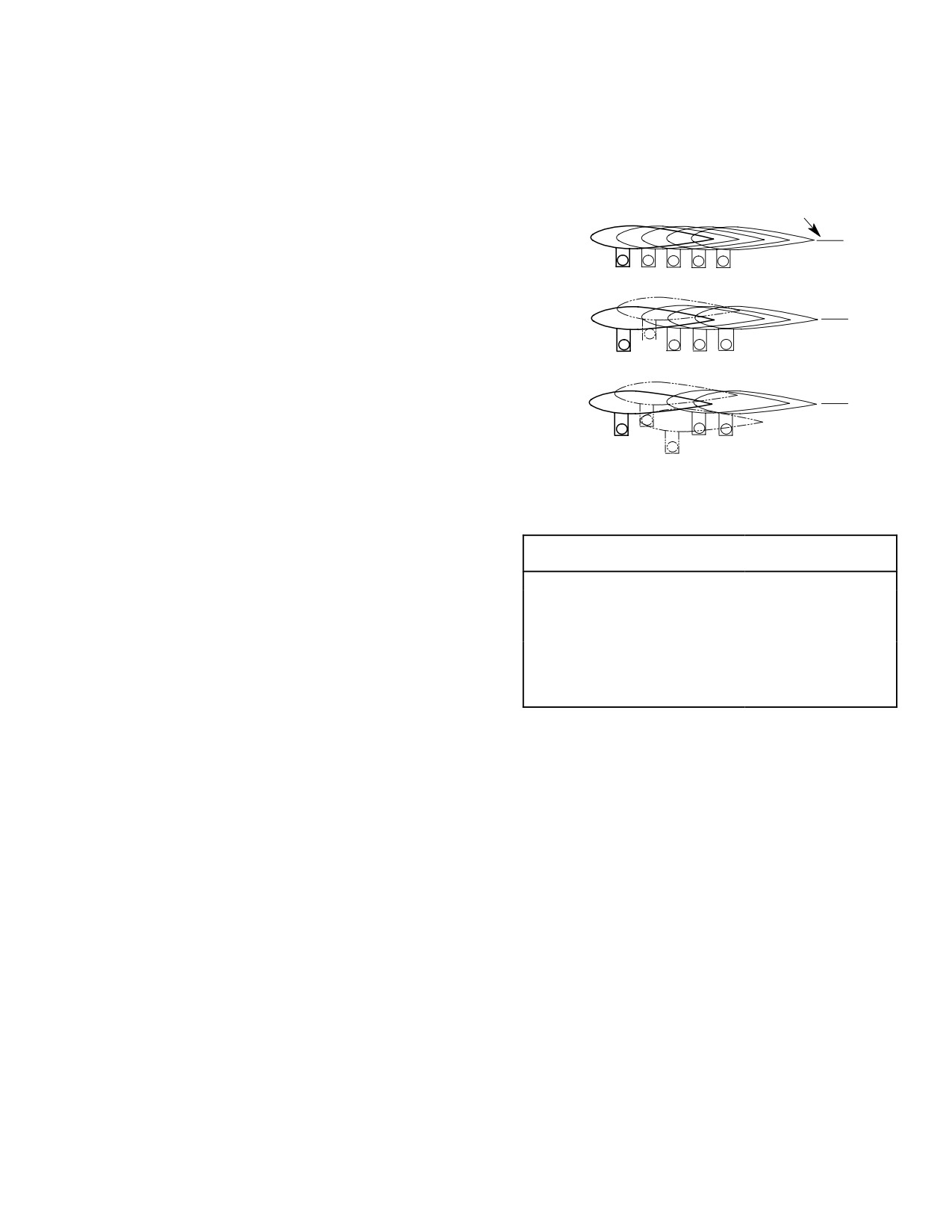
1. Blade Tracking Procedure
TIP PATH PLANE
Table 501 is a summary of the sequence of
required procedures for blade tracking.
1
2
3
4
5
(1). Install strobe light, blade tip cap
IMAGE A:
ALL BLADES
reflectors and related equipment.
IN TRACK
(2). Use 1/2 inch (12.7 mm) diameter
2
tracking tip cap reflector as a guide for
1
3
4
5
estimating track accuracy. For example:
IMAGE B:
ONE BLADE APPROX. 1/2 IN. (12.7
MM) HIGH
(a). A tip cap reflector image displace
ment of 1/2 diameter up, or down,
2
indicates blade tip is approximately
1
4
5
1/4 inch (6.35 mm) out of track.
3
IMAGE C:
ONE BLADE APPROX. 1/2 IN. (12.7
(b). One full reflector diameter indicates
MM) HIGH
ONE BLADE APPROX. 1 IN. (25.4
G18-1001A
1/2 inch (12.7 mm) out of track.
CORRECTIVE ACTION
NOTE: Rocking or stick shake caused by a cor
HIGH RPM AND
rectly tracking rotor indicates improper
CONDITION
GROUND IDLE RPM
FWD FLIGHT
blade phasing.
IMAGE A
NONE REQUIRED
NONE REQUIRED
IMAGE B
SHORTEN PITCH CONTROL MOVE TAB DOWNWARD
(3). Accomplish blade phasing (Ref. Sec.
ROD (2ND BLADE)
(2ND BLADE) MOVE TAB
62-20-00) when installing new rotor
UPWARD (3RD BLADE)
blades or if ground rock or stick shake
IMAGE C
SHORTEN PITCH CONTROL
MOVE TAB DOWNWARD
is noted. This must be accomplished
ROD (2ND BLADE):
(2ND BLADE): MOVE TAB
prior to starting tracking procedure.
LENGTHEN CONTROL ROD
UPWARD (3RD BLADE)
(3RD BLADE)
NOTE: Final rotor system balance cannot be
accomplished until blades are in track.
NOTE: Chordwise spacing of tracking images
are not an accurate indication of blade
(4). Ground tracking is basically track-ob
phasing. Do not adjust blade phasing in an
servation and adjustment of idle and
attempt to equalize spacing. Slight tilting of
flight rpm. Improper track at idle rpm
magnetic interrupters or balance of the main
is corrected by adjusting length of pitch
rotor system can move the image
control links connecting rotating
Figure 501. Typical Track Conditions and
swashplate and blade pitch housing.
Adjustments
Ground track at flat pitch and flight
rpm is corrected by blade tab adjust
(6). Forward flight track is corrected only
ment.
by making blade tab adjustments.
Forward flight tracking requires track
(5). Hover track verification is essentially
observation during following airspeeds
an observation to check for track
and maneuvers: Flight at 0-100 knots.
variations between high rpm (flat pitch)
Forty-five degree banked turns at
ground track check and hovering.
80-100 knots. Flight at 100-155 knots.
NOTE: Track adjustments are not made on ba
(7). Check for proper balance of rotor
sis of track observations during hovering.
system prior to checking autorotation.
However, track variations should be noted
and recorded for use during check of track in
(8). Obtaining correct autorotation rpm
forward flight.
consists of checking main rotor rpm
Page 501
18-10-00
Revision 23
CSP-HMI-2
MD Helicopters, Inc.
MAINTENANCE MANUAL
during stabilized autorotation flight
and adjusting rpm to specified limits as
Special Tools
necessary. Autorotation rpm check
(Ref. Section 91−00−00)
must be accomplished to ensure that
Item
Nomenclature
track adjustments do not alter rotor
ST902
Main rotor blade fixture and tab bending
performance necessary for safe power-
tool
off landings.
A. Blade Track Adjustment
Minimize bending and restrict
CAUTION
adjustments to very small incre
Although adjustment of pitch control links
ments so that bonded trailing edge joint be
affects blade track at all rotor speeds, they
tween upper and lower skins is not dam
should be adjusted only when necessary to
aged. Tabs must never be displaced more
establish acceptable track at ground idle
than five degrees above or below neutral po
speed; blade tabs are used for all other track
sition (parallel to chordline).
corrections.
(1). To lower blade tip that tends to climb
NOTE: Blade tab and/or track can make the
during ground tracking at high rpm or
collective heavy or light.
during forward flight, bend appropriate
tab section slightly downward; to raise
B. Pitch Control Link Adjustment
tip of blade that tends to descend, bend
Repeat this adjustment procedure as necessary
tab slightly upward. If only slight track
to establish ground idle track:
correction is necessary, limit tab
bending to width of bending tool. If
(1). To lower a blade tip, shorten pitch
more correction is necessary, bend a
control link assembly. To raise a blade
slightly wider section of tab. Use small
tip, lengthen pitch control link assem
adjustments to avoid excessive rebend
bly. One-sixth of a turn of link (one flat)
ing of tabs.
raises or lowers blade tip approximately
1/4 inch (6.35 mm).
NOTE: Tab zones on same blade can require
bending in opposite directions. For example,
Center each rod end or (fitting
after bending tab zone A downward to get
CAUTION
wear) results. Make sure there
good tracking at 60-90 knots, it might be
is no binding in full up travel position.
come necessary to bend tab zone D or E up
ward to correct track at redline airspeed. In
(2). After adjusting pitch control link
any case, do not use larger tab corrections
length, center each rod end in its fitting
than are actually necessary.
and hold while tightening jam nuts;
safety with lockwire.
(2). Each time blade tabs are adjusted,
recheck ground idle track and readjust
C. Blade Tab Adjustment
if necessary.
(Ref. Figure 502) Once ground idle track is
(3). After completion of forward flight
obtained, all remaining tracking correction is
tracking, balance and check autorota
accomplished by very slight bending of various
tion rpm.
blade tab zones with tab bending tool (ST902).
Different zones of tabs are used to adjust blade
D. Main Rotor Ground Tracking
track at different airspeeds. In general, tab
zone A is used for high rpm, flat pitch ground
(Ref. Figure 502) For best results, tracking
tracking (369D/E - 103% N2, 369FF/500N -
should be performed under calm air conditions.
100% N2) and zones C, D, and sometimes E,
Wind velocity should not exceed six knots
are used for tracking at higher airspeeds. Zone
during adjustments. Accurate adjustment of
B is used to supplement zone A track correc
initial ground track is very important. In most
tion when maximum tab (5 degrees) has been
instances, forward flight tracking problems
applied to zone A; if necessary, zone B may
can be avoided or greatly reduced by setting
also be used for correction in 0-110 knot
initial track as nearly perfect as possible.
airspeed range.
Tolerances specified in following instructions
Page 502
Revision 34
18-10-00
MD Helicopters, Inc.
CSP-HMI-2
MAINTENANCE MANUAL
should be considered maximum permissible
blade tab zone A until high rpm ground
deviation rather than desired goal.
track is within tolerance.
E. Hover Track Verification
NOTE: If main rotor hub or a pitch control rod
end bearing has been replaced, adjust pitch
control link(s) before proceeding with
(Ref. Figure 502)
ground tracking.
(1). Hover track verification must be
performed after ground tracking and
(1). Before tracking blades that are not new,
before forward flight tracking. Verifica
check that normally straight (not to be
tion is only a check of hover track. Do
used) tab areas are in neutral position
not adjust pitch control links or blade
(centered on chordline) and straight.
tabs because of track images observed
during hovering. Tab adjustments often
NOTE: On new (untracked) blades, check that
cause variation between ground track
all tab areas are straight and in neutral po
and hovering track. A large track
sition (centered on chordline 0° ±0.5°).
variation may indicate that one or more
blades is beyond its chordwise balance
tolerance, but this can only be deter
(2).
Load helicopter to a gross weight of
mined during forward flight tracking.
approximately 2350 pounds (1066 kg);
Perform hover track verification as
then ground idle (approximately
follows.
64-65% N1).
NOTE: Collective pitch stick may be ”heavy” af
(3).
Observe tracking tip cap reflector image
ter tracking reflectors are mounted on blade
by directing strobe light beam toward
tips. This condition is not unusual and may
blade tip path and sweeping beam
be disregarded.
slowly back and forth until reflector
images are clearly seen. Tracking image
(2). Verify helicopter gross weight of
should appear directly in front of
2000-2500 pounds (908-1135 kg).
helicopter or slightly off helicopter
centerline.
(3). With collective pitch stick full down,
increase N2 to 103% - 369D/E, 100% -
(4).
If blades are in track, tip cap reflector
369FF/500N.
image pattern should resemble image A
(Ref. Figure 501), (no blade tip more
(4). Observe tracking reflector images to
than 1/4 of one tracking reflector
verify that ground track is within
diameter, 1/8 inch (3.175 mm) above or
limits.
below adjacent reflectors). If blades are
in track, proceed with (5). below. If
(5). With helicopter in a stable hover,
blades are out of track, adjust pitch
observe reflector images. If one or more
control links and repeat step (3). above.
blades are out of track, record condi
tion(s) for reference during forward
flight tracking.
(5).
With collective pitch stick full down,
increase engine speed to 103% N2 -
369D/E, 100% N2 - 369FF/500N and
(6). Proceed with forward flight tracking.
observe tip cap reflector image to see if
blade track is changed from ground idle
Use of the tracking strobe
WARNING
track. When all five blades are in track
light in night flight is not
within 1/4 of one reflector diameter, 1/8
recommended. Such use can result in
inch (3.175 mm), ground track is
pilot disorientation or loss of vision
correct; proceed with hover verification.
with resultant damage to the helicop
When a blade is out of track, adjust
ter and personal injury.
Page 503
18-10-00
Revision 23
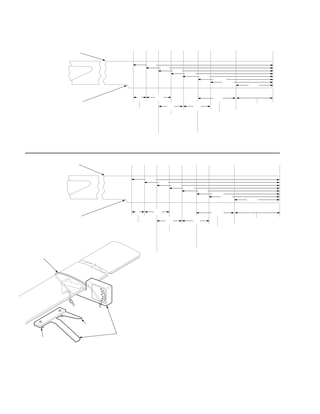
CSP-HMI-2
MD Helicopters, Inc.
MAINTENANCE MANUAL
BLADE STATIONS
93
99
105
111
117
124
130
142
158
MAIN ROTOR BLADE
(TOP VIEW)
65 IN.
(165 CM)
59 IN.
(150 CM)
53 IN.
369D/E
(135 CM)
47 IN.
(119 CM)
41 IN.
(104 CM)
34 IN.
(86 CM)
28 IN.
(71 CM)
16 IN.
(41 CM)
TAB ZONES
E
D
A
NOT USED
(NOTE 1)
C
B
TO END OF
NOTE 2
BLADE NOT USED
HIGH RPM GROUND
MEDIUM SPEED
(NOTE 1)
TRACKING AND UP TO
FLIGHT TRACKING
110 KNOTS IN FLIGHT
130-145 KNOTS
(103 % N2)
HIGH SPEED
110-130 KNOTS
FLIGHT TRACKING
IN FLIGHT
130-145 KNOTS
(103 % N2)
(103 % N2)
MAIN ROTOR BLADE
BLADE STATIONS
93
99
105
111
117
124
130
148
164
(TOP VIEW)
71 IN.
(180 CM)
65 IN.
(165 CM)
59 IN.
369FF/500N
(150 CM)
53 IN.
(135 CM)
47 IN.
(119 CM)
40 IN.
(102 CM
34 IN.
(86 CM)
16 IN.
(41 CM)
TAB ZONES
E
D
A
NOT USED
(NOTE 1)
C
B
TO END OF
NOTE 2
BLADE NOT USED
HIGH RPM GROUND
(NOTE 1)
MEDIUM SPEED
TRACKING AND UP TO
FLIGHT TRACKING
110 KNOTS IN FLIGHT
130-145 KNOTS
(100% N2)
SHOCK CORD
110-130 KNOTS
(OR EQUIVALENT)
HIGH SPEED
IN FLIGHT
FLIGHT TRACKING
(100% N2)
145-152 KNOTS
(100% N2)
NOTES:
1.
UNUSED TAB ZONES MUST BE MAINTAINED
STRAIGHT, NEUTRAL AND PARALLEL.
2.
USE ONLY AS NECESSARY TO SUPPLEMENT
ZONE D TO AVOID EXCESSIVE TAB BENDING
POINTER
IN ZONE D.
TAB BENDING TOOLS
BENDER
G18-1002C
Figure 502. Main Rotor Blade Tab Adjustment
Page 504
Revision 23
18-10-00
MD Helicopters, Inc.
CSP-HMI-2
MAINTENANCE MANUAL
F. Forward Flight Tracking
ferred, even though observed blade track
may be beyond specified tolerances.
(Ref. Figure 502) Forward flight tracking
should be performed whenever vertical flight
(4). After flight tracking is completed,
vibrations indicate that blades may be out of
perform a Main Rotor System Balance
track.
Procedure and Main Rotor Autorotation
RPM Check.
(1). Verify helicopter gross weight of
2000-2500 pounds (907-1134 kg).
3. Main Rotor System Balance Procedure
(2). Perform flight tracking from hover up
Balance the main rotor system according to
to 110 knots at 103% N2 - 369D/E,
instructions in the Tracking and Balancing
100% N2 - 369FF/500N. If flight track
Manual. Since vibration reduction is accom
varies from hover track more than 1/2
plished by slight adjustment in phasing, the
inch (12.7 mm), bend tab zone A (five
instruction outline in the Tracking and
degrees maximum) to limit variation to
Balancing Manual must be closely followed for
tab zone B (five degrees maximum).
best results. Safety damper turnbuckle after
completing phasing balance adjustments.
2. Main Rotor Blade Tab Adjustment
4. Main Rotor Autorotation RPM Check
(1). Check autorotation rpm; rpm must not
be less than 480.
(Ref. Table 502 for 369D/E and Table 503
369FF and 500N). An autorotation rpm check
Do not attempt to adjust chord
CAUTION
is required after each blade tracking operation
wise balance of a blade found to
and whenever rpm is outside limits listed.
be faulty when performing banked turns.
Check rotor rpm and make adjustments as
Chordwise balance corrections must be ac
follows.
complished by manufacturer (MDHI).
(2). Perform a series of 45 degree banked
CAUTION
turns at 100 knots and observe track
change from level flight. If any blade
D Autorotation rpm is critical to a success
climbs or dives more than one inch out
ful autorotation landing. When full main
of track with others, chordwise balance
rotor rpm is not available, autorotation
(center of gravity) of that blade is
function is decreased. At high gross
beyond its tolerance and blade must be
weights and/or density altitudes, the
replaced. (Hover track variations of this
main rotor rpm will try to overspeed. The
type that do not repeat during banked-
pilot must increase collective pitch to
turn maneuver may be disregarded.)
keep main rotor rpm within limits. At
lower gross weights and/or density alti
(3). Perform flight tracking at 110-155
tudes, the main rotor rpm will be under
knots and 103% N2 - 369D/E, 100% N2
speed. The pilot has less rotor energy
- 369FF/500N. If necessary, adjust tab
available to do the autorotation landing.
zone B (five degrees maximum) to limit
Set the autorotation rpm within the lim
track variation to 1/2 inch (12.7 mm) or
its of the Autorotation Percentage Chart
less and to minimize excessive vertical
to make sure sufficient autorotation rpm
(one-per revolution) vibration. If
is available at the helicopter minimum
variation is excessive, bend tab zone C
gross weight.
or D (five degrees maximum).
D All autorotation rpm adjustments shall
NOTE: When determining whether blade track
be made at the main rotor pitch control
is acceptable, overall vibration level of heli
links only. Do not re-adjust mixer control
copter should be determining factor. Some
rods after rigging is accomplished. Fail
combinations of rotor blades might produce
ure to observe this precaution may result
higher five-per-revolution vibration as
in serious damage to rotor system and
blade tips are brought into close track; in
controls. Do not adjust control rod end be
such cases, lowest vibration level is pre
yond witness hole.
Page 505
18-10-00
TR12-001

CSP-HMI-2
MD Helicopters, Inc.
MAINTENANCE MANUAL
D Tracking targets reduce blade to tailboom
5. Main Rotor Hub Balancing Procedure
clearance, performing autorotations to
the ground could result in boom strikes.
Balance the main rotor hub according to the
following instructions.
NOTE: Change length of all five pitch control
links as necessary to adjust autorotation
Consumable Materials
rpm. Be sure to lengthen or shorten all five
(Ref. Section 91−00−00)
links exactly same amount or blade track is
Item
Nomenclature
changed. One flat (1/6 turn) of control link
CM420
Sealant
body causes approximately four rpm change
in autorotation rpm.
Special Tools
(Ref. Section 91−00−00)
(1). Autorotation Rpm Check: Load 369D/E
Item
Nomenclature
helicopter to a gross weight of 2250
pounds (1021 kg): 2350 pounds (1066
ST903
Balancer/analyzer instrument kit
kg) for 369FF and 500N. Perform a
practice autorotative descent (Ref.
NOTE:
PFM), taking care not to allow rpm to
exceed rotor speed limitations. During
D If swashplate has weights removed, there
autorotation take careful note of
should be three AN970-3 washers at the
stabilized autorotation rpm at one of
green pitch housing bolt.
gross weight/density altitude combina
D In some instances, main rotor hub bal
tions. After landing, compare observed
ance may not be achieved without addi
rpm with values (Ref. Tables 502 and
tion of swashplate weights (Ref. Sec.
503). If observed rpm is within limits in
62-30-00,
Counterweight
and
table, rpm setting is correct. If limits
Interrupter Installation)
were exceeded, make corrective adjust
ments according to (2). below, until rpm
(1). Remove main rotor blades.
is within limits.
(2). Remove main rotor dampers.
NOTE: After autorotation rpm adjustments are
(3). Hook up Phazor. Refer to Chadwick-
satisfactorily accomplished, remove track
Helmuth Operation and Service
ing equipment before returning helicopter
Instruction Handbook (ST903).
to service. Be sure to correctly tighten and
safety all bolts after they are reinstalled.
NOTE: Refer to applicable Rotorcraft Flight
Manual, Section 7, for blades-off operating
(2). Autorotation Rpm Adjustment: Change
procedures.
length of all five pitch control links as
required to adjust autorotation rpm.
(4). Run engine at 103% N2 - 369D/E,
Make certain all five links are short
100% N2 - 369FF/500N.
ened or lengthened exactly the same
amount or blade track will be altered.
Observe N2 speed avoid range
CAUTION
limits during this procedure and
exercise caution when increasing twistgrip
CAUTION
to flight idle position to avoid N2 overshoots.
D Do not adjust (lengthen) pitch control link
(5). Record IPS reading and direction on
rodend threads beyond witness holes in
main rotor balance chart (Ref.
rods.
Figure 503).
D Do not readjust mixer control rods after
(6). Plot IPS reading and direction on main
rigging has once been accomplished. Fail
rotor balance chart (Ref. Figure 503).
ure to observe this precaution can result
in serious damage to rotor system and
(7). Analyze chart for weight location and
controls.
amount requirements.
Page 506
TR12-001
18-10-00

MD Helicopters, Inc.
CSP-HMI-2
MAINTENANCE MANUAL
The maximum allowable bal
as applicable. Coat screw threads, nuts
CAUTION
ance weight per lead-lag bolt on
and washers with sealant (CM420). (To
the main rotor hub assembly is 150 grams.
prevent imbalance, do not use excessive
amount of sealant.)
(8). Install weights as follows: (Ref.
Figure 504).
NOTE: Intermixing of P/N 369D21400-503 and
M50452 main rotor blade damper assem
(a). Engage head of screw, inside lead-lag
blies in a shipset is not permitted. All damp
bolt, with Phillips screwdriver, then
ers in shipset must be of same type and part
loosen locknut with 1/4 inch wrench.
number.
(b). Hold screw in place with screwdriver
(11). Reinstall main rotor blades (Ref. Sec.
while adding or removing flat wash
62-10-00).
ers as required, then reinstall
locknut.
NOTE: If main rotor dampers require more
(9). Repeat steps (4). thru (8). until reading
than four flats adjustment, re-phase main
is 0.15 IPS, or less.
rotor dampers (Ref. 62-20-00, Main Rotor
Damper Phasing Procedure).
(10). After balance has been established
satisfactorily, torque MS21042L08
(12). Perform main rotor system balance.
locknuts to 20 - 35 inch-pounds (2.26
- 3.95 Nm) or MS21042L3 locknuts to
(13). Track main rotor blades (Ref. Blade
30 - 60 inch-pounds (3.39 - 6.78 Nm)
Tracking Procedure).
Table 501. Summary Procedure for Blade Tracking
Satisfactory
Unsatisfactory
Step
Result
Result
Corrective Action
(1) Observe ground track.
Go to step (2). Ref. Corrective
Adjust pitch control links and blade
Action.
tabs as required. Repeat track
observation.
(2) Perform hover verification.
Go to step (3). Ref. Corrective
Record track verification and proceed
Action.
with forward flight tracking.
(3) Perform forward flight tracking. Go to step (4).
Ref. Corrective
Adjust blade tabs and repeat forward
Action.
flight tracking.
(4) Perform autorotation rpm
Go to step (5). Ref. Corrective Adjust autorotation rpm and repeat
check.
Action.
rpm check.
(5) Remove tracking equipment
and return helicopter to service.
NOTE: Ground rock or stick shake with rotor blades in track during ground track indicates rotor blades are not
properly phased.
Page 507
18-10-00
TR12-001

CSP-HMI-2
MD Helicopters, Inc.
MAINTENANCE MANUAL
Table 502. Autorotation Rpm Chart (369D/E)
Stabilized Autorotation Rpm at Density Chart
Gross Wt
lb/kg
Sea Level
1000 Ft
2000 Ft
3000 Ft
4000 Ft
5000 Ft
2050/930
460 − 470
466.5 − 476.5
473 − 483
479.5 − 489.5
486 − 496
492.6 − 502.6
2150/975
470 − 480
476.5 − 486.5
483 − 493
489.5 − 499.5
496 − 506
502.6 − 512.6
2250/1021
480 − 490
486.5 − 496.5
493 − 503
499.5 − 509.5
506 − 516
−−−
2350/1066
490 − 500
496.5 − 506.5
503 − 513
509.5 − 519.5
−−−
−−−
NOTES:
(1) Chart values based upon 15°C (59°F) outside air temperature. At sea level, 8°C (14°F) temperature
change is equal to 1000 feet (305 M) of change in density altitude.
(2) Perform autorotation rpm checks at gross weight/density altitude combinations for which rpm values are
given. Blank spaces indicate that application of collective pitch may be necessary to avoid rotor
overspeed.
Table 503. Autorotation Rpm Chart (369FF/500N)
Stabilized Autorotation Rpm at Density Chart
Gross Wt
lb/kg
Sea Level
1000 Ft
2000 Ft
3000 Ft
4000 Ft
5000 Ft
2216/1005
459-469
465-475
471-481
477-487
483-493
489-499
2316/1051
466-476
472-482
478-488
484-494
490-500
496-506
2416/1096
473-483
479-489
485-495
491-501
497-507
---
2516/1189
480-490
486-496
492-502
498-508
---
---
NOTES:
(1) Chart values based upon 15°C (59°F) outside air temperature. At sea level, 8°C (14°F) temperature
change is equal to 1000 feet (305 M) of change in density altitude.
(2) Perform autorotation rpm checks at gross weight/density altitude combinations for which rpm values are
given. Blank spaces indicate that application of collective pitch may be necessary to avoid rotor
overspeed.
Page 508
Revision 23
18-10-00
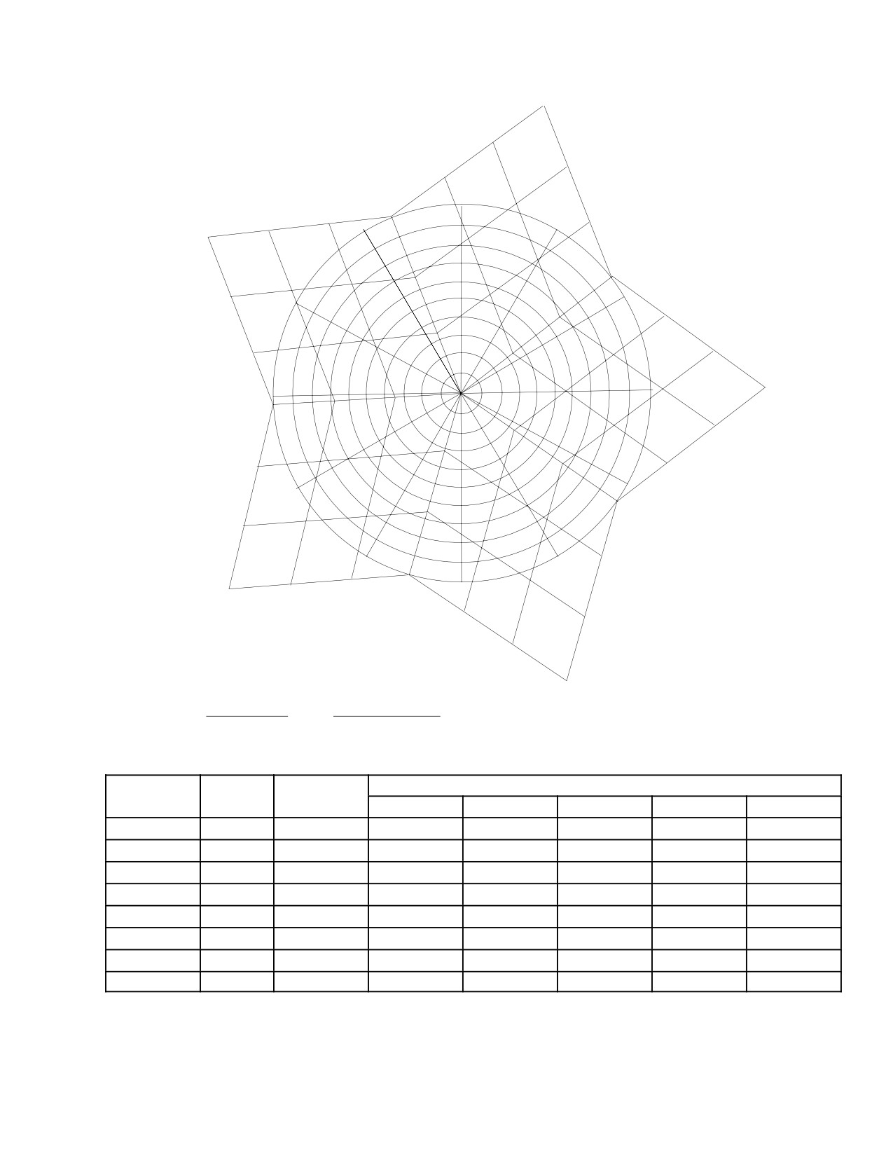
MD Helicopters, Inc.
CSP-HMI-2
MAINTENANCE MANUAL
60 GRAMS
BLUE
4
40
40
YEL
GRN
20
3
2
12
0
20
20
40
11
1
1.0
60 GRAMS
.9
.8
0
TGT
.7
2
WHITE
40
10
.6
5
YEL
20
.5
3
.4
.3
40
20
.2
.1
.6
.7
.8
.9
1.0
.1
.2
.3
.4
.5
3
60 GRAMS
9
.1
0
.2
.3
40
.4
BLUE
.5
RED
20
20
4
.6
1
4
8
.7
0
.8
40
.9
1.0
5
20
7
0
RED
20
6
60 GRAMS
40
1
20
40
GRN
2
40
TGT
WHITE
60 GRAMS
HELICOPTER S/N
HUB S/N
5
G18-1003A
CLOCK
BALANCE WEIGHT AND LOCATION
RUN NO.
IPS
ANGLE
(1) RED
(2) GREEN
(3) YELLOW
(4) BLUE
(5) WHITE
Figure 503. Main Rotor Hub Balancing Chart
Page 509
18-10-00
Revision 23
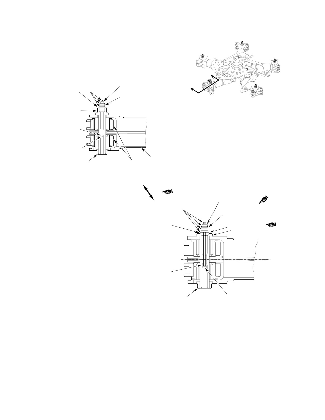
CSP-HMI-2
MD Helicopters, Inc.
MAINTENANCE MANUAL
A
MS21042L08 NUT
A
369D29935 MAIN ROTOR
NOTE 1
(NOTE 2)
HUB BALANCE WEIGHT
AN960C8, AN960C8L WASHERS
SUPPORT WASHER
AS REQUIRED TO BALANCE
(NOTE 5)
369D21220 LEAD-LAG BOLT
369D29934 WASHER
NAS602-64P, -72P OR -76P
SCREW
369D21300-501
LINK ASSY PITCH HOUSING
369A1219 NUT AND
MS24665-300 COTTER PIN
(NOTE 4)
A - A
SERIAL NO. 0260D AND SUBS
MS21042L3 LOCKNUT
(NOTE 3)
NOTE 1
AN960C10, AN960C10L WASHERS
AS REQUIRED TO BALANCE
(NOTE 5)
HS1555 WASHER
AN970-3 WASHER
369A1220 LEAD-LAG BOLT
HS1554 WASHER
369A1219 NUT AND
NAS603-56 OR -64
MS24665-300 COTTER PIN
SCREW
(NOTE 4)
A - A
SERIAL NO. 003D THRU 0259D
NOTES:
1.
COAT SCREW THREADS, NUTS AND WASHERS
WITH PR-1436-G, CLASS B-2 SEALANT.
2.
TORQUE MS21042L08 NUT TO 20 - 35 INCH-POUNDS
(2.26 - 3.95 NM).
3.
TORQUE MS21042L3 NUT TO 30 - 60 INCH-POUNDS
(3.39 - 6.78 NM).
4.
DO NOT REMOVE OR DISTURB TORQUE ON 369A1219 NUT.
5.
THE MAXIMUM ALLOWABLE BALANCE WEIGHT PER LEAD-LAG
G18-1004B
BOLT ON THE MAIN ROTOR HUB ASSEMBLY IS 150 GRAMS
Figure 504. Main Rotor Hub Balancing
Page 510
Revision 39
18-10-00
MD Helicopters, Inc.
CSP-HMI-2
MAINTENANCE MANUAL
Section
18−10−60
Main Rotor Track
and Balance (600N)
MD Helicopters, Inc.
CSP-HMI-2
MAINTENANCE MANUAL
MAIN ROTOR TRACK AND BALANCE (600N)
MAINTENANCE PRACTICES
1. Main Rotor Blade Tracking
CAUTION
Immediately investigate the
D Understand the blade tracking sequence
WARNING
cause of a sudden onset of
and related adjustments before attempt
excessive or unusual main rotor vibra
ing blade track procedures.
tion prior to continued flight. Under no
D If main rotor hub balance is suspect, bal
circumstance should main rotor track
ance rotor hub prior to performing blade
ing be attempted to correct the prob
track.
lem until a thorough inspection of the
main rotor blades, hub assembly and
2. Main Rotor System Balancing
strap pack assembly has been per
formed.
Main rotor hub balancing is accomplished by
adding or removing weight (flat washers) as
required at the lead-lag bolts (Ref. Main Rotor
NOTE: Ref. Table 201 to isolate ground or in-
Hub Balancing Procedure). Analysis of main
flight blade tracking problems.
rotor hub balance is accomplished using
instrumentation that measures and localizes
Main rotor blade track is observed by means of
vibrations due to main rotor hub imbalance.
reflective tip caps temporarily installed on
Data provided by the instrumentation is
each blade and a high-intensity strobe light.
plotted on a chart designed to indicate how
Blade track is determined by observing the
much weight must be added or removed from
apparent tip cap pattern created by strobe
the lead-lag bolt. No other means of balancing
light pulses synchronized with the rotating
is to be used.
blades. Strobe light electrical power is supplied
by the helicopter electrical system.
3. Balancing Equipment and Balance Spare
Kit
a. Tracking must be accomplished in the follow
ing sequence of six steps:
Special Tools
1). Verification of proper blade phasing
(Ref. Section 91−00−00)
(Ref. Main Rotor System Balance Procedure).
Item
Nomenclature
2). Ground tracking
ST903
Balancer/analyzer instrument kit
(Ref. Main Rotor Ground Tracking).
3). Verification of proper rotor balance
(Ref. Main Rotor System Balance Procedure).
The balancing equipment (ST903) contains all
4). Hover verification
equipment needed to analyze main rotor
(Ref. Hover Track Verification).
balance.
5). Forward flight tracking
When working near engine air
(Ref. Forward Flight Tracking).
CAUTION
inlet, comply with all precau
6). Autorotation rpm adjustment
tions to prevent entry of foreign material.
(Ref. Main Rotor Autorotation RPM Check).
Carefully observe precautions in the Track
ing and Balancing Manual relating to the
b. No attempt should be made to verify or adjust
placement and security of equipment (espe
blade track without first checking and adjust
ing blade phasing, a function of main rotor
cially cables) fastened to the exterior of the
damper adjustment.
helicopter.
Page 201
18-10-60
Revision 23
CSP-HMI-2
MD Helicopters, Inc.
MAINTENANCE MANUAL
Table 201. Isolating Tracking Problems
Symptom
Probable Cause
Corrective Action
GROUND TRACKING
Rotor does not follow adjustments.
Turning P/C link wrong direction.
Adjust correctly.
Pitch link bearing worn. Trim tab
Replace bearing. Zero trim tabs.
bent excessively.
Excessive diving or climbing of
Trim tab bent excessively.
Zero trim tabs.
blade from low speed ground track
Pitch link control not coordinated
Set pitch link to nominal 6.25 inches
to high speed ground track.
with trim tab bend (Intermixing
(15.88 cm) and zero trim tabs.
control input).
Damage to blade or tabs.
Inspect for damage.
Excessive torque and erratic high
Pitch change links too long or
Set to nominal 6.25 inches (15.88
speed ground tracking.
collective rigging too high.
cm). Check collective rigging.
IN−FLIGHT TRACKING
Blade track changes with power
Worn pitch bearing housing
Replace bearings.
and control changes.
bearings.
Missing pitch bearing liner.
Replace bearing.
Broken or loose feathering studs.
Repair or replace studs.
Binding rotating scissor crank at
Repair or replace crank.
lower main rotor hub shoe.
Play between longitudinal pitch
Re−bond collective pitch mixer
mixer bellcrank and collective pitch
bearings and install shims between
mixer bellcrank.
longitudinal pitch mixer bellcrank and
collective pitch mixer bellcrank
bearings (Ref. Sec. 62−30−60).
Helicopter has rough feeling with
Tilted tracking images, no blade in
Retrack blades.
some vibration while appearing to
track.
be in track.
Pitch link control not coordinated
Set pitch link to nominal 6.25 inches
with trim tab bend (intermixing
(15.88 cm) and zero trim tabs.
control input), with climbing or
diving blades within acceptable
track limits.
Blades very erratic in response to
Tab bent too much in wrong area.
Correct by limiting bending.
tab bends.
Blade erosion, but within chordwise
Track erratic blade to other blades.
limits.
Tab bent too many degrees in one
Limit tab bending to smaller degree
area.
over larger area.
Blades climb or dive excessively at
Too much tab bending in outboard
Remove outboard bending and
high speeds.
tab areas.
increase inboard bending.
Page 202
Revision 31
18-10-60
MD Helicopters, Inc.
CSP-HMI-2
MAINTENANCE MANUAL
Table 201. Isolating Tracking Problems (Cont.)
Symptom
Probable Cause
Corrective Action
Ground track off at low speed and
Excessive tab bending and pitch
Set pitch link to nominal 6.25 inches
stick shake at 100% N2.
link control not coordinated with tab
(15.88 cm) and zero trim tabs.
bend (intermixing control input).
Helicopter in track but has stick
Blade out of phase.
Check phasing.
shake.
Feedback in collective control.
Main rotor system out of balance.
Balance rotor system.
Loose or binding rotating scissors. Check and repair as required.
Heavy collective stick − climb and
Overcenter adjustment set too low. Adjust.
cruise.
Trim tab bent down excessively.
Adjust.
Light collective stick − climb and
Overcenter adjustment set too
Adjust.
cruise.
high.
Trim tabs bent up excessively.
Adjust.
Heavy collective lift-off − light flight. Bungee spring adjusted too short.
Adjust to nominal.
Light collective lift-off − heavy flight. Bungee spring adjusted too long.
Adjust to nominal.
Page 203
18-10-60
Revision 31
CSP-HMI-2
MD Helicopters, Inc.
MAINTENANCE MANUAL
This Page Intentionally Left Blank
Page 204
Revision 44
18-10-60
MD Helicopters, Inc.
CSP-HMI-2
MAINTENANCE MANUAL
MAIN ROTOR TRACK AND BALANCE (600N)
REMOVAL/INSTALLATION
1. Main Rotor System Tracking Equipment
(4). The number one blade is seen on the
Installation
extreme left, number two blade is seen
second from left, and so on thru number
six which is seen on the extreme right.
(Ref. Figure 401 and Figure 402) Equipment
needed to track main rotor blades consists of
(5). Additional interrupters can be added to
the tracking and balancing equipment (ST903)
be compatible with the older balance/
and the tip cap assemblies (ST901). Instruc
analyzer instrument kits.
tions for equipment installation are contained
in Chadwick-Helmuth Operation and Service
(6). Torque the interrupter as shown in
Instruction Handbook.
Figure 401.
B. Magnetic Pickup Installation
Special Tools
(Ref. Section 91−00−00)
(1).
The helicopter is originally equipped
Item
Nomenclature
with a magnetic pickup support bracket
ST901
Tip cap assembly
installed with shim washers to prevent
distortion of the bracket when the nut
ST903
Balancer/analyzer instrument kit
on the bolt that secures the link bearing
is torqued to 30 - 60 inch-pounds
(3.39 - 6.78 Nm).
NOTE: Main rotor tracking tip caps manufac
tured by the same firm that manufactures
(2).
To preclude rocking movement of
the tracking and balance equipment, are
magnetic pickup support bracket when
components of the tracking and balancing
installed on stationary swashplate,
equipment and may be used instead of tip
check clearance between swashplate
cap assembly (ST901). In procedures that
and lower flange of bracket. If gap
follow, use of tip cap assembly is presumed.
exists, tap bent tip of lower flange
If tip caps from the balancing equipment are
(typical both sides of bracket) until bent
used, refer to the Tracking and Balancing
tip touches swashplate.
Manual for tip cap data.
(3).
Reinstall by forcing bracket until
A. Interrupter Installation
elongated bracket holes align with hole
in stationary swashplate.
(1). The helicopter is equipped with a main
(4).
Install the magnetic pickup and cable
rotor blade tracking interrupter located
as instructed in the Chadwick-Hel
on the rotating swashplate.
muth Operation and Service Instruc
tion Handbook.
(2). The interrupter creates six equally
spaced horizontal reflective images, as
(5).
After final adjustment, torque the
viewed by the technician, when the
adjustment nut to 15 - 20 inch-
main rotor blade tips are illuminated
pounds (1.69 - 2.26 Nm) and ensure
with the test strobe light.
the cable is routed and tied down in
such a manner as not to be dislodged or
(3). The balance analyzer separates the
interfere with control components at
image of each main rotor blade tip cap
their extremes of travel.
by approximately 0.25 inch (6.35 mm).
This staggered relationship allows the
(6).
Ensure the interrupter passing closest
technician to view the stopped image of
over magnetic pickup, clears pickup by
each blade in order of rotation.
not less than 0.030 inch (0.76 mm).
Page 401
18-10-60
Revision 44
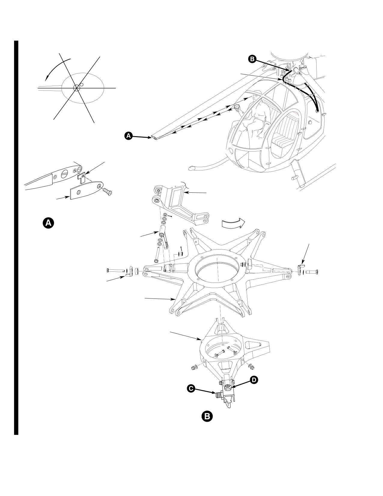
CSP-HMI-2
MD Helicopters, Inc.
MAINTENANCE MANUAL
2
1
PLACE DOUBLE INTERRUPTER
ROTATION
OVER MAGNETIC PICKUP AND
THEN ATTACH TIP TARGET
NUMBERS EXACTLY AS SHOWN.
TAPE
3
6
4
5
TRACKING TARGET
(NOTE 1)
SCISSORS
CRANK
TIP CAP
ROTATION
OF HUB
TRACKING TIP CAP
INSTALLATION
INTERRUPTER
(NOTE 4)
SCISSORS LINK
(NOTE 6)
INTERRUPTER
(NOTE 4)
(NOTE 5)
ROTATING
SWASHPLATE
STATIONARY
SWASHPLATE
NOTES:
1.
ALWAYS REMOVE TARGETS AFTER TRACKING.
2.
INSTALL WASHERS BETWEEN BRACKET AND
SWASHPLATE TO FILL GAP.
3.
ADJUST AS REQUIRED FOR GAP INDICATED.
MAGNETIC PICKUP
4.
REFER TO IPC FOR PART NUMBER.
5.
TORQUE NUT TO 15-20 IN-LBS.
6G18-014-1A
6
TORQUE NUT TO 50 60 IN LBS
Figure 401. Blade Tracking Equipment − Main Rotor Components (Sheet 1 of 2)
Page 402
Revision 44
18-10-60