HANDBOOK OF MAINTENANCE INSTRUCTIONS FOR MDHI 369D/E/FF-500/600N HELICOPTERS (ISSUED: 1990) - page 4

MD Helicopters, Inc.
CSP-HMI-2
MAINTENANCE MANUAL
MODEL
SERIAL NO.
REGISTRATION NO.
DATE
EXAMPLES OF FORWARD, AFT AND LATERAL LOADING
LONG.
LONG.
WEIGHT
EXAMPLE 1, FORWARD
ARM
MOMENT
(LBS)
(IN.)
(IN. LB.)
BASIC WEIGHT
PILOT
43.5
COPILOT
43.5
FULL FUEL QUANTITY
GROSS WEIGHT (CRITICAL FUEL) − FWD C.G.
APPROVED FWD C.G. LIMIT FOR EXAMPLE 1 GROSS WEIGHT
INCHES.
LONG.
LONG.
WEIGHT
EXAMPLE 2, AFT
ARM
MOMENT
(LBS)
(IN.)
(IN. LB.)
BASIC WEIGHT
PILOT
GROSS WEIGHT (ZERO FUEL) − AFT C.G.
APPROVED AFT C.G. LIMIT FOR EXAMPLE 2 GROSS WEIGHT
INCHES.
LATERAL
LATERAL
WEIGHT
EXAMPLE 3, LATERAL
ARM
MOMENT
(LBS)
(IN.)
(IN. LB.)
BASIC WEIGHT
PILOT
GROSS WEIGHT (ZERO FUEL) − LATERAL C.G.
APPROVED LATERAL C.G. FOR EXAMPLE 3 GROSS WEIGHT
INCHES.
*SEE FLIGHT MANUAL, SECTION 6, FOR C.G. LIMITS AT GROSS WEIGHT
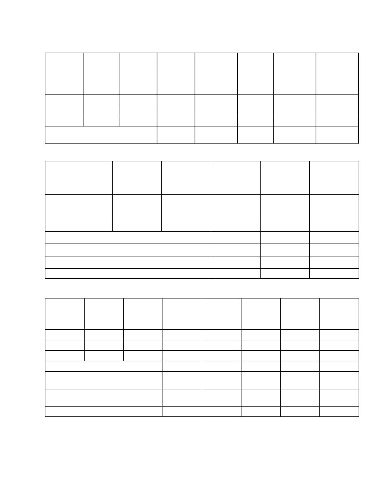
Figure 206. Weight and Balance Report Form (Sheet 2 of 2)
Page 213
08-10-00
Revision 23
CSP-HMI-2
MD Helicopters, Inc.
MAINTENANCE MANUAL
TABLE 1 SURPLUS AND MISSING EQUIPMENT
MODEL
SERIAL NO.
REGISTRATION NO.
DATE
WEIGHT
ARM − INCHES
MOMENT − IN/LBS
EQUIPMENT − ITEM
LBS
LONG
LATR
LONG
LATR
SURPLUS EQUIPMENT TOTAL:
(
1.3
)
(
96.9
)
(
)
(
126
)
(
)
JACK PADS (2)
1.3
96.9
126
MISSING EQUIPMENT TOTAL:
(
15.9
)
(
97.4
)
(
)
(
1549
)
(
)
ONE QT. ENGINE OIL
2.1
133.4
280
UNUSABLE FUEL
12.0
93.0
1116
FLIGHT MANUAL
1.8
85.0
153
McDonnell Douglas
FORM 1702 (REV 4−83)
Page
of
Helicopter Company
Figure 207. Surplus and Missing Items Report
Page 214
Revision 23
08-10-00
MD Helicopters, Inc.
CSP-HMI-2
MAINTENANCE MANUAL
G08−1006A
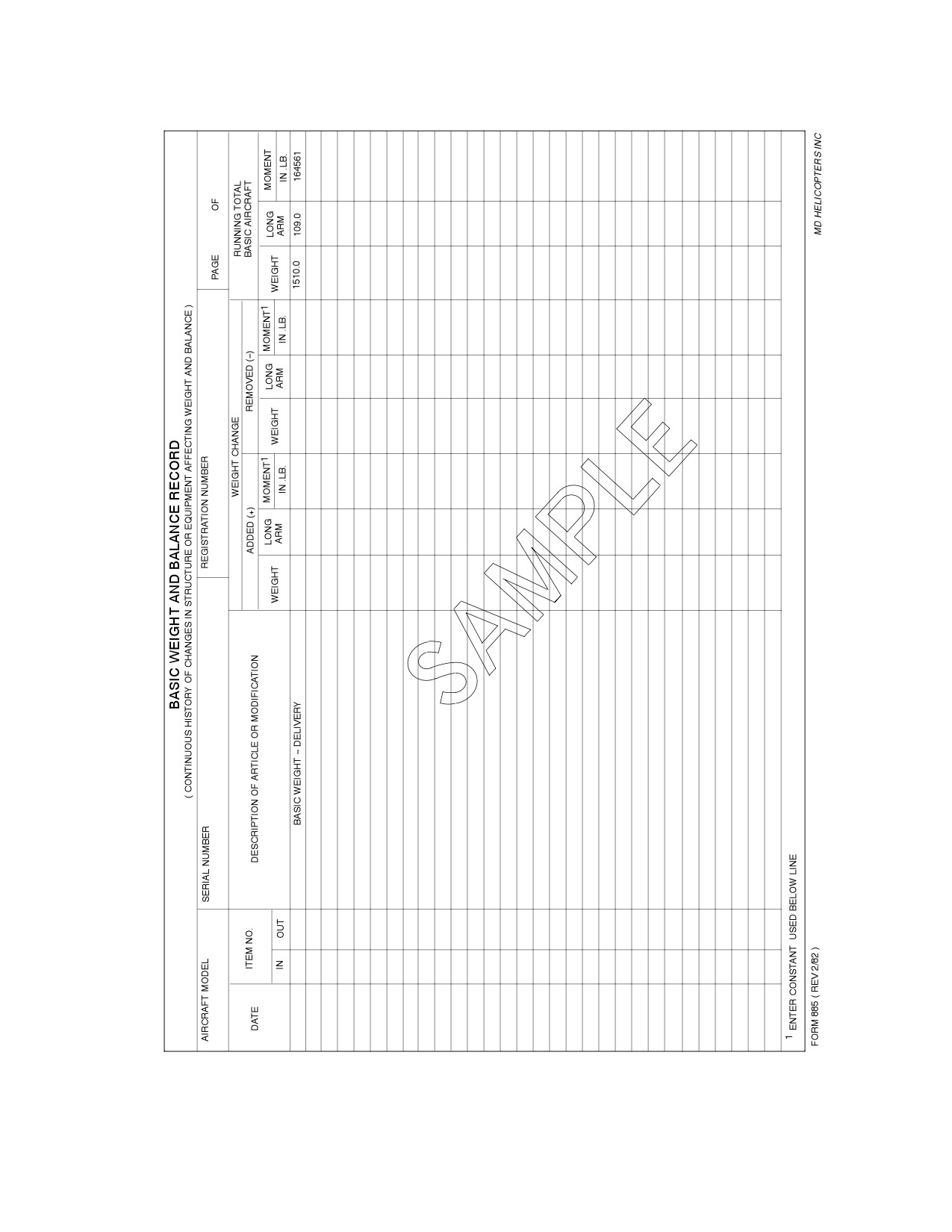
Figure 208. Basic Weight and Balance Record
Page 215
08-10-00
Revision 23

CSP-HMI-2
MD Helicopters, Inc.
MAINTENANCE MANUAL
Determining total unadjusted net weight and longitudinal CG - 369D/E/FF
(a)
(b)
(c)
(d)
Tare or
Weighing
Scale
Calibration
Net
Arm
Points
Reading (lbs)
Correction (lbs)
Weight (lbs)
(inches)
Moment (in.-lb)
Left Main
648.9
- 1.5
647.4
96.9
62733
Right Main
618.9
+ 0.5
619.4
96.9
60020
Tail
195.9
0
195.9
197.2
38631
Total Unadjusted Net Weight
1462.7
110.3
161384
(f)
(e)
Determining total unadjusted net weight, longitudinal and lateral CG - 500MD
(a)
(b)
(c)
(d)
(g)
Tare or
Scale
Calibration
Net
Longitudinal
Lateral
Longitudinal
Longitudinal
Weighing
Reading
Correction
Weight
Arm
Arm
Moment
Moment
Points
(lbs)
(lbs)
(lbs)
(inches)
(inches)
(inch-lb)
(inch-lb)
Left Main
1020.0
0.0
1020.0
96.9
- 25.6
98838
62733
Right Main
939.0
0.0
939.0
96.9
+ 25.6
90989
60020
Tail
128.0
0.0
128.0
197.2
0.0
25242
0
Total Unadjusted Net Weight
2087.0
103.1
- 1.0
215069
- 2084
(f)
(i)
(e)
(h)
Determining total unadjusted net weight, longitudinal and lateral CG - 500N
(a)
(b)
(c)
(d)
(g)
Tare or
Scale
Calibration
Net
Longitudinal
Lateral
Longitudinal
Longitudinal
Weighing
Reading
Correction
Weight
Arm
Arm
Moment
Moment
Points
(lbs)
(lbs)
(lbs)
(inches)
(inches)
(inch-lb)
(inch-lb)
Left Main
759.0
0.0
759.0
96.9
-25.6
73547.1
-19430.4
Right Main
738.8
0.0
738.8
96.9
+25.6
71589.7
18913.2
Tail
136.8
0.0
136.8
275.4
0
3764.7
0
Total Unadjusted Net Weight
1634.6
111.8
-.3
182811.5
-5172
(f)
(i)
(e)
(h)
Figure 209. Example 1 (Sheet 1 of 2)
Page 216
Revision 23
08-10-00
MD Helicopters, Inc.
CSP-HMI-2
MAINTENANCE MANUAL
Determining total unadjusted net weight, longitudinal and lateral CG - 600N
(a)
(b)
(c)
(d)
(g)
Tare or
Scale
Calibration
Net
Longitudinal
Lateral
Longitudinal
Lateral
Weighing
Reading
Correction
Weight
Arm
Arm
Moment
Moment
Points
(lbs.)
(lbs.)
(lbs.)
(inches)
(inches)
(inch-lbs.)
(inch-lbs.)
Left Main
919.2
0.0
919.2
96.9
-26.0
89070
-23899
Right Main
885.4
0.0
885.4
96.9
+26.0
85795
23020
Tail
104.7
0.0
104.7
303.3
0
31756
0
Total Unadjusted Net Weight
1909.3
108.2
-.5
206621
-879
(f)
(i)
(e)
(h)
Determining basic weight and the longitudinal and lateral CG - 500MD
Weighing
Scale
Tare or
Net Weight
Arm
Moment
Points
Reading
Calibration
(lbs)
(in.)
(in.-lb)
(lbs)
Correction
(lbs)
Left Main
648.9
- 1.5
647.4
96.9
62733
Right Main
618.9
+ 0.5
619.4
96.9
60020
Tail
195.9
0
195.9
197.2
38631
Total Unadjusted Net Weight
1462.7
110.3
161384
Total Weight of Missing Equipment (Ref. Figure 207)
+ 21.0
93.6
+ 1966
Total Weight of Surplus Equipment (Ref. Figure 207)
- 1.3
96.9
- 126
Total Basic Weight
1482.4
110.1
163224
Determining basic weight and the longitudinal and lateral CG - 600N
Tare or
Scale
Calibration
Longitudin
Lateral
Longitudin
Lateral
Weighing
Reading
Correction
Net Weight
al Arm
Arm
al Moment
Moment
Points
(lbs.)
(lbs.)
(lbs.)
(inches)
(inches)
(inch-lbs.)
(inch-lbs.)
Left Main
919.2
0.0
919.2
96.9
-26.0
89070
-23899
Right Main
885.4
0.0
885.4
96.9
+26.0
85795
23020
Tail
104.7
0.0
104.7
303.3
0
31756
0
Total Unadjusted Net Weight
1909.3
108.2
-.5
206621
-879
Total Weight of Missing Equipment
+15.9
97.4
0
1549
0
(Ref. Figure 207)
Total Weight of Surplus Equipment
-1.3
96.9
0
-126
0
(Ref. Figure 207)
Total Basic Weight
1923.9
108.1
-.5
208044
-879
Figure 209. Example 1 (Sheet 2 of 2)
Page 217
08-10-00
Revision 23
CSP-HMI-2
MD Helicopters, Inc.
MAINTENANCE MANUAL
This Page Intentionally Left Blank
Page 218
Revision 43
08-10-00

MD Helicopters, Inc.
CSP-HMI-2
MAINTENANCE MANUAL
Chapter
09
Towing
MD Helicopters, Inc.
CSP-HMI-2
MAINTENANCE MANUAL
TABLE OF CONTENTS
Para/Figure/Table
Title
Page
09-00-00 Towing
A
Maintenance Practices
201
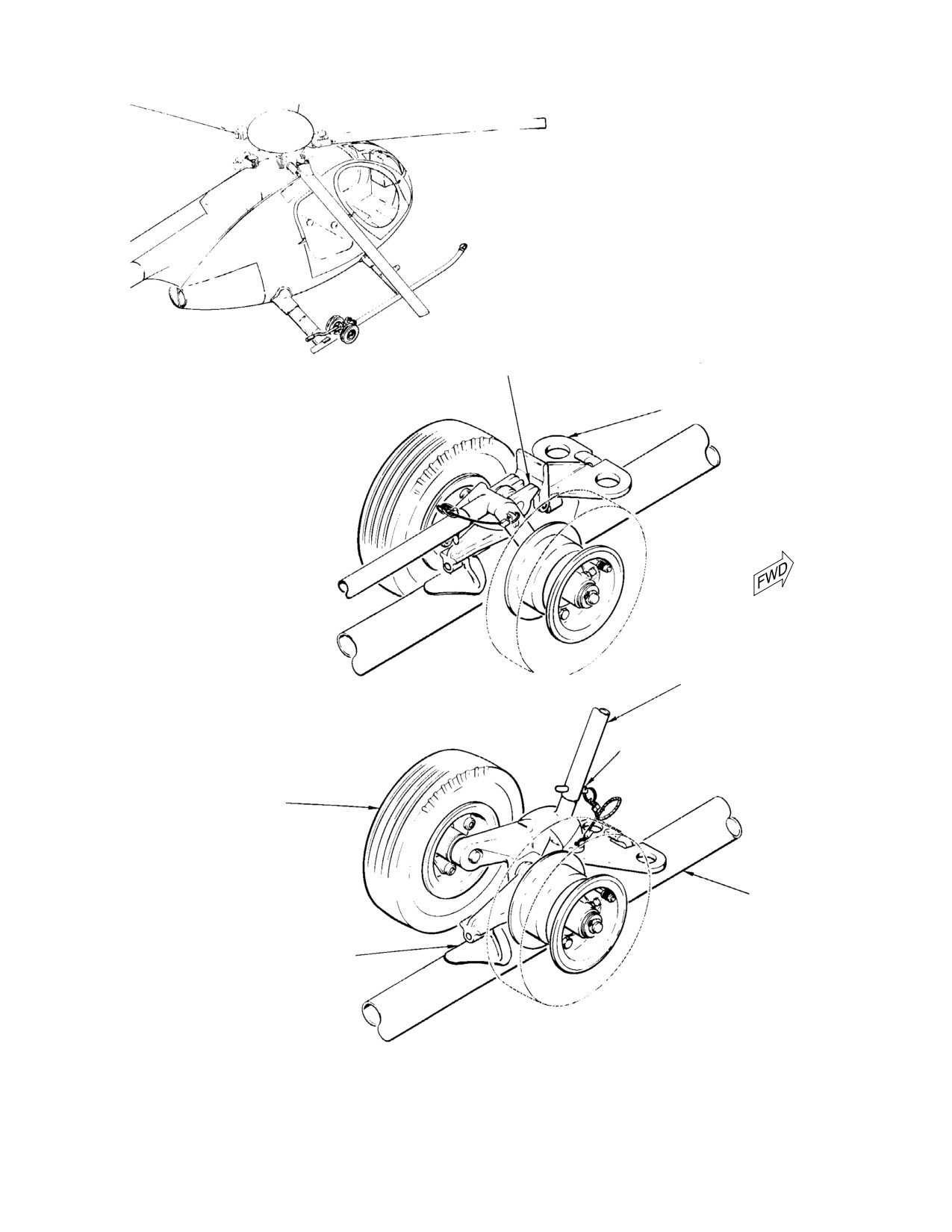
1. Ground Handling Wheels
201
A. Standard Ground Handling Wheels
201
B. Special Ground Handling Wheels (Float-Equipped Helicopters,
369D/E/FF - 500N)
201
2. Helicopter Towing and Manual Moving (369D/E/FF - 500N)
201
3. Helicopter Manual Moving (600N)
201
4. Helicopter Towing (600N)
202
Figure 201. Towing Helicopter (369D/E/FF - 500N)
203
Figure 202. Towing Helicopter (600N)
204
Page i
09 Contents
Revision 23
CSP-HMI-2
MD Helicopters, Inc.
MAINTENANCE MANUAL
TABLE OF CONTENTS (Cont.)
Para/Figure/Table
Title
Page
This Page Intentionally Left Blank
Page ii
Revision 43
09 Contents
MD Helicopters, Inc.
CSP-HMI-2
MAINTENANCE MANUAL
Section
09−00−00
Towing
MD Helicopters, Inc.
CSP-HMI-2
MAINTENANCE MANUAL
TOWING
MAINTENANCE PRACTICES
1. Ground Handling Wheels
Excessive lead-lag load applied
CAUTION
to the main rotor blades during
ground handling can result in damage to the
NOTE: At regular intervals, check wheel tire
elastomeric damper buns and failure of the
pressure and repack wheel bearings (Ref.
damper assembly. Operators and mainte
Sec. 32-40-00/32-40-60).
nance personnel should use extra caution to
avoid lead-lag loads in excess of 35 lb. (16
kg) at the tip of the main rotor blades.
A. Standard Ground Handling Wheels
(1). Attach ground handling wheels (ST101
or ST104) as shown (Ref. Figure 201),
(Ref. Figure 201) Standard ground handling
and hold tail up while lowering the
wheels, available as a special tool for helicop
wheels (raising helicopter) with
ters not equipped with floats, are used for
detachable jack handle (ST102 or
moving helicopter by hand and for towing
ST103).
helicopter. The wheels are manually lowered
with a detachable jack handle and are held in
(2). Manually move helicopter on ground
the down position (helicopter raised on wheels)
handling wheels by balancing at
by a mechanical lock. The wheels for the
tailboom and pushing on rear fuselage
369D/E/FF - 500N helicopters are equipped
portion of airframe.
with tow bar attach fitting.
Except under extreme emergen
CAUTION
cy conditions, do not tow heli
B. Special Ground Handling Wheels
copter at speeds over 5 mph (8 KmH). Do not
(Float−Equipped Helicopters, 369D/E/FF −
allow front ends of skid tubes to drag on
500N)
ground. Avoid sudden stops and starts, and
short turns which could cause helicopter to
turn over. Allow inside wheel to turn (not
Special ground handling wheels are available
pivot) while helicopter is being turned. Safe
for towing helicopters equipped with utility or
minimum turning radius is approximately
emergency floats (Ref. Sec. 32-40-00).
20 ft. (6 M).
NOTE: If tow bar is not equipped to keep front
end of skid tubes from dragging, have an as
2. Helicopter Towing and Manual Moving
sistant balance helicopter at tailboom.
(369D/E/FF − 500N)
(3). Tow helicopter on ground handling
wheels by attaching suitable tow bar to
Special Tools
tow bar fittings.
(Ref. Section 91−00−00)
Item
Nomenclature
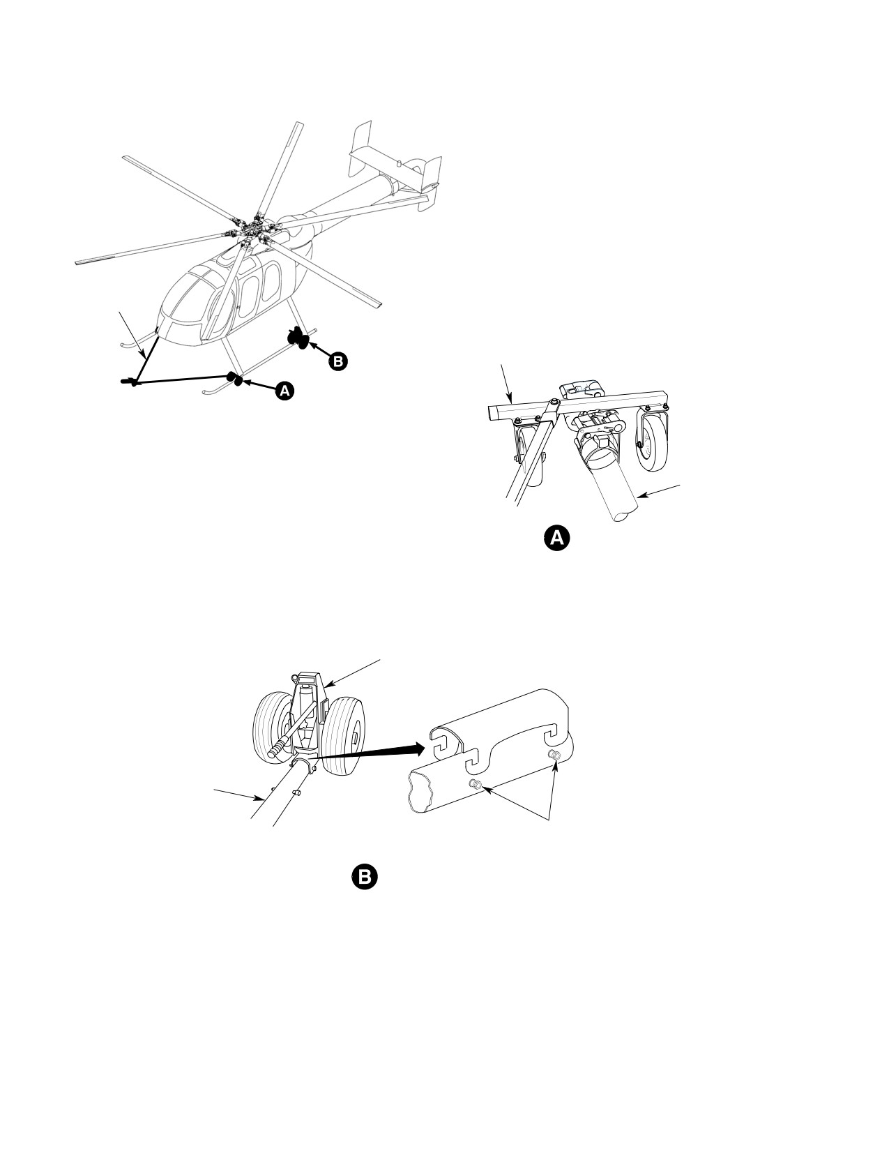
3. Helicopter Manual Moving (600N)
ST101
Ground handling wheels
(Ref. Figure 202)
ST102
Handle-jack assembly, ground handling
(straight)
Special Tools
ST103
Handle-jack assembly, ground handling
(Ref. Section 91−00−00)
(offset)
Item
Nomenclature
ST104
Ground handling wheels (one side)
ST101
Ground handling wheels
Page 201
09-00-00
Revision 23

CSP-HMI-2
MD Helicopters, Inc.
MAINTENANCE MANUAL
Excessive lead-lag load applied
ground handling wheel set, allowing the
CAUTION
to the main rotor blades during
helicopter to be moved by one person.
ground handling can result in damage to the
elastomeric damper buns and failure of the
Special Tools
damper assembly. Operators and mainte
(Ref. Section 91−00−00)
nance personnel should use extra caution to
Item
Nomenclature
avoid lead-lag loads in excess of 35 lb. (16
ST101
Ground handling wheels
kg) at the tip of the main rotor blades.
ST105
Tow bar (600N)
(1). Ensure all stress panels are installed
on helicopter before jacking.
Excessive lead-lag load applied
NOTE:
CAUTION
to the main rotor blades during
D The ground handling wheel set can be at
ground handling can result in damage to the
tached to the skids facing either direction
elastomeric damper buns and failure of the
for ease of jacking.
damper assembly. Operators and mainte
nance personnel should use extra caution to
D Ensure all four ground handling attach
avoid lead-lag loads in excess of 35 lb. (16
points are engaged in ground handling
kg) at the tip of the main rotor blades.
wheel set.
(2). Attach ground handling wheels (ST101)
(1). Ensure all stress panels are installed
and hold tail up while lowering the
on helicopter before jacking.
wheels (raising helicopter).
(2). Raise helicopter with ground handling
(3). Manually move helicopter on ground
wheel set (ST101).
handling wheels by balancing at
(3). Position tow bar (ST105), with caster
tailboom and pushing on rear fuselage
wheels, straddling front of skid tube
portion of airframe.
assembly.
Except under extreme emergen
CAUTION
(4). Attach nylon straps under skid tube
cy conditions, do not tow heli
and ratchet skid tube into rubber cups
copter at speeds over 5 mph (8 KmH). Do not
on tow bar.
allow front ends of skid tubes to drag on
ground. Avoid sudden stops and starts, and
Except under extreme emergen
short turns which could cause helicopter to
CAUTION
cy conditions, do not tow heli
turn over. Allow inside wheel to turn (not
copter at speeds over 5 mph (8 KmH). Do not
pivot) while helicopter is being turned. Safe
allow front ends of skid tubes to drag on
minimum turning radius is approximately
ground. Avoid sudden stops and starts, and
20 ft. (6 M).
short turns which could cause helicopter to
turn over. Allow inside wheel to turn (not
4. Helicopter Towing (600N)
pivot) while helicopter is being turned. Safe
(Ref. Figure 202) The tow bar is equipped with
minimum turning radius is approximately
caster wheels and is designed for use with the
20 ft. (6 M).
Page 202
Revision 23
09-00-00
MD Helicopters, Inc.
CSP-HMI-2
MAINTENANCE MANUAL
WARNING:
BE SURE LOCK SNAPS INTO
POSITION SHOWN BEFORE
LOCK
RELEASING JACK HANDLE
TOW BAR FITTING
JACK HANDLE
WHEELS LOWERED AND LOCKED
(HELICOPTER RAISED)
HANDLE LOCK PIN
GROUND HANDLING WHEELS
AND JACK ASSEMBLY
SKID TUBE
(RIGHT SIDE SHOWN)
SKID FITTING
WHEELS RAISED (HELICOPTER
LOWERED)
G09-0001
Figure 201. Towing Helicopter (369D/E/FF − 500N)
Page 203
09-00-00
Revision 23
CSP-HMI-2
MD Helicopters, Inc.
MAINTENANCE MANUAL
TOW BAR
TOW BAR
SKID TUBE AS
SEMBLY
VIEW ROTATED
GROUND HANDLING
WHEEL SET
SKID TUBE
ASSEMBLY
GROUND HANDLING
ATTACH POINTS
VIEW ROTATED
6G09-040
Figure 202. Towing Helicopter (600N)
Page 204
Revision 23
09-00-00

MD Helicopters, Inc.
CSP-HMI-2
MAINTENANCE MANUAL
Chapter
10
Parking and Mooring
MD Helicopters, Inc.
CSP-HMI-2
MAINTENANCE MANUAL
TABLE OF CONTENTS
Para/Figure/Table
Title
Page
10-10-00 Parking and Mooring
A
Maintenance Practices
201
1. Helicopter Parking
201
2. Helicopter Mooring
201
Figure 201. Parking and Mooring (Sheet 1 of 2)
203
10-20-00 Storage
A
Maintenance Practices
201
1. Preservation and Storage
201
2. Flyable Storage (No Time Limit)
201
A. Inspection Before Storage
201
B. Storage
201
C. Return to Service
201
3. Storage Up to 45 Days
201
A. Inspection During Storage
201
B. Storage
201
C. Return to Service
202
4. Storage Up to 6 Months
202
A. Inspection During Storage
202
B. Storage
202
C. Return to Service
203
10-30-00 Blade Folding
A
Maintenance Practices
201
1. Main Rotor Blades Storage Rack Description
201
2. Main Rotor Blades Storage Rack Inspection
201
3. Main Rotor Blades Folding and Unfolding
201
A. Helicopter Location for Blade Folding
201
B. Main Rotor Blades Folddown Preparation
201
C. Aft Main Rotor Blades Folding
202
D. Forward Main Rotor Blades Folding
203
Figure 201. Folding and Stowing Main Rotor Blades
204
E. Main Rotor Blades Unfolding Preparation
205
F. Aft Main Rotor Blades Unfolding
205
G. Forward Main Rotor Blades Unfolding
206
H. Main Rotor Blades Storage Rack Removal and Storage
206
4. Main Rotor Flight Controls Adjustment and Testing
206
Page i
10 Contents
Revision 23
CSP-HMI-2
MD Helicopters, Inc.
MAINTENANCE MANUAL
TABLE OF CONTENTS (Cont.)
Para/Figure/Table
Title
Page
This Page Intentionally Left Blank
Page ii
Revision 43
10 Contents
MD Helicopters, Inc.
CSP-HMI-2
MAINTENANCE MANUAL
Section
10−10−00
Parking and Mooring

MD Helicopters, Inc.
CSP-HMI-2
MAINTENANCE MANUAL
PARKING AND MOORING
MAINTENANCE PRACTICES
1. Helicopter Parking
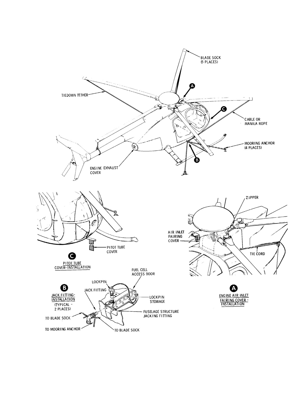
(c). Secure blade sock tiedown cord for
blade located above tailboom to
To park helicopter for short intervals, perform
tailboom. Secure other blade sock
following steps (1). thru (4). For longer
tiedown cords to fuselage jack fittings
duration parking, also perform steps (5). and
(ST202).
(6).
(4). Secure six-bladed main rotor blades as
follows:
Special Tools
(Ref. Section 91−00−00)
When securing blade sock tie
CAUTION
Item
Nomenclature
down cords, take up slack but do
not apply bending loads on blades.
ST202
Jack fittings
ST2002
Blade socks
(a). Position blades so that three blades
ST2004
Air inlet fairing cover
are on each side of helicopter (Ref.
ST2005
Engine exhaust cover
Figure 201).
(b). Install blade socks (ST2002) on all
blades.
To prevent rotor damage from
CAUTION
blade flapping
(droop stop
(c). Secure blade sock tiedown cords to
pounding) as a result of air turbulence from
fuselage jack fittings or cabin steps.
other aircraft landing, taking off or taxiing,
or sudden wind gusts, rotor blades should be
(5). Install air inlet fairing cover (ST2004)
secured whenever helicopter is parked.
on air inlet front fairing (Ref.
Figure 201).
(1). Locate helicopter slightly more than
blade clearance from nearby objects on
(6). Install engine exhaust cover (ST2005)
most level ground available.
on exhaust tailpipe (Ref. Figure 201).
(2). Apply friction to lock cyclic and collec
2. Helicopter Mooring
tive sticks so that friction control knobs
are positioned as follows: neutral for
Whenever severe storm conditions or wind
cyclic stick and full down for collective
velocities higher than 40 knots are forecast,
stick.
helicopter should be hangared or evacuated to
a safer area. If these precautions are not
NOTE: If not already accomplished, apply
possible, moor helicopter as follows.
paint mark on edge of guide to locate neu
tral position for future reference (Ref. Sec.
Special Tools
67-10-00).
(Ref. Section 91−00−00)
Item
Nomenclature
(3). Secure five-bladed main rotor blades as
follows:
N/A
Stakes or ground anchors (two)
N/A
Cable or rope
When securing blade sock tie
CAUTION
ST202
Jack fittings
down cords, take up slack but do
ST2001
Pitot tube cover
not apply bending loads on blades.
ST2004
Air inlet fairing cover
(a). Turn blades until one blade is
ST2005
Engine exhaust cover
directly above tailboom (Ref.
Figure 201).
(1). Park helicopter (Ref. Helicopter
(b). Install blade socks (ST2002) on all
Parking) or remove main rotor blades
blades.
(Ref. Sec. 62-10-00) and install air
Page 201
10-10-00
Revision 23
CSP-HMI-2
MD Helicopters, Inc.
MAINTENANCE MANUAL
inlet fairing cover (ST2004) and engine
(4). Apply friction to lock cyclic and collec
exhaust (ST2005) covers.
tive sticks (Ref. Helicopter Parking).
(5). Secure helicopter to ground by attach
(2). Install pitot tube cover (ST2001).
ing restraining lines (cable or rope)
between jack fittings (ST202) and
(3). Fill fuel tank (if possible) (Ref. Sec.
stakes or ground anchors (Ref.
12-00-00).
Figure 201).
Page 202
Revision 23
10-10-00
MD Helicopters, Inc.
CSP-HMI-2
MAINTENANCE MANUAL
G10−1001
Figure 201. Parking and Mooring (Sheet 1 of 2)
Page 203
10-10-00
Revision 23
CSP-HMI-2
MD Helicopters, Inc.
MAINTENANCE MANUAL
BLADE SOCK
(6 PLACES)
CABLE OR
MANILA ROPE
(6 PLACES)
MOORING ANCHOR
(4 PLACES)
ENGINE EXHAUST
COVER
ZIPPER
AIR INLET
FAIRING
COVER
PITOT TUBE
COVER
DOOR
ACCESS
LATCH
PITOT TUBE
TIE CORD
COVER INSTALLATION
FUEL CELL
ACCESS DOOR
LOCKPIN
ENGINE AIR INLET
LOCKPIN
JACK FITTING
STOWAGE
FAIRING COVER
INSTALLATION
TO BLADE SOCK
FUESELAGE
STRUCTURE
JACK FITTING
TO MOORING
ANCHOR
TO BLADE
SOCK
JACK FITTING INSTALLATION
(TYPICAL - 2 PLACES)
f60−039
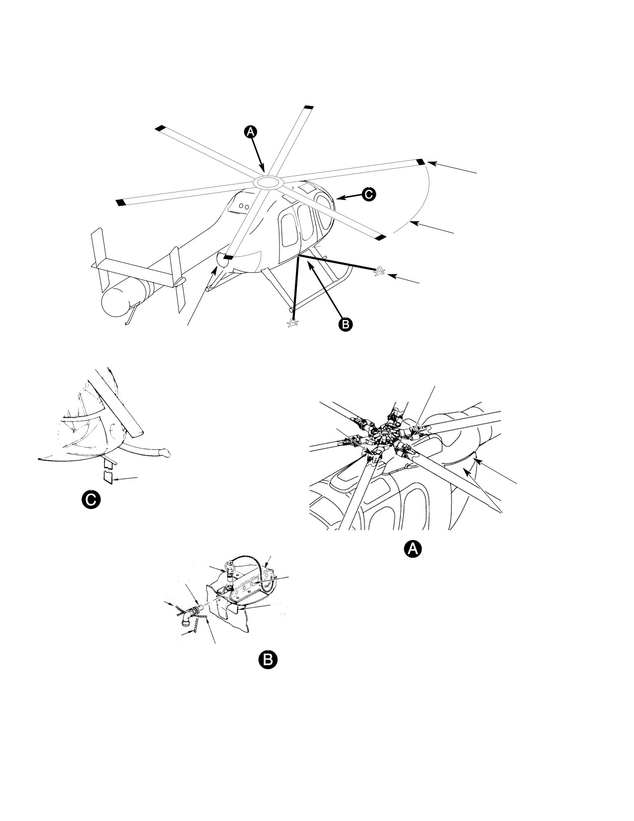
Figure 201. Parking and Mooring (Sheet 2 of 2)
Page 204
Revision 23
10-10-00
MD Helicopters, Inc.
CSP-HMI-2
MAINTENANCE MANUAL
Section
10−20−00
Storage
MD Helicopters, Inc.
CSP-HMI-2
MAINTENANCE MANUAL
STORAGE
MAINTENANCE PRACTICES
1. Preservation and Storage
(e). Open movable air vents in each door
of cargo compartment. Position
A helicopter to be placed in storage or non-op
opening in each air vent downward.
erational status must have adequate inspec
Close all other vents.
tion, maintenance and preservation to avoid
unnecessary deterioration of airframe and
(f). Install covers and equipment used to
components of equipment. Extent of preventive
park and moor helicopter.
maintenance that is to be performed depends
(g). Install a static ground.
on anticipated time in storage. Following
paragraphs describe what should be performed
C. Return to Service
in helicopter: for flyable storage; for up to 45
days in storage; and for up to 6 months in
(1). Remove covers and equipment used to
storage.
park and moor helicopter.
(2). Perform Daily Pre-Flight Check (Ref.
2. Flyable Storage (No Time Limit)
appropriate PFM or RFM).
A. Inspection Before Storage
3. Storage Up to 45 Days
(1). Perform Daily Pre-Flight Check (Ref.
A. Inspection During Storage
appropriate PFM or RFM).
(1).
Where local average humidity exceeds
(2). Ensure that fuel cells are full (topped
40 percent, carefully inspect helicopter
off), and that oil in engine oil tank and
every 15 days for corrosion. Perform
main, fan and tail rotor transmissions
corrosion control as necessary (Ref. Sec.
is at FULL level (Ref. Sec. 12-00-00).
20-40-00). When inspecting for
corrosion, pay particular attention to
B. Storage
those areas where moisture deposits do
not evaporate rapidly.
To maintain a flyable storage condition,
perform the following:
(2).
Where local average humidity is 40
percent or less, inspect for corrosion
(1). Perform Daily Pre-Flight Check (Ref.
every 30 days.
appropriate PFM or RFM).
(3).
If interior temperature of fuselage
(2). Perform ground runup at least once
exceeds 160°F (71°C), ventilate helicop
every five days (Ref. applicable PFM or
ter by opening all doors and vents. If
RFM, Table 201, Sec. 01-00-00).
necessary, promote air circulation by
use of fans or other forced air equip
(a). Start engine. After idle stabilizes,
ment.
accelerate engine to 100 percent N2,
collective full down. Operate until oil
(4).
Ensure that fuel cells are full (topped
temperature is in normal operating
off) and that rotor transmissions are at
range and ammeter indicates battery
FULL level.
is fully charged.
(5).
Drain fuel cell sump daily. (Replenish
fuel as necessary.)
(b). Shut down engine.
(6).
Check fuel and oil systems periodically
(c). Drain fuel cell sump (Ref. Sec.
for leakage. Replenish as necessary.
12-00-00). (Replenish fuel as neces
sary.)
B. Storage
(d). Ensure that fuel shutoff valve is
(1). Perform engine preservation according
closed (Ref. Sec. 28-00-00).
to applicable Allison Engine Operation
Page 201
10-20-00
Revision 23
CSP-HMI-2
MD Helicopters, Inc.
MAINTENANCE MANUAL
and Maintenance Manual (Ref. Table
(8). Perform Daily Pre-Flight Check (Ref.
201, Sec. 01-00-00) and current engine
appropriate PFM or RFM).
service letters.
4. Storage Up to 6 Months
(2).
Remove battery (Ref. Sec. 96-05-00)
A. Inspection During Storage
and store in cool, dry area.
(1). Perform same inspection as for 45 days
(3).
If necessary, clean battery compartment
of storage.
(Ref. Sec. 20-20-00).
(2). Check main rotor, tail rotor and fan
blades for damage every 15 days (Ref.
(4).
Ensure that fuel shutoff valve is closed
Chap. 62 and 64).
(Ref. Sec. 28-00-00).
(3). Check areas around mooring attach
(5).
Clean entire helicopter.
ments for damage every 15 days.
(6).
Inspect all drain holes (blades, fuselage,
B. Storage
etc.) for obstructions and clear where
necessary.
Consumable Materials
(Ref. Section 91−00−00)
(7).
Open movable air vents in each door of
Item
Nomenclature
cargo compartment; position opening in
each air vent downward. Close all other
CM201
Protective coating
air vents.
CM210
Corrosive preventive
CM729
Tape, masking, pressure sensitive
(8).
Park and moor helicopter.
(9).
Install a static ground.
Special Tools
(Ref. Section 91−00−00)
(10).
Remove from area any objects that are
Item
Nomenclature
likely to strike helicopter during high
ST2001
Pitot tube cover
wind conditions.
C. Return to Service
(1).
Perform engine preservation according
to applicable Allison Engine Operation
(1). Check that battery area is clean; then
and Maintenance Manual (Ref. Table
install and connect battery (Ref. Sec.
201, Sec. 01-00-00) and current
96-05-00).
applicable engine service letters.
(2). Check that fuel cells are full (Ref. Sec.
(2).
Drain engine oil system (Ref. Sec.
12-00-00).
12-00-00) and fill engine oil tank with
corrosion preventive (CM210).
(3). Remove covers and equipment used to
(3).
Remove battery (Ref. Sec. 96-05-00)
park and moor helicopter.
and store it in cool, dry area.
(4). Inspect areas around mooring attach
(4).
Clean battery compartment, if neces
ments for damage. Repair damage as
sary.
necessary.
(5).
Ensure that fuel shutoff valve is closed
(5). Clean helicopter, as necessary.
(Ref. Sec. 28-00-00).
(6). Check that all drain holes in helicopter
(6).
Seal static source openings in engine
are free of obstructions.
inlet fairing with masking tape
(CM729) and cover pitot tube with pitot
(7). Perform engine depreservation accord
tube cover (ST2001).
ing to applicable Allison Engine
(7).
Clean entire helicopter.
Operation and Maintenance Manual
(Ref. Table 201, Sec. 01-00-00) and
(8).
Inspect all drain holes (blades, fuselage,
current applicable engine service
etc) for obstructions and clear them
letters.
where necessary.
Page 202
Revision 23
10-20-00
MD Helicopters, Inc.
CSP-HMI-2
MAINTENANCE MANUAL
(9). Spray or brush on the canopy and all
(2). Remove masking tape from all external
windows a 0.008 inch (0.203 mm)
access doors.
thickness of protective coating (CM201).
Do not use steam or unautho
Cover and overlap all edges.
CAUTION
rized cleaning compounds to
(10). Inspect all external access doors for
clean helicopter as damage to equipment
close fit. If doors are likely to admit
may result.
moisture, seal edges with masking tape
(CM729).
(3). Drain corrosion preventive from oil
tank and replenish with correct oil (Ref.
(11). Park and moor helicopter.
Sec. 12-00-00).
(12). Install a static ground.
(4). Perform same procedures as for return
to service after 45 days of storage.
(13). Remove any objects from area that are
likely to strike helicopter during high
NOTE: Depreservation of engine fuel system
wind conditions.
can usually be accomplished by making a
normal start. (Ref. applicable Allison En
C. Return to Service
gine Operation and Maintenance Manual,
(1). Carefully lift protective coating along
Table 201, Sec. 01-00-00 and current appli
edges and peel it from canopy and
cable engine service letters for engine de
windows.
preservation procedures.)
Page 203
10-20-00
Revision 23
CSP-HMI-2
MD Helicopters, Inc.
MAINTENANCE MANUAL
This Page Intentionally Left Blank
Page 204
Revision 44
10-20-00
MD Helicopters, Inc.
CSP-HMI-2
MAINTENANCE MANUAL
Section
10−30−00
Blade Folding
MD Helicopters, Inc.
CSP-HMI-2
MAINTENANCE MANUAL
BLADE FOLDING
MAINTENANCE PRACTICES
1. Main Rotor Blades Storage Rack
(1). Verify that front and rear support
Description
assemblies are complete and tight in all
details.
(Ref. Figure 201)
(2). Visually inspect for missing nuts, bolts,
cushions, and shock cords.
(1).
The main rotor blade storage rack
(3). Verify that no support tubing is bent.
stows and secures the main rotor blades
on Model 369 helicopters during ground
(4). Verify that plywood of rear support is
handling operations. The storage rack
not split, cushions not torn, or nylon
consists of fore and aft units which,
webbing harness not missing its buckle.
when installed, provide blade protection
for helicopters that cannot be placed in
3. Main Rotor Blades Folding and Unfolding
hangers or evacuated during adverse
The following paragraphs provide instruction
weather conditions.
for operation of the main rotor blade storage
rack: For the unpinning of the main rotor
(2).
The aft blade storage rack supports
blades; for folding, unfolding, and repining of
three blades and consists of a plywood
the blades. Adjustment and testing of main
blade rack which incorporates shock
rotor flight controls, necessary after the blades
(bungee) cords and nylon-webbing
have been re-pinned, is also covered here.
harness straps with buckles, pull tabs,
(Ref. Sec. 20-40-00 for information about
and a grommet. The aft storage rack is
adjustment and corrosion protection of main
installed on the tailboom at Sta. 197.78,
rotor blade attaching pins.)
just above the jack fitting. A decal on
the aft side of the storage rack facili
If main rotor blades are to re
CAUTION
tates proper fore and aft positioning on
main folded for a considerable
the tailboom. The harness grommet
length of time, main rotor hub must be cov
engages the jack fitting and holds the
ered with a suitable weather-resistant cov
storage rack in position when the
er.
harness straps are tightened and
NOTE: A mechanic's assistant is needed for
secured. Shock cords secure the blades.
blade folding and unfolding.
(3).
The forward blade storage rack sup
A. Helicopter Location for Blade Folding
ports two blades and consists of a
(1). Locate helicopter slightly more than
plywood blade rack which incorporates
rotor span from other aircraft or
shock cords, blade clamp (top blade
vehicles.
only), rack support tubes, and landing
gear clamps. The storage rack is
(2). Park helicopter on the most level
installed forward of the fuselage so that
ground available so that the load is
the blade clamp support is positioned
balanced as much as possible.
left of the helicopter centerline. The
rack support tubes are secured with
B. Main Rotor Blades Folddown Preparation
clamps to the landing gear just aft of
the skid tip lights. Shock cords secure
Special Tools
the blades.
(Ref. Section 91−00−00)
Item
Nomenclature
2.
Main Rotor Blades Storage Rack
ST2003
Main rotor blade storage rack
Inspection
ST2004
Air inlet fairing cover
ST2005
Engine exhaust cover
(Ref. Figure 201)
Page 201
10-30-00
Revision 23

CSP-HMI-2
MD Helicopters, Inc.
MAINTENANCE MANUAL
(1). Inspect rack (Ref. Main Rotor Blades
(a). Position rear blade support assembly
Storage Rack Inspection).
on tailboom at Sta. 197.78, with its
lower step on left side of helicopter.
(2). Position main rotor so that one blade is
(b). Attach and secure straps. Adjust
directly above and parallel to helicopter
strap pull tabs so that harness
tailboom.
grommet engages jack fitting on
tailboom.
(3). Lock cyclic control stick (by applying
friction) in the following positions:
(2). Install trailing rotor blade to aft storage
rack.
(a). Set collective pitch to mid position.
(a). Into center cushioned support step of
(b). Set longitudinal cyclic to full aft
rear blade support assembly, position
position.
trailing rotor blade (blade that is
directly above and parallel to tail
(c). Set lateral cyclic to two thirds of total
boom).
stick travel from full left toward full
right.
Blade movement must be re
CAUTION
strained in the following steps
During blade folding, continual
to prevent damage since, with damper dis
CAUTION
ly monitor stick positions to
engaged, the blade is free to pivot on blade
make sure no change occurs. Serious blade
attaching pin.
damage may result from improper stick
(b). Remove bolt or (alternatively)
placement.
attaching pin from damper arm of
trailing rotor blade, and move
(4). Disconnect wires or antennas (as
damper away from blade; replace bolt
applicable) at tailboom attach fitting,
and coil them.
(or attaching pin) in damper arm.
NOTE: It is not necessary to remove a blade at
(5). Cover (ST2004 and ST2005) engine air
taching pin in order to fold the first blade.
inlet and exhaust openings to prevent
entry of foreign objects during blade
(c). Secure blade in support assembly
folding.
with shock cord fastener.
During blade folding, use blade
(3). Install remaining blades to aft storage
CAUTION
support pole (ST2003). Prevent
rack.
scratching of blade by attaching pins or
Blade movement must be re
bolts. Avoid brushing of blades against one
CAUTION
strained in the following steps
another or against any other surface. Lift
to prevent damage since, with damper dis
blade near tip to remove load on blade at
engaged, the blade is free to pivot on blade
taching pins.
attaching pin.
C. Aft Main Rotor Blades Folding
NOTE: The right blade goes to the top hold
down position, and the left blade to the bot
(Ref. Figure 201)
tom holddown position.
(a). Remove bolt or (alternatively)
Special Tools
attaching pin from damper arm of
(Ref. Section 91−00−00)
rotor blade, and move damper away
Item
Nomenclature
from blade; replace bolt (or attaching
ST2003
Main rotor blade storage rack
pin) in damper arm.
(b). Unlock (but do not remove) blade
(1). Install aft storage rack (ST2003) to
attaching pin that secures leading
helicopter.
edge of blade to main rotor hub.
Page 202
Revision 23
10-30-00
MD Helicopters, Inc.
CSP-HMI-2
MAINTENANCE MANUAL
(c). Unlock and remove blade attaching
(d). Attach upper ends of support tubes to
pin that secures trailing edge of blade
double blade support. Adjust tube
to lead-lag link, and position cam
length to proper height as required
handle vertically above pin.
for extended or standard landing
gear. Secure with hardware provided.
(d). Instruct mechanic's assistant using
blade-support pole (ST2003) to guide
(2). Install left forward blade to forward
rotor blade to its proper position on
storage rack. Observe that one blade is
rear support assembly.
directly above the left side of the front
blade support assembly. Secure that
(e). Secure blade in support assembly
blade in support with shock cord
with shock cord fastener.
fastener and hinged clamp fastener
(f). Reinstall blade attaching pin its
support.
original position in lead-lag link of
main rotor hub.
NOTE: It is not necessary to remove blade at
taching pins from the main rotor assembly
D. Forward Main Rotor Blades Folding
or damper arm in order to secure this blade.
(Ref. Figure 201)
(3). Install right forward blade to forward
storage rack.
Special Tools
(Ref. Section 91−00−00)
Blade movement must be re
CAUTION
Item
Nomenclature
strained in the following steps
to prevent damage since, with damper dis
ST2003
Main rotor blade storage rack
engaged, the blade is free to pivot on blade
attaching pin.
(1). Install forward storage rack (ST2003)
to helicopter.
(a). Remove bolt or (alternatively)
attaching pin from damper arm of
(a). Position blade storage rack so that
right forward blade and move damp
top holddown position on rack is
er away from rotor blade; replace bolt
approximately 15 degrees left of
(or attaching pin) in damper arm.
helicopter centerline.
(b). Unlock and remove blade attaching
(b). Attach U-bolt clamp subassemblies
pin that secures trailing edge of blade
to forward ends of each landing gear
to lead-lag link, and position cam
skid. Secure with hardware provided.
handle vertically above pin.
Ensure that each U-bolt is attached
ahead of curved portion of skid (but
(c). Instruct mechanic's assistant using
aft of skid tip light) to assure ground
blade support pole to guide rotor
clearance.
blade to its proper position on right
side of double blade front support.
NOTE: Top adjustment holes in support tubes
are for extended landing gear; bottom holes
(d). Secure blade in support assembly
are for standard landing gear.
with shock cord fastener.
(c). Attach lower ends of support tubes to
U-bolt clamp brackets. Attach short
(e). Reinstall blade attaching pin into its
tube to left skid. Secure with hard
original position in lead-lag link of
ware provided.
main rotor hub.
Page 203
10-30-00
Revision 23
CSP-HMI-2
MD Helicopters, Inc.
MAINTENANCE MANUAL
G10−3000
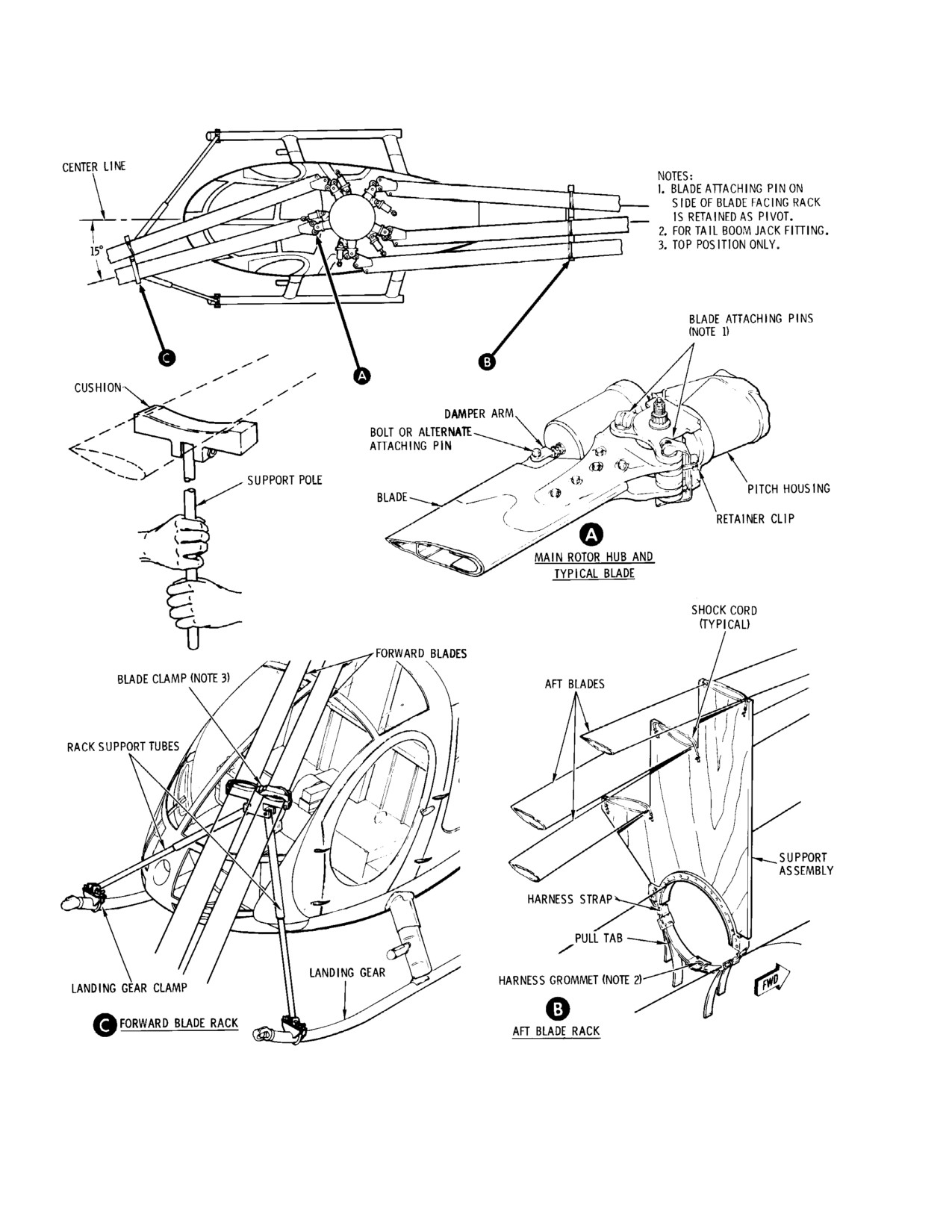
Figure 201. Folding and Stowing Main Rotor Blades
Page 204
Revision 23
10-30-00

MD Helicopters, Inc.
CSP-HMI-2
MAINTENANCE MANUAL
E. Main Rotor Blades Unfolding Preparation
(1). Begin with the trailing blade, the one
supported by the center support step of
the rear blade support assembly.
Special Tools
(Ref. Section 91−00−00)
Blade movement must be re
CAUTION
Item
Nomenclature
strained in the following steps
to prevent damage since, with damper dis
ST2003
Main rotor blade storage rack
engaged, the blade is free to pivot on blade
ST2004
Air inlet fairing cover
attaching pin.
ST2005
Engine exhaust cover
(a). Remove damper arm bolt or (alterna
tively) attaching pin from damper
Before unfolding the main rotor blades,
arm clevis. Extend and align damper
perform the following steps:
arm with bolt hole in trailing edge of
blade. Insert bolt or attaching pin,
(1). Lock cyclic control stick, by applying
but: If pin is used, do not lock pin at
friction, in the following positions:
this time; if bolt is used, tighten to
torque of 30 - 60 inch-pounds (3.39
(a). Set collective pitch to mid position.
- 6.78 Nm) and insert cotter pin.
(b). Set longitudinal cyclic to full aft
(b). Remove shock cord fastener and
position.
release blade from support.
NOTE: Only the damper arm attaching bolt (or
(c). Set lateral cyclic to two thirds of total
pin) was removed from this blade during
stick travel from full left toward full
folding, not a lead-lag link attaching pin.
right.
(2). For the remaining aft secured rotor
During blade unfolding, contin
blades, proceed as follows:
CAUTION
ually monitor stick positions to
make sure no change occurs. Serious blade
Blade movement must be re
CAUTION
damage may result from improper stick
strained in the following steps
placement.
to prevent damage since, with damper dis
engaged, the blade is free to pivot on blade
(2). Cover (ST2004 and ST2005) engine air
attaching pin.
inlet and exhaust openings to prevent
(a). Remove shock cord fastener and
entry of foreign objects during blade
release blade from support.
folding.
(b). Instruct mechanic's assistant using
During blade unfolding, use
blade support pole (ST2003) to lift
CAUTION
blade support pole (ST2003).
and rotate blade forward to align
Prevent scratching of blade by attaching
trailing edge of blade and attachment
pins or bolts. Avoid brushing of blades
hole in lead-lag link of main rotor
against one another or against any other
hub (remove attaching pin from
surface. Lift blade near tip to remove load
lead-lag link to allow hole align
on attaching pin.
ment). Re-insert attaching pin (but
do not lock at this time).
F. Aft Main Rotor Blades Unfolding
(c). Remove damper arm bolt or (alterna
(Ref. Figure 201)
tively) attaching pin from damper
arm clevis. Extend and align damper
arm with bolt hole in trailing edge of
Special Tools
blade. Insert bolt or attaching pin
(Ref. Section 91−00−00)
but: If pin is used, do not lock pin at
Item
Nomenclature
this time; if bolt is used, tighten to
ST2003
Main rotor blade storage rack
torque of 30 - 60 inch-pounds (3.39
- 6.78 Nm) and insert cotter pin.
Page 205
10-30-00
Revision 23
CSP-HMI-2
MD Helicopters, Inc.
MAINTENANCE MANUAL
G. Forward Main Rotor Blades Unfolding
H. Main Rotor Blades Storage Rack Removal
and Storage
(Ref. Figure 201)
(Ref. Figure 201)
Special Tools
(Ref. Section 91−00−00)
(1). Remove covers from engine exhaust
Item
Nomenclature
and air inlet fairing.
ST2003
Main rotor blade storage rack
(2). Unbuckle nylon webbing harness of
rear blade support assembly to disen
(1). Begin with the blade stowed on the left
gage aft blade storage rack from
side of the double blade front support
tailboom. Further disassembly is not
assembly. No attaching pins were
required.
removed from this blade for storage.
Release hinged clamp fastener support
(3). Loosen or remove wing nuts to disen
and shock cord fastener. Alignment is
gage U-bolt clamp subassemblies from
not necessary.
front end of landing gear skid assembly.
Remove forward blade storage rack
(2). For remaining forward rotor blade,
from helicopter.
proceed as follows:
Blade movement must be re
(4). Store blade storage racks.
CAUTION
strained in the following steps
to prevent damage since, with damper dis
(5). Reconnect any wires or antennas
engaged, the blade is free to pivot on blade
disconnected for blade folding.
attaching pin.
(a). Remove shock cord fastener and
4. Main Rotor Flight Controls Adjustment
release blade from support.
and Testing
(b). Instruct mechanic's assistant using
(Ref. Figure 201) Perform the following steps
blade support pole (ST2003) to lift
after main rotor blades have been unfolded
and rotate blade aft to align trailing
and repined.
edge of blade and attachment hole in
lead-lag link of main rotor hub
(1). Lock all attaching pins and check that
(remove attaching pin from lead-lag
locking force required to close pin
link to allow hole alignment). Re-in
handle is 25 - 35 pounds force (111.2
sert attaching pin (but do not lock at
- 155.7 N) (Ref. Sec. 62-10-00 Main
this time).
Rotor Blade and Damper Attach Pin
Installation and Adjustment, Sec.
(c). Remove damper arm bolt or (alterna
62-10-00).
tively) attaching pin from damper
arm clevis. Extend and align damper
arm with bolt hole in trailing edge of
NOTE: Blade attaching pin handle is posi
blade. Insert bolt or attaching pin,
tioned behind retainer clip as shown.
but: If pin is used, do not lock pin at
this time; if bolt is used, tighten to
(2). Loosen friction on cyclic and collective
torque of 30 - 60 inch pounds (3.39
sticks and check movement of controls
- 6.78 Nm) and insert cotter pin.
through complete range of travel.
Page 206
Revision 23
10-30-00

MD Helicopters, Inc.
CSP-HMI-2
MAINTENANCE MANUAL
Chapter
11
Placards and
Markings
MD Helicopters, Inc.
CSP-HMI-2
MAINTENANCE MANUAL
TABLE OF CONTENTS
Para/Figure/Table
Title
Page
11-00-00 Placards and Markings
A
Maintenance Practices
201
1. General
201
2. Decal Application
201
Figure 201. Placards - Exterior (Sheet 1 of 5)
202
Figure 202. Placards - Interior (Sheet 1 of 5)
207
Figure 203. Placards - Instrument Panels (Sheet 1 of 2)
212
Figure 204. Placards - Optional Equipment (Sheet 1 of 4)
214
11-40-00 Placards and Markings (600N)
A
Maintenance Practices
201
1. General
201
2. Decal Application
201
Figure 201. Exterior Placards and Markings (Sheet 1 of 4)
202
Figure 202. Interior Placards and Markings (Sheet 1 of 4)
206
Figure 203. Instrument Panel Placards and Markings (Sheet 1 of 2)
210
Page i
11 Contents
Revision 23
CSP-HMI-2
MD Helicopters, Inc.
MAINTENANCE MANUAL
TABLE OF CONTENTS (Cont.)
Para/Figure/Table
Title
Page
This Page Intentionally Left Blank
Page ii
Revision 43
11 Contents
MD Helicopters, Inc.
CSP-HMI-2
MAINTENANCE MANUAL
Section
11−00−00
Placards and
Markings
MD Helicopters, Inc.
CSP-HMI-2
MAINTENANCE MANUAL
PLACARDS AND MARKINGS
MAINTENANCE PRACTICES
1. General
2. Decal Application
(1). Where a decal overlaps or covers drain
(Ref. Figure 201 thru Figure 204 for placards
holes, access doors, etc., the decal shall
and markings most common to 369D/E/FF -
be cut out to provide proper draining or
500N Model Helicopters). Nomenclature
ease of opening or removing of doors,
corresponds to that used in the IPC. (Ref.
plates, etc.
Illustrated Parts Catalog for each decal part
number and the quantity required.)
(2). Where a decal is applied over a skin lap
(one skin overlapping another), the
The following illustrations cover different
decal must be cut so that it lies flat and
areas of decal placement on the helicopter:
makes a positive bond.
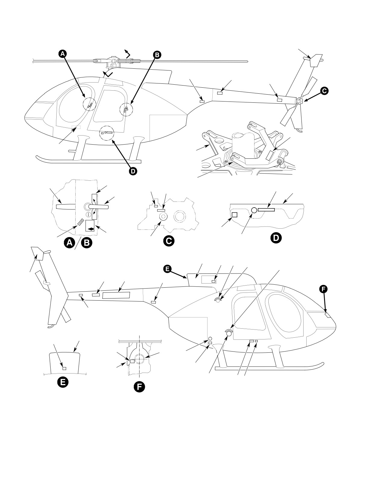
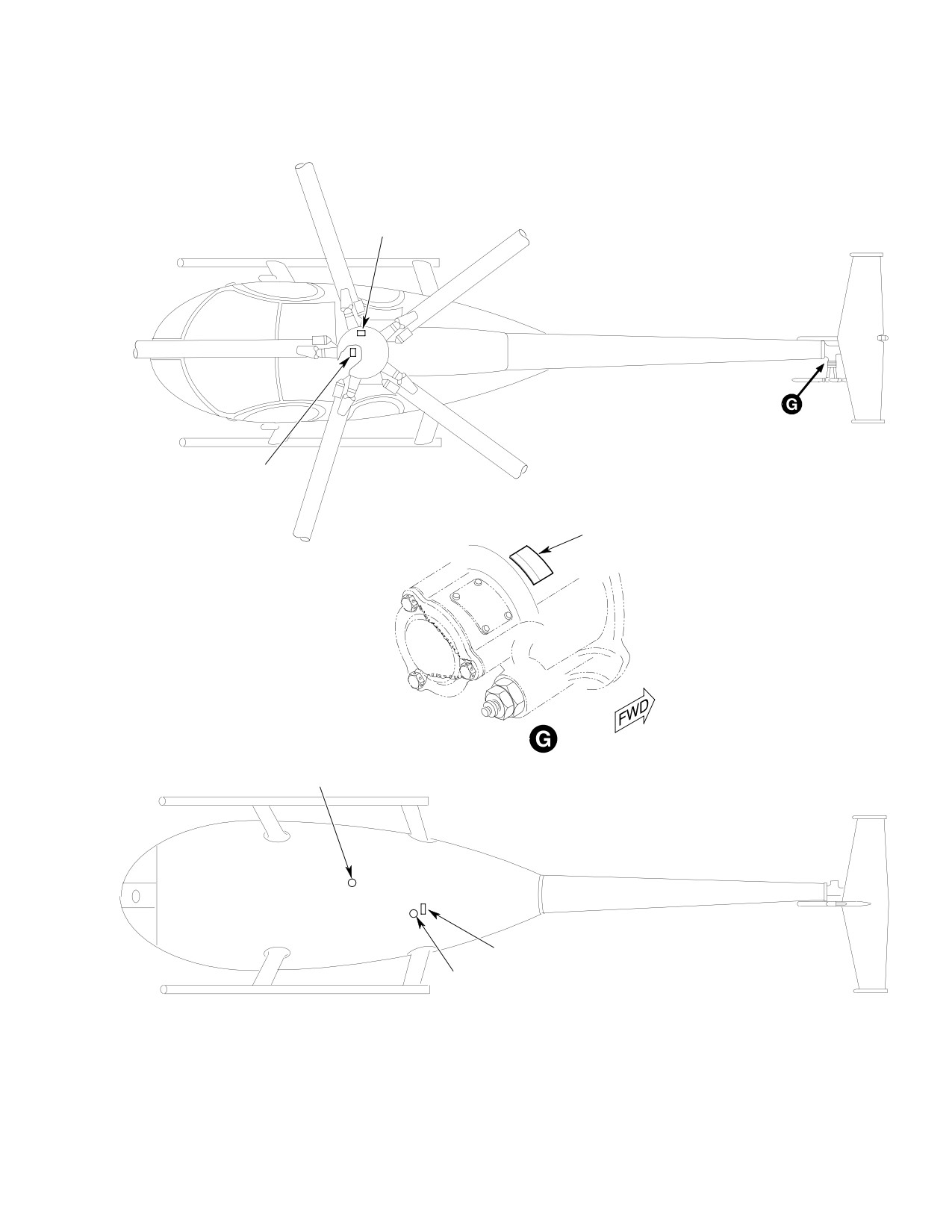
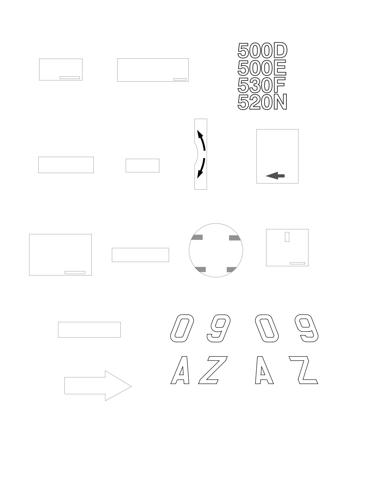
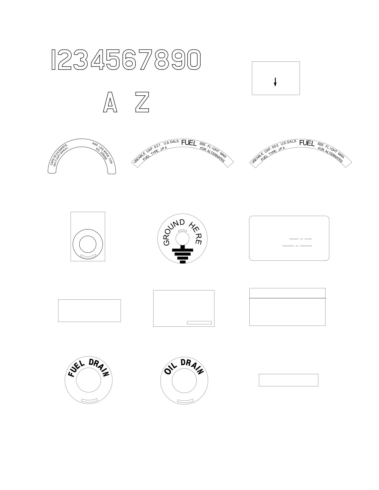
(1). Exterior - Figure 201.
(3). Seal edges of all exterior decals, and
only those interior decals in the engine
(2). Interior - Figure 202.
compartment and cargo compartment
aft of the transmission, with epoxy
(3). Instrument panels - Figure 203.
adhesive. Edge sealing to be a mini
mum of 1/32 inch (0.8mm) and a
(4). Optional equipment (various exterior
maximum of 1/8 inch (3mm) around
and interior locations) - Figure 204.
perimeter of decal.
Page 201
11-00-00
Revision 23
CSP-HMI-2
MD Helicopters, Inc.
MAINTENANCE MANUAL
A
3
500E
A
1
2
1
4
21
(NOTE 1)
ROTATING
SWASHPLATE
INNER
SCISSORS
6
DETAIL A-A
CRANK
CARGO
HANDLE
8
12
9
TO
OUTER
FLOOR
LOCK
HANDLE
TO
OPEN
CAUTION
11
7
5
10
JACK PAD
500E
EXT. LH DOOR SHOWN
OIL CAP
RH OPPOSITE
15
16
17
(REF)
18
3
13
14
N9011F
1
1
SHIP
L
FAIRING
19
AIR
16
20
DUCT
(REF)
21
HEATER
(NOTE 2)
DUCT
(REF)
FUEL CAP
12
11
(REF)
NOTES:
1.
EFFECTIVE ON S/N:
369D;
001 AND SUBS.
369E;
001 - 300
369FF;
001 - 054
2.
EFFECTIVE ON S/N:
369E;
301 AND SUBS
369FF;
055 AND SUBS
G11-0000-1B
500N
001 AND SUBS
Figure 201. Placards − Exterior (Sheet 1 of 5)
Page 202
Revision 23
11-00-00
MD Helicopters, Inc.
CSP-HMI-2
MAINTENANCE MANUAL
22
23
24
25
27
26
G11-0000-2
Figure 201. Placards − Exterior (Sheet 2 of 5)
Page 203
11-00-00
Revision 23
CSP-HMI-2
MD Helicopters, Inc.
MAINTENANCE MANUAL
CAUTION
PUSH
DISCONNECT ELECTRICAL WIRING
BEFORE REMOVING BOOM
1.
PUSH
2.
ELECTRICAL
DISCONNECT
3.
500D / 500E / 530F / 520N
TO
LOCK
CAUTION
SAFELOCK
INNER HANDLE
IN POSITION
INSTALL THIS SIDE
SHOWN BEFORE
TOWARD BLADES
LOCKED
FLIGHT
4.
MAIN ROTOR
5.
LOCKED
TO
OPEN
6.
OPEN AND LOCK,
7.
LOCK BEFORE FLIGHT,
OUTER, LH & RH
LH & RH
FULL
CAP. 0.4 U.S. PTS.
JIG POINT
SEE FLT MANUAL
CHECK LEVEL
STA 92.64
AND LOG BOOK
FOR OIL USAGE
ADD
8.
TAIL ROTOR
9.
CHECK LEVEL
10. OIL LEVEL PLUG
11. JIG POINT
TRANSMISSION OIL
THRU
THRU
ATTACH JACK PAD
12. JACK PAD
THRU
THRU
DANGER
LEFT-HAND
RIGHT-HAND
LETTERS AND NUMERALS
LETTERS AND NUMERALS
13. DANGER
14. RADIO CALL
G11−0000−3A
Figure 201. Placards − Exterior (Sheet 3 of 5)
Page 204
Revision 23
11-00-00
MD Helicopters, Inc.
CSP-HMI-2
MAINTENANCE MANUAL
STATIC LINE
DRAIN VALVE
PUSH BOTTOM UP
THRU
16. STATIC LINE
15. RADIO CALL
OIL
17. OIL
18. NON SELF-SEALING FUEL CELLS
18. SELF-SEALING FUEL CELLS
FUEL 62.1 GALLONS
FUEL 60.0 GALLONS
STATIC PORT
KEEP HOLES AND
MCDONNELL DOUGLAS
SURFACE CLEAN
HELICOPTER CO. MESA, AZ
MODEL NO. 369
SERIAL NO.
TYPE CERT NO. H3WE
PROD CERT NO. 410
19. STATIC PORT
20. GROUND SYMBOL
21. MODEL IDENTIFICATION
WARNING
CAP. 12.0 U.S. PTS.
SEE FLT MANUAL
DO NOT SUPPORT
TORQUE SCREWS
AND LOG BOOK
GEAR BOX WEIGHT FROM
TO 20−25 IN−LB
FOR OIL USAGE
DRIVE SHAFT COUPLING
22. HUB FAIRING
23. MAIN ROTOR
24. TAIL ROTOR
SCREW TORQUE
TRANSMISSION OIL
GEARBOX WARNING
ENGINE VENT
27. ENGINE VENT
25. FUEL DRAIN
26. OIL DRAIN
G11-0000-4
Figure 201. Placards − Exterior (Sheet 4 of 5)
Page 205
11-00-00
Revision 23
CSP-HMI-2
MD Helicopters, Inc.
MAINTENANCE MANUAL
28
30
30
2
29
31
1
32
33
1
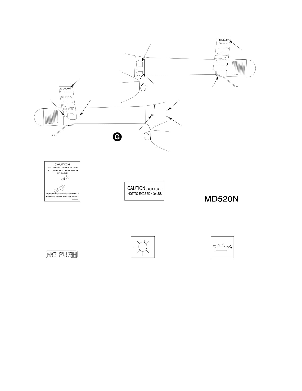
28. CAUTION-CABLE
29. CAUTION-JACK LOAD
30. MODEL MUMBER
31. NO PUSH INFORMATION
32. LIGHT ACCESS
33. TRANSMISSION CHECK
G11-0000-5
Figure 201. Placards − Exterior (Sheet 5 of 5)
Page 206
Revision 23
11-00-00
MD Helicopters, Inc.
CSP-HMI-2
MAINTENANCE MANUAL
11
5
8
10
9
1
4
6
3
7
2
ROTATED
13
14
15
G11-0002-1
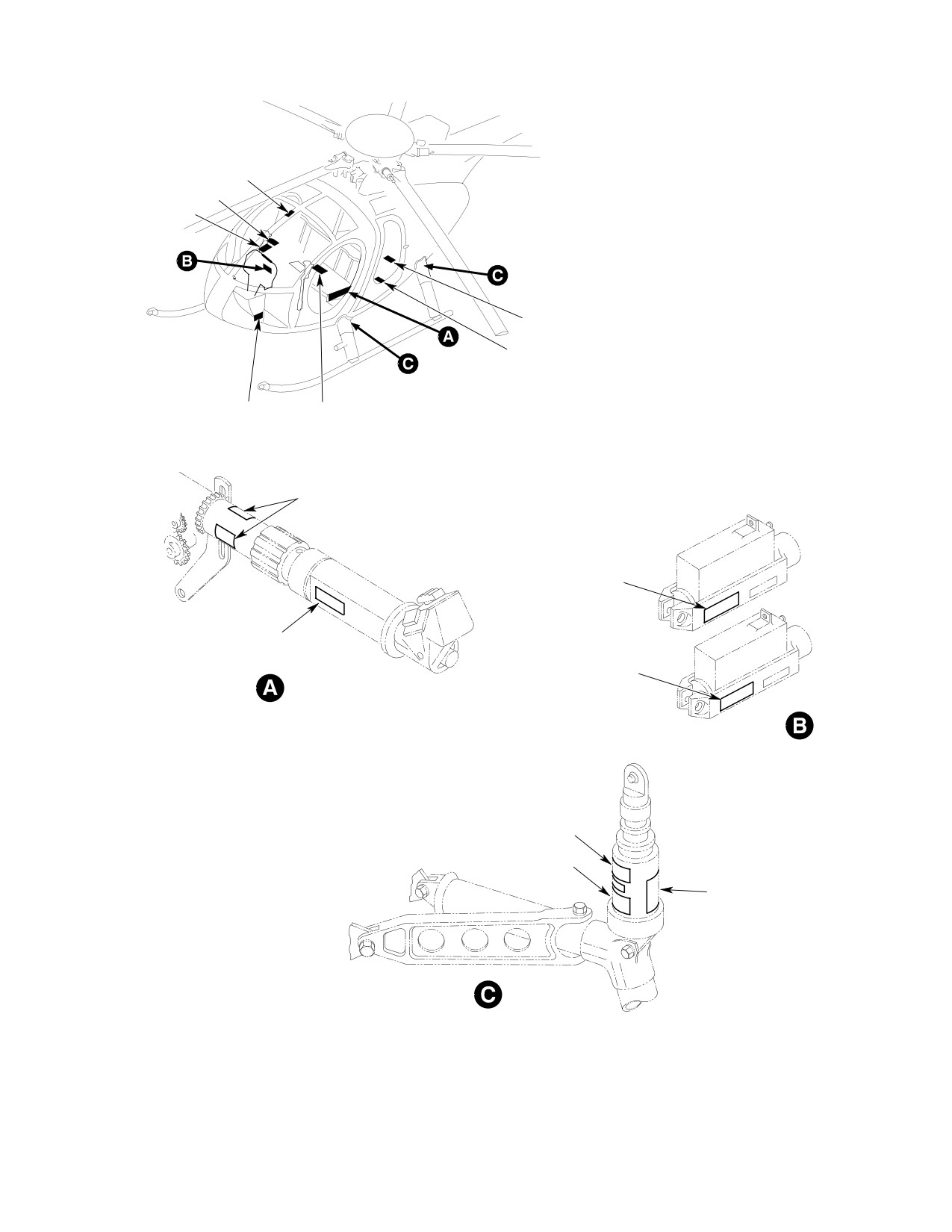
Figure 202. Placards − Interior (Sheet 1 of 5)
Page 207
11-00-00
Revision 23
CSP-HMI-2
MD Helicopters, Inc.
MAINTENANCE MANUAL
18
17
16
20
18
20
19
16
17
17
17
G11-0002-2
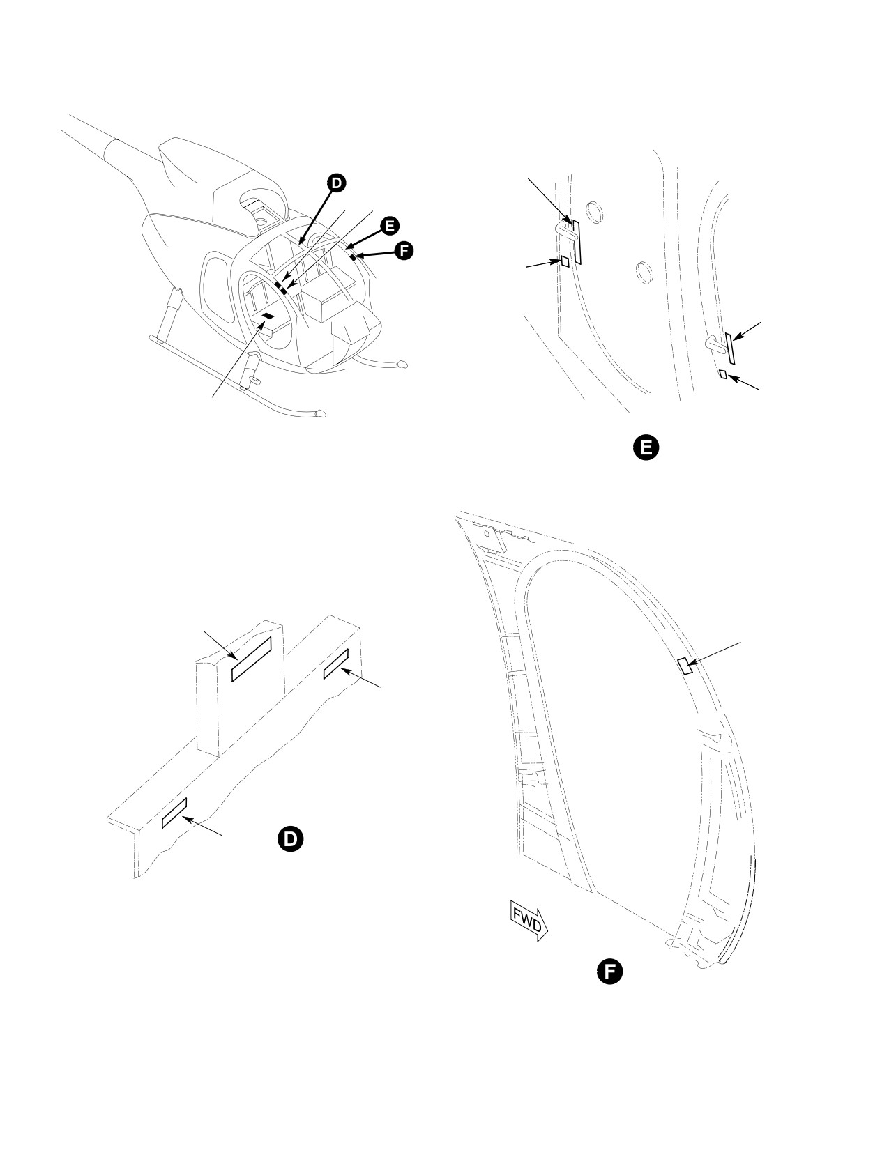
Figure 202. Placards − Interior (Sheet 2 of 5)
Page 208
Revision 23
11-00-00
MD Helicopters, Inc.
CSP-HMI-2
MAINTENANCE MANUAL
26
28
AFT BULKHEAD
21
ACCESS COVER
12
( NOTE 2 )
25
23
24
27
22
( NOTE 1 )
ROTATED
NOTES:
1.
NOT APPLICABLE TO 369D, SHIP
NO. 605 AND SUBSEQUENT,
2.
NOT APPLICABLE TO 369E/FF - 500N.
ROTATED
G11-0002-3A
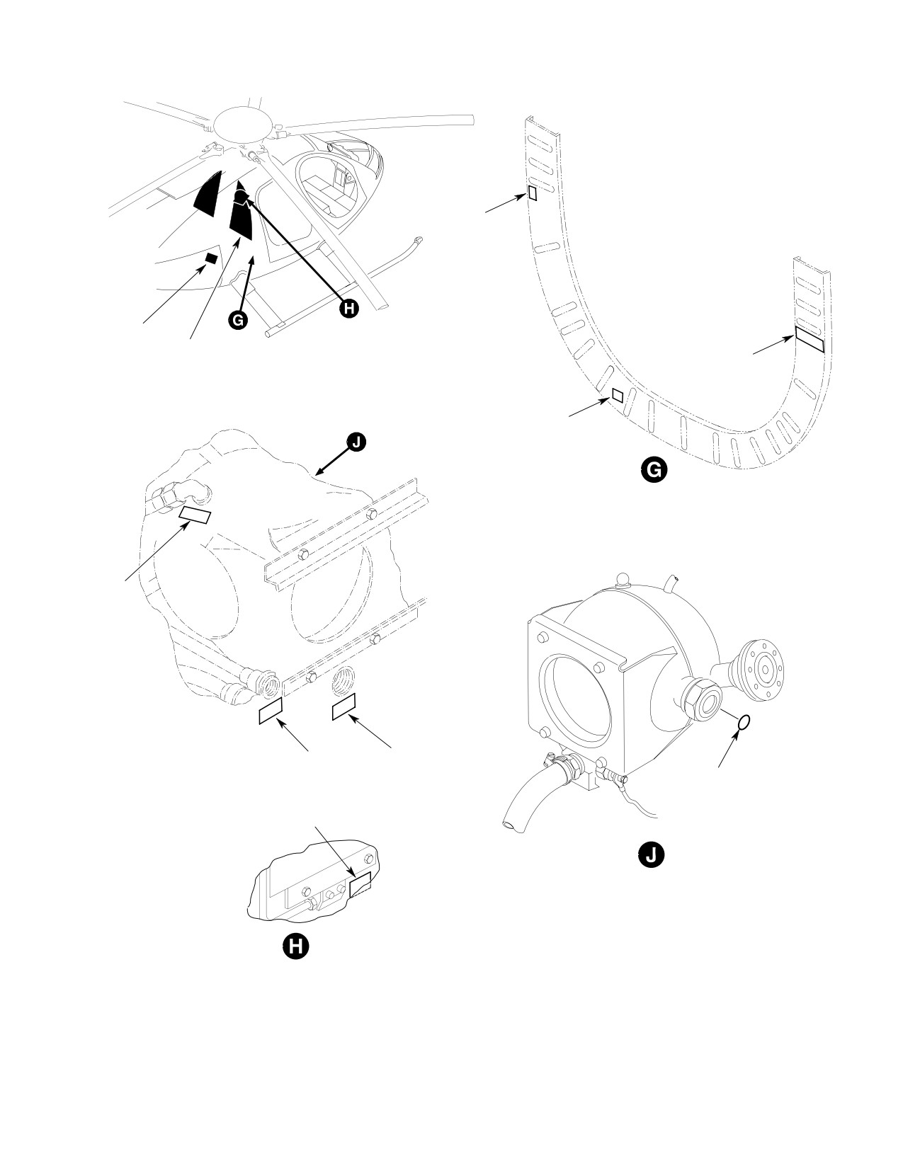
Figure 202. Placards − Interior (Sheet 3 of 5)
Page 209
11-00-00
Revision 23
CSP-HMI-2
MD Helicopters, Inc.
MAINTENANCE MANUAL
CONTROLS ACCESS DOOR
VOLTAGE REGULATOR
CAUTION
WARNING
ONLY QUALIFIED PERSONNEL
LAT TRIM
LONG TRIM
REPLACE DOOR BEFORE FLIGHT
WILL ADJUST THIS ASSEMBLY
4.
CONTROLS ACCESS DOOR
1.
VOLTAGE REGULATOR
2.
LATERAL TRIM
3.
LONGITUDINAL TRIM
WARNING - REPLACE DOOR
(369D;
S/N 002 AND
BEFORE FLIGHT
SUBS.)
(369E;
S/N 001 THRU
383 )
(369FF;
S/N 001 THRU
075)
T
H
R
O
T
T
FRICTION
IF MOISTURE VISIBLE
L
AND O.A.T. BELOW 5o C
E
INCREASE
24 VOLT DC
USE ANTI-ICE
OPEN
5.
OUTSIDE AIR TEMPERATURE
7.
FRICTION INCREASE
8.
24 VOLTS DC
6.
THROTTLE OPEN
OFF
CLOSE
BYP
DOOR
CAUTION
CABIN
ACTIVATE BOOST
HEAT
FUEL ACCESS DOOR
OPEN
PUMP BEFORE AND
WARNING
DURING DRAINING
LEVEL HERE
REPLACE DOOR BEFORE FLIGHT
FUEL SAMPLE
AND JACKING AIRCRAFT
ON
9.
LEVEL HERE
10. FUEL ACCESS DOOR
11. BYPASS DOOR
12. FUEL SAMPLING
ENGINE ANTI-ICE
(369D;
S/N 002 AND
SUBS.)
(369E;
S/N 001 THRU
383 )
DAMPER CHARGED RECOMMENDED
(369FF;
S/N 001 THRU
o
o
SERVICE BETWEEN 125
F TO 10
F
075)
SEE HANDBOOK OF MAINTENANCE
INSTRUCTIONS.
WARNING
CAUTION
CAUTION
UNIT CHARGED WITH HIGH PRES -
USE ONLY WITH
USE ONLY IN TWO
DAMPER CHARGED RECOMMENDED
SURE GAS. REFER TO HANDBOOK
STANDARD LANDING
AFT POSITIONS OR
SERVICE BETWEEN 70Fo TO -40 Fo
MAINTENANCE INSTRUCTIONS OR
GEAR OR IN TWO
EXTENDED LANDING
SEE HANDBOOK OF MAINTENANCE
RETURN TO MANUFACTURER ON
FORWARD POSITIONS
GEAR. DO NOT USE
INSTRUCTIONS.
OR EXTENDED
WITH STANDARD
EVIDENCE OF LEAKAGE OR
LANDING GEAR
LANDING GEAR.
MALFUNCTION.
DAMPER CHARGED RECOMMENDED
WHITE
BLACK
SERVICE BETWEEN 90Fo TO -25 Fo
DAMPER
DAMPER
SEE HANDBOOK OF MAINTENANCE
14. DAMPER WARNING
ONLY
ONLY
INSTRUCTIONS.
13. DAMPER SERVICE
15. DAMPER CAUTION
G11-0002-4A
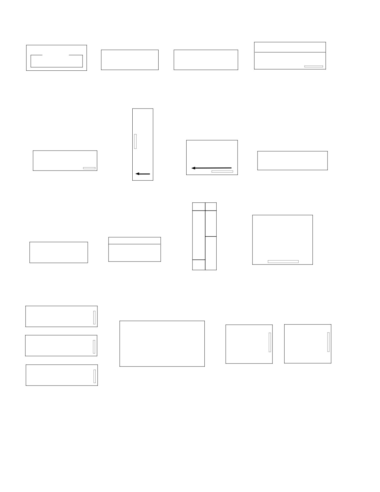
Figure 202. Placards − Interior (Sheet 4 of 5)
Page 210
Revision 23
11-00-00
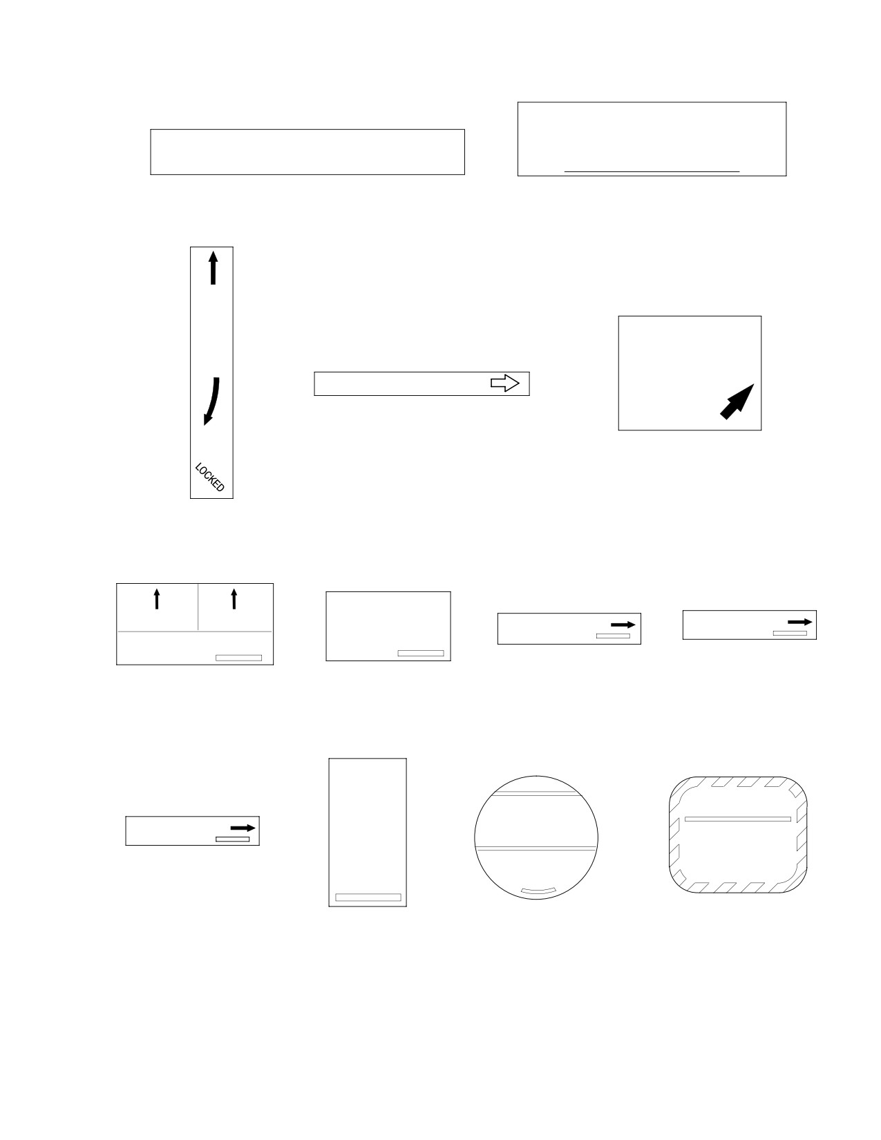
MD Helicopters, Inc.
CSP-HMI-2
MAINTENANCE MANUAL
DANGER
WHEN EXITING, WALK AWAY FROM THE
CAUTION - TO ASSURE PROPER RESTRAINT. ADJUST SHOULDER
HARNESS SLIDE SO HARNESS IS SNUG AGAINST TORSO
HELICOPTER, KEEP HANDS AND HEAD LOW,
WHILE SEATED UPRIGHT. FULL BACK IN THE SEAT
DO NOT WALK TO THE REAR.
16. CAUTION - SHOULDER HARNESS
17. EXIT
TO
OPEN
CAUTION
SAFELOCK
HANDLE IN
LONG RANGE TANK CONN
POSITION
SHOWN BEFORE
FLIGHT
19. LONG RANGE TANK CONNECTION
TO
LOCK
20. LOOK BEFORE EXIT
18. DOOR INSTRUCTIONS
PULL & TURN
TANK
COOLER
90o TO DRAIN
OIL TANK VENT
OIL TANK OUTLET
ENGINE LUBE OIL
ENGINE OIL DRAINS
23. OIL TANK OUTLET
24. OIL TANK VENT
22. OIL DRAINS
21. ENGINE OIL DRAINS
(369D:
S/N 002 −
605)
M/R
XMSN
FULL
WARNING
OIL
OIL TANK INLET
FAILURE TO PROPERLY INSTALL,ALIGN
COOLER
AND TORQUE,FUEL,OIL AND AIR TUBES
AND FITTINGS COULD RESULT IN AN
DRAIN
ENGINE FAILURE.REFER TO THE APPLI
25. DECAL. OIL TANK INLET
ADD 1 PINT
CABLE MANUAL FOR PROPER INSTAL4
ATION AND TORQUE PROCEDURES
26. MAIN ROTOR TRANSMISSION
28. WARNING
27.
,OIL LEVEL
OIL COOLER DRAIN
G11-0002-5A
Figure 202. Placards − Interior (Sheet 5 of 5)
Page 211
11-00-00
Revision 23
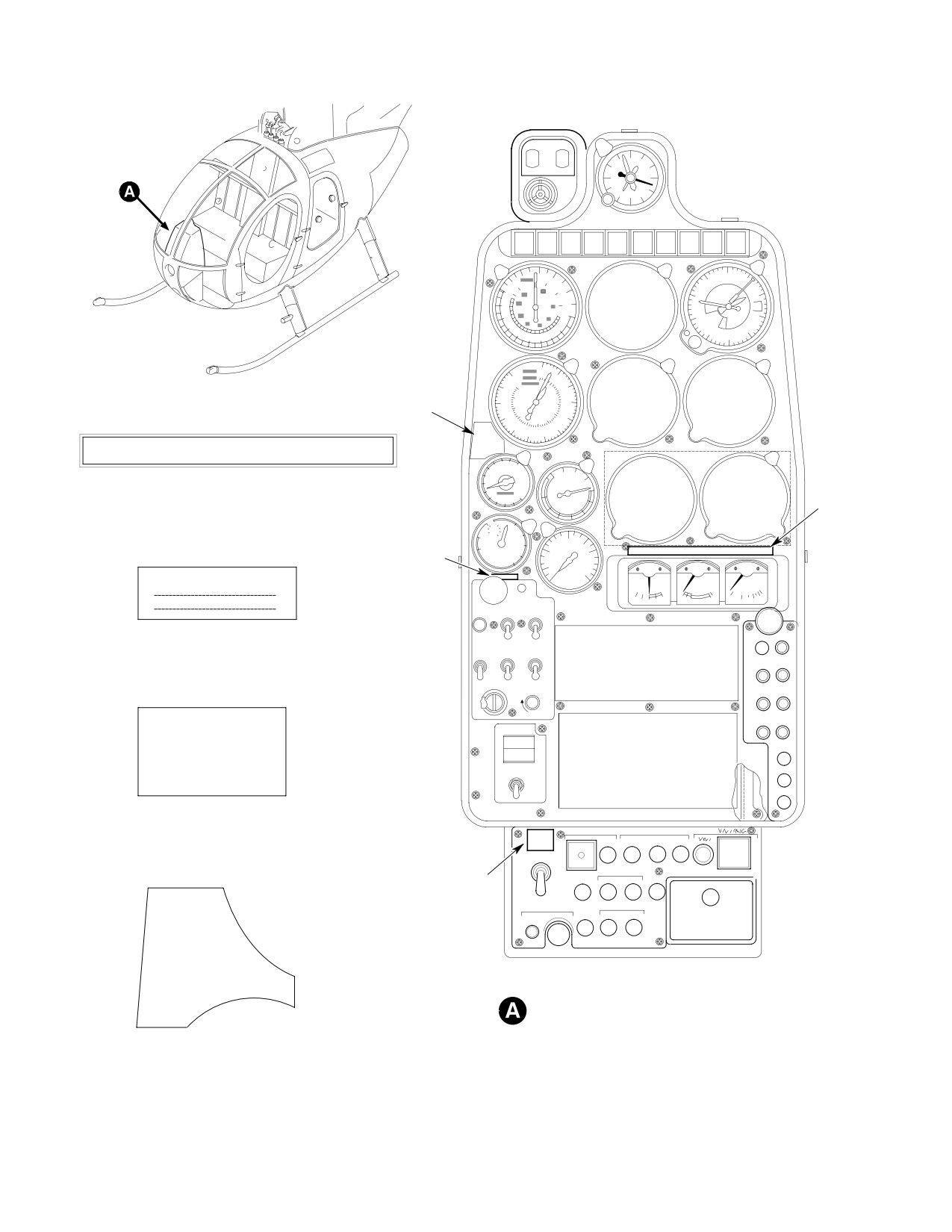
CSP-HMI-2
MD Helicopters, Inc.
MAINTENANCE MANUAL
BATTERY
12
140 F
150 F
9
3
6
ENGINE
XMSN
XMSN
GEN
ENGINE
XMSN
XMSN
FUEL
FUEL
PRESS
OUT
OIL
OIL
OUT
CHIPS
CHIPS
LOW
FILTER
TO
PRESS
CHIPS
TEST
TEMP
20
0
1
9
140
8
2
120
40
7
3
100
4
60
6
5
80
ALTITUDE
0
120
10
110
20
1
100
9
30
4
7
3
90
5
40
CAUTION
80
50
CYCLECYFSWWP
70
60
TO TRIM
THIS HELICOPTER MUST BE OPERATED IN COMPLIANCE WITH THE OPERATING
TO NEUTRAL
BRINGHTEVKKD
LIMITATIONS SPECIFIED IN THE F.A.A. APPROVED ROTORCRAFT FLIGHT MANUAL.
ADJUPLVVCMTMRUE
10
12
8
TQI
90
100
1.
FLIGHT COMPLIANCE
6
80
120
70
TORQUE
4
0
60
2
PSI
10
50
20
1
40
30
10
100
20
100
80
30
PERCENT
40
50
150
2
70
RPM
50
60
PRESS
RADIO CALL
P
PULL
AMPS
U
TO
S
CLOSE
ON
H
UTILITY
START
PWR
PUMP
PULL
FOR
AIR
OFF
GYRO
2.
RADIO CALL
CFM
POS
ANTI-COLL
LT
PNL
F
F
F
OFF
ON
BRT
TRIM
PRESS TO
ENG OUT
MID FRONT SEAT IS
RESET
NOT TO BE OCCUPIED
REIGN
NAV/COM
ARMED
IN FALLING AND/ OR
AUTO REIGN
ADF
BLOWING SNOW
TEST
XPDR
3.
SNOW WARNING
EMERG FLOATS
SEARCHLIGHT
AUTO
PRESS TO TEST
PWR
CONT
EXT
BATTERY
O
PRESS TO
HOIST
TEST
OFF
PRESS TO TEST
F
CARGO
3
F
HOOK
PWR
CTR
CAUTION
CIGAR LIGHTER
RADIO
PA
PWR
COMM 1
-CYCLIC
XMIT
FORCES TO
SYS
COMM 2
BE TRIMMED TO
NEUTRAL DURING
STARTUP AND SHUT-
DOWN
SLIM-LINE INSTRUMENT PANEL (369D)
4.
CYCLIC STICK POSITION WARNING
G11-0001-1A
Figure 203. Placards − Instrument Panels (Sheet 1 of 2)
Page 212
Revision 23
11-00-00
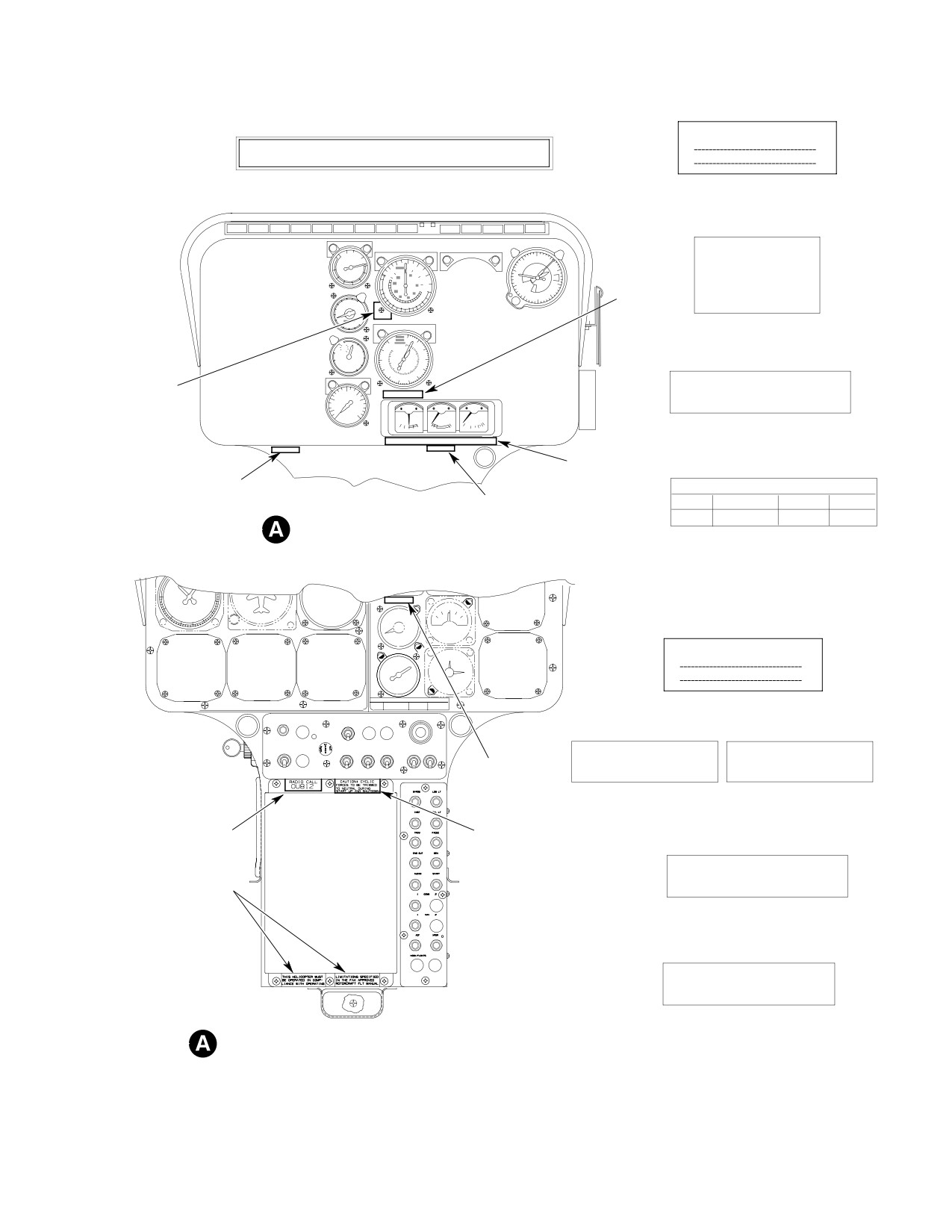
MD Helicopters, Inc.
CSP-HMI-2
MAINTENANCE MANUAL
RADIO CALL
THIS HELICOPTER MUST BE OPERATED IN COMPLIANCE WITH THE OPERATING
LIMITATIONS SPECIFIED IN THE F.A.A. APPROVED ROTORCRAFT FLIGHT MANUAL.
1.
FLIGHT COMPLIANCE
2.
RADIO CALL
80
90
100
VNE
70
TORQUE
120
9
0
1
60
10
140
20
50
PSI
20
8
2
130 KTS. I.A.S.
40
30
120
40
7
3
WITH LESS THAN
6
5ALTITUDE
4
100
60
4
35 LBS. FUEL
8
10
TQI
12
80
6
4
2
0
3.
LOW FUEL WARNING
0
10
120
10
100
20
110
1
20
80
30
100
9
30
70
PERCENT
40
7
3
60
RPM
50
90
5
40
80
70
60
50
CAUTION CYCLIC FORCES TO BE
3
100
TRIMMED TO NEUTRAL DURING
50
150
STARTUP AND SHUTDOWN
PRESS
AMPS
4.
CYCLIC STICK POSITION WARNING
PULL
FOR
AIR
1
2
START RECOMMENDATIONS
5
OAT
oC
-32 TO -18
-18 TO 7
7 TO 46
N
1 7o/o
12
13
15
T-INSTRUMENT PANEL (369MD)
5.
START RECOMMENDATIONS
RADIO CALL
1.
RADIO CALL
EXT
ANTI-COLL
PITOT
FUEL
O
START PUMP
LT
HTR
PULLFOR
VALVE
FF
AIR
EXT PWR
OFF
OFF
OFF
GEN
SCAV
POS
UTIL
OVSPD
FAULT
AIR
LTS
ANTI-ICE
PWR
TEST
TEST
THIS HELICOPTER MUST
LIMITATIONS SPECIFIED
BE OPERATED IN COMP-
IN THE F.A.A. APPROVED
OFF
OFF
OFF
OFF
OFF
OFF
OFF
4
LIANCE WITH OPERATING
ROTORCRAFT FLT MANUAL.
2.
FLIGHT COMPLIANCE
1
3
CAUTION CYCLIC FORCES TO BE
TRIMMED TO NEUTRAL DURING
2
STARTUP AND SHUTDOWN
3.
CYCLIC STICK POSITION WARNING
V NE 50 KTS MAX WHEN
TORQUE EXCEEDS 48.9 CONT.
4.
WARNING HIGH TORQUE. 369 FF
T-INSTRUMENT PANEL (369E/FF - 500N)
G11-0001-2A
Figure 203. Placards − Instrument Panels (Sheet 2 of 2)
Page 213
11-00-00
Revision 23
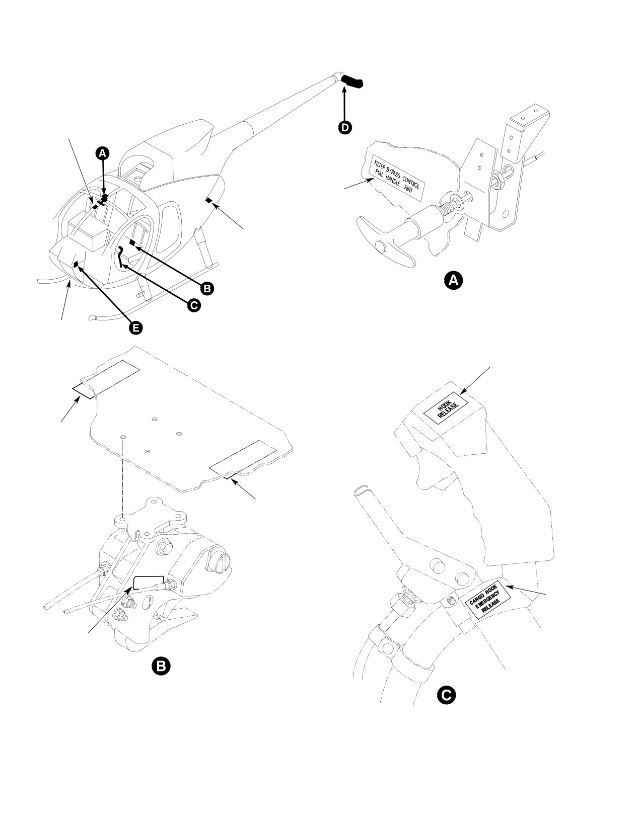
CSP-HMI-2
MD Helicopters, Inc.
MAINTENANCE MANUAL
ANTI-ICE
FUEL
FILTER
6
1
14
ENGINE OIL
SCAVENGE FILTER
PARTICLE SEPARATOR
8
HEATED
PITOT
TUBE
4
2
2
3
15
CARGO HOOK
CARGO HOOK
G11-0003-1
Figure 204. Placards − Optional Equipment (Sheet 1 of 4)
Page 214
Revision 23
11-00-00
MD Helicopters, Inc.
CSP-HMI-2
MAINTENANCE MANUAL
7
5
FOUR BLADE TAIL ROTOR
AUTOMATIC ENGINE RE-IGNITION
G11-0003-2
Figure 204. Placards − Optional Equipment (Sheet 2 of 4)
Page 215
11-00-00
Revision 23
CSP-HMI-2
MD Helicopters, Inc.
MAINTENANCE MANUAL
12
11
13
12
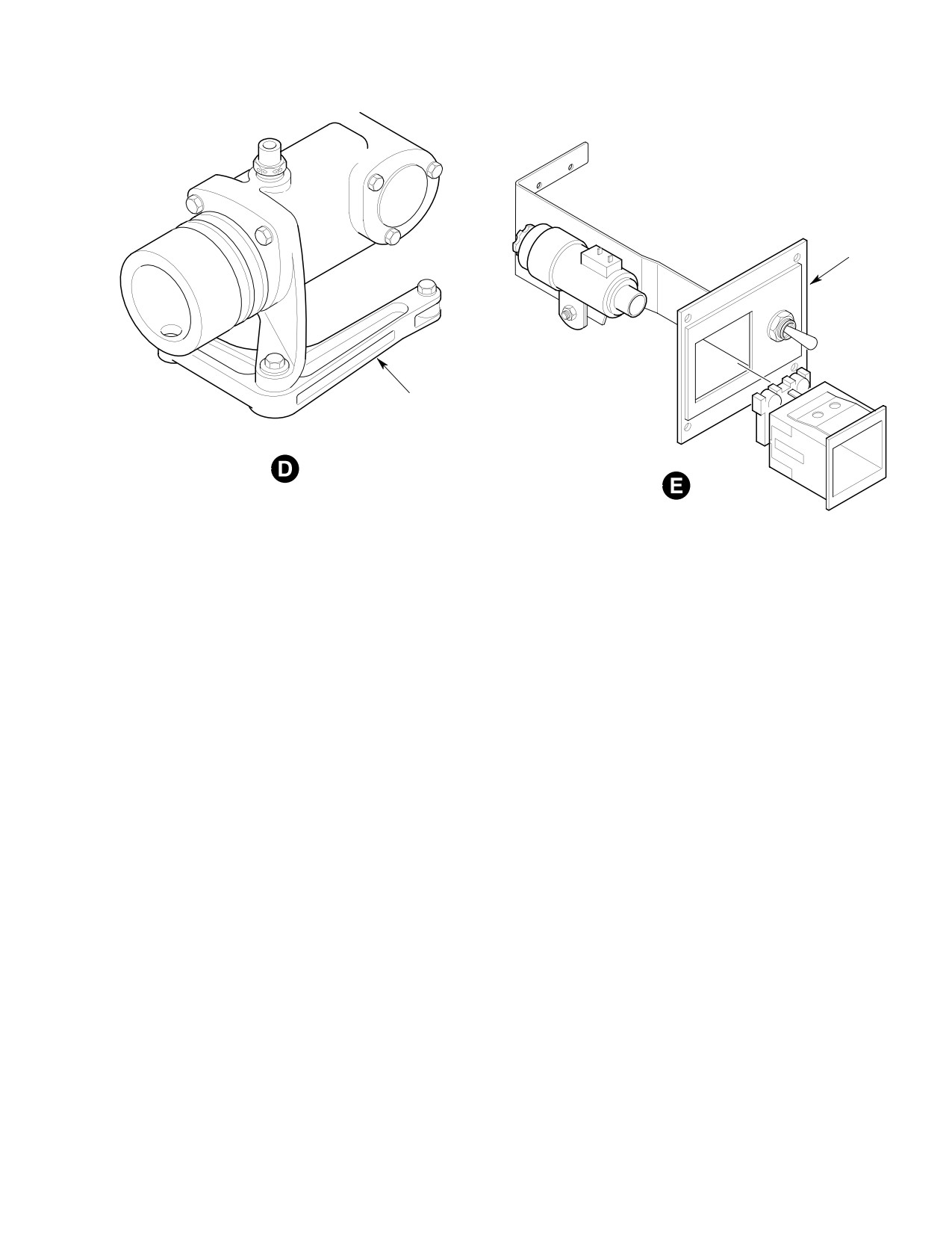
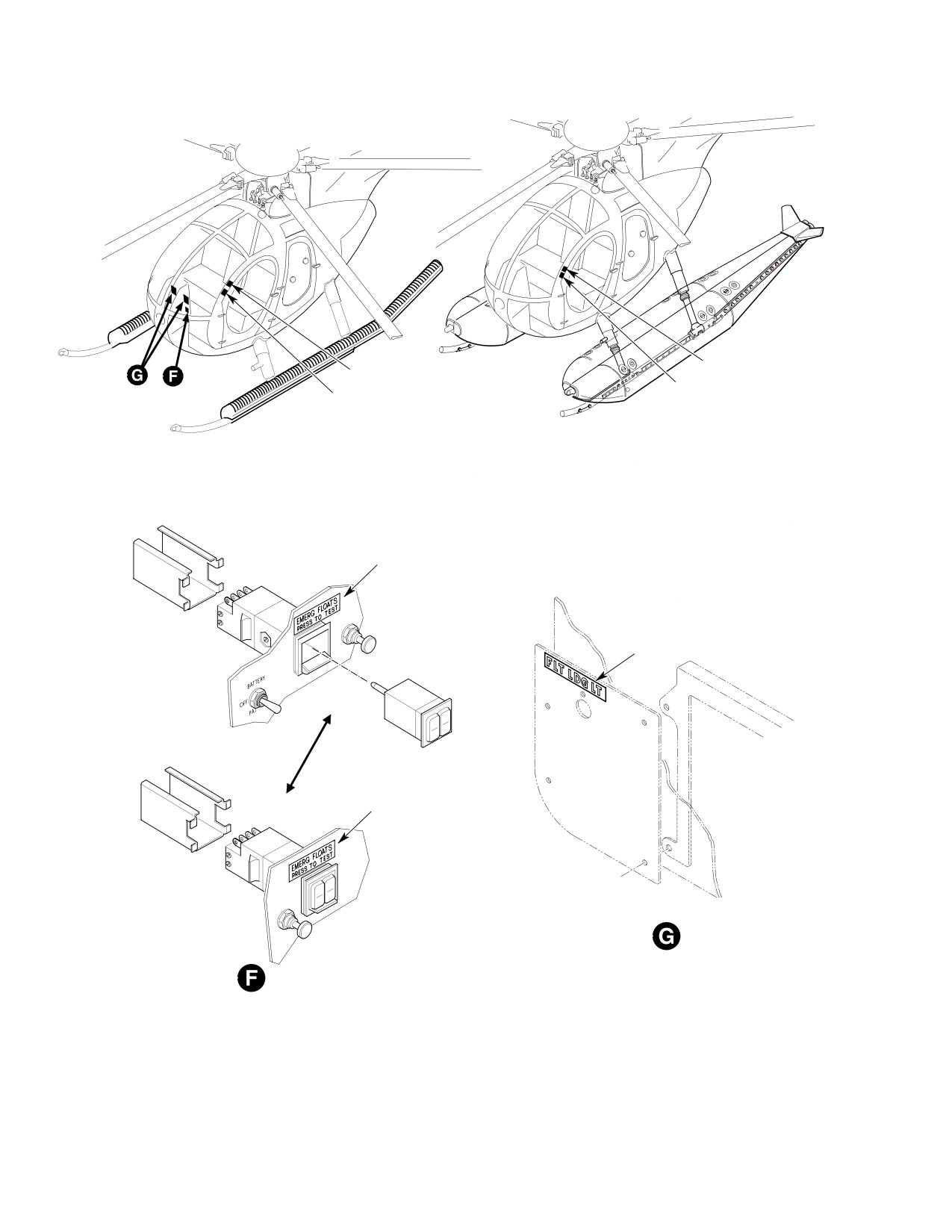
EMERGENCY FLOATS
UTILITY FLOATS
10
9
10
SWITCH INSTALLATION
(SLIMLINE PANEL)
G11-0003-3
Figure 204. Placards − Optional Equipment (Sheet 3 of 4)
Page 216
Revision 23
11-00-00
MD Helicopters, Inc.
CSP-HMI-2
MAINTENANCE MANUAL
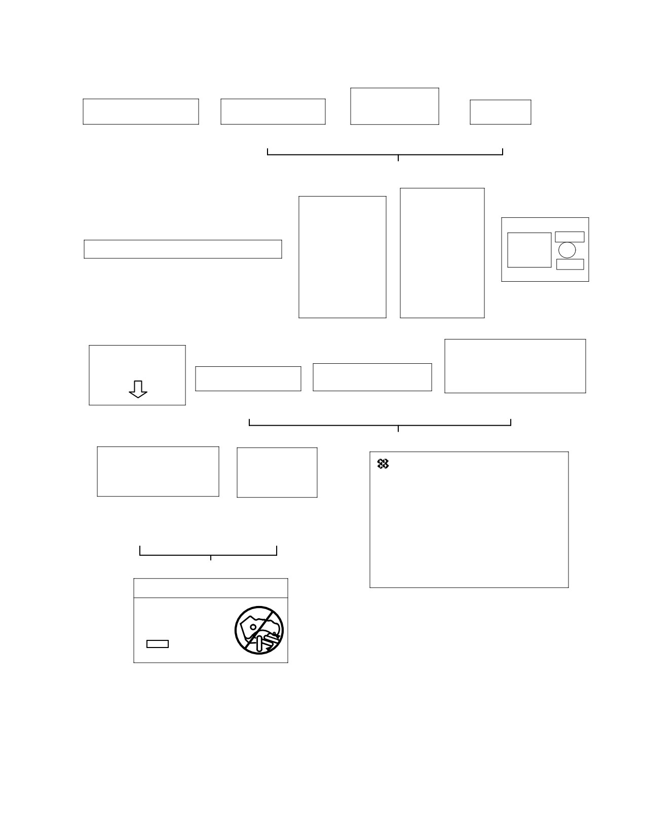
CARGO HOOK
FILTER BY−PASS CONTROL
EXTERNAL LOAD LIMIT
EMERGENCY
HOOK
PULL HANDLE FWD
2000 POUNDS
RELEASE
RELEASE
1. PARTICLE
2.
3.
4.
SEPARATOR
CARGO HOOK
ANTI−ICE
ANTI−ICE
AIRFRAME
FUEL FILTER
FUEL FILTER
INSTL
INSTL
AUTO−RE−IGNITION
FOR GROUND
FOR GROUND
ARM
TEMP. OF 5° C OR
TEMP. OF 5° C OR
CAUTION: SPRING LOADED, DO NOT PUSH
LESS MAX. ALT.
LESS. MAX. ALT.
12,000 FT.
12,000 FT.
OFF
5. FOUR−BLADED TAIL ROTOR
PRESS TO RESET
FOR GROUND
FOR GROUND
TEMP. GREATER
TEMP. GREATER
7. AUTOMATIC
THAN 5° C MAX.
THAN 5° C MAX.
ENGINE REIGNITION
ALT. 14,000 FT.
ALT. 14,000 FT.
6. ANTI−ICE FUEL FILTER
WARNING
WARNING
FLOAT INFLATION ABOVE 81 KNOTS IAS
PITOT MAY BE HOT
AT LESS THAN 6000 FEET ALTITUDE,
DO NOT TOUCH
EMERGENCY FLOATS
77 KNOTS IAS AT 6000 FEET AND ABOVE,
FLOAT LDG LT
PRESS TO TEST
IS PROHIBITED
9. LANDING
10. AUXILIARY
11. WARNING
LIGHT FLOAT
ELECTRICAL PANEL
8. HEATED
PITOT TUBE
EMERGENCY FLOATS
NIGHT FLIGHT OVER
MINIMUM FLOAT
WATER BEYOND
OPERATIONAL
FacetFILTER PRODUCTS DIVISION
GREENSBORO, NC 27409
AUTOROTATION CAPABILITY
PRESSURE IS
TO GROUND PROHIBITED
2.0 PSIG
A. INSPECT RED BUTTON ON BOTTOM
OF BOWL FOR INDICATION OF FILTER
12. NIGHT FLIGHT
13. MIN. OPERATIONAL
BYPASS.
RESTRICTION
PRESSURE
B. IF RED BUTTON IS NOT SHOWING
PROCEED WITH PREFLIGHT.
(ALSO EMERGENCY
C. RED BUTTON SHOWING, RESET
FLOATS)
BUTTON ONCE AND RUN ENGINE.
D. IF RED BUTTON REAPPEARS,
DISCONTINUE OPERATIONS AND IN−
UTILITY FLOATS
VESTIGATE REASON FOR FILTER
BYPASS INDICATION.
WARNING
14.
ENGINE OIL SCAVENGE
USE CORRECT LOAD
FILTER (MODEL D
RINGS, RINGS WITH
AND E WITH A C20/R−2
INTERNAL DIM.
ENGINE CONVERSION
GREATER THAN
1.5
INCHES
CAN SLIP OFF
15. CARGO HOOK
P/N 17149−1 THRU −5
G11-0003-4B
Figure 204. Placards − Optional Equipment (Sheet 4 of 4)
Page 217
11-00-00
Revision 23
CSP-HMI-2
MD Helicopters, Inc.
MAINTENANCE MANUAL
This Page Intentionally Left Blank
Page 218
Revision 44
11-00-00
MD Helicopters, Inc.
CSP-HMI-2
MAINTENANCE MANUAL
Section
11−40−00
Placards and
Markings (600N)