HANDBOOK OF MAINTENANCE INSTRUCTIONS FOR MDHI 369D/E/FF-500/600N HELICOPTERS (ISSUED: 1990) - page 3
CSP-HMI-2
MD Helicopters, Inc.
MAINTENANCE MANUAL
4. Overtorque
water, snow, thick vegetation, or other object of
sufficient mass to cause deceleration. Use the
Overtorque is an incident in which the main
schedule of inspections in Table 1, Conditional
transmission torque loads are more than the
Inspections, After Tail Rotor Blade Strike
permitted limits. Use the schedule of inspec
when sudden stoppage of the tail rotor has
tions in Table 1, Conditional Inspections, After
occurred.
Main Transmission Overtorque Beyond
Transient Limits when an overtorque has
6. Lightning Strike
occurred.
When you think there has been a lightening
5. Sudden Stoppage
strike on the helicopter, use the schedule of
inspections in Table 1, Conditional Inspec
Sudden stoppage is a rapid deceleration of the
tions, After Lightening Strike inspection
main rotor, rotor drive system, tail rotor, or
procedures.
anti-torque fan.
Sudden stoppage of the main rotor and rotor
7. Conditional Inspection Table
drive system is caused when the main rotor
blades hit the ground, water, snow, thick
D Inspections in this table are for MDHI
vegetation, or other object of sufficient mass to
369D/E/FF and 500/60N helicopters only.
cause deceleration. Sudden stoppage of the
The first column of the table denotes which
main rotor and rotor drive system can also
model helicopter the inspections are
occur during a hard landing if the blades hit
applicable to.
the fuselage or the tailboom. Use the schedule
of inspections in Table 1, Conditional Inspec
D The second column of the table has a short
tions, After Main Rotor Blade/Drive System
description of the necessary inspection or
Sudden Stoppage when sudden stoppage of the
procedure.
main rotor has occurred.
D The third column of the table shows, if
Sudden stoppage of the tail rotor is caused
applicable, the manual or section that has
when the tail rotor blades hit the ground,
the specific inspection or procedure.
Page 2
Revision 44
05-50-00

MD Helicopters, Inc.
CSP-HMI-2
MAINTENANCE MANUAL
Table 1. Conditional Inspections
Model
Requirement
Chap/Sect
AFTER HARD LANDING
WARNING: Any component, assembly or detailed part that is removed for overhaul must be identified as
to the reason for removal. Components that require replacement must be discarded.
ALL
Main rotor blades for bending, cracks or wrinkles.
62
ALL
Main rotor blade droop stops for damage.
62
ALL
Main rotor hub assembly and strap pack assembly for evidence of damage.
62
ALL
Accessible areas of main rotor mast assembly and transmission attachment area for
63
damage.
ALL
Perform Landing Gear Inspection. Forward and aft rub plates for condition.
32−10−00
ALL
Perform Tailboom Inspection; retorque mount bolts.
53−40−00
53−40−30
ALL
Inspect tailboom attachment area for damage.
53
500/600N
Inspect stationary thruster attachment flange for damage; retorque mount bolts.
53
369D/E/FF
Tail rotor drive shaft and damper, tail rotor transmission and tail rotor for distortion,
63
loose mounting or attaching parts, buckling, breaks or other damage. Tail rotor drive
64
shaft for contact with bulkheads.
500/600N
Main transmission−to−fan transmission drive shaft, fan transmission, fan drive shaft,
63
fan and fan control rod for distortion, loose mounting or attaching parts, buckling,
67
breaks or other damage. Drive shafts for contact with bulkheads.
Fan control rod for freedom of movement.
ALL
Perform Engine Mounts and Fittings Inspection. Inspect mounting pads and firewall for
71
damage and distortion. Inspect all suspected parts by magnetic particle or
dye−penetrant methods, as applicable (Ref. CSP−SRM−6).
ALL
All flight and engine control system push−pull tubes, links, bellcranks and bearings for
67
bends, cracks, security and free movement.
ALL
Tunnel area A−frame for distortion, buckling or any other damage.
53
ALL
Fuselage fittings for bends and cracks.
53
ALL
Main transmission chip detectors for metal particles.
63
Main transmission mounting flanges for cracks.
ALL
Perform Main Transmission Drive Shaft Inspection.
63−10−00
ALL
All engine accessories for cracked flanges, loose bolts and nuts, connections and
79
general condition.
ALL
Engine accessory drive housing for cracks.
79
ALL
Engine chip detectors for metal particles.
79
ALL
Engine oil tank, supports, tubing and hoses for leaks, cracks and security.
79
ALL
Fuel cells, supports, tubing and hoses for leaks, cracks and security.
28
ALL
Armor for security of attachment, buckling and distortion.
CSP−014
ALL
Rotor brake installation for security of attachment and disc alignment.
63
Page 3
05-50-00
Revision 42

CSP-HMI-2
MD Helicopters, Inc.
MAINTENANCE MANUAL
Table 1. Conditional Inspections (Cont.)
Model
Requirement
Chap/Sect
AFTER MAIN ROTOR OVERSPEED
WARNING: Any component, assembly or detailed part that is removed for overhaul must be identified as
to the reason for removal. Components that require replacement must be scrapped.
If overspeed is between 523 and 549 (369D/E) or 508 and 533 (369FF, 500N) rpm, or 106 and 112 percent
(600N):
ALL
Main rotor blades for visible damage and distortion; main rotor blade tip caps for
62
security; all bond lines for evidence of separation; root doublers and attachment
fittings for security. Replace any blade with visible bond line separation.
Main rotor blade dampers for security.
369D/E/FF
Tail rotor blades and hub for visible damage, free movement and security.
64
500/600N
NOTAR fan blades and hub for visible damage, free movement and security.
64
ALL
Main rotor hub and strap pack assembly for evidence of damage.
62
If overspeed is over 549 (369D/E) or 533 (369FF, 500N) rpm, or 112 percent (600N):
ALL
Remove main rotor hub assembly for overhaul inspection.
MDHI
ALL
Remove and scrap main rotor blades.
62
500/600N
Inspect anti−torque fan assembly.
64
369D/E/FF
Remove tail rotor hub assembly for overhaul inspection.
64
AFTER MAIN TRANSMISSION OVERTORQUE BEYOND TRANSIENT LIMITS
ALL
Main transmission for freedom of movement.
63
ALL
Main transmission chip detectors for metal particles. Re−inspect after 8 hours of
63
operation.
AFTER AIRSPEED 10% BEYOND VNE LIMIT
WARNING: Any component, assembly or detailed part that is removed for overhaul must be identified as
to the reason for removal. Components that require replacement must be scrapped.
ALL
Main rotor blades for visible damage and distortion; main rotor blade tip caps for
62
security; all bond lines for evidence of separation; root doublers and attachment
fittings for security. Replace any blade with visible bond line separation.
Main rotor hub assembly and strap pack assembly for evidence of damage.
Main rotor blade dampers for security.
369D/E/FF
Tail rotor blades and hub for visible damage, freedom of movement and security.
64
369D/E/FF
Horizontal stabilizer for skin damage and loose rivets.
53
Tip plates and vertical stabilizer for damage to leading and trailing edges and
damaged stressed side panels (no repair of side panels permitted).
Mounting fittings for cracks and security.
Retorque stabilizer attach bolts.
500/600N
Horizontal stabilizer for skin damage and loose rivets.
53
600N − Damage to gurney flap.
Vertical stabilizers for damage to leading and trailing edges and damaged side panels.
Mounting fittings for cracks and security.
Retorque stabilizer attach bolts.
Page 4
Revision 42
05-50-00

MD Helicopters, Inc.
CSP-HMI-2
MAINTENANCE MANUAL
Table 1. Conditional Inspections (Cont.)
Model
Requirement
Chap/Sect
ALL
Tailboom for visible deformation, loose or missing rivets, cracks and security; attaching
53
points to fuselage for cracks and security.
ALL
Canopy glass for security
53
AFTER MAIN ROTOR BLADE/DRIVE SYSTEM SUDDEN STOPPAGE
WARNING: Any component, assembly or detailed part that is removed for overhaul must be identified as
to the reason for removal. Components that require replacement must be scrapped.
Sudden stoppage of the main rotor and rotor drive system is any rapid deceleration of the main rotor drive
system. This may be caused by contact of one or more of the main rotor blades with the ground, water, snow,
dense vegetation or any other object of sufficient mass to cause deceleration or impact damage to the main
rotor blades.
A main rotor blade strike in which one or more of the main rotor blades exceed the repair limits in the
maintenance manual is defined as sudden stoppage.
Sudden stoppage of the main rotor may also occur simultaneously with hard landing in which the blades contact
the upper fuselage structure or the tailboom.
The inspection requirements, After Main Rotor Drive System Sudden Stoppage − Level 1, is to be used when
sudden stoppage of the main rotor drive system has occurred.
After Main Rotor Drive System Sudden Stoppage − Level 1
ALL
Perform inspection of main rotor blades. Pay particular attention to the upper and
62
lower root fittings and attach lug areas. If inspection determines that one or more
blades have separation of the trailing edge bond, due to leading edge impact, the
blade is bent or shows evidence of a significant impact, and the damage occurred with
the engine running, perform the additional inspection in After Main Rotor Drive System
Sudden Stoppage − Level 2.
ALL
Perform inspection of the main rotor hub and lead−lag link attach lugs. If the lead−lag
62
lug is broken or the pitch housing striker strip shows evidence of contact with the main
rotor hub and damage occurred the the engine running, perform the additional
inspection in After Main Rotor Drive System Sudden Stoppage − Level 2.
ALL
Perform Main Rotor Strap Pack Lamination Inspection.
62−20−00
62−20−60
ALL
Perform Main Rotor Blade and Damper Attach Pin Disassembly and Special
62−10−00
Inspection. If a pin is found cracked or bent and damage occurred with the engine
running, perform the additional inspection in After Main Rotor Drive System Sudden
Stoppage − Level 2.
ALL
Perform Main rotor Damper and Attachments Inspection. If damage to a damper is
62−20−00
suspected, perform Main Rotor Damper Weight Loading and Extension Check.
62−20−60
ALL
Perform Main Rotor Drive Shaft Inspection. If main rotor drive shaft is rejected for
63−10−00
broken shaft splines, straightness or sheared shaft, perform the additional inspection
in After Main Rotor Drive System Sudden Stoppage − Level 2.
ALL
Inspect overrunning clutch sprag assembly (Ref. Detailed Inspection after Cleaning).
COM
CAUTION:
Kamatic couplings are a balanced unit and cannot be disassembled.
ALL
Perform a visual inspection of all power train drive shafts and couplings for distortion,
63
breaks, cracks, contact with bulkheads and other damage.
ALL
Perform a visual inspection of the oil cooler blower assembly.
63
Page 5
05-50-00
Revision 42

CSP-HMI-2
MD Helicopters, Inc.
MAINTENANCE MANUAL
Table 1. Conditional Inspections (Cont.)
Model
Requirement
Chap/Sect
ALL
Check main rotor transmission for freedom of movement. Visually check main rotor
63
transmission mounting flanges for cracks. Inspect main rotor transmission chip
detectors for metal accumulation. Reinspect chip detectors after eight hours of
helicopter operation.
ALL
Perform visual inspection of main rotor flight controls.
67
ALL
Perform visual inspection of the anti−torque system.
64
ALL
Perform visual inspection of engine mounts for security, cracks or misalignment.
71
ALL
Perform visual inspection of the engine control linkage for bends, breaks and proper
76
alignment.
ALL
Inspect engine per the special inspection requirements in the appropriate Allison
01
Operation and Maintenance Manual.
After Main Rotor Drive System Sudden Stoppage − Level 2
WARNING: Any component, assembly or detailed part that is removed for overhaul must be identified as
being removed due to Main Rotor Sudden Stoppage − Level 2. Components that require replacement
must be scrapped.
ALL
Overhaul main rotor hub.
62
ALL
Remove and scrap main rotor drive shaft.
63
ALL
Overhaul main transmission assembly (Ref. COM).
63
ALL
Remove and scrap engine−to−transmission drive shaft.
63
ALL
Overhaul overrunning clutch assembly (Ref. COM).
63
AFTER TAIL ROTOR BLADE STRIKE
WARNING: Any component, assembly or detailed part that is removed for overhaul must be identified as
to the reason for removal. Components that require replacement must be scrapped.
After tail rotor blade strike, inspect the following:
369D/E/FF
If equipped with Bendix couplings, remove and scrap couplings.
63
369D/E/FF
Tail rotor blades for dents, nicks, scratches or separation of skin.
64
369D/E/FF
Tail rotor flapping hinge bolt for damage.
64
369D/E/FF
Tail rotor transmission for radial play and run−out of output shaft, cracks in mounting
63
flanges, and chip detector for metal particles.
Remove for overhaul tail rotor transmission if damage is indicated.
369D/E/FF
If equipped with Kamatics couplings:
63−15−10
63−25−10
Perform Tail Rotor Drive Shaft Twist Inspection. Misaligned or missing stripes require
63−25−20
removal and scrapping of drive shaft and Kamatics couplings, and an overhaul
inspection of tail rotor transmission (Ref. COM).
369D/E/FF
Remove tail rotor drive shaft and inspect couplings for distortion and cracks; damper,
63
damper bracket and bulkheads for damage.
NOTE: If damage in excess of allowable limits due to blade strike is noted in above areas, continue with following
inspections:
369D/E/FF
Tail rotor drive fork, pitch links, swashplate, hub and pitch control bearing housing for
64
obvious damage.
Page 6
Revision 42
05-50-00

MD Helicopters, Inc.
CSP-HMI-2
MAINTENANCE MANUAL
Table 1. Conditional Inspections (Cont.)
Model
Requirement
Chap/Sect
369D/E/FF
Upper fuselage and boom tail rotor control linkage.
67
If tail rotor control rod is damaged, ensure that all rod bulkhead grommets are in
place.
369D/E/FF
Aft frame of tailboom for cracks and boom skin for loosened or popped rivets.
53
369D/E/FF
Main transmission chip detectors and transmission lube pump oil filter for metal
63
particles.
369D/E/FF
Main rotor hub assembly and strap pack assembly for evidence of damage.
62
AFTER TAILBOOM STRIKE
WARNING: Any component, assembly or detailed part that is removed for overhaul must be identified as
to the reason for removal. Components that require replacement must be scrapped.
If one or more main rotor blades strike tailboom while blades are rotating, inspect following:
ALL
Perform Main Rotor Blade Inspection.
62−10−00
ALL
If excessive damage requires replacement of main rotor blade(s), inspect complete
62
main rotor and scissors assembly, including droop stop mechanism and strap packs,
for evidence of damage.
369D/E/FF
Remove and inspect tail rotor drive shaft for impact damage, buckling or twisting;
63
couplings for cracks and distortion; damper, damper bracket and bulkheads for
damage.
369D/E/FF
If excessive damage requires replacement of tail rotor drive shaft, replace couplings
63
and perform overhaul inspection of tail rotor transmission (Ref. COM).
CAUTION:
Any tailboom damage is significant (Ref. CSP−SRM−6).
ALL
Perform Tailboom Inspection. Dye−check or remove and scrap tailboom attach bolts.
53−40−00
53−40−30
ALL
Structure forward of tailboom attachment for evidence of sheet metal yielding or
53
buckling. Pay particular attention for signs of buckling at right side forward of tailboom
attachment (Ref. CSP−SRM−6).
ALL
Perform Upper Fuselage and Tailboom Control Linkage Inspection.
67
ALL
Perform Horizontal Stabilizer Inspection.
53−50−10
53−50−30
Perform Vertical Stabilizer Inspection.
Retorque stabilizer attach bolts.
369D/E/FF
Tail rotor assembly.
64
369D/E/FF
Tail rotor transmission for radial play and run−out of output shaft; cracks in mounted
64
flanges and chip detector for metal particles.
ALL
Main rotor brake, if installed, for condition and alignment of brake disc, calipers and
63
security of attachment.
If tailboom strike occurred during POWER ON condition, also inspect the following:
ALL
Remove and inspect main rotor drive shaft, main transmission drive shaft and
63
couplings for distortion, breaks, cracks and other damage.
ALL
Main transmission chip detectors and transmission lube system oil filter for metal
63
particles. Re−inspect chip detectors and oil filter after 8 hours of engine operation.
Visually check transmission mounting flanges for cracks.
Page 7
05-50-00
Revision 42

CSP-HMI-2
MD Helicopters, Inc.
MAINTENANCE MANUAL
Table 1. Conditional Inspections (Cont.)
Model
Requirement
Chap/Sect
ALL
Engine air inlet and plenum chamber for foreign objects; motor engine and check for
71
unusual noise.
76
Engine mounts for security, cracks or distortion.
Engine control linkage for bends, breaks and proper operation.
500/600N
Inspect stationary thruster attachment flange for damage; retorque mount bolts.
53
ALL
Inspect tailboom attachment area for damage; retorque mount bolts.
53
AFTER CHIP DETECTOR LIGHT COMES ON
ALL
Remove chip detector leads, in turn, to determine which chip detector caused indicator
63
to light.
71
Remove and inspect applicable chip detector for metal accumulation.
ALL
If an engine chip detector caused indicator to light, refer to applicable Rolls−Royce
01
Engine Operation and Maintenance Manual.
ALL
If main transmission chip detector caused indicator to light, perform Main
63−21−00
Transmission Filter Replacement.
ALL
If chips measure no longer than 0.125 inch (3.175 mm), drain and refill main
12
transmission, tail rotor transmission or fan transmission as applicable with new oil.
Recheck applicable chip detectors after 4 hours of flight.
AFTER ENGINE CHANGE BECAUSE OF INTERNAL ENGINE FAILURE
NOTE: Oil coolers are NOT cleanable and must be scrapped if an engine failure produces metal and NO scav-
enge oil filter is installed or if a scavenge oil filter is installed and indicates a by−pass has occurred.
ALL
Remove, flush and reinstall oil tank.
12
79
Flush all lines, fittings and associated components.
Remove and reverse flush or replace engine oil cooler.
CAUTION: Failure to bleed fuel system can result in unexpected engine flameout or power loss.
ALL
Bleed fuel system.
28
ALL
Remove and install new scavenge oil filter element (if installed).
79
AFTER ENGINE FLAMEOUT CAUSED BY FUEL EXHAUSTION
ALL
Bleed fuel system to remove any entrapped air.
28
AFTER ENGINE SHUTDOWN USING EMERGENCY FUEL SHUTOFF VALVE
ALL
Bleed fuel system to remove any entrapped air.
28
AFTER MAIN TRANSMISSION CHANGE BECAUSE OF INTERNAL TRANSMISSION FAILURE
ALL
Reverse flush or replace transmission oil cooler, all lines, fittings and associated
63
components.
AFTER FUEL FILTER CAUTION LIGHT COMES ON
ALL
Check FUEL FILTER caution light and circuit for discrepancies.
95
ALL
Perform Fuel Filter (Bypass) Caution Light Pressure Switch Test.
28−00−00
Page 8
TR12-001
05-50-00

MD Helicopters, Inc.
CSP-HMI-2
MAINTENANCE MANUAL
Table 1. Conditional Inspections (Cont.)
Model
Requirement
Chap/Sect
ALL
Remove and install new engine−driven fuel pump filter.
01
Remove and clean gas producer fuel control filter.
Clean and flush all lines and fittings.
Check bypass valve per applicable Allison Engine Operation and Maintenance
Manual.
369D/E
Inspect start pump inlet screen for contamination when large amounts of foreign
28
500N
material are found in the engine driven fuel pump filter (or optional airframe fuel filter, if
installed).
ALL
Perform Fuel Cell Inspection.
28−00−00
AFTER NEW OR REPLACEMENT MAIN ROTOR HUB IS INSTALLED
ALL
Perform Main Rotor Hub Droop Angle Check.
62−20−00
BEFORE INSTALLATION OF NEW BATTERY
ALL
Perform Battery Charging − Deep Cycling Procedure. Repeat deep cycling procedure
96−05−00
once to ensure complete stabilization of battery.
AFTER MAIN TRANSMISSION DRIVE SHAFT IS REMOVED (ENGINE INSTALLED)
ALL
Check overrunning clutch for correct oil level.
12
AFTER COOLER BLOWER IS REMOVED
ALL
Perform Cooling Blower Inspection (Disassembled). Check belt tension and clearance
63
after installation.
WHEN MAIN ROTOR DRIVE SHAFT IS REMOVED
ALL
Perform Main Rotor Drive Shaft Inspection.
63−10−00
AFTER LIGHTNING STRIKE
WARNING: Any component, assembly or detailed part that is removed for overhaul must be identified as
to the reason for removal. Components that require replacement must be scrapped.
If lightning strike is evident on helicopter exterior:
ALL
Inspect the fuselage interior and exterior, landing gear, rotor systems and ground wire
25
connection for burn marks, cracks, pitting or other signs of high temperature stress, to
32
determine the lightning entry and exit points.
53
ALL
Trace the path of the lightning strike to the extent possible using a magnetometer.
ALL
Check the magnetic compass for accuracy (the degree of inaccuracy may serve as an
95
indicator of the severity of the strike).
ALL
Inspect all wiring.
96
ALL
Inspect antenna(s) for burns and pitting.
97
ALL
Inspect all electrically operated components and lighting systems for damage.
96
ALL
Inspect communications and navigation equipment for damage.
97
ALL
If the preceding inspections reveal major damage has occurred, proceed as follows:
96
Bench test all avionics and electrical system and components.
97
Perform a continuity check on all wiring and cables.
Perform a Voltage Standing Wave Ratio (VSWR) check on all antennas, antenna
cables and connectors.
Page 9
05-50-00
Revision 42

CSP-HMI-2
MD Helicopters, Inc.
MAINTENANCE MANUAL
Table 1. Conditional Inspections (Cont.)
Model
Requirement
Chap/Sect
ALL
Perform specific inspection/replacements as required.
500/600N
Check fan transmission and interconnecting drive shafts for magnetism and/or burns.
63
500/600N
If previous drive train items show magnetism, overhaul fan transmission.
COM
500/600N
Inspect anti−torque fan and components for evidence of arcing and magnetism;
64
replace any part showing evidence of arcing or magnetism.
500/600N
Inspect bellcrank and control rod for any indications of arcing. Scrap parts with
67
indications of arcing.
500/600N
Inspect thruster cables, bellcranks and control tubes for any indications of arcing.
67
Scrap parts with indications of arcing.
500/600N
Inspect thruster rollers for any indications of arcing. Scrap parts with indications of
53
arcing.
ALL
Check oil cooler blower assembly and overrunning clutch for residual magnetism;
replace as necessary.
ALL
Inspect oil cooler assembly for damage; replace as necessary.
ALL
If previous drive train items show magnetism, overhaul transmission.
ALL
If overrunning clutch assembly shows magnetism, remove engine and overrunning
clutch and overhaul.
ALL
Perform a ground run operational check on the aircraft. Functionally check the flight
67
control system, and all avionics, electrical, lighting, communication, and navigation
96
systems.
97
ALL
Repair any damage and replace damaged components as required.
If lightning strike is evident on main rotor system:
ALL
Inspect blades for damage such as burns, pitting, skin separation, etc. If damage is
62
evident, scrap damaged blade(s).
ALL
Remove hub assembly and return for overhaul.
62
ALL
Inspect all bearings in the fixed and rotating control system located on the main rotor
62
mast.
ALL
Remove transmission assembly and overhaul.
63
ALL
Inspect main rotor mast and drive shaft for evidence of burns.
63
ALL
Check drive shafts for residual magnetism. If magnetized or damaged, scrap drive
63
shafts and remove engine for overhaul.
71
If lightning strike is evident on tail rotor system:
369D/E/FF
Inspect blades for damage such as burns, pitting, skin separation, etc. If damage is
64
evident, scrap damaged blade(s).
369D/E/FF
Overhaul tail rotor assembly.
COM
369D/E/FF
Scrap pitch change links and pitch change assembly.
64
369D/E/FF
Inspect bellcrank and control rod for any indications of arcing. Scrap parts with
67
indications of arcing.
369D/E/FF
Overhaul tail rotor gearbox.
COM
369D/E/FF
Inspect tail rotor drive shaft and drive shaft damper for magnetism and/or burns.
63
Page 10
Revision 42
05-50-00

MD Helicopters, Inc.
CSP-HMI-2
MAINTENANCE MANUAL
Table 1. Conditional Inspections (Cont.)
Model
Requirement
Chap/Sect
369D/E/FF
Check oil cooler blower assembly, overrunning clutch and tail rotor drive shaft
63
couplings for residual magnetism; replace as necessary.
369D/E/FF
Inspect oil cooler assembly for damage; replace as necessary.
63
369D/E/FF
If previous drive train items show magnetism, overhaul transmission.
COM
369D/E/FF
If overrunning clutch assembly shows magnetism, remove engine and overrunning
71
clutch and overhaul.
COM
369D/E/FF
Inspect engine mounts and fitting for damage. Replace as necessary.
71
AFTER 369F5100 MAIN TRANSMISSION LUBRICATION PUMP IMPENDING BYPASS INDICATOR POPS
ALL
Refer to Troubleshooting Power Train System
63−00−00
WHENEVER ENGINE IS REMOVED
ALL
Remove fire blanket from above engine and inspect airframe above engine for
53
evidence of cracks.
Page 11
05-50-00
Revision 42
CSP-HMI-2
MD Helicopters, Inc.
MAINTENANCE MANUAL
This Page Intentionally Left Blank
Page 12
Revision 42
05-50-00

MD Helicopters, Inc.
CSP-HMI-2
MAINTENANCE MANUAL
Chapter
06
Dimensions and
Areas
MD Helicopters, Inc.
CSP-HMI-2
MAINTENANCE MANUAL
TABLE OF CONTENTS
Para/Figure/Table
Title
Page
06-00-00 Dimensions and Areas
A
Maintenance Practices
201
1. Principal Dimensions
201
2. Airframe Stations Locations
201
Figure 201. Principal Dimensions - Model 369D
202
Figure 202. Principal Dimensions- Models 369E
203
Figure 203. Principal Dimensions Model 369FF
204
Figure 204. Principal Dimensions - Model 500N
205
Figure 205. Principal Dimensions - Model 600N (Sheet 1 of 2)
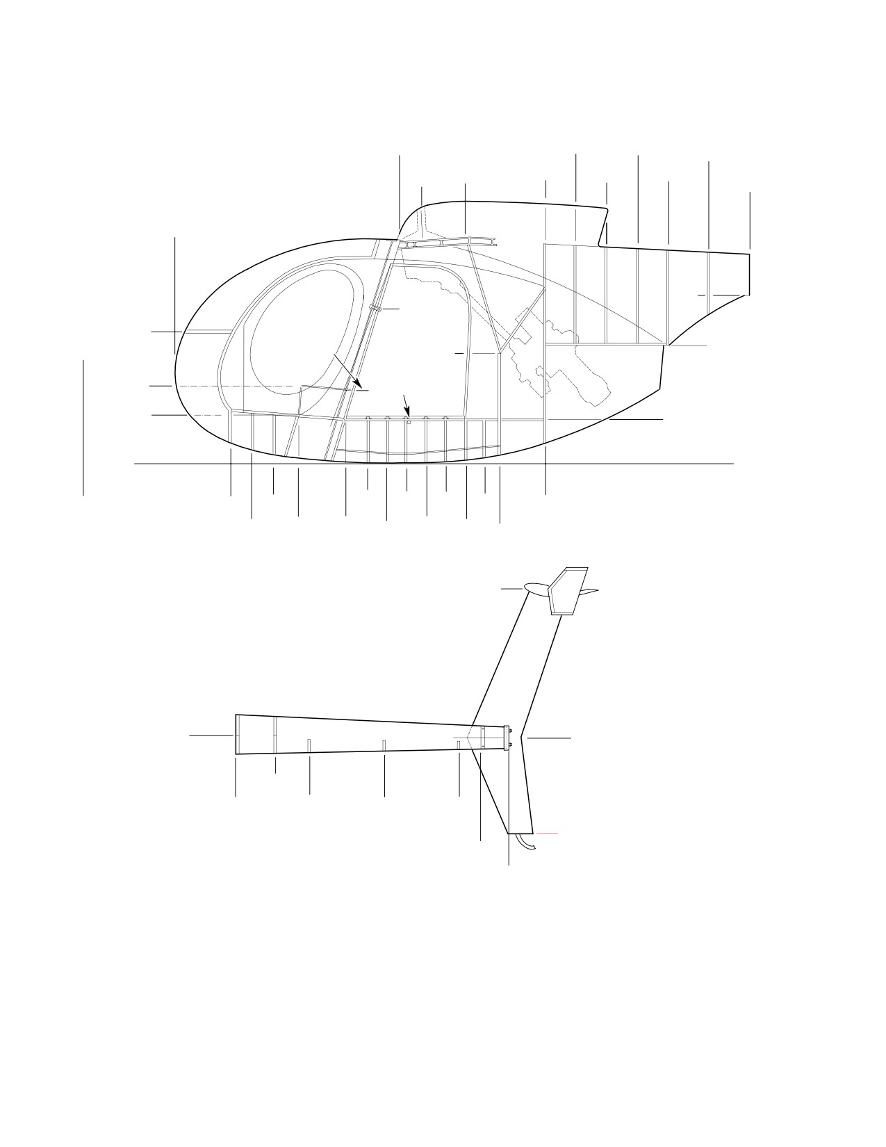
206
Figure 206. Station Diagram - Model 369D
208
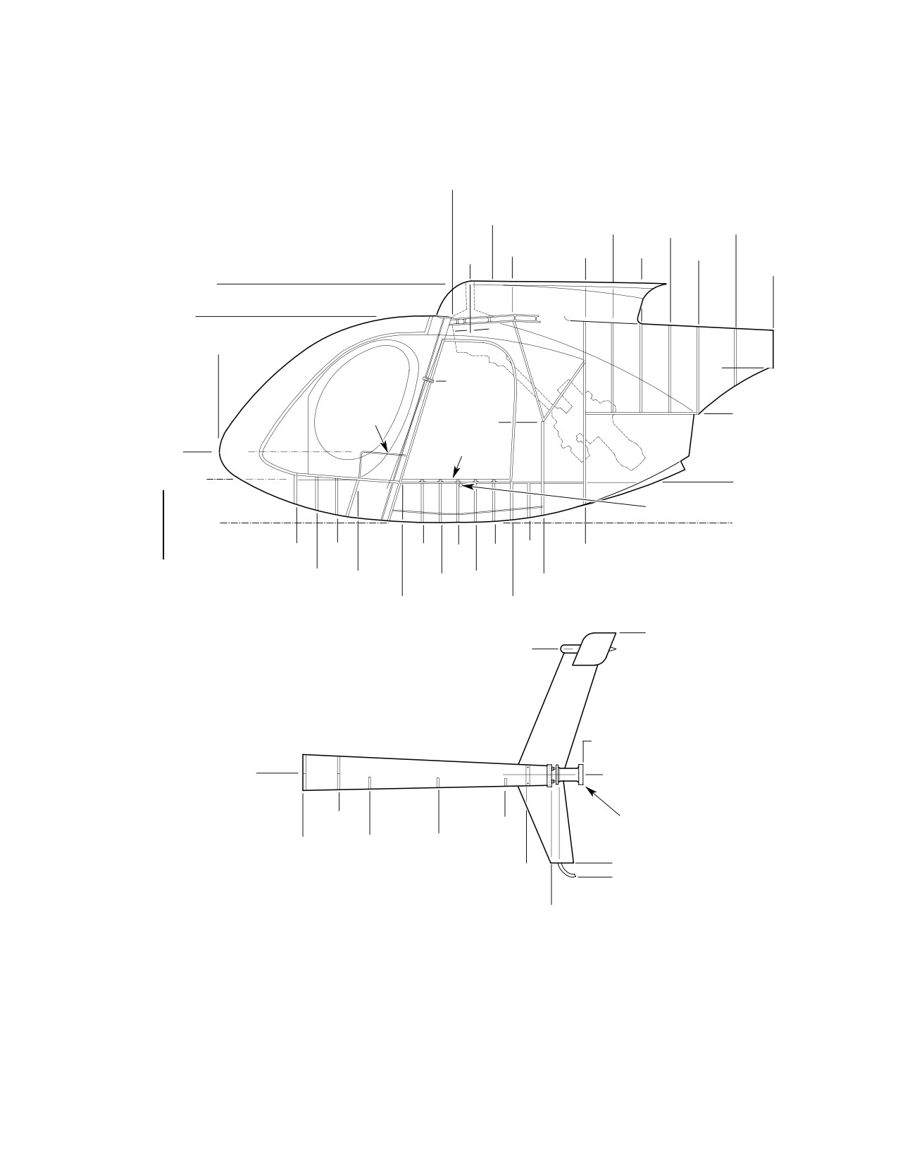
Figure 207. Station Diagram - Models 369E/FF
209
Figure 208. Station Diagram - Model 500N
210
Figure 209. Fuselage Station Diagram - Model 600N
211
Figure 210. Aft Empenage Access Plugs - Model 600N
212
Page i
06 Contents
Revision 34
CSP-HMI-2
MD Helicopters, Inc.
MAINTENANCE MANUAL
TABLE OF CONTENTS (Cont.)
Para/Figure/Table
Title
Page
This Page Intentionally Left Blank
Page ii
Revision 34
06 Contents
MD Helicopters, Inc.
CSP-HMI-2
MAINTENANCE MANUAL
Section
06−00−00
Dimensions and
Areas
MD Helicopters, Inc.
CSP-HMI-2
MAINTENANCE MANUAL
DIMENSIONS AND AREAS
MAINTENANCE PRACTICES
1. Principal Dimensions
cm) forward of the fuselage nose for
Models 369E/FF. WL 0.00 is tangential
(Ref. Figure 201 for Model 369D,
to bottom of fuselage at STA 90.61.
Figure 202 for Model 369E,
Canted stations start at WL 0.00 unless
Figure 203 369FF,
otherwise specified. The canted station
Figure 204 for 500N and
is not the same distance from STA 0.00
Figure 205 for 600N)
over its length, and should be referred
to in association with a waterline
2.
Airframe Stations Locations
reference.
(1).
Reference is occasionally made to
(3).
For the 600 Series Helicopter, all
Fuselage Station (STA or FS), Fuselage
dimensions are from three reference
Station Plug (P. STA or FSP) and
points designated as STA 0.00, P. STA
Waterline (WL) throughout the manual.
0.00 and WL 0.00 for the fuselage/engi
P. STA or FSP refers to the stretched
neering station references. STA 0.00 is
area or longer fuselage section of the
15.00 inches (38.1 cm) forward of the
600N as compared to the 500 Series
fuselage nose. P. STA 0.00 is located at
Helicopter. Fuselage Station and
the forward lower edge of the mid door
Waterline are the same as those
(also designated as canted STA 78.50).
referred to in the other 500 Series
All references outside of the designated
publications. To assist in locating
P. STA areas are labeled STA or FS.
components being discussed, station
Waterline 0.00 is tangential to bottom
diagrams are provided (Ref. Figure 206
of fuselage at fuselage station STA
for Model 369D, Figure 207 for Models
90.61. Canted stations start at water
369E/FF, Figure 208 for 500N and
line 0.00 unless otherwise specified.
Figure 209 for 600N). Station and
The canted station is not the same
Waterline references are also necessary
distance from WL 0.00 over its length,
for weight and balance procedures (Ref.
and should be referred to in association
Sec. 08-10-00).
with a waterline reference.
(2).
For the 500 Series Helicopters, all
(4).
Measurements from a station repre
dimensions are from two reference
sented by a rib, frame, or bulkhead that
points designated as STA 0.00 and WL
is not accessible may be taken by noting
0.00. STA 0.00 is 28.00 inches (71.12
flange bend direction and compensating
cm) forward of the fuselage nose for
on the correct side of visible external
Model 369D, and 15.00 inches (38.10
skin attachment rivet line.
Page 201
06-00-00
Revision 23
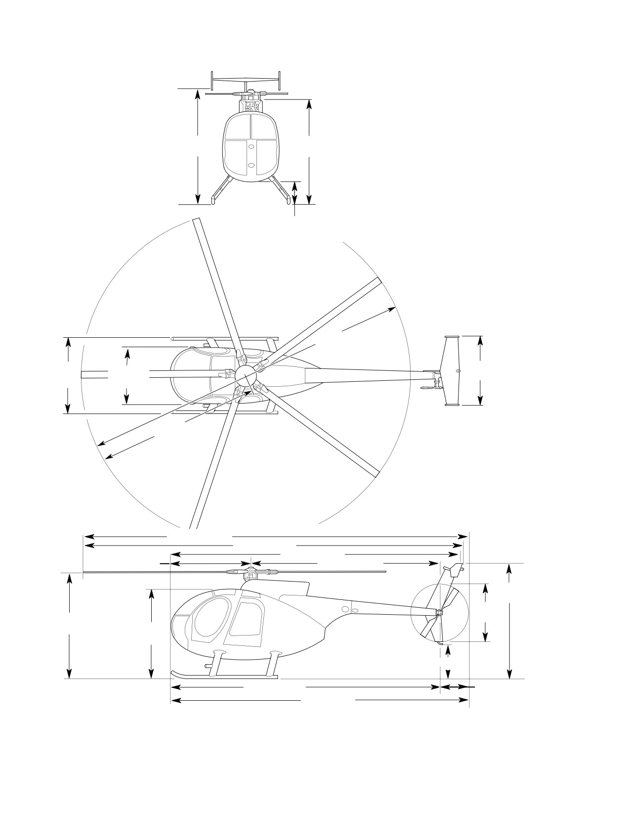
CSP-HMI-2
MD Helicopters, Inc.
MAINTENANCE MANUAL
GENERAL NOTES:
1.
HELICOPTER ON GROUND, MAX.
COMPRESSED DIMENSION: 6.8 IN.
(17.272 CM).
2.
IF OPTIONAL EXTENDED LANDING
GEAR IS INSTALLED, ADD 0.63 FT.
8.2 FT.
7.2 FT
(10.19 M) TO ALL VERTICAL DIMENSIONS.
(2.5 M)
(2.2M)
0.76 FT
(0.23 M)
26.41 FT (8.06 M)
5.46 FT.
6.45 FT.
4.57 FT.
(1.97 M)
(1.67 M)
(1.39 M)
13.205 FT. (4.028 M)
31.31 FT. (9.55 M)
30.84 FT. (9.41 M)
22.53 FT. (6.72 M)
6.002 FT. (1.831 M)
15.208 FT. (4.64 M)
8.9 FT.
(2.7 M)
4.58 FT.
7.67 FT.
(1.40 M)
(2.34 M)
6.3 FT.
(1.9 M)
1.58 FT. (0.48 M)
21.21 FT. (6.50 M)
2.29 FT. (0.70 M)
23.5 FT. (7.2 M)
G06-0001B
Figure 201. Principal Dimensions − Model 369D
Page 202
Revision 23
06-00-00
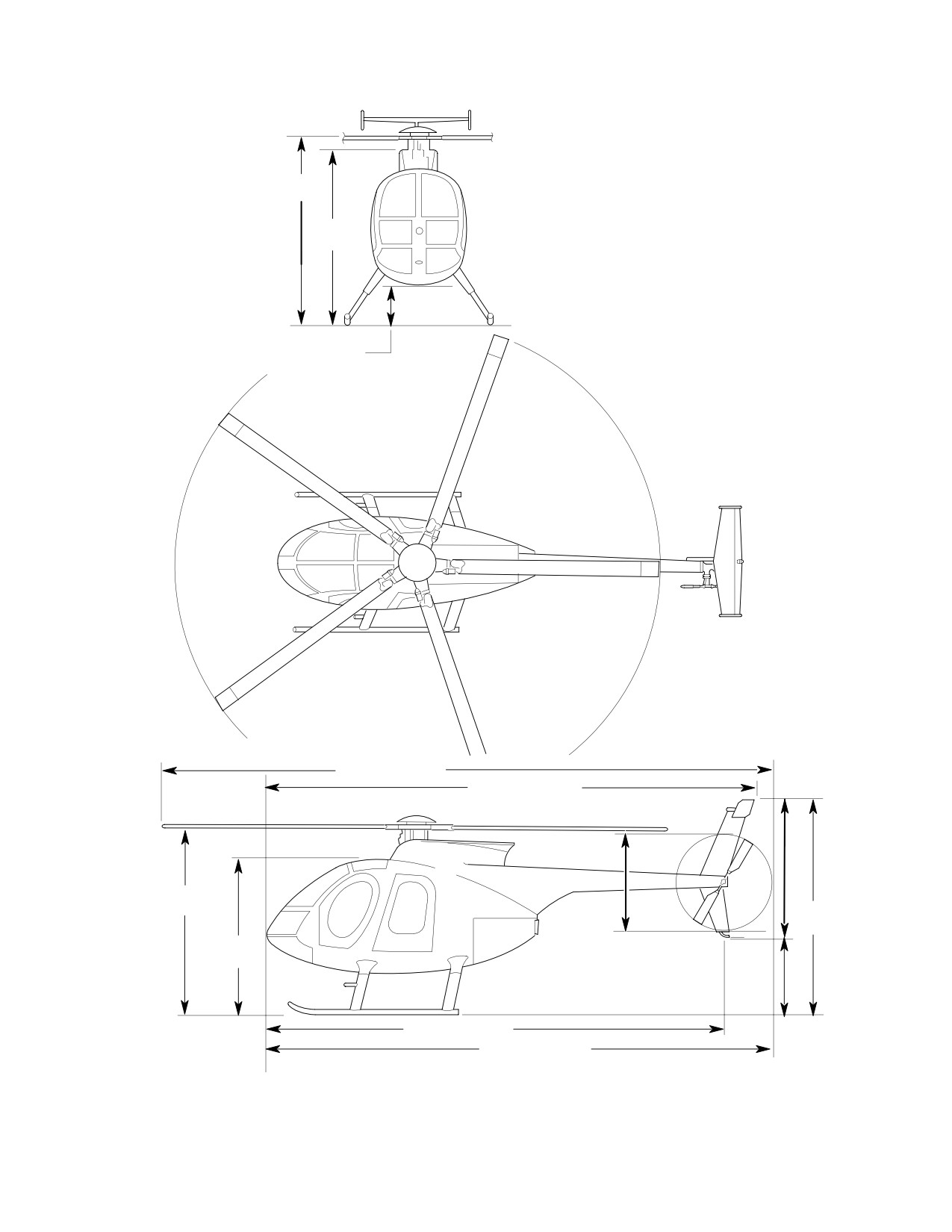
MD Helicopters, Inc.
CSP-HMI-2
MAINTENANCE MANUAL
GENERAL NOTES:
1.
HELICOPTER ON GROUND WITH FULL
FUEL. TYPICAL ATTITUDE OF CARGO
DECK 4.7 DEGREES NOSE UP.
8.72 FT.
2.
IF OPTIONAL EXTENDED LANDING GEAR
(2.66 M)
IS INSTALLED, ADD 0.87 FT. (0.27 M) TO
ALL VERTICAL DIMENSIONS.
7.65 FT.
(2.33 M)
1.27 FT.
(0.39 M)
30.81 FT. (9.40 M)
6.43 FT. (1.96 M)
23.88 FT. (7.28 M)
8.15 FT.
(2.49 M)
8.4 FT.
(2.6 M)
6.77 FT.
4.58 FT.
(2.06 M)
(1.40 M)
22.42 FT. (6.84 M)
2.0 FT. (0.61 M)
24.71 FT. (7.54 M)
G06-0002B
Figure 202. Principal Dimensions− Models 369E
Page 203
06-00-00
Revision 23
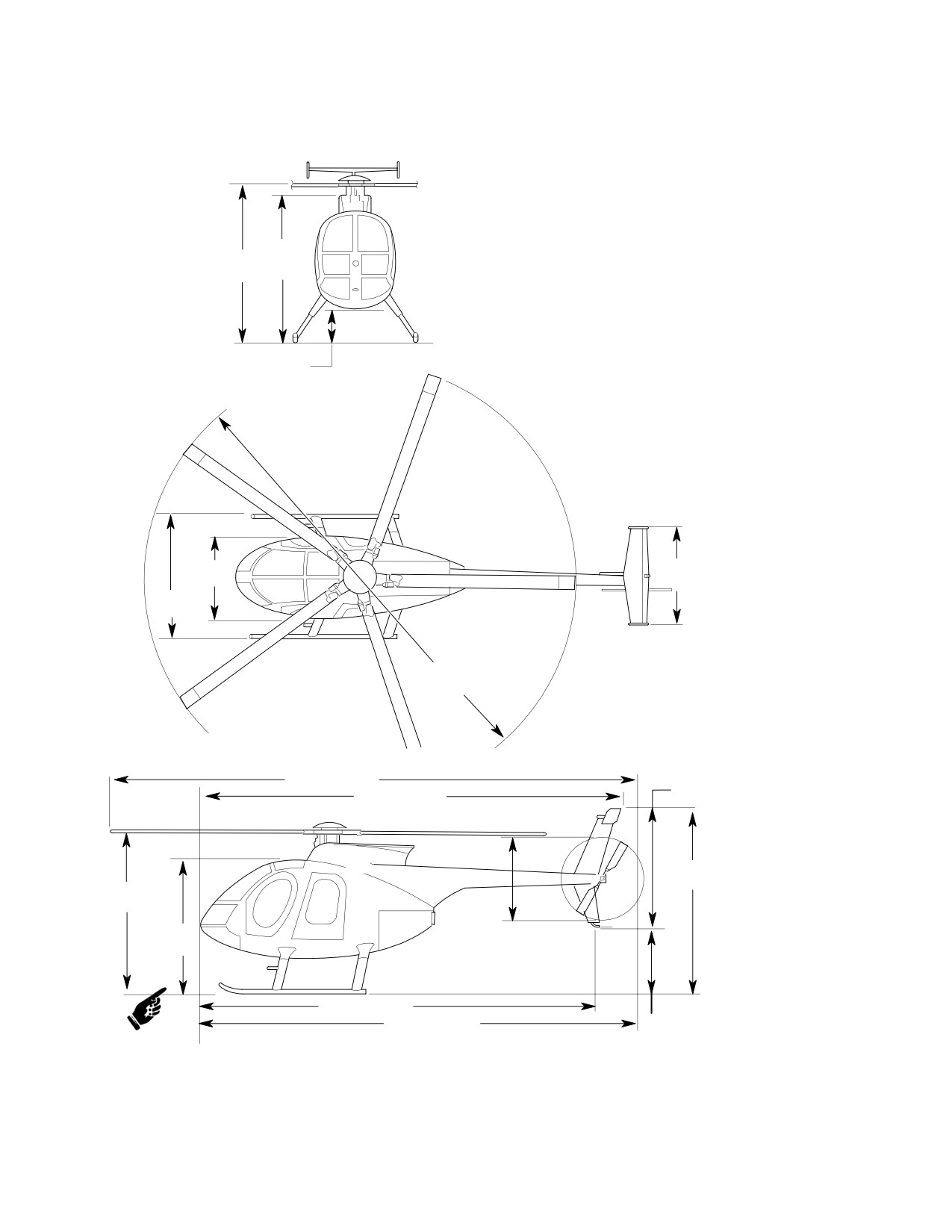
CSP-HMI-2
MD Helicopters, Inc.
MAINTENANCE MANUAL
GENERAL NOTES:
1.
HELICOPTER ON GROUND WITH FULL FUEL.
TYPICAL ATTITUDE OF CARGO DECK 5.3
DEGREES NOSE UP.
2.
IF OPTIONAL EXTENDED LANDING GEAR IS
INSTALLED, ADD 0.87 FT. (0.27 M) TO ALL
VERTICAL DIMENSIONS.
7.53 FT
8.6 FT.
(2.30 M)
(2.62 M)
1.15 FT
(0.35 M)
4.57 FT.
5.43 FT.
(1.40 M)
(1.66 M)
6.45 FT.
(1.97 M)
27.35 FT.
(8.34 M)
32.06 FT. (9.78 M)
6.8 FT. (2.1 M)
23.88 FT. (7.28 M)
8.1 FT
(2.5 M).
8.03 FT.
(2.45 M)
6.65 FT.
(2.03 M)
4.75 FT.
(1.45 M)
23.08 FT. (7.04 M)
25.46 FT. (7.77 M)
1.3 FT. (0.40 M)
G06-0003C
Figure 203. Principal Dimensions Model 369FF
Page 204
Revision 44
06-00-00
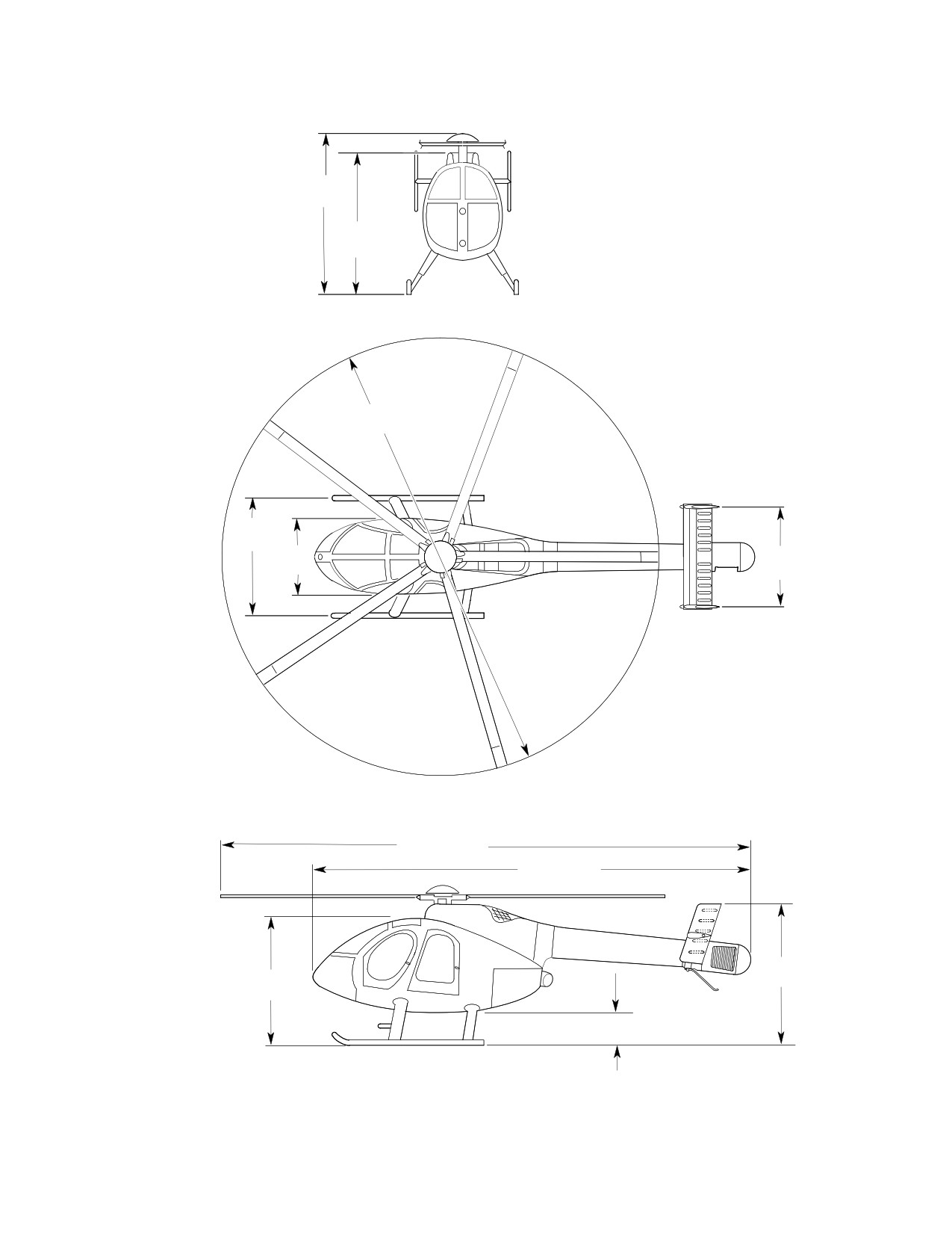
MD Helicopters, Inc.
CSP-HMI-2
MAINTENANCE MANUAL
GENERAL NOTES:
1.
HELICOPTER ON GROUND WITH FULL FUEL.
TYPICAL ATTITUDE OF CARGO DECK: 4.7 DEGREES
8.8 FT.
NOSE UP.
(2.7 M)
2.
IF EXTENDED LANDING GEAR IS INSTALLED, ADD
0.87 FT. (0.27 M) TO ALL VERTICAL DIMENSIONS.
7.7 FT.
(2.3 M)
27.35 FT.
(8.34 M)
6.3 FT.
(1.9 M)
4.6 FT.
6.5 FT.
(1.4 M)
(2.0 M)
31.39 FT. (9.6 M)
24.9 FT. (7.6 M)
7.7 FT.
6.9 FT.
(2.3 M)
(2.1 M)
1.4 FT.
(0.4 M)
G06-0006B
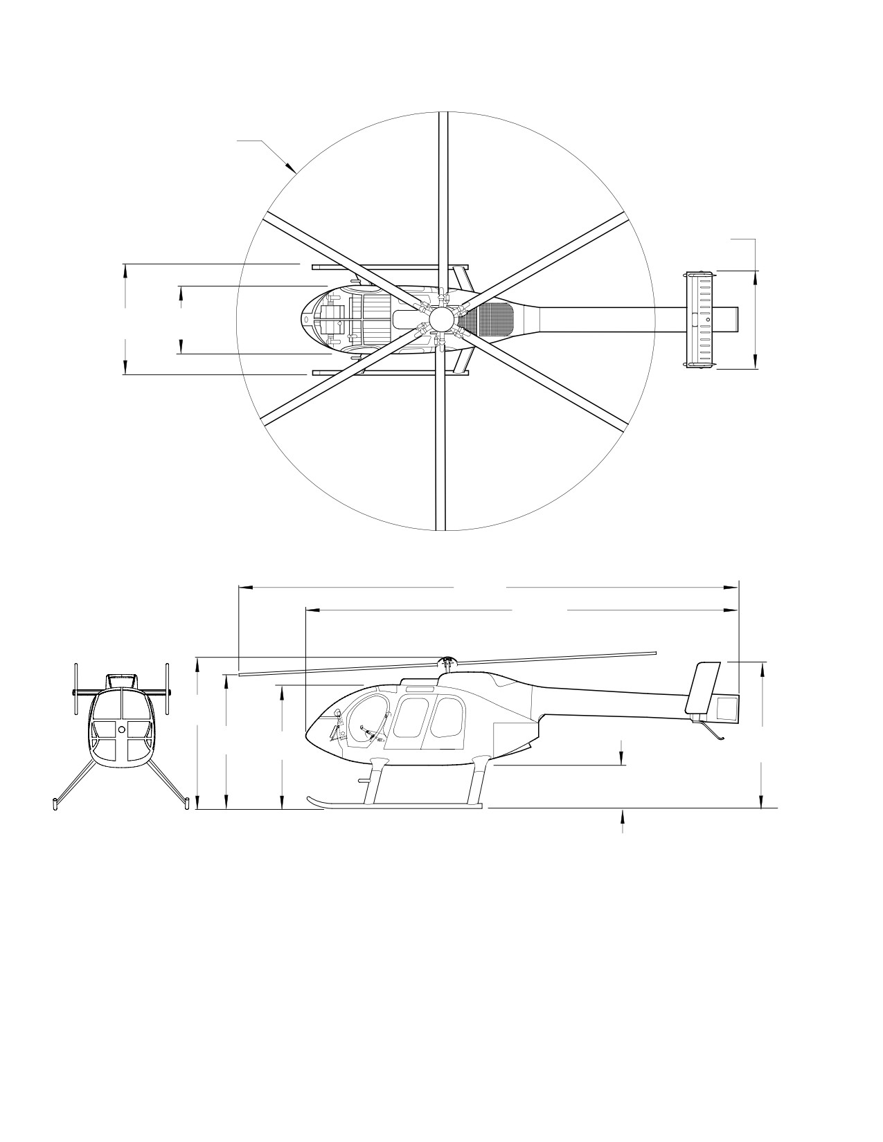
Figure 204. Principal Dimensions − Model 500N
Page 205
06-00-00
Revision 23
CSP-HMI-2
MD Helicopters, Inc.
MAINTENANCE MANUAL
27.5 FT
DIA
(8.4 M)
6.6 FT
(2.0 M)
8.8 FT
4.6 FT
(2.7 M)
(1.4 M)
36.9 FT
(11.3 M)
29.6 FT
(9.0 M)
9.7 FT
(2.9 M)
9.2 FT
9.8 FT
7.8 FT
(2.8 M)
(3.0 M)
(2.4 M)
2.4 FT
(0.7 M)
GENERAL NOTES:
1.
HELICOPTER ON GROUND WITH FULL FUEL.
TYPICAL ATTITUDE OF CARGO DECK 5.3 DEGREES NOSE UP.
2.
HEIGHT ABOVE GROUND DIMENSIONS VARY WITH INSTALLED
EQUIPMENT, CENTER OF GRAVITY AND TERRAIN FEATURES.
3.
ALL DIMENSIONS SHOWN DEPICT EXTENDED LANDING GEAR.
6G06-043D
Figure 205. Principal Dimensions − Model 600N (Sheet 1 of 2)
Page 206
Revision 39
06-00-00
MD Helicopters, Inc.
CSP-HMI-2
MAINTENANCE MANUAL
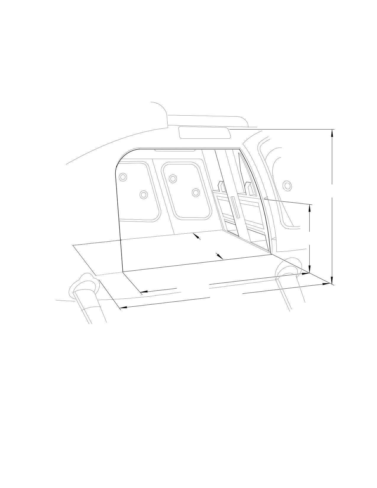
48 INCHES
(122 CM)
25 INCHES
(63 CM)
48 INCHES
(122 CM)
62 INCHES
(157 CM)
72 INCHES
(183 CM)
6G06-038
Figure 205. Principal Dimensions − Model 600N (Sheet 2 of 2)
Page 207
06-00-00
Revision 23
CSP-HMI-2
MD Helicopters, Inc.
MAINTENANCE MANUAL
CANT STA
STA
STA
STA
78.50
146.62
164.87
185.89
CANT STA
STA
STA
STA
C
CANT STA
124.00
137.50
155.75
174.00
MAST
197.78
STA
28.00
WL
WL 45.36
49.37
CORNER
L
WL
PILOT'S
WL
38.64
SEAT
JACKING
WL
32.00
WL 21.50
POINT
34.50
STA 96.89
WL
WL 11.98
22.75
WL
WL
14.19
13.10
WL
WL
0.00
0.00
STA
STA
STA
STA
STA
STA
STA
STA
44.65
56.85
84.79
96.42
108.04
119.67
137.50
0.00
STA
STA CANT STA STA STA
STA STA
50.50
64.37
78.50
90.61
102.23
113.85
124.00
WL
96.91
WL
WL
55.34
54.17
CANT STA
209.78
CANT STA
CANT STA
CANT STA CANT STA
197.78
219.96
242.14
264.32
WL
CANT STA
26.67
273.00
CANT STA
281.12
NOTE:
FRAME BASE
WHEN MEASURING EXTERNALLY FROM RIVET LINES,
NOTE THE SIDE AT BULKHEAD OR FRAME INDICATED AS
THE STATION AND COMPENSATE FOR RIVET POSITION
IN THE ATTACHMENT FLANGE.
G06-0004B
Figure 206. Station Diagram − Model 369D
Page 208
Revision 23
06-00-00
MD Helicopters, Inc.
CSP-HMI-2
MAINTENANCE MANUAL
CANT STA
78.50
STA
108.50
STA
STA
STA
146.62
164.87
185.89
C
CANT STA
STA
STA
STA
L
124.00
137.50
MAST
155.75
174.00
CANT STA
197.78
WL 76.70
WL 66.00
STA
15.00
WL
WL 45.36
49.37
CORNER
PILOT'S
L
SEAT
WL 34.50
WL 21.50
WL 32.00
WL 11.98
WL 22.75
WL 14.19
WL 13.10
JACKING POINT
STA 96.89, BL ±25.60
WL 0.00
WL 0.00
STA
STA
STA
STA
STA
STA
STA
44.65
56.85
84.79
96.42
108.04
119.67
137.50
STA
STA
STA
STA
0.00
STA
STA
50.50
64.37
102.23
90.61
124.00
CANT STA
STA
78.50
113.85
WL 102.17
WL 96.91
STA 289.12 (369FF)
WL 55.34
WL 54.17
CANT STA
CANT STA
369FF ONLY
209.78
CANT STA
CANT STA
CANT STA
264.32
197.78
219.96
242.14
WL 26.67
CANT STA
WL 25.46 (369E)
273.00
WL 22.36 (369FF)
CANT STA
281.12
NOTE:
FRAME BASE
WHEN MEASURING EXTERNALLY FROM RIVET LINES,
NOTE THE SIDE AT BULKHEAD OR FRAME INDICATED AS
THE STATION AND COMPENSATE FOR RIVET POSITION
IN THE ATTACHMENT FLANGE.
G06-0005B
Figure 207. Station Diagram − Models 369E/FF
Page 209
06-00-00
Revision 23
CSP-HMI-2
MD Helicopters, Inc.
MAINTENANCE MANUAL
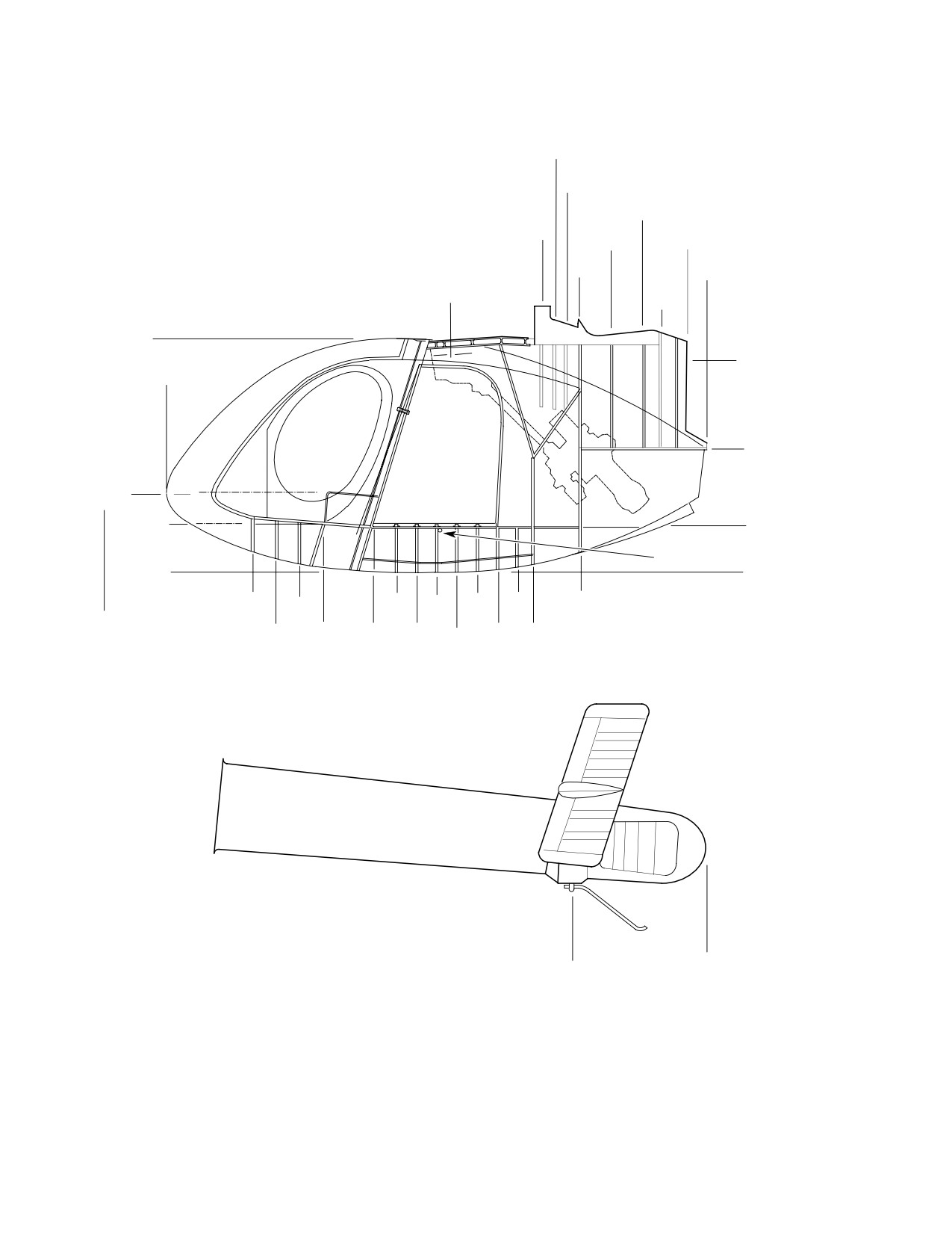
STA
129.00
STA
132.90
STA
155.75
STA
STA
STA
124.75
146.62
168.20
STA
STA
137.50
CANT
174.00
L
MAST
STA
159.97
WL 66.00
STA
WL 60.00
15.00
WL 34.50
WL 22.75
WL 14.19
WL 13.10
JACKING POINT
STA 96.89, BL ±25.60
WL 0.00
WL 0.00
STA
STA
96.42
STA
STA
STA
STA
44.65
84.79
STA
108.04
119.67
137.50
STA
56.85
STA
STA CANT STA
STA
102.23
STA
STA
0.00
50.50
64.37
78.50
90.61
113.85
124.00
STA
STA
AFT JACKING
315.00
POINT STA 275.40,
NOTE:
BL 0.00, WL 41.00
WHEN MEASURING EXTERNALLY FROM RIVET LINES,
NOTE THE SIDE AT BULKHEAD OR FRAME INDICATED AS
THE STATION AND COMPENSATE FOR RIVET POSITION
IN THE ATTACHMENT FLANGE.
G06-0007B
Figure 208. Station Diagram − Model 500N
Page 210
Revision 23
06-00-00
MD Helicopters, Inc.
CSP-HMI-2
MAINTENANCE MANUAL
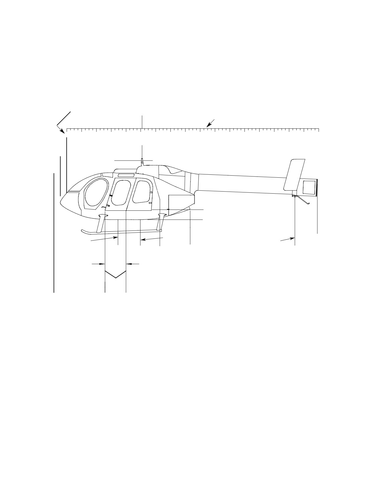
NOTE 2
CL
NOTE 3
0
20
40
60
80
120
140
160
180
200
220
240
260
280
300
320
340
STA
100.00
STA
15.00
WL
83.00
WL
14.00
WL
0.00
MID
FORWARD
STA
JACK POINT
AFT
JACK POINT
338.36
JACK POINT
P.STA
STA
STA
STA
STA
18.76
96.90
124.00
168.66
303.30
30 IN.
STA
78.50
P.STA
P.STA
STA
0.00
30.00
0.00
(NOTE 1)
NOTES:
1.
STA. 0.00, 15 INCHES (381 MM) FORWARD OF NOSE OF AIRCRAFT.
2.
THIS DIMENSION 15 INCHES (381 MM) AFT OF NOSE OF AIRCRAFT.
3.
THESE DIMENSIONS IN INCHES.
6G06-004BA
Figure 209. Fuselage Station Diagram − Model 600N
Page 211
06-00-00
Revision 36
CSP-HMI-2
MD Helicopters, Inc.
MAINTENANCE MANUAL
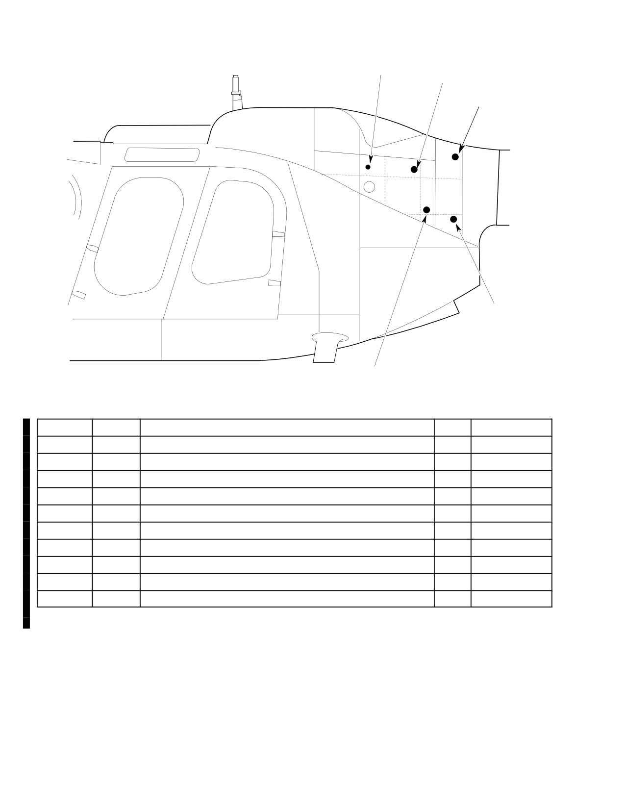
L137, R137
L153, R153
L167, R167
Î
Î
L166, R166
L158, R158
G06-0008
Item No.
Name
Permits Access To
Qty.
Type
L137
Plug
Left forward upper longeron
1
Button Plug
R137
Plug
Right forward upper longeron
1
Button Plug
L153
Plug
Left upper longeron
1
Button Plug
R153
Plug
Right upper longeron
1
Button Plug
L158
Plug
Left lower longeron
1
Button Plug
R158
Plug
Right lower longeron
1
Button Plug
L166
Plug
Left lower attach fitting
1
Button Plug
R166
Plug
Right lower attach fitting
1
Button Plug
L167
Plug
Left upper attach fitting
1
Button Plug
R167
Plug
Right upper attach fitting
1
Button Plug
Figure 210. Aft Empenage Access Plugs − Model 600N
Page 212
Revision 34
06-00-00

MD Helicopters, Inc.
CSP-HMI-2
MAINTENANCE MANUAL
Chapter
07
Lifting and Jacking
MD Helicopters, Inc.
CSP-HMI-2
MAINTENANCE MANUAL
TABLE OF CONTENTS
Para/Figure/Table
Title
Page
07-00-00 Lifting and Jacking
A
Maintenance Practices
201
1. Component Weights for Hoisting
201
Table 201. Approximate Maximum Hoisting Weights of Components -
369D/E
201
Table 202. Approximate Maximum Hoisting Weights of Components -
369FF
201
Table 203. Approximate Maximum Hoisting Weights of Components -
500N
201
Table 204. Approximate Maximum Hoisting Weights of Components -
600N
201
2. Helicopter Hoisting
201
3. Helicopter Sling Lifting
202
A. Helicopter Preparations
202
B. Helicopter Lifting
202
C. Helicopter Landing
202
4. Helicopter Jacking
203
Figure 201. Hoisting and Jacking Helicopter (Sheet 1 of 3)
204
Page i
07 Contents
Revision 23
CSP-HMI-2
MD Helicopters, Inc.
MAINTENANCE MANUAL
TABLE OF CONTENTS (Cont.)
Para/Figure/Table
Title
Page
This Page Intentionally Left Blank
Page ii
Revision 43
07 Contents
MD Helicopters, Inc.
CSP-HMI-2
MAINTENANCE MANUAL
Section
07−00−00
Lifting and Jacking

MD Helicopters, Inc.
CSP-HMI-2
MAINTENANCE MANUAL
LIFTING AND JACKING
MAINTENANCE PRACTICES
1. Component Weights for Hoisting
Table 203. Approximate Maximum Hoisting
Weights of Components − 500N
(Ref. Table 201 thru Table 204) The maximum
weights for large components that may require
Wgt
hoisting are listed.
Item
Lb/kg
Use hoist with minimum 3500
Tailboom (w/o empennage, thruster)
35/16
CAUTION
pound (1589 kg) capacity when
Main rotor hub
92/42
hoisting complete helicopter. Use hoisting
equipment with minimum 20% overrate to
Main transmission (wet) (369D25100)
105/48
hoist heavier components of helicopter (Ref.
Main transmission (wet) (369F5100)
140/64
Table 201 thru Table 204 for approximate
weights).
Engine (built−up)
207/94
Table 201. Approximate Maximum Hoisting
Helicopter (less main rotor hub,
1314/597
Weights of Components − 369D/E
swashplate, scissors and rotor blades)
Wgt
Helicopter (complete)
1542/700
Item
Lb/kg
Table 204. Approximate Maximum Hoisting
Tailboom
18/8
Weights of Components − 600N
Main rotor hub
85/39
Wgt
Main transmission (wet) (369D25100)
105/48
Item
Lb/kg
Main transmission (wet) (369F5100)
140/64
Tailboom (w/o empennage, thruster)
55/25
Engine (built−up) C20B
192/87
Main rotor hub (with dampers, pins)
107/49
Engine (built−up) C20R/2
207/94
Main transmission (wet)
140/64
Helicopter (less main rotor hub,
1153/523
swashplate, scissors and rotor blades)
Engine (built−up) C47
292/133
Helicopter (complete)
1361/618
Helicopter (less main rotor hub,
1830/830
swashplate, scissors and rotor blades)
Table 202. Approximate Maximum Hoisting
Helicopter (complete)
2100/953
Weights of Components − 369FF
2. Helicopter Hoisting
Wgt
Item
Lb/kg
(Ref. Figure 201)
Tailboom
23/10
Special Tools
Main rotor hub
92/42
(Ref. Section 91−00−00)
Item
Nomenclature
Main transmission (wet) (369D25100)
105/48
ST201
Hoisting adapter
Main transmission (wet) (369F5100)
140/64
N/A
Cable or Rope
Engine (built−up)
271/123
(1). Remove dome fairing (N/A 600N) from
Helicopter (less main rotor hub,
1369/622
main rotor hub and install hoisting
swashplate, scissors and rotor blades)
adapter (ST201) on hub so that hoisting
eyebolts fit into slots on hoisting
Helicopter (complete)
1589/721
adapter.
Page 201
07-00-00
Revision 23

CSP-HMI-2
MD Helicopters, Inc.
MAINTENANCE MANUAL
(2). Install quick release pins.
(7). Secure tail rotor hub to Sta. 284
bellcrank with strap or rope (369D/E/
(3). Attach cable from overhead hoist to
FF only).
adapter eye.
(8). Position one person to support tail of
(4). Secure a line to tailboom. Have assis
helicopter.
tant hold line to keep helicopter from
(9). Position one person to accomplish
swinging.
hookup to recovery helicopter.
(5). Hoist slowly and smoothly to maintain
(10). Position one person in view of recovery
steady lifting force.
helicopter to act as ground guide during
hookup.
3. Helicopter Sling Lifting
B. Helicopter Lifting
Follow below procedures for sling lifting the
helicopter.
Tail of helicopter may come
WARNING
down sharply if helicopter is
lifted abruptly.
Special Tools
(Ref. Section 91−00−00)
Avoid dragging helicopter dur
CAUTION
Item
Nomenclature
ing lift before ground clearance
is obtained. Dragging helicopter may cause
ST201
Hoisting adapter
extensive damage.
(1). Carefully lift helicopter. Ensure that
Sling-lift helicopter only when
CAUTION
person at tail of helicopter is familiar
other means of recovery are not
with above warning.
available. Ensure recovery helicopter has
adequate capabilities, performance and fuel
(2). Transport recovery crew and removed
to accomplish sling-lift recovery. Ensure re
equipment to landing site before
covery crew has experience level to assure
recovery helicopter with lifted helicop
optimum performance at assigned positions.
ter arrives.
Do not attempt lifting or lowering during
C. Helicopter Landing
adverse wind or weather conditions.
(1). Indicate wind direction with smoke
A. Helicopter Preparations
cannister.
Prepare helicopter to be lifted before attempt
(2). Ground guide recovery helicopter to
ing lift to avoid damage or loss of equipment
hover into wind before lowering begins.
during flight.
Do not attempt lowering if heli
(1). Remove dome fairing from main rotor
CAUTION
copter is spinning.
hub (N/A 600N).
(3). Lower helicopter.
(2). Remove main rotor blades (Ref. Sec.
(4). Restrain and support tail of helicopter
62-10-00).
as it contacts ground.
(3). Replace and secure blade damper bolts
Ground guide must signal re
and attaching pins.
CAUTION
covery helicopter to move to one
side before dropping sling or helicopter win
(4). Tape elastomeric damper to pitch
dow damage may occur.
housing.
(5). Signal recovery helicopter to drop sling.
(5). Install hoisting adapter (ST201).
(6). Remove sling and hoist adapter.
(6). Attach lifting straps or swivel-equipped
cable slings that clear lead by 10 feet
(7). Inspect recovered helicopter to deter
(3.048 M) to hoisting adapter.
mine condition.
Page 202
Revision 23
07-00-00
MD Helicopters, Inc.
CSP-HMI-2
MAINTENANCE MANUAL
(8). Inspect main rotor blades prior to
(1). Install jack fittings (ST202) in fuselage
installation for damage caused during
jacking points. Secure jack fittings with
removal and transportation (Ref. Sec.
locking pins located in fuel cell access
62-10-00).
doors.
4. Helicopter Jacking
NOTE: When jacking the 600N helicopter, only
(Ref. Figure 201) Provisions for jacking
use the forward and aft jacking points.
helicopter are provided by two (369D/E/FF -
500N) or four (600N) forward (side) jacking
point fittings and an aft jacking pad. The aft
(2). Place suitable jacks (ST203 or ST204)
jack pad locations differ for the 369D/E/FF and
under jack fittings and AFT jacking
the 500/600N helicopters.
pad.
Special Tools
NOTE: If helicopter is jacked from one side
(Ref. Section 91−00−00)
only, in next step, a cushioned saddle-type
Item
Nomenclature
support should be placed under tailboom at
ST202
Jack fittings
aft jacking pad location for extra stability.
ST203
Hydraulic jack: 1-5 ton (900-4500 kg)
ST204
Hydraulic jack: 80 inch (203 cm) leg
(3). Raise helicopter to desired height.
Page 203
07-00-00
Revision 23
CSP-HMI-2
MD Helicopters, Inc.
MAINTENANCE MANUAL
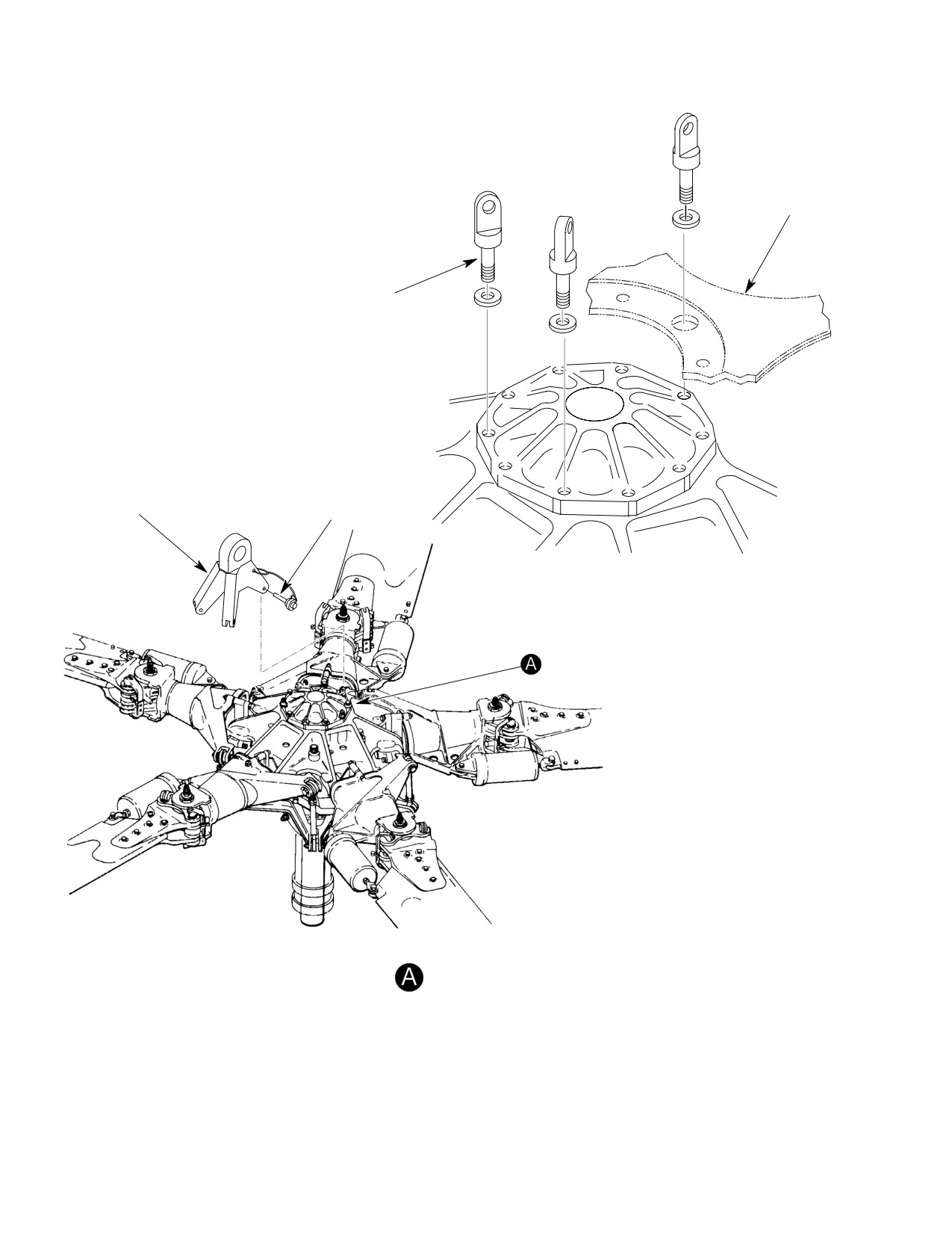
HUB FAIRING
SUPPORT
HOISTING EYEBOLTS
(3 PLACES)
HOISTING
QUICK RELEASE PINS
ADAPTER
(3 PLACES)
HOISTING
NOTE: HUB SUPPORT
REMOVED FOR CLARITY.
G07-0001-1
Figure 201. Hoisting and Jacking Helicopter (Sheet 1 of 3)
Page 204
Revision 23
07-00-00
MD Helicopters, Inc.
CSP-HMI-2
MAINTENANCE MANUAL
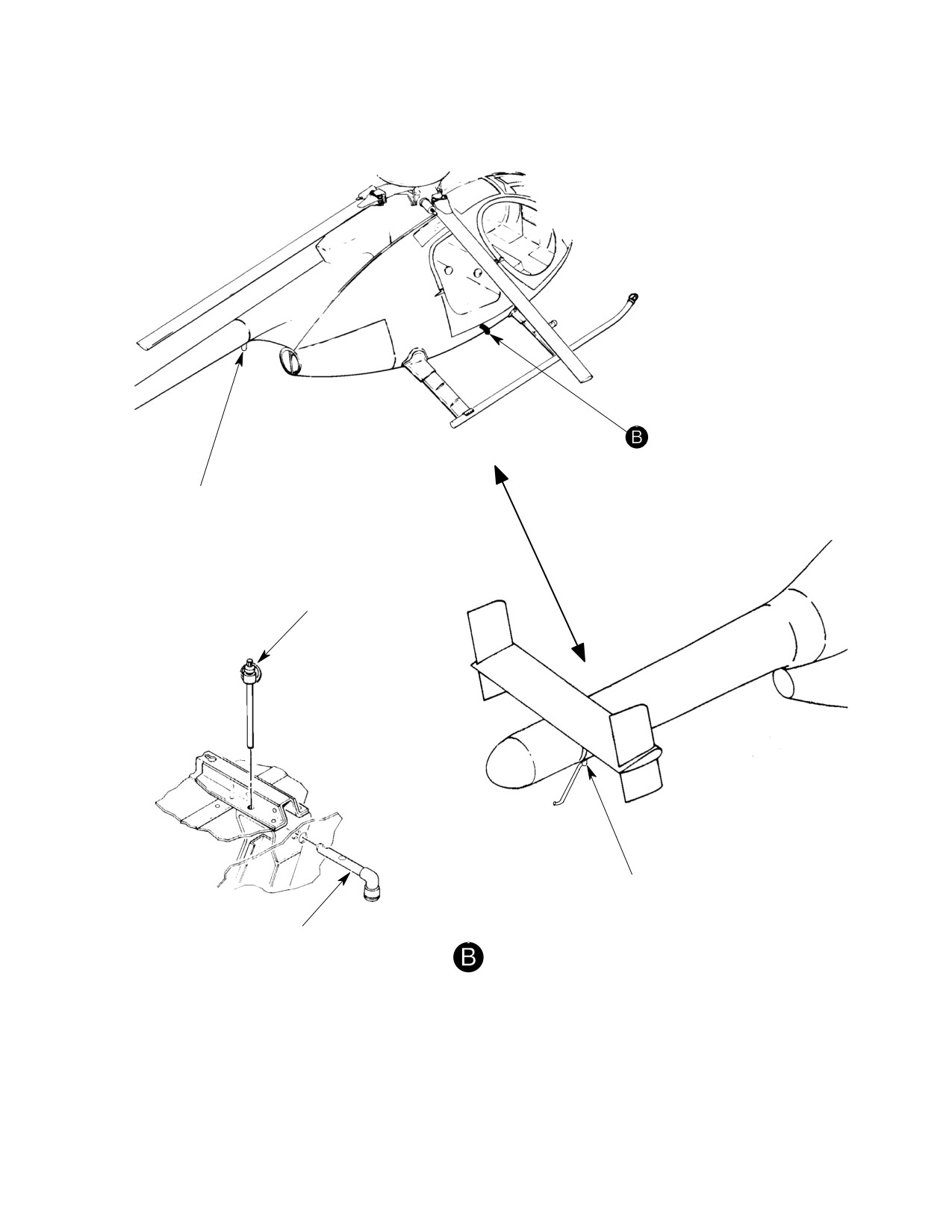
AFT JACKING PAD
(STA 197.2) (369D/E/FF)
LOCKPIN
AFT JACKING PAD
(STA 275.4) (500N)
JACK FITTING
JACKING
G07-0001-2A
Figure 201. Hoisting and Jacking Helicopter (Sheet 2 of 3)
Page 205
07-00-00
Revision 23
CSP-HMI-2
MD Helicopters, Inc.
MAINTENANCE MANUAL
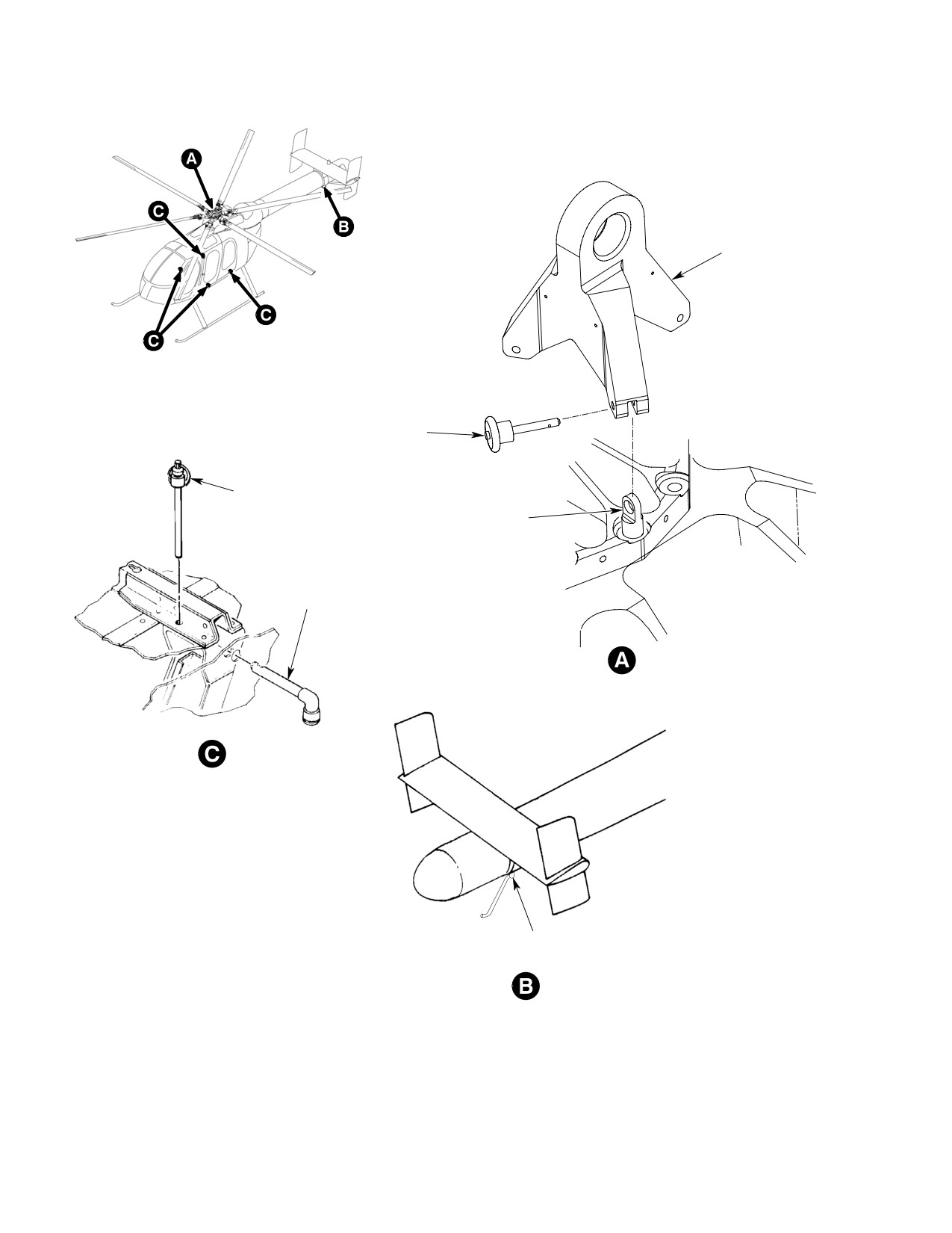
NOTE
HOISTING
ADAPTER
NOTE
NOTE
HOISTING
RELEASE PIN
(3 PLACES)
LOCKPIN
HOISTING EYEBOLT
(3 PLACES)
JACK FITTING
HOISTING
VIEW ROTATED
AFT JACKING PAD
(STA 303.3) (600N)
JACKING
NOTE: USE APPROPRIATE JACKING POINT
6G07-005
ACCORDING TO C/G OF HELICOPTER.
Figure 201. Hoisting and Jacking Helicopter (Sheet 3 of 3)
Page 206
Revision 23
07-00-00

MD Helicopters, Inc.
CSP-HMI-2
MAINTENANCE MANUAL
Chapter
08
Leveling/Weight and
Balance
MD Helicopters, Inc.
CSP-HMI-2
MAINTENANCE MANUAL
TABLE OF CONTENTS
Para/Figure/Table
Title
Page
08-00-00 Leveling
A
Maintenance Practices
201
1. Helicopter Leveling
201
Figure 201. Leveling Helicopter (Sheet 1 of 2)
202
08-10-00 Weight and Balance
A
Maintenance Practices
201
1.
General Weight and Balance Information
201
A. Approved Center of Gravity Limits
201
B. Terminology
201
2.
Helicopter Weighing
202
A. Helicopter Weighing Preparation
202
B. Preparation for Weighing - Electronic Method
203
C. Helicopter Weighing - Electronic Method
204
D. Preparation for Weighing - Mechanical Scales Method
(369D/E/FF - 500N Only)
204
E. Weighing Procedures - Mechanical Scales Method
(369D/E/FF - 500N Only)
205
F. Longitudinal CG Determination for Unadjusted Net Weight
(369D/E/FF - 500N Only)
205
G. Lateral CG Determination for Unadjusted Net Weight
205
H. Basic Weight and CG Determination
206
Figure 201. Balance Diagram - Model 369D
207
Figure 202. Balance Diagram - Model 369E
208
Figure 203. Balance Diagram - Model 369FF
209
Figure 204. Balance Diagram - Model 500N
210
Figure 205. Balance Diagram - Model 600N
211
Figure 206. Weight and Balance Report Form (Sheet 1 of 2)
212
Figure 207. Surplus and Missing Items Report
214
Figure 208. Basic Weight and Balance Record
215
Figure 209. Example 1 (Sheet 1 of 2)
216
Page i
08 Contents
Revision 23
CSP-HMI-2
MD Helicopters, Inc.
MAINTENANCE MANUAL
TABLE OF CONTENTS (Cont.)
Para/Figure/Table
Title
Page
This Page Intentionally Left Blank
Page ii
Revision 43
08 Contents
MD Helicopters, Inc.
CSP-HMI-2
MAINTENANCE MANUAL
Section
08−00−00
Leveling
MD Helicopters, Inc.
CSP-HMI-2
MAINTENANCE MANUAL
LEVELING
MAINTENANCE PRACTICES
1. Helicopter Leveling
(1). Suspend plumb line from bracket on
right side of controls tunnel at Sta.
92.64, BL+ 6.20.
(Ref. Figure 201) Leveling is accomplished by
positioning helicopter to align a plumb bob
(2). Adjust plumb line swing to leveling
with register marks on the target plate on
target plate on floor of passenger/cargo
cargo compartment floor.
compartment.
(3). With weight of helicopter supported by
Special Tools
load cells of electronic weighing kit or
(Ref. Section 91−00−00)
jacks (ST203), as applicable, adjust
Item
Nomenclature
appropriate jack until plumb line is
centered (Ref. Sec. 07-00-00, Helicop
N/A
Plumb bob (commercially available)
ter Jacking).
N/A
Twine
(a). Adjust side jacks to level helicopter
N/A
Electronic weighing kit
laterally.
ST202
Jack fittings
(b). Adjust tailboom jack to level helicop
ST203
Hydraulic jack: 1-5 ton (900-4500 kg)
ter longitudinally.
(c). Recheck lateral and longitudinal
levels until plumb bob exactly aligns
NOTE: Access to plumb line support bracket
with marks on target plate.
and target plate on floor of passenger/cargo
compartment requires removal of trim on
(4). After leveling helicopter, remove plumb
right side of controls tunnel, and floor carpet
bob, reinstall trim and carpet, and close
in aft compartment (Ref. Chap. 25).
compartment door.
Page 201
08-00-00
Revision 23
CSP-HMI-2
MD Helicopters, Inc.
MAINTENANCE MANUAL
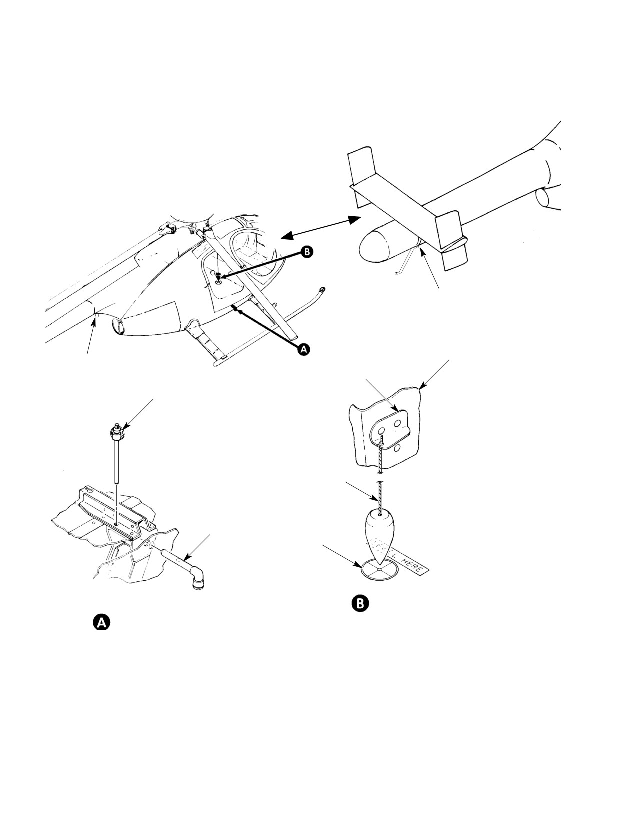
AFT JACKING PAD
(STA 275.4) (500N)
RIGHT EDGE OF
AFT JACKING PAD
PLUMB LINE
CONTROL TUNNEL
(STA 197.2) (369D/E/FF)
SUPPORT CLIP
LOCKPIN
PLUMB LINE
JACK FITTING
TARGET PLATE
LEVELING
JACKING
G08-0001B
Figure 201. Leveling Helicopter (Sheet 1 of 2)
Page 202
Revision 23
08-00-00
MD Helicopters, Inc.
CSP-HMI-2
MAINTENANCE MANUAL
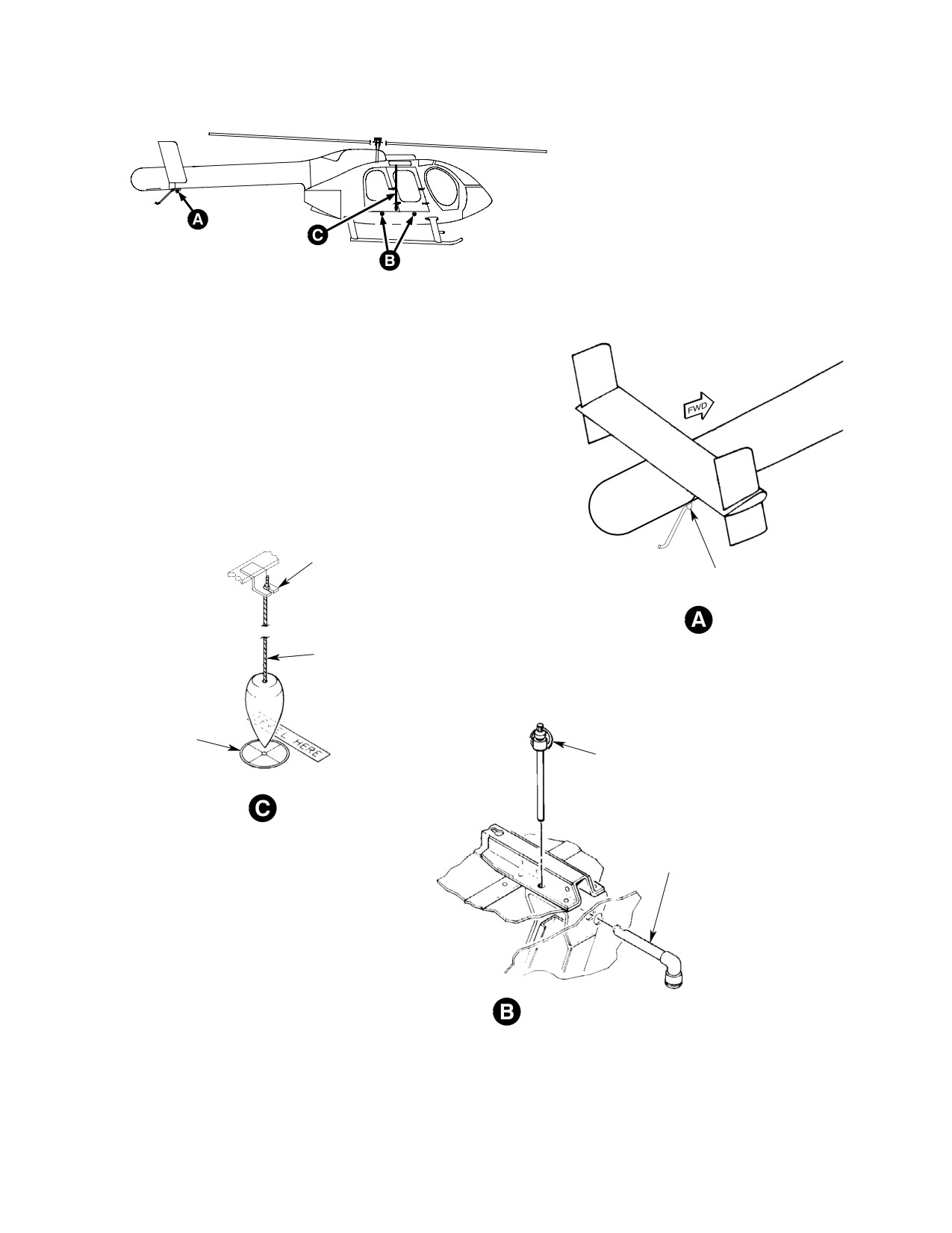
PLUMB BOB SUPPORT
AFT JACKING POINT
JACKING
PLUMB LINE
TARGET
PLATE
LOCKPIN
LEVELING
JACK FITTING
JACKING
(FORE AND MID POINTS ARE TYPICAL)
6G08-041A
Figure 201. Leveling Helicopter (Sheet 2 of 2)
Page 203
08-00-00
Revision 23
CSP-HMI-2
MD Helicopters, Inc.
MAINTENANCE MANUAL
This Page Intentionally Left Blank
Page 204
Revision 43
08-00-00
MD Helicopters, Inc.
CSP-HMI-2
MAINTENANCE MANUAL
Section
08−10−00
Weight and Balance
MD Helicopters, Inc.
CSP-HMI-2
MAINTENANCE MANUAL
WEIGHT AND BALANCE
MAINTENANCE PRACTICES
1.
General Weight and Balance Information
NOTE: Weight and balance information for op
tional equipment is found in the Initial In
(1).
Removal or addition of fuel or equip
stallation section for the optional equip
ment results in changes to weight and
ment.
balance of a helicopter, and the permis
sible useful load is affected accordingly.
Wt
These changes must be investigated to
Parameter
lb/kg
eliminate possible adverse effects on
the helicopter's flight characteristics.
Certified Gross Weight (369D/E)
3000/1362
Certified Gross Weight (369FF)
3100/1407
(2).
Basic weight and corresponding center
Certified Gross Weight (500N)
3350/1521
of gravity is determined by weighing
the helicopter without crew and
Certified Gross Weight (600N)
4100/1860
payload; however, basic weight does
Cargo Deck Capacity
1300/590
include trapped and unusable fuel, full
(369D/E/FF − 500N)
operating fluids, lubricants, etc., and
installed equipment.
Cargo Deck Capacity (600N)
1350/613
Cargo Deck Capacity not to exceed 115 pounds per
(3).
369D/E/FF - 500N - The longitudinal
square foot.
reference datum is located 100 inches
(254 cm) forward of the main rotor
Certified Gross Weights are for weight−on−skids.
centerline. The lateral reference datum
is located along the longitudinal
A. Approved Center of Gravity Limits
centerline of the helicopter. The vertical
reference datum is located at a point
(Ref. PFM)
100 inches (254 cm) below the center of
the main rotor blades.
B. Terminology
Following are terms with definitions, used
(4).
600N - The Weight and Balance
when determining helicopter weight and
longitudinal reference datum is located
balance:
100 inches (254 cm) forward of the
main rotor centerline or 15 inches (38.1
(1). Arm: The distance in inches from the
cm) aft of the aircraft nose. The Weight
longitudinal (longitudinal arm) and
and Balance (longitudinal) Reference
lateral (lateral arm) reference datum of
Datum is different from the Fuselage/
a part to the center of gravity (CG) of
Engineering Reference Datum (Ref.
the part.
Section 06-00-00). The lateral refer
ence datum is located along the longitu
NOTE: When viewing helicopter from rear,
dinal centerline of the helicopter. The
items to left of lateral reference datum (cen
vertical reference datum is located at a
ter line of helicopter) will be expressed as
point 83 inches (210.8 cm) below the
having negative (-) lateral arm, and those
center of the main rotor blades.
items to right of reference datum, a positive
(+) lateral arm.
(5).
Refer to the following for balance
diagrams
(2). Center of gravity (CG): A point on a
Figure 201 for Model 369D
part where the part will be perfectly
Figure 202 for Model 369E
balanced. Center of gravity is measured
Figure 203 for Model 369FF
in inches from a known reference. It
Figure 204 for Model 500N
can be determined using the following
Figure 205 for Model 600N.
formula:
Page 201
08-10-00
Revision 39
CSP-HMI-2
MD Helicopters, Inc.
MAINTENANCE MANUAL
CG(in)
= Moment (in−lb)
CAUTION
Weight (lb)
D The controls access panel (aft side of Sta.
78.5 bulkhead) and the fuel cell access
panels must be installed before jacking
(3). Moment: Product of weight of a part
helicopter.
and its arm, either longitudinal or
lateral, and is expressed in inch-
D 369D/E/FF - 500N: There are two meth
pounds (in-lb).
ods approved for weighing the helicopter.
Longitudinal moment = weight x
The preferred method is by using elec
longitudinal arm;
tronic weighing equipment. If equipment
Lateral moment = weight x lateral arm.
for electronic weighing is unavailable, the
second approved method, mechanical
scales, may be used.
(4). Reaction point: A fixed point on helicop
D 600N: There is one method approved for
ter where weight of helicopter counter
weighing the helicopter. The method is by
acts on a weighing device. The main
using electronic weighing equipment.
reaction points are;
A. Helicopter Weighing Preparation
The following items are required and should be
(a). ALL: Long. Sta. 96.9.
readily available prior to preparing and
weighing the helicopter, using the electronic
weighing method.
(b).
369D/E/FF - 500N: Lat. Sta. ±25.6.
Special Tools
(c).
600N: Lat. Sta. ±26.0.
(Ref. Section 91−00−00)
Item
Nomenclature
ST202
Jack fittings
(d).
369D/E/FF: Tail reaction point is at
Long. Sta. 197.2, Lat. Sta. 0.0.
NOTE:
D Weigh helicopter without fuel if possible.
(e).
500N: Tail reaction point is at Long.
Sta. 275.4, Lat. Sta. 0.0.
D 369D/E/FF - 500N: If fuel is drained from
low point in cell, 1.4 pounds (0.64 kg) of
trapped fuel at 93.5 inch (237.5 cm) arm
(f).
600N: Tail reaction point is at Long.
will remain. If fuel is pumped out using
Sta. 303.3, Lat. Sta. 0.0.
start pump, 3.7 pounds (1.68 kg) of
trapped (unusable) fuel at 93.5 inch
(237.5 cm) arm will remain.
2.
Helicopter Weighing
D 600N: If fuel is drained from low point in
cell, 1.6 pounds (0.73 kg) of trapped (un
usable) fuel at 93.5 inch (237.5 cm) arm
will remain. If fuel is pumped out using
start pump, 9.5 pounds (4.31 kg) of
Forms
trapped (unusable) fuel at 93.5 inch
Form Figure
(237.5 cm) arm will remain.
Nomenclature
No.
No.
(1). If defueling is not possible, ensure that
Weight and Balance Report
765B
206
fuel cell is full.
Surplus and Missing Items
1702
207
(a). Fluid weights at 70° ambient are:
Basic Weight and Balance
885
208
Fuel (Jet A)
Record
6.75 Lb (3.06 kg) per U.S. gallon
Page 202
Revision 27
08-10-00
MD Helicopters, Inc.
CSP-HMI-2
MAINTENANCE MANUAL
Fuel (JP-4)
B. Preparation for Weighing − Electronic
6.50 Lb (2.95 kg) per U.S. gallon
Method
Fuel (JP-5)
Special Tools
6.80 Lb (3.09 kg) per U.S. gallon
(Ref. Section 91−00−00)
Item
Nomenclature
Fuel (JP-8)
N/A
Electronic weighing kit/Platform Scales
6.75 Lb (3.06 kg) per U.S. gallon
N/A
Roll-away table (with weighing platform)
PRC Fuel (No 3)
N/A
Plumb Bob
6.75 Lb (3.06 kg) per U.S. gallon
ST203
Hydraulic jack: 1-5 ton (900-4500 kg)
ST204
Hydraulic jack: 80 inch (203 cm) leg
Lubricating Oil
7.70 Lb (3.50 kg) per U.S. gallon
(1).
Position hydraulic jack (ST203) under
(2).
De-fuel helicopter (Ref. Sec. 12-00-00).
each of main jacking points at Sta. 96.9,
left and right sides of helicopter.
(3).
Select weighing area that is enclosed
(2).
Position third hydraulic jack (ST203 or
and draft-free, with hard-surfaced
ST204), on roll-away table if needed,
floor.
and attached load cell at aft jacking
point of helicopter.
(4).
Ensure that helicopter and weighing
area is cleared of all tools and debris.
(3).
Attach electronic weighing kit load cell
to each jack, and to weighing kit control
(5).
369D/E/FF - 500N: Verify that five
unit.
main rotor blades are uniformly spaced
(72 degrees apart).
(4).
Turn electronic weighing kit power ON
600N: Verify that six main rotor blades
and allow warm up time as specified in
are uniformly spaced (60 degrees
electronic weighing kit operation
apart).
manual.
(6).
Check lubricant level at engine oil tank,
(5).
Calibrate and zero-in each load cell
main rotor gear box and tail rotor or fan
prior to applying aircraft load (Ref.
gearbox sight gages. Add lubricant as
Electronic Weighing Kit operation
necessary where less than full indica
manual).
tion is noted (Ref. Sec. 12-00-00).
On the 600N helicopter, never
CAUTION
exceed aft (tailboom) jack load of
(7).
Record weight, arm and moment of
500 Lbs (227 kg).
surplus equipment on board helicopter
at time of weighing, which will not be
(6). Exercise load cells by jacking all three
part of basic helicopter weight (Ref.
jacks simultaneously until load is
Figure 206).
supported by load cells at all jack point
stations. Do not check helicopter level
(8).
Record weight, arm and moment of
at this time.
missing equipment, to be installed after
weighing and prior to flight, that will
(7). Lower helicopter to floor so that no load
become part of basic helicopter weight
is supported by load cells.
(Ref. Figure 206).
(8). Repeat above steps (exercise load cells
(9).
Install two fuselage jack fittings
and lower helicopter) twice.
(ST202) for main weighing points at
Longitudinal Sta. 96.9 and Lateral Sta.
(9). Recheck calibration and zero of each
±25.6. Secure fittings with pip pins.
load cell.
Page 203
08-10-00
Revision 27
CSP-HMI-2
MD Helicopters, Inc.
MAINTENANCE MANUAL
C. Helicopter Weighing − Electronic Method
(Ref. Figure 209, example 1(b)). This
reading represents calibration correc
When preparations have been made (Ref.
tion for each load cell. Depending on
Helicopter Weighing Preparation and Prepara
sign shown on control unit (+ or -),
tion for Weighing - Electronic Method), weigh
reading will have to be added to or
helicopter as follows:
subtracted from reading in step (3).
above to obtain corrected weight for
Special Tools
each cell (Ref. Figure 209, example
(Ref. Section 91−00−00)
1(c)).
Item
Nomenclature
(6). Add corrected readings for all three
N/A
Spirit level
cells to determine total unadjusted net
N/A
Plumb Bob
weight of helicopter (Ref. Figure 209,
ST203
Hydraulic jack: 1-5 ton (900-4500 kg)
example 1(c).
ST204
Hydraulic jack: 80 inch (203 cm) leg
D. Preparation for Weighing − Mechanical
ST205
Inclinometer
Scales Method (369D/E/FF − 500N Only)
When preparing to weigh helicopter using
(1). Operate three hydraulic jacks (ST203
mechanical scales, complete preliminary
and/or ST204) simultaneously until
procedure (Ref. Helicopter Weighing Prepara
entire load is supported by load cells.
tion), then perform the following:
NOTE: If conditions permit, helicopter may be
leveled using plumb bob instead of spirit
Special Tools
level (Ref. Sec. 08-00-00).
(Ref. Section 91−00−00)
Item
Nomenclature
(2). After landing gear skids are clear of
N/A
Roll-away table (with weighing platform)
floor, level helicopter as follows:
N/A
Beam platform scales (two), 1000 lb. (450
(a). Remove main rotor hub fairing (Ref.
kg) capacity with current calibration
Sec. 62-20-00) (N/A 600N).
N/A
Platform scale, 300 lb. (135 kg) capacity
with current calibration
(b). Check lateral level by placing spirit
ST202
Jack fittings
level on main rotor mast, with axis of
spirit level 90 degrees to longitudinal
ST203
Hydraulic jack: 1-5 ton (900-4500 kg)
axis of helicopter. Adjust left or right
ST204
Hydraulic jack: 80 inch (203 cm) leg
jack at main jack points, as required,
to center bubble in spirit level.
(1).
Check 1,000 lb. (450 kg) capacity scales
(c). Place protractor or inclinometer
for zero.
(ST205) on main rotor mast so that
(2).
Place 300 lb. (135 kg) capacity scale on
its axis is parallel to longitudinal axis
roll-away table with weighing platform,
of helicopter. Adjust jack at aft
and check zero on scale.
jacking point until protractor or
inclinometer shows 3 degrees forward
(3).
Hoist helicopter so that main landing
tilt.
gear skids are sufficiently clear of floor
to enable 1,000 lb. (450 kg) capacity
(d). Reinstall hub fairing (N/A 600N).
beam platform scales to be rolled under
(3). Record reading shown on weighing kit
main skids on left and right sides.
control unit for each load cell (Ref.
(4).
Roll 1,000 lb. (450 kg) capacity beam
Figure 209, example 1(a)).
platform scales under main skids and
(4). Lower helicopter to floor by bleeding off
position so main jack fittings (ST202) at
jacks, and clear load cells.
Sta. 96.9 are on centerline of scale.
(5). Record reading on control unit for each
(5).
Place jack (ST203) on 300 lb. (135 kg)
load cell under NO LOAD condition
capacity platform scale (67). Position
Page 204
Revision 23
08-10-00
MD Helicopters, Inc.
CSP-HMI-2
MAINTENANCE MANUAL
roll-away table so that jack and 300
weight at each reaction point (Ref.
pound capacity scale are directly below
Figure 209, example 1(b)).
AFT jacking point.
(9). Subtract total tare weight for the three
(6). Lower helicopter so its weight is
reaction points obtained in step h above
supported by scales.
from weight recorded in step c above to
obtain total unadjusted net weight of
(7). Place jack on each 1,000 lb. (450 kg)
helicopter (Ref. Figure 209, example
capacity platform scale, inboard of main
1(c)).
skids and directly below main jacking
F. Longitudinal CG Determination for
points at Sta. 96.9.
Unadjusted Net Weight (369D/E/FF − 500N
E. Weighing Procedures − Mechanical
Only)
Scales Method (369D/E/FF − 500N Only)
(1). Multiply net weight obtained at each
jacking point by its longitudinal arm, to
Once preparations have been completed (Ref.
obtain a moment (Ref. Figure 209,
Helicopter Weighing Preparation and Prepara
example 1(d)).
tion for Weighing - Mechanical Scales Meth
od), weigh helicopter as follows:
(2). Add three moments determined in step
(1). to calculate total moment (Ref.
(1). Operate jacks (ST203 and/or ST204)
Figure 209, example 1(e)).
simultaneously until helicopter is
supported only by jacks at right and left
(3). Divide total moment obtained in step
Sta. 96.9 and AFT reaction points.
(2). by total unadjusted net weight, to
determine longitudinal CG (Ref.
NOTE: If conditions permit, helicopter may be
Figure 209, example 1(f)).
leveled using plumb bob instead of spirit
level (Ref. Sec. 08-00-00).
G. Lateral CG Determination for Unadjusted
Net Weight
(2).
With main skids clear of 1,000 lb. (450
kg) capacity platform scales, level
NOTE: Lateral CG is not critical with normal
helicopter (Ref. Helicopter Weighting -
internal loading. Certain optional equip
Electronic Method).
ment, such as an external cargo hook, may
induce lateral CG outside lateral CG limits,
(3).
Record weight shown on scale at each
if weight and CG control is not provided.
reaction point (Ref. Figure 209, exam
However, the Initial Installation section for
ple 1(a)).
each optional equipment installation pro
vides complete instructions on lateral CG
(4).
Simultaneously bleed off hydraulic
control, to ensure operation within ap
jacks until helicopter skids contact
proved limits.
1,000 lb. (450 kg) platform scales, and
total weight of helicopter is supported
(1). Multiply net weight for each jacking
by scales and AFT jack point.
point by its lateral reaction point
(369D/E/FF - 500N: left main, -25.6;
(5).
Remove jacks from 1,000 lb. (450 kg)
right main, +25.6; and aft, zero)
capacity platform scales.
(600N: left main, -26.0; right main,
+26.0; and aft, zero) to obtain moment
(6).
Hoist helicopter until scales at right
for each jacking point (Ref. Figure 209,
and left sides and jack at aft reaction
example 1(g)).
point can be rolled clear of helicopter
(Ref. Sec. 07-00-00).
(2). Add three moments determined in step
(1). above to calculate total moment
(7).
Lower helicopter to floor.
(Ref. Figure 209, example 1(h)).
(8).
Weigh each jack on same scale jack
(3). Divide total moment by total unad
occupied during helicopter weighing to
justed net weight to determine lateral
get the tare weight. Record the tare
CG (Ref. Figure 209, example 1(i)).
Page 205
08-10-00
Revision 23
CSP-HMI-2
MD Helicopters, Inc.
MAINTENANCE MANUAL
H. Basic Weight and CG Determination
moment of helicopter determined in
step (1). above.
Using unadjusted net weight and longitudinal
(3). Enter total basic weight, CG and
moment, determine basic weight and CG of
moment in Basic Weight and Balance
helicopter (Ref. Figure 209, example 1).
Record (Ref. Figure 208).
NOTE: Any changes that will affect basic
(1). Add total weight and moment of
weight and CG of helicopter must be re
missing equipment to unadjusted net
corded on Basic Weight and Balance Record
weight and moment of helicopter.
(Ref. Figure 208), and revised basic weight
and CG of helicopter must be calculated
(2). Subtract total weight and moment of
(Ref. PFM for preflight weight and balance
surplus equipment from weight and
requirements).
Page 206
Revision 23
08-10-00
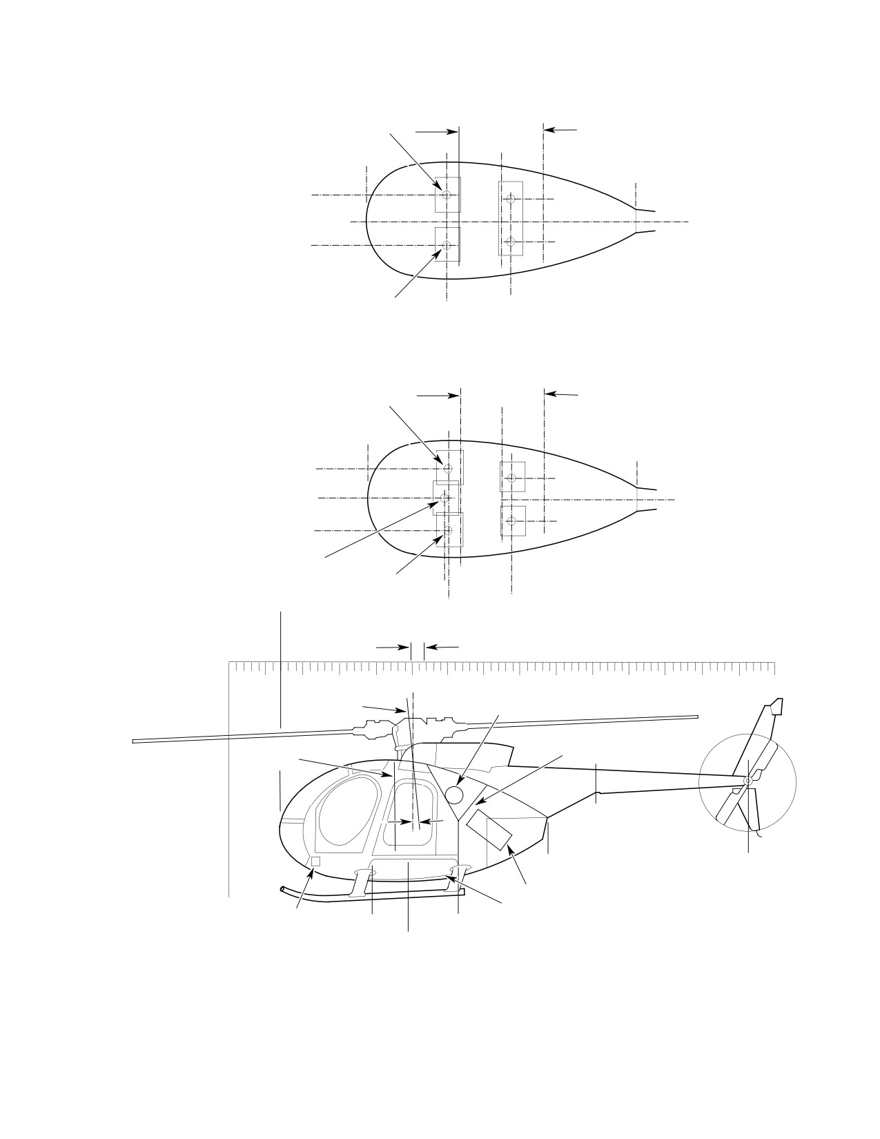
MD Helicopters, Inc.
CSP-HMI-2
MAINTENANCE MANUAL
STA.
STA.
78.5
ROTOR C
124.0
CG OF COPILOT/PASSENGER
L
STA.
CARGO COMPARTMENT
STA.
100.0
28.0
STA.
174.0
+13
+12.1
REFERENCE DATUM
-13
-12.1
TWO-PLACE COCKPIT
CG OF PILOT
(OPTIONAL)
STA.
STA.
73.3
105.0
STA.
STA.
78.5
ROTOR C
124.0
L
CG OF RIGHT SIDE
STA.
CARGO COMPARTMENT
FWD PASSENGER
100.0
STA.
28.0
STA.
174.0
+18.1
+12.1
+2.6
REFERENCE DATUM
-12.1
-13.0
CG OF AFT PASSENGERS
CG OF FWD PASSENGER
CG OF PILOT
STA.
THREE-PLACE COCKPIT
28.0
STA. 71.50
STA.
STA.
(STANDARD)
73.5
105.0
PERMISSIBLE CG LIMITS
20
40
60
80
100
120
140
160
180
200
220
240
260
280
300
SLING POINT
OIL TANK (RH SIDE)
LEVELING PLUMB
FIREWALL
STA. 92.6
JIG POINT
3°
AFT JACKING POINT
STA. 197.2 BL 0.00
STA. 174.0
STA.
BDH
284.0
ENGINE SECTION
FUEL CELL COMPARTMENT
REFERENCE
BATTERY
STA.
STA.
DATUM
78.5
124.0
JIG POINT
MAIN JACKING POINT
STA. 96.9 BL ±25.6
G08-1001
Figure 201. Balance Diagram − Model 369D
Page 207
08-10-00
Revision 23
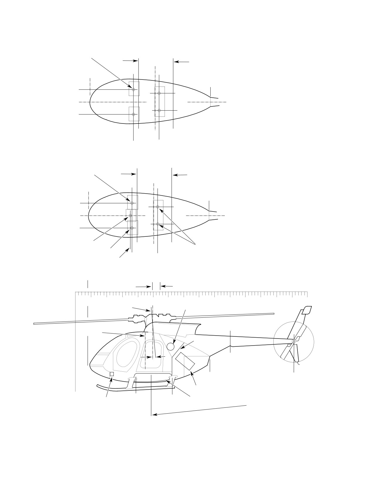
CSP-HMI-2
MD Helicopters, Inc.
MAINTENANCE MANUAL
STA.
STA.
78.5
ROTOR C
124.0
L
CG OF COPILOT/PASSENGER
STA.
CARGO COMPARTMENT
100.0
STA.
15.00
STA.
174.0
+15.5
+12.2
0.0
REFERENCE DATUM
-12.2
-13.0
TWO-PLACE COCKPIT
(WITH DUAL CONTROLS)
CG OF PILOT
STA.
STA.
73.3
105.0
STA.
STA.
78.5
124.0
CG OF RIGHT SIDE
ROTOR C
L
FWD PASSENGER
STA.
CARGO COMPARTMENT
100.0
STA.
15.00
STA.
174.0
+15.5
+12.2
0.0
REFERENCE DATUM
-12.2
-13.0
THREE-PLACE COCKPIT
(WITH SINGLE CONTROLS)
CG OF FWD PASSENGER
CG OF AFT PASSENGERS
CG OF PILOT
STA.
STA.
STA. 71.5
73.5
105.0
STA.
STA.
15.00
STA. 99.0
107.4
PERMISSIBLE CG LIMITS
20
40
60
80
100
120
140
160
180
200
220
240
260
280
300
SLING POINT
OIL TANK (RH SIDE)
LEVELING PLUMB
STA. 92.6
FIREWALL
3°
JIG POINT
AFT JACKING POINT
STA. 197.2 BL 0.00
STA. 174.0
STA.
BDH
284.0
ENGINE SECTION
STA.
FUEL CELL
REFERENCE
STA.
JIG POINT
BATTERY
78.5
COMPARTMENT
DATUM
124.0
MAIN JACKING POINT
STA. 96.9 BL ±25.6
G08-1002
Figure 202. Balance Diagram − Model 369E
Page 208
Revision 23
08-10-00
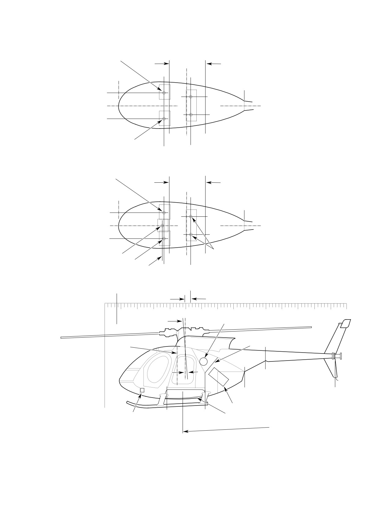
MD Helicopters, Inc.
CSP-HMI-2
MAINTENANCE MANUAL
STA.
STA.
78.5
ROTOR C
124.0
L
CG OF COPILOT/PASSENGER
STA.
CARGO COMPARTMENT
100.0
STA.
15.00
STA.
174.0
+15.5
+12.2
0.0
REFERENCE DATUM
-12.2
-13.0
TWO-PLACE COCKPIT
(WITH DUAL CONTROLS)
CG OF PILOT
STA.
STA.
73.3
105.0
STA.
STA.
CG OF RIGHT SIDE
78.5
124.0
FWD PASSENGER
ROTOR C
L
STA.
CARGO COMPARTMENT
100.0
STA.
15.00
STA.
174.0
+15.5
+12.2
0.0
REFERENCE DATUM
-12.2
-13.0
THREE-PLACE COCKPIT
(WITH SINGLE CONTROLS)
CG OF FWD PASSENGER
CG OF AFT PASSENGERS
CG OF PILOT
STA. 71.5
STA.
STA.
73.5
105.0
STA.
STA.
107.4
15.00
STA. 99.0
PERMISSIBLE CG LIMITS
20
40
60
80
100 120
140
160
OIL TANK (RH SIDE)
SLING POINT
180 200
220
240
260 280
300
LEVELING PLUMB
FIREWALL
STA. 92.6
3°
JIG POINT
AFT JACKING POINT
STA. 197.2 BL 0.00
STA. 174.0
STA.
BDH
284.0
ENGINE SECTION
REFERENCE
STA.
STA.
BATTERY
FUEL CELL
DATUM
78.5
124.0
COMPARTMENT
JIG POINT
MAIN JACKING POINT
STA. 96.9 BL ±25.6
G08-1003
Figure 203. Balance Diagram − Model 369FF
Page 209
08-10-00
Revision 23
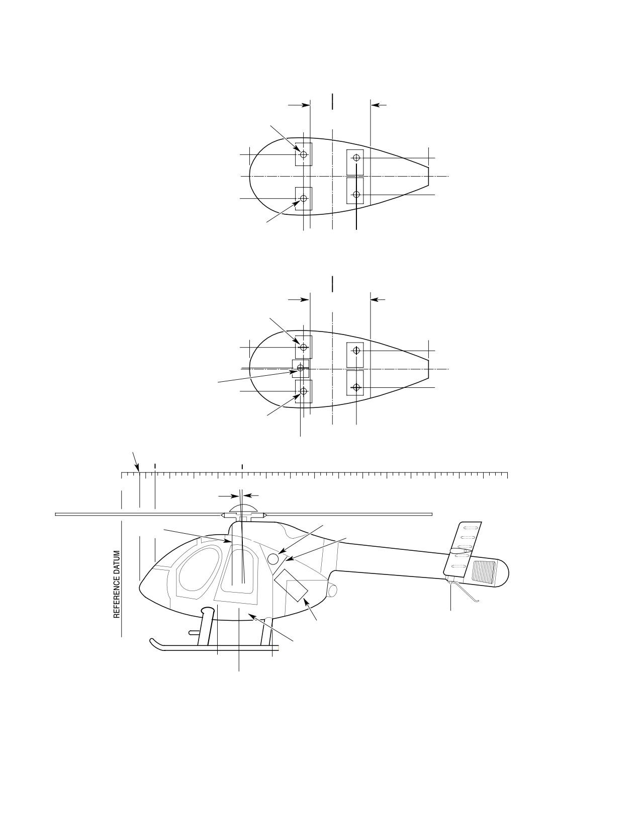
CSP-HMI-2
MD Helicopters, Inc.
MAINTENANCE MANUAL
ROTOR
STA
STA CL
78.5
124.0
CARGO COMPARTMENT
CG OF COPILOT/
STA
PASSENGER
100.0
STA
STA
15.0
168.8
+ 15.5
+ 12.2
REFERENCE
0.0
DATUM
- 12.2
- 13.0
TWO-PLACE COCKPIT
CG OF PILOT
WITH DUAL CONTROLS
STA
STA
105.0
73.5
ROTOR
CL
STA
STA
78.5
124.0
STA
CARGO COMPARTMENT
CG OF COPILOT/
100.0
PASSENGER
STA
STA
15.0
168.8
+ 15.5
+ 12.2
+ 0.8
REFERENCE
0.0
DATUM
CG OF CENTER
PASSENGER
- 12.2
- 13.0
THREE-PLACE COCKPIT
CG OF PILOT
STA
WITH SINGLE CONTROLS
73.5
STA
STA
STA
105.0
15.0
STA
STA
71.5
28.0
100.0
0
20
40
60
80
100
120
140
3 °
160 180
200
220
240 260
290
300
320LEVELING PLUMB
OIL TANK - RH SIDE
STA 92.6
FIREWALL
JIG POINT
ENGINE SECTION
AFT JACKING POINT
STA 275.4
FUEL CELL
COMPARTMENT
STA
STA
78.5
124.0
JIG POINT
FWD JACKING POINT
STA 96.9
G08-1007
Figure 204. Balance Diagram − Model 500N
Page 210
Revision 23
08-10-00
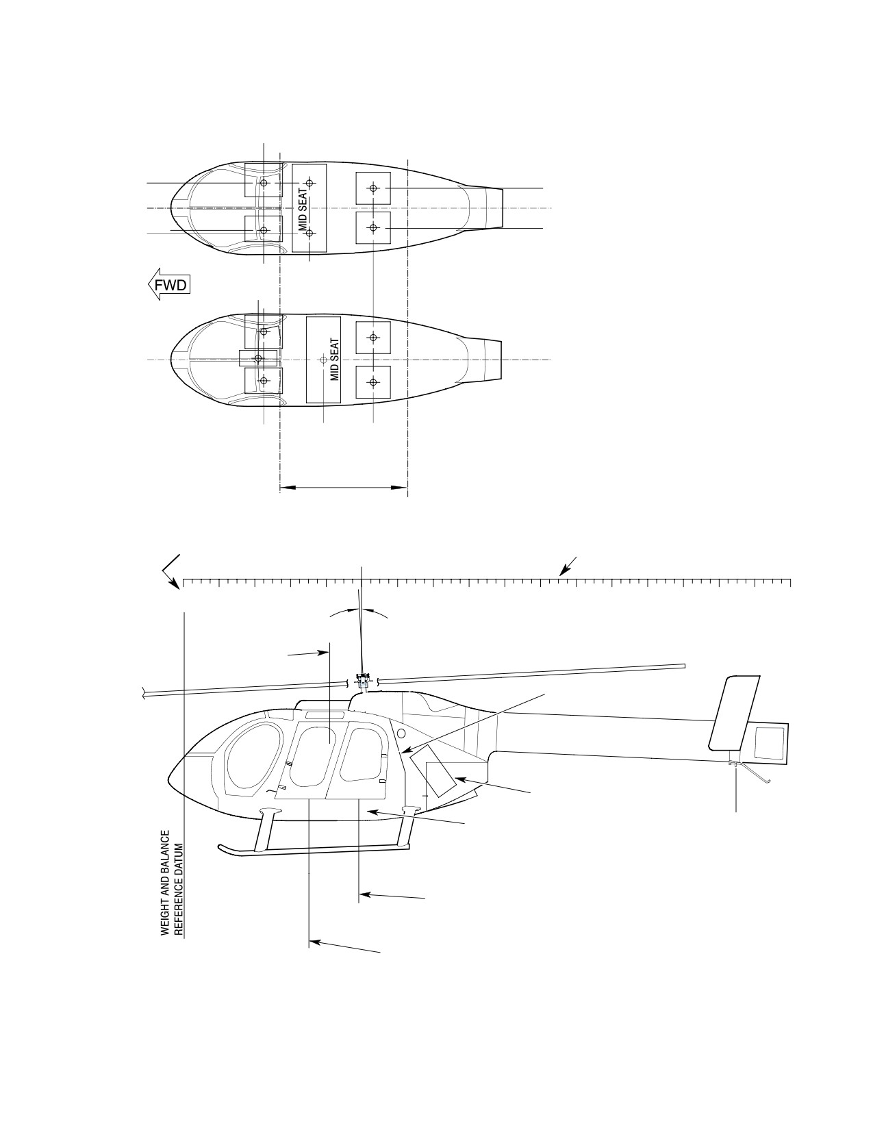
MD Helicopters, Inc.
CSP-HMI-2
MAINTENANCE MANUAL
CG OF PILOT OR
COPILOT/PASSENGER
7-PLACE SEATING,
TWO-PLACE COCKPIT WITH DUAL CONTROLS,
AFT-FACING MID-CABIN SEAT
+ 15.0
+ 12.2
0.00
0.00 REFERENCE DATUM
- 13.0
- 12.2
- 15.0
STA
STA
70.4
41.50
8-PLACE SEATING,
THREE-PLACE COCKPIT WITH SINGLE CONTROLS,
FWD-FACING MID-CABIN SEAT
0.00
0.00 REFERENCE DATUM
STA
STA
STA
43.50
77.1
105.0
PASSENGER/CARGO
COMPARTMENT
THIS DIMENSION 15 INCHES
(381 MM) AFT OF NOSE OF
STA
THESE DIMENSIONS
AIRCRAFT
100
IN INCHES
0
20
40
60
80
120
140
160
180 200
220
240
3 °
260 280
300
320
LEVELING PLUMB
340
STA 81.54
BL 4.00
FIREWALL
ENGINE SECTION
AFT JACKING
FUEL CELL
COMPARTMENT
POINT STA 303.3
JIG POINT
MID JACKING POINT
STA 96.9
JIG POINT
FORWARD
JACKING POINT P.STA 18.76 OR
67.40 INCHES FROM DATUM
6G08-007B
Figure 205. Balance Diagram − Model 600N
Page 211
08-10-00
Revision 36

CSP-HMI-2
MD Helicopters, Inc.
MAINTENANCE MANUAL
WEIGHT AND BALANCE REPORT
MODEL ___________
WEIGHED BY
CONFIGURATION
MODEL
SERIAL NO.
REGISTRATION NO.
DATE
TARE OR
NET
LONGITU-
LATERAL
LONGITU-
LATERAL
WEIGHING
SCALE READING
CALIBRATION
WEIGHT
DINAL
ARM
DINAL
MOMENT
POINTS
(LBS)
CORRECTION
(LBS)
ARM
(INCHES)
MOMENT
(INCH−LBS)
(LBS)
(INCHES)
(INCH−LBS)
LEFT MAIN
96.9
−26.0
RIGHT MAIN
96.9
+26.0
TAIL
303.3
0.0
TOTAL UNADJUSTED NET WEIGHT
TOTAL WEIGHT OF SURPLUS EQUIPMENT (SEE TABLE 1)
−
TOTAL WEIGHT OF MISSING EQUIPMENT (SEE TABLE 1)
+
TOTAL BASIC WEIGHT
FUEL/OIL ABOARD AT TIME OF WEIGHING:
EMPTY
FULL
FUEL
ENGINE OIL
MAIN GEAR BOX
TAIL GEAR BOX
McDonnell Douglas
FORM 765B (REV 4−83)
Page 1
of
Helicopter Company
Figure 206. Weight and Balance Report Form (Sheet 1 of 2)
Page 212
Revision 23
08-10-00