HANDBOOK OF MAINTENANCE INSTRUCTIONS FOR MDHI 369D/E/FF-500/600N HELICOPTERS (ISSUED: 1990) - page 8
MD Helicopters, Inc.
CSP-HMI-2
MAINTENANCE MANUAL
MESH SEATS
INITIAL INSTALLATION
1. Mesh Seat Initial Installation
(2). Install ball lock pins.
Procedures in this section are for initial
(3). With release pins raised and locked,
installation of 369H90040-BSC, -501, and
insert the two vertical legs into keyhole
-503 mesh seat installations on Model 369D
fitting slots in floor.
helicopters with to replace the existing cushion
NOTE: For height adjustment, install ball lock
seats.
fittings in any of the three attachment
A. Model Applicability
holes, in the vertical support legs, and in the
aft support fittings. For fore and aft adjust
To determine the applicability of the mesh seat
ment, insert the seat back lower legs in ei
installation for use on each model helicopter,
ther pair of holes in lower frame.
consult the Optional Equipment List (Ref.
Table 202, 01-00-00).
(4). Move vertical support legs to right in
keyhole fittings and unlock release pins
B. Preparation for Installation
in legs. The pins will drop to bottom of
slots and secure support legs to fittings
(1). Check all electrical switches for OFF
in floor.
position. Ensure that BATTERY-OFF-
EXT switch is OFF.
E. Passenger Compartment Individual Seat
Installation
(2). Identify all components and hardware
to be removed for access to work areas.
(Ref. Figure 202)
Protect components from damage and
NOTE: Installation procedures for left and
foreign matter until reinstalled.
right seats are identical.
C. Helicopter Equipment Removal
(1). Position passenger seat horizontal
Prior to installing the mesh seats, a limited
support legs in aft support fittings.
number of items must be removed from the
(2). Install ball lockpins.
helicopter to accommodate seat installation.
(3). Depress pushbutton quick disconnects
(1). Clear seats of seat belts and shoulder
at front legs of seat.
straps.
(4). Insert legs into keyhole fittings in floor.
(2). Lift crew compartment seat cushions
Move legs outboard and release push
away from fuselage seat structure to
buttons to secure legs in place.
release Velcro strips and fasteners.
Remove seats from helicopter (Ref. Sec.
F. Crew Compartment Mesh Seat
25-10-00).
Installation
(3). In passenger compartment, release
(Ref. Figure 201) Installation includes
existing seat quick-disconnect fittings
installing a shim under the inboard forward
at aft bulkhead, then at floor points.
leg of the left crew seat.
Remove existing installed seats from
helicopter.
(1). Position mesh seat back halves in crew
compartment.
D. Passenger Compartment Bench Seat
Installation
(2). Attach upper ends of seat backs to
canted stations with screws and
(Ref. Figure 203)
washers.
(1). Position bench seat horizontal support
(3). Attach lower legs to helicopter seat
legs in aft support fittings.
structure with screws.
Page 901
25-15-00
Revision 23
CSP-HMI-2
MD Helicopters, Inc.
MAINTENANCE MANUAL
(4). Position lower halves of mesh seats on
(1). Install seat belts and shoulder harness
helicopter seat structure.
in crew compartment (Ref. Sec.
25-20-00, Seat Belt/Inertia Reel
(5). Insert shim under inboard forward leg
Replacement).
of left seat. Attach leg to seat structure
with bolt and washer.
(2). Install seat belts and shoulder harness
in passenger compartment.
(6). Attach remaining forward legs of seats
to seat structure with bolts and wash
H. Weight and Balance Data
ers.
Weight and balance data resulting from -BSC,
G. Helicopter Equipment Installation
-501 and -503 mesh seat installations are
After installation of mesh seats, a limited
listed in Table 901. After installation, incorpo
number of items must be replaced in the
rate changes in helicopter weight and balance
helicopter.
records (Ref. Sec. 08-10-00).
Table 901. Weight and Balance Data
Weight
Arm
Moment
Configuration
Pounds (kg)
Inches (cm)
in−lb (kg cm)
−BSC Installation
+20.80
(+9.435)
99.7
(253.24)
+2074
(+2389.5)
−501 Installation
+20.35
(+9.231)
99.6
(252.98)
+2027
(+2335.3)
−503 Installation
+20.80
(+9.435)
99.7
(253.24)
+2074
(+2389.5)
Page 902
Revision 23
25-15-00
MD Helicopters, Inc.
CSP-HMI-2
MAINTENANCE MANUAL
Section
25−20−00
Seat Belts/Inertia
Reel
MD Helicopters, Inc.
CSP-HMI-2
MAINTENANCE MANUAL
SEAT BELTS/INERTIA REEL
MAINTENANCE PRACTICES
1. Seat Belts/Inertia Reel Description and
shoulder strap are joined at the end into a
Operation (369D/E/FF − 500N)
single unit for ease of attachment and conve
nience. In one motion, the lap and shoulder
Inertia reel-type seat belt/harness equipment
belts together can be attached to the seat
consists of a shoulder harness, an inertia reel,
buckle.
and a two-piece adjustable seat belt for both
the pilot and copilot.
3. Crew Seat Belt/Harness Cleaning
The shoulder harnesses and seat belts are of
The harness and seat belt may be cleaned
nylon web material with sewn-in length
using a soft-bristle brush and a mild solution
adjusters and end adapters for attachment of
of warm water and laundry detergent.
the harnesses to the seat belts. Inertia reels,
furnished as part of the harnesses, are
4. Seat Belt/Inertia Reel Replacement
mounted on the Sta. 78.50 canted frame. The
(369D/E/FF − 500N)
reels permit the pilot and copilot freedom for
(Ref. Figure 201, Figure 202 and Figure 203)
slow, deliberate shoulder movement, but lock
with any sudden forward movement. Full
(1). For access to seat belt attach fittings,
extension or retraction of the straps on the
remove crew compartment seats.
spring-loaded reels is approximately 25 inches
(63.5 cm).
(2). Remove inertia reel, with harness, from
canted bulkhead lateral beam by
Some installations have a handle: with the
removing four bolts.
handle up, the inertia reel operates normally;
with the handle down, the inertia reel is locked
(3). Install replacement harness by securing
up to restrain movement.
inertia reel, with harness, to canted
bulkhead lateral beam.
2. Seat Belts/Inertia Reel Description and
Operation (600N)
(4). Install replacement seat belts and
shoulder straps as shown. Place snap
The crew seats utilize a four-point restraint
end fittings up or down to eliminate any
harness. This harness combines the lap seat
twist in seat belt.
belts with double shoulder straps attached to
an inertia reel mechanism. Both mid and aft
(5). Tongue portion of center passenger lap
passenger seats are equipped with a three-
belt must be installed on right side and
point restraint system. The lap seat belt and
buckle portion on left side as shown.
Page 201
25-20-00
Revision 23
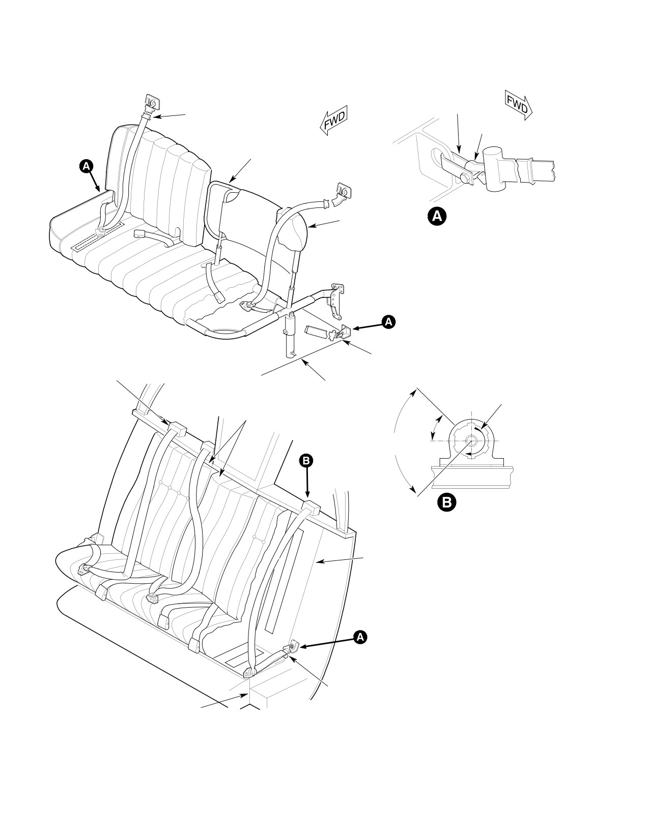
CSP-HMI-2
MD Helicopters, Inc.
MAINTENANCE MANUAL
FITTING
INERTIA REEL
SNAP END
FITTING
SEAT BACK
SEAT BELT FITTING
NOTE 1
ATTACHMENT
PASSENGER COMPARTMENT
INERTIA REEL
INERTIA REEL
FLOOR STRUCTURE
HARNESS MUST UNREEL
IN DIRECTION SHOWN
NOTE 2
41° ±3°
90° LIMITS OF CUTOUT
IN ALUM. HOUSING
INERTIA REEL
NOTE 1
NOTES:
1.
SHOWN WITHOUT CUSHION
FOR CLARITY.
2.
CENTER CUSHIONS AND SEAT
BELTS ONLY FOR 3-PLACE
SEATING.
CREW COMPARTMENT
INERTIA REEL
SEAT STRUCTURE
G25-2002
Figure 201. Seat Belt/Inertia Reel Installation (Sam Browne Style) (369D)
Page 202
Revision 23
25-20-00
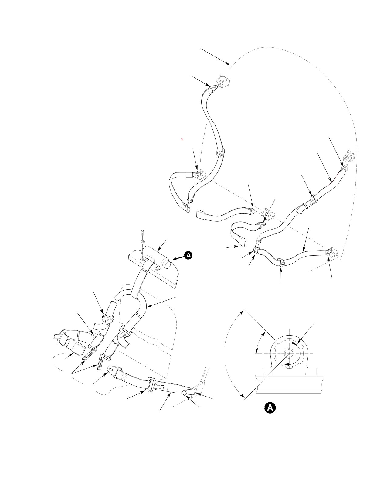
MD Helicopters, Inc.
CSP-HMI-2
MAINTENANCE MANUAL
PASSENGER / CARGO
COMPARTMENT AFT
BULKHEAD
SNAP END FITTING
(HOOK UP)
SEAT BELTS AND SHOULDER HARNESSES
SNAP END FITTING
(HOOK DOWN)
SNAP END FITTING
(HOOK UP)
NYLON WEBBING
SHOULDER STRAP
ADAPTER
NOTE:
SLIDE BAR
(NOTE)
SNAP END FITTING
HARNESS LENGTH ADJUSTER.
(HOOK UP)
SNAP END FITTING
(HOOK DOWN)
NYLON WEBBING
SEAT BELT
INERTIA REEL
BUCKLE
LATCH
ADAPTER
ADAPTER
SNAP END FITTING
(NOTE)
ADAPTER
(HOOK DOWN)
(NOTE)
NYLON WEBBING
SNAP END
SHOULDER STRAP
FITTING
HARNESS MUST UNREEL
IN DIRECTION SHOWN
41° ±3°
90° LIMITS OF CUTOUT
IN ALUM. HOUSING
BUCKLE
ADAPTER
LATCH
ADAPTER
FITTING
(NOTE)
INERTIA REEL
SNAP END FITTING
NYLON WEBBING
SEAT BELT
PILOT AND COPILOT SEAT BELT AND SHOULDER HARNESS ASSEMBLY
G25-2003
Figure 202. Seat Belt/Inertia Reel Installation (Yoke Style) (369D)
Page 203
25-20-00
Revision 23
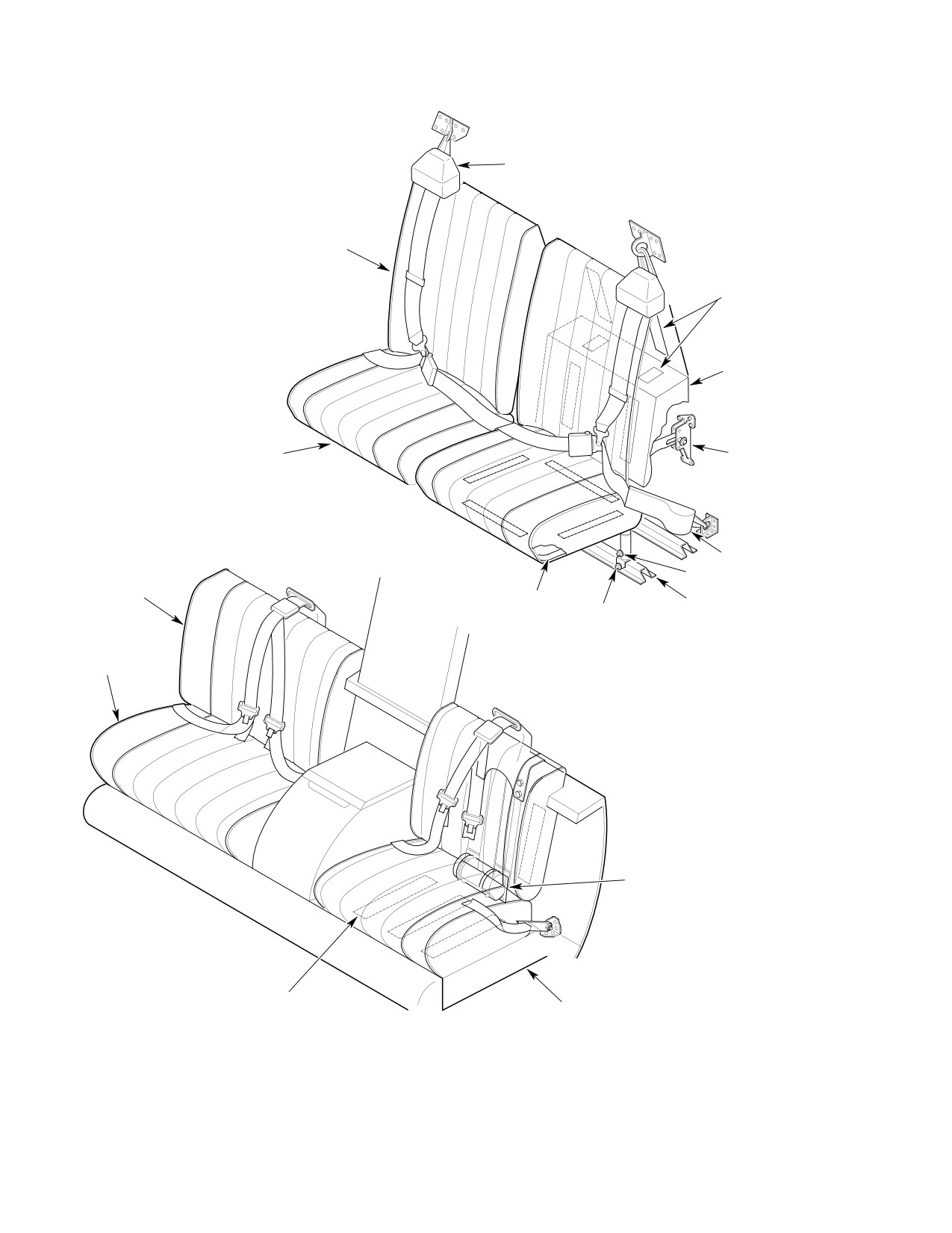
CSP-HMI-2
MD Helicopters, Inc.
MAINTENANCE MANUAL
INERTIA REEL (2)
SEAT BACK CUSHION
VELCRO STRIP
FASTENER (TYP)
SUPPORT CUSHION
SEAT BOTTOM CUSHION
AFT SUPPORT
FITTING AND HEIGHT
ADJUSTMENT
PASSENGER COMPARTMENT
INERTIA REEL (2)
LOCK PIN
SEAT BACK
CUSHION
LOWER FRAME
FLOOR STRUCTURE
RELEASE PIN
SUPPORT LEG AND
HEIGHT ADJUSTMENT
SEAT BOTTOM
CUSHION
INERTIA REEL (2)
CREW COMPARTMENT
VELCRO STRIP
SEAT STRUCTURE
FASTENER (TYP)
G25-2004
Figure 203. Seat Belt/Inertia Reel Installation (Yoke Style) (369E/FF − 500N)
Page 204
Revision 23
25-20-00
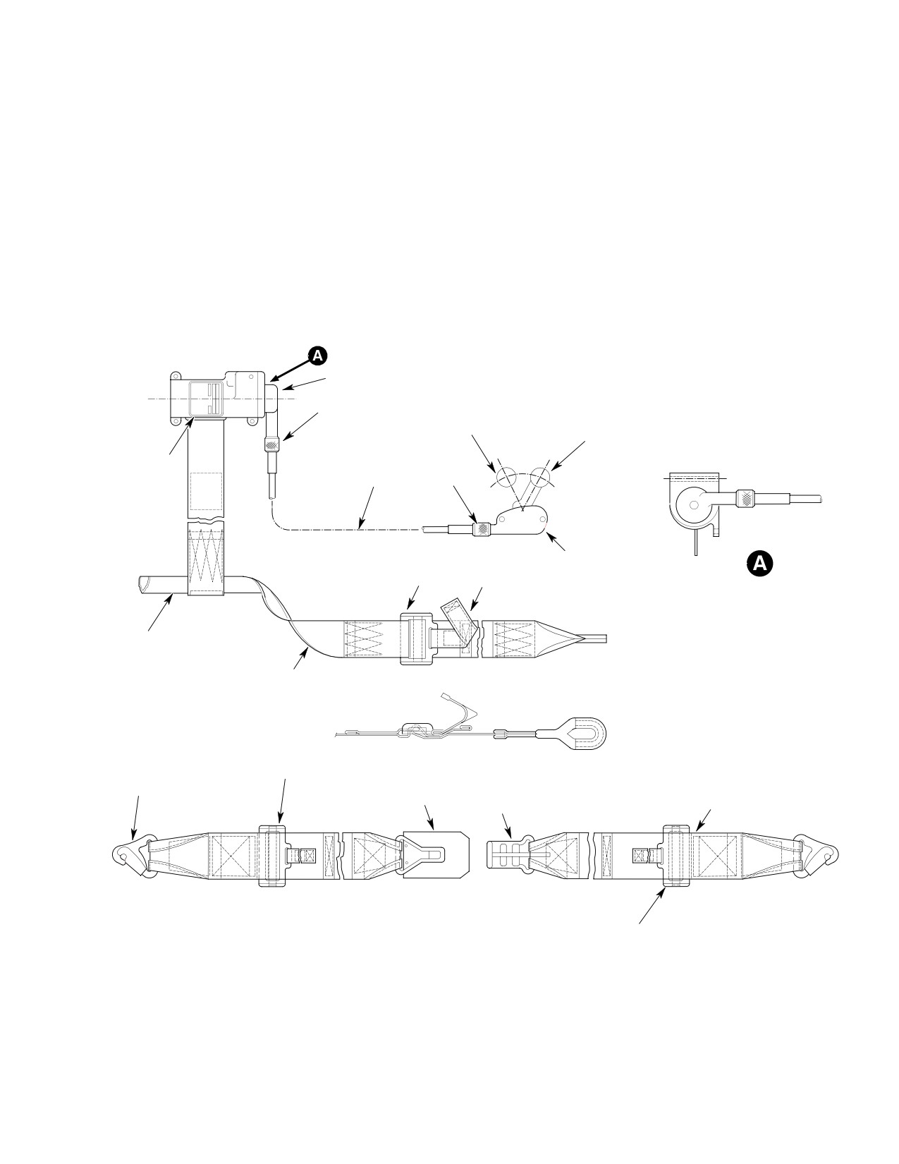
MD Helicopters, Inc.
CSP-HMI-2
MAINTENANCE MANUAL
5. Crew Seat Belt/Harness Replacement With
(2). Remove inertia reel, with harness, from
Manual Lock Option (369D/E/FF − 500N)
fiberglass mount by loosening four bolts
and upper ferrule nut.
(3). Install seatbelts by fastening snap type
(Ref. Figure 204 and Figure 205)
end fittings to bulkhead structure
fittings.
(1). Remove seatbelts by unfastening snap
(4). Install inertia reel, with harness, to
type end fittings from bulkhead
fiberglass mount with ferrule nut and
structure fittings.
four bolts, nuts and washers.
CONTROL HEAD ROTATED
90° CW FOR CLARITY
UPPER FERRULE NUT
AUTOMATIC
MANUAL LOCK
LOWER
INERTIA
FERULE
REEL ASSY
CABLE
NUT
CONTROL ASSY
ADJUSTER
TAB RELEASE
(TYP)
(TYP)
0101935-1 SHOULDER
HARNESS ASSY
1.88-2.12 IN. (4.776-5.385 CM)
WIDE WEBBING
ADJUSTER
2.88-3.12 IN. (7.315-7.925 CM)
END FITTING
WIDE WEBBING LAP BELT ASSY
LINK
LATCH
(0101936-1 ASSY)
ADJUSTER
G25-2006A
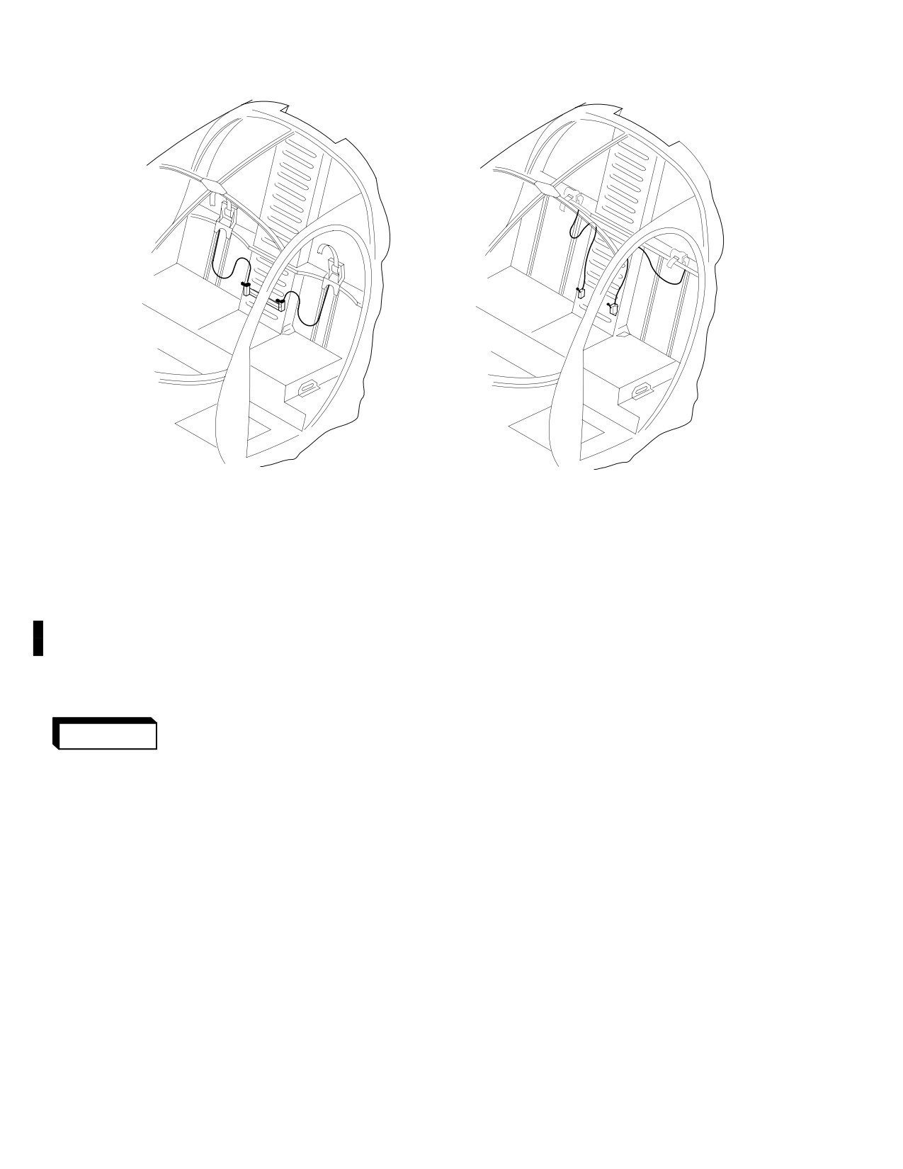
Figure 204. Webbed Shoulder Harness and Seat Belt Installation with Manual
Inertia Reel Lock (369D)
Page 205
25-20-00
Revision 23
CSP-HMI-2
MD Helicopters, Inc.
MAINTENANCE MANUAL
LOW SHOULDER BEAM INSTALLATION
HIGH SHOULDER BEAM INSTALLATION
G25-2005
Figure 205. Crew Inertia Reel Installation with Manual Inertia Reel Lock
(369D/E/FF − 500N)
6. Seat Belt/Inertia Reel Testing
leased, harness strap should automati
cally reel back into reel. Exert a sudden
(Ref. Pull tests of seat belts and shoulder strap
forward pull on seat belt or shoulder
harnesses shall be accomplished in accordance
strap to ensure inertia reel locks.
with FAA AC 43.13-1B, Aircraft Inspection
and Repair for Standard Sheet Metal Repair
(2).
Inspect inertia reels, snap end fittings,
and TSO C22.
adjusters, links, buckles, latches and
belt attachment fittings for cracks,
7. Seat Belt/Inertia Reel Inspection
wear, corrosion and deformation. Check
for freedom from binding, ease of
Ensure center passenger lap
WARNING
adjustment and operation as applicable.
belt is installed with tongue
If doubt exists as to strength, perform
portion to the right of the seat and
pull test (Ref. Seat Belts/Inertia Reel
buckle portion to the left. (Quick re
lease of the lap belt and shoulder strap
Testing).
may be impaired if the assembly is im
(3).
Inspect shoulder harnesses and seat
properly installed.) If tongue and
belts for worn, frayed or deteriorated
buckle portions are reversed, remove
condition, and loose stitching.
and reinstall in correct positions and
document reinstallation in Compliance
(4).
(Manual Lock Option) Check mechani
Record of Helicopter Log Book.
cal inertia lock mechanism for proper
(1). Pull seat belt or shoulder strap out of
operation, with handle up and with
inertia reel to full extended length.
handle down. Inspect fiberglass mounts
Ensure harness strap cannot be pulled
for cracking and separation. Inspect
out of inertia reel. With tension re
laminates for debonding.
Page 206
Revision 44
25-20-00
MD Helicopters, Inc.
CSP-HMI-2
MAINTENANCE MANUAL
8. Seat Belt/Inertia Reel Repair
(2). Remove hardware that attaches inertia
reel to mounting surface.
(1). Replace seat belts and shoulder straps
if fabric is frayed, worn, deteriorated,
(3). Remove complete seat belt restraint
stitching is loose, or if enertia reels are
harness from seat.
destroyed or do not function properly.
(2). Polish minor nicks and scratches.
B. Seat Belt/Restraint Harness Installation
Restore protective finish to aluminum
parts as required.
(1). Position lap seat belt and shoulder
(3). Repair fiberglass mounts (Ref. Sec.
harness into seat assembly.
25-30-00, Boltaron Trim Panels
Repair).
(2). Engage end fittings attaching lap seat
belts.
9. Seat Belt/Restraint Harness, Crew Seat,
Replacement (600N)
(3). Install hardware attaching inertia reel
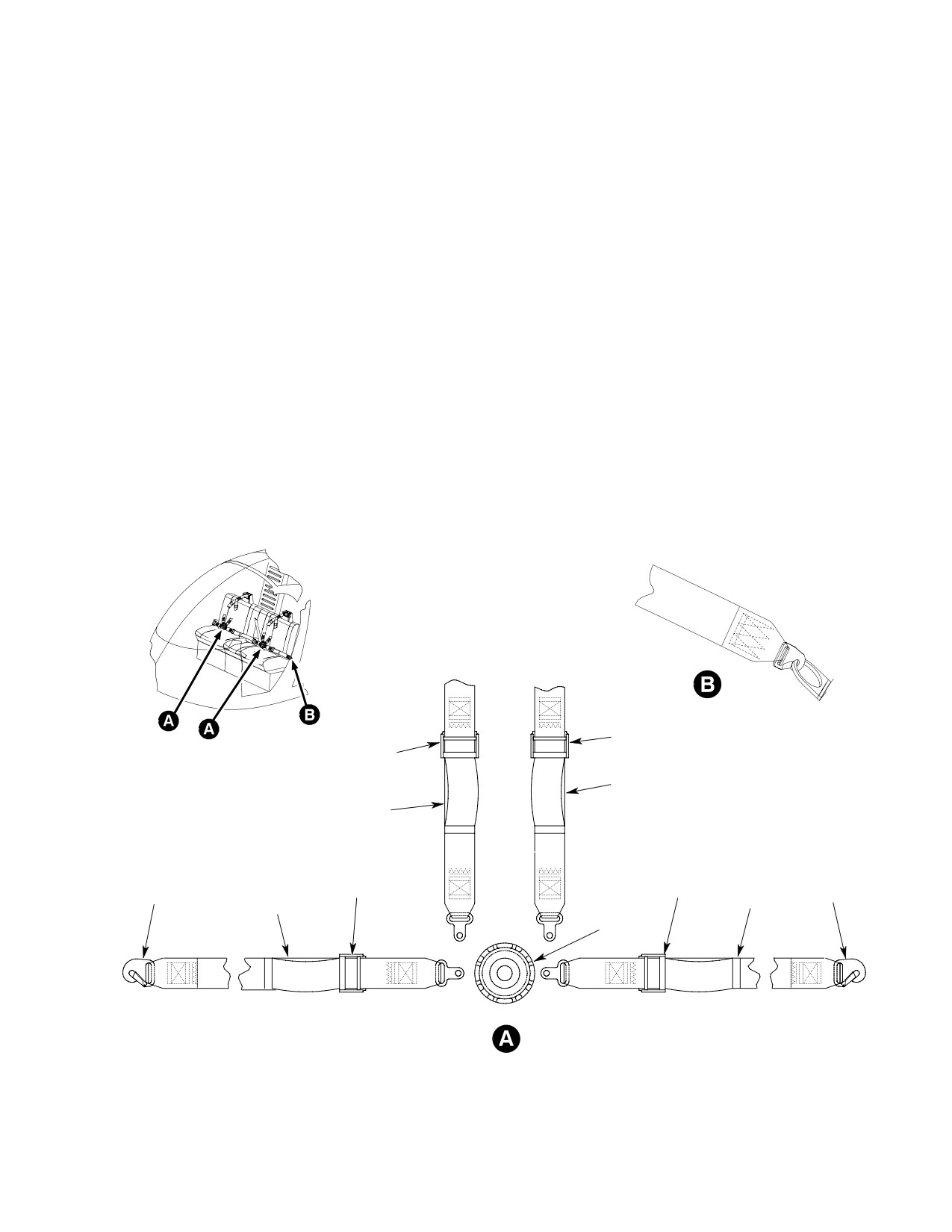
(Ref. Figure 206)
to mounting surface.
A. Seat Belt/Restraint Harness Removal
(4). Ensure proper engagement and release
(1). Release end fittings to remove lap seat
of seat buckle and inertia reel mecha
belts.
nism.
ADJUSTOR
ADJUSTOR
SHOULDER
HARNESS
SHOULDER
HARNESS
LAP
ADJUSTOR
ADJUSTOR
LAP
END FITTING
END FITTING
SEAT BELT
SEAT BELT
BUCKLE
6G25-070
Figure 206. Seat Belt/Restraint Harness Installation, Crew Seat (600N)
Page 207
25-20-00
Revision 23
CSP-HMI-2
MD Helicopters, Inc.
MAINTENANCE MANUAL
10. Seat Belt/Restraint Harness, Mid
11. Seat Belt/Restraint Harness, Aft
Passenger Seat, Replacement (600N)
Passenger Seat, Replacement (600N)
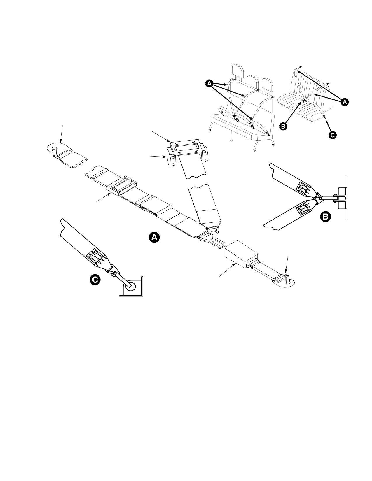
(Ref. Figure 207) These three individual seat
(Ref. Figure 207)
belt harnesses are completely contained in the
seat assembly and attach to the seat frame.
A. Seat Belt/Restraint Harness Removal
This feature aids in the quick removal and
installation of the mid bench seat assembly.
(1). Remove hardware that attaches inertia
reel end of harness to mounting
A. Seat Belt/Restraint Harness Removal
surface.
(1). Remove hardware that attaches inertia
(2). Release end fitting that attaches lap
reel end of harness to seat back.
belt to mounting surface.
(2). Release end fitting that attaches lap
seat belt to seat frame.
(3). Release end fitting that attaches buckle
end of harness to mounting surface.
(3). Release end fitting that attaches buckle
end of harness to seat frame.
(4). Remove seat belt/restraint harness.
(4). Remove seat belt/restraint harness.
B. Seat Belt/Restraint Harness Installation
B. Seat Belt/Restraint Harness Installation
(1). Position seat belt/restraint harness into
(1). Position seat belt/restraint harness into
seat assembly.
seat assembly.
(2). Engage end fitting attaching buckle end
(2). Engage end fitting attaching buckle end
of harness to mounting surface.
of harness to seat frame.
(3). Engage end fitting attaching lap belt to
(3). Engage end fitting attaching lap belt to
mounting surface.
seat frame.
(4). Install hardware attaching inertia reel
(4). Install hardware attaching inertia reel
end of harness to mounting surface.
end of harness to seat back.
(5). Ensure proper engagement and release
(5). Ensure proper engagement and release
of seat buckle and inertia reel mecha
of seat buckle and inertia reel mecha
nism.
nism.
Page 208
Revision 23
25-20-00
MD Helicopters, Inc.
CSP-HMI-2
MAINTENANCE MANUAL
MID SEAT
AFT SEAT
END FITTING
INERTIA REEL
MOUNT
INERTIA REEL
ADJUSTOR
END FITTING
BUCKLE
6G25-086
Figure 207. Seat Belt/Restraint Harness Installation, Passenger
Seats (600N)
Page 209
25-20-00
Revision 23
CSP-HMI-2
MD Helicopters, Inc.
MAINTENANCE MANUAL
12. Comfort Clip Installation and Decal
position as close as possible next to
Application (369D/E/FF − 500N)
inertia reel.
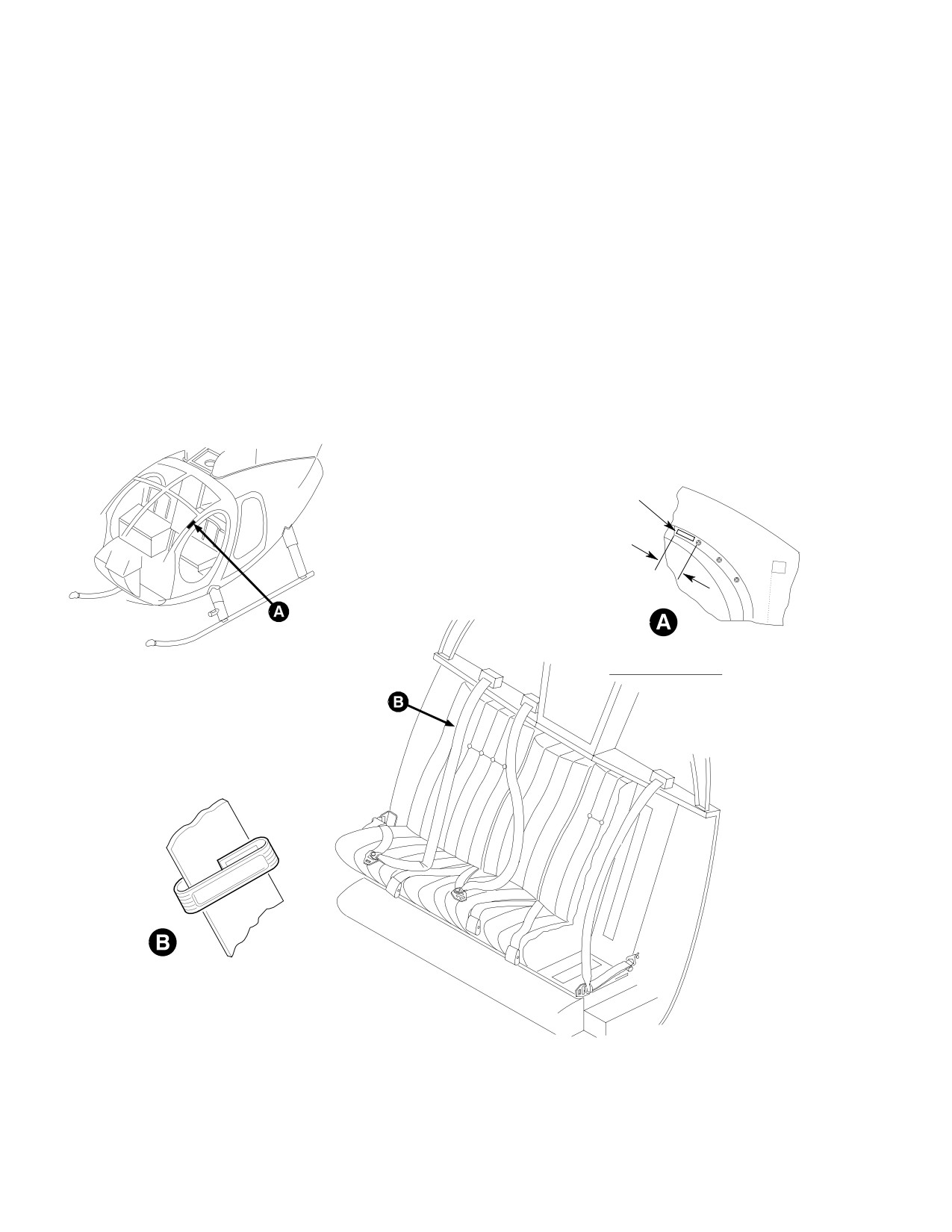
(Ref. Figure 208 and Figure 209) The comfort
(4). After each flight, reposition comfort clip
clip is designed to maintain proper strap
on harness strap at original position
tension and relieve excessive pressure of the
next to buckle.
inertia reel shoulder harness on the pilot or
passenger during flight. It is available for
(5). Clean panel or door frame where decal
installation on helicopters equipped with Sam
is to be applied. Decals will not adhere
Browne style seat belt assemblies.
to a greasy or soapy film.
(1). Pry open slot on underside of clip.
(6). Mark location(s) of decal per the
illustrations.
(2). Insert harness strap in slot.
(3). After seat belt and shoulder harness
(7). Peel backing off decal and position. Use
assembly is fastened and adjusted for
a cloth to squeeze all bubbles from
individual comfort and safety, slide
under the decal, working from the
comfort clip up on harness strap and
center outward.
DECAL
CENTER DECAL BETWEEN END OF
DOOR FRAME AND FIRST SCREW
VIEW LOOKING OUTBOARD FROM
L
COMFORT CLIP INSTALLATION
G25-2001
Figure 208. Comfort Clip Installation and Crew Compartment Decal
Application (369D/E/FF − 500N)
Page 210
Revision 23
25-20-00
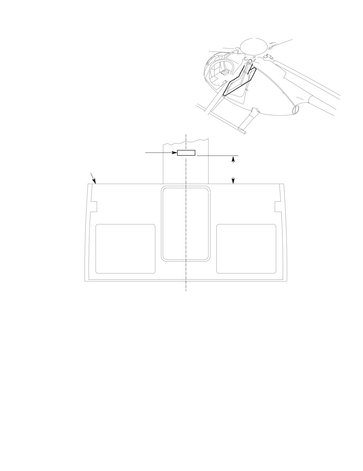
MD Helicopters, Inc.
CSP-HMI-2
MAINTENANCE MANUAL
TO APPLY DECAL:
1.
CLEAN PANEL AREA WHERE DECAL IS TO BE APPLIED.
DECAL WILL NOT ADHERE TO A GREASY OR SOAPY FILM.
2.
MARK LOCATION OF DECAL PER THE ILLUSTRATION.
3.
PEEL BACKING OFF DECAL AND POSITION. USE A CLOTH
TO SQUEEZE ALL BUBBLES FROM UNDER THE DECAL,
WORKING FROM THE CENTER OUTWARD.
C
L SHIP
DECAL
5.00 ±0.25 IN.
PANEL ASSEMBLY
(12.70 ±0.635 CM)
G25-2000A
Figure 209. Comfort Clip Decal Application − Passenger Compartment
(369D/E/FF − 500N)
Page 211
25-20-00
Revision 23
CSP-HMI-2
MD Helicopters, Inc.
MAINTENANCE MANUAL
This Page Intentionally Left Blank
Page 212
Revision 44
25-20-00
MD Helicopters, Inc.
CSP-HMI-2
MAINTENANCE MANUAL
Section
25−21−00
Seating/Belts (Four
on the Floor)
MD Helicopters, Inc.
CSP-HMI-2
MAINTENANCE MANUAL
SEATING/BELTS (FOUR ON THE FLOOR)
MAINTENANCE PRACTICES
1. General
(3). Remove seat belt assemblies and
shoulder straps by unsnapping hooks at
NOTE: This option has an aircraft effectivity
structure-mounted fittings.
limit. Refer to CSP-IPC-4 for effectivity.
B. Seating/Belt Installation
The four on the floor seating and belt installa
tion is designed for maximum use of the
(Ref. Figure 902 and Figure 903)
passenger compartment for transportation of
(1). Install seat assemblies by placing seat
personnel. The installation consists of four
in position and inserting tabbed rivets
floor-installed seat assemblies with seat belts
into holes in floor stiffeners (Ref.
and shoulder straps at each position. The two
Figure 903).
aft-facing seat positions include head and
back restraint panels mounted on Cant. Sta.
(2). Install restraint panels by securing
78.50 structure.
each panel at bracket assemblies with
four screws and washers (Ref.
The shoulder strap is adjusted to cross the
Figure 902).
passenger's chest from outboard shoulder to
center of lap where it joins the seat belt
(3). Install seat belt assemblies and
assembly. Seat belts are adjusted by individual
shoulder straps by snapping hooks to
passengers for a close and comfortable fit.
structure-mounted fittings.
The installation for the early configuration is
3. Seating/Belt Inspection
designed for use with a high shoulder beam.
The current configuration installation is used
(Ref. Sec. 25-20-00, Seat Belt/Inertia Reel
for a low shoulder beam.
Inspection)
NOTE: Shoulder straps for aft-facing passen
4. Seating/Belt Cleaning
gers are installed on early configuration he
licopters only.
(Ref. Sec. 20-20-00, Fuselage Interior Trim or
Upholstery Cleaning or 25-20-00, Crew Seat
2. Seating/Belt Replacement
Belt/Harness Cleaning)
A. Seating/Belt Removal
5. Seating/Belt Repair
(Ref. Figure 902 and Figure 903)
(1). Repair minor tears and cuts to the seat
and restraint panel coverings (Ref. Sec.
(1). Remove seat assemblies by lifting
25-20-00, Seat Belt/Inertia Reel
tabbed rivets from holes in floor
Repair).
stiffeners (two per seat), then lift seat
up (Ref. Figure 903).
(2). Replace unserviceable seats and
restraint panels.
(2). Remove restraint panels by removing
four screws and washers from each
(3). Seat belts or shoulder straps that show
panel bracket assembly (Ref.
signs of wear, deterioration, fraying, or
Figure 902).
loose stitching must be replaced.
Page 201
25-21-00
Revision 23
CSP-HMI-2
MD Helicopters, Inc.
MAINTENANCE MANUAL
This Page Intentionally Left Blank
Page 202
Revision 44
25-21-00
MD Helicopters, Inc.
CSP-HMI-2
MAINTENANCE MANUAL
SEATING/BELTS (FOUR ON THE FLOOR)
INITIAL INSTALLATION
1. Seating/Belts (Four on the Floor) Initial
(3). Remove passenger compartment carpet
Installation
floor covering.
NOTE: This option has an aircraft effectivity
(4). Remove aft trim panel from Cant. Sta.
limit. Refer to CSP-IPC-4 for effectivity.
78.50 and disconnect cigarette lighter
wiring.
Consult the optional equipment table (Ref.
Table 202, Sec. 01-00-00) for model applicabil
(5). Remove bulkhead trim panels or
ity for seating/belts (369H90035) installations.
insulation blankets at Sta. 124.00 in
The -501 and -503 installations are covered in
area of WL 40.00 and BL 20.00 right
the following paragraphs.
and left seats.
A. Preparation for Installation
(6).
(369D only) Remove crew compartment
outboard seat backs.
Consumable Materials
C. Seating and Belts Installation − General
(Ref. Section 91−00−00)
Item
Nomenclature
Installation of the seating and belts for four
CM318
Primer
includes procedures for installing restraint
panels on Cant. Sta. 78.50, seat assemblies,
shoulder straps, and seat belt assemblies.
(1). Ensure all electrical switches are set to
OFF position. Recheck master switch
for OFF position.
Consumable Materials
(Ref. Section 91−00−00)
(2). Identify all components and attaching
Item
Nomenclature
hardware to be removed for access to
CM318
Primer
work areas. Protect components from
damage and foreign matter until
reinstalled.
NOTE:
(3). After drilling or cutting, remove burrs
D Use Cleco clamps and fasteners as re
and metal particles. Apply a thin coat of
quired to facilitate rivet installation, and
primer (CM318) to all bare metal areas.
install rivets with wet primer (CM318).
D Rivets are equally spaced and are normal
NOTE: An application of color-matched paint
ly positioned twice the diameter of the riv
may be applied to primer painted reworked
et shank from the outside edge of the ma
areas and to installed hardware.
terial, edge joggle, or flange radius.
B. Removal of Existing Equipment
D. Cant. Sta. 78.50 Brackets, Fittings and
Prior to installing the seating and belts for
Restraint Panels Installation
four, a limited number of items must be
removed from the helicopter passenger
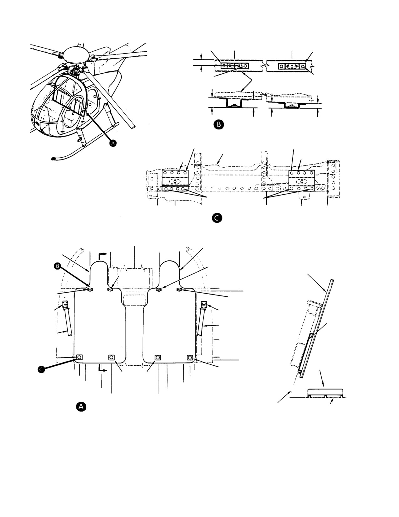
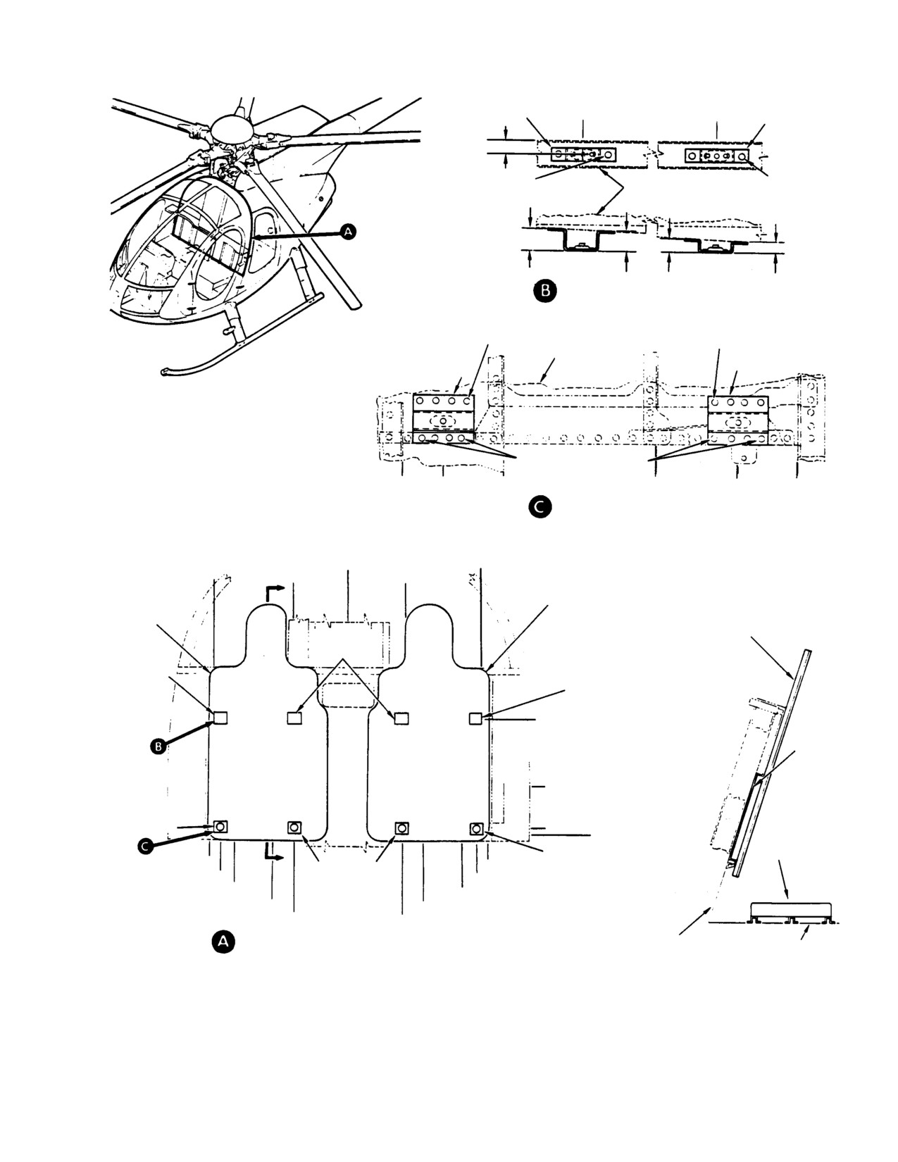
(Ref. Figure 901, Figure 902 and Figure 904)
compartment to accommodate installation.
(1). On Cant. Sta. 78.50, WL 22.45, remove
(1). Remove passenger compartment seats
four existing bracket rivets in area of
by releasing quick-disconnects on
LBL 8.25 and four rivets in area of LBL
seating structure at floor and firewall
19.25.
fittings.
(2). Position bracket assemblies to match
(2). Remove existing passenger compart
holes in removed rivet pattern. Locate
ment seat belt and shoulder strap
and drill four 0.1285 inch (3.2639 mm)
assemblies.
holes in each bracket.
Page 901
25-21-00
Revision 23
CSP-HMI-2
MD Helicopters, Inc.
MAINTENANCE MANUAL
LBL 15.50
LBL 8.50
BRACKET
BRACKET ASSEMBLY
ASSEMBLY
0.50 IN. (12.7 MM) (TYP)
RIVET (2)
RIVET (2)
CANT. STA 78.50
0.75 IN. (19.05 MM)
0.83 IN. (21.082 MM)
LH SHOWN
0.50 IN. (12.7 MM)
0.42 IN. (10.668 MM)
RH OPPOSITE
RIVET (4)
RIVET (4)
CANT. STA 78.50
BRACKET ASSEMBLY
BRACKET ASSEMBLY
NOTES: DRILL 0.217-0.229 IN.
(5.5118-5.8166 MM) HOLES (4) IN EACH
RESTRAINT PANEL ASSEMBLY; LOCATE
PICK UP EXISTING RIVETS
FROM BRACKETS. DRILL HOLES IN TRIM
PANEL ASSEMBLIES AS APPLICABLE.
LBL
LBL
LBL
LBL
LBL
LBL
20.75
19.25
17.00
LH SHOWN
11.30
8.25
6.00
RH OPPOSITE
LBL
LBL
BL
RBL
15.50
8.50
0.00
8.50
RESTRAINT PANEL
LH
LH
RH
RESTRAINT PANEL
ASSEMBLY
ASSEMBLY
D
BRACKET ASSEMBLY
RESTRAINT PANEL
BRACKET
ASSEMBLY
ASSEMBLY
WL 45.36
BRACKET
WL 45.30
ASSEMBLY
BRACKET ASSEMBLY
FITTING
FITTING SUPPORT
SUPPORT
TRIM
SHOULDER STRAP
PANEL
SHOULDER
STRAP
WL 28.44
BRACKET
WL 22.45
ASSEMBLY
SEAT AS
WL 21.50
BRACKET ASSEMBLY
SEMBLY
LBL 20.75 LH
D
RBL 20.75 RH
BRACKET AS
LBL 19.25 LH
SEMBLY
RBL 19.25 RH
LBL 17.00 LH
RBL 17.00 RH
LBL 11.30 LH
RBL 11.30 RH
LBL 8.25 LH
RBL 8.25 RH
RESTRAINT PANELS BRACKET
CANT. STA 78.50
WL 13.10
LOCATION HIGH BULKHEAD
SECTION D-D
G25-2008A
Figure 901. Restraint Panel Assemblies and Hardware Installation (369D)
Page 902
Revision 23
25-21-00
MD Helicopters, Inc.
CSP-HMI-2
MAINTENANCE MANUAL
BRACKET ASSEMBLY LBL 19.50
LBL 8.50
BRACKET
ASSEMBLY
0.50 IN. (12.7 MM) (TYP)
RIVET (2)
RIVET (2)
CANT. STA 78.50
0.94 IN. (23.876 MM)
0.42 IN. (10.668 MM)
1.02 IN. (2.59 CM)
0.50 IN. (12.7 MM)
LH SHOWN
RH OPPOSITE
RIVET (4)
RIVET (4)
CANT. STA 78.50
BRACKET ASSEMBLY
BRACKET ASSEMBLY
NOTES: DRILL 0.217-0.229 IN.
(5.5118-5.8166 MM) HOLES (4) IN EACH
RESTRAINT PANEL ASSEMBLY; LOCATE
PICK UP EXISTING RIVETS
FROM BRACKETS. DRILL HOLES IN TRIM
PANEL ASSEMBLIES AS APPLICABLE.
LBL
LBL
LBL
LBL
LBL
LBL
20.75
19.25
17.00
LH SHOWN
11.30
8.25
6.00
RH OPPOSITE
RBL
LBL
19.50
LBL
BL
RBL
19.50
RH
8.50
0.00
8.50
LH
LH
RH
D
RESTRAINT PANEL
RESTRAINT PANEL
ASSEMBLY
ASSEMBLY
RESTRAINT PANEL
BRACKET
ASSEMBLY
ASSEMBLY
BRACKET
ASSEMBLY
BRACKET ASSEMBLY
WL 37.85
TRIM
PANEL
WL 28.44
BRACKET
ASSEMBLY
WL 22.45
WL 21.50
SEAT
BRACKET ASSEMBLY
ASSEMBLY
D
LBL 20.75 LH
RBL 20.75 RH
BRACKET AS
LBL 19.25 LH
SEMBLY
RBL 19.25 RH
LBL 17.00 LH
RBL 17.00 RH
LBL 11.30 LH
RBL 11.30 RH
LBL 8.25 LH
RBL 8.25 RH
RESTRAINT PANELS BRACKET
CANT. STA 78.50
WL 13.10
LOCATION HIGH BULKHEAD
SECTION D-D
G25-2007A
Figure 902. Restraint Panel Assemblies and Hardware Installation (369E/FF − 500N)
Page 903
25-21-00
Revision 23
CSP-HMI-2
MD Helicopters, Inc.
MAINTENANCE MANUAL
(3). Hold brackets in position with Cleco
(8).
(369D only) Install shoulder strap
fasteners and drill four 0.1285 inch
fittings for aft-facing passenger seat as
(3.2639 mm) holes through upper flange
follow:
of each bracket and through Cant. Sta.
(a). On left side of Cant. Sta. 78.50
78.50 web.
bulkhead frame, locate four existing
(4). Install bracket assemblies with 16
nutplates in area of WL 41.06 and BL
rivets.
24.74.
(5). Repeat last four steps to install two
(b). Attach shoulder strap fitting with
bracket assemblies to opposite side.
four screws.
(6).
(369D only) Install bracket assemblies
(c). On right side of Cant. Sta. 78.50
as follows:
bulkhead frame, locate four existing
nutplates in area of WL 41.06 and BL
(a). On WL 45.33, position bracket
24.74.
assembly at LBL 15.50 and drill two
(d). Attach shoulder strap fitting with
0.1285 inch diameter holes through
four screws.
bracket and Cant. Sta. 78.50 channel.
(e). Attach L/H fitting to nutplates in L/H
(b). Install bracket assembly with two
tee using four screws.
blind rivets.
(f). Attach R/H fitting to nutplates in
(c). On WL 45.33 L/H, position bracket
R/H tee using four screws.
assembly at LBL 8.50 and drill two
0.1285 inch diameter holes through
(g). Cut out slots in removed passenger
bracket and Cant. Sta. 78.50 channel.
compartment forward trim panels to
accommodate lugs of shoulder strap
(d). Install bracket assembly with two
fittings.
blind rivets.
(9).
Drill four 0.217-0.229 inch
(e). Repeat last four steps to install two
(5.5118-5.8166 mm) holes in forward
bracket assemblies R/H opposite.
trim panel, and four holes in each
restraint panel. Locate holes from
(7).
(369E/FF only) Install bracket assem
bracket assemblies and install as in
blies as follows:
steps (1). thru (8).
(a). On WL 37.85, position bracket
(10).
Reinstall forward trim panel (connect
assembly at LBL 19.50 L/H. Drill two
cigarette lighter wiring).
0.1285 inch (3.2639 mm) holes
through bracket and Sta. 78.50
(11).
Install passenger compartment carpet
channel.
floor covering.
(b). Install bracket assembly with two
(12).
(369D only) Install fitting cap to L/H
blind rivets.
and R/H shoulder strap fittings with
two screws each side.
(c). On WL 37.85, position bracket
assembly at LBL 8.50 L/H. Drill two
(13).
Install restraint panel to L/H side over
0.1285 inch (3.2639 mm) holes
trim panel with four washers and
through bracket and Cant. Sta. 78.50
screws.
channel.
(14).
Install restraint panel to R/H side over
(d). Install bracket assembly with two
trim panel with four washers and
blind rivets.
screws.
(e). Repeat last four steps to install R/H
(15).
Reinstall crew compartment seat back
bracket assemblies.
assemblies.
Page 904
Revision 23
25-21-00
MD Helicopters, Inc.
CSP-HMI-2
MAINTENANCE MANUAL
E. Seat Assemblies Installation
NOTE: All seat belt assemblies are to be in
stalled as shown and as noted on cloth iden
(Ref. Figure 903)
tification labels attached to each seat belt
assembly. The two center belts are installed
NOTE: Seat assemblies are position-inter
with hooks down.
changeable.
(7). Connect adjustable portion of seat belt
(1). Position seat assemblies on floor
assembly to the R/H fitting and nonad
structure to locations specified.
justable portion to center fitting.
(2). Secure seats in position by pressing
(8). Connect adjustable portion of seat belt
tabbed rivets into holes in floor stiffen
assembly to L/H fitting and nonadjust
ers.
able portion to center fitting.
F. Aft Seat Belt Assemblies and Shoulder
G. Forward Seat Belt Assemblies and
Straps Installation
Shoulder Straps Installation
(Ref. Figure 903)
(Ref. Figure 904)
(1). On both left and right sides of Cant.
(1).
(369D only) Connect a shoulder strap to
Sta. 128.00 locate four existing nut
each shoulder strap fitting on Cant.
plates in areas of WL 40.0 and BL 20.0.
Sta. 78.50.
(2). Attach a shoulder strap support fitting
NOTE: Adjust shoulder strap to cross passen
on each side, using four washers and
ger's chest from outboard shoulder to inner
screws for each fitting.
center lap area.
(3). Cut out slots in removed trim panels or
(2). Locate the four tiedown fitting holes on
insulation blankets to accommodate
the first floor stiffener aft of Cant. Sta.
lugs of new support fittings.
78.50.
(4). Reinstall trim panels or insulation
(3). Install a cargo tiedown fitting in each
blankets.
floor stiffener hole.
(5). Connect a shoulder strap to each
(4). Connect adjustable portion of seat belt
fitting.
assembly to the L/H fitting and the
NOTE: Adjust shoulder strap to cross passen
nonadjustable portion to the L/H center
ger's chest from outboard shoulder to inner
fitting.
center of lap.
(5). Connect adjustable portion of seat belt
(6). Locate the three existing cargo floor
assembly to the R/H fitting and the
seat belt fittings on the passenger
nonadjustable portion to the R/H center
compartment floor at Sta. 124.00.
fitting.
Page 905
25-21-00
Revision 23
CSP-HMI-2
MD Helicopters, Inc.
MAINTENANCE MANUAL
H. Weight and Balance Data
(Ref. Table 901) After installation, incorporate
changes to helicopter weight and balance
records as instructed (Ref. Sec. 08-10-00).
Table 901. Weight and Balance Data
Weight
Arm
Moment
Configuration
Pounds (kg)
Inches (cm)
in−lb (kg cm)
369H90035−501
Added
+30.2
(+13.698)
+93.5
(+237.49)
+2824
(+3253.6)
Removed
− 32.7
(−14.832)
+108.6
(+275.84)
− 3551
(−4091.2)
369H90035−503
Added
+31.2
(+14.152)
+92.1
(+233.93)
+2874
(+3311.2)
Removed
Seat Belts (2)
− 5.1
(−2.313)
+117.2
(+297.69)
− 598
(−689.0)
Bench Seat
− 24.7
(−11.204)
+111.0
(+281.94)
− 2742
(−3159.1)
Page 906
Revision 23
25-21-00
MD Helicopters, Inc.
CSP-HMI-2
MAINTENANCE MANUAL
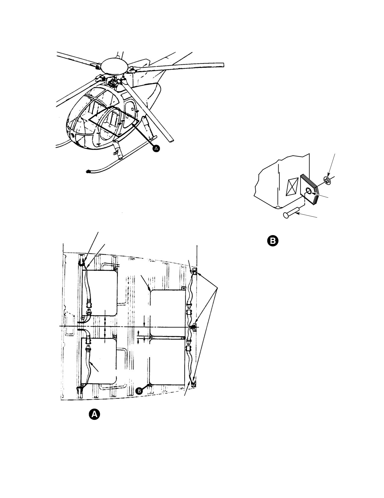
NUT
GROMMET
RIVET
CARGO TIE-DOWN FITTING
(4 PLCS)
STA. 78.50
RIVET TAB (TYP 4 PLCS)
BELT ASSEMBLY
STA. 124.00
BELT ASSEMBLY
SEAT ASSEMBLY
(4 PLCS)
EXISTING CARGO FLOOR
SEAT BELT FITTINGS
(3 PLCS)
4.0 IN.
(10.16 CM)
4.0 IN.
(10.16 CM)
4.0 IN.
1.25 IN.
(10.16 CM)
(3.175 CM)
BELT ASSEMBLY
BELT ASSEMBLY
SEAT LOCATIONS
G25-2010A
Figure 903. Seat Belt and Seat Assemblies Installation (369D/E/FF − 500N)
Page 907
25-21-00
Revision 23
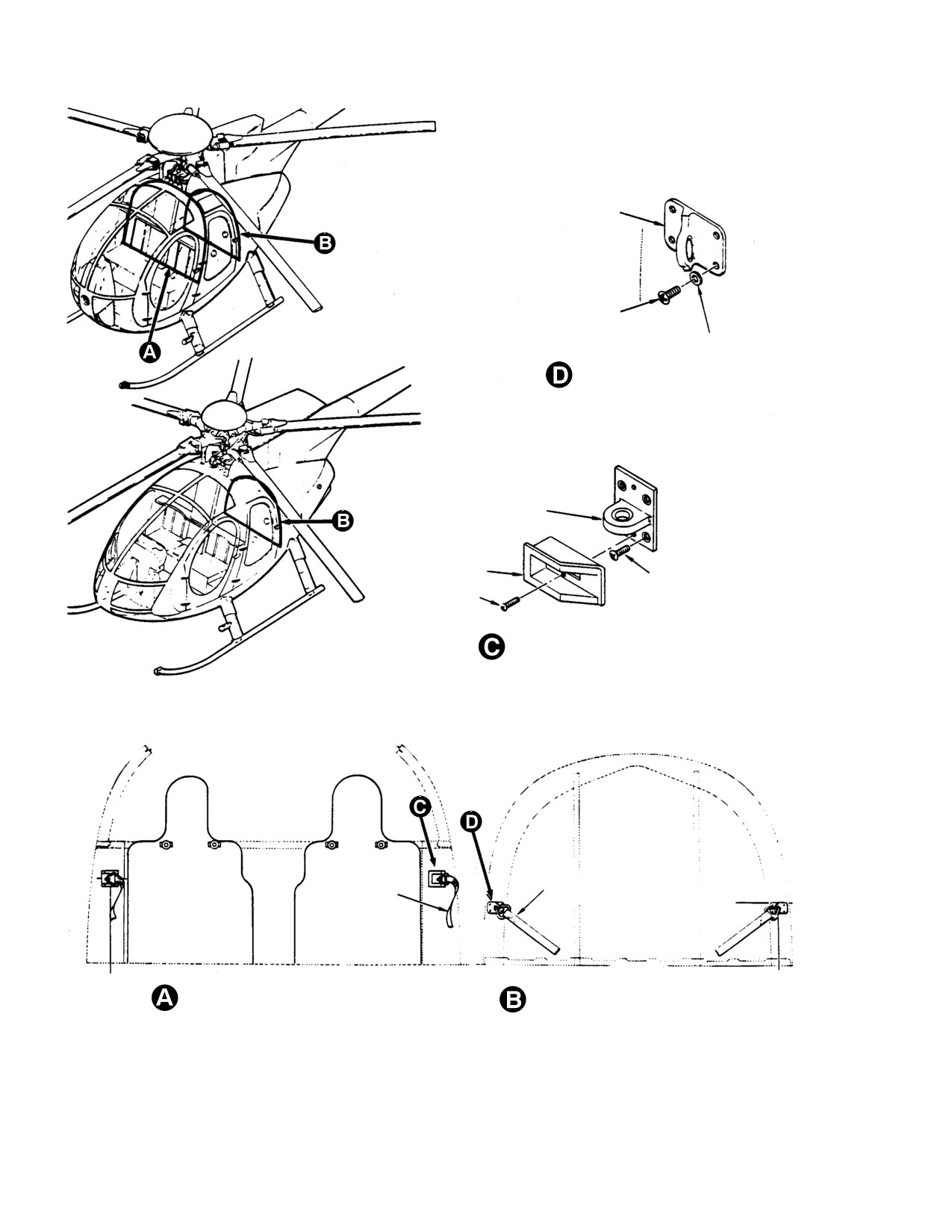
CSP-HMI-2
MD Helicopters, Inc.
MAINTENANCE MANUAL
SHOULDER STRAP
ATTACH FITTING
L.H. SHOWN
R.H. OPPOSITE
SCREW (4 REQ'D)
HIGH BULKHEAD
WASHER (4 REQ'D)
STA. 124.00 SHOULDER STRAP FITTING
SHOULDER STRAP
ATTACH FITTING
R.H. SHOWN
L.H. OPPOSITE
FITTING CAP
R.H. SHOWN
L.H. OPPOSITE
SCREW (4 REQ'D)
SCREW (2 REQ'D)
LOW BULKHEAD
STA. 78.50 SHOULDER STRAP FITTING
SHOULDER STRAP
SHOULDER STRAP
(TYP)
(TYP)
STA. 78.50
WL 28.44
WL 32.00
STA. 124.00
STA. 78.50 SHOULDER STRAP AND FITTINGS
STA. 124.00 SHOULDER STRAP AND FITTINGS
NOTE:
PICK UP EXISTING NUTPLATES LO
CATED ON CANT. STA. 78.50 BULKHEAD FRAME
AND CANT. STA. 124 BULKHEAD FRAME.
G25-2009
Figure 904. Shoulder Straps and Fittings Installation (369D/E/FF − 500N)
Page 908
Revision 23
25-21-00
MD Helicopters, Inc.
CSP-HMI-2
MAINTENANCE MANUAL
Section
25−30−00
Interior Trim
MD Helicopters, Inc.
CSP-HMI-2
MAINTENANCE MANUAL
INTERIOR TRIM
MAINTENANCE PRACTICES
1. Interior Trim
A. Cyclic Stick Control Cover Replacement
(L/H Command)
Trim panels, covers, and applicable attaching
devices are found in the following locations:
(Ref. Figure 201)
(1). Models 369D/E/FF - 500N crew
compartment (Ref. Figure 201).
(1). Remove four upper attaching cover
screws. Remove velcro attached boot
(2). Models 369D/E/FF - 500N passenger
assemblies from cover. Tip cover
compartment (Ref. Figure 202).
forward to remove two lower attaching
screws.
(3). Model 369D crew and passenger
compartments - R/H command helicop
ters with center console (Ref.
(2). Remove cover from cyclic stick assem
Figure 203).
bly and slip boot assemblies over cyclic
stick grips.
(4). Floor trim covering and applicable
methods of attachment (Ref.
(3). To replace, slip boot assemblies over
Figure 204).
cyclic stick grips and position cover in
A. Cyclic Stick Control Cover
place. Attach boot assemblies to cover
with the velcro fasteners.
(Ref. Figure 201) A cyclic stick control cover
protects the cyclic control linkage from objects
(4). Tip cover forward and install two lower
that might jam or foul control linkage. The
attaching screws. Install four upper
cover extends between the pilot's and copilot's
attaching screws.
cyclic sticks at the seat bulkhead and covers
the cyclic control linkage. Cyclic stick openings
B. Copilot’s Collective Pitch Stick Cover
in the cover are protected by boot assemblies
Replacement (L/H Command)
(dust covers) secured to the cover with Velcro
hook and pile fasteners. The cyclic sticks pass
through elastic ringed openings in the dust
(Ref. Figure 201)
covers.
(1). Remove crew seats.
B. Copilot’s Inboard Collective Pitch Stick
Cover
(2). Remove attaching hardware. While
The inboard collective pitch stick cover on L/H
carefully removing cover, ensure sliding
command helicopters provides access to the
protective cover remains fixed to
underseat flight controls linkage and forms a
collective pitch stick. Partial removal of
protective guard for the collective friction
the cyclic stick control cover may be
mechanism on the inboard collective pitch
required.
stick. A sliding protective cover at the collec
tive pitch stick slotted opening guards against
(3). Spread sliding cover at collective stick
foreign object entry.
and remove. If necessary, remove nylon
grommet on stick (Ref. Sec. 67-10-00,
2. Interior Trim Replacement
Pilot's Collective Pitch Stick Replace
ment).
NOTE: Electrical wires from passenger com
partment cigarette lighter, optional utility
light, and running time meter must be dis
(4). To replace, install nylon grommet on
connected before removing and reconnected
collective stick. Spread sliding cover at
before installing associated trim panel or
collective stick hole and fit over nylon
cover (Ref. Chap. 96).
grommet.
Page 201
25-30-00
Revision 23
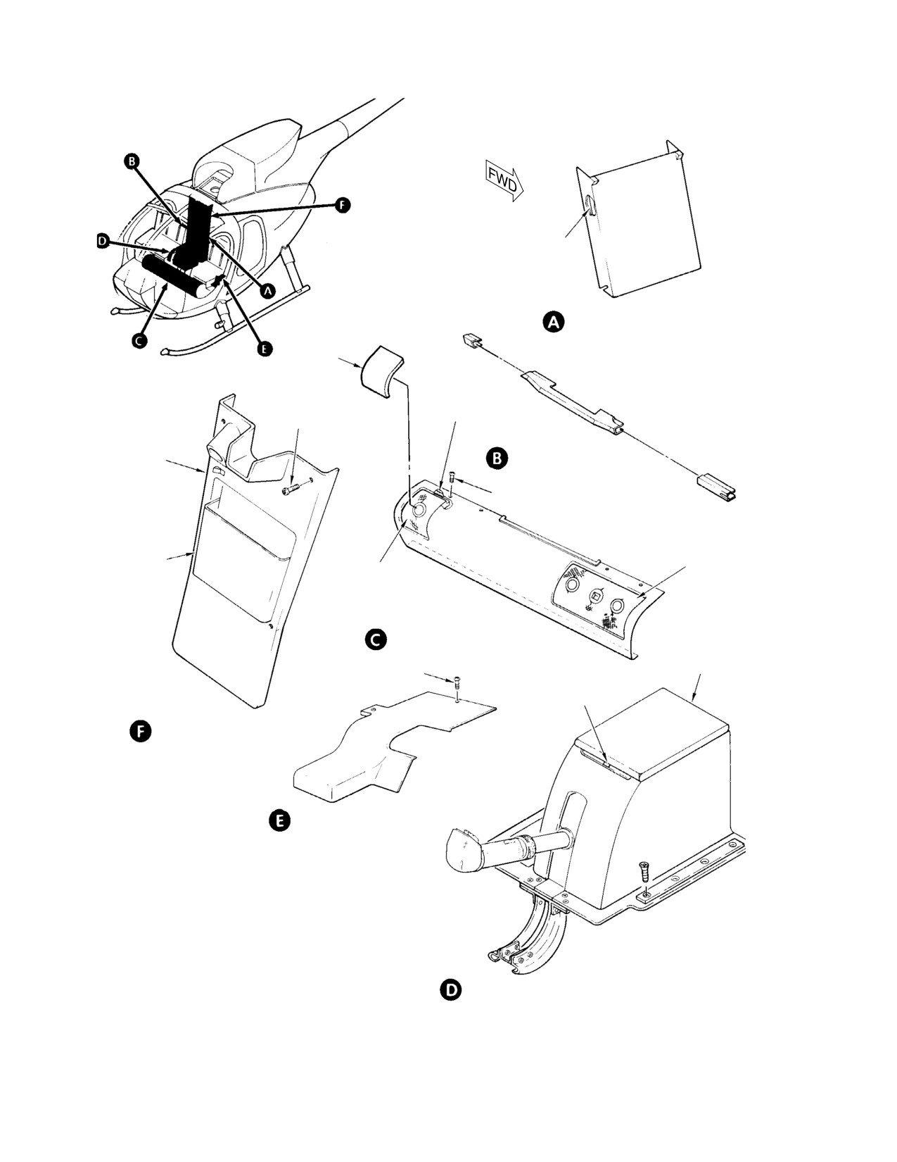
CSP-HMI-2
MD Helicopters, Inc.
MAINTENANCE MANUAL
VELCRO FASTENER
CONTROL TUNNEL PANEL
(NOTES 1, 5)
CAP
(NOTE 2)
VELCRO
FASTENER
4 PLCS
MAP CASE
SHOULDER BEAM PANEL
TRIM COVER
(NOTE 4)
6 PLCS
MAP POCKET
LH BOOT
RH BOOT
ASSEMBLY
ASSEMBLY
CYCLIC STICK CONTROL COVER
LID
3 PLCS
VELCRO
FASTENER
MAP CASE COVER
COLLECTIVE STICK COVER
NOTES:
1.
USED ONLY WITH OPTIONAL DUAL CONTROLS.
2.
USED ONLY WITH SINGLE CONTROLS.
3.
REMOVED FOR OPTIONAL UTILITY LIGHTS.
COPILOT'S COLLECTIVE PITCH STICK COVER
4.
TRIM COVER SHORTER ON HIGH BULKHEAD MODELS.
(NOTE 1)
5.
TRIM COVER LONGER ON HIGH BULKHEAD MODELS.
G25-3001-1
Figure 201. Crew Compartment Interior Trim (Sheet 1 of 2)
Page 202
Revision 23
25-30-00
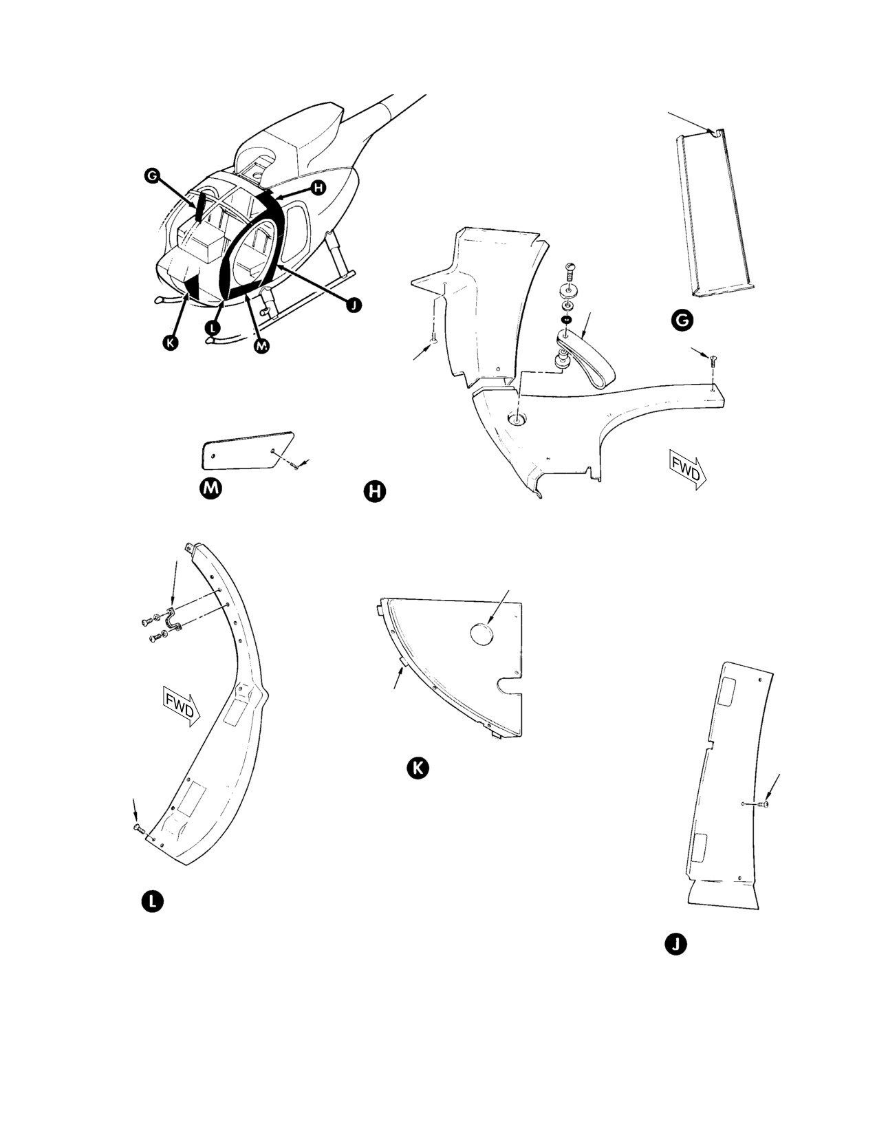
MD Helicopters, Inc.
CSP-HMI-2
MAINTENANCE MANUAL
VELCRO FASTENER
ASSIST STRAP
CANTED BULKHEAD PANEL
(RIGHT SIDE)
3 PLCS
2 PLCS
2 PLCS
DOOR PANEL
UPPER SIDE PANEL
ASSIST HANDLE
NOTE 6
VELCRO FASTENER
LOWER INSTRUMENT
4 PLCS
HOUSING PANEL
8 PLCS
FORWARD PANEL
NOTES: (CONT.)
6.
USED FOR RUNNING TIME METER ON MODEL 369D ONLY.
7.
UNLESS OTHERWISE INDICATED, LEFT SIDE ITEMS ARE
OUTBOARD AFT PANEL
SHOWN (EQUIVALENT RIGHT SIDE ITEM IS APPROXIMATELY
MIRROR IMAGE OPPOSITE).
8.
DOOR MAIN TRIM PANELS NOT SHOWN.
G25-3001-2
Figure 201. Crew Compartment Interior Trim (Sheet 2 of 2)
Page 203
25-30-00
Revision 23
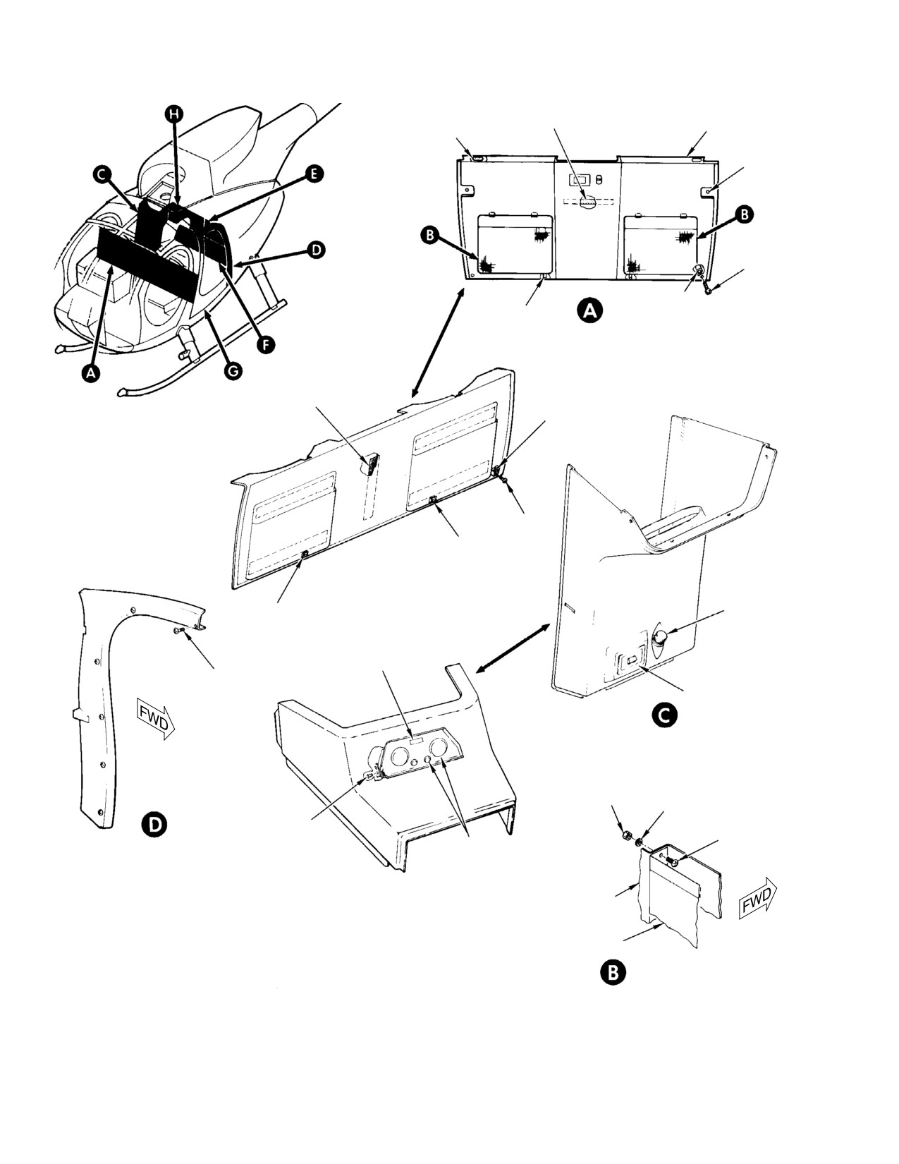
CSP-HMI-2
MD Helicopters, Inc.
MAINTENANCE MANUAL
VELCRO FASTENER
COVER
(8 PLCS)
(2 PLCS)
VELCRO FASTENER
SCREW
(4 PLCS)
SCREW
(2 PLCS)
STANDOFF
BRACKET
(2 PLCS)
HIGH FORWARD BULKHEAD PANEL
(LOOKING FORWARD)
VELCRO FASTENER
STANDOFF
(2 PLCS)
SCREW
(2 PLCS)
BRACKET
LOW FORWARD BULKHEAD PANEL
(LOOKING FORWARD)
BRACKET
LIGHTER
BLANK COVER
SCREW
(6 PLCS)
ASHTRAY
LOW BULKHEAD CONVENIENCE PANEL
NUT
(12 PLCS)
WASHER
(12 PLCS)
SCREW
(4 PLCS)
SCREW
PLUG
(12 PLCS)
AFT DOOR FRAME
(LEFT SIDE)
HIGH BULKHEAD CONVENIENCE PANEL COVER
BULKHEAD PANEL
(NOTES 1, 2)
POCKET
NOTES:
1.
NOT USED WITH OPTIONAL ROTOR BRAKE EQUIPMENT.
LITERATURE POCKET
2.
FOR INFORMATION ON OPTIONAL EQUIPMENT USED ON
THIS PANEL, REFER TO OPTIONAL EQUIPMENT LIST
(REF. SEC. 01-00-00).
G25-3002-1
Figure 202. Passenger Compartment Interior Trim (Sheet 1 of 2)
Page 204
Revision 23
25-30-00
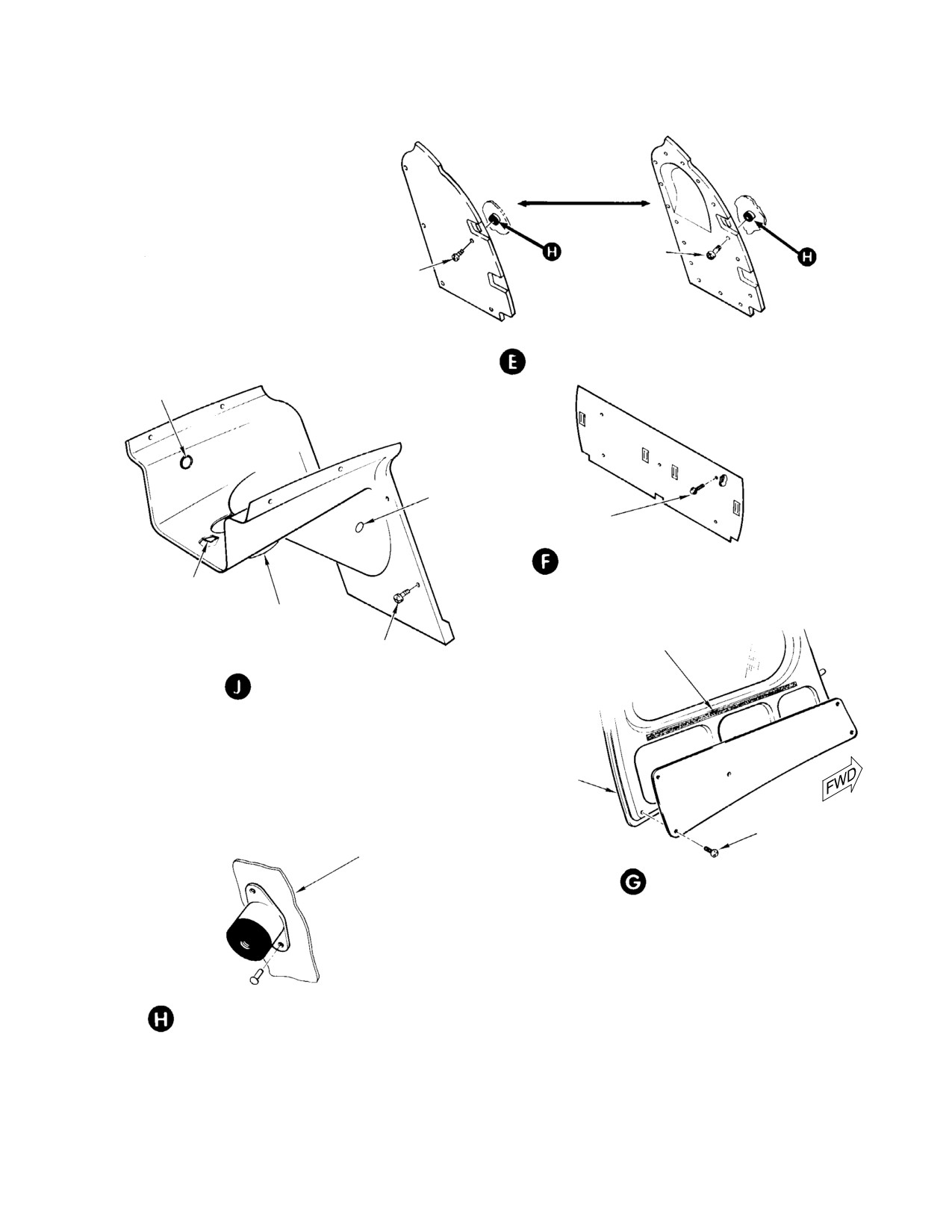
MD Helicopters, Inc.
CSP-HMI-2
MAINTENANCE MANUAL
SCREW
(16 PLCS)
SCREW
(5 PLCS)
EARLY CONFIGURATION
CURRENT CONFIGURATION
UPPER AFT BULKHEAD PANEL
(LEFT SIDE)
OIL LEVEL
CHECK COVER
PLUG BOTTOM
(BOTH SIDES)
5 PLCS
LOWER AFT BULKHEAD PANEL
VELCRO FASTENER
MAIN TRANSMISSION
ACCESS PANEL
VELCRO FASTENER
8 PLCS
TRANSMISSION PANEL
DOOR STRUCTURE
5 PLCS
STRUCTURE
DOOR PANEL
(LEFT SIDE)
ISOLATOR NUT MOUNT INSTALLATION
(TYP)
G25-3002-2
Figure 202. Passenger Compartment Interior Trim (Sheet 2 of 2)
Page 205
25-30-00
Revision 23
CSP-HMI-2
MD Helicopters, Inc.
MAINTENANCE MANUAL
(5). Position cover over collective stick and
F. Carpeting
start upper end of sliding cover into
cover tracks.
Consumable Materials
(Ref. Section 91−00−00)
(6). Slowly lower cover and guide remainder
Item
Nomenclature
of sliding cover upward in cover tracks.
CM405
Adhesive
(7). Secure with screws and washers.
CM718
Tape, double-faced
(8). Install crew seats.
Carpeting is secured in place with dou
NOTE:
ble-faced tape or bonded with adhesive, and
C. Inboard Collective Pitch Stick Cover
should not be removed unless replacement
Replacement (R/H Command)
or repair is required.
(Ref. Figure 203) At installation, tuck bottom
(1). Tear away carpeting (if bonded) and
edge of lower curtain under support.
clean surface with wire brush. Bond
replacement carpeting using adhesive
Curtains must not fold inward
CAUTION
(CM718).
through full travel of the collec
tive stick. Folding inward may result in en
(2). Lift carpeting (if taped) away from floor
tanglement with collective stick friction
and remove double-faced tape. Apply
gear mechanism.
new double-faced tape (CM718) and
press replacement carpeting in position.
D. Transmission Panel
3. Interior Trim Inspection
(Ref. Figure 203) Remove low or high bulkhead
convenience panel before removing transmis
(1).
Inspect interior trim for tears, cuts,
sion panel.
breaks, or other evidence of unservice
able condition.
E. Log Book Holder (Optional for R/H
(2).
Inspect trim panels and covers for
Command)
loose, damaged, or missing Velcro
fasteners, as applicable.
(Ref. Figure 203)
(3).
Inspect fuselage structure for loose,
damaged, or missing Velcro fasteners,
Consumable Materials
rivnuts or isolator nut mounts, as
(Ref. Section 91−00−00)
applicable.
Item
Nomenclature
CM217
Isopropyl alcohol
(4).
Inspect carpeting for cuts, tears, or
other unserviceable condition.
CM432
Dichloromethane
CM433
Ethylene chloride
(5).
Inspect foot fairings, floor trim, and
access doors for cuts, breaks or cracks.
(1). Remove upper two screws and loosen
(6).
Inspect Velcro fasteners on access flap
the bottom screws.
for security of attachment or other
damage.
(2). Lift holder up and out.
(7).
(L/H command helicopters) Inspect
sliding cover of copilot's collective pitch
(3). Repair cracks or separation by cleaning
stick cover for freedom of movement in
with isopropyl alcohol (CM217); then
cover tracks. Inspect stowage lid for
apply ethylene dichloride (CM433) or
condition and positive fastening.
dichloromethane (CM432) to patch or
mate surfaces.
A. Interior Trim Cleaning
(4). Join immediately with light pressure to
(Ref. Sec. 20-20-00, Fuselage Interior Trim
cement joint.
and Upholstery Cleaning)
Page 206
Revision 23
25-30-00
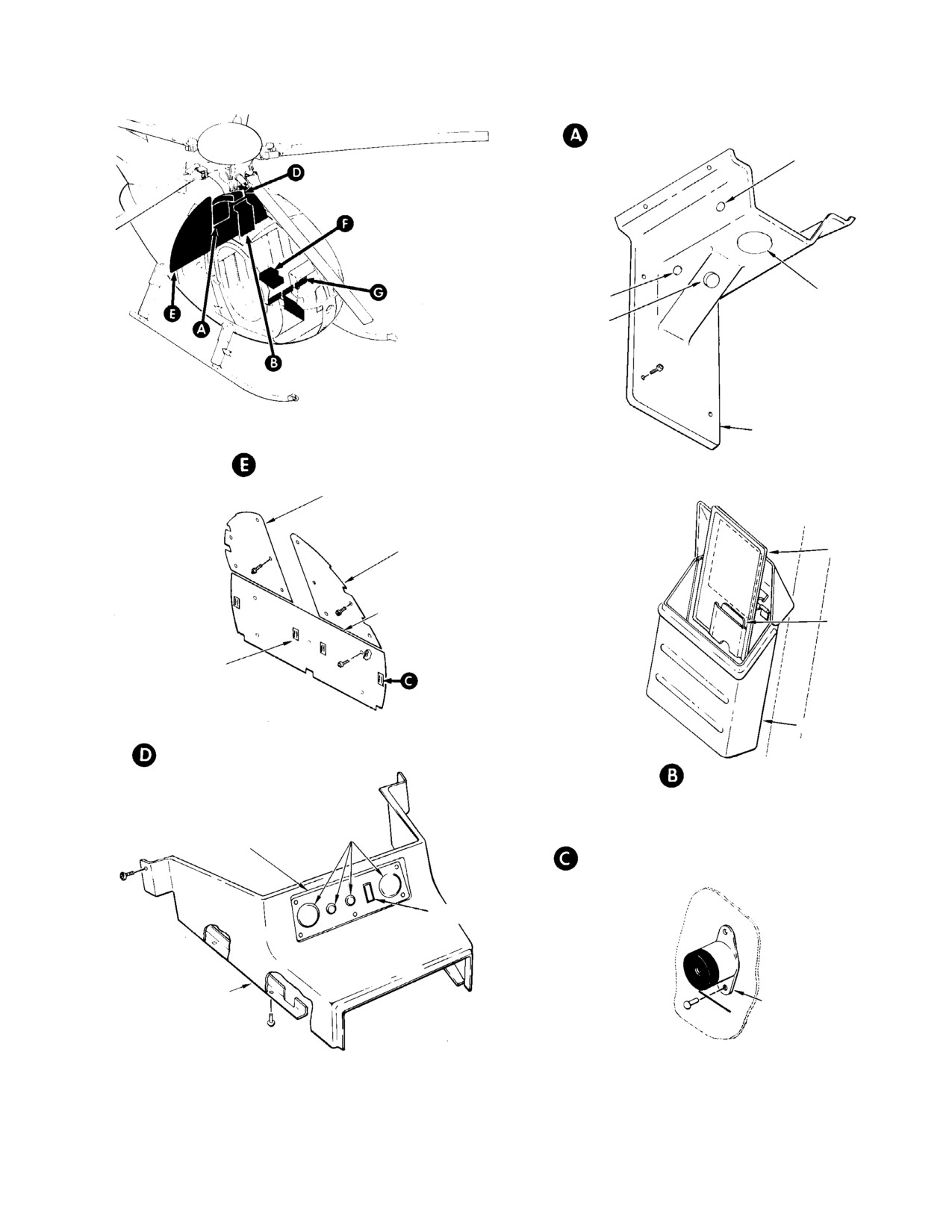
MD Helicopters, Inc.
CSP-HMI-2
MAINTENANCE MANUAL
TRANSMISSION PANEL
INSTALLATION
OIL LEVEL
CHECK COVER
PLUG BUTTON
(BOTH SIDES)
MAIN TRANSMISSION
ACCESS PANEL
CHIP DETECTOR
COVER PLUG
TRANSMISSION
PANEL
AFT BULKHEAD INSTALLATION
UPPER BULKHEAD PANEL
(RIGHT HAND)
UPPER BULKHEAD PANEL
CHECKLIST
(LEFT HAND)
LOWER BULKHEAD PANEL
MAGNETIC
COMPASS
CARD
SEAT FITTING COVER
LOGBOOK HOLDER
CONVENIENCE PANEL
INSTALLATION
LOGBOOK HOLDER
INSTALLATION
PLUGS
CONVENIENCE PANEL
ISOLATOR NUT MOUNT
INSTALLATION
BLANK COVER
CONVENIENCE
TRIM PANEL NUT
PANEL COVER
MOUNT
G25-3003-1
Figure 203. Crew and Passenger Compartment Interior Trim − R/H Command (Sheet 1 of 2)
Page 207
25-30-00
Revision 23
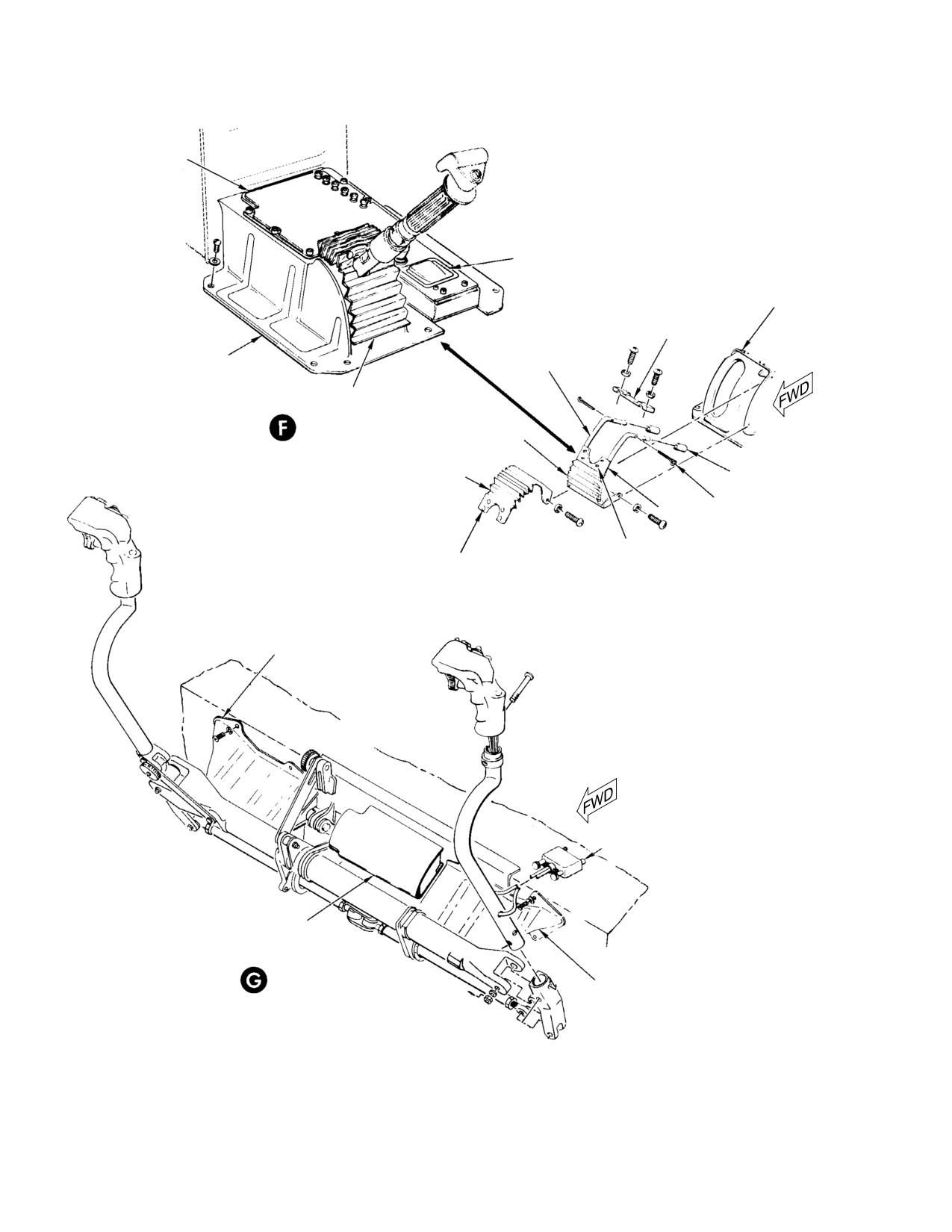
CSP-HMI-2
MD Helicopters, Inc.
MAINTENANCE MANUAL
CIRCUIT BREAKER
PANEL
ASH RECEIVER AND
CIGARETTE LIGHTER
PANEL
STICK COVER
SUPPORT TUBE
CLAMP
PILOT COLLECTIVE PITCH
SUPPORT TUBE
STICK COVER ASSEMBLY
ASSEMBLY
FLEXIBLE CLOSURE
ASSEMBLY
LOWER CURTAIN
PILOT'S INBOARD COLLECTIVE
PITCH STICK COVER
UPPER CURTAIN
CURTAIN STOP
COTTER PIN
SLIDER
FASTENER STUD
FASTENER BUTTON
EXPLODED VIEW
(ROTATED)
PILOT'S CYCLIC
STICK GUARD
CYCLIC CONTROLS
CENTER GUARD
COPILOT'S CYCLIC
STICK GUARD
CYCLIC STICK GUARDS
(ROTATED)
G25-3003-2
Figure 203. Crew and Passenger Compartments Interior Trim − R/H Command (Sheet 2 of 2)
Page 208
Revision 23
25-30-00
MD Helicopters, Inc.
CSP-HMI-2
MAINTENANCE MANUAL
4. Interior Trim and Carpeting General
(1).
Remove damaged panel.
Repair
(2).
Stop-drill end(s) of crack.
Consumable Materials
(Ref. Section 91−00−00)
(3).
Deburr stop drill(s) and clean any
Item
Nomenclature
jagged area of crack.
CM219
Methyl-ethyl-ketone
CM405
Adhesive
(4).
Cut patch from fiberglass cloth to
CM718
Tape, double-faced
overlap damaged area or crack, mini
mum 1 inch (2.54 cm) in all directions.
(1). Remove and replace broken or missing
rivnuts or isolator nut mounts, as
(5).
Cut second patch to overlap first,
applicable.
minimum 1/2 inch (12.7 mm) in all
directions. If required, cut third patch
(2). Bond loose insulation material on
to overlap second, minimum 1/2 inch
underside of trim panel or cover using
(12.7 mm) in all directions.
adhesive (CM405).
(3). Repair cut or torn floor trim or carpet
(6).
Abrade surface of panel in area to be
ing with new application of double-
patched with emery cloth (CM804).
faced tape (CM718) or adhesive
(CM405), as applicable.
(7).
Clean surface by wiping with cloth,
dampened not saturated, with
MEK solvent is flammable.
WARNING
1,1,1-trichloroethane (CM222) or
Use only in well-ventilated
surface cleaner (CM228).
area and away from heat and flame.
NOTE: Loosened Velcro fasteners may be reac
(8).
Place panel in horizontal position. Tape
tivated for adhesion by wiping original
around area to be repaired with
adhesive with MEK (CM219).
masking tape, to catch residual resin.
(4). Replace unserviceable Velcro fasteners
on access flap using adhesive (89).
(9).
Apply glass cloth (CM501) to panel one
ply at a time.
5. Boltaron Trim Panels Repair
(10).
Apply resin (CM505) to material with a
A. Fiberglass Patch Method
brush or squeegee.
(Ref. Figure 205)
(11).
Continue adding material and resin
until desired thickness has been
Consumable Materials
achieved.
(Ref. Section 91−00−00)
Item
Nomenclature
NOTE: Heat lamp should be placed a minimum
CM222
1,1,1-Trichloroethane
of 12 inches from fiberglass repair area.
CM228
Surface cleaner
CM501
Fiberglass cloth
(12). Allow repair to cure, minimum 45
CM505
Polyester laminating resin
minutes, at 265° ±10°F (129° ±5°C). Or
CM804
Emery cloth, fine
alternatively, heat lamp may be used
(minimum 2 hours).
Page 209
25-30-00
Revision 23
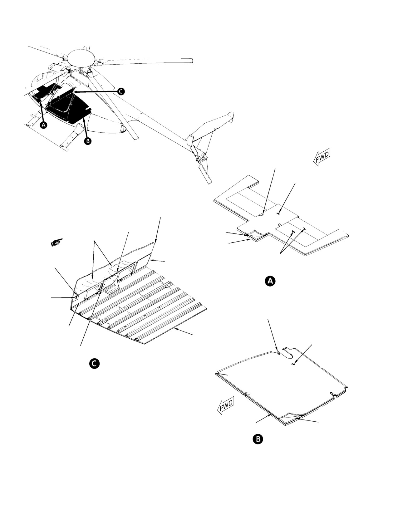
CSP-HMI-2
MD Helicopters, Inc.
MAINTENANCE MANUAL
NAUGAHYDE
HANDLE (2)
FLOOR CARPETING
STA. 78.50
BULKHEAD
ACCESS DOOR
CARPETING
DOUBLE
FOOTWELL PANEL
FACE TAPE
ASSEMBLY
FLOOR STRUCTURE
FLOOR ACCESS DOOR
ACCESS FLAP
RIGHT SIDE TRIM
CARPETING (2) (NOTE)
CARPETING
CARPETING
CREW COMPARTMENT
VELCRO
FASTENER
CUTOUT FOR
LEG OF SEAT
STRUCTURE (2)
LEFT SIDE TRIM
PASSENGER COMPARTMENT
CARPETING
FLOOR STRUCTURE
FLOOR CARPETING
CENTER TRIM
CARPETING
BULKHEAD TRIM (NOTE)
NOTE:
CARPETING IN THIS AREA
IS BONDED IN PLACE.
DOUBLE
FLOOR PAN
FACE TAPE
PASSENGER COMPARTMENT
G25-3004A
Figure 204. Floor Trim and Covering
Page 210
Revision 23
25-30-00
MD Helicopters, Inc.
CSP-HMI-2
MAINTENANCE MANUAL
B. Solvent Bonding Patch Method
(10). After forcing out bubbles, adjust clamps
to minimum pressure required to hold
(Ref. Figure 205)
parts together.
(11). If solvent has evaporated at or near
Consumable Materials
edge of patch, apply more solvent
(Ref. Section 91−00−00)
between mating surfaces using syringe
Item
Nomenclature
or eye dropper.
CM220
Naphtha aliphatic
CM435
Tetrahydrofuran
(12). Leave clamps in place for a minimum of
20 minutes.
(1). Remove damaged panel.
(13). Allow the panel to cure for 24 hours
prior to reinstallation.
(2). Stop-drill end(s) of crack.
C. Epoxy Adhesive Patch Method
(3). Deburr stop drill(s) and clean any
jagged area of crack.
(Ref. Figure 205)
(4). Select a piece of boltaron material with
Consumable Materials
same contour as patch area. Plating
(Ref. Section 91−00−00)
surfaces must provide a snug fit. Patch
Item
Nomenclature
material to overlap damaged area a
minimum of 1 inch (2.54 cm) in all
CM228
Surface cleaner
directions.
CM411
Adhesive, epoxy
CM804
Emery cloth, fine
(5). Clean mating surfaces with aliphatic
naphtha (CM220). Ensure surfaces are
free from oil, grease or other contami
(1).
Remove damaged panel.
nates.
(2).
Stop-drill end(s) of crack.
(6). Assemble patch with mating surface of
patch in contact with panel but without
(3).
Deburr stop drill(s) and clean any
application of pressure.
jagged area of cracks.
Tetrahydrofuran bonding
(4).
Select a piece of boltaron material with
WARNING
solvent is a flammable liq
same contour as patch area. Mating
uid. Care must be exercised in handl
surfaces must provide a snug fit. Patch
ing.
to overlap damaged area a minimum of
1 inch (2.54 cm) in all directions.
Solvent shall be applied careful
CAUTION
ly so no excess material will run
(5).
Lightly abrade mating surfaces with
over other surfaces and mar the finish.
emery cloth (CM804) and clean with
surface cleaner (CM228).
NOTE: On larger parts, solvent shall be applied
evenly to mating surfaces with brush.
(6).
Air dry for 30 minutes at ambient
(7). Inject tetrahydrofuran (CM435)
temperature. Apply adhesive (CM411)
between mating surfaces by means of
within 2 hours of drying.
syringe or eye dropper.
(7).
Thoroughly mix equal parts of adhesive
(8). Assemble mating surfaces as quickly as
by weight. Color should be uniform
possible by firmly pressing together.
green. Use unwaxed disposable contain
er and wooden tongue depressor or
(9). Apply clamps to assembly immediately
metal spatula for mixing. Pot life of
after solvent application. Use sufficient
mixed adhesive is 45 minutes at
pressure to force out air bubbles.
ambient temperature.
Page 211
25-30-00
Revision 23
CSP-HMI-2
MD Helicopters, Inc.
MAINTENANCE MANUAL
FIBERGLASS PATCH METHOD A
0.50 IN.
1.0 IN.
(12.7 MM)
(2.54 CM)
STOP DRILL
SOLVENT BONDING AND EPOXY
ADHESIVE PATCH METHOD B & C
1.0 IN.
(2.54 CM)
1.0 IN.
(2.54 CM)
STOP DRILL
BOND AND RIVET PATCH METHOD D
4-6 X O.D.
PANEL
PATCH
RIVETS
2 X O.D.
BOND AND RIVET PATCH METHOD D
STOP DRILL
+0.030 IN.
(0.762 MM)
2 X O.D.
+0.030 IN.
(0.762 MM)
WASHER
(NOTE)
NOTE:
USE AN960 WASHER, OF PROPER
SIZE TO FIT RIVET DIAMETER, TO PRECLUDE
4-6 X O.D.
RIVET TAIL FROM PULLING THROUGH BOLTA
RON PANEL.
G25-3005A
Figure 205. Boltaron Panel Repair
Page 212
Revision 23
25-30-00
MD Helicopters, Inc.
CSP-HMI-2
MAINTENANCE MANUAL
(8). Spread thin uniform layer (0.002-0.010
(3). Lay out rivet pattern on patch and drill
inch) (0.0508-0.254 mm) of adhesive
holes. Position patch on panel and drill
lightly on mating surfaces and clamp
holes.
lightly together.
(4). Deburr all holes on both sides of patch
and panel.
(9). Wipe excess adhesive from bond line.
(5). Countersink holes on patch if using
(10). The clamps are to remain in place for 8
MS20426A4 rivets.
hours minimum at ambient tempera
ture or 2 hours at 160° ±10°F (72°
(6). Comply with the following procedures if
±5°C).
using Solvent Bonding Patch Method
(tetrahydrofuran).
(11). Allow panel to cure for 24 hours prior to
(a). Clean mating surfaces with naphtha
installation.
aliphatic (CM220). Ensure surfaces
are free from oil, grease or other
D. Bond and Rivet Patch Method
contaminates.
(Ref. Figure 205) The following procedure may
(b). Set patch in place. Use a minimum
be used in conjunction with one of the above
amount of clecos required to hold
bonding procedures (Ref. Solvent Bonding
patch in contact with panel without
Patch Method or Epoxy Adhesive Patch
applying too much pressure.
Method). If cracks are excessive and/or a piece
of boltaron is not available that fits contour in
Tetrahydrofura bonding sol
WARNING
repair area, rivets may be used to help secure
vent is a flammable liquid.
patch to panel.
Care must be exercised in handling.
Solvent shall be applied careful
CAUTION
Consumable Materials
ly so no excess material will run
(Ref. Section 91−00−00)
over other surfaces and mar the finish.
Item
Nomenclature
NOTE: On larger parts, solvent shall be applied
CM220
Naphtha aliphatic
evenly to mating surfaces with brush.
CM228
Surface cleaner
(c). Inject tetrahydrofuran (CM435)
CM411
Adhesive, epoxy
between mating surfaces by means of
CM435
Tetrahydrofuran
syringe or eye dropper.
CM804
Emery cloth, fine
(d). Assemble mating surfaces as quickly
as possible by firmly pressing togeth
er.
(1). Cut patch to proper size.
(e). Apply clamps to assembly immedi
(2). Determine rivet spacing.
ately after solvent application, with
sufficient pressure to force out air
(a). Rivet spacing to be 4-6 times rivet
bubbles.
diameter.
(f). After forcing out bubbles, adjust
clamps to minimum pressure re
(b). Minimum edge distance to be 2 times
quired to hold parts together.
rivet diameter ±0.030 inch (0.762
mm).
(g). If solvent has evaporated at or near
edge of patch, apply more solvent
Example :For #4 rivet, minimum
between mating surfaces using
edge distance is 0.028 inch (0.7112
syringe or eye dropper.
mm). Rivet diameter 0.125 inch
(3.175 mm) X 2 + 0.030 inch (0.762
(h). Leave clamps in place for a minimum
mm) = 0.280 inch (7.112 mm).
of 20 minutes.
Page 213
25-30-00
Revision 23
CSP-HMI-2
MD Helicopters, Inc.
MAINTENANCE MANUAL
NOTE: If gap exists between patch and panel
(c). Thoroughly mix equal parts, of
prior to installing rivets, inject tetrahydro
adhesive by weight. Color should be
furan between mating surfaces in immedi
uniform green. Use unwaxed dispos
ate area of each rivet hole that has a gap us
able container and wooden tongue
ing a syringe or eye dropper.
depressor or metal spatula for
mixing. Pot life of mixed adhesive is
(i). Rivet patch to panel.
45 minutes at ambient temperature.
(d). Spread a thin uniform layer,
(j). Allow panel to cure for a minimum of
0.002-0.010 inch (0.0508-0.254 mm),
24 hours prior to installation.
of adhesive on mating surfaces. Try
to keep adhesive out of the rivet
(7). Comply with the following procedures if
holes.
using the Epoxy Adhesive Patch
Method.
(e). Install the patch on the panel with
clecos.
(a). Lightly abrade mating surfaces with
(f). Rivet the patch to the panel.
emery cloth (CM804) and clean with
surface cleaner (CM228).
(g). Wipe excess adhesive from bond line
and from around the rivets.
(b). Air dry for 30 minutes at ambient
temperature. Apply adhesive
(h). Allow the panel to cure for 24 hours
(CM411) within 2 hours of drying.
prior to installation.
Page 214
Revision 23
25-30-00
MD Helicopters, Inc.
CSP-HMI-2
MAINTENANCE MANUAL
Section
25−40−00
Miscellaneous
Furnishings