HANDBOOK OF MAINTENANCE INSTRUCTIONS FOR MDHI 369D/E/FF-500/600N HELICOPTERS (ISSUED: 1990) - page 10
MD Helicopters, Inc.
CSP-HMI-2
MAINTENANCE MANUAL
(a).
Remove bolts from inboard side of aft
(2). Install edgelighted and circuit breaker
abrasion strip (369H6102), and aft
panels as applicable (Ref. Chap. 96).
bolt from inboard side of forward
abrasion strip (369H6102), on left
(3). Install crew compartment left or right
landing gear skid.
bulkhead panel and lower portion of left
or right upper side panel as applicable.
(b).
Install screw (NAS603-8) in forward
attach hole of aft abrasion strip
(4). Install crew compartment lower aft
(369H6102).
trim panels (left and right).
(c).
Position chafing bar on inboard side
(5). Install left (outboard) collective stick
of left skid with bent end of bar aft,
cover.
and 3/8 inch (9.525 mm) recess hole
in chafing bar over aft abrasion strip
(6). Install seats and back cushions.
forward attach screw.
(7). In passenger/cargo compartment,
(d).
Align chafing bar aft screwhole with
install fuel cell forward vent in control
aft abrasion strip aft attach hole;
tunnel (Ref. Sec. 28-00-00).
install screw (NAS603-8) to secure
aft portion of chafing bar.
(8). In passenger/cargo compartment,
(e).
Hold chafing bar against skid; locate
install controls access door and foot
bar forward screw hole over forward
support fairings.
abrasion strip aft attach hole; drill
NOTE: The forward bulkhead, Sta. 78.50, trim
0.190-0.200 inch (4.826-5.08 mm)
panel is not installed during use of the hoist
screw hole through chafing bar.
system door retainer equipment.
(f).
Install screw (NAS603-8) to secure
forward end of chafing bar.
(9). Install battery.
I.
Helicopter Equipment Installation
(10). Perform operational check of hoist
system (Ref. Hoist System Operational
Install equipment and panels as follows:
Check).
Remove all tools and foreign
CAUTION
J. Weight and Balance Data
materials from helicopter before
panel installations.
(Ref. After installation of the hoist system,
(1). Prior to closing access areas, check
incorporate changes in the helicopter weight
integrity of entire hoist system installa
and balance records as instructed (Ref. Sec.
tion.
08-10-00).
Table 901. Weight and Balance Data
Weight
Arm
Moment
Configuration
Pounds (kg)
inches (cm)
in−lb (kg cm)
369H90070−521
+42.3
(+19.187)
+98.0
(+248.92)
+4145
(+4775.5)
(R/H Command)
369H90070−522
+39.3
(+17.826)
+98.7
(+250.70)
+3879
(+4469.1)
(L/H Command)
Page 909
25-63-00
Revision 23
CSP-HMI-2
MD Helicopters, Inc.
MAINTENANCE MANUAL
WHEEL FITTING
LANDING GEAR SKID
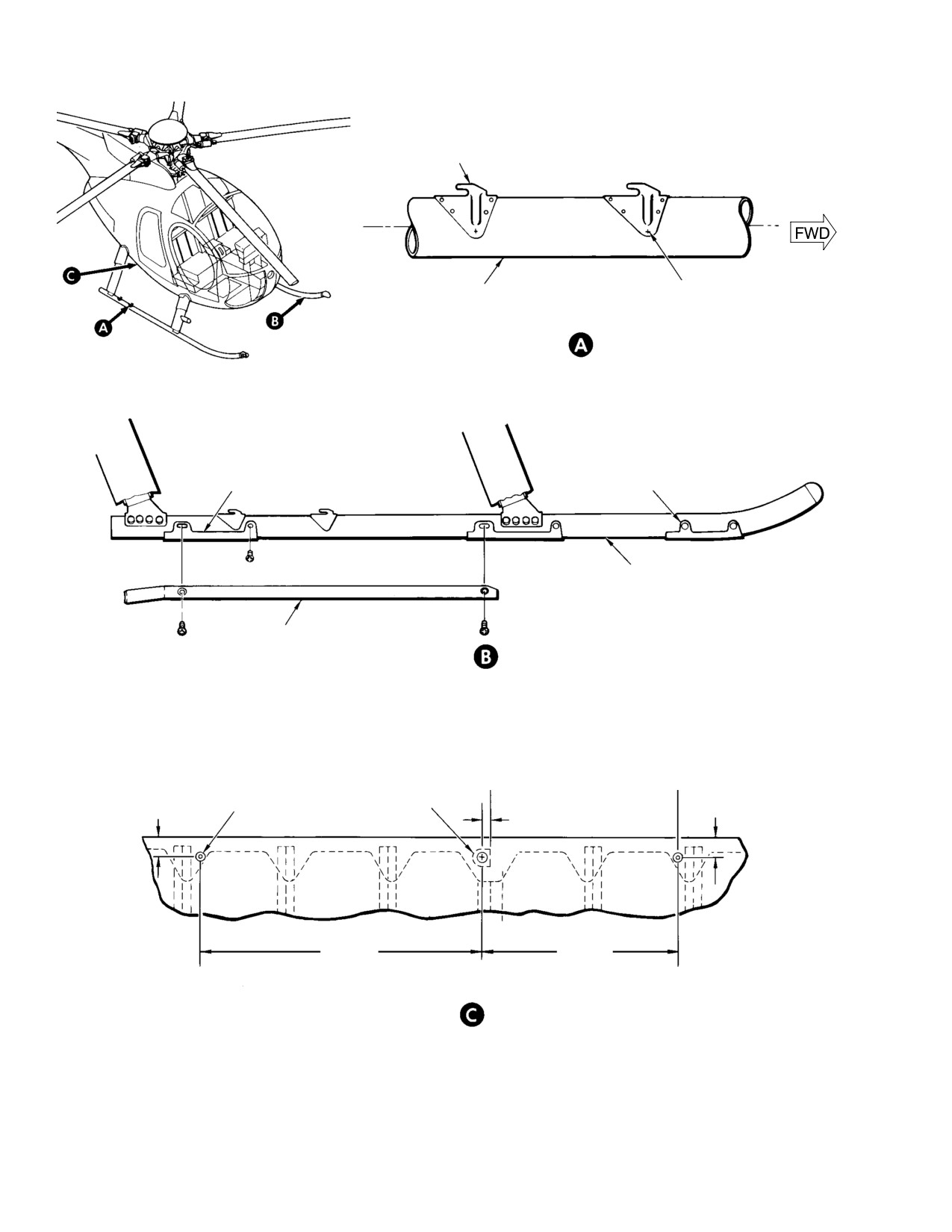
REMOVE EXISTING RIVETS
(INBOARD SIDE)
(2 PLCS), INSTALL FLUSH
RIVETS
CABLE ANTI-SNAG PROVISIONS
(ROTATED)
AFT ABRASION
FORWARD ABRASION
STRIP
STRIP
LEFT SKID (IN
BOARD SIDE)
CHAFING BAR
LEFT LANDING GEAR SKID CHAFING BAR PROVISION
(RH COMMAND HELICOPTERS WITH
CENTER ELECTRICAL CONSOLE ONLY)
STA.
STA.
96.92
85.69
1.12 IN.
INSTALL RIVETS
JACK FITTING
1.12 IN.
(2.8448 CM)
(2 PLCS)
0.47 IN.
(2.8448 CM)
(11.938 MM)
16.03 IN.
11.20 IN.
(40.7162 CM)
(28.448 CM)
STA.
112.92
DOOR SILL ANTI-CHAFING BAR PROVISIONS
G25-6008A
Figure 903. Cable Antichafing Bar Installation
Page 910
Revision 23
25-63-00

MD Helicopters, Inc.
CSP-HMI-2
MAINTENANCE MANUAL
Chapter
26
Fire Protection
MD Helicopters, Inc.
CSP-HMI-2
MAINTENANCE MANUAL
TABLE OF CONTENTS
Para/Figure/Table
Title
Page
26-10-00 Engine Fire Detection System
A
Maintenance Practices
201
1. Fire Detector System Description and Operation
201
2. Fire Detector System Troubleshooting
201
3. Fire Detection System Replacement
201
A. Fire Detection System Removal
201
B. Fire Detection System Installation
201
Figure 201. Fire Detection System Interconnect Data
202
Figure 202. Fire Detection System Installation
203
26-20-00 Fire Extinguisher
A
Maintenance Practices
201
1. Fire Extinguisher Description
201
2. Fire Extinguisher Operation
201
3. Fire Extinguisher Servicing/Inspection
201
Figure 201. Fire Extinguisher Installation (R/H Command)
202
Page i
26 Contents
Revision 23
CSP-HMI-2
MD Helicopters, Inc.
MAINTENANCE MANUAL
TABLE OF CONTENTS (Cont.)
Para/Figure/Table
Title
Page
This Page Intentionally Left Blank
Page ii
Revision 43
26 Contents
MD Helicopters, Inc.
CSP-HMI-2
MAINTENANCE MANUAL
Section
26−10−00
Engine Fire
Detection System
MD Helicopters, Inc.
CSP-HMI-2
MAINTENANCE MANUAL
FIRE DETECTION SYSTEM
MAINTENANCE PRACTICES
1. Fire Detector System Description and
3. Fire Detection System Replacement
Operation
(Ref. Figure 202)
The fire detection system is located in the aft
section of the fuselage encircling the engine
A. Fire Detection System Removal
bay area. The fire detector cable is looped
around the inboard structure of the engine
(1). Disconnect wire harness from fire
compartment. The fire detection system is held
detector unit.
in place by stainless steel positive locking
(2). Remove hardware securing clamps from
cable clips and clamps attached to the air
cable and fire detector unit.
frame.
The detector consists of a pressure switch
(3). Disconnect fire detection cable quick
connected to a small diameter tube. Inside the
release clips.
tube is helium gas and a core material that
(4). Careful remove fire detection cable
contains trapped hydrogen. The detector can
from engine compartment.
provide an output signal when heat is applied
to it in two ways. If the detector tube average
(5). Replace any broken quick release clips.
temperature exceeds a preset amount, the
helium gas pressure increase will trigger the
B. Fire Detection System Installation
output signal. If there is a local hot spot on the
detector tube, the core will outgas hydrogen.
NOTE:
The release of hydrogen gas will cause a
D Replace any damaged or broken quick re
pressure increase inside the tube, triggering
lease clips.
the output signal. Both of these processes are
reversible. When the tube cools, the output
D Do not exceed minimum bend radius
signal ceases, the hydrogen is readsorbed into
0.375 inch (9.53 mm) when installing fire
the core, and the system is reset. The detector
detection cable.
core has a spiral groove cut into its outside
diameter, so that crushing, flattening, or
(1). Form fire detection cable to fit original
kinking of the detector tube will not prevent
mounting locations.
gas pressure from reaching the pressure
(2). Secure fire detector cable in quick
switch. Loss of tube integrity through cracking
release clips.
or breakage will make the detector inopera
tive, but the detector incorporates a built in
(3). Install clamps to fire detector unit
test for tube integrity.
using previously removed hardware.
2. Fire Detector System Troubleshooting
(4). Attach electrical connector to fire
(Ref. Figure 201)
detection cable connector.
Page 201
26-10-00
Revision 23
CSP-HMI-2
MD Helicopters, Inc.
MAINTENANCE MANUAL
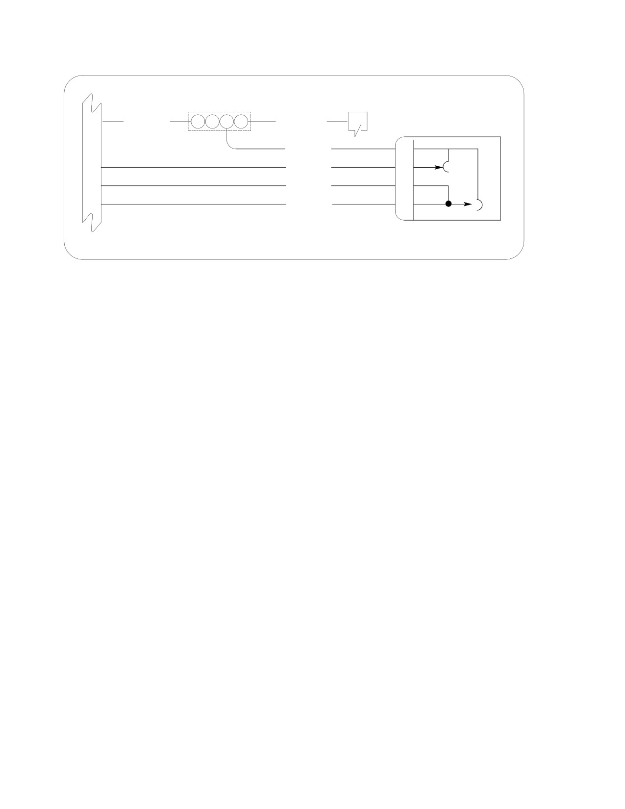
J1201
TB201-1
P19 VOICE/WARNING LRU
89
FIR 002AA22
E F G H
FIR 002AAA22
S
P/J 30
FIR 002A22
D
78
FIR 001A22
C
79
FIR 001F22
B
1
FIR 003A22
A
FIRE DETECTOR
6G26-095A
Figure 201. Fire Detection System Interconnect Data
Page 202
Revision 23
26-10-00
MD Helicopters, Inc.
CSP-HMI-2
MAINTENANCE MANUAL
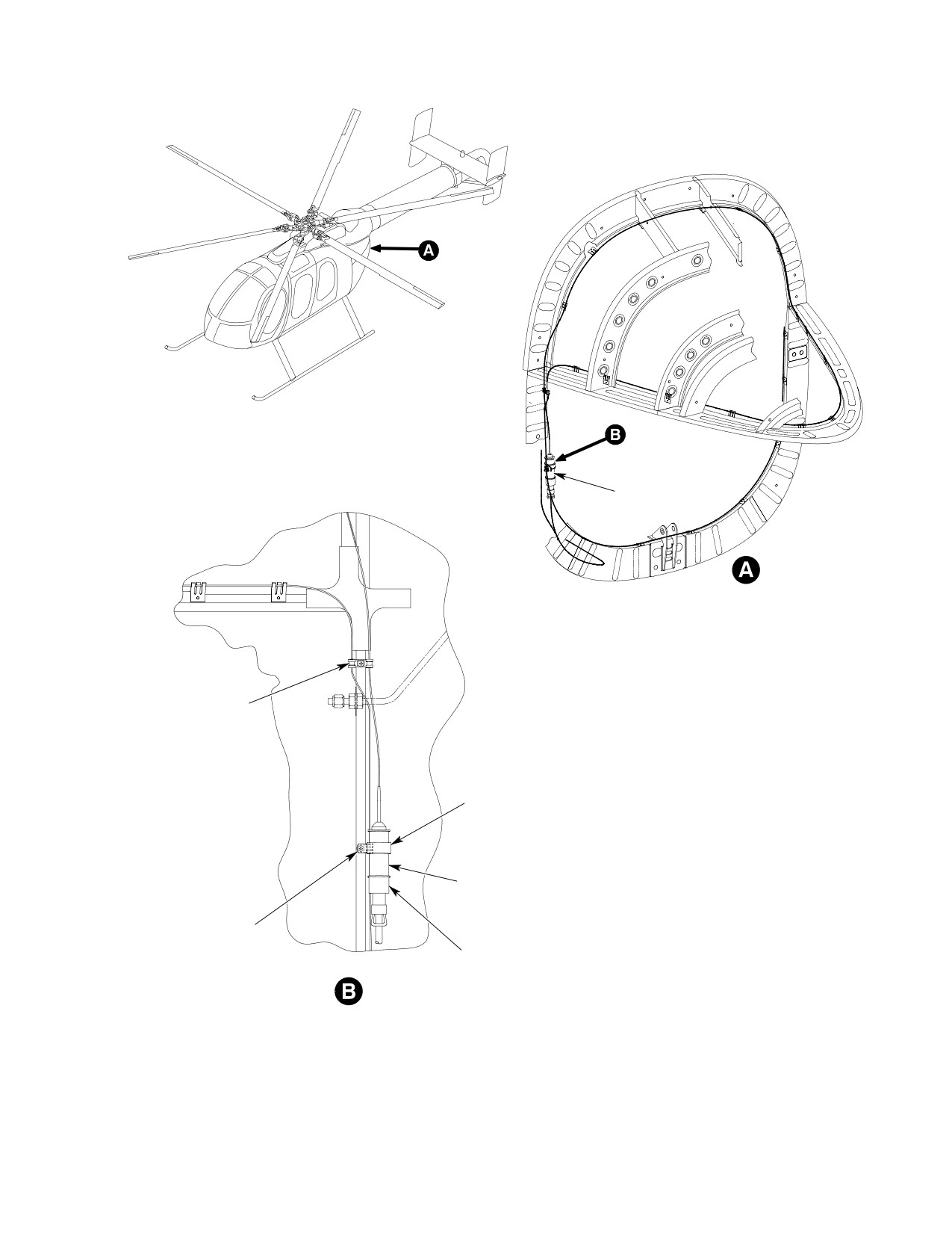
FIRE DETECTOR UNIT
VIEW ROTATED
MS21919WCH2 CLAMP
MS21919WCH16 CLAMP
3001-31-900/400
FIRE DETECTOR
MS21919WCH2 CLAMP
NAS1096-3-12 SCREW
MS21042-3 NUT
MS3456KT14S-5S PLUG
NAS43HT3-20 SPACER
M85049/52S14W BACKSHELL
AN960C10L WASHER
MS9029/30-217 SOCKETS (X5)
LOOKING OUTBOARD
LEFT SIDE
6G26-094
Figure 202. Fire Detection System Installation
Page 203
26-10-00
Revision 23
CSP-HMI-2
MD Helicopters, Inc.
MAINTENANCE MANUAL
This Page Intentionally Left Blank
Page 204
Revision 44
26-10-00
MD Helicopters, Inc.
CSP-HMI-2
MAINTENANCE MANUAL
Section
26−20−00
Fire Extinguisher
MD Helicopters, Inc.
CSP-HMI-2
MAINTENANCE MANUAL
FIRE EXTINGUISHER
MAINTENANCE PRACTICES
1. Fire Extinguisher Description
(2). Remove fire extinguisher from mount
ing bracket.
(Ref. Figure 201) The early model helicopters
(3). Remove safety pin from handle. Point
use the pressurized, dry chemical type of fire
nozzle toward base of flame and
extinguisher. The current models use a
squeeze the handle.
liquified gas which discharges as a vapor at
high nozzle velocity (Halon 1211). The L/H and
3. Fire Extinguisher Servicing/Inspection
R/H command fire extinguishers mount on the
forward door frame between the crew door and
The fire extinguishers are equipped with a
the canopy. The fire extinguisher quickly
pressure gage that indicates normal, charge,
detaches from the mounting bracket by
and overcharge pressures.
unfastening the quick-release clasps. Note the
(1). Dry chemical type - white area indi
current fire extinguishers are equipped with
cates normal operating range of 150 psi
two straps for extra high vibration applica
(1034 kPa). Red area indicates
tions.
CHARGE or OVERCHARGE.
(2). Halon type - green area indicates
2. Fire Extinguisher Operation
normal operating range of 125 psi (862
kPa). Red area indicates CHARGE or
(1). Grasp fire extinguisher handle with one
OVERCHARGE.
hand. Use the thumb and forefinger of
the other hand to unfasten the quick-
Service the fire extinguishers in accordance
release clasp.
with manufacturer's instructions.
Page 201
26-20-00
Revision 23
CSP-HMI-2
MD Helicopters, Inc.
MAINTENANCE MANUAL
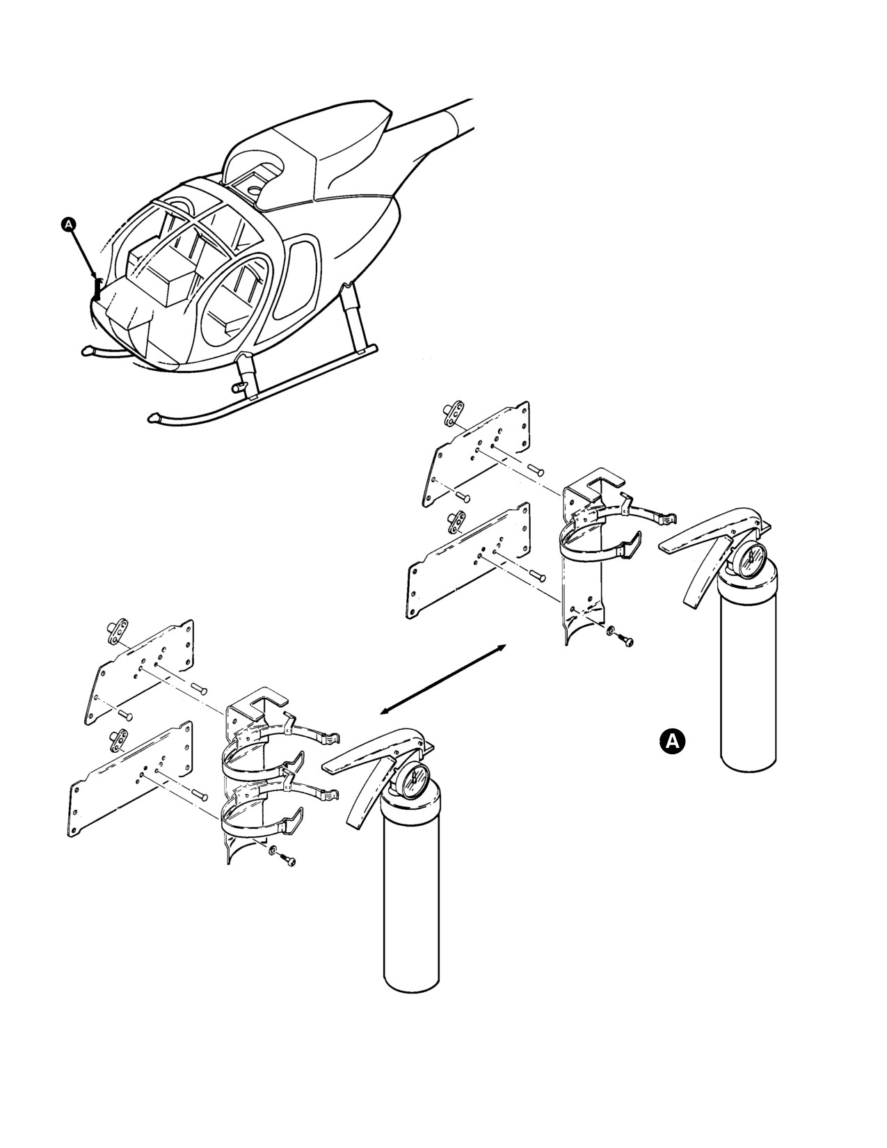
EARLY ASSEMBLY
CURRENT ASSEMBLY
G26-2001
Figure 201. Fire Extinguisher Installation (R/H Command)
Page 202
Revision 23
26-20-00

MD Helicopters, Inc.
CSP-HMI-2
MAINTENANCE MANUAL
Chapter
28
Fuel System
CSP-HMI-2
MD Helicopters, Inc.
MAINTENANCE MANUAL
This Page Intentionally Left Blank
MD Helicopters, Inc.
CSP−HMI−2
MAINTENANCE MANUAL
TABLE OF CONTENTS
Para/Figure/Table
Title
Page
28-00-00 Fuel System (369D/E/FF - 500N)
A
Description and Operation
1
1. Engine Fuel System
1
2. Fuel Cells
1
3. Fuel Quantity System
1
4. Vent System
1
5. Fuel Shutoff Valve Control
2
6. Fuel Shutoff Valve
2
7. Start Pump
2
8. Fuel Filter Caution Light Pressure Switch
2
9. Drain System and Drain Valves
2
10. Fuel Supply Lines
2
Fault Isolation
101
1. Fuel System Fault Isolation
101
Table 101. Fuel Supply System Fault Isolation
101
Figure 101. Fuel System Wiring Diagram (Model 250-C20B/R2 Engines)
103
Figure 102. Fuel Quantity System Wiring Diagram
103
Figure 103. Fuel System Schematic
104
Maintenance Practices
201
1. Fuel Cell Cleaning - General
201
2. Uniroyal Fuel Cell Cleaning
201
3. Engineered Fabrics Corp. Fuel Cell Cleaning
201
4. Fuel Cell Handling, Storage and Shipping
201
5. Fuel Cell Preservation and Storage (Uniroyal Cells)
201
6. Fuel Cell Preservation and Storage (Engineered Fabrics Corp. Cells)
201
7. Fuel System Air Bleed (Model 250-C30 Engine Installation)
202
8. Fuel System Air Bleed (Model 250-C20B/R2 Engine Installation)
202
Removal/Installation
401
1. Fuel Shutoff Valve Control Cable Replacement
401
A. Fuel Shutoff Valve Control Cable Removal
401
B. Fuel Shutoff Valve Control Cable Installation
401
Figure 401. Fuel Shutoff Valve Cable Installation
402
2. Fuel Shutoff Valve Replacement
403
A. Fuel Shutoff Valve Removal
403
B. Fuel Shutoff Valve Installation
403
Figure 402. Left Fuel Cell Cover Installation
404
Page i
28 Contents
Revision 19
CSP−HMI−2
MD Helicopters, Inc.
MAINTENANCE MANUAL
TABLE OF CONTENTS (Cont.)
Para/Figure/Table
Title
Page
3.
Fuel Tank Vent System Component Replacement
405
A. Vent Tube/Emergency Valve Assembly Removal
405
B. Forward Vent Crossover Fitting Removal
405
C. Aft Vent Crossover Fitting Removal
405
Figure 403. Vent System (Sheet 1 of 2)
406
D. Fuel Tank Vent System Installation
407
E. Vent Tube/Emergency Valve Assembly Installation
408
4.
Fuel Supply Lines Replacement
409
A. Fuel Supply Lines Removal
409
B. Fuel Supply Lines Installation
409
5.
Start Pump Replacement (Model 250-C20B/R2 / 250-C30 Engine Installation)
409
A. Start Pump Removal
409
Table 401. Fuel Line Torque Values
410
B. Start Pump Installation
410
Figure 404. Start Pump and Fuel Lines Installation (Sheet 1 of 4)
411
6.
Fuel Quantity Transmitter Replacement
415
A. Fuel Quantity Transmitter Removal
415
B. Fuel Quantity Transmitter Installation
415
7.
Fuel System Drain Valve Replacement
415
A. Fuel System Drain Valve Removal
415
B. Fuel System Drain Valve Installation
416
8.
Fuel Cell Replacement
416
A. Fuel Cell Removal
416
B. Fuel Cell Installation
418
C. Fuel Cell Cover Installation
419
Figure 405. Fuel Cells
420
Figure 406. Fuel Cell Support Lacing
421
Adjustment/Test
501
1. Fuel Level Low Caution Light System Test
501
2. Fuel Quantity Transmitter Calibration and Adjustment
501
Figure 501. Fuel Quantity Transmitter Calibration (Sheet 1 of 2)
502
A. Fuel Level Calibration
503
B. Fuel Level Low Warning Light Calibration
503
3. Fuel Quantity Transmitter Functional Check
504
4. Fuel Filter (Bypass) Caution Light Pressure Switch Test
506
Figure 502. Fuel Filter Caution Light Pressure Switch Test
(C20/C30 Engines)
508
Page ii
Revision 44
28 Contents
MD Helicopters, Inc.
CSP−HMI−2
MAINTENANCE MANUAL
TABLE OF CONTENTS (Cont.)
Para/Figure/Table
Title
Page
Figure 503. Fuel Filter Caution Light Pressure Switch (C30 Engine)
509
Figure 504. Fuel Filter Caution Light Pressure Switch (C20 Engines)
509
Figure 505. Fuel Filter Caution Light Pressure Switch (C20R/2 Engines
with CECO Pump)
510
Inspection/Check
601
1. Fuel System General Inspection
601
2. Fuel Shutoff Valve Control Cable Swage Test (369D/E)
601
Figure 601. Fuel Shut-Off Control Cable, PN 369A8137-503 Pull Test
602
3. Fuel Shutoff Valve Inspection
603
4. Fuel Quantity Transmitter Inspection
603
5. Tank Vent System Inspection
604
6. Fuel System Vacuum Leak Inspection
604
7. Start Pump Operational Check (Model 250-C20 Series Engines
or 250-C30 Engine With Optional Maintenance Fuel Pump)
605
8. Drain Valve Inspection
605
9. Fuel Cell Inspection
606
10. Fuel Cell Leak Inspection
606
A. Soap Bubble Leak Test Procedures
606
B. Phenolphthalein Stain Inspection Procedures
607
C. Liquid Stand Inspection
607
11. Fuel Tank Pressure Leak Test
608
Repairs
801
1. Fuel Shutoff Valve Control Cable Repair
801
2. Fuel Shutoff Valve Repair
801
3. Fuel Cell Repair
801
4. Uniroyal Self-Sealing and Non-Self-Sealing Cell Repairs
801
A. Scuff Mark Repair
802
B. Reinforcements, Hangers and Splice Repairs
802
C. Loose Patch Repair
802
D. Patch Installation
802
E. Loose Edge and Lap Seam Repairs
804
F. Blister Repair
805
5. Fuel Quantity Transmitter Repair
806
A. Resistor installation, Transmitters PN 369D296303, 369D296303-701 and
369A4245
806
B. MIL-S-8802 Application
807
Page iii
28 Contents
TR13−001
CSP−HMI−2
MD Helicopters, Inc.
MAINTENANCE MANUAL
TABLE OF CONTENTS (Cont.)
Para/Figure/Table
Title
Page
28-00-60 Fuel System (600N)
A
Description and Operation
1
1. Engine Fuel System
1
2. Fuel Cells
1
3. Fuel Distribution
1
4. Fuel Vent System
1
5. Fuel Quantity System
2
6. Fuel Shutoff Valve Control
2
7. Fuel Shutoff Valve
2
8. Fuel Filter Caution Light Pressure Switch
2
9. Drain System and Drain Valves
2
10. Fuel Supply Lines
2
Fault Isolation
101
1. Fuel System Fault Isolation
101
Table 101. Fuel Supply System Fault Isolation
101
Table 102. Fuel Quantity System Wire Data List
103
Figure 101. Fuel Quantity System Wiring Diagram
103
Maintenance Practices
201
1. Fuel Cell Cleaning - General
201
2. Engineered Fabrics Corp. Fuel Cell Cleaning
201
3. Fuel Cell Handling, Storage and Shipping
201
4. Fuel Cell Preservation and Storage (Engineered Fabrics Corp. Cells)
201
5. Fuel System Air Bleed (Model 250-C47 Engine Installation)
201
Figure 201. Field Fabricated Fuel System Bleeding Tool
202
Removal/Installation
401
1. Fuel Shutoff Valve Control Cable Replacement
401
A. Fuel Shutoff Valve Control Cable Removal
401
B. Fuel Shutoff Valve Control Cable Installation
401
Figure 401. Fuel Shutoff Valve Cable Installation
402
2. Fuel Shutoff Valve Replacement
403
A. Fuel Shutoff Valve Removal
403
B. Fuel Shutoff Valve Installation
403
Figure 402. Fuel Shutoff Valve and Fuel Cell Cover Installation
404
Page iv
Revision 44
28 Contents
MD Helicopters, Inc.
CSP−HMI−2
MAINTENANCE MANUAL
TABLE OF CONTENTS (Cont.)
Para/Figure/Table
Title
Page
3.
Fuel Cell Cover Replacement
405
A. Fuel Cell Cover Removal
405
B. Fuel Cell Cover Installation
406
4.
Fuel Supply Lines Replacement
407
A. Fuel Supply Lines Removal
407
B. Fuel Supply Lines Installation
407
Figure 403. Fuel Lines Installation
408
Figure 404. Ejector Pump and Fuel Lines Installation
409
5.
Fuel Cell Vent System Components Replacement
410
A. Fuel Cell Vent System Components Removal
410
B. Fuel Cell Vent System Components Installation
410
Figure 405. Fuel Cell Vent System Components
411
6.
Fuel Cell Replacement
412
A. Fuel Cell Removal
412
B. Fuel Cell Installation
414
Figure 406. Fuel Cell Interconnect and Support Lacing (Sheet 1 of 3)
416
7.
Fuel Filler Neck Gravity Fill Port Replacement
419
A. Fuel Filler Neck Gravity Fill Port Removal
419
B. Fuel Filler Neck Gravity Fill Port Installation
419
8.
Fuel System Drain Valve Replacement
419
A. Fuel System Drain Valve Removal
419
B. Fuel System Drain Valve Installation
419
9.
Fuel Quantity Probe Replacement
420
A. Forward Fuel Quantity Probe Removal
420
B. Forward Fuel Quantity Probe Installation
420
C. Aft Fuel Quantity Probe Removal
420
Figure 407. Fuel Quantity Probes (Sheet 1 of 2)
421
D. Aft Fuel Quantity Probe Installation
422
Adjustment/Test
501
1. Fuel Level Low Light/Fuel Quantity Indicator System Test and Calibration
501
2. Fuel Filter (Bypass) Caution Light Pressure Switch Test
502
Figure 501. Fuel Filter Caution Light Pressure Switch Test Apparatus
(C47 Engine)
503
Inspection/Check
601
1. Fuel System General Inspection
601
2. Fuel Shutoff Valve Inspection
601
3. Tank Vent System Inspection
602
Page v
28 Contents
Revision 44
CSP−HMI−2
MD Helicopters, Inc.
MAINTENANCE MANUAL
TABLE OF CONTENTS (Cont.)
Para/Figure/Table
Title
Page
4. Fuel Quantity Probe Inspection
602
5. Fuel System Vacuum Leak Inspection
602
Figure 601. Fuel System Vacuum Leak Inspection
603
6. Drain Valve Inspection
603
7. Fuel Cell Inspection
604
8. Fuel Cell Leak Inspection
604
A. Soap Bubble Leak Test Procedures
604
B. Phenolphthalein Stain Inspection Procedures
605
C. Liquid Stand Inspection
605
9. Fuel Tank Pressure Leak Test
605
10. Fuel Transfer System Functional Check
606
Figure 602. Fuel Transfer System Functional Check
606
A. Test Setup
607
Figure 603. Fuel Transfer Test Setup
607
B. Check Procedures
608
Repairs
801
1. Fuel Shutoff Valve Control Cable Repair
801
2. Fuel Cell Repair
801
3. Scuff Mark Repair
801
4. Reinforcements, Hangers and Splice Repairs
801
5. Loose Patch Repair
802
6. Patch Installation
802
7. Loose Edge and Lap Seam Repairs
803
8. Blister Repair
804
28-25-00 Anti-Ice / Airframe Fuel Filter (369D/E - 500/600N)
A
Description and Operation
1
Table 1. Anti-Ice/Airframe Fuel Filter Effectivity
1
1. Description
1
2. Operation
1
Fault Isolation
101
1. Anti-Ice Fuel Filter System Fault Isolation
101
Table 101. Anti-Ice Fuel Filter System Fault Isolation
101
Page vi
Revision 44
28 Contents
MD Helicopters, Inc.
CSP−HMI−2
MAINTENANCE MANUAL
TABLE OF CONTENTS (Cont.)
Para/Figure/Table
Title
Page
Maintenance Practices
201
1. Anti-Ice Fuel Filter Replacement
201
A. Anti-Ice Fuel Filter Removal
201
B. Anti-Ice Fuel Filter Installation
201
2. Fuel System Air Bleed
202
Figure 201. Anti-Ice Fuel Filter (Sheet 1 of 3)
203
Inspection/Check
601
1. Anti-Ice Fuel Filter System Inspection
601
2. Anti-Ice Fuel Filter Installation Operational Check: 369H90022-BSC
602
3. Anti-Ice Fuel Filter Installation Operational Check: 369H90022-503, -505
and 600N98110-501
602
4. Fuel System Vacuum Leak Check
602
Table 601. Fuel Supply System Torque Values
603
Figure 601. Anti-Ice Fuel Filter Controls (Sheet 1 of 2)
604
Initial Installation
901
1.
Anti-Ice Fuel Filter Initial Installation
901
A. Preparations for Installation
901
B. Anti-Ice Fuel Filter Control Panel Installation: 369H90022-BSC
901
C. Anti-Ice Fuel Filter Control Panel Installation: 369H90022-503, and -505
901
D. Anti-Ice Fuel Filter Control Panel Installation: 600N98110-501
902
E. Firewall Modifications and Bracket Installation
902
F. Fuel Filter Installation
903
Figure 901. Anti-Ice Fuel Filter Modifications and Installation
(369D/E - 500N) (Sheet 1 of 2)
904
Figure 902. Anti-Ice Fuel Filter Modifications and Installation (600N)
(Sheet 1 of 2)
907
Figure 903. Anti-Ice Fuel Filter Wiring Diagram (369D S/N 0001 - 1204)
(Sheet 1 of 2)
910
Figure 904. Anti-Ice Fuel Filter Wiring Diagram (369D S/N 1205 & Subs
and 369E S/N 001 - 383)
912
Figure 905. Anti-Ice Fuel Filter Wiring Diagram (369E S/N 384 & Subs
and 500N S/N 001 & Subs)
913
Figure 906. Anti-Ice Fuel Filter Wiring Diagram (600N S/N 003 & Subs)
(Sheet 1 of 2)
914
G. Post-Installation Inspection
916
H. Furnishings, Panels and Equipment Installation
916
Page vii
28 Contents
Revision 44
CSP−HMI−2
MD Helicopters, Inc.
MAINTENANCE MANUAL
TABLE OF CONTENTS (Cont.)
Para/Figure/Table
Title
Page
2. Anti-Ice Fuel Pump Initial Installation (600N98110-501 Installation)
916
A. Fuel Cell Cover Removal
916
Figure 907. Fuel Pump Initial Installation (600N)
917
B. Pump Installation
917
C. Fuel Cell Cover Installation
917
3. Anti-Ice Fuel Filter Installation Weight and Balance
918
Table 901. Weight and Balance Data
918
Page viii
Revision 44
28 Contents
MD Helicopters, Inc.
CSP-HMI-2
MAINTENANCE MANUAL
Section
28−00−00
Fuel System
(369D/E/FF − 500N)
CSP-HMI-2
MD Helicopters, Inc.
MAINTENANCE MANUAL
This Page Intentionally Left Blank
MD Helicopters, Inc.
CSP-HMI-2
MAINTENANCE MANUAL
FUEL SYSTEM
DESCRIPTION AND OPERATION
1.
Engine Fuel System
(6). Fuel tank servicing is through the tank
filler neck on the right side of the
(1). Engine fuel system operational infor
fuselage.
mation is provided in the applicable
3. Fuel Quantity System
Allison Engine Operation and Mainte
nance Manuals (Ref. Sec. 01-00-00).
(1).
The fuel quantity system is powered by
24 - 28 Vdc current and consists of a
2.
Fuel Cells
float operated quantity transmitter
mounted on the left fuel cell cover and a
(1).
The MDHS helicopter standard fuel
quantity indicator gauge and FUEL
tank consists of two interconnected
LEVEL LOW caution light on the
non-self-sealing bladder cells having a
instrument console. Early series
total capacity of 64 U.S. gallons (242.3
helicopters incorporate the gauge as
L), with 62 gallons (234.7 L) usable.
part of a three-pack instrument cluster.
Alternate self-sealing cells may be
Current helicopters feature an individ
installed having a capacity of 62 U.S.
ual quantity gauge. The system is
gallons (234.7 L), with 60.7 gallons
protected by the INSTR CLUSTER 5
(229.7 L) usable. Bladder and self
ampere circuit breaker. Power is
sealing fuel cells are supplied by
supplied to the system from the DC bus
Engineered Fabrics Corporation and
through the INSTR CLUSTER circuit
Uniroyal, Inc. (Ref. Sec. 01-00-00).
breaker, CB101. With power on and
approximately 35 or 70 pounds of fuel
(2).
Cells are located in separate fiberglass
remaining, depending on customer
lined bays below the passenger com
requirements, the fuel quantity trans
partment floor. Both cells are supported
mitter float arm contacts a spring wire
by a system of airframe brackets,
that completes a circuit to ground
hangers, grommets and nylon suspen
through a transistor located on a circuit
sion cords.
board inside the transmitter assembly.
The transistor switches on the FUEL
LEVEL LOW caution light. Refueling
(3).
Each fuel cell is equipped with an
raises the float, breaks the transistor
access cover fitting, cover, forward and
circuit and switches off the FUEL
aft vent crossover fittings, fuel intercon
LEVEL LOW caution lamp. The float
nect fittings, internal baffles and baffle
operates a rheostat that controls
support rods.
electrical current through the quantity
indicator circuit. Fuel level changes
(4).
The right fuel cell contains the male
alter transmitter resistance values that
portion of the cell interconnect fitting,
effect the fuel quantity indicator needle
filler neck, cap and attached filler
position.
shield.
4.
Vent System
(5).
The left fuel cell contains the female
half of the cell interconnect fitting,
(1). Tank cells are vented to atmosphere
sump plate, sump/tank drain valve,
through bottom and side fuselage ports
engine start fuel pump (C20 series
by a system of interconnected hoses and
engine installation) or fuel inlet fitting
tubes attached to the forward and aft
(C30 engine installation). The left cell
ends of each fuel cell. A fuel vent
cover supports the fuel quantity
emergency shutoff valve automatically
transmitter, manually actuated fuel
closes to prevent fuel loss through the
shutoff valve, fuel supply tubes, hoses
vent system when a 45° helicopter pitch
and attaching hardware.
or roll angle limit is exceeded.
Page 1
28-00-00
Revision 19
CSP-HMI-2
MD Helicopters, Inc.
MAINTENANCE MANUAL
5. Fuel Shutoff Valve Control
filter pressure AF (after filter) and BF
(before filter) ports just upstream of the
(1). A red fuel shutoff control knob labeled
engine fuel pump. The switch is
FUEL, PULL TO CLOSE is located on
sensitive to a preset differential
the instrument panel face. The flexible
pressure. An increase in BF pressure
cable and housing is routed aft under
with a concurrent decrease in AF
the floor to the shutoff valve lever on
pressure due to partial or complete
the left fuel cell access cover.
filter blockage may intermittently or
completely close the switch depending
6. Fuel Shutoff Valve
on the nature of the filtered material.
Switch contacts complete an electrical
(1). The cable actuated, mechanically
circuit through a case ground that
detented fuel shutoff valve is located on
switches on the FUEL FILTER
the left fuel cell access cover. Valve
caution lamp, a part of the instrument
lever arm travel from full open to closed
console caution and warning light
is 90°.
array.
7. Start Pump
9. Drain System and Drain Valves
NOTE: Helicopters with C30 engines are not
equipped with a start pump. Fuel is drawn
(1). One spring loaded plunger drain valve
from the tank by the engine-driven fuel
is installed in the fuel tank sump plate.
pump.
Air in the fuel system will
(1).
Helicopters with C20 series engines are
WARNING
cause a power reduction or
equipped with a submerged, single
flameout. Do a fuel system vacuum leak
stage centrifugal, 24 - 28 Vdc, 4.5
check and system air bleed after open
ampere, negative ground, electric start
ing fuel system to atmosphere and
pump bolted to the sump plate in the
prior to releasing helicopter for flight.
left fuel cell. Pump delivery volume at
sea level is 300 lbs/hr (136 kg/hr),
NOTE: The tank sump drain valve is installed
nominal at 10 psi (68.95 kPa), mini
in the tank sump mount plate on the bottom
mum. Delivery at 20,000 feet (6100 M)
of the left fuel cell. The valve is accessed
is 120 lbs/hr (54.48 kg/hr), nominal at
from under the helicopter.
11 psi (75.84 kPa), minimum. The start
pump is controlled by a 7.5 ampere
(2). An additional drain valve and asso
circuit breaker/switch on the instru
ciated tubing is installed on helicopters
ment panel.
equipped with an optional anti-ice
(airframe) fuel filter.
(2).
369F - Maintenance Fuel Pump
Helicopters with C30 engines are not
equipped with a start pump. An
10. Fuel Supply Lines
optional maintenance fuel pump with
the same specifications as the C20
(1). The engine fuel supply lines consist of:
series engine submerged start pump
(a). A hose between the start pump (C20
can be installed. The maintenance fuel
engines) or fuel pickup fitting (C30
pump is used to bleed or purge fuel
engines) to the fuel shutoff valve.
lines after maintenance and is not used
during engine operation. The mainte
(b). A tube between the fuel shutoff valve
nance fuel pump is controlled by a 7.5
and firewall fitting.
ampere circuit breaker/switch on the
instrument panel.
(c). A hose from the firewall fitting to the
8.
Fuel Filter Caution Light Pressure Switch
engine filter inlet port.
(1). A differential pressure switch is
(d). Associated elbows, fittings and
installed across the engine fuel pump
unions.
Page 2
Revision 44
28-00-00
MD Helicopters, Inc.
CSP-HMI-2
MAINTENANCE MANUAL
FUEL SYSTEM
FAULT ISOLATION
1. Fuel System Fault Isolation
Table 101. Fuel Supply System Fault Isolation
Symptom
Probable Trouble
Corrective Action
Start pump supplies
Fuel tank empty.
Refuel helicopter.
insufficient or no fuel to
Defective start pump.
Replace start pump.
engine.
Disconnected or ruptured fuel
Check all fuel lines for security and condition.
line.
Repair or replace parts as required.
Clogged fuel line.
Repair as required.
Clogged fuel cell and start
Clean as required.
pump inlet screens.
Twisted or kinked fuel supply
Repair as required.
hose.
Defective fuel shutoff valve.
Repair or replace fuel shutoff valve.
Fuel shutoff valve control
Repair or replace control cable.
cable failed or disconnected.
FUEL FILTER warning light
Clogged engine fuel filters.
Replace pump and gas producer fuel control
on.
filters. Clean fuel control pneumatic (air)
circuits (refer to Allison Engine Operation and
Maintenance Manual). When installed, replace
anti−ice (airframe) filter. Bench check FUEL
FILTER caution light pressure switch.
Fuel contamination
Inspect and clean the fuel cell and start pump
inlet screens if large amounts of foreign
material are found in the engine driven fuel
pump filter (or the optional airframe fuel filter if
installed).
Defective fuel filter pressure
Replace pressure switch.
switch.
Wiring fault.
Repair wiring.
Engine power surge or
Water/ice in fuel system.
Drain water out of tank and fuel supply system.
flameout with start pump ON
and adequate fuel on board.
Engine power surge or
Water/ice in fuel system.
Same as above.
flameout with start pump OFF.
Air in fuel system.
Bleed fuel system.
Air leaking into system.
Vacuum leak check fuel supply system.
Page 101
28-00-00
Revision 29
CSP-HMI-2
MD Helicopters, Inc.
MAINTENANCE MANUAL
Table 101. Fuel Supply System Fault Isolation
Symptom
Probable Trouble
Corrective Action
Bottom of fuselage stays wet Loose or broken lines or
Inspect and repair as required.
with fuel.
fittings.
Fuel tank leak.
Remove, test and repair, or replace cells.
FUEL LEVEL LOW caution
Transistor current leakage
Install resistor in transmitter circuit.
light stays on, glows or flickers
through FUEL LEVEL LOW
with known quantity above low
caution lamp.
level.
Defective fuel quantity
Remove, test, calibrate and repair or replace
transmitter.
fuel quantity transmitter.
Erroneous fuel quantity gauge Loose or defective wiring or
Inspect wiring and repair.
readings.
connections.
Defective gauge.
Remove, test and replace a defective gauge.
Defective fuel quantity
Remove, test, calibrate and repair or replace
transmitter.
transmitter.
NOTE: 369FF Helicopters are not equipped with a start pump.
Page 102
Revision 19
28-00-00

MD Helicopters, Inc.
CSP-HMI-2
MAINTENANCE MANUAL
FUEL SYSTEM
MAINTENANCE PRACTICES
1.
Fuel Cell Cleaning − General
4. Fuel Cell Handling, Storage and Shipping
Do not use cell fittings as hand
CAUTION
(1). Fuel cells are susceptible to fungus
holds. Do not store fuel cells un
growth after contact with contaminated
crated or exposed to direct sunlight, ozone,
fuel. Fungus trapped in the fuel filters
dirt, moisture, solvents, chemicals, or ex
indicates fuel tank contamination.
tremes of heat and humidity.
Remove, inspect, clean or replace filter
(1). Store and ship cells in a suitable
elements per applicable Allison Engine
protective container.
Operation and Maintenance Manual.
Where installed, service anti-ice
(a). Apply protective tape over all cell
(airframe) filter (Ref. Sec. 28-25-00).
machined fittings.
(b). Use packing material to keep the cell
(2). Periodic incorporation of an FAA
from shifting in transit.
approved anti-fungal fuel additive will
kill and prevent new fungus growth.
(c). Suspended self-sealing cells to
maintain cell shape.
5. Fuel Cell Preservation and Storage
2.
Uniroyal Fuel Cell Cleaning
(Uniroyal Cells)
Steam cleaning may cause ir
CAUTION
CAUTION
reparable cell damage. Do not
use MEK, soap or commercial cleaning de
D Uniroyal cells removed from service must
tergents to clean rubberized fabric fuel cells.
not be left dry for more than 10 days with
Some cleaning agents leave a residue that
out the application of oil as a plasticizing
will react with fuel to form materials that
agent. The cell liner will loose pliability if
can block fuel filters.
left dry for extended periods and subse
quent flexing may cause the material to
crack.
(1). Clean Uniroyal fuel cell interior/exter
D Do not work on cell in ambient tempera
ior surfaces with lint free cloth moist
tures below 50°F (10°C).
ened with water, alcohol or kerosene.
No other cleaning materials should be
(1). Before removing cell from airframe:
used.
(a). Spray or wipe exposed internal and
external cell surfaces with SAE 10
petroleum based oil.
3. Engineered Fabrics Corp. Fuel Cell
Cleaning
(b). Allow oil to soak into cell for 24 hours
to soften cell material prior to
handling or folding.
Do not steam clean Engineered
CAUTION
Fabrics Corp. fuel cells. Steam
(c). Mop up puddled oil.
cleaning may cause irreparable damage.
6. Fuel Cell Preservation and Storage
(Engineered Fabrics Corp. Cells)
(1). Clean cell exterior and interior surfaces
with warm soapy water and clean lint
NOTE: Engineered Fabrics Corp. VITHANE/R
free cloth. Rinse away all soap residue
fuel cells do not require oiling for preserva
and wipe dry.
tion.
Page 201
28-00-00
Revision 19
CSP-HMI-2
MD Helicopters, Inc.
MAINTENANCE MANUAL
(1). Thoroughly clean cell with warm soapy
NOTE: Check fuel supply system for leakage
water. Wipe completely dry.
with vacuum (Ref. Fuel System Vacuum
Leak Inspection).
Do not work on cell in ambient
CAUTION
temperatures below
70°F
8. Fuel System Air Bleed (Model
(21°C).
250−C20B/R2 Engine Installation)
(a). Fold cell over protective wadding as
Fuel/air vapor discharged
WARNING
loosely as possible and with a mini
during bleeding is a fire haz
mum number of folds.
ard. Prevent fuel vapor accumulation,
ignition and fire. Perform work in an
(b). Wrap the cell in a protective cover.
open, well ventilated area away from
all potential ignition sources. Attach
(c). Put cell in a suitable storage/ship
helicopter to an approved electrical
ping container. Use wadding as
ground. Wear approved eye protection.
required to prevent movement. Do
not stuff cell into an undersized
(1). Bleed air from helicopter fuel systems
container.
as follows:
Do not operate start pump in an
(d). Store cell at 70°F (21°C) away from
CAUTION
empty fuel tank.
sunlight and moisture.
(2). Refuel helicopter as required.
7. Fuel System Air Bleed (Model 250−C30
Engine Installation)
(a). Connect battery.
(b). Open engine access doors.
Fuel/air vapor discharged
WARNING
during bleeding is a fire haz
(c). In crew compartment; push FUEL
ard. Prevent fuel vapor accumulation,
shutoff valve knob in to open shutoff
ignition and fire. Perform work in an
valve.
open, well ventilated area away from
all potential ignition sources. Attach
(d). Set helicopter master switch to
helicopter to an approved electrical
BATTERY.
ground. Wear approved eye protection.
(e). Set START PUMP switch ON to
(1). Helicopters with C30 engines fuel
pressurize fuel system. Check; start
supply systems are not equipped with a
pump is operating.
start pump. However, the helicopter
NOTE: Refer to applicable Allison Engine Op
fuel system has an engine driven self
eration and Maintenance Manual for specif
priming pump that will fill the fuel
ic engine fuel system air bleed information.
system when the engine is motored
with the starter. Motor engine per the
(f). Purge air from engine fuel system
appropriate Pilot's Flight Manual.
per Allison Engine Operation and
Maintenance Manual.
(2). Bleed air out of helicopter engine fuel
controls per Allison Engine Operation
(3). Set START PUMP and battery
and Maintenance Manual.
switches OFF.
Page 202
Revision 19
28-00-00
MD Helicopters, Inc.
CSP-HMI-2
MAINTENANCE MANUAL
FUEL SYSTEM
REMOVAL/INSTALLATION
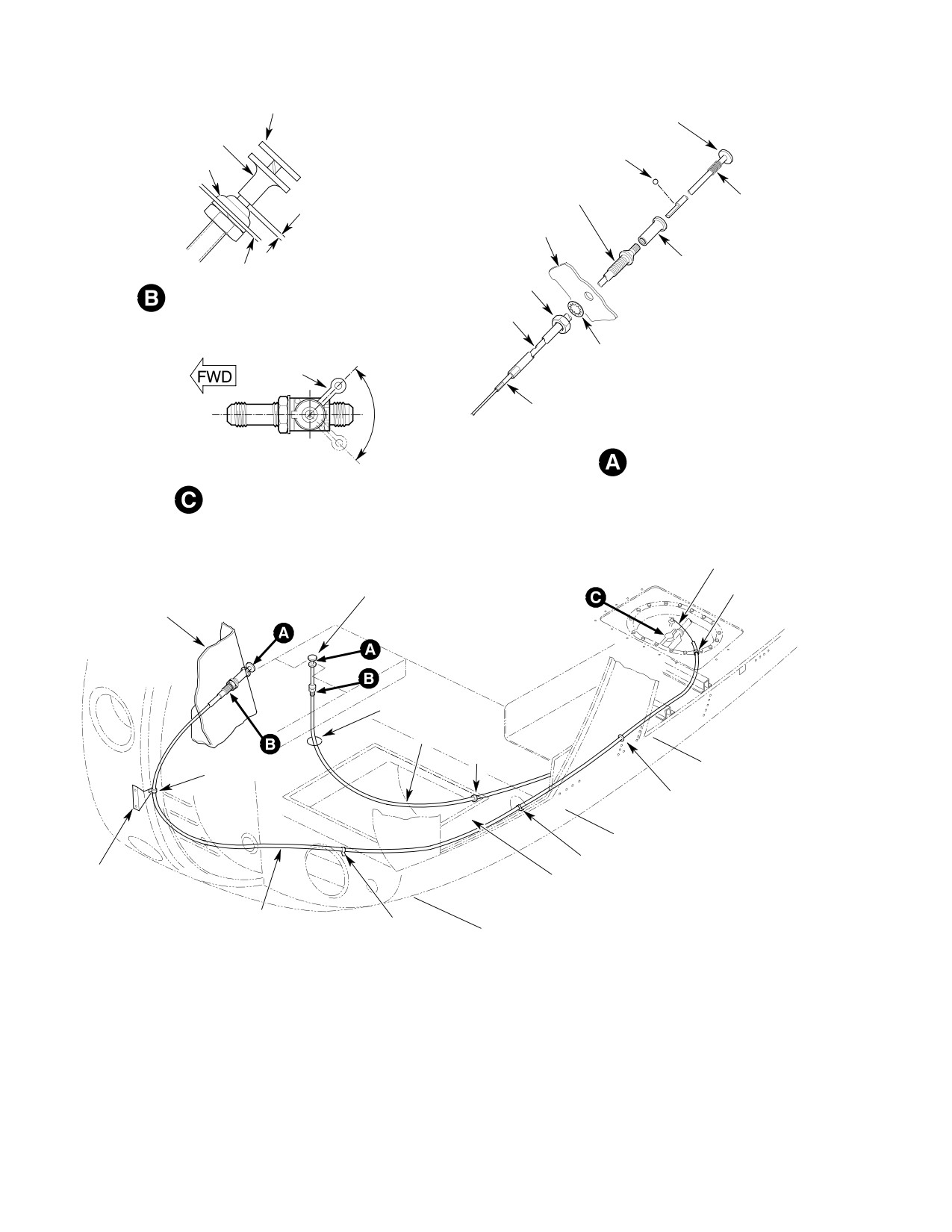
1. Fuel Shutoff Valve Control Cable
(1). Thread cable assembly aft through
Replacement
instrument panel or console, lockwash
er, jamnut and grommets to fuel shutoff
A. Fuel Shutoff Valve Control Cable
valve. Maintain a cable bend radius
Removal
greater than 3.5 inches (8.89 cm).
(Ref. Figure 401)
(2). Secure forward end of cable with
lockwasher and jamnut.
(1). Remove left fuel cell floor access panel.
(2). Disconnect control wire from fuel
(3). Slip control cable wire through fuel
shutoff valve swivel.
shutoff valve lever swivel.
(3). Remove control cable ty-raps and
(4). Secure end of cable housing to cell cover
clamps.
with a clamp, washer and screw.
(4). Remove instrument panel left fairing
(5). Install remaining clamps and ty-raps.
and lower cover panels (instrument
panel mounted).
(6). Rig cable with shutoff valve lever hard
against open stop. Adjust cable to get a
(5). Completely back jamnut away from
0.090-0.150 inch (2.286-3.810 mm) gap
cable plunger housing (Ref. Figure 401,
between bottom of control knob and
view A).
cable housing end fitting. Tighten cable
swivel pinch nut. Install cotter pin.
(6). Remove straps securing cable in nose
(instrument panel mounted) or remove
Control action must move valve
clamp in compartment under pilot's
CAUTION
to full open against mechanical
seat (console mounted).
stop without bottoming control knob on
cable housing. Control cable operation shall
NOTE: Attach a trace wire or cord to the valve
be smooth with no binding.
end of the cable before pulling assembly out
of the instrument panel. Trace will guide re
(7). Pull valve control knob out with a
placement cable into correct position.
spring scale. Required valve actuation
force to be not more than 12 pounds
(7). Pull cable assembly out through
(53.38 N).
washer, jamnut and instrument panel.
(8). Repair, adjust or replace valve control
B. Fuel Shutoff Valve Control Cable
system components to meet force limit.
Installation
(Ref. Figure 401)
(9). Reinstall left fuel cell floor access panel.
Pulling detent knob out of cable
(10). Reinstall instrument panel left fairing
CAUTION
housing two or more inches may
and lower cover panels (instrument
result in loss of the detent ball.
panel mounted).
Page 401
28-00-00
Revision 19
CSP-HMI-2
MD Helicopters, Inc.
MAINTENANCE MANUAL
DETENT RELEASE
DETENT RELEASE
CABLE PLUNGER
DETENT BALL
PLUNGER HOUSING
0.090-0.150 INCH
PLUNGER HOUSING
SPRING
(2.286-3.810 MM)
INSTRUMENT PANEL
CABLE PLUNGER
INSTRUMENT PANEL
NUT
CABLE RIGGING
HOLE
LOCKWASHER
OPEN
LEVER
CABLE HOUSING
L
CONTROL KNOB ASSEMBLY
CLOSED
FUEL SHUTOFF VALVE ORIENTATION
AND LEVER POSITIONS
(LOOKING DOWN)
CABLE WIRE
CONSOLE-MOUNTED
END CLAMP
CONTROL
INSTRUMENT
PANEL
GROMMET
FUEL SHUTOFF
CABLE
CLAMP
STRAP
STA. 78.50
NYLON GROMMET
STA. 64.36
STRAP
BRACKET
CREW COMPARTMENT
FLOOR
FUEL SHUTOFF
STRAP
CABLE
STA. 50.50
G28-0001A
Figure 401. Fuel Shutoff Valve Cable Installation
Page 402
Revision 19
28-00-00
MD Helicopters, Inc.
CSP-HMI-2
MAINTENANCE MANUAL
2. Fuel Shutoff Valve Replacement
(5). Unplug fuel quantity transmitter
connector from cell cover receptacle.
A. Fuel Shutoff Valve Removal
(Ref. Figure 402)
(6). Unclamp and disconnect control cable
from fuel shutoff valve.
Avoid fuel vapor ignition
WARNING
and fire. Use only nonspark
(7). Unfasten and remove Sta. 91.00 and
ing tools and explosion proof work
102.00 left fuel cell cover support
lights. Attach helicopter to an ap
brackets.
proved electrical ground. Switch OFF
all electrical power. Disconnect exter
nal power and battery before opening
CAUTION
fuel system. Ensure work area is ade
quately ventilated.
D Do not strain or bend fuel quantity trans
mitter float arm.
CAUTION
D Handle fuel cell cover with care. Prying
cover from cell opening or rough handling
D Air in fuel system may cause power
may damage seal or cell fitting.
surges or flameout. Bleed off trapped air
after opening system at any point be
tween fuel tank and engine fuel nozzle.
(8). Remove fuel quantity transmitter
flange screws. Lift transmitter assem
D Prevent fuel system contamination. In
bly out of cover opening.
stall caps on the ends of hoses, tubes and
fittings as parts are removed. Bag and
(9). Unbolt cell access cover. Prop cover
identify small parts to prevent loss or
open with suitably padded blocks.
damage.
(1). Defuel helicopter. Drain remaining fuel
(10). Using a backup wrench on valve,
from tank sump drain valve into a
separate fuel supply hose from fuel
suitable container.
shutoff valve.
(2). Remove left fuel tank access panel from
(11). Remove fuel shutoff valve and attach
passenger/cargo compartment floor.
ing hardware.
(3). Unclamp fuel supply tube between fuel
shutoff valve and Sta. 124.00 bulkhead
B. Fuel Shutoff Valve Installation
elbow. Using backup wrench on bulk
head elbow so it will not rotate, discon
(Ref. Figure 402)
nect and remove tube.
(4). With 250-C20B/R2 Engine or 250-C30
NOTE: Fuel shutoff valve installation steps are
Engine With Optional Maintenance
given in Fuel Cell Cover Installation proce
Fuel Pump: Unclamp start pump wire
dures.
harness and disconnect plug from cell
cover receptacle.
(Ref. Fuel Cell Cover Installation)
Page 403
28-00-00
Revision 44
CSP-HMI-2
MD Helicopters, Inc.
MAINTENANCE MANUAL
SCREW, TORQUE; 20-25 IN. LB
(2.26 - 2.82 NM) (TYP)
SETSCREW
CABLE
(NOTE)
WIRE
BOLT, TORQUE; 70-90 IN. LB
PIN
VALVE LEVER
(7.91 - 10.17 NM) (TYP)
AND SWIVEL
BUSHING
ELECTRICAL WIRING
HARNESS
ENGINE FEED HOSE
SUPPORT BRACKET (3
SHUTOFF VALVE TO
PLACES)
FIREWALL
TUBE NUT, TORQUE;
230-260 IN. LB (25.99 - 29.38 NM)
CONTROL
CABLE
CARGO
ELECTRICAL CONNECTOR
COMPARTMENT
FLOOR
FUEL SHUTOFF VALVE
SEAL WASHER
JAMNUT, TORQUE; 240-280 IN. LB
(27.12-31.64 NM)
HOSE NUT, TORQUE; 230-260 IN. LB
FUEL QUANTITY
(25.99-29.38 NM)
TRANSMITTER
FUEL INLET HOSE
ELECTRICAL
ELECTRICAL
RECEPTACLE
RECEPTACLE
START PUMP ELECTRICAL
WIRING HARNESS
NOTE:
REQUIRED AT LOCATION SHOWN.
G28-0002A
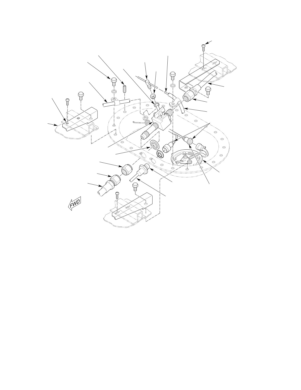
Figure 402. Left Fuel Cell Cover Installation
Page 404
Revision 19
28-00-00
MD Helicopters, Inc.
CSP-HMI-2
MAINTENANCE MANUAL
3. Fuel Tank Vent System Component
(7). Remove vent tube/emergency valve
Replacement
assembly attaching hardware. Remove
flexible tubing from lower vent tube tee.
Avoid fuel vapor ignition
WARNING
and fire. Use only nonspark
(8). Rotate emergency shutoff valve inboard
ing tools and explosion proof work
and slip assembly down over landing
lights. Attach helicopter to an ap
gear structure. Remove tube assembly
proved electrical ground. Switch OFF
through controls access panel opening.
all electrical power. Disconnect exter
nal power and battery before opening
(9). Unclamp flexible tubing from side vent
fuel system. Ensure work area is ade
fairing. Remove tubing through controls
quately ventilated.
access opening.
Prevent fuel system contamina
B. Forward Vent Crossover Fitting Removal
CAUTION
tion. Install caps on the ends of
(Ref. Figure 403)
hoses, tubes and fittings as parts are re
moved. Bag and identify small parts to pre
(1). Unbolt forward vent crossover fitting
vent loss or damage.
flanges.
(1). Defuel helicopter. Drain remaining fuel
(2). Remove fitting, clamps, seals and
from tank sump drain valve into a
washers.
suitable container.
(3). Cover cell vent fittings and aft vent line
Prevent spontaneous com
WARNING
tube openings.
bustion or explosion. Never
use oxygen to purge or ventilate fuel
C. Aft Vent Crossover Fitting Removal
tank or fuel system components. Fuel,
either vapor or liquid, will violently
(Ref. Figure 403)
react with an oxygen rich atmosphere.
NOTE: Left and right fuel cell access covers
(2). Ventilate fuel tank with an inert gas,
must be removed to get at aft vent crossover
such as nitrogen, or low pressure
U-tube attaching hardware.
compressed air applied through filler
neck.
(1).
Remove left and right fuel cell floor
access panels.
A. Vent Tube/Emergency Valve Assembly
Removal
(2).
Unclamp fuel supply tube between fuel
shutoff valve and Sta. 124.00 bulkhead
(Ref. Figure 403)
elbow. Using backup wrench on bulk
head elbow so it will not rotate, discon
(1). Unbolt and remove right fuel cell access
nect and remove tube.
cover.
(3).
With 250-C20 Series Engines or
(2). Remove right foot support, controls,
250-C30 Engine With Optional Mainte
and fuel vent access panels.
nance Fuel Pump: Unclamp start pump
(3). Remove right seat from crew compart
wire harness and disconnect plug from
ment.
cell cover receptacle.
(4). Move collective pitch stick full down.
(4).
Unplug fuel quantity transmitter
connector from cell cover receptacle.
(5). In passenger/cargo compartment;
remove right and left fuel tank floor
(5).
Unclamp and disconnect control cable
access panels.
from fuel shutoff valve.
(6). Remove lockwire from vent connector
(6).
Unfasten and remove Sta. 91.00 and
hoses and main rotor mast pan drain
102.00 left fuel cell cover support
tube.
brackets.
Page 405
28-00-00
Revision 44
CSP-HMI-2
MD Helicopters, Inc.
MAINTENANCE MANUAL
PAN
DRAIN TUBE
LOCKWIRE
CLIP
(2 PLACES)
BOLT
WASHER
LACING CORD
(TYPICAL)
WASHER
BOLT
CLAMP
BOLT
WASHER
WASHER
NUT
FROM AFT VENT
VENT TUBE
SCREW
LOCKWIRE
(TYPICAL)
WASHER
CONNECTOR HOSE
BOLT, TORQUE; 36-46 IN. LB
SIDE VENT FAIRING
(NOTE 2)
(4.06-5.20 NM)
WASHER
CLAMPS
SCREW
SUPPORT COIL
CLIP
WASHER
FUEL VENT
ANTI-SIPHON
COVER
HOLES
INTERCONNECT
FLEXIBLE TUBING
FITTING
(NOTE 1)
SEAL WASHER
STAND-OFF
SEAL WASHER
WASHER (TYP)
LOWER VENT FAIRING
FWD INTERCONNECT AND
NOTES:
EMERGENCY VALVE ASSY
1.
ROUTED THRU LANDING GEAR BRACE.
2.
NOT TO BE PAINTED.
G28-0003-1B
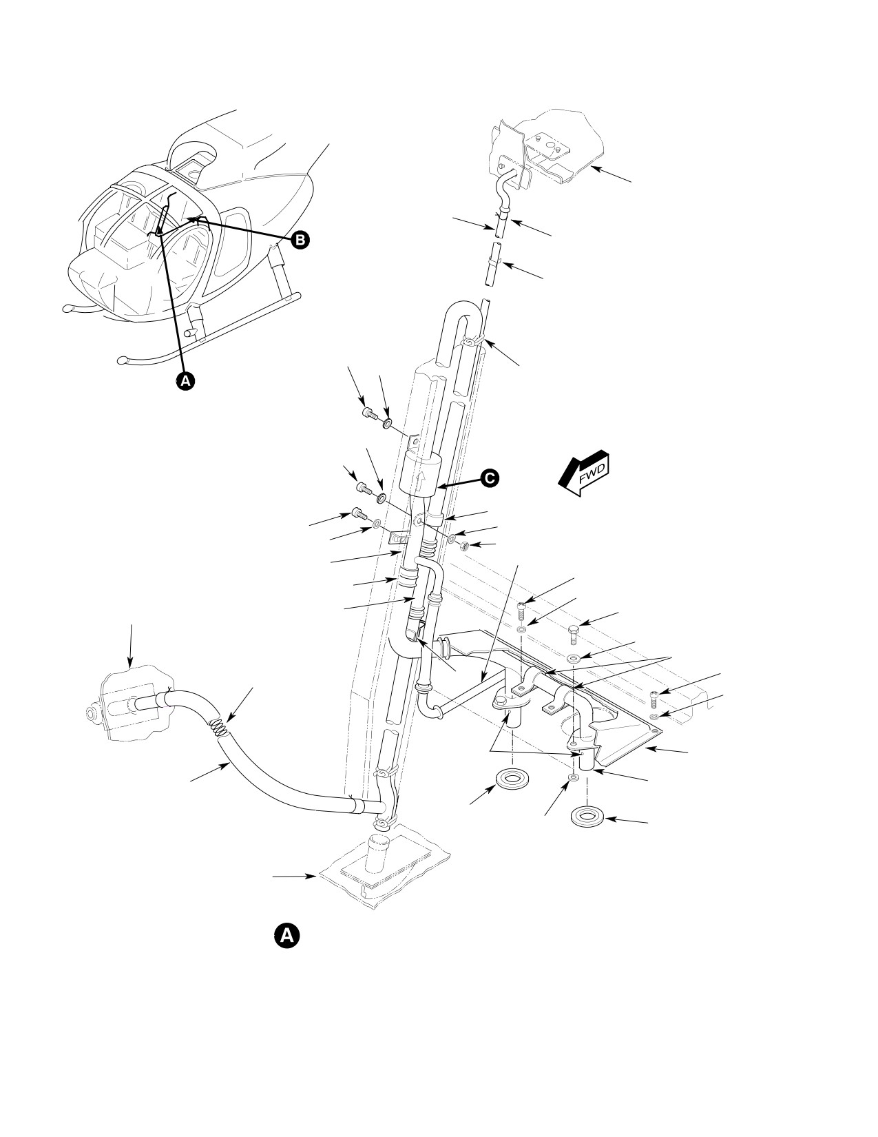
Figure 403. Vent System (Sheet 1 of 2)
Page 406
TR13-001
28-00-00
MD Helicopters, Inc.
CSP-HMI-2
MAINTENANCE MANUAL
VALVE CLOSED WHEN TILT
EXCEEDS 45° FROM VERTICAL
CLAMP
INTERCONNECT
OVERBOARD
HOSE
VALVE SEAT
SEAL WASHER
VALVE
CELL
TUBE
(REF)
WEIGHT
FUEL VENT
IN
NUT, TORQUE; 40-60 IN. LB
(4.52-6.78 NM)
G28-0003-2B
EMERGENCY VENT
AFT INTERCONNECT
SHUTOFF VALVE
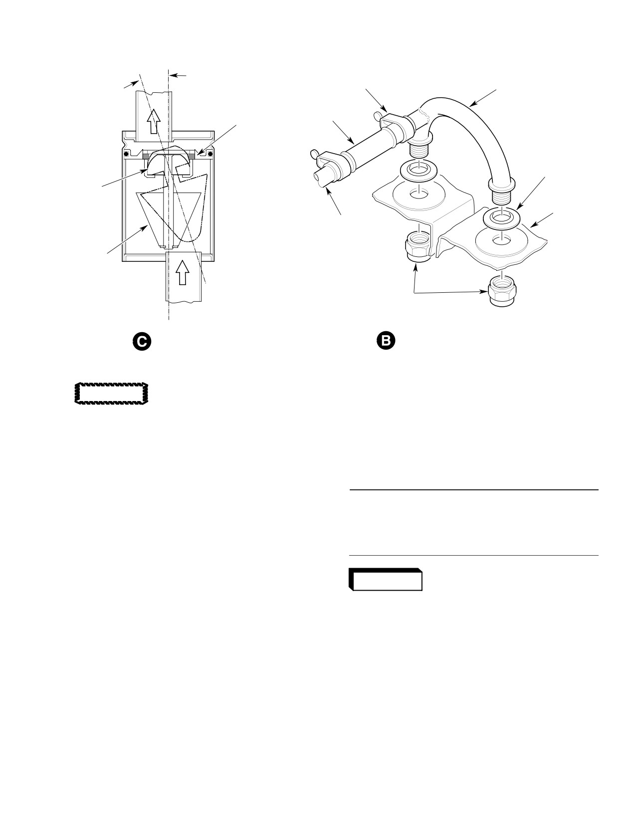
Figure 403. Vent System (Sheet 2 of 2)
(12). Cap tube and cell openings.
CAUTION
(13). Inspect all vent system components
D Do not strain or bend fuel quantity trans
(Ref. Fuel Tank Vent System Inspec
mitter float arm.
tion).
D Do not damage cell cover bonded seal.
D. Fuel Tank Vent System Installation
Handle fuel cell covers with care. Prying
covers from cell openings or rough handl
(Ref. Figure 403)
ing may damage seal or cell fitting.
Consumable Materials
(7). Remove fuel quantity transmitter
(Ref. Section 91−00−00)
flange screws. Lift transmitter assem
Item
Nomenclature
bly out of cover opening.
CM124
Kerosene
(8). Unbolt and prop fuel cell access cover
open with suitably padded blocks.
Avoid fuel vapor ignition
WARNING
and fire. Use only nonspark
(9). Use a backup wrench on valve and
ing tools and explosion proof work
separate fuel supply hose from fuel
lights. Attach helicopter to an ap
shutoff valve. Move fuel cell cover to get
proved electrical ground. Switch OFF
at remaining hardware.
all electrical power. Disconnect exter
nal power and battery before opening
(10). Reach back inside cells and remove
fuel system. Ensure work area is ade
vent interconnect nuts. Separate aft
quately ventilated.
U-tube interconnect from cells.
(1). Wipe forward and aft cell vent
(11). Unclamp and remove hose between
fittings and crossover tube flanges
U-tube interconnect tee and straight
clean with kerosene (CM124) or
tube. Remove U-tube interconnect.
equivalent on a clean shop towel.
Discard sealwashers.
Wipe dry.
Page 407
28-00-00
Revision 19
CSP-HMI-2
MD Helicopters, Inc.
MAINTENANCE MANUAL
NOTE: Do not lubricate fitting sealwashers.
E. Vent Tube/Emergency Valve Assembly
Lubricants may cause seal cold flow and
Installation
subsequent leakage.
(Ref. Figure 403)
(2). Install new sealwashers on aft vent
(1).
Move collective pitch stick full down.
tube ends. Insert tube ends through cell
fittings. Reach inside cell and install
(2).
Remove protective covers from fittings
nuts.
and tubes.
(3). Torque aft vent U-tube interconnect
(3).
Work emergency valve and vent tube
nuts to 40 - 60 inch-pounds (4.52 -
assembly through landing gear brace
6.78 Nm).
then into position in tunnel.
(4). Install hose and clamps between
(4).
Insert vent tube assembly in bottom
interconnect U-tube and straight tube.
vent fairing.
(5). Position new sealwashers on cell
(5).
Loosely install vent tube support
forward vent fittings. Slip vent tube
clamps, washers and bolts.
into cell fitting.
(6).
Install flexible tubing between side vent
NOTE: Permatex Form-A-Gasket No.1 may be
fairing and vent tube assembly tee.
used to hold metal stand-off washers in
place.
(7).
Clamp flex tube ends in position with
two or three wraps of lockwire.
(6). Sandwich one AN960-10 washer on
each side of seal washer between vent
(8).
Tighten vent tube assembly support
tube flanges and cell fittings. Align
clamp and bracket fasteners.
washers with bolt holes. Install bolts
with one washer under each bolt head.
(9).
Install and secure remaining vent
system connector hoses with lockwire.
(7). Torque forward vent interconnect tube
flange bolts to 36 - 46 inch-pounds
(10).
Operate all flight controls through full
(4.07 - 5.20 Nm).
range of motion to ensure no interfer
ence exists between control linkages
(8). Connect powerplant supply tube to Sta.
and vent system. No interference is
124.00 bulkhead elbow. Loosely install
allowed. Adjust vent system hardware
tube support clamps, screws, washers
as required.
and nuts. Using backup wrench on
bulkhead elbow so it will not rotate,
(11).
Install fuel vent access panel.
torque tube nut to 230 - 260 inch-
pounds (25.99 - 29.38 Nm).
(12).
Install controls access and foot support
panels.
(9). Install fuel cell covers (Ref. Fuel Cell
Cover Installation).
(13).
Install crew seat.
Page 408
Revision 19
28-00-00
MD Helicopters, Inc.
CSP-HMI-2
MAINTENANCE MANUAL
4. Fuel Supply Lines Replacement
(4). Apply a torque alignment stripe to fuel
line tube, hose and fitting fasteners.
A. Fuel Supply Lines Removal
5. Start Pump Replacement (Model
(Ref. Figure 404)
250−C20B/R2 / 250−C30 Engine Installation)
Avoid fuel vapor ignition
WARNING
and fire. Use only nonspark
NOTE: Use these start pump removal and
ing tools and explosion proof work
installation procedures for helicopters with
lights. Attach helicopter to an ap
250-C30 engines equipped with optional
proved electrical ground. Switch OFF
maintenance fuel pump.
all electrical power. Disconnect exter
nal power and battery before opening
A. Start Pump Removal
fuel system. Ensure work area is ade
(Ref. Figure 404)
quately ventilated.
Avoid fuel vapor ignition
CAUTION
WARNING
and fire. Use only nonspark
ing tools and explosion proof work
D Air in fuel system may cause power
lights. Attach helicopter to an ap
surges or flameout. Bleed off trapped air
proved electrical ground. Switch OFF
after opening system at any point be
all electrical power. Disconnect exter
tween fuel tank and engine fuel nozzle.
nal power and battery before opening
D Prevent fuel system contamination. In
fuel system. Ensure work area is ade
stall caps on the ends of hoses, tubes and
quately ventilated.
fittings as parts are removed. Bag and
identify small parts to prevent loss or
Prevent fuel system contamina
CAUTION
damage.
tion. Install caps on the ends of
hoses, tubes and fittings as the parts are re
(1). Defuel helicopter. Drain remaining fuel
moved. Bag and identify small parts to pre
from tank sump drain valve into a
vent loss or damage.
suitable container.
(1).
Defuel helicopter. Drain remaining fuel
(2). Disconnect, remove and cap fittings and
from tank sump drain valve into a
lines as required.
suitable container.
B. Fuel Supply Lines Installation
(2).
Remove left fuel tank access panel from
(Ref. Figure 404)
passenger/cargo compartment floor.
(1). Install and torque engine fuel supply
(3).
Unclamp fuel supply tube between fuel
lines (Ref. Table 401).
shutoff valve and Sta. 124.00 bulkhead
NOTE: It may be necessary to install a peelable
elbow. Using backup wrench on bulk
shim washer between the Sta. 124.00 fire
head elbow so it will not rotate, discon
wall and the bulkhead elbow washer to ob
nect and remove tube.
tain the proper clocking angle and clearance
(4).
Unclamp start pump wire harness and
needed for line installation.
disconnect plug from cell cover recep
(2). Install Sta. 124.00 firewall elbow, with
tacle.
jam nut on forward side of firewall, flat
of nut against stiffener, and washer
(5).
Unplug fuel quantity transmitter
against elbow. Torque elbow to 145 -
connector from cell cover receptacle.
155 inch-pounds (16.38 - 17.51 Nm).
(6).
Unclamp and disconnect control cable
Ensure elbow is clocked 12° - 16° to the
from fuel shutoff valve.
right from vertical after torquing.
(3). Connect flexible drain lines to drain
(7).
Unfasten and remove Sta. 91.00 and
valves and clamp in place with lock
102.00 left fuel cell cover support
wire.
brackets.
Page 409
28-00-00
Revision 44

CSP-HMI-2
MD Helicopters, Inc.
MAINTENANCE MANUAL
Table 401. Fuel Line Torque Values
Torque
Item/Position
Inch−Pounds (Nm)
Tube end−nuts; fuel shutoff valve; Sta. 124.00 Bulkhead elbow
230 − 260 (25.99 − 29.38)
Bulkhead elbow jamnut; Sta. 124.00
145 − 155 (16.38 − 17.51)
Three−port elbow jamnut; Sta. 124.00 (if equipped)
145 − 155 (16.38 − 17.51)
Drain valves (all)
95 − 105 (10.73 − 11.86)
Hose end−nuts; firewall/engine
230 − 260 (25.99 − 29.38)
pressure port union threads. Install
CAUTION
O-ring on union. Install union in start
pump pressure port and torque to 280 -
D Do not strain or bend fuel quantity trans
305 inch-pounds (31.64 - 34.46 Nm).
mitter float arm.
D Handle fuel cell covers with care. Prying
(2). Attach fuel supply hose to start pump
covers from cell openings or rough handl
pressure port union. Torque hose nut to
ing may damage the cover seal or cell fit
230 - 260 inch-pounds (25.99 - 29.38
ting.
Nm).
(8). Remove fuel quantity transmitter
flange screws. Lift transmitter assem
CAUTION
bly out of cover opening.
D Ensure start pump wire lead is wrapped
(9). Unbolt and prop fuel cell access cover
around or tie-wrapped to fuel supply hose
open with suitably padded blocks.
so that there is no possibility of its interf
ering with fuel quantity transmitter float
(10). Use a backup wrench on valve and
mechanism. Ensure electrical connec
separate fuel supply hose from fuel
tions will not be strained by G-induced
shutoff valve.
hose movements.
(11). Remove pump electrical receptacle from
D Do not mark torque alignment stripes on
cover. Remove fuel cell cover.
fuel cell internal hardware.
(12). Unbolt fuel pump from sump mount
NOTE: Use only MS3367 ty-raps inside fuel
plate. Remove fuel pump and hose.
tanks.
(13). Remove hose and union from pump
(3). Tie-wrap or wrap pump wire around
pressure port.
supply hose. Secure wire with ty-raps
as required.
B. Start Pump Installation
(4). Clean start pump and sump plate
(Ref. Figure 404)
mount contact surfaces to establish an
electrical bond per requirements of FAA
Consumable Materials
publication, EA-AC43.13-1A and 2A.
(Ref. Section 91−00−00)
Item
Nomenclature
(5). Install start pump on sump plate with
bolts and washers. Torque bolts to 36 -
CM114
Petrolatum
46 inch-pounds (4.07 - 5.20 Nm).
(1). Apply a thin coat of petrolatum
(6). Install fuel cell cover (Ref. Fuel Cell
(CM114) to a new O-ring and pump
Cover Installation).
Page 410
Revision 19
28-00-00
MD Helicopters, Inc.
CSP-HMI-2
MAINTENANCE MANUAL
TO ENGINE
HOSE AND FIRE
SLEEVE
WASHER
SHIM WASHER
(AS REQ'D)
NUT
HOSE ELBOW
STA 124.00
BULKHEAD
SUPPLY TUBE
HOSE
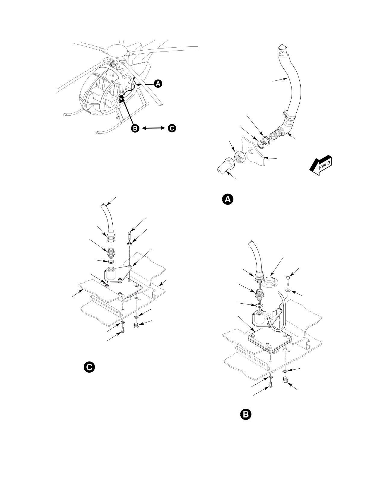
FUEL SUPPLY LINES INSTALLATION
BOLT, TORQUE; 36-46 IN. LB
HOSE NUT, TORQUE;
(4.06-5.20 NM)
230-260 IN. LB
(25.99-29.38 NM)
WASHER
UNION, TORQUE;
280-305 IN. LB
FUEL PICKUP FITTING
(31.64-34.46 NM)
STARTER PUMP
HOSE NUT, TORQUE;
O-RING
230-260 IN. LB
BOLT, TORQUE; 36-46 IN. LB
(25.99-29.38 NM)
TANK SUMP PLATE
(4.06-5.20 NM)
STRUCTURE
UNION, TORQUE;
280-305 IN. LB
(31.64-34.46 NM)
WASHER
FUEL CELL
O-RING
O-RING
TANK SUMP PLATE
TANK SUMP DRAIN VALVE,
TORQUE; 95-105 IN. LB
(10.73-11.86 NM)
WASHER
BOLT, TORQUE; 36-46 IN. LB
(4.06-5.20 NM)
FUEL PICKUP INSTALLATION (369FF)
O-RING
WASHER
TANK SUMP DRAIN VALVE,
BOLT, TORQUE; 36-46 IN. LB
TORQUE; 95-105 IN. LB
(4.06-5.20 NM)
(10.73-11.86 NM)
START PUMP INSTALLATION
G28-0004-1C
Figure 404. Start Pump and Fuel Lines Installation (Sheet 1 of 4)
Page 411
28-00-00
Revision 19
CSP-HMI-2
MD Helicopters, Inc.
MAINTENANCE MANUAL
TOP VIEW
FUEL HOSE
BATHTUB FITING
START PUMP WIRE
FLOAT ASSEMBLY
START PUMP
SIDE VIEW
NOTE:
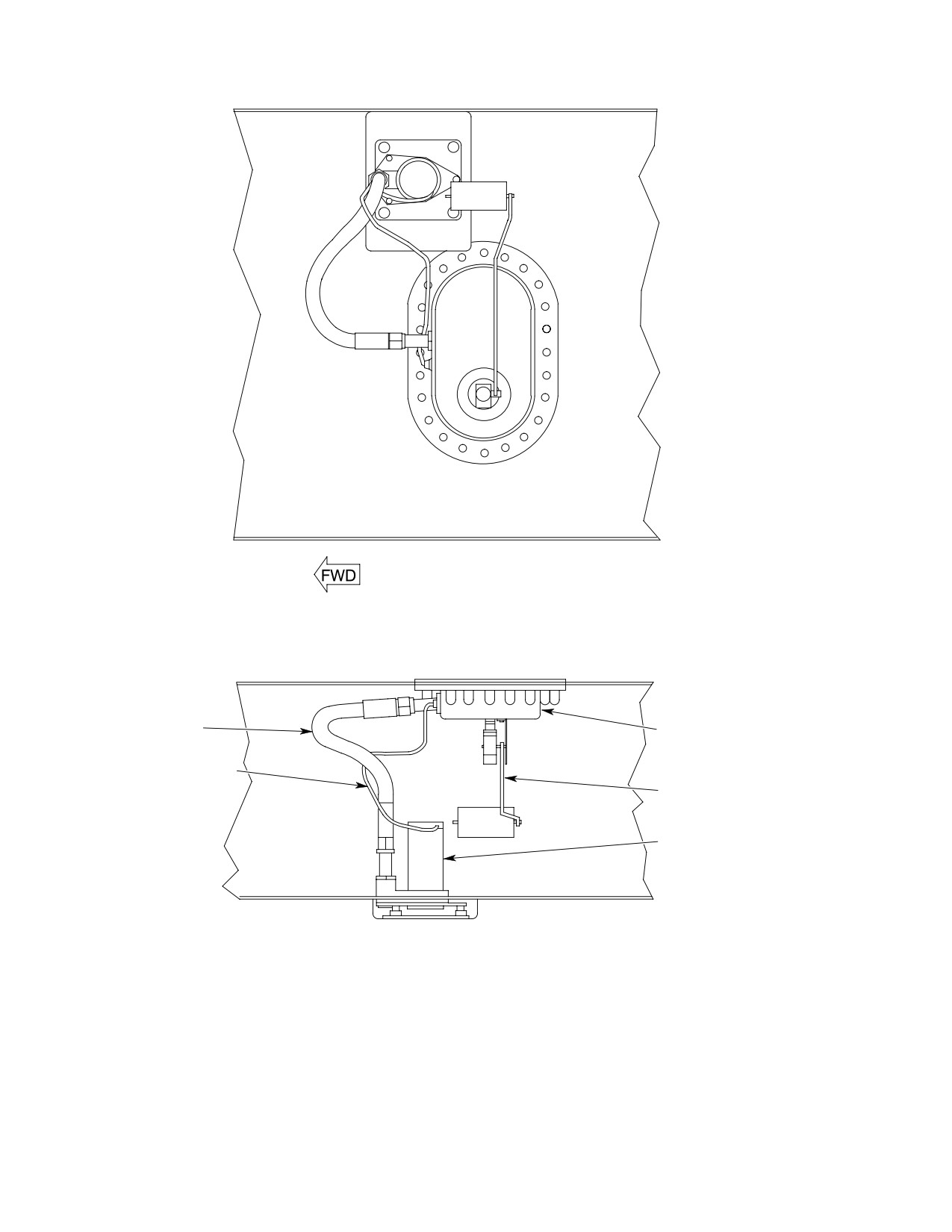
WRAP WIRE AROUND FUEL INLET HOSE TO PREVENT
INTERFERENCE WITH FLOAT.
G28-0004-2
Figure 404. Start Pump and Fuel Lines Installation (Sheet 2 of 4)
Page 412
Revision 19
28-00-00
MD Helicopters, Inc.
CSP-HMI-2
MAINTENANCE MANUAL
TOP VIEW
FUEL HOSE
BATHTUB FITING
START PUMP WIRE
FLOAT ASSEMBLY
START PUMP
SIDE VIEW
NOTE:
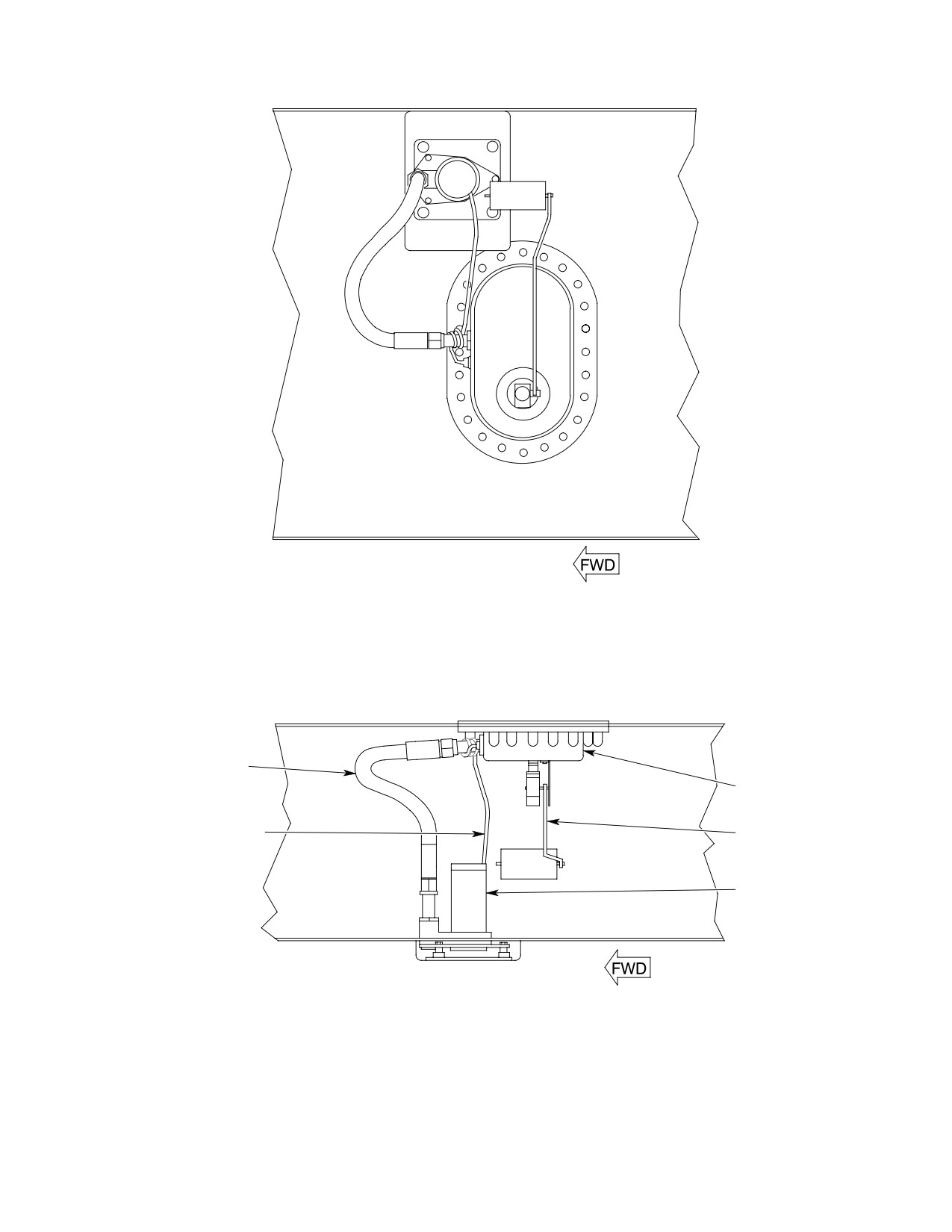
WRAP WIRE AROUND FUEL INLET HOSE TO PREVENT
INTERFERENCE WITH FLOAT.
G28-0004-3
Figure 404. Start Pump and Fuel Lines Installation (Sheet 3 of 4)
Page 413
28-00-00
Revision 19
CSP-HMI-2
MD Helicopters, Inc.
MAINTENANCE MANUAL
TOP VIEW
FUEL HOSE
BATHTUB FITING
START PUMP WIRE
FLOAT ASSEMBLY
START PUMP
SIDE VIEW
NOTE:
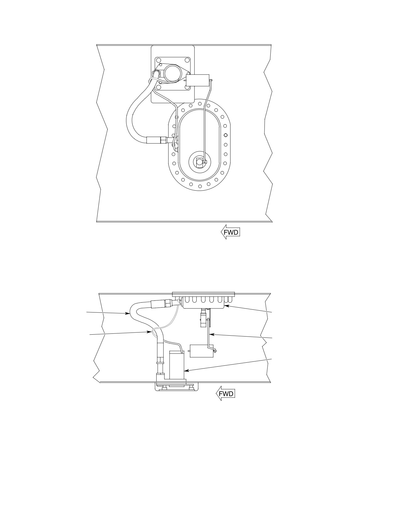
WRAP WIRE AROUND FUEL INLET HOSE TO PREVENT
INTERFERENCE WITH FLOAT.
G28-0004-4
Figure 404. Start Pump and Fuel Lines Installation (Sheet 4 of 4)
Page 414
Revision 19
28-00-00

MD Helicopters, Inc.
CSP-HMI-2
MAINTENANCE MANUAL
6. Fuel Quantity Transmitter Replacement
(7). Calibrate quantity transmitter as
required (Ref. Fuel Quantity Transmit
A. Fuel Quantity Transmitter Removal
ter Calibration and Adjustment).
(Ref. Figure 404)
B. Fuel Quantity Transmitter Installation
Avoid fuel vapor ignition
(Ref. Figure 404)
WARNING
and fire. Use only nonspark
ing tools and explosion proof work
Consumable Materials
lights. Attach helicopter to an ap
(Ref. Section 91−00−00)
proved electrical ground. Switch OFF
Item
Nomenclature
all electrical power. Disconnect exter
CM124
Kerosene
nal power and battery before opening
fuel system. Ensure work area is ade
quately ventilated.
(1). Wipe fuel quantity transmitter flange
and cell fitting clean with kerosene
(1). Defuel helicopter. Drain remaining fuel
(CM124) on a clean lint free cloth. Wipe
from tank sump drain valve into a
parts dry.
suitable container.
(2). Position fuel quantity transmitter and
Prevent spontaneous com
flange gasket on cell with float inboard
WARNING
bustion or explosion. Never
and clear of obstructions.
use oxygen to purge or ventilate fuel
tank or fuel system components. Fuel,
(3). Install screws and washers. Progres
either vapor or liquid, will violently
sively torque screws to 20 - 25 inch-
react with an oxygen rich atmosphere.
pounds (2.26 - 2.82 Nm). Lockwire
screws.
(2). Ventilate fuel tank with an inert gas
such as nitrogen or low pressure
(4). Attach fuel quantity electrical connec
compressed air applied through filler
tor to receptacle. Lockwire connector.
neck.
(5). Perform a Fuel Quantity Transmitter
(3). Remove left fuel tank access panel from
Functional Check.
passenger/cargo compartment floor.
(6). Install left fuel tank floor access panel
(Ref. Fuel Cell Cover Installation).
(4). Unplug fuel quantity transmitter
connector from cell cover receptacle.
7. Fuel System Drain Valve Replacement
Unclamp wire harness.
A. Fuel System Drain Valve Removal
CAUTION
Avoid fuel vapor ignition
WARNING
and fire. Use only nonspark
D Do not strain or bend fuel quantity trans
ing tools and explosion proof work
mitter float arm.
lights. Attach helicopter to an ap
D Prevent fuel system contamination. In
proved electrical ground. Switch OFF
stall a cover over quantity transmitter
all electrical power. Disconnect exter
cell opening. Bag small parts to prevent
nal power and battery before opening
loss or damage.
fuel system. Ensure work area is ade
quately ventilated.
(5). Remove fuel quantity transmitter
flange screws. Lift transmitter assem
Helicopter must be defueled and
CAUTION
bly out of cover opening. Discard
drained prior to removing tank
gasket.
sump drain valve.
(6). Inspect fuel quantity transmitter as
(1). Defuel helicopter, as required. Drain
required (Ref. Fuel Quantity Transmit
remaining fuel from tank sump drain
ter Inspection).
valve into a suitable container.
Page 415
28-00-00
Revision 36
CSP-HMI-2
MD Helicopters, Inc.
MAINTENANCE MANUAL
(2). Remove lockwire from tank sump drain
A. Fuel Cell Removal
valve.
Avoid fuel vapor ignition
WARNING
and fire. Use only nonspark
(3). Using appropriate socket or wrench,
ing tools and explosion proof work
remove drain valve.
lights. Attach helicopter to an ap
proved electrical ground. Switch OFF
B. Fuel System Drain Valve Installation
all electrical power. Disconnect exter
nal power and battery before opening
Consumable Materials
fuel system. Ensure work area is ade
(Ref. Section 91−00−00)
quately ventilated.
Item
Nomenclature
Prevent fuel system contamina
CM114
Petrolatum
CAUTION
tion. Install caps on the ends of
CM124
Kerosene
hoses, tubes and fittings as parts are re
moved. Bag and identify small parts to pre
CM702
Lockwire CRES
vent loss or damage.
(1). Defuel helicopter. Drain remaining fuel
(1).
Replace drain valve O-ring packings.
from tank sump drain valve into a
Lubricate packings with kerosene
suitable container.
(CM124), petrolatum (CM114) or jet
fuel.
Prevent spontaneous com
WARNING
bustion or explosion. Never
(2).
Install and torque sump drain valve to
use oxygen to purge or ventilate fuel
95 - 105 inch-pounds (10.73 - 11.86
tank or fuel system components. Fuel,
Nm). Lockwire valve.
either vapor or liquid, will violently
react with an oxygen rich atmosphere.
(3).
Apply a torque alignment stripe to fuel
(2). Ventilate fuel tank with low pressure
line tube, hose and fitting fasteners.
forced air or an inert gas such as
nitrogen through filler neck.
(4).
Refuel helicopter.
(3). Remove right and left fuel tank access
(5).
Check drain valve for leakage.
panels from passenger/cargo compart
ment floor.
(6).
Apply external power.
NOTE: The following procedures are required
(7).
In crew compartment; set battery
to access and separate the fuel cell intercon
switch to EXT PWR position.
nect fitting and vent system aft crossover
before either cell can be removed from its
(8).
Push fuel shutoff valve control knob in
bay.
to open valve.
(4). Unclamp fuel supply tube between fuel
shutoff valve and firewall Sta. 124.00
(9).
With 250-C20B/R2 Engine: Set START
bulkhead elbow. Using a backup
PUMP switch ON to pressurize fuel
wrench on bulkhead elbow so it will not
system.
rotate, disconnect and remove tube.
8.
Fuel Cell Replacement
(5). With 250-C20B/R2 Engine or 250-C30
Engine With Optional Maintenance
Fuel Pump: Unclamp start pump wire
CAUTION
harness and disconnect plug from cell
cover receptacle.
D Do not work on Uniroyal fuel cell in ambi
ent temperatures below 50°F (10°C).
(6). Unplug fuel quantity transmitter
connector from cell cover receptacle.
D Do not work on Engineering Fabric Corp.
fuel cell in ambient temperatures below
(7). Unclamp and disconnect control cable
70°F (21°C).
from fuel shutoff valve.
Page 416
Revision 44
28-00-00
MD Helicopters, Inc.
CSP-HMI-2
MAINTENANCE MANUAL
(8). Unfasten and remove Sta. 91.00 and
NOTE: At this point either cell may be re
102.00 left fuel cell cover support
moved, as required.
brackets from airframe structure.
(19). Remove left fuel cell as follows:
CAUTION
(a). Remove cell suspension cords (Ref.
Figure 406).
D Do not strain or bend fuel quantity trans
mitter float arm.
(b). Remove and discard forward and aft
vent sealwashers.
D Handle fuel cell covers with care. Prying
covers from cell openings or rough handl
(c). Lift inboard and outboard cell clips at
ing may damage the cover seal or cell fit
each end of baffle support rod out of
ting.
airframe hangers (Ref. Figure 405).
(9).
Remove fuel quantity transmitter
(d). Inside cell, work baffle support rod
flange screws. Lift transmitter assem
ends out of cell nipples (Ref.
bly out of cover opening.
Figure 405, detail B).
(10).
Unbolt and prop fuel cell access cover
(e). Remove support rod and baffle.
open with suitably padded blocks.
Cells are thin-walled and frag
CAUTION
(11).
Using a backup wrench on valve,
ile. Avoid snagging or dragging
separate fuel supply hose from fuel
cell over pointed or sharp edges. Do not
shutoff valve. Move fuel cell cover to get
scratch or nick any of the cell's metal fit
at remaining hardware.
tings.
(12).
With 250-C20B/R2 Engine or 250-C30
(f). Collapse and fold cell lengthwise and
Engine With Optional Maintenance
remove through floor access opening.
Fuel Pump: Unbolt start pump from
sump mount plate. Remove start pump,
(20). Remove right fuel cell as follows:
hose and cell cover. Remove pump
(a). Remove fuel filler cap and shield.
electrical receptacle from cover.
Unclamp and remove filler from cell
(13).
With 250-C30 Engine: Unbolt fuel inlet
filler neck.
fitting from sump plate. Remove fuel
(b). Remove cell suspension cords.
inlet fitting, hose and cell cover.
(c). Remove and discard forward and aft
(14).
Unbolt and remove right fuel cell access
vent sealwashers.
cover.
(d). Lift inboard and outboard cell clips at
(15).
Mop up any remaining fuel in both cells
each end of baffle support rod out of
with clean lint free cloth. Purge fuel
airframe hangers.
cells with dry, forced air or inert gas.
(e). Inside cell, work baffle support rod
(16).
Have an assistant hold the male end of
ends out of cell nipples.
the cell interconnect fitting with the
special spanner wrench. Disassemble
(f). Remove support rod and baffle.
fuel cell interconnect fitting (Ref.
Figure 405). Discard packing.
Cells are thin-walled and frag
CAUTION
ile. Avoid snagging or dragging
(17).
Remove aft vent crossover U-tube nuts
cell over pointed or sharp edges. Do not
from inside cells.
scratch or nick any of the cell's metal fit
tings.
(18).
Remove forward vent crossover tube
flange bolts and washers (Ref.
(g). Collapse and fold cell lengthwise and
Figure 403).
remove through floor access opening.
Page 417
28-00-00
Revision 44
CSP-HMI-2
MD Helicopters, Inc.
MAINTENANCE MANUAL
B. Fuel Cell Installation
(6). Insert baffle rod ends in nipples.
(7). Attach baffle external support hooks to
Consumable Materials
airframe hangers.
(Ref. Section 91−00−00)
Item
Nomenclature
(8). Wipe cell forward and aft vent fittings
and vent tube flanges clean with
CM114
Petrolatum
kerosene (CM124) or equivalent on a
CM124
Kerosene
clean shop towel. Wipe dry.
CM809
Nylon cord
NOTE: Do not lubricate fitting sealwashers.
Lubricants may cause seal cold flow and
Special Tools
subsequent leakage.
(Ref. Section 91−00−00)
Item
Nomenclature
(9). Install new sealwashers on aft vent
ST802
Spanner wrench
tube ends. Insert tube ends through cell
fittings and install nuts finger tight. Do
not torque at this time.
Avoid fuel vapor ignition
WARNING
(10). Position new sealwashers on cell
and fire. Use only nonspark
forward vent fittings. Slip cell fitting
ing tools and explosion proof work
lights. Attach helicopter to an ap
over vent tube.
proved electrical ground. Switch OFF
NOTE: Permatex Form-A-Gasket No. 1 may
all electrical power. Disconnect exter
be used to hold stand-off washers in place.
nal power and battery before opening
fuel system. Ensure work area is ade
(11). Sandwich one AN960-10 washer on
quately ventilated.
each side between vent tube flanges
and cell fittings. Align washers with
NOTE:
bolt holes. Install bolts with one washer
D Discard used O-rings and sealwashers.
under each bolt head and engage
Apply a thin coat of petrolatum (CM114)
several threads to keep bolt in place. Do
to all new O-rings except cell vent system
not torque bolts at this time.
sealwashers and interconnect fitting gas
(12). Fasten fuel cell sump plate to airframe
ket.
with washers and bolts. Torque bolts to
D Always test and inspect a repaired fuel
36 - 46 inch-pounds (4.07 - 5.20
cell for leaks using soap bubble, phe
Nm). Lockwire bolts.
nolphthalein or liquid stand method be
fore installing the cell in the helicopter.
(13). Install a new O-ring on sump drain
valve. Install valve and torque to 95 -
(1). Air-vacuum all debris from cell bays.
105 inch-pounds (10.73 - 11.86 Nm).
Ensure compartment liner will protect
Lockwire valve.
cell from airframe points and edges.
Repair liner as required.
NOTE: Do not lubricate fuel cell interconnect
fitting gasket. Lubrication may cause seal
(2). Wipe left and right cell interconnect
cold flow and subsequent leakage.
fitting halves clean with kerosene
(14). Thread gasket and nut onto cell
(CM124) on a clean lint free shop towel.
interconnect fitting. While having an
Wipe dry.
assistant hold the opposite end of
(3). Fold cell lengthwise and position in bay
fitting with spanner wrench (ST802)
through floor opening and unfold cell.
tighten nut. Gap between nut and
female fitting shall not be more than
(4). Align cell openings with airframe
0.005 inch (0.127 mm) after tightening.
openings.
(15). Connect powerplant supply tube to
(5). Insert baffle support rods through
firewall Sta. 124.00 bulkhead elbow.
baffle tabs (Ref. Figure 405)..
Loosely install tube support clamps,
Page 418
Revision 19
28-00-00
MD Helicopters, Inc.
CSP-HMI-2
MAINTENANCE MANUAL
screws, washers and nuts (Ref.
(24). Install filler on right fuel cell filler neck
Figure 404, detail A). Using a backup
with clamp and fuel filler shield. Install
wrench on bulkhead elbow so it will not
filler cap (Ref. Figure 405).
rotate, torque tube nut to 230 - 260
inch-pounds (25.99 - 29.38 Nm).
C. Fuel Cell Cover Installation
(16).
Torque aft vent U-tube interconnect
Consumable Materials
nuts to 40 - 60 inch-pounds (4.52 -
(Ref. Section 91−00−00)
6.78 Nm).
Item
Nomenclature
CM114
Petrolatum
(17).
Torque forward vent interconnect tube
CM124
Kerosene
flange bolts to 36 - 46 inch-pounds
(4.07 - 5.20 Nm) (Ref. Figure 403).
(1).
Inspect both cell cover seals for debond
(18).
Install nylon support lacing (CM809).
ing, nicks or cuts and any other damage
Anchor both ends of cord with a bowline
having a leak producing potential.
knot (Ref. Figure 406).
Replace covers as required.
(19).
With 250-C20B/R2 Engine or 250-C30
(2).
Wipe fuel cell and cover sealing sur
Engine With Optional Maintenance
faces clean with kerosene (CM124) on a
Fuel Pump: Install union in start pump
clean lint free cloth.
pressure port with a new O-ring
packing. Torque union to 280 - 305
(3).
Install right cell cover bolts and
inch-pounds (31.64 - 34.46 Nm) (Ref.
washers (Ref. Figure 405). Progressive
Figure 404, detail B). Attach fuel
ly torque cover bolts to 70 - 90 inch-
supply hose to start pump pressure port
pounds (7.91 - 10.17 Nm) in a cross
union. Torque hose nut to 230 - 260
pattern.
inch-pounds (25.99 - 29.38 Nm).
(4).
Apply a coating of petrolatum (CM114)
to a new fuel shutoff valve/cover
Ensure start pump wire lead is
CAUTION
sealwasher. Install valve on cell cover
wrapped around or tie-wrapped
with sealwasher next to valve body and
(using only MS3367 Ty-Raps) to fuel supply
valve properly aligned to make connec
hose so that there is no possibility of its in
tion with valve control cable. Install
terfering with fuel quantity transmitter
and torque valve jamnut to 240 - 280
float mechanism. Ensure electrical connec
inch-pounds (27.12 - 31.64 Nm) (Ref.
tions will not be strained by G-induced hose
Figure 402).
movements.
(5).
With 250-C20B/R2 Engine or 250-C30
(20). Wrap pump wire around supply hose or
Engine With Optional Maintenance
secure wire with ty-raps as required.
Fuel Pump: Plug start pump wire
harness cell cover hole with a bulkhead
(21). Clean start pump and sump plate
union, sealwasher inside cover and a
mount contact surfaces to establish an
plain washer outside. Install jamnut
electrical bond per requirements of FAA
and torque to 120 - 150 inch-pounds
publication, EA-AC43.13-1A and 2A.
(13.56 - 16.95 Nm). Install cap outside
of cell. Torque cap to 120 - 150 inch-
(22). Install start pump on sump plate with
pounds (13.56 - 16.95 Nm).
bolts and washers. Torque bolts to 36 -
46 inch-pounds (4.07 - 5.20 Nm).
(6).
Position cover over cell opening.
Connect fuel supply hose to fuel shutoff
(23). With 250-C30 Engine: Attach fuel inlet
valve. Torque hose nut to 230 - 260
fitting to cell sump plate with bolts and
inch-pounds (25.99 - 29.38 Nm).
washers. Torque bolts to 36 - 46
Ensure hose will not be twisted when
inch-pounds (4.07 - 5.20 Nm).
cover is installed.
Page 419
28-00-00
Revision 44
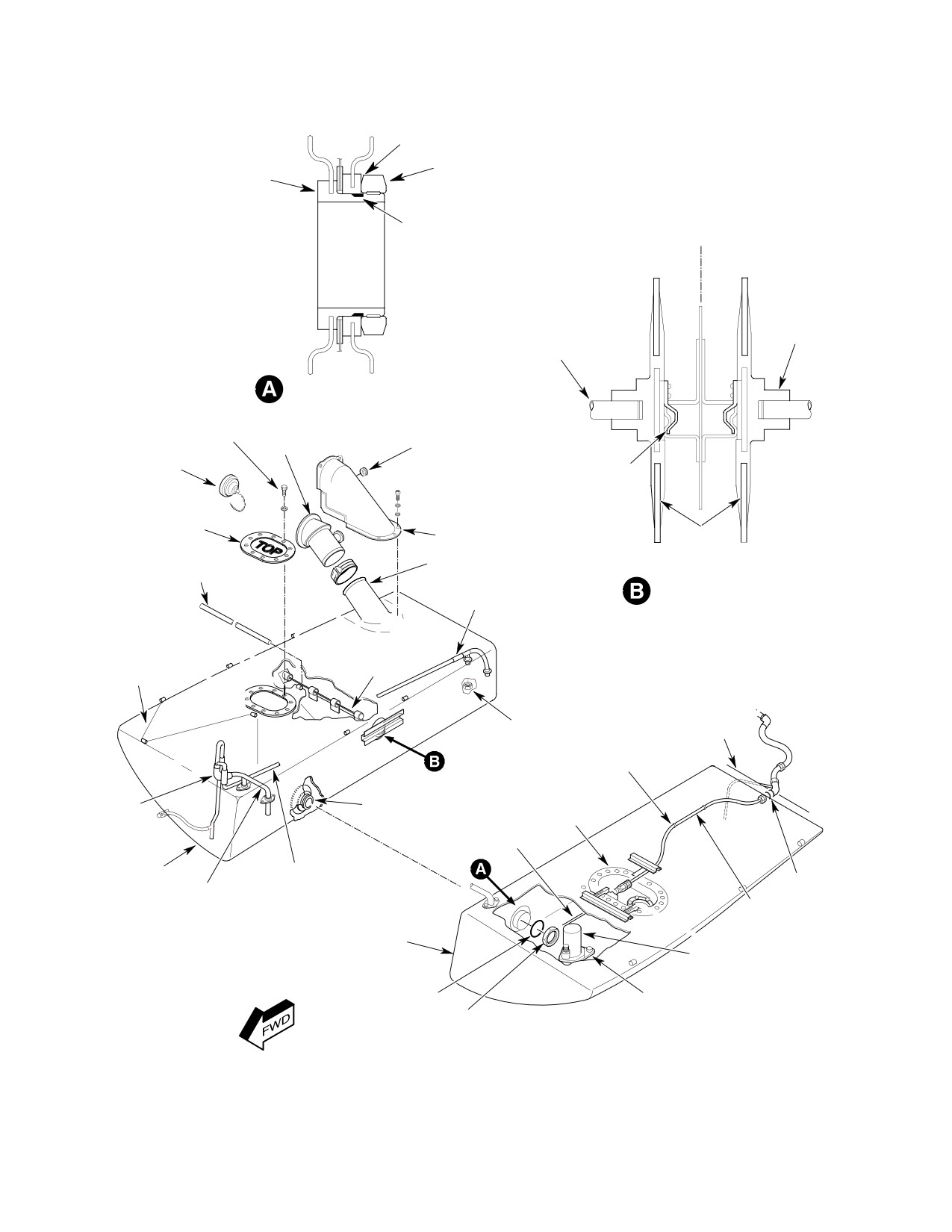
CSP-HMI-2
MD Helicopters, Inc.
MAINTENANCE MANUAL
0.005 IN. (0.127 MM) MAXIMUM GAP
BETWEEN NUT AND FITTING
CELL INTERCONNECT
NUT
FITTING
HELICOPTER
GASKET
L
NIPPLE
BAFFLE
SUPPORT ROD
FUEL CELL INTERCONNECT
BOLT, TORQUE;
70-90 IN. LB
(7.91-10.17 NM)
FILLER
GROMMET
FUEL FILLER CAP
BAFFLE SUPPORT HOOK
RIGHT FUEL CELL
ACCESS COVER
FUEL FILLER SHIELD
FUEL
CELL
BAFFLE SUPPORT ROD
FUEL TANK FILLER NECK
(2) (TYP)
AFT VENT CELL
BAFFLE SUPPORT
INTERCONNECT
(CROSS SECTION VIEW)
CLAMP
NYLON CELL
TANK BAFFLE
SUPPORT LACING
(TYP)
(TYP)
STA. 124.00
NUT
BULKHEAD
CLAMP
(TYP)
VENT TUBE
CELL INTERCONNECT
LEFT FUEL CELL
EMERGENCY
FITTING
ACCESS COVER
VALVE ASSY
FUEL INLET HOSE
RIGHT CELL
TUBE
UNION
FWD VENT CELL
INTERCONNECT
POWER PLANT
SUPPLY TUBE
LEFT CELL
START PUMP
(369D/E - 500N)
GASKET
TANK SUMP PLATE
NUT
G28-0005C
Figure 405. Fuel Cells
Page 420
Revision 19
28-00-00
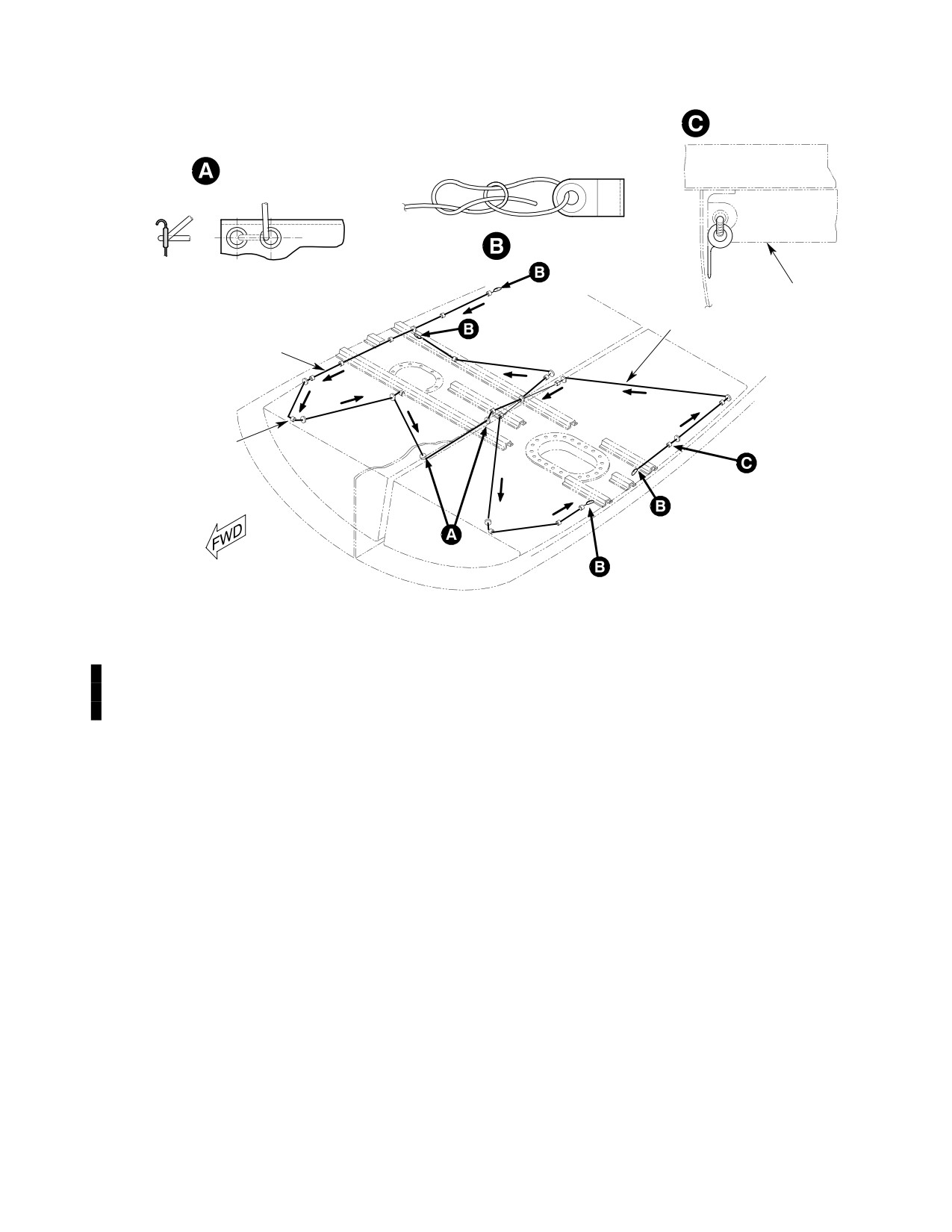
MD Helicopters, Inc.
CSP-HMI-2
MAINTENANCE MANUAL
CELL TOP ATTACHMENT
(TYP)
CELL SIDE ATTACHMENT
(TYP)
BOWLINE KNOT
START LACING WITH
BOWLINE KNOT
(FOLLOW ARROWS)
TOP OF CELL
END LACING WITH
NYLON LACING
BOWLINE KNOT
NYLON LACING
LOOP
START LACING WITH
BOWLINE KNOT
(FOLLOW ARROWS)
END LACING WITH
BOWLINE KNOT
G28-0006
Figure 406. Fuel Cell Support Lacing
(7).
With 250-C20B/R2 Engine or 250-C30
(12).
Inspect fuel quantity transmitter flange
Engine With Optional Maintenance
gasket for condition. Replace gasket if
Fuel Pump: Install start pump wiring
damaged or deteriorated. Position fuel
harness receptacle on fuel cell cover.
quantity transmitter in cell with float
inboard and clear of obstacles. Install
(8).
Install three support brackets on Sta.
screws and washers. Progressively
91.00 and 102.00 floor cross-members
torque screws to 20 - 25 inch-pounds
with washers and screws. Torque
(2.26 - 2.82 Nm). Lockwire screws.
screws to 20 - 25 inch-pounds (2.26 -
2.82 Nm).
(13).
Torque power plant fuel supply tube
nut to 230 - 260 inch-pounds (25.99 -
(9).
Finger tighten fuel supply tube nut
29.38 Nm). Tighten supply tube clamp
onto fuel shutoff valve. Position control
fasteners.
cable and electrical harness clamps on
cover.
(14).
Slip control cable through hole in fuel
(10).
Install cover bolts and washers. Install
shutoff valve lever swivel.
drilled-head bolt one bolt hole inboard
of pump electrical receptacle. Progres
(15).
Rig cable control system (Ref. Fuel
sively torque cover bolts to 70 - 90
Shutoff Valve Control Cable Installa
inch-pounds (7.91 - 10.17 Nm) in a
tion).
cross pattern.
(11).
Lockwire electrical receptacle nut to
(16).
Attach fuel quantity electrical connec
drilled bolt.
tor to receptacle. Lockwire connector.
Page 421
28-00-00
Revision 44
CSP-HMI-2
MD Helicopters, Inc.
MAINTENANCE MANUAL
(17). With 250-C20B/R2 Engine or 250-C30
(19). With 250-C20B/R2 Engine or 250-C30
Engine With Optional Maintenance
Engine With Optional Maintenance
Fuel Pump: Attach start pump electri
Fuel Pump: Perform a start pump
cal connector to receptacle. Lockwire
operation and system pressurization
connector.
check with a concurrent leak inspection
(Ref. Start Pump Operational Check
NOTE: To ensure that the C30 engine installa
(Model 250-C20 Series Engines).
tion fuel system is free of leaks you must
(20). Apply a torque alignment stripe to fuel
perform a vacuum leak test.
line tube, hose and fitting fasteners.
(18). Perform a vacuum leak inspection on
(21). Install left and right cell access panels
all helicopter models.
on cargo compartment floor.
Page 422
Revision 44
28-00-00
MD Helicopters, Inc.
CSP-HMI-2
MAINTENANCE MANUAL
FUEL SYSTEM
ADJUSTMENT/TEST
1. Fuel Level Low Caution Light System Test
previously installed, replace quantity
transmitter and calibrate system.
Special Tools
(8). Remove left fuel cell floor access panel.
(Ref. Section 91−00−00)
Item
Nomenclature
(9). Ground fuel quantity transmitter
terminal D to airframe with a jumper
N/A
Inclinometer, Sperry Model 45
wire.
(10). FUEL LEVEL LOW caution lamp
should show a steady bright light.
WARNING
(11). If the light is intermittent or does not
D FUEL LEVEL LOW warning light-on
come on at all, disconnect all power and
point, either 35 pounds for commer
run a continuity check on the warning
cial helicopters or 70 pounds fuel re
light and wiring between the INSTR
maining for noncommercial ma
circuit breaker and transmitter.
chines, must comply with the fuel
low level caution light calibration
(12). If the wiring and light check out,
specified in the Pilot's Flight Manual.
remove and bench check the transmit
D A 70 pound fuel level low warning
ter assembly (Ref. Fuel Quantity
light calibration is not approved for
Transmitter Calibration and Adjust
commercial applications.
ment).
(1).
Refuel to bring fuel quantity above 35
2. Fuel Quantity Transmitter Calibration and
or 70 pound low level warning point, as
Adjustment
appropriate.
(Ref. Figure 501)
(2).
Plug in and switch on 24 - 28 Vdc
external power.
Special Tools
(Ref. Section 91−00−00)
(3).
Set battery switch to EXT PWR.
Item
Nomenclature
N/A
Test harness and No. 328 lamp
(4).
Reset INSTR circuit breaker.
(5).
Set caution and warning light dimmer
Prevent fuel vapor accumu
control on BRT.
WARNING
lation, ignition and fire. At
tach helicopter to an approved electri
(6).
Test caution and warning light array.
cal ground. Switch OFF and disconnect
Replace lamps as required.
external power and battery before
opening fuel system. Perform work in
(7).
With known fuel quantity above 35 or
an open, well ventilated area away
70 pounds, caution lamp must be off.
from all potential ignition sources. Use
Check warning light to ensure it does
only nonsparking tools and explosion
not glow or flicker. A glowing caution
proof work lights.
lamp with fuel quantity above the low
level warning point indicates that
(1). Remove fuel quantity transmitter from
current is leaking past the low level
tank. Install a cover on cell opening.
warning transistor (switch) through the
caution lamp. This problem is corrected
(2). Fabricate a stand to support quantity
by installing a resistor in the transmit
transmitter level about 11 inches (28
ter warning light circuit (Ref. Fuel
cm) above work table surface. Support
System Repairs). If resistor has been
stand must allow access to float arm.
Page 501
28-00-00
Revision 44
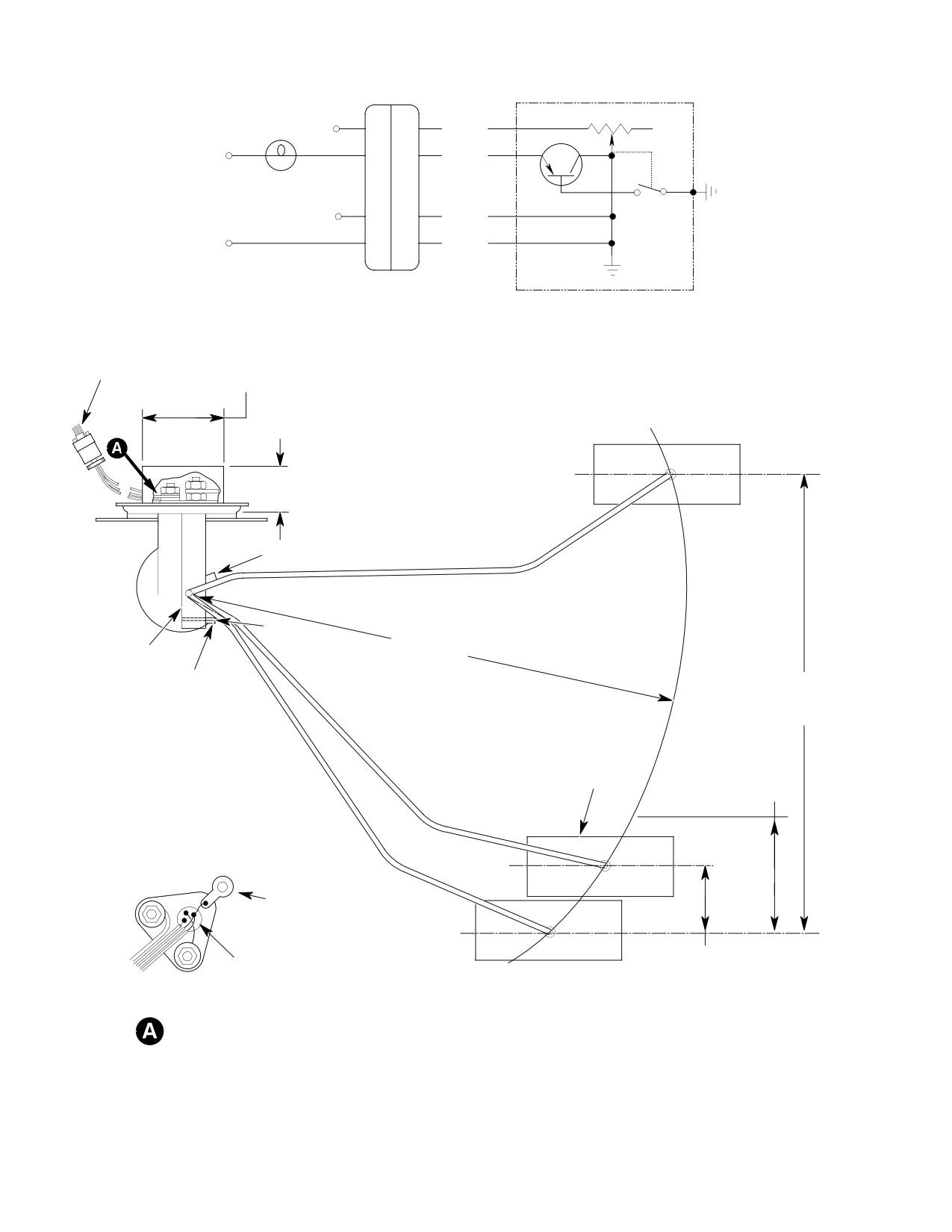
CSP-HMI-2
MD Helicopters, Inc.
MAINTENANCE MANUAL
R
NO. 328
A
LAMP
B
BLU
+
D
RED
Q
24 VDC
POWER
G B
SUPPLY
E
BLK
-
H
BLK
P251
CONNECTOR
FUEL QUANTITY
TRANSMITTER
TEST CONNECTIONS
1.75 IN. (4.45 CM)
DIA (MAX.
CONNECTOR
SEALANT
ENVELOPE)
0.75 IN. (4.45 CM) MAX.
SEALANT ENVELOPE
FULL
FLOAT STOP (FULL)
SPRING
10.08 IN.
(25.60 CM)
BRACKET
RADIUS
FLOAT STOP
(EMPTY)
8.99-9.11 IN.
(22.84-23.134CM)
SPRING CONTACT
FLOAT
2.15 IN. (5.46 CM)
(NOTE 2)
A
GROUND TERMINAL
G
EMPTY
1.25 IN.
TRANSISTOR SWITCH
(3.175 CM)
B
(ON UNDERSIDE)
CALIBRATION 369A4245 (EARLY UNIT)
(NOTE 1)
NOTES:
TANK UNIT
1.
CAUTION LIGHT ON, 35 LBS REMAINING.
CONNECTIONS
2.
CAUTION LIGHT ON, 70 LBS REMAINING.
NOT APPROVED FOR COMMERCIAL
G28-0007-1A
APPLICATION
Figure 501. Fuel Quantity Transmitter Calibration (Sheet 1 of 2)
Page 502
Revision 19
28-00-00
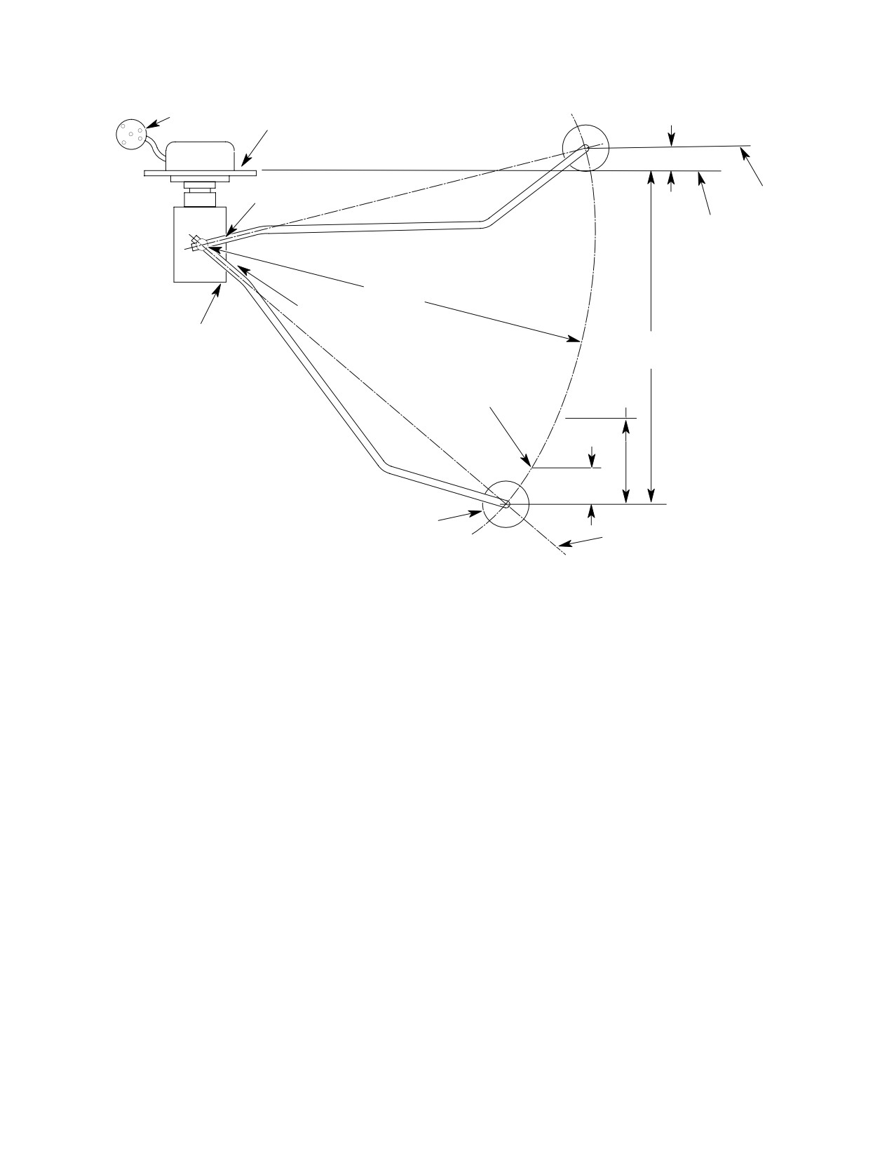
MD Helicopters, Inc.
CSP-HMI-2
MAINTENANCE MANUAL
0.62 IN.
CONNECTOR
MOUNTING FLANGE
(15.75 MM)
FLOAT STOP
FULL
(FULL)
BOTTOM OF FLOAT
10.08 IN.
(25.60 CM)
SPRING
RADIUS
FLOAT STOP
8.41-8.45 IN.
(EMPTY)
(21.36-21.46 CM)
2.13-2.17 IN.
(5.41-5.51 CM)
SPRING CONTACT
(NOTE 2)
(NOTE 1)
0.91-0.95 IN.
(23.11-24.13 MM)
FLOAT
NOTES:
EMPTY
1.
CAUTION LIGHT ON, 35 LBS REMAINING.
2.
CAUTION LIGHT ON, 70 LBS REMAINING.
NOT APPROVED FOR COMMERCIAL
CALIBRATION 369D296303 (CURRENT UNIT)
G28-0007-2A
Figure 501. Fuel Quantity Transmitter Calibration (Sheet 2 of 2)
A. Fuel Level Calibration
(6). On part Nos. 369A4245 (early) and
369D296303 (current) transmitters:
(1).
Let float arm rest on lower stop.
(a). Attach ohmmeter leads to connector
(2).
Set an ohmmeter on its low resistance
pins B and H.
scale. Measure resistance across
connector pins B and H.
(b). Raise float arm against upper stop.
(c). Indicated resistance shall be 88 - 95
Part number 369A4245 (early) quantity
ohms.
transmitter resistance must be 0 - 3
ohms.
(d). Bend stop to adjust resistance value.
P/N 369D296303 (current) units must
(e). Measure float travel between empty
register 0.10 - 2.00 ohms.
and full stops. Ensure travel is
within limits (Ref. Figure 501).
(3).
Bend float stop down to decrease, or up
to increase resistance.
(7). Disconnect ohmmeter.
(4).
Raise float arm to contact upper stop.
B. Fuel Level Low Warning Light Calibration
(5).
On 369A4245 (early) quantity transmit
(1). Fabricate test harness incorporating a
ters only, measure resistance between
No. 328 lamp bulb and P251 female
steel wire spring support bracket and
connector half. Alternatively, fabricate
mounting flange. Resistance must be
test wires with individual insulated
greater than 2 megohms.
tubular pin connectors.
Page 503
28-00-00
Revision 19
CSP-HMI-2
MD Helicopters, Inc.
MAINTENANCE MANUAL
(2). Attach test harness to transmitter
(5). Check P/N 369D296303 and
connector pins D and H and power
369D296303-701 (current) transmitter
source.
units as follows:
(a).
Hold float arm between stops. Test
(3). Switch on 24 Vdc power.
lamp must be off. A glowing lamp
indicates that current is leaking past
(4). Check P/N 369A4245 (early) transmit
transistor (lamp switch).
ter units as follows:
The problem is corrected by installing
(a). Hold float arm between stops. Test
a 510 ohm resistor in the transmitter
lamp must be off. A glowing lamp
caution light circuit (Ref. Fuel
indicates that current is leaking past
System Repairs).
transistor (lamp switch). The prob
lem is corrected by installing a 510
If resistor has been previously
ohm resistor in the transmitter
installed, replace quantity transmit
caution light circuit (Ref. Fuel
ter.
System Repairs). If resistor has been
previously installed, replace quantity
(b).
Lower float arm to just touch bracket
transmitter.
supported steel wire.
(c).
Test lamp should come on.
(b). Lower float arm until it just contacts
bracket supported steel wire:
(d).
Mark arm/float centerline position on
a ruler or stick where lamp comes on.
(c). Test lamp should come on.
(e).
Lower float. Mark ruler at arm/float
(d). Mark arm/float centerline position on
centerline position with float bot
a ruler or stick at point where lamp
tomed on stop.
comes on.
(f).
Measured distance between upper
and lower marks shall be:
(e). Lower float. Mark ruler at arm/float
centerline position with float bot
0.91 - 0.95 inch (23.11 - 24.39 mm)
tomed on stop.
for 35 pounds (nominal) fuel remain
ing.
WARNING
2.13 - 2.17 inch (5.41 - 5.51 cm) for
70 pounds (nominal) fuel remaining.
D FUEL LEVEL LOW warning light-on
point, either 35 pounds for commer
(6). Bend transmitter bracket spring wire to
cial helicopters or 70 pounds fuel re
adjust light-on position as required.
maining for noncommercial ma
chines, must comply with the fuel
(7). Check that lamp operation and float
low level caution light calibration
dimensions are within specified
specified in the Pilot's Flight Manual.
tolerances.
D A 70 pound fuel level low warning
(8). Disconnect electrical power and test
light calibration is not approved for
equipment.
commercial applications.
3. Fuel Quantity Transmitter Functional
(f). Distance between upper and lower
Check
marks shall be:
Special Tools
1.25 inch (3.18 cm) for 35 pounds
(Ref. Section 91−00−00)
(nominal) fuel remaining.
Item
Nomenclature
2.15 inch (5.46 cm) for 70 pounds
N/A
Inclinometer, Sperry Model 45
(nominal) fuel remaining.
Page 504
Revision 19
28-00-00
MD Helicopters, Inc.
CSP-HMI-2
MAINTENANCE MANUAL
Avoid fuel vapor accumula
(12). Disconnect fuel supply hose from
WARNING
tion, ignition and fire. Use
engine.
only non-sparking tools and explosion
(13). Have an assistant direct fuel hose into
proof work lights. Attach helicopter to
a suitable 10 gallon (37.85 L) container.
an approved electrical ground. Switch
Push fuel control valve knob in to open
OFF all electrical power. Disconnect
fuel shutoff valve.
external power and battery before
opening fuel system. Ensure work area
(14).
(C20 Series Engines) Set fuel start
is adequately ventilated.
pump switch to START PUMP.
(1). Attach helicopter to an approved
(15).
(C30 Engine) Attach a siphon pump to
electrical ground.
fuel supply hose to suck fuel out of
tank.
(2). Defuel and drain fuel tank.
(16). Pump 0.5 - 1.5 gallons (1.89 - 5.68 L),
(3). Locate inclinometer on rear deck
3.0 - 10.0 pounds (1.36 - 4.54 kg) out of
between Sta. 100 and 104.
the fuel tank while observing fuel
gauge for erratic or hung movement.
(4). Jack and level helicopter or spot
Fuel quantity gauge needle shall range
helicopter on level ground.
between 34 - 42 pounds.
(5). Jack helicopter to get a 2° nose down
NOTE:
attitude on the inclinometer. Stabilize
D (C20 Series Engines) A stuck needle on
helicopter with blocks as required.
a new, calibrated and tested gauge may be
due to transmitter float contact with the
(6). Reset INST and PNL LT circuit
start pump wire, pump or supply hose.
breakers.
D (C30 Engine) Transmitter float interfer
(7). Apply external power. Set battery
ence may be caused by the supply hose or
switch to EXT PWR.
sump pickup fitting.
(17).
Loosen fuel quantity transmitter
NOTE: All gauge readings are taken from the
mounting flange screws. Rotate
centerline of the fuel quantity indicator
transmitter clockwise as far as it will
pointer.
move and tighten screws. Check gauge
(8). Check that fuel quantity gauge needle
needle position.
points to empty, E with the pointer
(18).
If float interference problem persists,
centerline between the outer and inner
remove quantity transmitter and
edge of the E graduation mark. Check
determine action required to eliminate
that FUEL LEVEL LOW warning
problem; i.e. reposition transmitter
light is on.
float arm, fuel supply hose and, or start
NOTE: Do not bend float arm for adjustment of
pump wire.
fuel quantity indicating system.
(19).
Install transmitter and repeat function
al check.
(9). If adjustments are required; shut down
external electrical power, and remove
(20).
When 10 pounds (4.54 kg), 1.53 gallons
transmitter, bend float stops as re
(5.79 L) has been pumped, needle
quired and re-install transmitter.
pointer should be aligned on center of
the 35 pound red dot mark and FUEL
(10). Pump seven gallons of fuel into tank.
LOW caution light should come on.
(11). Apply external power. Set battery
(21).
Drain remaining fuel and observe that
switch to EXT PWR.
gauge needle falls to empty (E) as tank
runs dry.
FUEL LEVEL LOW warning light
should be out, and gauge should
(22).
Repeat adjustments as required.
indicate approximately 45 pounds.
Additional adjustments to float arm or
Page 505
28-00-00
Revision 36
CSP-HMI-2
MD Helicopters, Inc.
MAINTENANCE MANUAL
low level contact wire requires a
(4). Disconnect hose from from switch
verification check and repetition of the
bushing. Cap hose.
entire check procedure sequence.
(5). Remove fuel pressure switch with
bushing intact from after filter (AF)
(23). Connect fuel supply hose to engine inlet
port adapter. Install an O-ring on a
port. Torque hose nut to 230 - 260
suitable airtight plug and tighten into
inch-pounds (25.99 - 29.38 Nm).
adapter fitting.
(24). Install quantity transmitter (Ref. Fuel
(6). Bench test 369H8144 bypass pressure
Quantity Transmitter Installation).
switch as follows (denoted by three
housing screws):
4. Fuel Filter (Bypass) Caution Light
(a). Assemble test equipment shown in
Pressure Switch Test
Figure 502. Connect tester to pres
sure switch lead and connect ground
WARNING
test lead to one of three screws on the
housing body.
D Air in the fuel system will cause a
power reduction or flameout. Do a
(b). Remove bushing and O-ring from
fuel system vacuum leak check and
switch. Attach tubing to switch inlet
system air bleed after opening fuel
port as shown. Wipe switch complete
system to atmosphere and prior to
ly dry so any leakage can be detected
releasing helicopter for flight.
during the test.
D (Model 250-C20 Series Engines) En
(c). Add fuel to tube. Ohmmeter must
sure start pump is operating before
indicate switch contact closure as
taking fuel samples from system sup
fuel column height passes between
ply line drain valves.
24.5 and 35.0 inches (62.23 and 88.90
cm).
(1). Set all switches; OFF. Disconnect
(d). Check switch for leakage around
external electrical power. Disconnect
diaphragm. No leaks allowed.
battery.
Replace a leaking switch.
(2). Open engine access doors.
(e). Separate switch from test apparatus.
(3). Locate pressure switch on engine fuel
(f). Install new O-ring and bushing on
pump filter (Ref. Figure 503, Figure 504
switch. Torque switch bushing.
or Figure 505). Disconnect bypass
(7). Bench test 369D28144 bypass pressure
switch wire knife splice.
switch as follows (denoted by six
housing screws):
CAUTION
(a). Assemble test equipment shown in
Figure 502. Connect tester to pres
D Pressure switch is easily damaged. A
sure switch lead and connect ground
slight shearing force applied to half the
test lead to one of six screws on the
pressure switch can cause leakage and, or
housing body.
operational failure. Always grip both
halves of pressure switch hex flats with
(b). Pressure Method:
wrench when loosening or torquing at
taching hardware.
1). Remove bushing and O-ring from
switch. Attach tubing to switch
D Bypass pressure switch is not field repair
port A as shown. Tubing has to be
able. Do not disassemble switch. Return
airtight.
faulty switches to vender for repair.
2). Add pressure to the tube. Ohmme
NOTE: For all torques in the following proce
ter must indicate switch contact
dures, refer to Figure 503, Figure 504 or
closure as pressure passes between
Figure 505.
8 - 9 psig (16.3 - 18.3 in. hg.).
Page 506
Revision 19
28-00-00
MD Helicopters, Inc.
CSP-HMI-2
MAINTENANCE MANUAL
3). Hold pressure for five minutes and
(e).
Set battery switch to EXT PWR.
check for bleed-off. Any bleed-off
(f).
Reset INSTR circuit breaker.
indicates a leak in the switch and
requires switch replacement.
(g).
Set caution and warning light
dimmer control on BRT.
4). Slowly release pressure. Ohmme
ter must indicate switch contact
(h).
Test caution and warning light array.
opening by 4 psig (8.1 in. hg).
Replace lamps as required.
(c). Vacuum Method:
(i).
Connect a jumper wire between
switch body and airframe ground
1). Remove bushing and O-ring from
E12.
switch. Attach tubing to switch
port B as shown. Tubing has to be
(j).
Set start pump switch; ON. FUEL
airtight.
FILTER caution light should come
on. If FUEL FILTER caution light
2). Add vacuum to the tube. Ohmme
fails to light but works when tested,
ter must indicate switch contact
switch is probably faulty. Replace
closure as vacuum passes between
switch and repeat operational test.
8 - 9 psig (16.3 - 18.3 in. hg.).
(k).
Check switch diaphragm for leakage
3). Hold vacuum for five minutes and
through open port while pressurized.
check for bleed-off. Any bleed-off
Replace a leaky switch.
indicates a leak in the switch and
requires switch replacement.
(l).
Disconnect jumper wire between
pressure switch and ground. Set start
4). Slowly release vacuum. Ohmmeter
pump switch; OFF. Set battery
must indicate switch contact
switch; OFF. Disconnect external
opening as vacuum reaches 4 psig
power and battery.
(8.1 in. hg).
(m).
Disconnect bypass hose from switch
(d). Separate switch from test apparatus.
bushing. Install an airtight cap on
hose.
(e). Install new O-ring and bushing on
switch. Torque switch bushing.
(n).
Remove plug from adapter fitting.
Install bypass switch assembly and a
(8).
(Model 250-C20B/R2 Series Engines)
new O-ring in adapter fitting. Torque
Perform a switch operational check as
switch assembly.
follows:
(o).
Remove plug from bypass hose.
(a). Uncap and attach bypass hose to
Attach hose to switch bushing.
bushing. Torque hose nut.
Torque hose nut.
(b). Install a suitable airtight plug and
(p).
Install insulating sleeve and connect
O-ring in adapter fitting.
switch wire knife splice.
(c). Connect and insulate switch wire
(q).
Bleed fuel system.
knife splice.
(r).
Operate engine per Pilot's Flight
(d). Have an assistant hold switch clear
Manual and check fuel system for
of adjacent structures. Connect
correct operation. Shut down engine.
battery and external electrical power.
Inspect fuel system for leaks.
Page 507
28-00-00
Revision 29
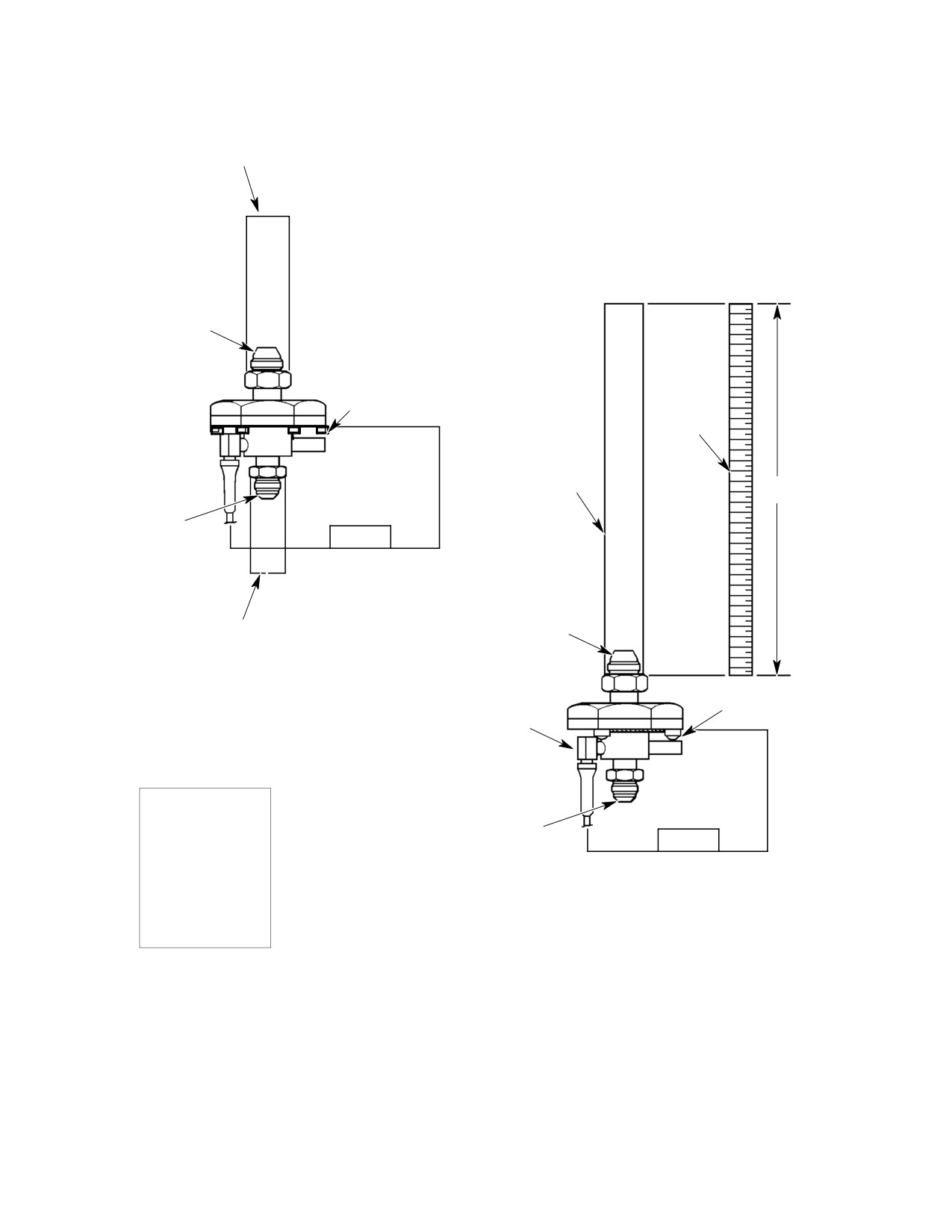
CSP-HMI-2
MD Helicopters, Inc.
MAINTENANCE MANUAL
PRESSURE METHOD:
APPLY 8-9 PSIG (16.3-18.3 IN. HG.) TO CLOSE SWITCH.
BLEED OFF TO 4 PSIG (8.1 IN. HG.) TO OPEN SWITCH.
PORT A
NOTE 2
36 INCH
SCALE
3/8” TYGON TUBING
OHMMETER
36 IN.
(OR EQUIV.)
OR
CONTINUITY TESTER
PORT B
VACUUM METHOD:
APPLY 8-9 PSIG (16.3-18.3 IN. HG.) TO CLOSE SWITCH.
PORT A
BLEED OFF TO 4 PSIG (8.1 IN. HG.) TO OPEN SWITCH.
369D28144 FUEL FILTER
NOTE 1
PRESSURE SWITCH
FUEL FILTER
PRESSURE SWITCH
OHMMETER
OR
CONTINUITY TESTER
PORT B
369H8144 FUEL FILTER
PRESSURE SWITCH
NOTES:
1.
CONNECT GROUND TEST LEAD TO ONE OF
THREE SCREW HEADS ON THE HOUSING BODY.
2.
CONNECT GROUND TEST LEAD TO ONE OF
G28-0010B
SIX SCREW HEADS ON THE HOUSING BODY
Figure 502. Fuel Filter Caution Light Pressure Switch Test (C20/C30 Engines)
Page 508
Revision 19
28-00-00
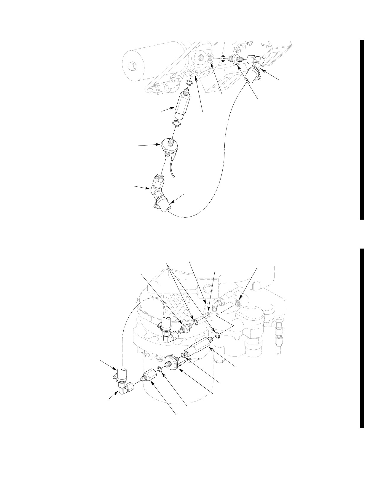
MD Helicopters, Inc.
CSP-HMI-2
MAINTENANCE MANUAL
ELBOW, TORQUE: 75-85 IN. LB
(8.47-9.60 NM)
BEFORE FILTER
REDUCER, TORQUE; 95-105 IN. LB
PORT (BF)
(10.73-11.86 NM)
FITTING, TORQUE; 95-105 IN. LB
ENGINE FUEL
(10.73-11.86 NM)
PUMP FILTER
FUEL FILTER PRESSURE SWITCH,
TORQUE; 90-100 IN. LB (10.16-11.30 NM)
ELBOW, TORQUE; 75-85 IN. LB
(8.47-9.60 NM)
HOSE
G28-0009B
Figure 503. Fuel Filter Caution Light Pressure Switch (C30 Engine)
ENGINE FUEL
PUMP FILTER
AFTER FILTER
O-RING
BEFORE FILTER
PORT (AF)
PORT (BF)
REDUCER, TORQUE; 65-75 IN. LB
(7.34-8.47 NM)
HOSE
FITTING, TORQUE; 65-75 IN. LB
(7.34-8.47 NM)
O-RING
FUEL FILTER PRESSURE SWITCH,
ELBOW, TORQUE; 75-85 IN. LB
TORQUE; 60-75 IN. LB (6.78-8.47 NM)
(8.47-9.60 NM) (2 PL)
O-RING
BUSHING, TORQUE; 90-100 IN. LB
(10.16-11.30 NM)
G28-0008B
Figure 504. Fuel Filter Caution Light Pressure Switch (C20 Engines)
Page 509
28-00-00
Revision 44