HANDBOOK OF MAINTENANCE INSTRUCTIONS FOR MDHI 369D/E/FF-500/600N HELICOPTERS (ISSUED: 1990) - page 13
CSP-HMI-2
MD Helicopters, Inc.
MAINTENANCE MANUAL
(10). For aircraft 369D; 001 & subs, 369E;
nose up/nose down attitude, perform
0001 thru 0528, 369FF; 0001 thru 0114
damper extension check.
and 500N; 001 thru 077: Remove plug
button from underside of fairing
NOTE:
assembly. Using a bright light and 10X
D The landing gear damper assemblies are
magnifying glass, inspect rivet hole in
to be checked at a helicopter gross weight
underside of strut for cracks. If crack is
of 1925 - 2075 pounds (874 - 942 kg) at a
found, strut must be scrapped and
longitudinal CG of approximately 103, ex
serviceable strut installed.
clusive of skid mounted flotation gear.
The empty weight of the 369D with full
4. Landing Gear Damper Inspection
fuel, but no passengers or cargo, is 1775 -
1925 pounds (806 - 874 kg). Therefore
(Ref. Table 601, Table 602 and Figure 401)
achieve the test configuration by adding
75 pounds (34 kg) of ballast to both sides
of the cabin floor, just aft of the tail rotor
NOTE: It is normal for a thin hydraulic oil film
pedals, 150 pounds (68 kg) total. Place the
to remain on damper as a result of wiping
helicopter on a smooth concrete or equiva
contact with piston seal. Newly-installed
lent surface (not asphalt).
dampers may also have slight oil seepage
from oil trapped in end cap threads during
D Dampers which have been modified (win
damper assembly. Neither of these should
terized) for cold weather operation are to
be considered damper leakage or cause for
be checked out no more than 30°F (-1°C)
damper replacement.
above the coldest temperature at which
the helicopter is operated.
(1). Inspect for hydraulic oil leakage. If
leakage is visible, wipe oil from damper
(a).
Raise and lower tailboom above and
after last flight of the day. Re-inspect
below the normal at-rest position
the following day for oil leakage. If
three times. On the last cycle, allow
leakage persists, perform bench check
the tailboom to slowly settle to the
(Ref. COM).
at-rest position.
(2). With helicopter on jacks, inspect
(b).
Measure and record dimension from
damper assemblies for evidence of
upper end cap to upper end of barrel
bearing looseness in upper and lower
on all four damper assemblies.
caps, worn bearings (excessive radial
(c).
Repeat steps (a). and (b). two more
play), loose or cracked caps and oil
times.
leakage. Any misalignment of torque
stripes on caps, piston and barrel
(d).
Lower and raise tailboom below and
indicates loosening of caps. Replace
above the normal at-rest position
immediately and repair removed
three times. On the last cycle, allow
damper.
the tailboom to slowly rise to the
at-rest position.
(3). Inspect damper attaching hardware for
security.
(e).
Measure and record dimension from
upper end cap to upper end of barrel
NOTE: Dampers which have been modified
on all four damper assemblies.
(winterized) for cold weather operation are
to be checked at not more than 30°F above
(f).
Repeat steps (d). and (e). two more
the coldest temperature at which the heli
times.
copter is operated.
(g).
Determine average extension from all
(4). Inspect landing gear dampers for
six readings for each damper assem
condition by observing stance of
bly. Remove and overhaul any
helicopter (normal stance is slightly
damper assembly not meeting
nose up). If stance indicates excessive
dimensions (Ref. Table 601).
Page 604
Revision 26
32-10-00

MD Helicopters, Inc.
CSP-HMI-2
MAINTENANCE MANUAL
NOTE: If two damper assemblies fail to meet
(4). Inspect safety walk tape for condition
the minimum extension (Ref. Table 601), re
and security. Replace unserviceable
place the damper having the greater
tape.
amount of deflection with a known service
(5). Inspect fairing seal for condition.
able damper and repeat steps (a). thru (g). If
the original damper again fails to meet
(6). Install landing gear fairing assembly.
minimum extension requirements, replace
it with the known serviceable damper, rein
6. Landing Gear Fairing Inspection
stall the first damper and repeat steps (a).
thru (g). This will determine whether one or
(Ref. Figure 802)
both dampers require overhaul. For owners
and operators having suitable equipment,
(1). Inspect fairing support brackets for
any damper not meeting minimum exten
security of attachment to strut, cracks
sion requirements can be bench-checked by
and deformation.
applying a single load and measuring the
(2). Inspect fairing-to-skid seal for deterio
deflection when compressed. (Ref. Table 602
ration and bonding.
for load and compression requirements.)
Dampers meeting specifications in
(3). Inspect fuselage rubbing plate for
Table 602 may be returned to service if oth
security of bond and excessive wear.
er defects are not noted.
(4). On forward fairings (aft fairings with
5. Cabin Entry Step Inspection
steps attached to struts), inspect fairing
(Ref. Figure 801)
step seal for deterioration and bonding.
(1). Remove landing gear fairing assembly.
Table 601. Minimum Damper Extension
(2). Inspect step-to-strut attachment for
Standard Landing Gear
Extended Landing Gear
loose attaching hardware by checking
(in/cm)
(in/cm)
for relative motion between mating
parts.
Aft
3.40 / 8.64
Aft
3.20 / 8.13
(3). Inspect welded joint of step for cracks.
Fwd
3.25 / 8.26
Fwd
2.90 / 7.37
Table 602. Landing Gear Damper Bench Test Requirements
Damper P/N (1)
Test Load
Compression Stroke
Pounds
(kg)
Inches
(mm/cm)
369D26300
(2)
1200
(545)
0.80
(20.32 mm)
369D26300−31
1320 ±100
(599 ±45)
0.80
(20.32 mm)
3780 ±400
(1716 ±182)
2.75
(6.99 cm)
369D26301
(2)
1700
(772)
0.80
(20.32 mm)
369D26301−31
1900 ±100
(863 ±45)
0.80
(20.32 mm)
3950 ±400
(1793 ±182)
2.75
(6.99 cm)
NOTES:
(1) Conduct all tests at 70 ±2° F except as noted.
(2) Cold−soak winterized dampers at 0 ±3° F for 24 hours minimum before testing.
Page 605
32-10-00
Revision 26
CSP-HMI-2
MD Helicopters, Inc.
MAINTENANCE MANUAL
This Page Intentionally Left Blank
Page 606
Revision 44
32-10-00
MD Helicopters, Inc.
CSP-HMI-2
MAINTENANCE MANUAL
LANDING GEAR SYSTEM
REPAIRS
1. Landing Gear System Repairs
NOTE: Following applies to early configuration
landing gear skids. Installation differences
(Ref. Figure 801) For more extensive repairs,
for current configuration landing gear skids
refer to CSP-SRM-6.
are noted in Figure 801.
(1).
Repair scratches and nicks by smooth
(1). Remove abrasion strip. Drill out rivets
ing sharp edges.
securing adapter sleeve and remove
residue from end of tube.
(2).
Repair elongated, enlarged or worn
holes in strut fittings, either inboard or
(2). Coat mating surface of replacement
outboard.
sleeve with a thin coat of sealing
compound (CM425) and install in skid
(3).
Repair bolt holes at large end of brace
tube with 9.06 inch (23.012 cm) over
that attaches to strut.
hang (Ref. Figure 801).
(4).
Replace strut; if cracked, if dents in
(3). Drill holes for replacement rivets and
strut exceed 0.060 inch (1.524 mm)
abrasion strip attachment bolt.
depth or if scratched and repaired area
depth would exceed 0.010 inch (0.254
(4). Coat replacement rivets with primer
mm) when measured to surrounding
(CM318) and install while wet; Main
unrepaired surface.
tain 9.06 inch (23.012 cm) overhang
during installation.
(5).
Replace defective or badly damaged
(5). Install replacement plug in sleeve 4
fairing.
inches (10.16 cm) inside skid from aft
(6).
Repair fairing fiberglass damage, such
end). Secure in place with bead of
as small tears or punctures that do not
sealant.
impair the telescoping action of the
(6). Install aft abrasion strip.
fairing.
3. Abrasion Strip Replacement
(7).
Replace cracked, dented or distorted
braces.
(Ref. Figure 801)
(8).
Repair or replace damaged skid tube.
Consumable Materials
(9).
Replace center beam-to-landing-gear
(Ref. Section 91−00−00)
attachment bearings that exceed 0.040
Item
Nomenclature
inch (1.016 mm) axial play.
CM209
Zinc chromate putty
(10).
Repair loose or defective rivets securing
CM318
Primer
foot to bearing; replace defective
CM425
Sealing compound
bearing.
2. Skid Adapter Sleeve Replacement
(1). Remove bolts securing defective
abrasion strip(s) to skid.
(Ref. Figure 801)
(2). Remove screws securing abrasion strip
to skid extension sleeve. Completely
Consumable Materials
remove any residual zinc chromate
(Ref. Section 91−00−00)
putty.
Item
Nomenclature
(3). Apply putty (CM209) to any bare metal.
CM318
Primer
CM425
Sealing compound
(4). Coat new screws or bolts for replace
ment abrasion strip with primer
Page 801
32-10-00
Revision 19
CSP-HMI-2
MD Helicopters, Inc.
MAINTENANCE MANUAL
(CM318) and install while primer is
edges of abrasion strip next to skid tube
still wet.
with an approximate 0.060 inch (1.524
mm) bead (fillet) of sealing compound
(5). After installation, seal all of parting
(CM425) to make watertight.
Table 801. Maximum Damage Limits − Landing Gear Components
Dents
Nicks
Scratches
Cracks
Holes
Component
in / mm
in / mm
in / mm
in / mm
in / mm
Skid tube (2)
0.200 / 5.08
0.010 / 0.254, from aft side of
(Same as for
No cracks
0.250 / 6.350
(1)
aft strut to 10 inches (25.4 cm)
nicks) (1)
allowed
(1) (3)
forward of the strut, with
cleanup not exceeding 0.015 /
0.381; 0.015 / 0.381 if forward
of that point to start of curved
section, with cleanup not
exceeding 0.020 / 0.508 (1)
Forward foot
0.060 / 1.524
0.060 / 1.524
0.010 / 0.254
No cracks
No holes
allowed
allowed
Strut
0.060 / 1.524
(1)
(1)
No cracks
No holes
allowed
allowed
Brace
0.050 / 1.270
0.010 / 0.254
0.005 / 0.127
No cracks
No holes
allowed
allowed
Damper assembly
0.060 / 1.524
0.010 / 0.254
0.010 / 0.254
No cracks
No holes
allowed
allowed
Fittings
0.010 / 0.254
0.010 / 0.254
0.010 / 0.254
No cracks
No holes
allowed
allowed
Aft foot
0.060 / 1.524
0.060 / 1.524
0.010 / 0.254
No cracks
No holes
allowed
allowed
Foot bearing
0.010 / 0.254
0.010 / 0.254
0.010 / 0.254
No cracks
No Holes
allowed
allowed
Indexing plug
0.040 / 1.016
0.040 / 1.016
0.040 / 1.016
No cracks
No holes
allowed
allowed
Skid extension
0.010 / 0.254
0.010 / 0.254 (4)
0.010 / 0.254
No cracks
No holes
(4)
(4)
allowed
allowed
NOTES:
(1) For other repair data, refer to CSP−SRM−6.
(2) Repair of minor skid tube damage aft of rear strut and on forward (curved) section is not required, but
surface finish must be restored.
(3) Hole must be plugged with correct size blind rivet.
(4) No damage is allowed on skid extension where skid and sleeve are attached.
Page 802
Revision 19
32-10-00
MD Helicopters, Inc.
CSP-HMI-2
MAINTENANCE MANUAL
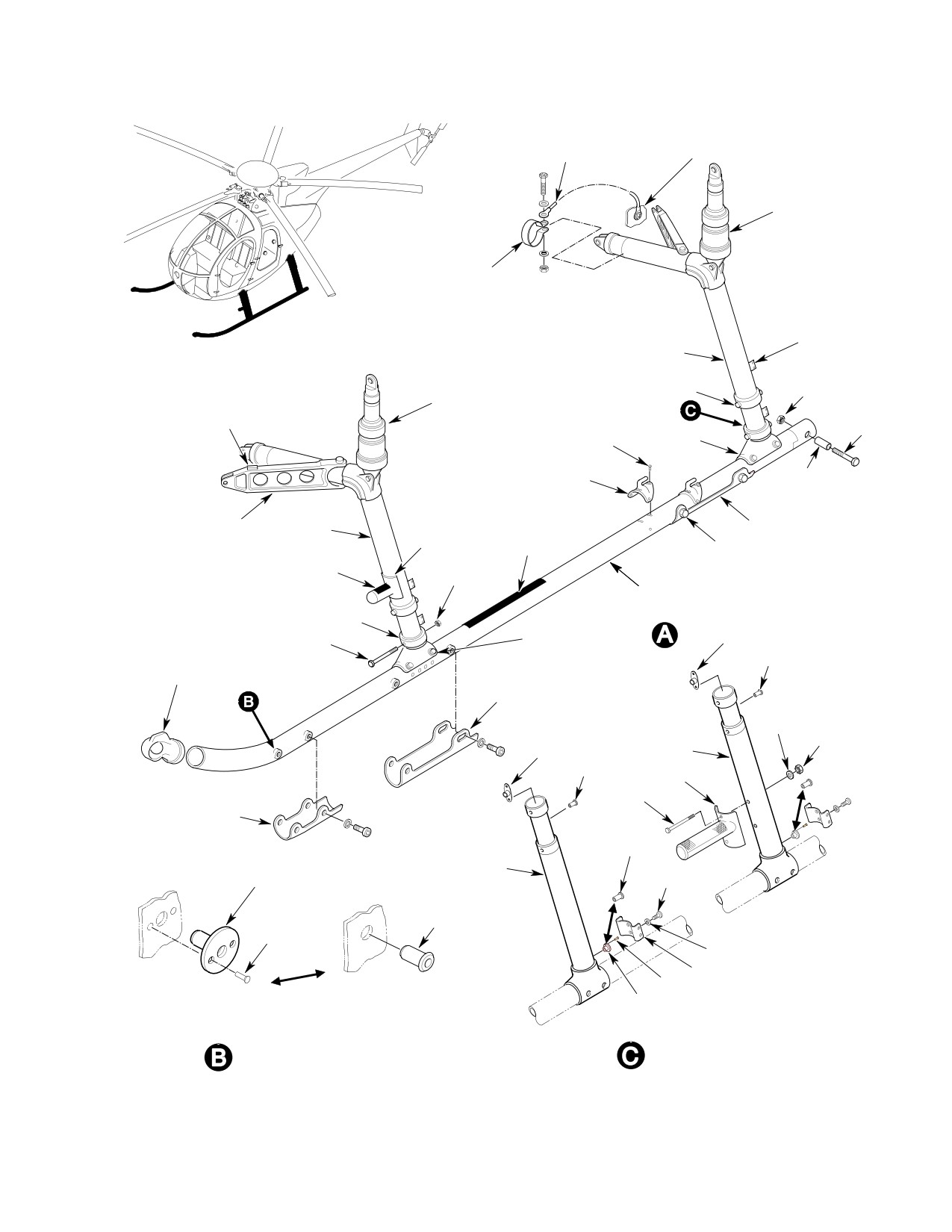
BONDING JUMPER
CENTER BEAM
DAMPER
CLAMP
FAIRING BRACKET
(8 PLCS)
STRUT
BOLT
NUT
DAMPER
ABRASION STRIP
BOLT
RIVET
FOOT
(TYP)
GROUND HANDLING
SPACER
FITTINGS
BRACE
STRUT
CABIN ENTRY
SAFETY WALK
ABRASION STRIP
STEP
TAPE
BOLT
NONSKID TAPE
NUT
SKID TUBE
FOOT
BOLT AND WASHER
NUTPLATE
BOLT
(4 PLCS) (NOTE 1)
SKID POSITION
RIVNUT
LIGHT
ABRASION STRIP
WASHER
NUT
NUTPLATE
FOOT
RIVNUT
STEP
BOLT
FORWARD
ABRASION STRIP
RIVNUT
NUTPLATE
FOOT
FITTING
SCREW
RIVET
RIVNUT
(TYP)
LOCKWASHER
BRACKET
RIVET
EARLY
CURRENT
NUTPLATE
CONFIGURATION
CONFIGURATION
NUTPLATE/RIVNUT ATTACHMENT
EXTENDED
FOR ABRASION STRIP MOUNTING
LANDING GEAR
G32-1002-1A
Figure 801. Landing Gear Repairs (Sheet 1 of 2)
Page 803
32-10-00
Revision 19
CSP-HMI-2
MD Helicopters, Inc.
MAINTENANCE MANUAL
RIVET
SPACER
BOLT
FOOT
WASHER
SPACER
SPACER
FOOT
`
RIVET
SCREW
EARLY
CURRENT
CONFIGURATION
CONFIGURATION
PIN RIVET
RIVETS (UPPER BRACKET)
HUCKBOLTS (LOWER BRACKET)
(NOTES 3 AND 6)
PACKING
FAIRING
(NOTES 5 AND 6)
BRACKET
SKID EXTENSION
SLEEVE
FOOT
BOLT
SKID ADAPTER
INDEXING
SLEEVE
PLUG
COLLAR
RIVET
PIN
ABRASION
DOUBLER
STRIP
SCREW
FORWARD FAIRING
PLUG
ATTACHMENT
BEARING
EARLY CONFIGURATION
SKID
COLLAR
PLUG
FOOT
NUT
WASHER
SKID ADAPTER
SLEEVE
BEARING
RIVET
SPACER
PIN
NOTES:
SKID
1.
BOLT AND WASHER 4 PLACES. 8 PLACES ON
EXTENSION
EARLY CONFIGURATION.
SLEEVE
BOLT
2.
HUCKBOLT 4 PLACES. 8 PLACES ON EARLY
CONFIGURATION.
3.
INSTALL NEW RIVETS WITH WET PRIMER
CURRENT CONFIGURATION
SKID
SCREW
(CM318).
4.
3/16 INCH (4.7625 MM) WELDING ROD OR
SKID TUBE ADAPTER AND PIVOT COMPONENTS
OTHER SUITABLE DEVICE (4 PLACES).
5.
FORWARD FAIRING ONLY.
6
HUCKBOLT HEAD COUNTERSUNK INSIDE
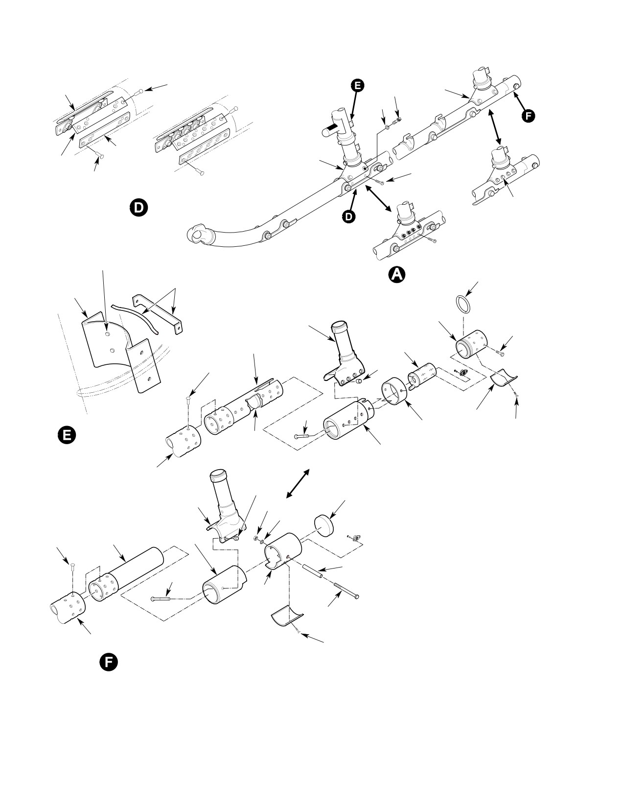
Figure 801. Landing Gear Repairs (Sheet 2 of 2)
Page 804
Revision 19
32-10-00
MD Helicopters, Inc.
CSP-HMI-2
MAINTENANCE MANUAL
4. Ground Handling Fitting Replacement
fiberglass repair limits, the fillet and fairing
must be removed.
(Ref. Figure 801)
Consumable Materials
Consumable Materials
(Ref. Section 91−00−00)
(Ref. Section 91−00−00)
Item
Nomenclature
Item
Nomenclature
CM418
Cement, epoxy
CM209
Zinc chromate putty
CM318
Primer
(1).
Replace an excessively damaged lower
CM425
Sealing compound
fairing.
(2).
Replace damaged fairing bracket or
(1). Drill out rivets securing defective
lower guide. Remove rivets, locate new
fitting.
part and install blind rivets. Use next
larger size rivets if mating holes in
(2). Coat mating surfaces with zinc chro
strut are enlarged.
mate putty (CM209) and install
replacement fitting in place.
(3).
Replace damaged guide/pin assembly or
guide half if guide is cracked, pins are
(3). Coat new rivets with primer (CM318)
bent or badly worn or teflon pad is loose
and install while primer is wet.
or badly worn.
(4). Seal edges with an approximate 0.060
(4).
Replace springs that are badly worn or
(1.524 mm) inch bead of sealing
rusty, or if free length is less than 8.72
compound (CM425) for waterproofing.
inches.
5. Safety Walk Tape Replacement
(5).
Replace fillet if teflon strip is loose or
badly worn.
(Ref. Figure 801)
(6).
Replace damaged strut bracket.
Remove rivets, locate new part and
Consumable Materials
install blind rivets. Use next larger size
(Ref. Section 91−00−00)
rivets if mating holes in strut are
Item
Nomenclature
enlarged.
CM220
Naphtha aliphatic
(7).
Replace unserviceable rubber seals; use
CM724
Tape, non-slip
cement (CM418).
7. Landing Gear Fairing Fillet Modification
(1). Carefully pull or scrape away damaged
tape.
The following is a procedure for modifying the
landing gear fairing fillet for easy removal and
(2). Remove all residual adhesive from skid
better access to the landing gear struts.
tube by wiping with a clean cloth
wetted by naphtha (CM220).
(1). Remove fillet from upper part of fairing
assembly (Ref. Landing Gear Fairing
(3). Install new tape (CM724) and press
Removal).
firmly into place. Expel air bubbles
while pressing down tape.
(2). Enlarge existing holes in fairing fillets
and fillet guides to 0.220 - 0.230 inch
6. Landing Gear Fairing Repair
(5.588 - 5.842 mm).
(Ref. Figure 802) Repair fairings according to
(3). Install A1133-4-3 Nut-Clips on fillet
SRM. If upper fairing is damaged beyond
guides over enlarged holes.
Page 805
32-10-00
Revision 19

CSP-HMI-2
MD Helicopters, Inc.
MAINTENANCE MANUAL
(4). Reinstall fillets using NAS603-6P
(b). If no cracks are noted, install new
screws and AN960KD10L washers
369H6023-3 bushing in hole with
through fillet into fairing guides.
wet primer.
(5). Secure trailing edge of fillet using
B. Landing Gear Strut with No Bushing
NAS603-6P screws, AN960KD10L
Installed
washers and MS21042-3 nuts (washer
under screw head and nut).
(1). Ream out top hole (DIM. A) to
0.5308-0.5313 inch (13.482-13.495
(6). Finish reinstalling fillet (Ref. Landing
mm) and ream out bottom hole (DIM.
Gear Fairing Installation).
B) to 0.4995-0.50 inch (12.687-12.70
mm).
8. Landing Gear Strut Drag Brace Hole
Repair
(2). Perform fluorescent penetrant inspec
tion of reworked areas for cracks.
(Ref. Figure 601) The following procedure is for
repair of the bolt hole in the landing gear strut
(a). If any cracks are noted, rework strut
where the drag brace attaches. This rework is
per step (3).
for either elongated or cracks in the bolt hole
area (Ref. Landing Gear Strut Inspection).
(b). If no cracks are noted, install new
369H6002-11 bushing in hole with
Consumable Materials
wet primer (CM318).
(Ref. Section 91−00−00)
(3). Ream out top hole (DIM. A) to
Item
Nomenclature
0.5608-0.5613 inch (12.244-14.257
CM318
Primer
mm) and ream out bottom hole (DIM.
B) to 0.5295-0.530 inch (13.449-13.462
A. Landing Gear Strut with Bushing
mm).
Installed
(4). Perform fluorescent penetrant inspec
(1). Ream out top hole (DIM. A) to
tion of reworked areas for cracks.
0.5608-0.5613 inch (12.244-14.257
mm) and ream out bottom hole (DIM.
(a). If any cracks are noted, procede with
B) to 0.5295-0.530 inch (13.449-13.462
step (5).
mm).
(b). If no cracks are found around drag
(2). Perform fluorescent penetrant inspec
brace attach hole in strut and hole is
tion of reworked areas for cracks.
not elongated, install new
369H6023-1 bushing in hole with
(a). If any cracks are noted, rework strut
wet primer (CM318).
per step (3).
(5). Ream out top hole (DIM. A) to
(b). If no cracks are noted, install new
0.5908-0.5913 inch (15.006-15.019
369H6023-1 bushing in hole with
mm) and ream out bottom hole (DIM.
wet primer (CM318).
B) to 0.5595-0.560 inch (14.211-14.224
(3). Ream out top hole (DIM. A) to
mm).
0.5908-0.5913 inch (15.006-15.019
(6). Perform fluorescent penetrant inspec
mm) and ream out bottom hole (DIM.
tion of reworked areas for cracks.
B) to 0.5595-0.560 inch (14.211-14.224
mm).
(7). If crack is found, strut must be
(4). Perform fluorescent penetrant inspec
scrapped and serviceable strut
tion of reworked areas for cracks.
installed.
(a). If crack is found, strut must be
(8). If no cracks are noted, install new
scrapped and serviceable strut
369H6023-3 bushing in hole with wet
installed.
primer.
Page 806
Revision 26
32-10-00
MD Helicopters, Inc.
CSP-HMI-2
MAINTENANCE MANUAL
CHAFING PAD
TEFLON STRIP
FILLET
(NOTE 3)
RIVETS
RETAINING BLOCKS
AND CLAMP
NOTE 4
0.35 INCH (8.89 MM)
TEFLON PAD
FAIRING TO LOWER GUIDE
UPPER
(INSIDE GUIDES)
0.80 INCH (20.32 MM)
(NOTE 1)
FAIRING
UPPER FAIRING
UPPER GUIDE
(NOTE 3)
PIN ASSEMBLY,
0.35 INCH (8.89 MM)
LOWER FAIRING
INNER GUIDE HALF
RIVET
AND SPRINGS
(FWD FAIRING, 1 RIVET)
OUTER GUIDE HALF
(AFT FAIRING, 2 RIVETS)
UPPER AND LOWER FAIRING
1-7/16 INCH (3.65 CM)
RIVETS
INSTALLATION
DOUBLER (TYP)
(NOTE 2)
LOWER FAIRING
LOWER GUIDE
(NOTE 3)
RIVETS (UPPER BRACKET)
(NOTE 1)
HUCKBOLTS (LOWER BRACKET)
(NOTES 2 AND 8)
3/4 INCH (19.05 MM)
RIVET
DOUBLER (TYP)
(2 PLCS)
SCREW, WASHER
HOLE
(4 PLACES)
AND SEAL
(NOTES 6, 7)
1/2 X 3/4 INCH
FAIRING
DOUBLER
BRACKET
(TYP)
FORWARD FAIRING
SKID
ATTACHMENT
SKID C
L
COVER (EXTENDED
LANDING GEAR ONLY)
NUTPLATE
NOTES:
(9 PLCS)
1.
BONDED AREA; USE EPOXY ADHESIVE (CM411).
2.
INSTALL NEW RIVETS WITH WET PRIMER (CM318).
3.
REFER TO CSP-SRM-6 FOR FIBERGLASS REPAIR.
4.
CLAMP FILLET AND FAIRING TRAILING EDGES DURING INSTALLATION
OF FILLET RIVETS.
5.
PENCILED CENTERLINE ALONG FLANGE.
6.
3/16 INCH (4.7625 MM) WELDED ROD OR OTHER SUITABLE DEVICE.
WASHER
7.
FORWARD FAIRING ONLY.
(9 PLCS)
8.
HUCKBOLT HEAD COUNTERSUNK INSIDE STRUT; NO PORTION OF HEAD
RIVET
(18 PLCS)
TO PROTRUDE INSIDE STRUT.
SCREW
9.
DIMENSIONS FOR BRACKET AND GUIDE LOCATIONS ON NEW STRUT
(9 PLCS)
G32-1003A
INSTALLATION
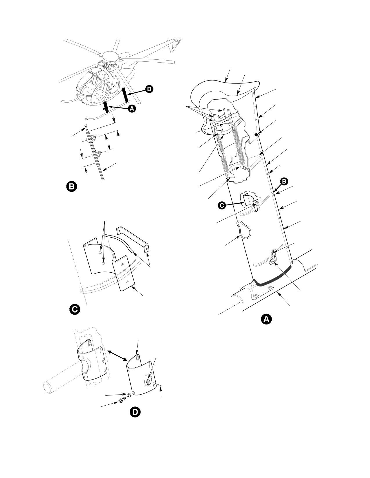
Figure 802. Landing Gear Fairing Repairs
Page 807
32-10-00
Revision 26
CSP-HMI-2
MD Helicopters, Inc.
MAINTENANCE MANUAL
This Page Intentionally Left Blank
Page 808
Revision 44
32-10-00
MD Helicopters, Inc.
CSP-HMI-2
MAINTENANCE MANUAL
EXTENDED LANDING GEAR
INITIAL INSTALLATION
1. Extended Landing Gear Initial Installation
for reuse. Remove skid assemblies with
foot assemblies attached.
The following instructions are for both left and
B. Standard Landing Gear Disassembly
right landing gear assemblies.
Complete disassembly of landing gear is not
(1). Identify all components, including
required; however, certain items must be
attaching hardware, or components
removed.
removed for access to work area.
Protect components from damage and
(1). On current configuration standard
foreign matter until installed.
landing gear, disassemble as follows:
(a). Remove bolt, washer and nut attach
(2). Ensure all cockpit electrical switches
ing aft foot assembly and skid
are OFF.
extension to skid tubes.
NOTE: Ensure BATT-OFF-EXT switch is
(b). Remove bolts and washers attaching
OFF.
forward foot assembly to skid tubes.
(3). Using jacking or hoisting methods,
(2). On early configuration standard
raise helicopter clear of ground.
landing gear, disassemble as follows:
(a). Remove screws and abrasion strip at
A. Standard Landing Gear Removal
aft section of skid tubes.
Removal of complete landing gear is not
(b). Remove bolts attaching skid exten
required.
sion, indexing plug and aft foot
assembly to skid tube.
(1). Open engine access doors.
(c). Remove bolts and washers attaching
(2). Remove hardware attaching aft damper
forward foot assembly to skid tube.
assemblies to fuselage fittings and
C. Extended Landing Gear Assembly
landing gear struts; remove aft damper
assemblies. Retain attaching hardware
Extended landing gear is shipped with as
for reuse.
many parts assembled as practical; however,
certain items require assembly at installation.
(3). Remove screws attaching position light
assemblies to skid assembles. Retain
Early configuration forward foot assembly and
screws for reuse. Disconnect electrical
skid tube have an eight-hole mounting
harness and remove position light
pattern; current configuration foot assembly
assemblies.
and skid tube have a four-bolt mounting
pattern.
(4). Remove hardware that secures trailing
edge of forward and aft lower fairings.
Consumable Materials
Remove hardware attaching lower
(Ref. Section 91−00−00)
fairings to strut assemblies. Carefully
Item
Nomenclature
spread trailing edge of lower fairings
CM318
Primer
and remove in forward direction.
CM425
Sealing compound
NOTE: If preload condition prevents removal of
skid assemblies, disconnect forward foot as
(1). If early foot assembly is used with
semblies from skid assemblies to eliminate
current skid tube:
preload.
(a). Drill out four rivets (48, Figure 902)
(5). Remove ABC bolts from forward and aft
and remove two spacers (49) from
strut assemblies. Retain ABC hardware
skid tube.
Page 901
32-10-00
Revision 19
CSP-HMI-2
MD Helicopters, Inc.
MAINTENANCE MANUAL
G32−1009
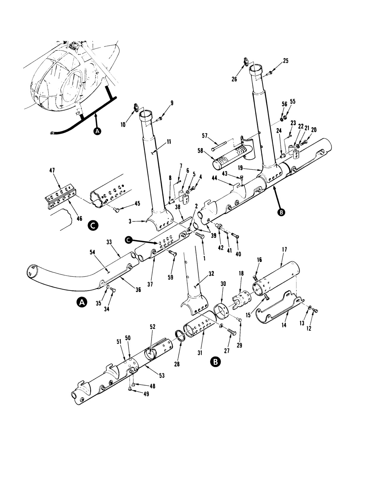
Figure 901. Extended Landing Gear Assembly (Early Configuration)
Page 902
Revision 19
32-10-00
MD Helicopters, Inc.
CSP-HMI-2
MAINTENANCE MANUAL
Legend (Ref. Figure 901)
1.
Bolt (MS21250−04006)
30.
Doubler (369D26031)
2.
Washer (MS20002C4)
31.
Bearing (369D26030−1 LH)
3.
Foot assy (369D292113−1 LH FWD)
(369D26030−2 RH)
(369D292113−2 RH FWD)
32.
Foot (369D29113−3 LH AFT)
4.
Screw (NAS1403−1)
(369D29113−4 RH AFT)
5.
Lockwasher (MS35338−43)
33.
Skid assy (369D292114)
6.
Bracket (369H92111−11)
34.
Bolt (NAS1223C1)
7.
Rivet (NAS1921M04−03)
35.
Washer (HS306−222)
8.
Nutplate (369H92507)
36.
Abrasion strip (369H92583)
9.
Rivet (CCR26455−3−5)
37.
Abrasion strip (369H6102)
10.
Nutplate (NAS1068A3)
38.
Tape (369D292114−3)
11.
Foot (369D29113−3 LH FWD)
39.
Tube assy (369D292114−5)
(369D29113−4 RH FWD)
40.
Screw (NAS1190C3P3)
12.
Bolt (NAS1223C1)
41.
Rivet (NAS1921M04−03)
13.
Washer (HS306−222)
42.
Nutplate (369H92507)
14.
Abrasion strip (369H6102)
43.
Rivet (NAS1919M04−03)
15.
Screw (NAS56HK3−6)
44.
Fitting (369A6107−3)
16.
Bolt (NAS1223C8P)
45.
Rivet (NAS1399D4−4)
17.
Extension assy (369D26038)
46.
Spacer (369A6100−7)
18.
Index plug (369D26037)
47.
Spacer (369A6100−5)
19.
Foot assy (369D292111−101 LH AFT)
48.
Rivet (NAS1399C5−3)
(369D292111−102 RH AFT)
49.
Rivet (NAS1399C5−2)
20.
Screw (NAS1403−1)
50.
Rivet (NAS1398C5−3)
21.
Lockwasher (MS35338−43)
51.
Rivet (NAS1398C5−2)
22.
Bracket (369H92111−11)
52.
Plug (369D26040)
23.
Rivet (ML5100M4−3)
53.
Adapter sleeve (369D26032)
24.
Nutplate (369H92507)
54.
Tube (369D292115)
25.
Rivet (MS20605AD3C3)
55.
Nut (MS21045−5)
26.
Nutplate (NAS1068A3)
56.
Washer (AN960KD513)
27.
Pin rivet (HL3375K8A6)
57.
Bolt (NAS1305−36)
28.
Packing (H53113E142)
58.
Step assy (369D292028)
29.
Rivet (MS20426AD4)
59.
Screw (1030−428−8M)
Page 903
32-10-00
Revision 19
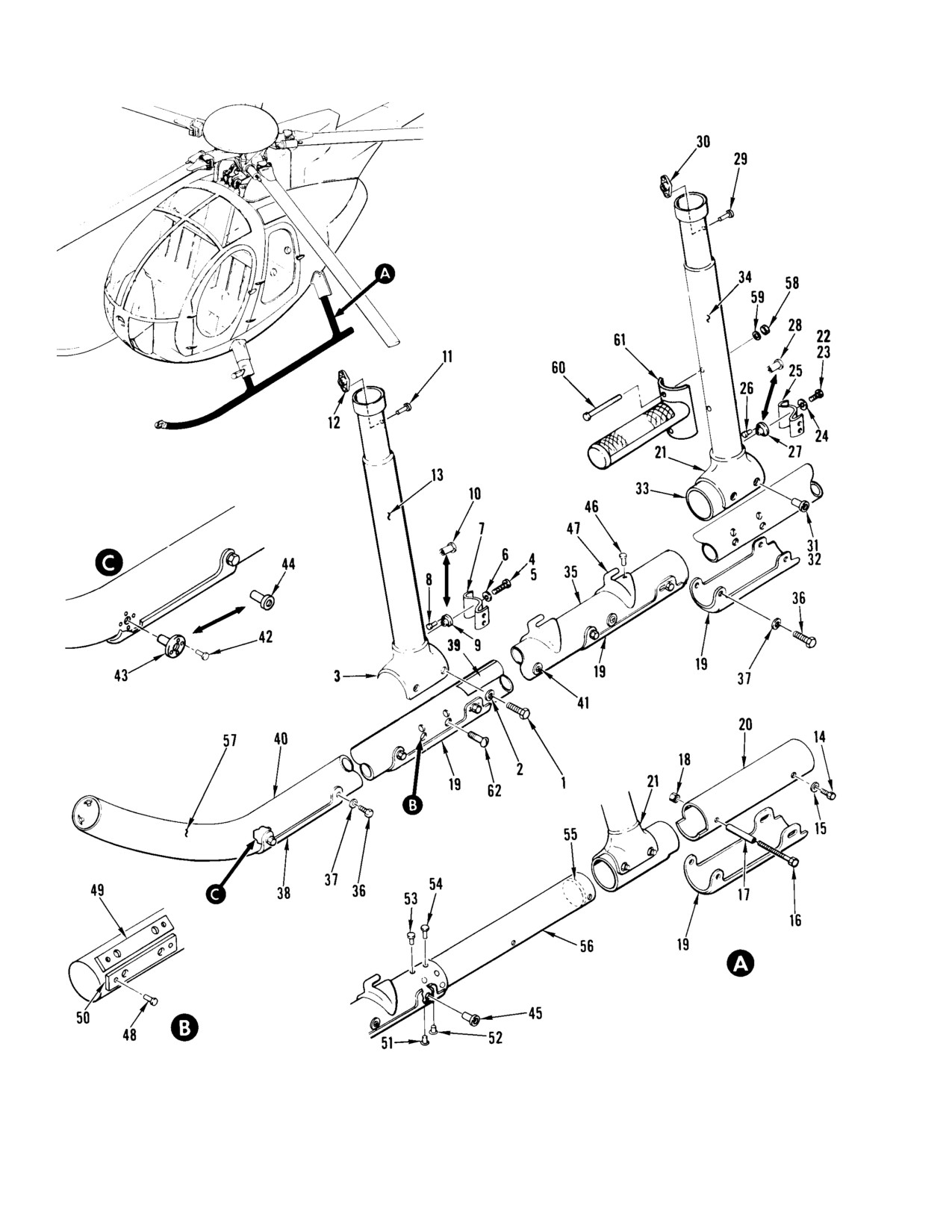
CSP-HMI-2
MD Helicopters, Inc.
MAINTENANCE MANUAL
G32−1010
Figure 902. Extended Landing Gear Assembly (Current Configuration)
Page 904
Revision 19
32-10-00
MD Helicopters, Inc.
CSP-HMI-2
MAINTENANCE MANUAL
Legend (Ref. Figure 902)
1.
Bolt (MS2125004006)
30.
Nutplate (NAS1068A3)
2.
Washer (MS20002C4)
31.
Pin rivet (HL3375K8A6)
3.
Foot assy. (369D292113−103 LH FWD)
32.
Pin rivet (HL3375K8A6)
(369D292113−104 RH FWD)
33.
Bearing (369D26010−1 LH)
(369D292113−101 LH FWD)
(369D26010−2 RH)
(369D292113−102 RH FWD)
34.
Foot (369D292113−5 LH AFT)
4.
Screw (NAS1403−1)
(369D292113−6 RH AFT)
5.
Screw (NAS1403−5)
35.
Skid assy (369D292114−101/−103)
6.
Lockwasher (MS35338−43)
36.
Bolt (NAS1223C1 (−101 assy))
7.
Bracket (369H92111−11)
(NAS1223C4 (−103 assy))
8.
Rivet (NAS1921M04−03)
37.
Washer (HS306−222)
9.
Nutplate (369H92507)
38.
Abrasion strip (369H92583)
10.
Rivnut (NAS1329C3KB180)
39.
Tape (369D292114−3)
11.
Rivnut (CCR26455−3−5)
40.
Tube assy (369D292114−7/−9)
12.
Nutplate (NAS1068A3)
41.
Screw (NAS1190C3P3 (−101 assy))
13.
Foot (369D292113−5 LH FWD)
(NAS1130C3P8 (−103 assy))
(369D292113−6 RH FWD)
42.
Rivet (NAS1921M04−03)
14.
Bolt (NAS1223C1 (−101 assy))
43.
Nutplate (369H92507)
(NAS1223C5 (−103 assy))
44.
Rivnut (C2R1947−1)
15.
Washer (HS306−222)
45.
Rivnut (C2R1947−2)
16.
Bolt (NAS1104−44)
46.
Rivet (NAS1919M04−03)
17.
Spacer (369D26013)
47.
Fitting (369A6107−3)
18.
Nut (NAS21042−4)
48.
Rivet (NAS1399D4−4)
19.
Abrasion strip (369H6102)
49.
Spacer (369D26014)
20.
Extension assy (369D26045)
50.
Spacer (369D26015)
21.
Foot assy (369D292111−105 LH AFT)
51.
Rivet (NAS1399C5−3)
(369D292111−106 RH AFT)
52.
Rivet (NAS1399C5−2)
(369D292111−103 LH AFT)
53.
Rivet (NAS1398C5−3)
(369D292111−104 RH AFT)
54.
Rivet (NAS1398C5−2)
22.
Screw (NAS1403−1)
55.
Plug (369D26040)
23.
Screw (NAS1403−5)
56.
Adapter sleeve (369D26012)
24.
Lockwasher (MS35338−43)
57.
Tube (369D292115)
25.
Bracket (369H92111−11)
58.
Nut (MS21045−5)
26.
Rivet (ML5100−M4−3)
59.
Washer (AN960KD516)
27.
Nutplate (369H92507)
60.
Bolt (NAS1305−36)
28.
Rivnut (NAS1329C3KB180)
61.
Step (369D292028)
29.
Rivet (MS20605AD3C3)
62.
Screw (1030−428−8M)
Page 905
32-10-00
Revision 19
CSP-HMI-2
MD Helicopters, Inc.
MAINTENANCE MANUAL
(b). Apply primer (CM318) to replace
(b). Coat screw (15) and bolts (16) with
ment spacers (47, Figure 901) and
primer and install.
install into skid tube with four
(3). Coat mating surface of abrasion strip
NAS1399D4-4 rivets.
and hardware with primer.
(c). Position foot assembly on skid tube
(a). Position abrasion strip (14) on aft
and locate center four holes.
section of skid tube.
(d). Mark holes and drill the needed
(b). Install abrasion strip using bolts (12)
0.254 - 0.260 inch (6.452 - 6.604
and washers (13).
mm) holes as required.
(c). Seal mating edge of abrasion strip
(2). If current foot assembly is used with
with 0.060 inch (1.524 mm) bead of
early skid tube:
sealing compound (CM425).
(a). Fill center four holes with sealing
E. Current Configuration Extended Landing
compound (CM425).
Gear Skid Tube Assembly Buildup
(Ref. Figure 903)
(3). Attach extended wire harness to
position light and install light in
forward end of skid tube (Ref.
Consumable Materials
Figure 903) using screws retained from
(Ref. Section 91−00−00)
standard landing gear.
Item
Nomenclature
CM318
Primer
D. Early Configuration Extended Landing
CM425
Sealing compound
Gear Assembly Buildup
(Ref. Figure 901)
(1). Coat mating surface of forward foot
assembly (3) and skid tube (57) with
Consumable Materials
primer (CM318).
(Ref. Section 91−00−00)
(a). Position forward foot assembly on
Item
Nomenclature
skid tube.
CM318
Primer
(b). Apply primer to bolts (1) and washers
CM425
Sealing compound
(2) and install; torque bolts to 80 -
100 inch-pounds (9.04 - 11.30
(1). Coat mating surface of forward foot
Nm).
assembly (3) and skid tube (54) with
(2). Coat mating surfaces of aft foot assem
primer (CM318).
bly (21) and extension (20) with primer.
Position extension and aft foot assem
(a). Position forward foot assembly on
bly on adapter sleeve (56).
skid tube.
(3). Coat mating surface of abrasion strip
(b). Apply primer to bolts (1) and washers
(19) and hardware with primer and
(2) and install; torque bolts to 80 -
position on extension (20).
100 inch-pounds (9.04 - 11.30
Nm).
(a). Install aft foot assembly (21), exten
sion (20) and abrasion strip (19)
(2). Coat mating surfaces of extension (17),
using bolts (14 and 16), washers (15),
indexing plug (18) and aft foot assembly
spacer (17) and nut (18).
(32) with primer.
(b). Seal mating edge of abrasion strip
(a). Position indexing plug, aft foot
with 0.060 inch (1.524 mm) bead of
assembly and extension on skid tube.
sealing compound (CM425).
Page 906
Revision 19
32-10-00
MD Helicopters, Inc.
CSP-HMI-2
MAINTENANCE MANUAL
F. Extended Landing Gear Installation
(6). Route extended wire harness from
position light through forward foot
(Ref. Figure 901)
assembly.
(a). Attach wire with splice (CM812);
Consumable Materials
cover splice with silicon tube
(Ref. Section 91−00−00)
(CM612) and tie tube with strap
Item
Nomenclature
(CM703).
CM318
Primer
CM420
Sealant
(b). Cover entire length of extended
CM612
Tube, silicone
electrical harness with vinyl sleeve
(CM613).
CM613
Sleeve, vinyl
CM703
Tie strap
(7). Install extended landing gear aft
CM812
Splice, knife
damper assemblies using serviceable
N/A
Wire, AWG 20, 47108-B-20
hardware removed from standard
landing gear (Ref. Landing Gear
Damper Replacement).
(1). Align foot and skid assembly with strut
assembly.
(8). Apply 0.060 inch (1.524 mm) bead of
sealant (CM420) to mating edge of foot
(2). Slide foot assembly into strut assembly.
assemblies and strut assemblies.
(3). Coat ABC bolts with primer (CM318).
(9). Install fairings (Ref. Landing Gear
(4). While primer is wet, install ABC bolts;
Fairing Replacement).
torque bolts to 40 - 60 inch-pounds
G. Weight and Balance
(4.52 - 6.78 Nm).
Weight and balance changes that result from
(5). Seal ABC bolts with sealant (CM420).
installation of extended landing gear are listed
NOTE: Leave a minimum of one full service
in Table 901. After installation of extended
loop in electrical harness to ensure that ten
landing gear, incorporate changes to helicopter
sion is not applied to position lights, if
weight and balance record as instructed in
installed.
Section 08-10-00.
Table 901. Weight and Balance Data
Weight
Arm
Moment
lbs (kg)
in.
(cm)
in.−lb/100 (kg mm/100)
Added
+94
(+42.638)
92.3
(234.44)
+86.8
(+10000.04)
Removed
−73
(−33.112)
97.0
(246.38)
−70.8
(−815.70)
Change
+21
(+9.525)
76.0
(193.04)
+16.0
(+184.34)
Page 907
32-10-00
Revision 19
CSP-HMI-2
MD Helicopters, Inc.
MAINTENANCE MANUAL
AFT DAMPER ASSEMBLY
(BLACK)
STRUT
(TYPICAL)
LOWER FAIRING
ASSEMBLY
FOOT ASSEMBLY
(TYPICAL)
SEALING
COMPOUND
KNIFE SPLICE
ABC BOLT
LOWER FAIRING
STEP
ASSEMBLY
SEALING COMPOUND
ABC BOLT
SEALING COMPOUND
SKID ASSEMBLY
SERVICE LOOP
POSITION
LIGHT
ELECTRICAL HARNESS
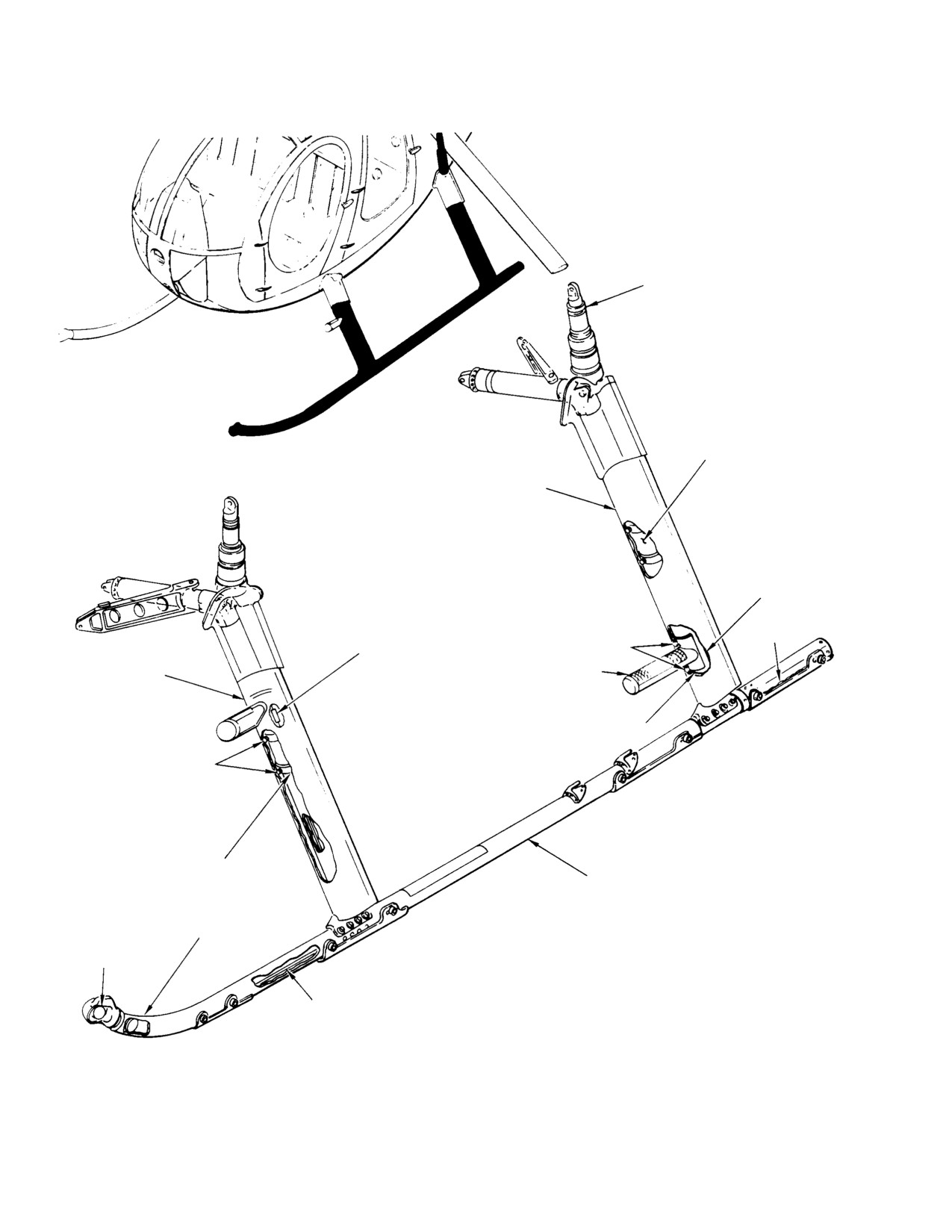
Figure 903. Extended Landing Gear
Page 908
Revision 19
32-10-00
MD Helicopters, Inc.
CSP-HMI-2
MAINTENANCE MANUAL
Section
32−10−60
Landing Gear
System (600N)
MD Helicopters, Inc.
CSP-HMI-2
MAINTENANCE MANUAL
LANDING GEAR SYSTEM
DESCRIPTION AND OPERATION
1. Landing Gear System
structure. Aft damper assemblies are attached
to oleo support fittings in the engine compart
The landing gear consists of two strut-
ment.
mounted, shock-dampened skids aligned
longitudinally along the helicopter fuselage.
The damper assemblies are approximately
Both right and left skids pivot as the damper
12.19 (31 cm) inches long when extended and
assemblies extend and retract. Replaceable
8.94 (22.7 cm) inches long when compressed.
abrasion strips are installed on each skid to
The dampers are nozzle-type and consist of a
retard wear on hard surfaces.
barrel, upper and lower mounting cap and a
piston.
A. Skid
Damper exterior surfaces are painted white for
Landing gear skids provide helicopter rest
the standard gear and black for the extended
mounts. Skid tubes are constructed from
gear as an aid to identification and for surface
seamless, extruded aluminum alloy tubing.
protection.
Abrasion strips attached to undersides of skid
tubes retard wear and damage. Ground
A damper must be replaced if damaged, or if
handling bolts, bolted through the skid tubes,
loss of hydraulic oil occurs.
are the ground handling attach points. An
D. Entry Step
adapter sleeve at the aft end of skid tube
provides a nonrigid mount for the aft foot
Entry steps mounted on the forward landing
bearing and skid extension.
gear struts allow for easy access into the cabin.
The landing gear step is covered with non-skid
B. Strut
tape and attached to the landing gear strut
The landing gear struts attach to the fuselage
with rivets.
center beam. Landing gear braces between the
E. Fairing
landing gear strut and fuselage center beam
prevent shearing of the strut and keep the
Aluminum fairings on each strut reduce
strut in alignment with the landing gear. At
aerodynamic drag during flight. The fairings
the lower ends of the struts, foot-shaped
extend from the fuselage to the skids to form
components attach the landing gear skids to
streamlined enclosures for the landing gear
the struts. Feet for the aft strut are bearing-
struts. Each fairing assembly is constructed of
mounted to provide a nonrigid and pivotal
three main parts: a fillet, an mid and lower
mount.
fairing. The fillet is spring-loaded to remain in
firm contact with a plastic rubbing plate that
C. Damper
is bonded and riveted to the fuselage. The
Landing gear assemblies are equipped with
fairing is secured to the landing gear and
front and rear damper assemblies. Dampers
telescopes up inside the fillet to allow move
absorb vertical shock to landing gear struts
ment of the strut as the landing gear dampers
during helicopter landings and help prevent
compress or extend. A seal on the bottom edge
ground resonance. Front damper assemblies
of the fairing forms a fillet between the fairing
are attached to oleo attachment fittings on the
and the skid tube. Forward fairings also have
outboard side of the pilot's compartment seat
openings for cabin entry steps.
Page 1
32-10-60
Revision 19
CSP-HMI-2
MD Helicopters, Inc.
MAINTENANCE MANUAL
This Page Intentionally Left Blank
Page 2
Revision 44
32-10-60
MD Helicopters, Inc.
CSP-HMI-2
MAINTENANCE MANUAL
LANDING GEAR SYSTEM
SERVICING
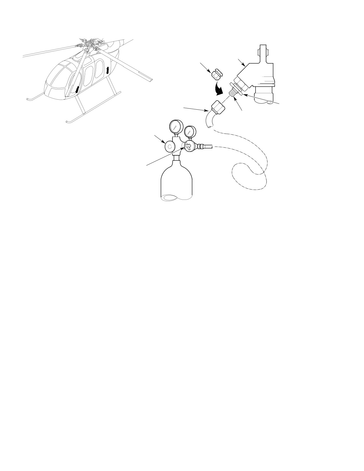
1. Landing Gear Damper Nitrogen Servicing
servicing hose-schrader valve connec
tion.
(Ref. Figure 301) Service landing gear damp
ers equipped with schrader valve according to
(6). While the nitrogen is still flowing,
the following steps.
tighten servicing hose. Allow nitrogen
pressure to build to the value according
Do not recharge a damper if
to part and dash number of damper
CAUTION
there is evidence of fluid leak
(Ref. Table 301).
age. Recharging of damper will cause fur
To prevent damage to damper or
ther leakage of both gas and damper fluid,
CAUTION
loss of damper fluid do not open
posing a danger to the helicopter.
schrader valve without pressurizing the
(1). Place helicopter on jacks or hoist and
servicing line. If fluid loss occurs, damper
will require overhaul.
elevate until dampers are fully ex
tended..
(7). Once pressure level is reached, open
schrader valve by turning outside nut
(2). For forward damper servicing, remove
counter clockwise. Allow system and
foot support fairings located in passen
damper pressure to equalize for a
ger compartment. For aft damper
minimum of 2 minutes. If slightly over
servicing, open engine access doors.
pressurized, bleed off excess very
slowly.
(3). Remove cap from schrader valve and
connect servicing hose, but do not
(8). Close schrader valve by turning the
tighten.
outside nut clockwise. Torque nut to 50
- 60 inch pounds (5.65 - 6.78 Nm).
(4). Ensure low side of nitrogen pressure
Remove servicing hose and install valve
regulator is backed off to the unpres
cap finger-tight.
surized position. Slowly open the high
pressure nitrogen bottle valve.
(9). Remove aircraft from jacks or hoist.
(5). Slowly turn regulator control until
(10). Inspect damper for leakage approxi
nitrogen begins to flow at the loose
mately two hours after servicing.
Page 301
32-10-60
TR12-001
CSP-HMI-2
MD Helicopters, Inc.
MAINTENANCE MANUAL
DAMPER
CAP
OUTSIDE NUT
SERVICING HOSE
SCHRADER VALVE
HIGH PRESSURE VALVE
REGULATOR CONTROL
6G32-045
Figure 301. Landing Gear Damper Nitrogen Servicing − On Helicopter
Page 302
Revision 19
32-10-60

MD Helicopters, Inc.
CSP-HMI-2
MAINTENANCE MANUAL
Table 301. Nitrogen Recharge Pressure
Ambient Temperature
600N6050−33
600N6050−31
° F (° C)
Psig (kPa)
Psig (kPa)
−40 (−40)
263 (1813)
151 (1041)
−35 (−37)
268 (1848)
153 (1055)
−30 (−34)
272 (1875)
156 (1076)
−25 (−32)
277 (1910)
158 (1089)
−20 (−29)
281 (1937)
161 (1110)
−15 (−26)
286 (1972)
163 (1124)
−10 (−23)
291 (2006)
166 (1145)
−5 (−21)
295 (2034)
169 (1165)
0 (−18)
300 (2068)
171 (1179)
5 (−15)
305 (2103)
174 (1200)
10 (−12)
310 (2137)
177 (1220)
15 (−9)
315 (2172)
179 (1234)
20 (−7)
320 (2206)
182 (1255)
25 (−4)
325 (2241)
185 (1276)
30 (−1)
330 (2275)
188 (1296)
35 (2)
335 (2310)
191 (1317)
40 (4)
340 (2344)
194 (1338)
45 (7)
345 (2379)
197 (1358)
50 (10)
351 (2420)
199 (1372)
55 (13)
356 (2455)
202 (1393)
60 (16)
361 (2489)
205 (1413)
65 (18)
367 (2530)
208 (1434)
70 (21)
372 (2565)
211 (1455)
75 (24)
378 (2606)
215 (1482)
80 (27)
383 (2641)
218 (1503)
85 (29)
389 (2682)
221 (1524)
90 (32)
395 (2723)
224 (1544)
95 (35)
400 (2758)
227 (1565)
100 (38)
406 (2799)
230 (1586)
105 (41)
412 (2841)
234 (1613)
110 (43)
418 (2882)
237 (1634)
115 (46)
424 (2923)
240 (1655)
120 (49)
430 (2965)
244 (1682)
125 (52)
436 (3006)
247 (1703)
Page 303
32-10-60
Revision 19
CSP-HMI-2
MD Helicopters, Inc.
MAINTENANCE MANUAL
This Page Intentionally Left Blank
Page 304
Revision 44
32-10-60
MD Helicopters, Inc.
CSP-HMI-2
MAINTENANCE MANUAL
LANDING GEAR SYSTEM
REMOVAL/INSTALLATION
1. Landing Gear Strut Replacement
(10). Gently work strut around bearing in
fuselage support fitting and remove.
(Ref. Figure 401)
B. Landing Gear Strut Installation
Consumable Materials
(1). For access to forward brace, strut and
(Ref. Section 91−00−00)
damper, open compartment access
Item
Nomenclature
doors.
CM318
Primer
(2). For access to aft landing gear attach
CM729
Tape, masking, pressure sensitive
ment points, open engine access doors.
NOTE: New bushings must be installed when
A. Landing Gear Strut Removal
installing struts. Torquing of the bolt will
press bushing into place.
NOTE: For component disassembly, refer to
(3). Gently work struts around bearings in
applicable section. For removal, two persons
fuselage support fittings.
are needed.
(4). Install attaching hardware with new
(1). Jack up or hoist helicopter until skid
bushing coated with wet primer
assemblies clear surface by 10 - 20
(CM318).
inches (25 - 50 cm) (Ref. Sec.
07-00-00).
(5). Torque nut to 85 - 110 inch-pounds
(9.60 - 12.43 Nm) plus drag torque
(2). Remove skid assemblies (Ref. Landing
and install cotter pin.
Gear Skid Replacement).
(6). Check for minimum 0.010 inch (0.254
(3). Pull strut fairing fillet downward
mm) gap between washer and airframe
against spring tension and secure with
clevis at slotted bushing.
tape (CM729).
NOTE: Install forward damper upper bolts
NOTE: Bushings must be removed from strut
with bolt heads facing aft. Install all other
to enable strut to clear bearing in fuselage
damper bolts with bolt head facing forward.
support fittings.
(7). Install damper (Ref. Landing Gear
(4). For access to forward brace, strut and
Damper Replacement).
damper, open compartment access
(8). Align inboard end of each brace with
doors.
mating bearing in fuselage supporting
fitting and install attaching hardware.
(5). For access to aft landing gear attach
ment points, open engine access doors.
(9). Torque nut to 60 - 85 inch-pounds
(6.78 - 9.60 Nm) plus drag torque
(6). Disconnect brace and damper from
and install cotter pin.
strut.
(10). Check for minimum 0.010 inch (0.254
(7). Remove hardware from strut pivot
mm) gap between washer and airframe
point.
clevis at slotted bushing.
(8). Use an ezy-out to pull both bushings
(11). Secure electrical bonding jumpers to
from strut clevis at pivot point.
airframe.
(9). Remove electrical bonding jumper
(12). Align outboard end of each brace with
attaching aft strut to airframe.
mating holes in strut.
Page 401
32-10-60
Revision 19
CSP-HMI-2
MD Helicopters, Inc.
MAINTENANCE MANUAL
Do not over-tighten brace-to-
(2). Install replacement damper in upper
CAUTION
strut hardware.
and lower mounting position with
attaching hardware. Ensure bushings
(13). Attach brace to strut with attaching
are in place.
hardware.
(14). Torque nut to 2 - 10 inch-pounds
NOTE: Install forward damper upper bolts
(0.226 - 1.13 Nm) plus drag torque
with bolt heads facing aft. Install all other
and install cotter pin.
damper bolts with bolt head facing forward.
(15). Reinstall skid assemblies (Ref. Landing
Gear Skid Replacement).
(3).
Align forward upper damper bearing
with airframe and install attaching
(16). Remove skid supports, lower helicopter,
hardware.
and remove jacks.
(17). Close or replace all access doors.
(4).
Torque nuts to 60 - 85 inch-pounds
(6.78 - 9.60 Nm) plus drag torque
and install cotter pin.
2. Landing Gear Damper Replacement
(Ref. Figure 401)
(5).
Check for minimum 0.010 inch (0.254
mm) gap between washer and airframe
A. Landing Gear Damper Removal
clevis at slotted bushing.
(1). Jack up or hoist helicopter on level
surface until landing gear skids just
(6).
Align aft upper damper bearing with
clear resting surface.
airframe and install attaching hard
ware.
(2). For forward damper removal, remove
footwell fairings located in passenger
compartment. For access for aft damper
(7).
Torque nuts to 95 - 110 inch-pounds
removal, open engine access doors.
(10.73 - 12.43 Nm) plus drag torque
and install cotter pin.
(3). Remove hardware (except bushings)
attaching damper assemblies to
fuselage attachment fittings and
(8).
Check for minimum 0.010 inch (0.254
landing gear struts.
mm) gap between washer and airframe
clevis at slotted bushing.
(4). Remove damper from aircraft.
B. Landing Gear Damper Installation
(9).
Align lower bearing of damper (forward
and aft) with mating holes in strut and
(1). Jack up or hoist helicopter on level
install attaching hardware.
surface until landing gear skids (Ref.
Sec. 7-00) just clear resting surface.
(10).
Torque nut to 95 - 110 inch-pounds
NOTE:
(10.73 - 12.43 Nm) plus drag torque
D Always be sure that replacement damper
and install cotter pin.
is correct for the helicopter.
D Check for proper alignment of cap torque
(11).
Check for minimum 0.010 inch (0.254
stripes before installation.
mm) gap between washer and airframe
clevis at slotted bushing.
D Install aft dampers with schrader valves
facing aft.
D Install fwd dampers with schrader valves
(12).
Install footwell fairings and close
facing forward.
engine access doors.
Page 402
Revision 26
32-10-60
MD Helicopters, Inc.
CSP-HMI-2
MAINTENANCE MANUAL
REF. AFT
FOOT ASSEMBLY
LANDING GEAR
SKID
REF. FRONT
ABRASION
FOOT ASSEMBLY
STRIP
ABRASION
STRIP
ABRASION
STRIP
ABRASION
STRIP
AFT BRACE
ASSEMBLY
AFT DAMPER
ASSEMBLY
FUSELAGE
FITTING
FRONT DAMPER
ASSEMBLY
AFT STRUT
ASSEMBLY
BONDING
FRONT STRUT
JUMPER
ASSEMBLY
FRONT BRACE
ASSEMBLY
REF. AFT
REF. AFT
BRACE ASSEMBLY
DAMPER ASSEMBLY
REF. FRONT
REF. AFT
DAMPER ASSEMBLY
STRUT
ASSEMBLY
REF. FRONT
MID FAIRING
STRUT
ASSEMBLY
MID FAIRING
BOLT
STEP
WASHER
LOWER FAIRING
ASSEMBLY
NUT
LOWER FAIRING
BOLT
WASHER
NUT
6G32-046B
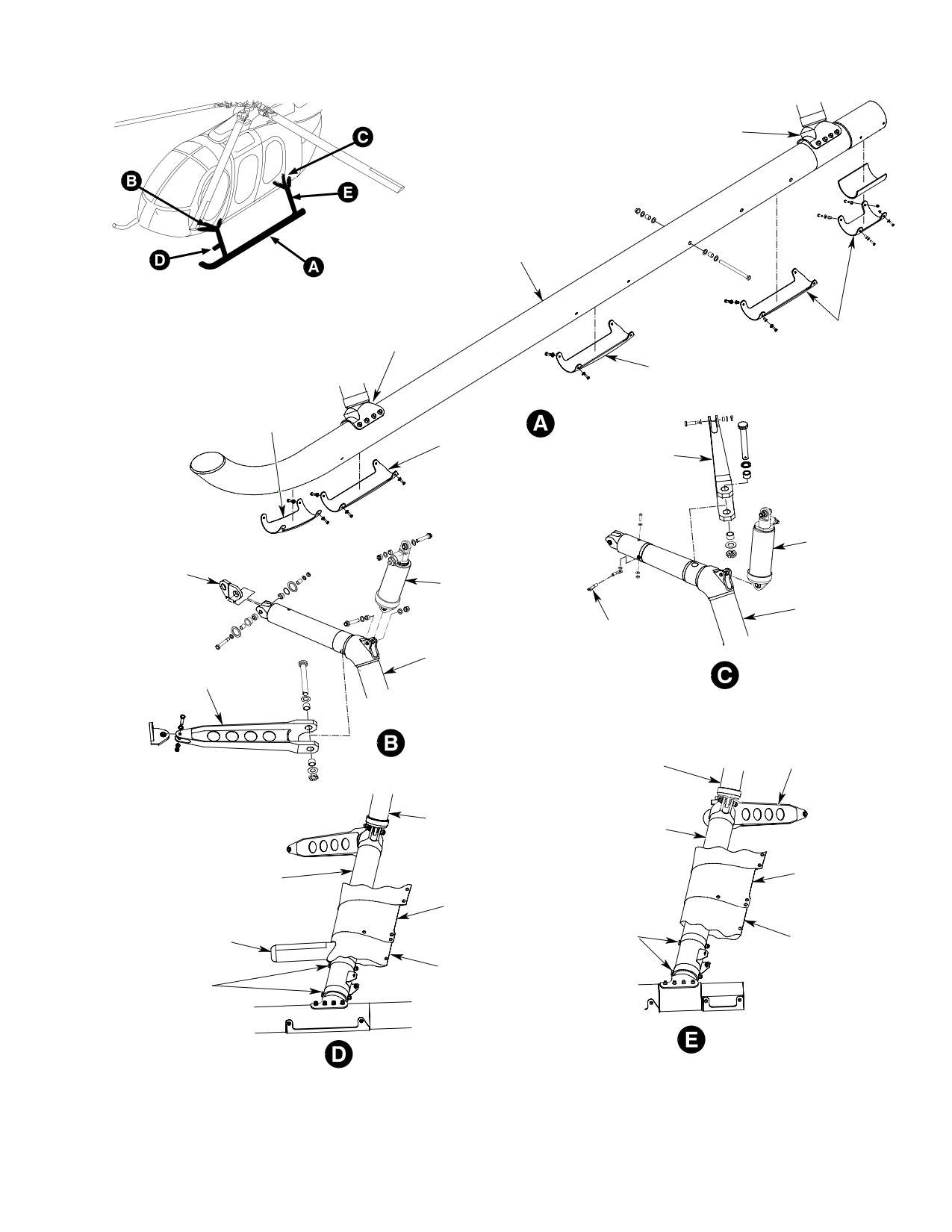
Figure 401. Landing Gear and Damper Installation
Page 403
32-10-60
Revision 34
CSP-HMI-2
MD Helicopters, Inc.
MAINTENANCE MANUAL
3. Landing Gear Skid Replacement
(b). Open underfloor compartment or
engine compartment doors for access
(Ref. Figure 401)
to strut cutout in fuselage skin. Have
an assistant push down on upper
A. Landing Gear Skid Removal
guide with suitable tool (wood dowel
or equivalent), to relieve spring
(1). Jack up or hoist helicopter until skid
tension.
assemblies clear surface by 10 - 20
(c). With spring tension off guide, remove
inches (Ref. Sec. 07-00).
screws attaching fillet to upper guide.
Slowly relax dowel pressure on guide
(2). Remove mid and lower fairings.
until springs fully expand.
(3). Remove bolts attaching forward and aft
(d). Carefully spread fillet at trailing
feet to forward and aft struts.
edge and remove in forward direc
tion.
(4). Simultaneously, slide front and rear
feet from struts.
(3). Remove mid fairing as follows.
(a). Remove hardware that secure
B. Landing Gear Skid Installation
trailing edge of mid fairing.
(1). Simultaneously, slide front and rear
(b). Remove hardware that secure fairing
feet onto struts.
to strut bracket.
(2). Install bolts attaching forward and aft
(c). Carefully spread trailing edge of
feet to forward and aft struts; torque
fairing and remove in forward
bolts to 95 - 110 inch-pounds (10.73 -
direction.
12.43 Nm) plus drag torque.
B. Landing Gear Fairing Installation
(3). Install mid and lower fairings.
(Ref. Figure 402 and Figure 403) Following
instructions apply to all four fairing assem
4. Landing Gear Fairing Replacement
blies.
(1). Install mid fairing as follows.
A. Landing Gear Fairing Removal
(a). Assemble upper guide, pin assembly,
(Ref. Figure 402 and Figure 403) The following
inner guide half, outer guide half,
instructions are typical for and apply to all
springs and lower support on landing
four fairing assemblies.
gear strut (guide pins must be
installed through matching holes of
(1). Remove lower fairing from fairing
lower guide).
assembly as follows.
(b). Wedge temporary holding device
(a). Remove attaching hardware that
between upper guide and strut to
secures lower fairing to two strut
keep pins engaged.
brackets, and that secures trailing
NOTE: Use two small wood blocks or any simi
edge of lower fairing.
lar suitable means to keep springs com
pressed. Device used must be small enough
(b). Carefully spread trailing edge of
to be removed through strut cutout in skin
lower fairing and remove in forward
after fillet is assembled.
direction.
(c). Carefully spread trailing edge of
(2). Remove fillet from upper fairing
fairing and position fairing on strut
assembly as follows.
bracket(s) and lower guide.
(a). Remove hardware that secure
(d). Install hardware in top hole of
trailing edge of fillet.
trailing edge of mid fairing.
Page 404
Revision 20
32-10-60
MD Helicopters, Inc.
CSP-HMI-2
MAINTENANCE MANUAL
(2). Install fillet as follows.
(e). Check for smooth telescoping action
of fairing into fillet by manually
sliding fillet up and down several
(a). Carefully spread trailing edge of fillet
times.
and position about upper guide.
(f). Close access doors.
(b). Have an assistant remove temporary
(3). Install lower fairing as follows.
holding device and push down on
upper guide with suitable tool (wood
(a). Carefully spread trailing edge of
dowel, etc).
fairing and position under the mid
fairing and over the lower strut
bracket.
(c). Install hardware securing fillet to
upper guide.
(b). Secure to upper and lower strut
brackets with hardware.
(d). Install hardware to secure fillet
(c). Secure fairing trailing edge with
trailing edge together.
attaching hardware.
Page 405
32-10-60
Revision 19
CSP-HMI-2
MD Helicopters, Inc.
MAINTENANCE MANUAL
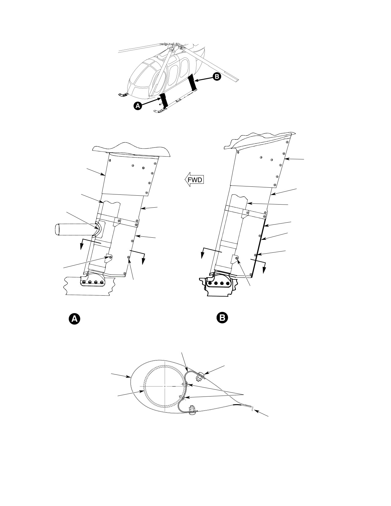
AFT FILLET
ASSEMBLY
FORWARD
FILET ASSEMBLY
MID FAIRING
STRUT
AFT STRUT
MID FAIRING
SEAL
LOWER FAIRING
FLAP
LOWER FAIRING
SCREW
A
WASHER
SCREW
A
NUT (5 PL)
WASHER
A
(2 PL)
A
SCREW
WASHERS (2 EA)
SCREW
NUT (5 PL)
WASHERS (2 EA) (2 PL)
FORWARD LEFT SIDE SHOWN
AFT LEFT SIDE SHOWN
FORWARD RIGHT SIDE IS OPPOSITE
AFT RIGHT SIDE IS OPPOSITE
BRACKET
ASSEMBLY
SCREW
WASHER (2 PL)
FAIRING ASSEMBLY
STRUT
RIVET
FLAP
(AFT FAIRING ONLY)
SECTION A - A
6G32-047A
Figure 402. Fairing Installation
Page 406
Revision 19
32-10-60
MD Helicopters, Inc.
CSP-HMI-2
MAINTENANCE MANUAL
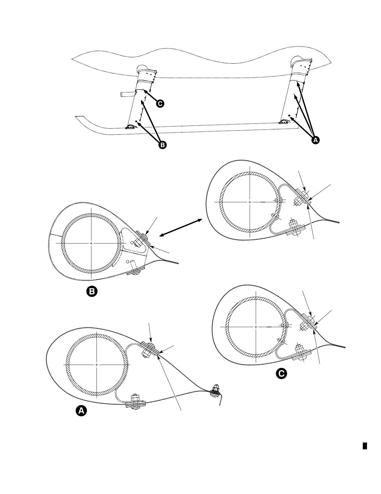
NAS603-9P SCREW
AN970-3 WASHER
600N6081-1
WASHER (RUBBER)
NAS603-9P SCREW
AN970-3 WASHER
600N6081-1
LOWER FORWARD FAIRING
WASHER (RUBBER)
600N6081-1
EARLY CONFIGURATION
WASHER (RUBBER)
NAS603-9P SCREW
AN970-3 WASHER
LOWER FORWARD FAIRING
600N6081-1
CURRENT CONFIGURATION
WASHER (RUBBER)
NAS603-9P SCREW
AN970-3 WASHER
600N6081-1
WASHER (RUBBER)
600N6081-1
WASHER (RUBBER)
UPPER FORWARD FAIRING
ALL CONFIGURATIONS
600N6081-1
AFT FAIRING
WASHER (RUBBER)
88-757
Figure 403. Landing Gear Rubber Washer Locations
Page 407
32-10-60
Revision 20
CSP-HMI-2
MD Helicopters, Inc.
MAINTENANCE MANUAL
This Page Intentionally Left Blank
Page 408
Revision 44
32-10-60
MD Helicopters, Inc.
CSP-HMI-2
MAINTENANCE MANUAL
LANDING GEAR SYSTEM
INSPECTION/CHECK
1. Landing Gear Inspection
(2).
Remove lower fairing from two-piece
fairing assembly.
(Ref. Figure 401)
(3).
Inspect skid for dents. If dents exceed a
depth of 0.20 inch (5.08 mm), they will
NOTE: If landing gear is installed, perform in
require repair.
spection with helicopter skids clear of
ground.
(4).
Inspect for punctures and cracks.
(1). Inspect skids, skid abrasion strips,
(5).
Perform fluorescent-penetrant inspec
struts, feet, braces and fairings for
tion of all crack areas, and of those
dents, cracks, loose components or
areas adjacent to all punctures. These
rivets, loose nuts and for missing
areas will require repair.
hardware.
(6).
Inspect from aft end of tube to a point
(2). Inspect skid-to-foot and foot-to-strut
10 inches (25.4 cm) forward of aft strut
attachments for loose bolts. Check aft
for scratches and nicks.
foot-to-bearing rivet installation for
security.
(7).
Inspect from forward end of tube to 10
inches (25.4 cm) forward of aft strut for
(3). Using 10X glass and bright light,
scratches and nicks. If scratches and
visually inspect area at, around and
nicks exceed a length of 0.25 inch (6.35
between foot-to-strut attach bolts not
mm) and a depth of 0.020 inch (0.508
covered by sealant for cracks and
mm), they will require repair.
corrosion.
(8).
Inspect abrasion strips for minimum
thickness of 0.040 inch (1 mm), damage
NOTE: If cracks or corrosion other than light
and for loose bolts and screws.
surface corrosion is found, replace affected
part.
(9).
Check skid extension rivet attachment
for security.
(4). Inspect keel beam areas where the
strut assemblies attach for loose
(10).
Check condition of plug installed in
bearings, condition of hardware and
skid extension.
strut adapters.
(11).
Check aft foot bearing and extension for
(5). Check condition of beaded seal around
wear, damage and corrosion.
edges of all rigid-mounted skid tube
components.
3. Landing Gear Strut Inspection
(Ref. Table 801)
2. Landing Gear Skid Inspection
(1). Repair elongated, enlarged or worn
(Ref. Figure 401)
holes in strut, either inboard or out
board (Ref. SRM).
NOTE: If landing gear assembly has not been
removed from helicopter, perform following
(2). Replace strut if cracked; if dents in
steps (1). and (2). before proceeding with in
strut exceed 0.060 inch (1.524 mm)
spection.
depth; or, if scratches and repair area
depth would exceed 0.010 inch (0.254
(1). Jack helicopter until landing gear
mm) when measured to surrounding
dampers are fully extended.
unrepaired surface.
Page 601
32-10-60
Revision 31
CSP-HMI-2
MD Helicopters, Inc.
MAINTENANCE MANUAL
4. Landing Gear Damper Inspection
(d). Lower and raise tailboom below and
above the normal at-rest position
three times. On the last cycle, allow
(Ref. Table 601 and Figure 401)
the tailboom to slowly rise to the
at-rest position.
NOTE: It is normal for a thin hydraulic oil film
to remain on damper as a result of wiping
(e). Measure and record dimension from
contact with piston seal. Newly-installed
bottom of upper end cap to top of
dampers may also have slight oil seepage
barrel on all four damper assemblies.
from oil trapped in end cap threads during
(f). Repeat steps (d). and (e). two more
damper assembly. Neither of these should
times.
be considered damper leakage or cause for
damper replacement.
(g). Determine average extension from all
six readings for each damper assem
(1). Inspect for hydraulic oil leakage. If
bly. Remove and overhaul any
leakage is visible, wipe oil from damper
damper assembly not meeting
after last flight of the day. Re-inspect
dimensions (Ref. Table 601).
the following day for oil leakage. If
NOTE: If two damper assemblies fail to meet
leakage persists, replace damper.
the minimum extension (Ref. Table 601), re
place the damper having the greater
(2). With helicopter on jacks, inspect
amount of deflection with a known service
damper assemblies for evidence of
able damper and repeat steps (a). thru (g). If
bearing looseness in upper and lower
the original damper again fails to meet
caps, worn bearings (excessive radial
minimum extension requirements, replace
play), loose or cracked caps and oil
it with the known serviceable damper, rein
leakage. Any misalignment of torque
stall the first damper and repeat steps (a).
stripes on caps, piston and barrel
thru (g). This will determine whether one or
indicates loosening of caps. Replace
both dampers require overhaul. For owners
immediately and repair removed
and operators having suitable equipment,
damper.
any damper not meeting minimum exten
sion requirements can be bench-checked.
(3). Inspect damper attaching hardware for
Dampers meeting specifications may be re
security.
turned to service if other defects are not
noted.
NOTE: The landing gear damper assemblies
5. Forward Cabin Entry Step Inspection
are to be checked at a helicopter gross
weight of 2130 - 2230 pounds (967 - 1012
(1). Remove landing gear fairing assembly.
kg) at a longitudinal CG of 94 ±1, exclusive
(2). Inspect step-to-strut attachment for
of skid mounted flotation gear. Place the he
loose attaching hardware by checking
licopter on a smooth concrete or equivalent
for relative motion between mating
surface (not asphalt).
parts.
(3). Inspect welded joint of step for cracks.
(a). Raise and lower tailboom above and
below the normal at-rest position
(4). Inspect safety walk tape for condition
three times. On the last cycle, allow
and security. Replace unserviceable
the tailboom to slowly settle to the
tape.
at-rest position.
(5). Install landing gear fairing assembly.
(b). Measure and record dimension from
6. Landing Gear Fairing Inspection
bottom of upper end cap to top of
(Ref. Figure 402)
barrel on all four damper assemblies.
(1). Inspect fairing support brackets for
(c). Repeat steps (a). and (b). two more
security of attachment to strut, cracks
times.
and deformation.
Page 602
Revision 19
32-10-60
MD Helicopters, Inc.
CSP-HMI-2
MAINTENANCE MANUAL
(2). Inspect fairing seals for deterioration
Table 601. Minimum Damper Extension
and bonding.
inches (cm)
(3). Inspect fuselage rubbing plate for
security of bond and excessive wear.
Fwd
1.60
(4.06)
(4). Inspect rubber washers for cracks or
deterioration.
Aft
1.71
(4.34)
Page 603
32-10-60
Revision 22
CSP-HMI-2
MD Helicopters, Inc.
MAINTENANCE MANUAL
This Page Intentionally Left Blank
Page 604
Revision 44
32-10-60
MD Helicopters, Inc.
CSP-HMI-2
MAINTENANCE MANUAL
LANDING GEAR SYSTEM
REPAIRS
1.
Landing Gear System Repairs
(3). Install new abrasion strip. Torque bolts
to 12 - 15 inch-pounds (1.36 - 1.69
(1).
Repair scratches and nicks by smooth
Nm) plus drag torque.
ing sharp edges.
(4). After installation, seal around bolts and
(2).
Repair elongated, enlarged or worn
all of parting edges of abrasion strip
holes in strut, either inboard or out
next to skid tube with an approximate
board.
0.060 inch (1.524 mm) bead (fillet) of
sealing compound (CM426) to make
(3).
Repair bolt holes at large end of brace
watertight.
that attaches to strut.
3. Ground Handling Bolt Replacement
(4).
Replace strut; if cracked, if dents in
strut exceed 0.060 inch (1.524 mm)
(Ref. Figure 401)
depth or if scratched and repaired area
depth would exceed 0.010 inch (0.254
(1). Remove nut, washers and spacer from
mm) when measured to surrounding
skid tube.
unrepaired surface.
(2). Slide bolt with washers and spacer from
(5).
Replace defective or badly damaged
skid tube.
fairing.
(3). Install, in order, bolt, washer, new
(6).
Replace cracked, dented or distorted
spacer and washer through skid tube
braces.
from outside-to-inside.
(7).
Repair or replace damaged skid tube.
(4). Install, in order, washer, spacer, washer
and nut onto bolt. Torque nut to 10 - 20
(8).
Replace center beam-to-landing gear
inch-pounds (1.13 - 2.26 Nm) plus
attachment bearings that exceed 0.040
drag torque.
inch (1.016 mm) axial play.
4. Safety Walk Tape Replacement
(9).
Repair loose or defective pins and nuts
securing foot to bearing; replace
(Ref. Figure 401)
defective bearing.
Consumable Materials
2.
Abrasion Strip Replacement
(Ref. Section 91−00−00)
Item
Nomenclature
(Ref. Figure 401)
CM220
Naphtha aliphatic
CM724
Tape, non-slip
Consumable Materials
(Ref. Section 91−00−00)
Item
Nomenclature
(1). Carefully pull or scrape away damaged
CM426
Sealing compound
tape.
(2). Remove all residual adhesive from step
(1). Remove bolts securing defective
by wiping with a clean cloth wetted by
abrasion strip(s) to skid.
naphtha (CM220).
(2). Remove bolts securing abrasion strip to
(3). Install new tape (CM724) and press
skid extension. Completely remove any
firmly into place. Expel air bubbles
residual sealant.
while pressing down tape.
Page 801
32-10-60
Revision 19
CSP-HMI-2
MD Helicopters, Inc.
MAINTENANCE MANUAL
5. Landing Gear Fairing Repair
(3). Replace damaged guide/pin assembly or
guide half if guide is cracked, pins are
bent or badly worn.
(Ref. Figure 402)
(4). Replace springs that are badly worn or
Consumable Materials
rusty, or if free length is less than 8.72
(Ref. Section 91−00−00)
inches (22.149 cm).
Item
Nomenclature
CM412
Adhesive, bonding, vulcanized
(5). Replace fillet if teflon strip is loose or
badly worn.
(1). Replace an excessively damaged lower
(6). Replace damaged strut bracket.
fairing.
Remove rivets, locate new part and
install blind rivets. Use next larger size
rivets if mating holes in strut are
(2). Replace damaged fairing bracket or
enlarged.
lower guide. Remove rivets, locate new
part and install blind rivets. Use next
larger size rivets if mating holes in
(7). Replace unserviceable rubber seals; use
strut are enlarged.
adhesive (CM412).
Table 801. Maximum Damage Limits − Landing Gear Components
Dents
Nicks
Scratches
Cracks
Holes
Component
in / mm
in / mm
in / mm
in / mm
in / mm
Skid tube (2)
0.200 / 5.08
0.010 / 0.254, from aft side of
(Same as for
No cracks
0.250 / 6.350
(1)
aft strut to 10 inches (25.4 cm).
nicks) (1)
allowed
(1) (3)
forward of the strut, with
cleanup not exceeding 0.015 /
0.381; 0.015 / 0.381 if forward
of that point to start of curved
section, with cleanup not
exceeding 0.020 / 0.508 (1)
Forward foot
0.060 / 1.524
0.060 / 1.524
0.010 / 0.254
No cracks
No holes
allowed
allowed
Strut
0.060 / 1.524
(1)
(1)
No cracks
No holes
allowed
allowed
Brace
0.050 / 1.270
0.010 / 0.254
0.005 / 0.127
No cracks
No holes
allowed
allowed
Damper assembly
0.060 / 1.524
0.010 / 0.254
0.010 / 0.254
No cracks
No holes
(5)
allowed
allowed
Fittings
0.010 / 0.254
0.010 / 0.254
0.010 / 0.254
No cracks
No holes
allowed
allowed
Aft foot
0.060 / 1.524
0.060 / 1.524
0.010 / 0.254
No cracks
No holes
allowed
allowed
Foot bearing
0.010 / 0.254
0.010 / 0.254
0.010 / 0.254
No cracks
No Holes
allowed
allowed
Page 802
Revision 19
32-10-60
MD Helicopters, Inc.
CSP-HMI-2
MAINTENANCE MANUAL
Table 801. Maximum Damage Limits − Landing Gear Components
Dents
Nicks
Scratches
Cracks
Holes
Component
in / mm
in / mm
in / mm
in / mm
in / mm
Skid extension
0.010 / 0.254
0.010 / 0.254 (4)
0.010 / 0.254
No cracks
No holes
(4)
(4)
allowed
allowed
NOTES:
(1) For other repair data, refer to CSP−SRM−6.
(2) Repair of minor skid tube damage on forward (curved) section is not required, but surface finish must be
restored.
(3) Hole must be plugged with correct size blind rivet.
(4) No damage is allowed on skid extension where skid and sleeve are attached.
(5) No dents allowed in damper barrel.
Page 803
32-10-60
Revision 19
CSP-HMI-2
MD Helicopters, Inc.
MAINTENANCE MANUAL
This Page Intentionally Left Blank
Page 804
Revision 44
32-10-60
MD Helicopters, Inc.
CSP-HMI-2
MAINTENANCE MANUAL
Section
32−40−00
Ground Handling
Wheels
(369D/E/FF − 500N)
MD Helicopters, Inc.
CSP-HMI-2
MAINTENANCE MANUAL
GROUND HANDLING WHEELS
MAINTENANCE PRACTICES
1. Ground Handling Wheel Assembly
(2). With ground handling wheels in the
retracted position, align and engage the
The standard ground handling wheel assem
skid fittings.
blies provide a means of moving the helicopter
by hand or by towing.
NOTE: Slide wheel assembly for and aft to en
sure locking mechanism is securely locked
The special ground handling wheel assemblies
into place.
for use with helicopters equipped with
emergency or utility floats provide a means of
(3). Install jack handle over the wheel
moving the helicopter by hand only.
assembly socket, install lock pin and
rotate handle downward to lower the
A. Ground Handling Wheel Description and
wheels and raise the helicopter.
Operation
Hold downward pressure on
(1).
Standard ground handling wheel
WARNING
jack handle until the extend
assembly consists of one detachable
lock snaps into locked position. If the
jack handle and two two-wheeled
lock is not properly engaged and the
jacking assemblies that can be
handle is released, the upward swing of
straddle-mounted to the left and right
the handle could cause serious person
landing gear skids by use of existing
al injury.
ground handling wheel fittings. The
wheels are manually lowered with a
(4). Check that the extend lock is engaged;
detachable jack handle and are held in
then release downward pressure and
the down position (helicopter raised on
remove jack handle.
wheels) by a mechanical lock. The
jacking assemblies are equipped with
(5). Install second ground handling wheel
two tow bar attach fittings for towing.
assembly on the other skid in the same
(2).
Special ground handling wheels are
manner.
needed in place of standard ground
handling wheel assemblies for moving a
3. Special Ground Handling Wheel
helicopter equipped with emergency or
Installation and Use
utility floats. These wheel assemblies
are specially designed for use with
(Ref. Figure 201)
emergency floats and raise the landing
skids higher off the ground than
Damage may result from push
CAUTION
standard ground handling wheels. A
ing up and/or pulling down on
channel provides support for the
the tail boom to facilitate installation of spe
underside of the landing gear skid. A
cial ground handling wheels.
rubber pad on the channel furnishes
sufficient skid retaining friction
NOTE: When the helicopter is jacked from one
without need for attachment of wheel
side only, a cushion saddle-type support
assembly to skid. Guards above the
should be placed under the tail boom at the
wheel on each side of the channel
jacking pad location for extra stability.
prevent wheel chafing of floats.
(1). Install and use special ground handling
2.
Standard Ground Handling Wheel
wheel assemblies as follows.
Installation and Use
(a). Jack up one side of the helicopter for
(1). Position ground handling wheel
clearance to place ground handling
assembly over the skid tube at the
wheel assembly under the landing
location of the skid fittings.
gear skid.
Page 201
32-40-00
Revision 19
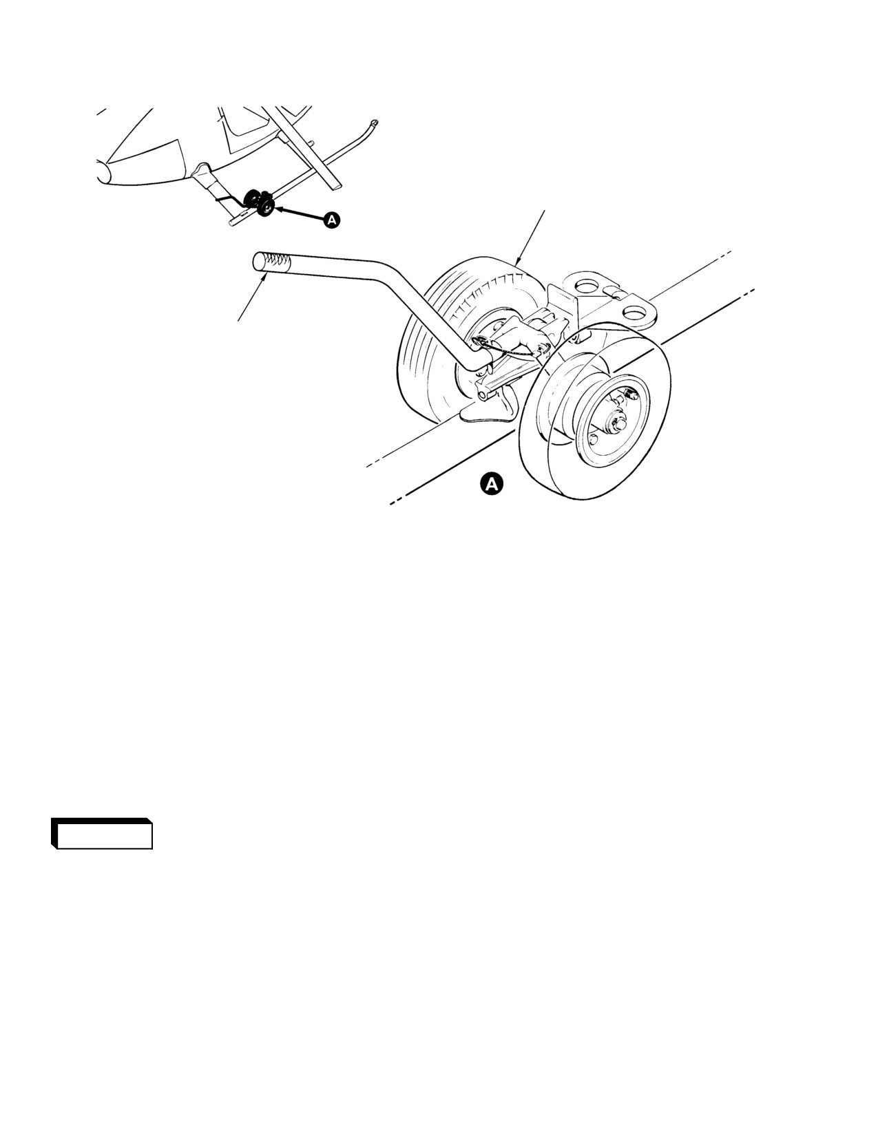
CSP-HMI-2
MD Helicopters, Inc.
MAINTENANCE MANUAL
WHEEL ASSEMBLY
HANDLE
G32-4001
Figure 201. Ground Handling Wheel Assembly (Standard)
(b). Position ground handling wheel
(6). To remove axle shaft from housing,
assembly below the ground handling
remove roll pin and slide shaft from
fittings, which is the approximate
housing.
center of gravity (CG) point.
5. Standard Ground Handling Wheel
Re−assembly (Early Configuration)
4. Standard Ground Handling Wheel
Disassembly (Early Configuration)
(1). If previously removed, install axle shaft
into housing and secure with roll pin.
(1). Remove cotter pin and washer from
axle shaft and slide hub-and-wheel
(2). Using suitable bearing press, install
assembly off axle.
bearings in hub.
(2). Remove three nuts securing wheel to
(3). Install washer, hub assembly and
hub.
washer on axle. Shim hub assembly,
0.010 inch maximum, using AB2578-24
Severe personal injury or
washers, as required, between bearing
WARNING
damage to property can oc
and outer washer and install cotter pin.
cur if tire is not deflated before at
(4). Using talcum powder, insert tube into
tempting to separate wheel halves.
tire and install on wheel halves.
(3). Deflate tire and remove six nuts,
(5). Secure wheel halves together using six
washers and screws securing wheel
screws, washers and nuts.
halves.
(6). Inflate tire in accordance with man
(4). Remove tire and tube from wheel.
ufacturers specifications.
(5). Using suitable bearing press, remove
(7). Install wheel on hub assembly using
bearings from hub.
three nuts and washers.
Page 202
Revision 19
32-40-00
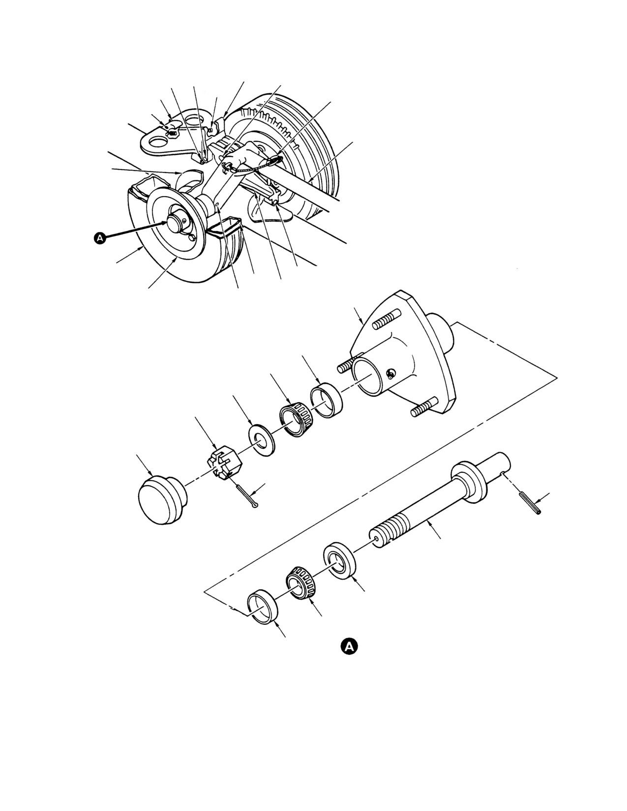
MD Helicopters, Inc.
CSP-HMI-2
MAINTENANCE MANUAL
ROLL
LOCK
BUSHING
PIN
PIVOT PIN
SPRING
RETAINER
LOCK PIN
ROLL PIN
HANDLE
INNER
WHEEL
TIRE
BUSHING
TUBE
BASE
OUTER WHEEL
ROLL
PIN
HUB
RACE
BEARING
WASHER
NUT
DUST CAP
COTTER PIN
ROLL PIN
AXLE
SEAL
BEARING
RACE
G32-4003
Figure 202. Ground Handling Wheel Assembly/Disassembly
Page 203
32-40-00
Revision 19
CSP-HMI-2
MD Helicopters, Inc.
MAINTENANCE MANUAL
6. Standard Ground Handling Wheel
(7). Secure wheel halves together using six
Disassembly (Current Configuration)
screws, washers and nuts.
(Ref. Figure 202)
(8). Inflate tire in accordance with man
ufacturers specifications.
(1). Remove three nuts and washers
(9). Install wheel on hub assembly using
securing wheel and tire assembly to
three nuts and washers.
hub and axle assembly.
8. Standard Ground Handling Wheel
(2). Remove dust cap, cotter pin, nut and
Servicing
washers from hub and axle assembly.
At regular intervals, Ground Handling Wheel
Severe personal injury or
Assemblies should be maintained to provide
WARNING
damage to property can oc
safe use and longer life of components.
cur if tire is not deflated before at
tempting to separate wheel halves.
(1). Ensure tire pressure is within manufac
turer's specifications.
(3). Deflate tire and remove six nuts,
washers and screws securing wheel
(2). Grease bearing using MIL-G-81322,
halves.
Mobil Grease 28 or alternate grease
MIL-G-25537, Aero Shell using
(4). Remove tire and tube from wheel.
available grease zerk (primary method)
or hand pack (alternate method).
Do not remove spacer from hub
CAUTION
body. Spacer is a close tolerance
(3). Remove excess play of hub-to-axle by
press fit and should not be removed.
inserting AB2578-24 washers, as
required, between bearing and outer
(5). Remove seal, bearings and races from
washer to maintain 0.010-inch axial
hub body.
play.
(6). To remove axle shaft from housing,
9. Special Ground Handling Wheel
remove roll pin and slide shaft from
Disassembly
housing.
(Ref. Figure 204)
7. Standard Ground Handling Wheel
(1). Remove cotter pin, nut and washer and
Re−assembly (Current Configuration)
remove wheel assembly.
(Ref. Figure 202)
(2). To remove axle shaft, remove slotted
pin and slide shaft from housing.
(1). If previously removed, install axle into
(3). Using suitable bearing press, remove
housing and secure with roll pin.
bearings from hub.
(2). Install races, bearings and seal in hub.
10. Special Ground Handling Wheel
(3). Install hub assembly on axle shaft and
Re−assembly
secure with washer and nut.
(Ref. Figure 204)
(4). Tighten nut until there is a maximum
(1). Insert axle shaft into housing and
of 0.010 inch axial play. Remove excess
insert slotted pin.
axial play by inserting AB2578-24
washers, as required, between bearing
(2). Using suitable bearing press, install
and outer washer.
bearings into hub.
(5). Install cotter pin and dust cap.
(3). Install wheel on axle using washer, nut
and cotter pin. Adjust axial play, 0.010
(6). Using talcum powder, insert tube into
inch maximum, using AN960C1016
tire and install on wheel halves.
washers as required.
Page 204
Revision 19
32-40-00
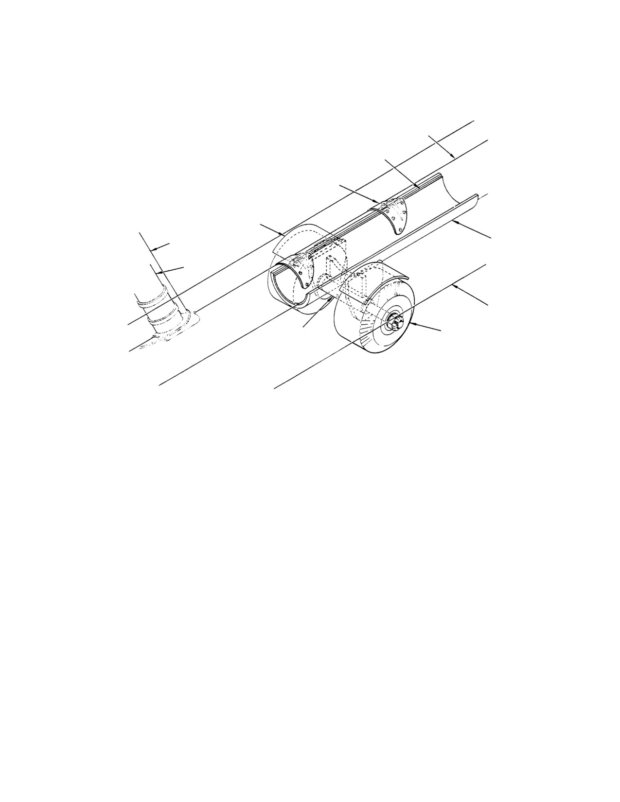
MD Helicopters, Inc.
CSP-HMI-2
MAINTENANCE MANUAL
11. Special Ground Handling Wheel Servicing
solid rubber tires and therefore require no
servicing.
(Ref. Figure 204) The special ground handling
wheel assemblies have sealed bearings and
SKID TUBE
RUBBER PAD
(NOTE 1)
SKID FITTING
(REF) (NOTE 2)
GUARD
FAIRING
WELD SUPPORT
STRUT
EMERGENCY FLOAT
CONTAINMENT COVER
SHAFT
RUBBER TREAD WHEEL
NOTES:
1.
LANDING GEAR SKID TUBE UNDERSIDE RESTS ON
CAUTION: BE SURE THAT FLOAT CONTAINMENT
RUBBER PAD AND IS SUPPORTED BY WELD SUPPORT
COVER CLEARS AND IS NOT PINCHED BY
WITHOUT RESTAINING ATTACHMENT.
HANDLING WHEEL ASSEMBLY.
2.
NOT USED WITH GROUND HANDLING WHEELS SHOWN.
3.
MAXIMUM LOAD RATE 800 LBS. (363 KG) AT 8 RPM.
G32-4000A
Figure 203. Special Ground Handling Wheel Assembly (Float Type)
Page 205
32-40-00
Revision 19
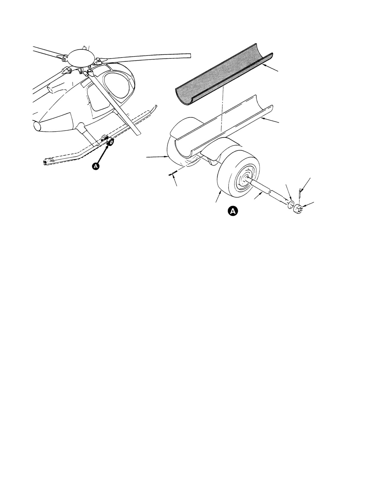
CSP-HMI-2
MD Helicopters, Inc.
MAINTENANCE MANUAL
PAD
WELD ASSEMBLY
WHEEL
COTTER PIN
WASHER
SLOTTED PIN
SHAFT
NUT
WHEEL
G32−4002
Figure 204. Special Ground Handling Wheel Assembly/Disassembly
Page 206
Revision 19
32-40-00
MD Helicopters, Inc.
CSP-HMI-2
MAINTENANCE MANUAL
Section
32−40−60
Ground Handling
Wheels (600N)
MD Helicopters, Inc.
CSP-HMI-2
MAINTENANCE MANUAL
GROUND HANDLING WHEELS
MAINTENANCE PRACTICES
1. Ground Handling Wheel Assembly
The jack retains a vertical position
during raising and lowering of the
The standard ground handling wheel assem
wheels.
blies provide a means of moving the helicopter
The ram of the jack is in constant
by hand or by towing.
contact with the upper cross frame of
the main body, providing vertical
A. Ground Handling Wheel Assembly
pumping leverage forcing the wheels
Description and Operation
down.
The ground handling wheel set consists of two
(4). Attach Cradle and Main Frame Body:
dual wheel assemblies, which are designed to
support a fully equipped helicopter. The wheel
The attach cradle is attached to the
assembly consists of two pneumatic tires, rims,
main frame body by means of two pins
spindles, hydraulic jack and attach cradle.
with cotter pins. The contoured cradle
is slotted to lock onto the skids.
(1). Tires:
2. Ground Handling Wheel Assembly
Maintenance
The tires are 10 ply with a maximum
rating of 1120 lb at 65 psi (508 kg at
(1). Ensure tire pressure is within manufac
448 kPa).
turer's specifications.
(2). Rims:
(2). Inspect tires for wear and cuts, none
allowed.
The rim rotates on a spindle by means
(3). Inspect wheels for cracks and defects,
of inner and outer tapered roller
none allowed.
bearings with an external grease fitting
on the hub for periodic servicing.
(4). At regular intervals, repack wheel
bearings and grease spindle assembly
(3). Hydraulic Jacks:
guides.
A six ton jack is held in place on the
(5). At regular intervals, inspect hydraulic
main frame by a support plate.
jacks for proper fluid levels.
Page 201
32-40-60
Revision 19
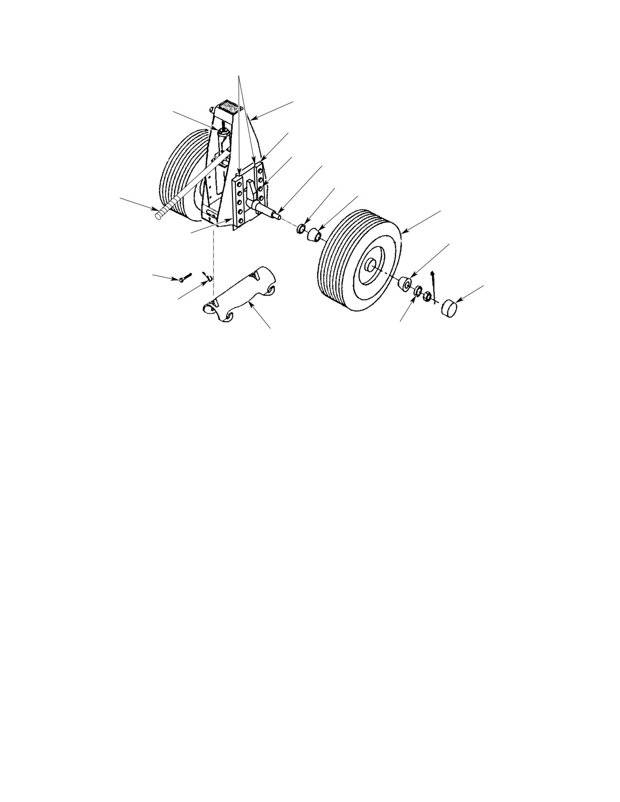
CSP-HMI-2
MD Helicopters, Inc.
MAINTENANCE MANUAL
NOTE
FRAME ASSEMBLY
JACK
GUIDE
NUT
SPINDLE ASSEMBLY
SEAL
HANDLE ASSEMBLY
WHEEL BEARING
TIRE
GUIDE
WHEEL BEARING
CLEVIS
HUB CAP
COTTER PIN
SPINDLE
CARRIER
WASHER
NOTE:
PERIODICALLY GREASE SPINDLE-TO-GUIDE
INTERFACE FOR PROPER OPERATION.
6G32-042
Figure 201. Ground Handling Wheel Assembly
Page 202
Revision 19
32-40-60
MD Helicopters, Inc.
CSP-HMI-2
MAINTENANCE MANUAL
Section
32−81−00
Utility Float System
(369D/E)
MD Helicopters, Inc.
CSP-HMI-2
MAINTENANCE MANUAL
UTILITY FLOAT SYSTEM
MAINTENANCE PRACTICES
1. Utility Float Description and Operation
0.5 psig (3.447 kPa) for each compart
ment.
Utility floats consists of neoprene airtight
(3). Place BATTERY-OFF-EXT PWR
chambers separated by internal walls that
switch at BATTERY. Actuate POS LT
provide six individual watertight compart
switch to the ON position. Observe that
ments. Skid attachment strips (girts), bonded
left and right position lights illuminate.
to underside of floats, are bolted to landing
Place all switches at OFF position.
gear skids and extensions. Floats are inflated
to a normal operating pressure of 2.0 psig (14
2. Utility Float Inspection
kPa). Relief valves release air pressure if
compartment pressure becomes excessive. A
(1). Inspect float chambers for correct air
stabilizer assembly is attached at the aft end
pressure.
of the skid tube extension.
(2). Inspect float bags for abrasion and
NOTE: If a helicopter with utility floats is tilted
chafing.
back on the tail skid to install ground handl
(3). Inspect pressure relief and fill valves
ing wheels, approximately 1 pint (0.437 li
for condition and closure.
ter) of oil is trapped in the tail rotor trans
mission. This condition gives a false sight
A. Skid Tube and Extension Assembly
plug oil level indication immediately after
Inspection
return to a level attitude. After ground ru
nup, oil level indication is normal.
Inspection of skid tube and extension assembly
is identical to that described in Sec. 32-10-00.
A. Utility Float Operational Check
B. Utility Float Repair
With helicopter on the ground and utility
Repair materials and information are avail
floats inflated to normal operating pressure,
able from the float manufacturer. Make
perform the following operational checks:
repairs to utility floats using materials
according to manufacturer's instructions.
(1). Check all float compartments for 2.0
psig (14 kPa).
3. Utility Float Troubleshooting
NOTE: Changes in atmospheric pressure, and
Refer to Table 201 for troubleshooting informa
temperature of float compartments affects
tion. Troubles presented are listed in order of
pressure gage readings. A temperature
possible occurrence during performance of
change of 1 degree equals 0.032 psig (0.2206
operational check. This information is pro
kPa).
vided to aid in isolating faults found during
operational check or normal operation of the
(2). Check for pressure drop with pressure
system. The fault is then removed by repair or
gage that indicates 0 - 15 psi (0 - 103
replacement to return the system to trouble-
kPa), graduated in 0.5 psi (3.447 kPa)
free operation. Troubleshooting and repair of
increments. Maximum allowable
internal components of the float is beyond the
pressure drop in 24 hours is limited to
scope of this section.
Page 201
32-81-00
Revision 19

CSP-HMI-2
MD Helicopters, Inc.
MAINTENANCE MANUAL
Table 201. Troubleshooting Utility Floats
Symptom
Probable Trouble
Corrective Action
Low air pressure
Damaged float
Repair float.
Defective fill valve
Replace fill valve.
Defective pressure relief valve
Replace pressure relief valve.
Position lights do not
POS LT switch not at ON position
Actuate switch to ON position.
illuminate
Position light lamp defective
Replace lamp.
Defective electrical wire splice
Repair electrical splice.
4. Utility Float Replacement
B. Utility Float Installation
(Ref. Figure 201)
Consumable Materials
(Ref. Section 91−00−00)
A. Utility Float Removal
Item
Nomenclature
CM209
Zinc chromate putty
Prior to removal of utility floats, jack or hoist
CM318
Primer
helicopter until landing gear dampers are fully
CM425
Sealing compound
extended and landing gear skid tubes are at
least six inches (15cm) from ground. Skid and
CM717
Tape, pressure sensitive
fairing assemblies must be removed to remove
float assemblies Ref. Sec. 32-10-00).
NOTE: Prior to assembly, apply
primer
(CM318) to all mating surfaces.
Maintain helicopter in level at
CAUTION
titude during jacking or hoist
(1). On early configuration extended
ing. Do not raise one side of helicopter at a
landing gear, coat abrasion strip with
time.
zinc chromate putty (CM209) and
install using screws.
(1). Remove position light cover screws,
(2). Install bolt covers using existing screws
then remove cover. Remove position
and wrap with two overlapping layers
light mounting screws and position
of tape (CM717).
light. Retain electrical wire for installa
tion.
(3). Install tyrap bracket on forward struts.
(4). Align extension and bearing sleeve
(2). Remove bolts and washers attaching
holes; install rivets using wet primer
stabilizer assembly to aft section of
(CM318).
floats.
(5). On early configuration extended
(3). Open fill valve at each of six float
landing gear, install skid tube extension
chambers. A suction device such as a
as follows:
vacuum cleaner speeds air evacuation.
(a). Install indexing plug in float kit
extension tube.
(4). Remove bolts, washers, gravel guards
and abrasion strip attaching float to
(b). Align indexing plug tabs with slots in
skid assembly and skid extension.
foot bearing sleeve on helicopter;
install indexing plug and forward end
(5). Depress float around strut assemblies
of extension tube over bearing sleeve.
and pull float free from skid tube
Use care not to damage packing
assembly and skid extension.
during installation.
Page 202
Revision 19
32-81-00
MD Helicopters, Inc.
CSP-HMI-2
MAINTENANCE MANUAL
(c). Align bolt holes in bearing sleeve,
bolts to 25 - 35 inch-pounds (2.82 -
indexing plug and extension tube;
3.95 Nm).
install rivets with wet primer.
(9). Connect wiring to position light then
(d). Coat mating surfaces of abrasion
install position light with screws.
strip with zinc chromate putty.
Install cover and secure with screws.
(e). Install abrasion strip on extension
5. Skid Tube Extension Replacement
tube with rivets and wet primer.
(Ref. Figure 901)
(f). Seal all edges of abrasion strip with
A. Skid Tube Extension Removal
approximately 0.060 (1.524 mm) bead
of sealing compound (CM425).
(1). Remove bolts and washers; then
remove stabilizer support from aft end
(6). Position floats on skid and extension
of skid extension.
assembly. Align bolt holes in float girt
and skid assembly. Secure floats in
(2). Remove bolts and nuts attaching
place using gravel guards, abrasion
extension to skid tube assembly.
strips, bolts and washers. Coat bolts
and washers with primer and torque to
(3). Separate skid extension from skid tube.
25 - 35 inch-pounds (2.82 - 3.95
B. Skid Tube Extension Installation
Nm).
(1). Insert skid extension into aft section of
(7). Position stabilizer cap on skid tube
skid tube.
extension. Coat mating surfaces with
sealing compound and secure with bolts
(2). Align bolt holes and secure in place
and washers.
using bolts and nuts as applicable.
(8). Position stabilizer assembly on aft
(3). Position stabilizer support on aft end of
section of skid extension and secure in
skid extension and secure in place
place using bolts and washers. Torque
using bolts and washers.
Page 203
32-81-00
Revision 19
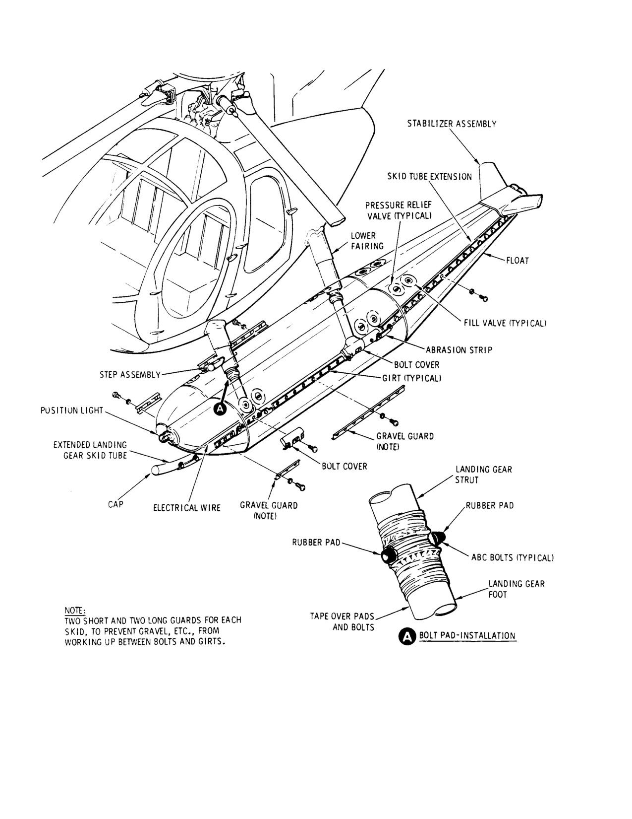
CSP-HMI-2
MD Helicopters, Inc.
MAINTENANCE MANUAL
G32−8012
Figure 201. Utility Float Installation
Page 204
Revision 19
32-81-00
MD Helicopters, Inc.
CSP-HMI-2
MAINTENANCE MANUAL
UTILITY FLOAT SYSTEM
INITIAL INSTALLATION
1. Utility Float Initial Installation
(6). Remove cargo compartment and aft
landing gear steps.
The utility float kit may not be installed in
combination with the following:
NOTE: Passenger steps,
369D26505 and
Passenger steps
369D292028, may not be installed in combi
Hoist kit
nation with utility floats. Upon removal of
Litter kit
369D292028 step assembly, install
Four-bladed tail rotor
PLT210-10-3 bolts (2 per assembly) coated
with sealing compound (CM425) into holes
A. Preparation for Installation
where step attaching hardware was located.
(7). Remove hardware that secures trailing
Consumable Materials
edge of lower fairings to strut assem
(Ref. Section 91−00−00)
blies. Carefully spread trailing edge of
Item
Nomenclature
lower fairings and remove fairings.
CM425
Sealing compound
NOTE: If preload condition prevents removal of
skid assemblies, disconnect one brace as
Instructions in the following paragraphs are
sembly from skid assemblies to eliminate
applicable to both left and right landing gear
preload (Ref. Sec. 32-10-00).
assemblies. Preparation for installation of
utility floats includes the following:
(8). Remove ABC bolts from forward and aft
NOTE: Make sure that the BATT-OFF-EXT
strut assemblies (Ref. Sec. 32-10-00).
switch is set to OFF.
Retain ABC hardware for reuse.
Remove skid assemblies with foot
(1).
Check all cockpit electrical switches in
assemblies attached.
the OFF position.
B. Disassembly of Extended Landing Gear
(2).
Identify all components, including
attaching hardware, or components
(Ref. Figure 901) Complete disassembly of
removed for access to work areas.
landing gear is not required; however, certain
Protect components from damage and
items must be removed.
foreign matter until installed.
(3).
Using jacking or hoisting methods,
Consumable Materials
raise helicopter 6 inches (15 cm) clear of
(Ref. Section 91−00−00)
ground.
Item
Nomenclature
CM318
Primer
(4).
Remove landing gear (Ref. Sec.
32-10-00). Removal of landing gear is
identical to that described in Sec.
(1). Remove screws from float attach
32-10-00, except that removal of
fittings.
complete landing gear is not required.
Remove extended landing gear accord
(2). Remove bolts and abrasion strip from
ing to Sec. 32-10-00, except as follows:
skid extension.
(5).
Remove screws attaching position light
assemblies to skid assemblies. Retain
(3). Remove bolts attaching skid tube
screws for reuse. Disconnect electrical
extension.
harness and remove position light
assemblies.
(4). Remove skid tube extension.
Page 901
32-81-00
Revision 19
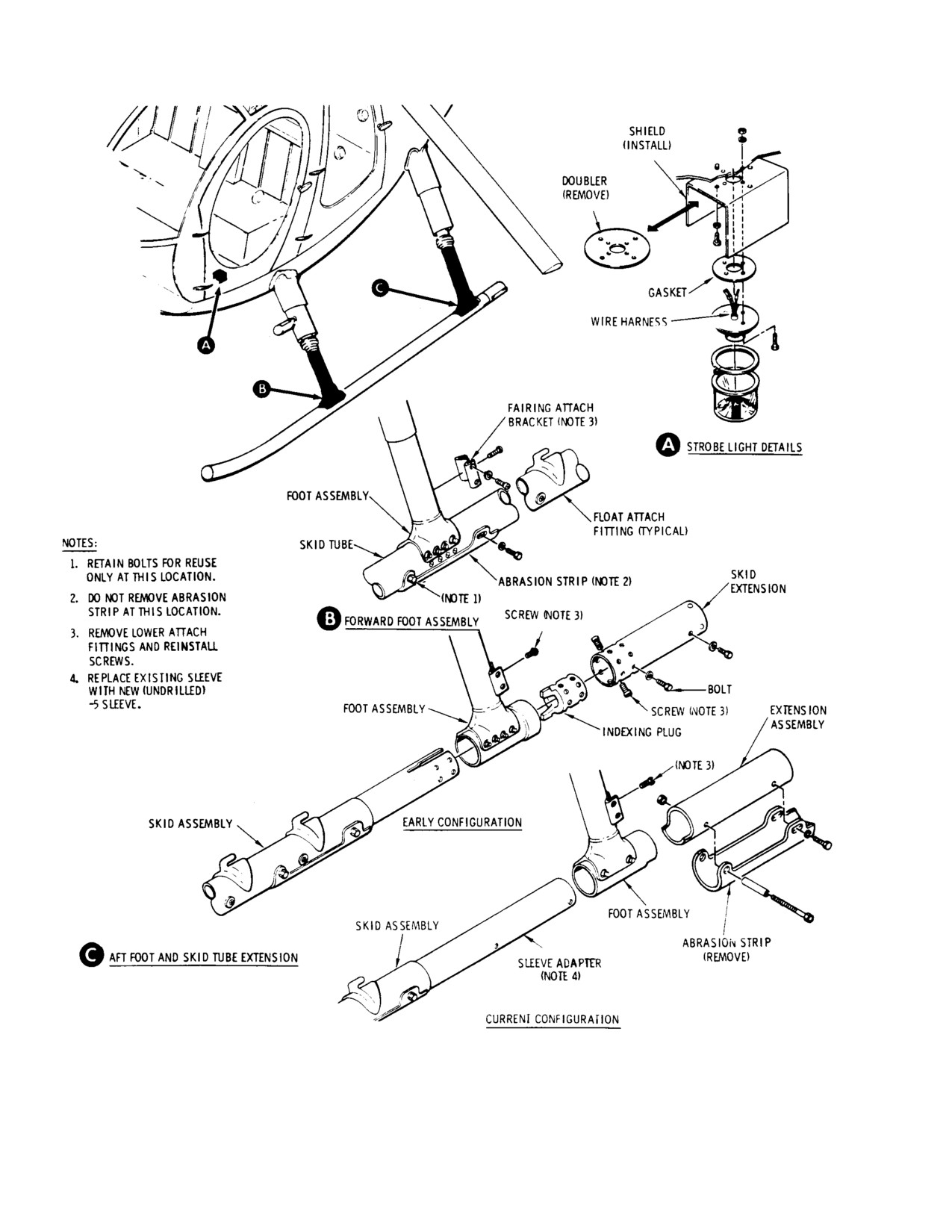
CSP-HMI-2
MD Helicopters, Inc.
MAINTENANCE MANUAL
G32−8008
Figure 901. Extended Landing Gear − Disassembly
Page 902
Revision 19
32-81-00
MD Helicopters, Inc.
CSP-HMI-2
MAINTENANCE MANUAL
NOTE: When installing the 369D292808-17
D. Landing Gear Skid Extension Assembly
and -18 extension tubes, it will be necessary
(Ref. Figure 903)
to remove and replace the 369D26012 or the
369D26012-5 sleeve adapter with a new -5
(undrilled at aft end) sleeve adapter (Ref.
Consumable Materials
Sec. 32-10-00).
(Ref. Section 91−00−00)
Item
Nomenclature
(5). Remove bolts attaching abrasion strip
CM209
Zinc chromate putty
to skid tube. Do not remove abrasion
CM318
Primer
strips. Retain four bolts for reuse.
CM425
Sealing compound
(6). Remove fairing attach brackets from
foot assemblies. Coat screws and
(1). On all types of landing gear skid tube
washers with primer (CM318) and
extensions:
reinstall screws and washers.
(a). Coat mating surfaces of the correct
plug with zinc chromate putty
C. Landing Gear Strut Modification
(CM209); assemble plug to tube with
rivets coated with primer (CM318).
(Ref. Figure 902) For modification of landing
Seal edges with sealing compound
gear strut assemblies to accommodate installa
(CM425).
tion of utility floats and return to extended
(b). Coat mating surface of support
landing gear configuration when utility floats
assembly and tube with zinc chro
are removed, perform the following:
mate putty; install using bolts and
washers.
Consumable Materials
(2). Assembly of landing gear skid exten
(Ref. Section 91−00−00)
sion (369D292808-17 and -18) on
Item
Nomenclature
current configuration landing gear:
CM318
Primer
NOTE: The 369D292808-17 and -18 skid tube
CM425
Sealing compound
extension assemblies may only be installed
on extended skid gear having new (un
drilled) 369D26012-5 adapter, sleeve-skid
(1). Using drill motor and number 15 drill
installed. For replacing the 369D26012 ba
bit, drill two holes through lower
sic sleeve with the -5 sleeve (Ref. Sec.
fairing attach brackets and aft wall of
32-10-00).
landing gear strut assemblies (view A).
Enlarge holes to 0.250 inch (6.350 mm)
(a). Insert skid tube extension on to -5
diameter using 1/4 inch (6.35 mm) drill
adapter sleeve. Align skid tube
bit.
rivnut centerline with extension tube
rivnut centerline. Secure both
(2). Using number 30 drill bit, drill out
assemblies with a suitable fixture.
huckbolts attaching bracket to strut.
(b). Mark and match drill eight 0.1945 -
Remove bracket. Seal huckbolt attach
0.1965 inch (4.9403 - 4.9911 mm)
holes in strut with sealing compound
diameter holes through tube and
(CM425). Coat bare metal with primer
sleeve (use locations and dimensions
(CM318).
as stated in Figure 903); separate
skid tube extension from adapter
(3). Remove rivets attaching nutplates
sleeve.
(view B).
(c). Countersink holes, 100° x 0.378 -
NOTE: When floats are removed from landing
0.385 inch (100° x 9.6012 - 9.779
gear assembly, modified foot assembly
mm) diameter in skid tube extension,
brackets may be reinstalled by using screws
deburr and apply primer to bare
and washers.
metal surfaces.
Page 903
32-81-00
Revision 19
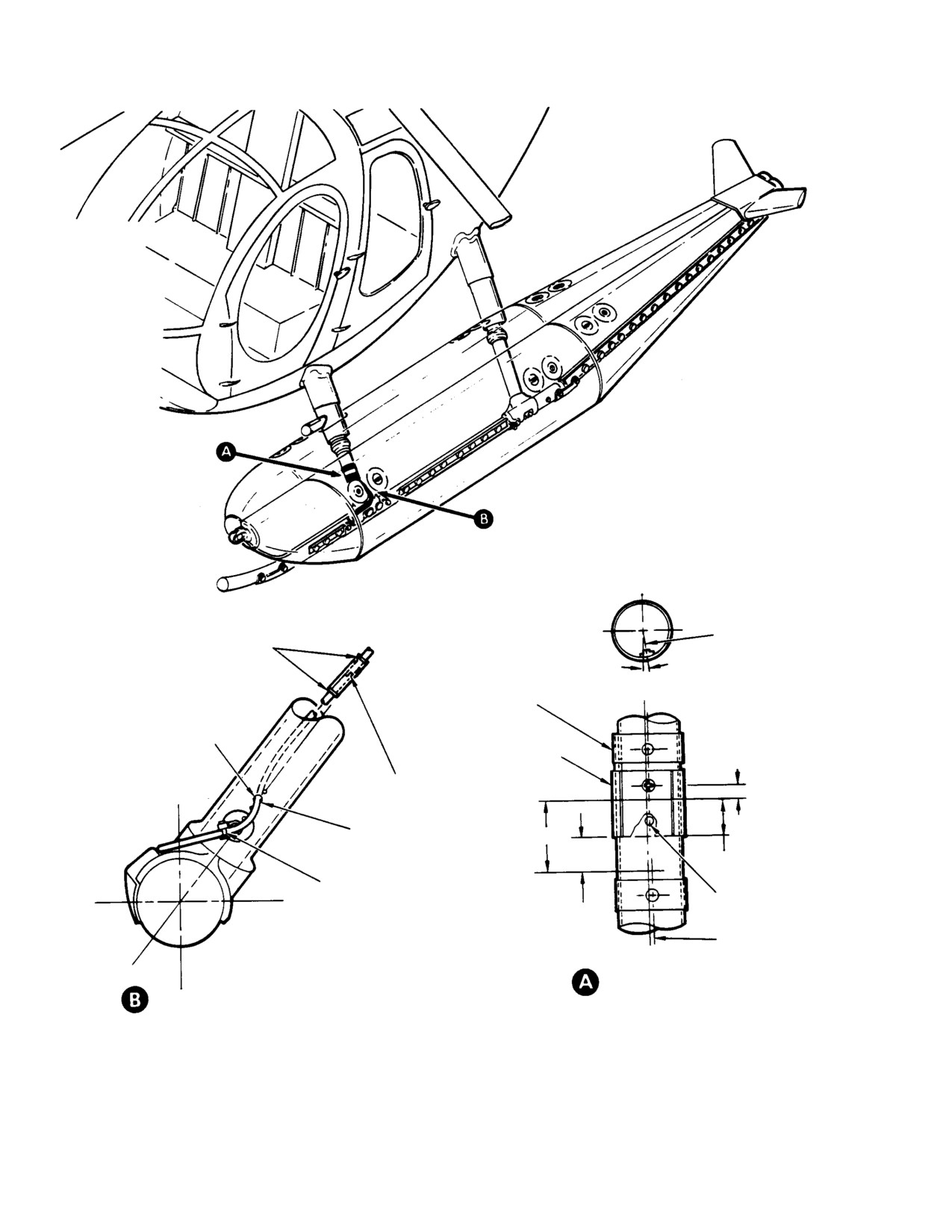
CSP-HMI-2
MD Helicopters, Inc.
MAINTENANCE MANUAL
STRUT
C
L
BRACKET
L
SILASTIC
2° 50’
STRUT ASSEMBLY (TYPI
CAL)
REMOVE NUT PLATE
LOWER FAIRING AT
0.59
TACH BRACKET
KNIFE SPLICE
SEALANT
2.41
1.28
1.13
TYRAP BRACKET
0.250 DIAMETER 2
HOLES
BRACKET
L
STRUT MODIFICATION
FORWARD FOOT MODIFICATION
G32−8009
Figure 902. Extended Landing Gear Modification
Page 904
Revision 19
32-81-00