HANDBOOK OF MAINTENANCE INSTRUCTIONS FOR MDHI 369D/E/FF-500/600N HELICOPTERS (ISSUED: 1990) - page 17
CSP-HMI-2
MD Helicopters, Inc.
MAINTENANCE MANUAL
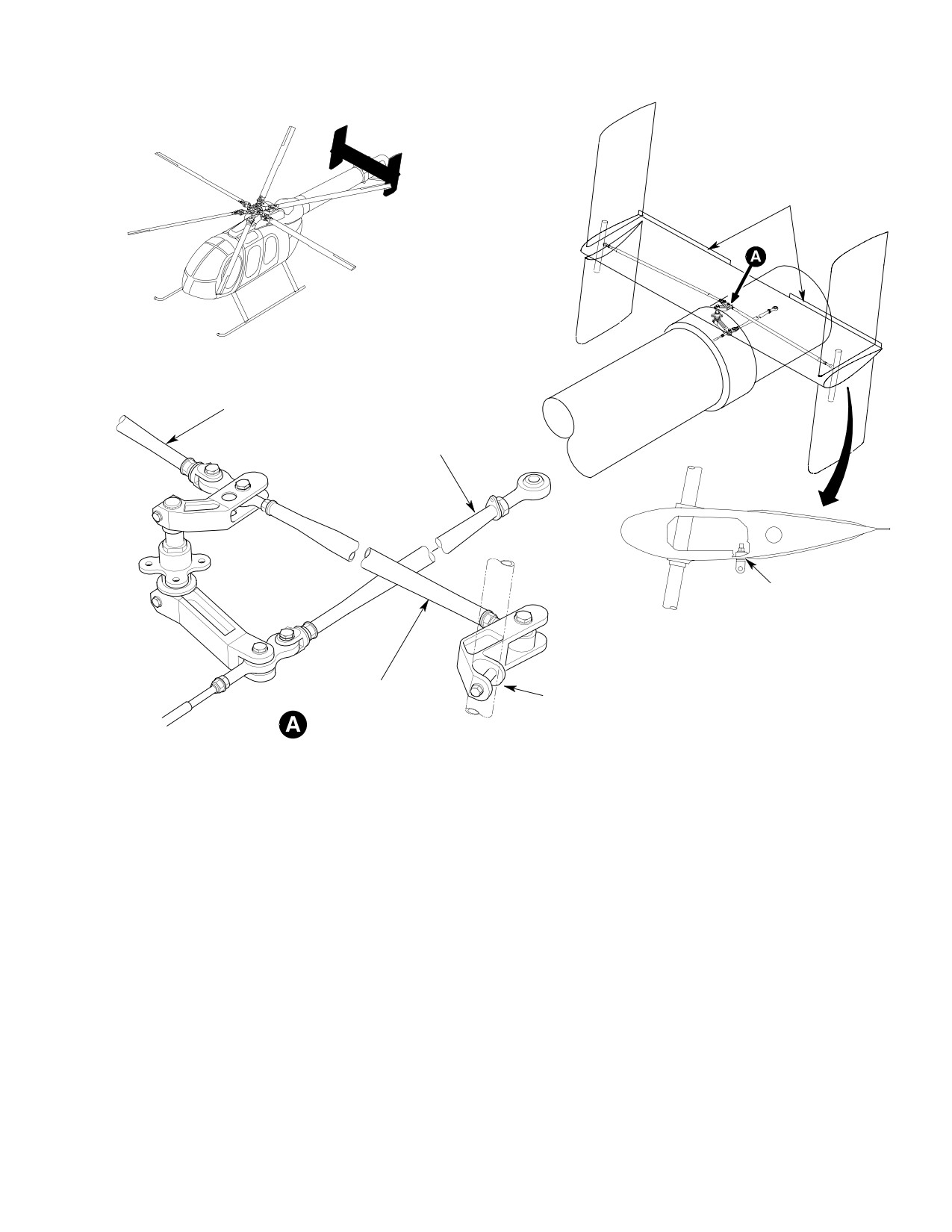
9. Vertical Stabilizer Torque Tube
(2). Apply one layer of teflon tape (CM726)
Replacement
to threads of torque tube prior to
installing locknut.
A. Vertical Stabilizer Torque Tube Removal
(3). Install locknut, hand tighten and adjust
(1). Remove vertical stabilizers (Ref.
to a 0.005-0.010 inch (0.127-0.254 mm)
Vertical Stabilizer Replacement).
gap; Install cotter pin.
NOTE: When installing the bellcrank, opening
(2). Remove horizontal tip plate access
in bellcrank must face outboard.
cover and disconnect YSAS torque tube
(if installed) from vertical stabilizer
(4). Install bellcrank, with opening facing
bellcrank.
outboard, on torque tube and install
expandable bolt; Torque to 30 - 40
(3). Remove bellcrank from torque tube by
inch-pounds (3.39 - 4.52 Nm) plus
removing expandable bolt.
drag torque; Install cotter pin.
(4). Remove cotter pin, locknut and bushing
(5). Connect YSAS actuator to vertical
from torque tube. Remove torque tube
stabilizer torque tube bellcrank. Torque
by lifting upward.
nut to 30 - 40 inch-pounds (3.39 -
4.52 Nm) and install cotter pin.
B. Vertical Stabilizer Torque Tube
Installation
(6). Install end plate access covers.
(1). Slide torque tube from the top thru the
(7). Install vertical stabilizer (Ref. Vertical
horizontal stabilizer.
Stabilizer Replacement).
Page 206
Revision 40
53-50-30
MD Helicopters, Inc.
CSP-HMI-2
MAINTENANCE MANUAL
GURNEY FLAPS
RIGHT
CONTROL ROD
AFT
CONTROL ROD
NOTE 1
NOTE:
1.
EXTRA WASHER BETWEEN RADIUS BLOCK
AND SPACER.
LEFT
NOTE 2
2.
OPENING IN BELLCRANK ALWAYS FACES
CONTROL ROD
OUTBOARD (LH AND RH SIDES).
EARLY 600N SHOWN
G53-5003-3B
Figure 202. Stabilizer Installation without YSAS
Page 207
53-50-30
Revision 40
CSP-HMI-2
MD Helicopters, Inc.
MAINTENANCE MANUAL
VERTICAL STABILIZER
TORQUE TUBE
EXPANDABLE
ELEMENTS
NON EXPANDABLE
ELEMENT
THIN WASHER
THIN WASHER
THICK
EXPANDABLE
WASHER SPACERS (2)
ELEMENTS
EXPANDABLE DIAMETER
BOLT INSTALLATION
WASHER
(OPTIONAL)
NUT
COTTER PIN
THICK WASHER
WASHER
SPACERS
BOLT
WASHER
(OPTIONAL)
NUT
COTTER
PIN
THICK WASHER
WASHER
SPACERS
BOLT
MAX. DIA. O.254 IN. (6.4516 MM)
(8 PLCS) EACH TORQUE TUBE
TORQUE TUBE
NOTE:
THE BOLT, WASHER, THICK WASHER, SPACERS AND NUT ARE
COMPONENTS OF THE EXPANDABLE DIAMETER BOLT ASSEMBLY.
53-5007
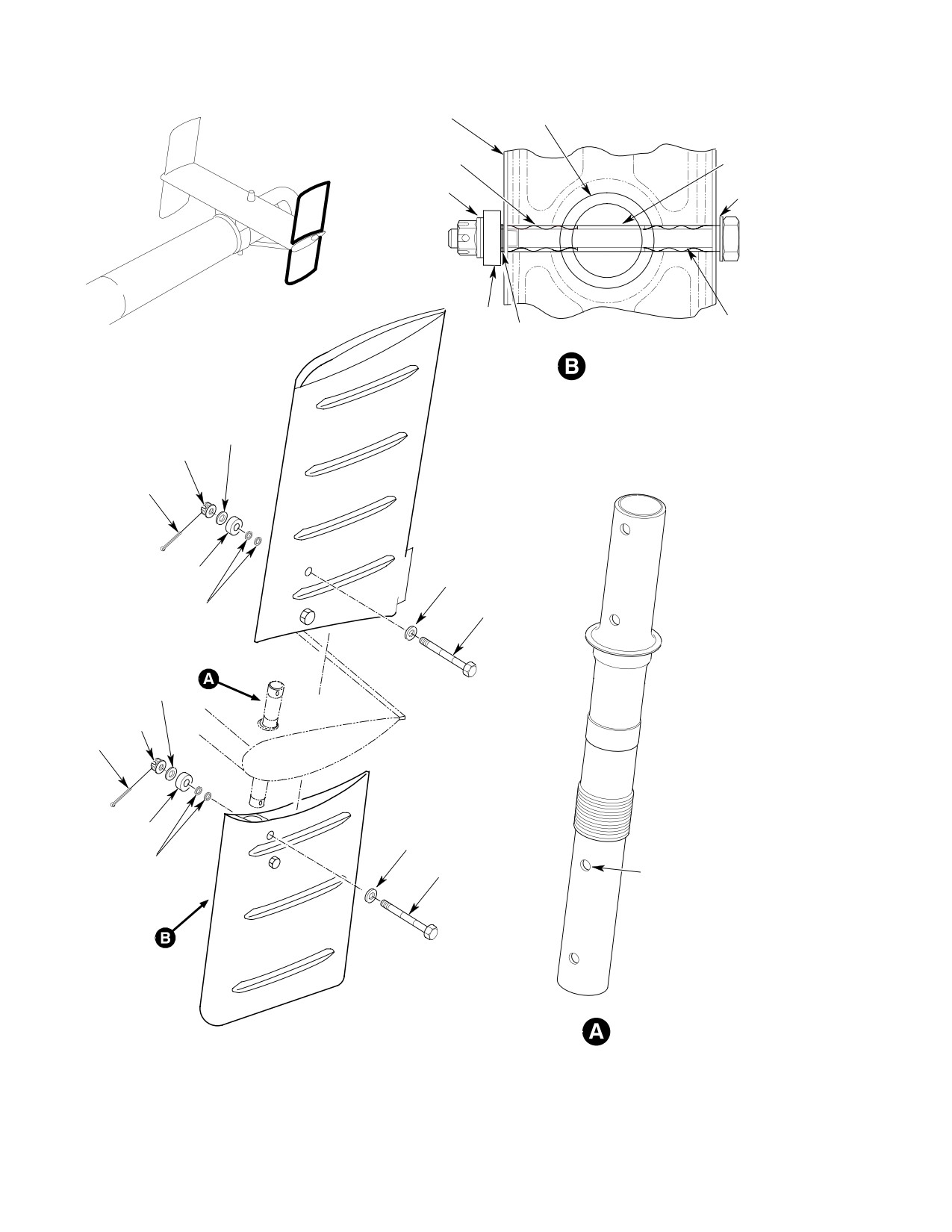
Figure 203. Vertical Stabilizer Installation with Expandable Bolts
Page 208
Revision 40
53-50-30
MD Helicopters, Inc.
CSP-HMI-2
MAINTENANCE MANUAL
10. Horizontal Stabilizer Repair
4.52 Nm) plus drag torque; Install
cotter pin.
Refer to MDHI Field Service Representative.
(10). Connect YSAS actuator to vertical
stabilizer torque tube bellcrank. Torque
11. Vertical Stabilizer Torque Tube and/or
nut to 30 - 40 inch-pounds (3.39 -
Bushing Replacement (Non−Bonded
4.52 Nm) and install cotter pin.
Bushings)
(11). Install end plate access covers.
(Ref. Figure 201) The following procedure is for
replacing the early style (non-bonded) torque
(12). Install vertical stabilizer (Ref. Vertical
tube bushings.
Stabilizer Replacement).
12. Vertical Stabilizer Torque Tube and/or
Consumable Materials
Bushing Replacement (Bonded Bushings)
(Ref. Section 91−00−00)
Item
Nomenclature
(Ref. Figure 201) The following procedure is for
CM726
Tape, teflon
replacing the current style (bonded) torque
tube bushings.
(1).
Remove vertical stabilizers (Ref.
Consumable Materials
Vertical Stabilizer Replacement).
(Ref. Section 91−00−00)
Item
Nomenclature
(2).
Remove horizontal tip plate access
cover and disconnect YSAS torque tube
CM222
1,1,1-Trichloroethane
(if installed) from vertical stabilizer
CM402
Adhesive
bellcrank.
CM726
Tape, teflon
CM802
Abrasive cloth, aluminum oxide
(3).
Remove bellcrank from torque tube by
removing expandable bolt.
(1). Remove vertical stabilizers (Ref.
(4).
Remove cotter pin, locknut and bushing
Vertical Stabilizer Replacement).
from torque tube. Remove torque tube
by lifting upward.
(2). Remove horizontal tip plate access
cover and disconnect YSAS torque tube
(5).
Remove bushing from bearing race of
(if installed) from vertical stabilizer
torque tube.
bellcrank.
(6).
Install one bushing on bearing race of
(3). Remove bellcrank from torque tube by
torque tube and insert torque tube
removing expandable bolt.
through fitting of horizontal stabilizer
(4). Remove cotter pin, locknut and bushing
from the top downward.
from torque tube. Remove torque tube
(7).
Apply one layer of teflon tape (CM726)
by lifting upward.
to threads of torque tube prior to
In the following steps, care must
installing locknut.
CAUTION
be taken to not damage the fi
bers of the horizontal stabilizer.
(8).
Install bushing and locknut, hand
tighten locknut and adjust to a
(5). Remove bushing(s) from horizontal
0.005-0.010 inch (0.127-0.254 mm)
stabilizer by gently working a sharp
gap; Install cotter pin.
scraper between bushing and stabilizer.
NOTE: Ensure shouldered bushings are
(6). Sand excess sealant from horizontal
installed in bellcrank.
stabilizer taking care not to disturb the
composite fibers of the stabilizer.
(9). Install bellcrank on torque tube and
install expandable bolt and washers;
(7). Clean faying surfaces of horizontal
Torque to 30 - 40 inch-pounds (3.39 -
stabilizer, where bushings are to be
Page 209
53-50-30
Revision 40
CSP-HMI-2
MD Helicopters, Inc.
MAINTENANCE MANUAL
bonded, with 1,1,1-trichloroethane
13. Vertical Stabilizer Torque Tube Bushing
(CM222).
Rework (Non−Bonded Bushings to
Bonded Bushings)
(8). Wipe dry using a clean dry rag and
then allow to air dry for 15 minutes.
(Ref. Figure 201) The following procedure is for
converting the vertical stabilizer torque tube to
(9). Lightly abrade the faying surface of the
the current 500N3980-3 bushings,
new bushings with abrasive cloth
500N3970-3 locknuts and MS24665-361
(CM802) until all gloss is removed.
cotter pins.
Wipe clean with 1,1,1-trichloroethane.
(10). Wipe dry using a clean dry rag and
Consumable Materials
then allow to air dry for 15 minutes.
(Ref. Section 91−00−00)
Item
Nomenclature
(11). Mix adhesive (CM402) according to
CM222
1,1,1-Trichloroethane
manufacturers instructions. Apply
CM402
Adhesive
adhesive within 2 hours of cleaning.
CM726
Tape, teflon
(12). Apply a thin uniform layer of adhesive
CM802
Abrasive cloth, aluminum oxide
to faying surfaces.
Do not apply too much pressure,
(1).
Remove vertical stabilizers (Ref.
CAUTION
damage to horizontal stabilizer
Vertical Stabilizer Replacement).
may occur.
(2).
Remove cotter pins, locknuts and
(13).
Press the faying surfaces firmly
bushings, and scrap. Remove torque
together and maintain contact pressure
tube by lifting upward. Remove bushing
or apply 50 psi (3.45 kPa) maximum for
and scrap.
24 hours at ambient temperature.
(3).
Clean faying surfaces of horizontal
stabilizer, where bushings are to be
(14).
Using 1,1,1-trichloroethane, clean
bonded, with 1,1,1-trichloroethane
excess adhesive from parts before
(CM222).
adhesive has had time to cure.
(4).
Wipe dry using a clean dry rag and
(15).
Slide torque tube from the top thru the
then allow to air dry for 15 minutes.
horizontal stabilizer.
(5).
Lightly abrade the faying surface of the
(16).
Apply one layer of teflon tape (CM726)
new bushings with abrasive cloth
to threads of torque tube prior to
(CM802) until all gloss is removed.
installing locknut.
Wipe clean with 1,1,1-trichloroethane.
(17).
Install locknut, hand tighten and adjust
(6).
Wipe dry using a clean dry rag and
to a 0.005-0.010 inch (0.127-0.254 mm)
then allow to air dry for 15 minutes.
gap; Install cotter pin.
(7).
Mix adhesive (CM402) according to
(18).
Install bellcrank on torque tube and
manufacturers instructions. Apply
install expandable bolt; Torque to 30 -
adhesive within 2 hours of cleaning.
40 inch-pounds (3.39 - 4.52 Nm)
plus drag torque; Install cotter pin.
(8).
Apply a thin uniform layer of adhesive
to faying surfaces.
(19).
Connect YSAS actuator to vertical
stabilizer torque tube bellcrank. Torque
Do not apply too much pressure,
CAUTION
nut to 30 - 40 inch-pounds (3.39 -
damage to horizontal stabilizer
4.52 Nm) and install cotter pin.
may occur.
(9). Press the faying surfaces firmly
(20).
Install end plate access covers.
together and maintain contact pressure
(21).
Install vertical stabilizer (Ref. Vertical
or apply 50 psi (3.45 kPa) maximum for
Stabilizer Replacement).
24 hours at ambient temperature.
Page 210
Revision 40
53-50-30
MD Helicopters, Inc.
CSP-HMI-2
MAINTENANCE MANUAL
(10).
Using 1,1,1-trichloroethane, clean
(a). Locate a steel plate of approximately
excess adhesive from parts before
0.250 inch (6.35 mm) thickness.
adhesive has had time to cure.
(b). Drill a 1.510 inch (38.3540 mm) hole
in the plate.
(11).
Slide torque tube from the top thru the
horizontal stabilizer.
(c). Deburr edges of hole to prevent
damage to torque tube.
(12).
Apply one layer of teflon tape (CM726)
to new 500N3970-3 locknut.
(d). Apply tape (CM730) to tool to prevent
damage to bearing race.
(13).
Install locknut, hand tighten and adjust
to a 0.005-0.010 inch (0.127-0.254 mm)
(4). Insert torque tube through the removal
gap; Install MS24665-361 cotter pin.
tool and install on arbor press.
In the following steps, care must
(14).
Install bellcrank on torque tube and
CAUTION
be taken to not damage the hori
install expandable bolt; Torque to 30 -
zontal stabilizer torque tube.
40 inch-pounds (3.39 - 4.52 Nm)
plus drag torque; Install cotter pin.
(5). Place suitable device over torque tube
end to protect tube from damage from
(15).
Install end plate access covers.
arbor press.
(16).
Install vertical stabilizer (Ref. Vertical
(6). Remove bearing from the torque tube
Stabilizer Replacement).
by gently pressing torque tube through
the removal tool.
14. Vertical Stabilizer Torque Tube Bearing
Race Replacement
(7). Using solvent (CM234), clean primer
residue from torque tube.
(Ref. Figure 201) The following procedure is for
(8). Inspect torque tube for damage to
removal of the bearing race from the vertical
bearing race contact surface.
stabilizer torque tube. Some special tools will
need to be manufactured for this procedure.
(9). Fabricate the following tool for bearing
race installation.
Consumable Materials
(a). Locate a steel plate of approximately
(Ref. Section 91−00−00)
0.250 inch (6.35 mm) thickness.
Item
Nomenclature
(b). Drill a 1.390 inch (35.306 mm) hole
CM234
Solvent, dry-cleaning
in the plate.
CM318
Primer
CM730
Tape, duct
(c). Deburr edges of hole to prevent
damage to torque tube.
Special Tools
(d). Apply tape (CM730) to tool to prevent
(Ref. Section 91−00−00)
damage to bearing race.
Item
Nomenclature
(10). Insert bearing race into tool and mount
N/A
Arbor press
on arbor press.
(11). Coat torque tube bearing race mating
(1). Remove vertical stabilizers (Ref.
surface with primer (CM318).
Vertical Stabilizer Replacement).
In the following steps, care must
(2). Remove vertical stabilizer torque tubes
CAUTION
be taken to not damage the the
(Ref. Vertical Stabilizer Torque Tube
horizontal stabilizer torque tube.
Replacement).
(12). Place suitable device over torque tube
(3). Fabricate the following tool for bearing
end to protect tube from damage from
race removal.
arbor press.
Page 211
53-50-30
Revision 40

CSP-HMI-2
MD Helicopters, Inc.
MAINTENANCE MANUAL
In the following step, ensure
ensure no warpage occurred during
CAUTION
bearing race is not cocked on
installation.
torque tube, this will cause non-repairable
(15). Reinstall vertical stabilizer torque
damage to bearing race and torque tube.
tubes (Ref. Vertical Stabilizer Torque
Tube Replacement).
(13). While primer is wet, press torque tube
down through the bearing race until
(16). Reinstall vertical stabilizers (Ref.
bearing race is tight against flange on
Vertical Stabilizer Replacement).
torque tube.
15. Stabilizer Troubleshooting
(14). Inspect bearing race flanged surface to
(Ref. Table 201)
Table 201. Troubleshooting Tailboom and Tail Surfaces
Symptom
Probable Trouble
Corrective Action
High frequency vibration
Fan assembly out of balance
Re−balance fan assembly.
Loose fan blades
Replace and re−balance fan assy.
Loose bolts/nuts on Horizontal or
Inspect mounting hardware; adjust or
Vertical stabilizer
replace as necessary.
NOTE: High frequency vibrations in helicopter can be caused by components in other systems (Ref. Sec.
64−00−00, 63−25−10, 63−25−30 and 71−00−00).
Page 212
Revision 40
53-50-30

MD Helicopters, Inc.
CSP-HMI-2
MAINTENANCE MANUAL
Chapter
62
Main Rotor
MD Helicopters, Inc.
CSP-HMI-2
MAINTENANCE MANUAL
TABLE OF CONTENTS
Para/Figure/Table
Title
Page
62-00-00 Main Rotor (369D/E/FF - 500/600N)
A
Fault Isolation
101
1. Main Rotor System - General Information
101
2. Main Rotor System Troubleshooting
101
Table 101. Troubleshooting Main Rotor Vibrations
102
62-10-00 Main Rotor Blade (369D/E/FF - 500/600N)
A
Removal/Installation
401
1. Main Rotor Blade - General
401
A. Main Rotor Blade Leading Edge Erosion Protection - General
401
2. Main Rotor Blade Replacement
401
A. Main Rotor Blade Removal
401
B. Main Rotor Blade Installation
401
3. Main Rotor Blade and Damper Attach Pin Installation and Adjustment
401
Figure 401. Main Rotor Blade - Attachment and Outboard End
403
Inspection/Check
601
1. Main Rotor Blade Inspection
601
Figure 601. Main Rotor Blade Damage and Repair Limits - Nicks,
Scratches, Gouges and Cracks
603
2. Main Rotor Blade and Damper Attach Pin Inspection and Corrosion
Protection
604
3. Main Rotor Blade and Damper Attach Pin Disassembly and Special
Inspection
605
4. Main Rotor Blade Forward Tip Cap Inspection and Corrosion Protection
605
5. Main Rotor Blade Upper and Lower Root Fitting Attach Lug and Lead-Lag
Link Attach Lug Inspection (25 Hour)
605
Figure 602. Main Rotor Blade Damage Limits for Dents and Depressions
606
Figure 603. Main Rotor Blade Attach Pin
607
6. Main Rotor Blade Upper and Lower Root Fitting, Attach Lug and Lead-Lag
Link Attach Lug Inspection (100 Hour)
608
7. Main Rotor Blade Leading Edge Abrasion Strip Check
610
8. Main Rotor Blade Torque Event Inspection
610
Figure 604. Main Rotor Blade Root Fitting, Attach Lugs and Lead-Lag Link
Assembly Inspection
611
Figure 605. Application of Slippage Mark to Main Rotor Blade Bushings and
Root Fittings
612
Repairs
801
1. Main Rotor Blade Repair (Nicks, Scratches and Wear Spots)
801
2. Main Rotor Blade Repair (Dents, Depressions and Erosion)
801
Page i
62 Contents
Revision 37
CSP-HMI-2
MD Helicopters, Inc.
MAINTENANCE MANUAL
TABLE OF CONTENTS (Cont.)
Para/Figure/Table
Title
Page
3. Trim Tab Damage Repair
802
4. Forward Tip Cap Threaded Insert Repair
802
Figure 801. Main Rotor Blade Trailing Edge Weight Rework
803
5. Loose Balance Weight Repair
804
6. Loose Trailing Edge Weight Repair
804
7. Loose or Missing Rivets or Aft Tip Cap Repair
804
Figure 802. Repair and Removal of Trim Tab, Main Rotor Blade
805
Figure 803. Bearing Replacement - Main Rotor Blade Damper Attach
Fitting
805
8. Damper Attach Blade Fitting Bearing Replacement
806
9. Leading Edge Protective Tape Replacement
806
Figure 804. Installation/Replacement of Stainless Steel Abrasion Tape
(Main Rotor Blade Leading Edge)
807
Figure 805. Installation/Replacement of Double Layer Abrasion Tape
(369D21100-505 and -509 Rotor Blades)
808
10. Leading Edge Abrasion Strip Sealing
809
11. Tip Cap Sealing
809
Figure 806. Main Rotor Blade Abrasion Strip and Tip Cap Sealing
810
12. Main Rotor Blade Protective Tape Installation
811
A. Stainless Steel Tape Installation
811
62-20-00 Main Rotor Hub (369D/E/FF - 500N)
A
Removal/Installation
401
1. Main Rotor Hub - General
401
2. Main Rotor Hub Replacement
401
A. Main Rotor Hub Removal
401
B. Main Rotor Hub Installation
401
Figure 401. Pulling Hub Assembly
403
3. Main Rotor Damper
404
4. Main Rotor Damper Replacement
404
A. Main Rotor Damper Removal
404
B. Main Rotor Damper Installation
404
5. Main Rotor Damper Nominal Adjustment
405
Figure 402. Main Rotor Hub - Installation
406
Inspection/Check
601
1. Main Rotor Hub Balancing - General
601
2. Main Rotor Blade Phasing Check and/or Adjustment
601
3. Main Rotor Hub Inspection
601
Page ii
Revision 37
62 Contents
MD Helicopters, Inc.
CSP-HMI-2
MAINTENANCE MANUAL
TABLE OF CONTENTS (Cont.)
Para/Figure/Table
Title
Page
Figure 601. Strap Pack Lamination - Exploded View
602
4. Lead-Lag Bolt Inspection
603
5. Main Rotor Strap Pack Lamination Inspection
603
Figure 602. Strap Pack Lamination Inspection (Sheet 1 of 2)
605
Table 601. Strap Pack Inspection
607
6. Main Rotor Hub Droop Angle Check
608
7. Main Rotor Damper and Attachments Inspection
608
8. Main Rotor Damper Weight Loading and Extension Check
609
Figure 603. Periodic Check of Main Rotor Damper Assembly
610
Repairs
801
1.
Main Rotor Retention Strap Pack Repair
801
2.
Pitch Housing Repair
801
3.
Unbushed Outboard Clevis Lug Hole Repair
801
Figure 801. Field Repair of Main Rotor Hub Pitch Control Lugs
(Sheet 1 of 2)
802
4.
Pitch Control Bearing Housing Assembly, Spacer or Striker Strip
Replacement
804
5.
Pitch Control Bearing Housing Modification
805
6.
Pitch Control Bearing Replacement
805
Figure 802. Main Rotor Hub Components - Repair and Installation
(Sheet 1 of 2)
806
7.
Lead-Lag Link Blade Stop Replacement
808
Figure 803. Striker Strip Replacement
809
8.
Damper Attach Lug Bearing Replacement
809
9.
Lead-Lag Bolt Corrosion Control
810
10.
Pitch Control Bearing Pivot Pin Repair or Replacement
810
11.
Droop Stop Roller Repair or Replacement
810
12.
Droop Stop Ring Repair
811
13.
Droop Stop Ring Replacement
811
14.
Droop Stop Follower (T-Head) Replacement
811
15.
Droop Stop Plunger Removal, Inspection and Installation
812
16.
Main Rotor Hub Droop Angle Adjustment
812
Figure 804. Main Rotor Hub Assembly - Repair
813
17.
Main Rotor Hub Tapered Bearing Grease Repack, Inspection and
Replacement
814
18.
Main Rotor Hub Scissors Attach Lug Bearing Replacement
815
Figure 805. Main Rotor Hub - Cross Section (Sheet 1 of 2)
817
Figure 806. Tapered Bearing Tools - Main Rotor Hub (Sheet 1 of 2)
819
Page iii
62 Contents
Revision 37
CSP-HMI-2
MD Helicopters, Inc.
MAINTENANCE MANUAL
TABLE OF CONTENTS (Cont.)
Para/Figure/Table
Title
Page
62-20-60 Main Rotor Hub (600N)
A
Removal/Installation
401
1. Main Rotor Hub - General
401
2. Main Rotor Hub Replacement
401
A. Main Rotor Hub Removal
401
B. Main Rotor Hub Installation
401
Figure 401. Pulling Hub Assembly
403
3. Main Rotor Damper
403
4. Main Rotor Damper Replacement
404
A. Main Rotor Damper Removal
404
B. Main Rotor Damper Installation
404
5. Main Rotor Damper Nominal Adjustment
404
Figure 402. Main Rotor Hub Installation
405
Inspection/Check
601
1. Main Rotor System Balancing - General
601
2. Main Rotor Hub Inspection
601
Figure 601. Strap Pack Lamination - Exploded View
602
3. Lead-Lag Bolt Inspection
603
4. Main Rotor Strap Pack Lamination Inspection
603
Figure 602. Strap Pack Lamination Inspection (Sheet 1 of 2)
604
Table 601. Strap Pack Inspection
606
5. Main Rotor Hub Droop Angle Check
608
6. Main Rotor Damper and Attachments Inspection
608
7. Main Rotor Damper Weight Loading and Extension Check
609
Figure 603. Periodic Check of Main Rotor Damper Assembly
610
Repairs
801
1. Main Rotor Retention Strap Pack Repair
801
2. Pitch Control Bearing Housing Assembly, Spacer or Striker Strip
Replacement
801
Figure 801. Striker Strip Replacement
802
3. Lead-Lag Link Blade Stop Replacement
802
Figure 802. Main Rotor Hub Components Repair and Installation
803
4. Lead-Lag Bolt Corrosion Control
804
5. Pitch Control Bearing Pivot Pin Repair or Replacement
804
6. Droop Stop Roller Repair or Replacement
804
7. Droop Stop Ring Repair
805
8. Droop Stop Ring Replacement
805
Page iv
Revision 37
62 Contents
MD Helicopters, Inc.
CSP-HMI-2
MAINTENANCE MANUAL
TABLE OF CONTENTS (Cont.)
Para/Figure/Table
Title
Page
9. Droop Stop Follower (T-Head) Replacement
805
Figure 803. Droop Stop Ring Replacement and Repair
806
10. Droop Stop Plunger Removal, Inspection and Installation
807
11. Main Rotor Hub Droop Angle Adjustment
807
12. Main Rotor Hub Tapered Bearing Grease Repack, Inspection and
Replacement
808
Figure 804. Tapered Bearing Tools - Main Rotor Hub (Sheet 1 of 2)
809
13. Main Rotor Hub Upper Bearing Grease Repack, Inspection and
Replacement
811
14. Main Rotor Hub Scissors Attach Lug Bearing Replacement
813
Figure 805. Main Rotor Hub - Cross Section
814
62-30-00 Swashplate and Mixer (369D/E/FF - 500N)
A
Removal/Installation
401
1.
Main Rotor Swashplate
401
2.
Swashplate Replacement
401
A. Swashplate Removal
401
B. Swashplate Installation
401
3.
Mixer Controls
401
4.
Mixer Controls Replacement
401
A. Mixer Controls Removal
401
Figure 401. Pitch Control Rods and Swashplate Scissors - Installation
402
B. Mixer Controls Installation
403
Figure 402. Mixer Controls - Assembly
404
5.
Scissors
405
6.
Scissors Replacement
405
A. Scissors Removal
405
B. Scissors Installation
405
7.
Scissors Link Replacement
405
8.
Pitch Control Rods
406
9.
Pitch Control Rod Replacement
406
A. Pitch Control Rod Removal
406
B. Pitch Control Rod Installation
406
10. Counterweight and Interrupter Installation
406
Figure 403. Main Rotor Swashplate
407
Inspection/Check
601
1. Swashplate Inspection
601
2. Mixer Controls Inspection
602
Page v
62 Contents
Revision 37
CSP-HMI-2
MD Helicopters, Inc.
MAINTENANCE MANUAL
TABLE OF CONTENTS (Cont.)
Para/Figure/Table
Title
Page
3. Scissors Inspection
602
4. Pitch Control Rod Inspection
602
Repairs
801
1. Swashplate Repairs
801
2. Mixer Controls Repair
801
3. Scissors Bushing and Bearing Replacement
801
4. Scissors Modification
802
Figure 801. Field Modification - 369D21002-11 Crank Assembly to
369D21002-21 Configuration
803
Figure 802. Installation of 369D21002-21 Crank to Hub Lower Shoes
804
5. Mixer Controls Rework
804
Figure 803. Rework of Main Rotor and Mixer Controls (Sheet 1 of 2)
806
62-30-60 Swashplate and Mixer (600N)
A
Removal/Installation
401
1.
Main Rotor Swashplate
401
2.
Swashplate Replacement
401
A. Swashplate Removal
401
B. Swashplate Installation
401
Figure 401. Pitch Control Rods and Swashplate Scissors - Installation
402
3.
Controls Mixer
403
4.
Controls Mixer Replacement
403
A. Controls Mixer Removal
403
B. Mixer Controls Installation
403
Figure 402. Controls Mixer - Assembly
404
5.
Scissors
405
6.
Scissors Replacement
405
A. Scissors Removal
405
B. Scissors Installation
405
7.
Scissors Link Replacement
405
8.
Pitch Control Rods
406
9.
Pitch Control Rod Replacement
406
A. Pitch Control Rod Removal
406
B. Pitch Control Rod Installation
406
Figure 403. Main Rotor Swashplate
407
Inspection/Check
601
1. Swashplate Inspection
601
2. Mixer Controls Inspection
602
Page vi
Revision 37
62 Contents
MD Helicopters, Inc.
CSP-HMI-2
MAINTENANCE MANUAL
TABLE OF CONTENTS (Cont.)
Para/Figure/Table
Title
Page
3. Scissors Inspection
602
4. Pitch Control Rod Inspection
602
Repairs
801
1. Swashplate Repairs
801
2. Mixer Controls Repair
801
3. Scissors Bushing and Bearing Replacement
801
Page vii
62 Contents
Revision 37
CSP-HMI-2
MD Helicopters, Inc.
MAINTENANCE MANUAL
TABLE OF CONTENTS (Cont.)
Para/Figure/Table
Title
Page
This Page Intentionally Left Blank
Page viii
Revision 37
62 Contents
MD Helicopters, Inc.
CSP-HMI-2
MAINTENANCE MANUAL
Section
62−00−00
Main Rotor
(369D/E/FF −
500/600N)
MD Helicopters, Inc.
CSP-HMI-2
MAINTENANCE MANUAL
MAIN ROTOR
FAULT ISOLATION
1. Main Rotor System − General Information
NOTE: Unless specifically indicated in the text
and illustrations, information applies to all
NOTE: Auto-Rotation RPM charts are found in
model helicopters. Where information is
Chapter 18.
limited to a specific model helicopter or con
figuration, the text or effectivity block will
The main rotor located over the helicopter
indicate.
center-of-gravity provides lift, lateral and
longitudinal control. The fundamental
components of the rotor are five or six remov
2. Main Rotor System Troubleshooting
able blades, pitch housings and a hub. Each
articulated blade is controlled through a pitch
Sudden onset of excessive
WARNING
housing and link arrangement which transfers
and/or unusual main rotor
flight control inputs into the rotor blades.
vibration should be investigated imme
Rotor blades, pitch housings and links are
diately as to the cause, prior to contin
secured to the hub by five sets of laminated
ued flight. Under no circumstance
steel straps. The collective, stick working
should main rotor tracking be at
through linkages, increases or decreases rotor
tempted to correct the problem until a
blade angle affecting helicopter ascent and
thorough inspection of the main rotor
descent (collective pitch). Helicopter pitch and
blades, hub assembly and strap pack
roll angles are controlled by the cyclic stick.
assembly has been performed.
Mixed collective and cyclic control inputs are
simultaneously transferred into the main rotor
(1). First determine which major installa
for coordinated flight control. The four main
tion is defective.
equipment groups of the main rotor and
(2). Isolate each linkage installation from
control system are the rotor blades, hub, upper
others until area of malfunction is
exterior controls, and cyclic and collective
located.
controls in the pilot's compartment.
(1). Main rotor blades
(3). Investigate and determine exact
(Ref. Sec. 62-10-00).
location of malfunction.
(2). Main rotor hub
(4). Repair or replace defective components.
(Ref. Sec. 62-20-00 and 62-20-60).
NOTE: First indications of trouble are usually
(3). Main rotor swashplate and mixer
felt through cyclic or collective controls. Iso
(Ref. Sec. 62-30-00 and 62-30-60).
lation procedures (Ref. Table 101, Sec.
(4). Main rotor flight controls
67-10) indicate symptoms detected through
(Ref. Chap. 67).
these controls.
Page 101
62-00-00
Revision 20
CSP-HMI-2
MD Helicopters, Inc.
MAINTENANCE MANUAL
Table 101. Troubleshooting Main Rotor Vibrations
Symptom
Probable Trouble
Corrective Action
Unusual or excessive vibration.
Main rotor blades damaged.
Inspect blades
(Ref. Sec. 62−10−00).
Vertical or Lateral vibration.
Main rotor hub or hub components
Inspect main rotor hub assembly
damaged.
(Ref. Sec. 62−20−00/62−20−60).
Inspect strap pack assemblies.
One−per revolution lateral beat in
Defective damper or blade phasing.
Check damper nominal adjustment
hover and cruise. May also occur
(Ref. Sec. 62−20−00/62−20−60)
on ground during warmup or
Replace defective damper.
shutdown.
Five−per−revolution or
Worn pitch control bearings.
Replace pitch control bearings
medium−frequency beat.
(Ref. Chap. 67).
One−per revolution vertical beat.
Main rotor blades out of track.
Track main rotor blades
Beat may appear throughout
(Ref. Sec. 18−10−00/18−10−60).
entire flight regime, becoming
more pronounced at higher
airspeeds.
Lateral feedback (beat) in cyclic
Rotor blades out of track.
Track main rotor blades
control stick with no longitudinal
(Ref. Sec. 18−10−00/18−10−60).
feedback detected.
One−per−revolution lateral beat,
Main rotor blade tip balance weights
Check balance weights for security;
continuous.
not secure.
repair as necessary:
(Ref. Sec. 62−10−00).
Incorrect blade phasing.
Check main rotor track and balance
(Ref. Sec. 18−10−00/18−10−60).
High frequency vibrations.
Loose or defective component in
(Ref. Chaps. 18, 62, 64 and 67)
another system.
Main rotor track and/or balance
Play between longitudinal pitch mixer
Re−bond collective pitch mixer
inconsistant.
bellcrank and collective pitch mixer
bearings and install shims between
bellcrank.
longitudinal pitch mixer bellcrank and
collective pitch mixer bellcrank
bearings (Ref. Sec. 62−30−00 or
62−30−60).
Page 102
Revision 31
62-00-00
MD Helicopters, Inc.
CSP-HMI-2
MAINTENANCE MANUAL
Section
62−10−00
Main Rotor Blade
(369D/E/FF −
500/600N)
MD Helicopters, Inc.
CSP-HMI-2
MAINTENANCE MANUAL
MAIN ROTOR BLADE
REMOVAL/INSTALLATION
1. Main Rotor Blade − General
etc). Detach damper clevis from blade.
Remove two blade fitting attaching
Each of the main rotor blades are a balanced
pins.
airfoil consisting primarily of a wraparound,
aluminum alloy skin bonded to an extruded
(3). If rotor system is not already color
aluminum alloy spar, an upper root fitting and
coded, use masking tape and/or grease
a lower root fitting (Ref. Figure 401). Two
pencil, to mark each blade and its
pre-set balance weights are installed in the tip
respective pitch housing links so that
end of each blade. A removable forward tip
blades can be reinstalled in same
cap, at the outboard end of each blade, is
relative positions.
replaced with a tracking cap when tracking.
(4). Slide blade from lead-lag links.
Blade trailing edge tab may be bent up or
down to compensate for differences in diving or
B. Main Rotor Blade Installation
climbing characteristics between individual
blades during forward flight.
(Ref. Figure 401)
A. Main Rotor Blade Leading Edge Erosion
(1). Position main rotor blade in its
Protection − General
(marked) pitch housing links. Install
blade attaching pins.
Rotor blades produced since 1980 have an 18
inch or 36 inch leading edge abrasion strip to
If new blade is to be installed, or
CAUTION
reduce wear. Earlier model blades without the
if blades are not reinstalled in
abrasion strip that are used in a highly
same positions from which removed or are
abrasive environment should have outer 24
installed on new rotor hub, blade attach
inches of each blade (PN 369D21100-503 or
pins must be adjusted. It is also necessary to
-507, Ref. Figure 804) or outer 18 inches of
track blades.
each blade (PN 369D21100-505 or -509, Ref.
Figure 805) leading edge covered equally by
(2). Align damper clevis on fitting of main
protective tape so blade life is not reduced by
rotor blade; install damper attach bolt
excessive erosion.
to attach clevis to blade.
(3). Remove blade-to-pitch housing link
2. Main Rotor Blade Replacement
match-markings.
A. Main Rotor Blade Removal
3. Main Rotor Blade and Damper Attach Pin
Installation and Adjustment
When main rotor blades are re
CAUTION
moved, the weight of the blades
Whenever new attach pin is in
is not there to balance the force of the col
CAUTION
stalled, main rotor blade is re
lective bungee spring. The collective may
placed, or rotor hub assembly is replaced,
move quickly when the collective stick is
adjustment is required to ensure that pins
moved past the over-center position.
properly fit in mating holes.
(Ref. Figure 401)
(1). Check main rotor blade and damper
arm attach pins for cracks, wear and
(1). Relieve load on blade attachment points
corrosion.
by supporting main rotor blade from
below.
(2). Support blade tip to establish align
ment of holes in blade root fittings and
(2). Identify blade attaching hardware and
pitch housing lead-lag links; install
pins for location (grease pencil, tape,
pin.
Page 401
62-10-00
TR12-001
CSP-HMI-2
MD Helicopters, Inc.
MAINTENANCE MANUAL
NOTE: After final adjustment of main rotor
NOTE: After adjustment, measure installed
blade and damper attach pins, thread pro
length of pins from face of thrust washer to
trusion from adjuster nut of 1/2 to 1 thread
outer edge of last bushing, dimension
is acceptable if adjuster nut run-on torque
should be 0.99-1.04 inch (2.515-2.642 cm)
is a minimum of 4 inch-pounds (0.45
for damper pins and 2.84-2.89 inches
Nm) and attach pin safety latch is securely
(7.214-7.341 cm) for main rotor blade pins.
latched over adjuster nut.
(3). Adjust pin for correct fit by rotating
(4). At final installation, locking levers of
small hex nut at end of pin until 25 -
35 pounds force (111.2 - 155.68 N) is
both blade root fitting pins should be
required to snap safety latch into place
located inboard of (behind) stop springs
over nut.
of pitch housing lead-lag links.
Page 402
TR12-001
62-10-00
MD Helicopters, Inc.
CSP-HMI-2
MAINTENANCE MANUAL
TURNBUCKLE
JAMNUT
MINIMUM 2-THREAD
PROTRUSION AFTER
FINAL ADJUSTMENT
BOLT
WASHER
WASHER
NUT
JAMNUT
COTTER PIN
ALTERNATE DAMPER
CLEVIS ATTACH PIN
JAMNUTS SAFETY WIRED TO
TURNBUCKLE AFTER FINAL
ADJUSTMENT
DAMPER CLEVIS ATTACHMENT
BLADE ATTACHING
PIN
DAMPER
UPPER ROOT
FITTING
369D21102 BLADE
BUSHING
(NOTE 2)
BLADE TAB
LOWER ROOT
FITTING
VENT HOLE
TIP CAP
BLIND RIVET
(NOTE 1)
AFT TIP CAP
0.130-0.160 IN.
SPAR AND WEIGHT RIVETS
2.62 INCH
(6.655 CM)
FORWARD BALANCE WEIGHT
AFT BALANCE WEIGHT
SCREW
THREADED
FORWARD
INSERT
TIP CAP
369D21100 BLADE
NOTES:
1.
BLIND RIVETS TO BE INSTALLED THRU EACH SIDE OF
ALL BLADES. IF ONE TIP CAP REPLACED OR REPAIRED,
ASSEMBLY BALANCE IS NOT AFFECTED.
2.
BUSHING INSTALLED IN EACH OF UPPER AND LOWER
ATTACHMENT LUGS.
G62-1000A
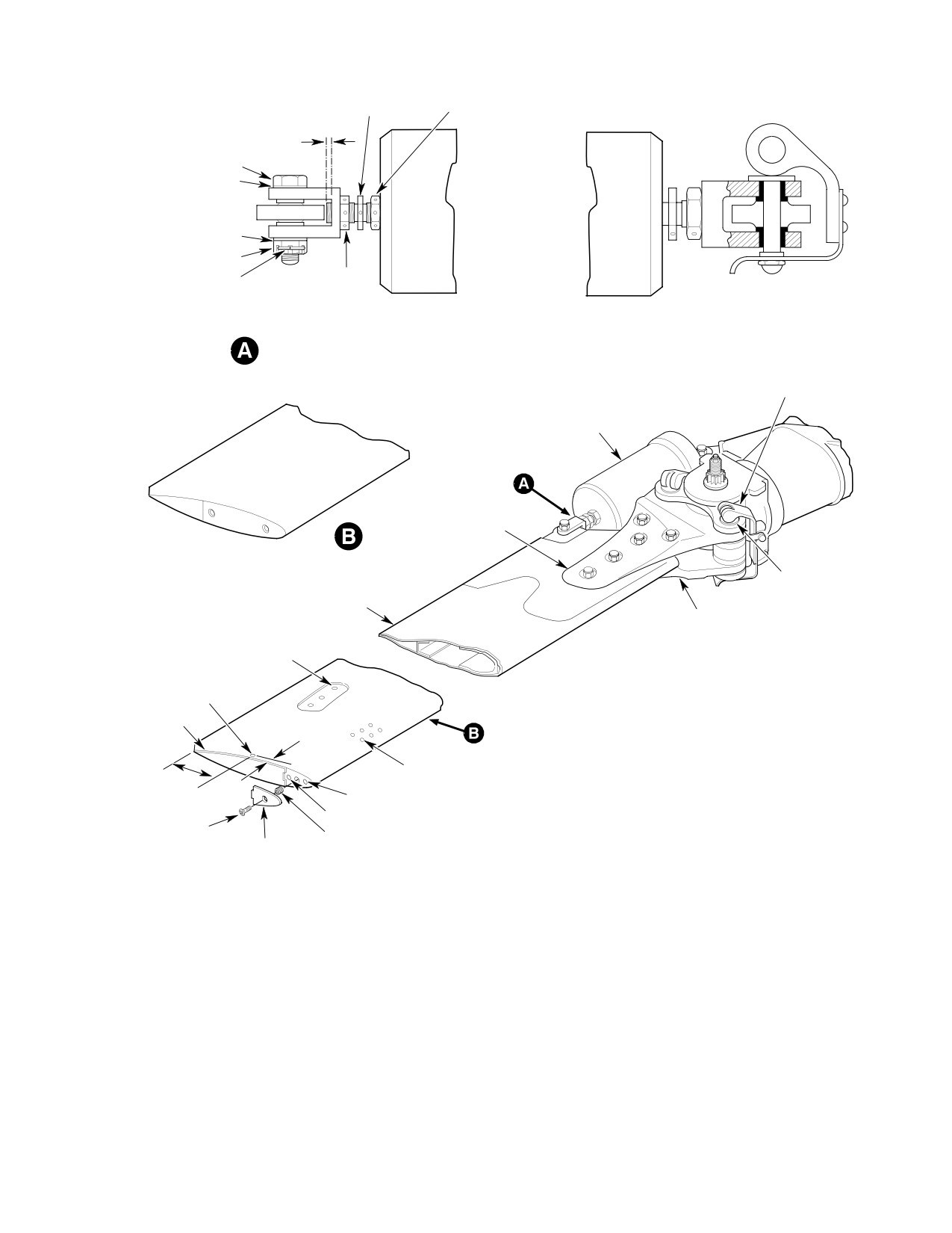
Figure 401. Main Rotor Blade − Attachment and Outboard End
Page 403
62-10-00
Revision 20
CSP-HMI-2
MD Helicopters, Inc.
MAINTENANCE MANUAL
This Page Intentionally Left Blank
Page 404
Revision 44
62-10-00
MD Helicopters, Inc.
CSP-HMI-2
MAINTENANCE MANUAL
MAIN ROTOR BLADE
INSPECTION/CHECK
1. Main Rotor Blade Inspection
90 degrees from spanline are acceptable
without repair. Nicks and gouges not
exceeding 0.003 inch (0.076 mm) depth
Special Tools
are acceptable without repair and to
(Ref. Section 91−00−00)
0.005 inch (0.127 mm) with repair.
Item
Nomenclature
N/A
Plastic inspection tool (Fabricate from
AREA 3: Scratches to 0.005 inch (0.127
0.001-0.002 inch (0.025-0.051 mm) thick
mm) depth if oriented 0-30 degrees
plastic material)
from spanline and to 0.003 inch (0.076
mm) deep if oriented between 30-40
degrees from spanline must be re
(1). Inspect skin for evidence of cracks and
moved. No sharp nicks or gouges
holes. Cracks or holes in blade skin
requiring more than 0.005 inch (0.127
surface, regardless of location, are
mm) removal of skin surface are
cause for rejection of blade. Scratches,
permissible.
dents, nicks and other surface defects
AREA 4: Scratches to 0.003 inch (0.076
in blade skin are limited according to
mm) depth if oriented 0-30 degrees and
(3). below. Use suitable dial indicator to
to 0.003 inch (0.076 mm) depth if
check depth of blade dents and
oriented between 30-90 degrees from
scratches.
spanline must be removed. No sharp
Repairable limit dimensions in
nicks or gouges requiring more than
CAUTION
following procedures apply to
0.003 inch (0.076 mm) removal of skin
surfaces that have not been repaired before.
surface are permissible.
Be sure that material has not been removed
AREA 5: Scratches exceeding a depth
from damaged areas before determining
of 0.001 inch (0.025 mm) are cause for
that damage depth limit has not been ex
rejection. Remove scratches to a depth
ceeded. Refer all questionable surface dam
of 0.001 inch (0.025 mm). Area inside
age not covered by following information to
outboard two root fitting bolt holes
MDHI.
(both upper and lower surfaces) and
(2).
(Ref. Figure 601) Limitations for
including skin surface adjacent to these
surface scratches, nicks, gouges and
bolt holes within radius of 1.00 inch
erosion in seven areas of blade skin are
(2.54 cm) from each hole must be free of
described below. Scratches that do not
scratches, nicks, or gouges as would be
penetrate clad surface are acceptable
detected under 5X magnification
without reword in all areas except
(minimum).
AREAS 5 and 8.
AREA 6: Scratches to 0.005 inch (0.127
mm) depth and oriented 0-15 degrees
AREA 1: Minor scratches, nicks and
from spanline are acceptable without
gouges without skin penetrations are
repair. Scratches to 0.005 inch (0.127
acceptable without repair. Skin defor
mm) depth and oriented from 15-30
mation with holes is cause for replace
degrees from spanline must be re
ment. Blade leading edge erosion may
moved. Scratches 0.003 inch (0.076
be repaired if skin is not eroded
mm) deep and oriented from 15-30
through. If leading edge skin is eroded
degrees from spanline are acceptable
through, no matter how slightly, blade
without repair. Scratches to 0.003 inch
must be replaced immediately.
(0.076 mm) depth and oriented from
AREA 2: Scratches to 0.005 inch (0.127
30-90 degrees from spanline must be
mm) depth if oriented 0-30 degrees
repaired. Nicks and gouges not exceed
from spanline and to 0.003 inch (0.076
ing 0.005 inch (0.127 mm) depth must
mm) depth if oriented between 30 and
be repaired. All gouges, nicks, scratches
Page 601
62-10-00
Revision 20
CSP-HMI-2
MD Helicopters, Inc.
MAINTENANCE MANUAL
and cracks on trailing edge not exceed
acceptable without repair. No repairs
ing 0.030 inch (0.076 mm) depth must
are permitted in this area.
be smoothed and radiused out over
0.120 inch (3.048 mm) area on each side
AREA C: No repairs permitted.
of damage. Defects beyond 0.030 inch
(0.762 mm) depth are cause for rejec
AREA D: Dents and depressions
tion.
exceeding 0.005 inch (0.127 mm)
without sharp change in section to a
AREA 7: Scratches, nicks, or gouges up
maximum of 0.030 inch (0.762 mm)
to 0.005 inch (0.127 mm) deep and
must be repaired.
detectable with 5X magnification are
not acceptable without repair. Defects
AREA E: Dents and depressions
beyond 0.005 inch (0.127 mm) depth are
exceeding 0.010 inch (0.254 mm)
cause for rejection. Gouges, nicks,
without sharp change in section to a
scratches and cracks not exceeding
maximum of 0.040 inch (1.016 mm)
0.250 inch (6.35 mm) depth on trailing
must be repaired.
edge, except for AREA 8, must be
smoothed and radiused out to 0.250
AREA F: Dents and depressions
inch (6.35 mm) area on each side of
exceeding 0.010 inch (0.254 mm)
damage center. Defects beyond 0.250
without sharp change in section to
inch (6.35 mm) depth require blade
maximum of 0.040 inch (1.016 mm)
replacement.
must be repaired.
AREA 8: Check for gouges, nicks,
AREA G: No repairs permitted.
scratches and cracks detected by using
a bright light and 5X magnification at
AREA H: Dents and depressions
trailing edge corners where blade and
exceeding 0.010 inch (0.254 mm)
tabs join. View area from different
without sharp change in section to
angles during inspection. Damage at
maximum of 0.040 inch (1.016 mm)
this point not exceeding 0.030 inch
must be repaired.
(0.762 mm) depth must be smoothed
and radiused out over a 0.120 inch
AREA J: Dents and depressions
(3.048 mm) area on each side of
exceeding 0.010 inch (0.254 mm)
damage. Defects beyond 0.030 inch
without sharp change in section to
(0.762 mm) depth (Ref. Trim Tab
maximum of 0.040 inch (1.016 mm)
Damage Repair).
must be repaired. Dents and depres
sions exceeding these limitations, refer
to trim tab damage repair.
(3).
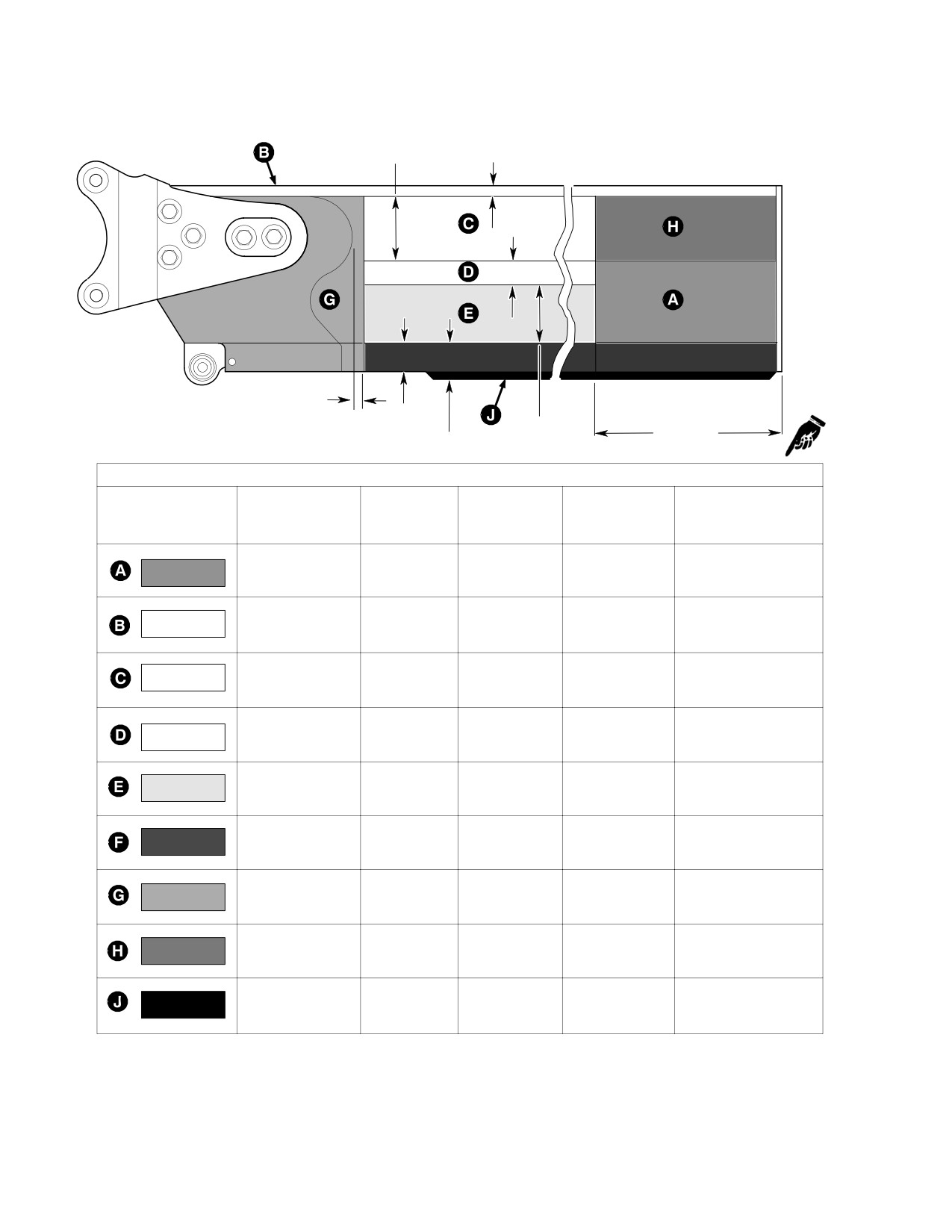
(Ref. Figure 602) Depth limitations for
surface dents or depressions in eight
areas of blade skin are described below.
(4).
Inspect surface areas of upper and
A dent or depression is defined as a
lower root fittings (other than AREA 5)
smooth depression or discontinuity with
for evidence of nicks, scratches, and
no sharp changes in section.
wear spots. Nicks, scratches, and wear
spots deeper than 0.010 inch (0.254
mm) in attachment lug area, and bolt
AREA A: Dents and depressions
hole area are not repairable. Damage
exceeding 0.015 inch (0.381 mm)
0.010 inch (0.254 mm) deep or less
without sharp changes in section to a
must be repaired.
maximum of 0.062 inch (1.575 mm)
must be repaired.
(5).
Inspect four attachment lug bushings
in root fittings (Ref. Figure 401) for
AREA B: Dents and depressions to a
security, and evidence of cracks or
maximum of 0.010 inch (0.254 mm) are
severe scoring.
Page 602
Revision 20
62-10-00
MD Helicopters, Inc.
CSP-HMI-2
MAINTENANCE MANUAL
DAMAGE 0.010 INCH (0.254 MM)
IN DEPTH OR LESS IS REPAIR
ABLE IN THESE AREAS (NOTE
1)
CHORD LINE
1
1.00 INCH (2.54 CM) RADIUS AROUND LAST
SPAN LINE
2 BOLT HOLES 0.001 INCH (0.025 MM) MAXI
0.380 INCH
5
MUM DEPTH
(9.652 MM)
90°
3.00 INCH
120°
2
4
(7.62 CM)
1.25
30°
30°
120°
120°
3
1.00 INCH
(2.54 CM)
305
30°
120°
30°
30°
15°
DAMAGE LESS THAN
0.030 INCH (0.762 MM)
6
DEPTH REPAIRABLE IN
THIS AREA (NOTE 1)
30°
15°
7
8
8
23.00 INCH
(58.42 CM)
GOUGES, NICKS AND CRACKS
SCRATCHES
GOUGES AND NICKS
TRAILING EDGE ONLY
ORIENTATION
MAXIMUM DEPTH WITH
MAXIMUM DEPTH
MAXIMUM DEPTH WITH
MAXIMUM DEPTH
MAXIMUM DEPTH WITH
MAXIMUM DEPTH WITH
AREA
FROM SPANLINE
OUT REPAIR
WITH REPAIR
OUT REPAIR
WITH REPAIR
OUT REPAIR
REPAIR
1
0°-90°
MINOR WITHOUT
MINOR WITHOUT
MINOR WITHOUT
MINOR WITHOUT
SKIN PENETRATION
SKIN PENETRATION
SKIN PENETRATION
SKIN PENETRATION
0°-30°
0.005 INCH (0.127 MM)
0.005 INCH (0.127 MM)
0.003 INCH (0.076 MM)
0.005 INCH (0.127 MM)
2
30°-90°
0.003 INCH (0.076 MM)
0.003 INCH (0.076 MM)
0.003 INCH (0.076 MM)
0.005 INCH (0.127 MM)
3
0°-30°
NONE
0.005 INCH (0.127 MM)
NONE
0.005 INCH (0.127 MM)
N/A
N/A
ÉÉÉ
30°-90°
NONE
0.003 INCH (0.076 MM)
NONE
0.005 INCH (0.127 MM)
ÉÉÉ
0°-30°
NONE
NONE
0.003 INCH (0.076 MM)
0.003 INCH (0.076 MM)
4
30°-90°
NONE
0.002 INCH (0.051 MM)
NONE
0.003 INCH (0.076 MM)
0.001 INCH (0.025 MM)
0.001 INCH (0.025 MM)
5
0°-90°
NONE
NONE
(NOTE 2)
(NOTE 2)
(NOTE 2)
0°-15°
0.005 INCH (0.127 MM)
NONE
0.005 INCH (0.127 MM)
0.005 INCH (0.127 MM)
0.030 INCH (0.762 MM)
6
15°-30°
0.005 INCH (0.127 MM)
NONE
0.005 INCH (0.127 MM)
NONE
0.003 INCH (0.076 MM)
(NOTES 2, 4)
30°-90°
NONE
0.003 INCH (0.076 MM)
NONE
0.005 INCH (0.127 MM)
0.005 INCH (0.127 MM)
0.005 INCH (0.127 MM)
7
0°-90°
NONE
NONE
NONE
0.250 INCH (6.35 MM)
(NOTE 2)
(NOTES 2, 5)
(NOTES 2, 3, 5)
8
NOT APPLICABLE
NONE
0.030 INCH (0.762 MM)
(NOTES 2, 4, 5)
TAB END
NOTES:
1.
DAMAGE LIMITS APPLY TO BOTH UPPER AND LOWER ROOT FITTING
4.
SMOOTHED AND RADIUSED CLEANOUT OVER 0.120 INCH (3.048 MM)
SURFACES.
AREA ON EACH SIDE OF DAMAGE.
2.
INSPECTION UNDER 5X MAGNIFICATION (MINIMUM) REQUIRED.
5.
REFER TO TRIM TAB DAMAGE REPAIR.
3.
AREAS NOTED: 0.250 INCH (6.35 MM) SMOTHERED AND RADIUSED
CLEANOUT ALLOWED.
G62-1001A
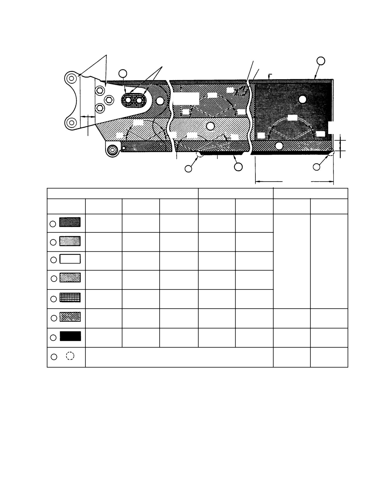
Figure 601. Main Rotor Blade Damage and Repair Limits −
Nicks, Scratches, Gouges and Cracks
Page 603
62-10-00
Revision 20
CSP-HMI-2
MD Helicopters, Inc.
MAINTENANCE MANUAL
(6). Inspect damper-attachment bearing for
and aft balance weights (Ref.
binding, evidence of galling or scoring
Figure 401) for security. Weights are
in bore and wear. No radial play is
normally recessed 0.050 inch (1.270
permissible. Maximum axial play is
mm) inside end surface of tip. Security
0.015 inch (0.381 mm).
of weights may be checked by using
torque wrench with screwdriver socket
(7). Inspect all bonded areas for evidence of
in slot of weight to detect if weight can
separation. If there appears to be
be rotated by less than 20 inch-
separation of trailing edge bond, lightly
pounds (2.26 Nm). If torque wrench is
probe joint with a 0.001-0.002 inch
not available, check weight security by
(0.025-0.051 mm) plastic inspection
fitting small coin in weight slots and
tool. If plastic inspection tool can be
applying maximum force that can be
inserted to a depth of 1/2 inch (12.70
exerted by only index finger and thumb.
mm) or more, either above or below V
If weights are found to be loose,
insert, separation is excessive.
retighten (Ref. Loose Balance Weight
Repair).
NOTE: Trailing edge structural bond line to V
insert starts 1/4 inch (6.35 mm) in (chord
2. Main Rotor Blade and Damper Attach Pin
wise) from trailing edge joint: therefore
Inspection and Corrosion Protection
above tolerance allows 1/4 inch (6.35 mm)
separation. Be sure measurement is taken
(Ref. Figure 603)
from trailing edge joint, not tab trailing
edge. Maximum trailing edge joint gap al
Consumable Materials
lowed during fabrication is 0.080 inch (2.032
(Ref. Section 91−00−00)
mm).
Item
Nomenclature
CM120
Oil, corrosion preventive
(8). Inspect doubler shown in AREA G
(Ref. Figure 602) for bonding voids
between doubler and blade skin top and
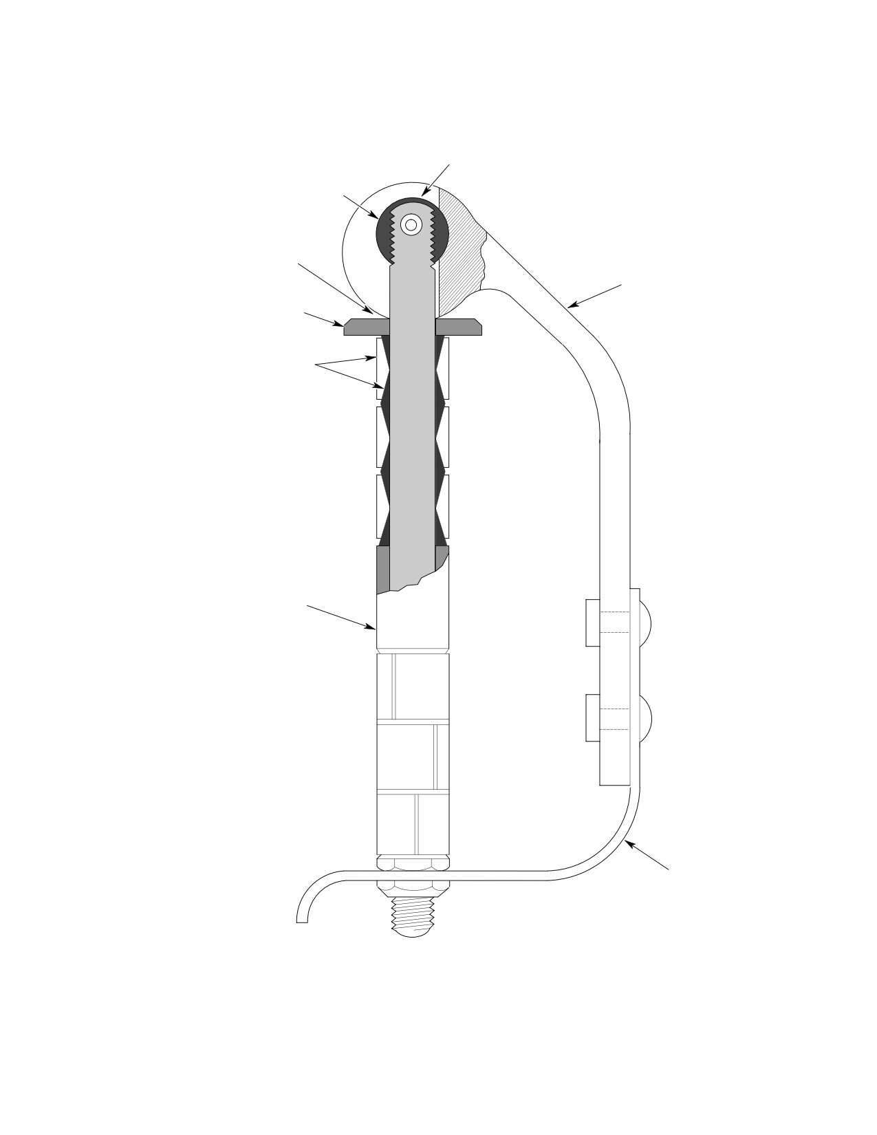
(1). Inspect pin cam handle lobe for cracks
bottom. Use a heavy coin and lightly
and excessive wear. Remove pin from
tap doubler surface. A void is detected
service if cracking or excessive wear is
by a distinct change in sound. Note that
noted.
tapping sounds differ slightly due to
blade structure in leading and trailing
NOTE: If hard anodizing surface of cam lobes is
edge, internal channel and doubler
worn, cam lobes can be re-anodized or
areas. Allowable voids or debonds on
treated with corrosion preventive oil
main rotor blade ribs are as follows:
(CM120).
(2). Inspect attach pin for evidence of
(a).
50% void or debond.
corrosion, or wear, and for straightness.
(b). Maximum four (4) ribs, no more than
Pay particular attention to area along
two (2) adjacent for the 369D21100
edges of barrel nut and bore in cam
and 369D21102 blades.
handle. Remove pin from service if
corrosion or wear is noted or if pin is
(9). Ensure that vent holes are open (Ref.
bent.
Figure 401).
NOTE: If subject to salt laden atmosphere, fol
(10). Inspect fasteners that secure upper and
lowing corrosion prevention treatment is to
lower root fittings, and six rivets that
be applied at each periodic inspection to en
secure skin to spar near tip, for securi
sure continued serviceability of attach pin;
ty. Inspect forward tip cap screw insert
and at each pin removal.
for security and thread damage. Inspect
(3). With attach pin removed, lubricate
trailing edge upper and lower weights
mating surfaces of barrel nut and cam
for debonding and loose rivets.
handle, using corrosion preventive oil
(11). When continuous one-per-revolution
(CM120). Rotate cam handle back and
lateral vibration occurs, inspect forward
forth on barrel nut several times to
Page 604
Revision 20
62-10-00

MD Helicopters, Inc.
CSP-HMI-2
MAINTENANCE MANUAL
ensure that oil penetrates all sections of
(1). Inspect tip caps for evidence of corro
pin operating mechanism. Wipe excess
sion, with particular attention at
oil from pin surfaces.
mating area of blade skin to tip weight
interface. Verify integrity of sealant
3. Main Rotor Blade and Damper Attach Pin
coating.
Disassembly and Special Inspection
(2). If damage is evident, remove tip caps
(Ref. Figure 603) This inspection is to be
and apply penetrating oil to blade tip
preformed in event of a main rotor blade
weight area. Oil arrests any corrosion
strike.
between blade skin and weight assem
bly.
Consumable Materials
(Ref. Section 91−00−00)
(3). Using brush and clean cloth, clean area
Item
Nomenclature
with isopropyl alcohol (CM217). Dry
CM217
Isopropyl alcohol
with clean cloth.
(4). Spray area with light film of rust
Do not intermix bushings,
CAUTION
inhibitor (CM232); then apply thin film
spacers and thrust washers be
of primer and paint lightly as required
tween bolts. Component parts make up a
(Ref. Sec. 20-40-00).
single bolt assembly.
(1). Remove adjusting nut and remove
5. Main Rotor Blade Upper and Lower Root
adjusting bushings, spacers and thrust
Fitting Attach Lug and Lead−Lag Link
washers from pin.
Attach Lug Inspection (25 Hour)
(2). Using brush and clean cloth, clean
parts with isopropyl alcohol (CM217).
(Ref. Figure 604 and Figure 605) The following
Dry with clean cloth.
procedure pertains to helicopters equipped
with 369D21100-BSC thru -515 and
(3). Inspect pin as follows:
369D21102-BSC and -501 main rotor blades
and/or 369H1203-BSC, -11, -21 and -31
(a). Fluorescent inspect pin per MIL-
lead-lag link assemblies.
STD-6866.
(b). Magnetic particle inspect thrust
Consumable Materials
washers, bushings and spacer per
(Ref. Section 91−00−00)
MIL-STD-1949.
Item
Nomenclature
(4). Reassemble pin in sequence as follows;
CM805
Dye penetrant kit
install thrust washer, three (3) adjust
able bushings, spacer, three (3) adjust
able bushings and secure with adjust
NOTE: Main rotor blades and hub assemblies
ing nut.
installed on helicopters operating in a salt
water or corrosive environment should be
4.
Main Rotor Blade Forward Tip Cap
cleaned and washed on a daily basis as a
Inspection and Corrosion Protection
preventative measure to arrest corrosion
(Ref. Figure 603)
(Ref. Main Rotor Hub Corrosion Prevention
(Tri-Flow Wash Procedures)).
Consumable Materials
(1). Visually inspect exposed portion of all
(Ref. Section 91−00−00)
installed main rotor blade upper and
Item
Nomenclature
lower root fitting attach lugs, and main
CM217
Isopropyl alcohol
rotor hub lead-lag link attach lugs, for
CM232
Rust inhibitor spray
broken or cracked lugs, corrosion or
other damage to the lug areas.
Page 605
62-10-00
Revision 20
CSP-HMI-2
MD Helicopters, Inc.
MAINTENANCE MANUAL
2.12 INCH
0.38 INCH
(5.385 CM)
(9.652 MM)
ÇÇÇÇÇÇÇÇÇÇ
1.58 INCH
(3.81CM)
ÇÇÇÇÇÇ
Ç
ÂÂÂÂÂÂÂÂÂÂ
ÂÂÂÂÂÂÂÂÂÂ
2.00 INCH
(5.08 CM)
0.58 INCH
(14.732 MM)
2.17 INCH
23.00 INCH
0.96 INCH
(5.512 CM)
(58.42 CM)
(24.384 MM)
DENTS AND DEPRESSIONS
MAXIMUM
MINIMUM DISTANCE
MAXIMUM DEPTH
MAXIMUM DEPTH
MAXIMUM NUMBER
AREA
ALLOWED
BETWEEN DEFECT
WITHOUT REPAIR
WITH REPAIR
OF DEFECTS
AREA
CENTERS
1.5 INCH (3.81 MM)
0.015 INCH
0.062 INCH
X
1
(0.381 MM)
(1.575 MM)
N/A
1.5 INCH (3.81 MM)
0.250 INCH (6.35 MM)
0.010 INCH
0.000
X
2
18
(0.254 MM)
0.25 INCH (6.35 MM)
ÇÇÇÇÇ
NONE
ÇÇÇÇÇ
0.000
0.000
0.000
N/A
ALLOWED
1.5 INCH (3.81 MM)
ÂÂÂÂÂ
0.005 INCH
0.030 INCH
X
2
18
(0.127 MM)
(0.762 MM)
1.5 INCH (3.81 MM)
ÂÂÂÂÂ
0.010 INCH
0.040 INCH
1.5 INCH (3.81 MM)
X
2
18
(0.254 MM)
(1.016 MM)
1.5 INCH (3.81 MM)
1.5 INCH (3.81 MM)
0.010 INCH
0.040 INCH
X
3
18
(0.254 MM)
(1.016 MM)
1.5 INCH (3.81 MM)
0.000
0.000
0.000
NONE
N/A
ALLOWED
1.5 INCH (3.81 MM)
0.010 INCH
0.040 INCH
X
1
N/A
(0.254 MM)
(1.016 MM)
1.5 INCH (3.81 MM)
0.350 INCH
1.5 INCH (3.81 MM)
0.010 INCH
N/A
(8.89 MM)
X
N/A
(0.254 MM)
(NOTE 2)
1.5 INCH (3.81 MM)
NOTES:
1.
N/A - NOT APPLICABLE.
G62-1002B
2
REFER TO TRIM TAB DAMAGE REPAIR
Figure 602. Main Rotor Blade Damage Limits for Dents and Depressions
Page 606
Revision 40
62-10-00
MD Helicopters, Inc.
CSP-HMI-2
MAINTENANCE MANUAL
OIL
BARREL NUT
OIL
CAM HANDLE
THRUST WASHER
BUSHING SEGMENTS
SPACER
SAFETY LATCH
G62-1008
Figure 603. Main Rotor Blade Attach Pin
Page 607
62-10-00
Revision 20
CSP-HMI-2
MD Helicopters, Inc.
MAINTENANCE MANUAL
NOTE: If movement is suspected but cannot be
verified with the blades installed, remove
Consumable Materials
those blades and inspect bushings for move
(Ref. Section 91−00−00)
ment.
Item
Nomenclature
CM217
Isopropyl alcohol
(2). Using a bright light, inspect slippage
CM318
Primer
marks on the root fitting bushings to
CM420
Sealant
ensure there has been no movement of
CM805
Dye penetrant kit
the bushings. If bushings have moved,
replace main rotor blade before next
flight. Return those main rotor blades
(1). Remove affected main rotor blades (Ref.
where bushing movement has occurred
Main Rotor Blade Removal).
to MDHI for possible rework.
CAUTION
CAUTION
D If cracked or broken lug is noted in main
rotor blade upper and lower root fittings,
D If broken or cracked lugs are noted in
replace main rotor blade (Ref. Main Rotor
main rotor blade upper and lower root fit
Blade Removal) before further flight.
tings, replace main rotor blade before fur
D If cracked or broken lug is noted in main
ther flight (Ref. Main Rotor Blade Remov
rotor lead-lag links, replace or repair
al).
main rotor hub before further flight (Ref.
D If broken or cracked lugs are noted in
Sec. 62-20) (Ref. NOTE: below).
main rotor lead-lag links, replace main
D If a crack is suspected in either the rotor
rotor hub (Ref. Sec. 62-20) (Ref. NOTE:
blade or lead-lag link attach lug, perform
below).
dye penetrant (CM805) inspection per
MIL-I-25135 of lug. If a crack in noted,
D If cracking is suspected in either the rotor
replace main rotor blade (Ref. Main Rotor
blade or hub lead-lag link attach lugs,
Blade Removal) or replace or repair main
perform dye penetrant (CM805) inspec
rotor hub assembly (Ref. Sec. 62-20) (Ref.
tion of lugs per MIL-I-25135. If cracking
NOTE: below).
is noted, replace main rotor blade (Ref.
Main Rotor Blade Removal) or replace or
NOTE: Do not remove bushings or corrosion in
repair main rotor hub assembly (Ref. Sec.
hibiting sealer.
62-20), before further flight (Ref. NOTE:
below).
(2). Using bright light and 5X magnifying
glass, visually inspect the attach lugs of
all main rotor blade upper and lower
NOTE: Lead-Lag link assemblies may only be
root fitting and main rotor lead-lag
replaced by MDHI authorized personnel or
links for broken or cracked lugs,
under MDHI supervision. Contact your local
corrosion or other damage to the lug
MDHI Field Service Representative for fur
areas.
ther information.
NOTE:
6. Main Rotor Blade Upper and Lower Root
D Pay particular attention to area around
Fitting, Attach Lug and Lead−Lag Link
attach pin hole bushings in the lugs.
Attach Lug Inspection (100 Hour)
D Pay particular attention to the cross-
hatched areas.
(Ref. Figure 604 and Figure 605) The following
procedure pertains to helicopters equipped
(3). If slippage marks have already been
with 369D21100-BSC thru -523,
applied, inspect the root fitting for any
369D21120-501, 369D21102-BSC thru -523
indication of movement of the bushings;
and 369D21121-501 main rotor blades and/or
no movement is allowed. Return main
369H1203-BSC, -11, -21 and -31 lead-lag
rotor blades that have root fitting
link assemblies.
bushing movement to MDHI for
Page 608
Revision 33
62-10-00
MD Helicopters, Inc.
CSP-HMI-2
MAINTENANCE MANUAL
possible rework. If slippage mark is
(5). Inspect lead-lag link blade attach pin
degraded, reapply.
hole bushings for any indication of
movement of the bushings in the links.
(4). Perform main rotor blade upper and
If any of the bushings have movement,
lower root fitting inspection as follows:
replace the links.
(a). Inspect main rotor blade root fitting
If required, apply a light but
for missing (no squeeze-out) or
CAUTION
thorough coat of sealer (CM420)
cracked adhesive/paint around the
or primer (CM318) around bushings. Note
periphery of the root fitting. If this
that excessive amounts of sealant or primer
condition exists, proceed as follows:
around the bushings are not desirable and
1). Loosen, but do not remove the
can unbalance the main rotor system.
extreme outboard bolt.
(6). If sealing compound is not already
2). Insert a 0.004 inch (0.102 mm)
installed or becomes loose, clean and
thick piece of mylar/viewfoil
then seal all junctions between all the
between the fitting and the dou
steel bushings and the main rotor blade
bler.
root fitting attach lugs with a film of
sealing compound or zinc-chromate
3). If the mylar can be inserted,
primer without removing the bushings.
contact Field Service Representa
tive for disposition of blade.
(7). For the main rotor blade root fitting
attach lugs, carefully remove sufficient
4). If the insertion is 0.10 inch (2.54
amount of sealant and paint from only
mm) or greater, remove blade from
the bushing in the area where the
service.
slippage mark is to be applied (if not
already done). Using isopropyl alcohol
NOTE: Measurement of the insertion is from
(CM217), clean the area where the
the edge of the root fitting.
slippage mark is going to be applied to
5). Retorque root fitting outboard bolt
allow adequate adherence of epoxy
to 60 - 65 inch-pounds (6.78 -
paint.
7.34 Nm) plus drag torque.
NOTE:
In the following step, a crack
CAUTION
D Locate slippage mark in a position that
might be difficult to detect if
can be viewed at subsequent inspections
bright light is not used.
with main rotor blade installed in the
NOTE: The lower side of the blade is more sus
hub. Slippage marks should not be ap
ceptible to cracking.
plied to cross-hatched areas to preclude
masking possible cracks.
(b). Using a bright light, inspect doubler
D Insure that slippage mark is applied to
and root fitting, paying particular
bushing at upper and lower root fitting in
attention to the lower side, for
side surfaces.
cracks. If crack is found, blade is to
be scrapped.
D Do not use torque seal.
NOTE: Lead-Lag link assemblies may only be
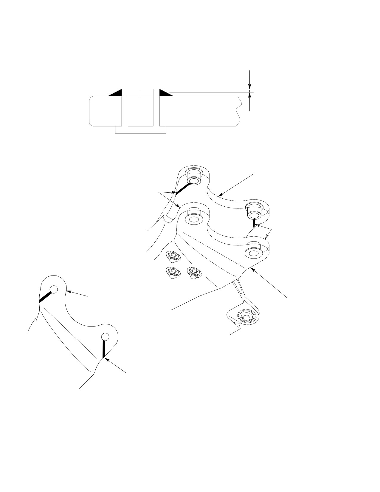
(8). Apply epoxy paint slippage marks to
replaced by MDHI authorized personnel or
four locations as shown.
under MDHI supervision. Contact your local
Field Service Representative for further in
(9). Install main rotor blades (Ref. Main
formation.
Rotor Blade Installation).
Page 609
62-10-00
Revision 29
CSP-HMI-2
MD Helicopters, Inc.
MAINTENANCE MANUAL
7. Main Rotor Blade Leading Edge Abrasion
8. Main Rotor Blade Torque Event Inspection
Strip Check
(Ref. Figure 604)
The leading edge abrasion strip should be
NOTE: This inspection requires the use of a
checked prior to each flight or on every daily
bright light.
check. The following is a comprehensive
checklist:
(1). Lifting from the outboard end of the
blade, lift blade off the droop stop.
NOTE: If void is noted towards end of blade, re
move tip cap and check for presence of bal
(2). Inspect the bottom-side of the blade as
ance weights. If weights are not installed, a
follows:
false indication of a void is possible.
(a). Using a bright light and 10x magni
(1). Check for any blistering, bubbling or
fying glass, inspect for chordwise
lifting of the abrasion strip; this
cracks protruding from under root
indicates a void.
fitting and doubler (View C and Note
7).
(a). Voids cannot be closer than 0.50 inch
(12.70 mm) to any outside edge of
(b). Inspect the area around the root
abrasion strip.
fitting, doubler and skin for cracks.
(b). Voids exceeding 1.5 square inch
(c). Inspect the attach lugs at the bush
(9.677 square cm) are unacceptable.
ings for cracks.
(c). Voids cannot be closer than one inch
(d). Inspect the entire length of the blade
(2.54 cm) to any other void.
for cracks.
(2). Number of acceptable voids depends
(e). Lower blade back onto droop stop.
upon length of abrasion strip.
(3). With blade resting on the droop stop,
inspect the top-side of the blade as
(a). There cannot be more than three
voids on either the top or bottom of
follows:
the 36 inch (91.44 cm) long abrasion
(a). Inspect the area around the root
strip surface.
fitting, doubler and skin for cracks.
(b). There cannot be more than two voids
(b). Inspect the attach lugs at the bush
on either the top or bottom of the 18
ings for cracks.
inch (45.72 cm) long abrasion strip
surface.
(c). Inspect the entire length of the blade
for cracks.
(3). Record all voids in regards to size and
location in the helicopter log book and
(4). If any of the above defects are found,
check each void prior to each flight for
the main rotor blade is to be rejected
growth and acceptable criteria.
and scrapped.
Page 610
Revision 35
62-10-00
MD Helicopters, Inc.
CSP-HMI-2
MAINTENANCE MANUAL
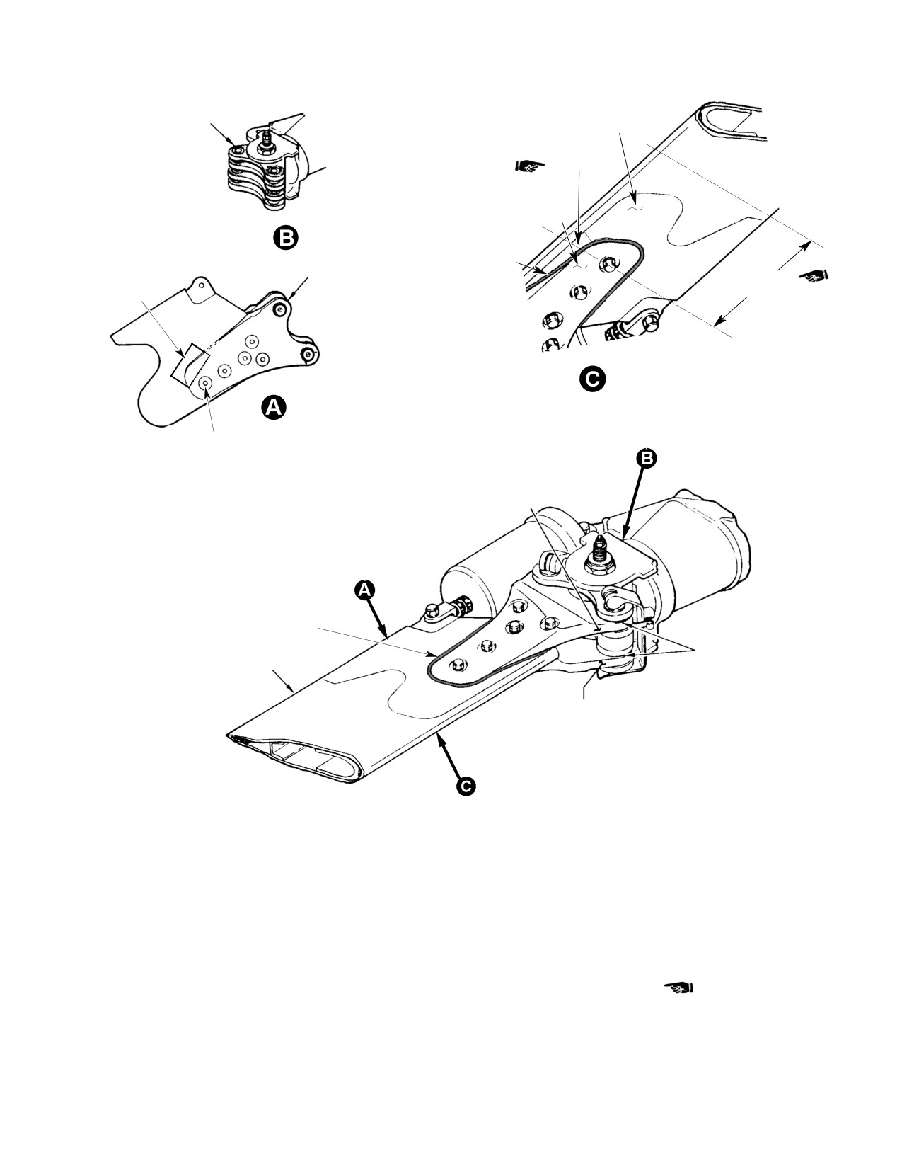
NOTES 2, 3 AND 4
DOUBLER
NOTE 6
ROOT FITTING
NOTE 5
(NOTES 1, 2 AND 3)
NOTE 7
NOTE 5
VIEW LOOKING UP
ROTATED
LOOSEN BUT DO NOT REMOVE BOLT.
RETORQUE BOLT TO 60 - 65 INCH-POUNDS
(6.78 - 7.34 NM) PLUS DRAG TORQUE.
UPPER ROOT FITTING ATTACH LUG
(TYP 2 PLACES) (NOTE 1)
NOTE 5
LEAD-LAG LINK ATTACH LUG
(TYP 8 PLCS) (NOTE 1)
MAIN ROTOR BLADE
LOWER ROOT FITTING AT
TACH LUG (TYP 2 PLCS)
(NOTE 1)
NOTES:
1.
VISUALLY INSPECT AREAS OF ALL ROOT FITTINGS AND LEAD-LAG ATTACH LUGS FOR CRACKS OR
BREAKS. INSPECT BLADE ATTACH BUSHINGS FOR LOOSENESS. IF LOOSE, REPLACE LEAD-LAG LINKS.
2.
PAY PARTICULAR ATTENTION TO AREA AROUND ATTACH PIN HOLES IN LUGS.
3.
SEAL ALL JUNCTIONS BETWEEN BUSHINGS AND ATTACH LUGS WITH SEALER OR PRIMER (CM318).
4.
LEAD-LAG LINK ASSEMBLIES ARE SUB-ASSEMBLIES OF THE MAIN ROTOR HUB ASSEMBLY.
5.
INSPECT MAIN ROTOR BLADE UPPER AND LOWER ROOT FITTING FOR MISSING OR CRACKED ADHESIVE.
6.
USING BRIGHT LIGHT, INSPECT MAIN ROTOR BLADE DOUBLER FOR CRACKS. PAY PARTICULAR ATTENTION
TO BOTTOM SIDE OF BLADE, JUST BEYOND ROOT FITTING AND IN LINE WITH ROOT FITTING ATTACH BOLTS.
7.
USING A BRIGHT LIGHT AND 10X MAGNIFYING GLASS, INSPECT FOR CHORDWISE CRACKS PROTRUDING
FROM UNDER ROOT FITTING AND DOUBLER.
G62-1009D
Figure 604. Main Rotor Blade Root Fitting, Attach Lugs and Lead−Lag Link
Assembly Inspection
Page 611
62-10-00
Revision 35
CSP-HMI-2
MD Helicopters, Inc.
MAINTENANCE MANUAL
ÇÇ Ç
* ONLY REMOVE 1/2 DEPTH OF
CORROSION INHIBITING SEALER
ÇÇ Ç
AT LOCATION WHERE SLIPPAGE
MARK IS TO BE APPLIED.
ÇÇ Ç
ÇÇ Ç
ÇÇÇÇÇÇ
UPPER ROOT FITTING
SLIPPAGE MARK LOCATIONS
ÎÎ
SLIPPAGE MARK LOCATIONS
(INSIDE SURFACES)
ÎÎ
Î
ÎÎ
ÎÎÎ
ÎÎÎ
DO NOT APPLY SLIPPAGE MARK
TO CROSS-HATCH AREAS
LOWER ROOT FITTING
Î
ÎÎ
ÎÎÎ
ÎÎÎ
VIEW LOOKING UP
ÎÎ
Î
SLIPPAGE MARK LOCATIONS
(LAG SIDE SHOWN)
(LEAD SIDE OPPOSITE)
UPPER AND LOWER
88-675
Figure 605. Application of Slippage Mark to Main Rotor Blade Bushings and Root Fittings
Page 612
Revision 20
62-10-00

MD Helicopters, Inc.
CSP-HMI-2
MAINTENANCE MANUAL
MAIN ROTOR BLADE
REPAIRS
1. Main Rotor Blade Repair (Nicks,
CAUTION
Scratches and Wear Spots)
D Repair only those damaged areas that are
Consumable Materials
within repairable limits specified.
(Ref. Section 91−00−00)
D Do not use chemical paint remover to re
Item
Nomenclature
move paint from abrasion strip. Chemi
CM206
Chemical coating
cals can attack the abrasion strip to blade
CM801
Abrasive paper, silicon carbide
bonding agent.
(1). Using abrasive paper (CM801), not
(Ref. Figure 601)
coarser than grade 320, remove paint
Do not use chemical paint re
from surface area to be repaired.
CAUTION
mover to remove paint from
abrasion strip. Chemicals can attack the
(2). Clean abraded area with clean cloth
abrasion strip to blade bonding agent.
dampened by solvent (CM234). Allow to
dry for minimum of 15 minutes.
(1). Using abrasive paper (CM801), not
coarser than grade 320, remove nicks,
(3). Mask edges of repair areas with one
scratches and wear spots from upper
layer of tape (CM708).
and lower root fittings, and from blade
skin.
Do not cut tape after it is
CAUTION
(2). Use finer grade of paper, as necessary
applied to blade.
to restore surface roughness to original
finish.
(4).
Mix filler (CM507), three parts ”A” and
two parts ”B” by weight. Mix thorough
(3). Remove material in such a manner that
ly until mixture is dark red in color. An
no abrupt changes occur in surface
alternate filler (CM508) may be used if
contours.
equal parts ”A” and ”B” by weight are
(4). Apply chemical film surface treatment
mixed.
(CM206) to repaired surface(s) (Ref.
Sec. 20-30).
(5).
Allow filler to cure for minimum of 24
hours at room temperature.
2. Main Rotor Blade Repair (Dents,
Depressions and Erosion)
(6).
Smooth filler area with grade 400
abrasive paper (CM801). Limit smooth
(Ref. Figure 602)
ing to masked area.
Consumable Materials
(7).
Remove the tape and inspect alclad
(Ref. Section 91−00−00)
coating of area around repair. Penetra
Item
Nomenclature
tion of coating is cause for blade
CM220
Naphtha aliphatic
replacement.
CM229
Paint remover
(8).
Clean repaired area with a cloth
CM234
Solvent, dry-cleaning
dampened by solvent (CM220).
CM304
Enamel, epoxy
CM507
Resin, filler
(9).
Apply chemical film treatment to
CM508
Resin, filler
repaired surface (Ref. Sec. 20-30-00).
CM708
Tape
CM801
Abrasive paper, silicon carbide
(10).
Touch-up reworked area with paint
(CM304) as required.
Page 801
62-10-00
Revision 33
CSP-HMI-2
MD Helicopters, Inc.
MAINTENANCE MANUAL
3. Trim Tab Damage Repair
(6). If excessive damage requires full or
partial removal of trim tab from blade,
(Ref. Figure 802)
perform the following (no minimum
length of trim tab is required):
Consumable Materials
(a). Position blade on workbench so that
(Ref. Section 91−00−00)
a straight edge is provided for cutting
Item
Nomenclature
or filing off trim tab.
CM206
Chemical coating
CM220
Naphtha aliphatic
Cutting, grinding or filing to re
CAUTION
move trim tab, and deburring of
CM234
Solvent, dry-cleaning
reworked blade trailing edge, are to be per
CM304
Enamel, epoxy
formed in a SPANWISE direction only. Do
CM318
Primer
NOT use shears or clippers to remove trim
tab.
Provide protective surface and/
(b). Use metal cutting saw or equivalent
CAUTION
or covering to prevent scratch
to remove the 0.38 inch (9.65 mm)
ing, nicking or other damage to blade during
wide trim tab per dimensions shown
rework. Position blade on work bench or
Ref. Figure 802, View A-A). Deburr
equivalent.
edges in a SPANWISE direction only.
NOTE: No minimum length of trim tab is re
(7). Peel and remove tape from blade and
quired. In addition, the entire trim tab, or
inspect area around repair; clean
portion of the trim tab, may be removed if
repaired area with cloth dampened in
required. Removal of entire trim tab elimi
naptha (CM220).
nates adjustment of blade tracking capabili
ty for that blade. Main rotor blades with and
(8). Apply chemical film treatment (CM206)
without trim tabs are 100% interchange
to reworked area of blade trailing edge
able, individually and in ship sets.
or trim tab; apply a thin film of primer
(CM318) and paint (CM304) lightly.
(1).
Remove main rotor blade with damaged
trim tab.
(9). Reinstall main rotor blade and perform
track and balance (Ref. Sec. 18-10).
(2).
Wipe away dirt on and around trim tab
area with clean cloth dampened with
NOTE: Removal of entire trim tab eliminates
dry cleaning solvent (CM234).
adjustment of blade tracking capability for
that blade.
(3).
Mask edges of blade area around trim
tab area with tape; do NOT cut tape
after it has been applied to blade.
4. Forward Tip Cap Threaded Insert Repair
(4).
Remove damaged area of trim tab by
Consumable Materials
making V-type cut with 45° sides
(Ref. Section 91−00−00)
joined by a 0.25 inch (6.35 mm) radius
Item
Nomenclature
at the bottom of the V. Maximum V-cut
depth is 0.35 inch (8.89 mm); do not cut
CM318
Primer
past trim tab area into main portion of
blade.
Replace a loose or stripped insert. Use
(5).
If damage occurs within 1 inch (2.54
self-locking insert of correct size and install
cm) of either or both ends of trim tab,
with wet primer (CM318). Comply with
remove tab end(s) and restore contour
replacement requirements of applicable NAS
as shown.
standard.
Page 802
Revision 20
62-10-00
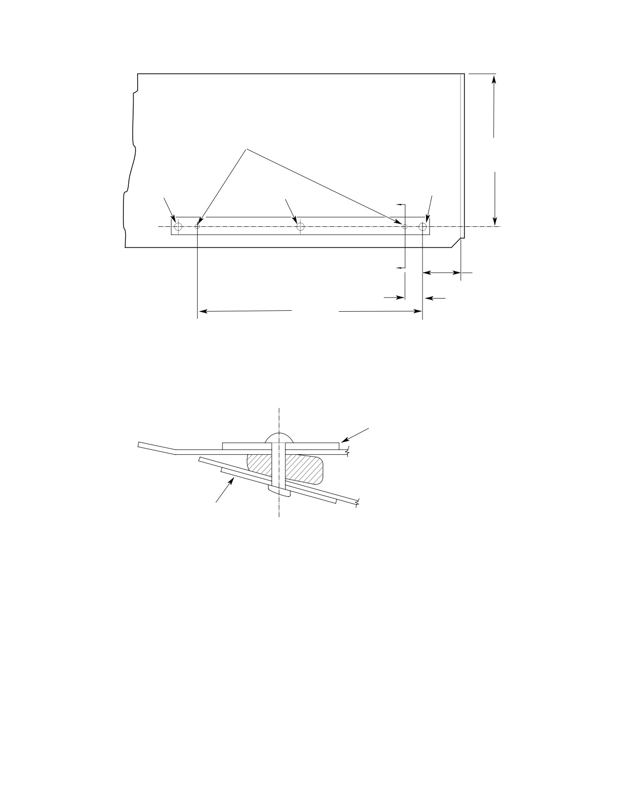
MD Helicopters, Inc.
CSP-HMI-2
MAINTENANCE MANUAL
MS2070AD3
RIVETS (2 PLS)
6.312 INCH
(16.033 CM)
(REF)
EXISTING
EXISTING
EXISTING
BLADE RIVET
BLADE RIVET
BLADE RIVET
A
1.58 INCH
A
(4.013 CM)
(REF)
0.75 INCH
9.25 INCH
(19.05 MM)
(23.495 CM)
369D21106 UPPER EXTERNAL
TRAILING EDGE WEIGHT
(369D21100 ONLY)
369D21106 LOWER EXTERNAL
TRAILING EDGE WEIGHT
(369D21100 ONLY)
VIEW A - A
(ROTATED 90°)
NOTES:
POSITION WEIGHT ONTO BLADE (ONE
EACH ON UPPER AND LOWER SURFACES) BY ALIGNING
G62 1003A
Figure 801. Main Rotor Blade Trailing Edge Weight Rework.
Page 803
62-10-00
Revision 20
CSP-HMI-2
MD Helicopters, Inc.
MAINTENANCE MANUAL
5. Loose Balance Weight Repair
(4). Mix epoxy adhesive (CM409) per
manufacturer`s instructions and apply
(Ref. Figure 401) Reinstall loose forward and aft
to bonding surfaces.
balance weights as follows:
(5). Position weights on blade by aligning
holes in weights to existing rivet holes
Consumable Materials
on blade and apply light pressure to
(Ref. Section 91−00−00)
weights until epoxy sets.
Item
Nomenclature
(6). Install (3 ea.) rivets in existing holes.
CM431
Sealing, locking and retaining compound
(7). If not already installed, install two
more rivets as follows.
(1). Unscrew loose weight until it projects
approximately one-half inch (12.7 mm)
(a). Mark location of rivets to be in
and remove old accumulation of
stalled.
powdered compound.
(b). Drill holes at marked locations.
(2). Apply grade A locking compound
(c). Deburr and clean debris from holes.
(CM431) and screw weight back into
(d). Coat all exposed surfaces with primer
blade until slotted end of weight is
(CM318).
recessed 0.050 inch (1.27 mm) below tip
surface. Wipe off excess compound.
(e). Install rivets.
Allow to cure for a minimum of
(f). Allow epoxy adhesive to cure per
CAUTION
12 hours. If faster cure is de
manufacturer's instructions before
sired, complete cure can be obtained by al
flying aircraft.
lowing part to set for 30 minutes at room
7. Loose or Missing Rivets or Aft Tip Cap
temperature and then heating for 30 min
Repair
utes at approximately 212°F (101°C).
(Ref. Figure 401) Replace all loose or missing
(3). If locking compound is not available,
rivets. Reinstall or replace loose or missing aft tip
screw weight into normal position and
cap as follows:
centerpunch end of weight into mating
threads at three evenly spaced points to
Consumable Materials
prevent rotation.
(Ref. Section 91−00−00)
6. Loose Trailing Edge Weight Repair
Item
Nomenclature
CM234
Solvent, dry-cleaning
(Ref. Figure 801)
CM318
Primer
CM411
Adhesive, epoxy
Consumable Materials
CM801
Abrasive paper, silicon carbide
(Ref. Section 91−00−00)
Item
Nomenclature
NOTE: Spare tip caps are supplied with bond
CM220
Naphtha aliphatic
ing surface coated with nylon primer to fa
CM318
Primer
cilitate installation. Main rotor balance is
CM409
Adhesive, epoxy
not affected by following repair.
CM804
Emery cloth, fine
(1). Lightly abrade primed surfaces of tip
cap with grade 180 abrasive paper
(1). Carefully remove loose or partially
(CM801). Wipe away residue with cloth
debonded weights.
dampened in solvent (CM234) and
allow tip cap to dry at room tempera
(2). Abrade debonded surface using
ture for 30 minutes.
#200-300 grit emery cloth (CM804).
(2). Mix two-part bonding adhesive
(3). Clean bonding surfaces with naptha
(CM411) in equal proportions by
aliphatic (CM220).
weight.
Page 804
Revision 20
62-10-00
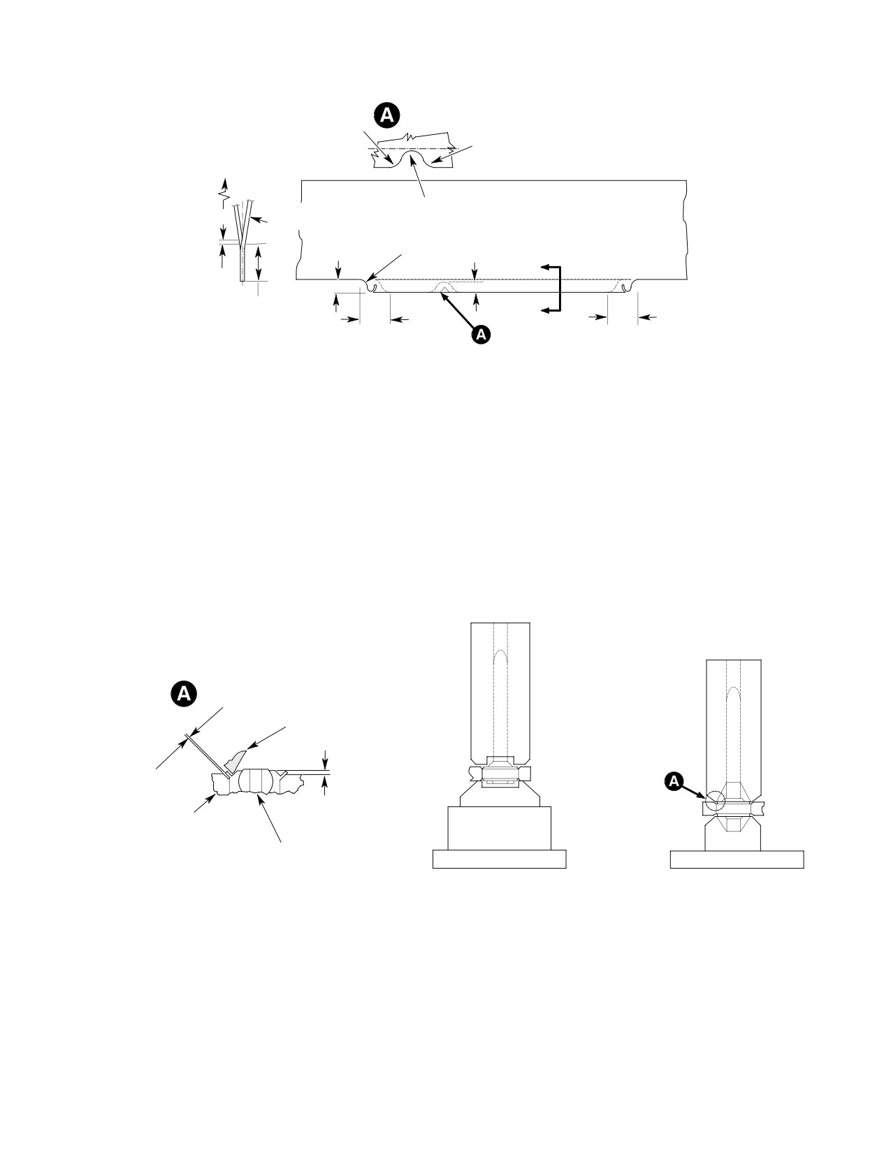
MD Helicopters, Inc.
CSP-HMI-2
MAINTENANCE MANUAL
NOTE 2
NOTE 2
NOTES 2, 3
TOP
6.80 INCH (17.272 CM)
SURFACE
0.38 INCH
NOTE 1
(9.652 MM)
NOTE 3
A
0.00 - 0.10 INCH
(0.00 - 2.54 MM)
NOTE 4
0.38 INCH
A
1.00 INCH
(9.652 MM)
1.00 INCH
(2.54 CM)
(2.54 CM)
VIEW A-A
NOTES:
1.
REMOVE DAMAGED END(S) IF THEY OCCUR WITHIN 1 INCH (2.54 CM) OF TAB ENDS.
2.
0.25 INCH (6.35 MM) RADIUS CLEANUP. FINISH PER BASIC HMI.
3.
MAXIMUM DEPTH OF REPAIR 0.35 INCH (8.89 MM).
4.
NO MINIMUM LENGTH OF TAB REQUIRED. IF DAMAGE OCCURS AT BOTH ENDS, IT IS
PERMISSIBLE TO REMOVE AT BOTH ENDS
Figure 802. Repair and Removal of Trim Tab, Main Rotor Blade
0.002 INCH
(0.0508 MM)
MAXIMUM
EDGE OF
STAKING TOOL
FLUSH TO
ARM
+0.010 INCH
(+0.254 MM)
BEARING WITH STAKING
GROOVE IN OUTER RACE
PRESSING
STAKING
BEARING IN ARM
BEARING IN ARM
G62 1005A
Figure 803. Bearing Replacement − Main Rotor Blade Damper Attach Fitting
Page 805
62-10-00
Revision 20
CSP-HMI-2
MD Helicopters, Inc.
MAINTENANCE MANUAL
(3). Apply bonding adhesive to abraded tip
(5). Measure fitting bore diameter. Accept
cap and mating surfaces at rotor blade
able limits are 0.7488-0.7493 inch
tip. To extent possible, be sure that
(19.01952-19.03222 mm).
there are no adhesive voids.
(6). Apply thin coat of primer (CM318) to
fitting bore.
(4). Install tip cap in blade tip, apply
uniform clamping pressure to joint, and
(7). Press bearing into fitting with arbor
wipe away excessive adhesive. Allow to
press and fixture (ST709). Wipe away
cure for eight hours at room tempera
excess primer.
ture or two hours at 150°F (66°C).
(8). Stake bearing at both sides of fitting
with staking tool (ST710) in hydraulic
(5). Install two MS20604AD3C2 blind
press with 6000-8000 pounds
rivets, one though each side of blade tip
(2722-3629 Kg) of force. When staked,
and tip cap.
outer race of bearing shall be flush to
not more than 0.010 inch (0.254 mm)
8. Damper Attach Blade Fitting Bearing
above fitting surface (both sides). Gap
Replacement
between staked lip of bearing race and
chamfered surface of fitting bore shall
(Ref. Figure 803)
not exceed 0.002 inch (0.0508 mm) as
checked with feeler gage. Staking
Consumable Materials
operation shall produce no cracks in
(Ref. Section 91−00−00)
fitting or bearing.
Item
Nomenclature
(9). Fill staking gap, if any, with primer
CM216
Loctite remover
(CM318).
CM219
Methyl-ethyl-ketone
9. Outboard Leading Edge Abrasion Tape
CM318
Primer
Replacement
(Ref. Figure 804 and Figure 805) Replace
Special Tools
abrasion tape when it is worn or eroded. Operation
(Ref. Section 91−00−00)
in rain or dust reduces tape life and more frequent
Item
Nomenclature
replacement is necessary.
ST709
Arbor press fixture
ST710
Staking tool
Consumable Materials
(Ref. Section 91−00−00)
Item
Nomenclature
(1).
Use fly or circle cutter with 5/16 inch
CM220
Naphtha aliphatic
(7.9375 mm) pilot to remove staked lip
CM717
Tape, pressure sensitive
from one side of bearing without
CM801
Abrasive paper, silicon carbide
removing any material from fitting. If
fitting is damaged by cutter, blade must
be replaced.
A. Removal
(2).
Use an arbor press to press bearing
NOTE: A second abrasion tape may be applied
from fitting.
on top of the first tape to help replacement
when top tape becomes eroded.
(3).
Clean primer residue from fitting bore
(1). When only the top tape is replaced, peel
with MEK (CM219). Remove locking
off top tape. Do not damage bottom tape
compound residue, if any, with locking
bond to main rotor blade.
compound remover (CM216).
(2). Wipe surface of bottom tape with a
(4).
Using 10-power magnifying glass,
clean cloth dampened with naptha
inspect fitting bore for cracks. No
aliphatic (CM220) to remove any
cracks are permitted.
adhesive.
Page 806
TR12-001
62-10-00
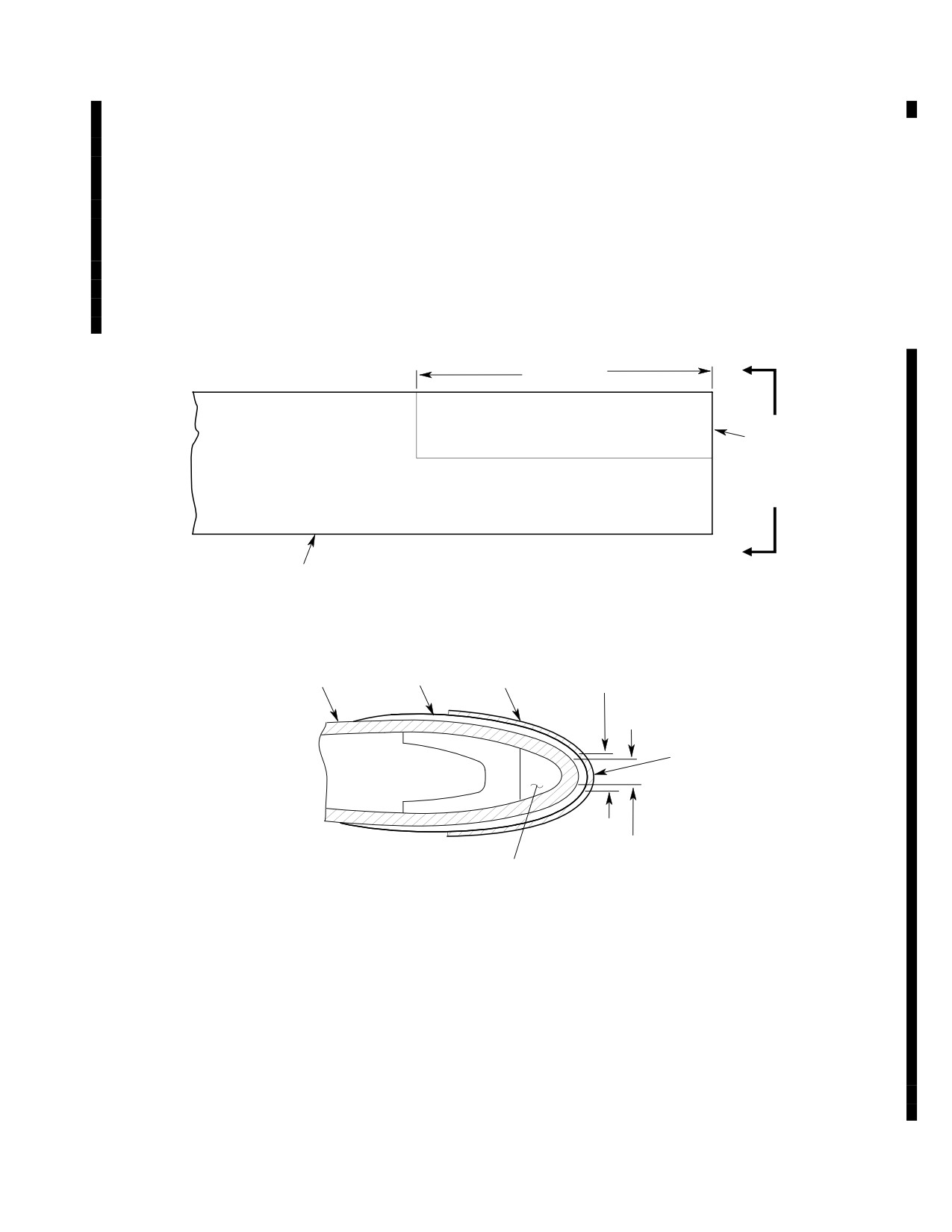
MD Helicopters, Inc.
CSP-HMI-2
MAINTENANCE MANUAL
(3). Do not allow naptha aliphatic (CM220)
B. Installation
to touch the bond line between the
bottom tape and the main rotor blade
(1). Lightly abrade faying surface of main
surface.
rotor blade with 400 grit abrasive paper
(CM801).
(4). If necessary, remove bottom tape from
(2). Wipe faying surface of blade with
main rotor blade.
naptha aliphatic (CM220) to eliminate
grease or dirt film.
(5). Wipe main rotor blade surface with a
clean cloth dampened with naptha
(3). Use heat gun or equivalent to warm
aliphatic (CM220) to remove any
blade faying surface. Temperature must
adhesive.
not exceed 120°F (49°C).
24.00 INCH
A
(60.96 CM)
(NOTE 1)
A
MAIN ROTOR BLADE
ABRASION STRIP
ABRASION STRIP TIP
(369A1105)
EROSION 0.40 INCH
BLADE PROFILE
(369D21105)
(NOTE 2)
(10.16 MM) MAXIMUM
ABRASION TAPE
(369D21104 OR CM717)
SKIN TIP EROSION
0.30 INCH (7.62 MM)
CHORDWISE
MAXIMUM
BALL. WEIGHT
VIEW A-A
(NOTE 3)
NOTES:
1.
END OF TAPE TO BE FLUSH WITH OUTBOARD END OF BLADE SKIN. TAPE
TO BE SYMMETRICAL ABOUT LEADING EDGE.
2.
ABRASION TAPE MUST BE ALIGNED AT TOP PART OF BLADE.
3.
VIEW IS TYPICAL FOR 369D21100 BLADES EXCEPT -505, -509, -511
G62-1006B
(SEE ALSO DN-39).
Figure 804. Installation/Replacement of Abrasion Tape
(Main Rotor Blade Leading Edge)
Page 807
62-10-00
TR12-001
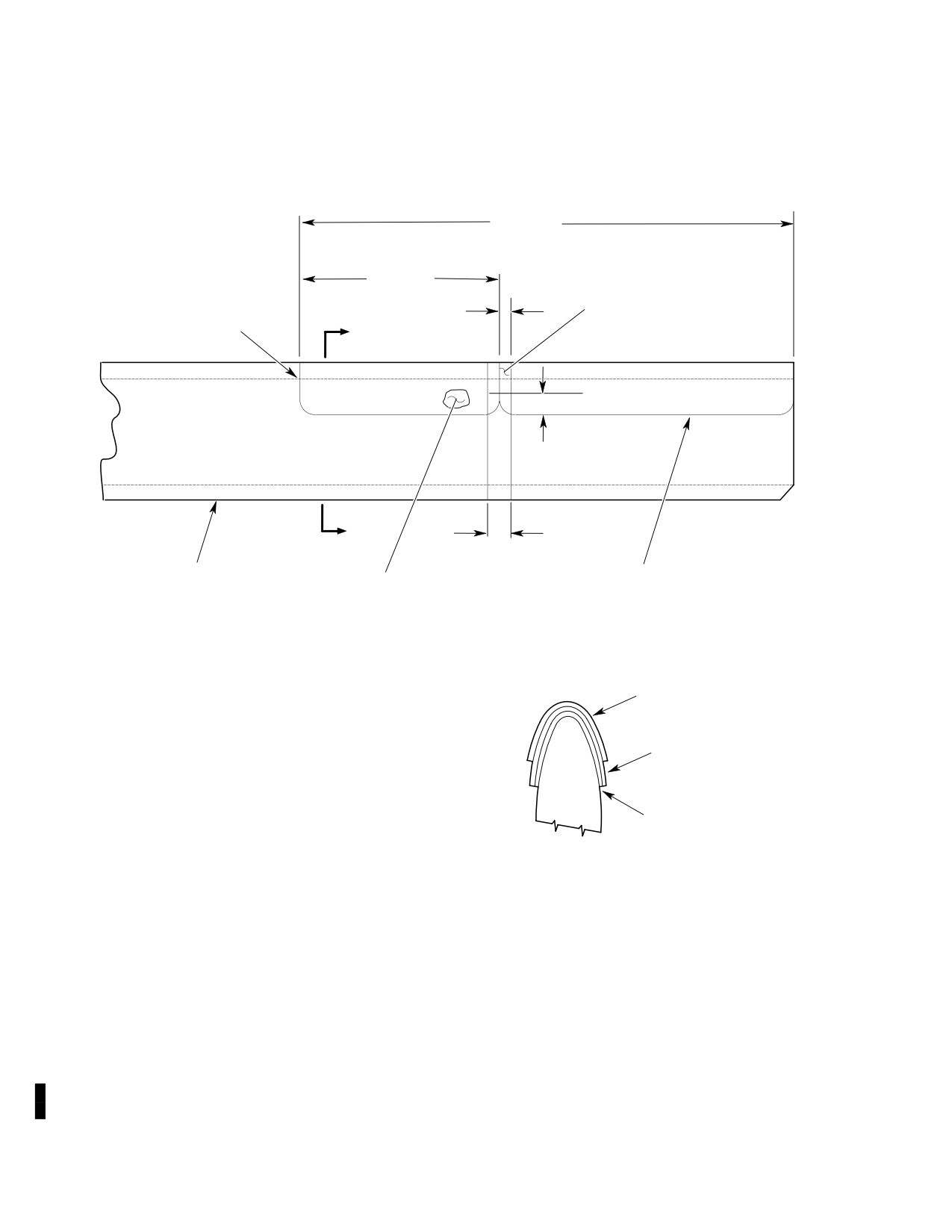
CSP-HMI-2
MD Helicopters, Inc.
MAINTENANCE MANUAL
30.00 INCH
(76.2 CM)
(REF)
12.00 INCH
(30.48 CM)
M50459-7
M50459-1
ABRASION TAPE
ABRASION TAPE
0.50 INCH
(12.7 MM)
(BOTTOM LAYER)
A
1.00 INCH
(2.54 CM)
A
1.00 INCH
(2.54 CM)
369D21100-505 OR
369D21105
M50459-1 ABRASION
369D21100-509 MAIN
OR
ROTOR BLADE ASSY
TAPE (BOTTOM LAYER)
369D21105-3
ABRASION STRIP
-7 ABRASION TAPE
-1 ABRASION TAPE
NOTE
VIEW A-A
NOTE:
ABRASION TAPE MUST
BE ALIGNED AT TOP SURFACE OF BLADE.
G62-1007A
Figure 805. Installation/Replacement of Double Layer Abrasion Tape
(369D21100−505, −509 and −511 Rotor Blades)
Page 808
TR12-001
62-10-00
MD Helicopters, Inc.
CSP-HMI-2
MAINTENANCE MANUAL
(4). Remove backing and apply (CM717
MEK is flammable. Use in
WARNING
preferred over 369D21104) abrasion
well ventilated area and
tape to outboard leading edge of main
away from open flame.
rotor blade as follows:
(3). Clean areas to be sealed with clean
(a). Trim corners of abrasion tape to a
cloth moistened with solvent (CM228).
0.25 inch (6.35 mm) radius to reduce
For hard to clean problem areas, MEK
peeling.
(CM219) may be used.
(b). Apply 6.50 inch (16.5 cm) wide and
(4). Prepare adhesive (CM404) per
24 inch (61 cm) long abrasion tape
manufacturer's instructions.
along blade leading edge (Ref.
Figure 804) so tape overlaps bottom
(5). Apply bead of adhesive to interface of
and top of blade edge equally or (Ref.
abrasion strip and blade skin. Ensure
Figure 805) for 369D21100-505, -509
there are no gaps or bridges in bead.
and -511 blades.
(6). Cure adhesive per manufacturer's
(c). Smooth and press abrasion tape into
instructions.
place by hand. Use heat gun or
equivalent to maintain temperature.
11. Tip Cap Sealing
(d). Re-apply pressure by hand following
(Ref. Figure 805)
initial installation to make sure of
proper bonding. Abrasion tape must
be free of surface wrinkles or air
Consumable Materials
(Ref. Section 91−00−00)
bubbles.
Item
Nomenclature
NOTE: A second abrasion tape may be applied
CM212
Releasing agent
on top of the first tape to facilitate replace
CM213
Releasing agent
ment when top tape becomes eroded. To ap
CM318
Primer
ply second tape, wipe surface of installed
strip clean with naptha aliphatic (CM220)
CM420
Sealant
and repeat steps (3). and (4). above. Second
CM427
Sealing compound
abrasion tape must be evenly aligned with
CM428
Sealing compound
first at top surface of blade (Ref. Figure 804
or Figure 805).
(1). Apply release agent (CM212 or CM213)
10. Leading Edge Abrasion Strip Sealing
to inside of tip cap per manufacturer's
instructions.
(Ref. Figure 805)
(2). Prepare and apply a 0.010-0.020 inch
(0.254-0.508 mm) coating of sealant
Consumable Materials
(CM420, CM427 or CM428) to faying
(Ref. Section 91−00−00)
surfaces per manufacturer's instruc
Item
Nomenclature
tions.
CM219
Methyl-ethyl-ketone
CM228
Surface cleaner
(3). Attach tip cap to blade and install
CM404
Adhesive, epoxy
screw with primer (CM318).
(4). Wipe off squeezed out sealant flush
(1). Remove screw and tip cap from main
with surface.
rotor blade.
NOTE: To inhibit moisture entering bond joint
(2). Remove any loose or cracked sealant or
of abrasion strip after initial application,
adhesive from areas of main rotor
reapply sealant, when sealant is worn away
blade.
or becomes cracked.
Page 809
62-10-00
TR12-001
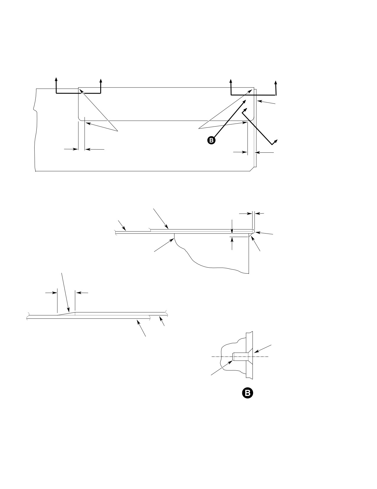
CSP-HMI-2
MD Helicopters, Inc.
MAINTENANCE MANUAL
C
C
A
A
369A1116 TIP CAP
C
SEAL WITH
PR1436G, CLASS B-2
OR
SEAL WITH EC2216 B/A FROM L.E. TO
PR1422G, CLASS B
0.75 INCH (19.05 MM) DIM. ON T.E.
RADIUS (UPPER AND LOWER SURFACE)
C
0.75 INCH
(19.05 MM)
0.75 INCH
(19.05 MM)
369D21100 MAIN ROTOR BLADE ASSEMBLY
369D21105 ABRASION STRIP REF.
0.003-0.005 INCH
369A1103 SKIN REF.
TYP.
(0.0762-0.127 MM)
SEAL WITH
EC2216 B/A
369A1109-501, 269A1186
0.010 INCH
SEAL SKIN / BAL. WT.
BAL. WT. REF.
(0.254 MM)
ASSY INTERFACE
SEAL WITH
TYP
WITH EC2216 B/A
EC2216 B/A
A-A
TIP CAP OMITTED FOR CLARITY
0.12 INCH
(3.048 MM)
TYP
369D21105 ABRASION STRIP
C-CTYP 2 PLCS
SEAL SCREW BY INSTALLING
369A1103 SKIN
WITH WET PRIMER
NAS517-3-0
Figure 806. Main Rotor Blade Abrasion Strip and Tip Cap Sealing
Page 810
Revision 20
62-10-00
MD Helicopters, Inc.
CSP-HMI-2
MAINTENANCE MANUAL
12. Main Rotor Blade Protective Tape
NOTE: Tape must be of equal length on all
Installation
blades to ensure proper balance.
In an effort to reduce the amount of erosion in
(2). Cut tape long enough to cover erosion
the area inboard of the abrasion strip, MDHS
plus approximately one-half inch (12.7
has approved the installation of stainless steel
mm) overlap on leading edge abrasion
or Mylar tape to the blade leading edge.
strip.
Installation of the tape is optional.
(3). Round off square corners of tape to
The approved 3M Mylar tape, P/N 8671-1, is
reduce peeling.
one inch (2.54 cm) wide and the 304 stainless
steel tape, P/N 87-369D21104, is 0.027 inch
(4). Lightly abrade faying surface of main
(0.6858 mm) thick and two inch (5.08 cm)
rotor blade in area where tape is to be
wide.
installed with 400-grit abrasive paper
(CM801).
The length of the tape can vary, up to 8.0
inches (20.32 cm) in length, but must be equal
(5). Wipe abraded area with naphtha
on all blades.
aliphatic (CM220) to eliminate grease
and dirt film.
It is recommended to start with 2.5 inch (6.35
cm) length and increase the length as erosion
(6). Treat any bare metal with epoxy-type
occurs by replacing the tape.
paint.
NOTE:
NOTE: Do not allow temperature to exceed
D This installation is only approved on
120°F (49°C).
main rotor blades equipped with the 36
(7). Using a heat gun, or equivalent, heat
inch (91.44 cm) abrasion strips.
abraded area.
D For installation of the Mylar tape, refer to
manufacturer's instructions. Use of aero
(8). Apply aerosol primer to bonding area
sol primer Promoter 86 may be used to
and allow to dry.
speed cure time of the tapes adhesive.
Mylar tape comes in rolls one inch (2.54
(9). Remove backing and apply tape to
cm) wide by 36 yards (329184 m) in length
leading edge of blade.
and the promoter comes in 36 ounce
(a). Apply tape so it overlaps each side of
(1.065 L) cans. Mylar tape can be pur
blade equally.
chased from RS Hughes Company
(1-800-453-8116).
(b). Tape should overlap the inboard end
of abrasion strip 0.5 ±0.03 inch (12.7
A. Stainless Steel Tape Installation
±0.762 mm) at the leading edge of
blade.
Consumable Materials
(Ref. Section 91−00−00)
NOTE: Tape must be free of surface wrinkles or
Item
Nomenclature
air bubbles.
CM220
Naphtha aliphatic
(10). Smooth and press tape into place by
CM801
Abrasive paper, silicon carbide
hand.
Do not cut or trim tape after
(11). Re-apply pressure by hand following
CAUTION
installation on blade, damage to
initial installation to ensure proper
blade will occur.
bonding.
(1). Measure length of eroded area on blade
(12). Perform main rotor balance (Ref. Sec.
with the most erosion.
18-10-00 or 18-10-60).
Page 811
62-10-00
Revision 20
CSP-HMI-2
MD Helicopters, Inc.
MAINTENANCE MANUAL
This Page Intentionally Left Blank
Page 812
Revision 44
62-10-00
MD Helicopters, Inc.
CSP-HMI-2
MAINTENANCE MANUAL
Section
62−20−00
Main Rotor Hub
(369D/E/FF − 500N)
MD Helicopters, Inc.
CSP-HMI-2
MAINTENANCE MANUAL
MAIN ROTOR HUB
REMOVAL/INSTALLATION
1. Main Rotor Hub − General
(3). Remove lockwire and disconnect
flexible boot from lower end of hub
The main rotor hub consists of a central hub,
liner.
five identical pitch housings spaced 72 degrees
apart horizontally around the hub with
(4). Disconnect each pitch control rod from
associated mechanisms and linkages.
pitch housing.
Lead-lag links, a lead-lag damper, a droop
(5). Disconnect scissors crank from main
stop striker strip and spacer, and a pitch
rotor hub or scissors link.
control bearing with each pitch housing
produce the pivoting axis, blade flapping stop
NOTE: To facilitate assembly, color code each
contact surfaces and lead-lag hinge function
pitch control rod to match pitch housing to
for the rotor blades.
which it is attached.
Five laminated retention strap assemblies that
(6). Remove two screws securing retainer to
are flexible both vertically and torsionally
main rotor hub nut.
extend through the pitch housings and connect
to the lead-lag links.
(7). Remove nut retainer.
(8). Using main rotor mast nut wrench
A lower shoe, attached to the central hub,
(ST701), remove nut from mast.
contains a droop stop ring and droop restrain
ers that support the blades at rest and
(9). Using hub puller (ST702), break loose
distribute droop loads at low blade rpm.
main rotor hub (Ref. Figure 401).
Remove hub puller.
The following instructions provide field
maintenance and repair procedures for the
(10). Attach hoisting adapter, to eyebolts and
main rotor hub.
hoist hub from mast.
2. Main Rotor Hub Replacement
B. Main Rotor Hub Installation
A. Main Rotor Hub Removal
(Ref. Figure 402)
(Ref. Figure 401)
Consumable Materials
(Ref. Section 91−00−00)
Special Tools
Item
Nomenclature
(Ref. Section 91−00−00)
CM111
Grease, aircraft
Item
Nomenclature
CM115
Grease, oscillating bearing
ST201
Hoisting adapter
CM204
Compound, corrosion preventative
ST701
Main rotor wrench assembly
CM702
Lockwire CRES
ST702
Hub puller
Special Tools
(1). Remove all main rotor blades.
(Ref. Section 91−00−00)
Item
Nomenclature
(2). Remove main rotor drive shaft; then
ST201
Hoisting adapter
reinstall hoisting eyebolts, washers and
ST701
Main rotor wrench assembly
nuts in rotor hub. Locate them to
correspond with lugs of hoisting
ST703
Main rotor hub driver
adapter (ST201).
Page 401
62-20-00
Revision 36
CSP-HMI-2
MD Helicopters, Inc.
MAINTENANCE MANUAL
Main rotor hub is a highly
(5). Hand-pack hub cavity, between sleeve
CAUTION
stressed component. Use ex
bushing and hub, with grease (CM111).
treme care to prevent it from striking any
(6). Place recessed spacer, recess down, on
object. Any impact damage may require re
top of sleeve bushing.
placement of hub.
(7). Hand-pack upper bearing cup and cone
NOTE:
with grease; then install cone on mast
D Removal of recessed spacer, upper bear
and use hub drive tool (ST703), to fully
ing cone, upper seal and seal retainer is
seat cone.
not mandatory for installation of the
main rotor hub. If these items are in
(8). Fill remaining cavity to upper seal with
stalled, perform steps (1). thru (4). and
grease.
(11). thru (22). Caution should be used
(9). Position upper seal in seal retainer
when installing hub to prevent damage to
with lip up; then press seal and retain
these parts.
er in hub counterbore.
D If recessed spacer, upper bearing cone,
upper seal and seal retainer have been re
(10). Using a soft drift, carefully tap seal
moved, these parts should not be as
outer ring to seat in counterbore. Wipe
sembled in hub before installation of hub
away any excess grease.
on helicopter. These items are reas
(11). Apply grease (CM111) to exposed
sembled in hub after seating hub on mast.
threads on mast.
Prior to installing main rotor hub, insure
that all bearings are adequately serviced
Be sure that seal is properly po
CAUTION
with grease (CM111).
sitioned against seal retainer
and that seal retainer does not pinch seal.
D Replacement main rotor hubs do not come
Check by inserting a loop of approximately
balanced from MDHS. If installing a re
0.050 inch (1.27 mm) diameter lockwire,
placement hub, perform a main rotor hub
balance (Ref. Sec. 18-10-00, Main Rotor
round feeler gage or other suitable tool with
Hub Balance Procedure).
out sharp edges between seal lip and retain
er.
(1). Attach hoisting adapter (ST201) to
NOTE: To insure that hub is seated onto mast
eyebolts in main rotor hub and connect
properly before torquing, 2 - 4 threads
suitable hoist.
should be showing above the mast nut with
If hub assembly (with sleeve
nut installed finger tight.
CAUTION
bushing, spacer, upper bearing
(12). Install mast nut, using wrench (ST701);
and seal retainer installed) does not seat
torque nut to 200 foot-pounds (271
properly onto mast, do not attempt to force it
Nm). Apply coat of corrosion preventive
into position. Remove hub assembly from
compound (CM204) to screw holes in
mast and determine cause of hub not seat
mast nut.
ing, correct the problem and follow the pro
cedures for reinstallation.
(13). Place retainer on nut and check
retainer-to-nut screw hole alignment.
(2). Check that rotor mast is clean. Hoist
main rotor hub and position over mast;
(14). Increase nut torque to not more than
then lower hub onto mast.
250 foot-pounds (339 Nm) to align
holes in retainer and nut.
NOTE: To inhibit mast corrosion when operat
ing in salt water environment, lightly coat
NOTE: If holes cannot be aligned in 200 - 250
bearing journals of mast with grease
foot-pound (271 - 339 Nm) torque range,
(CM115).
remove and invert nut and repeat proce
dures in (12). thru (14). to align holes.
(3). Remove adapter, hoist and eyebolts.
(15). Secure retainer to nut with two screws;
(4). Check that hub is fully seated on mast.
lockwire screws.
Page 402
Revision 20
62-20-00
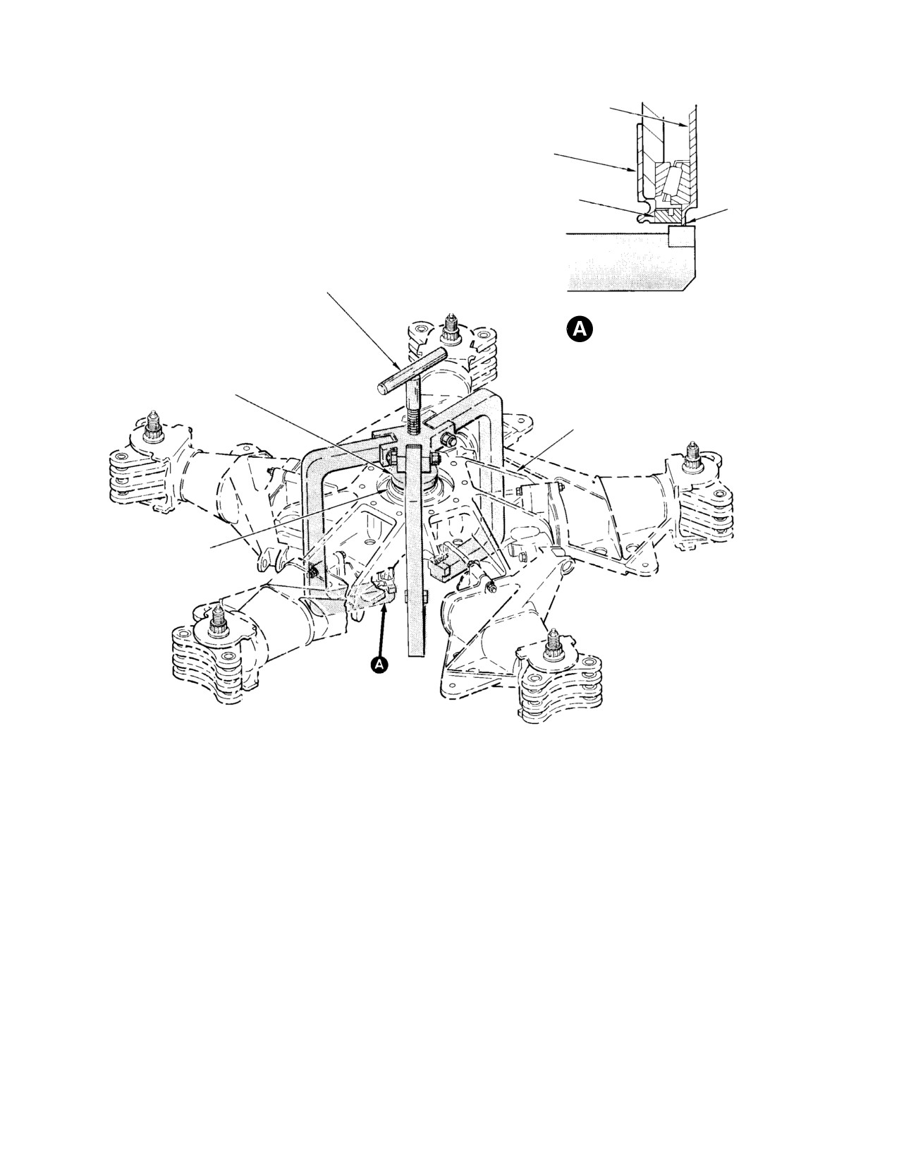
MD Helicopters, Inc.
CSP-HMI-2
MAINTENANCE MANUAL
SLEEVE BUSHING
ROTOR HUB
OUTER LINER
SEAL
JAW CONTACT
POINT
MAIN ROTOR PULLER
(ST702)
LIFT POINT
(TYPICAL 3 PLACES)
THRUST PAD
ROTOR MAST
ROTOR MAST
G62-2004A
Figure 401. Pulling Hub Assembly
Page 403
62-20-00
Revision 20
CSP-HMI-2
MD Helicopters, Inc.
MAINTENANCE MANUAL
Ensure that no washers are
Excessive lead-lag load applied
CAUTION
CAUTION
used under screwheads and that
to the main rotor blades during
screwheads are free of burrs.
ground handling can result in damage to the
elastomeric damper buns and failure of the
damper assembly. Operators and mainte
(16). Verify that screwheads do not project
nance personnel should use extra caution to
more than 0.020 inch (0.508 mm) above
avoid lead-lag loads in excess of 35 pounds
hub upper surface, for adequate
(155.68 N) at the tip of the main rotor
clearance between screwheads and
blades.
driveshaft flange.
NOTE:
(17). Connect scissors crank to main rotor
D Refer to MDHS Notice DN-45.2 for infor
hub lower shoe and/or to scissors link.
mation concerning required modification
of dampers produced prior to October
NOTE: Ensure pitch control rods are installed
1979. If lead-lag dampers, P/N
at same locations from which removed.
369D21400-501 are installed, they must
be modified to M50452 or be replaced
with P/N 369D21400-503 dampers.
(18). Install five pitch control rods to pitch
D If one or more main rotor blades strike an
housings (Ref. Sec. 62-30-00, Pitch
object while rotating or the drive system
Control Rod Replacement).
has been subjected to sudden stop, inspect
damper.
(19). Connect flexible boot to lower end of
rotor hub liner and secure with lock
4. Main Rotor Damper Replacement
wire (CM702).
A. Main Rotor Damper Removal
(20). Install main rotor drive shaft (Ref. Sec.
(1). Note and record location from which
63-10-00).
damper is to be removed from main
rotor hub.
(21). Install five main rotor blades.
NOTE: At reinstallation, if damper is not rein
stalled at same location, a check of and/or
(22). Perform main rotor blade droop angle
blade phasing is required.
check if hub is new or replacement.
(2). Support blade parallel to ground.
(23). Perform main rotor hub balance (Ref.
(3). Remove damper.
Sec. 18-10-00, Main Rotor Hub
NOTE: If damper is to be reinstalled at same lo
Balance Procedure) if a new or rebuilt
cation, do not disturb damper clevis, jam
hub is installed.
nuts or turnbuckle setting. Otherwise, blade
phasing is required at reinstallation of
damper.
3. Main Rotor Damper
(4). If damper is not to be reinstalled,
(Ref. Figure 603) A main rotor damper is
remove bushing from damper ear and
attached to each pitch housing of the rotor
retain with hub.
hub. The damper is connected to the inboard
B. Main Rotor Damper Installation
trailing edge of the associated main rotor blade
by an adjustable clevis to prevent lateral
(1). Check, and if necessary, preset main
vibrations from occurring in main rotor blades.
rotor damper length (Ref. Nominal
Neither damper travel nor stiffness is adjust
Damper Adjustment Procedure). Leave
able on the helicopter. Phasing of rotor blades
jamnuts fingertight.
is affected by turnbuckle adjustment. Any
phasing problem caused by a defective damper
NOTE: Ensure that bushing is installed in
should be corrected by replacing damper.
large hole of damper ears.
Page 404
Revision 36
62-20-00
MD Helicopters, Inc.
CSP-HMI-2
MAINTENANCE MANUAL
(2). With damper rotational direction decal
(2). Store all five dampers together in
facing outboard so it can be read, attach
horizontal position for minimum of six
damper ears to pitch housing lug with
hours. Preferred ambient temperature
bolt (head up), washers, and nut.
during storage is 55° to 85°F (13° to
Torque nut to 30 - 60 inch-pounds
30°C).
(3.39 - 6.78 Nm) and install cotter pin.
(3). Set damper length, centerline-to-cent
(3). Adjust main rotor blade phasing for
erline of bolt attach holes, for initial
associated main rotor blade.
installation.
369D/E
(4). After final phasing adjustments, torque
8.229 ±0.005 inch (209.017 ±0.127 mm)
jamnuts to 95 - 110 inch-pounds
369F/FF
(10.73 - 12.43 Nm). Safety jamnuts to
8.132 ±0.005 inch (206.553 ±0.127 mm)
turnbuckle with new lockwire. Lock
500N
wire must be located out-board, away
8.132 ±0.005 inch (206.553 ±0.127 mm).
from pitch housing.
(4). Install dampers on helicopter.
NOTE: Threaded end of damper turnbuckle
NOTE: If ground rock or stick shake is noted,
shaft must protrude through clevis base a
complete following step.
minimum of two full threads and must clear
blade damper attach fitting.
(5). Length of damper may be adjusted
after initial setting by checking main
(5). Connect damper to blade.
rotor system balance (Ref. Sec. 18-10,
(6). Remove blade support.
Main Rotor Balancing Procedure).
Check of main rotor system balance
5. Main Rotor Damper Nominal Adjustment
should be accomplished only after main
rotor blades have been tracked.
(1). Remove all five main rotor blade
If more than four flats turn of
dampers from helicopter if installed.
CAUTION
turnbuckle adjustment is neces
NOTE: If dampers are being replaced, do not
sary to correct balance, return to step (1).
mix part numbers.
and repeat procedure.
Page 405
62-20-00
Revision 20
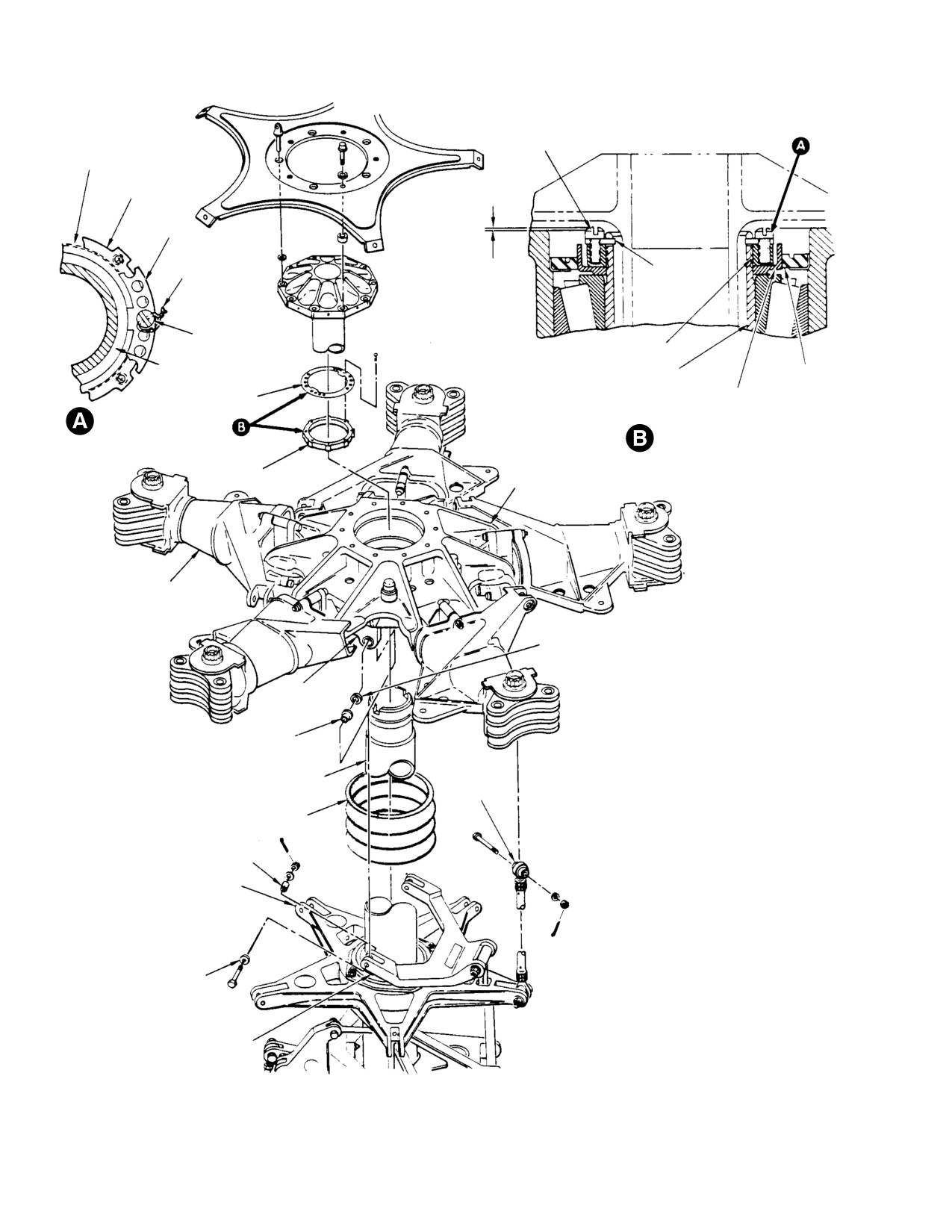
CSP-HMI-2
MD Helicopters, Inc.
MAINTENANCE MANUAL
SCREW (2 PLACES)
(NOTE 2)
MAST
LOCKNUT
RETAINER
0.020 INCH (0.508 MM)
RETAINER
LOCKWIRE
MAXIMUM SCREW HEAD
HEIGHT ABOVE HUB
SCREW
LOCKNUT
DRIVE SHAFT
MAST
SEAL
RETAINER
SEAL RETAINER
SAFETYING
LOCKNUT AND SEAL
INSTALLATION
LOCKNUT
MAIN ROTOR
HUB
PITCH HOUSING
ASSEMBLY
SHIMS / SHIM WASHERS
(NOTE 4)
LOWER
SHOE
SHOULDERED BUSHING
PITCH
MAIN ROTOR MAST
CONTROL
ROD
FLEXIBLE BOOT
NOTES:
1.
EDGE OF BUSHING MUST PROTRUDE A
NOTE 1
MINIMUM OF 0.010 INCH (0.254 MM) TO A
MAXIMUM OF 0.060 INCH (1.524 MM) ABOVE
ROTATING SWASHPLATE
OUTSIDE SURFACE OF PART AFTER NUT IS
TIGHTENED.
2.
IF LOCKNUT AND RETAINER SCREWHOLES
DO NOT MATCH WITHIN CORRECT TORQUE
RANGE, LOCKNUT IS TO BE INVERTED.
3.
WASHER(S) AS REQUIRED FOR BOLT END
NOTE 3
TO SWASHPLATE BOOT CLEARANCE.
4.
SHIMS / SHIM WASHERS USED TO FILL GAP
ON SHOULDERED BUSHING SIDE.
SCISSORS CRANK
G62-2005A
Figure 402. Main Rotor Hub − Installation
Page 406
Revision 20
62-20-00
MD Helicopters, Inc.
CSP-HMI-2
MAINTENANCE MANUAL
MAIN ROTOR HUB
INSPECTION/CHECK
1. Main Rotor Hub Balancing − General
form of crescent-shaped grooves. If
chafing wear exists, repair or replace.
(Ref. Sec. 18-20) Main rotor hub balancing is
Chafed area must be cleaned up before
accomplished by adding or removing weight
measuring depth of damage to deter
(flat washers) as required at the lead-lag
mine housing serviceability.
bolts. Analysis of main rotor hub balance is
accomplished using instrumentation that
(3). Inspect droop stop ring for corrosion,
measures and localizes vibrations due to main
dents and scratches. If defects are
rotor hub imbalance. Data provided by the
found, repair or replace.
instrumentation is plotted on a chart designed
NOTE: To inhibit corrosion, spray droop stop
to indicate how much weight must be added or
ring, rollers and pitch bearings with rust in
removed from the lead-lag bolt. No other
hibitor (CM232).
means of balancing is to be used.
(4). Inspect droop stop roller for flat spots,
2. Main Rotor Blade Phasing Check and/or
pit marks and looseness on roller shaft.
Adjustment
(5). Inspect striker plate for dents and pit
Main rotor blade phasing (alignment) is
marks that exceed 0.030 inch (0.762
necessary at damper installation or replace
mm) depth. Damage exceeding this
ment, and may be necessary if there is ground
limit requires replacement of striker
rocking, or if one-to-one lateral (main rotor)
plate.
vibration occurs during flight (Ref. Main Rotor
Damper Nominal Adjustment).
(6). Press each pitch housing downward
several times and check for evidence of
3. Main Rotor Hub Inspection
binding pitch bearing or droop restrain
er follower. Inspect visible portion of
droop restrainer for cracks and follower
Consumable Materials
spring for breaks.
(Ref. Section 91−00−00)
Item
Nomenclature
NOTE: Do not remove tetrafluoroethylene
CM232
Rust inhibitor spray
(TFE) debris which works out of pitch bear
ing edge. Debris is normal and helps lubri
cate bearing. Removal of debris increases
(1). Inspect pitch housing for scratches,
bearing wear rate.
nicks and cracks. No cracks are permis
sible. Scratches and nicks must be
(7). Use bright light and 5-power magnify
cleaned up before measuring depth of
ing glass to inspect all main rotor hub
damage to determine housing service
lead-lag links (Ref. Figure 802) for
ability.
discoloration, pitting, intergranular
cracks or stress corrosion cracks. Any
(2). Inspect sleeve bushing for snug fit in
discoloration or pitting is evidence of
pitch housing arm clevis lug (Ref.
more than superficial corrosion and
Figure 805); lug must not show evi
main rotor hub must be removed for
dence of wear caused by bushing
replacement of lead-lag links.
movement. Maximum allowable
diameter for hole in bushed lug is
NOTE: Normal or premature overhaul requires
0.5004 inch (12.71016 mm); for un
visual inspection plus dye-penetrant in
bushed lug, not more than 0.3135 inch
spection of links for same conditions.
(7.9629 mm). Inspect inner surfaces of
all pitch housing arm clevis lugs for
(8). Inspection lead-lag link stop for broken
chafing caused by misaligned pitch
spring, cracks, breaks or visible bond
control rod end bearings. Chafing is in
line cracks.
Page 601
62-20-00
Revision 20
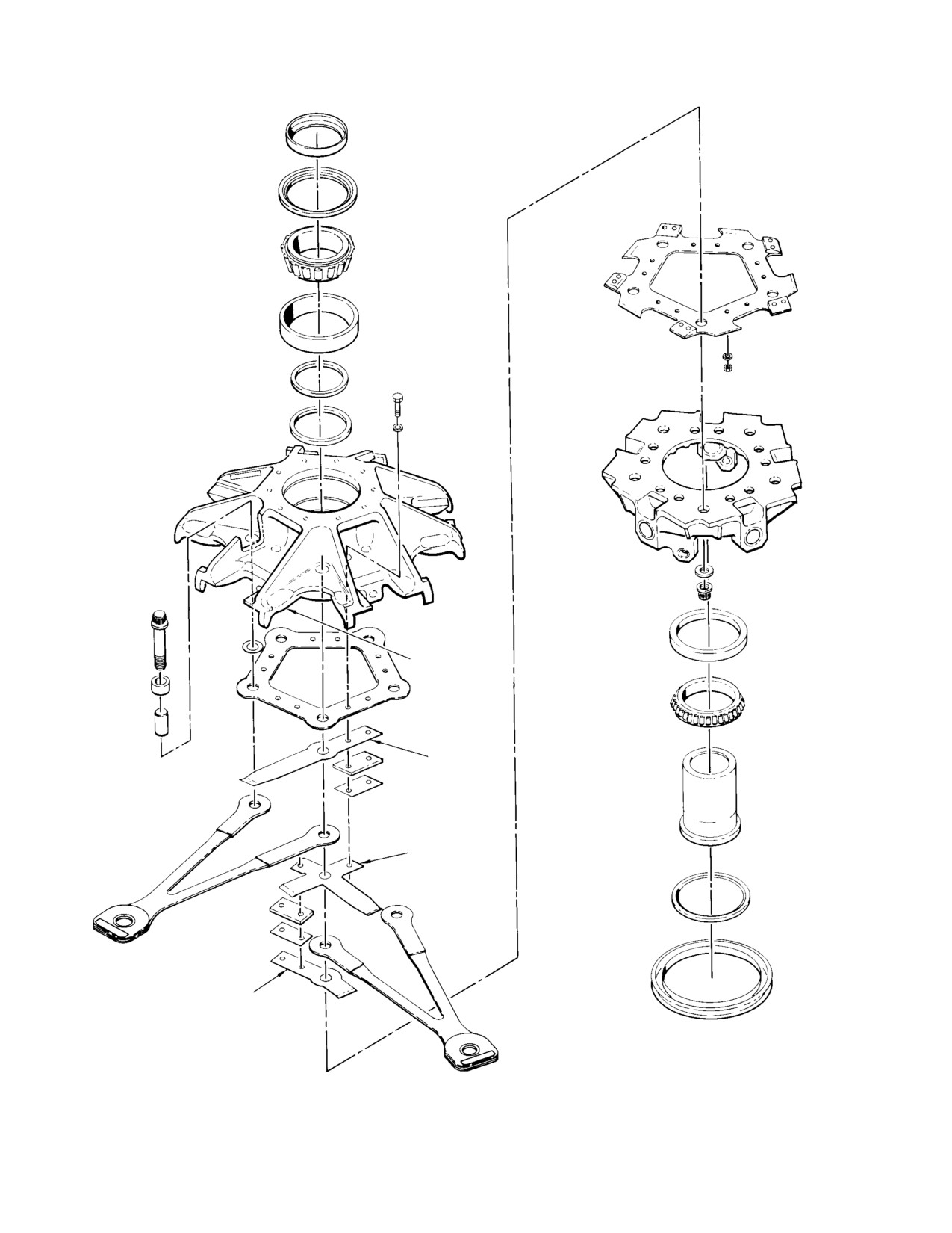
CSP-HMI-2
MD Helicopters, Inc.
MAINTENANCE MANUAL
DAMAGE AREA
369D21271-5
LAMINATE
369D21271-3
LAMINATE
369D21271-7
LAMINATE
G62-2006
Figure 601. Strap Pack Lamination − Exploded View
Page 602
Revision 20
62-20-00
MD Helicopters, Inc.
CSP-HMI-2
MAINTENANCE MANUAL
(9).
Inspect interiors of lead-lag bolts using
(e). Reinstall screw, nut, washers and
bright light and 5X glass for cracks or
balance hardware removed in step 2.
corrosion per Lead-Lag Bolt Inspection.
Ensure hardware is installed exactly
as removed. Torque MS21042L08
(10).
Inspect each striker strip for cracks,
locknut on screw to 20 - 35 inch-
deformation and badly worn contact
pounds (2.26 - 3.95 Nm). Torque
surfaces.
MS21042L3 locknut on screw to 30 -
60 inch-pounds (3.39 - 6.78 Nm).
(11).
Inspect all parts of main rotor hub for
Coat exposed screw threads, washers
cracks, breaks, scratches and nicks.
and nut with sealant (CM420).
(Refer all questionable damage to
MDHI for disposition.)
NOTE: Excessive amount of sealant can unbal
ance rotor system. Apply light but thorough
(12).
Inspect lower shoe scissors attach
coat of sealant.
bearings for binding, looseness in bore
(f). Install new cotter pin to secure nut to
and wear. Maximum wear limits are
lead-lag bolt.
0.010 inch (0.254 mm) radial and 0.020
inch (0.508 mm) axial.
NOTE: There are prebalanced rotor hubs in
service. Lead-lag bolts of prebalanced hubs
(13).
Inspect each of five main rotor reten
may contain balancing hardware. If so, re
tion strap packs (Ref. Main Rotor Strap
move balancing hardware to perform in
Pack Lamination Inspection) at
spection. Each set of removed hardware
specified intervals (Ref. Sec. 5-10).
should be tagged or color-coded to ensure
(Ref. MDHI Notices DN-154 / EN-44 /
correct reinstallation.
FN-33 for specific inspection require
ments.)
5. Main Rotor Strap Pack Lamination
Inspection
4. Lead−Lag Bolt Inspection
CAUTION
Consumable Materials
D Figure 601 and Figure 602 depict the
(Ref. Section 91−00−00)
main rotor hub and strap pack assembly
Item
Nomenclature
disassembled for clarity of location and
CM318
Primer
area to be inspected for cracks. Under no
circumstances should the strap pack or
CM420
Sealant
main rotor hub assembly ever be disas
sembled in the field. MDHI and MDHI
(1). Inspect interiors of lead-lag bolts using
Approved Licensees are the only ap
bright light and 5X glass for cracks or
proved repair stations for main rotor hub
corrosion.
assembly overhaul.
D If a hub assembly or strap pack assembly
(a). Remove cotter pin securing nut to
(other than new parts in storage) are sub
lower end of lead-lag bolt. Do not
jected to extended periods of non-use,
disturb torque on nut or remove nut.
whether installed on the helicopter or not,
the strap assembly should be inspected
(b). Remove screw, nut, washers and
critically for corrosion and pitting before
balance hardware, if installed, from
return to service. If corrosion is found on
lead-lag bolt.
the strap pack assemblies, contact MDHI
for disposition.
(c). Inspect bolt interior. Treat minor
surface corrosion if noted. If corrosion
D It is acceptable to operate a helicopter
pitting or cracks are noted remove
with a hub assembly having a strap pack
and replace hub.
with up to two failed laminates in any one
leg of the strap assembly. When a lami
(d). Swab entire ID of bolt with primer
nate in the strap assembly fails, the re
(CM318).
maining laminates pick up and carry the
Page 603
62-20-00
Revision 29
CSP-HMI-2
MD Helicopters, Inc.
MAINTENANCE MANUAL
load. This increased load causes slightly
areas of the outboard shoes and pitch
more elongation in the remaining lami
housing assemblies.
nates of that leg thus shifting the mass of
the rotor system. Any time a vibration de
(5). Using a 10X magnifying glass, visually
velops or there is an increase in vibration
inspect the edge of strap pack lami
level over a short period of time, the main
nates on both sides at outboard end of
rotor strap pack assembly should be in
blade pitch housing (area between
spected for cracked or failed laminates.
outboard shoes).
(6). Use the following as acceptance/rejec
NOTE: Conduct inspection indoors, if possible,
tion criteria for laminate inspection:
or in a shaded area to eliminate glare of sun
or bright outdoor light. To facilitate inspec
(a). A laminate has failed if cracked in
tion, field fabricate and use plastic inspec
tongue area or in lead and lag legs of
tion tool and wooden probe (Ref Figure 602).
the same laminate.
(1). Remove main rotor blades.
(b). Reject strap pack and return hub
for overhaul when:
(2). If required, trim teflon from edges of
laminates using a aluminum chisel.
1). Three or more laminates in a
Fabricate from stock 0.250 x 6.00 x
single strap pack have failed.
0.100 inch (6.35 x 152.4 x 2.54 mm).
Carefully scrape excess interlaminate
2). Three or more laminates in a
teflon sheets from both sides of strap
single strap pack are cracked in
pack between top and bottom shoes at
the same lead or lag leg.
outboard attachment bolt of all five
strap packs.
3). One laminate is cracked at the
outboard end in the area between
NOTE:
outboard shoes (Ref. Figure 602).
D Do not pry at strap pack assemblies with
4). There are two or more gaps in the
sharp or hard edged tools. If edges become
same strap pack. A single gap in
nicked or laminates get scratched, addi
any one strap pack assembly is
tional cracking can occur thus causing
allowed.
hub replacement.
(7).
Visually inspect strap pack assemblies
D Where accessible, ends of acceptable
for evidence of corrosion. If corrosion is
cracked or broken laminates should be
found on strap pack laminates contact
taped to prevent scratching and damag
MDHI service department for disposi
ing of adjacent laminates.
tion.
(3).
(Ref. Figure 602) Field fabricate plastic
(8).
Using a blunt-nosed wooden or pheno
tool. Run plastic inspection tool in both
lic pin, pencil size with 1/16 inch
directions along each laminate, feeling
(1.5875 mm) radius point, probe at the
for a ”catch” from a crack on a single
upper and lower strap laminations at
laminate. Use the wooden or phenolic
the outboard ends of the blade pitch
probe and probe at upper and lower end
housings for evidence of laminate
of pack. Failed laminate in lead or lag
failure. A failed laminate, either at the
will move away from the other lami
lead or lag end of the strap pack, will
nates.
move away from the other laminates. If
the adjacent upper and lower laminates
(4). Using a light and mirror, visually
remain in tension under the probing
inspect each of the main rotor strap
operation, no laminate failures have
pack assemblies for evidence of cracks
occurred. Refer to Step (5). Caution for
or breaks in strap pack laminates in the
gap limitations.
Page 604
Revision 25
62-20-00
MD Helicopters, Inc.
CSP-HMI-2
MAINTENANCE MANUAL
ALL LAMINATES STRAIGHT,
NO GAPS.
DETAIL 1 ACCEPTABLE
ALL LAMINATES STRAIGHT. SINGLE GAP
EXISTING ADJACENT TO EITHER SHOE.
DETAIL 2 ACCEPTABLE
NOTE:
WHILE TEFLON MAY APPEAR WRINKLED AND EXTEND PAST END OF LAMINATES,
PREVENTING CLEAR VIEW OF LAMINATES. WHEN THIS OCCURS, LOOK ALONG
EITHER SIDE IN AREA A-A OR B-B (DETAIL 3).
A
A
ALL LAMINATES STRAIGHT. SINGLE GAP
EXISTING ANYPLACE WITHIN LAMINATES.
B
B
DETAIL 3 ACCEPTABLE
REMOVE EXCESS TEFLON IN THIS AREA
G62−2007−1
Figure 602. Strap Pack Lamination Inspection (Sheet 1 of 2)
Page 605
62-20-00
Revision 20