HANDBOOK OF MAINTENANCE INSTRUCTIONS FOR MDHI 369D/E/FF-500/600N HELICOPTERS (ISSUED: 1990) - page 20
CSP-HMI-2
MD Helicopters, Inc.
MAINTENANCE MANUAL
(b). Use 5X to 10X magnifying glass and
(3). Inspect all other surfaces of the drive
bright side light (45° or less; down
shaft (Ref. Main Rotor Drive Shaft
ward lighting may not define cracks).
Inspection).
(c). Pay particular attention to side of
NOTE: If surface corrosion or pitting of the
(each) tooth with larger wear pattern.
shaft surface is noted, perform field repair of
Hairline cracks appear crescent-
drive shaft (Ref. Main Rotor Drive Shaft -
shaped and at the center and bottom
Exterior Repair and Main rotor Drive Shaft
of tooth in the root area. Also, inspect
- Corrosion Removal).
neck (shaded area) of spline for
cracks.
(4). Remove protective cover and install
main rotor drive shaft (Ref. Main Rotor
NOTE:
Drive Shaft Installation).
D If cracking is suspected, perform magnet
ic particle inspection of shaft spline and
teeth.
D If cracking or damage is found, the shaft
is no longer airworthy. Discard drive shaft
and return it to MDHS Customer Service
Department.
D Inspect replacement drive shaft per steps
(a). thru (c). prior to installation of shaft
on helicopter.
Page 606
Revision 20
63-10-00
MD Helicopters, Inc.
CSP-HMI-2
MAINTENANCE MANUAL
DRIVE SHAFTS / CLUTCHES / COUPLINGS
REPAIRS
1. Main Rotor Drive Shaft Exterior Repair
Exercise care when removing
CAUTION
pits to ensure that shot peening
(Ref. Figure 601) No repair of drive shaft is
is not completely penetrated. Remove only
permitted except for removal of light surface
minimum material necessary to remove
corrosion and polishing of minor nicks and
pits. Minimum wall thickness of 0.1775 inch
chips in noncritical spline areas indicated
(4.5085 mm) must be maintained.
below.
(d). Lightly abrade corroded surface with
crocus cloth (CM803) to remove pits.
If pit removal exceeds depth of
Consumable Materials
0.0012 inch (0.03048 mm) in Area 1
(Ref. Section 91−00−00)
or 0.0008 inch (0.02032 mm) in Area
Item
Nomenclature
2, shaft is unserviceable and must be
CM121
Preservation oil
replaced.
CM222
1,1,1-Trichloroethane
(e). Repeat steps (a). thru (c). above.
CM228
Surface cleaner
(f). Spray two coats of epoxy primer and
CM302
Epoxy primer / Catalyst reducer
catalyst reducer (CM302), mixed per
CM803
Crocus cloth
manufacturers instructions, on shaft
exterior. Do not prime spline teeth or
mounting surface.
(1). Remove corrosion as follows:
(2). Polish out minor nicks and chips on
(a). Degrease corroded area of drive shaft
shaft spline teeth as follows:
with clean cloth saturated with
(a). Using 320 - 400 grit abrasive stone,
trichloroethane (CM222).
carefully grind, blend and polish out
nicks and chips which are outside the
Surface cleaner, used in step
critical (active) spline tooth contact
WARNING
below, irritates hands on re
areas (Area 4 profile and end views
peated exposure. Rubber gloves should
for permissible repair areas).
be worn.
(b). If the repair (grind and polish)
(b). Swab shaft exterior with diluted
operation extends beyond limits
solution of surface cleaner (CM228).
shown, or if any tooth damage exists
(Mix one part surface cleaner with
within the critical tooth contact area,
four parts water.) Keep wet with
shaft is unserviceable and must be
solution for 10 minutes or until
replaced.
corrosion appears to be removed.
(c). Perform magnetic particle inspection
Wipe clean and inspect. Repeat as
according to Specification MIL-
necessary until there is no further
I-6868. No surface or subsurface
evidence of corrosion.
defects are permissible.
(c). Rinse with water and dry with
(3). Apply preservation oil (CM121) to
compressed air.
spline teeth.
Page 801
63-10-00
Revision 20
CSP-HMI-2
MD Helicopters, Inc.
MAINTENANCE MANUAL
(4). Immediately reinstall main rotor drive
Do not allow epoxy primer or
CAUTION
shaft.
epoxy enamel to contact drive
shaft splines or mounting surfaces.
2. Main Rotor Drive Shaft Corrosion
(7). Fill shaft with epoxy primer (CM302)
Removal
mixed according to manufacturer's
instructions. Drain primer from shaft.
(Ref. Figure 601)
Ensure that shaft ID is completely
coated. Allow primer to dry one hour at
Consumable Materials
room temperature.
(Ref. Section 91−00−00)
(8). Apply one coat of black epoxy enamel
Item
Nomenclature
(CM304) to driveshaft by filling and
CM222
1,1,1-Trichloroethane
draining shaft. Allow enamel to dry 48
CM228
Surface cleaner
hours at room temperature or let dry 30
CM302
Epoxy primer / Catalyst reducer
minutes at room temperature, then
CM303
Wash primer
cure for three hours in oven at 250° -
275°F (122° - 136°C).
CM304
Enamel, epoxy
CM425
Sealing compound
(9). Apply thin coat of sealing compound
(CM425), mixed according to container
instructions, to all cork plug surfaces;
(1). Degrease entire shaft inner diameter
press cork into drive shafts until top of
(ID), using 1, 1, 1, trichloroethane
cork is flush with top of drive shaft.
(CM222).
Allow sealing compound to cure
according to container instructions.
(2). Using a fine wire rotary brush or wire
Apply second coat of sealing compound
brush, remove corrosion and contami
to exposed surfaces of cork; allow to dry.
nants from drive shaft ID.
3. Main Transmission Drive Shaft Repair
Turco WO-1 will irritate the
(Bendix)
WARNING
skin; always use rubber
gloves when handling this material.
(Ref. Figure 402)
Wash skin exposed to Turco WO-1,
thoroughly with water.
Consumable Materials
(Ref. Section 91−00−00)
(3). Using swab and extension rod, swab ID
Item
Nomenclature
of driveshaft with Turco WO-1
CM318
Primer
(CM228), diluted one part to four parts
water.
CM801
Abrasive paper, silicon carbide
CM803
Crocus cloth
(4). Thoroughly rinse drive shaft ID with
clear water; dry with compressed air.
(1). Repair of drive shaft diaphragms
(5). Using suitable light or borescope,
(Bendix) is not permissible.
inspect shaft ID for corrosion pitting.
(2). Repair all damage that is no deeper
Remove pitting by honing locally. Shaft
than 0.003 inch (0.076 mm).
ID may not exceed 1.655 inches (4.2037
cm) after honing. Blend honed area
(a). Completely remove defect. Maintain
with existing surrounding area. If
smooth transition into surrounding
pitting removal causes or would cause
surface.
shaft ID to exceed 1.655 inches (4.2037
cm), replace shaft.
(b). Use grade 400 wet or dry abrasive
paper (CM801) for preliminary
(6). Apply one coat of wash primer (CM303)
finishing, and then polish with crocus
to shaft ID according to primer man
cloth (CM803). Restore surface until
ufacturer's instructions.
it equals original finish of shaft.
Page 802
Revision 20
63-10-00
MD Helicopters, Inc.
CSP-HMI-2
MAINTENANCE MANUAL
(c). After rework, check shaft tube wall
Care should be taken when re
CAUTION
thickness in repair area. Wall thick
moving or installing nutplates
ness shall not be less than 0.025 inch
in Kamatic drive shafts. Damage to flex
(0.635 mm).
frames could cause drive shaft replacement.
(a). Carefully drill out rivets securing
(d). Apply primer coating (CM318) for
nutplate.
corrosion protection.
(b). Using two MS20605-MP3W3 rivets,
4. Main Transmission Drive Shaft Repair
install a new MS21075-L4 nutplate
(Kamatic)
in place.
5. Overrunning Clutch Repair/Overhaul
Consumable Materials
(Ref. Section 91−00−00)
Accomplish repair/overhaul of overrunning
Item
Nomenclature
clutch according to instructions in COM.
CM318
Primer
6. Overrunning Clutch−to−Firewall Seal
CM801
Abrasive paper, silicon carbide
Repair
CM803
Crocus cloth
Consumable Materials
(Ref. Section 91−00−00)
(1). Repairs of Kamatic drive shaft flexible
Item
Nomenclature
couplings are limited. Repairs to spring
area are not allowed. No cracks are
CM411
Adhesive, epoxy
allowed.
Replace engine firewall seal by bonding new
(2). Repair drive shaft tube area damage
seal to backing with adhesive (CM411).
that is no deeper than 0.005 inch (0.127
mm). Maximum depth after repair is
7. Main Transmission Drive Shaft Coupling
0.010 inch (0.254 mm). The maximum
Corrosion Removal
thickness of material removed shall not
be more than 10 percent of the original
material thickness.
Consumable Materials
(Ref. Section 91−00−00)
(a). Completely remove defect. Maintain
Item
Nomenclature
smooth transition into surrounding
CM801
Abrasive paper, silicon carbide
surface.
CM804
Emery cloth, fine
(b). Use grade 400 wet or dry abrasive
paper (CM801) for preliminary
(1). Prior to installing original drive shaft
finishing, then polish with crocus
coupling (369A5512 or 369H5560 only),
cloth (CM803). Restore surface until
inspect flange face of coupling for
it equals original finish of shaft.
corrosion. Evidence of corrosion may be
removed by hand lapping the affected
parts by using a sheet of #440 (or finer)
(c). After rework, check shaft tube wall
emery cloth (CM804) or wet or dry
thickness in repair area.
abrasive paper (CM801) placed on a
surface table with a figure eight motion,
(d). Apply primer coating (CM318) for
using care not to let the part rock.
corrosion protection.
NOTE: Couplings may be reused if flange is not
(3). Replace nutplates on Kamatics drive
less than 0.100 inch (2.540 mm) after clean
shafts as follows:
up. Recheck shimming.
Page 803
63-10-00
Revision 20
CSP-HMI-2
MD Helicopters, Inc.
MAINTENANCE MANUAL
8. Bendix Coupling Repair
9. Kamatic Coupling Repair
Consumable Materials
Consumable Materials
(Ref. Section 91−00−00)
(Ref. Section 91−00−00)
Item
Nomenclature
Item
Nomenclature
CM202
Metal protector, aerosol
CM318
Primer
CM318
Primer
CM801
Abrasive paper, silicon carbide
CM801
Abrasive paper, silicon carbide
CM803
Crocus cloth
CM803
Crocus cloth
CM804
Emery cloth, fine
NOTE: If coupling is cleaned with solvent or de
(1). Repairs to coupling spring areas are not
tergent, spray a light coating of metal pro
allowed.
tector (CM202) on interior and exterior of
coupling diaphragm. Dip flange of coupling
(2). Repair damage to splined section and
in liquid or spray with aerosol metal protec
flange of coupling that is no deeper
tor. Wipe away excess liquid. Metal protec
than 0.005 inch (0.127 mm). Use
tor cures in eight hours at room tempera
abrasive paper grade 320 grit or finer
ture or 15 minutes at 150°F (66°C).
(CM801) and crocus cloth (CM803) to
completely remove and polish out
Metal protector
(CM202)
defect. Maximum depth after rework is
WARNING
must only be used in a well
0.007 inch (0.178 mm). Apply primer
ventilated area. Persons using the met
(CM318) to repaired area.
al protector must follow all safety pre
cautions normally used with a chlori
NOTE: Flange may be hand-lapped using a
nated solvent and all safety
sheet of #440 emery cloth (CM804), placed
precautions on the product label.
on a surface table. A figure ``8'' motion
should be used while lapping the coupling,
(1). Repairs to flexible web areas of dia
using care not to let part ``rock''.
phragms are not allowed.
(3). Minimum flange thickness after
(2). Repair damage to splined section and
cleanup is 0.100 inch (2.540 mm).
flange of coupling that is no deeper
than 0.005 inch (0.127 mm). Use
(4). Replace nutplates on Kamatics cou
abrasive paper (CM801) grade 400 -
plings as follows:
600 and crocus cloth (CM803) to
completely remove and polish out
Care should be taken when re
CAUTION
defect. Maximum depth after rework is
moving or installing nutplates
0.010 inch (0.254 mm). Apply primer
in Kamatic couplings. Damage to flex
(CM318) to repaired area.
frames could cause coupling replacement.
(3). Repair damage to outer welded portion
(a). Carefully drill out rivets securing
of diaphragm halves as in step (2).
nutplate.
above, except that maximum thickness
of material removed shall be not more
(b). Using two MS20605-MP3W3 rivets,
than 10 percent of original material
install a new MS21075-L4 nutplate
thickness.
in place.
Page 804
Revision 20
63-10-00
MD Helicopters, Inc.
CSP-HMI-2
MAINTENANCE MANUAL
Section
63−15−10
Tail Rotor Drive
Shaft (369D/E/FF)
CSP-HMI-2
MD Helicopters, Inc.
MAINTENANCE MANUAL
This Page Intentionally Left Blank
MD Helicopters, Inc.
CSP-HMI-2
MAINTENANCE MANUAL
TAIL ROTOR DRIVE SHAFT
REMOVAL/INSTALLATION
1. Tail Rotor Drive Shaft
washers, and remove drive shaft from
tail rotor transmission.
The tail rotor drive shaft connects the main
transmission and the tail rotor transmission.
B. Tail Rotor Drive Shaft Installation with
The total drive shaft length is approximately
Bendix Couplings
13 feet long for 369D/E and approximately 14
feet long for 369FF. Flanges at each end of the
shaft attach to flexible joint couplings on the
(Ref. Figure 401) Whenever main transmis
transmission shafts.
sion, tail rotor transmission, forward coupling
bolt and/or socket, transmission couplings or
2. Tail Rotor Drive Shaft Replacement
coupling shims, tail rotor drive shaft or
tailboom assembly have been replaced, start
A. Tail Rotor Drive Shaft Removal
installation with step (1). below. If none of
these components has been replaced, and only
(Ref. Figure 401, and Figure 402)
installation is involved, start with step (7).
below.
(1). Remove (or open) tail rotor drive shaft
access doors.
Consumable Materials
(2). Remove three bolts and washers that
(Ref. Section 91−00−00)
secure tail rotor drive shaft to output
Item
Nomenclature
shaft coupling on main transmission.
CM111
Grease, aircraft
(3). Disconnect chip detector wire from tail
CM112
Anti-seize compound high temperature
rotor transmission.
CM115
Grease, oscillating bearing
(4). Detach Sta. 284.00 bellcrank from tail
CM311
Coating, logo white / Thinner
rotor transmission.
CM318
Primer
(5). Remove nuts and washers that attach
tail rotor transmission to tailboom.
NOTE: If tail rotor drive shaft is replaced for
To prevent damage to transmis
CAUTION
torsional buckling, replace and discard
sion input shaft coupling during
transmission output gear shaft coupling bolt
and after shaft removal, provide level sup
and socket, and tail rotor gearbox coupling
port for both transmission and tail rotor, as
and coupling bolt.
weight of these items might buckle coupling
diaphragm.
(1). Remove existing shims. Coat coupling
(6). With assistance in guiding shaft
splines with grease (CM111) and
through damper, remove tail rotor, tail
coupling failsafe bolt threads with
rotor transmission and tail rotor drive
anti-seize compound (CM112) before
shaft as an assembly. Slowly and
assembly. Install coupling and tighten
carefully slide assembly aft until drive
failsafe coupling bolt to 250 - 300
shaft clears tailboom.
inch-pounds (28.25 - 33.90 Nm) plus
drag torque. (Check coupling bolt for
Do not carry or otherwise sup
CAUTION
drag torque serviceability of 25 inch-
port transmission by use of cou
pounds (2.82 Nm) minimum, 200
pling. Use care with removal tools to pre
inch-pounds (22.60 Nm) maximum.)
vent scratching of coupling diaphragms.
(7). Support assembly along its entire
(2). Determine shim thickness required at
length, remove three coupling bolts and
forward flexible coupling:
Page 401
63-15-10
Revision 20
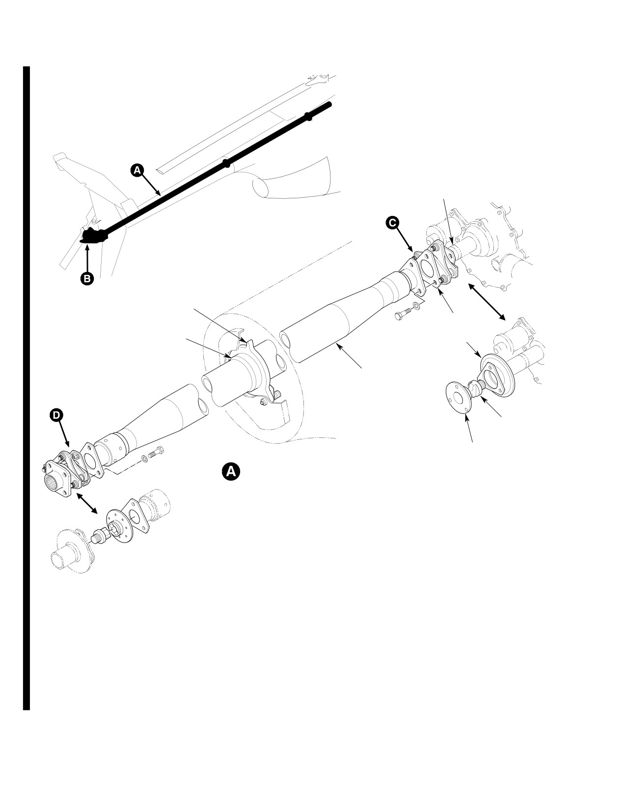
CSP-HMI-2
MD Helicopters, Inc.
MAINTENANCE MANUAL
COUPLING
SHIMS
TAIL ROTOR DRIVE
SHAFT DAMPER
MAIN TRANSMISSION
SHAFT DAMPER
OUTPUT GEARSHAFT
SLEEVE
COUPLING
TAIL ROTOR
DRIVE SHAFT
FAILSAFE
COUPLING
BOLT
FAILSAFE
SOCKET
DRIVE SHAFT INSTALLATION
NOTES:
1.
DO NOT LIFT TAIL ROTOR TRANSMISSION OR DRIVE SHAFT BY COUPLING. KEEP THE ASSEMBLY ALIGNED DURING REMOVAL.
2.
SHIM AS REQUIRED.
3.
ADD 0.005 IN. (0.127 MM) TO MEASURED GAP FOR MINIMUM SHIM THICKNESS.
4.
HOLD COUPLING AT 1.370 IN. (34.798 MM) OD ONLY, TO BOTTOM COUPLING.
5.
INSTALL BOLT WITH ANTI-SEIZE COMPOUND. MINIMUM DRAG TORQUE FOR COUPLING BOLT, 25 INCH-POUNDS (2.82 NM).
6.
MINIMUM 0.010 IN. (0.254 MM) STEP BETWEEN AFT END OF OUTPUT SHAFT AND SHOULDER OF FORWARD COUPLING.
7.
INSTALL WITH GAP EITHER SIDE OF FAILSAFE BOLT.
G63-1005-1B
Figure 401. Tail Rotor Drive Shaft Installation (369D/E/FF) (Sheet 1 of 3)
Page 402
Revision 42
63-15-10
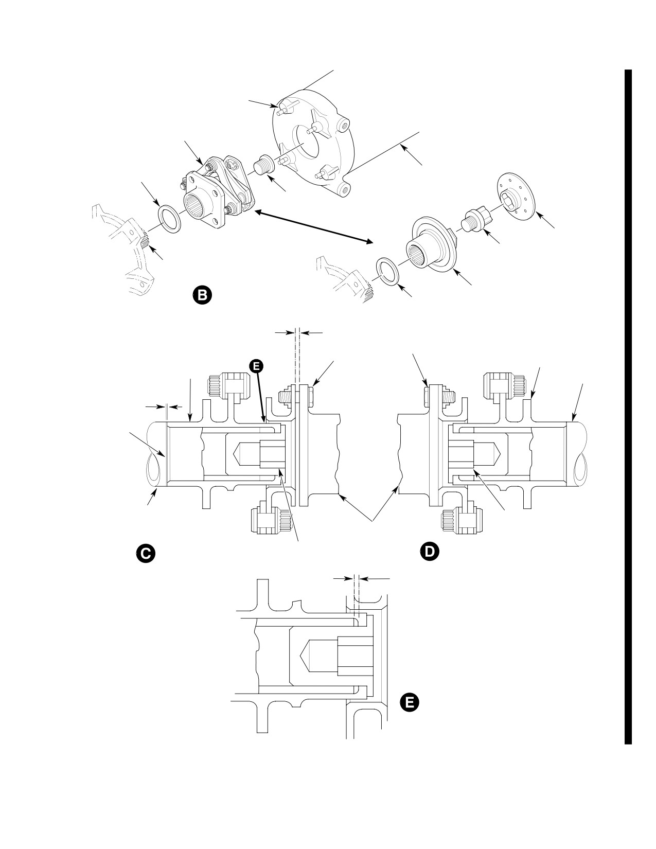
MD Helicopters, Inc.
CSP-HMI-2
MAINTENANCE MANUAL
LOCK RING
AND STUD
(4 PLCS)
TRANSMISSION
COUPLING (NOTE 1)
COUPLING SHIM
TAIL BOOM
(NOTE 2)
COUPLING
BOLT
FAILSAFE
SOCKET
FAILSAFE
COUPLING BOLT
INPUT
SHAFT
TAIL ROTOR TRANSMISSION
TRANSMISSION
COUPLING SHIM
COUPLING (NOTE 1)
(NOTE 2)
MEASURED GAP
0.010-0.020 IN.
THIN WASHER
ALIGNMENT
(0.254-0.508 MM)
(3 PLCS)
AFT
1.370 IN.
BOLT OR PIN
COUPLING TAIL ROTOR
(34.798 MM) OD
GEARSHAFT
(NOTE 4)
INPUT SHAFT
NOTE 3
SHIMS
MAIN TRANSMISSION
COUPLING BOLT
OUTPUT PINION
TAIL ROTOR
(NOTE 5)
DRIVE SHAFT
COUPLING BOLT
FORWARD KAMATIC COUPLING
AFT KAMATIC COUPLING
(NOTE 5)
0.010 IN. (0.254 MM)
MINIMUM STEP
(NOTE 6)
KAMATIC COUPLINGS
G63-1005-2A
Figure 401. Tail Rotor Drive Shaft Installation (369D/E/FF) (Sheet 2 of 3)
Page 403
63-15-10
Revision 42
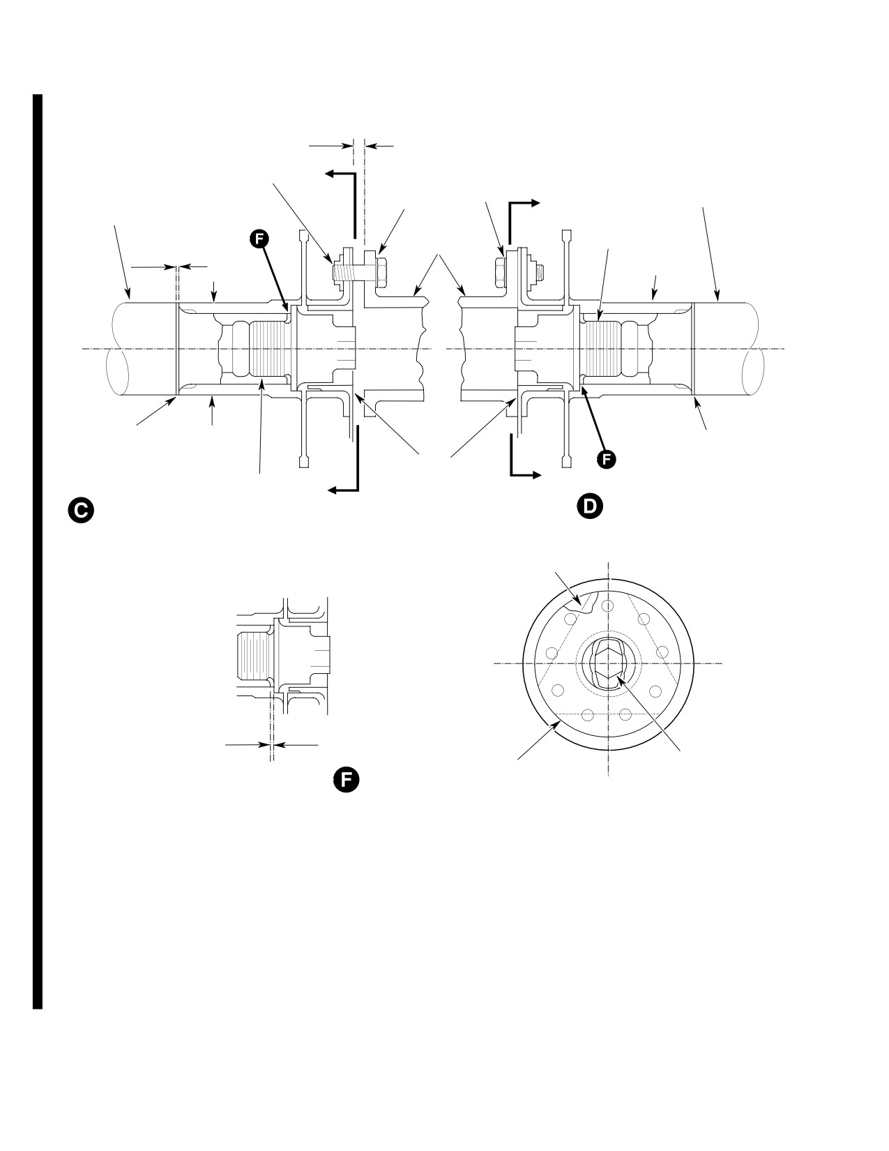
CSP-HMI-2
MD Helicopters, Inc.
MAINTENANCE MANUAL
MEASURED GAP
0.010-0.020 IN.
(0.254-0.508 MM)
ALIGNMENT
THIN
BOLT OR PIN
D
WASHER
WASHER
TAIL ROTOR GEARBOX
(3 PLCS)
MAIN TRANSMISSION
(3 PLCS)
D
OUTPUT SHAFT
OUTPUT PINION
FAILSAFE
TAIL ROTOR
BOLT
DRIVE SHAFT
AFT
NOTE 3
COUPLING
SHIMS
1.370 IN
SHIMS
(34.798 MM) OD
(NOTE 5)
FAILSAFE SOCKET
FAILSAFE BOLT
D
(NOTE 5)
D
AFT BENDIX COUPLING
FORWARD BENDIX COUPLING
COUPLING
0.010 IN. (0.254 MM)
MINIMUM STEP
FAILSAFE BOLT
FAILSAFE SOCKET
(NOTE 6)
(NOTE 7)
D-D FAILSAFE INSTALLATION
G63-1005-3D
Figure 401. Tail Rotor Drive Shaft Installation (369D/E/FF) (Sheet 3 of 3)
Page 404
Revision 42
63-15-10
MD Helicopters, Inc.
CSP-HMI-2
MAINTENANCE MANUAL
(a). Install minimum shim thickness on
CAUTION
main transmission output shaft.
D Ensure security of tail rotor gearbox
Bottom the flexible coupling by
CAUTION
mount studs. Maximum allowable side
holding at the
1.370 inch
play at end of stud is 0.004 inch (0.102
(3.4798 cm) OD of coupling. Do not bottom
mm), maximum allowable axial play is
coupling by pushing on drive shaft attach
0.005 inch
(0.127 mm)
(Ref. Sec.
flange; doing so may damage coupling.
63-25-10).
(b). Bottom forward coupling on main
D When installing tail rotor transmission
transmission output shaft.
and drive shaft, do not compress the for
ward or aft couplings as damage to the
(c). Measure step between aft end of
coupling could result.
output shaft and shoulder of flexible
coupling, by bottoming coupling
(7). With assistance, support transmission
against shims (refer to CAUTION
and shaft in line, for minimum deflec
above).
tion of coupling, and guide drive shaft
carefully through tailboom and damper
NOTE: Maintain minimum 0.010 inch (0.254
into position.
mm) step between aft end of output shaft
(8). Secure transmission to four tailboom
and coupling shoulder to prevent coupling
mounting studs (Ref. Sec. 63-25-10).
bolt from bottoming on output shaft.
Install four washers and nuts, torque
nuts to 75 - 95 inch-pounds (8.47 -
(d). Install additional shims to maintain
10.73 Nm) plus drag torque.
0.010 inch (0.254 mm) minimum step
as required.
(9). Align forward end of drive shaft with
coupling on main transmission output
(3).
Position failsafe socket on aft face of
gearshaft. Partially install two bolts as
forward coupling so that three of the
an alignment aid but do not tighten.
nine holes are indexed to the three
Align drive shaft inspection markings.
nutplates of the coupling in such a way
If any of four white stripes is indistinct
that maximum clearance is obtained
or does not exist, paint (CM311)
between the bolt key and socket.
replacement stripe:
Visually verify proper clearance before
installing tail rotor drive shaft.
(10). Obtain 0.010-0.020 inch (0.254-0.508
mm) gap between forward flange of tail
(4).
Repeat previous step to install failsafe
rotor drive shaft and aft end of socket,
socket on input coupling of tail rotor
using the following procedure:
transmission.
(a). Back off three attach bolts on for
(5).
Support entire length of tail rotor drive
ward flange of tail rotor drive shaft
shaft and position end stamped AFT to
assembly 0.050-0.100 inch
align with tail rotor transmission
(1.270-2.540 mm).
coupling.
(b). Pull and hold tail rotor output shaft
(6).
Install three bolts and washers to
of main rotor transmission aft (out of
connect tail rotor transmission coupling
transmission) to remove end play. If
to shaft; torque bolts to 80 - 100
rotor brake is installed, make certain
inch-pounds (9.04 - 11.30 Nm) plus
that brake pucks do not restrict axial
drag torque.
travel of tail rotor output shaft.
Page 405
63-15-10
Revision 43
CSP-HMI-2
MD Helicopters, Inc.
MAINTENANCE MANUAL
(c).
Remove end play in tail rotor trans
(12). With assistance, support transmission
mission by applying force to tail rotor
and shaft in line for minimum deflec
blades in opposite direction of
tion of coupling and guide drive shaft
operational rotation (while holding
carefully through tailboom and damper
forward coupling of tail rotor drive
into position.
shaft on main transmission output
shaft to prevent rotation). Do not
(13). Apply primer (CM318) to the four
push tail rotor drive shaft fore or aft.
gearbox mounting studs. Install nuts
and washers while the primer is still
(d).
Using feeler gage, measure gap
wet; torque evenly to 75 - 95 inch-
between socket and flange of tail
pounds (8.47 - 10.73 Nm) plus drag
rotor drive shaft. Socket flange must
torque.
be in full contact with flange of
flexible coupling.
Verify that a minimum of (1) one
CAUTION
thread protrudes through each
nut from the four tail rotor transmission
(e).
With assistance, remove tail rotor
mounting studs. If less than one thread is
transmission and driveshaft in line
showing, refer to CSP-DEF-6, Structural
for minimum deflection of coupling.
Repair Manual, to replace with a longer
MS1992A803-14 stud and insert.
(f).
Using measured gap from step (d).
above, add or remove required
(14).
Install three bolts and washers at
number of shims at tail rotor trans
forward end of tail rotor drive shaft to
mission input pinion shaft and
connect to forward coupling; torque
coupling to obtain specified gap of
bolts to 80 - 100 inch-pounds (9.04 -
0.010-0.020 inch (0.254-0.508 mm).
11.30 Nm) plus drag torque.
NOTE:
(15).
Connect electrical wire to tail rotor
transmission chip detector. Torque nut
D Maintain minimum 0.010 inch (0.254
to 12 - 15 inch-pounds (1.36 - 1.69
mm) step between coupling shoulder and
Nm).
output shaft (Ref. step (2).).
D If less than specified gap, 0.010-0.020
(16).
Coat pin of Sta. 284.00 bellcrank with
inch (0.254-0.508 mm) exists under mini
grease (CM111) and insert it into
mum shim requirements, install a maxi
bearing in tail rotor pitch control. Pivot
mum of one HS306-326 or HS306-326H
bellcrank to align with mating hole in
washer on each of the four tail rotor
tail rotor transmission and install bolt,
transmission mounting studs, between
washers, nut and cotter pin.
gearbox housing and boom fitting. Apply
primer (CM318) to both sides of washer at
(17).
Check transmission oil level and service
installation. After washer installation, re
peat step (10).
as required.
(18).
Slowly rotate drive shaft and visually
(11). Coat forward coupling splines with
check to ensure shaft is not bent and for
grease (CM111) and coupling bolt
not less than 0.250 inch (6.35 mm)
threads with antiseize compound (36)
clearance between shaft and fairing
before assembly. Install coupling and
tube at Sta. 137.5. In addition, check
torque failsafe bolt to 250 - 300
for minimum clearance of 0.190 inch
inch-pounds (28.25 - 33.90 Nm) plus
(4.83 mm) between shaft and cooling
drag torque. (Check coupling bolt for
blower scroll.
drag torque serviceability of 25 inch-
pounds minimum (2.82 Nm), 200
inch-pounds (22.60 Nm) maximum.)
(19).
Install all access doors and covers.
Page 406
Revision 42
63-15-10
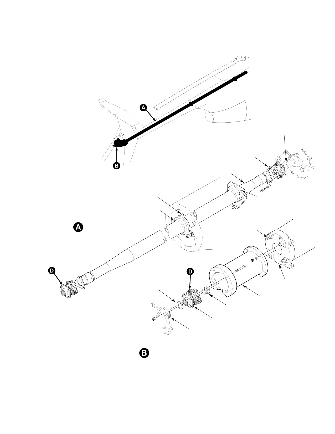
MD Helicopters, Inc.
CSP-HMI-2
MAINTENANCE MANUAL
COUPLING SHIMS
MAIN TRANSMISSION OUTPUT
GEARSHAFT COUPLING
TAIL ROTOR
DRIVE SHAFT
TAIL ROTOR DRIVE
SHAFT DAMPER
TAIL ROTOR DRIVE
SHAFT DAMPER SLEEVE
SHAFT DAMPER
(2 PLCS)
LOCK RING AND STUD
DRIVE SHAFT INSTALLATION
(4 PLCS)
TAILBOOM
COUPLING SHIM
(NOTE)
EXTENSION
COUPLING BOLT
TRANSMISSION COUPLING
INPUT SHAFT
TAIL ROTOR TRANSMISSION
NOTE:
SHIM AS REQUIRED.
G63-1006
Figure 402. Tail Rotor Drive Shaft Installation (369FF)
Page 407
63-15-10
Revision 42
CSP-HMI-2
MD Helicopters, Inc.
MAINTENANCE MANUAL
C. Tail Rotor Drive Shaft Installation with
coupling onto main transmission;
Kamatic Couplings
torque coupling bolt to 250 - 300
inch-pounds (28.25 - 33.90 Nm) plus
(Ref. Figure 401 and Figure 402) Whenever
drag torque. (Check coupling bolt for
main transmission, tail rotor transmission,
drag torque serviceability of 25 inch-
transmission couplings, coupling shims, tail
pounds (2.82 Nm) minimum, 200
rotor drive shaft or tailboom assembly have
inch-pounds (22.60 Nm) maximum.)
been replaced, start installation with step (1).
below. If none of these components have been
(3). Support entire length of tail rotor drive
replaced, and only installation is involved,
shaft and position end marked AFT to
start with step (5). below.
align with tail rotor transmission
coupling.
Consumable Materials
(4). Install three bolts and washers to
(Ref. Section 91−00−00)
connect tail rotor gearbox coupling to
Item
Nomenclature
shaft; torque bolts to 80 - 100 inch-
CM111
Grease, aircraft
pounds (9.04 - 11.30 Nm) plus drag
torque.
CM112
Anti-seize compound high temperature
CM115
Grease, oscillating bearing
Ensure security of tail rotor
CAUTION
CM311
Coating, logo white / Thinner
gearbox mount studs. Maxi
CM318
Primer
mum allowable side play at end of stud is
0.004 inch (0.102 mm), maximum allowable
axial play is 0.005 inch (0.127 mm) (Ref. Sec.
NOTE:
63-25-10).
D Kamatic couplings do not require failsafe
(5). With assistance, support tail rotor
bolts or sockets.
transmission and shaft in line, for
D When installing 369D25501-3 Kamatic
minimum deflection of coupling, and
coupling, install SKCP2554-13 coupling
guide drive shaft carefully through
bolt supplied with the Kamatic coupling.
tailboom and damper into position.
D If tail rotor drive shaft is replaced for tor
(6). Secure transmission to four tailboom
sional buckling, replace and discard main
mounting studs with washers and nuts;
transmission output gear shaft coupling,
torque to 75 - 95 inch-pounds (8.47 -
tail rotor gearbox coupling and both cou
10.73 Nm) plus drag torque.
pling bolts.
(7). Align forward end of driveshaft with
(1). Coat coupling splines with grease
coupling on main transmission output
(CM111) and coupling bolt threads with
gearshaft. Partially install two bolts as
anti-seize compound (CM112) before
an alignment aid but do not tighten.
assembly. Install coupling onto tail
Align drive shaft inspection markings.
rotor gearbox and torque coupling bolt
If any of four white stripes is indistinct
to 250 - 300 inch-pounds (28.25 -
or does not exist, paint replacement
33.90 Nm) plus drag torque (Check
stripes.
coupling bolt for drag torque service
ability of 25 inch-pounds (2.82 Nm)
(8). Obtain 0.010-0.020 inch (0.254-0.508
minimum, 200 inch-pounds (22.60 Nm)
mm) gap between forward flange of tail
maximum.)
rotor drive shaft and flange of forward
coupling using the following procedure:
(2). Coat forward coupling splines with
grease (CM111) and coupling bolt
(a). Ensure alignment bolts in previous
threads with anti-seize compound
step are backed off between
(CM112) before assembly. Install
0.050-0.100 inch (1.270-2.540 mm).
Page 408
Revision 20
63-15-10
MD Helicopters, Inc.
CSP-HMI-2
MAINTENANCE MANUAL
(b).
Pull and hold tail rotor output shaft
guide drive shaft carefully through
of main rotor transmission aft (out of
tailboom and damper into position.
transmission) to remove end play. If
(11).
Secure transmission to four tailboom
rotor brake is installed, ensure that
mounting studs with washers and nuts;
brake pucks do not restrict axial
torque to 75 - 95 inch-pounds (8.47 -
travel of tail rotor output shaft.
10.73 Nm) plus drag torque.
(c).
Remove end play in tail rotor trans
(12).
Install three bolts and washers at
mission by applying force to tail rotor
forward coupling; torque bolts to 80 -
blades in opposite direction of
100 inch-pounds (9.04 - 11.30 Nm)
operation (while holding forward
plus drag torque.
coupling of tail rotor drive shaft on
main transmission to prevent rota
(13).
Connect electrical wire to tail rotor
tion). Do not push tail rotor drive
transmission chip detector. Torque nut
shaft fore or aft.
to 12 - 15 inch-pounds (1.36 - 1.69
Nm).
(d).
Using feeler gage, measure gap
between forward coupling flange and
(14).
Coat pin of Sta. 284.00 bellcrank with
flange of tail rotor drive shaft. Record
grease (CM111) and insert into bearing
the gap.
in tail rotor pitch control. Pivot bell
crank to align with mating hole in tail
(e).
With assistance, remove tail rotor
rotor transmission and install bolt,
transmission and driveshaft in line
washers, nut and cotter pin.
for minimum deflection of coupling.
(15).
Check transmission oil level and service
as required (Ref. Sec. 12-10-00).
(f).
Using measured gap from step (d).
above, add or remove required
(16).
Slowly rotate driveshaft and check for
number of shims at tail rotor trans
not less than 0.25 inch (6.35 mm)
mission input pinion shaft and
clearance between shaft and fairing
coupling to obtain specified gap of
tube at Sta. 137.50. In addition, check
0.010-0.020 inch (0.254-0.508 mm).
for minimum clearance of 0.190 inch
(4.83 mm) between shaft and cooling
NOTE:
blower scroll.
D Maintain minimum 0.010 inch (0.254
(17).
Install all access doors and covers.
mm) step between coupling shoulder and
output shaft (Ref. Figure 401).
3. Tail Rotor Drive Shaft Damper
D If less than specified gap, 0.010-0.020
inch (0.254-0.508 mm) exists under mini
(Ref. Figure 603) The tail rotor drive shaft
mum shim requirements, install a maxi
damper is a graphite-filled teflon plate that
mum of one HS306-326 or HS306-326H
controls and limits deflection of the tail rotor
washer on each of the four tail rotor
drive shaft about its approximate mid-point.
transmission mounting studs, between
The damper is spring-loaded against a
gearbox housing and boom fitting. Apply
structural support bracket mounted on the aft
primer (CM318) to both sides of washer at
section tailboom fairing. On 369FF Model
installation. After washer installation, re
helicopters, a second damper is located at Sta.
peat step (10).
137.50 (Ref. Figure 602).
(9). Re-install coupling and torque coupling
4. Tail Rotor Drive Shaft Damper
bolt to 250 - 300 inch-pounds (28.25
Replacement
- 33.90 Nm) plus drag torque.
(Ref. Figure 602)
(10). With assistance, support tail rotor
(1). Remove boom-bolts access covers.
transmission and shaft in line for
minimum deflection of coupling and
(2). Remove tail rotor drive shaft.
Page 409
63-15-10
Revision 43
CSP-HMI-2
MD Helicopters, Inc.
MAINTENANCE MANUAL
(3). Remove two bolts, washers, springs,
(6). Install tail rotor drive shaft.
thin washers, plate and spacers and
damper.
(7). Displace damper so that it touches tail
NOTE: The damper at Sta. 137.50 (369FF only)
rotor drive shaft.
has 369DSK152-13 bushings installed in
side the Teflon Graphite Damper in conjunc
tion with the spacers.
(8). Use wire gage to measure damper to
(4). Position new damper over mounting
shaft clearance 180° from contact point.
holes in support bracket. Install plate
Minimum acceptable clearance is 0.020
and spacers with bolts, washers,
inch (0.508 mm).
springs and spacer washers.
Ensure washers under bol
CAUTION
(9). Repeat steps (7). and (8). above at 90°
theads are seated against
intervals from initial check point.
spacer when tightened. Bolts wear rapidly if
clamp-up is not solid.
(5). Adjust damper friction.
(10). Install boom-bolts access covers.
Page 410
Revision 28
63-15-10
MD Helicopters, Inc.
CSP-HMI-2
MAINTENANCE MANUAL
TAIL ROTOR DRIVE SHAFT
INSPECTION/CHECK
1. Tail Rotor Drive Shaft Inspection
straightness. When rotated between
centers, or with ends plugged and rolled
Inspect shaft as described below. Replace bent
over roller, runout of large diameter
shaft. Other damage (scratches, nicks, etc)
must not exceed 0.060 inch (1.524 mm)
that exceeds repairable limits also requires
(allowable dents excluded).
shaft replacement.
2. Tail Rotor Drive Shaft Twist Inspection
(1). Inspect for scratches in shaft section
that passes through plenum chamber
(Ref. Figure 601 and Figure 602) Following
fairing tube. Such scratches indicate
inspection determines if drive shaft has been
possible contact with tube edges at
torsionally strained to extent that permanent
bulkhead openings.
twist exists.
(2). Inspect for evidence of torsional
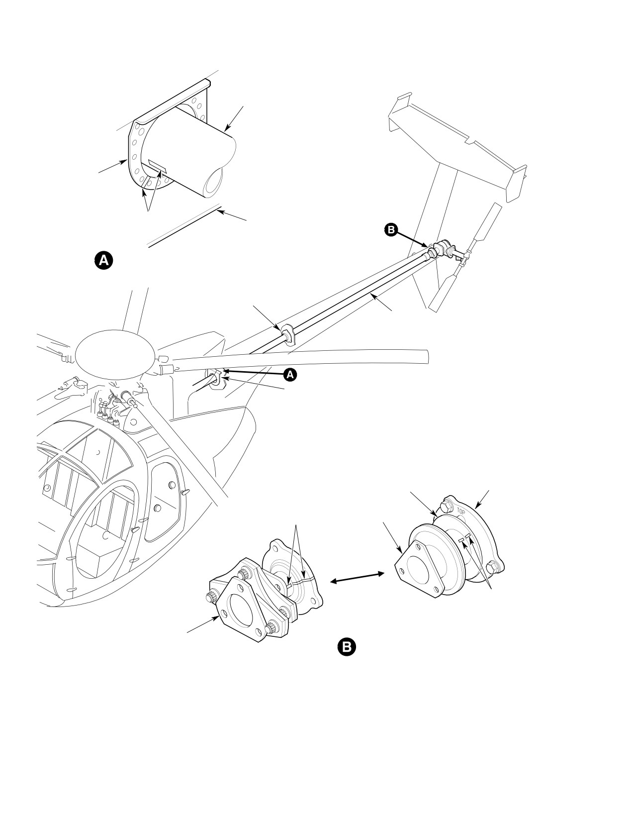
(1). Hand-turn main rotor until two white
buckling or shaft bending as result of
stripes (A, Figure 601) are aligned.
blade strike or hard ground contact by
lower stabilizer.
(2). Look inboard from tail rotor side of
helicopter and locate two white stripes
(3). Inspect for corrosion.
(B, Figure 601). Stripe on input shaft
bearing retainer flange of tail rotor
(4). Inspect for evidence of shaft damper
transmission is located at approximate
sleeve bond failure (sleeve shifting)
ly 2 o'clock, looking aft. Stripe on
from excessive heat or loads.
coupling should be at approximately 10
(5). If there is abnormal shaft vibrations,
o'clock, looking forward. Both stripes
check damper friction and shaft
should be aligned.
Page 601
63-15-10
Revision 20
CSP-HMI-2
MD Helicopters, Inc.
MAINTENANCE MANUAL
TAIL ROTOR
DRIVE SHAFT
DOUBLER
TAIL ROTOR
TRANSMISSION
WHITE STRIPES
STA. 137.50 RING
1/8 IN. (3.175 MM) WIDE
STA. 137.50
(LOOKING FORWARD)
DAMPER
TAIL ROTOR
DRIVE SHAFT
STA. 137.50
TAIL ROTOR
INPUT SHAFT
BEARING RETAINER
TRANSMISSION
WHITE STRIPES
1/8 INCH (3.175 MM)
COUPLING
WIDE
WHITE STRIPES
1/8 IN. (3.175 MM) WIDE
(EARLY CONFIGURATION)
COUPLING
AFT COUPLING
(NEW CONFIGURATION)
G63-1007A
Figure 601. Tail Rotor Drive Shaft − Inspection Markings
Page 602
Revision 20
63-15-10
MD Helicopters, Inc.
CSP-HMI-2
MAINTENANCE MANUAL
TAIL ROTOR
TAIL ROTOR
TRANSMISSION
DRIVE SHAFT
DAMPER
WHITE STRIPE
1/8 IN. (3.175 MM) WIDE
TAIL BOOM EXTENSION
INPUT SHAFT
BEARING RETAINER
COUPLING
WHITE STRIPE (1/8
INCH WIDE)
DOUBLER
BUSHING
WHITE STRIPE
1/8 IN. (3.175 MM)
WIDE
(EARLY CONFIGURATION)
WHITE
STRIPE
1/8 IN.
(3.175 MM)
TAIL ROTOR
WIDE
DRIVE SHAFT
STA. 137.50 RING
COUPLING
(CURRENT CONFIGURATION)
STA. 137.50
(LOOKING FORWARD)
AFT COUPLING
G63-1008B
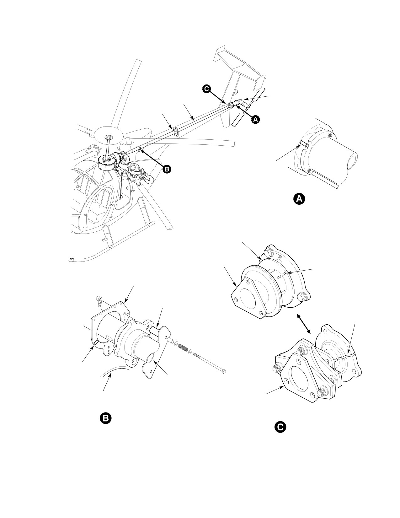
Figure 602. Tail Rotor Drive Shaft − Inspection Markings (Extended Tailboom)
Page 603
63-15-10
Revision 20
CSP-HMI-2
MD Helicopters, Inc.
MAINTENANCE MANUAL
3. Tail Rotor Drive Shaft Damper Inspection
NOTE: Tail rotor drive shaft must be removed
to perform following inspection.
(Ref. Figure 603)
(2). Inspect damper for correct drag friction
NOTE: If there is excessive drive shaft vibra
adjustment.
tion as shaft passes through first critical
rpm range, probable cause is defective or
(3). Inspect inside diameter of damper for
loose damper.
excessive wear. If diameter is more
than 3.035 inches (7.7089 cm), damper
(1). Inspect damper for shaft clearance as
must be replaced.
follows:
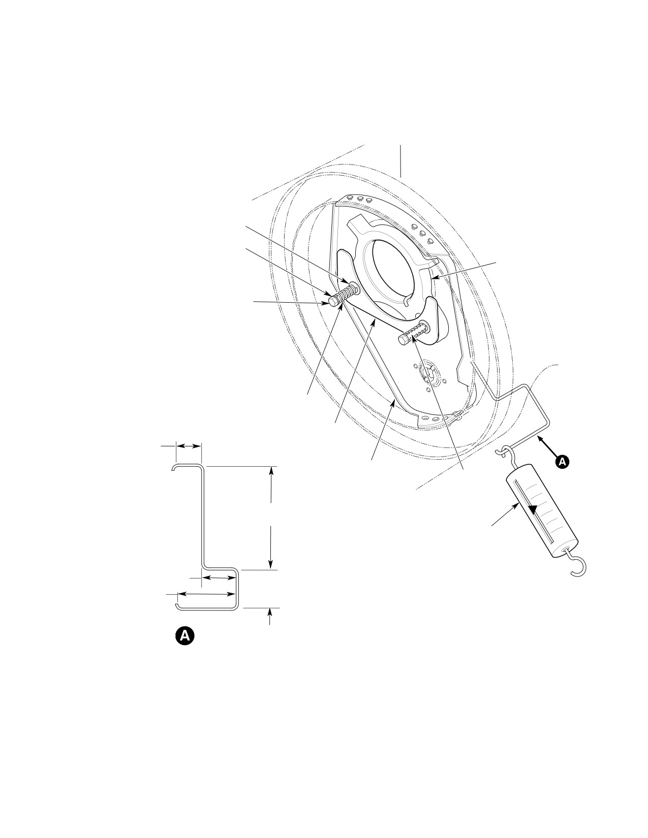
(4). Adjust friction damper as necessary to
(a). Remove boom-bolts access cover.
achieve the required drag as follows:
(b). Inspect tail rotor drive shaft damper
(a). Fabricate friction-checking tool.
and support structure for broken,
cracked or bent parts.
(b). Using 0-10 pound spring scale,
measure force required to move
(c). Displace damper so that it touches
damper radially on bulkhead. Fric
tail rotor drive shaft.
tion must be adjusted so that pull of
(d). Use wire gage to measure damper to
2 ±0.25 pounds (0.91 ±0.11 kg) is
shaft clearance 180° from contact
required to slide damper between
point. Minimum acceptable clearance
plate and support bracket.
is 0.020 inch (0.508 mm).
NOTE: Minimum of one washer must always
(e). Repeat steps (c). and (d). above at 90°
remain between each spring and plate.
intervals from initial check point.
(c). To increase friction, add thin washers
(f). Dampers not meeting minimum
between springs and plate. To
clearance of 0.020 inch (0.508 mm) at
decrease friction, remove washers.
four equidistant points are to be
(Add or remove same number of
replaced.
washers at each spring.)
Page 604
Revision 37
63-15-10
MD Helicopters, Inc.
CSP-HMI-2
MAINTENANCE MANUAL
STA. 197.78
THIN WASHER
(AS REQUIRED)
WASHER
TEFLON GRAPHITE
DAMPER
BOLT
SPRING
METAL PLATE
1.13 IN.
(2.8702 CM)
BRACKET
SPACER
5.00 IN.
(12.7 CM)
SPRING SCALE
0-10 POUNDS
0-5 KG)
1.75 IN.
(4.445 CM)
2.00 IN.
2.88 IN.
(5.08 CM)
(7.3152 CM)
FRICTION CHECKING TOOL
(NOTE)
NOTE:
MANUFACTURED LOCALLY FROM 1/8 IN. (3.175 MM)
CORROSION RESISTANCE SPRING WIRE.
G63-1009A
Figure 603. Tail Rotor Drive Shaft Damper − Inspection
Page 605
63-15-10
Revision 20
CSP-HMI-2
MD Helicopters, Inc.
MAINTENANCE MANUAL
This Page Intentionally Left Blank
Page 606
Revision 44
63-15-10
MD Helicopters, Inc.
CSP-HMI-2
MAINTENANCE MANUAL
TAIL ROTOR DRIVE SHAFT
REPAIRS
1. Tail Rotor Drive Shaft Repair Procedure
depth of a dent is 0.040 inch (1.016
mm). Dents that raise material require
that shaft be replaced.
Consumable Materials
(Ref. Section 91−00−00)
2. Tail Rotor Drive Shaft Index Stripe
Item
Nomenclature
Application
CM206
Chemical coating
CM318
Primer
(Ref. Figure 601 and Figure 602)
CM801
Abrasive paper, silicon carbide
CM803
Crocus cloth
Consumable Materials
(Ref. Section 91−00−00)
Item
Nomenclature
Nicks and scratches no deeper than 0.0015
CM311
Coating, logo white / Thinner
inch (0.0381 mm) are allowable without
rework but require finish protection with
chemical film (CM206). Other surface damage
If any of the four white index stripes used for
shall be evaluated and repaired according to
twist inspection of tail rotor drive shaft are
limits specified below. Use grade 400 abrasive
indistinct or do not exist, paint (CM311)
paper (CM801) to smooth out and blend repair
replacement aligning index stripes as follows:
area into surrounding material until damage
is completely removed; then polish with crocus
To prevent damage to gearbox
CAUTION
cloth (CM803) to equal original finish. Apply
coupling during and after shaft
finish protection with chemical film and two
removal, provide good level support for both
coats of primer (CM318).
tail rotor transmission and shaft, as the
weight of these items might buckle the cou
Any section of shaft that ap
pling.
CAUTION
pears to be scratched, nicked or
corroded in a previously reworked area
NOTE: Any time the associated tail rotor drive
must not be repaired a second time. Remove
shaft units are removed or replaced, an in
such shaft from further service. Replace any
dexing check and re-application of index
shaft that has damage in excess of following
marks is required.
limits.
(1). Remove tail rotor transmission and
(1). Scratches 0.007 inch (0.178 mm) deep
drive shaft as an assembly.
to maximum length of 1.00 inch (2.54
cm) at any random angle may be
(2). Inspect tail rotor drive shaft for
repaired.
evidence of torsional twist or buckling.
(2). Scratches 0.010 inch (0.254 mm) deep
(3). Remove any old index stripes.
to maximum length of 0.250 inch (6.35
(4). Apply white index stripe 0.120 inch
mm) at any random angle may be
(3.048 mm) wide and 0.250 inch (6.35
repaired.
mm) long onto tail rotor transmission
(3). Circumferential scratches 0.004 inch
input shaft bearing flange, at approxi
(0.102 mm) deep may be repaired.
mate 10 o'clock position (viewed looking
forward), so it can be seen when viewed
(4). Smoothly contoured dents are allowable
on left side of tailboom.
when ratio of dent diameter to dent
depth is at least 15:1; for example,
(5). Apply white index stripe 0.120 inch
when depth is 0.040 inch (1.016 mm)
(3.048 mm) wide and any length, on the
minimum acceptable diameter is 0.60
aft coupling in line with index stripe on
inch (15.24 mm). Maximum acceptable
tail rotor gearbox retainer.
Page 801
63-15-10
Revision 20
CSP-HMI-2
MD Helicopters, Inc.
MAINTENANCE MANUAL
(6). Install tail rotor drive shaft.
mm) long on boom bulkhead doubler
(Sta. 137.50), at approximately 6 - 8
(7). Align index stripes on tail rotor gearbox
o'clock position looking forward.
bearing retainer and aft coupling.
(8). Remove tail rotor bellcrank access door
(10). Apply a corresponding joining index
at the forward left side of fuselage boom
stripe on the tail rotor drive shaft at
fairing and observe the area where tail
Sta. 137.50, approximately 0.120 inch
rotor drive shaft passes through the
(3.048 mm) wide and 0.50 inch (12.70
fairing forward bulkhead.
mm) long.
(9). Apply white index stripe 0.120 inch
(3.048 mm) wide and 0.50 inch (12.70
(11). Install all access doors and covers.
Page 802
Revision 20
63-15-10
MD Helicopters, Inc.
CSP-HMI-2
MAINTENANCE MANUAL
Section
63−15−30
NOTAR®
Anti−Torque System
Drive Shafts
(500/600N)
CSP-HMI-2
MD Helicopters, Inc.
MAINTENANCE MANUAL
This Page Intentionally Left Blank
MD Helicopters, Inc.
CSP-HMI-2
MAINTENANCE MANUAL
NOTAR) ANTI−TORQUE SYSTEM DRIVE SHAFTS
MAINTENANCE PRACTICES
1. Anti−Torque System Drive Shafts
coupling and remove three bolts and
washers that secure fan gearbox drive
The Fan Gearbox Drive Shaft connects the
shaft to input shaft coupling on fan
main transmission and the fan gearbox. The
transmission gearbox. Support drive
total drive shaft length is approximately 14
shaft and output shaft coupling on
inches long. Flanges on each end of the shaft
main transmission.
attach to flexible (Kamatic) type joint coupling
on the main transmission output shaft and fan
(6). Remove fan gearbox (Ref. Sec.
gearbox input shaft.
63-25-30).
The Fan Inter-Connecting Drive Shaft is
(7). Remove fan gearbox drive shaft by
equipped with a kamatic flexible-type joint
removing three bolts and washers from
and mounting flange (coupling) at each end.
output shaft couping on main transmis
The shaft connects the fan gearbox to the fan
sion.
assembly by (two) couplings mounted on the
B. Fan Gearbox Drive Shaft Installation
output shaft of the fan gearbox and input shaft
of the fan assembly. The fan pitch control rod
(Ref. Figure 201) Whenever main transmis
is routed through the center of the inter-con
sion, fan gearbox, transmission couplings,
nect drive shaft.
coupling shims, fan gearbox drive shaft
assembly have been replaced, start installation
2. Fan Gearbox Drive Shaft Replacement
with step (1). below. If none of these compo
nents have been replaced, and only installa
A. Fan Gearbox Drive Shaft Removal
tion is involved, start with step (3). below.
(Ref. Figure 201)
Consumable Materials
(1). Remove fan gearbox drive shaft access
(Ref. Section 91−00−00)
doors and covers, upper aft section
Item
Nomenclature
fuselage and interior trim panels as
CM111
Grease, aircraft
required.
CM112
Anti-seize compound high temperature
(2). Remove tailboom fairing and tailboom
CM115
Grease, oscillating bearing
(Ref. Sec. 53-40-30).
CM318
Primer
(3). Remove fan pitch control rod (Ref. Sec.
67-20-30).
NOTE: Kamatic couplings do not require fail
safe bolts or sockets. When installing
(4). Remove fan inter-connecting drive
369D25501-9 Kamatic coupling, install
shaft (Ref. Fan Inter-Connect Drive
SKCP2554-15 coupling bolt supplied with
Shaft Replacement).
the Kamatic coupling or 369D25503-1 bolt.
If fan gearbox drive shaft is replaced for
WARNING
torsional buckling, replace and discard
main transmission output gear shaft
D To prevent damage to the engine in
coupling, fan gearbox coupling and both
stall F.O.D. cover over engine air in
coupling bolts.
let.
(1). Coat coupling splines with grease
D To prevent damage to shaft provide
(CM111) and coupling bolt threads with
level support for fan transmission
anti-seize compound (CM112) before
drive shaft during removal or instal
assembly. Install coupling onto fan
lation.
gearbox input shaft and torque coupling
(5). Gain access thru plenum chamber and
bolt to 250 - 300 inch-pounds (28.25
remove drive shaft access panel to aft
- 33.90 Nm) plus drag torque. Check
Page 201
63-15-30
Revision 20
CSP-HMI-2
MD Helicopters, Inc.
MAINTENANCE MANUAL
coupling bolt for drag torque service
(b).
Pull and hold fan output pinion shaft
ability of 25 inch-pounds (2.82 Nm)
of main rotor transmission aft (out of
minimum, 200 inch-pounds (22.60 Nm)
transmission) to remove end play. If
maximum.
rotor brake is installed, ensure that
brake pucks do not restrict axial
travel of fan output shaft.
(2).
Coat forward coupling splines with
grease (CM111) and coupling bolt
(c).
Remove end play in fan transmission
threads with anti-seize compound
by applying force to the coupling in
(CM112) before assembly. Install
opposite direction of operation while
coupling onto main transmission output
still holding forward coupling of drive
shaft and torque coupling bolt to 250 -
shaft on main transmission. Do not
300 inch-pounds (28.25 - 33.90 Nm)
push fan drive shaft fwd or aft.
plus drag torque. Check coupling bolt
for drag torque serviceability of 25
(d).
Using feeler gage, measure gap
inch-pounds (2.82 Nm) minimum, 200
between forward coupling flange and
inch-pounds (22.60 Nm) maximum.
flange of fan drive shaft using
average of 3 readings. Record the
gap.
(3).
Support drive shaft and position to
align with fan transmission coupling on
(e).
Adjust the number of shims
main transmission.
(369A5516-3, -5, -7, or -9). Using
measured gap from step 4 above, add
or remove required number of shims
(4).
Install fan gearbox with four mounting
behind the coupling of main trans
bolts and torque to 70 - 90 inch
mission output pinion shaft or
pounds (7.90 - 10.17 Nm); torque-
between fan gearbox forward cou
stripe bolts.
pling to obtain specified gap of
0.010-0.020 inch (0.254-0.508 mm).
NOTE: If re-shimming is required, removal
and installation of the fan gearbox is neces
NOTE: All shims may be removed from forward
sary to obtain the specified gap between the
or aft coupling if required.
coupling flange and flange of drive shaft.
(f). Coat forward coupling splines with
grease (CM111) and coupling bolt
(5). Install three bolts and washers to
threads with anti-seize compound
connect fan gearbox coupling to drive
(CM112) before assembly. Install
shaft; torque bolts to 80 - 100 inch-
coupling and torque coupling bolt to
pounds (9.04 - 11.30 Nm) plus drag
250 - 300 inch-pounds (28.25 -
torque.
33.90 Nm) plus drag torque. Check
coupling bolt for drag torque service
ability of 25 inch-pounds (2.82 Nm)
(6). Align forward end of drive shaft with
minimum, 200 inch-pounds (22.60
coupling on main transmission output
Nm) maximum.
gearshaft. Partially install three bolts
as an alignment aid but do not tighten.
(8). Install three bolts and washers at
forward coupling; torque bolts to 80 -
(7). Obtain 0.010-0.020 inch (0.254-0.508
100 inch-pounds (9.04 - 11.30 Nm)
mm) gap between forward flange of the
plus drag torque.
fan gearbox drive shaft and flange of
(9). Slowly rotate drive shaft and check for
forward coupling using the following
not less than 0.25 inch (6.35 mm)
procedure:
clearance between shaft and fairing
tube at Sta. 137.50. In addition, check
(a). Ensure alignment bolts in previous
for minimum clearance of 0.190 inch
step are backed off between
(4.83 mm) between shaft and cooling
0.050-0.100 inch (1.270-2.540 mm).
blower scroll.
Page 202
Revision 43
63-15-30
MD Helicopters, Inc.
CSP-HMI-2
MAINTENANCE MANUAL
(10). Install fan gearbox (Ref. Sec.
(1). Replace bent shaft. Other damage
63-25-30).
(scratches, nicks, etc.) that exceeds
repairable limits also requires shaft
(11). Install inter-connecting drive shaft
replacement.
(Ref. Fan Inter-Connect Drive Shaft
(2). Inspect for scratches in shaft section
Replacement)
that passes through plenum chamber
(12). Install fan pitch control; control rod
fairing tube. Such scratches indicate
(Ref. Sec. 67-20-30).
possible contact with tube edges at
bulkhead openings.
(13). Install tailboom and fairing (Ref. Sec.
(3). Inspect for evidence of torsional twist,
53-40-30).
buckling or shaft bending as result of
blade strike or hard ground contact.
(14). Check anti-torque flight control rigging
(Ref. Sec. 67-20-30).
(4). Inspect for corrosion.
(15). Install all access doors and covers, and
4. Fan Gearbox Drive Shaft Repair
interior trim panels.
Procedure
3. Fan Gearbox Drive Shaft Inspection
For information on repair procedures, refer to
Sec 63-15-10, Tail Rotor Drive Shafts Repair
Inspect shaft as described below.
Procedure.
Page 203
63-15-30
Revision 20
CSP-HMI-2
MD Helicopters, Inc.
MAINTENANCE MANUAL
BOLT
(NOTE 3)
SHIM
SHAFT
COUPLING
BOLT
(NOTE 3)
WASHER
SPEEDI
SLEEVE
BOLT
SHIM
WASHER
LOCKNUT
COUPLING
BOLT
WASHER
COUPLING
SHIM
LOCKNUT
(NOTE 1)
SPEEDI
SHAFT
SLEEVE
SHIM
(NOTE 1)
NOTE 2
COUPLING
NOTES:
1.
DO NOT EXCEED 0.100 IN. (2.54 MM) SHIM THICKNESS
IN EITHER OF THE TWO FLANGE LOCATIONS.
2.
0.010-0.020 IN. (0.254-0.508 MM) GAP.
WASHER
3.
TORQUE 250 - 300 INCH-POUNDS (28.25 - 33.90 NM) PLUS
BOLT
DRAG TORQUE OF 25 INCH-POUNDS (2.82 NM) MINIMUM,
200 INCH-POUNDS (22.60 NM) MAXIMUM.
G63-1012B
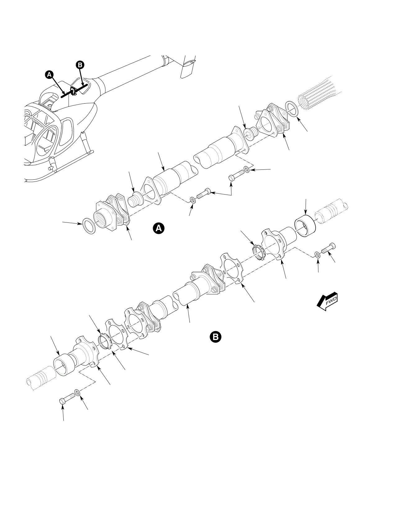
Figure 201. Fan Gearbox and Inter−Connecting Drive Shafts
Page 204
Revision 20
63-15-30
MD Helicopters, Inc.
CSP-HMI-2
MAINTENANCE MANUAL
5. Fan Inter−Connect Drive Shaft
Do not exceed 0.100 inch (2.540
CAUTION
Replacement
mm) shim thickness in either of
the two flange locations. Shim thickness in
(Ref. Figure 201)
both locations to be within 0.020 inch (0.508
mm) of each other.
A. Fan Inter−Connect Drive Shaft Removal
(4). Adjust the shim thickness between the
forward flange and the aft flange of the
(1). Remove fan inlet screen and fan
inter-connect drive shaft and the two
transmission cover (Ref. Sec.
couplings.
53-30-30).
(5). Install shims to obtain the specified
(2). Remove tailboom fairing and tailboom
0.010-0.020 inch (0.254-0.508 mm)
(Ref. Sec. 53-40-30).
gap. Install inter-connect drive shaft
with eight mounting bolts and washers.
(3). Remove fan pitch control rod (Ref. Sec.
Torque forward and aft mounting bolts
67-20-30).
50 - 70 inch-pounds (5.65 - 7.91 Nm)
plus drag torque.
To prevent damage to the shaft
CAUTION
(6). Install fan pitch control; control rod
and couplings during and after
(Ref. Sec. 67-20 -30).
removal, provide level support for inter-
connecting drive shaft.
(7). Install tailboom and fairing (Ref. Sec.
53-40-30).
(4). Remove four mounting bolts and
washers (2 places) and remove shims at
(8). Check control rigging (Ref. Sec.
both ends of inter-connect drive shaft,
67-20-30).
remove inter-connect drive shaft.
(9). Install access panels and covers (Ref.
Retain shims for reinstallation.
Sec. 53-30-30).
B. Fan Inter−Connect Drive Shaft
6. Inter−Connect Drive Shaft Inspection
Installation
Install inter-connect drive shaft to obtain
Consumable Materials
0.010-0.020 inch (0.254-0.508 mm) gap
(Ref. Section 91−00−00)
between the forward flange of the inter-con
Item
Nomenclature
nect drive shaft and the coupling aft flange as
CM318
Primer
follows:
(1). Inspect drive shaft coupling for dents,
(1). Install inter-connect drive shaft, install
cracks, scratches, nicks, rust spots and
8 mounting bolts and washers except
evidence of joint separation from shaft
leave the 4 mounting bolts on the
or outside edges.
forward flange of the inter-connect
drive shaft backed off 0.050-0.100 inch
(2). Inspect drive shaft tube between
(1.270-2.540 mm) and torque the four
coupling for dents, scratches, cracks or
aft mounting bolts 50 - 70 inch-
corrosion pits.
pounds (5.65 - 7.91 Nm).
(a). Measure depth and diameter of
(2). Pull and hold the coupling on the fan
dents. Dents that blend smoothly into
gearbox Aft to remove end play.
surrounding surface area with no
sharp change in contour and do not
(3). With a feeler gage measure gap (aver
exceed 0.010 inch (0.254 mm) depth
age of 4 readings) between the flange of
are acceptable. Dents not within
the inter-connect drive shaft and the
these limits require removal of shaft
coupling.
from service.
Page 205
63-15-30
Revision 20
CSP-HMI-2
MD Helicopters, Inc.
MAINTENANCE MANUAL
(b). Measure depth of cracks, nicks,
be more than 10 percent of original
corrosion pits or scratches; length
material thickness.
and direction are not limited. Maxi
(a). Completely remove defect. Maintain
mum depth allowed before rework is
smooth transition into surrounding
0.005 inch (0.127 mm).
surface.
(c). Check suspected cracks using dye
(b). Use grade 400 wet or dry abrasive
penetrant. If crack indication ap
paper (CM801) for preliminary
pears, remove coating from area.
finishing, and then polish with crocus
cloth (CM803).
(d). Re-inspect suspected area using
magnetic-particle or dye-penetrant
(c). After rework, check shaft tube wall
methods. If crack does not reappear,
thickness in repair area.
touch up cleaned area with primer
coating (CM318) and return part to
(d). Apply primer coating (CM318) for
service.
corrosion protection.
(3). Inspect all attaching hardware for
8. Transmission and Fan Coupling
serviceable condition. Discard and
Inspection
replace defective hardware.
The following procedures is for inspection of
fan gearbox and fan input coupling. For
NOTE: Perform inspection steps (4). and (5).
information on Kamatics coupling inspection,
below only if shaft damage is suspected.
refer to Sec. 63-10-00.
(4). Inspect shaft tube for out-of-round
(1). Inspect coupling splined section and
condition, which shall not exceed 0.060
flange for cracks, scratch, nicks, dent
inch (1.524 mm).
and corrosion pits. No cracks are
allowed. Maximum depth of other
(5). Inspect shaft for straightness. Shaft
defects allowed before rework is 0.005
shall be straight within 0.030 inch
inches.
(0.762 mm) at all locations relative to
centerlines of two flange mounting bolt
(2). Inspect coupling speedi-sleeve for wear,
patterns.
security of attachment to coupling.
7. Inter−Connect Drive Shaft Repair
9. Gearbox and Fan Coupling Repair
The following procedures is for repair of fan
Consumable Materials
gearbox and fan input coupling. For informa
(Ref. Section 91−00−00)
tion on Kamatic coupling repair, refer to Sec.
Item
Nomenclature
63-10-00.
CM318
Primer
Consumable Materials
CM801
Abrasive paper, silicon carbide
(Ref. Section 91−00−00)
CM803
Crocus cloth
Item
Nomenclature
CM318
Primer
(1). Repair of drive shaft Kamatic flexible
CM801
Abrasive paper, silicon carbide
type joint is limited. Repairs to spring
CM803
Crocus cloth
area are not allowed. No cracks are
allowed.
(1). Repair damage to splines section and
(2). Repair drive shaft tube area damage
flange of coupling that is no deeper
that is no deeper than 0.005 inch (0.127
than 0.005 inch (0.127 mm). Use
mm). Maximum depth after repair is
abrasive paper (CM801) grade 400 -
0.010 inch (0.254 mm). The maximum
600 and crocus cloth (CM803) to
thickness of material removed shall not
completely remove and polish out
Page 206
Revision 20
63-15-30
MD Helicopters, Inc.
CSP-HMI-2
MAINTENANCE MANUAL
defect. Maximum depth after rework is
0.010 inch (0.254 mm). Apply primer
Special Tools
(CM318) to repaired area.
(Ref. Section 91−00−00)
Item
Nomenclature
(2). After rework, check coupling wall
ST604
Coupling socket
thickness in repair area. The maximum
thickness of material removed shall not
A. Transmission Coupling / Fan Coupling
be more than 10 percent of original
Removal
material thickness.
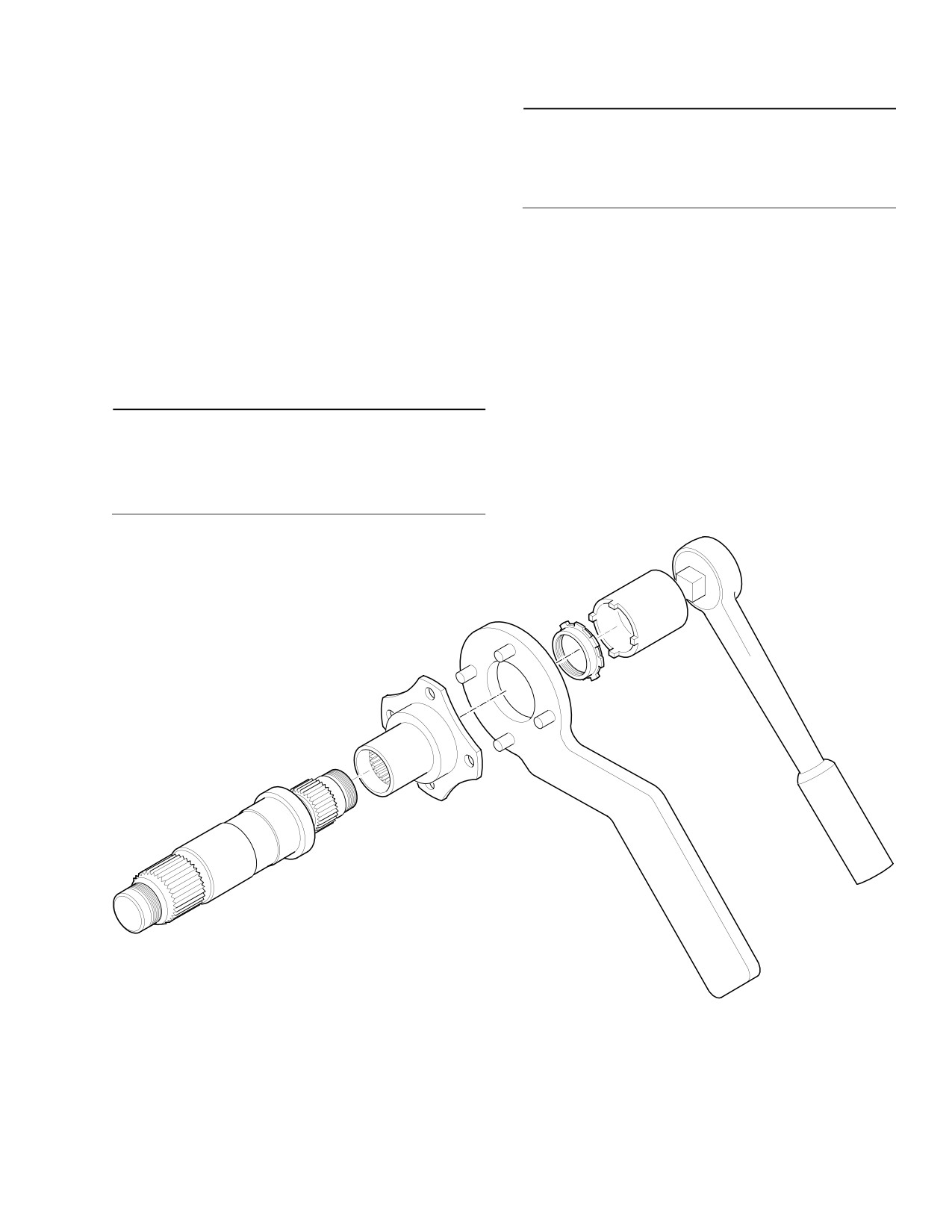
(1). Remove nut from shaft using coupling
socket (ST604) and coupling holding
10. Transmission Coupling / Fan Coupling
fixture tool; remove coupling.
Replacement
B. Transmission Coupling / Fan Coupling
(Ref. Figure 202)
Installation
(1). Slide coupling onto support shaft.
Consumable Materials
(2). Install nut using anti-seize compound
(Ref. Section 91−00−00)
(CM113) as required. Torque nut to 800
Item
Nomenclature
- 1000 inch-pounds (90.39 - 112.98
CM113
Anti-seize compound low temperature
Nm) plus drag torque using coupling
socket (ST604) and holding fixture.
G63-1023A
Figure 202. Fan Interconnect Drive Shaft Coupling Installation
Page 207
63-15-30
Revision 20
CSP-HMI-2
MD Helicopters, Inc.
MAINTENANCE MANUAL
This Page Intentionally Left Blank
Page 208
Revision 43
63-15-30
MD Helicopters, Inc.
CSP-HMI-2
MAINTENANCE MANUAL
Section
63−20−00
369D25100 Main
Transmission
(369D/E/FF − 500N)
MD Helicopters, Inc.
CSP-HMI-2
MAINTENANCE MANUAL
P/N 369D25100
369D25100 MAIN TRANSMISSION
MAINTENANCE PRACTICES
1. Main Transmission
(7). Drain oil from transmission.
The main transmission is secured to the
(8). Disconnect tail rotor output shaft seal
underside of the main rotor mast support
drain line, input shaft seal drain line
structure pan by four structure bolts, washers,
and two hoses that attach to lubrication
and nuts. The transmission is a two-stage
pump.
speed reduction unit. The first reduction stage
is for the tail rotor drive system and accessory
(9). With assistance, support transmission;
drive trains. The second stage is for further
then remove four nuts and washers
reducing rpm for the main rotor. The transmis
from mast support structure studs.
sion housing is magnesium alloy. The accesso
ry gear train drives a rotor tachometer
Lower transmission with ex
generator and the transmission oil pump that
CAUTION
treme care to prevent contact
are mounted on drive pads at the aft end of the
between tail rotor drive coupling and sur
transmission. The transmission is cooled by air
rounding structure. Any dents, nicks or
drawn through a cooling blower and routed
scratches on coupling diaphragm requires
through the transmission oil cooler. Access to
that coupling be scrapped. Use care to pro
the main transmission is attained by entrance
tect oil pressure sender and chip detector
into the passenger compartment.
terminal studs from damage during handl
ing or when placing transmission on any
2. Main Transmission Buildup and
surface.
Replacement
A. Main Transmission Removal
(10). With assistance, carefully lower
transmission from mounting studs.
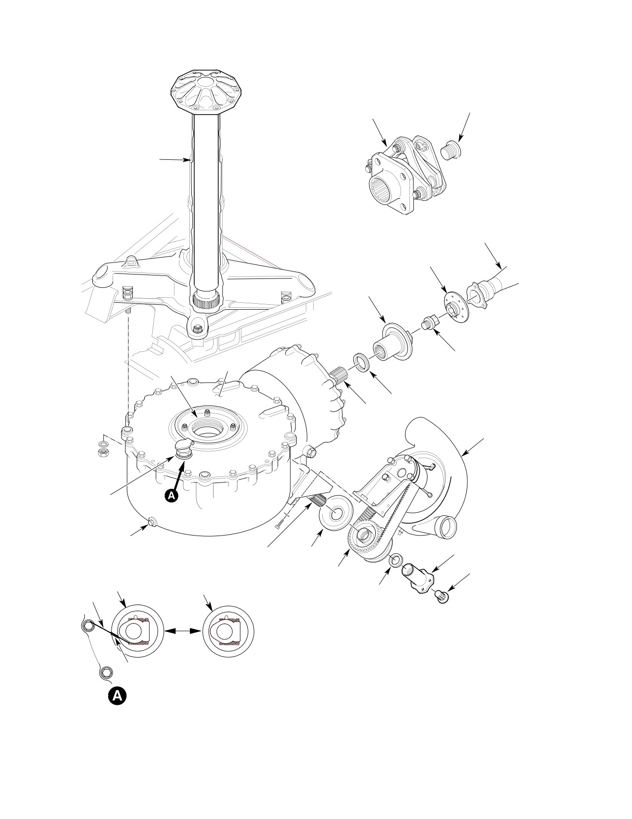
(Ref. (Ref. Figure 201)
NOTE: Cover top opening of transmission to
(1). Remove sound insulation and transmis
prevent entry of foreign material. Residual
sion access covers (Ref. Sec. 52-40-00).
operating lubricant is an approved preser
vative for transmission shipment or storage.
(2). Remove main transmission drive shaft
(Ref. Sec. 63-10-00).
(11). Perform the following steps as applica
ble to strip main transmission.
(3). Remove cooling blower (Ref. Sec.
63-21-00).
(a). Remove tachometer generator.
(4). Remove anti-torque drive shaft (Ref.
Sec. 63-15).
(b). Remove coupling bolt, coupling and
shim from tail rotor output shaft.
NOTE: Removal of main rotor drive shaft (step
e. below) is optional. If help is not available
(12). Remove coupling bolt, coupling, shim,
to rotate rotor hub for spline alignment,
drive pulley and pulley guard from
shaft removal simplifies reinstallation of
main transmission input shaft.
transmission.
(a). Remove input shaft seal drain
(5). Remove main rotor drive shaft (Ref.
connector (Ref. Figure 202).
Sec. 63-10-00).
(6). Disconnect wires from tachometer
(b). Install suitable covers and plugs to
generator, two chip detectors and oil
protect all openings, including
pressure sender.
threaded holes.
Page 201
63-20-00
Revision 20
CSP-HMI-2
MD Helicopters, Inc.
MAINTENANCE MANUAL
P/N 369D25100
COUPLING BOLT
COUPLING (KAMATIC)
MAIN ROTOR
DRIVE SHAFT
TAIL ROTOR
MAST BASE
DRIVE SHAFT
FAILSAFE SOCKET
(NOTE 2)
COUPLING
(BENDIX)
FAILSAFE COUPLING
DEBRIS
BOLT
COVER
OUTPUT SHAFT
LAMINATED SHIM
OUTPUT SHAFT
COOLING BLOWER
FILLER
PLUG
COUPLING
O-RING
INPUT SHAFT PULLEY GUARD
(NOTE 1)
INTERNAL-
PULLEY
SEAL
SEAL
WRENCHING
(NOTE 3)
BOLT
(NOTE 3)
LAMINATED SHIM
SAFETY WIRE
ÇÇÇÇ ÇÇÇÇ
Ç ÇÇ ÇÇ ÇÇ
ÇÇÇÇ ÇÇÇÇ
ÇÇÇ ÇÇÇ NOTES:
SEALANT
1.
O-RING MUST BE CEMENTED IN PLACE BEFORE INSTALLING TRANSMISSION.
(NOTE 4)
2.
NOT USED WITH KAMATIC COUPLING.
3.
SEAL MUST BE CEMENTED IN PLACE BEFORE INSTALLING TRANSMISSION.
FILLER SEAL INSTALLATION
4.
FILL CUT IN SEAL WITH SEALANT (CM430).
G63-2004B
Figure 201. 369D25100 Main Transmission Installation
Page 202
Revision 20
63-20-00
MD Helicopters, Inc.
CSP-HMI-2
MAINTENANCE MANUAL
P/N 369D25100
B. Main Transmission Installation
especially area contacted by O-ring on
top of transmission.
(Ref. Figure 201)
Damage to main rotor drive
CAUTION
shaft or main transmission
Consumable Materials
splines can occur during installation. Care
(Ref. Section 91−00−00)
should be taken while meshing drive shaft
Item
Nomenclature
splines into transmission output splines to
CM111
Grease, aircraft
prevent damage.
CM112
Anti-seize compound high temperature
(3). With assistance, slowly and evenly lift
CM121
Preservation oil
and position transmission in place on
CM125
Oil
mounting studs.
CM126
Oil, turbine
(4). Install four washers and nuts; torque to
CM234
Solvent, dry-cleaning
60 - 80 inch-pounds (6.78 - 9.04
CM417
Cement
Nm).
CM425
Sealing compound
(5). If transmission is new, drain any
CM430
Sealant, solvent resistant
residual preservative oil. Service
transmission with lubricating oil
(CM125 or CM126) (Ref. Sec.
(1). Perform the following steps as applica
12-00-00).
ble to build up main transmission prior
to installation.
(6). Connect wiring to tachometer genera
tor, two chip detectors and oil pressure
(a).
Install one preliminary 0.010 inch
switch.
(0.250 mm) shim on tail rotor output
shaft to prevent coupling bolt from
(7). Install anti-torque drive shaft (Ref.
bottoming in shaft.
Sec. 63-15-10/30).
(b).
Coat coupling splines with grease
When reinstalling main rotor
CAUTION
(CM111) and coat bolt threads with
drive shaft, check that there is
anti-seize compound (CM112) before
no gap between shaft mounting flange and
assembly. Install shaft coupling and
rotor hub before tightening installation
temporarily tighten coupling bolt to
bolts. Gap indicates that shaft splines are
approximately 250 inch-pounds
not correctly meshed in transmission.
(28.25 Nm).
(8). If main rotor drive shaft has been
removed, apply coating of lubricating
(c).
Install tachometer generator. With
rotor brake installed, ensure electri
oil (CM121) on shaft before reinstalla
cal receptacle is at 11 o'clock position.
tion and install drive shaft (Ref. Sec.
63-10-00).
(d).
Install input shaft seal drain connec
(9). Connect tail rotor output shaft seal
tor, bonding it in place with sealing
drain line and input shaft seal drain
compound (CM425).
line and two hoses that attach to
(e).
Bond main rotor output shaft O-ring
lubrication pump.
in place with cement (CM417).
(10). Install cooling blower (Ref. Sec.
(f).
Bond filler seal to transmission with
63-21-00).
cement (CM417).
(11). Coat input drive coupling splines with
grease (CM111) and coat bolt threads
(g).
If filler is safetied to case bolt, cut a
with anti-seize compound (CM112)
small section from seal and bond in
before assembly. Install pulley guard,
place. After bonding, fill gap in seal
drive pulley, shim, coupling and
with sealant (CM430).
coupling bolt and temporarily tighten
(2). Use clean, absorbent cloth to clean pan
coupling bolt to approximately 250
beneath main rotor mast support,
inch-pounds (28.25 Nm).
Page 203
63-20-00
Revision 20
CSP-HMI-2
MD Helicopters, Inc.
MAINTENANCE MANUAL
P/N 369D25100
NOTE: Refer to Sec. 63-10-00, Main Transmis
4. Main Transmission Repair Procedure
sion Drive Shaft Installation for coupling
(Ref. Figure 201) Replace electrical compo
shimming, coupling torque and drive shaft
nents, breather-filler, filler screen, externally
installation.
accessible O-rings, lubrication pump, filter,
input shaft oil seal and tail rotor output shaft
oil seal if defective. Dents in outer surface of
(12). Install main transmission drive shaft
transmission housing deeper than 0.10 inch or
(Ref. Sec. 63-10-00).
covering more than 0.60 square inch (3.87 cm2)
area require replacement of transmission (for
repairs not covered in this section, Ref. COM).
(13). Ground run helicopter (refer to appro
This procedure is applicable to dents not
priate PFM) and check drive system for
exceeding specified limits.
excessive vibration and unusual noise.
Verify absence of oil over-temperature
and low pressure indications. Inspect
Consumable Materials
for oil leakage.
(Ref. Section 91−00−00)
Item
Nomenclature
CM234
Solvent, dry-cleaning
(14). Install access covers and sound insula
CM318
Primer
tion (Ref. Sec. 52-40-00).
CM411
Adhesive, epoxy
CM801
Abrasive paper, silicon carbide
3. Main Transmission Inspection Procedure
NOTE: Any evidence of lubricating oil leakage
(Ref. Figure 201) The following procedures provide
in a repair area requires replacement of
information for checking the main transmission
transmission.
for oil leakage and mechanical defect.
(1). Clean area with solvent (CM234) and
(1). Remove sound insulation and transmis
remove sharp edges with grade 320
sion access covers (Ref. Sec. 52-40-00).
abrasive paper (CM801).
(2). Apply coat of primer (CM318) on
repaired surface.
(2). Inspect transmission for oil leaks,
cracks, corrosion, secure electrical
(3). If dent is deeper than 0.030 inch (0.76
connections and correct oil level.
mm), fill depression with epoxy adhe
Evaluate oil leakage according to Fluid
sive (CM411) and blend to surrounding
Leak Analysis.
surfaces.
(4). Touch up re-worked area with paint
(Ref. Sec. 20-30).
Inspect all fluid lines for ade
CAUTION
quate clearance between struc
5. Input Drive Assembly − Oil Leakage
ture and components. Vibration may cause
Repair Procedure
chafing of lines and subsequent leaking.
(Ref. Figure 202) Use the following repair
procedure when oil leakage occurs between the
(3). Inspect four mounting flanges on main
main transmission housing and the pinion
transmission housing for corrosion and
bearing sleeve flange. Replace the
cracks. Check that transmission
369D25184-3 O-ring as follows.
mounting studs and nuts are secure.
This should be accomplished from
Consumable Materials
fuselage interior as well as exterior at
(Ref. Section 91−00−00)
main rotor mast base.
Item
Nomenclature
CM218
Alcohol, denatured
(4). Check that all safety wiring is intact.
Page 204
Revision 36
63-20-00
MD Helicopters, Inc.
CSP-HMI-2
MAINTENANCE MANUAL
P/N 369D25100
(1). Remove the shaft interconnect, trans
(12). Remove alignment bolts and install
mission input coupling, drive pulley
assembly aid tool halves between
and guard, and cooling blower assembly
O-ring and input bearing sleeve flange.
(Ref. Sec. 63-21-00).
(Refer to Figure 203 for locally fabri
cated assembly aid tool.)
(2). Drain oil from input drive assembly
through the lower chip detector plug
(13). Install attaching hardware in blower
(Ref. Sec. 12-00-00).
mount, input pinion bearing sleeve, and
assembly aid tool.
(3). Remove attaching hardware securing
blower mount assembly (Ref. Sec.
(14). Tighten attaching hardware as follows:
63-21-00).
(a). Maintain an inward preload of the
(4). Install four alignment bolts in place of
assembly aid tool halves against the
attaching hardware for blower mount
input pinion bearing sleeve while
assembly. (Use any type of 2.00 inch
tightening the four attaching bolts
(5.08 cm) length x 1/4-28 diameter
equally.
bolt.)
(b). Tighten hardware until attaining a
(5). Install slide hammer tool on input drive
positive clamp-up between the main
assembly pinion.
housing, assembly aid tool halves,
and input pinion bearing sleeve
NOTE:
flange.
D It may be necessary to heat main housing
to move input drive assembly.
(15). Remove attaching hardware and slide
out the assembly aid tool halves.
D Any movement of more than 0.150 inch
(3.81 mm) may cause disengagement of
(16). Ensure the O-ring is seated in main
scavenge pump drive.
housing groove.
(6).
Gently tap input drive assembly away
(17). When O-ring is seated correctly,
from main housing no more than 0.150
reinstall input pattern shim between
inch (3.81 mm) to gain access to O-ring
main housing and input pinion bearing
between main housing and input
sleeve flange and reinstall hardware.
pattern shim.
(18). Tighten attaching hardware as follows:
(7).
Remove slide hammer tool from input
drive assembly pinion.
(a). Maintain an inward preload on input
pattern shim during the tightening
(8).
If required, cut defective O-ring for
sequence.
removal.
(9).
Clean and inspect pattern shim for
(b). Torque attaching hardware 65 - 75
distortion and ensure no overlap
inch-pounds (7.34 - 8.47 Nm).
condition exists at butt/split line of
shim.
(19). Inspect pattern shim to ensure no
overlap condition exists at butt/split
(10).
Clean area between main housing and
line.
input drive sleeve with alcohol (CM218)
to remove paint chips or other foreign
(20). Reinstall the shaft interconnect,
matter.
transmission input coupling, drive
pulley and guard, and cooling blower
(11).
Install new 369D25184-3 O-ring by
assembly (Ref. Sec. 63-21-00).
slipping over blower mount. Seat
O-ring in contact with the main
(21). Add oil to input drive assembly (Ref.
housing.
Sec. 12-00-00).
Page 205
63-20-00
Revision 36
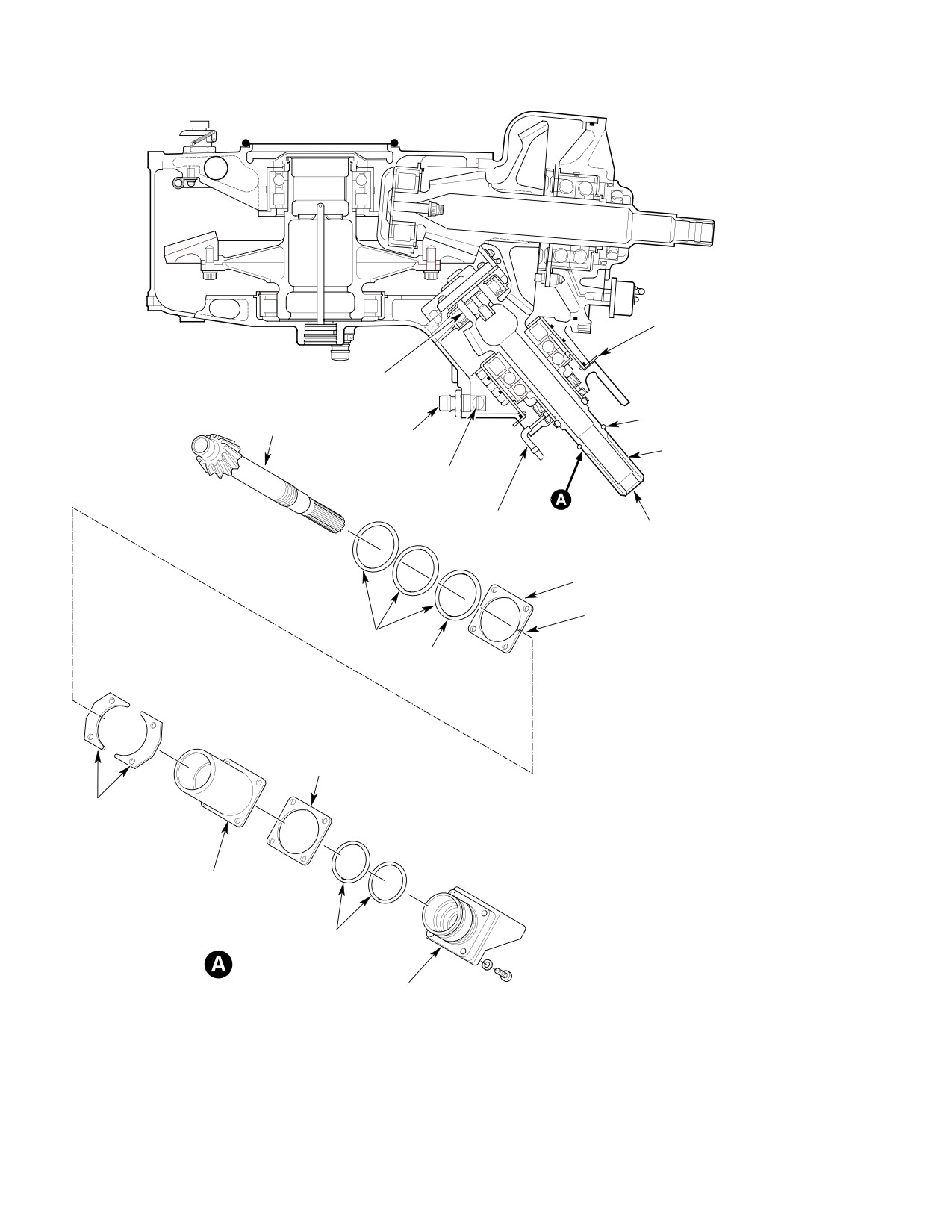
CSP-HMI-2
MD Helicopters, Inc.
MAINTENANCE MANUAL
P/N 369D25100
ASSEMBLY AID TOOL
COOLING BLOWER
MOUNTING BRACKET
SCAVENGE
PUMP DRIVE
(NOTE 1)
COOLING BLOWER
INPUT DRIVE
PULLEY SPACER
PINION
CHIP DETECTOR
INPUT SHAFT
SELF-CLOSING
DRAIN VALVE
INPUT SHAFT
NOTE 2
SEAL DRAIN
CONNECTOR
INPUT PATTERN
SHIM HALVES
NOTE 5
O-RINGS
CHANGE THIS
O-RING ONLY
NOTES:
1.
MOVEMENT IN EXCESS OF
0.15 IN. (3.81 MM) MAY CAUSE
DISENGAGEMENT OF SCAVENGE
CLAMP-UP
PUMP DRIVE.
SHIM
2.
INSTALL SLIDE HAMMER ON
INPUT DRIVE ASSEMBLY PINION.
3.
INSTALL BETWEEN O-RING AND
ASSEMBLY AID
FLANGE ON INPUT PINION
TOOL HALVES
BEARING SLEEVE.
(NOTE 3)
4.
USE SAME MOUNTING HOLES
FOR ALIGNMENT BOLTS.
5.
MOUNT SHIM WITH SPLIT AT
INPUT PINION
3 AND 9 O'CLOCK POSITION.
BEARING SLEEVE
0.000-0.030 IN. (0.000-0.762 MM)
MAXIMUM GAP ALLOWED.
MOUNTING
O-RINGS
HARDWARE
(NOTE 4)
BLOWER MOUNT
ASSEMBLY
G63-2027A
Figure 202. Input Drive Assembly O−Ring Replacement
Page 206
Revision 20
63-20-00
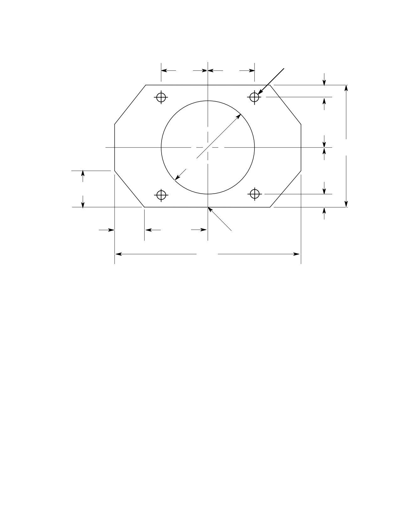
MD Helicopters, Inc.
CSP-HMI-2
MAINTENANCE MANUAL
P/N 369D25100
1.50 (3.81 CM)
1.50 (3.81 CM)
0.257 (0.653 CM) DIA
(TYP)
(TYP)
(4 PLS)
0.375 (9.53 MM)
(REF)
1.50 (3.81 CM)
(TYP)
3.750 (9.53 CM)
3.350 (8.51 CM) DIA
1.50 (3.81 CM)
(TYP)
1.250 (3.05 CM)
(4 PLS)
0.375 (9.53 MM)
(REF)
1.150
1.850
(2.92 CM)
4.70 CM)
SHIM SPLIT
(4 PLS)
(4 PLS)
(2 PLS)
6.00
(15.24 CM)
NOTES:
1.
MATERIAL - 0.070 INCH ( 1.78 MM) CRES STEEL.
2.
ALL DIMENSIONS ARE IN INCHES (CM).
G63-2028A
Figure 203. Assembly Aid Tool for Input Drive
Page 207
63-20-00
Revision 20
CSP-HMI-2
MD Helicopters, Inc.
MAINTENANCE MANUAL
P/N 369D25100
This Page Intentionally Left Blank
Page 208
Revision 44
63-20-00
MD Helicopters, Inc.
CSP-HMI-2
MAINTENANCE MANUAL
Section
63−20−25
369F5100 Main
Transmission
(369D/E/FF −
500/600N)
MD Helicopters, Inc.
CSP-HMI-2
MAINTENANCE MANUAL
P/N 369F5100
369F5100 MAIN TRANSMISSION
MAINTENANCE PRACTICES
1. Main Transmission
(8). Disconnect anti-torque output shaft
seal drain line, input shaft seal drain
The main transmission is secured to the
line and two hoses that attach to
underside of the main rotor mast support
lubrication pump.
structure pan by four structure bolts, washers,
and nuts. The transmission is a two-stage
NOTE: The following step will require an assis
speed reduction unit. The first reduction stage
tant to hold the transmission mount bolts
is for the tail rotor drive system and accessory
from the top of the helicopter and an assis
drive trains. The second stage is for further
tant to remove the nuts and washers.
reducing rpm for the main rotor. The transmis
sion housing is magnesium alloy. The accesso
(9). With assistance, support transmission;
ry gear train drives a rotor tachometer
then remove hardware securing
generator and the transmission oil pump that
transmission to mast support structure.
are mounted on drive pads at the aft end of the
transmission. The transmission is cooled by air
Lower transmission with ex
CAUTION
drawn through a cooling blower and routed
treme care to prevent contact
through the transmission oil cooler. Access to
between anti-torque drive coupling and sur
the main transmission is attained by entrance
rounding structure. Any dents, nicks or
into the passenger compartment.
scratches on coupling requires that coupling
be scrapped. Use care to protect oil pressure
2. Main Transmission Replacement
sender and chip detector terminal studs
from damage during handling or when plac
A. Main Transmission Removal
ing transmission on any surface.
(Ref. Figure 201)
(10). With assistance, carefully lower
transmission.
(1). Remove sound insulation and transmis
sion access covers.
NOTE: Cover top opening of transmission to
prevent entry of foreign material. Residual
(2). Remove main transmission drive shaft
operating lubricant is an approved preser
(Ref. Sec. 63-10-00).
vative for transmission shipment or storage.
(3). Remove cooling blower (Ref. Sec.
B. Main Transmission Installation
63-21-00).
(Ref. Figure 201)
(4). Remove anti-torque drive shaft (Ref.
Sec. 63-15-10/30).
Consumable Materials
(Ref. Section 91−00−00)
NOTE: Removal of main rotor drive shaft is op
Item
Nomenclature
tional. If help is not available to rotate rotor
hub for spline alignment, shaft removal sim
CM111
Grease, aircraft
plifies reinstallation of transmission.
CM112
Anti-seize compound high temperature
CM121
Preservation oil
(5). Remove main rotor drive shaft (Ref.
Sec. 63-10-00).
CM125
Oil
(6). Disconnect wires from tachometer
generator, two chip detectors and oil
(1). Use clean, absorbent cloth to clean pan
pressure sender.
beneath main rotor mast support,
especially area contacted by O-ring on
(7). Drain oil from transmission.
top of transmission.
Page 201
63-20-25
Revision 20
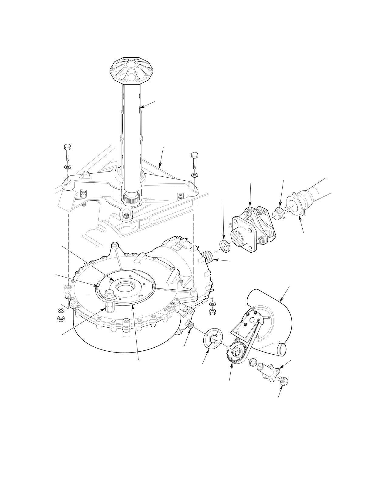
CSP-HMI-2
MD Helicopters, Inc.
MAINTENANCE MANUAL
P/N 369F5100
MAIN ROTOR DRIVE SHAFT
MAST BASE
COUPLING
COUPLING
BOLT
(KAMATIC)
LAMINATED
SHIM
TAIL ROTOR
OUTPUT
DRIVESHAFT
SHAFT
OUTPUT SHAFT
DEBRIS
COVER
COOLING BLOWER
FILLER
INPUT
SHAFT
COUPLING
O-RING
PULLEY
(NOTE)
GUARD
PULLEY
INTERNAL
WRENCHING BOLT
NOTE:
O-RING MUST BE CEMENTED IN PLACE
BEFORE INSTALLING TRANSMISSION.
G63-2032A
Figure 201. 369F5100 Main Transmission Installation
Page 202
Revision 20
63-20-25
MD Helicopters, Inc.
CSP-HMI-2
MAINTENANCE MANUAL
P/N 369F5100
Damage to main rotor drive
with anti-seize compound (CM112)
CAUTION
shaft or main transmission
before assembly.
splines can occur during installation. Care
When installing pulley and
should be taken while meshing drive shaft
CAUTION
guard, make sure the spring pin
splines into transmission output splines to
in pulley is fully engaged inside hole in
prevent damage.
pulley guard. If the spring pin does not align
NOTE: The following procedure will require
correctly with hole in pully guard, the
the assistance of another person.
torque will be incorrect.
(2). With assistance, slowly and evenly lift
(11). Install pulley guard, drive pulley, shim,
and position transmission in place.
coupling and coupling bolt and tempo
rarily tighten coupling bolt to approxi
(3). Install four washers and nuts; torque to
mately 250 inch-pounds (28.25 Nm).
900 - 1100 inch-pounds (101.69 -
124.28 Nm) plus drag torque.
NOTE: Refer to Sec. 63-10-00, Main Transmis
sion Drive Shaft Installation and for cou
(4). If transmission is new, drain any
pling shimming, coupling torque and drive
residual preservative oil. Service
shaft installation.
transmission with lubricating oil
(CM125) (Ref. Sec. 12-00-00).
(12). Install main transmission drive shaft
(Ref. Sec. 63-10-00).
(5). Connect wiring to tachometer genera
tor, two chip detectors and oil pressure
(13). Ground run helicopter (refer to appro
switch.
priate PFM) and check drive system for
excessive vibration and unusual noise.
(6). Install anti-torque drive shaft (Ref.
Verify absence of oil over-temperature
Sec. 63-15-10/30).
and low pressure indications. Inspect
When reinstalling main rotor
for oil leakage.
CAUTION
drive shaft, check that there is
(14). Install access covers and sound insula
no gap between shaft mounting flange and
tion.
rotor hub before tightening installation
bolts. Gap indicates that shaft splines are
3. Main Transmission Stripping
not correctly meshed in transmission.
(Ref. Figure 202)
(7). If main rotor drive shaft has been
removed, apply coating of preservative
(1). Remove tachometer generator.
oil (CM121) on shaft before reinstalla
tion and install drive shaft (Ref. Sec.
(2). Remove coupling bolt, coupling and
63-10-00).
shim from anti-torque output shaft.
(8). Connect anti-torque output shaft seal
(3). Remove coupling bolt, coupling, shim,
drain line and input shaft seal drain
drive pulley and pulley guard from
line and two hoses that attach to
main transmission input shaft.
lubrication pump.
(4). Remove input shaft seal drain connec
(9). Install cooling blower (Ref. Sec.
tor (Ref. Sec. 12-00-00).
63-21-00).
(5). Install suitable covers and plugs to
(10). Coat input drive coupling splines with
protect all openings, including threaded
grease (CM111) and coat bolt threads
holes.
Page 203
63-20-25
Revision 41
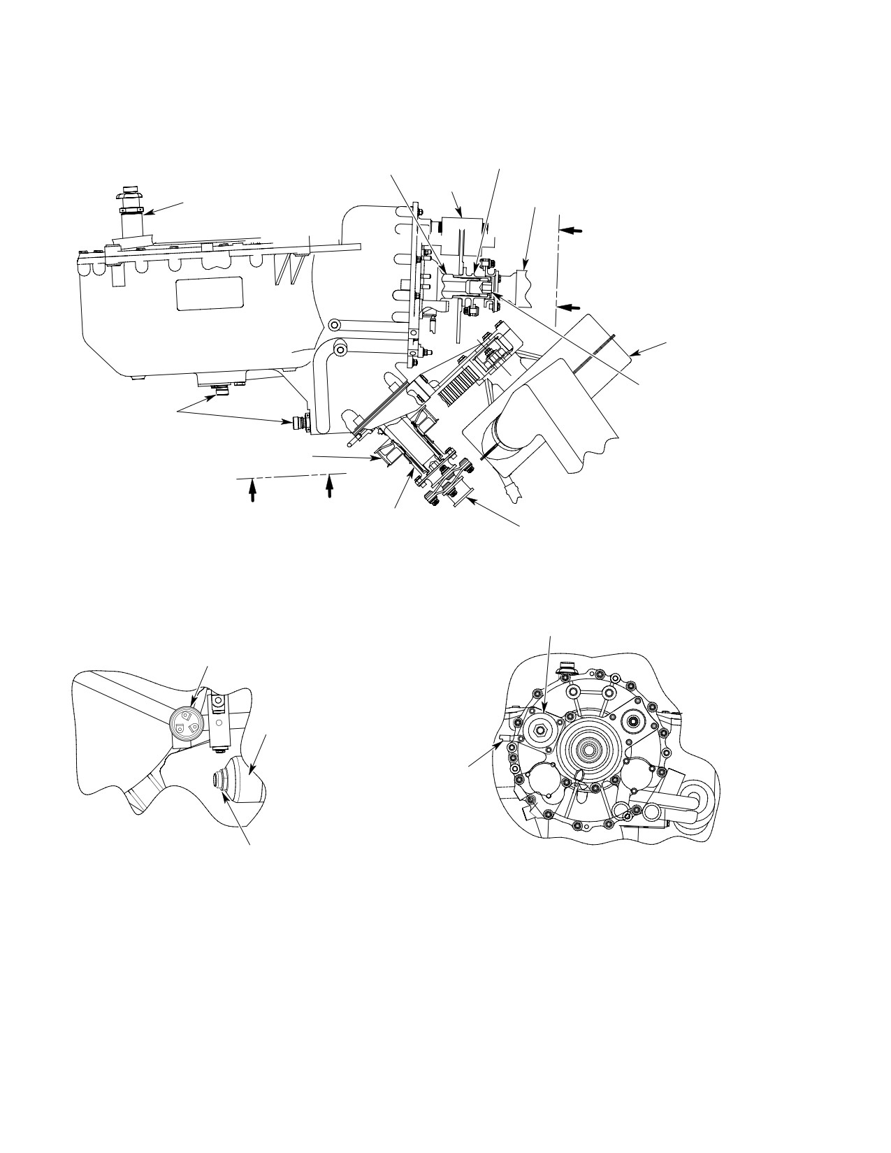
CSP-HMI-2
MD Helicopters, Inc.
MAINTENANCE MANUAL
P/N 369F5100
OUTPUT
OUTPUT
COUPLING
PINION
ROTOR
BRAKE
ANTI-TORQUE
OIL FILLER
DRIVE SHAFT
A
A
OIL COOLER
BLOWER
COUPLING BOLT
CHIP
DETECTORS
DRIVE PULLEY
B
B
INPUT
ENGINE-TO-TRANSMISSION
COUPLING
DRIVE SHAFT
SNUBBER (600N
TACH GENERATOR
ADAPTER (369D/E/FF - 500N
PACKING
PRESSURE SWITCH LOCK WIRE
TRANSMISSION
OIL FILTER
JUMPER ASSEMBLY
DIFFERENTIAL PRESSURE INDICATOR
(IMPENDING BYPASS INDICATOR)
VIEW A-A
LOOKING FORWARD
VIEW B-B
LOOKING UP
CSP102-009C
Figure 202. 369F5100 Main Transmission Build−Up
Page 204
Revision 28
63-20-25
MD Helicopters, Inc.
CSP-HMI-2
MAINTENANCE MANUAL
P/N 369F5100
4. Main Transmission Build−Up
(6). Using a new O-ring, install oil pressure
switch and safety with lockwire
(CM702).
(Ref. Figure 202)
(7). Bond main rotor output shaft O-ring in
place with cement (CM417).
Consumable Materials
(Ref. Section 91−00−00)
(8). Using two new O-rings, install exten
Item
Nomenclature
sion, screen and filler on transmission.
CM111
Grease, aircraft
Use 369A5169 shims to ensure filler is
angled no more than 30° from center
CM112
Anti-seize compound high temperature
facing forward.
CM417
Cement
CM425
Sealing compound
5. Main Transmission Inspection Procedure
CM702
Lockwire CRES
(Ref. Figure 201) The following procedures
provide information for checking the main
transmission for oil leakage and mechanical
(1).
Install one preliminary 0.010 inch
defect.
(0.254 mm) shim on anti-torque output
shaft to prevent coupling bolt from
(1). Remove sound insulation and transmis
bottoming in shaft.
sion access covers.
(2).
Coat coupling splines with grease
(2). Inspect transmission for oil leaks,
(CM111) and coat bolt threads with
cracks, corrosion, secure electrical
anti-seize compound (CM112) before
connections and correct oil level.
assembly. Install shaft coupling and
Evaluate oil leakage according to Fluid
temporarily tighten coupling bolt to
Leak Analysis.
approximately 250 inch-pounds
(28.25 Nm).
Inspect all fluid lines for ade
CAUTION
quate clearance between struc
(3).
Install tachometer generator. With
ture and components. Vibration may cause
rotor brake installed, ensure electrical
chafing of lines and subsequent leaking.
receptacle is at 11 o'clock position.
Torque nuts to 30 - 40 inch-pounds
(3). Inspect four mounting flanges on main
(3.39 - 4.52 Nm) plus drag torque.
transmission housing for corrosion and
cracks. Check that transmission
mounting nuts are secure.
(4).
Install input shaft seal drain connector,
bonding it in place with sealing com
(4). Check that all safety wiring is intact.
pound (CM425).
6. Main Transmission Repair Procedure
NOTE: On the 369F5100 transmission, the oil
pressure switch is mounted on the bottom,
(Ref. Figure 201) Replace electrical compo
right side, facing down.
nents, breather-filler, filler extension, filler
screen, externally accessible O-rings, scavenge
(5).
600N: Using a new O-ring, install
pump, lubrication pump, filter, input shaft oil
147D-2 snubber and torque to 155 -
seal and anti-torque output shaft oil seal if
165 inch-pounds (17.51 - 18.64 Nm).
defective. Dents in outer surface of transmis
369D/E/FF - 500N: Using a new
sion housing deeper than 0.10 inch (2.54 mm)
O-ring, install 369F5195-1 adapter
or covering more than 0.60 square inch (3.87
with teflon tape wrapped around
cm2) area require replacement of transmission
threads as required and torque to 155 -
(for repairs not covered in this section, Ref.
165 inch-pounds (17.51 - 18.64 Nm).
CSP-COM-5).
Page 205
63-20-25
Revision 24
CSP-HMI-2
MD Helicopters, Inc.
MAINTENANCE MANUAL
P/N 369F5100
This procedure is applicable to dents not
(3). Remove attaching hardware securing
exceeding specified limits.
blower mount assembly.
(4). Using NAS603-64 jack screws at two
Consumable Materials
corners of the input quill, begin pulling
(Ref. Section 91−00−00)
the input quill from the transmission
Item
Nomenclature
housing. As required, operators may
CM234
Solvent, dry-cleaning
use 0.5-1.0 inch (12.70-25.40 mm) bar
stock or equivalent as spacers to put
CM318
Primer
under the jack screws to assist
CM411
Adhesive, epoxy
removing the input quill.
CM801
Abrasive paper, silicon carbide
NOTE: It may be necessary to heat main hous
ing to move input drive assembly.
NOTE: Any evidence of lubricating oil leakage
in a repair area requires replacement of
(5).
Gently screw input drive assembly
transmission.
away from main housing no more than
0.150 inch (3.81 mm) to gain access to
(1). Clean area with solvent (CM234) and
O-ring between main housing and
remove sharp edges with grade 320
input pattern shim.
abrasive paper (CM801).
(6).
Remove jack screws from input drive
(2). Apply coat of primer (CM318) on
assembly pinion.
repaired surface.
(7).
If required, cut defective O-ring for
(3). If dent is deeper than 0.030 inch (0.762
removal.
mm), fill depression with epoxy adhe
sive (CM411) and blend to surrounding
(8).
Clean and inspect pattern shim for
surfaces.
distortion and ensure no overlap
condition exists at butt/split line of
(4). Touch up re-worked area with paint
shim.
(Ref. Sec. 20-30-00).
(9).
Clean area between main housing and
7. Input Drive Assembly − Oil Leakage
input drive sleeve with alcohol (CM218)
Repair Procedure
to remove paint chips or other foreign
matter.
A. Input Pinion O−Ring Replacement
(10).
Install new O-ring by slipping over
(Ref. Figure 203) Use the following repair
blower mount. Seat O-ring in contact
procedure when oil leakage occurs between the
with the main housing.
main transmission housing and the pinion
(11).
Remove alignment bolts and install
bearing sleeve flange.
attaching hardware in blower mount
and input pinion bearing sleeve.
Consumable Materials
(Ref. Section 91−00−00)
(12).
Tighten attaching hardware as follows:
Item
Nomenclature
(a). Tightening the four attaching bolts
CM218
Alcohol, denatured
equally.
(b). Tighten hardware until attaining a
(1). Remove the shaft interconnect, trans
positive clamp-up between the main
mission input coupling, drive pulley
housing and input pinion bearing
and guard, and cooling blower assembly
sleeve flange.
(Ref. Sec. 63-21-00).
(13). Remove attaching hardware.
(2). Drain oil from input drive assembly
through the lower chip detector plug
(14). Ensure the O-ring is seated in main
(Ref. Sec. 12-00-00).
housing groove.
Page 206
Revision 29
63-20-25
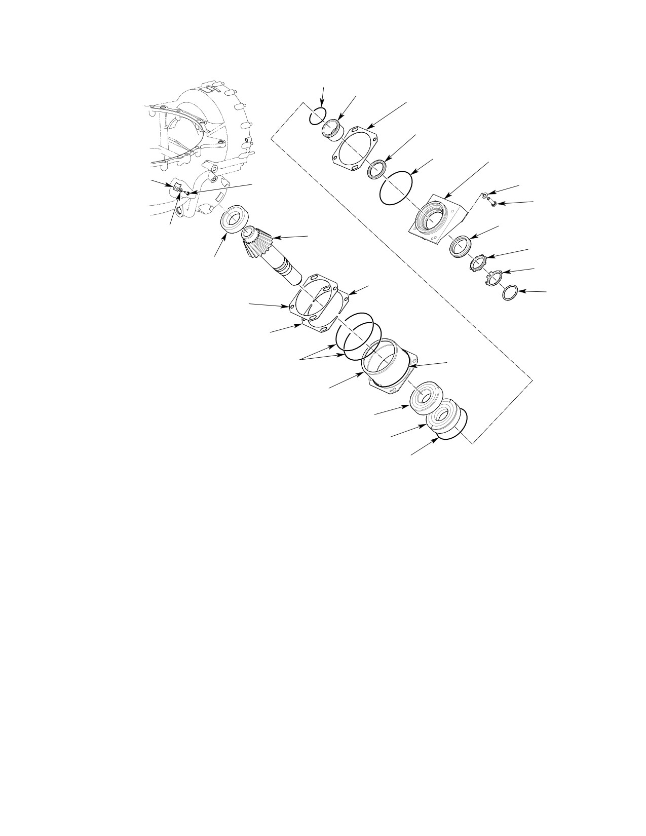
MD Helicopters, Inc.
CSP-HMI-2
MAINTENANCE MANUAL
P/N 369F5100
O-RING
SLEEVE
CRUSH SEAL
INPUT SEAL
O-RING
FAN MOUNT
BEARING RETAINER
BOLT
WASHER
BOLT
INPUT LABYRINTH SEAL
WASHER
INPUT PINION
LOCKNUT
INPUT
LOCKWASHER
NOSE BEARING
INPUT
BEARING
PULLEY SHIM
SHIM
SPACER
INPUT BEARING SHIM
O-RINGS
O-RING
INPUT SHAFT OUTER SLEEVE
INPUT BEARING
INPUT THRUST BEARING
O-RING
G63-2033B
Figure 203. Drive Assembly O−Ring Replacement
(15).
When O-ring is seated correctly,
(17). Inspect pattern shim to ensure no
reinstall input pattern shim between
overlap condition exists at butt/split
main housing and input pinion bearing
line.
sleeve flange and reinstall hardware.
(16).
Tighten attaching hardware as follows:
(18). Reinstall the shaft interconnect,
transmission input coupling, drive
(a). Maintain an inward preload on input
pulley and guard, and cooling blower
pattern shim during the tightening
assembly.
sequence.
(b). Torque attaching hardware 50 - 70
inch-pounds (5.65 - 7.91 Nm) plus
(19). Service the transmission (Ref. Sec.
drag torque.
12-00-00).
Page 207
63-20-25
Revision 29

CSP-HMI-2
MD Helicopters, Inc.
MAINTENANCE MANUAL
P/N 369F5100
B. Input Pinion Seal Replacement
(c). Insert adapter and breaker bar into
socket.
(Ref. Figure 203) Use the following repair
procedure when oil leakage occurs at the input
(d). Turn locknut removal tee counter-
pinion seal.
clockwise, while holding spline socket
stationary, to remove nut.
NOTE:
(6). Using seal removal tool, remove seal
D If replacing a magnetic seal with a la
from input quill.
brynth seal, a speedi-sleeve must be
installed (Ref. COM, Sec. 63-20-25).
(7). Clean sealant from seal seating surface
in blower mount with denatured alcohol
D If installing a 369F5165-1 labrynth seal,
(CM218).
seal must be modified (Ref. COM, Sec.
63-20-25).
(8). Allow to air dry.
(9). Apply sealing compound (CM425) to
Consumable Materials
seal edge and mating surface in blower
(Ref. Section 91−00−00)
mount.
Item
Nomenclature
CM112
Anti-seize compound high temperature
(10). Insert seal into blower mount.
CM218
Alcohol, denatured
(11). Clean any excess sealant and allow
CM425
Sealing compound
sealant to cure per manufacturer's
instructions.
Special Tools
(12). Apply anti-seize compound (CM112) to
(Ref. Section 91−00−00)
non-serrated threads on pinion and
Item
Nomenclature
install locknut.
N/A
369F5100ATP-1 Locknut removal tool
NOTE: The following procedure requires two
people to accomplish.
(1).
Remove the main transmission drive
(a). Insert tee over locknut and put
shaft (Ref. Sec. 63-10-00, Main
cheater bar over one ear of tee.
Transmission Drive Shaft Replace
ment).
(b). Insert socket through center of tee to
engage splines on input shaft.
(2).
Remove nut from transmission input
coupling, drive pulley and guard (Ref.
(c). Insert adapter and breaker bar into
Sec. 63-10-00, Main Transmission
socket.
Drive Shaft Replacement), keep all
shims with coupling.
(d). Turn input shaft counter-clockwise,
while holding locknut stationary, to
(3).
Drain oil from input drive assembly
install nut.
through the lower chip detector plug
(e). Torque nut to 250 foot-pounds (339
(Ref. Sec. 12-00-00).
Nm). Loosen locknut and re-torque
(4).
Remove lockwasher.
to 183 - 225 foot-pounds (248 -
305 Nm).
(5).
Using locknut removal tool, remove
locknut.
(13). Install lockwasher.
NOTE: The following procedure requires two
(14). Reinstall input coupling with shims
people to accomplish.
previously removed (Ref. Sec.
63-10-00, Main Transmission Drive
(a). Insert tee over locknut and put
Shaft Replacement).
cheater bar over one ear of tee.
(15). Reinstall main transmission drive shaft
(b). Insert socket through center of tee to
(Ref. Sec. 63-10-00, Main Transmission
engage splines on input shaft.
Drive Shaft Replacement).
Page 208
Revision 29
63-20-25
MD Helicopters, Inc.
CSP-HMI-2
MAINTENANCE MANUAL
P/N 369F5100
(16). Service transmission (Ref. Sec.
9. Main Transmission Run−In Procedure
12-00-00).
New (from the factory) transmissions must
have a run-in period to remove the corrosion
8. Main Transmission Filter Replacement
preventive coating from the coast-side of the
(Ref. Figure 202)
drive gears. If not done at installation, the
coating will come off, over time, and cause the
(1).
Remove interior trim and blower access
impending bypass button to pop.
door.
(1). Fly aircraft normally, monitoring the
(2).
Position container or cloth to catch
transmission chip detectors for metal
residual oil. Loosen and remove filter
particles, for the first 10 hours.
housing by turning counterclockwise.
NOTE: Ignore the impending bypass indicator
(3).
Remove filter element.
in the first 10 hours of flight.
(4).
Inspect filter element for metal par
(2). During the first 10 hours of flight time,
ticles. If metal particles are present,
perform at least three partial autorota
remove main transmission chip detec
tions (Ref. Pilots Flight Manual) to load
tors and inspect for other evidence of
the transmission on the coast side of
internal failure in gearbox.
the gears.
(5).
If filter is excessively clogged, flush
NOTE: Each autorotation should be at least 30
system and check filter bypass valve for
seconds in duration.
operation (Ref. COM).
(3). After 10 hours flight time has elapsed,
(6).
Install new filter element and new
replace filter element (Ref. Main
O-rings.
Transmission Filter Replacement).
(7).
Install housing and torque to 90 - 100
NOTE:
inch-pounds (10.17 - 11.30 Nm).
D Coating particles are black in color. Some
silver non-magnetic metallic particles
(8).
If necessary, replenish transmission oil
could be in the filter bowl, which are mag
supply.
nesium machining debris from manufac
turing.
(9).
Perform ground runup of helicopter and
check for oil leakage.
D Flushing transmission oil is preferred but
not necessary.
(10).
Reinstall, in order, blower access door
and interior trim.
(4). Reset the impending bypass indicator.
Page 209
63-20-25
Revision 29
CSP-HMI-2
MD Helicopters, Inc.
MAINTENANCE MANUAL
P/N 369F5100
This Page Intentionally Left Blank
Page 210
Revision 44
63-20-25
MD Helicopters, Inc.
CSP-HMI-2
MAINTENANCE MANUAL
Section
63−21−00
Main Transmission
Lubrication and
Cooling System
(369D/E/FF −
500/600N)
CSP-HMI-2
MD Helicopters, Inc.
MAINTENANCE MANUAL
This Page Intentionally Left Blank
MD Helicopters, Inc.
CSP-HMI-2
MAINTENANCE MANUAL
MAIN TRANSMISSION LUBRICATION
AND COOLING SYSTEM
REMOVAL/INSTALLATION
1. Main Transmission Lubrication System
(4). Ground run helicopter (Ref. PFM) and
check pump interface for leaks per
The main transmission lubrication system
Fluid Leak Analysis (Ref. Sec. 63-20).
consists of a lubrication pump driven by the
Verify that pressure warning light is
transmission, an oil filter, oil cooler, oil cooler
not on at 55% N2.
bypass valve, oil temperature sender, oil
pressure sender, liquid level plug, two chip
(5). Reinstall access covers and sound
detectors, a drain line from the tail rotor
insulation.
output shaft seal and a drain line from the
input shaft seal.
3. Main Transmission Lubrication Pump
Replacement (369F5100 Transmission)
2. Main Transmission Lubrication Pump
Replacement (369D25100 Transmission)
(Ref. Figure 402)
(Ref. Figure 401)
A. Main Transmission Lubrication Pump
A. Main Transmission Lubrication Pump
Removal (369F5100 Transmission)
Removal (369D25100 Transmission)
(1). Remove sound insulation and transmis
(1). Remove sound insulation and transmis
sion access covers (Ref. Sec. 52-40).
sion access covers.
(2). Remove hardware that secure pump
(2). Remove hardware that secure pump
housing to mounting pad.
housing to mounting pad.
(3). Remove pump and discard O-rings.
(3). Remove pump and discard three
O-rings.
B. Main Transmission Lubrication Pump
B. Main Transmission Lubrication Pump
Installation (369F5100 Transmission)
Installation (369D25100 Transmission)
Consumable Materials
Consumable Materials
(Ref. Section 91−00−00)
(Ref. Section 91−00−00)
Item
Nomenclature
Item
Nomenclature
CM114
Petrolatum
CM114
Petrolatum
(1). Install new O-rings in ports and in
(1). Install new O-rings in ports and in
groove of pump sleeve. Apply light
groove of pump sleeve. Apply light
coating of petrolatum (CM114) to both
coating of petrolatum (CM114) to both
O-rings and mating bores in transmis
O-rings and mating bores in transmis
sion to prevent damage to O-rings.
sion to prevent damage to O-rings.
(2). Align square drive of pump with drive
(2). Align square drive of pump with drive
shaft in transmission and carefully
shaft in transmission and carefully
press pump into place.
press pump into place.
(3). Install attaching hardware; torque to
(3). Install attaching hardware; torque to
50 - 70 inch-pounds (5.65 - 7.91
40 - 50 inch-pounds (4.52 - 5.65 Nm)
Nm).
plus drag torque.
Page 401
63-21-00
Revision 20
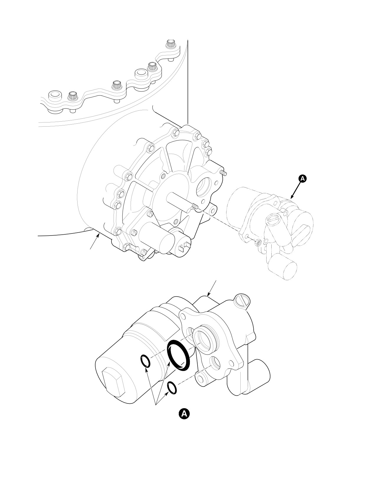
CSP-HMI-2
MD Helicopters, Inc.
MAINTENANCE MANUAL
MAIN TRANSMISSION
LUBRICATION PUMP
O-RINGS
ROTATED
63-2008
Figure 401. Main Transmission Lubrication Pump (369D25100 Transmission)
Page 402
Revision 20
63-21-00
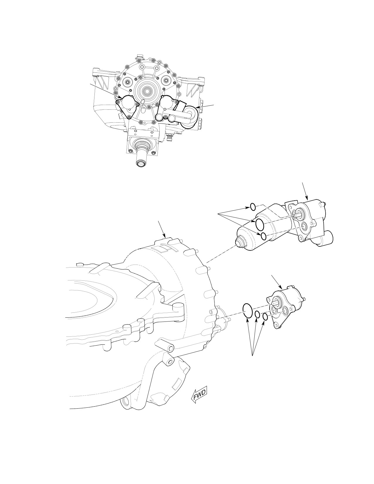
MD Helicopters, Inc.
CSP-HMI-2
MAINTENANCE MANUAL
SCAVENGE
OIL PUMP
LUBRICATION
PUMP
LOOKING FORWARD
LUBRICATION
PUMP
0-RINGS
MAIN
TRANSMISSION
DIFFERENTIAL PRESSURE INDICATOR
(IMPENDING BYPASS INDICATOR)
SCAVENGE OIL PUMP
0-RINGS
6G63-002A
Figure 402. Main Transmission Lubrication Pump (369F5100 Transmission)
Page 403
63-21-00
Revision 28
CSP-HMI-2
MD Helicopters, Inc.
MAINTENANCE MANUAL
(4). Ground run helicopter (Ref. PFM) and
tors and inspect for other evidence of
check pump interface for leaks per
internal failure in gearbox.
Fluid Leak Analysis (Ref. Sec. 63-20).
(5). If filter is excessively clogged, flush
Verify that pressure warning light is
system and check filter bypass valve for
not on at 55% N2.
operation (Ref. COM).
(5). Reinstall access covers and sound
(6). Install new filter element and new
insulation (Ref. Sec. 52-40).
O-rings.
4.
Main Transmission Filter Replacement
(7). Install and tighten housing.
(369D25100 Transmission)
(8). If necessary, replenish transmission oil
(1).
Remove interior trim and blower access
supply; then perform ground runup of
door.
helicopter and check split line for oil
(2).
Position container or cloth to catch
leakage.
residual oil. Loosen and remove filter
(9). Reinstall blower access door and
housing by turning counterclockwise.
interior trim.
(3).
Remove filter element.
6. Main Transmission Scavenge Pump
(4).
Inspect filter element for metal par
Replacement (369F5100 Transmission)
ticles. If metal particles are present,
remove main transmission chip detec
(Ref. Figure 402)
tors and inspect for other evidence of
A. Main Transmission Scavenge Pump
internal failure in gearbox.
Removal (369F5100 Transmission)
(5).
If filter is excessively clogged, flush
(1). Remove sound insulation and transmis
system and check filter bypass valve for
sion access covers (Ref. Sec. 52-40).
operation (Ref. COM).
(2). Remove hardware that secure pump
(6).
Install new filter element and new
housing to mounting pad.
O-rings.
(3). Remove pump and discard O-rings.
(7).
Install housing and torque to 70 - 100
inch-pounds (7.91 - 11.30 Nm).
B. Main Transmission Scavenge Pump
Installation (369F5100 Transmission)
(8).
If necessary, replenish transmission oil
supply; Then perform ground runup of
helicopter and check for oil leakage.
Consumable Materials
(Ref. Section 91−00−00)
(9).
Reinstall, in order, blower access door
Item
Nomenclature
and interior trim.
CM114
Petrolatum
5.
Main Transmission Filter Replacement
(369F5100 Transmission)
(1). Install new O-rings in ports and in
groove of pump sleeve. Apply light
(1). Remove interior trim and blower access
coating of petrolatum (CM114) to both
door.
O-rings and mating bores in transmis
(2). Position container or cloth to catch
sion to prevent damage to O-rings.
residual oil. Loosen and remove filter
(2). Align square drive of pump with drive
housing by turning counterclockwise.
shaft in transmission and carefully
(3). Remove filter element.
press pump into place.
(4). Inspect filter element for metal par
(3). Install attaching hardware; torque to
ticles. If metal particles are present,
40 - 50 inch-pounds (4.52 - 5.65 Nm)
remove main transmission chip detec
plus drag torque.
Page 404
Revision 20
63-21-00
MD Helicopters, Inc.
CSP-HMI-2
MAINTENANCE MANUAL
(4). Ground run helicopter (Ref. PFM) and
NOTE: MDHS Notice DN-72.1 provides in
check pump interface for leaks per
structions for modifying oil cooler drain sys
Fluid Leak Analysis (Ref. Sec. 63-20).
tem on early model helicopters to current
configuration.
7. Main Transmission Oil Cooler Bypass
(3). Remove oil drain tube and drain fitting.
Valve Replacement
(4). Detach oil cooler outlet duct.
(Ref. Figure 403) The oil cooler bypass valve
causes main transmission lubrication oil to
(5). Remove compressor cooling duct and
bypass the oil cooler when oil temperature is
pull oil cooler outlet duct away from oil
178° ±2°F (82° ±1°C) or less, or the following
cooler.
conditions exist: pressure differential of 25 psi
(6). Remove hardware that secures oil
(172 kPa) or higher across oil cooler with oil
cooler and oil cooler inlet duct to
temperature of 190°F (88°C) or higher.
firewall; remove oil cooler.
Excessive transmission oil temperature can be
caused by failure of oil cooler bypass valve to
(7). Remove covers from oil cooler by
seat in housing. Before installing new valve,
breaking lockwire and cutting sealant.
inspect seat within housing. If housing seat is
damaged, housing must also be replaced.
NOTE: MDHS Notice DN-23.2 contains infor
mation relative to installation of oil cooling
lines.
Consumable Materials
(Ref. Section 91−00−00)
B. Main Transmission Oil Cooler Installation
Item
Nomenclature
CM112
Anti-seize compound high temperature
Consumable Materials
(Ref. Section 91−00−00)
Item
Nomenclature
(1). Prepare container for draining oil from
transmission oil cooler lines upstream
CM112
Anti-seize compound high temperature
of bypass valve housing through bypass
CM408
Adhesive, silicone rubber
valve port. Unscrew valve and drain oil
CM702
Lockwire CRES
in container. Install an AN806-12 plug
CM715
Tape, pressure sensitive
in housing to eliminate residual drip.
(2). Apply light coat of antiseize compound
(1).
Scrape old sealant and remnants of
(CM112) to valve threads and install
pressure-sensitive tape seals from oil
O-ring on valve. Torque valve to 50 -
cooler covers and reinstall covers with
60 inch-pounds (5.65 - 6.78 Nm).
(CM702) lockwire and sealant (CM408).
Use sealant to fill gaps (four places) at
(3). Replenish transmission oil lost during
ends of covers.
bypass valve removal (Ref. Sec.
12-00-00).
(2).
Make up four 0.125 inch (3.175 mm)
thick and four 0.250 inch (6.35 mm)
thick seals, all 0.750 inch (19.05 mm)
8. Main Transmission Oil Cooler
wide, from pressure-sensitive tape
Replacement
(CM715).
A. Main Transmission Oil Cooler Removal
(3).
Apply seals, fabricated in previous step,
on oil cooler and oil cooler covers. Cut
(1). Drain main transmission lubrication
holes in seals to accommodate bolts
system (Ref. Sec. 12-00-00).
(eight places).
(2). Remove two tubes that connect oil
(4).
Secure oil cooler and oil cooler inlet
cooler to oil cooler bypass valve hous
duct to firewall with four bolts, washers
ing.
and nuts.
Page 405
63-21-00
Revision 20
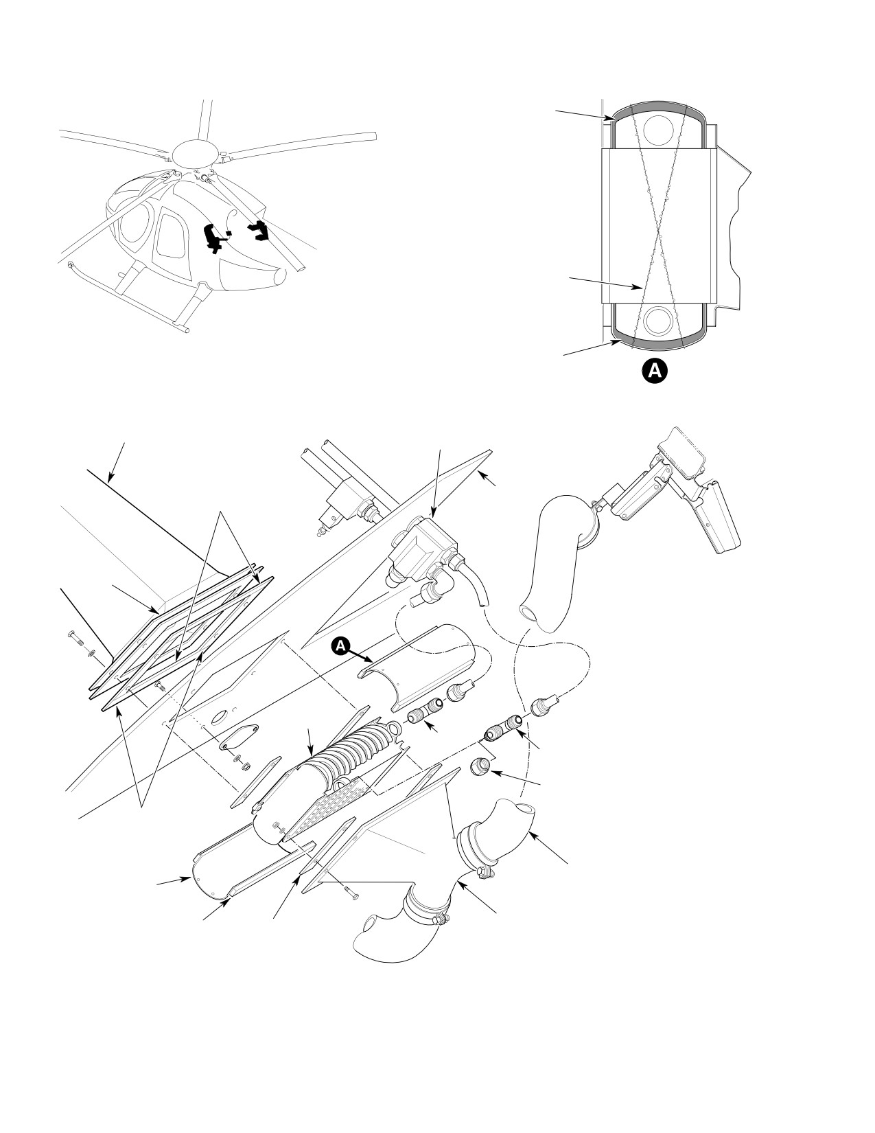
CSP-HMI-2
MD Helicopters, Inc.
MAINTENANCE MANUAL
SEALANT
LOCKWIRE
SEALANT
COOLER COVER LOCKWIRE AND
SEALANT (TYPICAL - BOTH ENDS)
OIL COOLER
OIL COOLER BYPASS
INLET DUCT
VALVE HOUSING
SEAL
0.125 X 0.50 X 7.06 IN.
FIREWALL
(3.175 X 1.270 X 179.324 MM)
DOUBLER
OIL COOLER
ELBOW
TEE
DRAIN CAP DRAIN
FITTING
SEAL
0.125 X 0.50 X 5.90 IN.
(3.175 X 1.270 X 149.86 MM)
COMPRESSOR
COVER
COOLING DUCT
(2 PLCS)
OIL COOLER
SEAL (4 PLCS)
SEAL (4 PLCS)
INLET DUCT
0.250 X 0.75 X 5.75 IN.
0.125 X 0.75 X 5.25 IN.
(6.35 X 19.05 X 146.05 MM)
(3.175 X 19.05 X 133.35 MM)
63-2002A
Figure 403. Main Transmission Oil Cooler Installation
Page 406
Revision 20
63-21-00