HANDBOOK OF MAINTENANCE INSTRUCTIONS FOR MDHI 369D/E/FF-500/600N HELICOPTERS (ISSUED: 1990) - page 23
MD Helicopters, Inc.
CSP-HMI-2
MAINTENANCE MANUAL
bearing cage and fork (bearing turns in
pounds (6.672-22.24 N). If load is not
fork). If failure is noted, remove bearing
within specified limit, replace bearing.
and rebond in fork according to instruc
(8). Reinstall rubber blade stop.
tions in the COM.
(2).
Teeter blades stop-to-stop. Observe
four radial molded ridges on each
bearing as teetering takes place. If
ridges assume continuous curved
shape, bearings are intact. Discontinu
ity in molded ridges indicates bearing
TAIL ROTOR
failure and bearing must be replaced.
(3).
Check bearing for general condition.
Replace bearing if damaged. Evidence
of light swelling, pock marks and
STRING
SPRING SCALE
crumbs are surface conditions and are
2.00 IN.
not indications of bearing failure.
(5.08 CM)
(4).
Elastomeric bearings are suspected of
1.00 IN.
369F/FF
being unserviceable if visual inspection
(2.54 CM)
reveals rubber deterioration or separa
tion, or a vibration is reported. Perform
369D/E
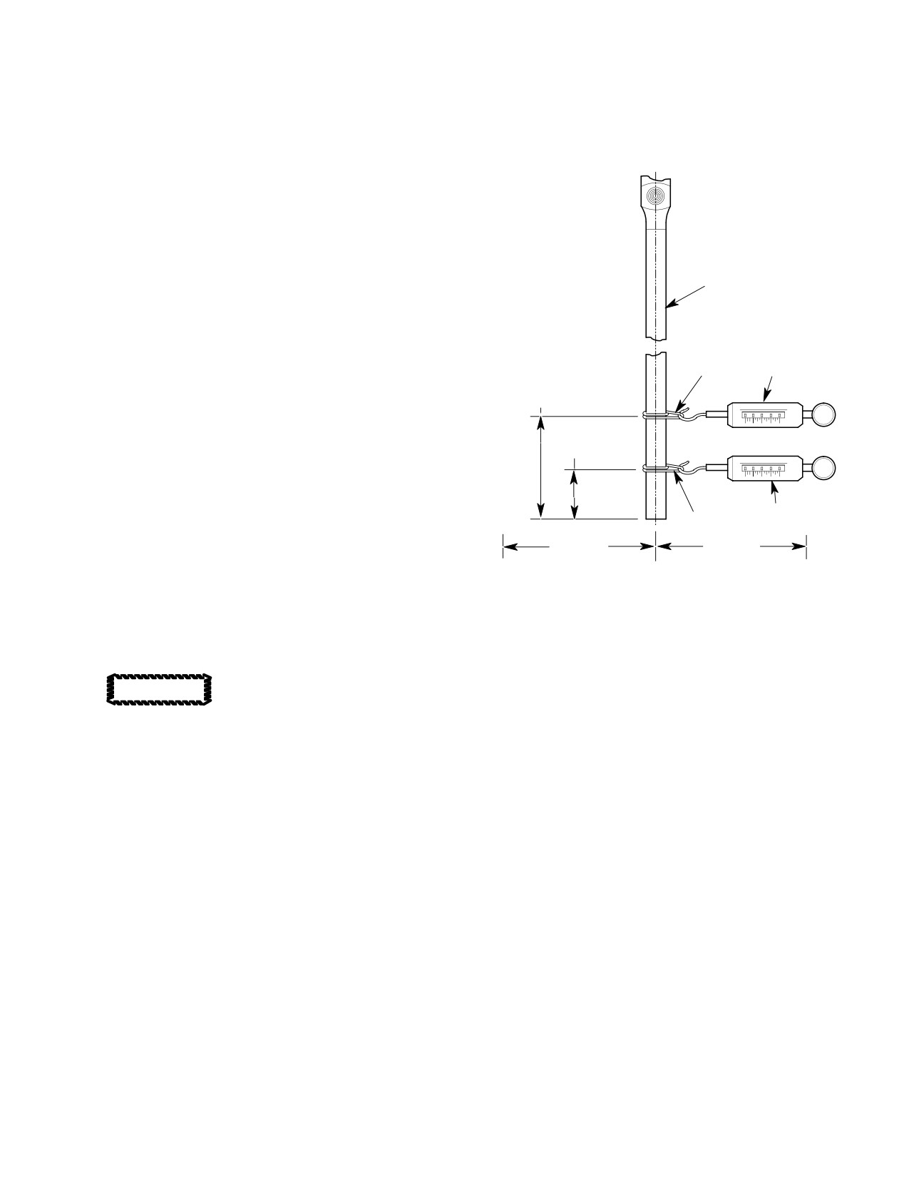
following steps to check blade flapping
SPRING SCALE
resistance measurement to determine if
STRING
suspected elastomeric bearing has
3.00 IN.
3.00 IN.
failed.
(7.62 CM)
(7.62 CM)
ZERO LOAD POSITION
(5).
To perform measurement, remove
VIEW LOOKING AFT
G64-2003A
rubber blade stop between tail rotor
hub and fork on inboard hub. The
Figure 204. Blade Flapping Resistance
outboard tail rotor assembly can be
Check
checked without any disassembly.
6.
Elastomeric Bearing Care and Cleaning
Do not remove hub-to-drive
CAUTION
Elastomeric bearings are not inherently
fork hinge bolt to remove
resistant to grease, oils or solvents if im
2-bladed tail rotor assembly. This bolt
mersed. They are, however, somewhat resis
should only be removed according to in
tant to occasional splash or spoilage of these
structions in the COM. Damage to strap
materials if exposed on an occasional basis. If
pack may occur if any other procedure is
elastomeric materials do come in contact with
used.
these fluids, the elastomer surface should be
(6). The rubber blade stop must be re
immediately cleaned. If cleaning is accom
moved. Reassemble tail rotor with
plished properly, the effect of greases, oils or
rubber blade stop removed.
solvents on the performance of the elastomeric
material will be minimal. If replacement of
(7). Measure flapping resistance of blades
elastomeric bearing is required, refer to COM.
using spring scale attached within 1.00
inch (2.54 cm) for 369D/E or 2.00 inch
(1). If greases, oils or solvents come in
(5.08 cm) for 369FF inboard of blade tip
contact with the elastomeric material,
(Ref. Figure 204). Block or hold tail
wipe immediately with clean, dry rag.
rotor pedal in neutral position. While
(2). If wiping is not sufficient (oil or grease
pulling 90 degrees from plane of
is too thick), clean the affected area of
rotation, record spring scale value when
the elastomer with a soft bristle brush
blade tip is 3.00 inches (7.62 cm)
and a solution of pure soap and water.
inboard and outboard from no-load
position. Scale must indicate 1.5-5.0
(3). Rinse with tap water.
Page 207
64-20-00
Revision 21
CSP-HMI-2
MD Helicopters, Inc.
MAINTENANCE MANUAL
This Page Intentionally Left Blank
Page 208
Revision 44
64-20-00
MD Helicopters, Inc.
CSP-HMI-2
MAINTENANCE MANUAL
Section
64−25−30
Anti−Torque Fan
(500/600N)
MD Helicopters, Inc.
CSP-HMI-2
MAINTENANCE MANUAL
ANTI−TORQUE FAN
REMOVAL/INSTALLATION
1. Anti−Torque Fan Assembly
(8). Remove fan from helicopter.
The purpose of the fan is to provide anti-tor
B. Anti−Torque Fan Installation
que control using a variable flow of air, across
variable pitch blades, down the tailboom. The
Consumable Materials
anti-torque fan liner, felt metal seal, provides
(Ref. Section 91−00−00)
a controlled gap between the fan and the felt
Item
Nomenclature
metal seal for optimum efficiency of the fan
CM702
Lockwire CRES
during flight.
NOTE: The NOTARr anti-torque control sys
(1).
Align and install fan assembly on
tem must be re-rigged immediately after re
support shaft.
placement of any component, control rods,
or linkages, and if helicopter operation re
(2).
Install washer on shaft.
veals a rigging deficiency.
(3).
Install locknut and torque nut to 40 -
2. Anti−Torque Fan Replacement
42 foot-pounds (54 - 57 Nm). Install
lock washer.
(Ref. Figure 401 and Figure 402)
(4).
Install pitch bearing housing using six
bolts and washers, Torque bolts to 80 -
Special Tools
100 inch-pounds (9.04 - 11.30 Nm)
(Ref. Section 91−00−00)
and lockwire (CM702).
Item
Nomenclature
ST605
Fan nut socket
(5).
Install fan pitch control tube (Ref. Sec.
67-20-30, Fan Pitch Control Tube
Installation).
A. Anti−Torque Fan Removal
(6).
Install tailboom (Ref. Sec. 53-40-30).
(1).
Remove tailboom (Ref. Sec. 53-40-30).
3. Anti−Torque Fan Blade Replacement
(2).
Remove nut and lock washer from aft
(Ref. Figure 401)
tube assembly.
NOTE: When a blade needs replacement for
(3).
Remove fan pitch control tube (Ref. Sec.
any reason, whether it be service related or
67-20-30, Fan Pitch Control Tube
at overhaul, replace associated bolt, washer,
Removal).
and nut.
(4).
Remove six bolts, washers and pitch
A. Anti−Torque Fan Blade Removal
control housing from fan.
(1). Remove anti-torque fan from helicopter
(5).
Remove lock washer from nut and shaft
(Ref. Anti-Torque Fan Removal).
by releasing the holding tangs from lock
nut and pull locking ring from support
(2). Remove fan blade from strap assembly
shaft knurl.
by removing cotter pin, washer and pin.
(6).
Remove locknut in a counter-clockwise
B. Anti−Torque Fan Blade Installation
direction, using coupling socket (ST605)
and coupling holding fixture tool.
(1). Install fan blade and align retention
hole with upper strap assembly reten
(7).
Remove washer from shaft.
tion hole.
Page 401
64-25-30
Revision 41
CSP-HMI-2
MD Helicopters, Inc.
MAINTENANCE MANUAL
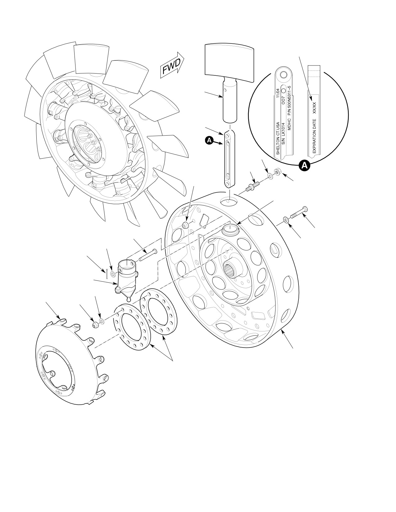
EXAMPLE OF INK MARK DATE.
BLADE
ASSY
STRAP ASSY
(NOTE 1)
WASHER
STUD
VIEW LOOKING
FORWARD
COLLAR
NUT
HUB - BLADE
BUSHING
BOLT
PIN
WASHER
WASHER
(COUNTERSUNK)
COTTER PIN
(NOTE 2)
PITCH HORN
WASHER
PITCH PLATE
NUT
FAN HUB
RETENTION PLATES
NOTE:
1. INSTALL STRAP WITH SERIAL NUMBER FACING AFT DIRECTION.
2. INSTALL WASHER WITH COUNTERSINK AGAINST BOLT-HEAD.
G64-2005C
Figure 401. Anti−Torque Fan
Page 402
Revision 42
64-25-30
MD Helicopters, Inc.
CSP-HMI-2
MAINTENANCE MANUAL
(2). Install pin, washer and cotter pin.
NOTE: Inspect strap assembly for condition
and expiration date. Pay particular atten
(3). Reinstall anti-torque fan in helicopter
tion to area around the two spools. Inspect
(Ref. Anti-Torque Fan Installation).
for cracks in the polyurethane coating. If
any cuts or breaks are found that exceed
(4). Perform fan balance check (Ref. Sec.
0.020 inch (0.508 mm) in depth or 0.25 inch
18-20-30, Fan Balance Check).
(6.35 mm) in length, replace the strap.
D Tension-torsion straps have a life limit
that starts when their package is opened.
Consumable Materials
If the date the package was opened is un
(Ref. Section 91−00−00)
known, the 5 year calendar life is based
Item
Nomenclature
on the manufacturing cure date.
CM312
Ink stamp, permanent
D Tension-torsion straps can be put back in
their package, and life limit not started, if
not out of the package more than five
4. Fan Blade Strap and Pitch Horn
days.
Replacement
(2). If tension-torsion strap is removed
from package for no more than five
(Ref. Figure 401) Remove and install the pitch
days, do the steps that follow:
horn and strap assembly using the following
procedures.
(a). Replace desiccant in package, use
desiccant (CM826).
NOTE:
NOTE: If you can not seal package; put, ten
sion-torsion strap, package, and desiccant
D The following procedure covers the indi
(CM826) in new plastic bag.
vidual removal of one strap assembly and
pitch horn. If disassembly of all is re
(b). Put tension-torsion strap in package
quired, use the following steps for each
and seal package opening with tape.
one requiring removal.
(c). Put package in box and seal box with
tape.
D When strap is replaced, replace related
bolt, washer, and nut.
(3). If replacement strap is new, remove
from package and write the words
A. Fan Blade Strap and Pitch Horn
EXPIRATION DATE on the strap face
Disassembly
and date five years after the package is
opened. Use permanent ink (CM312).
(1). Remove anti-torque fan from helicopter
(Ref. Anti-Torque Fan Removal).
(4). Make an item component record card
for each tension-torsion strap.
(2). Remove fan blade(s) (Ref. Anti-Torque
NOTE: Install tension-torsion straps so that
Fan Blade Replacement).
the cure date is in view when fan is as
(3). Remove bolt and washer retaining
sembled.
bottom half of strap assembly between
(5). Insert strap assembly thru top of fan
two retention plates.
hub and pitch horn until lower (smaller
diameter) hole is aligned between holes
(4). Remove strap assembly thru top hole of
of two retention plates.
fan hub.
(6). Install blade and align spar before
(5). Remove pitch horn from fan hub.
torquing inboard nut, this ensures
proper alignment of strap with blade.
B. Fan Blade Strap and Pitch Horn
(7). Install new bolt, washers (countersunk
Reassembly
washer against bolt-head), and nut
NOTE: Counterweights on pitch arms are set
thru holes of retention plates and of
by the factory; do not attempt to adjust.
strap assembly.
(1). Install pitch horn in fan assembly.
(8). Install fan blade(s) and torque bolts to
Ensure ball on lower side of pitch horn
100 inch-pounds (11.30 Nm) (Ref.
is inserted in bushing of pitch plate.
Anti-Torque Fan Blade Installation).
Page 403
64-25-30
Revision 42
CSP-HMI-2
MD Helicopters, Inc.
MAINTENANCE MANUAL
(9). Reinstall anti-torque fan in helicopter
A. Support Shaft Disassembly
(Ref. Anti-Torque Fan Replacement).
(1). Remove anti-torque fan from helicopter
(10). Perform fan balance (Ref. Sec.
(Ref. Anti-Torque Fan Removal).
18-20-30, Fan Balance Check).
(2). Remove fan pitch control tube (Ref. Sec.
67-20-30).
5. Retention Plate and Pitch Plate
Replacement
(3). Remove fan interconnect driveshaft
(Ref. Sec. 63-15-30).
(Ref. Figure 401) Remove and install the
retention strap and pitch plate using the
(4). Remove fan interconnect shaft coupling
following procedures.
from support shaft (Ref. Sec. 63-15-30).
A. Retention Plate and Pitch Plate
(5). Remove support shaft and fan hub
Disassembly
housing from fan support assembly by
removing four cotter pins, nuts,
(1). Remove anti-torque fan from helicopter
washers and bolts.
(Ref. Anti-Torque Fan Removal).
(6). Remove hub spacer from shaft.
(2). Remove fan blades (Ref. Anti-Torque
(7). Remove bearing retainer from support
Fan Blade Replacement).
housing.
(3). Remove strap assemblies and pitch
(8). Press shaft and fan support bearing out
horns.
of support housing.
(4). Remove pitch plate and retention plates
NOTE: Removal of bearing seal at disassembly
from fan hub.
is not required unless seals need replace
ment.
B. Retention Plate and Pitch Plate
Reassembly
(9). Remove bearing seal from support
housing and bearing retainer.
(1). Position retention plates in fan hub.
(10). Press bearing off support shaft using
NOTE: Install tension-torsion straps so that
removal ring.
the cure date is in view when fan is as
sembled.
B. Support Shaft Reassembly
(2). Install pitch horn and strap assemblies
(Ref. Strap and Pitch Horn Reassemb
Consumable Materials
ly).
(Ref. Section 91−00−00)
Item
Nomenclature
(3). Place pitch plate over retention plates
CM111
Grease, aircraft
within fan hub.
CM425
Sealing compound
(4). Install fan blades (Ref. Anti-Torque
Fan Blade Installation).
(1). Install removal ring on support shaft
until firmly seated against shoulder of
(5). Reinstall anti-torque fan in helicopter
support shaft.
(Ref. Anti-Torque Fan Installation).
(2). Install support bearing on support
6. Support Shaft Replacement
shaft.
(Ref. Figure 402) Remove and install the
(3). Install bearing seal in support housing
support shaft using the following procedures.
and bearing retainer using sealant
(CM425).
NOTE: When replacing pitch plate and/or sup
port shaft bearings, do not use 900R bear
(4). Fill seal cavity with 3.3-4.0 CCs of
ings in the 500/600N helicopters.
grease (CM111).
Page 404
Revision 41
64-25-30
MD Helicopters, Inc.
CSP-HMI-2
MAINTENANCE MANUAL
(5).
Install support bearing and shaft in
(2). Removal with Hand Tool:
support housing.
(a). Insert the applicable size hex wrench
into the pin wrenching cavity and
(6).
Install bearing retainer and align bolt
hold securely to prevent pin rotation.
holes on support housing.
(b). Rotate the collar counterclockwise
(7).
Install hub spacer on shaft.
with pliers or vise grips to remove.
(8).
Install support shaft and housing on
(c). Tap out pin with a nonmetallic-faced
fan support assembly. using four bolts,
mallet.
washers, and nuts. Torque nuts to 40 -
B. Fan Balance Stud Installation
50 inch-pounds (4.52 - 5.65 Nm).
Install cotter keys.
Pins may be reused, provided the finish has
not been marred and the threads and wrench
(9).
Install fan interconnect shaft coupling
ing cavity are in acceptable condition.
on support shaft (Ref. Sec. 63-15-30).
(10).
Install fan interconnect driveshaft (Ref.
Consumable Materials
Sec. 63-15-30).
(Ref. Section 91−00−00)
Item
Nomenclature
(11).
Install fan pitch control tube (Ref. Sec.
CM409
Adhesive, epoxy
67-20-30).
(12).
Install anti-torque fan on helicopter
(1). Apply adhesive (CM409) to pin and
(Ref. Anti-Torque Fan Installation).
insert, while wet, using a nonmetallic-
faced mallet or rivet set into hole.
(13).
Check fan balance (Ref Sec. 18-00-30,
Ensure Pin is seated flush against fan
Fan Balance Check).
hub.
(2). Manually screw the collar onto the pin
7. Fan Balance Stud Replacement
a minimum of two threads.
A. Fan Balance Stud Removal
(3). Installation with Pneumatic Tool:
The following procedure is for removal of the
(a). Insert the hex wrench tip of the
balance studs when the lock collars have
power driver into the wrenching
become loose and allow the stud to rotate.
cavity in the pin
(1). Removal with Pneumatic Tool: Pneu
(b). Press the power driver socket firmly
matic tools may be used only on
against the collar and actuate the
fasteners in interference fit holes and
driver until the collar wrenching
fasteners with aluminum collars.
device is torqued off.
(c). Withdraw the hex wrench tip from
(a). Select the applicable removal tool. Fit
the wrenching cavity and discard the
removal tool to a 0.375 inch (9.525
wrenching collar.
mm) square socket drive that will fit
a reversible screwdriver motor.
(4). Installation with hand tool:
(b). Place the collar removal tool over the
(a). Press socket from hand tool firmly
collar and press firmly.
onto collar.
(b). Insert hex wrench though center of
(c). Rotate the tool counterclockwise by
tool and hold pin to prevent it from
hand until the teeth bite into the
rotating.
collar.
(c). Turn socket clockwise, while holding
(d). Place the motor on the drive socket
hex wrench, until collar is firmly
and unscrew the collar using reverse
seated against fan hub; wrenching
drive.
collar will torque off when proper
(e). Tap out the pin with a nonmetallic-
torque is reached. Discard wrenching
faced mallet.
collar.
Page 405
64-25-30
Revision 41
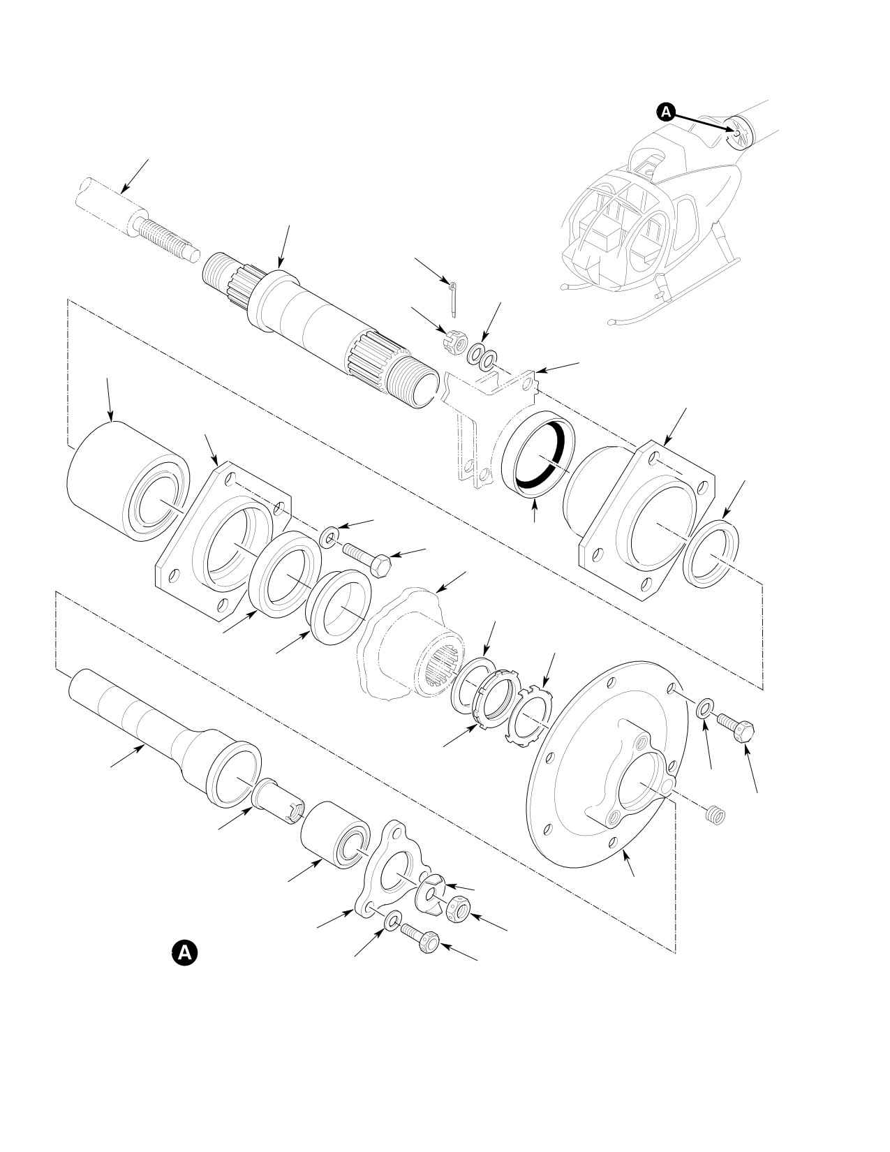
CSP-HMI-2
MD Helicopters, Inc.
MAINTENANCE MANUAL
AFT CONTROL TUBE
(REF)
SUPPORT SHAFT
COTTER KEY
WASHER
NUT
FAN SUPPORT ASSEMBLY
FAN SUPPORT
(REF)
BEARING
BEARING
HOUSING
BEARING
RETAINER
RING
WASHER
BEARING
BOLT
SEAL
FAN
(REF)
WASHER
BEARING
LOCKWASHER
SEAL
HUB
SPACER
LOCKNUT
PITCH
WASHER
SLIDER
BOLT
INNER BEARING
RETAINER
PITCH BEARING
PITCH BEARING
LOCKWASHER
HOUSING
PLATE
PITCH BEARING
NUT
RETAINER
WASHER
BOLT
G64-2006A
Figure 402. Anti−Torque Fan Support Shaft
Page 406
Revision 41
64-25-30
MD Helicopters, Inc.
CSP-HMI-2
MAINTENANCE MANUAL
8. Pitch Horn Counterweight Set Screw
NOTE: Ensure counterweight-to-pitch horn
Replacement
index mark aligns correctly. All counter
weights are indexed the same.
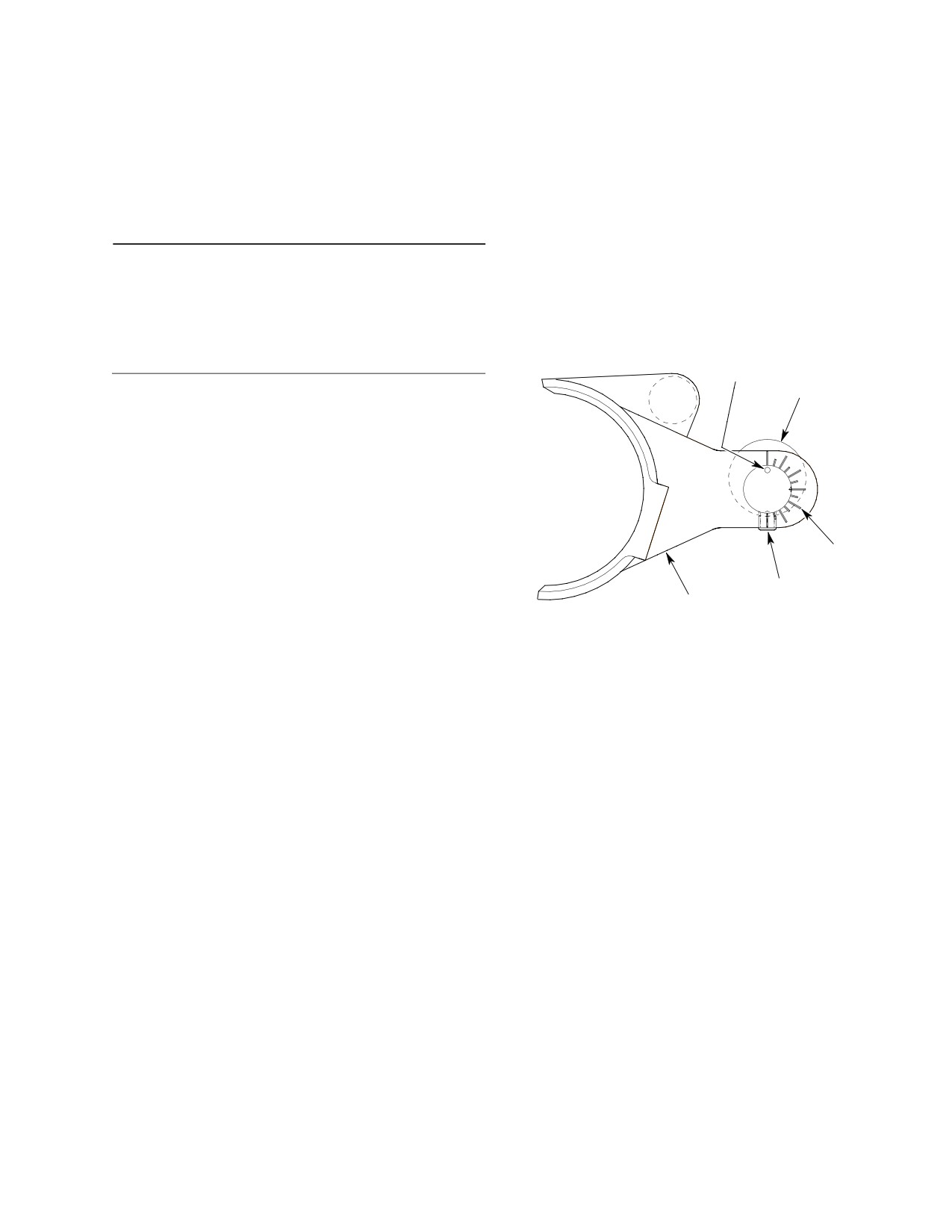
(Ref. Figure 403) If, during fan inspection, a
(7).
Align index mark on counterweight to
counterweight is found to be loose, the set
match with mark on pitch horn and
screw must be replaced.
install into pitch horn.
(8).
Apply grade B locking compound
Consumable Materials
(CM321) to threads of set screw and
(Ref. Section 91−00−00)
install into pitch horn. Tighten set
Item
Nomenclature
screw.
CM216
Loctite remover
CM321
Surface primer locking compound
COUNTERWEIGHT
INDEX MARK
COUNTERWEIGHT
(1). Apply heat to loose counterweight.
(2). Remove and discard set screw.
(3). Remove retaining ring and washer.
(4). Inspect threads in counterweight for
PITCH HORN
condition and cleanliness.
INDEX MARKS
SET SCREW
(5). Clean pitch horn threads with Loctite
PITCH HORN
remover (CM216).
G64-2011
(6). Apply grade T primer (CM321) to
threads of new set screw; allow to dry
Figure 403. Pitch Horn Counterweight Set
for 30 minutes at ambient temperature.
Screw Replacement
Page 407
64-25-30
Revision 41
CSP-HMI-2
MD Helicopters, Inc.
MAINTENANCE MANUAL
This Page Intentionally Left Blank
Page 408
Revision 34
64-25-30
MD Helicopters, Inc.
CSP-HMI-2
MAINTENANCE MANUAL
ANTI−TORQUE FAN
INSPECTION/CHECK
1. Anti−Torque Fan Inspection
(c). Scoring; axial marks from bearing
installation or removal.
Inspect the anti-torque fan for the following
conditions:
(d). Damaged spines; none allowed.
(1). All components for cracks, nicks,
(e). Corrosion and pitting.
corrosion or excessive wear.
(2). Fan support bearing for free movement
of set.
(2). Tension-torsion straps for nicks or cuts
in polyurethane coating. No exposed
(3). Fan support bearing retainer and
kevlar fibers allowed. Spools for cracks.
housing for:
(3). Hub-to-blade bushings for cracks.
(a). Cracks; none allowed.
(4). Pitch horn for excessive wear (out-of-
(b). Wear.
round condition).
(c). Scoring; axial marks from bearing
(5). Counterweights on pitch horn for
installation or removal.
security. If loose, perform Pitch Horn
(4). Bearing seals for condition.
Counterweight Set Screw Replacement.
(5). Hub spacer for cracks and wear.
NOTE: Access the forward counterweights
through the fan inlet. Fan hub fairing must
3. Anti−Torque Fan Liner (Felt Metal Seal)
be removed for access (Ref. Sec. 53-30-30).
Inspection
(6). Pitch plate bushing for excessive wear,
(1). Inspect for cracks and debonding of
grooves or cracking.
liner material.
(7). Blades for cracks, nicks or impact
(2). Inspect for cracks around the radius
damage.
cutouts of fan support.
(8). Inspect gap between fan blade and tip
(3). If cracks are found, stop drill and
seal. Inspect gap between fan blade and
inspect every 50 hours (Ref. Sec.
hub (inboard end of the blade). If gap
05-20-20).
for any blade end exceeds the average
gap of the other blades by more than
NOTE: Cracks protruding into the Felt Metal
0.10 inch (2.54 mm), remove and
Seal are unacceptable, replace seal (Ref.
inspect the tension-torsion strap for
Anti-Torque Fan Liner (Felt Metal Seal)
that blade.
Replacement).
(4). Inspect aft P-seal for tears, deteriora
2. Support Shaft Inspection
tion and debonding.
Inspect the support shaft and its associated
4. Fan Blade Inspection (100−Hour)
components as follows:
NOTE: Ensure proper pitch plate and/or sup
Consumable Materials
port shaft bearings are installed. 900R bear
(Ref. Section 91−00−00)
ings are not to be used in the 500/600N heli
Item
Nomenclature
copters.
CM437
Sealing compound
(1). Support shaft for:
(1). Inspect polypropylene portion of fan
(a). Cracks; none allowed.
blade for nicks, scratches, abrasions
(b). Wear.
and bulges; pay particular attention to
Page 601
64-25-30
Revision 42
CSP-HMI-2
MD Helicopters, Inc.
MAINTENANCE MANUAL
leading edge and area around the pin
outboard end of blade are reason for
near the outboard edge of blade.
blade rejection.
(3). Seal cracks up to 0.10 inch (2.54 mm),
(a). Nicks and abrasion pits that are less
coming from area of pin with sealing
than 0.040 inch (1.016 mm) deep and
compound (CM437).
0.25 inch (6.35 mm) in diameter may
be blended out. (No more than two
(4). If any cracks larger than 0.10 inch (2.54
such repairs can be made per blade.)
mm) are found, replace blade.
5. Fan Pitch Slider Inspection
(b). Nicks, scratches and abrasion pits
less than 0.020 inch (0.508 mm) and
(1). Inspect slider for dents, scratches,
1.5 inch (3.81 cm) long may be
nicks, gouges and corrosion, none
blended out. (Total length of all
allowed.
repairs not to exceed 2.0 inch (5.08
(2). Inspect Karon coating on slider for
cm).)
condition.
(2). Any bulges or blisters over 0.10 inch
(3). Measure across slider, minimum
(2.54 mm) long in area of pin near
diameter is 0.805 in. (20.447 mm).
Page 602
Revision 39
64-25-30

MD Helicopters, Inc.
CSP-HMI-2
MAINTENANCE MANUAL
ANTI−TORQUE FAN
REPAIRS
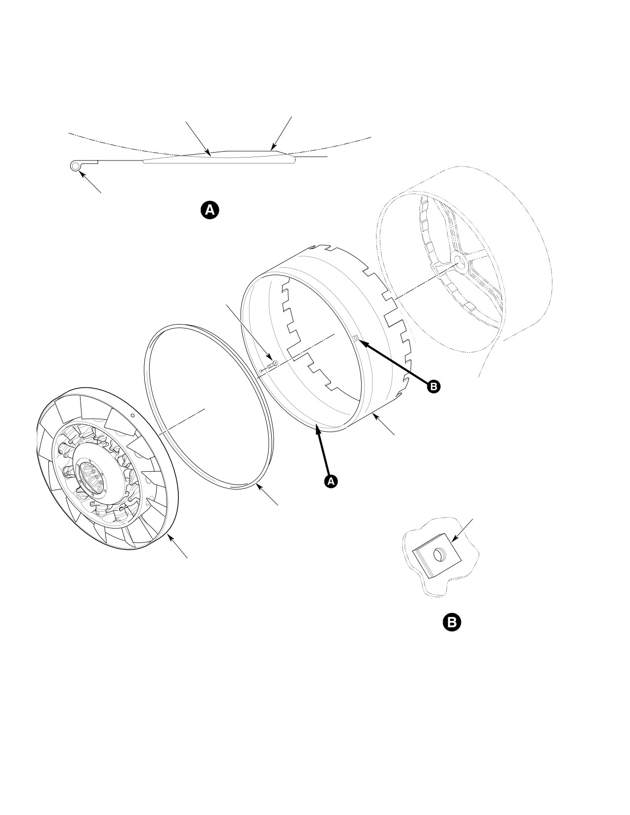
1. Anti−Torque Fan Liner (Felt Metal Seal)
NOTE: On installation of liner assembly, peel
Replacement
shim laminates equally among the four
shims to provide a tight fit without deform
(Ref. Figure 801)
ing the liner at screw holes and aircraft
structure.
A. Anti−Torque Fan Liner (Felt Metal Seal)
Removal
(2). Install four screws. Torque screws per
standard aircraft practices.
(1). Remove tailboom (Ref Sec. 53-40-30).
Do not install sealant in butt
CAUTION
(2). Disconnect safety wire and remove nut,
splices of liner until after felt
lockwasher, 3 bolts, washers and pitch
metal is turned/cut to correct clearance. Do
bearing retainer plate.
ing so will damage cutting tool and cause in
correct cutting radius to liner seal.
(3). Remove pitch bearing and inner pitch
(3). Install sealant (CM425) in mating bores
bearing retainer; remove pitch slider
(cutouts) and around liner edges.
from pitch bearing housing (Ref. Sec.
67-20-30).
(4). After installing the fan liner and before
installing the fan, trim liner felt metal
(4). Remove fan assembly (Ref. Anti-Torque
seal (Ref. Anti-Torque Fan Liner (Felt
Fan Replacement).
Metal Seal) Machining). Refer to MD
Helicopter Field Service Representative
(5). Remove sealant around liner edges
for additional information.
with plastic scraper.
C. Anti−Torque Fan Liner (Felt Metal Seal)
(6). Remove four screws that secure the
Machining
liner to the aircraft structure.
(Ref. Figure 801 and Figure 802)
NOTE: Mark liner to aircraft structure to en
sure proper clocking upon installation. If
Special Tools
liner is not installed in same position, felt
(Ref. Section 91−00−00)
metal seal machining will be necessary for
Item
Nomenclature
correct fan clearance.
ST603
Tip seal cutting fixture
(7). Carefully slide liner aft through
support structure and fan support
NOTE:
struts.
D Do this procedure only after a new fan lin
B. Anti−Torque Fan Liner (Felt Metal Seal)
er is installed.
Installation
D Felt metal material can cause FOD con
tamination.
Consumable Materials
(1). Apply masking tape and plastic sheet to
(Ref. Section 91−00−00)
fan duct and fan diffuser areas.
Item
Nomenclature
Use only cutter and equipment
CM425
Sealing compound
CAUTION
supplied with (ST603) tip seal
tool.
(1). Install fan liner so that the larger
NOTE: Make sure (ST603) tip seal tool is clean
cutouts fit around the fan support
before you install it.
struts and the smaller cutouts fit
around the rivets that secure the fan
(2). Install pin (5) and spacer (6) in fan
inlet fairing.
support assembly.
Page 801
64-25-30
Revision 42
CSP-HMI-2
MD Helicopters, Inc.
MAINTENANCE MANUAL
FELT METAL SEAL
FELT METAL SEAL
BEFORE TRIM
AFTER TRIM
ÇÇÇÇÇÇÇÇÇ
ÇÇÇÇÇÇÇÇÇÇ
P-SEAL
SCREW
LINER
P-SEAL
SHIM
FAN
G64-2007
Figure 801. Anti−Torque Fan Liner (Felt Metal Seal)
Page 802
Revision 21
64-25-30
MD Helicopters, Inc.
CSP-HMI-2
MAINTENANCE MANUAL
10
FAN SUPPORT ASSEMBLY (REF)
7
21 (4 PL)
8
20 (4 PL)
20 (4 PL)
19 (4 PL)
11
9
1 (REF)
15 (REF)
16 (REF)
6
18
CUTTING
CL
5
DIRECTION
2
CUTTER
7
12
3
ÉÉÉÉÉ
4
ÉÉÉ
22
ÉÉÉ
1
ÉÉÉ
ÉÉÉ
ÉÉÉ
ÉÉÉ
15
ÉÉÉ
13 (2 PL)
14 (2 PL)
ÉÉÉ
16
ÉÉÉ
23 (2 PL)
ÉÉÉ
17
ÉÉÉ
ÉÉÉ
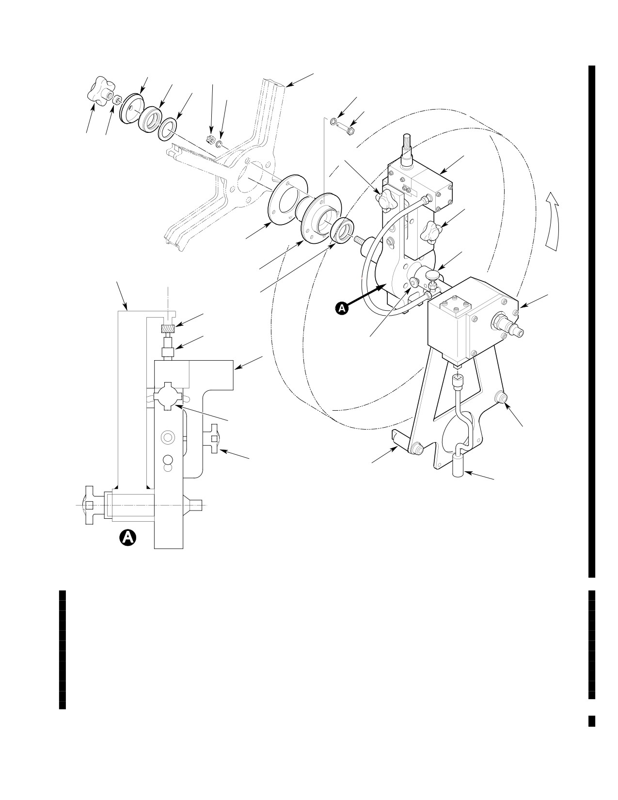
CALIBRATION OF CUTTING TOOL HEIGHT
G64-2008A
1. FAN TIP SEAL TOOL (PART 1)
13. CAP SCREW
2. CALIBRATION ARM
14. WASHER
3. CUTTER
15. POSITION LOCK KNOB
4. MOTOR COLLET
16. ADJUSTMENT KNOB
5. PIN
17. SPEED HANDLE
6. SPACER
18. AIR PRESSURE VALVE
7. THRUST BEARING
19. BOLT
8. SPACER
20. WASHER
9. NYLON WASHER
21. NUT
10. THRUST BEARING RETAINER
22. BALL LOCK PIN
11. THREADED KNOB
23. SPACER
12. FAN TIP SEAL TOOL (PART 2)
Figure 802. Anti−Torque Fan Liner Felt Metal Seal Machining
Page 803
64-25-30
Revision 42

CSP-HMI-2
MD Helicopters, Inc.
MAINTENANCE MANUAL
(3).
Install bolts (19), washers (20), and
Eye protection, a respirator,
WARNING
nuts (21). Torque nuts.
gloves, and protective cloth
ing must be worn during fan liner ma
(4).
Put cutter (3) in motor collet (4). Do not
chining.
tighten collet.
(22).
Loosen position lock knob (15) and turn
(5).
Apply a thin film of oil to inner side of
adjustment knob (16) to position cutter
pin (5) and outer side of tool (1) shaft.
(3) for a cut of not more than one fourth
width of cutter (3). Tighten lock knob.
(6).
Put thrust bearing (7) on tool (1) shaft.
(23).
Connect speed handle (17) to tool (12).
(7).
Put tool (1) in pin (5) and push forward.
(24).
Connect pneumatic pressure source to
(8).
Turn tool (1) by hand and adjust cutter
tool (12).
(3) to highest point on fan liner. Tighten
(25).
Turn valve (18) to adjust cutter (3)
collet (4).
speed.
(9).
Remove tool (1).
(26).
Turn speed handle (17) and turn tool (1)
(10).
Remove thrust bearing (7) from tool (1)
counter-clockwise at a moderate to
shaft.
slow rate. Do not force cut.
(27).
After one full turn, again loosen
(11).
Put calibration arm (2) on tool (1).
position lock knob (15) and turn
(12).
Measure dimension between cutter (3)
adjustment knob (16) to position cutter
and stop on calibration arm (2).
(3) for a cut of not more than one fourth
width of cutter (3). Tighten lock knob.
(13).
Loosen motor collet (4) and move cutter
(3) out 0.040-0.050 in. (1.02-1.27 mm)
(28).
Do step (27). again and again until fan
or until cutter touches stop on calibra
liner is fully machined.
tion arm (2). Tighten collet.
(29).
Disconnect pneumatic pressure source
to tool (12).
(14).
Loosen position lock knob (15) and turn
adjustment knob (16) until cutter (3) is
(30).
Disconnect speed handle (17) from tool
at aft most position. Tighten position
(12).
lock knob.
(31).
Remove cap screws (13), washers (14),
(15).
Put thrust bearing (7) on tool (1) shaft.
and spacers (23).
(16).
Put tool (1) in pin (5) and push forward.
(32).
Remove ball lock pin (22) and tool (12).
(17).
Install spacer (8), thrust bearing (7),
(33).
Remove threaded knob (11), nylon
thrust bearing retainer (10), nylon
washer (9), thrust bearing retainer (10),
washer (9), and threaded knob (11).
thrust bearing (7), and spacer (8).
Tighten knob.
(34).
Remove tool (1).
(18).
Put tool (12) on tool (1) and install ball
lock pin (22).
(35).
Remove thrust bearing (7) from tool (1)
shaft.
(19).
Install cap screws (13), washers (14),
and spacers (23). Torque cap screws.
NOTE: The following clearance may vary be
cause of variations in blade length.
(20).
Make sure there is no radial or axial
movement in tool (1).
(36). Install fan assembly and check for a
0.10 in. (2.54 mm) maximum clearance
(21).
Lubricate tool motor, use pneumatic
between fan blade ends and felt metal
tool oil.
seal.
Page 804
Revision 42
64-25-30
MD Helicopters, Inc.
CSP-HMI-2
MAINTENANCE MANUAL
(37). In step (13). did cutter touch stop on
NOTE: The anti-torque control system must be
calibration arm?
re-rigged immediately after removal or re
placement of control rods, linkages and com
ponents or if helicopter operation reveals a
(a). No, go to step (11).
rigging deficiency.
(41). Install fan assembly (Ref. Anti-Torque
(b). Yes, go to step (38).
Fan Replacement).
(38). Remove nuts (21), washers (20), and
(42). Install interconnect driveshaft (Ref.
bolts (19).
Sec. 63-15-30).
(43). Install fan pitch control rod (Ref. Sec.
(39). Remove pin (5) and spacer (6) from fan
67-20-30).
support assembly.
(44). Install pitch slider and inner pitch
bearing retainer (Ref. Sec. 67-20-30).
(40). Clean fan duct and diffuser areas and
remove masking tape and plastic sheet.
(45). Install tailboom (Ref. Sec. 53-40-30).
Page 805
64-25-30
Revision 42
CSP-HMI-2
MD Helicopters, Inc.
MAINTENANCE MANUAL
2. Anti−Torque Fan Bearing Regreasing
(2). Carefully remove both seals from
bearings (seals will be reused at
reassembly).
Special Tools
(Ref. Section 91−00−00)
(3). Inspect seals for damage; no damage is
Item
Nomenclature
allowed.
ST614
Fan bearing regreasing tool
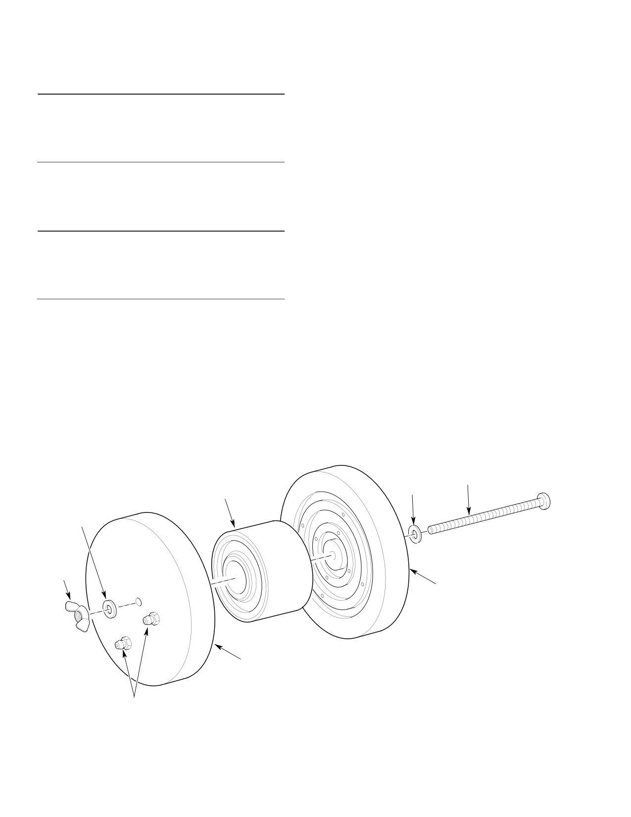
(4). Install bearings between regreasing
tools with a 4 inch (10 cm) 10-24
threaded bolt, washers and wing nut.
(Ref. Figure 803 and Figure 804) The following
procedure is for the regreasing of the
NOTE: The following procedure provides 100%
500N5364 and 500N7120 bearings.
grease fill. Normal grease fill is 30 to 50%.
Excess grease will extrude past seals for
several hours of operation until the proper
Consumable Materials
level is met.
(Ref. Section 91−00−00)
Item
Nomenclature
(5). Purge bearing with grease (CM111)
until clean grease protrudes from all
CM111
Grease, aircraft
four holes in back of tool.
(6). Remove regreasing tool.
NOTE:
(7). Hand spin bearing to purge excess
D Ensure proper pitch plate and shaft sup
grease.
port bearings are installed. 900R bear
ings are not to be used in the 500/600N
NOTE: Ensure seals are serviceable. If new
helicopters.
seals are required, seals and bearings must
come from the same vendor.
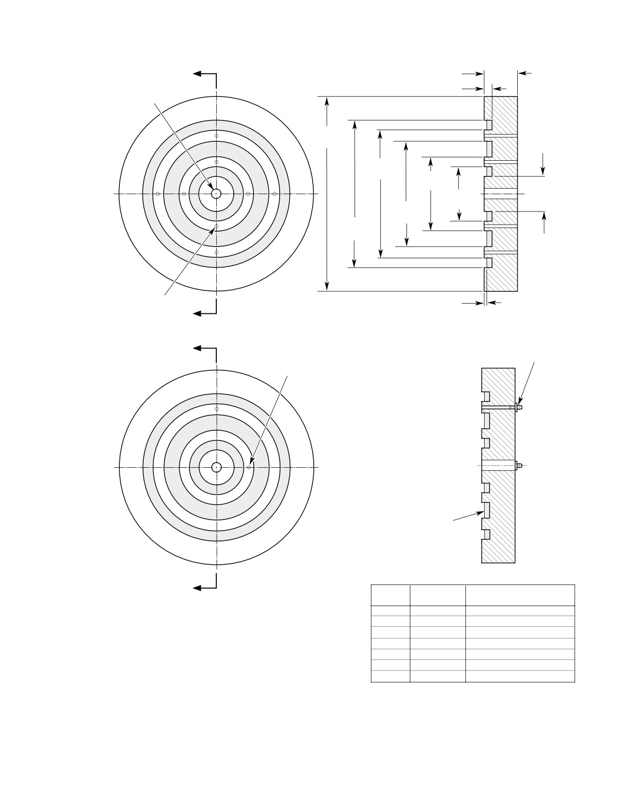
D Refer to Figure 804 for instructions on
the manufacture of a regreasing tool.
(8). Carefully install seals.
(1). Remove bearings from fan assembly
(9). Reinstall bearings (Ref. Support Shaft
(Ref. Support Shaft Disassembly).
Reassembly).
BOLT
WASHER
FAN BEARING
WASHER
NUT
REGREASE TOOL
PART A
REGREASE TOOL
PART B
GREASE FITTINGS
G64-2010A
Figure 803. Fan Bearing Regreasing Procedure
Page 806
Revision 42
64-25-30
MD Helicopters, Inc.
CSP-HMI-2
MAINTENANCE MANUAL
0.50 IN.
A
0.125 IN. (3.175 MM)
(12.7 MM)
0.188 IN. (4.7752 MM)
(NOTE 1)
DIA THRU HOLE
3.00 IN.
0.580 IN.
(7.62 CM)
(14.732 MM)
1.980 IN.
(5.0292 CM)
1.180 IN.
(2.9972 CM)
0.870 IN.
1.640 IN.
(22.098 MM)
(4.1656 CM)
2.280 IN.
(5.7912 CM)
0.040 IN.
0.094 IN. (2.3876 MM) DIA
(1.016 MM)
THRU HOLE (8 PL)
A
EQUALLY SPACED AND
SECTION A-A
PART A
CENTERED BETWEEN
GREASE FITTING
MACHINED GROOVES
MS15002-1 (2 PL)
0.094 IN. (2.3876 MM) DIA THRU
B
1/4-28 TAPER
HOLE (2 PL) EQUALLY SPACED
THREADS
AND CENTERED BETWEEN
MACHINED GROOVES (NOTE 2)
SEAL MATERIAL (3PL) (PARTS
A AND B) USE LOCALLY
AVAILABLE MATERIAL FIRM
HARDNESS [ 75
SECTION B-B
B
PART B
QUANTITY
STOCK SIZE
DESCRIPTION
NOTES:
1
4 x 4 x .50
PLATE
1.
DIMENSION MAY VARY DEPENDING ON SEAL MATERIAL THICKNESS AVAILABLE.
1
4 x 4 x .50
PLATE
2.
ALL OTHER DIMENSIONS SAME AS PART A.
1
AN23-64
BOLT
MATERIALS:
2
AN960D10L
WASHER
1.
6061-T651 ALUMINUM PER QQ-A-250/11 OR EQUIVALENT.
1
AN315-3R
NUT
2.
SURFACE FINISH 125 RMS.
2
MS15002-1
GREASE FITTING
3.
BREAK SHARP EDGES 0.002-0.015 IN. (0.0508-0.381 MM).
1
M6855/2
RUBBER
4.
CHEMICAL FILM TREAT PER MIL-C-5541.
5.
DIMENSION TOLERANCE ±0.010 IN. (±0.254 MM).
G64-2009B
6
GROOVE DIAMETERS TO BE CONCENTRIC TO 0 188 IN 4 7752 MM) DIA WITHIN 0 002 IN (0 0508 MM)
Figure 804. Fan Bearing Regreasing Tool (ST614)
Page 807
64-25-30
Revision 42
CSP-HMI-2
MD Helicopters, Inc.
MAINTENANCE MANUAL
This Page Intentionally Left Blank
Page 808
Revision 42
64-25-30
MD Helicopters, Inc.
CSP-HMI-2
MAINTENANCE MANUAL
Section
64−30−00
Tail Rotor Pitch
Control Assembly
(369D/E/FF)
MD Helicopters, Inc.
CSP-HMI-2
MAINTENANCE MANUAL
TAIL ROTOR PITCH CONTROL ASSEMBLY
MAINTENANCE PRACTICES
1. Tail Rotor Pitch Control Assembly
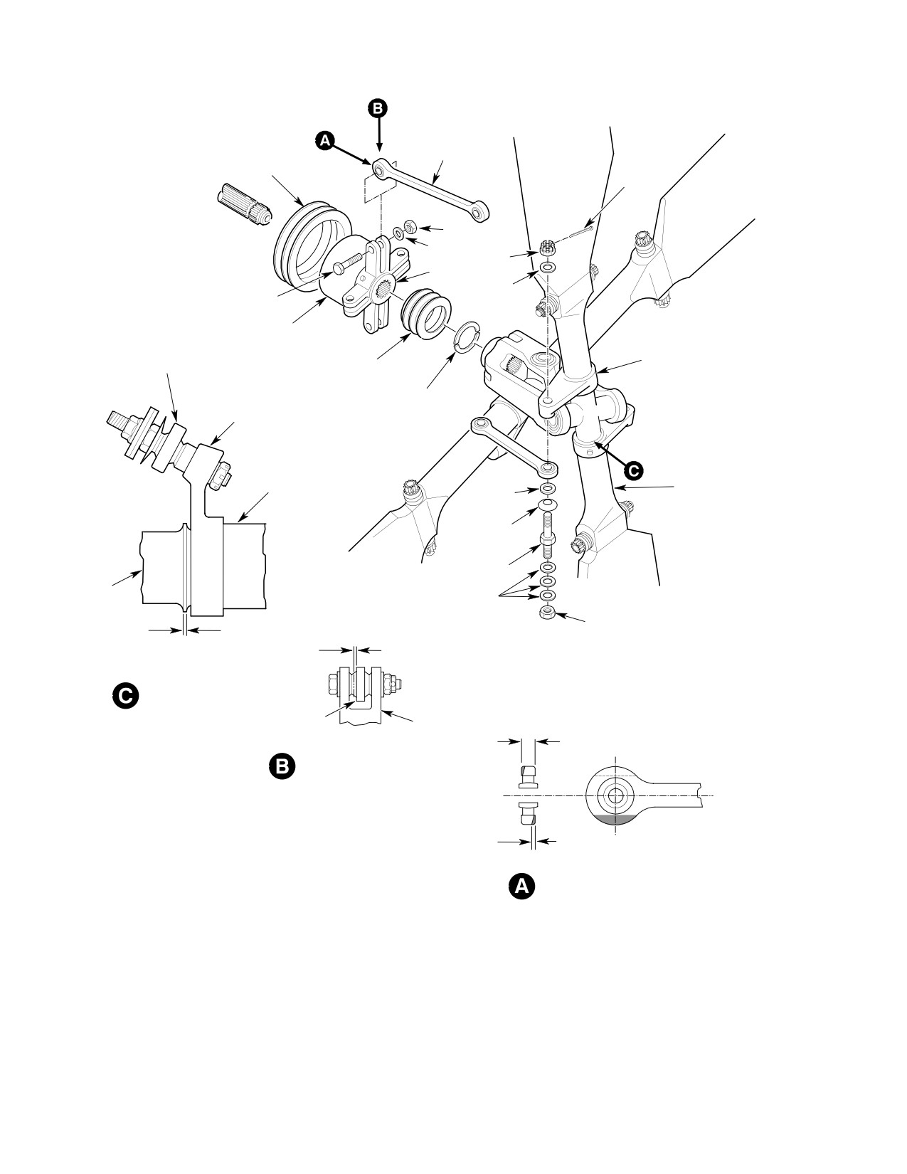
On four-bladed tail rotor
WARNING
system, there is strong
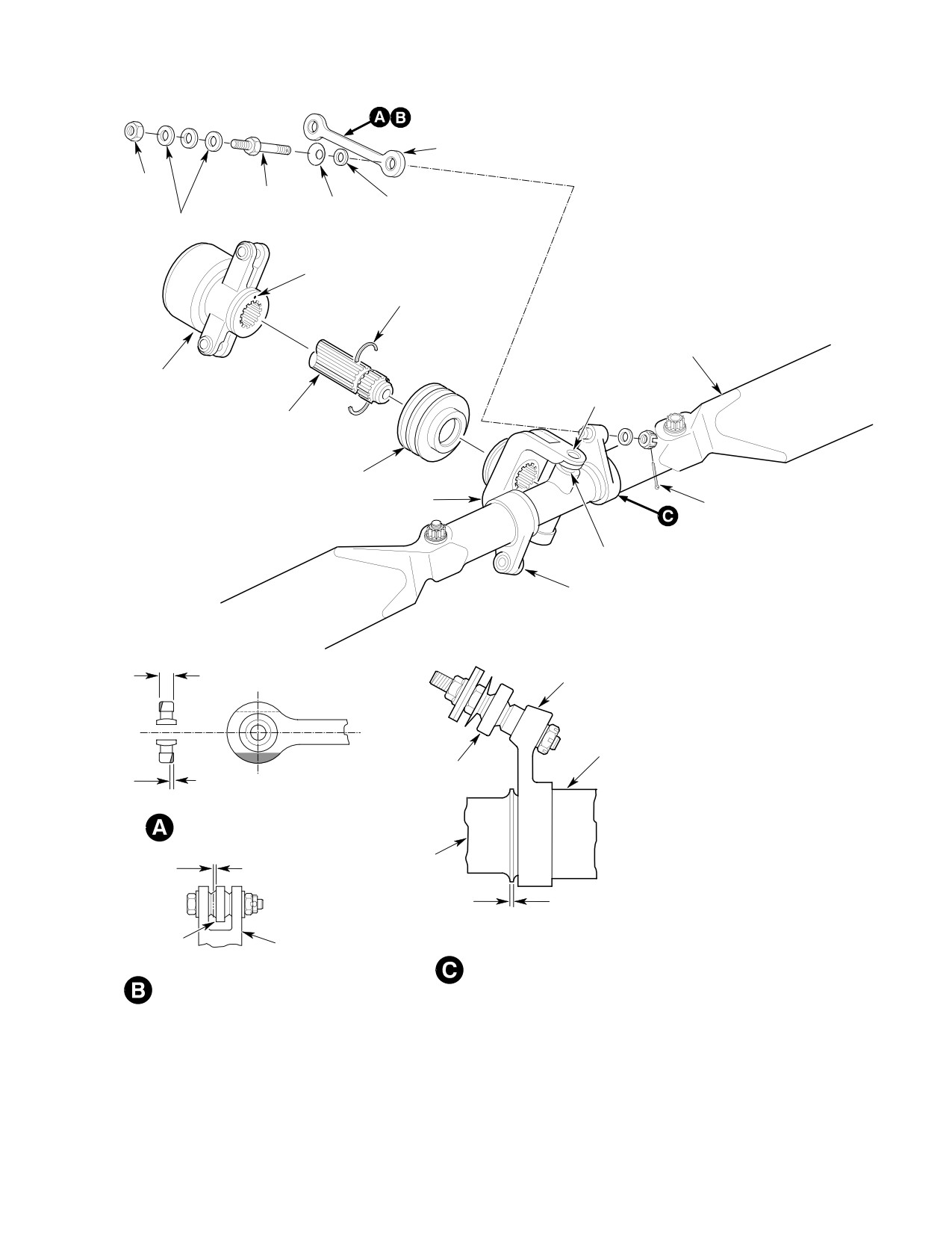
(Ref. Figure 203 and Figure 204) The pitch
spring pressure in installed tail rotor
control assembly consists of a swashplate that
linkage. Disconnect the in-line bungee
rotates in a matched set of two bearings
before beginning disassembly. Failure
swaged inside a housing. A self-aligning
to disconnect the bungee can result in
bearing staked in place at the underside of the
personal injury and/or parts damage.
housing provides a pivot for transferring
motion of Sta. 284 bellcrank to the housing.
Clevis ears on end of the swashplate provide
(1). Remove tail rotor hub and fork assem
for connection of pitch control links. Movement
bly (Ref. Sec. 64-20-00).
of Sta. 284 bellcrank shifts the housing axially
on the output shaft of the tail rotor transmis
sion and moves pitch control links inward and
outward to change pitch of tail rotor blades.
NOTE: The manner in which the pitch control
The swashplate is retained in the pitch control
assembly is installed determines rotor-
housing by a washer and locknut.
blade orientation to transmission splined
shaft. Installing rotor blades at 90 degrees
2. Tail Rotor Pitch Control Assembly
to high and low extremes of shaft runout,
Replacement
using reference marks placed on shaft at
time of shaft inspection (Ref. Sec. 63-25-10)
A. Tail Rotor Pitch Control Assembly
reduces chance of high-frequency vibration
Removal
and lessens likelihood of having to reba
(Ref. Figure 203 and Figure 204)
lance tail rotor.
DIRECTION OF PITCH CONTROL
ASSEMBLY WOBBLE ON OUTPUT SHAFT
0.020 IN.
(0.508 MM)
MAX.
BOLT HOLE
PITCH CONTROL
CENTERLINE
ASSEMBLY
0-10 LB (0-50 N)
SPRING SCALE
(NOTE 1)
TWINE
PIVOT
WASHER
PIN
(NOTE 2)
NOTES:
1.
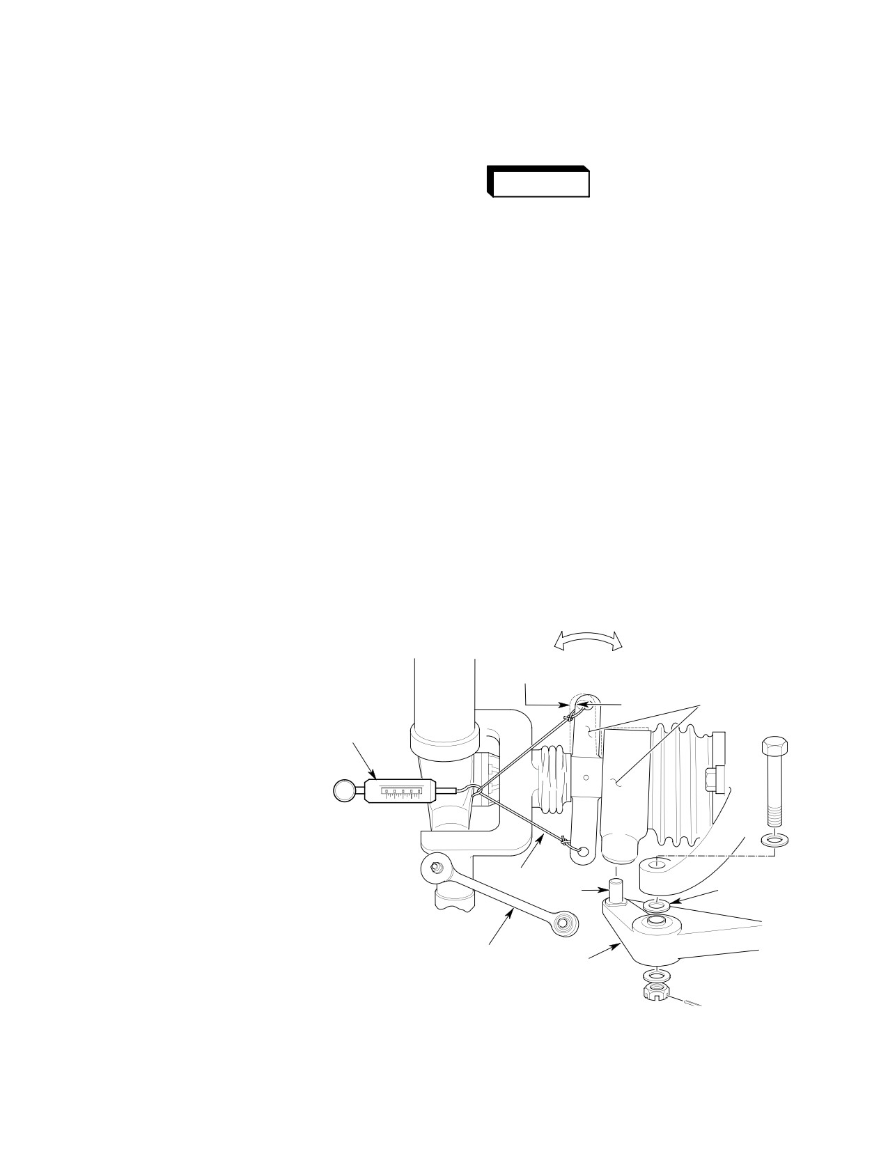
FORCE REQUIRED TO SLIDE PITCH CONTROL
ASSEMBLY INWARD OR OUTWARD ON OUTPUT
SHAFT MUST NOT EXCEED THREE POUNDS (13.4 N)
PITCH
WITH PITCH LINKS, BELLCRANK AND RUBBER BOOTS
CONTROL LINK
STA. 284
DETACHED FROM PITCH CONTROL ASSEMBLY.
BELLCRANK
2.
ADD ONE OR TWO AN960KD516 WASHERS AS
G64-3000A
REQUIRED FOR CLEARANCE AT PEDAL FULL STROKE
Figure 201. Pitch Control Assembly − Wobble Check
Page 201
64-30-00
Revision 21
CSP-HMI-2
MD Helicopters, Inc.
MAINTENANCE MANUAL
0.015 IN. (0.381 MM)
install Sta. 284 bellcrank. Rotate
MIN. CLEARANCE
bellcrank back and forth to align
bellcrank bearing with transmission
arm.
(5). If previously disconnected, reconnect
HOUSING
tail rotor bungee.
SWASHPLATE
3. Tail Rotor Pitch Control Link Replacement
(Ref. Figure 203 and Figure 204)
SWASHPLATE-TO-HOUSING
Consumable Materials
CLEARANCE
G64-3001A
(Ref. Section 91−00−00)
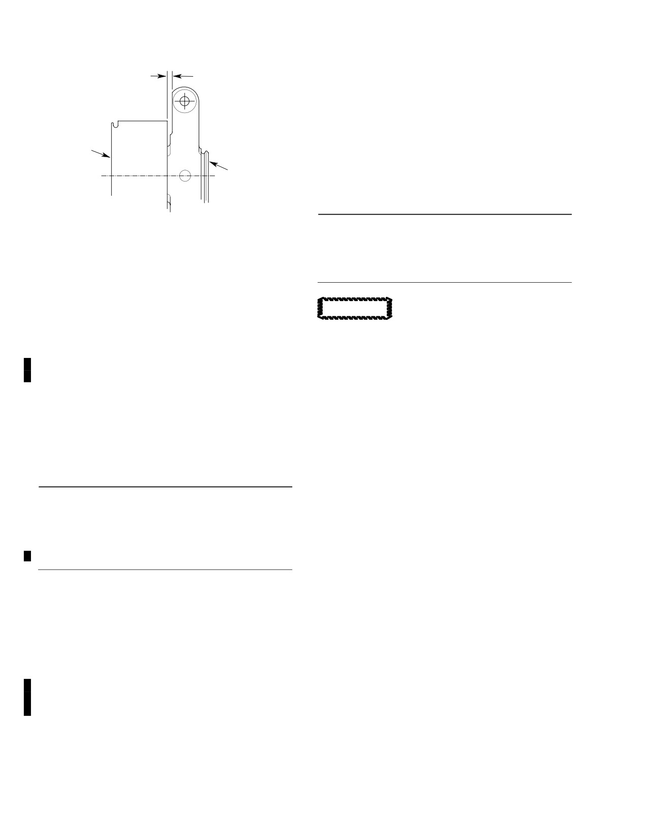
Figure 202. Swashplate−to−Pitch Control
Item
Nomenclature
Housing Clearance
CM318
Primer
(2). Remove Sta. 284 bellcrank from
transmission (Ref. Sec. 67-20-10) so
Prior to removal of pitch control
CAUTION
that pivot pin in bellcrank is disen
links, color-code pitch arm bolt
gaged from self-aligning pivot bearing
and all washers used at each arm. The bolt,
in pitch control housing.
or an identical one, and same combination of
washers must be reassembled at locations
(3). Cut lockwire and pull non-rotating boot
from which removed, or tail rotor balance
from groove in pitch control housing.
can be seriously affected. Do not allow blade
angles to exceed 30 degrees, approximately
(4). Slide pitch control assembly off trans
one inch (2.54 cm), in each direction. Unde
mission output shaft.
tected damage to tension-torsion strap pack
may occur.
B. Tail Rotor Pitch Control Assembly
Installation
(1).
Disconnect ends of pitch control link
(Ref. Figure 203 and Figure 204)
from clevis ear of swashplate and from
blade pitch control arm.
Consumable Materials
(2).
To install, insert either end of pitch
(Ref. Section 91−00−00)
control link between clevis ears of
Item
Nomenclature
swashplate.
CM115
Grease, oscillating bearing
(3).
Install color-coded attaching hardware
CM702
Lockwire CRES
and tighten nut to 30 - 40 inch-
pounds (3.39 - 4.52 Nm); install cotter
pin with wet primer (CM318).
(1). Insert edge of small end of non-rotating
boot into tail rotor transmission
(4).
Pull pitch control assembly inboard or
housing groove. Make certain that
outboard as required to align pitch
drain holes in boot are downward.
control link bearing with pitch control
arm bushing.
(2). Align spline index marks and slide
pitch control assembly on shaft.
(5).
Place special (reduced outside diame
ter) washer and large-diameter spring
(3). Insert non-rotating boot edge into
washer on pitch arm bolt so that
groove of pitch control housing and
concave surface of spring washer is
secure with lockwire (CM702).
against bolt head. With washers in
(4). Apply grease (CM115) to Sta. 284
place on bolt, insert bolt through
bellcrank pivot pin, insert pin into pitch
bearing of pitch control link and
housing self-aligning bearing and
bushing in pitch control arm.
Page 202
Revision 36
64-30-00
MD Helicopters, Inc.
CSP-HMI-2
MAINTENANCE MANUAL
PITCH CONTROL
LINK (2) TYPICAL
NUT
PITCH ARM
BOLT (STUD)
SPRING
SPECIAL WASHER
BALANCE WASHER(S)
WASHER
(NOTE 4)
(NOTE 3)
NOTE 1
SPLIT RING
(WIRE SPRING)
TAIL ROTOR
ASSEMBLY
PITCH CONTROL
HINGE
ASSEMBLY (NOTE 5)
BOLT
TRANSMISSION
OUTPUT SHAFT
ROTATING
BOOT
FORK
NOTE 2
FORK BEARING
PITCH ARM
0.255 IN. (6.477 MM)
ORIGINAL THICKNESS
BLADE PITCH ARM
ROOT FITTING
PITCH
0.070 IN. (1.778 MM) MAX. WEAR
CONTROL
ALLOWED 2 PLACES EACH END
LINK
LINK WEAR LIMIT
HUB
0.02 IN. (0.508 MM) MAX.
0.001-0.130 IN.
(0.025-3.302 MM
NOTES:
1.
CENTERLINE TOOTHSPACE MATCHMARK
LINK
SWASHPLATE
MUST ALIGN WITH CENTERLINE TOOTHSPACE
BEARING
HUB-TO-BLADE PITCH
MARK ON FORK WHEN ASSEMBLED ON
ARM-CLEARANCE
OUTPUT SHAFT.
(TYPICAL 2 PLACES)
LINK BEARING AXIAL PLAY
2.
INSTALL WITH WET PRIMER.
3.
QUANTITY (IF ANY) DETERMINED BY BALANCE
REQUIREMENTS.
4.
REDUCE OUTER DIAMETER.
5.
FOR DISASSEMBLY, REFER TO CSP-COM-5.
G64-3002C
Figure 203. Tail Rotor Pitch Control Assembly (Two−Bladed)
Page 203
64-30-00
Revision 21
CSP-HMI-2
MD Helicopters, Inc.
MAINTENANCE MANUAL
PITCH CONTROL
LINK (2) TYP
COTTER KEY
STATIONARY BOOT
(NOTE 2)
NUT
WASHER
NUT
NOTE 1
WASHER
BOLT
PITCH CONTROL
PITCH
ASSEMBLY (NOTE 5)
CONTROL
PITCH ARM
LINK
ROTATING BOOT
SPLIT RINGS
BLADE PITCH ARM
PITCH CONTROL
LINK (2) TYPICAL
SPECIAL
ROOT FITTING
TAIL ROTOR
WASHER
ASSEMBLY
(NOTE 4)
SPRING
WASHER
PITCH ARM BOLT (STUD)
HUB
BALANCE WASHER(S) (NOTE 3)
NUT
0.001-0.130 IN.
(0.025-3.302 MM
0.02 IN. (0.508 MM) MAX.
HUB-TO-BLADE PITCH
ARM-CLEARANCE
(TYPICAL 2 PLACES)
SWASHPLATE
0.255 IN. (6.477 MM)
ORIGINAL THICKNESS
LINK BEARING AXIAL PLAY
0.070 IN. (1.778 MM) MAX. WEAR
ALLOWED 2 PLACES EACH END
LINK WEAR LIMIT
NOTES:
1.
CENTERLINE TOOTHSPACE MATCHMARK MUST ALIGN WITH CENTERLINE
TOOTHSPACE MARK ON FORK WHEN ASSEMBLED ON OUTPUT SHAFT.
2.
INSTALL WITH WET PRIMER.
3.
QUANTITY (IF ANY) DETERMINED BY BALANCE REQUIREMENTS.
4.
REDUCE OUTER DIAMETER.
G64-3003C
Figure 204. Tail Rotor Pitch Control Assembly (Four−Bladed)
Page 204
Revision 21
64-30-00
MD Helicopters, Inc.
CSP-HMI-2
MAINTENANCE MANUAL
(6). Install washer and nut on end of the
assembly on shaft of tail rotor transmis
bolt that extends through pitch arm.
sion. Note that pitch control links, Sta.
Torque nut to 50 - 60 inch-pounds
284 bellcrank and rubber boots must be
(5.65 - 6.78 Nm); install cotter pin with
detached from the assembly during
wet primer (CM318).
drag check. If drag exceeds three
pounds (13.4 N), remove pitch control
(7). Check for clearance between pitch link
assembly and clean swashplate and
and tail rotor hub pivot bolt.
transmission shaft splines. Use solvent
(CM234) and grade 400 abrasive paper
(8). If removed from pitch arm bolt, install
(CM801) or crocus cloth (CM803). Clean
balance washer(s) of same color code as
again with solvent (CM234) and coat
pitch control arm and secure with nut.
output shaft splines with light film of
grease (CM115).
4. Tail Rotor and Pitch Control Assembly
Repair
(2).
Inspect fork and hub for scratches,
nicks, dents, cracks, corrosion and
(Ref. Figure 203 and Figure 204)
similar surface defects. Check for wear
caused by rubbing of aluminum
Consumable Materials
support. Scratches and nicks that do
(Ref. Section 91−00−00)
not exceed 0.005 inch (0.127 mm)
Item
Nomenclature
depth, 0.120 inch (3.048 mm) depth at
CM801
Abrasive paper, silicon carbide
inside corner of fork, may be repaired
(Ref. COM). Worn areas resulting from
rubbing of aluminum support up to
0.060 inch (1.524 mm) depth may be
Repair allowable surface defects on fork and
repaired (Ref. COM).
hub that may be reworked by using grade 320
abrasive paper (CM801) to round out and
(3).
Check wire-spring split ring halves for
blend defect. Apply exterior surface touchup
damage.
treatment and paint touchup (Ref. Sec.
(4).
If brinelling wear of inner surfaces of
20-30-00). (Repairable damage limits are
swashplate clevis ears is detected, 0.003
defined in the Component Overhaul Manual.)
inch (0.076 mm) depth is allowable
5. Tail Rotor Pitch Control Assembly
without rework or repair. For wear of
Inspection
greater depth, Ref. COM, for limits and
allowable repairs.
(Ref. Figure 203, Figure 204 and Figure 205)
(5).
If there is evidence of swashplate
contact with housing, check that
Consumable Materials
minimum clearance of 0.015 inch (0.381
(Ref. Section 91−00−00)
mm) exists through 360 degrees of
Item
Nomenclature
rotation with axial loading applied. If
CM115
Grease, oscillating bearing
contact is apparent or if axial play can
CM206
Chemical coating
be measured, replace swashplate or
CM234
Solvent, dry-cleaning
bearings (Ref. COM).
CM236
Paint remover
NOTE: Wobble may be accurately measured by
CM721
Tape, aluminum foil
attaching dial indicator support to tail rotor
CM801
Abrasive paper, silicon carbide
drive fork, with indicator probe contacting
CM803
Crocus cloth
swashplate clevis ear. Use care not to allow
pitch control assembly to slide on output
shaft while measuring wobble.
(1). If tail rotor control system drag or
friction is suspected, use spring scale
(6). If pitch control assembly wobbles on
(Ref. Figure 201) to measure drag
transmission output shaft, up to 0.020
(sliding friction) of pitch control
inch (0.508 mm) is allowable. If greater
Page 205
64-30-00
TR12-001

CSP-HMI-2
MD Helicopters, Inc.
MAINTENANCE MANUAL
amount of wobble is present, replace
from debris and paint remover. Use
swashplate, pitch control housing,
aluminum tape (CM721) that is
bearings (Ref, COM) or the complete
resistant to paint remover.
assembly.
(7). Check that hub-to-blade pitch arm
Extreme care shall be taken to
clearance is 0.001-0.130 inch
CAUTION
prevent debris or paint remover
(0.025-3.302 mm).
contamination in bearing and
bushing areas and tail rotor
(8). Inspect all bolts and nuts for security.
blade bond surfaces and cavit
(9). Inspect boots for installation and
ies.
deterioration.
Failure to comply with the
(c). Remove paint from tail rotor blade
WARNING
following inspection can res
pitch control arm (all four sides and
ult in the pitch control arm separating
the pocket) as shown in Figure 205
from the tail rotor blade. This will lead
with paint remover (CM236). (Ref.
to an unbalanced condition, vibration,
Sec. 20-30-00).
partial loss of tail rotor pitch control
and possible loss of directional control
of the helicopter.
The pitch control arm area is
CAUTION
shot peened and has a protective
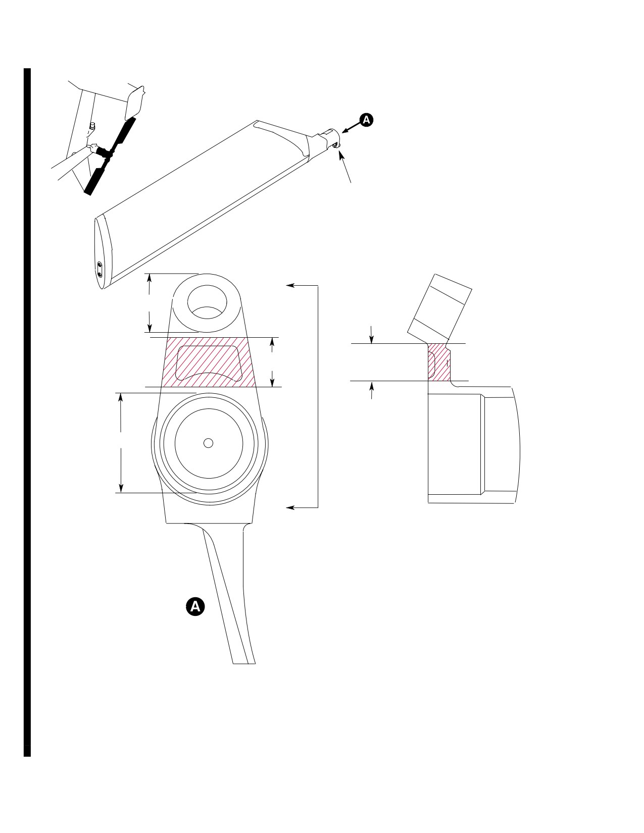
(10). For the following tail rotor assemblies
chemical coating. No abrasive
only (Ref Figure 205):
cleaning, sanding or blending is
MDHI P/N 369D21640-501 and -503
allowed.
HTC P/N 500P3100-101
to include “M”, “MT”, “I” and “IT”
MDHI P/N 369D21641-501 and -503
(d).
(Ref. Figure 205 hatched area). Use a
HTC P/N 500P3100-301
bright light and 10X magnifying
to include “M”, “MT”, “I” and “IT”
glass to inspect the tail rotor blade
MDHI P/N 369D21642-501 and -503
pitch control arm (all four sides and
HTC P/N 500P3500-701
the pocket) for corrosion, corrosion
to include “M”, “MT”, “I” and “IT”
pitting or cracks. No corrosion,
MDHI P/N 369D21643-501 and -503
corrosion pitting or cracks are
HTC P/N 500P3300-501
allowed. If corrosion, corrosion
pitting or cracks are present, replace
Inspect pitch horn area for corrosion or
blade assembly before next flight.
evidence of suspect corrosion due to
(Ref. Sec. 64-10-00). Mark the
paint blistering at times specified (Ref.
defective tail rotor blade assembly as
Sec. 05-20-15).
scrap and destroy.
(a). Remove tail rotor blade assembly
(Ref. Sec 64-10-00).
(e).
Make sure the inspection area has a
“dimpled” shot peen surface texture.
Use care when handling pitch
CAUTION
If the inspection area surface is not
bearings. Teflon reinforced lin
shot peened or there is evidence of
ings are easily damaged if mis
blending or material removal that
handled or exposed to contami
affected the shot peened surface,
nants. If lining is damaged or
replace blade assembly before next
contaminated, bearing service
flight. (Ref. Sec. 64-10-00). In
life will be shortened or bearing
addition, check rotorcraft mainten
replacement may be required.
ance records to make sure no rework
(b).
(Ref. Figure 205, Note 2) Carefully
was done in this area. Mark the
tape around bearing, bushing and
defective tail rotor blade assembly as
blade areas to prevent contamination
scrap and destroy.
Page 206
TR12-001
64-30-00
MD Helicopters, Inc.
CSP-HMI-2
MAINTENANCE MANUAL
(f). If no corrosion, corrosion pitting or
(12). Inspect for evidence of rotational
cracks exist and the inspection area
binding by hand-turning tail rotor
has an acceptable shot peen surface
assembly a few turns while listening for
texture, refinish stripped pitch
unusual sounds. If condition is ques
control arm as follows:
tionable, perform applicable inspection.
1). Apply chemical coating (alodine)
(CM206) per instructions con
6. Tail Rotor Blade Stop Inspection
tained in Sec. 20-40-00).
2). Apply primer and paint to match
NOTE: Change of blade pitch angle when tail
original as required (Ref. Sec.
rotor is not rotating can produce audible
20-30-00).
snapping noise. Noise results as lamina
tions of blade strap pack are twisted and
bent without a centrifugal load. Such noise
(g). Install tail rotor blade assembly (Ref
is normal and does not indicate a defect.
Sec. 64-10-00).
(11). Perform following inspections for pitch
(1). Teeter blades back and forth and check
control bearings at times specified (Ref.
for evidence of abnormal binding. Some
Sec. 05-20-00) and when bearing
stiffness is normal, especially when
condition is questionable.
blade stop is newer.
(a).
Remove cotter pin, nut, washers and
bolt securing Sta. 284 bellcrank to
(2). Inspect blade stop for deterioration. Be
transmission. Separate pivot pin on
sure to check for cracking or splitting in
bellcrank from pitch control assem
stem area of stop. Allowable wear for
bly.
rubber stop is to surface of aluminum
support. Stop (and support) may be
(b).
Rotate pitch control housing by hand;
rotated 90 degrees if stop is excessively
check for rough, binding or hard
worn at contact point. Replace rubber
turning. Inspect for grease leakage. If
stop if damaged, or if worn area cannot
any of these conditions exist, remove
be rotated away from contact point.
pitch control assembly and inspect
for further evidence of damage.
NOTE:
If replacement of stop support is re
quired, replace with one-piece stop support
(c).
Check that self-aligning bearing on
and retaining nut.
underside of pitch control housing is
adequately lubricated (packed
approximately 40 percent full) with
(3). Check aluminum support for condition
grease (CM115), is movable and is
and wear. Replace aluminum support if
serviceable.
damaged, or if excessive wear reduces
clearance between tail rotor blade and
(d).
Ensure that pivot pin on Sta. 284
tail boom to less than 0.50 inch (12.70
bellcrank is lubricated with grease
mm) minimum. Measure allowable
(CM115). Position bellcrank to
clearance between tip of tail rotor blade
engage pivot pin with pitch control
and tail boom while holding hub
assembly. Secure bellcrank to trans
against support, and with assistant
mission with bolt, washers, nut and
applying full right tail rotor pedal.
cotter pin.
NOTE: For more detailed information, refer to
NOTE: For any questionable items, refer to
inspection, damage, wear and repair limits,
complete and detailed inspection, damage,
and requirements for pitch control assembly
wear and repair limits, and requirements
(Ref. COM).
for tail rotor assembly in COM.
Page 207
64-30-00
TR12-001
CSP-HMI-2
MD Helicopters, Inc.
MAINTENANCE MANUAL
PITCH CONTROL ARM
A
NOTE 2
NOTE 1
NOTE 1
NOTE 2
A
SECTION A-A
ROTATED
NOTES:
1. REMOVE PAINT FROM ALL FOUR (4) SIDES OF PITCH CONTROL ARM.
2. PROTECT AREAS FROM PAINT STRIPPER, ALODINE AND PAINT.
G64-004
Figure 205. Tail Rotor Pitch Control Arm Inspection
Page 208
TR12-001
64-30-00
MD Helicopters, Inc.
CSP-HMI-2
MAINTENANCE MANUAL
7. Tail Rotor Pitch Control Link Inspection
(1). Maximum allowable pitch bearings play
is 0.250 inch (6.350 mm).
Consumable Materials
(Ref. Section 91−00−00)
10. Tail Rotor Swashplate Bearing Regreasing
Item
Nomenclature
CM318
Primer
(Ref. Figure 206)
(1). Maximum axial play for bearing in
pitch control link is 0.020 inch (0.508
Consumable Materials
mm).
(Ref. Section 91−00−00)
Item
Nomenclature
NOTE: Since bearing wear usually occurs only
CM111
Grease, aircraft
at blade pitch control arm from displace
ment during operation, links can be re
CM217
Isopropyl alcohol
versed and continued in service until either
or both bearings exceed wear tolerance.
Special Tools
(2). Replace pitch control link if worn
(Ref. Section 91−00−00)
beyond 0.070 inch (1.778 mm) limit. If
Item
Nomenclature
wear area(s) are within limits, touch-
ST608
Pitch control assembly holding block
up with primer (CM318) and paint (Ref.
Sec. 20-30-00) at inspection.
ST609
Adapter, torque wrench
8. Tail Rotor Conical Bearing Inspection
(1). Remove tail rotor from helicopter (Ref.
(1). Play is not permitted in conical drive
64-20-00, Tail Rotor Hub and Fork
fork bearings (Ref. COM).
Replacement).
9. Tail Rotor Pitch Bearing Inspection
(2). Remove swashplate from helicopter
NOTE: In the following step, physical check for
(Ref. Tail Rotor Pitch Control Assembly
pitch bearing wear that causes root fitting
Replacement).
play on hub can be made by holding one
blade firmly and measuring flapping play at
tip of opposite blade. Measured play indi
(3). Remove pitch control links from
cates combined wear of pitch bearings.
swashplate assembly.
Page 209
64-30-00
TR12-001
CSP-HMI-2
MD Helicopters, Inc.
MAINTENANCE MANUAL
Tail rotor swashplate bearings
CAUTION
cannot be removed from hous
ing without damage to the bearings. If bear
ings are removed from housing, install new
bearings.
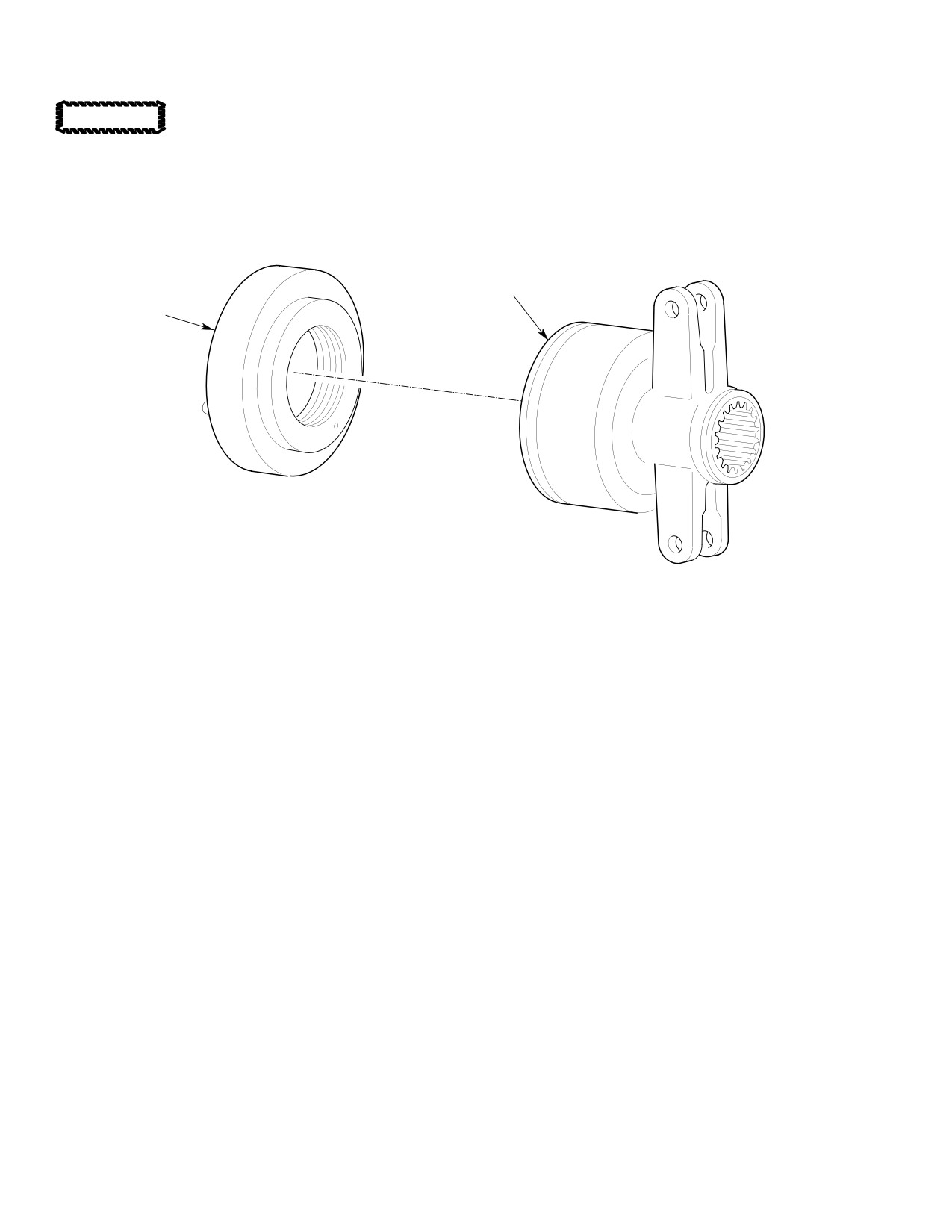
TAIL ROTOR SWASHPLATE
BEARING ASSEMBLY
REGREASE
TOOL
G64-3007
Figure 206. Tail Rotor Swashplate Bearing Regreasing
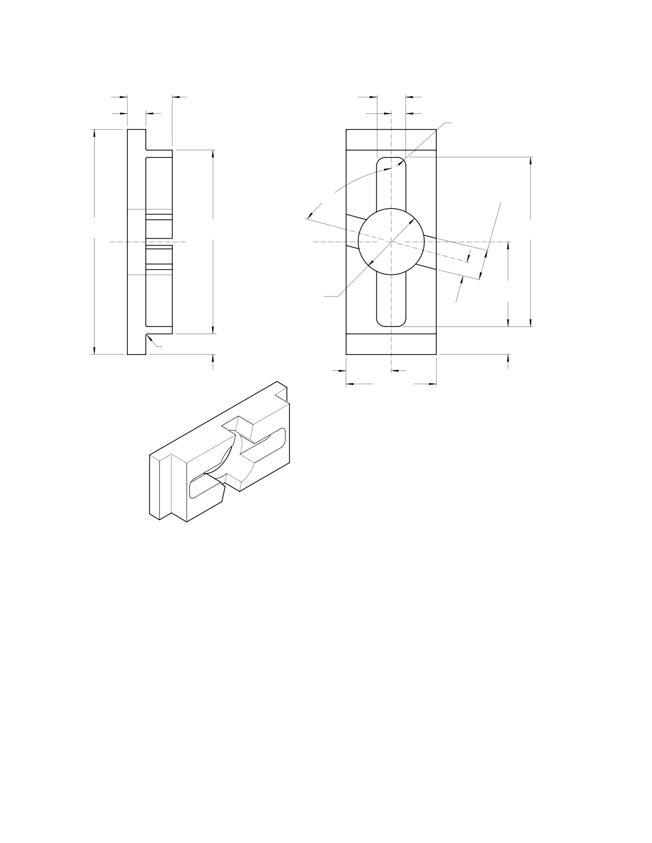
NOTE: For 4-Bladed tail rotor swashplates,
NOTE: The following procedure provides 100%
holding block (ST608) will need to be modi
grease fill. Normal grease fill is 20 to 40%.
fied. Accomplish modification, or build new
Excess grease will extrude past seals for
block, as per Figure 208.
several hours of operation until the proper
level is met.
(4). Using wrench (ST609) and holding
(8). Purge bearings with grease (CM111).
block (ST608), Remove nut and tang
washer from threaded end of swash
(a). Purge bearings slowly to prevent
plate. Discard tang washer.
damage to outer seal.
(b). Rotate bearings while greasing.
(5). Carefully remove bearing grease seal at
gearbox end of housing (seal will be
(9). Remove plastic wedge (or equivalent
reused at reassembly).
plug) and regreasing tool.
(6). Inspect seal for damage; no damage is
(10). Hand rotate bearing to remove excess
allowed.
grease.
NOTE: Ensure seal is serviceable. If new seal is
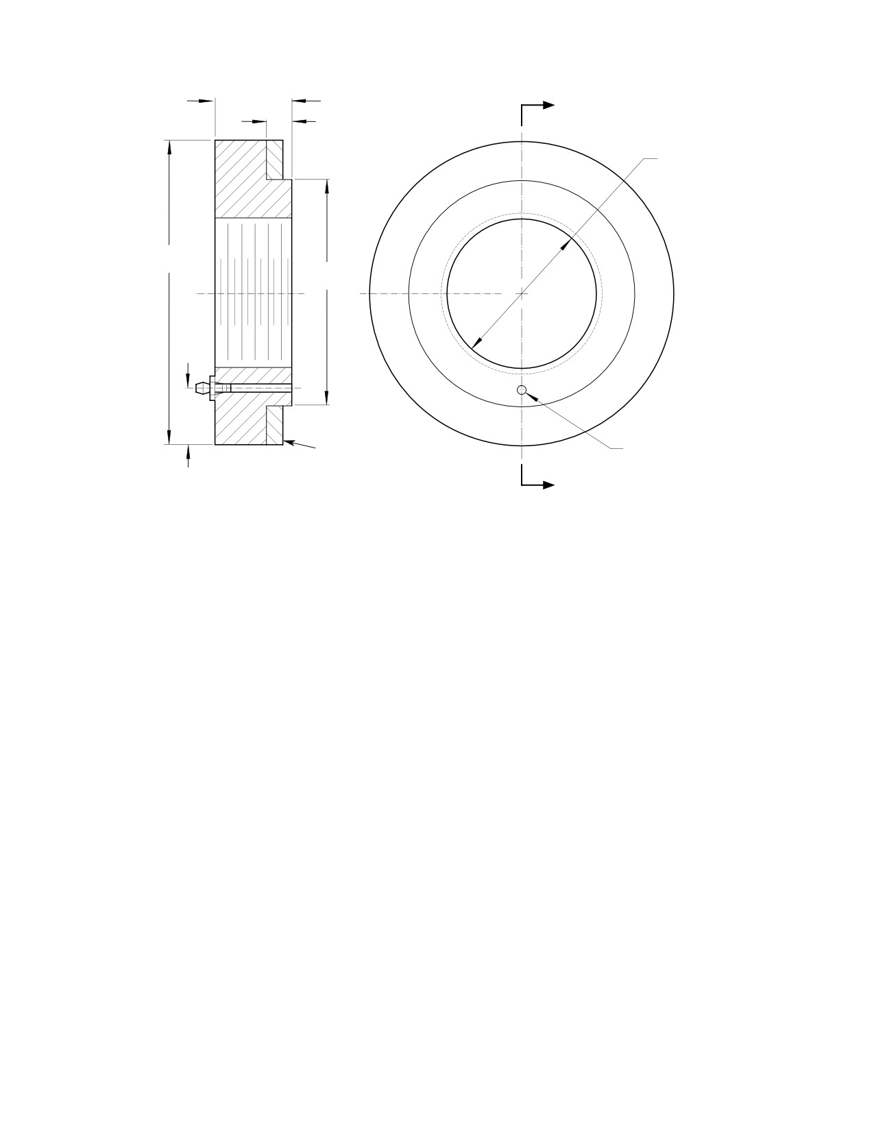
(7). Install regreasing tool (Ref. Figure 207)
required, seals and bearings must come
and plug tang washer groove with
from the same vendor.
locally fabricated plastic wedge (or
equivalent plug).
(11). Install serviceable seal.
Page 210
TR12-001
64-30-00
MD Helicopters, Inc.
CSP-HMI-2
MAINTENANCE MANUAL
0.75 IN. (19.05 MM)
A
0.25 IN. (6.35 MM)
1.563-18 UNJS-3B
THREADS PER MIL-S-8879
3.00 IN.
(7.62 CM)
2.25 IN.
(5.715 CM)
MS15002-1 GREASE FITTING
SEAL MATERIAL
1/4-28 TAPER THREADS 0.093 IN.
(2.3622 MM) DIA THRU HOLE
SECTION A-A
0.50 IN.
(12.70 MM)
A
MATERIAL:
1.
MATERIAL 6061-T651 ALUM PER QQ-A-250/11 OR EQUIVALENT.
2.
SURFACE FINISH 125 RMS.
3.
BREAK SHARP EDGES 0.002-0.015 IN. (0.051-0.381 MM).
4.
CHEMICAL FILM TREAT PER MIL-C-5541.
5.
DIMENSIONAL TOLERANCE ±.030 IN. (±0.762 MM); DIAMETERS TO BE
G64-3006A
Figure 207. Tail Rotor Swashplate Bearing Regreasing Tool
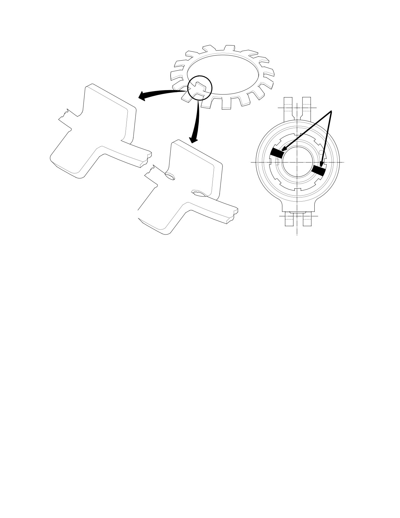
NOTE: Using a 5X to 10X magnifying glass, in
(14). Clean surface of locknut and swash
spect tang washer center tang to ensure it is
plate with a lint-free cloth dampened
acceptable (Ref. Figure 209).
with alcohol (CM217).
(12). Install nut with a new tang washer.
NOTE: Avoid getting torque seal in swashplate
Using wrench (ST609) and holding
splines.
block (ST608), torque nut to 550 - 600
inch-pounds (62.14 - 67.79 Nm).
(15). Apply a 0.125 inch (3.175 mm) wide
torque strip, using torque seal or
(13). Bend one tang of washer into any
equivalent, to surface of swashplate
aligned slot on nut.
assembly and locknut in two places
NOTE: Avoid getting alcohol in bearings.
(Ref. Figure 209).
Page 211
64-30-00
TR12-001
CSP-HMI-2
MD Helicopters, Inc.
MAINTENANCE MANUAL
1.50 IN.
0.980-1.010 IN.
(3.81 CM)
(24.892-25.654 MM)
0.62 IN.
0.50 IN.
(15.748 MM)
(12.70 MM)
.31 R - 4 PLACES
0.980-1.010 IN.
75°
(24.892-25.654 MM)
7.50 IN.
5.75 IN.
5.25 IN.
(19.05 CM)
(14.605 CM)
13.335 CM)
2.62 IN.
2.25 IN.
(6.6548 CM)
(5.715 CM)
DIA THRU
0.50 IN.
(12.70 MM)
1.13 IN.
0.06 R TYP
(2.8702 CM)
1.50 IN.
0.88 IN.
(3.81 CM)
3.00 IN.
(22.352 MM)
(7.62 CM)
MODIFICATION OF 369D29822-3 HOLDING BLOCK FOR USE
WITH 4 - BLADED PITCH CONTROL ASSEMBLY (369D21820).
G64-3008A
Figure 208. Tail Rotor Swashplate Holding Block
Page 212
TR12-001
64-30-00
MD Helicopters, Inc.
CSP-HMI-2
MAINTENANCE MANUAL
TORQUE STRIPE
LOCATIONS
ACCEPTABLE
UNACCEPTABLE
G64-3009
Figure 209. Tang Washer Inspection and Application of Torque Stripe
Page 213
64-30-00
TR12-001
CSP-HMI-2
MD Helicopters, Inc.
MAINTENANCE MANUAL
This Page Intentionally Left Blank
Page 214
TR12-001
64-30-00

MD Helicopters, Inc.
CSP-HMI-2
MAINTENANCE MANUAL
Chapter
67
Flight Controls
MD Helicopters, Inc.
CSP−HMI−2
MAINTENANCE MANUAL
TABLE OF CONTENTS
Para/Figure/Table
Title
Page
67-00-00 Flight Controls (369D/E/FF - 500/600N)
A
Fault Isolation
101
1. Main Rotor Flight Control System Troubleshooting
101
2. Anti-Torque Flight Controls
101
3. Anti-Torque and Control System Troubleshooting
101
4. Stability Augmentation System Troubleshooting
101
Table 101. Troubleshooting Main Rotor Controls
102
Table 102. Isolating Main Rotor Control System Troubles
103
Table 103. Isolating Tail Rotor Control System Troubles
104
Table 104. Anti-torque Fan System Troubleshooting
104
Figure 101. YSAS Electrical Diagram (Sheet 1 of 2)
105
Figure 102. YSAS Troubleshooting (Sheet 1 of 4)
107
Figure 103. YSAS Ground Test Box
111
67-10-00 Main Rotor Flight Controls (369D/E/FF - 500/600N)
A
Description and Operation
1
1.
Main Rotor Flight Controls
1
A. Collective Mixer, Lateral and Longitudinal Mixer (Tunnel-Routed)
Control Rods
1
B. Controls Support Bracket and Bellcranks
1
C. Collective Controls
1
D. Pilot's Collective Pitch Stick
1
E. Copilot's Collective Pitch Stick
1
F. Collective Pitch Stick Friction
1
G. Collective Control Interconnecting Torque Tube
2
H. Collective Bungee
2
I. Inboard Collective Stick Socket Assembly
2
J. Cyclic Controls
2
K. Pilot's Cyclic Control Stick
2
L. Copilot's Cyclic Control Stick
3
M. Pilot's Compartment Lateral and Longitudinal Cyclic Control Linkage
3
N. One-Way Lock Control System
3
O. Cyclic Trim Actuators
3
P. Roof-Mounted Control Rods (600N)
3
Q. Roof-Mounted Bellcranks (600N)
3
Figure 1. Main Rotor and Control System (369D/E/FF - 500N)
4
Figure 2. Main Rotor and Control System (600N)
5
Page i
67 Contents
Revision 42
CSP−HMI−2
MD Helicopters, Inc.
MAINTENANCE MANUAL
TABLE OF CONTENTS (Cont.)
Para/Figure/Table
Title
Page
Removal/Installation
401
1.
Tunnel-Routed Control Rod Replacement
401
A. Tunnel-Routed Control Rod Removal
401
B. Tunnel-Routed Control Rod Installation
401
2.
Roof-Mounted Control Rod Replacement (600N)
401
A. Roof-Mounted Control Rod Removal (600N)
401
Figure 401. Tunnel-Routed Control Rod Installation
402
Figure 402. Roof-Mounted Controls Installation
403
B. Roof-Mounted Control Rod Installation (600N)
403
3.
Roof-Mounted Bellcrank Replacement (600N)
403
A. Roof-Mounted Bellcrank Removal (600N)
403
B. Roof-Mounted Bellcrank Installation (600N)
404
4.
Link Assembly Replacement (600N)
404
A. Link Assembly Removal (600N)
404
B. Link Assembly Installation (600N)
404
5.
Controls Support Bracket and Bellcrank Replacement
404
A. Controls Support Bracket and Bellcrank Removal
404
Figure 403. Controls Support Bracket, Idler Bellcranks and Cyclic Trim
Actuators Installation
405
B. Controls Support Bracket and Bellcrank Installation
406
6.
Pilot's Collective Pitch Stick Replacement (L/H Command)
406
A. Pilot's Collective Pitch Stick Removal (L/H Command)
406
Figure 404. Dual Collective Controls (L/H Command)
407
B. Pilot's Collective Pitch Stick Installation (L/H Command)
408
7.
Pilot's Collective Pitch Stick Replacement (R/H Command)
408
A. Pilot's Collective Pitch Stick Removal (R/H Command)
408
B. Pilot's Collective Pitch Stick Installation (R/H Command)
408
Figure 405. Dual Collective Controls (R/H Command)
409
8.
Copilot's Collective Pitch Stick Replacement (L/H Command)
410
A. Copilot's Collective Pitch Stick Removal (L/H Command)
410
B. Copilot's Collective Pitch Stick Installation (L/H Command)
410
Figure 406. CoPilot's Collective Stick Assembly Installation (L/H Command)
410
9.
Copilot's Collective Pitch Stick Replacement (R/H Command)
411
A. Copilot's Collective Pitch Stick Removal (R/H Command)
411
B. Copilot's Collective Pitch Stick Installation (R/H Command)
411
Page ii
Revision 42
67 Contents
MD Helicopters, Inc.
CSP−HMI−2
MAINTENANCE MANUAL
TABLE OF CONTENTS (Cont.)
Para/Figure/Table
Title
Page
10. Collective Control Interconnecting Torque Tube Replacement
411
A. Collective Control Interconnecting Torque Tube Removal
411
B. Collective Control Interconnecting Torque Tube Installation
412
11. Collective Bungee Replacement
412
A. Collective Bungee and Over-Center Fitting - Removal
412
Figure 407. Collective Torque Tube, Gas Producer Torque Tube and
Collective Bungee
413
Figure 408. Inboard Collective Stick Socket Assembly (L/H Command)
414
B. Collective Over-Center Fitting and Bungee - Installation and
Preliminary Adjustment
415
12. Inboard Collective Stick Socket Assembly Replacement
415
A. Inboard Collective Stick Socket Assembly Removal
415
B. Inboard Collective Stick Socket Assembly Installation
415
13. Cyclic Control Stick Replacement (Inboard)
416
A. Cyclic Control Stick Removal (Inboard)
416
B. Cyclic Control Stick Installation (Inboard)
416
Figure 409. Cyclic Stick Assembly Installation (Inboard)
417
14. Cyclic Control Stick Replacement (Outboard)
417
A. Cyclic Control Stick Removal (Outboard)
417
B. Cyclic Control Stick Installation (Outboard)
417
Figure 410. Cyclic Stick Assembly Installation (Outboard)
418
15. Lateral Control Rods and Sta. 67 Lateral Cyclic Bellcrank Replacement
(L/H Command)
418
A. Lateral Control Rods and Sta. 67 Lateral Cyclic Bellcrank Removal
(L/H Command)
418
B. Lateral Control Rods and Sta. 67 Lateral Cyclic Bellcrank Installation
(L/H Command)
418
Figure 411. Cyclic Controls (R/H Command)
419
16. Lateral Control Rods and Sta. 67 Lateral Cyclic Bellcrank Replacement
(R/H Command)
420
A. Lateral Control Rods and Sta. 67 Lateral Cyclic Bellcrank Removal
(R/H Command)
420
B. Lateral Control Rods and Sta. 67 Lateral Cyclic Bellcrank Installation
(R/H Command)
420
17. Cyclic Pitch Interconnecting Torque Tube Replacement (L/H Command)
420
A. Cyclic Pitch Interconnecting Torque Tube Removal (L/H Command)
420
Figure 412. Cyclic Torque Tube and One-Way Lock Installation
421
B. Cyclic Pitch Interconnecting Torque Tube Installation (L/H Command)
422
Page iii
67 Contents
Revision 42
CSP−HMI−2
MD Helicopters, Inc.
MAINTENANCE MANUAL
TABLE OF CONTENTS (Cont.)
Para/Figure/Table
Title
Page
18. Cyclic Pitch Interconnecting Torque Tube Replacement (R/H Command)
422
A. Cyclic Pitch Interconnecting Torque Tube Removal (R/H Command)
422
B. Cyclic Pitch Interconnecting Torque Tube Installation (R/H Command)
422
19. One-Way Lock Replacement
422
A. One-Way Lock Removal
422
B. One-Way Lock Installation
423
20. Cyclic Trim Actuator Replacement
423
A. Cyclic Trim Actuator Removal
423
B. Cyclic Trim Actuator Installation
423
Adjustment/Test
501
1.
Cyclic and Collective Control System Rigging
501
2.
Collective Controls Rigging (L/H Command) (369D/E/FF - 500N)
501
Figure 501. Main Rotor Control System Rigging (369D/E/FF - 500N)
(Sheet 1 of 3)
502
Figure 502. Rigging Main Rotor Control System (600N) (Sheet 1 of 3)
505
Figure 503. Cyclic and Collective Controls Rigging Tools (R/H Command)
508
3.
Collective Controls Rigging (R/H Command) (369D/E/FF - 500N)
509
4.
Collective Control System Rigging (L/H Command) (600N)
509
5.
Collective Controls Rigging (R/H Command) (600N)
510
6.
Cyclic Controls Rigging (L/H Command) (369D/E/FF - 500N)
510
7.
Cyclic Controls Rigging (R/H Command) (369D/E/FF - 500N)
513
8.
Cyclic Controls Rigging (L/H Command) (600N)
513
9.
Cyclic Controls Rigging (R/H Command) (600N)
515
10.
Gas Producer Linkage Adjustment
515
Figure 504. Gas Producer Drive Backlash Adjustment
(Outboard Collective Stick)
516
Figure 505. Gas Producer Drive Backlash Adjustment
(Inboard Collective Stick)
517
11.
Pipe Plug Adjustment
518
12.
Gas Producer Interconnecting Torque Tube Assembly Shimming
(0003D thru 0929D)
518
Figure 506. Gas Producer Interconnecting Torque Tube Shimming Procedure
(0003D thru 0929D) (Sheet 1 of 2)
519
13.
Collective Stick Friction Mechanism Adjustment
521
Figure 507. Collective Stick Friction Adjustment
522
14.
Collective Bungee Adjustment
523
15.
Cyclic Trim Actuator Bench Testing (369D/E/FF - 500N)
524
Page iv
Revision 42
67 Contents
MD Helicopters, Inc.
CSP−HMI−2
MAINTENANCE MANUAL
TABLE OF CONTENTS (Cont.)
Para/Figure/Table
Title
Page
16. Cyclic Trim Actuator Bench Testing (600N)
525
Figure 508. Cyclic Trim Actuator Assembly
527
Figure 509. Cyclic Trim Wiring Diagram
528
Figure 510. Wiring Diagram and Cable Routing (Collective Stick)
529
Figure 511. Wiring Diagram and Cable Routing (Cyclic Stick)
530
Inspection/Check
601
1. Tunnel-Routed Control Rod Inspection
601
Figure 601. Tunnel-Routed Control Rod Inspection
602
2. Controls Support Bracket and Bellcrank Inspection
603
3. Pilot's Collective Pitch Stick Inspection
603
4. Copilot's Collective Pitch Stick Inspection
603
5. Collective Stick Friction Mechanism Operational Check
603
Figure 602. Outboard Collective Stick Inspection (L/H Command)
604
Figure 603. Outboard Collective Stick Inspection (R/H Command)
605
6. Collective Control Interconnecting Torque Tube Inspection
606
7. Collective Bungee Inspection
606
8. Inboard Collective Stick Socket Assembly Inspection
606
9. Pilot's Cyclic Control Stick Inspection
606
10. Copilot's Cyclic Control Stick Inspection
607
11. One-Way Lock Inspection
607
12. Cyclic Trim Actuator Inspection
607
13. Cyclic Control System Operational Check
607
Figure 604. Cyclic Stick and Friction Inspection
608
14. Main Rotor Flight Control System 600-Hour Inspection
609
Repairs
801
1. Tunnel-Routed Control Rod Repair
801
2. Tunnel-Routed Control Tube Inspection and Sleeve Installation
801
A. Control Tube End Sleeve Installation
801
Figure 801. Sleeve Fabrication and Installation
802
Table 801. Control Tube Re-Identification
803
B. Control Tube Straight Area Sleeve Installation
804
Table 802. Control Tube Straight Area Repair Limits
804
3. Controls Support Bracket and Bellcrank Disassembly
805
4. Controls Support Bracket and Bellcrank Repair
805
5. Controls Support Bracket and Bellcrank Reassembly
805
6. Pilot's Collective Pitch Stick Disassembly (L/H Command)
805
Figure 802. Control Tube Boot Rework
806
Page v
67 Contents
Revision 42
CSP−HMI−2
MD Helicopters, Inc.
MAINTENANCE MANUAL
TABLE OF CONTENTS (Cont.)
Para/Figure/Table
Title
Page
7.
Pilot's Collective Pitch Stick Repair (L/H Command)
806
8.
Pilot's Collective Pitch Stick Reassembly (L/H Command)
807
9.
Pilot's Collective Pitch Stick Disassembly (R/H Command)
808
10.
Pilot's Collective Pitch Stick Reassembly (R/H Command)
808
11.
Copilot's Collective Pitch Stick Disassembly (L/H and R/H Command)
809
12.
Copilot's Collective Pitch Stick Repair
809
13.
Copilot's Collective Pitch Stick Reassembly
809
14.
Collective Control Interconnecting Torque Tube Repair
810
15.
Collective Bungee Disassembly
811
16.
Collective Bungee Reassembly
811
17.
Inboard Collective Stick Socket Assembly Disassembly
811
18.
Inboard Collective Stick Socket Assembly Repair
812
19.
Inboard Collective Stick Socket Assembly Reassembly
812
20.
Cyclic Control Stick Repair
813
21.
Cyclic Friction Mechanism Repair
813
22.
Lateral Control Rods and Sta. 67 Bellcrank Repair
813
23.
Cyclic Pitch Interconnecting Torque Tube Repair
814
24.
One-Way Lock Repair
814
25.
Cyclic Trim Actuator Spring Assembly Replacement
814
26.
Cyclic Trim Actuator Housing or Trim Tube Replacement
815
27.
Cyclic Trim Actuator (Motor/Gear Drive Mechanism) Replacement
815
28.
Cyclic Trim Actuator Rework (Calco P/N 8222M6 and 8222M7)
815
67-10-20 Collective and Cyclic Stick Grips (369D/E/FF - 500/600N)
A
Maintenance Practices
201
1. Collective Pitch Stick Switches
201
2. Collective Pitch Stick Switches Replacement
201
3. Cyclic Stick Grip Switches
201
4. Cyclic Control Stick Grip Replacement
201
A. Cyclic Control Stick Grip Removal
201
B. Cyclic Control Stick Grip Installation
201
Figure 201. Collective Pitch Stick Switch Replacement
202
Figure 202. Cyclic Stick Grips
203
Figure 203. Cyclic Stick Grip Disassembly (Sheet 1 of 2)
204
Page vi
Revision 42
67 Contents
MD Helicopters, Inc.
CSP−HMI−2
MAINTENANCE MANUAL
TABLE OF CONTENTS (Cont.)
Para/Figure/Table
Title
Page
5. Cyclic Stick Grip Switch Replacement (Standard Grip)
206
6. Cyclic Stick Grip Disassembly (Optional T-Grip, PN 369D297846 Only)
207
7. Cyclic Stick Grip Reassembly and Modification
207
Figure 204. Rework of Cyclic Stick Grip
208
67-20-10 Anti-Torque Flight Controls (Two and Four Blade) (369D/E/FF)
A
Description and Operation
1
1. Tail Rotor Control Configuration
1
2. Upper Fuselage and Tailboom Control Linkage
1
Figure 101. Tail Rotor and Control System
2
Removal/Installation
401
1.
Sta. 120 Control Rod or Sta. 142 Bellcrank Replacement
401
A. Sta. 120 Control Rod or Sta. 142 Bellcrank Removal
401
B. Sta. 120 Control Rod or Sta. 142 Bellcrank Installation
401
Figure 401. Upper Fuselage and Boom Tail Rotor Control Linkage
402
2.
Sta. 284 Bellcrank Replacement
403
A. Sta. 284 Bellcrank Removal
403
B. Sta. 284 Bellcrank Installation
403
3.
Tailboom Control Rod Replacement
403
A. Tailboom Control Rod Removal
403
B. Tailboom Control Rod Installation
403
4.
Sta. 95 Bellcrank and Support Replacement
403
A. Sta. 95 Bellcrank and Support Removal
403
Figure 402. Tail Rotor Pedal Installation (Sheet 1 of 2)
404
B. Sta. 95 Bellcrank and Support Installation
405
C. Tail Rotor Pedal Assembly - General
405
D. Co-Pilot's Pedal Installation
406
5.
Tail Rotor Pedal Assembly Replacement
406
A. Tail Rotor Pedal Assembly Removal
406
B. Tail Rotor Pedal Assembly Installation
406
6.
Dual Tail Rotor Pedal Initial Installation
407
Adjustment/Test
501
1. Tail Rotor Controls Rigging
501
Figure 501. Rigging - Tail Rotor Control System
502
2. Tail Rotor Bungee Adjustment
503
Figure 502. Tail Rotor Bungee Adjustment
504
Page vii
67 Contents
Revision 42
CSP−HMI−2
MD Helicopters, Inc.
MAINTENANCE MANUAL
TABLE OF CONTENTS (Cont.)
Para/Figure/Table
Title
Page
Inspection/Check
601
1. Upper Fuselage and Tailboom Control Linkage Inspection
601
2. Tail Rotor Pedal Assembly Inspection
601
Table 601. Isolating Control System Troubles
602
Repairs
801
1. Floor- and Tunnel-Routed Control Rods
801
2. Floor-Routed Tail Rotor Control Rod Repair
801
3. Upper Fuselage and Tailboom Control Linkage Repair
801
Figure 801. Rework of Sta. 142 Bellcrank Assembly
803
4. Station 78.50 Tail Rotor (Tunnel-Routed) Control Rod
803
A. Tail Rotor Idler Bellcrank
803
5. Tail Rotor Pedal Disassembly
803
6. Tail Rotor Pedal Repair
803
7. Tail Rotor Pedal Reassembly
804
8. Tail Rotor Bungee Spring Forward Attachment Relocation
804
Figure 802. Relocation of Tail Rotor Bungee Spring Forward Attachment
805
67-20-30 NOTAR) Anti-Torque System Flight Controls (500/600N)
A
Description and Operation
1
1. NOTAR Anti-Torque System Control Linkages Configuration and Description . .
1
2. Stability Augmentation System Description and Operation
1
3.
500NM7301 YSAS Fin Position Indicator (U.K. Only)
2
Table 1. 500NM7301 YSAS Fin Position Indicator Components
2
Removal/installation
401
1. Anti-Torque Flight Controls
401
2. Upper Fuselage Sta. 97.50 (500N) or Sta. 95 (600N) Bellcrank and Support Bracket
Replacement
401
A. Sta. 97.50 (500N) or Sta. 95 (600N) Bellcrank and Support Bracket Removal .
401
B. Sta. 97.50 (500N) or Sta. 95 (600N) Bellcrank and Support Bracket
Installation
401
3. Forward Directional Control Tube Replacement
401
A. Forward Directional Control Tube Removal
401
B. Forward Directional Control Tube Installation
401
Page viii
Revision 42
67 Contents
MD Helicopters, Inc.
CSP−HMI−2
MAINTENANCE MANUAL
TABLE OF CONTENTS (Cont.)
Para/Figure/Table
Title
Page
4.
Splitter Bungee Spring Replacement (500N)
401
A. Splitter Bungee Spring Removal
402
B. Splitter Bungee Spring Installation
402
5.
Upper Fuselage Station 113.00 Splitter Assembly and Bellcrank Replacement . .
402
A. Station 113.00 Splitter Assembly and Bellcrank Removal
402
B. Station 113.00 Splitter Assembly and Bellcrank Installation
402
6.
Intermediate Control Tube Replacement
402
A. Intermediate Control Tube Removal
402
Figure 401. Anti-Torque Control System
403
B. Intermediate Control Tube Installation
404
7.
Station 137.50 Support Bracket and Bellcrank Replacement
404
A. Station 137.50 Support Bracket and Bellcrank Removal
404
B. Station 137.50 Support Bracket and Bellcrank Installation
404
8.
Fan Pitch Control Tube Replacement
405
A. Fan Pitch Control Tube Removal
405
B. Fan Pitch Control Tube Installation
405
9.
Forward Cable Assembly Replacement
406
A. Forward Cable Assembly Removal
406
Figure 402. Upper Fuselage and Boom Control Linkage (Sheet 1 of 2)
407
B. Forward Cable Assembly Installation
409
10. Center Cable Assembly Replacement
409
A. Center Cable Assembly Removal
409
B. Center Cable Assembly Installation
410
11. Aft Control Rod Assembly Replacement
410
A. Aft Control Rod Assembly Removal
410
B. Aft Control Rod Assembly Installation
410
12. Sector Assembly and Control Cable Replacement
411
A. Sector Assembly and Control Cable Removal
411
B. Sector Assembly and Control Cable Installation
411
13. Drum Assembly and Idler Pulley Replacement
411
A. Drum Assembly and Idler Pulley Removal
411
B. Drum Assembly and Idler Pulley Installation (500N)
412
C. Drum Assembly and Idler Pulley Installation (600N)
412
Page ix
67 Contents
Revision 42
CSP−HMI−2
MD Helicopters, Inc.
MAINTENANCE MANUAL
TABLE OF CONTENTS (Cont.)
Para/Figure/Table
Title
Page
14. Anti-Torque Pedal Friction Replacement
412
A. Anti-Torque Pedal Friction Removal
412
B. Anti-Torque Pedal Friction Installation
412
15. Anti-Torque Pedal Assembly Replacement
412
A. Anti-Torque Pedal Assembly Removal
412
Figure 403. Pedal Installation (Sheet 1 of 2)
413
B. Anti-Torque Pedal Assembly Installation
414
16. Stability Augmentation System (S.A.S.) Actuator Replacement
415
A. S.A.S. Actuator Removal
415
B. S.A.S. Actuator Installation
415
17. S.A.S. Rate Gyro and Electronic Control Box (Computer) Replacement
415
A. S.A.S. Rate Gyro and Electronic Control Box (Computer) Removal
416
B. S.A.S. Rate Gyro and Electronic Control Box (Computer) Installation
416
Adjustment/Test
501
1. Directional Controls Rigging
501
2. Fan Pitch Control Rigging
501
Figure 501. Fan Pitch Control Rigging
502
3. Pilot Pedal Rigging
503
Figure 502. Pilot Pedal Rigging
504
4. Anti-Torque Pedal Friction Installation and Adjustment
505
5. Thruster Control Rigging (500N)
505
Figure 503. Thruster Control Rigging (Sheet 1 of 2)
506
6. Thruster Control Rigging (600N)
508
7. Left Vertical Stabilizer Assembly Rigging (500N, and 600N with YSAS)
508
8. Stability Augmentation System Rigging Instructions
(500N, and 600N with YSAS)
509
9. Vertical Stabilizer Assembly Rigging (600N without YSAS System)
509
Figure 504. Left Vertical Stabilizer Rigging (500N, and 600N with YSAS)
510
Figure 505. Stability Augmentation System S.A.S. (Sheet 1 of 2)
511
Figure 506. Vertical Stabilizer Rigging (600N without YSAS)
513
Page x
Revision 42
67 Contents
MD Helicopters, Inc.
CSP−HMI−2
MAINTENANCE MANUAL
TABLE OF CONTENTS (Cont.)
Para/Figure/Table
Title
Page
10. Vertical Stabilizer Trim Tab Adjustment and Tool Manufacturing
(600N without YSAS)
514
A. Trim Tab Tool Manufacturing
514
B. Trim Tab Adjustment
514
Figure 507. Vertical Stabilizer Trim Tab Bending Tool
515
Table 501. Flight Controls Troubleshooting
516
Inspection/Check
601
1. Upper Fuselage and Tailboom Control Linkage Inspection
601
2. Anti-Torque Pedal Assembly Inspection
601
3. Sta. 97.50 (500N) or Sta. 95 (600N) Bellcrank and Support Bracket Inspection . .
601
4. Forward and Intermediate Directional Control Tube, and Link Inspection
601
5. Splitter Bungee Spring Inspection (500N)
602
6. Sta. 113.00 Splitter Assembly and Bellcrank Inspection
602
7. Forward and Center Cable Assembly Inspection
602
8. YSAS Actuator, Rate Gyro and Electronic Control Box Inspection
602
9. Fan Pitch Control Tube Inspection
602
Table 601. Isolating Control System Troubles
603
Figure 601. Control Cable Coupling Inspection
603
Figure 602. Forward and Center Cable Relief Area Inspection
604
Figure 603. Control Cable Telescopic Swivel End Inspection
605
10. Sector Assembly, Control Cables and Drum Assembly Inspection
606
Repairs
801
1. Anti-Torque Flight Control Repair - General
801
2. Sta. 97.50 (500N) or Sta. 95 (600N) Bellcrank and Support Bracket Repair
801
3. Forward Directional Control Tube Repair
801
4. Upper Fuselage Sta. 113.00 Splitter Assembly Repair
801
5. Intermediate Control Tube Repair
801
6. Sta. 137.50 Support Bracket and Bellcrank Repair
802
7. Fan Pitch Control Tube Repair
802
8. Forward Cable Assembly Repair
802
9. Center Cable Assembly Repair
802
Page xi
67 Contents
Revision 42
CSP−HMI−2
MD Helicopters, Inc.
MAINTENANCE MANUAL
TABLE OF CONTENTS (Cont.)
Para/Figure/Table
Title
Page
10. Aft Control Rod Repair
802
11. Thruster Sector Assembly Repair
802
12. Drum Assembly and Idler Pulleys Repair
802
13. Anti-Torque Pedal Disassembly
802
14. Anti-Torque Pedal Repair
803
15. Anti-Torque Pedal Reassembly
803
16. YSAS Actuator Regrease Procedure
804
A. YSAS Actuator Disassembly
804
B. YSAS Actuator Regrease and Reassembly
805
Figure 801. YSAS Actuator (Cross-Section View)
806
Page xii
Revision 42
67 Contents
MD Helicopters, Inc.
CSP-HMI-2
MAINTENANCE MANUAL
Section
67−00−00
Flight Controls
(369D/E/FF −
500/600N)
MD Helicopters, Inc.
CSP-HMI-2
MAINTENANCE MANUAL
FLIGHT CONTROLS
FAULT ISOLATION
1. Main Rotor Flight Control System
tube, tunnel-routed control tube, Sta. 120
Troubleshooting
control tube and tail boom control rod trans
mitting input through a series of bellcranks
Ensure that rotor controls are
and idlers.
CAUTION
not struck by any object. Many
of the components are highly stressed and
3. Anti−Torque and Control System
must not be returned to service if surface
Troubleshooting
damage occurs. When maintenance work is
performed near engine air inlet, comply
Troubleshooting information is divided into (1)
with precautions (Ref. Chap. 71) to prevent
investigation of operational vibration problems
entry of foreign objects.
originating with the tail rotor or symptoms
that can be recognized (Ref. Chap. 64) and (2)
Troubleshooting information is divided into: (1)
isolation and localization of an unusual
investigation of main rotor vibrations (Ref.
controls malfunction (Ref. Table 103 or
Chap. 62); (2) investigation of symptoms (Ref.
Table 104).
Table 101); and (3) isolation of troubles (Ref.
Table 102).
4. Stability Augmentation System
Troubleshooting
First determine which major installation is
defective. Isolate each linkage installation
Troubleshooting the Yaw Stability Augmenta
from others until area of malfunction is
tion System (YSAS) shall be performed using
located. Then investigate and determine exact
the wiring diagram (Ref. Figure 101) in
location of malfunction and repair or replace
conjunction with the fault isolation tree (Ref.
defective component(s). Since first indication of
Figure 102) and the ground test box (Ref.
trouble usually is felt at cyclic or collective
Figure 103).
pitch stick, isolation procedures in Table 101
and Table 102 begin with symptoms detected
Troubleshooting the YSAS by field mainte
during operation of these controls.
nance personnel shall be limited to isolating
the trouble to a malfunctioning or defective
Sudden onset of excessive
system unit/component.
WARNING
and/or unusual main rotor
vibrations should be investigated as to
For removal or replacement of YSAS compo
cause, prior to continued flight. Under
nents refer to applicable section.
no circumstance should main rotor
Death or injury can occur if
tracking be attempted to correct the
WARNING
proper safety precautions
problem until a thorough inspection of
are not taken while performing electri
the main rotor blades, hub assembly
cal system checks with electrical pow
and strap pack assembly has been per
er on.
formed.
Maintenance personnel other
2. Anti−Torque Flight Controls
CAUTION
than approved manufacturer's
Anti-Torque flight controls consist of anti-tor
representative shall not attempt to repair
que pedals, torque tube, floor-routed control
any part of the YSAS system.
Page 101
67-00-00
Revision 30
CSP-HMI-2
MD Helicopters, Inc.
MAINTENANCE MANUAL
Table 101. Troubleshooting Main Rotor Controls
Symptom
Probable Trouble
Corrective Action
Cyclic stick pressure in one
Check for continuity between pin S
If continuity exists, replace cyclic trim
direction; hands off condition −
and pins R, U, V, and X of
switch, Cyclic Stick Grip Switch
stick drifts in direction of
connector(s) P109 and/or P130.
Replacement (Standard Grip).
pressure.
Symptom remains.
Isolate wiring to circuit components.
If short exists, repair as necessary. If
Check for short circuit between ground
short does not exist, replace cyclic trim
and suspect trim mode circuit.
actuator.
Cyclic control stick pressures
Trim actuator inoperative.
Replace actuator.
cannot be reduced by
Defective components in trim actuator
Troubleshoot control circuits: replace
operating trim switch.
control circuit.
defective electrical component(s).
Trim change is too slow.
Defective trim actuator.
Replace actuator.
Cyclic control sticks have
Low fluid in one−way lock fluid
Add fluid to one−way lock reservoir.
tendency to move to aft
reservoir.
position.
Inadequate cyclic control
Helicopter loaded out of center of
Check and correct weight and
during flight.
gravity range.
balance.
Incorrect cyclic rigging.
Correct cyclic rigging.
Excessive pressure required
Lateral and/or longitudinal friction
Loosen lateral and/or longitudinal
for lateral and/or longitudinal
device improperly adjusted.
friction device.
movement of cyclic control
Swashplate spherical bearing surface
Replace swashplate bearing assembly
stick on ground and during
damaged.
if torque required to rotate bearing
flight. (Some droop friction is
exceeds 32 inch−pounds (3.61 Nm).
always felt when there is no
rotor rpm.)
Scissors crank bearings or hub lower
Replace defective bearings.
shoe bearings binding or frozen.
Lateral and/or longitudinal
Realign rod end bearing.
interconnecting rod end bearing
binding due to incorrect alignment.
Droop stop plungers sticking.
Clean plungers and mating shoe
bushings with isopropyl alcohol
(CM217).
Droop stop followers, rollers and/or
Apply rust inhibitor and lubricants
stop ring rusty or corroded.
(CM204) to followers, rollers and
droop stop ring.
Droop stop striker plate(s) or cam
Replace striker plate and/or cam roller.
roller(s) damaged.
One−way lock check valve, or push
Replace one−way lock assembly.
rod shaft that unseats the valve, is
galled or seized.
Page 102
Revision 21
67-00-00
MD Helicopters, Inc.
CSP-HMI-2
MAINTENANCE MANUAL
Table 102. Isolating Main Rotor Control System Troubles
Symptom
Isolating Step
Corrective Action
Binding, locking−up and
Disconnect one−way lock.
If symptom gone, replace one−way
erratic action of cyclic control
lock.
stick.
Symptom remains.
Disconnect upper ends of longitudinal
If symptom gone and rod ends are
and lateral control rods.
serviceable, disassemble and inspect
main rotor mixer controls until
defective part is located.
Symptom remains.
Reconnect upper ends of longitudinal
If symptom gone and rod ends are
and lateral control rods, and
serviceable, disassemble and inspect
disconnect lower ends.
pilot compartment controls until
defective part is located.
Trouble corrected (Reconnect all control linkage).
Binding, locking−up and
CAUTION: Before disconnecting collective pitch control rod, install collective
erratic action of collective
bungee installation tool (ST508) to prevent spring reaction on control rod.
control stick.
Disconnect upper end of collective
If symptom gone and rod end is
pitch control rod and operate stick.
serviceable, disassemble and inspect
main rotor mixer controls until
defective part is located.
Symptom remains.
Leave upper end of collective pitch
Trouble is in pilot compartment
control rod disconnected.
collective control linkage.
Symptom remains.
WARNING: Do not disconnect any hardware from pilot‘s collective stick unless
collective bungee installation tool (ST508) is installed. Strong bungee spring
pressure can cause linkage reaction and severe personal injury, or parts
damage.
Disconnect gas producer control rod
If symptom gone, trouble is in engine
from collective stick. Disconnect droop
controls.
control override link from collective
controls torque tube.
Symptom remains.
Leave gas producer control rod and
Disassemble and inspect pilot
droop control override link
compartment collective control linkage
disconnected.
until defective part is located.
Trouble corrected (Reconnect all control linkage)
Page 103
67-00-00
Revision 21

CSP-HMI-2
MD Helicopters, Inc.
MAINTENANCE MANUAL
Table 103. Isolating Tail Rotor Control System Troubles
Symptom
Isolating Step
Corrective Action
Binding, locking up and erratic
Disconnect pitch control links from
If symptom gone, replace tail rotor
action of foot pedals. (Do not
pitch control assembly.
assembly or repair (Ref. COM).
force controls)
Symptom remains.
Disconnect Sta. 284 aft boom
If symptom gone, clean swashplate
bellcrank from pitch control assembly.
bore and output shaft splines.
Lubricate splines. Replace swashplate
if necessary. Check for elongation of
bolt hole in support arm portion of
main housing assembly of tail rotor
gear box, caused by looseness of
bellcrank fulcrum bolt and nut. Repair
(Ref. COM).
Symptom remains.
Disconnect floor−routed tail rotor
If symptom gone, inspect tail rotor
control rod from foot pedal torque tube
control rods and bellcranks until
fitting.
defective part is located.
Symptom remains.
Loosen foot pedal torque tube
If symptom gone, pedal torque tube
brackets mounted on front of floor
misaligned; shim for correct alignment.
structure.
If symptom remains, disassemble and
inspect tail rotor foot pedal installation
until defective part is located (same
section).
Trouble corrected.
Table 104. Anti−torque Fan System Troubleshooting
Symptom
Probable Trouble
Corrective Action
Excessive resistance against Binding in controls linkage.
Isolate damage or obstruction and
pedal movements.
remove.
Restriction against rotating cone.
Isolate restriction or damage and
remove.
Binding, locking up or erratic
Control rod or cable restrictions or
Inspect control rod and control cable
action of pedal movement.
misalignment.
connections, rod end condition and
bearing movement, replace
components as required.
Pedals feel rachety.
Flat spotting on thruster rollers.
Replace rollers (Ref. Sec. 53−40−30).
Degraded movement or
Restriction or malfunction at splitter
Inspect splitter range and freedom of
response of fan control
assembly.
movement.
linkage.
Degraded travel of force limiting
Isolate damage or malfunction and
control rod or diffuser bellcrank
replace components.
connections.
Incorrect rigging.
Correct rigging.
Inadequate anti−torque/direc-
Incorrect rigging.
Correct rigging.
tional movement or response
during flight.
Page 104
Revision 29
67-00-00
MD Helicopters, Inc.
CSP-HMI-2
MAINTENANCE MANUAL
START
VERIFY ALL YSAS SYSTEM ASSOCIATED
ELECTRICAL CONNECTORS ARE MATED WITH
NO
COMPONENTS. VERIFY CIRCUIT BREAKER IS
GO TO SHEET 2
PUSHED IN AND YSAS SYSTEM ON/OFF SWITCH IS
ON. IS YSAS STILL INOPERATIVE?
YES
SHUT OFF ELECTRICAL POWER. CHECK FOR
REPAIR OPEN WIRE(S) BETWEEN PIN B
CONTINUITY TO A/C GROUND AT PINS B, E AND
NO
OF SAS COMPUTER AND GROUND
C OF SAS COMPUTER PLUG (P1 FOR 500N: P512
E40-B OR PIN E AND GROUND E40-A
FOR 600N). DOES CONTINUITY EXIST?
OR PIN C AND GROUND E31-S.
YES
SHUT OFF ELECTRICAL POWER. DISCONNECT
NO
REPAIR OPEN WIRE BETWEEN PIN M
SAS COMPUTER PLUG (P1 FOR 500N: P512 FOR
OF SAS COMPUTER AND CB121.
600N). REAPPLY ELECTRICAL POWER AND
CHECK FOR 28 VDC AT PIN M. IS VOLTAGE
PRESENT?
YES
DISCONNECT ELECTRICAL POWER. CONNECT
SAS TEST BETWEEN SAS COMPUTER AND SAS
NO
WIRE HARNESS. REAPPLY ELECTRICAL POWER
REPLACE FAULTY SAS COMPUTER
AND AT SAS TEST BOX, CHECK FOR +15 VDC
AND -15 VDC COMING FROM COMPUTER
POWER SUPPLY. IS VOLTAGE PRESENT?
YES
REMOVE YAW RATE GYRO ATTACHING HARDWARE
AND CAREFULLY ROTATE GYRO IN A CLOCKWISE
NO
DIRECTION. CHECK RIGHT VERTICAL STABILIZER FOR
GO TO SHEET 3
TRAILING EDGE LEFT (INITIAL MOVEMENT ONLY). DOES
RIGHT VERTICAL STABILIZER MOVE?
YES
REMOVE SAS COMPUTER ATTACHING HARDWARE
NO
AND CAREFULLY TILT COMPUTER, CONNECTOR
SIDE UP, CHECK RIGHT VERTICAL STABILIZER
GO TO SHEET 4
TRAILING EDGE RIGHT MOVEMENT. DOES RIGHT
VERTICAL STABILIZER MOVE?
YES
YAW SAS SYSTEM APPEARS TO OPERATE
CORRECTLY.
G67-2017-1A
Figure 102. YSAS Troubleshooting (Sheet 1 of 4)
Page 107
67-00-00
Revision 30
CSP-HMI-2
MD Helicopters, Inc.
MAINTENANCE MANUAL
FROM SHEET 1
NO
DOES RIGHT VERTICAL STABILIZER MOVE OR
YAW SAS SYSTEM APPEARS TO
OSCILLATE WITH NO SENSOR INPUTS?
OPERATE CORRECTLY.
YES
SHUT OFF ELECTRICAL POWER. CONNECT SAS
SHUT OFF ELECTRICAL POWER. CHECK
NO
NO
REPAIR OPEN WIRES BETWEEN YSAS
TEST BOX BETWEEN SAS COMPUTER AND SAS
FOR OPEN WIRES BETWEEN YSAS
COMPUTER AND RIGHT VERTICAL
WIRE HARNESS. REAPPLY ELECTRICAL
COMPUTER AND RIGHT VERTICAL
STABILIZER ACTUATOR.
POWER. CHECK FOR SERVO COMMAND SIGNAL
STABILIZER WIRE HARNESS. DOES
AT TEST BOX BETWEEN SERVO TEST POINT
CONTINUITY EXIST?
AND TEST BOX GROUND. IS SIGNAL VOLTAGE
YES
CHANGING?
REPLACE VERTICAL STABILIZER
YES
ACTUATOR.
CHECK FOR YAW RATE GYRO SIGNAL AT TEST
NO
BOX BETWEEN YAW RATE TEST POINT AND
REPLACE YSAS COMPUTER.
TEST BOX GROUND. IS SIGNAL PRESENT?
YES
SHUT OFF ELECTRICAL POWER. CHECK FOR
OPEN WIRES BETWEEN YSAS COMPUTER AND
YAW RATE GYRO WIRE HARNESS. VERIFY GOOD
NO
GROUND MODULES AND GROUND TERMINATIONS.
YSAS SYSTEM APPEARS TO OPERATE
CORRECTLY.
VERIFY THERE IS NO SHORTED OR CHAFFED
WIRES. APPLY ELECTRICAL POWER AND CHECK
FOR RATE GYRO SIGNAL TO TEST BOX TEST
POINT. IS SIGNAL PRESENT?
YES
REPLACE FAULTY YAW RATE GYRO.
G67-2017-2
Figure 102. YSAS Troubleshooting (Sheet 2 of 4)
Page 108
Revision 30
67-00-00
MD Helicopters, Inc.
CSP-HMI-2
MAINTENANCE MANUAL
FROM SHEET 1
SHUT OFF ELECTRICAL POWER. CHECK
NO
NO
CHECK YAW RATE GYRO TEST POINT ON THE
FOR OPEN WIRES BETWEEN YSAS
REPAIR OPEN WIRES BETWEEN YSAS
YSAS TEST BOX WHILE ROTATING THE YAW RATE
COMPUTER AND YAW RATE GYRO. DOES
COMPUTER AND YAW RATE GYRO.
GYRO. IS A VOLTAGE CHANGE PRESENT?
CONTINUITY EXIST?
YES
YES
REPLACE YAW RATE GYRO.
CHECK THE SERVO COMMAND TEST POINT ON
NO
THE YSAS TEST BOX WHILE ROTATING THE YAW
REPLACE YSAS COMPUTER.
RATE GYRO. IS A VOLTAGE CHANGE PRESENT?
YES
AT THE YSAS TEST BOX, CHECK THE ACTUATOR
SHUT OFF ELECTRICAL POWER. CHECK
NO
NO
REPAIR OPEN WIRES BETWEEN
POSITION TEST POINT TO TEST BOX GROUND
FOR OPEN WIRES BETWEEN YSAS
YSAS COMPUTER AND RIGHT
WHILE ROTATING THE YAW RATE GYRO. IS A
COMPUTER AND RIGHT VERTICAL
VERTICAL STABILIZER ACTUATOR.
VOLTAGE CHANGE PRESENT?
STABILIZER ACTUATOR. DOES CONTINUITY
EXIST?
YES
YES
DISCONNECT THE RIGHT VERTICAL
STABILIZER ACTUATOR PLUG (P4 FOR 500N:
P515 FOR 600N). REAPPLY ELECTRICAL
NO
POWER AND PLACE THE RIGGING SWITCH
REPLACE YSAS COMPUTER.
ON THE YSAS TEST BOX TO THE EXTEND
POSITION. CHECK THE VOLTAGE AT THE
STABILIZER ACTUATOR PLUG AT
TERMINALS S (H) AND A (L). IS VOLTAGE
GREATER THAN 6 VDC?
YES
REPLACE RIGHT VERTICAL STABILIZER
ACTUATOR.
SHUT OFF ELECTRICAL POWER. CHECK RIGHT
VERTICAL STABILIZER FOR PROPER
INSTALLATION OR DAMAGED CONTROL LINKAGE
NO
REPAIR OR REPLACE CONTROL LINKAGE OR
FROM ACTUATOR TO VERTICAL STABILIZER. IS
VERTICAL STABILIZER AND VALIDATE THE
STABILIZER PROPERLY INSTALLED AND FREE
CONTROL RIGGING AS REQUIRED.
FROM DAMAGE?
YES
REPLACE RIGHT VERTICAL STABILIZER
ACTUATOR.
G67-2017-3A
Figure 102. YSAS Troubleshooting (Sheet 3 of 4)
Page 109
67-00-00
Revision 30
CSP-HMI-2
MD Helicopters, Inc.
MAINTENANCE MANUAL
FROM SHEET 1
CHECK THE ACCELERATION TEST POINT ON THE
NO
YSAS TEST BOX WHILE TILTING THE YSAS
REPLACE THE YSAS COMPUTER.
COMPUTER. IS SIGNAL PRESENT?
YES
CHECK THE SERVO COMMAND TEST POINT ON
NO
THE YSAS TEST BOX WHILE TILTING THE YSAS
REPLACE THE YSAS COMPUTER.
COMPUTER. IS A VOLTAGE CHANGE PRESENT?
YES
AT THE YSAS TEST BOX, CHECK THE ACTUATOR
NO
SHUT OFF ELECTRICAL POWER. CHECK FOR
NO
REPAIR OPEN WIRES BETWEEN
POSITION TEST POINT TO TEST BOX GROUND
OPEN WIRES BETWEEN YSAS COMPUTER AND
WHILE TILTING THE YSAS COMPUTER. IS
YSAS COMPUTER AND RIGHT
RIGHT VERTICAL STABILIZER ACTUATOR. DOES
VERTICAL STABILIZER ACTUATOR.
VOLTAGE CHANGE PRESENT?
CONTINUITY EXIST?
YES
YES
DISCONNECT THE RIGHT VERTICAL STABILIZER
ACTUATOR PLUG (P4 FOR 500N: P515 FOR 600N).
REAPPLY ELECTRICAL POWER AND PLACE THE
NO
RIGGING SWITCH ON THE YSAS TEST BOX TO
REPLACE THE YSAS COMPUTER.
THE EXTEND POSITION. CHECK THE VOLTAGE
AT THE STABILIZER ACTUATOR PLUG AT
TERMINALS S (H) AND A (L). IS VOLTAGE
GREATER THAN 6 VDC?
YES
REPLACE RIGHT VERTICAL STABILIZER
ACTUATOR.
SHUT OFF ELECTRICAL POWER. CHECK RIGHT
VERTICAL STABILIZER FOR PROPER
NO
INSTALLATION OR DAMAGED CONTROL LINKAGE
REPAIR OR REPLACE CONTROL LINKAGE OR
FROM ACTUATOR TO VERTICAL STABILIZER. IS
VERTICAL STABILIZER AND VALIDATE THE
STABILIZER PROPERLY INSTALLED AND FREE
CONTROL RIGGING AS REQUIRED.
FROM DAMAGE?
YES
REPLACE RIGHT VERTICAL STABILIZER
ACTUATOR.
G67-2017-4A
Figure 102. YSAS Troubleshooting (Sheet 4 of 4)
Page 110
Revision 30
67-00-00
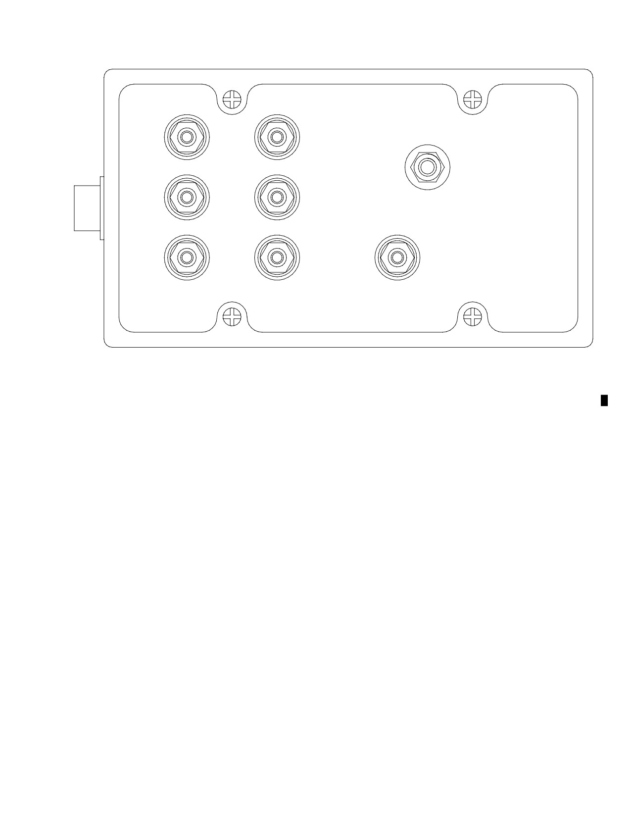
MD Helicopters, Inc.
CSP-HMI-2
MAINTENANCE MANUAL
ACTUATOR
ACCEL
POSITION
EXTEND
OFF
YAW
SERVO
RETRACT
RATE
COMMAND
-15
+15
GROUND
VDC
VDC
G67-2018
Figure 103. YSAS Ground Test Box
Page 111
67-00-00
Revision 30
CSP-HMI-2
MD Helicopters, Inc.
MAINTENANCE MANUAL
This Page Intentionally Left Blank
Page 112
Revision 43
67-00-00
MD Helicopters, Inc.
CSP-HMI-2
MAINTENANCE MANUAL
Section
67−10−00
Main Rotor Flight
Controls (369D/E/FF
− 500/600N)