HANDBOOK OF MAINTENANCE INSTRUCTIONS FOR MDHI 369D/E/FF-500/600N HELICOPTERS (ISSUED: 1990) - page 25
CSP-HMI-2
MD Helicopters, Inc.
MAINTENANCE MANUAL
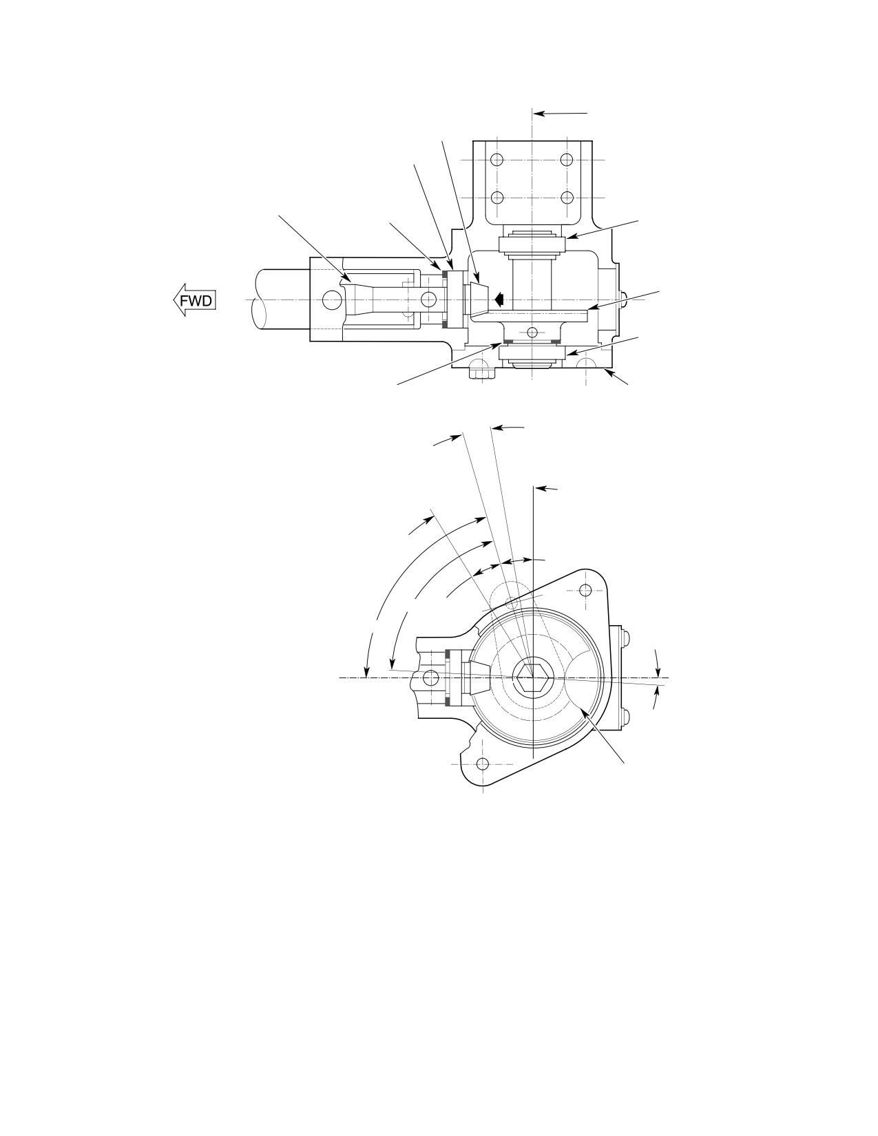
PINION GEAR MOUNTING DISTANCE
0.699-0.709 IN. (17.7546-18.0086 MM)
PINION GEAR
PINION BEARING
SPLIT SHIMS
GAS PRODUCER TORQUE TUBE
(NOTES 1, 3)
BEARING
DRIVEN GEAR
BEARING
BACKLASH SHIM(S)
TOP VIEW
HOUSING CAP
(NOTES 2, 3)
GENERAL NOTE:
IDLE STOP
SHIM SELECTED AS REQUIRED.
6°
STEEL SHIMS PROVIDED IN 0.001, 0.002,
GRIP MID-TRAVEL
0.005, 0.012 AND 0.032 IN.≥≥.025, 0.051,
0.127, 0.305, 0.813 MM) THICKNESS.
N1 CLOSED
N1 OPEN
15°
70° 40'
15°
73° 30'
2° 50'
(NOTE 5)
CENTERLINE OF GAS
PRODUCER TORQUE TUBE
(NOTE 4)
CUTOUT IN
DRIVEN GEAR
LEFT SIDE VIEW
NOTES:
1.
DETERMINES GEAR MOUNTING DISTANCE.
2.
DETERMINES GEAR BACKLASH MAXIMUM 0.003 IN. (0.0762 MM).
3.
SELECTED AS REQUIRED; STEEL SHIMS AVAILABLE IN 0.001, 0.002, 0.005,
0.0012 AND 0.032 IN. (0.025, 0.051, 0.127, 0.305, 0.813 MM) THICKNESSES.
4.
ALSO CENTERLINE OF PINION GEAR AND CUTOUT IN DRIVEN GEAR.
5.
CENTERLINE OF CENTER TOOTH ON DRIVEN GEAR.
G67-1014B
Figure 504. Gas Producer Drive Backlash Adjustment (Outboard Collective Stick)
Page 516
Revision 36
67-10-00
MD Helicopters, Inc.
CSP-HMI-2
MAINTENANCE MANUAL
NOTE:
SHIM SELECTED AS REQUIRED.
STEEL SHIMS PROVIDED IN 0.001, 0.002,
0.005, 0.012 AND 0.032 IN. ((0.025, 0.051,
0.127, 0.305, 0.813 MM) THICKNESS.
AFT BEARING
LOCK RING
LOCK RING
FORWARD BEARING
2° 50'
15°
70° 40'
73° 30'
15°
6°
IDLE STOP
N1 OPEN
N1 CLOSED
(R/H COMMAND)
GRIP/N1 PINION GEAR
N1 CLOSED
MID-TRAVEL
(L/H COMMAND)
ROTATED 90 DEGREES
(LINK AND IDLER REMOVED FOR CLARITY)
IDLER
BELLCRANK
LINK
BEARING
WIDE TOOTHSPACE
ON SPLINE
BACKLASH SHIM(S)
BEARING
(SEE NOTE)
LOOKING DOWN
G67-1023A
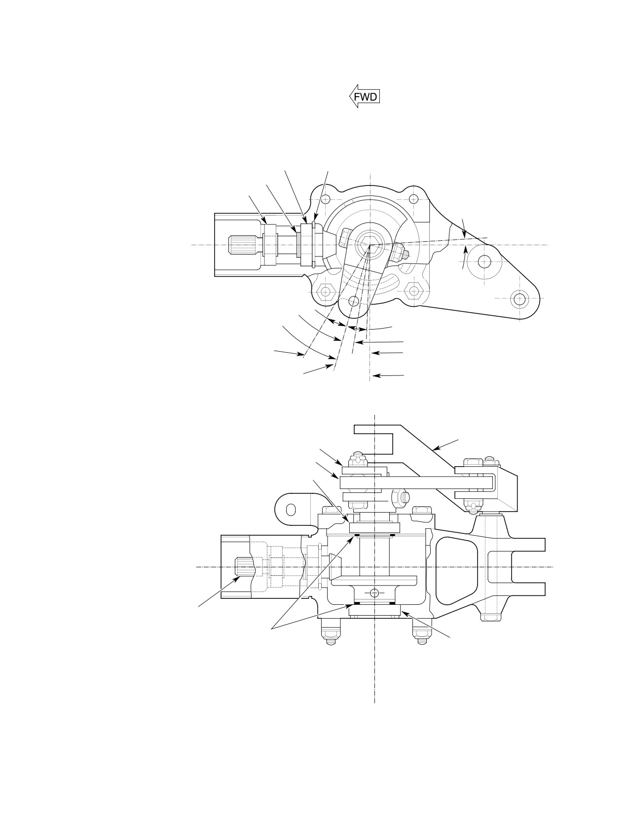
Figure 505. Gas Producer Drive Backlash Adjustment (Inboard Collective Stick)
Page 517
67-10-00
Revision 21
CSP-HMI-2
MD Helicopters, Inc.
MAINTENANCE MANUAL
(8). Install backlash shims and gear shaft
(6). Reinstall bolt to secure bellcrank to
in pilot's collective stick socket housing.
inboard gearshaft.
Ensure that gearshaft and pinion are
aligned and mated when pilot's throttle
(7). Reinstall snap plug in exterior skin.
grip is at mid-travel.
(8). Reinstall pilot seat cover.
NOTE: Make sure that shims are installed in
original locations.
NOTE: If optional dual controls are installed,
perform following rigging and deceleration
(9). Reinstall outboard bearing and cap on
checks using copilot throttle.
pilot's stick housing.
(9). Check engine gas producer controls
(10). Check that both pilot's throttle grip and
rigging (Ref. Chap. 76).
inboard collective pitch stick socket N1
pinion gear wide toothspace are correct
(10). Perform deceleration check (Ref. Pilot's
at mid-travel.
Flight Manual).
(11). Remove snap plug from skin, rotate
12. Gas Producer Interconnecting Torque
pilot's throttle grip and visually check
Tube Assembly Shimming (0003D thru
for evidence of backlash between gas
0929D)
producer interconnect torque tube and
hexagonal interior surfaces of gear
(Ref. Figure 506)
shaft. If necessary, remove cover and
gearshaft from torque tube and elimi
(1).
Remove pilot's seat cover and access
nate any backlash by tightening pipe
door.
plug in end of torque tube. Zero back
lash is required at both ends of tube.
(2).
Make an index mark on end of collec
Reinstall snap plug.
tive torque tube fitting flush with
inboard end of pilot's collective stick
11. Pipe Plug Adjustment
assembly housing using a felt pen or
pencil. Do not scribe index mark on
(Ref. Figure 407)
fitting.
(1). Remove pilot seat cover for access to
(3).
Remove four bolts securing pilot's
under seat controls.
collective stick assembly to end of
collective torque tube fitting.
(2). Remove snap plug from exterior skin.
(4).
Loosen pipe plug in end of gas producer
(3). Remove bolt securing bellcrank to
interconnecting torque tube which
inboard gearshaft.
secures it to gas producer gearshaft in
(4). Position throttle midway between idle
pilot's collective stick assembly.
stop and full open.
(5).
Remove pilot's collective stick assembly.
(5). With assistant, tighten pipe plugs at
each end of torque tube simultaneously;
(6).
Using rubber mallet or equivalent soft
maintain throttle as set in step (4).
tool, tap gas producer interconnecting
Initial torque required to turn pipe
torque tube assembly toward copilot's
plugs may be high because of dried zinc
collective socket assembly. Avoid
chromate primer used at installation.
damage to gas producer interconnecting
torque tube hex end or pipe plug
NOTE: If the normally installed plug does not
threads.
sufficiently expand tube, a 1/8-27 internal-
wrenching pipe plug 0.380 inch (9.652 mm)
(7).
Measure distance between index mark
long may be substituted. Whichever plug is
on collective torque tube fitting and hex
used, it must not protrude more than 0.030
end of gas producer interconnecting
inch (0.762 mm) when tightened.
torque tube.
Page 518
Revision 21
67-10-00
MD Helicopters, Inc.
CSP-HMI-2
MAINTENANCE MANUAL
369H7352 PILOT'S COLLECTIVE
CONTROL STICK ASSEMBLY
INDEX MARK OR LINE ON GAS
PRODUCER INTERCONNECTING
TORQUE TUBE END FITTING FLUSH
WITH THE INBOARD END OF THE
PILOT'S COLLECTIVE STICK ASSEMBLY
GAS PRODUCER
INTERCONNECTING
TORQUE TUBE FITTING
INDEX MARKING
MEASUREMENT BETWEEN INDEX MARK
AND HEX END OF GAS PRODUCER
INTERCONNECTING TORQUE TUBE
HEX END
INDEX MARK
369H7355 GAS PRODUCER
INTERCONNECTING TORQUE
TUBE END FITTING
GAS PRODUCER INTERCONNECTING TORQUE TUBE MEASUREMENT
G67-1015-1
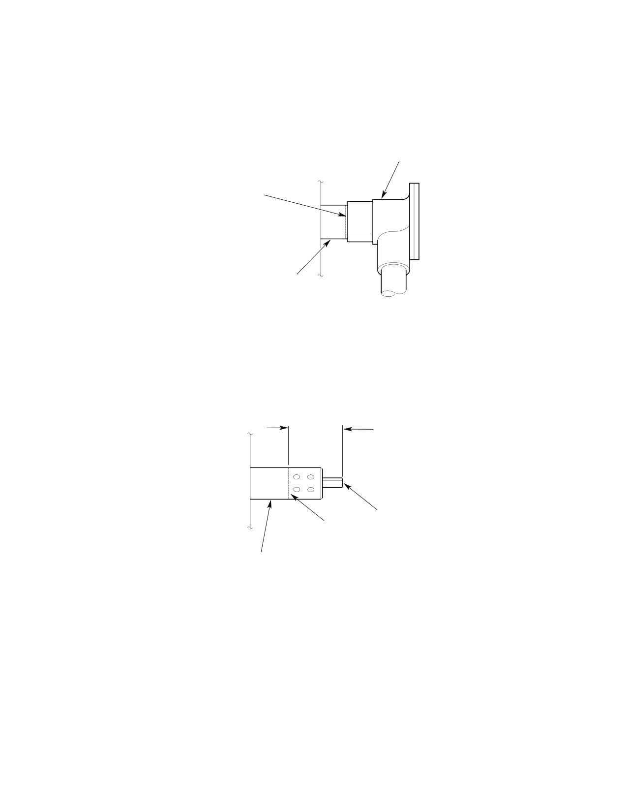
Figure 506. Gas Producer Interconnecting Torque Tube Shimming Procedure
(0003D thru 0929D) (Sheet 1 of 2)
Page 519
67-10-00
Revision 21
CSP-HMI-2
MD Helicopters, Inc.
MAINTENANCE MANUAL
MEASUREMENT BETWEEN INBOARD END OF PILOT'S
COLLECTIVE STICK HOUSING AND END OF GEAR
SHAFT IN PILOT'S COLLECTIVE STICK ASSEMBLY
PILOT'S COLLECTIVE STICK
HOUSING ASSEMBLY
GEAR SHAFT IN PILOT'S
COLLECTIVE STICK ASSEMBLY
GEAR SHAFT RECESSION MEASUREMENT
TOTAL THICKNESS OF AN960C816 WASHERS AND SNAP RING.
EQUAL TO 0.750 IN. (19.05 MM) MINUS ENGAGEMENT LENGTH OF
GAS PRODUCER INTERCONNECTING TORQUE TUBE INTO GEAR
SHAFT IN PILOT'S COLLECTIVE STICK ASSEMBLY ADDED TO
END OF GAS PRODUCER INTERCONNECTING TORQUE TUBE.
ENGAGEMENT LENGTH OF GAS PRODUCER
INTERCONNECTING TORQUE TUBE INTO GEARSHAFT
OF PILOT'S COLLECTIVE STICK ASSEMBLY.
0.750 IN. (19.05 MM) LENGTH OF HEX END ON
THE GAS PRODUCER INTERCONNECTING
TORQUE TUBE.
TORQUE TUBE SHIMMING
G67-1015-2
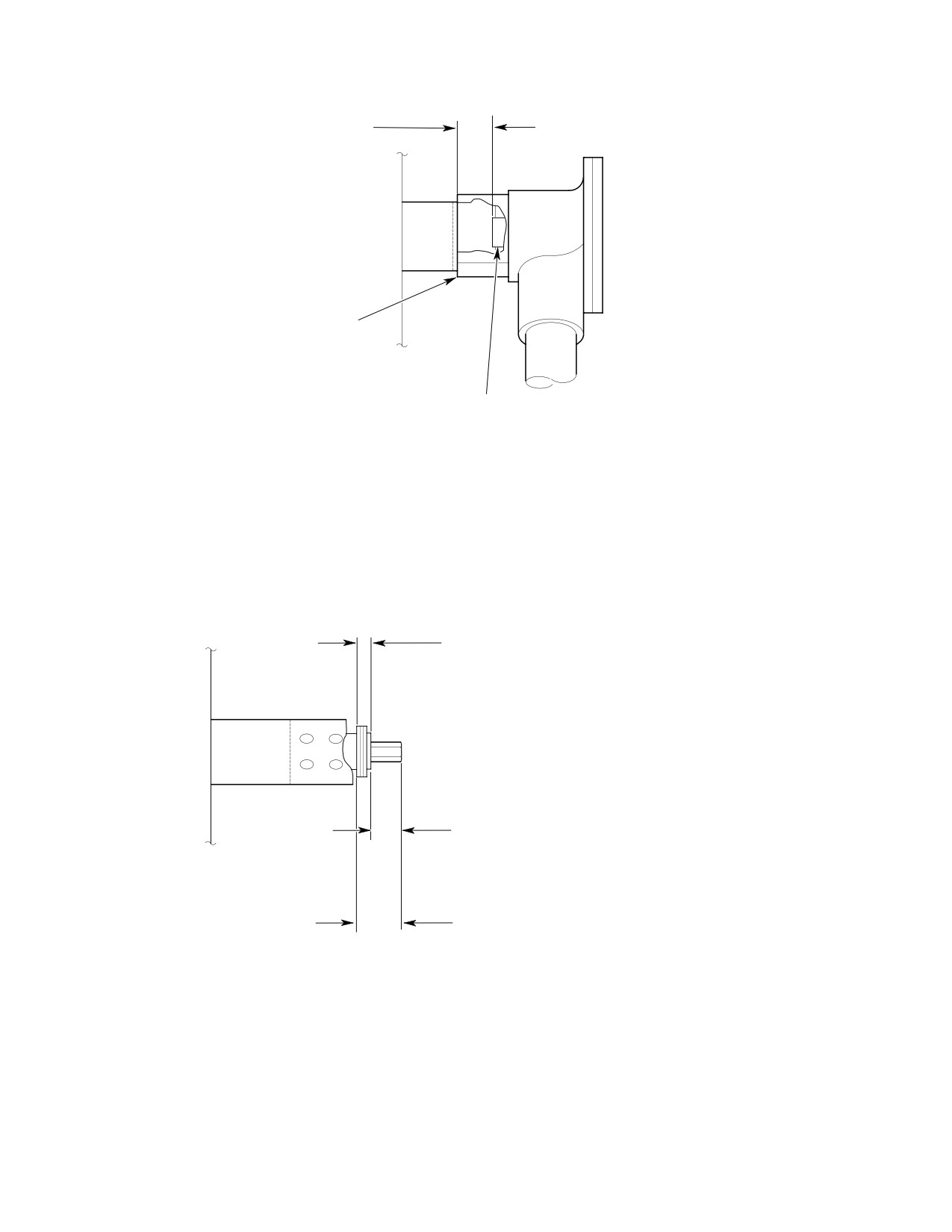
Figure 506 Gas Producer Interconnecting Torque Tube Shimming Procedure
(0003D thru 0929D) (Sheet 2 of 2)
Page 520
Revision 21
67-10-00
MD Helicopters, Inc.
CSP-HMI-2
MAINTENANCE MANUAL
(8).
Measure distance between inboard end
al rotation of drive gear grip and cause ny
of pilot's collective stick assembly
lon gears to be stripped.
housing and inboard face of gas produc
er gearshaft in pilot's collective stick
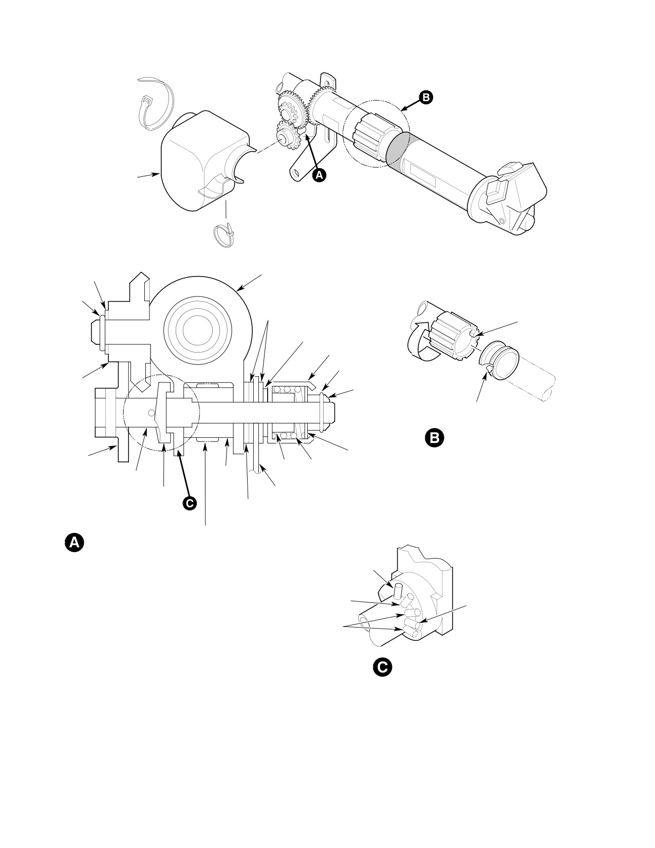
(1). Remove friction mechanism guard.
assembly.
(2). Rotate friction drive gear counterclock
(9).
Subtract measurement taken in step
wise to maximum friction position.
(8). from measurement taken in step
(7). Remainder is engagement of gas
(3). Remove cotter pin, nut, retainer
producer interconnecting torque tube
assembly, teflon washer and one
with gearshaft in pilot's collective stick
phenolic washer.
assembly.
(4). Slide gear assembly out far enough to
disengage it from idler gear. Use care to
(10).
Subtract engagement (remainder) from
keep other washers and spacer from
0.750 inch (19.05 mm). In addition to
thickness of external snap ring, add PN
dropping.
AN960C816 washers to end of gas
producer interconnecting torque tube to
(5). Remesh gear assembly with idler gear
a total thickness equal to the remainder
to position pin on peak of cam. Check
from 0.750 inch (19.05 mm) less
that drive gear is still at maximum
engagement. Equivalent washers in
friction stop position.
varying thicknesses may be in combina
tion with PN AN960C816 washers.
(6). If gear assembly does not correctly
position pin, reposition idler gear on
drive gear.
(11).
Reinstall pilot's collective stick assem
bly.
NOTE:
Ratio of idler gear to gear assembly is
3:1, which permits fine adjustment. When
(12).
Tighten pipe plug of gas producer
repositioning idler gear, be sure to reinstall
interconnecting torque tube to obtain
same number of washers that were removed
zero backlash between torque tube and
from between cotter pin and idler. These
gearshaft in pilot's collective stick
washers limit gear end play to maximum of
assembly.
0.010 inch (0.254 mm). When reassembled,
gear train must rotate freely.
(13).
Reinstall pilot's seat cover and access
door.
(7). Reinstall phenolic washer, teflon
washer, retainer assembly and nut.
13. Collective Stick Friction Mechanism
Adjustment
(8). With drive gear still at maximum
friction position, tighten retainer nut
(Ref. Figure 507)
until it just bottoms on retainer stop.
For collective friction mecha
(9). Rotate friction drive gear clockwise to
CAUTION
nism to be correctly adjusted for
minimum friction stop position, release
maximum friction, three actions must occur
grip and perform checks in steps (10).
at same time: Drive gear must contact stick
and (11). below.
fitting fixed stop; spring retainer housing
washer must contact retainer internal stop;
(10). If pin has overridden low point of cam
and gear assembly pin must be at approxi
(desired minimum friction position),
mate peak of cam. Do not overtighten re
and grip-to-stick friction prevents
tainer nut so that retainer washer contacts
springback of pin to cam low point, turn
retainer stop before friction drive gear
grip and move pin to low point.
reaches stick fitting stop. Adjustment that
does not produce approximately simulta
NOTE: A drive gear that does not rotate freely
neous contact will allow excessive addition
on collective stick tube should be replaced.
Page 521
67-10-00
Revision 21
CSP-HMI-2
MD Helicopters, Inc.
MAINTENANCE MANUAL
GUARD
WASHER(S)
STICK FITTING
(NOTE 1)
COTTER
FRICTION
PIN
DRIVE GEAR
PHENOLIC WASHERS
(ROTATING
TEFLON
STOP)
WASHER
RETAINER HOUSING
COTTER PIN
MAXIMUM
IDLER
FRICTION
GEAR
NUT
STICK FITTING
(FIXED STOP)
FRICTION CONTROL
WASHER
DRIVEN
GEAR
STOP SPRING
SPACER
GEAR
ASSEMBLY
CAM
GUIDE
(NOTE 2)
ALUMINUM
WASHER
GUARD
FRICTION MECHANISM
ATTACHMENT
NYLON STRAP
GEAR ASSEMBLY PIN
(NOTE 4)
NOTE 3
NOTE 5
NOTE 6
NOTES:
CAM ACTION
1.
SHIMMED AS REQUIRED FOR 0.010 IN. (0.254 MM) MAXIMUM
END PLAY. GEAR TRAIN MUST ROTATE FREELY.
2.
GEAR ASSEMBLY MUST SLIDE AND ROTATE FREELY IN FITTING.
GREASE APPLIED TO SHAFT.
3.
ACCEPTABLE MINIMUM FRICTION POSITION.
4.
DESIRED MINIMUM FRICTION POSITION (CAM LOW POINT).
G67-1016B
5.
CORRECT MAXIMUM FRICTION POSITION (CAM HIGH POINT).
Figure 507. Collective Stick Friction Adjustment
Page 522
Revision 36
67-10-00
MD Helicopters, Inc.
CSP-HMI-2
MAINTENANCE MANUAL
(11). With pin on cam low point, rotate
(2). Prior to test flight, establish half-way
retainer assembly. It should turn freely
point of collective friction adjustment
on shaft of gear assembly with only
grip (drive gear) as follows.
light finger pressure. Adjust retainer
nut to nearest castellation that pro
(a). Using soft, colored pencil; index
duces zero friction (no drag on retainer
collective friction adjustment grip at
assembly during rotation). Install cotter
zero friction.
pin.
(b). Roll on maximum friction (approxi
NOTE: If undesirable collective forces (”light”,
mately 275 degrees rotation). Note
”heavy” or ”creeping”) are reported to exist
travel and reset friction grip half-
in collective stick during flight, do not at
way; hold in this position.
tempt to compensate by an increase in col
lective friction. Condition should be cor
(c). Using dot of white paint or similar
rected elsewhere in control system (Ref.
method, temporarily mark top of
Collective Controls Rigging (L/H Command)
friction grip and adjacent exposed
and Collective Bungee Adjustment).
area of collective stick. Friction
half-way index mark should be
visible to pilot.
14. Collective Bungee Adjustment
(3). While helicopter is on ground, adjust
(Ref. Figure 404) Adjustment of bungee system
bungee to extent necessary to avoid any
is only permissible when helicopter is on
upload in flat pitch at normal rpm. This
ground.
adjustment must also provide absence
of an excessive download or upload
WARNING
while in hover and at 120 knots level
cruise. Helicopter must be landed after
D Do not attempt bungee adjustment in
each flight check, before making
flight, control jamming can result.
corrective adjustment.
D Use all necessary precautions to pre
vent possible entry of any foreign ob
CAUTION
jects into controls linkage exposed
by removal of pilot's seat cover to
D After each bungee adjustment is made,
make adjustment of bungee system.
collective stick must be slowly moved
Do not attempt bungee adjustment in
through its full travel range to assure
flight, control jamming could result.
that there is no binding or restriction of
stick motion, and that spring does not bot
(1). Collective load forces are affected by
tom at overcenter position.
any adjustment made in main rotor
D Do not turn female bearing assembly
system. Comply with the following.
spring retainer while bungee installation
tool is spring loaded.
(a). Bungee adjustment should be made
only when main rotor blades are in
D When making adjustments to the bungee
track and autorotation rpm is
over-center fitting, ensure nut turns
established.
when bolt adjustment is made. Cotter pin
can be sheared if nut does not turn with
(b). Ensure that collective stick friction is
bolt.
correctly adjusted.
(a). If an upload exists on ground at flat
(c). Perform flight evaluation of collective
pitch and normal rpm but a down
forces with helicopter takeoff weight
load prevails during hover and at 120
at 2350 pounds (1066 kg), N2 at 103
knot level cruise, turn bungee
percent and zero collective stick
adjustment retainer nut clockwise to
friction.
increase preload in bungee system.
Page 523
67-10-00
Revision 29
CSP-HMI-2
MD Helicopters, Inc.
MAINTENANCE MANUAL
(b). To correct a download on ground
During following tests, do not
CAUTION
during flat pitch at normal rpm and
retract spring assembly (ram) so
an upload condition during hover and
that actuator length is less than 13.50 in
120 knot level cruise, turn bungee
ches (34.29 cm) between attach bolt centers.
adjustment retainer nut counter
clockwise to decrease preload in
(4). With actuator spring assembly (ram)
bungee system.
approximately halfway between travel
limits (actuator length at 14.46 inches
(c). When a relatively constant upload
(36.7284 cm) between attach bolt
condition prevails during flat pitch at
centers), set up test dial indicator and
normal rpm on the ground, at hover,
measure ram end play. End play must
and at 120 knot level cruise, decrease
be within 0.010-0.050 inch (0.254-1.27
upload by turning bungee over-cent
mm). While adjusting screw, check that
er adjustment bolt clockwise.
there is thread-locking friction from
self-locking threaded insert. If end play
(d). When a relatively constant download
is excessive, replace actuator.
condition prevails during flat pitch at
normal rpm on the ground, at hover,
NOTE:
and at 120 knot level cruise, decrease
download by turning bungee over-
D When power is applied to the 8222M6
center adjustment bolt counterclock
(369A7014) actuator, it will move in the
wise.
commanded direction until it reaches the
end of the stroke. If, during mid-travel,
NOTE: Rotation of adjustment bolt head is the
an opposite power is applied simulta
only mechanical operation required to ad
neously, it will stop and remain stopped
just over-center position of bungee fitting.
until one or the other input is removed.
(e). After minimum and balanced collec
D When power is applied to the 8222M7
tive forces are obtained, not more
(369D27001) actuator, it will move, as
than one-half of available collective
commanded, and like the M6, if power is
stick friction (friction grip at half-
applied simultaneously in the opposite di
way index) must cancel collective
rection, it will stop. Unlike the M6, when
forces during flight test at 140 knots
one of the inputs is removed, the M7 ac
level flight.
tuator may or may not start. If it does not
restart, it has been latched into the off
(f). If friction applied in step (e). above is
state by the current surge generated upon
insufficient to cancel collective forces,
applying the second input. The M7 has a
repeat adjustment procedure.
built-in current limit circuit that latches
it off if the actuator current exceeds 2.7
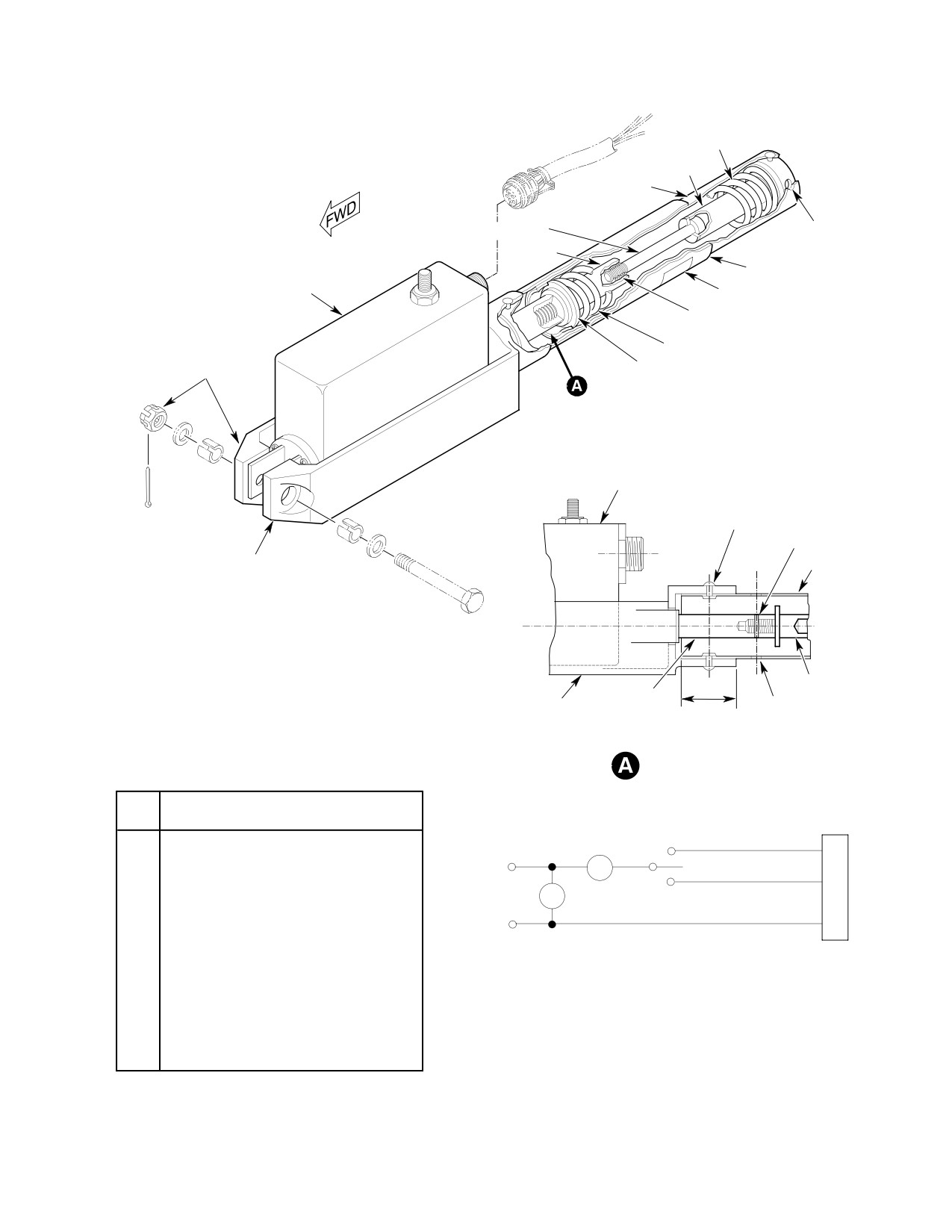
15. Cyclic Trim Actuator Bench Testing
amp. All power must be removed in order
(369D/E/FF − 500N)
to unlatch it.
(Ref. Figure 508)
(5). Position test switch to RETRACT and
(1). Connect cyclic trim actuator to test
allow actuator ram to retract to a
harness and equipment.
length of 13.50 inches (34.29 cm)
between attach bolt centers.
(2). Mount actuator in suitable fixture that
allows vertical extension and retrac
(6). Using stopwatch, check actuator ram
tion.
travel time from fully retracted to fully
(3). Turn on direct-current power and
extended. Check time interval for
adjust output to 25.75 - 26.25 volts.
actuator motor tested.
Page 524
Revision 31
67-10-00

MD Helicopters, Inc.
CSP-HMI-2
MAINTENANCE MANUAL
NOTE: The times in the following charts are
(0.508 mm) maximum with an overrid
maximum times. Some actuators will travel
ing (aiding) load; otherwise there must
at a greater speed than others. Intervals of
be no overtravel.
less time are acceptable.
(12). Remove 163 pound (74 kg) load and
repeat step (4). above.
Actuator Motor
Time Interval
Part number
(Seconds)
(13). Run actuator until arm is extended 1.75
inches (4.445 cm). Turn power off and
369A7001
58.4
disconnect cyclic trim actuator.
369A7014 (High Speed)
38.0
16. Cyclic Trim Actuator Bench Testing (600N)
369D27001 (Super Fast)
17.5
(Ref. Figure 508)
(1). Connect cyclic trim actuator to test
(7). Measure length of extended ram.
harness and equipment.
Subtract measured result of step (5).
above from this value. Result must be
(2). Mount actuator in suitable fixture that
1.92 inches (4.8768 cm) minimum.
allows vertical extension and retrac
tion.
Do not run actuator against ex
CAUTION
tend limit stop with the
(3). Turn on direct-current power and
163-pound weight aiding actuation. Actua
adjust output to 25.75 - 26.25 volts.
tor thrust bearing may be damaged.
During following tests, do not
CAUTION
retract spring assembly (ram) so
(8). Connect a 163 pound (74 kg) load to
that actuator length is less than 13.50 in
actuator. Set switch at RETRACT.
ches between attach bolt centers.
Check time it takes ram to travel
1.72-1.78 inches (4.3688-4.5212 cm) to
(4). With actuator spring assembly (ram)
retract stop. Check retraction time for
approximately halfway between travel
actuator motor tested.
limits (actuator length at 14.46 inches
(36.7284 cm) between attach bolt
Actuator Motor
Time Interval
centers), set up test dial indicator and
Part number
(Seconds)
measure ram end play. End play must
be within 0.010-0.050 inch (0.254-1.27
369A7001
30−50
mm). While adjusting screw, check that
369A7014 (High Speed)
15−25
there is thread-locking friction from
self-locking threaded insert. If end play
369D27001 (Super Fast)
7−12
is excessive, replace actuator.
NOTE: When power is applied to the 8222M21
(9). Operating current under load condi
(600N7001) actuator, it will move, as com
tions must not exceed 1.2 amperes
manded, and if power is applied simulta
running and 2.0 amperes stalled.
neously in the opposite direction, it will
(10). Reduce voltage input to 21 volts.
stop. When one of the inputs is removed, the
Actuator ram must retract and extend.
actuator may or may not start. If it does not
Overtravel is limited to 0.020 inch
restart, it has been latched into the off state
(0.508 mm) with an overriding (aiding)
by the current surge generated upon apply
load; otherwise there must be no
ing the second input. The actuator has a
overtravel.
built-in current limit circuit that latches it
off if the actuator current exceeds 3.1 amp.
NOTE: It is not necessary to extend or retract
All power must be removed in order to un
actuator ram more than 1/4 inch (6.35 mm)
latch it.
for test in steps (10). above or (11). below.
(5). Position test switch to RETRACT and
(11). Increase input voltage to 28 volts.
allow actuator ram to retract to a
Actuator arm must retract and extend.
length of 13.50 inches (34.29 cm)
Overtravel is limited to 0.020 inch
between attach bolt centers.
Page 525
67-10-00
Revision 36

CSP-HMI-2
MD Helicopters, Inc.
MAINTENANCE MANUAL
(6). Using stopwatch, check actuator ram
Actuator Motor
Time Interval
travel time from fully retracted to fully
Part number
(Seconds)
extended. Check time interval for
actuator motor tested.
600N7001−1 (longitudinal)
7−12
NOTE: The time in the following chart is maxi
369D27001−3 (lateral)
7−12
mum time. Some actuators will travel at a
600N7014−1 (lateral, with
7−12
greater speed than others. Intervals of less
YSAS)
time are acceptable.
(9). Operating current under load condi
Actuator Motor
Time Interval
tions must not exceed 1.2 amperes
Part number
(Seconds)
running and 2.0 amperes stalled.
600N7001−1 (longitudinal)
6.6
(10). Reduce voltage input to 21 volts.
Actuator ram must retract and extend.
369D27001−3 (lateral)
11.0
Overtravel is limited to 0.020 inch
(0.508 mm) with an overriding (aiding)
600N7014−1 (lateral, with
11.0
load; otherwise there must be no
YSAS)
overtravel.
(7). Measure length of extended ram.
NOTE: It is not necessary to extend or retract
Subtract measured result of step (5).
actuator ram more than 1/4 inch (6.35 mm)
above from this value. Result must be
for test in steps (10). above or (11). below.
1.92 inches (4.8768 cm).
(11). Increase input voltage to 28 volts.
Actuator arm must retract and extend.
Do not run actuator against ex
CAUTION
Overtravel is limited to 0.020 inch
tend limit stop with the
(0.508 mm) maximum with an overrid
163-pound weight aiding actuation. Actua
ing (aiding) load; otherwise there must
tor thrust bearing may be damaged.
be no overtravel.
(8). Connect a 163 pound (74 kg) load to
(12). Remove 163 pound (74 kg) load and
actuator. Set switch at RETRACT.
repeat step (4). above.
Check time it takes ram to travel
1.72-1.78 inches (4.3688-4.5212 cm) to
(13). Run actuator until arm is extended 1.75
retract stop. Check retraction time for
inches (4.445 cm). Turn power off and
actuator motor tested.
disconnect cyclic trim actuator.
Page 526
Revision 36
67-10-00
MD Helicopters, Inc.
CSP-HMI-2
MAINTENANCE MANUAL
SPRING
ADAPTER
SPRING GUIDE
SPRING ADAPTER SCREW
TEST LOAD
CONNECTION
ADAPTER
TRIM TUBE
ACTUATOR
TRIM DECAL
SELF-LOCKING THREAD INSERT
SPRING
NOTE
WASHER
ACTUATOR
RIVET
(4 PLCS)
SPRING PIN
ACTUATOR HOUSING
TRIM TUBE
ADAPTER
ACTUATOR
ACTUATOR
PIN INSTALLATION
TUBE
1.00 IN.
HOUSING
HOLE
(2.54 CM)
NOTE:
REPLACEMENT PARTS HAVE NUTPLATE
RIVETED IN PLACE. WASHER, NUT AND COTTER PIN NOT
REQUIRED.
TRIM TUBE - INSTALLATION
ITEM
TEST EQUIPMENT
SPDT SWITCH
NO.
1
STOPWATCH, MARKED IN
EXTEND
M1
A
1/10-SECOND
MA
INCREMENTS (MINERVA OR
26 VDC
OFF
B
EQUIVALENT).
ELECTRICAL
V M2
POWER
RETRACT
2
6 IN. (15.25 CM) SCALE.
SOURCE
C
3
DC VOLTMETER, 0-50 VOLTS
TEST HOOKUP
CONNECTOR
(WESTON
MODEL 931 OR EQUIVALENT).
4
DC MILLIAMMETER, 0-5 AMPERES
(WESTON
MODEL 931 OR EQUIVALENT).
5
VARIABLE DC POWER SUPPLY,
G67-1017B
Figure 508. Cyclic Trim Actuator Assembly
Page 527
67-10-00
Revision 21

MD Helicopters, Inc.
CSP-HMI-2
MAINTENANCE MANUAL
MAIN ROTOR FLIGHT CONTROLS
INSPECTION/CHECK
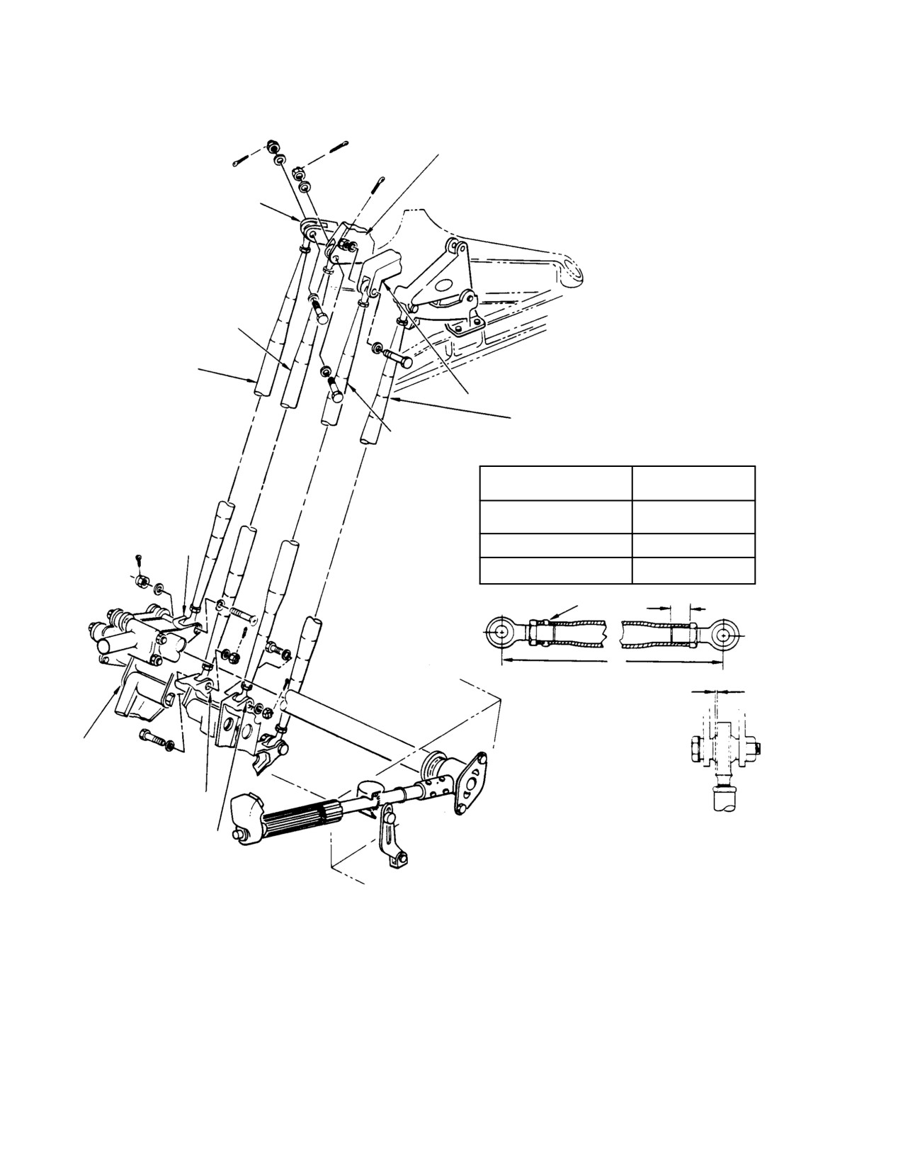
1. Tunnel−Routed Control Rod Inspection
(c). Lightly deflect tube laterally from
one extreme to other (maintain
(Ref. Figure 601)
preload).
(1). Inspect rod end bearings for binding
(d). With dial indicator or 6 inch (15.25
and excessive wear, 0.040 inch (1.016
cm) rule, measure total horizontal
mm) maximum axial play.
movement at top of tube where rod
end enters.
(2). Inspect control rod for surface damage
and evidence of bending.
(e). If total movement exceeds 1/16 inch
(1.5875 mm) rod assembly must be
(3). Inspect upper two inches (5.08 cm) of
replaced with serviceable parts.
each tunnel routed control rod for wear.
Replace rods with wear depth exceeding
(f). Movement less than 3/64 inch
0.020 inch (0.508 mm), or having outer
(1.190625 mm) is considered negligi
diameter (OD) less than minimum
ble.
which follow.
(g). If movement is between 3/64 and 1/16
inch (1.5875 and 1.190625 mm),
Minimum OD
inspect rod threads, step (6)., or rod
Control Rod
Inches (mm)
insert, step (7).
Collective mixer
0.470
(11.938)
(6). For early control tubes without swaged
Longitudinal mixer
0.520
(13.208)
inserts:
Lateral mixer
0.530
(13.462)
(a). If total lateral movement of upper
end of tube is found to be between
Tail rotor
0.470
(11.938))
3/64 and 1/16 inch (1.5875 and
1.190625 mm), check rod threads.
(4). Inspect for loose rivet at fixed rod end
(lower end).
(b). Disconnect rod end from control
system.
CAUTION
(c). Screw rod end completely out of
control rod.
D When tightening loosened jam nuts on
rod ends as in steps (5). and (6). or (7). be
(d). Use 0.339 inch (8.6106 mm) diameter
low, always hold rod end with wrench.
drill (size R), free of burrs, to check
rod threads.
D Do not disconnect rod ends from mixer as
sembly to perform this inspection except
1). If drill can be inserted, rod assem
as instructed.
bly is unserviceable and must be
replaced.
(5). Inspect upper end of tunnel-routed
control rod assemblies for excessive rod
2). If drill cannot be inserted, rod is
end play.
serviceable.
(a). Loosen jam nut minimum of two
(e). Reinstall rod end, reconnect rod to
threads.
control system and tighten jam nut.
(b). Preload rod end against either side of
(7). For current control rods with swaged
attaching clevis with light finger
inserts:
pressure to eliminate play other than
in area being inspected and effect of
(a). Disconnect rod end from control
bearing play.
system.
Page 601
67-10-00
Revision 28
CSP-HMI-2
MD Helicopters, Inc.
MAINTENANCE MANUAL
LONGITUDINAL PITCH IDLER
COLLECTIVE PITCH MIXER BELLCRANK
LONGITUDINAL MIXER
CONTROL ROD
COLLECTIVE MIXER
CONTROL ROD
LATERAL BELLCRANK
TAIL ROTOR CONTROL ROD
LATERAL MIXER CONTROL ROD
INITIAL ROD LENGTH (BEFORE RIG)
DIM L
CONTROL ROD
INCH (CM)
56.67
(
LONGITUDINAL MIXER
143.9418)
56.51
(
COLLECTIVE PITCH FITTING
LATERAL MIXER
143.5354)
COLLECTIVE MIXER
55.67
(
141.4018)
2.00 IN. (5.08 CM)
RIVET
(NOTE)
53.14
(
134.9756)
L
MAXIMUM ALLOWABLE AXIAL
PLAY 0.040 IN. (1.016 MM)
CONTROLS
SUPPORT BRACKET
LONGITUDINAL IDLER
BELLCRANK
LATERAL IDLER BELLCRANK
NOTE:
INSPECT FOR WEAR. REPLACE RODS WITH WEAR
DEPTH EXCEEDING 0.020 IN. (0.508 MM) OR HAVING
OD LESS THAN ALLOWABLE MINIMUM.
G67-1020A
Figure 601. Tunnel−Routed Control Rod Inspection
Page 602
Revision 21
67-10-00
MD Helicopters, Inc.
CSP-HMI-2
MAINTENANCE MANUAL
(b). Back off jam nut sufficiently enough
NOTE: Pitch stick housing and cap may be ei
to inspect insert.
ther magnesium or alloy casting. (For corro
sion control and identification of magne
(c). Inspect insert for proper installation,
sium or aluminum alloys, Ref. Sec.
flush to a maximum of 0.010 inch
20-40-00.)
(0.254 mm) below the surface of the
rod.
4. Copilot’s Collective Pitch Stick Inspection
(d). Check that insert is tight inside of
(Ref. Figure 603)
rod.
(1). Inspect bearings for binding or play.
1). If insert is loose or protrudes above
surface of rod, rod assembly is
(2). Inspect all gears for cracks, and
unserviceable and must be repla
chipped or broken teeth.
ced.
(3). Inspect stick tube and gas producer
2). If insert is tight and swaged flush
control tube for corrosion, deformation
to 0.010 inch (0.254 mm) below the
and loose rivets.
surface of the rod, rod is servi
ceable.
5. Collective Stick Friction Mechanism
Operational Check
(e). Reconnect rod to control system and
tighten jam nut.
(Ref. Figure 602)
(8). Check rigging of re-connected control
(1).
Remove guard from collective stick.
system.
(2).
Check that teeth of friction drive gear,
2.
Controls Support Bracket and Bellcrank
idler gear, and driven gear are not
Inspection
stripped or otherwise damaged.
(Ref. Figure 403)
(3).
Rotate friction drive gear grip counter
clockwise to maximum friction stop;
(1). Inspect bearings in bellcranks for
gear train must rotate freely. Check
binding.
position of shaft assembly pin. Pin
should be at highest point of cam.
(2). Perform fluorescent dye penetrant
inspection on any suspected part.
(4).
If pin is not at approximate peak of cam
NOTE: Parts identified with double asterisk
or has overridden peak, friction mecha
(**) (Ref. Figure 403) may be either magne
nism must be readjusted. If pin is in
correct position, continue with step (5).
sium or aluminum alloy. (For corrosion con
trol and identification of magnesium and
below.
aluminum alloys, Ref. Sec. 20-40-00.)
(5).
Rotate drive gear grip clockwise to
minimum friction position and release
3. Pilot’s Collective Pitch Stick Inspection
grip; gear train must rotate freely. Pin
should be at approximate low point of
(Ref. Figure 602)
cam.
(1). Inspect bearings for binding or play.
(6).
With pin on low point of cam, hand
(2). Inspect all gears for cracks, and
rotate spring release housing. If there is
chipped or broken teeth.
drag on retainer, there is friction on
guide and collective friction must be
(3). Inspect stick tube and gas producer
readjusted. If retainer rotates freely,
control tube for corrosion, deformation
without obvious play, low point friction
and loose rivets.
setting is correct.
Page 603
67-10-00
Revision 28
CSP-HMI-2
MD Helicopters, Inc.
MAINTENANCE MANUAL
FRICTION WASHER
(FELT)
BACKUP DISC
THROTTLE GRIP
(METAL)
(NOTE 1)
THROTTLE FRICTION
MOUNTING DISTANCE
NUT (NOTE 1)
SWITCH HOUSING
SHIM (CUT)
FRICTION DISC (NYLON)
COVER
BEARING
SPRING
BACKUP DISC (METAL)
(NOTE 3)
GRIP ATTACH BOLTS
GAS PRODUCER
CONTROL TUBE
IDLE STOP RELEASE RING
PINION
HOUSING SOCKET
NYLON STRAP
(NOTE 1)
SETSCREW
(NOTE 1)
FITTING
(NOTE 5)
SHIM WASHER
SETSCREW
IDLER GEAR
BEARING
BACKLASH
NYLON
STICK
(NOTE 3) SHIM GEARSHAFT
GUARD
STRAP
FITTING
BACKLASH SHIM
BEARING
(NOTE 3)
NYLON STRAP
GEAR
CAP
(NOTE 1)
PHENOLIC WASHERS
CAM
(NOTE 2)
(NOTE 1)
FRICTION ADJUSTMENT
TEFLON WASHER
STICK TUBE
WIRE GUIDE
SPACER
NOTE 1
FRICTION
(NOTE 1)
RETAINER
DRIVE GEAR
GUIDE
(NOTE 4)
SETSCREW
NOTES:
1.
SURFACES IN CONTACT DURING ROTATION, OR OTHERWISE
NOTED, TO BE LUBRICATED WITH GREASE.
2.
NEW PHENOLIC WASHERS ABRADED TO REMOVE GLAZE.
3.
BEARINGS INSTALLED WITH GRADE A LOCKING COMPOUND
AFTER SHIMMING.
4.
DRIVE GEAR END PLAY 0.002-0.010 IN. (0.0508-0.254 MM).
5.
USED ONLY WITH OPTIONAL EQUIPMENT.
G67 1021B
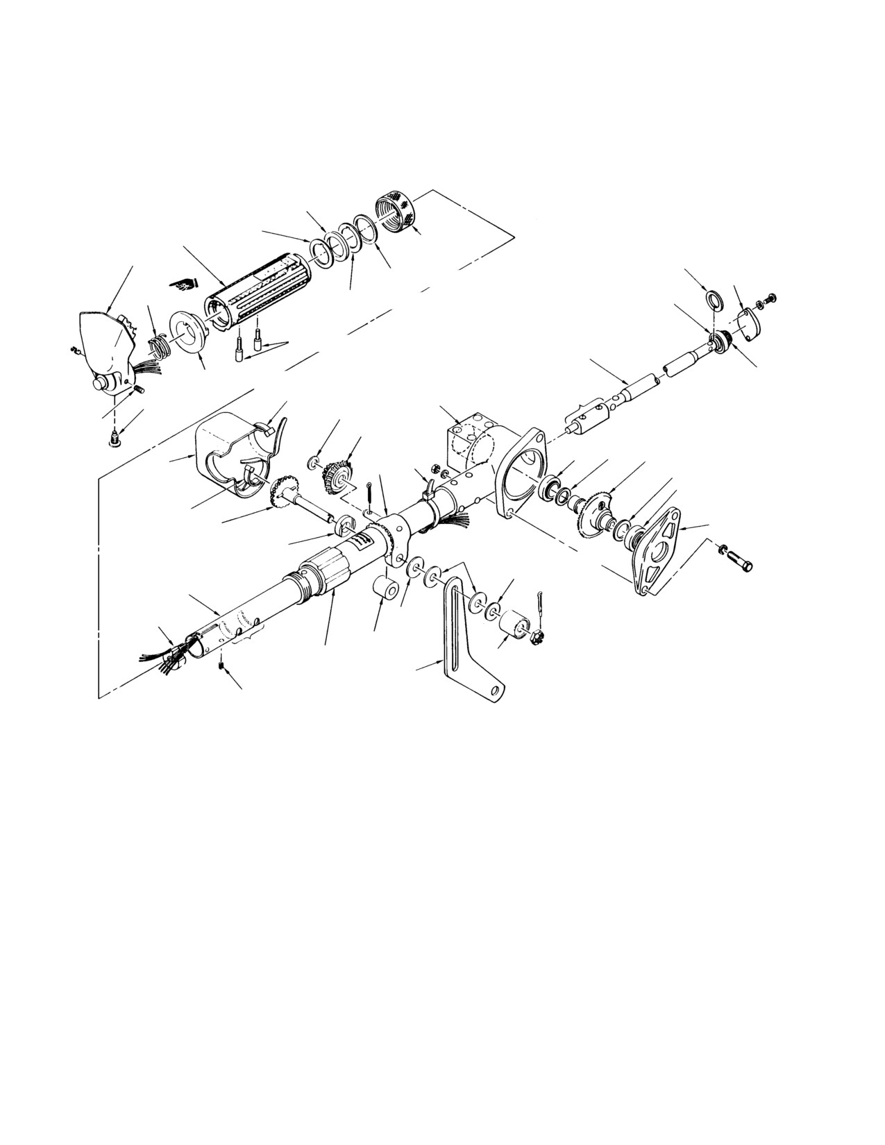
Figure 602. Outboard Collective Stick Inspection (L/H Command)
Page 604
Revision 39
67-10-00
MD Helicopters, Inc.
CSP-HMI-2
MAINTENANCE MANUAL
MOUNTING DISTANCE SHIM
(CUT)
BEARING
(NOTE 2)
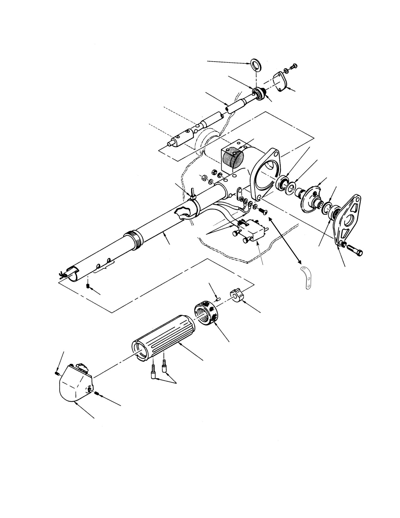
GAS PRODUCER CONTROL TUBE
COVER
PINION
HOUSING SOCKET
(NOTE 1)
BEARING
(NOTE 2)
BACKLASH SHIM
GEARSHAFT
NYLON STRAP
BACKLASH SHIM
ELECTRICAL
WIRING
STICK TUBE
BEARING
(NOTE 2)
NOTE 1
CONNECTOR
CAP
PIN
SETSCREW
WIRE GUIDE
ADJUSTMENT NUT
SETSCREW
THROTTLE GRIP
GRIP ATTACH BOLT
NOTES:
1.
SURFACES IN CONTACT DURING ROTATION
TO BE LUBRICATED OR OTHERWISE NOTED,
WITH GREASE (CM116).
SETSCREW
2.
INSTALL BEARINGS WITH GRADE A LOCKING
COMPOUND (CM431) AFTER SHIMMING FOR
SWITCH HOUSING
MOUNTING DISTANCE AND BACKLASH.
44-162B
Figure 603. Outboard Collective Stick Inspection (R/H Command)
Page 605
67-10-00
Revision 21
CSP-HMI-2
MD Helicopters, Inc.
MAINTENANCE MANUAL
6. Collective Control Interconnecting Torque
NOTE: Bungee support bracket may be either
Tube Inspection
an aluminum or magnesium casting. (For
corrosion control and identification of mag
nesium and aluminum alloys, Ref. Sec.
(Ref. Figure 404)
20-40-00.)
(1). Remove pilot's seat cover, control access
8. Inboard Collective Stick Socket Assembly
door, and left side foot support fairing.
Inspection
(Ref. Figure 408)
(2). Inspect collective interconnecting
(1). Inspect all bearings for binding or play.
torque tube for cracks, bends or
distortions.
(2). Inspect gears for cracks, and chipped or
broken teeth.
(3). Inspect bungee bracket and bungee
(3). Inspect all components for cracks,
fitting for security and condition.
corrosion and deformation.
Ensure cotter pin in over-center
adjustment bolt is not sheared.
NOTE: Bellcrank and idler may be either an
aluminum or magnesium casting. (For cor
(4). Inspect all accessible rivets for play.
rosion control and identification of magne
inspect support bearings for security
sium and aluminum alloy parts, Ref. Sec.
and evidence of binding.
20-40-00.)
(5). Reinstall pilot's seat cover, controls
9. Pilot’s Cyclic Control Stick Inspection
access door and foot support fairing.
(Ref. Figure 604)
NOTE:
7. Collective Bungee Inspection
D For this inspection, friction stop nut must
be loosened.
(Ref. Figure 407)
D Socket may be either an aluminum or
magnesium casting. (For corrosion con
NOTE: Replace any bungee parts in question
trol and identification of magnesium and
able condition.
aluminum alloys, Ref. Sec. 20-40-00.)
(1). Inspect bearings in male and female
(1). Inspect stick tube attachment to socket
bearing assemblies for evidence of
for evidence of loose rivets, distortion
binding, corrosion and galling.
and corrosion.
(2). Inspect parts of friction mechanism for
(2). Inspect female bearing assembly
physical damage. Free length of friction
threads for damage.
spring should be approximately 0.580
inch (14.732 mm).
(3). Inspect spring for evidence of deforma
tion. Free length of spring must be;
(3). To check installation, loosen lateral and
longitudinal friction knobs, move cyclic
(a). Effectivity: 369D/E/FF-500N, 3.64 ±
control stick and check for binding or
0.06 inches (92.456 ±1.524 mm)
unusual noises. Check that rod end
bearings of pilot's lateral control rod do
not jam when stick is full forward and
(b). Effectivity: 600N, 4.50 ±0.025 inches
full aft.
(114.30 +0.635 mm)
NOTE: Set minimum friction so that phenolic
(4). Inspect male bearing rod for cracks,
washers can be slightly turned by hand. If
evidence of binding, corrosion and
minimum friction is set too low, stick shake
deformation.
will occur.
Page 606
Revision 39
67-10-00
MD Helicopters, Inc.
CSP-HMI-2
MAINTENANCE MANUAL
10. Copilot’s Cyclic Control Stick Inspection
(5). Replace one-way lock if exposed portion
of piston has nicks, scratches or wear
(Ref. Figure 604)
penetrates chrome plating.
(6). Replace external mounting bushing if
Consumable Materials
outside diameter is less than 0.4979
(Ref. Section 91−00−00)
inch (12.64666 mm).
Item
Nomenclature
CM114
Petrolatum
(7). One-way lock must be replaced if nicks,
dents and scratches to body exceed
0.040 inch (1.016 mm) depth after
(1). Inspect quick-release pins for secure
repair.
fit, also stick tube and socket for
security, distortion and corrosion.
(8). One-way lock must be replaced if end
Check for presence of a light coating of
play between rod ends exceeds 0.010
grease in socket and on stick tube end.
inch (0.254 mm) measured at input
Apply thin coating of petrolatum
(forward) end.
(CM114), on contact surfaces.
(2). To check controls installation, loosen
(9). One-way lock must be replaced if
lateral and longitudinal friction knobs,
leaking, except as noted for reservoir in
move stick and check for binding or
step (1). above.
unusual noises. Check that rod end
bearings of copilot's lateral control rod
12. Cyclic Trim Actuator Inspection
do not jam throughout full range of
stick travel.
(Ref. Figure 508)
NOTE: Set minimum friction so that phenolic
(1). Inspect electrical connector for evidence
washers can be slightly turned by hand. If
of damage, and broken or missing
minimum friction is set too low, stick shake
contacts.
will occur.
(2). Inspect exterior of trim actuator for
11. One−Way Lock Inspection
evidence of damage and deformation.
(1). Replace reservoir if cracked, leaking or
(3). When actuator speed (response and/or
has loose or damaged filler cap (Ref.
travel time) is questionable, perform
COM).
bench test (Ref. Cyclic Trim Actuator
NOTE: It is normal for a thin hydraulic oil film
Bench Test).
to remain on piston as a result of wiping
contact with the piston seal. This should not
13. Cyclic Control System Operational Check
be considered leakage or cause for rejection.
Excessive slack or free play in the cyclic
(2). Replace forward input rod end bearing
control system may result in premature
if bearing binds.
control stop contact or roughness of the
helicopter and fanning out (out of track) of the
Do not attempt to adjust larger
CAUTION
main rotor tip path plane (Ref. Sec.
(aft) of two rod ends and do not
18-10-00/60). Areas to be checked include
remove cotter pin; malfunction of lock will
mixer linkages (Ref. Sec. 62-30-00/60) at the
likely result. (For overhaul and replacement
base of the main rotor mast, rotating controls
instructions, Ref. COM).
above the swashplate, trim actuators, and
(3). Replace one-way lock if aft (output) end
cyclic control stick in the pilot's compartment.
bearing binds.
If total free play at the top of the cyclic grip
exceeds 3/8 inch (9.525 mm) in either longitu
(4). Replace protective boot if it is cracked,
dinal or lateral direction, perform the follow
torn or deteriorated.
ing:
Page 607
67-10-00
Revision 39
CSP-HMI-2
MD Helicopters, Inc.
MAINTENANCE MANUAL
SLEEVE BUSHING
NOTE 2
NOTE 2
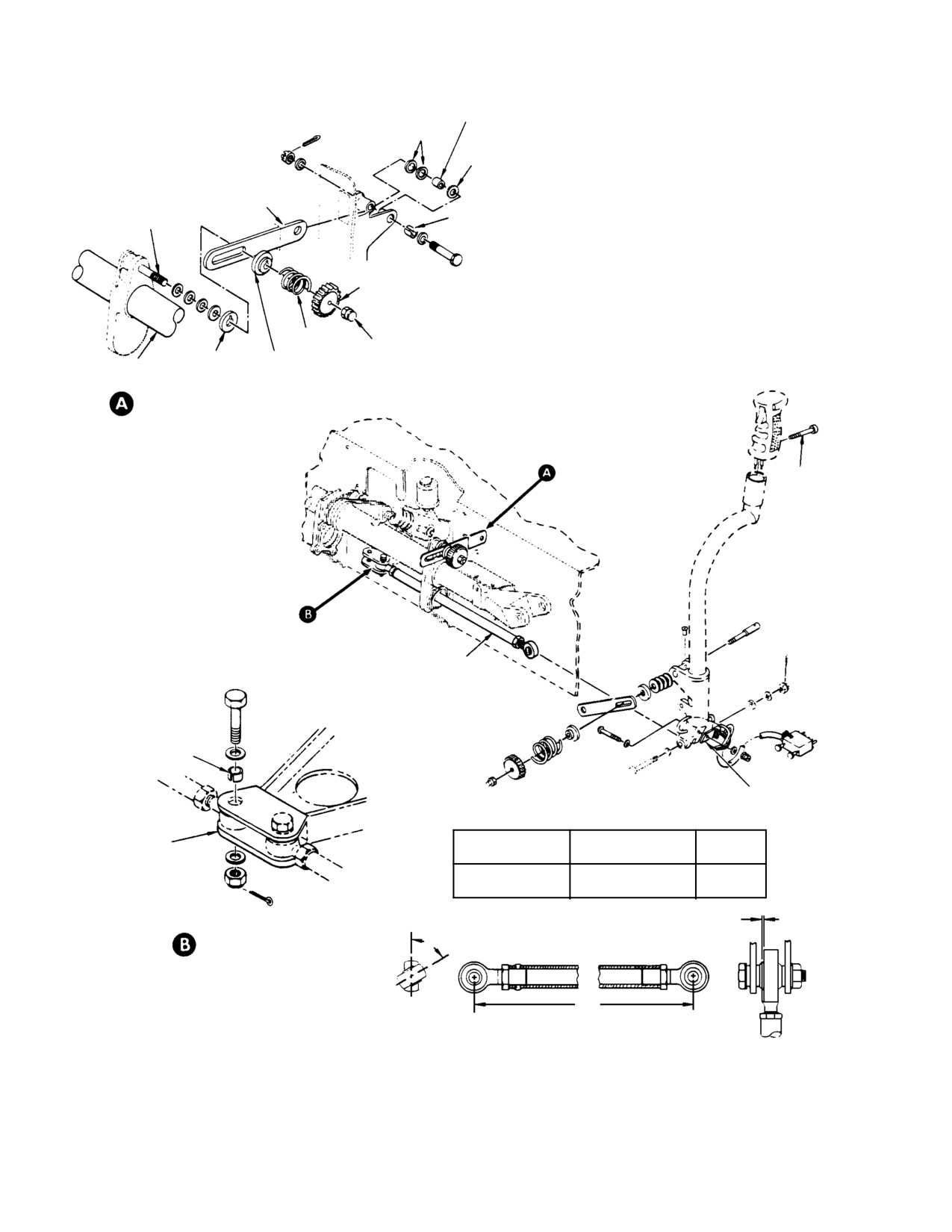
NOTES:
LINK
FRICTION
1.
EDGE OF BUSHING MUST PROTRUDE A MINIMUM OF
MECHANISM STUD
0.010 IN. (0.254 MM) TO A MAXIMUM OF 0.060 IN. (1.524 MM)
ABOVE OUTSIDE SURFACE OF PART AFTER BOLT IS
TIGHTENED.
2.
WASHERS ARRANGED TO ALIGN LINK WITH TORQUE
TUBE; LOOSELY SPACED WITH THREE WASHERS.
3.
CAP NUT ADJUSTED TO STOP KNOB WITH SPRING AT
KNOB
FREE LENGTH ±1/32 IN (0.79375 MM).
(NOTE 4)
4.
CYCLIC STICK LATERAL FRICTION MECHANISM IS SIMILAR
(SEE MAIN VIEW).
5.
IF NUT CAN BE TURNED WITH FINGER PRESSURE, NUT
SPRING
CAP NUT
MUST BE REPLACED.
RETAINER
(NOTE 3, 5)
DISC
TORQUE TUBE
CYCLIC STICK LONGITUDINAL
FRICTION MECHANISM
(NOTE 4)
SCREW
PILOT'S LATERAL
CONTROL ROD
SLOTTED BUSHING
(NOTE 1)
NYLON STRAP AND
MOUNTING PLATE
STA. 67 LATERAL
DIM L
CYCLIC BELLCRANK
CONTROL ROD
ANGLE A
INCH (CM)
PILOT'S LATERAL
12.63
(32.0802
42°
STA 70 LATERAL
) 6.65
(16.891)
90°
MAXIMUM ALLOWABLE AXIAL
PLAY 0.040 IN. (1.016 MM)
LATERAL CONTROL ROD
A
(INBOARD END) RIVET
INBOARD END ATTACHMENT
L
G67−1022
Figure 604. Cyclic Stick and Friction Inspection
Page 608
Revision 28
67-10-00
MD Helicopters, Inc.
CSP-HMI-2
MAINTENANCE MANUAL
When replacing control rod
(c). Check lower end of cyclic stick and
CAUTION
ends, measure length accurate
play at attachment of cyclic intercon
ly to ensure that replacement rod is exactly
necting torque tube. Replace bearings
the same length as the original. Control rods
and bushings as required.
are factory adjusted at installation to pro
(4). Check for axial play in cyclic trim
vide necessary clearances.
actuators.
(1). With the rotor stopped, check for free
(a). Disconnect lower end of cyclic control
play at the cyclic stick grip. While
rods from aft ends of trim actuators
moving cyclic stick through free play
and check for free play. Remove free
range, have assistant check controls
play by adjusting spring adjustment
mixer area for any free play motion.
screw located in center recess at aft
end of actuator. If end play exceeds
0.0075 inch (0.1905 mm), replace
(a). Check pivot bolt areas where mixer
actuator. Reconnect control rod.
bellcranks attach to control rod
bellcranks. If free play is noted,
(b). Check for free play in attachments
remove pivot bolts and inspect for
and linkages between trim actuators
wear and/or play between bolts,
and cyclic pitch interconnecting
bushings, and bellcranks. Replace
torque tube. Replace parts as re
parts as required.
quired; Install controls tunnel access
door.
(b). Check control rod assemblies by
14. Main Rotor Flight Control System
Pressing sidewards near the rod end
600−Hour Inspection
bearing. Replace rod end as required.
(Ref. Figure 508)
(2). Check for free play in blade pitch links
(1). With the rotor stopped, check for free
which connect rotating swashplate to
play at the cyclic stick grip.
blade pitch housings. Replace rod ends
NOTE: If total free play at the top of the cyclic
having free play in excess of 0.040 inch
grip is 3/8 inch (9.525 mm) or less in either
(1.016 mm) side motion.
longitudinal or lateral direction inspection
is not required. If total free play at the top of
NOTE: Rod ends on pitch links should be
the cyclic grip exceeds 3/8 inch (9.525 mm)
checked under a no-load condition which is
in either longitudinal or lateral direction,
best achieved by removing blades.
perform the following:
(2). While moving cyclic stick through free
(3). While moving cyclic stick through free
play range, have assistant check
play range, check lower controls for free
controls mixer area for any free play
play motion; Remove controls tunnel
motion.
access door.
(a). Check each pivot bolt area where
lateral mixer bellcranks attach to
(a). Check control rod assemblies by
collective bellcranks. If free play is
pressing sidewards near the rod end
noted at the lateral bellcranks,
bearings. Looseness indicates axial
remove pivot bolts and inspect for
play in rod end bearing. Replace rod
wear and/or looseness between bolt,
end as required.
bushings and bellcrank. Replace
parts as required.
(b). Check pivot bolt areas of lateral and
longitudinal bellcranks. If free play is
(b). Check control rod assemblies by
noted, remove pivot bolts and inspect
pressing sidewards near the rod end
for wear and/or play between bolts,
bearings; motion here indicates axial
bushings, and bellcranks. Replace
play in rod end bearing. Replace rod
parts as required.
end as required.
Page 609
67-10-00
Revision 39
CSP-HMI-2
MD Helicopters, Inc.
MAINTENANCE MANUAL
(3). Check for free play in blade pitch links
(a). Disconnect lower end of longitudinal
which connect rotating swashplate to
cyclic control rod from aft end of trim
blade pitch housings.
actuator and check for axial play.
Remove free play by adjusting spring
adapter screw located in center
NOTE: Both rod ends on each pitch link should
recess at aft end of actuator assem
be checked under a no load condition which
bly.
is best achieved by removing blades. Re
(b). Check for looseness in longitudinal
place rod ends having free play in excess of
and lateral cyclic control rod ends,
0.040 inch (1.016 mm) side motion.
located in tunnel. Replace rod ends
as required.
(4).
Inspect lower controls for slack between
(c). Check for free play in attachments
cyclic stick and attachment of the
and linkages between trim actuators
longitudinal and lateral control rods to
and cyclic pitch interconnecting
the mixer mechanisms, located just
torque tube. Replace parts as re
forward of the main rotor mast.
quired. Reinstall access door.
When replacing adjustable rod
CAUTION
(5).
Check lower end of cyclic stick for
ends, measure length accurate
ly to ensure that replacement rod is exactly
looseness at the attachment point to
same length as original. Mixer control rods
cyclic pitch interconnecting torque tube.
are factory adjusted at original installation
Replace bearings and/or bushings as
to provide necessary clearances.
required.
(8). Recheck for free play at the top of the
cyclic stick grip; as required, repeat
(6).
Check interconnecting torque tube
steps (1). thru (3). until total free play
bearings for free play; replace bearings
at top of grip is 3/8 inch (9.525 mm) or
if excessive free play is noted.
less in either longitudinal or lateral
direction.
(7).
Check for axial play in cyclic trim
(9). If replacement of parts is required
actuators (remove access door at lower
perform rigging of main rotor controls
end of pilot's bulkhead center tunnel in
(Ref. Collective Controls Rigging and
the cargo compartment).
Cyclic Controls Rigging).
Page 610
Revision 39
67-10-00
MD Helicopters, Inc.
CSP-HMI-2
MAINTENANCE MANUAL
MAIN ROTOR FLIGHT CONTROLS
REPAIRS
1. Tunnel−Routed Control Rod Repair
A. Control Tube End Sleeve Installation
Consumable Materials
(Ref. Figure 401)
(Ref. Section 91−00−00)
Item
Nomenclature
(1). Perform straightness check on control
CM219
Methyl-ethyl-ketone
rod that appears bent or bowed. Total
CM229
Paint remover
length of any tunnel-routed rod
CM230
Paint remover
(excluding rod ends) must be straight
within 0.050 inch (1.270 mm), with
CM231
Plastic bead, spherical 20 - 30 mesh
straightness variation limited to
CM318
Primer
maximum of 0.010 inch (0.254 mm) in
CM409
Adhesive, epoxy
each foot of length.
(1). Remove all four control rods (Ref.
Dye-check for cracking
Tunnel-Routed Control Rod Replace
WARNING
must always be performed
ment).
after cold-straightening. Replace
cracked rod, or cracked or bent rod
(2). Using paint remover (CM229, CM230
end.
or CM231) remove paint approximately
six inches back from end of each tube,
tape and cover-rap remaining area of
(2). Cold-straighten bent rod that is not
tube.
within tolerance (step (1). above)
provided there are no nicks or sharp
NOTE: Control tubes that are cracked must be
dents in bent length. Do not use rod
removed from service.
ends to support rod during straighten
ing.
(3). Dye penetrant inspect external surface
of stripped area for cracks.
Use care when drilling to re
CAUTION
(a). Cracked are indicated by heavy bleed
move or install riveted rod end;
out. It may be necessary to wipe off
rod end is steel and rod is aluminum.
and reapply the developer to distin
guish between surface defects caused
during swaging operation.
(3). Replace control rod end if bearing axial
play is more than 0.040 inch (1.016
(b). Light penetrant indications are not
mm). Set initial control rod length (Ref.
cause for rejection.
Figure 601).
(4). If no cracks are found; inspected control
tube can be reworked for sleeve instal
2. Tunnel−Routed Control Tube Inspection
lation. All four control tubes are to be
and Sleeve Installation
reworked as follows:
(a). Measure and record length of control
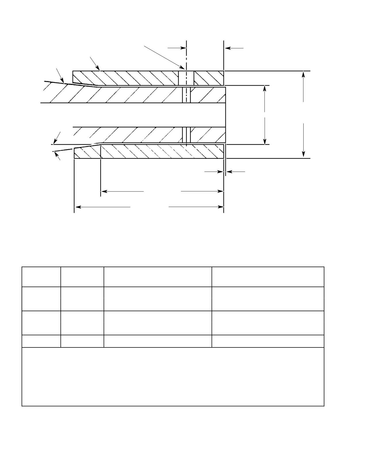
(Ref. Figure 801) The following procedures are
tubes for reinstalling rod ends and to
for inspection and installation of reinforcing
prevent rerigging after tube rein
sleeves to the tunnel-routed control tubes.
stallation.
Page 801
67-10-00
Revision 21
CSP-HMI-2
MD Helicopters, Inc.
MAINTENANCE MANUAL
0.097-0.102 IN.
DIA
0.340 IN.
(2.4638-2.5908 MM)
(8.635 CM)
SLEEVE
CONTROL TUBE
0.750 IN.
DIA.
A DIA
(19.05 MM)
7° ±0.5°
0.000-0.080 IN.
(0.000-2.032 MM)
0.720 IN.
(18.288 MM)
0.910 IN.
(23.114 MM)
G67-1035A
Dimensional Table
Sleeve No.
Dim A
Tube O.D.
Rod No.
369D27013
inch (mm)
inch (mm)
−1
0.540−0.545
(13.716−13.843)
0.501−0.530
(12.7254−13.462)
369A7007
369A7009
−2
0.510−0.515
(12.954−13.081)
0.470−0.500
(11.938−12.70)
−3
0.590−0.595
(14.986−15.113)
0.551−0.580
(13.9954−14.732)
369A7011
−4
0.560−0.565
(14.224−14.351)
0.520−0.550
(13.208−13.970)
369A7012
−5
0.570−0.575
(14.478−14.605)
0.530−0.560
(13.462−14.224)
NOTES:
(1) Material; 2024−T351 or T4 (QQA 225/6) bar or round stock
(2) Break sharp edges 0.005−0.015 inch (0.127−0.381 mm).
(3) Surface finish 125 RMS.
(4) Chemical film per MIL−C−5541.
(5) Tolerance * ±0.010 inch (±0.254 mm).
Figure 801. Sleeve Fabrication and Installation
Page 802
Revision 21
67-10-00

MD Helicopters, Inc.
CSP-HMI-2
MAINTENANCE MANUAL
Drilled out rivets may damage
Do not use heat gun. Use of heat
CAUTION
CAUTION
threads upon removal. Visually
lamp is acceptable.
inspect control tube threads for damage
from rivet and rod end removal. Replace
(i).
Allow to cure for 24 hours at mini
damaged control tubes. Drilled rod ends are
mum ambient temperature of 68°F
matched drilled to each control tube and
(20°C) (alternate cure 4 hours at
must be reinstalled into control tube end
115°-140°F (47°-60°C)).
from which removed.
(j).
Repeat procedure for ends of each
control tube.
(b). Remove rod ends, MS20470AD3
rivets must be removed from fixed
(k).
Using primer (CM318), touch-up
end.
repaired area(s) of control tube.
(c). Measure outside diameter of control
(l).
Install rod ends into ends in which it
tube end and select proper sleeve.
was removed. On fixed rod end, align
witness/rivet hole in sleeve and tube
with rivet hole in rod end. Drill (#40)
thru opposite end of sleeve. Rivet
(d). Temporarily install sleeve onto
fixed end with MS20470AD3-15
control tubes. Align sleeve and
rivet.
control tube witness hole. If sleeve
protrudes past end of control tube,
trim end of sleeve flush to 0.000 inch
(m).
Adjust each control tube to its
(0.000 mm) or back 0.080 inch (2.032
previously measured length and
mm) from end of tube.
paint the control tube ends with
primer. Paint adjustable ends of
control tube flat black.
NOTE: Bond integrity is dependent on clean
surfaces.
(n).
Reidentifiy, with permanent ink, the
control tubes that have been re
worked (Ref. Table 801).
(e).
Thoroughly clean end of control tube
and interior surface of sleeve with
lint free cloth and MEK (CM219) or
Table 801. Control Tube Re−Identification
equivalent.
Old Part Number
New Reworked Part Number
369A7007
369A7007−5
(f).
Mix epoxy adhesive (CM409) per
369A7009
369A7009−5
manufacturer's instructions.
369A7011
369A7011−5
369A7012
369A7012−5
(g).
Remove excessive adhesive with lint
free cloth moistened with MEK or
(o). Rework control tube boot (Ref.
equivalent. Do not saturate the
Figure 802).
cleaning cloth. Remove adhesive from
witness holes.
If control rod is not accurately
CAUTION
measured, flight controls will
(h).
Plug end of control tube to prevent
require rerigging.
adhesive from entering threads. Bond
sleeve to control tube. Apply adhesive
(p). Reinstall control tubes. Reinstall
to both surfaces and install sleeve.
trimmed boot with vertical seam
Align witness/rivet hole in sleeve and
facing aft. Check flight controls for
tube.
interference or binding.
Page 803
67-10-00
Revision 21
CSP-HMI-2
MD Helicopters, Inc.
MAINTENANCE MANUAL
B. Control Tube Straight Area Sleeve
(2). Tape around area to be repaired.
Installation
(3). Using paint remover (CM229, CM230
This repair is permissible on the straight area
or CM231), strip paint 1.0 inch (2.54
of the tube only and increases the outside
cm) beyond area of repair.
diameter.
(4). Polish out burrs and sharp edges.
Consumable Materials
Ensure defects do not exceed allowable
(Ref. Section 91−00−00)
limits (Ref. Table 801). Dye penetrant
Item
Nomenclature
inspect area per MIL-I-25135; no
cracks allowed.
CM219
Methyl-ethyl-ketone
CM229
Paint remover
NOTE: Bond integrity is dependent on clean
CM230
Paint remover
surfaces.
CM231
Plastic bead, spherical 20 - 30 mesh
CM318
Primer
(a). Thoroughly clean repair area of
CM409
Adhesive, epoxy
control tube and interior surface of
sleeve with lint free cloth and MEK
(CM219) or equivalent.
NOTE:
D Ensure adequate clearance exists prior to
(b). Mix epoxy adhesive (CM409) per
performing the repair. Determine and re
manufacturer's instructions.
pair condition that caused damage.
(c). Apply adhesive to both surfaces and
D Maximum length of repair sleeve is 6 in
install sleeve.
ches (15.24 cm). Two sleeve repairs per
mitted per control tube.
(d). Remove excessive adhesive with lint
(1). Remove damaged control rod(s) (Ref.
free cloth moistened with MEK or
Tunnel-Routed Control Rod Replace
equivalent. Do not saturate the
ment).
cleaning cloth.
Page 804
Revision 21
67-10-00
MD Helicopters, Inc.
CSP-HMI-2
MAINTENANCE MANUAL
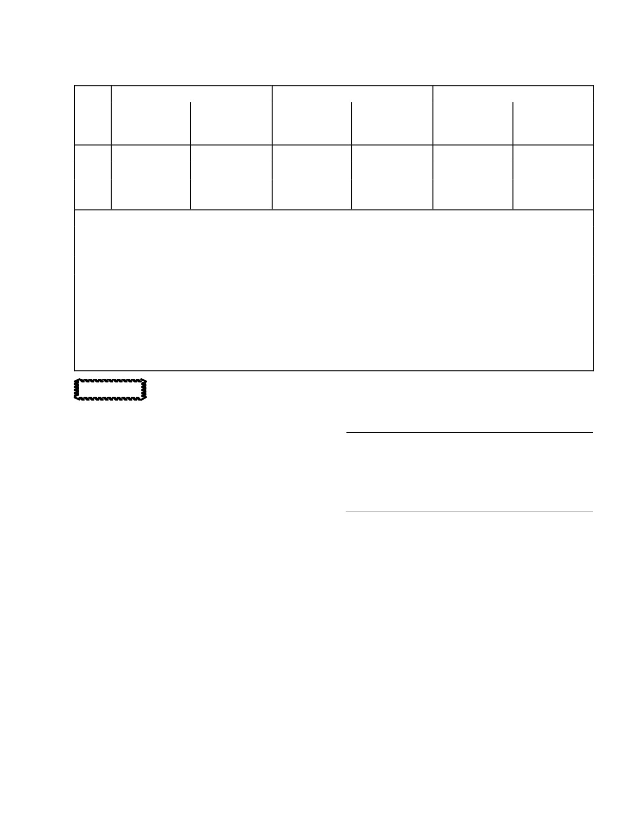
Table 802. Control Tube Straight Area Repair Limits
Nicks and Gouges (2)
Dents and Depressions (2)
Repair Sleeve (3)
Tube
Max. Depth
Max. Depth
Max. Depth
Max. Depth
Wall
O.D.
369A
W/O Repair (4)
With Repair (1)
W/O Repair (4)
With Repair (1)
Thickness
inch (cm)
Inch (mm)
inch (mm)
inch (mm)
inch (mm)
inch (mm)
7007
0.006
(0.152)
0.015
(0.381)
0.010
(0.254)
0.025
(0.635)
1.375
(3.4925)
0.049
(1.2446)
7009
0.008
(0.203)
0.020
(0.508)
0.010
(0.254)
0.025
(0.635)
1.50
(3.81)
0.049
(1.2446)
7011
0.010
(0.254)
0.025
(0.635)
0.010
(0.254)
0.025
(0.635)
1.625
4.1275)
0.049
(1.2446)
7012
NOTES:
(1) Sleeve repair not permitted in tapered area. Two sleeve repairs per control tube. Maximum defect area
0.375 in2 (2.41935 cm2) per sleeve.
(2) Must be free of burrs and sharp areas.
(3) Aluminum tube 6061−T6 WW−T−700/6 or 2024−T3 WW−T−700/3. Alternate: field fabricate from
2024−T351 or 2024−T4 (QQ−A−225/6 or QQ−A−200/3). Inside diameter to be 0.010−0.025 inch
(0.254−0.635 mm) larger than outside diameter of tube to be repaired. Outside diameter as listed in table,
±0.010 inch (±0.254 mm) and concentric to inside diameter 0.005 inch (0.127 mm). Maximum length of
repair sleeve 6 inches (15.24 cm). Break sharp edges 0.005−0.015 inch (0.127−0.381 mm).
(4) Maximum defect area without repair 0.10 in2 (0.64516 cm2) total. For threaded area, last 2 inches (5.08
cm) of both ends, maximum depth of defect 0.020 inch (0.508 mm).
Do not use heat gun. Use of heat
4. Controls Support Bracket and Bellcrank
CAUTION
lamp is acceptable.
Repair
(Ref. Figure 403)
(e). Allow to cure for 24 hours at mini
mum ambient temperature of 68°F
(20°C) (alternate cure 4 hours at
Consumable Materials
115°-140°F (47°-60°C)).
(Ref. Section 91−00−00)
Item
Nomenclature
(f). Using primer (CM318), touch-up
CM321
Surface primer locking compound
repaired area(s) of control tube.
CM431
Sealing, locking and retaining compound
3. Controls Support Bracket and Bellcrank
Disassembly
(1). Replace unserviceable bearings. Install
new bearing with surface primer
(Ref. Figure 403)
(CM321) and grade A locking compound
(CM431).
NOTE: In following steps, do not remove
slotted bushings unless replacement is nec
NOTE: When idler bellcrank bearings are re
essary.
placed, make sure that idler bellcrank
spacers are reinstalled between bearings.
(1). Remove lateral idler bellcrank.
(2). Replace bellcranks or controls support
(2). Remove tail rotor bellcrank.
bracket that has distortion, cracks or
elongated holes.
(3). Remove longitudinal idler bellcrank.
5. Controls Support Bracket and Bellcrank
NOTE: Shim washers between longitudinal
Reassembly
idler bellcrank and support brackets align
(Ref. Figure 403)
one-way lock for no sideload. Keep shim
washers with bracket for use during reas
(1). Install longitudinal idler bellcrank.
sembly.
Check that slotted bushing is in place
Page 805
67-10-00
Revision 21
CSP-HMI-2
MD Helicopters, Inc.
MAINTENANCE MANUAL
in support bracket lug, and reinstall
NOTE: Removal of additional setscrew is also
shim washers between bellcrank and
required on helicopters equipped with cargo
bracket for no sideload of one-way lock.
release mechanism.
(3). Cut nylon strap or twine that secures
NOTE: When performing following steps, en
electrical wiring to stick tube. Push
sure that slotted bushing is in support
wire slack into stick, carefully pull
bracket lug.
housing and wiring from end of stick
tube and disconnect wiring from
(2). Install lateral idler bellcrank.
switches.
(3). Install tail rotor bellcrank.
(4). Remove setscrew and wire guide from
forward end of stick. Tie string on each
wire bundle to aid reassembly and
6. Pilot’s Collective Pitch Stick Disassembly
remove wiring.
(L/H Command)
(5). Remove spring and idle stop release
(Ref. Figure 602)
ring.
(6). Remove grip attach bolts. Slide throttle
(1). Cut two nylon straps, and remove stick
grip friction washer and discs, and
friction mechanism guard.
friction nut from stick tube.
(2). Remove setscrews that secure switch
(7). Remove friction mechanism and guide
housing.
from stick fitting.
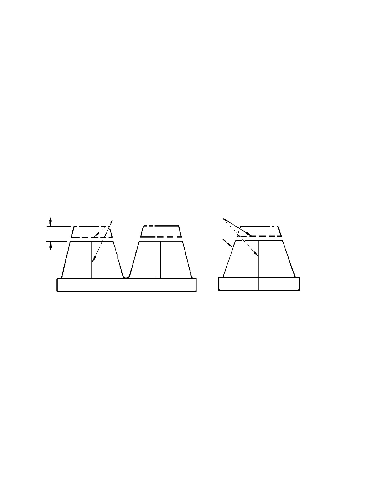
SEWN SEAMS
SEWN SEAMS
2 PLACES
0.40-0.50 IN.
(10.16-12.70 MM)
(NOTE 1)
DOUBLE BOOT
SINGLE BOOT
NOTES:
1.
TRIM BOOTS BELOW HORIZONTAL SEAM.
CAUTION: DO NOT USE SOLVENTS OR PETROLEUM BASED CLEANING
FLUIDS ON VINYL BOOTS.
2.
CLEAN INSIDE AND OUTSIDE OF VERTICAL SEAM AND TOP OF
BOOT WITH CLEAN CLOTH DAMPENED WITH ISOPROPYL ALCOHOL.
3.
COAT BOTH SIDES OF VERTICAL SEAM WITH CONTACT CEMENT.
4.
APPLY THIN COAT OF CONTACT CEMENT ALONG TRIMMED EDGE
AND 0.125-0.250 INCH (3.175-6.350 MM) DOWN INSIDE AND OUTSIDE
SURFACES OF BOOTS TO PREVENT FRAYING.
G67-1036A
Figure 802. Control Tube Boot Rework
(8). Remove idler gear from stick fitting.
(10). Remove gear shaft assembly. Keep
backlash shims with gear shaft.
NOTE: In following steps, do not remove bear
(11). Remove cover from back of stick
ings or pinion unless replacement is neces
housing.
sary.
(12). Remove gas producer control tube
(9). Remove cap from stick housing.
through access hole at back of stick
Page 806
Revision 21
67-10-00
MD Helicopters, Inc.
CSP-HMI-2
MAINTENANCE MANUAL
housing. Remove mounting distance
shim only if necessary to adjust pinion
Consumable Materials
gear mounting distance.
(Ref. Section 91−00−00)
Item
Nomenclature
7. Pilot’s Collective Pitch Stick Repair (L/H
CM116
Grease, aircraft and instrument
Command)
CM431
Sealing, locking and retaining compound
CM807
Twine, nylon
(Ref. Figure 602)
CM815
Solder
Consumable Materials
(1).
Check gearshaft bearings in housing
(Ref. Section 91−00−00)
cap a housing for security of outer
Item
Nomenclature
races. Use grade A locking compound
CM116
Grease, aircraft and instrument
(CM431) to install replacement bear
ings. Use care to prevent compound
from entering bearings, and make sure
(1). Replace bearings if corroded, excessive
that each bearing is seated against its
ly worn, or if outer or inner races of
bore shoulder.
bearings rotate on mating surfaces and
locking compound is inadequate to
(2).
Using grease (CM116), lubricate stick
prevent rotation.
tube interior where gas producer
control tube fitting makes contact.
(2). Replace loose rivets in gas producer
control tube.
(3).
Attach strings routed through stick
tube during disassembly, and thread
(3). Replace friction drive gear or idler gear
electrical wire bundles from plug
with cracked, chipped or broken teeth.
through exit hole, throttle friction nut,
friction washers and discs, throttle grip,
(4). Replace friction drive gear if it does not
idle stop release ring and spring. Pull
rotate freely on stick tube, or if rotating
wiring out through front end of stick
stop is damaged. To remove gear, drill
tube.
out rivets that attach throttle friction
(4).
Install wire guide so that it divides
nut fitting to stick.
switch wiring: three wires in one cutout
NOTE: Before replacing drive gear for binding,
and four in the other. Align guide with
clean and relubricate bore with grease
matching hole in stick tube and install
(CM116). Reinstall gear on stick tube and
setscrew. When tightened, setscrew
recheck for free rotation. If gear still binds it
must be flush or not recessed more than
0.010 inch (0.254 mm) below outer tube
must be replaced.
surface.
(5). Replace phenolic friction washers
NOTE: Ensure gas producer control tube is in
against guide if worn to less than 1/32
stalled into stick housing with elongated
inch thickness.
area of fitting facing down.
(6). Replace friction gear assembly if driven
(5). Install gas producer control tube
gear has cracked, chipped or broken
through access hole in back of stick
teeth or if cam pin is bent.
housing, and through stick tube until
control tube fitting engages wire guide
(7). Replace damaged idle stop release ring.
bore. Reinstall mounting distance
Ring must slide freely on tube and in
shims forward side of pinion bearing if
throttle grip.
removed during disassembly. (One edge
of shim must be cut for installation.)
8. Pilot’s Collective Pitch Stick Reassembly
(L/H Command)
NOTE: Steps (6). thru (8). below are used to de
termine gas producer control tube pinion
(Ref. Figure 602)
mounting distance.
Page 807
67-10-00
Revision 21
CSP-HMI-2
MD Helicopters, Inc.
MAINTENANCE MANUAL
(6).
Install approximate required thickness
(14). Lubricate teeth of pinion gear and shaft
of split shims between pinion bearing
assembly bevel gear with grease
and housing to establish gas producer
(CM116).
control tube pinion mounting distance.
(15). Apply grade A locking compound
(CM431) to secure gearshaft to bear
(7).
Use throttle friction nut to pull gas
ings. Do not allow compound to enter
producer torque tube forward until not
bearings. With throttle grip at mid-tra
less than 10 pounds (44.48 N) of force is
vel, install driven gear. Note that at
applied to compress shims.
throttle-grip mid-travel, cut out
portion of the driven gear is to be
(8).
Add or subtract shims to provide
opposite pinion gear. (Centerline of
0.699-0.709 inch (17.7546-18.0086
center tooth of driven gear is two
mm) dimension (Ref. Figure 504).
degrees and fifty minutes from center of
Repeat step (7). during each measure
driven gear cutout.)
ment.
NOTE: With throttle grip at mid-travel, two
grip attach bolts are positioned approxi
(9).
After mounting distance shimming is
mately straight down.
correct, remove gas producer control
tube and apply grade A locking com
(16).
Install housing cap on shaft assembly
pound (CM431) to outside diameter
and seat with hand pressure while
pinion bearing outer race and stick
slowly rotating grip back and forth.
housing bore. Reinstall control tube,
Secure cap to side of housing and cover
and check that compound does not
to back of housing.
enter bearing and that bearing outer
(17).
Using solder (CM815), connect wiring
race and shims are firmly seated
to stick switches. Pull electrical wiring
against housing bore.
slack out through exit holes in stick
tube, position release ring and. spring
(10).
Install throttle friction nut, friction
and install switch housing with set
discs and washers.
screws. Using nylon strap, or twine
(CM807), secure electrical wiring to
(11).
Using grease (CM116), lubricate
stick tube approximately one inch aft of
interior of throttle grip and install grip
exit holes.
on stick tube. Align grip and gas
producer control tube fitting and install
(18).
Install friction cam and driven gear
grip attach bolts. When tightened, bolts
assembly on stick fitting. Temporarily
must be flush or not more than 0.010
mesh idler gear and driven gear, and
inch (0.254 mm) below outer face of
rotate friction drive gear counterclock
grip.
wise to maximum stop.
(19).
Hold drive gear at stop and remesh
(12).
Establish gas producer control tube
idler gear and driven gear so that gear
pinion and shaft assembly bevel gear
assembly pin is at high point of cam.
backlash by temporarily installing
driven gear, shaft, and two bearings,
(20).
Use shim washers sufficient to limit
plus approximate required thickness of
gear end play to maximum of 0.010 inch
backlash shims in housing. Temporarily
(0.254 mm), and secure idler gear with
install housing cap. Add or subtract
cotter pin.
shims to provide maximum backlash of
(21).
Assemble remainder of friction mecha
0.003 inch (0.076 mm) without bind in
nism.
gears. Make certain that bearings are
completely seated in bores while
(22).
Adjust collective friction mechanism.
establishing this backlash adjustment.
9. Pilot’s Collective Pitch Stick Disassembly
(R/H Command)
(13).
After backlash shimming is correct,
remove housing cap and gear shaft.
(Ref. Figure 603)
Page 808
Revision 21
67-10-00
MD Helicopters, Inc.
CSP-HMI-2
MAINTENANCE MANUAL
(1).
Disassemble collective stick to extent of
from entering bearings, and make sure
removing friction mechanism idler gear
that each bearing is seated against its
from stick fitting, except also remove
bore shoulder.
screw and nut to disconnect electrical
(2). Completely reassemble pilot's collective
terminals from stick housing.
stick to the extent of assembling
(2).
Detach link and idler.
friction mechanism.
(3). Connect two electrical terminals to
(3).
Remove idler from socket housing. Do
stick housing.
not remove idler bearing unless
replacement is necessary.
(4). Shim and adjust pinion mounting
distance and backlash.
(4).
Remove four bolts and washers that
attach housing cap to socket housing.
(5). After backlash shimming is correct,
Rotate shaft assembly until gear tooth
install bellcrank on shaft assembly and
cutout clears pinion (bellcrank ears at
link to bellcrank; then install, seat and
approximately 195 degrees);, then
secure housing cap on stick housing. Do
separate bellcrank, housing cap and
not adjust collective friction mechanism
shaft assembly from housing.
at this point of assembly.
(5).
Remove bellcrank from shaft assembly
(6). Install idler to the stick housing, and
to separate housing cap from shaft. Do
link to the idler.
not press bearings from cap or housing
(7). Adjust the collective friction mechanism
unless replacement is necessary. Keep
(Ref. Collective Stick Friction Mecha
backlash shims with shaft assembly.
nism Adjustment).
(6).
Remove link from bellcrank.
11. Copilot’s Collective Pitch Stick
(7).
Remove gas producer control tube
Disassembly (L/H and R/H Command)
through access hole at back of pilot's
(1).
Cut nylon strap or twine securing
collective stick housing.
wiring to stick tube.
(8).
Remove mounting distance shim only if
(2).
Remove setscrews that secure the
necessary to adjust pinion gear mount
switch housing.
ing distance.
(3).
Push wire slack into stick and carefully
(9).
Remove pinion and bearing from
pull switch housing from end of stick
control tube only if replacement is
tube; disconnect wiring from N2 switch
necessary.
(Ref Chap. 96).
10. Pilot’s Collective Pitch Stick Reassembly
(4).
Remove grip attach bolts and grip.
(R/H Command)
(5).
Remove adjusting nut pin and throttle
end play adjusting nut only if stick tube
(Ref. Figure 603)
replacement is necessary, or if end play
must be adjusted.
Consumable Materials
(Ref. Section 91−00−00)
(6).
Remove setscrew and wire guide. Tie a
Item
Nomenclature
``fish'' string on end of wire bundle to
aid reassembly, and then remove the
CM431
Sealing, locking and retaining compound
wiring.
(7).
Remove cap from stick housing. Do not
(1). Check gearshaft bearings in housing
remove bearing from cap unless
cap and housing for security of outer
replacement is necessary.
races. Use grade A locking compound
(CM431) to install replacement bear
(8).
Remove gearshaft assembly. Keep
ings. Use care to prevent compound
backlash shims with gearshaft and do
Page 809
67-10-00
Revision 21
CSP-HMI-2
MD Helicopters, Inc.
MAINTENANCE MANUAL
not remove bearing from stick housing
(4).
Install wire guide in stick tube so it
unless replacement is necessary.
positions wire bundle in right cutout of
guide. Align guide with matching hole
(9). Remove cover from back of stick
in stick tube, and install setscrew.
housing.
When tightened, setscrew must be at
least flush and not recessed more than
(10). Remove gas producer control tube
0.010 inch (0.254 mm) below outer
through access hole in back of stick
surface of tube.
housing. Remove mounting distance
shim only if necessary to adjust pinion
(5).
Install gas producer control tube
gear mounting distance. Remove pinion
through access hole in back of stick
and bearing from control tube only if
housing, and through stick tube until
replacement is necessary.
control tube fitting engages wire guide
bore. Reinstall mounting distance
12. Copilot’s Collective Pitch Stick Repair
shims at forward side of pinion bearing
if removed during disassembly. (One
(1). Replace bearings if locking compound
edge of shims must lie cut for installa
does not prevent outer or inner races
tion.)
from rotating on mating surfaces, if
(6).
Establish gas producer control tube
corroded, or if excessively worn.
pinion mounting distance (Ref. Gas
(2). Replace loose rivets in gas producer
Producer Linkage Adjustment).
control tube, or damaged pinion gear.
(7).
After mounting distance shimming is
correct, remove gas producer control
13. Copilot’s Collective Pitch Stick
tube and apply grade A locking com
Reassembly
pound (CM431) to OD of pinion bearing
outer race, and stick housing bore.
Consumable Materials
Reinstall control tube and check that
(Ref. Section 91−00−00)
compound does not enter bearing and
Item
Nomenclature
that bearing outer race and shims are
firmly seated against housing bore.
CM116
Grease, aircraft and instrument
CM431
Sealing, locking and retaining compound
(8).
Using grease (CM116), lubricate ID of
CM807
Twine, nylon
throttle grip and install grip on stick
tube. Align grip and gas producer
CM815
Solder
control tube fitting and install grip
attach bolts. When tightened, bolts
(1). Check gearshaft bearings in housing
must be at least flush and not recessed
cap and housing for security of outer
more than 0.010 inch (0.254 mm) below
races. Use grade A locking compound
outer surface of grip.
(CM431) to install replacement bearing.
(9).
Establish gas producer control tube
Use care to prevent compound from
pinion and gearshaft bevel gear
entering bearings, and make sure each
backlash.
bearing is seated against its bore
shoulder.
(10).
After backlash shimming is correct,
remove housing cap and gearshaft.
(2). Using grease (CM116), lubricate stick
tube interior where gas producer
(11).
Lubricate teeth of pinion gear and
control tube fitting makes contact.
gearshaft bevel gear with grease
(CM116).
(3). Attach ``fish'' string (routed through
stick during disassembly) and thread
(12).
Apply grade A locking compound
electrical wire bundle from electrical
(CM431) to gearshaft and ID of bear
plug through exit hole in stick tube and
ings. With throttle grip at mid-travel,
out front end of tube.
install shaft assembly gear.
Page 810
Revision 21
67-10-00
MD Helicopters, Inc.
CSP-HMI-2
MAINTENANCE MANUAL
(13).
Install housing cap on gearshaft and
right end fitting to torque tube to
seat with hand pressure while slowly
replace right support bearing. Install
rotating grip back and forth. Secure cap
new bearings and rivets at existing
on side of housing and cover on back of
holes.
housing.
(2). Replace torque tube if it is cracked or
(14).
Check throttle grip for zero end play on
has elongated holes.
stick tube and that not more than 1
NOTE: Torque tube droop control bracket may
pound torque is required to rotate the
be either an aluminum or magnesium cast
grip. If these conditions exist, proceed
ing. (For corrosion control and identification
with step (18). below. If there is end
of magnesium and aluminum alloy parts,
play, or too much torque is required to
Ref. Sec. 20-40-00.)
rotate the grip, perform steps (15)., (16).
and (17).
(3). Replace bent or stripped bungee
adjusting bolt. Torque nut to 30 - 40
(15).
Remove grip attach bolts and grip.
inch-pounds (3.39 - 4.52 Nm).
(16).
Insert 3/64 inch (1.190625 mm) diame
(4). Replace scratched, nicked or otherwise
ter drift punch into access hole on
damaged reinforcement strap.
forward face of adjusting nut and drive
grooved taper pin from adjusting nut
15. Collective Bungee Disassembly
and threaded fitting of stick tube.
(Ref. Figure 407)
(17).
Reinstall grip with grip attach bolts
and establish zero end play and correct
rotational friction, 1 pound (4.448 N)
Special Tools
maximum, between nut and grip. The
(Ref. Section 91−00−00)
match-drill 3/64 inch (1.190625 mm)
Item
Nomenclature
maximum diameter stick tube fitting
ST510
Bungee spring compression tool rod and
threads to existing pin groove in nut,
channel
and install pin.
(18).
Using solder (CM815), connect wiring
(1). Remove male bearing from bungee
to N2 switch. Pull electrical wiring
clamped in compression by installation
slack out through exit hole in stick tube
tool.
and install switch housing with set
screws. Using nylon strap or twine
(2). Install bungee compression tool rod and
(CM807), secure electrical wiring to
channel (ST510) on compressed bungee.
stick tube, approximately one inch (2.54
Insert 1/4 inch (6.35 mm) bolt through
cm) aft of exit hole.
channel and female bearing rod end.
14. Collective Control Interconnecting Torque
(3). Place compression tool and bungee in
Tube Repair
vise so that vise jaws make contact with
tool rod and channel. Compress vise
(Ref. Figure 407)
and remove bungee clamp.
(1). Replace loose or binding torque tube
(4). Slowly open vise and remove bungee
sup- port bearings. Drill out rivets
components.
securing retainer and doubler to seat
structure to replace left support
NOTE: Do not disassemble female bearing as
bearing. Drill out three rivets securing
sembly; if defective, replace as a unit.
Page 811
67-10-00
Revision 21
CSP-HMI-2
MD Helicopters, Inc.
MAINTENANCE MANUAL
16. Collective Bungee Reassembly
Rotate shaft assembly until gear tooth
cutout clears pinion (bellcrank ears at
(Ref. Figure 407)
approximately 195 degrees); then
separate bellcrank, housing cap and
shaft assembly from housing.
Consumable Materials
(Ref. Section 91−00−00)
(4). Remove bellcrank from shaft assembly
Item
Nomenclature
to separate housing cap from shaft. Do
CM116
Grease, aircraft and instrument
not press bearings from cap or housing
unless replacement is necessary. Keep
backlash shims with shaft assembly.
Special Tools
(Ref. Section 91−00−00)
(5). Remove link from bellcrank.
Item
Nomenclature
ST508
Collective bungee installation tool
(6). Remove snap ring that retains N1
ST509
Not used at this time
pinion gear aft bearing in housing.
ST510
Bungee spring compression tool rod and
Press pinion gear and aft bearing, as an
channel
assembly, out through access hole at the
back of housing. Disassemble pinion
bearings from pinion and housing only
(1).
Lubricate cups of spring retainers and
if replacement is necessary.
threads and bore of female bearing
assembly with grease (CM116).
18. Inboard Collective Stick Socket Assembly
Repair
(2).
Assemble retainer, spring and female
bearing assembly. Install compression
(Ref. Figure 408)
tool rod and channel (ST510). Insert a
1/4 inch (6.35 mm) bolt through channel
and female bearing rod end.
Consumable Materials
(Ref. Section 91−00−00)
(3).
Position assembly in bench vise.
Item
Nomenclature
Compress bungee spring until bungee
CM116
Grease, aircraft and instrument
installation tool (ST508 or ST509) fits
over retainers. Secure tool halves in
place with clamp.
(1). Replace bearings if corroded, excessive
ly worn, or if outer or inner races of
(4).
Open vise slowly and remove bungee
bearings rotate on mating surfaces and
compression tool rod and channel.
locking compound does not prevent
(5).
Install male bearing in compressed
rotation. Install new bearings with
bungee.
grade A locking compound (CM116).
Check that replacement bearing is
properly seated in mounting bore.
17. Inboard Collective Stick Socket Assembly
Disassembly
(2). Replace any cracked part.
(Ref. Figure 408)
(3). Replace entire link if bearings are
(1). Disconnect link from idler.
defective; link bearings are not replace
able.
(2). Remove idler from socket housing. Do
not remove idler bearing unless
(4). Replace pinion gear or shaft assembly
replacement is necessary.
bevel gear when correct backlash
cannot be maintained because of tooth
(3). Remove four bolts and washers that
irregularities caused by wear or
attach housing cap to socket housing.
deformation.
Page 812
Revision 21
67-10-00
MD Helicopters, Inc.
CSP-HMI-2
MAINTENANCE MANUAL
19. Inboard Collective Stick Socket Assembly
NOTE: Bellcrank attachment bolt must be in
Reassembly
stalled with head slightly down and for
ward.
(Ref. Figure 408)
(7). Lubricate teeth of pinion gear and shaft
assembly bevel gear with grease
(CM116).
Consumable Materials
(Ref. Section 91−00−00)
(8). Apply grade A locking compound
Item
Nomenclature
(CM431) to bond bevel gearshaft and
CM116
Grease, aircraft and instrument
bearings. With centerline of wide
toothspace of N1 pinion gear spline up
CM431
Sealing, locking and retaining compound
(on top), install shaft assembly gear at
midtravel position.
(1).
Check gearshaft bearings in housing
NOTE: N1 pinion shaft spline wide toothspace
cap and housing for security of outer
should be positioned up at approximately
races. Use grade A locking compound
one o'clock position, as viewed looking aft
(CM431) to install replacement bear
into open end of socket.
ings. Use care to prevent compound
from entering bearings, and make sure
(9). Install four bolts, eight washers, four
that each bearing is seated against bore
spacers and nuts to secure cap to
shoulder.
housing.
(10). Install idler to housing, and link to
(2).
Apply grade A locking compound
idler.
(CM431) to pinion gear aft bearing
outer circumference and matching bore
NOTE: When installed, idler to gas producer
in socket housing. Install assembled N1
control rod bolt holes should be in line with
pinion gear and aft bearing; seat
centerline of stick assembly housing cap
bearing firmly against bore shoulder.
when gearshaft and pinion gears are posi
tioned as outlined in step (8). above.
(3).
Install snap ring that retains aft-bear
ing in housing bore. Apply locking
20. Cyclic Control Stick Repair
compound to bond pinion shaft to
(Ref. Figure 411) Disassemble cyclic control
forward bearing and to bond forward
stick only as necessary to replace damaged or
bearing to housing bore. Press bearing
faulty parts. Pilot's stick tube should not be
firmly against housing shoulder.
removed from stick socket; the assembly
(Housing is machined to provide a light
should only be replaced as a unit.
press-fit.)
21. Cyclic Friction Mechanism Repair
(4).
Establish N1 pinion and shaft assembly
bevel gear backlash by rotating N1
(Ref. Figure 603)
pinion gear assembly so that wide
toothspace on spline is at about one
(1). Remove cap nut from friction stud and
o'clock when viewed from socket
disassemble friction mechanism from
(looking aft). Install backlash shims to
stick socket or torque tube.
obtain maximum backlash of 0.003 inch
(2). Replace bent or stripped friction stud.
(0.076 mm) with bearings firmly seated
Drill out rivet and press stud from
in bores.
socket; install new stud and rivet in
place. Press replacement spring pin
(5).
After backlash shimming is correct,
into friction stud until one end of pin is
remove housing cap and gearshaft.
flush with surface of stud.
(6).
Install bellcrank on shaft assembly, and
(3). Assemble friction mechanism to stick
link to bellcrank.
socket or torque tube.
Page 813
67-10-00
Revision 21
CSP-HMI-2
MD Helicopters, Inc.
MAINTENANCE MANUAL
(4). Adjust friction knob cap nut to stop
Use care when drilling to re
CAUTION
knob when spring extends to free
move or install riveted rod end;
length, no compression ±1/32 inch
rod end is steel and rod is aluminum. Do not
(±0.79375 mm).
tighten adjustable rod end jam nut on pilot's
lateral control rod until rod is installed and
cyclic stick longitudinal travel is checked.
22. Lateral Control Rods and Sta. 67
(3). Replace control rod end if bearing axial
Bellcrank Repair
play is more than 0.040 inch (1.016
mm). Set initial control rod length and
(Ref. Figure 411)
bearing angularity.
23. Cyclic Pitch Interconnecting Torque Tube
Repair
Consumable Materials
(Ref. Section 91−00−00)
(Ref. Figure 412)
Item
Nomenclature
CM431
Sealing, locking and retaining compound
Consumable Materials
(Ref. Section 91−00−00)
Item
Nomenclature
(1). Replace Sta. 67 lateral bellcrank if it
CM116
Grease, aircraft and instrument
has elongated holes or is cracked.
CM431
Sealing, locking and retaining compound
Replace pivot bearing if it binds or is
excessively worn; install with grade A
NOTE: Cyclic torque tube may be either a ma
locking compound (CM431). Check free
chined magnesium or aluminum casting.
play of bellcrank with newly installed
(For corrosion control and identification of
pivot bearing by applying light up and
magnesium and aluminum alloys, Ref. Sec.
down pressure at forward end of
20-40-00.)
bellcrank with bearing secured. For
bearing to be acceptable, bellcrank total
(1). Replace torque tube if it is cracked, has
play measured at centerline of bolt that
elongated holes or deformed bearing
attaches pilot's lateral control rod end
supports.
must not exceed ±0.024 inch (±0.6096
mm).
(2). Replace main support bearings or cyclic
stick pivot bearings if they bind or are
excessively worn. Drill out four rivets
NOTE: Sta. 67 lateral bellcrank may be either
and remove bearing retainer to replace
an aluminum or magnesium machined forg
right support bearing. Install cyclic
ing. (For corrosion control and identification
stick pivot bearing and right support
of magnesium and aluminum alloys, Ref.
bearing with grade A locking compound
Sec. 20-40-00.)
(CM431).
NOTE: Left support bearing is a slip-fit in
(2). Perform straightness check on control
torque tube lug; coat outer circumference of
rod(s) that appear bent or bowed. Total
bearing with grease (CM116) prior to inser
length of rod (excluding rod ends) must
tion in lug.
be straight within 0.010 inch (0.254
mm). Cold-straightening of rod is
(3). Replace bent or stripped friction stud.
permissible if no nicks or sharp dents
Drill out rivet; install and rivet new
exist in bend length, and rod ends are
stud in place. Insert spring pin with one
not used to support rod during straight
end flush with stud.
ening process. Dye-check for cracking
is to be performed after cold-straigh
24. One−Way Lock Repair
tening. Replace cracked rod, or cracked
or bent rod end.
For overhaul information, Ref. COM.
Page 814
Revision 31
67-10-00
MD Helicopters, Inc.
CSP-HMI-2
MAINTENANCE MANUAL
(3). Clean inside of trim tube with solvent
Consumable Materials
(CM234).
(Ref. Section 91−00−00)
(4). Coat outside of replacement spring
Item
Nomenclature
assembly tube lightly with grease
CM206
Chemical coating
(CM116).
CM801
Abrasive paper, silicon carbide
(5). Slide replacement spring assembly into
CM803
Crocus cloth
trim tube.
(6). Install spring adapter screw in open
(1). Remove dents, nicks and scratches by
end of spring assembly and tighten
using grade 400 abrasive paper
screw until 0.010-0.050 inch
(CM801) to remove rough edges. Finish
(0.254-1.27 mm) play is felt while
by polishing with crocus cloth (CM803);
pushing or pulling on spring assembly.
maintain smooth transition into
While tightening screw, check that
surrounding area. After repair treat
friction exists from self-locking
area with chemical film (CM206).
threaded insert.
(2). When replacing input (forward) shaft
(7). Wipe off all excess grease.
rod end bearing, with piston at mid
stroke ensure bearing center-to-center
(8). Perform bench test to check actuator
distance is 8.58 ±0.030 inches (217.932
operation.
±0.762 mm). Adjust as required. After
correct length is set, tighten and safety
26. Cyclic Trim Actuator Housing or Trim
lock nut with lockwire.
Tube Replacement
NOTE: Support links may be either forged alu
(Ref. Figure 508)
minum or magnesium castings. (For corro
sion control and identification of magne
Consumable Materials
sium and aluminum parts, Ref. Sec.
(Ref. Section 91−00−00)
20-40-00.)
Item
Nomenclature
CM318
Primer
25. Cyclic Trim Actuator Spring Assembly
Replacement
(1). Remove actuator spring assembly.
(Ref. Figure 508)
(2). Carefully drill out four rivets attaching
trim tube. Remove trim tube.
Consumable Materials
(Ref. Section 91−00−00)
(3). Remove actuator from actuator hous
Item
Nomenclature
ing. Check housing for condition and
evidence of corrosion.
CM116
Grease, aircraft and instrument
CM234
Solvent, dry-cleaning
NOTE: Housing may be either aluminum or
magnesium casting. (For corrosion control
and identification of magnesium and alumi
(1). Insert screwdriver into open end of
num alloys, Ref. Sec. 20-40-00.)
spring guide and remove screw that
connects two spring adapters.
(4). Use dimensions to assemble replace
ment actuator housing and trim tube. If
NOTE: Identify screw for lateral or longitudi
replacement part is undrilled, drill #40
nal trim; screws are not interchangeable.
- 0.098 inch (2.4892 mm) four attaching
Lateral actuator screw is 2-7/8 inches
rivet holes.
(73.025 mm) long; longitudinal screw is
2-5/8 inches (66.675 mm) long.
(5). Coat mating surfaces of trim tube and
actuator housing with primer (CM318).
(2). Slide spring assembly out of trim tube.
Assemble while primer is still wet.
Page 815
67-10-00
Revision 31
CSP-HMI-2
MD Helicopters, Inc.
MAINTENANCE MANUAL
(6). Install four mechanically expanding
(1). Remove cyclic trim actuator from
rivets.
helicopter.
(7). Reinstall actuator.
(2). If actuator is inoperative, bench test
unit to determine whether mechanical
(8). Reinstall actuator spring assembly.
(stalled), electrical or other mechanical
failures exists.
(9). Perform bench test.
(a). A reading of 0.0 - 0.1 amperes
27. Cyclic Trim Actuator (Motor/Gear Drive
indicates electrical failure; replace
Mechanism) Replacement
actuator.
(Ref. Figure 508)
(b). The motor runs, but the output shaft
(1).
Remove actuator spring assembly.
does not move, indicates a mechani
cal failure; replace actuator.
(2).
Remove trim tube.
(c). A reading of 0.7 amperes (approxi
(3).
Support actuator tube and press out
mately), or actuator extends part way
spring pin.
and stalls, indicates stalled failure;
(4).
Unscrew adapter from actuator and
rework actuator per steps (3). thru
remove actuator from housing.
(9). below.
(5).
Screw adapter into replacement
(3). Remove lockwire and six screws
actuator shaft until it bottoms. If spring
securing actuator cover to housing.
pin hole drilled in adapter does not
align with guide hole in adapter,
When removing housing, note
CAUTION
adapter must be replaced; otherwise
the location and number of
adapter may be reused.
shims on each gear for reassembly in proper
location.
(6).
Use 1/16 inch (0.0625) drill to drill
spring pin hole through adapter and
NOTE: Step (4). not applicable if actuator is op
actuator; deburr hole.
erative. Perform steps (5). thru (9). below.
(7).
Reassemble actuator housing and trim
(4). Using fingers only, check gear drive
tube.
retention (hex) nut for looseness. If nut
is loose, rework per instructions below.
(8).
Install actuator in housing. Screw
If nut is NOT loose, replace actuator
adapter on actuator.
assembly.
(9).
Support actuator shaft; press in spring
(5). Remove nut and clean threads. Rein
pin. Ensure that pin is flush with shaft.
stall nut using Locktight #290 on
threads. Torque nut to 30 - 40 inch-
(10).
Install actuator spring assembly.
pounds (3.39 - 4.52 Nm).
(11).
Bench test actuator.
(6). Reinstall actuator cover with existing
28. Cyclic Trim Actuator Rework (Calco P/N
screws; lockwire screws.
8222M6 and 8222M7)
(7). Add letter ”R” at end of vendor part
The following procedure is for tightening the
number on actuator housing.
trim actuator drive gear retention nut and also
testing stalled actuators.
(8). As applicable, reinstall trim actuator.
NOTE: Rework is NOT applicable to actuators
(9). Record rework of trim actuator in
having letter ”R” following vendor part
Components Record of helicopter Log
number on actuator housing.
Book.
Page 816
Revision 21
67-10-00
MD Helicopters, Inc.
CSP-HMI-2
MAINTENANCE MANUAL
Section
67−10−20
Collective and
Cyclic Stick Grips
(369D/E/FF −
500/600N)
MD Helicopters, Inc.
CSP-HMI-2
MAINTENANCE MANUAL
COLLECTIVE AND CYCLIC STICK GRIPS
MAINTENANCE PRACTICES
1. Collective Pitch Stick Switches
provided at the left of the trim switch for
optional equipment. Coiled, insulated and
(Ref. Figure 201) The START, N2 GOV and
open-ended wiring is provided in the grip for
LDG LT switches are on the collective stick
connection to an optional switch.
assembly. Wiring for the switches is routed
down through the collective stick tube and
NOTE: Cyclic stick grip configurations vary
interconnects with electrical system wiring
and may have additional switches. Switch
through a connector at the base of the stick.
functions are described in appropriate sec
tions.
2. Collective Pitch Stick Switches
Replacement
4. Cyclic Control Stick Grip Replacement
(Ref. Figure 201)
A. Cyclic Control Stick Grip Removal
(Ref. Figure 203)
Consumable Materials
(Ref. Section 91−00−00)
(1). Disconnect removable contacts from
Item
Nomenclature
electrical plug.
CM703
Tie strap
CM807
Twine, nylon
(2). Remove nylon strap that secure wiring
to stick socket. Remove strap mounting
plate only if it is unserviceable.
Ensure all electrical power is
CAUTION
OFF.
(3). Remove screw from grip and separate
grip from tube.
(1). Disconnect grounding terminals.
(4). Tie a string to each wire bundle to aid
(2). Remove attaching hardware securing
reassembly. Push wire slack into wiring
stick grip switch housing. Remove
exit holes in stick socket while pulling
housing and switchplate.
grip wiring from stick tube. Remove
grip and wiring; leave strings in tube.
(3). Disconnect wiring and remove affected
switch.
B. Cyclic Control Stick Grip Installation
(4). Install replacement switch in reverse
(Ref. Figure 203)
order of removal. If nylon strap
(CM703) is not available, use twine
(1). Separate grip wiring into approximate
(CM807) to secure wiring to collective
ly equal size color-coded bundles,
pitch stick.
according to wiring diagram.
(5). Perform operational check of switch
(2). Install an eight inch (20.32 cm) length
and associated system or equipment
of AWG Size No. 3 electrical insulation
(Ref. appropriate PFM).
sleeving on each bundle and push
sleeving up into grip.
3. Cyclic Stick Grip Switches
(3). Route wiring through stick tube and
(Ref. Figure 202) The pilot's cyclic stick grip
out wiring exit holes with aid of strings
contains a toggle switch for cyclic trim control
inserted at stick removal. Push wires at
and a trigger switch for radio/interphone
grip end while pulling slack out of
communications. A blank switch socket is
socket.
Page 201
67-10-20
Revision 21
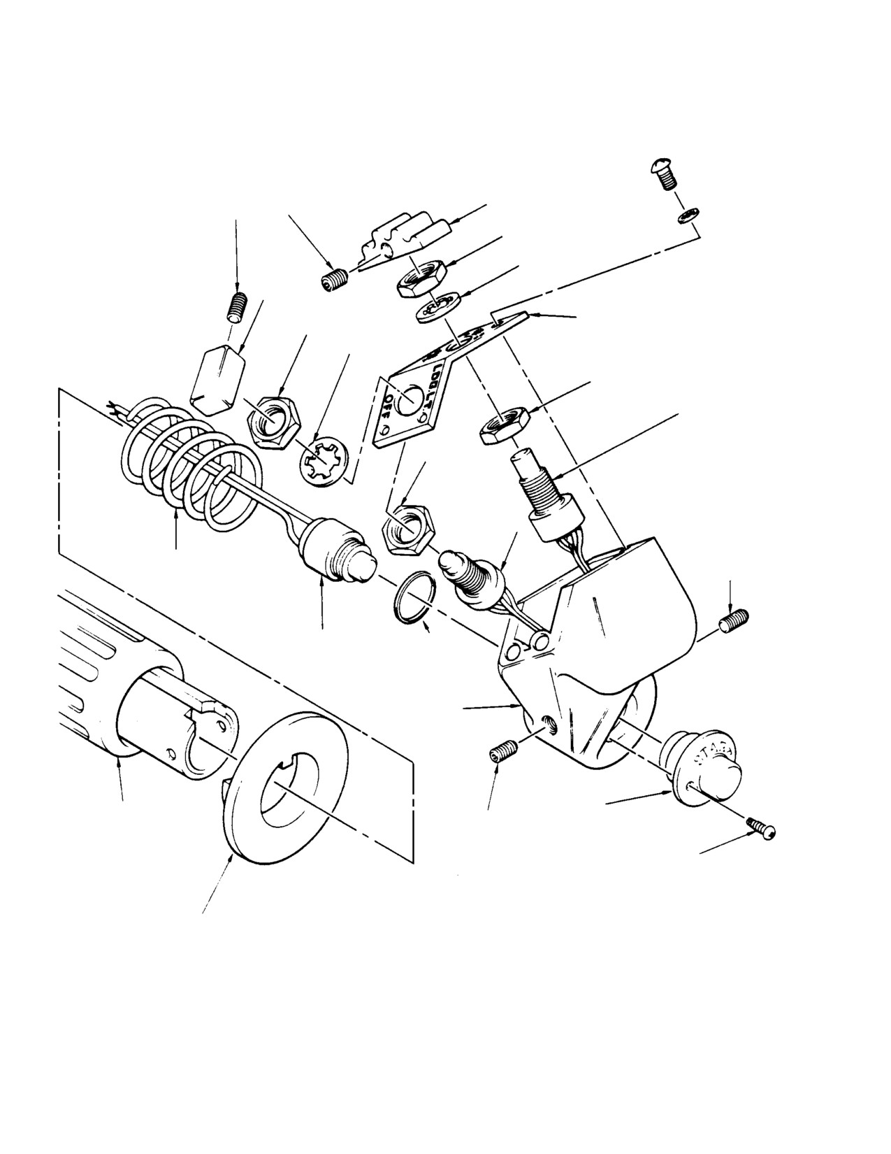
CSP-HMI-2
MD Helicopters, Inc.
MAINTENANCE MANUAL
KNOB
SETSCREW
PANEL NUT
LOCKWASHER
KNOB
SWITCH IDENTIFICATION
PANEL NUT
PLATE
LOCKWASHER
CHECK NUT
N2 GOV SWITCH
(TYPICAL)
CHECK NUT
LANDING LIGHT
SWITCH
IDLE STOP RE
LEASE SPRING
SETSCREW
START SWITCH
RETAINING RING
(HALF)
PILOT'S STICK GRIP
SWITCH HOUSING
THROTTLE
START SWITCH
SETSCREW
(HALF)
SELF-TAPPING SCREW
(SUPPIED WITH SWITCH)
IDLE STOP RE
LEASE RING
G67-1027
Figure 201. Collective Pitch Stick Switch Replacement
Page 202
Revision 21
67-10-20
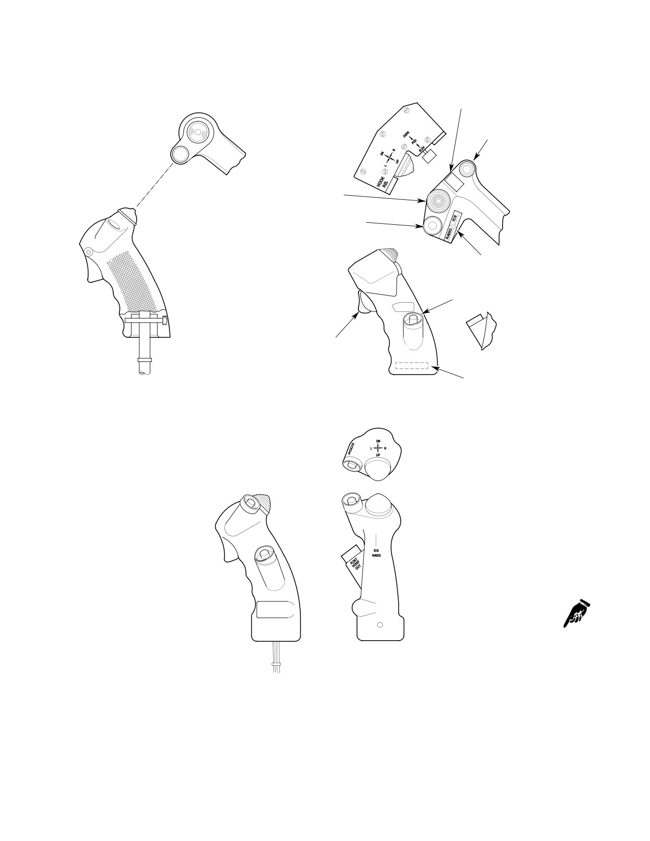
MD Helicopters, Inc.
CSP-HMI-2
MAINTENANCE MANUAL
SWITCH (S102)
(TOGGLE RED)
SWITCH (S4) *(S1)
(RED PUSHBUTTON WITH GUARD)
SWITCH
(S103) *(107)
(TRIM BLACK)
SWITCH (S1) *(S4)
(RED PUSHBUTTON WITH GUARD)
SWITCH (S111) *(S112)
(ROCKER, (OLIVE)
SWITCH (S5)
(RED PUSHBUTTON WITH GUARD
TRIGGER SWITCH
WITH GUARD
VENDOR NAME AND
P/N IDENTIFICATION
STANDARD GRIP
OPTIONAL ``T'' GRIP
NOTE:
OPTIONAL GRIP
AN ASTERISK (*) INDICATES - 3 VERSION
OF GRIP AND APPLICABLE SWITCH NUMBER.
G67-1028A
Figure 202. Cyclic Stick Grips
Page 203
67-10-20
Revision 40
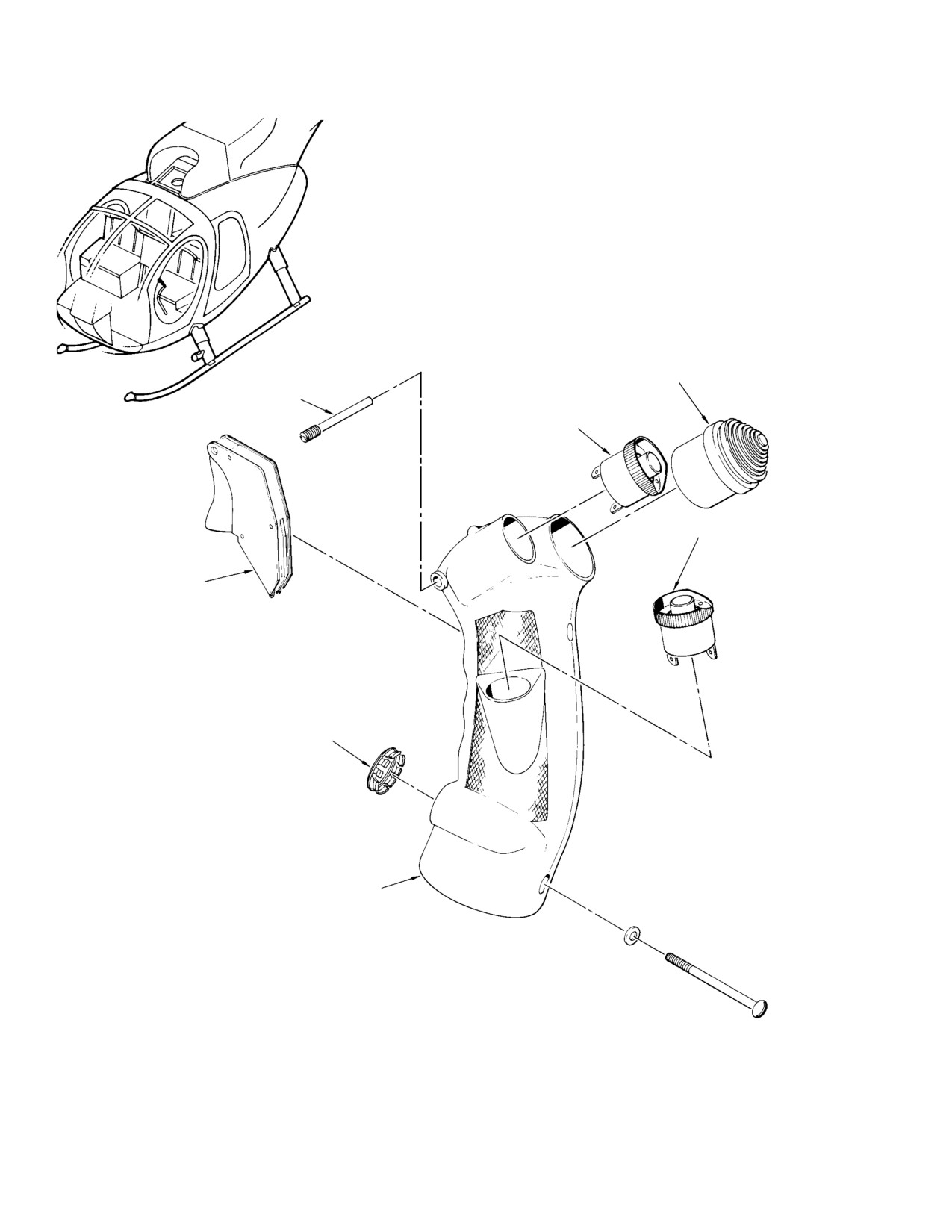
CSP-HMI-2
MD Helicopters, Inc.
MAINTENANCE MANUAL
CYCLIC TRIM SWITCH (S107)
TRIGGER PIN
HOOK SWITCH (S4)
AND GUARD
FLOAT INFLATE/ HOIST
CUTTER SWITCH (S1/S5)
AND GUARD
XMIT/ICS TRIGGER
SWITCH (S112)
PLUG BUTTON
GRIP ASSEMBLY
G67-1025-1
Figure 203. Cyclic Stick Grip Disassembly (Sheet 1 of 2)
Page 204
Revision 21
67-10-20
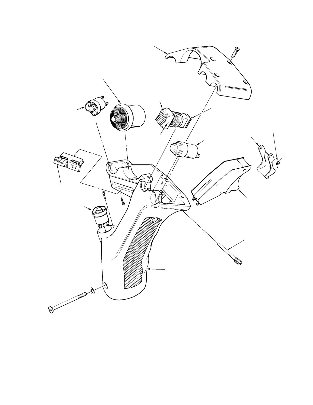
MD Helicopters, Inc.
CSP-HMI-2
MAINTENANCE MANUAL
GRIP CAP
FOUR-WAY TRIM SWITCH
(S103) *(S107)
BUTTON
TOGGLE SWITCH
SWITCH
(S102)
(S1) *(S4)
RETURN SPRING
TRIGGER GUARD
PIN
PUSHBUTTON SWITCH
(S4) *(S1)
ROCKER SWITCH
(S111) *(S112)
TRIGGER SWITCH
(S101)
SWITCH (S5)
TRIGGER PIN
GRIP ASSEMBLY
NOTE:
ASTERISK (*) INDICATES -3 VERSION OF
GRIP AND APPLICABLE SWITCH NUMBERS.
OPTIONAL T-GRIP
(P/N 369D297846)
G67-1025-2
Figure 203. Cyclic Stick Grip Disassembly (Sheet 2 of 2)
Page 205
67-10-20
Revision 21
CSP-HMI-2
MD Helicopters, Inc.
MAINTENANCE MANUAL
(4). Install an additional eight inch 20.32
(6). Push slack wiring into wiring exit holes
cm) length of insulation sleeving to
in stick socket while pulling grip wiring
protect each wire bundle where routed
from stick tube.
through exit holes in socket.
(7). Remove trim switch cap by carefully
pulling cap off.
(5). Position grip on stick tube and install
screw.
(8). Remove all attaching hardware secur
ing switches to grip, carefully remove
(6). Push as much wire slack as possible
switches and attached harness from
back into stick. Secure wiring to socket
grip assembly.
with new nylon strap, or equivalent.
(9). Tag, identify and un-solder wires of
(7). Cut wiring to correct length and
switch to be disconnected.
reinstall replaceable contacts and
electrical plug and wiring diagram.
(10). Clean grip, wiring and switches with
alcohol (CM217).
5. Cyclic Stick Grip Switch Replacement
(11). Reconnect all electrical wires using
(Standard Grip)
solder (CM815), remove identification
tags from wires.
(Ref. Figure 203)
(12). Carefully position switches to their
approximate location within the grip.
Consumable Materials
(Ref. Section 91−00−00)
NOTE: Ensure that switches are correctly posi
Item
Nomenclature
tioned with any applicable keyway, pin hole,
CM217
Isopropyl alcohol
etc, for proper alignment of mating parts.
CM425
Sealing compound
(13). Install attaching hardware securing
CM703
Tie strap
switches onto grip.
CM815
Solder
(14). Install trigger and trigger attach pin.
(15). Install cyclic trim switch cap.
Ensure that all electrical
WARNING
power is OFF.
(16). Reinstall grip on stick tube, route grip
wiring through stick tube and attach
(1). Disconnect cyclic grip wiring connector
connector.
from plug at lower end of cyclic stick.
(17). Check switch operation and wiring
(2). Remove strap securing wiring to stick
continuity.
socket; remove strap mounting plate if
(18). Apply sealing compound (CM425) to all
it is unserviceable.
screw holes and insert holes.
(3). Remove exterior sealant from grip
(19). Secure wiring to stick with nylon straps
assembly covering switch mounting
(CM703).
hardware and attaching screws.
Cyclic trim actuators should be
(4). Drive trigger pivot pin from grip to
CAUTION
operated only momentarily to
release trigger. Pin is removed from
prevent damage to equipment.
right to left while holding grip in
normal position. Remove trigger.
(20). Check operation of switch by momen
tarily cycling in all modes ensuring that
(5). Remove screw from grip and separate
the associated system operates correct
grip from stick tube.
ly.
Page 206
Revision 21
67-10-20
MD Helicopters, Inc.
CSP-HMI-2
MAINTENANCE MANUAL
6. Cyclic Stick Grip Disassembly (Optional
cal wires using solder (CM815) and
T−Grip, PN 369D297846 Only)
reinstall switches as applicable.
(Ref. Figure 203)
NOTE: Ensure that switch is correctly posi
tioned with any applicable keyway, pin hole,
Ensure that all electrical
etc, for proper alignment of matching parts.
WARNING
power is OFF.
(2). Insert replacement switch at the
(1). Remove the grip cap by removing six
approximate mounting position on the
screws.
grip subassembly.
NOTE: The grip is to be disassembled only to
(3). Using solder (CM815), connect wiring
the extent required for replacement of the
to terminals of the replacement switch.
switches. The wiring through the grip as
Remove identification tags from wires.
sembly is tied with nylon twine and covered
NOTE:
with a two inch (5.08 cm) insulating sleeve.
D Helicopters (369D) S/N 003 thru 480 may
Do not remove the twine and sleeves unless
require trigger switch rework to accom
wire replacement is required.
modate replacement switch
(Ref.
(2). Detach the rocker switch (S111) by
Figure 204).
removing two screws.
D Rework is not necessary for the following
cyclic grip assemblies; PN 369D27133 or
(3). Unscrew the trigger pin and carefully
A218-964401-00.
withdraw it while holding the trigger
guard and trigger switch (S101) in
(4). If rework is required, perform steps (a).
place. Then remove the trigger guard
thru (c). before continuing.
and switch and separate them with care
(a). Press or pull insert from top of grip.
to prevent distorting or losing the
return spring.
(b). Make template of profile of new
A218-158698-05 trigger switch.
(4). Remove toggle switch (S102). Switch
button is separated from housing by
(c). Using file, blade or equivalent
pressing out the pin.
routing tool, remove material from
lower inside edge of hole for trigger
(5). Unsolder wiring connected to terminals
switch to permit installation of new
on the switch to be disconnected. Tag
switch. Use template to determine
and identify wires to facilitate correct
amount and location of material to be
reconnection.
removed.
7.
Cyclic Stick Grip Reassembly and
(5).
As applicable, secure or attach the
Modification
trigger switch, (trigger guard and
return spring for 369D297846 cyclic
(Ref. Figure 203 and Figure 204)
grips) to the grip housing using the
original attaching hardware.
Consumable Materials
(6).
Apply sealing compound (CM425) to all
(Ref. Section 91−00−00)
open screw holes and insert hole.
Item
Nomenclature
CM217
Isopropyl alcohol
(7).
Secure the grip cap (for 369D297846
cyclic grips) to the grip subassembly
CM314
Varnish, moisture resistant
with six screws; coat the screws with
CM425
Sealing compound
varnish (CM314) before installation
CM703
Tie strap
into grip.
CM815
Solder
(8).
Reinstall grip on stick tube. Using
attached strings, route grip wiring
(1). Clean grip, wiring and switches with
through stick tube and reconnect at
alcohol (CM217). Reconnect all electri
electrical plug.
Page 207
67-10-20
Revision 21
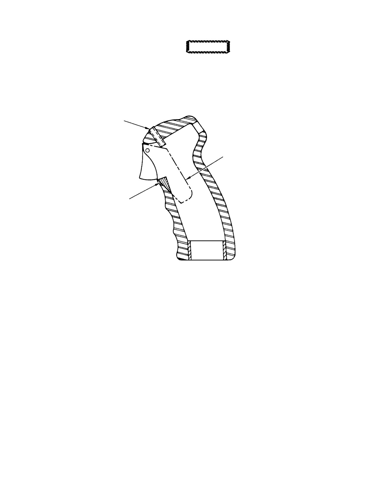
CSP-HMI-2
MD Helicopters, Inc.
MAINTENANCE MANUAL
(9). Check switch operation and wiring
Cyclic trim actuators should be
CAUTION
continuity.
operated only momentarily to
prevent damage to equipment.
(10). Secure wiring to stick socket with nylon
(12). Check operation of the switch by
strap (CM703).
momentarily activating it and ensuring
that the associated system operates
(11). Energize the electrical system.
correctly.
REMOVE THIS INSERT
A218-158698-05 SWITCH
REOMOVE MATERIAL HERE
NOTE:
TRIM INSIDE EDGE OF CYCLIC GRIP AS REQUIRED
FOR INSTALLATION OF NEW TRIGGER SWITCH.
G67-1026
Figure 204. Rework of Cyclic Stick Grip
Page 208
Revision 21
67-10-20
MD Helicopters, Inc.
CSP-HMI-2
MAINTENANCE MANUAL
Section
67−20−10
Anti−Torque Flight
Controls (Two and
Four Blade)
(369D/E/FF)
MD Helicopters, Inc.
CSP-HMI-2
MAINTENANCE MANUAL
ANTI−TORQUE FLIGHT CONTROLS
(TWO AND FOUR BLADE)
DESCRIPTION AND OPERATION
1. Tail Rotor Control Configuration
control pedals with left copilot's dual
controls. Foot rest not installed.
The helicopter may be equipped with either of
two basic pilot's tail rotor foot pedal control
configurations. The tail rotor and control
2. Upper Fuselage and Tailboom Control
linkage to the foot pedals are identical on
Linkage
either basic configuration.
Upper fuselage tail rotor controls consist of
(1). Basic Left-Hand Command Tail Rotor
Sta. 95 bellcrank and support at the front of
Controls. Single left position pilot's tail
the main rotor mast base, Sta. 120 control rod
rotor control pedals. Foot rest can be
and Sta. 142 bellcrank inside the boom fairing.
installed at right side of crew compart
Boom linkage consists of tailboom control rod,
ment in place of right-hand foot pedals.
supported by seven bushings (grommets), and
(2). Basic Right-Hand Command Tail Rotor
Sta. 284 Bellcrank mounted on the tail rotor
Controls. Right position pilot's tail rotor
transmission.
Page 1
67-20-10
Revision 21
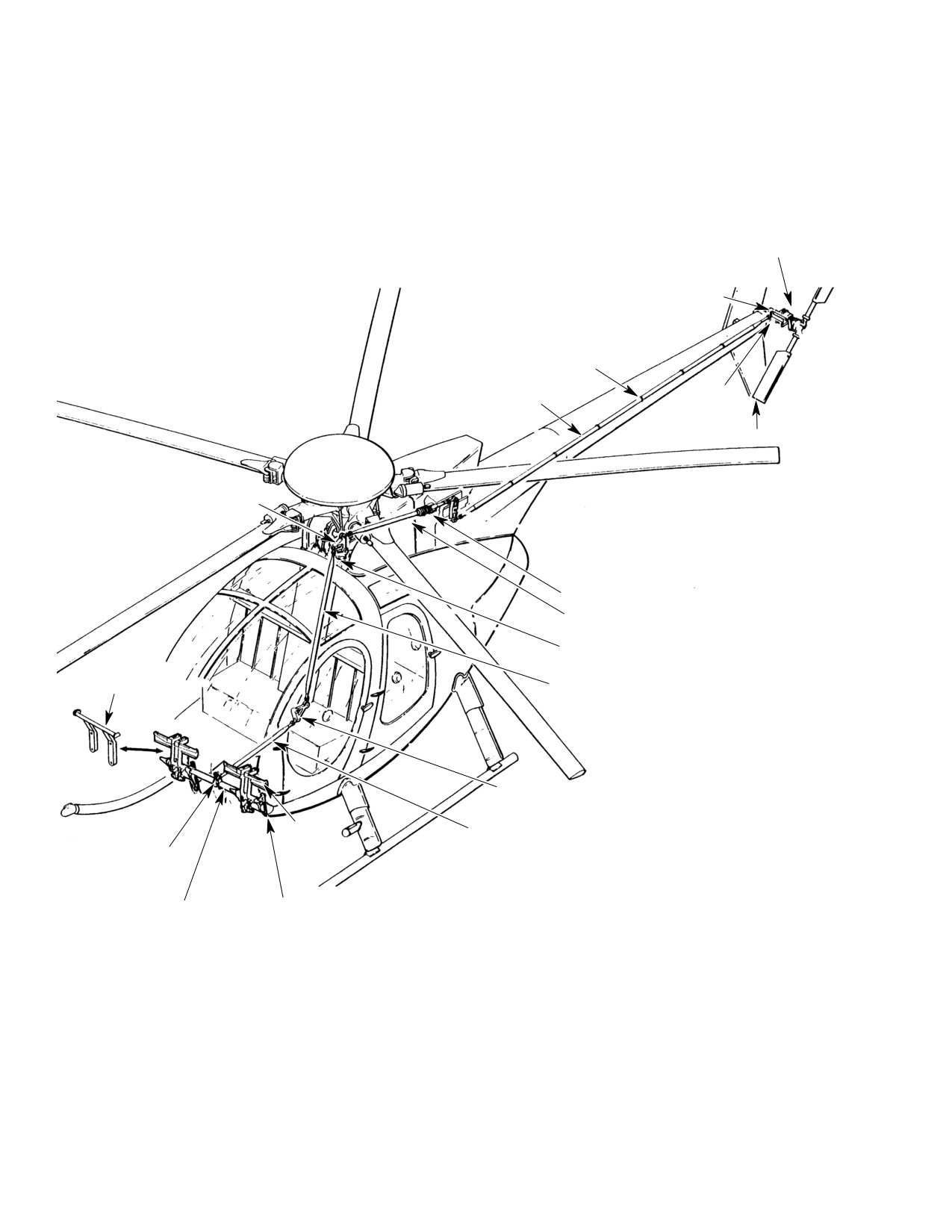
CSP-HMI-2
MD Helicopters, Inc.
MAINTENANCE MANUAL
PITCH CONTROL ASSEMBLY
TAIL ROTOR TRANSMISSION
CONTROL ROD BUSHING
(GROMMET) (7 PLCS)
TAILBOOM CONTROL ROD
STA. 284
BELLCRANK
TAIL ROTOR ASSEMBLY
STA. 95 BELLCRANK
BOOT
STA. 120 CONTROL ROD
TAIL ROTOR CONTROL SUPPORT
RIGHT POSI
TION FOOT
STA. 78.50 (TUNNEL-
REST
ROUTED) CONTROL ROD
IDLER BELLCKRANK
PEDAL
FLOOR-
ROUTED CON
TORQUE TUBE
TROL ROD
MOUNTING BRACKET
LEFT POSITION PED
TORQUE TUBE
AL MOUNTING
BRACKET
G67-0001A
Figure 101. Tail Rotor and Control System
Page 2
Revision 21
67-20-10
MD Helicopters, Inc.
CSP-HMI-2
MAINTENANCE MANUAL
ANTI−TORQUE FLIGHT CONTROLS
(TWO AND FOUR BLADE)
REMOVAL/INSTALLATION
1. Sta. 120 Control Rod or Sta. 142 Bellcrank
(2). Ensure that slotted bushings are in
Replacement
place at each end of bellcrank; then
position riveted rod end in bellcrank
A. Sta. 120 Control Rod or Sta. 142
and install bolt, two washers, nut and
Bellcrank Removal
cotter pin. Make sure that hump of
bellcrank faces forward.
(Ref. Figure 401) The Sta. 142 bellcrank and
Sta. 120 control rod must be removed as an
(3). Carefully feed assembled control rod
assembled unit.
and bellcrank through forward air
intake at left side of control mixer
(1). Remove tail rotor control bellcrank
installation while an assistant guides
access door from left side of boom
the assembly through boot support tube
fairing.
to bellcrank support bracket.
(2). Disconnect tailboom control rod from
lower end of Sta. 142 bellcrank.
(4). Position rubber boot in place at Sta.
137.50.
(3). Remove hardware that secures Sta. 142
bellcrank to boom fairing brackets.
(5). Position Sta. 142 bellcrank in support
bracket and install bolt, two washers,
(4). Open hinge-mounted access door on
nut and cotter pin.
engine air inlet aft fairing. Remove
clamp on boot support tube at Sta.
Check Sta. 142 bellcrank for
137.50.
CAUTION
clearance with support struc
ture. Pay particular attention to area above
(5). Disconnect forward end of Sta. 120
369A7951-23 bearing when top of bellcrank
control rod from Sta. 95 bellcrank.
is in forward position. If contact is noted,
machine surface of bellcrank (machine sur
NOTE: Sta. 95 bellcrank must also be detached
face with interference only)
(Ref.
from its support for clearance from air inlet
Figure 801).
fairing for rod-end bolt removal.
(6). Carefully pull forward end of control
(6). Check that slotted bushing is in place
rod and withdraw assembled rod and
in Sta. 95 bellcrank; then install
bellcrank out through boot support tube
forward rod end in bellcrank with bolt
at plenum chamber Sta. 137.50.
(head to left), two washers, nut and
cotter pin.
(7). Disconnect control rod from upper end
of bellcrank.
(7). Reinstall Sta. 95 bellcrank in its
support with bolt, two washers, nut and
B. Sta. 120 Control Rod or Sta. 142
cotter pin.
Bellcrank Installation
(8). Secure rubber boot at support tube with
(Ref. Figure 401) Sta. 142 bellcrank and Sta.
nylon strap. Then clamp tail rotor
120 control rod must be installed as a unit by
pedals in neutral, set free length of
routing assembled end of bellcrank and control
bellows portion of boot at approximately
rod through boot support tube at plenum
5.5 inches and secure end to control rod
chamber station (Sta. 137.50).
with nylon strap.
(1). For access to bellcrank support bracket,
use access door in boom fairing.
(9). Check rigging of tail rotor controls.
Page 401
67-20-10
Revision 21
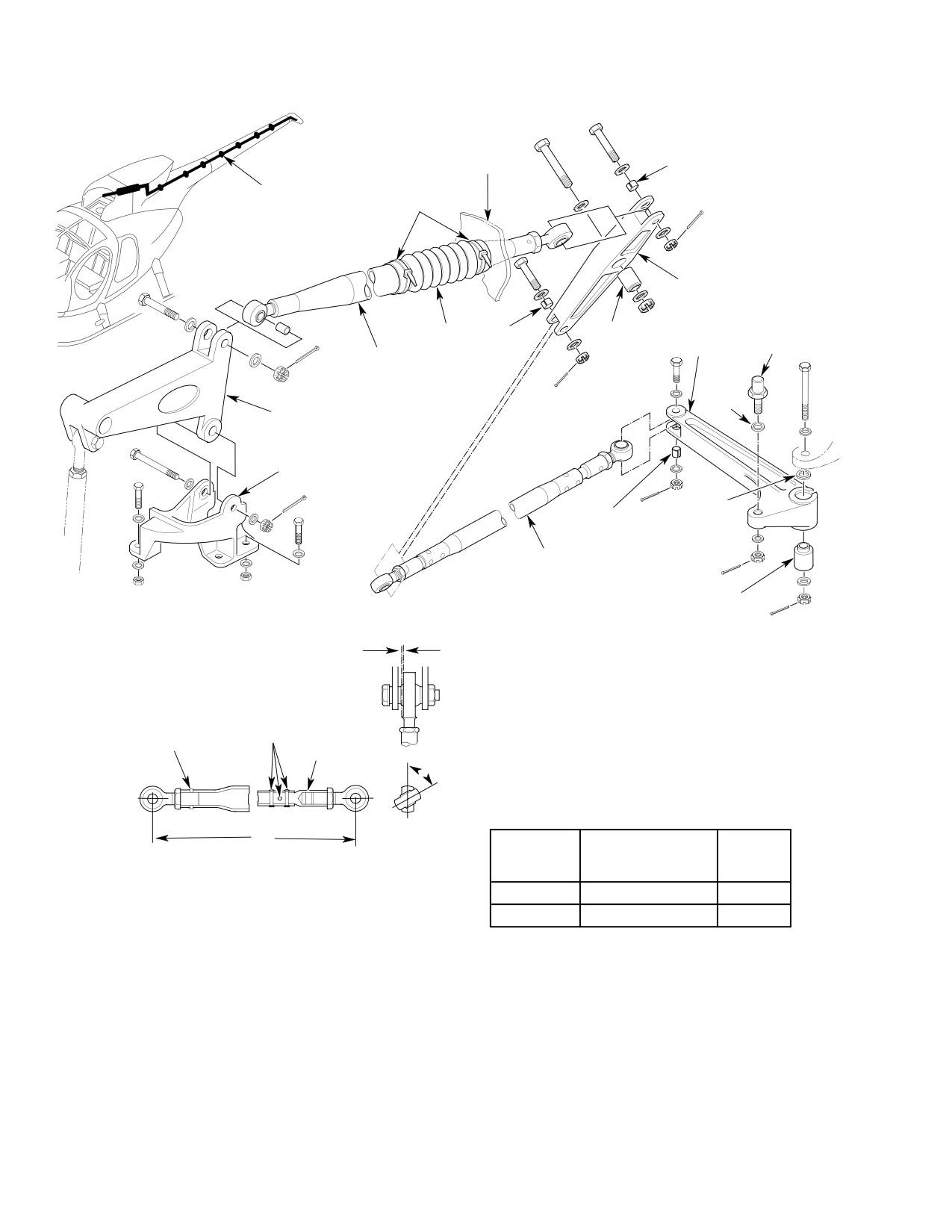
CSP-HMI-2
MD Helicopters, Inc.
MAINTENANCE MANUAL
STA. 137.50
NOTE 2
BUSHING (GROMMET)
NYLON
(7 PLACES)
STRAP
* STA. 142 BELLCRANK
BEARING
BOOT NOTE 2
STATION 284
BELLCRANK
PIVOT PIN
STA. 120
CONTROL ROD
(NOTE 1)
SPECIAL
WASHER
* STA. 95 BELLCRANK
* SUPPORT
WASHER
NOTE 2
(NOTE 5)
TAILBOOM
CONTROL ROD
(NOTE 3)
BEARING
MAXIMUM ALLOWABLE
LOOSENESS 0.040 IN.
(1.016 MM)
RIVET
BEARING
RIVET
ADAPTER
A
ROD LENGTH AND BEARING
ANGULARITY - BEFORE RIG
L
DIMENSION
CONTROL
ANGLE
L
ROD
A
INCHES (CM)
STA. 120
45.88
(
IN LINE
NOTES:
116.5352)
TAILBOOM
143.80
63°
1.
MINIMUM OF 0.060 IN. (1.524 MM) CLEARANCE FOR FULL RANGE OF
(365.252)
TRAVEL THRU STA. 137.50 BULKHEADS.
2.
EDGE OF BUSHING MUST PROTRUDE A MINIMUM OF 0.010 IN. (0.254 MM)
TO A MAXIMUM OF 0.060 IN. (1.524 MM) ABOVE OUTSIDE SURFACE OF
PART AFTER NUT IS TIGHTENED.
3.
MINIMUM OF 0.010 IN. (0.254 MM) CLEARANCE FOR FULL RANGE OF
TRAVEL BETWEEN BOOM AND TAIL ROTOR TRANSMISSION.
4.
ASTERISK ( * ) INDICATES PARTS THAT MAY BE EITHER ALUMINUM OR
MAGNESIUM ALLOY. FOR ALLOY IDENTIFICATION AND CORROSION
CONTROL (REF. SEC. 20-40-00).
5.
ADD ONE OR TWO AN960KD516 WASHERS AS REQUIRED FOR CLEARANCE
G67-2000B
Figure 401. Upper Fuselage and Boom Tail Rotor Control Linkage
Page 402
Revision 21
67-20-10
MD Helicopters, Inc.
CSP-HMI-2
MAINTENANCE MANUAL
2. Sta. 284 Bellcrank Replacement
(4). Slowly pull aft end of control rod and
withdraw rod through opening in tail
A. Sta. 284 Bellcrank Removal
rotor transmission mounting frame.
(Ref. Figure 401)
B. Tailboom Control Rod Installation
(Ref. Figure 401)
(1). Disconnect bellcrank from tailboom
control rod.
NOTE: Tailboom control rod is routed through
boom with forward rod end removed.
(2). Disconnect bellcrank from tail rotor
transmission. Disengage bellcrank
(1).
Deleted
pitch control pin from pitch control
housing and remove bellcrank.
(2).
Guide control rod through boom aft
frame opening and carefully route
B. Sta. 284 Bellcrank Installation
through seven bushings (grommets).
Rotate rod slightly to start it through
(Ref. Figure 401)
each grommet.
(1). Insert bellcrank pivot pin into pitch
(3).
Check that slotted bushing is in place
control housing self-aligning bearing.
in lower lug of Sta. 284 bellcrank; then
attach aft rod to bellcrank.
(2). Position bellcrank to align with mating
hole in tail rotor transmission arm and
(4).
Using measurement recorded at time of
install bolt.
rod removal, install forward rod end
bearing. Align rod ends so that bearings
(3). Check that slotted bushing is in place
have equal space for angular throw;
in lower lug of bellcrank; then attach
hold rod end and tighten jam nut.
tailboom control rod to bellcrank with
bolt, two washers, nut and cotter pin.
(5).
Check that slotted bushing is in place
in lower end of Sta. 142 bellcrank; then
(4). Check rigging of tail rotor controls (Ref.
attach forward rod end to bellcrank.
Tail Rotor Controls Rigging).
(6).
Check rigging of tail rotor controls (Ref.
Tail Rotor Controls Rigging).
3. Tailboom Control Rod Replacement
(7).
Close plenum chamber access door.
A. Tailboom Control Rod Removal
4. Sta. 95 Bellcrank and Support
(Ref. Figure 401)
Replacement
(1). Disconnect control rod from Sta. 284
A. Sta. 95 Bellcrank and Support Removal
bellcrank.
(Ref. Figure 401)
(2). Remove tail rotor control bellcrank
access door from left side of boom
(1). Disconnect tunnel-routed control rod
fairing.
from bellcrank.
(3). Accurately measure and record distance
(2). Disconnect bellcrank from support.
between unchamfered edge of forward
rod end bearing jam nut and center of
(3). Disconnect bellcrank from Sta. 120
bearing attach bolt hole. Hold forward
control rod and remove bellcrank.
rod end, loosen jam nut and unthread
control rod from rod end by turning aft
(4). Remove hardware that secures support
end of rod.
to mast structure; remove support.
Page 403
67-20-10
Revision 34
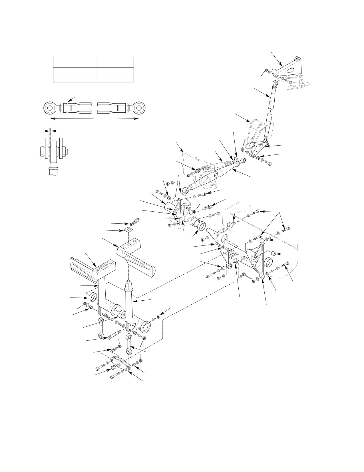
CSP-HMI-2
MD Helicopters, Inc.
MAINTENANCE MANUAL
INITIAL CONTROL ROD LENGTH
STA. 95 BELLCRANK
- BEFORE RIG
CONTROL
DIMENSION L
ROD
INCHES (CM)
TUNNEL-ROUTED
57.95
(147.193)
FLOOR-ROUTED
30.06
(76.3524)
STA. 97.50
(TUNNEL-ROUTED)
CONTROL ROD
RIVET
CONTROLS SUPPORT
BRACKET
L
MAXIMUM ALLOWABLE AXIAL
SPRING FITTING
PLAY 0.040 IN. (1.016 MM)
AFT EYEBOLT
STA. 63.00
TAIL ROTOR
BUNGEE
IDLER BELLCRANK
SPRING
NOTE 2
FORWARD EYEBOLT
NOTE 1
NOTE 2
FLOOR-ROUTED
CONTROL ROD
NOTE 3
TORQUE TUBE
BUSHING ASSY
* TORQUE TUBE BRACKET
(NOTE 4)
(NOTE 5)
NOTE 1
CONTROL ROD FITTING
NOTE 3
NOTE 1
PIN
WASHER
NOTE 4
* LEFT PEDAL
BEARING
NOTE 1
STOP BOLT
* RIGHT PEDAL
JAMNUT
BEARING
NOTE 2
NOTE 3
* PEDAL ARM
NOTE 1
BUSHING
* PEDAL ARM
NOTE 1
(TEFLON-LINED)
NOTE 4
* PEDAL BRACKET
NOTE 2
BUSHING
(TEFLON-LINED)
NOTES:
1.
SHIM BETWEEN BRACKET AND BULKHEAD WITH AN960PD416
BUSHING ASSY
(NOTE 4)
AND/OR -416L WASHERS AS REQUIRED FOR ALIGNMENT WITHIN
0.010 IN. (0.254 MM).
NOTE 2
LINK
2.
EDGE OF BUSHING MUST PROTRUDE A MINIMUM OF 0.010 IN.
(0.254 MM) TO A MAXIMUM OF 0.060 IN. (1.524 MM) ABOVE OUTSIDE
SURFACE OF PART AFTER NUT IS TIGHTENED.
NOTE 2
3.
DIRECTION OF BOLTS IS OPTIONAL.
BEARING
4.
ADJUSTABLE BUSHINGS MUST HAVE A MINIMUM PROTRUSION OF
BELLCRANK
0.002 INCH (0.051 MM) AT EACH END.
5.
INSTALLED WITH BEARING RECESS FACING FITTING.
6.
ASTERISK (*) INDICATES PART THAT MAY BE EITHER MAGNESIUM OR
ALUMINUM ALLOY. FOR ALLOY IDENTIFICATION AND CORROSION
CONTROL (REF. SEC. 20-40-00).
G67-2001-1D
Figure 402. Tail Rotor Pedal Installation (Sheet 1 of 2)
Page 404
Revision 26
67-20-10
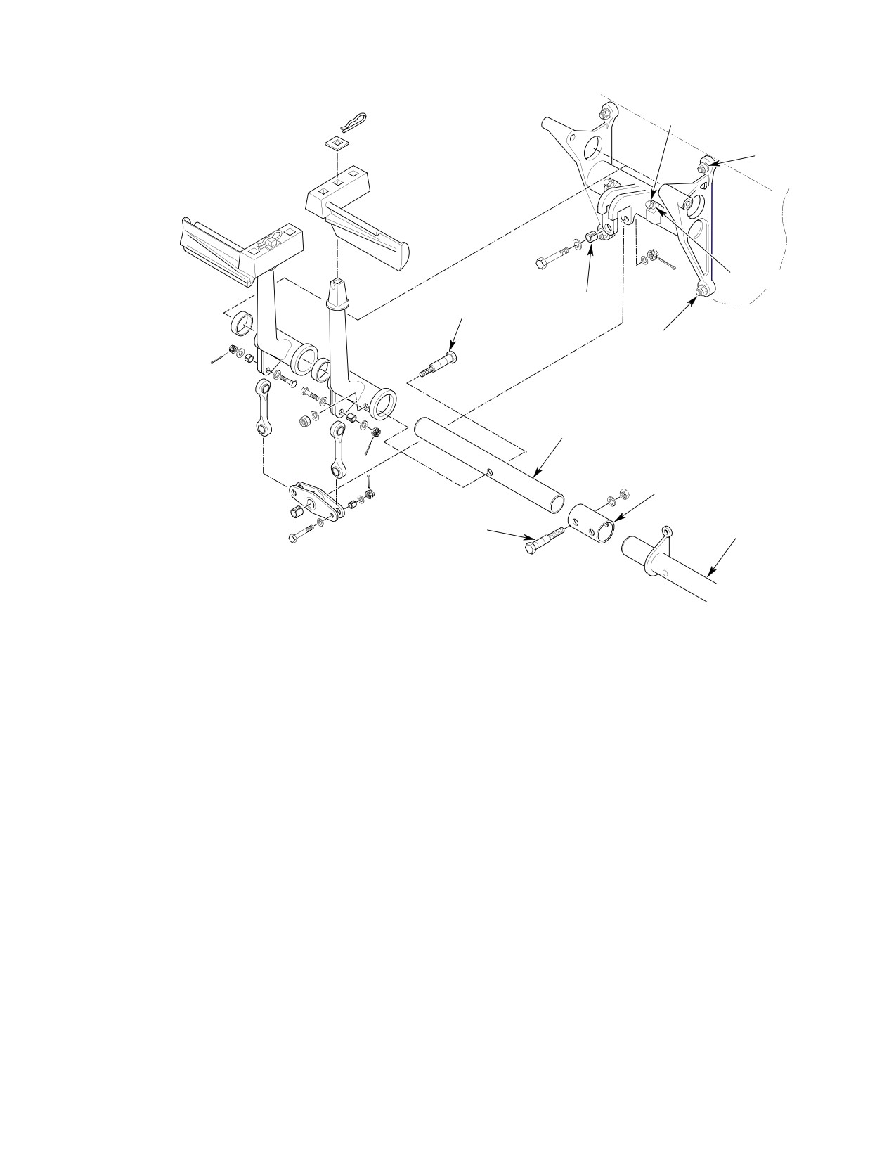
MD Helicopters, Inc.
CSP-HMI-2
MAINTENANCE MANUAL
STOP BOLT (2)
NOTE
ADJUSTABLE
JAMNUT
BUSHING ASSEMBLY
NOTE 2
(NOTE 4)
NOTE 3
TORQUE TUBE
SLEEVE
ADJUSTABLE
TORQUE TUBE
BUSHING ASSEMBLY
(NOTE 4)
RIGHT POSITION TAIL ROTOR PEDALS
G67-2001-2A
Figure 402. Tail Rotor Pedal Installation (Sheet 2 of 2)
B. Sta. 95 Bellcrank and Support Installation
C. Tail Rotor Pedal Assembly − General
(Ref. (Ref. Figure 401)
(Ref. (Ref. Figure 402) Tail rotor pedal
(1). Install bellcrank support to mast
installation consists of a pair of adjustable
structure with three bolts, seven
pedals, pedal arms with interconnecting
washers and three nuts. Forward bolt
linkage, pedal mounting bracket for left
requires an extra washer under
control position, torque tube with control rod
bolthead; two thin washers are used at
all three locations. Torque nuts to 80 -
fitting and torque tube mounting bracket.
100 inch-pounds (9.04 - 11.30 Nm).
Forward pressure on right pedal rotates torque
tube, moving control system linkage to
(2). Check that slotted bushings are in
increase tail rotor blade pitch. Pressure on left
place in bellcrank; then attach Sta. 120
pedal decreases tail rotor blade pitch. A
control rod to bellcrank with bolt (head
bungee spring is installed at aft end of
to left).
floor-routed control rod in underseat tail rotor
control linkage. This spring relieves left pedal
(3). Install bellcrank in support.
forces during flight and causes left pedal to
(4). Attach tunnel-routed control rod to
remain at forward position when helicopter is
bellcrank.
on ground and not operating.
Page 405
67-20-10
Revision 21
CSP-HMI-2
MD Helicopters, Inc.
MAINTENANCE MANUAL
NOTE: Parts identified with an asterisk (*)
simplify torque tube alignment during
may be either magnesium or aluminum
reinstallation.
alloy. (Ref. Sec. 20-40-00 for corrosion con
(10). Remove four nuts, eight washers, any
trol and identification of magnesium and
shim washers and four bolts that secure
aluminum alloys).
pedal bracket to bulkhead. Remove
D. Co−Pilot’s Pedal Installation
control pedal installation. Keep shim
washer selection with bracket.
(Ref. Figure 402) The copilot's pedal installa
B. Tail Rotor Pedal Assembly Installation
tion is essentially the same as the pilot's. A
sleeve couples a torque tube extension to the
(Ref. Figure 402)
pilot's torque tube. Dual pedal installation is
also equipped with pedal stop nuts, heel strips,
NOTE: Install both left and right pedal brack
retaining springs and attachment hardware.
ets for right-hand command helicopters.
(1). Install pedal bracket with four bolts,
5. Tail Rotor Pedal Assembly Replacement
eight washers and four nuts. Add shim
A. Tail Rotor Pedal Assembly Removal
washers as required at pedal bracket
attachment points to keep centerline
(Ref. Figure 402)
alignment of pedal bracket bearings
within 0.010 inch (0.254 mm). Correct
(1).
Pull two hinge pins from pilot's com
alignment is indicated by free rotation
partment floor access door hinges and
al movement of torque tube after nuts
remove door. Remove access panel from
are tightened.
each side of instrument panel lower
support structure.
(2). Position torque tube bracket over
mating holes in bulkhead and check
(2).
Remove battery (Ref. Chap. 96).
alignment with bulkhead. Add shim
washers as required at bracket attach
(3).
Remove pins securing pedals to pedal
ment points to maintain bearing
arms and remove pedals.
alignment established in step a above.
Install two bolts, four washers and two
(4).
For access to bungee, remove access
nuts.
cover between pilot's seats and/or by
removing left passenger's footwell on
(3). Install forward eyebolt, using same
aft side of canted bulkhead.
number of washers removed, on bungee
and then hook aft end of bungee into
(5).
Block left tail rotor control pedal at full
eyebolt on floor-routed control rod
forward position to relieve tension on
fitting.
bungee.
NOTE: If tail rotor pedal forces are not zero
(6).
Remove eyebolt and washers at Sta. 63
during level flight at 130 to 140 knots, tail
with bungee attached. Keep washers
rotor force adjustment may be accomplished
with eyebolt for reinstallation.
by removing washers as required from the
eyebolt at Sta. 63 bracket.
(7).
Disconnect bungee from eyebolt and
fitting at aft end of floor-routed control
(4). Using spring tension tool install bungee
rod by using spring tension removal
into position at Sta. 63 bracket; install
tool (75, Table 203, 91-00).
washer and nut on eyebolt.
(8).
Remove cotter pin, nut, two washers
(5). Check that slotted bushing is in place;
and bolt that connect floor-routed
then install floor-routed control rod in
control rod to torque tube fitting.
torque tube fitting and install bolt, two
washers, nut and cotter pin.
(9).
Remove two nuts, four washers, any
shim washers and two bolts that secure
(6). Check rigging of tail rotor controls and
torque tube bracket to bulkhead. Keep
pedal-to-canopy clearance (Ref. Tail
shim washer selection with bracket to
Rotor Controls Rigging). Pedals should
Page 406
Revision 21
67-20-10
MD Helicopters, Inc.
CSP-HMI-2
MAINTENANCE MANUAL
clear windows by a minimum of 0.20
(5).
Check that spherical bearings are in
inch (5.08 mm) with 20 pounds (88.96
place; then attach bellcrank to pedal
N) of force applied.
bracket with bolt, two washers, nut and
cotter pin.
6. Dual Tail Rotor Pedal Initial Installation
(6).
Check that slotted bushings are in
place; then fasten each link to bellcrank
(Ref. Figure 402)
with bolt, two washers, nut and cotter
pin.
NOTE: Before pedal installation, remove the
bushing assembly that secures pilot's left
(7).
Check that slotted bushings are in
pedal arm to the torque tube. This will allow
place; then fasten each link in pedal
the tube to rotate far enough to install the
arm lugs with bolt, two washers, nut
bushing assemblies.
and cotter pin.
(1). Thread a stop nut on each of the two
(8).
Install pedal bracket assembly with
stop-bolts and install bolts into
four bolts, eight washers and four nuts.
threaded inserts of pedal bracket.
Add shim washers as required at pedal
bracket attachment points to keep
(2). Locate pedal bracket and pedal arms
centerline alignment of pedal bracket
for correct position on torque tube.
bearings within 0.10 inch (2.54 mm).
Correct alignment is indicated by free
(3). Fasten left pedal arm to torque tube
rotational movement of torque tube
with adjustable bushing assembly;
after nuts are tightened.
install bushing bolt so that shank of the
(9).
Reinstall bushing assembly previously
bolt head end protrudes at least 0.002
removed from the pilot's left pedal arm.
inch. Install nut and torque to 80
inch-pounds (9.04 Nm) plus drag
(10).
Install pedals on pedal arms and secure
torque, do not allow bolt to turn.
with pins provided.
(4). Check that each end of bushing pro
(11).
Install heel strips with pins, washers
trudes at least 0.002 inch (0.051 mm). If
and cotter pins. Direction of pin head is
not, loosen nut and repeat prior step.
optional.
Page 407
67-20-10
Revision 21
CSP-HMI-2
MD Helicopters, Inc.
MAINTENANCE MANUAL
This Page Intentionally Left Blank
Page 408
Revision 44
67-20-10
MD Helicopters, Inc.
CSP-HMI-2
MAINTENANCE MANUAL
ANTI−TORQUE FLIGHT CONTROLS
(TWO AND FOUR BLADE)
ADJUSTMENT/TEST
1. Tail Rotor Controls Rigging
(b). Sta. 95 bellcrank: Centerline of
tunnel-routed control rod attach bolt
should be 4.30 ±0.090 inches (109.22
(Ref. Figure 501) The tail rotor control system
±2.286 mm) above mast base struc
must be re-rigged immediately after replace
ture.
ment of linkage that cannot be accurately
measured (by trammeling, etc) before it is
(c). Sta. 142 bellcrank: Centerline of
installed in the tail rotor control system, or if
tailboom control rod attach bolt
helicopter operation reveals a rigging deficien
should be 4.75-5.09 inches
cy.
(120.65-129.286 mm) from aft face of
Sta. 137.50 bulkhead. For access to
bellcrank, remove tail rotor control
Special Tools
bellcrank access door.
(Ref. Section 91−00−00)
Item
Nomenclature
(3).
Loosen rod end jam nut at forward end
of tailboom control rod.
ST606
T/R swashplate rigging tool
(4).
On tail rotor transmission, remove
hardware attaching tailboom control
Remove pilot's pedals and copi
rod to inboard end of Sta. 284 bellcrank.
CAUTION
lot's (if installed) to prevent pos
(5).
Tie back tail rotor rotating boot. Place
sible contact with lower windshield during
midtravel portion of swashplate rigging
rigging sequence.
tool (ST606) between swashplate and
tail rotor fork split-ring retainer (B,
NOTE: Control rod end bearing adjustments
Figure 501). Make sure that rigging
are to be made to nearest half turn that pro
tool contacts ring and not fork.
duces correct rigging. When tightening jam
(6).
Turn tailboom control rod at aft end.
nut at adjustable end of a control rod, al
Adjust rod length to nearest half turn of
ways hold rod end with a wrench to prevent
rod end that allows swashplate rigging
jamming of bearing. Never reinstall a used
tool to just slide between split-ring
cotter pin; always install a new one.
retainer and swashplate.
(1). Disconnect bungee spring at aft end of
(7).
Recheck that centerline of tailboom
floor-routed control rod (Ref.
control rod forward attach bolt remains
Figure 402).
4.75-5.09 inches (120.65-129.286 mm)
from aft face of Sta. 137.50 bulkhead.
Also check forward rod end for not less
(2). Using two pieces of wood and C-clamp
than one and one-half exposed threads
or rope, secure pilot's foot pedal arms so
with jam nut snug against rod. If either
they are aligned (A, Figure 501). With
condition does not exist, disconnect
pilot's foot pedals clamped in neutral
forward end of Sta. 120 control rod and
and control rod lengths adjusted (Ref.
readjust both control rods until Sta. 142
Figure 401 and Figure 402), control
bellcrank position and exposed threads
system bellcrank positions may be
of both control rods are within toler
checked as follows:
ance.
(a). Tail rotor idler bellcrank (pilot's
(8).
Ensure that slotted bushing is in place
compartment): Centerline of aft arm
in bottom ear of Sta. 284 bellcrank and
should be 90 ±2 degrees to Sta. 78.50
inboard ear of Sta. 95 bellcrank.
bulkhead.
Connect control rods (Ref. Figure 401).
Page 501
67-20-10
Revision 21
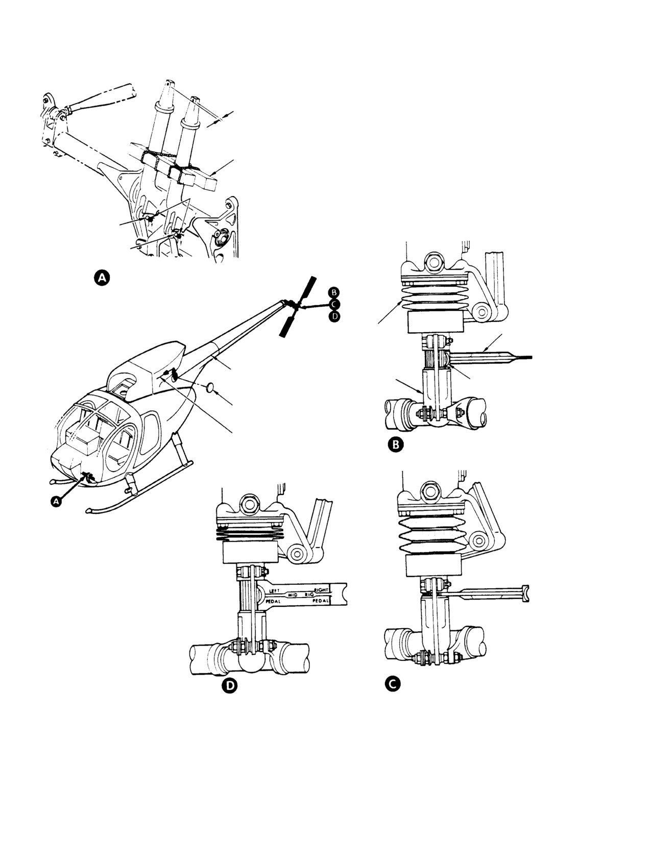
CSP-HMI-2
MD Helicopters, Inc.
MAINTENANCE MANUAL
0.250 IN. (6.35 MM)
MAX. MISALIGNMENT
NOTES:
BETWEEN PEDALS
1.
ROTATING BOOT NOT SHOWN. NORMALLY IT
IS TIED BACK TO LOCATE RIGGING TOOL.
2.
TAILBOOM CONTROL ROD AND STA. 120 CONTROL
ROD LENGTHS ARE ADJUSTED FOR CORRECT
CLAMPING BLOCKS
MID-TRAVEL RIGGING.
3.
ST606, TABLE 3, SEC. 91-00-00
STOP NUT
RIGHT STOP BOLT
LEFT STOP BOLT
PEDAL ARM ALIGNMENT AND
STOP BOLT ADJUSTMENT
SWASHPLATE
NON-ROTATING
RIGGING TOOL
BOOT
(NOTE 3)
TAILBOOM CONTROL ROD
(NOTE 2)
TAIL ROTOR FORK
SPLIT-RING
RETAINER
BELLCRANK ACCESS DOOR
STA. 120 CONTROL ROD
MID-TRAVEL RIGGING
(NOTE 2)
(NOTES 1, 2)
RIGHT PEDAL RIGGING
LEFT PEDAL RIGGING
G67-2002B
Figure 501. Rigging − Tail Rotor Control System
Page 502
Revision 21
67-20-10
MD Helicopters, Inc.
CSP-HMI-2
MAINTENANCE MANUAL
(9). Check witness holes for proper thread
(15). Operate pedals through full range of
engagement. Align rod ends to get
travel. While controls are being moved,
approximately equal angular throw in
check that there is never less than
bellcranks; tighten jam nuts.
0.060 inch (1.524 mm) clearance around
Sta. 120 control rod where it passes
through structure at Sta. 137.50 and
(10). Remove clamping device from foot pedal
that there is never less than 0.010 inch
arms.
(0.254 mm) clearance around tailboom
control rod where it exits between boom
(11). Loosen jam nuts on pedal stop bolts (A,
and tail rotor transmission.
Figure 501). Screw in pedal stop bolts
approximately 0.50 inch (12.70 mm).
(16). Connect bungee spring between aft end
of floor-routed control rod and Sta. 63
Use care when actuating pedals
bracket (Ref. Figure 402) and check
CAUTION
to avoid possibility of damaging
that pilot's left pedal moves to its
tool or windshield.
normal forward position.
NOTE: Adjust copilot's pedal stop bolts to
(17). Install Sta. 142 bellcrank access door.
match pilot's pedal travel, 0.001-0.003 inch
(0.025-0.076 mm) gap between stop bolts
2. Tail Rotor Bungee Adjustment
and pedals.
(Ref. (Ref. Figure 502)
(12).
Adjust right pedal stop bolt (A,
Figure 501) so that when pedal arm is
(1).
2-Bladed bungee adjustment:
held against stop, right pedal portion of
swashplate rigging tool just slides
between split-ring retainer and
(a). Increase pedal force by removing
swashplate (view C). Fit should be tight
washers from under bungee spring
enough to support weight of tool.
eyebolt.
Without changing adjustment of bolt or
tool fit, tighten jam nut on stop bolt.
(b). If tail rotor pedal forces are not zero
during level flight at 130 - 140 knots,
tail rotor force adjustment may be
(13).
Adjust left pedal stop bolt (A,
accomplished by removing a desired
Figure 501) so that when pedal arm is
number of AN970-3 washers.
held against stop with 20 - 25 pounds
(88.96 - 111.20 N) pressure (or pull on
right pedal), left pedal portion of
(2).
4-bladed bungee adjustment:
swashplate rigging tool just slides
between split-ring retainer and
(a). Adjust tail rotor pedal force by
swashplate (view D). Fit should be tight
tightening or loosening the 0.120
enough to support weight of tool.
inch (3.048 mm) thread adjustment
Without changing adjustment of bolt or
on bungee female bearing assembly.
tool fit, tighten jam nut on stop bolt.
Remove swashplate rigging tool and
(b). Tighten to maximum 0.120 inch
restore rotating boot to normal installed
(3.048 mm) thread adjustment on
position.
bungee female bearing assembly
increases pedal force approximately
(14).
Reinstall pedals. Slowly press outboard
five pounds; loosening decreases
pedal to its full forward travel position
pedal force.
against stop bolt. With not more than
20 pounds pressure applied, upper and
(c). Bungee spring may be attached to
lower edges of pedal must clear canopy
any of four holes in fitting. If exces
glass by not less than 0.20 inch (0.508
sive left pedal force is required,
mm).
position spring at lower hole.
Page 503
67-20-10
Revision 21
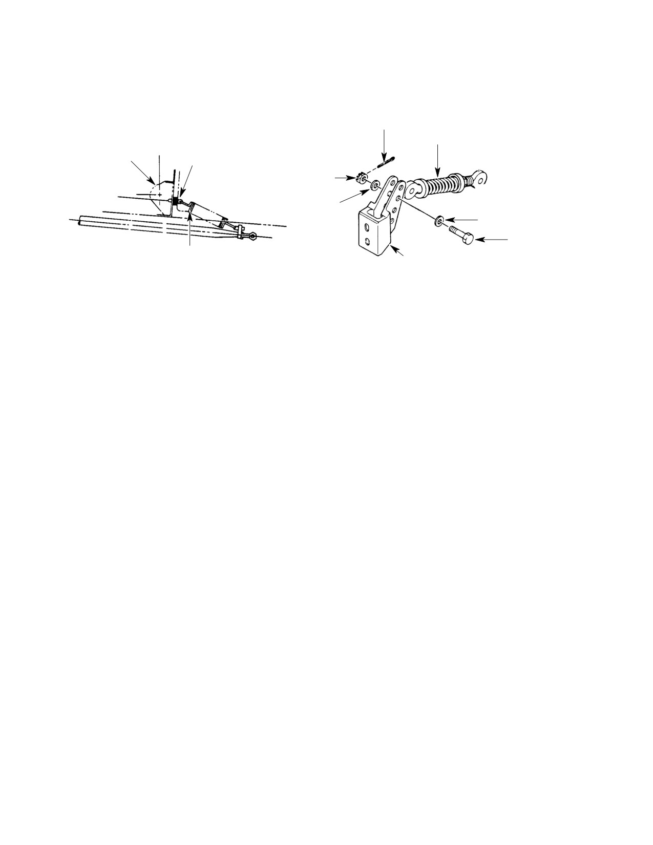
CSP-HMI-2
MD Helicopters, Inc.
MAINTENANCE MANUAL
MS24665-143
COTTER PIN
AN42B-C10A EYEBOLT
BUNGEE
STA.
AN970-3 WASHER (8 REQUIRED)
ASSEMBLY
63.00
MS21042-3 NUT
369A2541
AN960-10L WASHER
BRACKET
MS17826-4
NUT
AN960KD416L
WASHER
AN960KD416L
WASHER
NAS1104-11D
BOLT
369D27521
369DSK83-19
SPRING
FITTING
TAIL ROTOR BUNGEE
TAIL ROTOR BUNGEE
(2-BLADED)
(4-BLADED)
G67-2019
Figure 502. Tail Rotor Bungee Adjustment
Page 504
Revision 21
67-20-10