HANDBOOK OF MAINTENANCE INSTRUCTIONS FOR MDHI 369D/E/FF-500/600N HELICOPTERS (ISSUED: 1990) - page 28
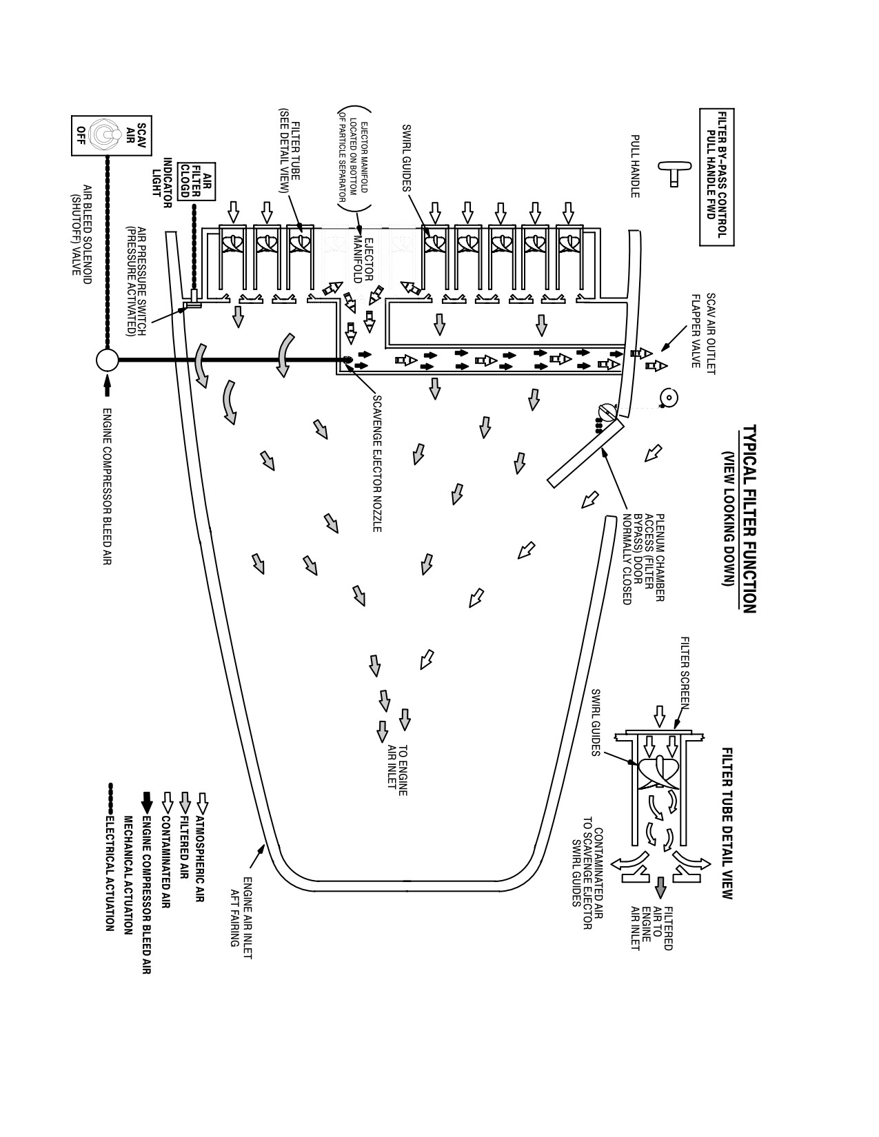
CSP-HMI-2
MD Helicopters, Inc.
MAINTENANCE MANUAL
This Page Intentionally Left Blank
Page 202
Revision 44
71-10-05
MD Helicopters, Inc.
CSP-HMI-2
MAINTENANCE MANUAL
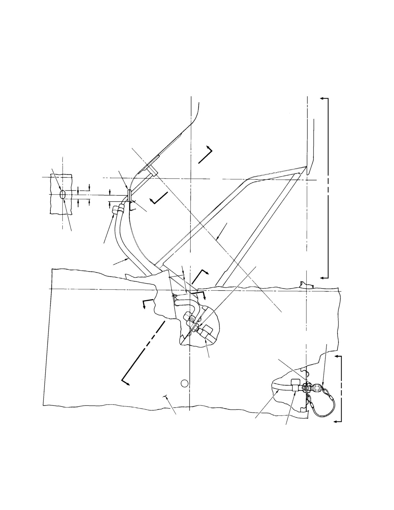
ENGINE COMPRESSOR WATER WASH KIT
INITIAL INSTALLATION
1. Engine Compressor Water Wash Kit Initial
(4).
Drill or cut 0.4531 inch (11.50874 mm)
Installation
hole in firewall assembly at dimension
shown in view A-A. Position and install
A. Gaining Access to Work Area
AN848-4D hose elbow in firewall with
hardware as shown.
(1). In aft compartment, remove seat
assemblies, L/H bulkhead trim, access
(5).
Cut hole for MS35489-11 grommet in
cover and insulation; gearbox access
forward wall of plenum chamber per
cover.
dimensions shown; install grommet
with sealant (CM430).
(2). Remove engine air inlet forward
fairing; open plenum chamber access
(6).
Position 369H3042 spray assembly on
door.
inner side of plenum chamber forward
wall, view B-B, with tube inserted
Install temporary cover of card
forward through grommet. Mark and
CAUTION
board or suitable material over
drill rivet holes and install spray
engine air intake.
assembly with eight NAS1738M4-2
rivets. Install rivets with primer.
(3). Remove engine air shield screen or
engine air inlet screen, as applicable;
(7).
Install 369H3048-5 hose on spray
remove access cover from mast support
assembly tube and on hose elbow at
structure panel.
firewall; secure hose at each end with
AN737TW22 clamps.
(4). Open L/H engine compartment door.
(8).
Mark and drill No. 8 hole in 369H3024
B. Airframe Modification and Installation
channel and install MS25281-4 clamp
and hardware as shown. Secure -5 hose
(Ref. Figure 901)
with clamp.
(9).
Install 369H3048-3 hose on elbow at
Consumable Materials
left side of firewall and on hose adapter
(Ref. Section 91−00−00)
at forward side of lower section ring.
Item
Nomenclature
Secure hose at each end with
CM318
Primer
AN737TW22 clamps.
CM430
Sealant, solvent resistant
2. Installation Inspection
(1). Position 369H3047 support on Sta.
(1). Carefully check and/or vacuum the
137.50 lower section ring at dimensions
plenum chamber for any foreign objects
shown in view E-E. Mark and drill
or debris. Remove protective cover from
rivet holes and install support with six
engine air intake.
NAS1398B4-2 rivets. Install rivets
with Primer (CM318).
NOTE: Spray kit using 369H3042 nozzle re
quires 60 PSI (414 kPa) to establish water
(2). Drill No. 8 hole in ring assembly; locate
flow rate of one quart (0.946 L) in 9-10 sec
from existing hole in support.
onds. A bypass valve or equivalent installed
at source hose connection is recommended
(3). Install AN807-4D hose adapter in
in order to relieve pressure and facilitate
support with hardware as shown;
disconnection at hose adapter.
install lanyard clip in hole with hard
ware as shown. Install 369H3046 cap
(2). Perform operational check of water
on hose adapter.
wash kit installation.
Page 901
71-10-05
Revision 22
CSP-HMI-2
MD Helicopters, Inc.
MAINTENANCE MANUAL
(3). Reinstall removed components and
(4). Record installation of 369H92537
assemblies; install and secure access
engine compressor water wash kit in
covers and doors.
helicopter Log Book.
STA.
STA.
127.00
137.50
C
B
BL
0.22 IN.
0.00
MS35489-11
R
(5.588 MM)
GROMMET (1 REQD)
TYPICAL
(DO NOT SPLIT)
0.76 IN.
WL
(19.304 MM)
0.60 IN.
50.00
(15.24 MM)
B
0.38 IN.
(9.652 MM)
NOTE
C ENGINE
L
HOLE FOR
GROMMET
AN737TW22
CLAMP (2 REQD)
AN848-4D HOSE ELBOW
1.75 ±0.10 IN.
(44.45 ±2.54 MM)
AN960PD716L WASHER
369H3048-5 HOSE
AN924-4D NUT
A
C
D
D
369H3046 CAP AND
LANYARD ASSEMBLY
AN807-4D HOSE ADAPTER
AN960PD716L WASHER
AN924-4D NUT
E
AN737TW22 CLAMP
(2 REQD)
A
AFT SECTION ASSEMBLY
369H3048-3 HOSE
E
FUSELAGE STRUCTURE
AN737TW22 CLAMP
NOTE: SEAL WITH SILICONE SEALANT.
G71-1023-1A
Figure 901. Engine Compressor Water Wash Kit Installation (Sheet 1 of 3)
Page 902
Revision 22
71-10-05
MD Helicopters, Inc.
CSP-HMI-2
MAINTENANCE MANUAL
BL
10.00
FIREWALL ASSEMBLY
BL
20.00
15°
APPROX.
TRACE
WL 40.00
0.453 IN.
(11.5094 MM)
0.79 IN.
(20.066 MM)
3.00 IN.
A-A
(76.2 MM)
TRACE
C ENGINE
WL 30.00
L
BL
0.00
INLET ASSEMBLY, ENGINE
0.78 IN.
AFT SECTION
(19.812 MM)
NAS1738M4-2 RIVET
369H3042 SPRAY ASSEMBLY
MFD. HEAD FAR SIDE
LOCATED FROM 369H3042
(8 REQD) (NOTE)
B-B
NOTE: ALTERNATE MS20615-3M5 RIVET
MAY BE USED IN PLACE OF NAS1738M4-2.
G96-1023-2A
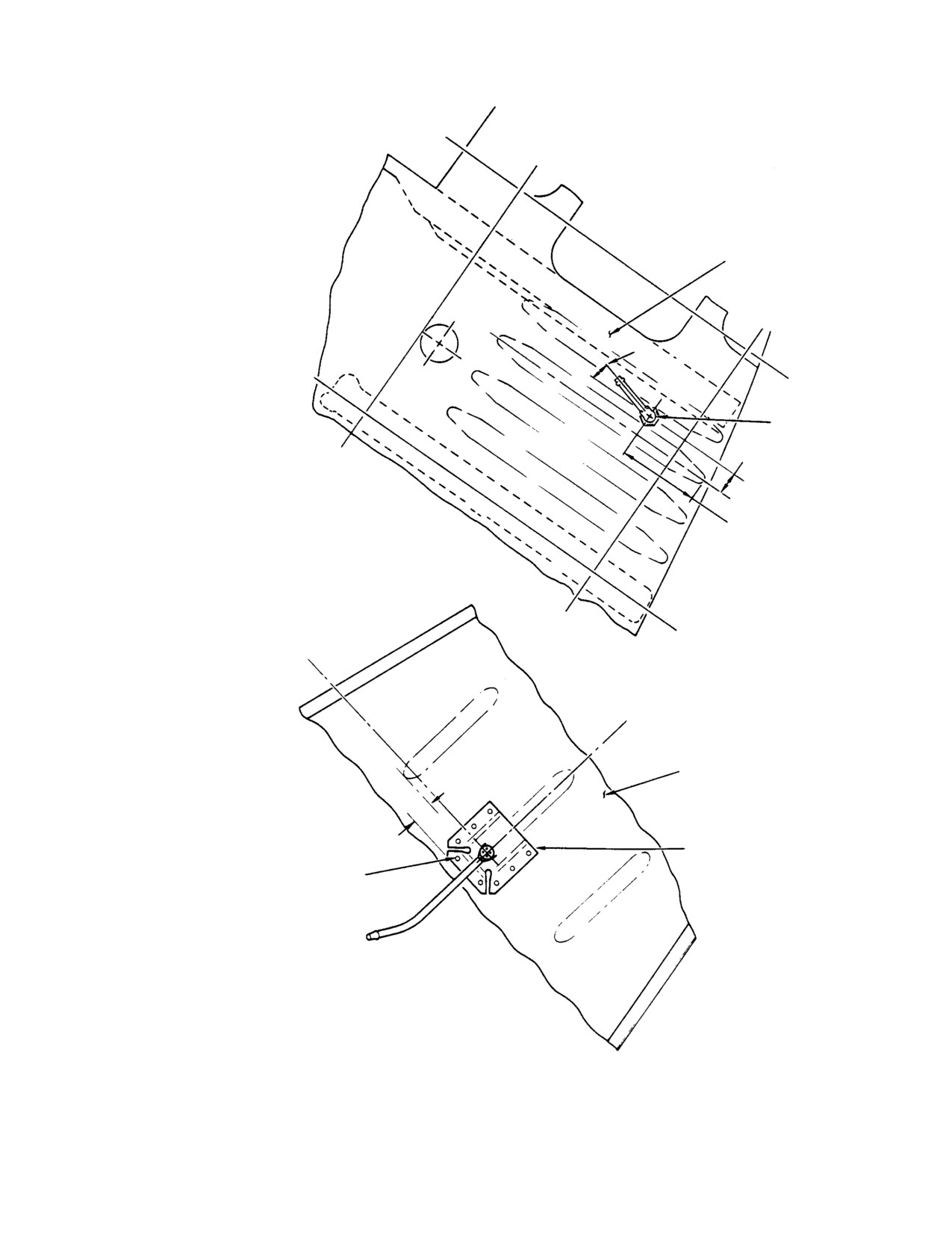
Figure 901. Engine Compressor Water Wash Kit Installation (Sheet 2 of 3)
Page 903
71-10-05
Revision 22
CSP-HMI-2
MD Helicopters, Inc.
MAINTENANCE MANUAL
BL
0.00
WL
50.00
INLET ASSEMBLY,
ENGINE AFT SECTION
RING ASSEMBLY, LOWER
SECTION STA. 137.50
C-C
0.198-0.204 IN.
(NO. 8) DIA. HOLE
(50.292-5.1816 MM)
NAS623-3-3 SCREW
WL
AN960PD10L WASHER (2 REQD)
34.50
MS25281-4 CLAMP
MS21042-3 NUT
0.50 IN.
369H3024 REF
(12.7 MM)
0.50 IN.
(12.7 MM)
NAS1398B-4-2 RIVET
LOCATE FROM
369H3047 (6 REQD)
1.18 IN.
LBL
(29.972 MM)
8.45
D-D
STA.
124.00
369H3047 SUPPORT
CANT
0.198-0.204 IN.
(50.292-5.1816 MM)(NO. 8) DIA. HOLE (LOCATED FROM 369H3047)
E-E
NAS623-3-3 SCREW
AN960PD10L WASHER
MS21042-3 NUT
G96-1023-3A
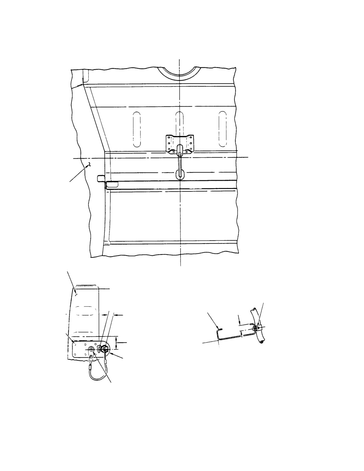
Figure 901. Engine Compressor Water Wash Kit Installation (Sheet 3 of 3)
Page 904
Revision 22
71-10-05
MD Helicopters, Inc.
CSP-HMI-2
MAINTENANCE MANUAL
Section
71−10−10
Engine Air Particle
Separator
(369D/E/FF − 500N)
MD Helicopters, Inc.
CSP-HMI-2
MAINTENANCE MANUAL
ENGINE AIR PARTICLE SEPARATOR
DESCRIPTION AND OPERATION
1. Description and Operation
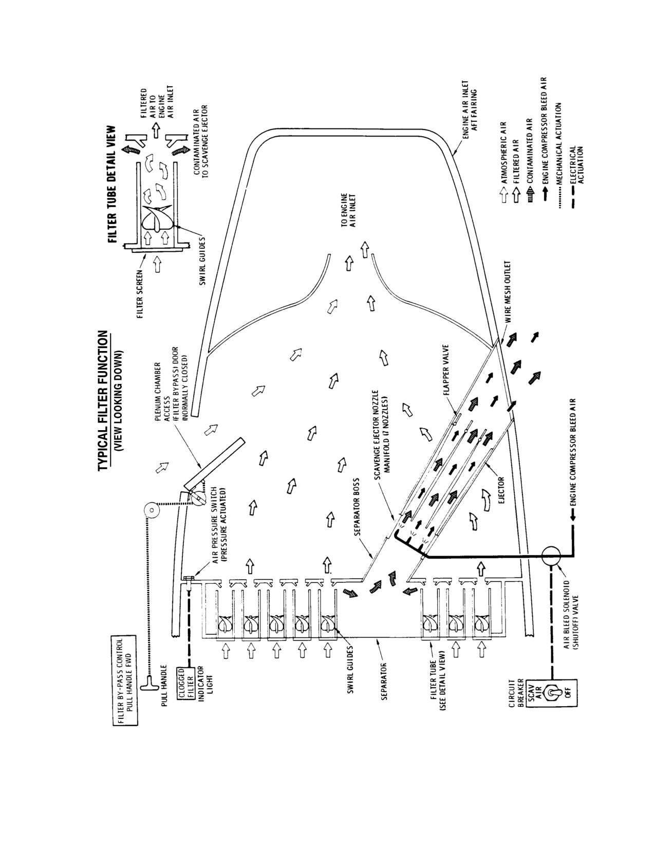
Later installations feature a system of
clips that retain the mist eliminator in
(Ref. Figure 1)
sealed contact with the particle separa
tor. The mist eliminator consists of a
(1).
MDHI 369/500 helicopters may be
welded stainless steel frame and wire
equipped with an optional engine inlet
mesh screens on the fore and aft faces.
air particle separator filter installation
in place of the standard engine air inlet
(5).
Air drawn through the particle separa
screen.
tor by the engine passes through the
parallel vortex tubes. Each tube is
(2).
Later model helicopters are equipped
fitted with vanes and an opening to the
with a Aircraft Porous Media (APM)
particle collection chamber. The vanes
filter. Earlier 500D helicopters were
spin the incoming air so that centrifu
fitted with a Donaldson particle
gal force separates heavier solid bits
separator. The APM unit is equipped
from the air flow. A smaller diameter
with provisions for an optional mist
tube directs particle free center vortex
eliminator installation.
tube air through the collection chamber
rear plate into the plenum chamber.
(3).
Both the APM and Donaldson particle
When the scavenge air system is
separators are installed inside the front
switched ON, trapped particles are
of the aft intake fairing above the
drawn out of the collection chamber by
plenum chamber and utilize the same
scavenge air vacuum and discharged
operating principle. The particle
overboard through an opening in the
separator installation consists of vortex
right side of the aft inlet fairing of APM
tubes, a collection chamber, a nozzle
equipped helicopters and the left side
manifold, ejectors, flapper valve, seals
on Donaldson equipped machines. The
and attaching hardware. A scavenge air
nozzle manifold is fitted with an engine
system is used to remove trapped
bleed air inlet port and air jets to
particles from the collection chamber
discharge contaminants. The ejector
with engine bleed air. The scavenge air
assembly consists of a mounting flange
system consists of a solenoid air valve,
with tubes, duct assembly and flapper
tubes, an air pressure switch, SCAV
valve.
AIR circuit breaker switch, AIR
FILTER CLOGGED caution light,
(6).
The scavenge air system is supplied
wiring, and attaching hardware. An air
compressor bleed air controlled by the
bypass door system is included to allow
solenoid air valve. Bleed air is delivered
the particle separator to be bypassed in
to a duct-mounted nozzle-manifold
the event the unit becomes clogged. The
that ejects contaminants from the
air bypass door system includes a
particle separator. The electrically
hinged plenum chamber door, door
actuated solenoid air valve is mounted
latches, door actuating forward and aft
on the left forward side of the Station
cables, cable return spring, two retain
124.00 bulkhead. The valve is con
ers, three cable pulleys, adjustable
trolled by the SCAV AIR circuit breaker
cable stop, handle and attaching
switch on the instrument panel.
hardware.
(7).
An increase in plenum chamber
(4).
An optional mist eliminator may be
vacuum (reduced plenum chamber
fitted to the back of APM separators to
pressure) caused by reduced airflow
filter liquid sprays out of engine inlet
through a clogged filter/mist eliminator
air. Nine self retaining bolts secure
is sensed by a differential pressure
early mist eliminator installations to
switch ported to the plenum chamber
the aft face of the particle separator.
and particle separator inlet. Sufficient
Page 1
71-10-10
Revision 22
CSP-HMI-2
MD Helicopters, Inc.
MAINTENANCE MANUAL
pressure differential causes the switch
retainers on the aft end of the forward
to close. Switch closure lights an AIR
cable returns the handle to the stowed
FILTER CLOGGED caution indicator
position. An adjustable stop provides
on the instrument panel. A cable
for cable travel adjustment and air
actuated filter bypass door on the
bypass door rigging.
plenum chamber wall may be opened by
the pilot to allow the engine to operate
On 500N installation, the FILTER
on unfiltered air.
BYPASS CONTROL handle in the crew
(8). Pulling the FILTER BYPASS CON
compartment disengages one door latch
TROL handle in the crew compartment
inside the air inlet aft fairing and opens
disengages two door latches inside the
the door inward. Adjustment of this
engine air inlet aft fairing and opens
cable installation is limited by reposi
the door inward. A spring and two
tioning the cable assembly.
Table 1. Engine Air Particle Separator Configurations
Model Part Number Cabin Heat
Principal Features
500N
500N90148−3
No
APM filter with new pressure switch and T−pedestal electrical
500N90148−1
Yes
installation.
530FF
369H90148−543
No
APM filter with generic wire harness and no cabin heat
369H90148−541
Yes
APM filter with generic wire harness and cabin heat
369H90148−529
No
APM filter with new pressure switch and T−pedestal electrical
369H90148−527
Yes
installation.
500E
369H90148−545
Yes
APM filter for C20R engine with generic wire harness
369H90148−539
No
APM filter for C20R engine with generic wire harness
369H90148−537
No
APM filter for C20B engine with generic wire harness
369H90148−535
Yes
APM filter for C20B engine with generic wire harness
369H90148−521
No
APM filter with T−pedestal electrical installation.
369H90148−519
Yes
500D
369H90148−509
No
APM filter with electrical controls bracket on side of slimline pedestal.
369H90148−507
Yes
369H90148−505
No
Donaldson filter with electrical controls bracket on side of slimline
369H90148−503
Yes
pedestal. No mist eliminator option.
Page 2
Revision 36
71-10-10
MD Helicopters, Inc.
CSP-HMI-2
MAINTENANCE MANUAL
G71-1000-1A
Figure 1. Particle Separator Operating Principle − Early Type (Donaldson Unit)
Page 3
71-10-10
Revision 22
CSP-HMI-2
MD Helicopters, Inc.
MAINTENANCE MANUAL
Ê
Ê
Ê
Ê
Ê
Ê
Ê
Ê
Ê
Ê
ËËË
Ê Ê
Ê
Ê
ËËËË
ËËËËËË
G71-1000-2
Figure 2. Particle Separator Operating Principle − Current Type (APM Unit)
Page 4
Revision 22
71-10-10
MD Helicopters, Inc.
CSP-HMI-2
MAINTENANCE MANUAL
ENGINE AIR PARTICLE SEPARATOR
FAULT ISOLATION
1. Engine Air Particle Separator Fault
Isolation
Table 101. Engine Air Particle Separator Fault Isolation
Symptom
Probable Trouble
Corrective Action
Turbine outlet temperature (TOT)
Partially blocked particle separator
Clean and service particle separator
gage indicates a moderate
and, or mist eliminator.
installation.
temperature increase with all other
indications normal.
FILTER CLOGGED caution light
Clogged filter.
Clean and service particle separator
on. Light goes out when air bypass
installation.
door is opened.
Filter requires frequent cleaning.
Inadequate scavenge air flow;
Inspect scavenge air system for
Loads up with SCAV AIR, ON and
leaking scavenge air bleed air
leakage. Repair system as required.
functioning.
lines.
Solenoid air valve blocked.
Clean solenoid air valve.
FILTER CLOGGED caution light
Lamp failed.
Replace lamp.
fails to come on when filter is
Disconnected, open or loose
Check continuity, repair or replace
clogged.
wiring.
wiring.
Faulty air pressure switch.
Replace pressure switch.
FILTER CLOGGED caution light
Defective light assembly.
Replace light assembly.
stays on regardless of bypass door
Defective air pressure switch.
Replace air pressure switch.
position.
Wiring problem.
Repair wiring.
FILTER CLOGGED caution light
Defective wiring.
Repair wiring.
fails to come on when air filter is
Defective air pressure switch.
Replace air pressure switch.
clogged but works when tested.
FILTER BYPASS CONTROL
Disconnected or broken cable.
Repair or replace cables.
handle is pulled but bypass door
fails to open.
Air bypass door does not open all
Cable stop out of adjustment.
Adjust cable stop.
the way when FILTER BYPASS
CONTROL handle is pulled to
forward limit.
FILTER BYPASS CONTROL
Defective return spring.
Replace return spring.
handle fails to return to full aft
Cable kinked, worn or binding.
Repair or replace cable assembly.
position after control actuation.
No air is exhausted through outlet
Defective wiring.
Repair wiring.
duct with SCAV AIR circuit breaker
Disconnected or damaged
Connect or replace scavenge air line.
ON and engine running.
scavenge air line.
Defective solenoid air valve.
Replace solenoid air valve.
Page 101
71-10-10
Revision 36
CSP-HMI-2
MD Helicopters, Inc.
MAINTENANCE MANUAL
This Page Intentionally Left Blank
Page 106
Revision 36
71-10-10

MD Helicopters, Inc.
CSP-HMI-2
MAINTENANCE MANUAL
ENGINE AIR PARTICLE SEPARATOR
MAINTENANCE PRACTICES
1. Air Bypass Door System Maintenance
2. Solenoid Air Valve Cleaning
Consumable Materials
Consumable Materials
(Ref. Section 91−00−00)
(Ref. Section 91−00−00)
Item
Nomenclature
Item
Nomenclature
CM112
Anti-seize compound high temperature
CM106
Fluorocarbon dry lubricant
NOTE: Maintain scavenge air equipment per
CAUTION
FAA publication, EA-AC43.13-1A and 2A.
D Prevent engine FOD. Secure a cover over
Use anti-seize compound
CAUTION
the engine intake prior to working inside
(CM112) on all male threaded
plenum chamber. Remove cover after
fittings prior to installation.
completing work.
(1). To access solenoid air valve; remove
D Loose, missing or improperly installed air
lower and center air duct trim from
bypass door hardware may cause engine
forward left side of aft passenger
damage.
compartment bulkhead.
NOTE: Maintain door system equipment per
NOTE: Solenoid air valve water flush proce
FAA publication, EA-AC43.13-1A and 2A.
dure may be accomplished with valve in
stalled or removed from helicopter. In either
(1).
Disconnect cable from door.
case, a 28 Vdc power supply is required to
actuate valve for cleaning.
(2).
Inspect and replace loose or worn door
(2). Connect a low pressure, clean water
hinge pins with 0.091 inch (2.3114 mm)
source to valve inlet fitting. Connect a
diameter corrosion resistant wire.
hose to the outlet fitting to route
(3).
Inspect all door hardware for wear,
discharged water to a drain. Connect a
corrosion, correct installation, secure
28 Vdc external power source to
attachment and proper operation.
helicopter or the valve, as required.
(3). Turn on water. Alternately open and
(4).
Connect cable to door.
close valve with SCAV AIR circuit
breaker switch to flush valve poppet
(5).
Close door. Check for positive latching
seat.
and correct alignment. Peel or add latch
clip shims to align door flush with
(4). Reverse air valve water connections.
fairing surface.
Repeat flushing procedure.
(6).
Rig air bypass door (Ref. Air Bypass
Compressor bleed air is hot
CAUTION
Door Rigging) after replacing either
enough to char tube identifica
forward or aft cable, or changing cable
tion tapes that may cause FOD. Remove
travel.
identification tapes from compressor bleed
air tubes prior to installation.
(7).
Spray gasket and door edge with S-122
fluorocarbon dry lubricant (CM106) if
(5). Install solenoid air valve. Torque valve
operating in temperatures below 40°F
mounting bolts to 22 - 27 inch-
(4.5°C).
pounds (2.49 - 3.05 Nm). Torque tube
nuts to 110 - 130 inch-pounds (12.43
(8).
Remove engine intake cover.
- 14.69 Nm).
Page 201
71-10-10
Revision 22
CSP-HMI-2
MD Helicopters, Inc.
MAINTENANCE MANUAL
3. Air Pressure Sensing Switch Maintenance
(b). Have an assistant press hard against
the air bypass door in an attempt to
Air pressure switch and AIR FILTER
keep the latch-bolts from moving up
CLOGGED caution light circuit function may
out of their clips.
be quick-checked as follows:
(c). Grasp FILTER BYPASS CONTROL
handle and slowly move it forward.
(1). Open air bypass door.
The distance the handle travels
before meeting the solid resistance of
Prevent engine FOD. Secure a
CAUTION
the latch-bolts gives an indication of
cover over the engine intake
cable slack and lost motion due to
prior to working inside plenum chamber.
wear.
Remove cover after completing work.
(4). Remove cable slack as follows:
(2). Attach a suitable length of 3/16 inch
(a). Break lockwire between door latch
(4.76 mm) ID hose to pressure switch
center crank threaded swivel fitting
nipple. Connect a vacuum source to the
and cable end fitting (Ref.
hose.
Figure 201, detail D). Remove
attaching hardware and swivel
(3). Connect 28 Vdc power to the helicopter.
fitting from door latch center crank.
(4). Apply vacuum to pressure switch. The
Thread swivel fitting up swaged
AIR FILTER CLOGGED caution light
cable terminal end 2 - 3 turns.
should come on. Release the vacuum
Reassemble all door hardware except
and the light should go out.
lockwire.
(b). Repeat previous steps as required
4. Air Bypass Door Rigging (369D/E/FF)
until slack is removed. Do not
preload cable.
Rig air bypass door installation after replacing
(c). Lockwire cable end fitting to door
forward or aft cables or when door operation or
latch center crank swivel fitting.
opening angle is incorrect. Rig door as follows:
(5). Adjust door opening angle as follows:
Prevent engine FOD. Secure a
CAUTION
(a). Thread cable-stop in or out of stop
cover over the engine intake
sleeve until top of cable-stop is 1.65
prior to working inside plenum chamber.
inches (4.19 cm) below cable swaged
Remove cover after completing work.
ball.
(1). Cycle air bypass door control handle
(b). Pull FILTER BYPASS CONTROL
and door mechanism several times to be
handle forward until aft cable
certain system does not bind at any
swaged ball bottoms in cable stop.
point. Isolate problem and repair a
Maintain cable tension to keep cable
binding cable or door latch system
ball against stop.
before continuing.
(c). Pull air bypass door outboard to
(2). With door open, make sure FILTER
maintain cable tension.
BYPASS CONTROL handle is returned
Avoid an erroneous cable adjust
full aft against cable housing and
CAUTION
ment. Maintain a constant cable
spring resistance is immediately felt as
ball contact with cable stop as stop is ad
handle is started forward.
justed.
(3). Determine if there is excess slack in the
(d). Adjust cable stop until air bypass
cable system as follows:
door opens to a minimum 45° angle
relative to fairing exterior surface.
(a). Close air bypass door. Try door to
Measure angle between door and
make sure latch-bolts are bottomed
fairing exterior surface at Sta. 136.00
in latch-clips.
(Ref. Figure 201, details G and H).
Page 202
Revision 22
71-10-10
MD Helicopters, Inc.
CSP-HMI-2
MAINTENANCE MANUAL
(e).
Release FILTER BYPASS CONTROL
(2). Cycle air bypass door control handle
handle. Inspect handle for freedom of
and door mechanism several times to be
movement, full retraction and contact
certain system does not bind at any
with forward fitting.
point. Isolate problem and repair a
binding cable or door latch system
(f).
Close air bypass door.
before continuing.
(g).
Check that aft cable is tight and
(3). Minor repositioning of the cable
cable swaged ball rests against top of
assembly can be performed by loosening
cable-stop.
the installation hardware to reposition
the cable.
(h).
Inspect pulley alignment. All pulleys
must line up within 0.13 inch (3.302
6. Particle Separator Cleaning
mm).
Consumable Materials
(i).
Inspect cable for correct routing
(Ref. Section 91−00−00)
around pulleys. Rotate each pulley
Item
Nomenclature
90° to distribute wear.
CM226
Cleaning compound, alkaline waterbase
(j).
Peel cable-stop support bracket
laminated shim as required to center
(1). Submerge separator in a solution of
cable inside cable-stop to within
detergent soap (CM226) and water for
0.060 inch (1.524 mm).
at least 15 minutes. Clean screens and
(k).
Torque cable-stop jam-nut to 10 - 30
vortex tubes with a soft, long-bristle
inch-pounds (1.13 - 3.39 Nm).
brush.
(2). Flush with clean water. Drain and blow
(6). Check all components of FILTER
out ejector nozzle with dry, low pressure
BYPASS CONTROL system for correct
compressed air.
operation. Inspect all fasteners for
security.
7. Mist Eliminator Maintenance
5.
Air Bypass Door Rigging (500N)
(1). Remove mist eliminator and clean with
solvent or steam.
(Ref. Figure 202)
NOTE: Mist eliminator is all stainless steel.
Prevent engine FOD. Secure a
The assembly will not be harmed by conven
CAUTION
cover over the engine intake
tional metal cleaning solutions.
prior to working inside plenum chamber.
Remove cover after completing work.
(2). Examine plenum chamber. A dust
accumulation indicates leakage which
(1). The bypass door cable length is deter
must be identified and eliminated.
mined on the initial installation.
(3). Spray 15 milliliters of engine oil on
NOTE: The control cable assembly shall actu
each face of the mist eliminator prior to
ate with one pound pull.
installation.
Page 203
71-10-10
Revision 22
CSP-HMI-2
MD Helicopters, Inc.
MAINTENANCE MANUAL
UPPER RIGHT PULLEY
DOOR OPERATING AFT
CABLE
ENGINE AIR INLET
AFT FAIRING
RETAINER (2)
CLIP
CABLE CONNECTOR
DOOR OPERATING
RETURN SPRING
FORWARD CABLE
GROMMET
CLAMP
GROMMET
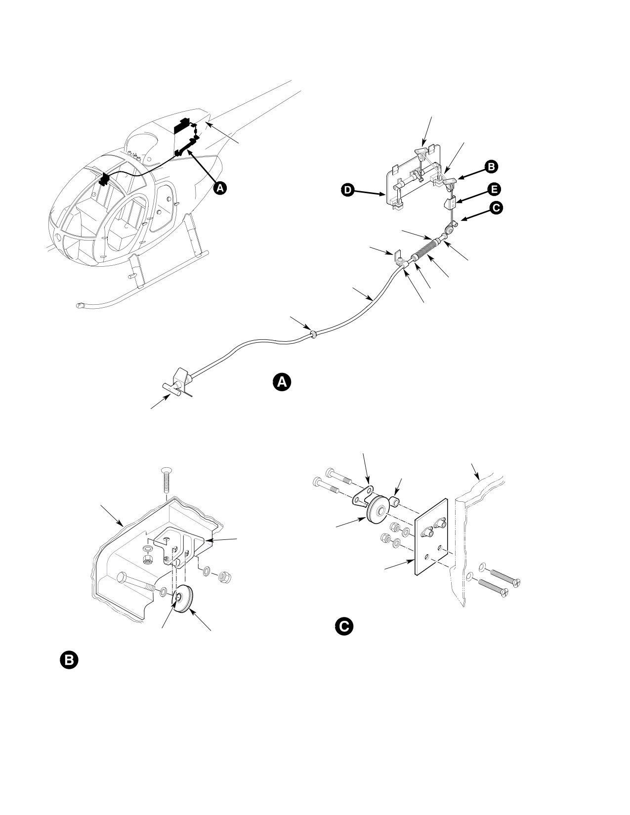
FORWARD AND AFT CABLE - INSTALLATION
BYPASS AIR CONTROL
RELEASE HANDLE
PULLEY GUARD
PLATE
AFT FAIRING
BUSHING
AFT FAIRING
PULLEY
UPPER PULLEY
(NOTE 1)
BRACKET
LOWER PULLEY
BRACKET
LOWER PULLEY - INSTALLATION
BUSHING
PULLEY
(NOTE 1)
UPPER PULLEY - INSTALLATION (TYPICAL)
G71-1003-1
Figure 201. Air Bypass Door System (369D/E/FF) (Sheet 1 of 3)
Page 204
Revision 22
71-10-10
MD Helicopters, Inc.
CSP-HMI-2
MAINTENANCE MANUAL
CABLE
CLIP
LINK
GASKET
CENTER
CRANK
LATCH ASSY
LAMINATED SHIM
(NOTE 3)
CLIP
FILTER BYPASS DOOR - INSTALLATION
WASHER
WASHER
BOLT
AFT FAIRING
NUT
CABLE STOP
(NOTE 2)
CABLE STOP
SLEEVE
TYPICAL LINKAGE - INSTALLATION
CABLE STOP
(4 PLCS)
BRACKET
SHIM
SLEEVE NUT
(NOTE 4)
NOTES:
1.
PULLEYS TO BE IN ALIGNMENT WITHIN 0.13 IN. (3.302 MM).
CABLE STOP JAMNUT
2.
TIGHTEN NUT TO GET 0.005-0.015 IN. (0.127-0.381 MM) GAP BETWEEN
BOLT HEAD AND WASHER; 4 PLACES.
3.
ADJUST LAMINATED SHIM THICKNESS TO GET CORRECT DOOR
LATCHING AND ALIGNMENT.
CABLE STOP - INSTALLATION
G71-1003-2B
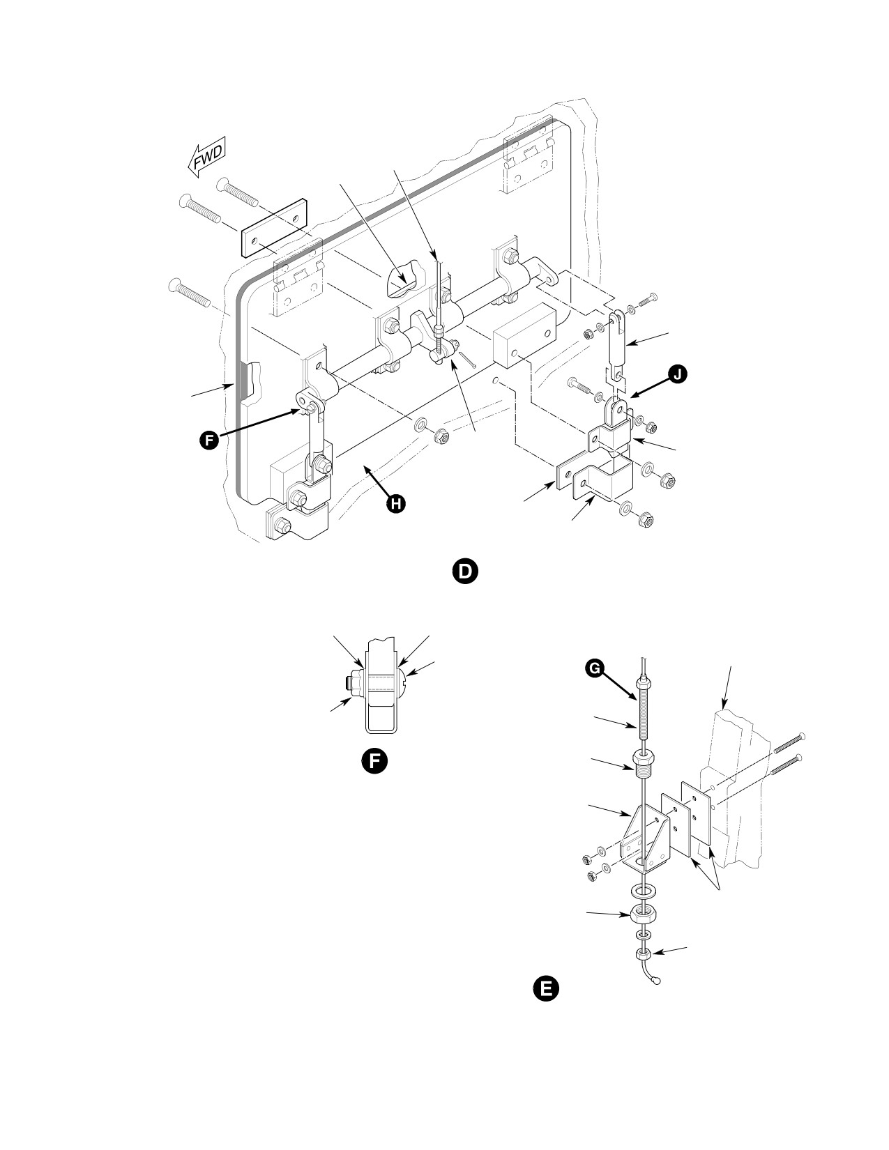
Figure 201. Air Bypass Door System (369D/E/FF) (Sheet 2 of 3)
Page 205
71-10-10
Revision 22
CSP-HMI-2
MD Helicopters, Inc.
MAINTENANCE MANUAL
DOOR
SWAGED BALL
LATCHED
1.65 IN. (4.191 CM)
CABLE TRAVEL
CABLE STOP
DOOR
OPEN
CABLE STOP JAMNUT
QUICK-DISCONNECT
DOOR STOP - ADJUSTMENT
COTTER PIN
MINIMUM DOOR
OPENING
45°
VIEW
369A8442-3 LATCH ASSEMBLY
G71-1003-3B
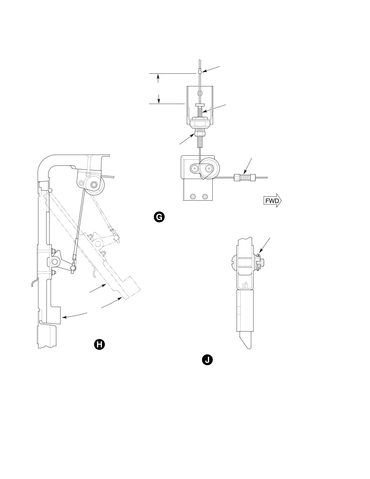
Figure 201. Air Bypass Door System (369D/E/FF) (Sheet 3 of 3)
Page 206
Revision 22
71-10-10
MD Helicopters, Inc.
CSP-HMI-2
MAINTENANCE MANUAL
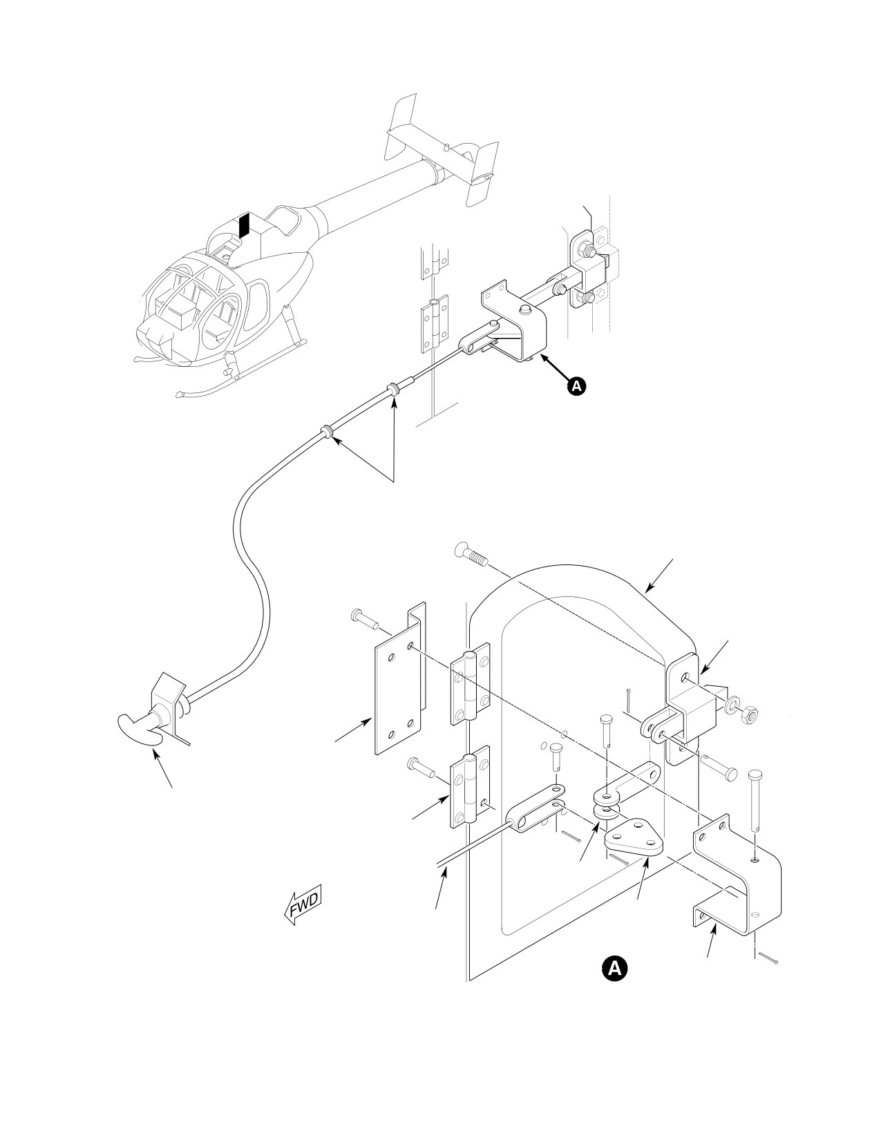
GROMMET
ENGINE INLET
BYPASS DOOR
LATCH ASSY
BYPASS DOOR
CLIP
BYPASS AIR CONTROL
RELEASE HANDLE
HINGE
LINK
PIVOT
CABLE ASSY
FITTING
BRACKET
G71-1024
Figure 202. Air Bypass Door System (500N)
Page 207
71-10-10
Revision 22
CSP-HMI-2
MD Helicopters, Inc.
MAINTENANCE MANUAL
This Page Intentionally Left Blank
Page 208
Revision 44
71-10-10
MD Helicopters, Inc.
CSP-HMI-2
MAINTENANCE MANUAL
ENGINE AIR PARTICLE SEPARATOR
REMOVAL/INSTALLATION
1. PLM Particle Separator Replacement
(14). Disconnect and remove ejector scavenge
air line between particle separator and
A. PLM Particle Separator Removal
bracket mounted elbow.
(1). Remove forward engine air inlet
(15). If installed, remove mist eliminator.
fairings.
(16). Unbolt, then tilt top of particle separa
tor forward and remove from fairing.
(2). Pull FILTER BYPASS CONTROL
handle to open filter bypass door.
B. PLM Particle Separator Installation
Prevent engine FOD. Secure a
Install particle separator in reverse order of
CAUTION
cover over the engine intake
removal and per the following procedures:
prior to working inside plenum chamber.
Remove cover after completing work.
Consumable Materials
(Ref. Section 91−00−00)
(3). Remove engine air cooling inlet screen.
Item
Nomenclature
(4). In crew compartment; remove map case
CM112
Anti-seize compound high temperature
trim panel from control channel (Ref.
Chap. 25).
(1). Center and clamp tail rotor control
(5). Disconnect forward cable from aft cable
pedals in neutral position. Install
at quick-disconnect fitting. Remove
forward boot on tail rotor pitch control
spring retainers and spring.
rod. Adjust boot free length between
7.13 and 7.22 inches (18.1102 and
(6). Remove handle plug button. Separate
18.3388 cm). Install ty-rap.
retainers and remove handle.
(2). Use the same number of washers under
(7). Remove attaching hardware and cable
forward cable fitting as were removed.
retaining clamps. Remove cable forward
Washer stack height variances will
fitting nut and washers.
affect door rigging.
Use anti-seize compound on all
(8). Pull cable assembly forward into crew
CAUTION
male threaded fittings prior to
compartment far enough to clear
installation.
particle separator.
(3). Apply anti-seize compound (CM112) to
(9). Disconnect and remove pressure switch
fitting threads and particle separator
tubes, jam-nut, washers and union.
attaching hardware.
(10). Remove particle separator fairing
(4). Check air bypass door rig (Ref. Air
retaining screws and washers.
Bypass Door Rigging).
NOTE: Left fairing installations without re
(5). Perform an operational check of air
movable lower cover require the tail rotor
bypass door and scavenge air systems
control rod be disconnected at Sta. 95.00
(Ref. Scavenge Air Operational Check).
bellcrank to remove fairing from helicopter.
2. PLM Scavenge Ejector Replacement
(11). Remove tail rotor control rod boot
A. PLM Scavenge Ejector Removal
forward clamp.
(1). Remove lockwire and unbolt ejector
(12). Slide boot and left fairing forward and
assembly support bracket.
clear of particle separator.
(2). Remove lockwire and bolts attaching
(13). Unfasten and remove ejector duct
ejector assembly hold down plates to
assembly.
particle separator ejector box.
Page 401
71-10-10
Revision 22

CSP-HMI-2
MD Helicopters, Inc.
MAINTENANCE MANUAL
(3). Remove ejector assembly.
B. Helicopters Without Mist Eliminator
Access Panel
B. PLM Scavenge Ejector Installation
Prevent engine FOD. Secure a
CAUTION
(1). Install ejector in reverse order of
cover over the engine intake
removal.
prior to working inside plenum chamber.
Remove cover after completing work.
3. PLM Ejector Nozzle and Manifold
(1). Pull FILTER BYPASS CONTROL
Replacement
handle to open air bypass door.
(1). Remove ejector assembly (Ref. PLM
(2). On 500N installation, remove the fan
Scavenge Ejector - Removal).
inlet screen and engine plenum access
fairing attachment hardware. Proceed
(2). Remove lockwire and two nuts securing
with step (5).
nozzle and manifold assembly to
particle separator ejector box.
(3). Remove four screws securing door hinge
upper halves to inlet fairing (Ref.
(3). Remove nozzle and manifold assembly.
Figure 201, detail D).
NOTE: Do not disturb established cable length.
(4). Clean mating surfaces between ejector
box and nozzle and manifold assembly.
(4). Remove cotter pin, nut and washer
from cable end-fitting. Remove cable
(5). Install nozzle and manifold assembly in
from door. Remove door.
reverse order of removal.
Nine mount bolts are retained
CAUTION
(6). Install ejector assembly.
in mist eliminator frame. Do not
attempt to remove bolts from frame.
4. Mist Eliminator Replacement
(5). Unbolt mist eliminator from particle
separator.
A. Helicopters With Mist Eliminator Access
Panel
(6). Pull mist eliminator aft to clear particle
separator frame. Tilt mist eliminator
CAUTION
lower edge up and remove unit through
bypass door opening.
D Prevent engine FOD. Secure a cover over
C. Mist Eliminator Installation
the engine intake prior to working inside
plenum chamber. Remove cover after
(1). Install mist eliminator in reverse order
completing work.
of removal.
D If mist eliminator is NOT to be rein
5. Donaldson Particle Separator
stalled, remove 4504 tape from particle
Replacement
separator. If not removed, tape may come
loose and be ingested by the engine.
A. Donaldson Particle Separator Removal
NOTE: Mist eliminator access panel installa
(1). Remove engine air inlet forward
tion replaces nine mist eliminator mount
fairings.
bolts with a system of permanently installed
(2). Pull FILTER BYPASS CONTROL
clips to secure mist eliminator.
handle to open the air bypass door (Ref.
Figure 201, detail A).
(1). On top of aft inlet fairing; unfasten two
1/4-turn panel fasteners. Lift panel
Prevent engine FOD. Secure a
trailing edge, then entire panel clear of
CAUTION
cover over the engine intake
access opening.
prior to working inside plenum chamber.
Remove cover after completing work.
(2). Lift mist eliminator out of access panel
opening.
(3). Remove engine air cooling inlet screen.
Page 402
Revision 37
71-10-10
MD Helicopters, Inc.
CSP-HMI-2
MAINTENANCE MANUAL
(4). In crew compartment; remove map case
(15). Remove exit port screen attaching
trim panel from control channel (Ref.
hardware and duct.
Chap. 25).
B. Donaldson Particle Separator Installation
(5). Disconnect forward cable from aft cable
Install particle separator assembly in reverse
at quick-disconnect fitting. Remove
order of removal and as follows:
handle plug button. Separate retainers
and remove handle.
Consumable Materials
(6). Remove spring retainers and spring.
(Ref. Section 91−00−00)
Item
Nomenclature
(7). Remove attaching hardware and cable
CM112
Anti-seize compound high temperature
retaining clamps. Remove cable forward
fitting nut and washers. Pull cable
assembly into crew compartment.
NOTE: Apply antiseize compound (CM112) to
male threads of fittings, nozzle manifold
(8). Remove pressure switch tubes and
bolts and particle separator attaching hard
union.
ware before installation.
NOTE: It is not necessary to disconnect tail ro
(1).
Bench assemble rubber sleeve and
tor control rod to remove left fairing if fair
O-ring on grooved end of ejector.
ing is equipped with a removable cover.
(2).
Align nozzle manifold and ejector inside
(9). Disconnect forward end of tail rotor
aft fairing.
control rod at Sta. 95.00 bellcrank.
(3).
Position ejector so that top flapper
(10). Remove fairing retaining screws and
valve vertical hinge line angle is 10 to
washers. Remove tail rotor control rod
20 degrees counterclockwise from
boot forward.
ejector vertical centerline.
clamp. Slide left fairing forward on tail rotor
(4).
Torque ejector and nozzle manifold
control rod to clear particle separator.
bolts to 12 - 15 inch-pounds (1.36 -
1.69 Nm).
NOTE: Paint an alignment mark across ejector
and nozzle manifold flanges prior to disas
(5).
Install tail rotor control rod forward
sembly as a reference for later assembly.
boot with a free length of 7.13 to 7.22
inches (18.1102 and 18.3388 cm) with
(11). Remove bolts and washers securing
tail rotor pedals centered.
nozzle manifold to particle separator.
(6).
Use the same number of washers under
(12). Unbolt particle separator. Tilt top of
forward cable fitting as were removed.
particle separator forward and remove
Hardware position changes or washer
from fairing.
stack height variances will affect door
rigging.
(13). Disconnect upper air tube assembly
from nozzle manifold. Move forward
(7).
Rig air bypass door (Ref. Air Bypass
O-ring from ejector to rubber sleeve.
Door Rigging).
Remove nozzle manifold and ejector
(8).
Perform air bypass door and scavenge
from aft fairing.
air system operational checks (Ref.
(14). Remove sleeve and O-rings from duct.
Scavenge Air Operational Check).
Page 403
71-10-10
Revision 22
CSP-HMI-2
MD Helicopters, Inc.
MAINTENANCE MANUAL
This Page Intentionally Left Blank
Page 404
Revision 44
71-10-10
MD Helicopters, Inc.
CSP-HMI-2
MAINTENANCE MANUAL
ENGINE AIR PARTICLE SEPARATOR
INSPECTION/CHECK
1. Engine Air Inlet Bypass Door 300−Hour
(c). The latch engagement faying surface,
Inspection
where it contacts the plenum, is worn
more than 0.050 inch (1.270 mm)
(Ref. Figure 201)
below the original surface.
(5).
Inspect door hinges for wear and hinge
fastening hardware for security. Repair
Consumable Materials
or replace hinges as required.
(Ref. Section 91−00−00)
Item
Nomenclature
(6).
Inspect door for worn or damaged
latching and attachment hardware.
CM425
Sealing compound
(7).
Check insert assembly and latch
linkages for wear and lost motion.
Prevent engine FOD. Secure a
Repair or replace latch hardware as
CAUTION
cover over the engine intake
required.
prior to working inside plenum chamber.
(8).
Inspect door system cable and cable
Use extreme care when working around en
ends for corrosion, fraying, chaffing and
gine inlet to prevent any foreign object from
freedom of movement.
entering engine. Remove cover after com
pleting work.
(9).
Inspect door system cable pulleys,
pulley bushings and brackets for wear,
NOTE: Inspect Engine Air Inlet Bypass Door
damage, freedom of movement and
per FAA publication, EA-AC43.13-1B.
security.
(10).
Reinstall engine inlet bypass door. Seal
(1). Remove engine inlet bypass door and
all cotter pins with sealant (CM425).
inspect air bypass door gasket seal for
(11).
Inspect door for proper alignment when
condition and secure attachment. No
closed. Door must fit snug against seal
gasket seal deterioration or debonding
with obvious seal compression.
allowed. Replace door gasket as
required.
(12).
Inspect latches for positive latching.
(13).
Pull FILTER BYPASS CONTROL
(2). Inspect door surfaces for cracking,
handle. Action to be a smooth, positive
chaffing or damage. Repair door per
door opening with no binding. Release
Structural Repair Manual (CSP-
handle. Handle should snap back to
SRM-6).
stowed position.
(3). Remove and replace the latch retention
2. PLM Particle Separator Inspection
cotter pin (located inside the attach
(1). Inspect vortex generator tubes for
cable ``U'' clamp). Seal cotter pin with
broken, loose or missing vanes and
sealant (CM425).
center pins.
(4). Replace latch assembly if:
(2). Inspect outlet tube for security and
damage.
(a). The cotter pin hole in the latch stem
(3). Inspect inlet plate for dents punctures
is elongated more than 0.080 inch
and cracks.
(2.032 mm).
(4). Inspect vortex tube particle discharge
openings for clogging.
(b). The cotter pin has worn into the
surface of the cable attach ``U'' clip,
(5). Inspect separator and mist eliminator
more than 1/2 the thickness of the
mounting seals for secure attachment
clip, 0.025 inch (0.635 mm) deep.
and damage. Replace damaged seals.
Page 601
71-10-10
Revision 39
CSP-HMI-2
MD Helicopters, Inc.
MAINTENANCE MANUAL
Left fairing inspection and re
(4). Inspect gasket tapes for deterioration
CAUTION
work or replacement is manda
and security. Replace damaged gasket
tory for particle separator installations, part
tapes.
numbers 369H90148-507, and -509. Early
(5). Inspect entire particle separator
installations were fitted with left forward
assembly for cracks, holes and distor
fairings, PN 369D290128-11 equipped with
tion. Cracks may indicate filter preload,
a single screw and nutplate securing a re
misalignment or distortion when
movable
fairing
section,
PN
installed. Align filter (Ref. Particle
369D290128-31 over the tail rotor control
Separator Alignment and Joint Surface
rod.
Repair).
(6).
Inspect tail rotor control rod for
(6). Inspect rubber sleeves for cuts, holes or
abrasion or gouging caused by contact
deterioration.
with particle separator fairing or
fairing hardware. Modify, repair or
(7). Inspect O-rings for nicks, cuts, wear or
replace fairing (Ref Fairing Modifica
deterioration.
tion (369D Only)). Inspect, repair or
(8). Inspect ejector tube for cuts, breaks or
replace control rod if damaged beyond
distortion.
limits (Ref. Sec. 67-20-10).
(9). Inspect flapper valve for condition and
(7).
Inspect ejector flapper valve and hinge
free movement.
for wear and corrosion. Repair or
NOTE: Ejectors with a missing flapper valve
replace valve parts as required.
may be continued in operation until a re
placement is installed.
(8).
Inspect ejector tubes for cuts, breaks
and distortion. Inspect flange condition.
(10). Inspect nozzle manifold for cracks and
distortion.
(9).
Inspect tube nuts and fittings for
crossed or stripped threads.
(11). Inspect fitting for crossed or stripped
threads. See that the seven nozzle air
(10).
Inspect scavenge air discharge duct for
passages are open, clean and undam
damage.
aged.
(12). Inspect ejector exhaust duct screen for
(11).
Inspect entire assembly for cracks,
damage or clogging.
holes and distortion. Cracks may
indicate that assembly is subject to
4. Scavenge Air Operational Check
distortion loads when installed.
Engine operation or helicop
WARNING
3. Donaldson Particle Separator Inspection
ter flight must be accom
plished in accordance with require
(1). Inspect filter inlet screens for damage
ments and limitations specified in the
and secure attachment. Remove
Pilot's Flight Manual and applicable
damaged inlet screens.
supplements.
(1). Ensure air bypass door is closed.
NOTE: Particle separator may be operated
without inlet screens.
(2). Ground run engine per Pilot's Flight
Manual.
(2). Inspect vortex tubes for for security and
(3). Switch SCAV AIR circuit breaker ON.
broken or missing vanes.
NOTE: A slight increase in turbine outlet tem
NOTE: Up to five damaged vortex tubes may be
perature (TOT) is normal when SCAV AIR
blocked off with patches.
circuit breaker is switched ON.
(3). Inspect vortex tube particle separator
(4). Have an assistant check for scavenge
openings for clogging.
air exhaust from outlet duct. Airflow
Page 602
Revision 22
71-10-10
MD Helicopters, Inc.
CSP-HMI-2
MAINTENANCE MANUAL
from duct indicates that solenoid air
the tube relative to the switch closing
valve has opened.
point. The total of the differential
heights of both legs of the u-tube is
(5). Switch SCAV AIR circuit breaker OFF.
equal to switch actuation pressure.
(6). Check that no scavenge air flows from
(6). Switch closing pressures shall be per
outlet duct.
the applicable particle separator
installation dash number shown (Ref.
(7). Shut down engine per Pilot's Flight
Figure 601).
Manual.
6. Mist Eliminator Inspection
5.
Air Pressure Sensing Switch Calibration
Check
(1). Check mist eliminator serial number
for APM serial numbers 005 thru 069.
(1). Assemble test equipment (Ref.
Remove the wire staples from a mist
Figure 601).
eliminator so identified.
(2). Attach pressure switch to test equip
(2). Inspect frame and screens for security
ment. Connect a suitable vacuum
and condition. Replace mist eliminator
source to pressure switch nipple and
if screens are partially detached, or
u-tube.
assembly distortion prevents joint seal
(3). Connect an ohmmeter or continuity
contact with the particle separator.
tester to pressure switch electrical
(3). Inspect all nine bolts, where installed,
leads.
for security in mist eliminator frame.
(4). Cycle switch from open to close several
Repair or replace bolts as required (Ref.
times with vacuum. Watch meter for
Page 803).
indication of switch closure. Release
(4). Examine outlet side of mist eliminator.
vacuum.
Surface should be slightly oily but
(5). Slowly apply vacuum. Note u-tube
clean. Dirt on the outlet side signals the
water height differential in both legs of
need to clean the assembly.
Page 603
71-10-10
Revision 22
CSP-HMI-2
MD Helicopters, Inc.
MAINTENANCE MANUAL
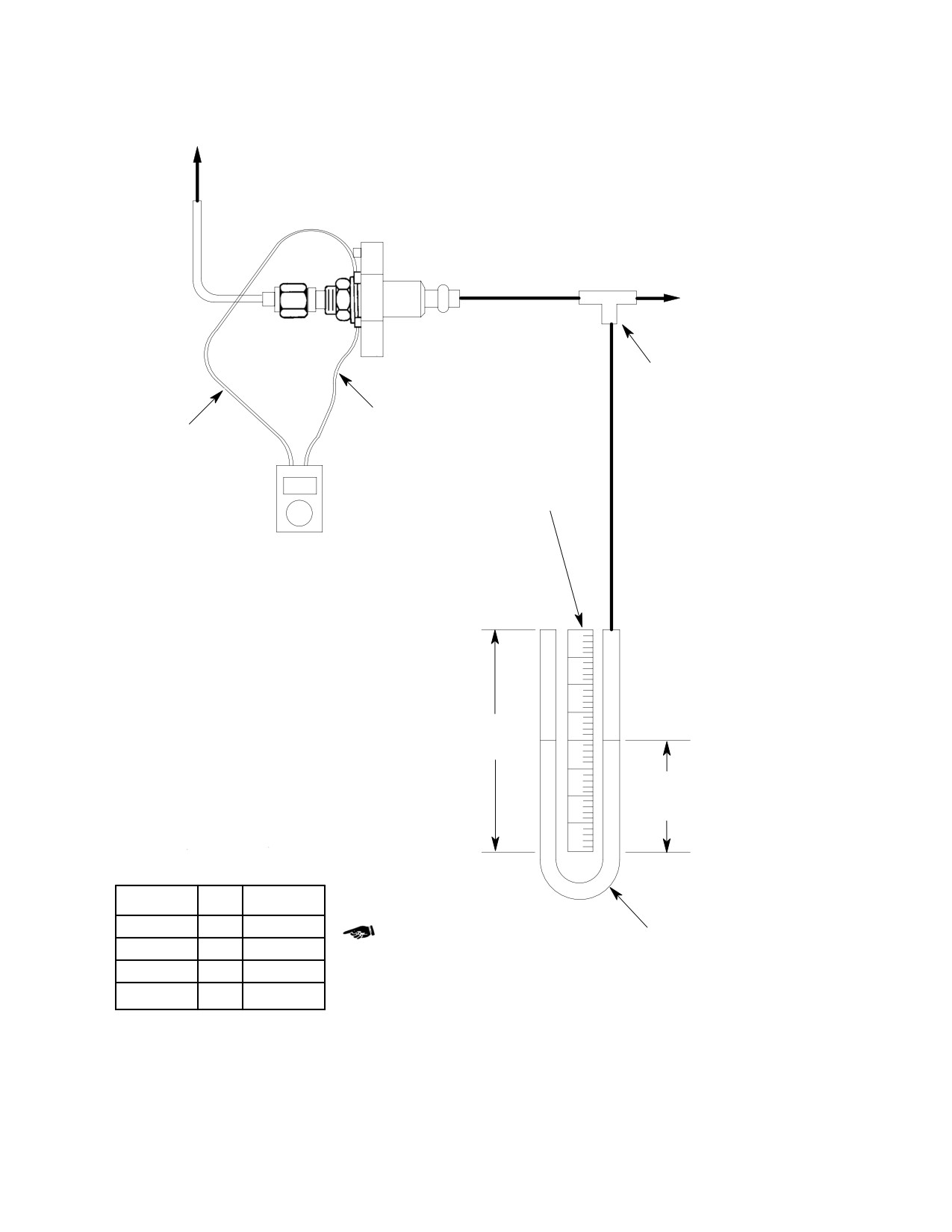
TO L.H. FAIRING
ATTACHING UNION
SUCTION SOURCE
HOSE TEE
POWER LEAD
RETURN LEAD
24 IN (61 CM)
SCALE
OHMMETER OR
CONTINUITY
TESTER
24 IN (61 CM)
STRAIGHT
SECTION
12 IN (30.5 CM)
H2O STATIC
HEIGHT
369A8402
OPEN
CLOSE
-15
2.0
12.50±0.25
TYGON TUBING (OR EQUIVALENT)
-13
2.0
18.50±0.25
BENT AND FILLED WITH H2O TO
STATIC HEIGHT AS SHOWN
-7
2.0
10.50±0.25
-3
2.0
4.8±0.4
G71-1004E
Figure 601. Air Pressure Sensing Switch Calibration Check
Page 604
Revision 38
71-10-10
MD Helicopters, Inc.
CSP-HMI-2
MAINTENANCE MANUAL
ENGINE AIR PARTICLE SEPARATOR
REPAIRS
1. PLM Particle Separator Repairs
Permanent repairs or particle
CAUTION
separator replacement should
be accomplished as soon as possible. Do not
use repair kit if mounting plate holes are en
Consumable Materials
larged or distorted so as to prevent the re
(Ref. Section 91−00−00)
pair plug snap-lock lip from fully engaging
Item
Nomenclature
plate hole edge.
CM234
Solvent, dry-cleaning
(a). Repair plugs, AA-9500-D929 are
CM728
Tape, pressure sensitive
used to seal pushed-in but otherwise
undamaged vortex generator tubes.
(b). Stems, AA-9500-D930 are used with
NOTE:
repair plugs to seal the vortex
generator tube hole when the the
D The following particle separator repair/
tube is missing or removed.
replacement items and, or kits are avail
(c). Stems, AA-9500-D931 are used with
able from Pall Land Marine (PLM) or
repair plugs when both the vortex
through your local distributor (Ref. Sec.
generator tube and outlet tube are
01-00-00).
missing or removed.
D AA-A224-1D1KF1 Repair kit, Centrisep
No more than 30 of the 292
scavenge ejector Assy. (Ejector, two plate
WARNING
vortex generator tubes may
halves, four bolts).
be plugged. Plugged tubes shall be
widely distributed over particle sepa
D AA-224A-1D1KF2 Repair kit, Centrisep
rator. Not more than 15 plugged tubes
nozzle and manifold Assy.
may be concentrated in any one area.
B. Displaced Vortex Generator Tube
The following procedures are for
CAUTION
(Ref. Figure 801)
Pall Land Marine (PLM) par
ticle separators only.
(1). Inspect displaced vortex generator tube
for missing center pin and extensive
rim damage. Should either condition
A. Vortex Tube Plug Installation
exist, refer to Damaged Or Missing
Vortex Generator Tube.
NOTE: Procedures are per Pall Land Marine
(2). Position particle separator on a table
Corporation publication, PLM-TM-80-1.
with front surface of vortex tube plate
Contact PLM direct for additional informa
up.
tion. A vortex generator tube replacement
(3). Press damaged tube assembly all the
kit may be available that will supersede use
way in. Ensure that vortex tube
of Tube Repair Kit AA-8101-1KF1 required
bottoms on outlet tube per illustration
to accomplish the following temporary re
(Ref. Figure 801, view B).
pairs.
(4). Insert repair plug AA-9500-D929 in
the hole. Align plug with vortex
(1). The AA-8101-1KF1 repair kit contain
generator center pin.
parts required to plug holes created by
displacement of, or damage to, the
(5). Press plug into inlet tube plate until
vortex generator and outlet tubes.
plug snaps in place.
Page 801
71-10-10
Revision 22
CSP-HMI-2
MD Helicopters, Inc.
MAINTENANCE MANUAL
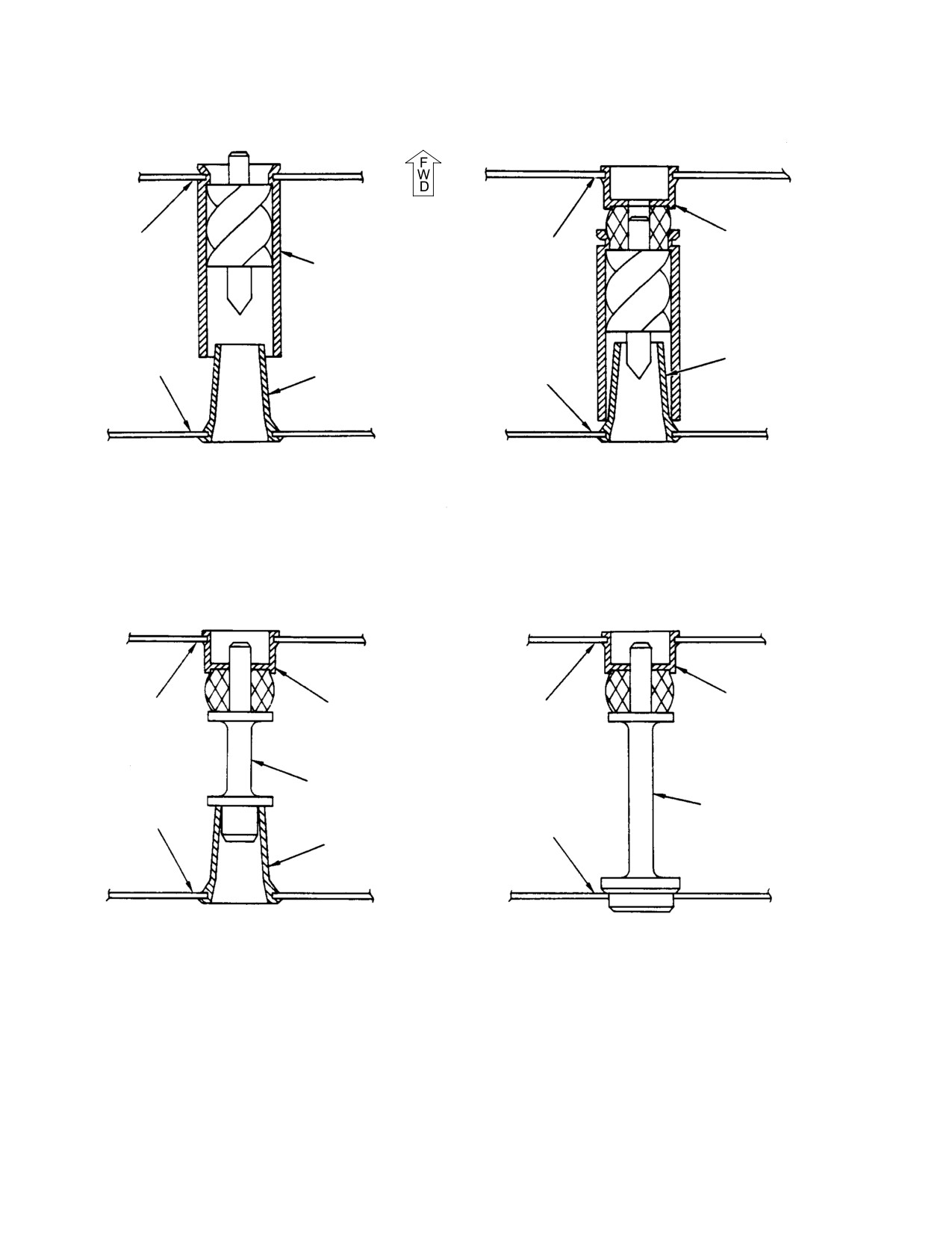
INLET TUBE
INLET TUBE
REPAIR PLUG
PLATE
AA-9500-D929
PLATE
VORTEX GENERATOR
TUBE
OUTLET TUBE
OUTLET TUBE
OUTLET TUBE
OUTLET TUBE
PLATE
PLATE
A. SERVICEABLE INSTALLATION
B. DISPLACE VORTEX GENERATOR
TUBE REPAIR
INLET TUBE
REPAIR PLUG
REPAIR PLUG
INLET TUBE
PLATE
AA-9500-D929
AA-9500-D929
PLATE
STEM
AA-9500-D930
STEM
OUTLET TUBE
AA-9500-D931
OUTLET TUBE
PLATE
OUTLET TUBE
PLATE
C. MISSING VOTEX GENERATOR
D. MISSING VORTEX GENERATOR
TUBE REPAIR
AND OUTLET TUBE REPAIR
G71-1005
Figure 801. Vortex Generator Repairs
Page 802
Revision 22
71-10-10
MD Helicopters, Inc.
CSP-HMI-2
MAINTENANCE MANUAL
C. Damaged Or Missing Vortex Generator
F. Fairing Modifications (369D Only)
Tube
(1). Remove remaining vortex generator
Consumable Materials
tube material without damaging plate
(Ref. Section 91−00−00)
hole.
Item
Nomenclature
CM501
Fiberglass cloth
(2). Insert center pin of stem
CM505
Polyester laminating resin
AA-9500-D930 into plug
AA-9500-D929 and install in hole per
illustration (Ref. Figure 801, view C).
NOTE: Modification procedures apply to 500D
Ensure stem free end is inside outlet
series helicopters equipped with
tube.
369H90148-507 or -509 particle separator
(3). Press plug into hole until it snaps in
installations and APM (now PLM) particle
place.
separators. Early installations were fitted
with left forward fairings, PN
D. Damaged Or Missing Vortex Generator
369D290128-11 equipped with a single
and Outlet Tubes
screw and nutplate securing a removable
fairing section, PN 369D290128-31 over the
(1). Remove remaining vortex generator
tail rotor control rod. Modify the -11 and
and outlet tube material. Do not
-31 fairing components as follows.
damage either plate hole.
(1). Remove fairings (Ref. PLM Particle
(2). Insert center pin of stem
Separator Removal).
AA-9500-D931 into plug
AA-9500-D929 and install in hole per
(2). Drill out rivets and remove nutplate
illustration (Ref. Figure 801, view D).
from 369D290128-11 left fairing
Ensure stem free end protrudes from
assembly (Ref. Figure 802, detail A).
outlet tube plate.
(3). Patch nutplate rivet and screw holes
(3). Press plug into hole until it snaps in
with fiberglass cloth (CM501) and resin
place.
(CM505) per structural repair manual
E. PLM Particle Separator Gasket
(SRM).
Replacement
NOTE: A replacement
cover,
PN
(1). Remove old gasket and clean joint
369D290128-51 may be installed in lieu of
surfaces with P-D-680 dry cleaning
reworking 369D290128-31 cover assembly.
solvent (CM234) on a clean cloth.
(4). Rework cover, PN 369D290128-31 per
(2). Cut 1/8 inch (3.175 mm) thick pressure
illustration using fiberglass cloth and
sensitive tape (CM728) to 3/8 inch
resin. Laminate one layer of fiberglass
(9.525 mm) width.
cloth on top of cover and two layers on
bottom surface (Ref. Figure 802, detail
NOTE:
B).
D Note that the particle separator/aft inlet
fairing seal tape is not installed on the
(5). Drill two 0.250 inch (6.35 mm) diameter
bottom.
screw holes through cover to match
holes in PN 369D290128-11 fairing
D The inner seal tape is the mist eliminator
assembly.
joint seal.
(6). Install 369D290128-55 and -57 seals
(3). Cut tape to length, peel off backing and
on cover.
apply to surface.
(4). Ensure gasket tape is firmly attached
(7). Install reworked fairings (Ref. PLM
to surface.
Particle Separator Installation).
Page 803
71-10-10
Revision 22
CSP-HMI-2
MD Helicopters, Inc.
MAINTENANCE MANUAL
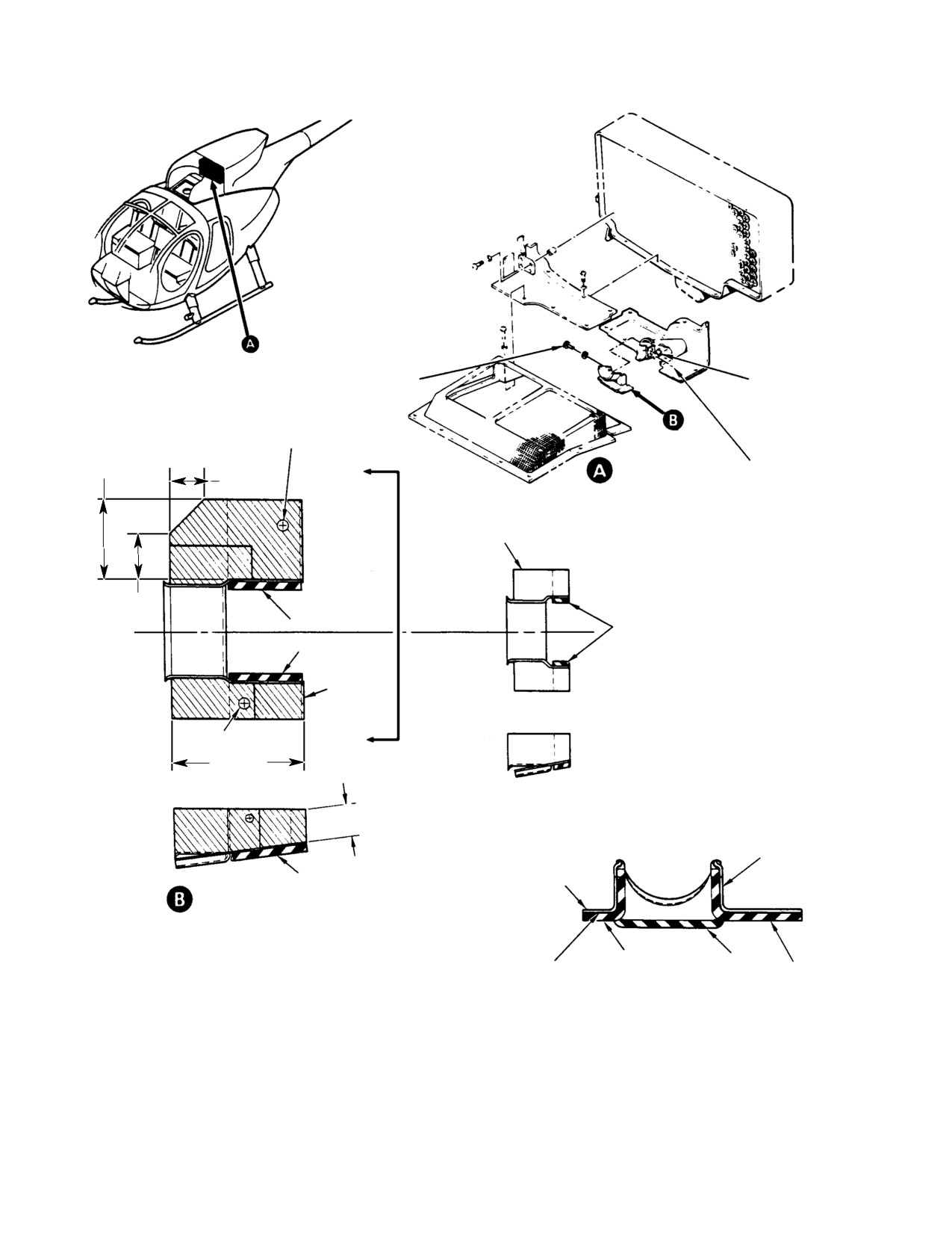
SCREW, WASHER
NUTPLATE
(REMOVED)
(REMOVED)
NOTE 1
1.40 IN.
RIVETS
FAIRING
(35.56 MM)
(REMOVED)
0.60 IN.
A
MODIFICATIONS
(1.524 MM)
-31 COVER
(BEFORE REWORK)
0.80 IN.
(20.32 MM)
-57 SEAL
EXISTING -39 SEAL
(REMOVED)
-55 SEAL
BUILDUP
(NOTE 2)
NOTE 1
A
2.40 IN.
(60.96 MM)
0.61 IN.
(15.494 MM)
ONE LAYER
-31 COVER
181 FIBERGLASS
-55 SEAL
(TOP) (TYP)
COVER MODIFICATION
-55 SEAL
-41 SEAL
TWO LAYERS
-57 SEAL
181 FIBERGLASS
VIEW A-A
NOTES:
(BOTTOM) (TYP)
1.
DRILL 0.250 IN (6.35 MM) DIAMETER HOLES IN
COVER TO MATCH -11 FAIRING.
2.
SHADED AREA DENOTES FIBERGLASS BUILDUP.
G71-1019A
Figure 802. Fairing Modifications
Page 804
Revision 22
71-10-10
MD Helicopters, Inc.
CSP-HMI-2
MAINTENANCE MANUAL
2. Mist Eliminator Repair
(3). Using a 0.030 inch (0.762 mm) feeler
gage, check for gaps at the three
(1). The mist eliminator is a non-repairable
mounting bolt attach points. Install
all welded assembly except for the
shims in areas where gaps exceed 0.030
mounting bolts required for some
inch (0.762 mm) width per the next
installations. Repairs are limited to bolt
step.
repair or replacement.
(4). Bond an aluminum or fiberglass shim
NOTE:
thickness to the fairing that is equiva
lent to the gap.
D The following mist eliminator repair/re
placement items and, or kits are available
(a). Bond aluminum shims to the fairing
from Pall Land Marine (PLM) or through
with epoxy resin (CM504).
your local distributor.
(b). Laminate and bond fiberglass cloth
D AE-A224-1D2 Mist eliminator Assy.,
per Structural Repair Manual
complete.
procedures (CSP-DEF-6).
D AA-A224-1D2KF1 Repair kit, mist elimi
nator (nine mounting bolts).
4. Donaldson Particle Separator Repair
(369D Only)
(2). Remove mist eliminator assembly per
`Mist Eliminator Replacement'.
Consumable Materials
(3). Chase mounting bolt threads with a
(Ref. Section 91−00−00)
10-32 die, as required.
Item
Nomenclature
CM234
Solvent, dry-cleaning
(4). Remove mounting bolts from mist
CM503
Fiberglass repair kit
eliminator frame by pulling bolt aft
CM728
Tape, pressure sensitive
while unscrewing.
(5). Replace mounting bolts.
NOTE: Particle separator repairs are accom
plished per standard fiberglass repair meth
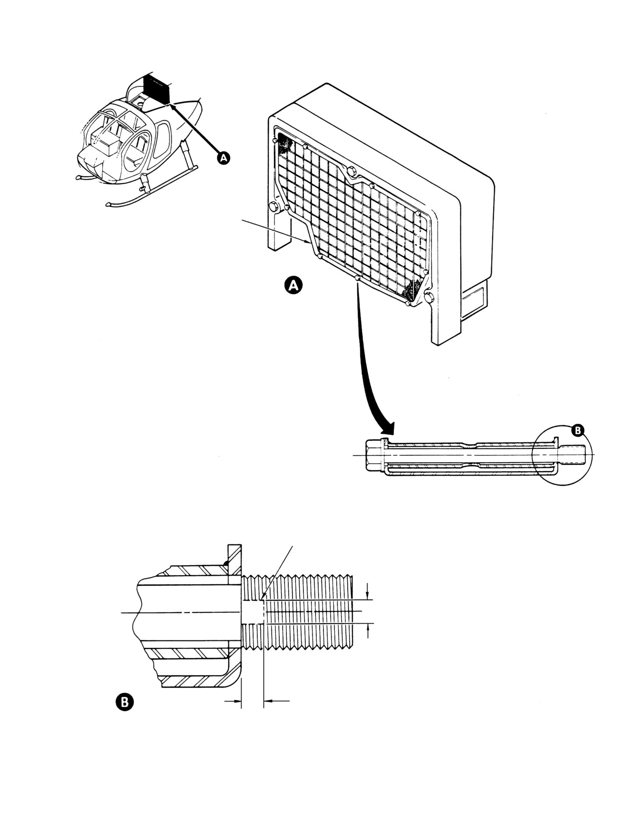
(6). Flatten an area 0.160-0.170 inch
ods using fiberglass repair kit (CM503). En
(4.064-4.318 mm) wide by 0.125 inch
sure that no potential for engine foreign
(3.175 mm) long, maximum, across the
object damage occurs as a result of filter re
first three to four threads adjacent to
pair.
the bolt shank to inhibit removal.
(1). Rebond loose or missing fiberglass
3.
Particle Separator Alignment and Joint
attachment spacers.
Surface Repair (369D/E/FF)
(2). Rebond front and back wall to center
section seams as required.
Consumable Materials
(Ref. Section 91−00−00)
(3). Rebond manifold nozzle attachment
Item
Nomenclature
tube.
CM504
Epoxy resin with catalyst
(4). Patch repair or fill any other damaged
or cracked areas.
(1). Draw an outline of the particle separa
(5). Replace damaged vortex tubes.
tor on smooth, parallel surfaced, 1/2
NOTE: Up to five damaged vortex tubes may be
inch (12.7 mm) thick phenolic or close
temporarily blocked.
grained plywood. Cut template from
material. Drill mounting bolt holes.
(6). Install not more than five aluminum
patches over vortex tube outlet holes.
(2). Position template against engine air
Install patches with at least three
inlet fairing-to-filter mounting surface
mechanically expanded rivets.
and install three bolts and nuts finger
tight. Ensure template is secure and
(7). Replace worn or loose gasket tapes as
undistorted.
follows:
Page 805
71-10-10
Revision 22
CSP-HMI-2
MD Helicopters, Inc.
MAINTENANCE MANUAL
MOUNTING
STRUCTURE
AFT AIR INLET
FAIRING
SCREEN
(TYPICAL)
PARTICLE
SEPARATOR
GASKET
(NOTE)
PARTICLE SEPARATOR
NOTE:
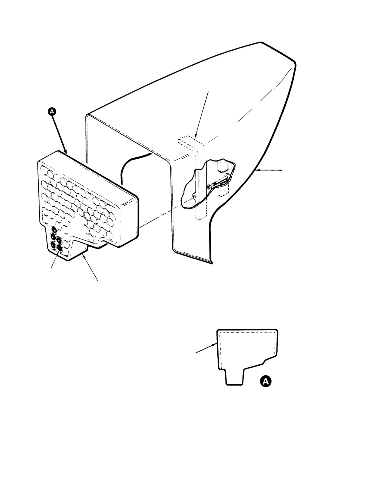
INSTALL GASKET AS SHOWN ON AFT FACE
OF PARTICLE SEPARATOR
G71-1017
Figure 803. Donaldson Particle Separator Gasket Replacement
Page 806
Revision 22
71-10-10
MD Helicopters, Inc.
CSP-HMI-2
MAINTENANCE MANUAL
MIST ELIMINATOR
ROTATED 180°
SECTIONAL VIEW
FLATTENED THREADS
(NOTE)
0.160-0.170 IN.
(4.064-4.318 MM)
NOTE:
FLATTEN THREADS TO DIMENSION SHOWN.
DO NOT EXCEED MAXIMUM DIMENSION.
0.125 IN.
DETAIL
MAX.
(3.175 MM)
G71-1018A
Figure 804. Mist Eliminator Bolt Repair
Page 807
71-10-10
Revision 22
CSP-HMI-2
MD Helicopters, Inc.
MAINTENANCE MANUAL
(a). Remove tape debris. Wipe tape
NOTE:
contact surfaces with a clean cloth
D Installation of sealed fairings around the
and P-D-680 dry-cleaning solvent
particle separator to protect the engine
(CM234).
from FOD is required for early Donaldson
particle
separator
installations
369H90148-503 and -505 used on some
(b). Cut tape 0.380 inch (9.652 mm) wide
369D series helicopters.
from 0.125 inch (3.175 mm) thick
Y-3192-B material (CM728).
D Donaldson particle separator installa
tions are identified by the scavenge air ex
haust port on the left side of the aft inlet
(c). Install tape across the top and down
fairing.
right and left sides of the fairing
D Procedures cover fairing
kit,
contact area. Do not apply seal tape
PN 369D290140 and pressure switch,
across the bottom (Ref. Figure 803).
PN 369A8402-7 installation.
Install particle separator.
D PN 369A8402-3 pressure switch modifi
cations to -7 specifications using a Jensen
(8). Perform particle separator alignment
#800-174 kit are provided. Modification
procedures and the following steps.
of a -3 switch to a -7, or procurement and
installation of a -7 switch is mandatory
when auxiliary fairings are installed.
(a). Remove ejector-to-outlet duct rubber
sleeve. Use a straight edge to check
(1). Remove air inlet forward fairings.
for misalignment between the ejector
(2). Remove particle separator (Ref.
and outlet duct. Maximum allowed
Donaldson Particle Separator Remov
misalignment is 1/4 inch (6.35 mm).
al).
(3). Clean particle separator (Ref. Particle
(b). Install tapered shims between duct
Separator Cleaning).
and screen rubber rim to repair
ejector-to-outlet duct misalignment.
(4). Inspect particle separator (Ref. Donald
Use at least two attachment screws
son Particle Separator Inspection).
to retain shim.
(5). Repair unit (Ref. Donaldson Particle
Separator Repair).
NOTE: Existing screen and duct attachment
NOTE: 369D290140-5 and -7 supports and
screws are long enough to allow addition of
369D290140-11 and -12 fairing assemblies
1/4 inch (6.35 mm) thick shim.
may be manufactured using drawings pro
vided (Ref. Figure 806). Apply a coat of
(9). Install particle separator.
primer (CM318) after making the parts.
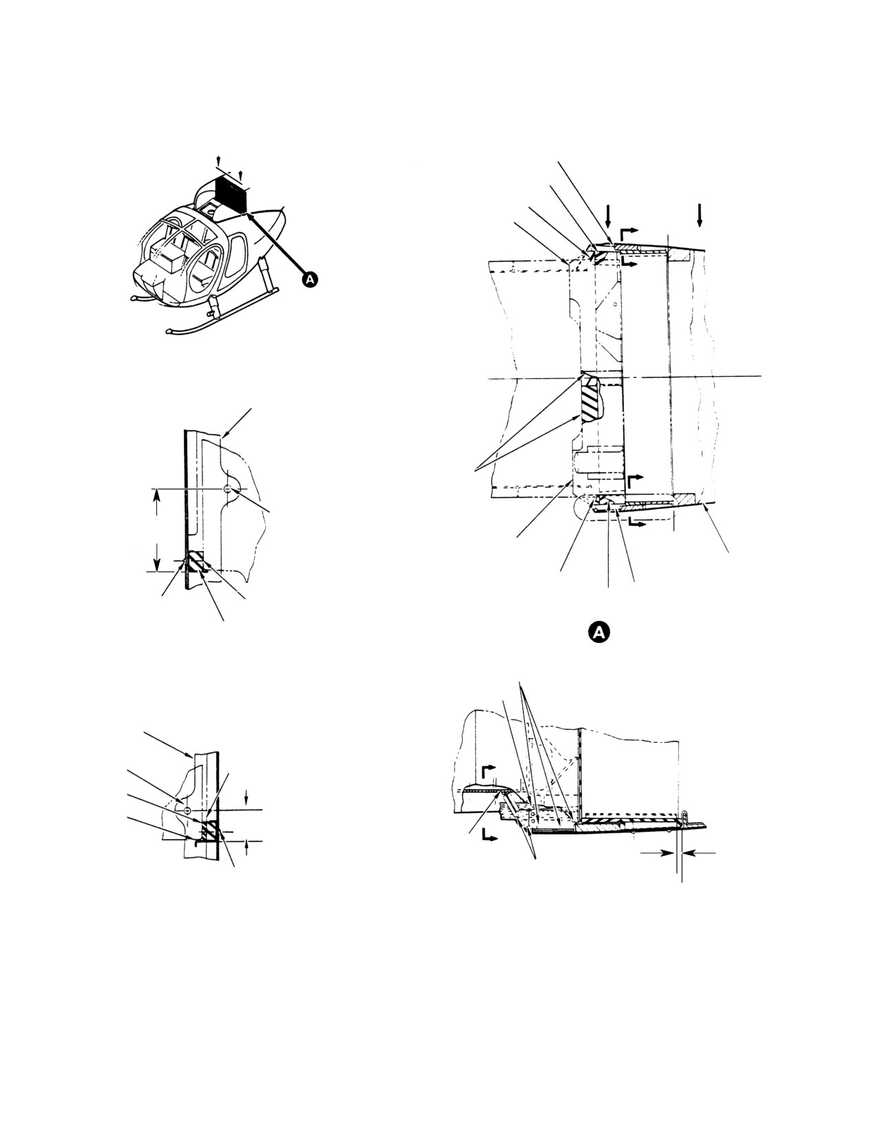
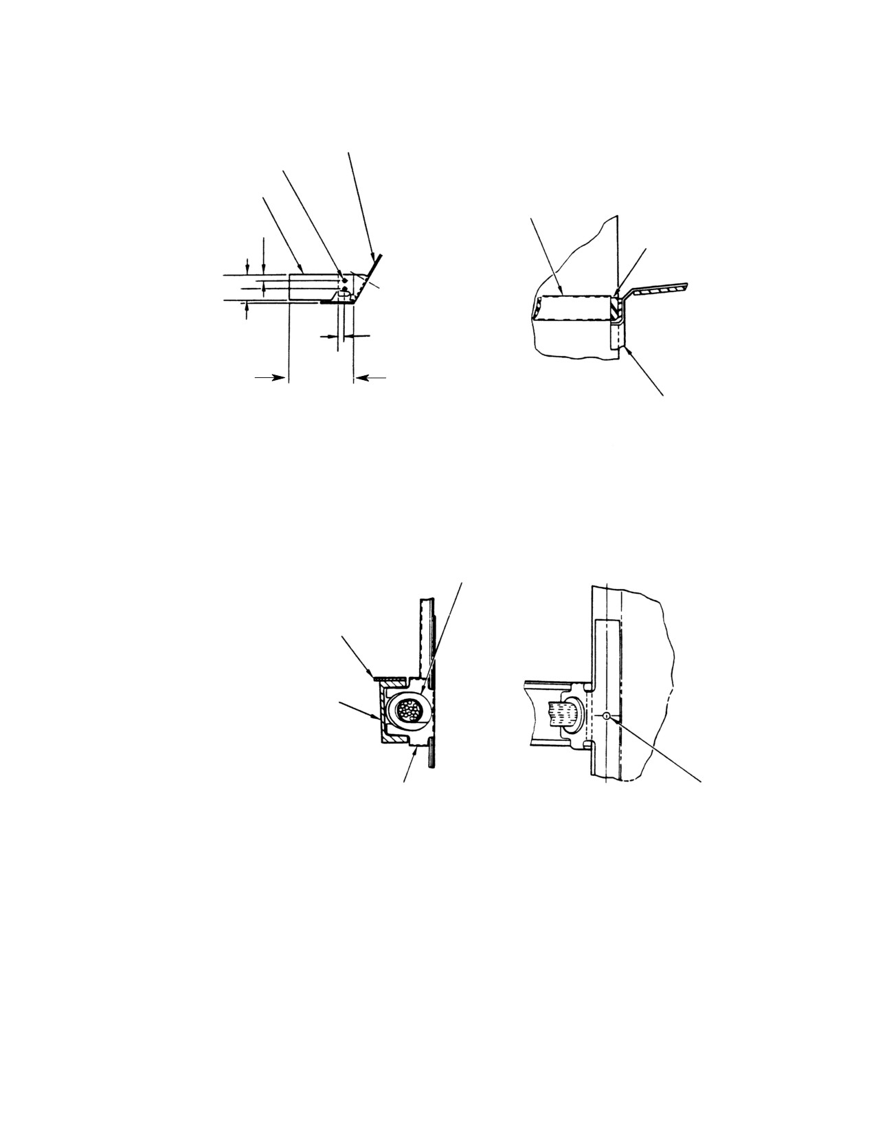
(6). Install LH fairings and seals as follows:
5. Donaldson Particle Separator Auxiliary
(a). Locate 369D290140-5 seal support
Fairings and Seals Installation
forward of aft fairing filter mounting
frame as indicated (Ref. Figure 805,
detail A and section B-B).
Consumable Materials
(b). Use -5 support as a guide and drill
(Ref. Section 91−00−00)
two rivet holes through fairing.
Item
Nomenclature
(c). Install support with two
CM234
Solvent, dry-cleaning
NAS1738B4-2 rivets.
CM318
Primer
(d). Install 369D290140-13 and -25 seals
CM430
Sealant, solvent resistant
on support (Ref. Figure 805, view
A-A and section B-B).
Page 808
Revision 22
71-10-10
MD Helicopters, Inc.
CSP-HMI-2
MAINTENANCE MANUAL
(e). Position and mark 369D290140-11
(h). Install 369D290140-17 and -23 seals
fairing (Ref. Figure 805, view E-E).
on underside of 369H90151-41
Drill 0.250 inch (6.35 mm) diameter
fairing. Trim -23 seal to match
hole through -11 to match inlet
fairing contour (Ref. Figure 805, view
fairing existing nutplate.
A-A).
(f). Split grommet and install on wire
(8). Disconnect and remove 369A8402-3
and controls bundle (Ref. Figure 805,
pressure switch.
view E-E). Slip -11 fairing into
(a). Remove screws and separate switch
grommet groove.
halves. Remove diaphragm-magnet
(g). Trial fit 369D290140-11 fairing on
and return spring (Ref. Figure 807).
aft inlet fairing with washer and
(b). Clean parts with P-D-680 dry
screw. Remove fairing assembly.
cleaning solvent (CM234).
(h). Install 369D290140-17, -19 and -23
(c). Reassemble switch with new diaph
seals on underside of 369H90151-31
ragm-magnet and return spring per
fairing. Trim -19 and -23 seals to
illustration.
match fairing contour (Ref.
Figure 805, view A-A).
(d). Align screw holes, magnet-diaph
(7). Install RH fairings and seals as follows:
ragm, spring and switch halves and
assemble unit with screws. Lockwire
(a).
Locate 369D290140-7 seal support
screws.
forward of aft fairing filter mounting
frame as indicated (Ref. Figure 805,
(e). Install new name plate over existing
view A-A and section C-C).
name plate.
(b).
Use -5 support as a guide and drill
(9). Check pressure switch operation (Ref.
three rivet holes through fairing.
Air Pressure Sensing Switch Calibra
tion Check). Switch closing should occur
(c).
Install support with three
between 10.25-10.75 inches
NAS1738B4-2 rivets.
(26.035-27.305 cm) of water.
(d).
Install 369D290140-15 seal on
(10). Install pressure switch.
support (Ref. Figure 805, view A-A
and section C-C).
(11). Install particle separator (Ref. Donald
son Particle Separator Installation).
(e).
Position and mark 369D290140-12
fairing (Ref. Figure 805, view E-E).
(a). Install 369H90151-31 and -41
Drill 0.250 inch (6.35 mm) diameter
fairing halves with washers and
hole through -11 to match inlet
screws (Ref. Figure 805, view A-A).
fairing existing nutplate.
(b). Install 369D290140-11 and -12
(f).
Split grommet and install on wire
fairings with washers and screws
and controls bundle (Ref. Figure 805,
(Ref. Figure 805, view E-E).
view E-E). Slip -12 fairing into
(c). Apply sealing compound, RTV732
grommet groove.
(CM430) around all gaps between -11
(g).
Trial fit 369D290140-12 fairing on
and -12 fairings, grommets, wire
aft inlet fairing with washer and
bundles, aft fairing and mast fitting
screw. Remove fairing assembly.
(Ref. Figure 805, detail A).
Page 809
71-10-10
Revision 22
CSP-HMI-2
MD Helicopters, Inc.
MAINTENANCE MANUAL
-12 FAIRING ASSY
TRIM -12 FAIRING AS REQUIRED TO CLEAR
EXISTING STRUCTURE IN 369A3053
A
TYP. FOR INSTL. OF -11 FAIRING
A
-17 SEAL
D
D
-23 SEAL
369H90151-41
C
C
MOUNTING FRAME FOR
369H90152 FILTER AT
STA. 124.00
TRIM -19 AND -23 SEALS
B
TO MATCH CONTOURS
OF 369H90151 FAIRINGS
W.L. 67.00
3.31 IN.
B.L. 865 RN
(8.4074 CM)
369H90151-31
B
STA.
FAIRING
124.00
369A3053
FAIRING
SEE DETAIL A
-11 FAIRING ASSY
NAS173884-2 RIVET
-15 SEAL
-17 SEAL
(3 REQD)
DRILL 369A3053 TO
-7 SUPPORT
VIEW A - A
MATCH HOLES IN
SEAL ALL OPENINGS OR
SUPPORT
SECTION C - C
GAPS USING SILASTIC
ROTATED 90° CCW
NO. 732 OR EQUIV.
-11 FAIRING ASSY
MOUNTING FRAME FOR
369H90152 FILTER AT
STA. 124.00
W.L. 68.36
E
-13 SEAL
B.L. 8.70 LH
-25 SEAL
-5 SUPPORT
1.25 IN.
(3.175 CM)
APPLY SILASTIC NO. 732 OR
EQUIV. BETWEEN FLANGE
0.19 IN.
E
(4.826 MM)
OF FAIRING AND 369H3003
SEAL ALL OPENINGS OR
NAS173884-2 RIVET
GAPS USING SILASTIC
(3 REQD)
STA.
NO. 732 OR EQUIV.
DRILL 369A3053 TO MATCH
124.00
HOLES IN SUPPORT
SECTION B - B
DETAIL A
ROTATED 90° CCW
TYP. FOR INSTAL. OF -12 FAIRING
G71-1014-1A
Figure 805. Auxiliary Fairings and Seals Installation (Sheet 1 of 2)
Page 810
Revision 22
71-10-10
MD Helicopters, Inc.
CSP-HMI-2
MAINTENANCE MANUAL
-4 FAIRING FOR -12 ASSY (NOTE)
-3 FAIRING FOR -11 ASSY (NOTE)
MS20470AD2 RIVET (2)
-9 PLATE
-7 SUPPORT
0.19 IN.
(4.826 MM)
-15 SEAL
0.44 IN.
0.19 IN.
(11.176 MM)
(4.826 MM)
2.03 IN.
(5.1562 CM)
SECTION D - D
369H90151-41 FAIRING
ROTATED 180°
MS35489-19 GROMMET
SPLIT GROMMET APPROX.
AS SHOWN PRIOR TO INSTL.
369D23011
369H3003 FAIRING
-11 FAIRING ASSY
0.250 IN. (6.35 MM) DIA.
THRU -11 FAIRING ASSY
TO MATCH EXISTING
NUTPLATE LOCATIONS
VIEW E - E
ROTATED 90° CCW TYP. FOR
INSTL. OF -12 FAIRING ASSY
NOTE:
DRILL 0.063 IN. (1.6002 MM) DIA. HOLES IN
-3 AND -4 FAIRINGS TO MATCH HOLES IN
-9 PLATE (2 PLCS)
G71-1014-2A
Figure 805. Auxiliary Fairings and Seals Installation (Sheet 2 of 2)
Page 811
71-10-10
Revision 22
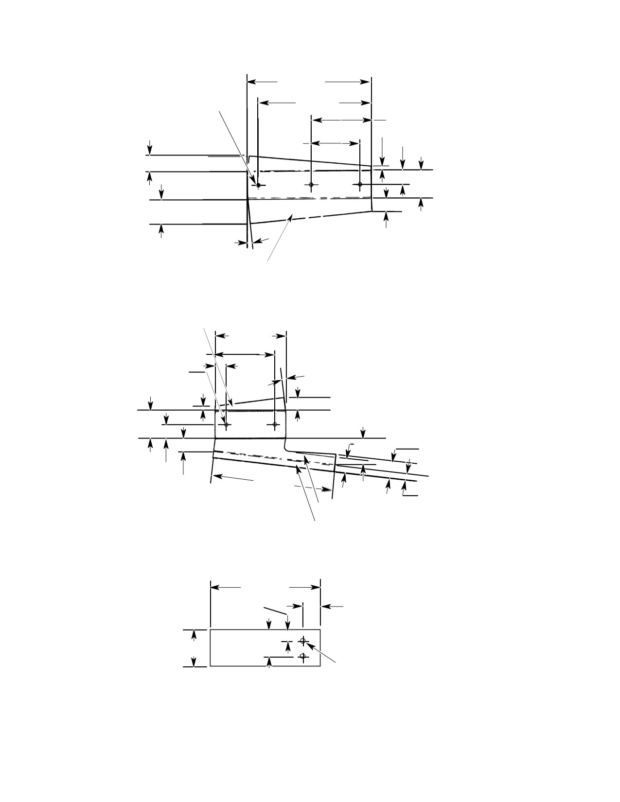
CSP-HMI-2
MD Helicopters, Inc.
MAINTENANCE MANUAL
3.51 IN.
(8.9154 CM)
0.098 IN. (2.4892 MM) DIA.
3.20 IN.
(3 PILOT HOLES)
(8.128 CM)
1.70 IN. (4.318 CM)
0.12 IN. (3.048 MM)
0.31 IN.
0.40 IN. (10.16 MM)
(7.874 MM)
0.80 IN. (20.32 MM)
0.43 IN. (10.922 MM)
0.68 IN. (17.272 MM)
0.37 IN.
5°
(9.398 MM)
(4 PLCS)
BEND UP X 0.09 IN. (2.286 MM) R
(2 PLCS)
-7 SUPPORT (FLAT PATTERN)
BEND UP X 0.09 IN. (2.286 MM) R
2.02 IN.
(5.1308 CM)
1.70 IN. (4.318 CM)
0.31 IN.
0.098 IN. (2.4892 MM) DIA.
(7.874 MM)
(2 PILOT HOLES)
6° 30' (4 PLCS)
0.12 IN. (3.048 MM)
0.35 IN. (8.89 MM)
0.77 IN. (19.558 MM)
0.23 IN. (5.842 MM)
0.31 IN. (7.874 MM)
0.80 IN. (20.32 MM)
0.40 IN. (10.16 MM)
0.37 IN. (9.398 MM)
3.50 IN.
(8.89 CM)
0.18 IN. (4.572 MM)
BEND DN X 0.09 IN. (2.286 MM) R
BEND UP X 0.09 IN. (2.286 MM) R
-5 SUPPORT (FLAT PATTERN)
2.03 IN.
(5.1562 CM)
0.19 IN.
0.31 IN.
(4.826 MM)
(7.874 MM)
0.44 IN.
0.75 IN. (19.05 MM)
(11.176 MM)
0.0635 IN (0.16129 MM)
(#52 DRILL)
-9 PLATE
G71-1015-1A
Figure 806. Auxiliary Fairings and Supports Fabrication (Sheet 1 of 2)
Page 812
Revision 22
71-10-10
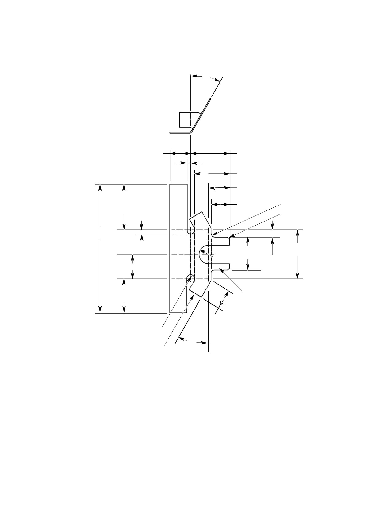
MD Helicopters, Inc.
CSP-HMI-2
MAINTENANCE MANUAL
30°
0.95 IN.
1.70 IN.
(24.13 MM)
(4.318 CM)
0.17 IN.
(4.318 MM)
1.56 IN.
(3.9624 CM)
0.93 IN.
(23.622 MM)
0.12 IN. (3.048 MM) R
0.81 IN.
2.00 IN.
(2 PLCS)
(20.574 MM)
(5.08 CM)
0.06 IN. (1.524 MM) R
(2 PLCS)
5.63 IN.
(14.3002 CM)
0.18 IN.
2.13 IN.
1.44 IN.
(4.572 MM)
(5.4102 CM)
0.40 IN.
(3.6576 CM)
0.31 IN.
(10.16 MM)
(7.781 MM)
1.06 IN. (2.6924 CM)
1.50 IN.
BEND DN 30° OPEN X
(3.81 CM)
0.12 IN. (3.048 MM) R
0.92 IN. (23.368 MM)
(2 PLCS)
0.12 IN. (3.048 MM) R
(2 PLCS)
30°
BEND DN X
0.12 IN. (3.048 MM) R
(2 PLCS)
-4 FAIRING (FLAT PATTERN) SHOWN
-3 OPP.
G71-1015-2A
Figure 806. Auxiliary Fairings and Supports Fabrication (Sheet 2 of 2)
Page 813
71-10-10
Revision 22
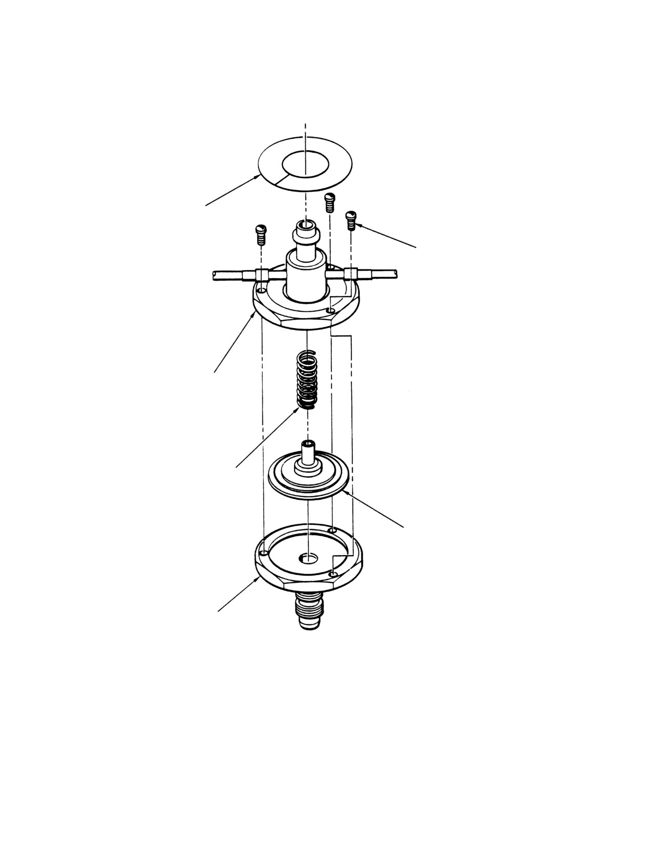
CSP-HMI-2
MD Helicopters, Inc.
MAINTENANCE MANUAL
NAMEPLATE
RETAINING SCREWS
SWITCH BODY
DIAPHRAGM RETURN
SPRING
DIAPHRAGM MAGNET
ASSEMBLY
SWITCH BODY
G71-1016
Figure 807. Pressure Switch
Page 814
Revision 22
71-10-10
MD Helicopters, Inc.
CSP-HMI-2
MAINTENANCE MANUAL
ENGINE AIR PARTICLE SEPARATOR
INITIAL INSTALLATION
1. Engine Air Particle Separator Initial
(10). On helicopters with cabin heat, remove
Installation
cabin heat control valve to facilitate
installing part number
369H90148-507, -519, or -527 particle
Consumable Materials
separators.
(Ref. Section 91−00−00)
Item
Nomenclature
Prevent engine FOD. Secure a
CAUTION
cover over the engine intake be
CM206
Chemical coating
fore working in or around plenum chamber.
CM318
Primer
(11). Remove engine air inlet forward fairing
and aft fairing access cover.
(1).
369H90148-519, -521, -527 and -529
particle separator installations are
(12). Remove plenum chamber access door.
covered by procedures in this section.
(13). Disconnect forward end of tail rotor
NOTE: Tag components as they are removed,
control rod at Sta. 95.00 bellcrank (Ref.
including attaching hardware. Protect loose
Sec. 67-20-10). Remove forward boot.
parts from damage, dirt or loss.
(14). Remove engine air cooling inlet screen.
(2). Ensure that battery switch and all
(15). Modify engine air cooling inlet screen
other helicopter switches are OFF.
(Ref. Figure 903, view B).
(3). Open crew compartment left floor
(16). Remove engine intake air inlet screen
access door and disconnect battery
(Ref. Sec. 71-10-00).
connector J108.
(17). Prepare airframe electrical ground
(4). Remove fairings from instrument panel
points per FAA publication, EA-
(Ref. Chap. 95).
AC43.13-1A and 2A.
(5). Remove rotor brake cover, where
(18). Using chemical film (CM206) treat
installed.
reworked areas as required and apply
primer (CM318) except on electrical
(6). Remove map case and interior trim
ground or bonding points.
panel (Ref. Sec. 25-30-00).
A. Filter Bypass Door and Aft Cable
(7). Remove map case cover upper left
(Ref. Figure 901)
support bracket.
(8). Remove transmission oil cooler inlet
Consumable Materials
duct (Ref. Sec. 63-21-00).
(Ref. Section 91−00−00)
Item
Nomenclature
NOTE: Installation of bleed air extraction el
CM410
Adhesive, epoxy (parts A & B)
bow, tee and hose with the engine in the he
licopter can be done; however, clearance is
minimal.
(1). Modify the plenum chamber access door
as follows:
(9). On helicopters without cabin heat,
remove engine to ease bleed air extrac
(2). Install clip and insert assembly on door
tion hardware installation prior to
with screws, washers and nuts.
installing part numbers
369H90148-509, -521, or -529 particle
(3). Install latch assemblies on door with
separators.
screws, washers and nuts.
Page 901
71-10-10
Revision 22
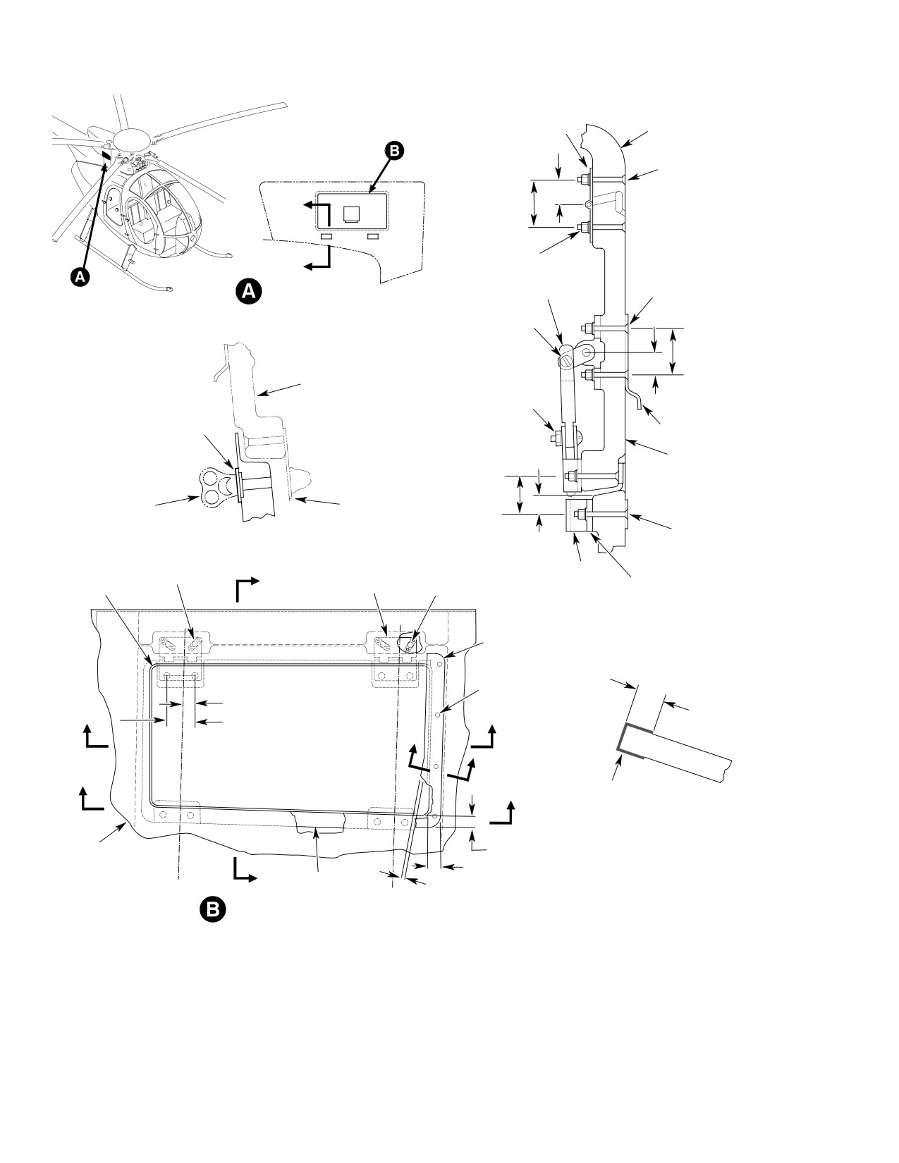
CSP-HMI-2
MD Helicopters, Inc.
MAINTENANCE MANUAL
HINGE (2 PLCS)
FAIRING
0.63 IN. (16.002 MM)
SCREW
A
1.250 IN. (3.175 CM)
SCREW
WASHER
A
SCREW
NUT
WASHER
PLENUM CHAMBER ACCESS DOOR
LINK (2 REQD)
NUT
BOLT
NUT
WASHER
1.250 IN. (3.175 CM)
(NOTE 10)
BOLT
DOOR
NUT
WASHER
0.63 IN. (16.002 MM)
(NOTE 10)
PLATE
CLIP
DOOR
(NOTE 1)
1.00 IN. (2.54 CM)
PLATE (2 REQD)
REMOVE
REMOVE
A-A
SCREW
0.53 IN. (13.462 MM)
WASHER
NUT
NUTPLATE (4 PLCS)
CLIP
(NOTE 4)
RIVET (8 PLCS)
(NOTE 13)
SHIM
DOOR
HINGE
(NOTE 3)
(NOTE 9)
B-B
COVER
(NOTE 6)
RIVET (4 PLCS)
(NOTE 5)
0.62 IN. (15.748 MM) (TYP)
0.50 ±0.03 IN.
1.250 IN. (3.175 CM) (TYP)
(12.70 ±0.762 MM)
FIBERGLASS
CLOTH (1 PLY)
C-C
(NOTE 8)
FAIRING
0.50 ±0.03 IN. (12.70 ±0.762 MM)
0.56 ±0.03 IN. (14.224 ±0.762 MM)
GASKET
0.19 ±0.03 IN. (4.826 ±0.762 MM)
STA.
(NOTE 7)
STA.
(NOTE 3)
141.00
DOOR INSTALLATION
131.00
G71-1006-1A
Figure 901. Air Bypass Door Installation (Sheet 1 of 2)
Page 902
Revision 22
71-10-10
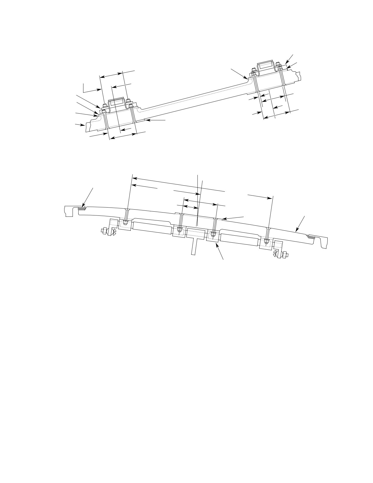
MD Helicopters, Inc.
CSP-HMI-2
MAINTENANCE MANUAL
LATCH
CLIP
1.450 IN. (3.683 CM)
SHIM
(NOTE 1)
0.56 IN. (14.224 MM)
PLATE
LATCH
1.450 IN. (3.683 CM)
CLIP
0.56 IN.
(NOTE 1)
(14.224 MM)
1.62 IN. (4.1148 CM)
SHIM
0.68 IN. (17.373 MM)
(NOTE 12)
PLATE
DOOR
1.62 IN. (4.1148 CM)
0.68 IN. (17.373 MM)
(NOTE 12)
(REF)
D-D
STA.
136.00
GASKET
4.12 IN.
8.42 IN.
(10.4648 CM)
(21.3868 CM)
0.91 IN. (23.114 MM)
2.00 IN. (5.08 CM)
DOOR
CLIP
INSERT ASSY
E-E
NOTES:
1.
DOOR PN 369A2099, 369H2087 AND 369D22087.
8.
APPLY ONE PLY OF FIBERGLASS TO COVER-TRIMMED DOOR
2.
INSTALL COVER. TRIM DOOR TO MATCH CONTOUR OF COVER SO AFT
EDGE PER DIMENSION SHOWN.
EDGE OF COVER OVERLAPS DOOR BY 0.19 IN. (4.826 MM) NOMINAL.
9.
PEEL SHIM, AS REQUIRED, TO ALIGN DOOR AND FAIRING
REWORK NOT REQUIRED ON 369D290134 DOOR.
EXTERNAL SURFACES FLUSH WHEN DOOR IS LATCHED.
3.
INSTALL MS20426A03-5 RIVETS FLUSH ON HINGE NEAR SIDE.
10. TIGHTEN NUT TO GET 0.005-0.015 IN. (0.127-0.381 MM) GAP
4.
CENTER NUTPLATES ON EXISTING 0.196-0.210 IN. (4.9784-5.334 MM) DIA.
BETWEEN BOLT HEAD AND WASHER.
HOLES IN HINGE. POSITION NUTPLATES AS SHOWN ON FAR SIDE IF HINGE.
11. DIMENSION TO MATCH LATCH AND BE CENTERED WITHIN
5.
DRILL FAIRING TO MATCH HOLE PATTERN IN COVER. INSTALL FOUR
0.060 IN. (1.524 MM) WITH CLIP.
MS20470AD-3 RIVETS.
12. DIMENSION TO MATCH CLIP AND BE CENTERED WITHIN 0.060 IN.
6.
BOND COVER TO AFT FAIRING (REF. CSP-DEF-6).
(1.824 MM) WITH LATCH.
7.
MAKE GASKET FROM DE41 CLOSED CELL NEOPRENE RUBBER. BOND TO
13. CHAMFER UPPER EDGE TO EASE DOOR LATCH ENGAGEMENT.
DOOR WITH ADHESIVE (CM418).
G71-1006-2A
Figure 901. Air Bypass Door Installation (Sheet 2 of 2)
Page 903
71-10-10
Revision 22
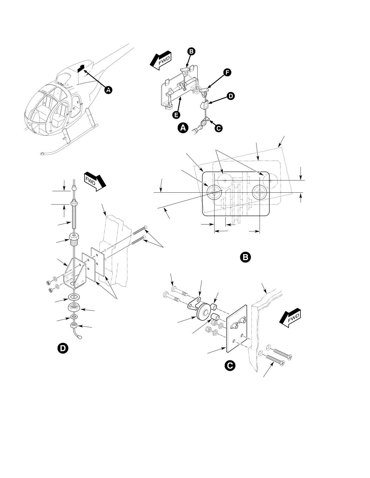
CSP-HMI-2
MD Helicopters, Inc.
MAINTENANCE MANUAL
FAIRING BRACKET
BOSS
ORIGINAL BRACKET
LOCATION
NEW BRACKET
NOTE 2
LOCATION
SCREW (2 PLCS)
(NOTE 1)
1.65 IN. (4.191 CM)
CABLE TRAVEL
DOOR LATCHED
FAIRING
11° 30”
0.29 IN. (7.366 MM)
DOOR OPEN
B.L. 5.83 RH
CABLE STOP
0.39 IN. (9.906 MM)
1.375 IN.
(3.4925 CM)
SLEEVE
VIEW LOOKING DOWN
EXISTING SCREWS,
FAIRING MODIFICATION,
BRACKET
WASHERS, NUTS
UPPER RIGHT PULLEY
BRACKET
SCREW (2 PLCS)
GUARD PLATE
FAIRING
SPACER
WASHER
SHIM
(NOTE 4)
NUT
WASHER
PULLEY
JAMNUT
(NOTE 3)
BUSHING
CABLE STOP
INSTALLATION
LOWER PULLEY
BRACKET
SCREW (2 PLCS)
G71-1007-1A
Figure 902. Aft Cable Installation (Sheet 1 of 2)
Page 904
Revision 22
71-10-10
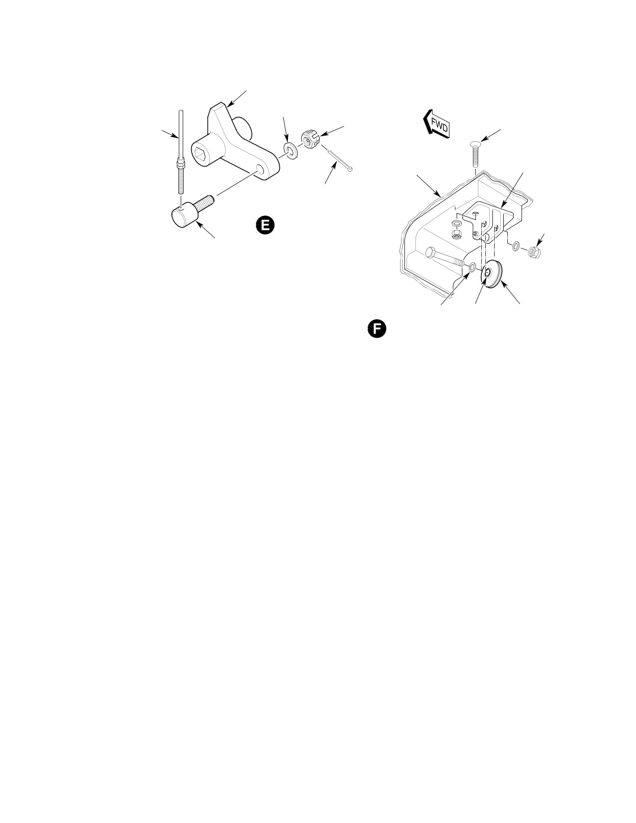
MD Helicopters, Inc.
CSP-HMI-2
MAINTENANCE MANUAL
DOOR CRANK
WASHER
EXISTING SCREWS,
CABLE TERMINAL
NUT
WASHERS, NUTS
AFT FAIRING
BRACKET
COTTER PIN
BOLT
CABLE
CONNECTION
NUT
FITTING
WASHER (2 PLCS)
BUSHING
PULLEY
NOTES:
(NOTE 3)
UPPER PULLEY
1.
DRILL TWO 0.217-0.229 IN. (5.5118-5.8166 MM) DIAMETER HOLES.
INSTALLATION
COUNTERSINK 100° TO 0.43 IN. (10.922 MM) MINOR DIAMETER.
(TYP 2 PLCS)
2.
FILL HOLES WITH ADHESIVE (CM410) OR EQUIVALENT.
3.
PULLEYS TO BE IN ALIGNMENT WITHIN 0.13 IN. (3.302 MM).
G71-1007-2A
4
SHIM TO ALIGN CABLE WITH CABLE STOP WITHIN 0 060 IN (1 524 MM)
Figure 902. Aft Cable Installation (Sheet 2 of 2)
(4).
Attach links to latch and insert assem
stop into sleeve. Install washer and
bly with bolts, washers and nuts.
cable-stop jamnut.
Tighten nuts to get a 0.005-0.015 inch
(10).
Install sleeve assembly in bracket.
(0.127-0.381 mm) clearance between
Secure with washer and nut.
bolt-heads and washers.
(11).
Install door latch shims, clips, plates,
(5).
Install door hinge nut-plates with
screws, washers and nuts (Ref.
rivets.
Figure 901, view D-D).
(6).
Relocate upper right pulley bracket
(12).
Install bushing in lower pulley. Attach
mount holes (Ref. Figure 902, view B).
pulley assembly to bracket with shim
Drill 0.217-0.229 inch (5.5118-5.8166
between pulley and bracket. Install
mm) diameter holes. Countersink 100°
guard plate, spacer, screws and washers
to 0.430 inch (10.922 mm) diameter. Fill
over pulley. Attach the assembled
original holes with EA9314 epoxy
pulley bracket to fairing with screws,
adhesive (CM410) mixed per manufac
washers and existing nuts (Ref.
turers instructions.
Figure 902 detail C).
(7).
Install upper pulley brackets using
(13).
Install air bypass door on aft fairing
existing fasteners. Insert bushings in
with screws, washers and nuts.
two upper pulleys. Route cable assem
(14).
Screw fitting (Ref. Figure 902, detail E)
bly over pulleys.
onto cable terminal. Install fitting in
(8).
Install pulleys and cable assembly in
insert assembly crank arm with washer
brackets; install pulley bracket bolts,
and nut. Tighten nut to get a
washers and nuts.
0.005-0.015 inch (0.127-0.381 mm) gap
between crank and fitting head. Install
(9).
Install cable-stop bracket and shim
cotter pin. Bend cotter pin only enough
using existing fasteners. Thread cable
to keep it in place. Door rigging adjust
Page 905
71-10-10
Revision 22
CSP-HMI-2
MD Helicopters, Inc.
MAINTENANCE MANUAL
ments will be required later to complete
(3). Cover saw cut with a single ply of glass
the installation.
cloth (Ref. Figure 901, detail C-C) and
per Structural Repair Manual, CSP-
(15).
Add or peel latch clip shims to align
DEF-6.
door and fairing external surfaces flush
C. Handle and Forward Cable Installation
with door closed and latched (Ref.
Figure 901).
(Ref. Figure 903)
(16).
Check pulley alignment. Pulleys shall
line up within 0.130 inch (3.302 mm) of
Consumable Materials
each other.
(Ref. Section 91−00−00)
Item
Nomenclature
(17).
Locate seal supports on fairing. Drill
CM318
Primer
fairing to match holes in supports.
Install rivets (Ref. Figure 904, detail A).
Special Tools
(Ref. Section 91−00−00)
(18).
Install seals on supports. Align LH
Item
Nomenclature
seals (Ref. Figure 904, detail A, sections
A-A and C-C).
ST2007
Rivnut installation speed header
ST2008
Rivnut keyway cutter
(19).
Remove coax, anti-ice and wire harness
cable support hardware, including clip
(Ref. Figure 904, views H-H and J-J).
(1).
Remove 369H6524-835 bracket (Ref.
Figure 903).
(20).
Locate and rivet ty-rap base in posi
(2).
Remove oil pressure sender tube
tion. Tie coax, anti-ice and wire
assembly from frame hole at canted
harness in one bundle. Secure bundle to
Sta. 78.50.
base with ty-raps.
(3).
Enlarge oil pressure sender tube
B. Cover Installation
bulkhead hole to 0.042 inch (1.0668
mm) diameter. Install grommet.
Consumable Materials
(4).
Modify map case or rotor brake cover
(Ref. Section 91−00−00)
(Ref. Figure 903, Sheet 3). Use fly-cut
Item
Nomenclature
ter as required.
CM418
Cement, epoxy
(5).
Attach control handle identification
decal to map case.
NOTE: 369D series helicopters equipped with
(6).
Drill and deburr rivet holes in angle,
engine inlet fairings other than part num
brackets and mount. Install brackets
bers 369A3053-505, -507 and -509 require
and mount.
modification of the air bypass door to clear
particle separator and the installation of a
(7).
Insert cable end into handle. Fit two
cover on the fairing (Ref. Figure 901, detail
retainer halves over swaged ball. Pull
B).
assembly back into handle to secure.
Install button plug.
(1). Use cover as a template and drill a
0.098 inch (2.4892 mm) diameter hole
(8).
Route cable assembly through bracket
in four places. Bond cover to fairing
and secure with nut and washers. Stack
using bonding adhesive (CM418).
washers as required to adjust handle
Install rivets.
protrusion into cabin.
(2). Trace aft edge of cover onto bypass door.
(9).
Trim fairing to get a 0.120 inch (3.048
Remove door and cut away material
mm) diameter gap between main rotor
0.190 inch (4.826 mm) forward of trace
mast and fairing (Ref. Figure 903, view
line.
F).
Page 906
Revision 22
71-10-10

MD Helicopters, Inc.
CSP-HMI-2
MAINTENANCE MANUAL
(10).
Locate rivnut installation point (Ref.
D. Bleed Air System Installation (Helicopters
Figure 903, view A). Drill one
Without Cabin Heat)
0.250-0.256 inch (6.35-6.5024 mm)
diameter hole through pan. Use a
Consumable Materials
C-3576 key cutting tool (ST2008) to
(Ref. Section 91−00−00)
make a 0.062-0.065 inch (1.5748-1.651
Item
Nomenclature
mm) wide by 0.056-0.058 inch
CM112
Anti-seize compound high temperature
(1.4224-1.4732 mm) deep rivnut
keyway. Apply primer (CM318) to hole.
Install rivnut with a C-6000 speed
Compressor bleed air is hot
header (ST2007) while primer is wet.
CAUTION
enough to char tube identifica
tion tapes that may cause FOD. Remove
identification tapes from compressor bleed
(11).
Inspect rivnut installation. Rivnut
air tubes prior to installation.
length measured from upper surface of
head to blind end shall be between
NOTE:
0.365-0.415 inch (9.271-10.541 mm).
D Helicopters without Cabin Heating re
Rivnut shall be tight.
quire the installation of compressor bleed
air hardware on the engine for the par
(12).
Secure cable to rivnut with a clamp,
ticle separator scavenge air system.
washer and screw.
D Installation of bleed air extraction elbow,
tee and hose with the engine installed in
the helicopter can be done; however,
(13).
Install grommet in fairing (Ref.
clearance is minimal.
Figure 903, view D). Route cable
through grommet.
D Apply high temperature anti-seize com
pound (CM112) to male threads of all fit
tings prior to installation.
(14).
Locate and drill 0.390 inch (9.906 mm)
diameter hole through left fairing for
(1). Remove engine (Ref. Sec. 71-00).
pressure switch tube union (Ref.
(2). Continue with `Scavenge Air System
Figure 904, Sheet 1). Do not install
Installation'.
union at this time.
E. Bleed Air System Installation (Helicopters
With Cabin Heat)
(15).
Locate pressure switch support angle
position (Ref. Figure 904, Sheet 1). Drill
and deburr rivet holes. Install angle
Consumable Materials
with rivets. Do not install pressure
(Ref. Section 91−00−00)
switch at this time.
Item
Nomenclature
CM112
Anti-seize compound high temperature
NOTE: Ground connection (E45) requires mini
mum resistance to current flow for reliable
Compressor bleed air is hot
CAUTION
solenoid air valve operation.
enough to char tube identifica
tion tapes that may cause FOD. Remove
identification tapes from compressor bleed
(16). Prepare electrical ground (E45) stud
air tubes prior to installation.
installation per FAA publication,
EA-AC43.13-1A and 2A.
NOTE: Apply high temperature anti-seize
compound (CM112) to male threads of all fit
tings prior to installation.
(17). Install ground stud screw through
existing tool hole in stringer with
(1). Remove cabin heat control valve.
washers, jamnut and nut. Install decal
Remove existing control valve elbow
(Ref. Figure 907, detail B).
and O-ring.
Page 907
71-10-10
Revision 22
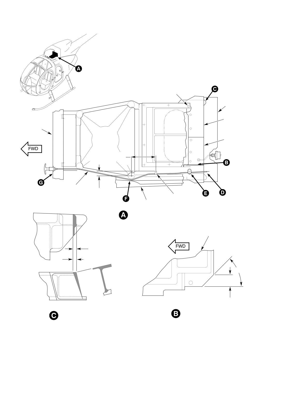
CSP-HMI-2
MD Helicopters, Inc.
MAINTENANCE MANUAL
0.250 IN. (6.35 MM) DIA. HOLE
TO MATE WITH EXISTING
NUTPLATES (6 PLCS)
PARTICLE SEPARATOR
RIGHT FAIRING
MAP CASE
LEFT FAIRING
5.55-5.68 IN.
(14.097-14.4272 CM)
FORWARD CABLE
5.55-5.68 IN.
(14.097-14.4272 CM)
RIVNUT, CLAMP,
ENGINE INLET
SCREW, WASHER
FAIRING
TOP VIEW LOOKING DOWN
ENGINE AIR COOLING
INLET SCREEN
GRIND OFF SHADED AREA IN
SEPARATOR INTERFERES WITH FITTING
0.25 IN.
(6.35 MM)
45° ANGLE
1.00 IN.
(2.54 CM)
ENGINE AIR COOLING INLET
MAST SUPPORT FITTING
SCREEN MODIFICATION
G71-1008-1A
Figure 903. Handle and Forward Cable Installation (Sheet 1 of 3)
Page 908
Revision 22
71-10-10
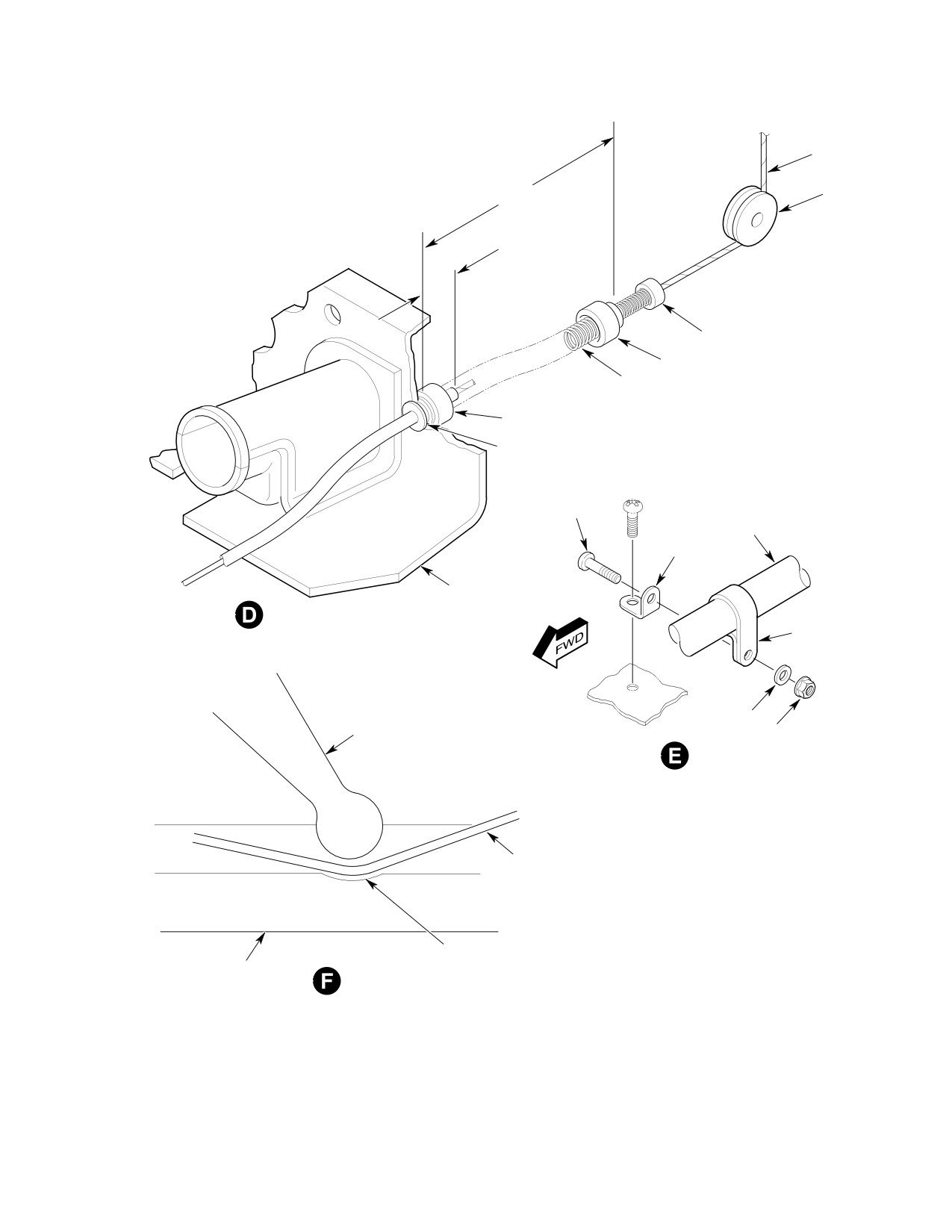
MD Helicopters, Inc.
CSP-HMI-2
MAINTENANCE MANUAL
CABLE
6.56-6.80 IN. (16.6624-17.272 CM)
PULLEY
0.88-1.12 IN.
(22.352-28.448 MM)
CABLE CONNECTOR
RETAINER
SPRING
RETAINER
GROMMET
SCREW
CABLE
CLIP
LEFT FAIRING
CLAMP
WASHER
MAST SUPPORT
NUT
CABLE HOUSING
0.12 IN. (3.048 MM) DIA.
FAIRING
CLEARANCE
G71-1008-2A
Figure 903. Handle and Forward Cable Installation (Sheet 2 of 3)
Page 909
71-10-10
Revision 22
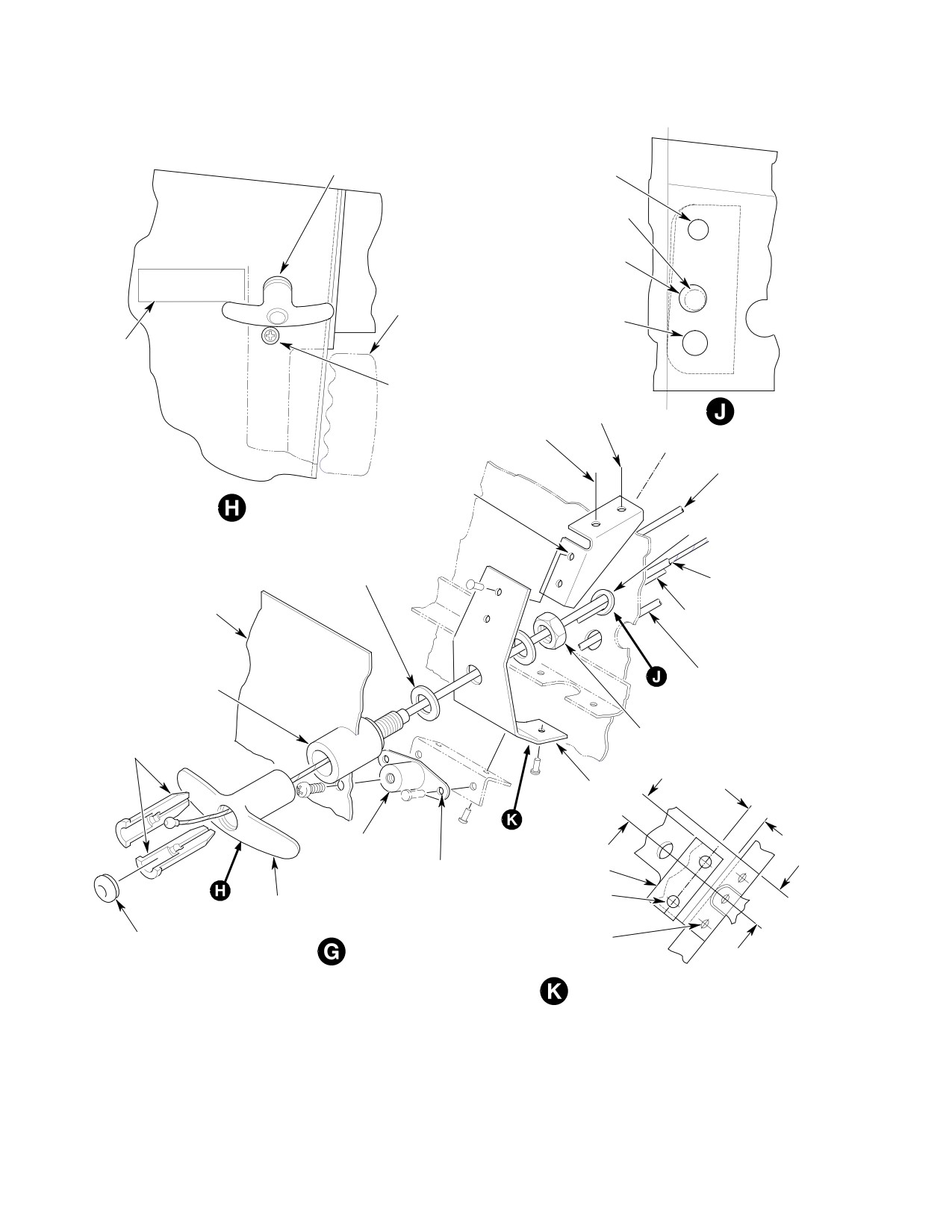
CSP-HMI-2
MD Helicopters, Inc.
MAINTENANCE MANUAL
0.70 IN. (17.78 MM) DIA. HOLE
IN TRIM PANEL TO MATCH
TORQUE GAGE
CABLE FITTING
TUBE (REF)
OIL PRESSURE TUBE
ENLARGE HOLE TO 0.42 IN.
(10.668 MM) DIA.,
INSTALL GROMMET
FILTER BY-PASS CONTROL
PULL HANDLE FWD
OPTIONAL ROTOR
BRAKE HANDLE (REF)
HEATER CONTROL
CABLE
DECAL
0.22 IN. (5.588 MM) DIA.
HOLE IN TRIM PANEL TO
EXISTING RIVET
MATCH SHOCK MOUNT
LOCATION
0.096 IN. (2.4384 MM)
DIA. HOLE (8 PLCS)
CANTED STA. 78.50
0.22 IN. (5.588 MM)
TORQUE GAGE TUBE
RIVET EDGE
OPTIONAL ROTOR
(REF)
DISTANCE (TYP)
BRAKE COVER (REF)
MAP CASE OR OPTIONAL
ROTOR BRAKE COVER
GROMMET
WASHERS, AS REQUIRED, TO
ADJUST HANDLE PROTRUSION
FORWARD CABLE
MAP CASE OR OPTIONAL
ROTOR BRAKE COVER
OIL PRESSURE
SENDER TUBE (REF)
CABIN HEAT CONTROL
CABLE END FITTING
CABLE (REF)
NUT
RETAINER HALVES
0.44 IN.
(11.176 MM)
BRACKET
SHOCK MOUNT
0.73 IN. (18.542 MM)
0.096 IN. (2.4384 MM)
ANGLE
DIA. HOLE (2 PLCS)
RIVET (2 PLCS)
BYPASS DOOR
HANDLE
0.28 IN. (7.112 MM) RIVET EDGE
BUTTON
DISTANCE (TYP), PICK UP EXISTING
RIVET LOCATIONS
0.95 IN.
(24.13 MM)
HANDLE SUPPORT BRACKET INST
G71-1008-3A
Figure 903. Handle and Forward Cable Installation (Sheet 3 of 3)
Page 910
Revision 22
71-10-10
MD Helicopters, Inc.
CSP-HMI-2
MAINTENANCE MANUAL
(2).
Install special three-port elbow and
(2). Attach one end of compressor bleed air
O-rings with existing fasteners. Torque
tube to special three-port elbow. Torque
three-port elbow flange self-locking
tube nut to 110 - 130 inch-pounds
nuts up to 18 inch-pounds (2.03 Nm).
(12.43 - 14.69 Nm).
Install cabin heat control valve. Torque
(3). Bolt solenoid valve to bracket. Attach
nuts to 20 - 25 inch-pounds (2.26 -
free end of bleed air tube assembly to
2.82 Nm).
solenoid valve. Torque tube nut to 110 -
(3).
Install universal elbow, O-ring and
130 inch-pounds (12.43 - 14.69 Nm).
jamnut on engine compressor scroll.
Do not scratch or gouge firewall
Torque jamnut to 145 - 155 inch-
CAUTION
surface when trimming heat
pounds (16.38 - 17.51 Nm) (Ref.
shield.
Figure 905).
(4).
Mark solenoid valve bracket position on
(4).
Install tee, jamnut and O-ring on
firewall heat shield pad. Remove
compressor diffuser duct. Torque tee
bracket, valve and tube. Cut an 0.125
jamnut to 285 - 315 inch-pounds
inch (3.175 mm) oversize opening
(32.20 - 35.59 Nm).
through heat shield pad for the valve
mounting bracket.
(5).
Install hose assembly between elbow
and tee. Torque hose nuts to 150 - 250
(5).
Drill and deburr valve bracket rivet
inch-pounds (16.95 - 28.25 Nm).
holes.
(6).
Install cover, spacer and gaskets on
(6).
Install bracket on firewall with six
special three-port elbow with bolts,
rivets.
washers and nuts.
(7).
Mount solenoid valve on bracket.
(7).
Loosely install special three-port elbow
Torque valve mounting bolts to 20 - 25
on canted firewall with bolts, washers
inch-pounds (2.26 - 2.82 Nm).
and nuts.
(8).
Install scavenge air tube between the
valve and elbow. Torque tube nuts 110 -
(8).
Install nut and O-ring on 0.750 inch
130 inch-pounds (12.43 - 14.69 Nm).
(19.05 mm) universal elbow and install
in three-port elbow. Torque three-port
(9).
Install elbow on scavenge air line
elbow flange self-locking nuts up to 18
support bracket (Ref. Figure 904, view
inch-pounds (2.03 Nm). Torque
G-G) with one washer on each side.
universal elbow jamnut 285 - 315
Install and torque jamnut to 120 - 150
inch-pounds (32.20 - 35.59 Nm).
inch-pounds (13.56 - 16.95 Nm).
(9).
Install engine (Ref. Sec. 71-00).
(10).
Trim away up to 0.050 inch (1.270 mm)
of bracket outboard edge to clear
(10).
Install tube assembly between firewall
intersecting angle and rivet heads.
mounted universal elbow and tee-fit
Install support assembly on shelf with
ting. Torque tube nuts to 460 - 500
washers and screws.
inch-pounds (51.97 - 56.49 Nm).
(11).
Locate scavenge air line elbow doubler
F. Scavenge Air System Installation
on plenum chamber bulkhead. Fasten
doubler to structure with rivets.
(Ref. Figure 905)
(12).
Install elbow, washer and nut on
(1). The scavenge air system consists of a
doubler. Torque elbow jamnut to 120 -
solenoid air valve, tubes, air pressure
150 inch-pounds (13.56 - 16.95 Nm).
switch, SCAV AIR circuit breaker
switch, AIR FILTER CLOGGED
(13).
Install upper scavenge air tube between
caution light, wiring, and attaching
elbows. Torque tube nuts 110 - 130
hardware.
inch-pounds (12.43 - 14.69 Nm).
Page 911
71-10-10
Revision 22
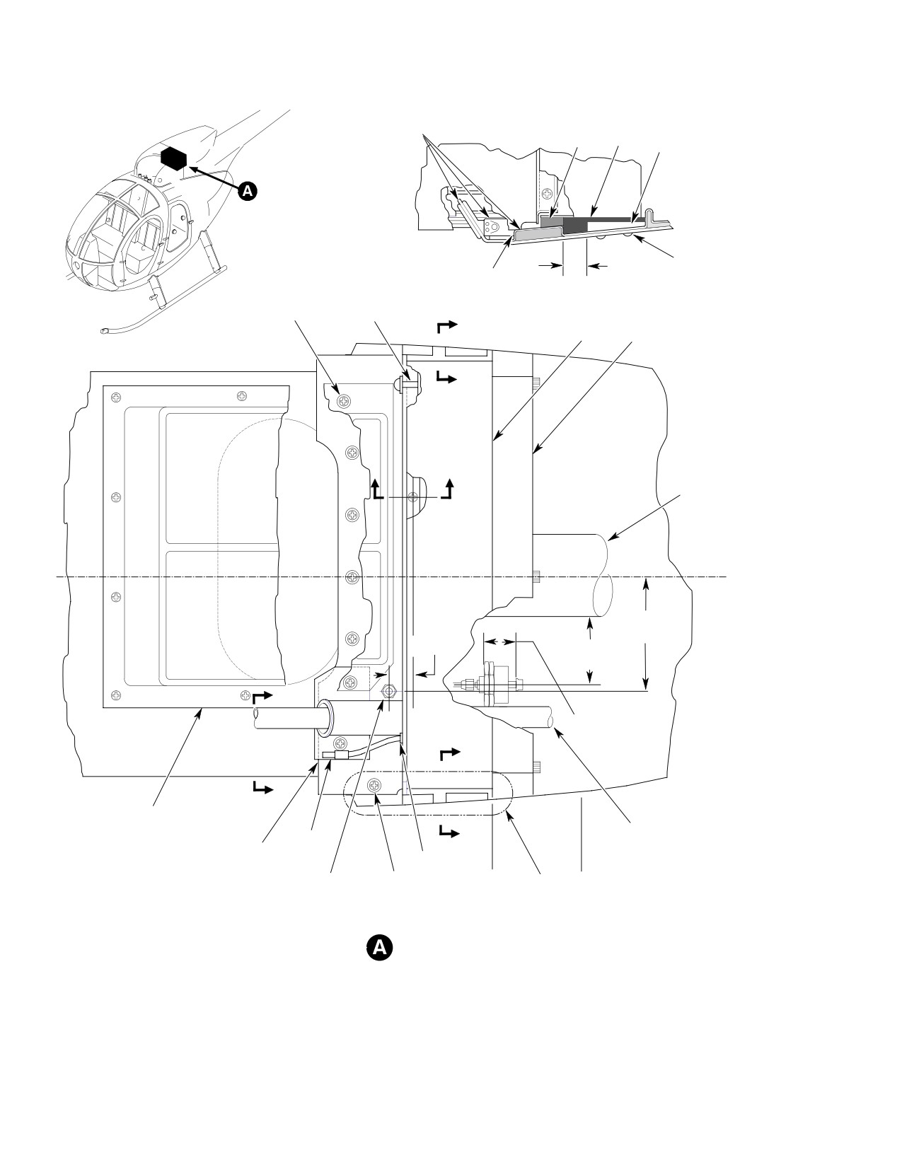
CSP-HMI-2
MD Helicopters, Inc.
MAINTENANCE MANUAL
SEALING COMPOUND
(NOTE 6)
SEAL
(NOTE 7) SEAL
SUPPORT
RIVET (2 REQD)
0.84 IN.
TRIM
(21.336 MM)
SCREW,
(NOTE 8)
A
DETAIL
WASHER SCREW, WASHER
(NOTE 1)
SPACER
A
PARTICLE
SEPARATOR MIST ELIMINATOR
A
B
B
TAIL ROTOR SHAFT
TUNNEL (REF)
C
L
5.21 IN.
1.11 IN.
(13.2334 CM)
(2.8194 CM)
2.94-3.06 IN.
(7.4676-7.7724 CM)
D
1.36-1.48 IN.
(3.4544-3.7592 CM)
C
D
SCREEN
C
TAIL ROTOR PITCH
BYPASS
CONTROL ROD (REF)
FAIRING ASSY DOOR
GROMMET
CABLE
0.39 IN. (9.906 MM)
SCREW,
STA.
STA.
SEE
DIA. HOLE THRU
WASHER
127.00
131.00
DETAIL
FAIRING
(NOTE 2)
A
TOP VIEW
G71-1009-1A
Figure 904. Modifications and Installation (Sheet 1 of 4)
Page 912
Revision 22
71-10-10
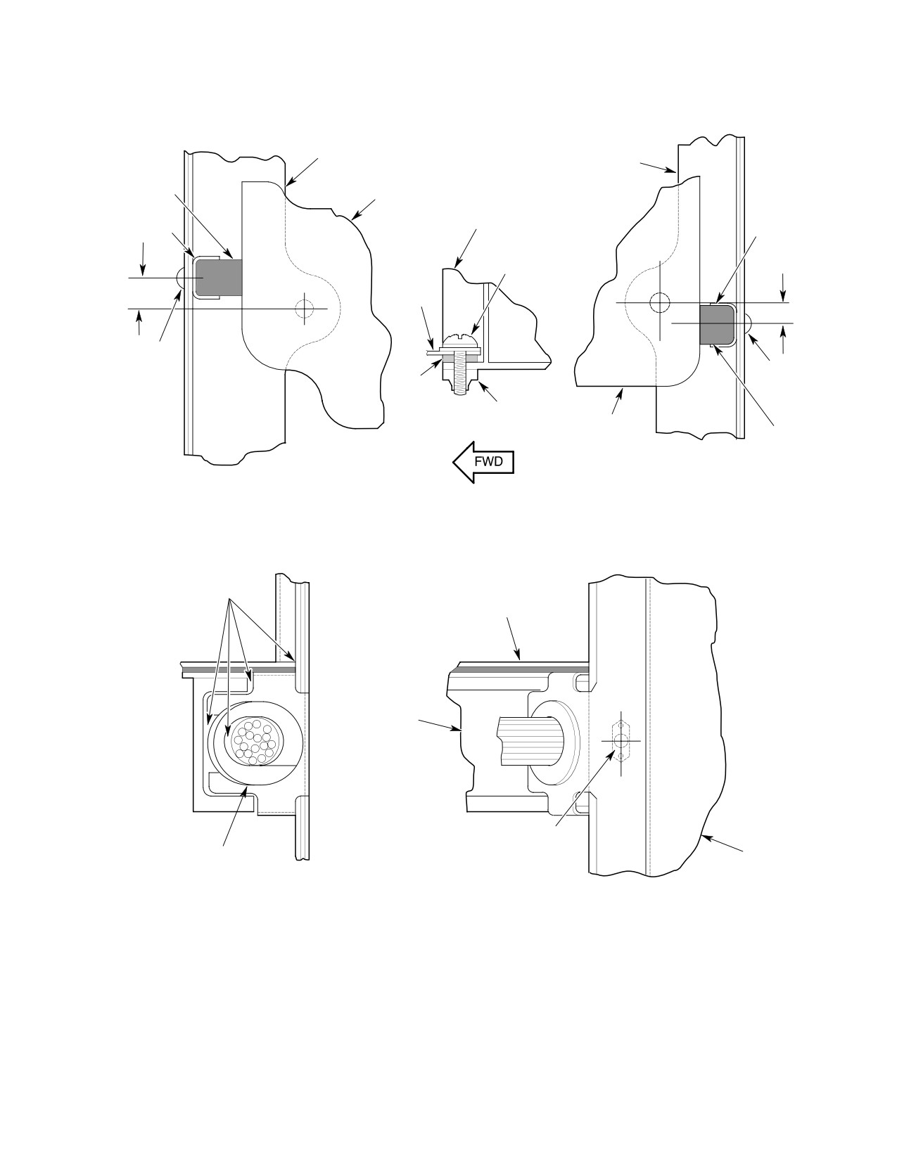
MD Helicopters, Inc.
CSP-HMI-2
MAINTENANCE MANUAL
PARTICLE SEPARATOR
PARTICLE SEPARATOR
MOUNTING FRAME
MOUNTING FRAME
SEAL
PARTICLE SEPARATOR
(NOTE 3)
(REF)
FORWARD FLANGE,
PARTICLE SEPARATOR
SUPPORT
SUPPORT
SCREW,
WASHER
0.43 IN.
(10.922 MM)
FAIRING
0.31 IN. (7.874 MM)
DRILL FAIRING
TO MATCH
DRILL FAIRING
SUPPORT
SEAL
TO MATCH
SUPPORT
NUTPLATE
PARTICLE
SEPARATOR
SEAL
(NOTE 3)
A-A
B-B
C-C
SECTION
SECTION
SECTION
SEALING COMPOUND
(NOTE 6)
FAIRING
MAST SUPPORT
FITTING
0.250 IN. (6.35 MM)
DIA. HOLE
GROMMET
INLET FAIRING
(NOTE 4)
(NOTE 5)
VIEW
D-D
G71-1009-2A
Figure 904. Modifications and Installation (Sheet 2 of 4)
Page 913
71-10-10
Revision 22
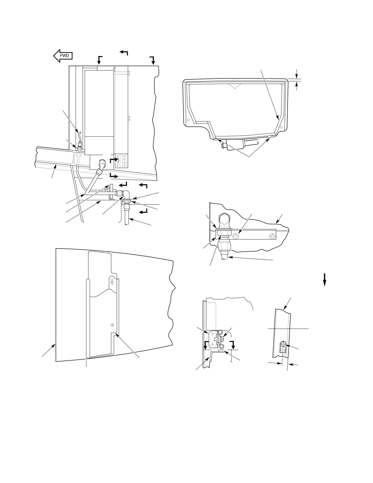
CSP-HMI-2
MD Helicopters, Inc.
MAINTENANCE MANUAL
E
F
F
TAPE
(NOTE 9)
TUBE ASSY,
0.38 IN.
TORQUE TO
(9.652 MM)
25-35 IN. LB
(2.82-3.95 NM)
UNION, WASHERS,
JAMNUT, TORQUE
TO 65-80 IN. LB
(7.34-9.04 NM)
H
MIST ELIMINATOR
MOUNTING CLIPS
E- E
H
VIEW
MAST SUPPORT
E
G
FITTING (REF)
SUPPORT
SCREW,
TUBE ASSY
TRIM
WASHER
WASHER,
(NOTE 12)
SUPPORT
G
(NOTE 10)
SWITCH ASSY
WASHER,
NUT
ELBOW
ENGINE INLET
SCAVENGE AIR
ASSY (REF)
TUBE ASSY
SIDE VIEW
TRIM
(NOTE 11)
TUBE, TORQUE TO
G - G
110-130 IN. LB
VIEW
JAMNUT, TORQUE TO
FWD
(12.43-14.69 NM)
120-150 IN. LB
(13.56-16.95 NM)
INLET FAIRING
(REF)
MAST SUPPORT
(REF)
SCREW,
CLIP
CLAMPS
(REMOVE)
(REMOVE)
STA.
127.00
J
J
BASE,
RIVET
INLET
MIST ELIMINATOR
BASE,
0.38-0.50 IN.
FAIRING
ACCESS PANEL
RIVET
(9.652-12.7 MM
(REF)
STA.
MAST SUPPORT
(INSTALL)
127.00
F- F
VIEW
H- H
VIEW
J - J
(REF)
VIEW
(RH SIDE ONLY)
G71-1009-3A
Figure 904. Modifications and Installation (Sheet 3 of 4)
Page 914
Revision 22
71-10-10
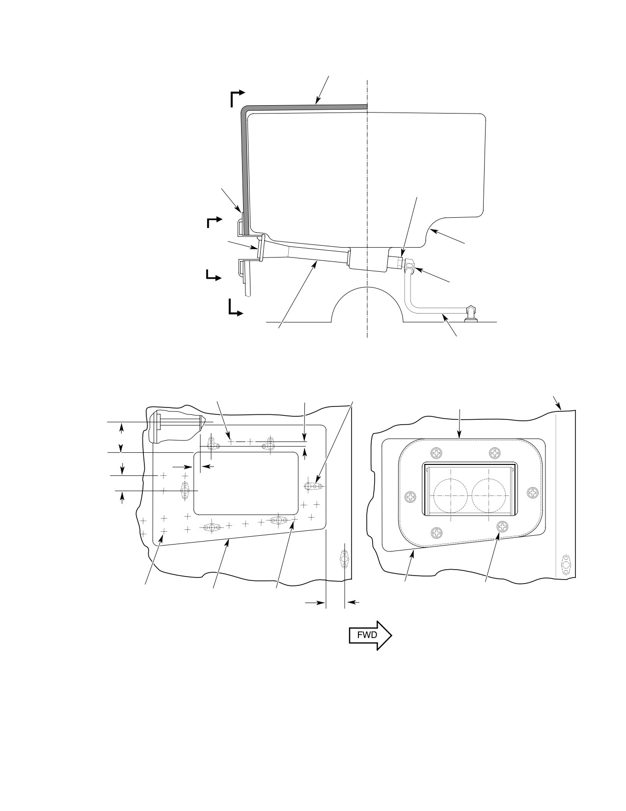
MD Helicopters, Inc.
CSP-HMI-2
MAINTENANCE MANUAL
FAIRING
K
JAMNUT, TORQUE
DOUBLER
TO 240-280 IN. LB
(27.12-31.64 NM)
L
FLAPPER VALVE
PARTICLE SEPARATOR
L
ELBOW, FITTING,
O-RING, NUT
K
EJECTOR
TUBE, TORQUE
VIEW LOOKING AFT
TO 110-130 IN. LB
(12.43-14.69 NM)
NUTPLATES, RIVETS
RIVET (2 PLCS)
0.16 IN.
(6 PLCS), FAR SIDE
FAIRING
(NOTE 14)
(4.064 MM)
(NOTE 13)
DUCT
1.13 IN. (2.8702 CM)
0.33 IN.
(8.382 MM)
0.63 IN.
(16.002 MM)
(TYP)
DOUBLER
SCREW, WASHER
RIVET
DOUBLER
RIVET
(6 PLCS)
(NOTE 15)
(NOTE 16)
(NOTE 15)
0.63-0.69 IN.
(16.002-17.526 MM)
VIEW
k-k
VIEW
L-l
LOOKING INBOARD
LOOKING INBOARD
G71-1009-4A
Figure 904. Modifications and Installation (Sheet 4 of 4)
Page 915
71-10-10
Revision 22
CSP-HMI-2
MD Helicopters, Inc.
MAINTENANCE MANUAL
Legend (Ref. Figure 904)
1.
0.250 IN. (6.35 MM) DIAMETER HOLE THROUGH
9.
IF INSTALLING MIST ELIMINATOR; APPLY 0.125 IN.
FAIRINGS TO MATCH EXISTING NUT−PLATE
(3.175 MM) THICK BY 0.380 IN. (9.652 MM) WIDE
LOCATION.
PRESSURE SENSITIVE TAPE (CM728) OR
2.
0.250 IN. (6.35 MM) DIAMETER HOLE THROUGH
EQUIVALENT TO PARTICLE SEPARATOR PRIOR TO
INSTALLATION.
FAIRING TO MATCH LOWER FAIRING ASSEMBLY
10.
USE EXISTING NUT−PLATES.
NUT−PLATE LOCATION; LEFT AND RIGHT SIDES.
11.
TRIM SUPPORT AS REQUIRED TO CLEAR RIVET
3.
INSTALL SEAL AFTER SUPPORT INSTALLATION.
HEADS.
4.
DRILL 0.250 IN. (6.35 MM) DIAMETER HOLE
12.
TRIM OUTBOARD EDGE OF SUPPORT 0.050 IN.
THROUGH FAIRING ASSEMBLY TO MATCH EXISTING
(1.270 MM), MAXIMUM, TO CLEAR ANGLE.
NUT−PLATE LOCATION.
13.
DRILL 0.217−0.229 IN. (5.5118−5.8166 MM) DIAMETER
5.
SPLIT GROMMET ON TANGENT SHOWN PRIOR TO
SCREW HOLES TO MATCH DOUBLER HOLES.
INSTALLATION.
14.
EQUALLY SPACE RIVETS BETWEEN NUT−PLATES.
6.
APPLY SEALING COMPOUND (CM430) TO ALL
15.
PICK UP EXISTING RIVET LOCATIONS.
OPENINGS AND GAPS.
16.
CUT HOLE THROUGH AFT FAIRING TO MATCH
7.
ALIGN BOTTOM EDGES OF SEALS.
DOUBLER. BOND DOUBLER TO EXTERIOR FAIRING
8.
TRIM LOWER FAIRING AS REQUIRED TO CLEAR AFT
SURFACE WITH ADHESIVE (CM410) PER
FAIRING STRUCTURE.
MANUFACTURERS INSTRUCTIONS.
(14).
Install tee on solenoid air valve. Install
(2).
Install varistor across connector P206
cap on tee.
pins A and B (Ref. Figure 103, detail A).
Solder (CM815) connections per
(15).
Install tube assembly between solenoid
standard shop practices.
valve tee and elbow. Torque tube nuts
110 - 130 inch-pounds (12.43 - 14.69
(3).
Connect wire P17D20N to solenoid
Nm).
valve connector P206 pin B and ground
lug E45 with washers and nut.
(16).
Install scavenge air tube clamp support
bracket, spacer, clamp, screws, wash
(4).
Solder wire P16C20 to connector P206,
ers, and nuts (Ref. Figure 905, detail
pin A.
C).
(5).
Route solenoid air valve wire harness
(17).
Clamp tube assembly to air duct with
through airframe (Ref. Figure 907).
clamps, screw, washers and nut (Ref.
(6).
Install wire harness, part number
Figure 905, detail B).
369A4163 as follows:
G. Solenoid Valve and Pressure Switch Wire
(7).
Solder varistor between pins A and B of
Harness Installation
connector P206 (Ref. Figure 103, detail
A).
Consumable Materials
(8).
Route wire harness through airframe
(Ref. Section 91−00−00)
Item
Nomenclature
(Ref. Figure 907).
CM815
Solder
(9).
Connect wire P17A20N to ground lug
E45.
NOTE: If using prefabricated wire harness,
(10).
Splice solenoid valve wire P16D20 to
part number 369A4163, go to step (6). If not
airframe wire P16C20.
using prefabricated wire harness, proceed
as follows:
(11).
Determine correct pressure switch wire
length. Trim wires as required.
(1). Do not clamp wiring until routing and
connections are complete. Install wires
(12).
Install knife splice halves on pressure
per FAA publication, EA-AC43.13-1A
switch pigtails. Install knife splice
and 2A. Where possible, route added
halves on airframe wires P16G22 and
wiring along existing wire harness.
P16H22N.
Page 916
Revision 22
71-10-10
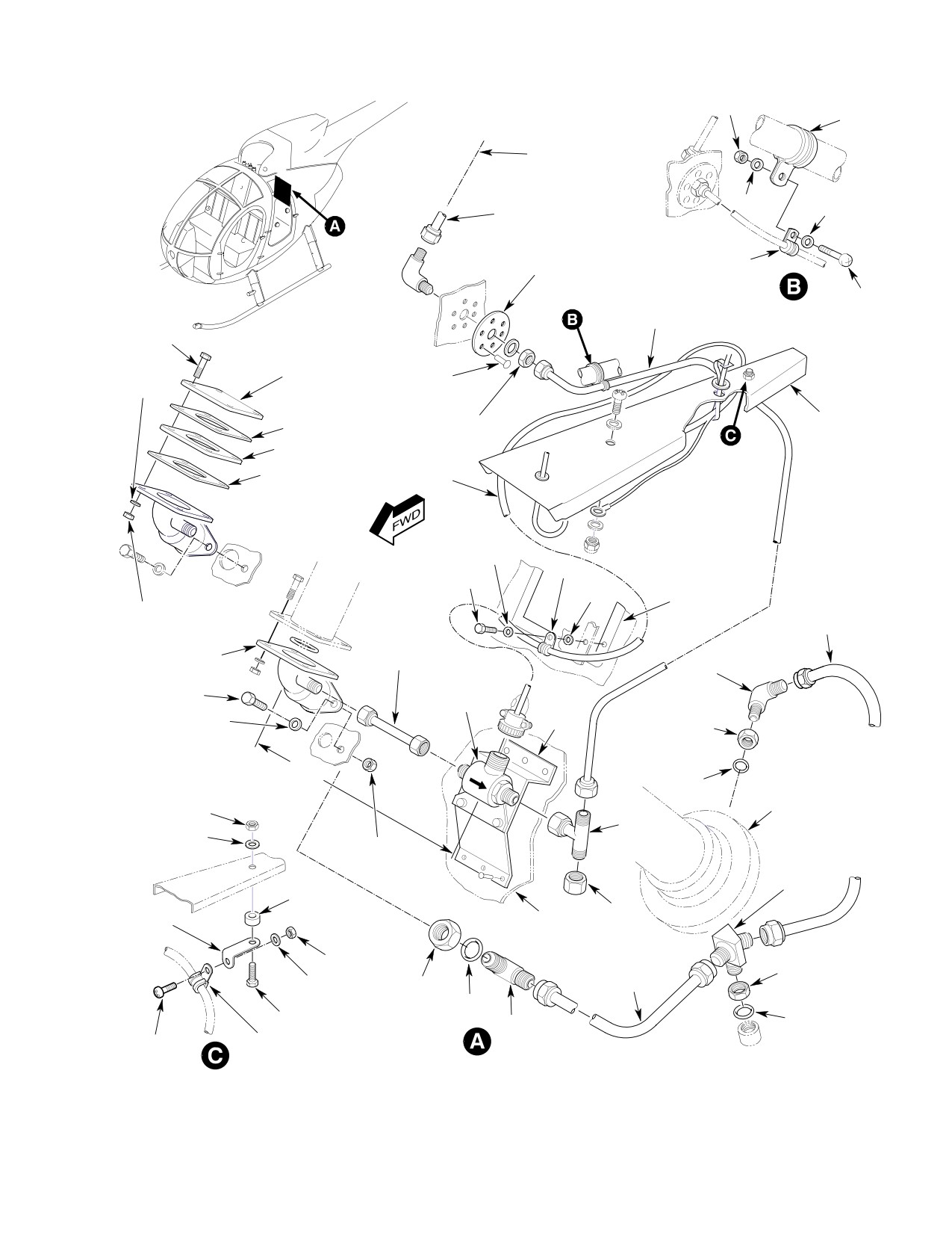
MD Helicopters, Inc.
CSP-HMI-2
MAINTENANCE MANUAL
NUT
CLAMP
TO EJECTOR
NOZZLE (REF)
WASHER
WASHER
TUBE ASSY
DOUBLER
CLAMP
(NOTE 1)
TUBE ASSY, TORQUE
TO 110-130 IN. LB
SCREW
(12.43-14.69 NM)
(NOTE 4)
BOLT
COVER
RIVET
WASHER
(6 PLCS)
NUT, TORQUE TO
STRINGER
GASKET
120-150 IN. LB
SPACER
(13.56-16.95 NM)
GASKET
WIRE HARNESS
WASHER
CLAMP
TRANSMISSION
BOLT
OIL COOLING
WASHER
HOSE ASSY, TORQUE
DUCT (REF)
NUT, TORQUE
TUBE ASSY,
TO 150-250 IN. LB
TO 20-25 IN. LB
TORQUE TO
(16.95-28.25 NM)
(2.26-2.82 NM)
110-130 IN. LB
(12.43-14.69 NM)
ELBOW
(NOTE 2)
ELBOW
SOLENOID
BRACKET
BOLT
VALVE
ASSY
NUT, TORQUE TO
WASHER
(NOTE 2)
145-155 IN. LB
(16.38-17.51 NM)
5.65 IN. (14.351 CM)
O-RING
ENGINE
COMPRESSOR
NUT
SCROLL (REF)
TEE
WASHER
NUT, TORQUE
TO 18 IN. LB
(2.03 NM)
TEE
SPACER
BRACKET
CAP
HEAT SHIELD
(NOTE 3)
PAD (NOTE 2)
NUT
TUBE, TORQUE TO
NUT, TORQUE TO
460-500 IN. LB
285-315 IN. LB
WASHER
NUT, TORQUE TO
(51.97-56.49 NM)
(32.20-35.59 NM)
285-315 IN. LB
O-RING
SCREW
(32.20-35.59 NM)
ELBOW
O-RING
SCREW
CLAMP
G71-1010A
Figure 905. Scavenge Air Equipment Installation
Page 917
71-10-10
Revision 22
CSP-HMI-2
MD Helicopters, Inc.
MAINTENANCE MANUAL
Legend (Ref. Figure 905)
1. LOCATE DOUBLER ON PLENUM CHAMBER WALL AT
2. BOLT SOLENOID VALVE TO MOUNTING BRACKET.
THE INTERSECTIONS OF STA. 126.25 AND W/L 52.50.
ATTACH TUBE BETWEEN VALVE AND ELBOW TO
CENTER DOUBLER ON A POINT 1.50 IN. (3.81 CM)
LOCATE VALVE ASSEMBLY ON FIREWALL. TRIM
BELOW PLENUM CHAMBER ANGLED FLOOR PAN.
AWAY HEAT SHIELD PAD BENEATH BRACKET PRIOR
DRILL ONE 0.578 IN. (14.6812 MM) DIAMETER HOLE
TO RIVETING BRACKET TO FIREWALL.
THROUGH CENTER. DRILL SIX EQUALLY SPACED
3. USE EXISTING STRINGER TOOLING HOLE.
RIVET HOLES AROUND DOUBLER. MAINTAIN A 0.220
4. HAND FORM AS REQUIRED TO CLEAR
IN. (5.588 MM) MINIMUM RIVET EDGE DISTANCE.
STRUCTURES.
NOTE: Ensure electrical continuity and mini
(5). Cut hole in aft engine inlet fairing to
mum resistance between ground wire
match hole in doubler.
P16H22N and airframe.
(6). Bond rib in position (Ref. Figure 906).
(13). Connect either switch pigtail to air
(7). Drill six holes through fairing to match
frame wire P16G22. Connect remaining
holes in doubler, Install nut-plates and
lead to airframe ground wire P16H22N.
rivets (Ref. Figure 904, view K-K).
(14). Install clamps and ty-raps.
(8). Install ejector duct (Ref. Figure 904,
view L-L) with screws and washers.
(15). Refer to Instrument Panel Modifica
tions; T-Pedestal or Slimline Panel
I. Particle Separator Installation
Modification for crew compartment
wiring information.
Consumable Materials
(16). Vacuum all debris from work area.
(Ref. Section 91−00−00)
Item
Nomenclature
(17). Inspect all tube connections for correct
CM106
Fluorocarbon dry lubricant
torque values. Inspect all components
CM112
Anti-seize compound high temperature
and attaching hardware for correct
CM234
Solvent, dry-cleaning
installation and security.
CM405
Adhesive
H. Ejector Duct Doubler and Rib Installation
CM425
Sealing compound
CM430
Sealant, solvent resistant
Consumable Materials
(Ref. Section 91−00−00)
(1). Position particle separator inside
Item
Nomenclature
engine air inlet aft fairing. Coat
CM418
Cement, epoxy
mounting bolt threads with anti-seize
compound (CM112).
NOTE: Doubler is required for all installations.
(a). Temporarily attach separator to
Rib installation is required for helicopters
mount boss with bolts and washers.
not equipped with 369A3053-505, -507, or
Stack washers under right bolt head
-509 engine inlet fairing assemblies.
as necessary. Check fit.
(1). Drill out required rivets (Ref.
NOTE: Do not grind mast support fitting un
Figure 904, view K-K and Figure 906).
less particle separator cannot be installed
due to interference with fitting.
(2). Locate and bond doubler to fairing
exterior with adhesive (CM418).
(2). Remove particle separator and grind
material from corner of mast support
(3). Install rivets through doubler and
fitting (Ref. Figure 903, detail C).
fairing.
(3). Drill 0.250 inch (6.35 mm) diameter
(4). Back-drill from inside of engine inlet
holes through horizontal fairings to
fairing through existing rivet holes and
match auxiliary fairing nut-plates (Ref.
doubler.
Figure 904, Sheet 1).
Page 918
Revision 22
71-10-10
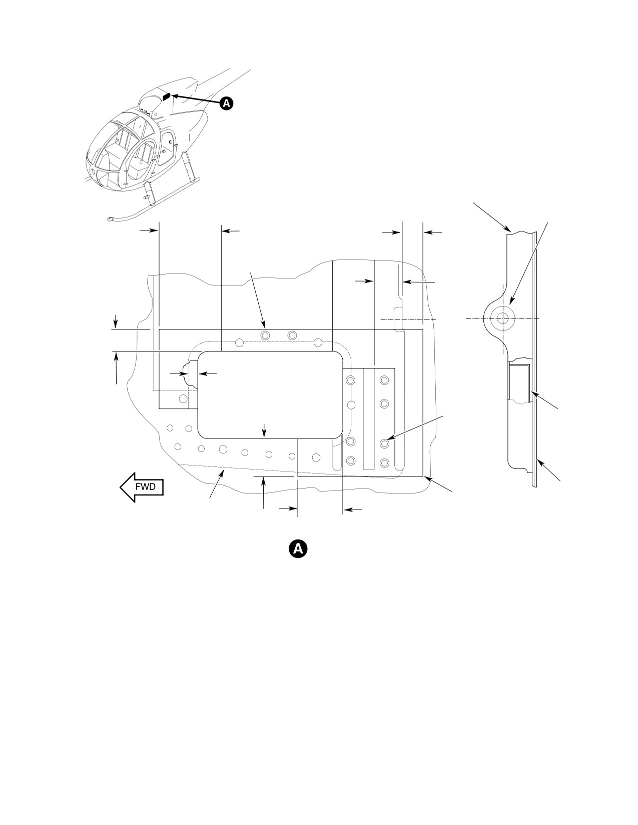
MD Helicopters, Inc.
CSP-HMI-2
MAINTENANCE MANUAL
PARTICLE SEPARATOR
TRIM FIBERGLASS
MOUNTING FRAME
CLOTH TO PREVENT
OVERLAP INTO
1.19-1.44 IN.
0.50-0.75 IN.
COUNTERBORE
(3.0226-3.6576 CM)
(12.7-19.05 MM)
RIVET, WASHER
(2 PLCS)
0.75 IN.
(19.05 MM)
0.63-0.88 IN.
(16.002-22.352 MM)
OVERLAP
(NOTE 4)
RIVET,
1.03-1.25 IN.
WASHER
RIB
(2.6162-3.175 CM)
(7 PLCS)
(NOTE 1, 2)
FAIRING
FIBERGLASS CLOTH
DOUBLER
(NOTE 3)
1.13-1.25 IN.
(FAR SIDE)
(2.8702-3.175 CM)
EJECTOR DUCT OPENING
LOOKING OUTBOARD
NOTES:
1.
RIB INSTALLATION ONLY REQUIRED FOR HELICOPTERS NOT EQUIPPED
WITH 369A3053-505, -507 OR -509 ENGINE INLET FAIRING ASSEMBLY.
INSTALL RIB AND FIBERGLASS CLOTH PRIOR TO INSTALLING NUTPLATES
AND NUTPLATE RIVETS.
2.
BOND RIB TO FAIRING WITH ADHESIVE (CM410) PER MANUFACTURERS
INSTRUCTIONS.
3.
APPLY A MINIMUM OF TWO PLIES OF FIBERGLASS CLOTH (CM501) WITH
RESIN (CM506) OR EQUIVALENT PER MANUFACTURERS INSTRUCTIONS.
G71-1011A
4
FIBERGLASS CLOTH TO OVERLAP HOLE EDGE 0 09 0 19 IN (2 286 4 826 MM)
Figure 906. Ejector Duct Doubler Installation
Page 919
71-10-10
Revision 22
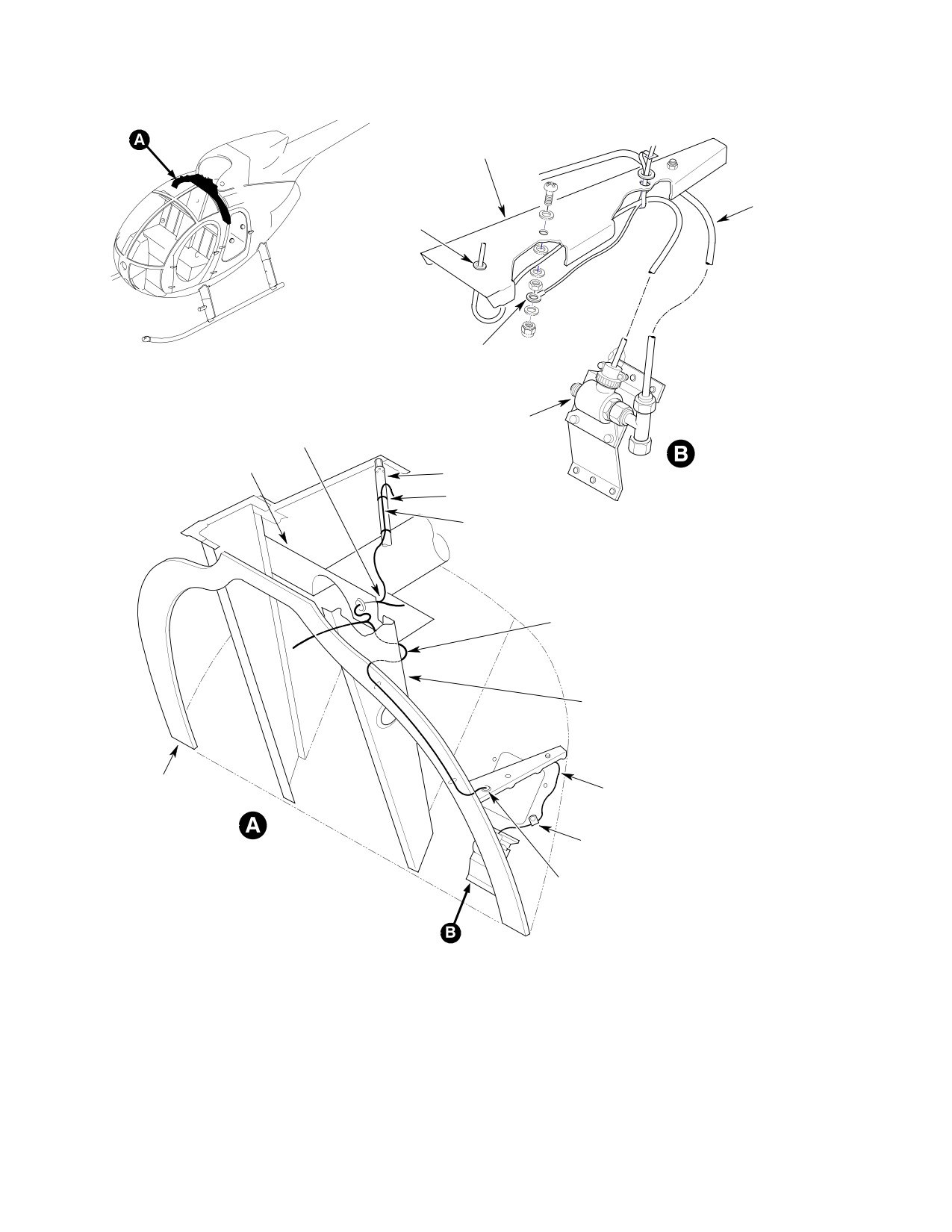
CSP-HMI-2
MD Helicopters, Inc.
MAINTENANCE MANUAL
STRINGER (REF)
TUBE (REF)
GROMMET
(NOTE 2)
GROUND
(E45)
SOLENOID
MAIN ROTOR WIRE
VALVE
HARNESS (REF)
ENGINE INLET ASSY
STRUT
STRAP
P16G22 WIRE
P16H22N WIRE TO
PRESSURE SWITCH
(NOTE 1)
P16C20 WIRE,
WASHER, STRAP
(NOTE 3)
CHANNEL ASSY (REF)
FRAME, CANTED
P16C20 WIRE
STA. 124.00
P17D20N WIRE
CLAMP
GROMMET
(NOTE 2)
NOTES:
1.
P16H22N WIRE FROM PRESSURE SWITCH
TO GROUND E15.
2.
INSTALL GROMMET IN EXISTING TOOLING
HOLE.
3.
SECURE WIRE TO FRAME USING WASHERS
AND STRAPS THROUGH EXISTING TOOLING
G71-1012
Figure 907. Wiring Harness Installation
Page 920
Revision 22
71-10-10
MD Helicopters, Inc.
CSP-HMI-2
MAINTENANCE MANUAL
(4). Drill 0.250 inch (6.35 mm) diameter
(11).
Install particle separator with washers
holes through auxiliary fairing vertical
and bolts.
plates to match aft inlet fairing nut-
(12).
Install scavenge air supply tube
plates (Ref. Figure 904, view D-D).
between ejector nozzle and shelf
NOTE: Do not install auxiliary fairings at this
mounted elbows. Torque ejector nozzle
time.
elbow jamnut 240 - 280 inch-pounds
(27.12 - 31.64 Nm). Torque tube nuts
(5). If installation does not include mist
110 - 130 inch-pounds (12.43 - 14.69
eliminator, install bolts and washers in
Nm).
the three lowest particle separator mist
(13).
Modify two grommets as shown (Ref.
eliminator attachment holes. Torque
Figure 904, view D-D). Install grom
bolts 20 - 25 inch-pounds (2.26 - 2.82
mets over left and right wire bundles.
Nm).
Insert left and right auxiliary fairing
(6). If installation includes mist eliminator,
assemblies into grommet grooves.
wipe rear surfaces of particle separator
Install screws and washers through
clean with dry cleaning solvent
auxiliary fairing vertical plates.
(CM234) on a clean cloth. Wipe dry.
(14).
Install pressure switch sensing tube
union on left fairing with one washer on
(7). Attach 0.125 inch (3.175 mm) thick by
each side of fairing. Torque union
0.380 inch (9.652 mm) wide pressure
jamnut 65 - 80 inch- pounds (7.34 -
sensitive seal tape to particle separator
9.04 Nm).
aft surface around mist eliminator
frame and fairing frame contact areas
(15).
Attach tail rotor control rod cover, if so
(Ref. Figure 904, view E-E).
equipped, to left fairing with existing
fasteners. Complete all fairing installa
(8). Install rubber seal (Ref. Figure 904,
tions.
section B-B) on the forward lower shelf
edge of the particle separator as
(16).
Install pressure switch. Torque pres
follows:
sure switch jamnut 65 - 80 inch-
pounds (7.34 - 9.04 Nm).
(a). Apply one heavy brush coat of
(17).
Install upper and lower pressure switch
adhesive (CM405) to seal and particle
tubes. Torque tube nuts to 25 - 35
separator joint surfaces. Let surfaces
inch-pounds (2.82 - 3.95 Nm).
dry 15 minutes.
(18).
Seal all gaps around auxiliary fairing
(b). Apply a second coat of adhesive.
installations with sealant (CM430)
Immediately press seal in place.
(Ref. Figure 904, view D-D).
Allow assembly to air dry a minimum
of eight hours.
(19).
Use existing screw to attach clip to
structure (Ref. Figure 903, detail E).
NOTE: Do not install mist eliminator support
Install clamp on cable with clip, screw,
channels if helicopter is not equipped with a
washer and nut.
mist eliminator access panel on top of the aft
fairing (Ref. Figure 904, view F-F).
(20).
Install cable return spring and retain
ers (Ref. Figure 903, detail D). Secure
(9). Install mist eliminator support chan
spring assembly with cable connector.
nels on particle separator lower aft face
(21).
Close and latch air bypass door.
with screws (Ref. Figure 904, view
Connect forward and aft cable sections.
E-E).
Distance between center of forward
(10). Install scavenge air line special elbow,
cable swaged ball terminal and aft face
O-ring and nut on particle separator
of fairing should be between 6.56 and
ejector assembly. Do not torque elbow
6.80 inches (16.662 and 17.272 cm) with
jamnut at this time (Ref. Figure 904,
no cable slack (Ref. Figure 903 detail
Sheet 4).
D).
Page 921
71-10-10
Revision 22
CSP-HMI-2
MD Helicopters, Inc.
MAINTENANCE MANUAL
(22).
On helicopters without mist eliminator
rod forward boot free length to between
access panel, remove air bypass door.
7.130 and 7.250 inches (18.1102 and
Spray 15 milliliters, total, of engine oil
18.4150 cm). Secure with ty-raps.
on mist eliminator front and rear
J. Instrument Panel Modifications;
surfaces. Insert mist eliminator,
T−Pedestal
forward face up, through bypass door
opening and move to engage nine mist
(1).
Do not install clamps or ty-raps on
eliminator mount bolts with particle
wiring until wiring installation is
separator. Start all bolts by hand.
complete. Install wires per FAA
Torque bolts to 20 - 25 inch-pounds
publication, EA-AC43.13-1A and 2A.
(2.82 - 3.95 Nm).
Where possible, route added wiring
along existing wire bundles.
(23).
Install door gasket on aft fairing with
adhesive (CM405) per manufacturers
(2).
Remove plug button from SCAV AIR
instructions.
switch panel hole.
(24).
For operation below 40°F (4.5°C), spray
(3).
Connect wire P514D20 between pin 1 of
door gasket and door edge with fluoro
SCAV AIR (CB15) circuit breaker
carbon dry lubricant (CM106).
switch and pin 1 of POS LT circuit
breaker switch CB119 (Ref.
(25).
Install air bypass door.
Figure 103).
(26).
Rig bypass door (Ref. Air Bypass Door
(4).
Connect wire P16MA20 (stowed inside
Rigging).
console) to pin 2 of CB15.
(27).
Apply sealing compound (CM425) to
(5).
Install SCAV AIR circuit breaker switch
door cable fitting cotter pin (Ref.
in panel.
Figure 902, detail E).
(6).
Remove third from right dummy block
(28).
On helicopters equipped with mist
from caution and warning light panel.
eliminator access panel disengage two
(7).
Connect stowed wires P514C20 to pin 2
1/4-turn fasteners and remove access
of light assembly and wire P514B20 to
panel (Ref. Figure 904, view F-F).
pin C.
(29).
Use locking pliers to pull while turning
(8).
Install AIR FILTER CLOGGED caution
nine mounting bolts, if so equipped, out
light assembly.
of mist eliminator frame. Discard bolts.
K. Slimline Panel Modification
(30).
Pass mist eliminator through access
opening into engagement with lower
(1). Use switch and light subpanel bracket
support channels. Hold mist eliminator
as a template. Locate and drill a 0.219
against particle separator and install
inch (5.5626 mm) diameter hole
access panel. Lock panel fasteners.
through instrument panel hood and left
fairing above existing hole.
(31).
Inspect mist eliminator installation
through bypass door opening. Check
(2). Cut a 0.50 inch (12.70 mm) wide slot,
that mist eliminator is firmly in
2.98 inches (7.5692 cm) long with full
position against particle separator.
radius at forward end in instrument
Adjust as required.
panel left fairing.
(32).
Remove mist eliminator and spray a
(3). On helicopters equipped with
total of 15 milliliters of clean engine oil
369H90022 anti-ice fuel filter (airframe
on front and rear surfaces. Reinstall
filter) installation; remove plug buttons
mist eliminator.
from AIR FILTER CLOGGED and
SCAV AIR subpanel positions. Wire and
(33).
Clamp tail rotor control pedals in
install switch and light (Ref.
mid-position. Adjust tail rotor control
Figure 103).
Page 922
Revision 22
71-10-10