HANDBOOK OF MAINTENANCE INSTRUCTIONS FOR MDHI 369D/E/FF-500/600N HELICOPTERS (ISSUED: 1990) - page 30
MD Helicopters, Inc.
CSP-HMI-2
MAINTENANCE MANUAL
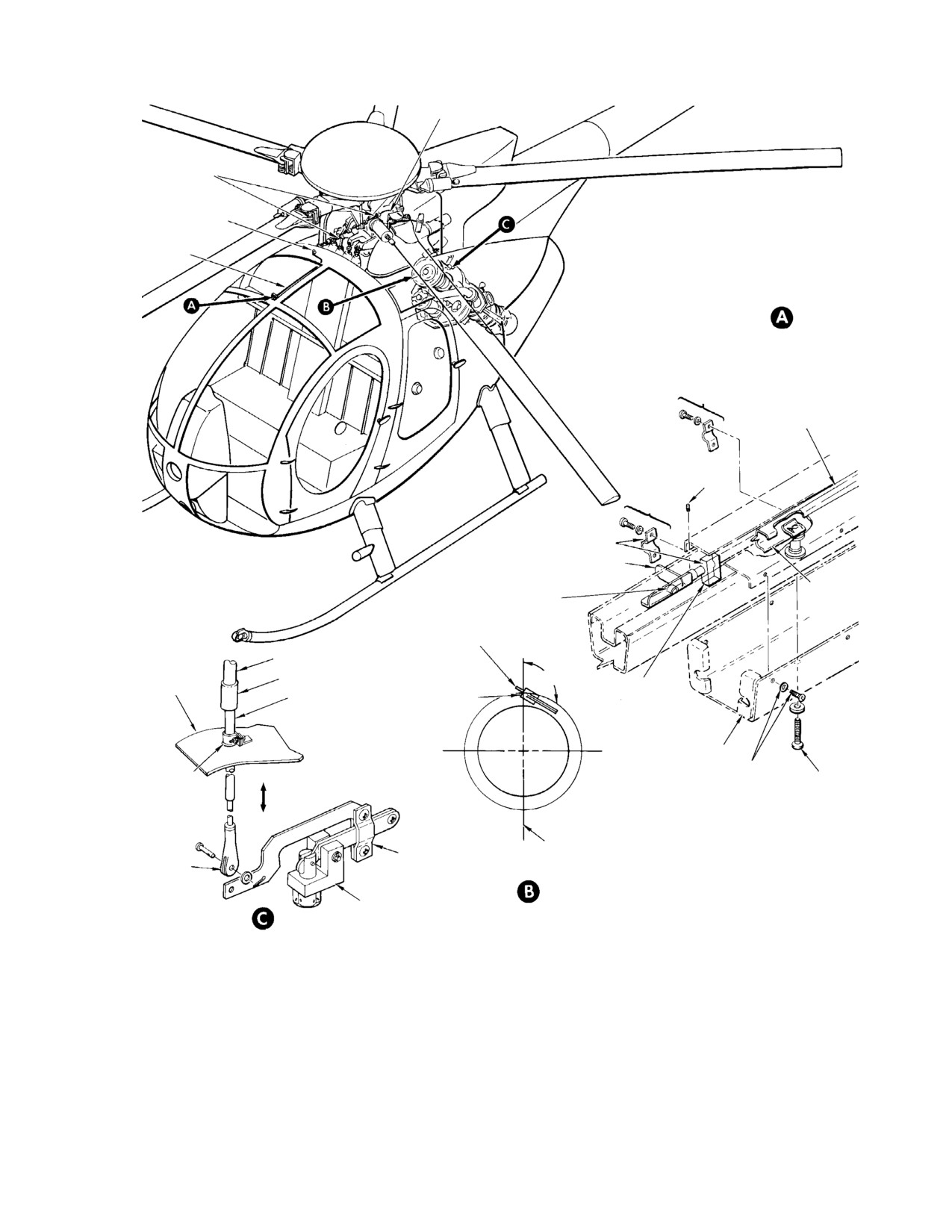
ENGINE ANTI−ICING SYSTEM
MAINTENANCE PRACTICES
1.
Engine Anti−Icing System Description and
handle in both ON and OFF positions.
Operation
There is no intermediate heat position.
(1). Compressor inlet guide vanes and the
(3). Model 250-C20/R2, 250-C30 and
front bearing hub are the only compo
250-C47 Engines: The engine installa
nents supplied anti-icing air on the
tions use an electrically controlled
helicopter engines.
anti-ice system. Compressor bleed air,
supplied to the inlet guide vanes and
the number one bearing housing, is
(2). Model 250-C20B Engines: The anti-ice
controlled by the ANTI-ICE circuit
system consist of a manually operated
breaker/switch, CB143 on the 369FF -
push-pull control cable, mechanical
500/600N, and CB122 on 369D/E
anti-icing valve, air distribution tubing
helicopters fitted with a 250-C20/R2
and, attaching hardware. The poppet-
engine. Moving the console mounted
type anti-icing valve is mounted on the
switch to ANTI-ICE de-energizes a
engine compressor scroll and controls
solenoid fastened to the engine heat
compressor bleed air used for engine
shield that controls the anti-icing
anti-icing. The control cable is as
system.
sembled of rigid and flexible sections
clamped along the right side of the
(4). Refer to the applicable Allison engine
overhead cabin heat duct. Moving the
manual for additional engine anti-ice
control handle forward opens the
information.
anti-icing valve. Control handle travel
is approximately 1.44 inches (3.66 cm)
from OFF to ON. A detent holds the
2. Engine Anti−Icing System Fault Isolation
Table 201. 250−C20B Engine Anti−icing System Fault Isolation
Symptom
Probable Trouble
Corrective Action
Anti−ice ON does not restore
System not rigged correctly.
Check rigging.
normal engine operation when
compressor icing occurs.
Lack of anti−icing air.
Defective anti−ice air lines.
Check engine air lines for leaks.
Anti−icing air valve stuck closed.
Replace valve.
Cable wire sheared.
Replace cable.
Cable clevis pin sheared or
Replace clevis pin.
missing.
Anti−ice OFF has no effect. Inflight
Anti−icing air valve stuck open.
Replace valve.
symptom is continuation of
Corroded, pinched or crushed
Replace cable.
approximately 10% reduction in
cable.
available power or torque.
Cable clevis pin sheared or
Replace clevis pin.
missing.
Cable wire sheared.
Replace cable.
Anti−ice air valve compres-
Loosen adapter nut. Torque nut to 10
sor scroll adapter nut
inch−pounds (1.13 Nm).
over−tightened.
Page 201
75-10-00
Revision 22

CSP-HMI-2
MD Helicopters, Inc.
MAINTENANCE MANUAL
Table 201. 250−C20B Engine Anti−icing System Fault Isolation
Symptom
Probable Trouble
Corrective Action
Anti−icing control drags or binds.
Control cable rigid sleeve kinked.
Check operation with cable clevis
One or more flexible cable section
disconnected from anti−ice valve lever.
bend radii less than 3 inch (7.62
Replace kinked or corroded cable.
cm) minimum.
Increase flexible cable bend radius.
Control handle creeps open or
ON−OFF detent−spring weak or
Replace detent−spring assembly.
closed.
broken.
Handle detent grooves worn or
Clean, repair or replace cable.
dirty.
Table 202. 250−C20/R2, 250−C30 and 250−C47 Engine Anti−icing System Fault Isolation
Symptom
Probable Trouble
Corrective Action
System ON fails to restore normal
Lack of anti−icing air.
Inspect air lines for leaks.
engine operation in compressor
Inoperative/defective anti−icing valve. Replace valve.
icing conditions.
Faulty switch or wiring.
Repair or replace switch/wiring as
required.
Switching anti−ice OFF has no
Anti−icing air valve stuck open.
Replace valve.
effect. Inflight symptom is
continuation of approximately 10%
reduction in available power or
torque.
3.
250−C20B Engine Anti−Icing Valve
B. 250−C20B Engine Anti−Icing Valve
Control Cable Replacement
Control Cable Installation
Consumable Materials
A. 250−C20B Engine Anti−Icing Valve
(Ref. Section 91−00−00)
Control Cable Removal
Item
Nomenclature
CM430
Sealant, solvent resistant
(1). Open engine access doors.
CM707
Tape, fastener
(2). Remove right half of engine air inlet
Do not kink cable rigid sleeve
CAUTION
forward fairing.
section.
(1). Position bulkhead hole grommet on
(3). Remove heater duct outer box attaching
rigid sleeve section.
hardware.
(2). Install Velcro tape (CM707) on mating
surfaces of forward clamp, and block.
(4). Remove clamps and straps attaching
(3). Route cable assembly through bulk
the control cable to structure.
head, flexible cable bend radius shall
be, not less than 3.00 inches (7.62 cm),
minimum.
(5). Remove valve lever cable clevis attach
ing hardware.
NOTE: Check valve lever travel before tighten
ing clamp nearest anti-icing valve.
(6). Remove the heater duct box, and
(4). Install cable clamps, straps, and
control cable.
attaching hardware.
Page 202
Revision 22
75-10-00
MD Helicopters, Inc.
CSP-HMI-2
MAINTENANCE MANUAL
P9J
CB122
SP888
P307
1
2
Q516G20
F
Q516F20
2
1
Q516E20
1
3A
ANTI-ICE
3
SOLENOID
VALVE
P535F20N
2
E12
G75−1002
Figure 201. 250−C20/R2, 250−C30 and 250−C47 Engine Anti−Icing System Wiring
(5). Perform an anti-icing system opera
(15). Install right half of engine air inlet
tional check.
forward fairing.
(a). Determine that control operates
(16). Close and latch engine access doors.
valve through full range of travel
4.
250−C20/R2, 250−C30 and 250−C47
from ON to OFF.
Engine Anti−Icing System Controls
(6). Secure clamp nearest anti-icing valve.
Replacement
(7). Apply sealant (CM430) around engine
(1). Refer to the applicable Allison Mainte
side of air inlet pan cable hole (Ref.
nance and Operation Manual for
Figure 202).
anti-ice system maintenance instruc
tions (Ref. Sec. 01-00-00).
(8). Move anti-ice handle to OFF. Ensure
(2). Refer to Figure 201 for airframe wiring.
handle is locked in OFF position by
detent.
5.
250−C20B Engine Anti−Icing System
(9). Move engine anti-ice valve lever to the
Inspection
closed position (poppet plunger down).
(1). Inspect anti-ice system controls as
follows:
(10). Loosen cable clevis jamnut.
(a). Controls for freedom of movement,
NOTE: Do not push, or pull actuator cable to
and control handle detent-spring for
get lever-arm and clevis-pin hole align
positive lock.
ment.
(2). Isolate stiff control operation problems
(a). Screw clevis up or down cable
as follows:
end-fitting threads to align cable
clevis with valve lever-arm pin holes.
(a). Disconnect cable clevis from valve
lever. Check for binding as control
(b). Check hole alignment by inserting
lever is moved from ON to OFF.
clevis pin. Remove pin.
1). If control binds, inspect flexible
(c). Extend cable length by 1 to 2 full
cable length for bend radii less
counterclockwise turns of clevis.
than the three inch minimum.
Look for kinks, a crushed outer
(11). Install clevis-pin, washer, and cotter-
sleeve, and corrosion.
pin.
2). Inspect rigid cable section for
(12). Tighten clevis jamnut.
corrosion, kinks, and dents.
(13). Install heat duct outer box.
3). Repair or replace damaged cable.
(14). Adjust handle position parallel to
(3). Inspect anti-icing valve lever assembly
windshield glass using handle set
for wear, lost motion, and freedom of
screw, as required.
movement.
Page 203
75-10-00
Revision 22
CSP-HMI-2
MD Helicopters, Inc.
MAINTENANCE MANUAL
(4). Repair or replace system components as
1). Valve lever is at forward travel
required.
limit (valve closed).
6.
250−C20/R2, 250−C30 and 250−C47
(3). Adjust cable to correct insufficient
Engine Anti−Icing System Inspection
anti-icing valve lever travel or cable
distortion.
(1). Inspect solenoid valve for secure
attachment.
NOTE: Check that poppet guide, and lever as
sembly are parallel with top of engine (Ref.
(2). Check wire insulation for abrasion, and
Figure 202, view B).
connections for security. Repair as
required.
8.
250−C20/R2, 250−C30 and 250−C47
(3). Inspect tubes for cracks, and connec
Engines Anti−Icing System Test
tions for security.
(1). Perform anti-icing system test per the
7.
250−C20B Engine Anti−Icing System Test
appropriate Pilot's Flight Manual (Ref.
Sec. 01-00-00).
(1). Test system operation as follows:
(a). Pull control handle ON.
9.
250−C20B Engine Anti−Icing System
Control Cable Repair
(b). Check control detent locks handle in
ON position and does not creep
(1). The control cable assembly is normally
toward OFF.
replaced as a unit. However, disassem
bly to the extent shown in the illustra
(c). In engine compartment, check
tions can be accomplished for inspection
anti-icing air valve as follows:
purposes (Ref. Figure 202). No repairs
1). Valve lever is at aft travel limit
are recommended except for replace
(valve open), and cable is not
ment of lever mechanism parts.
distorted by overdrive.
10. 250−C20/R2, 250−C30 and 250−C47
(2). Return control handle to OFF position.
Engine Anti−Icing Valve Repair
(a). Check control detent locks handle in
(Ref. Figure 203)
OFF position and does not creep
toward ON.
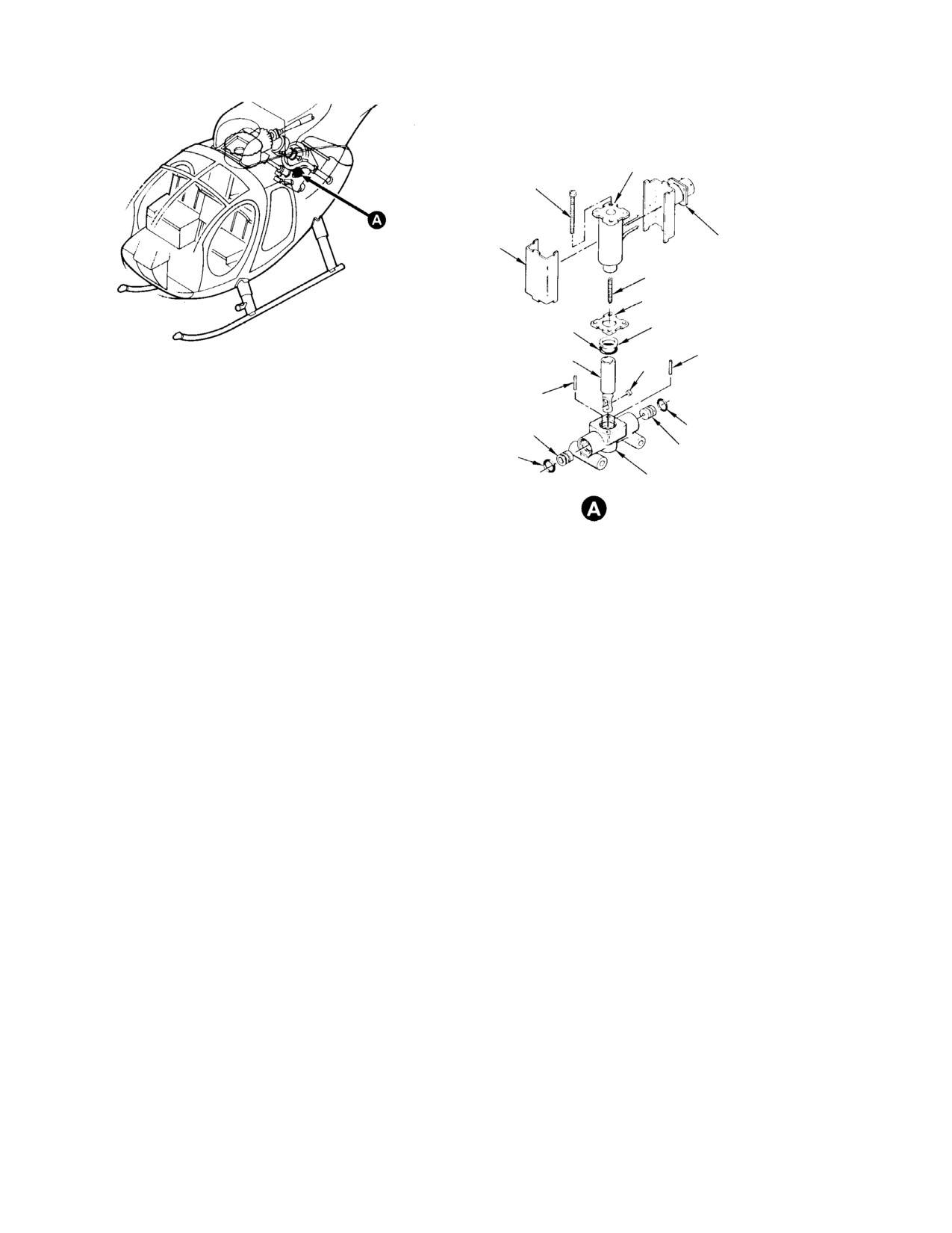
(1). Repair or replace engine anti-icing
(b). In engine compartment, check
valve per Allison Engine Operation and
anti-icing valve position:
Maintenance Manual.
Page 204
Revision 37
75-10-00
MD Helicopters, Inc.
CSP-HMI-2
MAINTENANCE MANUAL
FLEXIBLE SLEEVE
NYLON STRAP
(TYP)
GROMMET
(TYP)
RIGID SLEEVE
CONTROL HANDLE
INSTALLATION
2 PLCS
RIGID SLEEVE
HANDLE
SETSCREW
1 PLS
TAPE
(NOTE 2)
CONTROL HANDLE
HANDLE DETENT
CANOPY FRAME
SPRING
CLEVIS ATTACHING
POINT
FLEXIBLE SLEEVE
PLENUM CHAMBER
CABLE SPLICE
120°
AIR INLET PAN
CABLE SUPPORT
RIGID TUBING
ANTI-ICING VALVE
BLOCK (3 PLCS)
OUTER BOX
6 PLCS
NOTE 1
OPEN
HEAT DUCT
MOUNTING
SCREW
CLOSED
VERTICAL CENTERLINE OF
LEVER ASSY
ENGINE (LOOKING AFT)
CABLE CLEVIS
ANTI-ICING VALVE
INSTALLATION ANGLE
POPPET VALVE
(ANTI-ICING VALVE)
CONTROL CABLE TO
VALVE ATTACHMENT
NOTE:
1.
SEAL HOLE ON ENGINE SIDE OF PAN WITH ADHESIVE.
2.
APPLY VELCRO TAPE TO FORWARD BLOCK AND CLAMP
MATING SURFACES.
G75-1000
Figure 202. 250−C20B Engine Anti−Icing System
Page 205
75-10-00
Revision 22
CSP-HMI-2
MD Helicopters, Inc.
MAINTENANCE MANUAL
COIL
SCREW
CONNECTOR
COVER
SPRING
PLATE
O-RING
BACKUP RING
SEAL
PLUNGER
LOCKPIN
DISC
LOCKPIN
SEAT
O-RING
SEAT
O-RING
BODY
SOLENOID VALVE ASSY
G75-1001
Figure 203. 250−C20/R2, 250−C30 and 250−C47 Engine Anti−Icing Control Valve
Page 206
Revision 22
75-10-00

MD Helicopters, Inc.
CSP-HMI-2
MAINTENANCE MANUAL
Chapter
76
Engine Power
Controls
MD Helicopters, Inc.
CSP−HMI−2
MAINTENANCE MANUAL
TABLE OF CONTENTS
Para/Figure/Table
Title
Page
76-00-00 Engine Power Controls (250-C20B, 250-C20R/2 and 250-C30)
A
Description and Operation
1
1. Engine Power Controls Description and Operation
1
A. Power Turbine Governor Controls
1
B. Power Turbine Governor Trim Actuator
1
C. Gas Producer Controls
1
D. Rigging
1
Figure 1. Engine Control Systems
2
Fault Isolation
101
1. Engine Power Controls Fault Isolation
101
Table 101. Engine Control Fault Isolation
101
Figure 101. N2 Trim Actuator Wiring Schematic
102
76-10-00 Power Turbine Governor Controls (250-C20B, 250-C20R/2
and 250-C30)
A
Maintenance Practices
201
1.
Engine Governor Control Rigging
201
Figure 201. Power Turbine Governor Controls Rigging
203
2.
Governor Lever Pointer Rigging for 250-C20B (P/N 2524769-10 and Prior)
204
Figure 202. Power Turbine Governor Adjustments (P/N 2524769-10 and Prior)
205
3.
Governor Lever Pointer Rigging for 250-C20B / -C20R2 (P/N 2524769-11, -12)
206
Figure 203. Power Turbine Governor Adjustments (P/N 2524769-11, -12)
207
4.
Governor Lever Pointer Rigging for 250-C20B / -C20R/2 (P/N 2524667-13)
208
Figure 204. Power Turbine Governor Adjustments (P/N 2524667-13)
209
5.
Governor Lever Pointer Rigging for 250-C20B (P/N 2524667-14 and Higher,
P/N 2524769-13 and Higher and P/N 2549170-1 and Higher)
210
Figure 205. Power Turbine Governor Adjustments (P/N 2524667-14 and Higher,
P/N 2524769-13 and Higher and P/N 2549170-1 and Higher
on 250-C20B Engine)
211
6.
Governor Lever Pointer Rigging for 250-C20R/2 (P/N 2524667-14 and Higher,
P/N 2524769-13 and Higher and P/N 2549170-1 and Higher)
212
Figure 206. Power Turbine Governor Adjustments (P/N 2524667-14 and Higher,
P/N 2524769-13 and Higher and P/N 2549170-1 and Higher
on 250-C20R/2 Engine)
213
7.
Governor Lever Pointer Rigging for 250-C30
214
Figure 207. Power Turbine Governor Adjustments (250-C30 Engine)
215
8.
Governor Controls Final Check and Adjustment (250-C20B, -C20R/2)
216
9.
Governor Controls Final Check and Adjustment (250-C30)
217
Page i
76 Contents
Revision 44
CSP−HMI−2
MD Helicopters, Inc.
MAINTENANCE MANUAL
TABLE OF CONTENTS (Cont.)
Para/Figure/Table
Title
Page
10. Governor Controls Replacement
218
11. Control Rod Inspection
218
12. Bellcrank Inspection
219
13. Droop Compensation Link Inspection
219
14. Droop Control Override Link Repair
219
Figure 208. Power Turbine Governor Controls (Sheet 1 of 2)
220
15. Control Rod Repair
222
16. Bellcrank and Support Fitting Repair
222
17. N2 Trim Actuator Test
222
Figure 209. N2 Trim Actuator Test Hookup
223
18. N2 Trim Actuator Repair
223
19. Sta. 68.00 Bellcrank Rework, P/N 369A7717-3 and 369N2606 Only
223
Figure 210. Station 68.00 Bellcrank Rework
224
76-20-00 Gas Producer Controls (250-C20B, 250-C20R/2 and 250-C30)
A
Maintenance Practices
201
1. Gas Producer Controls Rigging (250-C20B and 250-C20R/2)
201
2. Gas Producer Controls Rigging (250-C30)
203
Figure 201. Gas Producer Controls Rigging (Sheet 1 of 3)
204
A. Gas Producer Fuel Control De-richment Valve Adjustment
210
B. Power Controls Operational Test/Final Adjustments
210
3. Gas Producer Controls Linkage Replacement
210
4. Sta. 124.00 Support Fitting Replacement
210
A. Sta. 124.00 Support Fitting Removal
210
B. Sta. 124.00 Support Fitting Installation
210
5. Gas Producer Controls Inspection
211
6. Gas Producer Control Rod Repair
211
7. Bellcrank Repair
212
Figure 202. Gas Producer Controls Replacement
213
76-47-00 Engine Power Controls (250-C47)
A
Maintenance Practices
201
1. Engine Controls Description
201
2. Engine Controls Operation
201
3. Engine Controls Fault Isolation
201
Table 201. Engine Controls Fault Isolation
201
Figure 201. Engine Control Unit Wiring Diagram (Sheet 1 of 2)
202
4. ECU (Electronic Control Unit) Replacement
204
Page ii
TR12−001
76 Contents
MD Helicopters, Inc.
CSP−HMI−2
MAINTENANCE MANUAL
TABLE OF CONTENTS (Cont.)
Para/Figure/Table
Title
Page
A. ECU Removal
204
B. ECU Installation
204
5.
Engine Control Potentiometer Replacement
204
A. Collective Potentiometer Removal
204
B. Collective Potentiometer Installation
204
C. Directional Potentiometer Removal
205
D. Directional Potentiometer Installation
205
6.
CIT (Compressor Inlet Temperature) Sensor Replacement
206
A. CIT Sensor Removal
206
B. CIT Sensor Installation
206
7.
Engine Control Box Replacement
206
A. Engine Control Box Removal
206
B. Engine Control Box Installation
206
8.
Engine Control Cable Replacement
206
A. Engine Control Cable Removal
206
B. Engine Control Cable Installation
207
Figure 202. Engine Controls Installation (Sheet 1 of 2)
208
9.
Engine Throttle Control Cable Mounting Bracket Replacement
210
A. Engine Throttle Control Cable Mounting Bracket Removal
210
B. Engine Throttle Control Cable Mounting Bracket Installation
210
10. Engine Control Cable Rigging
210
11. Engine Controls Inspection
210
Figure 203. Engine Control Cable Rigging
211
12. Engine Control Cable Shipping and Handling
211
A. Control Cable Removal From Shipping Box
211
Figure 204. Effective Bend Angle
212
B. Control Cable Installation into Shipping Box
212
Page iii
76 Contents
TR12−001
CSP−HMI−2
MD Helicopters, Inc.
MAINTENANCE MANUAL
TABLE OF CONTENTS (Cont.)
Para/Figure/Table
Title
Page
This Page Intentionally Left Blank
Page iv
Revision 37
76 Contents
MD Helicopters, Inc.
CSP-HMI-2
MAINTENANCE MANUAL
Section
76−00−00
Engine Power
Controls (250−C20B,
250−C20R/2 and
250−C30)
MD Helicopters, Inc.
CSP-HMI-2
MAINTENANCE MANUAL
ENGINE POWER CONTROLS
DESCRIPTION AND OPERATION
1.
Engine Power Controls Description and
train driving a ram equipped with an
Operation
adjustable rod-end. The actuator,
operated by an N2
trim (beep) switch on
(1).
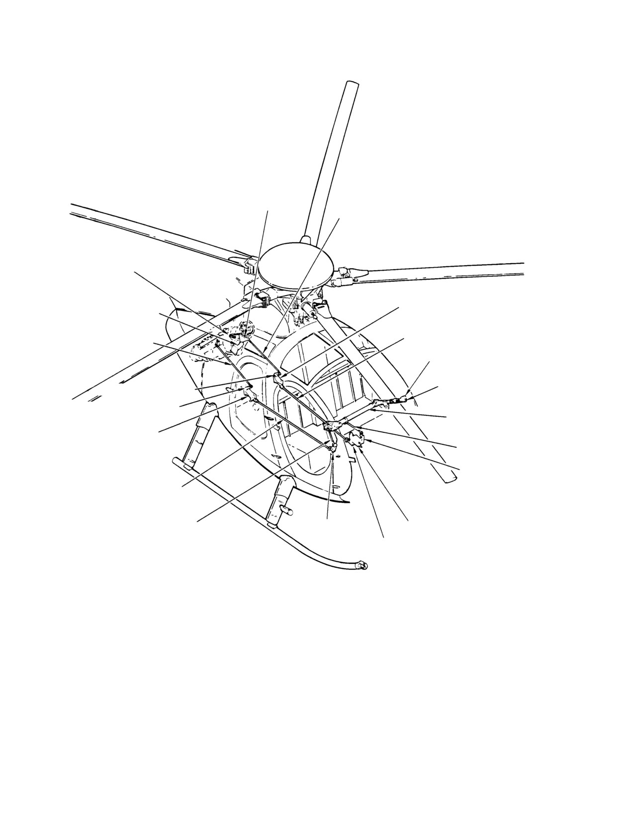
The engine control system consists of
the collective pitch stick, moves gover
gas producer (N1) throttle controls and
nor linkage that varies engine N2 speed
power turbine (N2) governor controls.
from 94 to 105% rpm. Operating stroke
The throttle twist grip mechanically
of the actuator ram is approximately
actuates a lever on the gas producer
1.00 inch (2.54 cm); speed is 0.15 inch
fuel control that establishes a base line
(3.81 mm) per second; travel time from
from which the unit schedules metered
full retraction to full extension is
fuel to the gas producer portion of the
approximately 7 seconds. The actuator
engine. An electrically operated trim
is lubricated when manufactured and
actuator and mechanical rpm droop
requires no further lubrication service.
compensator in the main rotor collec
tive pitch control mechanism changes
C. Gas Producer Controls
power turbine governor lever position
when collective is increased or reduced
(1). The gas producer portion of the engine
and when N2 speed increase or decrease
is controlled by the pilot's throttle twist
is commanded with the beep switch on
grip which effects gas producer fuel
the collective stick. Either, or both
control lever position through a system
actions regulate power output by
of torque tubes, gears, push-rods,
biassing the gas producer fuel control to
bellcranks, bellcrank support fittings,
increase or decrease fuel flow to
levers and attaching hardware (Ref.
compensate for rotor system torque
Figure 1).
requirements.
(2).
Refer to the applicable Allison Engine
(2). Refer to Allison Engine Operation and
Operation and Maintenance Manual for
Maintenance Manual for engine fuel
additional engine fuel system theory,
system theory, operation and mainte
operation and maintenance data.
nance data.
A. Power Turbine Governor Controls
D. Rigging
(1). Power turbine governor (N2) controls
include the N2 trim actuator controlled
(1). Rig engine control system prior to the
by the beep switch on the pilot's
next flight when engine operation
collective stick. Governor trim droop
reveals a rigging problem, or after
control override components and
replacing any system component.
linkages are installed within the pilot's
seat structure. A fuselage routed
NOTE: Perform a deceleration time check per
control rod assembly, engine compart
pilot's flight manual after rigging and test
ment linkages, bellcranks and supports
ing power turbine controls. Refer to Allison
transfer motion to the power turbine
Operation and Maintenance Manual for ad
governor. A droop control override
justment procedures if deceleration time is
spring compensates for over-travel in
less than allowable minimum.
maximum collective pitch/speed
conditions.
(2). Rig gas producer controls per (Ref. Sec.
76-20-00).
B. Power Turbine Governor Trim Actuator
(1). The actuator consists of a reversible
(3). Rig power turbine governor controls per
continuous duty 26Vdc motor and gear
(Ref. Sec. 76-10-00).
Page 1
76-00-00
Revision 22
CSP-HMI-2
MD Helicopters, Inc.
MAINTENANCE MANUAL
N2 CONTROL
IDLER BELLCRANK
N2 IDLER BELLCRANK
CONTROL ROD
GOVERNOR LEVER
CONTROL ROD
RPM GOVERNOR CONTROL
STA 124.00 CONTROL SUPPORT
IDLER SUPPORT FITTING
POWER TURBINE GOVERNOR
GAS PRODUCER LEVER
FUSELAGE-ROUTED CONTROL ROD
CONTROL ROD
N2 TRIM SWITCH
COLLECTIVE PITCH STICK
STA 124.00 BELLCRANK
STA 129.00 BELLCRANK
INTERCONNECT
TORQUE TUBE
GAS PRODUCER
CONTROLS SUPPORT
FITTING
DROOP CONTROL
OVERRIDE LINK
STA 68.00 BELLCRANK
GAS PRODUCER
FUSELAGE-ROUTED
CONTROL ROD
STA 73.00 GAS PRODUCER
STA 70.00 BELLCRANK
CONTROL ROD
N2 TRIM ACTUATOR
STA 72.00 BELLCRANK
G76-0001
Figure 1. Engine Control Systems
Page 2
Revision 22
76-00-00
MD Helicopters, Inc.
CSP-HMI-2
MAINTENANCE MANUAL
ENGINE POWER CONTROLS
FAULT ISOLATION
1. Engine Power Controls Fault Isolation
Table 101. Engine Control Fault Isolation
Symptom
Probable Trouble
Corrective Action
Throttle movement springy;
Lost motion; gas producer
Tighten torque tube pipe plug for
response lags behind control
interconnect torque tube loose in
zero backlash.
movement.
collective stick gear shafts.
Worn rod−ends; worn bellcrank
Replace worn parts.
bearings.
Stiff control action.
Rod−ends binding/jammed.
Realign rod−end bearings to
eliminate jamming.
Low power; improper idling speed;
Incorrectly adjusted gas producer
Adjust gas producer or power turbine
improper acceleration; variable
or power turbine governor controls.
governor controls for correct
power output at constant setting.
operation.
Defective gas producer or power
Replace faulty unit per Allison
turbine governor assembly.
Engine Operation and Maintenance
Manual.
Stagnated or hot engine starts.
Fuel control derichment valve out
Adjust derichment valve.
of adjustment.
Excessive TOT readings during
Engine controls out of adjustment. Adjust engine controls per the
engine shutdown.
applicable Allison manual.
Fuel cut−off valve not closing.
Adjust, repair or replace gas
producer control per Allison manual.
Page 101
76-00-00
Revision 22
MD Helicopters, Inc.
CSP-HMI-2
MAINTENANCE MANUAL
Section
76−10−00
Power Turbine
Governor Controls
(250−C20B,
250−C20R/2 and
250−C30)

MD Helicopters, Inc.
CSP-HMI-2
MAINTENANCE MANUAL
POWER TURBINE GOVERNOR CONTROLS
MAINTENANCE PRACTICES
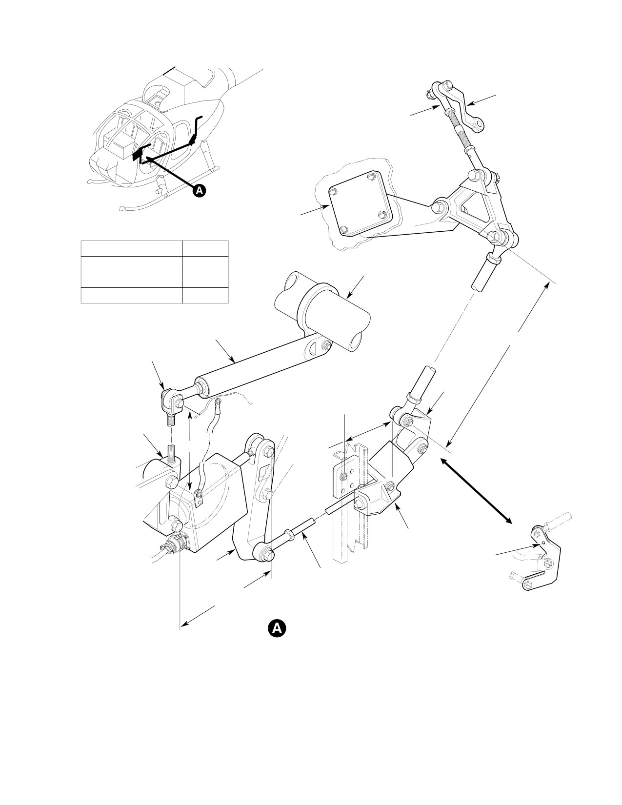
1. Engine Governor Control Rigging
D 250-C30 engine installations may re
quire replacement of the 369A7717-3
(Ref. Figure 201)
droop compensation adjustment fork to
the longer 369A7717-7 fork to achieve
NOTE: The rigging procedures for the C20B,
the necessary 1/2% to 1% droop compen
C20R/2 and C30 engine controls are similar,
sation. Upon installation of the longer
differing mostly in adjustments.
369A7717-7 fork assembly, ensure that
no interference occurs between the collec
tive torque tube and the 369A7712 link
CAUTION
assembly. Also check between the pro
D Do not make any adjustments to governor
truding end of the droop fork and N2 ac
stops, adjustment screws or nut positions.
tuator.
D To identify forks with obscured part num
D Replace worn linkage components prior to
bers, measure distance between threaded
rigging engine controls or adjusting en
shank end-flat to clevis bolt hole center:
gine fuel controls. Several worn rod-end,
369A7717-3 fork:
fitting and bellcrank bearings in the gov
3.00 inches (76.20 mm)
ernor control system compound otherwise
369A7717-5 fork:
minimal lost motion. Loose control sys
2.63 inches (66.802 mm)
tems will not hold rigging adjustments,
369A7717-7 fork:
and if continued in service may result in
3.87 inches (98.298 mm).
engine power creep, hunting or flame out.
(2). Set the initial reference dimension
NOTE: Gas producer throttle control tube, in
between center of Sta. 68.00 bellcrank
terconnect torque tube, collective pitch
pivot bolt and droop compensation fork
stick, interconnecting collective pitch torque
clevis bolt-center.
tube and linkage maintenance practices are
covered under `Main Rotor Flight Controls'
Droop Fork Settings
(Ref. Sec. 67-10-00) and `Gas Producer Con
trols' (Ref. Sec. 76-20-00).
Engine
Length
Installation
In.
(mm)
(1). Disconnect control rod between idler
250−C20B
2.20 ±0.03
(55.880 ±0.762)
bellcrank and governor lever at idler
bellcrank. Secure rod to avoid damage.
250−C20R/2
2.20 ±0.03
(55.880 ±0.762)
250−C20R/2 (1)
2.50 ±0.03
(63.500 ±0.762)
CAUTION
250−C30
(2)
D 250-C20R/2 engines equipped with a
(1) With 2524667-13 governor
2524667-13 engine governor require re
(2)
3.40 ±0.03 inches (86.360 ±0.762 mm) with
moval of the 369A7717-5 droop compen
369A7717-7 ext. fork and 369A7704 bell
sation adjustment fork and installation of
crank
the longer 369A7717-3 fork to achieve
2.60 ±0.03 inches (66.040 ±0.762 mm) with
the necessary 1/2% to 1% droop com
369A7717-3 ext. fork and 369A7704-7 bell
pensation (approximately 2% for 500N).
crank
Page 201
76-10-00
Revision 22

CSP-HMI-2
MD Helicopters, Inc.
MAINTENANCE MANUAL
NOTE:
proper engine installation as indicated
below.
D Make control rod-end adjustments to the
nearest half turn that produces correct
rigging.
Idler Bellcrank Control Rod Setting
D Stabilize rod-end with a backup wrench
Engine
Length
when torquing rod-end jamnut.
Installation
In.
(mm)
D Inspect rod-end thread engagement
250−C20B, R/2
14.38 ±0.03 (365.252 ±0.762)
through witness hole to ensure a safe, se
250−C30
13.70 ±0.03 (347.980 ±0.762)
cure installation.
(3). Connect 28Vdc external power. Reset
(7). Verify that collective is FULL DOWN
N2 GOV circuit breaker. Set battery
and governor trim actuator is at
switch to EXT PWR.
maximum extension.
(4). With pilot's collective stick the FULL
(8). Check governor lever and pointer
DOWN position, beep N2 actuator to
position, as follows.
maximum extension. Adjust actuator
ram as required to get 5.47 ±0.03 inches
Governor and fuel control levers
CAUTION
(138.938 ±0.762 mm) measured be
can be installed on the wrong
tween pivot bolt-centers.
fuel system component shaft. Governor le
ver is relatively short with an offset angle of
(5). Adjust fuselage-routed governor control
about 65°. Fuel control lever offset angle is a
rod length to move Sta. 124.00 bell
more moderate 38°.
crank. The lower arm pivot bolt-center
measurement from the firewall should
NOTE:
be set to the applicable engine installa
D Specified pointer/lever angular relation
tion as indicated below.
ships are standard production settings.
Slight variations in position may be re
Station 124 Bellcrank Setting
quired to obtain proper travel and satis
Engine
Setting
factory engine operation. Such variation
Installation
In.
(mm)
is acceptable provided all other rigging
and engine performance requirements
250−C20B, R/2
3.63 ±0.03
(92.20 ±0.762)
are met.
(Multi−Engine)
D Governor lever travel produced by trim
250−C30
3.34 ±0.03
(84.84 ±0.762)
actuator operation, from forward travel
(Current)
point (trim actuator retracted and collec
250−C30
3.75 ±0.03
(95.25 ±0.762)
tive stick down) to aft travel point (trim
(Early)
actuator extended and collective stick
down), is 31° to 32°. Approximately 36° to
(6). In engine compartment; set idler
38° of governor lever travel from mini
bellcrank control rod length to the
mum N2 stop is unused.
Page 202
Revision 22
76-10-00
MD Helicopters, Inc.
CSP-HMI-2
MAINTENANCE MANUAL
GOVERNOR
LEVER
GOVERNOR LEVER
CONTROL ROD
IDLER
SUPPORT
RODEND ANGULAR RELATIONSHIPS
CONTROL ROD
ANGLE
FUSELAGE ROUTED
IN LINE
COLLECTIVE
TORQUE TUBE
N2 IDLER BELLCRANK
90°
GOVERNOR LEVER
90°
DROOP CONTROL
OVERRIDE LINK
NOTE 4
DROOP COMPENSATION
ADJUSTMENT FORK
STA. 124.00
BELLCRANK
STA. 124.00
FIREWALL
STA 68.00
BELLCRANK
NOTE 1
NOTE 3
STA. 124.00 SUPPORT
FITTING
250-C30 ENGINE
STA. 72.00
INSTALLATION
BELLCRANK
FUSELAGE-ROUTED
CONTROL ROD
5.47 +0.03 (138.938 ±7.62 MM)
MULTI-ENGINE
(NOTE 2)
POWER TURBINE CONTROL LINKAGE
NOTES:
INITIAL SETTINGS.
1.
DROOP FORK.
2.
N2 ACTUATOR RAM.
3.
STA. 124.00 BELLCRANK.
G76-1002B
4
IDLER BELLCRANK CONTROL ROD
Figure 201. Power Turbine Governor Controls Rigging
Page 203
76-10-00
Revision 22
CSP-HMI-2
MD Helicopters, Inc.
MAINTENANCE MANUAL
2. Governor Lever Pointer Rigging for
and D of the word SPEED on the
250−C20B (P/N 2524769−10 and Prior)
governor.
NOTE:
(Ref. Figure 202)
D The pointer control arm shall not hit the
(1). Reposition the lever arm only, not the
mechanical stops.
pointer, one serration (15°) counter
D As stick is raised, the Sta. 124.00 bell
clockwise from pointer centerline.
crank will bottom out on the support and
until it reaches FULL UP travel, the
Do not overtorque governor con
CAUTION
droop control override spring will com
trol lever nut. Exceeding nut
press.
torque limit may cause binding.
(6). Bottom collective stick and beep N2
(2). Torque lever nut to 40 - 50 inch-
trim to minimum; The governor pointer
pounds (4.52 - 5.65 Nm) while
shifts back to approximately the first
holding lever center screw with a hex
vertical leg of the letter N of N2 on the
wrench. Apply a torque stripe.
governor.
(3). Verify collective stick is FULL DOWN
If any interference exists at gov
CAUTION
and governor actuator is at maximum
ernor lever, check that correct
extension.
lever is installed.
(4). Connect short control rod between idler
(7). Verify that all jamnuts, bolts, nuts,
bellcrank and governor control arm.
lockwire and cotter pins are properly
Adjust the rod to locate the N2 pointer
installed and secured.
between the letters P and E of the word
(8). Pull the N2 GOV circuit breaker reset
SPEED embossed on the governor.
button, as required.
(5). Raise the pilot's collective stick until
(9). Set the battery switch OFF.
the Sta. 124.00 bellcrank bottoms on
support and ensure the governor
(10). Shut down and disconnect external
pointer shifts to between the letters E
power.
Page 204
Revision 22
76-10-00
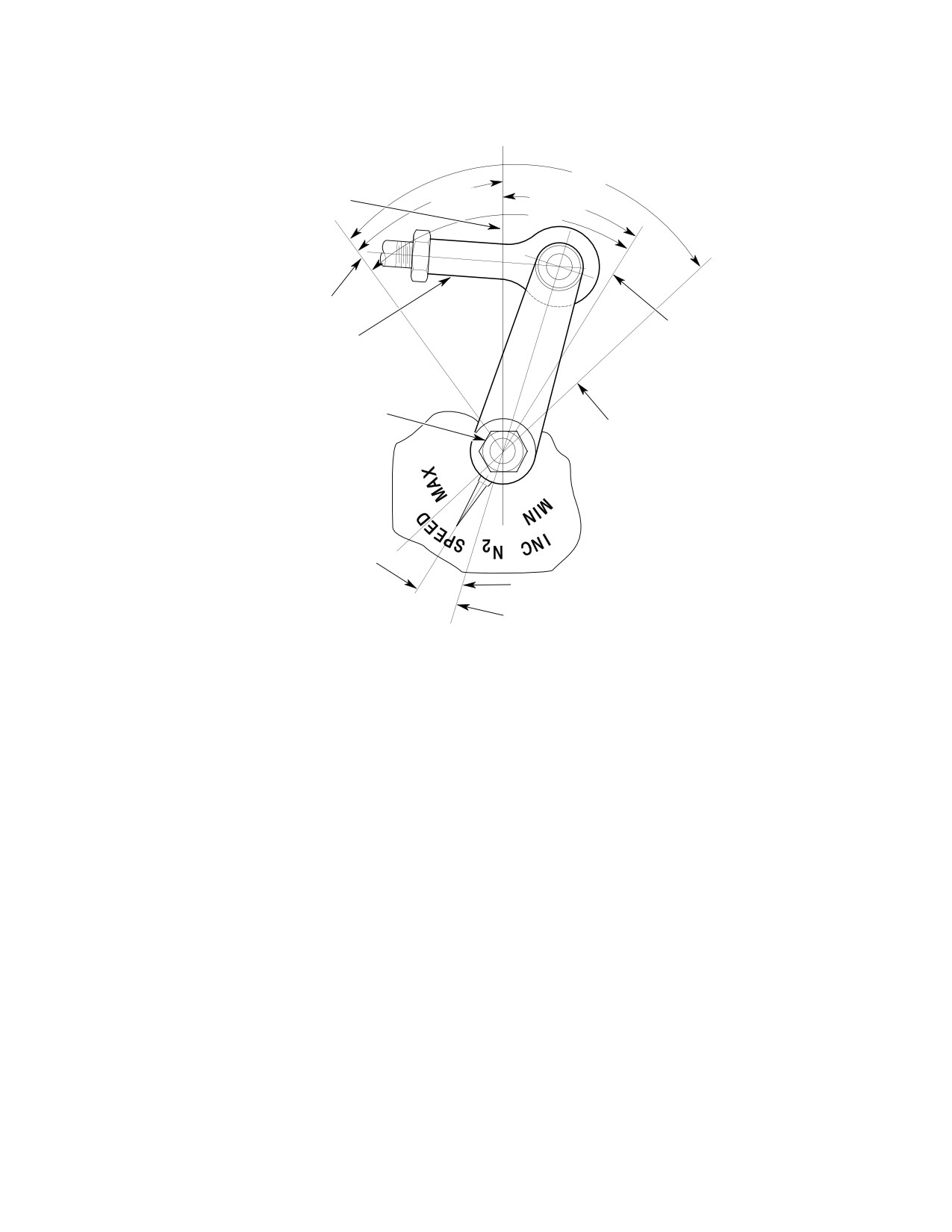
MD Helicopters, Inc.
CSP-HMI-2
MAINTENANCE MANUAL
MINIMUM N2 ACTUATOR EXTENSION
COLLECTIVE DOWN
86°
POINTER AT THE FIRST VERTICAL LEG
36° - 38°
31° - 32°
OF THE LETTER ``N'' OF N2 (94-98%)
68°
UNUSED TRAVEL
MAXIMUM N2
ACTUATOR EXTENSION
GOVERNOR LEVER
COLLECTIVE DOWN
CONTROL ROD
POINTER BETWEEN ``P'' AND ``E'' OF THE
WORD SPEED (103-105%)
TORQUE NUT
40-50 IN. LBS.
(4.52-5.65 NM)
MAXIMUM N2 ACTUATOR EXTENSION
COLLECTIVE RAISED
POINTER BETWEEN ``E'' AND ``D'' OF THE
WORD SPEED
POINTER C
L
GOVERNOR LC
ONE SERRATION 15°
NOTE:
DROOP CONTROL OVERRIDE LINK SPRING STARTS TO
COMPRESS; ARM IS NOT REQUIRED TO HIT MAXIMUM STOP
G76-1004A
WITH FULL COLLECTIVE AND ACTUATOR EXTENDED.
Figure 202. Power Turbine Governor Adjustments (P/N 2524769−10 and Prior)
Page 205
76-10-00
Revision 22
CSP-HMI-2
MD Helicopters, Inc.
MAINTENANCE MANUAL
3. Governor Lever Pointer Rigging for
the first letter E in the word SPEED on
250−C20B / −C20R2 (P/N 2524769−11, −12)
the governor.
NOTE:
(Ref. Figure 203)
D The pointer control arm shall not hit the
(1). Position the governor lever arm in line
mechanical stops.
with the pointer.
D As stick is raised, the Sta. 124.00 bell
crank will bottom out on the support and
Do not overtorque governor con
CAUTION
until it reaches FULL UP travel, the
trol lever nut. Exceeding nut
droop control override spring will com
torque limit may cause binding.
press.
(2). Torque lever nut to 40 - 50 inch-
(6). Bottom collective stick and beep N2
pounds (4.52 - 5.65 Nm) while
trim to minimum; The governor pointer
holding lever center screw with a hex
shifts back to approximately the first
wrench. Apply a torque stripe.
vertical leg of the letter R of INCR on
the governor.
(3). Verify collective stick is FULL DOWN
and governor actuator is at maximum
If any interference exists at gov
CAUTION
extension.
ernor lever, check that correct
lever is installed.
(4). Connect short control rod between idler
bellcrank and governor control arm.
(7). Verify that all jamnuts, bolts, nuts,
Adjust the rod to locate the N2 pointer
lockwire and cotter pins are properly
between the letters S and P of the word
installed and secured.
SPEED embossed on the governor.
(8). Pull the N2 GOV circuit breaker reset
button, as required.
(5). Raise the pilot's collective stick until
the Sta. 124.00 bellcrank bottoms on
(9). Set the battery switch OFF.
support and ensure the governor
pointer shifts to a position approxi
(10). Shut down and disconnect external
mately aligning with the vertical leg in
power.
Page 206
Revision 22
76-10-00
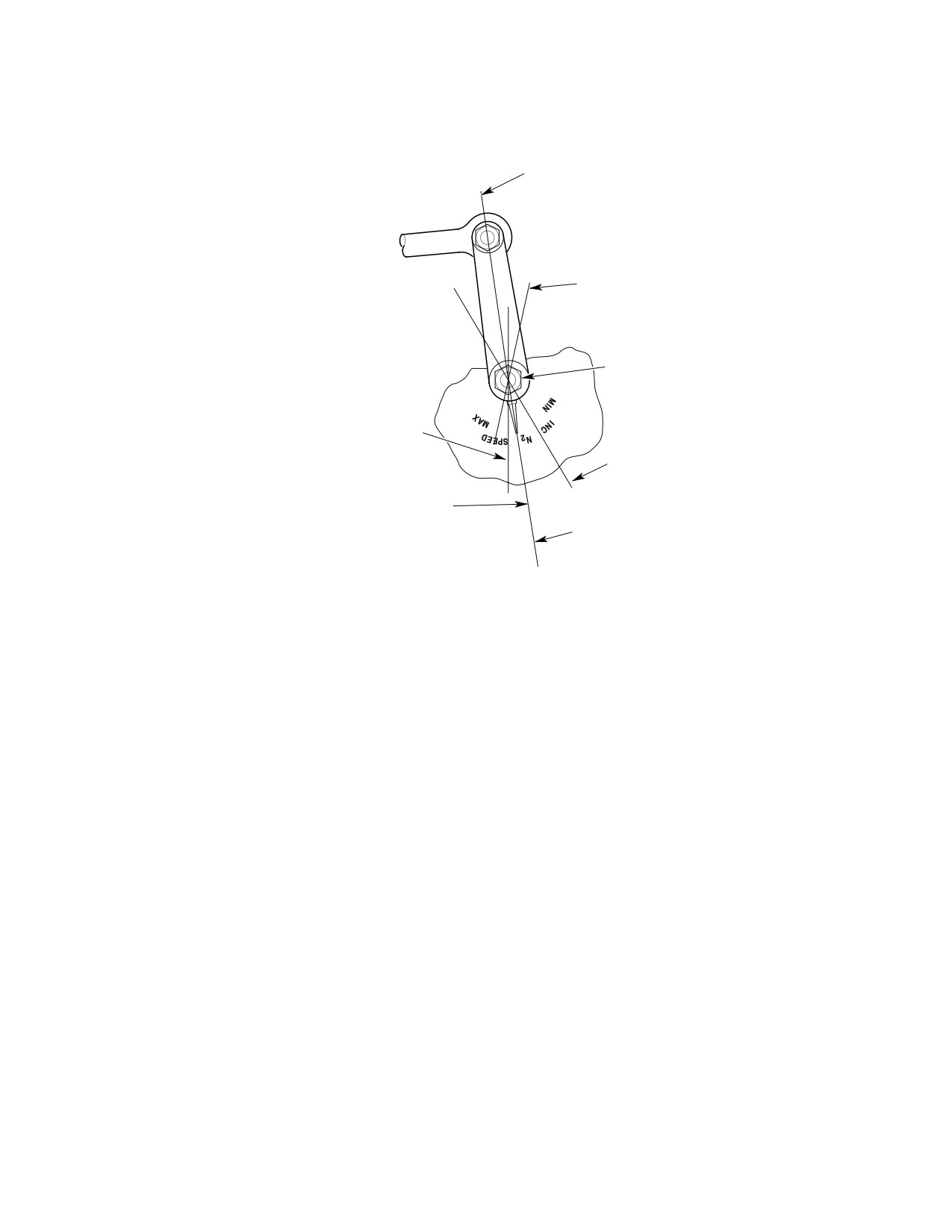
MD Helicopters, Inc.
CSP-HMI-2
MAINTENANCE MANUAL
N2 GOVERNOR ARM
PARALLEL TO POINT
L
MAXIMUM N2 ACTUATOR EXTENSION
COLLECTIVE UP
APPROXIMATE POINTER LOCATION
TORQUE NUT
40-50 IN. LBS.
(4.52-5.65 NM)
MAXIMUM N2 ACTUATOR EXTENSION
COLLECTIVE DOWN
POINTER GREATER THAN LETTER ``S'' IN SPEED
MINIMUM N2 ACTUATOR EXTENSION
COLLECTIVE DOWN
POINTER APPROXIMATELY AT VERTICAL
MINIMUM N2 ACTUATOR EXTENSION
LEG OF LETTER ``R'' IN INCR
COLLECTIVE UP
POINTERLC
POINTER APPROXIMATELY AT LEADING
EDGE OF LETTER ``S'' IN SPEED
NOTE:
DROOP CONTROL OVERRIDE LINK SPRING
STARTS TO COMPRESS; ARM IS NOT REQUIRED
TO HIT MAXIMUM STOP WITH FULL COLLECTIVE
AND ACTUATOR EXTENDED.
ACCORDING TO STA. 124.00 BELLCRANK
INSTALLATION, POINTER LOCATIONS ARE
APPROXIMATE.
G76-1005B
Figure 203. Power Turbine Governor Adjustments (P/N 2524769−11, −12)
Page 207
76-10-00
Revision 22
CSP-HMI-2
MD Helicopters, Inc.
MAINTENANCE MANUAL
4. Governor Lever Pointer Rigging for
NOTE:
250−C20B / −C20R/2 (P/N 2524667−13)
D The pointer control arm shall not hit the
(Ref. Figure 204)
mechanical stops.
D As stick is raised, the Sta. 124.00 bell
(1). Position the governor lever arm in line
crank will bottom out on the support and
with the pointer.
until it reaches FULL UP travel, the
Do not overtorque governor con
droop control override spring will com
CAUTION
trol lever nut. Exceeding nut
press.
torque limit may cause binding.
(6). Bottom collective stick and beep N2
(2). Torque lever nut to 40 - 50 inch-
trim to minimum; The governor pointer
pounds (4.52 - 5.65 Nm) while
shifts back to approximately the aft end
holding lever center screw with a hex
of the letter R of INCR on the governor.
wrench. Apply a torque stripe.
If any interference exists at gov
(3). Verify collective stick is FULL DOWN
CAUTION
ernor lever, check that correct
and governor actuator is at maximum
lever is installed.
extension.
(7). Verify that all jamnuts, bolts, nuts,
(4). Connect short control rod between idler
bellcrank and governor control arm.
lockwire and cotter pins are properly
Adjust the rod to locate the N2 pointer
installed and secured.
greater than the letter P in the word
(8). Pull the N2 GOV circuit breaker reset
SPEED embossed on the governor.
button, as required.
(5). Raise the pilot's collective stick until
the Sta. 124.00 bellcrank bottoms on
(9). Set the battery switch OFF.
support and ensure the governor
pointer is greater than the second letter
(10). Shut down and disconnect external
E in the word SPEED on the governor.
power.
Page 208
Revision 22
76-10-00
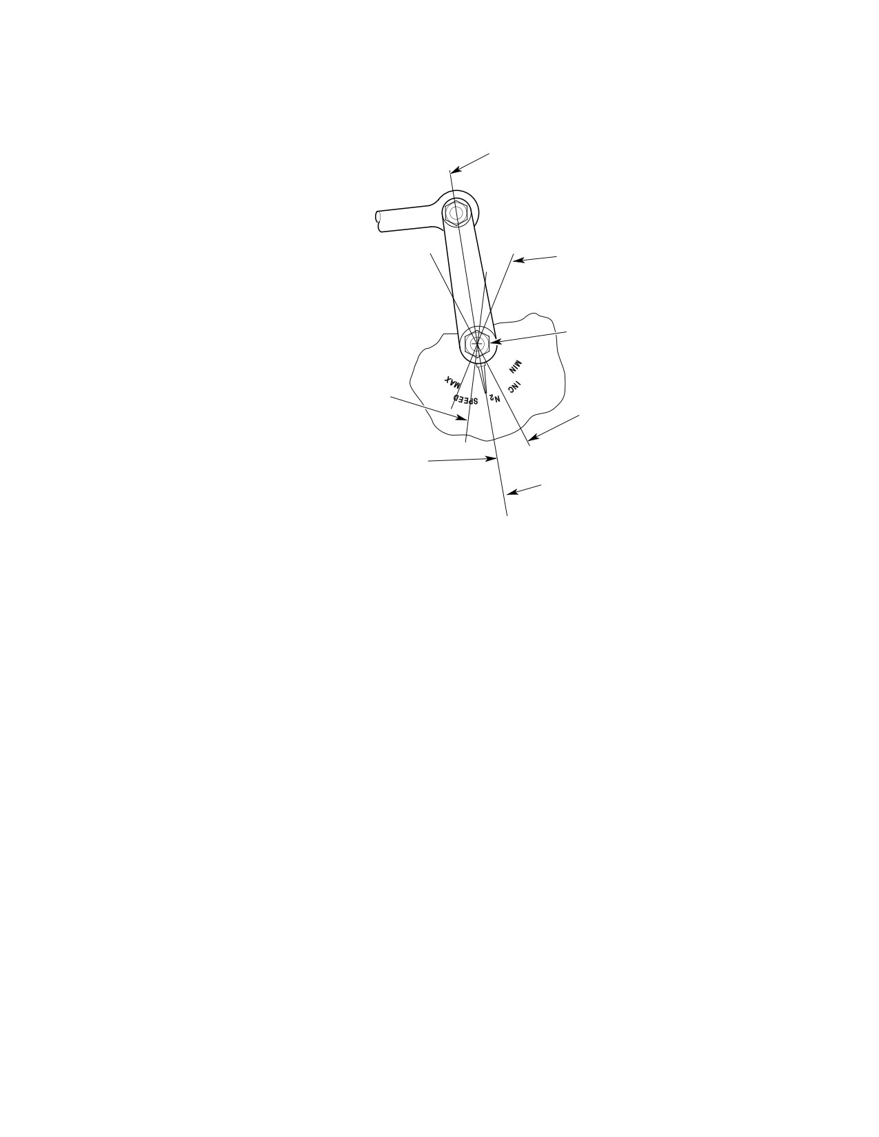
MD Helicopters, Inc.
CSP-HMI-2
MAINTENANCE MANUAL
N2 GOVERNOR ARM
PARALLEL TO POINT
L
MAXIMUM N2 ACTUATOR EXTENSION
COLLECTIVE UP
APPROXIMATE POINTER LOCATION
TORQUE NUT
40-50 IN. LBS.
(4.52-5.65 NM)
MAXIMUM N2 ACTUATOR EXTENSION
COLLECTIVE DOWN
POINTER GREATER THAN LETTER ``P'' IN SPEED
MINIMUM N2 ACTUATOR EXTENSION
COLLECTIVE DOWN
POINTER APPROXIMATELY AT AFT END
OF LETTER ``R'' IN INCR
MINIMUM N2 ACTUATOR EXTENSION
COLLECTIVE UP
POINTER APPROXIMATELY AT LEADING EDGE
POINTER
C
OF LETTER ``S'' IN SPEED
L
NOTE:
DROOP CONTROL OVERRIDE LINK SPRING
STARTS TO COMPRESS; ARM IS NOT REQUIRED
TO HIT MAXIMUM STOP WITH FULL COLLECTIVE
AND ACTUATOR EXTENDED.
ACCORDING TO STA. 124.00 BELLCRANK
G76-1010B
INSTALLATION, POINTER LOCATIONS ARE
Figure 204. Power Turbine Governor Adjustments (P/N 2524667−13)
Page 209
76-10-00
Revision 22
CSP-HMI-2
MD Helicopters, Inc.
MAINTENANCE MANUAL
5. Governor Lever Pointer Rigging for
support and ensure the governor
250−C20B (P/N 2524667−14 and Higher,
pointer is approximately at 81°.
P/N 2524769−13 and Higher and P/N
NOTE:
2549170−1 and Higher)
D The pointer control arm shall not hit the
(Ref. Figure 205)
mechanical stops.
(1). Position the governor lever arm, not the
D As stick is raised, the Sta. 124.00 bell
pointer, to the first serration counter-
crank will bottom out on the support and
clockwise from pointer centerline.
until it reaches FULL UP travel, the
droop control override spring will com
Do not overtorque governor con
press.
CAUTION
trol lever nut. Exceeding nut
(6). Bottom collective stick and beep N2
torque limit may cause binding.
trim to minimum; The governor pointer
(2). Torque lever nut to 40 - 50 inch-
shifts back to 38° ±3°.
pounds (4.52 - 5.65 Nm) while
If any interference exists at gov
holding lever center screw with a hex
CAUTION
ernor lever, check that correct
wrench. Apply a torque stripe.
lever is installed.
(3). Verify collective stick is FULL DOWN
(7). Verify that all jamnuts, bolts, nuts,
and governor actuator is at maximum
lockwire and cotter pins are properly
extension.
installed and secured.
(4). Connect short control rod between idler
(8). Pull the N2 GOV circuit breaker reset
bellcrank and governor control arm.
button, as required.
Adjust the rod to locate the N2 pointer
at 69° ±3°.
(9). Set the battery switch OFF.
(5). Raise the pilot's collective stick until
(10). Shut down and disconnect external
the Sta. 124.00 bellcrank bottoms on
power.
Page 210
Revision 44
76-10-00
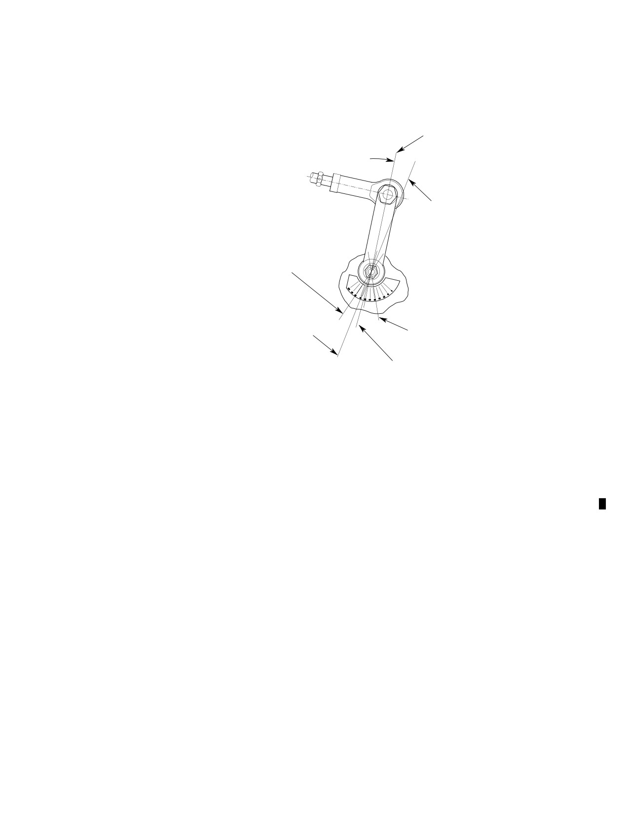
MD Helicopters, Inc.
CSP-HMI-2
MAINTENANCE MANUAL
N2 GOVERNOR ARM POSITION TO FIRST
SERRATION COUNTER-CLOCKWISE
FROM POINTER CENTERLINE
10°
POINTER LC
N2 ACTUATOR EXTENDED
COLLECTIVE UP 1/3 TO 1/2 TRAVEL
APPROXIMATE POINTER LOCATION 81°
N2 ACTUATOR EXTENDED
COLLECTIVE DOWN
N2 ACTUATOR RETRACTED
POINTER AT 69° +3°
COLLECTIVE DOWN
POINTER AT 38° +3°
N2 ACTUATOR RETRACTED
COLLECTIVE UP
POINTER AT 63° +3°
NOTE:
DROOP CONTROL OVERRIDE LINK SPRING STARTS TO
COMPRESS; ARM IS NOT REQUIRED TO HIT MAXIMUM
STOP WITH FULL COLLECTIVE AND ACTUATOR
EXTENDED.
-14GOV - C20B
ACCORDING TO STA. 124.00 BELLCRANK INSTALLATION,
Figure 205. Power Turbine Governor Adjustments (P/N 2524667−14 and Higher,
P/N 2524769−13 and Higher and P/N 2549170−1 and Higher on 250−C20B Engine)
Page 211
76-10-00
Revision 44
CSP-HMI-2
MD Helicopters, Inc.
MAINTENANCE MANUAL
6. Governor Lever Pointer Rigging for
support and ensure the governor
250−C20R/2 (P/N 2524667−14 and Higher,
pointer is approximately at 94°.
P/N 2524769−13 and Higher and P/N
NOTE:
2549170−1 and Higher)
D The pointer control arm shall not hit the
(Ref. Figure 206)
mechanical stops.
(1). Position the governor lever arm, not the
D As stick is raised, the Sta. 124.00 bell
pointer, to the first serration counter-
crank will bottom out on the support and
clockwise from pointer centerline.
until it reaches FULL UP travel, the
droop control override spring will com
Do not overtorque governor con
press.
CAUTION
trol lever nut. Exceeding nut
(6). Bottom collective stick and beep N2
torque limit may cause binding.
trim to minimum; The governor pointer
(2). Torque lever nut to 40 - 50 inch-
shifts back to 44° ±3°.
pounds (4.52 - 5.65 Nm) while
If any interference exists at gov
holding lever center screw with a hex
CAUTION
ernor lever, check that correct
wrench. Apply a torque stripe.
lever is installed.
(3). Verify collective stick is FULL DOWN
(7). Verify that all jamnuts, bolts, nuts,
and governor actuator is at maximum
lockwire and cotter pins are properly
extension.
installed and secured.
(4). Connect short control rod between idler
(8). Pull the N2 GOV circuit breaker reset
bellcrank and governor control arm.
button, as required.
Adjust the rod to locate the N2 pointer
at 77° ±3°.
(9). Set the battery switch OFF.
(5). Raise the pilot's collective stick until
(10). Shut down and disconnect external
the Sta. 124.00 bellcrank bottoms on
power.
Page 212
Revision 44
76-10-00
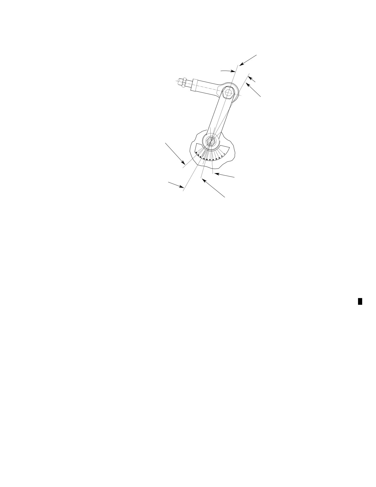
MD Helicopters, Inc.
CSP-HMI-2
MAINTENANCE MANUAL
N2 GOVERNOR ARM POSITION TO FIRST
SERRATION COUNTER-CLOCKWISE
FROM POINTER CENTERLINE
10°
POINTER C
L
N2 ACTUATOR EXTENDED
COLLECTIVE UP 1/3 TO 1/2 TRAVEL
APPROXIMATE POINTER LOCATION 94°
N2 ACTUATOR EXTENDED
COLLECTIVE DOWN
N2 ACTUATOR RETRACTED
POINTER AT 77° +3°
COLLECTIVE DOWN
POINTER AT 44° +3°
N2 ACTUATOR RETRACTED
COLLECTIVE UP
POINTER AT 63° +3°
NOTE:
DROOP CONTROL OVERRIDE LINK SPRING STARTS TO
COMPRESS; ARM IS NOT REQUIRED TO HIT MAXIMUM STOP
WITH FULL COLLECTIVE AND ACTUATOR EXTENDED.
ACCORDING TO STA. 124.00 BELLCRANK INSTALLATION,
POINTER LOCATIONS ARE APPROXIMATE.
-14GOV - C20R2
Figure 206. Power Turbine Governor Adjustments (P/N 2524667−14 and Higher,
P/N 2524769−13 and Higher and P/N 2549170−1 and Higher on 250−C20R/2 Engine)
Page 213
76-10-00
Revision 44
CSP-HMI-2
MD Helicopters, Inc.
MAINTENANCE MANUAL
7. Governor Lever Pointer Rigging for
(6). Move collective stick FULL DOWN.
250−C30
Beep governor trim actuator to maxi
mum extension. The pointer will point
(Ref. Figure 207)
to approximately the 50° mark.
(1). At the governor unit position the
governor lever to within 10 degrees
(7). Raise the collective stick until Sta.
parallel with the pointer arm.
124.00 bellcrank bottoms on support,
Do not overtorque governor con
the pointer will point approximately the
CAUTION
trol lever nut. Exceeding nut
58° mark.
torque limit may cause binding.
(2). Torque lever nut to 40 - 50 inch-
NOTE: The control arm of the pointer should
pounds (4.52 - Nm) while holding
not hit the mechanical stops.
lever center screw with a hex wrench.
Apply a torque stripe.
(8).
Continue raising the pilot's collective
(3). Verify that collective is FULL DOWN
stick; droop control override spring
and governor trim actuator is at
compression continues to increase until
minimum extension.
the stick reaches FULL UP. The
(4). Adjust governor lever control rod link
governor pointer should remain
so that the governor pointer points to
approximately stationary on the 58°
20° mark on the N2 governor plate.
mark.
(5). Raise the pilot's collective stick,
minimum beep, and check that pointer
(9).
Verify that all jamnuts are torqued to
is at is at the 35° mark on the in the N2
25 - 30 inch-pounds (2.82 - 3.39
governor plate.
Nm). Check all bolts, nuts and cotter
pins for proper installation and securi
NOTE:
ty.
D If pointer is above 35° mark, lengthen the
369A7706 rod. If the pointer is below the
35° mark, shorten the rod. After adjusting
(10).
Pull the N2 GOV circuit breaker reset
rod, repeat steps (3). and (4)..
button, as required.
D Specified pointer/lever angular relation
ships are standard production settings.
Slight variations may be required to ob
(11).
Set the battery switch OFF.
tain proper travel and satisfactory engine
operation. Variations are acceptable pro
vided all engine performance require
(12).
Shut down and disconnect external
ments are met.
power.
Page 214
Revision 22
76-10-00
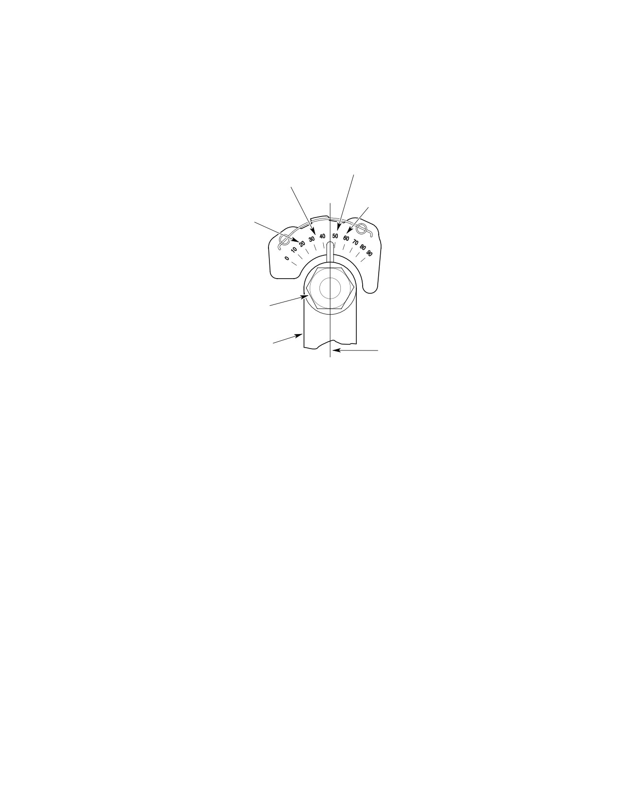
MD Helicopters, Inc.
CSP-HMI-2
MAINTENANCE MANUAL
MAXIMUM N2 ACTUATOR EXTENSION
COLLECTIVE DOWN
MINIMUM N2 ACTUATOR EXTENSION
POINTER TO BE AT THE 50° MARK
COLLECTIVE UP
POINTER AT THE 35° MARK
MAXIMUM N2 ACTUATOR EXTENSION
COLLECTIVE UP 1/3 TO 1/2 TRAVEL
MINIMUM N2 ACTUATOR EXTENSION
POINTER TO BE APPROXIMATELY AT THE 58° MARK
COLLECTIVE DOWN
POINTER AT THE 20° MARK
TORQUE NUT
40-50 IN. LBS.
(4.52-5.65 NM)
LEVER ARM
POINTER PARALLEL TO WITHIN 10°
G76-1006C
Figure 207. Power Turbine Governor Adjustments (250−C30 Engine)
Page 215
76-10-00
Revision 35
CSP-HMI-2
MD Helicopters, Inc.
MAINTENANCE MANUAL
8.
Governor Controls Final Check and
Make all engine compart
WARNING
Adjustment (250−C20B, −C20R/2)
ment control rod adjust
ments with engine shut down.
(1).
Have an assistant move collective
(10).
Mark N2 lever position on governor
through full range of travel while
quadrant.
inspecting all movable linkage for
clearance with adjacent parts. Check
(11).
Connect external electric power.
that control rod, N2 actuator and
override link bearings are not jammed
(12).
With collective at bottom stop, beep N2
when linkage is at extreme control
trim to maximum rpm.
positions.
(13).
Adjust governor lever control rod (105%
(2).
Start and operate engine at idle with
N2 maximum: 369D/E) (104% N2
main rotor blades in flat pitch per
maximum: 500N).
Pilot's Flight Manual.
(14).
Start engine. With main rotor blades in
flat pitch, beep N2 trim to (102% rpm:
(3).
Decrease N2 trim to minimum.
369D/E) (100% rpm: 500N). Lift off and
hover.
(4).
Throttle up to maximum rpm.
(15).
Observe N2 tachometer pointer when
(5).
Observe N2 tachometer pointer for (98%
pointer of Nl tachometer is stabilized.
or less rpm: 369D/E) (94% or less:
N2 pointer indication, that is, droop
500N) when rotor rpm pointer is
compensation, should be (1/2% to 1%
superimposed on N2 pointer and Nl
rpm: 369 D/E) (1% to 2% rpm: 500N)
tachometer pointer is stabilized.
above indication in previous step.
(6).
Check for the following engine power
(16).
Land and shut down engine.
out (EPO) indications:
(17).
If droop compensation occurred as
(a). Engine-out flashing light.
required, no further adjustments are
required.
(b). Audio signal in headset.
(18).
If droop compensation did not occur per
step (15)., check and re-rig power
(c). Horn; sounds when N2 pointer on
turbine and gas producer linkage
dual indicator is stable.
systems as required.
(7). With collective stick down, increase N2
(19).
Where Nl and N2 linkage are correctly
trim to (104% to 105% rpm: 369D/E)
adjusted, additional adjustment may be
(103% to 104% rpm: 500N). Observe N2
made to droop compensation adjust
tachometer pointer when rotor rpm
ment fork; as follows:
pointer is superimposed on N2 pointer
and N1 tachometer pointer is stabilized.
NOTE: Three to five turns of droop compensa
tion fork may be necessary to change droop
(8). Without decreasing N2 trim, rotate
compensation approximately 0.5% rpm.
pilot's throttle to ground idle.
(a). Shorten droop compensation adjust
NOTE: Perform a deceleration time check per
ment fork to increase compensation.
PFM after rigging and testing power tur
(b). Lengthen fork extension to decrease
bine controls. Refer to Allison Operation
compensation.
and Maintenance Manual for adjustment
procedures if deceleration time is less than
(c). Align fork with override link rod-end
allowable minimum.
before tightening fork jamnut.
(9). Shut down engine per Pilot's Flight
(20). Move collective through full travel after
Manual.
adjustment and check for clearance
Page 216
Revision 42
76-10-00
MD Helicopters, Inc.
CSP-HMI-2
MAINTENANCE MANUAL
between movable linkage and adjacent
(9). Restart engine. With main rotor blades
parts.
in flat pitch, actuate N2 trim for 100
percent, lift-off and hover.
(21). When full power is demanded in flight
and high N1 and TOT operating range
(10). Observe N2 tachometer pointer when
cannot be reached, gas producer fuel
pointer of N1 tachometer is stabilized.
control maximum throttle stop may
N2 pointer indication (droop compensa
require adjustment. Refer to Allison
tion) should be 1 to 2 percent above N2
Operation and Maintenance Manual for
setting in step (9).
adjustment procedure.
(11). Land and shut down engine.
9.
Governor Controls Final Check and
Adjustment (250−C30)
NOTE: If droop compensation occurs as re
quired in (10). above, skip steps (12). and
(1).
Have an assistant move collective
(13). below.
through full range of travel while
inspecting all movable linkage for
(12). If droop compensation does not occur as
clearance with adjacent parts. Check
required in step (10). above, recheck
that control rod, N2 actuator and
entire power turbine governor (N2
override link bearings are not jammed
RPM) control linkage rigging and gas
when linkage is at extreme control
producer (N1 fuel control) linkage
positions.
adjustment.
(2).
Start and operate engine at idle with
Any change to initial droop com
CAUTION
main rotor blades in flat pitch per
pensation fork length may re
Pilot's Flight Manual.
sult in interference between N2 trim actua
tor case and fork threaded end. Move
(3).
Rotate pilots throttle counterclockwise
collective through full travel after adjust
up to maximum rpm.
ment and check for clearance between mov
able linkage and adjacent parts.
(4).
Decrease N2 trim to minimum.
(5).
Observe N2 tachometer pointer for 94%
(13). If N1 and N2 linkage are correctly
or less rpm and N1 tachometer is
installed, an additional adjustment may
stabilized.
be made at droop compensation adjust
ment fork. Shorten droop compensation
(6).
With collective stick down, increase N2
adjustment fork to increase compensa
trim to maximum.
tion. Lengthen fork extension to
decrease compensation. Align fork with
(7).
Observe N2 tachometer pointer for
override link rod end before tightening
103% to 104% rpm and N1 tachometer
fork jam nut. Three to five turns of
pointer is stabilized.
droop compensation fork may be
Make all engine compart
necessary to change droop compensa
WARNING
tion fork approximately 0.5 percent.
ment control rod adjust
ments with engine shut down.
NOTE: Perform a deceleration time check per
(8). Stop engine. Adjust length of governor
PFM after rigging and testing power tur
control lever rod until N2 trim is within
bine controls. Refer to Allison Operation
limits specified in steps (5). and (7).
and Maintenance Manual for adjustment
above. Adjust one rod end not more
procedures if deceleration time is less than
than one turn at a time.
allowable minimum.
Page 217
76-10-00
Revision 42
CSP-HMI-2
MD Helicopters, Inc.
MAINTENANCE MANUAL
10. Governor Controls Replacement
(11). The sleeve bushings in Sta. 68 bell
crank arm must rotate freely, without
(Ref. Figure 208)
any binding, after the actuator is
attached and the connecting hardware
(1). Remove and replace control rods,
is tightened.
bellcranks and supports as required,
except as follows:
(12). Connect replacement droop control
override link to collective torque tube.
Only high temperature all
WARNING
metal self-locking nuts are
(13). Push on rod end and check that the link
to be used for attaching control idler
assembly plunger head is free to slide
support to engine gearcase accessory
back and forth in the link housing end
pad.
fitting.
NOTE: Remove droop control override link, N2
(14). Connect rod end to droop compensation
trim actuator, and Sta. 72.00 bellcrank from
fork; the rod end should align with the
airframe as a unit.
fork.
(15). Connect the bonding jumper and
(2).
Leave Sta. 72.00 bellcrank attached to
electrical connector to the actuator.
N2 trim actuator and remove as a unit.
NOTE: Replacement trim actuator may have a
(3).
Disconnect the bonding jumper and
tab or use a bonding strap/clamp for connec
electrical connector from the actuator.
tion of the bonding jumper.
(4).
Disconnect the actuator from Sta. 68
(16). Rig power turbine governor controls if
bellcrank.
any linkage components have been
removed and replaced.
(5).
Disconnect Sta. 72 bellcrank from the
fuselage-routed control rod end.
NOTE: Perform a deceleration time check per
PFM after rigging and testing power tur
(6).
Remove the pivot bolt that attaches
bine controls. Refer to Allison Operation
Sta. 72 bellcrank to structure rib and
and Maintenance Manual for adjustment
controls support bracket; remove
procedures if deceleration time is less than
actuator and bellcrank.
allowable minimum.
(7).
Disconnect the trim actuator from Sta.
72 bellcrank. Use care to keep sleeve
11. Control Rod Inspection
bushings with bellcrank.
(Ref. Figure 208)
(8).
Check replacement actuator for a
(1). Inspect rod end bearings for binding
maximum extended length of 5.44-5.50
and excessive wear, 0.040 inch (1.013
inches (13.82-13.97 cm) measured
mm) maximum axial play).
between bolt hole centers. Test actuator
for proper operation (Ref. N2 Trim
(2). Inspect control rod for surface damage
Actuator Test).
and evidence of bending.
(9).
Assemble original or replacement trim
(3). When necessary, perform straightness
actuator to original or replacement Sta.
check on control rods that appear bent
72 bellcrank with a bolt, two washers,
or bowed. Total length of gas producer
nut and new cotter pin.
control rods (excluding rod ends) must
be straight within the following
(10).
Check that both sleeve bushings are in
tolerances, with straightness variation
place in Sta. 68 bellcrank arm before
limited to maximum of 0.010 inch
connecting the actuator; then install
(0.254 mm) in each foot of length.
assembled unit in controls support
bracket and connect linkage as shown
(a). Fuselage-routed control rods: 0.050
in Figure 208.
inch (1.27 mm).
Page 218
Revision 35
76-10-00
MD Helicopters, Inc.
CSP-HMI-2
MAINTENANCE MANUAL
(b). Governor lever control rod: 0.020
14. Droop Control Override Link Repair
inch (0.508 mm).
(Ref. Figure 208)
(c). Idler bellcrank control rod: 0.020 inch
(0.508 mm).
Consumable Materials
(4). Inspect for loose rivet at fixed rod ends.
(Ref. Section 91−00−00)
Item
Nomenclature
(5). Inspect bearings in bellcranks for
CM117
Grease
binding.
CM321
Surface primer locking compound
(6). Perform fluorescent dye penetrant
CM431
Sealing, locking and retaining compound
inspection of any suspect part.
Control rods, part number
(1). Install link end-fitting bearing (detail
CAUTION
369A7706-3, between the idler
B) using surface primer (CM321) and
bellcrank and governor control lever were
locking compound (CM431) per contain
made of aluminum and must be replaced
er instructions.
with a steel part, P/N 369A7706-5, or the
complete assembly, P/N 369A7706-11.
(2). Replace rod-end or spring as follows:
NOTE: After replacement and inspection of the
(a). Remove four retaining rivets from
power turbine governor controls linkage,
housing rod-end.
perform a deceleration check in accordance
with procedures found in the PFM. If con
(b). Drill out rod-end rivet and dismantle
firmed deceleration time is less than the al
spring assembly. Discard rod-end
lowable minimum, refer to the appropriate
and plunger.
Allison Operation and Maintenance Manu
al.
(c). Assemble plunger, retainers, spring
and jam nut. Thread jamnut onto
12. Bellcrank Inspection
plunger until there is minimum
spring free-play.
(Ref. Figure 208)
(d). Thread rod-end onto plunger until it
(1).
369D Only: Inspect droop compensation
contacts jamnut.
bellcrank for installation of a spacer
between fork extension jamnut and
Plunger must be free to travel to
bellcrank threaded insert.
CAUTION
bottom of end-fitting oblong slot
As required, install spacer.
without binding.
(2). Perform a fluorescent penetrant crack
(e). Align plunger-head hex-flats so that
inspection on all suspected parts.
two parallel flats are at a right angle
(90°) to rod-end bearing. Tighten jam
13. Droop Compensation Link Inspection
nut.
(Ref. Figure 208)
(f). Using No. 50 drill, drill through
(1). Inspect droop compensation spring
rod-end and plunger at witness hole.
cartridge for condition and wear.
Install rivet.
Cartridge total end play is not to exceed
0.015 inch (0.381 mm).
(g). Lubricate interior of housing, spring
retainers and plunger with grease
NOTE: Perform a deceleration time check per
(CM117). Install spring assembly in
PFM after rigging and testing power tur
housing so that plunger hex enters
bine controls. Refer to Allison Operation
end fitting slot and rod-end aligns
and Maintenance Manual for adjustment
vertically with housing bearing.
procedures if deceleration time is less than
allowable minimum.
(h). Install four plunger retaining rivets.
Page 219
76-10-00
Revision 35
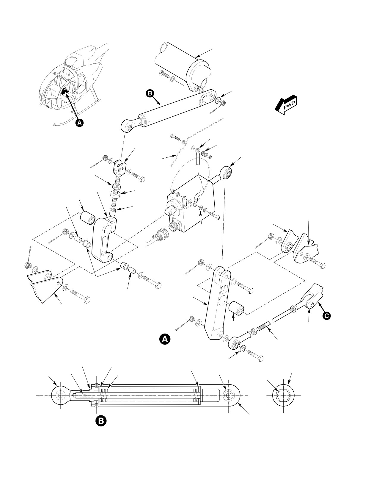
CSP-HMI-2
MD Helicopters, Inc.
MAINTENANCE MANUAL
COLLECTIVE TORQUE TUBE
NOTE 3
DROOP
GROUND JUMPER
COMPENSATION
FORK
AIRFRAME
N2 TRIM ACTUATOR
STRUCTURE
JAM NUT
STA. 68.00 BELLCRANK
SPACER
BEARING
SLEEVE BUSHING
LOCKED
THREAD
AIRFRAME
INSERT
STRUCTURE
BRACKET
*
FLANGED
BUSHING
STA. 72.00
SLEEVE
BELLCRANK
BUSHING
STA. 64.00 SEAT
STRUCTURE
BRACKET
NOTES:
BEARING
STA. 124.00
1.
BUSHINGS AND BEARINGS MUST ROTATE
BELLCRANK
FREELY AFTER ASSEMBLY.
2.
ASTERISK ( * ) INDICATES CORROSION
FUSELAGE-ROUTED
RESISTANT STEEL.
CONTROL ROD
JAM NUT
NOTE 3
RETAINER
HOUSING END
RETAINER
RIVET
BEARING
FITTING
ROD END
SPRING
PLUNGER
LINK HOUSING
DROOP CONTROL OVERRIDE LINK
G76-1007-1
Figure 208. Power Turbine Governor Controls (Sheet 1 of 2)
Page 220
Revision 22
76-10-00
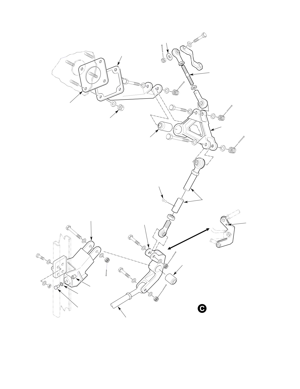
MD Helicopters, Inc.
CSP-HMI-2
MAINTENANCE MANUAL
NOTE 3
IDLER
BELLCRANK
SUPPORT
GOVERNOR LEVER
CONTROL ROD
GASKET
NUT
(NOTE 5)
IDLER BELLCRANK
BEARING
(NOTE 2)
RIVET
IDLER BELLCRANK
CONTROL ROD
STA. 124.00
SUPPORT FITTING
STA. 124.00
BELLCRANK
250-C30 ENGINE
INSTALLATION
BEARING
NOTES: (CONT.)
3.
SPECIAL ALUMINUM ALLOY WASHER;
0.25 IN. (6.35 MM) ID X 0.80 IN. (20.32 MM) OD.
4.
MAXIMUM OF 3 WASHERS ALLOWED TO
COLLAR
CORRECT PIN GRIP.
5.
ONLY HIGH TEMPERATURE ALL-METAL
WASHER
(NOTE 4)
NUTS MUST BE USED.
PULL-TYPE
LOCKBOLT PIN
ENGINE COMPARTMENT LINKAGE
FUSELAGE-ROUTED
(POWER TURBINE CONTROL)
CONTROL ROD
G76-1007-2A
Figure 208. Power Turbine Governor Controls (Sheet 2 of 2)
Page 221
76-10-00
Revision 22
CSP-HMI-2
MD Helicopters, Inc.
MAINTENANCE MANUAL
15. Control Rod Repair
(3). With actuator ram approximately
halfway between stops, measure ram
(Ref. Figure 208)
end-play with dial indicator. End-play
must not exceed 0.005 inch (0.127 mm)
(1). Repair rod assemblies as follows:
total indicator reading when measured
under 10 pound (4.5 kg) reversing load.
Fluorescent penetrant crack in
CAUTION
spection shall be performed af
(4). Set test switch to RETRACT and allow
ter cold-straightening control rods. Replace
actuator ram to fully retract. Using end
a cracked rod. Replace a cracked or bent
of ram sleeve as reference point,
rod-end.
measure portion of ram that remains
out of sleeve to nearest 1/64 inch
(2). Cold-straighten bent rods provided
(0.3968 mm). Record this measurement
there are no nicks or sharp dents in
for use in the following step.
bend length. Do not use rod-ends to
support rod during straightening
(5). Set test switch to EXTEND and run
process.
ram to extend stop. Measure length of
extended ram. Subtract result of step
Use care when drilling to re
CAUTION
(4). from extended ram value. Result
move or install riveted rod-end.
should be 0.97-1.03 inches
Tighten jam nut before drilling or riveting.
(24.638-26.162 mm).
(3). Replace control rod end if bearing axial
(6). Actuator current draw at 26.0Vdc shall
play is more than 0.040 inch (1.016
be:
mm).
(a). Under no-load; 0.60-1.25 amperes.
16. Bellcrank and Support Fitting Repair
(b). Stalled; 2.0 amperes, maximum.
(Ref. Figure 208)
(7).
Operate actuator motor in both extend
Consumable Materials
and retract directions. Over-travel
(Ref. Section 91−00−00)
must not exceed 0.020 inch (0.508 mm)
Item
Nomenclature
maximum when power is switched off.
CM321
Surface primer locking compound
(8).
Reduce voltage input to 21 volts.
CM431
Sealing, locking and retaining compound
Actuator ram must retract and extend
to stops without binding on or between
stops.
(1). Install replacement bearings using
surface primer (CM321) and grade A
(9).
Increase input voltage to 28 volts.
locking compound (CM431) per contain
Actuator ram must retract and extend
er instructions.
to stops without binding on stops or
(2). Replace distorted or cracked bellcranks
between stops.
and support fittings. Replace parts that
have elongated holes.
(10).
Run actuator to full extended position.
Extended actuator overall length shall
be 5.47-5.50 inches (13.894-13.970 cm)
17. N2 Trim Actuator Test
between pivot bolt centers.
(Ref. Figure 209)
(11).
Torque rod-end jamnut to 30 - 40
(1). Connect N2 trim actuator to test
inch-pounds (3.39 - 4.52 Nm).
equipment.
(12).
Turn off power.
(2). Turn on dc power and adjust output to
25.75 to 26.25 volts.
(13).
Disconnect actuator.
Page 222
Revision 35
76-10-00
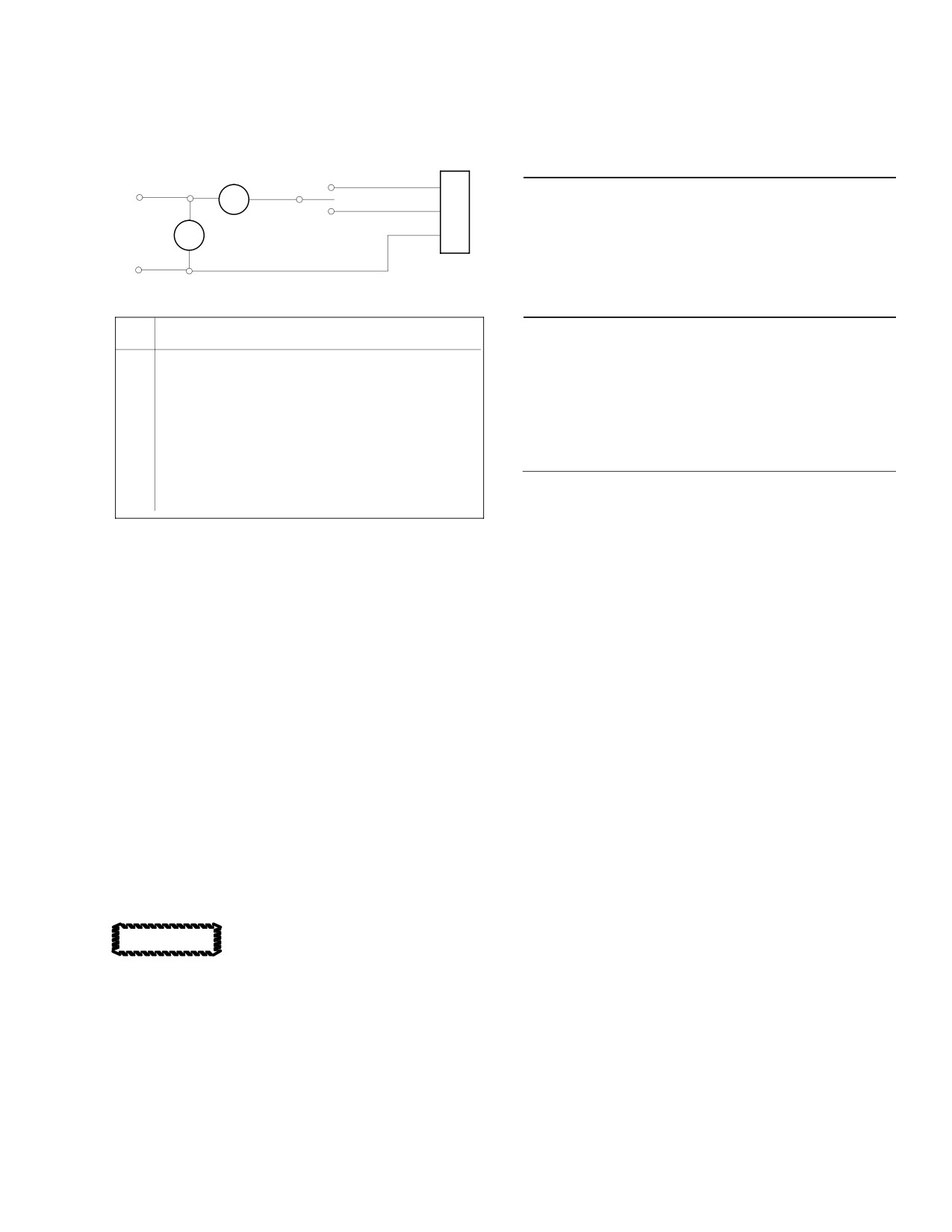
MD Helicopters, Inc.
CSP-HMI-2
MAINTENANCE MANUAL
19. Sta. 68.00 Bellcrank Rework, P/N
369A7717−3 and 369N2606 Only
MS3106-10L-3S
(Ref. Figure 210)
CONNECTOR
M1
SPDT
EXTEND
SWITCH
A
+
Consumable Materials
MA
RETRACT
B
(Ref. Section 91−00−00)
26 VDC
Item
Nomenclature
V M2
POWER
C
CM318
Primer
-
N/A
Dichromate
N/A
Anodizing compound
ITEM
EQUIPMENT DESCRIPTION
Special Tools
N
O.
(Ref. Section 91−00−00)
1
6-INCH SCALE
Item
Nomenclature
2
DC VOLTMETER, CALIBRATED 0-5 VOLTS.
(WESTON MODEL 931 OR
N/A
Spotface cutter, 0.687 inch (17450 mm)
EQUIVALNET)
dia., 0.030 inch (0.762 mm) corner radius
3
DC MILLIAMMETER, CALIBRATED 0-5AMPERES.
(WESTON MODEL 931 OR
N/A
Spotface cutter pilot, 5/16-24 UNF-3A
EQUIVALENT)
thread
4
VARIABLE DC POWER SUPPLY, 10-36 VOLTS,
(N.J.E. MODEL SY36-10 OR
EQUIVALENT)
(1).
Remove panels required to get at power
5
DIAL INDICATOR GAGE
turbine governor controls linkage.
(BROWN AND SHARP MODEL 740
OR EQUIVALENT)
G76-1008
(2).
Unbolt and remove Sta. 68.00 bellcrank
assembly.
Figure 209. N2 Trim Actuator Test Hookup
(3).
To expedite reassembly, measure and
note distance between the center of
droop compensation fork clevis bolt hole
and bellcrank pivot bolt hole. Remove
droop compensation fork from bell
18. N2 Trim Actuator Repair
crank.
(4).
Screw spotface cutter pilot into bell
crank. Cut away only enough material
(1). N2 actuator repairs are limited to
to provide a 360° flat surface around
actuator ram rod-end replacement. Set
hole. Do not cut into thread insert.
distance between pivot-bolt centers to
(5).
Coat bare metal surface with Dow #7 or
5.44-5.50 inches (13.818-13.970 cm)
#17 chemical treatment per manufac
with ram fully extended. Torque
turers instructions.
rod-end jamnut to 30 - 40 inch-
(6).
Apply primer (CM318) over reworked
pounds (3.39 - 4.52 Nm).
surfaces. Allow primer to dry.
(7).
Assemble locknut, spacer and droop
compensation fork on bellcrank. Get as
All other actuator repairs are to
close to previously noted dimension as
CAUTION
possible.
be performed by an authorized
overhaul station or the actuator manufac
(8).
Rig power turbine governor controls.
turer.
(9).
Note compliance in helicopter log book.
Page 223
76-10-00
Revision 35
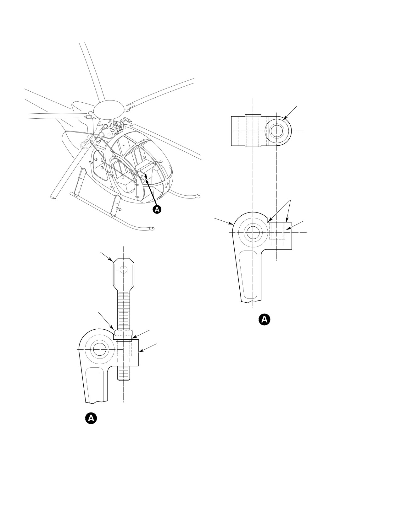
CSP-HMI-2
MD Helicopters, Inc.
MAINTENANCE MANUAL
0.687 IN. (17.45 MM)
DIA SPOTFACE
(NOTE)
NOTE
BELLCRANK
THREAD INSERT
DROOP
COMPENSATION
FORK
JAM NUT
SPACER
STA. 68.00
BELLCRANK
ASSEMBLY
NOTE:
ASSEMBLY ARRANGEMENT
DO NOT SPOTFACE BELOW INSERT
G76-1009
Figure 210. Station 68.00 Bellcrank Rework
Page 224
Revision 22
76-10-00
MD Helicopters, Inc.
CSP-HMI-2
MAINTENANCE MANUAL
Section
76−20−00
Gas Producer
Controls (250−C20B,
250−C20R/2 and
250−C30)
MD Helicopters, Inc.
CSP-HMI-2
MAINTENANCE MANUAL
GAS PRODUCER CONTROLS
MAINTENANCE PRACTICES
1. Gas Producer Controls Rigging
D Rigging check/adjustments are required
(250−C20B and 250−C20R/2)
when pilot's compartment linkage, or con
trol rod lengths have been disturbed, or
(Ref. Figure 201)
when there is less than a 0.010 inch
(0.254 mm) gap between Sta. 129.00 fire
wall bellcrank upper arm and its support
Special Tools
fitting with the throttle in CUT-OFF.
(Ref. Section 91−00−00)
Item
Nomenclature
(1).
Remove gas producer lever control rod
ST404
Wrench, ground idle adjusting
(Detail B).
ST501
Collective rigging fixture
(2).
Position pilot's collective stick at
(LH command)
mid-travel. Insert rigging fixture
ST502
Collective rigging fixture
(ST501) or (ST502) in collective friction
(RH command)
guide link slot. Rest collective stick on
fixture (Detail A).
NOTE:
(3).
On dual control installations; check for
D The following throttle control rigging pro
asynchronous motion between collective
cedures are applicable to Allison
stick throttle assemblies with the
250-C20B and 250-C20R/2 engines
throttle wide open and in CUT-OFF.
equipped with Bendix or Chandler Evans
Dual control throttle movement should
(CECO) fuel control systems.
be synchronized, but with the pilot's
(command position) throttle dominating
D Make fuel flow metering adjustments per
the copilot's throttle at idle.
Allison Engine Operation and Mainte
nance Manual except for 369/500 series
(4).
Position pilot's throttle twist grip so
helicopter specific idle speed variances
that twist grip set-screws are at six
explained in the following steps.
o'clock.
Failure to bleed fuel supply
(5).
Remove gearbox inspection plate on the
WARNING
system after opening system
bottom of the collective stick. Ensure
to atmosphere can result in power loss
that the centerline of the cutaway on
or engine flameout. Bleed trapped air
the large bevel gear is aligned on the
after opening any fuel lines between
collective stick lengthwise centerline. If
fuel tank and combustion chamber
gear is not properly positioned, remove
nozzle. Bleed fuel system following re
gearbox side plate and reposition the
moval and replacement of any part of
gear.
the engine or aircraft fuel system (Ref.
Sec. 28-00-00).
NOTE: When a ring adjustment is made, check
engagement of ring gear and pinion. Cutout
Do not exceed adjustable rod-
CAUTION
in ring gear should face aft with throttle in
end maximum extension/thread
CLOSED position. When dual controls are
engagement. Inspect rod-end thread en
in installed, check for override or interfer
gagement through witness hole.
ence between collective stick assemblies
with with the throttle grip in the CLOSED
NOTE:
and FULL OPEN position. Return throttle
D Refer to Collective Controls (Ref. Sec.
grip to MID travel position.
67-10-00) for information on rigging
throttle gas producer control tube, inter
(6). Find and remove all lost motion in the
connect torque tube and associated link
throttle system before making rigging
age.
adjustments.
Page 201
76-20-00
Revision 22
CSP-HMI-2
MD Helicopters, Inc.
MAINTENANCE MANUAL
NOTE: It is important that all assembly toler
Governor and fuel control levers
CAUTION
ances between the gas producer intercon
can be erroneously installed on
nects and torque tube assemblies are correct
the wrong fuel system component shaft.
and all backlash removed to assure accurate
Governor lever is relatively short with an
rigging of the fuel control system.
offset angle of about 65°. Fuel control lever
offset angle is a more moderate 38°.
(7). Check idler for interference with its
(14). Move throttle twist grip from wide open
support.
to CUT-OFF to ensure that the throttle
lever is contacting open and closed fuel
(8). Adjust Sta. 73.00 control rod length so
control mechanical stops. Adjust gas
that lower arm of Sta. 70.00 bellcrank
producer lever control rod as required
is parallel to seat structure (Detail B).
to cause lever contact. Do not adjust
stops.
(9). Adjust fuselage-routed control rod
(15). Turn pilot's throttle to maximum rpm,
length so that bolt center in lower arm
then to idle.
of Sta. 129.00 bellcrank is 4.97-5.03
(16). Bendix Fuel Control: With pilot's
inches (12.624-12.776 cm) from Sta.
throttle held at idle, adjust gas produc
124.00 firewall bulkhead.
er lever control rod until gas producer
pointer is at 30° (View C).
(10). Move throttle to CUT-OFF.
(17). CECO Fuel Control: With pilot's
throttle held at idle, adjust gas produc
(11). Adjust the fuselage routed control rod
er lever rod until gas producer pointer
to provide a gap of 0.010-0.050 inch
is at 30° to 32°.
(0.254-1.270 mm) between Sta. 129.00
bellcrank upper arm and support
CAUTION
fitting. Push the rod and bellcrank
toward the firewall bulkhead to remove
D Do not alter gas producer lever position or
all friction errors before checking gap.
control linkage to adjust idle speed. Idle
speed is to be checked during engine op
erational test and adjusted with fuel con
NOTE:
trol idle screw, not with the linkage.
D Bendix Fuel Control: Pointer position
D Check linkage at extreme travel posi
may range from 0° to 10° when contacting
tions. Ensure gas producer lever hits fuel
the CUT-OFF stop, depending on calibra
control mechanical stops before throttle
tion settings peculiar to the fuel control.
twist grip stops are contacted.
D Bendix fuel control lever and shaft serra
D Interference or binding anywhere in link
tions are at 15° intervals.
age is not allowed.
D Be sure that linkage movement is clear of
(12). Set fuel control lever against CUT-OFF
wires, tubes and hoses.
stop. Pointer position should range
(18). Rotate pilot's throttle counterclockwise
between the 0° and 10° quadrant
to maximum rpm.
marks. Set the fuel control throttle
shaft lever, without moving the pointer,
(19). Make sure gas producer lever strikes
15° counterclockwise from parallel with
maximum speed stop.
the engine compartment door frame
(20). Raise collective stick to up stop.
while keeping the pointer at CUT-OFF
and inboard lever half in contact with
(21). Gas producer lever must remain in
stop.
contact with maximum speed stop; if
lever comes off stop, check gas producer
controls for binding.
(13). Torque fuel control lever nut to 40 - 50
inch-pounds (4.52 - 5.65 Nm). Do not
(22). Release idle detent and roll pilot's
over-tighten nut. Apply a torque stripe.
throttle to CUT-OFF. Make sure that
Page 202
Revision 22
76-20-00
MD Helicopters, Inc.
CSP-HMI-2
MAINTENANCE MANUAL
gas producer lever strikes CUT-OFF
fault isolation procedures per Allison
stop.
Manual.
(29). Accelerate and decelerate engine three
(23). Lower collective stick. Ensure gas
times to ensure repeatability.
producer lever does not move off
CUT-OFF stop.
Throttle snap to idle must be
WARNING
performed to ensure that en
(24). When dual controls are installed, move
gine will not flame out.
copilot's throttle twist grip to its idle
stop. Fuel control pointer shall not be
(30). Accelerate engine to to normal operat
more than 5/64 inch (1.9844 mm) below
ing rpm with pilot's throttle; then snap
the idle degree mark specified for a
clockwise to idle. Repeat this check
Bendix fuel control (30°) or a CECO
using copilot's throttle where installed.
fuel control (30 to 32°) as applicable.
If flameout occurs, adjust engine idle
speed per the applicable Allison
(25). Have an assistant cycle the throttle
Operation and Maintenance Manual.
from CUT-OFF to wide open. Ensure
control rods do not roll over or jam
Perform a deceleration time
CAUTION
when linkage is at extreme travel
check per PFM following gas
positions.
producer or linkage replacement or adjust
ment. Refer to Allison Engine Operation
NOTE: Refer to your Allison Operation and
and Maintenance Manual for adjustment
Maintenance Manual for complete gas pro
procedures when deceleration time is less
ducer fuel control rigging procedures to
than allowable minimum.
make the following adjustments.
(31). Shut down engine.
(26). Start and operate engine at idle with
main rotor in flat pitch per Pilot's
2. Gas Producer Controls Rigging (250−C30)
Flight Manual (PFM).
(Ref. Figure 201)
Operating requirements de
CAUTION
mand that idle rpm be adjusted
Special Tools
within minus 1% of the Allison specified up
(Ref. Section 91−00−00)
per limit of 65% rpm. Achieving required
Item
Nomenclature
idle rpm is particularly important for heli
ST404
Wrench, ground idle adjusting
copters equipped with dual controls.
ST405
Rigging fixture, collective stick
(27). With pilot's throttle at idle, observe Nl
ST406
Alignment fixture
tachometer indicator. Ensure Nl speed
ST407
Rigging pin
stabilizes between 64 - 65 %. To adjust
ST501
Collective rigging fixture
idle rpm, proceed as follows:
(LH command)
ST502
Collective rigging fixture
(a). Bendix: Adjust idle speed with
(RH command)
adjusting tool (ST404) per the
applicable Allison Operation and
Maintenance Manual.
NOTE:
D The following throttle control rigging pro
(b). CECO: Adjust idle speed with a 5/32
cedures are applicable to Allison 250-C30
hex-wrench per the 250-C20 Allison
engines equipped with Bendix fuel control
Operation and Maintenance Manual.
systems.
(28). Accelerate engine to 100%, stabilize,
D Make fuel flow metering adjustments per
then decelerate to idle after each
Allison Engine Operation and Mainte
adjustment. If idle adjustments do not
nance Manual except for 369/500 series
consistently stabilize rpm within 64% -
helicopter specific idle speed variances
65% limit, follow engine fuel control
explained in the following steps.
Page 203
76-20-00
Revision 22
CSP-HMI-2
MD Helicopters, Inc.
MAINTENANCE MANUAL
RIGGING
FIXTURE
FIXTURE INSTALLATION
TORQUE TUBE
ASSEMBLY
GEARBOX
INSPECTION
PLATE
COLLECTIVE FRICTION
CONTROL
GEARBOX
SIDE PLATE
PILOT'S COLLECTIVE
PITCH STICK
FRICTION
GUIDE LINK
G76-2000-1
Figure 201. Gas Producer Controls Rigging (Sheet 1 of 3)
Page 204
Revision 22
76-20-00
MD Helicopters, Inc.
CSP-HMI-2
MAINTENANCE MANUAL
IDLE POSITION
(NOTES 10, 11)
GAS
PRODUCER
MID POSITION
CUT-OFF
(NOTE 1
POSITION
LEVER
TORQUE NUT
(NOTE 8)
40-50 IN. LBS.
(4.52-5.65 NM)
GAS PRODUCER
CUT-OFF
LEVER CONTROL
(NOTE 7)
C
L
OF
CONTROL ROD
POINTER
QUADRANT
CECO FUEL CONTROL
IDLE RANGE
(NOTES 9, 11)
OVERTRAVEL
POINTER
(NOTE 1)
(NOTE 12)
BENDIX FUEL CONTROL
LEVER CONTROL
ROD
LEVER POSITION
QUADRANT
250-C30 FUEL CONTROL
FUEL CONTROL LEVER
AND POINTER
GAS PRODUCER
SUPPORT
LEVER CONTROL ROD
FITTING
STA. 129.00
BELLCRANK
STA. 74.87
GAP
(NOTE 6)
STA. 73.00
CONTROL ROD
IDLER ASSY.
DISTANCE
(NOTES 4, 5)
STA. 70.00
STA. 124.00
BELLCRANK
FIREWALL
(NOTES 2, 3)
FUSELAGE-ROUTED
CONTROL ROD
LINKAGE INSTALLATION
(NOTE 1)
G76-2000-2A
Figure 201. Gas Producer Controls Rigging (Sheet 2 of 3)
Page 205
76-20-00
Revision 22
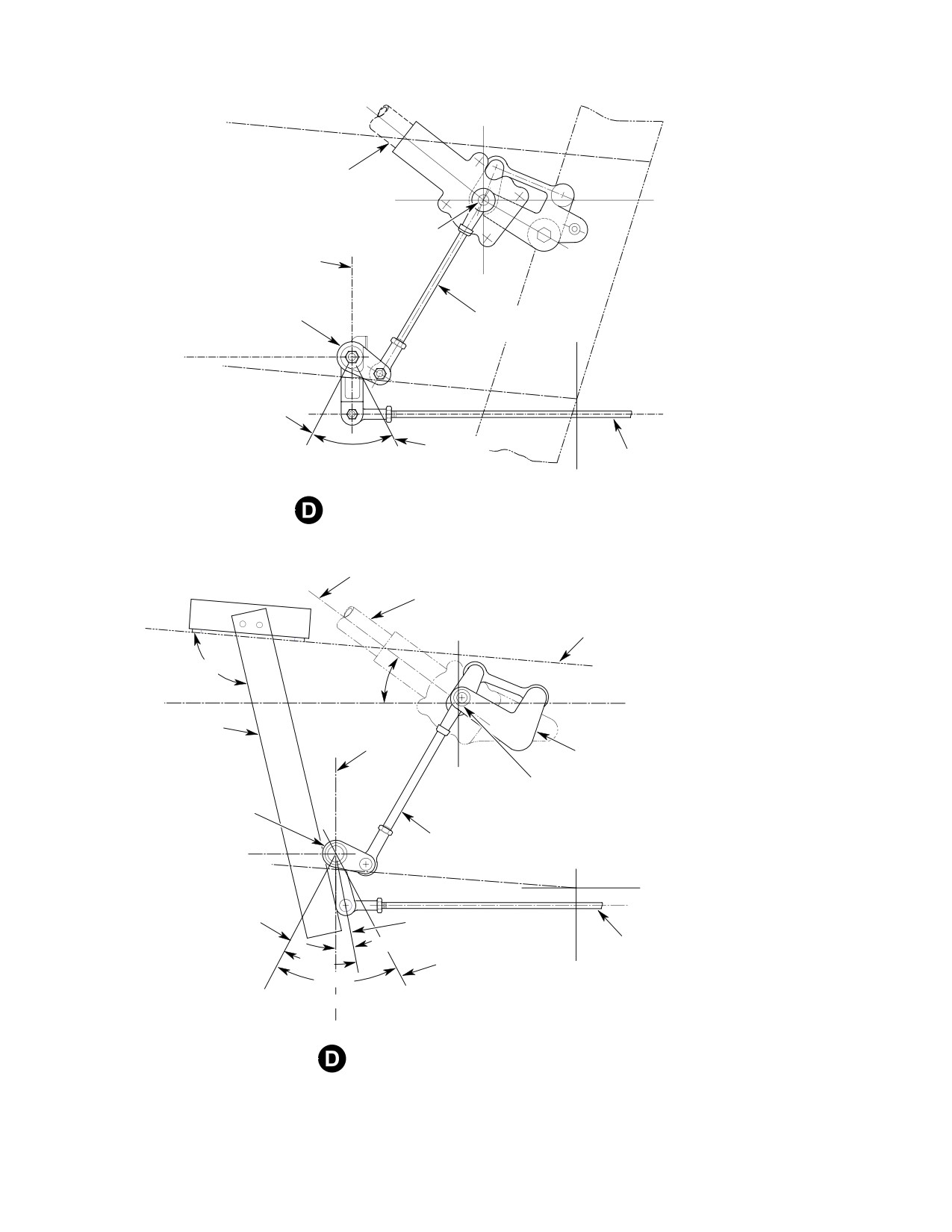
CSP-HMI-2
MD Helicopters, Inc.
MAINTENANCE MANUAL
COLLECTIVE STICK
(NOTE 1)
C COLLECTIVE
VERTICAL (PARALLEL)
WITH FORWARD SEAT
TORQUE TUBE
STRUCTURE
STA. 70.00
BELLCRANK ASSY.
STA. 73.00 CONTROL
(NOTE 2)
ROD ASSY.
WL
14.47
THROTTLE
WL
OPEN
13.10
THROTTLE
54° 30'
CUT-OFF
FUSELAGE-ROUTED
CONTROL ROD ASSY.
STA. 78.21
COLLECTIVE STICK LINKAGE RIGGING, 250-C20B
AND 250-C20R/2 ENGINE EQUIPPED HELICOPTERS
COLLECTIVE
(NOTE 1)
THROTTLE TWIST GRIP
IN FLIGHT IDLE
PILOT'S SEAT
STRUCTURE
(REF)
99° 55' 12”
38° (REF)
(REF)
WL
20.03
ALIGNMENT
FIXTURE
VERTICAL
IDLER
STA. 74.87
C
L COLLECTIVE
STA. 70.00
TORQUE TUBE
BELLCRANK
(NOTE 3)
STA. 73.00 CONTROL
WL
ROD ASSY.
14.47
WL
13.10
THROTTLE
OPEN
IDLE
5° 45'
FUSELAGE-ROUTED
THROTTLE
ROD ASSY.
37° 30'
CUT-OFF
STA. 78.21
54° 30'
MID
STA. 70.35
COLLECTIVE STICK LINKAGE RIGGING
250-C30 ENGINE EQUIPPED HELICOPTERS
G76-2000-3A
Figure 201. Gas Producer Controls Rigging (Sheet 3 of 3)
Page 206
Revision 22
76-20-00
MD Helicopters, Inc.
CSP-HMI-2
MAINTENANCE MANUAL
Legend (Ref. Figure 201)
1.
EXCEPT AS NOTED, GAS PRODUCER AIRFRAME
6.
ON ALL ENGINE INSTALLATIONS: ROLL THROTTLE
CONTROL LINKAGE RIGGING ADJUSTMENTS AND
TO CUT−OFF AND PUSH CONTROL ROD AND
MEASUREMENTS ON ALL 369/500 SERIES
BELLCRANK TOWARD FIREWALL TO ELIMINATE
HELICOPTER MODELS ARE NORMALLY STARTED
PLAY. ADJUST FUSELAGE ROUTED CONTROL ROD
WITH FUEL CONTROL LEVER CONTROL ROD
TO GET A GAP OF 0.010−0.050 INCH (0.254−1.270
DISCONNECTED, COLLECTIVE STICK AT
MM) BETWEEN UPPER BELLCRANK ARM AND
MID−TRAVEL; I.E., RIGGING FIXTURE (ST501) OR
SUPPORT FITTING.
(ST502) INSTALLED, AND THE PILOT’S THROTTLE
7.
BENDIX FUEL CONTROL CUT−OFF POINTER
TWIST GRIP ROTATED TO MID−POSITION; I.E., TWIST
POSITION NORMALLY RANGES BETWEEN 0 − 10°
GRIP SET−SCREWS AT SIX O’CLOCK.
WITH FUEL CONTROL LEVER AGAINST CUT−OFF
2.
ON 250−C20B AND 250−C20R/2 ENGINE EQUIPPED
STOP. CUT−OFF RANGE IS DUE TO FACTORY SET
HELICOPTERS; ADJUST STA. 73.00 CONTROL ROD
CALIBRATION VARIATIONS BETWEEN FUEL
SO LOWER ARM OF STA. 70.00 BELLCRANK IS
CONTROL UNITS.
VERTICAL WHEN THROTTLE TWIST GRIP IS AT IDLE
8.
CECO FUEL CONTROL CUT−OFF POINTER
POSITION.
POSITION IS 2° TO MINUS, 1/32 INCH (0.7938 MM)
3.
FOR 250−C30 ENGINE EQUIPPED HELICOPTERS;
FROM QUADRANT EDGE, WITH FUEL CONTROL
ALIGN FORWARD FACE OF STA. 70.00 BELLCRANK
LEVER AGAINST CUT−OFF STOP.
WITH AFT EDGE OF FIXTURE (ST406).
9.
WITH PILOT’S THROTTLE TWIST GRIP HELD AT IDLE:
4.
FOR 250−C20B AND 250−C20R/2 ENGINE EQUIPPED
BENDIX FUEL CONTROL IDLE POINTER POSITION IS
HELICOPTERS; WITH THROTTLE AND COLLECTIVE
30°.
IN MID−POSITION, ADJUST FUSELAGE ROUTED
10.
CECO FUEL CONTROL IDLE POINTER POSITION IS
CONTROL ROD SO CENTER OF STA. 129.00
30 − 32°.
BELLCRANK LOWER ARM PIVOT BOLT IS 4.97−5.03
11.
MAXIMUM ALLOWABLE POINTER MOVEMENT
INCHES (12.624−12.776 CM) FROM FIREWALL
BELOW THE OPTIMAL IDLE POSITION ON ALL
BULKHEAD.
ENGINE INSTALLATIONS FROM ALL CAUSES IS, 5/64
5.
FOR 250−C30 ENGINE EQUIPPED HELICOPTERS;
INCH (1.9844 MM).
WITH THROTTLE AND COLLECTIVE IN
12.
NORMAL SETTING IS 40° WITH PILOT’S THROTTLE
MID−POSITION, ADJUST FUSELAGE ROUTED
AT IDLE.
CONTROL ROD SO CENTER OF STA. 129.00
BELLCRANK LOWER ARM PIVOT BOLT IS 5.47 − 5.50
INCHES (13.894−13.970 CM) FROM FIREWALL
BULKHEAD.
Failure to bleed fuel supply
D Rigging check/adjustments are required
WARNING
system after opening system
when pilot's compartment linkage or fuse
to atmosphere can result in power loss
lage-routed control rod length adjust
or engine flameout. Bleed trapped air
ments have been disturbed, or when there
after opening any fuel lines between
is less than a 0.010 inch (0.254 mm) gap
fuel tank and combustion chamber
between Sta. 129.00 firewall bellcrank
nozzle. Bleed fuel system following re
upper arm and its support fitting with the
moval and replacement of any part of
throttle in CUT-OFF position.
the engine or aircraft fuel system (Ref.
(1). Remove gas producer lever control rod
Sec. 28-00-00).
(Detail B).
(2). Position pilot's collective stick at
Do not exceed adjustable rod-
mid-travel. Insert rigging fixture
CAUTION
end maximum extension/thread
(ST501) or (ST502) in collective friction
engagement. Inspect rod-end thread en
guide link slot. Rest collective stick on
gagement through witness hole.
fixture.
(3). On dual control installations; check for
NOTE:
a synchronous motion between collec
tive stick throttle assemblies with the
D Refer to Collective Controls (Ref. Sec.
throttle wide open and in CUT-OFF.
67-10-00) for information on rigging
Dual control throttle movement should
throttle gas producer control tube, inter
be synchronized, but with the pilot's
connect torque tube and associated link
(command position) throttle dominating
age.
the copilot's throttle at idle.
Page 207
76-20-00
Revision 22
CSP-HMI-2
MD Helicopters, Inc.
MAINTENANCE MANUAL
(4).
Position plot's throttle twist grip so that
(15). Torque control rod jamnuts to 25 - 30
twist grip set screws are at six o'clock.
inch-pounds (2.82 - 3.39 Nm).
(5).
Remove gearbox inspection plate on the
CAUTION
bottom of the collective stick. Ensure
that the centerline of the cutaway on
D Adjusting fuel control mechanical stop
the large bevel gear is aligned on the
settings for any reason is not allowed.
collective stick lengthwise centerline. If
D Governor and fuel control levers can be
gear is not properly positioned, remove
erroneously installed on the wrong fuel
gearbox side plate and reposition the
system component shaft. Governor lever
gear.
is relatively short with an offset angle of
about 65°. Fuel control lever offset angle
(6).
Find and remove all lost motion in the
is a more moderate 38°.
throttle system before making rigging
adjustments.
NOTE:
D Pointer position may range from 0° to 10°
(7).
Put throttle in idle position and secure
when contacting the idle CUT-OFF stop,
with friction lock.
depending on calibration settings pecul
(8).
Locate and secure alignment fixture
iar to the fuel control unit.
(ST406) on the pilot's seat structure.
D The Bendix fuel control features a double
The forward face of the Sta. 70.00
serrated washer between the lever and
bellcrank should align with the aft edge
fuel control input shaft. There are 24 (15°
of the fixture. Adjust Sta. 73.00 control
each) serrations on the lever side and 25
rod as required to align bellcrank with
(14.4° each) serrations on the fuel control
fixture. Remove the rigging fixture.
side that allow coarse or fine lever posi
tion adjustments to be made. Make 0.6°
(9).
Bottom the collective stick and check
incremental adjustments by moving the
the idler assembly for clearance with
washer one serration in one direction and
support.
the lever one serration in the opposite di
rection. Fifteen degree adjustments are
(10).
Set collective and throttle at mid-tra
made by moving the lever against the
vel.
washer; 14.4°
adjustments by moving the
(11).
Adjust fuselage-routed control rod
washer and lever together against the fuel
length so bolt center through lower arm
control shaft.
of Sta. 129.00 bellcrank is 5.50 ±0.03
(16). Rotate the throttle twist grip to idle.
inches (139.7 ±0.762 mm) from Sta.
124.00 firewall bulkhead.
(17). Insert rigging pin (ST407) through fuel
control lever. Position the lever on the
(12).
Rotate throttle twist grip to CUT-OFF.
fuel control throttle shaft so that lever
is close to parallel to, or a maximum of
(13).
Adjust the fuselage routed control rod
5° forward of the Sta. 137.50 engine
to provide a gap of 0.010-0.050 inch
compartment bulkhead. Torque lever
(0.254-1.270 mm) between Sta. 129.00
nut to 40 - 50 inch-pounds (4.52 -
bellcrank upper arm and support
5.65 Nm). Do not over-tighten the nut.
fitting. Push the rod and bellcrank
Apply a torque stripe.
toward the firewall bulkhead to remove
all friction errors before adjusting gap.
(18). Set gas producer lever control rod to a
preliminary length of 16.4 inches (41.66
NOTE: It will be necessary, during the rigging
cm) measured between rod-end bolt
procedure to remove and reinstall the rig
hole centers.
ging fixtures as required.
(19). Set throttle twist grip in the idle
(14). Move collective through full range of
position. Connect gas producer lever
travel. Ensure throttle movement is
control rod. Adjust rod length as
unrestricted in all collective stick
required to align it with the fuel control
positions.
lever.
Page 208
Revision 22
76-20-00
MD Helicopters, Inc.
CSP-HMI-2
MAINTENANCE MANUAL
To prevent flameout, the fuel
(24). Move and hold throttle at idle. Check;
CAUTION
control pointer should not move
gas producer pointer is at 40° quadrant
more than 5/64 inch (1.9844 mm) below the
position.
fuel control quadrant 40° mark with throttle
at idle and commanded by either the pilot's
CAUTION
or copilot's twist grip.
D Do not alter gas producer lever position or
NOTE:
control linkage to adjust idle speed. Idle
speed shall be adjusted by the fuel control
D When dual controls are installed, move
idle screw, not the linkage.
copilot's throttle twist grip to its idle stop.
Fuel control pointer shall not be more
D Check linkage at travel extremes to en
than 5/64 inch (1.9844 mm) below the idle
sure that the linkage does not bind at any
degree mark.
point and the gas producer lever hits the
fuel control mechanical stops before the
D Throttle twist grip stopped at idle setting
throttle twist grip stops make contact.
must produce a 40° pointer/quadrant
alignment on the fuel control with the rig
(25). Set pilot's throttle wide open. Raise
ging pin inserted.
collective stick to upper stop. Check
that fuel control lever remains on max
(20). Remove rigging pin and operate pilot's
speed stop. Inspect the fuel control
throttle twist grip from CUT-OFF to
linkage for binding if the fuel control
wide open while an assistant deter
lever comes off the max speed stop.
mines that the fuel control lever
contacts the max open and CUT-OFF
(26). Leave throttle wide open and bottom
mechanical stops and the following
pilot's collective stick. Check that fuel
pointer positions are indicated.
control lever remains in contact with
the max stop.
(a). With pilot's throttle wide open, fuel
(27). Have an assistant move throttle and
control pointer shall align with
collective stick through entire range of
quadrant 100° mark and fuel control
travel while inspecting installation for
max stop shall be in contact with
operating clearances, control rod
lever.
bearing jamming and rod roll-over.
(b). With pilot's throttle in CUT-OFF;
(28). Check that the copilot's throttle
fuel control pointer shall be between
operates N1 fuel control the same as the
0° and 10° quadrant marks with
pilot's with the following exception:
lever in contact with fuel control
minimum stop.
(a). When the copilot's throttle twist grip
is rotated to its idle stop, the fuel
(21). Adjust the gas producer lever control
control pointer shall move no more
rod length as required to move lever
than 5/64 inch (1.9844 mm) below the
into stop contact. If the Sta. 124.00
quadrant 40° mark (Detail C).
bellcrank bottoms on its support fitting,
(29). Inspect all bolts, nuts, control rod
adjust fuselage routed control rod one
jamnuts, cotter pins and lockwire
turn away from the bellcrank bottoming
installations for security.
problem.
NOTE: Refer to your Allison Operation and
(22). Return pilot's throttle twist grip to idle
Maintenance Manual for complete gas pro
detent. Ensure fuel control pointer
ducer fuel control rigging procedures to
aligns with 40° mark.
make the following adjustments.
(23). Bottom the pilot's collective stick.
(30). Start and operate engine at idle with
Rotate throttle to wide open. Check for
main rotor in flat pitch per Pilot's
stop/lever contact.
Flight Manual.
Page 209
76-20-00
Revision 22
CSP-HMI-2
MD Helicopters, Inc.
MAINTENANCE MANUAL
Operating requirements de
B. Power Controls Operational Test/Final
CAUTION
mand that idle rpm be adjusted
Adjustments
within minus 1% of the Allison specified up
(Ref. Sec. 76-10-00)
per limit of 65% rpm. Achieving required
idle rpm is particularly important for heli
3. Gas Producer Controls Linkage
copters equipped with dual controls.
Replacement
(31). With pilot's throttle at idle, observe Nl
(Ref. Figure 202)
tachometer indicator. Ensure Nl speed
stabilizes between 64% - 65%.
(1). Disassemble linkage only to point
required to make repairs.
(a). Adjust idle speed with adjusting tool
(2). Measure and note control rod length
(ST404) per the applicable Allison
before removing rod-ends to expedite
Operation and Maintenance Manual.
reassembly and rigging.
(32). Accelerate engine to 100%, stabilize,
4. Sta. 124.00 Support Fitting Replacement
then decelerate to idle after each
adjustment. If idle adjustments do not
(Ref. Figure 202)
consistently stabilize rpm within 64% -
65% limit, follow engine fuel control
A. Sta. 124.00 Support Fitting Removal
fault isolation procedures per Allison
Manual.
(1). Remove lockbolt from Sta. 124.00
support fitting as follows:
(33). Accelerate and decelerate engine three
(2). Split collar axially with a sharp chisel.
times to ensure repeatability.
Have an assistant support opposite side
with a bucking bar to prevent hole
Throttle snap to idle must be
deformation or breakout. Drive pin out
WARNING
performed to ensure that en
with a drift.
gine will not flame out.
NOTE: Lockbolt hole enlargement beyond
(34). Accelerate engine to to normal operat
0.1870 inch (4.7498 mm) diameter requires
ing rpm with pilot's throttle, then snap
an oversize lockbolt pin installation.
to idle. Repeat this check using copilot's
B. Sta. 124.00 Support Fitting Installation
throttle where installed. If flameout
occurs, adjust engine idle speed per the
applicable Allison Operation and
Special Tools
Maintenance Manual.
(Ref. Section 91−00−00)
Item
Nomenclature
Perform a deceleration time
ST2009
Inspection gauge
CAUTION
check per PFM following gas
producer or linkage replacement or adjust
ment. Refer to Allison Engine Operation
(1). Position support fitting on Sta. 124.00
and Maintenance Manual for adjustment
lower frame. Install standard bolts,
procedures when deceleration time is less
washers and nuts. Do not tighten.
than allowable minimum.
NOTE: A standard size pin may be used where
pin hole does not exceed 0.1870 inch (4.7498
(35). Shut down engine.
mm) diameter; otherwise, proceed as fol
lows:
A. Gas Producer Fuel Control De−richment
Valve Adjustment
(2). Use a No.7 drill to enlarge a damaged
hole to 0.2015 inch (5.1181 mm)
(1). Refer to Allison Engine Operation and
maximum diameter. Use a 3/16 inch
Maintenance Manual.
(4.7625 mm) diameter replacement pin.
Page 210
Revision 22
76-20-00
MD Helicopters, Inc.
CSP-HMI-2
MAINTENANCE MANUAL
NOTE: Up to three washers may be used under
1). Bearing wear is limited to 0.040
pin head to establish correct lockbolt grip.
inch (1.016 mm) maximum axial
looseness.
(3). Install lockbolt pin and collar; best fit
results when pulling gun air pressure is
(b). Surface damage.
90-125 psi (621-862 kPa).
(c). Cracks
(4). Inspect lockbolt installation with gauge
(d). Gouges
(ST2009) or equivalent.
(e). Nicks
(a). No gap is allowed under either pin
head or collar. If pin grip length or
(f). Loose end rivets
collar swage quality is questionable,
(g). Misalignment, bent or bowed
replace lockbolt.
Control rod variation from a
(5). Torque control support fitting/Sta.
CAUTION
straight line is limited to 0.010
124.00 attaching hardware.
inch (0.254 mm), maximum, in each foot.
Do not jam bearing against fit
CAUTION
(3). Bent or bowed gas producer control
ting. Hold rod-end with a
rods, excluding rod-ends, must fall
wrench when tightening adjustable end jam
within the following tolerances:
nut. Ensure bearing misalignment is di
vided equally between each control rod
(a). Fuselage-routed control rods: Not
bearing assembly.
more than 0.050 inch (1.270 mm),
total variation.
(6). Rig gas producer controls (Ref. Model
250-C20B and 250-C20R/2 Gas
(b). Sta. 73.00 control rod: Not more than
Producer Controls Rigging).
0.010 inch (0.254 mm), total varia
tion.
5. Gas Producer Controls Inspection
(c). Gas producer lever control rod: Not
(Ref. Figure 202)
more than 0.020 inch (0.508 mm),
total variation.
(1). Check gas producer linkage for lost
motion due to wear as follows:
(4). Inspect bellcrank and support fitting
bearings for binding.
(a). Open throttle to maximum speed
stop, then slowly back to to idle stop.
(5). Fluorescent penetrant inspect sus
pected parts for cracks.
(b). Mark pointer position on gas produc
er fuel control quadrant.
Check control system rig
WARNING
and engine operation follow
(c). Use light finger pressure to move gas
ing any repair that required gas pro
producer lever toward CUT-OFF.
ducer control or linkage disassembly
Mark pointer position on quadrant.
or replacement; prior to releasing heli
Relax pressure.
copter for flight.
(d). Measure distance between lever
Perform a deceleration time
CAUTION
position marks. Measurement
check per pilot's flight manual
exceeding 5/64 inch (1.9844 mm)
after adjusting or replacing gas producer
indicates unacceptable wear in
fuel control or linkage parts. Make adjust
throttle control linkage. Inspect
ments per Allison Operation and Mainte
individual linkage components for
nance Manual if deceleration time is less
loose fasteners and wear.
than allowable minimum.
(2). Inspect control rods for:
6. Gas Producer Control Rod Repair
(a). Worn or binding end bearings.
(Ref. Figure 201)
Page 211
76-20-00
Revision 22

CSP-HMI-2
MD Helicopters, Inc.
MAINTENANCE MANUAL
7. Bellcrank Repair
Consumable Materials
(Ref. Figure 202)
(Ref. Section 91−00−00)
Item
Nomenclature
(1). Replace bellcranks or control supports
that are distorted, cracked or have
CM321
Surface primer locking compound
elongated holes.
CM431
Sealing, locking and retaining compound
(2). Replace unserviceable bellcrank
bearings.
Fluorescent penetrant crack in
Do not get primer or locking
CAUTION
CAUTION
spection shall be performed af
compound on bearing surfaces.
ter cold-straightening. Replace a cracked or
bent rod, or rod-end.
(a). Apply surface primer and grade A
locking compound (CM321 and
CM431) to bearing outer race and
(1). Cold-straighten a bent rod provided
installation hole per manufacturers
there are no nicks or sharp dents in
instructions. Install bearing.
bend length. Do not use rod-ends to
Check control system rig
support rod during straightening
WARNING
and engine operation follow
process.
ing any repair that required gas pro
ducer control or linkage disassembly
Use care when drilling to re
or replacement; prior to releasing heli
CAUTION
move or install riveted rod-end.
copter for flight.
Tighten jam nut before drilling and riveting
Perform a deceleration time
to prevent hole enlargement.
CAUTION
check per pilot's flight manual
after replacing or adjusting gas producer
(2). Replace control rod-end if bearing axial
fuel control or linkage parts. Make adjust
play is more than 0.040 inch (1.016
ments per Allison Operation and Mainte
mm). Set initial control rod length and
nance Manual if deceleration time is less
bearing angularity as shown.
than allowable minimum.
Page 212
Revision 22
76-20-00
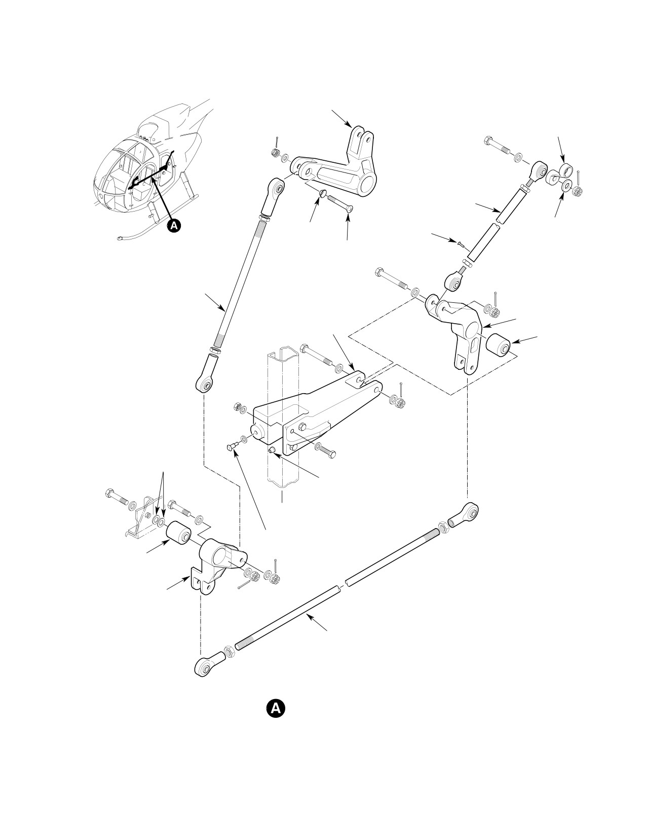
MD Helicopters, Inc.
CSP-HMI-2
MAINTENANCE MANUAL
COLLECTIVE STICK
GAS PRODUCER IDLER
GAS PRODUCER
LEVER
GAS PRODUCER
LEVER CONTROL ROD
WASHER
COUNTERSUNK
RIVET
(NOTE)
WASHER
COUNTERSUNK
SCREW
STA. 73.00
CONTROL ROD
STA. 129.00
BELLCRANK
SUPPORT FITTING
BEARING
THIN
WASHERS
COLLAR
STA. 124.00
FIREWALL
PULL-TYPE
LOCKBOLT PIN
BEARING
STA. 70.00
BELLCRANK
FUSELAGE-ROUTED
CONTROL ROD
NOTE:
GAS PRODUCER CONTROL LINKAGE
SPECIAL ALUMINUM ALLOY WASHER, 0.25 IN.
(6.35 MM) ID X 0.80 IN. (20.32 MM) OD.
G76-2001
Figure 202. Gas Producer Controls Replacement
Page 213
76-20-00
Revision 22
CSP-HMI-2
MD Helicopters, Inc.
MAINTENANCE MANUAL
This Page Intentionally Left Blank
Page 214
Revision 44
76-20-00
MD Helicopters, Inc.
CSP-HMI-2
MAINTENANCE MANUAL
Section
76−47−00
Engine Power
Controls (250−C47)
MD Helicopters, Inc.
CSP−HMI−2
MAINTENANCE MANUAL
ENGINE CONTROLS
MAINTENANCE PRACTICES
1. Engine Controls Description
modulates fuel flow to the engine in
conjunction with the position of the
(1). The 250-C47 engine control system
power lever angle (PLA) which is
consists of a full authority digital
connected to the throttle grip on the
engine control (FADEC) system for
collective stick by a control cable. The
automatic operation and a hydrome
PLA will be set with the throttle grip to
chanical backup system for emergencies
either the Cutoff, Ground Idle or Flight
or manual operation.
Idle position. The ECU provides hot
start and overspeed protection, over
(2). Refer to the 250-C47M Rolls-Royce
speed test function and auto-reignition
Engine Operation and Maintenance
and rotor speed trim capability.
Manual for additional engine fuel
system theory, operation and mainte
(2). In the Manual Mode, the fuel flow is
nance data.
modulated by the PLA on the Hydrome
chanical Control Unit with the throttle
2. Engine Controls Operation
grip and control cable. The ignition
exciter operates continuously in this
(1). Engine control mode is selected by the
mode.
Auto/Manual Switch. In the Auto Mode,
the Electronic Control Unit (ECU)
3. Engine Controls Fault Isolation
Table 201. Engine Controls Fault Isolation
Symptom
Probable Trouble
Corrective Action
ECU FAIL on Warning/Caution
Faulty ECU.
Replace ECU.
panel.
Faulty wiring.
Test and repair wiring.
Flight controls unresponsive.
Faulty ECU.
Replace ECU.
Faulty collective potentiometer.
Replace Collective Potentiometer.
Faulty directional potentiometer.
Replace Directional Potentiometer.
Faulty wiring.
Test and repair wiring.
Page 201
76-47-00
Revision 44
CSP−HMI−2
MD Helicopters, Inc.
MAINTENANCE MANUAL
4. ECU (Electronic Control Unit)
5. Engine Control Potentiometer
Replacement
Replacement
(Ref. Figure 202)
(Ref. Figure 202)
A. Collective Potentiometer Removal
(1). Detach electrical connector from
A. ECU Removal
collective potentiometer.
(2). Loosen potentiometer mounting screws
(1). Disconnect engine harness and air
and remove drive belt.
frame harness connectors from ECU.
(3). Remove screws and washers and
remove potentiometer assembly from
(2). Remove screw, lockwasher and washer
mounting bracket.
and disconnect bonding jumper from
ECU.
B. Collective Potentiometer Installation
Special Tools
(3). ECU P/N - 23068338, 23070259,
(Ref. Section 91−00−00)
23072949 and 23080491 - Remove
Item
Nomenclature
bolts, washers, large area washers and
ST1010
Volt-ohmmeter
bushings and remove ECU from
mounting bracket.
N/A
Laptop computer with MT35 program
(1). Prepare potentiometer mounting
(4). ECU P/N - 23088905, 23089311 -
surfaces for electrical bonding (Ref.
Remove bolts and washers and remove
CSP-HMI-3, Section 96-00-00).
ECU from mounting bracket.
(2). Install potentiometer with screws and
washers. Torque screws to 20 - 25
B. ECU Installation
inch-pounds (2.25 - 2.82 Nm).
(3). Rig potentiometer to collective stick.
(1). ECU P/N - 23068338, 23070259,
23072949 and 23080491 - Install
(a). Place collective stick in full down
ECU on mounting bracket with bush
position and connect an ohmmeter
ings, large area washers, bolts and
(ST1010) between pins 1 and 2. Turn
washers. Torque bolts to 36 - 46 inch
potentiometer gear until resistance is
pounds (4.06 - 5.19 Nm).
between 1000 and 1175 ohms.
or
Attach electrical connector to poten
(2). ECU P/N - 23088905, 23089311 -
tiometer. Connect MT35 to the ECU
Install ECU on mounting bracket with
and apply power to aircraft. Reading
bolts and washers. Torque bolts to 36 -
on MT35 should be 0.0% - 5.0%.
46 inch pounds (4.06 - 5.19 Nm).
Excessive tension on drive belt
CAUTION
may damage potentiometer.
(3). Connect bonding jumper to ECU with
screw, lockwasher and washer. Torque
(b). Install drive belt over both pulleys
screw to 20 - 25 inch-pounds (2.25 -
with teeth fully engaged. Tension
2.82 Nm).
belt with potentiometer mounting
screws so that the belt does not
noticeably sag over the span. Retor
(4). Connect engine harness and airframe
que screws to 20 - 25 inch-pounds
harness connectors to ECU.
(2.25 - 2.82 Nm).
Page 204
Revision 44
76-47-00
MD Helicopters, Inc.
CSP−HMI−2
MAINTENANCE MANUAL
(c). Place collective in full up position and
(3). Rig potentiometer to directional
verify that potentiometer resistance
controls.
is between 4500 and 4675 ohms.
or
(a). Place directional control pedals to full
With electrical connector attached to
left pedal position and connect
potentiometer and MT35 connected
ohmmeter (ST1010) between pins 2
apply power to aircraft, reading
and 3. Turn potentiometer gear until
should be 98.6% - 105.0%.
resistance is between 1000 and 1250
ohms.
(d). If necessary, belt may be adjusted
or
one tooth on either pulley (one tooth
Attach electrical connector to poten
equals 450 ohms).
tiometer. Connect MT35 to the ECU
and apply power to aircraft. Reading
(e). If more adjustment is required,
on MT35 should be 0.0% - 7.1%.
loosen pulley to bracket bolts on
collective (view B) and rotate pulley
to obtain desired resistance. Retor
Excessive tension on drive belt
CAUTION
que bolts to 20 - 25 inch-pounds
may damage potentiometer.
(2.25 - 2.82 Nm).
(b).
Install drive belt over both pulleys
(4). If not already connected, attach
with teeth fully engaged. Tension
electrical connector to potentiometer.
belt with potentiometer mounting
screws so that the belt does not
C. Directional Potentiometer Removal
noticeably sag over the span. Retor
(1). Detach electrical connector from
que screws to 20 - 25 inch-pounds
directional potentiometer.
(2.25 - 2.82 Nm).
(2). Loosen potentiometer mounting screws
(c).
Place directional control pedals to full
and remove drive belt.
right pedal position and verify that
potentiometer resistance is between
(3). Remove screws and washers and
4500 and 4675 ohms.
remove potentiometer assembly from
or
mounting bracket.
With electrical connector attached to
D. Directional Potentiometer Installation
potentiometer and MT35 connected
apply power to aircraft, reading
should be 98.6% - 105.0%.
Special Tools
(Ref. Section 91−00−00)
(d).
If necessary, belt may be adjusted
Item
Nomenclature
one tooth on either pulley (one tooth
ST1010
Volt-ohmmeter
equals 400 ohms).
N/A
Laptop computer with MT35 program
(e).
If more adjustment is required,
loosen pedal pulley bolt and rotate
(1). Prepare potentiometer mounting
pulley to obtain desired resistance.
surfaces for electrical bonding (Ref.
Retorque bolt to 20 - 25 inch-
CSP-HMI-3, Chap. 96).
pounds (2.25 - 2.82 Nm).
(2). Install potentiometer with screws and
washers. Torque screws to 20 - 25
(4). If not already connected, attach
inch-pounds (2.25 - 2.82 Nm).
electrical connector to potentiometer.
Page 205
76-47-00
Revision 44