TECHNICAL MANUAL MAINTENANCE MANUAL FOR ARMY CH-47D HELICOPTER (1992) - page 6
TM 55-1520-240-10
a.
MODE SELECTOR - UTM.
d. Press keys 1, 3, and 1. Left display indicates 131.
Press KYBD pushbutton, control shifts to right display,
b. DISPLAY selector - DEST-TGT.
and right display blanks. Press keys 0, 2 and 4.)
c. DEST DISP thumbwheel - P, numeral, or H as
e. ENT key -
Press. The entire display will blank,
desired.
and TGT STR number will reappear. Display should
d. Present position and destination - Enter. (Exam-
indicate
131
024°.
ple: Entry of zone 31T, area CF, casting 0958 and
northing
3849).
3-43. System Initialization.
(1) KYBD pushbutton
- Press. Observe that dis-
a. DEST DISP thumbwheel - P.
play freeze and TGT STR indicator blanks.
b. Present position spheroid and/or variation (para.
(2) KYBD pushbutton - Press. Observe that
3-39)
- Enter.
center display blanks.
NOTE
(3) Key 3, 1, 7, and 8 - Press.
Do not press ENT key after entering initial
(4) KYBD button -
Press. Observe left and right
position fix.
displays blank.
(5) Key 1, 3, 2, 3, 0, 9, 5, 8, 3, 8, 4, 9 - Press.
c. Initial fix position (para. 3-40 or 3-41) - Enter.
(6) ENT key -
Press. Left, right and center dis-
d. When the helicopter is sitting over or overflies the
plays will momentarily blank and then display CF 0958,
initial fix position - ENT..
3849, 31T, respectively. TGT STR number will appear.
e. FLY-TO DEST thumbwheel - Set to desired des-
3-41. Entering Present Position or Destination in
tination. The computer calculates a course between the
LAT/LONG.
destination and the helicopter position at the time the
The variation of a destination must be entered after the
destination was selected.
associated destination coordinates are entered, since
each time a destination is entered its associated varia-
3-44. Flight Procedures.
tion is deleted. The order of entry for present position is
irrelevant.
3-45. Update of Present Position from Stored
Destination.
a. MODE selector - LAT/LONG.
b. DISPLAY selector - DEST-TGT.
a. FLY-TO DEST thumbwheel - Set to destination
to be overflown.
c. DEST DISP thumbwheel - P, numeral, or H as
desired.
b. DISPLAY selector - DIST/BRG-TIME.
d. Present position or destination - Enter. (Exam-
c. KYBD pushbutton -
Press and release when he-
ple: Entry of N41° 10.1 minutes and E035° 50.2 min-
licopter is over the destination. Display freezes upon
utes.)
release of the pushbutton.
(1) KYBD pushbutton - Press. Observe that dis-
NOTE
play freezes and TGT STR indicator blanks.
If a present position update is not desired, as
(2) KYBD pushbutton
- Press. Observe that left
indicated by an appropriately small value of
display blanks.
distance to go on overflying the destination,
(3) Key 5, 5, 4.1, 1, 0, and 1 - Press.
set the DISPLAY selector to some other
position; this aborts the update mode.
(4) KYBD pushbutton - Press. Observe right
display blank.
(5) Key 2, 2, 0, 3, 5, 5, 0, and 2- Press.
d, ENT key - Press if update is required.
(6) ENT key - Press. Left, right, and center
3-46. Update of Present Position from Landmark.
displays will momentarily blank and TGT STR number
will reappear. Displays should indicate N41° 10.1 E 035°
There are two methods for updating from a landmark.
50.2.
Method 1 is useful if the landmark comes up unexpect-
edly and the operator needs time to determine the
3-42. Entering Ground Speed and Track.
coordinates. Method 2 is used when the landmark
a. MODE selector - BACK UP.
update is anticipated.
b. DISPLAY selector - GS-TK.
a. Method 1.
c. Ground speed and track - Enter. (Example; En-
(1) DISPLAY selector - PP.
ter 131 km/h and 024°. Press KYBD pushbutton, ob-
serve that left display freezes and TGT STR indicator
(2) KYBD pushbutton - Press as landmark is
blanks. Press KYBD pushbutton and observe that left
overflown. Present position display will freeze upon
display blanks.
release of pushbutton.
3-27
TM 55-1520-240-10
(3) Compare landmark coordinates with those on
b. DISPLAY selector - XTK/TKE.
display.
c. Fly to keep the left display at L or R 000.0 and the
right display to L or R 000.
NOTE
If present position update is not desired, as
3-49. Target Store (TGT STR) Operation.
indicated by a small difference between the
Two methods may be used for target store operation.
displayed coordinates and the landmark co-
Method 1 is normally used when time is not available for
ordinates, set the DISPLAY selector to some
preplanning a target store operation. Method 2 is used
other position; this aborts the update.
when time is available and it is desired to store a target
in a specific DEST DISP position.
(4) Landmark coordinates - Enter if difference
a. Method 1.
warrants an update.
(1) TGT STR pushbutton - Press when flying
(5) ENT key -
Press if update is required.
over target.
b. Method 2.
(2) Present position at the time the pushbutton is
(1) DISPLAY selector - DEST/TGT.
released is automatically stored and the destination
(2) DEST DISP thumbwheel - P. Present posi-
location is that which was displayed in the target store
tion coordinates should be displayed.
indicator (position
6,
7,
8 or 9) immediately before
pressing the TGT STR pushbutton.
(3) KYBD pushbutton
- Press, observe that dis-
play freezes.
b. Method 2,
(1) MODE selector -
UTM or LAT/LONG, de-
NOTE
pending on coordinate format desired.
If present position update is not desired, as
(2)
DISPLAY selector - DEST/TGT.
indicated by a small difference between the
displayed coordinates and the landmark co-
(3)
DEST DISP thumbwheel - P.
ordinates, set the DISPLAY selector to some
(4)
KYBD pushbutton -
Press when over flying
other position; this aborts the update.
potential
target, Display should freeze.
(4) Landmark coordinates - Manually enter via
NOTE
keyboard.
Do not press ENT key while DEST DISP
thumbwheel is at P.
(5) ENT key - Press when overflying landmark.
3-47. FLY-TO-DEST Operation.
(5) If it is desired to store the target, turn DEST
a. When the FLY-TO-DEST thumbwheel is selected
DISP thumbwheel to destination location desired and
to a new position, the helicopter’s present position at
press ENT key.
the time is stored in the computer. A course is then
(6) If it is not desired to store the target, place
computed from the helicopter’s present position, as
DISPLAY selector momentarily to another position.
stored, to the destination selected. If the helicopter
deviates from this course, crosstrack error (XTK) is
3-50. Transferring Stored Target Coordinates
computed.
from One Location to Another.
b. Range and bearing to destination, current track
The following procedure allows the operator to transfer
made good, and track angle error (TKE) correction are
stored target coordinates from one thumbwheel loca-
computed from the helicopter’s present position to
tion to another. For example, it is assumed that the pilot
selected destination.
wants to put the coordinates of stored target 7 into
location of destination 2.
3-48. Left-Right Steering Signals.
Flying the shortest distance to the destination from
NOTE
present position:
Throughout this procedure, range, time-to-
a. FLY-TO DEST thumbwheel - Select desired des-
go, bearing and left/right steering data are
tination.
computed and displayed for the destination
selected via the FLY-TO DEST thumbwheel.
NOTE
If the desired destination is already selected
a.
DISPLAY selector - DEST/TGT.
but an updated course is needed, then the
FLY-TO DEST thumbwheel must be cycled
b.
DEST DISP thumbwheel - 7.
to another destination and back so the com-
c.
KYBD pushbutton - Press,
puter will recalculate the new course.
d. DEST DISP thumbwheel - 2.
3-28
TM 55-1520-240-10
e. ENT key - Press.
through the HSI MODE SELECT panel on each
instrument panel below each HSI. Each HSI receives
3-51.
Transferring Variation from One Location to
electrical power from three different sources (copilots
Another.
sources are in parentheses): 28 volt DC from the No. 2
The procedure to transfer variation data to the same
(No. 1) DC bus through the NAV PLT (COPLT) HSI
location where the associated stored target coordinates
MODE SEL circuit breaker, 115 volt AC from the No. 2
has been transferred is the same as in previous
(No. 1) AC bus through the NAV PLT (COPLT) HSI
paragraph. Transferring Stored Target Coordinates from
circuit breaker, and 26 volt AC from the No. 2 (No. 1)
One Location to Another, except that the DISPLAY
instrument bus through the NAV PLT (COPLT) HSI
selector is placed at SPH/VAR.
circuit breaker.
3-52.
Dead Reckoning Navigation.
3-56.
Controls and Indicators - Horizontal Situation
As a BACKUP mode, dead reckoning navigation can be
Indicators. (fig. 3-14)
done using ground speed and track angle estimates
provided by the operator.
CONTROLS/
INDICATOR
FUNCTION
a. MODE selector - BACKUP.
b. DISPLAY selector - GS/TK.
Compass Card
The compass card is a 360° scale
c. Best estimate of ground speed and track angle -
that turns to display heading data
Enter via keyboard.
obtained from the gyro magnetic
d. Set MODE selector to any other position to abort
compass (AN/ASN43A. .The
this mode.
helicopter headings are read at the
upper lubber line.
3-53.
Operation During and After Power
Interruption.
Bearing Pointer No.1 The pointer operates in conjunction
During a DC power interruption inflight, or when all
with
doppler
or
mixed
helicopter power is removed, the random access
GPS/Doppler. With Doppler Only,
memory (RAM) (stored destination and present position)
indicates magnetic bearing to
data is retained by power from an 8.4 volt DC dry cell
doppler destination. With mixed
battery. This makes it unnecessary to reenter any
GPS/Doppler, indicates magnetic
navigational data when power returns or before each
bearing to GPS destination. (With
flight. If the battery does not retain the stored destination
GPS Only, bearing information is
data during power interruption, the display will indicate an
not available.
EN when power returns. This indicates to the pilot that
previously stored data has been lost, and that present
Bearing Pointer No.2 The pointer operates in conjunction
position, spheroid/variation, and destinations must be
with selected VOR or ADF receiver.
entered. The computer, upon return of power, resets
The pointer is read against the
present position variation to E000.0, destination and
compass card and indicates the
associated variations to a non-entered state, sets wind to
magnetic bearing to the VOR or
zero and spheroid to CL6.The following data must be
ADF station.
entered following battery failure:
Course Deviation Indi-This indicator indicates This
a. Spheroid.
cator
indicator indicates lateral deviation
b. Present position variation.
from a selected VOR course or
c. Present position.
GPS/Doppler computed course or
d. Each destination and its associated variation.
heading in the case of FM homing.
When the helicopter is flying to
3-54.
Stopping Procedure.
correct
course,
the
course
indicator will be aligned with the
MODE selector - OFF.
course pointer and will be centered
on the fixed aircraft symbol. The
3-55.
Horizontal Situation Indicator (HSI).
two dots on either side of the
Two horizontal situation indicators (HSI) (fig. 3-14), one
indicator indicate amount of course
on each pilot’s instrument panel, are installed. Each
deviation. One dot displacement is
indicator can display helicopter heading, FM homing, and
equivalent to
5 off VOR or
position relative to a selected course or bearing. Also,
GPS/Doppler and 11/4 degree 1 off
during an ILS approach, the indicator displays helicopter
localizer
course.
These
position relative to the glide slope and localizer. The
displacements do not apply to FM
automatic heading select feature of the AFCS is also
homing.
controlled through the HSI. Selection of navigational
equipment to be displayed on each HSI is controlled
Change 6 3-29
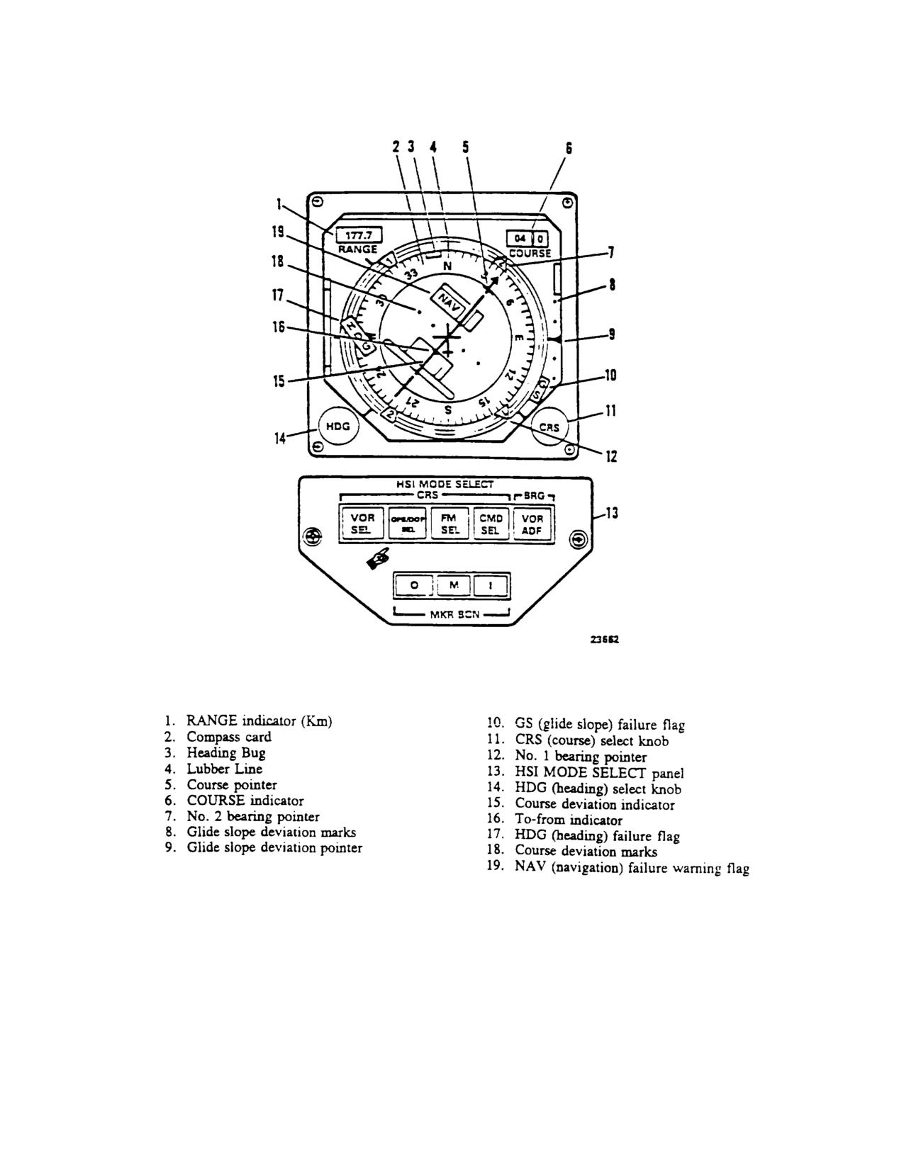
TM 55-1520-240-10
Figure 3-14. Horizontal Situation Indicator and Mode Select Panel
3-30 Change 6
TM 55-1520-240-10
CONTROLS/
CONTROLS/
INDICATOR
FUNCTION
INDICATOR
FUNCTION
CRS Knob
The COURSE indicator and course
Glide Slope (GS)
Indicates loss of or an unreliable
Course Indicator
pointer operate in conjunction with
Warning Flag
glide slope or FM homing signal.
Course Pointer
the course select (CRS) knob, and
allow the pilot to select any VOR
357.
Horizontal Situation Indicator Mode Select
course. The course pointer turns
Panel. (fig. 3-14) The HSI MODE SELECT panel is on
with the compass card and will he
each pilots instrument panel below the HSI. The panel
aligned with the lubber line when the
allows the pilot to select the navigation mode to be
helicopter heading is the same as
displayed on the HSI, command AFCS heading select
the selected course.
feature, and visually indicates marker beacon passage.
The panel is divided into three sections labeled CRS,
Range Indicator
Digital distance display in kilometers
BRG, and MKR BCN.
(KM) to destination set on GPS
Control Display Unit (CDU) (para.
a. The CRS (course) section consists of four
3-67) or doppler control FLYTODEST
pushbutton selector switches labeled VOR SEL,
thumbwheel (para. 3-34).
GPS/DOP SEL, FM I SEL, and CMDSEL.
Pressing
VOR SEL, GPS/DOP SEL, or FMSEL causes the output
HDG Knob
Heading select (HDG)
knob
of the selected navigation set to be electrically connected
operates in conjunction with the
to the course deviation indicator on the corresponding
heading bug. It allows the pilot to
HSI and lights SEL legend in the switch. These switches
select any one heading. With CMD
are electrically interlocked so only one set may be
SEL (fig.
3-14) selected on the HSI
selected at a time. Selecting another navigational
MODE SELECT panel, the AFCS
modes, automatically disengages the mode in use, turns
(chapter 2) will turn the helicopter to
out the SEL legend of the mode in use, engages the
and maintain the selected heading.
selected mode, and lights the SEL legend of the selected
mode. Each pilot may independently select different
HDG Flag
The HDG flag is in view when the
navigational modes for display on his HSI.
signal from the gyro magnetic
compass is unreliable or power to
b. Pressing CMD SEL engages the AFCS heading
the indicator is lost.
select feature, causes the helicopter to turn to and
maintain heading to which the HSI heading bug is set,
To-From Arrow
To from arrow indicates that the
and illuminates the SEL legend on the switch. Due to
helicopter is flying to or away from a
electrical interlocks between the two HSI control panels,
selected VOR.
both CMD SEL switches cannot be engaged at the same
time. The engaged switch is indicated by the lit SEL
NAV Flag
The NAV flag turns with the
legend. If the opposite CMD SEL switch is pressed
compass card. The flag will retract
when operating with heading select, the HDG on the
from view when a reliable VOR,
AFCS panel will release and heading select will be
GPS/Doppler or FM homing signal is
disengaged. Control of the course deviation indicator in
being applied to the instrument.
the VOR mode relative to bearing and course deviation
to or from a VOR is assigned to the pilot who has CMD
Aircraft Symbol
Corresponds to longitudinal axis of
SEL engaged. If the pilot who does not have CMD SEL
the helicopter; shows helicopter
engaged makes an adjustment on his CRS knob, it will
position and heading relative to the
have no effect on the CDI relative to the course.
selected course.
c. Pressing VOR/ADF pushbutton on the BRG side
Glide Slope Pointer Displays glide slope position relative
selects the navigational aid, the bearing of which will be
to the helicopter or FM homing
indicated by the HSI No. 2 pointer. The switch is divided
signal strength. When pointer is
into two segments labeled VOR and ADF. If the VOR
above center, helicopter is below
segment is lit, the No. 2 pointer will indicate the bearing
glide slope, conversely when pointer
to a VOR station to which the VHF navigation set is
is below center, helicopter is above
tuned. Pressing the switch will cause the VOR segment
glide slope.
Increasing homing
to go out and the No. 2 pointer will indicate the bearing to
signal strength is shown by pointer
the station to which the ADF set is tuned out and light the
rising. Decreasing signal strength
ADF segment. The opposite action occurs if the ADF
is shown by pointer falling.
segment is lit and the switch is pressed.
Change 6 3-31
TM 55-1520-240-10
d. A MKR BCN light will illuminate during marker
entry. The CLR key clears the data entry field, the ENT
beacon passage. The light labeled O comes on when
key enters data after it has been selected. The ALP key
passing through an outer marker beam. The light la-
allows for mode switching between alpha and numeric
beled M comes on when passing through a middle
data in fields where both need to be entered.
marker and finally the light labeled I comes on when
passing through an inner marker. As each light illumi-
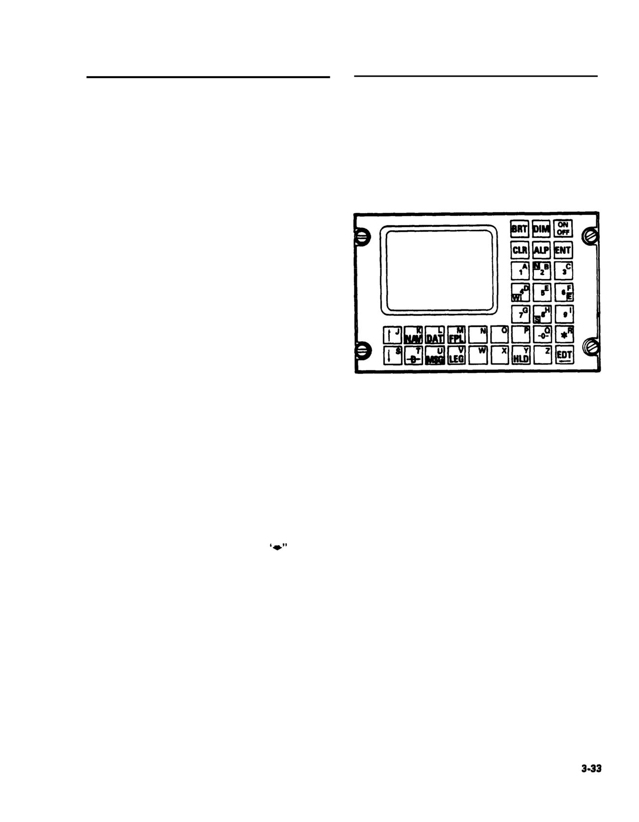
3-61. Controls and Function, Omega Control Unit.
nates, a distinctive tone identifying the beacon will be
(fig. 3-15)
heard over the interphone (table 3-2). The lights have a
press-to-test feature; pressing any one of the three
CONTROLS/
lamps will cause all MKR BCN lamps to illuminate on
INDICATOR
FUNCTION
both pilots HSI MODE SELECT panels.
BRT/DIM
Controls intensity of dis-
3-58. Omega Navigation System (AN/ARN-148).
play.
The AN/ARN-148 is a global navigation system provid-
CLR
Calls up a cursor for data
ing the crew with actual position, distance, bearing and
modification or cancels an
receiver signal strength from Omega station(s). The
operation.
system is comprised of a control display unit (CDU), a
ALP
Shifts keyboard from nu-
navigation processor unit (NW), an airspeed processor,
meric to alpha and back
and an antenna coupler. The airspeed processor takes
to numeric.
airspeed data from the helicopter pitot system for
ENT
Enters selected data into
calculations. Heading information is accessed from the
navigation processing unit
gyro compass system. A zero velocity signal that locks-
memory.
out the system is provided from the aft landing gear
proximity switch when the helicopter is on the ground.
NAV
Provides access to four
The system also features the capability of storing up to
pages of display relative
six pages of flight plans for easy reference.
to aircraft position and
track leg data. Selected
3-59. Omega Navigation Principles.
data pertinent to aircraft
The Omega navigation system (ONS) uses a global
position and track leg
network of eight Omega transmitting stations to provide
data may be altered
dead reckoning coordinates to position the helicopter
through these pages.
relative to one or more transmitting stations. Each
FPL
Provides display, assem-
Omega station transmits a very low frequency (VLF)
bly, selection, entry and
signal continuously.
modification of flight
The Omega VLF signals are received as phase (a
plan.
measure of range to the station) and amplitude (signal
LEG
Provides display and se-
strength). The ONS automatically selects an appropri-
lection from waypoint and
ate set of Omega signals, based on signal strength and
to a waypoint. Provides
geometry, and computes present position and all other
for display and selection
navigation parameters.
of track change mode.
Provides a means of flying
3-60. Omega Control Display Unit.
from present position di-
The CDU is mounted in the center console. The CDU
rect to a defined way-
functions as the primary input and output of navigation
point.
information for the operator (fig. 3-15). This data
Provides a means of dis-
defines helicopter position and navigational guidance
playing additional data
according to a selected path across the ground.
when more than 8 lines of
The CDU has a dual function. The display function is
data are available.
handled by a two inch by three inch color cathode ray
HLD
Provides a means of man-
tube (CRT). The CRT displays information in seven
ually updating position
different colors which uniquely communicates different
either by entering lat/long
information in different colors to the operator. The
coordinates or by refer-
second function of the CDU allows the operator to
ence to point which has
input data into the system to define helicopter position
already been defined to
along the desired navigational path, The data is entered
the Omega Navigation
through a keyboard consisting of 33 keys, Two of the
System (ONS).
keys are used to select the display brightness and one
key is used to turn the system on and off. The remaining
30 keys are used for alpha-numeric data input.
The alphabet is uniquely laid out so that there are no
multi-key-stroke requirements for alpha information
3-32
TM
55-1520-240-10
CONTROLS
CONTROLS/
INDICATOR
FUNCTION
INDICATOR
FUNCTION
EDT
During data entry mode,
O
The “O” (alpha) key pro-
ç
provides a back space
vides for operator deselec-
function. During non-data
tion of an Omega or VLF
entry mode, provides the
station when the cursor is
capability to change dis-
positioned on the same
play mode of angular
line as the station to be
data, i.e., magnetic, true,
deselected.
grid, heading, bearing,
DTK.
*
Identifies and permits en-
try of waypoints as a
range and bearing from a
previously entered way-
point.
DAT
Provides six pages for the
selection, display, and en-
try of data related to
flight planning and
Omega/VLF status.
MSG
Provides a display of sys-
tem malfunctions and op
erator actions required.
Displays condition of
ONS data base and allows
selection of various test
modes to ensure correct
system operation.
E
The “E” or “5” key pro-
vides a means of activat-
ing the erase function
Figure, 3-15.
AN/ARN-148 Omega Control
when the cursor is dis-
Display Unit
played at the top of the
flight plan page.
I
The “I” or “9” key pro-
vides a means of reversing
the flight plan when the
cursor is displayed at the
top of the flight plan
page.
The "S” or
key pro-
vides a means of selecting
the flight plan for use
when the cursor is dis-
played at the top of the
flight plan page.
TM
55-1520-240-10
3-61.1Doppler/GPS Navigation Set
CONTROL/
FUNCTION
AN/ASN-128B (DGNS).
INDICATOR
The AN/ASN-128B DGNS is an AN/ASN-128 LDNS wMGRS
Selects Military Grid-Referen
an embedded GPS receiver. The AN/ASN-128B in
Systems (MGRS) navigational
conjunction with the aircraft’s heading, vertical refermode of operation.
and position and velocity updates from its internal GPS,
provides accurate aircraft velocity, positioLAT/LONGeeSele
cts latitude/longitude na
information from ground level to 10,000 feet. The systga
tional mode of operation.
provides world-wide navigation, with position readout
available in both Military Grid Reference SyGPSm (MGRS)
Places navigation set in GP
and Latitude and Longitude (LAT/LONG) cooLDGates.
landing mode of operation. Th
Navigation and steering is performed using LAT/LONG
mode provides real-time, tactic
coordinates and a bilateral MGRS-LAT/LONG conversion
precisi
landingguidance
routine is provided for MGRS operation. Up to 100
information to the HSI indica
destinations may be entered in either format and not
necessarily the same format.
DISPLAY switch
Selects navigation data for displ
3-61.2.
Controls, Displays and Function.
WIND-UTC
Used for wind speed and direc
DATA
tion, UTC tim
current,
The control and displays for the AN/ASN-128B are on the
surface wind, GPS status and
front panel (figure 3.15.1). The function of each control is as
data load functions.
follows:
XTK/TKE
Displays steering (cross tra
NOTE
KEY
distance and track angle erro
The MODE switch is locked in the OFF position
information and GPS variabl
and must be pulled out and turned to get into or out
key status. Selection of fl
of OFF position.
destination by direct entry of
digit destination number.
CONTROL/
FUNCTION
INDICATOR
GS/TK
Displays ground speed, trac
NAV M
angle and selection of GPS an
MODE switch
Selects navigation set mode of
navigation mode.
operation.
Displayspresentposition,
OFF
in this position the navigatioPPet
altitude and magnetic variatio
is inoperable; non-volatile RAM
retains stored data.
DIST BRG
Displays distance, bearing an
LAMP TEST
Checks operation of all lamps.TIME
time information
he
destination or course selecte
TEST
Initiates built-in-self-test exer-
Selection of fly to destination
cise for the Doppler and GPS
be accomplished by direct ent
functions of the navigation set.
of two digit destination numb
3-34 Change
8
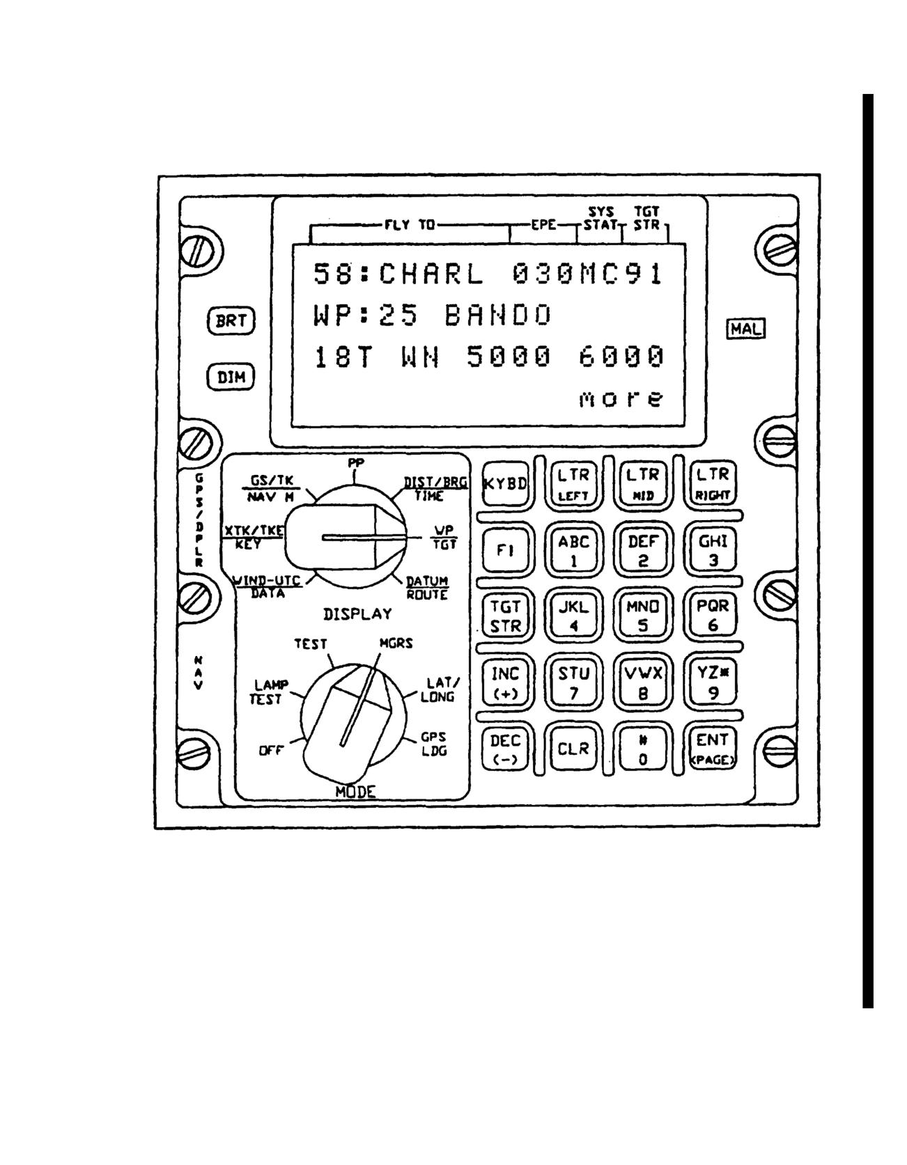
TM
55-1520-240-10
Figure 3-1Doppler/GPS Navigation System AN/ASN- 128B
Change
8
3-34.1
TM
55-1520-240-10
CONTROL/
FUNCTION
CONTROL/
FUNCTION
INDICATOR
INDICATOR
Keyboard and LTRUsed to set up data for entry
Keys
to
memory. When DISPLAY
WP
Accesses way point or target data
switch is set to a position
TGT
(landing data, variation, motion).
which new data is required a
Selection of destination for
KYBD key is pressed, data may
display/entry by direct entry of
be displayed on the appropri
two digit destination number.
input field of display. To d
a
number, press the
DATUM
Accesses datum and steering/
corresponding key or keys
(
ROUTE
route functions.
through
9). To display a let
first depress the LTR key
corresponding to the position
the desired letter on a key.
MAL Indicator
Lights when a navigation set mal-
depress the key which contai
Lamp
function is detected by the
the desired letter. Example:
built-in-test circuitry. In the
enter an L, First depress the
event
of
intermittent
RIGHT key, then depress the
malfunction, the system may
key.
operate correctly but must be
cycled to OFF position tINC an
d DEC Keyssed to increment or decremen
on, to extinguish the MAL light.
the displayed Waypoint/Targe
number when the DISPLAY
switch is set to WP/TGT. T
access P, depress the LTR LEF
BRT and DIM Keys
Used to brighten or dim the light
key followed by the
6 key
intensity of the LCD display.
display way point 99 then depr
the INC key, or display way p
00 then depress the DEC key.
Also used to increment or
Four Line Alpha-
Displays alphanumeric characters,
decrement the Fly-To destinat
Numeric Display
as determined by the setting of
number when the DISPLAY
the DISPLAY switch, the MODE
switchis set toDIST/
switch and operation. keyboard.
BRG/TIME or XTK/TKE/KEY.
The keys activate function upon
release and are to be released
ENT Key
Enters data into memory (as s
immediatelyafter being
up on keyboard and displayed
depressed.
This key is also used for pag
of displays. The bottom rig
corner of the display indic
“morewhen additional pages
TGT STR Key
Stores present position data in the
are available, and “end” when
indicated target store\memory
additional pages are availabl
location (90-99) when depressed
and released.
CLR Key
Clears last entered charact
when pressed once. When
pressed twice, clears entire
field ofdisplay keyboard con
KYBD Key
Used in conjunction with the
keyboard to allow data display
and entry into the compu
F1 Key
Reserved for future growth.
3-34.2
Change
8
TM
55-1520-240-10
3-61.3. Modes of Operation.
selected and the GPS becomes invalid (para
the AN/ASN-128B will not navigate.
Control of the AN/ASN-128B, including selection of modes
and displays, and entry and readout of da3-61.5.3. Doppler Mode.
the Computer Display Unit (CDU) front panel. The
Doppler position and velocity data are u
AN/ASN-128B has four basic modes of operation: off,
Doppler mode is selected and the Doppler
navigate, test and GPS landing. In navigate mode three
(para.3-61.5.1 abothe, A N / A S N - 1 2 8 B w i
submodes may be selected manually or automatically. These
automatically switch
remembered veloci
are combined mode (default or primary mode of operation),
sensor is not available. If Doppler mode
GPS only mode, or Doppler only mode.
at the start of the flight an initial p
obtained and entered prior to flight. Na
3-61.4. Off Mode.
in latitude/longitude for computational
the same time, distance, bearing and time
In the off mode the system is inoperable. However, the Edge
100 preset destinations are computed
lighting is lighted by an external aircraft power source and is
FLY-TO-DEST).
independent of the AN/ASN-128B mode switch setting.
Edge lighting may not be available if the helicopter is
3-61.6. Test Mode.
modified with the night vision MWO.
The test mode contains two functions:
3-61.5. Navigate Mode.
which all display segments are lit; and T
operation is verified. In lamp test,
In the navigate mode (MGRS or LAT/LONG) pidentical to t
hat of the navigate mode
CDU MODE switch) power is applied tosegments and
the MAL indicator lamp are
components, and all required outputs antheir operation.
In TEST, the RTA no l
provided. The Doppler radar velocity receives elect
romagnetic energy; instead,
measures aircraft velocity, and convertssignals are inserted into the electronic
pitch and roll into digital form. This dathe DRVS. At this time a self test is perf
Receiver (EGR) velocity and position data anavigation computations continue usin
CDU for processing. Baro altitude is usedvelocity.gInhthe
TEST mode, Doppler t
when only three space vehicles are availabldisplayed on theon
CDU front panel for th
is computed by using one of three navig(approximate).
At the end of this perio
which can be selected manually or automdisplayed if there is no malfunction in
submodes are as follows:
failure code is displayed if a malfunct
rotating bar on the display indicates t
3-61.5.1.
Combined Mode (Default or Primary
completed self test. If the navigation s
Mode of Operation).
TEST mode, no navigation data can be displ
front panel. If a Doppler malfunction i
Doppler and GPS position and velocity datindicator lamp lights and DF is displaye
provide navigation. This mode is used whof GPS self test (up to two minutes),
three (with baro) or four space vehiclesreplaced with a complete test result cod
Estimated Position Error (EPE) is less tthe failed circuit
card are also indicated
150 meters, and the Doppler is not indisplay.If GPS
becomes invalid (e.g., due to increased EPE), the
AN-ASN-128B will automatically switch tThe CDU is continuously monitored for
until a valid GPS status is received. Ifown computer as built-in-test-equipment
invalid (e.g., flight over glassy smoomalfunction the MAL indicator lamp on t
memory), the AN/ASN-128B will automaticthe MODE switch on the CDU is set to TE
GPS mode if GPS is valid or an alternate of the failed LRUe
is indicated by a code
GPS is not valid.
Aircraft heading, pitch and roll are a
mode by depressing the ENT key after
3-61.5.2. GPS Mode.
completed. GPS test status is displayed
depressed a secondMa
lfunction codes
GPS positions and velocities are used forautomatically latc
hed and can only be c
Doppler navigation processor in the CDU.the CDU power
via the CDU mode switch (
Change
8
3-34.3
TM
55-1520-240-10
3-61.7. GPS Landing Mode.
pressed. The position change which occurr
over-flying the fix point is automatical
In the GPS landing mode, the Doppler navigatithe fix point coordinates to complete th
provides information to the HSI indicator fupdate.l-time
landing guidance to a touch down point previously entered in
any of the 100 fly-to destinations. The landiMagneticcvariation can be entered for
determined by present position and the entereddestination, and the system will compute
altitude, glideslope and inbound approach courposition magnetic variation. If operation
in a region with relatively constant
3-61.6. CDU Operation.
variation, the operator enters magnetic
only for present position and the compute
Various required operating data, such as inthis value throughout the flight. If MGRS
position (if GPS is not valid or Doppler modebe entered or
displayed, the MGRS datu
destination coordinates with or without GPS loperation is
also entered.
and magnetic variation can at any time be entered into the
CDU via its keyorathe dataloader viTarget-of-opportunity data can be stored by p
preprogrammed dataloader cartridge. In mSTR (target store) key when the target is ov
data will be entered before the aircraftoperation
stores the coordinates of the target
destination locations in the computer; locatio
The GPS provides present position to the99 sequentiallyfincrementing each time the TGT
GPS is not available or Doppler is selectdepressed. The location is displayed in the
can be initialized as follows:
display field. The computer can keep track o
target positions which may include speeds and
The MODE switch should be set to MGRS or
input by the operator.
LAT/LONG, the WT/TGT display position of the
DISPLAY switch is selected, the Selfiteston
of the AN/ASN-128B is accomplish
number is set to P and KYBD key isbuilt-in-test-equipment (BITE) with the RTA,
coordinates of the initial positionCDU units connected and energized for normal
ENT key is pressed. The computer theSelf test en
ables the unit to isolate failures
changes from the initial position cmain functions (RTA, SDC, CDU or EGR) or to o
the coordinates of the current prescircuit cards in
the SDC or CDU. Self test is a
be read either by remaining in thisfollows:ation or
by setting the DISPLAY switch to PP (present
position) and the MODE switch to MGRSThe
CDU (except for the keyboard and dis
LAT/LONG.
checked on a continuous basis, and any f
displayed by the illumination of the MAL
To update present position over a stored dlamp on the CDU. If the MODE switch on th
KYBD key is depressed and released whenis set to the TEST position, identifica
aircraft overflies this destination. Iffailed circuit card in the CDU is indicat
desired. the ENT key is depressed and releaon theddisplay panel.
the update is completed. The DISPLAY switch is in
the DIST/BRG/TIME position and the FLYThe
DRVS and EGR are tested by setting
DEST is set to this destination during thMODE switch
on the CDU to the TEST posi
The distance-to-go, displayed while over Failure of
the DRVS or EGR are displayed
destination, is the position error of theCDU by illumination of the MAL indicato
moment.
and identification of the failed unit or
indicated by a code on the display panel of
To update present position over a fixed point not
previously stored in the computer, the Continuous monitoring of the Signal
switch is placed PP and KYBD key is depressConverter and Receiver Transmitter Ante
released as the fix point is overflown. provided by
the system status indicati
the display while allowing computation osystem will not use Doppler velocities
in present position to continue within thoperation when flying over glassy smooth
If an update is required, the coordinateHowever, ifix
the system continues to not us
point are entered via the keyboard, and E(e.g., using GPS only when combined has
3-34.4
Change
6
TM
55-1520-240-10
selected) for excessive periods ofnew data has been entered) causes the d
than 10 minutes) over land or roughmomentarily and return with the latest c
malfunction may exist in the navigaabort a keyboardoperation. move the mode
operator should set the MODE switchto anothero
position.
determine the nature of the failure.
NOTE
The display portion of the CDU is tested by
All keys activate upon release aft
illuminating all the lamp segments in each
depressed. Keys should be depressed
alphanumeric character in the LAMP TEST mode.
immediately released in one continuous
Keyboard operation is verified by observing the
a. Data Entry. To display a letter, firs
alphanumeric characters as the keyboard is
key corresponding to the position of the
exercised.
key. Then depress the key which contains
Forexample, to enter an L, first depress t
3-61.9. Route Sequencing Modes.
then depress the 4 key.
The system has the ability to fly a preprogrammed sequence
of waypoints. This sequence can be eitherb.coKeyboardeCorrection Capability. The
numbered in which case a start and end wayentered may be cleared by depressing the
or randomly numbered in which case all waCLR key isdepressed twice in succession, t
control (indicated by bl
a list and the start and end waypointsbut remains under
sequence modes can be flown in the order valid data enteredt
is displayed.
or in the reverse order. Directions will be displayed to the
way point next on the list until approximc.eD
es10 secondsVariation Constraint.
before overflying the way point at whichvariationdassociated
with a destination
advance to the next way point and the newAFTER the coordinates for that destinatio
will blink for ten seconds. One consecutiorder of entry for present position is ir
sequence may be stored in the system.
d. Impossibility of Entering Unacceptabl
3-61.10.
To-To Route Mode.
cases the computer program will reject unac
example, a MGRS area of W1 does not exis
The system has the ability to provide srejected). If the operator attempts to inse
onto a course defined by the start and endthe unacceptable data will be displayed on
second way point will be over flown. The dtheaselected field will blink after EN
the distance to the course when outside 2 ndisplaying the last
valid data.
course and the distance to the second way point when inside 2
nautical miles of the course.
NOTE
The computer cannot prevent insert
3-61.11.
General Operating Procedures for
erroneous data resulting, for examp
Entering Data.
human or map errors.
The panel display consists of four line LCD readout. The top
e. Procedure for Displaying Wind Speed a
line of the display is reserved for the display of Fly-To
destination number and destination name/International Civil
NOTE
Aeronautic Organization (ICAO) identifier, EPE in meters,
mode of GPS and mode of AN/ASN-128B operatIn MGRS
mode, wind speed isdisplayed i
target store number. The remaining lines wilin LAT/LONG mode,
wind speed is displ
accordance with the DISPLAY and MODE switchknots,en
Wind direction is defined as t
depressing the KYBD key for the first timfrom which the wind originates.
procedure, the display freezes, kybd is displayed in the
bottom right corner indicating the display is(1) Set MODErd
switch to LAT/LONG
mode and the input field under keyboard cmay also be used).it is
not desired to change the display field under control, the pilot
can advance to the next field of the display by(2)pSet DISPLAY switch to WIND-UT
KYBD key again. Depressing the ENT key (andtobserve
display.
Change
8
3-34.5
TM
55-1520-240-10
(3) The display indicates:
KEY STATUS
TIME
REMARKS
DK
OK
Days or hours
PS daily key
SP;XXXKn
available on
n use and
DIR:XXX°
verified
f. Procedure for Displaying/Entering UTC and
*
DK
NO
No GPS daily
Displaying GPS Status.
key available
(1) Set MODE switch to LAT/LONGDK
*
IN
GPS daily key
may also be used).
available but
not verified
(2) Set DISPLAY switch to WIND-UTC/DATA
and observe the wind speed/direction disp3-61.12.
Preflight Procedures.
Required Prior to DGNS Turn-on
(3) Depress ENT key. Observe that a.DataU
display indicates year XX, day XXX and indicates hours,
The following initial data must be entered by
minutes, and seconds of UTC time: XX Hours, XX Minutes,
system turn-on and initialization, unless prev
XX Seconds.
data is satisfactory:
(4) To enter year, day and time depress the KYBD
Datums of operation, when using MGRS coordi
key to select the field for input shown as a blinking field, enter
This data may be part of the data load if prep
the desired data and depress the ENT key.
In combined or GPS mode the GPS provides p
(5) To display GPS status depress theposition.
If the Doppler only mode is selec
display selection menu.
coordinates of present position
- zone area,
northing; latitude/longitude coordinates may al
1> SEA CURRENT
input present position. This data may be part o
2> SURFACE WIND
if preprogrammed. Variation of present posit
3> GPS STATUS
nearest one-tenth of a degree.
4> DATA LOAD end
Coordinates of desired destinations 00 through
y to enter all destinations in the sa
(6) To select the GPS STATUS page deprnecessar
system. This data may be part of the data
key.
preprogrammed.
(7) Observe the CDU display. The display
Variation of destinations to the nearest on
indicated the GPS test mode status as of one of the following:
degree.
GPS TEST: IN PROCESS
Crypto-Key variables necessary to enable t
GPS TEST: NOT RUN
receiver to operate in Y code are entered via r
GPS TEST: PASSED
only and not via the CDU keyboard.
GPS TEST: FAILED
NOTE
g. Procedure for Displaying GPS Key and GPS Space
Destinations are entered manually when stee
Vehicle Status.
information is required to a destination th
not in the set of data loaded via the data loa
(1) Set the DISPLAY switch to XTK/TKE/is d
esired to update present position by ove
a destination, or a present position var
(2) Set the MODE switch to LAT/LONG (MGcomputation is desired. (See CDU operation).
may also be used.
present position variation update is des
destination variation must be entered. T
(3) The display indicates GPS daily operator may enter one or more destinati
time remaining on the currently entered keysvariations: it is not necessary for all dest
Space Vehicles (SV) are currently being usedhave associated variations entered and also
3-34.6
Change
8
TM
55-1520-240-10
necessary to enter all destinations into be performed. Foraccurate navigation it
variations must be entered AFTER desvariations after each destination unless t
coordinates are entered.
same.
The Doppler outputs true heading and accepts(8) Select
DGNS operating mode (para
heading from gyromagnetic heading reference. If accurate
magnetic variations are not applied, then navigation accuNOTEy
will be affected.
The set will automatically select comb
(default or primary operating mode) as
b. System Initialization
the system to select the best possible
(1) Enter GPS mode “M”.
method available.
NOTE
(9) Set the FLY-TO DEST to the
tination location.
You must select GPS mode “M” durdes
initialization. If “Y” mode is selected before
Crypto-Key variables are loaded the sysc.mProcedure for Downloading Data From
lock-up forever.
Cartridge
(2) Perform self test (para d. below).
(1) Set the CDU mode switch to OFF.
(3) Perform download (para c. below) o(2)aInsert the preprogrammed dat
loader cartridge if necessary, or manuacartridge. datum,
destinations. magnetic variations, and present position (para
f. org. below).
(3) Set the CDU mode switch to
(LAT/LONG may be used). Enterdesired GPS c
(4) LoadCrypto-Keyvariables (unless
mode of operation.
previously loaded and still valid) necessary for operation of
the GPS in Y mode.
(4). Setthe DISPLAY switch to
WIND-UTC/DATA.
NOTE
It is necessary to wait at least 12 minutes for key
(5)To display the select menu depre
validation when new keys have been entered, or
key twice.
collection of almanac data when set has no
previous almanac data. During this time the GPS
1> SEA CURRENT
operating mode must be M and uninterrupted.
2> SURFACE WIND
After this time the GPS operating mode may be
3> GPS STATUS
switched to Y. Observe the GPS Key status and
4> DATA LOAD end
number of SVs tracked after switching to Y mode.
If the SV number goes to zero repeat this
(6) To select the DATA LOADER page d
procedure. The Key status shall switch from DK
the 4 key.
IN to DK OK sometime during the 12 minutes.
DATA LOADER
(5) Check datum of operation, if MGRS is being
used.
ENTER DATA: N
end
(6) Check destinations in MGRS or LAT/LONG
coordinates as desired.
(7) To begin the download depress the
(7) Check associated destination enter Y (yes)
desired. Remove all incorrect variationsby setting DISPLAY
switch to WP/TGT, setting the destination (8) Observe the CDU display. The
appropriate destination, and depressing tdisplay DOWNLOAD WAYPTS and WAIT ACK.
ENT key in that order. Variations of at ltransmission error occurs the CDU display
must be entered for automatic variation
ERROR-RETRYING.
Change
8
3-34.7
TM
55-1520-240-10
(9) When the transmission is complete the CDU
(a) All edge lighting is illuminated.
shall display DOWNLOAD WAYPTS COMPLETE. If this
display is not obtained within one minute of beg(b) All keyboard keys are illuminated.
download check the data programming and connections.
(3) Set MODE switch to TEST.
(10)Set the CDU mode switch to OFF, remove
the data loader cartridge if desired, and then s(a) While
test is performing, depre
mode switch to the desired setting.
DIM pushbutton several times, then the BRT p
several times. The LCD display should glow di
d. Self-Test
brighter. Adjust LCD display for comfortable
(1) Set the MODE switch to LAMP TEST. Enter
(h) After Doppler and/or GPS self tests
GPS mode “M” or “Y”. Verify the following:
completed (approximately 15 seconds for Dopple
minutes for GPS), one of the following disp
(a) All LCD on four-line display are
observed in the left and right displays:
illuminated.
NOTE
(b)The MAL lamp is illuminated.
In the event the TEST mode display is not
(2) Rotate the center console lightiALL the system should be recycled through O
Verify the following:
to verify the failure is to a momentary on
LEFT DISPLAY
RIGHT DISPLAY
REMARKS
GO
Doppler has completed Built in Test ( BIT) and is
factorily, GPS is still performing BIT (GPS has
cycle maximum). Note that a rotating bar in the d
that the GPS is still performing self test.
GO
ALL
The entire system has completed BIT and is operati
rily.
GO
P
Pitch or Roll data is missing or exceeds 90°. In
and roll in the computer are both set to zero and n
Doppler mode continues with degrade operation. P
be in the vertical gyro or aircraft cabling.
NG
C.R.S. or H followed Ayfailure has occurred in the Computer Display Un
a numeric code
nal Data. Converter Power Supply. The operator sh
the system
DN
GPS failure code
GPS has failed but operator can use doppler to pe
gation.
DF
Doppler failure code Doppler has failed. GPS is still performing self
GN
Doppler failure code Doppler has failed but operator can use GPS to pe
gation.
3-34.8
Change
6
TM
55-1520-240-10
e. Procedure for Displaying or Selectin9.GASYM
will be displayed. Depress ENT
Operating Mode, Doppler, GPS, or Combindisplay will blank out for less than one s
and Displaying Groundspeed and Track.
display will now indicate: Y.
(1) Set MODE switch to MGRS positi(5) Selection of DGNS mode of operat
(LAT/LONG or GPS LDG position may also be used).
As an example, consider selection
mode of operation. Depress KYBD key twice
(2) Set DISPLAY switch to GS/TK/NAV M.
the DGNS mode blinks. To enter G (for GPS
(3) The display indicates the curkey LTR LEFT
followed by key
3. A G wil
navigation mode on the top line:
Depress ENT key. The entire display will
than one second and the DGNS Mode will no
(a) Selected Fly to waypoint.
(or * if GPS is not available).
(6) Ground Speed and Ground Track An
(b) EPE (GPS Estimated Position Error in
displayed on lines 3 and 4.
Meters. An asterisk (*) in the character position of the EPE
display indicates an EPE of greater than
999 or data
f. Procedure for Entering/Displaying Pres
unavailable.
One of the 100 Possible Destinations in M
(c)GPS mode of operation:
The DGNS has the capability to display
(numbered 00 through 99).
M for mixed C/A and P/Y code GPS
reception
100 destinations
Y for only Y code GPS reception
-00 to 69 Standard Waypoints
(d) DGNS mode of operation:
-70 to 89 Data Load-only Waypoints,
Observable but not changeab
C for combined Doppler and GPS
CDU keyboard. Used for Nat
Airspace Data Such as VORs,
D for Doppler only
NDBs. and intersections.
G for GPS only
-90 to 99 Target Store Waypoints (Usa
Standard Waypoints)
R for remembered velocities
As an example, consider display of desti
* for no navigation.
(1) Enterdatum asdescribed in paragra
(e) Target destination where the present
(2) Set MODE switch to MGRS.
position will be stored next time TGT/STR is depressed.
(3) Set DISPLAY switch to WP/TGT.
NOTE
(4) Notice the current destinat
In MGRS mode, ground speed is displayed in
displayed. To display destination number 2
km/hr; in LAT/LONG mode, ground speed is
or DEC keys, or depress keys 2 then 5. Th
displayed in knots.
entry action.
Only mode C, G, and D may be selected as the
primary navigation mode. Modes R and
* a(5) Observe that the current desti
automatic fall back modes used when zonearea, and easting/northing coordina
Doppler and GPS are unavailable.
displayed. The destination number
25
name/ICAO identifier also appears in the
(4) Selection of GPS mode of operation:
(6) Entry for destination coordinates
As an example, consider selection oname/ICAO identifier: As an example, consi
Depress KYBD key. Observe that the GPS mo18T, area WN, easting
5000, northing
60
enter Y (for Y mode) depress key LTR LEFTidentifier BANDO.
Change
8
3-34.9
TM 55-1520-240-10
(7) To enter keyboard mode depress or DECD
keys, or depress keys 2 then 5. This i
key. Observe “kybd” displayed in the botentry action.ner of
the display. (Destination number blinks.) Depress KYBD
e1,8,
that the current Latitu
again. (Zone field blinks.) To enter
18T depr(5)Obs
Longitude coordinates are now displayed. The
LTR MID.
7.
number 25 and location name/ICAO identifier a
(8) Depress KYBD. (Area and northdisplay.ing
blinks.) To enter WN5000 6000 depress keys LTR MID, 8
(6) Entry of destination coordinates and
LTR MID,
5, KYBD,5,0,0,0,6,0,0,0.
name/ICAO identifier: As an example, consid
Latitude N41°
10.13 minutes and longitude E
(9) Depress KYBD. (Location name/ICAO
minutes and ICAO identifier BANDO.
identifier blinks.) To enter BANDO depress keys LTR MID,
1, LTR LEFT, 1, LTR MID, 5, LTR LEFT, 2, LTR RIGHT, 5.
(7)To enter keyboard mode depress KYBD
Observe “kybd” displayed in the bottom right
(10)To store the displayed information into the
display. (Destination number blinks.) Depress
selected destination display position depress the ENT key.
(Latitude field is blinks.) To enter N41° 10.
N,4,1,1,0,1,3.
NOTE
To access P, depress the LTR LEFT key follo(8) Depress KYBD. (Longitude field blink
by the 6 key. Another way to access P ienter E035°
50.27 depress keys E,0,3,5,5,0,2,7
way point 99 then depress the INC key or display
way point 00 then depress the DEC key.
(9) Depress KYBD. (Location name/;l
identifier blinks.) To enter BANDO depress ke
Way points cannot be recalled by location
1, LTR LEFT, 1, LTR MID, 5, LTR LEFT, 2, LTR
name/ICAO identifier.
(10)To store the displayed information
g. Procedure for Entering/Displaying Present Position
selected destination display position depress
or one of the 100 Possible Destinations in LAT/LONG.
Display indicates:
The DGNS set has the capability to display
100
destinations (number 00 through 99).
N41° 10.13 E035° 50.27.
100 destinations
NOTE
To access P, depress the LTR LEFT key foll
-00 to 69 Standard Waypoints
by the 6 key. Another way to access P is to
way point 99 then depress the IUNC key or di
-70 to 89 Data Load only Waypoints,
way point 00 then depress the DEC key.
observable but not changeable via
Waypoints cannot be recalled by locati
CDU keyboard. Used for National
name/ICAO identifier.
Airspace Data such as VORs.
NDBs, and intersections.
h. Procedures for Entering Variation and Lan
Data
-90 to 99 Target Store Waypoints (Usable as
Standard Waypoints)
(1)Set MODE switch to MGRS position-alt
entered/displayed in meters (LAT/LONG may
As an example, consider display ofdestinused-
altitude entered/displayed in feet).
(1) Enter the datum as described in parag(2) Set
DISPLAY switch to WP/TGT positio
below.
(3) Select the way point number desi
(2) Set MODE switch to LAT/LONG.
directly entering the two digit target number
INC/DEC keys. Observe the way point number en
(3) Set DISPLAY switch TO WP/TGT.
position data.
(4) Notice that the current destination n(4)rDepress the ENT key and observe
displayed. To display destination number
way point number, variation and/or landing da
3-34.10
Change
8
TM
55-1520-240-10
(5) To enter a magnetic variation and/or(4) Depress the ENT key and observe t
mode data depress the KYBD key to select speed and direction
page.
and enter the desired data as shown in steps 6 through 10
elect target speed depress th
below. To end the entry operation depress the (5)To s
twice and enter the target speed. The maxi
(6) Entry of variation: as an exathat may be entered is
50 knots. Fill le
entry of a variation of E001.2. Depress entering.0,1 and 2.
The decimal point is inserted automatically. If no landing
(6) To select the target direction
mode data is to be enter depress ENT to complete the
KYBD key and enter the target direction.
operation. Display indicates: E001.2°
(7)To end the entry operation depres
NOTE
key. At the time the ENT key is depressed
An asterisk appearing in the variattarget position will begin to be updated a
indicates the variation is not enterebased on thes
speed and direction entered.
may not be entered for waypoints containing
NOTE
target motion.
To abort/cancel and entry of target mot
(7) The bottom two lines indicate target speed of 000 using the above pro
altitude, desired glideslope, and the desired inbound
approach course (IAC) to the indicated dej. Procedure for
Entering/Displaying Datu
example, consider entry of a glideslope oAll°Waypoints 270°,
and an altitude of +230 meters. for destination number 25.
(1) Set the MODE switch to MGRS
(LAT/LONG may also be used).
(8) Depress the KYBD key to blink the altitude
field. Depress the INC/+ key to enter a positive altitude,
(2) Setthe DISPLAY switch to
depress keys 2,3,0 (the leading zeros may be omitted) for the
DATUM/ROUTE.
altitude of 230 meters in the example.
(3) To select the datum field depres
(9) Depress the KYBD key to blink theKEY.de slope
field. Enter glideslope. The maximum allowable glideslope
is
9 degrees. In the example enter
8 for an (4) Entry of
datum: as an example con
glideslope.
of
25. Depress keys LTR
2,5. Depress the
display shall show DATUM:25.
(10)Depress the KYBD key to blink the inbound
(5) To clear all waypoints, varia
approach course field. Enter a three digit inbound approach
data and target motions, enter RDW for the
course angle. In the example enter 2,7,0 to enter a 270 degree
inbound approach course. Depress the ENT key to complete
k. Procedure for Entering Sea Current
the operation.
Direction for Water Motion Correction.
i. Procedures for Entering Target Motion and Direction
NOTE
In MGRS mode, wind speed isdisplayed in
In MGRS mode, target speed is entered in km/h; in
in LAT/LONG mode, wind speed is displa
LAT/LONG mode, target speed is entered in knots.
knots. Leading zeros must be entered. Se
direction is defined as the direction
(1) Set the MODE switch to LAT/LONG (MGRS
flowing.
may be used).
(1) Set MODE switch to LAT/LONG
(2) Set the DISPLAY switch to WP/TGT and
may be used).
select the target number desired (00-69 or 90-99) by directly
entering the two digit target number or INC(2) Set DISPLAY switch to WIND-UT
Observe the way point number entered and and observe t
he standard wind speed and di
(3) Depress the ENT key and observe (3)
Depress the ENT key twice to
way point number, variation and/or landi
selection menu
Change
8
3-34.11
TM
55-1520-240-10
1> SEA CURRENT
3> GPS STATUS
2> SURFACE WIND
4> DATA LOAD end
3> GPS STATUS
4> DATA LOAD end
(4) Depress the 2 key to select SURFACE WI
The display indicates:
(4) Depress the 1 key to select SEA CURRENT.
The display indicates:
SURFACE WIND
SP:XXXKn
SEA CURRENT
DIR:XXX°
SP:XXXn
DIR:XXX°
(5) Entry of wind speed and direction:
example, consider the entry of 20 knots and 1
(5) Entry of sea current speed and direction: as an
Depress KYBD key. Observe that the wind speed f
example, consider the entry of
4 knots and
135 degrees.
Depress KYBD key. Observe that the speed field blinks.
(6)To enter speed, depress keys 0, 2 and
wind speed indicates 020. The maximum surface w
(6)To enter speed, depress keys 0,0 and 4. The
is 50 knots.
speed indicates
004Kn. The maximum sea current speed that
may be entered is 50 knots.
(7) Depress KYBD key. The direction d
(7) Depress KYBD key. The direct blinks.play
blinks.
(8)To enter direction, depress keys 1, 5
(8) To enter direction, depress keysWind direction indicates 150°.
Direction indicates
135°.
(9) Depress ENT key. The display momenta
(9) Depress ENT key. The display momentarily
blinks and then reappears.
blinks and then reappears.
NOTE
NOTE
To abort entry of surface wind speed a
To abort entry of sea current, enter a sea current
direction, enter a surface wind speed of 000
speed of 000 using the above procedure.
the above procedure.
1. Procedure for Entering Surface Wind Speed and
3-61.13. Flight Procedures.
Direction for Water Motion Correction.
NOTE
NOTE
Not required or necessary when in combinThisrprocedure is applicable to the Dopple
GPS mode. In MGRS mode, surface wind speedmode. Present position is automatically up
entered in km/hr; in LAT/LONG mode, surwhen
DGNS is in combined mode.
wind speed is entered in knots. Leading zeros
must be entered. Wind direction is defia.dUpdating Present Position from a Stored De
direction from which the wind originates.
NOTE
(1) Set MODE switch to LAT/LONG (MGRS
The preface is: The aircraft is flying
may also be used).
destination, that is, the FLY-TO Destinatio
to the number of the desired destination.
(2) Set DISPLAY switch to WIND-UTC/DATA
and observe the wind speed/direction display.
(1) Set DISPLAY switch to DIST/BRG/TI
(3) Depress the ENT key twice to position. Distance, bearing and time-to-go t
selection menu.
destination are displayed.
1> SEA CURRENT
(2) When the aircraft is over the des
2> SURFACE WIND
depress KYBD key. Observe that the display fre
3-34.12
Change
8
TM
55-1520-240-10
(3) Position update can be effected by depr(3)Depress KYBD key. Observe that th
the ENT key. The computer updated the prefreezes.sition at
the time the KYBD key was depressed by using the stored
enter the landmark coord
destination coordinates, and adding to them (4) Manually
traveled between the time the KYBD key wadepressing thed
KYBD key to blink the field t
ates.
the ENT key was depressed. In addition,enter the coordin
variation for the stored destination exists, the present position
(5) When overflying landmark, depress
variation is also updated.
(6) If an update is not desired, set
(4) If a present position update is unnecessary (as
switch to some other position. This action
indicated by an appropriately small value of DISTANCE to
mode.
go on overflying the destination), set the DISPLAY switches
to some other position - this action abort61.14. Fly-update mode.
To Destination Operation.
b. Updating Present Position from a Landmark
a. Initialization of Desired Course
NOTE
When a fly-to destination is selected such
There are two methods for updating leg, the present position at the time is s
position from a landmark. Method
A course is then computed between the select
particularly useful if the landmark
destination. If the aircraft deviates from
ral offset or crosstrack distance
unexpectedly and the operator needs the late
determine the coordinates. Method
2 is useful
Distance and bearing to destination, actual
when a landmark update is anticipated.
track angle error correction are compute
position to destination. See figure
3-15
Method 1 (Unexpected update)
definition of these terms.
(1) Set DISPLAY switch to PP position.
b. Procedure for Selecting One of 100 Po
Destinations (Direct Mode)
(2) Overfly landmark and depress KYBD key.
The present position display shall freeze.
The Doppler/GPS navigation set has the
selecting a fly-to destination from 100 d
(3) Compare landmark coordinates with those on
00 through 99).
display.
As and example, consider selecting Fly-
(4) If the difference warrants an update, enter the
number
43.
landmark coordinates by depressing the KYBD key to blink
the field to be changed, enter coordinates, then depress the
(1) Set MODE switch to MGRS (LAT/LON
ENT key. The computer updates the present position (from
GPS LDG may also be used).
the time the KYBD key was depressed) to the landmark
coordinates, and adds to the updated present(2) Set DISPLAY switch to XTK/TKE. O
distance traveled between the time the standard Cross Track (XTK) and Track angl
depressed and the ENT key was depressed.
display. (DIST/BRG/TIME may also be used)
(5) If an update is not desired, set the(3)ToAY
display Fly-To destination 43
switch to some other position. This actioINC or DEC keys, or
depress keys 4 then 3
mode.
key entry action.
Method
2 (Anticipated update)
Left-Right Steering Signals
(1) Set DISPLAY switch to WP/TGT posiThere
are two methods the pilot may
destination, using left-right steering sig
(2) Access P by depressing the LTR computer-display unit. Left-right steerin
followed by the
6 key, entering destiused when flying the shortest distance to
depressing the DEC key, or entering despresent
position
(Method 1) or when flyin
depressing the INC key.
from start of leg to destination (Method
Change
6
3-34.13
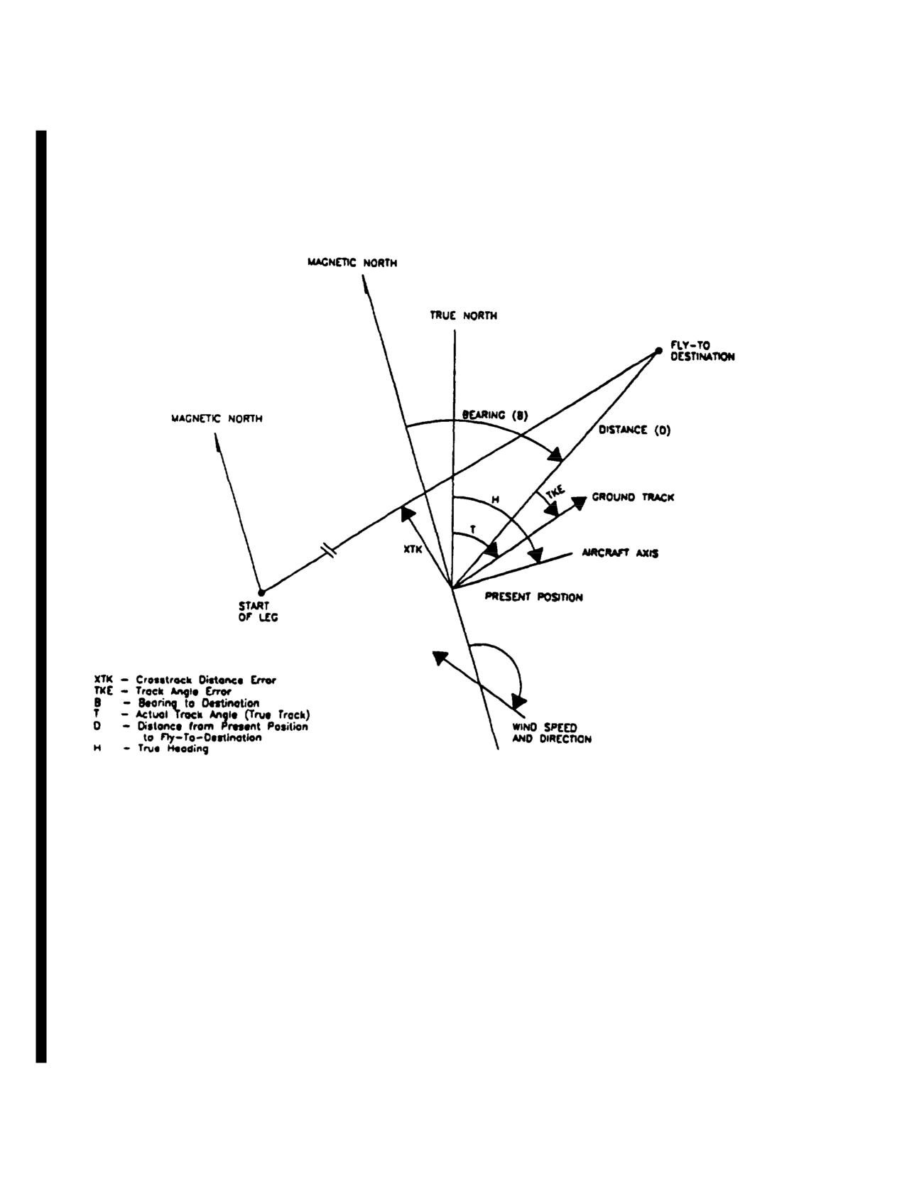
TM
55-1520-240-10
Figure 3-1Graphic Definition of Course Terms
3-34.14
Change
6
TM
55-1520-240-10
METHOD
1
(6)Depress KYBD key. (END field bl
enter ending destination 45 depress keys 4
When flying shortest distance to destination from
present pos
set DISPLAY switch to
(7) Depress KYBD key. (SELECT field
DIS/BRG/TIME position and steer Enter Y (yes) for mode selection. N may be
bearing displayed. As an aid to maisystemgwithrsthe start and end destinati
set DISPLAY switch to XTK/TKE posenteringd
the Route-Sequence To-To mode,
steer aircraft to keep track anglroute-Sequence
To-To mode if the system is
nominally zero. If the display indmode.s a L (left)
TKE, the aircraft must be flown to the left to zero the
NOTE
error.
If an entry is changed after Y is e
METHOD
2
selection, and N must be entered for th
then it may be changed to Y. The sequence
When flying a ground track, set DISPLAYflown from
the beginning waypoint.
XTK/TKE position. Steer vehicle to obtain zero for
No target destinations or destinations
crosstrack error (XTK). If XTK is left (L), aircraft is
motion may be included as To-To waypoi
to right of the desired course and must be flown to
the left to regain the initial course.
d. Procedure to Enter Route-Sequence Ran
NOTE
The Doppler/GPS navigation set has the
Since the aircraft has the Horizontanavigate through a sequence of random
Indicator (HSI) and when the Dopplerdestinations.
selected then the pilot may use the “#1” needle and
ple, consider navigating thro
course deviation indicator (CDI) for naAs an exam
the Fly-To destination selected on thnumbers 32, 25, 74, 01, 48, 83, 35.
(1) Set MODE switch to MGRS (LAT
Select CDI by depressing, then releasing the DPLR GPS
may also be used).
lens on the HSI Mode Select Panel.
(2) Set DISPLAY switch to DATUM/ROU
c. Procedure to Enter Route-Sequence To-To Mode
(3) Depress the ENT key. Observe that
The Doppler/GPS navigation set has the capability to
special steering functions appears.
navigate a course set up between to destinations.
(4) To select the Route-Sequence
As an example, consider navigating onto a course starting
display depress key 2. Observe that RT SEQ
from destination number
62 and ending at destination
appears in the display followed by th
number 45.
destination numbers and a continuation pr
(1) Set MODE switch to MGRS (LAT/LONG
(5) Enter the sequence of destination
may also be used).
depressing the KYBD key to enter keyboar
destination field is blinks.) To enter
(2) Set DISPLAY switch to DATUM/ROUTE.
depress keys 3, 2.
(3) Depress the ENT key. Observe that a menu of
(6) Depress KYBD key. (next destinat
special steering functions appears.
blinked.) Depress keys 2., 5 to enter seco
(4) To select the Route-Sequence To-To di(7)yRepeat step
6 until a maxim
depress key
1. Observe that TO-TO and sdestinations
are entered or if less than
appears in the display. The display proviasterisks are left f
or remaining destinat
and ending destination numbers.
(8)To complete the entry of the rando
(5) To enter keyboard mode depress of waypoints depress ENT key.
key. (START field blinks.) To enter starting destination
62
depress keys 6, 2.
(9) Depress ENT key to select next pa
Change
6
3-34.15
TM
55-1520-240-10
(10)To select the start field and enter t(7) Depress
KYBD key. (SELECT field bli
destination depress KYBD key.
Enter Y (yes) for mode selection. N may be ente
system but without entering the Route-Se
(11) To select the ending field Consecutivehe
mode, or to exit the Route-S
ending destination depress KYBD key.
Consecutive mode if the system is currently in
entry of Y and R indicates a choice of Y-flyi
(12)Depress KYBD key. (SELECT fieldorder, or
R-flying in reverse order.
Enter Y (yes) for mode selection. N may beentered to arm the
system but without entering the Rout-Sequence Random
NOTE
mode, or to exit the rout-Sequence Random If an entry
is changed after Y or R is en
system is currently in that mode. An entry Y selection, and N
must be entered for the s
choice of Y-flying in forward order, or R-then it may be changed to Y or R. the seq
order. To clear the random sequence, enter amust be flown from the beginning waypoint
No target destinations or destinations wit
NOTE
motion may be included as Route sequenc
If an entry is changed after Y or R is econsecutive waypoints.
selection, an N must be entered for the selection
cedure for Displaying Distance/Bea
then it may be changed to Y or R. The sf. Pro
Information
must be flown form the beginning waypoint.
No target destinations or destinations with target
(1) Set MODE switch to MGRS (LAT/LONG o
motion may be included as Route sequence
GPS LDG may also be used)
random waypoints.
(2) Set DISPLAY switch to DIS/BRG/TIME.
(13)After all entries are made, depress ENT key.
(3) Observe that the distance-to-go in k
e. Procedure to Enter Route-Sequence-Consecutive
(to the fly-to destination), bearing, and tim
Mode
the bottom two lines of the display. (Distan
miles when MODE switch position is LAT/
The Doppler/GPS navigation set has the capability to
Bearing-to-destination is displayed in degr
navigate through a sequence of consecutively numbered
time-to-go is displayed in hours, minutes, a
destinations.
minute.
As an example, consider navigating through destination(4)The display of the second line depend
numbers 32 through 35.
current steering mode as follows:
(1) Set MODE switch to MGRS (LAT/LONG
(a) Direct-To Steering (default):
may also be used).
destination number and ICAO identifier are
Example:
58:BANDO
(2) Set DISPLAY switch to DATUM/ROUTE.
(b) To-To Steering: TO-TO-:XX TO
(3) Depress the ENT key. Observe thatwhere XX is the ‘To-To’ start-of-leg destinat
special steering functions appears.
YY is the ‘To-To’ fly-to destination number.
(4) To select the Route-Sequence-Consecuti(c) Route-SequeSteering(both
display depress key 3. Observe that RT SEconsecutivew
and random): RT-RANDOM:XXTOYY w
appears in the display, followed by stXX is the current
Route-Sequence fly-to desti
destination numbers, and mode selection.
and YY is the next destination number in th
Approximately
10 seconds before overflying
(5) To enter keyboard mode depress destination, the system automatically ‘pickl
key. (START field blinks.) To enter stardestination, and
the new fly-to number blinks
depress keys 3, 2
then stops blinking.
(6) Depress KYBD key. (END field g. Procedure for Displaying Present Positio
Depress keys 3, 5 to enter ending destinaAltitude
3-34.16
Change
6
TM
55-1520-240-10
(1) Set the MODE switch to MGRS (LAT/LONG6) If it is not desired to store the
or GPS LDG may also be used). Set the DISDISPLAYiswitch
momentarily or permanently
PP and observe present position display.
position.
e for Entering Landing Mode
(2) To display present position variati. Procedur
altitude depress the ENT key. Present position variation may
(1) Set the Fly-to destination by
be entered by depressing the KYBD key to select the
DISPLAY switch
itherX T K / T K E / K E Y o r
variation field. A variation is entered and the ENT key is
DIST/BRG/TIME. Directly enter the two di
depressed.
number or use the INC or DEC keys.
h . Target Store (TGT STR) Operation
(2)Set MODE switch to GPS LDG.
Two methods may be used for target store o(3)The DISPLAY switch continues to fu
Method
1 is normally used when time isbefore. To switch
between metric and Engli
preplan a target store operation. Method the ENT key.n time
is available and it is desired to store a target in a specific
location.
NOTE
In this mode, the DGNS provides rea
Method 1 (uses location 90-99)
landing guidance information to th
indicator. To display course deviation
(1) Depress the TGT STR key while flyi(CDI)er
on VSI and HSI, depress then rel
target.
DPLR GPS button on the HSI Mode Select P
(2)
Present
position
and
variaj.P
rocedure for Transferring Stored Dest
on to Another
automatically stored in the target destiData From One Locati
was displayed in the target store field immediately prior to
The following procedure allows the opera
depressing the TGT STR key.
stored destination/target data from one
location to another destination location.
Method 2 (uses locations 00-69 and 90-99)
consists of destination name/ICAO ident
variation, and landing information. For i
(1) Set MODE switch to MGRS or LAT/LONG
only, it is assumed that the operator w
position, depending on coordinate from desired.
coordinates of stored target
97 into t
destination 12.
(2) Set DISPLAY switch to WP/TGT position.
(1)Set DISPLAY switch to WP/TGT posi
(3) To access P, depress the LTR LEFT key
followed by the 6 key. Another way to access P(2) Depress keys
9 then 7.
way point 99 then depress the INC key ordisplay way point 00
(3) Depress KYBD key, depress keys 1 t
then depress the DEC key.
NOTE
(4) Depress KYBD key when overflying potential
target. Observe that display freezes and kybLocation name/ICAO identifier, variat
the bottom right corner of the display indlanding data may
be deleted by first di
mode. The destination number is now underwaypoint,
depressing the KYBD key, th
control indicated by a blinking field.
ENT key.
CAUTION
(4) Depress ENT key.
k. Operation During and After a Power In
Do not depress ENT key while destination is set to
P.
During a power interruption, the stored
target data and present position are retai
(5) If it is desired to store the taRAM inside the CDU. This makes it unnecess
digit destination number and depress the
any navigation data when power returns. GP
Change
8
3-34.17
TM
55-1520-240-10
are also retained by a rechargeable battery in(3) Observe the CDU display. The top indic
This makes it unnecessary to reload the crin degrees and tenths of a degree, aircraft sy
the collection of any almanac. Navigationpitch, and roll.pted
during the absence of power; however the present position
will be updated when the GPS data becomes valid provided
nd Indicators - Horizontal
the DGNS mode has not been selected as Do3-61.15.r oControlsa
g. 3-15.3.)
pilot will have to re-enter the GPS operating mSituation(Indicators.Y(fi
using a single key (5 or 9).
CONTROLS/
In the event the CDU is initialized, the display will indicate
INDICATOR
FUNCTION
only EN when the CDU is operated. This is an indication to
the operator that previously stored data has been lost and that
spheroid/variation, destinations, and calibration data must be
Compass Card
The compass card is a 360° scale
entered. Present position needs to be entered only if Doppler
that turns to display heading d
only mode has been selected. The KYBD key must be
obtained from the gyro magneti
depressed to clear the EN.
compass (AN/ASN-43). The
helicopter headings are read a
The computer initializes to the following: operating mode
the upper lubber line.
to combined, present position variation to E000.0,
destinations and associated variations to a non-entered state,
wind speed (water motion) and sea currenBearing Pointer
The 1pointeroperatesin
DATUM:
00, present position to N45°
00.00' E000°00.00’
conjunction with doppler/GPS
(until
updated by GPS), target store location to
91, alInd
icates magnetic bearing to
track calibration correction to
00.0 percent, and magnedop
pler/GPS destination set on
compass deviation corrections to
000.0 degrees. The
FLY-TO-DEST.
following data must be entered:
(1) Depress KYBD key.
Bearing Pointer The 2pointeroperates in
conjunction with selected VOR
(2) Set MODE switch to OFF momentarily, to
or ADF receiver. The pointer
LAMP TEST for approximately one second, and then to
read against the compass card
MGRS or LAT/LONG.
and indicates the magnetic
bearing to the VOR or ADF
(3) Select GPS M or Y mode.
station.
(4) Select DGNS operating mode if other than
combined.
Course Deviation
his indicator indicates later
cator
deviation from a selected VOR
(5) Enter datum.
course or doppler computed
course or heading in the case
(6) Enter present position if Doppler only has
FM homing. When the helicopter
been selected.
is flying to correct course,
course indicator will be alig
(7) Enter each destination and its associated
with the course pointer and w
variation.
be centered on the fixed aircr
1. Procedure for Displaying Aircraft Heading, Pitch, andymbol. The two dots on eithe
side of the indicator indica
roll (Maintenance Function)
amount of course deviation. On
(1) Set the CDU mode switch to test and observe
dot displacement is equivalent
the CDU test mode display.
5° off VOR or doppler and 1 1/
degrees off localizer course
(2) After the Doppler test iscompleted depress the
These displacements do not
ENT key.
apply to FM homing.
3-34.18
Change
8
TM
55-1520-240-0
CONTROL/
FUNCTION
CONTROL/
FUNCTION
INDICATOR
INDICATOR
CRS Knob
The COURSE indicator and
Course Indicatorcourse pointer operate in course
Glide Slope PoinDisplays glide slope p
Pointer
conjunction with
the course
relative to the helicopt
select (CRS) knob, and allow the
homing signal strength.
pilot to select any VOR course.
pointer
bove center,
The course pointer turns with the
helicopter is below glid
compass card and will be aligned
conversely
pointer is
with the lubber line when the
below center, helicopter
helicopter heading is the same as
glide slope. Increasing
the selected course.
signal strength is sho
pointerrisingDecreasing
Range Indicator
Digital distance display in
homing strength is show
kilometers (KM) to destination
pointer falling.
set on doppler FLY-TODEST
thumbwheel.
HDG Knob
Heading select (HDG) kGlide Slope (GS)Indicates loss of or an
Flag
glide slope or FM homing
operates in conjunction Warning
heading bug. It allows the pilot to
select any one heading. With
CMD SEL (fig. 3-14) selec3-61.16.Horizontal Situation Indicator Mode
the HSI MODE SELECT panel,
Select Panel. (fig.
3-15.3)
the AFCS (chapter
2) will turn
the helicopter to and maintain the
selected heading.
The HSI MODE SELECT panel is on each pil
panel below the HSI. The panel allows the
HDG Flag
The HDG flag is in view when
navigation mode to be displayed on the HSI
the signal from the gyro magnetic
heading select feature, and visually indi
compass is unreliable or power to
passage. The panel isdivided into threese
the indicator is lost.
BRG, and MKR BCN,
To-From Arrow
To-from arrow indicates that the
helicopter is flying to or away
a. The CRS (course) section consists of
from a selected VOR.
selector switches labeled VOR SEL, GPS/
NAV Flag
The NAV flag turns witSEL,e
and CMD SEL. Pressing VOR SEL, GPS/D
compass card. The flagFM SEL causes the output of the selected na
retract from view when aelectrically connected to the course devi
VOR doppler or FM homicorresponding HSI and lights SEL legend
signal is being appliedThese switches are electrically interloc
instrument.
may be selected at a time. Selecting an
modes, automatically disengages the mode
Aircraft Symbol Corresponds to longitudithe SEL
legend of the mode in use, enga
of the helicopt
shows
mode, and lights the SEL legend of the se
helicopter position andpilot may independently select different
relative to the selected forrdisplay on his HSI.
Change
8
3-34.19
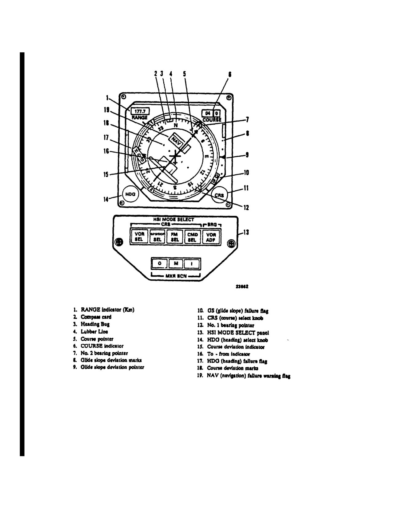
TM
55-1520-240-10
Figure 3-15.3. Horizontal Situation Indicator Mode Select Panel
3-34.20
Change
8
TM 55-1520-240-10
b. Pressing CMD SEL engages the AFCS headtwo segments labeled VOR and ADF. If the
feature, causes the helicopter to turn tolit, the No.,h2 pointer will indicate
to which the HSI heading bug is set, and station to which the VHF navigation set is
legend on the switch. Due to electrical iswitch will cause the VOR segment to go
two HSI control panels, both CMD SEL swipointer will indicate the bearing to th
engaged at the same time. The engaged switcADF set is tuned out and light the AD
the lit SEL legend. If the opposite CMopposite actions
occurs if the ADF segme
pressed when operating with heading selecswitch is pressed.
AFCS panel will release and heading select will be
disengaged. Control of the course deviatiod. A MKR BCN light will illuminate
VOR mode relative to bearing and coursebeacon passage. The light labeled O comes
from a VOR is assigned to the pilot whothrough an outer marker beam. The light la
engaged. If the pilot who does not have Cwhen passing through a middle marker and
makes an adjustment on his CRS knob, it wlabeled I comes on
when passing through an
on the CDI relative to the course.
each light illuminates, a distinctive
beacon will be heard over the interphon
c. Pressing VOR/ADF pushbutton on thlights have a press-to-test feature; pre
selects the navigational aid, the bearinthree lamps will cause all mode select p
indicated by the HSI No. 2 pointer. The stotilluminatedon that HSI MODE SELECT p
Change
8
3-34.21
TM
55-1520-240-10
SECTION IV TRANSPONDERS
3-62. Transponder System (AN/APX-100).
CONTROLS/
INDICATOR
FUNCTION
The transponder system provides automatic radar iden-
tification of the helicopter. The syM-1, M-2, M-3/A SA
itONes
position, the appli-
codes, and replies to interrogations on modes
1,
2,
3/Acble mode is selected for
4, TEST and C from all suitably equipped challenging
operation. OUT position
helicopter or ground facilities. The receiver sectioturns off applicable mode.
operates on a frequency of
1,030 MHz and the trans-
At TEST position, that
mitter section operates on
a frequency of
1,090 MHz.
particular mode is tested
Because these frequencies are in the UHF band, the
for proper operation. If
operational range is limited to line-of-sight. Power te
st is valid, TEST lamp
operate the system is supplied by the No.
2 DC bus
will illuminate.
through the COMM IFF circuit breaker on No.
2 PDP.
M-C
In mode C, altitude infor-
The integral receiver-transmitter-control panel is on mation is provided to
console. It provides the control switches for applicatground controllers by the
of power, setting of the -modes and codes, modes of
AAU-32A encoding altim-
operation, identification of position, and emergencyeter. Switch position func-
functions of the set. It receives coded interrogatintons are the same as for
pulses and tests them for validity. If the signals confM-l, M-2, and M-3A
to the preset mode and code, a coded reply is transmit-
switches.
ted. Additional preset codes for emMODEc1 Selecto
r
Selects and indicates a
available when selected. These emergeSwitcheses are
two digit
32 code reply
transmitted on modes
1,2,3/A and
4 regardless of codes
number.
selected. Transponder functions are continuously mon-
MODE
2 Selector
Selects and indicates a
4
itored by built-in-test circuits. Each mode also has a
Switches
digit
4096 code reply
self-test feature which can be selected by the pilot to
number. (Switches are
verify operation. The RT-1285/APX-100 is the interim
preset and covered by a
NVG compatible control. The RT-1558/APX-100 is the
guard. Only the reply
NVG Blue Green version. Both units are form, fit and
code can be seen.)
functionally interchangeable. The receiver-transmitter
must be removed from the console to rMODEc3/A Selector
Selects and indicates a
4
Switches
digit
4096 code reply
3-83. Controls and Function, Transponder Control
number.
(RT-1285/APX-100)(RT-1558/APX-100).
(fig.
3-16)
MODE
4 CODE ContSelects type of MODE
4
Switch
operation.
CONTROLS/
HOLD
This function is enabled
INDICATOR
FUNCTION
only when the right aft
MASTER Control
landing gear strut is com-
Switch:
pressed. It holds the
OFF
Removes power from
MODE
4 code which
transponder set and com-
would otherwise be
cleared when the set is
puter.
turned off or electrical
STBY
Power is applied to tran-
power is removed. Switch
sponder receiver and com-
is spring-loaded to A.
puter; transmitter inoper-
HOLD function is reset
ative. Set ready for
when the transponder is
operation after
2 minute
turned on.
warmup in STBY.
A
Enables transponder to
NORM
Transponder in normal
reply to code A interroga-
operation.
tions.
EMER
Transmits emergency re-
B
Enables transponder to
ply signals to mode
1,
2,
reply to code B interroga-
or
3/A and
4 interroga-
tions.
tions, regardless of mode
control settings.
3-34.22
Change
8
TM 55-1520-240-10
CONTROLS/
CONTROLS/
INDICATOR
FUNCTION
INDICATOR
FUNCTION
ZERO
Clears (zeroizes) mode
4
RAD TEST feature is
inoperative.
code settings in transpon-
der computer.
IDENT-MIC Switch
At IDENT, the set will
transmit a coded identifi-
MODE 4 AUDIO
At AUDIO, the REPLY
indicator light will illumi-
cation pulse for about 20
LIGHT OUT Switch
nate when the transpon-
seconds to all interrogat-
der replies to valid mode
ing stations on modes 1, 2,
4 interrogations. A pulse
and 3/A to identify the
helicopters position. OUT
tone will be heard in the
headset when a code A
position turns off the
interrogation is received
identification pulse. MIC
but the CODE control
feature is not used in this
switch is in B position and
installation.
vice versa. At LIGHT,
STATUS Indicators
The indicator lights are
only the light will illumi-
part of built-in-test equip-
nate when the transpon-
ment. A lit ALT indicator
der replies to mode 4 in-
indicates trouble in the
terrogations. At OUT, the
encoding altimeter. A lit
audio and REPLY light
KIT indicator indicates
monitoring is disabled.
trouble in the computer
MODE 4 TEST-ON-OUT
At ON, the transponder
or the computer is not
Switch
replies to valid mode 4
installed. A lit ANT indi-
interrogations. At OUT,
cator indicates antenna
mode is disabled. At
trouble.
TEST, mode 4 is tested
ANT Switch
Three-position antenna
for proper operation. If
diversity switch labeled
test is valid, TEST GO.
TOP, DIV, and BOT.
Normal position is DIV.
Mode 4 REPLY Light
Illuminates to indicate
When jamming is heavy,
valid mode 4 replies when
TOP or BOT antenna
MODE 4 AUDIO
may be selected.
LIGHT switch is set to
either AUDIO or LIGHT.
IFF Fail Light
The light will illuminate in
TEST GO Light
Illuminates when tran-
sponder responds properly
(Located on the center
MODE 4 when any of the
to TEST position of M-1,
instrument panel)
following occurs:
M-2, M-31A, M-C, or
a.
The computer is in-
MODE 4 TEST-ON-
stalled without a code.
OUT switches.
b.
No reply or improper
TEST/MON NO GO
The light illuminates when
reply is made to a valid
Light
any of the following oc-
interrogation.
curs:
c. A malfunction occurs
a.
MASTER switch is on
in the transponder.
STBY.
b.
Transponder does not
3-64. Normal Operation - Transponder System.
respond to interroga-
The following steps provide transponder system operat-
tion.
ing procedures.
c.
Transponder does not
a. Starting.
respond to TEST posi-
tion of mode switches.
(1)
MASTER control switch - STBY. Red
TEST/MON NO GO light illuminates.
d. Transponder malfunc-
tions.
(2)
Warmup
- 2 minutes.
RAD TEST Switch
At RAD TEST, the tran-
(3)
RAD TEST switch - OUT.
sponder replies to interro-
(4)
IDENT-MIC switch - OUT.
gations from external test
equipment. At OUT, the
(5) AUDIO-LIGHT switch
- OUT. (During
mode 4 operation - As desired.)
3-35
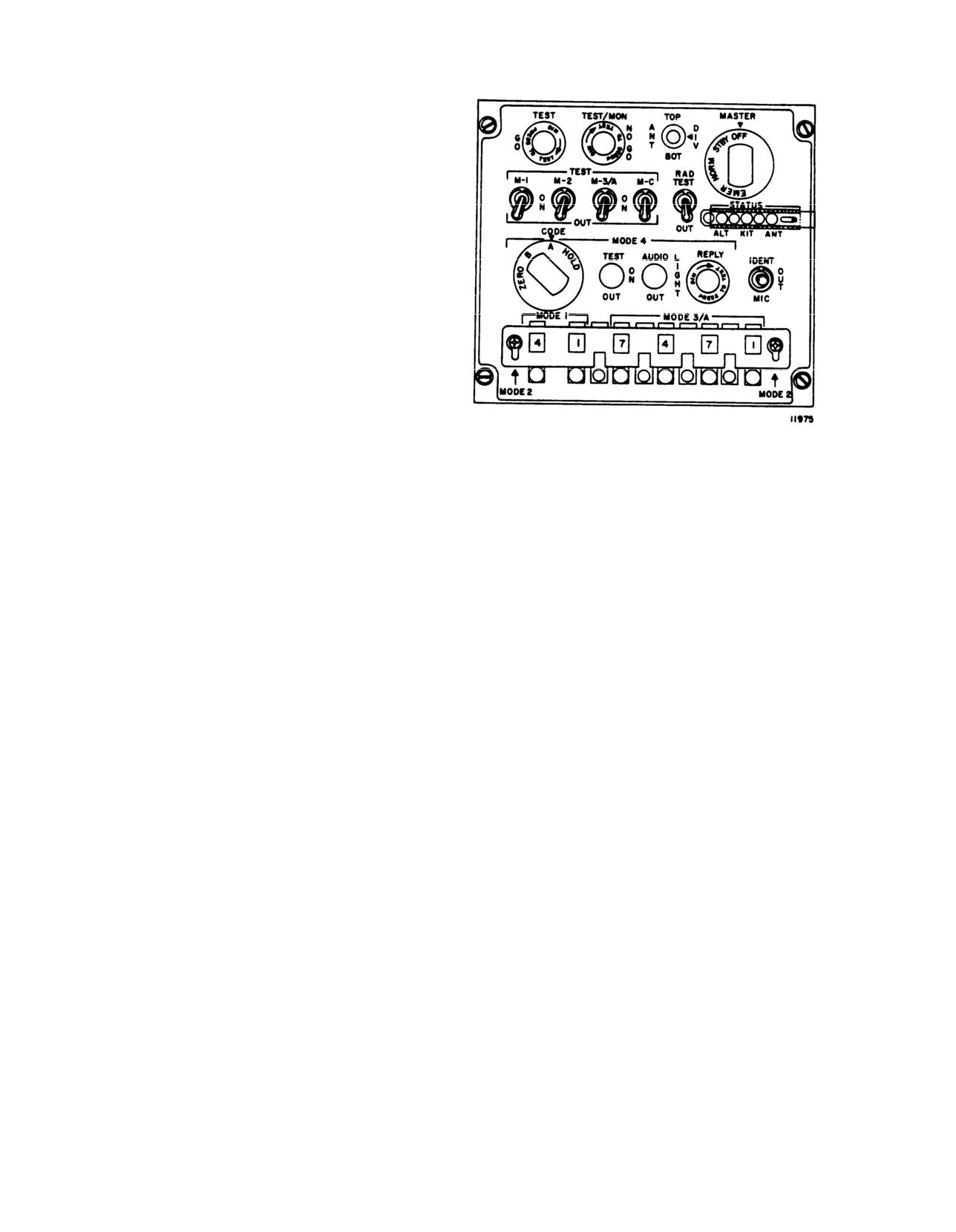
TM 55-1520-240-10
(6) M-1, M-2, M-3/A, M-C and MODE 4 switches
- As required. MODE 4 switch must be
OUT when computer is not installed.
(7) MODE 4 CODE control switch
- A
S re-
quired.
(8) MASTER control switch - NORM,
(9) ANT DIV switch - DIV. TEST/MON light
should extinguish after 6 seconds.
b. Stopping.
(1) If code retention is desired:
(a)
MODE
4 CODE selector switch-
- HOLD, then release.
(b)
MODE 4 CODE selector switch - A or
B, as applicable.
(c) MASTER control switch - OFF.
(2) If code retention is not desired:
Figure 3-16. AN/APX-100 Control Panel
(a)
MODE 4 CODE selector switch
- ZERO.
(b)
MODE 4 CODE selector switch - A or
B, as applicable.
(c) MASTER control switch - OFF.
3-36
TM 55-1520-240-10
3-65.
AN/ASN-149(V) Global Positioning System
satellites. The aircraft location data calculated by the
(GPS).
GPS is then used to update the INS present position of
a. Description.
The AN/ASN-149 Global
the aircraft.
Positioning System (GPS) shown in Figure 3-17 receives
satellite signals through an antenna located on top of the
b. Controls and Functions. The controls and
aircraft above the cockpit. The GPS then calculates the
functions for the Global Positioning System are
aircraft’s location with respect to the position of the
described in Table 3-5.
Table 3-5. AN/ASN- 149( ) GPS Controls/Indicators and Functions.
Control/Indicator
Function
Line Select
Keys
Lighted. Momentary-contact push-button switches.
Provide three functions:
Enable scratch-pad display to allow operator to enter data on display line
Transfer data from scratch-display to memory.
Select or cancel action displayed on the data entry display line.
Display Screen
Displays operational menus and data entry fields. Contains four display lines with
each line displaying up to 13 characters.
Mode Switch
Four-position rotary switch with pull-to-turn mechanical interlock at OFF and TEST
positions.
OFF
Disables Receivel aLid ilndicaiil-Coiitroller power supplies. Mode switch knob must
be pulled out to rotate to or from OFF position.
INIT (initialize)
Enables initialization (start-up) of the GPS.
NAV (navigation)
Enables GPS navigation functions and sends/receives outputs/receives to/from the
operator and/or other on-board navigation systems.
TEST
Enables GPS self-test. Failures are isolated to assembly level and failure codes
are displayed on the data display. Mode switch knob must be pulled out to rotate to
or from TEST position.
BRT Control
Adjusts data display brightness.
NOTE
Panel lighting brightness is controlled by aircraft dimmer control.
Data Entry Keys
Lighted momentary-contact push-button switches.
Change 6 3-37
TM 55-1520-240-10
Table 3-5. AN/ASN- 149( ) GPS Controls/indicators and Functions - (Continued)
Control/Indicator
Function
USE LTR Key
Lighted momentary-contact push-button switch.
Allows letters to be selected for entry. Also terminates alphabetic data entry.
CLR (clear)
Lighted momentary-contact push-button switch. During Data entry:
One press clears last character entered.
Two presses clears entire display line.
Three presses exits data entry and returns original data display.
WP (Waypoint) Key
Lighted momentary-contact push-button switch.
Allows selection of destination (> ) or waypoint (WP) operation.
MARK Key
Lighted momentary-contact push-button switch.
Enters present position into scratch-pad memory to either freeze position display
or store position information in GPS memory.
Data Select Switch
Ten position rotary switch.
POS (position)
Allows display of resent position coordinates and altitude when D is displayed
on display line 1 or waypoint position coordinates and altitude when WP is
displayed on display line 1.
MSN (mission)
Allows selection of area navigation (RNAV) (stationary waypoint), rendezvous
(moving waypoint) operation. Doppler aiding and GPS outputs to other aircraft
systems. Operates only when > is displayed on display line 1.
OPT (option)
Allows selection of display options.
STAT (status)
Allows display of system status and performance information. Operates only
when > is displayed on display line 1.
VAR-DTM
Allows display of present position magnetic variation and map datum when
(magnetic
> is displayed on display line 1, or waypoint magnetic variation and map datum
variation-map
when WP is displayed on display line 1.
datum)
ERR (error)
Allows display of crosstrack, vertical and track angle errors. Operates only when
> when WP is displayed on display line 1.
3-38 Change 6
TM 55-1520-240-10
Table 3-5. AN/ASN- 149( ) GPS Controls/lndicators and Functions - (Continued)
Control/Indicator
Function
WIND
Allows display of wind speed and wind direction. Computed by GPS using drift
angle, true airspeed and heading. Operates only when> is displayed on
display line 1.
DIS-TG (distance-
Allows display of great circle distance, time to go, bearing and slant range to
time to go)
waypoint.
TRK-GS (track
Allows display of ground track, ground speed of aircraft and time of day when
ground speed)
> is displayed on display line 1, or display of ground track, ground speed and
time of fix of moving waypoint when WP is displayed on display line 1.
DKT-VA (desired
Allows display of desired track and vertical angle to destination when >
track-vertical angle)
is displayed on display line I or desired track and angle to waypoint when WP
is displayed on display line 1.
SLEW ( ) Key
Lighted momentary-contact push-button switch.
Accesses next page of multiple-page displays. Operates when double-headed
arrow ( ) is displayed on right side of display line 1.
Change 6 3-39
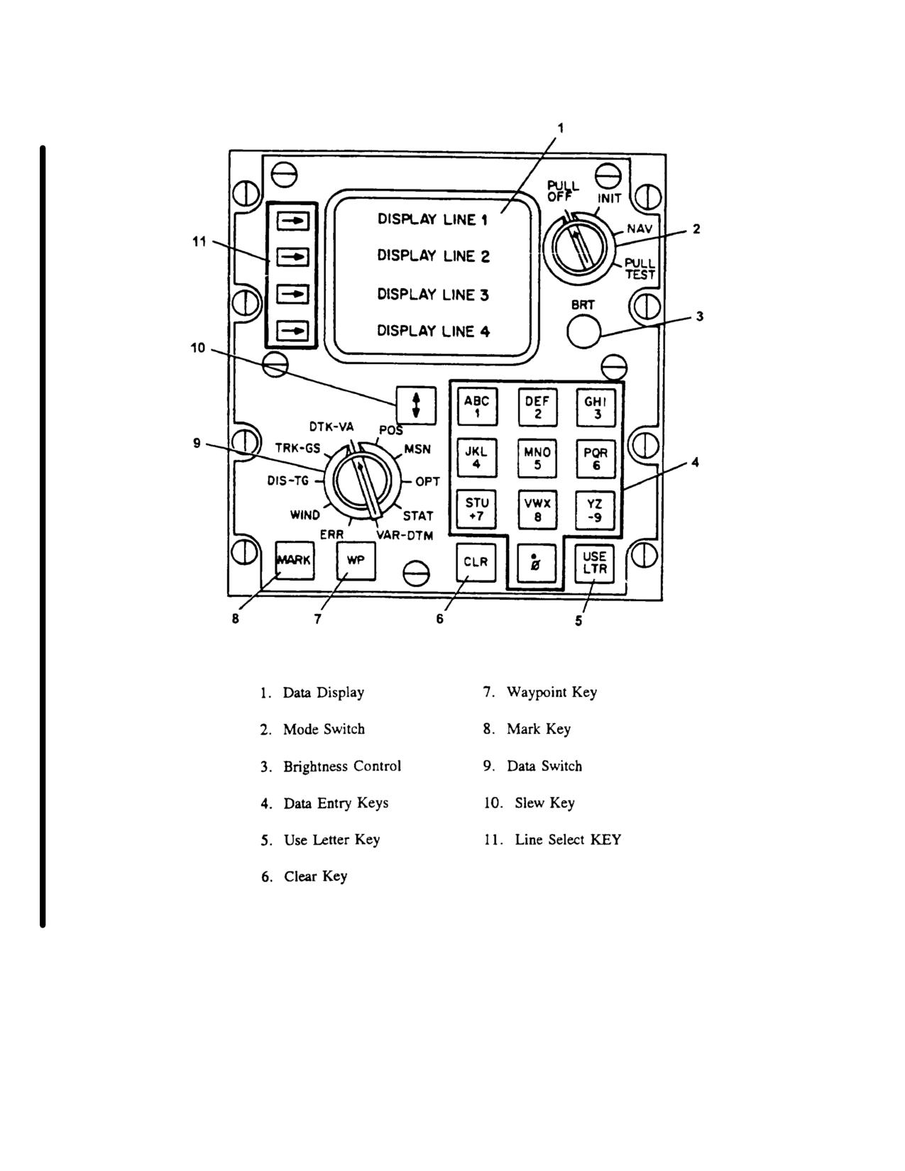
TM 55-1520-240-10
Figure 3-17. AN/ASN-149( ) GPS Controls and Display Unit (CDU)
3-40 Change 6
TM 55-1520-240-10
c. Operation. The GPS requires map datum. a
If the GPS already has current almanac, the first search
position reference, a time reference, and almanac or
pattern will be based on information contained in the
ephemeris data to perform a normal start-up. Table 3-6.
almanac. For example, if the GPS contains almanac for
If the position reference is not available from internal
PRN3, 9, 12 etc., it will search for PRN3 first then PRN6
memory or external aircraft systems the GPS will request
etc. The time cold start takes under these conditions
position data be entered by the operator. If the almanac
may be considerably less than described above:
data is not available from memory or the data loader,
however, it is still based on satellite visibility. The start-
the GPS will automatically perform a cold-start of the sky
up procedure must be performed prior to using the GPS
to receive satellites. The GPS begins cold-start by
for navigation. Before operating, be sure GPS antenna
searching for PRN6. The search takes up to 6 minutes.
is open to the sky (TM 11-5826-308-12),
If PRN6 signal is not received (tracked), the GPS will
search for PRN 7. If PRN7 is not tracked in 6 minutes,
(1) Preliminary Procedures. Perform the
the GPS will search for PRN
8.This process will
following procedure before attempting GPS start-up.
continue up to PRN32 and start over at PRN1 until a
good satellite is tracked.
Commanded Self-Test - Table 3-8.
Once a good satellite is tracked the AN/ASN149(V)
Selecting units of measurement, coordinate systems,
receive almanac (data). This takes about 13 minutes.
north reference, altitude reference. Table 3-7.
After which the GPS will begin normal start-up operation.
Based on the above description, the time to complete a
cold start is totally dependent on satellite visibility. If
Start-up is being done when PRN6 is overhead and
good. start-up may be completed in less than
20
minutes.
Table 3-6. AN/ASN-149(V) GPS Start-Up Procedure
Step
Procedure
Display
a.
Set mode switch to INIT.
NOTE
Complete step b if data transfer module receptacle is installed; if
not, go to step c. Transfer data takes 30 seconds. If NAV is
selected before data transfer is finished, the data will be lost.
b.
Ensure data transfer module (if required) is programmed with current data,
then insert data transfer module into data transfer module receptacle.
Change 6 3-41
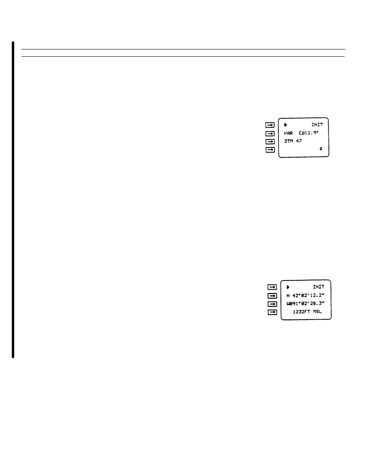
TM 55-1520-240-10
Table 3-6. AN/ASN-149(V) GPS Stan-Up Procedure - (Continued).
Step
Procedure
Display
NOTE
ENTER POS will be displayed if AN/ASN-
149(V) has no position data in memory. If
ENTER POS is displayed, line select key 3 must
be pressed to return to normal display.
c.
Set data switch to VAR-DTM.
d.
Check display line 1. If WP is displayed, press WP key.
e.
Check map datum on map in use- Look up code for that
map datum in Table 3-16. Compare map datum (DTM)
code displayed on display line 3 with Table 3-16 map
datum code. If displayed DTM code is incorrect, enter
correct DTM code display line 3.
f.
Set data switch to POS.
NOTE
When entering MGRS coordinates, do not press
line select key 2 after entering zone, and line
select key 3 before entering coordinates. MGRS
zone and coordinates are entered like a one
display line entry.
NOTE
Leading zeros must be entered (Example:
91°02'28.3' = 091°02'28.3", 800 = 00800) in steps
g. thru i. if required.
g.
Check latitude/MGRS zone displayed on display line 2. If
displayed position and actual position differ by more
than 60 miles or 100 kilometers, enter correct position
on display line 2.
h.
Check longitude/MGRS coordinates displayed on display
line 3. If displayed position and actual position differ by
more than 60 miles or 100 kilometers, enter correct
position on display line 3.
3-42 Change 6
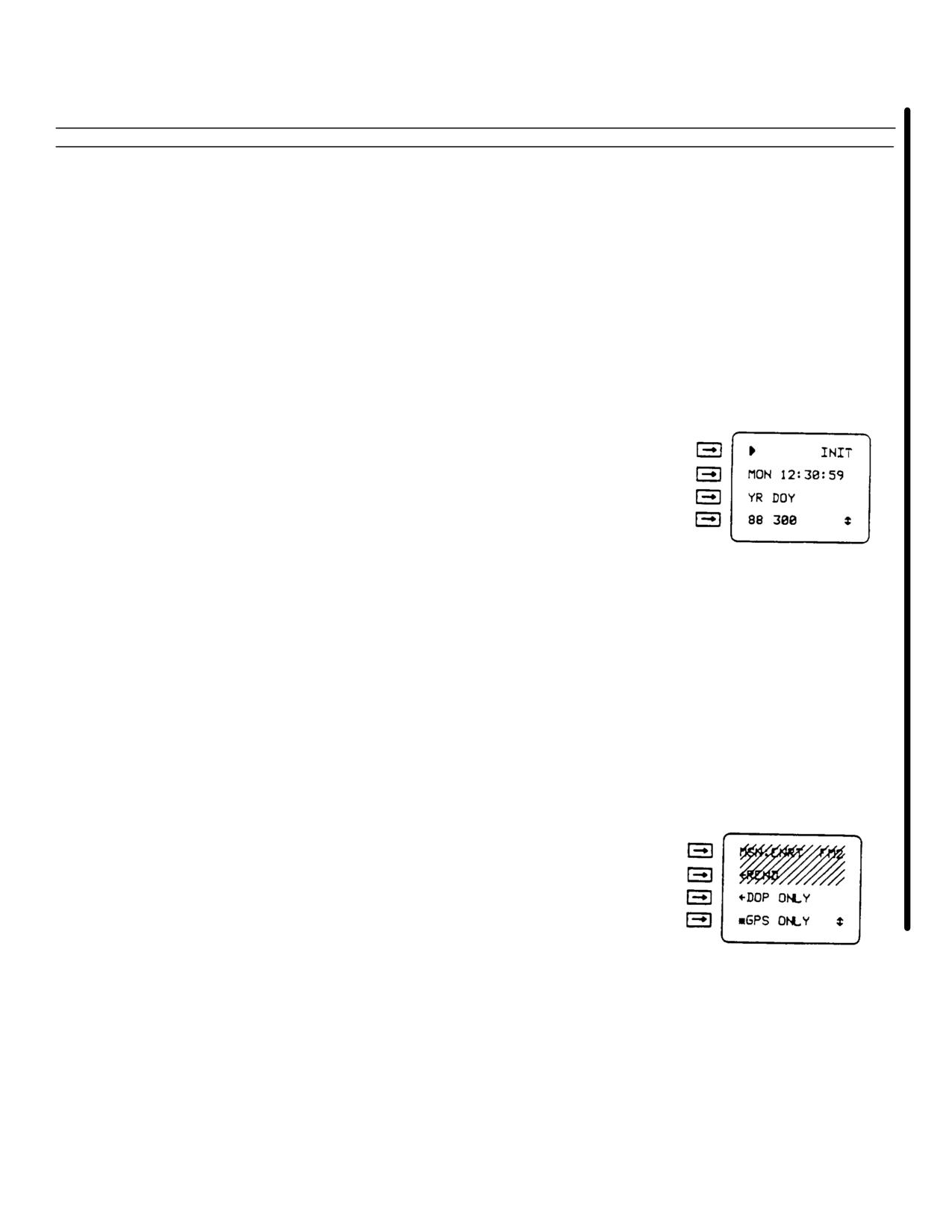
TM 55-1520-240-10
Table 3-6. AN/ASN-149(V) GPS Start-Up Procedure - (Continued).
Step
Procedure
Display
i.
Check altitude on display line 4. If displayed altitude and
actual altitude differ by more than 656 feet (FT) or 200
meters (M), enter correct altitude on display line 4.
j.
Set data switch to TRK-GS.
k.
Press slew key.
NOTE
Time is displayed in coordinated universal
(Zulu) time (24 hour clock).
Leading zeros must be entered (Example: 1:09:08
= 01:09-.08) in step I if required. Leading zeros
will not be erased when entry is complete.
1.
Check Zulu time displayed on display line 2. If displayed
Zulu time differs from actual Zulu time by more than 1
minute, enter correct Zulu time on display line 2.
NOTE
Day of year is Julian date.
Leading zeros must be entered (example: 3 =
003, 33 - 033) in step m, if required. Leading
zeros will not be erased when entry is complete.
m.
Check year (YR) and day of year (DOY) on display line 4.
If YR and DOY and actual YR and DOY differ, enter
actual YR and DOY on display line 4.
n.
Set data select switch to MSN.
o.
Check display line 3; if *DOP ONLY displayed, press line
select key 3.
p.
Check display line 4; if *GPS ONLY displayed, press line
select key 4.
q.
Press slew key.
Change 6 3-43
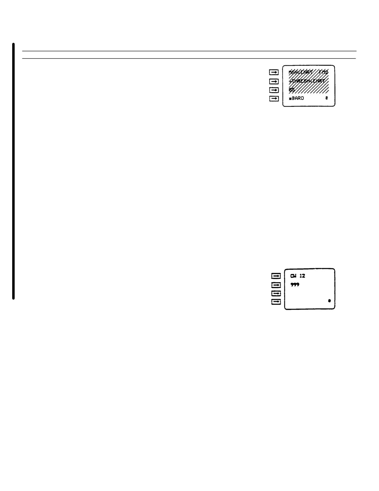
TM 55-1520-240-10
Table 3-6. AN/ASN-149(V) GPS Start-Up Procedure - (Continued).
Step
Procedure
Display
r.
Check display line 4; if - BARO is displayed, press line
select key 4.
NOTE
After NAV is selected, time and position
initialization inputs cannot be changed.
s.
Remove data transfer module from data transfer module
receptacle if installed.
NOTE
Complete steps t thru y if AN/ASN-149(V) is to
supply time correction information to precise
time and time interval (PTTI) equipment. If
not, go to step z.
t.
Rotate data switch to OPT.
u.
Press slew key until CW is displayed on display line L
v.
Enter 12 on display line 1.
NOTE
Leading zeros must be entered (example: 5 =
005, 10 = 010) in steps w and y, if required.
Leading zeros will be erased when data entry is
complete.
w.
Check LI path delay on display line 2. If displayed LI
path delay and actual LI path delay differ, enter actual
LI path delay in nanoseconds on display line 2.
3-44 Change 6