TECHNICAL MANUAL MAINTENANCE MANUAL FOR ARMY CH-47D HELICOPTER (1992) - page 7
TM 55-1520-240-10
Table 3-6. AN/ASN-149V) GPS Start-Up Procedure-(Continued).
Step
Procedure
Display
x.
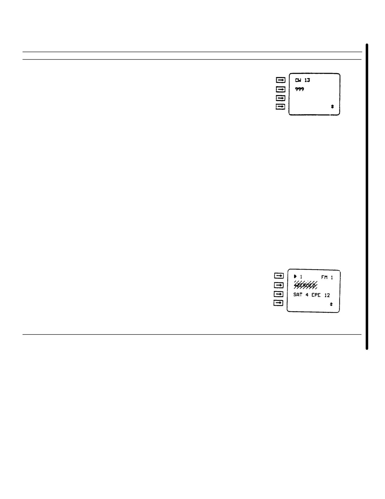
Enter 13 on display line 1.
y.
Check L2 path delay on display line 2. If displayed L2
path delay and actual 12 path delay differ, enter actual
L2 path delay in nanoseconds on display line 2.
NOTE
After NAV is selected, initialization inputs
cannot be changed. If a cold start is required,
COLD will alternate with FM on display line 1
while cold start is in progress. Cold start
progress may be checked by setting the data
switch to STAT and pressing the slew key three times.
After NAV is selected, FM will be replaced with
MEM or DOP until FM 2 or less is displayed.
z.
Set mode switch to NAV.
aa.
Set data switch to STAT.
ab.
Check number of satellite measurements (SAT) being used
in the navigation solution and estimated position error
(EPE) on display line 3. The AN/ASN-149(V) is ready
for operation when four satellite measurements are
being used and EPE is less than 25 meters,
approximately 2 minutes. If only three satellites are
available, the AN/ASN-149(V) may be prepared for use
by entering an altitude estimate. Altitude can be entered
by setting the data switch to POS and entering the
altitude estimate. M will be displayed to left of altitude
display indicating that an altitude may be entered. If an
altitude has been entered AHLD (altitude hold) will
alternate with FM while the entered altitude is being
used. M and AHLD will be automatically dropped when
four satellites are acquired. Manual altitude hold
may be dropped by pressing line select key 4 twice.
Change 6 3-45
TM 55-1520-240-10
Table 3-7. Units of Measurement, Coordinate Systems. North Reference, Altitude Reference,
and Lever Arm Selection Procedure.
Step
Procedure
Display
a.
Set mode switch to INIT or NAV.
b.
Set data switch to OPT.
c.
Check display line 1. If WP is displayed, press WP key.
d.
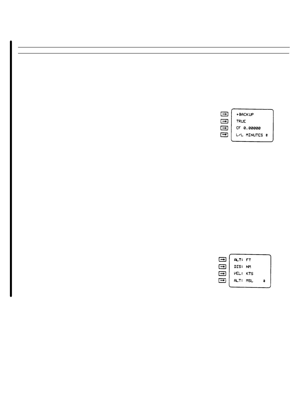
Press line select key 2 to select a desired north reference
TRUE, GRID, or MAG (magnetic).
NOTE
Convergence factor (CG) is meaningless unless
GRID is selected.
NOTE
Leading zeros must be entered (example:
0.00098, 0.00100) in step e, if required. Leading
zeros will not be erased when entry is complete.
e.
Check convergence factor (CF) displayed on display line 3.
If the displayed convergence factor is different than the
convergence factor of the map in use, enter new
convergence factor on display line 3.
f.
Press line select key 4 until the desired coordinate system
is displayed on display line 4:
L/L SECONDS - Latitude/longitude in degrees,
minutes, seconds, and tenths of seconds.
L/L MINUTES - Latitude/longitude in degrees,
minutes, and thousandths of minutes.
MGRS - Military grid reference system.
g.
Press slew key.
h.
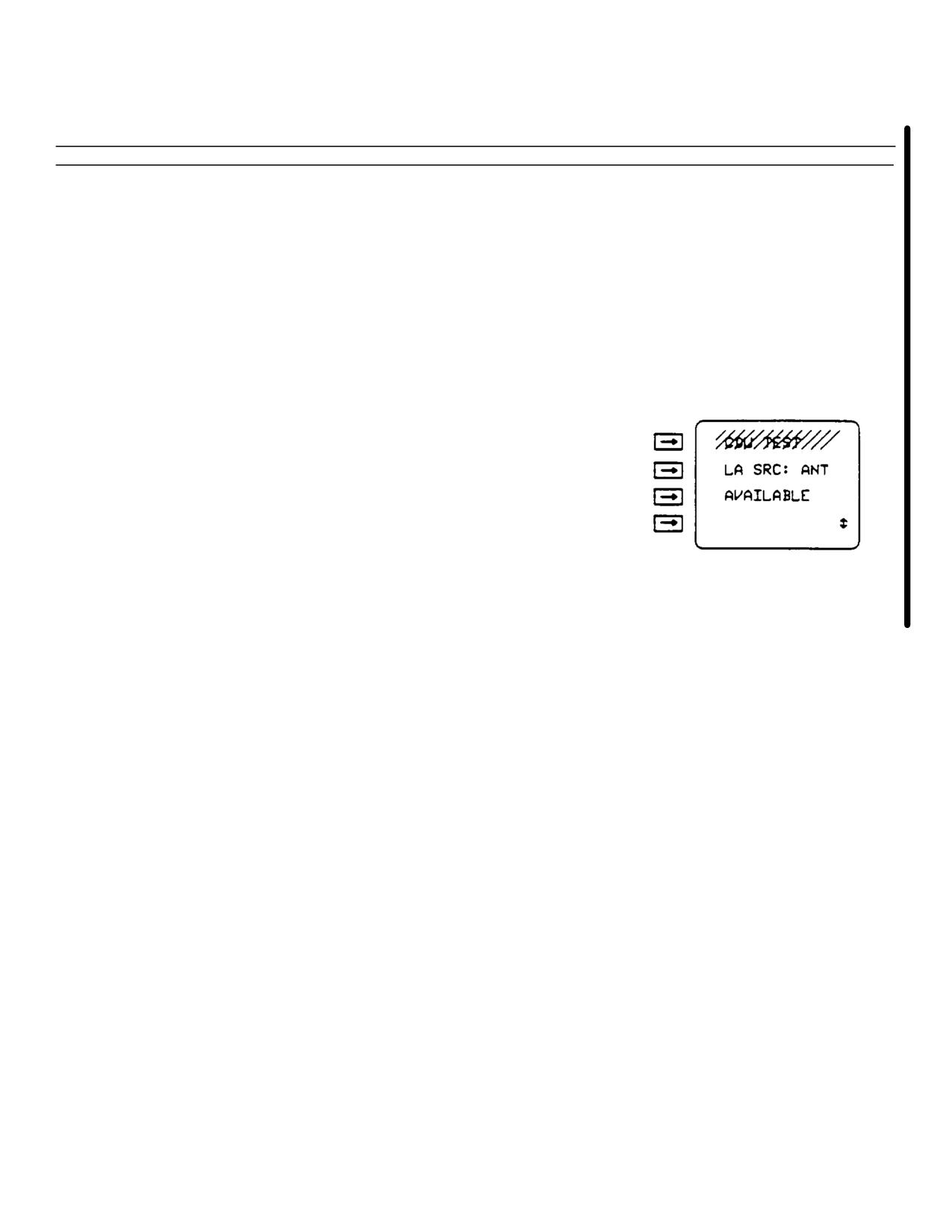
Press line select key 1 to select FT (feet) or M (meters)
for altitude (ALT) and estimated position error (EPE)
displays.
3-46 Change 6
TM 55-1520-240-10
Table 3-7. Units of Measurement, Coordinate Systems. North Reference, Altitude Reference,
and Lever Arm Selection Procedure - (Continued).
Step
Procedure
Display
i.
Press line select key 2 to select NM (nautical miles) or KM
(kilometers) for distance (DIS) displays.
j.
Press line select key 3 to select KTS (knots) or KPH
(kilometers per hour) for speed (VEL) displays.
k.
Press line select key 4 to select mean sea level (MSL) or
map datum (DTM) for altitude reference.
l.
Press and release slew key until LA SRC: is displayed on
display line 2.
m.
Check lever arm source (LA SRC) on display line 2:
ANT - antenna
CDU - C-11702/UR
DL - data loader
HV - aircraft external navigation equipment
NOTE
The status will change automatically depending
on the selection on display line 2.
Change 6 3-47

TM 55-1520-240-10
Table 3-7. Units of Measurement, Coordinate Systems. North Reference, Altitude Reference,
and Lever Ann Selection Procedure - (Continued).
Step
Procedure
Display
n.
Check status of LA SRC on display line 3:
AVAILABLE - Indicates data is available for the LA SRC
displayed on display line 2, but is not
being currently used.
NO DATA - Indicates no data is available for LA SRC
displayed on display line 2.
USING - Indicates LA SRC displayed on display line 2 is
being used for lever arm input data.
DEFAULT - Indicates the AN/ASN-149(V) has no LA
SRC in memory. The default lever arm data
source is the antenna. To select the antenna,
press line select key 3. Display line 3 will
automatically change from DEFAULT TO
USING. If line select key 3 is not pressed,
the AN/ASN-149(V) will automatically select
the antenna as the LA SRC.
NOTE
An LA SRC may be selected only when display
line 3 displays AVAILABLE or DEFAULT.
o.
Select desired LA SRC on display line 2 by pressing line
select key 3.
NOTE
To check actual lever arm data being used by the
AN/ASN-149(V), complete steps p thru v. To
enter lever arm enter data using the C-11702/UR,
complete steps w thru ab.
p.
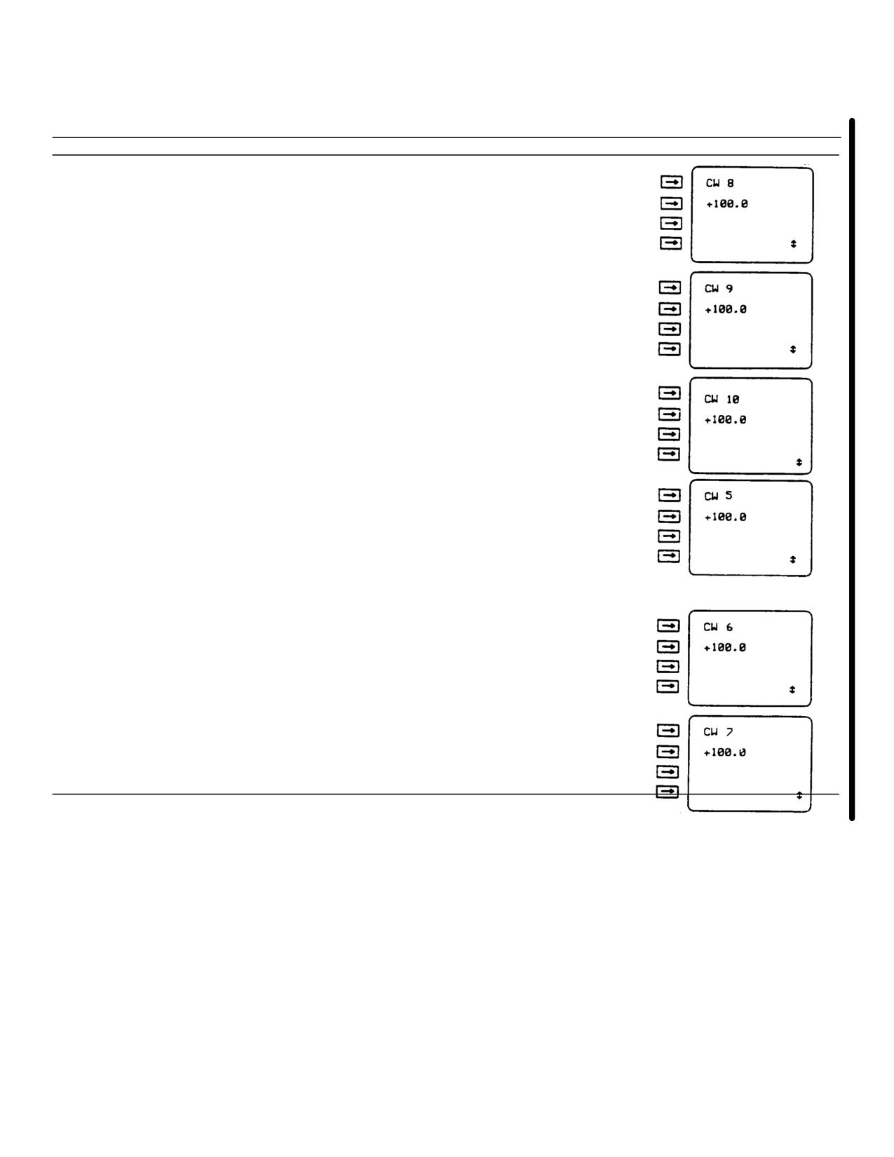
Press and release slew key until CW is displayed on
display line 1.
q.
Enter 08 on display line 1.
3-48 Change 6
TM 55-1520-240-10
Table 3-7. Units of Measurement, Coordinate Systems. North Reference, Altitude Reference,
and Lever Arm Selection Procedure - (Continued).
Step
Procedure
Display
r.
Check current up/down (+ - up, - = down) lever arm
displayed in meters (M) on display line 2.
s.
Enter 09 on display line 1.
t.
Check current fore/aft (+ = fore, - = aft) lever arm
displayed in meters (M) an display line 2.
u.
Enter 10 on display line 1.
v.
Check current left/right (+ = left, - = right) lever arm in
meters (M) displayed on display line 2.
NOTE
To enter new or correct lever arm source data,
complete steps w. thru ab.
w.
Enter 05 on display line 1.
NOTE
Leading zeros must be entered (example: 005.0 =
5, 010.0 = 10.0) in steps x, z, and ab if required.
Leading zeros will be erased when entry is
complete.
x.
Enter desired up/down (+ = up, - = down) lever arm in
meters (M) on display line 2.
y.
Enter 06 on display line 1.
z.
Enter desired fore/aft (+ = fore, - = aft) lever arm in
meters (M) on display line 2.
aa.
Enter 07 on display line 1.
ab.
Enter desired left/right (+ = left, - = right) lever arm in
meters (M) on display line 2.
Change 6 3-49
TM 55-1520-240-10
d. GPS Self-Test. Testing is divided into three
The keyboard/display test is done by pressing each of
parts: automatic built-in test (BIT), command self-test
the keys on the indicator controller and checking that
and keyboard/display test. The automatic BIT is done
each character is displayed correctly. Perform the
each time the indicator controller is set to INIT, NAV or
keyboard/display test only when the keyboard or the data
TEST from OFF. The command self-test is done when
display appears to work incorrectly.
the indicator controller mode switch is set to TEST.
Preliminary Procedures. None
Table 3-8. Command Self-Test Procedure.
Step
Procedure
Display
NOTE
Be sure aircraft power is applied to AN/ASN-149(V)
before starting procedure.
a.
Adjust indicator controller BRT control full clockwise.
b.
Set mode switch to TEST. Mode switch must be pulled out
to set to TEST.
NOTE
The indicator controller requires a 30-second warm-up
before the data display will display data.
NOTE
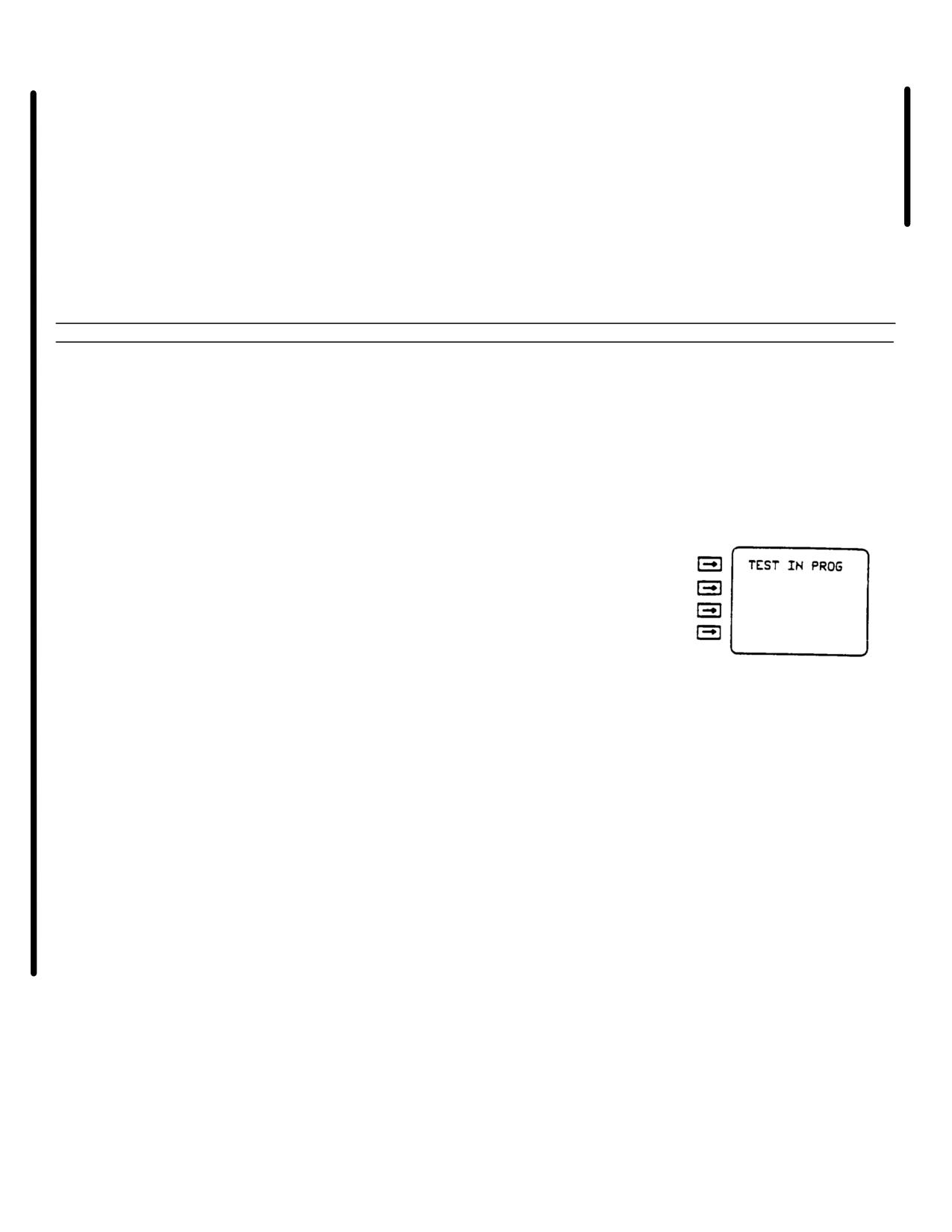
If failure data is displayed instead of TEST IN PROG,
notify organizational maintenance.
c.
After 30 seconds, check TEST IN PROG is displayed on
display line 1.
NOTE
Test may take up to 5 minutes Test progress
reports will flash briefly during testing.
d.
Adjust indicator controller BRT control counterclockwise for a
comfortable viewing level.
NOTE
Indicator controller panel lighting glows green. Light
level is very low; shield C-1 1702/UR from any
light while checking.
3-50 Change 6
TM 55-1520-240-10
Table 3-8. Command Self-Test Procedure - (Continued).
Step
Procedure
Display
e.
Adjust aircraft dimmer control clockwise and
Panel light level varies with
counterclockwise while checking indicator controller panel
changing setting of aircraft
lighting.
dimmer control.
f.
Adjust aircraft dimmer control for a comfortable viewing
level.
g.
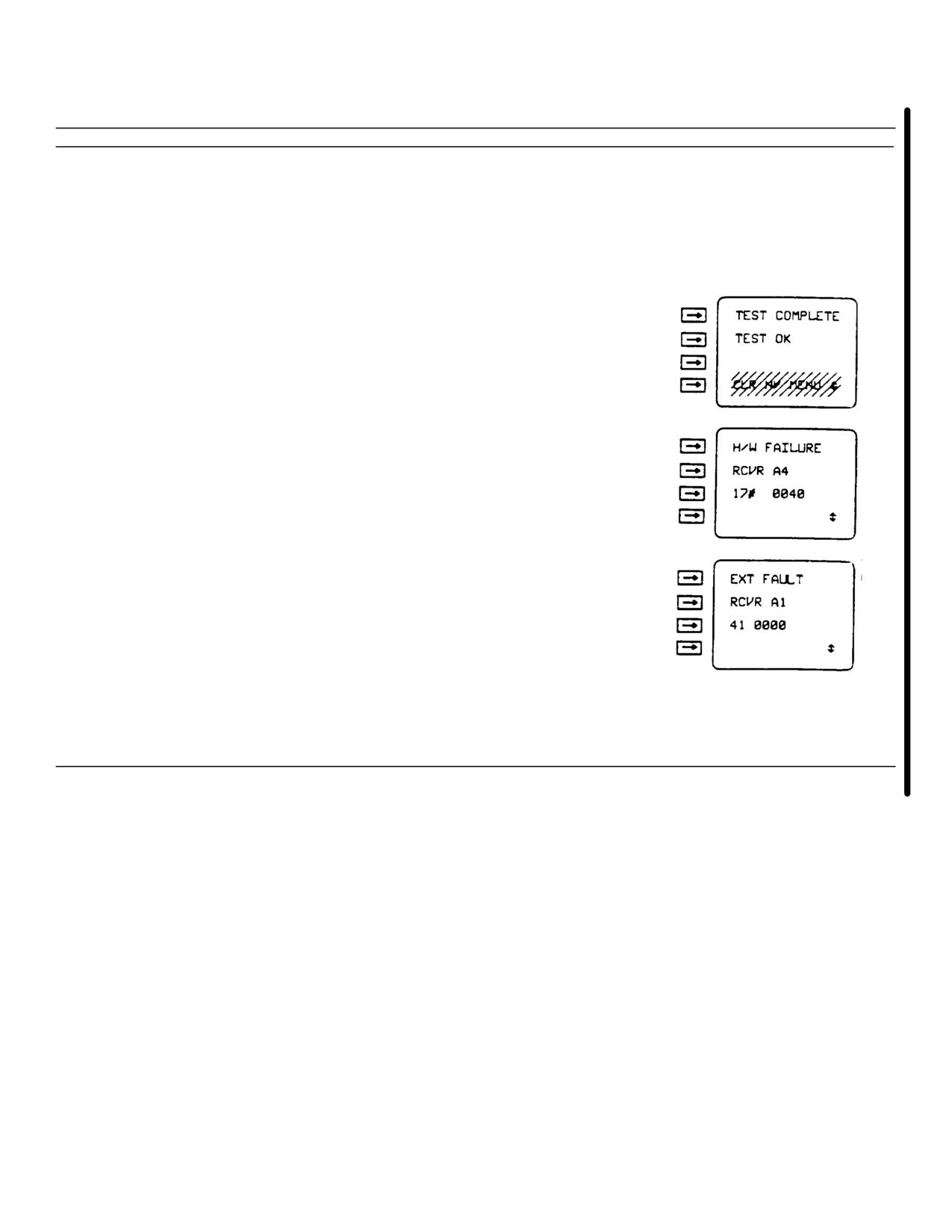
Check data display. If no failures were detected, display
line 1 will display TEST COMPLETE. Display line 2 will
display TEST OK- Display line 4 will display CLEAR N/V
MENU; this is for maintenance use only. If a failure
is detected, H/W FAILURE or a fault code will be
displayed on display line 1. Display lines 2 and 3 will
display failure codes. Display line 4 may display
additional information. Report all failures to
organizational maintenance.
h.
Set mode switch to any position except TEST to end
commanded self-test.
Change 6 3-51
TM 55-1520-240-10
Table 3-9. Keyboard/Display Test Procedure.
Step
Procedure
Display
a.
Set mode switch to NAV.
b.
Set data switch to OPT.
c.
Check display line 1. If WP is displayed, press WP key.
d.
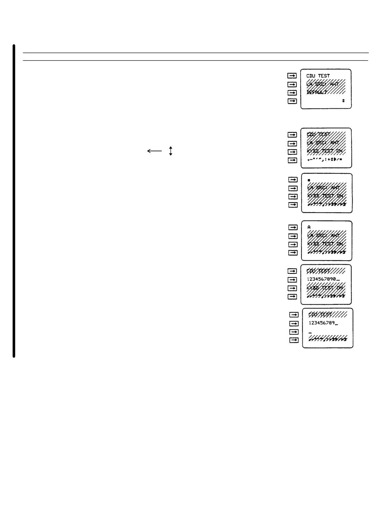
Press slew key until CDU TEST is displayed on display
line 1.
e. Press line select key 1.
f.
Check symbols +-°O, ‘ “ , :
> / = are displayed on display line 4.
g.
Press line select key 1. Check display line 1 is cleared.
h.
Press USE/LTR key. Check (*) is displayed on display
line 1.
NOTE
Letters will blink after entering. This is normal.
i.
Enter letters A thru Z while checking that letters are
displayed on display line 1, in the first character
position.
j.
Press line select key 1.
k.
Press line select key 2. Check display line 2 is cleared.
l.
Enter numbers 1 thru 0 while checking 1234567890 are
displayed on display line 2.
m.
Press CLR key and check last number is erased.
n.
Press line select key 2.
3-52 Change 6
TM 55-1520-240-10
Table3-9. Keyboard/Display Test Procedure.
Step
Procedure
Display
o.
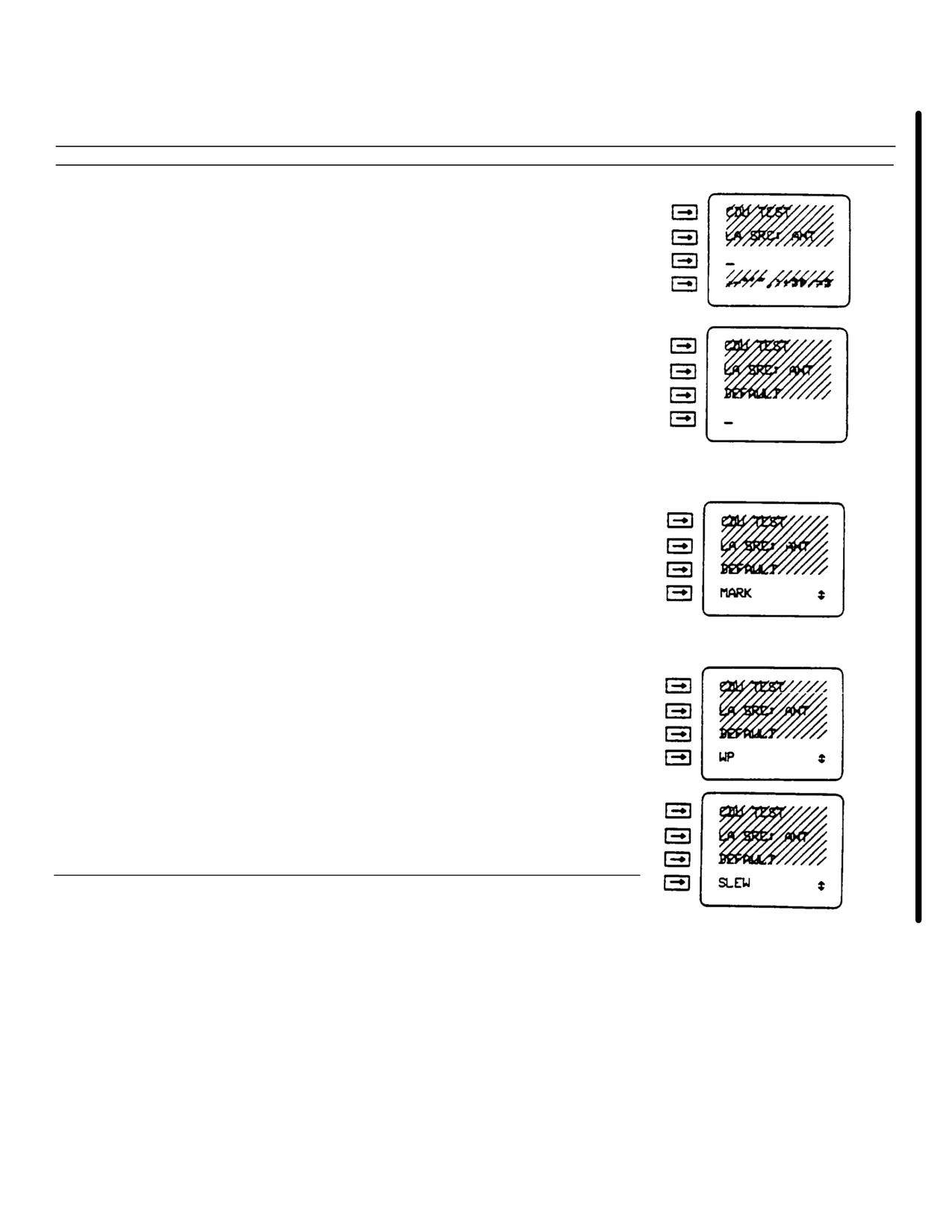
Press line select key 3. Check display line 3 is cleared.
p.
Press line select key 3.
q.
Press line select key 4. Check display line 4 is cleared.
NOTE
First letter will blink after MARK key is
pressed. This is normal.
r.
Press MARK key and check MARK is displayed on display
line 4.
NOTE
First letter will blink W then M. This is
normal.
s.
Press WP key and check WP is displayed on display line 4.
NOTE
First letter will blink S then W. This is normal.
t.
Press slew key and check SLEW is displayed on display
line 4.
u.
Set data switch to any position except OPT to end
keyboard/display test.
Change 6 3-53
TM 55-1520-240-10
e.
Entering and Checking Waypoints.
Waypoints can also be defined by a bearing (BRG),
range (RNG), and elevation angle (EL ANG) from some
A waypoint is the location of a point on the desired
reference point.
Present positionor a previously
course. The AN/ASN-149(V) provides information to
defined
waypoint
are
theusual references.
perform area navigation (RNAV) operations.
The
Alphanumeric identifier can be stored for all
209
AN/ASN-149 (V) displays data that allows the aircraft to
waypoints. If the waypoint identifies a NAVAID, the
fly from the present position to the next programmed
frequency or channel can be stored. An alphanumeric
waypoint. The next waypoint is referred to as the
identifier is required if more than one waypoint will be
current steer-to destination. A normal mission consists
stored using the same frequency or channel information.
of a series of waypoints. During normal operation the
Desired track (DTK) vertical angle (VA), and map datum
aircraft is navigated from the departure point to waypoint
(DTM) to the waypoint may also be stored.
1 (WP1). After arriving at WP1, WP2 is entered as the
steerto destination and the aircraft is navigated to WP2
Waypoints can be automatically entered with a data
The aircraft is navigated to consecutive waypoints until
loader using a data transfer module containing the
reaching the final destination. The location of targets,
required data.
When a data loader capability is
prominent landmarks, or navigational aids (NAVAID) are
available, entering waypoints is accomplished during the
usually used to define waypoints. NAVAID include very
start-up procedure (Table
3-6).
If the data loader
high frequency omnidirectional radio range (VOR),
capability is not available, waypoints may be entered
tactical air navigation (TACAN), and nondirectional
using the indicator controller, Table 3-6.
beacon (NDB) stations. Another aircraft can also be
defined as a moving waypoint. Moving waypoints are
NOTE
normally used in rendezvous (*REND) operation. The
Keeping a written record of the waypoint
AN/ASN-149(V) can store 209 waypoints in memory.
memory
numbers, alphanumeric
These waypoints are numbered WP1 thru WP209. WP1
identifiers, and frequency or channel
thru WP9 may be used as stationary or moving
numbers may save time later.
destinations. WP100 thru WP209 may be used with
stationary destinations only. Data for moving waypoints
may be stored in W10 thru WP209; however, the data
must be moved to a WP1 thru WP9 location to be
selected as a destination. All waypoints are defined by
position (latitude/longitude (L/L) or military grid reference
system (MGRS) coordinates) altitude, and map datum
(DTM). A ground track (TRK), ground speed (GS), and
time of fix (TOF) are also required for moving waypoints.
3-54 Change 6
TM 55-1520-240-10
Table 3-10. Entering Stationary Waypoints via the Indicator Controller
Step
Procedure
Display
NOTE
This procedure can be used for waypoint
numbers 1 thru 209. The waypoint must be
stationary
a.
Ensure mode switch set to NAV or INIT.
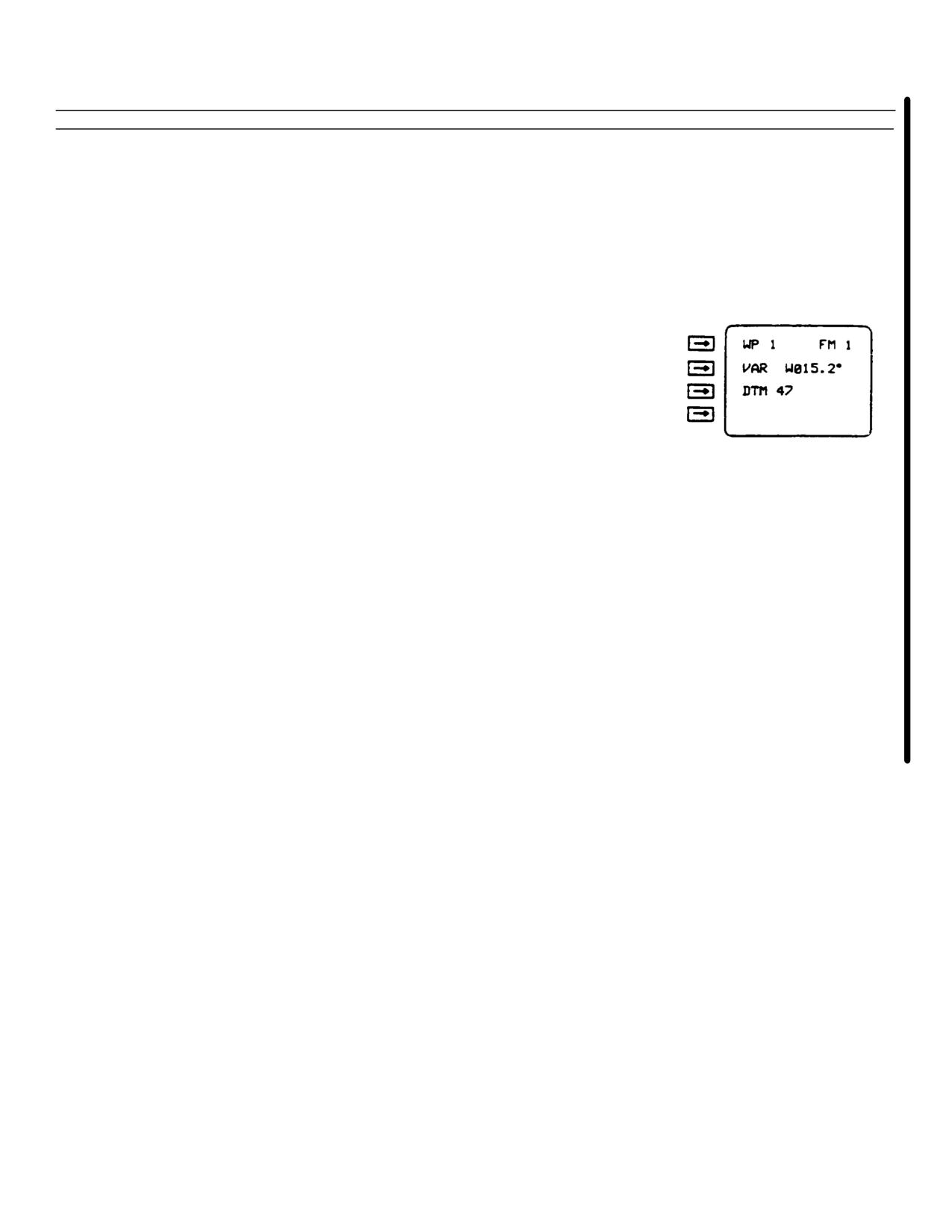
b.
Set data switch to VAR-DTM
c.
Check display line 1. If > is displayed, press WP key.
NOTE
If WP entered in step d has been previously
defined with an alphanumeric identifier, the
alphanumeric identifier will be displayed when
the waypoint number is entered.
d.
Enter waypoint (WP) number (1 thru 209) for waypoint to
be defined on line 1
NOTE
Step e is optional.
NOTE
Leading zeros must be entered (example: 1=
00.0, 10- 010.0) in step e, if required. Leading
zeros will not be erased when entry is complete.
e.
Enter waypoint magnetic variation (VAR) on display line
2. First character must be E (east) or W (west).
f.
Enter waypoint map datum (DTM) code on display line 3
Map datum codes are listed in Table 3-12
Change 6 3-55
TM 55-1520-240-10
Table 3-10. Entering Stationary Waypoints via the Indicator Controller - (Continued).
Step
Procedure
Display
g.
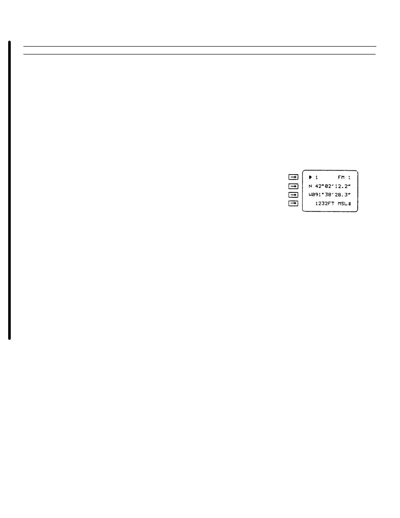
Set data switch to POS.
NOTE
When entering MGRS coordinates, do not press
line select key 2 after entering zone, and line
select key 3 before entering coordinates. MGRS
zone and coordinates are entered like a one
display line entry.
NOTE
Leading zeros must be entered (example:
91 02’28.3" = 091 02’28.3", 800 =00800) in steps
h thru j, if required.
h.
Enter waypoint latitude or MGRS grid zone on display
line 2.
i.
Enter waypoint longitude or MGRS coordinates on display
line 3.
j.
Enter waypoint altitude on display line 4.
NOTE
Steps k thru m are optional. A waypoint may
be identified by entering an alphanumeric
identifier (step 1) and/or a NAVAID frequency
(step m) in addition to the waypoint number
(step d).
NOTE
If an alphanumeric identifier is selected and the
data switch is set to another position, the WP
display will indicate the alphanumeric identifier
and the waypoint number will not be displayed.
If an alphanumeric identifier is not selected, the
waypoint number will be displayed.
3-56 Change 6
TM 55-1520-240-10
Table 3-10. Entering Stationary Waypoints via the Indicator Controller - (Continued)
Step
Procedure
Display
k.
Press slew key
l.
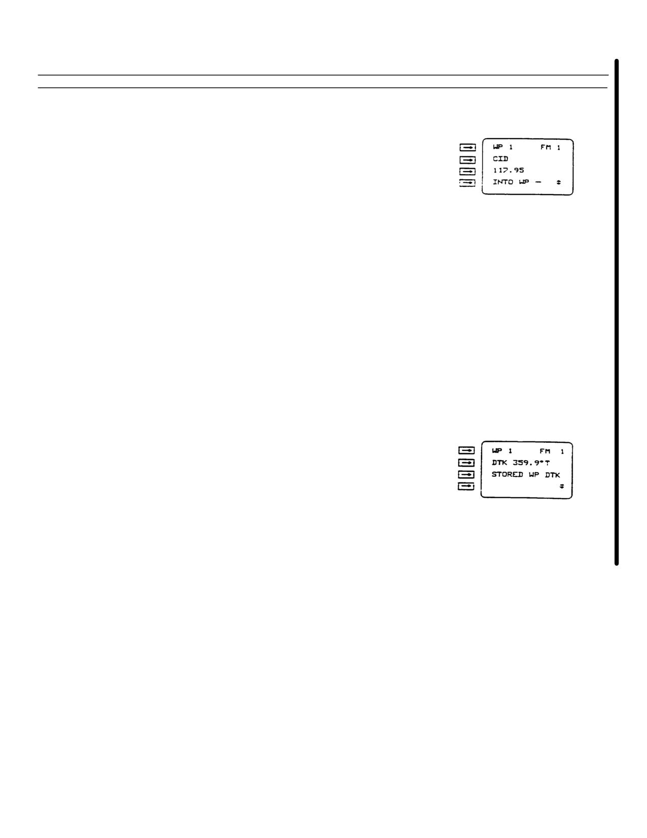
Enter waypoint alphanumeric identifier on display line 2.
Alphanumeric identifier can be a maximum of six
characters.
m.
Enter NAVAID frequency or channel on display line 3.
Allowable NAVAID frequencies are:
VOR - 108.00 to 117.99
TACAN - IX to 126X and IY to 126Y.
NDB - 1 to 9999
Decimal point must be entered for VOR or NDB
frequencies.
NOTE
To transfer waypoint description into WP 1
thru 9, enter applicable waypoint (WP) number
on display line 4.
NOTE
Steps n thru q are optional.
n.
Set data switch to DTK-VA
NOTE
Leading zeros must be entered (example: 5 =
000.5, 50 = 050.0) in step o, if required. leading
zeros will not be erased when entry is complete.
o.
Enter desired track (DTK) to waypoint as referenced to
true (1), grid (G), or magnetic (M) north on display
line 2.
NOTE
Display line 3 displays STORED WP DTK to
remind operator that DTK displayed is entered
for waypoint number displayed on display
line 1.
Change 6 3-57

TM 55-1520-240-10
Table 3-10. Entering Stationary Waypoints via the Indicator Controller - (Continued)
Step
Procedure
Display
p.
Press slew key.
NOTE
Leading zeros must be entered (example: .5 =
00.5, 2 = 02.0) in step q, if required. Leading
zeros will not be erased when entry is complete.
q.
Enter vertical angle (VA) from present position to
waypoint on display line 2.
NOTE
Display line 3 displays STORED WP VA to
remind operator that VA displayed is entered
for waypoint number displayed on display
line 1.
Table 3-11. Entering Moving Waypoints via the Indicator Controller.
Step
Procedure
Display
NOTE
The displayed position coordinates of a moving
waypoint will not change unless it is selected as
the destination in rendezvous (*REND)
operation.
a.
Ensure mode switch set to NAV or INIT.
b.
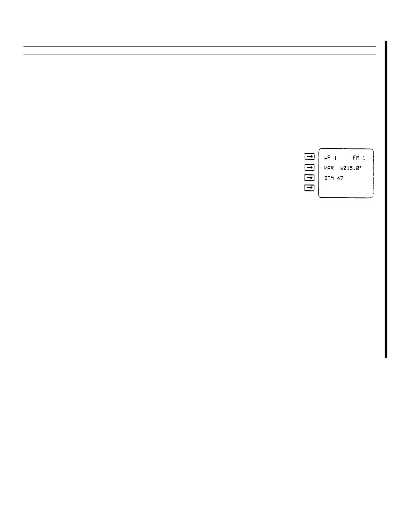
Set data switch to VAR-DTM.
c.
Check display line 1. If > is displayed, press WP key
3-58 Change 6
TM 55-1520-240-10
Table 3-11. Entering Moving Waypoints via the Indicator Controller (Continued).
Step
Procedure
Display
d.
Enter waypoint (WP) number for waypoint to be defined
on display line 1
NOTE
Step e. is optional
NOTE
Leading zeros must be entered (example: 1 =
001.0, 10 = 010.0) in step e, if required. Leading
zeros will not be erased when entry is complete
e.
Enter waypoint magnetic variation (VAR) on display line
2.
First character must be E (east) or W (west)
f.
Enter waypoint map datum (DTM) code on display line 3.
Map datum codes are listed in Appendix E. If datum
code is 20, complete paragraph 2-27 before going to
step g
g.
Set data switch to POS
NOTE
When entering MGRS coordinates, do not press
line select key 2 after entering zone and line
select key 3 before entering coordinates. MGRS
zone, and coordinates are entered like a one
display line entry
NOTE
Leading zeros must be entered(example:
91 02"28.3" = 091 °02"28.3",800 in steps
h. thru j. if required
h.
Enter waypoint initial latitude or MGRS grid zone on
display line 2
Change 6 3-59
TM 55-1520-240-10
Table 3-11. Entering Moving Waypoints via the Indicator Controller (Continued)
Step
Procedure
Display
i.
Enter waypoint initial longitude or MGRS coordinates on
display line 3
j.
Enter waypoint initial altitude on display line 4
NOTE
Steps k. thru m. are optional. A waypoint may
be identified by entering an alphanumeric
identifier (step 1) and/or a NAVAID frequency
(step m.) in addition to the waypoint number
(step d.)
NOTE
If an alphanumeric identifier is selected and the
data switch is set to another position, the WP
display will indicate the alphanumeric identifier
and the waypoint number will not be displayed
If an alphanumeric identifier is not selected, the
waypoint number will remain displayed
k.
Press slew key
l.
Enter moving waypoint alphanumeric identifier on display
line 2. Alphanumeric identifier can be a maximum of six
characters
3-60 Change 6
TM 55-1520-240-10
Table 3-11. Entering Moving Waypoints via the Indicator Controller (Continued)
Step
Procedure
Display
m.
Enter NAVAID frequency or channel on display line 3.
Allowable NAVAID frequencies are:
VOR- 108.00 to 117.99
TACAN -IX to 126X and 1Y to 126Y
NDB - 1. to 9999Decimal point must be entered for VOR or NDB
frequencies
n.
Set data switch to TRK-GS
NOTE
Leading zeros must be entered (example: 0.1 =
000.1, 1=001.0) in step o, if required. Leading
zeros will not be erased when entry is complete
o.
Enter moving waypoint track (TRK) referenced to true
(T), grid (G), or magnetic (M) north on display line 2
NOTE
Leading zeros must be entered (example: 10 =
0010, 100 = 0100) in step p, if required. Leading
zeros will be erased when entry is complete
p.
Enter moving waypoint ground speed (GS) in knots (KTS)
or kilometers per hour (KPH) on display line 3
NOTE
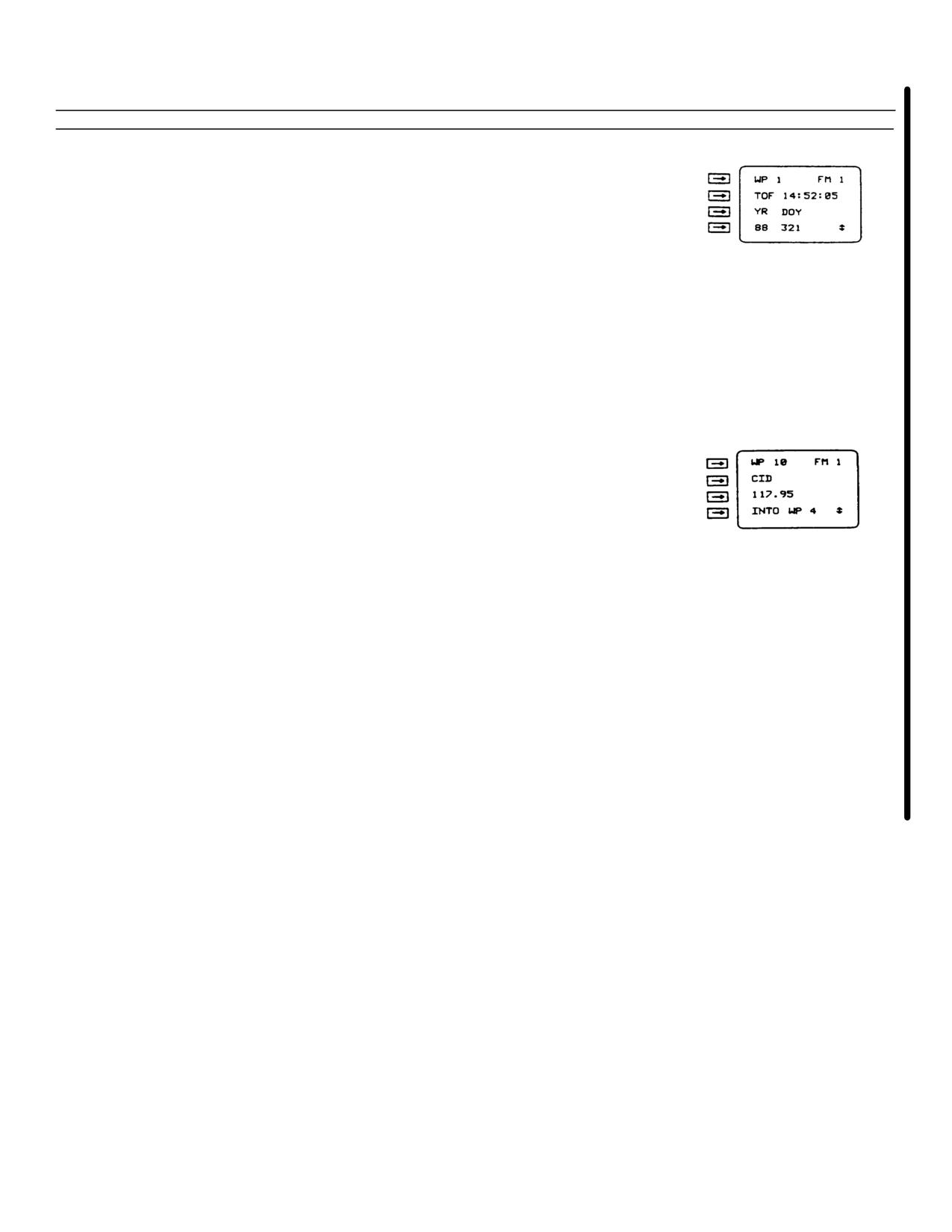
Time of fix (TOF) is the time at which the
waypoint was at the position coordinates,
altitude, TRK, and GS just entered;
or
The starting time for the waypoint to begin
moving
Change 6 3-61
TM 55-1520-240-10
Table 3-11. Entering Moving Waypoints via the Indicator Controller - (Continued)
Step
Procedure
Display
q.
Press slew key
NOTE
Leading zeros must be entered (example: 1:09:08
= 01:09:08) in step r, if required. Leading zeros
will not be erased when entry is complete
r.
Enter time of fix (TOF) of moving waypoint on display
line 2
NOTE
Leading zeros must be entered (example: 3 =
003, 33=033) in step s if required. Leading
zeros will not be erased when entry is complete
s.
Enter year (YR) and Julienne date (day of year) (DOY) on
display line 4
NOTE
Complete steps t thru w to move data to
waypoints 1 thru 9 if necessary
t.
Set data switch to POS
u.
Check display line 1. If I> is displayed, press WP key
v.
Press slew key
w.
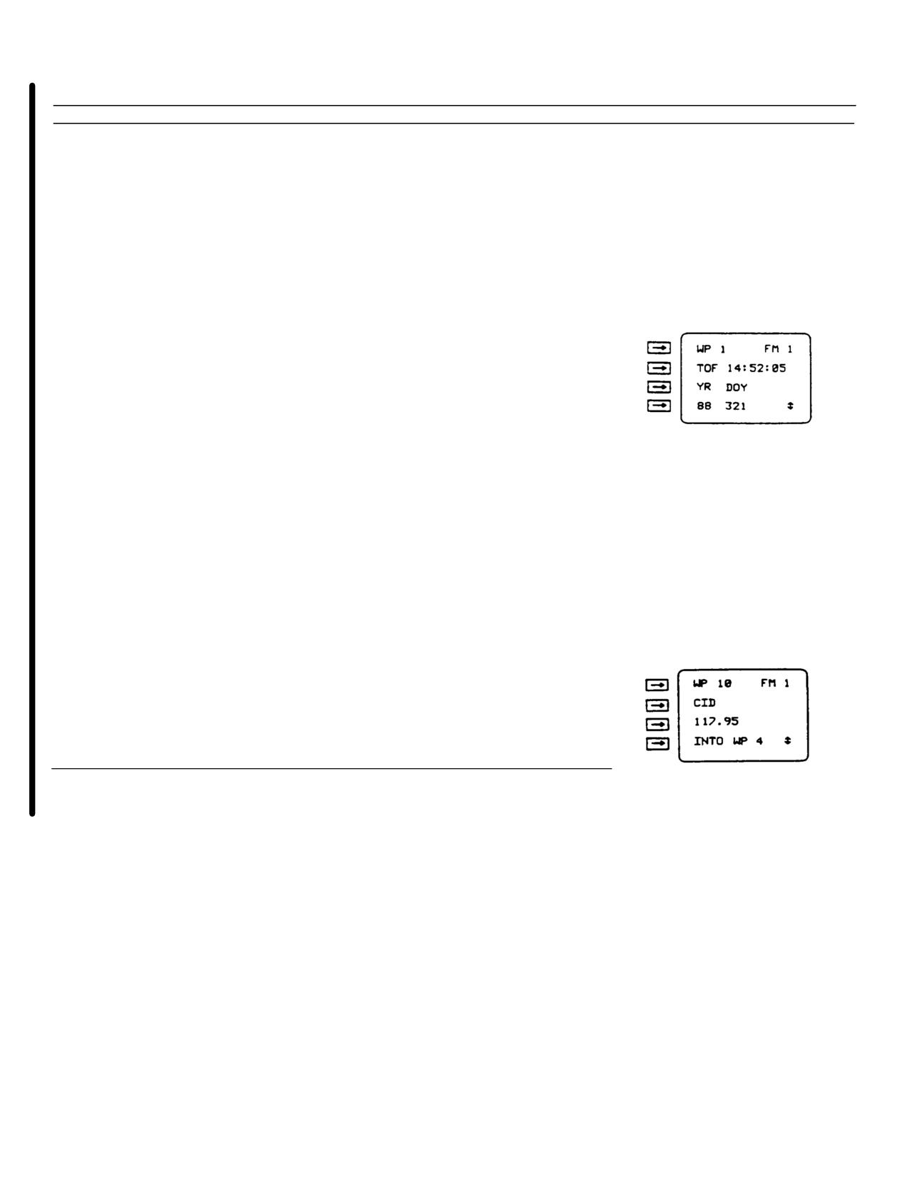
Enter waypoint number on display line 4 where waypoint
data is to be moved
3-62 Change 6
TM 55-1520-240-10
Table 3-12. Entering Waypoints by Bearing, Range and Elevation Angle Procedure
Step
Procedure
Display
a.
Ensure mode switch set to NAV or INIT
b.
Set data switch to POS
c.
Check display line 1 If > is selected, press WP key
d.
Enter waypoint (WP) number (1 thru 209) for waypoint to
be defined on display line 1
e.
Set data switch to DIS-TG
NOTE
After BRG has been entered, data display will
automatically change to enter range (RNG). Do
not press slew key
NOTE
Leading zeros must be entered (Example: .5 =
000.5, 10 = 0010) in step f and g, if required.
Leading zeros will not be erased when entry is
complete
f.
Enter bearing (BRG) to waypoint referenced to true (T),
grid (G), or magnetic (M) north on display line 4
NOTE
If no range is entered, AN/ASN-149(V) will
assume range of zero
Change 6 3-63
TM 55-1520-240-10
Table 3-12. Entering Waypoints by Bearing, Range and Elevation Angle Procedure - (Continued)
Step
Procedure
Display
g.
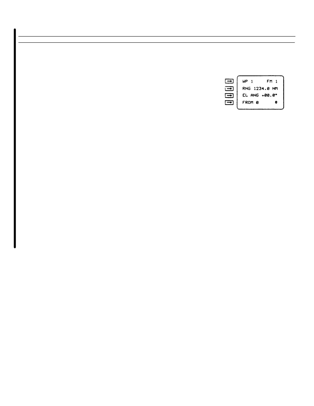
Enter range (RNG) in kilometers (KM) or nautical miles
(NM) on display line 2
NOTE
A negative elevation angle means the waypoint
is lower than reference point. If no elevation
angle is entered, the range in step g is a great
circle distance and the AN/ASN-149(V) will
assume waypoint is at same altitude as
reference point
NOTE
Leading zeros must be entered (Example: I =
00.1, 1 = 01) in step h, if required. Leading zeros
will not be erased when entry is complete
h.
Enter elevation angle (EL ANG) on display line 3
NOTE
If no reference waypoint number or identifier is
entered, AN/ASN-149(V) will assume reference
is present position and will display dashes (-)
i.
Enter reference waypoint number or alphanumeric
identifier on display line 4
NOTE
Waypoint position will not be computed until
step j. is performed. If present position is being
used as reference and aircraft has moved since
bearing, range, and elevation angle were
determined, waypoint position will be incorrect
3-64 Change 6
TM 55-1520-240-10
Table 3-12.
Entering Waypoints by Bearing, Range and Elevation Angle Procedure - (Continued)
Step
Procedure
Display
j.
Press slew key to return to normal DIS-TG display
NOTE
Steps k. thru n. are optional. A waypoint may be
identified by entering an alphanumeric
identifier (step m.) and/or a NAVAID frequency
(step n.) in addition to the waypoint number
(step d.)
NOTE
If an alphanumeric identifier is selected and the
data switch is set to another position, the WP
display will indicate the alphanumeric identifier
and the waypoint number will be erased. If an
alphanumeric identifier is not selected, the
waypoint number will be displayed
k.
Set data switch to POS
l.
Press slew key
m.
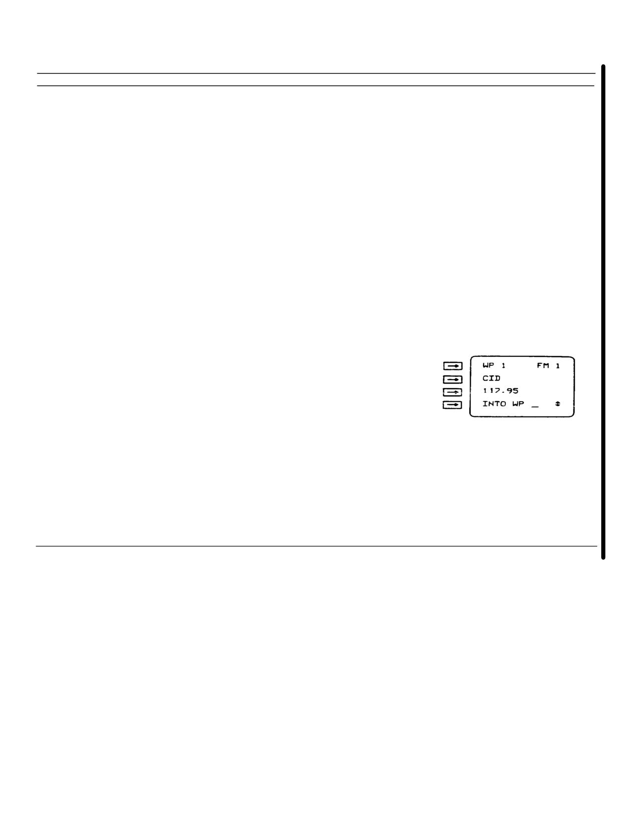
Enter waypoint alphanumeric identifier on display line 2.
Alphanumeric identifier can be a maximum of six
characters
n.
Enter NAVAID frequency or channel on display line 3.
Allowable NAVAID frequencies are:
VOR- 108.00to 117.99
TACAN - 1X to 126X and 1Y to 126Y
NDB - 1. to 9999Decimal point must be entered for
VOR or NDB frequencies
NOTE
To transfer waypoint description into WP 1
thru 9, enter applicable waypoint (WP) number
on display line 4
Change 6 3-65
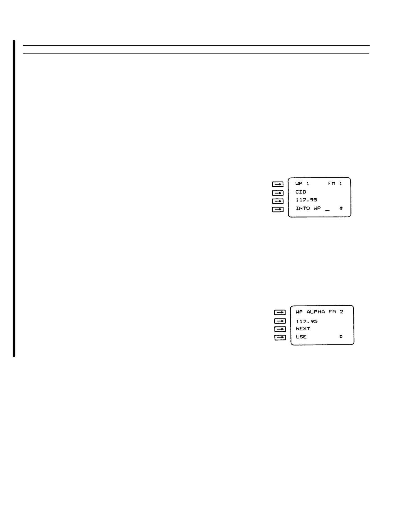
TM 55-1520-240-10
Table 3-13. Checking Waypoints Procedure
Step
Procedure
Display
a.
Ensure mode switch set to NAV or INIT
b.
Set data switch to POS
c.
Check display line 1. If is displayed, press WP key
NOTE
More than one waypoint may be defined
using the same NAVAID frequency or channel. The
first waypoint displayed is the closest to present
position. The next waypoint or waypoints are
displayed in the order entered. Verify
alphanumeric identifier is the correct choice
before selecting waypoint for checking
d.
Enter waypoint (WP) number, alphanumeric identifier, or
NAVAID frequency or channel on display line 1
NOTE
Allowable NAVAID frequencies are:
VOR- 10800 to 117.99
TACAN - IX to 126X and 1Y to 126Y
NDB - 1. to 9999.
Decimal point must be entered for VOR or
NDB frequencies
If multiple waypoints were entered that
have the same NAVAID frequency or channel
go to step e; if not, go to step F
e.
Check waypoint (WP) identifier displayed on display
line 1
1.
If incorrect, press line select key 3 (NEXT) for next
waypoint with the same frequency or channel
2.
If correct, press line select key 4 (USE) to return to
normal display
3-66 Change 6
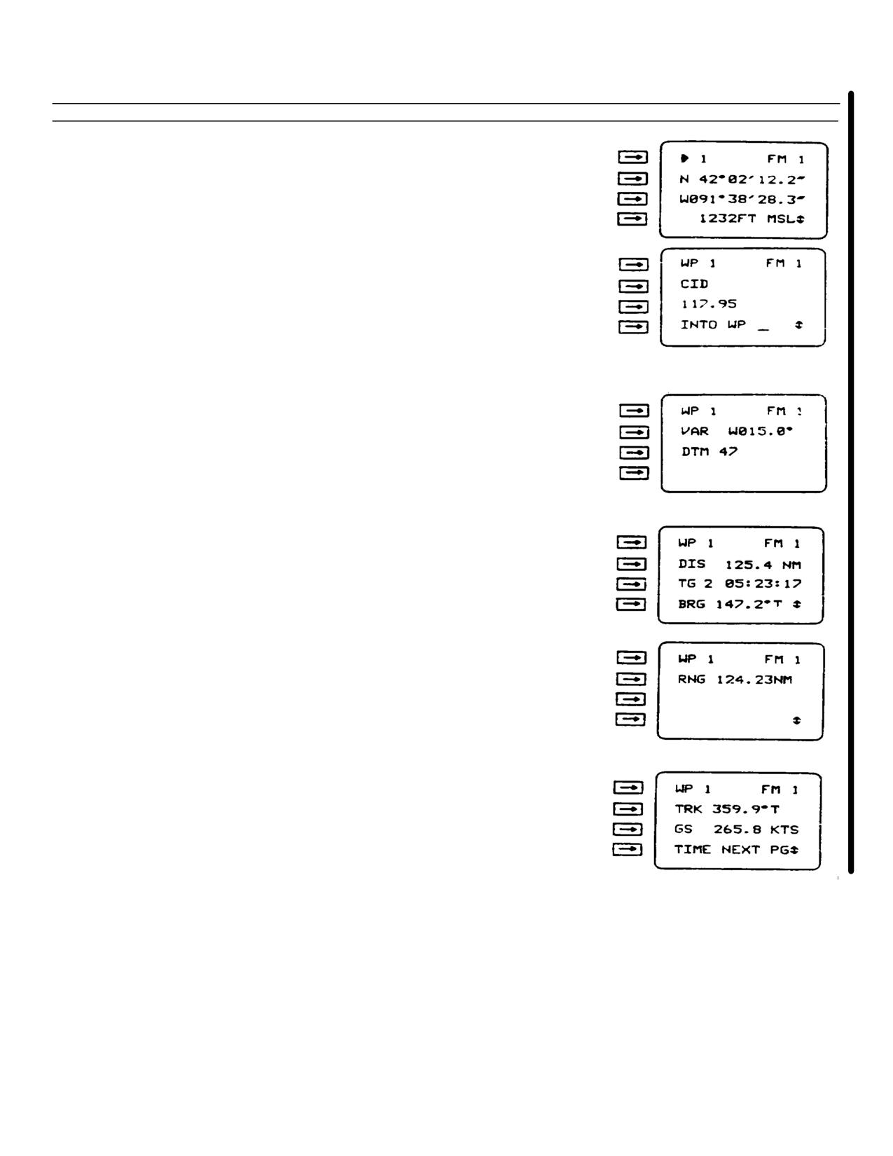
TM 55-1520-240-10
Table 3-13. Checking Waypoints Procedure (Continued)
Step
Procedure
Display
f.
Check waypoint position coordinates and altitude on
display lines 2, 3, and 4
g.
Press slew key
h.
Check waypoint number on display line 1, alphanumeric
identifier on display line 2, and NAVAID frequency or
channel on display line 3
NOTE
Entering a number (1-9) on display line 4
causes the waypoint being checked to be
transferred into the WP number selected
i.
Set data switch to VAR-DTM
j.
Check magnetic variation (VAR) on display line 2 and map
datum (DTM) code on display line 3. If no magnetic
variation is stored display line 2 will display dashes
k.
Set data switch to DIS-TG
l.
Check great circle distance (DIS) to waypoint on display
line 2, time to go (TG) to waypoint in days; hours,
minutes, and seconds on display line 3; and bearing
(BRG) to waypoint on display line 4
m.
Press slew key
n.
Check slant range (RNG) to waypoint on display line 2
o.
Set data switch to TRK-GS
p.
Check ground track (TRK) on display line 2 and ground
speed (GS) for the moving waypoint (*REND operation
only) on display line 3
Change 6 3-67
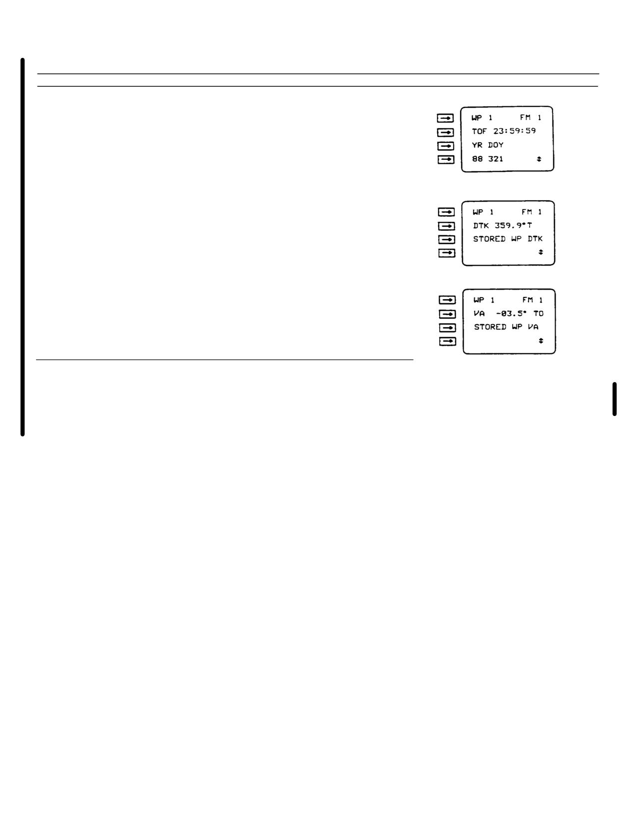
TM 55-1520-240-10
Table 3-13. Checking Waypoints Procedure - (Continued)
Step
Procedure
Display
q.
Press slew key
r.
Check starting time of fix (TOF) for moving waypoint
(*REND operation only) on display line 2 and year (YR)
and day of year (DOY) for the starting time on display
line 4. Line 3 always displays YR and DOY as label
references for line 4
s.
Set data switch to DTK-VA
t.
Check desired track (DTK) to rendezvous with moving
waypoint (*REND operation only) or desired track
(DTK) stored with stationary waypoint on display line 2.
If no (DTK) is stored, display line 2 will display dashes
u.
Press slew key
v.
Check vertical angle (VA) to moving waypoint (*REND
operation only) or vertical angle stored with stationary
waypoint on display line 2.
If no VA is stored, display
line 2 will display dashes (-)
f.
Displaying Present Position.
be displayed at any time after start-up is completed This
data is available while the aircraft is moving or stationary.
Present position latitude, longitude or military grid
To display present position perform the procedure in
reference system (MGRS) coordinates, and altitude may
Table 3-14
3-68 Change 6
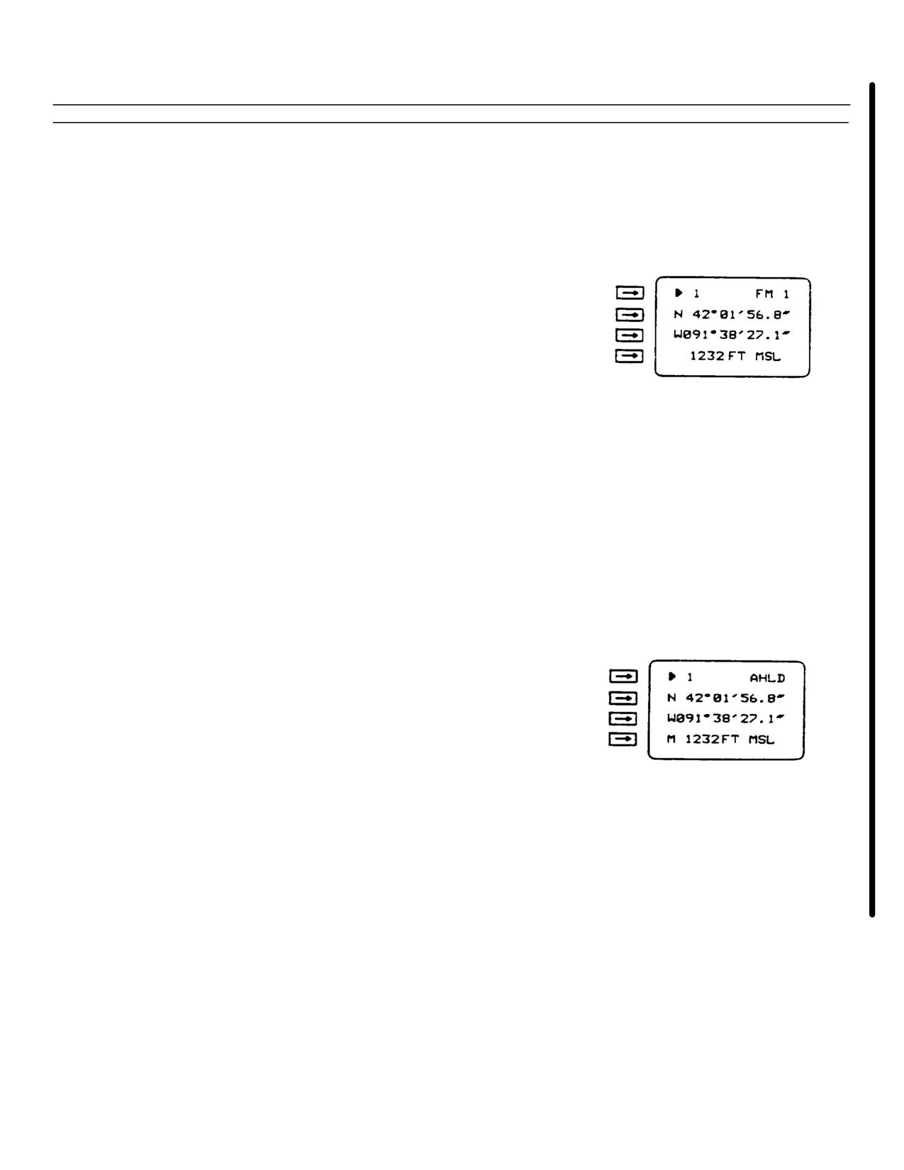
TM 55-1520-240-10
Table 3-14. Displaying Present Position
Step
Procedure
Display
a.
Set mode switch to NAV
b.
Set data switch to POS
c.
Check display line 1. If WP is displayed, press WP key
d.
Read present position:
Display line 2 - Latitude or MGRS zone
Display line 3 - Longitude or MGRS coordinates
Display line 4 - Altitude in feet (FT) or meters (M),
referenced to mean sea level (MSL)
or datum (DTM)
NOTE
Present position is calculated from the antenna
position, or at the point designated by the lever
arm. This position may differ from expected
present position
NOTE
If the figure of merit is high and AN/ASN-
149(V) is tracking fewer than four satellites,
accuracy may be improved by entering a
manual altitude hold. Manual altitude hold can
be entered any time M is displayed on display
line 4
e.
If manual altitude hold is desired, enter present altitude
estimate on display line 4. M will continue to be
displayed and AHLD will alternate with FM
NOTE
AN/ASN-149(V) will automatically drop manual
altitude hold if four satellites are received
NOTE
The position display is more accurate when
*STATIONARY operation is selected. The
aircraft must be stationary when
*STATIONARY operation is selected. Complete
steps f thru h for *STATIONARY operation
Change 6 3-69
TM 55-1520-240-10
Table 3-14. Displaying Present Position - (Continued)
Step
Procedure
Display
f.
Set data switch to OPT
g.
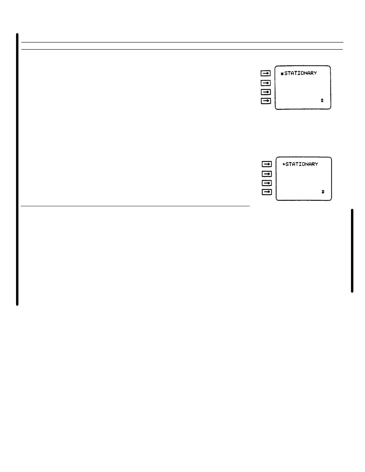
Press and release slew key until STATIONARY is
displayed on display 1
h.
Check display line 1, if-STATIONARY displayed press
line select key 1.
Set data switch to POS
j.
Repeat steps d thru e
NOTE
To return to moving operation
(-STATIONARY) complete steps k. thru m.
k.
Set data switch to OPT
l.
Press and release slew key until *STATIONARY is
displayed on display line 1
m.
Press line select key 1.
g.
Area Navigation (RNAV). The GPS can
h.
Features.A desired track may be defined
display information needed to navigate from present
and stored with each waypoint entry. When a waypoint
position to any mark or waypoint whether stationary or
is selected as the destination, the desired course is
moving, that is selected as the destination. Horizontal
computed by the GPS based on the desired track
information (bearing, great circle distance time to go to
information. The operator may enter a desired track
destination and slant range distance) can be displayed
when an approach to the destination is required from a
for all waypoints as well as the selected NAVAID
specific direction. When the destination waypoint is
frequency or channel and alphanumeric station identifier.
passed, the desired course will be maintained on the
To use the GPS efficiently, it is necessary to understand
outboard radial. The GPS does not automatically
the basic definitions of area navigation (RNAV).
advance to the next waypoint when the selected one has
been reached: the operator must manually select the
next waypoint
3-70 Change 6
TM 55-1520-240-10
Table 3-15. Area Navigation (RNAV)
Step
Procedure
Display
a.
Set mode switch to NAV
b.
Set data switch to POS
c.
Check display line 1. If > is displayed, press the WP key
NOTE
Steer-to destination is the next waypoint you
want to steer to. It may not be the final
destination of the mission
d.
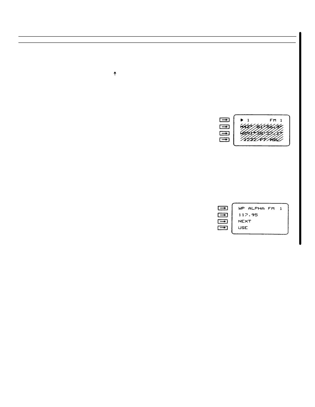
Check display line 1. If waypoint (WP) number,
alphanumeric identifier, NAVAID frequency or channel
displayed is the next steer-to destination, go to step g. If
waypoint (WP) number alphanumeric identifier,
NAVAID frequency or channel displayed is not the next
steer-to destination, go to step e
NOTE
Multiple waypoints may be defined using the
same NAVAID frequency or channel The first
waypoint displayed is the closest to present
position. The next waypoint or waypoints are
displayed in the order entered. Verify
alphanumeric identifier is the correct choice
before selecting waypoint for use
e.
Enter waypoint (WP) number, alphanumeric identifier,
NAVAID frequency or channel of steer-to destination on
display line 1. If multiple waypoints were entered that
have the same NAVAID frequency or channel go to step
f. if not, go to step g
Change 6 3-71
TM 55-1520-240-10
Table 3-15. Area Navigation (RNAV) - Continued)
Step
Procedure
Display
f.
Check alphanumeric identifier displayed on display line 1
1.
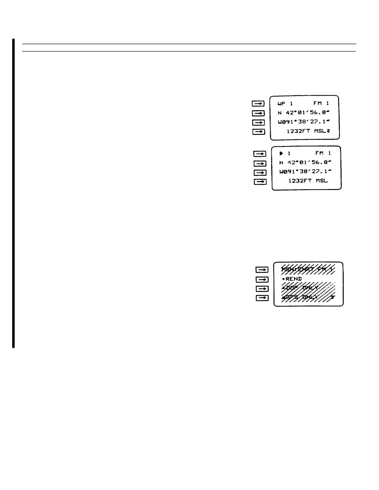
If incorrect press line select key 3 (NEXT) for waypoint
with the same frequency or channel
2.
If correct, press line select key 4 (USE) to return to
normal display
g.
Check waypoint position coordinates and altitude to be
sure that the correct waypoint is displayed
h.
Press WP key. The > will be displayed on display line 1;
present position coordinates and altitude will be
displayed on display lines 2, 3, and 4
NOTE
GPS will continue to compute RNAV data to
the previously selected waypoint until
the next waypoint number entry is completed
by pressing line select key 1
i.
Check steer-to destination number on display line 1. If not
correct, enter correct steer-to destination number on
display line 1
j.
Set data switch to MSN
k.
Check mission profile. If waypoint is not moving, RNAV
mission profile should be selected (- REND displayed).
If waypoint is moving, rendezvous mission profile
should be selected (- REND displayed). Press line select key 2
until correct profile is displayed on display line 2
NOTE
If NO REND DATA is displayed, some data for
a moving waypoint is missing. See paragraph 2-
17
l.
Set data switch to DIS-TG
3-72 Change 6
TM 55-1520-240-10
Table 3-15. Area Navigation (RNAV)- Continued)
Step
Procedure
Display
m.
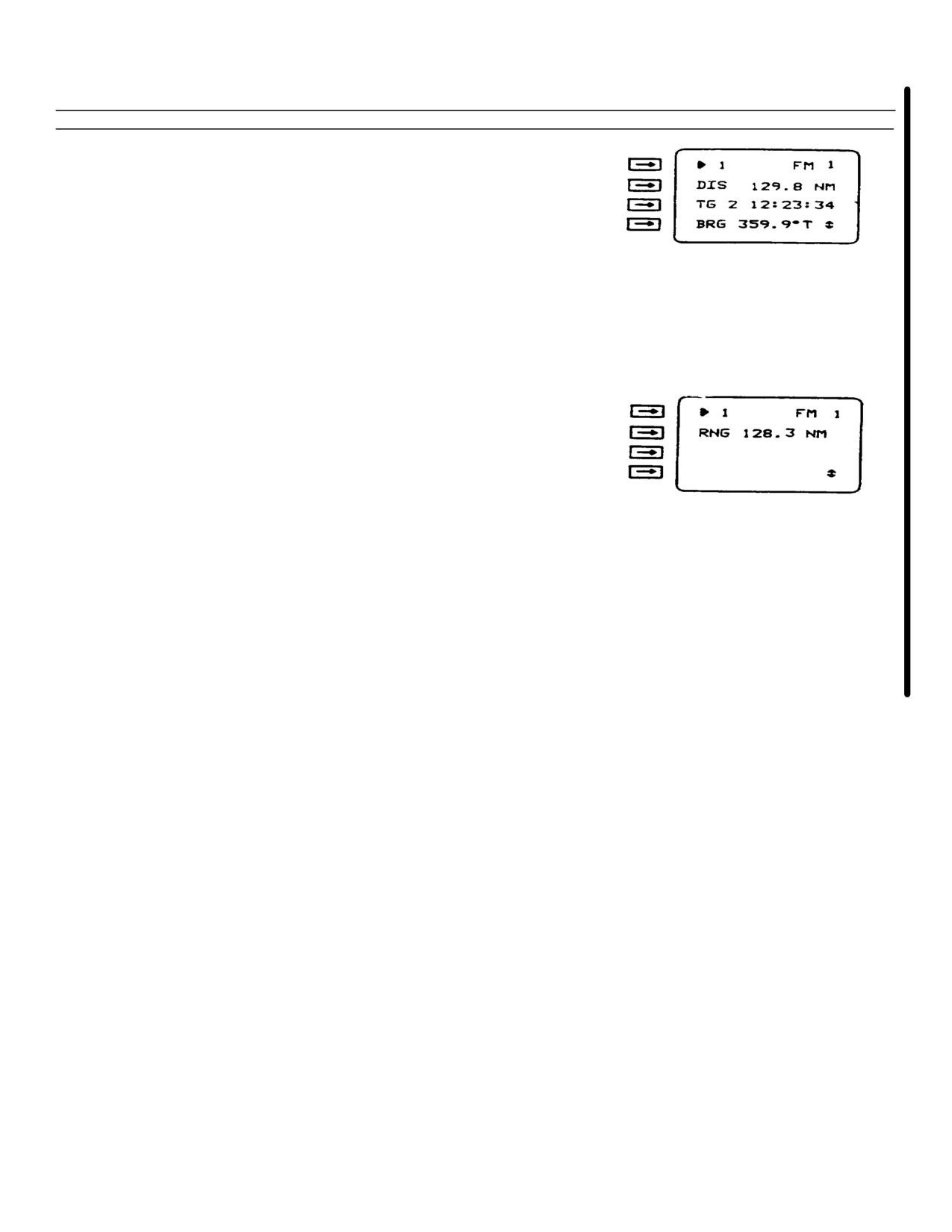
Read great circle distance (DIS) in nautical miles (NM) or
kilometers (KM) to destination on display line 2
NOTE
Time to go (TG) is invalid unless your aircraft
is moving
n.
Read time to go (TG) on display line 3
o.
Read bearing (BRG) to destination referenced to true (T),
grid (G), or magnetic (M) north on display line 4
p.
Press slew key
q.
Read slant range (RNG) in nautical miles (NM) or
kilometers (KM) to destination on display line 2
r.
Set data switch to DTK-VA
NOTE
If NO DEST or DEST MOVING is displayed
on display line 2, the GPS will not
accept a source of DTK or DTK entry
NOTE
Each time a new waypoint is selected as the
new destination, verify that the correct DTK
is being used
Change 6 3-73
TM 55-1520-240-10
Table 3-15. Area Navigation (RNAV) - Continued)
Step
Procedure
Display
s.
Select source of desired track (DTK) by pressing line
select key 3. Sources are:
USING OE DTK - Using operator-entered DTK.
If selected and there is no operator-entered DTK,
display line 2 will display dashes (- -). A DTK may
be entered by completing step u on display line 2. A
DTK may be cleared by pressing line select key 2
twice. Display line 3 will automatically display
USING OE DTK if an entry has been made on
display line 2
USING WP DTK - Using the DTK entered during
waypoint entering (Table 3-10). If DTK was not
entered, display line 2 will display dashes (- -)
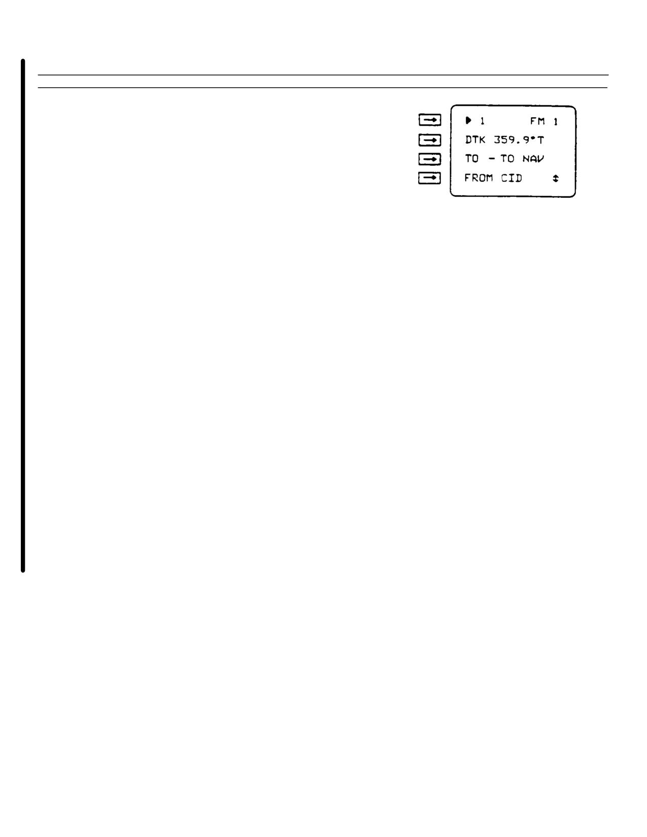
TO-TO NAV - Using FROM waypoint entered on
display line 4 as the destination to define a great
circle path as the desired course. If no valid FROM
waypoint is entered (by completing step t), display
lines 2 and 4 will display dashes (- -). Display line 3
will automatically display TO-TO NAV if a valid
FROM waypoint has been entered on display line 4
DIRECT-TO - Using present position to destination
great circle desired track. Gives desired track (DTK)
defined by the great circle path from the present
position to the destination
NOTE
Complete step t. if TO-TO NAV was selected on
display line 3
t.
Enter waypoint (WP) number or alphanumeric identifier
(that was entered with the desired waypoint) on display
line 4
NOTE
Complete step u if USING OE DTK was
selected on display line 3
3-74 Change 6
TM 55-1520-240-10
Table 3-15. Area Navigation (RNAV) - Continued)
Step
Procedure
Display
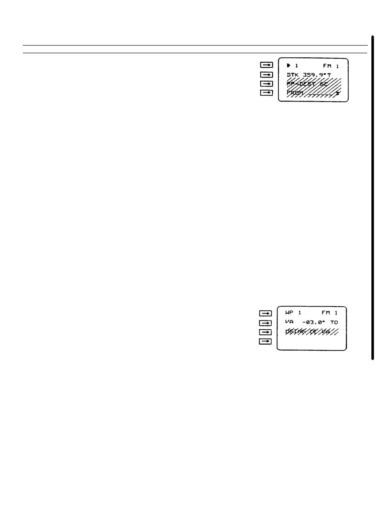
u.
Enter desired track (DTK) on display line 2
v.
Read desired track (DTK) on display line 2
w.
Press slew key
NOTE
If NO DEST is displayed on display line 3, the
GPS will not accept a VA entry
x.
Select source of vertical angle (VA) by pressing line select
key 3. Sources of VA are:
USING OE VA - Using operator entered VA. If
selected and there is no operator entered VA, display
line 2 will display dashes (- -). A VA may be entered
by completing step y on display line 2. A VA may be
cleared by pressing line select key 2 twice. Display
line 3 will automatically display USING OE VA if an
entry has been made on display line 2
USING WP VA - Using the VA entered during
waypoint entering (Table 3-10). If VA was not
entered, display line 2 will display dashes (- -)
NO VA USED - No VA computation made or desired.
If VA is not desired go to step aa
NOTE
Complete step y if USING OE VA was selected
on display line 3. If not go to step aa
y.
Enter vertical angle (VA) on display line 2
z.
Read vertical angle (VA) on display line 2
aa.
Set data switch to ERR
ab.
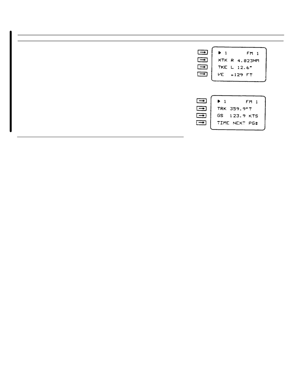
Read crosstrack error (XTK) left (L) or right (R) of
desired course in nautical miles (NM) or kilometers
(KM) on display line 2
Change 6 3-75
TM 55-1520-240-10
Table 3-15. Area Navigation (RNAV) - Continued)
Step
Procedure
Display
ac.
Read track angle error (TKE) in degrees left (L) or right
(R) of desired track on display line 3
ad.
Read vertical error (VE) in meters (M) or feet (FT) above
(+) or below (-) desired vertical angle (VA) on display
line 4
ae.
Set data switch to TRK-GS
af.
Read present ground track (TRK) referenced to true (T),
grid (G), or magnetic (M) north on display line 2
ag.
Read present ground speed (GS) in knots (KTS) or
kilometers per hour (KPH) on display line 3
3-76 Change 6
TM 55-1520-240-10
Table 3-16. Map Datum Codes.
Map datum
Data Code
ADINDAN
01
ARC 1950
02
AUSTRALIAN GEODETIC 1966
03
BUKIT RIMPAH
04
CAMP AREA ASTRO
05
DJAKARTA
06
EUROPEAN 1950
07
GEODETIC DATUM 1949
08
GHANA
09
GUAM 1963
10
G. SEGARA
11
G. SERINDUNG
12
HERAT NORTH
13
!JORSEY 1955
14
HU-TZU-SHAN
15
INDIAN
16
IRELAND 1965
17
KERTAU (MALAYAN REVISED TRIANGULATION)
18
LIBERIA 1964
19
USER ENTERED
20
LUZON
21
Change 6 3-77
TM 55-1520-240-10
Table 3-16. Map Datum Codes - (Continued).
Map datum
Data Code
MERCHICH
22
MONTJONG LOWE
23
NIGERIA (MINNA)
24
NORTH-AM ERICAN-1927:
CONUS
25
ALASKA AND CANADA
26
OLD HAWAIIAN:
MAUI
27
OAHU
28
KAUAI
29
ORDINANCE SURVEY OF GREAT BRITAIN 1936
30
QORNOQ
31
SIERRA LEONE 1960
32
SOUTH AMERICA:
PROVISIONAL SOUTH AMERICAN 1956
33
CORREGO ALEGRE
34
CAMPO INCHAUSPE
35
CHUA ASTRO
36
YACARE
37
TANANARIVE OBSERVATORY 1925
38
TIMBALAI
39
TOKYO
40
VOIROL
41
SPECIAL DATUMS(SD) MGRS RELATED
SD, INDIAN SPECIAL
42
SD, LUZON SPECIAL
43
SD, TOKYO SPECIAL
44
SD, WGS-84 SPECIAL
45
WGS-72
46
WGS-84 (Default map datum))
47
3-78 Change 6
TM 55-1520-240-10
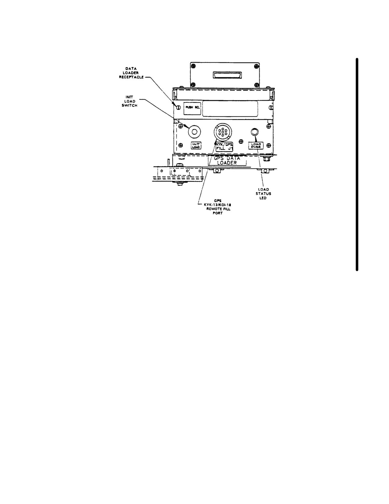
3-66. GPS Data Loader Receptacle. (fig. 3-18)
rotate Data Select switch to position desired. Then
compare data displayed with the known programmed
The GPS data loader receptacle allows the operator to
data.
load pre-programmed navigation information into the
GPS receiver. This navigational information, such as
(5)
Repeat steps (1) thru (5) as desired
way point position, DTM or almanac data is pre-loaded
for any or all remaining way points.
on a data loader module, part number 164191-01-02 or
164191-03-01, if Unit Operations and mission dictates.
(6)
GPS should now be ready for use
during flight operations.
3-67. Controls and Function
- GPS Data Loader
Receptacle.
3-69. GPS KYK-13 Remote Fill Panel. (fig. 3-18)
Controls of the GPS Data Loader Receptacle are as
The GPS KYK-13 Remote Fill Panel allows encryption
follows:
data to be loaded from a KYK-13 or KOI-18 fill device.
Reference will only be made to the KYK-13.
CONTROLS/
INDICATOR
FUNCTION
3-70. Controls and Function - GPS KYK-13 Remote
Fill Panel. (fig. 3-18)
RELEASE
When pressed, releases
Pushbutton
Data Loader Module from
Controls of the GPS KYK-13 Remote Fill Panel are as
Data Loader Receptacle.
follows:
3-68. Normal Operation - GPS Data Loader
CONTROLS/
Receptacle.
INDICATOR
FUNCTION
Perform the following steps in sequence to operate the
LOADProvides positive indication that
data loader system:
STATUS
GPS receiver has successfully
LED
received crypto key fill.
a.
Turn on the GPS System. Allow system to
INIT
When pressed, causes the trans-
warm up and time in for approximately one minute.
LOADfer of crypto key from fill de-
switch
vice (KYK-13 or KOI-18) to GPS
Note
receiver.
Loading data loader must be done in INIT
Mode.
3-71. Normal Operation - GPS KYK-13 Remote Fill
Panel.
b.
Insert data loader module into data loader
receptacle. Wait at least 30 seconds before switching to
To load keys from KYK-13 into the GPS receiver:
another mode. Display momentarily flashes when
information has been successfully transferred.
Note
The GPS receiver does not need to be
c.
Locate module release button on left side of
on to load keys with the KYK-13 Fill
data loader receptacle. Release and remove data loader
Device.
module from data loader receptacle.
a.
Connect KYK-13. either directly or using a
d.
Verify operation of data loader system by:
fill cable, to KYK/GPS FILL JI receptacle located on the
Remote Fill Panel (Figure 3-18).
(1)
Turn GPS Data Select switch to POS.
b.
Turn KYK-13 Fill switch to desired position.
(2)
Select a way point that is known to be
pre-programmed.
c.
Turn KYK-13 Mode switch to ON.
(3)
Compare data displayed with known
d.
Press LOAD IN!T switch on the Remote Fill
programmed data.
Panel (Figure 3-18). Wait approximately 5 seconds. If
key was successfully loaded, Load Indicator light on the
(4)
If other selections are to be checked,
Remote Fill Panel will flash.
e.
Repeat steps b. thru d. to load additional
keys.
Change 6 3-79
TM 55-1520-240-10
f.
Turn KYK-13 Mode switch to OFF.
a.
Lift protective guard from zeroize toggle
switch and activate switch.
g.
Disconnect KYK-13 from aircraft receptacle.
b.
If GPS receiver is on, turn Data Switch to
Stat. Observe message on Page 1, Line 2.
3-72. GPS Zeroize Switch. (fig. 2-9)
The message ZEROED indicates a successful attempt to
The GPS Zeroize switch is located on center instrument
erase information stored in the GPS receiver.
panel, right side of AN/APR-39AV(1) Indicator, and is
used to erase any crypto data and all navigational
The message ZERO FAIL indicates an unsuccessful
information stored in the GPS Receiver.
attempt to erase the information. The GPS receiver
remains classified.
This zeorize switch consists of a guarded toggle switch.
c.
An alternate method to zeroize the GPS
3-73. Normal Operation - GPS Zeroize Switch.
receiver is to use the C-11702/UR and GPS Control Unit
keyboard as follows:
Note
Aircraft battery must be connected, or power applied to
(1)
Select STAT page 1.
aircraft.
(2)
Enter ZZ on line 4, and push Line
Select Key 4.
(3)
If ZEROIZED message is displayed on
Stat Page 1, Line 2, the GPS receiver is declassified.
(4)
If ZERO FAIL message is displayed,
zeroization was not successful and the GPS receiver
remains classified.
3-80 Change 6
TM 55-1520-240-10
Figure 3-18. Remote GPS Data Loader Receptacle/KYK-13 Fill! Panel
Change 6 3-81/(3-82 blank)
TM
55-1520-240-10
CHAPTER
4
MISSION EQUIPMENT
SECTION I MISSION AVIONICS
4-1.
Radar Signal Detecting Set, AN/
interval (PRI), pulse width (PW).
APR-39A(V)1.
signal strength. The system does not
signals. I
The radar signal detecting set (RSresolution for detected
ibrary s
a passive electronic warfare systeparameters to the threat l
match
aural indications of the presence cation data (EID) files. If ar
ymbol data
transmitters. The RSDS detects thsends the appropriate s
sized
usually associated with hostile ficorresponding computer-synthe
S. If the recei
and MMW (millimeter wave) frequencto the helicopter IC
, the
the heart of the helicopter threatmatch a threat in the EID files
unknown thre
with the laser detecting set AN/bol “U” to indicate an
of an IBIT routin
system AN/AAR-47, and radar warniates the resultsR
Also, it
44(V)3 to process, display, and anresults on the indicator.y
those systems. The system consistsfromtheiAN/AVR-2,oAN/APR-44(3),
icator
center instrument panel (fig. 4-0)systems for display on the ind
in the right aft avionics pod, tICS.ideo receivers (one at
station
50, another at station
605d. The blade antenna senses C/D
(hi-band) outside the helicopter it to the C/D band amplifier porti
station 623). and a blade antennaThe RF signal is filtered, limited
bottom of the fuselage at stationband amplifier with the resultant v
AN/APR-39A volume control labeledpresence of a threat in the C/D ba
canted console provides additionalconjunction with the hi-band signa
ties external(fig.h4-1). The RSDS threat type and current threat mod
the No. 2 DC bus through the ASE launch, etc.).cuit
breaker on No. 2 PDP.
e. The RSDS employs a removable
a. The antenna-detector charact(UDM) which is mountede
in the digi
frequency range of the system. Eaccontains the classified portion of
contain two spiral elements, one oprogram (OFP) and the classified e
and one operating in the MMW (mil(EID) files. The EID.files contain
Each of the spiral elements receiincludes threat signal parameters,
signals in their respective band aaudio data. The UDM can be removed
circuits. The detector portion reprogrammed to accomodate new and
employs an elaborate set of filterallows the RSDS to be tailored
to th
(pulses) from the RF received intion and/or current mission requi
video outputs are then summed andUDM from the digital processor dec
video signal to the appropriate video receiver.
NOTE
b.Each video receiver has two videoThreat symbols (except for U) sh
they serve the left and right anteillustrations are for
illustra
corresponding forward or aft sector.Actual threat symbols are class
plies power to the antenna-detectors and amplifies the
f. The indicator displays threat
detected video inputs from the antenna-detectors. Two video
to threat signals detected and iden
outputs are then sent to the digital processor for signal
relative position from the helicopte
analysis. The video receiver also performs initiated built-in
Symbol position relative to the ce
test on command from the digital processor.
the threats lethality. The highest
c The digital processor suppliare shown nearest12touter edge marki
power to the two video receivers athe indicator graticule represent
signal on the 15 VDC power line to helicopter heading. The
sys
seven
self-test. The digital processor rthreat symbols. If the number
of t
video receivers and processes thexceeds the number the
system can
parameters. These signal parameterhigh
st priority threats will be d
Change
9
4-1
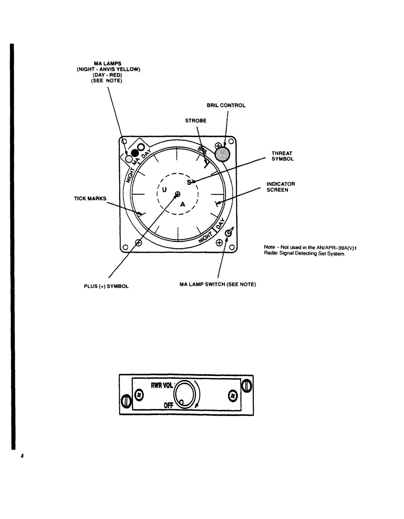
TM 55-1520-240-10
Figure 4-0.
Radar Signal Detecting Set Indicator
Figure 4-1.
AN/APR-39A Volume Control
4-2
Change
9
TM
55-1520-240-10
cannot be identified as a specifictem, radar beacon transponder
syste
as an unknown (symbol U). Search tem, pulse radar jammer
system, or t
radars operating in search mode artem is transmitting. This blanking i
edge of the indicator. The positiothe possible detection of false thr
represents the relative bearing oence induced by these systems. Becau
helicopter. New threats appear insystem, it does not provide any inpu
Threats that drop out of the envirtial blanking of other systems.
displa
10 seconds
before being dropped. A ghosted
symbol appears as though drawn with4-2. dControls and Function, Ra
dar Signal
g. Threats are announced by voice mDetecting Set Indicator. (fig. 4-0)
helicopter ICS. Either of two voice message formats can be
selected using page 2 of the CDU ASE control layer. RWR
AUDIO 1 or normal (full message foCONTROLS/cts full audio.
RWR AUDIO 2 or terse (shortened mesINDICATOR
FUNCTION
shorter audio messages and reduces the audio clutter in dense
Indicator Screen
Displays the appro
signal environments. Both modes provide specific threat type
(CRT)
symbol at the appr
and threat position voice messages.
ate position for e
h. When dense signal environments cause the systeprocessed signal r
operate in a degraded (less sensitive) mode, the eivedm
by the anten
informs the operator by flashing the plus (+) symbodetectors.
RSDS indicator and the voice message “Threat Detection
Plus (+) Symbol
Displayed in cente
Degraded” will be heard over the ICS. When system sensitiv-
indicator during o
ity returns to normal, the plus (+) symbol in the center of the
tion and self-test
RSDS indicator stops flashing and the voice message “Threat
(+) symbol flashes
Detection Restored” will be heard over the ICS.
operator know when
i. The RSDS, LDS, and MWS all execute periodicsystem is operatin
built-in test (PBIT) routines during normal operatiodense signal envir
operational status with the results of these tests bment and threat de
to the digital processor. Failures of PBIT for thestion is degraded.
tems are indicated by the presence Tick MarksreplaciThe 12 out
er edge
(+) symbol in the center of the RSDS indicator. Tings o
n the indica
informs the operator that one or more of the systemsgraticuled
represen
at least some portion of their respective PBIT routpositionss
relative
prompts the operator to perform initiated built-in copter head
ing.
to determine what system(s) has failed and the extent of the
Red MA Indicator
Not used.
failure(s).
Anvis Yellow MA
Not used.
j. IBIT may be selected by the operator. If the RSDS
interface circuitry within either Indicator the self-test. the
RWR TEST FAIL advisory is displayedMA Lamp SwitchFauNot
used.
receivers are shown on the indicator as blinking symbols and
the voice message “APR-39 Failure” will be heard over the
ICS. If the test is good, the voice message “APR-39 Opera-
tional” will be heard over the ICS.BRIL ControlL cauVariessthe brillia
displayed if the RSDS interface circuitry within bothe indicator disp
fails while in its normal operating state. Self-tesTurning knober
clock
detecting set (LDS) and the missile warning systemincreases brightne
are incorporated in the RSDS self-test.
k. The system interfaces with the interference blanker
unit (IBU) in an attempt to prevent other aircraft systems,
Indicates that a s
which operate in the same approxiStroberequency range,
a fire co
from interfering with it. The lo-band portion of thradar ors
radar operating in
blanked by the IBU when either the IFF transponder system
mode has been dete
or the TACAN system is transmitting. The hi-band portion of
nd identified.
Change
9
4-2.1