TECHNICAL MANUAL MAINTENANCE MANUAL FOR ARMY CH-47D HELICOPTER (1992) - page 5
TM 55-1520-240-10
-10 kHz, -5kHz, + lkHz is provided in both receive and
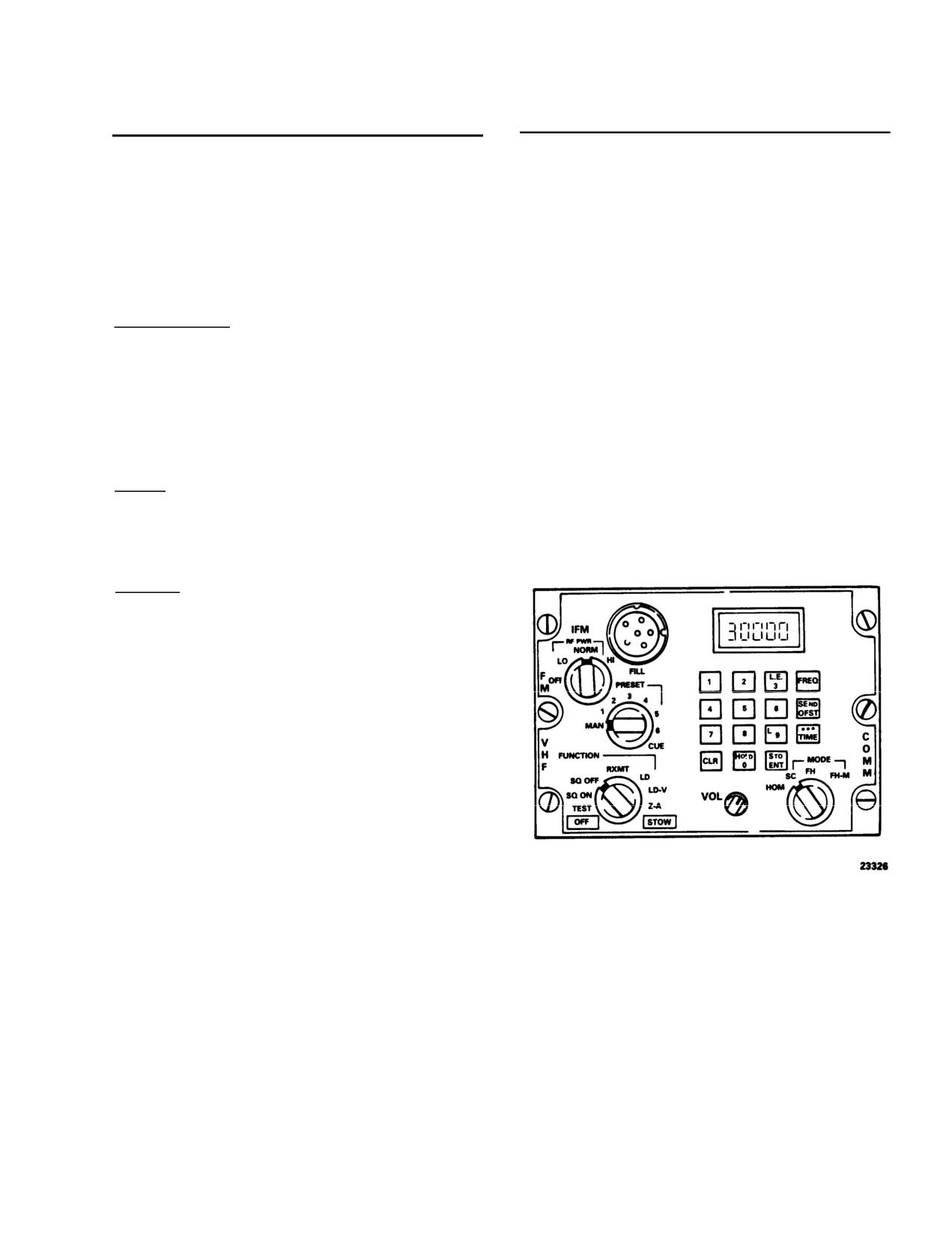
3-14. Controls and Functions VHF/FM Radio Set.
transmit mode; this frequency is not used in the ECCM
(fig. 3-6)
mode.
CONTROLS/
d. Homing.
INDICATOR
FUNCTION
(1) Mode select switch - HOM.
Function Selector
(2) Operating frequency - Set.
OFF
Primary power OFF.
Memory battery power
NOTE
ON.
Any strong single channel signal within the
TEST
RT and ECCM modules
frequency range of the radio set can be used
are tested. Results;
for homing.
GOOD or FAIL.
SQ ON
RT on with squelch.
(3) FM button on HSI MODE SELECT PANEL
- press. Check that SEL lamp is lit.
SQ OFF
RT with no squelch.,
RXMT
RT in RECEIVE mode.
(4) Homing procedures. The course deviation
Used as a radio relay link.
bar on the HSI provides the primary navigation indica-
tion when the set is in homing mode. The bar only
LD
Keyboard loading of pre-
provides information on whether the helicopter is left,
set frequencies.
right, on a heading to the signal source, or over the
LD-V
TRANSEC variable load-
signal source. The TO-FROM ambiguity arrows will not
ing is enabled.
function and the selective course feature is not avail-
Z-A
Not an operational posi-
able. Ambiguity is solved using either of the following
tion. Used to clear the
methods:
TRANSEC variable.
(a) Directional method. When the helicopter
STOW
All power removed. Used
is heading inbound to the signal source with the bar
during extended storage.
centered, the indications are directional in that a change
in heading to the right will cause the bar to drift to the
Mode Selector
left. Conversely, a change in heading to the left will
HOM
Homing antennas are ac-
cause the bar to drift to the right. When the helicopter
tive; communication an-
is heading outbound from the signal source with the
tenna is disconnected.
vertical pointer centered, the indications are nondirec-
Provides pilot with steer-
tional in terms of steering. A change in heading to the
ing, station approach, and
right will cause the bar to drift to the right. A change in
signal strength indicators.
heading to the left will cause the bar to drift left.
(b) Build and fade method. If the signal
SC
Single channel mode of
source is transmitting a 150-Hz tone-modulated signal
operation. Operating fre-
and the helicopter is inbound to the signal source, the
quency selected by PRE-
tone will increase in intensity. The tone will decrease in
SET selector or keyboard
intensity on an outbound heading.
entry.
(5) Additional homing characteristics. The fol-
FH
Frequency hopping mode
lowing additional characteristics may be observed when
selected. PRESET selec-
homing. The glideslope deviation pointer will rise from
tor positions 1-6 select
the horizontal mark when the aircraft is inbound (in-
frequency hopping net
creasing signal strength) to a transmitter. The pointer
parameters.
will fall to the horizontal mark when outbound. The
FM-M
Frequency hopping-master
glideslope failure and navigation failure warning flags
position selects control
will be in view if there is inadequate homing signal
station as the time stan-
strength. A dip in the horizontal pointer may or may not
dard for communicating
occur when passing over the station, depending on the
equipment.
signal source, helicopter speed, and altitude.
Preset Selector
MAN
Used in single mode to
select any operating fre-
quency in 25 kHz incre-
ments.
3-10
TM 55-1520-240-10
CONTROLS/
CONTROLS/
INDICATOR
FUNCTION
INDICATOR
FUNCTION
SEND/OFST
Modify a single channel
POS. 1-6
In single channel mode,
operating frequency, man-
preset frequencies are
selected or loaded. In FH
ually select or preset, to
or FM-M mode, fre-
inclue offsets of ±5 or
±10 kHz. It has a second
quency hopping nets are
function on initiating an
selected.
ERF Transmission if a
CUE
Used by a non-ECCM
Hopset or Lockout
radio to signal to CUE or
ECCM radio.
Set is in the holding mem-
ory and the Mode Switch
IFM RF Selector
is in the FH-M position.
TIME
Used to display or change
OFF
(Bypass) - 10 watts.
the time setting maim
LO
(Low power) - 2.5 watts,
tained within each RT.
(Normal) - 10 watts.
FILL
Used to fill ECCM pa-
NORM
rameters from an external
HI
(High power) - 40 watts.
fill device. Entry of
ECCM parameters is initi-
ated by the H-LD button
The display generally op-
Display
erates in conjunction with
on the keyboard with the
the keyboard. Other dis-
FUNCTION switch in LD
plays may be selected by
or LD-V.
the FUNCTION and
MODE selectors.
Keyboard
A 15-button array of
switches in a 4 x 4 matrix,
used to insert data or se-
lect data for display. The
keyboard is comprised of
10 numerical buttons,
three special functions,
and two command but-
tons.
Switches 1-9
Used to key in frequen-
cies, load time informat-
ion, or offsets.
CLR
Used to zeroize the dis-
play or to clear erroneous
entries.
0 (H-LD)
Used to enter zeroes. Sec-
ond function (hold) ini-
tiates transfer of ECCM
Figure 3-6. VHF/FM Radio Set (AN/ARC-201)
parameters.
3-15. HF Radio Set (AN/ARC-HF-SSB 199).
STO/ENT
Initiate entry of all data
by keyboard entry. Its sec-
The HF radio set (AN/ARC-199) provides communica-
ond function is to store a
tion in a 28 MHz high frequency band between 2.0 to
received Hopset or Lock-
29.999 MHz. Transmit and receive frequencies are
out Set held in holding
programmable in 100 Hz steps on 20 preselectable
channels, for a total of 280,000 possible frequencies.
The operating modes of the HF radio set are Upper and
FREQ
Display the current oper-
lower sideband (USB, LSB), amplitude modulation
ating frequency during
equivalent (AME), and modulated carrier wave (MCW).
single channel (manual or
The data may be transmitted or received in LSB, USB,
preset) operation.
or AME modes. DC power to operate the HF radio set
is supplied by the No. 2 DC bus through the COMM
ARC-199 HF and PWR circuit breakers on the No. 2
PDP.
3-11
TM 55-1520-240-10
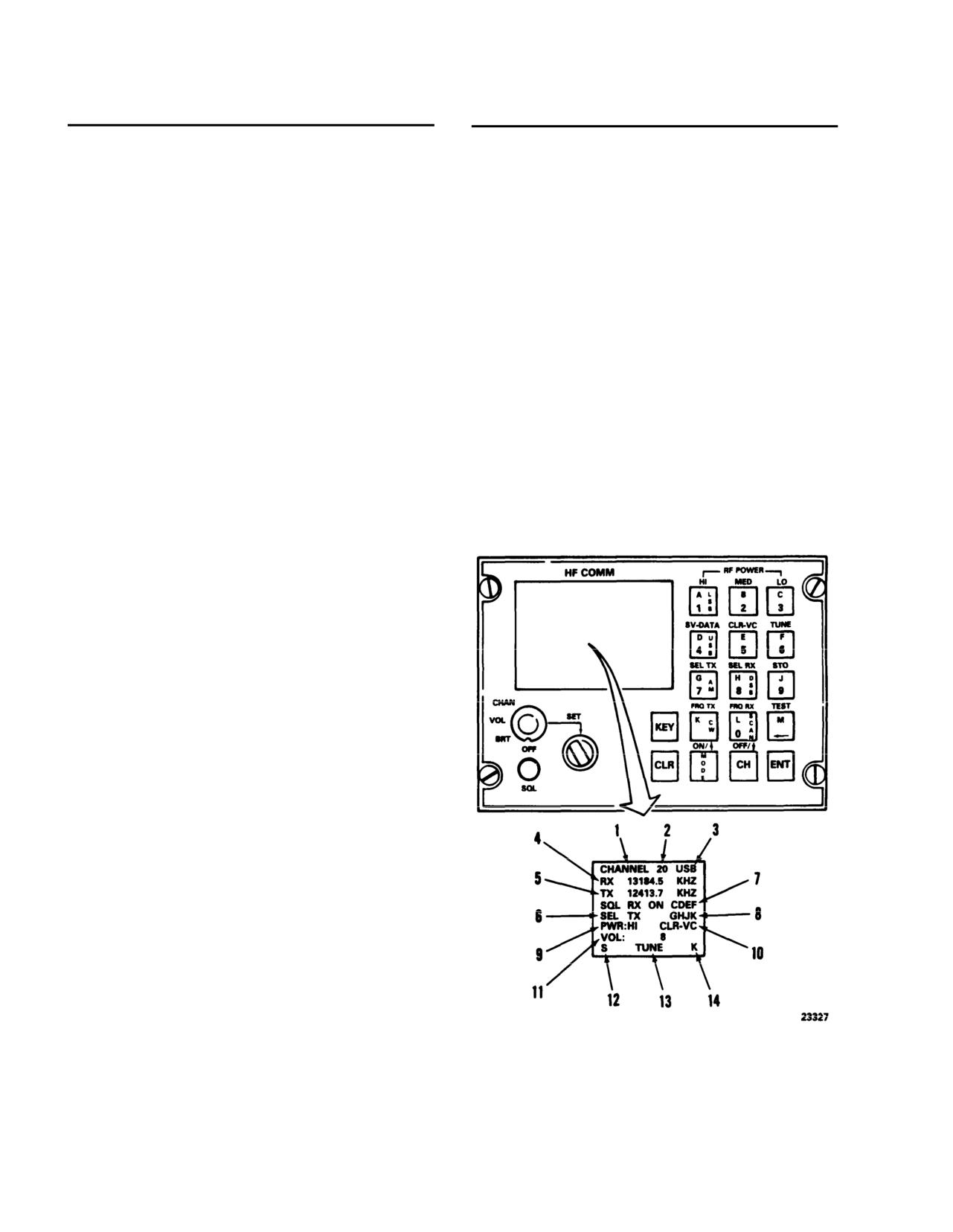
3-16. Display Fields, Controls and Function, HF
CONTROLS/
Radio Set (AN/ARC-199). (fig. 3-7)
INDICATOR
FUNCTION
CONTROLS/
VOL MIN 1, 2, 3, through
INDICATOR
FUNCTION
14, MAX.
Display Field
NOTE
Field 1
Channel - This field ap-
AUDIO VOLUME LEVEL should normally be
pears in inverse video to
set at 14. Adjust HF volume using external vol-
indicate that current
ume control on console.
channel information has
Field
12
S (SCAN) - Indicates
not been stored.
that the currently dis-
Field 2
Active channel number:
0
played channel is on
through 20
the scan list.
Field
3
Modulation on Mode:
Field
13
Indications are: XMIT,
USB, LSB, AM, CW. CW
TEST, SCAN, or
represents MCW and may
TUNE.
be used in conjunction
XMIT
Transmitter is keyed
with the mic key to trans-
and channel is tuned.
mit code.
TEST
Built-in-test (BIT)
Field 4
Receive frequency in kilo-
mode is active.
hertz
SCAN
Scan mode is active.
Field
5
Transmit frequency in ki-
TUNE
Tuning for one or all
lohertz,
channel - blank if not
Field 6
Squelch Level - Display
one of the above keys
MIN, 1, 2, 3, through 14,
are active.
MAX in conjunction with
Field
14
K (Key) - Indicates
squelch knob in control
KEY has been pressed,
panel.
and the functions above
Field 7
Receive Selective Ad-
the keys are active.
dress.
M (MODE) - Indicates
Field 8
Transmit Selective Ad-
MODE has been
dress. In the sample dis-
pressed, and USB,
play shown above, ON
LSB, AM, or CW
indicates that SELADR
should be selected next.
mode is operational for
Indicates slewing may
RX. If SELADR is opera-
be used, or scan flag
tional for TX, ON is an-
may be set or cleared.
nunciated on the line with
Controls
TX.
Function Select
Power ON/OFF, CRT
Field 9
Transmitter Output Power
brightness, audio vol-
- LOW, MED, or HI.
ume and channel num-
Field
10
Modulation Source. The
ber selection.
field displays are:
Function Control
Single-step, detent-type
DATA
Indicates 600 ohm data
switch, with continuous
input.
rotation in either direc-
CIPHER
Indicates input from
tion. Clockwise rotation
KY-75 input. (If in-
increases and counter-
stalled).
clockwise rotation de-
creases the CRT
CLR-VC
Indicates non-encrypted
brightness, audio vol-
KY-75 input. (If in-
ume, or channel num-
stalled).
ber. In cases of CRT
Field 11
Fault Field. Displayed
brightness and audio
fault messages are: NOT
volume, knob has no
TUNED, DATA NOT
effect once limit of that
SAVED, and AUDIO
particular function has
VOLUME LEVEL:
been reached. In
3-12
TM 55-1520-240-10
CONTROLS/
CONTROLS/
INDICATOR
FUNCTION
INDICATOR
FUNCTION
channel select mode,
volume control for the
function control knob is
desired level.
continuously active. That
Channel Number
Channel number may be
is, channel 20 is always
changed using the Func-
one position counterclock-
tion Select and Function
wise from channel 0.
Control Knob or by using
Squelch Control
Continuous rotation in
a combination of key-
either direction; squelch
strokes.
level is annunciated in
Modulation Mode
Four modes are available:
field #6. Once upper or
USB, LSB, AM (AME),
lower limit of squelch has
and CW (MCW). To
been reached, further op-
change from one mode to
eration of knob in same
another, press MODE +
direction has no effect.
desired mode key + ENT.
Receive Frequency
2.0-29.9999 MHz, pro-
3-17. Operating Modes/Functions, HF Radio Set
grammable in 100 Hz
(AN/ARC-199). (fig. 3-7)
steps. To change frequen-
cies press KEY + FRQ
CONTROLS/
RX + desired frequency
INDICATOR
FUNCTION
+ ENT.
Power ON/OFF
On Function Select Knob.
Transmit Frequency
2.0-29.9999 MHz pro-
Ready Indication
When the radio is initially
grammable in 100 Hz
powered on, a system
steps. To change frequen-
ready message will be dis-
cies press KEY +FRQ
played for a few seconds.
TX + desired frequency
+ ENT.
The channel 0 informa-
tion will then be dis-
Squelch Level
Single step, detent-type
played.
control; squelch level is
annunciated on the dis-
CRT Brightness
Set Function Select Knob
to BRT. Rotate the Func-
play and varies from MIN,
tion Control Knob in the
1, 2, 3 through 14, MAX.
desired direction to in-
The squelch level is not a
crease or decrease bright-
stored parameter.
ness.
Transmit Selective
A 4-letter code pro-
Address
grammed by pressing HE
Audio Volume
Set Function Knob to
VOL, rotate the Function
KEY+ SELTX + a
4-letter code + ENT, or
Control Knob in the de-
by activating SELADR
sired direction to increase
or decrease audio volume.
RX and keying the mic.
Audio volume is not a
stored parameter. Audio
Receiver Selective
A 4-letter code pro-
volume level is annunci-
Address
grammed by pressing
ated briefly in the fault
KEY + SEL RX + a
area of the display when
4-letter code + ENT. Re-
the level is being changed.
ceive selective address
The display levels are:
mode is activated by using
MIN, 1, 2, 3 through 14,
key sequence: KEY +
MAX. A secondary HF
SEL RX + ON + ENT.
audio volume control is
located in the console.
Output Power Level
Three ouptut power levels
This is provided for audio
are selectable from the
keyboard; LO, MED, or
level compatibility with
HI. The key sequence
the KY-75 (if installed).
Preset the CDU VOL
used is KEY + LO,
MED, or HI + ENT.
level to the max. position
and adjust the secondary
3-13
TM
55-1520-240-10
CONTROLS/
CONTROLS/
INDICATOR
FUNCTION
INDICATOR
FUNCTION
Modulation Source
Audio sources available
SCAN
Displayed channels may
are CLR-VC (clear voice),
be placed on scan list by
DATA, or encrypted au-
pressing SCAN + ON +
dio when used with voice
ENT. It can be removed
security equipment. CI-
from scan list by pressing
PHER is displayed when
SCAN + OFF + ENT.
the KY-75 is in the secure
To automatically scan
voice mode. DATA and
those channels which have
CLR-VC modes are se-
been placed on scan list,
lectable from control
press the SCAN key, then
panel, when KY-75 is in
ENT key.
non-secure mode, using
CW Keying
To utilize the CW keying
key sequence: KEY +
function, first place the
(SV-DATA or CLR-VC)
radio in CW mode. This is
+ ENT. The modulation
accomplished by pressing
source is not a stored pa-
the following key se-
rameter.
quence : MODE + CW +
Tune
By using appropriate key
ENT. Now either the
sequence, either currently
KEY key on the control
displayed channel or all
panel, or any external key
20 channels may be tuned
switch (a mic key) may be
to the antenna. The tun-
used to transmit CW.
ing information is stored
for future use with no
tuning necessary. Current
channel may be tuned by
pressing KEY + TUNE +
ENT. All 20 channels may
be tuned by pressing KEY
+ TUNE + SCAN +
ENT.
TEST
Built-in-Test (BIT) fea-
ture allows operator to
test both receiving and
transmitting capabilities at
several frequencies. Any
failure to meet predeter-
mined performance levels
results in a failure mes-
sage being
displayed. This identifies
the faulty unit and pro-
vides a maintenance code.
The test is initiated by
pressing KEY + TEST +
ENT.
STORE
ENT key, used to termi-
nate mode changes, does
not automatically store
channel information;
therefore, a store se-
quence is provided. The
key sequence is: KEY +
Figure 3-7. Control/Display Panel, HF Radio Set
STO + ENT.
(AN/ARC-HF-SSB 199)
3-18. Voice Security Equipment TSEC/KY-58.
The voice security equipment is used with the FM band
of the No. 1 VHF AM/FM radio to provide secure
3-14
TM 55-1520-240-10
two-way communication. The equipment is controlled
by the remote control unit (RCU) Z-AHP mounted on
the right side of the console. The POWER switch must
be at ON, regardless of the mode of operation, when-
ever the equipment is installed. Power to operate the
voice security system is supplied by the No. 2 DC bus
through the COMM KY-28 circuit breaker on the No. 2
PDP.
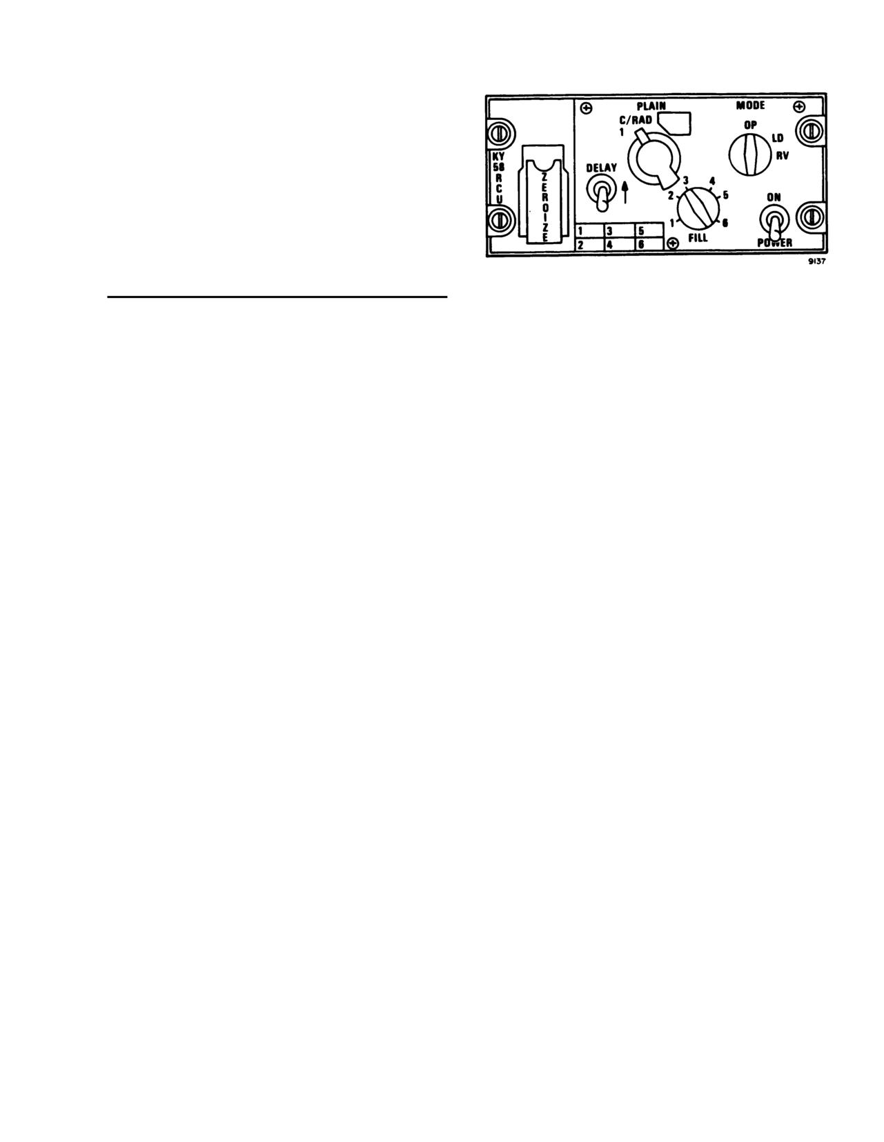
3-19. Controls and Function. (fig. 3-8)
CONTROLS/
INDICATOR
FUNCTION
Figure 3-8. Remote Control Unit TSEC/KY-58
ZEROIZE Switch
Momentary contact toggle
(Z-AHP)
(under spring-loaded
switch used to clear (ZE-
cover)
ROIZE) any crypto-net
NOTE
variables stored in the
To talk in secure voice, the KY-58 must be
TSEC/KY-58.
loaded with any number of desired variables.
DELAY Switch
Two position toggle
switch; DELAY position
(1)
Set the MODE switch to OP.
used when received signal
(2)
Set the FILL switch to the storage register
is to be retransmitted.
which contains the required CNV.
PLAIN/C/RAD1 Switch
Two position rotary switch
used to select TSEC/
(3)
Pull out and lift up the POWER switch to
KY-58 operating mode. A
ON. A beeping tone and backg0round noise
third position (C/RAD 2)
will be heard in the headset. Before the set
is covered and locked out.
can be used, the tone must be cleared by
momentarily keying the No. 1 VHF AM/FM
PLAIN
Permits normal (unse-
radio with the PTT switch.
cured) communications on
associated FM radio set.
(4)
Set the PLAIN C/RAD1 switch to C/RADl.
C/RADl
Permits secured communi-
(5)
If the signal is to be retransmitted, pull out
cations on associated FM
and lift up the DELAY switch to (ON).
radio set.
(6) Clear voice procedures: To operate in clear
FILL Switch
Six position, rotary switch,
voice (plain text) simply:
used to select any of six
storage registers for stor-
(a) Set the PLAIN-C/RAD switch to PLAIN.
age of crypto-net variable
(b) Operate the equipment.
(CNV).
b.
Zeroizing procedures.
MODE Switch
Three position rotary
switch used to select the
NOTE
operating/loading mode of
Instructions should originate from the net
the TSEC/KY-58.
controller or commander as to when to
OP
Allows normal operation
zeroize the equipment.
of KY-58.
LD
Allows normal loading of
(1)
Lift the red ZEROIZE switch cover.
CNV.
(2)
Push the spring-loaded ZEROIZE switch up.
RV
Allows remote loading of
This will zeroize positions 1-6.
CNN.
(3) Close the red cover. The equipment is now.
POWER ON
Two position toggle switch
zeroized and secure voice communications
Switch Position
used to apply power to
are no longer possible.
TSEC/KY-58.
c. Automatic remote keying procedures.
NOTE
3-20. Normal Operation.
Automatic remote keying (AK) causes an
old CNV to be replaced by a new CNV. Net
a. Operating procedures for secure voice.
controller simply transmits the new CNV
over the air to your KY-58.
3-15
TM 55-1520-240-10
(1)
The net controller will use a secure voice
applied to the KY-58 or when the KY-58 is zeroized.
channel, with directions to stand by for an
This beeping is part of normal KY-58 operation but
AK transmission. Calls should not be made
must be cleared by momentarily keying the No. 1 VHF
during this stand-by action.
AM/FM Radio before communications can be achieved.
(2)
Several beeps will be heard in the headset.
(2) Background noise indicates that the KY-58 is
This means that the old CNV is being re-
working properly. This noise should occur at power on
placed by a new CNV.
of the KY-58 and when the KY-58 is generating a
cryptovariable. If the backg0round noise is not heard at
(3)
Using this new CNV, the net controller will
power on, the equipment must be checked out by
ask for a radio check.
maintenance personnel.
(4) After the radio check is completed, the net
(3) Continuous tone should indicate a parity
controller instructions will be to resume nor-
alarm. This will occur whenever an empty storage
mal communications. No action should be
register is selected while holding the PTT button in.
taken until the net controller requests a radio
This tone can mean any of three conditions:
check.
(a) Selection of an empty storage register.
d. Manual remote keying procedures. The net con-
troller will make contact on a secure voice channel with
(b) A bad cryptovariable is present.
instructions to stand by for a new CNV by a manual
(c) Equipment failure has occurred. To clear
remote keying (MK) action. Upon instructions from the
this tone, follow the loading procedures in TM 11-5810-
net controller:
262-0P. If this tone continues, have the equipment
(1)
Set the FILL switch to position 6. Notify the
checked out by maintenance personnel.
net controller by radio and stand by.
(4) Continuous tone could also indicate a crypto
(2)
When notified by the net controller, set the
alarm. If this tone occurs at any time other than in (3)
MODE switch to RV (receive variable). No-
above, equipment failure may have occurred. To clear
tify the net controller and stand by.
this tone, repeat the loading procedures in TM 11-5810-
262-0P. If this tone continues, have the equipment
(3) When notified by the net controller, set the
checked out by maintenance personnel.
FILL switch to any storage position selected
to receive the new CNV (may be unused or
(5) Single beep, when DELAY switch is down,
may contain the variable being replaced).
(not selected), can indicate any of three normal condi-
Notify the net controller and stand by.
tions:
(a) Each time the PTT button is pressed
NOTE
when the KY-58 is in C (cipher) and a filled storage
When performing step (3), the storage posi-
register is selected, this tone-will be heard. Normal use
tion (1 through 6) selected to receive the new
(speaking) of the KY-58 is possible.
CNV may be unused or it may contain the
variable which is being replaced.
(b) When the KY-58 has successfully received
a cryptovariable, this tone indicates that a good crypto-
variable is present in the selected register.
(4)
Upon instructions from the net controller:
(c) When you begin to receive a transmis-
(a)
Listen for a beep on your headset.
sion, this tone indicates that the received signal is in
(b)
Wait two seconds.
secure voice.
(c)
Set the MODE switch to OP.
(6) A single beep, when the DELAY switch is up
(time delay) occurring after the preamble is sent, indi-
(d) Confirm.
cates that you may begin speaking.
(5)
If the MK operation was successful, the net
(7) A single beep, followed by a burst of noise
controller will now contact you via the new
and a seemingly dead condition, indicates that your
CNV.
receiver is on a different variable than the distant
(6)
If the MK operation was not successful, the
transmitter. If this tone occurs when in C/RADl: Turn
net controller will contact you via clear voice
FILL switch to the CNV, Plain-Cipher switch to PLAIN,
(plain) transmission, with instructions to set
and contact the transmitter in clear text and agree to
your FILL selector switch to position 6 and
meet on a particular variable.
stand by while the MK operation is repeated.
3-21. Voice Security Equipment TSEC/KY-75.
e. It isimportant to be familiar with certain KY-58
Voice security equipment (TSEC/KY-75), whenever
audio tones; Some tones indicate normal operation
installed, provides two-way clear or secure voice com-
while others indicate equipment malfunction. These
munication for the HF radio system (AN/ARC-199).
tones are heard only in the cipher mode and are:
Power to operate the voice security equipment is sup-
(1) Continuous beeping, with backg0round noise,
plied by the No. 2 DC bus through the KY-75 circuit
is a crypto alarm. This occurs when power is first
breaker located on the No. 2 PDP.
3-16
TM
55-1520-240-10
3-22. Controls and Function, Voice Security
Equipment (TSEC/KY-75).
(Refer to TM 11-5810-281-OP).
3-23. Normal Operations, Voice Security Equip-
CONTROLS/
ment (TSEC/KY-75).
INDICATOR
FUNCTION
(Refer to TM 11-5810-281-OP).
Line-select (3)
Pushbutton switches to select
3-23.1. HF Radio Set (AN/ARC-220).
options displayed to left of
each switch.
The HF radio set (AN/ARC-220) provides
Brightness
(4)
Pushbutton switches to vary
communication in a 28MHz high frequency band
display brightness.
between 2.0 and 29.9999 MHz.
Channels are spaced at
100-Hz increments, giving 280,000 possible frequencies.
Channel/Net
Seven-position rotary switch
Preset channels can be manually programmed or
Selector (5)
used to select programmed
preprogrammed as part of the communications mission
operating channels or nets.
load information.
A total of 72 channels can be
Data Connector (6)
Interfaces ARC-220 system to
programmed: 20 manual simplex or half-duplex,
20
data transfer device for
programmable simplex or half-duplex, 20 programmable
datafill.
ALE scan lists, and 12 programmable ECCM hop-sets
Key Connector (7)
Interfaces ARC-220 system to
(with ALE capability).
Operating modes of the HF radio
data transfer device for
set using either simplex or half-duplex operation are
keyfill.
Upper and Lower sideband (USB, LSB), amplitude
modulation equivalent (AME), and continuous wave
Mode Switch (8)
Five-position rotary switch
(CW).
Data may be transmitted or received in USB or
selects mode of operation.
LSB modes. Both standard and advanced narrow-band
Selects HF conventional
digital voice terminal (ANDVT) are supported. DC
communications. Operating
power to operate the HF radio set is supplied by the No.
frequency and emission mode
2 DC bus through the COMM ARC-220 HF circuit
are selected manually.
breaker on the No. 2 PDP.
Selected information can be
stored in preset channels for
future recall.
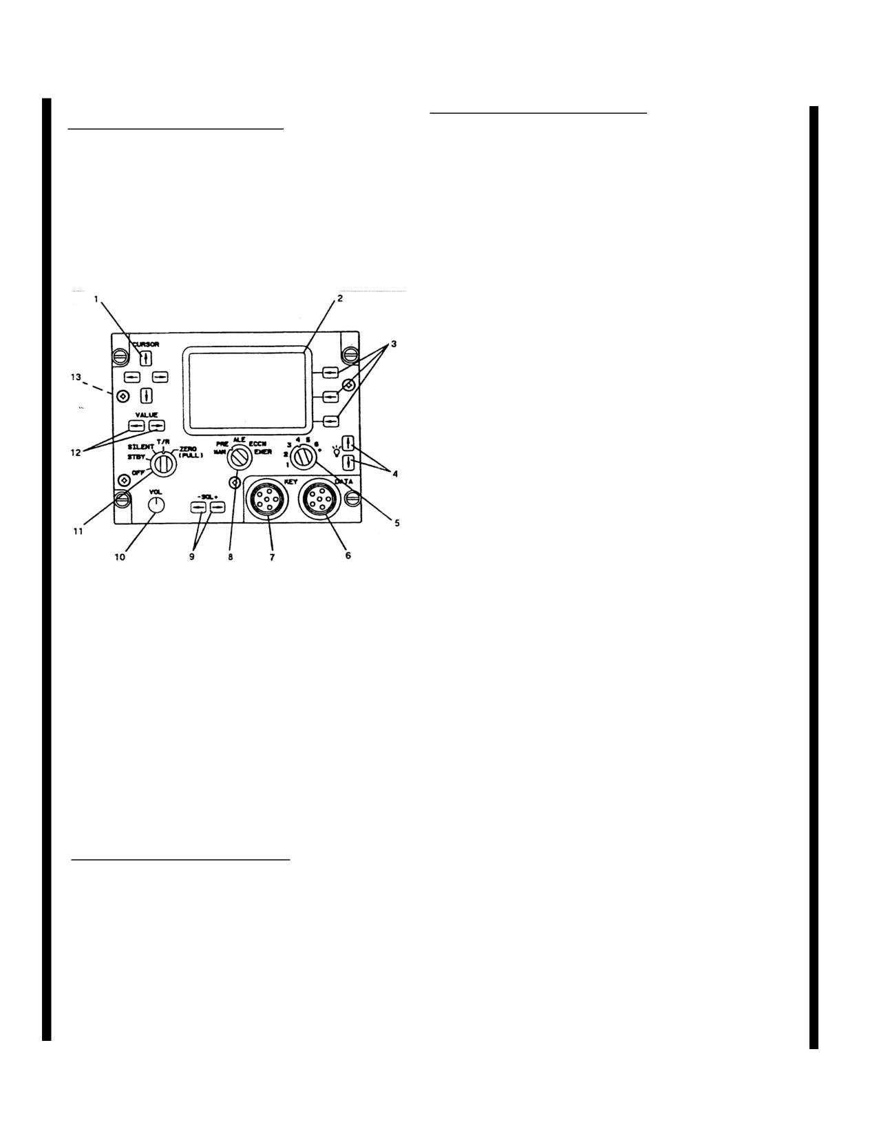
3-23.2. Controls and Function, HF Radio Set
PRE
Selects conventional HF
(AN/ARC-220). (fig. 3-7.1)
communications. Channel/net
CONTROLS/
selector is used to select a
INDICATOR
FUNCTION
preprogrammed preset
channel. Frequency and
Cursor (1)
Four pushbutton switches
emission mode cannot be
position the cursor vertically
changed during preset
or horizontally.
operation.
Display
(2)
NVG compatible, contains six
ALE
Selects automatic link
lines. Each line holds up to 20
establishment mode of
characters. 15 characters are
operation.
left justified for
ECCM
Selects electronic counter-
communications, advisory,
countermeasure mode of
and status information.
5
operation.
characters are right justified
for control selection.
EMER
Used during emergency to
place a distress call. The
mode, frequency, net, etc.., is
determined by the datafill.
SQL (9)
Two pushbutton switches
which controls squelch and
audio muting.
Change
13
3-16.1
TM
22-1520-240-10
CONTROLS/
CONTROLS/
INDICATOR
FUNCTION
INDICATOR
FUNCTION
Fill Type
Character display (KEY,
VOL
(10)
Eight-position rotary switch
DATA) having a display
varies the receive audio output
Format - TYPE: xxxx x.
level.
Default is DATA.
Function Switch (11)
Five-position rotary switch
Contention Control
Character display (ON, OFF)
selects system operation
having a display format of -
function.
LBC: xxx. Default is OFF.
OFF
Turns the ARC-220 off.
Line 3
STBY
Selects the standby function
Receive Frequency
Numeric display (2.0 to
where built-in test (BIT),
29.9999 MHz) with a display
setup, or fill operations can be
format of: RCV xx.xxxx.
performed.
ECCM Station Type
Character display (MEMBER,
SILENT
Used in ALE or ALE ECCM
ALTERNATE, MASTER,
modes to prevent the ARC-220
NET ENTRY, ALT NET
from automatically responding
ENT). Default is MEMBER.
to incoming calls.
Lines
3,4
Character display of emission
T/R
Allows the ARC-220 to
mode (USB, LSB, AME, CW)
transmit and receive in the
one space to right of
selected mode of operation.
frequency. Default is USB.
ZERO
Erases all data (including
Line 4
datafill and keyfill) which has
Transmit Frequency
Numeric display (2.0 to
been loaded into the system
29.9999 MHz) with a format
Value
(12)
Two pushbutton switches
of: XMT xx.xxxx.
increments a field value or
Time
Numeric display (00:00:00 to
single character value,
23:59:59) with a format of -
depending on cursor position.
Hour:Minute:Second.
Line 5
3-23.3. Display Lines, HF Radio Set
(AN/ARC-220).
Link Protection Character display (OFF, ON) with a
format of - LINK PROT: xxx.
The information displayed on each line is dependent upon
Default is ON (OFF if no link
the operation being performed. This section specifies
protection datafill).
what information can be displayed on each particular
Date
Alphanumeric display (01 JAN
line.
00 to 31 DEC 99) with format
of - dd MMM yy.
CONTROLS/
Antenna Type
Character display (T/R, RCV)
INDICATOR
FUNCTION
with format of - ANT: x xx.
Line 1
Alpha-numeric display of 15
Default is T/R.
characters maximum
Line 6
containing channel title (call
Power Level
Character display (LOW,
sign). Default value -
MED, HIGH) with format of -
Mode:channel#.
PWR: xxxx, Default is
Line 2
HIGH.
ALE Address
Alpha-numeric display of 15
Squelch
Alpha-numeric display
characters maximum
(TONE, 0 to 5) with format of
containing the Call To
- SQ: xxx.
(ADRS: xxx) or Self (SELF:
xxx) Address. (ADRS:) and
Volume
Numeric display (1 to 8) with
(SELF:) labels are removed
format of - VOL: x.
for addresses greater than 10
Listen Before Talk
Character display (ON, OFF)
characters in length.
with format of - LBT: xxx.
Noise Reduction
Character display (ON, OFF)
Default value is OFF.
having a display format of -
NOISE REDUCE: xxx.
Default value is ON.
3-16.2
Change 13
TM
55-1520-240-10
3-23.4. Operating Modes/Functions, HF Radio
CONTROLS/
Set (AN/ARC-220). (fig. 3-7.1)
INDICATOR
FUNCTION
the CURSOR
switches to
CONTROLS/
position cursor under the
INDICATOR
FUNCTION
appropriate frequency. Use
the VALUE
switches to
Power ON/OFF
On Function Switch
change frequency. (Note:
System Turn-On
Turning the Function Switch
The XMT frequency will
clock-wise from Off to STBY
automatically change with the
rns system on and selects
RCV frequency, but the
standby function.
SYSTEM
reverse is not true).
TESTING
is displayed while
Squelch Level/
Two pushbutton switches
power-up BIT (P-BIT) is in
Audio Muting
- SQL
+, when pressed
process. SYSTEM-GO
will
displays the squelch status on
be displayed if all tests good,
line 6 of display for 5 sec-
SYSTEM-NOGQ
if not.
nds. Settings are TONE
CRT Brightness
Two pushbutton switches used
and
0 through
5. TONE
to vary brightness. The
- (up
provides no muting and no
arrow) increases intensity
squelch. Position
0 provides
while the Ø (down arrow)
muting but no squelch.
decreases intensity.
Positions
1 through
5 provide
Audio Volume
Eight-position rotary switch
muting and increasing levels
varies output level. Setting is
of squelch. Muting is
displayed on line 6 (bottom) of
normally enabled during ALE
display for 5 seconds when
and ALE ECCM operation.
system first turned on or when
Output Power Level
Three output levels are
VOL
setting is changed. The
selectable for the display
display level are 1, 2, 3 thru
screen by using the
EDIT
line-
8
select switch, which brings up
Channel Selection
Channel number may be
the edit mode, moving the
changed using the Channel
cursor under the power
Selector seven-position rotary
character field and using the
switch. The + position of the
VALUE
switches to change
greater to be selected using the
the field. Depress the RTN
VALUE
switch.
line-select switch which stores
the change and returns to
Modulation Mode
Four modes are available:
normal operating mode. There
USB, LSB, AME, and CW.
are two Built-in-Test (BIT)
To change modes, depress the
features which concerns the
EDIT
line select switch.
operator, P-BIT and C-BIT.
While in the Edit screen use
The Power-Up Bit (P-Bit) tests
the CURSOR
switches to
the ARC-220 when initially
position cursor under the
turned on. P-Bit exercise
appropriate emission mode
basic radio control functions
(RCV or XMT). Use the
which must be operational
VALUE
switches to change
prior to entering a system
mode. (Note: The XMT
operational mode. A GO/NO-
mode will automatically
GO status appears on the
change with the RCV mode,
display and defaults to stand-
but the reverse is not true).
by mode upon completion.
Depress RTN
line select
When NO-GO status appears,
switch to enter the edited data
depressing the INOP
line-
and return to operational
select switch displays
INOP
mode.
MODES
so an operator can
Receive/Transmit
2.0 - 29.9999 MHz, program-
see if limited capability exists.
Frequency
mable in 100 Hz steps. To
The Continuous Bit (C-BIT)
change frequencies, depress
is
the EDIT
line select switch.
While in the Edit screen use
Change 13
3-16.3
TM
55-1520-240-10
CONTROLS/
CONTROLS/
INDICATOR
FUNCTION
INDICATOR
FUNCTION
automatically performed
connector on radio set control
during system operation
front panel. Use the VALUE
without any operator
right arrow switch to select
intervention. Critical system
key number
(1 through
6) to
functions are monitored. Any
be loaded. Initiate key-fill
failures cause a NO-GO
from DTD.
LOADING
is
advisory, accompanied by the
displayed during keyfill,
portion of system which
LOAD COMPLETE
if
failed, to appear on line 5 of
successful, LOAD FAIL
if
the display. C-Bit failures are
may cause interference to
stored in nonvolatile memory.
other stations. Default is ON.
LBT: (listed before talk) -
STORE
RTN line-select key, used to
This field is used for manual,
terminate edit mode,
preset, or conventional (non-
automatically stores any
ALE) ECCM operation and
change(s) made.
turns LBT
ON or OFF.
DataFill
Contains preset frequencies,
When
OFF, transmission is
scan lists, addresses, data
accomplished without regard
messages and ALE and/or
to traffic and may cause
ECCM parameters. With
interference to other stations.
system in STBY,
press the
Default is OFF.
FILL
line-select switch. Use
ANT:
(antenna) - Useful if
VALUE
switches to select
system uses both receive-only
DATA
in the fill TYPE:
field
and transmit/receive antennas.
(line 2). Connect data transfer
When
T/R is selected, the
device (DTD) of
DATA
system transmits and receives
connector on radio set control
on same antenna. When
RCV
front panel and initiate fill
is selected, the system
from the DTD.
LOADING
is
transmits on one and receives
displayed during datafill.
on the other antenna. Default
LOAD COMPLETE
is
is T/R.
displayed for a successful fill,
LINK PROT:
(link
LOAD FAIL
displayed if fill
protection) - This field turns
cannot be completed. (NOTE:
ALE link protection
ON or
using an AN/CYZ-10 DTD,
OFF. Default is ON (OFF
if
the radio set control displays
no link protection datafill).
DTD DETECTED
when
Press RTN
line-select switch
DTD is detected). A copy of
when setup edit is complete to
loaded datafill can be sent to
enter all data and return to
DTD by pressing
COPY
line-
STBY
screen.
select switch. COPYING
is
General Editing
Select desired channel and
displayed during operation,
press the EDIT
line-select
COPY COMPLETE
switch. Use the
CURSOR
displayed if successful, COPY
switches to position cursor
FAIL if copy cannot be
under character position or
completed. Press
RTN
line-
data field to be edited. Use
select switch to return to
VALUE
switches to change
STBY
screen when datafill is
the character or data field to
complete. Disconnect the
desired value. If available,
DTD.
the data setup can be modified
KeyFill
Loads secure keys. From
by pressing the DATA
line-
STBY
screen, press FILL
select switch in the EDIT
line-select switch. Use
screen, using the VALUE
VALUE
switches to select
switches to scroll through the
KEY
in fillTYPE:
field.
list of modem set
Connect DTD to
KEY
configurations. Press the
3-16.4
Change 13
TM
55-1520-240-10
CONTROLS/
INDICATOR
FUNCTION
CONTROLS/
INDICATOR
FUNCTION
be performed. If ALE data is
not loaded for the selected
RTN
line-select switch when
scan list, a CHANNEL INOP
all changes are complete to
advisory is displayed). Use -
store the changes and return to
SQL+
switch to set squelch to
normal operation mode.
TONE.
Adjust VOL
for
Transmit Position
Set function switch to
T/R
comfortable listening level.
Report
and mode switch to proper
Use -SQL+
switch to set
mode. Press the
POSN
line
squelch to
0. Headset is muted
select switch. (NOTE:
until a link is established. If
POSN
line-select is available
channel is noisy, set squelch to
only if configuration data
1. CONTROLS/
indicates GPS is installed).
Higher squelch levels are not
Manual Operation
Set function switch to
T/R and
recommended for ALE mode
mode switch to
MAN.
Use -
of operation.
SQL switch to set squelch to
Normal ALE
When ALE call is received
0. Adjust VOL
control to a
Communication
INCOMING CALL
is displ
comfortable listening level.
Receiving
ayed with the address field
Use SQL
+ switch to set
displaying caller’s ALE
squelch to
1, the optimum for
address. LINKED
is displayed
manual mode. If radio breaks
and a short gong tone sounds
in and out of squelch, increase
when an ALE link is
as required. Set to desired
established. Communication
channel. Press microphone
can now begin. Proper
PTT switch, wait until tune
protocol is for calling station
tone stops and begin
to make first transmission.
communications. When PTT
Normal ALE
Select ALE address to be
switch is pressed, the XMT
Communication
called by doing a, b, or c:
frequency is displayed.
Transmitting
a. Set channel/net switch to
Preset Operation
Set function switch to
T/R and
desired preprogrammed net.
mode switch to
PRE. Use -
b. Use VALUE
switch to
SQL switch to set squelch to
scroll through and select
0. Adjust VOL
control for
preprogrammed address.
comfortable listening level.
c. Press EDIT
line-select
Use SQL
+ switch to set
switch, then use CURSOR
squelch to position
1, the
and VALUE
switches to
optimum setting for preset
manually select an address
mode. If radio breaks in and
character-by-character.
out of squelch, increase as
(NOTE:
NET INOP
advisory
required. Set to desired
is displayed if a selected
channel. Press microphone
channel or net contains: no
PTT switch, wait until tune
data or corrupted data; or
tone stops and begin
hardware cannot support the
communications. When PTT
selected mode). Press
switch is pressed, the XMT
microphone PTT switch.
frequency is displayed.
CALLING
is displayed.
Normal ALE
Set function switch to
T/R
LINKED
is displayed with a
Communication
and mode switch to
ALE.
short gong tone and headset
(NOTE: If the selected net is
audio is restored when link
configured for link protection
established. Start
but does not have accurate
transmission. The system
time, SYNC
instead of POSN
terminates the link and returns
will appear on display, line 2
to ALE scanning after a period
right side along with an
of inactivity (30 seconds typi-
UNSYNC
advisory at bottom
cal). GPS position can also be
of screen. An ALE link
protection time sync needs to
Change
13
3-16.5
TM
55-1520-240-10
CONTROLS/
CONTROLS/
INDICATOR
FUNCTION
INDICATOR
FUNCTION
ECCM Operation -
RCVING PREAMBLE
Receiving Calls
and/or INCOMING CALL
is
transmitted by using the steps
displayed.
above plus the Transmit
Position Report steps.
ECCM Operation -
Press microphone PTT
Transmitting
switch. Wait for preamble
ALE Link Protection
Press PTT switch or
SYNC
Time Sync
line-select switch. System
tones to cease then begin
communications. If an
returns to scan and the net
ALE/ECCM channel is used,
default address if sync
successful, but if unsuccessful
CALLING
is displayed while
call is in process. LINKED
is
press ABORT
line-select
displayed and a short gong
switch to return to ALE
tone sounds, and headset audio
screen.
restored when link established.
ECCM Net
Set function switch to
T/R
(NOTE: Press
ABRT
line-
Initialization
and mode switch to
ECCM.
select switch to abort calling
(NOTE: If ECCM data or
process). Call
keys are not loaded for net
initiator should make first
selected, a CHANNEL INOP
transmission. The system
advisory is displayed). Set
terminates link and returns to
channel/net switch to desired
scan after a period of inactivi-
net. If selected channel is an
ty (30 seconds typical).
ALE/ECCM channel, the
GPS position can also be
address of station being called
transmitted by using the steps
is displayed on line two.
above plus the Transmit
(NOTE:
NET INOP
advisory
Position Report steps.
is displayed if selected channel
Data Messages
The ARC-220 radio set can
or net contains: no or
corrupted data; or hardware
store up to 10 transmit and 10
cannot support selected mode.
received data messages up to
500 characters long each.
If screen displays UNTUNED
or UNSYNC
advisories
Received data messages are
proceed with system
stored in memory and can be
Tune/Sync operation, other
retransmitted. An advisory
wise proceed with ECCM
alerts when a data message is
received. Data can be
operation.
transmitted or received in any
ECCM Tune/Sync
Press either the TUNE
line-
mode (manual, ALE, or
Operation
select switch or microphone
ECCM). Procedure to
PTT switch to initiate
send/receive (recall) messages
combined tune and sync.
is the same for all modes,
TUNING
followed by
except in manual mode when
SYNCING
is displayed during
an ALE link is not established.
process. System will return to
Data Messages -
Received messages are stored
ECCM screen without
Received
in MSG location 1. MSG 10
UNTUNED
and/or UNSYNC
is the oldest message and is
advisories if successful.
deleted from memory upon
ECCM Operation
Use -SQL switch to set
receipt of an incoming
squelch to TONE.
Adjust
message. Received messages
VOL
control for comfortable
can be read and/or forwarded,
listening level. Use SQL+
but not edited. A CHECK
switch to set squelch to
0. If
MSG
advisor is displayed
channel is noisy, set to
1.
when data message received.
Higher settings are not
To recall data messages,
recommended for ECCM
perform the following:
operation.
3-16.6
Change 13
TM
55-1520-240-10
CONTROLS/
CONTROLS/
INDICATOR
FUNCTION
INDICATOR
FUNCTION
Program/Edit
Press the MSG line-select
1. Press MSG
line-select
Data Messages
switch to go to MESSAGE
switch to view message. If
operator desires to check
screen, then press PGRM
line-select switch. NO
messages even though a
MESSAGES
is displayed if
CHECK MSG
advisory was
none exists. Use the
not displayed, press MSG
CURSOR
up/down arrows to
line-select switch, then RCVD
line-select switch to view
position the cursor, then use
VALUE
switches to enter
messages. NO MESSAGES
desired data (if a previously
advisory appears if no
programmed message is to be
messages exist.
edited, use CURSOR
and
2. Use the CURSOR
up/
down arrows to view message
VALUE
switches to obtain
one line at a time and left/right
appropriate message and line
as described earlier). To
arrows to move cursor to left
delete a character in cursor
margin. Use
VALUE
position and to shift remaining
switches to page up or down.
3. To view additional
characters one position to left,
press DEL
line-select switch.
messages, use
CURSOR
A built-in word dictionary is
switches to position cursor
under the MSG number the
available (either default or
use
filled). To access word
dictionary, press WORD
line-
VALUE
switches to scroll to
select switch to obtain
next consecutive message
INSERT
screen. Use
number.
CURSOR
and VALUE
4. To retain messages in
memory, press the
RTN
line-
switches to scroll dictionary.
Place cursor under desired
select switch.
word and press
SELCT
line-
5. To delete messages,
select switch to insert a blank
position cursor under message
number to delete, press the
and the selected word at
DEL
line-select switch until
cursor position of message
edit screen or if no word
NO MESSAGES
is displayed.
found, press CANCL
line-
Press RTN
line-select switch
to return to operational mode.
select switch to return to edit
CONTROLS/screen. When
Data Messages -
Press SEND
line-select switch
complete, press
RTN
line-
Transmit
to transmit last selected
select switch to load message
address in ALE or ECCM
into memory and to return to
mode, or to transmit message
top-level screen. Shutdown
using current mode and
Procedures Set function switch
frequency in manual mode. In
to OFF. Gently pull and turn
ALE or ECCM modes
function switch to zeroize
advisories are displayed during
(ZERO)
position to erase
tuning, synching and linking
preprogrammed information,
which is done automatically.
including all fills. Zeroize
SENDING DATA
is dis-
function is operational
played while message is
regardless if system is on or
transmitted.
off.
Change 13
3-16.7
TM
55-1520-240-10
CONTROLS/
CONTROLS/
INDICATOR
FUNCTION
INDICATOR
FUNCTION
CT
Ciphertext mode. Allows
Emergency
The mode used during emer-
transmission of encrypted
Communication
gencies is determined by the
voice or data and reception of
datafill. The equipment
encrypted or unencrypted
operates normally for mode
voice or data, and non-
selected. Set mode switch to
cooperative terminal rekeying.
EMER.
Press the PTT switch
RK
Remote Keying mode.
to transmit. If in ALE mode,
Permits KY-100 to perform
an ALE call is placed to the
automatic and manual rekey
selected address.
operations.
OFFLINE
Disables communications and
gives access to the system of
menus used to select mode
settings, self-test features, and
filling the KY-100 with
crypto-variables.
Z ALL
Zeroize mode. Erases all
(PULL)
cryptographic data stored in
the KY-100 except the
Emergency Back-up Key.
CIK Receptacle
Interfaces with a
Cryptographic Ignition Key
which is needed to enable all
secure voice and data
communications.
This
function is currently
disabled.
DSPL/OFF BRT Two-function rotary switch
Figure 3-7.1. Control/Display Panel, HF Radio Set
Control
which controls the on/off
(AN/ARC-220)
status and backlight intensity
of the LCD display.
PNL/OFF BRT
Two-function rotary switch
3-23.5. Voice Security Equipment
Control
which controls the on/off
TSEC/KY-100.
status and backlight intensity
Voice security equipment (TSEC/KY-100), when in-
for the overall front panel.
stalled, provides two-way clear or secure half-duplex
PRESET Switch
Rotary selector switch which
voice/data communication for the HF radio system
controls unit operating power
(AN/ARC-220). Power to operate the TSEC/KY-100 is
and settings which are stored
supplied by the No. 2 DC bus through the HF KY-100
in memory.
circuit breaker located on the No. 2 PDP.
OFF
Removes power from KY-100.
3-23.6. Controls, Indicators, Connectors and
MAN
Manual position which allows
Function (TSEC/KY-100, Z-AVH).
operating modes to be selected
(fig 3-8.1)
using both OFFLINE and on-
CONTROLS/
line menu system,
INDICATOR
FUNCTION
1 thru 6
Six separate preset modes
MODE Switch
Six position rotary switch used
which can only be set up in the
to select one of the operational
OFFLINE mode.
modes.
FILL Connector
Used to load cryptographic
PT
Plaintext mode. Allows
keys through the use of a
reception or transmission of
common fill device such as
unencrypted analog voice.
KYK-13/TSEC Electronic
Transfer Device, KYX-
EB
Emergency Back-up mode.
15/TSEC Net Control Device,
Uses the emergency back-up
AN/CYZ-10 Data Transfer
key to encrypt voice for
transmission or reception.
3-16.8
Change 13
TM 55-1520-240-10
CONTROLS/
INDICATOR
FUNCTION
CONTROLS/
INDICATOR
FUNCTION
Eb Annunciator (5)
Displayed when MODE
control switch is in the
Device (DTD), or the KOI-
Emergency Backup (EB)
18/TSEC General Purpose
position.
Tape Reader.
Alphanumeric
Provides prompts, messages,
Three Button
Momentary pushbutton
Display (6)
and mode indications.
Keypad
switches active in both
OFFLINE and on-line modes.
PT Annunciator (7)
Displayed when KY-100 is
Used to enter and exit
processing plaintext voice.
submenus, activate the
Key Symbol (8)
Displayed when menu system
selected mode, select fields,
is locked.
and to scroll through menus
D Annunciator (9)
Displayed when in Data mode.
and options.
V Annunciator (10)
Displayed when in Voice
INIT
Initiate switch. In the
mode.
OFFLINE mode it activates
the displayed menu mode and
Rate Display (12)3-character display indicates voice or
provides entry into submenus.
data rate.
In on-line modes (CT, RK,
EB, PT), it selects the display
3-23.8. Turn-On Procedures.
field to be changed.
When the KY-100 is turned on, tests are automatically
up Arrow
(-)
In the OFFLINE mode, it is
performed to determine the equipment’s operating status.
Switch
used to scroll through menus
The results of these tests will be presented on the
from top to bottom. In on-line
display. Also, a CLd START
message will be
modes (CT, RK, EB, PT), it
displayed.
is used to scroll through
available options for the
a. Cold start turn-on. (Initiated if no traffic
display field being changed.
encryption key (TEK) is contained in the KY-100).
Right Arrow
(Æ) In the OFFLINE mode, it is
(1) Turn on the KY-100 by turning the PRESET
Switch
used to scroll through menus
switch to the MAN position.
from bottom to top. In the on-
line modes (CT, RK, EB, PT)
(2) The KY-100 will initiate a self-test. The display
it is used to select the display
reads CLd STRT
and then PSH INIT.
field to be changed.
Simultaneous
(-Æ)
Used to exit a submenu.
(3) Connect a fill device to the KY-100 fill
Display, LCD
Back-lighted Liquid Crystal
connector using a fill cable.
Select the fill position
Display (LCD) indicates
containing the valid key and turn it on.
operational status, operator
prompts and messages
(4) Press the INIT pushbutton (PUSH INIT).
(5) The KY-100 displays
KEY 1 01, PASS,
3-23.7. Display Annunciators/Fields
WORKING, LOCKED, READY.
(TSEC/KY-100, Z-AVH).
(fig 3-8.1)
CONTROLS/
NOTE
INDICATOR
FUNCTION
If a fill device is not connected to the KY-100
when the INIT pushbutton is pressed, a dEV
TX Annunciator (1)
Displayed when KY-100 is
ERR (Device Error) message will be displayed.
transmitting.
When this occurs, the only available
RX Annunciator (2)
Displayed when KY-100 is
communication mode will be PT (Plaintext).
receiving.
Wb Annunciator (3)
Displayed when KY-100 is in
(6) If a FAIL message is displayed, notify the next
the Wideband (VINSON)
level of maintenance.
configuration.
(7) To load additional keys (up to a total of 6),
Nb Annunciator (4)
Displayed when KY-100 is in
proceed to Key Loading Section.
the Narrowband (ANDVT)
configuration.
Change 13
3-16.9
TM
55-1520-240-10
NOTE
b. Normal turn-on.
DO NOT
press the INITIATE pushbutton (or
pull tape through tape reader) on fill device.
(1) Set the front panel MODE control to the
OFFLINE position.
j. Press the INIT button. (When using a KOI-18 pull
tape through tape reader at a steady rate after the
(2) Rotate the DSPL and PNL switches clockwise,
terminal INIT button is pressed).
Upon completion of a
out of the OFF detent positions and adjust the display and
successful load, a pass tone will be heard and the display
panel lighting for comfortable viewing.
will momentarily indicate
KEY N,
where N is the key
location loaded.
(3) Set the PRESET switch to the MAN (manual)
position to apply power to the KY-100 electronics.
k. The display will again show
LOAD N
with N
Power-on tests will automatically be run when primary
flashing. To load additional keys, repeat steps g.
power is applied.
through j. until all desired key locations have been
loaded.
(4) Upon successful completion of the power-on
tests, the test results should appear in the display. If
1. Turn off and disconnect the fill device from the
PASS is displayed, continue with the turn-on procedures.
KY-100.
However, if a FAIL message appears in the display,
notify the next level of maintenance.
If PUSH INIT
is
m. Rotate MODE switch out of OFFLINE to exit Key
displayed, perform the cold start procedures as described
Load.
above in paragraph a.
3-23.10. Zeroize Procedures.
3-23.9. Key Loading Procedures.
a. Zeroize ALL keys. This procedure is active even
Key loading may be accomplished using a KYX-15,
if primary Power is removed from the KY-100.
All key
KYK-13 or a KOI-18. One Key Encryption Key (KEK),
locations within the KY-100 will be zeroized.
Once
up to six Traffic Encryption Keys (TEKs), and one
zeroized, only PT voice communications are possible
Emergency Backup (EB) key can be loaded in the KY-
until a new Traffic Encryption Key (TEK) is loaded.
100. A Fill Cable (ON190191) is required when using
one of these devices.
Proceed with the following generic
(1) Pull the MODE switch and rotate it to the
Key Loading procedures:
Z ALL position.
All keys stored in locations 1-6 and U
will be erased.
a. Place the KY-100 MODE switch in OFFLINE
position.
(2) If the KY-100 is on when this procedure is
performed, ZEROED
will be displayed, and a tone will
b. If the KY-100 is not on, turn PRESET switch to
be heard.
MAN position.
(3) If the KY-100 power is on when the MODE
c. Connect a fill device to the KY-100 fill connector.
switch is rotated out of the Z ALL position, PUSH INIT
will be displayed. Follow the COLD START
d. Push the
- (up arrow) or Æ (right arrow) button
procedures.
until KEY OPS
is displayed.
b. Zeroize SPECIFIC key locations.
e. Push the INIT button.
LOAD KEY
will be
displayed.
(1) Place the KY-100 MODE switch to the
OFFLINE position.
f. Push the INIT button.
LOAD N
with a flashing N
will be displayed. The flashing N indicates the currently
(2) If the KY-100 is not on, turn PRESET switch to
selected key location.
MAN position.
g. Press the - (up arrow) or Æ (right arrow) button
(3) Push the
- (up arrow) or (right arrow) button
until the required location (1, 2, 3, 4, 5, 6, or U) is
until KEY OPS
is displayed.
displayed.
(4) Push the INIT button.
LOAD KEY
will be
h. Press the INIT button. The entire LOAD N
displayed.
message will now be flashing.
(5) Push the
- (up arrow) or Æ (right arrow) button
i. Turn on fill device and select key to be loaded.
until ZERO
is displayed.
3-16.10
Change 13
TM
55-1520-240-10
3-22. Controls and Function, Voice Security
Equipment (TSEC/KY-75).
(Refer to TM 11-5810-281-OP).
3-23. Normal Operations, Voice Security Equip-
CONTROLS/
ment (TSC/KY-75).
INDICATOR
FUNCTION
(Refer to TM 11-5810-281-OP).
Line-select
(3) Pushbutton switches to select
3-23.2. HF Radio Set (AN/ARC-220).
options displayed to left of
each switch.
The HF radio set (AN/ARC-220) provides
Brightness
(4)
Pushbutton switches to vary
communication in a 28MHz high frequency band
display brightness.
between 2.0 and 29.9999 MHz. Channels are spaced at
100-Hz increments, giving
280,000 posChannel/NetencieSeven-position rotary switch
Preset channels can be manually progrSelector
(5)
used to select programmed
preprogrammed as part of the communications mission
operating channels or nets.
load information. A total of 72 chaDataelConnecto
r (6Interfaces ARC-220 system to
programmed: 20 manual simplex or half-duplex, 20
data transfer device for
programmable simplex or half-duplex, 20 programmable
datafill,
ALE scan lists, and 12 programmable ECCM hop-sets
Key
Connector
(7)Interfaces ARC-220 system to
(with ALE capability). Operating modes of the HF radio
data transfer device for
set using either simplex or half-duplex operation are
keyfill.
Upper and Lower sideband (USB, LSB), amplitude
modulation equivalent (AME), and conMode Switche(8)
Five-position rotary switch
(CW). Data may be transmitted or received in USB or
selects mode of operation.
LSB modes. Both standard and advancedMANrrow-band
Selects HF conventional
digital voice terminal (ANDVT) are supported. DC
communications. Operating
power to operate the HF radio set is supplied by thefreq
uency and emission mode
2 DC bus through the COMM ARC-220 HF circuit
are selected manually.
breaker on the No. 2 PDP.
Selected information can be
stored in preset channels for
future recall.
3-23.3. Controls and Function, HF Radio Set
PRE
Selects conventional HF
(AN/ARC-220). (fig. 3-7.1)
communications. Channel/net
CONTROLS/
selector is used to select a
INDICATOR
FUNCTION
preprogrammed preset
channel. Frequency and
Cursor (1)
Four pushbutton switches
emission mode cannot be
position the cursor vertically
changed during preset
or horizontally.
operation.
Display (2)
NVG compatible, contaiALE six
Selects automatic link
lines. Each line holds up to
establishment mode of
20 characters.
15 characters
operation.
are left justified for
ECCM
Selects electronic counter-
communications, advisory,
countermeasure mode of
and status information. 5
operation.
characters are right justified
for control selection.EMER
Used during emergency to
place a distress call. The
mode, frequency, net, etc..,
determined by the datatill.
SQL
(9)
Two pushbutton switches
which controls squelch and
audio muting.
Change 12
3-17
TM 55-1520-240-10
CONTROLS/
CONTROLS/
INDICATOR
FUNCTION
INDICATOR
FUNCTION
VOL
(10)
Eight-position rotary switch
Fill Type
Character display (KEY,
varies the receive audio output
DATA) having a display
level.
Format - TYPE: xxxx x.
Function Switch
Five-position rotary switch
Default is DATA.
selects system operatioC
ontention ContCharacter display (ON, OFF)
function.
having a display format of -
OFF
Turns the ARC-220 off.
LBC: xxx. Default is OFF.
STBY
Selects the standby fLine 3
where built-in test (BIT),
Receive FrequenNumeric display (2.0 to
setup, or fill operations can be
29.9999 MHz) with a display
performed.
format of: RCV xx.xxxx.
SILENT
Used in ALE or ALE ECCM
ECCM Station TCharacter display (MEMBER,
modes to prevent the ARC-
ALTERNATE, MASTER,
220 from automatically
NET ENTRY, ALT NET
responding to incoming calls.
ENT). Default is MEMBER.
T/R
Allows the ARC-220 to
Lines 3,4
Character display of emissio
transmit and receive in the
mode (USB, LSB, AME,
selected mode of operation.
CW) one space to right of
ZERO
Erases all data (including
frequency. Default is USB.
datafill and keyfill) which has
Line 4
been loaded into the system
Transmit FrequeNumeric display (2.0 to
Value
(12)
Two pushbutton switches
29.9999 MHz) with a format
increments a field value or
of: XMT xx.xxxx.
single character value,
Time
Numeric display (00:00:00 to
depending on cursor position.
23:59:59) with a format of
Hour:Minute:Second.
3-23.4. Display Lines, HF Radio Set
(AN/ARC-220).
Line 5
Link Protection Character display (OFF, ON
The information displayed on each line is dependent
format of - LINK PROT: xxx
upon the operation being performed. This section
Default is ON (OFF if no li
specifies what information can be displayed on each
protection datafill).
particular line.
Date
Alphanumeric display (01
JAN 00 to 31 DEC 99) with
CONTROLS/
format of - dd MMM yy.
INDICATOR
FUNCTION
Antenna Type
Character display (T/R, RCV)
Line 1
Alpha-numeric display of 15
with format of - ANT: x xx
characters maximum
Default is T/R.
containing channel title (call
Line 6
sign). Default value -
Mode:channel#.
Power Level
Character display (LOW,
MED, HIGH) with format of
Line 2
PWR: xxxx. Default is
ALE Address
Alpha-numeric display of 15
HIGH.
characters maximum
containing the Call To
Squelch
Alpha-numeric display
(ADRS: xxx) or Self (SELF:
(TONE, 0 to 5) with format
xxx) Address. (ADRS:) and
- SQ: xxx.
(SELF:) labels are removed
Volume
Numeric display (1 to 8) wi
for addresses greater than 10
format of - VOL: x.
characters in length.
Listen Before
Character display (ON, OFF)
Noise ReductionCharacter display (ON, OFF)
with format of - LBT: xxx.
having a display format of -
Default value is OFF.
NOISE REDUCE: xxx.
Default value is ON.
3-17.1
Change
12
TM
55-1520-240-10
3-23.5. Operating Modes/Functions, HF Radio
CONTROLS/
Set (AN/ARC-220). (fig
3-7.1)
INDICATOR
FUNCTION
theCURSOR
switches to
CONTROLS/
position cursor under the
INDICATOR
FUNCTION
appropriate frequency. Use
th
VALUE
switches to
Power ON/OFF
On Function Switch
change
frequency. (Note:
System Turn-On
Turning the Function Switch
The XMT frequency will
clock-wise from Off to STBY
automatically change with the
ms system on and selects
RCV frequency, but the
standby fu
SYSTEM
reverse is not true).
TESTING
is displayed while
Level/
Two pushbutton switches
power-up BIT (P-BIT)Squelch
Audio Muting
-SQL
+, when pressed
proce
SYSTEM-GO
will
displays the squelch status o
be displayed if all tests good,
line 6 of display for 5 sec-
SYSTEM-NOGO
if not.
nds. Setti
TONE
CRT Brightness
Two pushbutton switches used
and O throu
. TONE
to vary bright
- (up
provides no muting and no
arrow) increases intensity
squelch. P
0 provides
while
Ø (down arrow)
muting but
no squelch.
decreases intensity.
Posit
1 throu5provide
Audio Volume
Eight-position rotary switch
muting and increasing levels
varies output level. Setting is
of squelch. Muting is
displayed on line 6 (bottom) of
normally enabled during ALE
display for 5 seconds when
and ALE ECCM operation.
system first turned oOutput Power Le
Three output levels are
VOL
setting is changed. The
selectable for the display
display level are 1, 2, 3 thru
screen by usEDIT
8.
line-select switch, which
Channel SelectionChannel number may be
brings up the edit mode,
changed using the Channel
moving the cursor under the
Selector seven-position rotary
power character field and
switch. The + position of the
using
ALUE
switches to
greater to be selected using the
change the field. Depress th
VALUE
switch.
RTN
line-select switch which
stores the change and returns
Modulation Mode Four modes are available:
to normal operating
USB, LSB, AME, and CW.
mode. There are two Built-in-
To change modes, depress the
Test (BIT) features which
EDIT
line select switch.
concerns the operator, P-BIT
While in the Edit screen use
and C-BIT. The Power-Up
theCURSOR
switches to
Bit (P-Bit) tests the ARC-22
position cursor under the
when initially turned on. P
appropriate emission mode
Bit exercise basic radio con
(RCV or XMT). Use the
trol functions which must be
VALUE
switches to change
operational prior to enterin
mode. (Note: The XMT
system operational mode. A
mode will automatically
GO/NO-GO status appears on
change with the RCV mode,
the display and defaults to
but the reverse is not true).
stand-by mode upon
Depre
RTN
line select
completion. When NO-GO
switch to enter the edited data
status appears, depressing the
and return to operational
INOP
line-select switch
mode.
displ
INOP MODES
so an
Receive/Transmit 2.0 - 29.9999 MHz, program-
operator can see if limited
Frequency
mable in 100 Hz steps. To
capability exists. The
change frequencies, depress
Continuous Bit (C-BIT) is
the EDIT line select switch.
While in the Edit screen use
Change 12
3-17.2
TM
55-1520-240-10
CONTROLS/
CONTROLS/
INDICATOR
FUNCTION
INDICATOR
FUNCTION
automatically performed
connector on radio set contr
during system operation
front panel.
ALUE
without any operator
right arrow switch to select
intervention. Critical system
key number (1 through 6) to
functions are monitored. Any
be loaded. Initiate keyfill
failures cause a NO-GO
from D
LOADING
is
advisory, accompanied by the
displayed during key fill,
portion of system which
LOAD COMPLETE
if
failed, to appear on line 5 of
successLOAD FAIL
if
the display. C-Bit failures are
may cause interference to
stored in nonvolatile memory.
other stations.
N.
LBT:
(listed before talk) -
STORE
RTN line-select key, used to
This field is used for manua
terminate edit mode,
preset, or conventional (non
automatically stores any
ALE) ECCM operation and
change(s) made.
turns
ON
or OFF.
DataFill
Contains preset frequencies,
WhenOFF, transmission is
scan lists, addresses, data
accomplished without regard
messages and ALE and/or
to traffic and may cause
ECCM parameters. With
interference to other station
system
TBY,
press the
Defaul
OFF.
FILL
line-select switch. Use
ANT:
(antenna) - Useful if
VALUE
switches to select
system uses both receive-only
DATA
in the
PE:
field
and transmit/receive antennas
(line 2). Connect data transfer
WhenT/R is selected, the
device (DT
ATA
system transmits and receives
connector on radio set control
on same antennaRCV
front panel and initiate fill
is selected, the system
from the
OADING
is
transmits on one and receives
displayed
during datafill.
on the other antenna. Defaul
LOAD COMPLETE
is
i
T/R.
displayed for a successful fill,
LINK PROT:
(link
LOAD FAIL
displayed if fill
protection) - This field tur
cannot be completed.
ALE link pr
ON
or
(NOTE: using an AN/CYZ-
OFF.
Defaul
ON (OFF
if
10 DTD, the radio set control
no link protection datafill
displ
DTD DETECTED
Pre
RTN
line-select switch
when DTD is detected). A
when setup edit is complete t
copy of loaded datafill can be
enter all data and return to
sent to DTD by pressing
STBY
screen.
COPY
line-select switch.
General Editing Select desired channel and
COPYING
is displayed
press
DIT
line-select
during ope
COPY
switch. U
CURSOR
COMPLETE
displayed if
switches to position cursor
successCOPY FAIL
if
under character position or
copy cannot be completed.
data field to be edited. Use
pre
RTN
line-select switch
VALUE
switches to change
to retuSTBY
screen
the character or data field
when datafill is complete.
desired value. If available
Disconnect the DTD.
the data setup can be modifie
KeyFill
Loads secure keys. From
by pressi
DATA
line-
STBY
screen,
FILL
select switch in the EDIT
line-select
switch. Use
screen, us
VALUE
VALUE
switches to select
switches to scroll through t
KEY
in
TYPE:
field.
list of modem set
Connect DT
EY
configurations. Press the
3-17.3
Change
12
TM
55-1520-240-10
CONTROLS/
INDICATOR
FUNCTION
CONTROLS/
INDICATOR
FUNCTION
be performed. If ALE data i
not loaded for the selected
RTN
line-select switch when
scan l
CHANNEL INOP
all changes are complete to
advisory is displayed). Use
store the changes and return to
SQL+
switch to set squelch
normal operation mode.
toONE.
AdjuVOL
for
Transmit PositioSet function
T/R
comfortable listening level.
Report
and mode switch to proper
Use -SQL+ switch to set
mode. presPOSN
line
squelch
. Headset is muted
select switch. (NOTE:
until a link is established
POSN
line-select is available
channel is noisy, set squelch
only if configuration data
to1. CONTROLS/
indicates GPS is installed).
Higher squelch levels are not
Manual Operation
Set function
T/R and
recommended for ALE mode
mode swit
MAN.
Use -
of operation.
SQL
switch to set squelch to
Normal ALE
When ALE call is received
0. AdjuVOL
control to a
Communication
-
INCOMING CALL
is displ
comfortable listening level.
Receiving
ayed with the address field
UseSQL
+ switch to set
displaying caller’s ALE
squelch,the optimum for
addre
LINKED
is
manual mode. If radio breaks
displayed and a short gong
in and out of squelch, increase
tone sounds when an ALE link
as required. Set to desired
is established. Communication
channel. Press microphone
can now begin. Proper
PTT switch, wait until tune
protocol is for calling stat
tone stops and begin
to make first transmission.
communications. When PTT
Normal ALE
Select ALE address to be
switch is pre
XMT
Communication
-
called by doing a, b, or c:
frequency is
displayed.
Transmitting
a. Set channel/net switch to
Preset OperationSet function
T/R and
desired preprogrammed net.
mode swit
PRE.
Use -
b. U
VALUE
switch to
SQL
switch to set squelch to
scroll through and select
0. AdjuVOL
control for
preprogrammed address.
comfortable listening level.
c. PrEDIT
line-select
UseSQL
+ switch to set
switch, th
CURSOR
squelch to
1, the
andVALUE
switches to
optimum setting for preset
manually select an address
mode. If radio breaks in and
character-by-character.
out of squelch. increase as
(NOTEN ET INOP
advisory
required. Set to desired
is displayed if a selected
channel. Press microphone
channel or net contains: no
PTT switch, wait until tune
data or corrupted data; or
tone stops and begin
hardware cannot support the
communications. When PTlT
selected mode). Press
switch is pre
XMT
microph
PTT
switch.
frequency is
displayed.
CALLING
is displayed.
Normal ALE
Set function
T/R
LINKED
is displayed with a
Communication
and mode swi
LE.
short gong tone and headset
(NOTE: If the selected net is
audio is restored when link
configured for link protection
established. Start
but does not have accurate
transmission. The system
tim
SYNC
instea
POSN
terminates the link and retur
will appear on display, line 2
to ALE scanning after a
right side along with an
period of inactivity (30
UNSYNC
advisory at bottom
seconds typical). GPS
of screen. An ALE link
position can also be
protection time sync needs to
Change
12
3-17.4
TM
55-1520-240-10
CONTROLS/
INDICATOR
FUNCTION
CONTROLS/
INDICATOR
FUNCTION
ECCM Operation -
RCVING PREAMBLE
Receiving Calls and/
INCOMING CALL
transmitted by using the steps
is displayed.
above plus the Transmit
Position Report steps.
ECCM Operation -
Press microphone PTT
Transmitting
switch. Wait for preamble
ALE Link ProtecPress PTT switch or SYNC
tones to cease then begin
Time Sync
line-select switch. System
communications. If an
returns to scan and the net
ALE/ECCM channel is used,
default address if sync
CALLING
is displayed while
successful, but if unsuccessful
call is in
LINKED
is
presABORT
line-select
displayed and a short gong
switch to return to ALE
tone sounds, and headset audi
screen.
restored when link establish
ECCM Net
Set function
T/R
(NOTE: P
ABRT
line-
Initialization
and mode swi
CCM.
select switch to abort calli
(NOTE: If ECCM data or
process). Call
keys are not loaded for net
initiator should make first
selecte
CHANNEL INOP
transmission. The system
advisory is displayed). Set
terminates link and returns
channel/net switch to desired
scan after a period of inact
net. If selected channel is an
ty (30 seconds typical).
ALE/ECCM channel, the
GPS position can also be
address of station being called
transmitted by using the ste
is displayed on line two.
above plus the Transmit
(NOTEN ET INOP
advisory
Position Report steps.
is displayed if selected channel
Data Messages
The ARC-220 radio set can
or net contains: no or
store up to 10 transmit and
corrupted data; or hardware
received data messages up to
cannot support selected mode.
500 characters long each.
If screen displays
Received data messages are
UNTUNED
orUNSYNC
stored in memory and can be
advisories proceed with
retransmitted. An advisory
system Tune/Sync operation,
alerts when a data message is
other wise proceed with
received. Data can be
ECCM operation.
transmitted or received in a
ECCM Tune/Sync
Press eit
TUNE
line-
mode (manual, ALE. or
Operation
select switch
or microphone
ECCM). Procedure to
PTT switch to initiate
send/receive (recall) message
combined tune and sync.
is the same for all modes,
TUNING
followed by
except in manual mode when
SYNCING
is displayed during
an ALE link is not establish
process. System will return to
Data Messages - Received messages are stored
ECCM screen without
Received
in MSG location 1. MSG 10
UNTUNED
and/
UNSYNC
is the oldest message and is
advisories if successful.
deleted from memory upon
ECCM Operation UseSQL
switch to set
receipt of an incoming
squelch
ONE.
Adjust
message. Received messages
VOL
control for comfortable
can be read and/or forwarded
listening l
SQL+
but not ed
CHECK
switch to set
0. If
MSG
advisor is displayed
channel is no
1.
when data message received.
Higher settings are not
To recall data messages,
recommended for ECCM
perform the following:
operation.
3-17.5
Change 12
TM
55-1520-240-10
INDICATOR
FUNCTION
CONTROLS/
Program/Edit
Press
MSG
line-select
INDICATOR
FUNCTION
Data Messages
switch to
ESSAGE
1. Pr
MSG
line-select
screen, then
GRM
switch to view message. If
line-select
O
MESSAGES
is displayed if
operator desires to check
none exists. Use the
messages even though a
CHECK MSG
advisory was
CURSOR
up/down arrows to
position the cursor, then use
not displaye
MSG
VALUE
switches to enter
line-select swRCVD
desired data (if a previously
line-select switch to view
programmed message is to be
messageNO MESSAGES
edited,
URSOR
and
advisory appears if no
VALUE
switches to obtain
messages exist.
appropriate message and line
2. Use
CURSOR
up/
as described earlier). To
down arrows to view message
delete a character in cursor
one line at a time and
position and to shift remainin
left/right arrows to move
characters one position to left
cursor to left margin. Use
pre
DEL
line-select switch.
VALUE
switches to page up
A built-in word dictionary i
or down.
available (either default or
3. To view additional
filled). To access word
messages,
CURSOR
switches to position cursor
dictionary,
RD
line-
select switch to obtain
under the MSG number the
INSERT
screen. Use
use
VALUE
switches to scroll to
CURSOR
andVALUE
switches to scroll dictionary.
next
consecutive message
Place cursor under desired
number.
word and
SELCT
line-
4. To retain messages in
select switch to insert a blank
memory, pre
RTN
line-
and the selected word at
select switch.
cursor position of message
5. To delete messages,
edit screen or if no word
position cursor under message
found,
CANCL
line-
number to delete, press the
select switch to return to edi
DEL
line-select switch until
CONTROLS/screen. When
NO MESSAGES
is displayed.
complete,
RTN
line-
Pre
RTN
line-select switch
select switch to load message
to return to operational mode.
into memory and to return to
Data Messages -
Pres
SEND
line-select switch
top-level screen. Shutdown
Transmit
to transmit last selected
Procedures Set function switch
address in ALE or ECCM
to
F.
Gently pull and turn
mode, or to transmit message
function switch to zeroize
using current mode and
(ZERO)
position to erase
frequency in manual mode. In
preprogrammed information,
ALE or ECCM modes
including all fills. Zeroize
advisories are displayed
function is operational
during tuning, synching and
regardless if system is on or
linking which is done
off.
automati
SENDING
DATA
is dis-played while
message is transmitted.
CONTROLS/
Change
12
3-17.6
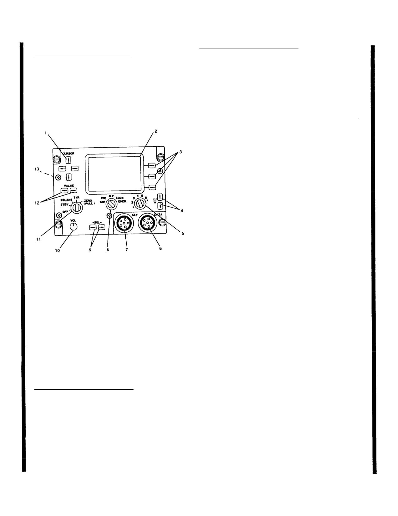
TM
55-1520-240-10
CONTROLS/
CONTROLS/
INDICATOR
FUNCTION
INDICATOR
FUNCTION
CT
Ciphertext mode. Allows
Emergency
The mode used during emer-
transmission of encrypted
Communication
gencies is determined by the
voice or data and reception
datafill. The equipment
encrypted or unencrypted
operates normally for mode
voice or data, and non-
selected. Set mode switch to
cooperative terminal rekeyin
EMER.
Press the PTT switch
RK
Remote Keying mode.
to transmit. If in ALE mode,
Permits KY-100 to perform
an ALE call is placed to the
automatic and manual rekey
selected address.
operations.
OFFLINE
Disables communications and
gives access to the system of
menus used to select mode
settings, self-test features,
filling the KY-100 with
crypto-variables.
Z ALL
Zeroize mode. Erases all
(PULL)
cryptographic data stored in
the KY - 100 except the
Emergency Back-up Key.
CIK Receptacle
Interfaces with a
Cryptographic Ignition Key
which is needed to enable all
secure voice and data
communicati
his
function is currently
disabled.
DSPL/OFF BRT
Two-function rotary switch
Figure 3-7.1.
Control/Display Panel, HF Radio Set
Control
which controls the on/off
(AN/ARC-220)
status and backlight intensit
of the LCD display.
Two-function rotary switch
PNL/OFF BRT
3-23.6. Voice Security Equipment
Control
which controls the on/off
TSEC/KY-100.
status and backlight intensit
Voice security equipment (TSEC/KY-100), when in-
for the overall front panel.
stalled, provides two-way clear or secure half-duplex
PRESET Switch
Rotary selector switch which
voice/data communication for the HF radio system
controls unit operating powe
(AN/ARC-220). Power to operate the TSEC/KY-100 is
and settings which are stored
supplied by the No. 2 DC bus through the HF KY- 100
in memory.
circuit breaker located on the No. 2 PDP.
OFF
Removes power from KY-
100.
3-23.7. Controls, Indicators, Connectors and
Function (TSEC/KY-100, Z-AVH).
MAN
Manual position which allows
(fig 3-8.1)
operating modes to be selected
using both OFFLINE and on-
CONTROLS/
line menu system.
INDICATOR
FUNCTION
Six separate preset modes
MODE Switch
Six position rotary sw1 thru 6d
which can only be set up in
to select one of the operational
modes.
the OFFLINE mode.
PT
Plaintext mode. AlloFILL Connector Used to load cryptographic
keys through the use of a
reception or transmission of
common fill device such as
unencrypted analog voice.
KYK-13/TSEC Electronic
EB
Emergency Back-up mode.
Transfer Device, KYX-
Uses the emergency back-up
15/TSEC Net Control Device,
key to encrypt voice for
AN/CYZ-10 Data Transfer
transmission or reception.
3-17.7
Change 12
TM
55-1520-240-10
CONTROLS/
INDICATOR
FUNCTION
CONTROLS/
INDICATOR
FUNCTION
Eb Annunciator Displayed when MODE
control switch is in the
Device (DTD), or the KOI-
Emergency Backup (EB)
18/TSEC General Purpose
position.
Tape Reader.
Alphanumeric
Provides prompts, messages,
Three Button
Momentary pushbutton
Display (6)
and mode indications.
Keypad
switches active in both
OFFLINE and on-line PT Annunciator Displayed when KY-100 is
Used to enter and exit
processing plaintext voice.
submenus. activate the
Key Symbol (8)
Displayed when menu system
selected mode, select fields,
is locked.
and to scroll through menus
D Annunciator (Displayed when in Data mode.
and options.
V Annunciator (Displayed when in Voice
INIT
Initiate switch. In the
mode.
OFFLINE mode it activates
the displayed menu modRatedisplay (12)3-character display indicate
provides entry into submenus.
data rate.
In on-line modes (CT, RK,
EB. PT), it selects t3-23.9.Turn-OnProcedures.
field to be changed.
When the KY-100 is turned on, tests are auto
Up Arrow (t) In the OFFLINE mode,performed to determine the equipment’s operati
Switch
used to scroll throughThe results of these tests will be presented o
from top to bottom.display. AC
Ldso, a
message will be
modes (CT, RK, EB, Pdisplayed.
is used to scroll through
available options for a.
Cold start turn-on. (Initiated if no
display field being cencryption key (TEK) is contained in the KY-
Right Arrow (+)In the OFFLINE mode, it is
(1) Turn on the KY-100 by turning the PRE
Switch
used to scroll through menus
switch to the MAN position.
from bottom to top. In the
on-line modes (CT, RK, EB,
(2) The KY-100 will initiate a self-tes
PT) it is used to select the
display reads CM STRT and then PSH INIT.
display field to be changed.
Simullan
(-Æ)
Used to exit a submenu.
(3) Connect a fill device to the KY-100
tor using a fill cable. Select the fil
Display, LCD
Back-lighted Liquid connec
ntaining the valid key and turn it on.
Display (LCD) indicaco
operational status, operator
(4) Press the INIT pushbutton (PUSH INIT)
prompts and messages
(5) The KY-100
KEY
1
01, PASS,
3-23.8. Display Annunciators/Fields
WORKING, LOCKED, READY.
(TSEC/KY-100, Z-AVH). (fig 3-8.2)
NOTE
CONTROLS/
INDICATOR
FUNCTION
If a fill device is not connected to the
when the INIT pushbutton is pressed, a dEV
TX AnnunciatorDisplayed when KY-100 is
ERR (Device Error) message will be display
transmitting.
When this occurs, the only available
RX Annunciator Displayed when KY-100 icommunication mode will be PT (Plaintext)
receiving.
If a FAIL message is displayed, notif
Wb Annunciator
Displayed when KY-100 i(6)
level of maintenance.
the Wideband (VINSON)
configuration.
(7) To load additional keys (up to a tota
Nb Annunciator
Displayed when KY-100 is in
proceed to Key Loading Section.
the Narrowband (ANDVT)
configuration.
Change
12
3-17.8
TM 55-1520-240-10
NOTE
b. Normal turn-on.
DO NOT press the INITIATE pushbutton (or
pull tape through tape reader) on fill de
(1) Set the front panel MODE control to the
OFFLINE position.
j. Press the INIT button. (When using a
tape through tape reader at a steady rate afte
(2) Rotate the DSPL and PNL switcterminal INIT,button is pressed). Upon comp
out of the OFF detent positions and asuccessful load, a
pass tone will be heard an
and panel lighting for comfortable play will momenta
KEY N,
where N is the
key location loaded.
(3) Set the PRESET switch to the MAN (manual)
position to apply power to the KY-100k. The display wil
OAD N
with N
Power-on tests will automatically beflashing. To load
additional keys, repeat s
power is applied.
through j. until all desired key locations h
loaded.
(4) Upon successful completion of the power-on
tests, the test results should appear1. Turn off and disconnect the till device
PASS
is displayed, continue with theKY-100.
procedures. However, if a FAIL message appears in the
display, notify the next lev
PUSH
m. Rotate MODE switch out of OFFLINE to
INIT
is displayed, perform the cold sLoad.procedures as
described above in paragraph a.
3-23.11. Zeroize Procedures.
3-23.10. Key Loading Procedures.
a. Zeroize ALL keys. This procedure is a
Key loading may be accomplished usinif primary
Power is removed from the KY-1
KYK-13 or a KOI-18. One Key Encryplocations within the KY-100 will be zeroize
up to six Traffic Encryption Keys (Tzeroized, only PT voice communications are
Emergency Backup (EB) key can be loauntil a new Traffic Encryption Key (TEK)
100. A Fill Cable (ON190191) is required when using
one of these devices. Proceed with the(1) Pull the MODE
switch and rotate it to
Key Loading procedures:
Z ALL position. All keys stored in locati
will be erased.
a. Place the KY-100 MODE switch in OFFLINE
position.
(2) If the KY-100 is on when this proced
perform
EROED
will be displayed, and a tone
b. If the KY-100 is not on, turn PRbe heard.ch to
MAN position.
(3) If the KY-100 power is on when the M
c. Connect a fill device to the KYswitch is rotated out of the Z ALL positi
will be displayed. Follow the COLD START
d. Push
(up arro
Æ (right arrow) buprocedures.
un
KEY OPS
is displayed.
b. Zeroize SPECIFIC key locations.
e. Push the IN
LOAD KEY
will be
displayed.
(1) Place the KY-100 MODE switch to the
OFFLINE position.
f. Push the INLOAD N
with a flashing N
will be displayed. The flashing N indic(2) If the KY-100ys not on, turn PRESET
selected key location.
to MAN position.
g. Press(up arroÆ)(right arrow) butto(3) Push(up arrow) or (right arrow) bu
until the required location (1, 2, 3,EY OPS 5,is displayed
unt
displayed.
(4) Push the INLOAD KEY
will be
h. Press the INIT button. The entdisplayed.
message will now be flashing.
(5) Push(up arroÆ)(right arrow)
i. Turn on fill device and select
button
ERO
is displayed.
3-17.9
Change
12
TM
55-1520-240-10
i. PresÆ
(right arrow) button. The Key fi
(6) Push the IN
ERO N
with a flaswill
be flashing.
N will be displayed. The flashing N indicates the
currently selected key location to bej. Pres- (up
arrow) button until the desired
location (1, 2, 3, 4, 5, or 6) is flashing
(7) Pres
- (up arroÆ)(right arrow)
button until the required location (1, 2, 3, 4(right arrow)
k. PressÆ
button. The Data Ra
is displayed.
field will be flashing.
(8) Press the INIT but
ZERO N
1. Press
(up arrow) button until the desired
message will now be flashing.
Rate (300, 600, 1.2K, or 2.4K) is flashing.
(9) Press the INIT button. The dism. After all fields have been set properly:
while the key zeroize process is beiINIT button to save the settings and return
completion of a successful key zeroiOperations.s tone
will be heard and the display will briefly indicate
ZEROED N,
where N is the key location
3-23.13. Cipher/Plain Text Level Modification.
The following procedures are used to modify
(10) To zeroize additional keys,Cipher Text Level Receive Plain Text Level,
display in
ZERO N
(with N flashing), tCT/PT or Cipher Text Only menus.
steps 7 through 9.
a. Place the KY-100 MODE switch to the CT
(11) Rotate MODE switch out of OFFLINE to exit
b. Rotate the KY-100 PRESET switch to the
Key Load.
position.
c. To modify the Receive Ciphertext Volume,
3-23.12. Online Mode Selection Menu.
This
step d, to modify the CT/PT or Ciphertext On
procedure is used to modify the Online MODE configu-
go to step i, and to modify the Receive Plai
ration.
Volume, go to step n.
a. Place the KY-100 MODE switch to the CT
position.
d. Push
(up arro
Æ (right arrow) button
unt
XCTV N
(where N represents the current re
b. Rotate the KY-100 PRESET switch to the MAN
level) is displayed.
position. If the PRESET switch is in position 1, 2, 3, 4,
5, or 6, the MODE selections cannot be modified. Refer
e. Push the INIT button. The N in RXCTV
to the section on changing PRESET settings to modify
begin to flash.
the PRESET ‘configuration.
f. Push
(up arro
Æ (right arrow) button
c. Press the INIT button. The WB (Wide Band) or
until the desired receive level is displayed
NB (Narrow Band) (which ever mode is active)
enunciator will begin flashing.
g. Push the INIT button. The N in RXCTV
NOTE
stop flashing.
The KY-100 will be operated in Narrow Band
h. Push
(up arro
Æ (right arrow) button
mode only with the ARC-220 Radio Set.
until the Operating Mode is displayed. This
the Receive Ciphertext Volume adjustment.
d. Press(up arrow) button until the desired
enunciator (WB or NB) is flashing.
i. Push
(up arro
Æ (right arrow) button
un
CT or CT ONLY
is displayed.
e. Pres
Æ (right arrow) button. The Mode field
will be flashing.
j. Push the INIT button. The CT or CT ON
begin to flash.
f. Pres- (up arrow) button until the desired Mode
setting (CT or PT) is flashing.
k. Push
(up arro
Æ (right arrow) button
until CT (Ciphertext and Plaintext operation
g. PressÆ
(right arrow) button. The Modem
LY (Ciphertext only operation) is displayed.
field will be flashing.
1. Push the INlT button. The CT or CT ON
stop flashing.
h. PressÆ(up arrow) button until the desired
Modem setting (HF, LOS, or bd) is flashing.
Change
12
3-17.10
TM
55-1520-240-10
f. Pull the MODE switch and rotate it to t
m. Push
(up arroÆ)
right arrow) bposition.
until the Operating Mode is displayed. This completes
the CT/PT or CT Only setting.
g. Follow the COLD START Procedures.
n. Push
(up arro
Æ (right arrow) butth.
If the KY-100 does not display a FAIL mes
unt
XPTV N
(where N represents the curafter self test: Return to normal operation.
level) is displayed.
i. If the KY-100 does display a FAIL message
o. Push the INIT button. The N inself test: Notify maintenance.
begin to flash.
3-23.16. Off-Line Tests.
The off line TEST menu
p. Push
(up arro
Æ (right arrow) buconsist of automatic (AUTO) tests, user-selecta
ests and software version (VERSION) c
until the desired receive level is d(USER) t
procedures.
q. Push the INIT button. The N in a. Preliminary.
stop flashing.
r. Push(up arroÆ)
right arrow) butt(1) Set the KY-100 MODE control to the OF
until the Operating Mode is displayeposition.completes
the Receive Plaintext Volume adjustment.
(2) The display
TEST
which is the
3-23.14. Standard Operation,
These procedures
first OFFLINE menu.
describe normal transmit/receive operation for cipher
text and plaintext voice messages.
(3) Press the INIT pushbutton to access the
submenus.
a. Rotate the KY-100 PRESET switch to MAN (for
manual selection) or the desir
b. For
(4) Pres
- (up arro
Æ (right arrow)
ciphertext operation: Place the MODE switch in CT.
ton until the desired sub-menu option
Ciphertext messages can now be transmipushbut
yed.
received. If the CT, CT ONLY menu USER) is displa
plaintext messages can also be received. When
raph b, c or d as applic
transmitting in ciphertext, the TX and(5) Proceed to parag
be lit. When receiving a ciphertext message, the RX and
V enunciators will be lit. When receb. Automatic (AUTO) Tests.
message, the PT enunciator will be lit.
(1) With AUTO displayed, press the INIT
t the automatic tests.
c. For plaintext operation: Place tpushbutton to star
PT. The CT, CT ONLY menu must be set for CT to
usion of the automatic test
be able to transmit or receive plaintex(2) At the concl
ed in the display.
transmitting in plaintext. the TX eresults will be present
When receiving a plaintext message, the RX and PT
(3) If the automatic tes
ASS
will
enunciators will be lit.
be displayed and a pass tone will be heard. N
y will
SER
which is the next sub-menu.
3-23.15. Troubleshooting.
Follow these procdispla
rm the USER tests, proceed to paragra
if the KY-100 displays a FAIL messagTo perfo
equipment configuration or operation.
exit. rotate the MODE control switch out of t
LINE position.
a. Rotate the KY-100 PRESET switch to the PWR
OFF position.
(4) If a failure is detected during the au
tests, a FAIL message will be displayed.
b. Place the MODE switch in the OFFLINE position.
c. User Tests.
c. Rotate the PRESET switch to MAN.
(1) WUSER
displayed, press the INIT
d. If the KY-100 does not display a FAIL message
pushbutton to start the user tests.
after self test: Return to normal operation.
e. If the KY-100 does display a FAIL message after
self test: Rotate the PRESET to the PWR OFF position.
3-17.11
Change 12
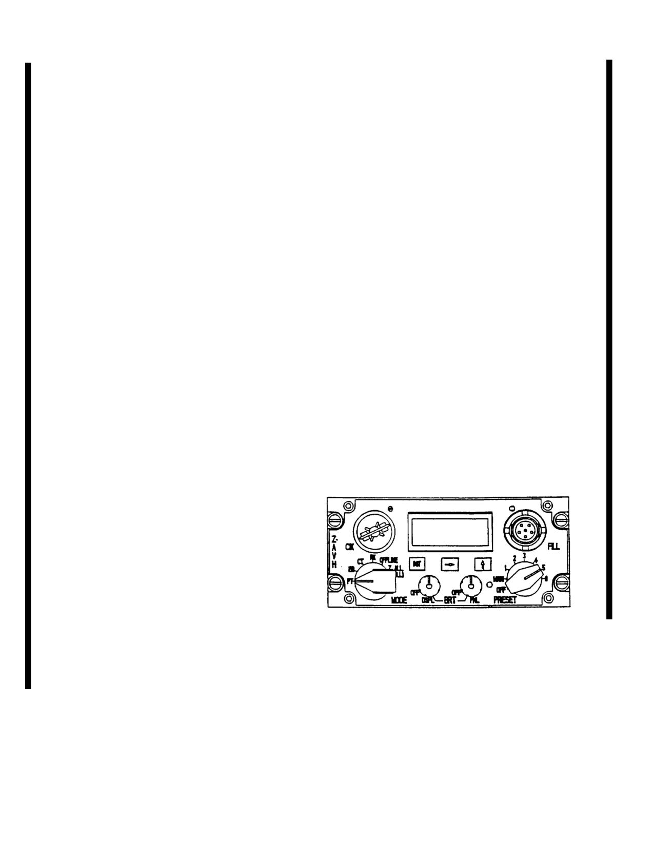
TM
55-1520-240-10
(2PT LOOP
will be momentarily display(14)oSet the MODE control switch to RK.
indicate that a plaintext loopback tdisplayed.e performed.
Next,
TT
prompt is displayed.
(15) Set the MODE control switch to OFFL
(3) Depress and hold the PTT switEbhis displayed
TALK
prompt displayed, speak into the microphone.
Looped back plaintext voice will be hea(16) Set the MODE controlRESET
receiver.
will be momentarily displayed, followed by
(4) Release the PTT switch.
(17) Set the PRESET switch to MAN. A ‘
(5
CT LOOP
will be momentarily dispdisplayed.
indicating that the KY-100 is in the cipher text loopback
mode. Ne
PTIT
operator prompt is displaye(18) Set the PRESET switch to 1. A ‘2’
displayed.
(6) Press and hold the PTT switch and, with a
TALK
prompt displayed, speak into the m(19) Set
the PRESET switch to 2. A ‘3’
until
ALK
prompt disappears (approximdisplayed.
seconds).
(20) Set the PRESET sA ‘4’ is
(7) Release the PTT
LISTEN
prompt
displayed.
is displayed. Listen to synthesized speech at the
receiver. Upon completion of the speech(21) Set the PRESET sA ‘5’ is
observe
PANEL
is displayed.
displayed.
NOTE
(22) Set the PRESET switch to 5. A ‘6’
displayed.
To exit and skip remaining USER tests, press
th
- (up arro
Æ (right arrow) pushbutton
(23) Set the PRESET switch to 6. A pass t
switch within 5 seconds.
be heard indicating that the panel test was c
successfully.
(8) Within 5 seconds after completion of the CT
loopback test, observe that all liquid crystal display
(24) Upon completion of the USER tests, t
(LCD) segments are on. At completion of the display
will sequence to
Exit the user test mode at
test a mom
INIT operator prompt is displayed
this time by rotating the MODE control switc
indicating the start of front panel switch test.
OFFLINE position.
NOTE
Failure to perform any of the panel pushbutton
and switch prompts within 30 seconds will
result in a fail tone and the display will indicate
FAIL FP
(Front Panel).
(9) Press the INIT push
A Æ (right
arrow) is displayed.
(10) PresÆ
(right arrow) pushbutton switch.
An (up arrow) is displayed.
(11) Pres(
up arrow) pushbutPT
Figure 3-8.1. Remote Control Unit TSEC/KY-100
is displayed.
(Z-AVH)
(12) Set the MODE controlT is
displayed.
(13) Set the MODE controlK
is
displayed.
Change 12
3-17.12
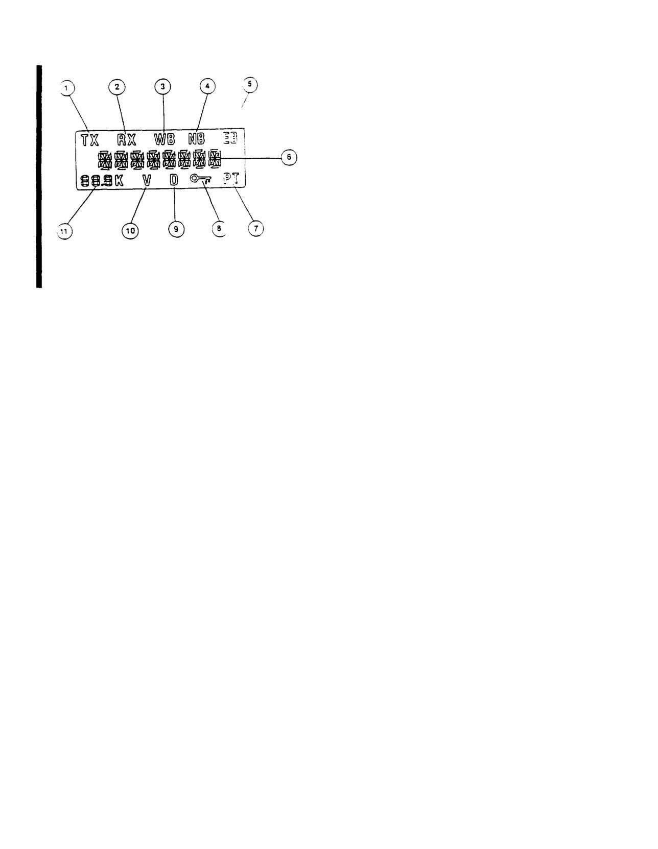
TM
55-1520-240-10
Figure 3-8.2.
LCD Display TSEC/KY-100 (Z-AVH)
3-17.13/(3-17.14 Blank)
Change 12
TM
55-1520-240-10
SECTION III NAVIGATION EQUIPMENT
3-24. VHF NAVIGATION AND INSTRUMENT
NOTE
LANDING SYSTEM (AN/ARN-123).
This test requires an external VOR R
generated by a ground station. or ramp
The VHF navigation and instrument landing system (AN/
Set the course indicator OBS contr
ARN-123) is an integrated navigation ra.eiver consisting of
315 degrees indication under the cour
a 160-channel VOR receiver, a 48-channel localizer receiver,
l unit VOR/MB switc
a
40-channel glideslope receiver, andb. Move the contro
receiver. Each receiver operates indthe test position (down).
consists of a control panel on the conc. The CDI deviation needle should
avionics shelf, and three antennas ocenter ±2 dots. The set
includes VOR and marker beacon self-tesd. The VOR/LOC flag should be burle
a. VOR/LocaRecerive,: V
OR/localizer
e.The RMI should point to the 315 d
receiver processes signals in the fradial (±5 deg
r108.00
through
117.95 MHz. The VOR/localizerf.The marker beacon lamp(s) should i
presented on the course deviation barnate.he HSI on the pilot’s
and copilot’s instrument panels. VOR bearing information is
25. Controls and Function, VHF Navigation and
displayed on the No. 2 pointer of the indicator. If the received
Instrument Landing System Set.
(fig. 3-9)
signal is weak or the set malfunctions, a red NAV flag will
appear on the indicator. The VOR/lCONTROLS/ntenna is on the
bottom of the helicopter at sta. 79INDICATOR
FUNCTION
b. Glideslope Receiver The glidNAV VOLreceiver sec-
Provides power to set whe
tion of the AN/ARN-123 processes signals in the fturned f
rom OFF Turning
range of 329.15 through 335.00 MHz. Glideslope iknob clockwise Increases
tion is displayed on the HSI. The set will also cavolume.ed GS
warning flag to appear on the indicVOR/MB TESThe rSwitch spring-loaded from
nal is unreliable or the glideslope receiver malfTEST position. At TEST,
glideslope antenna is on the forward pylon above the MKR BCN lights Illumi
shield.
nate.
Megahertz SelecLeft frequency select kno
c. Marker Beacon Receiver. The marker beacon
sets second and third dig
receiver is a fixed-frequency receiver
(75 MHz) which
of frequency in one mega-
receives signals from a ground marker beacon transmitter to
hertz steps.
determine helicopter position. The audio output of the marker
Kilohertz SelecSelects last two digits o
beacon receiver is applied through the interphone system to
quency in 50-kilohertz
the headsets as a direct input (no interphone cincrements
switch setting necessary). Three marker beacon lights are on
MB VOL
Adjusts audio output leve
each HSI MODE SELECT panel. The lights are labeled MKR
of marker beacon receiver
BCN and indicate marker beacon passage. Also. specific
Provides power to the
tones will be heard over the interphone while flyimarker beac
on when turned
beacon. Table 3-2 presents the indication as eachfrom OFF.
passed. The lights are tested by moMB SENSly pressLabeled HI
and LO LO
of three lights. The marker beacon antenna is undesensitivity
is used for p
lage forward of the forward cargo hook. Power to otive identification of ma
set is from the DC essential bus through the NAV VORbeaconit
passage HI is use
breaker on the No. 1 PDP. Power is supplied by the 2for station passage ident
instrument bus through the NAV VOR circuit breakercation.at the outer marke
enroute.
1 PDP.
Marker Beacon IThreet
lights marked O.M.
Table 3-2.
Marker Beacon Indicator
Lights
and I on both HSI MODE
SELECT panels. Lights ill
BEACON
LIGHT COLOR TONE (HERTZ)
minate when passing over
Outer (O)
Blue/Green
400
beacons.
Middle (M)
Blue/Green
1300
3-26. Normal Operation - VHF Navigation and
Inner (I) Blue/Green
3000
Instrument Landing System.
The following para-
graphs provide navigation radio set oper
a. Starting.
3-24.1 OPERATIONAL CHECK/SELF-TEST
(1) Interphone AUX switch - ON.
3-18
Change
9
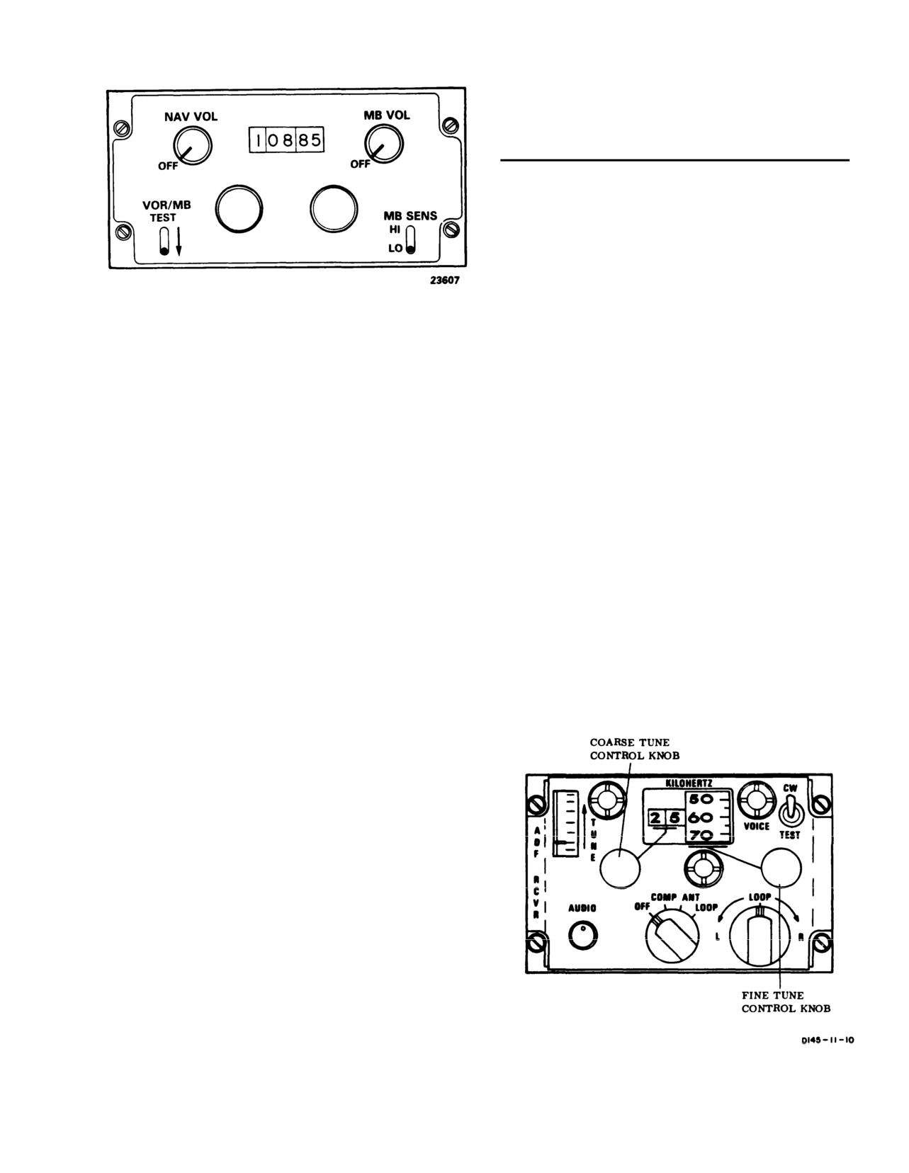
TM 55-1520-240-10
3-28. Controls and Function, Direction Finder Set
(AN/ARN-89). (fig. 3-10)
CONTROLS/
INDICATOR
FUNCTION
Mode Switch OFF
OFF position deenergizes
the direction finder set.
COMP
COMP position selects
automatic direction find-
ing.
ANT
ANT position permits re-
ception for radio naviga-
tion or as a broadcast re-
Figure 3-9. VHF Navigation and Instrument Land-
ceiver.
ing System Control (ANIARN-123)
LOOP
LOOP position, used m
conjunction with LOOP
(2) NAV VOL switch - ON.
switch, permits aural null
b. VOR/Localizer/ILS Operation.
homing and manual direc-
tion finding.
(1)
Megahertz and kilohertz selector - Set fre-
quency of facility.
AUDIO Control
Adjusts audio level in
COMP position. Used as
(2)
VOR SEL switch on HSI MODE SELECT
RF gain control in LOOP
panel - Press. Check SEL light lit.
or ANT position.
(3)
VOR ADF switch on HSI MODE SELECT
LOOP Switch
When function switch is
panel - Press, if VOR segment is not lit.
set to LOOP, LOOP
(4)
Volume control -
Adjust. Identify facility.
switch enables manual
rotation of ADF loop an-
(5) HSIs - Check for correct indications.
tenna and bearing indica-
c. Marker Beacon Operation.
tor pointer left or right
for manual direction find-
(1) MB VOL switch - ON.
ing, or when homing to a
(2) MB SENS
- HI for enroute. LO for ap-
radio station. Returning
proach.
LOOP switch to center
position stops rotation of
(3) MKR BKN lamps on HSI MODE SELECT
bearing indicator pointer
panels - Check lit at corresponding station
at any desired position.
passage.
d. Stopping
- NAV VOL and MB VOL switches -
OFF.
3-27. Direction Finder Set (AN/ARN-89).
Direction finder set (AN/ARN-89) is an airborne auto-
matic direction finder (ADF) operating within the
frequency range of 100 to 3,000 kHz. The equipment
provides visual and aural facilities for ADF homing and
position fixing. It is used as a navigational radio aid to
continuously and visually indicate the magnetic bearing
of a radio station while providing aural reception. The
bearing of a radio station is displayed on the No.
2
bearing pointer on the HSI. Power to operate the
direction-finder set is supplied by the No. 1 DC bus and
the AC instrument bus through the NAV ADF circuit
breakers on No. 1 PDP.
Figure 3-10. Direction Finder Control
3-19
TM 55-1520-240-10
CONTROLS/
d. Aural Null.
INDICATOR
FUNCTION
(1)
CW-VOICE-TEST switch - CW.
Coarse Tune Control
Tunes receiver in 100 kHz
(2)
Function switch - LOOP.
steps as indicated by first
two digits of KILO-
(3) LOOP switch
- Rotate for audio and tune
HERTZ indicator.
indicator null. Release switch. Observe bear-
ing to station on indicators. Two null posi-
Fine Tune Control
Provides selection of 10
tions, 180° apart, may be obtained.
kHz digits (continuous
tuning) as indicated by
last two digits of KILO
3-30. Gyromagnetic Compass Set (AN/ASN-43).
HERTZ indicator.
The gyromagnetic compass set (fig. 3-11) is a direction
KILOHERTZ Indicator
Displays operating fre-
sensing system which provides a visual indication of the
quency to which receiver
heading of the helicopter with respect to the earth’s
is tuned.
magnetic field or referenced to a free directional gyro.
TUNE Meter
Provides indication of rel-
Heading information is displayed on both HSIS. The
ative signal strength while
display is used in navigation to maintain flight path
tuning receiver to specific
direction. Also, any heading selected with the heading
radio signal.
bug on either HSI can be automatically maintained by
CW-VOICE-TEST Switch
Three position toggle
the AFCS. Power to operate the system is supplied by
switch. Spring loaded
the No. 1 AC bus and the AC instrument bus through
from TEST.
the NAV CMPS circuit breakers on the No. 1 PDP.
CW
Enables the beat fre-
3-31. Controls and Function, Gyromagnetic Com-
quency oscillator (BFO)
to permit tuning to con-
pass Set (AN/ASN-43). (fig. 3-11 and 3-12)
tinuous wave stations.
CONTROLS/
VOICE
Enables the set to operate
INDICATOR
FUNCTION
as an AM receiver.
LATITUDE Switch
Two-position switch on
TEST
Rotates the bearing indi-
the directional gyro lo-
cator approximately 180°
cated on the avionics
to check operation of the
shelf. This switch is used
set. The TEST switch
to correct for gyro preces-
functions when the func-
sion for the hemisphere of
tion switch is at COMP
operation: N for northern
only.
hemisphere and S for
southern hemisphere.
3-29. Normal Operation - Direction Finder Set.
The following paragraphs discuss ADF set operation.
LATITUDE Control
Rotary control on direc-
Switch
tional gyro labeled 0 to
a.
Starting.
90. It is used to set the
(1) Interphone control panel - Receivers NAV
local latitude into the di-
switch - ON.
rectional gyro for free
gyro operation.
(2) Mode switch - COMP.
SLAVED-FREE Switch
On compass control
(3) CW-VOICE-TEST - CW or VOICE.
panel. When switch is at
(4) Tune controls -
Set frequency. Tune for
SLAVED, the compass
maximum signal strength on the tuning meter.
cards on both HSIs are
slaved to the output of
(5) AUDIO control - Adjust.
the remote compass and-
b.
ADF Operation.
stabilized by the direc-
tional gyro. At FREE, the
(1) VOR ADF switch on HSI MODE SELECT
cards are referenced to
panel
- Press, if ADF segment is not lit,
the directional gyro only
(2) Check for the correct bearing indication, on
and act as turn indicators.
HSI No. 2 bearing pointer.
FREE is used primarily in
polar regions where mag-
c. Radio Receiver Operation.
netic indications may be
(1) Function switch - ANT.
unreliable.
(2) Tune control -
Set frequency; then tune for
maximum signal strength on the tuning meter.
3-20
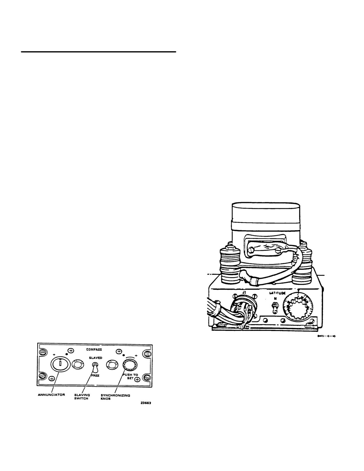
TM 55-1520-240-10
CONTROLS/
NOTE
INDICATOR
FUNCTION
If synchronizing becomes necessary in
flight with the AFCS on, position the
Annunciator
Indicates misalignment between
SWIVEL switch to UNLOCK. After
compass cards and gyro-
synchronization is complete, position the
compass when pointer is not
SWIVEL switch to LOCK This prevents
centered.
unwanted yaw axis inputs.
PUSH TO SET synchro-Rotated in (- ) or (+)
nizing knob
direction
as indicated by
annunciator pointer to align
c. Manual Synchronization. If power has been
compass cards with gyro-
applied to the system with the compass slaving switch at
compass.
FREE or if the system has been operated in the free
HDG Flag
A red flag on both HSIs
directional gyro mode for a period of time, the compass
indicates
failure
of
the
cards will not be aligned with the magnetic heading of the
gyromagnetic compass system
helicopter. The system can be reset to the correct
when displayed.
magnetic heading by pushing and turning the PUSH TO
SET knob in the direction of the symbol indicated by the
3-32.
Operating Procedures - Gyromagnetic
annunciator pointer until the pointer is centered. If the
Compass Set. (fig. 3-11)
slaving switch is then set to SLAVED. the compass
cards will maintain correct magnetic heading.
a. Slaved Gyro Operation. With compass slaving
switch at SLAVED, the system operates in the slaved
mode and the directional gyro precesses to align the
compass cards on the HSIs with the magnetic heading of
the helicopter. During the first 2 minutes after power is
applied, the system operates in a fast slave mode while
the gyro attains its speed. After this initial alignment
period is complete, the gyromagnetic compass will return
to the normal slaved mode. During this mode of
operation, the compass cards will remain aligned with
the magnetic heading of the helicopter. The annunciator
pointer will occasionally point to a dot (a ) or a plus sign
(+) indicating that corrections are automatically being
made.
b. Free Directional Gyro Operation. If the compass
slaving switch is at FREE, the system operates in the
free directional mode. In this mode, the compass cards
car be set to any heading by pressing the PUSH TO SET
knob and turning it until the cards reach the selected
setting. Normally, the free directional gyro mode is
employed only in polar regions of the earth where
magnetic references are unreliable. However, it can be
useful if the slaving system malfunctions. For proper
operation, the latitude controls on the directional gyro
(fig. 3-12) must be set to the local latitude.
Figure 3-12. Directional Gyro (CN-998/ASN-43)
Figure 3-11. Gyromagnetic Compass Set Control
Panel
Change 6 3-21
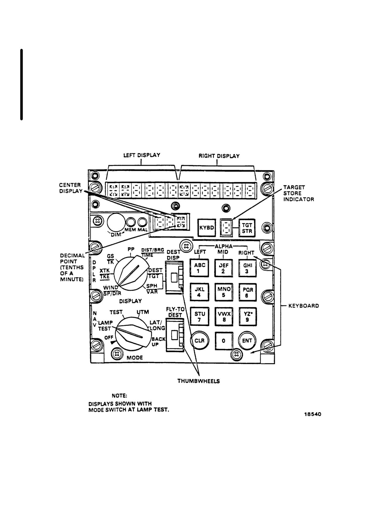
TM 55-1520-240-10
3-33.
Doppler Navigation Set (AN/ASN-128).
navigation, with position readout available in both
universal transverse mercator (grid) (UTM) and latitude
NOTE
and longitude (lat/long). Navigation and steering is done
When the Airborne Navigation Set
using lat/long coordinates, and bilateral UTM-lat/long
ANIASN-149
(Global
Positioning
conversion routine is provided for UTM operation.
System, GPS) is installed, the Doppler
NavigationSetAN/ASN-128is controlled
b. The system in conjunction with heading data
by the GPS CDU. For a description of
from the gyro compass, and pitch and roll data from the
the Airborne Navigation Set and Doppler
copilot’s attitude gyro, provides velocity, position, and
Navigation Set, refer to paragraph 3-65.
steering information from ground level to 10, 000 feet.
a. The doppler navigation set (fig 3-13) is a self-
c. The computer-display unit (CDU) is on the
contained navigation system that does not require any
canted console, between the pilot and copilot positions.
ground-based aids. The system provides worldwide
Course
Figure 3-13. Doppler Navigation Set Control (AN/ASN- 128)
3-22 Change 6
TM 55-1520-240-10
deviation, bearing, distance to destination, and NAV
CONTROLS/
GO/NO GO are also presented on the HSI. Built in test
INDICATOR
FUNCTION
equipment (BITE) continuously monitors system oper-
ation. If a failure occurs, a malfunction indicator lamp
SEL on the HSI MODE
will light and coded data, indicating the failed compo-
SELECT panel is pressed.
nent, will be displayed on the CDU when the MODE
(Right Display)
Track angle error (TKE)
switch is set to TEST. Power to operate the set is
in degrees and right or
supplied by the No. 2 DC bus through the NAV
left of present helicopter
DOPPLER circuit breaker on the No. 2 PDP, and the
heading.
No. 1 AC instrument bus through the NAV DOPPLER
GS/TK
circuit breaker on the No. 1 PDP.
(Left Display)
Ground speed (GS) in
km/hr.
3-34. Controls and Function - Doppler Naviga-
tion Set. (fig. 3-13 and table 3-3)
(Right Display)
Track angle in degrees
relative to true north.
CONTROLS/
PP with mode
INDICATOR
FUNCTION
switch set to UTM
MODE Selector
Selects doppler navigation
(Center
Present position UTM
mode of operation as fol-
Display)
zone.
lows:
(Left Display)
Present position UTM
OFF
Turns set off. Pull knob
square designator and
out to move from, or to
casting in km to nearest
this position.
10 meters.
LAMP TEST
Checks operation of all
(Right Display)
Present position UTM
lamps and lamp segments.
northing in km to nearest
TEST
Initiates (BIT) for set.
10 meters.
System reverts to backup
PP with MODE switch
navigation operation dur-
set to LAT/LONG
ing this mode.
(Left Display)
Present latitude position
UTM
Selects universal trans-
in degrees, minutes, and
verse mercator coordinate
tenths of minutes.
system for display and
(Right Display)
Present longitude position
insertion of information.
in degrees, minutes, and
LAT/LONG
Select latitude/longitude
tenths of minutes.
coordinate system for dis-
DIST/BRG/TIME
play and insertion of in-
play and insertion of in-
(Center
Time to the destination
Display)
set on FLY-TO DEST
BACKUP
Places set in remembered
thumbwheel in minutes
velocity mode of opera-
and tenths of minutes.
tion.
(Left Display)
Distance to the destina-
DISPLAY
SelectorSelects navigation data for
tion set on FLY-TO
display as follows:
DEST thumbwheel in km
WIND SP/DIR
Used only with BACKUP
and tenths of a km.
mode.
(Right Display)
Bearing to the destination
(Left Display)
Windspeed kilometer(s)
set on FLY-TO DEST
per hour.
thumbwheel in degrees.
(Right Display)
Direction (degrees) rela-
Bearing is also indicated
tive to true north.
by the No. 1 bearing
pointer on both HSIs.
XTK/TKE
DEST/TGT
(Left Display)
Distance crosstrack error
(XTK) in km and tenths
(Center
UTM zone of destination
of a km left or right of
Display)
set on DEST DISP thum-
helicopter. Track error
bwheel.
will also be displayed by
the course deviation indi
-cator (CDI) on the HSI
when DOP
Change 6 3-23
TM 55-1520-240-10
CONTROLS/
CONTROLS/
INDICATOR
FUNCTION
INDICATOR
FUNCTION
(Left Display)
UTM square designator
(present position) and Hr
and casting or latitude (N
(home).
84° to S 80° approx) of
Keyboard
Used to enter data into
destination set on DEST
system. Keys set up data
DISP thumbwheel.
on display. All resulting
SPH/VAR
actions are initiated upon
release of the key.
(Left Display)
Spheroid code of destina-
tion set on DEST DISP
FLY-TO-DEST Thumb-
Selects destination to
thumbwheel.
wheel Switch
which steering informa-
(Right Display)
Magnetic variation (in
tion is desired. Destina-
degrees and tenths of de-
tions are 0 through 9, P
(present position) and H
grees) of destination set
(home).
on DEST DISP thumb-
wheel.
ENT Key
Enters data set upon key-
MAL Indicator Lamp
Lights when set malfunc-
board into memory when
tions. In case of an inter-
pressed.
mittent malfunction, sys-
CLR Key
Clears last entered char-
tem may operate
acter when pressed once.
correctly, but must be cy-
Clears entire display panel
cled to OFF and then to
under keyboard control
on to put MAL light off.
when pressed twice.
MEM Indicator Lamp
Lights when radar portion
of set is not tracking. May
3-35. Display and Keyboard Operation.
occur over smooth water.
In LAT/LONG coordinates, the two fields of control
DIM Control
Controls light intensity of
are the left and right displays. In UTM coordinates, the
display characters.
first field of control is the center display and the second
Left, Right, and Center
Alphanumeric and nu-
field is the combination of the left and right displays.
Display Lamp
meric characters that dis-
When pressing the KYBD pushbutton, one or other of
play data as determined
the fields described above is under control. If it is not
by setting of DISPLAY
desired to change the information in the field under
control, the pilot can advance to the next field of the
switch, mode switch, and
keyboard.
display panel by pressing the KYBD pushbutton again.
Target Storage Indicator
Displays destination num-
3-36. Data Entry.
ber (memory location) in
which present position
To enter a number, press the corresponding key. To
will be stored when TGT
enter a letter, first press the key corresponding to the
STR pushbutton is
desired letter. Then press a key in the LEFT, MID, or
pressed.
RIGHT column corresponding to the position of the
TGT STR Pushbutton
Stores present position
letter on the pushbutton.
data when pressed.
Example: To enter an L, first press L, then either 3, 6,
KYBD Pushbutton
Used in conjunction with
or 9 in the RIGHT column. The computer program is
keyboard to allow data
designed to reject unacceptable data (for example, a
entry. KYBD pushbutton
UTM area of WI does not exist, and will be rejected). If
is always lighted when
the operator attempts to insert unacceptable data, the
system is on.
display will be blank after ENT is pressed.
DEST DISP Thumbwheel
Destination display thum-
3-37. Starting Procedure.
Switch
bwheel switch is used
along with DEST/TGT
a. MODE selector
- LAMP TEST. All lights and
and SPH/VAR positions
lamp segments should be lit.
of DISPLAY switch to
select destination whose
(1) Left, right, center and target storage indica-
coordinates or magnetic
tor - Lit (fig. 3-13). All other lights should be on,
variation to be displayed
(2) Turn DIM control fully clockwise, then fully
or entered. Destinations
counterclockwise, and return to full clockwise; all seg-
are 0 through 9, P
ments of the display should alternately glow brightly, go
off, and then glow brightly.
3-24
TM 55-1520-240-10
Table 3-3. Computer-Display Unit Data displays
CENTER DISPLAY
LEFT DISPLAY
RIGHT DISPIAY
RANGE
DATA
RANGE
DATA
RANGE
SWITCH POSITION
DATA
WIND SP/DIR
Windspeed
999 km/h
Wind Direction
359°
XTK/TKE
Crosstrack Dis-
L/R 999.9 km
Track Angle
R/L 180°
tance Error
Error
GS/TK
Groundspeed
999 km/h
Track
359°
PP UTM
UTM Zone
Note 2
Area/Easting
WV9999
Northing
9999
LAT/LONG
Latitude
N84°00.0"
Longitude
E/W 180°00.0”
S 80°00.0"
DIST/BRG/TIME
Time
99.9 Min.
Distance to Go
999.9 km
Bearing
359°
DEST/TGT UTM
UTM Zone
Note 2
Area/Easting
WV9999
Northing
9999
Note 3
LAT/LONG
Latitude
N 84°00.0"
Longitude
E/W 180°00.0"
S 80°00.0"
SPH/VAR
Spheroid
Note 1
Variation
E/w 180°
Note 4
NOTES
1. See table 3-4 for spheroid data codes and covered areas.
2. Numeric 01-60.
Alpha: C-X, except I and O.
3. Typical 100 km Designaton
Column Designation A-Z, except I and O.
Row Designator A-V, except I and O.
4. Variation displayed is for destination indicated by DEST DISP thumbwheel.
b. MODE selector -
TEST. After about 15 seconds,
DISPLAY
left display should display GO. Ignore the random
LEFT
RIGHT
REMARKS
display of alpha and numeric characters which occurs
GO
P
If right display is P, then
during the first 15 seconds. Also ignore test velocity and
angle data displayed after the display has frozen. After
pitch or roll data is missing or
in error. In this case, pitch
about 15 seconds, one of the following five displays will
be observed in the first two character positions in the
and roll in the computer are
left display.
both set to zero and naviga-
tion is degraded. Problem
NOTE
may be in the vertical gyro-
If the MAL lamp lights during any mode of
scope or helicopter wiring.
operation
except LAMP TEST, the
BU
C, R, S,
A failure has occurred and
computer-display unit MODE switch should
or H fol-
the system has automatically
be set to OFF, and then to TEST, to verify
lowed by
switched to a BACKUP mode
the failure. If the MAL lamp remains on at
a numeric
of operation using last re-
TEST, notify maintenance.
code
membered velocities for navi-
If the TEST mode display is MN or NG, the
gation. The operator can, as
MODE switch should be recycled through
an option, enter his best esti-
OFF to verify that the failure is not a mo-
mate of ground speed and
mentary one. If the TEST mode display is
track angle.
MN, the data entry may be made in the
MN
C, R, S,
A failure has occurred and
UTM or LAT/LONG mode, but any naviga-
or H fol-
the BACKUP mode used for
tion must be carried on with the system in
the BACKUP mode.
lowed by
manual navigation (MN) is
a numeric
the only means of valid navi-
DISPLAY
code
gation. The operator may use
the computer as a dead reck-
LEFT
RIGHT
REMARKS
oning device by entering
GO
Display
System is operating satisfacto-
ground speed and track data.
blanks
rily.
3-25
TM 55-1520-240-10
DISPLAY
b. DISPLAY selector - SPH-VAR.
LEFT
RIGHT
REMARKS
c. DEST DISP thumbwheel - P, numeral, or H as
desired.
The operator should update
present position as soon as
d. KYBD pushbutton
- Press. Observe display
possible, because it is possible
freezes and TGT STR indicator blanks. Press KYBD
significant navigation errors
pushbutton again and observe left display blanks. If no
spheroid data is to be entered, KYBD pushbutton-
may have accumulated.
- Press again, go to step g.
NG
C, R, S,
A failure has occurred in the
e. Spheroid data (table 3-4) - Entry. (Example: INO).
or H fol-
system and the operator
Press keys 3, 3, 5, 5 and 0. Left display should indicate
lowed by
should not use the system.
INO.
a numeric
code
f. ENT key -
Press if no variation data are to be
entered.
EN
The 9V battery has failed.
The system will still operate
g. KYBD pushbutton
- Press, if variation data is to
but all stored data will be lost
be entered, and note right display blanks.
when set is turned off. Data
h. Variation data -
Enter. (Example: E001.2, press
must be recentered.
keyboard keys 2, 2, 0, 0, 1 and 2. Press ENT key. the
Random Random
A failure occurred and the
entire display will blank and TGT STR number will
reappear, display should indicate INO E001.2.)
display
display
operator should not use the
system.
If operation is to occur in a region with
relatively constant variation, the operator
3-38. Entering Data.
enters variation only for present position,
This initial data is inserted before navigating with the
and the computer will use this value through-
doppler.
out the flight.
a. Spheroid of operation, when using UTM coordi-
Table 3-4. Spheroid Data Codes
nates.
b. UTM or LAT/LONG coordinates of present posi-
SPHEROID
CODE
AREA COVERED
tion.
CLARKE
1866
United States north
c. Magnetic Variation (MAG VAR) of present posi-
tion.
through North Pole
CLARKE
1880
Africa west through
d. Coordinates of desired destination -
0 through 5
Algeria
and H: (6 through 9 are normally used for target store
INTERNATIONAL
IN
All of Europe, Saudi
locations; but may also be used for destinations.) It is
not necessary to enter all destinations in the same
Arabia, Greenland,
coordinate system.
South America, In-
dian Ocean, Pacific
NOTE
Ocean, and Atlantic
It is not necessary to enter destinations
Ocean
unless steering information is required, un-
BESSEL
BE
Indonesia, Manchu-
less it is desired to update present position
ria, to Eastern Rus-
by overflying a destination, or unless a
sia
present position MAG VAR computation is
EVEREST
EV
Mt. Everest, India,
desired. If a present position MAG VAR
and Pakistan
running update is desired, destination MAG
AUSTRALIAN
AU
Australia
VAR must be entered. The operator may
NATIONAL
enter one or more destination variations to
effect the variation update; it is not neces-
sary for all destinations to have associated
MAG VAR entered.
3-40. Entering Present Position or Destination in
UTM.
e. Variations of destinations.
The variation of a destination must be entered after the
associated destination coordinates are entered, since
3-39. Entering Spheroid and/or Variation.
each time a destination is entered its associated varia-
a. MODE
selector
- UTM, LAT/LONG or
tion is deleted. The order of entry for present position is
BACKUP.
irrelevant.
3-26