TECHNICAL MANUAL MAINTENANCE MANUAL FOR ARMY CH-47D HELICOPTER (1992) - page 4
TM 55-1520-240-10
CONTROLS/
INDICATOR
FUNCTION
CAUTION
RAD ALT dimming
On right side of both in
When operating over dense foliage, the radar
controls
strument panels.
altimeters will indicate the altitude to the tops of
Controls light intensity
the trees. When operating over sparse foliage,
of digital display and HI
the altimeters may indicate the altitude between
and LO caution light.
the ground and about half the average tree
height, depending on ground speed. When
2-200. Normal Operation - Radar Altimeter (AN/APN-
external cargo is carried, the radar altimeter may
209A).
occasionally indicate the distance between the
bottom of the helicopter and the load.
a. Starting.
(1) Set RAD ALT dimming control to desired
(1) Rotate the LO SET knob on the pilot’s
digital display light level.
altimeter until the LO index is at 100 feet. Rotate the HI
set knob until the HI index is at 800 feet. Allow 1 minute
(2) Set HI and LO indexes as desired. If HI or
for warmup.
LO indexes are not desired, set the LO index at 0 feet or the
HI index above 1, 500 feet.
(2) Check for the following indications:
2-200.1. RADAR ALTIMETEIR AN/APN-209( )) Altitude
(a) The pointers indicate between 0 and 2 feet.
Voice Warning System (AVWS). (If Installed by
(b) The digital displays indicate between 0 and 2
MWO 1-1520-240-50-61)
feet.
(c) LO caution light is on.
The RT-I 115F/APN-209 Altitude Voice Warning System
(d) HI caution light is off.
(AVWS) consists of a panel mounted receiver-
(e) OFF flag not in view.
transmitter/height indicator (RT-1115F/APN-209) and two
flush-mounted antennas.
When installed, the height
b. Testing.
indicator is mounted in the pilot instrument panel.
(1) Press and hold the PUSH-TO-TEST knob.
Check for the following indications:
The face of the altitude voice warning radar altimeter (RT-11
15F/APN-209) is exactly the same as that of the visual only
(a) OFF flags not in view.
AN/APN-209A radar altimeter, with the operation being the
(b) Pointers indicate between 900 feet and
same as outlined in section 2-198. The difference is only
1,100 feet.
internal. A transmitter added internally sends out an aural
(c) Digital displays read between 900 feet
warning to the pilot, copilot, and flight engineer interphone
and 1,100 feet.
station ICS panels when the helicopter descends below the
(d) LO caution light is off.
low index setting or rises above the high index setting (in
(e) HI caution light is on.
addition to the LO or HI caution lights).
(2) Release the PUSH-TO-TEST knob. Check
NOTE
that all indications return to those specified in step a.(2).
The voice portion of the system works off a 10
second clock. If a transition is made thru either
NOTE
Preset, back to the original warning condition within
The LO caution light may appear to go out.
this time frame, the voice warning will stay at its
However, the light will be visible with night vision
original volume level.
goggles. In bright daylight, it may be necessary
to shade the indicator to verify operation of the
The volume of the aural warning message can be adjusted
dimming control.
by the flight crew. On initial transition the volume is always
set to Full. By momentarily pressing the PUSH-TO-TEST
(3) Rotate the RAD ALT dimming control from
(PTT) knob once, the message is decreased to 1/2 the
BRT to DIM. Check that the digital display dims and
volume. Momentarily pressing the PTT knob a second time
goes out. Check that the LO caution light dims but does
disables the aural warning message. Regardless of the
not go out completely.
volume level, when the aircraft transitions back through
either Preset (HI or LO) (from caution light Off to On), the
(4) Repeat on copilot’s instrument.
volume level of the aural warning message will return to Full.
c. Inflight operation.
Change 6 2-75
TM 55-1520-240-10
2-200.2. Controls and Function, Radar Altimeter
(1) Rotate the LO SET knob on the pilot’s altimeter
(AN/APN-209()) (AVWS).
until the LO index is at 100 feet. Rotate the HI set knob
until the HI index is at 800 feet. Allow 1 minute for
CONTROLS/
warmup.
INDICATOR
FUNCTION
(2) Check for the following indications:
LO SET knob
The LO SET knob applies
(a) The pointers indicate between 0 and 2 feet.
power to altimeter system. LO
(b) The digital displays indicate between 0 and 2
set index on both pilot’s
feet.
altimeters
can
be
set
(c) LO caution light is on.
independently. Both LO set
(d) Low altitude warning (“ALTITUDE LOW, TOO
indexes must be masked to
LOW") is heard in the headset.
turn the set off.
(e) HI caution light is off.
(f) OFF flag not in view.
HI SET knob
Sets position of HI set index
b. Testing.
when turned.
Adjusts the
NOTE
warning message volume level
Connect monitor headset to the aircraft ICS.
and tests altimeter system
when pressed.
(1) On the AN/APN-209( ) indicator, rotate the
and tests altimeter system whenLOSET knob to a point
LO set index
Indicates altitude trip point for
just above the OFF detent. Adjust HI SET knob to
LO caution light.
position the HI index to 100 feet. Allow 1 minute for
warmup. Verify the following:
HI set index
Indicates altitude trip point for
HI caution light
(a) The indicator pointer reads 0 to 2 feet.
(b) The digital display reads 0 to 2 feet.
Indicator pointer
Indicates absolute altitude from
(c) LO caution light is off.
0 to 1, 500 feet.
(2) Verify low altitude warning ("ALTITUDE LOW,
TOO LOW”) is NOT heard in the headset.
Digital indicator
Provides direct reading four
(3)
Adjust LO index to approximately 10 feet
digit indication of absolute
position on indicator. Verify the following:
altitude from 0 to 1,500 feet.
(a) The LO warning lamp is illuminated.
(b) The low altitude warning, “ALTITUDE
LO caution light
Comes on when helicopter
LOW, TOO LOW" is heard, clear and distinctly, in
descends below altitude on LO
headset and at FULL volume. Audio warning repeat
set index.
interval is 10 (+1) seconds. Momentarily press the
PUSH- TO-TEST knob once and verify the message is
HI caution light
Light
comes
on
when
at ½ volume. Momentarily press the PUSH-TO-TEST a
helicopter rises above altitude
second time and verify the warning message is OFF.
on HI set index.
(c) Reset the LO index to a point just above
the OFF detent. Check that system is still functional and
OFF flag
Flag is displayed when power
LO warning lamp is extinguished. Wait 11 seconds
is removed from set, when
before proceeding to the next step.
indications are unreliable,
or
(4) Readjust the LO index to approximately 10 feet
when
altitude
exceeds
position on indicator.
The LO warning lamp is
approximately 1,500 feet.
illuminated and the low altitude warning, “ALTITUDE
LOW, TOO LOW”, is audible at FULL volume.
RAD ALT dimming
On right side of both controls
(5) Press and hold the PUSH-TO-TEST knob to
instrument panels. Controls
actuate the PUSH-TO-TEST condition. Verify the
light intensity of digital display
following:
and HI and LO caution light.
(a) OFF flags not in view.
(b) Pointers indicate between 900 feet and
2-200.3 Normal Operation - Radar Altimeter
1,100 feet.
(AN/APN-209()) (AVWS).
(c) Digital displays read between 900 feet and
a. Starting.
1,100 feet.
NOTE
(d) LO caution light is off.
Connect monitor headset to the aircraft ICS.
2-76 Change 6
TM 55-1520-240-10
(e) HI caution light is o2-201. VERTICAL SPEED Indicator.
(f) The high altitude warTwo VERTICAL SPEED indicators are
HIGH, CHECK ALTITUDE’, is audiblpanel (fig. 2-They
dindicate the ra
10 second intervals throughout tbased on
the rate of changeThe atm
indicator is a direct-reading pres
(6) Release the PUSH-TO-TEST knob. Check that
no electrical power for operation
all indications return to those specified in step b.(4).
2-202. Attitude Indicator.
NOTE
Two attitude indicators are on the
The LO caution light may app8 and 2-10). The attitude indicato
However, the light will be vtailored for the flight characteri
vision goggles. In bright dainclusion of an electrical trim ca
necessary to shade the indicaaddition to the stNormal flight at
tion of the dimming control.
of helicopters, defined by fixed a
pitch, are easily trimmed unto thi
(7) Rotate the RAD ALT dimming control from
operation of the helicopter in an
BRT to DIM. Check that the digital display dims and
facilitated. Degrees of pitch and
goes out. Check that the LO caution light dims but does
movement of a universally mounted
not go out completely.
black and light gray to symbolize
ng the two
(8) Set gain controls on thhorizon line separati
elation to
flight engineer interphone statiminiature aircraft in r
ose upoand
the minimum (counter-clockwise)The pitch adjustmento n
(3) thru
Verify that the voice nose down. To compensate attitude
o
discernable in the headset at auppereknThe r
minimum in either direction.
c. Inflight operation.
NOTE
CAUTION
Rapid rotation of the pitch and
When operating over dense foliage, the radar
the attitude indicator may caus
altimeters will indicate the altitude to the tops
roll attitude changes with AFCS
of the trees. When operating over sparse
The indicator incorporates integra
foliage, the altimeters may indicate the altitude
copilot attitude indicators shoul
between the ground and about half the average
seconds after electrical
ower to
tree height, depending on ground sped.
operate the attitude indicator gym
When extend cargo is carried, the radar
1 and No. 2 AC bus through the N
altimeter may occasionally indicate the dis-
NAV COPLT VGI circuit breakers on
tance between the bottom of the helicopter and
2 PDP.
the load
ndicator (VGI)
(1) Set RAD ALT dimming co2-203. Pilot and Copilot Attitude I
digital display light level.
switch.
the instrumen
(2) Set HI and LO indexes A VGI switch is on
2-8 and
helicopter exceeds one of theseattitude indicator (fig.
en the s
message will be heard at full labeled NORM and EMER. Wh
volume level can be decreased by one-half
(1/2) by
pressing the PUSH-TO-TEST once or inhibited by press-
ing PUSH-TO-TEST a
If HI or LO indexes
are not desired. set the LO index at O feet or the HI index
above 1,500 feet.
Change
9
2-76.1
TM 55-1520-240-10
NORM, each attitude indicator opa. SELECT Button. I
t allows the select
rate gyro. If either the pilot three modes on the four-di
git display:
signaled by the OFF flag on thtime), or ET (elapse
d time). The six-di
switching to the remaining gyroGMT only.mplished by
placing the respective VGI switch to EMER. The
n. It is used to set
switching of the gyros from NORMb. CONTROL Burto
is accomplished by a gyro transfselected.onatheefour-digit display. Wh
gyro will also result in failureTROLtandaSELECT buttons are pressed
Power is supplied by the No.
2neously,ttheufour-digit display is cha
NAV CONT VGI circuit breaker onnormal.
to2 PDP.time set mode, and the
button is functional.
2-204. Turn and Slip Indicator (4-Minute Type).
C. DIM Control Switch. It is used to
Each turn and slip indicator (intensity of
the display. At low light
controlled by an electrically acdisplay is NVG compatible.
ment has a pointer (turn indicator) and a ball (slip
Integral alkaline batteries maintain
indicator). Power to operate the gyros is supplied by the
when no aircraft power is applied, but
DC essential bus through the NAV TURN & SLIP
and SELECT buttons arc disabled. Power
circuit breakers on the No.
1 and No.
2 PDP.
the chronometers is supplied by the DC
through the CPLT CLOCK and PLT CLOCK o
2-205. Magnetic Compass.
No. 1 PDP and No. 2 PDP.
The magnetic compass is mounted on top of the center
instrument panel glareshield (fi2-208.
No2-Operation - CHRONOMETER.
reading instrument requiring no electrical power. It
2-209. Setting GMT.
the SELECT button un
consists of a compass card mounted on a maPressc
GMT is selected. Simultaneously press
element in a liquid-filled bowl.
LECT and CONTROL buttons to enter the
2-206. Free Air Temperature Gauge.
The tens of hours digit will start fl
CONTROL button has full control of the
The free air temperature gauge is on the exterior of the
Each time the CONTROL button is pressed
pilot’s eyebrow window (fig.
2-4). The unit is calibrated
ing digit will increment. Once the tent
in degreesofto
o+50
pressing the SELECT button will select t
be set. After the last digit has been s
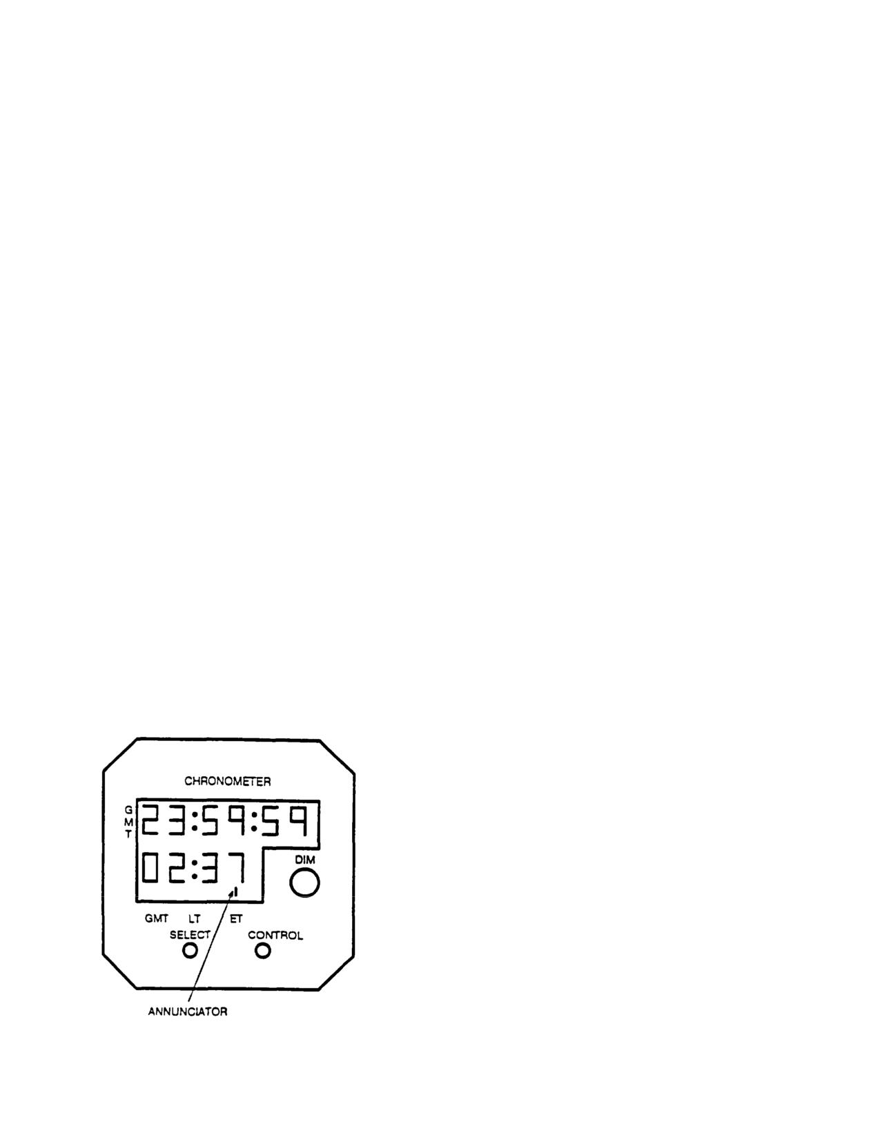
2-207. CHRONOMETER.
the CONTROL button, press the SELECT
Two digital clocks labeled CHROexit the set mode. The annunciator wi
cated on the copilot and pilotnormalmflashinglcondition to indicate
2-50). Each clock has a six-digiclock is running.mean
time) display and a four-digit selectable display. A test
mode is provided to check system2-210.ASettingaLT.hingPressunthe
SELECT button un
ator identifies which clock modLT is selected. Simultaneously press bo
There are three controls on eaand CONTROL buttons
to enter the set mo
button, a CONTROL button, and aof hours digit will start flashing and
button has full control of the flashin
same sequence as for setting GMT with
that the minutes are already synchron
GMT clock and can not be set when in L
2-211. Setting ET.
The elapsed time allows for
up or count down modes.
a. Count Up. Press the SELECT button
selected. Press the CONTROL button to s
sequence. The clock will count up to
5
seconds and then changes to hours and
m
count up to
99 hours and
59 minutes.
CONTROL button again resets the ET to
b. Count
Press the SELECT button unti
is selected. Simultaneously press both
CONTROL buttons to enter the set mode
down from any time, not to exceed
59 m
seconds, can be set using the same se
setting GMT. Once the last digit is s
SELECT button exits the set mode and
Figure
2-50. Chronometer
ready to start count down. Pressing t
2-76.2 Change
6
TM 55-1520-240-10
button will start count down sequence. When the clock
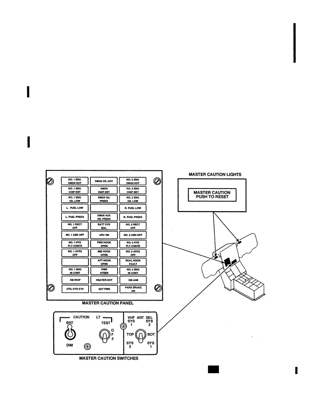
2-5 1.1). Each capsule is labeled with word segments which
reaches zero, an alarm becomes active by flashing the
are related to the fault or condition. When a caution capsule
numbers and the ET counter will begin to count up. To reset
illuminates, the word segments lettered into the panel are of
the alarm press either the SELECT or CONTROL button.
an amber color. When they extinguish, the lettering is not
readable. Tables 2-2 and 2-2.1 contain lists of the word
2-212. Test Mode.
To activate the test mode, press and
segments displayed on the capsules and their actual mean-
hold the SELECT button for three seconds and all numerical
ing and cause.
displays will show an 8 and all annunciators will be active.
An NVG filter is provided for use during NVG operations.
2-213. Master Caution System.
The filter fits over the master caution panel and is secured
in place by hook and pile tape at its base. When the filter is
The master caution system provides the pilots with a visual
in this position, any light coming from the caution lights
indication of helicopter conditions or faults (fig. 2-51 and
will be NVG compatible. For normal operations, the filter is
2-51.1). The components of the systems are the master
rotated from its base to a horizontal position, and stowed in
caution panel with NVG filter, two MASTER CAUTION
a compartment above the master caution panel.
lights with NVG filters, and a CAUTION LT panel with a
TEST and a BRT-DIM switch. Power to operate and control
2-215. MASTER CAUTION Lights. T
WO
MASTER
the master caution system is supplied by the DC essential
CAUTION lights on the instrument panels indicate that one
bus through the LIGHTING CAUTION PNL circuit breaker
or more of the caution capsules have illuminated. On the
on the No. 1 PDP.
pilot instrument panel, the caution light is above the
airspeed indicator. On the copilot instrument panel, it is
2-214. Master Caution Panel.
The master caution
above the altimeter.
panel is on the center instrument panel (fig. 2-51 and
A66987
Figure 2-51.
Master Caution System
712
Change 13
2-76.3/(2-76.4 blank)
TM 55-1520-240-10
Table 2-2.
Master Caution Panel Capsules
712
WORD SEGMENT
EXPLANATION
XMSN OIL HOT
Transmission oil temperature is more than 140°C.
XMSN OIL PRESS
Transmission main oil pressure is less than 20 psi, or less than 10 psi in the aft rotor shaft.
XMSN AUX OIL PRESS
Less than 20 psi auxiliary oil pressure in the forward, or aft transmission or less than 10 psi in the combining transmis-
sion.
NO. 1 ENG OIL LOW
Approximately 2 qt of usable oil is remaining in No. 1 engine oil tank.
NO. 2 ENG OIL LOW
Approximately 2 qt of usable oil is remaining in No. 2 engine oil tank.
L FUEL PRESS
Left fuel pressure is below 10 psi.
R FUEL PRESS
Right fuel pressure is below 10 psi.
PWR STEER
Steering control has been disabled due to system malfunction or steering limits have been exceeded.
NO. 1 HYD FLT CONTR
No. 1 flight control hydraulic system pressure is below 1,800 psi.
NO. 2 HYD FLT CONTR
No. 2 flight control hydraulic system pressure is below 1,800 psi.
UTIL HYD SYS
Utility hydraulic system pressure is below 1,800 psi.
PARK BRAKE ON
Parking brake is on.
NO. 1 RECT OFF
Transformer-rectifier has failed or the generator output is interrupted.
NO. 2 RECT OFF
Transformer-rectifier has failed or the generator output is interrupted.
NO. 1 GEN OFF
No. 1 generator is inoperative or the generator switch is at OFF.
NO. 2 GEN OFF
No. 2 generator is inoperative or the generator switch is at OFF.
BATT SYS MAL
Battery or battery charging system has failed or the battery has exceeded the safe operating temperature.
EXT PWR
This light comes on whenever external power is connected to the bus.
L FUEL LOW
Left main fuel tank has approximately 20 percent of fuel remaining.
R FUEL LOW
Right main fuel tank has approximately 20 percent of fuel remaining.
HEATER HOT
Temperature within heater is greater than 177°C.
MID HOOK OPEN
The midcargo hook has been opened, either hydraulically, pneumatically, or manually.
APU ON
The APU is up to speed and can be used.
DUAL HOOK FAULT
The forward and/or aft hook circuit has an electrical fault and the hook(s) shall not be released electrically.
FWD HOOK OPEN
The forward cargo hook has been opened either electrically or manually.
AFT HOOK OPEN
The aft cargo hook has been opened either electrically or manually.
NO. 1 AFCS OFF
The No. 1 AFCS is off, failed, or DASH is reprogramming.
NO. 2 AFCS OFF
The No. 2 AFCS is off, failed, or DASH is reprogramming.
NO. 1 ENG CHIP DET
Metal chips in No. 1 engine or engine transmission oil.
NO. 2 ENG CHIP DET
Metal chips in No. 2 engine or engine transmission oil.
XMSN CHIP DET
Metal chips in the oil of the forward, combining, or aft transmissions or the aft thrust bearing.
NO. 1 ENG N1 CONT
No. 1 engine N1 component has failed or the engine condition lever or N1 actuator is not in the STOP, GND, or FLT
position.
NO. 2 ENG N1 CONT
No. 2 engine N1 component has failed or engine condition lever or N1 actuator is not in the STOP, GND, or FLT posi-
tion.
NO. 1 ENG XMSN HOT
No. 1 engine transmission oil temperature is above about 190°C.
NO. 2 ENG XMSN HOT
No. 2 engine transmission oil temperature is above about 190°C.
CM INOP
Countermeasures set has failed.
CM JAM
Countermeasures set has detected interference from other countermeasures sets or system is being jammed.
Movable NVG filters are attached to the instrument panels
Once the malfunction is corrected, the affected caution
to the left of each light. For NVG operations, the filters can
capsule will extinguish. The HEATER HOT capsule is an
be rotated over the two MASTER CAUTION lights making
exception (Refer to Section X). If either generator is cycled
the lights NVG compatible. After the MASTER CAUTION
OFF then ON while another caution capsule is lit, the
light has illuminated and the condition noted, the pilots
MASTER CAUTION light may remain illuminated after
should extinguish the MASTER CAUTION light by press-
the generator comes back on and the associated GEN OFF
ing (PUSH TO RESET) the face of the light. The MASTER
capsule extinguishes. If this occurs, press to extinguish the
CAUTION light is then ready to indicate a subsequent
MASTER CAUTION light.
malfunction of a different system.
Change 13
2-77
TM 55-1520-240-10
A73387
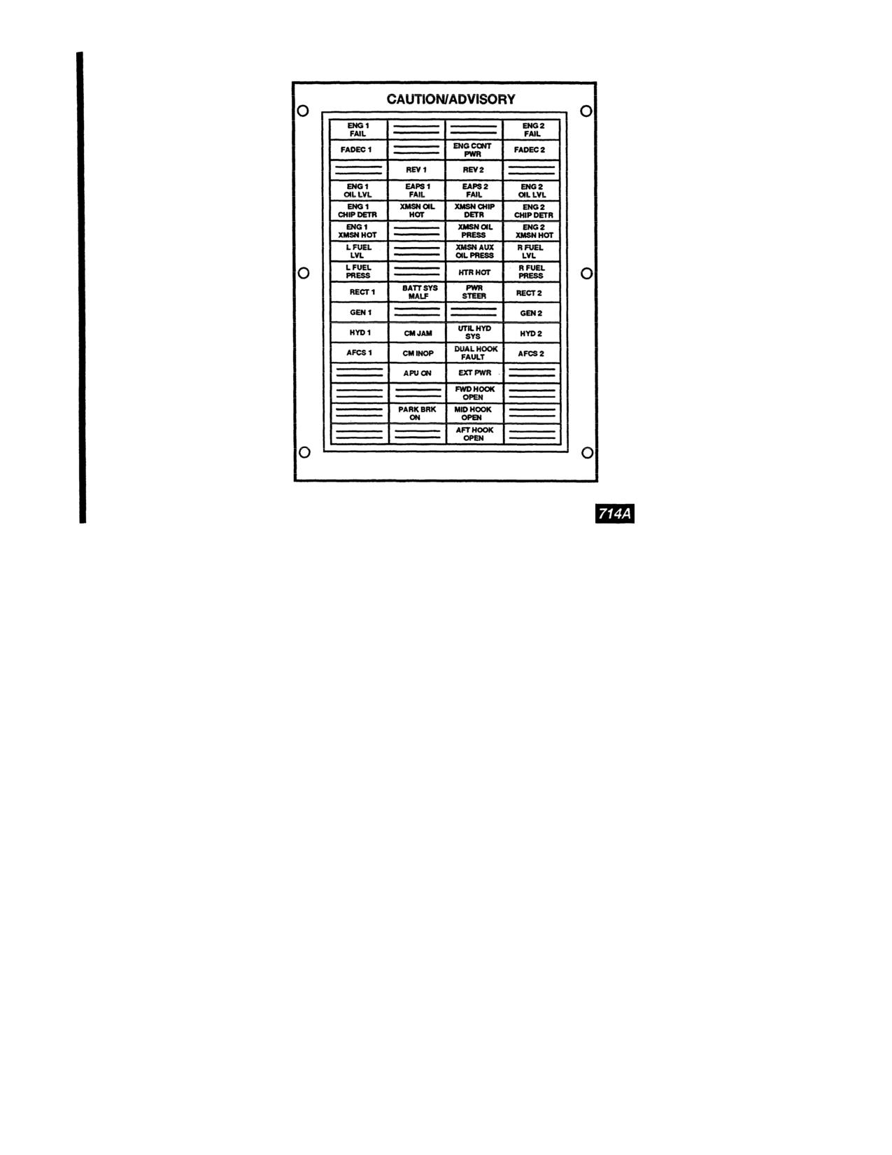
Figure 2-51.1.
Master Caution/Advisory Panel
2-216. CAUTION LT Panel.
The CAUTION LT (cau-
b. TEST Switch.
When the switch is placed to TEST, all
tion light) panel is located on the center instrument panel
the caution capsules on the master caution panel and the two
(fig. 2-51). It comprises of a. BRT-DIM switch and a TEST
MASTER CAUTION lights illuminate to facilitate check-
switch.
ing the individual capsule lamps. When released to OFF, the
lamps in the MASTER CAUTION lights and all the caution
a. BRT-DIM Switch.
When the switch is placed to BRT,
the caution capsule will light to full intensity. When moved
capsules extinguish. When the PLT INST and CPLT INST
to DIM, the caution capsules will not be as bright. When the
lights rotary control switches are active, and the VHF NAV
cockpit dome lights are on white, it is not possible to dim
and marker beacon VOL switches are on, the test feature
the master caution panel. If the white dome light is selected
will also light all the select legends on the MODE SELECT
while the caution lights are operating on DIM, the caution
panel and the MKR BCN indicator lights.
lights will automatically switch to BRT mode of operation.
2-78
Change 13
TM 55-1520-240-10
Table 2-2.1.
Master Caution/Advisory Panel Capsules
WORD SEGMENT
EXPLANATION
ENG 1 FAIL
Power turbine shaft failure, Nl underspeed, or flameout. During engine start this caution is illuminated if the engine
fails to start.
ENG 2 FAIL
Power turbine shaft failure, N1 underspeed, or flameout. During engine start this caution is illuminated if the engine
fails to start.
FADEC 1
No. 1 PRI system hard fails.
ENG CONT PWR
PTIT is within contingency power range.
FADEC
2
No. 2 PRI system hard fails.
REV 1
No. 1 REV system hard fails.
REV 2
No. 2 REV system hard fails.
ENG 1 OIL LVL
Approximately 2 qt of usable oil is remaining in No. 1 engine oil tank.
EAPS 1 FAIL
Pressure switch within No.1 EAPS has sensed a pressure differential of 10 psi, indicating a partial blockage of inlet air.
EAPS 2 FAIL
Pressure switch within No.2 EAPS has sensed a pressure differential of 10 psi, indicating a partial blockage of inlet air.
ENG 2 OIL LVL
Approximately 2 qt of usable oil is remaining in No. 2 engine oil tank.
ENG 1 CHIP DETR
Metal chips in No. 1 engine or engine transmission oil.
XMSN OIL HOT
Transmission oil temperature is more than 140°C.
XMSN CHIP DETR
Metal chips in the oil of the forward, combining, or aft transmissions or the aft thrust bearing.
ENG 2 CHIP DETR
Metal chips in No. 2 engine or engine transmission oil.
ENG 1 XMSN HOT
No. 1 engine transmission oil temperature is above about 190°C.
XMSN OIL PRESS
Transmission main oil pressure is less than 20 psi, or less than 10 psi in the aft rotor shaft.
ENG 2 XMSN HOT
No. 2 engine transmission oil temperature is above about 190°C.
L FUEL LVL
Left main fuel tank has approximately 20 percent of fuel remaining.
XMSN AUX OIL PRESS
Less than 20 psi auxiliary oil pressure in the forward, or aft transmission or less than 10 psi in the combining transmis-
sion.
R FUEL LVL
Right main fuel tank has approximately 20 percent of fuel remaining.
L FUEL PRESS
Left fuel pressure is below 10 psi.
HTR HOT
Temperature within heater is greater than 177°C.
R FUEL PRESS
Right fuel pressure is below 10 psi.
RECT 1
Transformer-rectifier has failed or the generator output is interrupted.
BATT SYS MALF
Battery or battery charging system has failed or the battery has exceeded the safe operating temperature.
PWR STEER
Steering control has been disabled due to system malfunction or steering limits have been exceeded.
RECT
2
Transformer-rectifier has failed or the generator output is interrupted.
GEN 1
No. 1 generator is inoperative or the generator switch is at OFF.
GEN 2
No. 2 generator is inoperative or the generator switch is at OFF.
HYD 1
No. 1 flight control hydraulic system pressure is below 1,800 psi.
CM JAM
Counter measures jammer failed.
UTIL HYD SYS
Utility hydraulic system pressure is below 1,800 psi.
HYD 2
No. 2 flight control hydraulic system pressure is below 1,800 psi.
AFCS 1
The No. 1 AFCS is off, failed, or DASH is reprogramming.
CM INOP
Counter measures inoperative.
DUAL HOOK FAULT
The forward and/or aft hook circuit has an electrical fault and the hook(s) shall not be released electrically.
AFCS
2
The No. 2 AFCS is off, failed, or DASH is reprogramming.
APU ON
The APU is up to speed and can be used.
EXT PWR
This light comes on whenever external power is connected to the bus.
FWD HOOK OPEN
The forward cargo hook has been opened either electrically or manually.
PARK BRK ON
Parking brake is on.
MID HOOK OPEN
The midcargo hook has been opened, either hydraulically, pneumatically, or manually.
AFT HOOK OPEN
The aft cargo hook has been opened either electrically or manually.
Change
13
2-79
TM
55-1520-240-10
SECTION XV
SERVICING, PARKING, AND MOORING
2-217. General.
not available. This usually occurs duri
flights where aircraft using NATO F-44 (J
This section contains instructions on servicing, parking, and
with NATO F-40 (JP-4) or Commercial ASTM T
mooring the helicopter. These instructions include only those
When this occurs. engine operating char
tasks which a flight crew may be expected to perform when
change in that lower operating temperatur
away from a military maintenance support activity. Diagrams
tion. lower engine speed, easier starting
and tables are provided depicting servicing points, materials,
may be experienced. The reverse is true w
and walkways.
F-40 (JP-4) fuel to F-44 (JP-5) or Commer
2-218. Servicing.
A-l fuels.
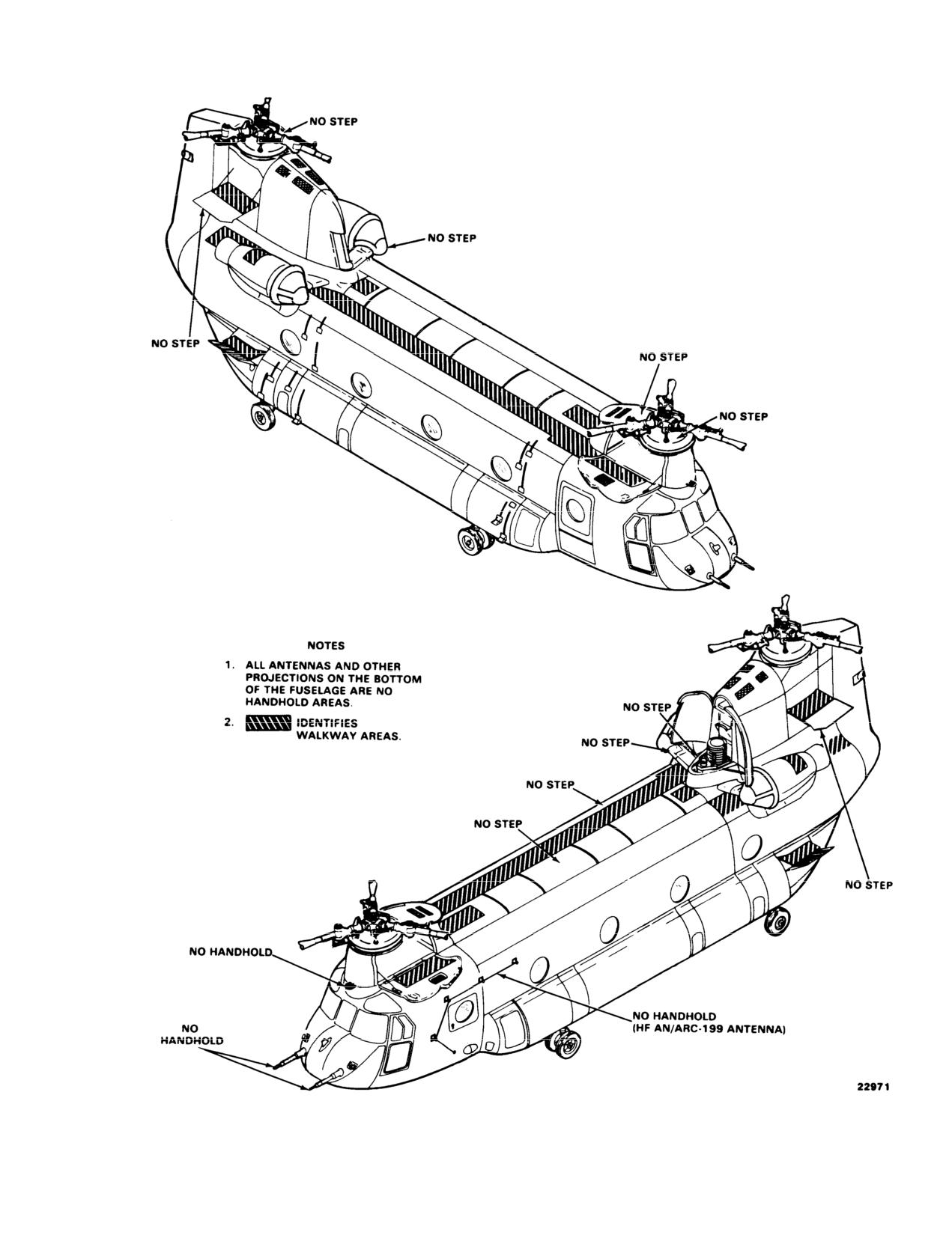
Safe walkway areas, no step areas, and no hand holds are
depicted in Figure 2-52. Servicing points areWARNING
ure 2-53. Table 2-3 lists the approved materials, specifica-
tions and capacities. Table 2-4 listTo prevent fuel from spilling from the tanks,ents
for oils.
caution should be used when opening fuel caps
after pressure refueling or when the aircraft
2-219. Fuel Types.
has been sitting in the sun.
The following describe the various types of fuels:
2-221. Fuel Tanks Servicing.
a. Army StandaJP
4 is the Army-designated
The CH-47D helicopter has six fuel tanks,
primary fuels adopted for worldwide use.
side. The tanks can be serviced through
b. AlternatT
ese are JP-5, JP-8, and equiva-
pressure refueling system or through fille
lent commercial fuels which can beThe single-
point method of servicing is p
out power reduction when Army standard fuel is not avail-
method, all tanks can be filled, partiall
able. Power setting adjustments afilled in less than 4 m
inutes. Refer to t
may be required when an alternate fuel is used.
tank capacities.
c. Emergency100LLs(Low Lead) AVGA222. Single--
Point Pressure Refueling.
ation gasoline) is authorized for use as an emergency fuel with
The pressure refueling control panel and
operation not to exceed 6 hours cumulative time.
are on the right side of the helicopter a
2-220. Use of Fuels.
ing gear (fig. 2-25). Thelanding gear ac
opened to expose the panel and receptacle
Consult TB 55-9150-200-24 for use of fuel and substitute data
ing adapter is located on the structure a
as applicable for turbine engine aircraft. (Refer to tables 2-3,
tacle.
2-5, and 2-6).
Be sure the heli
50 feet from any han-
a.
a.There is no special limitation on the use of Army stan-
gar or structure.
dard or alternate fuel. Certain limitations are imposed when
emergency fuels are used. For recordb. Be sure the refue10ifeet from the le
shall be identified as to the majohelicopter. of the mixture.
c. Electrically ground the helicopter
b.The use of kerosene fuels (JP-5 or JP-8 type) in turbine
engines dictates a need for speciaas follows:ns. Ground starts
and air restarts at low temperature m(1)Connect one end of ground cable to t
to low vapor pressure.
gear eyebolt or to the jack on the right
other end to a grou
c. When changing from one type sta 115. Connect theo
ble has no br
another - for example, JP-4 to JP-ground point. Be sure the ca
clips are securely attached to the cable
sary to drain the aircraft fuel system before adding the new
fuel.
(2)Be sure the fueling unit is grounde
ground point as the helicopter.
d. Fuels having the same NATO code number are inter-
changeable. Jet fuels conforming tod. At the cockpit overhead FUEL CONTR
tion may be used when MIL-T-5624 orREFUEL STA switch to
ON.
2-80
Change
9
TM 55-1520-240-10
Figure 2-52. No Step, No Handhold, and Walkway Areas
2-81
TM 55-1520-240-10
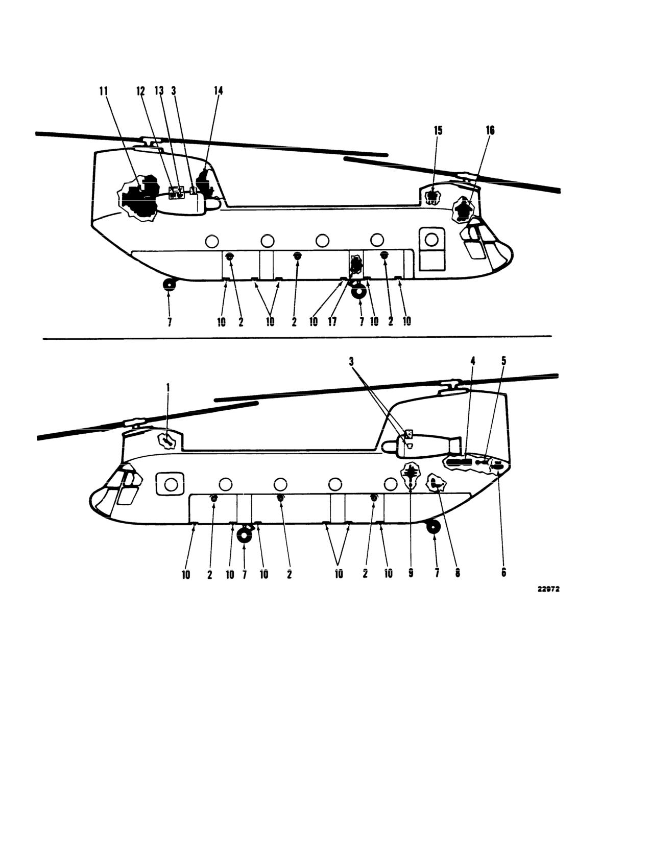
1. Brake accumulator
8. Hydraulic systems fill module
14.
Engine and combining transmission oil
2. Gravity fuel filler
9. Power steering and swivel lock
level indicator and filler
3. Engine oil level indicator and filler
accumulator
15.
No. 1 flight control system
(Typical)
10. Fuel tank drain valve
accumulator
4. APU start accumulator
11. Aft transmission
16.
Forward transmission oil level indica-
5. APU start module accumulator
12. No. 2 flight control systems
tor and filler
6. APU
accumulator
17.
Pressure refueling system filler and
7. Tire
13. Utility reservoir pressurization
control panel
accumulator
Figure 2-53. Servicing Diagram (Sheet 1 of 4)
2-82

TM 55-1520-240-10
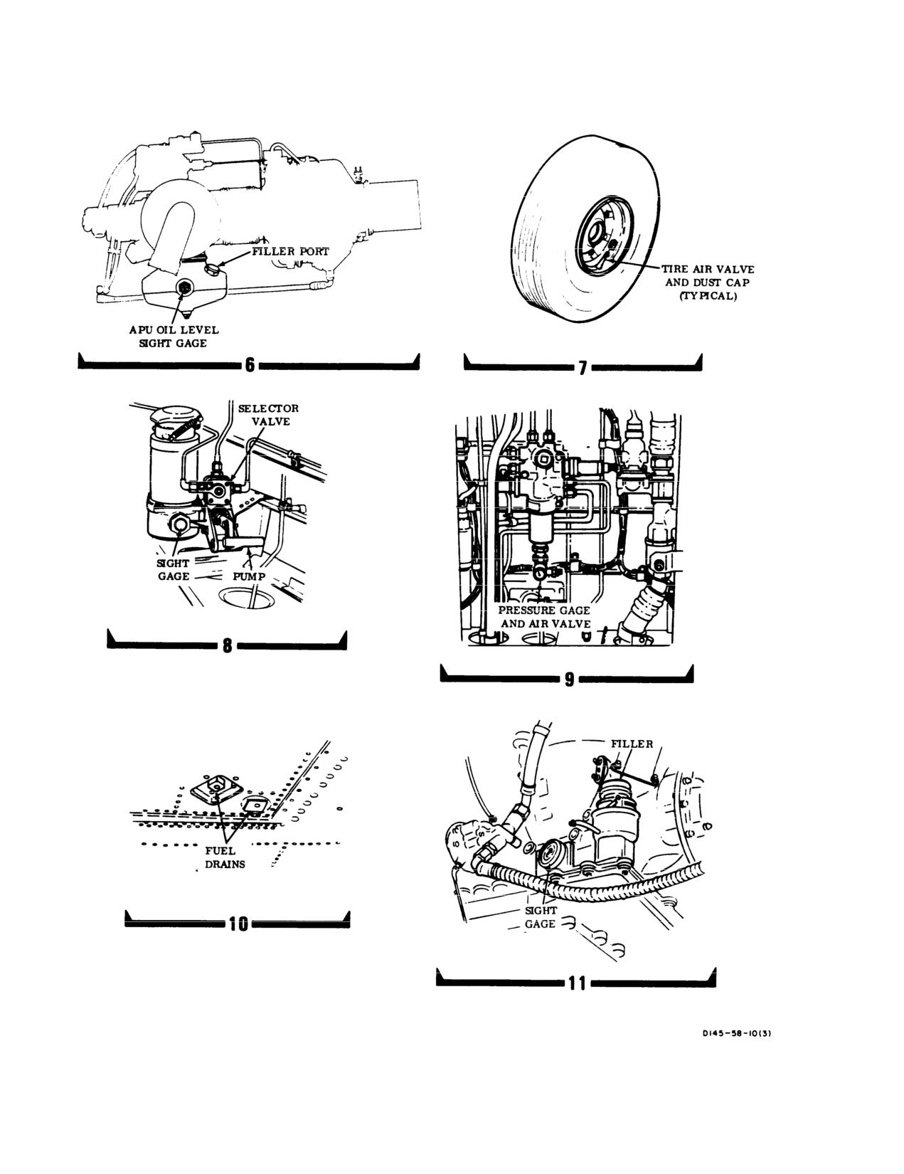
Figure 2-53. Servicing Diagram (Sheet 2 of 4)
2-83
TM 55-1520-240-10
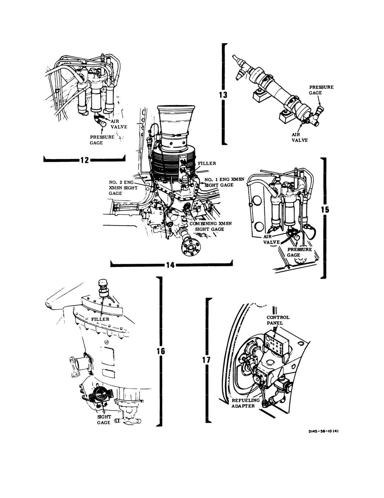
Figure 2-53. Servicing Diagram (Sheet 3 of 4)
2-84
TM 55-1520-240-10
Figure 2-53. Servicing Diagram (Sheet 4 of 4)
2-85
TM 55-1520-240-10
Table 2-3. Servicing
CAPACITY
SERVICEABLE ITEM
MATERIAL
SPECIFICATION
(See note A)
L Main Tank
JP-4, JP-5
MIL-T-5624
278 Gallons
R Main Tank
or JP-8
MIL-T-83133
274 Gallons
L Fwd Aux Tank
JP-4, JP-5
MIL-T-5624
122 Gallons
R Fwd Aux Tank
or JP-8
MIL-T-83133
119 Gallons
L Aft Aux Tank
JP-4, JP-5
MIL-T-5624
118 Gallons
R Aft Aux Tank
or JP-8
MIL-T-83133
117 Gallons
ERFS II Tank 1,
JP-4, JP-5
MIL-T-5624
825.5 Gallons
2, or 3
or JP-8
MIL-T-83133
825.5 Gallons
Each Engine Oil Tank
Lubrication Oil
MIL-L-23699 or MIL-L-7808
12 Quarts
(See note C)
APU Engine Oil
Lubrication Oil
MIL-L-7808 or MIL-L-23699
3 Quarts
(See note C)
Forward Transmission
Lubrication Oil
DOD-L-85734 or MIL-L-23699
26 Quarts
(See note C)
Aft Transmission
Lubrication Oil
DOD-L-85734 or MIL-L-23699
41 Quarts
(See note C)
Combining Transmission
Lubrication Oil
DOD-L-85734 or MIL-L-23699
20 Quarts
(See note C)
Engine Transmission (each)
Lubrication Oil
DOD-L-85734 or MIL-L-23699
10 Quarts
(See note C)
Each Flight Control System Reservoir
Hydraulic Fluid
MIL-H-83282 (See note B)
2 Quarts
Utility Hydraulic System Reservoir
Hydraulic Fluid
MIL-H-83282 (See note B)
6 Quarts
Rotor Head Oil Tanks
Lubrication Oil
MIL-L-7808
As Required
Shock Absorbers and Landing Gear Shock Struts
Hydraulic Fluid
MIL-H-5606
As Required
Swashplates
Grease
MIL-G-81322
As Required
Tires-8.50 x 10 Type III, Forward and Aft
Air/Nitrogen
88 PSI
Accumulators
Air/Nitrogen
BB-N-411
Apu Start
Brakes
Power Steering/Swivel Lock
Signal Accumulator
Utility Reservoir
No. 1 and No. 2 Flight Control
WARNING
Synthetic oils, such as MIL-L-23699, DOD-L-85734 and MIL-L-7808, may soften paint or stain
clothing upon contact. If synthetic oil is spilled on painted surfaces, those surfaces should be
cleaned immediately. Skin should be thoroughly washed after contact and saturated clothing should
be removed immediately. Prolonged skin contact with synthetic oils may cause a skin rash. Areas
where synthetic oils are used should have adequate ventilation to keep mist and fumes to a mini-
mum.
NOTES:
A.
These are maximum capacities which include residual and trapped oil. Servicing capaci-
ties will be less.
B.
Hydraulic fluid MIL-H-5606 may be used when MIL-H-83282 is not available.
C.
When FAT is below -32_C, use MIL-L-7808.
2-86
Change 14
TM 55-1520-240-10
Table 2-4. Equivalent Oils and Hydraulic Fluids
APPROVED DOMESTIC COMMERCIAL OILS FOR MIL-L-23699
Manufacturer’s Designation:
PQ Turbine Lubricant 6423/6700/3889/C3788/9598
Brayco
8991899-G
Castrol 5000
EMGARD Synthesized Turbine Lubricant
2592/2949
EXXON 2380
ESSO Turbo Oil 2830
HATCOL 3211/3611/1639/1680
Mobil RM-139A/147A/247A/246A/249A/250A/270A
Royco
899/899B/899C/899HC/899E-11899E-2
Aeroshell Turbine Oil
500
Stauffer Jet II E-7603
APPROVED DOMESTIC COMMERCIAL FLUIDS FOR MIL-H-5606
Manufacturer’s Designation:
PQ 2890/2863/2903/2905/2950/4140/3808/4328
Mobil Aero HFD
Stauffer Aero Hydroil 500
Brayco
757B/756F/756ES/756E
Brayco Micronic 756ES
TEXACO Aircraft Hydraulic Oil 15/TL-1071 1
Chevron Aviation Hydraulic Fluid D PED 5225
Penreco Petrofluid
4606/4146/4607
Royco
756C/756D/756E
Castrol Hyspin A
Aeroshell Fluid 41
APPROVED DOMESTIC COMMERCIAL FLUIDS FOR MIL-H-63282
Manufacturer’s Designation:
Royco
782 E-1/782 E-2
Gulf TS-741
Brayco Micronic 882/882A
Royco
782/782-1/782-2
Aeroshell Fluid 31
American Oil PQ3883/4219/4401B/4627/4268/4362C/4401/4401A/4923/4908
Emery
2946A/2942/2857/2858
HATCOL
4283/4284/4285
Penreco Petrofluid
822
APPROVED DOMESTIC COMMERCIAL FLUIDS FOR MIL-L-7808
Manufacturer’s Designation:
Aeroshell Turbine Oil 308
American Oil PQ Turbine Oil
8365/9900/4236
Castrol
399
Brayco
880
EXXON Turbo Oil 2389/2391
HATCO 1278/1280
Mobil RM-272A/248A
Royco
808H/808HC
Technolube SYN TURBO No. 3
2-87
TM 55-1520-240-10
Table 2-5. JP-4 Equivalent Fuel
JP-4 EQUIVALENT FUELS
MILITARY FUEL
U.S.
JP-4 (MIL-T-5624)
NATO
F-40 (Wide cut type)
COMMERCIAL FUEL (ASTM-D-1655) JET B*
American Oil Co.
American JP-4
Atlantic Richfield, Richfield Div.
Arcojet B
B.P. Trading
B.P.A.T.G.
Caltex Petroleum Corp.
Caltex Jet B
Chevron
Chevron B
Continental Oil Co.
Conoco JP-4
EXXON Co., USA
EXXON Turbo Fuel B
Gulf Oil
Gulf Jet B
Mobil Oil
Mobil Jet B
Phillips Petroleum
Philjet JP-4
Shell Oil
Aeroshell JP-4
Texaco
Texaco Avjet B
Union Oil
Union JP-4
FOREIGN FUEL (F-40)
Belgium
BA-PF-2B
Canada
3GP-22F
Denmark
JP-4 MIL-T-5624
France
Air 3407 A
Germany (West)
VTL-9130-006
Greece
JP-4 MIL-T-5624
Italy
AA-M-C-1421
Netherlands
JP-4 MIL-T-5624
Norway
JP-4 MIL-T-5624
Portugal
JP-4 MIL-T-5624
Turkey
JP-4 MIL-T-5624
United Kingdom (Britain)
D. Eng RD 2454
* Commercial fuel such as ASTM-D-1655 not containing a icing inhibitor per MIL-I-27686 (commercial name is “PRIST”). Use PRIST in ac-
cordance with instructions on the can. Anti-icing and Biocidal Additive for Commercial Turbine Engine Fuel - The fuel system icing inhibitor
shall conform to MIL-L-27686. The additive provides anti-icing protection and also functions as a biocide to kill microbial growths in helicop-
ter fuel systems. Icing inhibitor conforming to MIL-I-27686 shall be added to commercial fuel not containing an icing inhibitor during refuel-
ing operations, regardless of ambient temperatures. Refueling operations shall be accomplished in accordance with accepted commercial pro-
cedures. Commercial product PRIST conforms to MIL-I-27686.
2-88
TM 55-1520-240-10
Table 2-6. JP-5 and JP-8 Equivalent Fuel
JP-5 AND JP-8 Equivalent FUELS
MILITARY FUEL
U.S.
JP-5 (MIL-T-5624)
JP-8 (MIL-T-83133)
NATO
F-44
F-34
COMMERCIAL FUELS (ASTM-D-1655) JET A/JET A-1*
American type A
American Oil Co.
Atlantic Richfield
ArcoJet A
Arcojet A-1
Richfield Div.
Richfield A
Richfield A-1
B.P. Trading
B.P.A.T.K.
Caltex Petroleum Corp.
Caltex Jet A-1
Chevron
Chevron A-50
Chevron A-1
Cities Service Co.
CITGO A
Continental Oil Co.
Conoco Jet-50
Conoco Jet-60
EXXON Co., USA
EXXON A
EXXON A-1
Gulf Oil
Gulf Jet A
Gulf Jet A-1
Mobil Oil
Mobil Jet A
Mobil Jet A-1
Phillips Petroleum
Phillijet A-SO
Shell Oil
Aeroshell 640
Aeroshell 650
Sinclair
Superjet A
Superjet A-1
Standard Oil Co.
Jet A Kerosene
Jet A-1 Kerosene
Texaco
Avjet A
Avjet A-1
Union Oil
76 Turbine Fuel
FOREIGN FUELS (NATO F-44)
Canada
3-GP-24e
West Germany
UTL-9130-007/UTL-9130-0l0
Italy
AMC-143
Netherlands
D. Eng RD 2493
United Kingdom (Britain)
D. Eng RD 2498
* Commercial fuel such as ASTM-D-1655 not containing a icing inhibitor per MIL-I-27686 (commercial name is “PRIST’). Use PRIST in ac-
cordance with instructions on the can. Anti-icing and Biocidal Additive for Commercial Turbine Engine Fuel - The fuel system icing inhibitor
shall conform to MIL-L-27686. The additive provides anti-icing protection and also functions as a biocide to kill microbial growths in helicop-
ter fuel systems. Icing inhibitor conforming to MIL-I-27686 shall be added to commercial fuel not containing an icing inhibitor during refuel-
ing operations, regardless of ambient temperatures. Refueling operations shall be accomplished in accordance with accepted commercial pro-
cedures. Commercial product PRIST conforms to MIL-I-27686.
2-89
TM 55-1520-240-10
CAUTION
(2) Set the ALL TEST switch to FLOW.
(3) Rotate the FUEL QUANTITY selector
Be sure the fueling station fuel quantity
switch to the tank to be filled. The indicator pointer will
indicator is operating before pressure fuel-
indicate tank fuel quantity.
ing. If the indicator is not operating, the fuel
shutoff valves cannot be checked properly
(4) Set the FUEL CELL SHUTOFF VALVE
and fuel cell overpressurization may result.
TEST switch of the tank to be filled to FLOW.
(5) Open the flow control valve.
e. Open the right forward landing gear access panel
(6) When the desired fuel level is reached, set
and perform the following check:
the FUEL CELL SHUTOFF VALVE TEST switch to
(1) Set the PWR switch to ON. Check that both
PRI OFF.
REFUEL VALVE POSN lights momentarily illumi-
(7) Repeat steps
(3),
(4), and (6) on each tank
nate, then extinguish. If either light illuminates and
until the desired amount of fuel is in each tank.
does not extinguish, the associated refueling valve has
failed and fuel will not flow into that aft auxiliary tank.
(8) Close the flow control valve and disconnect
If the fuel in this tank is required to complete the
the nozzle and ground cable.
mission, notify maintenance.
i. Set the PWR switch to OFF. Check that the
(2) If required, set the LIGHT switch to ON.
REFUEL VALVE POSN lights momentarily illumi-
(3) Set the FUEL QUANTITY selector switch to
nate, then extinguish. If either light does not illuminate
TOTAL.
on, then extinguish, the fuel in that aft auxiliary tank is
unusable. Notify maintenance.
(4) Set the ALL TEST switch to PRI OFF.
j. Close the landing gear access door.
(5) Connect the grounding wire to the grounding
receptacle and connect the fueling nozzle to the adapter.
k. Remove ground cables from the helicopter.
CAUTION
l. Set the REFUEL STA switch on the FUEL
CONTR overhead panel to OFF.
If either the primary or secondary float
switch for any tank is inoperative, do not
CAUTION
pressure refuel that tank unless the fuel cap
is removed to prevent possible fuel cell over-
Perform steps m., n., and o. if helicopter will
pressurization. If both switches are inopera-
not be operated immediately. Failure to do
tive, do not pressure refuel the helicopter. In
so could result in refuel manifold seepage
addition, if both float switches are inopera-
caused by fuel expansion.
tive for either main tank, the system must be
repaired before flight to prevent fuel cell
overpressure.
m. APU -
Start (refer to Chapter 8). Place APU
GEN switch to ON or apply AC external power.
(6) Open the flow control valve on the nozzle.
n. Operate the forward boost pump on either main
Check that fuel flow stops within
4 seconds. A small
tank for about two
minutes.
amount of fuel will continue to flow through the open
secondary ports.
o. Place APU GEN switch to OFF, APU switch to
OFF, or disconnect the external power.
(7) Set the ALL TEST switch to SEC OFF.
Check that fuel flow stops within 4 seconds. A small
2-223. Gravity Refueling. Perform the following
amount of fuel will continue to flow through the open
steps:
primary ports.
a. Be sure the helicopter is at least
50 feet from any
f. If all tanks are to be filled, set the ALL TEST
hangar or structure.
switch to FLOW. All tanks will now fill independently.
Rotate the FUEL QUANTITY selector switch, check-
b. Be sure the fueling vehicle is at least
10 feet from
ing each tank for proper fill and quantity. Shutoff valves
the helicopter.
in each tank will close and stop fuel flow as each tank
fills.
c. Electrically ground the helicopter as follows:
g. When refueling is complete, close the flow control
(1) Connect one end of an approved ground
valve.
cable to the aft landing gear eyebolt or to one of the
jacks on the side of the fuselage. Grounding jacks are
h. If tanks are to be partially or selectively filled, be
located at sta. 115 on the RH side and sta. 530 on the
sure to perform steps e.(6) and e.(7), then proceed as
LH side in the fuselage skin. Connect the other end to
follows:
a grounding rod or ramp ground point. Make sure the
(1) Set the six FUEL CELL SHUTOFF VALVE
cable has no broken strands and the clips are securely
TEST switches to PRI OFF.
attached to the cable and ground points.
2-90
TM 55-1520-240-10
(2) Make sure the fueling unit is grounded to the
b. Fuel hose from refueling source - Connect to aircraft
same ground rod or ground point as the helicopter.
single-point pressure refueling connection.
(3) Before opening the filler cap, ground the nozzle
c. Single-Point Pressure Refueling Hose Assembly -
to the ground jack directly above the fuel tank filler.
Unisex valve at the ERFS II tank - OPEN.
d. When the fuel is at the desired level, remove the
d. Manual FUEL/DEFUEL VALVE at each tank
nozzle. Secure the filler cap. Then, disconnect the nozzle
assembly - OPEN.
ground wire.
e. REFUEL STA switch located on the overhead FUEL
e. Remove the ground connection. If the helicopter is
CONTR Panel - ON.
to remain parked, do not disconnect the helicopter
ground.
f.
REFUEL VALVE switch on the ERFS II Fuel Control
Panel OPEN. IN TRANSIT light will briefly illuminate.
2-223.1. ERFS II Refueling.
g. Refuel the ERFS II tanks. Fuel flow will automatically
Refueling the ERFS II tanks is performed by either single
stop when tanks are full.
point pressure refueling or gravity refueling.
h. FUEL QUANTITY switch - Set to 1, 2, 3, and TOTAL
WARNING
to confirm tanks and system contain desired fuel
quantities.
The manually operated fuel/defuel vent valve
on each tank must be placed in the closed
i.
REFUEL VALVE switch - CLOSE. IN TRANSIT light
position following pressure refueling. Fail-
will briefly illuminate.
ure to do so could permit significant fuel leak-
age in the event of a crash and the vent self-
WARNING
sealing breakaway valve fails to actuate.
The manually operated fuel/defuel valve
must be placed in the closed position follow-
CAUTION
ing pressure refueling. Failure to do so could
If the fuel/vent valve is not opened, the tank
permit significant fuel leakage in the event of
cannot be pressure refueled.
a crash and the vent self-sealing breakaway
a. Single Point Pressure Refueling. The ERFS II tanks
valve fails to actuate.
are single point pressure refueled from a connection at the
j.
Manual FUEL/VENT VALVE at each tank assembly
motorized gate valve. The motorized gate valve must be
– CLOSED.
open to pressure refuel and is controlled by the refuel
valve switch on the ERFS II fuel control panel located on
k. Single-Point Pressure Refueling Hose Assembly -
the forward most ERFS II tank installed. The fuel transfer
Unisex valve at the ERFS II tank - CLOSE.
hose is connected to the forward interconnecting ERFS II
l.
Fuel hose from refueling source - Disconnect from
fuel manifold. Fuel from the transfer hose passes through
aircraft single-point pressure refueling connection.
the breakaway valve and the manual fuel/defuel valve to
the lower fuel/shutoff valve in the tank bottom.
m. Electrical ground - Disconnect electrical ground
from refueling source to the aircraft.
CAUTION
2-223.3. Gravity Refueling.
The operator must exercise caution to avoid
a. Electrical ground - Connect electrical ground from
ERFS II tank overflow during gravity refuel-
refueling source to aircraft.
ing. There is no automatic fuel flow shutoff.
b. Grounding Cable on each ERFS II tank - Check
b. Gravity Refueling. If pressure refueling of ERFS II
connection security.
tanks is not performed or prevented, each tank can also
be gravity filled through the gravity filler opening on the top
c. Filler Cap - Remove.
of each tank. To gravity fill, the crashworthy filler cap is
d. Service tank.
removed and external fuel source nozzle is inserted and
the tank is filled. Low pressure flow rates must be
CAUTION
maintained as venting of vapors bypass the filler opening
The operator must exercise caution to avoid
and the fuel/defuel vent valve is closed during this
ERFS II tank overflow during gravity refuel-
operation. Because fuel is not entering the tank through
ing. There is no automatic fuel flow shutoff.
the fuel/defuel line, the high level shutoff valve has no
effect stopping the fuel flow into the tank.
e. FUEL QUANTITY switch - Set to 1, 2, 3, TOTAL to
confirm tanks and system contain desired fuel quantities.
2-223.2. Single Point Pressure Remodeling.
(Will indicate only when aircraft power is applied).
a. Electrical ground - Connect electrical ground from
f.
Filler Cap - Replace.
refueling aircraft. Check that the ground wire from each
ERFS II tank is connected to an aircraft ground
g. Electrical ground - Disconnect electrical ground
receptacle.
from refueling source to aircraft.
Change 14
2-90.1
TM 55-1520-240-10
2-223.4. Fuel Transfer. Fuel transfer from the ERFS II
closed, fuel is pumped into the fuel manifold at a rate of
tanks to the helicopter’s main tanks is accomplished
approximately 20 gpm. Fuel is delivered by the fuel
through the use of dual centrifugal pumps in each ERFS
manifold to the helicopter.
II tank. During fuel transfer, the manually operated
fuel/defuel valve on each tank must be closed to prevent
fuel circulation inside the tank. With the fuel/defuel valve
2-90.2
Change 14
TM 55-1520-240-10
main fuel tanks through the aircraft fuel system quick
2-226. Transmission Oil System.
disconnect fittings in the left and right side cargo
Service the forward transmission, engine/combining
compartment at STA 380. During transfer, the roll-over
transmission, and aft transmission as follows:
vent valve in each ERFS II tank allows venting and
a. Access to oil filler and location of sight gage of each
equalization of tank pressure above 5 psi from thermal
transmission (fig. 2-53) are as follows:
expansion, contraction, and barometric pressure
(1) The oil filler and sight gage for forward transmis-
changes in the bladders. The high level fuel shutoff valves
sion are accessible within the hinged fairing on the right
in the tanks prevent overfilling. The metallic float and ball
in the roll-over vent valve prevents fuel from escaping
side of the forward pylon. The filler neck is in the top for-
ward area of the transmission. The sight gage is located
should the tank become inverted in a roll-over and
prevents slosh from uncoordinated flight from leaking to
in the bottom area below the filler neck; it can be viewed
the overboard vent lines. To transfer fuel from the fARE
from above and can also be seen through a viewing port
in the canted bulkhead at sta. 95 above the pilots seat.
system, fuel is pumped from the ERFS II tanks by the
FARE pump. The manually operated fuel/defuel valve
(2) The oil filler and sight gage for aft transmission is
must be in the open position for the FARE transfer.
on forward right side of the transmission sump. It is acces-
sible from the cargo ramp area.
2-224. Engine Oil System.
(3) The common oil filler for the combining transmis-
The engine oil tank an oil quantity indicator are an integral
sion and both engine transmissions is on the combining
part of the engine (fig. 2-53). Service either engine oil
transmission oil tank. It is accessible within the fairing of
system as follows:
aft pylon leading edge.
a. If the engine has not been operated in the preceding
b. Refer to DA Form 2408-13 and table 2-3 for the type
24 hours and the oil level is low, run it and then recheck
of oil to use. Under normal conditions, the transmissions
the oil level. Otherwise, an inaccurate oil level may be
shall be serviced with one type of oil only. If one type of oil
indicated.
is in a transmission and that oil is not available, the other
b. Check oil level by looking through the grilled opening
type may be used in an emergency.
on the left side of the engine cowling at the 9 o’clock
NOTE
position.
To prevent overfilling the forward, aft, and en-
c. If the indicator shows less than full, open the oil filler
gine/combining transmissions, check oil level
access panel on the forward top side of the engine cover.
within 30 minutes of shutdown. If the transmis-
sions have been shut down for more than 30
d. Refer to DA Form 2408-13 and table 2-3 for the type
minutes, run the helicopter for a minimum of 5
of oil to use. Under normal conditions, engines shall be
minutes to verify oil level before servicing.
serviced with one type of oil only. If one type of oil is in an
NOTE
engine and that oil is not available, the other type may be
To prevent overfilling the forward and aft trans-
used in an emergency.
mission, check oil level after the aircraft has
e. Remove the filler cap. Fill the tank with oil until the
been shut down for 30 minutes.
indicator shows full. Do not overfill tank.
c. Fill the forward transmission, engine/combining and
f.
Install the filler cap. Close both access panels.
aft transmissions to the FULL mark next to each sight
gage.
2-225. APU Oil System.
2-227. Hydraulic Systems Servicing.
Service the APU as follows:
2-228. Hydraulic Systems Fluid Servicing. The util-
CAUTION
ity systems and both flight control hydraulic systems are
Do not use the APU drip pan as a handhold.
serviced by a common fill module on the right side of the
Damage to equipment will result.
helicopter above the ramp (fig. 2-53). The fluid level indi-
a. Remove the filler cap from the left side of the APU
cators are on the MAINTENANCE PANEL above the fill
(fig. 2-53).
module. One indicator is for both flight control hydraulic
CAUTION
systems. The other indicator is for the utility system. Di-
Do not overfill. Damage to the APU can result
rect level checks can also be made from the reservoir pis-
from overfilling.
ton rods. Service any system as follows:
b. Add oil to the APU oil tank until the level reaches the
a. Check the sight gage on the fill module reservoir for
FULL mark on the sight gage. Under normal conditions,
fluid level. If fluid cannot be seen on the sight gage, fill the
the APU shall be serviced with one type of oil only. If one
reservoir.
type of oil is in an APU and that oil is not available, the
b. Check the fluid level in the flight control reservoirs by
order type may be used in an emergency.
selecting each system at the FLT CONTR switch on the
c. Reinstall and check security of the filler cap.
MAINTENANCE PANEL. Then press the LEVEL CHECK
Change 14
2-91
TM 55-1520-240-10
CHECK switch. Check the fluid level in the utility
(3) Note precharge on accumulators and ensure
reservoir by pressing the LEVEL CHECK switch.
is within limits as per figure 2-54.
c. Turn the system select valve to the position for the
(4) If servicing is required, refer to TM 55-1520-
system to be serviced.
240-23.
d. Using the handpump on the fill module, pump
b. The power steering and swivel lock accumulator is
fluid into the system until the fluid in the reservoir is at
located on the right side of the cabin, in the cargo ramp
the FULL mark. Keep the sight gage on the fill module
area. Determine accumulator precharge as follows:
full of fluid by adding fluid to the reservoir as required.
e. Turn the system select valve to OFF.
NOTE
An alternate method is to apply external
2-229. Hydraulic Systems Accumulator Precharge.
power to the helicopter and cycling the
Figure 2-54 depicts the relationship between proper
STEERING CONTROL SWIVEL STEER
accumulator precharge and ambient temperature. To
switch on the center console from LOCK to
check that an accumulator is properly precharged, read
UNLOCK several times.
free air temperature from the FAT gauge. Enter the
bottom of the chart at the indicated temperature and
move vertically to the pressure indicated on the accu-
(1)
Repressurize the accumulator by starting the
APU and placing the APU GEN switch to
mulator pressure gage. If the indicated pressure is
within the minimum and maximum limits, the accumu-
ON.
lator is properly precharged. If the indicated pressure is
(2)
Place the HYD BRK STEER isolation switch
not within limits, refer to TM 55-1520-240-23 to service
on the overhead switch panel to OFF. Cycle
the accumulator.
the STEERING CONTROL SWIVEL
STEER switch on the center console from
2-230. Flight Controls Hydraulic Systems Accu-
LOCK to UNLOCK approximately six times.
mulators. The No. 1 flight control system accumulator
is within the forward transmission fairing, on the right
(3)
Note precharge on accumulator and ensure
side. The No. 2 system accumulator is within the aft
precharge is within limits as per figure 2-54.
pylon, on the right side. Determine either accumulator
(4) If servicing is required, refer to TM 55-1520-
precharge as follows:
240-23.
a. Access to the respective accumulator.
c. The brake accumulator is located within the aft left
b. Note precharge on accumulator and ensure is
side of the forward transmission fairing. Determine
within limits as per figure 2-54.
accumulator precharge as follows:
c. If servicing is required, refer to TM 55-1520-240-
(1) Repressurize the accumulator by pressing the
23.
brakes approximately four times or until it
becomes hard to apply the brakes.
2-231. Utility System Accumulators. There are five
accumulators in the utility hydraulic system. They pro-
(2) Accumulator precharge should read between
vide pressure to start the APU, operate the power
600 to 850 psi.
brakes and swivel locks, and maintain line pressure
(3) If servicing is required refer to TM 55-1520-
throughout the system.
240-23.
a. The APU start accumulator is the largest in the
helicopter. It is mounted overhead in the cabin at the
2-232. Ground Handling (Towing).
right of the aft transmission sump. The APU start
Refer to TM 55-1520-240-23.
module accumulator is located aft and to the right of the
APU start accumulator. The utility reservoir pressuriza-
2-233. Parking.
tion (bootstrap) accumulator is located forward of the
No. 2 flight control accumulator in the aft pylon,
Park the helicopter as directed in the following steps:
accessible through the pylon right access panel. Deter-
a. Apply wheel brakes. Then, set the parking brakes.
mine accumulators precharge as follows:
b. Place chocks as required.
(1)
Repressurize the accumulator by turning the
handle on the UTILITY RESERVOIR RE-
CAUTION
PRESSURIZE valve to OPEN. The valve is
on the right side of the cabin, in the cargo
Failure to position blades properly can allow
ramp area.
a blade to hit the fuselage. This may damage
(2)
Press and hold the depressurization valve on
the fuselage and blade.
the APU start module accumulator until sys-
tem pressure is depleted. When the accumu-
c. Position rotary-wing blades 30° off centerline of
lator has been repressurized, return the han-
helicopter.
dle of the UTILITY RESERVOIR
REPRESSURIZE valve to NORMAL.
d. Unplug the battery after the last flight of the day.
2-92
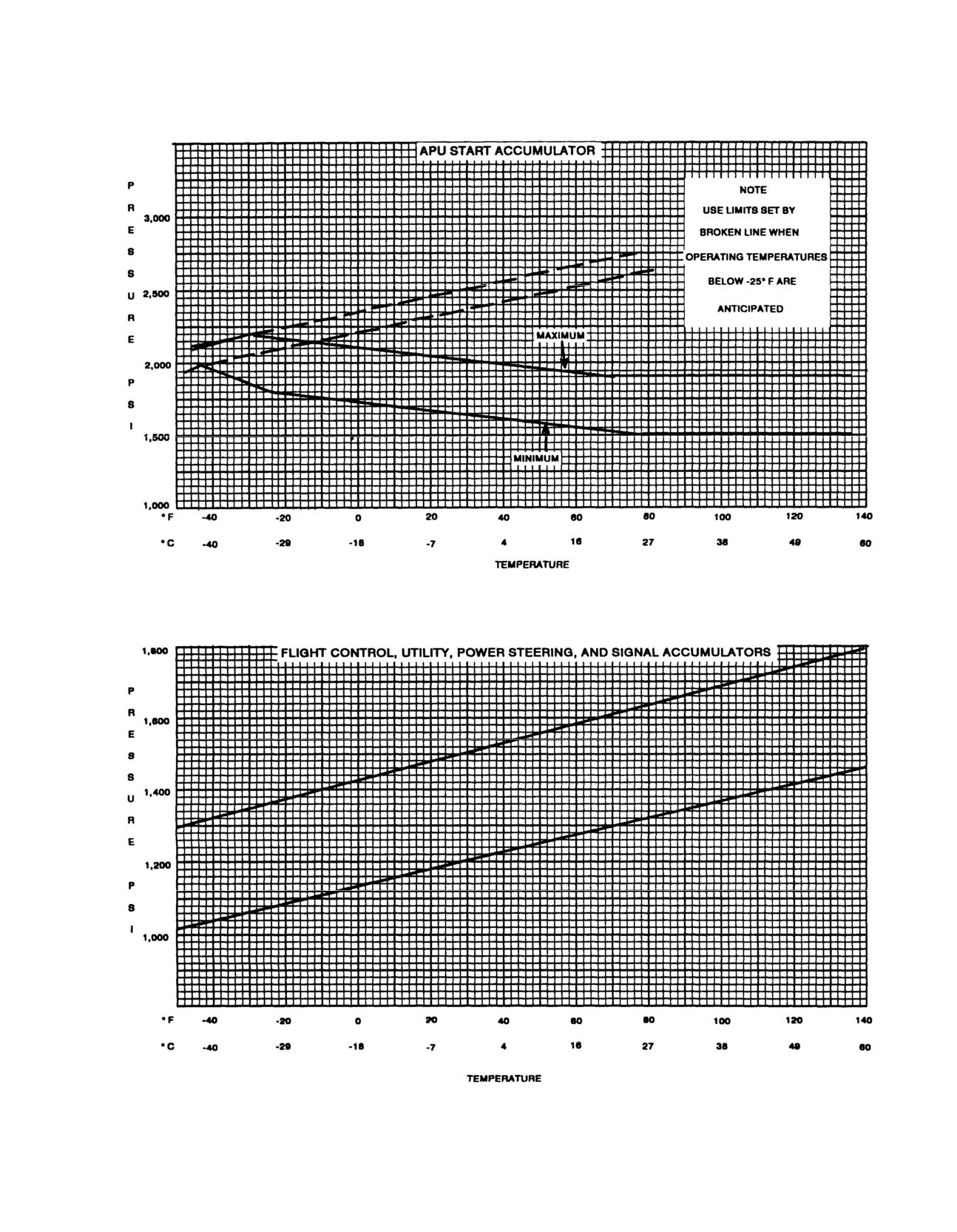
TM 55-1520-240-10
Figure 2-54. Accumulators Precharge Limits
2-93
TM
55-1520-240-10
e. Lock all doors and hatches.
k.Rotor hub protective cover (2 ea).
f. Moor the helicopter (refer to TM 1l.Heater exhaust protective cover.
2-234. Mooring.
m. Heater inlet cover.
Refer to TM 1-1500-250-23. The methods of mooring vary
with intensity of winds. Table 2-72-236.oHelicoptersSecurityc(Typical).ry
precautions to be taken pertaining to these conditions.
The helicopter is equipped with door lock se
(fig. 2-56). These devices prevent interior
Table 2-7. Mooring Data
helicopter by unauthorized persons. Install
follows:
WIND SPEED
TIEDOWN REQUIREMENT
a. Make sure the ramp is full up. Install
0 to 39 mph
Two forward blades tied down.
through the ramp controls access door latch
39 to 65 mph
Fuselage and blades tied dfas
tener to the bracket. Make sure the warnin
Over 65 mph
Evacuate helicopter from tvisibl
e.
or store helicopter in hangar.
b. Close the lower rescue hatch door. If t
be closed, secure the utility hatch to a ti
2-235. Protective Covers.
cargo strap.
The following protective covers should be stowed in the
helicopter (fig. 2-55). They are used asc. Secure the release straps of the two
helicopter is parked or moored.
hatches and the cargo door escape hatch wit
clamps. Make sure the clamps are located as c
a.
Engine (LH) inlet cover.
release grommet as possible. Make sure the warn
b.
Engine (RH) inlet cover.
ers are readily visible.
C.
Engine outlet cover (2 ea).
d. Install lock pins through the pilot’
d.
Hydraulic cooler exhaust cover.
window latches. Then, insert the quick-releas
the bracket on the floor and into the door la
e.
Pitot tube covers (2 ea).
sure the warning streamers are readily visibl
f.
Aft transmission cooler and APU exhaust cover.
e. Install left forward latchable escape ha
g.
Transmission and hydraulic cooler intake.
f. Close the cabin doors. Install the b
h.Transmission and hydraulic cooler exhaust (LH and
padlock.
RH).
i. Transmission and hydraulic cooler inlet (aft pylon).
j. Cockpit enclosure protective cover.
2-94
Change
11
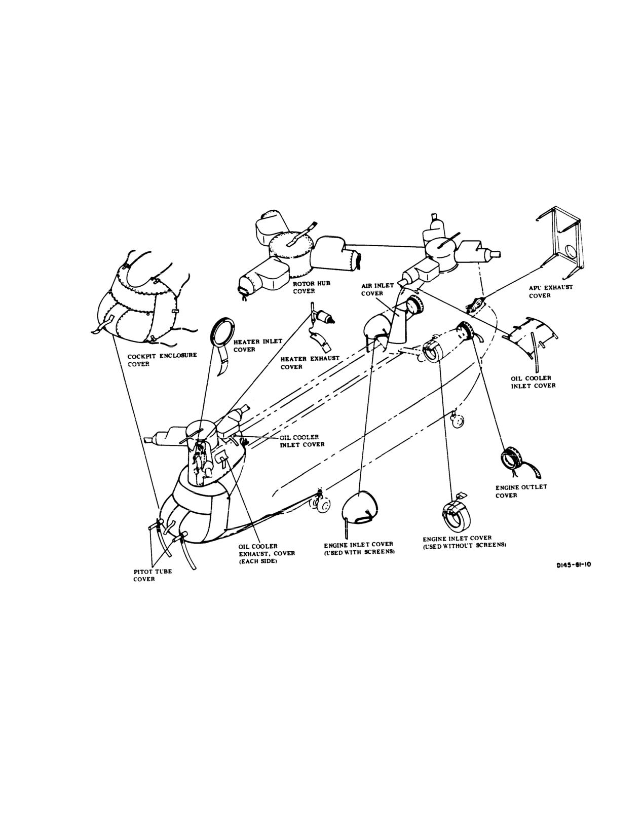
TM 55-1520-240-10
Figure 2-55. Protective Covers
2-95
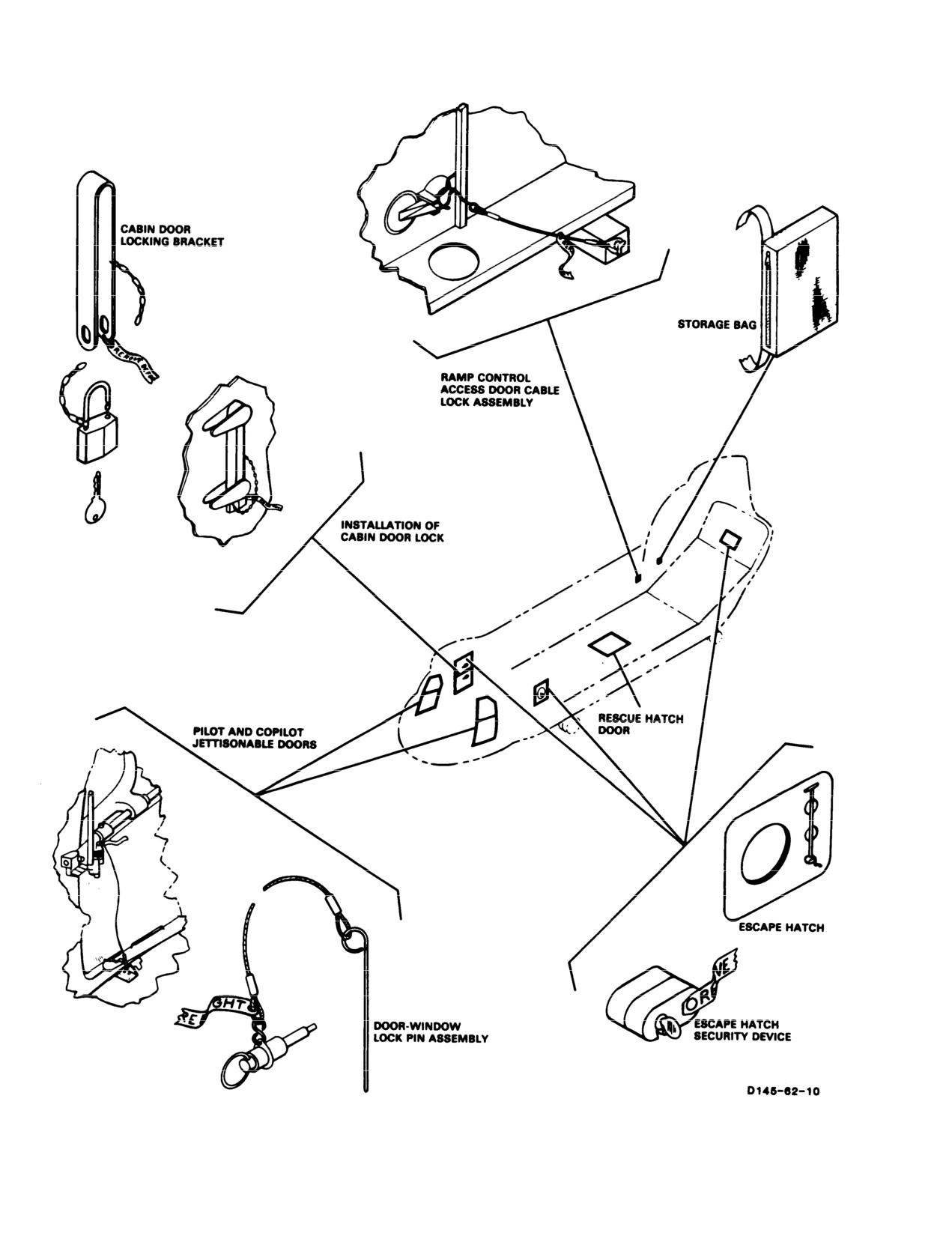
TM 55-1520-240-10
Figure 2-56. Installation of Helicopter Security Devices (Typical)
2-96
TM
55-1520-240-10
CHAPTER
3
AVIONICS
SECTION I GENERAL
3-1. Description.
3-3. Avionics Power Supply.
The avionic systems in the CH 47D helicopters consist of the
communications equipment providing HPower to operate the avionic systems is supp
VHF-FM, and UHF-AM communications. The and No. 2 DC buses, the DC essential bus, an
equipment includes LF-ADF, VOR ILS, Mar115-volt and 26-volt AC buses (Chapter 2)
Doppler/GPS, and Omega. VHF-FM homing is provided
through the AN/ARC-201 FM communication radio.
Transpondeequipmentconsists
of IFF
The No. 1 VHF AM/FM, interphone and UHF
receiver-transmitter with inputs fromoperated by selecting the BATT switch to O
equipment, the APU ge
altimeter for altitude encoding. Absolutremaining avionicsed
by a radar altimeter. For mission avionicmain helicopter generators. must be operat
power must be connected. All circuit brea
Chapter 4, Mission Equipment.
3-2. Avionics Equipment Configuration.
Equipment configuration in the CH-47D helicopter is listed
in table 3-1.
Change
8
3-1
TM
55-1520-240-10
Table
3-1.
Communications/Navigation Equipment
FACILITY
DESIGNATION
USE
LOCATION
INTERPHONE
C-6533/ARC
INTERCOMMUNICATIONS BETWEEN
THREE INTERPHONE CONTROLS ON
CREWMEMBERS AND RADIO CONTROLONSOLE, THREE INTERPHONE
CONTROLS IN CABIN
UHF RADIO
AN/ARC-164
TWO-WAY UHF-AM COMMUNICATIONCONTROL ON CONSOLE
(INCLUDES R/T)
VHF AM/FM
AN/ARC-186
TWO-WAY VHF AM/FM
CONTROL ON CONSOLE
RADIO
COMMUNICATIONS
(INCLUDES R/T)
VOICE SECURITY
TSEC/KY-58
TWO-WAY CLEAR OR SECURE VOICECONTROL ON CONSOLE
EQUIPMENT
COMMUNICATION FOR NO. 1 VHF/FM
RADIO
TSEC/KY-75
COMSEC
CONTROL ON CONSOLE
(IF INSTALLED)
TSEC/KY-100
SECURE VOICE AND DATA
CONTROL ON CONSOLE
COMMUNICATION. OPERATIONAL
(IF INSTALLED)
WITH NARROW AND WIDE BAND
RADIOS (HF, VHF, UHF, SATCOM)
VHF NAVIGATION
AN/ARN-123
PROVIDES VOR BEARING AND COURCONTROL ON CANTED CONSOLE
AND INSTRUMENT
INFORMATION, ILS LOCALIZER, GLIDE
LANDING SYSTEM
SLOPE, AND MARKER BEACON
INDICATIONS
DIRECTION
AN/ARN-89
AUTOMATIC OR MANUAL DIRECTIOCONTROL ON CANTED CONSOLE
FINDER SET
FINDING AND HOMING
GYROMAGNETIC
AN/ASN-43
PROVlDES HEADING INFORMATIONCONTROL ON OVERHEAD SWITCH
COMPASS SET
FREE GYRO OR MAGNETIC MODES
PANEL
DOPPLER
AN/ASN-128
PROVIDES WORLDWIDE NAVIGATION
CONTROLS ON CANTED CONSOLE
NAVIGATION SET
CAPABILITY WITHOUT USE OF
GROUND FACILITIES
DOPPLER GPS
AN/ASN-128B
PROVIDES WORLDWIDE NAVIGATION
CONTROL ON CANTED CONSOLE
NAVIGATION SET
CAPABILITY WITHOUT USE OF
(INCLUDES DISPLAY)
GROUND FACILITIES
TRANSPONDER
AN/APX-100
RADAR IDENTIFICATION AND
CONTROL ON CANTED CONSOLES
SYSTEM
TRACKING
OMEGA NAVIGA-
AN/ARN-148
PROVIDES NAVIGATION CAPABILICONTROL ON CONSOLE
TION SYSTEM
USING GROUND FACILITIES
HIGH FREQUENCY
AN/ARC-199
LONG RANGE TWO-WAY
CONTROL ON CONSOLE
RADIO SET
COMMUNICATIONS
HIGH FREQUENCY
AN/ARC-220
LONG RANGE TWO-WAY
CONTROL ON CONSOLE
RADIO SET
COMMUNICATIONS WITH ALE AND
ECCM
VHF-FM RADIO
AN/ARC-201
TWO-WAY VHF-FM COMMUNICA-
CONTROL ON CONSOLE
TIONS AND HOMING
3-2
Change
12
TM 55-1520-240-10
SECTION II COMMUNICATIONS
CONTROL/
3-4. Interphone System (C-6533/ARC).
INDICATOR
FUNCTION
The interphone system is a multi-station intercommu-
2- UHF radio
nication and radio control system for control of voice
radio communication. It also monitors the output of
3- No. 2 VHF AM/FM
radio
navigation radio receivers and warning tones from IFF
4- HF radio
and radar warning sets. The basic components of the
5- Not used
interphone system are six control panels (fig. 3-1).
AUX - VOR/Localizer
There is one panel each for the pilot, copilot, troop
NAV - direction finder
commander, the two gunners stations, and flight engi-
OFF disables associated
neer. In addition, there is an interphone station for the
audio input to headset.
hoist operator and two external interphone receptacles.
ON radio enables associ-
Power for the system is supplied by the DC essential bus
ated input to headset.
through the COMM INTPH LH and COMM INTPH
RH circuit breakers on the No. 1 and No. 2 PDP.
HOT MIKE
Two position toggle switch
Switch Position
enables hands-free opera-
tion (PIT/foot switch op-
3-5. Controls and Function, Interphone Control
eration not required) of
(C-6533/ARC). (fig. 3-2)
headset microphone for
CONTROL
interphone only.
INDICATOR
FUNCTION
OFF
Hands-free operation dis-
abled. PTT/foot switch
Function Selector Switch
Five position rotary switch
operation required for
Position
used to select interphone
operation.
operating mode.
HOT MIKE
Hands-free operation en-
ICS
Connects headset-
abled.
microphone to interphone
system.
NOTE
1
Connects headset-
Switch settings are not necessary to receive marker
microphone to No. 1 VHF
beacon, radar warning, and IFF audio tones.
FM or No. 1 VHF
Press to talk (PTT)
Two or three position
AM/FM radio set.
Switches Position
switches used to enable
2
Connects headset-
the microphone side of
microphone to UHF radio
the interphone system
set.
when operator is speak-
3
Connects headset-
ing. These switches are
microphone to No. 2 VHF
described in detail below.
AM/FM radio set.
Pilot/Copilot Trigger PTT
Three position PTT
4
Connects headset-
Switch (on pilot and copi-
switch. Off disables micro-
microphone to HF radio
lot cyclic stick) Position
phone (not pressed) en-
set.
ables headset.
5
Not used.
Interphone
Enables microphone
(First detent)
transmission to all inter-
NOTE
phone stations, regardless
Pilot/Copilot can transmit on all four transmitters.
of function switch settings.
Troop Commander can transmit on the HF and
Radio transmit
Enables microphone
VHF FM transmitters only. Gunners and Flight En-
(Second detent)
transmission over radio
gineer cannot access any transmitters.
set selected by control
panel function switch.
Receiver Switches 1-5,
Seven two position toggle
Pilot’s/Copilot’s Foot
Two position PTT switch.
AUX, and NAV Position switches used to select-
Switches (on cockpit floor
headset audio input as
next to heel slide) Posi-
follows:
tion
1- No. 1 VHF FM or No.
1 VHF AM/FM radio
3-3
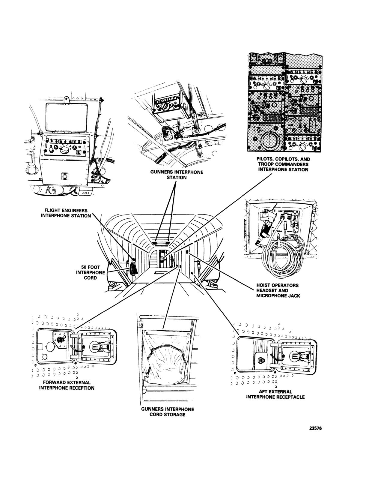
TM 55-1520-240-10
Figure 3-1. Interphone Stations
3-4
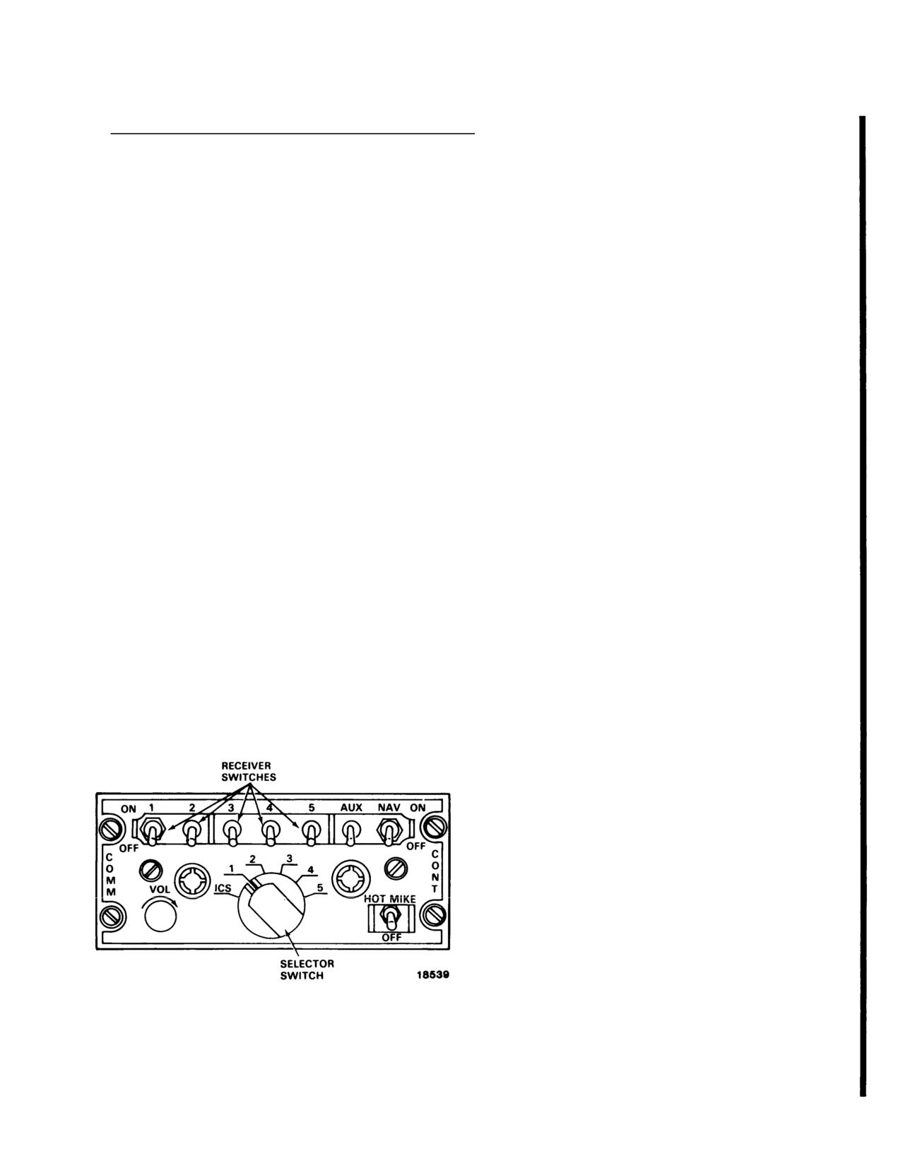
TM 55-1520-240-10
CONTROL/
figure shows the maximum antenna configuration. All
INDICATOR
FUNCTION
antennas illustrated may not appear on all helicopters.
Off
Released position; dis-
3-7. UHF-AM Have Quick II Radio (AN/ARC-164).
ables microphone.
The UHF Have Quick II (HQ II) radio (AN/ARC-164)
Talk
Depressed position; en-
ables headset microphone.
is located on the center console. It is capable of
providing normal and ECCM, anti-jam (AJ) two-way
Hoist Control PTT Switch
Two position PTT Switch.
voice communications in the band from 225.000 to
(on hoist control grip)
399.975 MHz in 25 kHz increments. The HQ II is
Position
capable of operating with the Basic HAVE QUICK
Off
Released position; dis-
radio,. It also provides 20 preset frequencies and will
ables microphone.
monitor and transmit on a permanent guard channel
Talk
Depressed position; en-
(243.000 MHz). When in the AJ mode preset 20 is
ables headset microphone.
restricted to AJ operations. The usual operating mode
HOT MIKE switch on
Three position toggle
for the radio set is the normal mode where the radio
HOIST OPERATORS
switch selects hoist opera-
uses 1 of 7,000 frequencies. Power for the UHF-AM
PANEL (Chapter 4)
tor’s interphone operating
Have Quick II radio set is supplied by the 28 volt
mode.
essential bus through the COMM UHF AM circuit
OFF
Requires operation of
breaker on the No. 1 PDP.
PTT switch for interphone
There are presently three configurations of the AN/
communications.
ARC 164 UHF/AM radio. The following paragraphs
HOT MIKE
Operation of PTT switch
identify the the visual differences in their configuration.
not required for inter-
phone communications.
a. AN/ARC 164, UHF/AM Basic (not modified for
Have Quick) 100MHz selector for the hundreds digit
MOM ON
Operation of PTT switch
only has a 2 and a 3 position.
not required for inter-
phone communications.
b. AN/ARC 164 UHF/AM Have Quick I (capable of
(Spring loaded to OFF
single WOD entry only) Has a four position selector for
position when released.)
the hundreds digit, A,2,3, and T. Does not have EMB
Gunner’s Foot Switch
Two position pressure
label ajacent to the Pre-set channel selector.
Position
sensitive switch mounted
c. AN/ARC 164 UHF/AM Have Quick II. Same as b.
in moveable floor mat.
above, but includes EMB label ajacent to the preset
Off
Released position; dis-
channel selector.
ables microphone.
Reverse compatible communications between HQ II
On
Depressed position; en-
and HQ I radios in the AJ mode, is accomplished by
ables microphone.
either, entering a single WOD or selecting the appro-
priate MWOD and net number with a suffix 00.
3-7.1. Anti-Jam Mode.
The AJ mode uses a frequency hopping scheme to
change the frequency many times per second. This
makes it difficult for the enemy to jam the frequencies
since knowledge of the frequencies being used by the
pilot are unavailable. Because the particular frequency
used at any instant depends on the precise time-of-day
(TOD), all participating UHF-AM Have Quick II ra-
dios must have clocks which are synchronized. In addi-
tion, all participating radios must have the same word-
of-day (WOD) and net number data when in the AJ
mode.
3-7.2. Word-of-Day. The WOD programs the fre-
Figure 3-2. Interphone Control (C-6533/ARC)
quency hopping rate and pattern. Without it, the radio
cannot function in the AJ mode. A WOD is made up of
3-6. Antenna System.
a maximum of six WOD segments plus a date code. The
Have Quick II radios are capable of storing up to six
Antennas used for avionics communications and elec-
WODs, thus allowing for multi-day use of the radio set.
tronic systems equipment are shown in figure 3-3. This
This technique is known as multiple word-of-day
Change
3
3-5
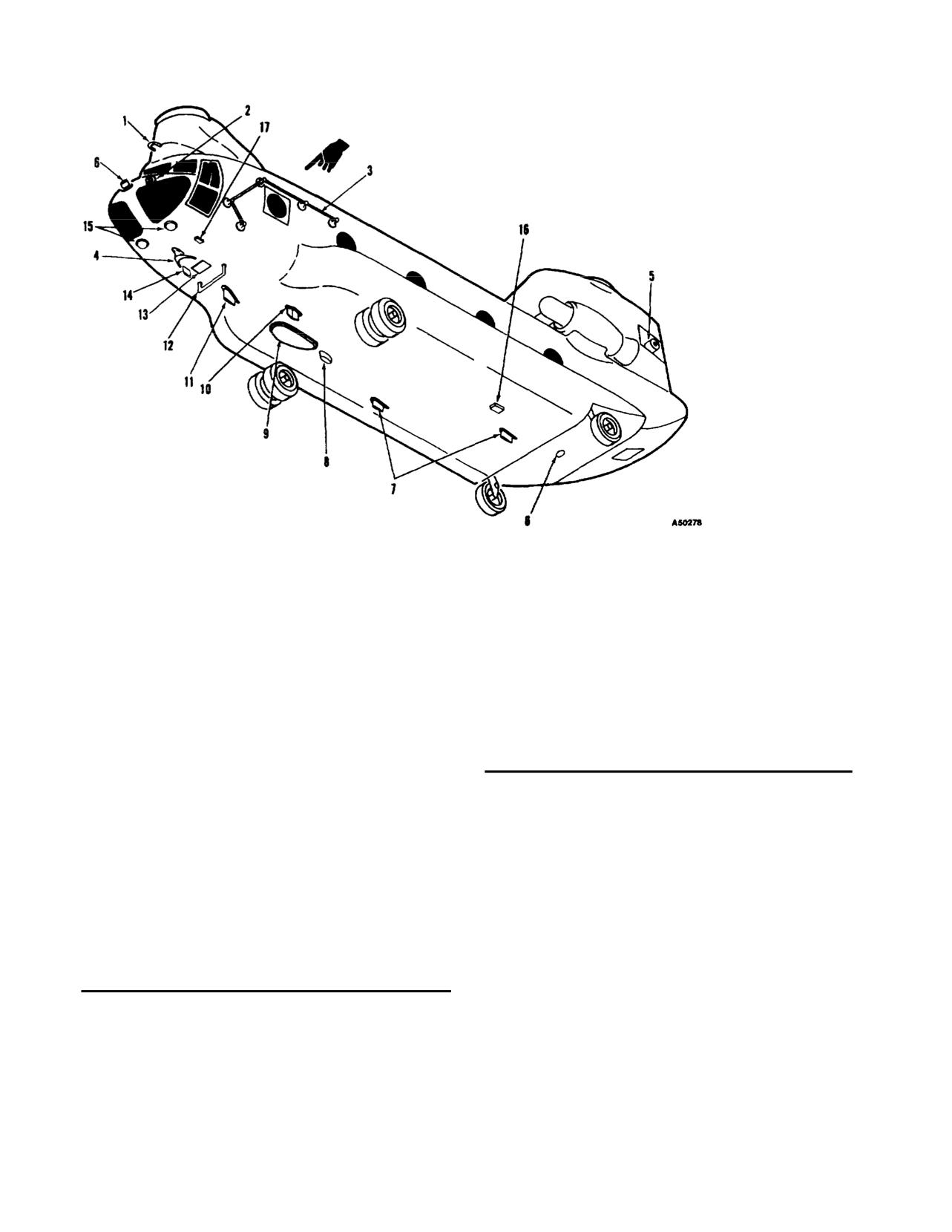
TM
55-1520-240-10
1. Glide slope
9. ADF loop and sense antennas
2. Radar warning
10.UHF-AM
3. HF ARC-199 antenna
11. VHF AM/FM (typical top and bottom)
4. VHF navigation
12.FM homing
5. Radar warning
13. Doppler navigation
6. IFF
14.Radar warning
ntenna
7. ECM antennas
15. Radar altimeter
8. Marker beacon
16.Omega antenna
17. Omega temperature probe
Figure 3-3. Antenna Locations
(MWOD) loading. The basic HAVE QUICKFUNCTIONio allowFREQUENCY
USE
loading a single WOD, in volatile memory.
logged for an en-
Four operating modes are used within the radio set to
tered date code.
initiate various Have Quick (HQ) proMWOD loadun220.025.
Enables the load-
They are accessed via preset 20 with the frequencies listed
ing of MWODs.
in Table 3-1.1. The functions are Operate/verify, MWOD
MWOD Erase
220.050
Enables the pilot
load, MWOD erase, and frequency managed training (FMT)
to completely
frequency load.
erase the non-
volatile memory
Table 3-1.1.
Have Quick II Additional Functions
containing the
Frequency and USE.
MWODs.
FUNCTION
FREQUENCY
USE
FMT frequen
220.075
Enables the load-
load
ing of training
Operate/veri
20,000
Places the radio
frequencies.
in the normal op-
erating mode anMWOD data is stored in nonvolatile memory
provides for tradio set. Seven memory locations are avail
verification oMWOD
with the capability of storing a max
MWOD
MWODs within the radio set. The channel
3-6
Change
11
TM 55-1520-240-10
the manual frequency selectors, and the tone button are
Table 3-1.2 Net selection (Continued)
utilized to load the required segments for each MWOD.
TRAINING
Channel positions 20-14 are used to facilitate the load-
ing of MWOD segments. A minimum of one WOD must
00 - Basic HAVE QUICK Training
be stored for the unit to be functional in the AJ mode.
25
- HAVE QUICK II Training
Channel position 14 is used for day-of-month informat-
50/75 Not Used- Interrupted Fault Tone
ion (date code). The date code is represented by
frequency 3AB.000 MHz in which AB is the day of the
Table 3-1.3 Net Type, Quantity, and Frequency Range
month. For example; if today’s date is the 15th of the
month, the date code entry would be 315.000 MHz.
Types of Nets
Quantity
Range of Nets
Channel position 1 is used for entering the current
operational date when HQ II TOD is not available. The
format used to enter the operational date is the same as
Basic HQ Training
5
A00.000 - A000.400
the date code format.
Basic HQ Tactical
1000
A00.000 - A01.500
HQ H Training
16
A00.025 - A01.525
When the radio is turned off or power is lost after entry
HQ II Tactical
1000 A00.0XX-A99.9XX
of MWOD and date code, the data is not lost; therefore,
the information remains intact until manually changed
or erased. The six most recently entered MWOD’s are
NOTE
retained. If a MWOD with a duplicate date is entered,
Any selection of a net number outside the-
the new entry takes precedence.
range indicated, for each type of net, will
After the MWOD information is entered, the pilot
result in the invalid net number warning
would proceed to obtain the TOD. Operational date
tone.
information is part of the HQII TOD message. If HQII
TOD message is unavailable, the pilot must manually
enter the operational date so the radio can select the
3-7.5. Conferencing. In the AJ mode, the radio has
proper MWOD. If power is lost, operational date is lost
the capability to receive and process two simultaneous
and must be reentered.
transmissions on the same net. This conferencing capa-
bility is selected by the hundredth and thousandth digits
3-7.3. Time-of-Day. The TOD is essential for com-
of WOD segment 2, loaded using channel position 19
municating in the AJ mode which allows frequency-
and is disabled when operating in the secure speech
hopping at the same instant in time. Reception and
mode.
transmission of the TOD is possible in normal and AJ
modes. The first TOD reception must occur in the
In a conference net, the second transmitting radio will
normal mode.
automatically shift its transmission frequency by 25 kHz
The radio automatically accepts the first TOD message
when it monitors a transmission on the primary net
once the predesignated frequency for TOD transmis-
frequency. The wide band receiver will monitor both
sion has been entered and the T position of the
transmissions without the interference normally associ-
hundredth megahertz selector has been momentarily
ated with two radios transmitting on the same frequency
selected and released. Subsequent messages are ignored
simultaneously. Three simultaneous transmissions will
unless the pilot enables the radio to receive a new/
create garbled reception.
updated TOD. The TOD contained in a radio may also
be sent to other radios similarly equipped.
3-8. Controls and Function, UHF-AM Have Quick
II Radio (AN/ARC-184). (fig. 3-4)
3-7.4. Net Number. The net number enables multi-
ple station nets to operate simultaneously on a non-
CONTROLS/
interfering basis in AJ mode, while sharing a common
INDICATOR
FUNCTION
WOD and TOD. The net number begins with the letter
A and is followed by three digits from 000 to 999. The
Function Select Switch
Four position rotary
last two digits of the display designate how the radio is
switch used to select radio
to function and/ or the frequency hopping table being
operating mode.
used (Table 3-1.2). Net number availability is depend-
OFF
Power to set is disabled;
ent on the operational mode of AJ and is depicted in
radio set inoperative.
Table 3-1.3.
MAIN
Radio set can be used to
Table 3-1.2 Net selection
transmit and receive;
guard receiver inopera-
TACTICAL
tive.
BOTH
Radio set can be used to
00 - Basic HAVE QUICK
transmit and receive;
25
- HAVE QUICK II NATO Hopset
guard receiver operates.
50 - HAVE QUICK II non-NATO Hopset
75
- Not Used-Interrupted fault Tone
ADF
Not used.
Change
3
3-7
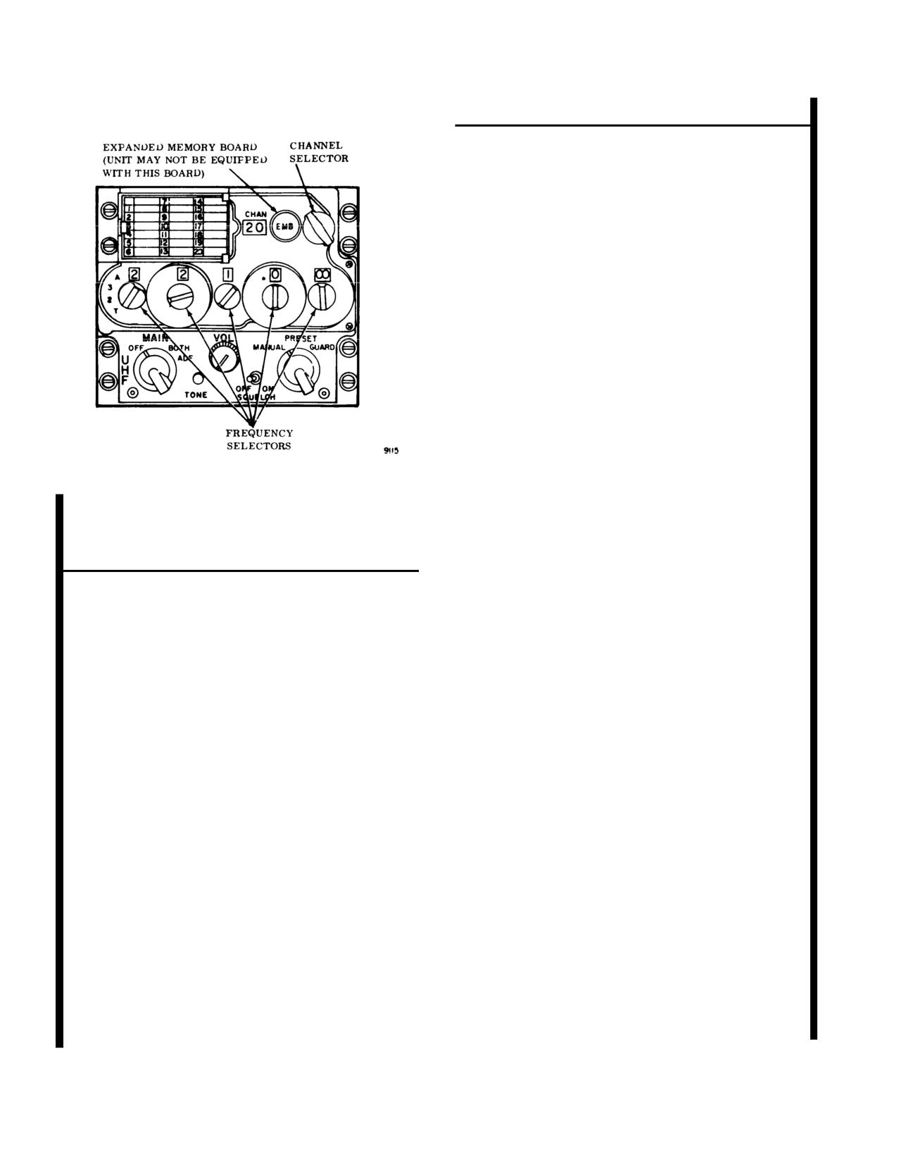
TM 55-1520-240-10
CONTROLS/
INDICATOR
FUNCTION
VOL
Rotary control used to
adjust radio output vol-
ume.
SQUELCH Switch
Two position toggle switch
to select radio squelch
mode.
OFF
Squelch is disabled.
ON
Squelch is enabled.
Frequency Mode Selector
Three position rotary con-
trol used to select fre-
quency tuning mode.
MANUAL
Permits manual frequency
selection using frequency
controls.
PRESET
Permits selection of preset
channel frequencies in
radio set (maximum of 20
channels).
GUARD
Automatically disables the
anti-jam mode and tunes
Figure 3-4. UHF-AM Have Quick II Radio (AN/
radio set to guard channel
ARC-764)
frequency (243.000 MHz).
Frequency Selectors
Five rotary controls used
CONTROLS/
to select radio operating
INDICATOR
FUNCTION
frequency or state.
TONE
Momentary contact
100 MHz Control
Four position rotary con-
switch. Pressing the
(A-3-2-T)
trol switch.
TONE switch when in the
A
Selects anti-jam mode.
normal mode enables a
3
Hundreds digit of desired
1020 Hz tone on the se-
lected frequency, unless
frequency while in the
normal mode.
TOD has been accepted
in which case a1667 Hz-
2
Hundreds digit of desired
tone is heard prior to the
frequency while in the
1020 Hz tone. When A-3-
normal mode.
2-T switch is in A, it en-
T
Momentary spring-return
ables TOD transmission
position which enables the
followed by a 1020 Hz
radio to accept a new
tone on the selected fre-
TOD for up to one
quency. When A-3-2-T
minute after selection.
switch is in T, it initiates
Also used in conjunction
the emergency startup of
with the tone button in
the TOD clock. When in
the emergency startup of
the load mode, Pressing
the TOD clock when
the TONE switch with
TOD is not available from
channels 1, 14, or 15
external sources.
through 20 selected in the
10 MHz Control
Ten position (0 through
9)
manual mode enters the
rotary control used to se-
MWOD data into non-
lect second digit of oper-
volatile memory. Pressing
ating frequency. When in
the TONE switch when in
AJ mode, it selects the
the erase mode, erases all
first digit of net number.
MWOD data from non-
volatile memory.
3-8
Change 3
TM 55-1520-240-10
CONTROLS/
b. Presetting Channels. Perform the following steps
INDICATOR
FUNCTION
to preset a channel to a desired frequency.
(1)
Set the Frequency Mode Selector to PRE-
1 MHz Control
Ten position (0 through 9)
SET.
rotary control used to se-
lect third digit of operat-
(2)
Use the manual frequency selector switches
ing frequency. When in
to select the frequency to be placed in mem-
AJ mode, it selects the
ory.
second digit of net num-
(3)
Turn the preset channel control switch to the
ber.
desired channel number.
0.1 MHz Control
Ten position (0 through 9)
rotary control used to se-
(4)
Raise the cover under the channel card. Press
lect fourth digit of operat-
and release the PRESET switch. Close the
ing frequency. When in
cover.
AJ mode, it selects the
(5) Using a soft lead pencil, record the frequency
third digit of net number.
selected for the channel number on the card
0.025 MHz Control
Four position rotary con-
provided.
trol used to select fifth
c. Stopping. Function switch - OFF.
and sixth digits of operat-
ing frequency. Operates in
3-9.1. Anti-Jam Operation - UHF-AM Have Quick
0.025 MHz increments.
II Radio. The following steps provide AJ operating
When in the AJ mode, it
procedures.
selects the appropriate fre-
quency table within the
a. MWOD Loading.
radio net.
(1)
Perform paragraph 3-9 Starting steps a(1)
and a(2).
Frequency Display
Six digit display
(200.00
(2)
Channel selector switch - Set to 20.
through 399.975) displays
selected radio operating
(3)
Frequency mode selector switch - PRESET.
frequency.
(4)
Frequency selector switches - Set
220.025
Channel Selector
Used to select and display
MHz.
any of the 20 preset radio
(5)
PRESET switch
- Press. Radio is now pro-
frequency channels.
grammed to accept MWOD.
Displays selected preset
(6)
Frequency mode selector switch - MAN-
channel.
UAL.
PRESET Switch (Under
Momentary contact
channel/frequency card)
switch, when depressed
(7)
Frequency selector switches - Enter first
causes selected radio fre-
WOD segment.
quency entered on fre-
(8)
TONE switch
- Press. First WOD segment
quency display to be
is now loaded to the nonvolatile memory of
stored in channel indi-
the radio - Listen for BEEP.
cated on channel display,
(9)
Channel selector switch - Set to 19.
in normal operation.
(l0)
Frequency selector switches - Enter sec-
3-9. Normal Operation - UHF-AM Have Quick II
ond WOD segment.
Radio. The following steps provide operating proce-
(11)
TONE switch - Press.
dures.
(12)
The remaining four WODs can be loaded in
a. Starting.
a similar fashion by dialing the next lower
(1)
Interphone control panel - Set switches as
preset channel, selecting the next WOD
follows:
segment. After entering last segment, listen
for a double (3125 Hz) beep.
(a) Receiver 2 switch - ON.
(13)
Channel selector switch - Set to 14.
(b) Function select switch - 2.
(14)
Frequency selector switches - Enter date
(2)
Function switch - MAIN or BOTH.
code.
(3)
Mode selector
- As required.
(15) TONE switch
- Press. At this time, one
complete WOD with its corresponding date
(4)
SQUELCH switch
- As required.
code has been entered to the nonvolatile
(5) VOL control
- As required.
memory.
Change 3
3-8.1
TM 55-1520-240-10
(16)
Additional WODs can be loaded by repeat-
(6) TONE switch
- Press. All MWODs are now
ing steps (5) through (15). Once WODs
erased.
have been entered, today’s operational date
d. Training Frequency Load.
must then be entered.
(1)
Channel selector switch - Set to 20.
(17)
Channel selector switch - Set to 1.
(2)
Frequency mode selector switch - PRESET.
(18)
Frequency selector switches - Enter oper-
ational date.
(3)
Frequency selector switches - Enter 220.075
MHz.
(19) TONE switch - Press.
(4)
PRESET switch - Press.
b. Operate/Verify Modes.
(5)
Frequency mode selector switch - MAN-
(1) Operate Mode.
UAL.
(a)
Frequency mode selector switch - PRE-
(6)
Frequency selector switches - Enter desired
SET.
training frequency.
Channel selector switch - Set to 20.
(7)
TONE switch
- Press. A single beep will be
(b)
heard.
(c)
Frequency
selector switches - Enter
220.000 MHz.
(8) The next frequency is loaded by entering the
next lower preset channel, selecting the next
(d) PRESET switch -
Press. Radio set is
training frequency, and pressing the TONE
now programmed to operate in either
switch. Up to 16 training frequencies may be
normal mode or anti-jam mode.
entered. Following this procedure.
(2) Verify Mode.
e. TOD.
(1) TOD Receive/Update.
NOTE
This verification test only checks for pres-
NOTE
ence of a WOD with the corresponding date
The first TOD message received within one
code. It does not check for the authenticity
minute of selecting T on the hundreds fre-
of the WOD segments entered.
quency selector switch will be accepted.
When communications are slightly garbled
but otherwise acceptable during AJ opera-
(a)
Channel selector switch - Set to 20.
tions, this is an indication of drift in TOD
Frequency mode selector switch - MAN-
synchronization. A TOD update should be
(b)
UAL.
performed.
(c) Frequency
selector switches - Enter
date code to be verified.
(a) Frequency selector switches or channel
selector switch
- Set to predetermined
TOD frequency.
NOTE
If a single beep is not present for a particular
(b) Hundreds frequency selector switch -
date code and the anti-jam mode is entered
Momentarily select T, then release. A
using that date, a constant warning tone will
momentary 1667 Hz tone will be heard
be heard signifying that the anti-jam mode
while receiving the TOD message.
initialization cannot be properly completed.
NOTE
The following step is not necessary if TOD
(d) Channel selector switch - Set to 19, then
message is being transmitted continuously
back to 20. A single beep will be heard if
on the predetermined TOD frequency; for
a WOD with the date code in step (c) is
example, continuous TOD message is being
present.
transmitted from a satellite.
c. Erase Mode.
(c) Request TOD from another station within
(1)
Channel selector switch - Set to 20.
the net.
(2)
Frequency mode selector switch - PRESET.
(2) TOD Send.
(3)
Frequency selector switches - Enter
220.050
(a) Frequency selector switches or channel
MHz.
selector switch - Set to predetermined
(4)
PRESET switch - Press.
TOD frequency.
(5)
Frequency mode selector switch - MAN-
(b) TONE switch -
Press. A momentary
UAL.
1667 Hz tone will be heard, when the
3-8.2
Change 3
TM 55-1520-240-10
TOD message is transmitted, followed by
by the HSI MODE SELECT panel, steering informa-
a 1020 Hz tone until switch is released.
tion will be shown by the course deviation indicator;
homing signal strength will be shown by the glideslope
(3) Emergency TOD Start-up.
deviation pointer; and homing signal adequacy warning
NOTE
will be shown by the glideslope failure and navigation
failure warning flags. The set operates on 28-volt DC
The emergency TOD start-up provides an
power: No. 1 set receives power from the DC essential
arbitrary TOD which is not synchronized to
bus through the COMM VHF NO. 1 AM/FM circuit
coordinated time. The radio set will not
communicate with any other Have Quick II
breaker in the No. 2 PDP; No. 2 set receives power from
radio set in AJ mode unless this new TOD is
the No. 1 DC bus through the COMM VI-IF NO.
2
transmitted to other radio sets.
AM/FM circuit breaker on the No. 1 PDP.
b. Antenna Select System
Three antennas are in-
(a)
Perform step a MWOD Loading
stalled as part of the AM/FM radio installation: a top
and bottom communications antenna and a FM homing
(b)
Perform step b (1) Operate Mode
antenna. Both AM and FM can be transmitted and
(c)
Hundreds frequency selector switch -
received over the same antenna but not at the same
Select T and hold while simultaneously
time. Antenna selection is controlled by the two position
pressing TONE switch. A 1667 Hz tone
VHF ANT SEL switch on the center instrument panel.
will be heard when the TOD is pro-
The normal switch position is down at the SYS 2 - SYS
grammed.
1 position. The No. 1 AM/FM set is connected to the
(d)
TONE switch - Release.
bottom antenna and the No. 2 AM/FM set is connected
(e) Hundreds frequency selector switch -
to the top antenna. If a water landing is to be made or
Release.
the bottom antenna is damaged, setting the switch up to
SYS 1- SYS 2 reverses the normal antenna connections
f. Anti-Jam Mode.
and connects the No. 1 AM/FM set to the top antenna
(1)
Perform paragraph 3-9 step a Starting.
and the No. 2 AM/FM set to the bottom antenna. This
ensures that secure voice is available through the top
(2)
Load MWOD - Refer to paragraph 3-9.1
antenna. Power to operate the system is supplied by the
step a MWOD Loading.
DC essential bus through the VHF ANT SEL circuit
(3)
Receive TOD -
Refer to paragraph 3-9.1
breaker on the No. 2 PDP.
step e(1) TOD Receive/ Update.
(4) Perform paragraph 3-9.1 step b(1) Operate
NOTE
Mode.
The antenna select system has no effect on
the FM homing antenna. The homing an-
NOTE
tenna (towel bar) is on the bottom of the
A steady 3125 Hz warning tone will be heard
fuselage aft of the cockpit (fig. 3-3) and is
connected to the FM set only.
when the anti-jam (A) mode is selected and
either the WOD is not in the nonvolatile
memory or the TOD has not been pro-
grammed.
3-11. Controls and Function, VHF AM/FM Radio
Set. (fig. 3-5)
(5) Hundreds frequency selector switch - A.
CONTROLS/
INDICATOR
FUNCTION
(6) Other frequency selector switches - Enter
net number.
Mode Select
Three position rotary
Switch
switch used to select radio
3-10. VHF AM/FM Radio Sets (AN/ARC-186).
operating mode. Power is
a. One or two VHF AM/FM radio sets (AN/ARC-
applied to radio in all po-
186) are installed: No. 1 set on the pilot side of the
sitions except OFF.
console, No. 2 on the copilot side. Each set provides
OFF
Power to set is disabled,
communications in the VHF AM and FM bands. The
radio is inoperative.
set operates in the following modes and frequency
ranges: AM reception between 108.00 and
151.975
TR
Radio operates in the
MHz, AM receive and transmit between 116.000 and
transmit-receive mode.
151.975 MHz, and FM transmit, receive, and homing
DF
Radio operates in the di-
from 30.000 to 87.975 MHz. Channel spacing is 25 kHz
rection finder mode.
in all bands. Up to 20 channels plus two guard channels
Frequency Control/
Four position rotary used
can be prestored in the set (removing power from the
Emergency Select
to select radio frequency
set does not affect stored channels). When the set is
Switch
tuning mode.
used for FM homing and selected for display on the HSI
Change 3
3-8.3
TM 55-1520-240-10
CONTROLS/
CONTROLS/
INDICATOR
FUNCTION
INDICATOR
FUNCTION
EMER AM
Radio is tuned to AM
Frequency Display
Display selected radio op-
Guard channel frequency.
crating frequency.
EMER FM
Radio is tuned to FM
WB/NB/MEM LOAD
Three position toggle
Guard channel frequency.
Switch (under channel
switch used to select radio
NAB
card)
operating band, and dur-
Allows manual tuning of
ing preset channel fre-
radio operating frequency.
quency loading.
PRE
Allows selection of any of
NB
Places radio in NB (nar-
20 preset operating fre-
row band) operation.
quencies.
WB
Places radio in WB (wide
VOL
Rotary control adjusts
band) operation.
radio output volume.
SQ DIS/TONE
Three position toggle
NOTE
Switch
switch used to select radio
Switch will remain in WB position unless otherwise
squelch operation.
instructed by radio set controller.
Normal (center
Preset squelch level is se-
position)
lected.
MEM LOAD
Momentary contact posi-
tion used with frequency
SO DIS
Squelch operation is dis-
controls and channel se-
abled.
lector to load preset chan-
TONE
Not used - maintenance
nels.
operation only.
Preset Channel Selector
Twenty position rotary
3-12. Normal Operation - AM/FM Radio Set. The
control used to select any
following steps provide operating procedures.
of 20 preset channel fre-
quencies.
a. Starting.
Display selected radio op-
(1) Interphone control panel - Set switches as
erating preset channel.
follows:
Frequency Controls
Four rotary controls used
to manually select radio
(a) Receiver 3 switch - ON.
operating frequency.
(b) Selector switch - 3.
10 MHz Control
Thirteen position
(03
through 17) rotary control
(2) VHF ANT SEL switch - SYS 2- SYS 1.
used to select first and
second digits of operating
b. Transmit-receive mode.
frequency.
(1)
Mode select switch - TR.
1 MHz Control
Ten position (0 through 9)
(2)
Frequency Control/Emergency Select Switch -
rotary control used to se-
As required. If greater receiver sensitivity
lect third digit of operat-
ing frequency.
is required, set the SQ DIS/TONE switch
to SQ DIS.
0.1 MHz Control
Ten position (0 through 9)
rotart control used to se-
(3) VOL control
- As required.
lect fourth digit of operat-
ing frequency.
0.025 MHz Control
Four position rotary con-
trol used to select fifth
and sixth digits (00
through 75) of operating
frequency in 0.025 MHz
increments.
3-8.4 Change
3
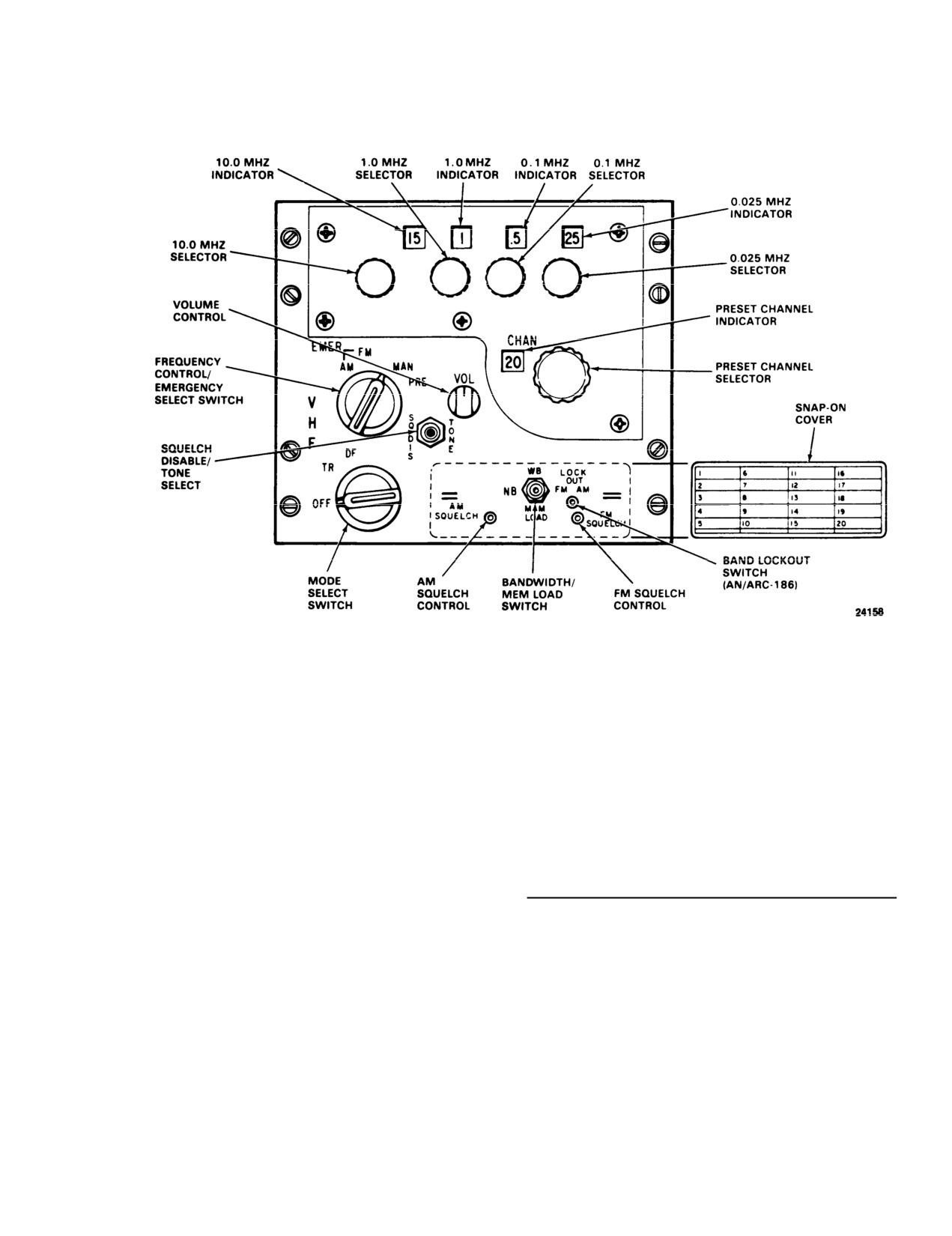
TM 55-1520-240-10
Figure 3-5. VHF AM/FM Radio Set (AN/ARC- 786)
c. Stopping. Mode select switch - OFF.
3-13. VHF/FM Radio Set (AN/ARC-201).
d. Presetting channels. Perform the following steps to
The AN/ARC-201 is located on the pilot instrument
preset a channel to a desired frequency.
panel and provides two-way frequency modulated
(FM)
narrow band voice communications.
(1)
Mode select switch - TR.
a. The following items form the airborne radio sys-
(2)
Frequency select switch - MAN.
tem.
(3)
Rotate the four frequency select switches
until the desired frequency is displayed.
ITEM
DESCRIPTION
(4)
Rotate the preset channel selector until the
1.
Receiver-Transmitter Radio Panel Mounted
desired channel appears in the preset CHAN
(RT-1476)
indicator.
2.
Amplifier (AM 7189)
(5)
Remove the snap-on cover.
(6)
Momentarily set the bandwidth WB, NB,
b. Essential Operational Technical Characteristics.
MEM LOAD switch to MEM LOAD. The
Except where specifically indicated otherwise, the fol-
preset frequency is now in memory.
lowing operational/ technical parameters are the mini-
(7)
Using a soft lead pencil, record the loaded
mum essential characteristics. Unless otherwise speci-
frequency opposite the channel number on
fied, they apply to each radio configuration.
the snap-on cover.
c. Frequency Range. The frequency range is 30 to
(8) Using the above procedure, preset any other
channelized in tuning increments of
25
channels and install the snap-on cover.
kHz. In addition a frequency offset tuning capability of
3-9