TECHNICAL MANUAL MAINTENANCE MANUAL FOR ARMY CH-47D HELICOPTER (1992) - page 3
TM 55-1520-240-10
When the right pedal is displaced forward, the forward
not apparent to the pilot because AFCS control inputs
rotor disk tilts to the right and the aft rotor disk tilts to
do not move the cockpit controls. The pitch, roll, and
the left. The opposite action occurs when the left pedal
yaw axis all operate in fundamentally the same manner,
is displaced forward. An ILCA is installed to assist the
Should a hardover occur, the pilot can easily override
pilot in moving the pedals.
AFCS.
The pedals are adjusted individually fore and aft by
f. Pitch attitude stability, airspeed hold, and a posi-
pressing a lever mounted on the pedal support and
tive stick gradient from hover to Vmax are provided
moving the pedal to a new position before repositioning
through the DASH actuator. The DASH actuator ex-
the lever. Insure that both pedals are adjusted equally
tends or retracts to maintain airspeed for a given stick
(left and right pedals in same respective hole position)
position.
and pedal adjustment lockpins are engaged. A balance
2-84. Bank Angle Hold.
spring is installed to stop pedal creep. A viscous damper
is installed to reduce control sensitivity.
Bank angle trim without cyclic stick movement is pro-
vided through left or right positioning of the cyclic stick
2-83. Advanced Flight Control System (AFCS).
AFCS trim switch. Bank angle hold is disengaged
anytime a CENTERING DEVICE RELEASE switch is
a. The Advanced Flight Control System (AFCS) sta-
pressed, a cyclic stick is moved laterally, or the HDG
bilizes the helicopter about all axes and enhances
switch is ENGAGED. Bank angle hold cannot be
control response. It automatically maintains desired
reengaged until the roll rate is less than 1.5° per second.
airspeed, altitude, bank angle, and heading. An auto-
matic turn feature, coupled to the pilot or copilot HSI
2-85. Heading Hold.
(horizontal situation indicator) is also included in the
AFCS.
The directional gyro provides an input to each AFCS
which signals the yaw ILCA to maintain heading within
b. Built In Test Equipment (BITE) is installed in
5 degrees. Heading hold is disengaged if the swivel
each AFCS computer. This equipment is intended for
switch is set to STEER or UNLOCK, a CENTERING
ground troubleshooting purposes only. An interlock
DEVICE RELEASE switch is pressed, or the direc-
circuit through the engine condition control box pre-
tional pedals are moved. Also, heading hold will be
vents BITE use anytime either ECL is out of STOP.
disengaged at airspeed
above 40
knots anytime lateral
c. Power is supplied to the HDG ENGAGED, BARO
trim is used, the stick is moved laterally, or the HDG
ALT and RAD ALT ENGAGED lights from the DC
switch is ENGAGED. Heading hold will not resume
essential bus through the CAUTION PNL circuit
until yaw rate is less than 1.5° per second at an airspeed
breaker on the No. 1 PDP. The No. 1 AFCS receives AC
above 40 knots with a bank angle of
less than 1.5°.
and DC power from the No. 1 AC and DC buses
respectively through the AFCS NO. 1 circuit breakers
2-86. Airspeed Hold.
on the No. 1 PDP. The No. 2 AFCS receives AC and
The airspeed hold feature provides a constant airspeed
DC power from the No. 2 AC and DC buses respectively
and pitch attitude relative to cyclic stick position at
through the AFCS NO. 2 circuit breakers on the No. 2
airspeeds above 40 knots. Airspeed and pitch can be set
PDP.
with the AFCS trim switch on the cyclic stick or by
d. The AFCS consists of the following components:
displacing the cyclic stick until the desired airspeed is
achieved then pressing the CENTERING DEVICE
(1) A cockpit control panel.
RELEASE switch. Refer to Chapter 8 AFCS Off Flight
(2) Two AFCS computers in the avionics com-
Characteristics.
partment.
2-87. Altitude Hold.
(3) Three ILCA’s in the flight controls closet.
Two methods of altitude hold can be selected. They are
(4) A differential airspeed hold (DASH) actua-
radar altitude hold or barometric altitude hold.
tor in the flight controls closet.
a. Radar Altitude Hold.
Radar altitude hold will
(5) Two longitudinal cyclic trim (LCT) actuators
maintain a more precise altitude in hover or over water
are installed, one in the forward upper controls, the
flight than barometric altitude hold. Maximum altitude
other in the aft upper controls.
for the use of radar altitude hold is
1,500 feet AGL.
(6) Roll and yaw magnetic brakes, a longitudinal
An error signal, caused by radar altitude deviations, is
CCDA, and a thrust CCDA are all located in the flight
derived from the pilot radar altimeter receiver-
controls closet.
transmitter and is processed by the No. 1 AFCS com-
(7) Three control position transducers.
puter. The processed error signal is applied to the
collective CCDA which drives the THRUST CONT
e. Attitude changes sensed by the attitude gyros, a
levers in the direction necessary to null the error signal.
yaw rate gyro in each AFCS computer, and the direc-
tional gyro are processed by the AFCS computers and
b. Barometric Altiude Hold.
Barometric altitude hold
applied to the ILCA’s. The ILCA’s extend or retract
is used in forward flight over terrain. It uses error
and move the upper flight controls. This control input is
signals produced within the No. 1 AFCS computer.
2-35
TM 55-1520-240-10
These error signals are in response to static pressure
changes and are proportional to altitude changes. The
signal is processed by the AFCS computer and applied
to the collective CCDA which drives the THRUST
CONT levers in the direction necessary to null the error
signal.
2-88. Heading Select,
Heading select is engaged when the HDG switch on the
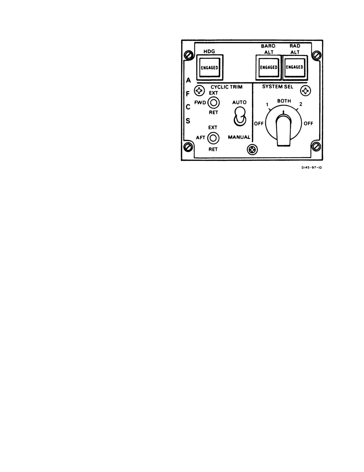
AFCS panel (fig. 2-28) is pressed and the ENGAGED
light illuminates. The heading bug on the selected HSI
is the referenced heading. Rotating the HDG knob of
the HSI to set the bug at a new referenced heading
produces an error signal which is processed by the
AFCS computers and applied to the roll ILCA. The roll
ILCA then moves to produce a standard rate turn up to
a maximum bank angle of 2°
until the selected heading
is captured. Heading select can only be selected at
airspeeds above 40 knots. Heading select is disengaged
anytime a CENTERING DEVICE RELEASE switch is
pressed, the HDG switch on the AFCS panel is disen-
gaged, or when the opposite CMD SEL switch on the
Figure 2-28. Advanced Flight Control System
HSI MODE SELECT panel is pressed. .
Panel
2-89. Longitudinal Cyclic Trim System.
Heading select is disengaged if either CENTERING
Longitudinal cyclic trim (LCT) control is part of AFCS.
DEVICE RELEASE switch is pressed.
LCT reduces fuselage nose down attitude as forward
(2) BARO ALT and RAD ALT Switches. The
airspeed is increased, thus reducing fuselage drag. The
BARO ALT and RAD ALT are used to select altitude
system also reduces rotor blade flapping which results in
hold mode. An interlock prevents both switches from
lower stresses on the rotor shafts. The LCT actuators
being engaged at the same time. When pressed, the
are installed under the swashplates. Signals are trans-
ENGAGED legend will illuminate. RAD ALT hold is
mitted to these actuators either automatically by AFCS
used below 1,500
feet AGL. BARO ALT hold is used in
or manually by CYCLIC TRIM switches on the AFCS
forward flight to maintain a constant cruise altitude or
panel. Landing gear proximity switches drive the actu-
may be used in HOGE.
ators to GND (ground) operating position on ground
contact.
b. SYSTEM SEL Switch.
The SYSTEM SEL switch
is a five position rotary switch labeled OFF, 1, BOTH, 2,
2-90. Controls and Indicators.
OFF. Normally, the switch is at BOTH. In this position,
both AFCS are operating at
one-half gain. If one system
2-91. AFCS Control Panel. The AFCS control panel
should fail, the good system is selected and that system
(fig. 2-28) is on the canted console. It consists of the
operates at
3/4 gain. At OFF, both systems are inoper-
heading and altitude select, SYSTEM SEL (select), and
ative except for CYCLIC TRIM.
CYCLIC TRIM sections.
c. CYCLIC TRIM Switches.
The AUTO and MAN-
a. Heading and Altitude Select Switches.
The legend
UAL switch selects the mode of cyclic trim operation.
on these switches will dim when the PLT INST rotary
The FWD and AFT switches are used to extend or
control switch is placed out of the OFF detent.
retract the appropriate cyclic trim actuator.
(1) HDG Switch. The HDG (heading) switch is
(1) AUTO and MANUAL switch. A two-position
used in conjunction with the CMD SEL switch on either
switch which is normally placed in AUTO.
HSI MODE SELECT panel and the heading bug on
either HSI to select coupled turns. The switch can be
(a) AUTO Mode. In this mode, No. 1 AFCS
used only when airspeed is
above 40 knots. When the
controls the forward actuator and the No. 2 AFCS
switch is pressed and either CMD SEL switch is pressed,
controls the aft actuator.
the helicopter will automatically turn to and capture the
heading bug on the selected HSI. In addition, the
(b) MANUAL Mode. In this mode, the actu-
ENGAGED legend will illuminate. The switch is disen-
ators can be controlled with separate FWD and AFT
gaged by pressing it again.
actuator control switches, using the airspeed indicator
and the CYCLIC TRIM indicators.
Heading intercept will be at a standard rate of
3° per
second up to a bank angle limit of
20° at 133 knots. The
(2) FWD and AFT switches. Three-position
helicopter must be trimmed before engaging the mode
switches that can be placed in the EXT (extend) or RET
and cyclic stick control inputs should be avoided except
(retract) position. These switches are spring-loaded to
for longitudinal AFCS trim inputs to adjust airspeed.
the center off position. If the cyclic trim actuators fail to
2-36
TM 55-1520-240-10
extend or retract as indicated on the CYCLIC TRIM
indicators, MANUAL mode can be selected.
2-92. Cyclic Trim Indicators.
If the longitudinal cyclic trim actuators fail
at the full retract position or are manually
selected to the full retract position, do not
exceed the airspeed limitations shown in fig.
5-6.
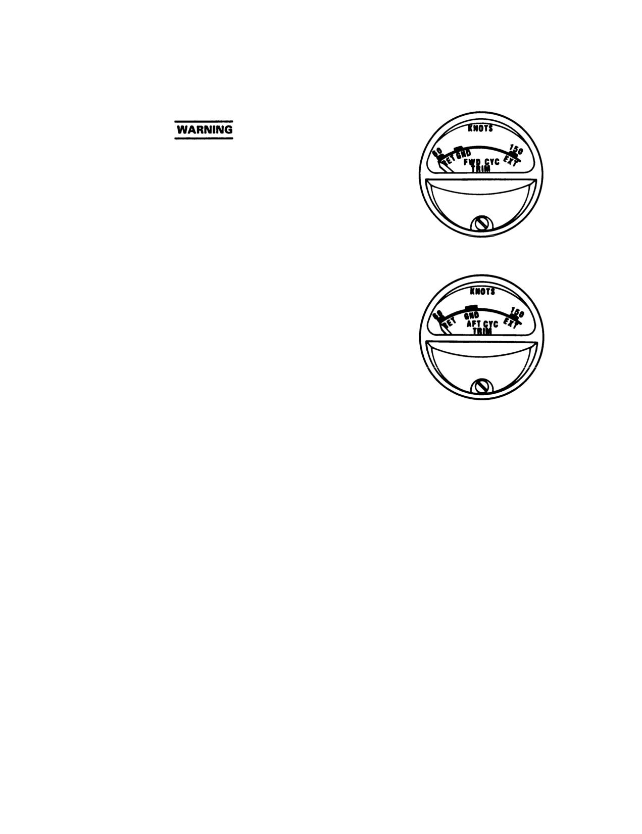
The FWD and AFT CYC (cyclic) TRIM indicators (fig.
2-29) are on the center instrument panel. The indicators
are labeled 60 RET, GND, 150 EXT. The indicators
display position of the forward and aft LCT actuators
relative to airspeed. During ground operations, the
pointer will be at GND to indicate activation of the
landing gear proximity switches.
2-93. AFCS OFF Caution. Two AFCS OFF caution
capsules are on the master caution panel (fig. 2-51).
They are labeled NO. 1 AFCS OFF and NO. 2 AFCS
OFF. These cautions will illuminate when the associ-
ated AFCS is manually shutoff or has failed or the
associated DASH is in a low rate condition. Refer to
Chapter 8 AFCS Off Flight Characteristics.
2-94. Command Select Switch. The CMD SEL
switch is on the pilot and copilot HSI MODE SELECT
panels (Chapter 3). The switches are used to select the
HSI which will provide the referenced heading when the
HDG switch is engaged. Only one CMD SEL switch
may be selected at a time. If the other CMD SEL switch
is selected during heading select operations, the HDG
switch on the AFCS panel will disengage and heading
Figure 2-29. Forward and Aft Cyclic Trim
select will be disabled until the HDG switch is again
Indicators
pressed. When selected, the SEL legend on the switch
illuminates.
2-37
TM 55-1520-240-10
SECTION VI HYDRAULIC SYSTEMS
2-95. Hydraulic Power Supply System.
2-98. Utility Hydraulic System.
The hydraulic power supply systemThe utility hydraulic sy
stem supplies hy
rate systems. They are the No. 1 flight control system, No.
wheel brakes, power steering actuator, s
2 flight control system, and a utility system. Each system
ing cams, ramp actuating cylinders, hyd
includes a variable delivery pump and a reservoir cooler. In
motor, actuator for the center cargo h
addition, each flight control system has a power control
winch control valve, two engine starters
module, and the utility system has a pressure control
start circuit. When the APU is running,
module. Each flight control system is connected to the
system is pressurized by an APU driven
utility system by a power transfer unit (PTU). All systems
APU is not running and the rotors are t
are serviced by a common fill module and are pressurized to
hydraulic system is pressurized by an
prevent pump cavitation.
driven pump.
2-96. Flight Control Systems.
The utility hydraulic system incorporate
The No. 1 and No. 2 flight control systems are identical.
module which isolates utility subsystems
They are parallel in operation, hydraulically separated, and
When a failure occurs in one utility hy
electrically integrated. The flight control systems operate at
the remaining subsystems continue to op
approxi
3,000
psi, which is
500
psi for
the BRK STEER and RAMP PWR switches in t
ILCA operation. They power four dual upper boost actua-
are set to OFF.
to
(3,000
psi) and four
1,500
psi). Each flight
control system powers
one piston The APU starting.
subsystem of the utilit
No. 1 flight control system is princludes three accumulators which accele
forward transmission. No.
2 syststart, maintain reservoir pressure throu
pump on the aft transmission. Theand control operationsf the APU motor
consist of pressure-operated valstarting subsystem also
includes a two-s
pressure-line and return-line filcharging.
the APU start accumulators. The
control module is in the forward is normally recharged by
the APU motor-
control module is in the aft pylon. The accumulators
ditional accumulato
APU is started An ad
dampen low frequency pressure surges and provide stored
system provides for limited brake operat
hydraulic power for peak loads.
utility hydraulic system failure. The s
The PTU in each system allows ground checkout of the
flight control systems with the rotors stopped. Each PTU
consists of a pump driven by a hydraulic motor which is
pressurized by the utility hydraulic system. The PTU’s are
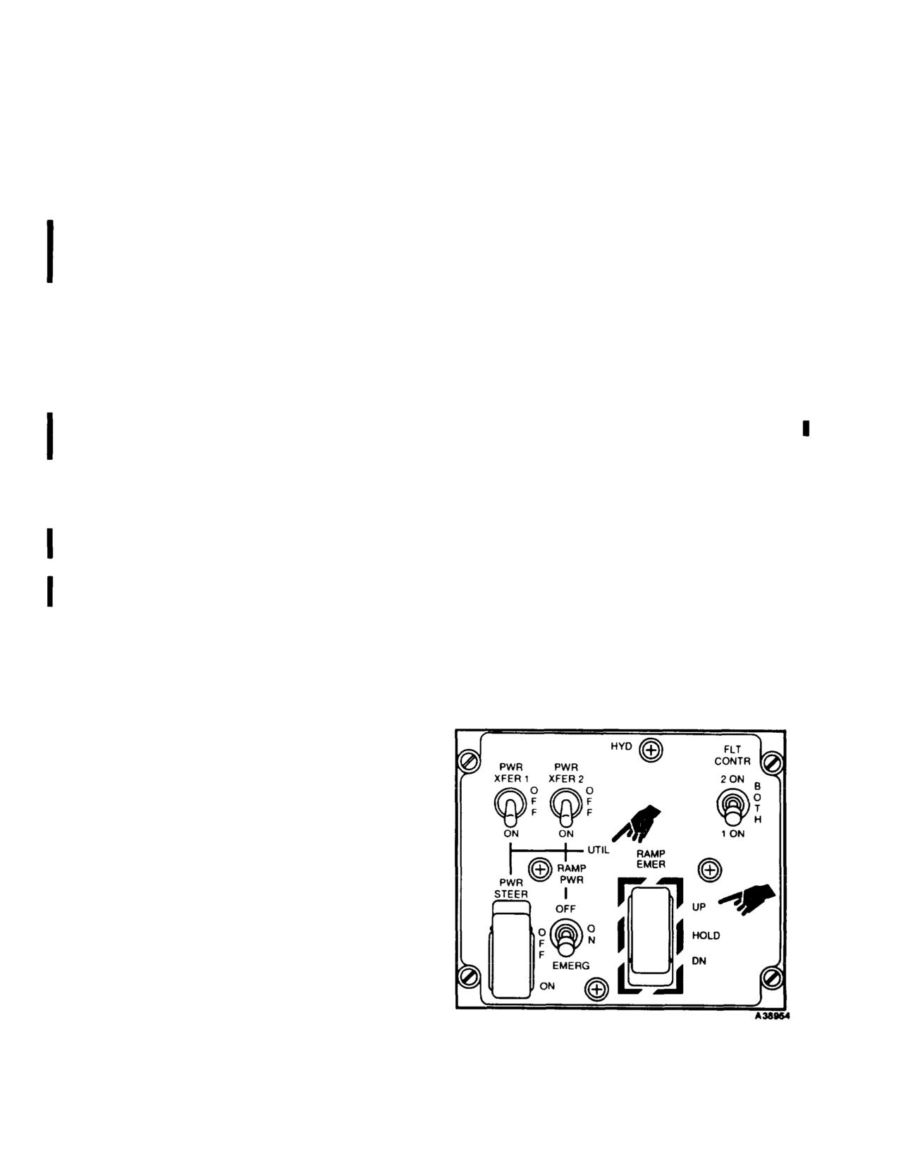
controlled by the PWR XFER 1 and 2 switches on the HYD
panel in the overhead switch panel.
2-97. FLT CONTR Switch.
The FLT CONTR (flight
control) switch is located on the HYD panel in the overhead
switch panel (fig. 2-30). It is a three-position center locked
switch labeled 2 ON, BOTH, and 1 ON. This switch can be
used to turn off one of the flight control systems. provided
the other one is operating. Turning off one of the flight
control hydraulic systems disables the corresponding AFCS
and causes the remaining AFCS to make full corrections. In
addition the respective AFCS OFF and HYD FLT CONTR
caution capsules will illuminate. The FLT CONTR switch
shall be set to BOTH during all flight conditions.
A1 BOTH. both solenoid valves are deenergized open and
both flight control systems are pressurized. When the FLT
CONTR switch is set to 1 ON, the two-way solenoid valve
on No. 2 power control module is energized closed. This
causes No. 2 pressure-operated valve to close. depressuriz-
ing No. 2 system. When the FLT CONTR switch is moved
to 2 ON, the two-way solenoid valve on No. 2 power control
module is deenergized open, and No. 2 system is pressur-
ized. Simultaneously, No. 1 solenoid valve closes and No. 1
system is turned off.
Figure 2-30. Hydraulics Control Panel
2-38
Change
9
TM 55-1520-240-10
has an accumulator to keep the swsystem pressure for normal brake an
the BRK STEER switch is OFF.
OFF, the brake and steering isola
isolating the brake and steering s
Normal operating pressure range for the utility hydraulic
ity systems. ON is the
syste
500
t
3500
psi. During APU operamaining util
is incr
approximately
3350
psi for engineOFF is used when there has been a h
(See table 2-3 for flight controlbrake or steering system. Setting th
capacities and fig.
2-54 for accprevents loss of system
fluid. Thi
sures.)
utility subsystems to continue to
brake system contains an accumulato
2-99. PWR XFER Switches.
The two-positiosystem operation in a hydraulic fa
XFER (power transfer) 1 and 2 swisystem also has a smalleccumulator
UTIL (utility) hydraulic portion locks locked with the system isolat
(fig. 2-30). Each switch is labelBRK STEER switch and va
lve is sup
switch is ON,
28-volt DC opens the normally closed
HYDRAULICS BRK STEER circuit breake
solenoid valve in the corresponding PTU and opens a valve
PDP.
in the pressure control module. This allows utility hydraulic
system pressure to operate the hydraulic motor pump on that
2-101.1. RAMP EMER Control Switch.
PTU, pressurizing the flight control hydraulic system.
Consequently, the flight controls can be operated on the
ground for maintenance and checks without tWARNINGrotors
turning.
When both switches are ON, No. 1 andThe RAMP EMER control switch is intendedntrol
hydraulic systems will be pressurizedforemergencyhusehonlyduringsmokeandmotor
pumps of the PTU’s supply pressure fumeeliminationlprocedures. Inadvertentop-
operation. When the switches are OFFerationhofthescargoerampandcargoadoores
are closed and the flight controls cfromnthetcockpitmay result in injury to
the rotors are turning. Power for thpersonnel or damage to equipment.s supplied
by the No.
2 DC bus through the HYDRAULICS PWR
XFER circuit breaker on the No. 2 PDP.
The momentary, guarded, three-posi
2-100. RAMP PWR Switch.
(ramp emergency) control switch is
hydraulic portion of the HYD control
switch allows the pilot, in an emer
WARNING
or lower the ramp to a partially o
closed position. The switch is labe
When the RAMP PWR switch is at OFF, be
sure the RAMP CONTROL valve is not
(down), and is spring loaded to the
moved from STOP. Operating the valve from
The switch is active only when the
STOP to UP or DN may cause the ramp to
set to EMERG. For up operation, the
free fall.
while the momentary switch is held
will stop as soon as the switch i
operation, the switch has a minimu
The RAMP PWR switch is on the lower right side of the
which allows the pilot to lower the
UTIL hydraulic portion of the HYD control panel (fig.
momentarily moving the switch to D
2-30). The switch has three positions labeled ON, OFF, and
releasing il. The downward ramp mo
EMERG. At ON, the ramp isolation valve in the utility
seconds after the switch is selecte
system pressure control module is open, allowing system
second timer circuit). If the ramp
pressure for normal ramp operation. At OFF, the ramp
osed pos
isolation valve is closed, isolatitongue) are in the fully cl
remaining utility systems. Thisselection of the DN position will p
system fluid if the ramp system fthe cargo door to be fully retracte
power is supplied to the RAMP EMEcan be further lowered in
5 second
ramp and cargo door to be openedtarily reselecting the DN position
cockpit. Power to operate the RAMPdownward motion of the ramp may be
isolation valve is supplied by thby momentarily setting the
RAMP EME
HYDRAULICS UTIL SYS CONT circuitposition. Thehe
ramp can also be low
No. 1 PDP.
more than
5 seconds) by holding th
position until the desired ramp lev
2-101. BRK STEER Isolation Switch.
The BRK
STEER isolation switch is on the HYD control panel (fig.
At the UP or DN positon, 28-volt DC
2-30). It is a guarded two-position switch labeled ON and
tive up or down solenoid on th
OFF. At ON, the brake and steering isolation valve in the
utility system pressure control module is open, allowing
Change
9
2-39
TM 55-1520-240-10
valve. The ramp control valve hanhand pump may be used to
operate the ram
position, and the ramp repositionNORMAL position of the,check valve is
electrical power is removed fromsystem is pressurized
by the APU or by t
solenoids. The ramp control valvpump. When the engines
and the APU are n
STOP position and the ramp remaicontrollable check valve is set to OPEN
Power for the switch is supplied handle is set to UP or DN, and the hand
bus through the RAMP PWR switch aWhenerampPmovement
is completed, the
CONT circuit breaker on the No. 1handl
e is set to STOP and the controllab
to NORMAL. This valve may also be used
2-102. Hydraulic System Service Module.
A ser-
event of utility pump or system failure
vice module, on the right
side of the cargo compartment
lator pressure
to the subsystems.
above the ramp, provides for filling the two flight control
hydraulic systems and the utility hydraulic system. It
105. Hydraulic Pressure Cautions.
Three hydrau-
consists of a filler assembly, a two-stage hand pump, and a
lic pressure caution capsules, one for
selector valve for selection of any of the three hydraulic
system and one for the utility hydraulic
systems for tilling.
on the master caution panel (fig.
2-51
2-103. Utility System Hand Pump.
A two-stage NO.
1 HYD FLT CONTR, NO. 2 HYD FLT CONT
pump, on the right side of the caUTIL HYD SYS. Each capsule is electrica
ramp, is used to pressurize the AaUpressurecswitch in the corresponding
APU starting. Also, in conjunctioWhenever hydraulicbelow
1,800supsi in one
PRESS controllable check valve, iofmathe flight control systems or the
the ramp and door.
system caution
illuminates. The cautio
guishes as incr
approaches
2,300
psi. Cau-
2-104. EMERG UTIL PRESS Controllable Check
tion capsule operation is independent o
Valve.
The EMERG UTIL PRESS controllable check
indicator operation. Power for these ca
valve is located above the hand pump. It allows APU start
the DC essential bus through the CAUTI
accumulator pressure to be used for operation of the ramp or
breaker on NO. 1 PDP.
any other subsystem (brakes, swivel locks, etc.). When the
APU motor pump or utility pump is2-106.tHydraulicrPressurenIndicators. is not
Three HY-
necessary to use the hand pump unless the accumulator is
DRAULICS PRESSURE indicators (fig. 2-34)
discharged.
hydraulic system, are on the MAINTENAN
When the accumulator is dischargRefer to Section IX Utility Systems.
PRESS controllable check valve in conjunction with the
2-40
Change
9
TM 55-1520-240-10
SECTION Vll POWER TRAIN SYSTEM
2-107. General.
from the sump through the main lube pump, main filter,
cooler, and the jet protection screen to jets where the oil
Engine power is supplied to the rotors through a
is sprayed onto the various gears and bearings. In
mechanical transmission system (fig. 2-1). This system
addition, after the oil leaves the jet protection screen,
consists of a forward, a combining (mix), an aft, two
alternate paths routes some of the lubricating oil to the
engine transmissions, and drive shafting. An overrun-
aft shaft bearing and cooling oil to the generators.
ning sprag clutch is installed in each engine transmis-
Auxiliary system oil flows from the auxiliary sump
sion. The clutch provides a positive drive connection to
through the auxiliary pump and filter to the various
transmit power and permits freewheeling of both rotors
gears and bearings. Separate oil jets are utilized for
when in an actual autorotation or during a simulated
each oil system. The auxiliary system does not lubricate
power failure. Because of the freewheeling feature, no
the aft shaft bearing or the generators. An oil cooler
drag will be place on the rotors if an engine (or engines)
mounted on the aft end of the transmission cools main
fails.
system oil. Cooling air is drawn through the cooler by a
transmission-driven fan.
Power from the engine transmissions is transmitted
through separate drive shafts to the combining (mix)
2-111. Combining and Engine Transmission Lubri-
transmission. The combining (mix) transmission com-
cation Systems. The combining (mix) transmission
bines the power of the engines and transmits it at
contains the oil reservoirs to supply lubrication oil to the
reduced shaft speed to the forward and aft transmis-
various gears and bearings in the combining (mix)
sions. Further speed reduction occurs within the rotor
transmission, No. 1 engine transmission, and the No.
2
transmission.
engine transmission. Two lubricating pumps with four
elements each are within the combining (mix) transmis-
Two AC generators, the No. 2 flight control hydraulic
sion: left pump assembly and right pump assembly. The
pump, and the utility system pump are mounted on and
left pump assembly provides main lubrication to the
driven by the aft transmission. The No. 1 flight control
combining (mix) transmission and the No. 1 engine
hydraulic pump is mounted on and driven by the
transmission. The right pump assembly provides auxil-
forward transmission.
iary lubrication to the combining (mix) transmission and
2-108. Transmission Lubrication Systems.
lubricates the No. 2 engine transmission. Each pump
assembly contains two pumping elements and two scav-
The forward, aft, and combining (mix) transmissions
enge elements.
have independent main and auxiliary lubrication sys-
tems which operate concurrently. Each transmission has
Combining transmission main lubrication oil flows from
a filter with an impending bypass indicator. If the
the combining (mix) transmission oil reservoir through
differential pressure across the filter exceeds
15 to 18
the left pump assembly, filter, cooler, jet protection
psi, the bypass indicator will extend to indicate a
screen, and to the jets which spray the oil onto the
partially clogged filter. When the differential pressure
various gears and bearings. One of the scavenge ele-
reaches
25 to 30 psi, lubrication oil will bypass the filter.
ments of the left pump assembly returns the oil from the
Refer to table 2-3 for transmission oil system capacities,
combining (mix) transmission sump to the combining
oil specifications, and servicing procedures.
(mix) transmission oil reservoir. The auxiliary lubrica-
tion oil flows from the combining (mix) transmission
2-109. Forward Transmission. The forward trans-
auxiliary oil reservoir to the right pump assembly,
mission lubrication system supplies lubricating oil to the
auxiliary lubrication filter, and to the jets which spray
gears and bearings in the forward transmission. Main
the oil on to the various gears and bearings. One of the
system oil flows from the sump, through the main oil
scavenge elements of the right pump assembly returns
pump, oil filter, cooler, and a jet protection screen to
the oil from the combining (mix) transmission sump to
jets from which the oil is discharged to the various gears
the combining (mix) transmission oil reservoir. The
and bearings. Auxiliary system oil flows from the auxil-
right pump assembly does not route oil through a
iary sump through the auxiliary oil pump, and the
cooler.
auxiliary system filter to separate auxiliary oil jets. An
No. 1 engine transmission oil flows from the No.
1
oil cooler mounted on the aft end of the transmission
engine transmission oil reservoir on the combining (mix)
around the input pinion cools main system oil. Air is
transmission through the left pump assembly, filter,
forced through the cooler by a transmission-driven fan.
cooler, jet protection screen, and to the jets which spray
2-110. Aft Transmission. The aft transmission lubri-
the oil onto the various gears and bearings. One of the
cation system supplies lubricating oil to the various
scavenge elements of the left pump assembly returns the
gears and bearings in the aft transmission and to the aft
oil from the No. 1 engine transmission sump through a
rotor shaft bearing. In addition, the main lubrication
debris indicating screen and back to the No. 1 engine
system circulates cooling oil through the two AC gen-
transmission oil reservoir. No. 2 engine transmission oil
erators on the aft transmission. Transmission oil flows
flows from the No. 2 engine transmission oil reservoir
2-41
TM 55-1520-240-10
on the combining (mix) transmission through the right
pump assembly, filter, cooler, jet protection screen, and
to the jets which spray the oil onto the various gears and
bearings. One of the scavenge elements of the right
pump assembly returns the oil from the No. 2 engine
transmission sump through a debris indicating screen
and back to the No. 2 engine transmission oil reservoir.
Engine transmissions do not have auxiliary lubrication
systems.
All No. 1 and No. 2 engine transmission lubrication
system components are on the combining (mix) trans-
mission except the jet protection screens and jets.
Separate oil jets are utilized for each transmission
lubrication oil system. The individual oil coolers for the
combining (mix) and both engine transmissions are
mounted on the combining (mix) transmission and
utilize a common transmission driven fan for cooling air.
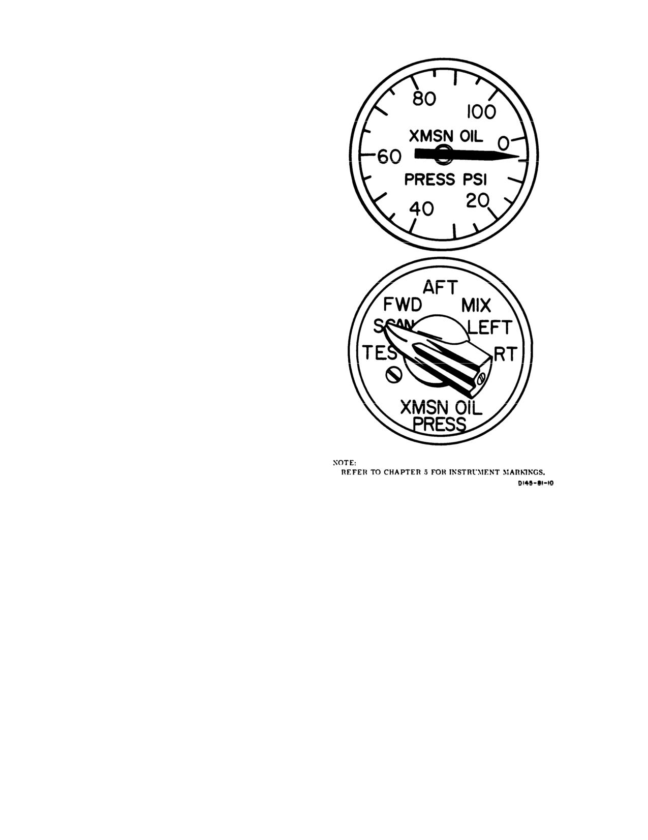
2-112. Transmission Main Oil Pressure Indicator.
A transmission main oil pressure indicator is located on
the center instrument panel (fig. 2-31). It indicates
either the lowest main oil pressure in any one of the
transmissions or only the oil pressure in the transmis-
sion selected by the pilot. The indicator is electrically
connected to each transmission. In addition, each trans-
mission and the aft rotor shaft bearing has a separate
low pressure switch. These switches are connected to
the XMSN OIL PRESS caution capsule on the master
caution panel and the TRANSMISSION MAIN OIL
PRESS indicating lights on the MAINTENANCE
PANEL (fig. 2-34). Power to operate the indicator is
supplied by the No. 1 AC bus through the XMSN OIL
PRESS circuit breaker on the No. 1 PDP.
2-113. Transmission Main Oil Pressure Selector
Switch. A transmission oil pressure selector switch is
located on the center instrument panel (fig. 2-31). The
switch positions are labeled TEST, SCAN, FWD, AFT,
MIX, LEFT, and RT. When the switch is set to TEST,
Figure 2-31. Transmission Main Oil Pressure In-
the pointer on the transmission pressure indicator will
drop to zero or below. When the switch is set to SCAN,
dicator and Selector Switch
the lowest main oil pressure among all the transmission
Each temperature probe incorporates a high oil temper-
will be indicated. The remaining positions are used to
ature switch which is independent of the temperature
select a particular transmission oil pressure indication.
indicator and is triggered at
140°C, lighting the XMSN
When selecting a particular switch position, be sure the
OIL HOT caution capsule on the master caution panel
switch is in detent. If the switch is not in detent, the
and to the TRANSMISSION OVERTEMP magnetic
pressure gage will indicate zero.
indicators on the MAINTENANCE PANEL. Power to
operate the indicator is supplied by the No. 1 AC bus
2-114. Transmission Main Oil Temperature Indica-
through the XMSN OIL TEMP circuit breaker on the
tor. A transmission oil temperature indicator is lo-
No. 1 PDP.
cated on the center instrument panel (fig. 2-32). It reads
from
-70° to + 150°C.
It indicates the highest oil
2-115. Transmission Main Oil Temperature Selec-
temperature among all the transmissions or only the oil
tor Switch. A transmission oil temperature selector
temperature of the selected transmission. A tempera-
switch is on the center instrument panel below the
ture probe is located in the forward and aft transmission
transmission oil temperature indicator (fig. 2-32). The
sumps and in each compartment of a three-compartment
switch positions are labeled TEST, SCAN, FWD, AFT,
oil tank for the combining (mix) transmission and in
MIX, LEFT, and RT. When the switch is set to TEST,
each engine transmission. The temperature probes in
the pointer on the transmission oil temperature indica-
the three tank compartments measure oil temperature
tor deflects full scale toward low temperature. When
in the tank and may not immediately indicate a trans-
the switch is set to SCAN, the highest oil temperature
mission problem. Loss of oil or low oil pressure may not
among all transmissions is indicated. The remaining
be accompanied by a high oil temperature indication.
positions are used for selecting a particular transmission
2-42
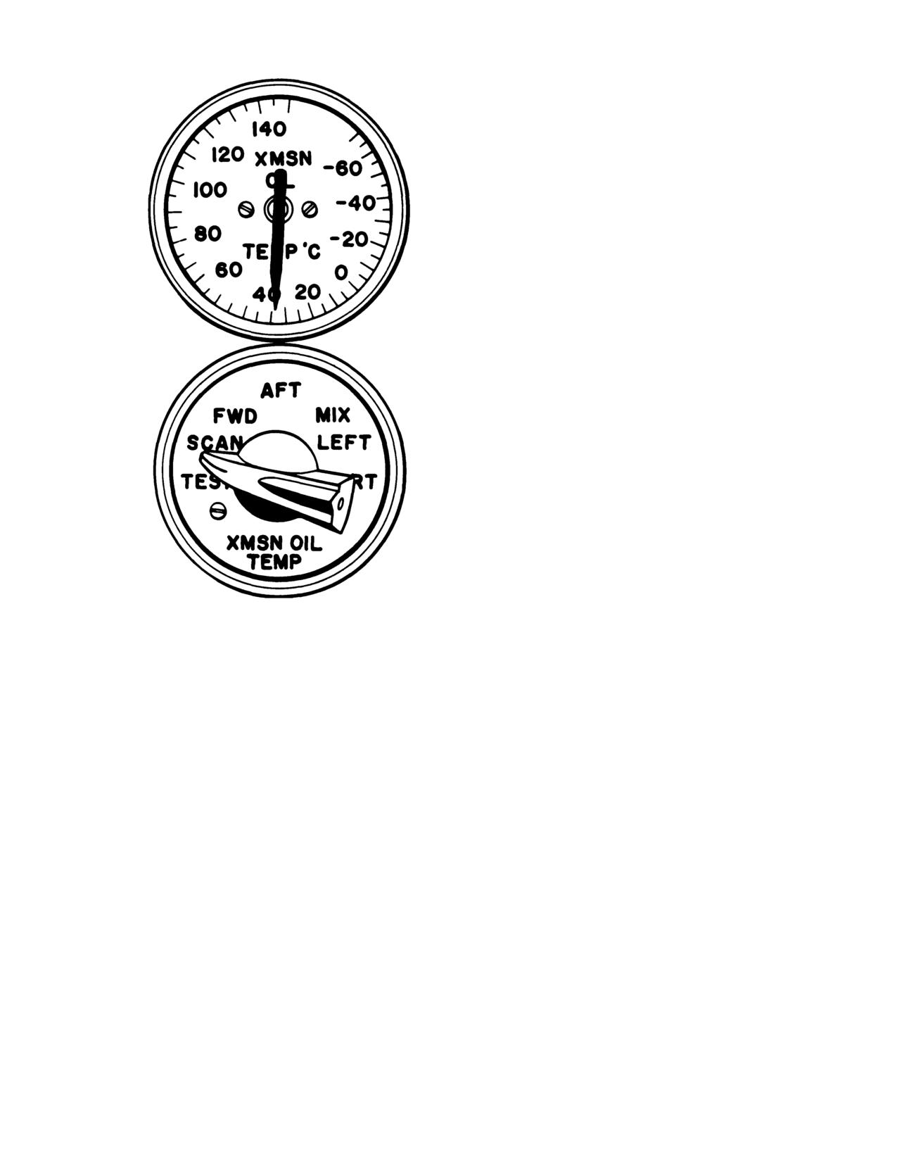
TM 55-1520-240-10
and indicator and the TRANSMISSION OVERTEMP
magnetic indicators on the MAINTENANCE PANEL.
b. XMSN OIL PRESS Caution.
It illuminates when
main oil pressure drops
below 20
psi in any transmission
or aft rotor shaft pressure drops
below
10
psi. The
low-pressure system is identified by the transmission oil
pressure selector switch and indicator on the center
instrument panel and the TRANSMISSION MAIN
OIL PRESS indicating lights on the MAINTENANCE
PANEL. If the XMSN OIL PRESS caution capsule
illuminates and the affected transmission cannot be
determined using the selector switch, the condition may
be caused by loss of aft rotor shaft oil pressure. Low oil
pressure at the aft rotor shaft is indicated by the
illumination of the TRANSMISSION AFT SHAFT
MAIN OIL PRESS indicating light on the MAINTE-
NANCE PANEL.
c. XMSN AUX OIL PRESS Caution.
It is activated
by individual aux oil switches and illuminates when
auxiliary oil pressure drops
below 20 psi in the fwd or aft
transmission and
10 psi in the combining (mix) trans-
mission. The transmission with the low pressure is
identified by a lit TRANSMISSION AUX OIL PRESS
indicating light on the MAINTENANCE PANEL.
d. NO. 1 or NO. 2 ENG XMSN HOT Caution.
They
illuminate if oil temperature in either engine transmis-
sion exceeds about
190°C. The capsules are activated by
a thermoswitch in each engine transmission. The ther-
moswitch monitors oil temperature in the transmission,
not in the reservoir. It is part of a chip detector and
temperature assembly in each engine transmission.
NOTE: REFER TO CHAPTER 5 FOR INSTRUMENT MARKING.
D145-82-10
2-117. Transmission Chip Detectors. Chip detec-
Figure 2-32. Transmission Main Oil Temperature
tors are installed in all transmission and aft rotor shaft
Switch and Indicator
thrust bearing lubrication systems. All transmission chip
detectors, except those in the engine transmission, are
oil temperature indication. When selecting a particular
connected to the XMSN CHIP DET caution capsule on
switch position, be sure the switch is in detent. If the
the master caution panel. Engine transmission chip
switch is not in detent, the oil temperature indicator will
detectors are connected to the corresponding NO. 1 or
indicate -70°C.
NO. 2 ENG CHIP DET caution capsules.
2-116. Transmission Oil Cautions. Five transmis-
All transmissions and the aft rotor shaft chip detectors
sion oil caution capsules are on the master caution
are also connected to the TRANSMISSION CHIP
panel. The capsules are labeled XMSN OIL HOT,
DETECTOR magnetic indicators on the MAINTE-
XMSN OIL PRESS, XMSN AUX OIL PRESS, and
NANCE PANEL. When a chip detector is bridged by
NO. 1 AND NO. 2 ENG XMSN HOT. These cautions,
ferrous particles, the XMSN CHIP DET, or the NO. 1
in conjunction with the transmission oil pressure and
and/or NO. 2 ENG CHIP DET caution capsule illumi-
nates. At the same time, the corresponding TRANS-
temperature indicators on the center instrument panel
MISSION CHIP DETECTOR indicator on the MAIN-
and the TRANSMISSION OVERTEMP magnetic in-
TENANCE PANEL will trip and change from an
dicators, MAIN OIL PRESS, and AUX OIL PRESS
all-black indication to a black-and-white indication,
indicating lights on the MAINTENANCE PANEL,
identifying the transmission.
alert the crew to impending transmission lubrication
problems. The cautions operate independently of the
2-118. Transmission Chip Detectors Fuzz Burn-
pressure and temperature indicators on the center
Off. Helicopters equipped with the chip detector fuzz
instrument panel.
bum-off system in the forward, combining (mix), aft,
No. 1 and No. 2 engine transmission, and aft rotor shaft
a. XMSN OIL HOT Caution.
It illuminates when
thrust bearing are identified by a module labeled PWR
the main oil temperature in the sump of the forward,
MDL CHIP BURN-OFF located below the MAINTE-
aft, and reservoir of the combining (mix) or either
NANCE PANEL. The chip detector fuzz burn-off
engine transmission
exceeds 140°C.
The hot transmis-
system employs an automatically operated fuzz bum-off
sion is identified by the oil temperature selector switch
electrical circuit with the ability to eliminate nuisance
2-43
TM 55-1520-240-10
chip lights caused by minute ferrous metallic fuzz or
the XMSN CHIP DET caution will illuminate. Also, the
ferrous metallic particles on the transmission chip de-
corresponding TRANSMISSION CHIP DETECTOR
tectors. The response time of the fuzz bum-off circuit is
or ENGINE CHIP DETECTOR magnetic indicator on
more rapid than that of the helicopter warning system;
the MAINTENANCE PANEL will latch. Power for the
thus a successful fuzz burn-off will be accomplished
PWR MDL CHIP BURN-OFF is supplied by the No. 1
before any caution capsule on the master caution panel
DC bus through the HYDRAULICS MAINT PNL
illuminates. Should the particle or particles not burn off,
circuit breaker on the No. 1 PDP.
2-44
TM 55-1520-240-10
SECTION Vlll
ROTOR SYSTEM
2-119. General.
of the shock absorber is disconnected, the blade can be
folded in either direction about the vertical hinge pin.
Lift is produced by a rotor system consisting of two fully
articulated counter-rotating rotors. Each rotor has three
2-120. Rotor Blades.
fiberglass blades. The forward rotor is driven by the
forward transmission through a rotor drive shaft. The
a. Each rotor blade consists of a D-shaped fiberglass
aft rotor is driven by the aft transmission through a
spar assembly and a Nomex fairing assembly bonded to
vertical drive shaft.
the spar. The blade chord is
32 inches.
The rotor head consists of a hub connected to three
b. A titanium nose cap is bonded to the leading edge
pitch-varying shafts by three horizontal hinge pins.
of the spar. A nickel erosion cap is bonded to the blade
These pins permit blade flapping. Stops on the top and
along the outer
54 inches of leading edge. This cap
the bottom of the hub limit the blade flapping motion.
protects the part of the blade most vulnerable to
The aft rotor head is equipped with centrifugal droop
erosion.
stops which provide increased blade flapping angle for
c. The fairing assembly is bonded to the trailing edge
ground and flight operation.
of the spar. These fairings are constructed of a Nomex
Covers may be installed on the centrifugal droop stop
honeycomb core covered with a fiberglass skin. Wire
operating mechanism. The covers prevent ice accumu-
mesh screens are embedded in the fiberglass skin at the
lation on the mechanism and ensure proper droop stop
tip and the trim tab. The wire mesh screens provide an
operation following flight in icing conditions. For infor-
electrical path to the rotor hub from the metal trim tab
mation on use of the droop stop covers, refer to Chapter
and tip for lightning protection. Also, to provide light-
8, Section IV.
ning protection, each blade has two lightning protection
cables and two straps. The cables and straps complete
Mounted coaxially over the pitch-varying shafts are
the path from the wire mesh to the rotor head.
pitch-varying housings to which the blades are attached
d. Balance and tracking weights are installed in the
by vertical hinge pins. These pins permit blade leading
and lagging. Each pitch-varying shaft is connected to the
tip of spar and fairing assembly. The tracking weights
pitch-varying housing by a laminated tie bar assembly.
are removable and are used for blade track and balance.
The high tensile strength and low torsional stiffness of
2-121. Rotor Tachometers.
the tie bar retains the blade against centrifugal force
and allows blade pitch changes about the pitch axis.
Two rotor tachometers (16, fig. 2-8 and fig. 2-10), one
mounted on the pilot instrument panel, the other
Blade pitch changes are accomplished by three pitch-
mounted on the copilot instrument, indicate percent of
varying links connected from the rotating ring of the
rotor revolutions per minute (RRPM). A small needle
swashplate to the pitch-varying housing on each rotor
on the tachometer indicates percent RPM from
0 to 60.
blade. Cyclic pitch changes are accomplished by tilting
The large needle indicates percent RPM from
60 to 130.
the swashplate. Collective pitch changes are accom-
The RRPM sense signal is supplied by the AC genera-
plished by vertical movement of the swashplate. Com-
tors. Generator No. 1 supplies the copilot indicator and
bined collective and cyclic pitch changes result from
generator No. 2 supplies the pilot indicator. Power to
combined control inputs by the pilot.
operate the indicators is supplied by the DC essential
A direct-action shock absorber is attached to the blade
bus through the ROTOR TACH circuit breaker on the
and to the pitch-varying housing. When the inboard end
No. 1 and No. 2 PDP.
2-45
TM 55-1520-240-10
SECTION IX UTILITY SYSTEMS
2-122. Anti-Icing Systems.
CAUTION
Anti-icing is provided for the pitot tubes, AFCS yaw
If windshield bubbling or delamination oc-
ports, and windshields.
curs around the sensor element, immediately
place switch to OFF for that windshield.
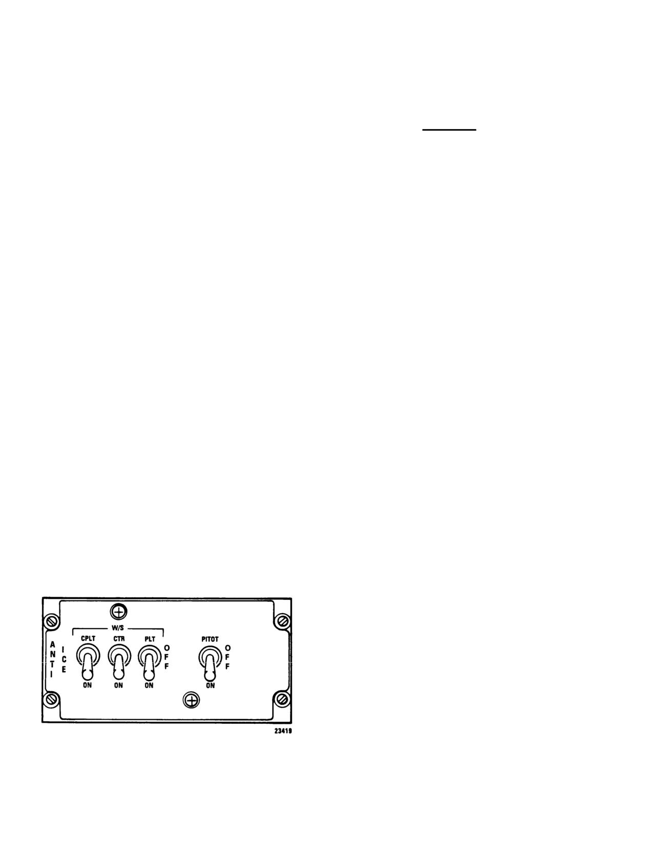
2-123. ANTI ICE Panel.
The ANTI ICE panel is located on the overhead switch
When any switch is moved to ON, current flows to the
associated temperature controller and then to the wind-
panel (fig. 2-33). It has three two-position W/S (wind-
shield. As the temperature of the windshield rises to a
shield) switches labeled CPLT, CTR, and PLT. The
preset value (about 44°C),
as sensed by the sensor
switches positions are OFF and ON. In addition, a
element, the electrical current to the windshield is
two-position PITOT heat switch is in this panel. The
interrupted by the temperature control relay. Once the
switch positions are OFF and ON.
windshield has cooled sufficiently, electrical current is
Power for the pilot and center windshields is from the
reapplied. This causes a cycling effect which maintains
No. 2 AC bus through the WSHLD ANTI ICE HEAT
windshield temperature within operating limits.
PILOT and CTR circuit breakers. Power for the copilot
Operating temperature is reached in
less than 1 minute
windshield is from the No. 1 AC bus through the
after the switch is placed to ON. When the switch is
WSHLD COPLT HEAT circuit breaker on the No. 1
placed to OFF, the anti-icing system is deenergized.
PDP. Anti-ice control for the pilot and center wind-
b. PITOT Heal Switch.
Heating elements prevent ice
shield is from the 28-volt No. 2 DC bus through the
accumulation in the pitot tubes and the yaw ports.
WSHLD ANTI ICE CONT CTR and PILOT circuit
When the PITOT switch is placed to ON, power to the
breakers on the No. 2 PDP. Anti-ice control for the
heater elements in the pitot tubes and yaw ports is
copilot windshield is from the 28-volt No. 1 DC bus
applied. When the switch is placed to OFF, the heating
through the WSHLD COPLT CONT circuit breaker on
elements are deenergized.
the No. 1 PDP. Power to operate the heater elements in
the pitot tubes and yaw ports is supplied by the No. 2
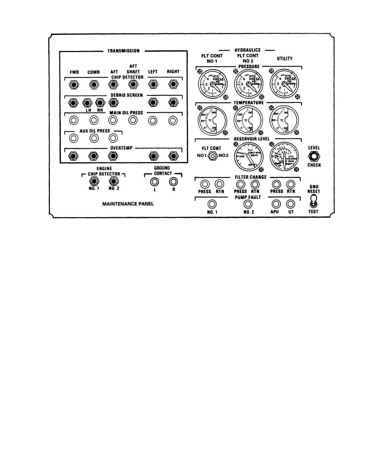
2-124. MAINTENANCE PANEL.
AC bus through the PITOT HEAT and YAW PORT
The MAINTENANCE PANEL is on the right side of
HEAT circuit breakers on the No. 2 PDP.
the cabin above the ramp (fig. 2-34). The panel is
provided to assist in the identification of system mal-
a. W/S Switches.
The pilot and copilot windshields
are anti-iced and defogged electrically. The center
function or condition that may require servicing or other
maintenance. The panel is divided into four sections.
windshield is defogged but not anti-iced. The laminated
They are labeled TRANSMISSION, HYDRAULICS,
windshield panels are heated electrically by current
ENGINE, and GROUND CONTACT.
which passes through a transparent conductive coating
embedded between the layers.
2-125. TRANSMISSION Section. This section mon-
itors the FWD, COMB, AFT, AFT SHAFT, LEFT, and
RIGHT transmissions. It consists of six CHIP DETEC-
TOR magnetic indicators, six DEBRIS SCREEN mag
netic indicators, six MAIN OIL PRESS indicating
PRESS-TO-TEST lights, three AUX OIL PRESS indi-
cating PRESS-TO-TEST lights, and five OVERTEMP
magnetic indicators. Power to operate the indicators is
supplied by the No. 1 DC bus through the HYDRAU-
LICS MAINT PNL circuit breaker on the No. 1 PDP.
a. CHIP DETECTOR Magnetic Indicators.
When the
corresponding CHIP DETECTOR is bridged by ferrous
particles, the associated chip detector indicator changes
from all-black to black-and-white. In addition, the
XMSN CHIP DET or ENG CHIP DET caution capsule
illuminates on the master caution panel.
b. DEBRIS SCREEN Magnetic Indicators.
There is
one indicator each for the FWD transmission, AFT
transmission, and LEFT and RIGHT engine transmis-
sions. There are two indicators for the COMB transmis-
sion. One indicator for the left sump and one indicator
Figure 2-33. Anti Ice Panel
for the right sump.
2-46
TM 55-1520-240-10
NOTE:
REFER TO CHAPTER 5 FOR INSTRUMENT LIMIT MARKINGS.
12501
Figure 2-34. Maintenance Panel
NOTE
XMSN OIL HOT caution illuminates on the master
Their is no cockpit indication of a latched
caution panel and trips the corresponding OVERTEMP
DEBRIS SCREEN magetic indicator. If a
magnetic indicator on the MAINTENANCE PANEL,
DEBRIS SCREEN magnetic indicator
thus identifying the hot transmission.
latches, the flight engineer shall advise the
2-126. HYDRAULICS Section. This section monitors
pilot immediately.
the FLT CONT NO 1, FLT CONT NO 2, and UTIL-
ITY hydraulic systems. It consists of three PRESSURE
The indicators are electrically connected to screens in
indicators, three fluid TEMPERATURE indicators,
the sumps of each transmission. If the screen mesh is
two RESERVOIR LEVEL indicators, six FILTER
bridged with conductive particles, the indicating circuit
CHANGE indicating PRESS-TO-TEST lights, and four
closes and trips the corresponding DEBRIS SCREEN
PUMP FAULT indicating PRESS-TO-TEST lights.
magnetic indicator on the MAINTENANCE PANEL.
Power to operate the indicators is supplied by the No. 2
DC bus through the HYDRAULICS MAINT PNL LTS
c. MAIN OIL PRESS Indicating Lights.
If main oil
circuit breaker on the No, 2 PDP.
pressure drops
below 20 psi in any transmission or 10 psi
in the aft shaft bearing, the corresponding indicating
a. PRESSURE Indicators.
The FLT CONT NO
1
light will illuminate. In addition, the XMSN OIL PRESS
and NO 2 PRESSURE indicators are electrically con-
caution will illuminate on the master caution panel.
nected to a corresponding pressure transmitter on the
respective power control module. The UTILITY PRES-
d. AUX OIL PRESS Indicating Lights.
If auxiliary oil
SURE indicator is electrically connected to a pressure
pressure drops
below
20
psi in the FWD or AFT
transmission or
10 psi in the COMB transmission, the
transmitter on the pressure control module. Indicator
corresponding indicating light will illuminate. In addi-
operation is independent of caution capsule operation.
tion, the XMSN AUX OIL PRESS caution will illumi-
Power to operate the indicators is supplied by the No. 2
nate on the master caution panel.
DC bus through the HYDRAULICS PRESS IND
circuit breaker on the No. 2 PDP.
e. OVERTEMP Magnetic Indicators.
Each OVER-
TEMP magnetic indicator is electrically connected to a
b. TEMPERATURE Indicators.
The indicators are
temperature probe in the reservoir of each transmission.
below the PRESSURE indicators. They indicate the
If oil temperature in the transmission reservoir,
exceeds
temperature of the hydraulic fluid at the outlet of the
140°C, a switch closes. When the switch closes, the
corresponding reservoir-cooler. Power to operate the
2-47
TM
55-1520-240-10
O.
2 DC bus throThis section consists of two indicating l
HYDRAULICS FLUID
TEMP circuit breaWhen the landing
gear proximity switch
PDP.
appropriate GROUND CONTACT indicating l
illuminate.
c. RESERVOIR LEVEL
The left indicator
is dedicated to the No. 1 and No. 22-129.GNDSwitch.ntrol hyraulics sys-
tem. In addition. a two-position FLT CONT switch labeled
NOTE
NO I and NO 2 is used to select the system of which the fluid
level is to be indicated. The reservoiWhile in flight. the flight
engineer s
FULL mark before flight. The right inpilot when placing theo
GND switch on t
the utility hydraulic system. When tTENANCE PANEL to TEST. Placing the swi
CHECK switch is pressed, the fluid lto TEST will cause the
NO. 1 and NO.
cooler will be indicated by the approCHIP DET, XMSN O
IL HOT, and XMSN CHIP
DET cautions to illuminate.
d. FILTER CHANGE indicating Lights. The indicat-
ing lights are arranged in three sThe GND switch allows the flight engineer
system. Each set of indicating lig(Built In Test Equipment)
test on the cir
RTN. The PRESS indicating light iTENANCE PANEL. The switch is springloaded
pressure line filter in each systeat center-off position. AttTEST, a black
monitors the return line filter appears on all magnetic BITE indicators.
pressure drop a
exceeds
75
psi. indicneti
ISsupplied
impending filter bypass, the corto the switch by the No.
1 DC bus through
indicating light will illuminate.MAINT PNL circuit breaker No. 1 PDP.
change indicating lights is supplied by the No.
2 DC bus
2-130. Windshield Wipers.
through the HYDRAULICS MAINT PNL LTS circuit
breaker on the No. 2 PDP.
CAUTION
e. PUMP FAULT IndicaTheg indicating
To prevent windshield damage, do not operate
lights are labeled NO.
1, NO.
2, APUwindshield wipers when windshields are dry.e
connected to sensors in the case drain line of each pump. If
the flow rate from the case drainTwo electrically driven windshield wiper
point which causes an increased pinstalled, one on eache
pilot windshield.
sensor, the sensor turns on the coboth wipers through two flexible shafts
light (a high flow rate from the wipers converters. The windshield wiper m
indicate impending pump failure). by the W/S (windshield) WIPER switch loca
is supplied by the No. 1 DC bus thhead switch panel.CS
Power is supplied by
MAINT PNL circuit breaker on the NthroughP.
the WSHLD WIPER circuit breaker
PDP.
2-127. ENGINE CHIP DETECTOR Section.
This
five positions
section consists of two magnetic iThe W/S WIPER switch hasd
and PARK. Wiper speed can
NO. 2. When the corresponding ENGISLOW, MED, FAST,
as desired, by rotating the switch from
is bridged by ferrous particles, the associated chip detector
ately at any posi
indicator changes from all-blackwipers will stop immedi
pers stop and rep
addition. the ENG CHIP DET cautiontravel. At PARK. the wi
inside windshield frame.
master caution panel.
2-131. Map and Data Case.
2-128. GROUND CONTACT Section.
The map and data case is in the passagewa
CAUTION
maps, and other data.
Should either or both GROUND CONTACT
2-132. Cockpit Rearview Mirror.
indicating lights remain illuminated after lift-
off to hover, the indicated system(s) DASH will
A rearview mirror is installed on the ri
not function properly in forward flight. If both
support to enable the pilot to observe th
GROUND CONTACT indicating lights
2-133. Spare Lamp Stowage Box.
remain illuminated after lift-off, the AUTO
function of both cyclic trims system will be
The spare lamp stowage box is in the cockpi
inoperative.
1 PDP. Spare lamps are provided for the ins
2-48
Change
9
TM 55-1520-240-10
instrument light shields, dome lig2-136.DC Cabin Utility Receptacles.
and nacelle work lights.
Four 28-volt DC utility receptacles
the sidewalls of the cargo compartm
2-134. Cockpit Utility Receptacles.
left cabin utility receptacles is s
Two 28-volt DC utility receptaclesthrough the UTILITY LH FWDnnd LH A
No. 1 PDP and one on No. 2 PDP. Eaon the No. 1 PDP. Power
to operate
UTIL RCPT 28V DC. Power to operatereceptacles is supplied by the No.
is supplied by the No. 1 DC bus thrUTILITY RCPT RH AFTTand RH FWD cir
circuit breaker on the No. 1 PDP.the No. 2 PDP.ate the pilot
receptacle is supplied by the No.
2 DC bus through the
2-137. Ash Trays.
UTILITY RCPT PILOT circuit breaker on the No. 2 PDP.
Three ash trays are installed in th
and one for the troop commander.
2-135. AC Cabin Utility Receptacles.
2-136. Compass Correction Card Holder.
A 115 volt, single-phase 400 Hz AC utility receptacle and a
The magnetic compass correction car
200 volt 3-phase 400 Hz AC utility receptacle are on each side
the left side of the magnetic compa
of the cabin at sta 320. The receptacles are accessible after the
necessary deviation values which ar
acoustical access cover and the receptacle dust cap are
reading.
removed. Power to operate the 115 volt receptacles is sup-
plied by the No. 1 and No. 2 AC buse2-139.P
ilot Assist Straps.
UTIL RCPT circuit breakers on No. Two assist straps are
attached to t
to operate the 200 volt receptaclesthe cockpit structure to provide t
No. 2 AC buses through the LH andwhile getting into the seats. The a
3-phase circuit breakers on No. 1
flat against the structure after us
Change
9
2-49
TM 55-1520-240-10
SECTION X HEATING, VENTILATION, COOLING, AND ENVIRONMENTAL CONTROL
SYSTEMS
2-140. Heating and Ventilating System.
A 200,000 btu/hr capacity internal combustion heating
system is provided. It consists of a heater unit, a fuel
control unit, an ignition assembly, a blower, control
relays, and air pressure and temperature control cir-
cuits. Ducting carries heated air or ventilating air to the
cockpit and the cabin. The heater consumes approxi-
mately
15 pounds of fuel per hour from the right main
fuel tank.
The heater and blower are mounted vertically on the
right side of the helicopter, immediately aft of the
forward cabin section bulkhead. Air for the system is
provided by the blower which draws air from an inlet on
the forward upper side of the fuselage. If sufficient air is
not available for proper heater operation, an automatic
differential pressure switch in the heater circuit will stop
the heater.
Both ventilating and combustion air enters the heater
inlet. The heating air passes over the heated metal walls
of the combustion chamber and is directed to a network
of ducting. The air entering the combustion chamber is
combined with atomized fuel and, after combustion that
heats the metal walls, the exhaust is discharged through
an outlet on the forward upper side of the fuselage.
Power to operate the blower is supplied by the No. 2 AC
bus through the CABIN HEATER BLOWER circuit
breaker on the No. 2 PDP. Power to the rest of the
system is supplied by the No. 2 DC bus through the
CABIN HEATER CONT circuit breaker on the No. 2
PDP.
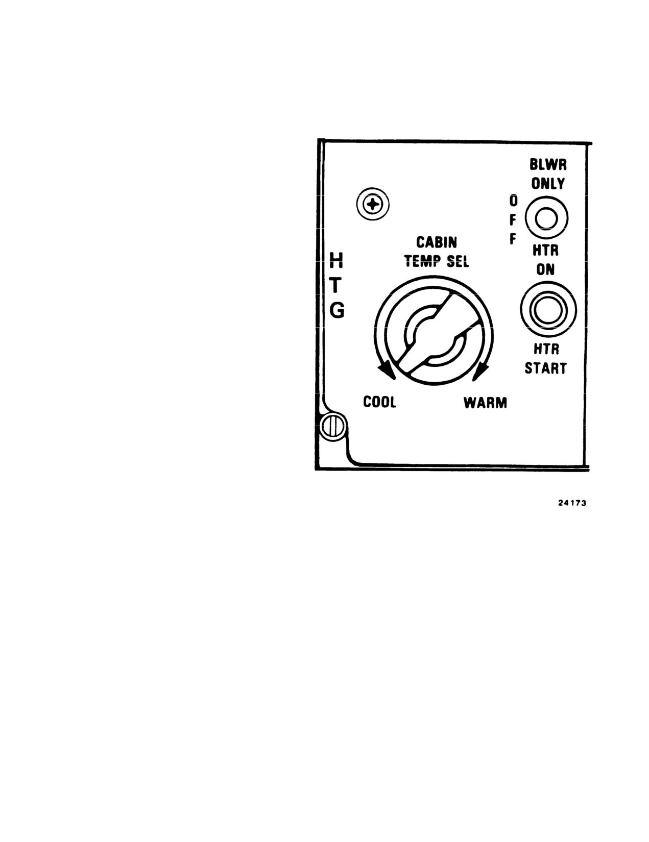
2-141. HTG Panel.
The HTG (heating) panel (fig. 2-35) is located on the
Figure 2-35. HTG Panel
overhead switch panel (fig. 2-12). It consist of a rheostat-
type CABIN TEMP SEL rotary switch, a three-position
The circuit to the thermostat heater winding is also
heater function switch, and a spring-loaded pushbutton
interrupted, allowing the winding to cool and the mer-
HTR START switch.
cury column to contract, thus reenergizing the temper-
ature controller relay. This creates a cycling effect, the
a. CABIN TEMP SEL Rotary Switch.
The CABIN
rate of which can be varied by increasing or decreasing
TEMP SEL rotary switch is labeled COOL and WARM.
the resistance between the temperature selector and the
This switch operates in conjunction with the tempera-
ture controller relay in the heater circuit and with a
thermostat heating winding. Resistance is varied by
cabin thermostat. One set of contacts on the tempera-
turning the CABIN TEMP SEL rotary switch. This
ture controller relay closes to complete a circuit to the
increase or decrease in resistance directly varies the
fuel control solenoid valve. This allows fuel to be
time the heater is allowed to operate before being
delivered to the heater.
automatically cycled.
The second set of contacts on the temperature control-
b. Heater Function Switch.
The heater function
ler relay closes to complete the circuit to the heater
switch is labeled BLWR ONLY, OFF, and HTR ON.
windings in the cabin thermostat. The heater windings
The switch selects the desired feature of the heating and
heat a column of mercury in the thermostat, causing it
ventilating system. When the switch is set to BLWR
to rise. When the mercury column reaches a
34°C
ONLY, the blower forces unheated air into both the
contact, the temperature control relay is shunted, caus-
cockpit and cabin. Further movement of the heater
ing its contacts to open and interrupt the circuit to the
controls is not required. Selecting HTR ON energizes
fuel control solenoid valve. This stops heater operation
the various units of the heater once the HTR START
by shutting off the fuel supply to the heater.
2-50
TM 55-1520-240-10
switch is pressed. The heating and ventilating system is
forward cockpit section heating. When the CABIN AIR
shut down when the switch is set to OFF.
handle is pulled, heated or ventilating air flows through
the ducting to the cabin.
c. HTR START Switch.
When HTR ON is selected
on the heater function switch and the HTR START
2-144. Cabin Heat Controls.
switch is pressed, the heater control circuits are ener-
Fourteen manually adjustable outlets are provided in
gized. The blower starts and purges the heater combus-
the cabin for the comfort of the passengers.
tion chamber of any unburned fuel, while the remainder
of the circuit remains inactive because of a
10 to 15
2-145. Heater Caution.
second time-delay relay. After the time-delay relay is
energized, the ignition assembly is powered and the
NOTE
master fuel solenoid valve opens, allowing fuel to flow to
the heater fuel control unit to complete the start.
Since the HEATER HOT caution will not
extinguish until the temperature in the com-
2-142. Cockpit Air Knob.
bustion chamber is
below 177°C,
it may take
several attempts at restarting the heater
Two cockpit air knobs (15, fig. 2-8 and 9, fig. 2-10) are
before the HEATER HOT caution extin-
on the lower outboard comer of both the pilot and the
guishes.
copilot instrument panels. The knobs are labeled PULL
FOR COCKPIT AIR. Each knob controls a valve on the
heater ducting which regulates the airflow to the cock-
A heater caution capsule labeled HEATER HOT is on
pit.
the master caution panel (fig. 2-51). This caution indi-
cates failure of the automatic temperature control cir-
2-143. Air Control Handles.
cuit. If air temperature in the heater
rises to 177°C
, an
Two air control handles are mounted through a placard
overheat switch deenergizes the automatic temperature
on the right side of the canted console. The placard is
controller relay, shuts off the heating system, except the
labeled AIR CONTROL PULL FOR ON with each
blower, and activates the HEATER HOT caution. The
handle labeled COCKPIT DEFOG OR DEFROST and
heating system will not operate until the blower has
CABIN AIR. By pulling the DEFOG OR DEFROST
lowered the heater temperature to normal and the HTR
handle, heater or ventilating air is directed to the
START switch is pressed. Even though the temperature
cockpit nose enclosure ducting. The airflow is directed
in the combustion chamber has lowered, the HEATER
to the transparent portion of the jettisonable doors and
HOT caution will not extinguish until the HTR START
nose enclosure providing defrosting as well as additional
switch is pressed.
2-51
TM 55-1520-240-10
SECTION Xl ELECTRICAL POWER SUPPLY AND DISTRIBUTION SYSTEMS
2-146. Electrical Power Supply System.
2-147. AC System.
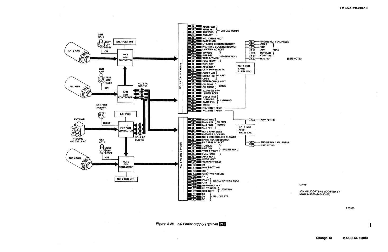
The AC system supplies 115/200-volt three-phase 400-Hz
Alternating current (AC) is the primary source of power
power from No. 1 AC generator to No. 1 three-phase
to operate the electrical and electronic equipment.
AC bus and from No. 2 AC generator to the No.
2
Three AC generators, two driven by the aft transmission
three-phase AC bus (fig. 2-38). The AC equipment is
and one driven by the APU, produce 115/200-volt
powered by these buses. Some of the equipment is
3-phase 400-Hz power. The system develops 28-volt DC
operated by 115-volt single-phase AC and some equip-
through two transformer rectifiers (RECT) one each in
ment by 26-volt AC power supplied through the trans-
the forward section of the left and right fuselage pods.
formers.
DC is also supplied by a 24-volt nickel-cadmium battery.
The AC system is protected from overvoltage, under-
Both 115/200-volt 3- phase AC and 28-volt DC can be
voltage, and underfrequency conditions by generator
supplied by operating the APU or by connecting an AC
control units. The generators will be disconnected from
external power source to the external power receptacles
the AC buses any time the RRPM
drops below 82
to 85
(fig. 2-36). If the APU is running or AC external power
percent for more than 3
to 7 seconds. The AC power
is connected, DC power is supplied by the helicopter
distribution system has four power sources, a contactor
transformer rectifiers (RECT). If only DC external
control circuit, an AC power transfer circuit, and two
power is supplied, AC power is not available on the
AC buses.
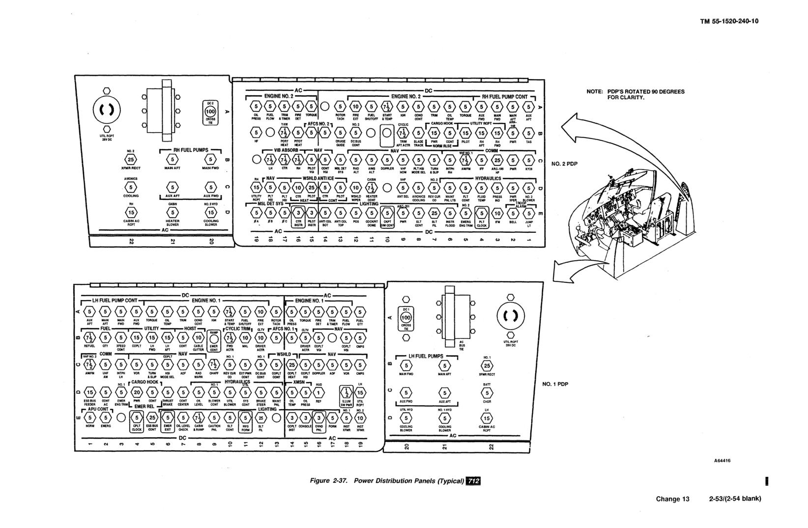
helicopter. Circuits are protected by circuit breakers
The No. 1 and No. 2 generator power sources are two
(fig. 2-37). The electrical load is divided between the
main generators driven directly by the aft transmission.
two AC generators (fig. 2-38). Should one generator
The APU generator is driven directly by the APU. The
fail, the other will automatically take over the entire
external power source is an AC power supply connected
load. When the APU is running, its single generator
to the helicopter.
powers the entire load.
No. 1 and No. 2 generators feed their respective buses.
If No. 1 or No. 2 generator fails (or are shut down), the
failed generator is isolated from its bus and the operat-
ing generator feeds both buses. When No. 1 or No. 2 or
both generators are operating, APU generator and
external power are blocked from the AC buses.
When the APU generator is operating and the main
generators are shut down (or rotors turning
below about
84%)
or switched off, the APU generator feeds both
buses. When the APU generator is operating, external
power is blocked from the AC buses. When external
power is applied to the helicopter (GEN APU, GEN
1,
and GEN 2 are OFF), the external power source feeds
both buses.
The generator control unit (GCU) also provides gener-
ator feeder fault protection. If a fault occurs between
the feeder and the airframe, the GCU will disable the
generators. This prevents structural damage to the
airframe when a ground fault occurs.
The permanent magnet generator (PMG) section within
the generator is used to power the main contractors
(relays) in the distribution system. A pickoff coil within
the PMG provides an RPM signal for the rotor tachom-
eter indicators. This tachometer signal is available when-
ever the rotors are turning.
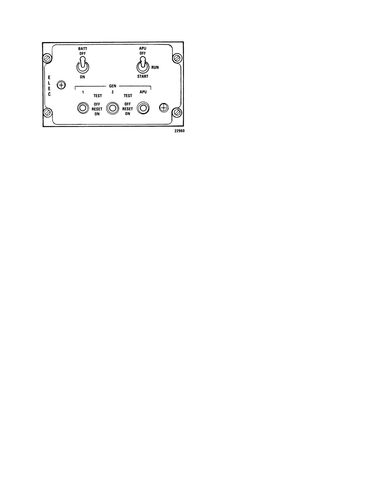
2-148. Generator Control Switches. The generator
control switches are located on the ELEC panel of the
overhead switch panel (fig. 2-39). The three switches are
labeled GEN 1, GEN 2, and GEN APU. The switch
positions are TEST, OFF RESET, and ON.
When the switches are ON, the respective main relay
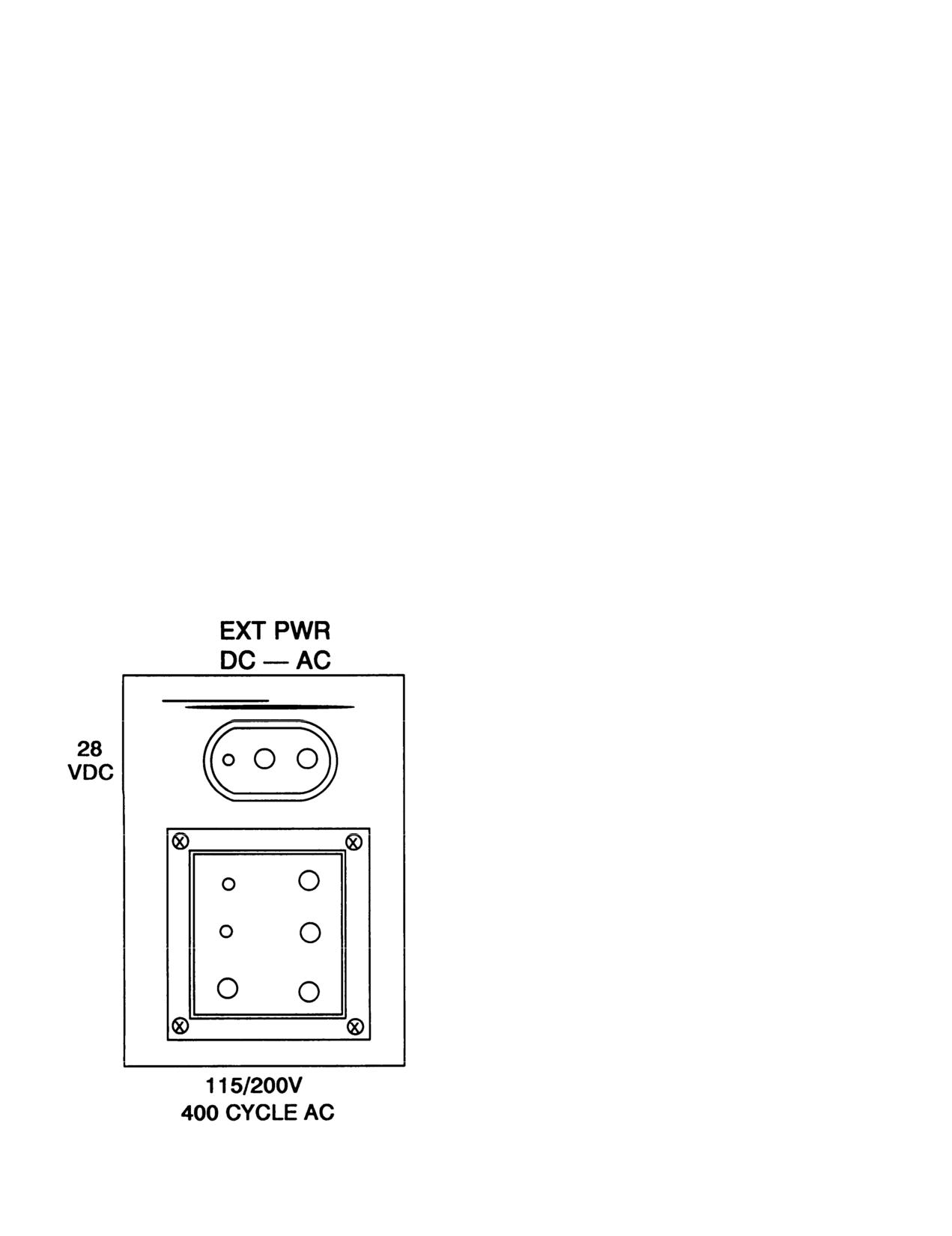
Figure 2-36. External Power Receptacles
operates, which energizes and connects the generator to
TM 55-1520-240-10
(fig. 2-40). RECT convert 200 VAC power to 28-volt DC
power for use in the DC distribution system.
Cooling air for the RECT is obtained from within the
cabin. The air inlets are located at sta. 176 on the left
and right side of the cabin behind the troop seats. If the
inlets are blocked, the RECT will overheat.
A bus-tie relay is between No. 1 and No. 2 DC buses. If
either RECT fails, the respective RECT failure relay
operates and the bus-tie relay closes automatically to
connect the unpowered bus to the operating RECT. In
addition to No. 1 and No. 2 DC buses, the DC system
includes an essential bus, a switched battery bus, and a
battery bus.
During normal operation, the essential bus and the
Figure 2-39. Electrical Power Panel
switched battery are energized by No. 1 DC bus. If both
DC buses fail or if No. 1 DC bus fails and does not
the buses. At OFF RESET, the generator is deener-
bus-tie to No. 2 DC bus, the essential bus, the switched
gized and disconnected from the bus. This position is
battery bus, and the battery bus will be energized by the
also used to reset a generator. The TEST position is
battert as long as the BATT switch is ON. These buses
provided to allow the generator to be energized but
provide power to emergency, ground maintenance, and
disconnected from the bus to determine whether the
communications components. The battery bus and
AC produced is of proper frequency and voltage.
switched battery bus are energized as long as the battery
2-149. GEN OFF Cautions. Two generator caution
is connected. The hydraulic reservoir level indicators
capsules labeled NO. 1 GEN OFF and NO. 2 GEN
and the emergency APU control circuits and cabin and
OFF are on the master caution panel (fig. 2-51). These
maintenance lights are on these buses.
caution capsules illuminate whenever the generators are
The 24-volt nickel-cadmium battery is located in the left
inoperative. The capsules are controlled by the main
forward electrical compartment. The battery capacity is
generator contractors when the generator control
11 ampere-hours. A battery charger is connected to the
switches are in either ON or OFF RESET. In TEST, the
battery. The battery charger receives power from No. 1
capsules are controlled by the generator control switch
AC bus, rectifies the AC and applies the DC to the
and will extinguish if generator output has the proper
battery to maintain a charge on the battery.
frequency and voltage. Power to operate the generator
capsules is supplied by the DC essential bus through the
Sensors in the battery charger detect battery or battery
LIGHTING CAUTION PNL circuit breaker on the No.
charger overtemperature, short or open circuits or cell
1 PDP.
imbalance. If any of these conditions occur, the battery
charger will stop functioning and activates the BATT
2-150. EXT PWR Caution.
SYS MAL caution capsule on the master caution panel,
CAUTION
External DC power is supplied to the DC buses of the
helicopter by connecting the external DC power source
When external power is used, a visual check
to the DC external power receptacle (fig. 2-36). Appli-
shall be made by the crew to ensure that the
cation of external power operates the DC external
external power unit has been disconnected
power relay which connects the power source to No.
1
from the helicopter before taxiing.
DC bus. No. 2 DC bus is energized when the bus tie
relay operates. If the polarity of the external power is
reversed, a blocking diode in the circuit prevents the
An external power caution capsule labeled EXT PWR
external power relay from closing.
is on the master caution panel (fig. 2-51). This capsule
illuminates and remains illuminated whenever external
2-152. BATT Switch.
power is connected. The light is controlled by the AC
external power contactor and the DC power relay. The
NOTE
capsule extinguishes when the generators are supplying
The following information applies only if the
current to the buses. Power to operate the external
battery is the only source of power.
power caution capsule is supplied by the DC essential
bus through the LIGHTING CAUTION PNL circuit
breaker on the No. 1 PDP.
The BATT (battery) switch is located on the ELEC
panel of the overhead switch panel (fig. 2-39) The
2-151. DC System.
two-position switch is labeled ON and OFF. When the
The direct current (DC) power supply system supplies
switch is at ON, the essential, switched battery, and
28-volt DC from the No. 1 transformer rectifier (RECT)
battery buses are energized. Regardless of the battery
to No. 1 DC bus and the No. 2 RECT to No. 2 DC bus
switch position, the switched battery and battery buses
2-57/(2-58 blank)
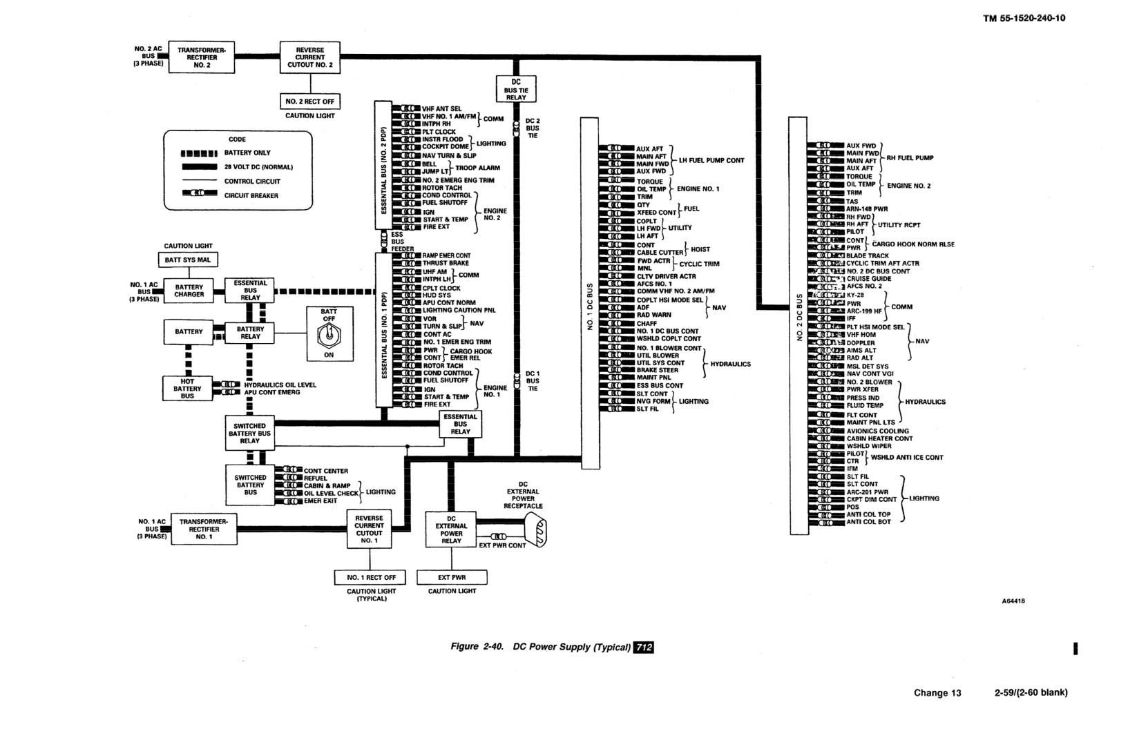
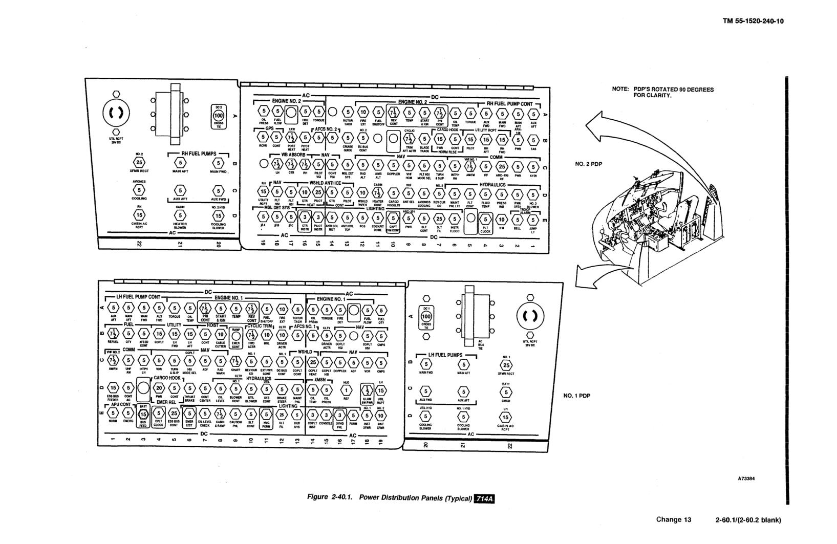
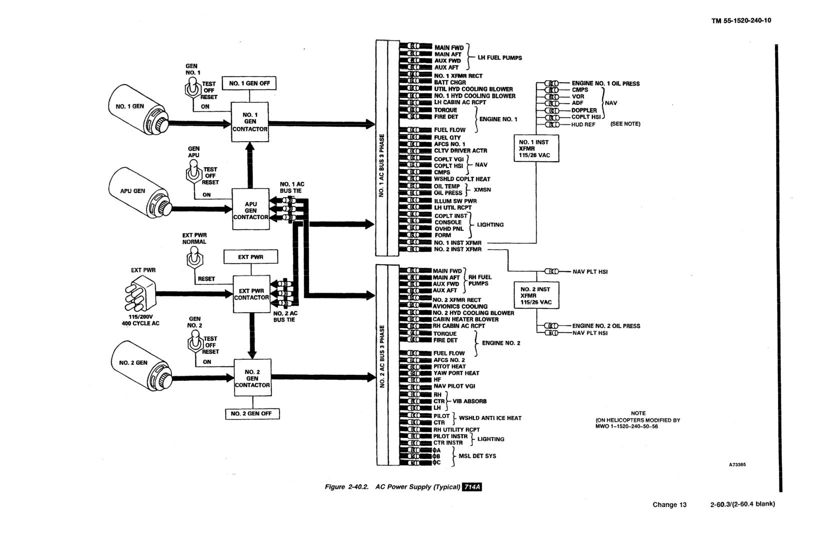
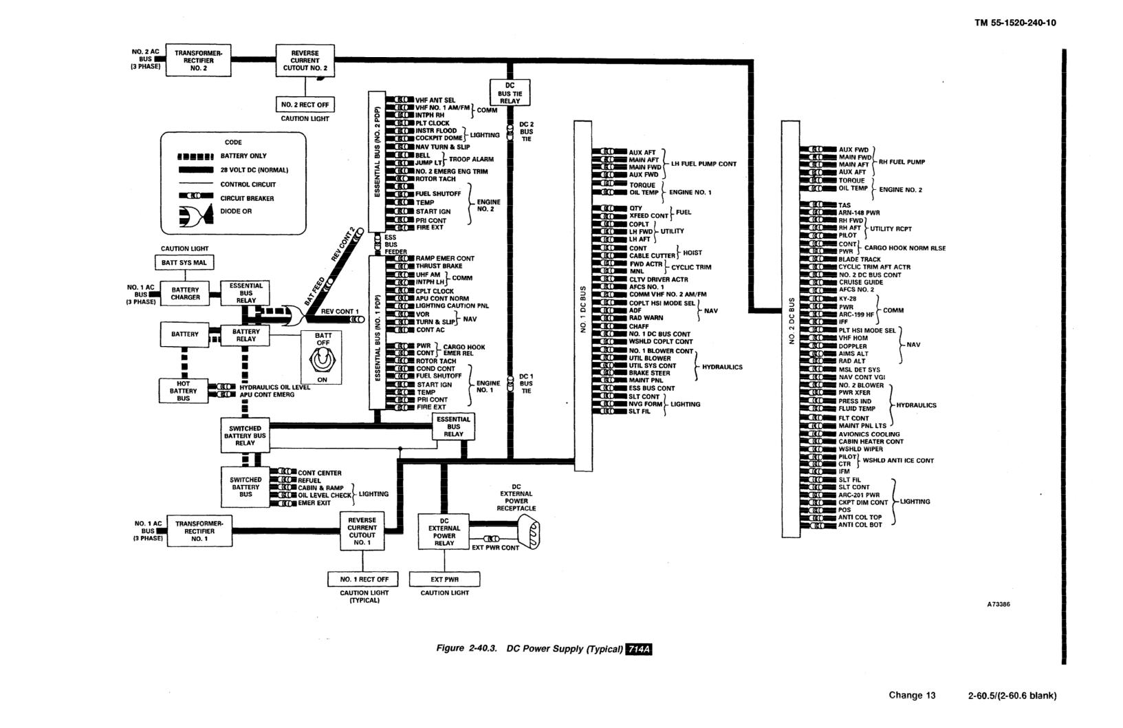
TM 55-1520-240-10
are powered directly by the battery. To prevent exten-
LIGHTING CAUTION PNL circuit breaker on the No.
sive discharging of the battery while making extended
1 PDP.
ground checks of equipment, use an external electrical
power source or operate the APU generator.
2-154. BATT SYS MAL Caution.
2-153. RECT OFF Cautions. Two RECT caution cap-
A battery system malfunction caution capsule labeled
sules labeled NO. 1 RECT OFF and NO. 2 RECT OFF
BATT SYS MAL is on the master caution panel (fig.
are on the master caution panel (fig. 2-51). These
2-51). This caution illuminates when the battery charger
has stopped charging the battery. This can be caused by
caution are controlled by the reverse-current cutouts.
an overheated battery or battery charger, battery cell
Whenever one of the RECT fails, either through a fault
imbalance, or an output short or open circuit. Power to
in the RECT or a bus fault, the respective caution
operate the capsule is supplied by the DC essential bus
illuminates. Power to operate the transformer rectifier
through the LIGHTING CAUTION PNL circuit
capsules is supplied by the DC essential bus through the
breaker on the No. 1 PDP.
2-61
TM 55-1520-240-10
SECTION XII AUXILIARY POWER UNIT
2-155. General.
or white. A label on the ESU explains the various BITE
indications and their meaning.
The gas turbine auxiliary power unit T62-T-2B (APU)
(fig. 2-41) is mounted in the aft cabin above the ramp.
2-157. APU Switch. The APU switch is on the ELEC
The basic components of the APU are the gas turbine
panel of the overhead switch panel (fig. 2-39). It is a
engine, hydraulic motor-pump, fuel control, accessory
three-position switch labeled OFF, RUN, and START.
drive, and AC generator. An APU ELECTRONIC
The switch is spring loaded from START to RUN.
SEQUENCING UNIT (ESU) which monitors APU
Normally, power to operate the APU is supplied by the
operation is on the left side of the cabin above the ramp.
DC essential bus through the APU CONT NORM
The ESU is also labeled APU CONTROL BOX.
circuit breaker on the No. 1 PDP. Emergency power to
The motor-pump on the APU pressurizes the utility and
operate the APU is from the battery bus through the
hydraulic system for main engine starting and ground
APU CONT EMERG circuit breaker on the No. 1 PDP.
checks. The APU also drives an AC generator which
supplies power to No. 1 and No. 2 electrical systems.
2-158. APU ON Caution. The APU ON caution cap-
Refer to Section VI for further information on the
sule is on the master caution panel (fig. 2-51). Normally,
hydraulic systems. The APU oil supply is integral and
the APU is intended for ground operation only. It is not
contained within the sump of the accessory drive assem-
intended for operation during flight. If the caution
bly. The APU receives fuel from the left main fuel tank
remains illuminated following take-off, it alerts the pilot
through a booster pump, a manual fuel shutoff valve,
to shut down the APU. When the caution is illuminated,
and a solenoid valve.
it indicates the APU is up to speed and the exhaust gas
temperature is normal, It does not necessarily indicate
2-156. ELECTRONIC SEQUENCING UNIT.
that APU hydraulic pump or generator output is nor-
The ESU is mounted on the left side of the cabin above
mal. If the rotors are not turning, check the UTIL HYD
the ramp. The unit monitors APU starting and opera-
SYS and RECT OFF cautions to evaluate output of the
tion. In addition, it monitors APU speed and exhaust
APU hydraulic pump and generator. The APU ON
gas temperature. The unit continuously compares these
caution is controlled by the ESU.
parameters with limits programmed into ESU circuits.
If a limit is exceeded, the ESU will automatically shut
2-159. EMERGENCY APU FLUID SHUT OFF
down the APU.
VALVE.
The EMERGENCY APU FLUID SHUT OFF VALVE
NOTE
is in the fuel supply line to the APU (fig. 2-42). It is
The BITE indicators indicate engine condi-
located inside the aft cabin above and to the left of the
tion only. They will not indicate a defective
ramp interphone station. The valve can also be reached
hydraulic motor-pump or generator.
from the outside through an access door labeled AC-
CESS APU EMER FLUID SHUT OFF. The knob on
Four magnetic built-in-test-equipment (BITE) indica-
the valve has an OPEN and CLOSE position. Placing
tors are on the ESU. These indicators are either black
the knob to CLOSE shuts off fuel to the APU.
2-62
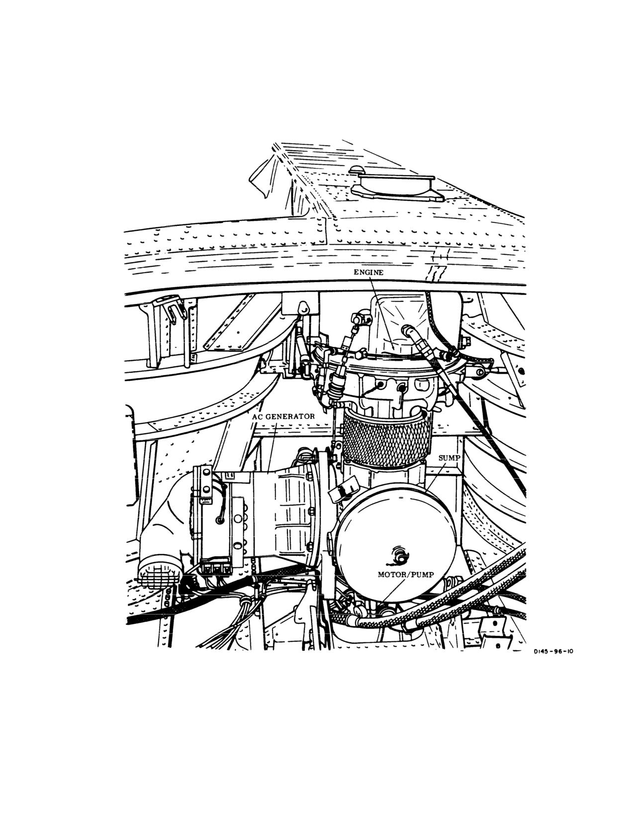
TM 55-1520-240-10
Figure 2-41. Auxiliary Power Unit
2-63
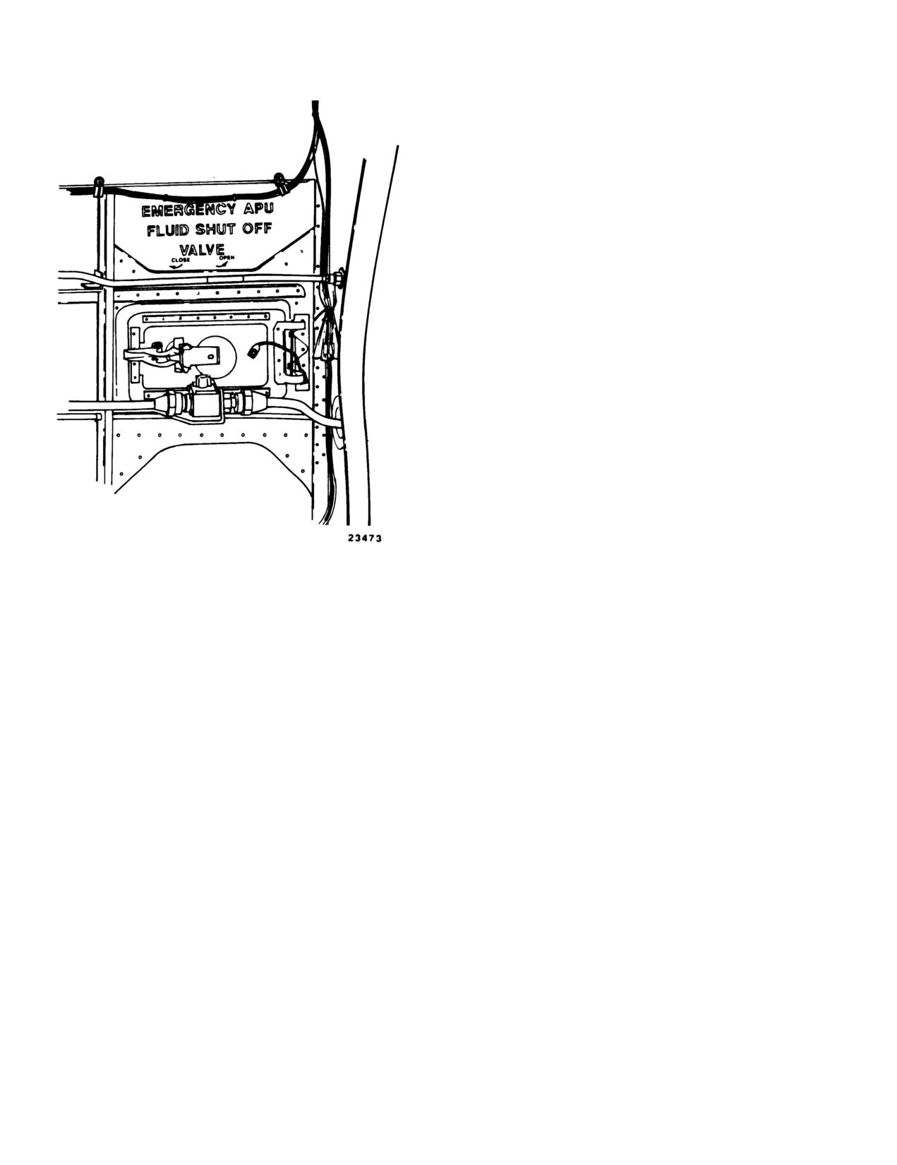
TM 55-1520-240-10
Figure 2-42. Emergency APU Fluid Shut Off Valve
2-64
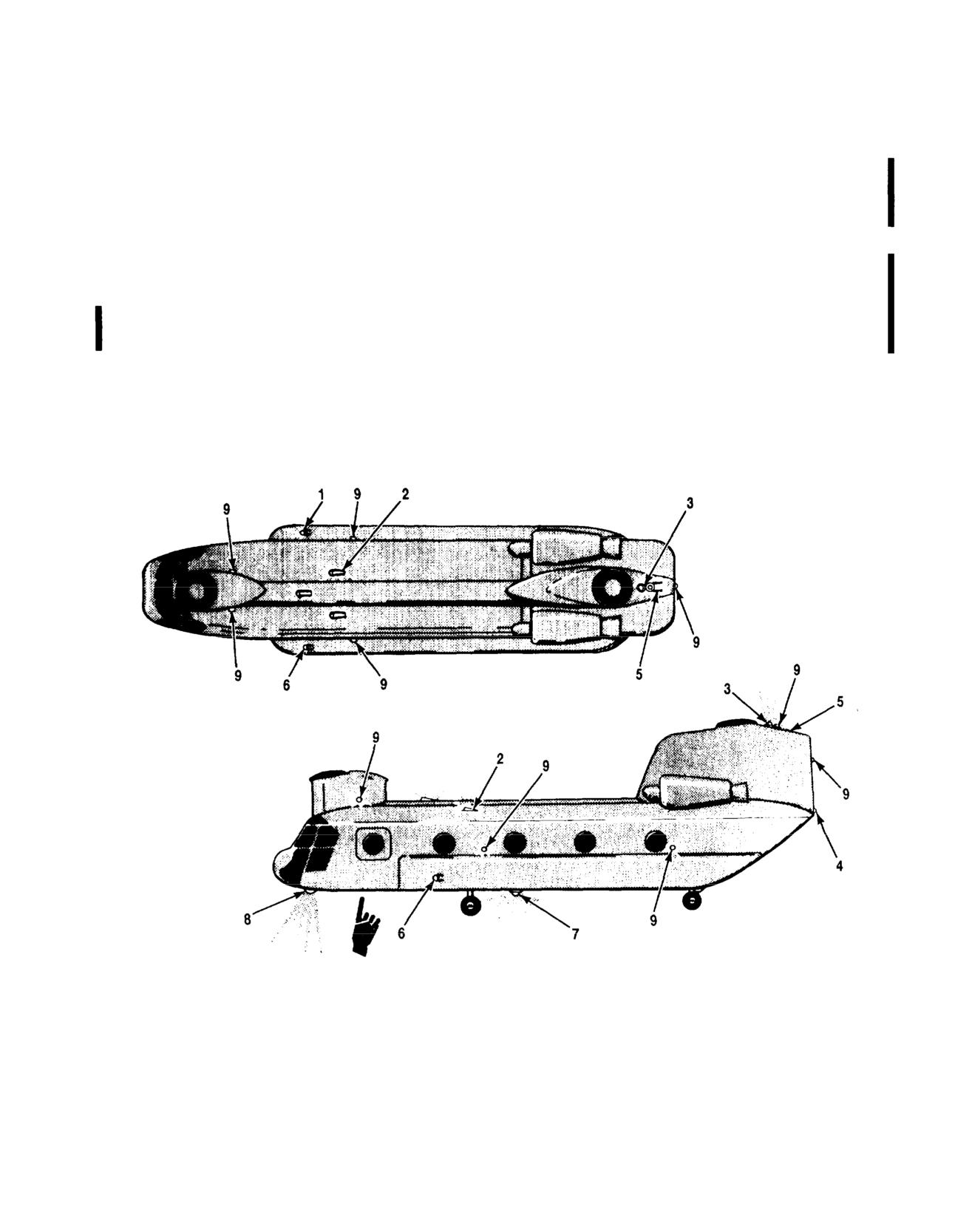
TM
55-1520-240-10
SECTION XIII
LIGHTING (NVG)
2-160. Position Lights.
NOTE
The crew chief must inform the pilot w
Three position lights (1, 4, and 6, fig. 2-43) are installed on
AFT POS LIGHT switch has been changed
the helicopter. On the right side of the fuselage is a green
the OFF position.
light (1); on the left, red (6); and on the vertical panel of the
aft pylon, white (4). Power to operate the position lights is
supplied by the No. 2 DC bus through thb. AFT POS LIGHTT
he AFT POS LIGHT
switch is located in the cabin at sta. 5
circuit breaker on the No. 2 PDP.
TENANCE PANEL (fig. 2-45). The guarded t
2-161. Position Light Switches.
switch is labeled OFF and ON. It allows
light to be turned off during aided (NVG) o
a
POSN Light
The POSN (position) sduringiunaided night operations.
located on the EXT LTG (exterior lighting) panel on the left
side of the overhead switch panel (fi2-162.Formation)Lights.he three-
position switch is labeled DIM, OFF, anThere are five elec
troluminescent panels
intensity of the position lights. Whenformation operations (
2 and 5, fig. 2-43
position light system is deenergized. compatible formation lights for NVG forma
(9, fig. 2-43).
A50277
1. Right position light (Gre6.
Left position light (Red)
2. Formation lights (3)
7. Bottom anticollision light
3. Top anticollision light
8. Landing-search lights (2)
4. Position light (White)
9. NVG formation lights (8)
5. Formation lights (2)
Figure 2-43. Exterior Lights
Change
11
2-65
TM
55-1520-240-10
a.ElectroluminesceThree panels whichnormal operations use the pilot searchlight
an equilateral triangle are aft of tlight. For NVG operations use the copilot s
panels are on the top of the aft pylonlandingtlight.icollision
light. Power to operate and control the electroluminescent
formation lights is supplied by th2-167.ISRCHLTCONTRSwitch.M
Two SRCHLT
circuit breaker on the No. 1 PDP.
CONTR (searchlight control) switches are on t
switch panel (fig. 2-44). The PLT SRCHLT CONT
b.NVG Formation
There is an NVG formation
is on the PLT LTG panel. The CPLT SRCHLT C
light on each side of the forward pylon, two NVG formation
switch is on the CPLT LTG panel. Each two-pos
lights on each side of the fuselage, two NVG formation
is labeled RET and ON.
lights on the aft pylon, one aft of the anticollision light, and
one on the vertical panel at the rear oWhen the SRCHLT CONTR
switch is placed to O
he THRUST CONTR lever be
to operate and control the NVG formatioSLT-FIL switch on t
by the No. 1 DC bus through the LIGHToperational.
If the searchlight is at any angl
circuit breaker on the No. I PDP.
the SRCHLT CONTR switch is placed to RET, the
light will automatically rotate to point forw
2-163. FORM Light Switches.
The FORM (formaretract flush with the fuselage. Power is supp
tion) light select and control switch1 and No. 2 DC bus through the LIGHTING SL
EXT LTG panel on the left side of tcircuit breakers on
the No. 1 and No. 2 PDP.
panel (fig. 2-12).
2-168. SLT-FIL Switch.
a.FORM Light SelecA twoŧposition toggle
switch labeled NVG and NORM. In the NORM position,
CAUTION
the five electroluminescent panels may be controlled by the
FORM light rotary control switch for norThe copilot landing searchlight emits
tion operations. In the NVG position,ible infrared rays which may be hazardou
‘formation lights may be controlled bypersonnel looking directly at the light
rotary control switch for NVG night formrange or touching it. Ensure that the
landing SLT-FIL switch Is OFF and the
b.FORM Light Contro
A rotary control switch
ted when it is not in use.
labeled OFF, DIM, and BRT with three efully retrac
incremental markings between DIM and BRT. It adjusts the
intensity of the formation lights selecA SLT-FIL (searchlig
ht filament) switch is
select switch. When the rotary contropilot and copilot THRUST CONT lever switch b
formation light system is deenergized.
2-26.) Each switch is labeled ON and OFF. T
turn on the landing-searchlight lamp, before
2-164. Anticollision Lights.
sion. Power to operate the landing search
Two red strobe anticollision lights asupplied by the No. 1
and No. 2 DC bus t
and 7, fig. 2-43). One is on top of theLIGHTING SLT FIL circuit breakers on the No
is on the fuselage underside. Power to2 PDP.e the anticol-
lision lights is supplied by the No. 2 DC bus through the
2-169. SEARCH LIGHT Position Switch.
LIGHTING ANTI COL TOP and BOT circuit breakers on
the No. 2 PDP.
CAUTION
2-165. ANTI COL Light Switches.
Two ANTI COL
Do not confuse the SEARCH LIGHT posi-
TOP and BOT toggle switches are on the EXT LTG panel
tion switch with the two engine beep
on the left side of the overhead switch panel (fig. 2-12).
switches.
Each two-position switch is labeled OFF and ON. When the
anticollision light switch is ON, the lights are energized.
When the switch is placed to OFF, theA five-position momentary SEARCH LIGHT swit
are deenergized.
each THRUST CONTR lever switch bracket (fig
is labeled L (left), EXTEND, R (right), and
2-166. Landing Searchlights.
switch is spring-loaded to center off posit
Two controllable landing-searchlights aWhen the SRCHLT CO
NTR and SLT-FIL switches ar
bottom of the fuselage (8, fig. 2-43).the searchlight can b
e controlled up and do
the pilot THRUST CONT lever and theright with thehe
SEARCH LIGHT position switch
copilot THRUST CONT lever. The copilotoperate the searc
hlight position switch is
with an infrared (IR) filter for NVGNo. 1 and
No. 2 DC bus through the LIGHT
CONT circuit brea
1and No. 2 PDP.
Each light is operated independently by a SRCHLT CONTR
switch, SLT-FIL (searchlight filament), and position switch.
170. Overhead Switch Panel Lights.
They may be extended and stopped at any angle up to 90°
in a vertical plane and rotated 360° abThe overhead switch panel has integral light
long as the searchlight position switoperate and control the overhead panel lights
2-66
Change
11
TM 55-1520-240-10
the No. 1 AC bus through the LIGHT
left side of the overhead switch pa
circuit breaker on the No. 1 PDP.
2-171. OVHD CSL Switch.
The OVHD CSL (overhead
console) switch is located on the CPLT LTG panel on the
Change
11
2-66.1/(2-66.2 blank)
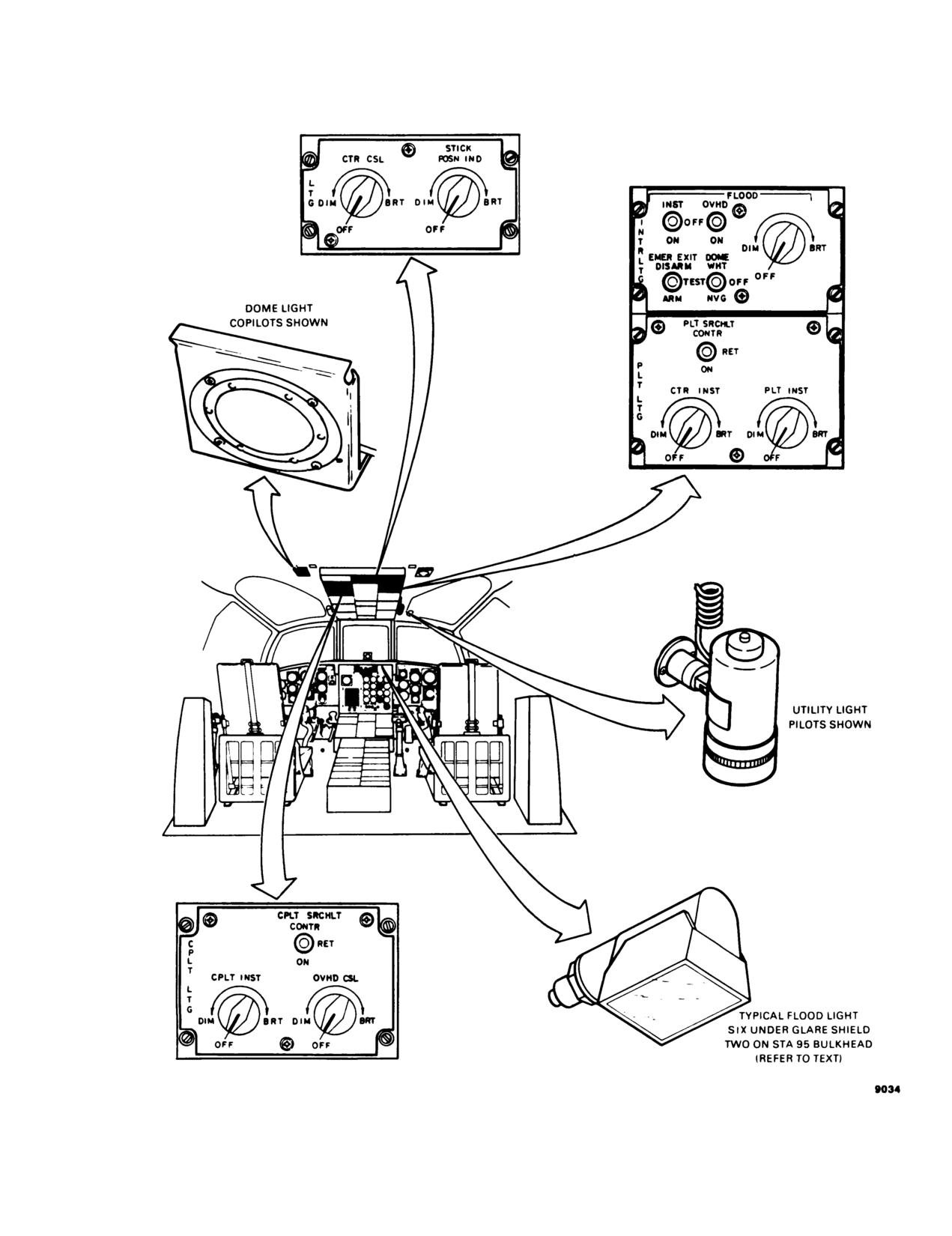
TM 55-1520-240-10
Figure 2-44. Cockpit Lighting and Control
2-67
TM 55-1520-240-10
The rotary control switch is labeled OFF, DIM, and
2-176. Canted and Center Console Lights.
BRT. It adjusts the light level from DIM to BRT. When
NOTE
the rotart control switch is OFF, the overhead switch
The console lights are incompatible with
panel light system is deenergized.
NVG. During NVG operations, turn the
console lights off and light the console with
2-172. Pilot and Copilot Instrument Panel Lights.
utility lights or floodlights.
All flight instruments and placards on both pilot and
copilot instrument panels receive lighting. The HSI,
Lighting is provided for all control panels on the canted
attitude indicator (VGI), radar altimeter, and turn and
and center console. Power to operate and control the
slip indicator for both pilot and copilot have integral
console lights is supplied by the No. 1 AC bus through
lighting. The remaining instruments are externally lit by
the LIGHTING CONSOLE circuit breaker on the No.
lighting posts adjacent to the instruments. Power to
1 PDP.
operate and control the pilot flight instrument lights is
supplied by the No. 2 AC bus through the LIGHTING
2-177. LTG Panel. The LTG panel is located at the
PILOT INSTR circuit breaker on the No. 2 PDP. Power
rear of the overhead switch panel (fig. 2-44). It consists
to operate and control the copilot flight instrument
of the CTR CSL and STICK POSN IND control
switches.
lights is supplied by the No. 1 AC bus through the
LIGHTING COPLT INST circuit breaker on the No.
1
a. CTR CSL Switch.
Rotary control switch labeled
PDP.
OFF, DIM, and BRT. It adjusts the light level on the
canted and center consoles from DIM to BRT. When
2-173. PLT and CPLT INST Switches. The PLT
the rotary control switch is OFF, the canted and center
INST (pilot instrument) control switch is located on the
consoles light system is deenergized.
PLT LTG panel on the right side of the overhead switch
b. Stick POSN IND Switch.
Rotary control switch
panel (fig. 2-44). The CPLT INST (copilot instrument)
labeled OFF, DIM, and BRT. It adjusts the light level
control switch is located on the CPLT LTG panel on the
on the stick position indicator from DIM to BRT. When
left side of the overhead switch panel. The rotary
the rotary control switch is OFF, the stick position
control switches are labeled OFF, DIM, and BRT. They
indicator light system is deenergized.
adjust the light level from DIM to BRT. When the
rotary control switch is OFF, the respective instrument
2-178. Dome Lights.
panel light system is deenergized.
When the PLT INST rotary control switch is placed out
of the OFF detent, the following lighting is dimmed:
If the white dome light is turned on during
a. Troop warning jump lights on the overhead switch
NVG operations, the effectiveness of the NVG
panel and on the emergency troop alarm and jump
may be severely impaired and a hazardous
lights boxes on the cargo compartment.
situation may be created due to sudden loss
of pilot visual references. Do not turn on the
b. The legend on pushbutton switches on the heading
white dome lights during NVG operations.
and altitude section of the AFCS panel.
Two cockpit dome lights are attached to the overhead
c. The legend on pushbutton switches on the pilot
structure adjacent to the overhead switch panel (fig.
and copilot HSI MODE SELECT panels.
2-44). Each dome contains a white lamp and a blue
d. The legend on STATUS pushbutton switch on the
NVG filtered lamp which can be selected individually.
countermeasure set AN/ALQ-156 control panel.
Power to operate and control the dome lights is sup-
plied by the DC essential bus through the LIGHTING
2-174. Center Instrument Panel Lights.
COCKPIT DOME circuit breaker on the No. 2 PDP.
The center instrument panel as well as the fire warning
2-179. DOME Switch. The DOME switch is located
panel are lighted. Power to operate and control the
on the INTR LTG panel at the right rear of the
center instrument panel lights is supplied by the No.
2
overhead switch panel (fig. 2-44). The three-position
AC bus through the LIGHTING CTR INSTR circuit
positive-locking switch is labeled WHT, OFF, and NVG.
breaker on the No. 2 PDP.
It selects the function of the dome light. The center
position lever locking switch prevents inadvertent white
2-175. CTR INST Switch. The CTR INST control
light activation during NVG operations.
switch is located on the PLT LTG panel on the right
When the DOME switch is placed to WI-IT, the master
side of the overhead switch panel (fig. 2-44). The rotary
caution panel cannot be dimmed. If WHT is selected
control switch is labeled OFF, DIM, and BRT. It adjusts
while the caution panel is operating on DIM, the
the light level from DIM to BRT. When the rotary
caution lights will automatically switch to BRT mode.
control switch is OFF, the respective instrument panel
During NVG operations, the DOME switch should only
light system is deenergized.
be placed to NVG.
2-68
Change 1
TM 55-1520-240-10
2-180. Pilot and Copilot Utility Lights.
an NVG blue lamp and a red lamp which can be
selected individually. Power to operate and control the
Two utility lights, connected to individual flexible cords,
cabin and ramp lights is supplied by the switched battery
are mounted in two retaining sockets on either side of
bus through the LIGHTING CABIN & RAMP circuit
the overhead switch panel above the pilot and copilot
breaker on the No. 1 PDP.
(fig. 2-44). The lights are detachable and can be moved
about to take care of special lighting situations. Each
2-185. CABIN AND RAMP LIGHTS Switches. The
utility light has a rheostat switch as an integral part of its
CABIN AND RAMP LIGHTS switches are located on
assembly. This switch, located on the aft part of the
a control panel below the ramp control lever. The
light, regulates the intensity of the light from OFF to
control panel consists of a select switch and a CON-
BRT. A white button on the light housing, opposite the
TROL rotary switch.
switch, is used for flashing the light. By selecting the
color desired on the barrel of the light, blue or white
a. Select Switch. Three-position toggle switch labeled
light will be emitted. Power to operate the utility light is
RED, OFF, and NVG. It is used to select the appro-
supplied by the No. 2 DC bus through the LIGHTING
priate cabin and ramp lights. When placed to OFF,
COCKPIT DOME circuit breaker on the No. 2 PDP.
cabin and ramp lights are deenergized.
b. CONTROL Switch.
Rotary switch labeled DIM
2-181. Floodlights.
and BRT. It adjusts the cabin and ramp RED or NVG
Eight floodlights provide a secondary source of light
light level from DIM to BRT.
(fig. 2-44). Six are under the glareshield and two on the
cockpit bulkhead. The six floodlights under the
2-186. Emergency Exit Lighting.
glareshield light the pilot, center, and copilot instru-
ment panel. The two overhead floodlights light the
Three emergency exit lights are in the cargo compart-
overhead switch panel. Power to. operate and control
ment close to each of the three primary emergency exits
the floodlights is supplied by the DC essential bus
(fig. 2-46). They are located by the main cabin door, the
through the LIGHTING INSTR FLOOD circuit
emergency exit opposite the main cabin door, and the
breaker on the No. 2 PDP.
ramp emergency exit. The lights come on whenever a
loss of power on the switched battery bus occurs or
2-182. FLOOD Switches. The FLOOD switches are
during a landing when 3 to 4g’s are exceeded as sensed
located on the INTR LTG panel at the right rear of the
by an inertia switch.
overhead switch panel (fig. 2-44). They consist of two
floodlight selection switches and a rotary control switch.
The emergency exit lights system is controlled by the
The floodlight selection switches are labeled INST and
EMER EXIT switch on the INTR LTG panel of the
OVHD. Each switch has an OFF and ON position. The
overhead switch panel. The lights may also be used as
rotary control switch is labeled OFF, DIM, and BRT.
portable lamps by removing them from their housing
and by rotating the handle, marked PULL EMER-
a. INST and OVHD Floodlights Selection Switches.
GENCY LIGHT, 45° from its normal position. Power to
Each switch is labeled for the area the floodlights will
operate the emergency exit lights is supplied by two,
light. By placing either switch ON, the associated flood-
internal, 1.25 volt, nickel-cadmium batteries. Power to
lights will light when the floodlight rotary control switch
operate and control the charging, monitoring, and test
is turned toward BRT. Placing the switch to OFF
circuit is supplied by the switched battery bus through
deenergizes the floodlight circuit.
the LIGHTING EMER EXIT circuit breaker on the
b. Floodlight Rotary Control Switch.
The rotary con-
No. 1 PDP.
trol switch is used to adjust the floodlights from DIM to
BRT once the respective floodlight selection switch is
2-187. EMER EXIT Switch.
placed to ON. When the rotary control switch is OFF,
the floodlights will be deenergized.
CAUTION
2-183. Emergency Floodlights.
If the EMER EXIT switch is left in ARM or
If the pilot flight instrument lights have been turned on,
DISARM with the helicopter shutdown and
loss of electrical power will cause the floodlights to
the battery connected, the charging circuit of
automatically come on. All floodlights will function
the emergency exit light system will dis-
automatically in the BRT mode. Simultaneous dimming
charge the helicopter battery.
control of all floodlights can be regained by setting the
FLOOD INST and OVHD selection switches to ON,
turning the floodlight rotary control switch to BRT on
The EMER EXIT switch is located on the INTR LTG
the INTR LTG panel, and turning the PLT INST rotary
panel of the overhead switch panel (fig. 2-44). The
control switch to OFF. Floodlight intensity can be
three-position switch is labeled DISARM, TEST, and
ARM. When the switch is placed to ARM, the emer-
controlled by the floodlight rotary control switch on the
INTR LTG panel.
gency exit lights stay off, the batteries are charging, and
the charge indicator lights come on. The circuit moni-
2-184. Cabin and Ramp Lights.
tors electrical failures and landings in
excess of 3 to 4g’s.
Five cabin and ramp lights are in the cabin, attached to
The light from the charge indicator lamps can be seen
the overhead structure (fig. 2-45). Each light contains
emitting through two pin holes at the base of the main
2-69
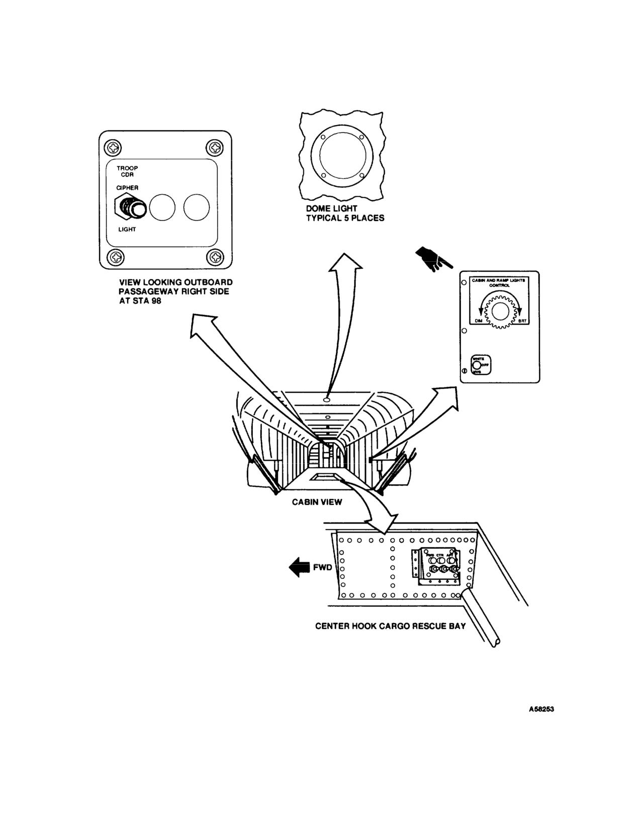
TM
55-1520-240-10
Figure
2-45.
Cabin Lighting and Controls
2-70
Change
11
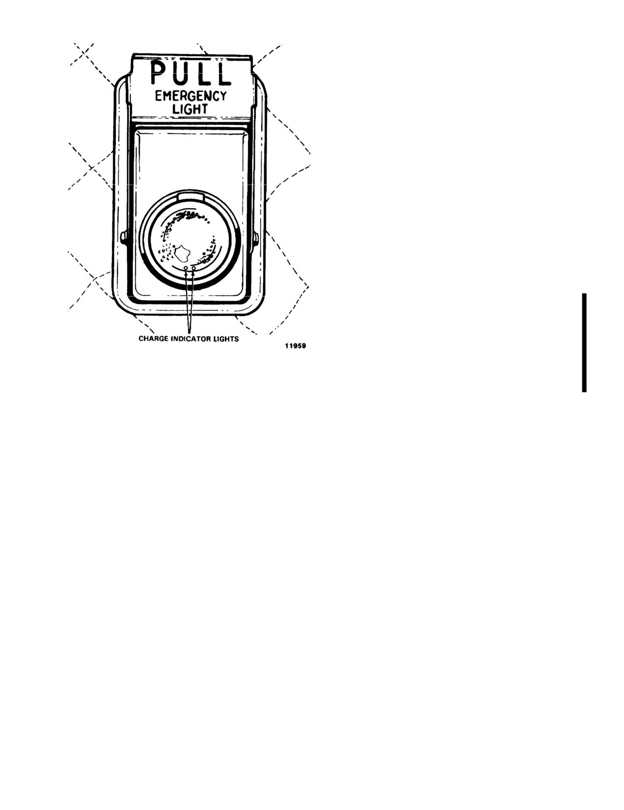
TM 55-1520-240-10
switch is set to DISARM, the indications ar
the ARM position, except the circuit d
electrical failures and hard landings.
2-188. Forward Transmission Oil Level Check
Lights.
The forward transmission floodlight provid
the oil level of the transmission. The fl
sight gage on the transmission. Power to op
the oil level check light is supplied by
bus through the LIGHTING OIL LEVEL CHE
breaker on the No. 1 PDP.
2-189. Oil Level Check Light Switch.
The OIL LEVEL CHECK LT SW is inside the
the canted bulkhead at sta. 95 above the
two-position switch labeled ON and OFF. Wh
ON, the oil check light turns on by the
sion.
2-189.1. Cargo Hook Lights.
Three cargo hook lights have been provid
the cargo hooks during normal and NVG
operations. A light is mounted adjacent to
and is controlled by a two-position swit
Figure 2-46. Emergency Exit Light
CTR, and AFT on the cargo hook light sw
light reflector. When the switch is s
cargo hook lights switch box is mounted on
the main light comes on, powered by the
STA. 360 in the center cargo hook well.
Change
11
2-71
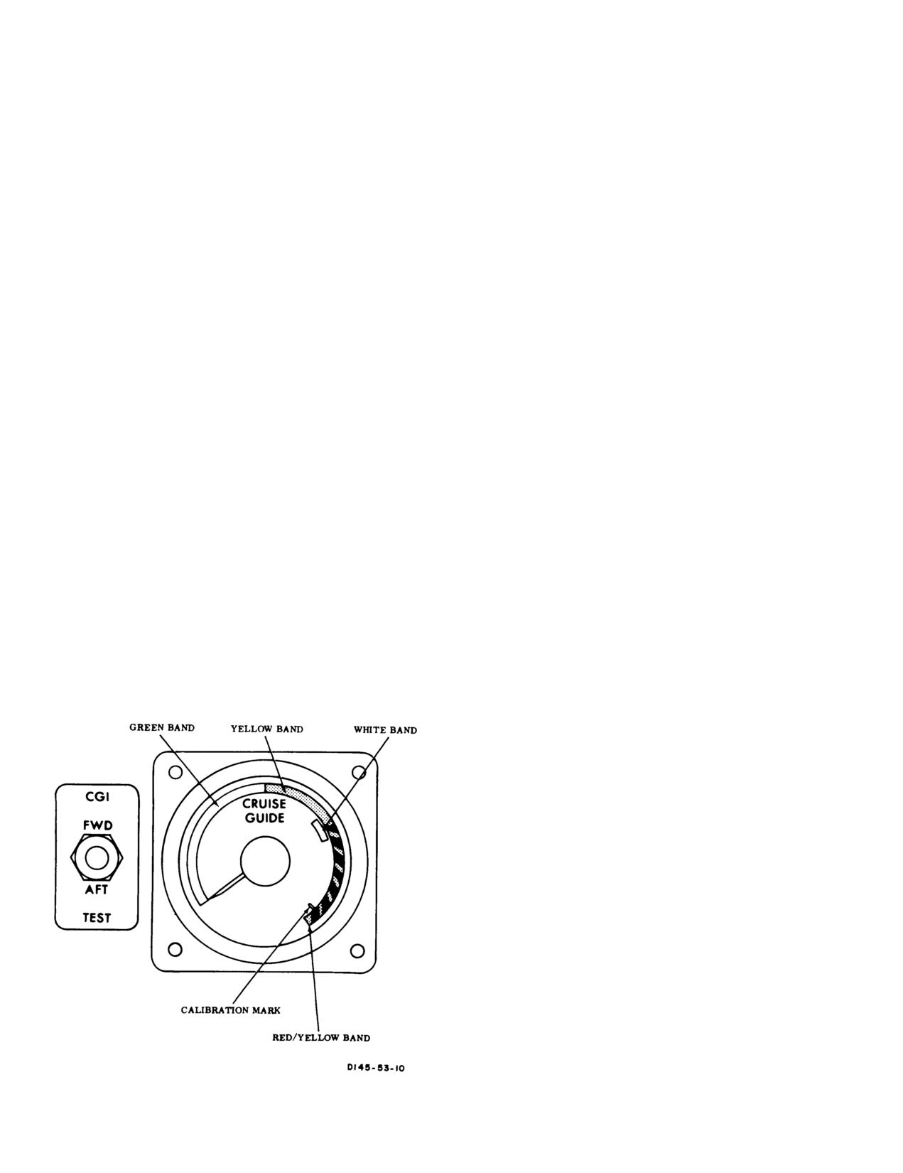
TM 55-1520-240-10
SECTION XIV FLIGHT INSTRUMENTS
2-190. General.
stress when in the red-and-yellow striped band. This can
be accomplished by lowering THRUST CONT lever,
The following paragraphs contain information on the
reducing airspeed, releasing back pressure on the cyclic
flight instruments. Information on the navigation instru-
stick, or by reducing the severity of the maneuver.
ments will be found in Chapter 3, Avionics. All other
instruments directly related to one of the helicopter
2-193. CGI TEST Switch. The CGI TEST switch is
systems are found under the appropriate system head-
on the pilot instrument panel, on the left side of the
ing in this chapter. Refer to fig. 2-6, 2-7, 2-8, 2-9, 2-10,
indicator (fig. 2-47). It is a three-position switch spring
and 2-12 for illustrations of the instrument panels,
loaded to center off position labeled FWD and AFT.
canted and center consoles, and overhead switch panel.
NOTE
2-191. Cruise Guide Indicator System.
Do not test the cruise guide system with
The cruise guide indicator (CGI) system gives the pilot
rotors turning. False indications will result.
a visual indication of actual loads imposed on critical
components of the helicopter dynamic system, The
When the switch is placed from center position to each
system allows the pilot to achieve maximum helicopter
utilization under various conditions of payload, altitude,
test position, the pointer on the indicator should indi-
airspeed, ambient temperature, and center-of-gravity.
cate within the white test band. The white test band
indicates proper system operation.
The system consists of strain gages bonded to fixed links
in the forward and aft rotor controls, an indicator, a
When the test function is activated, circuits from the
signal processor unit in the aft pylon, a signal condi-
strain gages to the indicator are tested. However, sep-
tioner unit in the forward pylon, and interconnecting
aration of the bond of the strain gage to a link will not
wiring. The system measures alternating stress loads at
be detected by the test function. The narrow white line
each rotor and displays the larger of the two signals.
towards the high end of the striped red-and-yellow band
Power to operate the cruise guide indicator system is
is used for calibrating the indicator during bench test.
supplied by No. 2 DC bus through the CRUISE GUIDE
circuit breaker on the No. 2 PDP.
2-194. Airspeed Indicator.
There are two airspeed indicators located on the upper
2-192. CRUISE GUIDE Indicator.
The CRUISE
left portion of the copilot and pilot instrument panel
GUIDE indicator is on the pilot instrument panel (fig.
(fig. 2-8 and 2-10). The difference between dynamic
2-47). Three bands are displayed on the dial face of the
pressure and static pressure as measured by the pitot
indicator. These bands are colored green, yellow, and
static system is introduced into these instruments. Indi-
striped red-and-yellow, Refer to fig. 5-1 for limitations.
cated airspeed is shown in knots.
Immediate corrective action must be taken to reduce
2-195. Altimeter.
An AIMS altimeter is provided for the pilot (fig. 2-48).
In the term AIMS, the A stands for Air Traffic Control
Radar Beacon System (ATCRBS), the I stands for
identification friend or foe (IFF), the M represents the
Mark XII identification system, and the S means system.
A pneumatic counter-drum-pointer type altimeter is
installed for the copilot. The pilot’s altimeter is a
pneumatic counter-drum-pointer type which is a self-
contained unit consisting of a precision pressure altim-
eter combined with an altitude encoder.
Simultaneously, the display indicates and the encoder
transmits through the transponder the altitude of the
helicopter. Altitude is displayed on the altimeter by a
10,000-foot counter, and a 100-foot drum. A single
pointer indicates hundreds of feet on a circular scale
with 50-foot center markings. Below 10,000 feet, a
diagonal warning symbol will appear on the 10,000 foot
counter. Power to operate the AIMS altimeter is sup-
plied by the No. 2 DC bus through the NAV AIMS ALT
circuit breaker on the No. 2 PDP.
A barometric pressure setting knob is provided to insert
Figure 2-47. Cruise Guide Indicator
the desired altimeter setting in inches of Hg. A vibrator
2-72
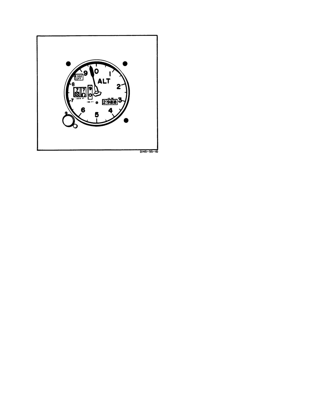
TM 55-1520-240-10
b. Check that the pilot’s altimeter indicates within
±70 feet of field elevation. If the altimeter error is
greater than
±70 feet, do not use the altimeter for IFR
flight.
2-197. In Flight Operation - Altimeter.
Operate the AIMS altimeter encoding function as fol-
lows:
a. Be sure the IFF set is on and set to the proper
code.
b. Be sure the altimeter is set to the local altimeter
setting.
c. Set the M-C (mode c) switch on the IFF control
panel to ON.
d. Check that the red CODE OFF flag is not visible in
the pilot’s altimeter.
The copilot’s altimeter is a pneumatic counter-drum-
pointer type which displays altitude in the same manner
as the pilot’s altimeter. It also incorporates a barometric
pressure setting knob and an internal vibrator powered
Figure 2-48. AIMS Altimeter
by the No. 2 DC bus. A
minimum of 1
minute of vibrator
operation is required before setting or checking the
powered by No. 2 DC bus is contained in the altimeter
altimeter.
and requires a minimum of 1 minute warmup before
checking or setting the altimeter. If DC power to the
At ambient pressure,
both altimeters should agree
altitude encoder is lost, a warning flag placarded CODE
within
±70 feet of the field elevation when the proper
OFF appears in the upper left instrument dial.
barometric pressure setting is set in the altimeter. If the
internal vibrator of either altimeter becomes inopera-
The flag indicates that the altitude encoder is inopera-
tive due to DC power failure, the pointer drum may
tive and that the system is not reporting altitude to
momentarily hang up when passing from
9 through
0
ground stations. The CODE OFF flag monitors only the
encoder function of the altimeter. It does not indicate
(climbing) or from
0 to 9 (descending). This will cause a
transponder condition. The AIMS altitude reporting
lag of magnitude which will depend on the vertical
function can be inoperative without the CODE OFF
velocity of the aircraft and the friction in the altimeter.
flag showing, as in case of transponder failure or
2-198. Radar Altimeter (AN/APN-209A). Radar al-
improper control settings. It is also possible to get a
timeters are provided for the pilot and copilot (fig.
good Mode C test on the transponder control with the
2-49). The altimeters provide a continuous indication of
CODE OFF flag showing. Display of the CODE OFF
the height of the helicopter above the surface from
0 to
flag only indicates an encoder power failure or a CODE
1,500 feet. Altimeter indications are reliable with pitch
OFF flag failure. In this event, check that DC power is
and roll attitude up to 45°.
available and that the circuit breakers are in. If the flag
is still visible, radio contact should be made with a
Altitude is displayed by a dial, pointer, and by a digital
ground radar site to determine whether the AIMS
display. Each altimeter has HI and LO caution lights.
altitude reporting function is operative. The remainder
The caution lights on each altimeter can be set inde-
of the flight should be conducted accordingly.
pendently of the other altimeter. The caution lights are
set by rotating the LO SET and HI SET knobs until the
2-196. Preflight Operation - Altimeter.
L index and H index on the perimeter of the altimeter
If the AIMS altimeter encoding function is to be used
are at the desired altitudes.
during a flight, perform the following steps before
takeoff
When the helicopter descends below the low index
setting or rises above the high index setting, the corre-
CAUTION
sponding HI or LO caution light will illuminate. If
helicopter altitude exceeds
1,500
feet, pitch or roll angle
If the baroset knob binds or sticks, do not
exceeds 45°,
or the system is unreliable, the following
use excessive force to set the altimeter. Ex-
will occur. The OFF flag will appear, the pointer will
cessive force can damage altimeter gears,
move through
1,500 feet behind the dial mask, and the
resulting in altimeter error. Settings can
digital display and LO and HI caution lights will extin-
sometimes be made by backing off the knob
guish.
and turning at a slower rate.
If power to the system is lost, the following will occur.
a. Set the pilot’s altimeter to the field barometric
The OFF flag will appear, the digital display and
setting.
caution lights will go out, and the pointer will remain at
2-73
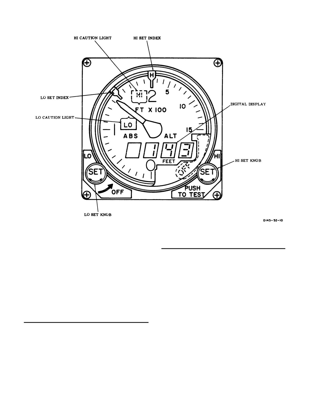
TM 55-1520-240-10
Figure 2-49. Radar Altimeter (AN/APN-209)
the last valid indication when power was lost. The
CONTROLS/
altimeters have a self-test feature. Pressing the PUSH-
INDICATOR
FUNCTION
TO-TEST knob will cause the pointer and digital dis-
LO set index
Indicates altitude trip
play to indicate between 900
and 1,100 feet. If LO set
point for LO caution light.
and HI set are indexed
below 900
feet, the LO caution
HI set index
Indicates altitude trip
light goes out, and the HI caution light comes on. Power
point for HI caution light.
to operate the radar altimeter is supplied by the No. 2
Indicator pointer
Indicates absolute altitude
DC bus through the NAV RAD ALT circuit breaker on
from 0 to 1,500 feet.
the No. 2 PDP.
Digital indicator
Provides direct reading
four digit indication of
2-199. Controls and Function, Radar Altimeter
absolute altitude from
0
(AN/APN-209A).
to 1,500 feet.
LO caution light
Comes on when helicop-
CONTROLS/
INDICATOR
FUNCTION
ter descends below alti-
tude on LO set index.
LO SET knob
Either pilot’s LO SET
HI caution light
Light comes on when heli-
knob applies power to
copter rises above altitude
altimeter system. LO set
on HI set index.
index on both altimeters
OFF flag
Flag is displayed when
can be set independently.
power is removed from
Both LO set indices must
set, when indications are
be masked to turn the set
unreliable, or when alti-
off.
tude exceeds approxi-
HI SET knob
Sets position of HI set
mately 1,500 feet.
index and tests altimeter
system when pressed.
2-74