TECHNICAL MANUAL MAINTENANCE MANUAL FOR ARMY CH-47D HELICOPTER (1992) - page 1
*TM 55-1520-240-10
TECHNICAL MANUAL
MAINTENANCE MANUAL
FOR
ARMY CH-47D
HELICOPTER
(EIC: RCD)
*This manual supersedes TM 55-1520-240-10, dated 10 November
1982, including all changes.
DISTRIBUTION STATEMENT A:
Approved for public release; distribution
unlimited.
HEADQUARTERS
DEPARTMENT OF THE ARMY
30 April 1992
URGENT
TM 55
-1520
-240
-10
C 19
CHANGE
HEADQUARTERS
DEPARTMENT OF THE ARMY
NO. 19
WASHINGTON, D.C., 15 FEBRUARY 2002
OPERATOR’S MANUAL
FOR
ARMY MODEL
CH-47D HELICOPTERS
(EIC: RCD)
DISRIBUTION STATEMEN
Approved for public release; distribution is u
TM
-152-24-10, 30 April 1992 is changed as follows:
1. Remove and insert pages as indicated below. New or changed text ma
vertical bar in.th
An illustration change is indicated by a miniature
Remove pages
Insert pages
A and B
A and B
5-1 thro
-4
5-1 thro
-4
2. Retain this sheet in front of the manual for reference purposes.
By Order of the Secretary of th
e Army:
ERIC K. SHINSEKI
General, United States Army
Chief of Staff
Official:
JOEL B. HUDSON
Administrative Assistant to the
Secretary of the Army
0204207
DISTRIBUTION:
To be distributed in accordance with Initial Distribution Number (IDN)
TM
-152-24-10.
URGENT
TM 55-1520-240-10
C 18
CHANGE
HEADQUARTERS
DEPARTMENT OF THE ARMY
NO. 18
WASHINGTON, D.C., 15 OCTOBER
2001
OPERATOR’S MANUAL
FOR
ARMY MODEL
CH-47D HELICOPTERS
(EIC: RCD)
DISTRIBUTION STATEM:Approved for public release; distribution is u
TM 55-152010, 30 April 1992 is changed as follows:
1. Remove and insert pages as
New or changed text material is indicat
vertical bar in
An illustration change is indicated by a miniature poi
Remove pages
Insert pages
A and B
A and B
4-29 and 4-30
4-29 and 4-30
8-3 and 8-4
8-3 and 8-4
-------
8-4.1/(8-4.2 blank)
8-15 and 8-16
8-15 and 8-16
2. Retain this front of the manual for reference purposes.
By Order of the Secretary of the Army:
ERIC K. SHINSEKI
General, United States Army
Official:
Chief of Staff
JOEL B. HUDSON
Administrative Assistant to the
Secretary of the Army
0129101
DISTRIBUTION:
To be distributed in accordance with Initial Distribution Number (IDN)
TM 55-1520-240-10.
URGENT
TM 55-1520-240-10
C 17
CHANGE
HEADQUARTERS
DEPARTMENT OF THE ARMY
NO. 17
WASHINGTON, D.C., 31 JULY
2001
OPERATOR’S MANUAL
FOR
ARMY MODEL
CH-47D HELICOPTERS
(EIC: RCD)
DISTRIBUTION STATEM:Approved for public release; distribution is u
TM 55-152010, 30 April 1992 is changed as follows:
1. Remove and insert pages as
New or changed text material is indicat
vertical bar in
An illustration change is indicated by a miniature poi
Remove pages
Insert pages
A and B
A and B
2-1/(2-2 blank)
2-1/(2-2 blank)
8-9 and 8-10
8-9 and 8-10
--------
8-10.1/(8-10.2 blank)
8-13 and 8-14
8-13 and 8-14
--------
8-14.1
4.2 blank)
9-12.1 and 9-12.2
9-12.1 and 9-12.2
9-13 and 9-14
9-13 and 9-14
2. Retain this sheet in front of the manual for reference purposes.
By Order of the Secretary of the Army:
ERIC K. SHINSEKI
General, United States Army
Official:
Chief of Staff
JOEL B. HUDSON
Administrative Assistant to the
Secretary of the Army
0120406
DISTRIBUTION:
To be distributed in accordance with Initial Distribution Number (IDN)
TM 55-1520-240-10.
URGENT
TM 55-1520-240-10
C16
CHANGE
HEADQUARTERS
DEPARTMENT OF THE ARMY
NO. 16
WASHINGTON, D.C., 20 APRIL 2001
OPERATOR’S MANUAL
FOR
ARMY MODEL
CH-47D HELICOPTERS
(EIC:RCD)
DISTRIBUTION STATEMENT A: Approved for public release; distribution is
TM 55-1520-240-10, 30 April 1992, is changed as follows:
1. Remove and insert pages as indicated below. New or changed text mat
vertical bar in the margin. An illustration change is indicated by a m
Remove pages
Insert pages
A and B
A and B
9-17 and 9-18
9-17 and 9-18
2. Retain this sheet in front of the manual for reference purposes.
By Order of the Secretary of the Army
ERIC K. SHINSEKI
General, United States Army
Official
Chief of Staff
JOEL B. HUDSON
Administrative Assistant to the
Secretary of the Army
0110703
DISTRIBUTION:
To be distributed in accordance with Initial Distribution Number (IDN
TM 55-1520-240-10.
URGENT
TM 55-1520-240-10
CHANGE
HEADQUARTERS
DEPARTMENT OF THE ARMY
NO. 15
WASHINGTON, D.C.,
29 DECEMBER
2000
OPERATOR’S MANUAL
FOR
ARMY MODEL
CH-47D
HELICOPTERS
(EIC: RCD)
DISTRIBUTION STATEMENT A: Approved for public release; distribution is unlimited
TM 55-1520-240-1
April 1992 is changed as follows:
Remove and insert pages as indicated below. New or changed text material is indicated by a
vertical bar in the margin. An illustration change is indicated by a miniature pointing hand.
Remove pages
Insert pages
A and B
9-17 and 9-18
9-17 and 9-18
2.
Retain this sheet in front of the manual for reference purposes.
By Order of the Secretary
of the Army:
ERIC K.
General, United States Army
of
OFFICIAL:
JOEL B. HUDSON
Administrative
t to the
of the Army
0101001
DISTRIBUTION:
To be distributed in accordance
Initial Distribution Number (IDN)
310194, requirements for
TM
55-1520-240-10.
URGENT
TM 55-1520-240-10
C 14
CHANGE
HEADQUARTERS
DEPARTMENT OF THE ARMY
NO. 14
WASHINGTON, D.C., 28 JULY 2000
OPERATOR’S MANUAL
FOR
ARMY MODEL
CH-47D HELICOPTERS
(EIC: RCD)
DISTRIBUTION STATEMENT A: Approved for public release; distribution is unlimited
TM 55-1520-240-10, 30 April 1992 is changed as follows:
1. Remove and insert pages as indicated below. New or changed text material is indicated by a
vertical bar in the margin. An illustration change is indicated by a miniature pointing hand.
Remove pages
Insert pages
A and B
A and B
i through iii/(iv blank)
i and ii
2-27 and 2-28
2-27 and 2-28
2-85 and 2-86
2-85 and 2-86
------------
2-90.1 and 2-90.2
2-91 and 2-92
2-91 and 2-92
4-39 and 4-40
4-39 and 4-40
------------
4-41 through 4-45/(4-46 blank)
5-17/(5-18 blank)
5-17/(5-18 blank)
6-1 and 6-2
6-1 and 6-2
6-37 and 6-38
6-37 and 6-38
------------
6-38.1/(6-38.2 blank)
7-1 and 7-2
7-1 and 7-2
8-3 through 8-6
8-3 through 8-6
-----------
8-6.1/(8-6.2 blank)
-----------
9-23/(9-24 blank)
B-1 through B-4
B-1 through B-4
2. Retain this sheet in front of the manual for reference purposes.
TM 55-1520-240-10
C14
By Order of the Secretary of the Army:
Official:
ERIC K. SHINSEKI
General, United States Army
Chief of Staff
JOEL B. HUDSON
Administrative Assistant to the
cretarySo
f the Army
0017907
DISTRIBUTION:
To be distributed in accordance with Initial Distribution Number (ID
TM 55-1520-240-10.
TM 55-1520-240-10
C 13
CHANGE
HEADQUARTERS
DEPARTMENT OF THE ARMY
NO. 13
WASHINGTON, D.C., 15 MAY 2000
OPERATOR’S MANUAL
FOR
ARMY MODEL
CH-47D HELICOPTERS
(EIC: RCD)
DISTRIBUTION STATEMENT A: Approved for public release; distribution is unlimited
TM 55-1520-240-10, 30 April 1992 is changed as follows:
1.
Remove and insert pages as indicated below. New or changed text material is indicated by a
vertical bar in the margin. An illustration change is indicated by a miniature pointing hand.
Remove pages
Insert pages
A and B
A and B
i and ii
i - ii
-----
iii/(iv blank)
1-1/(1-2 blank)
1-1/(1-2 blank)
2-1/(2-2 blank)
2-1/(2-2 blank)
2-9 and 2-10
2-9 and 2-10
2-10.1/(2-10.2 blank)
-----
2-11 and 2-12
2-11 and 2-12
-----
2-12.1/(2-12.2 blank)
2-13 through 2-16
2-13 through 2-16
-----
2-16.1 through 2-16.5/(2-16.2 blank)
2-21 and 2-22
2-21 and 2-22
2-22.1/(2-22.2 blank)
-----
2-23 through 2-26
2-23 through 2-26
-----
2-26.1 through 2-26.5/(2-26.6 blank)
2-33 and 2-34
2-33 and 2-34
2-53/(2-54 blank)
2-53/(2-54 blank)
2-55/(2-56 blank)
2-55/(2-56 blank)
2-59/(2-60 blank)
2-59/(2-60 blank)
-----
2-60.1/(2-60.2 blank)
-----
2-60.3/(2-60.4 blank)
-----
2-60.5/(2-60.6 blank)
-----
2-76.3/(2-76.4 blank)
2-77 through 2-80
2-77 through 2-80
-----
3-16.1 through 3-16.14
3-17 and 3-18
(3-17 blank)/3-18
-----
3-17.1 through 3-17.14 blank
5-1 through 5-6
5-1 through 5-6
-----
5-6.1/(5-6.2 blank)
5-7 and 5-8
5-7 and 5-8
7-1 and 7-2
7-1 and 7-2
-----
7A-1 through 7A-112
TM 55-1520-240-10
C13
Remove Pages
Insert Pages
8-3 through
8-14
8-3 through 8-14
9-1 and 9-2
9-1 and 9-2
9-5 through
9-8
9-5 through 9-8
-----
9-8.1 through 9-8.4
9-9 through
9-12
9-9 through 9-12
-----
9-12.1 and 9-12.2
9-15 and 9-16
9-15 and 9-16
9-17 and 9-18
9-17 and 9-18
B-1 through B-4
B-1 through B-4
Index 1 through Index 8
Index 1 through Index 8
-----
Index 8.1/(lndex 8.2 blank)
Index 9 through Index 10
Index 9 through Index 10
-----
Index 10.1/(10.2 blank)
Index 11 and Index 12
Index 11 and Index 12
-----
Index 12.1/(lndex 12.2 blank)
Index 13 through
Index 15/(lndex 16 blank)
Index 13 through Index 16
-----
Index 17 and Index 18
2.
Retain this sheet in front of the manual for reference purposes.
By Order of the Secretary of the Army:
Official:
ERIC K. SHINSEKI
General, United States Army
Chief of Staff
JOEL B. HUDSON
Administrative Assistant to the
Secretary of the Army
0012903
DISTRIBUTION:
To be distributed in accordance with Initial Distribution Number (IDN) 310194, requirements for
TM
55-1520-240-10.
TM 55-1520-240-10
C12
CHANGE
HEADQUARTERS
DEPARTMENT OF THE ARMY
NO. 12
WASHINGTON, D.C., 15 March
1999
OPERATOR’S MANUAL
FOR
ARMY MODEL
CH-47D HELICOPTERS
(EIC: RCD)
DISTRIBUTION STATEMENT A: Approved for public release; distributio
TM 55-1520-240-10, 30 April 1992 is changed as follows:
1. Remove and insert pages as indicated below. New or changed text ma
vertical bar in the margin. An illustration change is indicated by a
Remove pages
Insert pages
-----
A and B
3-1 and 3-2
3-1 and 3-2
3-17 and
3-18
3-17 and
3-18
-----
3-17.1 through 3-17.13/
(3-17.14 blank)
Index 7 and8Index
Index 7 and Index 8
2. Retain this sheet in front of the manual for reference purposes.
By Order of the Secretary of the Army:
DENNIS J. REIMER
General, United States Army
Chief of Staff
Administrative Assistant to the
Secretary of the Army
051968
DISTRIBUTION:
To be distributed in accordance with Initial Distribution Number (ID
TM
55-1520-240-10.
TM
55-1520-240-10
C11
CHANGE
HEADQUARTERS
DEPARTMENT OF THE ARMY
NO.
11
WASHINGTON, D.C., 16 October
1998
OPERATOR’S MANUAL
FOR
ARMY MODEL
CH-47D HELICOPTERS
(EIC: RCD)
DISTRIBUTION STATEMENT A: Approved for public release; distributio
TM 55-1520-240-10, 30 April 1992 is changed as follows:
1. Remove and insert pages as indicated below. New or changed text mat
vertical bar in the margin. An illustration change is indicated by a m
Remove pages
Insert pages
2-5 and 2-6
2-5 and 2-6
2-11 and 2-12
2-11 and 2-12
2-13 and 2-14
2-13 and 2-14
2-65 and 2-66
2-65 and 2-66
-------
2-66.1/(2-66.2 blank)
2-69 through
2-72
2-69 through
2-72
2-93 and
2-94
2-93 and
2-94
3-5 and 3-6
3-5 and 3-6
8-3 and 8-4
8-3 and 8-4
9-3 and 9-4
9-3 and 9-4
Index 9 and Index 10
Index 9 and Index 10
2. Retain this sheet in front of the manual for reference purposes.
By Order of the Secretary of the Army:
DENNIS J. REIMER
General, United States Army
Official:
Chief of Staff
Administrative Assistant to the
Secretary of the Army
05594
DISTRIBUTION:
To be distributed in accordance with Initial Distribution Number (IDN
TM 55-1520-240-10.
URGENT
TM 55-1520-240-10
C10
CHANGE
HEADQUARTERS
DEPARTMENT OF THE ARMY
NO. 10
WASHINGTON, D.C., 31 August 1998
OPERATOR’S MANUAL
FOR
ARMY MODEL
CH-47D HELICOPTERS
(EIC:RCD)
DISTRIBUTION STATEMENT A: Approved for public release; distribution is
TM 55-1520-240-10, 30 April 1992, is changed as follows:
1. Remove and insert pages as indicated below. New or changed text mat
vertical bar in the margin. An illustration change is indicated by a m
Remove pages
Insert pages
9-17 and 9-18
9-17 and 9-18
2. Retain this sheet in front of the manual for reference purposes.
By Order of the Secretary of the Army
DENNIS J. REIMER
General, United States Army
Official
Chief of Staff
JOEL B. HUDSON
Administrative Assistant to the
Secretary of the Army
04855
DISTRIBUTION:
To be distributed in accordance with Initial Distribution Number (IDN
TM 55-1520-240-10.
TM
55-1520-240-10
C9
CHANGE
HEADQUARTERS
DEPARTMENT OF THE ARMY
NO.
9
WASHINGTON D.C., 27 April 1998
OPERATOR’S MANUAL
FOR
ARMY MODEL
CH-47D HELICOPTERS
(EIC: RCD)
DISTRIBUTION STATEMENT A: Approved for public release;
TM 55-1520-240-10, 30 April 1992, is changed as fol
1. Remove and insert pages as indicated below. New or c
vertical bar in the margin. An illustration change is indicated
Remove pages
Insert pages
2-13 through
2-18
2-13 through
2-18
2-21 and
2-22
2-21 and
2-22
2-37 through
2-40
2-37 through
2-40
2-47 through
2-50
2-47 through
2-50
2-53/(2-54 blank)
2-53/(2-54 blank)
2-59/(2-60 blank)
2-59/(2-60 blank)
2-69 and 2-70
2-69 and 2-70
2-76.1 and
2-76.2
2-76.1 and 2-76.2
2-77 through
2-80
2-77 through
2-80
2-91 through
2-94
2-91 through
2-94
3-17 and 3-18
3-17 and
3-18
4-1 and
4-2
4-1 and 4-2
4-2.1 and
4-2.2
4-7 and
4-8
4-7 and
4-8
4-29 and
4-30
4-29 and
4-30
4-33 and
4-34
4-33 and
4-34
5-1 and 5-2
5-1 and
5-2
5-15 and 5-16
5-15 and 5-16
5-17/(5-18 blank)
5-17/(5-18 blank)
6-3 and 6-4
6-3 and 6-4
6-15 and 6-16
6-15 and 6-16
6-29 through
6-32
6-29 through
6-32
6-32.1/(6-32.2 blank)
TM
55-1520-240-10
C9
Remove pages
Insert pages
7-1 and
7-2
7-1 and
7-2
8-3 and
8-4
8-3 and
8-4
8-7 and
8-8
8-7 and
8-8
8-8.1 and
8-8.2
8-8.1 and
8-8.2
8-9 and
8-10
8-9 and
8-10
9-5 and
9-6
9-5 and
9-6
9-13 and
9-14
9-13 and
9-14
9-14.1/(9-14.2
blank)9-14.1/(9-14.2 blank)
9-15 and
9-16
9-15 and
9-16
9-16.1/(9-16.2 blank)
9-17 and
9-18
9-17 and
9-18
Index
13 and Index
14 Index
13 and Index
14
2.Retain this sheet in front of the manual for reference purp
By Order of the Secretary of the Army:
DENNIS J. REIMER
General, United States Army
Chief of Staff
Administrative Assistant to the
Secretary of the Army
04918
DISTRIBUTION:
To be distributed in accordance with Initial Distribution Number (I
TM
55-1520-240-10.
TM 55-1520-240-10
C8
CHANGE
HEADQUARTERS
DEPARTMENT OF THE ARMY
NO. 8
WASHINGTON D.C., 2 February 1
OPERATOR’S MANUAL
FOR
ARMY MODEL
CH-47D HELICOPTER
(EIC: RCD)
DISTRIBUTION STATEMENT A: Approved for public release; distri
TM
55-1520-240-10,30 April
1992, is changed as follows:
1. Remove and insert pages as indicated below. New or changed te
vertical bar in the margin. An illustration change is indicated by a mini
Remove pages
Insert pages
i and ii
i and ii
3-1 and 3-2
3-1 and 3-2
3-33 and 3-34
3-33 and 3-34
-------
3-34.1 through 3-34.22
Index 3
h In
x 6
Index 3 through Index 6
2. Retain this sheet in front of the manual for reference purpos
TM
55-1520-240-10
C
8
By Order of the Secretary of the Army:
DENNIS J. REIMER
General, United States Army
Official
Chief of Staff
JOEL B. HUDSON
Administrative Assistant to the
Secretary of the Army
04516
DISTRIBUTION:
To be distributed in accordance with the Initial Distribution Number (ID
for TM 55-1520-240-10.
PIN 051968-008
TM 55-1520-240-10
C7
CHANGE
HEADQUARTERS
NO. 7
DEPARTMENT OF THE ARMY
WASHINGTON, D.C., 25 June 1997
Operator’s Manual
For
ARMY MODEL
CH-47D HELICOPTER
(EIC:RCD)
DISTRIBUTION STATEMENT A: Approved for public release; distribution is unlimited
TM 55-1520-240-10, 30 April 1992, is changed as follows:
1. Remove and insert pages as indicated below. New or changed text material is indicated by a vertical bar in the
margin. An illustration change is indicated by a miniature pointing hand.
Remove pages
Insert pages
2-7 through 2-10
2-7 through 2-10
------------
2-10.1/(2-10.2 blank)
2-33 and 2-34
2-33 and 2-34
------------
2-34.1/(2-34.2 blank)
2-53/(2-54 blank)
2-53/(2-54 blank)
2-55/(2-56 blank)
2-55/(2-56 blank)
2-59/(2-60 blank)
2-59/(2-60 blank)
4-7 and 4-8
4-7 and 4-8
-----------
4-8.1 through 4-8.10
8-5 through 8-8
8-5 through 8-8
----------
8-8.1 and 8-8.2
8-9 and 8-10
8-9 and 8-10
8-13 and 8-14
8-13 and 8-14
A-1/(A-2 blank)
A-1/(A-2 blank)
B-1 through B-4
B-1 through B-4
Index 7 and Index 8
Index 7 and Index 8
Index 8.1/(Index 8.2 blank)
Index 8.1/(Index 8.2 blank)
2. Retain this sheet in front of manual for reference purposes.
TM 55-1520-240-10
C7
By Order of the Secretary of the Army:
DENNIS J. REIMER
General, United States Army
Official:
Chief of Staff
JOEL B. HUDSON
Administrative Assistant to the
Secretary of the Army
03578
DISTRIBUTION:
To be distributed in accordance with DA Form 12-31-E, block no. 0194, requirements for TM 55-1520-240-10.
TM 55-1520-240-10
C6
CHANGE
HEADQUARTERS
NO. 6
DEPARTMENT OF THE ARMY
WASHINGTON, D C., 27 February 1997
OPERATOR’S MANUAL
FOR
ARMY MODEL
CH-47D HELICOPTER
(EIC:RCD)
DISTRIBUTION STATEMENT A: Approved for public release; distribution is unlimited
TM 55-1520-240-10, 30 April 1992, is changed as follows:
1.
Remove and insert pages as indicated below. New or changed text material is indicated by a vertical bar in the
margin. An illustration change is indicated by a miniature pointing hand.
Remove pages
Insert pages
i and ii
i and ii
2-9 through 2-12
2-9 through 2-12
----------
2-12.1/(2-12.2 blank)
2-53/(2-54 blank)
2-53/(2-54 blank)
2-75 and 2-76
2-75 and 2-76
----------
2-76.1 and 2-76.2
3-1 and 3-2
3-1 and 3-2
3-21 through 3-24
3-21 through 3-24
3-29 through 3-32
3-29 through 3-32
----------
3-37 through 3-81/(3-82 blank)
8-7 and 8-8
8-7 and 8-8
Index 7 and Index 8
Index 7 and Index 8
----------
Index 8.1/(Index 8.2 blank)
Index 11 and Index12
Index 11 and Indexl2
----------
Index 12.1/(Index 12.2 blank)
2.
Retain this sheet in front of manual for reference purposes.
TM 55-1520-240-10
C6
By Order of the Secretary of the Army:
DENNIS J. REIMER
General, United States Army
Official:
Chief of Staff
JOEL B. HUDSON
Administrative Assistant to the
Secretary of the Army
03114
To be distributed in accordance with DA Form 12-31-E, block no. 0194, requirements for TM 55-1520-240-10.
TM 55-1520-240-10
C 5
CHANGE
HEADQUARTERS
DEPARTMENT OF THE ARMY
NO.
5
WASHINGTON, D. C., 17 April 1995
OPERATOR’S MANUAL
FOR
ARMY MODEL
CH-47D HELlCOPTERS
(EIC: RCD)
DISTRIBUTlON STATEMENT A: Approved for public release; distribution is unlimited
TM 55-1520-240-10,30 April 1992, is changed as follows:
1. Remove and insert pages as indicated below. New or changed text material is indicated by a vertical bar
in the margin. An illustration change is indicated by a miniature pointing hand.
Remove pages
Insert pages
8-3 and 8-4
8-3 and 8-4
8-11 and 8-12
8-11 and 8-12
2. Retain this sheet in front of manual for reference purposes.
By Order of the Secretary of the Army:
GORDON R. SULLIVAN
General, United States Army
Official:
Chief of Staff
JOEL B. HUDSON
Acting Administrative Assistant to the
Secretary of the Army
00116
DISTRIBUTION:
To be distributed in accordance with DA Form 12-31-E, block no. 0194, requirements for
TM 55-1520-240-10.
TM 55-1520-240-10
C 4
CHANGE
HEADQUARTERS
DEPARTMENT OF THE ARMY
NO.
4
WASHINGTON, D.C. 30 November 1994
OPERATORS MANUAL
FOR
ARMY MODEL
CH-47D HELICOPTERS
DISTRIBUTION STATEMENT A: Approved for public release; distribution is unlimited
TM 55-1520-240-10,30 April 1992, is changed as follows:
1. Remove and insert pages as indicated below. New or changed text material is indicated by a vertical bar
in the margin. An illustration change is indicated by a miniature pointing hand.
Remove pages
Insert pages
a/(b blank)
a/(b blank)
2-1/(2-2 blank)
2-1/(2-2 blank)
2-21 and 2-22
2-21 and 2-22
---
2-22.1/(2-22.2 blank)
5-13 through 5-16
5-13 through 5-16
6-37 and 6-38
6-37 and 6-38
8-19/(8-20 blank)
8-19/(8-20 blank)
9-13 and 9-14
9-13 and 9-14
---
9-14.1/(9-14.2 blank)
9-15 and 9-16
9-15 and 9-16
Index 13 and Index 14
Index 13 and Index 14
2. Retain this sheet in front of manual for reference purposes.
By Order of the Secretary of the Army:
GORDON R. SULLIVAN
General, United States Army
Official:
Chief of Staff
MILTON H. HAMILTON
Administrative Assistant to the
Secretary of the Army
07690
DISTRIBUTION:
To be distributed in accordance with DA Form 12-31-E, block no. 0194, requirements for
TM 55-1520-240-10.
TM
55-1520-240-10
C
3
CHANGE
HEADQUARTERS
DEPARTMENT OF THE ARMY
-
NO.
3
WASHINGTON, D.C.,
30 SEPTEMBER
1994
Operators Manual
for
ARMY CH-47D HELICOPTER
(EIC: RCD)
DISTRIBUTION STATEMENT A:
Approved for public release; distribution is unlimited.
TM
55-1520-240-10,
30 April
1992, is changed as follows:
1.
Remove and insert pages as indicated below. New or changed text material is
indicated by a vertical bar in the margin. An illustration change is indicated
by a miniature pointing hand.
Remove pages
Insert pages
2-85 and
2-86
2-85 and
2-86
3-5 through
3-8
3-5 through
3-8
----
3-8.1 through
3-8.4
5-1 and
5-2
5-1 and
5-2
5-13 through
5-16
5-13 through
5-16
6-17 through
6-20
6-17 through
6-20
B-1 through B-4
B-1 through B-4
Index
13 and Index
14
Index
13 and Index
14
2.
Retain this sheet in front of manual for reference purposes.
By Order of the Secretary of the Army:
GORDON R. SULLIVAN
General, United States Army
Official:
Chief of Staff
MILTON H. HAMILTON
Administrative Assistant to the
Secretary of the Army
07584
DISTRIBUTION:
To be distributed in accordance with DA Form
12-31-E, block no.
0194, require-
ments for TM
55-1520-240-10.
URGENT
TM
55-1520-240-10
C2
CHANGE
HEADQUARTERS
DEPARTMENT OF THE ARMY
NO.
2
WASHINGTON, D. C., 1 March 1994
Operator’s, Manual
for
ARMY CH-47D HELlCOPTER
(EIC: RCD)
DISTRIBUTION STATEMENT A: Approved for public release; distribution is unlimited
TM 55-1520-240-10, 30 April 1992, is changed as follows:
1. Remove and insert pages as indicated below. New or changed text material is indicated by a vertical bar
in the margin. An illustration change is indicated by a miniature pointing hand.
Remove pages
Insert pages
3-7 and 3-8
3-7 and 3-8
5-9 and 5-10
5-9 and 5-10
8-3 through 8-8
8-3 through 8-8
8-11 through 8-14
8-11 through 8-14
2. Retain this sheet in front of manual for reference purposes.
By Order of the Secretary of the Army:
GORDON R. SULLIVAN
General, United States Army
Official:
Chief of Staff
MILTON H. HAMILTON
Administrative Assistant to the
Secretary of the Army
05818
DISTRIBUTION:
To be distributed in accordance with DA Form 12-31-E, block no. 0194, requirements for
TM 55-1520-240-10.
TM 55-1520-240-10
C
1
CHANGE
HEADQUARTERS
DEPARTMENT OF THE ARMY
NO.
1
WASHINGTON, D.C., 29 OCTOBER
1993
Operator’s Manual
for
ARMY CH-47D HELICOPTER
(EIC: RCD)
DISTRIBUTION STATEMENT A:
Approved for public release; distribution is unlimited.
TM
55-1520-240-10,
30 April
1992, has been changed as follows:
1.
Remove and insert pages as indicated below.
New or changed text material is
indicated by a vertical bar in the margin.
An illustration change is indicated
by a miniature pointing hand.
Remove pages
Insert pages
i and ii
i and ii
2-9 and
2-10
2-9 and
2-10
2-67 and
2-68
2-67 and
2-68
3-33 and
3-34
3-33 and
3-34
4-1 through
4-4
4-1 through
4-4
----
4-4.1 and
4-4.2
A-1/(A-2 blank)
A-1/(A-2 blank)
Index
11 through Index
14
Index
11 through Index
14
2.
Retain this sheet in front of manual for reference purposes.
By Order of the Secretary of the Army:
GORDON R. SULLIVAN
GeneraI, United States Army
Official:
Chief of Staff
MILTON H. HAMILTON
Administrative Assistant to the
Secretary of the Army
05611
DISTRIBUTION:
To be distributed in accordance with DA Form
12-31-E, block no.
0194, require-
ments for TM
55-1520-240-10.
TM 55-1520-240-10
WARNING PAGE
Personnel performing operations, procedures, and practices which are included or implied in this technical manual
shall observe the following warnings. Disregard of these warnings and precautionary information can cause serious
injury or death.
WARNINGS, CAUTIONS, NOTES
ARMAMENT
Loaded weapons or weapons being loaded or unloaded,
Warnings, cautions, and notes are used in this manual to
shall be pointed in a direction which offers the least
emphasize important and critical instructions, and are
exposure to personnel or property in the event of
used for the following conditions:
accidental firing. Personnel shall remain clear of the
hazardous area of all loaded weapons.
VERTIGO
Turn the anti-collision lights off during flight through
An operating procedure, practice, etc., which,
clouds. This will eliminate light reflections from the
if not correctly followed, could result in
clouds, which could cause vertigo.
personnel injury or loss of life.
CARBON MONOXIDE
When smoke, suspected carbon monoxide fumes, or
symptoms of anoxia exist, the crew should immediately
ventilate the aircraft.
An operating procedure, practice, etc., which,
HANDLING FUEL AND OIL
if not strictly observed, could result in dam-
Turbine fuels and lubricating oils contain additives that
age to or destruction of equipment.
are poisonous and readily absorbed through the skin.
Do not allow them to remain on skin longer than
necessary.
NOTE
ELECTROMAGNETIC INTERFERENCE (EMI)
An operating procedure, condition, etc.,
which is essential to highlight.
No electrical/electronic devices of any sort, other than
those described in this manual or appropriate airwor-
thiness release and approved by USAATCOM, are to
STARTING ENGINES
be operated by crewmembers or passengers during
operation of this helicopter.
Coordinate all cockpit actions with ground observer.
RADIOACTIVE MATERIALS
Insure that wheels are chocked (if applicable), rotor and
blast areas are clear, and fire guard is posted.
Instrument dials on CH-47 series aircraft contain radio-
active materials. If an instrument is broken or becomes
GROUND OPERATION
unsealed, avoid personal contact with the item. Use
forceps or gloves made of rubber or polyethylene to pick
Engines will be started and operated only by authorized
up contaminated material. Place the material and the
personnel.
gloves in a plastic bag, seal the bag, and dispose of it as
radioactive waste in accordance with AR 385-11 and
ROTOR BLADES
TM 3-261. (Refer to TB 43-0108.)
Beware of moving rotor blades, particularly the blades
NOISE LEVELS
of the forward rotor system.
Sound pressure levels in this aircraft during some
operating conditions exceed the Surgeon General’s
HIGH VOLTAGE
hearing conservation criteria, as defined in TB MED
All ground handling personnel must be informed of
251. Hearing protection devices, such as the aviator
high voltage hazards when making external cargo hook-
helmet or ear plugs are required to be worn by all
ups.
personnel in and around the aircraft during its opera-
tion.
FIRE EXTINGUISHER
HAZARDOUS CARGO
Exposure to high concentrations of fire extinguishing
Items of cargo possessing dangerous physical proper-
ties, such as explosives, acids, flammables, etc., must be
agents or decomposition products should be avoided.
The liquid should not contact the skin. It may cause
handled with extreme caution and in accordance with
frostbite or low temperature burns.
established regulations. Ref TM 38-250.
Change 4
a/(b blank)
TM 55-1520-240-10
LIST OF EFFECTIVE PAGES
Insert latest changed pages; dispose of superseded pages in accordance with regulations.
N0TE: On a changed page, the portion of the text affected by the latest change is indicated by a vertical line,
or other change symbol, in the outer margin of the page. Changes to illustrations are indicated by miniature
pointing hands. Changes to wiring diagrams are indicated by shaded areas.
Dates of issue for original and changed pages are:
Original
30 April 1992
Change 11
16 October 1998
Change 1
29 October 1993
Change 12
15 March 1999
Change 2
1 March 1994
Change 13
15 May 2000
Change 3
30 September 1994
Change 14
28 July 2000
Change 4
30 November 1994
Change 15
29 December 2000
Change 5
17 April 1995
Change 16
20 April 2001
Change 6
27 February 1997
Change 17
31 July 2001
Change 7
25 June 1997
Change 18
15 October 2001
Change 8
2 February 1998
Change 9
27 April 1998
Change 19
15 February 2002
Change 10
31 August 1998
Page
*Change
Page
*Change
No.
No.
No.
No.
Title .
0
2-35 through 2-37 .
0
a/b blank .
4
2-38 through 2-40 .
9
A and B .
19
2-41 through 2-47 .
0
i and ii .
14
2-48 and 2-49 .
9
iii/iv blank deleted .
14
2-50 through 2-52 .
0
1-1/1-2 blank .
13
2-53/2-54 blank .
13
2-1/2-2 blank .
17
2-55/2-56 blank .
13
2-3/2-4 blank .
0
2-57/2-58 blank .
0
2-5 .
11
2-59/2-60 blank .
13
2-6 .
0
2-60.1 - 2-60.6 blank .
13
2-7 .
7
2-61 through 2-64 .
0
2-8 .
0
2-65 and 2-66 .
11
2-9 and 2-10 .
13
2-66.1/2-66.2 blank .
11
2-10.1/2-10.2 blank del. . 13
2-67 .
0
2-11 and 2-12 .
13
2-68 .
1
2-12.1/2-12.2 blank del. . 13
2-69 .
0
2-13 through 2-16 .
13
2-70 and 2-71 .
11
2-16.1 through 2-16.4 .
13
2-72 through 2-74 .
0
2-16.5/2-16.6 blank .
13
2-75 and 2-76 .
6
2-17 and 2-18 .
9
2-76.1 .
9
2-19 and 2-20 .
0
2-76.2 .
6
2-21 and 2-22 .
13
2-76.3/2-76.4 blank .
13
2-22.1/2-22.2 blank del. . 13
2-77 through 2-79 .
13
2-23 through 2-26 .
13
2-80 .
9
2-26.1 - 2-26.6 blank .
13
2-81 through 2-85 .
0
2-27 .
14
2-86 .
14
2-28 through 2-32 .
0
2-87 through 2-90 .
0
2-33 and 2-34 .
13
2-90.1 and 2-90.2 .
14
2-34.1/2-34.2 blank .
7
2-91 .
14
*Zero in this column indicates an original page.
Change 19
A
TM 5501520-240-10
Page
*Change
Page
*Change
No.
No.
No.
No.
2-92 and 2-93 .
0
6-30 .
0
2-94 .
11
6-31 and 6-32 .
9
2-95 and 2-96 .
0
6-32.1/6-32.2 blank .
9
3-1 .
8
6-33 through 6-37 .
0
3-2 .
12
6-38 .
14
3-3 and 3-4 .
0
6-38.1/6-38.2 blank .
14
3-5 .
3
6-39 through 6-46 .
0
3-6 .
11
7-1 .
13
3-7 .
3
7-2 .
14
3-8.1 through 3-8.4 .
3
7-3 through 7-114 .
0
3-9 through 3-16 .
0
7-115/7-116 blank .
0
3-16.1 - 3-16.14 .
13
7A-1 - 7A-112 .
13
3-17 blank/3-18 .
13
8-1 and 8-2 .
0
3-17.1-3-17.14 blank del . 13
8-3 .
14
3-19 and 3-20 .
0
8-4 .
18
3-21 through 3-23 .
6
8-4.1/8-4.2 blank .
18
3-24 through 3-28 .
0
8-5 - 8-6.1/8-6.2 blank .
14
3-29 through 3-31 .
6
8-7 anc 8-8 .
13
3-32 and 3-33 .
0
8-9 .
17
3-34 .
8
8-10 .
13
3-34.1 through 3-34.22 .
8
8-10.1/8-10.2 blank .
17
3-35 and 3-36 .
0
8-11 through 8-13 .
13
3-37 through 3-82 blank . 6
8-14
17
4-1 through 4-2. .
9
8-14.1/8-14.2 blank .
17
4-3 through 4-4.2 .
1
8-15 .
18
4-5 and 4-6 .
0
8-16 through 8-18 .
0
4-7 and 4-8 .
9
8-19/8-20 blank .
4
4-8.1 through 4-8.10 .
7
9-1 and 9-2 .
13
4-9 through 4-28 .
0
9-3 .
11
4-29 .
18
9-4 .
0
4-30 through 4-32 .
0
9-5 through 9-8.4 .
13
4-33 .
9
9-9 .
13
4-34 through 4-39 .
0
9-10 .
0
4-40 through 4-44 .
14
9-11 through 9-12.1 .
13
4-45/4-46 blank .
14
9-12.2 .
17
5-1 .
0
9-13 .
17
5-2 and 5-3 .
19
9-14 .
9
5-4 through 5-6 .
13
9-14.1/9-14.2 blank .
9
5-6.1/5-6.2 blank .
13
9-15 .
9
5-7 .
13
9-16 .
13
5-8 .
0
9-16.1/9-16.2 blank .
9
5-9 .
2
9-17 .
16
5-10 through 5-13 .
0
9-18 through 9-22 .
0
5-14 .
4
9-23/9-24 blank .
14
5-15 .
9
A-1/A-2 blank .
7
5-16 .
0
B-1 .
7
5-17/5-18 blank .
14
B-2 through B-4 .
14
6-1 .
0
C-1 through C-4 blank .
0
6-2 .
14
Index 1 - Index 8 .
13
6-3 .
0
Index 8.1 - 8.2 blank del. . 13
6-4 .
9
Index 9 - Index 10 .
13
6-5 through 6-17 .
0
Index 10.1/10.2 blank .
13
6-18 and 6-19 .
3
Index 11 and Index 12 .
13
6-20 through 6-28 .
0
Index 12.1/12.2 blank del.
13
6-29 .
9
Index 13 - Index 18 .
13
*Zero in this column indicates an original page.
B
Change 19
TM 55-1520-240-10
TECHNICAL MANUAL
HEADQUARTERS
DEPARTMENT OF THE ARMY
WASHINGTON, D.C.,
30 April 1992
OPERATOR’S MANUAL
for
ARMY CH-47D HELICOPTER
REPORTING OF ERRORS AND RECOMMENDING IMPROVEMENTS
You can help improve this manual. If you find any mistakes or if you know of a way to improve
the procedures, please let us know. Mail your letter, DA Form 2028 (Recommended changes to
Publications and Blank Forms), or DA Form 2028-2 located in back of this manual direct to:
Commander, U.S. Army Aviation and Missile Command, ATTN: AMSAM-MMC-LS-LP, Redstone
Arsenal, AL 35898-5230. A reply will be furnished to you. You may also send in your comments
electronically to our e-mail address: ls-lp@redstone.army.mil or by fax 256-842-6546/DSN
788-6546. Instruction for sending an electronic 2028 may be found at the back of this manual
immediately preceding the hard copy 2028.
TABLE OF CONTENTS
Page
CHAPTER 1
INTRODUCTION .
1-1
CHAPTER 2
AIRCRAFT AND SYSTEMS DESCRIPTION AND OPERATION .
2-1
SECTION I
HELICOPTER .
2-1
SECTION II
EMERGENCY EQUIPMENT .
2-17
SECTION III
ENGINES AND RELATED SYSTEMS .
2-21
SECTION IV
FUEL SYSTEM .
2-27
SECTION V
FLIGHT CONTROLS .
2-33
SECTION VI
HYDRAULIC SYSTEMS .
2-38
SECTION VII
POWER TRAIN SYSTEM .
2-41
SECTION VIII
ROTOR SYSTEM .
2-45
SECTION IX
UTILITY SYSTEMS .
2-46
HEATING, VENTILATION, COOLING, AND ENVIRONMENTAL
SECTION X
CONTROL SYSTEMS .
2-50
SECTION XI
ELECTRICAL POWER SUPPLY AND DISTRIBUTION SYSTEMS .
2-52
SECTION XII
AUXILIARY POWER UNIT .
2-62
SECTION XIII
LIGHTING (NVG) .
2-65
SECTION XIV
FLIGHT INSTRUMENTS .
2-72
SECTION XV
SERVICING, PARKING, AND MOORING .
2-80
CHAPTER 3
AVIONICS .
3-1
SECTION I
GENERAL .
3-1
SECTION II
COMMUNICATIONS .
3-3
SECTION III
NAVIGATION EQUIPMENT .
3-18
SECTION IV
TRANSPONDERS .
3-34
CHAPTER 4
MISSION EQUIPMENT .
4-1
SECTION I
MISSION AVIONICS .
4-1
SECTION II
ARMAMENT .
4-9
SECTION III
CARGO HANDLING SYSTEMS .
4-18
SECTION IV
EXTENDED RANGE FUEL SYSTEM (ERFS) AND ERFS II .
4-40
CHAPTER 5
OPERATING LIMITS AND RESTRICTIONS .
5-1
SECTION I
GENERAL .
5-1
SECTION II
SYSTEM LIMITS .
5-2
SECTION III
POWER LIMITS .
5-7
Change 14
i
TM 55-1520-240-10
Page
SECTION IV
LOADING LIMITS .
5-8
SECTION V
AIRSPEED LIMITS .
5-9
SECTION VI
MANEUVERING LIMITS .
5-13
SECTION VII
ENVIRONMENTAL RESTRICTIONS .
5-14
SECTION VIII
WATER OPERATION LIMITATIONS .
5-16
SECTION IX
ADDITIONAL LIMITATIONS .
5-17
CHAPTER 6
WEIGHT/BALANCE AND LOADING .
6-1
SECTION I
GENERAL .
6-1
SECTION II
WEIGHT AND BALANCE .
6-3
SECTION III
FUEL/OIL .
6-4
SECTION IV
PERSONNEL .
6-6
SECTION V
MISSION EQUIPMENT .
6-16
SECTION VI
CARGO LOADING .
6-18
SECTION VII
LOADING LIMITS .
6-45
CHAPTER 7
712
PERFORMANCE DATA .
7-1
SECTION I
INTRODUCTION .
7-1
SECTION II
EMERGENCY TORQUE AVAILABLE .
7-4
SECTION III
MAXIMUM TORQUE AVAILABLE .
7-6
SECTION IV
CONTINUOUS TORQUE AVAILABLE .
7-10
SECTION V
HOVER .
7-12
SECTION VI
TAKEOFF .
7-16
SECTION VII
CRUISE .
7-18
SECTION VIII
DRAG .
7-104
SECTION IX
CLIMB-DESCENT .
7-106
SECTION X
FUEL FLOW .
7-110
SECTION XI
AIRSPEED CALIBRATION .
7-114
CHAPTER 7A
714A
PERFORMANCE DATA .
7A-1
SECTION I
INTRODUCTION .
7A-1
SECTION II
CONTINGENCY TORQUE AVAILABLE .
7A-4
SECTION III
MAXIMUM TORQUE AVAILABLE .
7A-6
SECTION IV
CONTINUOUS TORQUE AVAILABLE .
7A-8.2
SECTION V
HOVER .
7A-10
SECTION VI
TAKEOFF .
7A-14
SECTION VII
CRUISE .
7A-16
SECTION VIII
DRAG .
7A-102
SECTION IX
CLIMB-DESCENT .
7A-104
SECTION X
FUEL FLOW .
7A-108
SECTION XI
AIRSPEED CALIBRATION .
7A-110.2
CHAPTER 8
NORMAL PROCEDURES .
8-1
SECTION I
MISSION PLANNING .
8-1
SECTION II
OPERATING PROCEDURES AND MANEUVERS .
8-3
SECTION III
FLIGHT CHARACTERISTICS .
8-15
SECTION IV
ADVERSE ENVIRONMENTAL CONDITIONS .
8-16
CHAPTER 9
EMERGENCY PROCEDURES .
9-1
SECTION I
HELICOPTER SYSTEMS .
9-1
SECTION II
MISSION EQUIPMENT .
9-22
APPENDIX A
REFERENCES .
A-1
APPENDIX B
GLOSSARY .
B-1
APPENDIX C
CONDITIONAL INSPECTIONS .
C-1
ALPHABETICAL INDEX .
Index-1
ii
Change 14
TM
55-1520-240-10
CHAPTER 1
INTRODUCTION
1-1. General.
extends close to the entire area of the material affected with
the following exception: pages with emergency markings,
These instructions are for use by the operator. They apply to
which consist of black diagonal lines around three edges,
CH-47D helicopters.
may have the vertical line or change symbol placed along
1-2. Helicopter Description.
the inner margins. Symbols show current changes only. A
miniature pointing hand symbol is used to denote a change
This manual contains the complete operating instructions
to an illustration. However, a vertical line in the outer
and procedures for the CH-47D helicopters. It is powered by
margin, rather than miniature pointing hands, is used when
two T55-L-712 or T55-GA-714A engines. The primary
there have been extensive changes made to an illustration.
mission of the helicopter is troop and cargo transport. The
Change symbols are not used to indicate changes in the
observance of limitations, performance, and weight and
following:
balance data provided is mandatory. Your flying experience
is recognized, therefore, basic flight principles are not
a. Introductory material.
included. It is required that THIS MANUAL BE CARRIED
b. Indexes and tabular data where the change cannot be
IN THE HELICOPTER AT ALL TIMES.
identified.
1-3. Introductory
Material.
c. Blank space resulting from the deletion of text, an
The following paragraphs describe certain sections of this
illustration, or a table.
manual, referenced forms, manuals, and Army Regulations.
d. Correction of minor inaccuracies, such as spelling,
Also included is the procedure to follow to report errors or
punctuation, relocation of material, etc., unless such correc-
to recommend changes.
tion changes the meaning of instructive information and
procedures.
1-4. Appendix A, References.
Appendix A is a listing of official publications cited within
1-12. Aircraft Designation System.
the manual applicable to and available to flight crews.
The designation system prescribed by AR 70-50 is used in
1-5. Appendix B, Abbreviation.
aircraft designations as follows:
Example CH-47D
Appendix B is a list of the abbreviations used in this
C
- Mission symbol (cargo)
manual.
H
- Basic mission and type symbol (Helicopter)
1-6. Appendix C, Conditional Inspections.
47
- Design number
D
- Series symbol
Appendix C is a listing of conditions which require a DA
Form 2408-13 entry.
1-12.1. Series and Effectivity Codes.
1-7. Index.
Designator symbols listed below are used to show limited
The index lists in alphabetical order, every titled paragraph,
effectivity of airframe information material in conjunction
figure, and table contained in this manual.
with text content, paragraph titles, and illustrations. Desig-
nators may be used to indicate proper effectivity, unless the
1-8. Army Aviation Safety Program.
material applies to all models and configuration within the
Reports necessary to comply with the Army Aviation Safety
manual. Designator symbols precede procedural steps in
Program are prescribed. in AR 385-40.
Chapters 5, 8 and 9. If the material applies to all series and
configurations, no designator symbol will be used.
1-9. Destruction of Army Material to Prevent En-
DESIGNATOR
APPLICATION
emy Use.
SYMBOL
For information concerning destruction of Army material to
CH-47D aircraft equipped with T55-
prevent enemy use, refer to TM 750-2441-5.
L-712 engines.
CH-47D aircraft equipped with T55-
1-10. Forms and Records.
GA-714A engines.
Army aviators flight record and aircraft maintenance records
which are to be used by crewmembers are prescribed in DA
1-13. Use of “Shall, Should, and May”.
PAM 738-751 and TM 55-1500-342-23.
Within this technical manual, the word “shall” is used to
1-11. Change Symbol Explanation.
indicate a mandatory requirement. The word “should” is
Changes, except as noted below, to the text and tables,
used to indicate a nonmandatory but preferred method of
including new material on added pages, are indicated by a
accomplishment. The word “may” is used to indicate an
vertical line. The vertical line is in the outer margin and
acceptable method of accomplishment.
Change
13
1-1/(1-2 blank)
TM 55-1520-240-10
CHAPTER 2
AIRCRAFT AND SYSTEMS DESCRIPTION AND OPERATION
SECTION I HELICOPTER
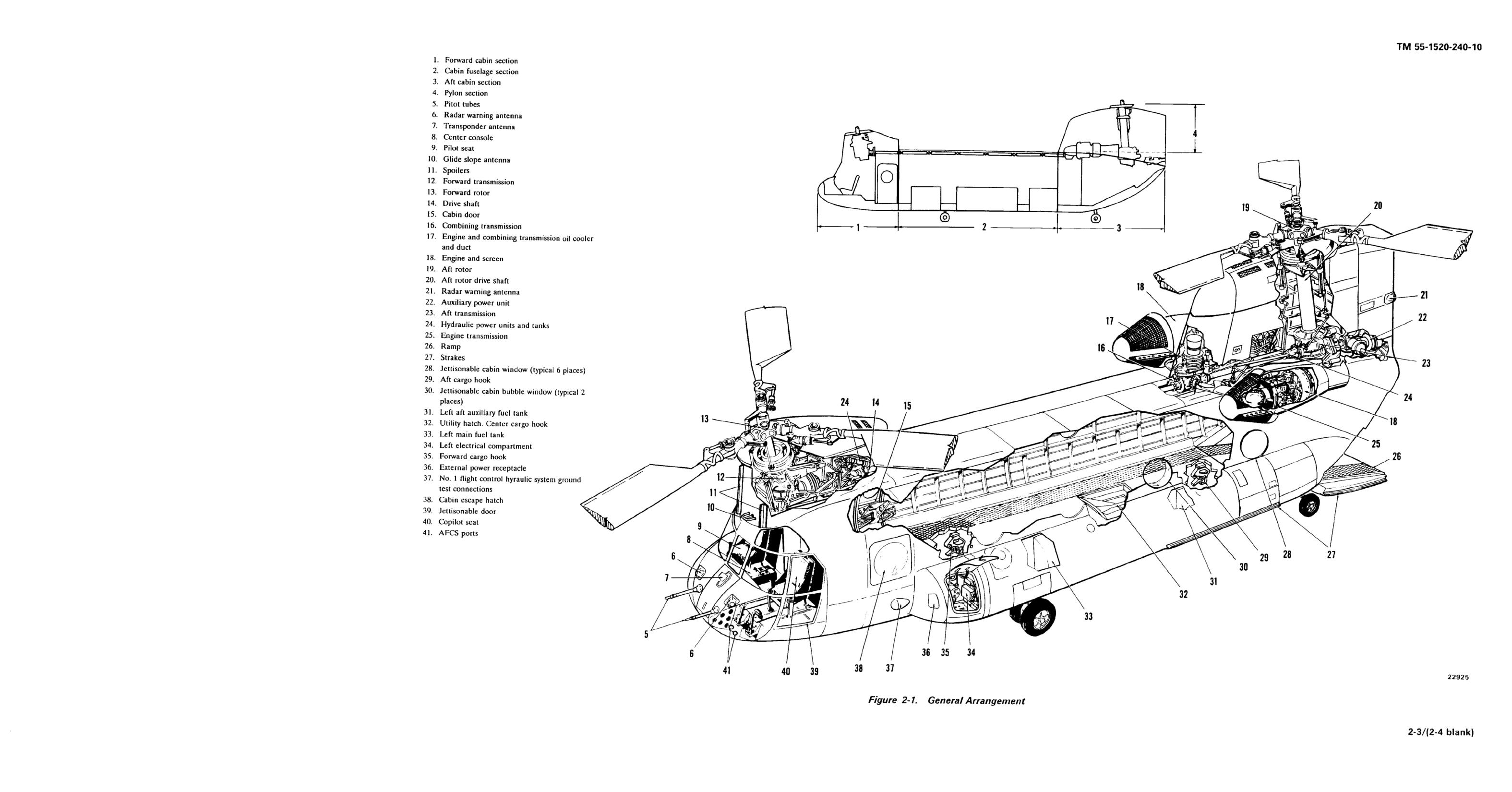
2-1. General.
2-4. Landing Gear Proximity Switches.
a. Two proximity switches are installed, one on each
The CH-47D (fig. 2-1 through 2-3) is a twin-turbine en-
aft landing gear. Each switch is activated when its associ-
gine, tandem rotor helicopter designed for transportation
ated shock strut is compressed during touchdown. The
of cargo, troops, and weapons during day, night, visual,
switches improve ground handling by reducing pitch axis
and instrument conditions. (Unless otherwise noted,
gain of the AFCS, by cancelling the longitudinal control
numbers refer to fig. 2-1.) The helicopter is powered by
position transducer (CPT), therefore longitudinal stick
two T55-L-712 or T55-GA-714A shaft-turbine engines
input, to the differential airspeed hold (DASH) actuators,
(18) on the aft fuselage. The engines simultaneously
and by driving both longitudinal cyclic trim (LCT) actua-
drive two tandem three-bladed counterrotating rotors (13
tors to the ground position. In addition to the above func-
and 19) through engine transmissions (25), a combining
tions, the switch on the right aft landing gear, when acti-
transmission (16), drive shafting (14), and reduction
vated, disables the flare dispenser to prevent accidental
transmissions (12 and 23). The forward transmission is
flare release, lockouts the OMEGA navigation system,
on the forward pylon above the cockpit (1). The aft trans-
and enables the hold function of mode 4 transponder
mission, the combining transmission, and drive shafting
codes.
are in the aft cabin section and aft pylon sections (3 and
4). Drive shafting from the combining transmission to the
b. On helicopters equipped with GROUND CON-
forward transmission is housed in a tunnel along top of
TACT indicating lights, activation of the proximity
the fuselage. When the rotors are stationary, a gas-tur-
switches when the associated shock strut is compressed
bine auxiliary power unit (22) drives a generator and
will cause the associated GROUND CONTACT indicat-
hydraulic pump to furnish hydraulic and electrical power.
ing light on the MAINTENANCE PANEL to illuminate.
Fuel is carried in pods on each side of the fuselage. The
helicopter is equipped with four non-retractable landing
CAUTION
gear. An entrance door (15) is at the forward right side of
Should either or both GROUND CONTACT
the cargo compartment (2). At the rear of the cargo
indicating lights remain illuminated after
compartment is a hydraulically powered loading ramp
lift-off to hover, the indicated system(s)
(26). The pilot’s seat (9) and controls are at the right side
of the cockpit; the copilot’s seat (40) and controls are on
DASH will not function properly in forward
the left side. See figure 2-4 for typical cockpit and con-
flight. If both GROUND CONTACT indicat-
trols.
ing lights remain illuminated after lift-off,
the AUTO function of both cyclic trim sys-
tems will be inoperative and both LCT ac-
tuators will remain in the GND position.
2-2. Gross Weight.
c. Aft landing gear proximity switches are not acti-
The maximum gross weight of the CH-47D is 50,000
vated in a water landing. As a result, DASH actuators will
pounds. Chapters 5 and 6 provides additional weight
respond to longitudinal stick motion, producing an appar-
information.
ent increase in control sensitivity. Cyclic motion of ± 3/4
inch from neutral, if held, will drive DASH actuators hard-
over. If longitudinal cyclic movement is required for taxi-
ing, set the AFCS SYSTEM SEL switch to OFF.
2-3. Landing Gear System.
2-5. Steering and Swivel Lock System.
The landing gear system consists of four non-retractable
landing gears mounted on the fuselage pods. The for-
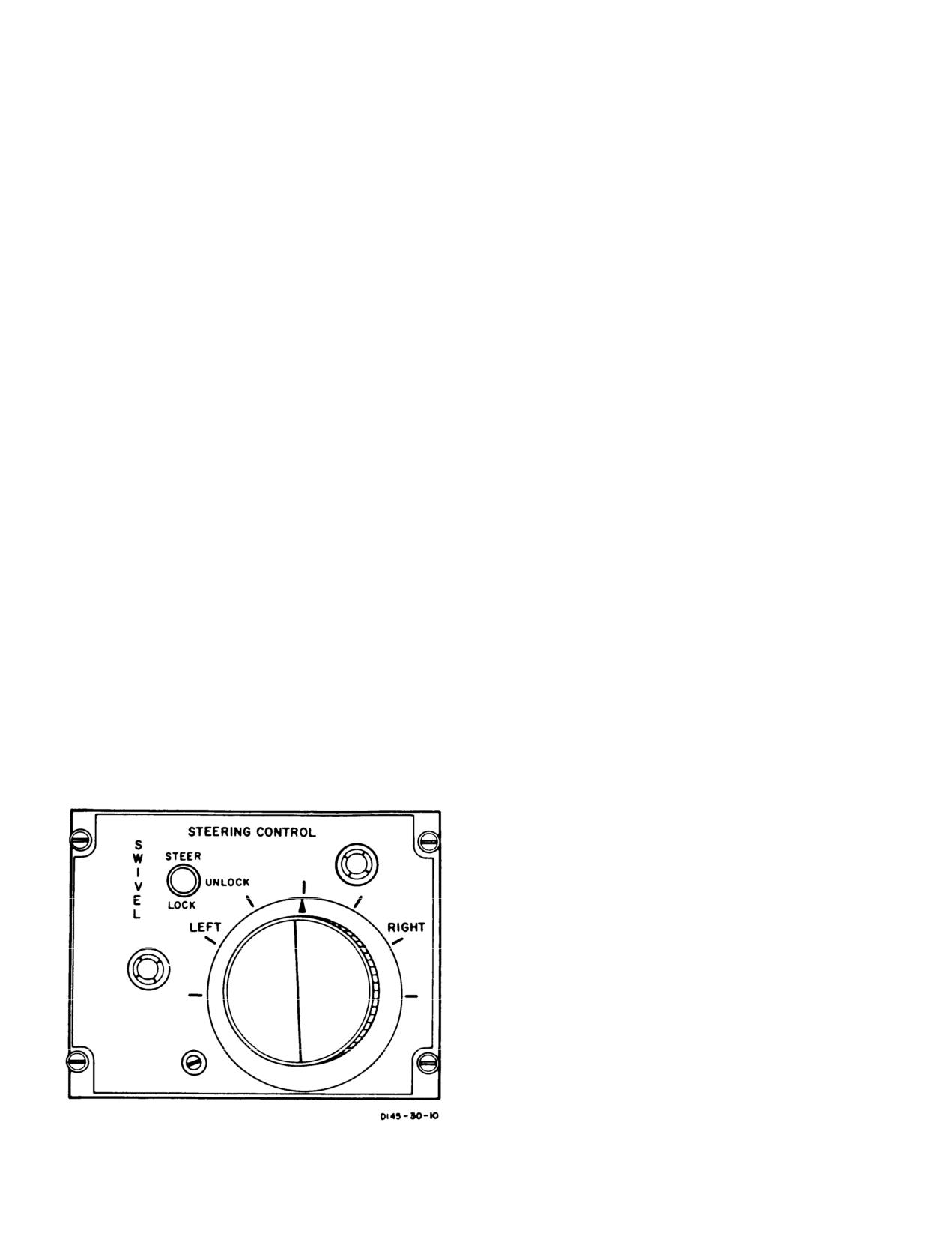
The steering and swivel lock system consists of the pow-
ward landing gears are a fixed-cantilever type and have
er steering control box with the STEERING CONTROL
twin wheels. The aft landing gears are of the single-
panel on the center console, utility system pressure con-
wheel, full-swivel (360°) type which can be power cen-
trol module, power steering actuator, power steering
tered and locked in trailed position. In addition, the aft
module, swivel lock module, and the PWR STEER mas-
right landing gear can be steered from the cockpit by
ter caution capsule. The STEERING CONTROL panel
using the steering control knob on the console. Each
consists of a three position SWIVEL switch and a steer-
landing gear has an individual air-oil shock strut and is
ing control knob. The SWIVEL switch controls operation
equipped with tube-type tires.
of power steering and swivel locks.
Change 17
2-1/(2-2 blank)
TM 55-1520-240-10
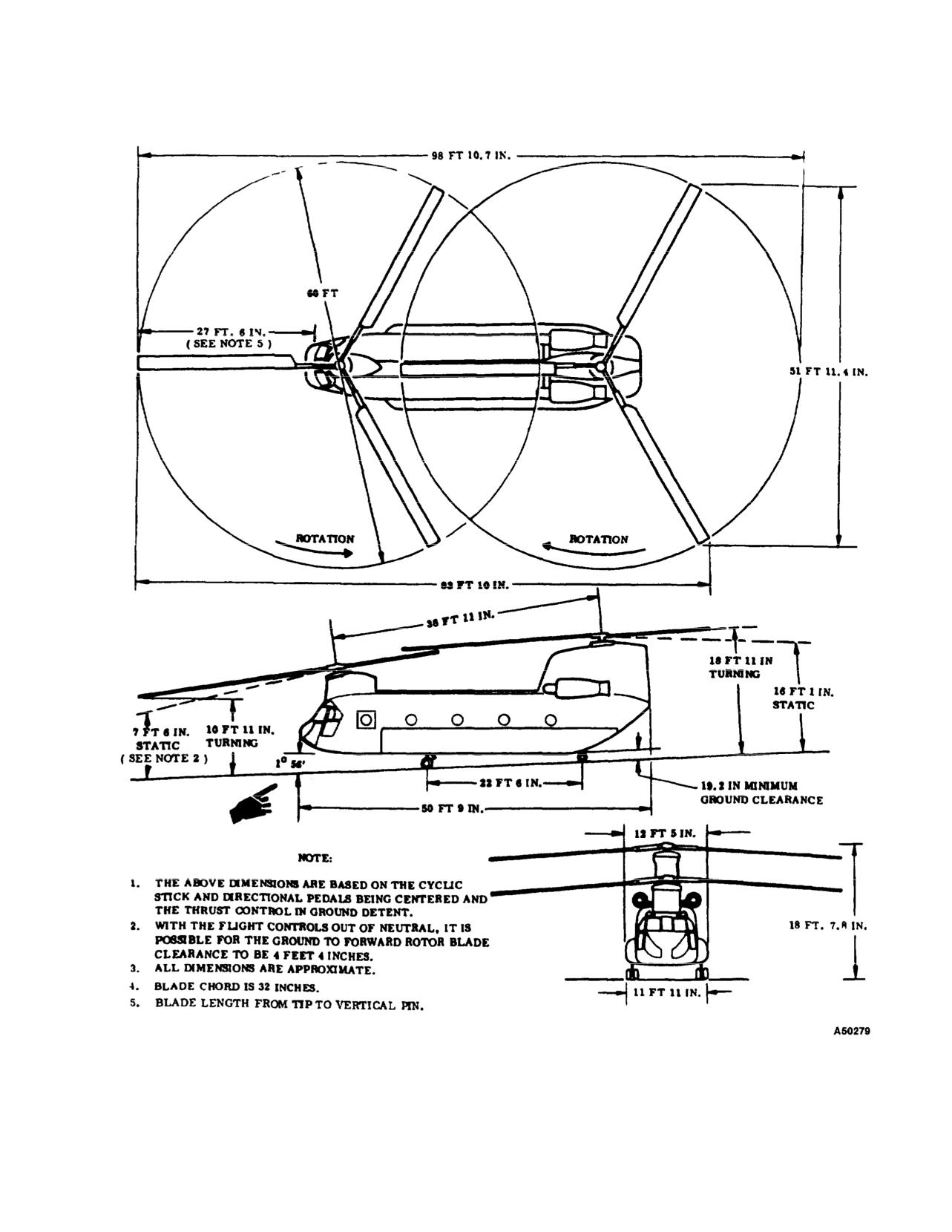
Figure 2-2. Principal Dimensions Diagram
Change
11
2-5
TM 55-1520-240-10
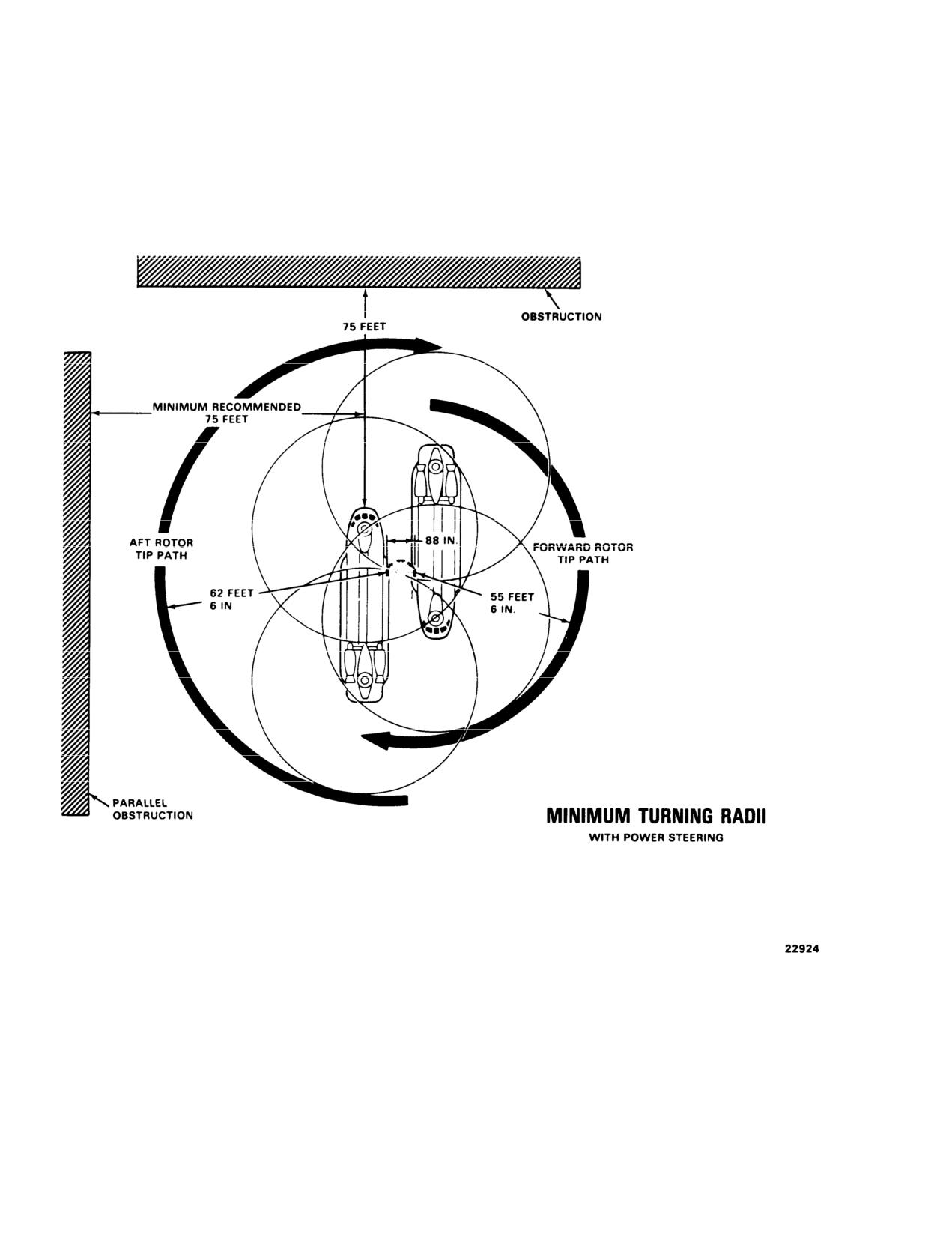
Figure 2-3. Turning Radii
2-6
TM 55-1520-240-10
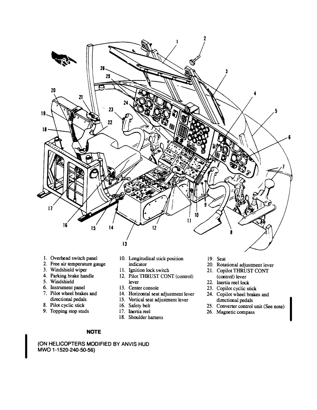
Figure 2-4. Cockpit and Controls
Change 7 2-7
TM 55-1520-240-10
The switch positions are arranged so the power steering
swivel. Setting the SWIVEL switch to UNLOCK deen-
system cannot be energized and used with swivel locks
ergizes the power steering circuits in the control box and
engaged. The aft right landing gear is hydraulically
the power steering actuator. It maintains the swivel
steerable and electrically controlled by the steering
locks in the disengaged position and both aft wheels are
control knob.
free to swivel, Setting the SWIVEL switch to LOCK
The PWR STEER caution capsule on the master cau-
energizes the swivel lock and centering cam control
tion panel indicates that power steering circuits have
valve. Utility system pressure is directed to the lock port
failed or the aft right wheel has exceeded turning limits.
of the swivel lock cylinder and centering cam. The aft
These limits are set at
58° for a left turn and 82° for a
wheels will rotate to neutral trail position and the swivel
right turn. If turning limits are exceeded, an out-of-
lock will engage when helicopter weight is lifted from
phase switch on the landing gear automatically closes
the rear wheels. AFCS heading hold is disabled at
the power steering solenoid valve, lights the caution
STEER and UNLOCK.
capsule, and removes electrical power from the control
b. Steering control knob.
The steering control knob
box. To reenergize the power steering system, the
landing gear must be returned within operating limits
has index marks around the knob to indicate degrees of
and the SWIVEL switch must be recycled.
knob rotation LEFT and RIGHT in increments of 30°,
These index marks do not represent wheel turn angle;
Hydraulic power to operate the power steering actuator
they are reference marks only. The knob is spring-
and the swivel locks is supplied by the utility hydraulic
loaded to zero turn angle. Power steering is accom-
system through the utility system pressure control mod-
plished by rotating the knob a given amount in the
ule and a separate power steering and swivel lock
desired direction. When the knob is rotated, a servo
module. Electrical power to control the steering and
valve on the power steering actuator regulates hydraulic
swivel locks system is supplied by the No. 1 DC bus
pressure to extend or retract the actuator. A feedback
through the BRAKE STEER circuit breaker on the No.
variable resistor, also on the power steering actuator,
1 PDP.
stops actuator travel when the selected turn radius is
2-6. STEERING CONTROL Panel. The STEERING
reached.
CONTROL panel (fig. 2-5) is on the aft end of the
console. It contains the SWIVEL switch, the steering
2-7. Brake System.
control knob, a fail-safe module and relay, and a
The four wheels of the forward landing gear, and two
servoamplifier. The fail-safe module monitors the steer-
wheels of the aft landing gear, are equipped with
ing electrical circuits. A malfunction which could cause
self-adjusting disk brakes. Both forward and aft brakes
a steering hardover will be detected by the fail-safe
can be applied and brake pressure maintained by de-
module and relay which disables the system and turns
pressing the pedals. Hydraulic pressure is supplied by
on the PWR STEER caution light.
the utility hydraulic system.
a. SWIVEL switch.
A three-position switch labeled
STEER, UNLOCK, and LOCK. Setting the switch to
2-8. Brake Pedals. When either the pilot’s or copi-
STEER applies DC power to the circuits in the power
lot’s brake pedals are pressed, pressure from the master
steering control box and arms the power steering actu-
brake cylinders goes to a transfer valve in the brake
ator. Rotating the steering control knob will activate the
lines. This allows independent braking by either pilot,
power steering actuator and the aft right wheel will
From these transfer valves, pressure is directed through
a parking brake valve to the forward and aft wheel
brakes.
2-9. Parking Brake Handle. A parking brake handle
(4, fig. 2-4) is at the bottom left corner of the pilot’s
section of the instrument panel. The brake handle is
mechanically connected to the parking brake valve. The
parking brake valve is electrically connected to the
PARK BRAKE ON caution capsule on the master
caution panel. When the brake pedals are pressed and
the parking brake handle is pulled OUT, pressure is
trapped and maintained on forward and aft wheel
brakes. At the same time, electrical power from the DC
essential bus through the LIGHTING CAUTION PNL
circuit breaker, lights the PARK BRAKE ON caution
capsule.
The parking brakes must be released by applying pres-
sure to the brake pedals. This action automatically
opens the parking brake valve, retracts the parking
brake handle, and extinguishes the PARK BRAKE ON
Figure 2-5. Steering Control Panel
caution capsule.
2-8
TM 55-1520-240-10
2-10. Brakes and Steering Isolation Switch.
2-16. Seats.
The brakes and steering isolation switch is on the HYD
The pilot’s and copilot’s seats (9 and 40, fig. 2-1) are on
control panel on the overhead switch panel (fig. 2-12). It is
tracks to permit forward-and-aft, vertical, and reclining
labeled BRK STEER, ON, and OFF. The switch isolates the
position adjustments. Bungee cords in each seat exert au
brakes and steering hydraulic subsystems from the rest of
upward force on the seat when it is down or tilted.
the utility hydraulic system in the event of a leak in the
subsystem. The normal position of the switch is ON. The
2-17. Seat Fore-and-Aft Lever.
A fore-and-aft control
switch is guarded to ON. Setting the switch to OFF, closes
lever (14, fig. 2-4) for horizontal seat adjustment is on the
the power steering and brakes valve on the utility system
right side of each seat support carriage. When the lever is
pressure control module, isolating the brakes and steering
pulled UP, the seat is unlocked and can be moved along the
subsystem. With the switch at OFF, limited brake applica-
tracks on the cockpit floor. When the lever is released, the
tions are available due to an emergency brake accumulator
seat is locked in position horizontally. The total range of
in the brake subsystem. Power to operate the isolation valve
horizontal movement is 4 inches in 1 inch increments.
is from the No. 1 DC bus through the HYDRAULICS
BRAISE STEER circuit breaker on the No. 1 PDP.
2-18. Seat Vertical Lever.
Vertical seat adjustment
(15,
fig. 2-4) is controlled by a lever on the right side of each
2-11. Instrument and Control Panels.
seat. When this lever is pulled UP, the seat is unlocked and
can be moved vertically along a track through a range of 5
NOTE
inches. The range is divided into 1/2 inch increments. When
The NVG overhead switch panels are shown.
the lever is released, the seat is locked in position vertically.
Description of control panels and operating
procedures reflect NVG configuration only.
2-19. Seat Rotation Lever.
A control lever (20, fig.
2-4) for adjusting the seat reclining position is on the left
Figures 2-6 and 2-7 show center and canted consoles.
side of each seat. When this lever is pulled UP, the seat is
Figures 2-8 through 2-12 show the copilot instrument panel,
unlocked and can be rotated through a 15° tilt range divided
center instrument panel, pilot instrument panel, and the
into four equal increments. The seat, in effect, is pivoted up
NVG overhead switch panel.
Figures 2-12.1 through
and down around a horizontal axis. When the lever is
2-12.6 show the copilot instrument panel, center instrument
released, the seat is locked in the selected tilt position.
panel, pilot instrument panel, and the NVG overhead switch
panel.
2-20. Armored Seats.
Both the pilot and copilot seats
are equipped with a combination of fixed and adjustable
2-12. Personnel/Cargo Doors.
ceramic armor panels (fig. 2-13). Fixed panels are installed
under the back and bottom seat cushions and on the
Entry can be made through either the main cabin door or the
outboard side of each seat. A shoulder panel (if installed) is
cargo door and ramp.
mounted on the outboard side of each seat. The shoulder
2-13. Main Cabin Door.
panel is hinged from the seat back so it can be moved aside
for ease of exit from the helicopter. The panel is secured in
The main cabin entrance (15, fig. 2-1) door is on the right
its normal position by a latch and an exerciser cord.
side of the cargo compartment. The door is divided into two
sections: the upper section containing a jettisonable panel
2-21. Shoulder Harness Inertia Reel Lock Lever.
and the lower section forming the entrance step. When
A two-position shoulder harness inertia reel lock lever is on
opened, the upper section slides upward on overhead rails
the left side of each seat (22, fig. 2-4). The lever positions
and the lower section swings downward. When closed, the
are LOCKED (forward) and UNLOCKED (aft). The lock
two sections mate to form the complete door. Handles are
may be moved freely from one position to the other. When
provided on both the outside and inside of the door for
the lock lever is in UNLOCKED position, the reel harness
accessibility. Refer to Chapter 5 for the allowable airspeed
cable is released to allow freedom of movement. However,
imposed on the helicopter while operating with the cabin
the reel will automatically lock if a horizontal impact force
entrance door sections in various positions.
of 2 to 3 g is encountered. When the reel is locked in this
manner, it stays locked until the lock lever is moved forward
2-14. Cargo Door and Ramp.
to LOCKED and then returned to UNLOCKED. When the
Chapter 6 provides a detail description and operation of the
lever is at LOCKED, the reel is manually locked so the pilot
cargo door and ramp.
is restrained from bending forward. When a crash landing or
ditching is anticipated and time permits, manual locking of
2-15. Pilot and Copilot Sliding Windows.
the shoulder harness inertia reel provides added safety
The upper section of each jettisonable door (39, fig. 2-1) in
beyond the automatic feature of the inertia reel. Depending
the cockpit contains a sliding window. The window slides
on the pilot’s seat adjustment, it may not be possible to
fore and aft and is locked and unlocked by a handle at the
reach all switches with the inertia reel locked. Each pilot
forward end of the jettisonable door. The handle is moved
should check and adjust the shoulder harness in locked
forward to lock the window and aft to unlock the window,
position to determine whether all switches can be reached.
Change
13
2-9
//////////////////////////////////////////