TECHNICAL MANUAL MAINTENANCE MANUAL FOR ARMY CH-47D HELICOPTER (1992) - page 2
TM 55-1520-240-10
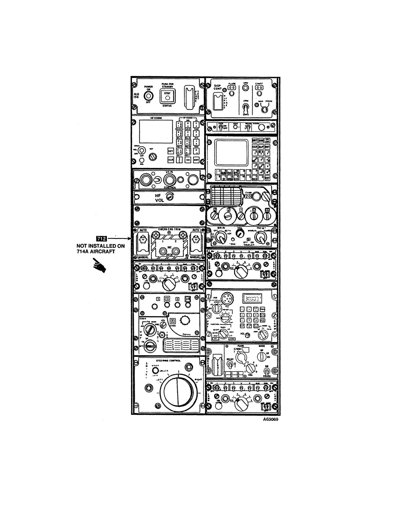
Figure 2-6. Center Console (Typical)
2-10
Change
13
TM 55-1520-240-10
2-21. Shoulder Harness Inertia Reel Lock Lever. A
Depending on the pilot’s seat adjustment, it may not be
two-position shoulder harness inertia reel lock lever is on
possible to reach all switches with the inertia reel locked.
the left side of each seat (22, fig.
2-4). The lever
Each pilot should check and adjust the shoulder harness
positions are LOCKED (forward) and UNLOCKED (aft).
in locked position to determine whether all switches can
The lock may be moved freely from one position to the
be reached.
other. When the lock lever is in UNLOCKED position,
the reel harness cable is released to allow freedom of
2-22.Self-Tuning Dynamic Absorbers.
movement. However. the reel will automatically lock if a
horizontal impact force of 2 to 3 g is encountered. When
The helicopter is equipped with three self-tuning dy-
the reel is locked in this manner. it stays locked until the
namic absorbers. One absorber is in the nose compart-
lock lever is moved forward to LOCKED and then
ment and the other two absorbers are under each pilot’s
returned to UNLOCKED. When the lever is at LOCKED,
seat below the cockpit floor. All three absorbers serve to
the reel is manually locked so the pilot is restrained from,
maintain a minimum vibration level through the nor- mal
bending forward. When a crash landing or ditching is
operating rotor RPM range of the helicopter. The self-
anticipated and time permits, manual locking of the
tuning feature of the dynamic absorber functions as
shoulder harness inertia reel provides added safety
follows: each dynamic absorber consists of a tuning
beyond the automatic feature of the inertia reel.
mass
Change 7 2-10.1/(2-10.2 blank)
TM
55-1520-240-10
2-22. Self-Tuning Dynamic Absorbers.
the helicopter and the spring-mounted mass. When the
measured vibration phases differ from a built-in phase
The helicopter is equipped with three self-tuning dynamic
relationship required to assure proper tune, the electronic
absorbers. One absorber is in the nose compartment and the
circuit extends or retracts the electrical actuator to reposi-
other two absorbers are under each pilot’s seat below the
tion the counterweights which, in turn,. increases or de-
cockpit floor. All three absorbers serve to maintain a
creases the resonant frequency of the spring-mounted mass
minimum vibration level through the normal operating rotor
The dynamic absorbers are constantly being adjusted (tuned)
RPM range of the helicopter. The self-tuning feature of
to minimize helicopter vibration. A self-test box is in the
the dynamic absorber functions as follows: each dynamic
heater compartment to provide maintenance personnel with
absorber consists of a tuning mass ‘suspended by springs,
an integral testing capability for the self-tuning feature of
and electronic measuring circuit, accelerometers, counter-
the dynamic absorbers. Power is supplied by the No. 2 AC
weights, an electrical actuator and a self-test box. The
bus through the VIB ABSORB-LH, CTR, and RH circuit
accelerometers sense and compare the vibration phases of
breakers on the No. 2 PDP.
NOTE:
(ON HELlCOPTERS MODIFIED BY ANVIS HUD
MWO
1-1520-240-50-56)
A64351
Figure
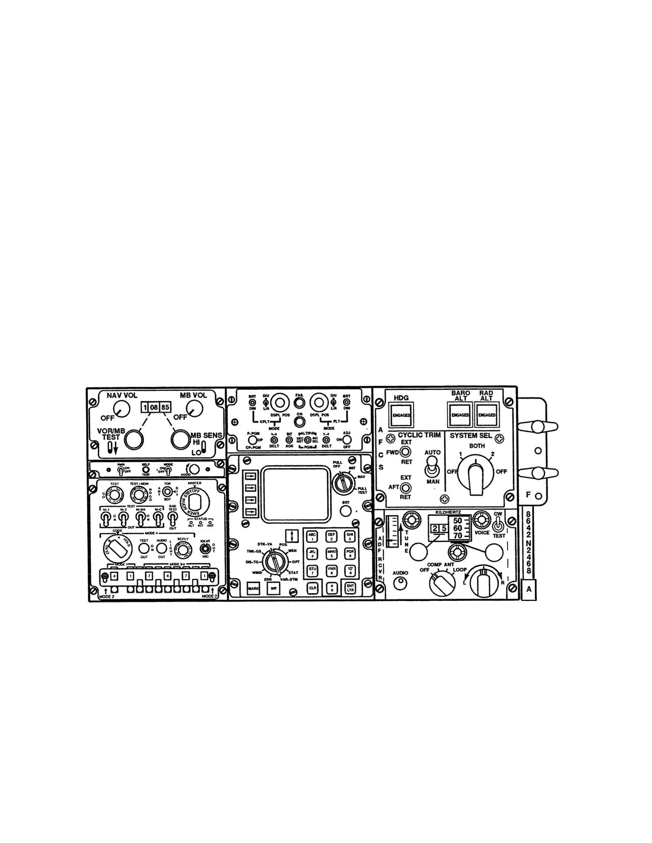
2-7 Canted Console (Typical)
Change 13
2-11
TM
55-1520-240-10
A9024
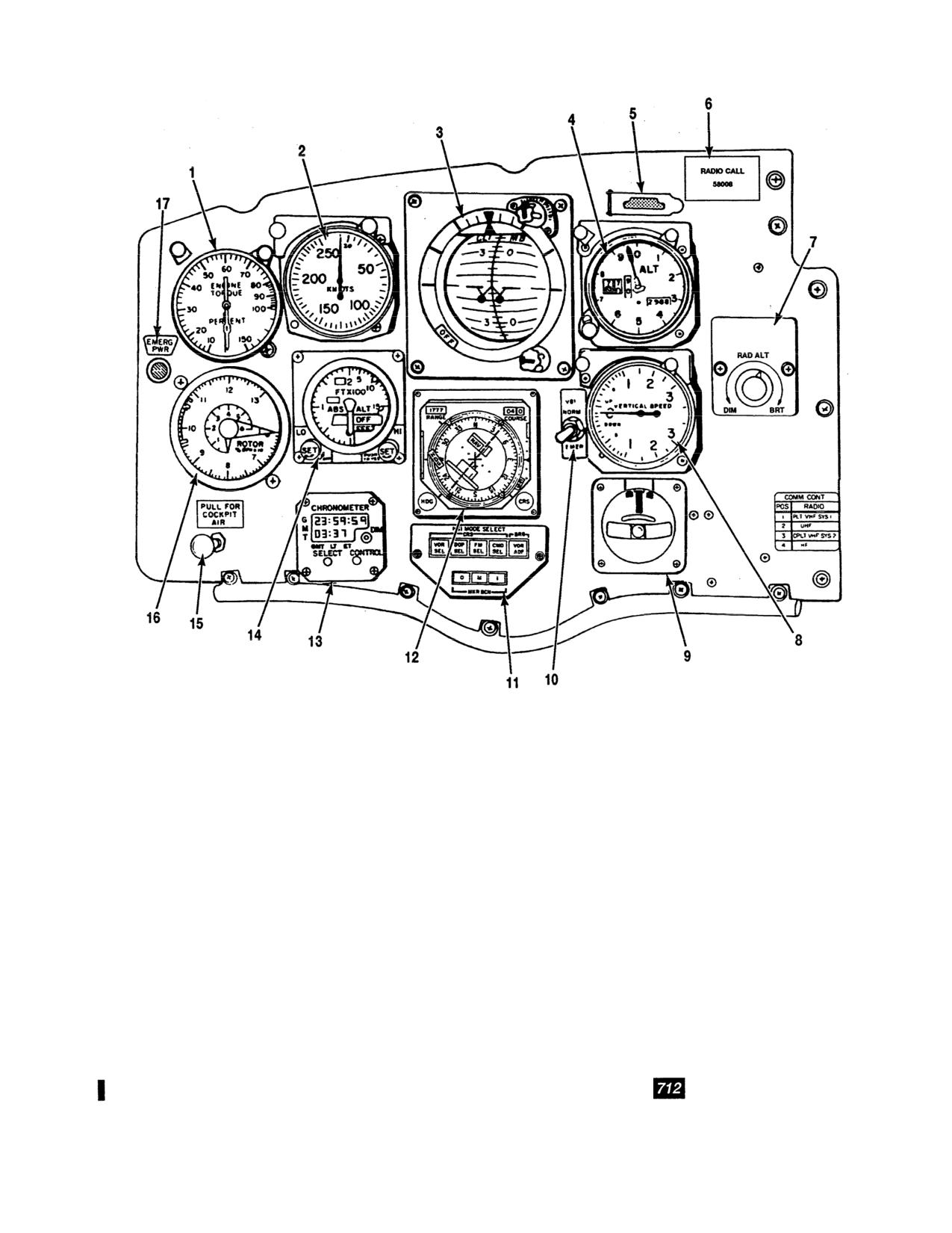
1. Torquemeter
10. VGI (vertical gyro indicator) switch
2. Airspeed indicator
11. HSI MODE SELECT panel
3. Attitude indicator
12. Horizontal situation indicator (HSI)
4. Altimeter
13. CHRONOMETER
5. Master caution light with NVG filter
14. Radar Altimeter
6. RADIO CALL plate
15. Cockpit air knob
7. RAD ALT display dimmer switch
16. Rotor Tachometer
8. Vertical speed indicator (VSI)
17. EMERG PWR (emergency power) indicator light
9. Turn and slip indicator
Figure 2-8. Copilot Instrument Panel (Typical)
2-12
Change 13
TM 55-1520-240-10
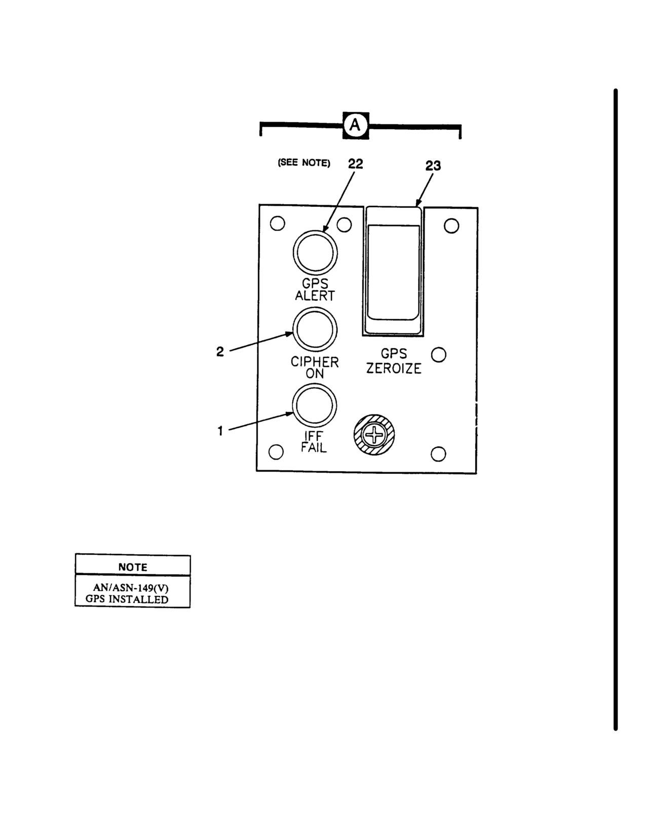
Figure 2-9. Center Instrument Panel (Typical)/ (Sheet 2 of 2)
Change 6 2-12.1/(2-12.2 blank)
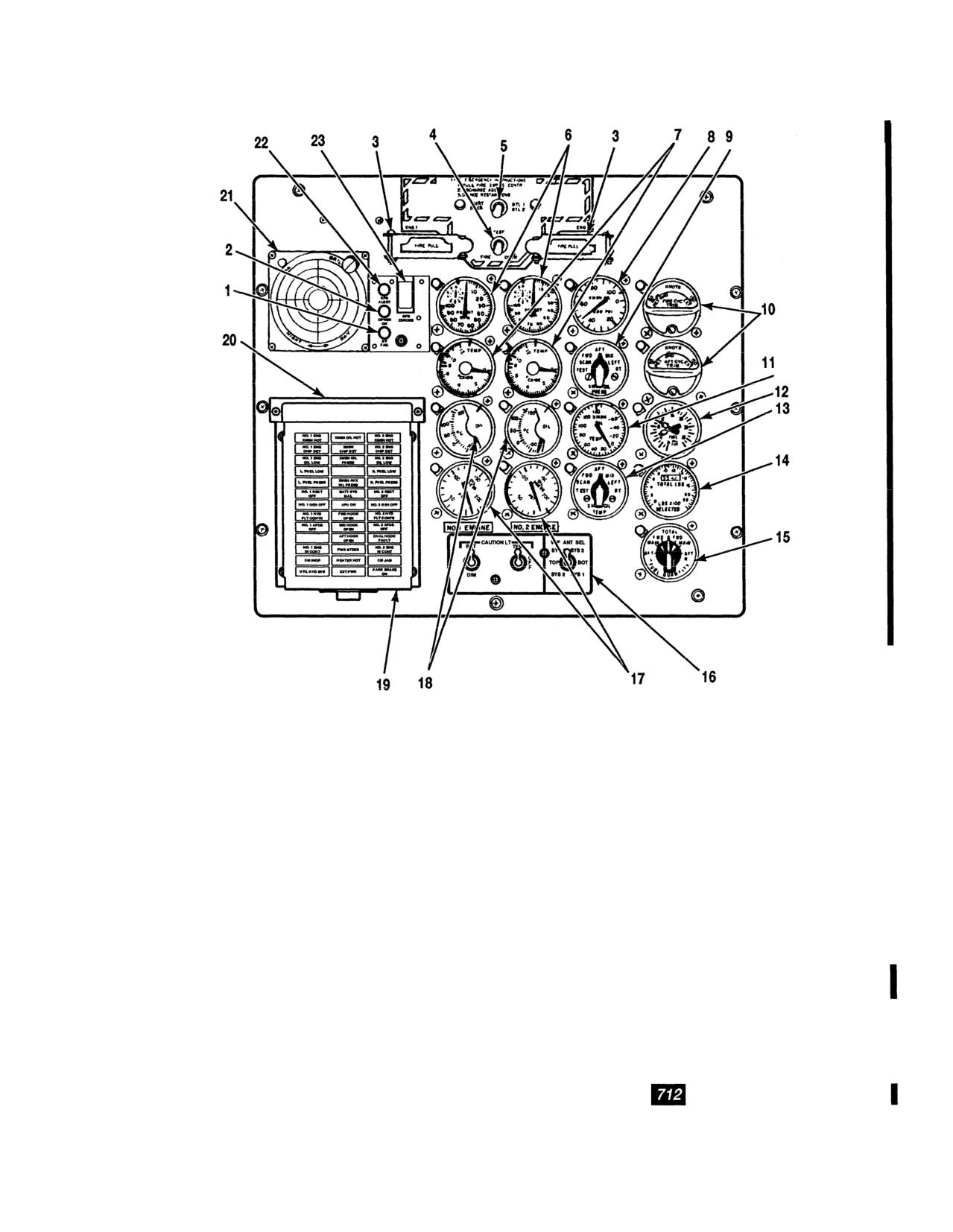
TM
55-1520-240-10
A64346
1. IFF indicator light
13. XMSN OIL TEMP selector switch
2. TSEC KY-58 indicator light
14. Fuel quantity indicator
3. FIRE PULL handles with NVG filters
15. FUEL QUANTITY selector switch
4. FIRE DETR test switch
16. CAUTION LT and VHF ANT SEL panel
5. AGENT DISCH switch
17. Engine oil pressure indicators
6. Gas producer tachometer
18. Engine oil temperature indicators
7. Power turbine inlet temperature (PTIT) indicators
19. Master caution panel
8. Transmission oil pressure indicator
20. Master caution panel NVG filter
9. XMSN OIL PRESS selector switch
21. Missile alert display
10. Longitudinal cyclic trim (LCT) indicators
22. GPS ALERT indicator light
11. Transmission oil temperature indicator
23. GPS ZEROIZE switch
12. Fuel flow indicator
Figure 2-9. Center Instrument Panel (Typical)
Change
13
2-13
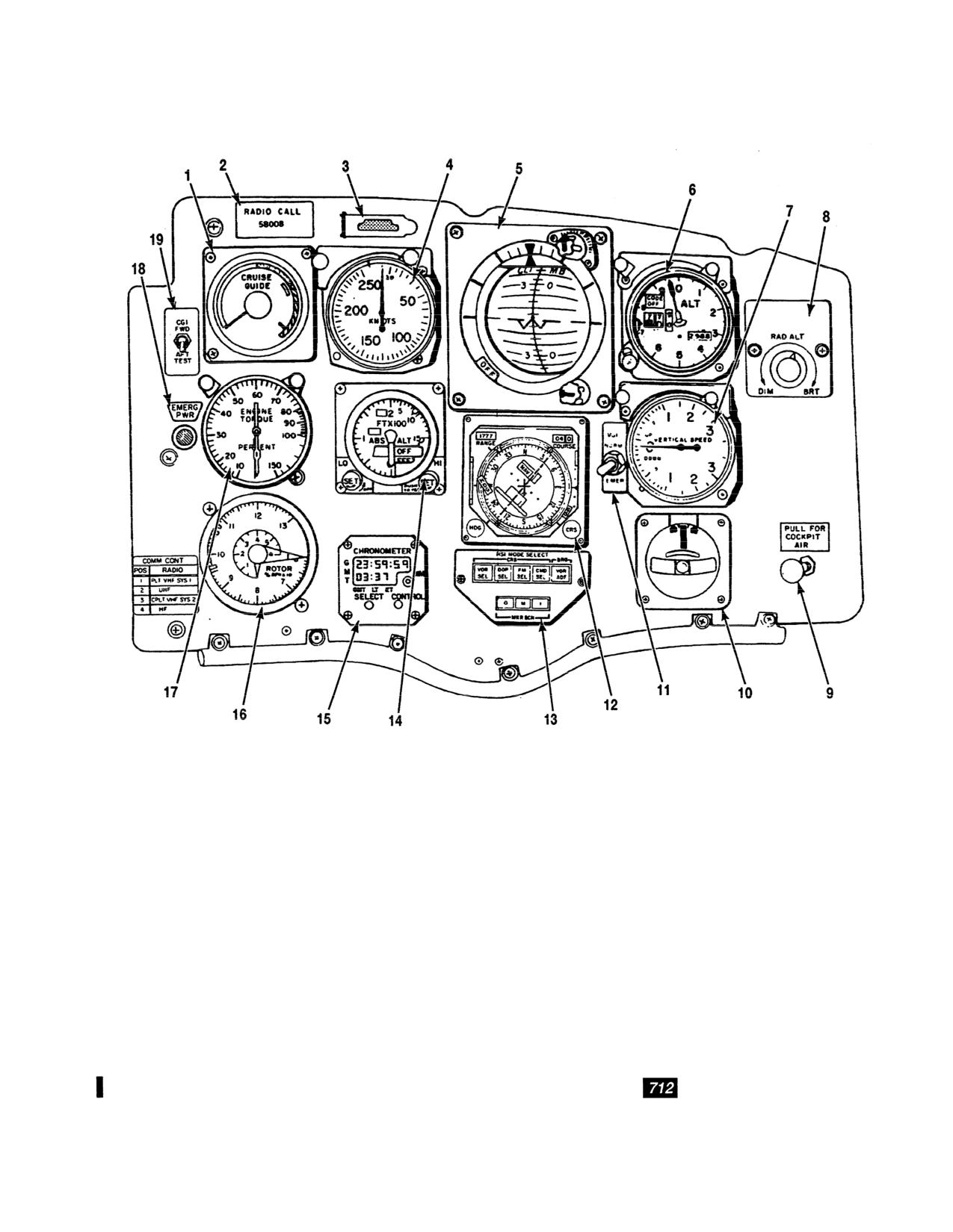
TM
55-1520-240-10
A9023
1. CRUISE GUIDE indicator
11. VGI (vertical gyro indicator) switch
2. RADIO CALL plate
12. Horizontal situation indicator (HSI)
3. Master caution light with NVG filter
13. HSI MODE SELECT panel
4. Airspeed indicator
14. Radar altimeter
5. Attitude indicator
15. CHRONOMETER
6. AIMS altimeter
16. Rotor tachometer
7. Vertical speed indicator (VSI)
17. Torquemeter
8. RAD ALT display dimmer switch
18. EMERG PWR (emergency power) indicator light
9. Cockpit air knob
19. CGI (cruise guide indicator) test switch
10. Turn and slip indicator
Figure 2-10. Pilot Instrument Panel (Typical)
2-14
Change
13
TM 55-1520-240-10
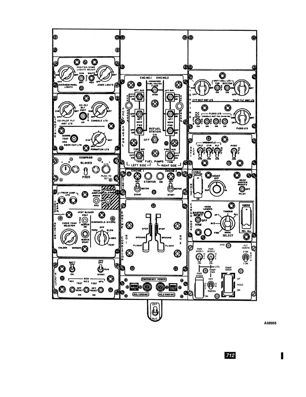
Figure 2-11. Overhead Switch Panel (Typical) (Interim NVG)
Change
13
2-15
TM 55-1520-240-10
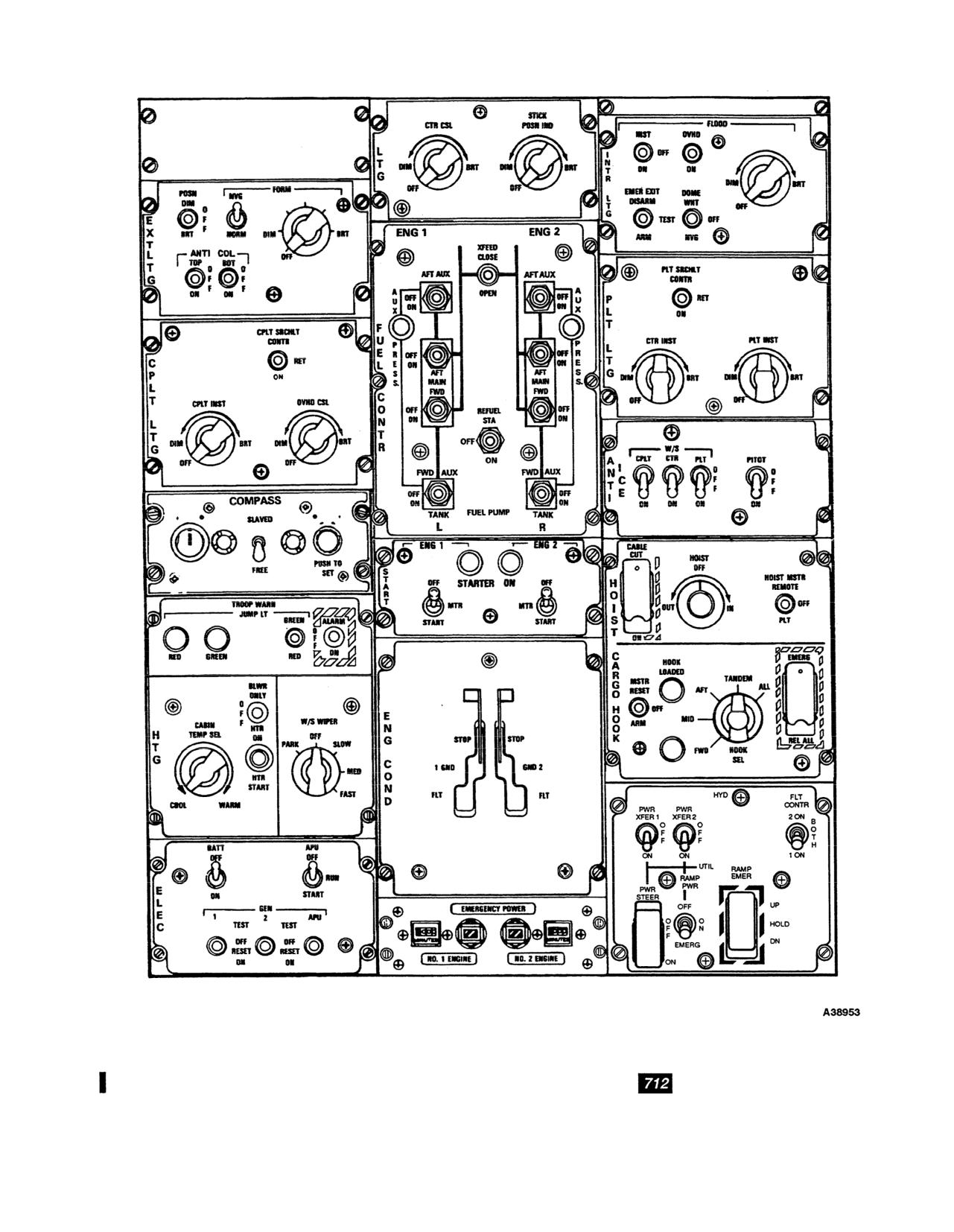
Figure 2-12. Overhead Switch Panel (NVG)
2-16
Change 13
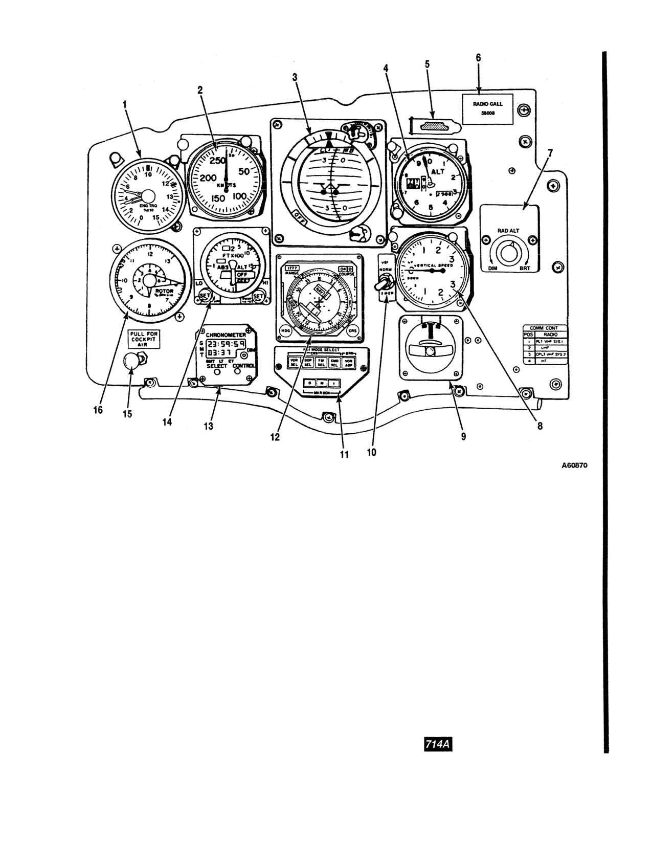
TM 55-1520-240-10
1. Torquemeter
10. VGI (vertical gyro indicator) switch
2. Airspeed indicator
11. HSI MODE SELECT panel
3. Attitude indicator
12. Horizontal situation indicator
4. Altimeter
13. CHRONOMETER
5. Master caution light with NVG filter
14. Radar altimeter
6. RADIO CALL plate
15. Cockpit air knob
7. RAD ALT display dimmer switch
16. Rotor tachometer
8. Vertical speed indicator (VSI)
9. Turn and slip indicator
Figure 2-12.1. Copilot Instrument Panel
Change 13
2-16.1
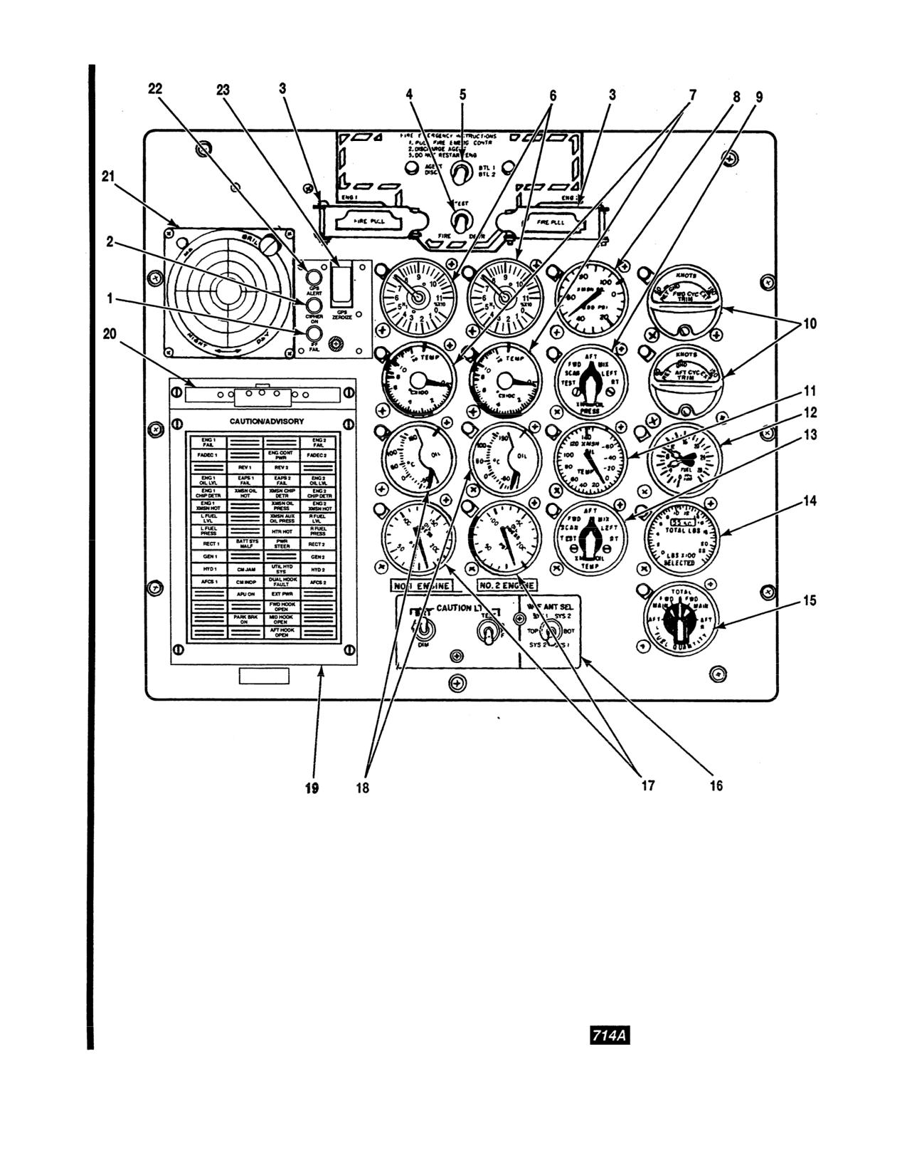
TM 55-1520-240-10
1. IFF indicator light
13. XMSN OIL TEMP selector switch
2. TSEC KY-58 indicator light
14. Fuel quantity indicator
A64395
3. FIRE PULL handles with NVG filters
15. FUEL QUANTITY selector switch
4. FIRE DETR test switch
16. CAUTION LT and VHF ANT SEL panel
5. AGENT DISCH switch
17. Engine oil pressure indicators
6. Gas producer tachometer
18. Engine oil temperature indicators
7. Power turbine inlet temperature (PTIT) indicators
19. CAUTION/ADVISORY panel
8. Transmission oil pressure indicator
20. Master caution advisory NVG filter
9. XMSN OIL PRESS selector switch
21. Missile alert display
10. Longitudinal cyclic trim (LCT) indicators
22. GPS ALERT indicator light
11. Transmission oil temperature indicator
23. GPS ZEROIZE switch
12. Fuel flow indicator
Figure 2-12.2. Center Instrument Panel
2-16.2
Change 13
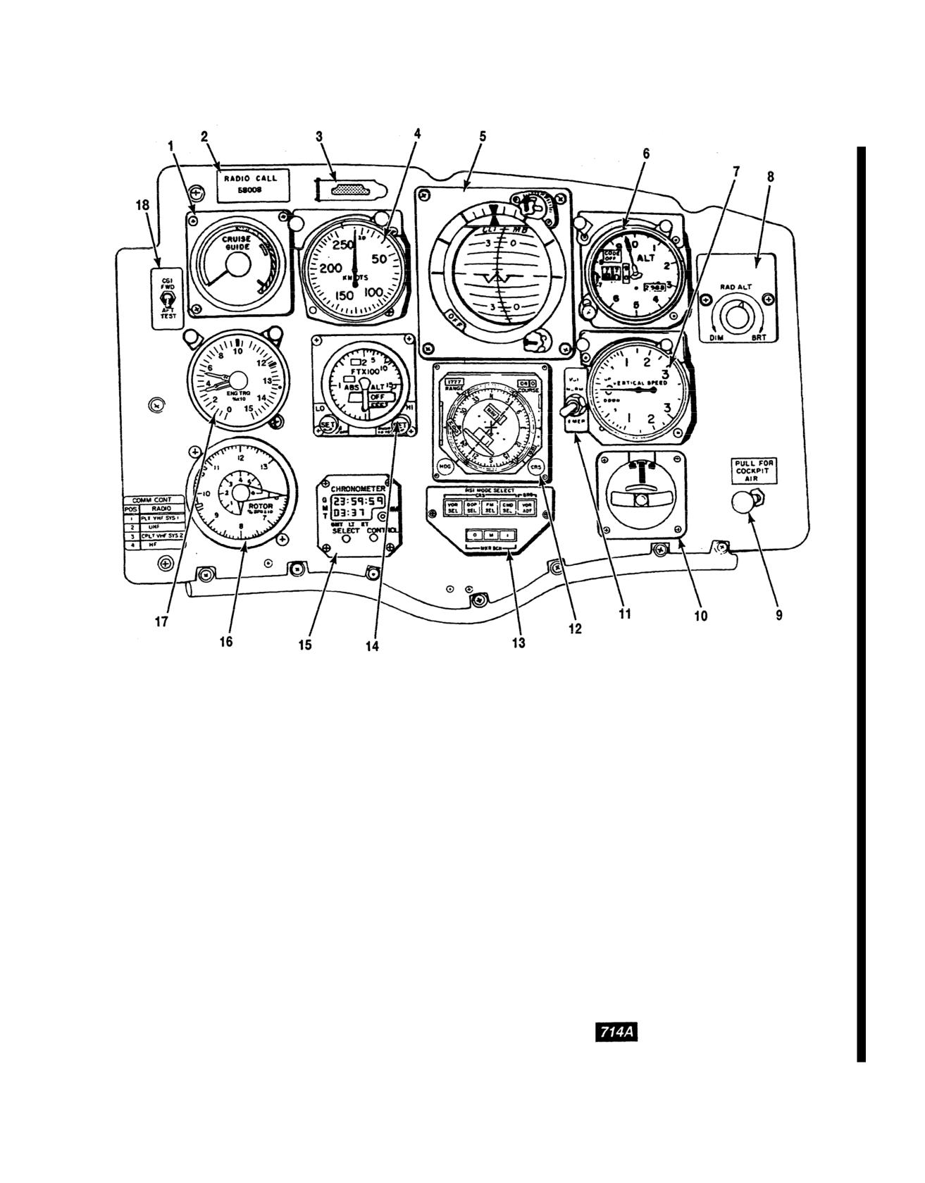
TM
55-1520-240-10
A60869
11. VGI (vertical gyro indicator) switch
1. CRUISE GUIDE indicator
12. Horizontal situation indicator (HSI)
2. RADIO CALL plate
13. HSI MODE SELECT panel
3. Master caution light with NVG filter
14. Radar altimeter
4. Airspeed indicator
15. CHRONOMETER
5. Attitude indicator
16. Rotor tachometer
6. AIMS altimeter
17. Torquemeter
7. Vertical speed indicator (VSI)
18. CGI (cruise guide indicator) test switch
8. RAD ALT display dimmer switch
9. Cockpit air knob
10. Turn and slip indicator
Figure 2-12.3. Pilot Instrument Panel
Change 13
2-16.3
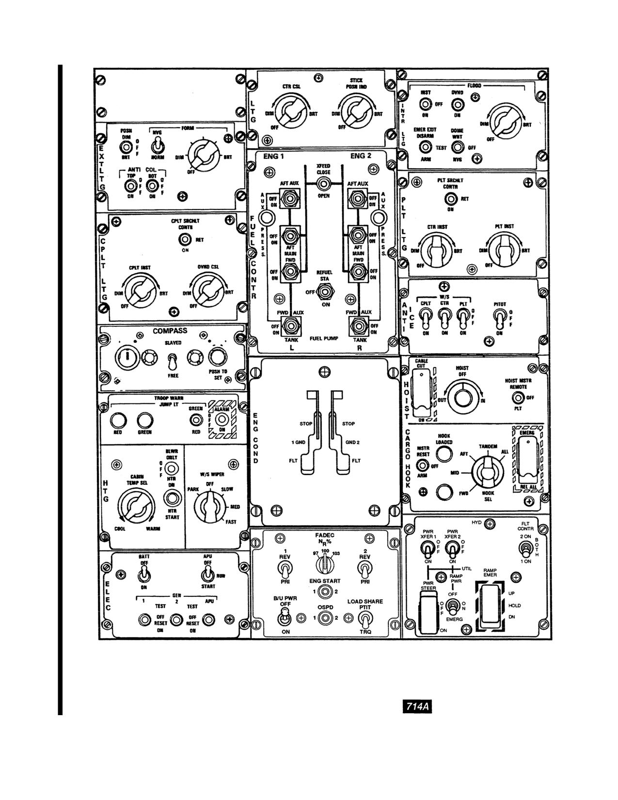
TM
55-1520-240-10
A60882
Figure
2-12.4.
Overhead
Switch
Panel
2-16.4
Change 13
TM
55-1520-240-10
SECTION II EMERGENCY EQUIPMENT
2-23. Emergency Procedures.
2-25. FIRE PULL Handles.
Refer to Chapter 9 for all emergency procedures.
WARNING
2-24. Engine Compartment Fire Extinguisher
Before flying the aircraft ensure that each
System.
FIRE PULL handle NVG filter holder can be
rotated from the closed to the open position
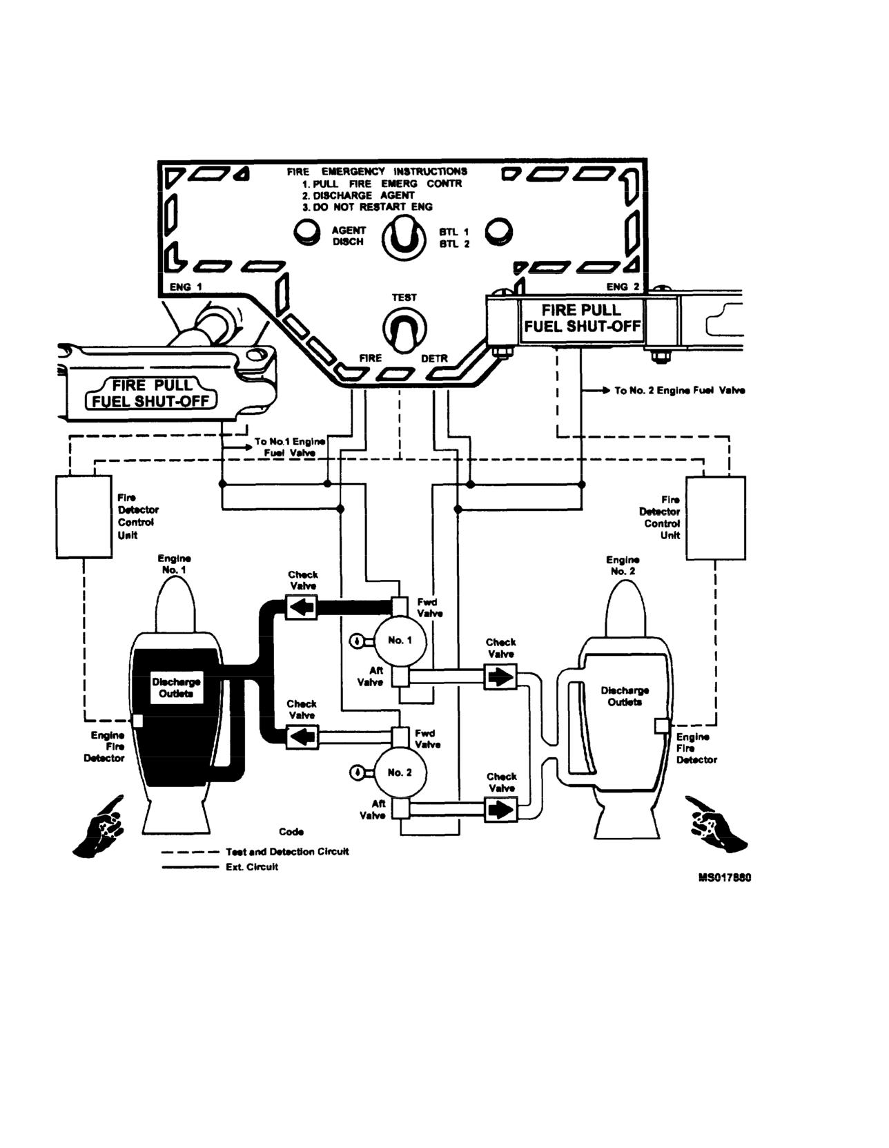
The engine compartment fire extinguisher system (fig. 2-14)
without causing the FIRE PULL handle to be
enables the pilot or copilot to extinguish a fire in either engine
pulled. Improper handling of the NVG filter
compartment only. It is not designed to extinguish internal
holder may cause the FIRE PULL handle to be
engine tires. The system consists of two FIRE PULL handles,
pulled unintentionally, thus fuel to the affected
an AGENT DISCH (agent discharge) switch, a FIRE DETR
engine will be shut off and the engine will shut
(fire detector) switch on the center instrument panel. and two
down. Do not use sudden or excessive force
extinguisher agent containers on the overhead structure at
when rotating the FIRE PULL handle NVG
stations 482 and 502. The containers are partially filled with
filter holder from the closed to the open posi-
or BR3) and
tion.
pressurized with nitrogen (table
2-1 provides the range of
engine fire extinguisher pressures.) The agent in one or both
of the containers can be discharTwo control handles for
the engine
compartment. Selection of the co(fig. 2-14) are labeled FIRE PULL-FU
pulling the appropriate FIRE PULL top center section of the
center ins
ENG 1 FIRE PULL handle has been puhas a cover for the NVG filter, two
container is made by placing the necessary control switches that clos
the appropriate position. In figuvalve and ar
m the fire extinguisher
selected.
supplied for each FIRE PULL handle f
1 and No.
2 DC essential buses th
ENGINE NO. 1 and NO. 2 FUEL SHUTOFF
on the No. 1 and No. 2 PDP. Power is
of warning lights from the correspon
bus through the ENGINE NO. 1 and NO.
breakers on the No. 1 and No. 2 PDP.
Table 2-1.
Engine Compartment Fire Extinguisher Pressures
AMBIENT TEMPERATURE
MINIMUM INDICATION
MAXIMUM INDICATION
(C)
(PSI)
(PSI)
o
271
344
o
275
350
o
292
370
o
320
400
o
355
437
o
396
486
4o
449
540
15o
518
618
o
593
702
o
691
784
o
785
902
Change
9
2-17
TM 55-1520-240-10
Figure 2-14. Engine Compartment Fire Detect/on and Extinguishing System (Typical)
2-18
Change
9
TM 55-1520-240-10
a fire occur in the other engine compartment. Power is
supplied from the corresponding No. 1 or No. 2 DC
essential bus through the ENGINE NO. 1 and NO.
2
If the FIRE PULL handle warning lights are
FIRE EXT circuit breakers on the No. 1 and No.
2
covered by the NVG filters during daylight
PDP.
operation, illumination of the fire warning
lights may not be apparent in the event of an
2-27. FIRE DETR Switch.
engine fire. Do not operate the aircraft with
the NVG filters covering or obscuring the fire
A two-position FIRE DETR (detector) switch is below
warning lights unless night vision goggles
the AGENT DISCH switch on the top center section of
are being used.
the center instrument panel (fig. 2-14). It is labeled
FIRE DETR and TEST. The toggle switch is spring-
loaded to FIRE DETR which monitors the engine fire
The NVG filter is attached to one end the FIRE PULL
detection system. When the switch is placed to TEST, it
handle by a hinged fitting. The other end of the filter
checks the operation of the engine fire detection system
holder forms a tab by which the filter holder and filter
by closing relays in both controls units and the warning
may be rotated about the hinged fitting. For NVG
lights in both FIRE PULL handles illuminate. Power to
operations, the filter holder is rotated to a closed
operate the test circuit is supplied by the DC essential
position over the front of the FIRE PULL handle cover.
bus through the LIGHTING CAUTION PNL circuit
In this position, the fire warning light is NVG compat-
breaker on the No. 1 PDP.
ible. For normal operations, the filter holder is rotated
from the closed position to the fully open position. In
2-28. Hand Fire Extinguishers.
this position, the FIRE PULL handle warning lights will
be red.
Avoid prolonged exposure (5 minutes or
more) to high concentrations of fire extin-
If there is a tire in both engine compart-
guishing agent and its decomposition prod-
ments, do not pull both FIRE PULL handles
ucts because of irritation to the eyes and
simultaneously. Extinguish fire in one com-
nose. Adequate respiratory and eye relief
partment only as described below. Leave the
from excessive exposure should be sought as
FIRE PULL handle out after fire has been
soon as the primary fire emergency permits.
extinguished. Proceed in a like manner to
Use of oxygen for personnel is recommended.
extinguish fire in the other engine compart-
ment.
Three portable
6.3 pound capacity hand fire extinguish-
ers are provided in the helicopter. One is in the cockpit,
When an engine compartment fire occurs on either side,
on the floor to the right of the pilot’s seat. Two hand fire
the respective pair of warning lights comes on. The
extinguishers are in the cabin section. One on the
appropriate FIRE PULL handle is pulled, that engine
forward bulkhead and one in the left rear, just forward
fuel shutoff valve closes and the AGENT DISCH switch
of the ramp.
is armed.
2-29. Emergency Troop Alarm and Jump Lights.
Selection and discharge of either fire bottle is accom-
plished by placing the AGENT DISCH switch to BTL 1
Two emergency troop alarm and jump light boxes are in
or BTL 2. After depletion of the charge in the initially
the cargo compartment. The forward box is on the
selected bottle, the remaining bottle can be discharged
bulkhead above the avionics equipment shelves and the
to the same engine compartment by selecting the oppo-
aft box is on the left side of the fuselage above the ramp
site position on the AGENT DISCH switch. The other
at sta. 575. Each box has an electric bell in the center
FIRE PULL handle performs the same function for its
with a red light future on one side and a green light
respective engine compartment.
fixture on the other side. The TROOP WARN panel on
the overhead switch console is used to operate the
2-26. AGENT DISCH Switch.
emergency troop alarm and jump lights.
A three-position AGENT DISCH (discharge) switch is
The emergency troop alarm and jump lights have sev-
above the FIRE PULL handles on the center instru-
eral functions. They can be used to notify passengers
ment panel (fig. 2-14). The lever-lock momentary switch
and crew with predetermined signals in time of emer-
positions are BTL 1, neutral, and BTL 2. When BTL 1
gency. The jump lights can be used to notify flight
is selected, the agent is discharged from the No. 1 bottle
engineer during airborne delivery operations and to
into the selected engine compartment. When BTL 2 is
alert the troop commander during paratroop drop mis-
selected, the agent is discharged from the No. 2 bottle
sions. Refer to Chapter 9 for standard use of the troop
into the selected engine compartment. Only two fire
alarm.
extinguisher agent bottles are provided. If the agent
from both bottles is used in combating a fire in one
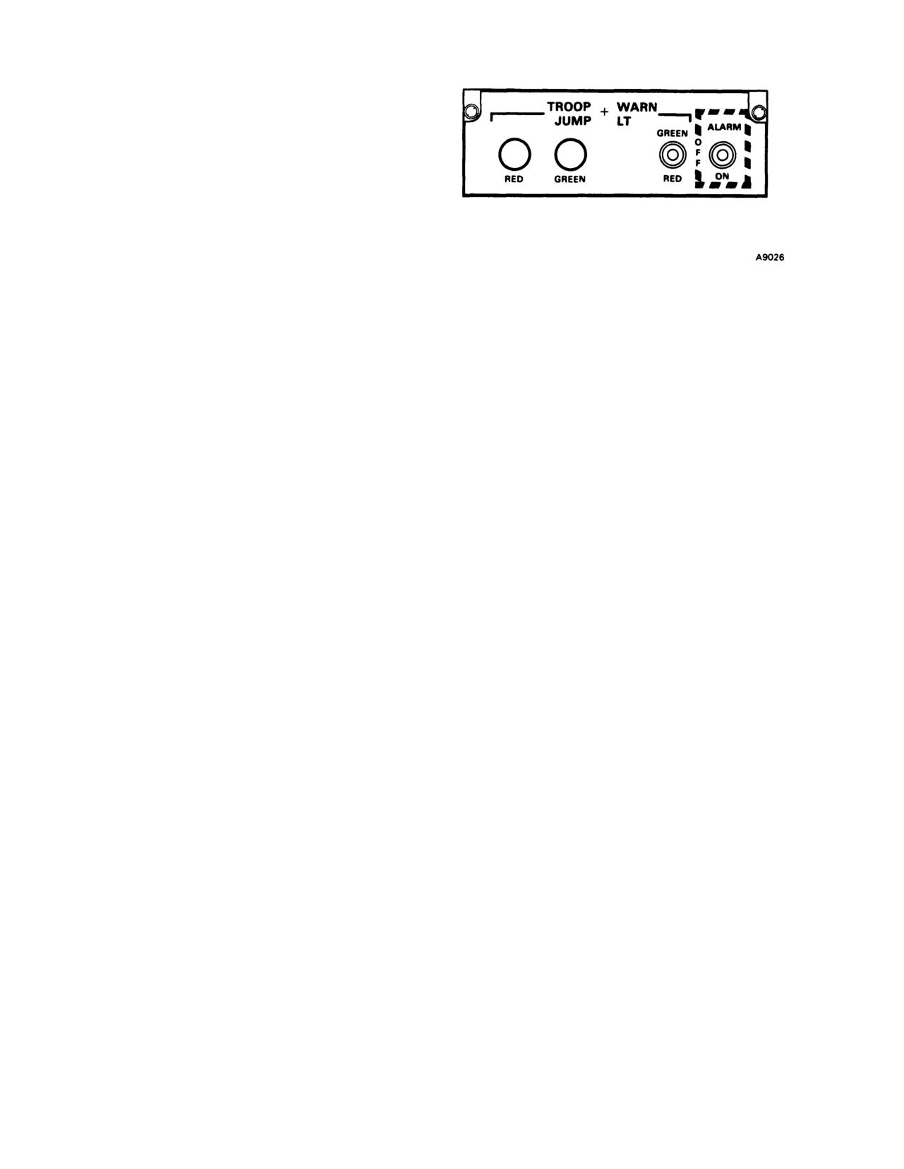
2-30. TROOP WARN Panel. The TROOP WARN
engine compartment, agent will not be available should
(warning) panel is located on the overhead switch panel
2-19
TM 55-1520-240-10
(fig. 2-15). It has two troop jump lights labeled RED
and GREEN. Also, two switches labeled JUMP LT and
ALARM. Power to operate and control the emergency
troop alarm and jump lights is supplied by the DC
essential bus through the TROOP ALARM BELL and
TROOP ALARM JUMP LT circuit breakers on the No.
2 PDP.
a. Troop jump lights.
The troop jump lights provides
the pilots a visual indication of the troop jump light
selected. One light is provided for each color selection
and comes on when the respective light is selected. The
brightness of the lights is controlled by the PLT INST
rotary control switch on the PLT LTG panel of the
Figure 2-15. Troop Warning Panel (Typical)
overhead switch panel.
2-31. First Aid Kits.
b. JUMP LT switch.
The three-position JUMP LT
Seven aeronautic first aid kits are installed in the
switch is labeled GREEN, OFF, and RED. When the
helicopter. One kit is in the passageway between the
switch is set to GREEN, the green lights on the
cockpit and cabin. The other six kits are in the cabin
emergency troop and jump light box, at both stations,
fuselage section, three on each side.
and the troop jump lights on the overhead switch panel
2-32. Emergency Entrances and Exits.
come on. When the switch is set to RED, the red lights
Refer to Chapter 9 for information on emergency
come on. OFF position turns off both sets of lights.
entrances and exits.
c. ALARM switch.
The two-position ALARM switch
2-33. Emergency Escape Axe.
is labeled OFF and ON. Moving the ALARM switch to
An emergency escape axe is provided. It is located on
ON rings the bell continuously at both stations until the
the right side of the cargo compartment slightly forward
switch is moved to OFF.
of station 200.
2-20
TM
55-1520-240-10
SECTION Ill ENGINES AND RELATED SYSTEMS
2-34. Engines.
response to any setting of the engine controls selected by the
pilot. Engine gas producer rotor speed (Nl) and power
The CH-47D is powered by either two T55-L-712 or two
turbine speed (N2) are controlled by the fuel control unit,
T55-GA-714A engines. The engines are housed in separate
which varies the amount of fuel delivered to the engine fuel
nacelles mounted externally on each side of the aft pylon.
nozzles. During normal operation, the fuel control unit
The engines have the capability to produce emergency
automatically controls fuel flow metering during power
power on pilot demand. See Performance Charts in Chapter
changes, thus protecting the engine from overspeed and
7
or Chapter 7A
overtemp. Fuel flow is automatically monitored to compen-
sate for changes in outside air temperature and compressor
2-35. General.
Each engine has a gas producer section
discharge pressure.
and a power turbine section. The gas producer supplies hot
gases to drive the power turbine. It also mechanically drives
2-39. Engine Fuel Control Units.
the engine accessory gearbox. The power turbine shaft
extends coaxially through the gas producer rotor and rotates
Each engine fuel control unit contains a single element fuel
independently of it. The gas producer section and the power
pump, a gas producer speed governor, a power turbine speed
turbine section are connected by only the hot gases which
governor, an acceleration-deceleration control, a fuel flow
pass from one section to the other.
limiter, a fuel control fuel shutoff valve, and a main
metering valve. A gas producer (N1) lever and a power
During engine starting, air enters the engine inlet and is
turbine (N2) lever are mounted on the fuel control unit.
compressed as it passes through seven axial stages and one
centrifugal stage of the compressor rotor. The compressed
Output power of the power turbine (a function of the speed
air passes through a diffuser. Some of the air enters the
and torque) is restricted by limiting the maximum fuel flow
combustion chamber where it is mixed with start fuel.
to the gas producer. Maximum gas producer rotor speed is
The mixture is ignited by four igniter plugs. Some of the air
set by the ENG COND (engine condition) levers in the
is directed to the fuel nozzles. After the engine is started, it
cockpit. The ENG COND levers electromechanically posi-
continues to operate on metered fuel supplied to the fuel
tions the gas producer lever, which controls the fuel control
nozzles.
fuel shutoff valve and the operating level of the gas
producer. During flight, the ENG COND levers are left at
Hot expanding gases leave the combustion chamber and
FLT and the output shaft speed is regulated by the power
drive a two-stage gas producer turbine. Energy from the
turbine speed (N2) governor.
combustion gases also drives the two-stage power turbine,
which drives the power turbine shaft to the engine trans-
The power turbine lever is electromechanically positioned
mission. The engine lubrication system has an integral oil
by the ENGINE BEEP TRIM switches, thrust control and
tank which is inside the air inlet housing and is serviced
EMERG ENG TRIM (emergency engine trim)
with approximately 12 quarts. (Refer to table 2-3.)
switches. Output shaft torques are limited by the fuel flow
limiter, which limits the maximum fuel flow. The position
2-36. Engine Inlet Screens.
of the main metering valve is determined by the gas
An engine inlet screen which minimizes foreign object
producer speed governor, power turbine speed governor, the
damage (FOD) is installed on each engine. The reduction in
acceleration-deceleration control, or the fuel flow limiter,
engine power available with screens installed is negligible.
depending on engine requirements at that time. The gover-
The engine inlet screens have bypass panels. These two
nor or the control unit demanding the least fuel flow
panels are on the aft end of each screen. Refer to Chapter 5
overrides the other in regulating the metering valve.
for information on use of bypass panels. Helicopters with
2-40. Speed Governing.
engine air particle separator (EAPS) installed, refer to TM
55-1520-240-10 EAPS SUPPLEMENT.
The power turbine speed governor senses the speed of the
power turbine and regulates the amount of fuel which is
2-37. Engine Anti-Icing.
supplied to the gas producer. This slows down or speeds up
The engine air inlet fairing and engine drive shaft fairing
the gas producer rotor so that power turbine and rotor
receive anti-icing protection from the thermal radiation
system speed remains nearly constant as loads vary.
produced by the oil tank in the engine inlet housing. The hot
At minimum rotor blade pitch, the amount of power
oil in the oil cavity of the inlet housing warms the air as it
required is at minimum. As pitch is increased, power turbine
passes into the engine inlet.
speed (N2) starts to decrease since more power is required
from the engine to maintain a constant rotor speed. The
2-38. Engine Power Control System.
power turbine speed governor senses the decrease of N2
Each engine is controlled by a separate power control
RPM and increases the flow of fuel to the gas producer.
system which includes cockpit controls and an engine fuel
Decreasing pitch causes N2 to increase. The power turbine
control unit. Each system provides automatic control of
governor senses the increase and reduces the flow of fuel to
engine gas producer rotor speed and power turbine speed in
the gas producer, thus decreasing the engine output power.
Change 13
2-21
TM 55-1520-240-10
The power turbine speed governor allows the power turbine
CAUTION
output speed to decrease (droop) approximately 10 percent
when the power loading varies from minimum to full load.
When the ENG COND lever is placed to
This is minimized by a droop eliminator linked to the thrust
GND during start sequence, the N1 actuator
control rod. The droop eliminator automatically changes the
could inadvertently go beyond the ground
power turbine lever to compensate for droop as pitch is
position. The respective ENG N1 COND
increased or decreased. Another type of droop, which is
caution capsule will illuminate. However, ig-
only transient, occurs as a result of the time required for the
nition will still occur if the start switch is
engine to respond to changing loads due to system lag.
moved to START, thus resulting in a possible
engine runaway.
2-41. ENG COND Levers
CAUTION
Two ENG COND (engine condition) levers, one for each
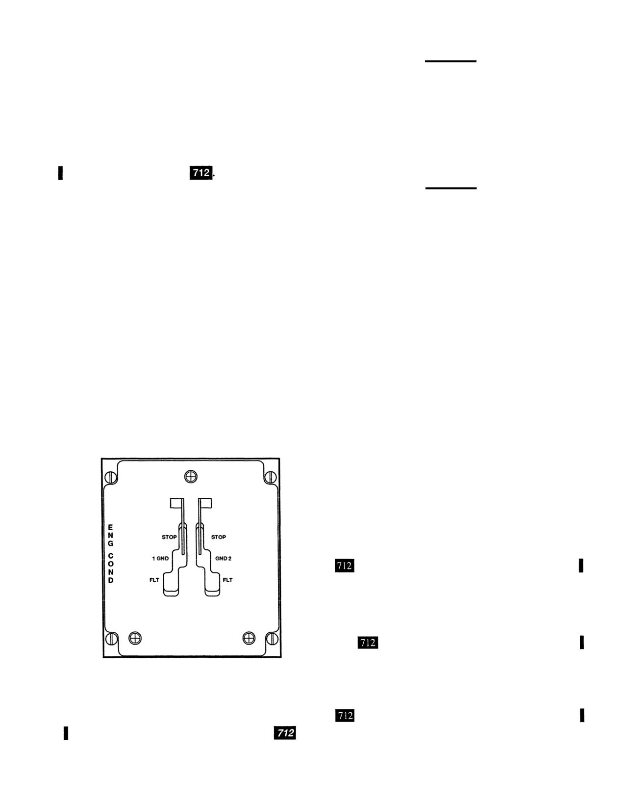
engine, are on the ENG COND panel (fig. 2-16) of the
When adjusting controls or switches on the
overhead switch panel. Each lever has three positions
overhead switch panel, make sure gloves or
labeled STOP, GND, and FLT. They are used to select
sleeves do not catch and inadvertently move
appropriate fuel flow rates for GND, FLT, and STOP
the ENG COND levers.
(engine shutdown). Power is supplied by the DC essential
buses through the ENGINE NO. 1 and NO. 2 COND CONT
The ENG COND lever must be at GND before the engine
circuit breakers on the No. 1 and No. 2 PDP
will start. When an ENG COND lever is advanced from
STOP to GND, power is then supplied to the electrome-
Each ENG COND lever is spring-loaded outboard and is
chanical actuator which establishes an appropriate fuel flow
inhibited by lock gates. They allow the pilot to proportion-
rate at ground idle. The speed of the gas producer with the
ally control acceleration of the gas producer from STOP to
lever at GND should be 60 to 63 percent N1. When an ENG
FLT. Two engine control caution capsules are on the master
COND lever is moved to FLT, the engine is operating within
caution panel (fig. 2-51). They are labeled NO. 1 ENG N1
the N2 governing range, unless the engine is “topped out”
CONT and NO. 2 ENG N1 CONT. The capsules normally
at which time it goes back to N1 governing. The N2
illuminate when the ENG COND levers or the N1 actuators
governor then takes control to maintain selected rotor RPM
are at an intermediate position between STOP, GND, or
(RRPM) in response to the engine beep trim switches and
FLT. They extinguish when the ENG COND lever and N1
actuator positions agree. However, they remain illuminated
collective pitch changes, When an ENG COND lever is
if a component of the system (actuator, control box, or
moved to STOP, the gas producer lever closes the fuel
condition panel) has failed in other than a detent position.
control fuel shutoff valve which stops fuel flow to the gas
Power is supplied by the DC essential bus through the
producer.
LIGHTING CAUTION PNL circuit breaker on the No. 1
Each electrical system is completely separate and a failure
PDP.
in one system will not affect the other. A built-in mechanical
brake holds the actuator at its last selected position if loss of
electrical power occurs.
ENG COND lever friction is
provided to reduce the possibility of overtorquing the
engine transmissions by resisting movement of the ENG
COND levers. The ENG COND lever friction brake cannot
be adjusted by the pilot and a force of 4 to 5 pounds is
needed to move them.
2-42. Normal Engine Beep Trim Switches.
On 712 engine installations engine beep trim switches
are active at all times during normal operation.
Two momentary switches are on the auxiliary switch
bracket of each THRUST CONT lever and are labeled
ENGINE BEEP TRIM (fig. 2-26). Both switches have an
RPM INCREASE, RPM DECREASE, and a neutral posi-
tion.
One switch is labeled NO. 1 & 2 which is
normally used to select desired RRPM. The second switch
is labeled NO. 1 which will only affect the No. 1 engine and
is used to match engine loads which are indicated by the
910000-A6010
dual torquemeters.
Power to operate the beep trim system is supplied by
the DC and AC buses. DC power to operate a trim motor in
Figure 2-16. Engine Condition Panel
2-22
Change 13
TM 55-1520-240-10
the No. 1 or No. 2 AC buses through the ENGINE NO.
1 or NO. 2 TRIM & TIMER circuit breakers on the No.
1 or No. 2 PDP to be transformed and rectified to DC
voltage. This DC power operates the power turbine
actuator on the engine fuel control.
NOTE
No two engines provide matched perfor-
mance with regard to torque, RPM, PTIT, or
fuel flow. With torque matched, all other
parameters may not be matched.
Change 4
2-22.1/(2-22.2 blank)
TM 55-1520-240-10
the power turbine control box, which unbalances a control
AUTO (cover down), the normal beep trim system is
circuit, is supplied by the corresponding No. 1 or No. 2 DC
functional (115-volt AC from the AC bus is reconnected to
buses through the ENGINE NO. 1 or NO. 2 TRIM circuit
the associated engine power turbine control box). Refer to
breakers on the No. 1 or No. 2 PDP. The unbalanced control
Chapter 9 for emergency engine trim operation.
circuit causes the AC power from the No. 1 or No. 2 AC
buses through the ENGINE NO. 1 or NO. 2 TRIM &
CAUTION
TIMER circuit breakers on the No. 1 or No. 2 PDP to be
transformed and rectified to DC voltage. This DC power
Engine response is much faster when RRPM
operates the power turbine actuator on the engine fuel
is controlled with emergency engine beep
control.
trim system. It is possible to beep the rotor
speed below safe operating speed and low
NOTE
enough to disconnect the generators from the
No two engines provide matched performance
buses. The generators are disconnected at
with regard to torque, RPM, PTIT, or fuel flow.
85% to 82% RRPM after a 3 to 7 second time
With torque matched all other parameters may
delay.
not be matched.
b. Emergency Engine Trim Switches.
Each momentary
Holding the NO. 1 & 2 switch forward (RPM
switch is used to change the power turbine speed of its
INCREASE) will increase the RRPM. Holding the switch
respective engine if the power turbine control box (normal
aft (RPM DECREASE) will decrease the RRPM. When the
beep trim system) malfunctions.
switch is released, it returns to the center or neutral position.
The switch electrically controls both power turbines by
When the normal trim system fails, the droop eliminator
movement of the N2 actuator through each engine power
also fails to function. Both switches have an INC, DECR,
turbine control box.
and a spring-loaded center position. When one of the
switches is held at INC, power from the essential DC bus
The procedure for matching engine load requires that NO. 1
& 2 engine beep switch be used in conjunction with NO. 1
goes directly to the respective power turbine actuator and
engine beep switch. When NO. 1 engine beep switch is
increases the lever setting and the power turbine speed.
moved forward (RPM INCREASE), the torque of No. 1
When the switch is held at DECR, the lever setting is
engine increases. At the same time RRPM increases, even
decreased, and the power turbine speed is decreased.
though No. 2 engine torque decreases slightly. Moving NO.
The emergency engine trim switches are to be used when
1 & 2 engine beep trim switch aft (RPM DECREASE)
the normal beep trim system is disabled. If one of the
causes both engine torques to decrease and reduce RRPM.
switches is used while the respective power turbine control
If torques are still not matched, this procedure is continued
box is functioning normally, the power turbine actuator
until torques are matched and desired RRPM is attained.
The opposite action occurs when NO. 1 engine beep switch
setting will temporarily change but will return to its original
is moved aft.
setting when the switch is released. Power to operate the
emergency engine beep trim switches and actuators is
The engine beep trim switches should not be used during
supplied by the essential DC bus through the NO. 1 and NO.
power changes initiated by thrust lever movement because
2 EMERG ENG TRIM circuit breakers on the No. 1 and
RRPM droop should only be momentary. The engine beep
No. 2 PDP.
tim system adjusts engine RPM only if the respective ENG
COND lever is at FLT. At, STOP or GND, it is possible to
move the power turbine lever by moving the engine beep
trim switches to RPM DECREASE or RPM INCREASE,
but in either case, engine RPM will not be affected because
the engine is not operating in the N2 governing range.
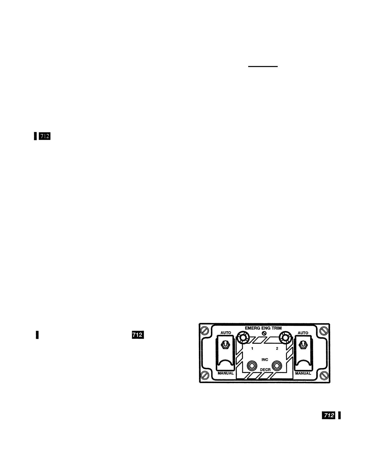
2-43. EMERG ENG TRIM Panel.
The EMERG ENG TRIM (emergency engine) panel is
located on the center console (fig. 2-17). The panel consists
of two guarded normal engine trim system disable switches
and two momentary emergency engine trim switches.
a. Normal Engine Trim System Disable Switches.
The
guarded switches permit the pilot to disable either or both
normal beep trim systems. This prevents unwanted signals
from the normal beep trim system to interfere with the
A61206
operation of the emergency engine trim system. Each switch
is labeled AUTO and MANUAL. When either switch is at
MANUAL, the respective normal beep trim system is
Figure 2-17.
Emergency Engine Trim Panel
disabled (115-volt AC from the AC bus to the engine power
turbine control box is interrupted). When the switch is at
Change 13
2-23
TM 55-1520-240-10
2-44. Emergency Power System.
CAUTION
To prevent damage, monitor the torque and
the PTIT indicators when operating with
emergency power. Failure to observe these
indicators could result in serious damage to
the drive train and engines.
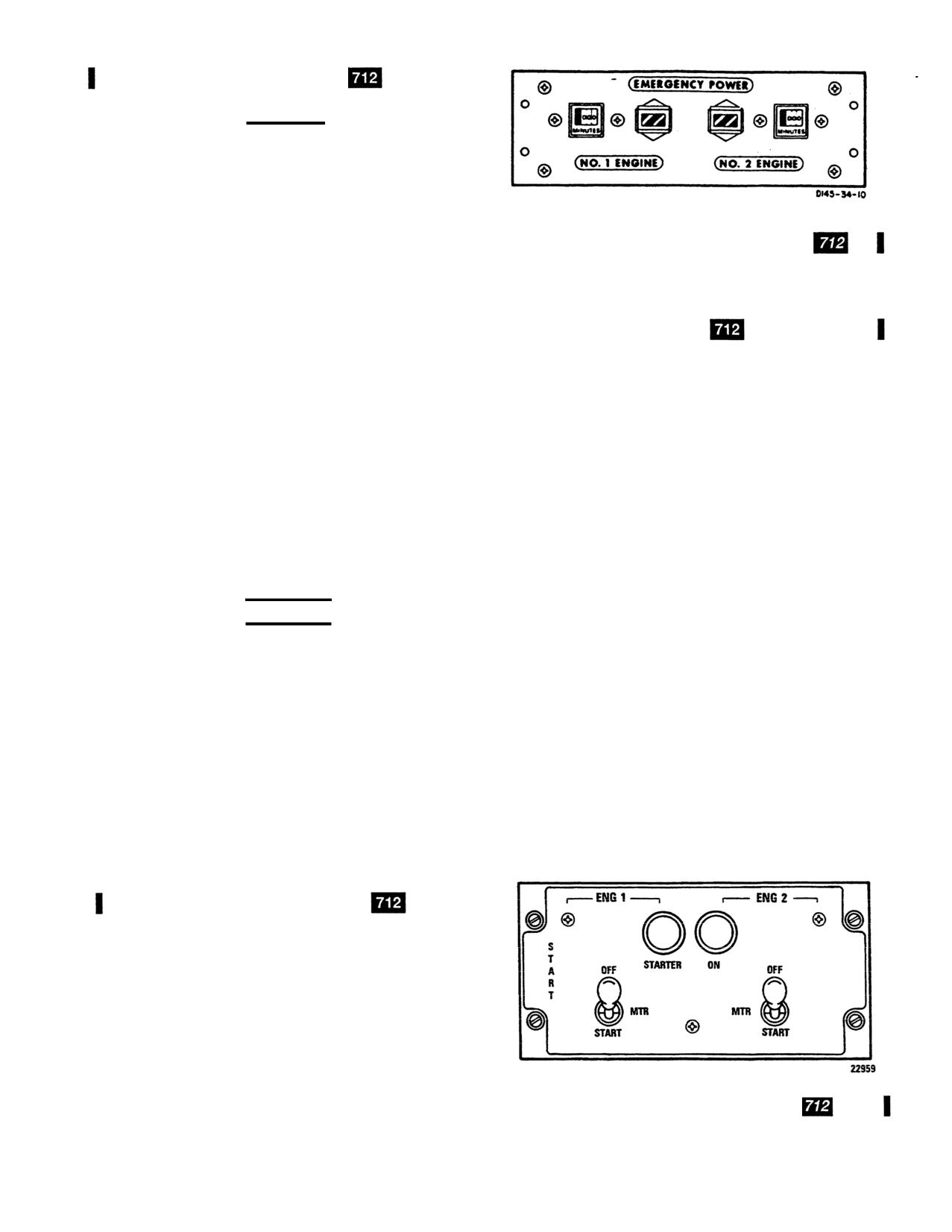
An emergency power system is included with T55-L-712
Figure 2-18. Emergency Power Panel
engines. With the emergency power system, increased
power is available on pilot demand and is actuated by
tank capacity. If the oil level decreases to about 2 quarts
raising the thrust control into the emergency power range.
usable, the corresponding ENG OIL LOW caution capsule
Refer to Chapter 5 for limitations on its use.
will illuminate.
2-47. Engine Start System.
When fuel flow increases to the point where PTIT is 890° to
910°C, the EMERG PWR lights will illuminate on the
The engine start system includes the hydraulic starters on
copilot and pilot instrument console (17, fig. 2-8 and 18, fig
each engine, the engine start valves and the solenoid-
2-10) If temperature is maintained in this range for more
operated pilot valves on the utility system pressure control
than 5 seconds, the associated indicator will apply 28-volt
modules, the START switch, and the start fuel solenoids and
DC from the ENGINE NO. 1 and /or NO. 2 START &
ignition exciters on the engines.
TEMP circuit breaker to the EMERGENCY POWER panel.
With 28-volt DC applied to the panel, the applicable
When the start switch is moved to MTR, the respective
emergency power timer will start, and the indicator will
engine STARTER ON indicator light illuminates and the
display a black-and-white flag. When thrust is reduced
start valve opens (fig. 2-19). The start valve applies utility
below the emergency power level, the emergency power
system pressure from the APU to the engine starter; rotating
light will extinguish and the timer will stop. However, the
the engine starter and compressor. At 15 percent N1, the
emergency power indicator will continue to display the
ENG COND lever is moved to GND. The start switch is
black-and-white flag. The flag can be reset on the ground
immediately moved to START, energizing the ignition
only.
exciter. Start fuel is sprayed into the combustor and com-
bustion begins. Before PTIT reaches 200°C, the START
WARNING
switch is manually released to MTR. At MTR, the start fuel
valve is closed and the ignition exciter is deenergized.
Before flight, be sure the two topping stops
are in their stowed position on the right side
The engine then accelerates to ground idle speed. At 50
of the console. If the stops are not stowed, be
percent N1, the START switch is manually moved to the
sure the stops are not installed on the fuel
locked OFF position. At OFF, the pilot valve closes, closing
controls before you start the engine. Failure
the start valve and deenergizing the STARTER ON indicator
to check may result in inability to achieve
light. A relay in each engine start circuit is energized when
emergency power in an emergency.
either START switch is at MTR or START. The relay, when
energized, disables the start circuit of the opposite engine,
Topping stops are stowed on each helicopter. The stops are
thus preventing simultaneous dual engine starts. Power is
installed on the N1 control of each engine for maintenance
supplied by the No. 1 and No.
2 DC essential buses through
engine topping checks. The stops provide an established
the ENGINE NO. 1 and NO. 2 START & TEMP and IGN
fuel flow when topping. When not in use, the stops are
circuit breakers on the No. 1 and No. 2 PDP.
stowed on the right side of the center console aft of the
pedals.
2-45. EMERGENCY POWER Panel.
The EMERGENCY POWER panel is located on the over-
head switch panel (fig. 2-18). It consists of an emergency
power indicator and a digital timer for each engine. They are
labeled NO. 1 and NO. 2 ENGINE. The timer counts the
minutes that emergency power is in use.
2-46. Oil Supply System.
The oil supply system is an integral part of the engine. The
oil tank is part of the air inlet housing and the filler neck is
on the top of the housing. An oil level indicator is on the left
side of the engine inlet housing. Refer to table 2-3 for the
Figure 2-19.
Engine Start Panel
2-24
Change 13
TM 55-1520-240-10
2-48. START Panel.
712 The START panel is located
power supply unit
714A and RDPS is provided by the No.
on the overhead switch panel (fig. 2-19). It consists of the
1 and No. 2 DC buses through the DC ENGINE NO. 1 and
ENG 1 and ENG 2 STARTER ON indicator lights and two
NO. 2 TORQUE circuit breakers on the No. 1 and No. 2
start switches.
PDP.
a. Start Switches.
The switches are labeled OFF, MTR,
2-53. Power Turbine Inlet Temperature Indicators.
and START. They are locked in OFF, detented in MTR and
Two power turbine inlet temperature (PTIT) indicators, one
spring-loaded from START to MTR. At MTR, the engine is
for each engine, are on the center instrument panel (7, fig.
rotated by the starter, but ignition and start fuel circuits are
2-9). Each indicator is calibrated from
0° to 1,200°C. The
deenergized. At START, the engine is rotated with start fuel
temperatures registered on the PTIT indicator are transmit-
and the ignition circuits are energized . MTR is selected
ted by chromel-alumel thermocouples. The thermocouples
during starting, in case of engine fire or to clear the
sense gas temperature at the power turbine inlet and
combustion chamber.
transmit an average gas temperature reading to the PTIT
b. STARTER ON Indicator Lights.
The STARTER ON
indicator in the cockpit.
712 When power turbine inlet
indicator lights will illuminate when the associated START
temperature increases to the emergency power range, the
switch is moved to MTR or START. The light alerts the
EMERG PWR indicator light will illuminate and DC ower
pilots when the START switch is inadvertently left at MTR.
is supplied to the EMERGENCY POWER panel.
714A
Power is supplied by the No. 1 and No. 2 DC essential buses
When power turbine inlet temperature increases to the
through the ENGINE NO. 1 and NO. 2 START & TEMP
contingency power range, the ENG CONT PWR master
circuit breakers on the No. 1 and No. 2 PDP.
caution advisory panel capsule will illuminate.
2-49. Ignition Lock Switch.
2-54. Engine Oil Pressure Indicator.
An engine oil
pressure indicator on the center instrument panel is provided
An ignition system lock switch (11, fig. 2-4) is installed on
for each engine (17, fig.
2-9). Each indicator relates pressure
the right side of the console forward of the thrust lever. The
sensed at No. 2 bearing by an oil pressure transmitter
key-operated switch prevents unauthorized use of the heli-
mounted near the engine. Each engine oil pressure indicator
copter. When the switch is off, the circuits of the ignition
displays a pressure range from
0 to 200 psi. Power to
exciters and the start fuel solenoids of both engines are
operate the engine oil pressure circuit is supplied by the AC
open. Therefore, the engines cannot be started. Be sure both
instrument buses through the ENGINE NO. 1 and NO. 2
START switches are OFF before turning the ignition lock
OIL PRESS circuit breakers on the No. 1 and No. 2 PDP.
switch ON or OFF.
2-55. Engine Oil Temperature Indicator. T
WO
en-
2-50. Engine Instruments and Cautions.
gine oil temperature indicators are on the center the instru-
ment panel (18, fig. 2-9). Each engine oil temperature
The engine instruments are the gas producer tachometer, the
indicator is calibrated from
-70° to +150°C. A temperature
dual torquemeter, power turbine inlet temperature (PTIT),
probe within the lubrication lines of the engine, before the
fuel flow, oil pressure arid oil temperature indicators. The
fuel-oil cooler, is the point at which the temperature is
caution capsules are the NO. 1 and NO. 2 ENGINE OIL
sensed. Power to operate the resistance-type oil temperature
LOW and the NO. 1 and NO. 2 ENG CHIP DET.
circuit is supplied by No. 1 and No. 2 DC buses through the
ENGINE NO. 1 and NO. 2 OIL TEMP circuit breakers on
2-51. Gas Producer Tachometer.
Two gas producer
the No. 1 and No. 2 PDP.
tachometers (Nl), one for each engine, are on the center
instrument panel, above the PTIT indicators. Each tachom-
2.56. Engine Caution Capsules.
712 The following
eter displays gas producer turbine speed in percent of N1.
items are in reference to Fig. 2-51:
Each tachometer operates from power supplied by a gas
producer tachometer generator on the accessory gear box
a. NO. 1 (2) ENGINE OIL LOW. This is illuminated
section of each engine.
712 The outer scale of the tachom-
when approximately 2 quarts of usable oil is remaining in
eter is calibrated from
0 to 100 in increments of two. The
the engine oil tank.
smaller, vernier scale is calibrated from
0 to 10, in incre-
b. NO. 1 (2) ENG CHIP DET. This is illuminated if a
ments of one.
714A The tachometer is calibrated from
0 to
detector is bridged by metal particles which may indicate
110.
impending engine or engine transmission failure.
2-52. Torquemeter.
One torquemeter is on the copilot
c. NO. 1 (2) ENG N1 CONT. This is illuminated when the
instrument panel and the other on the pilot instrument panel
ECL is not in the STOP, GROUND or FLIGHT detent or
(1, fig. 2-8 and 17, fig. 2-10). Each torquemeter has two
when the ECL position does not agree with the N1 actuator
pointers, one for each engine, labeled 1 and 2. Each
position.
torquemeter has a range of
0 to 150 percent. The system
consists of a power output shaft, torquemeter head assem-
2-56.1. Engine
CAUTION/ADVISORY Capsules.
bly, power supply unit,
714A ratio detector power supply
714A The following items are in reference to Fig. 2-51.1:
unit (RDPS), and a torquemeter junction box. Power to
operate the torquemeters is provided by No. 1 and No. 2 AC
a. ENG 1 (2) FAIL. Active when the engine failure logic
buses through the ENGINE NO. 1 and NO. 2 TORQUE
in the DECU detects a failed engine condition. The engine
circuit breakers on the No. 1 and No. 2 PDP. Power for the
failure logic is active when N1 is greater than 60% and the
Change 13
2-25
TM 55-1520-240-10
ECL position is greater than 50°. The engine failure logic in
2-59. Engine Interstage Air Bleed.
each DECU is used to recognize any of following:
NOTE
(1) Power turbine shaft failure. N2 is greater than
Bleed band oscillations at low torque settings
RRPM by more than 3 percent.
(approximately
30%
torque per engine), indi-
(2) N1 underspeed. N1 speed drops below 48 per-
cated by fluctuating engine RPM and torque,
cent.
can occur and are not cause for engine rejection.
(3) Engine flameout.
To aid compressor rotor acceleration and prevent compres-
(4) Over temperature start abort (Primary mode
sor stall, an interstage air bleed system is provided on each
only).
engine. A series of vent holes through the compressor
housing at the sixth stage vane area allows pressurized air to
(5) During normal shutdown as the N1 goes below
bleed from the compressor area. This enables the compres-
48 percent the ENG 1 (2) FAIL caution is illuminated for 12
sor rotor to quickly attain a preselected RPM. The pneu-
seconds, this is a BIT self system check.
matic interstage air bleed actuator controls operation of the
b. FADEC 1 (2). Active if Primary FADEC system hard
air bleed by tightening or loosening a metal band over the
fails.
vent holes. Should the bleed band malfunction and remain
open, there would be a noticeable loss in power.
712 The
c. REV 1 (2). Active if Reversionary FADEC system
interstage air bleed system operates automatically when the
hard fails.
ENG COND levers or the engine beep trim switches are
d. ENG 1 (2) OIL LVL. Active when approximately 2
used to govern RPM.
714A
The interstage air bleed
quarts of usable oil is remaining in the engine oil tank.
system operates automatically through the FADEC system.
e. ENG. 1 (2) CHIP DETR. Active if a detector is bridged
2-60. Engine Drain Valves.
by metal particles which may indicate impending engine or
engine transmission failure.
Pressure-operated engine drain valves are in the bottom of
each engine combustion housing. The valves automatically
f. ENG CONT PWR. Active when power turbine inlet
dram unburned fuel from the combustion chamber follow-
temperature is in the contingency power range.
ing an aborted start or whenever the engine is shut down.
2-57. Engine Chip Detectors.
The engine accessory
One valve is at the forward end of the combustion chamber
section oil sump and engine transmission chip detector is
and the other is at the aft end to ensure complete drainage.
electrically connected to the corresponding NO. 1 or NO. 2
ENG CHIP DET caution capsule on the master caution
2-60.1. FADEC Description.
714A
Each engine is
panel (fig 2-51). If a detector is bridged by metal particles
controlled by its own Full Authority Digital Electronic
which may indicate impending engine or engine transmis-
Control system (FADEC) which provides the following
sion failure, the corresponding NO. 1 or 2 ENG CHIP DET
features:
caution capsule will illuminate. Also, the associated EN-
a. Automatic start scheduling.
GINE CHIP DETECTOR or TRANSMISSION CHIP DE-
TECTOR magnetic indicator on the MAINTENANCE
b. 1 and 2 engine load sharing.
PANEL (fig. 2-34) will latch. Refer to Chapter 9 for
c. Power turbine speed governing.
emergency procedures.
d. Transient load anticipation (using rotor speed and
2-58. Engine Chip Detector Fuzz Burn-Off.
collective pitch rates).
Helicopters equipped with the chip detector fuzz bum-off
e. Transient torque smoothing (using N2 rates)
system in the engine are identified by a module labeled
f. Contingency power capability to meet aircraft de-
PWR MDL CHIP BURN-OFF located below the MAIN-
mands.
TENANCE PANEL. The chip detector fuzz bum-off system
employs an automatically operated fuzz burn-off electrical
g. Acceleration and deceleration control.
circuit with the ability to eliminate nuisance chip lights
h. Engine temperature limiting throughout the operating
caused by minute ferrous metallic fuzz or ferrous metallic
range.
particles on the engine accessory gear box (AGB) chip
detectors. The response time of the fuzz bum-off circuit is
i. Surge avoidance.
more rapid than that of the helicopter warning system; thus
j. Compressor bleed band scheduling.
a successful fuzz bum-off will be accomplished before any
k. Fuel flow limiting.
caution capsule on the master caution panel illuminates.
Should the particle or particles not bum-off, the NO. 1 or
l. Engine fail detection.
NO. 2 .ENG CHIP DET caution capsule will illuminate.
m. Power assurance test.
Also, the corresponding ENGINE CHIP DETECTOR or
TRANSMISSION CHIP DETECTOR magnetic indicator
n. Engine history/fault recording.
on the MAINTENANCE PANEL will latch. Power for the
o. Engine-to-engine communication (via data bus).
PWR MDL CHIP BURN-OFF is supplied by the No. 1 DC
bus through the HYDRAULICS MAINT PNL circuit breaker
p. Automatic switchover to reversionary backup in the
on the No. 1 PDP.
event of a FADEC primary system failure.
2-26
Change
13
TM 55-1520-240-10
The FADEC provides automatic engine start, simulta-
When both engines are in reversionary mode, RRPM will
neously sequencing ignition, start fuel, and stabilized op-
require more pilot attention since proportional rotor speed
eration at idle. A data link between 1 and 2 engine FADEC
governor will not hold speed as accurately as the primary
systems transmits signlas to achieve load sharing. It also
systems. With large collective changes, the rotor speed can
provides control of N1 speed and NR (N2) output shaft
change up to ±
3 percent from a nominal setting.
speed to maintain the rotor system at a near constant RRPM
throughout all flight power demand conditions. FADEC
If a fault is detected and to ensure positive engagement of
provides smooth acceleration and overtemperature protec-
the reversionary mode, set the FADEC control REV/PRI
tion when ECLs (both together) are moved from GROUND
switch for the affected engine to REV
to FLIGHT. Overtemperature protection is provided
The reversionary system provides the following control
(through the DECU temperature limiting function) by con-
functions:
trol system thermocouple interface at the power turbine
inlet. The control system compares PTIT temperature sig-
a. Automatic start sequencing including over temperature
nals with reference limits to calculate and provide appro
protection, but not start abort.
priate N1 acceleration. During starts, an absolute
816°C
limit is set and if exceeded an engine out indication and
b. Pilot controlled start fuel enrichment/derichment, if
shutdown will occur. If compressor performance deterio-
required, through ECL modulation.
rates for any reason, surge detection automatically allows
c. Ground idle set at
50 to 59 percent
with ECL at GND.
recovery from compressor instability while protecting the
engine from damage due to overtemperature..
d. RRPM droop compensation based on thrust lever
The FADEC system consists of:
position.
q. The Digital Electronic Control Unit (DECU) includes
e. Beep capability becomes active for load match to other
a primary mode and a reversionary section for backup (fig
engine.
2-19.3).
f. Full contingency power capability.
r. The Hydromechanical Metering Assembly (HMA),
includes Hydromechanical Fuel Metering Unit (HMU) and
g. Over temperature protection throughout operation.
fuel pump unit for all fuel metering to support both primary
and reversionary fuel metering, a self-contained alternator
h. Engine shutdown in response to ECL being placed at
for powering the FADEC electronics, primary and rever-
STOP.
sionary compressor bleed air control, and redundant speed
i. Tracking of the primary mode during normal primary
sensing.
mode operation allowing a smooth switchover when se-
s. ENG COND panel (fig. 2-19.1).
lected.
t. FADEC control panel (fig. 2-19.2).
If in reversionary mode for any reason (training) and there
u. RPM INC/DEC (Beep) switch on THRUST CONT
is a reversionary failure, the FADEC will not automatically
Lever.
switch back to the primary mode. The pilot must manually
(1) On 714A engine installations, engine beep
select PRI mode.
switches are only active when in reversionary mode.
CAUTION
(2) Each switch is labeled NO. 1 or 2 which is used
to adjust RRPM when in reversionary mode.
If both the primary and reversionary system
(3) Operation of the beep switches on the 714A in
fail, the engine remains at the fuel flow being
the reversionary mode are the same as for the 712 except
used at the time of the failure. When a failed
that each switch operates respective engine independently.
fixed fuel flow condition exists, the ECL and
If only one engine is in reversionary mode, the RRPM will
the beep trim switch for the affected engine is
not change, as it is governed by the engine in primary mode.
inoperative, therefore there is no propor-
tional control through the ECL except under
2-60.2. Reversionary System.
714A
some conditions STOP. Engine shutdown may
be accomplished by moving the ECL from its
NOTE
present position to STOP Under these con-
Aircrew should be alert to the possibility of
ditions, the ENG 1 (2) FAIL and FADEC 1 (2)
abrupt NR and engine power changes when
cautions are illuminated.
operating the FADEC in single or dual engine
REV mode (s).
When taking off with one engine in reversionary mode the
The reversionary (backup mode) automatically takes control
procedure is, before lift-off, the engine still in PRI mode is
of the engine if the primary mode fails or if selected by the
used to set the correct rotor speed via the FADEC NR%
operator via the FADEC panel, REV switch.
switch. The operator then uses the beep switch of the engine
When an engine is operating in reversionary mode, FADEC
in reversionary mode to match engine torque.
provides engine and rotor control through an N1 speed
governor, beep control, and a thrust pitch compensator.
Change
13
2-26.1
TM 55-1520-240-10
This provides the FADEC system with back up electrical
2-60.3. ENG COND Panel. 714A
power in the event of a HMU integral alternator failure thus
CAUTION
preventing loss of the PRI mode. Placing the B/U PWR
switch to OFF will reduce operating time on the FADEC
When adjusting controls or switches on the
circuitry. The B/U PWR switch should always be ON during
overhead switch panel, make sure gloves or
engine operation.
sleeves do not catch and inadvertently move
d. OSPD 1, 2 Switch.
The Over Speed test switch is a
the ENG COND levers
three position switch used to test the FADEC overspeed
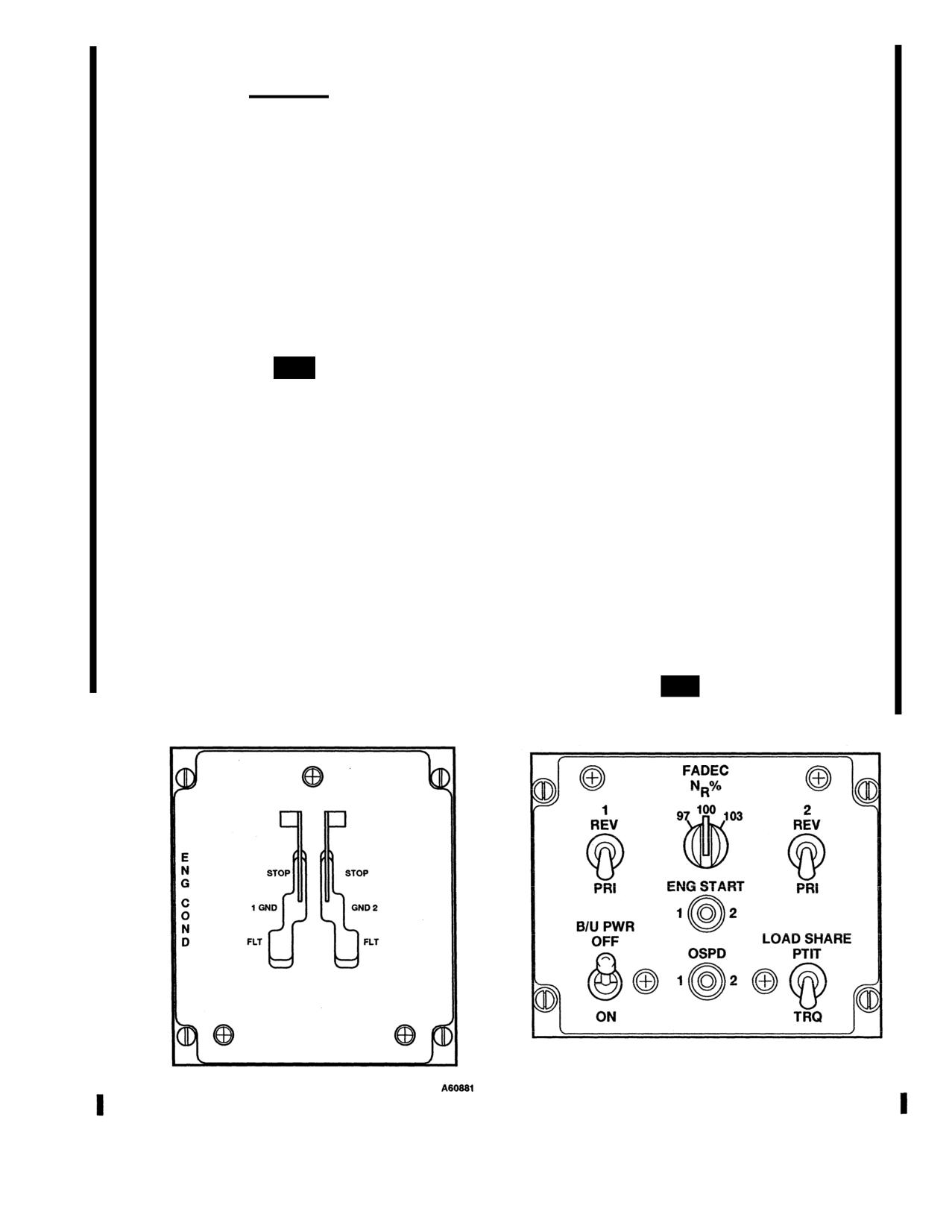
The ENG COND panel is located in the overhead switch
system. In the event of a NR over-speed of 114.8. percent,
panel (fig. 2-19.1).
FADEC reduces fuel flow to a ground idle condition. The
NO. 1 and NO. 2 Levers. The ENG COND Levers (ECL)
system remains activated until the over-speed condition no
provide the pilot with proportional acceleration and decel-
longer exists, and will re-activate as soon as an overspeed
eration authority. The levers are spring-loaded outboard
re-occurs. The system contains provisions to inhibit over-
creating a gated motion when advanced from the STOP to 1
speed trip command if the other engine has experienced a
/ 2 GND and to FLT positions. ENG COND lever friction is
overspeed trip condition. To prevent inadvertent operation
provided to reduce the possibility of over-torquing trans-
during flight, this test is locked out if NR is greater than
missions by resisting rapid movement of the levers.
81.3 percent. When performing an overspeed test with the
engine running and the RRPM 79.0 ±1% and the function is
2-60.4. FADEC Panel.
714A
The FADEC panel is
locked out above 81.3 percent, pressing the test switch to 1
located in the overhead switch panel (fig. 2-19.2). It
or 2, lowers the overspeed trip threshold to 79 ±1% NR. At
comprises of the following:
this time the system senses an overspeed and reduces the
fuel flow.
a. NR% Switch.
The NR% switch controls a rheostat
which allows the operator to select any RRPM between
e. LOAD SHARE, PTIT/TRQ Switch.
The primary FA-
97% and 103%. There are detents at 97%, 100% and 103%.
DEC system provides pilot selectable engine torque or PTIT
With the ECL(s) in FLT, NR will be maintained at the
matching to govern the engines. Torque matching is nor-
selected speed. 100% is the normal position.
mally the preferred option. The selected parameter is
constantly compared between the two engines until the
b. PRI/REV Switches.
The primary mode is the normal
RRPM stabilizes at a datum figure. The PTIT option may be
mode of operation. The REV (reversionary) mode is select-
used when one engine is running hot. N1 matching is
able as a backup mode or is automatically selected if the
engaged automatically if the selected matching mode fails.
primary system has a hard fault failure. A hard fault failure
is defined as one in which normal primary system perfor-
f. ENG START Switch.
It is a three position switch,
mance might be jeopardized. Other failures are classified as
spring loaded to the center position, labeled 1 and 2. It is
soft failures when the system is fault tolerant and can
used to commence the start sequence on the respective
continue fully operational with the fault signal present.
engine.
c. B/U PWR Switch.
The Back-Up Power switch when
ON connects the aircraft battery relay and essential relay.
2-60.5. DECU Unit.
714A The two airframe mounted
DECUs, one for each engine, contain the primary and
A60879
Figure 2-19.1. Engine Condition Panel 714A
Figure 2-19.2.
FADEC Panel 714A
2-26.2
Change 13
TM 55-1520-240-10
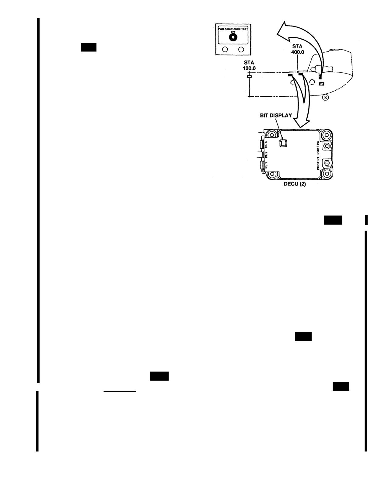
reversionary mode electronics. The DECUs are located on
the left and right side of the aft cabin at station 400 (fig.
2-19.3).
2-60.6. BIT.
714A
The DECU contains a two-digit BIT
display. When active, the display indicates the operating
status of the FADEC system and power assurance test
results. A complete list of the FADEC BIT fault codes are
located at Table 2-1.1. The fault monitoring carried out by
the DECU consists of:
a. Power up tests.
b. Fault tests designed to discover dormant faults.
c. A set of repeated monitoring tests to detect faults
occurring during normal operation.
Fault information for the previous or current engine cycle
can be seen on the DECU BIT display. The last engine cycle
is reset on the first occurrence of start mode and not on
engine shutdown. During engine shutdown (when a ECL is
at STOP or N1 is less than 10 percent) faults are not stored.
Fault indications are stored in the DECU and are retained
throughout the life of the control unit. However, fault
information prior to the previous cycle can only be accessed
with specialized test equipment. During engine start the
DECU BIT displays 88 for a satisfactory test or if the test
A73381
fails, a fault code. Faults are classified as either “HARD“ or
"SOFT". In primary mode a Hard fault will cause the
FADEC to transfer to Reversionary, while in Reversionary a
Hard fault will cause the FADEC to "fail fixed" to a constant
Figure
2-19.3. DECU Panel
714A
power condition. If a hard fault occurs in Primary after a
percent N1 then release the ENG START switch. The
hard fault exists in reversionary then the primary will fail
automatic start sequence has been energized and FADEC
fixed. In the event of a soft fault the FADEC will remain in
the mode it was in prior to the fault but there may be some
will complete the start. When an engine start is energized,
degradation or redundancy. All soft faults are less severe
FADEC turns on the engine start solenoid to introduce fuel
than a Hard fault since the FADEC will not switch modes
flow and energize the engine igniters. Successful engine
due to a soft fault.
ignition is immediately indicated to FADEC by an increase
of PTIT or compressor speed (N1). Engine temperature is
The activation of the BIT display is dependent upon the
monitored throughout the sequence and will result in a fuel
position of the ECL as follows:
flow reduction if the temperature exceeds
650°C with a full
a. With the ECL at STOP, the fault information for the
cutback to minimum flow limit at
760°C. The starter motor
last engine cycle and current faults are displayed.
and igniter are automatically turned off when N1 speed
exceeds
48 percent. Ground idle is
50 to 59 percent and is
b. When the ECL is positioned at GROUND IDLE only
corrected for temperature. The engine is allowed to take 45
current faults are displayed.
seconds to stabilize at ground idle.
c. When the ECL is positioned at FLIGHT the display
will be turned off except as required for power assurance
2-60.8. Engine Start Abort.
714A
PTIT above
816°C
test
will cause immediate fuel shutoff to below minimum fuel
flow. The ECL must be retarded to STOP to achieve total
fuel shutoff. A start abort results in the ENG 1 (2) FAIL
warning to be illuminated until the abort is reset by moving
the ECL to STOP
2-60.7. Starting in Primary Mode.
714A
CAUTION
2-60.9. Starting in Reversionary Mode.
714A
The
initial start sequence in reversionary mode is the same as in
The (P3) compressor pressure signal line
primary mode except, when N1 reaches
8 percent, the
going to the DECU contains a manually
control system turns on the engine start fuel solenoid to
operated moisture drain valve. This valve
provide an initial altitude biased fuel flow and activates the
should not be drained while the engine is
igniters and latches the starter motor. The pilot can modulate
running.
fuel flow to the engine with ECL to start the engine at a
In primary mode, engine start is initiated with the ECL in
desired acceleration rate. Temperature and temperature rate
the GND position. Select and hold the respective ENG
limiters are the same as in primary mode except that the
START switch and allow the engine to accelerate to 10
over temperature start abort facility is not provided.
Change 13
2-26.3
TM 55-1520-240-10
Alternate Reversionary Starting. For most conditions, a start
(2) Retard the ECL to GROUND as ground idle
is successfully completed with the ECL held at the GND
speed is approached. Check that N1 is stabilized at ground
position. However, if the engine fails to start due to either a
idle,
rich or lean hung start condition, the pilot may use the ECL
to increase or decrease the start flow as required to complete
2-60.10. Starting Cycle, Aborting . and Motoring.
a successful start. If the engine fails to start using the normal
714A A starting cycle can be aborted at any time by
starting procedure, proceed as follows:
moving the ECL to STOP. If a motoring is required:
a. Reversionary Rich Hung Start. A rich hung start is
a. Set the ECL to STOP.
characterized by N1 holding at about 40 percent and PTIT
climbing above
600°C. If a rich hung start is experienced:
b. ENG START switch to 1 (2).
(1) Set the affected engine ECL to STOP.
c. Hold ENG START switch until PTIT decreases below
(2) Allow PTIT to decay to 260°C or below (motor
26O°C.
engine as required).
2-60.11. Power Assurance Test Switch.
714A
The
(3) Check N1 0 percent.
primary FADEC will perform a BIT whenever the PWR
(4) Advance ECL half the distance between STOP
ASSURANCE TEST switch has been placed to the desired
and GND (15°).
engine position. The switch is located below the mainte-
(5) Motor engine using ENG START switch until
nance panel at station 524. The switch is labeled 1/OFF/2
10% N1 and then release switch.
and spring loaded to OFF’. The results of the test are
displayed in the DECU BIT window.
(6) After engine ignition (PTIT rising), slowly ad-
vance ECL to GND. Check that N1 is stabilized at ground
2-60.12. Engine Wash System.
714A
The heli-
idle.
copter is equipped with an engine wash system for each
b. Reversionary Lean Hung Start. A lean hung start is
engine. Air and water connections are externally mounted
characterized by N1 hanging at approximately 30 percent
inboard of each engine work platform. A series of spray
and PTIT remaining below 500°C. If a lean hung start is
nozzles are installed at the engine inlet and air lines are
experienced:
routed to the bleed band actuator.
(1) Slowly advance the hung engine ECL to achieve
acceleration (maximum of one-third travel from GND to
FLT).
2-26.4
Change 13
TM 55-1520-240-10
Table
2-1.1. FADEC Bit Fault Code List
714A
FAULT
FAULT
CODE
FAULT DESCRIPTION
CODE
FAULT DESCRIPTION
10
Microprocessor hard fault
C7
Communication line soft fault on NR (0) sig-
11
Non-volatile random access memory (RAM)
nal
check sum hard fault
C8
Communication link soft fault
12
Non-volatile RAM engine history data soft
C9
Communication line soft fault on N1B (0)
fault
signal
13
Non-volatile RAM fault data soft fault
CF
Loss of load share signals hard fault
14
Non-volatile RAM accumulated fault data soft
DO
Overspeed drive soft fault
fault
D1
P3 transducer soft fault
15
Non-volatile RAM write test soft fault
D2
P1 transducer soft fault
16
Non-volatile RAM storage incomplete
D3
28V “OR” diodes soft fault
17
Non-volatile RAM history data inconsistent
D4
+ 1OV reference hard fault
18
Minor cycle not competed hard or soft fault
D5
±15V hard fault
1B
Engine monitoring system cycle not com-
D6
+12V reversionary or ±12V overspeed soft
pleted soft fault
fault
1C
Analog-to-digital conversion not completed
D7
+5V hard fault
hard fault or soft fault
D8
Primary and reversionary cold junction com-
1E
RAM failure hard fault
pensation for temperature signal soft fault
1F
Opcode error hard fault
D9
+24V regulator soft fault
A1
Q sensor soft fault
DA
+5V reversionary soft fault
A2
N2 set potentiometer soft fault
DB
Reversionary system soft fault or idle check
A3
Primary and reversionary collective pitch
soft fault
angle linear variable displacement transformer
DC
T4.5 calibration soft fault
(LVDT) soft fault
DD
Over-speed check soft fault
A4
NR sensor soft fault
DE
Primary and reversionary 400Hz resolver ref-
A5
Primary and reversionary ENG COND lever
erence soft fault
resolver soft fault
DF
Watchdog timer test hard fault
A6
Airframe emergency 28V DC supply soft fault
E1*
Primary and reversionary T4.5 sensor soft
A7
Airframe +28V DC supply soft fault
fault
B2
Primary or reversionary N1B sensor soft fault
E2*
T1 sensor soft fault
B3
Primary or reversionary N2B sensor soft fault
E3*
N2A sensor soft fault
B4
Primary or reversionary T4.5 sensor soft fault
E4*
Primary and reversionary N2B sensor hard
B5
Primary or reversionary collective pitch angle
fault
LVDT soft fault
E5*
N2A/N2B difference soft fault
B6
Primary or reversionary ENG COND lever
F1
N1A sensor soft fault
resolver soft fault
F2
Primary and reversionary N1B sensor hard
B7
Primary or reversionary power level angle
fault
potentiometer soft fault
F3
N1A/N1B difference soft fault
B9
Primary or reversionary cold junction com-
F4
MV potentiometer hard or soft fault
pensation for temperature signal soft fault
F5
Fuel flow stepcount difference hard fault
BA
Reversionary +28V soft fault
F6
Primary and reversionary power level angle
BB
Reversionary T4.5 calibration soft fault
potentiometer soft fault
BC
Primary or reversionary 400Hz resolver refer-
F7
Bleed valve solenoid hard fault
ence soft fault
F8
Primary/Reversionary solenoid hard fault
C1
Communication line soft fault on T4.5 (0)
F9
Alternator voltage soft fault
signal
FA*
Start fuel solenoid soft fault
C2
Communication line hard or soft fault on P1
FB
Reversionary step count soft fault
(0) signal
C3
Communication line hard or soft fault on T1
*Denotes engine related faults.
(0) signal
C4
Communication line soft fault on Q (0) signal
C5
Communication line soft fault on N2 SET (0)
signal
C6
Communication line soft fault on collective
pitch angle (0) signal
Change 13
2-26.5/(2-26.6 blank)
TM 55-1520-240-10
SECTION IV
FUEL SYSTEM
2-61. Fuel Supply System.
quantity probes, a jet pump for evacuating the pressure
refueling system, a dual pressure refueling shutoff valve,
The fuel supply system furnishes fuel to the two engines,
a dual fuel level control valve, and a gravity filler port.
the heater, and the APU. Two separate systems,
Each auxiliary tank contains a fuel pump with automatic
connected by crossfeed and a pressure refueling lines
shutoff feature, a quantity probe, a dual pressure
are installed. Provisions are available within the cargo
refueling shutoff valve, and a fuel level control valve.
compartment for connecting Extended Range Fuel
System (ERFS) and ERFS II to the two fuel systems.
Each fuel system consists of three fuel tanks contained
in a pod on each side of the fuselage. The tanks are
identified as forward auxiliary, main, and aft auxiliary
tanks. During normal operation, with all boost pumps
operating, fuel is pumped from the auxiliary tanks into the
main tanks, then from the main tanks to the engine. A
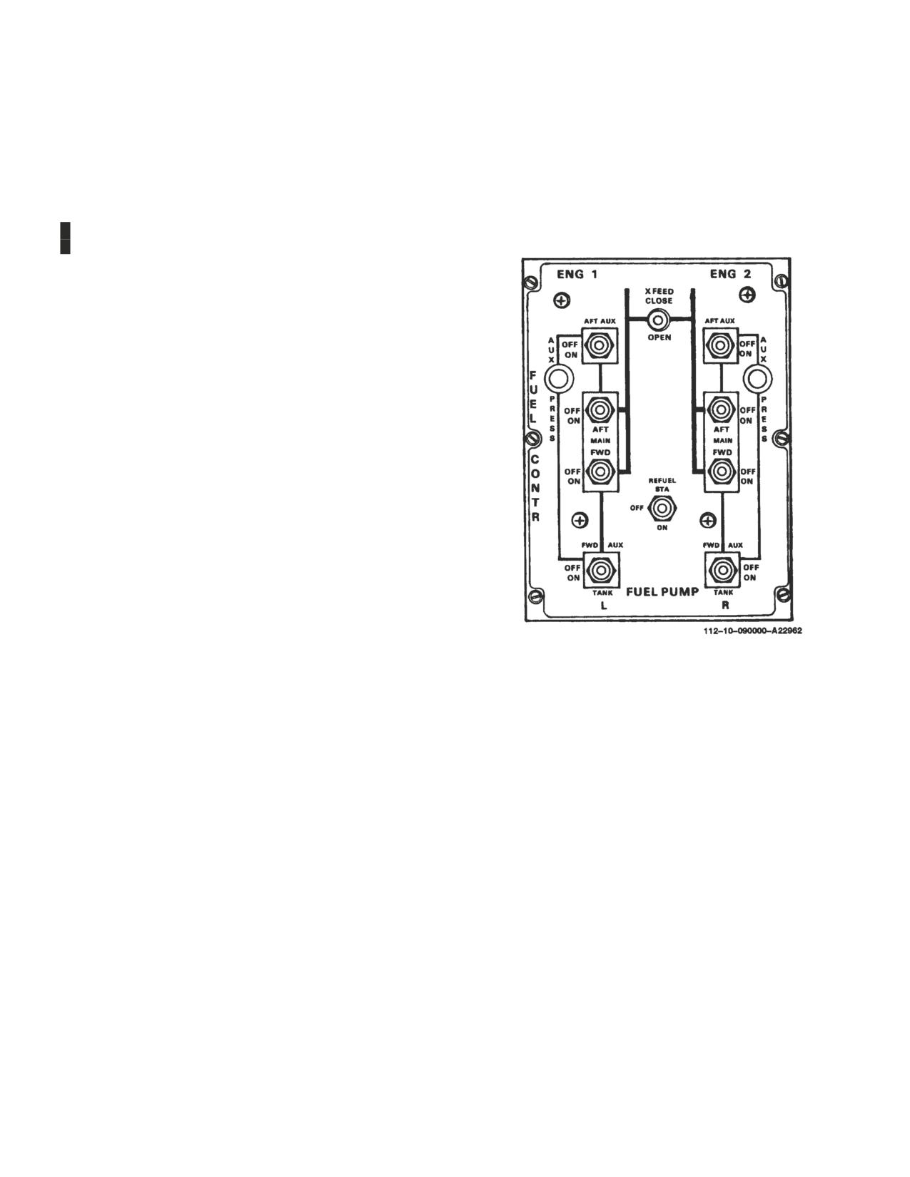
simplified fuel flow diagram is engraved on the FUEL
CONTR (control) panel on the overhead switch panel
(fig. 2-20).
When the fuel is consumed in an auxiliary tank, the fuel
pump is automatically shut off and a check valve closes
to prevent fuel from being pumped back into that tank.
Should a fuel pump fail in an auxiliary tank, the fuel in that
tank is not usable. However, should both boost pumps
fail in a main tank, fuel will be drawn from the main tank
as long as the helicopter is below 6,000 feet pressure
altitude (PA).
Fuel is delivered to the APU from the left main tank and
to the heater from the right main tank. Fuel system
switches and the auxiliary tank low pressure indicating
lights are on the FUEL CONTR panel, the fuel line
pressure caution capsules are on the master caution
panel, and the fuel flow meter is on the center instrument
Figure 2-20. Fuel Control Panel
panel. The single point pressure refueling panel and
A rollover vent system is installed in each tank. This
nozzle adapter are on the right side above the forward
system prevents fuel spillage from the vents should the
landing gear. Refer to Section XV for fuel tank capacities,
helicopter roll over following a crash landing. The vent
fuel grades, and fuel system servicing procedures.
system within the tanks have a condensate drain at the
aft end, however, aircraft maneuvering should never
2-62. Fuel Tanks.
force fuel into the vents. Sump drains are also installed
The fuel tanks are crashworthy self-sealing tanks with
on the bottom forward end of each tank.
breakaway fittings. The main fuel lines are constructed
of self-sealing material. Penetration of the tank wall or a
2-63. Controls and Indicators.
fuel line by a projectile exposes the sealant to the fuel,
The fuel controls are the FUEL PUMP switches, XFEED
activates the sealant, and close the hole.
fuel valve switch, the engine fuel valve, and the manual
Breakaway self-sealing fittings are installed where the
defueling valve. Indicators include the crossfeed fuel and
main fuel lines connect to the fuel tank and adjacent
engine fuel valve warning lights, the FUEL QUANTITY
structure. Under high impact loads, the fittings shear or
indicator and caution capsules, FUEL flow indicator,
break at predetermined locations, seal themselves,
AUX PRESS indicating lights, and FUEL PRESS caution
retain the fuel, keeping fuel loss and post-crash fire
capsules. Refer to para. 2-70 for a description of the
hazard to a minimum. Electrical cables having
pressure refueling system controls and indicators.
lanyard-release type connectors are installed where the
2-64. FUEL CONTR Panel. The FUEL CONTR panel
cables attach to adjacent structure. The connectors
(fig. 2-20) consists of eight two-position fuel boost pump
automatically release if the fuel tank breaks away from
switches, two PRESS-TO-TEST AUX PRESS indicating
the pod.
lights, a two-position XFEED switch, and a two-position
Each main tank contains two fuel boost pumps, three fuel
REFUEL STA switch.
Change 14
2-27
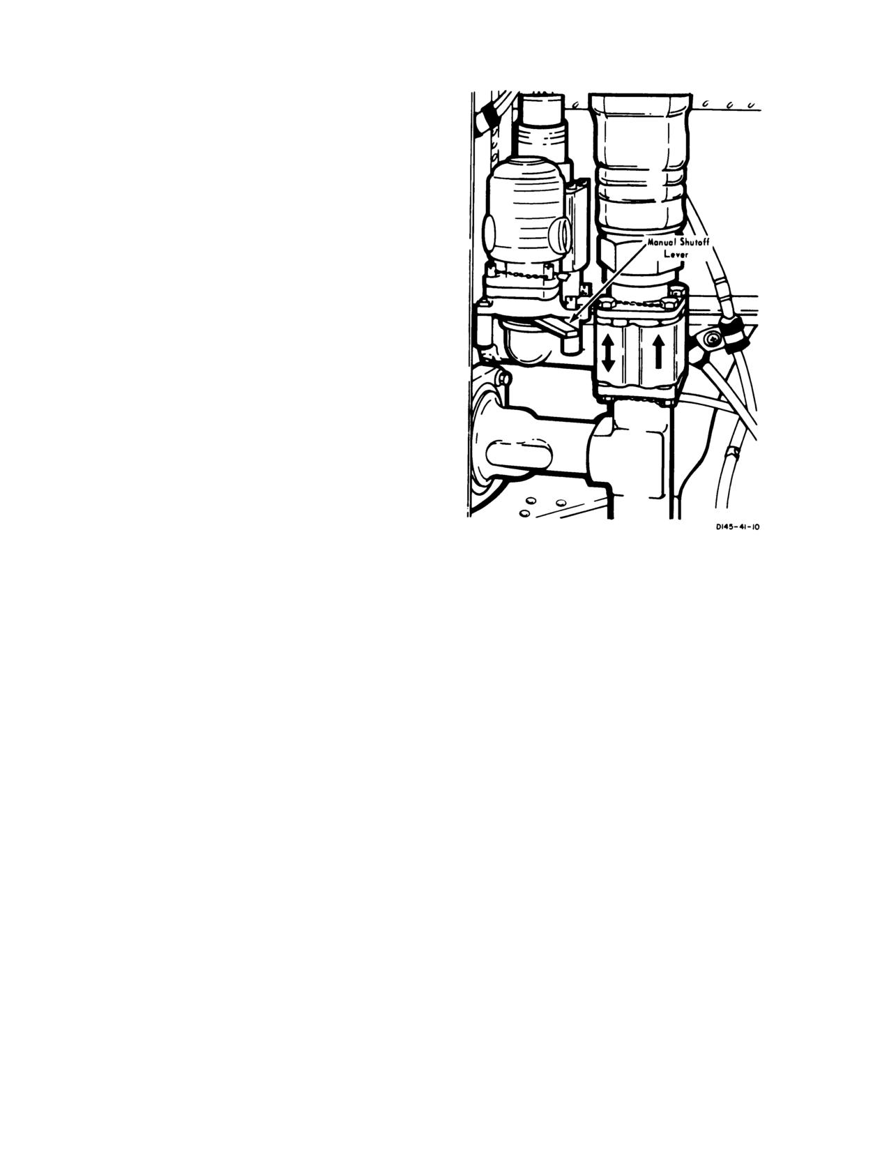
TM 55-1520-240-10
a. FUEL PUMP Switches.
Each switch controls a
single-speed electrically driven fuel boost pump. La-
beled next to each switch is the name of the pump which
it operates. Each switch has an ON and OFF position.
When one of these switches is at ON, power from the
No. 1 or No. 2 DC bus closes the respective pump relay
connecting power from the No. 1 or No. 2 AC bus to
energize the pump. When switch is at OFF, the relay
circuits open and power from the No. 1 and No. 2 AC
bus is de-energized thus shutting off the pump. Power is
supplied for these relay circuits by the No. 1 and No. 2
DC bus through the LH and RH FUEL PUMP CON-
T - AUX AFT, MAIN AFT, MAIN FWD, and AUX
FWD circuit breakers on the No. 1 and No. 2 PDP.
Power is supplied to the pumps circuits by the No. 1 and
No.
2 AC bus through the LH and RH FUEL
PUMPS -
MAIN FWD, MAIN AFT, AUX FWD,
and AUX AFT circuit breakers on the No. 1 and No. 2
PDP.
b. AUX PRESS Indicating Lights.
Each light is elec-
trically connected to the forward and aft auxiliary tank
pressure switches. When this indicating light illumi-
nates, it indicates that the fuel pressure in-either the
forward or aft auxiliary fuel line is below
10
± 1 psi. The
auxiliary tank fuel boost pump switches must be at ON
to provide electrical power to the indicating light. The
light intensity can be adjusted by turning the light
housing. Power is supplied to operate the indicating
light by the No. 1 and No. 2 DC bus through the LH or
Figure 2-21. Engine Fuel Valves, Sta. 498
RH FUEL PUMP CONT AUX FWD & AUX AFT
and two PRESS-TO-TEST FUEL VALVE WARNING
circuit breakers on the No. 1 and No. 2 PDP.
LIGHT next to FUEL VALVE # 1 ENGINE and # 2
c. XFEED Switch.
The switch electrically operates
ENGINE (fig. 2-22). They indicate the operating con-
two fuel valves in the crossfeed line. The switch has an
dition of the individual valve and
-associated circuitry.
OPEN and CLOSE position. When the switch is at
Power is supplied to operate the crossfeed FUEL
OPEN, power from the No. 1 DC bus opens the fuel
VALVE WARNING LIGHT by the No. 1 DC bus
valves through the XFEED CONT circuit breaker on
through the XFEED CONT circuit breaker on the No.
No. 1 PDP. When the switch is at CLOSE, electrical
1 PDP. Power is supplied to operate the engine FUEL
power closes the valves.
VALVE WARNING LIGHT by the DC essential bus
through the ENGINE NO. 1 and NO. 2 FUEL SHUT-
2-65. Fuel Valves. There are two engine and two
OFF circuit breakers on the No, 1 and No. 2 PDP.
crossfeed fuel valves.
The following description on when the light will illumi-
a. Engine Fuel Valves.
One engine fuel valve (fig.
2-21) is in the fuel supply line to each engine. The valve
nate is for the XFEED switch. The same result applies
is electrically operated by the FIRE PULL handles and
to the engine fuel valves with the FIRE PULL handles.
manually by a lever on the valve. They are located at sta.
(1) Each time the XFEED switch is moved from
498 and labeled FUEL VALVE # 1 ENGINE and
CLOSE to OPEN or OPEN to CLOSE. After this
FUEL VALVE # 2 ENGINE.
operation, the light should extinguish, indicating the
b. Crossfeed Fuel Valves.
The crossfeed fuel valves
crossfeed valve is synchronized with the switch position.
connects the No. 1 and No. 2 engine fuel lines. When
(2) When a short circuit occurs, causing a signal
the valve is opened, both engine fuel feed lines are
to be applied opposite to the valve position. However,
interconnected and fuel can be supplied from both fuel
the valve will remain at the position last selected by the
tanks to feed either engine or from either tank to feed
XFEED switch.
both engines. Fuel cannot be transferred between tanks.
The valves are electrically operated by the XFEED
(3) When the crossfeed valve protection relay
switch on the FUEL CONTR panel or manually by a
fails. The crossfeed valve will remain at the last selected
position and the valve can be operated electrically or
lever on the valve. They are labeled FUEL VALVE
CROSS FEED and located at station 504.
manually, as required.
c. FUEL VALVE WARNING LIGHT.
There are
2-66. Manual Defueling Valve. A manual defueling
two PRESS-TO-TEST FUEL VALVE WARNING
valve is in the aft cargo compartment next to FUEL
LIGHT next to each FUEL VALVE CROSS FEED
VALVE # 2 ENGINE. The valve should only be used
2-28
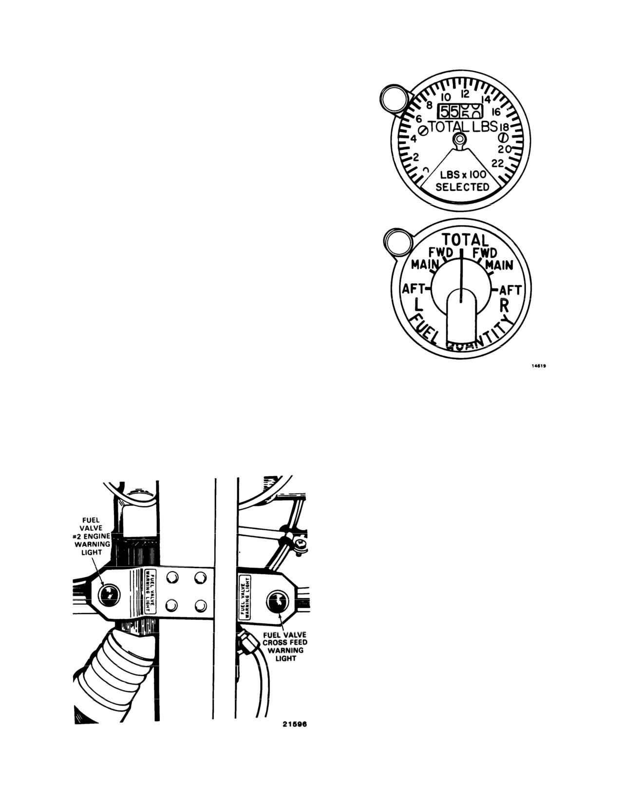
TM 55-1520--240-10
by maintenance personnel to defuel the helicopter or
adjust fuel load.
2-67. Fuel Quantity indicator and Selector
Switch. An indicator calibrated to measure fuel quan-
tity in pounds and a seven position selector switch (fig.
2-23) is on the center instrument panel. Power is
supplied to the indicator through the FUEL QUAN-
TITY selector switch by the No. 1 AC bus through the
FUEL QTY circuit breaker on the No. 1 PDP.
a. FUEL QUANTITY Indicator.
The indicator pro-
vides two types of display. One display is in digital form
and the other is a pointer, The digital readout contin-
uously indicates the total amount of fuel remaining in
all the fuel tanks. The pointer remains hidden until one
of the tank positions on the FUEL QUANTITY selec-
tor switch is selected. Then, the pointer will indicate
fuel remaining in that tank. The fuel quantity indicator
is electrically connected to 10 capacitance-type measur-
ing units in the tanks.
b. Fuel Quantify Selector Switch.
The fuel quantity
selector switch has seven positions labeled TOTAL, L
(left) and R (right) FWD, MAIN, and AFT. Selecting
any position other than TOTAL causes the indicator
pointer to display the fuel remaining in that tank. The
digital readout is not affected during individual tank
readings.
2-68. Fuel System Cautions. Four caution capsules
Figure 2-23. Fuel Quantity Indicator and Selector
are dedicated to the fuel system.
Switch
a. L and R FUEL LOW.
Two fuel quantity caution
caution panel (fig. 2-51) of the center instrument con-
capsules, one for each main tank, are on the master
sole. Each light is electrically connected to a thermistor
sensor on a measuring unit in the respective main tank.
These lights are labeled L FUEL LOW and R FUEL
LOW. When there is
20 percent of fuel remaining in the
main tank, the caution capsule for that main tank
illuminates (20 percent of fuel is equal to
320 to 420
pounds.) Power for these capsules is supplied by the DC
essential bus through the LIGHTING CAUTION PNL
circuit breaker on the No. 1 PDP.
b. L and R FUEL PRESS.
Two caution capsules
labeled L FUEL PRESS and R FUEL PRESS are on
the master caution panel. Each caution capsule is
electrically connected to a fuel pressure switch between
the main tank and the engine fuel valves. When one of
these capsules illuminates, it indicates that fuel pressure
in the respective fuel line is below
10
± 1 psi. Fuel
pressure is measured after the fuel boost pumps and not
at the engine driven pump. When a fuel pressure
caution illuminates, it does not represent a possible
engine flameout, unless flight is being conducted
above
6,000 feet PA. Power for these capsules is supplied by
the DC essential bus through the LIGHTING CAU-
TION PNL circuit breaker on No. 1 PDP.
2-69. FUEL Flow Indicators.
A dual fuel-flow indicator (fig. 2-24), on the center
instrument panel , indicates fuel flow to each engine in
pounds per hours. The indicator dial is graduated from
0 to 3000 pounds per hour in
100 pound increments.
Figure 2-22. Fuel Valve Warning Light, Sta. 500
The signal to drive the indicator is derived from a fuel
2-29

TM 55-1520-240-10
Electrical power is applied to the system only when the
REFUEL STA switch on the cockpit FUEL CONTR
panel is placed to ON. Power to operate the pressure
refueling system is supplied by the DC switched battery
bus through the REFUEL circuit breaker on the No. 1
PDP.
2-71. Controls and Indicators.
Except for the REFUEL STA switch on the cockpit
FUEL CONTR panel, all pressure refueling system
controls and indicators are on the pressure refueling
station panel (fig. 2-25).
2-72. PWR Control Switch. The PWR (power) con-
trol switch is labeled ON and OFF. When placed to ON,
electrical power is applied to the pressure refueling
system and to the refueling station quantity indicator
provided the REFUEL STA switch on the cockpit
FUEL CONTR panel is at ON. Also, the PWR ON light
Figure 2-24. Fuel Flow Indicator
will illuminate, the fuel quantity indicator will register
flow transmitter in the fuel line of each engine at the
the quantity of fuel in the tanks, and the REFUEL
quick disconnect shelf. Power to operate the No.
1
VALVE POSN lights will illuminate momentarily. When
indicator is from the No. 1 AC bus through the EN-
placed to OFF, electrical power is removed,
GINE NO. 1 FUEL FLOW circuit breaker on the No.
2-73. REFUEL STA Switch. The REFUEL STA
1 PDP. Power to operate the No. 2 indicator is from the
switch is on the cockpit FUEL CONTR panel (fig. 2-20)
No. 2 AC bus through the ENGINE NO. 2 FUEL
when placed to ON, applies electrical power from the
FLOW circuit breaker on the No. 2 PDP.
DC switched battery bus to the PWR ON switch on the
2-70. Pressure Refueling System.
refueling station panel. Setting the switch to OFF after
pressure refueling, closes the refuel valves and discon-
The pressure refueling system permits rapid refueling of
tinues electrical power to the refueling panel. When
all fuel tanks simultaneously or selective refueling of
pressure refueling, be sure the switch is at ON at all
any tank or combination of tanks. Maximum fueling rate
times. If the switch is at OFF, the aft auxiliary tanks will
is 300 gallons per minute at
55 psi. The system control
not fill, the remaining four tanks will fill to maximum,
panel and refueling nozzle receptacle are on the right
the refuel station quantity indicator is inoperative, and
side of the helicopter above the forward right landing
there is no precheck capability.
gear (fig. 2-25).
2-74. Fuel Quantity Indicator and Selector
In addition to the control panel and refueling recepta-
Switch. The pressure refueling station fuel quantity
cle, the system consists of a dual fuel level control valve,
indicator and selector switch (fig. 2-25) are identical to
a dual fuel shutoff valve in each tank, a jet pump in each
those in the cockpit. The indicator at the refueling
main tank, and pressure refueling manifold.
station indicates fuel quantity only when the REFUEL
a. Dual Fuel Level Control Valves and Dual Fuel
STA switch on the cockpit FUEL CONTR panel (fig.
Shutoff Valves. The dual fuel level control valves con-
2-20) is at ON and the PWR switch on the refueling
trol the operation of the dual fuel shutoff valves. When
station panel (fig. 2-25) is at PWR ON. Electrical power
fuel in a tank rises to the full level during pressure
to drive the indicator is AC from a solid-state inverter in
refueling, the floats in the control valve close and apply
the cabin at sta 220. The inverter, in turn, is powered by
a signal to the shutoff valve, closing it. The floats can
the DC switched battery bus through the FUEL RE-
also be closed electrically to stop fuel flow into a tank at
FUEL circuit breaker on the No. 1 PDP.
some intermediate level. The floats are controlled by
the FUEL CELL SHUTOFF VALVE TEST switches
2-75. FUEL CELL SHUTOFF VALVE TEST
on the refueling control panel.
Switches. Seven three-position FUEL CELL SHUT-
OFF VALVE TEST switches are on the refueling
b. Jet Pumps.
The jet pump installed in each main
control panel (fig. 2-25). The switches are used to test
tank evacuates the refueling manifold and discharges
the automatic shutoff features in each tank and to stop
the displaced fuel into the main tank. The jet pump is
refueling when the desired fuel level is attained in each
activated when the forward boost pump in each main
or all tanks. Six of the seven switches are connected to
tank is first turned ON following pressure refueling.
fuel level control valves in a specific tank. The seventh
c. Pressure Refueling Manifold.
The pressure refuel-
switch, labeled ALL TEST, is electrically connected to
ing manifold connects all tanks to the pressure refueling
the fuel level control valves in all six tanks. Setting any
receptacle. It does not include projectile resistant fea-
of the six switches to PRI OFF or SEC OFF raises the
tures because the fuel is evacuated before flight by the
corresponding primary or secondary float in the fuel
jet pumps.
level control valve. This action simulates a high fuel
2-30
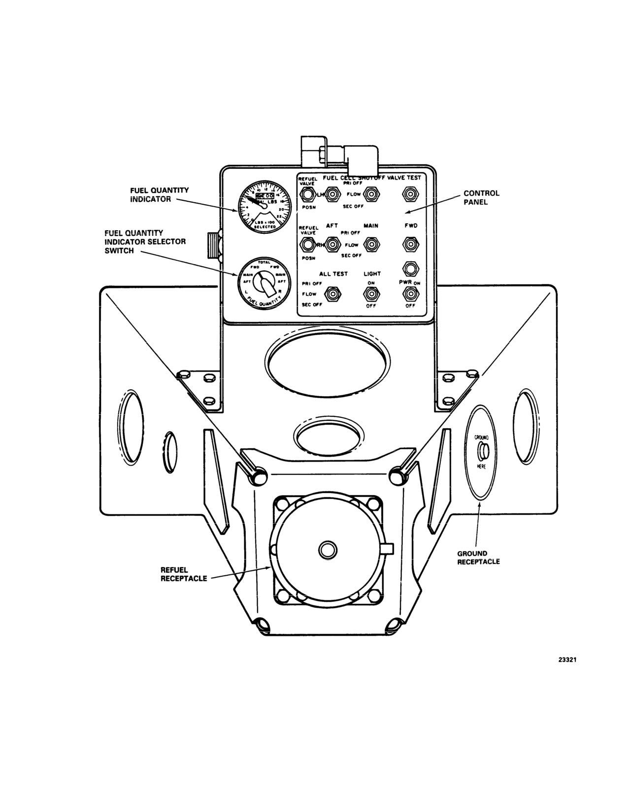
TM 55-1520-240-10
Figure 2-25. Pressure Refueling Station
2-31
TM 55-1520-240-10
level and causes the fuel shutoff valve in that tank to
opened and allow fuel flow from the refueling system
close. Setting the ALL TEST switch to PRI OFF or SEC
into the aft tank,
OFF raises the corresponding float in all six tanks and
The valves are controlled by the refueling station PWR
shuts off the fuel flow into all tanks simultaneously.
ON switch. When the switch is ON, the valves are
2-76. REFUEL VALVE POSN Indicating Lights. The
opened and the indicating lights will illuminate momen-
two amber PRESS-TO-TEST REFUEL VALVE POSN
tarily indicating valve transitioned from close to open.
Conversely, when the switch is OFF, the valves are
(position) lights (fig. 2-25) indicate the status of the two
closed and the indicating lights will illuminate momen-
refueling valves in the pressure refueling system. The
tarily indicating valve transitioned from open to close. A
valves are normally closed and prevent fuel feedback
continuously illuminated light, with the switch at OFF,
into the aft auxiliary tanks when the aft tank pumps are
indicates the associated valve is opened and the fuel in
operating. While pressure refueling, the valves are
that tank will not be available.
2-32
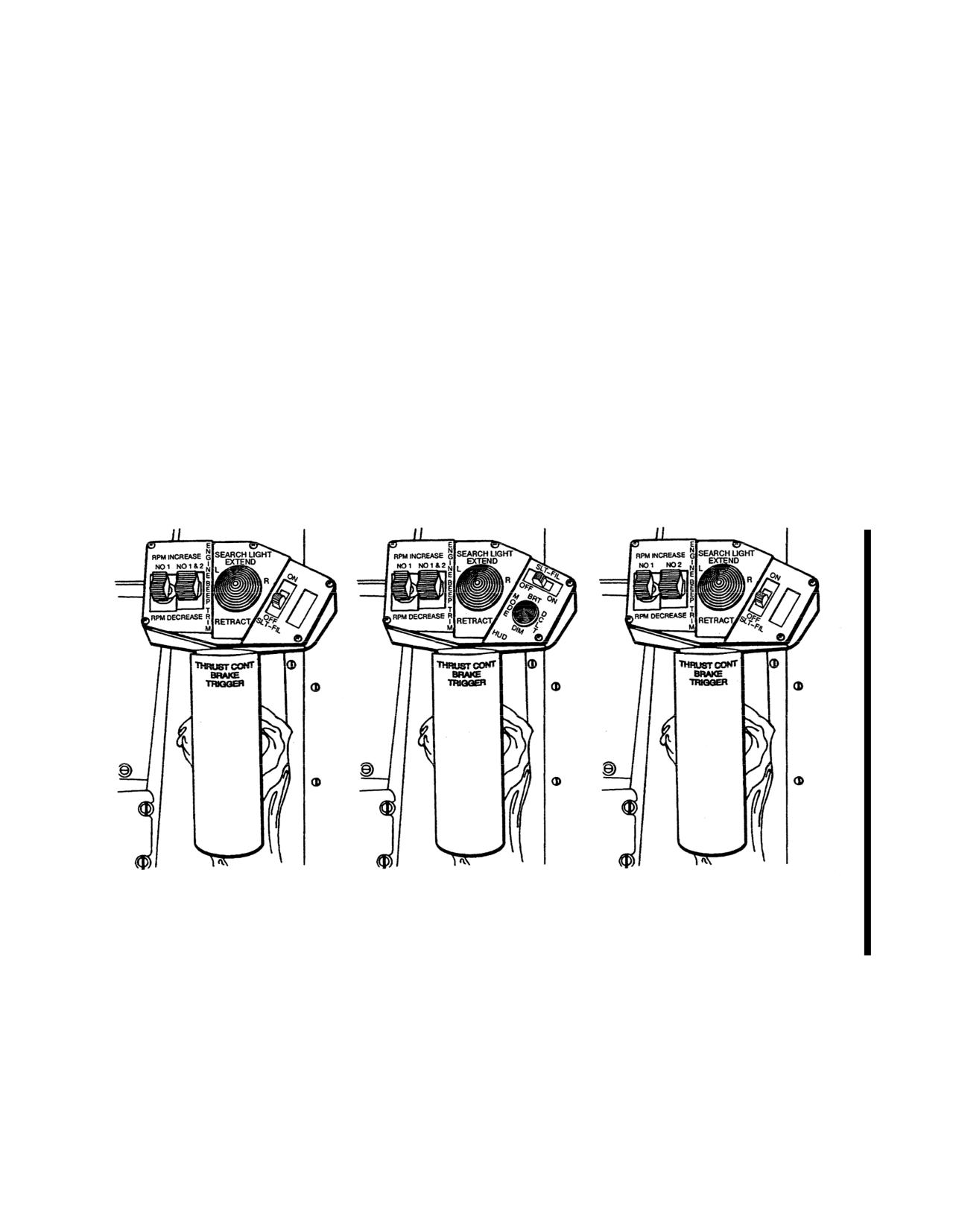
TM 55-1520-240-10
SECTION V
FLIGHT CONTROLS
2-77. Flight Control System.
by imparting equal but opposite lateral cyclic pitch to the
blades. Lateral control is obtained by application of equal
The helicopter is controlled by changing the pitch of the
lateral cyclic pitch to the blades with the cyclic control stick.
blades either collectively or cyclically. Pitch changes are
The helicopter is controlled longitudinally with the cyclic
made by the pilot’s movement of the flight controls which
stick through application of differential collective pitch.
include a THRUST CONT (control) lever, a cyclic control
stick, and directional pedals. The pilot’s controls are inter-
In addition, the helicopter has an advanced flight control
connected with the copilot’s controls.
system (AFCS). AFCS provides the following features:
Plight control movements are transmitted through a system
a. Rate damping in all axes and sideslip stability.
of bellcranks, push-pull tubes, and actuators to a mixing unit
just aft of the cockpit, next to the forward transmission. The
b. Pitch and roll attitude hold and heading hold.
control movements are mixed to give the correct lateral
c. Airspeed hold.
cyclic and collective pitch motions to the rotors through
d. Improved control response in pitch, roll, and yaw.
dual hydraulic actuators. These dual boost actuators are
under each swashplate. Each set of dual boost actuators is
e. Barometric and radar altitude hold.
normally powered by both flight control hydraulic systems.
f. Automatic coupled turns.
The helicopter is vertically controlled with the THRUST
CONT lever through application of equal pitch to all blades.
g. Longitudinal cyclic trim scheduling.
Directional control is obtained with the directional pedals
THRUST CONTROL LEVER
THRUST CONTROL LEVER
THRUST CONTROL LEVER
(TYPICAL)
(ON HELICOPTERS MODIFIED BY
(ON HELICOPTERS MODIFIED
MWO 1-1520-240-50-56, HUD)
WITH 714A FADEC)
A73382
Figure 2-26.
Thrust Control Lever
Change 13
2-33
TM 55-1520-240-10
2-78. THRUST CONT Lever.
A detent capsule establishes a ground operation detent to
reduce droop stop pounding. A viscous damper in the thrust
Either THRUST CONT lever
712 (fig. 2-26) or 714A
control system improves control feel. Mounted on each
[fig. 2-26) is used to apply equal pitch simultaneously to
THRUST CONT lever is an auxiliary switch bracket con-
both rotors, thus controlling ascent and descent of the
taining a SEARCH LIGHT control switch, a SLT-FIL
helicopter. Raising the THRUST CONT lever increases
(search light filament) switch, two ENGINE BEEP TRIM
pitch. Lowering the THRUST CONT lever decreases pitch.
switches, and a HUD control switch.
An integrated lower control actuator (ILCA) is installed
2-79. Cyclic Stick
between the THRUST CONT lever and the mixing unit.
Each cyclic stick (fig. 2-27) is used for lateral and longitu-
This actuator assists the pilot in moving the THRUST
dinal control of the helicopter. Moving the cyclic stick to the
CONT lever. A cockpit control driver actuator (CCDA) is
right tilts both rotor disks equally to the right and causes the
also installed in the thrust control system. This actuator
helicopter to roll to the right in flight. Moving the cyclic
responds to signals from the AFCS and increases or de-
stick to the left causes the opposite movement. When
creases collective pitch on the blades to maintain a constant
moving the cyclic stick forward, the pitch of the fwd rotor
altitude. In addition, a balance spring is installed that
blades is decreased collectively while the pitch of the aft
counteracts the downward imbalance of the THRUST
rotor blades is increased collectively, thus causing a nose-
CONT level.
down helicopter attitude in flight. Moving the cyclic stick
aft causes the opposite movement resulting in a nose-up
NOTE
attitude.
If the THRUST CONT lever CCDA fails, the
Two ILCA’s, one for lateral control and one for longitudinal
THRUST CONT lever will slip when a force
control, are installed to assist the pilot in moving the cyclic
between 7 and 23 pounds is applied.
stick. In addition to these actuators, viscous dampers are
A BRAKE TRIGGER switch under each THRUST CONT
installed. One damper is for longitudinal control and one for
grip controls the magnetic brake of the CCDA in the flight
lateral control to improve control feel.
control closet. Pressing the switch applies electrical power
Located on the pilot and copilot cyclic stick grips are a
to release the magnetic brake in the THRUST CONT lever
CENTERING DEVICE RELEASE switch, an AFCS trim
CCDA. The THRUST CONT lever can then be freely
switch, a CARGO HOOK RELEASE switch, interphone-
moved.
transmitter TRIGGER switch, and a FLARE DISP (dis-
When barometric or radar altitude
hold has been selected,
penser) control switch.
pressing the trigger will disengage
altitude hold. When the
switch is released, power is applied through the simplex
2-80. CENTERING DEVICE RELEASE Switch.
The
clutch to the THRUST CONT lever CCDA and the AFCS
CENTERING DEVICE RELEASE switch (fig. 2-27) is
will hold the altitude. Power is supplied to operate the
used to simultaneously release the force feel trim magnetic
THRUST CONT lever magnetic brake from the DC essen-
brakes for the lateral, longitudinal, and directional flight
tial bus through the THRUST BRAKE circuit breaker on the
controls. In addition, it disengages bank angle hold, heading
No. 1 PDP
hold, and heading select functions when AFCS is operating.
Power is supplied to operate the magnetic brakes from the
The
712 THRUST CONT lever is also electrically linked
DC switched battery bus through the CONT CENTER
to the power turbine actuator through the droop eliminator
circuit breaker on the No. 1 PDP.
system. An upward movement of the THRUST CONT lever
A centering spring and a magnetic brake for each control
electrically increases the power turbine governor
speed
provide a sense of force feel to hold the control in a trim
setting to compensate
for inherent engine droop and main-
position. However, the pilot can override the force manually
tain engine speed as rotor loads are increased. A downward
while maneuvering the helicopter. When the switch is
movement of the THRUST CONT lever electrically de-
pressed, electrical power is applied to release the magnetic
creases the power turbine governor speed setting.
brakes. Each centering spring assumes a new trim position
where the control forces are nulled. Releasing the switch
The
714A
714A system includes both thrust lever position
removes electrical power and applies the magnetic brakes.
compensation and thrust lever rate compensation.
The centering springs are retained in their new positions.
2-34
Change
13
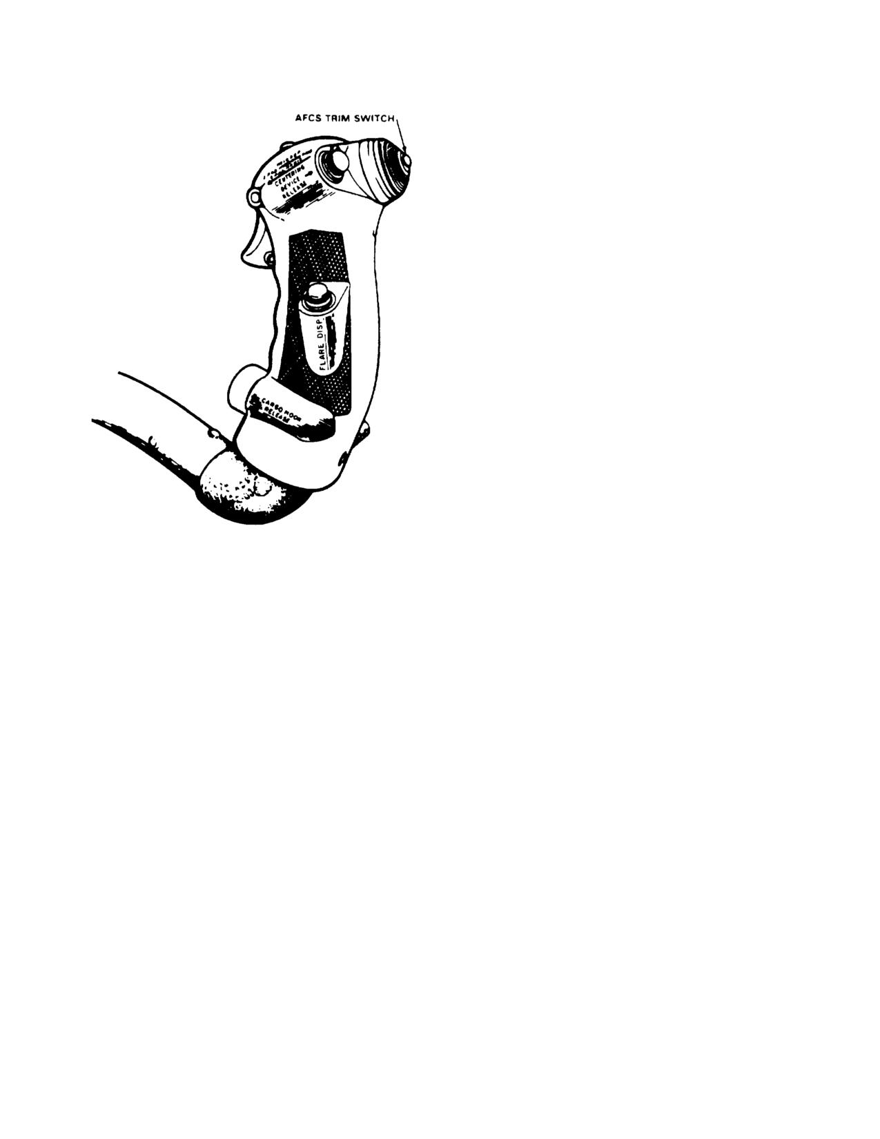
TM 55-1520-240-10
2-81. AFCS Trim Switch.
NOTE
If the longitudinal CCDA fails, it can be
recognized by loss of pitch trim or failure of
the centering device to release. A centering
spring in the pitch axis allows these forces to
be over-come.
The AFCS trim switch (fig. 2-27) is used to make small
changes in pitch (airspeed) and roll attitude while the
AFCS is operating. The switch is spring-loaded to center
off position. Moving the switch forward or aft from center
off position commands an increase (forward) or
decrease (aft) in airspeed by driving a trim motor in the
longitudinal CCDA.
Moving the switch left or right commands the roll ILCA to
bank the helicopter in the selected direction without
moving the stick. Power is supplied to drive the pitch
rim motor from the No.
1 AC bus through the CLTV
DRIVER ACTR circuit breaker on the No. 1 PDP.
2-82. Directional Pedals.
The directional pedals (7 and 24, fig.
2-24) are used for
directional control of the helicopter during flight and while
taxiing with the forward gear off the ground.
Figure 2-27. Cyclic Stick Grip
Change 7 2-34.1/(2-34.2 blank)