OPERATOR’S MANUAL FOR ARMY CH-47D HELICOPTER (EIC: RCD, 2003) - page 6
TM 1-1520-240-10
CAUTION
WARNING
The quick-disconnect cover guard must
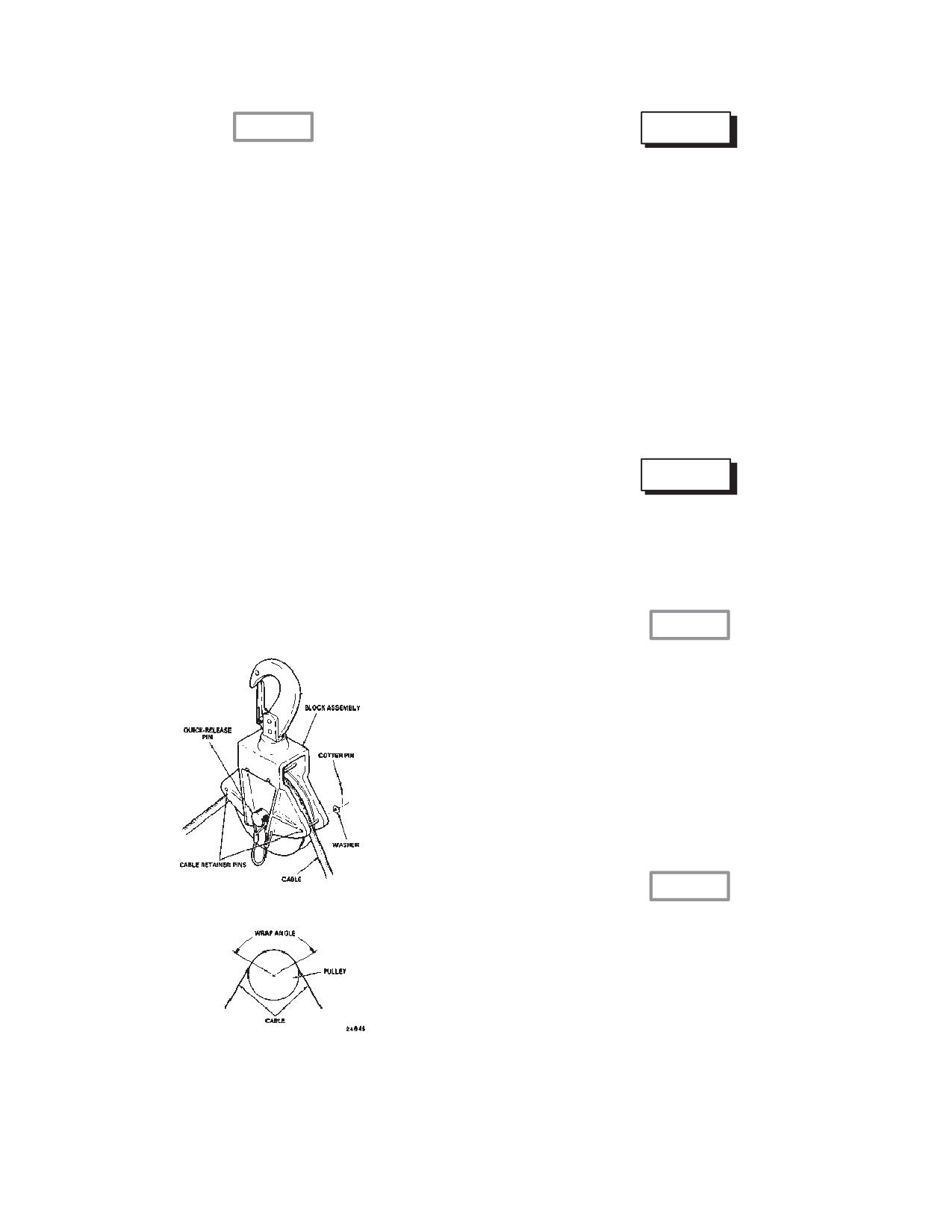
Some pulley block assemblies have
be installed during rescue and cargo op-
flanges with cable retainer pins as shown
erations. Otherwise, the hook assembly
in fig. 4-3-9 (Sheet 1 of 2). These pins
can be inadvertently disconnected from
should be installed only if the cable makes
the winch cable which can result in loss of
a wrap angle of 180_ or more around the
life or the load or serious injury to operat-
ing personnel. For personnel rescue, the
pulley. Otherwise, the cable will bind on
cable must touch the ground or water
the pins and overload the winch and cable.
prior to touching personnel or a danger-
When not in use, the pins and attaching
ous static electrical shock may result.
hardware should be stowed in the contain-
(4)
Attach the winch cable to the cable hook
er provided for the hoist accessories.
assembly by depressing the lock rings on each end of the
quick-disconnect device, inserting the ball ends of the
winch and hook assembly cables into the quick-discon-
(2)
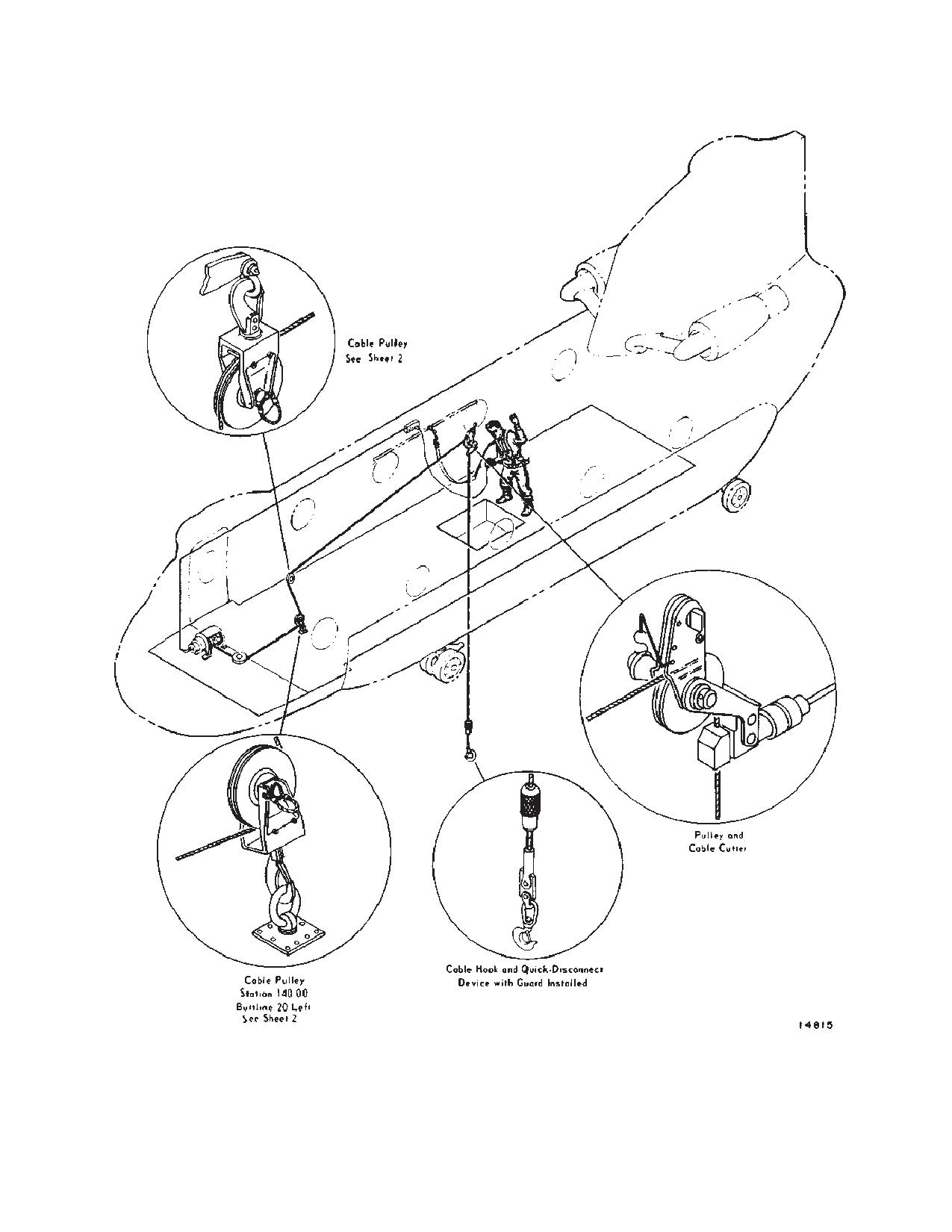
Install the pulley block assembly on the floor
nect device and releasing the lock rings. Install the quick-
at sta 140, the overhead on the aft face of sta 120 bulk-
disconnect cover guard.
head and the cable cutter pulley block over the rescue
hatch (fig. 4-3-9 (Sheet 2 of 2)).
WARNING
(3)
Reeve the cable through the pulley at each
Slack must be removed from the cable
train before applying the full load to the
location by first removing the quick-release pin, removing
winch system to prevent shock and over-
the pulley and positioning the cable over the pulley. Rein-
load of the system and possible injury to
stall each pulley and secure with the quick-release pin
the personnel being hoisted.
(fig. 4-3-9 (Sheet 1 of 2)).
CAUTION
Ensure that the load is clear of the ground
and all obstacles before proceeding from
hover to forward flight. Do not exceed 600
pounds. An overload can result in damage
or failure of the support structure for the
overhead cable pulley.
(5)
Reel the cable out and attach the cable hook
to load - Reel in or out as required.
g. When electrical power to the winch is not avail-
able, the winch may be operated in emergency mode as
follows:
CAUTION
When the winch is operated in emergency
mode, the cable limit switches are dis-
abled. To avoid kinking the cable, stop the
winch when there is no less than 3 turns of
cable on the drum. Stop reeling the cable
in when the quick-disconnect guard as-
sembly contacts the pulley and fairlead
(fig. 4-3-1).
(1)
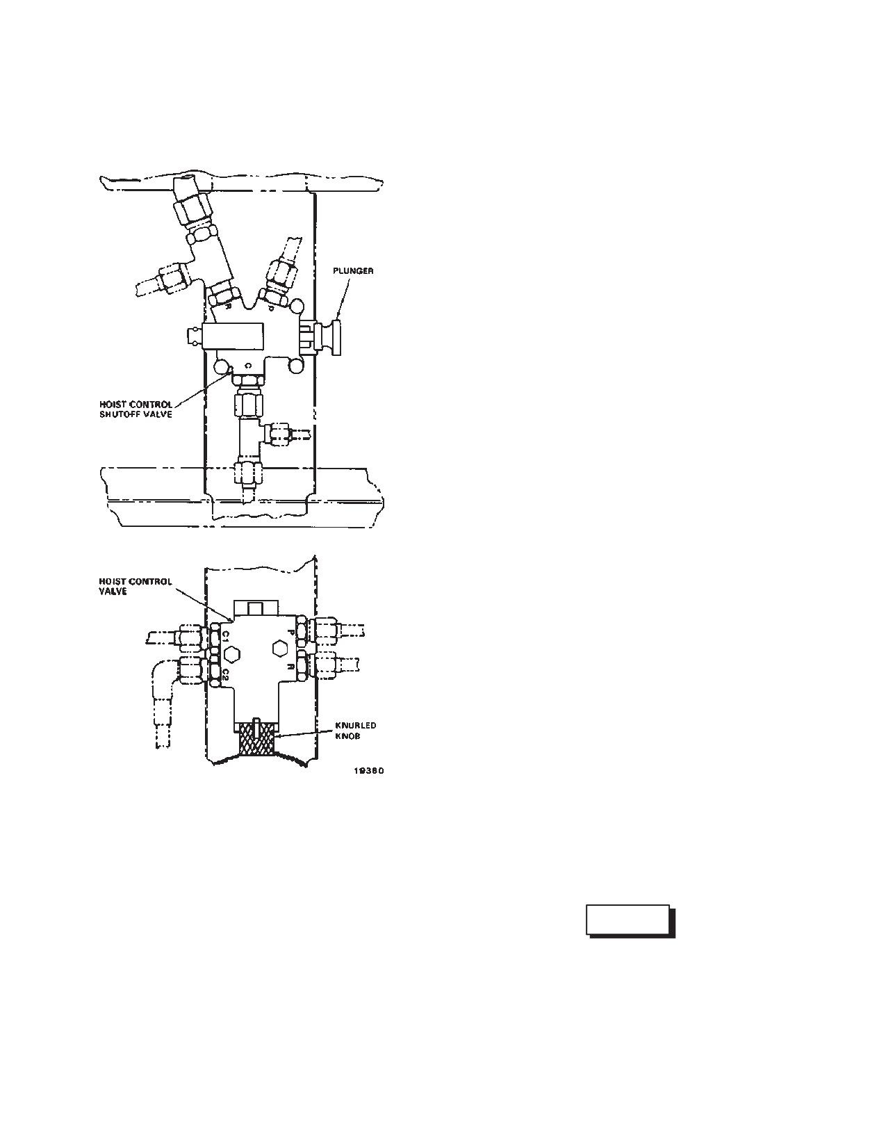
Remove electrical connectors from the hoist
control valve and hoist control shutoff valve on the left
Figure 4-3-9. Hoisting System (Sheet 1 of 2)
bulkhead of the heater compartment (fig. 4-3-10).
4-3-9
TM 1-1520-240-10
(2)
Break the shear wire on the knurled knob of
valve clockwise to reel the cable out or counterclockwise
the hoist control valve.
to reel it in. Return the knob to the center (detent) position
to stop the winch.
(3)
Push in the plunger on the hoist control shut-
off valve and rotate it 90 degrees to lock the valve open.
(5)
When use of the winch is completed, turn the
plunger on the hoist control shutoff valve to unlock and
(4)
Turn the knurled knob on the hoist control
extend it.
4-3-10
TM 1-1520-240-10
Figure 4-3-9. Hoisting System (Sheet 2 of 2)
4-3-11
TM 1-1520-240-10
a. Cable Pulleys. A sufficient number of pulleys are
provided to permit routing the winch cable for winching
and hoisting operations. The pulleys are equipped with
snap-lock fasteners for attachment to tiedown fittings or
shackles as required.
b. Cable Hook. A 2-ton-capacity removable hook is
provided for use in winching and hoisting operations.
Extending from the hook is a length of 1/4 inch cable,
equipped with a metal ball which locks into a quick-dis-
connect device that is used for attaching the hook to the
cable. The full-swiveling hook contains a spring snap
lock to prevent opening of the hook and accidental loss
of cargo.
c. Quick-Disconnect Device. The quick-discon-
nect device permits rapid connecting and disconnecting
of winch cable hooks. The device consists of a short
length of steel with socket cavities at each end. The
sockets are enclosed by spring-loaded rings that rest
against flared rims in either edge of the device. The lock-
rings are depressed to admit the ball ends of the cables
into the sockets and snap into place when released, se-
curing the ball ends of the cables in a positive connection.
A guard is supplied with the quick-disconnect device.
When installed, it prevents the hoist operator from inad-
vertently operating the quick-disconnect device when
assisting a rescued person into the helicopter.
d. Cable cutter. In hoisting operations, there is al-
ways a possibility that the cable hook might snag, result-
ing in critical strain on the hoisting system and restriction
of helicopter mobility. The cable cutter provides a means
of quickly severing the snagged hook by cutting the
cable. The cable cutter consists of a housing, two follow-
er rollers that permit free travel of cable through the hous-
ing, a cutting shell, a ballistic cartridge, and a threaded
receptacle for electrical connector. The cutter housing is
split to allow reeving the cable and is bolted to a pulley
bracket through two holes in the housing. The cable cut-
ter is armed by coupling an arming device to the recep-
tacle in the cutter housing and plugging the device into
the receptacle above the utility hatch marked CABLE
CUTTER. The cable cutter cartridge is to be checked for
total time prior to any hoisting or rescue operations. The
cartridge should not be used after 8 years from date of
manufacture and should also be replaced after 1 year of
installed service life. Cartridges are considered over age
when either limit is exceeded.
Figure 4-3-10. Hoist Control Valve and Hoist
Control Shutoff Valve
WARNING
If personnel are in the cargo compartment
4-3-4. Winching Accessories.
when a load is jettisoned, make sure that
Accessories are provided for winching and hoisting op-
they remain aft of the rescue hatch and
erations. Employment of these accessories is deter-
face away from the cable cutter. The hoist
mined by winch usage. A compartment bag is attached
cable can whip forward when it is cut and
to the bulkhead wall above the winch for stowage of
particles can be ejected from the cable
winching accessories.
cutter.
4-3-12
TM 1-1520-240-10
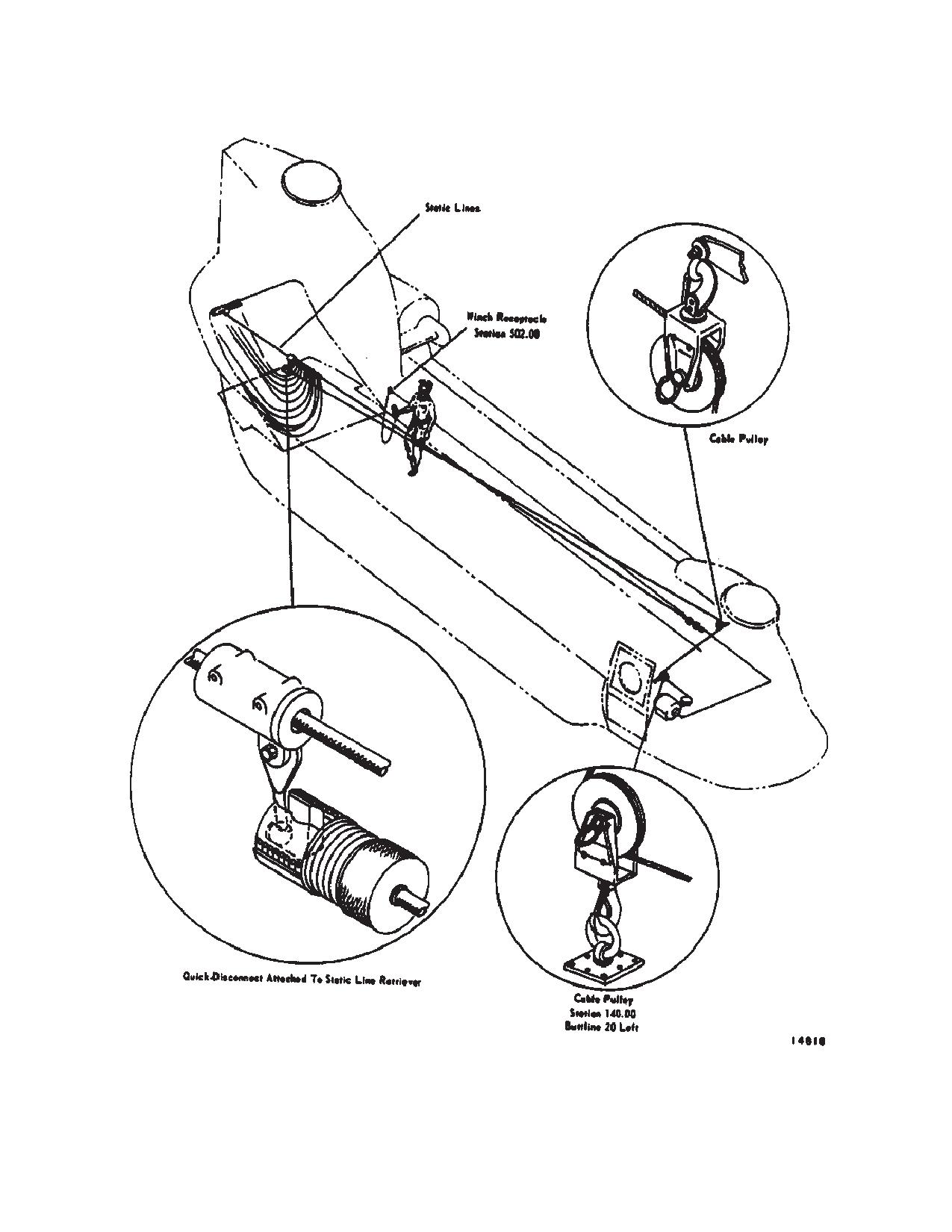
e. Cable Cutter Arming Device. The arming device
a. Install the anchor cable between sta 120 and
consists of an electrical wiring harness with electrical
592.
connectors at either end. This device is used to arm the
NOTE
cable cutter during hoisting operations. A connector at
Do not allow the cable to sag more than 6
one end of the device couples with the threaded recep-
inches.
tacle in the cable cutter; the connector at the other end
of the device plugs into a receptacle above the utility
b. Plug the cable cutter into the auxiliary control
hatch and is labeled CABLE CUTTER.
panel at sta 95 and move the speed selector on the winch
to CARGO.
f.
Extension Cord. A 15-foot extension cord is pro-
vided to allow mobility of the winch or hoist operator.
c. Plug the winch control grip into the power recep-
Electrical connectors at each end of the cord connect
tacle at sta 502 on the left side.
with receptacles in the winch control grip and in the hoist
d. Reeve the winch cable through a pulley attached
control panel. This cord is the only means of plugging in
to a 5,000-pound tiedown fitting at sta 140, buttline 20 left
power to the switches on the control grip.
and then through another pulley attached at sta 120.
g. Safety Harness. A safety harness is provided for
buttline 18 left (fig. 4-3-11).
the hoist operator in operations involving the use of the
e. Reel out enough cable to allow the cable to rest
rescue hatch. The harness permits complete freedom of
on the floor and out of the way of personnel. Attach quick-
movement while affording a measure of safety in pre-
disconnect and cover guard to the winch cable.
venting the wearer from falling through the door opening.
The safety harness is attached to a fitting on the wall of
f.
When the static lines are ready to be retrieved,
the cargo compartment near the hoist control panel or a
reel out additional cable and attach the retriever to the
floor tiedown fitting.
winch cable. Reel in sufficient cable; then disconnect the
static lines from the anchor cable.
4-3-5. Hoisting System.
4-3-7. Triple Cargo Hook System.
The hoisting system (fig. 4-3-9) is used for air rescue and
for aerial loading of smaller general cargo through the
Three external cargo hooks are provided for attaching
external cargo. The hooks can be used with a single load
utility hatch. The hoisting system differs from the winch-
on one hook, two hooks in tandem (forward and aft
ing system only in the manner in which the cable is
hooks), or individual loads on three hooks. The tandem
reeved and the mode selected at the winch. Hoisting
hook configuration provides improved load stability at
operations require the winch cable to be reeved over-
higher airspeeds. With the triple hook system, up to three
head and the hoist load capacity to be limited to a maxi-
loads can be deposited at different locations during a
mum of 600 pounds. The winch cable hook is used for
single mission. The forward hook is at sta 249. The cen-
hoisting operations together with the cable cutter which
ter hook is at sta 331. The aft hook is at sta 409.
provides for quick release of the paid out cable and hook
in event of emergency. On those aircraft provided with
All hooks have normal release modes, emergency re-
pulley block assemblies having pins as shown in (fig.
lease modes, and manual release modes. Normal re-
4-3-9 Sheet 1 of 2), the following instruments apply:
lease mode can be controlled by both pilots or by the
When the hoisting system is reeved as shown in (fig.
hoist operator. Emergency release of all hooks can be
4-3-9 Sheet 2 of 2), the pins and their retaining hardware
performed electrically by either pilot or manually by the
are to be installed only if the cable makes a wrap angle
crew member.
of 180_ or more around the pulley. When not in use, the
pins and their retaining hardware are to be stowed in the
CAUTION
container provided for hoist accessories.
Do not lift or rotate the center cargo hook
WARNING
into the cabin area or allow the mid hook
to lay on the cargo floor or access door
To prevent dangerous electrical shock to
panel during inspection or use. The exces-
personnel being hoisted, the cable must
sive tension placed on the triple emergen-
touch the ground or water prior to contact-
cy release cable housing assembly may
ing personnel.
partially dislodge the housing and engage
or activate the forward and aft hook emer-
4-3-6. Static Line Retriever.
gency release mechanism. This may
cause an inadvertent release of loaded
A static line retriever is provided with the static line an-
forward and aft hook assemblies in flight.
chor cable (fig. 4-3-11). The retriever is used to haul static
lines into the helicopter at the completion of a paradrop
4-3-8. Center Cargo Hook.
mission and can also be used to haul in a paratrooper
hung up on a static line. The static line anchor cable and
The position of the center cargo hook is such that the load
retriever are installed and operated as follows:
is suspended beneath the CG of the helicopter at sta 331.
4-3-13
TM 1-1520-240-10
The hook assembly consists of a hook, hydraulic actua-
4-3-9. Center Cargo Hook Loading Pole.
tor, and a release mechanism. The hook is suspended by
means of a beam which is mounted inside the rescue
WARNING
hatch. This beam rotates within its mounting supports for
longitudinal swing. The hook pivots about its attachment
Make sure the ground cable is connected.
bolt for lateral swing. The cargo hook system is normally
With the rotors turning, static potential be-
operated hydraulically by pressure from the utility hy-
tween the helicopter and a load on the
draulicsystem. In the event of a loss in utility system
ground can be as high as 40,000 volts.
pressure, the cargo hook can be opened pneumatically
A cargo hook loading pole (fig. 4-3-12) is provided for
or manually. The cargo hook contains a spring-tensioned
picking up the sling loop of external cargo loads from
keeper which prevents accidental loss of cargo through
inside the helicopter. The loop is then placed on the cargo
slippage of the sling rings. When not in use, the cargo
hook by hand. The pole has a hook at one end and a
hook can be removed from the hatch since both the elec-
cable at the other end. The cable is attached to the fuse-
trical and hydraulic lines are equipped with quick-discon-
lage to prevent accidental loss of the pole when in use
nectors or the cargo hook can be stowed. The cargo hook
and to provide a discharge path for static electricity.
and beam assembly must be removed for rescue opera-
When not in use, the pole is stowed on the lower right side
tions through the hatch.
of the cabin at about sta 360.
4-3-10. Forward and AFT Cargo Hooks,
The forward and aft cargo hooks (fig. 4-3-14) are at-
tached to bottom centerline of the helicopter at sta 249
and 409. Unlike the center hook, these hooks are not
accessible to the crew in flight. Both hooks have electri-
cal normal
4-3-14
TM 1-1520-240-10
Figure 4-3-11. Static Line Retriever System
4-3-15
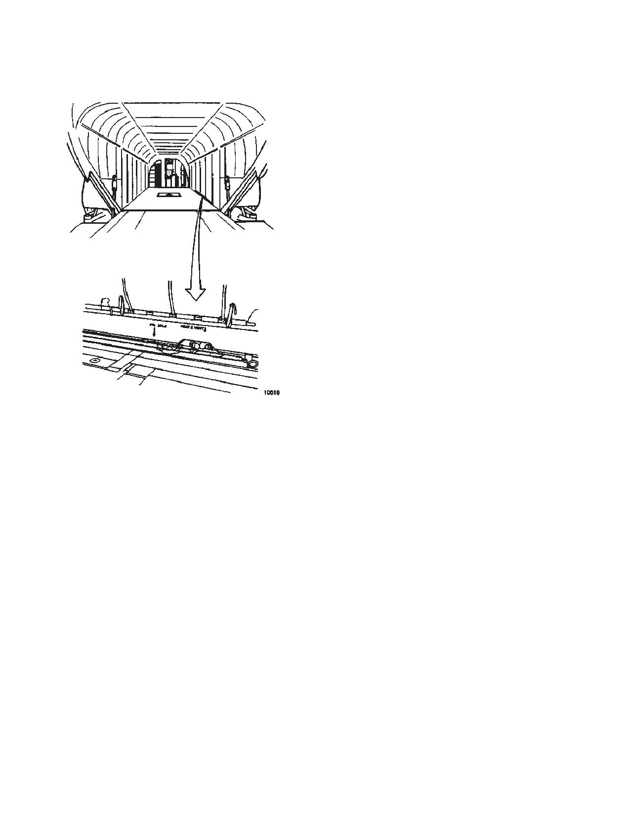
TM 1-1520-240-10
is supplied by the 28-volt DC bus, through the CARGO
HOOK NORM RELEASE PWR and CONT circuit breakers
on the No. 2 PDP. Power to operate and control the emer-
gency release is provided by the 28-volt essential bus
through the CARGO HOOK EMER RELEASE PWR and
CONT circuit breakers on the No. 1 PDP.
a. Cargo Hook MSTR Switch. The CARGO HOOK
MSTR (master) switch is on the CARGO HOOK panel
(fig. 4-3-3) of the overhead panel. The switch has three
positions marked ARM, OFF, and RESET. When the
switch is set to ARM, power is applied to the CARGO
HOOK RELEASE switches on the cyclic sticks and also
to the CARGO HOOK ARMING switch at the hoist opera-
tor’s station. OFF position is used to close the mid cargo
hook. RESET position is used to turn off the FWD, MID,
and/or AFT HOOK OPEN caution capsule(s).
b. CARGO HOOK SEL Switch. The CARGO
HOOK SEL (select) switch is on the CARGO HOOK pan-
el on the overhead switch panel. It is a five position rotary
switch marked HOOK SELECT. The switch positions are
FWD, MID, AFT, TANDEM, and ALL. The position of this
switch determines which hook or hooks open when the
CARGO HOOK RELEASE switch on either cyclic stick or
the hoist operator’s grip is pressed.
c. CARGO HOOK ARM Switch. A CARGO HOOK
ARM (arming) switch is on the hoist operator’s panel (fig.
4-3-8) in the cargo compartment. The hoist operator’s
control panel CARGO HOOK ARM switch has three
marked positions: ARM, RMTE (remote), and RESET.
Figure 4-3-12. Center Cargo Hook Loading Pole
When the cockpit CARGO HOOK MASTER switch is at
(Typical)
ARM, and the hoist operator’s switch is moved to ARM,
and emergency release mechanisms. The normal mech-
power is applied to the CARGO HOOK RELEASE
anisms can be operated by either pilot or by the hoist
switch, on the winch/hoist control grip. When the switch
operator. In an emergency, both hooks can also be re-
is at RMTE, power is removed from the CARGO HOOK
leased from the cockpit through a dedicated emergency
RELEASE switch and the cargo hooks can be operated
release circuit or manually by the hoist operator. A
from the cockpit only. RESET position is used when the
knurled knob on the side of each hook allows the hook to
pilot requests that the center cargo hook be closed from
be opened by a ground crewman. A spring-loaded keep-
the hoist operator’s station. When the switch is set to
er prevents accidental loss of cargo through slippage of
RESET, the CARGO HOOK OPEN cautions will go out.
sling rings. Each hook has a hook-loaded sensor. The
sensor will close and light a hook loaded advisory light
d. CARGO HOOK RELEASE Switches. A CARGO
when the hook load exceeds approximately 150 pounds.
HOOK RELEASE switch is on each of the following: the
Stops on the hook allow the hook to swing approximately
pilot’s and copilot’s cyclic grip, and the winch/hoist con-
80_ between full forward and full aft and approximately
trol grip. Any one of these switches can be used to oper-
50_ full right to full left.
ate the cargo hooks. Each of these switches are the
momentary type. When either the pilot’s or copilot’s CAR-
4-3-11. Cargo Hook Controls.
GO HOOK RELEASE switch is pressed with the CARGO
HOOK MASTER switch at ARM, the hook or hooks se-
The cargo hook control can be operated from the cockpit by
lected on the HOOK SELECT switch will open. The for-
a switch on each cyclic stick grip and switches on the over-
ward and aft hooks will open, then close. The center
head panel (fig. 4-3-3). The hooks can be operated from the
hook, if selected, will open and remain open until the
cargo compartment by a switch on the winch/hoist control
cargo hook MASTER switch on the overhead panel is set
grip (fig. 4-3-7) and switches on the hoist operators panel
to OFF or the cargo hook ARM switch on the hoist opera-
(fig. 4-3-8). Normal power to control the cargo hook system
tors panel is set to RESET.
4-3-16
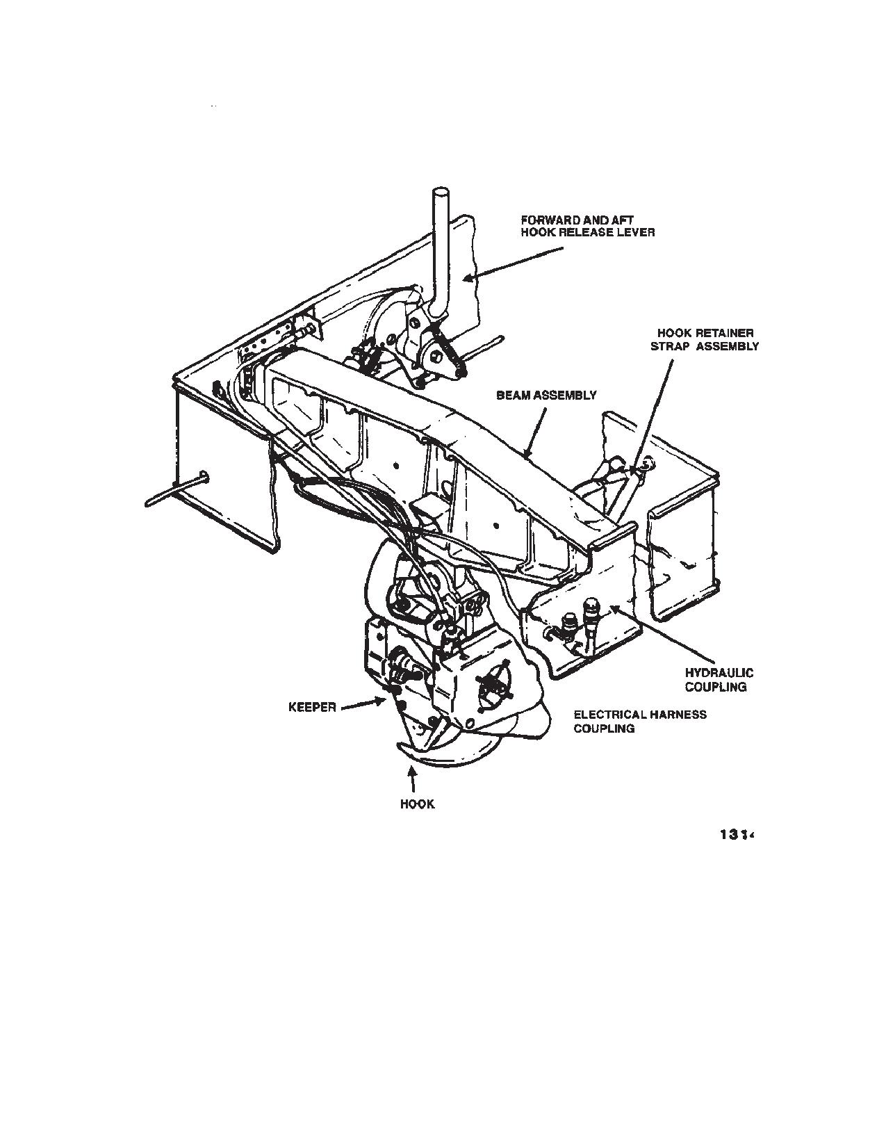
TM 1-1520-240-10
Figure 4-3-13. Center Cargo Hook and Cargo Hook Release
4-3-17
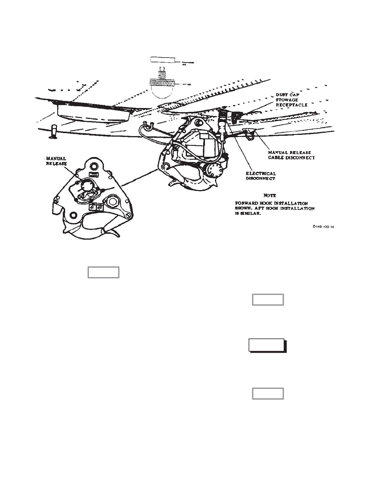
TM 1-1520-240-10
Figure 4-3-14. Forward and Aft Cargo Hooks
emergency hook release relay will automatically deener-
CAUTION
gized after a 10 second time delay. This prevents dam-
age to the hook release solenoids.
The forward and aft hooks may fail to open
if the slings are slack when the release
solenoids are energized (a load of approx-
CAUTION
imately 20 pounds is required for open-
Before external load operations, crew-
ing). The hooks can be opened by select-
members shall familiarize themselves
ing the desired hook(s) and depressing
with the manual emergency cargo release
the release switch as the aircraft is lifted to
mechanism installed on the helicopter
apply tension to the slings.
e. CARGO HOOK EMERG Switch. The emergen-
WARNING
cy cargo hook release switch is on the CARGO HOOK
control panel. It is a guarded switch and it is labeled
When the center cargo hook is opened
EMERG REL ALL (emergency release all). The switch is
with the external load off the ground, the
used to simultaneously open the three hooks, if an emer-
cargo hook will whip back back and forth.
gency situation develops. The three hooks will open re-
gardless of CARGO HOOK MSTR or HOOK SEL switch
positions. Setting the switch to REL ALL, energizes an
CAUTION
emergency hook release relay. The relay then energizes
release solenoids in the forward and aft hooks and a
When the center cargo hook is opened us-
solenoid valve in the center hook. The solenoid valve in
ing the manual emergency release handle,
the center hook releases the aircharge stored in the low-
the hook must be closed manually. No at-
er half of the hydraulic actuator, transferring the charge
tempt should be made to close the hook
to the upper (release) half of the actuator to open the
using the normal hydraulic or pneumatic
hook. After this method of opening the hook, the hook
method, since damage to the cargo hook
actuator must be recharged to 2,000 to 2,100 psi. The
can result.
4-3-18
TM 1-1520-240-10
4-3-12. Manual Release System.
4-3-16. Cargo Hooks Operational Check.
NOTE
WARNING
Depending on the mission requirement, the
When stowing or positioning the cargo
manual release lever may be positioned in the
hook, do not grasp the hook assembly by
forward or stowed position.
the synchronizing assembly shaft. Seri-
The manual emergency release lever for all three cargo
ous injury can result if the hook is oper-
hooks is located on the right side of the rescue hatch
ated while the hand is in this position. The
door. The lever is connected by cables to the manual
nylon web strap is to be used when posi-
release mechanism in each hook. The lever has three
tioning or stowing the hook.
positions; forward, vertical, and aft. In the forward posi-
Before external load operations, perform the following
tion the lever is stowed. In the vertical position the lever
check of the cargo hooks.
is in the normal position when external cargo is carried
1. CARGO HOOK MSTR switch - ARM.
on any of the hooks. In the aft position the lever releases
all hooks simultaneously, loaded or not.
2. CARGO HOOK SEL switch - FWD.
3. Press the CARGO HOOK RELEASE switch
on the pilot’s cyclic stick - Check that the
4-3-13. Cargo Hook Cautions.
FWD HOOK OPEN caution capsule comes
on and the hook opens.
The cargo hook caution capsules are on the master cau-
NOTE
tion panel. They are labeled FWD HOOK OPEN, MID
HOOK OPEN, and AFT HOOK OPEN. A lit caution cap-
The forward and aft hooks will not open unless a force is
sule indicates that the corresponding hook has opened.
applied. As long as one of the CARGO HOOK RELEASE
The cautions can be extinguished by setting the CARGO
switches are pressed, the forward and aft hooks will
HOOK MSTR switch to RESET or by setting the CARGO
make a chattering sound. This sound indicates the hook
HOOK switch on the hoist operators panel to RESET.
solenoids are operating normally.
4. CARGO HOOK SEL switch - MID.
5. Press the CARGO HOOK RELEASE switch
4-3-14. Hook Loaded Advisory Lights.
on the copilot’s cyclic stick - Check that the
MID HOOK OPEN caution capsule comes
Two advisory lights marked HOOK LOADED are on the
on and the hook opens.
CARGO HOOK control panel (fig 4-3-3). The lights are
6. CARGO HOOK SEL switch - AFT.
marked HOOK LOADED. When on, the light indicates
that the corresponding (forward or aft) hook has a load
F 7. Press the CARGO HOOK RELEASE switch
of above approximately 150 pounds on it. The lights are
on the WINCH/HOIST CONTROLGRIP -
turned on by sensors in the forward and aft hooks.
Check that the AFT HOOK OPEN caution
capsule comes on and the hook solenoid
activates. Reset and release to OFF.
8. CARGO HOOK MSTR switch - RESET
WARNING
and release to OFF. Check all HOOK OPEN
caution lights go out and the hooks close.
If the DUAL HOOK FAULT light indicates a
Then set ARM.
malfunction of the forward or aft hook, re-
9. CARGO HOOK SEL switch - TANDEM.
leasing the load using other than the
manual release handle is prohibited.
10. Press the CARGO HOOK RELEASE switch
on the pilot’s cyclic stick. Check that the
FWD and AFT HOOK OPEN caution cap-
4-3-15. Dual Hook Fault Caution.
sules come on and the forward and aft hook
solenoids activate.
A caution capsule labeled DUAL HOOK FAULT is on the
11. CARGO HOOK MSTR switch - RESET
master caution panel. The light provides continuous
and release to OFF. Check both HOOK
monitoring of the electrical continuity of the release sole-
OPEN caution capsules go out and the
noids in the forward and aft hook. When on, it indicates
hooks close. Then set to ARM.
a loss of electrical release capability of the forward and/or
12. CARGO HOOK SEL switch - ALL.
aft hook in both normal and emergency modes. When the
capsule is on, loads on the forward or aft hooks can only
13. Press CARGO HOOK RELEASE switch on
be released by the manual release system.
the copilot’s cyclic stick - Check that all
4-3-19
TM 1-1520-240-10
HOOK OPEN caution capsules come on
4-3-19. Helicopter Internal Cargo Handling System
and the hooks open or the solenoids acti-
(HICHS).
vate.
An internal cargo handling system is provided for quick
14. CARGO HOOK MSTR switch - RESET
loading securing and unloading of palletized cargo (fig.
and release to OFF. Check all HOOK OPEN
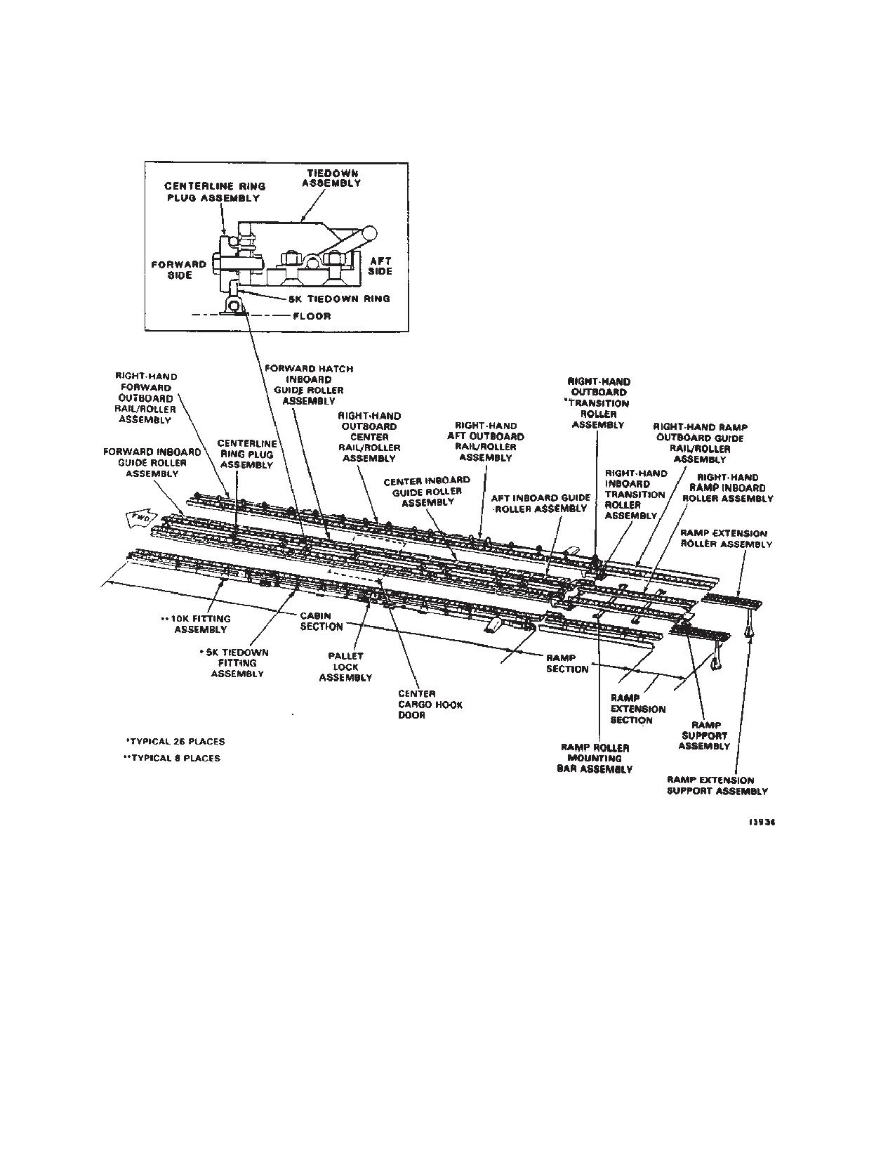
4-3-15 and 4-3-17). The system consists of a set of rail
cautions go out and the hooks close.
assemblies and guide roller assemblies that are secured
to the helicopter floor. For descriptive information, ser-
15. To confirm safety of the cargo hook system,
vice/maintenance instructions. operation, installation
the pilot, copilot, and flight engineer each
and removal instructions, refer to TM 55-1680-358-12 &
press a CARGO HOOK RELEASE switch to
P.
attempt to open cargo hooks with the CAR-
The system has three main sections: a cabin section, a
GO HOOK MSTR switch at OFF.
ramp section, and a ramp extension section (fig. 4-3-17).
The cabin section has outboard rail/rollers along both
4-3-17. Normal Operation of Cargo hooks.
sides of the cabin, and inboard guide rollers running
Normal operation of the cargo hooks from the cockpit or
along the center of the cabin. There are six outboard
from the cargo compartments is as follows:
rail/roller assemblies, three on each side of the cabin.
Each of the six rail/roller assemblies has its own dedi-
1. CARGO HOOK MSTR switch - ARM. (If
cated location in the helicopter. The left and right side rail/
used from the cockpit or the cargo compart-
roller assemblies are symmetrically opposite. There are four
ment.)
inboard guide roller assemblies mounted in the center of the
cabin floor. All of the outboard and inboard guide roller as-
2. HOIST OPERATORS PANEL CARGO
semblies are installed by being bolted to the existing tiedown
HOOK switch - ARM. (if used from the
fitting locations in the cabin floor.
cargo compartment.)
The system is equipped with a set of locking devices and
3. HOOK SEL switch - ROTATE to hook or
tiedown fittings for securing loaded cargo.
hooks to be released.
NOTE
4. CARGO HOOK RELEASE switch - Press.
All cargo must be properly restrained to en-
(From either the cockpit or the cargo
sure safe operation of the helicopter and the
compartment)
safety of personnel. Loads must be restrained
in accordance with procedures and guide-
5. Master caution panel - Check HOOK
lines in Chapter 6 and TM 10-450-2, Helicop-
OPEN cautions come on.
ter Internal Loads.
6. Loads - Check released. If the forward or
The ramp section has two inboard roller assemblies along
aft hooks did not open because of sling
the center of the ramp and two outboard guide/roller assem-
slack, press the release switch and lift the
blies along the sides of the ramp. A ramp support assembly
helicopters to apply a strain to the sling and
is used to support the ramp when loading or unloading the
pull the hooks open.
helicopter with the ramp in the horizontal position
The ramp extension section has two ramp extension roll-
4-3-18. Emergency Operation of Cargo Hooks.
er assemblies and two ramp extension support assem-
Refer to Chapter 9 for emergency operation of cargo
blies to support the ramp extensions when loading and
hooks.
unloading with the ramp in the horizontal position.
4-3-20
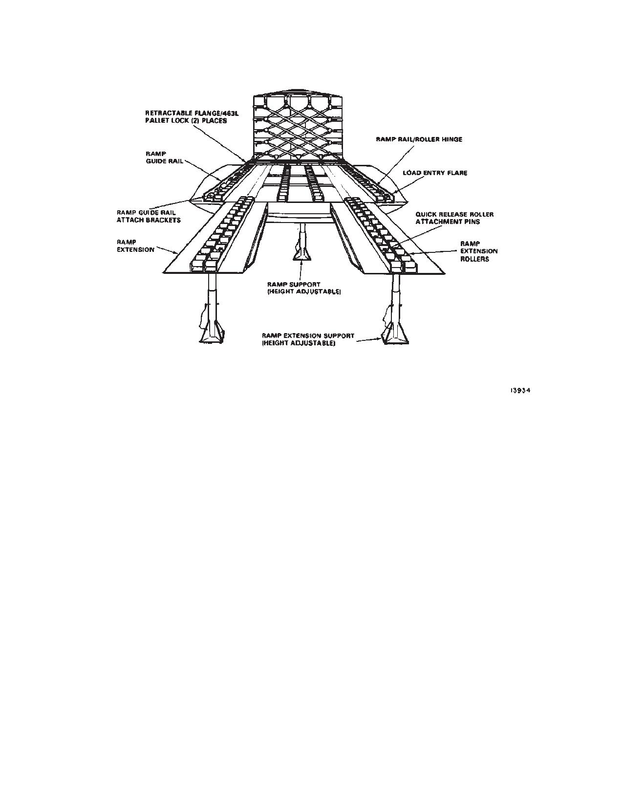
TM 1-1520-240-10
Figure 4-3-15. HICHS with 463L Palletized
4-3-21
TM 1-1520-240-10
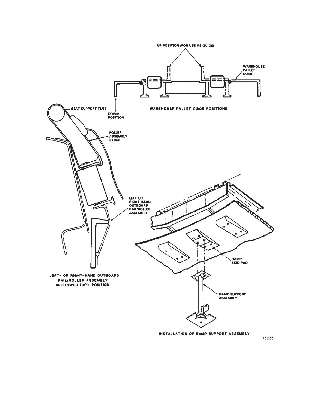
Figure 4-3-16. Fixture Configuration
4-3-22
TM 1-1520-240-10
4-3-20. HICHS Cargo Types.
d. Pallet lock assembly - fig. 4-3-17.
The HICHS allows relatively quick and easy loading of
e. Retractable flange assembly - fig. 4-3-15.
palletized cargo. The following pallet types may be used:
f.
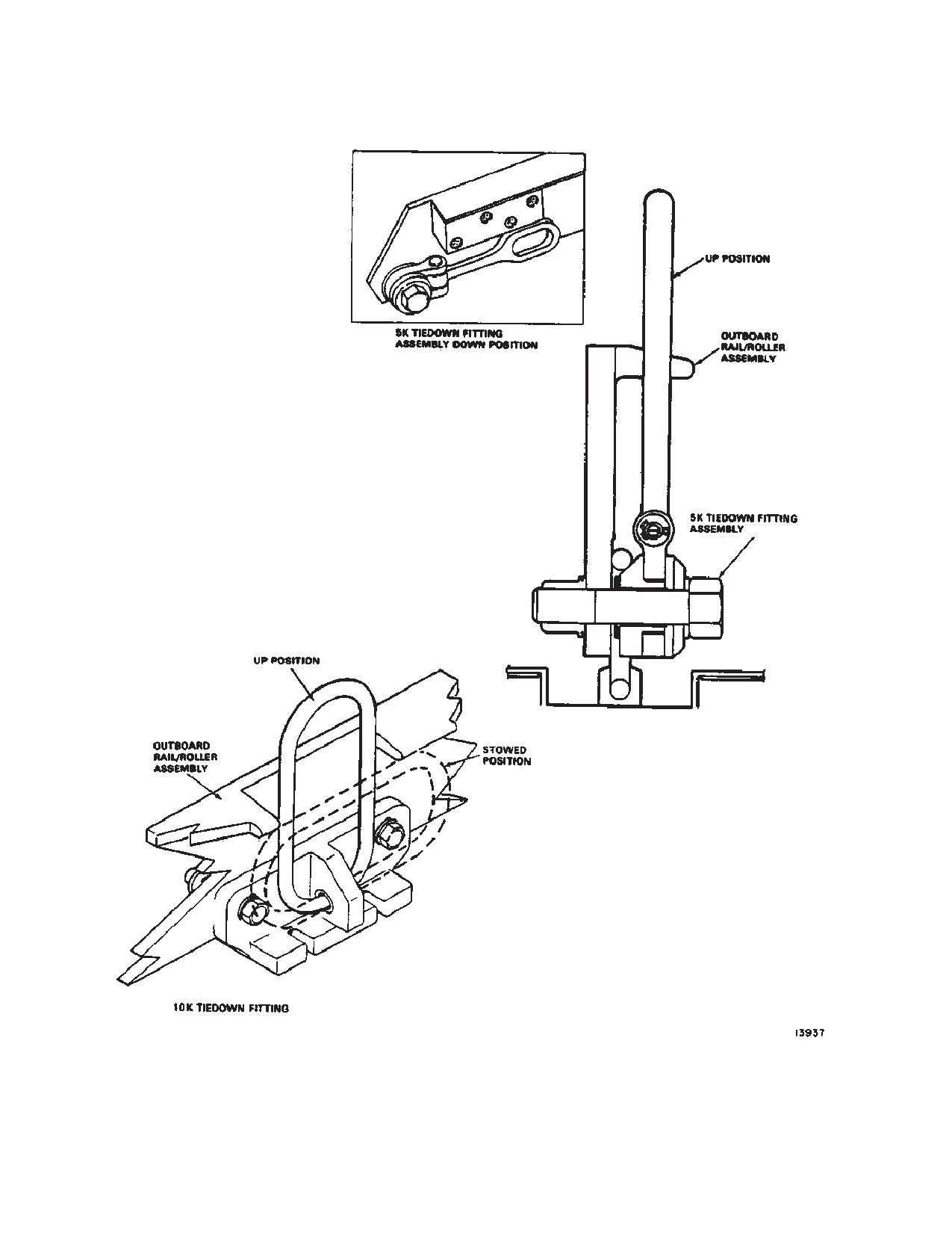
10K fitting assemblies - fig. 4-3-18.
a. Three 436L pallets, 88 x 108 inches.
g. 5K fitting assemblies - fig. 4-3-18.
b. Six HCU-12/E or HCU/C pallets, 54 x 88 inches.
4-3-22. Hatch Access.
c. Eight to ten warehouse wooden pallets, 40 x 48
inches.
Remove, if necessary, any cargo forward of sta 377.250
to at least sta 157.750.
The HICHS has provisions for locking and securing 463L
pallets. This type of pallet does not need to be tied down, but
Remove three centerline ring plug assemblies to free the
the cargo must be secured to the pallet. Combinations of
forward hatch inboard guide roller assembly (fig. 4-3-17).
different pallet types may be used. Miscellaneous cargo and
Stow the removed parts ahead of sta 272.250. The hatch
equipment may be carried providing that they do not exceed
is now accessible and the removed parts can be re-
weight or floor loading restrictions, and can be properly tied
installed by reversing the proceeding steps.
down.
4-3-23. System Stowage.
4-3-21. System Configuration.
Flip-up the outboard rail/roller assemblies and secure
The HICHS can be placed in any of four configurations.
the seat support tube as shown in fig. 4-3-16. Secure
These are loading, restraint, flight and unloading. Refer to
loading pole to clips located at the top of the buffer board
Chapter 6 for configurations applicable to 463L pallets,
between sta 300 and 400 on right side of helicopter with
warehouse pallets, and wheeled vehicles.
quick release pin. Inboard guide roller assemblies can be
stowed on the floor beneath the troop seats. Secure
To accomplish the configuration described above and in the
ramp extension rollers to the underside of the ramp ex-
referenced tables, several components must be set in a
tensions with quick release pins. Stow ramp extension
predetermined position. These components are listed below
supports on the left side of the helicopter in brackets
in conjunction with the illustration that defines the compo-
mounted between sta 520 and 534. Stow ramp support
nent location or position.
at sta 550 left side.
a. Outboard rollers - fig. 4-3-16.
4-3-24. Load Configuration and Sequence.
b. Warehouse pallet guides - fig. 4-3-16.
Chapter 6 contains the detailed descriptions and proce-
c. Ramp support assembly - fig. 4-3-16.
dures for load configuration and sequence.
4-3-23
TM 1-1520-240-10
Figure 4-3-17. Internal Cargo Handling System
4-3-24
TM 1-1520-240-10
Figure 4-3-18. Tiedown Fittings HICHS
4-3-25/(4-3-26 blank)
TM 1-1520-240-10
SECTION IV. EXTENDED RANGE FUEL SYSTEM (ERFS) AND ERFS II
4-4-2. Extended Range Fuel System II.
WARNING
The Extended Range Fuel System II (ERFS II) is an
internal tank fuel system that provides the CH-47D with
The ERFS is a non-crashworthy auxiliary
the ability to fly for an extended period of time without
fuel system. The use of a non-crashworthy
having to land for refueling. The ERFS II may be installed
internal extended range fuel system may
in one, two or three tank applications in addition to the
compromise the helicopters crashworthi-
Forward Area Refuel Equipment (FARE) kit installation.
ness and may increase the risk of burns in
Through the use of a FARE kit, the CH-47D can also be
a potentially survivable accident.
used to ferry fuel to forward areas to support refueling
operations of other aircraft and equipment. The system
4-4-1. Extended Range Fuel System
consists of five functional components: the fuel tank as-
sembly with fuel and vent hoses, restraint system, ERFS
The ERFS provides mission flexibility as
II Fuel Control Panel, and FARE kit assembly. Refer-
an extended range mission kit and a for-
ences and illustrations provided describe the three tank
ward area refueling source. The ERFS is
and FARE kit installation. Power is supplied to the ERFS
mounted on the left side of the cabin be-
II from the No. 1 DC BUS and No. 1 AC BUS through LH
tween sta 190 and 450, depending on the
Utility Receptacles and wiring harness to the ERFS II
helicopter CG limits. The ERFS is a modu-
Fuel Control Panel. Refer to TM 55-1520-240-23 and tM
lar, interconnected system composed of
1-1560-312-10 for installation and maintenance proce-
up to four 600 gal non-crashworthy metal
dures.
tanks, four electrically operated fuel
pumps, and a vent system with associated
wiring and plumbing. The tanks are se-
cured using 5K and 10K pound cargo
4-4-3. ERFS Capabilities.
straps. The fuel management control pan-
a. The ERFS provides up to 2320 gallons, (580 gal-
el (FMCP) is housed in an aluminum box
lons maximum per tank) of usable fuel for extended
and is mounted on the forward most tank.
range missions.
Refer to TM 55-1560-307-13&P for installa-
tion, operation, and maintenance proce-
b. The ERFS can be installed, operated, removed,
dures.
transported, handled, and stored in climatic conditions of
-32_C to +52_C.
c. The ERFS can be installed and used in a one tank
WARNING
or multiple tank configuration as the mission requires.
d. Fuel quantity can be accurately monitored in
Chains will not be used to tie down the
flight within four percent of the actual quantity using the
ERFS.
liquid level indicators.
e. The ERFS can be refueled using the splash fill or
CAUTION
pressure fill techniques.
FMCP will not be operated without fuel in
f.
The system can also be defueled using standard
the tank(s), or with tank cam lever in the
equipment.
CLOSED position.
g. The ERFS has redundant fuel feed capability in
all pump/tank combinations.
CAUTION
h. Fuel transfer pump system can operate with
A fuel sample is required before the first
APU, engine, or external power applied.
flight of the day.
i.
The ERFS can be used as a forward area refuel-
ing equipment (FARE) system, providing 2320 gallons of
CAUTION
fuel for refueling other helicopters.
Hot refueling is not recommended.
4-4-4. Fuel Tank Assembly.
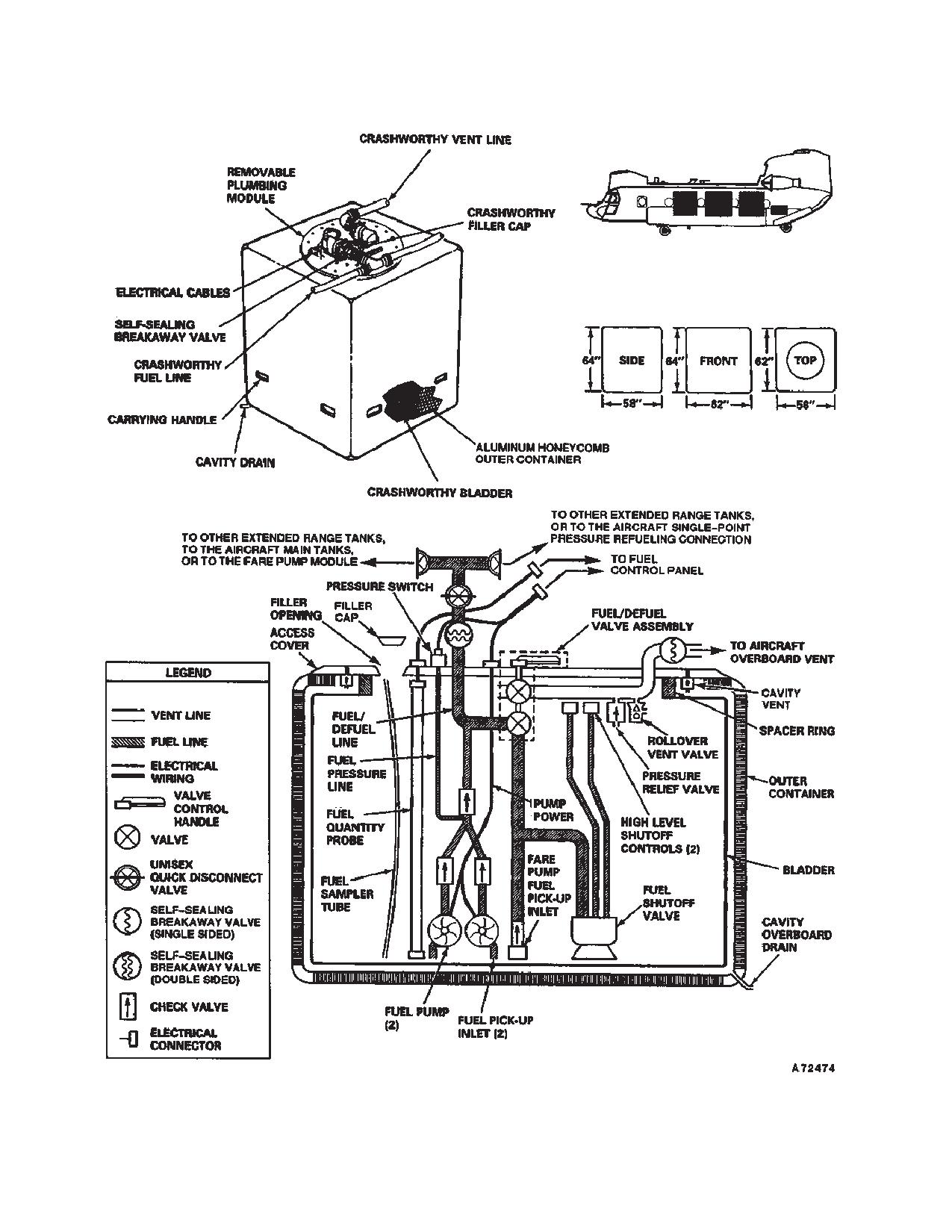
The ERFS II fuel tank assembly consists of an outer
NOTE
aluminum honeycomb and fiberglass shell container,
For clarity, the tanks are numbered front to
ballistically self-sealing bladder, plumping module, fuel
rear 1,2,3,4. In order to maintain helicopter
hose, vent hose assembly, and ground cable. Each tank
CG, suggested tank burn is 4, 1, 3, 2.
measures 58 inch L x 62 inch W x 64 inch H with the
4-4-1
TM 1-1520-240-10
capacity of 800 to 820 gallons of usable fuel and empty
b. Vent Hose Assembly. Aircraft overboard vents
weight of approximately 607 pounds (fig. 4-4-1). ERFS
and connections are installed on the left side of the cabin
II tanks are designed to be loaded and unloaded by four
area through the fuselage at STA 254.0, 330.0, and
persons (with restraint system in place) in no more than
410.0. Overboard fuel vent caps must be removed any-
10 minutes and require no tools. The tanks should not be
time internal fuel tanks are installed. Vent hoses are con-
unloaded with any quantity of remaining fuel. When the
nected to the tank vent line at the self-sealing breakaway
tanks are installed there is an aisle up the right side of the
valve on the top of the tank assembly and one of the three
aircraft which is approximately 25 inches wide. The
aircraft overboard vent connections.
plumbing module consists of an aluminum access cover
secured to an energy-absorbing aluminum tube or col-
umn. The in-tank plumbing components are attached to
a column in the center of the tank permitting easy remov-
CAUTION
al and maintenance on components. A 75 psi fuel cap,
dual transfer pumps, fuel quantity probe, fuel sampling
tube, and a fuel pressure switch are the internal parts of
Trying to pressure refuel the tanks without
each of the tanks. Refueling the ERFS II tanks is per-
connecting the vent line could overpres-
formed by either the helicopter Single Point Refueling
surize the tanks.
System or gravity.
a. Fuel Hoses. An interconnecting fuel hose man-
The vent hose assembly allows the venting to atmo-
ifold connects the ERFS II tanks together. A two inch
sphere of fuel vapor, thus providing vent air to relieve
hose connected at the forward end of the ERFS II fuel
internal tank pressures. Fuel hoses and manifold are
manifold is connected to the helicopter Single POINT
self-sealing incorporating Unisex couplings. Each Uni-
Refueling System in the vicinity of STA 225 on the left
sex coupling, ballcock valve, permits hose removal with-
side of the cargo compartment. Fuel transfer hoses con-
out fuel spillage. The manifold also provides connection
nected at the aft end of the manifold carry fuel to the
to the FARE pump module. The fuel/defuel valve is a
aircraft fuel system quick disconnects at STA 380 on both
manually operated vented valve that simultaneously
left and right sides of the cargo compartment.
opens a high flow rate fuel path in the fuel/defuel line, and
a high flow rate vent path out of the tank. The valve must
CAUTION
be open for pressure refueling of the tanks, FARE opera-
tions, or suction defueling. An automatic fuel shutoff
Up to 4 OZ. of fuel can be trapped between
valve, with dual high level shutoff controls is located in-
the closed “Dry Break” valves in the Uni-
side the tank. Inside each of the tanks is an open vent
sex couplings. Care should be taken to
valve to allow fuel to vent overboard in the event of high
minimize spillage of this trapped fuel
level shutoff valve failure.
when separating the couplings.
4-4-2
TM 1-1520-240-10
Figure 4-4-1. ERFS II Fuel Tank
4-4-3
TM 1-1520-240-10
4-4-5. Restraint System.
culation inside the tank. An OPEN valve on a
non-transferring tank will result in fuel transfer
Each tank restraint system consists of an aluminum
into that tank if it is not full.
frame and straps of polyester webbing with connecting
b. Unisex valves in ERFS II fuel transfer hose as-
hardware and ratcheting buckles. This system provides
sembly - OPEN.
longitudinal, vertical, and lateral restraint. The forward,
vertical, and lateral restraint ratings are 8g’s and the aft
c. Select the ERFS II tank from which fuel is to be
rating is greater than 3g’s. Each of the buckles are con-
transferred.
nected to twelve 5,000 pound tiedown rings on the heli-
copter cargo floor.
d. PUMP switch for the selected tank - OVERRIDE.
Hold in this position until PRESS LOW light goes out
4-4-6. ERFS II Fuel Control Panel.
(normally less than five seconds). When released, the
spring-loaded switch will return to the ON position and
All transfer of ERFS II fuel into the helicopter main fuel
fuel transfer will continue.
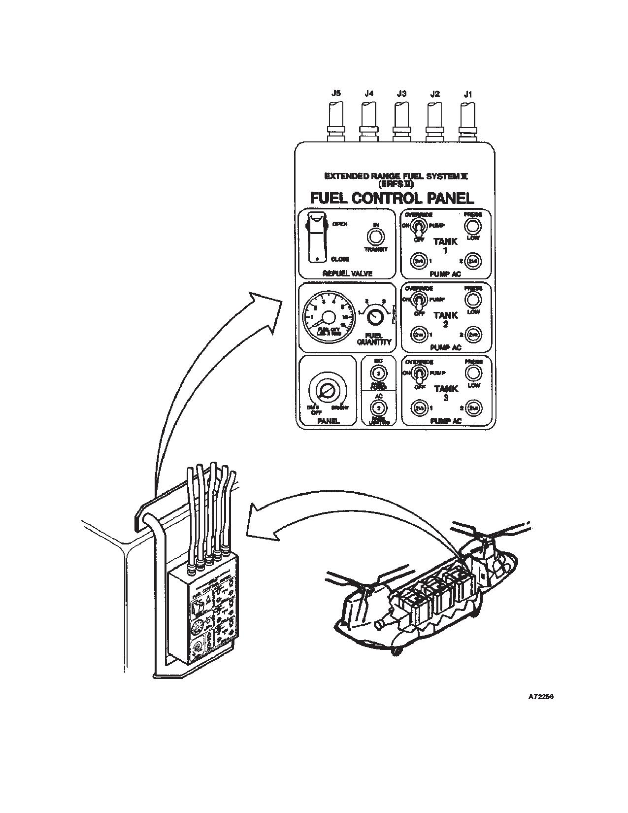
tanks is controlled by the ERFS II Fuel Control Panel (fig.
4-4-2). The control panel is located and mounted on the
e. Monitor the helicopter fuel indicators to verify fuel
forward most ERFS II tank facing forward. It has individu-
transfer.
al switches that control the operation of the transfer
f.
PUMP switch for selected tank - OFF when di-
pumps and circuit breakers to protect each of the pumps
rected by the pilot or when the PRESS LOW light illumi-
in the tank. Illumination is controlled by a dimmer rheo-
nates.
stat on the fuel control panel and is night vision goggles
(NVG) compatible. Electrical cables run from cargo
g. FUEL QUANTITY switch - Set to 1, 2, or 3 for
compartment AC and DC utility outlets at STA 358 and
selected tank to confirm desired amount of fuel trans-
320 to the ERFS II fuel control panel, and from the panel
ferred.
to connectors on each tank. A fuel quantity gauge is
4-4-8. Forward Area Refuel (FARE) Kit Assembly.
installed on the panel to provide readings in pounds of
fuel for the individual tanks and their combined total fuel
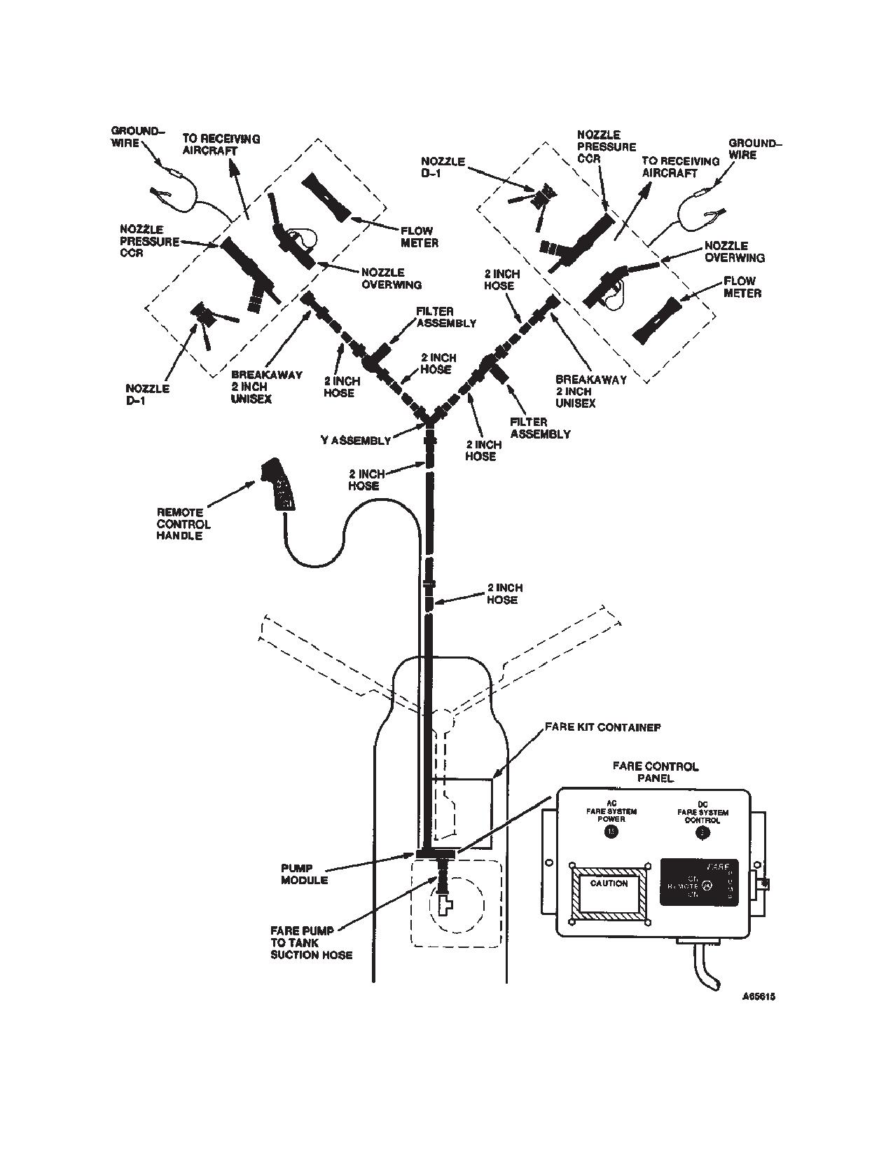
The FARE kit contains a pump module with a self-priming
remaining.
pump rated at 120 GPM and Flowmeter. The pump can
be used to either fuel or defuel the ERFS II tanks. The
4-4-7. Fuel Transfer to Helicopter Main Tanks.
pump module easily mounts on any one of the tanks
a. Manual FUEL/DEFUEL valve in all installed
when used. A manually operated valve reverses the fuel
ERFS II tanks - CLOSED.
flow and permits defueling of the hoses after FARE op-
eration. Two in-line, multiple cartridge filters capable of
NOTE
filtering out 5 micron absolute particulates are included
An OPEN manual FUEL/DEFUEL valve on
as part of the FARE kit. The 45 inch x 44 inch x 35 inch
the transferring ERFS II tank will significantly
container for FARE component storage is secured to the
reduce the transfer rate because of fuel cir-
cargo floor (fig. 4-4-3).
4-4-4
TM 1-1520-240-10
Figure 4-4-2. ERFS II Fuel Control Panel
4-4-5
TM 1-1520-240-10
Figure 4-4-3. ERFS Fuel System Schematic
4-4-6
TM 1-1520-240-10
4-4-9. FARE Transfer.
g.
FARE PUMP switch - REMOTE.
h.To begin FARE transfer.
CAUTION
i.
Remote Control Handle trigger switch
-
Squeeze.
Some fuel will remain trapped in the FARE
pump module, suction hose, filters, and
When FARE transfer is complete:
collapsible hoses after suctioning and
j.
FARE Valve Control Handle - SUCTION.
rolling of the FARE hoses has been com-
pleted. To avoid spilling trapped fuel, the
k.
Valves in the Unisex couplings adjoining the
valves in the Unisex couplings must re-
nozzle(s), and filter(s) - CLOSE. Remove nozzles and
main closed and the couplings capped af-
filters from dispensing hoses, replace dust caps, and
ter the FARE system is disassembled. All
stow in FARE container. Reconnect hoses. Valves in the
trapped fuel should be drained into an ap-
Unisex couplings, except at nozzle end - OPEN. Valve
propriate container when the operational
in Unisex coupling at far end of hose assembly -
situation permits.
CLOSE.
l.
Remote Control Handle trigger switch
-
WARNING
Squeeze to suction fuel from hose assemblies and return
it to tank. While the FARE pump is running, slightly open
the Unisex valves at the nozzle ends of the collapsible
The manually operated FUEL/DEFUEL
hoses to permit the pump to evacuate most of the fuel
valve must be placed in the CLOSED posi-
prior to rolling the hose.
tion following FARE operation. Failure to
do so could permit significant fuel leakage
m. Collapsible Fuel Hose Assemblies - Lift and
in the event of a crash and the vent self-
tightly roll from the nozzle end toward the pump module
sealing breakaway valve fails to actuate.
while the pump is suctioning fuel from the hose. Close the
valves in the Unisex couplings as they are reached in the
a. Single-Point Pressure Refueling Hose Assembly
disassembly process. Disconnect the hoses, replace
- Unisex valve at ERFS II tank - check CLOSE.
dust caps, and stow in the FARE container. Repeat this
b. Valve in the base of the Unisex “T” coupling on
process until all collapsible fuel hose assemblies are
tanks that are NOT the fuel source - CLOSE.
recovered.
c. Valve in the base of the Unisex “T” coupling on
n. Remote Control Handle trigger switch - Re-
tank that is the fuel source - OPEN.
lease.
d. Manual FUEL/DEFUEL Valve on the tank that is
o. FARE PUMP switch - OFF.
the fuel source - OPEN.
p. Manual FUEL/DEFUEL valve(s) - CLOSED.
e. FARE Valve Control Handle - OFF-LOAD.
q. Valve in the base of the Unisex “T” coupling on all
f.
Flowmeter DISPLAY button - Press until TOTAL
tanks - check OPEN.
2 is displayed. Press and hold three seconds to zero
batch total.
4-4-7/(4-4-8 blank)
TM 1-1520-240-10
CHAPTER 5
OPERATING LIMITS AND RESTRICTIONS
SECTION I. GENERAL
5-5-1. Purpose.
derive maximum utility from the aircraft. Limits concern-
ing maneuvers, weight, and center of gravity limitations
This chapter identifies or refers to all important operating
are also covered in this chapter. If any operating limita-
limits and restrictions that shall be observed during
tions are exceeded, an entry will be made on DA Form
ground and flight operations.
2408-13-1.
5-5-3. Minimum Crew Requirement.
5-5-2. General.
The minimum crew required to fly this helicopter is two
The operating limitations set forth in this chapter are the
pilots, and flight engineer. Additional crewmembers, as
direct result of design analysis, test, and operating exper-
required, will be added at the discretion of the command-
ience. Compliance with these limits will allow the pilot to
er, in accordance with pertinent Department of the Army
safely perform the assigned missions and to
directives.
5-1-1/(5-1-2 blank)
TM 1-1520-240-10
SECTION II. SYSTEM LIMITS
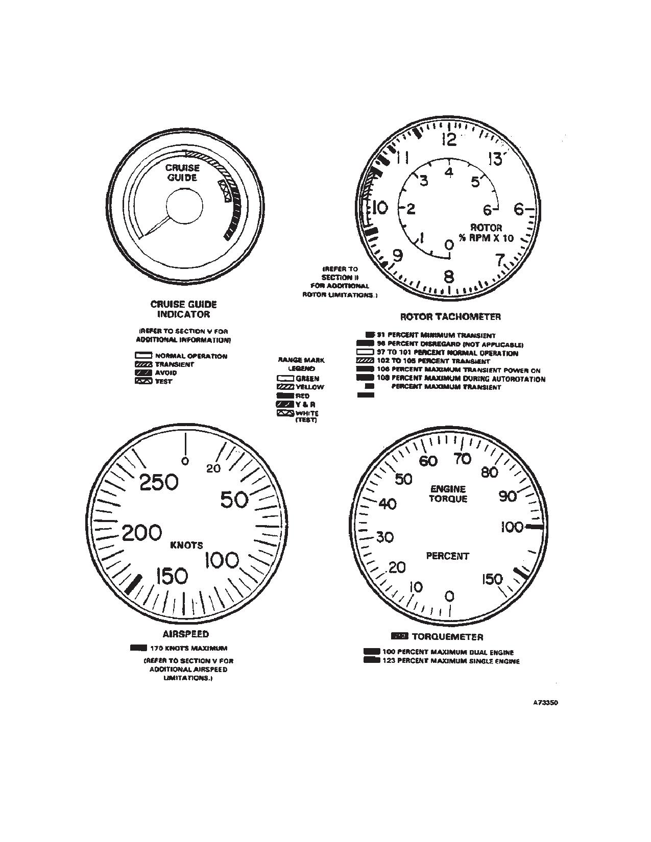
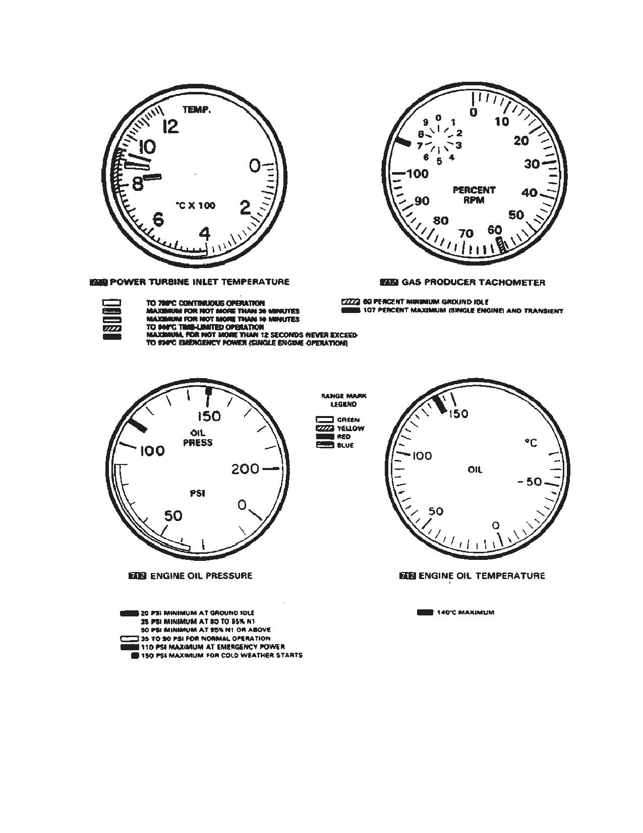
5-2-1. Instrument Markings.
5-2-4. Rotor Limitations.
Refer to figure 5-2-1 for limitations. Should 108 percent
5-2-2. Instrument Marking Color Codes.
power off be inadvertently exceeded, no entry need be
made in DA Form 2408-13-1 unless the rotor system
Operating limitations and ranges are identified by the
accelerates to 111 percent or above. Even though no
colored markings on the dials of engine, flight and utility
action is required when RPM exceed 108 percent power
drive train system instruments. The RED markings on the
off but remains less than 111 percent, willful operation
dials of these instruments indicate the limit above or be-
should not be conducted in this range. Operation be-
low which continued operation is likely to cause damage
tween 96 and 92 percent is permitted when water taxiing.
or shortened life, white background may be utilized to
highlight RED markings. The GREEN markings on in-
5-2-5. Inoperative Cruise Guide Indicator.
struments indicate safe or normal range of operation.
Flight at or below 98 percent RRPM with an inoperative
The YELLOW markings on instruments indicate the time
cruise guide indicator is prohibited.
limited range or when special attention should be given
to the operation covered by the instrument. Operation is
5-2-6. Starting and Shutdown Limits.
permissible in the yellow range, but should be avoided.
BLUE is a maximum indication associated with sustained
The APU shall not be started with a tailwind in excess of
operation of the related aircraft system for a prescribed
25 knots. Main engines shall not be started with a tailwind
period of time. Limitations (fig. 5-2-1) which are marked
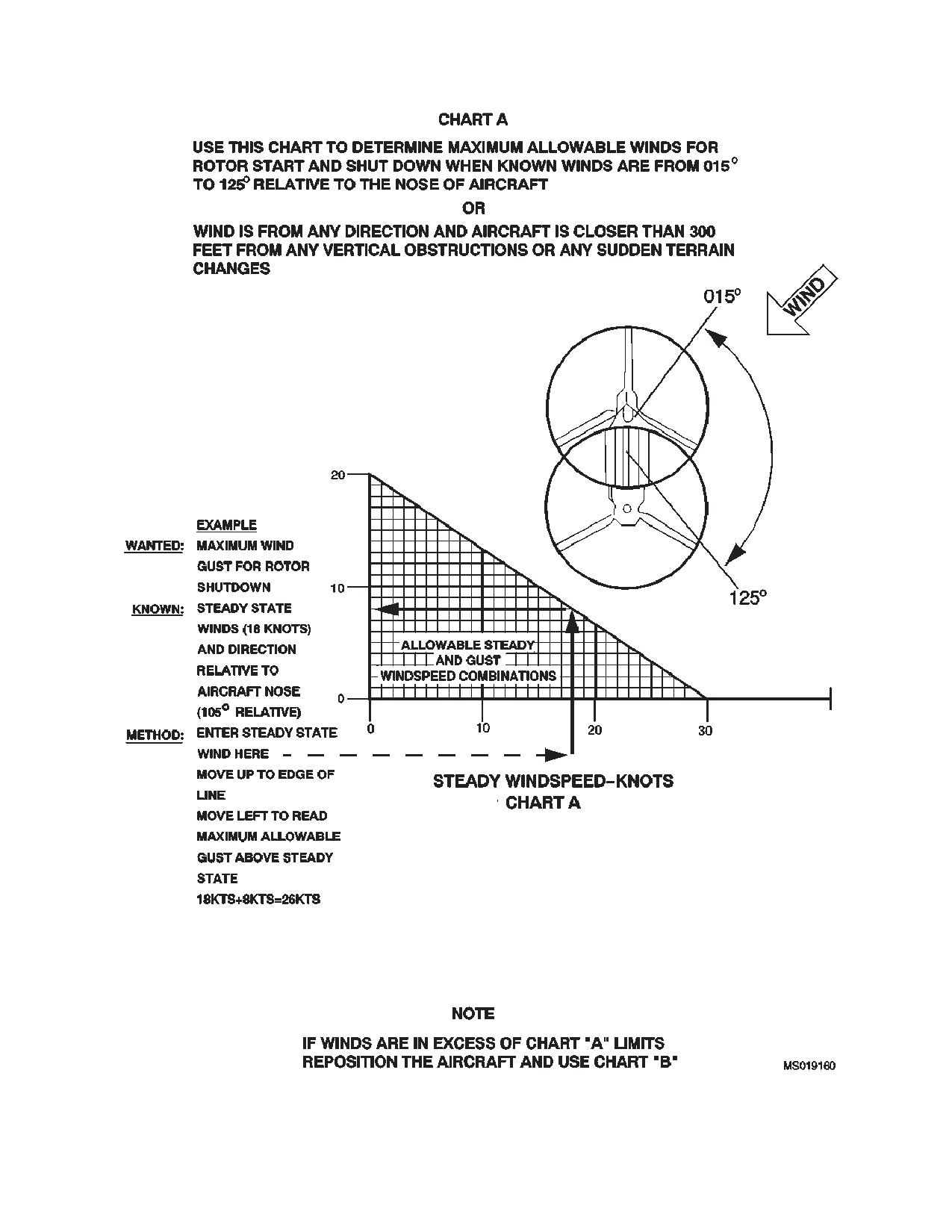
in excess of 10 knots. The rotor blade start-up and shut-
on the various instruments are not necessarily repeated
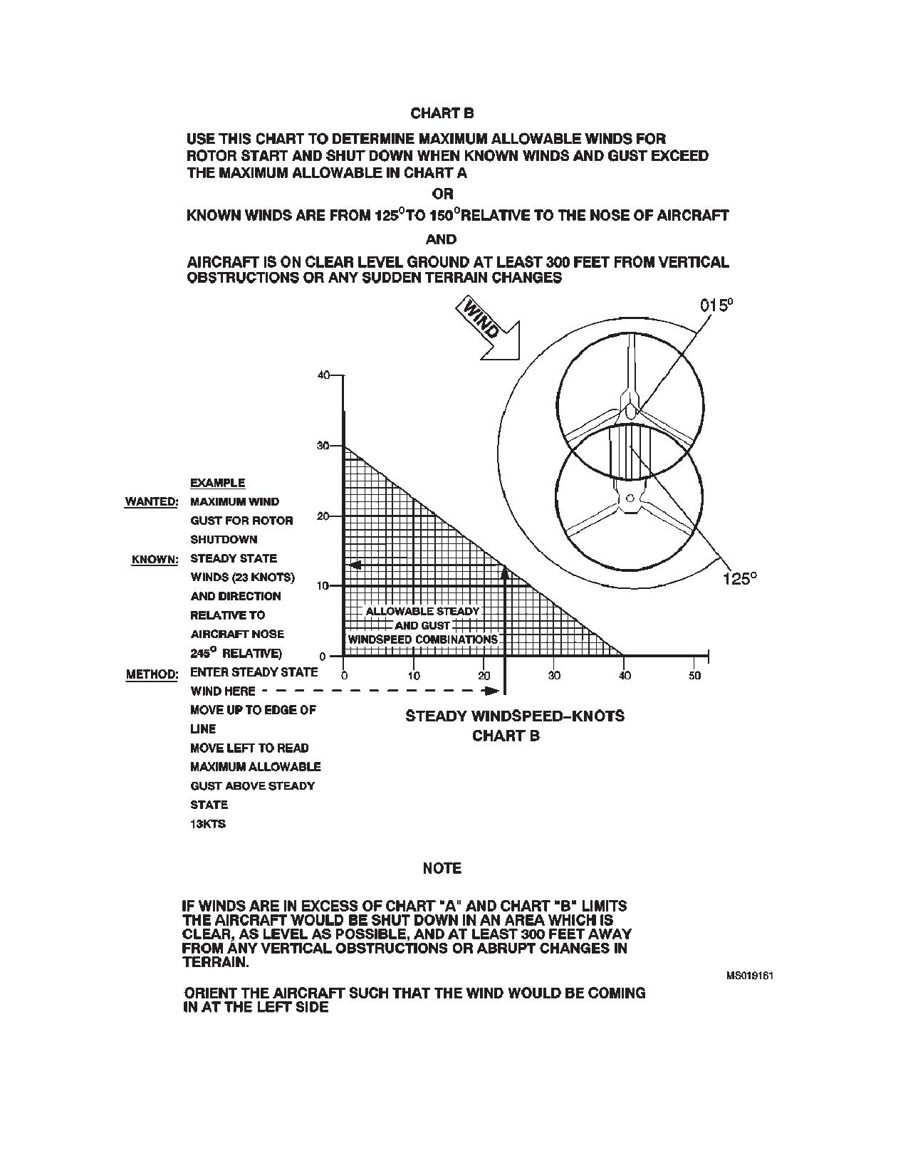
down limits of figure 5-7-1 shall be observed. if it be-
in the subsequent text. When further explanation of cer-
comes necessary to shut down in conditions outside the
tain markings is required, refer to the specific area of
limits shown in figure 5-7-1, the following precautions are
discussion.
recommended:
a. Aircraft should be landed in an area which is
5-2-3. Instrument Glass Alignment.
clear, as level as possible, and at least 300 feet away
from any vertical obstructions, abrupt changes in ground
All instruments with range markings on the glass have
terrain, trees, bushes, fences, etc.
short white alignment marks extending from the dial
glass onto the rim of the indicator. These slippage marks
b. Aircraft should be oriented such that the wind
appear as a single line when limitation markings on the
would be coming in at the left side. If the pilot is unsure
glass properly align with the proper increments on the
of the wind direction after landing, a crew member should
dial face. However, the slippage marks appear as sepa-
be dispatched beyond the rotorwash to make a true wind
rate radial lines when a dial glass has rotated
direction determination before engines are secured.
5-2-1
TM 1-1520-240-10
111
115 PERCENT DISREAGRD (NOT APPLICABLE)
Figure 5-2-1. Instrument Markings (Sheet 1 of 5)
5-2-2
TM 1-1520-240-10
400
O
C
O
810
C
890
O
C
781
O
C
940
O
C
890O C
Figure 5-2-1 Instrument Markings (Sheet 2 of 5)
5-2-3
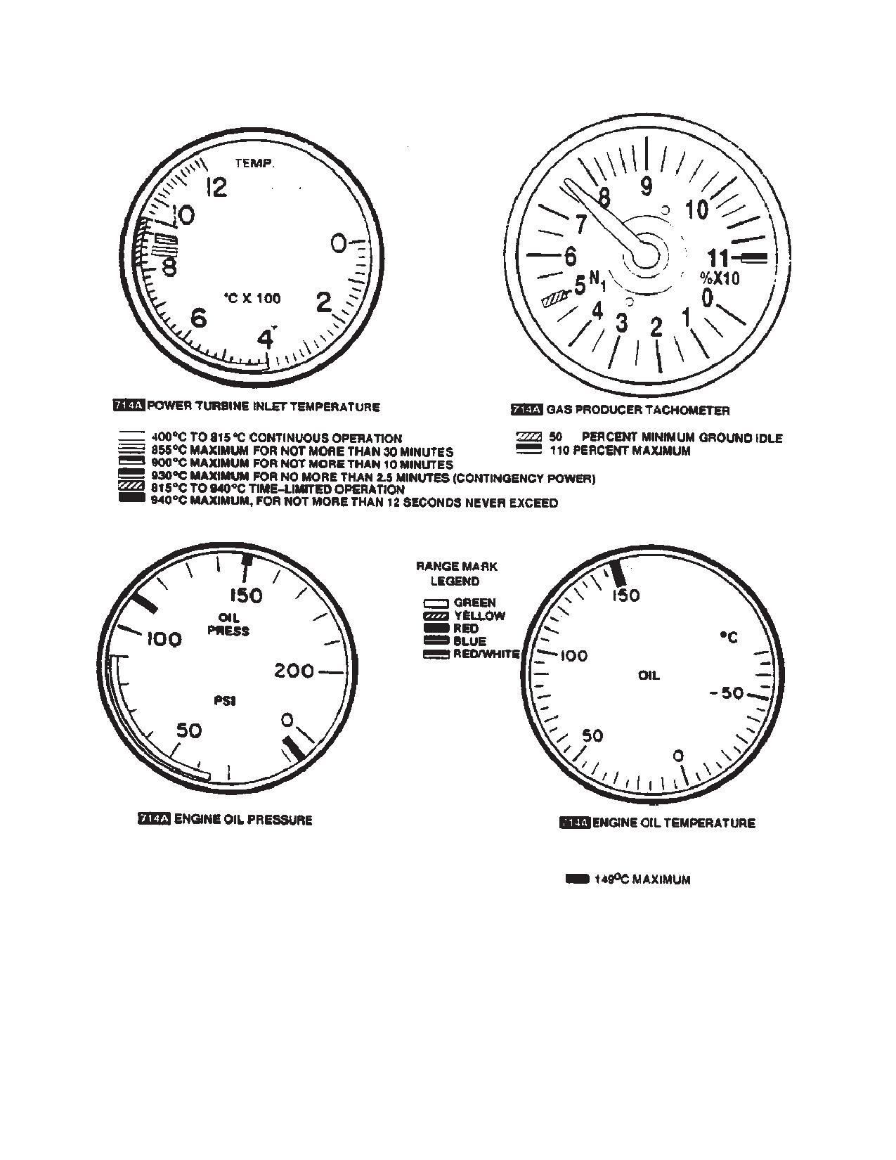
TM 1-1520-240-10
RED
5 PSI MINIMUM PRESSURE AT GROUND IDLE (50% N1)
35 PSI MINIMUM AT 80 TO 95% N1
50 PSI MINIMUM AT 95% N1 OR ABOVE
GREEN
35-90 PSIG MINIMUM NORMAL OPERATING PRESSURE RANGE
RED
110 PSIG MAXIMUM PRESSURE FOR CONTINGENCY POWER
RED
150 PSIG MAXIMUM PRESSURE FOR COLD
Figure 5-2-1 Instrument Markings (Sheet 3 of 5)
5-2-4
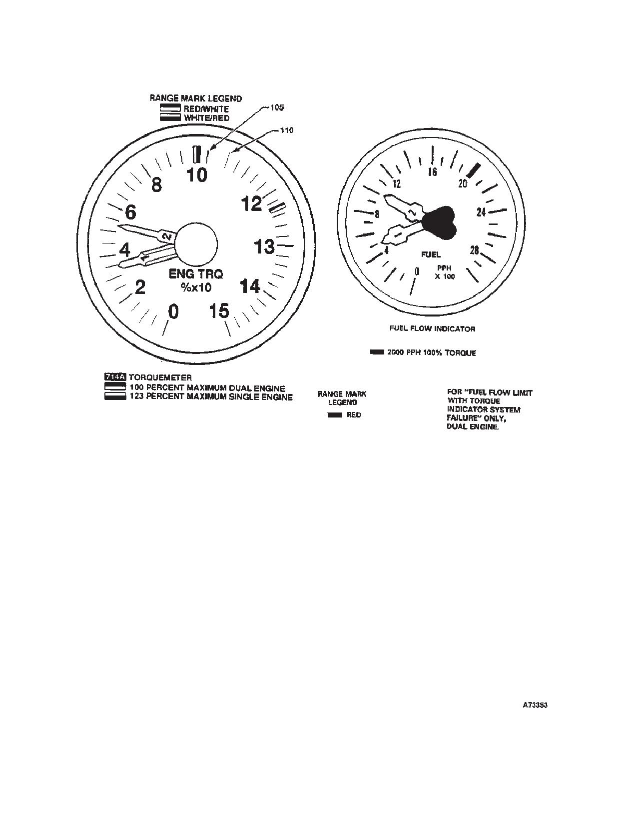
TM 1-1520-240-10
Figure 5-2-1 Instrument Markings (Sheet 4 of 5)
5-2-5
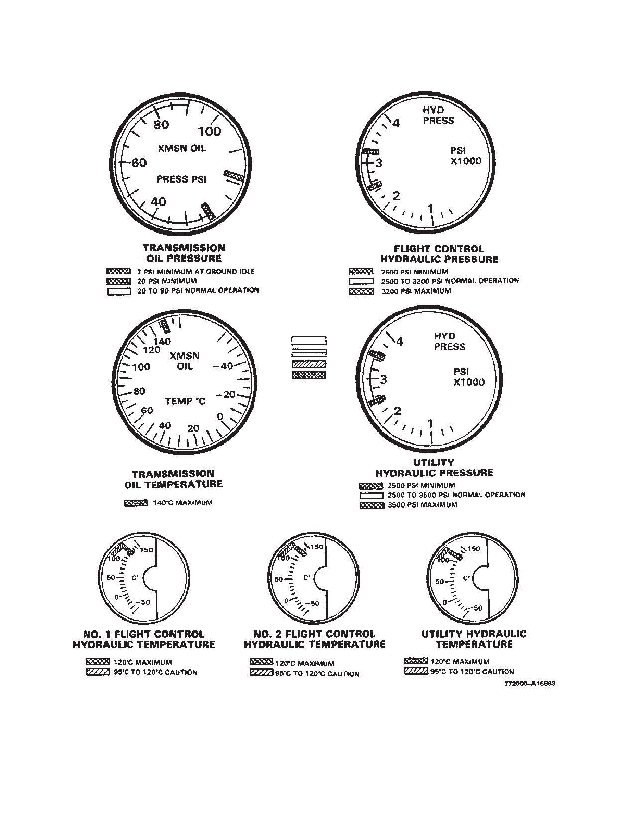
TM 1-1520-240-10
GREEN
BLUE
YELLOW
RED
Figure 5-2-1 Instrument Markings (Sheet 5 of 5)
5-2-6
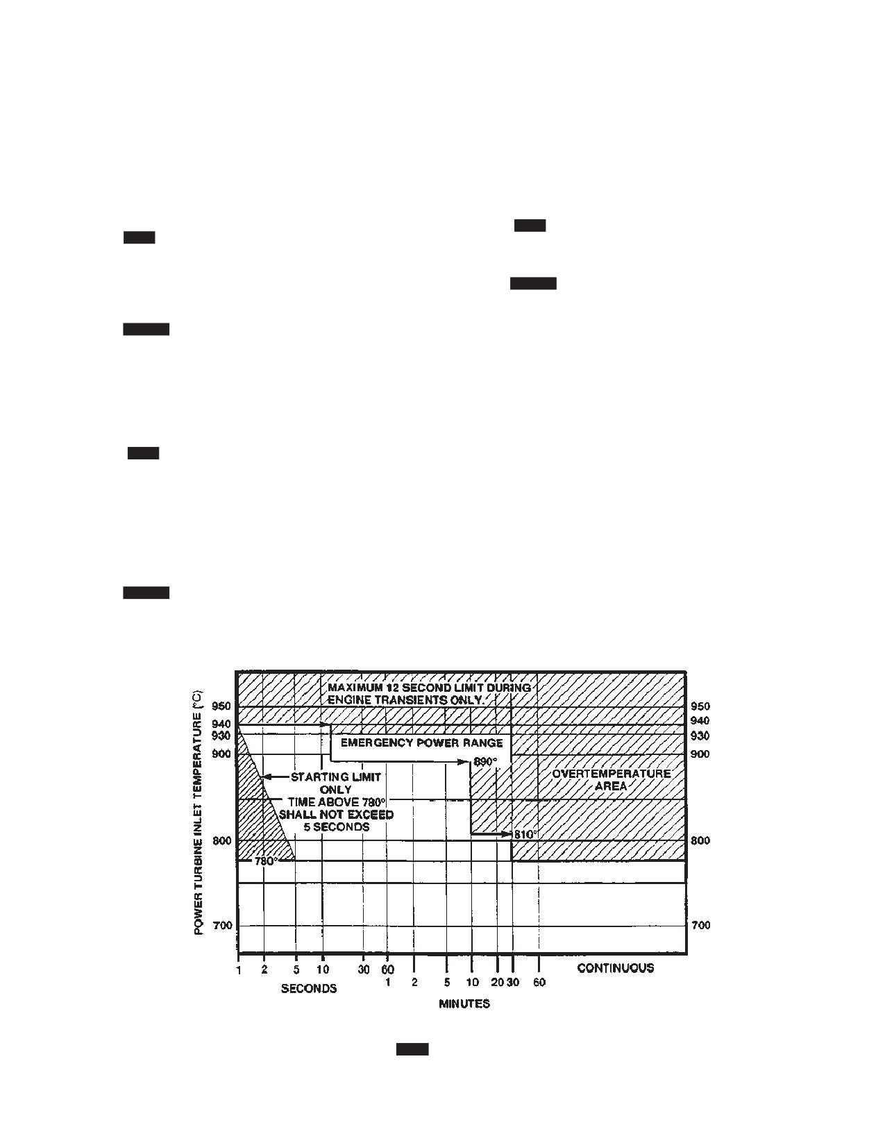
TM 1-1520-240-10
SECTION III. POWER LIMITS
5-3-1. Engine Rating and Power Level Limits.
overspeed can cause overtemperature and/or over
torque. A power turbine (N2) overspeed may exist, de-
For variations in torque available with temperature and
pending on power being used when 106% RRPM is ex-
pressure altitude, refer to the Torque Available charts in
ceeded.
Chapter 7.
5-3-6.
712 Engine Temperature Limitations.
5-3-2.
712 Emergency Power.
See figure 5-2-1 and 5-3-1.
Emergency power is only to be used during actual emer-
gency conditions. After 30 minutes of emergency power
5-3-7.
714A Engine Temperature (PTIT) Limita-
time have accumulated, the engine must be inspected
tions.
See figure 5-2-1 and 5-3-1.
5-3-3.
714A Contingency Power.
Usage of contingency power 900_to 930_C PTIT is per-
5-3-8. Fuel Limitations.
missible for an unlimited number of occurrences as long
Only those listed in Chapter 2 shall be used. Emergency
as each occurrence is 2 minutes 30 seconds or less.
fuel shall not be used for more than six hours cumulative
Maximum transient 940_C PTIT is not to exceed 12 sec-
time.
onds.
NOTE
5-3-4.
712 Engine Limitations.
JP8+100 is not considered “Emergency
Fuel”. A DA FORM 2408-13-1 entry will be
See figure 5-2-1 for limitations. A gas producer (N1)
made as described in Appendix C.
overspeed exists when an N1 of 110 percent is exceed-
ed. An N1 overspeed can cause overtemperature and/or
5-3-9. Transmission Torque Limitations (Steady
overtorque. A power turbine (N2) overspeed may exist,
State).
depending on power being used, when 106 percent
RRPM is exceeded.
See figure 5-2-1 for limitations.
NOTE
5-3-5.
714A Engine Limitations.
Aircrew should be alert to the potential for
See figure 5-2-1 for limitations. A gas producer (N1)
large engine torque oscillations during rear-
overspeed exists when an N1 of 110 is exceeded. An N1
ward flight operations.
Figure 5-3-1.
712 Operational PTIT Limits
5-3-1/(5-3-2 blank)
TM 1-1520-240-10
SECTION IV. LOADING LIMITS
5-4-1. Center -of-Gravity Limitations.
d. When combination of internal and external loads
are carried during the same flight and the external load
See fig 6-7-1 for center-of-gravity (CG) limits in terms of
exceeds 12,000 pounds, position the internal load for-
gross weight (GW) and arm-inches (fuselage stations).
ward of the utility hatch. This procedure will preclude
encountering an excessively aft CG.
5-4-2. Maximum Gross Weight.
The maximum allowable operating gross weight is
5-4-4. Winch/ Rescue Hoist Limitations.
50,000 pounds.
a. The winch shall not exceed:
5-4-3. Cargo Hook Limitations. The limits presented
(1)
3,000 pounds straight line pull.
below are structural limitations only.
(2)
6,000 pounds, one pulley.
a. The structural limit of the forward and aft hook is
(3)
9,000 pounds, two pulleys.
17,000 pounds each.
(4)
12,000 pounds, three pulleys.
b. The maximum single load that can be suspended
as a tandem load from the forward and aft hooks is
b. The rescue hoist is limited to a maximum load of
25, 000 pounds.
600 pounds.
c. The center cargo hook is limited to a maximum
c. Refer to Chapter 4 for system configuration and
load of 26,000 pounds.
operation.
5-4-1/(5-4-2 blank)
TM 1-1520-240-10
SECTION V. AIRSPEED LIMITS
5-5-1. Airspeed Operating Limits.
If a sling or hook should fail while carrying a tandem load,
limit airspeed to a maximum of 60 KIAS.
Any excursion into the red band of the cruise guide indi-
cator for more than 45 seconds requires an entry on the
5-5-5. Longitudinal Cyclic Trim (LCT) Actuator Air-
DA Form 2408-13-1. Provide the following information:
speed Limits.
aircraft gross weight, TAT, pressure altitude, total time in
The airspeed operating limits chart, fig. 5-5-2, shows the
the red zone, and needle position within the red zone (i.e.
maximum allowable airspeeds with either LCT, fully re-
lower half or upper half).
tracted.Do not manually extend the LCT beyond the
GND position on the cyclic trim indicators at indicated
5-5-2. Airspeed Limitations With An Inoperative
airspeeds below 60 knots.Use of extended cyclic trim at
Cruise Guide Indicator.
low airspeeds will result in high aft rotor blade stresses.
The airspeed operating limits chart, fig. 5-5-1, shows the
maximum allowable airspeeds with an inoperative cruise
5-5-6. Use of Airspeed Limitations Chart.
guide indicator.
The use of these charts is illustrated by the example on
each chart.To determine the maximum operating air-
5-5-3. Airspeed Limitations With An Operative or In-
speed, it is necessary to know the free air temperature,
operative Cruise Guide Indicator.
(FAT), pressure altitude, (PA), and gross weight,
The following limitations apply with an operative or inopera-
(GW).Enter the chart at known FAT, move right to known
tive cruise guide indicator.
PA, move down following the graph lines to known GW,
then move left and read maximum indicated airspeed.If
a. Maximum airspeed in sideward flight is 45 knots.
the cruise guide indicator is inoperative, two airspeed
limits must be determined and the lower limit used.One
b. Maximum airspeed in rearward flight is 45 knots.
is the structural limit based on GW; the other is based on
c. Maximum crosswind or tailwind for hover is 45
blade compressibility limit at lower temperatures.After
knots.
determining the structural limit, move up or down to the
dashed line representing FAT, then deflect left and read
d. Maximum airspeed with the lower section of the
airspeed.This airspeed should be increased for GW be-
cabin entrance door open and locked is 60 KIAS.
low 50,000 pounds.Go to the insert graph and enter it at
known GW.Move right to the sloping line, then deflect
e. The rescue hatch door shall not be opened or
down and read speed increase.To determine maximum
closed above 90 KIAS.
operating airspeed, add this value to that previously de-
f.
The windshield wipers shall be off at airspeeds
termined.
above 130 knots.
5-5-7. AFCS Limitations.
g. Upper section of the cabin entrance-assure that
airspeed is less than 100 KIAS before closing door in
The airspeed limit when operating on single AFCS is
flight.
100 KIAS or Vne, whichever is slower.The helicopter
may be operated with both AFCS off up to 160 KIAS or
5-5-4. External Cargo Airspeed Limits.
Vne, whichever is slower.
Change 3
5-5-1
TM 1-1520-240-10
Figure 5-5-1. Airspeed Limitations - Inoperative Cruise Guide Indicator
5-5-2
TM 1-1520-240-10
Figure 5-5-2. Airspeed Limitations - Longitudinal Cyclic Trim Retracted
5-5-3/(5-5-4 blank)
TM 1-1520-240-10
SECTION VI. MANEUVERING LIMITS
5-6-1. Aerobatics Prohibition
5-6-4. Ground Operation Limitations.
Aerobatics are prohibited with this helicopter. Aerobatics
a. To prevent droop stop pounding, when all the
is defined as intentional maneuvers beyond + 30_ pitch
landing gears are in contact with the ground and the
and/or 60_ roll.
thrust is at ground detent flight control movements shall
not exceed the floowong from the neutral position:
5-6-2. Bank Limitations
Right or left
The following bank angle limits apply:
directional pedal
.75 inches
a. With an operative cruise guide indicator, bank
Aft cyclic
2.00 inches
angles are limited by the cruise guide indicator, but no
greater than 60 degrees. When operating with altitude
Lateral cyclic
1.00 inches
hold, limit bank angle limits to 45 degrees maximum.
Thrust
No lower than
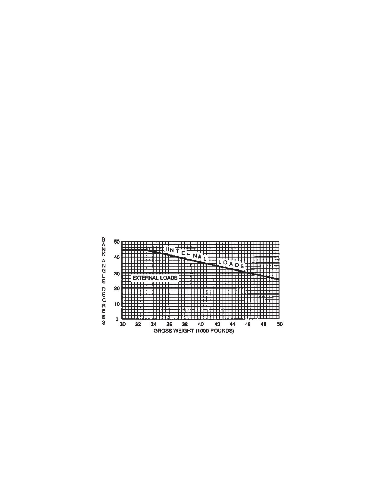
b. With an inoperative cruise guide indicator, use
ground detent
the bank angle limits defined by fig. 5-6-1.
b. When ground taxiing less than 75 feet from an
5-6-3. Landing Limitations.
obstruction, on an unimproved/unfamiliar airfield not
designated for CH-47D helicopters, a blade watcher and
a. The maximum ground speed for running land-
taxi director shall be positioned as shown in figure 8-2-1.
ings is 60 knots.
If the airfield is designated for CH-47D helicopter and taxi
b. The maximum nose-up attitude during landings
ways are in accordance with UFC 3-260-01, the above
is 20º.
does not apply.
Figure 5-6-1. Bank Angle Limitations
5-6-1/(5-6-2 blank)
TM 1-1520-240-10
SECTION VII. ENVIRONMENTAL RESTRICTIONS
5-7-1. Engine Inlet Screen Limitation.
5-7-3. Flight in Ice.
NOTE
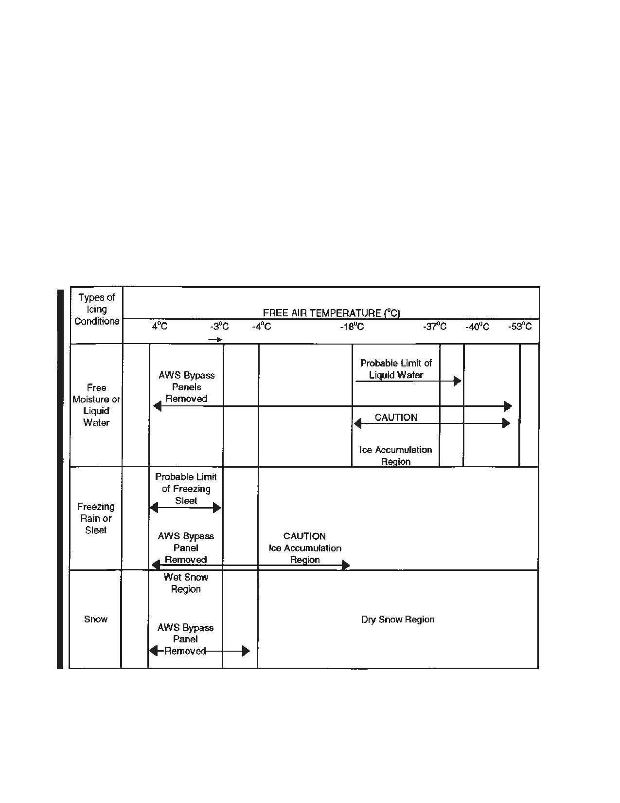
Refer to table 5-7-1 for information on engine bypass
During flight in icing conditions with the EAPS
panel removal.
installed, the bypass doors must remain
closed.
Pitot tube and Advanced Flight Control Systems (AFCS)
5-7-2. Flight Under Instrument Meteorological Con-
yaw port heating, and windshield anti-icing systems en-
ditions (IMC).
able safe flight in light-icing conditions. The EAPS is
designed to permit safe flight in light-icing conditions.
This helicopter is qualified for flight instrument metero-
Continuous flight in light-icing conditions below 5_C is
logical conditions provided the following conditions exist:
not recommended since blade damage can occur from
asymmetric ice shedding. Intentional flight into known
NOTE
icing conditions with rotor blade erosion protection mate-
rials installed is prohibited. Icing conditions include
Should one AFCS fail during IMC flight, the
“trace,” “light,” “moderate,” and “heavy.”
flight may be continued to destination.
Should both AFCS fail during IMC flight, a
5-7-4. Thunderstorm Operation.
landing should be made as soon as practical.
To ensure adequate lightning strike protection, the light-
a. Both AFCS are operational (ALT Hold and Hea-
ning protection cables and straps must be installed and
ding not required for IMC Flight).
intact on all rotor blades. If any lightning cables or straps
are missing or broken, avoid flight in or near thunder-
b. Two vertical gyros and two vertical gyro indica-
storms, especially in areas of observed or anticipated
tors (VGI) are installed and operative.
lightning discharges.
Change 1
5-7-1
TM 1-1520-240-10
5-7-5. Operation With Skis. If skis are installed, the
c. The maximum allowable rate of descent at
following limits apply:
touchdown in snow is 480 feet per minute at gross
weights up to 33,000 pounds, decreasing linearly to 240
feet per minute at 46,000 pounds gross weight. For
a. The maximum allowable airspeed is limited to
gross weights 46,000 pounds to 50,000 pounds, the rate
130 knots indicated airspeed or Vne, whichever is lower,
of descent is 240 feet per minute.
regardless of gross weight.
b. The maximum allowable gross weight for
d. The maximum taxi speed is 5 knots when operat-
ground operation is 50,000 pounds.
ing on hard prepared surfaces.
Table 5-7-1. Bypass Panel Removal Requirement
5-7-2
Change 1
TM 1-1520-240-10
Figure 5-7-1. Rotor Blade Start-Up & Shutdown Limits Sheet (1 of 2)
5-7-3
TM 1-1520-240-10
Figure 5-7-1. Rotor Blade Start-Up & Shutdown Limits Sheet (2 of 2)
5-7-4
TM 1-1520-240-10
5-7-5/(5-7-6 blank)