OPERATOR’S MANUAL FOR ARMY CH-47D HELICOPTER (EIC: RCD, 2003) - page 4
TM 1-1520-240-10
(2)
Several beeps will be heard in the headset.
(1)
Continuous beeping, with background
This means that the old CNV is being replaced by a new
noise, is a crypto alarm. This occurs when power is first
CNV..
applied to the KY-58 or when the KY-58 is zeroized. This
beeping is part of normal KY-58 operation but must be
(3)
Using this new CNV, the net controller will
cleared by momentarily keying the No.1 VHF AM/FM
Radio before communications can be achieved.
ask for a radio check.
(2)
Background noise indicates that the KY-58
(4)
After the radio check is completed, the net
is working properly. This noise should occur at power on
controller instructions will be to resume normal commu-
of the KY-58 and when the KY-58 is generating a crypto-
nications. No action should be taken until the net control-
variable. If the background noise is not heard at power
ler requests a radio check.
on, the equipment must be checked out by maintenance
personnel.
d. Manual remote keying procedures. The net con-
troller will make contact on a secure voice channel with
(3)
Continuous tone should indicate a parity
instructions to stand by for a new CNV by a manual
alarm. This will occur whenever an empty storage regis-
remote keying (MK) action. Upon instructions from the
ter is selected while holding the PTT button in. This tone
net controller:
can mean any of three conditions:
(1)
Set the FILL switch to position 6. Notify the
(a) Selection of an empty storage register.
net controller by radio and stand by.
(b) A bad cryptovariable is present.
(2)
When notified by the net controller, set the
(c) Equipment failure has occurred. To
MODE switch to RV (receive variable). Notify the net
clear this tone, follow the loading procedures in TM
controller and stand by.
11-5810-262 -OP. If this tone continues, have the equip-
ment checked out by maintenance personnel.
(3)
When notified by the net controller, set the
FILL switch to any storage position selected to receive
(4)
Continuous tone could also indicate a crypto
the new CNV (may be unused or contain the variable
alarm. If this tone occurs at any other time other than in
being replaced). Notify the net controller and stand by.
(3) above, equipment failure may have occurred. To clear
this tone, repeat the loading procedures in TM
11-5810-262 -OP. If this tone continues, have the equip-
NOTE
ment checked out by maintenance personnel.
When performing step (3), the storage posi-
(5)
Single beep, when DELAY switch is
tion (1 through 6) selected to receive the new
down(not selected), can indicate any of three normal
CNV may be unused or it may contain the
conditions.
variable which is being replaced.
(4)
Upon instructions from the net controller:
(a) Each time the PTT button is pressed
when the KY-58 is in C (cipher) and a filled storage regis-
(a) Listen for the beep on your headset.
ter is selected, this tone will be heard. Normal use
(speaking) of the KY-58 is possible.
(b) Wait two seconds.
(b) When the KY-58 has successfully re-
(c) Set the MODE switch to OP.
ceived a cryptovariable, this tone indicates that a good
cryptovariable is present in the selected register.
(d) Confirm.
(c) When you begin to receive a transmis-
sion, this tone indicates that the received signal is in a
(5)
If the MK operation was successful, the net
secure voice.
controller will now contact you via the CNV.
(6)
A single beep, when the DELAY switch is up
(6)
If the MK operation was not successful, the
(time delay) occurring after the preamble is sent, indi-
net controller will contact you via clear voice (plain) trans-
cates you may begin speaking.
mission, with instructions to set your FILL selector switch
to position 6 and stand by while the MK operations re-
(7)
A single beep, followed by a burst of noise
peated.
and a seemingly dead condition, indicates that your re-
ceiver is on a different variable than the distant transmit-
e. It is important to be familiar with certain KY-58
ter. If this tone occurs when in C/RAD1: Turn FILL switch
audio tones. Some tones indicate normal operation while
to the CNV, Plain-Cipher switch to PLAIN and contact the
others indicate equipment malfunction. These tones are
transmitter in clear text and agree to meet on a particular
heard only in the cipher mode and are:
variable.
3-2-15
TM 1-1520-240-10
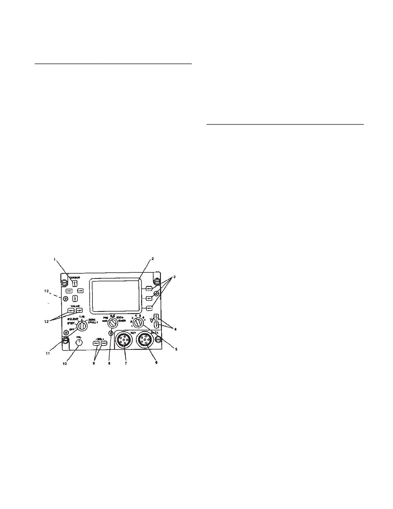
3-2-21. HF Radio Set (AN/ARC-220).
Data Connector (6)
Interfaces ARC-220 system to
data transfer device for datafill.
WARNING
Key Connector (7)
Interfaces ARC-220 system to
data transfer device for keyfill.
ANTENNA DANGERS
Mode Switch (8)
Five position rotary switch se-
The HF Radio Liaison Facility AN/ARC-220
lects mode of operation.
in the ALE mode sounds (transmits short
MAN
Selects HF conventional com-
tone bursts) and replies to ALE calls auto-
munications. Operating fre-
matically without operator action. Anytime
quency and emission mode
local flight directives forbid HF emissions,
are selected manually. Se-
such as during ordinance loading and re-
lected information can be
fueling, or when personnel are working
stored in preset channels for
near the aircraft, ensure the radio set con-
future recall.
trol function switch is set to SILENT, STBY,
or OFF.
PRE
Selects conventional HF com-
The HF radio set (AN/ARC-220) provides communica-
munications. Channel/net se-
tions in a 28 MHz high frequency band between 2.0 and
lector is used to select prepro-
29.9999 MHz. Channels are spaced at 100-Hz incre-
grammed preset channel. Fre-
ments, giving 280,00 possible frequencies. Preset chan-
quency and emission mode
nels can be manually programmed or preprogrammed
cannot be changed during pre-
as part of the communications mission load information.
set operation.
A total of 72 channels can be programmed: 20 manual
simplex or half-duplex, 20 programmable simplex or half-
ALE
Selects automatic link estab-
duplex, 20 programmable ALE scan lists and 12 pro-
lishment mode of operation.
grammable ECCM hop-sets (with ALE capability). Oper-
ECCM
Selects electronic counter-
ating modes of the HF radio set using either simplex or
countermeasure mode of op-
half-duplex operation are Upper and Lower sideband
eration.
(USB, LSB), amplitude modulation equivalent (AME),
and continuous wave (CW). Data may be transmitted or
EMER
Used during emergency to
received in USB or LSB modes. Both standard and ad-
place a distress call. The
vanced narrow-band digital voice terminal (ANDVT) are
mode, frequency, net, etc., is
supported. DC power to operate the HF radio set is sup-
determined by the datafill.
plied by the No. 2 DC bus through the COMM ARC-220
HF circuit breaker on the No. 2 PDP.
SQL (9)
Two pushbutton switches
which controls squelch and au-
3-2-22. Controls and Function, HF Radio Set (AN/
dio muting.
ARC-220). (fig. 3-2-8)
VOL (10)
Eight-position rotary switch
CONTROLS/
FUNCTION
varies the receive audio output
INDICATOR
level.
Cursor (1)
Four pushbutton switches
Function Switch
Five-position rotary switch se-
position the cursor verticallyor
(11)
lects system operation func-
horizontally.
tion.
Line-Select (3)
Pushbutton switches to select
options displayed to left of
OFF
Turns the ARC-220 off.
each switch.
STBY
Selects the standby function
Brightness (4)
Pushbutton switches to vary
where built-in test (BIT), setup,
display brightness.
or fill operations can be per-
formed.
Channel/Net Selec- Seven-position rotary switch
tor (5)
used to select programmed
SILENT
Used in ALE or ALE ECCM
operating channels or nets.
modes to prevent the ARC-220
CONTROLS/
FUNCTION
from automatically responding
INDICATOR
to incoming calls.
3-2-16
TM 1-1520-240-10
CONTROLS/
FUNCTION
CONTROLS/
FUNCTION
INDICATOR
INDICATOR
Line 3
T/R
Allows the ARC-220 to trans-
mit and receive in the selected
Receive Frequency
Numeric display (2.0 to
mode of operation.
29.9999 MHz) with a display
format of RCV xx.xxxx.
ZERO
Erases all data (including data-
fill and keyfill) which has been
ECCM Station Type
Character display (MEMBER,
loaded into the system.
ALTERNATE, MASTER, NET
ENTRY, ALT NET ENT). De-
Value (12)
Two pushbutton switches in-
fault is MEMBER.
crements a field value or single
Lines 3, 4
Character display of emission
character value, depending on
mode (USB, LSB, AME, CW)
cursor position.
one space to right of frequen-
cy. Default is USB.
Line 4
3-2-23. Display Lines, HF Radio Set (AN/ARC-220).
Transmit Frequency
Numeric display (2.0 to
29.999 MHz) with format of
The information displayed on each line is dependent
XMT xx.xxxx.
upon the operation being performed. This section speci-
fies what information can be displayed on each particular
Time
Numeric display (00:00:00 to
line.
23:59:59) with a format of -
Hour:Minute:Second.
CONTROLS/
FUNCTION
Line 5
INDICATOR
Link Protection
Character display (OFF, ON)
Line 1
Alpha-numeric display of 15
with a format of - LINK
characters maximum contain-
PROT: xxx. Default is ON
ing channel title (call sign).
(OFF if no link protection da-
Default value - Mode: chan-
nel#
tafill.
Line 2
Date
Alphanumeric display (01
JAN 00 to 31 DEC 99) with
ALE Address
Alpha-numeric display of 15
format of - dd MM yy.
characters maximum contain-
ing the Call To (ADRS: xxx)
Antenna Type
Character display (T/R, RCV)
or Self (SELF: xxx) Addresss.
with format of - ANT: x xx.
(ADRS:) and (SELF:) labels
Default is T/r.
are removed for addresses
greater than 10 characters in
Line 6
length.
Power Level
Character display (LOW,
Noise Reduction
Character display (ON, OFF)
MED, HIGH) with format of -
having a display format of -
PWR: xxxx. Default is HIGH.
NOISE REDUCE: xxx. De-
Squelch
Alpha-numeric display
fault value is ON.
(TONE, 0 to 5) with format of
Fill Type
Character display (KEY,
- SQ: xxx.
DATA) having a display For-
Volume
Numeric display (1 to 8) with
mat - TYPE: xxxx x. Default
is DATA.
format of - VOL: x.
Contention Control Character display (ON, OFF)
Listen Before Talk
Character display (ON, OFF)
having a display format of -
with format of - LBT: xxx. De-
LBC: xxx. Default is OFF.
fault value is OFF.
3-2-17
TM 1-1520-240-10
3-2-24. Operating Modes/Functions, HF Radio Set
CONTROLS/
FUNCTION
(AN/ARC-220). (fig. 3-2-8)
INDICATOR
Receive/Transmit
2.0 - 29.9999 MHz, program-
CONTROLS/
FUNCTION
Frequency
mable in 100 HZ steps. To
INDICATOR
change frequencies, depress
the EDIT line select switch.
Power ON/OFF
On function Switch.
While in the Edit screen use
the Cursor switches to posi-
CRT Brightness
Two pushbuttons switches
tion cursor under the ap-
used to vary brightness. The
propriate frequency. Use the
↑ (up arrow) increases inten-
VALUE switches to change
sity while the ↓ (down arrow)
frequency. (Note: The XMT
decreases intensity.
frequency will automatically
change with the RCV fre-
System Turn-On
Turning the Function Switch
quency, but the reverse is not
clock-wise from OFF to
true).
STBY turns system on and
selects standby function.
Squelch Level/ Audio
Two pushbutton switches
SYSTEM TESTING is dis-
Muting
-SQL +, when pressed dis-
played while power-up BIT
plays the squelch status on
(P-BIT) is in process. SYS-
line 6 of display for 5 se-
TEM -GO will be displayed if
conds. Settings are TONE
all tests good, SYSTEM-
and 0 through 5. TONE pro-
NOGO if not.
vides no muting and no
squelch. Position 0 provides
Audio Volume
Eight-position rotary switch
muting but no squelch. Posi-
varies output level. Setting is
tions 1 through 5 provide
muting and increasing levels
displayed on line 6 (bottom)
of squelch. Muting is normal-
of display for 5 seconds
ly enabled during ALE and
when system first turned on
ALE ECCM operation.
or when VOL setting is chan-
ged. The display level are 1,
Output Power Level
Three output levels are se-
2, 3 thru 8.
lectable for the display
screen by using the EDIT
Channel Selection
Channel number may be
line-select switch, which
changed using the Channel
brings up the edit mode,
Selector seven-position
moving the cursor under the
rotary switch. The + position
power character field and us-
of the greater to be selected
ing the VALUE switches to
using the VALUE switch.
change the field. Depress the
Modulation Mode
Four modes are available:
RTN line-select switch which
USB, LSB, AME, and CW. To
stores the change and re-
change modes, depress the
turns to normal operating
EDIT line select switch.
mode. There are two Built-in-
While in the Edit screen use
Test (BIT) features which
the CURSOR switches to
concerns the operator, P-BIT
position cursor under the ap-
and C-BIT. The Power-UP Bit
propriate emission mode
(P-BIT) test the ARC-220
when initially turned on. P-Bit
(RCV or XMT). Use the VAL-
exercise basic radio control
UE switches to change
functions which must be op-
mode. (Note: The XMT mode
erational prior to entering a
will automatically change with
system operational mode. A
RCV mode, but the reverse is
GO/NO/-GO status appears
not true). Depress RTN line
on the display and defaults to
select switch to enter the
standby mode upon comple-
edited data and return to op-
tion. When NO-GO status ap-
erational mode.
pears, depressing the
3-2-18
TM 1-1520-240-10
CONTROLS/
FUNCTION
CONTROLS/
FUNCTION
INDICATOR
INDICATOR
INOP line-select switch dis-
Key Fill
Loads secure keys. From
plays INOP MODES so an
STBY screen, press FILL
operator can see if limited ca-
line-select switch. Use VAL-
pability exists. The Continu-
UE switched to select KEY in
ous Bit (C-BIT) is automati-
fill TYPE: field. Connect DTD
cally performed during sys-
to KEY connector on radio
tem operation without any
set cotnrol panel. Use VAL-
operator intervention. Critical
system functions are monito-
UE right arrow switch to se-
red. Any failures cause a NO-
lect key number (1 through 6)
GO advisory, accomplished
to be loaded. Initiate keyfill
by the portion of system
from DTD. LOADING is dis-
which failed, to appear on
played during keyfill, LOAD
line 5 of the display. C-Bit fail-
COMPLETE if successful.
ures are stored in nonvolatile
LOAD FAIL may cause inter-
memory.
ference to other stations. De-
Store
RTN line-select key, used to
fault is ON. LBT: (listed be-
terminate edit mode, auto-
fore talk) - This field is used
matically stores any
for manual, preset, or con-
change(s) made.
ventional (non-ALE) ECCM
operation and turns LBT ON
DataFill
Contains preset frequencies,
scan lists, addresses, data
or OFF. When OFF, transmis-
messages and ALE and/or
sion is accomplished without
ECCM parameters. With sys-
regard to traffic and may
tem in STBY, press the FILL
cause interference to other
line-select switch. Use VAL-
stations. Default is OFF.
UE switches to select DATA
ANT: (antenna) - Useful if
in the fill TYPE: field (line 2).
system uses both receive-
Connect data transfer devise
only and transmit/ receive an-
(DTD) of DATA connector on
tennas.
radio set control front panel
and initiate fill from the DTD.
When T/R is selected, the
LOADING is displayed dur-
system transmits and re-
ing datafill. LOAD COM-
ceives on the same antenna.
PLETE is displayed for suc-
When RCV is selected the
cessful fill, LOAD FAIL dis-
system transmits on one and
played if fill cannot be com-
receives the other antenna.
pleted. (NOTE: using an AN/
Default is T/R
CYZ-10 DTD, the radio set
LINK PROT: (link protection)
control displays DTD DE-
TECTED when DTD is de-
- This field turns ALE link
tected). A copy of loaded da-
protection ON or OFF. De-
tafill can be sent to DTD by
fault is ON (OFF if no link
pressing COPY line-select
protection datafill). Press
switch. COPYING is dis-
RTN line-select switch when
played during operation,
setup edit is complete to en-
COPY COMPLETE displayed
ter all data and return to
if successful, COPY FAIL if
STBY screen.
copy cannot be completed.
Press RTN line-select switch
to return to STBY screen
when datafill is complete.
Disconnect the DTD.
3-2-19
TM 1-1520-240-10
CONTROLS/
FUNCTION
CONTROLS/
FUNCTION
INDICATOR
INDICATOR
General Editing
Select desired channel and
as required. Set to desired
press the EDIT line-select
channel. Press microphone
switch. Use the CURSOR
PTT switch, wait until tune
switches to position cursor
tone stops and begin com-
under character position or
munications. When PTT
data field to be edited. Use
switch is pressed, the XMT
VALUE switches to change
frequency is displayed.
the character or data field to
desired value. If available,
Normal ALE Commu- Set function switch to T/R
the data setup can be modi-
nication
and mode switch to ALE.
fied by pressing the DATA
(NOTE: If the selected net is
line-select switch in the EDIT
configured for link protection
screen, using the VALUE
but does not have accurate
switches to scroll through the
time, SYNC instead of POSN
list of modem set configura-
will appear on display, line 2
tion. Press theRTN line-se-
right side along with an UN-
lect switch when all changes
SYNC advisory at bottom of
are complete to store the
screen. An ALE link protec-
changes and return to normal
tion time sync needs to be
operation mode.
performed. If ALE data is not
loaded for the selected scan
Transmit Position
Set function switch to T/R
list, a CHANNEL INOP advi-
Report
and mode switch to proper
sory is displayed). Use - SQL
mode. Press the POSN line
+ switch too set squelch to
select switch. (NOTE: POSN
line-select is available only if
TONE. Adjust VOL for com-
configuration data indicates
fortable listening level. Use -
GPS is installed).
SQL + switch to set squelch
to 0. Headset is muted until a
Manual Operation
Set function switch to T/R
link is established. If channel
and mode switch to MAN.
Use - SQL switch to set
is noisy, adjust squelch. High-
squelch to 0. Adjust VOL
er squelch levels are not rec-
control to comfortable listen-
ommended for ALE mode of
ing level. Use SQL + switch
operation.
to set squelch to 1, the opti-
mum for manual mode. If ra-
Normal ALE
When ALE call is received
dio breaks in and out of
Communication
INCOMING CALL is dis-
squelch, increase as requi-
Receiving
played with the address field
red. Set to desired channel.
displaying xcaller’s ALE ad-
Press microphone PTT
dress. LINKED is displayed
switch, wait until tune tone
and short gong tone sounds
stops and begin communica-
when an ALE link is establi-
tions. When PTT switch is
shed. Communication can
pressed, the XMT frequency
is displayed.
now begin. Proper protocol is
for calling station to make
Preset Operation
Set function switch to T/R
first transmission.
and mode switch to PRE.
Use - SQL switch to set
Normal ALE
Select ALE address to be
squelch to 0. Adjust VOL
Communication -
called by doing a, b, or c:
control for comfortable listen-
Transmitting
a. Set channel/net
ing level. Use SQL + switch
switch to desired prepro-
to set squelch to position 1,
grammed net.
the optimum setting for pre-
b. Use VALUE switch
set mode. If radio breaks in
to scroll through and select
and out of squelch, increase
preprogrammed address.
3-2-20
TM 1-1520-240-10
CONTROLS/
FUNCTION
CONTROLS/
FUNCTION
INDICATOR
INDICATOR
c. Press EDIT line-select
ECCM Tune/Sync
Press either TUNE line-select
switch, then use CURSOR
Operation
switch or microphone PTT
and VALUE switches to
switch to initiate combined
manually select an address
tune and sync. TUNING fol-
character-by-character.
lowed by SYNCING is dis-
(NOTE: NET INOP advisory
played during process. Sys-
is displayed if a selected
tem, will return to ECCM
channel or net contains: no
screen without UNTUNED
data or corrupted data; or
and/or UNSYNC advisories if
hardware cannot support the
successful.
selected mode). Press mi-
ECCM Operation
Use -SQL switch to set
crophone PTT switch CALL-
squelch to TONE. Adjust
ING is displayed LINKED is
VOL control for comfortable
displayed with a short gong
listening level. Use SQL +
tone and headset audio is re-
switch to set squelch to 0. If
stored when link established.
channel is noisy, set to 1.
Start transmission. The sys-
Higher settings are not rec-
tem terminates the link and
ommended for ECCM opera-
returns to ALE scanning after
tion.
a period of inactivity (30 sec-
onds typical). GPS position
ECCM Operation -
RCVING PREAMBLE and/or
can also be transmitted by
Receiving Calls
INCOMING CALL is dis-
using the steps above plus
played.
the Transmit Position Report
steps.
ECCM Operations -
Press microphone PTT
Transmitting
switch. Wait for preamble
ALE Link Protection
Press PTT switch or SYNC
tones to cease then begin
Time Sync
line-select switch. System re-
communications. If an ALE/
turns to scan and the net de-
ECCM channel is used,
fault address if sync success-
CALLING is displayed while
ful, but if unsuccessful press
call in process. LINKED is
ABORT line-select switch to
displayed and a short gong
return to ALE screen.
tone sounds, and headset
audio is restored when link
ECCM Net Initializa-
Set function switch to T/R
established. (NOTE: Press
tion
and mode switch to ECCM.
ABRT line-select switch to
(NOTE: If ECCM data or
abort calling process). Call
keys are not loaded for net
initiator should make first
selected, a CHANNEL INOP
transmission. The system ter-
advisory is displayed). Set
minates link and returns to
channel/net switch to desired
scan after a period of inactiv-
net. If selected channel is an
ity (30 seconds typical). GPS
ALE/ECCM channel, the ad-
position can also be trans-
dress of station being called
mitted by using the steps
is displayed on line two.
above plus the Transmit
(NOTE: NET INOP advisory
Position Report steps.
is displayed if selected chan-
nel or net contains: no or cor-
Data Messages
The ARC-220 radio set can
rupted data; or hardware
store up to 10 transmit and
cannot support selected
10 received data messages
mode. If screen displays UN-
up to 500 characters long
TUNED or UNSYNC adviso-
each. Received data mes-
ries proceed with system
sages are stored in memory
Tune/Sync operation, other
and can be retransmitted.
wise proceed with ECCM op-
eration.
3-2-21
TM 1-1520-240-10
CONTROLS/
FUNCTION
CONTROLS/
FUNCTION
INDICATOR
INDICATOR
5. To delete messages,
An advisory alerts when a
position cursor under mes-
data message is received.
sage number to delete, press
Data can be transmitted or
the DEL line-select switch
received in any mode (manu-
until NO MESSAGES is dis-
al, ALE, or ECCM). Proce-
played mode.
dure to send/receive (recall)
messages is the same for all
modes, except in manual
Data Messages -
Press SEND line-select
mode when ALE link is not
Transmit
switch to transmit last se-
established.
lected address in ALE or
ECCM mode, or to transmit
message using current mode
Data Messages - Re- Received messages are
and frequency in manual
ceived
stored in MSG location 1.
mode. In ALE or ECCM
MSG 10 is the oldest mes-
modes advisories are dis-
sage and is deleted from
played during tuning, synch-
memory upon receipt of an
ing and linking which is done
incoming message. Received
automatically. SENDING
messages can be read and/
DATA is displayed while
or forwarded, but not edited.
message is transmitted.
A CHECK MSG advisor is
displayed when data mes-
sage received. To recall data
Program/Edit Data
Press MSG line-select switch
messages perform the follow-
Messages
to go to MESSAGE screen,
ing:
then press PGRM line-select
1. Press MSG line-select
switch. NO MESSAGES is
switch to view message. If
displayed if none exists. Use
operator desires to check
the CURSOR up/down ar-
messages even though a
rows to position the cursor,
CHECK MSG advisory was
then use VALUE switches to
nor displayed, press MSG
enter desired data (if a pre-
line-select switch, then
viously programmed mes-
RCVD line-select switch to
sage is to be edited, use
view messages. NO MES-
CURSOR an VALUE
SAGES advisory appears if
switches to obtain appropri-
no messages exists.
ate message and line as de-
2. Use the CURSOR up/
scribed earlier). To delete a
down arrow to view message
character in cursor position
one line at a time and left/
and to shift remaining char-
right arrows to move cursor
acters one position to the left,
to left margin. Use VALUE
press DEL line-select switch.
switches to page up or down.
A built-in word dictionary is
3. To view additional
available (either default or
messages, use CURSOR
filled). To access word dictio-
switches to position cursor
nary, press WORD line-select
under the MSG number the
switch to obtain INSERT
use. VALUE switches to
screen. Use CURSOR and
scroll to next consecutive
VALUE switches to scroll dic-
message number.
tionary. Place cursor under
4. To retain messages in
desired word and press
memory, press RTN line-se-
SELCT line-select switch to
lect switch. Press RTN line-
insert a blank and the se-
select switch to return to op-
lected word at cursor position
erational
of message edit screen or if
no word found, press CANCL
3-2-22
TM 1-1520-240-10
plied by the No. 2 DC bus through the HF KY-100 circuit
CONTROLS/
FUNCTION
breaker located on the No. 2 PDP.
INDICATOR
line-select switch to return to
edit CONTROLS/screen.
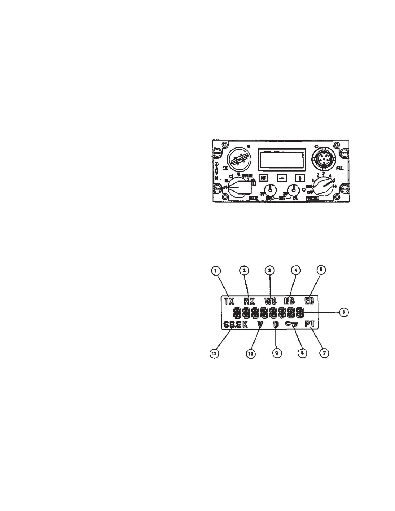
3-2-26. Controls, Indicators, Connectors and Func-
When complete, press RTN
tion (TSEC/KY-100-, Z-AVH) (fig. 3-2-9)
line-select switch to load
message into memory and to
return to top-level screen.
Shutdown Procedures Set
CONTROLS/
FUNCTION
function switch to OFF. Gent-
INDICATOR
ly pull and turn function
MODE Switch
Six position rotary switch
switch to zeroize.
used to select one of the op-
(ZERO) position to erase pre-
erational modes.
programmed information, in-
cluding all fills. Zeroize func-
PT
Plaintext mode. Allows re-
tion is operational regardless
ception or transmission of un-
if system is on or off.
encrypted analog voice.
Emergency Commu- The mode used during emer-
EB
Emergency Back-up mode.
nication
gencies is determined by the
Uses the emergency back-up
datafill. The equipment oper-
key to encrypt voice for trans-
ates normally for mode selec-
mission or reception.
ted. Set mode switch to EM-
CT
Ciphertext mode. Allows
ER. Press the PTT switch to
transmission of encrypted
transmit. If in ALE mode, an
voice or data and reception
ALE call is placed to the se-
of encrypted or unencrypted
lected address.
voice or data, and non-coop-
erative terminal rekeying.
RK
Remote Keying mode. Per-
mits KY-100 to perform auto-
matic and manual rekey op-
erations.
OFFLINE
Disables communications
and gives access to the sys-
tem of menus used to select
mode settings, self-test fea-
tures, and filling the KY-100
with crypto-variables.
Z ALL
Zeroize mode. Erase all cryp-
(PULL)
tographic data stored in the
KY-100 except the Emergen-
cy Back-up Key.
CIK Receptacle
Interfaces with a Crypto-
graphic Ignition Key which is
needed to enable all secure
voice and data communica-
Figure 3-2-8. Control/Display Panel, HF Radio Set
tions. This function is cur-
(AN/ARC-220)
rently disabled.
DSPL/OFF BRT
Two-function rotary switch
Control
which controls the on/off sta-
tus and backlight intensity of
3-2-25. Voice Security Equipment TSEC/KY-100.
the LCD display.
PNL/OFF BRT
Two-function rotary switch
Voice security equipment (TSEC/KY-100), when
Control
which controls the on/off sta-
installed, provides two-way clear or secure half-duplex
tus and backlight intensity for
voice/data communication for the HF radio system (AN/
the overall front panel.
ARC-200). Power to operate the TSEC/KY-100 is sup-
3-2-23
TM 1-1520-240-10
CONTROLS/
FUNCTION
CONTROLS/
FUNCTION
INDICATOR
INDICATOR
PRESET Switch
Rotary selector switch which
Simultaneous (↑→)
Used to exit a submenu.
controls unit operating power
Display, LCD
Back-lighted Liquid Crystal
and settings which are stored
Display (LCD) indicates op-
in memory.
erational status, operator
prompts and messages.
OFF
Removes power from
KY-100.
3-2-27. Display
Annunciators/Fields
(TSEC/
MAN
Manual position which allows
KY-100, Z-AVH). (fig. 3-2-10)
operating modes to be se-
lected using both OFFLINE
CONTROLS/
FUNCTION
and online menu system.
INDICATOR
1 thru 6
Six separate preset modes
TX Annunciator (1)
Displayed when KY-100 is
which can only be set up in
transmitting.
the OFFLINE mode.
RX Annunciator (2)
Displayed when KY-100 is re-
FILL Connector
Used to load cryptographic
ceiving.
keys through the use of com-
Wb Annunciator (3)
Displayed when KY-100 is in
mon fill devise such as
the Wideband (VINSON)
KYK-13/TSEC Electronic
configuration.
Transfer Devise, KYX-15/
TSEC Net Control Devise,
Nb Annunciator (4)
Displayed when KY-100 is in
AN/CYZ-10 Data Transfer
the Narrowband (ANDVT)
Devise (DTD), or the
configuration.
KOI-1//TSEC General pur-
Eb Annunciator (5)
Displayed when MODE con-
pose Tape Reader.
trol switch is in the Emergen-
Three Button
Momentary pushbutton
cy Backup (EB) position.
Keypad
switches active in both OF-
Alphanumeric
Provides prompts, mes-
FLINE and on-line modes.
Display (6)
sages, and mode indications.
Used to enter and exit sub-
PT Annunciator (7)
Displayed when KY-100 is
menus, activate the selected
processing plaintext voice.
mode, select fields,and to
scroll through menus and op-
Key Symbol (8)
Displayed when menu sys-
tions.
tem is locked.
INIT
Initiate switch. In the OF-
D Annunciator (9)
Displayed when in Data
FLINE mode activates the
mode.
displayed menu mode and
V Annunciator (10)
Displayed when in Voice
provides entry into subme-
mode.
nus. In on-line modes (CT,
Rate Display (12)
3-character display indicates
RK, EB,PT), it selects the dis-
voice or data rate.
play field to be change.
Up Arrow (↑)
In the OFFLINE mode, it is
3-2-28. Turn-On Procedure.
Switch
used to scroll through menus
from top to bottom. In on-line
When the KY-100 is turned on, tests are automatically
modes (CT, RK, EB, PT), it is
performed to determine the equipment’s operating sta-
used to scroll through avail-
tus. The results of these tests will be presented on the
able options for the display
display. Also, a Cld START message will be displayed.
field being changed.
a. Cold start turn-on. (Initiated if no traffic encryption
Right Arrow (→)
In the OFFLINE mode, it is
key (TEK) is contained in the KY-100).
Switch
used to scroll through menus
(1)
Turn on the KY-100 by turning the PRESET
from bottom to top. In the on-
switch to the MAN position.
line modes (CT, RK, EB, PT)
it is used to select the display
(2)
The KY-100 will initiate a self -test. The dis-
field to be changed.
play reads Cld STRT and then PSH INIT.
3-2-24
TM 1-1520-240-10
(3)
Connect a fill devise to the KY-100 fill con-
f. Push the INIT button. LOAD N with a flashing N will
nector using a fill cable. Select the fill position containing
be displayed. The flashing N indicates the currently se-
the valid key and turn it on.
lected key location.
(4)
Press the INIT pushbutton (PUSH INIT).
g. Press the ↑ (up arrow) or → (right arrow) button
until the required location (1, 2, 3, 4, 5, 6, or U) is dis-
(5)
The KY-100 displays KEY 1 01, PASS,
played.
WORKING, LOCKED, READY.
h. Press the INIT button. The entire LOAD N mes-
NOTE
sage will now be flashing.
If a fill devise is not connected to the KY-100
i. Turn on fill devise and select key to be loaded.
when the INIT pushbutton is pressed, a dEV
NOTE
ERR (Devise Error) message will be dis-
played. When this occurs, the only available
DO NOT press the INITIATE pushbutton (or
communication mode will be PT (Plaintext).
pull tape through tape reader) on fill devise.
(6)
If a FAIL message is displayed, notify the
j. Press the INIT button. (When using a KOI-18 pull
next level of maintenance.
tape through tape reader at a steady rate after the termi-
nal INIT button is pressed). Upon completion of a suc-
(7)
To load additional keys (up to a total of 6),
cessful load, a pass tone will be heard and the display will
proceed to Key Loading Section.
momentarily indicate KEY N, where N is the key location
b. Normal turn-on.
loaded.
(1)
Set the front panel MODE control to the OF-
k. The display will again show LOAD N with N fla-
FLINE position.
shing. To load additional keys, repeat steps g. through j.
until all desired key locations have been loaded.
(2)
Rotate the DSPL and PNL switches clock-
l. Turn off and disconnect the fill devise from the
wise, out of the OFF detent positions and adjust the
KY-100.
display and panel lighting for comfortable viewing.
m. Rotate MODE switch out of OFFLINE to exit Key
(3)
Set the PRESET switch to the MAN (manu-
Load.
al) position to apply power to the KY-100 electronics.
Power -on tests will automatically be run when primary
3-2-30. Zeroize Procedures.
power is applied.-
a. Zeroize ALL keys. This procedure is active even if
(4)
Upon successful completion of the power-
primary Power is removed from the KY-100. All key loca-
on tests, the test results should appear in the display. If
tions within the KY-100 will be zeroized. Once zeroized,
PASS is displayed, continue with the turn-on procedures.
only PT voice communications are possible until a new
However, if a FAIL message appears in the display, notify
Traffic Encryption Key (TEK) is loaded.
the next level of maintenance. If PUSH INIT is displayed,
(1)
Pull the MODE switch and rotate it to the Z
perform the cold start procedures as described above in
ALL position. All keys stored in locations 1-6 and U will
paragraph a.
be erased.
3-2-29. Key Loading Procedures.
(2)
If the KY-100 is on when this procedure is
performed, ZEROIZED will be displayed, and a tone will
Key loading may be accomplished using a KYX-15,
be heard.
KYK-13 or a KOI-18. One Key Encryption Key (KEK), up
to six Traffic Encryption Keys (TEKs), and one Emergen-
(3)
If the KY-100 power is on when the MODE
cy Backup (EB) key can be loaded in the KY-100. A Fill
switch is rotated out of Z ALL position, PUSH INIT will be
Cable (ON190191) is required when using one of these
displayed. Follow the COLD START procedures.
devises. Proceed with the following generic Key Loading
b. Zeroize SPECIFIC key locations.
procedures:
(1)
Place the KY-100 MODE switch to the OF-
a. Place the KY-100 MODE switch in OFFLINE posi-
FLINE position.
tion.
(2)
If the KY-100 is not on, turn PRESET switch
b. If the KY-100 is not on, turn PRESET switch to
to MAN position.
MAN position.
(3)
Push the ↑ (up arrow) or → (right arrow)
c. Connect a fill devise to the KY-100 fill connector.
button until KEY OPS is displayed.
d. Push the ↑ (up arrow) or → (right arrow) button
(4)
Push the INIT button. LOAD KEY will be
until KEY OPS is displayed.
displayed.
e. Push the INIT button. LOAD KEY will be dis-
(5)
Push the ↑ (up arrow) or → (right arrow)
played.
button until ZERO is displayed.
3-2-25
TM 1-1520-240-10
(6)
Push the INIT button. ZERO N with a flash-
k. Press the→ (right arrow) button. The Data Rate
ing N will be displayed. The flashing N indicates the cur-
field will be flashing.
rently selected key location to be zeroized.
l. Press the ↑ (up arrow) button until the desired Data
(7)
Press the ↑ (up arrow) or → (right arrow)
Rate (300, 600, 1.2K, or 2.4K) is flashing.
button until the required location (1, 2, 3, 4, 5, 6, U) is
m. After all fields have been set properly: Press the
displayed.
INIT button to save the settings and return to Standard
(8)
Press the INIT button. The entire ZERO N
Operations.
message will now be flashing.
3-2-32. Cipher/Plain Text Level Modification.
(9)
Press the INIT button. The display will go
blank while the key zeroize process is being performed.
The following procedures are used to modify the Receive
Upon completion of a successful key zeroizing, a pass
Cipher Text Level, Receive Plain Text Level, and CT/PT
tone will be heard and display will briefly indicate
or Cipher Text Only menus.
ZEROED N, where N is the key location.
a. Place the KY-100 MODE switch to the CT posi-
tion.
(10) To zeroize additional keys, wait until the dis-
play indicates ZERO N (with N flashing), then repeat
b. Rotate the KY-100 PRESET switch to the CT posi-
steps 7 through 9.
tion.
(11) Rotate MODE switch out of OFFLINE to exit
c. To modify the Receive Ciphertext Volume, go to
Key Load.
step d, to modify the CT/PT or Ciphertext Only setting, go
to step i, and to modify the Receive Plaintext Volume go
3-2-31. Online Mode Selection Menu.
to step n.
This procedure is used to modify the Online MODE con-
d. Push the ↑ (up arrow) or → (right arrow) button
figuration.
until RXCTV N (where N represents the current receive
level) is displayed.
a. Place the KY-100 MODE switch to the CT posi-
tion.
e. Push INIT button. The N in RXCTV N will begin to
flash.
b. Rotate the KY-100 PRESET switch to the MAN
position. If the PRESET switch is in position 1, 2, 3, 4, 5,
f. Push the ↑ (up arrow) or → (right arrow) button until
or 6, the MODE selections cannot be modified. Refer to
the desired receive level is displayed.
the section on changing PRESET settings to modify the
PRESET configuration.
g. Push the INIT button. The N in RXCTV N will stop
flashing.
c. Press the INIT button. The WB (Wide Band) or NB
(Narrow Band) (which ever mode is active) enunciator
h. Push the ↑ (up arrow) or → (right arrow) button
will begin flashing.
until the Operating Mode is displayed. This completes
the Receive Ciphertext Volume adjustment.
NOTE
i. Push the ↑ (up arrow) or → (right arrow) button until
The KY-100 will be operated in Narrow Band
CT or CT ONLY is displayed.
mode only with the ARC-220 Radio Set.
d. Press the ↑ (up arrow) button until the desired
j. Push the INIT button. The CT or CT ONLY will begin
enunciator (WB or NB) is flashing.
to flash.
e. Press the → (right arrow) button. The Mode field
k. Push the ↑ (up arrow) or → (right arrow) button
will be flashing.
until CT (Ciphertext and Plaintext operation) or CT ONLY
(Ciphertext only operation) is displayed.
f. Press the ↑ (up arrow) button until the desired
MODE setting (CT or PT) is flashing.
l. Push INIT button. The CT or CT ONLY will stop
flashing.
g. Press the→ (right arrow) button. The Modem field
will be flashing.
m. Push the ↑ (up arrow) or → (right arrow) button
until the Operating Mode is displayed. This completes
h. Press the ↑ (up arrow) button until the desired
the CT/PT or CT Only setting.
Modem setting (HF, LOS, or bd) is flashing.
n. Push the ↑ (up arrow) or → (right arrow) button
i. Press the→ (right arrow) button. The Key field will
until RXPTV N (where N represents the current receive
be flashing.
level) is displayed.
j. Press the ↑ (up arrow) button until the desired Key
o. Push INIT button. The N in RXPTV will begin to
location (1, 2, 3, 4, 5, or 6) is flashing.
flash.
3-2-26
TM 1-1520-240-10
p. Push the ↑ (up arrow) or → (right arrow) button
The off-line TEST menu consist of automatic (AUTO)
until the desired receive level is displayed.
tests, user-selectable (USER) tests and software version
(VERSION) checking procedures.
q. Push the INIT button. The N in RXPTV N will stop
flashing.
a. Preliminary.
(1)
Set the KY-100 MODE control to the OF-
r. Push the ↑ (up arrow) or → (right arrow) button until
FLINE position.
the Operating Mode is displayed. This completes the
Receive Plaintext Volume adjustment.
(2)
The display will indicate TEST which is the
first OFFLINE menu.
3-2-33. Standard Operation.
(3)
Press the INIT pushbutton to access the
These procedures describe normal transmit/receive op-
TEST submenus.
eration for cipher text and plaintext voice messages.
(4)
Press the ↑ (up arrow) or → (right arrow)
a. Rotate the KY-100 PRESET switch to MAN (for
pushbutton until the desired sub-menu option (AUTO or
manual selection) or the desired preset position.
USER) is displayed.
(5)
Proceed to paragraph b, c or d as applica-
b. For ciphertext operation: Place the MODE switch
ble.
in CT. Ciphertext messages can now be transmitted or
received. If the CT, CT ONLY menu is set for CT, plaintext
b. Automatic (AUTO) Tests.
messages can also be received. When transmitting in
ciphertext, the TX an V enunciators will be lit. When
(1)
With AUTO displayed, press the INIT push-
receiving a ciphertext message, the RX and V enuncia-
button to start the automatic tests.
tors will be lit. When receiving a plaintext message, the
(2)
At the conclusion of the automatic tests, the
PT enunciator will be lit.
test results will be presented in the display.
c. For plaintext operation: Place the MODE switch in
(3)
If the automatic test are successful, PASS
PT. The CT, CT ONLY menu must be set for CT to be able
will be displayed and a pass tome will be heard. Next, the
to transmit or receive plaintext messages. When trans-
display will indicate USER which is the next sub-menu.
mitting in plaintext, the TX enunciator will be lit. When
To perform the USER tests, proceed to paragraph c. To
receiving a plaintext message, the RX and PT enuncia-
exit, rotate the MODE control switch out of the OFFLINE
tors will be lit.
position.
(4)
If a failure is detected during the automatic
3-2-34. Troubleshooting.
tests, a FAIL message will be displayed.
Follow these procedures if the KY-100 displays a FAIL
c. User Tests.
message during equipment configuration or operation.
(1)
With USER displayed, press the INIT push-
a. Rotate the KY-100 PRESET switch to the PWR
button to start the user tests.
OFF position.
(2)
PT LOOP will be momentarily displayed to
b. Place the MODE switch in the OFFLINE position.
indicate that a plaintext loopback test will be performed.
Next, a PTT prompt is displayed.
c. Rotate the RESET switch to MAN.
(3)
Depress and hold the PTT switch and, with
d. If the KY-100 does not display a FAIL message
a TALK prompt displayed, speak into the microphone.
after self test: Return to normal operation.
Looped back plaintext voice will be heard in the handset
receiver.
e. If the KY-100 does display a FAIL message after
self test: Rotate the PRESET to the PWR OFF position.
(4)
Release the PTT switch.
f. Pull the MODE switch and rotate it to the Z ALL
(5)
CT LOOP will be momentarily displayed in-
position.
dicating that the KY-100 is in the cipher text loopback
mode. Next, a PTT operator prompt is displayed.
g. Follow the COLD START Procedures.
(6)
Press and hold PTT switch and, with a TALK
h. If the KY-100 does not display a FAIL message
prompt displayed, speak into the microphone until the
after self test: Return to normal operation.
TALK prompt disappears (approximately 15 seconds).
i. If the KY-100 does display a FAIL message after
(7)
Release the PTT switch. The LISTEN
self test: Notify maintenance.
prompt is displayed. Listen to synthesized speech at the
receiver. Upon completion of the speech loopback, ob-
3-2-35. Off-Line Tests.
serve that PANEL is displayed.
3-2-27
TM 1-1520-240-10
NOTE
(22) Set the PRESET switch to 5. A ’6’is dis-
To exit and skip remaining USER tests, press
played.
the ↑ (up arrow) or → (right arrow) pushbutton
(23) Set the PRESET switch to 6. A pass tone will
switch within 5 seconds.
be heard indicating that the panel test was completed
(8)
Within 5 seconds after completion of the CT
successfully.
loopback test, observe that all liquid crystal display (LCD)
segments are on. At completion of the display test a
(24) Upon completion of the USER tests, the
momentary INIT operator prompt is displayed indicating
menu will sequence to VERSION. Exit the user test mode
the start of front panel switch test.
at this time by rotating the MODE control switch out of the
OFFLINE position.
NOTE
Failure to perform any of the panel pushbut-
ton and switch prompts within 30 seconds will
result in a fail tone and the display will indicate
FAIL FP (Front Panel.
(9)
Press the INIT pushbutton switch. An →
(right arrow) is displayed.
(10) Press the
→ (right arrow) pushbutton
switch. An ↑ (up arrow) is displayed.
(11) Press the ↑ (up arrow pushbutton switch. PT
is displayed.
(12) Set the MODE control switch to PT. CT is
displayed.
Figure 3-2-9. Remote Control Unit TSEC/KY-100
(13) Set the MODE control switch to CT. RK is
(Z-AVH)
displayed.
(14) Set the MODE switch to RK. OFL is dis-
played.
(15) Set the MODE control switch to OFFLINE.
Eb is displayed.
(16) Set the MODE control switch to EB. PRE-
SET will be momentarily displayed, followed by MAN.
(17) Set the PRESET switch to MAN. A ’1’ is
displayed.
(18) Set the PRESET switch to 1. A ’2’ is dis-
played.
(19) Set the PRESET switch to 2. A ’3’ is dis-
played.
(20) Set the PRESET switch to 3. A ’4’ is dis-
played.
(21) Set the PRESET switch to 4. A ’5’ is dis-
played.
Figure 3-2-10. LCD Display TSEC/KY-100 (Z-AVH)
3-2-28
TM 1-1520-240-10
SECTION III. NAVIGATION EQUIPMENT
3-3-1. VHF NAVIGATION AND INSTRUMENT LAND-
3-3-2. OPERATION CHECK/SELF - TEST.
ING SYSTEM (AN/ARN-123).
The VHF navigation and instrument landing system (AN/
NOTE
ARN-123) is an integrated navigation receiver consisting of
a 160 channel VOR receiver, a 40-channel localizer receiv-
This test requires an external VOR RF signal
er, a 40 channel glideslope receiver, and a market beacon
generated by a ground station, or ramp test
receiver. Each receiver operates independently. The sys-
set.
tem consists of a control panel on the console, a receiver
on the avionics shelf, and three antennas on the fuselage.
a. Set the course indicator OBS control for a 315
The set includes VOR and marker beacon self-test capabil-
degrees indication under the course index.
ity.
a. VOR/Localizer Receiver. The VOR/localizer re-
ceiver processes signals in the frequency range 108.00
b. Move the control unit VOR/MB switch to the test
through 117.95 MHz. The VOR/localizer information is pre-
position (down).
sented on the course deviation bar of the HSI on the pilot’s
and copilot’s instrument panels. VOR bearing information is
displayed on the No. 2 pointer of the indicator. If the received
c. The CDI deviation needle should indicate center
signal is weak or the set malfunctions, a red NAV flag will
"2 dots.
appear on the indicator. The VOR/localizer antenna is on the
bottom of the helicopter at sta. 79.
d. The VOR/LOC flag should be buried.
b. Glideslope Receiver. The glideslope receiver sec-
tion of the AN/ARN-123 processes signals in the frequency
range of 329.15 through 335.00 MHz. Glideslope informa-
e. The RMI should point to the 315 degrees ra-
tion is displayed on the HSI. The set will also cause a red
dial("5 degrees).
GS warning flag to appear on the indicator when the re-
ceived signal is unreliable or the glideslope receiver mal-
functions. The glideslope antenna is on the forward pylon
f.
The marker beacon lamp(s) should illuminate.
above the windshield.
c. Marker Beacon Receiver. The marker beacon re-
ceiver is a fixed -frequency receiver (75 MHz) which re-
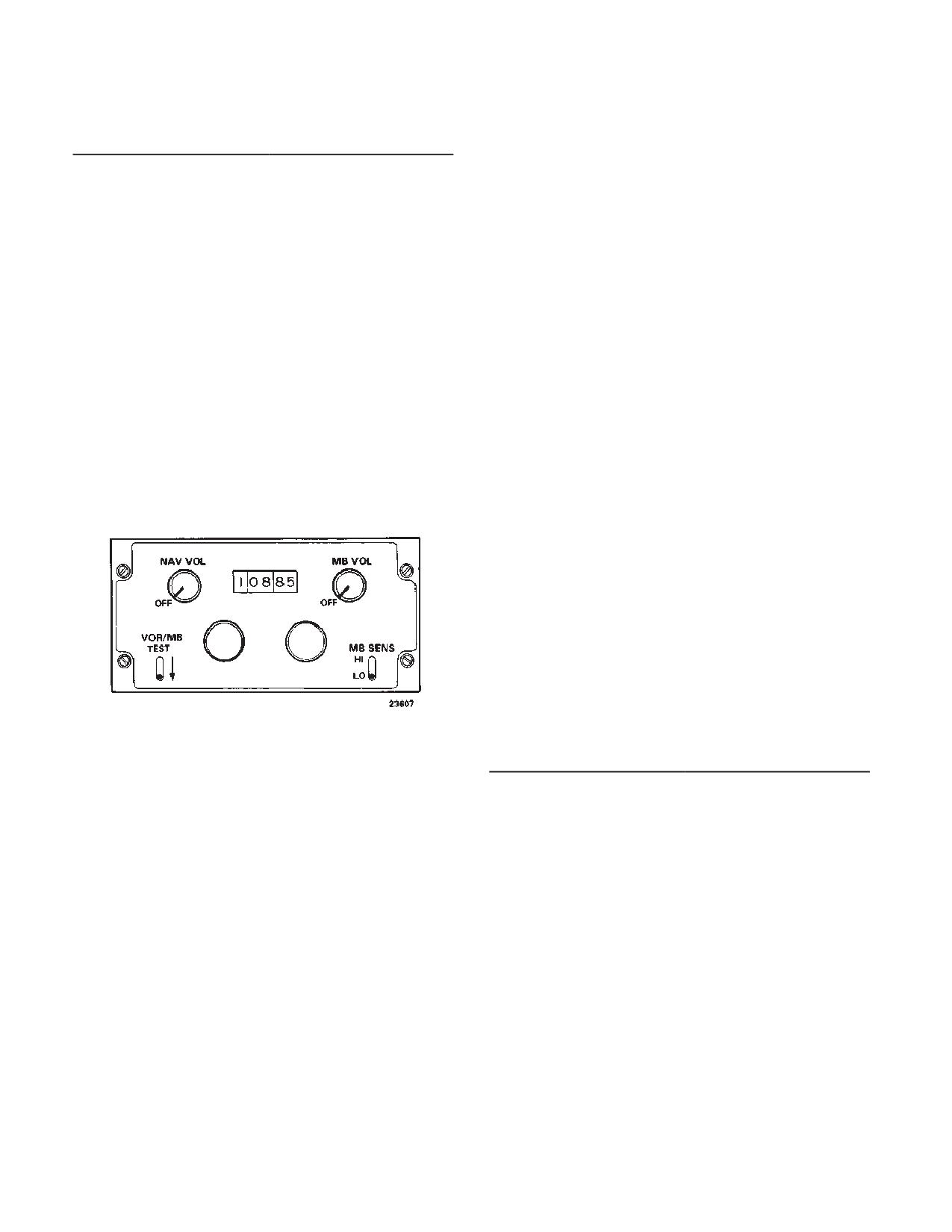
3-3-3. Controls and Function, VHF Navigation and
ceives signals from a ground marker beacon transmitter
Instrument Landing System Set. (fig. 3-3-1)
to determine helicopter position. The audio output of the
marker beacon receiver is applied through the inter-
phone system to the headsets as a direct input (no inter-
phone control box switch setting necessary). Three
CONTROLS/
FUNCTION
marker beacon lights are on each HSI MODE SELECT
INDICATOR
panel. The lights are labeled MKR BCN and indicate
marker beacon passage. Also specific tones will be
NAV VOL
Provides power to set
heard over the interphone while flying over each beacon.
when turned from OFF.
Table 3-3-1 presents the indication as each beacon is
Turning knob clock-wise
passed. The lights are tested by momentarily pressing
increases volume.
any one of three lights. The marker beacon antenna is
under the fuselage is under the fuselage forward of the
VOR/MB TEST
Switch spring-loaded
forward cargo hook. Power to operate the set is from the
from TEST position. At
DC essential bus through the NAV VOR circuit breaker
TEST, the MKR BCN
on the No.1 PDP. Power is supplied by the 26-volt AC
lights illuminate.
instrument bus through the NAV VOR circuit breaker on
Megahertz Select Knob
Selects last two digits of
the No. 1 PDP.
frequency in 50 -kilohertz
Table 3-3-1. Marker Beacon Indicator
increments.
BEACON
LIGHT COLOR TONE (HERTZ)
MB VOL
Adjusts audio output lev-
Outer (O)
Blue/Green
400
el of marker beacon re-
ceiver. Provides power to
Middle (M)
Blue/Green
1300
the marker beacon when
Inner (I)
Blue/Green
3000
turned from OFF.
3-3-1
TM 1-1520-240-10
(2)
MB SENS - HI for enroute. Lo for ap-
CONTROLS/
FUNCTION
INDICATOR
proach.
MB SENS
Labeled HI and LO. LO
sensitivity is used for
(3)
MKR BKN lamps on HSI MODE SELECT
positive identification of
panels - Check lit at corresponding station passage.
marker beacon passage.
HI is used for station
passage identification at
d. Stopping - NAV VOL and MB VOL switches -
the outer marker or en-
OFF
route.
Marker Beacon Indicator
Three lights marked 0,M,
Lights
and I on both HSI MODE
3-3-5. Direction Finder Set (AN/ARN-89).
SELECT panels. Lights
illuminate when passing
over beacons.
Direction finder set (AN/ARN-89) is an airborne automat-
ic direction finder (ADF) operating within the frequency
3-3-4. Normal Operation - VHF Navigation and In-
range of 100 to 3,000 kHz. The equipment provides visu-
strument Landing System. The following paragraphs
provide navigation radio set operating procedures.
al and aural facilities for ADF homing and position fixing.
It is used as a navigational radio aid to continuously and
a. Starting.
visually indicate the magnetic bearing of a radio station
(1)
Interphone AUX switch - ON
while providing aural reception. The bearing of a radio
station is displayed on the No. 2 bearing pointer on the
HSI. Power to operate the direction-finder set is supplied
by the No. 1 DC bus and the AC instrument bus through
the NAV ADF circuit breakers on the No. 1 PDP.
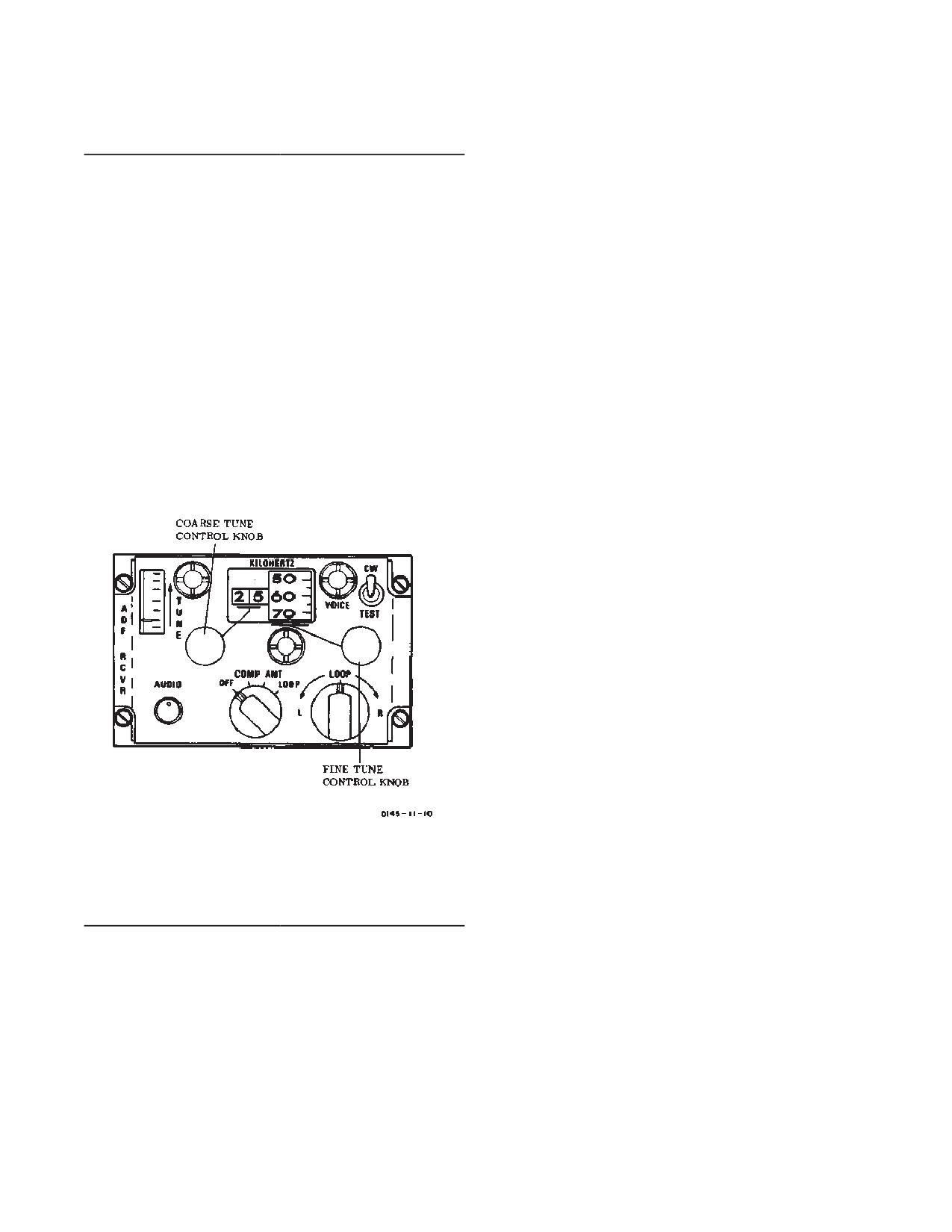
3-3-6. Controls and Function, Direction Finder Set
(AN/ARN-89). (fig. 3-3-2)
Figure 3-3-1. VHF Navigation and Instrument
CONTROLS/
FUNCTION
Landing System Control (AN/ARN-123)
INDICATOR
Mode Switch OFF
OFF position deener-
gizes the direction finder
(2)
NAV VOL switch - ON.
set.
b. VOR/Localizer/ILS Operation.
COMP
COMP position selects
(1)
Megahertz and kilohertz selector - Set fre-
automatic direction find-
quency of facility.
ing.
(2)
VOR SEL switch on HSI MODE SELECT
ANT
ANT position permits re-
panel - Press. Check SEL light lit.
ception for radio naviga-
(3)
VOR ADF switch on HSI MODE SELECT
tion or as a broadcast
panel - Press, if VOR segment is not lit
receiver.
(4)
Volume control - Adjust. Identify facility
LOOP
LOOP position, used in
conjunction with LOOP
(5)
HSIs - Check for correct indications.
switch, permits aural null
c. Marker Beacon operation.
homing and manual di-
rection finding.
(1)
MB VOL switch - ON.
3-3-2
TM 1-1520-240-10
CONTROLS/
FUNCTION
KILOHERTZ Indicator
Displays operating fre-
INDICATOR
quency to which receiv-
er is tuned.
AUDIO Control
Adjusts audio level in
COMP position. Used as
TUNE Meter
Provides indication of
RF gain control in LOOP
relative signal strength
or ANT position.
while tuning receiver to
specific radio signal.
LOOP Switch
When function switch is
set to LOOP, LOOP
CW-VOICE-TEST Switch Three position toggle
switch enables manual
switch. Spring-loaded
rotation of ADF loop an-
from TEST.
tenna and bearing indi-
CW
Enables the beat fre-
cator pointer left or right
quency oscillator (BFO)
for manual direction
to permit tuning to con-
finding, or when homing
tinuous wave stations.
to a radio station. Re-
turning LOOP switch to
VOICE
Enables the set to oper-
center position stops
ate as an AM receiver.
rotation of bearing indi-
TEST
Rotates the bearing indi-
cator pointer at any de-
cator approximately
sired position.
180_ to check operation
of the set. The TEST
switch functions when
the function switch is at
COMP only.
3-3-7. Normal Operation
- Direction Finder
Set. The following paragraphs discuss ADF set opera-
tion.
a. Starting.
(1)
Interphone control panel - Receivers NAV
switch - ON.
(2)
Mode switch - ON.
(3)
CW-VOICE-TEST - CW or VOICE.
(4)
Tune controls - Set frequency. Tune for
maximum signal strength on the tuning meter.
(5)
AUDIO control - Adjust.
b. ADF Operation.
(1)
VOR ADF switch on HSI MODE SELECT
panel - Press, if ADF segment is not lit.
Figure 3-3-2. Direction Finder Control
(2)
Check for the correct bearing indication, on
CONTROLS/
FUNCTION
HSI No. 2 bearing pointer.
INDICATOR
c. Radio Receiver Operation.
Coarse Tune Control
Tunes receiver in 100
(1)
Function switch - ANT
kHz steps as indicated
(2)
Tune control - Set frequency; then tune for
by first two digits of KI-
maximum signal strength on the tuning meter.
LOHERTZ indicator.
d. Aural Null.
Fine Tune Control
Provides selection of 10
kHz digits (continuous
(1)
CW-VOICE-TEST switch - CW.
tuning) as indicated by
(2)
Function switch - LOOP.
last two digits of KI-
(3)
Loop switch - Rotate for audio and tune
LOHERTZ indicator.
indicator null. Release switch. Observe bearing to station
CONTROLS/
FUNCTION
on indicators. Two null positions, 180_ apart, may be
INDICATOR
obtained.
3-3-3
TM 1-1520-240-10
3-3-8. Gyromagnetic Compass Set (AN/ASN-43).
CONTROLS/
FUNCTION
INDICATOR
The gyromagnetic compass set (fig. 3-3-3) is a direction
HDG Flag
A red flag on both HSIs
sensing system which provides a visual indication of the
indicates failure of the
heading of the helicopter with respect to the earth’s mag-
gyromagnetic compass
netic field or referenced to a free directional gyro. Head-
system when displayed.
ing information is displayed on both HSIs. The display is
used in a navigation to maintain flight path direction.
Also, any heading selected with the heading bug on ei-
3-3-10. Operating Procedures
- Gyromagnetic
ther HSI can be automatically maintained by the AFCS.
Compass Set. (fig. 3-3-3)
Power to operate the system is supplied by the No. 1 AC
bus and the AC instrument bus through the NAV CMPS
circuit breakers on the No. 1 PDP.
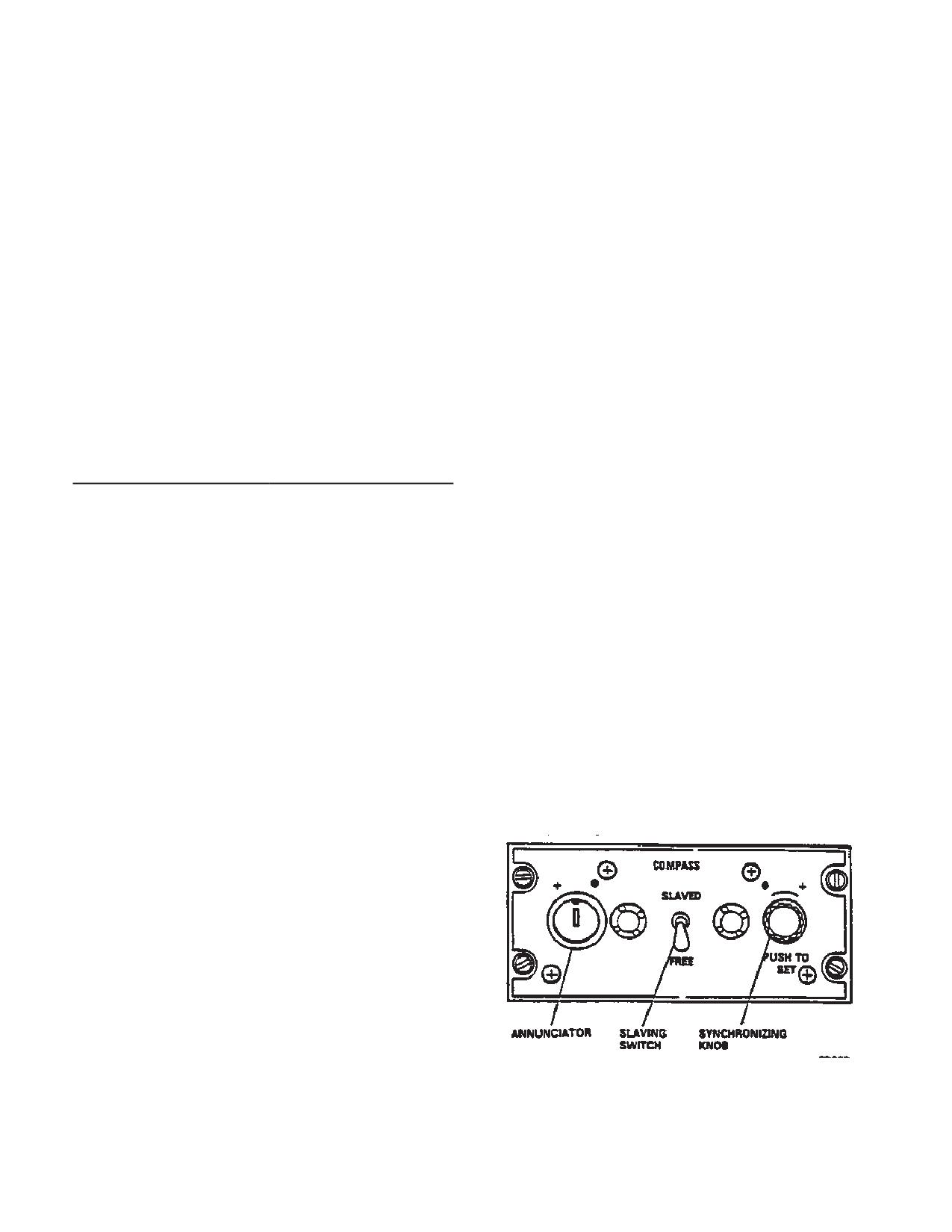
a. Slaved Gyro Operation. With compass slaving
switch at SLAVED, the system operates in the slaved
mode and the directional gyro precesses to align the
3-3-9. Controls and Function, Gyromagnetic Com-
compass cards on the HSIs with the magnetic heading
pass Set (AN/ASN-43). (fig 3-3-3 and 3-3-4)
of the helicopter. During the first 2 minutes after power is
applied, the system operates in a fast slave mode while
the gyro attains its speed. After this initial alignment peri-
CONTROLS/
FUNCTION
od is complete, the gyromagnetic compass will return to
INDICATOR
the normal slaved mode. During this mode of operation,
the compass cards will remain aligned with the magnetic
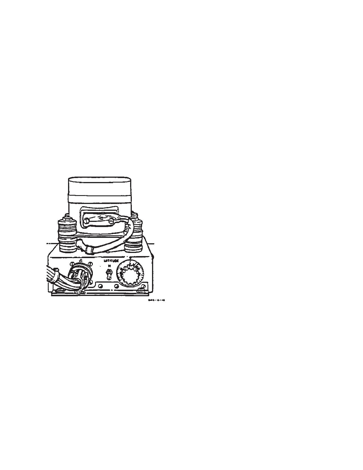
LATITUDE Switch
Two-position switch on
the directional gyro lo-
heading of the helicopter. The annunciator pointer will
cated on the avionics
occasionally point to a dot (Ĥ) or a plus sign (+) indicat-
shelf. This switch is
ing that corrections are automatically being made.
used to correct for gyro
precession for the hemi-
b. Free Directional Gyro Operation. If the compass
sphere of operation: N
slaving switch is at FREE, the system operates in the free
for northern hemisphere
directional mode. In this mode, the compass cards can
and S for southern
be set to any heading by pressing the PUSH TO SET
hemisphere.
knob and turning it until the cards reach the selected
LATITUDE Control Switch
Rotary control on direc-
setting. Normally, the free directional gyro mode is
tional gyro labeled 0 to
employed only in polar regions of the earth where mag-
90. It is used to set the
netic references are unreliable. However, it can be useful
local latitude into the di-
if the slaving system malfunctions. For proper operation,
rectional gyro for free
the latitude controls on the directional gyro (fig. 3-3-4)
gyro operation.
must be set to the local latitude.
SLAVED-FREE Switch
On compass control
panel. When switch is at
SLAVED, the compass
cards on both HSIs are
slaved to the output of
the remote compass
and-stabilized by the di-
rectional gyro. At FREE,
the cards are referenced
to the directional gyro
only and act as turn indi-
cators. FREE is used
primarily in polar regions
where magnetic indica-
tions may be unreliable.
PUSH TO SET synchro-
Rotated in (Ĥ) or (+) di-
nizing knob
rection as indicated by
annunciator pointer to
align compass cards
Figure 3-3-3. Gyromagnetic Compass Set Control
with gyro-compass.
Panel
3-3-4
TM 1-1520-240-10
NOTE
3-3-11. Doppler Navigation Set (AN/ASN-128).
If synchronizing becomes necessary in flight
with the AFCS on, position the SWIVEL
NOTE
switch to UNLOCK. After synchronization is
complete, position the SWIVEL switch to
When the Airborne Navigation Set AN/
LOCK. This prevents unwanted yaw axis in-
ASN-149 (Global Positioning System GPS) is
puts.
installed, the Doppler Navigation Set AN/
c. Manual Synchronization. If power has been ap-
ASN-128 is controlled by the GPS CDU. For
plied to the system with the compass slaving switch at
a description of the Airborne navigation Set
FREE or if the system has been operated in the free
and Doppler Navigation Set.
directional gyro mode for a period of time, the compass
a. The doppler navigation set (fig. 3-3-5) is a self-
cards will not be aligned with the magnetic heading of the
contained navigation system that does not require any
helicopter. The system can be reset to the correct mag-
ground-based aids. The system provides worldwide nav-
netic heading by pushing and turning the PUSH TO SET
igation with position readout available in both universal
knob in the direction of the symbol indicated by the an-
transverse mercator (grid) (UTM) and latitude and longi-
nunciator pointer until the pointer is centered. If the slav-
tude (lat/long). Navigation and steering is done using
ing switch is then set to SLAVED, the compass cards will
lat/long coordinates, and bilateral UTM-lat/long conver-
maintain correct magnetic heading.
sion routine is provided for UTM operation.
b. The system in conjunction with heading data from
the gyro compass, and pitch and roll data from the copi-
lot’s attitude gyro, provides velocity, position, and steer-
ing information from ground level to 10,000 feet.
c. The computer-display unit (CDU) is on the canted
console, between the pilot and copilot positions. Course
deviation, bearing, distance to destination, and NAV GO/
NOGO are also presented to the HSI. Built in test equip-
ment (BITE) continuously monitors system operation. If
a failure occurs, a malfunction indicator lamp will light
and coded data, indicating the failed component, will be
displayed on the CDU when the MODE switch is set to
TEST. Power to operate the set is supplied by the No. 2
DC bus through the NAV DOPPLER circuit breaker on
the No. 2 PDP, and the No. 1 AC instrument bus through
the NAV DOPPLER circuit breaker on the No. 1 PDP.
Figure 3-3-4. Directional Gyro (CN-998/ASN-43)
3-3-5
TM 1-1520-240-10
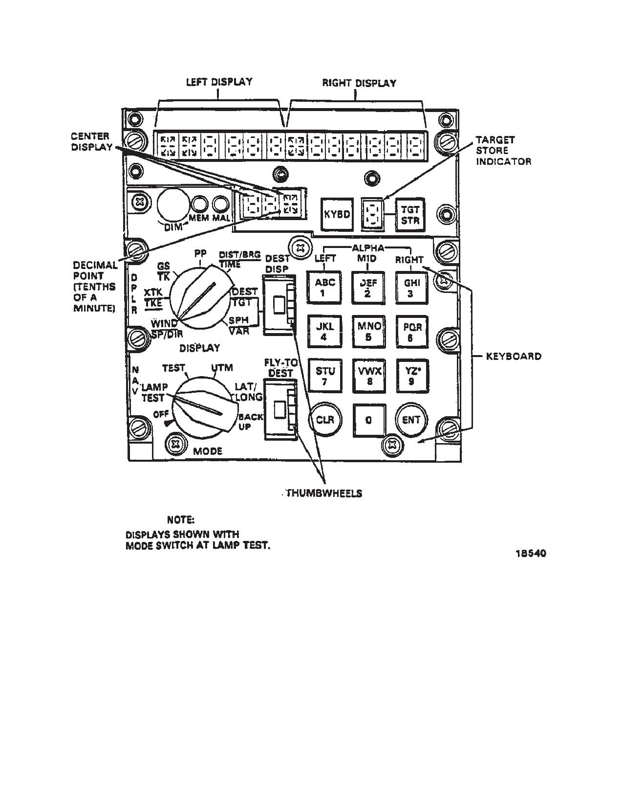
Figure 3-3-5. Doppler Navigation Set Control (AN/ASN-128)
3-3-6
TM 1-1520-240-10
3-3-12. Controls and Function -- Doppler Naviga-
CONTROLS/
FUNCTION
tion Set. (fig. 3-3-5 and table 3-3-2)
INDICATOR
GS/TK
CONTROLS/
FUNCTION
INDICATOR
(Left Display)
Ground speed (GS) in
MODE Selector
Selects doppler naviga-
km/hr.
tion mode of operation as
(Right Display)
Track angle in degrees
follows:
relative to true north.
OFF
Turns set off. Pull knob
PP with mode switch
out to move from, or to
set to UTM
this position.
(Center Display)
Present position UTN
LAMP TEST
Checks operation of all
zone.
lamps and lamp seg-
ments.
(Left Display)
Present position UTM
square designator and
TEST
Initiates (BIT) for set.
easting in km to nearest
System reverts to backup
10 meters.
navigation operation dur-
ing mode.
(Right Display)
Present position UTM
UTM
Selects universal trans-
northing in km nearest 10
verse mercator coordi-
meters.
nate system for display
PP with MODE switch
and insertion of informa-
set to LAT/LONG
tion.
LAT/LONG
Select latitude/longitude
(Left Display)
Present latitude position
coordinate system for
in degrees, minutes, and
display and insertion of
tenths of minutes.
information.
(Right Display)
Present longitude posi-
BACKUP
Places set in remem-
tion in degrees, minutes,
bered velocity mode of
and tenths of minutes.
operation.
DIST/BRG/TIME
DISPLAY Selector
Selects navigation data
for display as follows:
(Center Display)
Time to the destination
set on FLY-TO DEST
WIND SP/DIR
Used only with BACKUP
thumbwheel in minutes
mode.
and tenths of minutes.
(Left Display)
Windspeed kilometer(s)
(Left Display)
Distance to the destina-
per hour.
tion set on FLY-TO DEST
(Right Display)
Direction (degrees) rela-
thumbwheel in km and
tive to true north.
tenths of a km.
XTK/TKE
(Right Display)
Bearing to the destination
set on FLY- TO DEST
(Left Display)
Distance crosstrack error
thumbwheel is degrees.
(XTK) in km and tenths of
Bearing is also indicated
a km left or right of heli-
by the No. 1 bearing
copter. Track error will
pointer on both HSIs.
also be displayed by the
course deviation indicator
DEST/TGT
(CDI) on the HSI when
DOP.
(Center Display)
UTM zone of destination
SEL on the HSI MODE
set on DEST DISP
SELECT panel is
thumbwheel.
pressed.
(Left Display)
UTM square designator
(Right Display)
Track angle error (TKE)
and easting or latitude (N
in degrees and right or
84_ to S 80_ approx) of
left of present helicopter
destination set on DEST
heading.
DISP thumbwheel.
3-3-7
TM 1-1520-240-10
CONTROLS/
FUNCTION
CONTROLS/
FUNCTION
INDICATOR
INDICATOR
SPH/VAR
Keyboard
Used to enter data into
system. Keys set up data
(Left Display)
Spheroid code of desig-
on display. All resulting
nation set on DEST DISP
actions are initiated upon
thumbwheel.
release of the key.
(Right Display)
Magnetic variation (in de-
FLY-TO-DEST Thumb-
Selects destination to
grees and tenths of de-
wheel Switch
which steering informa-
grees) of destination set
tion is desired. Destina-
on DEST DISP thumb-
tions are 0 through 9, P
wheel.
(present position) and H
(home).
MAL Indicator Lamp
Lights when set malfunc-
tions. In case of an inter-
ENT Key
Enters data set up on
mittent malfunction, sys-
keyboard into memory
tem may operate correct-
when pressed.
ly, but must be cycled to
CLR Key
Clears last entered char-
OFF and then to on to
acter when pressed
put MAL light off.
once. Clears entire dis-
MEM Indicator Lamp
Lights when radar portion
play panel under key-
of set is not tracking. May
board control when
occur over smooth water.
pressed twice.
DIM Control
Controls light intensity of
3-3-13. Display and Keyboard Operation.
display characters.
In LAT/LONG coordinates, the two fields of control are
Left, Right, and Center
Alphanumeric and nu-
Display Lamp
meric characters that dis-
the left and right displays. In UTM coordinates, the first
play data as determined
field of control is the center display and the second field
by setting of DISPLAY
is the combination of the left and right displays. When
switch, mode switch, and
pressing the KYBD pushbutton, one or other of the fields
keyboard.
described above is under control. If it is not desired to
change the information in the field under control, the pilot
Target Storage Indicator
Displays destination
can advance to the next field of the display panel by
number (memory loca-
tion) in which present
pressing the KYBD pushbutton again.
position will be stored
when TGT STR pushbut-
3-3-14. Data Entry
ton is pressed.
To enter a number, press the corresponding key. To enter
TGT STR Pushbutton
Stores present position
a letter, first press the key corresponding to the desired
data when pressed.
letter. Then press a key in the LEFT, MID, or RIGHT
column corresponding to the position of the letter on the
KYBD Pushbutton
Used in conjunction with
pushbutton.
keyboard to allow data
entry. KYBD pushbutton
Example: To enter an L, first press L, then either 3, 6, or
is always lighted when
9 in the RIGHT column. The computer program is de-
system is on.
signed to reject unacceptable data (for example, a UTM
DEST DISP Thumbwheel
Destination display
area of WI does not exists, and will be rejected). If the
Switch
thumbwheel switch is
operator attempts to insert unacceptable data, the dis-
used along with DEST/
play will be blank after ENT is pressed.
TGT and SPH/VAR posi-
tions of DISPLAY switch
3-3-15. Starting Procedure.
to select destinations
whose coordinates or
a. MODE selector - LAMP TEST. All lights and lamp
magnetic variation to be
segments should be lit.
displayed or entered.
(1)
Left, right, center and target storage indica-
Destinations are 0
through 9, P (present
tor - Lit (fig. 3-3-5). All other lights should be on.
position) and H (home).
(2)
Turn DIM control fully clockwise, then fully
counterclockwise, and return to full clockwise; all seg-
ments of the display should alternately glow brightly, go
off, and then glow brightly.
3-3-8
TM 1-1520-240-10
Table 3-3-2. Computer-Display Unit Data Displays
CENTER DISPLAY
LEFT DISPLAY
RIGHT DISPLAY
SWITCH POSI-
DATA
RANGE
DATA
RANGE
DATA
RANGE
TION
WIND SP/DIR
Windspeed
999 km/h
Wind Direc-
359_
tion
XTK/TKE
Crosstrack Dis-
L/R 999.9
Track Angle
R/L 180_
tance Error
km
Error
GS/TK
Groundspeeed
999 km/h
Track
359_
PP
UTM
UTM Zone Note 2
Area/Easting
WV9999
Northing
9999
LAT/LONG
Latitude
N 84_00.0”
Longitude
E/W
S 80_00.0”
180_00.0”
DIST/BRG/TIME
Time
99.9 Min.
Distance to Go
999.9 km
Bearing
359_
DEST/TGT UTM
UTM Zone Note 2
Area/Easting
WV9999
Northing
9999
Note 3
LAT/LONG
Latitude
N 84_00.0”
Longitude
E/W
S 80_00.0”
180_00.0”
SPH/VAR
Spheroid
Note 1
Variation
E/W 180_
Note 4
NOTES:
1. See table 3-3-3 for spheroid data codes and covered areas.
2. Numeric: 01-60.
Alpha: C-X, except I and O.
3. Typical 100 km Designator:
Column Designator: A-Z, except I and O.
Row Designator: A-V, except I and O.
4. Variation displayed is for destination indicated by DESP DISP thumbwheel.
b. MODE selector - TEST. After about 15 seconds,
DISPLAY
left display should display GO. Ignore the random display
of alpha and numeric characters which occurs during the
LEFT
RIGHT
REMARKS
first 15 seconds. Also ignore test velocity and angle data
displayed after the display has frozen. After about 15
GO
Display
System is operating satisfac-
seconds, one of the following five displays will be ob-
blanks
torily.
served in the first two character positions in the left dis-
play.
GO
P
If right display is P, then pitch
or roll data is missing or in er-
NOTE
ror. In this case, pitch and roll
If the MAL lamp lights during any mode of
in the computer are both set
operation except LAMP TEST, the computer-
to zero and navigation is de-
display unit MODE switch should be set to
graded. Problem may be in
OFF, and then to TEST, to verify the failure. If
the vertical gyroscope or heli-
the MAL lamp remains on at TEST, notify
copter wing.
maintenance.
BU
C, R, S,
A failure has occurred and the
If the TEST mode display is MN or NG, the MODE switch
or H fol-
system has automatically
should be recycled through OFF to verify that the failure
lowed
switched to a BACKUP mode
is not a momentary one. If the TEST mode display is MN,
by a nu-
of operation using last re-
the data entry may be made in the UTM or LAT/LONG
meric
membered velocities for na-
mode, but any navigation must be carried on with the
code
vigation. The operator can, as
system in the BACKUP mode.
3-3-9
TM 1-1520-240-10
NOTE
DISPLAY
It is not necessary to enter destinations un-
LEFT
RIGHT
REMARKS
less steering information is required, unless it
an option, enter his best esti-
is desired to update present position by over-
mate of ground speed and
flying a destination, or unless a present posi-
track angle.
tion MAG VAR computation is desired. If a
present position MAG VAR running update is
MN
C, R, S,
A failure occurred and the
desired, destination MAG VAR must be enter-
or H fol-
BACKUP mode used for
ed. The operator may enter one or more des-
lowed
manual navigation (MN) is the
tination variations to effect the variation up-
by a nu-
only means of valid naviga-
date; it is not necessary for all destinations to
meric
tion. The operator may use
have associated MAG VAR entered.
code
the computer as a dead reck-
oning devise by entering
e. Variation of destinations.
ground speed and track data.
3-3-17. Entering Spheroid and/or Variation.
The operator should update
present position as soon as
a. MODE selector - UTM, LAT/LONG or BACKUP.
possible, because it is pos-
b. DISPLAY selector - SPH-VAR.
sible significant navigation er-
rors may have accumulated.
c. DEST DISP thumbwheel - P, numeral, or H as
NG
C, R, S,
A failure has occurred in the
desired.
or H fol-
system and the operator
d. KYBD pushbutton - Press. Observe display
lowed
should not use the system.
freezes and TGT STR indicator blanks. Press KYBD
by a nu-
pushbutton again and observe left display blanks. If no
meric
spheroid data is to be entered, KYBD pushbutton -
code
Press again, go to step g.
EN
The 9V battery has failed. The
e. Spheroid data (table 3-3-3) - Entry. (Example:
system will still operate but all
IN0). Press keys 3, 3, 5, 5, and 0. Left display should
stored data will be lost when
indicate IN0.
set is turned off. Data must be
re-entered.
f. ENT key - Press if no variation data are to be
entered.
Random
Random
A failure occurred and the op-
display
display
erator should not use the sys-
g. KYBD pushbutton - Press, if variation data is to
tem.
be entered, and note right display blanks.
h. Variation data - Enter. (Example: E001.2, press
keyboard keys 2, 2, 0, 0, 1 and 2. Press ENT key, the
3-3-16. Entering Data.
entire display will blank and TGT STR number will re-
appear, display should indicate IN0 E001.2.)
This initial data is inserted before navigating with the
NOTE
doppler.
If operation is to occur in a region with relative-
a. Spheroid of operation, when using UTM coordi-
ly constant variation, the operator enters vari-
nates.
ation only for present position, and the com-
puter will use this value throughout the flight.
b. UTM or LAT/LONG coordinates of present posi-
tion.
Table 3-3-3 Spheroid Data Codes
c. Magnetic Variation (MAG VAR) of present posi-
SPHEROID
CODE
AREA COV-
tion.
ERED
CLARKE 1866
CL6
United States
d. Coordinates of desired destination - 0 through 5
north through
and H: (6 through 9 are normally used for target store
North Pole
locations; but may also be used for destinations.) It is not
CLARKE 1880
CLφ
Africa west
necessary to enter all destinations in the same coordi-
through Algeria
nate system.
3-3-10
TM 1-1520-240-10
Table 3-3-3. Spheroid Data Codes (Continued)
is deleted. The order of entry for present position is irrele-
vant.
SPHEROID
CODE AREA COVERED
a. MODE selector - LAT/LONG.
INTERNATIONAL
INφ
All of Europe, Saudi
b. DISPLAY selector - DEST-TGT.
Arabia, Greenland,
c. DEST DISP thumbwheel - P, numeral, or H as
South America, Indian
desired.
Ocean, Pacific
Ocean, and Atlantic
d. Present position or destination - Enter. (Exam-
Ocean.
ple: Entry of N41_ 10.1 minutes and E035_ 50.2 min-
BESSEL
BEφ
Indonesia, Manchu-
utes.)
rian, to Eastern Rus-
(1)
KYBD pushbutton - Press. Observe that
sia.
display freezes and TGT STR indicator blanks.
EVEREST
EVφ
Mt. Everest, India,
(2)
KYBD pushbutton - Press. Observe that
and Pakistan
left display blanks.
AUSTRALIAN
AUφ
Australia
(3)
Key 5, 5, 4.1, 1, 0, and 1 - Press.
NATIONAL
(4)
KYBD pushbutton - Press. Observe right
display blank.
3-3-18. Entering Present Position or Destination in
UTM.
(5)
Key 2, 2, 0, 3, 5, 5, 0, and 2- Press.
The variation of a destination must be entered after the
(6)
ENT key - Press. Left, right, and center
associated destination coordinates are entered, since
displays will momentarily blank and TGT STR number
each time a destination is entered its associated variation
will reappear. Displays should indicate N41_ 10.1 E035_
is deleted. The order of entry for present position is irrele-
50.2.
vant.
3-3-20. Entering Ground Speed and Track.
a. MODE SELECTOR - UTM.
a. MODE selector - BACK UP.
b. DISPLAY selector - DEST-TGT.
b. DISPLAY selector - GS-TK.
c. DEST DISP thumbwheel - P, numeral, or H as
c. Ground speed and track - Enter. (Example; Enter
desired.
131 km/h and 024_. Press KYBD pushbutton, observe
d. Present position and destination - Enter. (Exam-
that left display freezes and TGT STR indicator blanks.
ple: Entry of zone 31T, area CF, easting 0958 and north-
Press KYBD pushbutton and observe that left display
ing 3849).
blanks.
d. Press keys 1, 3, and 1. Left display indicates 131.
(1)
KYBD pushbutton - Press. Observe that
Press KYBD pushbutton, control shifts to right display,
display freeze and TGT STR indicator blanks.
and right display blanks. Press keys 0, 2 and 4.
(2)
KYBD pushbutton - Press. Observe that
e. ENT key - Press. The entire display will blank,
center display blanks.
and TGT STR number will reappear. Display should indi-
(3)
Key 3, 1, 7, and 8 - Press.
cate 131 024_.
(4)
KYBD pushbutton - Press. Observe left
3-3-21. System Initialization.
and right displays blank.
a. DEST DISP thumbwheel - P.
(5)
Key 1, 3, 2, 3, 0, 9, 5, 8, 3, 8, 4, 9- Press.
b. Present position spheroid and/or variation (para.
(6)
ENT key - Press. Left, right and center dis-
3-39) - Enter.
plays will momentarily blank and then display CF 0958,
NOTE
3849, 31T, respectively, TGT STR number will appear.
Do not press ENT key after entering initial
3-3-19. Entering Present Position or Destination in
position fix.
LAT/LONG.
c. Initial fix position (para. 3-3-18 or 3-3-19) - En-
ter.
The variation of a destination must be entered after the
associated destination coordinates are entered, since
d. When the helicopter is sitting over or overflies the
each time a destination is entered its associated variation
initial fix position - ENT.
3-3-11
TM 1-1520-240-10
e. FLY-TO DEST thumbwheel - Set to desired des-
(2)
DEST DISP thumbwheel - P. Present posi-
tination. The computer calculates a course between the
tion coordinates should be displayed.
destination and the helicopter position at the time the
(3)
KYBD pushbutton - Press, observe that
destination was selected.
display freezes.
3-3-22. Flight Procedures.
NOTE
If present position update is not desired, as
3-3-23. Update of Present Position from Stored Des-
indicated by a small difference between the
tination.
displayed coordinates and the landmark
coordinates, set the DISPLAY selector to
a. FLY-TO DEST thumbwheel - Set to destination to
some other position; this aborts the update.
be overflown.
(4)
Landmark coordinates - Manually enter via
b. DISPLAY selector - DIST/BRG-TIME.
keyboard.
(5)
ENT key - Press when overflying land-
c. KYBD pushbutton - Press and release when heli-
mark.
copter is over the destination. Display freezes upon re-
lease of the pushbutton.
3-3-25. FLY-TO-DEST Operation.
NOTE
a. When the FLY-TO-DEST thumbwheel is selected
If a present position update is not desired, as
to a new position, the helicopter’s present position at the
indicated by an approximately small value of
time is stored in the computer. A course is then computed
distance to go on overflying the destination,
from the helicopter’s present position, as stored, to the
set the DISPLAY selector to some other posi-
destination selected. If the helicopter deviates from this
tion; this aborts the update mode.
course, crosstrack error (XTK) is computed.
d. ENT key - Press if update is required.
b. Range and bearing to destination, current track
made good, and track angel error (TKE) correction are
3-3-24. Update of Present Position from Land-
computed from the helicopter’s present position to se-
mark.
lected destination.
There are two methods for updating from landmark.
Method 1 is used if the landmark comes up unexpectedly
3-3-26. Left-Right Steering Signals.
and the operator needs time to determine the coordina-
Flying the shortest distance to the destination from pres-
tes. Method 2 is used when the landmark update is antici-
ent position:
pated.
a. FLY-TO-DEST thumbwheel - Select desired des-
a. Method 1.
tination.
(1)
DISPLAY selector - PP.
NOTE
(2)
KYBD pushbutton - Press as landmark is
If the desired destination is already selected
overflown. Present position display will freeze upon re-
but an updated course is needed, then the
lease of pushbutton.
FLY-TO-DEST thumbwheel must be cycled to
another destination and back so the computer
(3)
Compare landmark coordinates with those
will recalculate the new course.
on display.
b. DISPLAY selector - XTK/TKE.
NOTE
c. Fly to keep the left display at L or R 000.0 and the
right display to L or R 000.
If present position update is not desired, as
indicated by a small difference between the
3-3-27. Target Store (TGT STR) Operation.
display coordinates and the landmark coordi-
nates, set the DISPLAY selector to some oth-
Two methods may be used for target store operation.
er position; this aborts the update.
Method 1 is normally used when time is not available for
(4)
Landmark coordinates - Enter if difference
preplaning a target store operation. Method 2 is used
warrants an update.
when time is available and it is desired to store a target
in a specific DEST DISP position.
(5)
ENT key - Press if update is required.
a. Method 1.
b. Method 2.
(1)
TGT STR pushbutton - Press when flying
(1)
DISPLAY selector - DEST/TGT.
over target.
3-3-12
TM 1-1520-240-10
(2)
Present position at the time the pushbutton
3-3-30. Dead Reckoning Navigation.
is released is automatically stored and the destination
As a BACKUP mode, dead reckoning navigation can be
location is that which was displayed in the target store
done using ground speed and track angle estimates pro-
indicator (position 6, 7, 8 or 9) immediately before press-
vided by the operator.
ing the TGT STR pushbutton.
a. MODE selector - BACKUP.
b. Method 2.
b. DISPLAY selector - GS/TK.
(1)
MODE selector - UTM or LAT/LONG, de-
c. Best estimate of ground speed and track angle -
pending on coordinate format desired.
Enter via keyboard.
(2)
DISPLAY selector - DEST/TGT.
d. Set MODE selector to any position to abort this
mode.
(3)
DEST DISP thumbwheel -P.
3-3-31. Operation During and After Power Interrup-
(4)
KYBD pushbutton - Press when over flying
tion.
potential target. Display should freeze.
During a DC power interruption inflight, or when all heli-
NOTE
copter power is removed, the random access memory
Do not press ENT key while DEST DISP
(RAM) (stored destination and present position) data is
thumbwheel is at P.
retained by power from an 8.4 volt DC dry cell battery.
This makes it unnecessary to reenter any navigational
(5)
If it is desired to store target, turn DEST
data when power returns or before each flight. If the
DISP thumbwheel to destination location desired and
battery does not retain the stored destination data during
press ENT key.
power interruption the display will indicate an EN when
(6)
If it is not desired to store target, place DIS-
power returns. This indicates to the pilot that previously
PLAY selector momentarily to another position.
stored data has been lost, and that present position,
spheroid/variation, and destinations must be entered.
The computer, upon return of power, resets present posi-
3-3-28. Transferring Stored Target Coordinates from
tion variation to E000.0, destination and associated vari-
One Location to Another.
ations to a non-entered state, sets wind to zero and
The following procedure allows the operator to transfer
spheroid to CL6. The following data must be entered
stored target coordinates from one thumbwheel location
following battery failure:
to another. For example, it is assumed that the pilot wants
a. Spheroid.
to put the coordinates of stored target 7 into location of
destination 2.
b. Present position variation.
NOTE
c. Present position.
Throughout this procedure, range, time-to-
d. Each destination and its associated variation.
go, bearing and left/right steering data are
3-3-32. Stopping Procedure.
computed and displayed for the destination
selected via the FLY-TO-DEST thumbwheel.
MODE selector - OFF.
a. DISPLAY selector - DEST/TGT.
3-3-33. Horizontal Situation Indicator (HSI).
b. DEST DISP thumbwheel - 7.
Two horizontal situation indicators (HSI) (fig. 3-3-6), one
on each pilot’s instrument panel, are installed. Each indi-
c. KYBD pushbutton - Press.
cator can display helicopter heading, FM homing, and
d. DEST DISP thumbwheel - 2.
position relative to a selected course or bearing. Also,
during an ILS approach, the indicator displays helicopter
e. ENT key - Press.
position relative to the glide slope and localizer. The auto-
matic heading select feature of the AFCS is also con-
3-3-29. Transferring Variation from One Location to
trolled through the HSI. Selection of navigational equip-
Another.
ment to be displayed on each HSI is controlled through
the HSI MODE SELECT panel on each instrument panel
The procedure to transfer variation data to the same
below each HSI. Each HSI receives electrical power from
location where the associated stored target coordinates
three different sources (copilots sources are in paren-
has been transferred is the same as in previous para-
theses): 28 volt DC from the No. 2 (No. 1) DC bus through
graph. Transferring Stored Target Coordinates from One
the NAV PLT (COPLT) HSI MODE SEL circuit breaker,
Location to Another, except that the DISPLAY selector is
115 volt AC from the No. 2 (No. 1) AC bus through the
placed at SPH/VAR.
NAV PLT (COPLT) HSI circuit breaker, and 26 volt AC
3-3-13
TM 1-1520-240-10
from the No. 2 (No.1) instrument bus through the NAV
CONTROLS/
FUNCTION
PLT (COPLT) HSI circuit breaker.
INDICATOR
lubber line when the helicop-
3-3-34. Controls and Indicators - Horizontal Situa-
ter heading is the same as
tion Indicators. (fig, 3-3-6)
the selected course.
CONTROLS/
FUNCTION
Range indicator
Digital distance display in ki-
INDICATOR
lometers (KM) to destination
Compass Card
The compass card is a 360_
set on GPS Control Display
Unit (CDU) (para. 3-3-36) or
scale that turns to display
doppler control FLY-TO-
heading data obtained from
DEST thumbwheel (para.
the gyro magnetic compass
3-3-12).
(AN/ASN-43). The helicopter
headings are read at the up-
HDG Knob
Heading select (HDG) knob
per lubber line.
operates in conjunction with
Bearing Pointer No. 1 The pointer operates in con-
the heading bug. It allows
junction with doppler or
the pilot to select any one
mixed GPS/DOPPLER. With
heading. With CMD SEL (fig.
Doppler Only, indicates
3-3-6) selected on the HSI
magnetic bearing to doppler
MODE SELECT panel, the
destination. With mixed
AFCS (chapter 2) will turn
GPS/Doppler, indicates
the helicopter to and main-
magnetic bearing to GPS
tain the selected heading.
destination. (With GPS Only,
HDG Flag
The HDG flag is in view
bearing information is not
when the signal from the
available.)
gyro magnetic compass is
Bearing pointer No. 2 The pointer operated in con-
unreliable or power to the in-
junction with selected VOR
dicator is lost.
or ADF receiver. The pointer
is read against the compass
To-From Arrow
To-from arrow indicates that
card and indicates the mag-
the helicopter is flying to or
netic bearing to the VOR or
away from the selected
ADF station.
VOR.
Course Deviation Indi-
This indicator indicates
NAV Flag
The NAV flag turns with the
cator.
lateral deviation from se-
compass card. The flag will
lected VOR course or GPS/
retract from view when a re-
Doppler computed course or
liable VOR, GPS/Doppler or
heading in the case of FM
FM homing signal is being
homing. When the helicopter
applied to the instrument.
is flying to correct course,
the course indicator will be
Aircraft Symbol
Corresponds to longitudinal
aligned with the course
axis of the helicopter; shows
pointer and will be centered
helicopter position and
on the fixed aircraft symbol.
heading relative to the se-
The two dots on either side
lected course.
of the indicator indicate
amount of course deviation.
Glide Slope Pointer
Displays glide slope position
One dot displacement is
relative to the helicopter or
equivalent to 5_ off VOR or
FM homing signal strength.
GPS/Doppler and 1 1/4 de-
When pointer is above cen-
gree off localizer course.
ter, helicopter is below glide
These displacements do not
slope, conversely when
apply to FM homing.
pointer is below center, heli-
copter is above glide slope.
CRS Knob
The COURSE indicator and
Increasing homing signal
Course Indicator
course pointer operate in
strength is shown by pointer
Course Pointer
conjunction with the course
rising. decreasing signal
selected (CRS) knob, and
strength is shown by pointer
allow the pilot to select any
falling.
VOR course. The course
pointer turns with the com-
Glide Slope (GS)
Indicates loss of or an unre-
pass card and will be
Warning Flag
liable glide slope or FM
aligned with the with the
homing signal.
3-3-14
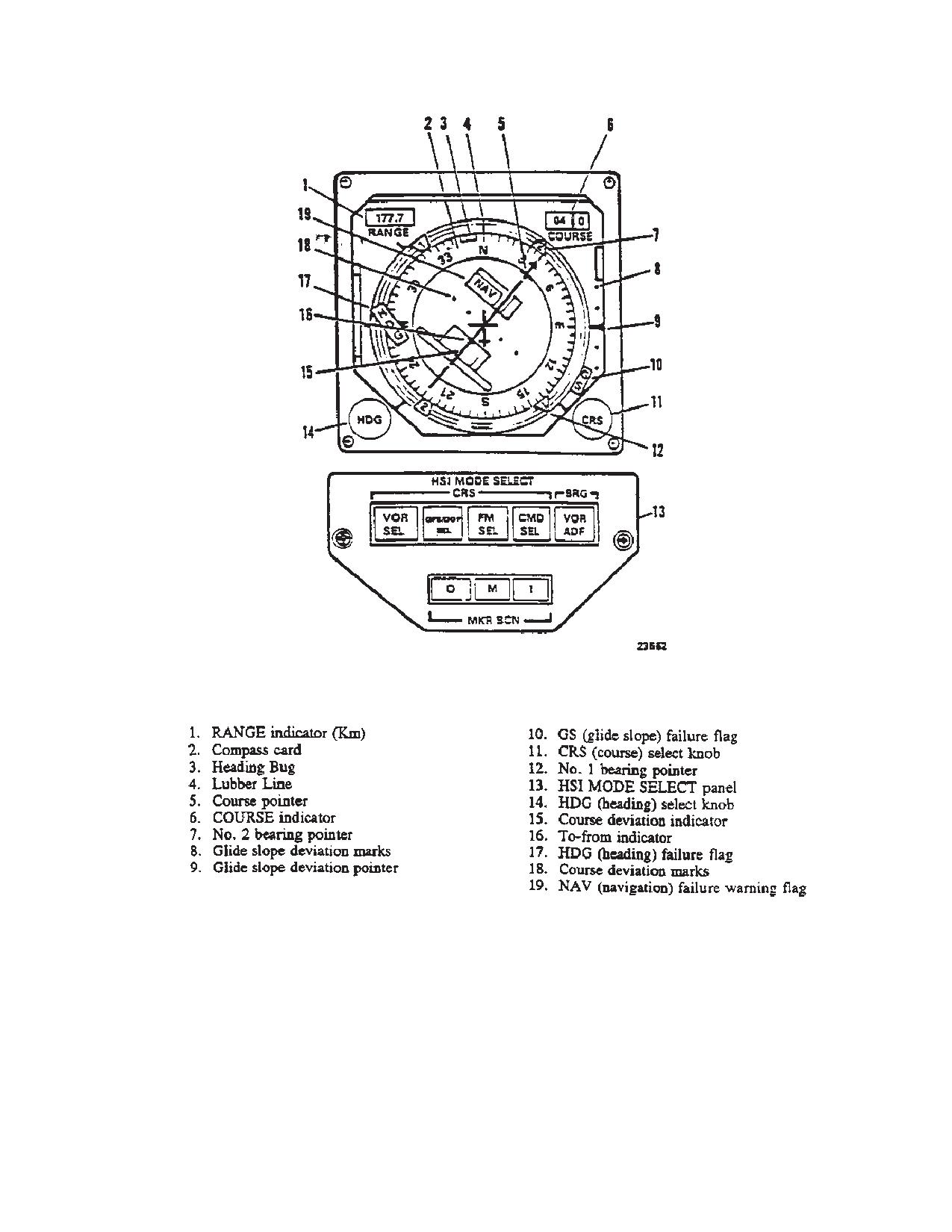
TM 1-1520-240-10
Figure 3-3-6. Horizontal Situation Indicator and Mode Select Panel
3-3-15
TM 1-1520-240-10
3-3-35. Horizontal Situation Indicator Mode Se-
d. A MKR BCN light will illuminate during marker bea-
lect. (fig. 3-3-6)
con passage. The light labeled O comes on when pass-
ing through an outer marker beam. The light labeled M
comes on when passing through a middle marker and
The HSI MODE SELECT panel is on each pilots instru-
finally the light labeled I comes on when passing through
ment panel below HSI. The panel allows the pilot to se-
an inner marker. As each light illuminates, a distinctive
lect the navigation mode to be displayed on the HSI,
tone identifying the beacon will be heard over the inter-
command AFCS heading select feature, and visually in-
phone (table 3-2-1). The lights have a press-to-test fea-
dicates marker beacon passage. The panel is divided
ture; pressing any one of the three lamps will cause all
into three sections labeled CRS, BRG, and MKR BCN.
MKR BCN lamps to illuminate on both pilots HSI MODE
SELECT panels.
a. The CRS (course) section consists of four push-
3-3-36. Doppler/GPS Navigation Set AN/ASN-128B
button selector switches labeled VOR SEL, GPS/DOP
(DGNS).
SEL, FM SEL, and CMD SEL. Pressing VOR SEL, GPS/
DOP SEL, or FM SEL causes the output of the selected
The AN/ASN-128B DGNS is an AN/ASN-128 LDNS with
navigation set to be electrically connected to the course
embedded GPS receiver. The AN/ANS-128B in conjunc-
deviation indicator on the corresponding HSI and lights
tion with the aircraft’s heading, vertical references, and
SEL legend in the switch. These switches are electrically
position and velocity updates from its internal GPS, pro-
interlocked so only one set may be selected at a time.
vides accurate aircraft velocity, position and steering in-
Selecting another navigational modes, automatically dis-
formation from ground level to 10,000 feet. The system
engages the mode in use, turns out the SEL legend of the
provides world-wide navigation, with position readout
mode in use, engages the selected mode, and lights the
available in both Military Grid Reference System
SEL legend of the selected mode. Each pilot may inde-
(MGRS) and Latitude and Longitude (LAT/LONG) coor-
pendently select different navigational modes for display
dinates. Navigation and steering is performed using LAT/
on his HSI.
LONG coordinates and a bilateral MGRS-LAT/LONG
conversion routine is provided for MGRS operation. Up
to 100 destinations may be entered in either format and
b. Pressing CMD SEL engages the AFCS heading
not necessarily the same format.
select feature, and will illuminate the SEL legend on the
3-3-37. Controls, Displays and Function.
switch. Due to electrical interlocks between the two HSI
control panels, both CMD SEL switches cannot be en-
The control and displays for the AN/ANS-128B are on the
gaged at the same time. The engaged switch is indicated
front panel (fig. 3-3-7). The function of each control is as
by the lit SEL legend. If the opposite CMD SEL switch is
follows:
pressed when operating with heading select, the HDG on
NOTE
the AFCS panel will release and heading select will be
The MODE switch is locked in the OFF posi-
disengaged. Control of the course deviation indicator in
tion and must be pulled out and turned to get
the VOR mode relative to bearing and course deviation
into or out of OFF position.
to or from a VOR is assigned to the pilot who has CMD
SEL engaged. If the pilot who does not have CMD SEL
CONTROLS/
FUNCTION
engaged makes an adjustment on his CRS knob, it will
INDICATOR
have no effect on the CDI relative to the course.
MODE switch
Selects navigation set mode
of operation.
c. Pressing VOR/ADF pushbutton on the BRG side
OFF
In this position the naviga-
selects the navigational aid, the bearing of which will be
tion set is inoperable; non-
indicated by the HSI No. 2 pointer. The switch is divided
volatile RAM retains stored
into two segments labeled VOR and ADF. If VOR seg-
data.
ment is lit, the No. 2 pointer will indicate the bearing to a
LAMP TEST
Checks operation of all
VOR station to which the VHF navigation set is tuned.
lamps.
Pressing the switch will cause the VOR segment to go
out and the No. 2 pointer will indicate the bearing to the
TEST
Initiates built-in-self-test ex-
station to which the ADF set is tuned out and light the
ercise for the Doppler and
ADF segment. The opposite action occurs if the ADF
GPS functions of the naviga-
tion set.
segment is lit and the switch is pressed.
3-3-16
TM 1-1520-240-10
CONTROLS/
FUNCTION
CONTROLS/
FUNCTION
INDICATOR
INDICATOR
MGRS
Selects Military Grid-Ref-
BRT and DIM Keys
Used to brighten or dim the
ence System (MGRS) navi-
light intensity of the LCD dis-
gational mode of operation.
play.
LAT/LONG
Selects latitude/longitude
Four Line Alpha-
Displays alphanumeric char-
navigational mode of opera-
Numeric Display
acters, as determined by the
tion.
setting of the DISPLAY
GPS
Places navigation set in
switch, the MODE switch
LDG
GPS landing mode of opera-
and operation keyboard.
tion. This mode provides
The keys activate function
real-time, tactical precision
upon release and are to be
landing guidance informa-
released immediately after
tion to the HSI indicator.
being depressed.
DISPLAY switch
Selects navigation data for
display.
TGT STR Key
Stores present position data
in the indicated target store/
WIND-UTC
Used for wind speed and di-
memory location (90-99)
DATA
rection, UTC time, sea cur-
when depressed and re-
rent, surface wind, GPS sta-
leased.
tus and data load functions.
KYBD Key
Used in conjunction with the
XTK/TKE
Displays steering (cross
KEY
track distance and track
keyboard to allow data dis-
angle error) information and
play and entry into comput-
GPS variable key status.
er.
Selection of fly to destination
by direct entry of two digit
Keyboard and LTR
Used to set up data for entry
destination number.
Keys
into memory. When DIS-
PLAY switch is set to a posi-
GS/TK
Displays ground speed,
tion in which new data is re-
NAV M
track angle and selection of
quired and KYBD key is
GPS and navigation mode.
pressed, data may be dis-
played on the appropriate in-
PP
Displays present position, al-
put field of display. To dis-
titude and magnetic varia-
play a number, press the
tion.
corresponding key or keys
DIST BRG
Displays distance, bearing
(6 through 9). To display a
TIME
and time information to the
letter, first depress the LTR
destination or course selec-
key corresponding to the
ted. Selection of fly to des-
position of the desired letter
tination can be accom-
on a key. Then depress the
plished by direct entry of two
key which contains the de-
digit destination number.
sired letter. Example: To en-
ter an L, first depress the
WP
Accesses waypoint or target
LTR RIGHT key then de-
TGT
data (landing data, variation,
press the 4 key.
motion). Selection of des-
INC and DEC Keys
Used to increment or decre-
tination for display/entry by
ment the displaced WAY-
direct entry of two digit des-
point/Target number when
tination number.
the DIPLAY switch is set to
DATUM
Accesses datum and steer-
WP/TGT. To access P, de-
press the LTR LEFT key fol-
ROUTE
ing/route functions.
lowed by the 6 key, display
MAL Indicator
Lights when navigation set
waypoint 99 then depress
Lamp
malfunction is detected by
the inc key, or display way-
the built-in test circuitry. In
point 99 then depress the
the event of an intermittent
INC key, or display waypoint
malfunction, the system may
00 key then depress the
operate correctly but must
DEC key. Also used to incre-
be cycled to OFF position
ment or decrement the Fly-
then to on, to extinguish the
To-Destination number when
MAL light.
the DISPLAY switch is
3-3-17
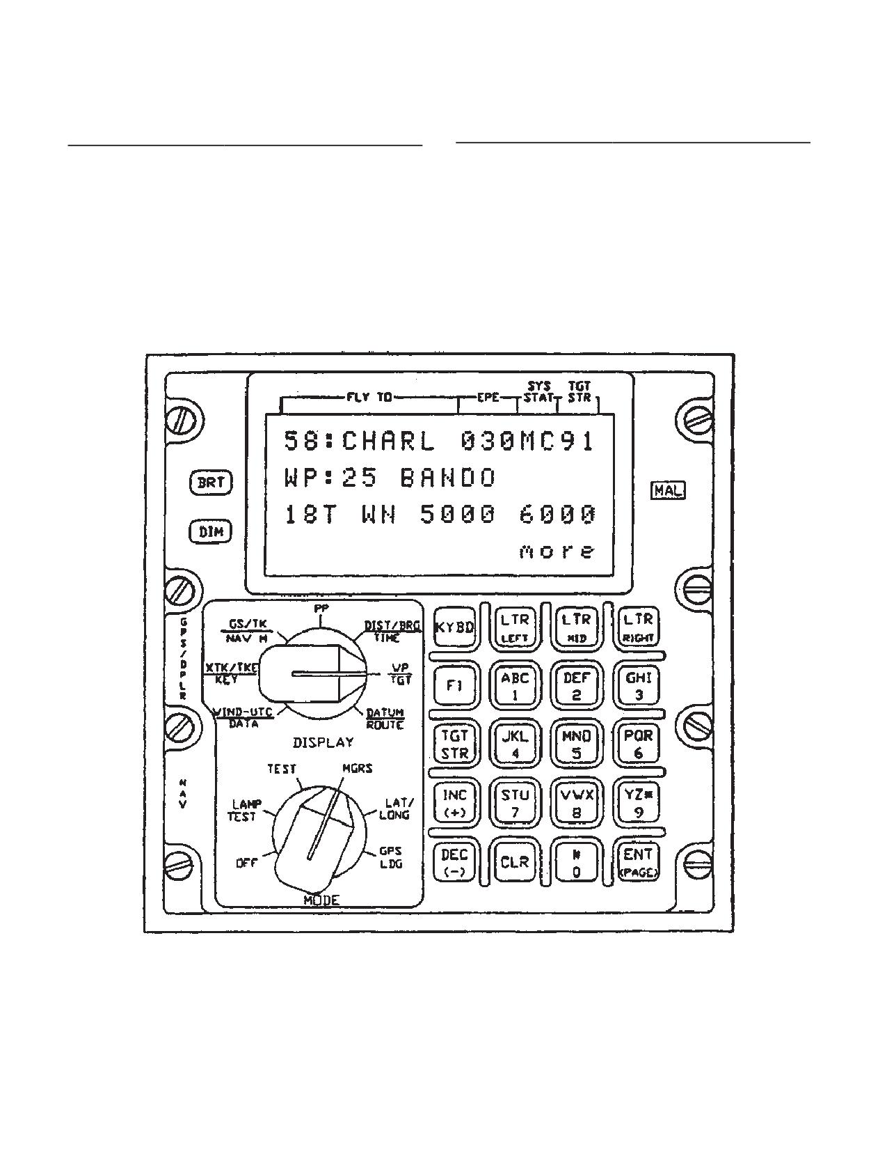
TM 1-1520-240-10
CONTROLS/
FUNCTION
CONTROLS/
FUNCTION
INDICATOR
INDICATOR
set to DIST/BRG/TIME or
available, and “end” when
no additional pages are
XTK/TKE/KEY.
available.
ENT Key
Enters data into memory (as
CLR Key
Clears last entered charac-
set up on keyboard and dis-
ter when pressed once.
played). This key is also
When pressed twice, clears
used for paging of displays.
entire input field of display
The bottom right corner of
keyboard control.
the display indicates “more”
when additional pages are
F1 Key
Reserved for future growth.
Figure 3-3-7. Doppler/GPS Navigation System AN/ANS-128B
3-3-18
TM 1-1520-240-10
3-3-38. Modes of Operation.
selected and the GPS becomes invalid (para. 3-3-41
above), the AN/ASN-128B will not navigate.
Control of the AN/ASN-128B, including selection of
3-3-43. Doppler Mode.
modes and displays, and entry and readout of data is
performed via the Computer Display Unit (CDU) front
Doppler position and velocity data are used for naviga-
panel. The AN/ASN-128B has four basic modes of op-
tion. If Doppler mode is selected and the Doppler be-
eration: off, navigate, test and GPS landing. In navigate
comes invalid (para. 3-3-41 above), the AN/ASN-128B
mode three submodes may be selected manually or au-
will automatically switch remembered velocity since a
tomatically. These are combined mode (default or prima-
TAS sensor is not available. If Doppler mode is manually
ry mode of operation), GPS only mode, or Doppler only
selected at the start of the flight an initial present position
mode.
must be obtained and entered prior to flight. Navigation
is performed in a latitude/longitude for computational
convenience only. At the same time, distance, bearing
3-3-39. Off Mode.
and time-to-go to any one of 100 preset destinations are
computed (as selected by FLY-TO-DEST.
In the off mode the system is inoperable. However, the
Edge lighting is lighted by an external aircraft power
3-3-44. Test Mode.
source and is independent of the AN/ASN-128B mode
The test mode contains two functions: LAMP TEST, in
switch setting. Edge lighting may not be available if the
which all display segments are lit; and TEST , in which
helicopter is modified with the night vision MWO.
system operation is verified. In lamp test, system opera-
tion is identical to that of the navigate mode except that
all lamp segments and the MAL indicator lamp are lighted
3-3-40. Navigate Mode.
to verify their operation. In TEST, the RTA no longer
transmits or receives electromagnetic energy; instead,
In the navigation mode (MGRS or LAT/LONG) position of
self generated test signals are inserted into the electron-
the CDU MODE switch) power is applied to all system
ics to verify operation of the DRVS. At this time a self test
components, and all required outputs and functions are
is performed by the GPS and navigation computations
provided. The Doppler radar velocity sensor (DRVS)
continue using remembered velocity. In the TEST mode,
measures aircraft velocity, and converts analog heading,
Doppler test results are displayed on the CDU front panel
pitch and roll into digital form. This data and Embedded
for the first 15 seconds (approximate). At the end of this
GPS Receiver (EGR) velocity and position data are then
period either GO ALL is displayed if there is no malfunc-
sent to the CDU for processing. Baro altitude is used for
tion in the navigation set, or a failure code is displayed if
aiding the GPS when only three space vehicles are avai-
a malfunction has occurred. A rotating bar on the display
lable. Present position is computed by using one of three
indicates that the GPS has not completed self test. If the
navigation submodes which can be selected manually or
navigation set is maintained in the TEST mode, no navi-
automatically. These submodes are as follows:
gation data can be displayed on the CDU front panel. If
a Doppler malfunction is detected, the MAL indicator
lamp lights and DF is displayed. At the completion of
3-3-41. Combined Mode (Default or Primary Mode of
GPS self test (up to two minutes), The rotating bar is
Operation).
replaced with a complete test result code. the failed unit
and the failed circuit card are also indicated by a code on
Doppler and GPS position and velocity data are com-
the CDU display.
bined to provide navigation. This mode is used when a
minimum of three (with baro) or four space vehicles are
The CDU is continuously monitored for failures, using its
available. GPS Estimated Position Error (EPE) is less
own computer as built-in-test-equipment (BITE). Any
than approximately 150 meters, and the Doppler is not in
BITE malfunction the MAL indicator lamp on the CDU to
memory. If GPS becomes invalid (e.g., due to increased
light. If the MODE switch on the CDU is set to TEST,
EPE), the AN/ASN-128B will automatically switch to
identification of the failed LRU is indicated by a code on
Doppler mode until a valid GPS status is received. If the
the display panel. Aircraft heading, pitch and roll are also
displayed in this mode by depressing the ENT key after
Doppler becomes invalid (e.g., flight over glassy smooth
Doppler test is completed. GPS test status is displayed
water causing memory), the AN/ASN-128B will automati-
if the ENT key is depressed a second time. Malfunction
cally switch to GPS mode if GPS is valid or an alternate
codes are automatically latched and can only be cleared
Doppler mode if the GPS is not valid.
by recycling the CDU power via the CDU mode switch
(OFF/ON).
3-3-42. GPS Mode.
3-3-45. GPS Landing Mode.
GPS positions and velocities are used for navigation by
In the GPS landing mode, the Doppler navigation system
the Doppler navigation processor in the CDU. If GPS
provides information to the HSI indicator for real-time
mode is
landing guidance to a touch down point previously en-
3-3-19
TM 1-1520-240-10
tered in any of the 100 fly-to destinations. The landing
b. Target-of-opportunity can be stored by pressing
approach is determined by present position and the en-
TGT STR (target store) key when the target is overflown.
tered touch down altitude, glideslope and inbound ap-
This operation stores the coordinates of the target in one
proach course.
of ten destination locations in the computer; locations 90
through 99 sequentially incrementing each time the TGT
3-3-46. CDU Operation.
STR key is depressed. The location is displayed in the
appropriate display field. The computer can keep track of
Various required operating data, such an initial present
individual target positions which may include speeds and
position (if GPS is not valid or Doppler mode is selected).
directions input by the operator.
destination coordinates with or without GPS landing
c. Self test of the AN/ASN-128B is accomplished
data, and magnetic variation can at any time be entered
using built-in-test-equipment (BITE) with the RTA, SDC,
into the CDU via its keyboard, or the dataloader via the
and CDU units connected an energized for normal op-
preprogrammed dataloader cartridge. In most cases,
eration. Self test enables the unit to isolate failures to one
these data will be entered before the aircraft takes off.
of the four main functions (RTA, SDC, CDU or EGR) or
to one of the circuit cards in the SDC or CDU. Self test is
accomplished as follows: Self test of the AN/ASN-128B
a. The GPS provides present positions to AN/
is accomplished using built-in-test-equipment (BITE)
ASN-128B. If GPS is not available or Doppler is selected
with the RTA, SDC, and CDU units connected an ener-
present position can be initialized as follows:
gized for normal operation. Self test enables the unit to
isolate failures to one of the four main functions (RTA,
(1)
The MODE switch should be set to MGRS or
SDC, CDU or EGR) or to one of the circuit cards in the
LAT/LONG, the WT/TGT display position of the DISPLAY
SDC or CDU. Self test is accomplished as follows:
switch is selected, the destination number is set to P and
KYBD key is pressed. The coordinates of the initial posi-
(1)
The CDU (except for the keyboard and dis-
tion is overflown, the ENT key is pressed. The computer
play) is checked on a continuous basis, and any failure
then determines changes from the initial position contin-
is displayed by illumination of the MAL indicator lamp on
uously, and the coordinates of the current present posi-
the CDU. If the MODE switch on the CDU is set to the
tion can be read either by remaining in this configuration
TEST position, identification of the failed circuit card in
or by setting the DISPLAY switch to PP (present position)
the CDU is indicated by a code on the display panel.
and the MODE switch to MGRS or LAT/LONG.
(2)
The DRVS and EGR are tested by setting
(2)
To update present position over a stored
the MODE switch on the CDU to the TEST position.
destination, KYBD key is depressed and released when
Failure of the DRVS or EGR are displayed on the CDU
the aircraft overflies this destination. If an update is de-
by illumination of the MAL indicator lamp, and identifica-
sired, the ENT key is depressed and released and the
tion of the failed unit or circuit card is indicated by a code
update is completed. The DISPLAY switch is in the DIST/
on the display panel of the CDU.
BRG/TIME position and the FLY-TO-DEST is set to this
(3)
Continuous monitoring of the Signal Digital
destination during this process. The distance-to-go, dis-
Data Converter and Receiver Transmitter Antenna is
played while over the stored destination, is the position
provided by the system status indication. The system will
error of the system at that moment.
not use Doppler velocities in normal operation when fly-
ing over glassy smooth water. However, if the system
(3)
To update present position over fixed point
continues to not use Doppler (e.g., using GPS only when
not previously stored in the computer, the DISPLAY
combined has been selected) for excessive periods of
switch is placed PP and KYBD key is depressed and
time (e.g. more than10 minutes) over land or rough wa-
released as the fix point is overflown. This freezes the
ter, then a malfunction may exist in the navigation set and
display while allowing computation of changes in present
the operator should set the MODE switch to TEST to
position to continue within the computer. If an update is
determine the nature of failure.
required, the coordinates of the fix point are entered via
the keyboard, and ENT key is pressed. The position
(4)
The display portion of the CDU is tested by
change which occurred since over-flying the fix point
illuminating all the lamp segments in each alphanumeric
automatically added to the fix point coordinates to com-
characters in the LAMP TEST mode.
plete the position update.
(5)
Keyboard operation is verified by observing
(4)
Magnetic variation can be entered for each
the alphanumeric characters as the keyboard is exer-
destination, and the system will compute present posi-
cised.
tion magnetic variation. If operation is to occur in a region
3-3-47. Route Sequencing Modes.
with relatively constant magnetic variation, the operator
enters magnetic variation only for present position and
The system has the ability to fly a preprogrammed se-
the computer will use this value throughout the flight. If
quence of waypoints. This sequence can be either con-
MGRS data are to be entered or displayed, the MGRS
secutively numbered in which case a start and end way-
datum of operation is also entered.
point are entered or randomly numbered in which case
3-3-20
TM 1-1520-240-10
all waypoints are put in a list and the start and end way-
c. Destination Variation Constraint. The magnetic
points are entered. Both sequence modes can be flown
variation associated with a destination must be entered
in the order they are in the list or in reverse order. Direc-
AFTER the coordinates for that destination are entered.
tions will be displayed to the waypoint next on the list until
The order of entry for present position is irrelevant.
approximately 10 seconds before overflying the way-
d. Impossibility of Entering Unacceptable Data. In
point at which time the display will advance to the next
most cases the computer program will reject unaccept-
waypoint and the new waypoint number will blink for ten
able data (for example, a MGRS area W1 does not exists
seconds. One consecutive and one random sequence
and will be rejected). If the operator attempts to insert
may be stored in the system.
unacceptable data, the unacceptable data will be dis-
played on the panel and then the selected field will blink
3-3-48. To-To Route Mode.
after ENT key is pressed displaying the last valid data.
NOTE
The system has the ability to provide steering information
onto a course defined by the start and end waypoints.
The computer cannot prevent insertion of er-
Only the second waypoint will be overflown. The distance
roneous data resulting, for example, from hu-
displayed is the distance to the course when outside 2
man or map errors.
nautical miles of the course and the distance to the sec-
e. Procedure for Displaying Wind Speed and Direc-
ond waypoint when inside 2 nautical miles of the course.
tion.
NOTE
3-3-49. General Operating Procedures for Entering
Data.
In MGRS mode, wind speed is displayed in
km/hr; in LAT/LONG mode, wind speed is dis-
The panel display consists of four line LCD readout. The
played in knots. Wind direction is defined as
top line of the display is reserved for the display of Fly-To-
the direction from which the wind originates.
destination number and destination name/International
(1)
Set MODE switch to LAT/LONG (MGRS
Civil Aeronautic Organization (ICAO) identifier, EPE in
may also be used).
meters, mode of GPS and mode of AN/ASN-128B opera-
(2)
Set DISPLAY switch to WIND-UTC/DATA
tion and target store number. The remaining lines will
and observe display.
display data in accordance with the DISPLAY and MODE
switches. When depressing the KYBD key for the first
(3)
The display indicates:
time in an entry procedure, the display freezes, kybd is
displayed in the bottom right corner indicating the display
SP;XXXKn
is in the keyboard mode and the input field under key-
DIR:XXX_
board control blinks. If it is not desired to change the
f. Procedure for Displaying/Entering UTC and Dis-
display field under control, the pilot can advance to the
playing GPS Status.
next field of the display by depressing the KYBD key
again. Depressing ENT key (whether or not new data has
(1)
Set MODE switch to LAT/LONG (MGRS
been entered) causes the display to blank momentarily
may also be used).
and return with the latest computed data. To abort a
(2)
Set DISPLAY switch to WIND-UTC/DATA
keyboard operation, move the mode or display switch to
and observe the wind speed/direction display.
another position.
(3)
Depress ENT key. Observe that the CDU
NOTE
display indicates year XX, day XXX and indicates hours,
minutes, and seconds of UTC time: XX Hours, XX Min-
All keys activate upon release after being de-
utes, XX Seconds.
pressed. Keys should be depressed and im-
mediately released in one continuous motion.
(4)
To enter year, day, and time depress the
KYBD key to select the field for input shown as a blinking
a. Data Entry. To display a letter, first depress the LTR
field, enter the desired data and depress the ENT key.
key corresponding to the position of the desired letter on
a key. Then depress the key which contains the desired
(5)
To display GPS status depress the ENT to
letter. For example, to enter an L, first depress The LTR
display selection menu.
RIGHT key, then depress the 4 key.
1>SEA CURRENT
2>SURFACE WIND
b. Keyboard Correction Capability. The last charac-
3>GPS STATUS
ter entered may be cleared by depressing the CLR key.
4>DATA LOAD end
If the CLR key is depressed twice in succession, the field
is cleared but remains under control (indicated by blink-
(6)
To select the GPS STATUS page depress
ing) and the last valid data entered is displayed.
the 3 key.
3-3-21
TM 1-1520-240-10
(7)
Observe the CDU display. The display indi-
NOTE
cated the GPS test mode status as of one of the follow-
Destinations are entered manually when
ing.
steering information is required to a destina-
GPS TEST: IN PROCESS
tion that was not in the set of data loaded via
GPS TEST: NOT RUN
the data loader, or it is desired to update pres-
GPS TEST: PASSED
ent position by overflying a destination, or a
GPS TEST: FAILED
present position variation computation is de-
sired. (See CDU operation). If a present posi-
g. Procedure for Displaying GPS Key and GPS
tion variation update is desired, destination
Space Vehicle Status.
variation must be entered. The operator may
enter one or more destination variations; it is
(1)
Set the DISPLAY switch to XTK/TKE/KEY.
not necessary for all destinations to have as-
(2)
Set the MODE switch to LAT/LONG (MGRS
sociated variations entered and also not nec-
may also be used).
essary to enter all destinations in any case,
but variations must be entered AFTER des-
(3)
The display indicates GPS daily key status,
tination coordinates are entered.
time remaining on the currently entered keys and how
The Doppler outputs true heading and accepts magnetic
many Space Vehicles (SV) are currently being used by
heading from gyromagnetic heading reference. If accu-
the GPS.
rate magnetic variations are not applied, then navigation
accuracy will be affected.
KEY
STATUS
TIME
REMARKS
b. System Initialization
DK
OK
Days or hours still GPS daily key
available on key
in use and
(1)
Enter GPS mode “M”.
verified.
NOTE
DK
NO
*
No GPS daily
You must select GPS mode “M” during initial-
key available
ization. If “Y” mode is selected before Crypto-
Key variables are loaded the system will lock-
DK
IN
*
GPS daily key
up forever.
available but
not verified.
You must select GPS mode “M” during initial-
ization. If “Y” mode is selected before Crypto-
Key variables are loaded the system will lock-
3-3-50. Preflight Procedures.
up forever.
a. Data Required Prior to DGNS Turn-on
(2)
Perform self test (para d. below).
The following initial data must be entered by the pilot after
(3)
Perform download (para c. below) of data
system turn-on and initialization, unless previously en-
loader cartridge if necessary, or manually enter datum,
tered data is satisfactory:
destinations, magnetic variations, and present position
(para. f or g. below).
Datums of operation, when using MGRS coordinates.
This data may be part of the data load if preprogrammed.
(4)
Load Crypto-Key variables (unless pre-
viously loaded and still valid) necessary for operation of
In combined or GPS mode the GPS provides preset posi-
the GPS in Y mode.
tion. If Doppler only mode is selected MGRS coordinates
of present position - zone area, easting and northing;
NOTE
latitude/longitude coordinates may also be used to input
It is necessary to wait at least 12 minutes for
present position. This data may be part of the data load
key validation when new keys have been en-
if preprogrammed. Variation of present position to the
tered, or collection of almanac data when set
nearest one-tenth of a degree.
has no previous almanac data. During this
Coordinates of desired destinations 00 through 99. It is
time the GPS operating mode must be M and
not necessary to enter all destinations in the same coor-
uninterrupted. After this time the GPS operat-
dinate system. This data may be part of the data load if
ing mode may be switched to Y. Observe the
preprogrammed.
GPS Key status and number of SVs tracked
after switching to Y mode. If the SV number
Variation of destinations to the nearest one-tenth of a
goes to zero repeat this procedure. The Key
degree.
status shall switch from DK IN to DK OK
sometime during the 12 minutes.
Crypto-Key variables necessary to enable the GPS re-
ceiver to operate in Y code are entered via remote fill data
(5)
Check datum of operation, if MGRS is being
only and not via the CDU keyboard.
used.
3-3-22
TM 1-1520-240-10
(6)
Check destinations in MRGS or LAT/LONG
DATA LOADER
coordinates as desired.
ENTER DATA:N
(7)
Check associated destination variations as
end
desired. Remove all incorrect variations by setting DIS-
(7)
To begin the download depress the KYBD
PLAY switch to WP/TGT, setting the destination number
and enter Y (yes).
to appropriate destination, and depressing the KYBD key
and ENT key in that order. Variations of at least two
(8)
Observe the CDU display. The CDU shall
destinations must be entered for automatic variation up-
display DOWNLOAD WAYPTS and WAIT ACK. If a
date computation to be performed. For accurate naviga-
transmission error occurs the CDU display shall change
tion it is advised to enter variation after each destination
to ERROR-RETRYING.
unless the variations are the same.
(9)
When the transmission is complete the CDU
shall display DOWNLOAD WAYPTS COMPLETE. If this
display is not obtained within one minute of beginning the
(8)
Select DGNS operating mode (para e. be-
download check the data programming and connection.
low).
(10) Set the CDU mode switch to OFF, remove
NOTE
the data loader cartridge if desired, and then set the CDU
mode switch to desired setting.
The set will automatically select combined
mode (default or primary operating mode) as
d. Self-Test
this allows the system to select the best pos-
(1)
Set the MODE switch to LAMP TEST. Enter
sible navigation method available.
GPS mode “M” or “Y”. Verify the following:
(9)
Set the FLY-TO DEST to the desired des-
(a) All LCD on four-line display are illumi-
tination location.
nated.
c. Procedure for Downloading Data From Dataload-
(b) The MAL lamp is illuminated.
er Cartridge.
(2)
Rotate the center lighting control. Verify the
(1)
Set the CDU mode switch to OFF.
following:
(2)
Insert the preprogrammed data loader car-
(a) All edge lighting is illuminated.
tridge.
(b) All keyboard keys are illuminated.
(3)
Set the CDU mode switch to MGRS (LAT/
(3)
Set MODE switch to TEST.
LONG may be used). Enter desired GPS code (M or Y)
(a) While test is performing, depress the
mode of operation.
DIM pushbutton several times, then the BRT pushbutton
(4)
Set the DISPLAY switch to WIND-UTC/
several times. The LCD display should glow dimmer then
DATA.
brighter. Adjust LCD display for comfortable viewing.
(b) After Doppler and/or GPS self test have
(5)
To display the select menu depress the ENT
completed (approximately 15 seconds for Doppler, up to
key twice.
2 minutes for GPS), one of the following displays will be
1>SEA CURRENT
observed in the left and right displays:
2>SURFACE WIND
NOTE
3>GPS STATUS
In the event the TEST mode display is not GO
4>DATA LOAD end
ALL the system should be recycled through
(6)
To select the DATA LOADER page depress
OFF to verify the failure is to a momentary
the 4 key.
one.
3-3-23
TM 1-1520-240-10
LEFT DISPLAY
RIGHT DISPLAY REMARKS
GO
Doppler has completed Built in Test (BIT) and is operating satisfactorily,
GPS is still performing BIT (GPS has 2 minute BIT cycle maximum).
Note that a rotating bar in the display indicates that the GPS is still per-
forming self test.
GO
ALL
The entire system has completed BIT and is operating satisfactorily.
GO
P
Pitch or Roll data is missing or exceeds 90_. In this case, pitch and roll in
the computer are both set to zero and navigation in the Doppler mode
continues with degrade operation. Problem may be in the vertical gyro or
aircraft cabling.
NG
C, R, S, or H fol-
A failure has occurred in the Computer Display Unit or the Signal Data
lowed by a nu-
Converter Power Supply. The operator should not use the system.
meric code
DN
GPS failure code
GPS has failed but operator can use doppler to perform all navigation.
DF
Doppler failure
Doppler has failed. GPS is still performing self test.
code
GN
Doppler failure
Doppler has failed but operator can use GPS to perform all navigation.
code
e. Procedure for Displaying or Selecting GPS M or Y
are automatic fall back modes used when
Operating Mode, Doppler, GPS, or Combined Operation,
both the Doppler and GPS are unavailable.
and Displaying Groundspeed and Track.
(4)
Selection of GPS mode of operation:
(1)
Set MODE switch to MGRS position (LAT/
As an example, consider selection of Y-only mode. De-
LONG or GPS LDG position may also be used).
press KYBD key. Observe that the GPS mode blinks. To
enter Y (for Y mode) depress key LTR LEFT followed by
(2)
Set DISPLAY switch to GS/TK/NAV M.
key 9. A Y will be displayed. Depress ENT key. The entire
display will blank out for less than one second and the
(3)
The display indicates the current GPS and
center display will now indicate: Y.
navigation mode on the top line:
(5)
Selection of DGNS mode of operation.
(a) Selected Fly to waypoint.
As an example, consider selection of GPS-only mode of
(b) EPE (GPS Estimated Position Error in
operation. Depress KYBD key twice. Observe that the
Meters. An asterisk (*) in the character position of the
DGNS mode blinks. To enter G (for GPS mode) depress
EPE display indicates an EPE of greater than 999 or data
key LTR LEFT followed by key 3. A G will be displayed.
unavailable.
Depress ENT key. The entire display will blank out less
than one second and the DGNS Mode will now indicate:
(c) GPS mode of operation:
G (or * if GPS is not available).
M for mixed C\A and P/Y code GPS reception
Y for only Y code GPS reception.
(6)
Ground Speed and Ground Track Angle are
displayed on lines 3 and 4.
(d) DGNS mode of operation:
f. Procedure for Entering/Displaying Present posi-
C for combined Doppler and GPS
tion or One of the 100 Possible Destinations in MGRS.
D for Doppler only
G for GPS only
The DGNS has the capability to display 100 destinations
R for remembered velocities
(numbered 00 through 99).
* for no navigation.
100 destinations
(e) Target destination where the present
position will be stored next time TGT/STR is depressed.
-00 to 69
Standard Waypoints
-70 to 89
Data Load-only Waypoints, Ob-
NOTE
servable but not changeable via
CDU keyboard. Used for Nation-
In MGRS mode, ground speed is displayed in
al Airspace Data Such as VORs,
km/hr; in LAT/LONG mode, ground speed is
NDB’s and intersections.
displayed in knots.
-90 to 99
Target Store Waypoints (Usable
Only mode C, G, and D may be selected as
as Standard Waypoints)
the primary navigation mode. Modes R and *
3-3-24
TM 1-1520-240-10
As an example, consider display of destination number
-70 to 89
Data Load-only Waypoints, ob-
25.
servable but not changeable via
CDU keyboard. Used for Nation-
(1)
Enter datum as described in paragraph j be-
al Airspace Data Such as VORs,
low.
NDB’s and intersections.
(2)
Set MODE switch to MGRS.
-90 to 99
Target Store Waypoints (Usable
as Standard Waypoints)
(3)
Set DISPLAY switch to WP/TGT.
(4)
Notice the current destination number dis-
As an example, consider display of destination number
played. To display destination number 25 depress the
25.
INC or DEC keys, or depress keys 2 then 5. this is a direct
key entry action.
(1)
Enter the datum as described in paragraph
(5)
Observe that the current destination MGRS
j. below.
zone, area, and easting/northing coordinates are now
displayed. The destination number 25 and location
(2)
Set MODE switch to LAT/LONG.
name/ICAO identifier also appears in the display.
(6)
Entry for destination coordinates and loca-
(3)
Set DISPLAY switch TO WP/TGT.
tion name/ICAO identifier: As an example, consider entry
of zone 18T, area WN, easting 5000, northing 6000, and
(4)
Notice that the current destination number is
ICAO identifier BANDO.
displayed. To display destination number 25 depress the
INC or DEC keys, or depress keys 2 then 5. This is a
(7)
To enter keyboard mode depress the KYBD
direct key entry action.
key. Observe “kybd” displayed in the bottom right corner
of the display. (Destination number blinks.) Depress
KYBD again. (Zone field blinks.) To enter 18T depress
(5)
Observe that the current Latitude and Longi-
keys 1, 8, LTR MID, 7.
tude coordinates are now displayed. The destination
number 25 and location name/ICAO identifier appears in
(8)
Depress KYBD. (Area and northing/easting
the display.
blinks.) To enter WN5000 6000 depress keys LTR MID,
8, LTR MID, 5, KYBD, 5, 0, 0, 0, 6, 0, 0, 0.
(6)
Entry of destination coordinates and loca-
tion name/ICAO identifier: As an example, consider entry
(9)
Depress KYBD. (Location name/ICAO iden-
tifier blinks.) To enter BANDO depress keys LTR MID, 1,
of Latitude N41_ 10.13 minutes and longitude E035_
LTR LEFT, 1, LTR MID, 5, LTR LEFT, 2, LTR RIGHT, 5.
50.27 minutes and ICAO identifier BANDO.
(10) To store the displayed information into the
(7)
To enter keyboard mode depress KYBD key.
selected destination display position depress the ENT
Observe “kybd” displayed in the bottom right corner of
key.
the display. (Destination number blinks.) Depress KYBD
NOTE
again (Latitude field blinks.) To enter N41_ 10.13 depress
keys N, 4, 1, 1, 0, 1, 3.
To access P, depress the LTR LEFT key fol-
lowed by the 6 key. Another way to access P
(8)
Depress KYBD. (longitude field blinks.) To
is to display waypoint 99 then depress the INC
enter E035_ 50.27 depress keys E, 0, 3, 5, 5, 0, 2, 7.
key or display waypoint 00 then depress the
DEC key.
(9)
Depress KYBD. (Location name/;ICAO
Way points cannot be recalled by location
identifier blinks.) To enter BANDO depress keys LTR
name/ICAO identifier.
MID, 1, LTR LEFT, 1, LTR MID, 5, LTR LEFT, 2, LTR
g. Procedure for Entering/Displaying Present Posi-
RIGHT, 5.
tion or one of the 100 Possible Destinations in LAT/
LONG.
(10) To store the displayed information into the
selected destination display position depress the ENT
The DGNS set has the capability to display 100 destina-
key.
tions (number 00 through 99).
Display indicates:
100 destinations
-00 to 69
Standard Waypoints
N41_ 10.13 E035_ 50.27.
3-3-25
TM 1-1520-240-10
NOTE
(10) Depress the KYBD key to blink the inbound
approach course field. Enter a three digit inbound ap-
To access P, depress the LTR LEFT key fol-
proach course angle. In the example enter 2, 7, 0 to enter
lowed by the 6 key. Another way to access P
a 270 degree inbound approach course. Depress the
is to display waypoint 99 then depress the INC
ENT key to complete the operation.
key or display waypoint 00 then depress the
DEC key.
i. Procedures for Entering Target Motion and Direc-
tion
Waypoints cannot be recalled by location
name/ICAO identifier.
In MGRS mode, target speed is entered in km/h; in LAT/
LONG mode, target speed is entered in knots.
h. Procedures for Entering Variation and Landing
Mode Data.
(1)
Set the MODE switch to LAT/LONG (MGRS
may be used).
(1)
Set MODE switch to MGRS position-altitude
entered/displayed in meters (LAT/LONG may also be
(2)
Set the DISPLAY switch to WP/TGT and se-
used-altitude entered/displayed in feet).
lect the target number desired (00-69 or 90-99) by direct-
ly entering the two digit target number or INC/DEC keys.
(2)
Set DISPLAY switch to WP/TGT position.
Observe the waypoint number entered and position
data.
(3)
Select the waypoint desired by directly en-
(3)
Depress the ENT key and observe the way-
tering the two digit target number or depressing the INC/
point number, variation and/or landing data if entered.
DEC keys. Observe the waypoint number entered and
position data.
(4)
Depress the ENT key and observe the target
speed and direction page.
(4)
Depress the ENT key and observe the way-
point number, variation and/or landing data if entered.
(5)
To select target speed depress the KYBD
key twice and enter the target speed. The maximum
(5)
To enter a magnetic variation and/or landing
target speed that may be entered is 50 knots. Fill leading
mode data depress the KYBD key to select the field for
zeros before entering.
entry and enter the desired data as shown in steps 6
through 10 below. To end the entry operation depress the
(6)
To select the target direction depress the
ENT key.
KYBD key and enter the target direction.
(7)
To end the entry operation depress the ENT
(6)
Entry of variation: as an example, consider
key. At the time ENT key is depressed and released, the
entry of a variation of E001.2. Depress keys E, 0, 0, 1,
target position will begin to be updated as a function of
and 2. The decimal point is inserted automatically. If no
time based on the speed and direction entered.
landing mode data is to be enter depress ENT to com-
plete the operation. Display indicates: E001.2_.
NOTE
NOTE
To abort/cancel an entry of target motion, en-
ter a target speed of 000 using the above
An asterisk appearing in the variation fielded
procedure.
indicates the variation is not entered. Varia-
j. Procedure for Entering/Displaying Datum or
tions may not be entered for waypoints con-
Cleaning All Waypoints.
taining target motion.
(1)
Set the MODE switch to MGRS position
(7)
The bottom two lines indicate the MSL alti-
(LAT/LONG may also be used).
tude, desired glideslope, and the desired inbound ap-
proach course (IAC) to the indicated destination. As an
(2)
Set the DISPLAY switch to DATUM/
example, consider entry of a glideslope of 8_ an IAC of
ROUTE.
270_ and an altitude of +230 meters, for destination num-
ber 25.
(3)
To select the datum field depress the KYBD
KEY.
(8)
Depress the KYBD key to blink altitude field.
(4)
Entry of datum: as an example consider
Depress the INC/+ key to enter a positive altitude, de-
entry of 25. Depress keys LTR 2, 5. Depress the ENT key.
press keys 2, 3, 0 (the leading zeros may be omitted) for
The display shall show DATUM:25.
the altitude of 230 meters in the example.
(5)
To clear all waypoints, variations, landing
(9)
Depress the KYBD key to blink the glide
data and target motions, enter RDW for the spheroid.
slope field. Enter glideslope. The maximum allowable
glideslope is 9 degrees. In the example enter 8 for an
k. Procedure for Entering Sea Current Speed and
eight degree glideslope.
Direction for Water Motion Correction.
3-3-26
TM 1-1520-240-10
NOTE
(1)
Set MODE switch to LAT/LONG (MGRS
may also be used).
In MGRS mode, wind speed is displayed in
km/hr; in LAT/LONG mode, wind speed is dis-
(2)
Set DISPLAY switch to WIND-UTC/DATA
played in knots. Leading zeros must be enter-
and observe the wind speed/direction display.
ed. Sea current direction is defined as the
(3)
Depress ENT key twice to display the selec-
direction the current is flowing.
tion menu.
(1)
Set MODE switch to LAT/LONG (MGRS
may be used).
1>SEA CURRENT
2>SURFACE WIND
(2)
Set DISPLAY switch to WIND-UTC/DATA
3>GPS STATUS
and observe the standard wind speed and direction dis-
4>DATA LOAD end
play.
(4)
Depress the 2 key to select SURFACE
(3)
Depress the ENT key twice to display the
WIND. The display indicates:
selection menu.
SURFACE WIND
SP:XXXKn
1>SEA CURRENT
DIR:XXX_
2>SURFACE WIND
3>GPS STATUS
(5)
Entry of wind speed and direction: as an
4>DATA LOAD end
example, consider the entry of 20 knots and 150 de-
grees. Depress KYBD key. Observe that the wind speed
(4)
Depress the 1 key to select SEA CURRENT.
field blinks.
The display indicates:
(6)
To enter speed, depress keys 0, 2 and 0. The
SEA CURRENT
wind speed indicates 020. The maximum surface wind
SP;XXXKn
speed is 50 knots.
DIR:XXX_
(7)
Depress KYBD key. The direction display
(5)
Entry of sea current speed and direction: as
blinks.
an example, consider the entry 4 knots and 135 degrees.
Depress KYBD key. Observe that the speed field blinks.
(8)
To enter direction, depress keys 1, 5, and 0.
Wind direction indicates 150_.
(6)
To enter speed, depress keys 0, 0 and 4. The
(9)
Depress ENT key. The display momentarily
speed indicates 004Kn. The maximum sea current
blinks and then reappears.
speed that may be entered is 50 knots.
NOTE
(7)
Depress KYBD key. The direction display
blinks.
To abort entry of surface wind speed and di-
rection, enter a surface wind speed of 000
(8)
To enter direction, depress keys 1, 3, and 5.
using the above procedure.
Direction indicates 135_.
3-3-51. Flight Procedures.
(9)
Depress ENT key. The display momentarily
NOTE
blinks and then reappears.
This procedure is applicable to the Doppler
NOTE
only mode. Present position is automatically
updated when DGNS is in combined mode.
To abort entry of sea current, enter a sea cur-
a. Updating Present Position from a Stored Destina-
rent speed of 000 using the above procedure.
tion.
l. Procedure for Entering Surface Wind Speed and
NOTE
Direction for Water Motion Correction.
The preface is: The aircraft is flying to a des-
NOTE
tination, that is, the FLY-TO Destination is set
Not required or necessary when in combined
to the number of the desired destination.
or GPS mode. In MGRS mode, surface wind
(1)
Set DISPLAY switch to DIST/BRG/TIME
speed is entered in km/hr: in LAT/LONG
position. Distance, bearing and time-to-go to the fly-to
mode, surface wind speed is entered in knots.
destination are displayed.
Leading zeros must be entered. Wind direc-
tion is defined as the direction from which the
(2)
When the aircraft is over the destination,
wind originates.
depress KYBD key. Observe that the display freezes.
3-3-27
TM 1-1520-240-10
(3)
Position update can be effected by depress-
Method 2 (Anticipated update)
ing the ENT key. The computer updated the present posi-
1. Set DISPLAY switch to WP/TGT position.
tion at the time the KYBD key was depressed by using the
2. Access P by depressing the LTR LEFT key
stored destination coordinates, and adding to them the
followed by the 6 key, entering destination
distance traveled between the time the KYBD key was
00 then depressing the DEC key, or enter-
depressed and the ENT key was depressed. In addition,
ing destination 99 then depressing the INC
if an associated variation for the stored destination ex-
key.
ists, the present position variation is also updated.
3. Depress KYBD key. Observe that the dis-
play freezes.
4. Manually enter the landmark coordinates
(4)
If a present position update is unnecessary
by depressing the KYBD key to blink the
(as indicated by an appropriately small value of DIS-
field to be changed and enter the coordi-
TANCE to go on overflying the destination), set the DIS-
nates.
PLAY switched to some other position - this action aborts
5. When overflying landmark, depress ENT
the update mode.
key.
6. If an update is not desired, set the DISPLAY
b. Updating Present Position from a Landmark.
switch to some other position. This action
aborts the update mode.
NOTE
3-3-52. Fly-To Destination Operation.
a. Initialization of Desired Course.
There are two methods for updating present
When a fly-to destination is selected such as at the start
position from a landmark. Method 1 is particu-
of a leg, the present position at the time is stored in the
larly useful if the landmark comes up unex-
computer. A course is then computed between the se-
pectedly and the operator needs time to de-
lected point and the destination. If the aircraft deviates
termine the coordinates. Method 2 is useful
from this desired course, the lateral offset or crosstrack
when a landmark update is anticipated.
distance error is computed.
Distance and bearing to destination, actual track angle,
Method 1 (Unexpected update)
and track angle error correction are computed from pres-
ent position to destination. See figure 3-3-8 for graphic
(1)
Set DISPLAY switch to PP position.
definition of these terms.
b. Procedure for Selecting One of 100 Possible Fly-
To Destinations (Direct Mode).
(2)
Overfly landmark and depress KYBD key.
The Doppler/GPS navigation set has the capability of
The present position display shall freeze.
selecting a fly-to destination from 100 destinations (num-
ber 00 through 99).
(3)
Compare landmark coordinates with those
As an example, consider selecting Fly-To destination
on display.
number 43.
(1)
Set MODE switch to MGRS (LAT/LONG or
GPS LDG may also be used).
(4)
If the difference warrants an update, enter
(2)
Set DISPLAY switch to XTK/TKE. Observe
the landmark coordinates by depressing the KYBD key
e standard Cross Track (XTK) and Track angle error
to blink the field to be changed, enter coordinates, then
(TKE) display. (DIST/BRG/TIME may also be used)
depress the ENT key. The computer updates the present
position (from the time the KYBD key was depressed) to
(3)
To display Fly-To destination 43 depress the
INC or DEC keys, or depress keys 4 then 3. This is a
the landmark coordinates, and adds to the updated pres-
direct key entry action.
ent position the distance traveled between the time the
Left-Right Steering Signals
KYBD key was depressed and the ENT key was de-
pressed.
There are two methods the pilot may use to fly-to destina-
tion, using left-right steering signals displayed on the
computer-display unit. Left-right steering signals may be
(5)
If an update is not desired, set the DISPLAY
used when flying the shortest distance to destination
switch to some other position. This action aborts the
from present position (Method 1) or when flying a ground
update mode.
track from start of leg to destination (Method 2).
3-3-28
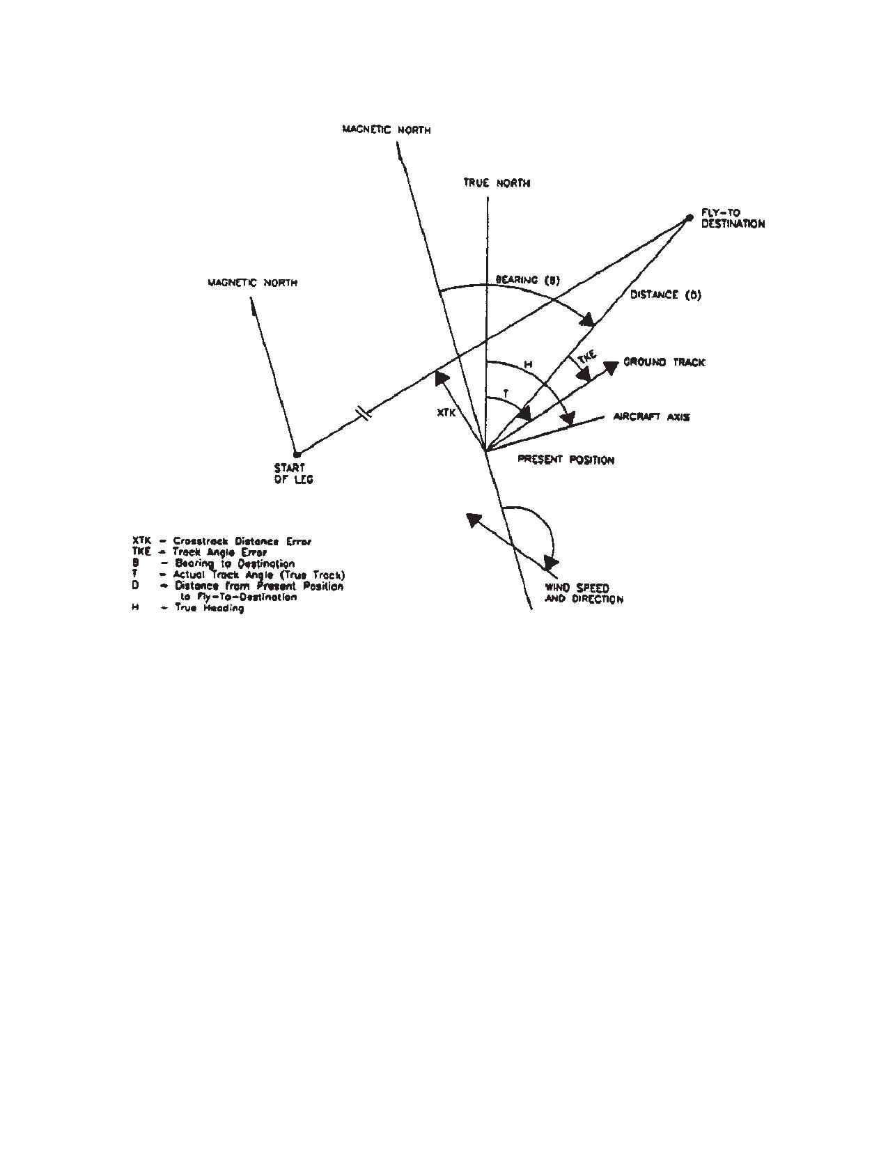
TM 1-1520-240-10
Figure 3-3-8. Graphic Definition of Course Terms
METHOD 1
been selected then the pilot may use the “#1”
needle and course deviation indicator (CDI)
When flying shortest distance to destination from
for navigation to the Fly-To destination se-
present position, set DISPLAY switch to DIS/BRG/
lected on the CDU.
TIME position and steer vehicle to bearing dis-
Select CDI by depressing, then releasing the DPLR GPS
played. As an aid to maintaining course, set DIS-
lens on the HSI Mode Select PAnel.
PLAY switch to XTK/TKE position and steer
aircraft to keep track angle error (TKE) nominally
c. Procedure to Enter Route-Sequence To-To Mode
zero. If the display indicates a L (left) TKE, the
aircraft must be flown to the left to zero the error.
The Doppler/GPS navigation set has the capability to
navigate a course set up between to destinations.
METHOD 2
As an example, consider navigation onto a course start-
When flying a ground track, set DISPLAY switch
ing from destination number 62 and ending at destination
to XTK/TKE position. Steer vehicle to obtain zero
number 45.
for crosstrack error (XTK). If XTK is left (L), aircraft
(1)
Set MODE switch to MGRS (LAT/LONG
is to right of the desired course and must be flown
may also be used).
to the left to regain the initial course.
NOTE
(2)
Set DISPLAY switch to DATUM/ROUTE.
Since the aircraft has the Horizontal Situation
(3)
Depress the ENT key. Observe that a menu
Indicator (HSI) and when the Doppler has
of special steering functions appears.
3-3-29
TM 1-1520-240-10
(4)
To select the Route-Sequence To-To display
(7)
Repeat step 6 until a maximum of ten des-
depress key 1. Observe that TO-TO and selection mode
tinations are entered or if less than ten need to be en-
appears in the display. The display provides entry of
tered, asterisks are left for remaining destinations.
starting and ending destinations numbers.
(8)
To complete the entry of the random se-
(5)
To enter keyboard mode depress the KYBD
quence of waypoints depress ENT key.
key. (START field blinks.) To enter starting destination 62
(9)
Depress ENT key to select next page.
depress keys 6, 2.
(10) To select the start field and enter the starting
(6)
Depress KYBD key. (END field blinks.) To
destination depress KYBD key.
enter ending destination 45 depress keys 4, 5.
(11) To select the ending field and enter the end-
(7)
Depress KYBD key. (SELECT field blinks.)
ing destination depress KYBD key.
Enter Y (yes) for mode selection. N may be entered to
(12) Depress KYBD key. (SELECT field blinks.)
arm the system with the start and end destinations but
Enter Y (yes) for mode selection. N may be entered to
without entering the Route-Sequence To-To mode, or to
arm the system but without entering the ROUTE-Se-
exit the Route-Sequence To-To mode if the system is
quence Random mode, or to exit the ROUTE-Sequence
currently in that mode.
Random mode if the system is currently in that mode. An
NOTE
entry Y and R indicates a choice of Y-flying in forward
order, or R-flying in reverse order. To clear the random
If an entry is changed after Y is entered for
sequence, enter C for selection.
selection, and N must be entered for the
NOTE
selection then it may be changed to Y. The
sequence must be flown from the beginning
If an entry is changed after Y or R is entered
waypoint.
for selection, an N must be entered for the
selection then it may be changed to Y or R.
No target destinations or destinations with
The sequence must be flown from the begin-
target motion may be included as To-To way-
ning waypoint. No target destinations or des-
points.
tinations with target motion may be included
d. Procedure to Enter Route-Sequence Random
as Route Sequence Random waypoints.
Mode.
(13) After all entries are made, depress ENT
key.
The Doppler/GPS navigation set has the capability to
navigate through a sequence of randomly number des-
e. Procedure to Enter Route-Sequence-Consecu-
tinations.
tive Mode
As an example, consider navigating through destination
The Doppler/GPS navigation set has the capability to
numbers 32, 25, 74, 01, 48, 83, 35.
navigate through a sequence of consecutively numbered
destinations.
(1)
Set MODE switch to MGRS (LAT/LONG
As an example, consider navigating through destination
may also be used).
numbers 32 through 35.
(2)
Set DISPLAY switch to DATUM/ROUTE.
(1)
Set MODE switch to MGRS (LAT/LONG
may also be sued).
(3)
Depress the ENT key. Observe that a menu
of special steering functions appears.
(2)
Set DISPLAY switch to DATUM/ROUTE.
(4)
To select the Route-Sequence Random dis-
(3)
Depress the ENT key. Observe that a menu
play depress key 2. Observe that RT SEQ RANDOM now
of special steering functions appears.
appears in the display followed by the sequence of des-
(4)
To select the Route-Sequence-Consecutive
tination numbers and a continuation prompt.
display depress key 3. Observe that RT SEQ CONSEC
now appears in the display, followed by starting and end-
(5)
Enter the sequence of destination numbers
ing destination numbers, and mode selection.
by depressing the KYBD key to enter keyboard mode.
(First destination field is blinks.) To enter first destination
(5)
To enter keyboard depress the KYBD key.
32 depress 3, 2.
(START field blinks.) To enter starting destination 32 de-
press leys 3, 2.
(6)
Depress KYBD key. (Next destination field is
blinked.) Depress keys 2, 5 to enter second destination
(6)
Depress KYBD key. (END field blinks.) De-
25.
press keys 3, 5 to enter destination 35.
3-3-30
TM 1-1520-240-10
(7)
Depress KYBD key. (SELECT field blinks.)
h. Target Store (TGT STR) Operation
Enter Y (yes) for mode selection. N may be entered to
Two methods may be used for target store operation.
arm the system but without entering the Route-Se-
Method 1 is normally used when time is not available to
quence-Consecutive mode, or to exit the Route-Se-
preplan a target store operation. Method 2 is used when
quence-Consecutive mode if the system is currently in
time is available and it is desired to store a target in a
that mode. An entry of Y or R indicates a choice of Y-flying
specific location.
in the forward order, or R-flying in reverse order.
NOTE
Method 1 (uses location 90-99)
If an entry is changed after Y or R is entered
(1)
Depress the TGT STR key while flying over
for selection, and N must be entered for the
target.
selection then it may be changed to Y or R.
(2)
Present position and variation are automati-
The sequence must be flown from the begin-
cally stored in the target destination location which was
ning waypoint. No target destinations or des-
displayed in the target store field immediately prior to
tinations with target motion may be included
depressing the TGT STR key.
as Route Sequence Consecutive waypoints.
f. Procedure for Displaying Distance/Bearing/Time
Method 2 (uses locations 00-69 and 90-99)
Information.
1. Set MODE switch to MGRS or LAT/LONG
(1)
Set MODE switch to MGRS (LAT/LONG or
position, depending on coordinate from de-
GPS LDG may also be used).
sired.
(2)
Set DISPLAY switch to DIS/BRG/TIME.
2. Set display switch to WP/TGT position.
(3)
Observe that the distance-to-go in kilome-
3. To access P, depress the LTR LEFT key
ters (to the fly-destination), bearing, and time-to-go ap-
followed by the 6 key. Another way to ac-
pears on the bottom two lines of the display. (Distance is
cess P, is to display waypoint 99 then de-
in nautical miles when MODE switch position is LAT/
press the INC key or display waypoint 00
LONG.) Bearing-to-destination is displayed in hours,
then depress the DEC key.
minutes, and tenths of a minute.
4. Depress KYBD key when overflying poten-
(4)
The display of the second line depends on
tial target. Observe that display freezes and
the current steering mode as follows:
kybd is displayed in the bottom right corner
of the display indicating keyboard mode.
(a) Direct-To Steering (default): Fly-to des-
The destination number is now under key-
tination number and ICAO identifier are displayed. Ex-
board control indicated by a blinking field.
ample: 58:BANDO
(b) To-To Steering: TO-TO-:XX TO YY
CAUTION
where XX is the ’To-To’ start-of-leg destination number,
and YY is the ’To-To’ fly-to destination number.
Do not depress ENT key while destination
(c) Route-Sequence Steering (both con-
is set to P.
secutive and random): RT-RANDOM: XXTOYY where
5. If it desired to store the target enter the two
XX is current Route-Sequence fly-to destination number,
digit destination number and depress the
and YY is the next destination number in the sequence.
ENT key.
Approximately 10 seconds before overflying the fly-to
destination, the system automatically ’pickles’ to the next
6. If is not desired to store the target , set the
destination, and the new fly-to number blinks for 10 sec-
DISPLAY switch momentarily or perma-
onds then stops blinking.
nently to another position.
g. Procedure for Displaying Present Position and
i. Procedure for Entering Landing Mode
GPS Altitude
(1)
Set the Fly-to destination by setting the DIS-
(1)
Set the MODE switch to MGRS (LAT/LONG
PLAY switch to either XTK/TKE/KEY or DIST/BRG/
or GPS LDG may also be used). Set the DISPLAY switch
TIME. Directly enter the two digit destination number or
to PP and observe present position display.
use the INC or DEC keys.
(2)
To display present position variation and
(2)
Set MODE switch to GPS LDG.
GPS altitude depress the ENT key. Present position vari-
ation may be entered by depressing the KYBD key to
(3)
The DISPLAY switch continues to function
select the variation field. A variation is entered and the
as before. To switch between metric and English units,
ENT key is depressed.
depress the ENT key.
3-3-31
TM 1-1520-240-10
NOTE
In the event the CDU is initialized, the display will indicate
only EN when the CDU is operated. This is an indication
In this mode, the DGNS provides real-time
to the operator that previously stored data has been lost
landing guidance information to the HSI indi-
and that spheroid/variation, destinations, and calibration
cator. To display course deviation indication
data must be entered. Present position needs to be en-
(CDI) on VSI and HSI, depress then release
tered only if Doppler only mode has been selected. The
the DPLR GPS button on the HSI Mode Se-
KYBD key must be depressed to clear the EN.
lect Panel.
j. Procedure for Transferring Stored Destination/Tar-
The computer initializes to the following: operating mode
get Data From One Location to Another.
to combined, present position variation to E000.0, des-
tinations and associated variations to a non-entered
The following procedure allows the operator to transfer
state, wind speed (water motion) and sea current speed
stored destination/target data from one destination/tar-
to
000, DATUM:
00, present position to N45_
get location to another destination location. The trans-
00.00’E000_ 00.00’ (until updated by GPS), target store
ferred data consists of destination name/ICAO identifier,
location to 91, along track calibration correction to 00.0
location, variation, and landing information. For illustra-
percent, and magnetic compass deviation corrections to
tive purposes only, it is assumed that the operator wants
000.0 degrees. The following data must be entered:
to put the coordinates of stored target 97 into the location
for destination 12.
(1)
Depress KYBD key.
(1)
Set DISPLAY switch to WP/TGT position.
(2)
Set MODE switch to OFF momentarily, to
(2)
Depress keys 9 then 7.
LAMP TEST for approximately one second, and then to
MGRS or LAT/LONG.
(3)
Depress KYBD key, depress keys 1 then 2.
(3)
Select GPS or Y mode.
NOTE
(4)
Select DGNS operating mode if other than
Location name/ICAO identifier, variation, and
combined.
landing data may be deleted by first display-
ing the waypoint, depressing KYBD key, then
(5)
Enter datum.
the ENT key.
(6)
Enter present position if Doppler only has
(4)
Depress ENT key.
been selected.
k. Operation During and After a Power Interruption
(7)
Enter each destination and its associated
During a power interruption, the stored destination and
variation.
target data and present position are retained by non-vol-
l. Procedure for Display Aircraft heading, Pitch, and
atile RAM inside the CDU. This makes it unnecessary to
roll (Maintenance Function)
reenter any navigation data power returns. GPS satellite
data are also retained by a rechargeable battery inside
(1)
Set the CDU mode switch to test and ob-
the SDC. This makes it unnecessary to reload the crypto
serve the CDU test mode display.
key or wait for the collection of any almanac. Navigation
will be interrupted during the absence of power; however
(2)
After the Doppler test is completed depress
the present position will be updated when the GPS data
the ENT key.
becomes valid provided the DGNS mode has not been
selected as Doppler only. The pilot will have to re-enter
(3)
Observe the CDU display. The top indicates
the GPS operating mode (M or Y) using a single key (5
in degrees and tenths of a degree, aircraft system head-
or 9).
ing, pitch, and roll.
Table 3-3-4. Map Datum Codes.
Map Datum
Data Code
ADINDAN
01
ARC1950
02
AUSTRALIAN GEODETIC 1966
03
BUKIT RIMPAH
04
CAMP AREA ASTRO
05
DIAKARTA
06
EUROPEAN 1950
07
3-3-32
TM 1-1520-240-10
Table 3-3-4. Map Datum Codes - (Continued).
Map Datum
Data Code
GEODETIC DATUM 1949
08
GHANA
09
GUAM 1963
10
G. SEGARA
11
G. SERINDUNG
12
HERAT NORTH
13
HJORSEY 1955
14
HU-TZU-SHAN
15
INDIAN
16
IRELAND1965
17
KERTAU (MALAYAN REVISED TRIANGULATION)
18
LIBERIA
19
USER ENTERED
20
LUZON
21
MERCHICH
22
MONTJONG LOWE
23
NIGERIA (MINNA)
24
NORTH-AMERICAN-1927:
CONUS
25
ALASKA AND CANADA
26
OLD HAWAIIAN:
MAUI
27
OAHU
28
KAUAI
29
ORDINANCE SURVEY OF GREAT BRITIAN 1936
30
QORNOQ
31
SIERRA LEONE 1960
32
SOUTH AMERICA:
PROVISIONAL SOUTH AMERICAN 1956
33
CORREGO ALEGRE
34
CAMPO INCHAUSPE
35
CHUA ASTRO
36
YACARE
37
TANANARIVE OBSERVATORY 1925
38
TIMBALAI
39
TOKYO
40
VOIROL
41
SPECIAL DATUM(SD) MGRS RELATED
3-3-33
TM 1-1520-240-10
Table 3-3-4. Map Datum Codes - (Continued).
Map Datum
Data Code
SD, INDIAN SPECIAL
42
SD, LUZON SPECIAL
43
SD, TOKYO SPECIAL
44
SD, WGS-84 SPECIAL
45
WGS-72
46
WGS-84 (Default map datum)
47
3-3-53. GPS Data Loader Receptacle. (fig. 3-3-9)
(4)
If other selections are to be checked,
The GPS data loader receptacle allows the operator to
rotate Data Select switch to position desired. Then
load pre-programmed navigation information into the
compare data displayed with the known programmed
GPS receiver. This navigational information, such as way
data.
point position, DTM or almanac data is pre-loaded on a
(5)
Repeat steps (1) thru (5) as desired for any
data loader module, part number 164191-01-02 or
or all remaining way points.
164191-03-01, if Unit Operations and mission dictates.
(6)
GPS should now be ready for use during
flight operations.
3-3-54. Controls and Function - GPS Data Loader
Receptacle.
3-3-56. GPS KYK-13 Remote Fill Panel. (fig. 3-4-2)
Controls of the GPS Data Loader Receptacle are as
The GPS KYK-13 Remote Fill Panel allows encryption
follows:
data to be loaded from a KYK-13 or KOI-18 fill devise.
Reference will only be made to the KYK-13.
CONTROLS/
FUNCTION
3-3-57. Controls and Function - GPS KYK-13 Re-
INDICATOR
mote Fill Panel. (fig. 3-4-2)
RELEASE
When Pressed, releases
Controls of the GPS KYK-13 Remote Fill Panel are as
Pushbutton
Data Loader Module from
follows:
Data Loader Receptacle.
CONTROLS/
FUNCTION
3-3-55. Normal Operation - GPS Data Loader Recep-
INDICATOR
tacle.
LOADS
Provides positive indication that
Perform the following steps in sequence to operate the
STATUS
GPS receiver has successfully
data loader system:
LED
received crypto key fill.
a. Turn on the GPS System. Allow system to warm up
INIT
When pressed, causes the
and time in for approximately one minute.
LOAD
transfer of crypto key from fill
switch
devise (KYK-13 or KOI-18) to
NOTE
GPS receivers
Loading data loader must be done in INIT
Mode.
3-3-58. Normal Operation - GPS KYK-13 Remote Fill
b. Insert data loader module into data loader recep-
Panel.
tacle. Wait at least 30 seconds before switching to anoth-
To load keys from KYK-13 into the GPS receiver:
er mode. Display momentarily flashes when information
NOTE
has been successfully transferred.
The GPS receiver does not need to be on to
c. Locate module release button on left side of data
load keys with the KYK-13 Fill Devise.
loader receptacle. Release and remove data loader
a. Connect KYK-13, either directly or using a fill
module from data loader receptacle.
cable, to KYK/GPS FILL J1 receptacle located on the
Remote Fill Panel (Figure 3-4-2).
d. Verify operation of data loader system by:
b. Turn KYK-13 Fill switch to desired position.
(1)
Turn GPS Data Select switch to POS.
c. Turn KYK-13 Mode switch to ON.
(2)
Select a way point that is known to be pre-
d. Press LOAD INIT switch on the Remote Fill Panel
programmed.
(Figure 3-4-2). Wait approximately 5 seconds. If key was
(3)
Compare data displayed with known pro-
successfully loaded, Load Indicator light on the Remote
grammed data.
Fill Panel will flash.
3-3-34
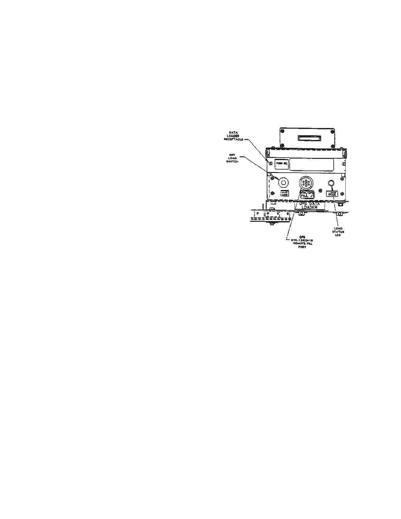
TM 1-1520-240-10
e. Repeat steps b. thru d. to load additional keys.
(3)
If ZEROIZED message is displayed on
STAT Page 1, Line 2, the GPS receiver is declassified.
f. Turn KYK-13 Mode switch to OFF.
(4)
If ZERO FAIL message is displayed, zer-
g. Disconnect KYK-13 from aircraft receptacle.
oization was not successful and the GPS receiver re-
3-3-59. GPS Zeroize Switch. (fig. 2-1-8)
mains classified.
The GPS Zeroize switch is located on center instrument
panel, right side of AN/APR-39AV(1) Indicator, and is
used to erase any crypto data and all navigational infor-
mation stored in the GPS Receiver.
This zeroize switch consists of a guarded toggle switch.
3-3-60. Normal Operation GPS Zeroize Switch.
NOTE
Aircraft battery must be connected, or power
applied to aircraft.
a. Lift protective guard from zeroize toggle switch
and activate switch.
b. If GPS receiver is on, turn Data Switch to Stat.
Observe message on Page 1, Line 2.
The message ZEROED indicates a successful attempt
to erase information stored in the GPS receiver.
The message ZERO FAIL indicates an unsuccessful at-
tempt to erase the information. The GPS receiver re-
mains classified.
c. An alternate method to zeroize the GPS receiver
is to use the C-11702/UR and GPS Control Unit keyboard
as follows:
(1)
Select STAT page 1.
(2)
Enter ZZ on line 4, and push Line Select Key
Figure 3-3-9. Remote GPS Data Loader
4.
Receptacle/KYK-13 Fill Panel
3-3-35/(3-3-36 blank)