OPERATOR’S MANUAL FOR ARMY CH-47D HELICOPTER (EIC: RCD, 2003) - page 5
TM 1-1520-240-10
SECTION IV. TRANSPONDERS
3-4-1. Transponder System (AN/APX-100).
CONTROLS/
FUNCTION
INDICATOR
The transponder system provides automatic radar identi-
EMER
Transmits emergency re-
fication of the helicopter. The system receives, decodes,
ply signals to mode 1, 2,
and replies to interrogations on modes 1, 2, 3/A, 4, TEST
or 3/A and 4 interroga-
and C from all suitably equipped challenging helicopter
tions, regardless of mode
or ground facilities. The receiver section operates on a
control settings.
frequency of 1,030 MHz and the transmitter section oper-
ates on a frequency of 1,090 MHz. Because these fre-
M-1, M-2, M-3/A
At ON position, the appli-
quencies are in the UHF band, the operational range is
Switches
cable mode is selected
limited to line-sight. Power to operate the system is sup-
for operation. OUT posi-
plied by the No. 2 DC bus through the COMM IFF circuit
tion turns off applicable
breaker on No. 2 PDP.
mode. AT TEST position,
that particular mode sis
tested for proper opera-
The integral receiver-transmitter-control panel is on the
tion. If test is valid, TEST
console. It provides the control switches for application
lamp will illuminate.
of power, setting of the modes and codes, modes of
operation, identification of position, and emergency func-
M-C
In mode C, altitude infor-
tions of the set. It receives coded interrogating pulses
mation is provided to
and tests them for validity. If the signals conform to the
ground controllers by the
preset mode and code, a codes reply is transmitted.
AAU-32A encoding alti-
Additional preset codes for emergency use are available
meter. Switch position
when selected. These emergency codes are transmitted
functions are the same
on modes 1, 2, 3/A and 4 regardless of codes selected.
as for M-1, M-2, and
Transponder functions are continuously monitored by
M-3A switches.
built-in-test circuits. Each mode also has a self-test fea-
MODE 1 Selector
Selects and indicates a
ture which can be selected by the pilot to verify operation.
Switches
two digit 32 code reply
The RT-1285/APX-100 is the interim NVG compatible
number.
control. The RT-1558/APX-100 is the NVG Blue Green
version. Both units are form, fit and functionally inter-
MODE 2 Selector
Selects and indicates a 4
changeable. The receiver-transmitter must be removed
Switches
digit 4096 code reply
from the console to replace the fuse.
number. (Switches are
preset and covered by a
guard. Only the reply
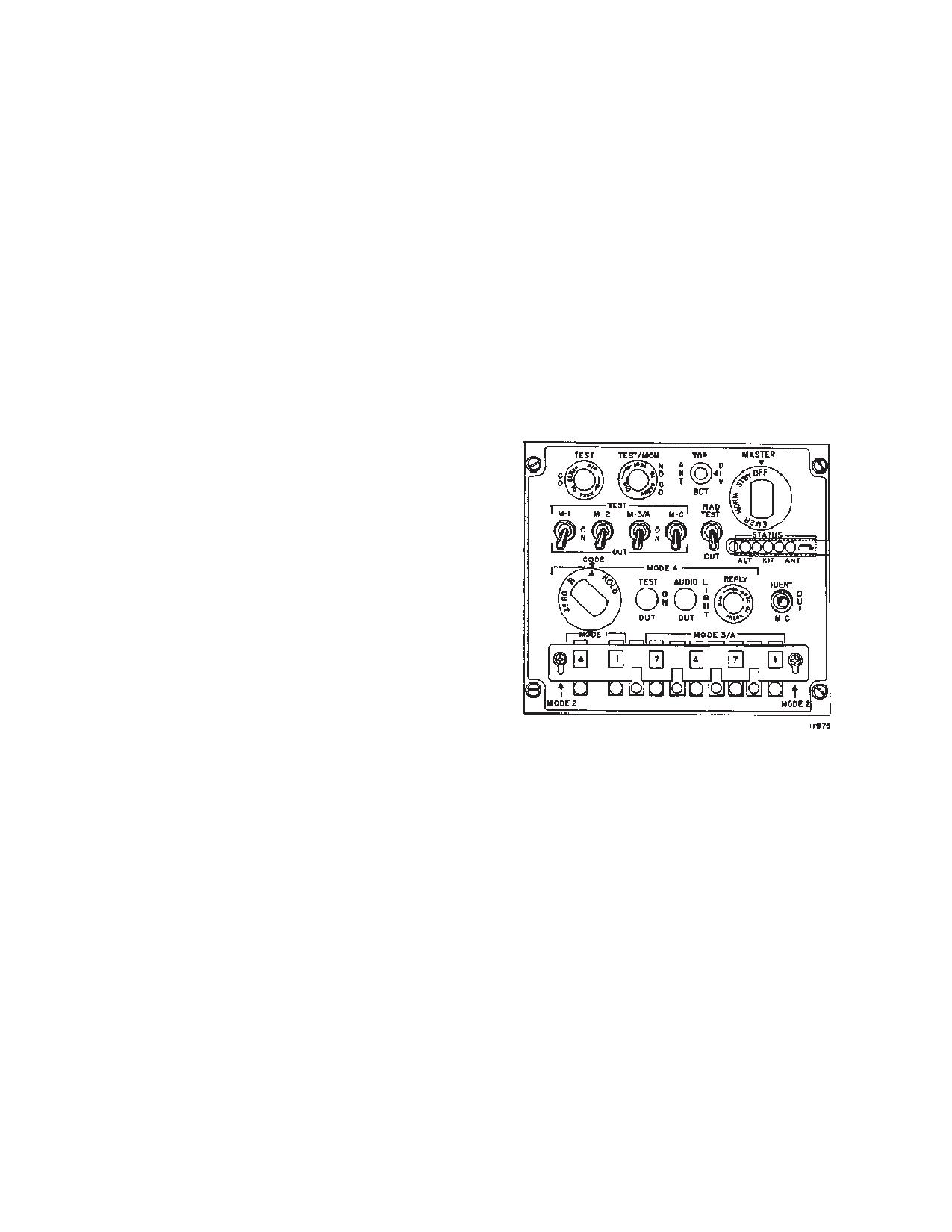
3-4-2. Controls and Function, Transponder Control
code can be seen.)
(TR-1285/APX-100) (RT-1558/APX-100). (fig. 3-4-1)
MODE 3/A Selector
Selects and indicates a 4
Switches
digit 4096 code reply
CONTROLS/
FUNCTION
number.
INDICATOR
MASTER Control
MODE 4 CODE Control
Selects type MODE 4 op-
Switch:
Switch
eration.
OFF
Removes power from
HOLD
This function is enabled
transponder set and
only when the right aft
computer
landing gear strut is com-
pressed. It holds the
STBY
Power is applied to trans-
MODE 4 code which
ponder receiver and
would otherwise be
computer; transmitter in-
cleared when the set is
operative. Set ready for
turned off or electrical
operation after 2 minute
power is removed.
warmup in STBY.
Switch is spring-loaded
to A. HOLD function is
NORM
Transponder in normal
reset when the trans-
operation.
ponder is turned on.
3-4-1
TM 1-1520-240-10
CONTROL/
FUNCTION
CONTROL/
FUNCTION
INDICATOR
INDICATOR
A
Enables transponder to
c. Transponder does not
reply to code A interroga-
respond to TEST position
tions.
of mode switches.
d. Transponder malfunc-
B
Enables transponder to
tions.
reply to code B interroga-
tions.
RAD TEST Switch
At RAD TEST, the trans-
ZERO
Clears (zeroizes mode 4
ponder replies to interro-
code settings in trans-
gations from external test
ponder computer.
equipment. At OUT the
RAD TEST feature is in-
MODE 4 AUDIO LIGHT
AT AUDIO, the REPLY
operative.
OUT Switch
indicator light will illumi-
nate when the trans-
IDENT-MIC Switch
AT IDENT, the set will
ponder replies to valid
transmit a coded identifi-
mode 4 interrogations. A
cation pulse for about 20
pulse tone will be heard
seconds to all interrogat-
in the headset when a
code A interrogation is
ing stations on modes 1,
received but the CODE
2, and 3/A to identify the
control switch is in B
helicopters position. OUT
position and vice versa.
position turns off the
At LIGHT, only the light
identification pulse. MIC
will illuminate when the
feature is not used in this
transponder replies to
installation.
mode 4 interrogations. At
OUT, the audio and RE-
STATUS Indicators
The indicator lights are
PLY light monitoring is
part of built-in-test equip-
disabled.
ment. A lit ALT indicator
MODE 4 TEST-ON-OUT
At ON, the transponder
indicates trouble in The
Switch
replies to valid mode 4
encoding altimeter. A lit
interrogations. At OUT,
KIT indicator indicates
mode is disabled. At
trouble in the computer
TEST, mode 4 is tested
or the computer is not
for proper operation. If
installed. A lit ANT indi-
test is valid, TEST GO.
cator indicates antenna
Mode 4 REPLY Light
Illuminates to indicate
trouble.
valid mode 4 replies
when MODE 4 AUDIO
ANT Switch
Three-position antenna
LIGHT switch is set to ei-
diversity switch labeled
ther AUDIO or LIGHT.
TOP, DIV, and BOT. Nor-
TEST GO Light
Illuminates when trans-
mal position is DIV.
ponder responds proper-
When jamming is heavy,
ly to TEST position of
TOP or BOT antenna
M-1, M-2, M-3A, M-C, or
may be selected.
MODE 4 TEST-ON-OUT
IFF Fail Light (Located
The light will illuminate in
swithces.
on the center instrument
MODE 4 when any of the
TEST/MON NO GO Light
The light illuminates
panel)
following occurs:
a. The computer is
when any of the following
installed without a code.
occurs:
b. No reply or improper
a. MASTER switch is on
reply is made to a valid
STBY.
interrogation.
b. Transponder does not
c. A malfunction occurs
respond to interrogation.
in the transponder.
3-4-2
TM 1-1520-240-10
3-4-3. Normal Operation - Transponder System.
(a) MODE 4 CODE selector switch -
The following steps provide transponder system operat-
HOLD, then release.
ing procedures.
(b) MODE 4 CODE selector switch - A or
a. Starting.
B, as applicable.
(1)
Move the MASTER switch from OFF to
(c) MASTER control switch - OFF.
STBY. If the aircraft is so equipped, observe that the
(2)
If code retention is not desired:
STBY light on the aircraft advisory panel comes on. Also,
note that the NO GO light is on.
(a) MODE 4 CODE selector switch -
ZERO.
(2)
Allow 2 minutes for warmup.
(b) MODE 4 CODE selector switch - A or
(3)
Select the codes assigned for use in modes
B, as applicable.
1 and 3/A by depressing and releasing the pushbutton for
(c) MASTER control switch - OFF.
each switch until the desired number shows.
d. Turn KYK-13 Mode switch to OFF.
(4)
Operate the PRESS-TO-TEST feature of
the lamp indicators.
e. Disconnect KYK-13 from aircraft receptacle.
(5)
Place the ANT switch BOT.
(6)
Move the MASTER switch from STBY to
NORM.
(7)
Hold the M-11 switch to TEST, observe that
the TEST/GO indicator lights.
(8)
Restore the M-1 switch to ON.
(9)
Repeat (7) and (8) above for the M-2, M-3/A
and M-C mode switches.
(10) Place the ANT switch TOP.
(11) Repeat (7), (8), and (9) above.
(12) Place the ANT switch DIV.
(13) Repeat (7), (8), and (9) above.
NOTE
If KIT1C is not installed or keyed the following
steps are not required.
(14) Set the MODE 4 rotary switch to A. If the
external computer is used, set a code in it.
Figure 3-4-1. AN/APX-100 Control Panel
(15) Set the MODE 4 AUDIO/LIGHT/OUT switch
to OUT.
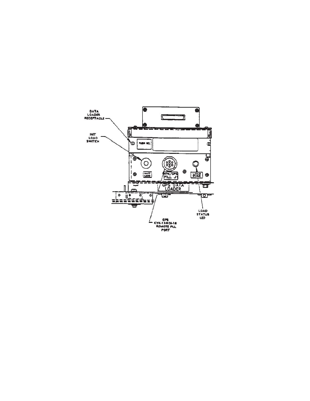
3-4-4. GPS Zeroize Switch. (fig. 2-1-8)
(16) Hold the MODE 4 TEST/ON/OUT switch to
The GPS Zeroize switch is located on center instrument
TEST.b.
panel, right side of AN/APR-39AV(1) Indicator, and is
(1)
If the computer is used, observe that the
used to erase any crypto data and all navigational infor-
TEST GO indicator lights. If the computer is not con-
mation stored in the GPS Receiver.
nected, observe that the TEST/MON/NO GO indicator
This zeroize switch consists of a guarded toggle switch.
lights and the KIT STATUS indicator lights.
3-4-5. Normal Operation - GPS Zeroize Switch.
(2)
Observe that the MODE 4 REPLY light and
CAUTION light (on a separate “panel”) do not light.
NOTE
Aircraft battery must be connected, or power
(3)
Restore the MODE 4 TEST/ON/OUT switch
applied to aircraft.
to ON for computer use, or to OUT if no computer is
used.
a. Lift protective guard from zeroize toggle switch
and activate switch.
c. Stopping.
b. If GPS receiver is on, turn Data Switch to Stat.
(1)
If code retention is desired:
Observe message on Page 1, Line 2.
3-4-3
TM 1-1520-240-10
The message ZEROED indicates a successful attempt
(1)
Select STAT page 1.
to erase information stored in the GPS receiver.
(2)
Enter ZZ on line 4, and push Line Select Key
4.
The message ZERO FAIL indicates an unsuccessful at-
tempt to erase the information. The GPS receiver re-
(3)
If ZEROIZED message is displayed on
mains classified.
STAT Page 1, Line 2, the GPS receiver is declassified.
c. An alternate method to zeroize the GPS receiver
(4)
If ZERO FAIL message is displayed, zer-
is to use the C-11702/UR and GPS Control Unit keyboard
oization was not successful and the GPS receiver re-
as follows:
mains classified.
Figure 3-4-2. Remote GPS Data Loader Receptacle/KYK-13 Fill Panel
3-4-4
TM 1-1520-240-10
CHAPTER 4
MISSION EQUIPMENT
SECTION I. MISSION AVIONICS
4-1-1. Radar Signal Detecting, AN/APR-39(V)1.
c. The digital processor supplies 15 VDC operating
power to the two video receivers and superimposes a
The radar signal detecting set (RSDS) AN/APR-39A(V)1 is
self-test signal on the 15 VDC power line to the receivers
a passive electronic warfare system that provides visual
during RSDS self-test. The digital processor receives
and aural indications of the presence of and bearing to
video inputs from the video receivers and processes
active radar transmitters. The RSDS detects those pulse
them to determine signal parameters. These signal pa-
radar signals usually associated with hostile fire control
rameters include pulse repetition interval (PRI) pulse
radars in the H-J and MMW (millimeter wave) frequency
with (PW), pulse spacing (PS), and signal strength. The
bands. The RSDS is the heart of the helicopter threat warn-
system does not provide center frequency resolution for
ing suite. It interfaces with the laser detecting set AN/
detected signals. It then compares these signals param-
AVR-2, missile warning system AN/AAR-47, and radar
eters to the threat library stored in the emitter identification
warning system AN/APR 44(V)3 to process, display, and
data (EID) files. If a match occurs, the digital processor
announce threats detected by those systems. The system
send the appropriate symbol data to the indicator and a
consists of the indicator on the center instrument panel (fig.
corresponding computer-synthesized voice warning mes-
2-1-8), a digital processor located in the right aft avionics
sage to the helicopter ICS. If the received signal parame-
pod, two video receivers (one at station 50, another at
ters do not match a threat in the EID files, the processor
station 605), four spiral antennas (hi-band) outside the
generates a symbol “U” to indicate an unknown threat. It
helicopter (Two at station 26, two at station 623), and a
executes and evaluates the results of an IBIT routine, pro-
blade antenna (lo-band) mounted on the bottom of the
viding an indication of results on the indicator. Also, it pro-
fuselage at station 99. In addition, a separate AN/
cesses threat data inputs from the AN/AVR-2, AN/
APR-39A(V)1 volume control labeled audio on the cen-
APR-44(3), and AN/AAR-47 systems for display on the
tered console provides additional volume control capabili-
ties external of the ICS (fig. 4-1-2). The RSDS is powered
indicator and annunciation over the ICS.
in the No. 2 DC bus through the ASE RADAR WARN circuit
breaker on the No. 2 PDP
d. The blade antenna senses C/D lo-band RF and
routes it to the C/D band amplifier portion of the digital
a. The antenna-detector characteristics determine
processor. The RF signal is filtered, limited, and detected
the frequency range of the system. Each of the antenna-
by the C/D band amplifier with the resultant video being
detectors contain two spiral elements, one operating in the
analyzed for the presence of a threat in the C/D band.
H-J bands and operating in the MMW (millimeter wave)
This analysis occurs in conjunction with the hi-band sig-
region. Each of the spiral elements receive radio frequency
nal analysis to determine the threat type and current
(RF) signals in their respective band and supply it to the
threat mode (scan. acquisition, track, launch, etc.)
detector circuits. The detector portion of the antenna-de-
tector employs an elaborate set of filter banks that extract
e. The RSDS employs a removable user data module
the video (pulses) from the RF received in each band. The
(UDM) which is mounted in the digital processor. The UDM
resultant video outputs are then summed and provided as
contains the classified portion of the system operational flight
a composite video signal to the appropriate video receiver.
program (OFP) and the classified emitter identification
b. Each video receiver has two video input chan-
data(EID) files. The EID files contain the threat library which
nels and they serve the left and right antenna-detectors for
includes threat signal parameters, threat symbols, and
the corresponding forward or aft sector. The video receiver
threat audio data. The UDM can be removed at the unit level
supplies power to the antenna-detectors and amplifies the
and reprogrammed to accommodate new and changing
detected video inputs from the antenna-detectors. Two vid-
threats. It allows the RSDS to be tailored to the specific
eo outputs are then sent to the digital processor for signal
theatre of operation and/or current mission requirements.
analysis. The video receiver also performs initiated built-in
Removal of the UDM from the digital processor declassifies
test on command from the digital processor
the RSDS.
4-1-1
TM 1-1520-240-10
NOTE
i.
The RSDS, LDS, and MWS all execute periodic
Threat symbols (except for U) shown on indi-
built-in-test (PBIT) routines during normal operation to
cator illustrations are for illustration purposes
verify operational status with the results of these tests
only. Actual threat symbols are classified.
being reported to the digital processor. Failures of PBIT for
these three systems are indicated by the presence of an “F”
f.
The indicator displays threat symbols corresponding
replacing the plus (+) symbol in the center of the RSDS
to threat signals detected and identified by the system.
Threat relative position from the helicopter is shown on the
indicator. The “F” informs the operator that one or more of
indicator. Symbol position relative to the center of the indica-
the systems has failed at least some portion of their respec-
tor shows the threats lethality. The highest priority threats
tive PBIT routines. This prompts the operator to perform
(most lethal) are shown nearest the center. The 12 outer
initiated built-in-test (IBIT) to determine what system(s) has
edge markings on the indicator graticule represent clock
failed and the extent of the failure(s)..
positions relative to helicopter heading. The system displays
a maximum of seven threat symbols. If the number of
threats in the environment exceeds the number the system
j.
IBIT may be selected by the operator. If the RSDS
can display, only the seven highest priority threats will be
interface circuitry within either RTU fails the self-test, the
displayed. If a detected threat cannot be identified as a
RWR TEST FAIL advisory is displayed on the MFD.
specific threat type, it is displayed as an unknown (symbol
Faulty receivers are shown on the indicator as blinking
U). Search radars and fire control radars operating in search
symbols and the voice message “APR-39 Failure” will be
mode are displayed as strobes at the edge of the indicator.
heard over the ICS. If the test is good, the voice message
The position of the strobe on the display represents the
“APR-39 Operational” will be heard over the ICS. The
relative bearing of the search radar from the helicopter. New
RWR FAIL caution is displayed if the RSDS interface
threats appear in boldface on the display. Threats that drop-
circuitry within both RTU’s fails while in its normal operat-
out of the environment are ghosted on the display for 10
ing state. Self-test of the laser detecting set (LDS) and
seconds before being dropped. A ghosted symbol appears
as though drawn with a dotted line.
the missile warning system (MWS) are incorporated in
the RSDS self-test.
g. Threats are announced by voice messages over
the helicopter ICS. Either of the two voice message for-
mats can be selected using page 2 of the CDU ASE
k. The system interfaces with the Interference
control layer. RWR AUDIO 1 or normal (full message
Blanker Unit (IBU) in an attempt to prevent other aircraft
format) selects full audio. RWR AUDIO 2 or terse (short-
systems, which operate in the same approximate fre-
ened message format) provides shorter audio messages
quency range, from interfering with it. The lo-band portion
and reduces the audio clutter in dense signal environ-
of the RSDS is blanked by the IBU when either the IFF
ments. Both modes provide specific threat type or threat
transponder system or the TACAN system is transmitting.
position voice messages.
The hi-band portion of the system is blanked by the IBU
h. When dense signal environments cause the sys-
when the radar altimeter system, radar beacon transponder
tem to operate in a degraded (less sensitive) mode, the
system, multimode radar system, pulse radar jammer sys-
system informs the operator by flashing the plus (+) sym-
tem, or the CW radar jammer system is transmitting. This
bol on the RSDS indicator and the voice message
blanking is accomplished to prevent the possible detection
“Threat Detection Degraded” will be heard over the ICS.
of false threats as a result of interference induced by these
When the system sensitivity returns to normal, the plus
(+) symbol in the center of the RSDS indicator stops
systems. Because the RSDS is a passive system, it does
flashing and the voice message “Threat Detection Re-
not provide any input to the IBU for the potential blanking of
stored” will be heard over the ICS.
other systems.
4-1-2
TM 1-1520-240-10
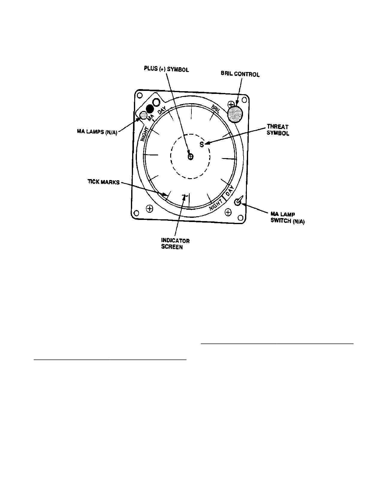
Figure 4-1-1. Radar Signal Detecting Set Indicator
4-1-2. CONTROLS AND FUNCTION, RADAR SIGNAL
CONTROLS/
FUNCTION
DETECTING SET INDICATOR
INDICATOR
CONTROLS/
FUNCTION
Plus (+) Symbol
Displayed in the center of
INDICATOR
indicator during operation
and self-test. Plus
(+)
MA Lamps
Not used in the AN/
symbol flashes to
let
APR-39A(V)1 system.
operator know when the
BRIL Control
Sets indicator display
system is operating in a
brightness. Turn clock-
dense signal environment
wise to increase bright-
and threat detection is
ness. Adjust for best
degraded.
readable display of plus
Tick Marks
The
12 outer edge
(+) symbol.
markings on the indicator
MA Lamp Switch
Not used in the AN/
graticule, represent clock
APR-39A(V)1 system.
positions
relative
to
aircraft heading.
Threat Symbol
Typical Threat
4-1-3
TM 1-1520-240-10
NOTE
CONTROLS/
FUNCTION
INDICATOR
The concentric circle is a reference mark only
and is not a range marking.
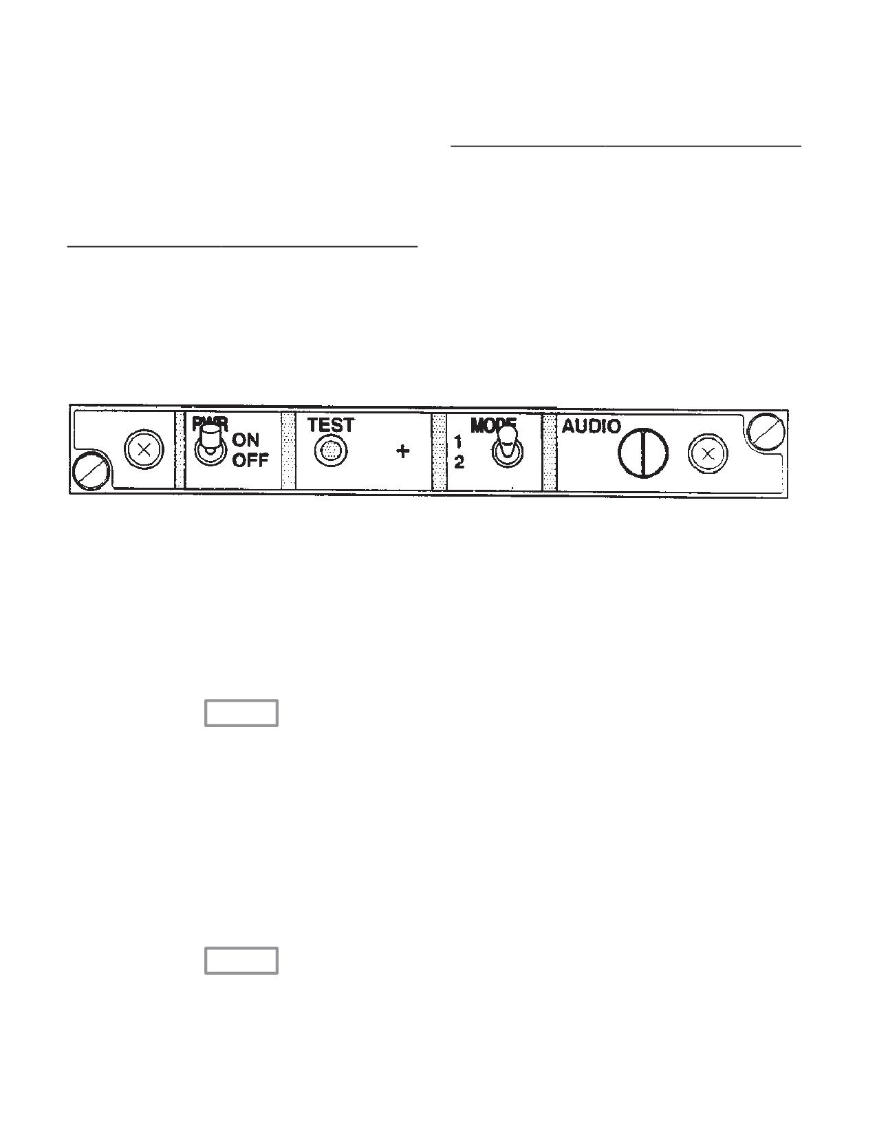
MODE Switch
Two position switch. Selects
4-1-3. Controls and Function, Radar Signal Detect-
synthetic voice message for-
ing Control.
mat. Mode 1 (up) selects
normal message format.
CONTROLS/
FUNCTION
Mode 2 (down) selects terse
INDICATOR
(abbreviated) message for-
mat. Mode 2 reduces audio
PWR Switch
Two position switch. At ON,
distractions when operating
power is applied to set. Set
in dense signal environ-
is operational after 1-minute
ments.
warmup.
TEST Switch
Switch is spring-loaded to
AUDIO
When turned clockwise, the
off. When pressed, the self
audio output of the set is in-
test function is enabled.
creased.
Figure 4-1-2. Radar Signal Detecting Set Control
4-1-4. Normal Operation - Radar Signal Detecting
a. Starting.
Set.
(1)
PWR switch - ON. Allow 1 minute for war-
mup - Check for synthetic voice message “APR-39
This paragraph provides radar signal detecting set oper-
POWER UP”.
ating procedures.
(2)
BRIL control - adjust display of (+) symbol
(3)
MODE switch - Select MODE 1 (up) for
normal messages. Select MODE 2 (down) for terse (ab-
breviated ) messages.
CAUTION
b. Self-test check.
NOTE
To prevent damage to the antenna detec-
SYSTEM SELF-TEST provides a four step
tors (when operating) never operate the
test of system functions. A complete system
AN/APR-39A(V)1within 60 yards of ground
self-test is initiated any time the test button is
based radars or within six yards of air-
pressed. The complete system self test runs
borne radar antennas. Operating the sys-
in less than 30 seconds. The following is a
tem closer than these limits may damage
description of the system functions.
the antenna detectors. Allow an extra mar-
gin for new, unusual, or high-powered ra-
(1)
TEST - As follows:
dar transmitters.
(a) MODE switch - Set position 1 (up)
(b) TEST switch - Press.
A synthetic voice long count is performed. The audio
message “SELF-TEST, SET VOLUME 1, 2, 3, 4, 5, 6, 7,
CAUTION
8, 9, 10, 11, 12” will be heard on the ICS.
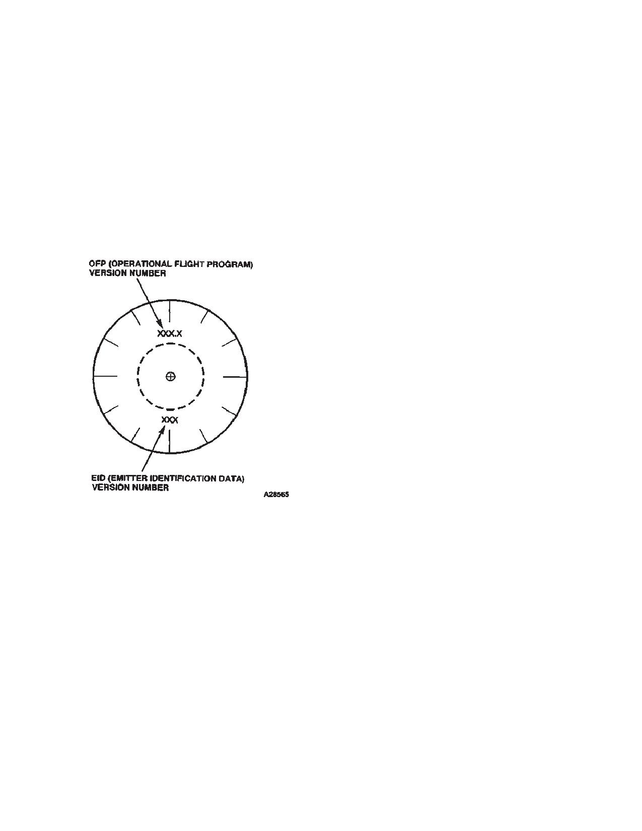
A display of two numbers which represent the installed
Excessive indicator display brightness
software revision on the indicator; one number (OFP-Op-
may damage the CRT. Set indicator BRIL
erational Flight Program) at the top and one number
control for readable display.
(EID-Emitter Identification Data) at the bottom (fig.
4-1-4
TM 1-1520-240-10
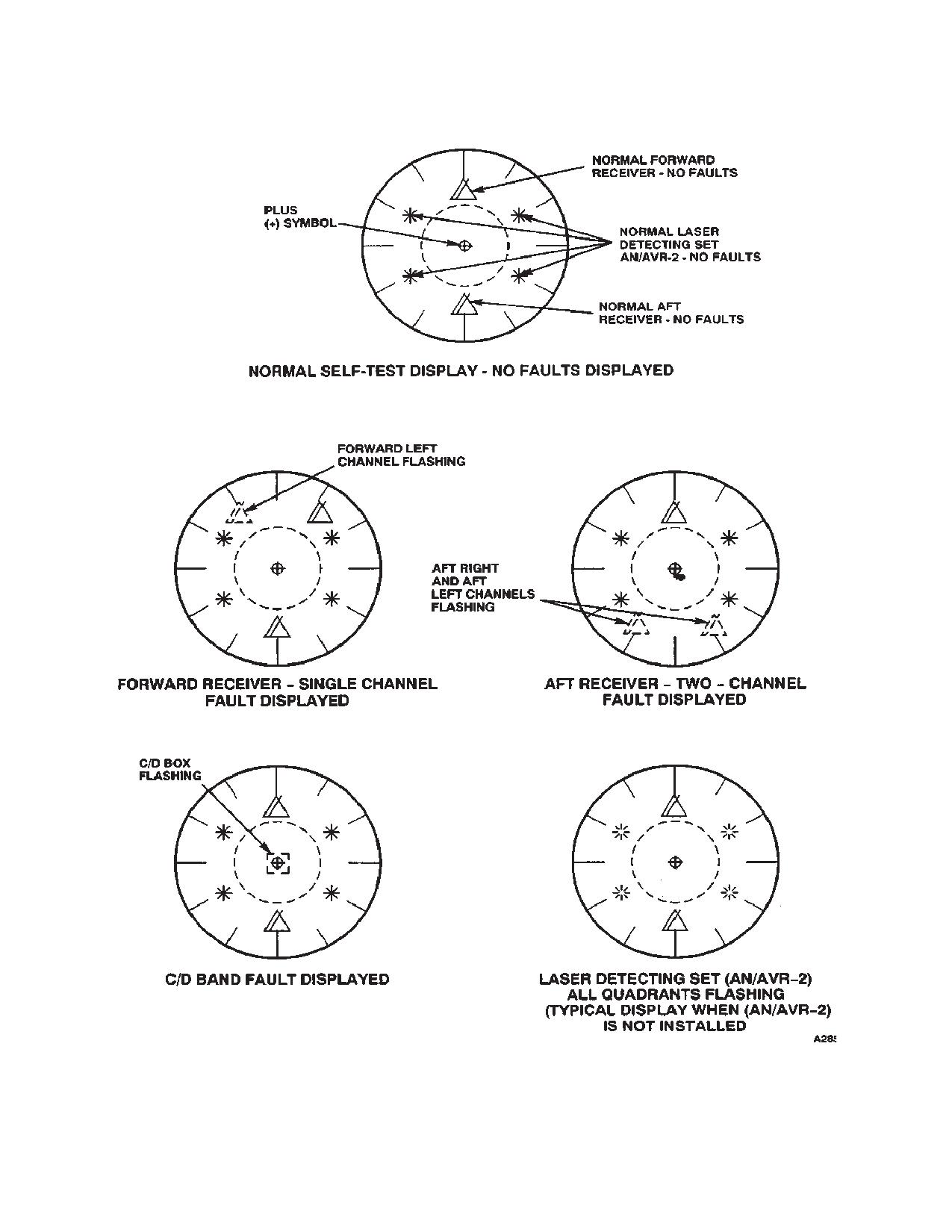
4-1-3). Check OFP and EID numbers are correct for the-
(a) If a receiver fault is noted, faulty receiver
ater or mission.
is shown as two triangles, (fig. 4-1-4) representing right
and left video channel (s) will be flashing.
Performs the Receiver and AN/AVR-2 status display.
See figure 4-1-4 for normal indicator displays, and faulty
(b) A faulty C/D band amplifier in a proces-
indicator displays.
sor is shown as a flashing square centered on indicator
display ( fig. 4-1-4).
Performs a test on the synthetic voice status messages.
A no fault detected during test will end with message
(c) The Laser Detecting Set (LDS)(AN/
APR-39 OPERATIONAL” any fault detected will end with
AVR-2) status is displayed along with the receiver status.
message “APR-39 FAILURE”, which will be heard over
A faulty LDS quadrant is shown as a flashing asterisk.
the ICS.
LDS faults do not cause an audio message “APR-39
FAILURE”, heard over the ICS.
Performs the plus (+) symbol display status. The plus (+)
symbol will be displayed, centered within the small circle
(d) If LDS is not installed, all four quadrants
on the indicator, anytime the symbol is operational.
(asterisks) will flash.
(3)
Operating In A Dense Signal Environment.
(a) When a dense signal environment is de-
tected, the plus (+) symbol on the Radar Signal Detecting
Set (RSDS) indicator will flash, and the voice message
“THREAT DETECTION DEGRADED” will be announced
over the ICS.
(b) Position mode switch to mode 2 (terse
mode). When the plus(+) symbol stops flashing, the
voice message “THREAT DETECTION RESTORED”
will be announced over the ICS.
4-1-5. Countermeasure Set (AN/ALQ-156).
The Countermeasures Set (AN/ALQ-156) detects the
approach of anti-aircraft missiles, and signals the M-130
Flare Dispenser to launch flares to decoy the missiles
from the helicopter. The set consists of a control unit on
the console, a receiver-transmitter in the electronics
compartment, two antennas on the bottom of the fuse-
lage, and two caution light capsules on the master cau-
tion panel. The set alternately applies pulsed signals to
the two antennas which radiate the signals about the
Figure 4-1-3. Radar Signal Detecting Set (OFP and
helicopter. A missile approach is detected by the fre-
EID VERSION DISPLAY)
quency shift of the transmitted signals echo returned
from the missile. Any echo is received during the interval
following each pulsed transmission. Built-in-test-equip-
ment monitors system operation. If a malfunction is de-
(c) MODE switch - MODE 2 (down),
tected, the system is disabled and the CM INOP caution
(d) TEST switch - Press.
capsule on the master caution panel will come on. Also,
if enemy jamming or interference from other counter-
Performs the synthetic voice short count. Listen to syn-
measures sets is detected, the set will automatically shift
thetic voice message and adjust volume. Mode 2 short
to a clear channel. The set receives AC electrical power
count is: “SELF-TEST SET VOLUME 5, 4, 3, 2, 1”.
from the No. 2 AC bus through the MSL DET SYS circuit
(2)
The following fault display conditions are on
breaker on the No. 2 PDP. The set receives DC power
the result of a bad self test and will result in an audio
from the No. 2 DC bus through the MSL DET SYS circuit
message “APR-39 FAILURE” over the ICS.
breaker also on the No. 2 PDP.
4-1-5
TM 1-1520-240-10
Figure 4-1-4. Radar Signal Detecting Set Indicator (Self Test Displays)
4-1-6
TM 1-1520-240-10
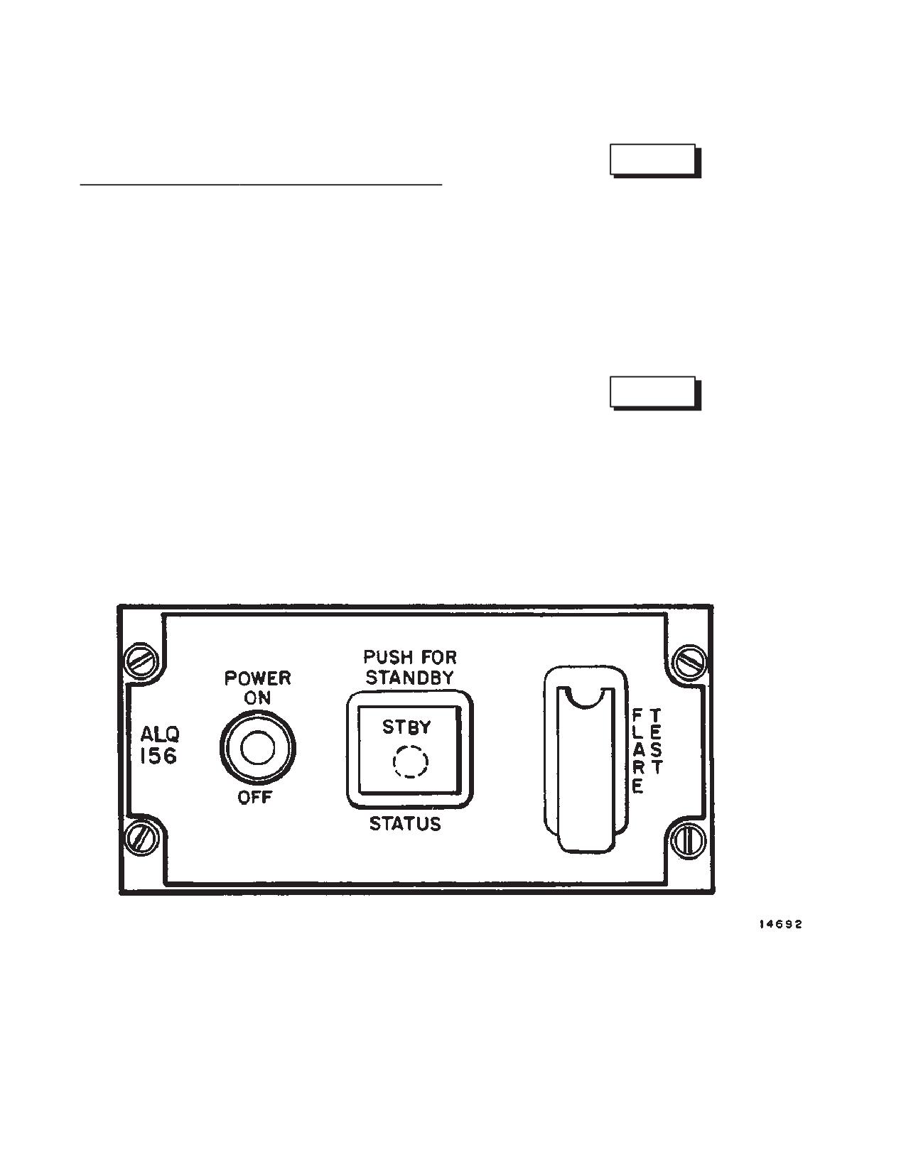
4-1-6. Controls and Indicators, Missile Detector Set
4-1-7. Normal Operation; Countermeasure Set.
(AN/ALQ-156). (fig. 4-1-5)
CONTROLS /
FUNCTION
WARNING
INDICATOR
POWER OFF/ON
At ON, power is applied to
An accidental flare launch can occur when
set. The switch is locked at
Flare Dispenser System is armed (control
ON. Signals radiate after the
switch at ARM) and the Countermeasure
normal warmup period is
Set is operating (CM caution and indicat-
completed.
ing lights off). A flare launch will also oc-
cur is the FLARE TEST switch on the
STBY Indicator Light
Lights when switch is de-
countermeasures control panel is opera-
on STATUS Switch
pressed and system is in
ted. Arm these systems only in cases
standby operation.
where a launched flare will not cause inju-
Amber Warmup Cau-
Lights when power is ap-
ry or property damage.
tion Light on STATUS
plied to set and remains on
Switch
until operating temperatures
are reached.
WARNING
FLARE TEST Switch
Simulates launch command
signal to flare dispenser.
During operation, the AN/ALQ-156 anten-
nas radiate radio-frequency energy. This
CM INOP Caution
When lit indicates the set
energy may cause burns to personnel
Light (on caution pan-
has failed and the helicopter
near the antennas. Be sure ground per-
el)
is without countermeasures
sonnel are at least 6 feet from the anten-
protection.
nas when the control switch is at ON.
CM JAM Caution
Lights when system detects
a. Starting.
Light (on caution pan-
mutual interference from
el)
nearby countermeasures
(1)
MSL DET SYS circuit breakers on No. 2
sets or enemy jamming.
PDP - Check in.
Figure 4-1-5. Countermeasures Set Control Panel (AN/ALQ-156)
4-1-7
TM 1-1520-240-10
stability resulting in interference with oth-
WARNING
er countermeasures sets.
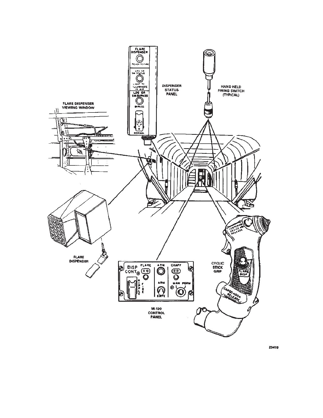
4-1-8. Flare Dispenser M-130.
The system requires a 10-minute warm-up
The Flare Dispenser M-130 (fig. 4-1-6) will dispense up
prior to operation. To ensure automatic
to 30 decoy flares as a countermeasure to infrared seek-
system operation when required, be sure
ing missiles. The externally mounted dispenser is con-
the set is operational and all caution and
trolled by a DISP CONT control panel on the console and
indicator lights are out prior to entering
six firing switches. Two cockpit firing switches are pro-
hostile areas.
vided, one on each pilot’s control stick grip. Four hand-
held crewmember firing switches are installed in the cab-
in area. Flares can also be automatically fired by firing
(2)
POWER control switch - ON
commands from the countermeasure set (AN/ALQ-156)
if the set detects a missile approach. A timer in the cabin
provides a 2.5 second delay between firing pulses re-
(3)
Warm-up light - ON, allow 10 minutes for
gardless of firing switch position. A ground safety relay,
warm-up. At the end of warm-up period, the warm-up
controlled by a landing gear proximity and a safety pin
light will be shut off.
manually installed into the dispenser, prevents firing
flares when the helicopter is on the ground. The system
b. ECM operation.
is powered by the No. 1 DC bus through the CHAFF
circuit breaker on the No. 1 PDP.
(1)
Status switch - Push for standby operation
or release to commence automatic protection.
NOTE
Although the control panel, dispenser, and
circuit breaker are marked CHAFF or have
(2)
CM JAM caution light - Check OUT.
CHAFF (C) selector positions, chaff cannot
be dispensed at this installation.
(3)
CM INOP caution light - Check OUT. If cau-
4-1-9. Dispenser Control Panel.
tion light is on, the set has malfunctioned and the helicop-
The DISP CONT panel is installed in the center console. The
ter is without countermeasure protection.
panel contains the ARM SAFE switch, ARM indicator light,
RIPPLE FIRE switch, FLARE counter, and counter setting
(4)
STATUS switch - Push for standby operation
knob. The panel also includes a MAN-PGRM switch and
when countermeasures protection temporarily is not re-
CHAFF counter, which are not used in this installation.
quired and/or accidental flare launch is a danger (LZ/PZ
4-1-10. Dispenser Status Panel.
operations).
The dispenser status panel (fig. 4-1-6) provides an indication
of safety relay operation and system arming. It also allows
(5)
POWER switch - OFF when countermea-
the landing gear safety switch to be bypassed for ground
sures protection is no longer required (EOM).
testing of the dispenser system. The panel is on the left side
of the cabin at sta 534.
4-1-11. Controls and Function, Flare Dispenser Sys-
WARNING
tem (M-130) (fig. 4-1-6)
CONTROLS/
FUNCTION
If countermeasures set has been off for
INDICATOR
less than 5 minutes and further operation
ARM/SAFE Switch
At SAFE, the system is not
is required, the warm-up indicator light
powered. At ARM, the sys-
may go out immediately (or within some
tem is powered, provided
interval less than the normal 10 minute
the safety pin is removed
warmup period) after the power switch is
from the electronic module
set to on. If this occurs, it is mandatory
and the ground safety relay
that the system be operated in STBY for at
is energized. (Helicopter air-
least 1 minute. Failure to observe this re-
borne or remote bypass
quirement can result in a false alarm
switch on remote test panel
is at BYPASS.)
(launch) and/or transmitting frequency in-
4-1-8
TM 1-1520-240-10
CONTROLS/
FUNCTION
WARNING
INDICATOR
ARM Indicator Light
Red PRESS-TO-TEST
1. Dispenser Assembly.
warning light indicates, when
lit, that ARM SAFE switch is
a. Selector switch - Set to F.
at ARM, safety relay is
b. Safety pin - Remove and stow.
closed, and safety pin is not
installed in electronic mod-
c. Flares - Note quantity installed.
ule.
2. Dispenser Status Panel.
FLARE Counter
Two digit counter displays
a. LDG GR SW BYPASS switch - NOR-
number of flares remaining in
MAL Cover down.
the dispenser. The number of
flares loaded is set manually,
b. Indicator lights - PRESS -TO-TEST.
using the knob directly below
3. Cabin hand held firing switches - Check
the counter.
connected and secured in holder.
RIPPLE FIRE Switch
Guarded two-position switch
4. Cockpit Control Panel.
allows rapid emergency ejec-
tion of all remaining flares.
a. RIPPLE FIRE switch - Cover down.
CHAFF Counter
Not used in this installation.
b. ARM/SAFE switch - SAFE.
MAN/PGRM Switch
Light intensity controlled by
c. FLARE counter - Set to amount of
caution panel DIM/BRT SW.
flares in dispenser.
Dispenser Status
(fig. 4-1-6)
4-1-12. Normal Operation - M-130 Flare Dispens-
Panel
er.
READY TO FIRE
Amber light comes on when
Light
system is armed and ready to
4-1-13. Preflight.
fire. Light receives power
through timer and will go out
for 2.5 seconds after flare
WARNING
launch.
An inadvertent flare launch can occur
LDG GR SW STATUS
Green light comes on when
when the Flare Dispenser System is
Light
ground safety relay is
armed (control switch at ARM) and the
deactivated. The safety relay
Countermeasures Set is operating (CM
is deactivated when the
caution and indicating lights off).
helicopter is airborne or
bypassed via the LDG GR
4-1-14. In-Flight Operation.
SW BYPASS switch.
1. After liftoff, LDG GR SW STATUS advisory
LDG GR SW BYPASS
Red light, when lit, indicates
light on remote test panel - Check on.
Light
that the ground safety relay is
bypassed
2. ARM/SAFE switch - ARM. Check ARM
(NORMAL/BYPASS switch is
warning light on.
at BYPASS).
3. READY-TO-FIRE light on dispenser status
NORMAL/BYPASS
Guarded switch. At BYPASS,
panel - Check on.
Switch
the landing gear safety switch
4. ECM set - ON. Allow 10 minutes for war-
is bypassed. Switch normally
mup. The ECM set will monitor the area
used to test system prior to
around the helicopter for missiles and auto-
installing flares.
matically fire flares when missiles are de-
Cyclic Stick FLARE
Pushbutton switch on side of
tected.
DISP Switch
each cyclic stick. Fires a flare
NOTE
each time when pressed.
The flare dispenser can be safely observed
Hand Held Firing
Located in forward and aft
from the cabin through the filtered glass win-
Switched (4)
cabin
sections.
When
dow on the left side of the helicopter above the
pressed, a single flare is fired.
ramp at sta. 575.
4-1-9
TM 1-1520-240-10
5. If the ECM set is inoperative, proceed as
4-1-16. After Landing Check.
follows:
1. Check that the LDG GR SW Status light
NOTE
goes out.
The crewmember observing a missile launch
2. Install the ground safety pin in the dispenser
is responsible for firing the flares.
electric module.
a. Missile threat - Actuate the dispensing
switch on the cyclic grip to fire flares or
3. Remove and stow the crew firing switches.
chaff or press one of the four firing
switches in the cabin to fire flares. Fire
4-1-17. Countermeasures Dispenser System, AN/
a total of three flares or hold button
ALE 47. (fig. 4-1-6)
down and timer will automatically space
firing interval.
The AN/ALE-47 Countermeasures Dispenser System
(CMDS) provides the aircraft with protection from air-to-
NOTE
air and surface-to-air heat seeking missiles. Modes of
The flare dispensers will fire one flare each
operation are manual (five stored programs), semi-auto-
time a button is pressed following the 2.5 sec-
matic (operator/sensor activated), and automatic (opera-
ond time delay or at 2.5 second intervals if the
tor/sensor activated). The CMDS is integrated with the
flare dispense button is held down. If the flare
AN/ALQ-156 Missile Detection System to automatically
fails to ignite, a second flare will automatically
dispense expendables when a threat is detected by the
fire within 75 milliseconds. If burning is still not
AN/ALQ-156 when in the AUTO or SEMI AUTO mode of
detected, a third flare will be fired. If all three
operation. The CMDS may be pre-programmed to re-
flares fail to ignite, automatic operation will
spond threat environments.
stop until one of the fire switches is again
pressed.
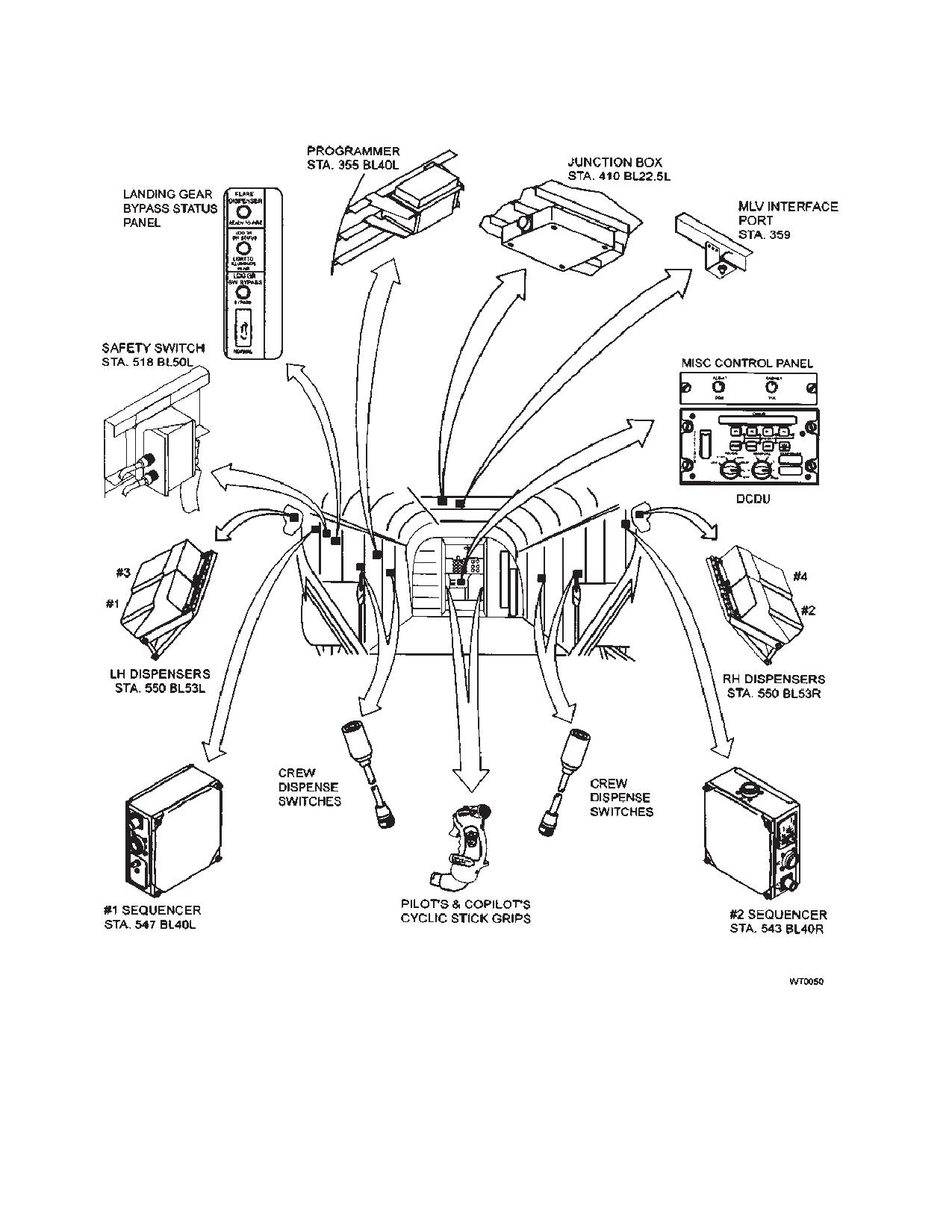
The CMDS is comprised of the following components: a
b. Announce over interphone that a mis-
Digital Control Display Unit, (DCDU), a programmer, a
junction box, two sequencers, and four dispenser as-
sile launch was detected and flares
semblies, each containing a payload module (maga-
have been fired.
zine). The system also contains a safety switch and a
c. If more than one missile launch is ob-
Mission Load Verifier (MLV) interface port.
served, continue firing flares at 3-sec-
ond intervals until the helicopter is clear
Power required to operate the CMDS is 28 Vdc, 2 amps
of the threat.
max in STANDBY and 7 amps for 20 milliseconds during
each squib ignition, is taken from the No. 1 DC Bus. The
4-1-15. Before Landing Check.
three circuit breakers for the CMDS are found on the
EAPS 1 PDP labeled DC ALE47. Power for the DCDU is
1. ARM-SAFE switch - Set to SAFE.
taken through a 5 amp CB labeled DCDU. Power re-
2. Indicator lights - Check that READY-TO-
quired to jettison expendables is taken through two 10
FIRE and ARM lights are out.
amp CBs labeled PWR NO. 1 SEQ and NO. 2 SEQ.
4-1-10
TM 1-1520-240-10
Figure 4-1-6. Flare Dispenser System (Sheet 1 of 2)
4-1-11
TM 1-1520-240-10
Figure 4-1-6. ALE 47 Flare Dispenser System (Sheet 2 of 2)
4-1-12
TM 1-1520-240-10
4-1-18. Controls and Function, Countermeasures
CONTROLS/
FUNCTION
Dispenser System (AN/ALE-47 (fig. 4-1-6)
INDICATOR
AFT (off)
Jettison function deacti-
CONTROLS/
FUNCTION
vated.
INDICATOR
DCDU:
Dispense Annuncia-
Displays status
tor:
READY/NO-GO
MODE Switch
OFF
Off mode. Remove power
from DCDU. All functions dis-
Input sensor enable/inhibit switches:
abled except Jettison.
RWR
Not used.
STBY
Standby mode. Applies pow-
er to DCDU to enable BIT,
MWS
Enables/inhibits missile
reprogramming, inventory,
detection system sensor dis-
and jettison.
pense input.
MAN
Manual mode. Enables
JMR
Not used.
manual dispensing of ex-
pendables.
Input sensor inhibit indicators:
SEMI
Semi-automatic mode. En-
ables manual dispensing of
RWR
Not used.
expendables and automatic
dispensing when threat has
MWS
Indicates missile detection
been detected by the
system sensor input has
ALQ-156 without operator
been inhibited.
action.
JMR
Not used.
AUTO
Automatic mode. Enables
manual dispensing of ex-
pendables and automatic
Payload enable/inhibit switches:
dispensing when threat has
been detected by the
01
Enables/inhibits payload 01.
ALQ-156 without operator
02
Enables/inhibits payload 02.
action.
CH
Not used.
BYP
Bypass mode. Expendables
dispensed directly by pilot or
FL
Enables/inhibits payload FL.
copilot using cyclic grip
FLARE DISP switches, by-
ENT/BIT switch
With MODE switch is in
passing the programmed
STBY, the ENT/BIT switch
values stored in the Missile
allows operator to initiate
Data File.
self-test (BIT).
MANUAL Switch
1, 2, 3, 4
Selects one of four manual
Payload enable/inhibit indicators:
dispense programs for use
Illuminated indicates payload is inhibited. Not illumi-
when MODE switch is in
nated indicates payload is enabled.
MAN.
O1
Indicates payload O1 is in-
PRG
Program mode. Enables
hibited.
manual dispensing of ex-
pendables.
O2
Indicates payload O2 is in-
hibited.
JETTISON switch
CH
Not used.
Forward (on)
Dispenses all expendables
with safety switch removed if
FL
Indicates payload FL is in-
weight off wheels.
hibited.
4-1-13
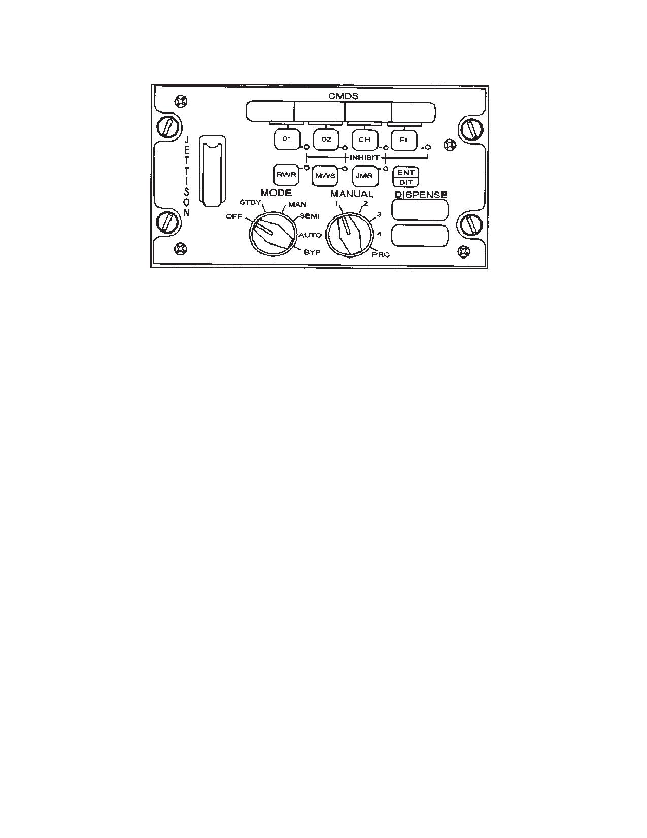
TM 1-1520-240-10
Figure 4-1-7. AN/ALE-47 Countermeasures Dispenser System (CMDS)
4-1-19. The AN/ALE-47 Programmer.
4-1-21. AN/ALE-47 Safety Switch.
The AN/ALE-47 programmer, located at STA 355 in the
left side of the cabin, is the central processing unit for the
A safety switch located at station 518 BL50L is installed
CMDS and provides the interface between the DCDU
in the CMDS to provide a safeguard against inadvertent
and the four flare dispensers via two sequencers. The
dispensing of expendable. When the safety pin is
programmer receives input data from the AN/ALQ-156
installed in the safety switch, squib power (28 Vdc) to the
missile detection system, processes it to determine the
sequencers is interrupted, inhibiting dispensing expen-
appropriate dispense response, and sends fire com-
dables. The safety switch provides ground to the AN/
mands to the sequencers when CMDS is in Auto or Semi
ALE-47 squib power relay (located in the AN/ALE-47
Auto mode of operation.
junction box at station 410 BL22.5L) when safety pin is
removed allowing squib power to the sequencers for dis-
The software program within the programmer that man-
pensing expendables.
ages all communications, operations, and calculations is
called the Operational Flight Program (OFP). The pro-
grammer also contains the Mission Data File (MDF)
4-1-22. Dispenser Assemblies.
which is user-programmable and contains data elements
that enable the CMDS to be configured to specific pay-
Four flare dispenser assemblies are mounted in pairs on
load types, dispense sequence, and dispense quantities.
the LH and RH sides of the aft fuselage. Each dispenser
The OFP and MDF are loaded into the programmer using
assembly consists of a housing and a breech plate. The
Mission Load Verifier (MLV) via the MLV interface port
breech plate provides interface for the payload module
located in the cabin at station 359 overhead.
and routes firing and polling pulses from the sequencers
to the payload squibs.
4-1-20. AN/ALE-47 Sequencers.
There are two AN/ALE-47 sequencers installed in the aft
cabin at station 547 buttline (BL)40L and station 543
4-1-23. Payload Module Assemblies.
BL40R. The sequencers receive payload type and fire
commands from the programmer over the Sequencer
The payload module assemblies are mounted on the
Data Link (SDL). The sequencers select the dispenser
dispenser assemblies. Each payload module assembly
with the appropriate payload and send high power im-
consists of a payload module (magazine), and an EMI
pulses to the dispenser(s) and magazine to dispense the
(HERO) gasket/breech plate. The payload modules can
programmed expendable. The sequencers also detect
hold up to 30 expendable cartridges which are loaded
magazine type, monitor the remaining inventories in the
and installed in the dispenser assemblies prior to the
magazines, and detect payload misfires. This informa-
mission.
tion is sent to the programmer via the SDL. Each se-
quencer also performs internal BIT. Sequencer NO. 1
controls the two dispensers (1 and 3) on the LH side of
The payload modules are capable of being loaded with
the aircraft, and sequencer NO. 2 controls two dispens-
3 types of expendables; XM211, XM212 and M206. They
ers (2 and 4) on the RH side of the aircraft.
use either the M796 or BBU-35/B cartridge.
4-1-14
TM 1-1520-240-10
4-1-24. Normal Operation.
1. Safety pin - Installed in AN/ALE-47 safety
switch, streamer visible.
2. Set DCDU switches as follows:
WARNING
a. JETTISON switch - Aft (switch guard
closed).
Keep all expendables impulse cartridges
(located inside the base of the expend-
b. MANUAL switch - 1, 2, 3, or 4 as re-
able), away from fire and high temperatu-
quired.
res. Each cartridge generates an extreme-
NOTE
ly high gas pressure and temperature if
accidentally fired. Impulse cartridges
The CMDS takes five seconds to warm up
must be handled with extreme care or inju-
when turned on. No dispensing is possible
ry to personnel could result.
during warm-up. The system performs BIT
during power-up and displays GO or NO-GO
Ensure safety pin with streamer is
with a momentary illumination of the DIS-
installed in the safety switch when the he-
PENSE READY advisory on the DCDU. The
licopter is parked to prevent accidental fir-
DCDU then displays the Operational Flight
ing of expendables, possibly resulting in
Program (OFP), followed by the Mission Data
injury to personnel. Remove safety pin
File (MDF) version number (#XXXX), then the
only to perform authorized tests or imme-
number of loaded expendables (flares) is dis-
diately before takeoff.
played.
The CMDS is capable of automatic or manual dispensing
c. MODE switch - STBY.
of expendables. Selecting SEMI or AUTO mode enables
d. O1, O2, CH, and FL inhibit switches -
automatic dispensing of expendables when the AN/
Off (Indicator light not illuminated).
ALQ-156 missile detection system senses a missile ap-
proaching and MWS switch on the DCDU is on. Expend-
e. RWR, JMR, and MWS inhibit switches
able cartridges are manually dispensed using the FLARE
- Off (Indicator light not illuminated).
DISP button on the pilot’s or copilot’s cyclic grip or by
f. AN/ALE-47 lighting control potentiome-
using any of the four hand-held crew dispense switches
ter (Misc. Control Panel) - Adjust
located in the cabin at station 200 and 400 BL47 left and
DCDU LED display illumination as re-
right. Dispensing of expendables is inhibited when the
quired.
aircraft has weight on the wheels (WOW); safety pin in
AN/ALE-47 safety switch; squib power circuit breakers
are pulled (out). CMDS operation is as follows:
WARNING
WARNING
A countermeasure dispense may be initi-
ated if BIT is initiated with DCDU power on,
the safety pin removed from the safety
Jettison mode will dispense flares with
switch, the aircraft in a weight off wheels
mode switch in the OFF position if the
condition, and either squib power circuit
safety pin is removed from the safety
breaker in.
switch and landing gear proximity switch
indicates no ground contact or if the land-
3. Observe the following on the DCDU:
ing gear status panel’s landing gear
a. DISPENSE READY and NO-GO lights
switch is in bypass.
illuminate.
b. The four segments above each pay-
WARNING
load enable switch illuminate all pixels.
c. The following appears in the sixteen
Prior to turning on power to the system,
character display of the DCDU:
ensure that the safety pin is installed in the
(1) Current version of the OFP and
AN/ALE-47 safety switch to prevent the in-
MDF.
advertent dispensing of expendables.
NOTE
(2) CMDS pilot’s fault list (PFL), if a
fault has been detected.
The AN/ALQ-156 should be turned on and in
standby mode prior to applying power to the
(3) Payload inventory O1, O2, and FL
CDMS.
displays current inventory.
4-1-15
TM 1-1520-240-10
d. BIT checks and reports system status
CAUTION
in one pass if expendables are installed
in all four dispensers. If only one maga-
The DCDU MODE switch should be placed
zine is installed, BIT must be initiated
to OFF or STBY for takeoffs and landings.
each time the magazine is moved to a
Additional safeing of the system would in-
different dispenser, or a new magazine
clude inserting the safety pin in the safety
is installed.
switch located in the aft cabin at station
518 BL50L.
NOTE
1. AN/ALE-47 safety switch pin - Removed.
Faults detected during BIT are stored in the
DCDU programmer memory. NO-GO indi-
2. DCDU switches - Set as follows:
cates the system has detected a fault which
a. MODE - MAN, SEMI, or AUTO as re-
must be corrected prior to resuming CMDS
quired.
operation. Maintenance must be performed
to correct the fault prior to clearing the
b. MWS switch - ON (if AUTO dispense
memory.
of expendables is desired).
e. To clear a fault indication from memory
c. O1, O2, CH. and FL switches - ON. As
after maintenance has been per-
required (Indicator lights not illumi-
formed, momentarily press ENT/BIT
nated).
switch. If no other faults are identified,
NOTE
system inventory will be displayed.
Current programming enables AUTO and
MAN dispense of expendables while in SEMI
4-1-25. Flight Operations.
mode when MWS switch is ON.
d. To initiate flare dispense, after MODE
switch is set to MAN, SEMI, or AUTO,
press FLARE DISP switch on the pilot’s
or copilot’s cyclic grip or press any of
WARNING
the four hand-held crew dispense
switches located in the cabin at station
200 and 400 left and right.
Missions in a threat environment require
e. MANUAL switch - Set to any program
the AN/ALE-47 Countermeasure Dispens-
1 through 4, as required.
er System to loaded with Advanced In-
frared Counter-measures Munitions (AIR-
f. To dispense using manual program 6
CMM) flare combination. The dispenser is
(not selected o the DCDU), set MODE
divided into 3 zones and each zone is
switch to MAN; Manual switch in any
loaded with 10 of the same type flares. A
position; and press any of the four crew
correctly loaded dispenser will have an
dispense switches in the cabin at sta-
equal number of M206, XM211 and XM212
tion 200 and 400 left and right.
Aircraft Countermeasure Flares. This
combination provides optimal counter-
measure capability. Deviations from this
CAUTION
AIRCMM flare combination will signifi-
cantly reduce countermeasure capability
If jettison is attempted and no expend-
and increase aircrew vulnerability to In-
ables jettison, set JETTISON switch to
frared (IR) missile threats. Aircraft shall
OFF, and reset CMDS system by turning
not be flown into threat environments with
the DCDU MODE switch to OFF, then to
any combination of flares other than this
STBY, MAN, SEMI, or AUTO. Reattempt jet-
AIRCMM flare solution unless authorized
tison by setting JETTISON switch to ON.
by the unit commander. Failure to comply
3. Jettison is inhibited with safety pin installed
could result in death or injury to personnel
in safety switch.
or damage to equipment.
4. If an in-flight emergency is evident and pay-
Follow all procedures carefully. All coun-
load jettison is required: JETTISON switch
termeasure expendables can cause injury
- Raise switch guard, set switch to ON. All
and serious damage to equipment.
expendables should jettison.
4-1-16
TM 1-1520-240-10
4-1-26. CMDS Messages.
symbols that will always be displayed: Airspeed, Altitude
(MSL), Altitude (pitch and roll), and Engine Torque (s). An
Below is a list of messages appearing on the CMDS
adjust mode, during operation is used to adjust baromet-
display:
ric altitude, pitch and roll. If the HUD system loses operat-
ing power after adjustments have been made, the baro-
DISPLAY
MALFUNCTION
metric altitude, pitch and roll must be readjusted. The
OFP
MDF#
None
system self test is divided into power-up and operator
initialized built-in-test (BIT) and infight (BIT). The system
JETTISON ON
Jettison switch on
built-in test (BIT) is initialized during power-up or se-
PROFAIL GO BYP
Loss of programmer
lected by the operator. Part of the BIT is a periodic test
AUTOFAIL GO MAN
Not used
that is performed automatically along with normal system
operation. A failure of the SDC, pilot’s DU, or copilot’s DU
BUMP FAIL
Not used
will illuminate the CCU FAIL light and display a FAIL
AUTO DEG
Not used
message on the DU. When a fail message is displayed
PROGAFIL GO BYP
Loss of SDL
on the DU, the operator should acknowledge the failure
and rerun BIT to confirm the fault. 26-volt AC to operate
CDU FAIL GO BYP
DCDU failure
the HUD system is taken from the No. 1 INSTXFMR
CH ENAB SW FAIL
Loss of chaff inhibit
through the HUD REF circuit breaker on the No. 1 PDP
DC power for the system is taken from the ESSENTIAL
FL ENAB SW FAIL
Loss of flare inhibit
bus through the HUD SYS circuit breaker also on the No.
O1 ENAB SW FAIL
Loss of OTHER 1 inhibit
1 PDP.
O2 ENAB SW FAIL
Loss of OTHER 2 inhibit
RWR ENAB SW FAIL
Loss of RWR inhibit
4-1-28. Controls and Function, Converter Control
JETT FAIL
Loss of remote jettison switch
Unit. (fig. 4-1-8)
MAN FAIL CH PROG
Loss of DCDU PRGM switch
MAN FAIL1-4 FAIL
Loss of manual dispense
SEQ#
FAIL
Sequencer failure
CONTROLS/
FUNCTION
INDICATOR
SEQ#
INV DEG
Payload polling problem
SEQ#
BYP DEG
Bypass dispense problem
CPLT
Three position toggle switch
spring loaded to off. When
BRT/DIM Switch
SEQ#
JETT FAIL
Loss of bypass jettison
placed to BRT or DIM position
SEQ#
OP FAIL
Sequencer safety failure
momentarily, copilots display
will increase or decrease
brightness (when held,
4-1-27. Heads Up Display (AN/AVS-7) System.
displays will go full bright or
The Heads Up Display (HUD) System (fig. 4-1-8) serves
full dim).
as an aid to pilots using the AN/AVS -6 (ANVIS) during
DSPL POS D/U/
Copilot’s control for display
night flight operations. The system allows the pilot and
L/R
position down/up (outer
copilot to receive flight data without viewing the instru-
knob) and left/right (inner
ment panel. Instrument data is applied to the system,
knob).
processed for display, and superimposed over the AN-
VIS image. The set consists of the Converter Control Unit
MODE 1-4/DCLT
Three position toggle switch
(CCU) on the console, the Signal Data Converter (SDC)
spring loaded to off. Changes
on the avionics shelf, an inclinometer and air data trans-
the copilot’s primary mode
ducer both located on the avionics shelf, a HUD control
and/or primary mode’s
switch on the pilot’s/copilot’s THRUST CONT (control)
declutter display.
lever, and the Display Unit (DU), consisting of the Optical
PLT
Three position toggle switch
Unit (OU) and Power Supply Calibration Unit (PSCU).
spring loaded to off. When
The CCU selects pilot/copilot programming which allows
BRT/DIM Switch
placed to BRT or DIM
the pilot and copilot to select information for their respec-
position momentarily,
tive display modes from a master set of symbols. The
copilot’s display will increase
pilot and copilot can independently program up to eight
or decrease brightness
display modes, four normal and four declutter, which can
(when held, display will go
be selected for display. Declutter can be used when less
full bright or full dim).
symboling is needed. The declutter mode has four vital
4-1-17
TM 1-1520-240-10
CONTROLS/
FUNCTION
CONTROLS/
FUNCTION
INDICATOR
INDICATOR
DSPL POS D/U/
Pilot’s control for display
ACK, used to acknowledge
L/R
position down/up (outer
displayed fault, completion of
knob) and left/right (inner
adjustment, or completion of
knob).
programming sequence. After
ACK is used to acknowledge
MODE 1-4/DCLT
Three position toggle switch
a fault, fault will not appear
Switch
spring-loaded to off. Changes
until BIT is selected or power
the pilot’s primary mode
is cycled off and on.
and/or primary mode’s
decluttered display. refer to
ALT/P/R DEC/INC
Thee position toggle switch
paragraph 4-1-36 for detailed
Switch
spring-loaded to off. Active
procedures.
when adjust mode is selected
to decrease/increase
ADJ/ON/OFF Switch
Three position switch. Selects
altitude/pitch/roll. When
adjust mode, enabling the
adjusting altitude (MSL)
INC/DEC switch to
momentary movement of
adjust,altitudes, pitch or roll.
DEC/INC switch will change
Turns power on/off to HUD
data in 5 ft increments. When
system.
DEC/INC switch is held for
FAIL Light
Illuminates to indicate a
one second, data will change
system failure.
in 10 ft increments. Pitch and
roll change in increments of 1
ON Light
Illuminates to indicate when
degree.
system is powered up.
PGM NXT/SEL
Thee position toggle switch
P-PGM/OP/CP-PGM
Three position switch. Selects
spring-loaded to off. Active
Switch
pilot program mode,
when program mode is
operational mode or copilot
selected. Operator can
program mode. Used with the
preprogram four normal
PGM NXT/SEL switch.
modes and four declutter
BIT/ACK Switch
Thee position toggle switch
modes. Operator selects
spring-loaded to off. Placed to
flashing symbol for display or
BIT momentarily, selects
goes to next symbol. Once
built-in-test. Placed to BIT
complete, operator toggles
position and held, changes
ACK switch to save
display to symbol generator
programmed display. To
test mode until switch is
program full display, use ACK
released. When placed to
after changing to new mode.
4-1-18
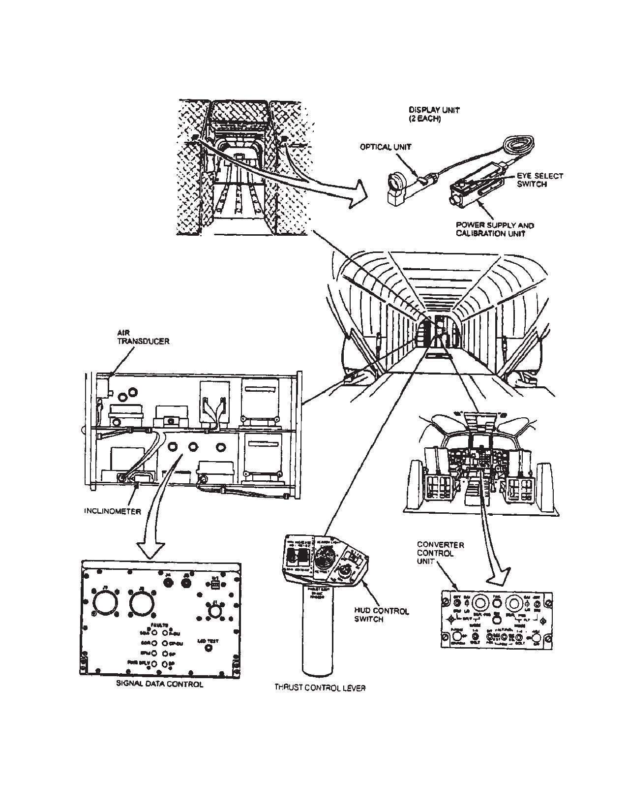
TM 1-1520-240-10
Figure 4-1-8. Heads Up Display AN/AVS-7
4-1-19
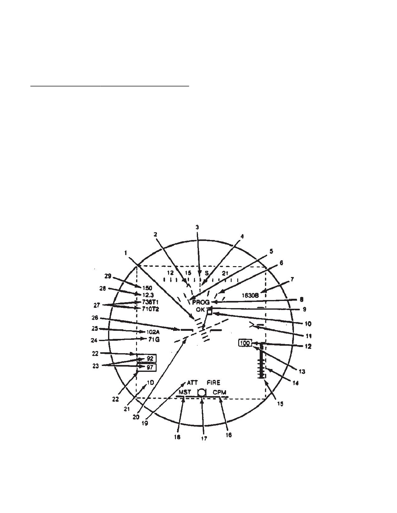
TM 1-1520-240-10
4-1-29. Controls and Function, Pilot/Copilot HUD
a. Pilot programming - Switch set to P-PGM.
Control (THRUST CONT LEVER). (fig. 4-1-8)
b. Copilot programming - Switch set to CP-PGM.
CONTROLS/
FUNCTION
c. Operation (flight mode) - Switch set to OP. (Ad-
INDICATOR
just - ADJ/ON/OFF switch to ADJ).
BRT/DIM
Allows pilot/copilot to control
brightness of their respective
4-1-31. Display Modes.
displays.
MODE/DCLT
Allows pilot/copilot to select
Symbology display modes are programmable by the pilot
respective display modes or
and copilot via the converter control unit located on the
declutter modes.
console. Modes are defined by selecting from a master
symbology menu (fig. 4-1-9). Up to eight (8) display
EYE SELECT
Selects the proper orientation
modes, four normal and four declutter can be pro-
of the symbology for left or
grammed for each user and can be selected for display
right eye viewing.
using the display mode selection switch on the pilot or
copilot thrust control lever or on the CCU. The default
4-1-30. Modes of Operation.
declutter mode has a minimum symbology display of:
There are two programming modes and one operational
Airspeed - No. 25
mode for the HUD system selected by the programming
Altitude (MSL) - No. 7
switch on the CCU. The adjust mode is a sub-mode
Attitude (pitch and roll) - Nos. 5, 6, 20, 26
under the operational mode.
Engine Torque(s) - No. 22, 23
Figure 4-1-9. CH-47D HUD Master Mode Symbology Display (Sheet 1 of 3)
4-1-20
TM 1-1520-240-10
No.
Symbol
Source
Range/Description
1
Angle of Pitch Scale
HUD System
"30_ (10_ units, tic marks flash when angle of pitch is
u"30_)
2
Bearing to Waypoint -
Doppler
0 - 359_ (cursor will invert “V” when aircraft is moving away
Pointer
from the waypoint)
3
Compass Reference
HUD System
0 - 359_ (10_ units)
Scale
4
Aircraft Heading Fix
HUD System
Fixed Reference Mark
Index
5
Angle of Roll - Pointer
Vertical Gyro, Co-
"30_ (right turn moves pointer to right, pointer flashes
pilot
u"30_)
6
Angle of Roll - Scale
HUD System
"30_ (10_ units)
7
Barometric Altitude
Air Data Trans-
-1500 to 20,000 feet (set during adjustment mode)
(MSl)
ducer
8
Adjust/Program Mode
HUD System
ADJ or PROG
Message
9
OK/FAIL
HUD System
OK or FAIL
10
Velocity Vector
Doppler
0 - 15 knots/15 kilometers, 0-359_
11
Rate of Climb Pointer
Air Data Trans-
"2000 feet-per-minute (used with vertical speed scale, No.
ducer
15)
12
Radar Altitude (AGL) -
Radar Altimeter,
0 - 1000 feet (0 - 200 feet, 1 foot units; 200 -1000 feet, 10
Numeric
Pilot
feet units; disappears above 999 feet, and reappears below
950 feet)
13
Minimum Altitude
Radar Altimeter,
Blinking square around symbol - No. 12, set on pilot’s radar
Warning
Pilot
altimeter (use low set index)
14
Radar Altitude (AGL)
Radar Altimeter,
0 - 200 feet (disappears at 250 feet, reappears at 225 feet;
Analog Bar
Pilot
digital readout symbol, No. 12)
15
AGL Vertical Speed -
HUD System
0 -200 feet/"2000 feet-per-minute
Scale
16
HUD Fail Message
HUD System
CPM, SDR, SDA, PS, PDU, CPDU, NAV, PGM; can be
cleared from the display by selecting “ACK” (See NOTE)
17
Trim (Slide Ball)
Inclinometer
"2 balls (left/right)
18
MST, MEM, HOOK
Master Caution
MST, MEM, HOOK; cannot be cleared from the display by
Messages
Panel
selecting “ACK”
NOTE: After ACK is used to acknowledge a fault, the fault will not reappear until BIT is selected or power is cycled
off and on.
Figure 4-1-9. CH-47D HUD Master Mode Symbology Display (Sheet 2 of 3)
Change 20
4-1-21
TM 1-1520-240-10
No.
Symbol
Source
Range/Description
19
Sensor, Fire Warnings Light Plate Ass’y
ATT (failure of copilot VGI), MSL, IAS, FIRE; ATT, MSL, and
Cockpit
IAS can be cleared from display by selecting “ACK” (See
NOTE). FIRE cannot be cleared.
20
Horizon Line (pitch,
Vertical Gyro, Co- Pitch: "30_
Roll: 0 - 359_
roll)
pilot
21
Display Mode Number HUD System
1N - 4N for normal modes, 1D - 4D for declutter modes
22
Torque Limits
Torque Transduc-
(> 100%, solid box)
(>123%, thresholds, solid box
er
flashes)
23
Torque - Numerics
Torque Transduc-
0 - 130% (flashes when engine torque separation is greater
er
than 5% threshold) Max % torque split between cockpit pan-
el and HUD is 3%
24
Ground Speed
Doppler
0 - 999 knots/ 0 -530 km/h (dependent on doppler)
25
Indicated Airspeed
Air Data Trans-
0 - 220 knots (no symbol 00 knots and below, reappears at
ducer
02 knots)
26
Attitude Reference In- HUD System
Represents helicopter
dicator
27
Engines Temperature Thermocouple
0 - 999_C (0 - 755_C, 2_units; 776_C - 999_C, 1_units) Max
Amplifiers
split between cockpit and HUD is "15_
28
Distance to Waypoint Doppler
0 - 999.9 km
29
Bearing to Waypoint - Doppler
0 - 359_
Numeric
NOTE: After ACK is used to acknowledge a fault, the fault will not reappear until BIT is selected or power is cycled
off and on.
Figure 4-1-9. CH-47D HUD Master Mode Symbology Display (Sheet 3 of 3)
4-1-32. Operation.
housing. Do not tighten OU clamp com-
pletely with thumbscrew at this time. The
4-1-33. Starting Procedure.
OU (display) may have to be rotated to hori-
zon after the system is operating.
1. ADJ/ON/OFF switch - OFF.
2. Optical unit support clamps - Installed on
ANVIS. Verify clamps can be rotated.
The helmet may now have to be rebalanced.
6. EYE SELECT switch on PSCU - L or R.
NOTE
Check surface of lense for cleanliness. Clean
WARNING
in accordance with TM 11-5855-300-10.
3. DU lens - Check.
CCU ADJ/ON/OFF switch must be OFF be-
fore connecting or disconnecting quick
release connector.
WARNING
Failure to remove the ANVIS neck cord
CAUTION
prior to operation of the HUD may prevent
The AN/AVS-7 system should not be used
egress from the aircraft in an emergency
if the quick-release connector is not in
and may result in serious injury or death.
working order.
4. ANVIS neck cord - Removed.
7. PSCU
- Connect. Connect PSCU to
5. Optical unit - Install on ANVIS. Attach Opti-
quick-release connector by rotating the
cal Unit (OU) to either ANVIS monocular
connector engagement ring.
4-1-22
TM 1-1520-240-10
3. BIT/ACK switch - Release.
CAUTION
Keep the protective caps on the ANVIS
4-1-35. Displayed System Faults.
whenever it is not in use. Operate the AN-
The system self test is divided into power-up or operator
VIS only under darkened conditions.
initialized built-in-test (BIT) and in-flight BIT. The faults
NOTE
result as warnings and messages that blink at a rate of
Ensure ANVIS operator procedures have
two per second in the Display Units.
been completed.
Part of the BIT is a periodic test that is performed auto-
8. P-PGM/OP/CP-PGM switch - OP.
matically along with normal system operation. This BIT
NOTE
monitors and/or tests SDC functions and/or signals. A
failure of the SDC, NAV signals, pilot’s DU, or copilot’s
The system ON and FAIL lights will not be
DU will illuminate the converter control FAIL light and
visible if the center console lights are turned
display a FAIl message CPM, SDR, SA, PS NAV, PDU or
off.
CPDU on the Display Unit. An ATT (gyro invalid), IAS
9. ADJ/ON/OFF switch - ON. SYS ON and
(indicated air speed out of range), or MSL (MSL altitude
FAIL lights illuminated and BIT will initiate
out of range) sensor failure warning message will be
automatically.
displayed when condition exists. ATT, IAS, MSL, NAV,
PDU, CPDU, and all SDC faults can be cleared by setting
10. FAIL light - Check. Light should go out
BIT/ACK switch to ACK.
after ten seconds. BIT is complete.
NOTE
The following helicopter status messages are also dis-
played.
Allow 1 minute for display warmup. Display
intensity is preset to low each time ADJ/ON/
1. The caption MST (first priority) indicates
OFF switch is set from OFF to On.
operation of the mater caution warning
If a fault is displayed in the DU, acknowledge fault and
lamp. This message will disappear during
re-run BIT to confirm fault. If the fault remains notify
the reset of the main warning lamp opera-
AVUM personnel.
tion.
11. BRT/DIM switch - As desired.
2. The caption MEM (second priority) indi-
12. DSPL POS control - As required. Center
cates that the doppler data is not updated.
display in field of view.
A previous computed data is available. This
message will appear simultaneously with
13. Display aligned to horizon - Check. Tight-
the MEM lamp on the doppler operating
en OU clamp.
panel.
4-1-34. Operator Self Test (BIT).
3. The caption HOOK (third priority) indicates
the selected cargo hook has been opened
1. BIT/ACK switch - Press to BIT and hold.
in the helicopter. The message will appear
The ON and FAIL LIGHT will illuminate. At
after the reset of the master caution warning
end of BIT, FAIL indicator will extinguish
light when any of the cargo hooks have
(lamp will not be visible when center con-
been opened.
sole lights are off).
2. Display Units(s) - Verify symbol generator
Setting BIT/ACK switch to ACK will not clear MST, MEM,
test mode software for CH-47 (figure 4-1-9).
HOOK status messages, or FIRE warning from the DU.
4-1-23
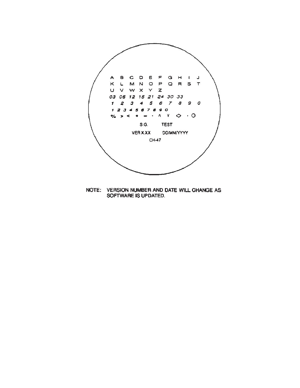
TM 1-1520-240-10
Figure 4-1-10. Symbol Generator Test Mode
4-1-36. Programming Procedures.
5. PGM SEL/NXT control - SEL to select
symbol. Selected symbol stops blinking. If
symbol is not desired, toggle switch to NXT
NOTE
and the symbol will disappear.
The programming procedure for the pilot and
copilot is identical except for the location of
NOTE
controls on the CCU.
All symbols have been programmed when the
1. Select mode to be programmed
(1N
“PROG” annunciator is the only symbol flash-
through 4N). The first mode that will appear
ing.
is “1N” (Normal Mode 1).
6. BIT/ACK switch - ACK. (Hold switch to
ACK for one second.)
2. P-PGM/CP-PGM/OPR switch - P-PGM or
CP-PGM.
7. ”OK” displayed - Check. (”OK” will be
displayed for two seconds.)
3. ”PROG” blinking in display - Check. Verify
that a complete set of symbology is dis-
NOTE
played and attitude reference symbol is
If programming is not accepted, “FAIL” will be
blinking. Verify “PGM” is displayed in the
displayed. If a fail message is displayed, at-
HUD FAIL message location for the DU not
tempt to reprogram the same mode, if fail re-
being programmed.
appears notify maintenance.
4. BIT/ACK switch - ACK to program the full
Declutter mode is recognized by flashing
display or go to step 5 and select desired
ground speed indicator in lieu of attitude refer-
symbols.
ence symbology.
4-1-24
TM 1-1520-240-10
8. MODE 1-4/DCLT switch
- DCLT (1D
4-1-38. In-flight Operation.
through 4D). The first DCLT mode that will
appear is “1D” (Declutter Mode 1).
WARNING
NOTE
Whenever the symbology displayed in the
If MODE 1-4/DCLT switch is toggled to DCLT
DU is suspected of being incorrect the pi-
a second time the display will cycle back to the
lot will compare the data with the aircraft
DCLT’s normal mode (1N-4N). The MODE
instrument indicator and take appropriate
1-4/DCLT switch must be set to MODE 1-4 to
action.
advance to another normal mode.
9. Repeat steps 4 through 7, for declutter.
WARNING
10. Mode 1-4/DCLT switch - As required.
Excessive brightness of the symbology
display may impair vision outside the
11. Repeat steps 4 through 10 until all desired
cockpit.
modes are programmed.
12. P-PGM/CP-PGM/OP switch - OP.
WARNING
Interruption of electrical power, such as
WARNING
change over from APU generator to NO. 1
and NO. 2 generators and vice versa, will
cause DU to default to minimum bright-
An improperly adjusted barometric altim-
ness and normal MODE 1N. Any adjust-
eter will result in an improperly set HUD
ments made to the barometric altitude,
barometric altitude display.
pitch and roll prior to flight will be lost,
thereby decreasing the accuracy of the
barometric altitude, pitch and roll.
NOTE
1. BRT/DIM switch - As desired.
Barometric altimeter set to the most current
NOTE
altimeter settings, field elevation.
Whenever the symbology is interfering with
4-1-37. Adjustment of Barometric Altitude, Pitch,
the outside visibility, declutter may be se-
and Roll.
lected to remove symbology.
2. MODE 1-4/DCLT switch - As required.
1. Ensure P-PGM/OP/CP-PGM switch is in
the OP position.
4-1-39. System Shutdown Procedure.
1. Set ADJ/ON/OFF switch -OFF.
2. ADJ/ON/OFF switch - Pull and set to ADJ.
2. Turn off ANVIS.
NOTE
WARNING
Changes to barometric altimeter settings will
require a corresponding change to the HUD
barometric altitude. Each 0.01 inch change in
CCU ADJ/ON/OFF switch must be OFF be-
pressure equals 10 feet.
fore connecting or disconnecting quick-
release connector.
3. ADJ blinking in display - Check.
4. INC/DEC switch - As required for BARO
WARNING
ALT.
5. BIT/ACK switch - ACK.
Do not disconnect DU by pulling on the
cable connected to the PSCU. The DU
6. Repeat steps 3 through 5 for pitch and roll.
could be damage or the cable may sepa-
rate from the PSCU creating an explosive
7. ADJ/ON/OFF switch - ON.
atmosphere hazard.
4-1-25
TM 1-1520-240-10
4-1-40. Emergency Egress.
WARNING
The quick-release feature allows you to exit quickly from
the aircraft in an emergency without:
Do not attempt to egress the aircraft with-
a. Damaging or turning the unit off.
out performing disconnect as this may re-
b. Getting tangled in cords.
sult in neck injury.
c. Being restrained in the cockpit by hardwired con-
nections.
d. Removing ANVIS.
CAUTION
It is up to the operator to determine the desired mode of
disconnect based upon his evaluation of the emergency
condition and whether or not the ANVIS goggles will be
Do not disconnect DU by pulling on the
needed following egress. The available means of discon-
cable. To do so may damage the DU.
nect are as follows.
e. Release the ANVIS goggles from the helmet.
3. Display Unit - Disconnect. Disconnect DU
by gasping the PSCU and rotating the
f.
Disconnect the OU from the ANVIS goggles via
quick-release connector engagement ring
the thumbscrew.
and pull downward. Remove OU by loosen-
g. For routine disconnect, take hold of PSCU and
ing thumbscrew on OU and remove OU
rotate the quick-release connector engagement ring and
from the ANVIS and place into protective
pull downward.
storage case.
h. For emergency disconnect, take hold of PSCU
4. Reattach neck cord to ANVIS.
pull down.
4-1-26
TM 1-1520-240-10
SECTION II. ARMAMENT
4-2-1. Armament Subsystems
4-2-5. Mount Assembly Stops, Cams, Quick-Re-
lease Pin, and Shock Cord (M24).
The armament subsystems, (fig. 4-2-1) are the M24, and
M41 machine guns installed in the cabin door, cabin es-
The mount stops, cams, quick-release pin, and shock
cape hatch, (M24) and on the ramp (M41). The two flex-
cord have the following functions:
ible 7.62 mm machine guns (M60D) (fig. 4-2-2) are free
a. Maximum traverse (table 4-2-1) of the machine
pointing but limited in traverse, elevation, and depression
gun are controlled by stops on both sides of the cam on
by cam surfaces, stops on the pintles, and pintle posts of
the pintle post.
the left and right mount assemblies (fig. 4-2-3). Spent
cartridges are collected by an ejection control bag on the
b. Maximum elevation and depression are con-
right side of the machine gun, and an ammunition can is
trolled by cam surfaces on the pintle.
on the left side (fig. 4-2-4).
c. The quick-release pin (fig. 4-2-5 is attached by
4-2-2. Machine Gun.
cable to the mount bracket of the mount and fastens the
mount bracket to the rear bracket at the helicopter open-
The 7.62 machine gun (M60D) is a link-belt-fed gas-op-
ing.
erated air-cooled automatic weapon. Refer to TM
9-1005-224-10.
d. The shock cord (fig. 4-2-6) is fastened to the
mount bracket and to the machine gun when stowed.
4-2-3. Mount Assemblies (M24).
4-2-6. Operation - Armament Subsystem M24.
The mount assemblies (fig. 4-2-5) are installed on
mounting brackets fastened inside the helicopter and
Operate the ARMAMENT SUBSYSTEM M24 as de-
secured with mounting pins.
scribed in the following paragraphs.
4-2-4. Machine Gun Controls.
4-2-7. Preflight Checks.
For information on the operation and maintenance of the
The preflight check consists of the following:
M24 and M42 machine gun systems, refer to TM
9-1005-224-10 and 9-1005-262-13.
1. Machine Gun M60D - Check to make sure
that gun is thoroughly cleaned and lubri-
cated, operable, and secured on the pintle
WARNING
with the quick-release pin (fig. 4-2-9).
2. Ejection control bag (fig. 4-2-7) - Installed
To prevent injury to personnel, the cock-
and securely latched.
ing handle must be returned to the forward
or locked position before firing.
3. Ammunition can (fig. 4-2-8) - Installed on
machine gun and loaded.
4. Safety - Push button to safe (S) position,
WARNING
aim at clear area, and try to fire the un-
loaded machine gun.
Pressing the trigger to release the bolt ac-
complishes feeding and releasing of the
5. Mount - Secured and checked for free
firing mechanism. Unless firing is in-
pintle movement.
tended, make sure the machine gun is
cleared of cartridges before pressing the
6. Extra ammunition boxes
- Properly
trigger.
stowed.
4-2-8. Before Takeoff Check.
CAUTION
1. Check the weapon safety is on - (S) posi-
tion.
To prevent damage to the cartridge tray
when no ammunition is in the machine
2. Inspect the chamber to be sure it is clear.
gun, retard the forward force of the re-
leased bolt by manually restraining for-
3. Close the cover and secure the machine
ward movement of the cocking handle.
gun in stowed position.
4-2-1
TM 1-1520-240-10
Table 4-2-1. Armament Subsystem M24 Data
Effective range
1100 meters (max)
Depression and elevation lim-
its:
Rate of fire
550-650 rnds per
min
Left side maximum depres-
67_30_
sion
Length, overall
44.875 in
Left side maximum eleva-
7_30_
Sighting
Aircraft ring and post
tion
type
Total traversing capability - left
122_
Right side maximum de-
73_
side
pression
Total traversing capability -
127_
Right side maximum eleva-
7_
right side
tion
4-2-2
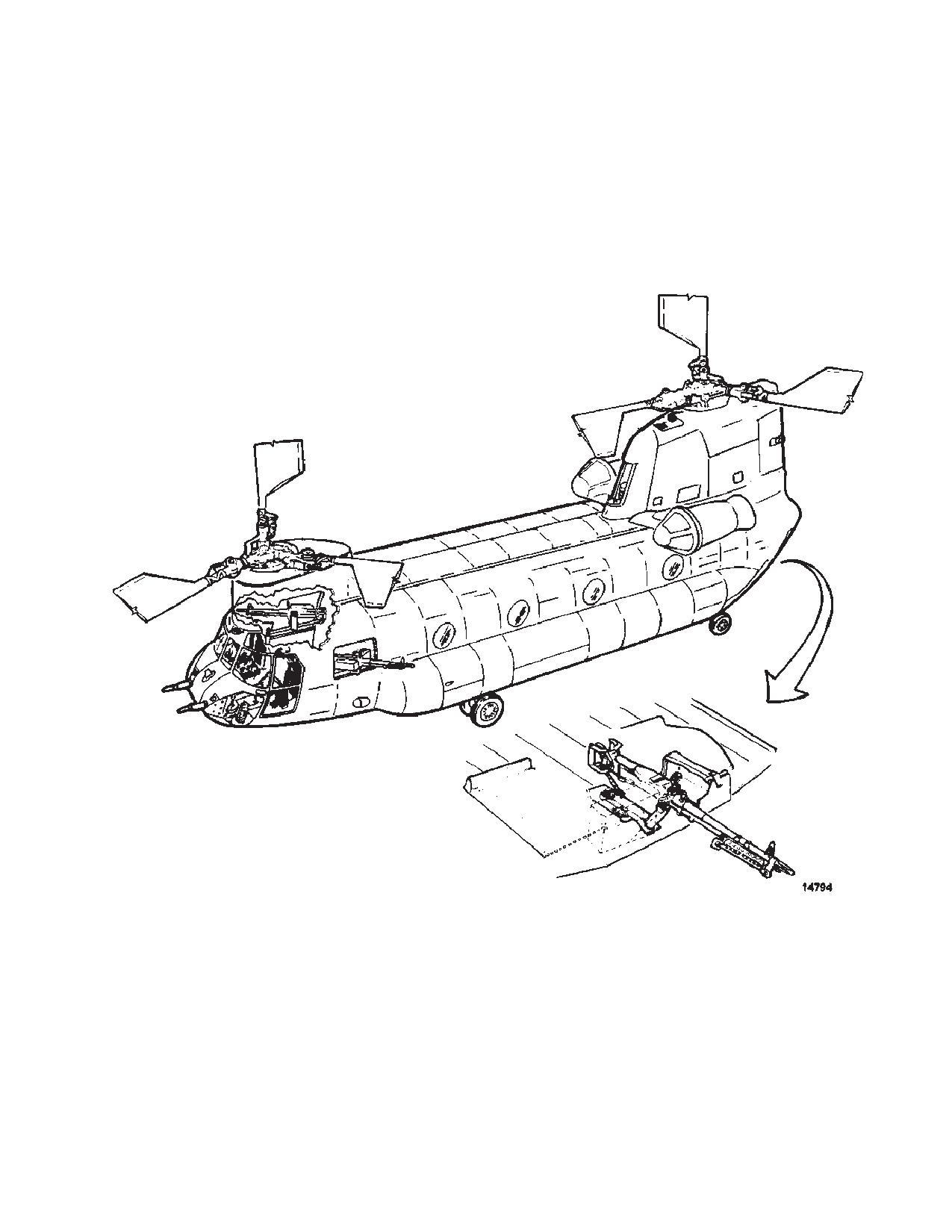
TM 1-1520-240-10
Figure 4-2-1. Armament Subsystem
4-2-3
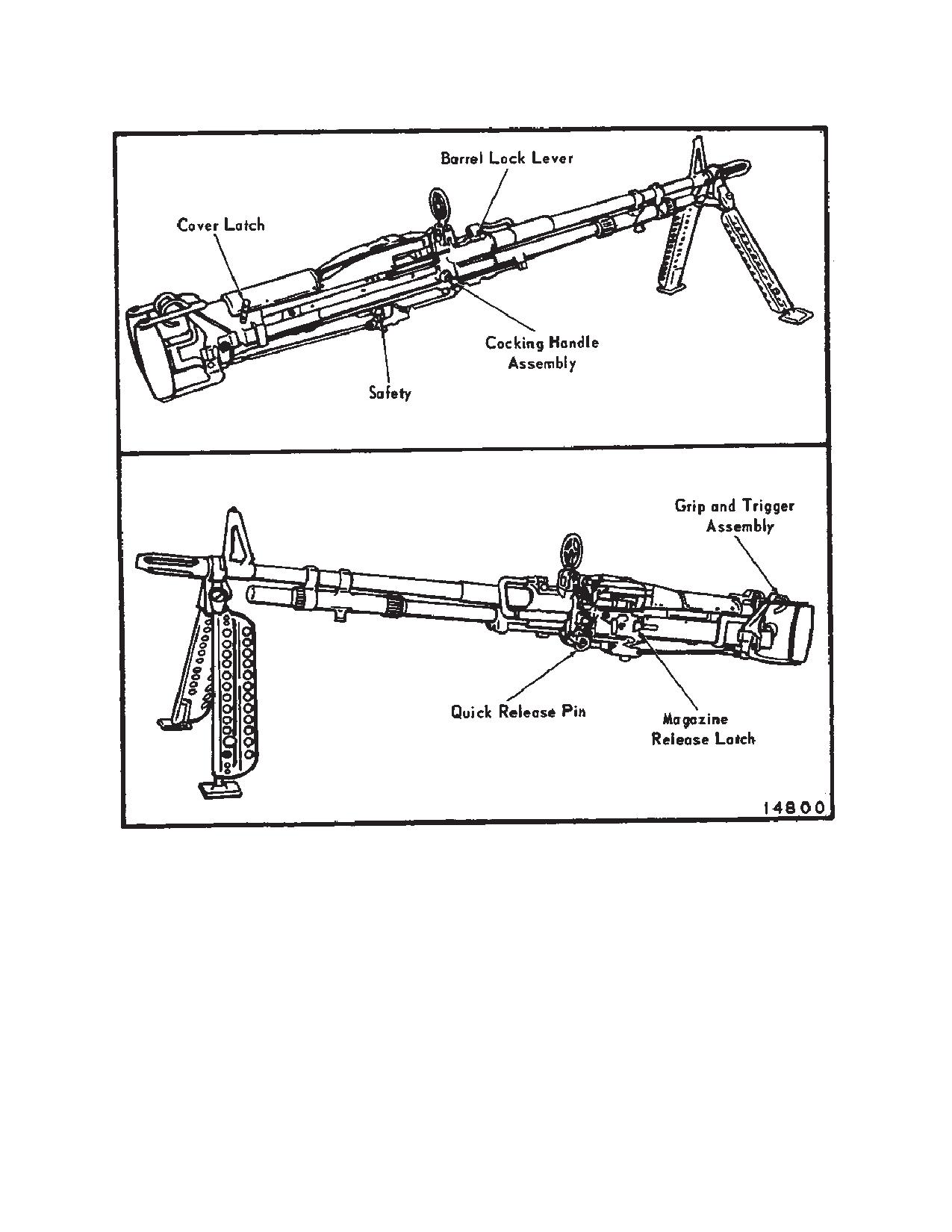
TM 1-1520-240-10
Figure 4-2-2. Machine Gun M60D
4-2-9. Inflight Operation. Inflight operation con-
c. Load the linked cartridges into the ma-
sists of the following:
chine gun.
NOTE
Inflight operation consists of the following:
Inspect the linked cartridges to make sure
1. Preparation for firing.
they are securely positioned in the links.
NOTE
a. Check the machine gun to see that it is
secured with a quick-release pin on the
The pilot will alert the gunners when there is
pintle (fig. 4-2-9).
need to fire the machine gun.
2. Firing.
b. Check the machine gun for freedom of
movement in elevation, depression,
With the machine gun loaded and aimed, push the safety
and traverse.
button to fire (F) position. Because of the low rate of fire,
4-2-4
TM 1-1520-240-10
single cartridges or short bursts can be fired. The trigger
3. After Firing Operation.
must be completely released for each shot to fire single
cartridges or to interrupt firing. When the ammunition is
a. Ensure the bolt is locked to the rear and
exhausted, the last link will remain in the cartridge tray.
the weapon is placed on safe. Open the
Remove the link and the end plug by hand after the cover
feed tray cover and remove any rounds,
is opened for loading.
links or end plug. Point the weapon sys-
tem in a safe direction. Close the feed
tray cover. Place the weapon in FIRE
CAUTION
and ride bolt forward.
Do not fire the M24 machine guns unless
b. Retract the bolt by pulling the handle
the ejection control bags are installed.
fully rearward until the sear engages
Failure to install the bags before firing the
and then push the handle to forward
machine guns could cause the brass and
position. Move the cover latch rearward
links to be ejected overboard and ingested
to the horizontal position and then raise
into the engines if engine screens are re-
the cover. Remove the linked car-
moved.
tridges.
c. Inspect the chamber to be sure it is
CAUTION
clear.
The M24 machine guns are not to be fired
d. Close the cover and secure the ma-
unless the RRPM is at minimum beep or
chine gun in stowed position.
higher.
4-2-5
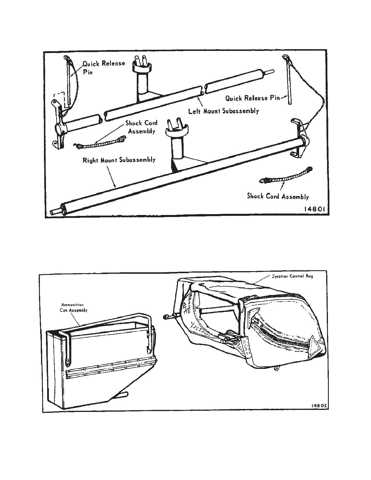
TM 1-1520-240-10
Figure 4-2-3. M24 Mount
Figure 4-2-4. Ammunition Can and Ejection Control Bag
4-2-6
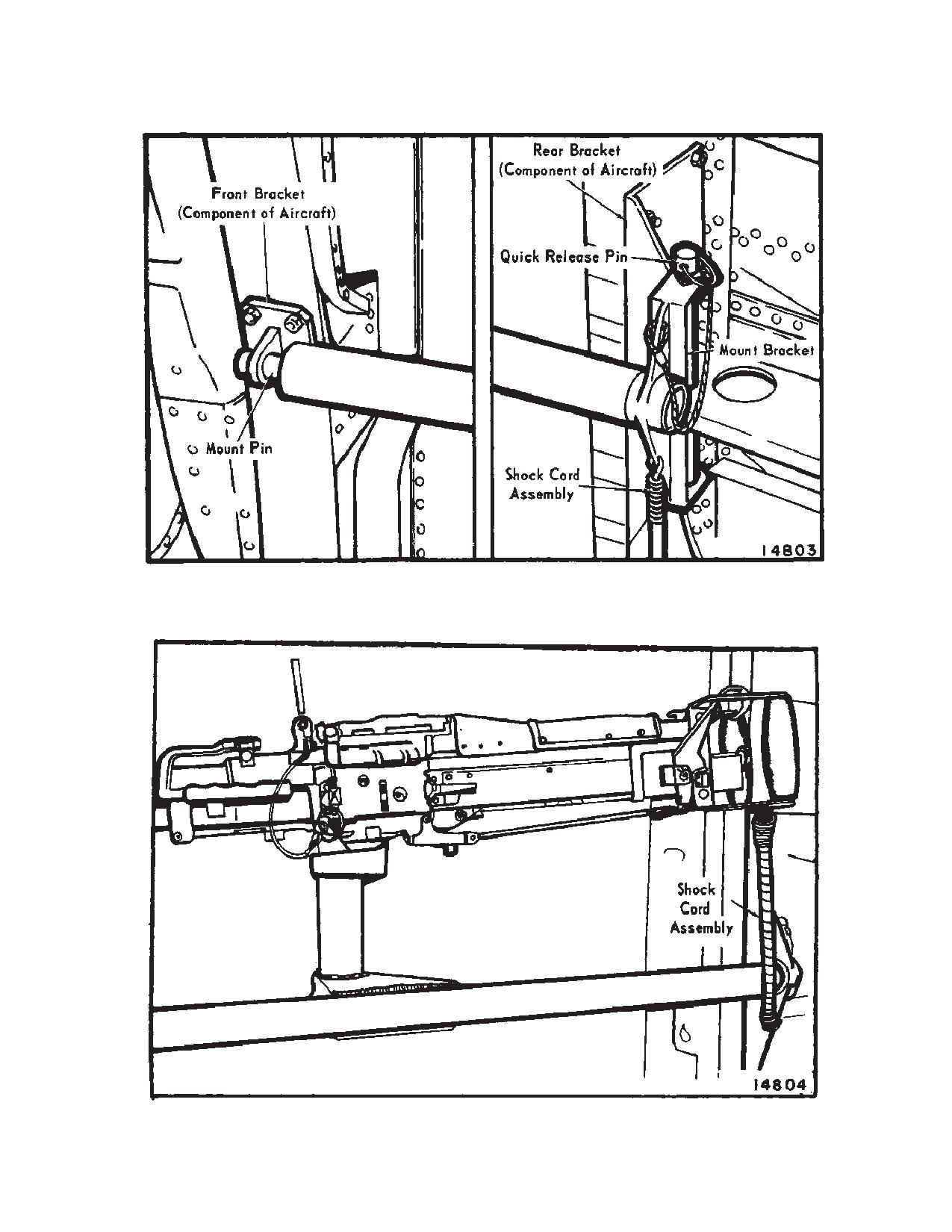
TM 1-1520-240-10
Figure 4-2-5. Right Machine Gun Mount - Installed
Figure 4-2-6. Machine Gun Stowed on Right Mount
4-2-7
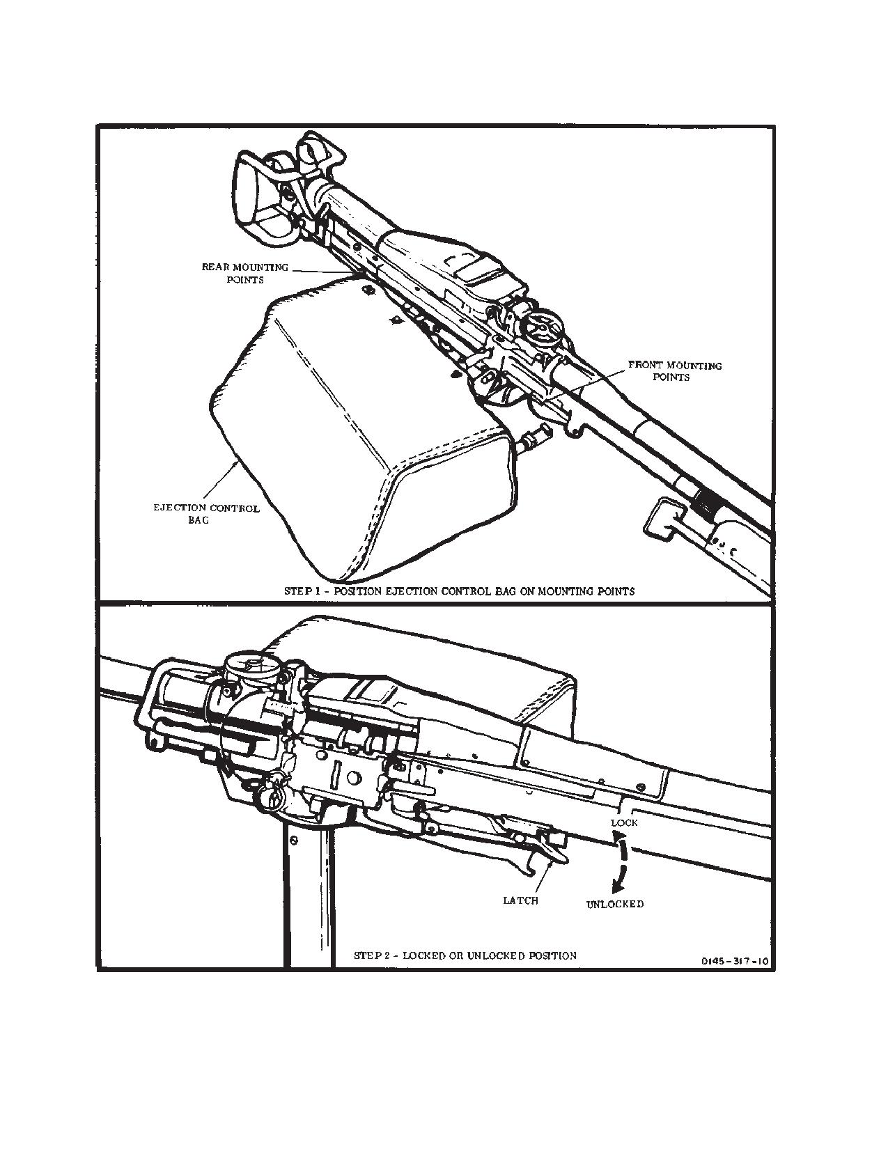
TM 1-1520-240-10
Figure 4-2-7. Ejection control Bag - Installed
4-2-8
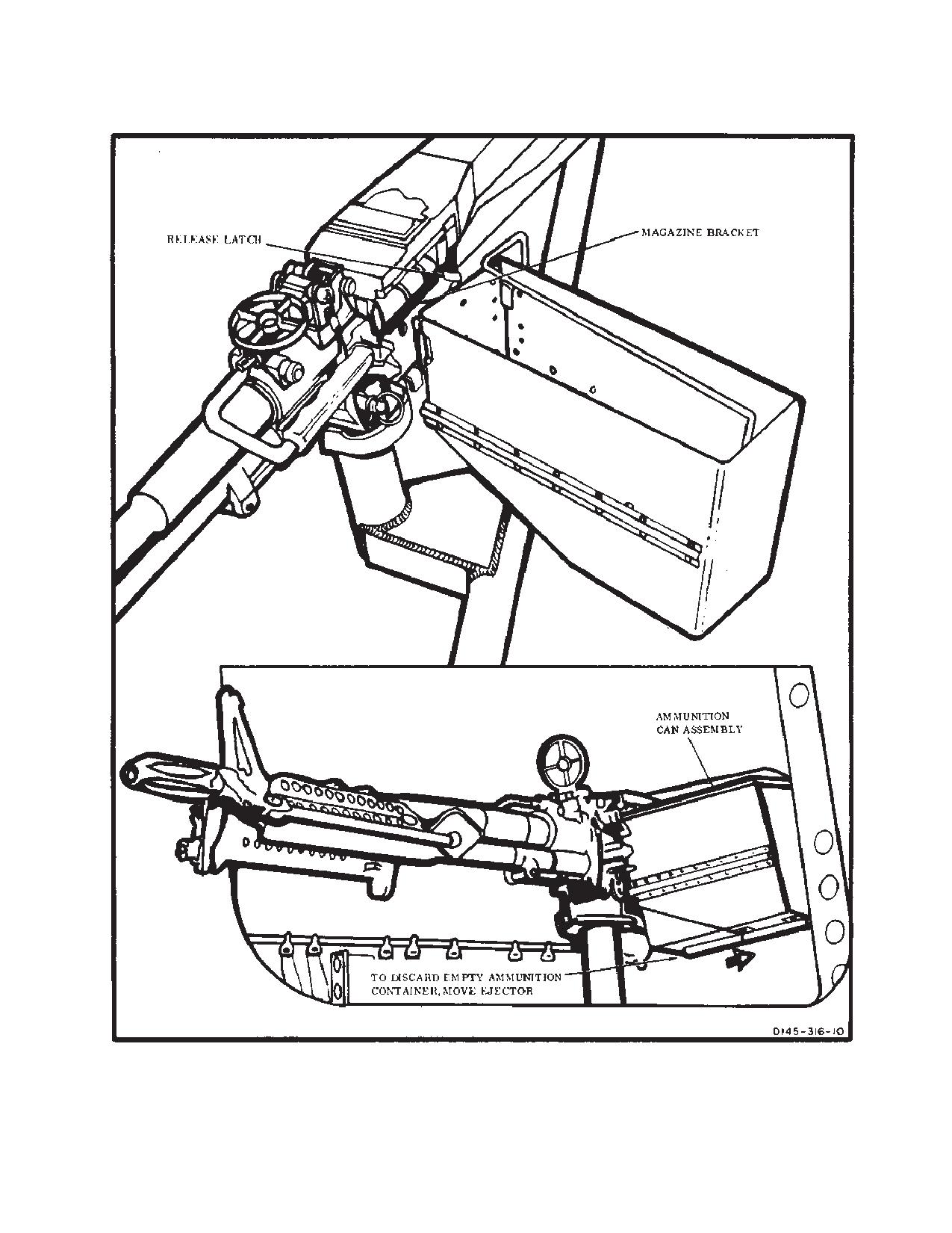
TM 1-1520-240-10
Figure 4-2-8. Ammunition Can - Installed
4-2-9
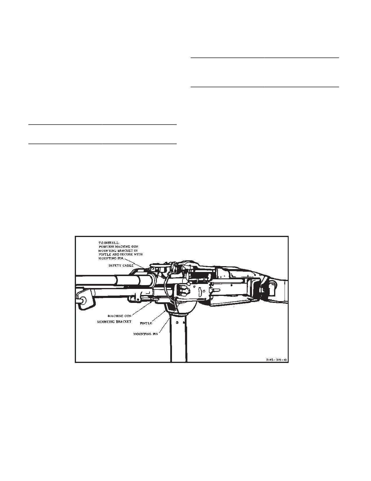
TM 1-1520-240-10
4-2-10. Ammunition.
Table 4-2-2. Authorized Cartridges (Continued)
The M60D machine gun is used for M24 and M41 arma-
7.62-millimeter: Ball, NATO M80
ment subsystems. The ammunition for 7.62 mm machine
gun M60D is classified as small arms ammunition and is
7.62-millimeter: Tracer, NATO M62
issued in linked belts. Issue is in proportion by types to
7.62-millimeter: Dummy, NATO M63
meet tactical requirements (table 4-2-2).
4-2-11. Armament Subsystem M41.
Table 4-2-2. Authorized Cartridges
Armament subsystem M41 is installed at the rear edge
of the ramp. The mount has a pintle and post with limiting
cam surfaces similar to those on armament subsystem
M24 mount assembly. The machine gun, ammunition
7.62-millimeter: AP, NATO M61
can, and ejection control bag are the same as those on
7.62-millimeter: Ball, NATO M59
armament subsystem M24.
Figure 4-2-9. Machine Gun Positioned on Pintle - Left Side Shown
4-2-10
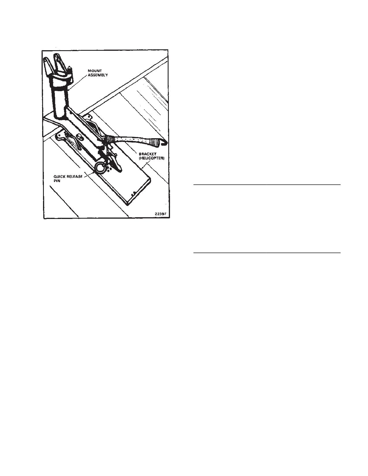
TM 1-1520-240-10
NOTE
If the bracket must be installed, be sure to center it along
the rear edge of the loading ramp.
4-2-13. Mount Assembly Stops, Cams, Quick-Re-
lease Pin, and Elastic Cord (M41).
The mount stops, cams, quick-release pin, and elastic
cord have the following functions:
a. Maximum traverse, elevation, and depression of
the machine gun M60D are controlled by cam surfaces
and stops on the pintle and the pintle post (table 4-2-3).
b. The quick-release pin, attached by cable to the
rear of the mount, secures the mount to the ramp (fig.
4-2-10).
c. The elastic cord is fastened to the mount and the
machine gun when holding it in a stowed position.
Table 4-2-3. Armament Subsystem M41 Data
Effective range
1100 meters (max)
Rate of fire
550-650 rnds per min.
Length, overall
44.875 in.
Sighting
Aircraft ring and post type
Total traversing capability
94_
Figure 4-2-10. M41 Mount - Installed on Ramp
Elevation
12_30’
Depression
69_
4-2-12. Mount Assembly (M41).
4-2-14. Operation - Armament Subsystem M41
The mount is positioned on the lugs of the ramp bracket
Operation of the armament subsystem M41 is the same
and is secured with a quick-release pin (fig. 4-2-10).
as operation of the M24.
4-2-11/(4-2-12 blank)
TM 1-1520-240-10
SECTION III. CARGO HANDLING SYSTEMS
4-3-1. Winch/Hoist System.
NOTE
A 3,000-pound-capacity hydraulically operated winch
The cable cutter arming devise must be
(fig. 4-3-1) is mounted on the floor in the right forward
plugged into the receptacle on the auxiliary
cabin at sta 120. Hydraulic power to operate the winch is
control panel at sta 95 (fig. 4-3-4) and the
supplied by the utility hydraulic system. The winch (fig.
cable speed selector lever must be at CAR-
4-3-2) has 150 feet of usable 1/4 inch cable. It is capable
GO to complete the winch control circuit for
of winching up to 12,000 pounds of cargo with the aid of
cargo operations. The cable cutter arming de-
pulley blocks. When used in hoisting mode (fig. 4-3-9),
the load is limited to 600 pounds. The winch has two
vise must be plugged into the receptacle on
maximum reeling speeds: one for cargo loading (20 fpm)
the overhead above the utility hatch (fig.
and one for hoisting (100 fpm). When the winch is used
4-3-6) and the cable speed selector lever
for cargo loading, a selector control lever on the cable
must be at RESCUE to complete the hoist
drum housing is moved to CARGO. When the winch is
control circuit for hoisting operations.
used for hoisting the selector control lever is moved to
a. Winch control switched (overhead switch pan-
RESCUE. A mechanical braking devise automatically
el).
locks the cable drum when power is off, preventing loss
of load control through cable payout. If the winch cable
load exceeds 3,200 pounds, an overload switch will au-
(1)
Hoist master switch. A toggle hoist master
tomatically stop the winch. The free end of the winch
switch is on the hoist control panel (fig. 4-3-3). The switch
cable is equipped with a metal ball which locks into one
(labeled HOIST MSTR) has positions marked REMOTE,
end of the quick-disconnect devise that is used to attach
OFF, and PLT. When the switch is at REMOTE, electrical
hooks to the cable. Both ends of the cable are painted red
power from the 28-volt No. 1 DC bus, through the HOIST
for 20 feet to alert the operator that the cable end is
CONT circuit breaker, energizes the winch arming switch
approaching. In CARGO mode, the winch will automati-
on the winch/hoist control grip. Once this switch is
cally stop when the cable is reeled out 150 feet, and at
pressed, the winch cable switch, also on the grip, is ener-
3 feet when the cable is reeled in. In RESCUE mode, the
gized, allowing the winch reeling speed to be controlled
winch will stop when the cable is reeled out 150 feet and
at the hoist operator’s station. When the master switch is
at 28.5 feet when the cable is reeled in.
at PLT, electrical power energizes the hoist control switch
on the overhead switch panel, which gives the pilot con-
4-3-2. Winch Controls.
trol of the hoisting system. When the switch is at OFF,
The winch can be controlled from the cockpit by switches
power is removed from the hoist control switches at both
on the overhead switch panel (fig. 4-3-3) or from the
stations.
cargo compartment by switches on the winch/hoist con-
trol grip. The switches in the cockpit override the
switches on the control grip, enabling the pilot to assume
(2)
Hoist control switch. A spring-loaded, rheo-
control of the hoisting operations in an emergency. When
stat-type switch is provided for hoist control and is on the
operating from the cargo compartment, the winch-hoist
hoist control panel. The switch (labeled HOIST) has posi-
control grip can be plugged into a receptacle on the auxil-
tions marked OFF, IN, and OUT. When the hoist master
iary control panel (fig. 4-3-4) at sta 95, the hoist operators
switch is at PLT, electrical power, from the 28-volt No. 1
panel at sta 320 (fig. 4-3-8), or the receptacle at sta 502
DC bus through the HOIST CONT circuit breaker, ener-
(fig. 4-3-5) by an extension cord. The winch can also be
gizes the hoist control switch. Then the switch is moved
manually operated from the cabin. These controls are for
to IN or OUT, the hoist brake release solenoid valve is
emergency use only. The controls are mounted on the
energized open. The open valve applies hydraulic pres-
structure in the heater compartment. Instructions for
sure through the hoist control valve to the winch to turn
manual operation of the winch are on the structure above
the cable drum in the appropriate direction. The speed of
the control valves and instructions in this section. Electri-
the cable is proportional to hoist control switch move-
cal power to operate and control the winch is supplied by
ment. When the switch is released, the switch assumes
the 28-volt No. 1 DC bus through two circuit breakers on
the center OFF position. In addition, the brake release
the No. 1 PDP. These two circuit breakers are marked
solenoid valve is deenergized closed, which removes
HOIST CABLE CUTTER and HOIST CONT.
hydraulic pressure to brake the cable drum.
4-3-1
TM 1-1520-240-10
(3)
Cable cutter switch. A cable cutter switch is
(2)
Winch cable switch. Winch cable reeling is
on the left side of the hoist control panel. The guarded
controlled by a rotary switch on the left side if the control
switch (labeled CABLE CUT) has positions marked ON
grip. Action markings around the switch are IN, OFF, and
and OFF. When the switch is at ON, electrical power from
OUT. The switch is spring-loaded to center OFF position.
the 28-volt No. 1 DC bus, through the CABLE CUTTER
When the switch is moved to IN or OUT, a selector valve
circuit breaker, detonates a ballistic cartridge in the cable
in the winch hydraulic system is electrically actuated,
cutter which cuts the cable. When the switch is at OFF,
providing hydraulic pressure to turn the cable drum. The
the cable cutter circuit is deenergized.
speed of the cable is proportional to cable switch move-
ment in either direction.
b. Winch control switches (fig. 4-3-7). A portable
pistol-shaped control grip contains a built-in microphone
(3)
Cable cutter switch. A push button switch on
switch and a number of other switches used in hoisting,
the upper shoulder of the control grip actuates the cable
winching, and cargo hook operations. A receptacle for
cutter. A metal guard marked CABLE CUTTER prevents
plugging in the extension cord is in the butt end of the
accidental closing of the switch. When pressed, the
grip. A hook extending from the side of the grip is used
switch closes a circuit, providing electrical current to fire
to hang the grip in its stowed position on the hoist control
a ballistic cartridge in the cable cutter. The firing propels
panel. The switches contained in the grip are as follows:
a cutter which cuts the cable.
(1)
Winch arming switch. The winch is armed
(4)
A cargo hook release switch.
for use by a trigger-type, spring-loaded switch. When the
switch is pressed, a circuit closes, arming the control
(5)
Microphone switch.
circuits of the winch hydraulic motor. When the switch is
released, the circuit opens, rendering the winch inoper-
able
CAUTION
NOTE
When using the microphone switch on the
The winch arming switch must be pressed to
hoist control grip, be careful not to press
operate the winch.
the cargo hook switch.
4-3-2
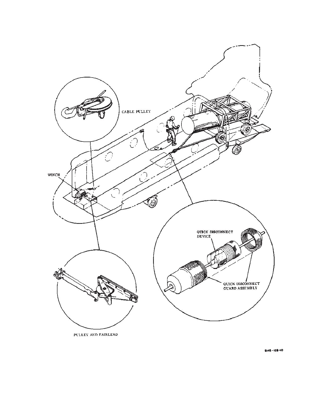
TM 1-1520-240-10
Figure 4-3-1. Winching System
4-3-3
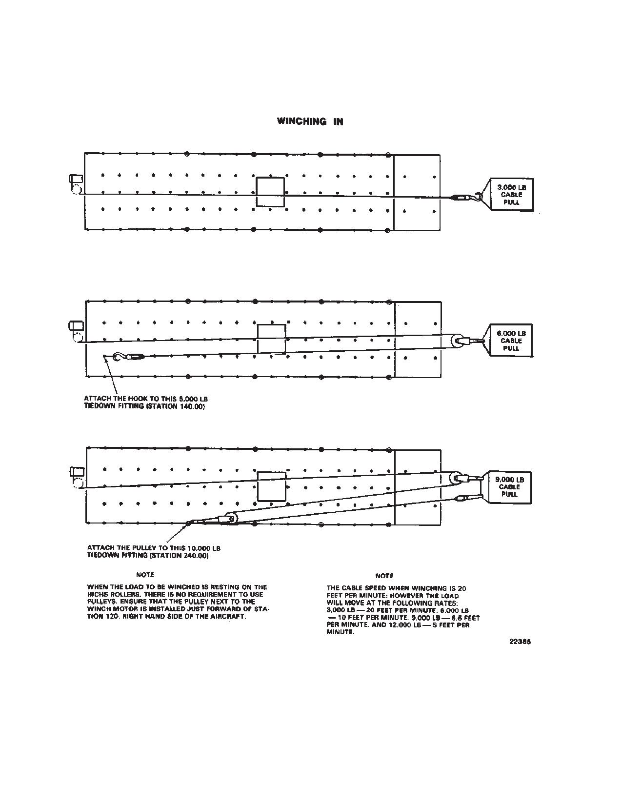
TM 1-1520-240-10
Figure 4-3-2. Winch Capabilities (Sheet 1 of 2)
4-3-4
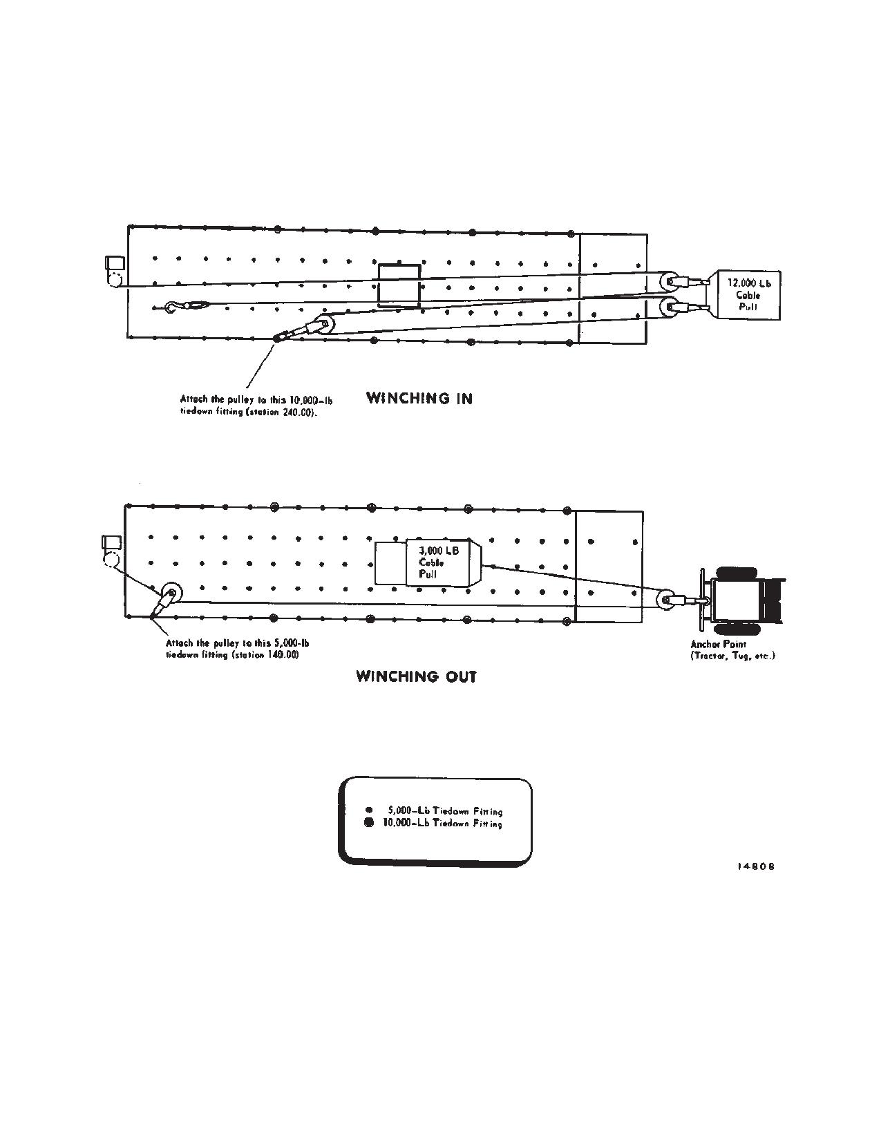
TM 1-1520-240-10
Figure 4-3-2. Winch Capabilities (Sheet 2 of 2)
4-3-5
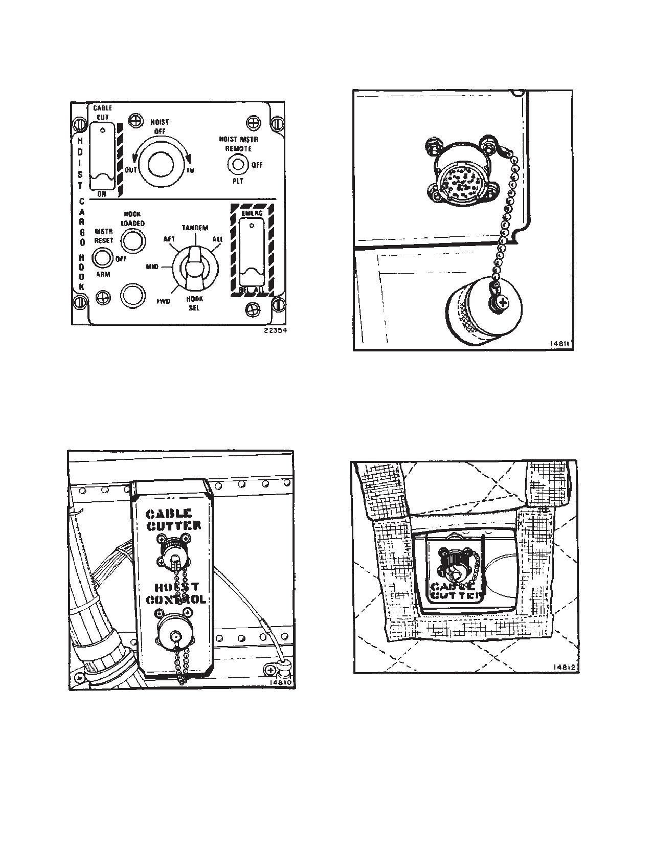
TM 1-1520-240-10
Figure 4-3-3. Hoist Control Panel
Figure 4-3-5. Winching Receptacle (Station 502)
Figure 4-3-4. Auxiliary Control Panel (Station 95)
Figure 4-3-6. Overhead Cable Cutter Receptacle
4-3-6
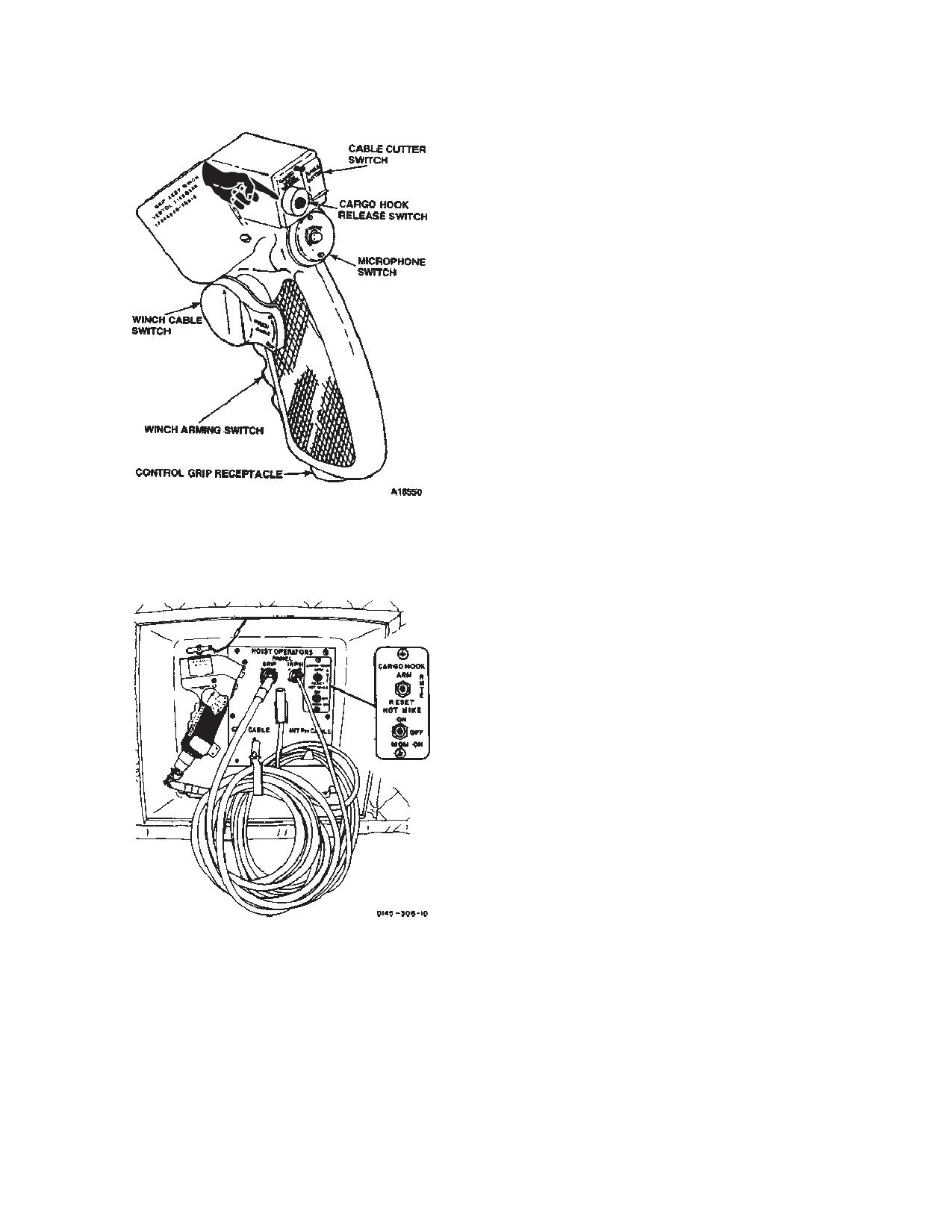
TM 1-1520-240-10
a. Control settings and electrical connections for
operating the winch in the cargo mode from the cockpit
are as follows:
(1)
Cable speed selector lever on the winch -
CARGO.
(2)
Cable cutter arming device (or adapter
cable, pig-tail) - Plugged into the auxiliary control panel,
in the heater compartment at sta 95.
(3)
Hoist master switch on the cockpit overhead
panel - PLT.
(4)
Hoist control switch on the cockpit overhead
panel - OUT, OFF, or IN as required to control direction
and speed of cable.
b. Control settings and electrical connections for
operating the winch in the cargo mode from the cargo
compartment are as follows.
(1)
Cable speed selector lever on the winch -
CARGO.
(2)
Cable cutter arming device (or adapter
cable, pig-tail) - Plugged into the auxiliary control panel,
Figure 4-3-7. Winch/Hoist Control Grip
in the heater compartment at sta 95.
(3)
Hoist master switch on the cockpit overhead
panel - REMOTE.
(4)
Winch/hoist control grip - Plugged into ei-
ther the auxiliary control panel in the heater compart-
ment, sta 95, the hoist control panel, right side sta 320,
or the receptacle, left side sta 502.
(5)
Winch arming switch on the winch/hoist con-
trol grip - Depress.
(6)
Winch cable switch on the winch/hoist con-
trol grip - OUT, OFF, or IN as required to control direc-
tion and speed of the winch cable.
c. Control settings and electrical connections for
operating the winch in the rescue mode from the cockpit
are as follows:
(1)
Cable speed selector lever on the winch -
RESCUE.
(2)
Cable cutter arming device - Plugged into
the overhead receptacle above the rescue hatch.
(3)
Hoist master switch on the cockpit overhead
panel - PLT.
Figure 4-3-8. Hoist Operators Panel (Station 320)
(4)
Hoist cable switch on the cockpit overhead
panel - OUT, OFF, or IN as required to control the direc-
tion and speed of the winch cable.
d. Control settings and electrical connections for
4-3-3. Winch Operation.
operating the winch in the rescue mode from the cargo
With hydraulic and electrical power available, the winch
compartment are as follows:
can be operated from the cockpit or from the cargo
(1)
Cable speed selector lever on the winch -
compartment, in either the cargo mode (for winching car-
RESCUE.
go into the cargo compartment via the ramp) or in the
rescue mode (for rescue or hoisting small cargo through
(2)
Cable cutter arming device - Plugged into
the rescue hatch).
the overhead receptacle above the rescue hatch.
4-3-7
TM 1-1520-240-10
(3)
Hoist master switch on the cockpit overhead
WARNING
panel - REMOTE.
(4)
Winch/hoist control grip - Plugged into the
receptacle on the hoist control panel, right side sta 320.
Personnel not required for the winching
operation must remain well clear of the
(5)
Winch arming switch on the winch/hoist con-
winch cable to prevent possible injury
trol grip - Depress.
should the cable break.
(6)
Winch cable switch on the winch/hoist con-
trol grip - OUT, OFF, or IN as required to control direc-
tion and speed of the winch cable.
CAUTION
e. Rigging and operating procedures for use of the
winch in the cargo mode are as follows:
Slack must removed from the cable train
(1)
Using the hoist control switch on the cockpit
before applying the full load to the winch
overhead panel or on the winch/hoist control grip - reel
system to prevent shock and overload of
out the winch cable as required for rigging. As the cable
the system.
is being reeled out, a crewman should maintain tension
on the cable to avoid snarling and kinking. After the cable
(5)
Reel the cable in slowly until all the slack in
is extended, the usable cable length will be checked to
the cable is removed. Then winch the load into the cargo
ensure that the cable is free of any broken strands or
compartment to the desired position.
definite bends that may reduce the cable capability.
CAUTION
WARNING
Do not exceed 3,000 pounds single line
pull. Overload will result in the winch over-
load switch actuating to stop the winch.
Chock vehicles and wheeled cargo before
disengaging cable hook. Injuries to per-
(2)
Remove the pulley from the pulley blocks by
sonnel can result from uncontrolled roll-
removing the quick-release pins. Reeve the cable
ing of the load.
through pulley as required to provide the required pull
and angle of entry (fig. 4-3-9 Sheet 1 of 2) for rigging
(6)
Reel out the cable slowly to provide slack in
configurations for various loads. Install the pulley blocks
the cable. The hook can either be left attached to the load
and secure them with the quick-release pins.
or disconnected. If the hook is disconnected, it should be
attached to a tiedown fitting to prevent in-flight vibrations
damage to the cargo floor.
WARNING
f.
Rigging and operating procedures for use of the
The cable quick-disconnect cover guard
winch in the rescue mode as follows:
must be installed during all cargo opera-
tions. Otherwise, the hook assembly can
NOTE
be inadvertently disconnected from the
The cargo hook assembly must be removed
winch cable which can result in serious
from the rescue hatch.
injury to personnel.
(1)
Using the hoist control switch on either the
(3)
Attach the winch cable to the cable hook
cockpit overhead panel or on the winch/hoist control grip,
assembly by depressing the lock rings on each end of the
reel out the winch cable as required for rigging. As the
quick-disconnect device, inserting the ball ends of the
cable is being reeled out, a crewman should maintain
winch and hook assembly cables into the quick-discon-
tension on the cable to avoid snarling and kinking. After
nect device and releasing the lock rings. Install the quick-
the cable is extended, the usable cable length will be
disconnect cover guard.
checked to ensure that the cable is free of broken strands
(4)
Attach the winch cable to the load.
or definite bends that may reduce the cable capability.
4-3-8