OPERATOR’S MANUAL FOR ARMY CH-47D HELICOPTER (EIC: RCD, 2003) - page 3
TM 1-1520-240-10
SECTION XIV. FLIGHT INSTRUMENTS
2-14-1. General.
wards the high end of the striped red-and-yellow band is
used for calibrating the indicator during bench test.
The following paragraphs contain information on the
flight instruments. Information on the navigation instru-
ments will be found in Chapter 3, Avionics. All other in-
struments directly related to one of the helicopter sys-
tems are found under the appropriate system heading in
this chapter. Refer to fig. 2-1-5 thru 2-1-14 for illustrations
of the instrument panels, canted and center consoles,
and overhead switch panel.
2-14-2. Cruise Guide indicator System.
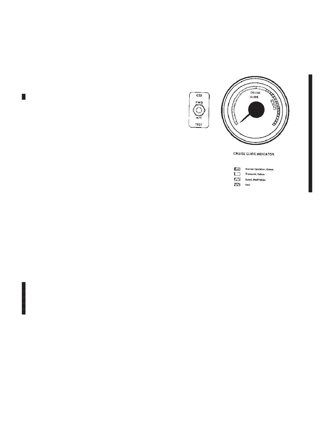
The cruise guide indicator (CGI) system gives the pilot a
visual indication of actual loads imposed on critical com-
ponents of the helicopter dynamic system. The system
allows the pilot to achieve maximum helicopter utilization
under various conditions of payload, altitude, airspeed,
ambient temperature, and center-of-gravity. The system
consists of strain gages bonded to fixed links in the for-
ward and aft rotor controls, an indicator, a signal proces-
sor unit in the aft pylon, a signal conditioner unit in the
forward pylon, and interconnecting wiring. The system
measures alternating stress loads at each rotor and dis-
plays the larger of the two signals. Power to operate the
Figure 2-14-1. Cruise Guide Indicator
cruise guide indicator system is supplied by No. 2 DC bus
through the CRUISE GUIDE circuit breaker on the No. 2
PDP.
2-14-3. CRUISE GUIDE Indicator.
The CRUISE GUIDE indicator is on the pilot instrument
2-14-5. Airspeed Indicator.
panel (fig. 2-14-1). Three bands are colored green, yel-
low, and striped red-and-yellow. Refer to figure 5-2-1 for
There are two airspeed indicators located on the upper
limitations. Immediate corrective action must be taken to
left portion of the copilot and pilot instrument panel (fig.
reduce stress when in the red-and-yellow striped band.
2-1-7 and 2-1-9). The difference between dynamic pres-
This can be accomplished by lowering THRUST CONT
sure and static pressure as measured by the pitot static
lever, reducing airspeed, releasing back pressure on the
system is introduced into these instruments. Indicated
cyclic stick, or by reducing the severity of the maneuver.
airspeed is shown in knots.
2-14-4. CGI TEST Switch.
2-14-6. Altimeter.
The CGI TEST switch is on the pilot instrument panel, on
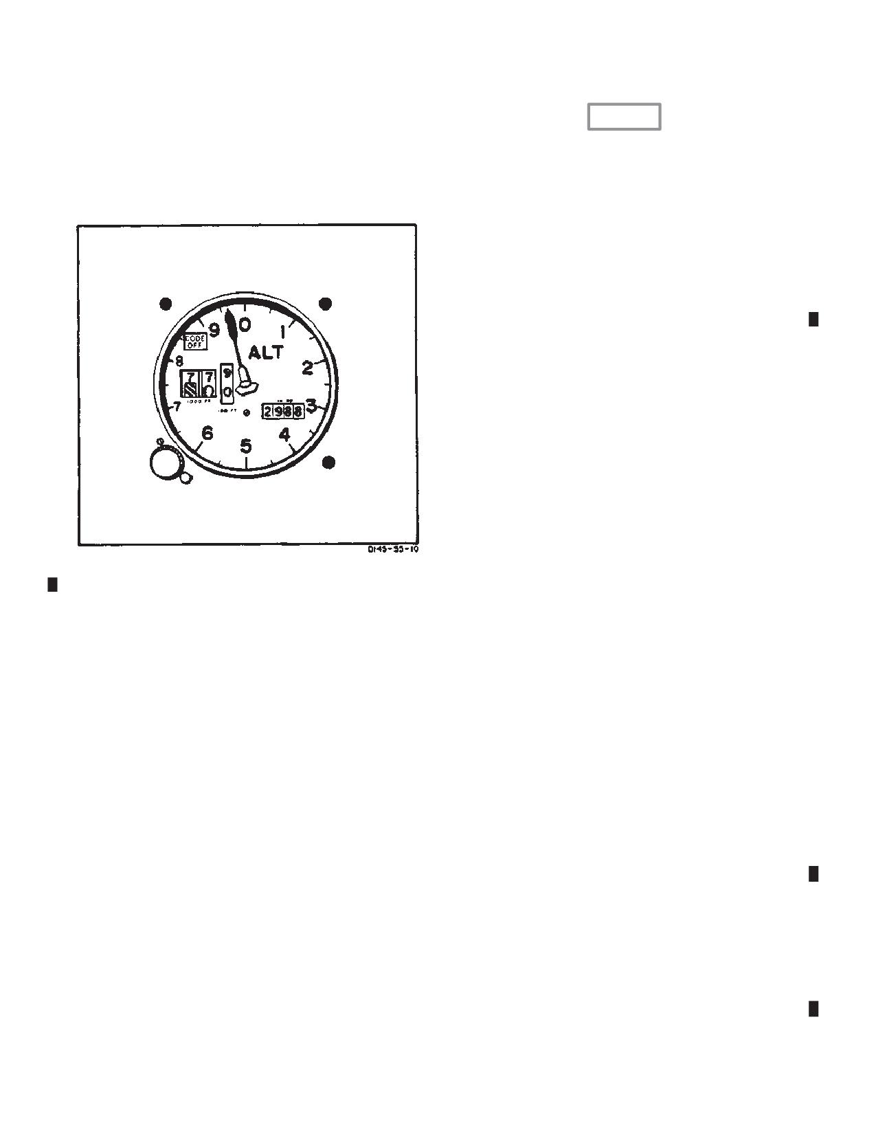
An AIMS altimeter is provided for the pilot (fig. 2-14-2).
the left side of the indicator (fig. 2-14-1). It is a three-posi-
In the term AIMS, the A stands for Air Traffic Control
tion switch spring loaded to center off position labeled
Radar Beacon System (ATCRBS), the I stands for identi-
FWD and AFT.
fication friend or foe (IFF), the M represents the Mark XII
identification system, and the S means system. A pneu-
NOTE
matic counter-drum-pointer type altimeter is installed for
Do not test the cruise guide system with rotors
the copilot. The pilots altimeter is a pneumatic counter-
turning. False indications will result.
drum-pointer type which is a self-contained unit consist-
When the switch is placed from the center position to
ing of a precision pressure altimeter combined with an
each test position, the pointer on the indicator should
altitude encoder.
indicate within the white test band. The white test band
Simultaneously, the display indicates and the encoder
indicates proper system operation.
transmits through the transponder the altitude of the heli-
When the test function is activated, circuits from the
copter. Altitude is displayed on the altimeter by a
strain gages to the indicator are tested. However, sepa-
10,000-foot counter, and a 100-foot drum. A single point-
ration of the bond of the strain gage to a link will not be
er indicates hundreds of feet on a circular scale with
detected by the test function. The narrow white line to-
50-foot center markings. Below 10,000 feet a diagonal
Change 3
2-14-1
TM 1-1520-240-10
warning symbol will appear on the 10,000 foot counter.
CAUTION
Power to operate the AIMS altimeter is supplied by the
No. 2 DC bus through the NAV AIMS ALT circuit breaker
If the baroset knob binds or sticks, do not
on the No. 2 PDP.
use excessive force to set the altimeter.
Excessive force can damage altimeter
A barometric pressure setting knob is provided to insert
gears, resulting in altimeter error. Settings
the desired altimeter setting in inches of Hg. A vibrator
can sometimes be made by backing off the
knob and turning at a slower rate.
a. Set the pilot’s altimeter to the field barometric
setting.
b. Check that the pilot’s altimeter indicates within ±
70 feet of field elevation. If the altimeter error is greater
than ± 70 feet, do not use the altimeter for IFR flight.
2-14-8. In Flight Operation - Altimeter.
Operate the AIMS altimeter function as follows:
a. Be sure the IFF set is on and set to the proper
code.
b. Be sure the altimeter is set to the local altimeter
setting.
c. Set the M-C (mode c) switch on the IFF control
panel to ON.
d. Check that the red CODE OFF flag is not visible
in the pilot’s altimeter.
The copilot’s altimeter is a pneumatic counter-drum-
pointer type which displays altitude in the same manner
Figure 2-14-2. AIMS Altimeter
as the pilot’s altimeter. It also incorporates a barometric
pressure setting knob and an internal vibrator powered
by the No. 2 DC bus. A minimum of 1 minute of vibrator
operation is require before setting or checking the altime-
powered by No. 2 DC bus is contained in the altimeter
ter.
and requires a minimum of 1 minute warmup before
checking or setting the altimeter. If DC power to the alti-
At ambient pressure, both altimeters should agree within
tude encoder is lost, a warning flag placarded CODE
± 70 feet of the field elevation when the proper barometric
OFF appears in the upper left instrument dial.
pressure setting is set in the altimeter. If the internal
vibrator of either altimeter becomes inoperative due to
The flag indicates that the altitude encoder is inoperative
DC power failure, the pointer drum may momentarily
and that the system is not reporting altitude to ground
hang up when passing from 9 through 0 (climbing) or
stations. The CODE OFF flag monitors only the encoder
from 0 to 9 (descending). This will cause a lag of magni-
function of the altimeter. It does not indicate transponder
tude which will depend on the vertical velocity of the
condition. The AIMS altitude reporting function can be
aircraft and the friction in the altimeter.
inoperative without the CODE OFF flag showing, as in
case of transponder failure or improper control settings.
2-14-9. Radar Altimeter (AN/APN-209A).
It is also possible to get a good Mode C test on the
transponder control with the CODE OFF flag showing.
Radar altimeters are provided for the pilot and copilot and
Display of the CODE OFF flag only indicates an encoder
filght engineer (fig. 2-14-3). The altimeters provide a con-
power failure or a CODE OFF flag failure. In this event,
tinuous indication of the height of the helicopter above
check that DC power is available and the circuit breakers
the surface from 0 to 1,500 feet. Altimeter indications are
are in. If the flag is still visible, radio contact should be
reliable with pitch and roll attitude up to 45_.
made with a ground radar site to determine whether the
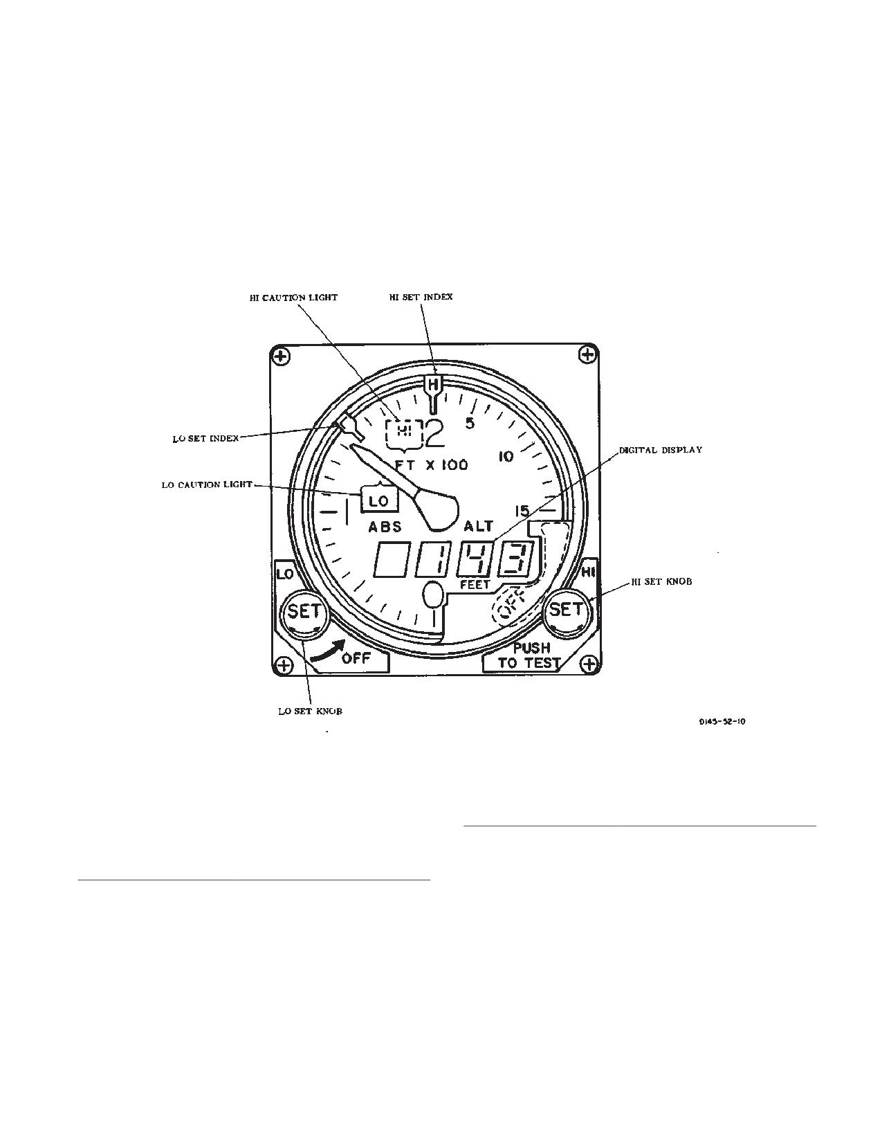
Altitude is displayed by a dial, pointer, and a digital dis-
AIMS altitude reporting function is operative. The re-
play. Each altimeter has HI and LO caution lights. The
mainder of the flight should be conducted accordingly.
caution lights on each altimeter can be set independently
of the other altimeter. The caution lights are set by rotat-
2-14-7. Preflight Operation - Altimeter.
ing the LO SET and HI SET knobs until the L index and
If the AIMS altimeter encoding function is to be used
H index on the perimeter of the altimeter are at the de-
during flight, perform the following steps before takeoff:
sired altitudes.
2-14-2
Change 3
TM 1-1520-240-10
When the helicopter descends below the low index set-
will go out, and the pointer will remain at the last valid
ting or rises above the high index setting, the correspond-
indication when power was lost. The altimeters have a
ing HI or LO caution light will illuminate. If helicopter
self-test feature. Pressing the PUSH-TO-TEST knob will
altitude exceeds 1,500 feet, pitch or roll angle exceeds
cause the pointer and digital display to indicate between
45_, or the system is unreliable, the following will occur.
900 and1,100 feet. If LO set and HI set are indexed
The OFF flag will appear, the pointer will move through
below 900 feet, the LO caution light goes out, and the HI
1,500 feet behind the dial mask, and the digital display
caution light comes on. Power to operate the radar altim-
and LO and HI caution lights will extinguish.
eter is supplied by the No. 2 DC bus through the NAV
RAD ALT circuit breaker on the No. 2 PDP.
If power to the system is lost, the following will occur. The
OFF flag will appear, the digital display and caution lights
Figure 2-14-3. Radar Altimeter (AN/APN-209)
2-14-10. Controls and Functions, Radar Altimeter
CONTROLS/
(AN/ APN-209A).
INDICATOR
FUNCTION
LO set index
Indicates altitude trip point
CONTROLS/
for LO caution light.
INDICATOR
FUNCTION
HI set index
Indicates altitude trip point
LO SET knob
Either pilot’s LO SET knob
for HI caution light.
applies power to altimeter
Indicator pointer
Indicates absolute altitude
system. LO set index on
from 0 to 1,500 feet.
both altimeters can be set
independently. Both LO set
Digital indicator
Provides direct reading four
indices must be masked to
digit indication of absolute
turn the set off.
altitude from 0 to 1,500.
HI SET knob
Sets position of HI set index
LO caution light
Comes on when helicopter
and tests altimeter system
descends below altitude on
when pressed.
LO set index.
2-14-3
TM 1-1520-240-10
necessary to shade the indicator to verify op-
CONTROLS/
eration of the dimming control.
INDICATOR
FUNCTION
HI caution light
Light comes on when heli-
(3)
Rotate the RAD ALT dimming control from
copter rises above altitude
BRT to DIM. Check that the digital display dims and goes
on HI set index.
out. Check that the LO caution light dims but does not go
out completely.
OFF flag
Flag is displayed when pow-
er is removed from set,
c. Inflight operation.
when indications are unreli-
able, or when altitude ex-
ceeds approximately 1,500
CAUTION
feet.
RAD ALT dimming
On right side of both instru-
When operating over dense foliage, the
controls
ment panels. Controls light
radar altimeters will indicate the altitude to
intensity of digital display
the tops of the trees. When operating over
and HI and LO caution light.
sparse foliage, the altimeters may indicate
the altitude between the ground and about
2-14-11. Normal Operation - Radar Altimeter (AN/
half the average tree height, depending on
APN-209A).
ground speed. When external cargo is car-
ried, the radar altimeter may occasionally
a. Starting.
indicate the distance between the bottom
of the helicopter and the load.
(1)
Rotate the LO SET knob on the altimeter
until LO index is at 100 feet. Rotate the HI set knob until
(1)
Set the RAD ALT dimming control to desired
the HI index at at 800 feet. Allow 1 minute for warmup.
digital display light level.
(2)
Check for the following indications:
(2)
Set HI and LO indexes as desired. If HI or LO
(a) The pointer indicate between -5 and 5
indexes are not desired, set the LO index at 0 feet or the
feet.
HI index above 1,500 feet.
(b) The digital displays indicate between 0
2-14-12. RADAR ALTIMETER (AN/APN-209(V)) Alti-
and 3 feet.
tude Voice Warning System (AVWS).
(c) LO caution light is on.
The face of the altitude voice warning radar altimeter
(d) HI caution light is off.
(RT-1115F/APN-209) is exactly the same as that of the
visual only AN/APN-209A radar altimeter, with the opera-
(e) OFF flag not in view.
tion being the same as outlined in paragraph 2-14-9. The
difference is only internal. A transmitter added internally
b. Testing.
sends out an aural warning to the pilot, copilot, and flight
(1)
Press and hold the PUSH-TO-TEST knob.
engineer interphone station ICS panels when the heli-
Check for the following indications:
copter descends below the low index setting or rises
above the high index setting (in addition to the LO or HI
(a) OFF flags not in view.
caution lights).
(b) Pointers indicate between 900 feet and
1,100
NOTE
The voice portion of the system works off a 10
(c) Digital displays between 900 feet and
second clock. If a transition is made thru ei-
1,100 feet.
ther Preset, back to the original warning con-
(d) LO caution light is off.
dition within this time frame, the voice warn-
ing will stay at its original volume level.
(e) HI caution light is on.
On initial transition the volume is always set to Full. By
(2)
Release the PUSH-TO-TEST knob. Check
momentarily pressing the PUSH-TO-TEST (PTT) knob
that all indications return to those specified in step a.(2).
once, the message is decreased to 1/2 volume. Momen-
tarily pressing the PTT knob a second time disables the
NOTE
aural warning message. Regardless of the volume level,
The LO caution light may appear to go out.
when the aircraft transitions back through either Preset
However, the light will be visible with night
(HI or LO) (from caution light OFF to ON), the volume
vision goggles. In bright daylight, it may be
level of the aural warning message will return to Full.
2-14-4
TM 1-1520-240-10
2-14-13. Controls and Function, Radar Altime-
(a) The pointers indicate between -5 and 5
ter(AN/APN-209(V)) (AVWS).
feet.
(b) The digital displays indicate between 0
CONTROLS/
and 3 feet.
INDICATOR
FUNCTION
(c) LO caution light is on.
LO SET knob
The LO Set knob applies
power to altimeter system. LO
(d) Low altitude warning (”ALTITUDE LOW,
set index on both pilot’s altim-
TOO LOW”) is heard in the headset.
eters can be set independent-
ly. Both LO set indexes must
(e) HI caution light is off.
be masked to turn the set off.
HI SET knob
Sets position of HI set index
(f)
Off flag not in view.
when turned. Adjusts the
warning message volume lev-
b. Testing.
el and tests altimeter system
when pressed.
(1)
Press and hold the PUSH-TO-TEST knob to
actuate the PUSH-TO-TEST condition. Verify the follow-
LO set index
Indicates altitude trip point for
ing:
LO caution light.
HI set index
Indicates altitude trip point for
(a) OFF flags not in view.
HI caution light.
(b) Pointers indicate between 900 feet and
Indicator pointer
Indicates absolute altitude
1,100 feet.
from 0 to 1,500 feet.
Digital indicator
Provides direct reading four
(c) Digital displays read between 900 feet
digit indication of absolute alti-
and 1,100 feet.
tude from 0 to 1,500 feet.
(d) LO caution light is off
LO caution light
Comes on when helicopter
descends below altitude on
(e) HI caution light is on.
LO set index.
(f)
The high altitude warning “ALTITUDE
HI caution light
Light comes on when helicop-
ter rises above altitude on HI
HIGH, CHECK ALTITUDE”, is audible (Full volume) at 10
set Index.
seconds intervals throughout the test. Verify that the
voice warning audio is discernable by all active crew
OFF flag
Flag is displayed when power
members.
is removed from set, when in-
dications are unreliable, or
(2)
Release the PUSH-TO-TEST knob. Check
when altitude exceeds
that all indications return to those specified in step a. (2).
approximately 1,500 feet.
RAD ALT dimming
On right side of both instru-
(a) Momentarily press the PUSH-TO-TEST
controls
ment panels. Controls light in-
knob once and verify the message is at 1/2 volume.
tensity of digital display and HI
and LO caution light.
(b) Momentarily press the PUSH-TO-TEST
a second time and verify the warning message is OFF.
2-14-14. Normal Operation - Radar Altimeter(AN/
(c) Pointers indicate between 900 feet and
APN-209(V)) (AVWS).
1,100 feet.
NOTE
a. Starting.
The LO caution light may appear to go out.
However, the light will be visible with night
NOTE
vision goggles. In bright daylight, it may be
necessary to shade the indicator to verify op-
Connect monitor headset to the aircraft ICS.
eration of the dimming control.
(3)
Rotate the RAD ALT dimming control from
(1)
Rotate the LO SET knob on the altimeter
BRT to DIM. Check that the digital display dims and goes
until the LO index is at 100 feet. Rotate the HI set knob
out. Check that the LO caution light dims but does not go
until HI index is at 800 feet. Allow 1 minute for warmup.
out completely.
(2)
Check for the following indications:
c. Inflight operation.
2-14-5
TM 1-1520-240-10
in the roll axis, use the upper knob. The roll adjustment
CAUTION
range is about 8_minimum in either direction.
NOTE
When operating over dense foliage, the
radar altimeters will indicate the altitude to
Rapid rotation of the pitch and roll trim knobs
the tops of the trees. When operating over
on the attitude indicator may cause abrupt
sparse foliage, the altimeters may indicate
pitch and roll attitude changes with AFCS on.
the altitude between the ground and about
The indicator incorporates integral lighting. The pilot and
half the average tree height, depending on
copilot attitude indicators should erect within 90 seconds
ground speed. When external cargo is car-
after electrical power is applied. Power to operate the
ried, the radar altimeter may occasionally
attitude indicator gyros is supplied by the No. 1 and No.
indicate the distance between the bottom
2 AC bus through the NAV PILOT VGI and NAV COPLT
of the helicopter and the load.
VGI circuit breakers on the No. 1 and No.2 PDP.
(1)
Set RAD ALT dimming control to desired
2-14-17. Pilot and Copilot Attitude Indicator (VGI)
digital display light level.
Switch.
(2)
Set HI and LO indexes as desired. If the
A VGI switch is on the instrument panel below each atti-
helicopter exceeds one of these indexes, an aural warn-
tude indicator (fig. 2-1-7 and 2-1-9). The switch is labeled
ing message will be heard at full volume initially, but the
NORM and EMER. When the switch is at NORM, each
volume level can be decreased by one-half (1/2) by
attitude indicator operates from a separate gyro. If either
pressing the PUSH-TO-TEST once or inhibited by press-
the pilot or the copilot gyro fails, signaled by the OFF flag
ing PUSH-TO-TEST a second time. If HI or LO indexes
on the indicator, manual switching to the remaining gyro
are not desired, set the LO index at 0 feet or the HI index
is accomplished by placing the respective VGI switch to
above 1,500 feet.
EMER. The switching of the gyros from NORM to EMER
operation is accomplished by a gyro transfer relay. Fail-
2-14-15. VERTICAL SPEED Indicator.
ure of the gyro will also result in failure of the associated
AFCS. Power is supplied by the No. 2 DC bus through the
Two VERTICAL SPEED indicators are in the instrument
NAV CONT VGI circuit breaker on the No. 2 PDP.
panel (fig. 2-1-7 and 2-1-9). They indicate the rate of
climb based on the rate of change of atmospheric pres-
2-14-18. Turn and Slip Indicator (4-Minute Type).
sure. The indicator is a direct-reading pressure instru-
ment requiring no electrical power for operation.
Each turn and slip indicator (fig. 2-1-7 and 2-1-9) is con-
trolled by an electrically actuated gyro. The instrument
2-14-16. Attitude Indicator.
has a pointer (turn indicator) and a ball (slip indicator).
Power to operate the gyros is supplied by the DC essen-
Two attitude indicators are on the instrument panel (fig.
tial bust through the NAV TURN & SLIP circuit breakers
2-1-7 and 2-1-9). The attitude indicators have been spe-
on the No. 1 and No. 2 PDP.
cifically tailored for the flight characteristics of a helicop-
ter by the inclusion of an electrical trim capability in the
2-14-19. Magnetic Compass.
roll axis in addition to the standard pitch trim. Normal
The magnetic compass is mounted on the top of the
flight attitudes of helicopters, defined by fixed amounts of
center instrument panel glareshield (fig. 2-1-3). It is a
roll as well as pitch, are easily trimmed into this indicator,
direct reading instrument requiring no electrical power. It
and optimum operation of the helicopter in an attitude
consists of compass card mounted on a magnetic ele-
such as hover is facilitated. Degrees of pitch and roll are
ment in a liquid-filled bowl.
indicated by movement of a universally mounted sphere
painted optical black and light gray to symbolize earth
2-14-20. Free Air Temperature Gauge.
and sky, with a horizon line separating the two colores.
To adjust the miniature aircraft in relation to pitch, use the
The free air temperature gauge is on the exterior of the
lower knob. The pitch adjustment range is about 5_ nose
pilot’s eyebrow window (fig. 2-1-3). The unit is calibrated
up and 10_ nose down minimum. To compensate attitude
in degrees from -70 to + 50_C.
2-14-6
TM 1-1520-240-10
2-14-21. CHRONOMETER.
is set, pressing the SELECT button will select the next
digit to be set. After the last digit has been selected and
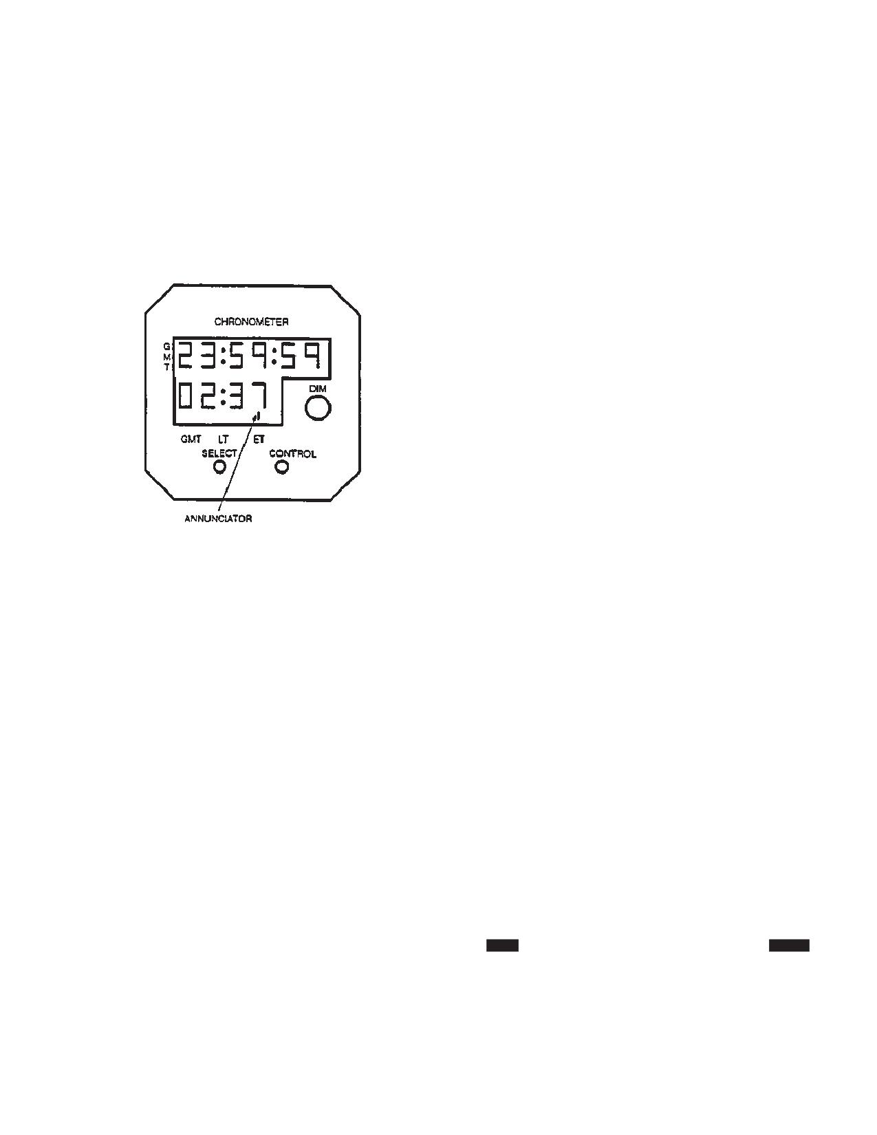
Two digital clocks labeled CHRONOMETER are located
set with the CONTROL button, press the SELECT button
on the copilot and pilot instrument panels (fig. 2-14-4).
to exit the set mode. The annunciator will resume its
Each clock has a six-digit GMT (greenwich mean time)
normal flashing condition to indicate that the GMT clock
display and four-digit selectable display. A test mode is
is running.
provided to check system. A flashing annunciator identi-
fies which clock mode has been selected. There are
2-14-24. Setting LT.
three controls on each clock, a SELECT button, a CON-
TROL button, and a DIM switch.
Press the SELECT button until LT is selected. Simulta-
neously press both the SELECT and CONTROL buttons
to enter the set mode. The tens of hours digit will start
flashing and CONTROL button has full control of the
flashing digit. Use the same sequence as for setting GMT
with the exception that the minutes are already synchro-
nized with the GMT clock and can not be set when in LT
mode.
2-14-25. Setting ET.
The elapsed time allows for count up or count down
modes.
a. Count Up. Press the SELECT button until ET is
selected. Press the CONTROL button to start count up
sequence. The clock will count up to 59 minutes, 59
seconds and then changes to hours and minutes. It will
count up to 99 hours and 59 minutes. Pressing the CON-
Figure 2-14-4. Chronometer
TROL button again resets the ET to zero.
a. SELECT Button. It allows the selection of any of
b. Count Down. Press the SELECT button until ET
three modes on the four-digit display: GMT, LT (local
is selected. Simultaneously press both SELECT and
time), or ET (elapsed time). The six-digit display shows
CONTROL buttons to enter the set mode. A count down
GMT only.
from any time, not to exceed 59 minutes and 59 seconds,
can be set using the same sequence as for setting GMT.
b. CONTROL Button. It is used to set the time se-
Once the last digit is set, pressing the SELECT button
lected on the four-digit display. When the CONTROL and
exits the set mode and the clock is ready to start count
SELECT buttons are pressed simultaneously, the four-
down. Pressing the CONTROL button will start count
digit display is changed from the normal to the time set
down sequence. When the clock reaches zero, an alarm
mode, and the CONTROL button is functional.
becomes active by flashing the numbers and the ET
c. DIM Control Switch. It is used to set the light
counter will begin to count up. To reset the alarm press
intensity of the display. At low light settings, the clock
either the SELECT or CONTROL button.
display is NVG compatible.
2-14-26. Test Mode.
Integral alkaline batteries maintain clock operation when
no aircraft power is applied, but the CONTROL and SE-
To activate the test mode, press and hold the SELECT
LECT buttons are disabled. Power to operate the chro-
button for three seconds and all numerical displays will
nometers is supplied by the DC essential bus through the
show an 8 and all annunciators will be active.
CPLT CLOCK and PLT CLOCK on the No. 1 PDP and
No. 2 PDP.
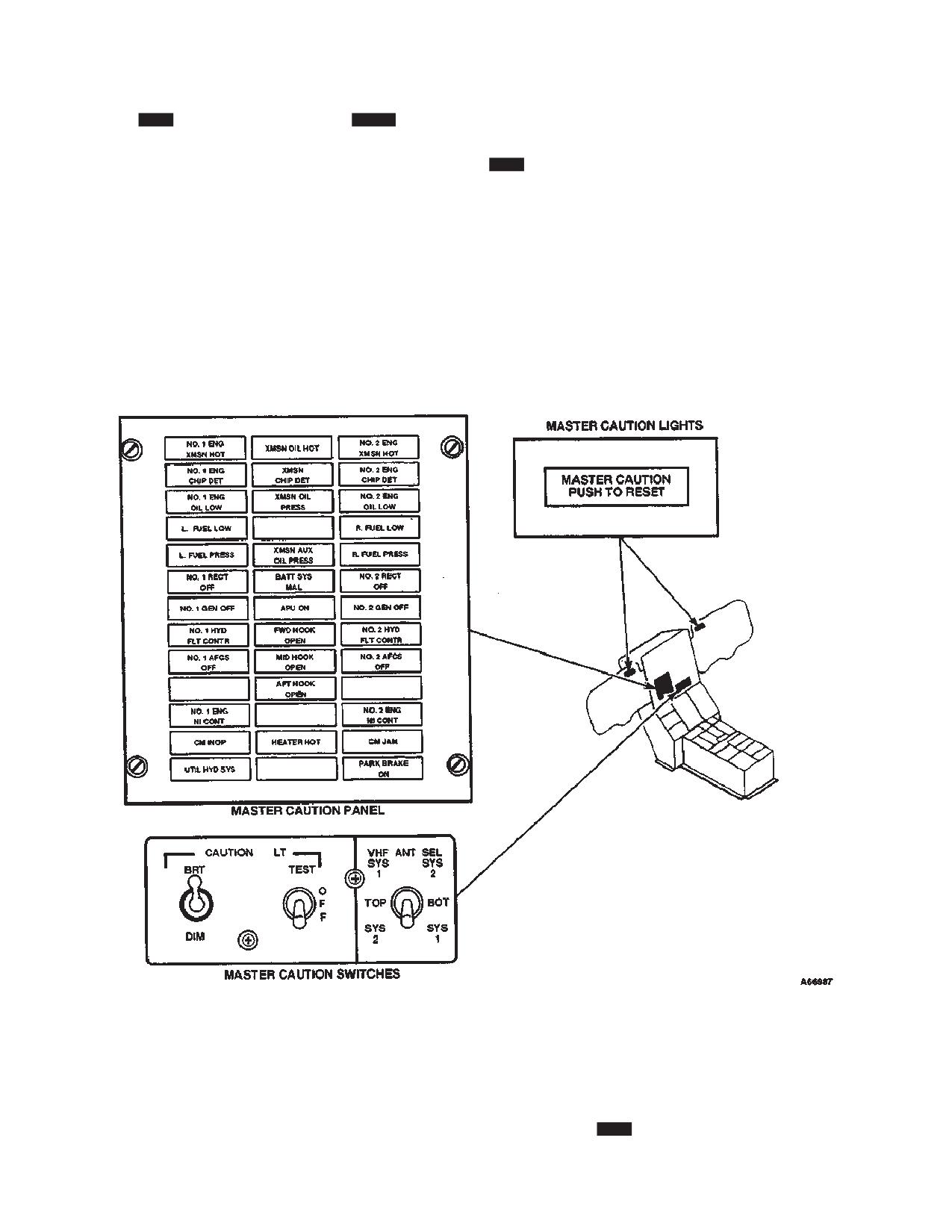
2-14-27. Master Caution System.
2-14-22. Normal Operation - CHRONOMETER.
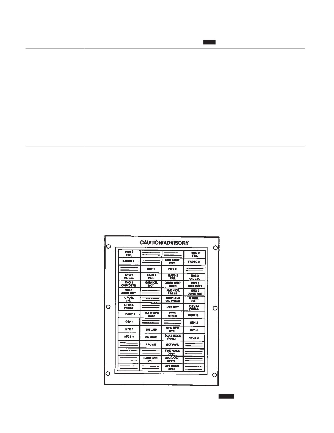
The master caution system provides the pilots with a
visual indication of helicopter conditions or faults (fig.
2-14-5 and 2-14-6). The components of the systems are
2-14-23. Setting GMT.
the 712 Master Caution Panel with NVG filter, 714A
Press the SELECT button until GMT is selected. Simulta-
Master Caution/Advisory Panel, two MASTER CAU-
neously press both the SELECT and CONTROL buttons
TION lights with NVG filters, and a CAUTION LT panel
to enter the set mode. The tens of hours digit will start
with a TEST and BRT-DIM switch. Power to operate and
flashing and the CONTROL button has full control of the
control the master caution system is supplied by the DC
flashing digit. Each time the CONTROL button is pressed
essential bus through the LIGHTING CAUTION PN cir-
, the flashing digit will increment. Once the tenth of hours
cuit breaker on the No. 1 PDP.
2-14-7
TM 1-1520-240-10
2-14-28.
712 Master Caution Panel.
714A Master
ments displayed on the capsules and their actual mean-
Caution/Advisory Panel.
ing and cause.
712 An NVG filter is provided for use during NVG opera-
The Master Caution Panel is on the center instrument
tions. The filter fits over the master caution panel and is
panel (fig. 2-14-5 and 2-14-6). Each capsule is labeled
secured in place by hook and pile tape at its base. When
with word segments which are related to the fault or
the filter is in this position, any light coming from the
condition. When a caution capsule illuminates, the word
caution lights will be NVG compatible. For normal opera-
segments lettered into the panel are of an amber color.
tions, the filter is rotated from its base to a horizontal
When they extinguish, the lettering is not readable.
position, and stowed in a compartment above the master
Tables 2-14-1 and 2-14-2 contain lists of the word seg-
caution panel.
EXT PWR
EXT PWR
EAPS 1
EAPS 2
FAIL
FAIL
DUAL HOOK
FAULT
PWR STEER
Figure 2-14-5. Master Caution System 712
2-14-8
TM 1-1520-240-10
Table 2-14-1. Master Caution Panel Capsules 712
WORD SEGMENT
EXPLANATION
XMSN OIL HOT
Transmission oil temperature is more than 140_C.
XMSN OIL PRESS
Transmission main oil pressure is less than 20 psi, or less than 10 psi in the aft rotor
shaft.
XMSN AUX OIL
Less than 20 psi auxilliary oil pressure in the forward, or aft transmision or less than 10
PRESS
psi in the combining transmission.
NO. 1 ENG OIL LOW
Approximately 2 qt of usable oil is remaining in No. 1 engine oil tank.
NO. 2 ENG OIL LOW
Approximately 2 qt of usable oil is remaining in No. 2 engine oil tank.
L FUEL PRESS
Left fuel pressure is below 10 psi.
R FUEL PRESS
Right fuel pressure is below 10 psi.
PWR STEER
Steering control has been disabled due to system malfunction or steering limits have
been exceeded.
NO. 1 HYD FLT
No. 1 flight control hydraulic system pressure is below 1,800 psi.
CONTR
NO. 2 HYD FLT
No. 2 flight control hydraulic system pressure is below 1,800 psi.
CONTR
UTIL HYD SYS
Utility hydraulic system pressure is below 1,800 psi.
PARK BRAKE ON
Parking brake is on.
NO. 1 RECT OFF
Transformer-rectifier has failed or the generator ouput is interrupted.
NO. 2 RECT OFF
Transformer-rectifier has failed or the generator ouput is interrupted.
NO. 1 GEN OFF
No. 1 generator is inoperative on the generator switch is at OFF.
NO. 2 GEN OFF
No. 2 generator is inoperative on the generator switch is at OFF.
BATT SYS MAL
Battery or battery charging system has failed or the battery has exceeded the safe oper-
ating temperature.
EXT PWR
This light comes on whenever external power is connected to the bus.
L FUEL LOW
Left main fuel tank has approximately 20 percent fuel remaining.
R FUEL LOW
Right main fuel tank has approximately 20 percent fuel remaining.
HEATER HOT
Temperature within heater is greater than 177_C.
MID HOOK OPEN
The midcargo hook has been opened, either hydraulically, pneumatically, or manually.
APU ON
The APU is up to speed and can be used.
DUAL HOOK FAULT
The forward and/or aft hook circuit has an electrical fault and the hook(s) shall not be re-
leased electrically.
FWD HOOK OPEN
The forward cargo hook has been opened either electrically or manually.
AFT HOOK OPEN
The aft cargo hook has been opened either electrically or manually.
NO. 1 AFCS OFF
The No. 1 AFCS is off, failed, or DASH is reprogramming.
NO. 2 AFCS OFF
The No. 2 AFCS is off, failed, or DASH is reprogramming.
No. 1 ENG CHIP DET
Metal chips in No. 1 engine or engine transmission oil.
NO. 2 ENG CHIP DET
Metal chips in No. 2 engine or engine transmission oil.
XMSN CHIP DET
Metal chips in the oil of the forward, combining, or aft transmision or the aft thrust bear-
ing.
NO. 1 ENG N1 CONT
No. 1 engine N1 component has failed or the engine condition lever or N1 actuator is not
in the STOP, GND, or FLT position.
2-14-9
TM 1-1520-240-10
Table 2-14-1. Master Caution Panel Capsules 712 (Continued)
WORD SEGMENT
EXPLANATION
NO. 2 ENG N1 CONT No. 2 engine N1 component has failed or the engine condition lever or N1 actuator is not
in the STOP, GND, or FLT position.
NO. 1 ENG XMSN
No. 1 engine transmission oil temperature is above about 190_C.
HOT
NO. 2 XMSN HOT
No. 2 engine transmission oil temperature is above about 190_C.
CM INOP
Countermeasure set has failed.
CM JAM
Countermeasures set has detected interference from other countermeasures sets or sys-
tem is being jammed.
EAPS 1 FAIL
Pressure switch within No. 1 EAPS has sensed a pressure differential of 10 psi, indicat-
ing a partial blockage of inlet air.
EAPS 2 FAIL
Pressure switch within No. 2 EAPS has sensed a pressure differential of 10 psi, indicat-
ing a partial blockage of inlet air.
2-14-29. MASTER CAUTION Lights.
pilots should extinguish the MASTER CAUTION light by
pressing (PUSH TO RESET) the face of the light. The
Two MASTER CAUTION lights on the instrument panels
MASTER CAUTION light is then ready to indicate a sub-
indicate that one or more of the caution capsules have
sequent malfunction of a different system.
illuminated. On the pilot instrument panel, the caution
light is above the airspeed indicator. On the copilot instru-
Once the malfunction is corrected, the affected caution
ment panel, it is above the altimeter.
capsule will extinguish. The HEATER HOT capsule is an
exception (Refer to Section X). If either generator is
Movable NVG filters are attached to the instrument pan-
cycled OFF then ON while another caution capsule is lit,
els to the left of each light. For NVG operations, the filters
the MASTER CAUTION light may remain illuminated af-
can be rotated over the two MASTER CAUTION lights
ter the generator comes back on and the associated
making the lights NVG compatible. After the MASTER
GEN OFF capsule extinguishes. If this occurs, press to
CAUTION has illuminated and the condition noted, the
extinguish the MASTER CAUTION light.
Figure 2-14-6. Master Caution /Advisory Panel 714A
2-14-10
TM 1-1520-240-10
2-14-30. CAUTION LT Panel.
mode of operation.
The CAUTION LT (caution light) panel is located on the
b. TEST Switch. When the switch is placed to
center instrument panel (16, fig. 2-1-4). It comprises of a
TEST, all the caution capsules on the master caution
BRT-DIM switch and a TEST switch.
panel and the two MASTER CAUTION lights illuminate
to faciliate checking the individual capsule lamps. When
a. BRT-DIM Switch. When the switch is placed to
released to OFF, the lamps in the MASTER CAUTION
BRT, the caution capsule will light to full intensity. When
lights and all the caution capsules extinguish. When the
moved to DIM, the caution capsules will not be as bright.
PLT INST and CPLT INST lights rotary control switches
When the cockpit dome lights are on white, it is not pos-
are active, and the VHF NAV and marker beacon VOL
sible to dim the master caution panel. If the white dome
switches are on, the test feature will also light all the
light is selected while the caution lights are operating on
select legends on the MODE SELECT panel and the
DIM, the caution lights will automatically switch to BRT
MKR BCN indicator lights.
Table 2-14-2 Master Caution/Advisory Panel Capsules 714A
WORD SEGMENT
EXPLANATION
ENG 1 FAIL
Power turbine shaft faliure, N1 underspeed, or flameout. During engine start this caution
is illuminated if the engine fails to start.
ENG 2 FAIL
Power turbine shaft faliure, N1 underspeed, or flameout. During engine start this caution
is illuminated if the engine fails to start.
FADEC 1
No. 1 PRI system hard fails.
ENG CONT PWR
PTIT is within contingency power range.
FADEC 2
No. 2 PRI system hard fails.
REV 1
No. 1 REV system hard fails.
REV 2
No. 2 REV system hard fails.
ENG 1 OIL LVL
Approximately 2 qt of usable oil is remaining in No. 1 engine oil tank.
EAPS 1 FAIL
Pressure switch within No. 1 EAPS has sensed a pressure differential of 10 psi, indicat-
ing a partial blockage of inlet air.
EAPS 2 FAIL
Pressure switch within No. 2 EAPS has sensed a pressure differential of 10 psi, indicat-
ing a partial blockage of inlet air.
ENG 2 OIL LVL
Approximately 2 qt of usable oil is remaining in No. 2 engine oil tank.
ENG 1 CHIP DETR
Metal chips in No. 1 engine or engine transmission oil.
XMSN OIL HOT
Transmission oil temperature is more than 140_C.
XMSN CHIP DETR
Metal chips in the oil of the forward, combining, or aft transmission or the aft thrust bear-
ing.
ENG 2 CHIP DETR
Metal chip in the No. 2 engine or engine transmission oil.
ENG 1 XMSN HOT
No. 1 engine transmission oil temperature is above about 190_C.
XMSN OIL PRESS
Transmission main oil pressure is less than 20 psi, or less than 10 psi in the aft rotor
shaft.
ENG 2 XMSN HOT
No. 2 engine transmission oil temperature is above about 190_C.
L FUEL LVL
Left main fuel tank has approximately 20 percent of fuel remaining.
XMSN AUX OIL
Less than 20 psi auxilliary oil pressure in the forward, or aft transmission or less than 10
PRESS
psi in the combining transmission.
R FUEL LVL
Right main fuel tank has approximately 20 percent of fuel remaining.
L FUEL PRESS
Left fuel pressure is below 10 spi.
HTR HOT
Temperature within heater is greater than 177_C.
R FUEL PRESS
Right fuel pressure is below 10 psi.
RECT 1
Transformer-rectifier has failed or the generator output is interrupted.
BATT SYS MALF
Battery or battery charging system has failed or the battery has exceeded the safe oper-
ating temperature.
2-14-11
TM 1-1520-240-10
Table 2-14-2 Master Caution/Advisory Panel Capsules 714A (Continued)
WORD SEGMENT
EXPLANATION
PWR STEER
Steering control has been disabled due to system malfunction or steering limits have
been exceeded.
RECT 2
Transformer-rectifier has failed or the generator output is interrupted.
GEN 1
No. 1 generator is inoperative or the generator switch is at OFF.
GEN 2
No. 2 generator is inoperative or the generator switch is at OFF.
HYD 1
No. 1 flight control hydraulic system pressure us below 1,800 psi.
CD JAM
Counter measures jammer failed.
UTIL HYD SYS
Utility hydraulic system pressure is below 1,800 psi.
HYD 2
No. 2 flight control hydraulic system pressure is below 1,800 psi.
AFCS 1
The No. 1 AFCS is off, failed, or DASH is reprogramming.
CM INOP
Counter measures inoperative.
DUAL HOOK FAULT
The forward and/or aft hook circuit has an electrical fault and the hook(s) shall not be re-
leased electrically.
AFCS 2
The No. 2 AFCS is off, failed, or DASH is reprogramming.
APU ON
The APU is up to speed and can be used.
EXT PWR
The light comes on whenever external popwer is conencted to the bus.
FWD HOOK OPEN
The forward cargo hook has been opened either electrically or manually.
PARK BRK ON
Parking brake is on.
MID HOOK OPEN
The midcargo hook has been opened, either hydraulically, pneumatically, or manually.
AFT HOOK OPEN
The aft cargo hook has been opened either electrically or manually.
2-14-12
TM 1-1520-240-10
SECTION XV. SERVICING, PARKING, AND MOORING
2-15-1. General.
(3)
If circumstances dictate an aircraft defuel-
ing, transfer the JP8+100 to another aircraft. If this is not
This section contains instructions on servicing, parking,
possible, the JP8+100 must be treated as a hazardous
and mooring the helicopter. These instructions include
waste material and disposed of accordingly.
only those tasks which a flight crew may be expected to
perform when away from a military maintenance support
(4)
For ground equipment, defuel the JP8+100
activity. Diagrams and tables are provided depicting ser-
and treat as hazardous waste. After defueling, consume
vicing points, materials and walkways.
one tank full of JP8, then immediately replace filter/coa-
lescer elements.
2-15-2. Servicing.
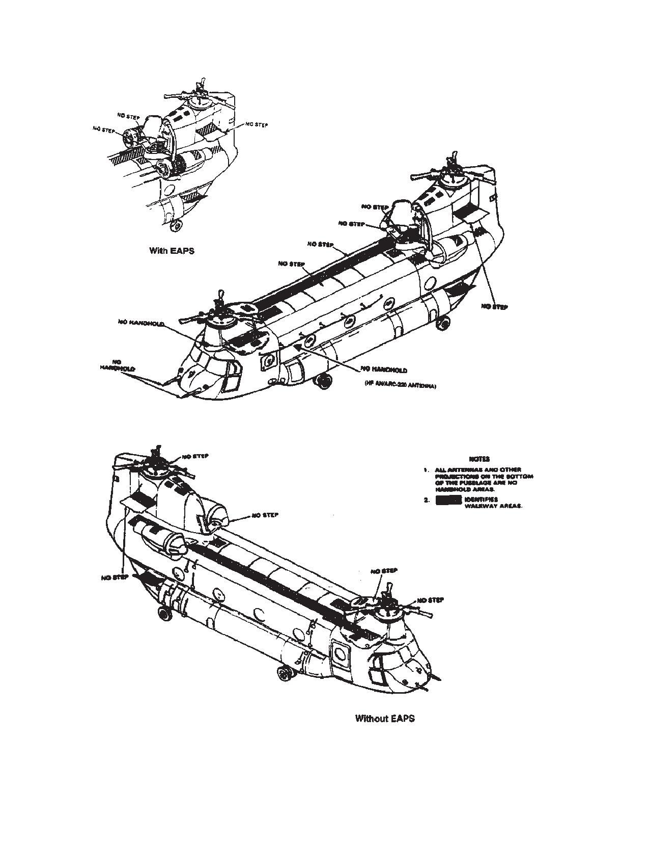
Safe walkway areas, no step areas, and no hand holds
c. The use of kerosene fuels (JP-5 or JP-8 type) in
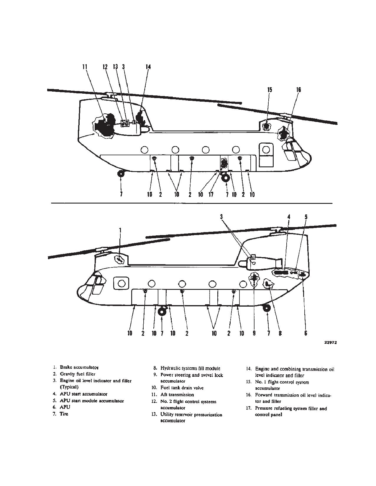
are depicted in Figure 2-15-1. Servicing points are de-
turbine engines dictates a need for special precautions.
picted in Figure 2-15-2. Table 2-15-1 lists the approved
Ground starts and air restarts at low temperature maybe
materials, specifications and capabilities. Table 2-15-2
more difficult due to low vapor pressure.
lists commercial equivalents for oils.
d. When changing from one type of authorized fuel
2-15-3. Fuel Types.
to another - for example, JP-4 to JP-5 or JP-8 - it is not
The following describe the various types of fuel.
necessary to drain the aircraft fuel system before adding
the new fuel.
a. Army Standard Fuels. JP-8 is the Army-desig-
nated primary fuels adopted for worldwide use.
e. Fuels having the same NATO code number are
b. Alternate Fuels. These are JP-4 and equivalent
interchangeable. Jet fuels conforming to ASTM-3-1655
commercial fuels which can be used continuously with-
specification may be used when MIL-T-5624 or
out power reduction when Army standard fuel is not avai-
MIL-T-83133 fuels are not available. This usually occurs
lable. Power setting adjustments and increased mainte-
during cross-country flights where aircraft using NATO
nance may be required when an alternate fuel is used.
F-44 (JP-5) are refueled with NATO F-40 (JP-4) or Com-
mercial ASTM Type B fuels. When this occurs, engine
c. Emergency Fuels. 100LL (Low Lead) AVGAS
operating characteristics may change in that lower oper-
(aviation gasoline) is authorized for use as an emergency
ating temperature, slower acceleration, lower engine
fuel with operation not to exceed 6 hours cumulative
speed, easier starting, and shorter range may be exper-
time.
ienced. The reverse is true when changing from F-40
(JP-4) fuel to F-44 (JP-5) or Commercial ASTM Type A-1
2-15-4. Use of Fuel.
fuels.
Consult TB 55-9150-200-24 for use of fuel and substitute
data as applicable for turbine engine aircraft (Refer to
tables 2-15-2, 2-15-3 and 2-15-4.)
a. There is no special limitation on the use of Army
WARNING
standard or alternate fuel. Certain limitations are im-
posed when emergency fuels are used. For record pur-
poses, fuel mixtures shall be identified as to the major
component of the mixture.
To prevent fuel from spilling from the
tanks, caution should be used when open-
b. The use of JP8+100 additive is not authorized for
ing fuel caps after pressure refueling or
use. However in the event of an inadvertent JP8+100
when aircraft has been sitting in the sun.
refueling (ground or aviation), the following procedures
will apply;
(1)
Document the incident and quantity of
2-15-5. Fuel Tanks Servicing.
JP8+100 received on the aircraft DA Form 2408-13-1.
Register the incident with the USAPC so systemic prob-
The CH-47D helicopter has six fuel tanks, three tanks on
lems can be identifed and rectified. Contact USAPC at
each side. The tanks can be serviced through the single-
DSN: 977-8580.
point pressure refueling system or through filler ports in
(2)
The aircraft will be allowed to operate with
each tank. The single-point method of servicing is prefer-
this additive without restriction and will be considered
red. Using this method, all tanks can be filled, partially
“+100” free after (3) refuelings with a full usuable fuel
filled, or selectively filled in less than 4 minutes. Refer to
load of JP8.
table 2-15-1 for individual tank capacities.
2-15-1
TM 1-1520-240-10
2-15-6. Single-Point Pressure Refueling.
CAUTION
The pressure refueling control panel and nozzle recep-
If either the primary or secondary float
tacle are on the right side of the helicopter above the
switch for any tank is inoperative, do not
forward landing gear (fig. 2-4-6). The landing gear ac-
pressure refuel that tank unless the fuel
cess cover must be opened to expose the panel and
cap is removed to prevent possible fuel
receptacle. A nozzle grounding adapter is located on the
cell over-pressurization. If both switches
structure adjacent to the receptacle.
are inoperative, do not pressure refuel the
helicopter. In addition, if both float
a. Be sure the helicopter is at least 50 feet from any
switches are inoperative for either main
hangar or structure.
tank, the system must be repaired before
flight to prevent fuel cell over-pressure.
b. Be sure the refueling unit is at least 10 feet from
the helicopter.
(6)
Open the flow control valve on the nozzle.
Check that fuel flow stops within 4 seconds. A small
c. Electrically ground the helicopter and refueling
amount of fuel will continue to flow through the open
unit as follows:
secondary ports.
(7)
Set the ALL TEST switch to SEC OFF.
(1)
Connect one end of ground cable to the aft
Check that fuel flow stops within 4 seconds. A small
landing gear eyebolt or to the jack on the right side of the
amount of fuel will continue to flow through the open
fuselage at sta 115. Connect the other end to a grounding
primary ports.
rod or ramp ground point. Be sure the cable has no bro-
ken strands and the clips are securely attached to the
f.
If all tanks are to be filled, set the ALL TEST
cable and ground points.
switch to FLOW. All tanks will now fill independently.
Rotate the FUEL QUANTITY selector switch, checking
(2)
Be sure the fueling unit is grounded to the
each tank for proper fill and quantity. Shutoff valves in
same ground point as the helicopter.
each tank will close and stop fuel flow as each tank fills.
d. At the cockpit overhead Fuel CONTR panel, set
g. When refueling is completer, close the flow con-
REFUEL STA switch to ON.
trol valve.
h. If tanks are to be partially or selectively filled, be
CAUTION
sure to perform steps e. (6) and e. (7), then proceed as
follows:
Be sure the fueling station fuel quantity
(1)
Set the six FUEL CELL SHUT OFF VALVE
indicator is operating before pressure fue-
TEST switches to PRI OFF.
ling. If the indicator is not operating, the
fuel shutoff valves cannot be checked
(2)
Set the ALL TEST switch to FLOW.
properly and fuel cell overpressurization
may result.
(3)
Rotate the FUEL QUANTITY selector
switch to the tank to be filled. The indicator pointer will
e. Open the right forward landing gear access panel
indicate tank fuel quantity.
and perform the following check:
(4)
Set the FUEL CELL SHUTOFF VALVE
TEST switch of the tank to be filled to FLOW.
(1)
Set the PWR switch to ON. Check that both
REFUEL VALVE POSN lights momentarily illuminate,
(5)
Open the flow control valve.
then extinguish. If either light illuminates and does not
(6)
When the desired fuel level is reached, set
extinguish, the associated refueling valve has failed and
the FUEL CELL SHUTOFF VALVE TEST switch to PRI
fuel will not flow into that aft auxiliary tank. If the fuel in this
OFF.
tank is required to complete the mission, notify mainte-
nance.
(7)
Repeat steps (3), (4), AND (6) on each tank
until the desired amount of fuel is in each tank.
(2)
If required, set the LIGHT switch to ON.
(8)
Close the flow control valve and disconnect
(3)
Set the FUEL QUANTITY selector switch to
the nozzle and ground cable.
TOTAL.
i.
Set the PWR switch to OFF. Check that the RE-
FUEL VALVE POSN lights momentarily illuminate, then
(4)
Set the ALL TEST switch to PRI OFF.
extinguish. If either light does not illuminate on, then
extinguish, the fuel in that aft auxiliary tank is unusable.
(5)
Connect the grounding wire to the ground-
Notify maintenance.
ing receptacle and connect the fueling nozzle to the
adapter.
j.
Close the landing gear access door.
2-15-2
TM 1-1520-240-10
k. Remove ground cables from the helicopter.
m. APU - Start (refer to Chapter 8). Place APU
l.
Set the REFUEL STA switch on the FUEL
GEN switch to ON or apply AC external power.
CONTR overhead panel to OFF.
n. Operate the forward boost pump on either main
CAUTION
tank for about two minutes.
Perform steps m., n., and o. if helicopter
will not be operated immediately. Failure
o. Place APU GEN switch to OFF, APU switch to
to do so could result in refuel manifold
OFF, or disconnect the external power.
seepage caused by fuel expansion.
2-15-3
TM 1-1520-240-10
Figure 2-15-1. No Step, No Handhold, and Walkway Areas
2-15-4
TM 1-1520-240-10
Figure 2-15-2. Servicing Diagram (Sheet 1 of 4)
2-15-5
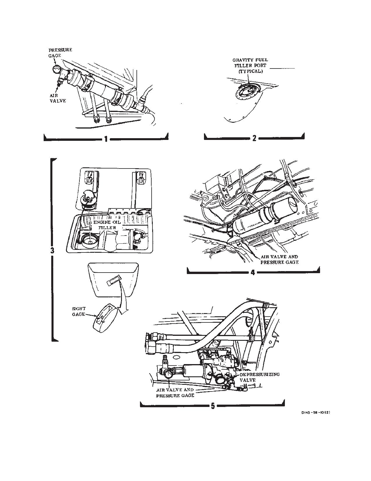
TM 1-1520-240-10
Figure 2-15-2. Servicing Diagram (Sheet 2 of 4)
2-15-6
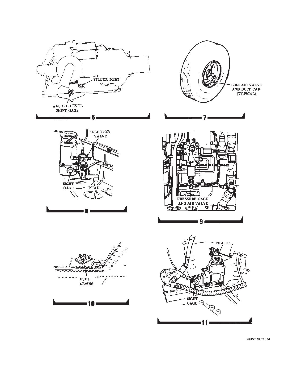
TM 1-1520-240-10
Figure 2-15-2. Servicing Diagram (Sheet 3 of 4)
2-15-7
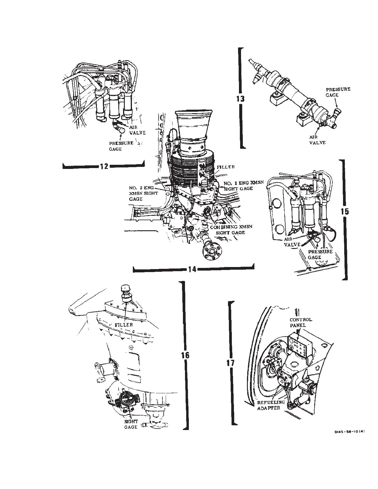
TM 1-1520-240-10
Figure 2-15-2. Servicing Diagram (Sheet 4 of 4)
2-15-8
TM 1-1520-240-10
Table 2-15-1. Servicing
SERVICEABLE ITEM
MATERIAL
SPECIFICATION
CAPACITY
(SEE NOTE A)
L Main Tank
JP-4, JP-5
MIL-T-5624
278 Gallons
R Main Tank
or JP-8
MIL-T-83133
274 Gallons
L Fwd Aux Tank
JP-4, JP-5
MIL-T-5624
122 Gallons
R Fwd Aux Tank
or JP-8
MIL-T-83133
119 Gallons
L Aft Aux Tank
JP-4, JP-5
MIL-T-5624
118 Gallons
R Aft Aux Tank
or JP-8
MIL-T-83133
117 Gallons
ERFS II Tank 1,
JP-4, JP-5
MIL-T-5624
825.5 Gallons
2, or 3
or JP-8
MIL-T-83133
825.5 Gallons
Each Engine Oil TAnk
Lubrication Oil
MIL-L-23699 or MIL-L-7808
12 Quarts
(See note C)
APU Engine Oil
Lubrication Oil
MIL-L-23699 or MIL-L-7808
3 Quarts
(See note C)
Forward Transmission
Lubrication Oil
DOD-L-85734 or MIL-L-23699
26 Quarts
(See note C)
Aft Transmission
Lubrication Oil
DOD-L-85734 or MIL-L-23699
41 Quarts
(See note C)
Combining Transmission
Lubrication Oil
DOD-L-85734 or MIL-L-23699
20 Quarts
(See note C)
Engine Transmission (each)
Lubrication Oil
DOD-L-85734 or MIL-L-23699
10 Quarts
(See note C)
Each Flight Control System Res-
Hydraulic Fluid
MIL-H-83282 (See note B)
2 Quarts
ervoir
Utility Hydraulic System Reservoir
Hydraulic Fluid
MIL-H-83282 (See note B)
6 Quarts
Rotor Head Oil Tanks
Lubrication Oil
MIL-L-7808
As Required
Shock Absorbers and Landing
Hydraulic Fluid
MIL-5606
As Required
Gear Shock Struts
Swashplates
Grease
MIL-G-81322
As Required
Tires - 8.50 x 10 Type III, For-
Air/Nitrogen
88 PSI
ward and Aft
Accumulators
Air/Nitrogen
BB-N-411
Apu Start
Brakes
Power Steering/Swivel Lock
Signal Accumulator
Utility Reservoir
No. 1 and No. 2 Flight Control
WARNING
Synthetic oils, such as MIL-L-23699, DOD-L-85734 and MIL-L-7808, may soften paint or stain clothing
upon contact. If synthetic oil is spilled on painted surfaces, those surfaces should be cleaned
immediately. Skin should be thoroughly washed after contact and saturated clothing should be
removed immediately. Prolonged skin contact with synthetic oils may cause a skin rash. Areas
where synthetic oils are used should have adequate ventilation to keep mist and fumes to a mini-
mum.
NOTES:
A. These are maximum capacities which include residual and trapped oil/fuel. Servicing capacities will
be less.
B. Hydraulic fluid MIL-H-5606 may be used when MIL-H-83282 is not available.
C. When FAT is below -32_C, use MIL-L-7808.
2-15-9
TM 1-1520-240-10
Table 2-15-2. Equivalent Oils and Hydraulic Fluids
APPROVED DOMESTIC COMMERCIAL OILS FOR MIL-L-23699
Manufacturer’s Designation:
PQ Turbine Lubricant 6423/6700/C3889/ C3788/9598
Brayco 899/899-G
Castrol 5000
EMGARD Synthezied Turbine Lubricant 2592/2949
EXXON 2830
ESSO Turbo Oil 2830
HATCOL 3211/3611/11639/1680
Mobil RM-139A/147A/247A/246A/249A/250A/270A
Royco 899/899B/899C/899HC/899E-1/899-2
Aeroshell Turbine Oil 500
Stauffer Jet II E-7603
APPROVED DOMESTIC COMMERCIAL FLUIDS FOR MIL-H-5606
Manufacturer’s Designation:
PQ 2890/2863/2903/2905/2950/4140/3808/4328
Mobil Aero HFD
Stauffer Aero Hydroil 500
Brayco 757B/756F/756ES/756E
Brayco Micronic 756ES
TEXACO Aircraft Hydraulic Oil 15/TL-10711
Cheveron Aviation Hydraulic Fluid D PED 5225
Penreco Petrofluid 4606/4146/4607
Royco 756C/756D/756E
Castrol Hyspin A
Aeroshell Fluid 41
APPROVED DOMESTIC COMMERCIAL FLUIDS FOR MIL-H-83282
Manufacturer’s Designation:
Royco 782 E-1/782 E-2
Gulf TS-741
Brayco Micronic 882/882A
Royco 782/782-1/782-2
Aeroshell Fluid 31
American Oil PQ3883/4219/4401B/4627/4268/4362C/4401/4401A/4923/4908
Emery 2946A/2942/2857/2858
HATCOL 4283/4284/4285
Penreco Petrofluid 822
APPROVED DOMESTIC COMMERCIAL FLUIDS FOR MIL-L-7808
Manufacturer’s Designation:
Aero Turbine Oil 308
American Oil PQ Turbine Oil 8365/9900/4236
Castrol 399
Brayco 880
EXXON Turbo Oil 2389/2391
HATCO 1278/1280
Mobil RM-272A/248A
Royco 808H/808HC
Technolube SYN TURBO No. 3
2-15-10
TM 1-1520-240-10
Table 2-15-3. JP-4 Equivalent Fuel
MILITARY FUEL
U.S.
JP-4 (MIL-T-5624)
NATO
F-40 (Wide cut type)
COMMERCIAL FUEL (ASTM-D-1655) JET B*
American Oil Co.
American JP-4
Atlantic Richfield, Richfield Div.
Arcojet B
B.P. Trading
B.P.A.T.G.
Caltex Petroleum Corp.
Caltrex Jet B
Cheveron
Cheveron B
Continental Oil Co.
Conoco JP-4
EXXON Co., USA
Exxon Turbo Fuel B
Gulf Oil
Gulf Jet B
Mobil Oil
Mobil Jet B
Phillips Petroleum
Philijet JP-4
Shell Oil
Aeroshell JP-4
Texaco
Texaco Avjet B
Union Oil
Union JP-4
FOREIGN FUEL (F-40)
Belgium
BA-PF-2B
Canada
3GP-22F
Denmark
JP-4 MIL-T-5624
France
Air 3407 A
Germany
VTL-9130-006
Greece
JP-4 MIL-T-5624
Italy
AA-M-C-1421
Netherlands
JP-4 MIL-T-5624
Norway
JP-4 MIL-T-5624
Portugal
JP-4 MIL-T-5624
Turkey
JP-4 MIL-T-5624
United Kingdom (Britain)
D. ENG RD 2454
* Commercial fuel such as ASTM-D-1655 not containing a icing inhibitor per MIL-I-27686 (commercial name is
“PRIST”). Use PRIST in accordance with instructions on the can. Anti-icing and Biocidal Additive for Commercial
Turbine Engine Fuel - The fuel system icing inhibitor shall conform to MIL-L-27686. The additive provides anti-ic-
ing protection and also functions as a biocide to kill microbial growths in helicopter fuel system,s. Icing inhibitor
conforming to MIL-I-27686 shall be added to commercial fuel not containing an icing inhibitor during refueling op-
erations, regardless of ambient temperatures. Refueling operations shall be accomplished in accordance with ac-
cepted commercial procedures. Commercial product PRIST conforms to MIL-I-27686.
2-15-11
TM 1-1520-240-10
Table 2-15-4. JP-5 and JP-8 Equivalent Fuel
MILITARY FUEL
U.S.
JP-5 (MIL-T-5624)
JP-8 (MIL-T-83133)
NATO
F-44
F-34
COMMERCIAL FUELS (ASTM-D-1655) JET A/JET A-1*
American Oil Co.
American type A
Atlantic Richfield
ArcoJet A
Arcojet A-1
Richfield Div.
Richfield A
Richfield A-1
B.P. Trading
B.P.A.T.K
Caltrex Petroleum Corp.
Caltex Jet A-1
Chevron
Chevron A-50
Chevron A-1
Cities Service Co.
CITGO A
Continetal Oil Co.
Conoco Jet-50
Conoco Jet-60
EXXON Co., USA
EXXON A
EXXON A-1
Gulf Oil
Gulf Jet A
Gulf Jet A-1
Mobil Oil
Mobil Jet A
Mobil Jet A-1
Phillips Petroleum
Philijet A-50
Shell Oil
Aeroshell 640
Aeroshell 650
Sinclair
Superjet A
Superjet A-1
Standard Oil Co.
Jet A Kerosene
Jet A-1 Kerosene
Texaco
Avjet A
Avjet A-1
Union Oil
76 Turbine Fuel
FOREIGN FUELS (NATO-F44)
Canada
3-GP-24e
West Germany
UTL-9130-007.UTL-9130-010
Italy
AMC-143
Netherlands
D. Eng RD 2493
United Kingdom (Britain)
D. Eng RD 2498
* Commercial fuel such as ASTM-D-1655 not containing a icing inhibitor per MIL-I-27686 (commercial name is
“PRIST”). Use PRIST in accordance with instructions on the can. Anti-icing and Biocidal Additive for Commercial
Turbine Engine Fuel - The fuel system icing inhibitor shall conform to MIL-L-27686. The additive provides anti-ic-
ing protection and also functions as a biocide to kill microbial growths in helicopter fuel system,s. Icing inhibitor
conforming to MIL-I-27686 shall be added to commercial fuel not containing an icing inhibitor during refueling op-
erations, regardless of ambient temperatures. Refueling operations shall be accomplished in accordance with ac-
cepted commercial procedures. Commercial product PRIST conforms to MIL-I-27686.
2-15-12
TM 1-1520-240-10
2-15-7. Gravity Refueling. Perform the following
a. Single Point Pressure Refueling. The ERFS II
steps:
tanks are single point pressure refuled from a connection
at the motorized gate valve. The motorized gate valve
a. Be sure the helicopter is at least 50 feet from any
must be open to pressure refuel and is controlled by the
hangar or structure.
refuel valve switch on the ERFS II fuel control panel
located on the forward most ERFS II tank installed. The
b. Be sure the fueling vehicle is at least 10 feet from
fuel transfer hose is connected to the forward intercon-
the helicopter.
necting ERFS II fuel manifold. Fuel from the transfer
hose passes through the breakaway valve and the
c. Electrically ground the helicopter as follows:
manual fuel/defuel valve to the lower fuel/shutoff valve in
the tank bottom.
(1)
Connect one end of an approved ground
cable to the aft landing gear eyebolt or to one of the jacks
on the side of the fuselage. Grounding jacks are located
CAUTION
at sta. 115 on the RH side and sta. 530 on the LH side in
The operator must exercise caution to
the fuselage skin. Connect the other end to a grounding
avoid ERFS II tank overflow during gravity
rod or ramp ground point. Make sure the cable has no
refueling. There is no automatic fuel flow
broken strands and the clip are securely attached to the
shutoff.
cable and ground points.
b. Gravity Refueling. If pressure refueling of ERFS
(2)
Make sure the fueling unit is grounded to the
II tanks is not performed or prevented, each tank can also
same ground rod or ground point as the helicopter.
be gravity filled through the gravity filler opening on the
top of each tank. To gravity fill, the crashworthy filler cap
(3)
Before opening the filler cap, ground the
is removed and external fuel source nozzle is inserted
nozzle to the ground jack directly above the fuel tank
and the tank is filled. Low pressure flow rates must be
filler.
maintained as venting or vapors bypass the filler opening
d. When the fuel is at the desired level, remove the
and the fuel/defuel vent valve is closed during this opera-
nozzle. Secure the filler cap. Then, disconnect the nozzle
tion. Because fuel is not entering the tank through the
ground wire.
fuel/defuel line, the high level shutoff valve has no effect
stopping the fuel flow into the tank.
e. Remove the ground connection. If the helicopter
is to remain parked, do not disconnect the helicopter
2-15-10. Single Point Pressure Refueling.
ground.
a. Electrical ground - Connect electrical ground
from refueling aircraft. Check that the ground wire from
2-15-8. ERFS Refueling and Fuel Transfer.
each ERFS II tank is connected to an aircraft ground
receptacle.
ERFS Refueling and Fuel transfer will be in accordance
with existing Air Worthiness Release (AWR).
b. Fuel hose from refueling source - Connect to
aircraft single-point pressure refueling connection.
2-15-9. ERFS II Refueling.
c. Single-Point Pressure Refueling Hose
Assembly - Unisex valve at the ERFS II tank - OPEN.
Refueling the ERFS II tanks is performed by either single
point pressure refueling or gravity refueling.
d. Manual FUEL/DEFUEL VALVE at each tank as-
sembly - OPEN.
WARNING
e. REFUEL STA switch located on the overhead
FUEL CONTR Panel - ON.
The manually operated fuel/defuel vent
valve on each tank must be placed in the
f.
REFUEL VALVE switch on the ERFS II Fuel Con-
closed position following pressure refue-
trol Panel OPEN. IN TRANSIT light will briefly illuminate
ling. Failure to do so could permit signifi-
g. Refuel the ERFS II tanks. Fuel flow will automati-
cant fuel leakage in the event of a crash
cally stop when tanks are full.
and the vent self-sealing breakaway valve
fails to actuate.
h. FUEL QUANTITY switch - Set to 1, 2, 3, and
TOTAL to confirm tanks and system contain desired fuel
CAUTION
quantities.
If the fuel/vent valve is not opened, the
i.
REFUEL VALVE switch. - CLOSE. IN TRANSIT
tank cannot be pressure refueled.
light will briefly illuminate.
2-15-13
TM 1-1520-240-10
tion, and barometric pressure changes in the bladders.
WARNING
The high level fuel shutoff valves in the tanks prevent
overfilling. The high level fuel shutoff valves in the tanks
The manually operated fuel/defuel valve
prevent overfilling. The metallic float and ball in the roll-
must be placed in the closed position fol-
over vent valve prevents fuel from escaping should the
lowing pressure refueling. Failure to do so
tank become inverted in a roll-over and prevents slosh
could permit significant fuel leakage in the
from uncoordinated flight from leaking to the overboard
event of a crash and the vent self-sealing
vent lines. To transfer fuel from the FARE system, fuel is
breakaway valve fails to actuate.
pumped from the ERFS II tanks by the FARE pump. The
manually operated fuel/defuel valve must be in the open
j.
Manual FUEL/VENT VALVE at each tank assem-
position for the FARE transfer.
bly - CLOSED.
2-15-13. Engine Oil System.
k. Single-Point Pressure Refueling Hose
Assembly- Unisex valve at the ERFS II tank - CLOSE.
The engine oil tank and oil quantity indicator are an inte-
gral part of the engine (fig. 2-15-2). Service either engine
l.
Fuel hose from refueling source - Disconnect
oil system as follows:
from aircraft single-point pressure refueling connection.
a. If the engine has not been operated in the preceding
m. Electrical ground - Disconnect electrical ground
24 hours and the oil level is low, run it and then recheck the
from refueling source to the aircraft.
oil level. Otherwise an inaccurate oil level may be indicated.
2-15-11. Gravity Refueling.
b. Check oil level by looking through the grilled opening
on the left side of the engine cowling at the 9 o’clock posi-
a. Electrical ground - Connect electrical ground
tion.
from refueling source to aircraft.
c. If the indicator shows less than full, open the oil filler
b. Grounding Cable on each ERFS II tank - Check
access panel on the forward top side of the engine cover.
connection security.
d. Refer to DA Form 2408-13-1 and table 2-15-1 for
c. Filler cap - Remove.
the type of oil to use. Under normal conditions, engines shall
d. Service tank.
be serviced with one type of oil only. If one type of oil is in
an engine and that oil is not available, the other type may be
used in an emergency.
CAUTION
e. Remove the filler cap. Fill the tank with oil until the
The operator must exercise caution to
indicator shows full. Do not overfill tank.
avoid ERFS II tank overflow during gravity
refueling. there is no automatic fuel flow
f.
Install the filler cap. Close both access panels.
shutoff.
e. FUEL QUANTITY switch - Set to 1, 2, 3, TOTAL
2-15-14. APU Oil System.
to confirm tanks and system contain desired fuel quanti-
Service the APU as follows:
ties. (Will indicate only when aircraft power is applied).
f.
Filler Cap - Replace.
CAUTION
g. Electrical ground - Disconnect electrical ground
Do not use the APU drip pan as a hand-
from refueling source to aircraft.
hold. Damage to equipment will result.
2-15-12. Fuel Transfer.
a. Remove the filler cap from the left side of the APU
(fig. 2-15-2).
Fuel transfer from the ERFS II tanks to the helicopter’s
main tanks is accomplished through the use of dual cen-
CAUTION
trifugal pumps in each ERFS II tank. During fuel transfer,
the manually operated fuel/defuel valve on each tank
Do not overfill. Damage to the APU can
must be closed to prevent fuel circulation inside the tank.
result from overfilling.
With the fuel/defuel valve closed, fuel is pumped into the
fuel manifold at a rate of approximately 20 gpm. Fuel is
b. Add oil to the APU oil tank until the level reaches the
delivered by the fuel manifold to the helicoter main fuel
FULL mark on the sight gage. Under normal conditions, the
tanks through the aircraft fuel system quick disconnect
APU shall be serviced with one type of oil only. If one type
fittings in the left and right side cargo compartment at
of oil is in an APU and that oil is not available, the other type
STA 380. During transfer, the roll-over vent valve in each
may be used in an emergency.
ERFS II tank allows venting and equalization of tank
pressure above 5 psi from thermal expansion, contrac-
c. Reinstall and check security of the filler cap.
2-15-14
TM 1-1520-240-10
2-15-15. Transmission Oil System.
b. Check the fluid level in the flight control reservoirs by
selecting each system at the FLT CONTR switch on the
Service the forward transmission, engine/combining trans-
MAINTENANCE PANEL. Then press the LEVEL
mission, and aft transmission as follows:
CHECK switch. Check the fluid level in the utility reser-
a. Access to oil filler and location of sight gage of each
voir by pressing the LEVEL CHECK switch.
transmission (fig. 2-15-2) are as follows.
c. Turn the system select valve to the position for
(1)
The oil filler and sight gage for forward trans-
the system to be serviced.
mission are accessible within the hinged fairing on the right
d. Using the handpump on the fill module, pump
side of the forward pylon. The filler neck is in the top forward
fluid into the system until the fluid in the reservoir is at the
area of the transmission. The sight gage is located in the
FULL mark. Keep the sight gage on the fill module full of
bottom area below the filler neck; it can be viewed from
fluid by adding fluid to the reservoir as required.
above and can also be seen through a viewing port in the
e. Turn the system select valve to OFF.
canted bulkhead at sta. 95 above the pilot’s seat.
2-15-18. Hydraulic Systems Accumulator Prechar-
(2)
The oil filler and sight gage for aft transmission
ge.
is on forward right side of the transmission sump. It is acces-
sible from the cargo ramp area.
Figure 2-15-3 depicts the relationship between proper
accumulator precharge and ambient temperature. To
(3)
The common oil filler for the combining trans-
check that an accumulator is properly precharged, read
mission and both engine transmissions is on the combining
free air temperature from the FAT gauge. Enter the bot-
transmission oil tank. It is accessible within the fairing of aft
tom of the chart at the indicated temperature and move
pylon leading edge.
vertically to the pressure indicated on the accumulator
b. Refer to DA Form 2408-13-1 and table 2-15-1 for
pressure gage. If the indicated pressure is within the
the type of oil to use. Under normal conditions, the transmis-
minimum and maximum limits, the accumulator is prop-
sions shall be serviced with one type of oil only. If one type
erly precharged. If the indicated pressure is not within
of oil is in an transmission and that oil is not available, the
limits, refer to TM 55-1520-240-23 to service the accu-
other type may be used in an emergency.
mulator.
2-15-19. Flight Controls Hydraulic Systems Accu-
NOTE
mulators.
To prevent overfilling the engine and combin-
The No. 1 flight control system accumulator is within the
ing transmissions, check oil level within 30
forward transmission fairing, on the right side. The No. 2
minutes of shutdown. If the transmissions
system accumulator is within the aft pylon, on the right
have been shut down for more than 30 min-
side. Determine either accumulator precharge as fol-
utes, run the helicopter for a minimum of 5
lows:
minutes to verify oil level before servicing.
a. Access to the respective accumulator.
NOTE
b. Note precharge on accumulator and ensure is
within limits as per figure 2-15-3.
To prevent overfilling the forward and aft
transmission, check oil level after the aircraft
c. If
servicing is required, refer to TM
has been shut down for 30 minutes.
55-1520-240-23.
c. Fill the forward transmission, engine/combining and
2-15-20. Utility System Accumulators.
aft transmissions to the FULL mark next to each sight
There are five accumulators in the utility hydraulic sys-
gage.
tem. They provide pressure to start the APU, operate the
power brakes and swivel locks, and maintain line pres-
2-15-16. Hydraulic Systems Servicing.
sure throughout the system.
2-15-17. Hydraulic Systems Fluid Servicing.
a. The APU start accumulator is the largest in the
helicopter. It is mounted overhead in the ramp area at the
The utility systems and both flight control hydraulic systems
right of the aft transmission sump. The APU start module
are serviced by a common fill module on the right side of the
accumulator is located aft and to the right of the APU start
helicopter above the ramp (fig. 2-15-2). The fluid level indi-
accumulator. The utility reservoir pressurization (boot-
cators are on the MAINTENANCE PANEL above the fill
strap) accumulator is located forward of the No. 2 flight
module. One indicator is for both flight control hydraulic
control accumulator in the aft pylon, accessible through
systems. The other indicator is for the utility system. Direct
the pylon right access panel. Determine accumulator
level checks can also be made from the reservoir piston
precharge as follows:
rods. Service any system as follows:
(1)
Depressurize the accumulator by turning
a. Check the sight gage on the fill module reservoir for
the handle on the UTILITY RESERVOIR DEPRESSU-
fluid level. If fluid cannot be seen on the sight gage, fill the
RIZE valve to OPEN. The valve is on the right side of the
reservoir.
cabin, in the cargo ramp area.
2-15-15
TM 1-1520-240-10
(2)
Press and hold the depressurization valve
c. The brake accumulator is located within the aft
on the APU start module accumulator until system pres-
left side of the forward transmission fairing. Determine
sure is depleted. When the accumulator has been de-
accumulator precharge as follows:
pressurized, return the handle of the UTILITY RES-
(1)
Depressurize the accumulator by pressing
ERVOIR DEPRESSURIZE valve to NORMAL.
the brakes approximately four times or until it becomes
(3)
Not precharge on accumulators and ensure
hard to apply the brakes.
is within limits as per figure 2-15-3.
(2)
Accumulator precharge should read be-
(4)
If servicing is required, refer to TM
tween 600 and 850 psi.
55-1520-240-23.
(3)
If servicing is required refer to TM
b. The power steering and swivel lock accumulator
55-1520-240-23.
is located on the right side of the cabin, in the cargo ramp
area. Determine accumulator precharge as follows:
2-15-21. Ground Handling (Towing).
Refer to TM 55-1520-240-23.
NOTE
An alternate method is to apply external pow-
2-15-22. Parking.
er to the helicopter and cycling the STEER-
ING CONTROL SWIVEL STEER switch on
Park helicopter as directed in the following steps:
the center console from LOCK to UNLOCK
a. Apply wheel brakes. Then, set the parking bra-
several times.
kes.
(1)
Depressurize the accumulator by starting
b. Place chocks as required.
the APU and placing the APU GEN switch to ON.
(2)
Place the HYD BRK STEER isolation switch
on the overhead switch panel to OFF. Cycle the STEER-
CAUTION
ING CONTROL SWIVEL STEER switch on the center
console from LOCK to UNLOCK approximately six
Failure to position blades properly can al-
times.
low a blade to hit the fuselage. This may
damage the fuselage and blade.
(3)
Note precharge on accumulator and ensure
precharge is within limits as per figure 2-15-3.
c. Position rotary-wing blades 30_ off centerline of
helicopter.
(4)
If servicing is required, refer to TM
55-1520-240-23.
d. Unplug the battery after the last flight of the day.
2-15-16
TM 1-1520-240-10
FLIGHT CONTROL, UTILITY, POWER STEERING AND SIGNAL ACCUMULATORS
APU START ACCUMULATOR
Figure 2-15-3. Accumulators Precharge Limits
Change 2
2-15-17
TM 1-1520-240-10
e. Lock all doors and hatches.
l.
Heater exhaust protective cover
f.
Moor the helicopter (refer to
TM
m. Heater inlet cover.
1-1500-250-23).
2-15-25. Helicopter Security (Typical).
2-15-23. Mooring.
The helicopter is equipped with door lock security de-
vices (fig. 2-15-6). These devices prevent interior access
Refer to TM 1-1500-250-23.
to the helicopter by unauthorized persons. Install the
2-15-24. Protective Covers.
devises as follows:
The following protective covers should be stowed in the
a. Make sure the ramp is full up. Install the cable
helicopter (fig. 2-15-4 and 2-15-5). They are used as
hook through the ramp controls access door latch. Se-
necessary whenever helicopter is parked or moored.
cure the fastener to the bracket. Make sure the warning
streamer is visible.
a. Engine (LH) inlet cover or EAPS (LH) inlet cover.
b. Close the lower rescue hatch door. If the door
b. Engine (RH) inlet cover EAPS (LH) inlet cover.
cannot be closed, secure the utility hatch to a tiedown
ring with a cargo strap.
c. Engine outlet cover (2 ea).
c. Secure the release straps of the two cabin es-
d. Hydraulic cooler exhaust cover
cape hatches and cargo door escape hatch will restrain-
e. Pitot tube covers (2 ea)
ing clamps. Make sure clamps are located as close to the
release grommet as possible. Make sure the warning
f.
Aft transmission cooler and APU exhaust cover.
streamers are readily visible.
g. Transmission and hydraulic cooler intake.
d. Install lock pins through the pilot’s and copilot’s
window latches. Then, insert the quick-release pin
h. Transmission and hydraulic cooler exhaust (LH
through the bracket on the floor and into the door latch
and RH).
plate. Make sure the warning streamers are readily vis-
i.
Transmission and hydraulic cooler inlet (aft py-
ible.
lon).
e. Install left forward latchable escape hatch cover.
j.
Cockpit enclosure protective cover
f.
Close the cabin doors. Install the bracket with the
k. Rotor hub protective cover (2 ea).
padlock.
2-15-18
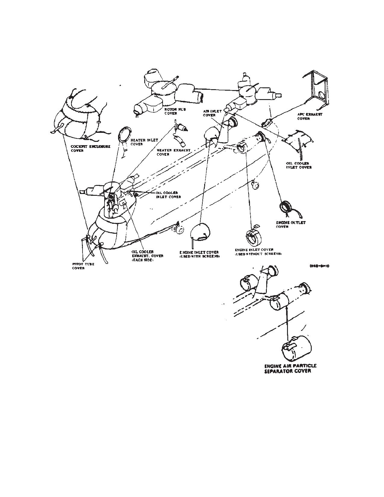
TM 1-1520-240-10
Figure 2-15-4. Protective Covers
2-15-19
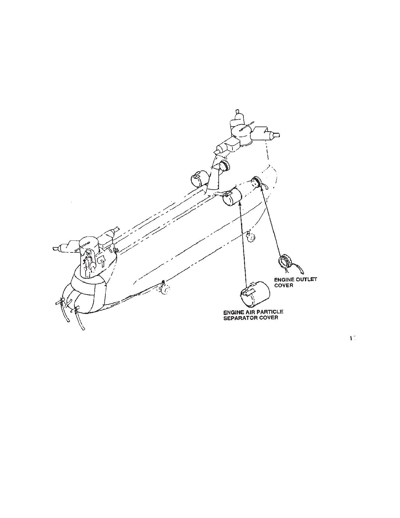
TM 1-1520-240-10
Figure 2-15-5. EAPS Protective Covers
2-15-20
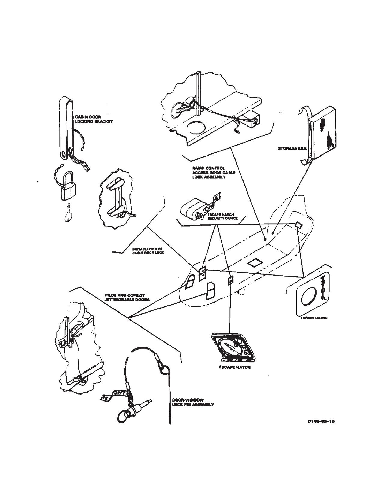
TM 1-1520-240-10
Figure 2-15-6. Installation of Helicopter Security Devises (Typical)
2-15-21/(2-15-22 blank)
TM 1-1520-240-10
CHAPTER 3
AVIONICS
SECTION I. GENERAL
3-1-1. Description.
3-1-2. Avionics Equipment Configuration.
Equipment configuration in the CH-47D helicopter is
listed in table 3-1-1.
The avionic systems in the CH 47D helicopters consist
of the communications equipment providing HF, VHF
3-1-3. Avionics Power Supply.
AM/FM, and UHF-AM communications. The navigation
Power to operate the avionics systems is supplied by the
equipment includes LF-ADF, VOR ILS, Marker Beacon,
No. 1 and No. 2 DC buses, the DC essential bus, and No.
Doppler/GPS, and Omega. VHF-FM homing is provided
1 and No. 2 115-volt and 26-volt AC buses (Chapter 2).
through the AN/ARC-201 FM communication radio.
The No. 1 VHF AM/FM, interphone and UHF sets can be
Transponder equipment consists of an IFF receiver-
operated by selecting the BATT switch to ON. To operate
transmitter with inputs from the barometric altimeter for
the remaining avionics equipment, the APU generator or
altitude encoding. Absolute height is provided by a radar
the main helicopter generators, must be operating, or AC
altimeter. For mission avionics equipment, refer to Chap-
ground power must be connected. All circuit breakers
ter 4, Mission Equipment.
must be in.
3-1-1
TM 1-1520-240-10
Table 3-1-1. Communications/Navigation Equipment
FACILITY
DESIGNA-
USE
LOCATION
TION
INTERPHONE
C-6533/ARC
INTERCOMMUNICATIONS BETWEEN
THREE INTERPHONE CON-
CREWMEMBERS AND RADIO CON-
TROLS ON CONSOLE,
TROL
THREE INTERPHONE CON-
TROLS IN CABIN
UHF RADIO
AN/ARC-164
TWO-WAY UHF-AM COMMUNICATIONS
CONTROL ON CONSOLE
(INCLUDES R/T)
VHF AM/FM RADIO
AN/ARC-186
TWO-WAY VHF AM/FM COMMUNICA-
CONTROL ON CONSOLE
TIONS
(INCLUDES R/T)
VOICE SECURITY
TSEC/KY-58
TWO-WAY CLEAR OR SECURE VOICE
CONTROL ON CONSOLE
EQUIPMENT
COMMUNICATION FOR NO. 1 VHF/FM
RADIO
TSEC/KY-75
COMSEC
CONTROL ON CONSOLE (IF
INSTALLED)
TSEC/KY-100
SECURE VOICE AND DATA COMMU-
CONTROL ON CONSOLE (IF
NICATION. OPERATIONAL WITH NAR-
INSTALLED)
ROW AND WIDE BAND RADIOS (HF,
VHF, UHF, SATCOM)
VHF NAVIGATION
AN/ARN-123
PROVIDES VOR BEARINGS AND
CONTROL ON CANTED
AND INSTRUMENT
COURSE INFORMATION, ILS LOCALIZ-
CONSOLE
LANDING SYSTEM
ER, GLIDE SLOPE, AND MARKER BEA-
CON INDICATIONS
DIRECTION FIND-
AN/ARN-89
AUTOMATIC OR MANUAL DIRECTION
CONTROL ON CANTED
ER SET
FINDING AND HOMING
CONSOLE
GYROMAGNETIC
AN/ASN-43
PROVIDES HEADING INFORMATION IN
CONTROL ON OVERHEAD
COMPASS SET
FREE GYRO OR MAGNETIC MODES
SWITCH PANEL
DOPPLER NAVIGA-
AN/ASN-128
PROVIDES WORLDWIDE NAVIGATION
CONTROL ON CANTED
TION SET
CAPABILITY WITHOUT USE OF
CONSOLE
GROUND FACILITIES
DOPPLER GPS
AN/ASN-128B
PROVIDES WORLDWIDE NAVIGATION
CONTROL ON CANTED
NAVIGATION SET
CAPABILITY WITHOUT USE OF
CONSOLE (INCLUDES DIS-
GROUND FACILITIES
PLAY)
TRANSPONDER
AN/APX-100
RADAR IDENTIFICATION AND TRACK-
CONTROL ON CANTED
SYSTEM
ING
CONSOLE
HIGH FREQUENCY
AN/ARC-220
LONG RANGE TWO-WAY COMMUNICA-
CONTROL ON CONSOLE
RADIO SET
TIONS WITH ALE AND ECCM
VHF-FM RADIO
AN/ARC-201
TWO-WAY VHF-FM COMMUNICATIONS
CONTROL ON CONSOLE
AND HOMING
3-1-2
TM 1-1520-240-10
SECTION II. COMMUNICATIONS
3-2-1. Interphone System (C-6533/ARC).
CONTROLS/
FUNCTION
INDICATOR
The interphone system is a multi-station intercommu-
nication and radio control system for control of voice
2 - UHF radio
radio communication. It also monitors the output of navi-
3 - No. 2 VHF AM/FM radio
gation radio receivers and warning tones from IFF and
4 - HF radio
radar warning sets. The basic components of the inter-
5 - Not used
phone system are six control panels (fig. 3-2-1). There is
AUX - VOR/Localizer
one panel each for the pilot, copilot, troop commander,
NAV - direction finder
the gunners stations, and flight engineer. in addition,
OFF disables associated audio
there is an interphone station for the hoist operator and
input to headset.
two external interphone receptacles. Power for the sys-
ON radio enables associated
tem is supplied by the DC essential bust through the
input to headset.
COMM INTPH LH and COMM INTPH RH circuit break-
HOT MIKE
Two position toggle switch en-
ers on the No. 1 and No. 2 PDP.
Switch Position
ables hands-free operation
3-2-2. Controls and Function, Interphone Control
(PTT/foot switch operation not
(C-6533/ARC). (fig. 3-2-2)
required) of headset micro-
phone for interphone only.
CONTROLS/
FUNCTION
OFF
Hands-free operation disabled.
INDICATOR
PTT/foot switch operation re-
Function Selector
Five position rotary switch
quired for operation.
Switch Position
used to select interphone oper-
HOT MIKE
Hands-fee operation enabled.
ating mode.
ICS
Connects headset-microphone
NOTE
to interphone system.
Switch settings are not necessary to receive
1
Connects headset-microphone
marker beacon, radar warning, and IFF audio
to No. 1 VHF FM or No. 1 VHF
tones.
AM/FM radio set.
2
Connects headset-micro-
Press to talk (PTT) Two or three position switches
phone to UHF radio set.
Switches Position
used to enable the microphone
side of the interphone system
3
Connects headset-microphone
when operator is speaking.
to No. 2 VHF AM/FM radio set.
These switches are described
4
Connects headset-microphone
in detail below.
to HF radio set.
Pilot/Copilot Trigger
Three position PTT switch. Off
5
Not used.
PTT Switch (on pi-
disables microphone (not
lot and copilot cyclic
pressed) enables headset.
NOTE
stick) Position
Pilot/Copilot can transmit on all four transmit-
Interphone
Enables microphone transmis-
ters. Troop Commander can transmit on the
(First detent)
sion to all interphone stations,
HF and VHF FM transmitters only. Gunners
regardless of function switch
and Flight Engineer cannot access any trans-
settings.
mitters.
Radio transmit
Enables microphone transmis-
Receiver Switches
Seven two position toggle
(Second detent)
sion over radio set selected by
1-5, AUX, and NAV
switches used to select-head-
control panel function switch.
Position
set audio input as follows:
Pilot’s/Copilot’s
Two position PTT switch.
1 - No. 1 VHF FM or No. 1
Foot Switches (on
VHF AM/FM radio
cockpit floor next to
heel slide) Position
3-2-1
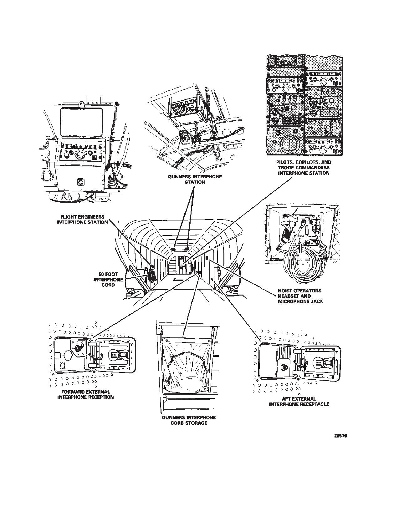
TM 1-1520-240-10
Figure 3-2-1. Interphone Stations
3-2-2
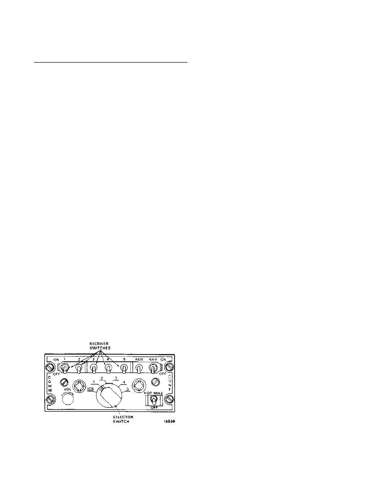
TM 1-1520-240-10
3-2-3. Antenna System.
CONTROLS/
FUNCTION
INDICATOR
Antennas used for avionics communications and elec-
Off
Released position disables mi-
tronic systems equipment are shown in figure 3-2-3. This
crophone.
figure shows the maximum antenna configuration. All
antennas illustrated may not appear on all helicopters.
Talk
Depressed position: enables
3-2-4. UHF-AM Have Quick II Radio (AN/ARC-164).
headset microphone.
The UHF Have Quick II (HQ II) radio (AN/ARC-164) is
Hoist Control PTT
Two position PTT Switch.
located on the center console. It is capable of providing
Switch (on hoist
normal and ECCM, Anti-Jam (AJ) two-way voice com-
control grip) Posi-
munications in the band from 225.000 to 399.975 MHz in
tion
25 kHz increments. The HQ II is capable of operating with
Off
Released position; disables mi-
the Basic HAVE QUICK radio. It also provides 20 preset
crophone.
frequencies and will monitor and transmit on a perma-
Talk
Depressed position; enables
nent guard channel (243.000 MHz). When in the AJ
headset microphone
mode preset 20 is restricted to AJ operations. The usual
operating mode for the radio set is the normal mode
HOT MIKE switch
Three position toggle switch
where the radio uses 1 of 7,000 frequencies. Power for
on HOIST OPERA-
selects hoist operator’s inter-
the UHF-AM Have Quick II radio set is supplied by the 28
TORS PANEl
phone operating mode.
volt essential bus through the COMM UHF AM circuit
(Chapter 4)
breaker on the No. 1 PDP.
OFF
Requires operation of PTT
There are presently three configurations of the AN/ARC
switch for interphone commu-
164-UHF/AM radio. The following paragraphs identify
nications.
the visual differences in their configurations.
HOT MIKE
Operation of PTT switch not
required for interphone com-
a. AN/ARC-164, UHF/AM Basic (not modified for
munications.
Have Quick) 100MHz selector for the hundreds digit only
has a 2 and a 3 position.
MOM ON
Operation of PTT switch re-
quired for interphone commu-
b. AN/ARC-164 UHF/AM Have Quick I (capable of
nications. (Spring loaded to
single WOD entry only). Has a four position selector for
OFF position when released.)
the hundreds digit, A, 2. 3, and T. Does not have EMB
Gunner’s Foot
Two position pressure sensi-
label adjacent to the Pre-set channel selector.
Switch Position
tive switch mounted in move-
c. AN/ARC-164 UHF/AM Have Quick II. Same as b.
able floor mat.
above, but includes EMB label adjacent to the Pre-set
Off
Released position; disables mi-
channel selector.
crophone.
Reverse compatible communications between HQ II and
On
Depressed position; enables
HQ I radios in the AJ mode, is accomplished by either,
microphone.
entering a single WOD or selecting the appropriate
MWOD and net number with a suffix 00.
3-2-5. Anti-Jam Mode.
The AJ mode uses a frequency hopping scheme to
change the frequency many times per second. this
makes it difficult for the enemy to jam the frequencies
since knowledge of the frequencies being used by the
pilot are unavailable. Because the particular frequency
used at any instant depends on the precise time-of-day
(TOD), all participating UHF-AM Have Quick II radios
must have clocks which are synchronized. In addition, all
participating radios must have the same word-of-day
Figure 3-2-2. Interphone Control (C-6533/ARC)
(WOD) and net number data when in the AJ mode.
3-2-3
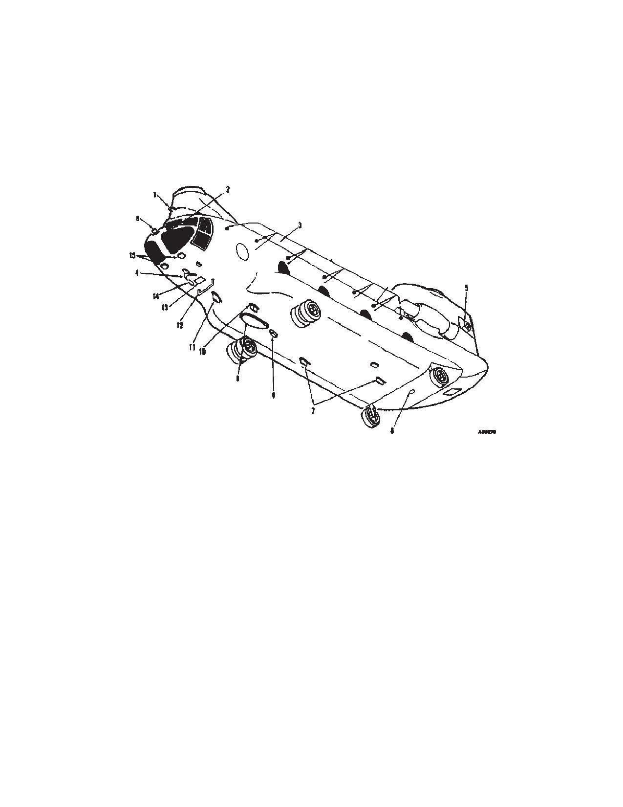
TM 1-1520-240-10
3-2-6. Word-of-Day.
Four operating modes are used within the radio set to
initiate various Have Quick (HQ) programing functions.
The WOD programs the frequency hopping rate and pat-
They are accessed via preset 20 with the frequencies
tern. Without it, the radio cannot function in the AJ mode.
listed in Table 3-2-1. The functions are Operate/verify,
A WOD is made up of a maximum of six WOD segments
MWOD load, MWOD erase, and Frequency Managed
plus a date code. The Have Quick II radios are capable
Training (FMT) frequency load.
of storing up to six WODs, thus allowing for multi-day use
of the radio set. This technique is known as multiple
word-of-day (MWOD) loading. The basic have QUICK
radio allows loading a single WOD, in volatile memory.
1. Glide slope
9. ADF loop and sense antennas
2. Radar warning
10. UHF -AM
3. HF ARC-220 antenna
11. VHF AM/FM (typical top and bottom)
4. VHF navigation
12. FM homing
5. Radar warning
13. Doppler navigation
6. IFF
7. ECM antennas
14. Radar warning blade antenna
8. Marker beacon
15. Radar altimeter
Figure 3-2-3. Antenna Locations
3-2-4
TM 1-1520-240-10
Table 3-2-1. Have Quick II Additional Functions
3-2-7. Time-of-Day.
Frequency and Use
The TOD is essential for communicating in the AJ mode
which allows frequency-hopping at the same instant in
time. Reception and transmission of the TOD is possible
FUNCTION
FREQUENCY USE
in normal and AJ modes. The first TOD reception must
occur in the normal mode.
Operate/verify
220.000
Places the radio in
the normal operat-
The radio automatically accepts the first TOD message
ing mode and pro-
once the predesignated frequency for TOD transmission
vides for the verifi-
has been entered and the T position of the hundredth
cation of an
megahertz selector has been momentarily selected and
MWOD
released. Subsequent messages are ignored unless the
logged for entered
pilot enables the radio to receive a new/updated TOD.
date code.
The TOD contained in a radio may also be sent to other
radios similarly equipped.
MWOD load
220.025
Enables the load-
ing of MWOD’s.
3-2-8. Net Number.
MWOD Erase
220.050
Enables the pilot
The net number enables multiple station nets to operate
to completely
simultaneously on a noninterfering basis in AJ mode,
erase the nonvola-
while sharing a common WOD and TOD. The net number
tile memory con-
begins with the letter A and is followed by three digits
taining the
from 000 to 999. The last two digits of the display desig-
MWOD’s.
nate how the radio is to function and/or the frequency
FMT frequency
220.075
Enables the load-
hopping table being used (Table 3-2-2). Net number
load
ing of training fre-
availability is dependent on the operational mode of AJ
quencies.
and is depicted in table 3-2-3.
Table 3-2-2. Net Selection
MWOD data is stored in nonvolatile memory within the
TACTICAL
radio set. Seven memory locations are available for each
00
- Basic HAVE QUICK
MWOD with the capability of storing a maximum of six
MWODs within the radio set. The channel selectors, the
25
- HAVE QUICK II NATO Hopset
manual frequency selectors, and the tone button are uti-
50
- HAVE QUICK II non-NATO Hopset
lized to load the required segments for each MWOD.
Channel positions 20-14 are used to facilitate the load-
75
- Not Used-Interrupted Fault Tone
ing of MWOD segments. A minimum of one WOD must
be stored for the unit to be functional in the AJ mode.
TRAINING
Channel position 14 is used for day-of-month information
00
- Basic HAVE QUICK Training
(date code). The date code is represented by frequency
3AB.000 MHz in which AB is the day of the month. For
25
- HAVE QUICK II Training
example; if today’s date is the 15th of the month, the date
50/75
- Not Used - Interrupted Fault Tone
code entry would be 315.000 MHz. Channel position 1 is
used for entering the current operational date is the same
as the date code format.
Table 3-2-3. Net Type, Quantity, and Frequency
Range
When the radio is turned off or power is lost after entry of
MWOD and date code, the data is not lost; therefore, the
Types of Nets
Quantity Range of Nets
information remains intact until manually changed or era-
sed. The six most recently entered MWOD’s are retai-
Basic HQ Training
5
A00.000 - A00.400
ned. If a MWOD with duplicate date is entered, the new
Basic HQ Tactical
1000
A00.000 - A01.500
entry takes precedence.
HQ II Training
16
A00.025 - A01.525
After the MWOD information is entered, the pilot would
HQ II Tactical
1000
A00.0XX - A99.9XX
proceed to obtain the TOD. Operational date information
is part of the HQII TOD message. If HQII TOD message
NOTE
is unavailable, the pilot must manually enter the opera-
tional date so the radio can select the proper MWOD. If
Any selection of a net number outside the
power is lost, operational date is lost and must be reen-
range indicated, for each type of net, will re-
tered.
sult in the invalid number warning tone.
3-2-5
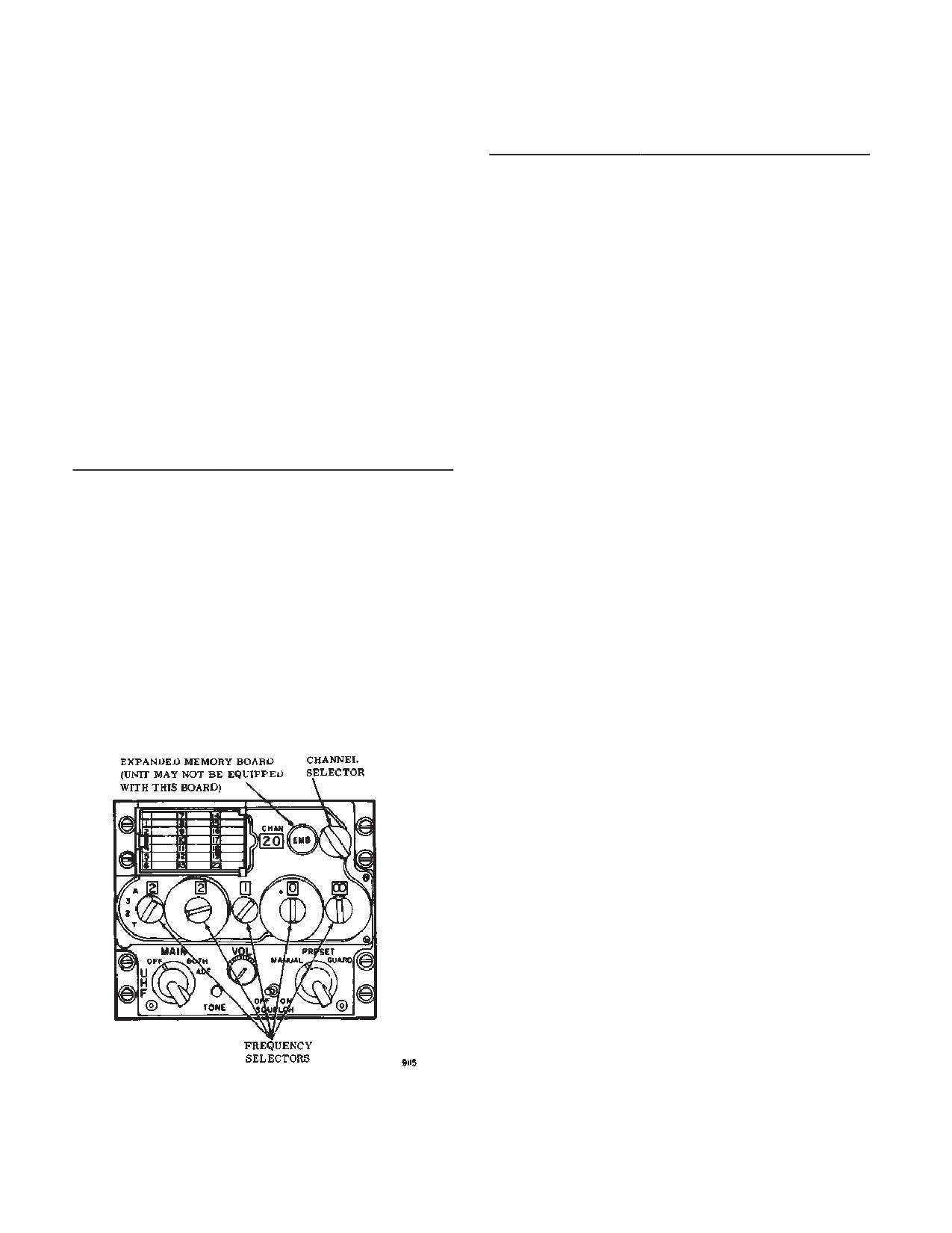
TM 1-1520-240-10
3-2-9. Conferencing.
CONTROLS/
FUNCTION
In the AJ mode, the radio has the capability to receive
INDICATOR
and process two simultaneous transmissions on the
TONE
Momentary contact switch.
same net. This conferencing capability is selected by the
Pressing the TONE switch
hundredth and thousandth digits of WOD segment 2,
when in the normal mode en-
loaded using channel position 19 and is disabled when
ables a 1020 Hz tone on the
operating in the secure speech mode.
selected frequency, unless
In a conference net, the second transmitting radio will
TOD has been accepted in
automatically shift its transmission frequency by 25 kHz
which case a1667 Hz-tone is
when it monitors a transmission on the primary net fre-
heard prior to the 1020 Hz
quency. The wide band receiver will monitor both trans-
tone. When A-3-2-T switch is
missions without the interference normally associated
in A, it enables TOD transmis-
with two radio transmitting on the same frequency simul-
sion followed by a 1020 Hz
taneously. Three simultaneous transmissions will create
tone on the selected frequen-
garbled reception.
cy. When A-3-2-T switch is in
3-2-10. Controls and Function, UHF-AM Have Quick
T, it initiates the emergency
II Radio (AN/ARC-164). (fig. 3-2-4)
startup of the TOD clock.
When in the load mode. Press-
CONTROL/
FUNCTION
ing the TONE switch with
INDICATOR
channels 1, 14, or 15 through
Function Select
Four position rotary switch
20 selected in the manual
Switch
used to select radio operating
mode enters the MWOD data
into non-volatile memory.
mode.
Pressing the TONE switch
OFF
Power to set is disabled; radio
when in the erase mode,
set inoperative.
erases all MWOD data from
MAIN
Radio set can be used to
non-volatile memory.
transmit and receive; guard re-
VOL
Rotary control used to adjust
ceiver inoperative.
radio output volume.
BOTH
Radio set can be used to
SQUELCH Switch
Two position toggle switch to
transmit and receive; guard re-
select radio squelch mode.
ceiver operates.
OFF
Squelch is disabled
ADF
Not used.
ON
Squelch is enabled
Frequency Mode
Three position rotary control
Selector
used to select frequency tun-
ing mode.
MANUAL
Permits manual frequency
selection using frequency con-
trols.
PRESET
Permits selection of preset
channel frequencies in radio
set (maximum of 20 channels).
GUARD
Automatically disables the anti-
jam mode and tunes radio set
to guard channel frequency
(243.000 MHz).
Frequency Selec-
Five rotary controls used to se-
tors
lect radio operating frequency
or state.
Figure 3-2-4. UHF-AM Have Quick II Radio
(An/ARC-164)
3-2-6
TM 1-1520-240-10
CONTROLS/
FUNCTION
CONTROLS/
FUNCTION
INDICATOR
INDICATOR
100 MHz Control
Four position rotary control
Channel Selector
Used to select and display any
(A-3-2-T)
switch
of the 20 preset radio frequen-
cy channels.
A
Selects anti-jam mode.
CHAN
Displays selected preset chan-
nel.
3
Hundreds digit of desired fre-
quency while in the normal
PRESET Switch
Momentary contact switch.
mode.
(Under channel/fre-
when depressed causes se-
quency card)
lected radio frequency entered
2
Hundreds digit of desired fre-
on frequency display to be
quency while in the normal
stored in channel indicated on
mode.
channel display, in normal op-
eration.
T
Momentary spring-return posi-
tion which enables the radio to
3-2-11. Normal Operation - UHF-AM Have Quick II
accept a new TOD for up to
Radio.
one minute after selection.
Also used in conjunction with
The following steps provide operating procedures.
the tone button in the emer-
a. Starting.
gency startup of the TOD clock
when TOD is not available
(1)
Interphone control panel - Set switches as
from external sources.
follows.
(a) Receiver 2 switch - ON.
10 MHz Control
Ten position (0 through 9)
rotary control used to select
(b) Function select - 2.
second digit of operating fre-
(2)
Function switch - MAIN or BOTH.
quency. When in AJ mode, it
(3)
Mode selector - As required.
selects the first digit of net
number.
(4)
SQUELCH switch - As required.
(5)
VOL control - As required.
1 MHz Control
Ten position (0 through 9)
rotary control used to elect
b. Presetting Channels. Perform the following steps
third digit of operating frequen-
to preset a channel to desired frequency.
cy. When in AJ mode, it selects
(1)
Set the Frequency Mode Selector to PRE-
the second digit of net number.
SET.
0.1 MHz Control
Ten position (0 through 9)
(2)
Use the manual frequency selector switches
rotary control used to elect
to select the frequency to be placed in memory.
fourth digit of operating fre-
(3)
Turn the preset channel control switch to the
quency. When in AJ mode, it
desired channel number.
selects the third digit of net
number.
(4)
Raise the cover under the channel card.
Press and release the PRESET switch. Close the cover.
0.025 MHz Control
Four position rotary control
(5)
Using a soft lead pencil, record the frequen-
used to select fifth and sixth
cy selected for the channel number on the card pro-
digits of operating frequency.
vided.
Operates in 0.025 MHz incre-
ments. When in the AJ mode,
c. Stopping. Function switch - OFF.
it selects the appropriate fre-
quency table within the radio
3-2-12. Anti-Jam Operation - UH-AM Have Quick II
net.
Radio.
The following steps provide AJ operating procedures.
Frequency Display
Six digit display (200.000
through 399.975) displays se-
a. MWOD Loading.
lected radio operating frequen-
(1)
Perform paragraph 3-2-11 Starting steps
cy.
a(1) and a (2).
3-2-7
TM 1-1520-240-10
(2)
Channel selector switch - Set to 20.
(2)
Verify Mode.
NOTE
(3)
Frequency mode selector switch - PRE-
SET.
This verification test only checks for presence
(4)
Frequency mode selector switch - Set
of a WOD with the corresponding date code.
220.025 MHz.
It does not check for the authenticity of the
WOD segments entered.
(5)
PRESET switch - Press. Radio is now pro-
grammed to accept MWOD.
(a)
Channel selector switch - Set to 20.
(b)
Frequency mode selector switch -
(6)
Frequency mode selector switch - MANU-
MANUAL.
AL.
(c)
Frequency selector switches - Enter
(7)
Frequency selector switches - Enter first
date code to be verified.
WOD segment.
NOTE
(8)
TONE switch - Press. First WOD segment
If a single beep is not present for a particular
is now loaded to the nonvolatile memory of the radio -
date code and the anti-jam mode is entered
Listen for BEEP.
using that date, a constant warning tone will
(9)
Channel selector switch - Set to 19.
be heard signifying that the anti-jam mode
initialization cannot be properly completed.
(10) Frequency selector switches - Enter sec-
(d)
Channel selector switch - Set to 19,
ond WOD segment.
then back to 20. A single beep will be heard if WOD with
(11) TONE switch - Press.
the date code in step (c) is present.
c. Erase Mode.
(12) The remaining four WODs can be loaded in
a similar fashion by dialing the next lower preset channel,
(1)
Channel selector switch - Set to 20.
selecting the next WOD segment. After entering last seg-
(2)
Frequency mode selector switch -
ment, listen for a double (3125 Hz) beep.
PRESET.
(13) Channel selector switch - Set to 14.
(3)
Frequency selector switches - Enter
220.050 MHz.
(14) Frequency selector switches - Enter date
code.
(4)
PRESET switch - Press.
(15) TONE switch - Press. At this time, one
(5)
Frequency mode selector switch -
complete WOD with its corresponding date code has
MANUAL.
been entered to the nonvolatile memory.
(6)
TONE switch - Press. All MWODs are
(16) Additional WODs can be loaded by repeat-
now erased.
ing steps (5) through (15). Once WODs have been en-
d. Training Frequency Load.
tered, today’s operational date must then be entered.
(1)
Channel selector switch - Set to 20.
(17) Channel selector switch - Set to 1.
(2)
Frequency mode selector switch -
(18) Frequency selector switches - Enter op-
PRESET.
erational date.
(3)
Frequency selector switches - Enter
220.075 MHz
(19) TONE switch - Press.
(4)
PRESET switch - Press.
b. Operate/Verify Modes.
(5)
Frequency mode selector switch -
(1)
Operate Mode.
MANUAL.
(a) Frequency mode selector switch -
(6)
Frequency selector switches - Enter
PRESET.
desired training frequency.
(b) Channel selector switch - Set to 20.
(7)
TONE switch - Press. A single beep
will be heard.
(c) Frequency selector switches - Enter
(8)
The next frequency is loaded by enter-
220.000 MHz.
ing the next lower preset channel, selecting the next
(d) PRESET switch - Press. Radio set is
training frequency, and pressing the TONE switch. Up to
now programmed to operate in either normal mode or
16 training frequencies may be entered. Following this
anti-jam mode.
procedure.
3-2-8
TM 1-1520-240-10
e. TOD.
(2)
Load MWOD - Refer to paragraph 3-2-12
step a MWOD Loading.
(1)
TOD Receive/Update.
(3)
Receive TOD - Refer to paragraph 3-2-12
NOTE
step e(1) TOD Receive/Update.
The first TOD message received within one
(4)
Perform paragraph 3-2-12 step b(1) Oper-
minute of selecting T on the hundreds fre-
ate Mode.
quency selector switch will be accepted.
When communications are slightly garbled
NOTE
but otherwise acceptable during AJ opera-
A steady 3125 Hz warning tone will be heard
tions, this is an indication of drift in TOD syn-
when the anti-jam (A) mode is selected and
chronization. A TOD update should be per-
either the WOD is not in the nonvolatile
formed.
memory or the TOD has not been pro-
(a) Frequency selector switches or channel
grammed.
selector switch - Set to predetermined TOD frequency.
(5)
Hundred frequency selectors switch - A.
(b) Hundreds frequency selector switch -
(6)
Other frequency selector switches - Enter
Momentarily select T, then release. A momentary 1667
net number.
Hz tone will be heard while receiving the TOD message.
3-2-13. VHF AM/FM Radio Sets (AN/ARC-186)
NOTE
a. One or two VHF AM/FM radio sets (AN/ARC-186)
The following step is not necessary if TOD
are installed: No. 1 set on the pilot side of the console, No.
message is being transmitted continuously
2 on the copilot side. Each set provides communications
on the predetermined TOD frequency; for ex-
in the VHF AM and FM bands. The set operates in the
ample, continuous TOD message is being
following modes and frequency ranges: AM reception
transmitted from a satellite.
between 108.00 and 151.975 MHz, AM receiver and
(c) Request TOD from another station with-
transmit between 116.000 and 151.975 MHz , and FM
in the net.
transmit , receive, and homing from 30.000 to 87.975
MHz. Channel spacing is 25 kHz in all bands. Up to 20
(2)
TOD Send.
channels plus two guard channels can be prestored in
(a) Frequency selector switches or channel
the set (removing power from the set does not affect
selector switch - Set to predetermined TOD frequency.
stored channels). When the set is used for FM homing
and selected for display on the HSI by the HSI MODE
(b) TONE switch - Press. A momentary
SELECT panel, steering information will be shown by the
1667 Hz tone will be heard, when the TOD message is
course deviation indicator; homing signal strength will be
transmitted, followed by a 1020 Hz tone until switch is
shown by the glideslope deviation pointer: and homing
released.
signal adequacy warning will be shown by the glideslope
(3)
Emergency TOD Start-UP.
failure and navigation failure warning flags. The set oper-
ates on 28-volt DC power: No. 1 set receives power from
NOTE
the DC essential bus through the COMM VHF NO. 1
The emergency TOD start-up provides an ar-
AM/FM circuit breaker in the No. 2 PDP; No. 2 set re-
bitrary TOD which is not synchronized to
ceives power from the No. 1 DC bus through the COMM
coordinated time. The radio set will not com-
VHF NO. 2 AM/FM circuit breaker on the No. 1 PDP..
municate with any other Have Quick II radio
b. Antenna Select System. Three antennas are
set in AJ mode unless this new TOD is trans-
installed as part of the AM/FM radio installation: a top and
mitted to other radio sets.
bottom communications antenna and a FM homing an-
(a) Perform step a MWOD Loading
tenna. Both AM and FM can be transmitted and received
(b) Perform step b (1) Operate Mode
over the same antenna but not at the same time. Antenna
selection is controlled by the two position VHF ANT SEL
(c) Hundreds frequency selector switch -
switch on the center instrument panel. The normal switch
Select T and hold while simultaneously pressing TONE
position is down at the SYS 2-SYS 1 position. The No. 1
switch. A 1667 Hz tone will be heard when the TOD is
AM/FM set is connected to the top antenna. If a water
programmed.
landing is to be made or the bottom antenna is damaged,
setting the switch up to SYS 1-SYS 2 reverses the normal
(d) TONE switch - Release.
antenna connections and connects the NO. 1 AM/FM set
(e) Hundreds frequency selector switch -
to the top antenna and the No. 2 AM/FM set to the bottom
Release.
antenna. This ensures that secure voice is available
through the top antenna. Power to operate the system is
f. Anti-Jam Mode.
supplied by the DC essential bus through the VHF ANT
(1)
Perform paragraph 3-2-6 step Starting.
SEL circuit breaker on the No. 2 PDP.
3-2-9
TM 1-1520-240-10
NOTE
CONTROLS/
FUNCTION
INDICATOR
The antenna select system has no effect on
Frequency Controls
Four rotary controls used to
the FM homing antenna. The homing antenna
manually select radio operat-
(towel bar) is on the bottom of the fuselage aft
ing frequency.
of the cockpit (fig. 3-2-3) and is connected to
10 MHz Control
Thirteen position (03 through
the FM set only.
17) rotary control used to se-
lect first and second digits of
3-2-14. Controls and Function, VHF AM/FM Radio
operating frequency.
Set. (fig. 3-2-5)
1 MHz Control
Ten position (0 through 9)
rotary control used to select
third digit of operating frequen-
cy.
CONTROLS/
FUNCTION
INDICATOR
0.1 MHz Control
Ten position (0 through 9)
rotary control used to select
Mode Select Switch
Three position rotary switch
fourth digit of operating fre-
used to select radio operating
quency
mode. Power is applied to ra-
dio in all positions except OFF.
0.025 MHz Control
Four position rotary control
used to select fifth and sixth
OFF
Power to set is disabled, radio
digits (00 through 75) of oper-
is inoperative.
ating frequency in 0.025 MHz
TR
Radio operates in the transmit-
increments.
receive mode.
Frequency Display
Display selected radio operat-
DF
Radio operates in the direction
ing frequency.
finder mode.
WB/NB/MEM LOAD
Three position toggle switch
Frequency Control/
Four position rotary used to
Switch (under chan-
used to select radio operating
Emergency Select
select radio frequency tuning
nel card)
band, and during preset chan-
Switch
mode.
nel frequency loading.
EMER AM
Radio is tuned to AM Guard
NB
Places radio in NB (narrow
channel frequency.
band) operation.
EMER FM
Radio is tuned to FM Guard
WB
Places radio in WB (wide
channel frequency.
band) operation.
MAN
Allows manual tuning of radio
NOTE
operating frequency.
Switch will remain in WB position unless
PRE
Allows selection of any 20 pre-
otherwise instructed by radio set controller.
set operating frequencies.
VOL
Rotary control adjusts radio
MEM LOAD
Momentary contact position
output volume.
used with frequency controls
and channel selector to load
SQ DIS/TONE
Three position toggle switch
preset channels.
Switch
used to select radio squelch
operations.
3-2-15. Normal Operation - AM/FM Radio Set.
Normal (center
Preset squelch level is se-
position)
lected.
The following steps provide operating procedures.
SQ DIS
Squelch operation is disabled.
a. Starting.
TONE
Not used - maintenance opera-
tion only.
(1)
Interphone control panel -- Set switches as
follows:
Preset Channel Se-
Twenty position rotary control
lector
used to select any 20 preset
(a) Receiver 3 switch - ON
channel frequencies.
(b) Selector switch - 3.
CHAN
Display selected radio operat-
ing preset channel.
(2)
VHF ANT SEL switch - SYS 2 - SYS 1.
3-2-10
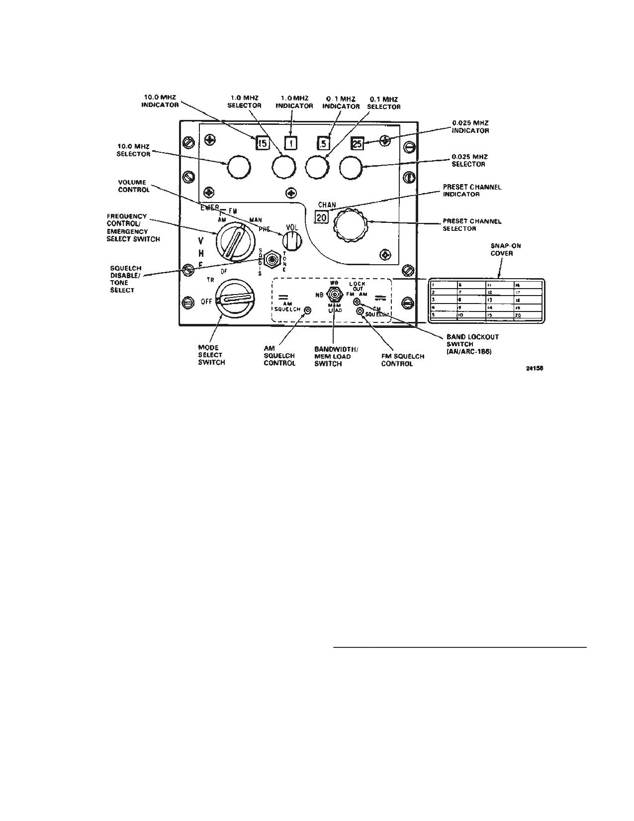
TM 1-1520-240-10
Figure 3-2-5. VHF AM/FM Radio Set (AN/ARC-186)
b. Transmit-receiver mode.
(7)
Using a soft lead pencil, record the loaded
frequency opposite the channel number on the snap-on
(1)
Mode select switch - TR.
cover.
(2)
Frequency Control/Emergency Select
(8)
Using the above procedure, preset any oth-
Switch - As required. If greater receiver sensitivity is
er channels and install the snap-on cover.
required, set the SQ DIS/TONE switch to SQ DIS.
3-2-16. VHF/FM Radio Set (AN/ARC-201).
(3)
VOL control - As required.
The AN/ARC-201 is located on the pilot instrument panel
c. Stopping. Mode select switch - OFF.
and provides two-way frequency modulated (FM narrow
d. Presetting channels. Perform the following steps
band voice communications.
to preset a channel to a desired frequency.
a. The following items from the airborne radio sys-
(1)
Mode select switch - TR.
tem.
(2)
Frequency select switch - MAN.
ITEM DESCRIPTION
(3)
Rotate the four frequency select switches
1.
Receiver-Transmitter Radio Panel Mounted
until the desired frequency is displayed.
(RT-1476)
(4)
Rotate the preset channel selector until the
2.
Amplifier (AM 7189)
desired channel appears in the preset CHAN indicator.
b. Essential Operational Technical Characteristics.
(5)
Remove the snap-on cover.
Except where specifically indicated otherwise, the follow-
(6)
Momentarily set the bandwidth WB, NB,
ing operational/technical parameters are the minimum
MEM LOAD switch to MEM LOAD. The preset frequency
essential characteristics. Unless otherwise specified,
is now in memory.
they apply to each radio configuration.
3-2-11
TM 1-1520-240-10
c. Frequency Range. The frequency range is 30 to
3-2-17. Controls and Functions VHF/FM Radio
87.975 MHz channelized in tuning increments of 25 kHz.
Set. (fig.3-2-6)
In addition a frequency offset tuning capability of -10 kHz,
CONTROLS/
FUNCTION
-5kHz, +1kHz is provided in both receive and transmit
INDICATOR
mode; this frequency is not used in the ECCM mode.
Function Selector
d. Homing.
OFF
Primary power OFF. Memory
(1)
Mode select switch - HOM.
battery power ON.
(2)
Operating frequency - Set.
TEST
RT and ECCM modules are
NOTE
tested. Results; GOOD or
FAIL.
Any strong single channel signal within the
frequency range of the radio set can be used
SQ ON
RT on with squelch.
for homing.
SQ OFF
RT with no squelch.
(3)
FM button on HSI MODE SELECT PANEL
— press. Check that SEL lamp is lit.
RXMT
RT in RECEIVE mode. Used
as a radio relay link.
(4)
Homing procedures. The course deviation
LD
Keyboard loading of preset fre-
bar on the HSI provides the primary navigation indication
quencies.
when the set is in homing mode. The bar only provides
information on whether the helicopter is left, right, on
LD-V
TRANSEC variable loading is
heading to a signal source, or over the signal source. The
enabled.
TO-FROM ambiguity arrows will not function and selec-
Z-A
Not an operational position.
tive source feature is not available. Ambiguity is solved
Used to clear the TRANSEC
using either of the following methods:
variable.
(a) Directional method. When the helicop-
STOW
All power removed. Used dur-
ter is heading inbound to the signal source with the bar
ing extended storage.
centered, the indications are directional in that a change
in heading to the right will cause the bar to drift to the left.
Mode Selector
Conversely, a change in heading to the left will cause the
HOM
Homing antennas are active;
bar to drift to the right. When the helicopter is heading
communication antenna is dis-
outbound from the signal source with the vertical pointer
connected. Provides pilot
centered, the indications are nondirectional in terms of
steering, station approach, and
steering. A change in heading to the right will cause the
signal strength indicators.
bar to drift to the right. A change in heading to the left will
cause the bar to drift to the left.
SC
Single channel mode of opera-
tion. Operating frequency se-
(b) Build and fade method. If the signal
lected by PRESET selector
source is transmitting a 150-Hz tone-modulated signal
keyboard entry.
and the helicopter is inbound to the signal source, the
tone will increase in intensity. The tone will decrease in
FH
Frequency hopping mode se-
intensity on an outbound heading.
lected. PRESET selector posi-
tions 1-6 select frequency hop-
(5)
Additional homing characteristics. The fol-
ping net parameters.
lowing additional characteristics may be observed when
FM-M
Frequency hopping-master
homing. The glideslope deviation pointer will rise from
the horizontal mark when the aircraft is inbound (increas-
position selects control station
ing signal strength) to a transmitter. The pointer will fall
as the time standard for com-
to the horizontal mark when outbound. The glidescope
municating equipment.
failure and navigation failure warning flags will be in view
Preset Selector
if there is inadequate homing signal strength. A dip in the
MAN
Used in a single mode to se-
horizontal pointer may or may not occur when passing
lect any operating frequency in
over the station, depending on the signal source, helicop-
25 kHz increments.
ter speed, and altitude.
3-2-12
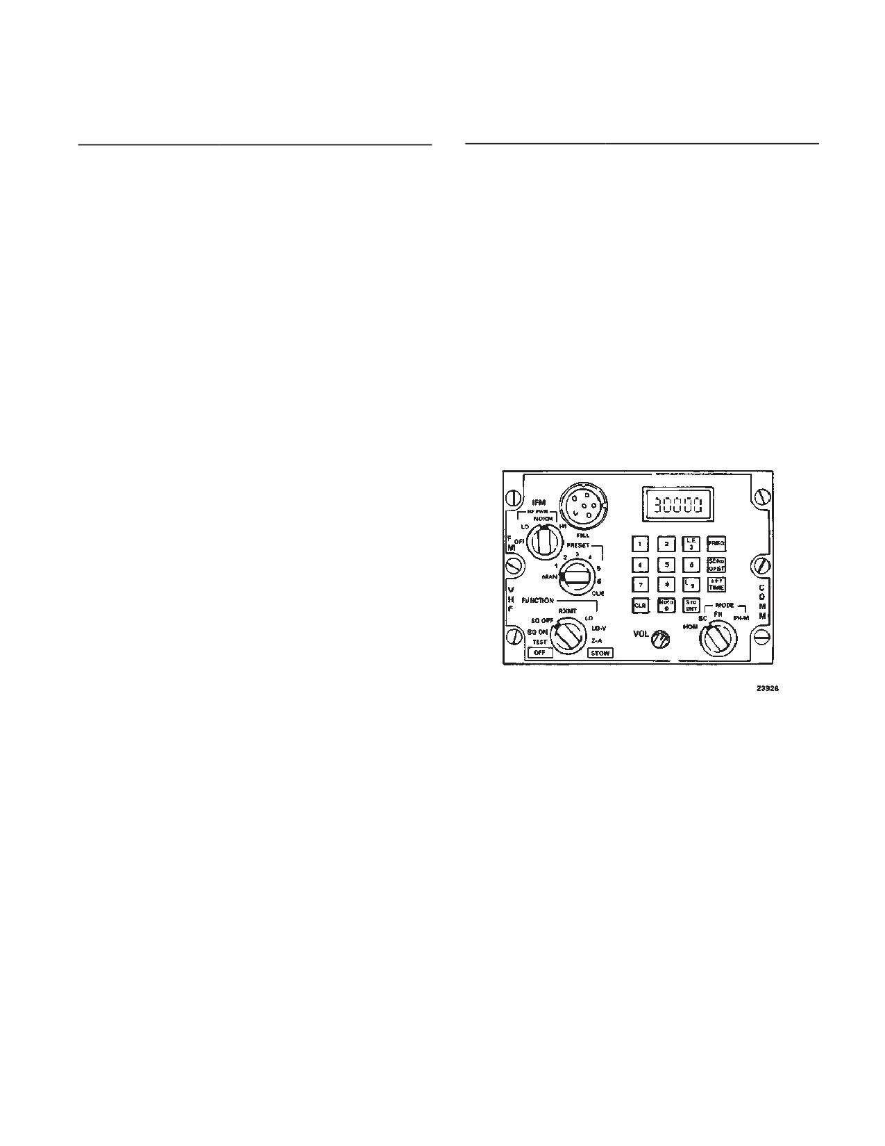
TM 1-1520-240-10
CONTROLS/
FUNCTION
CONTROLS/
FUNCTION
INDICATOR
INDICATOR
POS. 1-6
In single channel mode, preset
SEND/OFST
Modify a single channel oper-
frequencies are selected or
ating frequency, manually se-
lect or preset, to include offsets
loaded. In FH or FM-M mode,
of + 5 or +10 kHz. It has a sec-
frequency hopping nets are se-
ond function on initiating an
lected.
ERF Transmission if a Hopset
CUE
Used by a non-ECCM radio to
or Lockout.
signal to CUE or ECCM radio.
Set is in the holding memory
and the Mode Switch is in the
IFM RF Selector
FH-M position.
OFF
(Bypass) - 10 watts
TIME
Used to display or change the
LO
(Low Power) -2.5 watts
time setting maintained within
each RT.
NORM
(Normal) -10 watts
FILL
Used to fill ECCM parameters
HI
(High power) - 40 watts
from an external fill device.
Entry of ECCM parameters is
Display
The display generally operates
initiated by the H-LD button on
in conjunction with the key-
the keyboard with the FUNC-
board. Other displays may be
TION switch in LD or LD-V.
selected by the FUNCTION
and MODE selectors.
Keyboard
A 15- button array of switches
in a 4 x 4 matrix, used to insert
data or select data for display.
The keyboard is comprised of
10 numerical buttons, three
special functions, and two
command buttons.
Switches 1 - 9
Used to key in frequencies,
load time information, or off-
sets.
CLR
Used to zeroize the display or
to clear erroneous entries.
0 (H-LD)
Used to enter zeroes. Second
Figure 3-2-6. VHF/FM Radio Set (AN/ARC-201)
function (hold) initiates transfer
of ECCM parameters.
3-2-18. Voice Security Equipment TSEC/KY-58.
STO/ENT
Initiate entry of all data by key-
board entry. Its second func-
The voice security equipment is user with the FM band
tion is to store a received Hop-
of the No. 1 VHF AM/FM radio to provide secure two-way
set or Lockout Set held in hold-
communication. The equipment is controlled by the re-
ing.
mote control unit (RCU) Z-AHP mounted on the right side
of the console. The POWER switch must be at ON, re-
FREQ
Display the current operating
gardless of the mode of operation, whenever the equip-
frequency during single chan-
ment is installed. Power to operate the voice security
nel (manual or preset) opera-
system is supplied by the No. 2 DC bus through the
tion.
COMM KY-28 circuit breaker on the No. 2 PDP.
3-2-13
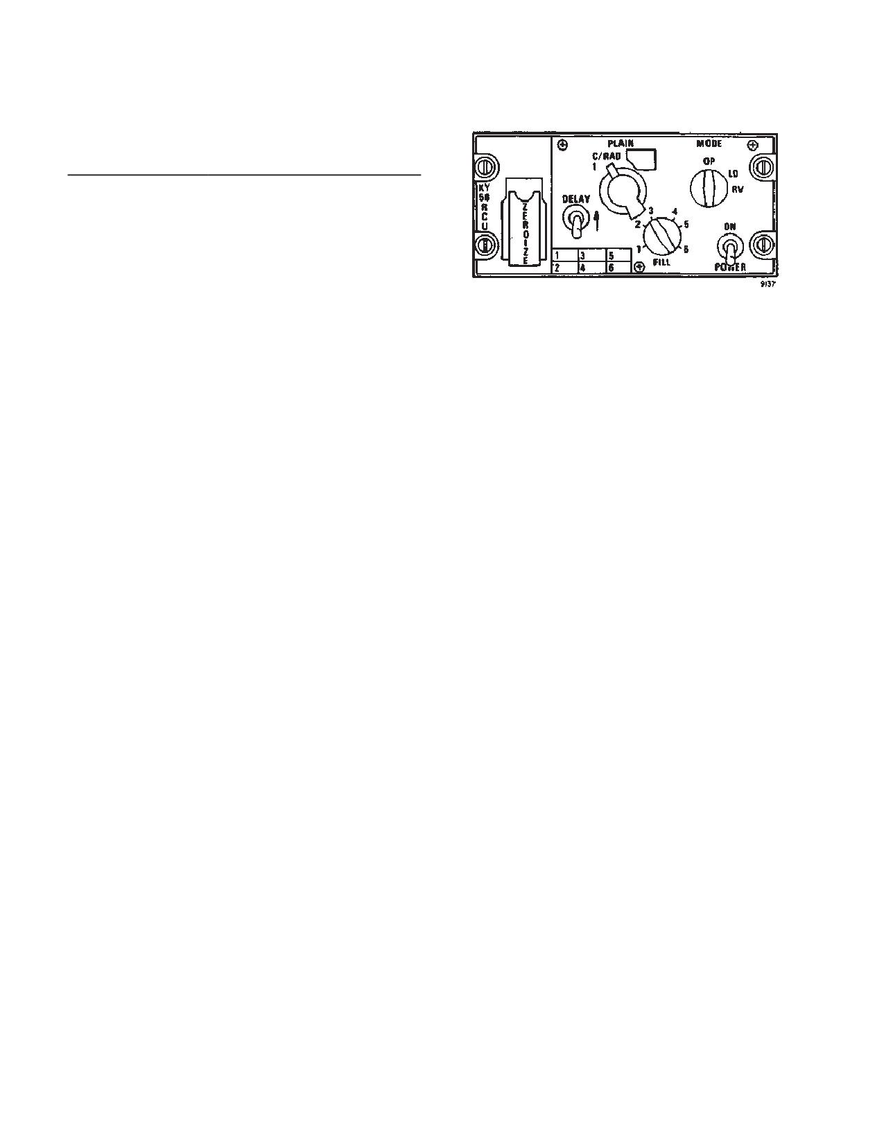
TM 1-1520-240-10
3-2-19. Controls and Functions. (fig. 3-2-7)
CONTROLS/
FUNCTION
INDICATOR
ZEROIZE Switch
Momentary contact toggle
(under spring-
switch used to clear (ZER-
loaded cover)
OIZE) any crypto-net variables
stored in the TSEC/KY-58.
Delay Switch
Two position toggle switch;
DELAY position used when re-
ceived signal is to be retrans-
mitted.
PLAIN/C/RAD1
Two position rotary switch
Figure 3-2-7. Remote Control Unit TSEC/KY-58
Switch
used to select TSEC/KY-58 op-
(Z-AHP)
erating mode. A third position
(C/RAD 2) is covered and
locked out.
(3)
Pull out and lift up the POWER switch to ON.
A beeping tone and background noise will be heard in the
PLAIN
Permits normal (unsecured)
headset. Before the set can be used, the tone must be
communications on associated
cleared by momentarily keying the No. 1 VHF AM/FM
FM radio set.
radio with the PTT switch.
C/RAD1
Permits secured communica-
(4)
Set the PLAIN C/RAD1 switch to C/RAD1.
tions on associated FM radio
set.
(5)
If the signal is to be retransmitted, pull out
and lift up the DELAY switch to (ON).
FILL Switch
Six position, rotary switch,
used to select any of six stor-
(6)
Clear voice procedures: To operate in
age registers for storage of
clear voice (plain text) simply:
crypto-net variable (CNV).
(a) Set the PLAIN-C/RAD switch to
MODE Switch
Three position rotary switch
PLAIN.
used to select the operating/
(b) Operate the equipment.
loading mode of the TSEC/
KY-58.
b. Zeroizing procedures.
OP
Allows normal operation of
KY-58.
NOTE
LD
Allows normal loading of CNV.
Instructions should originate from the net con-
troller or commander as to when to zeroize
RV
Allows remote loading of CNV.
the equipment.
POWER ON Switch
Two position toggle switch
(1)
Lift the red ZEROIZE switch cover.
Position
used to apply power to TSEC/
KY-58.
(2)
Push the spring-loaded ZEROIZE switch
up. This will zeroize position 1-16.
(3)
Close the red cover. The equipment is now
zeroized and secure voice communications are no lon-
3-2-20. Normal Operation.
ger possible.
c. Automatic remoter keying procedures.
a. Operating procedures for secure voice.
NOTE
NOTE
Automatic remote keying (AK) causes an old
To talk in secure voice, the KY-58 must be
CNV to be replaced by a new CNV. Net con-
loaded with any number of desired variables.
troller simply transmits the new CNV over the
air to your KY-58.
(1)
Set the MODE switch to OP.
(1)
The net controller will use a secure voice
channel, with directions to stand by for an AK transmis-
(2)
Set the FILL switch to the storage register
sion. Calls should not be made during this stand-by ac-
which contains the required CNV.
tion.
3-2-14