OPERATOR’S MANUAL FOR ARMY CH-47D HELICOPTER (EIC: RCD, 2003) - page 7
TM 1-1520-240-10
SECTION VIII. WATER OPERATION LIMITATIONS
5-8-1. WATER OPERATION LIMITATIONS.
ed do not reflect indicated airspeed but actual forward
velocity at touchdown. Running landings will only be
5-8-2. Night Operation on Water.
conducted onto calm water. The ramp, lower rescue
door, and main cabin door shall be closed during water
Night operation on water is permissible provided:
landing. Water landings are prohibited when fuel in the
a. Both AFCS are operational (ALT Hold and Head-
main tanks is less than 50 percent.
ing Select not required for night operation on water).
5-8-8. Rotor Starting and Shutdown Limitations.
b. Pilot and copilot radar altimeter systems are op-
erational.
Rotor starting or shutdown will not be conducted when
water conditions exceed Sea State 1 or wind exceeds 6
c. A visible horizon is present at the landing site.
knots. maximum gross weight for starting and shutdown
d. Two or more highly visible, stationary objects are
is 28,550 pounds.
on the water surface to provide necessary visual cues for
landing.
5-8-3. Sea State Limits.
Operation on water is restricted to a maximum of Sea
State 2. Refer to table 5-8-1 for information on sea
states.
5-8-4. Operation Time Limit.
Operation on water is restricted to 30 minutes total flota-
tion time without draining the helicopter.
5-8-5. Gross Weight Limitations.
Maximum gross weight for water operations is as follows:
a. Normal operations - 36,000 pounds.
b. Emergency rescue missions - 46,000 pounds.
5-8-6. Taxiing Limitations.
Taxiing will not be conducted in water conditions above
Sea State 1 or in wind above 6 knots. Fast taxiing will be
conducted in a straight line only and to a maximum speed
of 10 knots when the lower nose enclosure is left in the
water.
5-8-7. Landing Limitations.
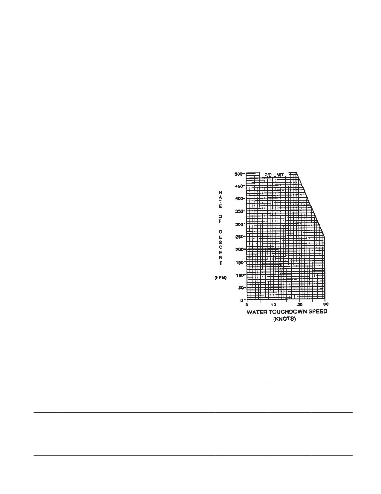
Water landings can be performed within the limitations
Figure 5-8-1. Water Landing Speed Limitations Up
presented on fig. 5-8-1. The touchdown speeds present-
To 46,000 Pounds gross Weight
Table 5-8-1. Description of Sea States
SEA
SEA DESCRIPTION
WIND
WIND
AVERAGE
STATE
DESCRIPTION
VELOCITY
WAVE
(KNOTS)
HEIGHT
(FT)
Sea like mirror (calm)
Calm
Less than 1
0.0
0
Ripples with appearance of scales; no foam crests
Light Air
1-3
0.05
(smooth)
1
Small wavelets; crests of glassy appearance, not
Light Breeze
4-6
0.2
breaking (slight)
5-8-1
TM 1-1520-240-10
Table 5-8-1. Description of Sea States (Continued)
SEA
SEA DESCRIPTION
WIND
WIND
AVERAGE
STATE
DESCRIPTION
VELOCITY
WAVE
(KNOTS)
HEIGHT
(FT)
2
Large wavelets;crests begin to break; scattered white- Gentle Breeze
7-10
0.6
caps
3
Small waves, becoming longer, numerous whitecaps
Moderate Breeze
11-16
1.4
(moderate)
5-8-2
TM 1-1520-240-10
SECTION IX. ADDITIONAL LIMITATIONS
5-9-1. Air-to-Ground Towing.
ERFS operation will be in accordance with existing Air
Worthiness Release (AWR).
Air-to-ground towing operations are prohibited.
5-9-7. Extended Range Fuel System II (ERFS II)
5-9-2. APU Operation.
The following paragraphs contain important operating
APU operation in flight is prohibited except during emer-
limits and restrictions that shall be observed during the
gencies.
operation of the ERFS II. Compliance with these limits
will allow the operator to safely perform the assigned
5-9-3. Pitot Tube and AFCS Sideslip Port Anti-Icing
missions and derive the maximum utility from the ERFS
Limitation.
II.
The PITOT switch shall not be on for more than 5 minutes
a. The maximum capacity of one ERFS II tank as-
on the ground.
sembly is 825.5 US Gallons. The usable fuel in one
ERFS II tank assembly is 800 US Gallons when single
5-9-4. Windshield Heat.
point pressure refueled.
Windshield heat shall not be used above 24_C.
CAUTION
5-9-5. Single Point Refueling.
The maximum rate for pressure refueling is 300 gal/min
Trying to pressure refuel the tanks without
at 55 psi.
connecting the vent lines could overpres-
surize the tanks.
5-9-6. Extended Range Fuel System (ERFS).
b. The maximum pressure inside the ERFS II tank
should not exceed 5 PSI.
WARNING
CAUTION
Installing the non-crashworthy/non self
Conducting suction defueling at pres-
sealing ERFS increases the potential for
sures greater than minus 11 PSI could
explosion and burn injuries during a
damage the internal components of the
crash. Therefore, the number of personnel
ERFS II tank assembly.
on board the helicopter should be kept to
the minimum required to perform the re-
c. The maximum allowable suction defueling pres-
quired mission.
sure is minus 11 PSI.
5-9-1/(5-9-2 blank)
TM 1-1520-240-10
CHAPTER 6
WEIGHT/BALANCE AND LOADING
SECTION I. GENERAL
6-1-1. Purpose.
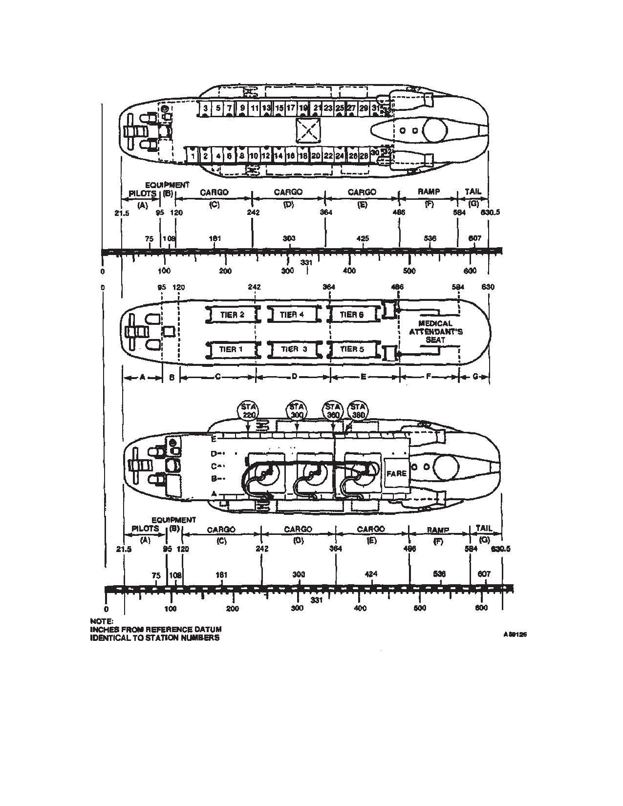
6-1-2. Helicopter Compartment and Loading Dia-
gram.
This chapter contains sufficient instructions and data so
Figure 6-1-1 defines the compartments, shows the refer-
that the aviator, knowing the basic weight and moment of
ence datum line, and depicts other information essential
the helicopter, can compute any combination of weight
for helicopter weight/balance and loading.
and balance.
6-1-3. Classification of Helicopter.
Army Model CH-47D is in Class 1. Additional directives
governing weight and balance of Class 1 aircraft forms
and records are contained in AR
95-1, TM
55-1500-342-23, and DA PAM 738-751.
6-1-1
TM 1-1520-240-10
Figure 6-1-1. Aircraft Compartment and Loading Diagram
6-1-2
TM 1-1520-240-10
SECTION II. WEIGHT AND BALANCE
6-2-1. DD Form 365-3 Chart C - Basic Weight and
and any corrections that must be made to insure that the
Balance Record.
helicopter will be within weight and C.G. limits. Sufficient
completed FORMS F must be onboard the helicopter to
Chart C is a continuous history of the basic weight and
verify that the weight and C.G. will remain within allow-
moment resulting from structural and equipment
able limits for the entire flight. Sufficient forms can be one
changes in service. At all times, the last weight and mo-
(for a specific flight) or it can be several. Several FORMS
ment/1,000 are considered the current weight and bal-
ance status of the basic helicopter.
F for various loadings of crew, passengers, stores, cargo,
fuel slingloads, etc., which result in extreme forward or
6-2-2. DD Form 365-4 (Weight and Balance Clear-
extreme aft C.G. locations and variations in gross weight,
ance Form F).
but which remain within limits. There are two versions of
this form: Transport and Tactical; they are designed to
This form is used to derive the gross weight and center-
of-gravity (C.G.) of the helicopter. The FORM F furnishes
provide for the respective loading arrangements of these
a record of the helicopter weight and balance status at
two type aircraft. The general use and fulfillment of either
each step of the loading process. It serves as a work-
version are the same. Specific instructions for filling out
sheet on which to record weight and balance calculations
the form are given in TM 55-1500-342-23.
6-2-1/(6-2-2 blank)
TM 1-1520-240-10
SECTION III. FUEL/OIL
6-3-1. Fuel and Oil Data.
The following information is provided to show the general
range of fuel specific weights to be expected. Specific
The CH 47D is equipped with six fuel tanks and an inte-
weight of fuel will vary depending on fuel temperature.
gral oil tank on each engine. The capacities of each fuel
Specific weight will decrease as fuel temperature rises
tank and each oil tank are given in Chapter 2.
and increase as fuel temperature decreases at the rate
of approximately 0.1 lb/gal for each 15ºC change. Specif-
6-3-2. Fuel Weight and Moment.
ic weight may also vary between lots of the same type
Fuel moments for the forward auxiliary, main and aft
fuel at the same temperature by as much as 0.5 lb/gal.
auxiliary fuel tanks are shown in figure 6-3-1. The fuel
The following approximate fuel specific weights at 15ºC
arms for these tanks are constant thus, for a given weight
may be used for most mission planning.
of fuel there is no variation in fuel moment with change
in fuel specific weight. The common auxiliary fuel tank
Fuel Type
Specific Weight
arm is 314.
JP-4
6.5 lb/gal
The full tank usable fuel weight will vary depending upon
JP-5
6.8 lb/gal
fuel specific weight. The gallon scales on figure 6-3-1 are
based on JP-4 @ 6.5 lb/gal, JP-5 @ 6.8lb/gal, and JP-8
JP-8
6.7 lb/gal
@ 6.7 lb/gal. The aircraft fuel gage system was designed
for use with JP-4, but does tend to compensate for other
6-3-3. Oil Data
fuels and provide acceptable readings. When possible
the weight of fuel onboard should be determined by direct
For weight and balance purposes, the weight of engine
reference to the aircraft fuel gages.
oil is included in the basic weight.
6-3-1
TM 1-1520-240-10
Figure 6-3-1. Fuel Moment Chart
6-3-2
TM 1-1520-240-10
SECTION IV. PERSONNEL
6-4-1. Personnel Loading and Unloading.
the vertical edges of the seat-back rests. A slide adjuster
below the back rest hanger clips affords adjustment of
The loading procedures should be accomplished and
back rest tension. Seat tension is adjusted by relocating
observed before loading to ensure the safety and comfort
retaining pins in the holes drilled in the front seat tubes.
of personnel to be airlifted:
A row of male snap fastener studs along the rear of the
seat-back rest matches a row of female snap fastener
a. Passenger compartment - Clean.
sockets along the rear edge of the seat fabric. These
fasteners are jointed to provide greater seat depth for
b. Equipment - Stow and secure.
troops equipped with parachutes. Two stowage straps
c. Troop seats - Install,as required.
are attached to the underside of the seat fabric; one is
equipped with a hanger clip for folded stowage, the other
d. Litters - Install, as required.
is equipped with a buckle for rolled stowage. The seats
will normally be stowed in the folded position for cargo
e. Static line anchor cable - Install, as required.
transport.
f.
Safety belts - Check, attached.
A 2,000-pound-capacity nylon web safety belt is pro-
vided for each seat occupant. The belt is adjustable and
g. Emergency equipment - Check.
is equipped with a positive-grip buckle fastener designed
h. Emergency exits - Inspect.
for quick release.
i.
Special equipment - Check.
6-4-5. Troop Seat Installation.
6-4-2. Personnel Weight Computation.
Install the troop seats from the rolled position as shown
in figure 6-4-4. Install troop seats from the folded position
When the helicopter is to be operated at critical gross
by performing steps 1, 4, 6, and 7 of figure 6-4-4.
weights, the exact weight of each individual occupant
plus equipment should be used. If weighing facilities are
6-4-6. Troop Seat Stowage.
not available, or if the tactical situation dictates other-
wise, loads shall be computed as follows:
Stow the troop seats in the rolled position by performing
steps 1 through 9 in reverse order as set forth in figure
a. Combat equipped soldiers - 240 pounds per indi-
6-4-4. Stow troop seats in the folded position by revers-
vidual.
ing the procedures in steps 7, 6, 4, and 1 of figure 6-4-4.
b. Combat equipped paratroopers - 260 pounds
per individual.
6-4-7. Troop Loading.
c. Litter patient (including litter, splints, etc.) - 200
6-4-8. The loading and unloading of troops will normally
pounds per individual.
be accomplished through the lowered aft cargo door and
ramp. The most orderly and efficient troop loading proce-
d. Medical attendants - 200 pounds per individual.
dure is for the troops to occupy from the front to the rear.
e. Crew and passengers with no equipment - Com-
In unloading, the troops will leave the helicopter progres-
pute weight according to each individual’s estimate.
sively from the rear to the front. If the troops to be loaded
are carrying full field equipment, it is recommended that
f.
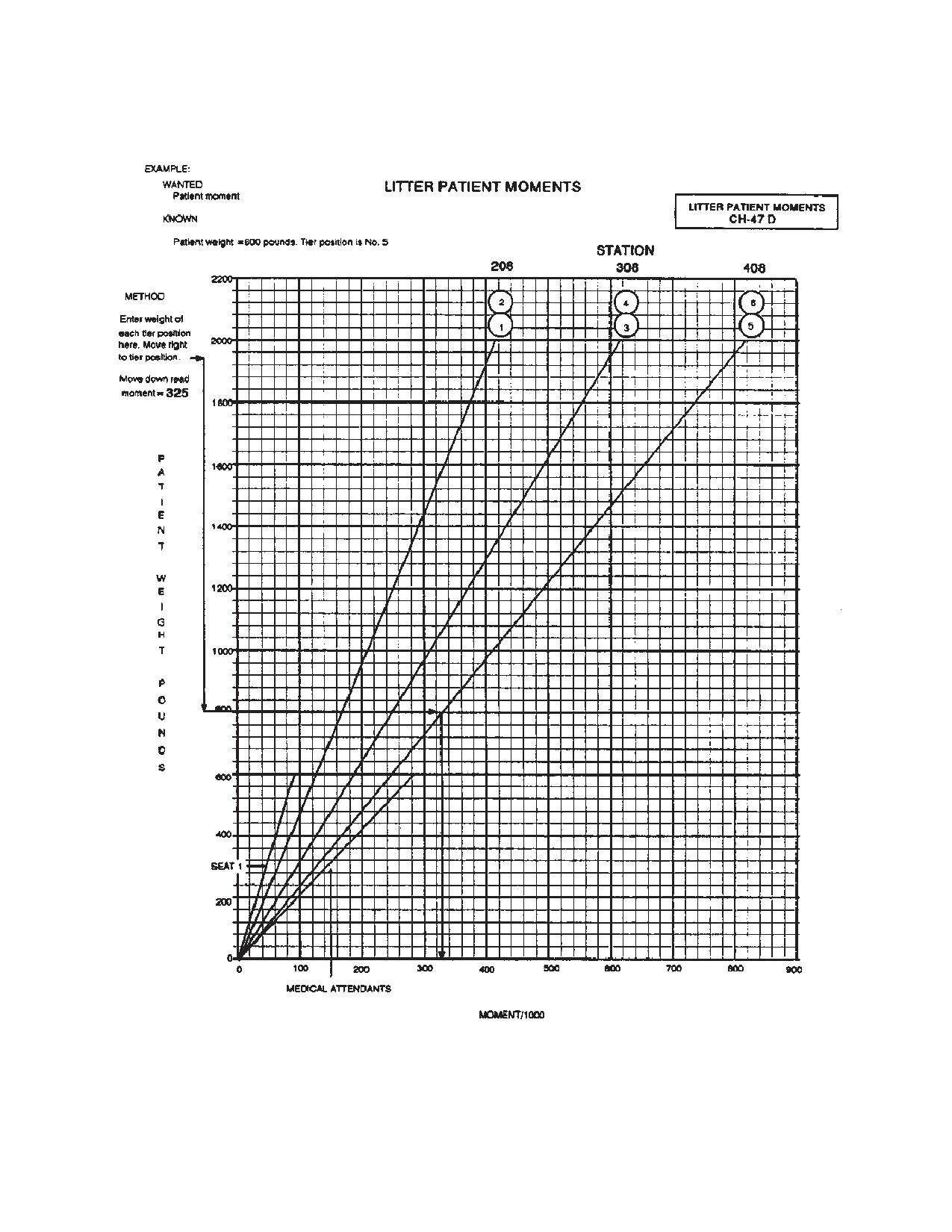
Refer to figure 6-4-1 or 6-4-2 for personnel or litter
the seat-back rests be folded to avoid entanglement with
patient moment data. The chart (fig. 6-4-1) provides pre-
the equipment and damage to the seat-back rests.
computed moments for each troop seat position.
6-4-9. Troop Commander’s Jump Seat.
6-4-3. Seating Arrangement.
A collapsible fold-away seat is located in the cockpit en-
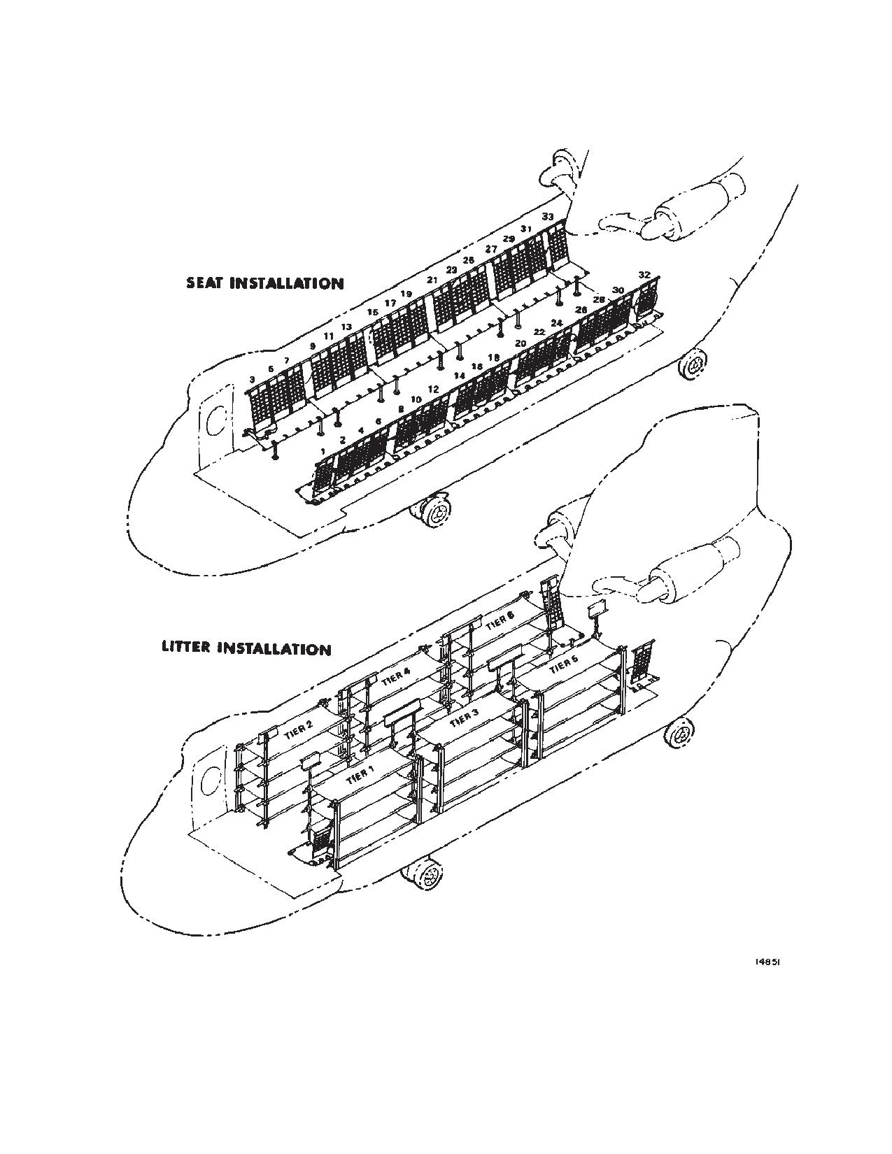
Seating arrangement for 33 fully equipped ground troops
trance for the use of the troop commander. The seat is
is provided by ten 3-man seats and three 1-man seats
made of nylon on a tubular aluminum frame.
(fig. 6-4-3). A row of five 3-man seats is installed along
each side of the cargo compartment. One-man seats are
6-4-10. Litter Arrangement.
installed at the forward and aft ends of the left-hand row
of seats and one at the end of the right-hand row of seats.
There are provisions for 24 litters, three tiers, four high,
along each cargo compartment wall normally occupied
6-4-4. Troop Seats.
by troop seats (fig. 6-4-3). The two 1-man seats in the aft
section of the cargo compartment may remain in place to
These seats are made of nylon on tubular aluminum
serve as seats for medical attendants. If needed, the
frames and are joined together for greater rigidity and
comfort. The seats are joined by means of slide bolt
1-man seat in the forward section of the cargo compart-
fasteners in the front seat tubes, zipper fasteners on the
ment may also remain. It is not necessary to remove the
underside of the seat fabric, and snap fasteners along
troop seats to install the litters.
6-4-1
TM 1-1520-240-10
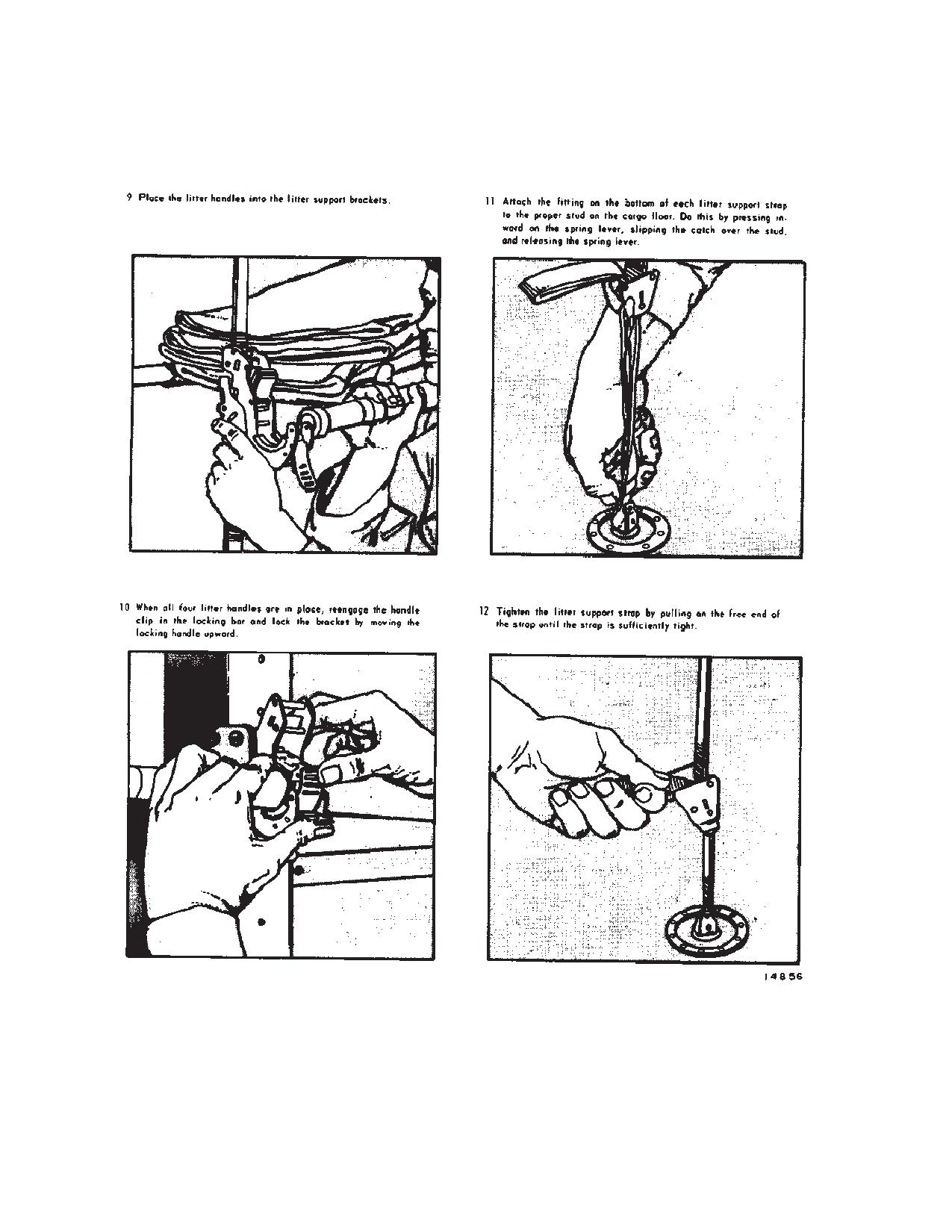
6-4-11. Litter Support Brackets.
is installed. This prevents accidental dislocation of the
pole. The retainer is released for litter pole removal by
Refer to figure 6-4-5 for litter installation. Four litter sup-
pulling the grommet which protrudes from the front of the
port brackets are permanently attached to each litter pole
pole. When not in use, the litter poles may be stowed at
and each litter strap. The brackets are spaced 18 inches
station 120.
apart. A locking device in each bracket secures the litter
handles in place. The locking device consists of a handle
Twelve litter straps are used with the litter poles to sup-
clip, a slotted locking bar, and a locking handle. The
port the litters. The straps can be adjusted upward or
locking handle is hinged to the lower jaw of the bracket.
downward by slide adjusters near the upper and lower
The slotted locking bar is hinged, cam fashion, to the
ends of the straps. All of the straps are fitted at the top
locking handle. The handle clip is hinged to the upper jaw
with slipover hooks which are fastened to brackets in the
of the bracket and has a hook end which is engaged in
strap stowage recesses. The lower end of each strap has
one of the slots in the locking bar. When the locking
a fitting for attaching the strap to a tiedown stud on the
handle is moved down, it forces the locking bar up and
floor. The straps are stowed in the overhead recesses
releases tension on the handle clip. When the locking
directly over the floor studs to which the straps will be
handle is moved up, it pulls the locking bar down and
attached. The stowage recesses are covered with can-
forces the handle clip to a positive grip on the litter han-
vas flaps which are zipped along two sides.
dle.
6-4-13. Litter Loading.
6-4-12. Litter Poles and Straps.
Twelve litter poles are provided for use in adapting the
The loading of litters will be accomplished through the
helicopter for medical evacuation. An attachment fitted to
lowered aft cargo door and ramp. The forward litter tiers
the bottom of each pole has two indentations, on oppos-
should be loaded first, top to bottom, then progressively
ing sides, which fit between two studs located in a floor
rearward. Litter patients requiring in-flight medical care
channel. The upper rear side of the pole contains two
should be positioned to enable access to injuries requir-
keyhole slots by which the pole is anchored to studs on
ing attention. If the helicopter is to be loaded with a com-
the seatback support tubes. A metal spring retainer in-
bination of troops and litter patients, the litter patients
side the pole locks under one of the studs when the pole
should be positioned to the rear of the troops.
6-4-2
TM 1-1520-240-10
Figure 6-4-1. Personnel Moments
6-4-3
TM 1-1520-240-10
Figure 6-4-2. Litter Patient Moments
6-4-4
TM 1-1520-240-10
Figure 6-4-3. Troop Seats and Litters
6-4-5
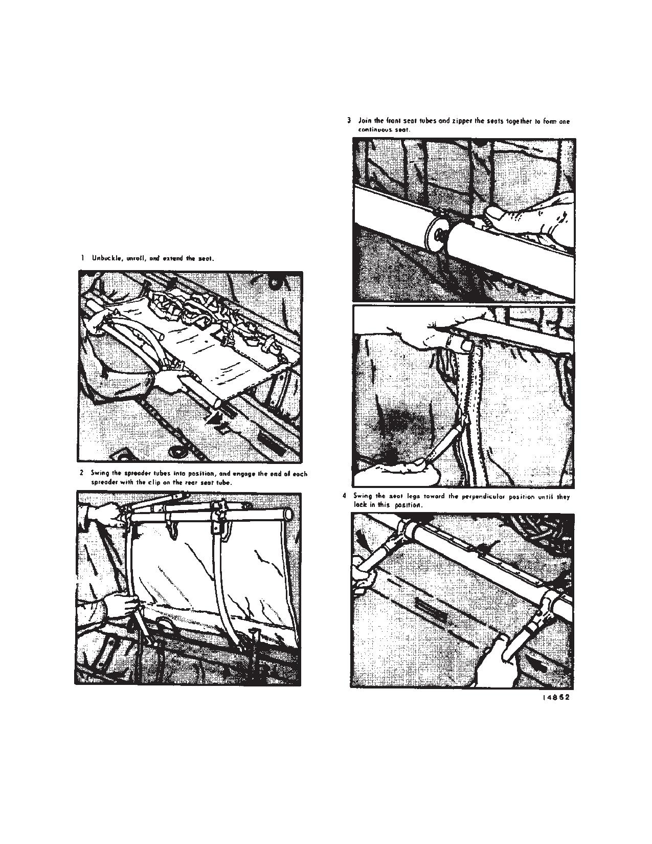
TM 1-1520-240-10
Figure 6-4-4. Troop Seat Installation (Sheet 1 of 2)
6-4-6
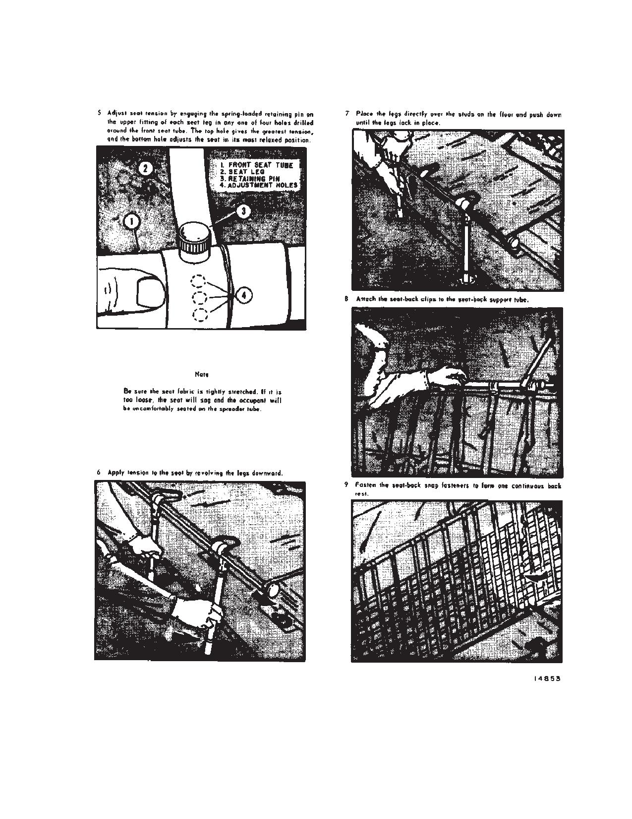
TM 1-1520-240-10
Figure 6-4-4. Troop Seat Installation (Sheet 2 of 2)
6-4-7
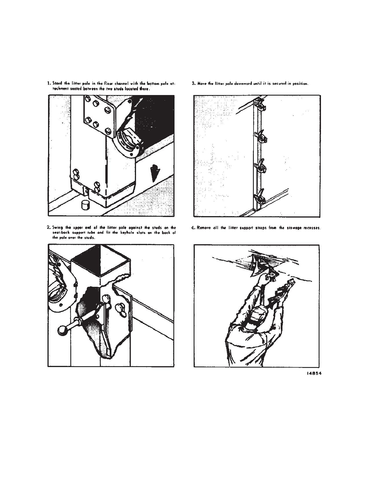
TM 1-1520-240-10
Figure 6-4-5. Litter Installation (Sheet 1 of 3)
6-4-8
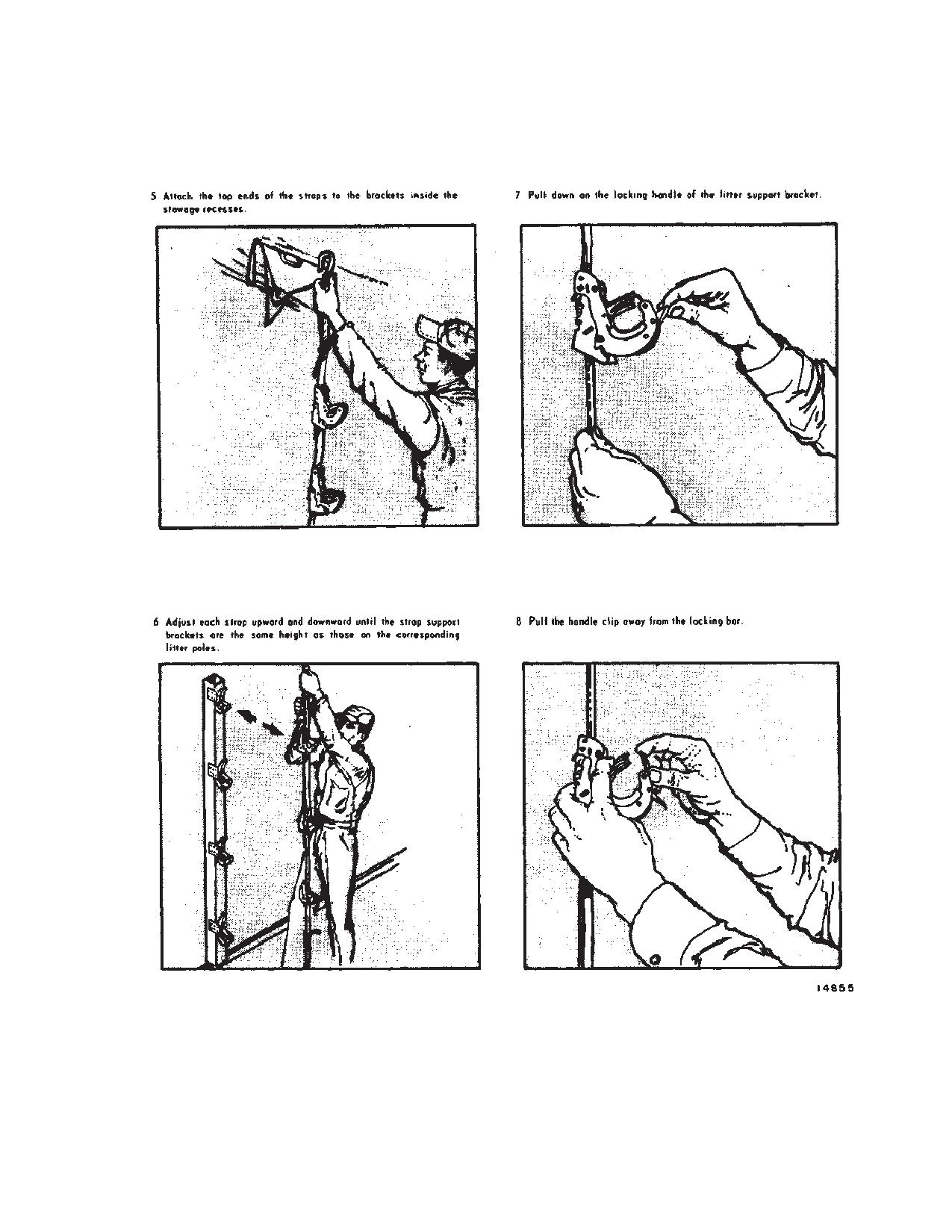
TM 1-1520-240-10
Figure 6-4-5. Litter Installation (Sheet 2 of 3)
6-4-9
TM 1-1520-240-10
Figure 6-4-5. Litter Installation (Sheet 3 of 3)
6-4-10
TM 1-1520-240-10
6-4-14. Combination Seat and Litter Arrangement.
right side of the cargo compartment at station 160. When
the static line anchor is installed, the cable is attached to
Combined troop and litter patient loads can be trans-
the structure between stations 120 and 592. A static line
ported by arranging seats and litters as required. Table
6-4-1 gives the various combinations of seats and litters
retriever is provided with the static line anchor cable. The
which can be used.
retriever is used in conjunction with the winch and is
provided to haul in the static lines at the end of the jump-
6-4-15. Static Line Anchor Cable.
ing exercise or to retrieve a hung up paratrooper in an
A static line anchor cable is provided. The cable is nor-
emergency. Refer to Chapter 4 for the procedures on
mally stowed in a container (fig. 6-6-10) located on the
using the static line retriever.
Table 6-4-1. Seat and Litter Arrangement Data
PERSONNEL
LITTER TIERS
SEATS
SEATS
LITTERS
(4-MAN)
(1-MAN)
(3-MAN)
33
0
0
3
10
27
4
1
3
8
21
8
2
3
6
15
12
3
3
5
9
16
4
3
3
6
20
5
3
1
3
24
6
3
0
6-4-11/(6-4-12 blank)
TM 1-1520-240-10
SECTION V. MISSION EQUIPMENT
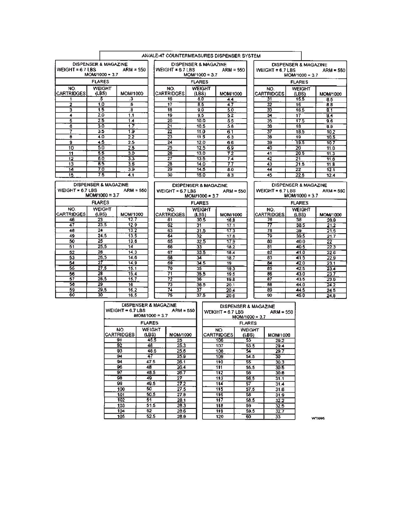
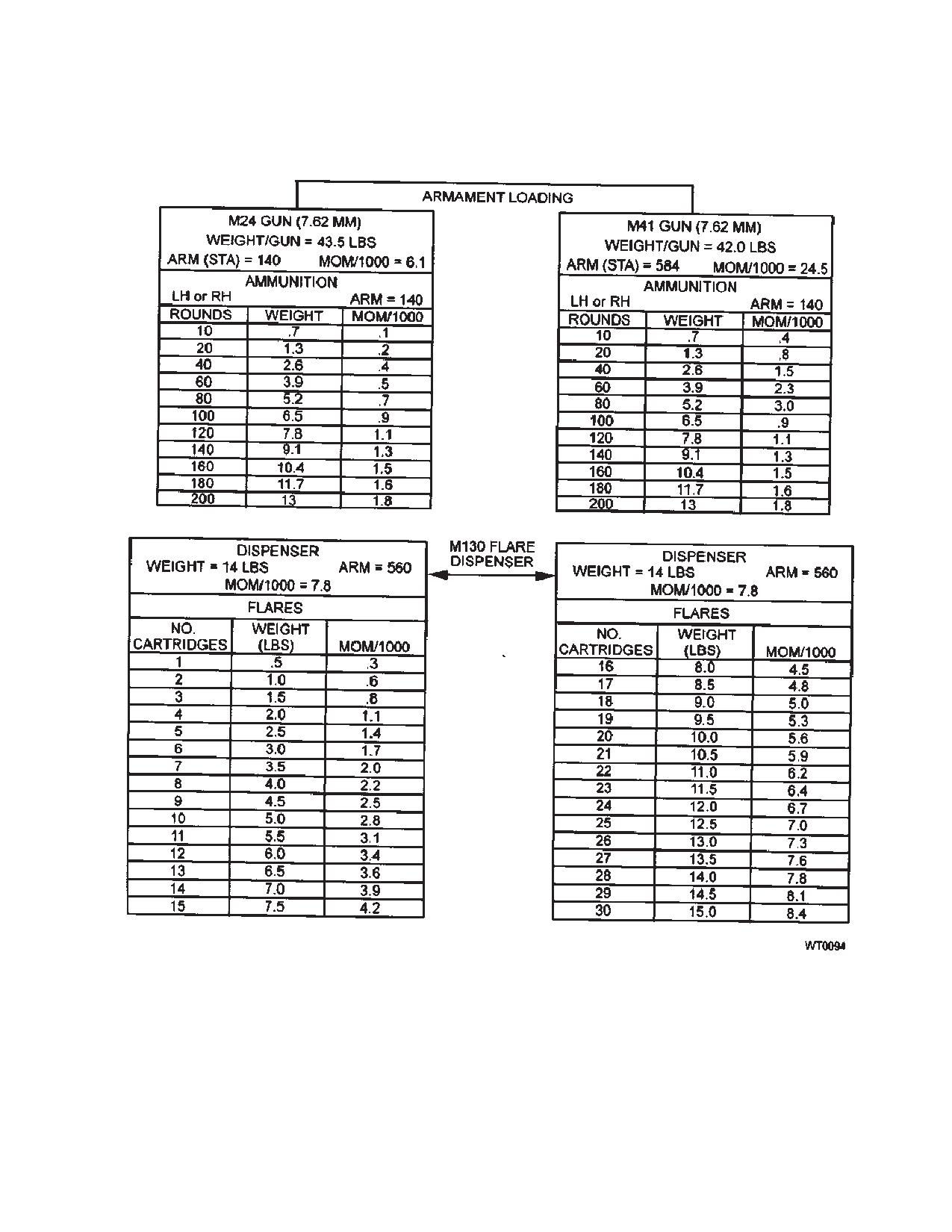
6-5-1. Mission Equipment.
system weight and balance data is provided in table
6-5-2.
CH-47D mission equipment includes the M-24 arma-
6-5-2. EAPS System Weight and Balance.
ment subsystem, the M-41 armament subsystem,either
Table 6-5-1 provides planning data for changes to the
the M-130 flare dispenser system, AN/ALE-47 Counter-
weight and balance with EAPS module/intake screen
Measures Dispenser System (MDS), AN/ALQ-156 mis-
removal/installation.
sile detector system, the cargo handling systems, the
cargo hooks and the static line retriever. The cargo han-
dling systems, (except HICHS) the cargo hooks, and the
Table 6-5-1 EAPS Module/Engine Screen Weight
static line retriever are included in the basic weight of the
and Balance
helicopter or are listed on the chart C for the particular
helicopter. Figure 6-5-1 lists the weight and the mo-
Item
Weight
Arm
Moment
ment/1,000 for the M-24 armament subsystem, the
M-130 flare dispenser systems and the AN/ALE-47
EAPS Module
266
458
121,828
CMDS. If spare ammunition containers are carried on a
Fine Mesh Engine
100
462
46,200
particular mission, compute the moment/1,000 for each
Screens
spare container from the cargo moments chart. Figure
Standard Mesh En-
88
462
40,656
6-6-5 provides the weight and moments charts for inter-
gine Screens
nal cargo, figure 6-6-6 charts for external cargo. HICHS
Table 6-5-2. Internal Cargo Handling System Weight and Balance
SECTION
WEIGHT (LB)
ARM
MOM/1000
Cabin Section
647
323
208.91
Ramp Section
141
335
75.435
Ramp Extension
51
554
28.254
Ramp Extension Supports
26
527
13.702
(Stowed)
Ramp Support (Stowed)
13
550
7.150
System Totals
878
333.5
System Center of Gravity
[379.9]
Table 6-5-3. Engine Air Particle Separator System Weight and Balance
REMOVED
WEIGHT
ARM
MOM/1000
EAPS Filters
-266
458
121.828
INSTALLED
WEIGHT
ARM
MOM
Fine Mesh Screens
+100
462
46,200
Standards Screens
+100
462
40,656
6-5-1
TM 1-1520-240-10
Figure 6-5-1. Mission Equipment Weights and Moments (Sheet 1 of 2)
6-5-2
TM 1-1520-240-10
Figure 6-5-1. Mission Equipment Weights and Moments (Sheet 2 of 2)
6-5-3/(6-5-4 blank)
TM 1-1520-240-10
SECTION VI. CARGO LOADING
6-6-1. General.
6-6-5. Lower Rescue Door.
This section contains information and instructions for
When closed, the lower rescue door forms a part of the
loading and securing cargo in the helicopter. t lists and
fuselage bottom. It is accessible through the utility hatch
describes the items of equipment incidental to these op-
door. The lower rescue door is secured by four latches
erations, instructions for their use, and illustrations where
centered around the door perimeter. These latches are
necessary or desirable. It is not the intent of this section
connected by linkage to an actuator labeled OPEN and
to teach principles of cargo loading. It is the purpose of
CLOSED. A handcrank, stowed in spring metal clips on
this section to provide detailed information on cargo load-
the left side of the fuselage, is used to unlatch the door
ing with regard to this helicopter.
and turn the gears. A drive shaft, which is turned by the
gears, moves the door actuator links. The door opens
downward and aft underneath the fuselage where it re-
6-6-2. Cargo Compartment.
mains during operation.
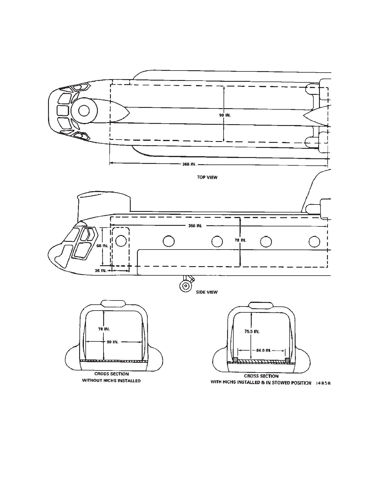
The cargo compartment (fig. 6-6-1) is 366 inches long, 90
inches wide, and 78 inches high. These dimensions are
uniform through out the cargo compartment, unless the
CAUTION
aircraft is configured with HICHS (fig. 6-6-1). The lower
rescue door is opened for rescue operations, aerial load-
Although tightening of the tiedown straps
ing, and external cargo transport operations. A hydrauli-
may be necessary to reduce internal load
cally operated door and ramp provide a means for quick
vibrations, excessive tightening of tie-
and efficient straight-in loading and unloading.
downs attached to the outboard row of tie-
down fittings will limit the effectiveness of
NOTE
the isolated cargo floor.
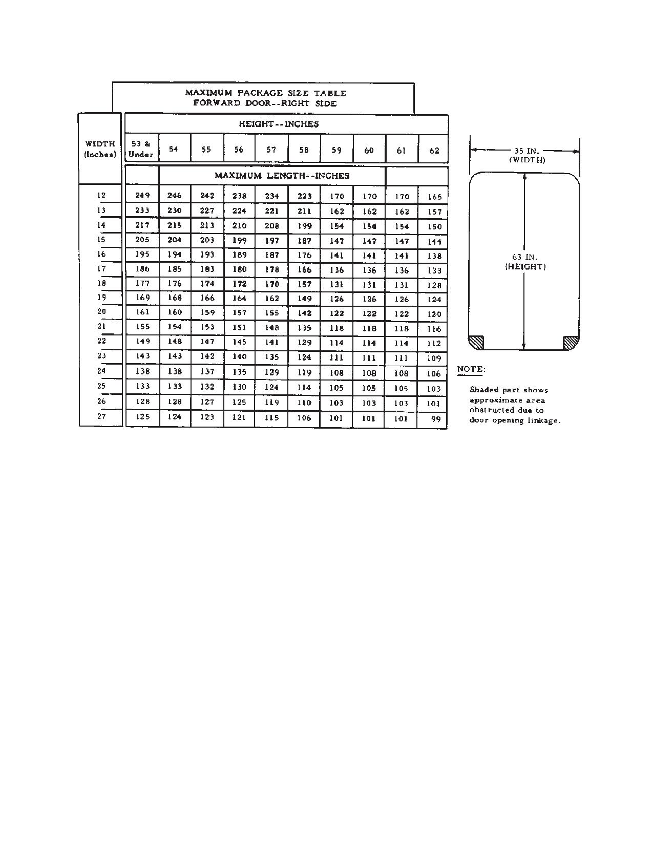
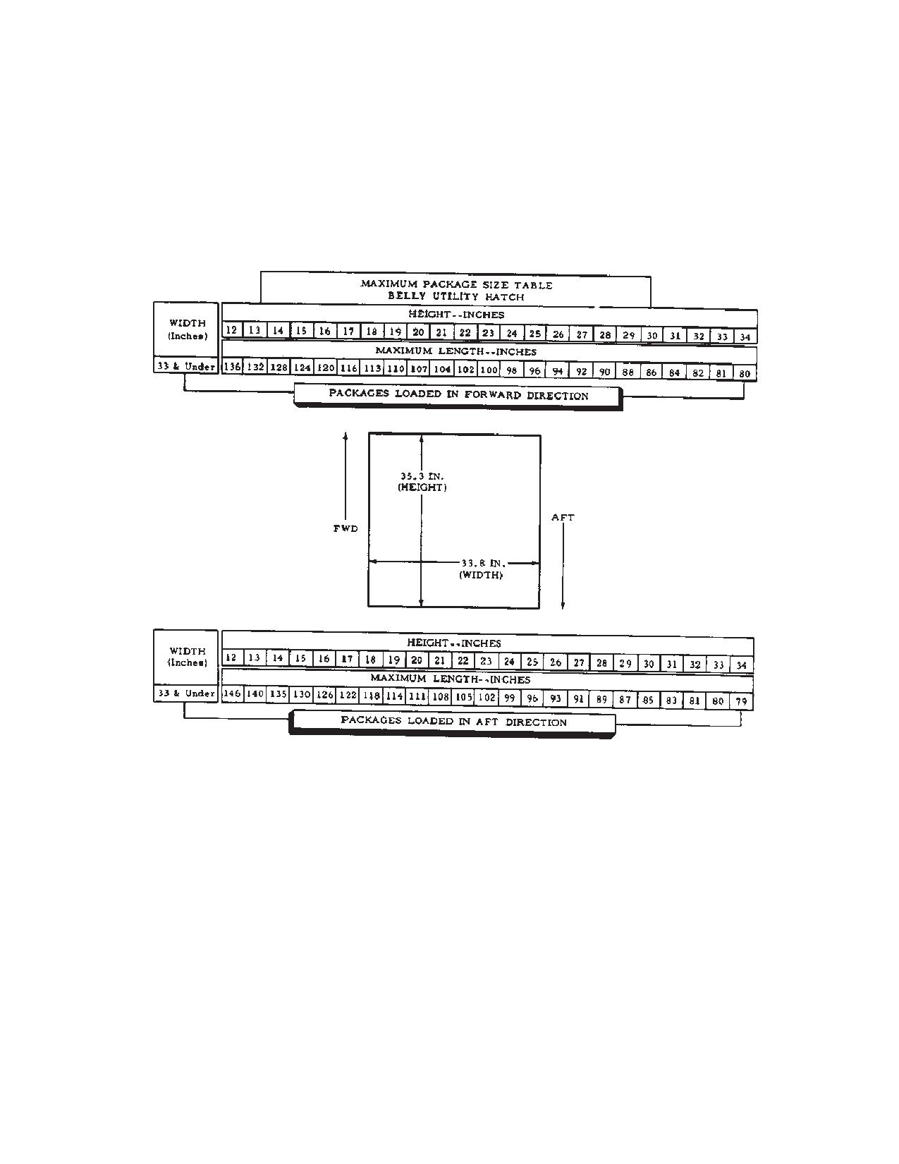
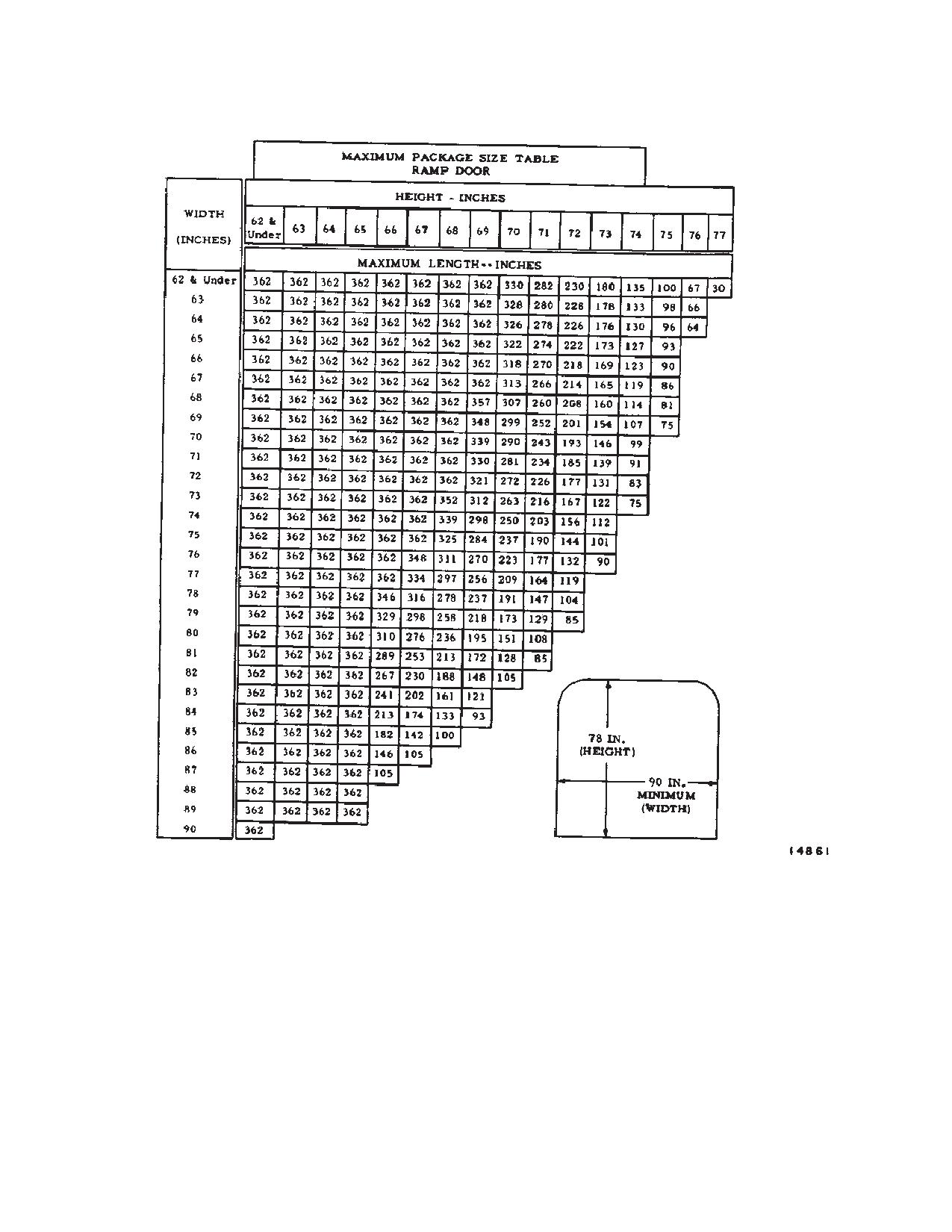
Figure 6-6-2 shows the maximum cube size
6-6-6. Cargo Compartment Floor.
which can be taken into the helicopter through
either the main cabin entrance, utility hatch,
The floor is made of extruded panels, riveted together in
or cargo loading ramp.
sections. Raised extruded ridges, running the entire
length of the floor, provided surfaces on which cargo is
6-6-3. Main Cabin Entrance.
moved. The flooring in the cargo compartment contains
sections on either side of the centerline which are
The main entrance door is located on the right side of the
strengthened to serve as vehicle treadways. The flooring
cargo compartment at the forward end and measures 66
from station 200 to 400 and from buttline 44 left to 44
inches in height by 36 inches in width. The door is com-
right, rests on rubber vibration isolators which reduce
posed of two sections: the upper section rolls inward and
overall internal load vibrations. Tiedown fittings (fig.
upward to a rest position overhead; the lower section
6-6-3) for securing cargo are installed in the floor. There
opens outward and downward and serves as a step in the
are also studs for attaching troop seats, litter supports,
lowered position.
and the base plate for the maintenance crane. The floor-
ing is covered with a walkway compound which provides
6-6-4. Utility Hatch Door.
a non-skid surface for personnel and for vehicles. In
The utility hatch door is in the center of the cargo
construction, the ramp floor is identical with the cargo
compartment floor between stations 320 and 360. the
floor.
door is hinged along its entire forward edge. It opens
upward and forward to expose the lower rescue door and
NOTE
the cargo hook. The door is unlatched by pressing the
Whenever possible, place all wheeled ve-
knob labeled PUSH, and is latched by pressing the un-
hicles entirely on the treadways between sta-
marked knob.
tions 200 and 400.
NOTE
6-6-7. Strength Areas.
When opening or closing the lower rescue
The weight which the cargo compartment floor (fig.
door, be certain that the cargo hook is proper-
6-6-4) can support varies. These variations are largely
ly stowed and supported by the restraining
due to difference in strength of supporting frames and
straps. In addition, close the rescue door, us-
fuselage construction, not because of varying floor
ing the actuator only to the point where the
strength. To gain the maximum benefit from the cargo
latch can engage; the latches will then lift the
compartment floor, the following definitions and weight
door and compress the door seal.
limitations must be observed.
6-6-1
TM 1-1520-240-10
6-6-8. Uniformly Distributed Loads.
6-6-9. Uniformly Distributed Load Limits.
Uniformly distributed loads are those loads wherein the
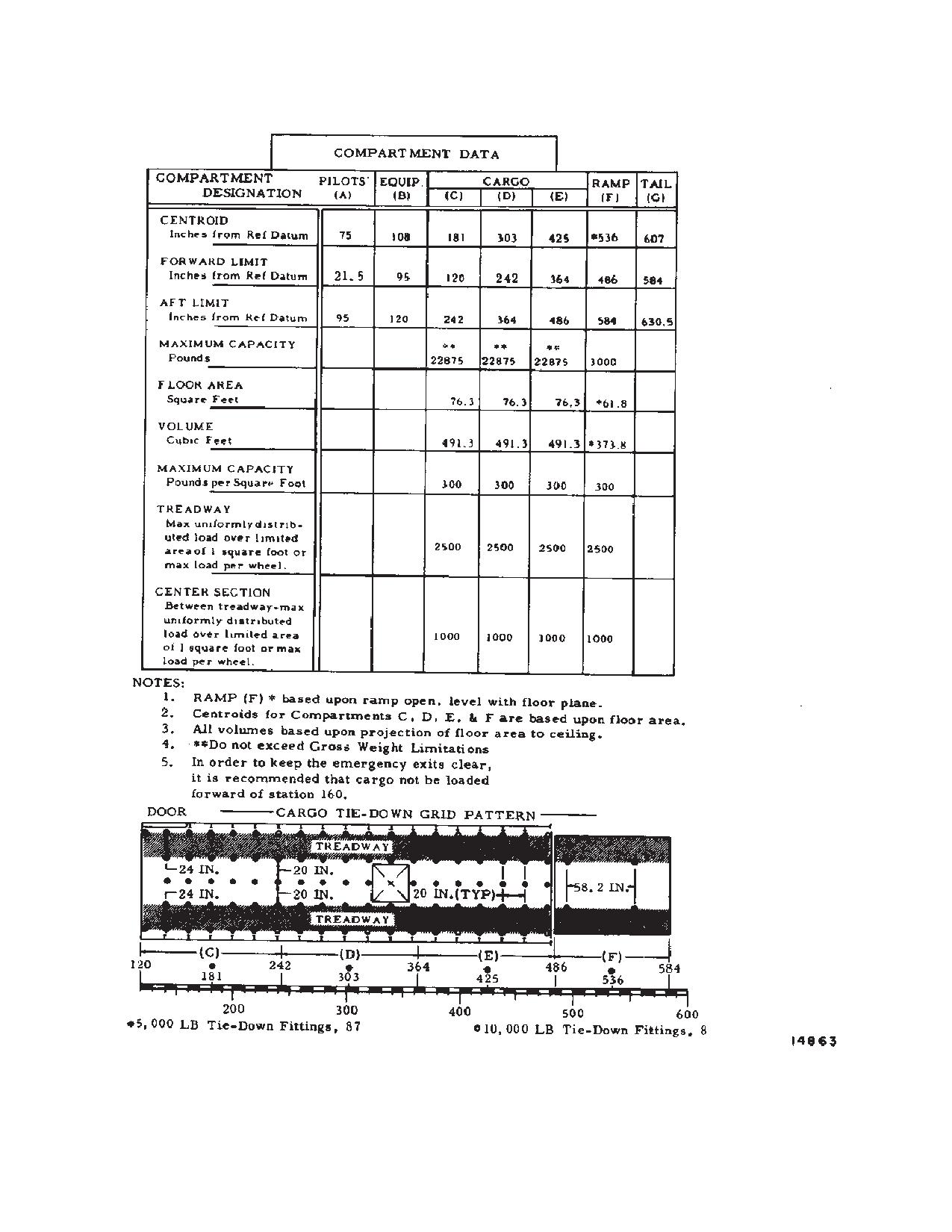
Compartments C, D, and E (fig 6-6-4) are limited to 300
total weight of the item is equally spread over the item’s
psf. The cargo loading ramp (fig. 6-6-4) is limited to 300
entire contact area. Contact area is large compared to
psf with a maximum total load of 3,000 pounds when the
size and weight of the load.
ramp is level with the cargo floor.
6-6-2
TM 1-1520-240-10
Figure 6-6-1. Cargo Compartment Dimensions
6-6-3
TM 1-1520-240-10
Figure 6-6-2. Maximum Package Size (Sheet 1 of 3)
6-6-10. Concentrated Loads.
loads is determined by totaling the adjacent
loads and dividing by 1,000.
Concentrated loads are those loads wherein the total
weight of the item is supported by a contact area that is
6-6-12. Load limits.
small compared to the size and weight of the load.
Vehicles exceeding the limitations may be loaded with
the use of shoring, provided that the vehicle weights
6-6-11. Concentrated Load Limits.
remain within the operating weight limits of the helicopter.
Concentrated loads can be loaded on the treadways and
In cases where the wheels of a vehicle cannot rest on
on the walkway. The treadways aft of station 160 and
both treadways because of a narrow wheel tread, shor-
ramp extensions are stressed for a total wheel load of
ing must be used to spread the load over the treadways.
2,500 pounds. The treadways forward of station1 60 and
General cargo must not exceed floor pressure of 300 psf.
the walkway can be loaded to a total wheel load of 1,000
An easy way to determine floor pressure of various loads
pounds. Concentrated loads are not to exceed 75 psi for
is to divide the weight of the load by the contact area (in
pneumatic tires or 50 psi for block or roller type wheels.
square inches or square feet).
NOTE
NOTE
The above floor loading limitations apply to
Load on pallets supported by the longitudinal
the static weight of the item prior to applying
beams or skids resting on the floor can result
any restraint devises.
in concentrated loads at points where the
beam/skid rests on or crosses floor formers.
The concentrated load can be determined by
NOTE
dividing the weight of the item by the number
The minimum distance, in feet, between the
of floor former/skid intersection points or by
centers of any two adjacent concentrated
the number of locations where the skid rests
6-6-4
TM 1-1520-240-10
on the floor formers. The floor limits are the
6-6-13. Compartment Identification.
same as the concentrated load limits in the
The cargo compartment is divided, for weight and bal-
treadway and center section of the floor, that
ance purposes, into three compartments designated
is 2,500 pounds and 1,000 pounds.
C,D, and E, running fore and aft. (fig. 6-6-1). When the
cargo ramp is used as an extension of the cargo compart-
ment, it is designated as F for weight and balance purpo-
ses. These compartment designations and their limiting
fuselage stations are stenciled on the cargo compart-
ment walls.
Figure 6-6-2. Maximum Package Size (Sheet 2 of 3)
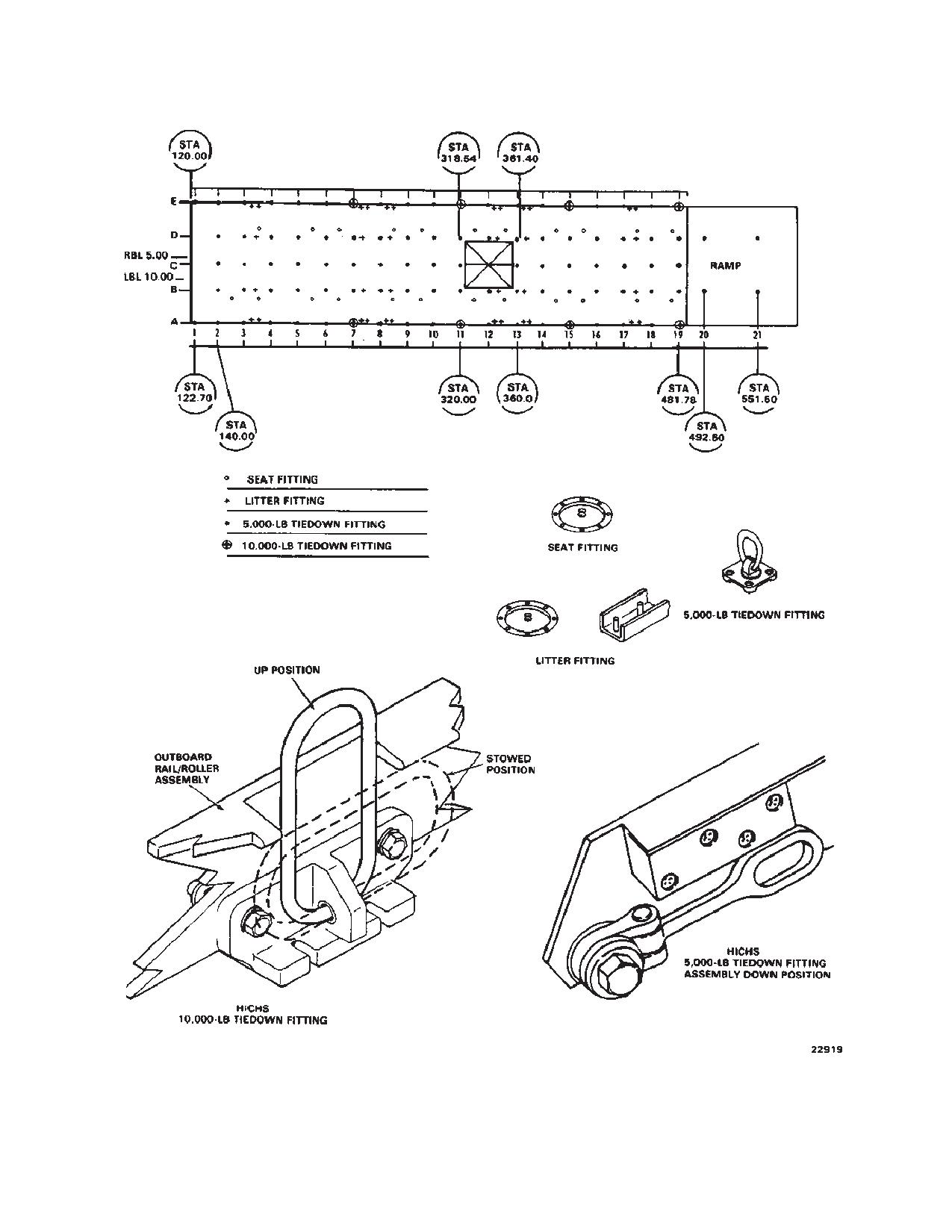
floor. All the fittings are D-ring types. There are 87
5,000-pound-capacity tiedown rings (83 in the fuselage
6-6-14. Compartment Capacities.
floor and 4 in the ramp floor) and eight 10,000-pound-ca-
pacity tiedown fittings. The fittings are normally used with
Based on a maximum distributed floor loading of 300 psf,
tiedown devices which will not exceed the limits of the
the compartment capacities can be obtained by multiply-
fitting.
ing the floor loading by the floor area of the individual
compartment; however, this weight may exceed present
6-6-16. Five Thousand-Pound Capacity Tiedown Fit-
limitations. Figure 6-6-4 lists the maximum capacity of
tings.
each compartment. In addition to the limitations in figure
The 83 5,000-pound-capacity tiedown fittings in the car-
6-6-4, compartment loads will be limited by those limita-
go compartment floor are equally spaced in five rows
tions set forth in Chapter 5.
spaced 20 inches apart longitudinally. The four in the
ramp are in a rectangular pattern. Each 5,000-pound-ca-
6-6-15. Tiedown Fittings.
pacity fitting swivels freely and is capable of resisting a
Tiedown fittings (fig. 6-6-3) for securing cargo are
single maximum load of 5,000 pounds exerted along any
installed on the cargo compartment floor and on the ramp
radius of a hemisphere, the flat side of which is the sur-
6-6-5
TM 1-1520-240-10
face of the floor. The fittings are hinged so that they can
ity fittings, spaced at intervals of 80 inches from station
be seated in floor recesses when not in use.
240 to station 480. These fittings are not always used and
they might be in the way when installed, therefor install
only when necessary. When they are to be used, the
fittings are screwed into threaded receptacles, at the
fitting locations. When the fittings are not being used,
WARNING
threaded plugs are screwed into the receptacles to pro-
tect the thread in the receptacles.
The 10,000-pound-capacity tiedown fit-
tings must be screwed into the threaded
6-6-18. Cargo Loading Aids.
receptacles to full depth to achieve their
rated capacity.
The helicopter has a number of features to facilitate load-
ing of cargo. Some of these features are parts of systems
6-6-17. Ten Thousand-Pound-Capacity Tiedown Fit-
and are permanently installed; others are equipment
tings.
which is stowed in the helicopter. The following para-
There are eight 10,000-pound-capacity tiedown fittings
graphs contain descriptions of items classed as loading
on the cargo compartment floor. Four fittings are inter-
aids. Specific instructions for some of these items may be
posed along both outboard rows of 5,000-pound-capac-
found in other parts of this manual and are referenced.
6-6-6
TM 1-1520-240-10
Figure 6-6-2. Maximum Package Size (Sheet 3 of 3)
6-6-19. Cargo Loading Ramp.
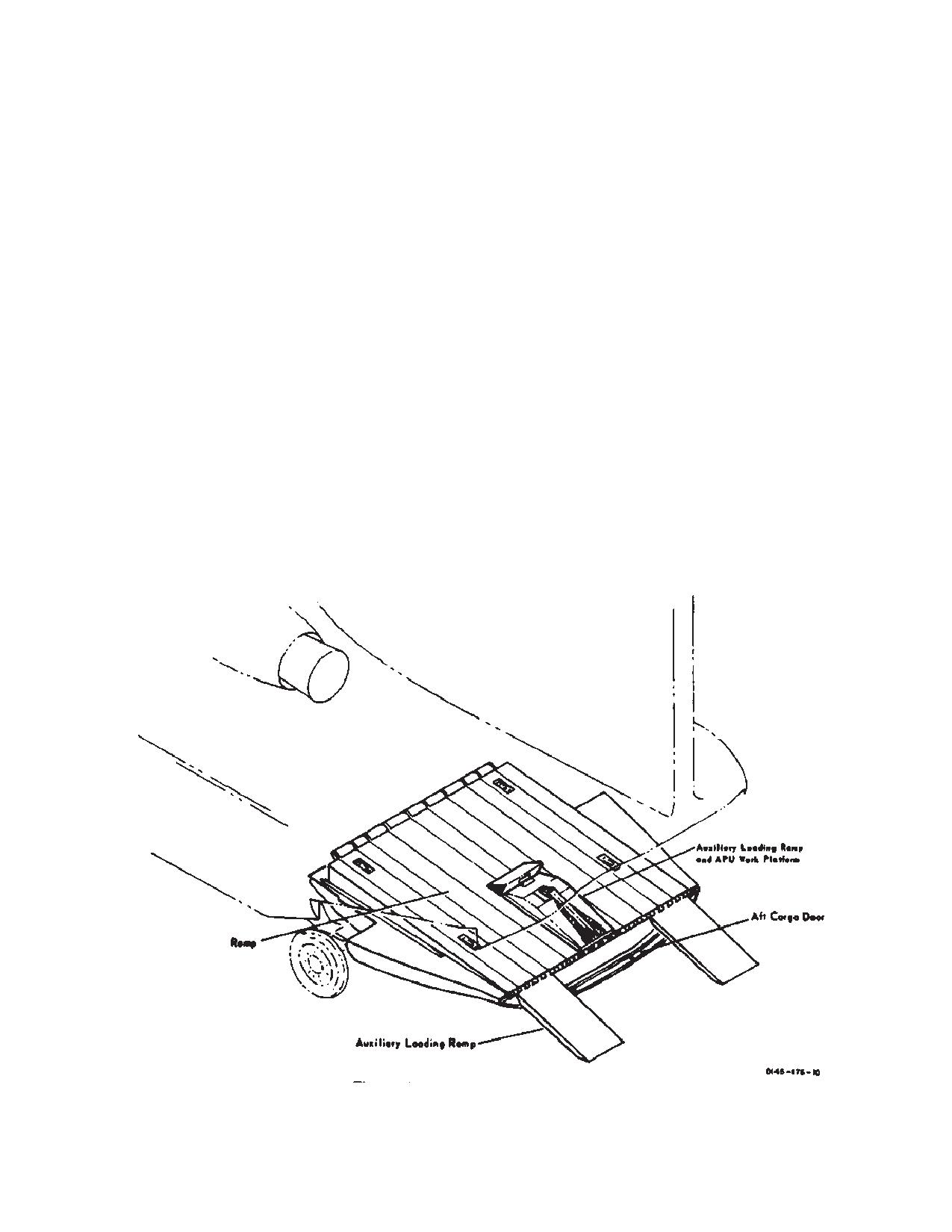
of the ramp (fig. 6-6-7). When the ramp is lowered, these
auxiliary ramps are unfolded to provide flush contact be-
The ramp provides a means of quickly loading and un-
tween the ramp and the ground. The auxiliary loading
loading troops and cargo. It can also be used to support
ramps can be positioned to accommodate various vehi-
portions of a cargo load which exceeds the longitudinal
cle tread widths or butted together to facilitate winching
dimensions of the cargo floor. When used for additional
of bulk cargo. When not in use, the auxiliary ramps are
cargo space, the ramp must be positioned so that the
stowed in an inverted position on the floor of the ramp or
ramp floor is level with the cargo floor. In this situation, the
removed. One of the auxiliary loading ramps when at-
weight of the cargo item resting on the ramp must not
tached to the ramp can also be used as a work platform.
exceed 3,000 pounds or 300 psf.
A collapsible support attached to the ramp bottom allows
6-6-20. Auxiliary Loading Ramps.
the ramp to be positioned at any convenient height when
Three auxiliary loading ramps are hinged to the aft end
used as a work platform.
6-6-7
TM 1-1520-240-10
Figure 6-6-3. Tiedown Fittings
6-6-8
TM 1-1520-240-10
Figure 6-6-4. Compartment Data
6-6-9
TM 1-1520-240-10
Figure 6-6-5. Internal Cargo Moments Chart (Sheet 1 of 2)
6-6-10
TM 1-1520-240-10
Figure 6-6-5. Internal Cargo Moments Chart (Sheet 2 of 2)
6-6-11
TM 1-1520-240-10
Figure 6-6-6. External Cargo Moments Chart (Sheet 1 of 2)
6-6-12
TM 1-1520-240-10
Figure 6-6-6. External Cargo Moments Chart (Sheet 2 of 2)
6-6-13
TM 1-1520-240-10
6-6-21. Winch.
78-inch overhead clearance, (if HICHS is not installed),
of the cargo compartment. A continuous hinge runs the
Refer to Chapter 4, Section III.
entire width of the aft upper edge of the ramp and holds
the three auxiliary loading ramps. The auxiliary ramps
6-6-22. Cargo Door and Ramp.
unfold to bridge the gap between the ramp and the
ground for vehicle loading and unloading. they can be
The cargo door and ramp has an upper section, or cargo
adjusted laterally to accommodate various vehicle
door, and lower section, or ramp. The door retracts into
thread widths. Hydraulic power to operate the ramp is
the ramp when the ramp is being lowered and extends
supplied through the utility hydraulic system.
when the ramp is being raised. Retraction or extension
of the door can be isolated through the ramp sequence
valve so the ramp can be raised or lowered with the door
6-6-23. RAMP CONTROL Valve.
retracted into the ramp or extended. The door is an inte-
gral part of the ramp and only provides closure; therefore,
Lowering and raising the ramp is controlled by a RAMP
references made to the ramp will be understood to in-
CONTROL valve on the right side of the aft cargo
clude the door and its related movements. The cargo
compartment between the floor and the overhead at sta
door is jettisonable to provide an emergency exit. The
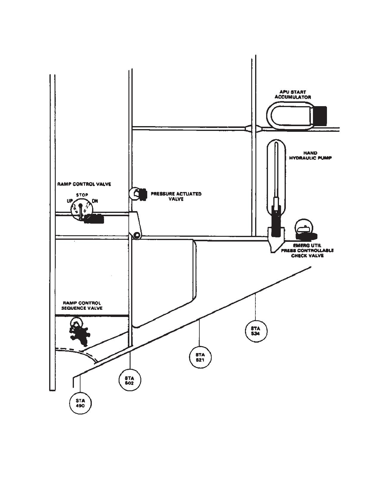
490 (fig. 6-6-8). The RAMP CONTROL valve is operated
cargo door and ramp is located at the aft end of the cargo
either electrically or manually. Electrical operation is per-
compartment and is used for troop and cargo loading and
formed by setting the RAMP PWR switch to EMERG, and
unloading. In closed position, it conforms to the side con-
using the RAMP EMER control switch on the cockpit
tours of the fuselage (fig. 6-6-7). Internal locks in the
overhead HYD control panel (Chapter 2, Section VI).
ramp actuating cylinders prevent accidental opening and
Manual operation is accomplished by setting the RAMP
constitute the only locking mechanism for keeping the
PWR switch to ON, and using a three-position lever
ramp closed. The ramp is hinged to the fuselage and
mounted on the RAMP CONTROL valve. the lever posi-
opens rearward and downward to rest on the ground.
tions are labeled UP, STOP, and DN (down). The control
When lowered to ground rest, the ramp inclines down-
lever can be reached from the outside through a hinged
ward approximately 6.75_ and maintains a uniform
panel on the aft fuselage.
Figure 6-6-7. Cargo Door and Ramp
6-6-14
TM 1-1520-240-10
Figure 6-6-8. Ramp Controls
6-6-15
TM 1-1520-240-10
d. Cargo compartment - Clean.
CAUTION
e. Tiedown devises - Check, for type and quanti-
ty.
Do not press the sequence valve plunger
unless the ramp is down.
f.
10,000 lb tiedown fittings - Install as required.
g. Loading aids - Check, for condition and opera-
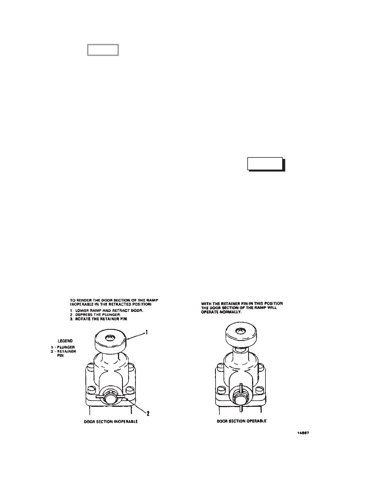
6-6-24. Ramp Control Sequence Valve.
tion.
A mechanically operated sequence valve controls the
h. Weight and balance data - Check.
sequence of the cargo door and ramp operation (fig.
i.
Emergency equipment - Check.
6-6-9). The valve is below the ramp control valve at the
j.
Emergency exits - Inspect.
ramp hinge line. A plunger on the top of the valve is
k.
Cargo load - Inspect.
manually pressed to hold the cargo door at full open
during ramp operation. The plunger can be locked in the
6-6-28. Ramp Operation.
depressed position by rotating a retainer pin which ex-
tends from the side of the valve.
6-6-29. Normal Operation.
6-6-25. Pressure Actuated VAlve.
WARNING
Ramp operation is stopped during cargo door operation
by a hydraulic pressure actuated valve. The valve is
locked near the ramp control valve (fig. 6-6-8). A plunger
When the RAMP PWR switch is OFF, be
provides manual override of the valve if it sticks.
sure the RAMP CONTROL VALVE remains
at STOP. If the RAMP CONTROL VALVE is
6-6-26. Accumulator Gage.
moved to UP or DN, the ramp may free fall.
A gage at station 534, right side indicates APU accumu-
1. Lower the ramp as follows:
lator pressure in psi (fig. 6-6-8). A pressure reading on
a. RAMP PWR switch - ON.
the accumulator gage in excess of 2,500 psi is sufficient
for operating the ramp.
NOTE
6-6-27. Equipment Loading and Unloading.
Perform step b. and c. only if the ramp is low-
ered with accumulator pressure.
The following procedures should be observed in prepar-
b. APU accumulator gage - Check 2,500
ing the helicopter for cargo transport mission:
psi or more. If pressure reading is below
a. Doors - Open.
2,500 psi, operate the hand pump to
build up pressure.
b. Parking brake - ON.
c. Troop seats - Stow.
c. EMERG UTIL PRESS valve - Open.
Figure 6-6-9. Sequence Valve Operation
6-6-16
TM 1-1520-240-10
d. Ramp control lever - DN, allowing
NOTE
ramp to lower to a position of ground
Momentary selection of the RAMP EMERG
rest, then STOP. If the ramp is to be
control switch to the DN position will result in
adjusted to a level other than ground
approximately 5 seconds of the ramp and car-
rest, or fully closed, with the cargo door
go door opening operation sequence. The
in the retracted position, perform the
opening sequence of the ramp can be halted
following:
during the 5 second cycle by momentarily
(1) Sequence valve plunger - Press
placing the RAMP EMER control switch to the
and hold.
UP position. Continuous lowering of the ramp
(longer than 5 seconds) can be achieved by
(2) Sequence valve plunger retainer
holding the RAMP EMER switch in the DN
pin - Rotate to the horizontal posi-
position until the desired ramp position is at-
tion to lock the plunger in.
tained
2. Raise the ramp as follows:
b. RAMP EMERG control switch - DN mo-
mentarily then back to HOLD. The ramp
a. Sequence valve plunger - Check, re-
downward cycle can be halted by mo-
leased if ramp and cargo door are to be
mentarily setting the RAMP EMER con-
closed.
trol switch to UP.
NOTE
c. Repeat step b. if necessary, until desired
Perform step b. only if accumulator pressure
ramp position is achieved, or hold the
is used to raise the ramp.
switch in the DN position until the ramp
reaches the desired portion.
b. EMERG UTIL PRESS valve - Open.
2. Close the ramp as follows:
c. Ramp control valve lever - UP, allow-
a. RAMP PWR Switch - EMERG.
ing ramp to close. If accumulator pres-
sure is not sufficient to raise the ramp,
b. RAMP EMER control switch - UP until
operate the hand pump.
door is closed, then back to HOLD.
d. Ramp control lever - STOP.
6-6-32. Manual Operation - Cargo Door.
6-6-30. In Flight Operation.
CAUTION
CAUTION
The ramp must be at or above floor level
during takeoffs and landings.
Do not attempt to manually operate the
cargo door when the utility hydraulic sys-
CAUTION
tem is pressurized. Motor damage can re-
sult.
Do not attempt to manually operate the
The ramp can be operated up to Vne. At speeds up to 60
cargo door when the utility hydraulic sys-
knots, the ramp will open normally. At speeds above 60
tem is pressurized. Motor damage can re-
knots. air pressure from within the cargo compartment is
sult.
required. To get this pressure, the vent blower can be
Should the need arise to retract or extend the cargo door
turned on or the upper section of the cabin door can be
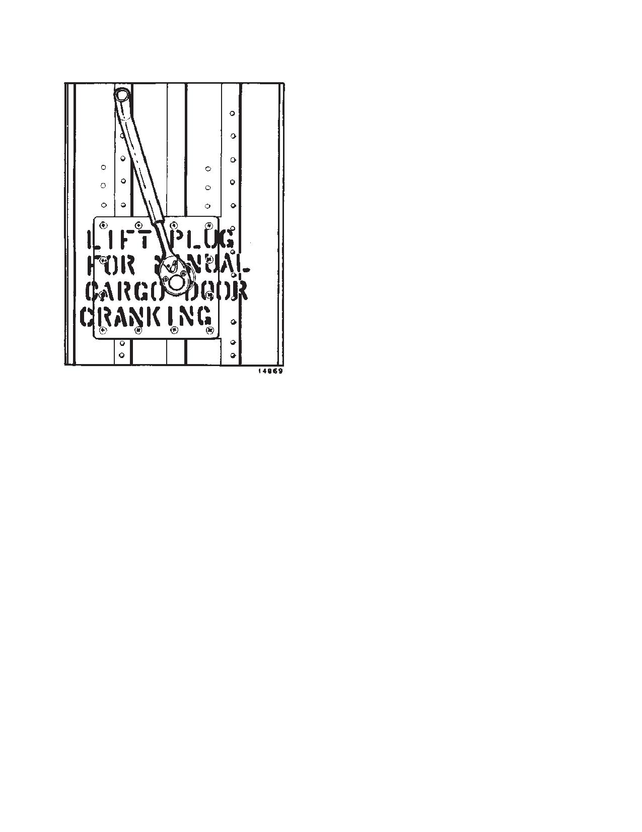
section of the ramp manually, insert the handcrank as shown
opened.
in figure 6-6-11. Crank clockwise to retract. Crank counter
clockwise to extend.
6-6-31. Ramp Emergency Control.
6-6-33. Preparation of General Cargo.
Before loading cargo, it is advisable to inspect items of cargo
WARNING
with regard to dimensions, weight, contact pressure, center
The RAMP EMER control switch is in-
of gravity, and hazards. This data will be helpful in determin-
tended for emergency use only during
ing the placement of the load in the helicopter and in com-
smoke and fume elimination procedures.
puting weight and balance. Refer to TM 10-450-2.
Inadvertent operation of the cargo ramp
and cargo door from the cockpit may re-
6-6-34. Cargo Dimensions.
sult in injury to personnel or damage to
Any item of cargo which appears to have critical dimensions
equipment.
for loading into the helicopter should be measured and
1. Open the ramp as follows:
checked against door and compartment dimension limita-
a. RAMP PWR switch - EMERG.
tions.
6-6-17
TM 1-1520-240-10
6-6-35. Cargo Weight.
6-6-38. Hazardous Cargo.
Package weight of individual items of cargo should be legibly
Items of cargo possessing dangerous physical proper-
stenciled on an exterior surface. If not provided, the weight
ties, such as explosives, acids, flammables. etc., must be
must be determined in order to plan cargo placement, to
handled with extreme caution and in accordance with
calculate contact pressure, and too compute helicopter
established regulations and TM 38-250.
weight and balance. The same rule applies to palletized
6-6-39. General Instructions for Loading, Securing,
cargo and vehicle loads.
and Unloading Cargo.
6-6-36. Cargo Center of Gravity.
There are three prime factors to be considered in proper-
ly loading the helicopter. These factors are weight, bal-
The center of gravity (C.G.) of each item of cargo must be
ance, and restraint. The weight of the cargo to be loaded
determined in order to compute weight and balance by the
must remain within safe operating limits, and the cargo
station method. As a rule, those items of cargo crated for
transport will be marked with a C.G. If the C. G. is not
must be restrained from shifting during takeoff, flight, and
landing. Refer to TM 10-450-10 to determine or compute
marked, it can be determined by methods provided in TM
loading, shoring and restraint criteria.
10-450-10.
6-6-40. Weight and Balance.
6-6-37. Vehicle Load.
Refer to TM 55-1500-342-23 and figure 6-7-1 to compute
The same general rules that are observed in cargo loading
helicopter GW/CG and complete Form F.
apply to vehicle loading. In addition, the fuel tank caps,
radiator caps and battery filler caps should be checked and
6-6-41. Restraint.
secured. Fuel tanks should be checked to see that they are
not filled above three-quarters capacity. Air trapped in a fuel
Items of cargo within the helicopter are subject to the
tank will expand at altitude and force fuel out through the filler
same forces which affect the helicopter in flight. These
neck, creating a fire hazard. If fuel tanks are filled to capacity,
forces will cause the cargo to shift unless the cargo is
some fuel must be drained off before the vehicle is loaded.
restrained. To maintain helicopter balance and prevent
Also, check tire pressures and if necessary, deflate tires to
injury to personnel, cargo must be restrained from shift-
prescribed limits.
ing.
6-6-18
TM 1-1520-240-10
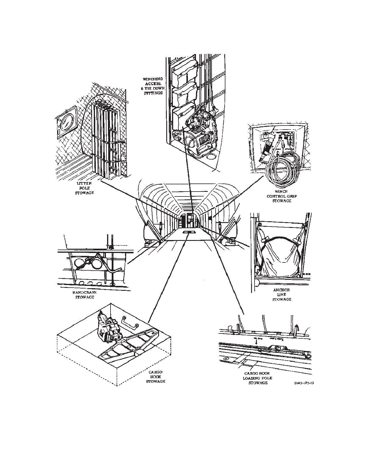
Figure 6-6-10. Stowage Locations
6-6-19
TM 1-1520-240-10
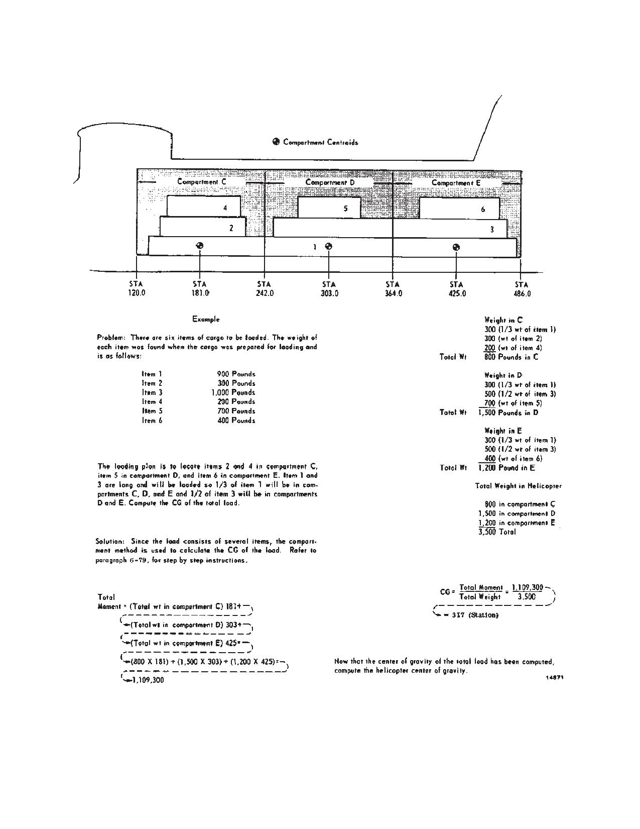
three compartments, the weight of the item should be
proportionately distributed in each compartment. The
C.G. of the cargo load is computed as follows:
a. Record the weight of cargo in each compart-
ment.
b. Calculate the compartment moment by multiply-
ing the total weight in each compartment by the station
number of the compartment centroid.
c. Add the compartment moments.
d. Add the weight in all compartments.
e. Divide the sums of the cargo moments by the total
weight of the cargo. The result is the arm or the C.G.
location of the load.
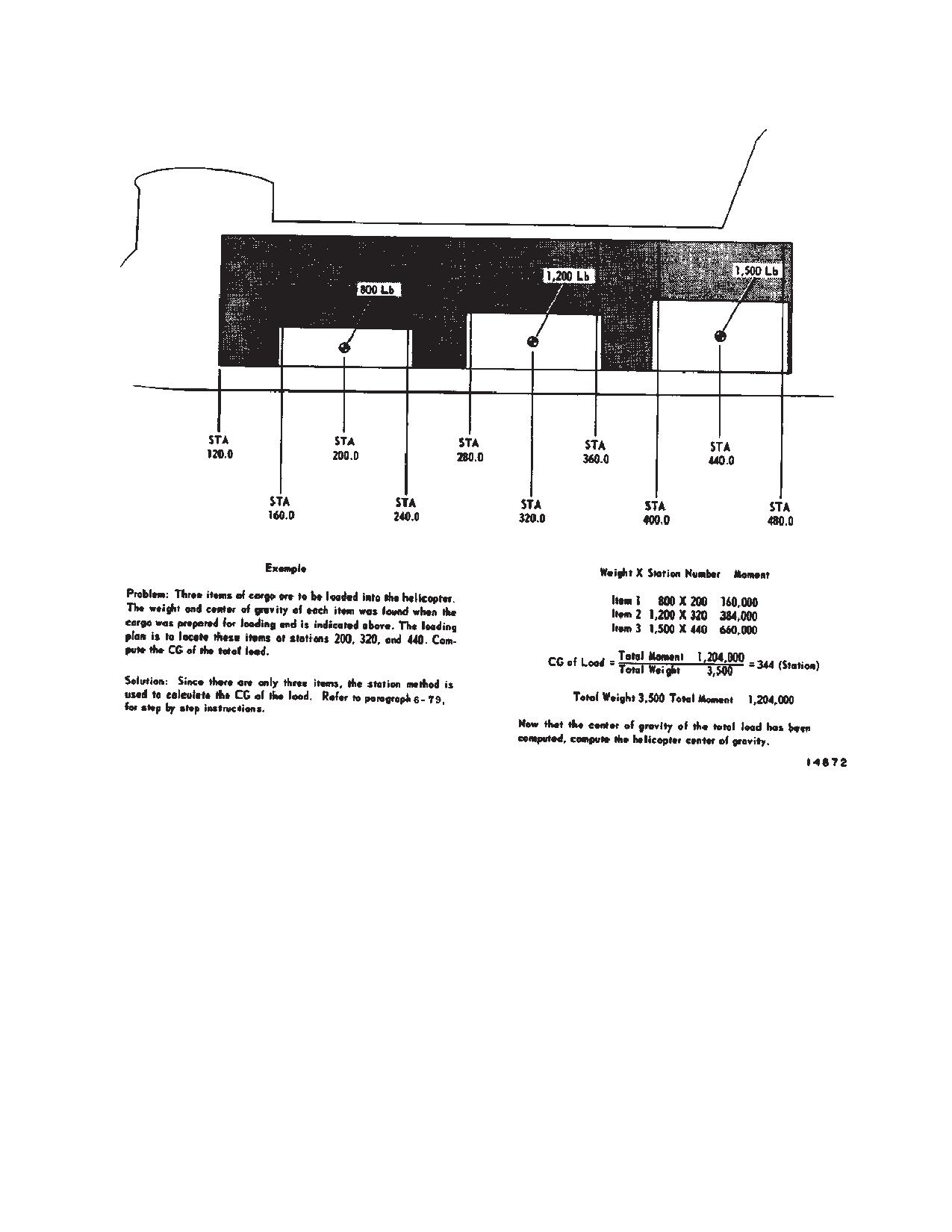
6-6-44. Station Loading.
Loading by stations provides a more precise method of
computing the C.G. of a load and should be used when-
ever possible (fig. 6-6-13). To use this method, it is nec-
essary to know the C.G. of each item of cargo. If the C.G.
of an item is not marked, it can be determined by the
procedure given in TM 10-450-2. Station loading re-
quires that the C.G. of each item placed on the helicopter
coincides with a fuselage station number. The C.G. of the
Figure 6-6-11. Cargo Door Cranking
load is calculated as follows:
6-6-42. Load Planning.
a. Record the weight and station number of each
Before loading cargo, the placement of individual items
item of cargo.
of cargo in the helicopter should be planned and then
b. Calculate the moment of each item by multiplying
checked to determine if the planned arrangement falls
the weight of the item by the station number of its C.G.
within the C.G. limits. there are three basic steps involved
in load planning. The first step is to decide which method
c. Add the moment of each item to obtain the total
will be used to compute C.G. of the load. If the compart-
load weight.
ment method is to be used, each item of cargo must be
d. Add the weights of each item to obtain the total
assigned a location in one of the three compartments. If
load weight
the station method is to be used, specific station loca-
tions must be assigned to each item of cargo. The sec-
e. Divide the total load moment by the total load
ond step is to compute the C.G. of the load. If the load
weight to obtain the arm or the C.G. location of the load.
consists of a number of items of cargo, the compartment
method should be used. If the load consists of only a few
6-6-45. Vehicle Loading.
bulky items, the station method should be used. The third
step is to check if the C.G. falls within the allowable limits.
The same procedures observed in cargo loading apply
If it does, the cargo can be loaded; if not, the location of
to vehicle loading.
individual items should be rearranged until an acceptable
loading plan is obtained.
6-6-46. Shoring.
Shoring is used to protect the cargo floor and to distribute
6-6-43. Compartment Loading.
load pressure over a greater area of the floor. Shoring
Loading by compartments provides a rapid means of
can often make the difference between being able to
computing the C.G. of a load and can be used whenever
carry a given load and not being able to; however, it is
the cargo load consists of a number of items. The heli-
important not to exaggerate the effectiveness of shoring.
copter cargo compartment is divided into three compart-
Some vehicles have a tread width too narrow to allow the
ments (fig. 6-6-12). The centroid, or center of balance, of
wheels to rest on the treadways. In this case, shoring
each compartment is located at station 181, 303, and
must be used to reduce the contact pressure on the
425, respectively. When using the compartment method,
walkway to an allowable figure. In general, shoring is
it is assumed that the weight of all the cargo in the
required for all wheeled platforms and dollies and for any
compartment is concentrated at the centroid of the
item of cargo whose contact pressure exceeds the floor
compartment. If an item of cargo extends into two or
limitations.
6-6-20
TM 1-1520-240-10
6-6-47. Securing Cargo.
required to keep the cargo from moving in any direction
is called the restraint criterion and is expressed in units
The helicopter is subjected to forces which result from air
of the force of gravity, or g’s. In each case, the maximum
turbulence, acceleration, rough or crash landings, and
force exerted by the item of cargo to be restrained would
aerial maneuvers. These same forces act upon the cargo
be its normal weight times the number of g’s of the re-
in the helicopter and tend to shift the cargo unless it is
straint criteria. In order to safely carry cargo, the amount
firmly secure. Forward motion of the helicopter is the
most rapid movement that will be encountered and is the
of restraint applied should equal or exceed the maximum
strongest force that is likely to act on the cargo if the
amount of restraint required. Restraint is referred to by
helicopter is suddenly slowed or stopped in a crash lan-
the direction in which it keeps the cargo from moving.
ding. Other forces tending to shift the cargo aft, laterally,
Forward restraint keeps the cargo from moving forward,
or vertically will be less severe. The amount of restraint
aft restraint keeps the cargo from moving aft, and so on.
6-6-21
TM 1-1520-240-10
Figure 6-6-12. Compartment Loading
6-6-22
TM 1-1520-240-10
Figure 6-6-13. Station Loading
6-6-48. Restraint Criteria.
6-6-49. Restraint Devises.
The following restraint factors are ultimate values and the
Refer to TM 55-450-2.
minimum acceptable factors for crew and passenger
safety.
6-6-50. Calculation of Tiedown Devises Required.
Direction
Restraint Criteria
Refer to TM 55-450-2.
Forward
4.0 g’s
6-6-51. Tiedown Methods.
Aft
2.0 g’s
Methods of applying restraint will vary depending on the
Down
4.0 g’s
type of cargo making up the load. Vehicles, crated ob-
Up
2.0 g’s
jects, and associated items of general cargo will require
different methods of application. (Refer to TM 55-450-2
Lateral
1.5 g’s
for restraint methods.)
6-6-23
TM 1-1520-240-10
6-6-57. Warehouse Pallets.
CAUTION
Refer to table 6-4-2 to select the proper configuration for
system components during loading. Up to 10 warehouse
Excessive tightening of the tiedown
pallets can be loaded into the helicopter provided that the
straps attached to the outboard row of tie-
weight and C.G. requirements are within the limits speci-
down fittings will limit the effectiveness of
fied as follows. The 40- inch side should be positioned
the isolated floor.
across the handling system so that the 48-inch side is on
the outboard rail. Pallets may be winched or manually
6-6-52. Vehicle Tiedown.
loaded. During loading, the pallet should be fork lifted
onto the ramp extension and balanced onto the ramp
Because of the numerous points of attachment available,
rollers. On the ramp, it should be pushed on board.
vehicles are the items of cargo easiest to tie down. An
MB-1 chain devise should be used to restrain vehicle
NOTE
loads. These devises should be fastened to the
10,000-pound tiedown fittings whenever possible.
All cargo must be properly restrained to en-
sure safe operation of the helicopter and safe-
ty of personnel. Loads must be restrained in
6-6-53. Bulk Cargo Tiedown.
accordance with procedures and guidelines
Typical methods of restraining large crates are shown in
in TM 10-450-2, Helicopter Internal Loads.
TM 55-450-2. If the crate is very heavy, an MB-1 tiedown
Individual warehouse pallets may weigh up to 3,700 lbs.
devise should be used to provide forward restraint and
However, to maintain floor isolation, the sum of the
should be fastened to the 10,000-pound tiedown fittings.
weights of longitudinally adjacent pallets must not ex-
ceed 4,300 lbs. For example, pallets weighing 2,100 lbs
6-6-54. General Cargo Tiedown.
or less may be loaded without discrimination; a mix of
pallets weighing, for example, 3,000 lbs and 1,200 lbs,
General cargo tiedown methods are shown in TM
would require alternate loading of a 3,000 lb pallet and a
55-450-2.
1,200 lb pallet. If the load consists entirely of pallets
weighing in excess of 2,150 lbs, the pallets must be
6-6-55. 463 L Pallet/Extended Range Fuel System
spaced longitudinally such that the distance, in inches,
(ERFS).
between the forward edge of one pallet and the forward
edge of one pallet and the forward edge of the subse-
The restraint criteria of a 463L pallet/ERFS loaded to
quent pallet will not be less than W/45.2 when W is the
7,500 pounds is as follows.
average pallet load in pounds. For example, load of pal-
Direction
Load Factor
lets weighing 3,000 lbs each would need to be spaced
3000/45.2 = 66 inches center-to center apart. Pallets that
Forward
6g plus 1.5g down
are spaced longitudinally will require tiedowns for longi-
Aft
3g plus 1.5g down
tudinal, lateral, and vertical forces. In this situation there
is no requirement to use the barrier systems.
Lateral
2.25g plus 1.5g down
Up
6g
6-6-58. Wheeled Vehicles.
Down
3g
Refer to table 6-4-2 to select the proper configuration for
system components during loading. Winch or manually
NOTE
load the vehicles into the helicopter.
The HICHS can yield locally under the above
6-6-59. Personnel.
loads, but ultimate failure cannot occur; that
The Internal Cargo Handling System (HICHS), is com-
is the cargo (e.g., pallet, ERFS) cannot be-
patible for personnel only or for both cargo and person-
come a flying object when the above loads are
nel. If both are loaded, the cargo should be forward of the
applied. The above ultimate load factors shall
personnel for safety.
be applied to the entire HICHS. All other cargo
will be restrained to the normal restraint crite-
6-6-60. Miscellaneous Cargo.
ria as stated in this chapter.
Place on a pallet or skid as desired. If a 6/E (463L) pallet
6-6-56. Loading Sequence.
is used, secure the pallet with the locks or retractable
flanges. Straps or chains may be used as required.
Refer to table 6-4-2 to select the proper configuration for
system components during loading. Up to three pallets
6-6-61. Mixed Cargo.
may be winched or manually loaded on the system.
Loading clearances are shown in figures 6-6-14, 6-6-15,
Any of the previous cargos may be mixed as desired. The
and 6-6-16.
only limitation is space.
6-6-24