ARMY MODEL UH-1H/V HELICOPTERS. OPERATOR’S MANUAL (1988) - page 4
TM 55-1520-210-10
3-45.1. DIRECTION FINDER SET AN/ARN-149 (MWO
(1) If there is a HSI control installed, the ADF can
1-1520-210-50-30 Installed).
display the bearing on either NO.
1 or NO.
2 pointer.
a. Description. This low frequency automatic
This is dependent upon the position of the HSI control
direction finder (AD F) radio set provides either
Mode Select Switch.
automatic or manual compass bearing on any radio
(2) If there is a RMI installed, the ADF will display
signal between 100 and 2199.5 kHz. This frequency
on NO 1 pointer when ADF is selected
range includes both commercial broadcast stations and
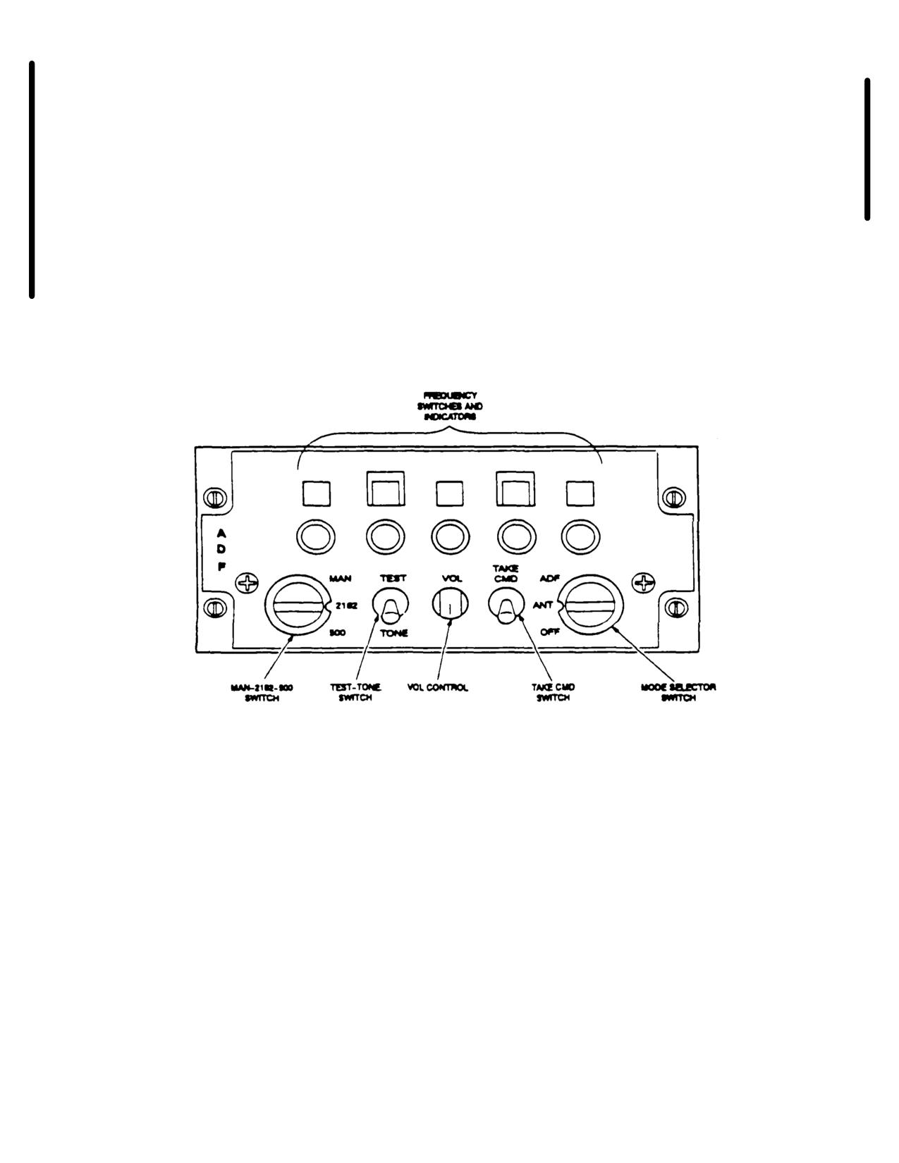
b Controls and Functions. Ref to Figure 3-
nondirectional beacons (NDB). If there is no Horizontal
29.24.1.
Situation Indicator (HSI) control installed, the ADF
dismays the helicopter relative bearing to a selected
radio transmission on the horizontal situation indicator
NO. 2 bearing pointer (Figure 3-29.29 if HSI) (Ref Fig 3-
21 if RMI).
Figure 3-29.24.1 ADF Control Panel C-12192/ARN-149(V)
Change 16
3-68.1
TM 55-1520-210-10
Controls and Functions of ADF Control Panel C-12192/ARN-149(V)
CONTROL
FUNCTION
Mode Select Switch
OFF
Turns system power off.
ANT
System functions as an aural receiver providing only aural
output of the received signal
ADF
Provides operation as an ADF using the AN/ARN-149 an-
tenna as a signal source, and the aural functions are en-
abled.
TEST
Test mode causing the RMI pointer to shift 90 degrees as a
self test.
TONE
Test mode causing the normal audio to be replaced by a
1000 hertz tone for continuous wave (CW) operation.
TAKE CMD
This switch Is used In a dual control system. Placing the
switch In the TAKE CMD position allows control of the re-
ceiver. (Not applicable for the UH-1 aircraft.)
VOL control
Controls the volume In 12 discrete steps.
MAN
Enables the frequency controls and indicators.
2182
Selects 2182 kHz as the operating frequency.
500
Selects 500 kHz as the operating frequency.
Frequency switches and indicators
Allows frequency (kHz) selection in manual mode.
3-68.2 Change 16
TM 55-1520-210-10
c.
Operation.
(a)
Mode selector switch - ANT. Monitor receiver by
listening.
(1) Normal ADF Operation
(b) ICS NAV switch - ON.
(a) ICS NAV receiver selector - ON.
d.
Stopping Procedures. Mode selector switch OFF.
(b) Mode selector switch - ADF.
3-46.
RADIO RECEIVING SET AN/ARN-123(V)
(c) Frequency - Select.
(VOR/ILS/MB).
(d) MAN/2182/500 switch - MAN.
a. Description.
Radio set AN/ARN-123 (V)
(Figure3-29.5) Is a very high frequency receiver that
(e) HS/VSI MODE SEL BRG 2 switch - ADF.
operates from
108
00 to
117
95 MHz. Course
information is presented by the HSI course deviation
(f)
VOL control - as desired.
pointer and the selectable No.
2 bearing pointer on the
horizontal situation indicator. The combination of the
(g) TEST/TONE control - TEST. Verify the RMI pointer
glide slope capability and the localizer capability makes
No. 2 rotates 90 degrees from present bearing Release
up the instrument landing system (ILS).
test switch.
(1) The marker beacon portion of the receiver
(2) ANT Mode Operation (Optional).
visually indicates to the right of either the ID-2103 or ID-
988 a MB advisory light. A Tone can be heard In the
head-phones of passage of the helicopter over a marker
beacon transmitter
Change 16 3-68.3/(3-68.4 blank)
TM 55-1520-210-10
(2) The receiving set may be used as a VCR
(3) The three receiver sections do the intended
receiver, or ILS receive. The desired type of operation
functions independent of each other. Performance
is selected by tuning the receiving set to the frequency
degradation within any one of the major sections will
corresponding to that operation. ILS operation is
not affect the performance of the others. Power for the
selected by tuning to the odd tenth MHz frequencies
AN/ARN-123 is provided from the dc essential bus
between
108.0 and
112.0 MHz. VOR operation is
through a circuit breaker, marked VOR/lLS.
selected by tuning in .050 MHz units to the frequen-
cies between
108.0 and
117.95 MHz. However, the
NOTE
odd tenth MHz between
108.0 and
112.0 MHz are
reserved for ILS operation.
Tuning to a Iocalizer frequency will auto-
matically tune to a glide slope frequency,
when available.
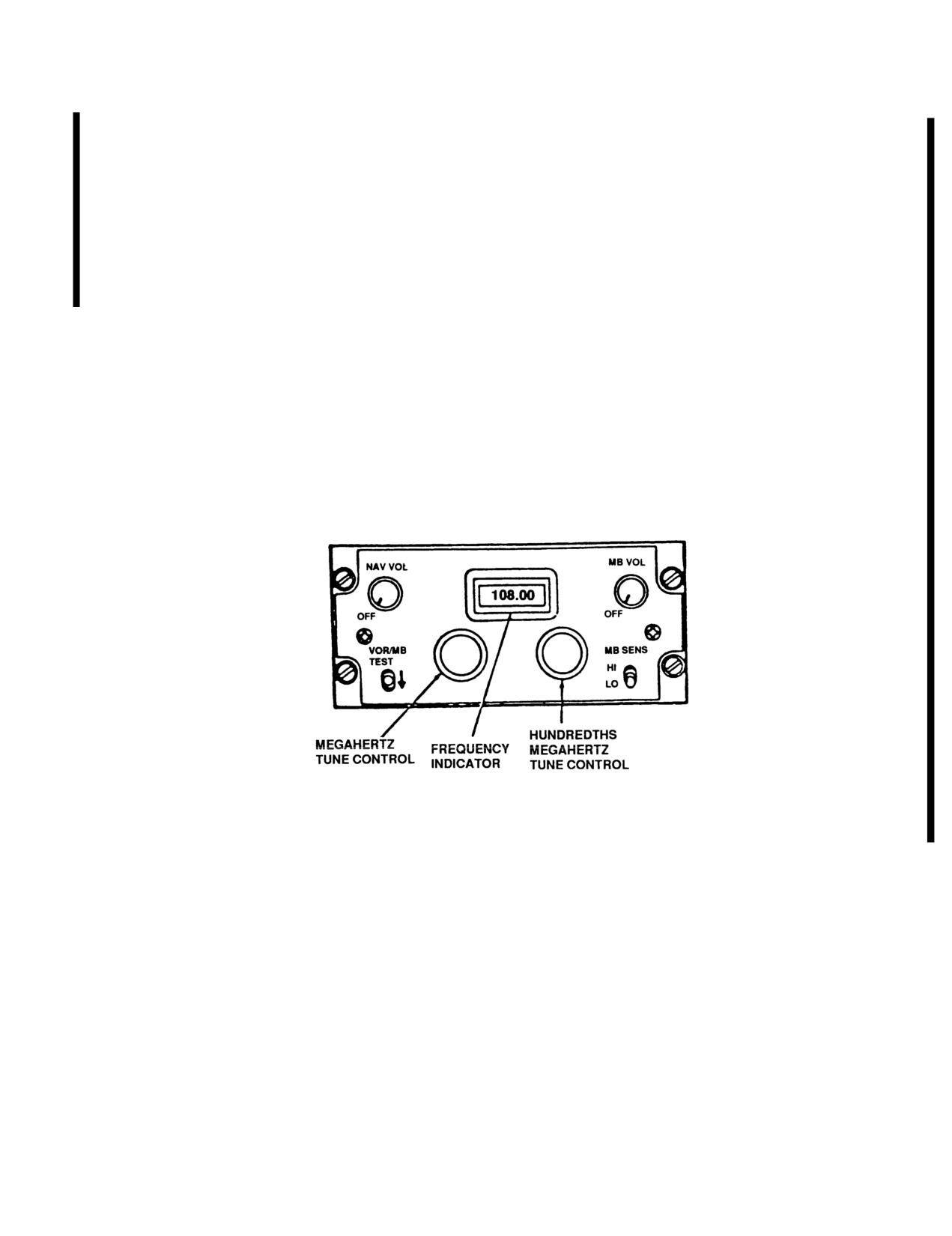
b. Controls and Functions. Refer to Figure
3-29.25.
Figure 3-29.25
Radio Receiving Set AN/ARN-123 (V).
Change 7
3-69
TM 55-1520-210-10
Controls and Functions for VOR/lLS/MB Receivers
CONTROL
FUNCTION
NAV VOL-OFF control
Turns VOR/lLS receiver on and off,
adjusts volume.
MB VOL-OFF control
Turns marker beacon receiver on and
off; adjusts volume.
Megahertz tune
Tunes VOR/ILS receiver in MHz as
control
indicated on frequency indicator.
Hundredths megahertz
Tunes VOR/ILS receiver in hundredths
tune control
MHz as indicated on frequency indicator.
VOR/MB TEST control
Activates VOR test circuit and MB
receiver lamp self-test circuits.
MB SENS HI-LO control
For controlling MB sensitivity.
LO
Decreases receiver sensitivity: Results
in shortening time transmitted signal
will be received.
HI
Increases receiver sensitivity: Results
in lengthening time transmitted signal
will be received.
c. Operation.
(2) VOR/Marker Beacon Test.
(1) Starting Procedure.
(a) HSI CRS set -315 on COURSE set display.
(a) ICS AUX selector - ON.
(b) VOR/MB TEST switch
- down and hold. The
MB light on the VSI should go on.
(b) NAV VOL OFF control - ON.
(c) HSI VOR/LOC course bar - centered ±1 dot.
(c) Frequency
- Select.
(d) No. 2 bearing pointer - Should go to 310°.
(d) MODE SEL BRG 2 switch - VOR.
(e) VOR/MB TEST switch - Release.
(e) MODE SEL VOR/lLS switch - ON.
3-70
Change 7
TM 55-1520-210-10
(3) Communications Test.
3-47. DOPPLER NAVIGATION SET AN/ASN-128.
(a) ICS AUX receiver selector- ON.
a. Description. The doppler navigation set,
AN/ASN-l28, in conjunction with the helicopter’s
heading and vertical reference systems, provides
(b) NAV VOL control - Adjust to midrange.
helicopter velocity position. It also provides steering
information from ground level to 10,000 feet. The dop-
(c) VOR/MB TEST switch
- Down and hold. Noise
pler navigation system is a completely self-contained
should be heard in headphones.
navigation system and does not require any ground-
based aids.
(d) VOR/MB TEST switch
- Release. Noise
should not be heard in headphones, indicating that
(1) The system provides world-wide navigation,
squelch is operation properly.
with position readout available in both Universal
Transverse Mercator (UTM), and Latitude and Lon-
(4) VOR Operation.
gitude (LAT/LONG). Navigation and steering is done
using LAT/LONG coordinates, and a bilateral UTM-
Course - Set.
LAT/LONG conversion routine is provided for UTM
operation. Up to ten destinations may be entered in
(5) ILS (LOC/GS) operation.
either format and not necessarily the same format.
Preset position data entry format is also optional and
ILS operation frequency - Set.
independent of destination format.
(6) Marker Beacon (MB) Operation.
(2) The AN/ASN-l28 operates in conjunction with
the Horizontal Situation Indicator (HSI) and a Horizon-
tal Situation Indicator Control (HSI Control). A Com-
(a) MB VOL OFF switch - ON.
pass Control C-8021/ASN-75 is also included to
synchronize Gyromagnetic Compass Set AN/ASN-43
(b) MB SENS switch -as desired.
to correct magnetic heading. This is accomplished
when in the SLAVED mode of operation.
(7) VOR communications. Receiving Operation.
b. Controls, Displays, and Function. The controls
Frequency - Set.
and displays for the doppler are on the front panel
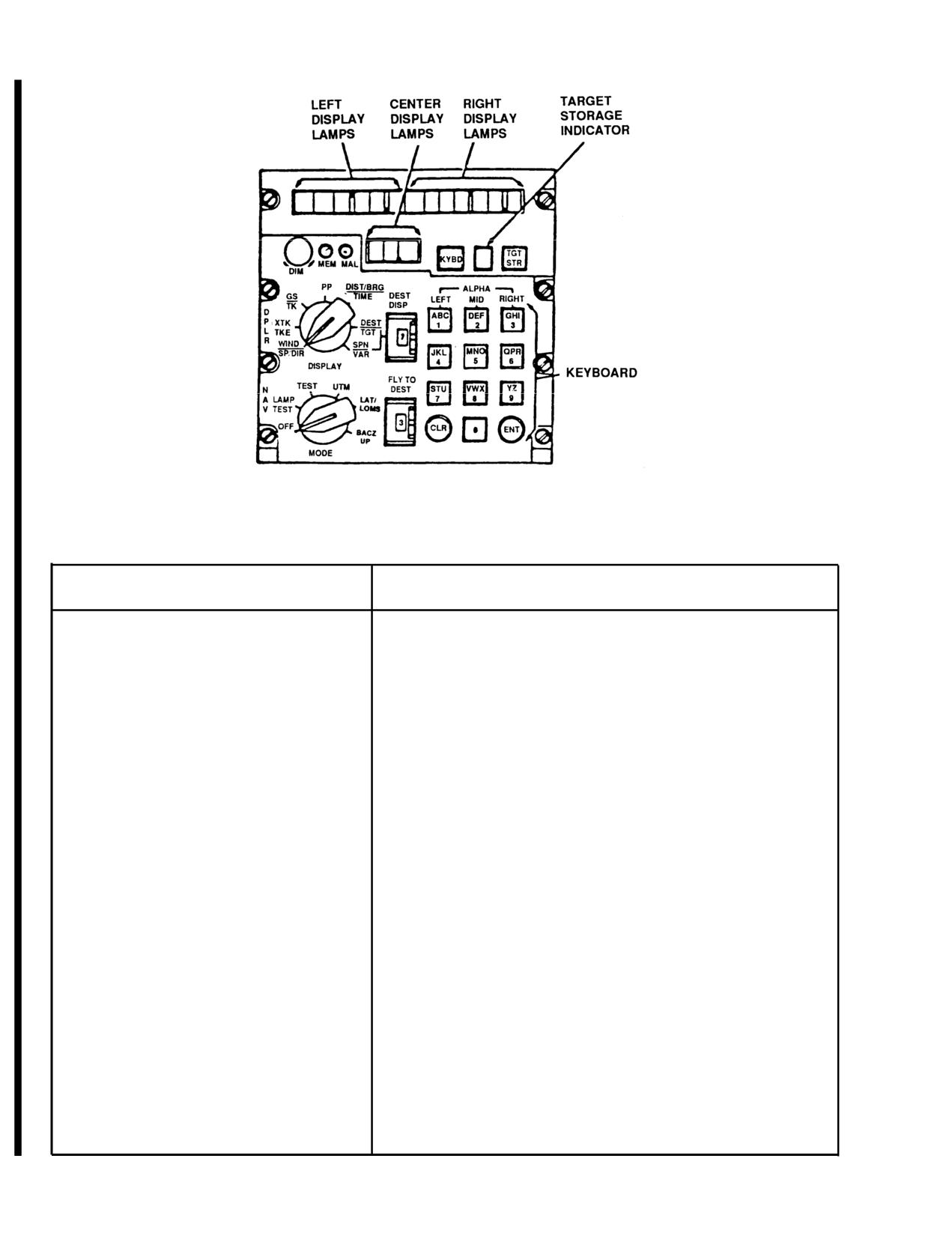
(Figure 3-29.26).
(8) Stopping Procedure.
NAV VOL OFF switch - OFF.
Change 7
3-71
TM
55-1520-210-10
Figure
3-29.26. Doppler Navigation Set AN/ASN-128.
Controls and Functions of Doppler Navigation Set.
CONTROL/INDICATOR
FUNCTION
Mode Selector
Selects Doppler Navigation of operation.
OFF
Turns navigation set off.
LAMP TEST
Checks operation of all lamps.
TEST
Initiates built-in-test exercises for navigation set.
UTM
Selects Universal Transverse Mercator (UTM)
navigational mode of operation
LAT/LONG
Select latitude/longitude navigational mode of operation.
BACKUP
Places navigation set in estimated mode of operation or
estimated velocity mode of operation.
DISPLAY Selector
Selects navigation data for display.
WIND SP/DIR
Not applicable.
XTK-TKE
Distance crosstrack (XTK) of initial course to destination
(Left Display)
in km and tenths of a km. Track angle error (TKE) in
(Right Display)
degrees displayed as right or left of bearing to destination.
GS-TK (Left Display)
Ground speed (GS) in (Left Display) km/hr.
3-72
Change 7
Controls and Functions of Doppler Nav. Set ASN-128 - CONT.
CONTROL/INDICATOR
FUNCTION
(Right Display)
Track angle (TK) in degrees
PP with switch set
Present position UTM zone.
to UTM (Center
Display)
(Left Display)
Present position UTM area square
designator and casting in km to nearest
ten meters.
(Right Display)
Present position UTM area northing in km
to nearest ten meters.
PP with MODE switch
Present position latitude in degrees,
set to LAT/LONG
minutes and tenths of minutes.
(Left Display)
(Right Display)
Present position longitude in degrees,
minutes and tenths of minutes.
DIST/BRG-TIME
Time to destination selected by FLY TO
(Center Display)
DEST (in minutes and tenth of minutes).
(Left Display)
Distance to destination selected by FLY TO
DEST (in KM and tenths of a km).
(Right Display)
Bearing to destination selected by FLY TO
DEST (in degrees).
DEST-TGT (Mode
UTM zone of destination selected by DEST
switch set to UTM)
DISP thumbwheel.
(Center Display)
(Left Display)
UTM area and casting of destination set on
DEST DISP thumbwheel.
(Right Display)
Northing of destination set on DEST DISP
thumbwheel.
DEST-TGT (Mode
Longitude of destination set on DEST DISP
switch set to LAT/
thumbwheel.
LONG (Left Display)
(Right Display)
Latitude (N 84° or S 80° max.) of desti-
nation set on DEST DISP thumbwheel.
SPH-VAR
Spheriod code of destination set on DES
(Left Display)
DISP thumbwheel.
(Right Display)
Magnetic variation (in degrees and tenths
of degrees) of destination set on DEST
DISP thumbwheel.
Change 7
3-73
TM 55-1520-210-10
Controls and Functions of Doppler Navigation Set - CONT.
CONTROL/INDICATOR
F U N C T I O N
MEM Indicator Lamp
Lights when radar portion of navigation
set is in non-track condition.
MAL Indicator Lamp
Lights when navigation set malfunction
is detected by built in self-test.
DIM Control
Controls light intensity of display
characters.
Left, Right, and
Lights to provide data in alphanumeric
Center Display
and numeric characters, as determined by
L a m p s
setting of DISPLAY switch, MODE switch,
and operation of keyboard.
Target Storage
Displays destination number (memory location)
indicator
in which present position will be stored when TGT
STR pushbutton is pressed.
TGT STR Pushbutton
Stores present position data when pressed.
KYBD Pushbutton
Used in conjunction with the keyboard to
allow data to be displayed and subsequent-
ly entered into the computer when the ENT
key is pressed.
DEST DISP
Destination display thumbwheel switch is
Thumbwheel switch
used along with DEST-TGT and SPH-VAR posi-
tion of DISPLAY switch. Used to select
destination whose coordinates or magnetic
variation are to be displayed, or to be
entered. Destinations are
0 through
9, P
(Present Position) and
H (Home).
Keyboard
Used to setup data for entry into memory.
When the DISPLAY switch is turned to the
position in which new data is required, the
KYBD pushbutton is pressed. Data maybe
displayed on the appropriate left, right
and center display. To display a number,
press corresponding key or keys
(1 through
0). To display a letter, first depress key
corresponding to desired letter. Then
depress a key in left, middle, or right
column, corresponding to position of the
letter on the key. Example: To enter an L,
first depress L, then
3,6, or
9 in the
3-74
Change 7
TM 55-1520-210-10
Controls and Functions of Doppler Navigation Set - CONT.
CONTROL/INDICATOR
FUNCTION
FLY-TO-DEST
Selects the destination for XTK/TKE and
Thumbwheel switch
DIST/BRG/TlME. They are displayed when
DISPLAY switch is turned to either of
these positions which steering information
is desired. Destinations are 0 through 9,
P (Present Position) and H (Home).
ENT Key
Enters data set upon keyboard into memory
when pressed.
CLR Key
Clears last entered character when pressed
once. When pressed twice, clears entire
display panel under keyboard control.
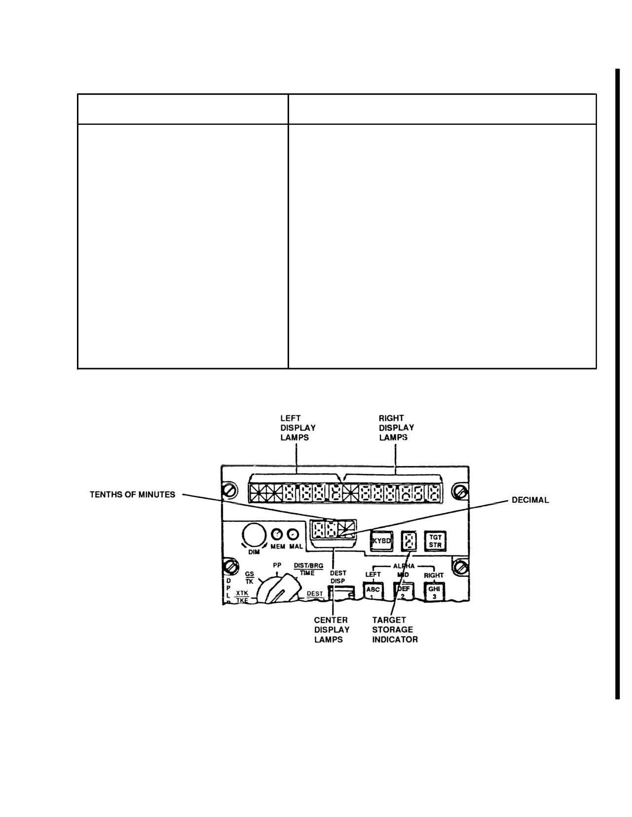
Figure 3-29.27 Doppler Lamp Test Mode Display
Change 7
3-75
TM 55-1520-210-10
c. Modes of Operation. The three basic modes of
(c) Continuous monitoring of the signal data con-
operation are: Navigate, test, and backup.
verter and receiver-transmitter-antenna is provided by
the MEM indicator lamp. The MEM indicator lamp will
(1) Test Mode. The TEST mode contains two
light in normal operation when flying over smooth
functions: LAMP TEST mode, in which all display seg-
water. However, if lamp remains on for over
10
ments are lit, and TEST mode, in which system opera-
minutes, over land or rough water, there is a malfunc-
tion is verified. In LAMP TEST mode, system
tion in the doppler set. Then the operator should turn
operation is identical to that of navigate mode. With
the MODE switch to TEST, to determine the nature of
exception that all lamp segments and MEM and MAL
the malfunction. Keyboard operation is verified by ob-
indicator lamps are lighted to verify their operation
serving the alphanumeric readout as the keyboard is
(see Figure
3-27.2).
used.
(a) The TEST mode, the system antenna no
(2) Navigate Mode. In navigate mode (UTM or
longer transmits or receives electromagnetic energy.
LAT/LONG position of the MODE selector), power is
Instead, self generated test signals are inserted into
applied to all system components. All required outputs
the electronics to verify operation. System operation
and functions are provided. Changes in present posi-
automatically reverts into the backup mode during test
tion are computed and added to initial position to
mode. Self-test of the doppler set is done using built-
determine the instantaneous Iatitude/longitude of the
in-test equipment (BITE), and all units connected and
helicopter. Destination and present position coor-
energized for normal operation.
dinates can be entered and displayed in UTM and
latitude/longitude. At the same time, distance, bearing
and time-to-go to any one of ten preset destinations
(b) Self-test isolates failures to one of the three
are computed. They are displayed as selected by the
units. The computer-display unit (except for the key-
FLY-TO-DEST thumbwheel.
board and display) is on a continuous basis. Any
failure is displayed by turn-on of the MAL indicator
lamp on computer-display unit. The signal data con-
(3) Backup Mode. In this mode, remembered
verter and receiver-transmitter-antenna are tested by
velocity data are used for navigation. The operator
turning MODE switch to TEST. Failure of those com-
can insert ground speed and track angle with the key-
ponents is displayed on computer-display unit by turn-
board and the display in GS-TK position. This remem-
on of the MAL indicator lamp. Identification of the
bered velocity data can be manually updated through
failed unit is indicated by a code on the display panel
use of the keyboard and CDU DISPLAY switch in the
of the computer-display unit.
GS-TK position. When GS-TK values are inserted
under these conditions, navigation continues using
only these values.
d. Operation.
3 - 7 6
Change 7
TM 55-1520-210-10
(1) Window Display and Keyboard Operation. In
(a) MODE selector - LAMP TEST. All lights
all data display except UTM coordinates, the two fields
should be lit.
are the left and right display windows. In UTM coor-
dinates displays, the first field of control is the center
1. Left, right, Center and Target storage indicator -
window. The second field is the combination of the left
Lit (Figure 3-29..27). All other lights should be on.
and right displays. When pressing the KYBD pushbut-
ton, one or other of the fields described above is
2. Turn DIM control fully clockwise, then fully
under control.
counterclockwise, and return to full clockwise. All seg-
ments of the display should alternately glow brightly,
(a) If it is not desired to change display under con-
go off, and then glow brightly.
trol, the pilot can advance to next field of display
panel. This is done by pressing the KYBD pushbutton
(b) MODE selector
- TEST. After about
15
again. The last character entered may be cleared by
seconds left display should display GO. Ignore the
pressing the CLR key. That character may be a sym-
random display of alpha and numeric characters
bol or an alphanumeric character. However, if CLR
which occurs during the first 15 seconds. Also ignore
key is pressed twice in succession, all characters in
test velocity and angle data displayed after the display
the field under control will be cleared. That field will
has frozen. After about 15 seconds, one of the follow-
still remain under control.
ing five displays will be observed in the first two char-
acter positions in the left display.
(2) Data Entry. To enter a number, press the cor-
responding key. To enter a letter, press the key cor-
NOTE
responding to the desired letter. Then press a key in
left, middle, or right column corresponding to position
If the MAL lamp lights during any mode ex-
of letter on pushbutton. Example: To enter an L, first
cept LAMP TEST, the computer-display unit
press L, then either 3, 6, or 9 in the right column. The
MODE switch turn to OFF. The turn to
computer program is designed to reject unacceptable
TEST, to verify the failure. If the MAL LAMP
data (for example, a UTM area of WI does not exist,
remains on after recycling to TEST, notify
and will be rejected). If the operator attempts to insert
organizational maintenance personnel.
unacceptable data, the display will be blank after ENT
is pressed.
(3) Start Procedure.
Change 7
3-77
TM 55-1520-210-10
Test Mode Display and Remarks
DISPLAY
REMARKS
LEFT
RIGHT
GO
No display
If right display is blank, system is operating satisfactorily.
Display Blanks (normal).
GO
P
If right display is P, then pitch or roll data is missing, or
pitch exceeds 90°. In this case, pitch and roll in the com-
puter are both set to zero and navigation continues in a
degraded operation. Problem may be in the vertical gyro-
scope or helicopter cabling.
NOTE
If TEST mode display is BU, MN or NG, MODE switch
should be recycled through OFF. This verifies that failure
is not a momentary one. If the TEST mode display is BU
or MN, the data entry may be made in the UTM or
LAT/LONG mode. However, any navigation must be car-
ried on with the system in the BACKUP mode.
BU
C, R, S, or H
A failure has occurred and the system has automatically
followed by a
switched to a BACKUP mode of operation as follows:
numeric code
1. The operator has the option of turning the MODE
switch to BACKUP and entering the best estimate of
ground speed and track angle.
2. The operator has the option of turning the MODE
switch to BACKUP. He enters his best estimate of wind
speed, direction, ground speed and track angle. Update
present position as soon as possible, because the sig-
nificant navigation errors may have accumulated.
3-78
Change 7
TM 55-1520-210-10
Test Mode Display and Remarks - CONT.
DISPLAY
REMARKS
LEFT
RIGHT
MN
C, R, S, or H
A failure has occurred and the BACKUP mode used for
followed by a
manual navigation (MN), is the only means of valid
numeric code
navigation. The operator may use the computer as a
dead reckoning device by entering ground speed and
track data. The operator should update present position
as soon as possible, because it is possible significant
navigation errors may have accumulated.
NG
C, R, S, or H
A failure has occurred in the system and the operator
followed by a
should not use the system.
numeric code
EN
The 9V battery has failed. All stored data must be
reentered.
NOTE
If the TEST mode display is BU, MN or NG, the MODE
switch should be recycled through OFF. This verifies that
the failure is not a momentary one. If the TEST mode dis-
play is BU or MN, the data entry may be made in the
UTM or LAT/LONG mode. However, any navigation must
be carried on with the system in the BACKUP mode.
(4) Entering UTM Data. This initial data is inserted
(d) Coordinates of desired destination
-0 through
before navigating with the doppler.
5 and H; (6 through 9 are normally used for target
store locations but may also be used for destinations).
(a) Spheroid of operation, when using UTM coor-
It is not necessary to enter all destinations in the same
dinates.
coordinate system.
(b) UTM coordinates of present position - zone,
NOTE
area, casting (four significant digits) and northing (four
significant digits; latitude/longitude coordinates may
It is not necessary to enter destinations.
be used).
Unless steering information, updating
present position, or a present position
variation computation is desired. If a
(c) Variation of present position to the nearest
present position variation running update is
one-tenth of a degree.
desired, destination must be entered. The
operator may enter one or more destina-
tions to effect the variation update. If is not
necessary for all destinations to have as-
sociated variations entered.
Change 7
3-79
TM 55-1520-210-10
(e) Variations of destinations to be to nearest one-
(6) Entering Present Position
or Destination in
tenth of a degree.
UTM.
(5) Entering Spheroid and/or Variation.
(a) MODE selector - UTM.
(a) MODE selector - UTM, LAT/LONG or BACK-
(b) DISPLAY selector - DEST-TGT.
UP.
(c) DEST DISP thumbwheel - P, numerical, or H
(b) DISPLAY selector - SPH-VAR.
as desired.
(c) DEST DISP thumbwheel - P, numeral, or H as
(d) Present position and destination - Enter. (Ex-
desired.
ample: Entry of zone 31 T, area CF, casting 0958 and
northing
3849.)
(d) KYBD pushbutton
- Press. Observe display
freezes and TGT STR indicator blanks. Press KYBD
1. KYBD pushbutton - Press. Observe that dis-
pushbutton again and observe left display blinks. If no
play freezes and TGT STR indicator blanks.
spheroid data is to be entered, KYBD pushbutton
-
Press again, go to Step g.
2. KYBD button - Press. Observe that center dis-
play blanks.
(e) Spheroid data
- Entry. (Example: INO). Press
keys 3 (left window blanks), 3, 5, 5 and 0. Left display
3. Key
3,
1,7 and 8- Press.
should indicate INO.
4. KYBD button - Press. Observe left and right
(f) ENT pushbutton - Press if no variation data is
displays blank.
to be entered.
5. Key 1, 0, 9, 5, 8, 3, 8, 4, 9- Press.
(g) KYBD pushbutton - Press, if variation data is
to be entered, and note right display blanks. (If no
6. ENT pushbutton
- Press. Left, right, and center
variation data is to be entered, ENT key - Press.)
displays will momentarily blank and TGT STR number
will appear. Displays should indicate
31T CF
(h) Variation data
- Enter. (Example: E001.2,
09583849.
press keyboard keys 2 (right window blanks), 2, 0, 0, 1
and 2. Press ENT key, the entire display will blank and
TGT STR number will reappear, display should indi-
cate INO E001 .2).
3 - 8 0
Change 7
TM 55-1520-210-10
(7) Entering Present Position or Destination Varia-
(8) Ground Speed and Track.
tion in LAT/LONG. The variation of a destination must
be entered after the associated destination coor-
(a) MODE selector - BACKUP.
dinates are entered. As each time a destination is
entered its associated variation is deleted. The order
(b) DISPLAY selector - GS-TK.
of entry for present position is irrelevant.
(c) Ground speed and track
- Enter. (Example:
NOTE
Enter
131 km/h and
024°. Press KYBD pushbutton,
observe that left display freezes and TGT STR in-
IF operation is to occur in a region with
dicator blanks. Press keys 3 and 1. Left display indi-
relatively constant variation, the operator
cates 131. Press KYBD pushbutton, control shifts to
enters variation only for present position.
right display, and right display blanks. Press keys
0,
2
The computer will use this value throughout
and 4.
the flight.
(d) ENT pushbutton - Press. The entire display
(a) MODE selector
- LAT/LONG.
will blank, and TGT STR number will reappear. Dis-
play should indicate 131 024°.
(b) DISPLAY selector - DEST-TGT.
(9) Initial Data Entry. Initial data entry variation
(c) DEST DISP thumbwheel - P, numerical or H as
coordinates are normally done prior to takeoff. To
desired.
make the initial data entry, do the following:
(d) Present position of destination
- Enter. (Ex-
(a) Present position - variation - Enter Paragraph
ample: Entry of N 41° 10.1 minutes and E 035°
50.2
5.
minutes.) Press KYBD pushbutton. Observe that dis-
play freezes and TGT STR indicator blanks. Press
(b) DISPLAY selector - DEST-TGT.
KYBD pushbutton again and observe left display
blanks. Press keys 5, 5, 4, 1, 1, 0 and 1. Press KYBD
(c) DEST DISP thumbwheel
- P. Do not press
pushbutton (right display should clear), and keys
2,
2,
ENT key now.
0, 3, 5, 5, 0 and 2.
(d) ENT pushbutton - Press as helicopter is sitting
(e) ENT pushbutton - Press. Entire display will
over or overflies initial fix position.
blank and TGT STR number will reappear. Display
should indicate N41° 10.1 E 035°
50.2
(e) FLY-TO DEST thumbwheel
- Desired destina-
tion location.
Change 7
3-81
TM 55-1520-210-10
(10) Update of Present. Position From Stored
3. Compare landmark coordinates with those on
Destination. The helicopter is flying to a destination
display.
set by the FLY-TO DEST thumbwheel. When the
helicopter is over the destination, the computer up-
4. Landmark coordinates
- Enter. If difference
dates the present position when the KYBD pushbutton
warrants an update.
is pressed. Use stored destination coordinates for
destination number shown in FLY-TO DEST window.
5. ENT key - Press is update is required.
Add the distance traveled between the time KYBD
pushbutton was pressed and ENT key was pressed.
6. DISPLAY selector - Set to some other position
to abort update.
(a) DISPLAY selector - DIST/BRG TIME.
(b) Method
2.
(b) KYBD pushbutton
- Press, when helicopter is
over the destination. Display freezes.
1. DISPLAY selector - DEST/TGT.
NOTE
2. DEST DISP thumbwheel
- P. Present position
coordinates should be displayed.
If a present position update is not desired,
set the DISPLAY selector to some other
3. KYBD pushbutton - Press, observe that display
position. This aborts the update mode.
freezes.
(c) ENT key - Press.
4. Landmark coordinates
- Manually enter via key-
board.
(11) Update of Present Position from Landmark.
There are two methods for updating present position
5. ENT key - Press when overflying landmark.
from a landmark. Method 1 is useful if the landmark
comes up unexpectedly and the operator needs time
6. DISPLAY selector - Set to some other position
to determine the coordinates. Method 2 is used when
to abort update.
a landmark update is anticipated.
(12) Left-Right Steering Signals. Flying shortest
(a)
Method 1.
distance to destination from present position.
1.
DISPLAY selector - PP.
(a) DISPLAY selector - XTK-TKE.
2.
KYBD pushbutton - Press as landmark is over-
(b) MODE SEL - DPLR.
flown. Present position display will freeze.
(c) Fly helicopter in direction of lateral deviation
pointer or vertical situation indicator. Center the
pointer or course deviation baron HSI.
3-82
Change 7
TM 55-1520-210-10
(13) Target Store (TGT STR) operation. Two
6. If, it is not desired to store the target, place
methods may be used for target store operation.
DISPLAY selector momentarily to another position.
Method 1 is normally used when time is not available
for preplanning a target store operation. Method 2 is
(14) Transferring Stored Target Coordinates From
used when it is desired to store a target in a specific
One Location to Another. The following procedure al-
DEST DISP position.
lows the operator to transfer stored target coordinates
from one thumbwheel location to another. For ex-
(a) Method
1.
ample, it is assumed that the pilot wants to put the
coordinates of stored target 7 into location of destina-
1. TGT STR pushbutton - Press when flying over
tion.
target.
NOTE
2. Present position is automatically stored. The
destination location is that which was displayed in tar-
Range, time-to-go, bearing and left/right
get store indicator (position
6,
7,
8 or
9) immediately
steering data are computed and displayed
before pressing TGT STR pushbutton.
for destination selected via FLY-TO DEST
thumbwheel.
(b) Method
2.
(a)
DISPLAY selector -DEST-TGT.
1. MODE selector
- UTM or LAT/LONG, depend-
ing on coordinate format desired.
(b)
DEST DISP thumbwheel -7.
2. DISPLAY selector - DEST-TGT.
(c)
KYBD pushbutton - Press.
3. DEST DISP thumbwheel - P.
(d)
DEST DISP thumbwheel -2.
4. KYBD pushbutton
- Press when over flying
(e) ENT key - Press.
potential target. Display should freeze.
(14) Transferring Variation From One Location to
NOTE
Another. To transfer variation data to same location
where associated stored target coordinates has been
transferred is the same as in Stored Target Coor-
Do not press ENT key while DEST DISP
dinates From One Location To Another, except that
thumbwheel is at P.
the DISPLAY selector is placed at SPH-VAR.
5. If it is not desired to store the target, turn DEST
DISP thumbwheel to destination location desired and
press ENT key.
Change 7
3-83
TM 55-1520-210-10
(15) Dead Reckoning Navigation. As an alternate
(b) If battery does not stored destination data, the
BACKUP mode, dead reckoning navigation can be
display will indicate on EN when power returns. This
done using ground speed and track angle estimates.
indicates to the pilot that previously stored data has
been lost. Present position, spheroid/variation, and
(a) MODE selector - BACKUP.
destinations must be entered.
(c) The computer, upon return of power, resets
(b) DISPLAY selector - GS-TK.
presents position variation to E OOO.OO. Resets des-
tination and associated variations to a non-entered
(c) Best estimate of ground speed and track angle
state, remembers wind to zero and spheroid to CL6.
- Enter via keyboard.
(d) The following data must be entered following
(d) Set MODE selector to any other position to
battery failure:
abort procedure.
1. Enter spheroid.
(16) Operation During and After Power Interrup-
tion. During a dc power interruption or when power is
2. Enter present position variation.
removed, random access memory (RAM) (stored des-
tination and present position) data is retained.
3. Enter present position.
(a) It is retained by power from an 8.4 volt dc dry
cell battery. This makes it unnecessary to reenter any
navigational data when power returns or before each
flight.
Figure
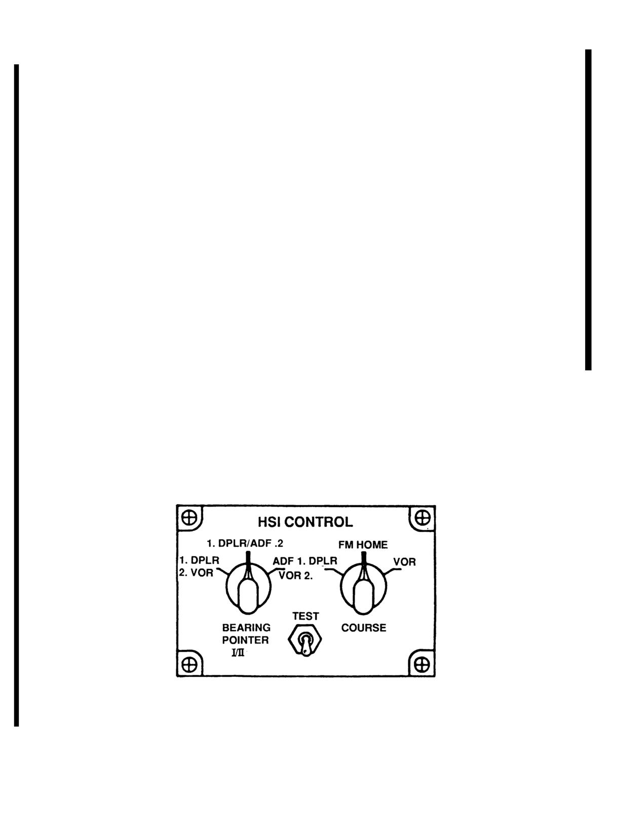
3-29.28. Horizontal Situation indicator Control (C-11740/A)
3 - 8 4
Change
7
TM 55-1520-210-10
4. Enter each destination and its associated varia-
(2) The CRS DEVN Control Switch (Course
tion.
Deviation) selects DPLR, FM, HOME or VOR func-
tions to be displayed on the HSI vertical needle. The
e. Stopping Procedure.
ID - 250 RM indicator only displays ADF on the No. 1
pointer and VOR on the No. 2 pointer.
Mode selector - OFF.
g. Horizontal Situation lndicator.
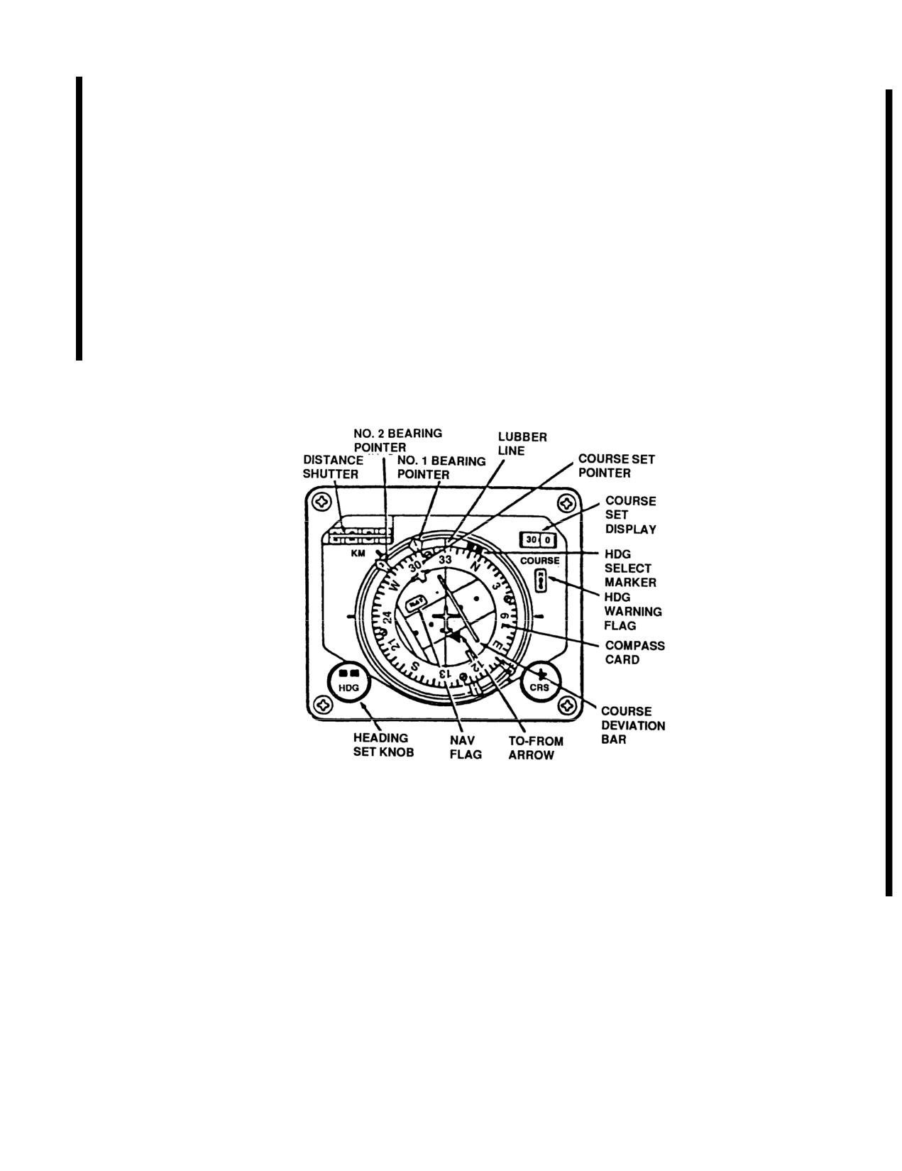
f. HSI Control.
Controls and Indicators. Refer to Figure 3-29.29.
(1) BEARING POINTER NO. I & II Control Switch
(Figure
3-29.28) selects either ADF/VOR, DPLR/ADF
or DPLR/ADF bearing information to be displayed on
the No. I & II BEARING POINTERS on the horizontal
situation indicator (HSI).
Figure
3-29.29 Horizontal Situation Indicator (lD-2103/A)
Change 7
3 - 8 5
TM 55-1520-210-10
Controls/Functions of Horizontal Situation Indicator
CONTROL
FUNCTION
Compass card
The compass is a 360° scale that turns to display heading
data obtained from the compass control. The helicopter
headings are read at the upper lubber line.
Bearing pointer
The pointer operates in conjuction with Doppler. Indicates
No. 1
relative bearing to doppler destination set on FLY-TO-DEST
thumbwheel.
Bearing pointer
The pointer operates in conjunction with selected VOR or
No. 2
ADF receiver. The pointer is read against the compass card
and indicates the magnetic bearing of the VOR or ADF
station.
Course deviation
This bar indicates lateral deviation from a selected course.
bar
When the helicopter is flying the selected course, the course
bar will be aligned with the course set pointer. It will be
centered on the fixed aircraft symbol.
CRS knob
Course set (CRS) knob and the course set counter operate
in conjunction with the course pointer. Allows the pilot to
select any of 360° courses. Once set, the course pointer
will turn with the compass card. It will be centered on the
upper lubber line when the helicopter is flying the selected
course.
KM indicator
Digital distance display in kilometers (KM) to destination set
on doppler DEST DISP.
HDG knob
Heading set (HDG) knob operates in conjunction with the
heading select marker. Allows the pilot to select any one of
360° headings. Seven full turns to the knob produces a
360° turn to the marker.
TO-FROM arrow
To-from arrow indicates that the helicopter is flying to or
away from a selected VOR.
NAV flag
The NAV flag at the top of the to indicator, turns with the
compass card. The flag will retract from view when a reliable
navigation signal is being applied to the instrument.
3-86
Change 7
TM 55-1520-210-10
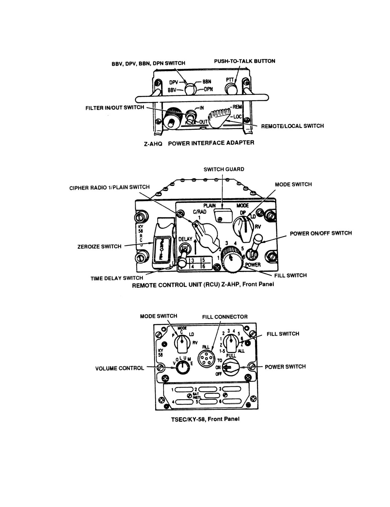
Figure 3-29.30. Voice Security System Equipment
Change 7
3-87
TM 55-1520-210-10
Nomenclature
Common Name
Use
Range
V1
V2 V3 V4
Control Intercommunications
ICS Box
Integrate Interphone
Stations within
X
X
X
X
Set C-1611/AlC
and all communications
helicopter
equipment
Receiver-Transmitter, Radio
FM Radio
Two-way voice
Line of sight
X
X
X
X
RT-823/ARC-131
communications
TSEC/KY-28
Voice Security
Secure two-way voice
N/A
X
X
Equipment
communications
Receiver-Transmitter, Radio
UHF Radio
Two-way voice
Line of Sight
X
X
RT-742/ARC-51BX
set
communications
Receiver-Transmitter, Radio
UHF Radio
Two-way voice
Line of Sight
X
X
RT-1167/ARC-164
set
communications
TSEC/KY-58, Z-AHP Control
Voice Security
Secure two-way voice
N/A
X
X
Indicator and Z-AHQ Adapter
Equipment
communications
HYL-3/TSEC
HYL-3/TSEC
Used to increase
N/A
X
X
Regenerative Repeater
link reliability
MX-9331A/URC
Repeater
Used to increase
N/A
X
X
Regenerative Repeater
link reliability
Receiver-Transmitter
PLRS
Position Locating
RT-1343/TSQ-129
Reporting System
N/A
X
X
Basic User Unit (BUU)
Message Processor
Figure 3-30. AN/ASC-15A(V) 1,2,3, and 4 Equipment Configuration (Sheet 1 of 3)
3-88 Change 7
TM 55-1520-210-10
Nomenclature
Common Name
Use
Range
V1
V2 V3 V4
C-10830-/PSQ-4 Control-
URO
Enter and display
N/A
X
X
Readout Unit
message
CN-1547/ASQ-177,
Voltage
Provide power for
N/A
X
X
SM-D-911821 Power Adapter
Regulator
the BUU
MX-9545/VR
Voltage
Provide power for
N/A
X
X
Vehicle Adapter
Regulator
the Repeater
C-8157/ARC
Control
Control for the
N/A
X
X
X
X
Control Indicator
ARC-131
VHF-AM Comm
VHF-FM
Two-way voice
Line of Sight
ARC/186
Command
Communications
Set
#1 VHF-FM Comm/Homing
VHF-FM
Two-way voice
Line of Sight
ARC/201
Comm/Homing
Communications
#2 VHF-FM Comm
VHF-FM
Two-way voice
Line of Sight
ARC/201
Comm Set
Communications
HF-AM Communications System
HF Radio Set
Two-way voice
Long Range
ARC/199
Communications
HF Comm Sec.
COMSEC
Secure Voice
N/A
TSEC/KY-75
HF ARC-199
Figure 3-30. AN/ASC-15A(V) 1,2,3, and 4 Equipment Configuration (Sheet 2 of 3)
3-89 Change 7
TM
55-1520-210-10
Nomenclature
Common Name
Use
Range
VI
V2
V3
V4
Direction Finder Set
Direction
Radio Range
150 to 200 Mi
ARN/89
Finder Set
Navigation
Radio Navigation System
VHF Navig-
VHF Navigational
Line of Sight
ARN/123
ation Set
and VHF Audio
Doppler Navigation Set
Doppler Navig-
Navigational system
Long Range
ASN/128
ation Set
Gyromagnetic Compass Set
Gyromagnetic
Navigational Aid
N/A
ASN/43
Compass
IFF Transponder
Transponder
Navigational Aid
Line of Sight
AN/APX-100
Set
Figure
3-30. AN/ASC-15A(V)
1,2,3, and
4 Equipment Configuration (Sheet
3 of
3)
3
-
9
0
Change
7
TM
55-1520-210-10
Chapter 4
Mission Equipment
Section 1.
ARMAMENT
4-1. Armament Subsystem M23 The armament
WARNING
subsystem M23 is attached to external stores hard
point fittings on both sides of the helicopter. The two
Pressing the trigger to release the bolt
flexible 7.62 millimeter machine guns M60D are free
assembly also accomplishes feeding and
pointing but limited in traverse, elevation, and de-
releases the firing mechanism, Weapon
pression by cam surfaces and stops on pointless
shall be cleared of cartridges before
and pintle post assemblies of the two mount assem-
pressing trigger assembly, unless firing is
blies on which the M60D machine guns are
intended.
mounted. An ejection control bag is latched to the
right side of each M60D machine gun to hold the
e. Grip and Trigger Assembly. The grip and trigger
spent cases, unfired rounds and links. Cartridges
assembly includes the spade grips and is located at
travel from ammunition box and cover assemblies to
rear of receiver. The U-shaped design permits firing
M60D machine gun through flexible chute and brace
of weapon by index finger of either hand.
assemblies. The following paragraphs describe ma-
chine gun M60D components.
Caution
When ammunition is not present in machine
a. Cover Latch. The cover latch is located at the
right rear of the cover assembly. In the vertical posi-
gun M60D, retard forward force of released
bolt assembly by manually restraining for-
tion it secures cover assembly in closed position.
ward movement of cocking handle assem-
Turning to horizontal position unlocks cover assem-
bly.
bly to prevent damage to cartridge tray.
f. Magazine Release Latch. The magazine release
b. Barrel Lock Lever. The barrel lock lever, located
at right front of receiver, is secured to barrel locking
latch, located on left side of receiver, locks adapter
of the ammunition chute when it is seated in maga-
shaft and rotates shaft to lock or unlock barrel as-
zine bracket.
sembly.
WARNING
g,
Ammunition Chute Adapter, The ammunition
chute
adapter is required for flexible chute installa-
Cocking handle assembly shall be re-
tion.
turned to the forward or locked position
before firing to prevent injury to person-
4-2.
Preflight Procedures-Machine Gun M60D
nel.
1.
Gun-Secure-Stowed position.
c. Cocking Handle Assemb/y. The cocking handle
2.
Barrel-Free of obstruction.
assembly, at right f rent of receiver, is used for
manually charging the weapon.
3.
Gas cylinder-Plug tight, safety-wired.
d. Safety. The safety, located at lower front of
4.
Cover-Free movement, latch secure.
receiver, consists of a cylindrical pin with a sear
clearance cut which slides across receiver to block
5.
Ejection control bag-Latched.
the sear and prevent accidental firing. Ends of pin
are marked for pushing to “S” safe and “F” firing
6. Ammunition box-Latches and cover-Secure.
positions.
Check cartridges for proper position in links.
4-1
TM 55-1520-210-10
7.
Chute and brace-Secure.
an unfired cartridge in the chamber. Treat this as a
hangfire.
8.
Safety-Safe.
d. Runaway Gun. if gun continues to fire after trig-
9. Mount-Check free pintle movement.
ger has been released, open cover and permit bolt
to go underneath cartridge and stop in the forward
10. Ammunition boxes-Stowed.
position.
4-3. Before Takeoff/Before Landing Procedure-
e. Cookoff. A cookoff is a functioning of any or all
Machine Gun M60D
of the explosive components of a cartridge cham-
bered in a very hot machine gun. If the primer or
1.
Bolt-Retract, push handle forward,
propelling charge should cookoff, the projectile may
2.
Safety-Check safe.
be propelled from the machine gun with normal ve-
locity, even though no attempt was made to fire the
3.
Cover-Open.
primer, by actuating firing mechanism. In such a
case, although there may be uncertainty as to
4.
Ammunition-Load.
whether or when the cartridge will fire, the precau-
tions to be observed are the same as those pre-
5. Cover-Close, latch secure.
scribed for a “hangfire”. To prevent a cookoff, a
cartridge, which has been loaded into a very hot ma-
WARNING
chine gun, should be fired immediately or removed
Safety harness shall be worn by gunner
within 5 seconds to 10 seconds.
and attached to helicopter during flight
4-6, Armament Subsystem M56 and M132 Mine
operations.
Dispersing
4-4. Before Leaving Helicopter Procedures-Ma-
a, The M56 mine dispersing subsystem is at-
chine Gun M60D
Remove gun. Refer to TM
tached to external stores hardpoint fittings on both
9-1005-224-10.
sides of the helicopter and is electrically or manually
4-5, Emergency Procedures-Machine Gun M60D
jettisonable in an emergency. The mine dispenser is
designed to provide release of mines from the
40
WARNING
canisters with application of current through the in-
tervalometer, which is part of the disperser electrical
If a stoppage occurs, never retract bolt
circuit. Total release of mines in all canisters is ac-
assembly and allow it to go forward again
complished within a variable time span between
without inspecting chamber to see it is
each canister release, which is set by the pilot. A
clear. Such an action strips another car-
quick-release safe pin with an attached REMOVE
tridge from the belt. if an unfired car-
BEFORE FLIGHT red flag is installed in the inter-
tridge remains in the chamber, a second
valometer to prevent accidental activation of the in-
cartridge can fire the first and cause in-
tervalometer before flight. A quick-release safe pin
jury to personnel and/or weapon damage.
with an attached REMOVE BEFORE FLIGHT red flag is
One hundred fifty cartridges fired in a 2
also installed in the pylon ejector rack to prevent the
minute period will make a barrel hot
accidental dropping of the mines from the pylon.
enough to produce a cookoff.
The subsystem consists of a bomb (mine) dispenser
SUU-13D/A loaded with 40 mine canisters, each of
a. Misfire. A misfire is a complete failure to fire. It
which contains two anti-tank/anti-vehicle (AT/AV)
must be treated as a hangfire until possibility of a
mines and one mine ejection charge Ml 98. The sub-
hangfire is eliminated.
system is used in conjunction with a dispenser con-
trol panel and a helicopter cable (harness) assembly
b. Hangfire. A hangfire is a delay in functioning of
(fig 4-1 ). A pallet, which is used for safety and han-
the propelling charge. If a stoppage occurs, wait five
dling purposes, attaches to the underside of the
seconds. Pull handle assembly to rear, ensuring op-
subsystem. The dispenser control panel allows the
erating rod assembly is held back.
pilot to initiate mine dispersing, stop mine dispers-
c. Double Feeding. When a stoppage occurs with
ing, control quantity of mines dispersed, set the
bolt assembly in forward position, assume there is
time interval between the ejection of mines, and
4-2
TM
55-1520-210-10
electrically jettison the subsystems in an emer-
9. Press to
test lights-Check.
gency. The dispenser is fired by pressing the FIRE
button of the DISP control. The firing sequence will
10. HEATED BLANKET circuit breakers-Out.
continue until the quantity of mines selected have
been ejected from the dispenser. Anytime after FIRE
4-8. Before Takeoff Procedures-M56 and M132
button is pressed, the firing sequence may be termi-
Mine Dispersing Subsystem
nated by resetting the SAFE-ARM switch to the cen-
1.
SAFE/STBY/ARM switch-SAFE.
ter STBY (standby) position. When the switch is
again set in the ARM position and the FIRE button is
2.
Safety pallets-Remove.
again pressed, a new firing sequence is initiated.
The helicopter cable (harness) assembly provides
3.
Intervalometer safety pins-Remove.
connection of the dispenser control panel to the
heated blanket receptacle and to the subsystem fir-
4,
Pylon safety pins-Remove,
ing and jettison circuitry.
4-9. Inflight Procedures-M56 and M132 Mine Dis-
b, The subsystem M132 is used by helicopter
persing Subsystem
crews for gaining experience in dispersing mines
which simulate those in the M56 subsystem. The
1.
HEATED BLANKET circuit breakers-in.
M132 consists of a dispenser SUU-13D/A containing
three practice mine canisters. Dispenser loading for
2.
SAFE-STBY-ARM switch-STBY.
a practice mining mission consists of three practice
3.
Mode selector switch-As desired.
mine canisters loaded into each dispenser in firing
locations
1,
20, and 40. The remaining 37 positions
4.
QUANTITY selector switch--As desired.
will be left empty. With the dispenser control panel
mode selector switch set to PAIRS and the QUAN-
5.
INTERVAL selector switch-As desired. Switch
TITY selector switch set to ALL, the dummy mines
shall
be position 1 through 10.
will be dispersed to land at the beginning, in the mid-
dle and at the end of the target area.
6.
SAFE-STBY-ARM switch-ARM.
7. FIRE button-Press.
4-7. Preflight Procedures-M56 and M132 Mine
Dispersing Subsystem
4-10. Before Landing Procedures-M56 and M132
Mine Dispersing Subsystem
1.
Pylons and supports-Secure.
1. SAFE-STBY-ARM switch-SAFE.
2.
Sway braces-Secure to disperser pads.
2. HEATED BLANKET circuit breakers-Out.
3.
Electrical connectors-Secure.
4-11. Before Leaving Helicopter Procedures-M56
4.
Wiring harness-Taped to pylon support.
and M132 Mine Dispersing Subsystem
5. Pallet-In place.
1. Subsystem-Check for unfired canisters.
Caution
2,
Maintenance
checks-Refer to TM
9-1345-201-12.
Connector marked with a plus (+) sign must
be placed in the heater blanket receptacle
properly.
4-12.
Emergency Procedures-Electrical-M56
and M132 Mine Dispersing Subsystem
6. Wiring harness-Connected to heater blanket
1.
HEATED BLANKET circuit breakers-Check in.
receptacle.
2.
NON-ESS BUS switch-MANUAL ON.
7. HEATED BLANKET circuit breakers-in.
8. Wiring harness-Secure to cabin deck.
3. FIRE button-Press.
4-3
TM
55-1520-210-10
4-13.
Emergency Procedures-Fire-M56 and
breaker is located in the overhead panel. The circuit
M132 Mine Dispersing Subsystem
breaker protects the pump and motor assembly. An
oil level gage is mounted on the center post in the
1. JETTISON switch cover-Up.
cockpit. The gage is marked from E (empty) to F
(full) in \1/4\ tank increments, to indicate the quan-
2, JETTISON switch-Up,
tity of oil remaining in the oil tank. The prescribed
4-14.
Safety-M56 and M132 Mine Dispersing
fog oil is type SFG2 (Military Specification
MlL-F-12070).
Subsystem
WARNING
WARNING
Unfired canisters and mines accidentally
Alternate fluids shall not be used in the
released from subsystem will not be han-
oil tank.
dled or moved.
1. Failure to fire-After completion of mission and
a check of the subsystem reveals unfired canisters,
Caution
install safety pallets and notify explosive ordnance
Do not operate the smoke generating sub-
disposal or other authorized personnel.
system when there is no fog oil in the oil
tank.
2. If dangerous explosive item is encountered, all
operation in the immediate vicinity will be shut down,
personnel evacuated to a safe location (800 foot ra-
4-16. Preflight Procedures-M52 Smoke Genera-
dius) and explosive ordnance disposal or other
tor Subsystem
authorized personnel notified to render assistance in
elimination of the hazard.
1.
Fluid-Check.
3. Refer to TM
9-1345-201-12 for minimum
2.
Pump and motor-Secure.
safety standards and requirements.
3.
Hoses and connections-Leaks-Security.
4-15. M52 Smoke Generator Subsystem
4,
Exhaust ring-Secure.
WARNING
5. Electrical connections-Secure.
Never operate the smoke generating sub-
system when the helicopter is on the
4-17.
Before Takeoff-M52 Smoke Generator
ground and engine is operating,
Subsystem
The smoke generating subsystem basically consists
1. SMOKE GENERATOR circuit breaker-OUT.
of the oil tank assembly, pump and motor assembly,
nozzle ring assembly, operating switch and fog oil
2. The circuit breaker must be in to provide oper-
level gage. The smoke generating subsystem dis-
ating power to the pump and motor when the oper-
charges atomized fog oil into the hot exhaust gases
ating switch is activated.
of a helicopter jet engine. A dense white smoke is
formed which settles rapidly to the ground when fog
4-18. Inflight Procedures-M52 Smoke Generator
oil is released at altitudes less than 50 feet and
Subsystem
airspeeds less than 90 knots. The tank capacity is 50
gallons (approximately) and provide approximately
1. SMOKE GENERATOR circuit breaker-in.
three minutes of smoke generator operation. The
2. Operating switch-Push-As desired. Smoke
length of time the smoke screen will obscure enemy
can be generated either continuously or in short
vision depends on wind conditions and the altitude at
bursts. Smoke generation will stop when the operat-
which the smoke is released. The operating switch is
ing switch push button is released,
a hand-held push button switch, attached to the end
of a six foot cable, suspended from the cabin roof
and held by a clip near the center line of the roof
4-19.
Before Landing-M52 Smoke Generator
structure. Its location is accessible to the pilot, copi-
Subsystem SMOKE GENERATOR circuit breaker-
lot, or crewmembers. The tank level fog oil circuit
out.
4-4
TM 55-1520-210-10
4-20. Before Leaving Helicopter-M52 Smoke Generator Subsystem.
1. System - check for leaks.
2. Ring - Condition and security.
Section II MISSION AVIONICS
4-20.1.
Communications Command Console
(2) The PLRS system provides timely and
AN/ASC-15A(V) 1, 2, 3, 4 (if installed).
accurate positioning information in support of tactical
commander.
a The
communications
command
console
provides tactical commands with air-to-ground command
(3) The VHF-FM links have voice encryption
and control communications in a battlefield environment.
capabilities if the TSEC/KY-28 or TSEC/KY-58 security
The console provides ground-air ground automatic
equipment Is employed. The UHF-AM link cannot be
secure transmission from an airborne platform and a
voice encrypted.
Position Locating Reporting System (PLRS).
(4) The intercommunicatlon control set
b. Use:
provides intercommunication circuit
for
two-way
voice communications between the operator; pilot,
(1) When installed in the UH-IH helicopter,
copilot, communications officer or observer.
AN/ASC-15A(V)3, 4, configured m the command post
mode, can be used as a forward area airborne command
(5) The regenerative repeater is used with two
and observation post. This mode provides six separate
FM receiver-transmitter units to automatically retransmit
intercommunication stations. Three of the six stations
plain or secure voice message from two other receiver-
have control of three separate very high frequency,
transmitter units which are too far apart to communicate
frequency-modulated (VHF-FM) radio communicator
with each other using normal communications.
links (V3) or two VHF-FM links (V4), and one ultra high
frequency, amplitude-modulated (UHF-AM) link.
c. AN/ASC-15A(V)
1,
2,
3, and
4 equipment
configuration. Refer to Figure 3-30.
Section III. CARGO HANDLING
Paragraphs 4-21. through 4-26. and table 4-1 have
been deleted. This Includes all data from pages 4-5
through 4-8.
Change 17
4-5/(4-6 blank)
TM 55-1520-210-10
NOTE
operators cable cutter switch is mounted on the back of
the hoist control box (Figure 4-4 and Figure 4-5). The
During hoist operation overtravel of
high performance hoist is an electronically speed
the cable assembly may occur in the
controlled unit. Speed varies from 125 fpm at 600
extended mode of operation after
pounds to 250 fpm at 300 pounds. The winch has four
stopping hoist operation in MID-
positive action switches. Number One is an all-stop
TRAVEL. Cable over-travel should
switch that opens when three wraps of cable remain on
drum. Number Two is a deceleration switch that opens
not exceed 10 feet. If cable overtravel
when five wraps of cable remain on drum. Number
is
observed,
refer
hoist
to
Three switch has two functions, operates caution
maintenance for repair.
indicator light on control pendant (when caution light is
on, a cable deceleration should occur) and limits cable
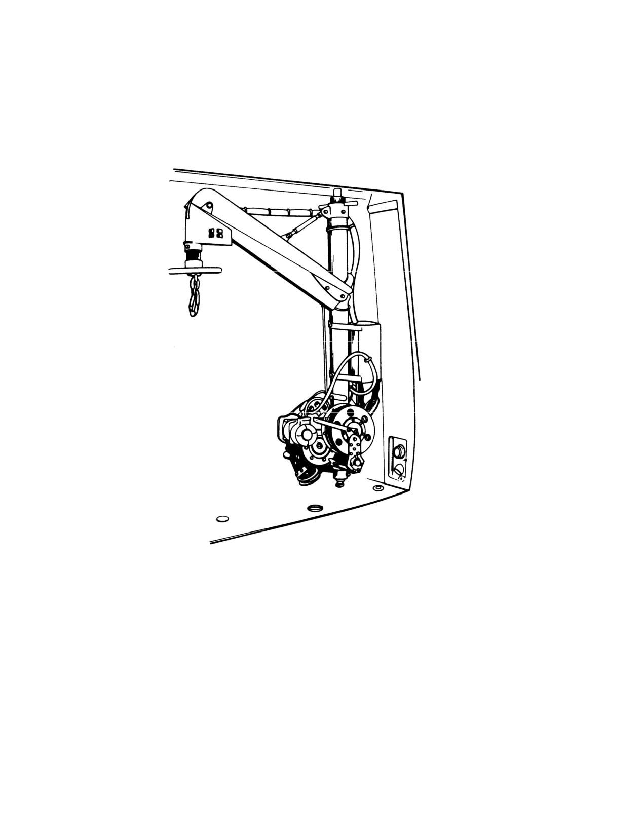
4-27. High Performance Hoist. Provisions have been
speed when hook is 8 to 10 feet from up-stow position.
made for the installation of an internal rescue hoist
Number Four switch further limits cable speed when
(Figure 4-2). The hoist may be installed in any one of
hook is 12 to 18 inches from the up-stow position. The
our positions in the helicopter cabin.
The hoist
first and last 20 feet of the cable are painted red. An
installation consists of a vertical column extending from
elapsed time meter and power-on indicator are located
the floor structure to the cabin roof, a boom with an
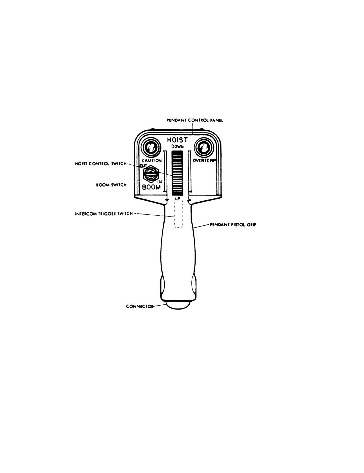
on the control panel. A pistol grip control (Figure 4-6) is
electrically powered traction sheave, and an electrically
provided for the hoist operator and contains a boom
operated winch. Two electrical control stations for the
in/out switch, a variable speed control, cable limit and
operation of the rescue hoist are provided, one for the
overtemperature indicator (when hoist operating
pilot, and one for the hoist operator. A control switch is
temperature limit has been exceeded the over temp light
located on the cyclic control stick and provides up and
will come on). (Secure hoist as soon as operations
down operation of the hoist as well as positioning the
permit), and an intercommunication switch. The hoist
boom (Figure 2-5). A pendant control is provided for the
has 250 feet of usable cable. Power is provided by the
hoist operator and contains a boom positioning switch
essential bus. Circuit protection is provided by the
and a toggle switch for hoist operation (Figure 4-6). The
RESCUE HOIST POWER, RESCUE HOIST CONT, and
pilot control will override the hoist operators control. A
RESCUE HOIST CABLE CUTTER circuit breakers.
pressure cartridge cable cutter is provided with two
RESCUE HOIST CABLE CUTTER circuit breaker
guarded cable cutter switches. The pilot cable cutter
controls only the pilot’s cable cutter switch.
switch is mounted on the pedestal and the hoist
Change 17
(4-7 blank)/4-8
TM 55-1520-210-10
4-28. Preflight Procedures.
11. SPEED MODE switch High.
12. HOIST switch (pilot) Down. Reel cable out until
WARNING
caution light is out on pendant (approximately 10 feet).
If
hoist is installed check for
installation of safety clip.
13. HOIST control switch (pilot) Reel m cable and
observe that cable speed slows when caution light
1. Check that vertical shaft for ceiling attaching
comes ON (approximately 10 feet).
point is raised vertically to prevent the ceiling attaching
device from disconnecting.
14. Boom up limit switch actuator arm-Push up on
arm during reeling in to check that hoist stops running
2. Oil level Check in hoist and boom head.
when up limit switches are actuated. Observe that cable
speed slows when hook is 12 to 18 inches from the full
3. RESCUE HOIST CONT, RESCUE HOIST
up position when cable is reeled in with no load on hook.
POWER AND RESCUE HOIST CABLE CUTTER circuit
breakers Check out.
15. Repeat steps 12 through 14 using the boom
switch (pendant). Check that cable speed can be
4. CABLE CUT switches (pilot and hoist operator)
regulated by the control from 0 to 250 foot per minute
guard Down and safetied.
when cable is reeled out beyond the 10 feet caution light.
(Caution light is out). Check pilots override during
5. Deleted.
reeling out and in.
6. Boom sheave Check that no foreign matter is
16. SPEED MODE switch LOW SPEED and repeat
entrapped at sheave.
steps 12 through 15.
7. GPU Connect to helicopter.
17. Hoist switch (pilots) Rotate boom in the stowed
position.
8. RESCUE HOIST CONT and RESCUE HOIST
POWER circuit breakers In. Blue POWER ON light and
18. RESCUE HOIST CONT, RESCUE HOIST
yellow CAUTION
POWER and RESCUE HOIST CABLE CUTTER circuit
light should be on and fan should be operating.
breakers Out upon completion of preflight check.
9. BOOM switch (Pendant) Rotate boom out and
4-29. Operating Procedures.
in, check hoist switch (pilot) override during operation.
1. RESCUE HOIST CONT, RESCUE HOIST
10. HOIST switch (pilot) Rotate boom out.
POWER and CABLE CUTTER breakers In.
2. Blue POWER ON and yellow CAUTION indicator
WARNING
lights should be on.
The cable should be reeled out and in
within 30 degrees of vertical during
WARNING
these checks. Care should be taken
to avoid twisting the cable which will
Hands must be kept off hoist boom
cause it to kink.
during operation to prevent hand
entrapment and injury.
NOTE
Observe the condition of the hoisting
3. BOOM switch Rotate boom out.
cable to assure that there are no
4. SPEED MODE switch As required.
broken wires or kinks.
Change 17
4-9
TM 55-1520-210-10
5. HOIST switch DOWN. Adjust cable reel-out
WARNING
speed as required. CAUTION light should be out when 8
to 10 feet of cable is reeled out
When a load is attached on the hoist
hook (and if conditions permit), it is
6. HOIST control switch UP and adjust cable
advisable not to make abrupt
reeling speed as required. CAUTION light should be ON
changes in helicopter attitude until
when rescue hook is 8 to 10 feet from up stow position.
load is aboard or raised as dose as
Reel cable completely up.
possible. G-forces on hoist could
become excessive if hoist load is
CAUTION
being
raised
during
abrupt
When hoist is installed in positions 1
movements of helicopter. These G-
or 4, the boom head assembly and
forces could result in the yield or
hook assembly could bump the
failure of the hoist cable.
pilot/copilot helmets if stowed behind
seat back.
4-32. Inflight Procedures Hoist Operator.
Refer to FM 8-10-6 for litter missions.
7. BOOM OUT/IN switch Rotate boom in.
WARNING
8. RESCUE HOIST POWER, RESCUE CONT and
CABLE CUTTER circuit breakers Out.
When any crewmember is not in his
4-30.
Before Takeoff RESCUE HOIST CABLE
seat and is in the vicinity of open
CUTTER, RESCUE HOIST CONT and RESCUE HOIST
cargo door, he shall be secured with
POWER circuit breakers Out.
a gunner harness.
All hoist
operations will be coordinated with
4-31. Inflight Procedures.
the pilot. Continuous status reports
required.
WARNING
1. Doors Open as required.
Operations during gusty or turbulent
2. Hoist operator ICS panel HOT MIC/PRIVATE.
wind conditions may result in
contracting the lateral cyclic control
WARNING
stops. During hoisting operations
the
helicopter
should
be
positioned to maximize the control
Attempt to discharge electrostatic
margins.
charge on hook before letting it touch
person to be hoisted. With personnel
1. Hover over pick-up location.
suspended on the hoist cable, adjust
cable sway and speed as needed in
2. Use operating procedures as required. Pilot
order to avoid catching personnel
should lift load off ground by increasing collective to
under the aircraft or bumping
ensure helicopter control with the load.
personnel against the aircraft.
Change 17
4-10
TM 55-1520-210-10
3. When helicopter is hovered over pickup loca-
(a) Condition and installation.
tion use operational procedures as required.
(b) Freedom of movement: fore, aft, and lateral.
4, Pull out RESCUE HOIST CONT, RESCUE HOIST
POWER and RESCUE HOIST CABLE CUTTER circuit
(c) Centering springs (3)-Check for centering of
breakers upon completion of hoist operations.
the hook.
4-33. Engine Shutdown Procedures
(d) Shear pin installation-The hook should not ro-
tate.
1. RESCUE HOIST CONT circuit breaker-in.
(e) Electrical wiring-Condition and installation.
2. Hoist-Stowed position.
(f) Manual release cable-Condition and installa-
3. RESCUE HOIST CONT circuit breaker-Out.
tion.
4. Enter the length of cable and number of lifts
(g) Cargo hook-Closed.
used in the remarks section of DA Form 2408-13.
2. Hook operation-Check as follows:
4-34. Cargo Hook
(a) BAT switch-ON.
Caution
(b) CARGO RELEASE switch-ARM. The CARGO
Helicopters equipped with a nonrotating
RELEASE light should illuminate.
cargo suspension unit, which maintains the
hook in a fixed position (facing forward),
(c) Pilot electrical release switch-Press and hold.
should be used only with a cargo sling hav-
The cargo hook should open with slight pressure ap-
ing a swivel attachment ring. A device
plied to the hook.
which may be used for this application is:
(d) Cargo hook-Close. Release the pilot electri-
Sling, Endless, Nylon Webbing, Type 1, 10
inch, NSN
3940-00-675-5001.
cal release switch.
a. Description. External cargo can be carried by
(e) Copilot electrical release switch-Press and
means of a short single cable suspension unit, se-
hold. The cargo hook should open with slight pres-
cured to the primary structure and located at the
sure applied to the hook.
approximate center of gravity. This method of at-
(f) Cargo hook-Close. Release the copilot electri-
tachment and location has proved to be the most
cal release switch.
satisfactory for carrying external cargo. Pitching and
rolling due to cargo swinging is minimized, and good
(g) Manual release-Press. The cargo hook
stability and control characteristics are maintained
should open with 20 to 30 pounds pressure applied
under -load. A MANUAL CARGO RELEASE PUSH
to the hook.
pedal is located between the pilot tail rotor control
pedals, and an electrical release pushbutton switch
(h) Cargo hook-Close.
is on the cyclic control stick, Before the electrical
release switch on the cyclic control stick can be ac-
(i) CARGO RELEASE switch-OFF The CARGO RE-
tuated, the CARGO RELEASE switch on the overhead
LEASE light should go off.
panel must be positioned to ARM MISC. When not in
use, the cargo suspension unit need not be re-
(j) Apply approximately 20 to 30 pounds pressure
moved, nor does it require stowing. Three cable and
to the hook-The cargo hook should not open.
spring attachments keep the unit centralized, and
(k) Pilot and copilot electrical release switches-
the hook protrudes only slightly below the lower sur-
Press. The cargo hook should not open. Release the
face of the helicopter. A rear view mirror enables
switches.
the pilot to visually check operation of the external
cargo suspension hook.
(l) BAT switch-OFF.
b. Prefiight Procedure.
c. Deleted.
1. Hook assembly-Check as follows:
d. Deleted.
Change 5
4-11
TM
55-1520-210-10
4-35. Parachute Operations
b. After the last chutist has exited the aircraft, the
a. Crewmembers must become familiar with pro-
crew chief will pull in the static lines and will hold
cedures outlines in TM 57-220 prior to parachute op-
them secured until the aircraft has landed.
erations.
Caution
At no time during flight will the static line,
snap hook or safety pins be disconnected
from the aircraft static /ine anchor cable.
4-12
Change 5
TM 55-1520-210-10
Figure
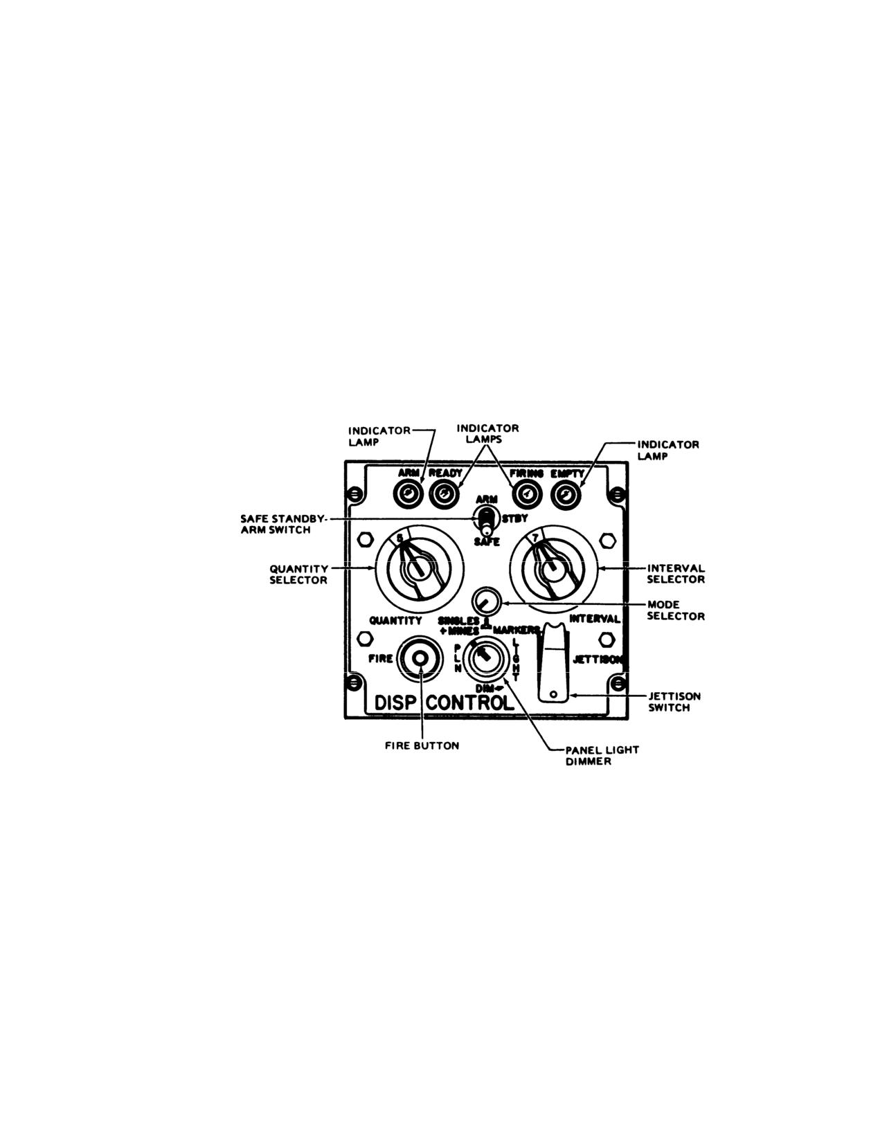
4-1. Mine Dispenser Control Panel-Typical
4-13
TM
55-1520-210-10
Figure
4-2. Hoist Installation-Typical
4-14
TM
55-1520-210-10
Figure 4-3, 4-4 and 4-5 has been deleted.
Change 14
4-15
TM 55-1520-210-10
Figure
4-6. Control Pendant Assembly, High Performance Hoist
4 -
1 6
TM 55-1520-210-10
Chapter 5
Operating Limits and Restrictions
Section I. GENERAL
5-1. Purpose. This chapter identifies or refers to all
and any additional data that would aid maintenance
important operating limits and restrictions that shall be
personnel in the maintenance action that may be
observed during ground and flight operations.
required.
5-2. General. The operating limitations set forth in this
5-4. Minimum Crew Requirements. The minimum
chapter are the direct results of design analysis, tests,
crew required to fly the helicopter is one pilot whose
and operating experiences. Compliance with these limits
station is in the right seat. Additional crewmembers as
will allow the pilot to safely perform the assigned
required will be added at the discretion of the
missions and to derive maximum utility from the
commander, in accordance with pertinent Department of
helicopter.
the Army regulations.
5-3. Exceeding Operational Limits. Anytime an
operational limit is exceeded an appropriate entry shall
be made on DA Form 2408-13. Entry shall state what
limit or limits were exceeded, range, time beyond Limits,
Section II. SYSTEM LIMITS
5-5. Instrument Markings (Figure 5-1).
Each tape strip aligns to increment marks on the dial
face so correct operating limits are portrayed. The pilot
a Instrument Marking Color Codes.. Operating
should occasionally verify alignment of the glass to the
limits and ranges color markings which appear on the
dial face. For this purpose, all instruments that have
dial faces of engine, flight, and utility system instruments
range markings have short, vertical white alignment
are illustrated with the following symbols:
marks extending from the dial glass onto the fixed base
of the indicator. These slippage marks appear as a
R-Red, G-Green, Y-Yellow
single vertical line when limitation markings on the glass
properly align with reading increments on the dial face.
RED markings on the dial faces of these instruments
However, the slippage marks appear as separate radial
indicate the limit above or below which continued
lines when a dial glass has rotated.
operation is likely to cause damage or shorten life. The
GREEN markings on instruments indicate the safe or
5-6. Rotor Limitations.
normal range of operation. The YELLOW markings on
instruments indicate the range when special attention
a. Refer to Figure 5-1.
should be given to the operation covered by the
instrument.
b. When metal main rotor blades are installed,
restrict rotor speed to 319 to 324 RPM (6500 to 6600
b. Instrument Glass Alignment Mark. Limitation
Engine RPM) during cruise flight This restriction does not
markings consist of strips of semitransparent color tape
apply when composite main rotor blades (CB) are
which adhere to the glass outside of an indicator dial.
installed.
Section II. POWER LIMITS
5-7. Engine Limitations.
c. Health Indicator Test When a difference
between a recorded EGT and the baseline EGT is plus
a. Refer to Figure 5-1.
or minus 20° C or greater, make an entry on DA Form
2408-13-1; if +/-30° C or greater, make an entry on DA
b. Maximum starter energize time is 40 seconds
Form 240813-1 and do not fly the aircraft.
with a three-minute cooling time between start attempts
with three attempts in any one hour.
Change 17
5-1
TM 55-1520-210-10
Section IV. LOADING LIMITS
5-8. Center of Gravity Limitations.
b. Maximum Gross Weight for Towing. The
maximum gross weight for towing is 9500 pounds.
a. Center of gravity limits for the helicopter to which
this manual applies and instructions for computation of
c. Cargo Hook Weight Limitations. Maximum
the center of gravity are contained in Chapter 6.
allowable weight for the cargo hook is 4000 pounds.
b. Do not carry external loads if the cg is aft of
d. Weight Distribution Limitations.
Cargo
station 142 prior to lifting external load.
distribution over the cargo floor area shall not exceed
100 pounds per square foot. For information pertaining
c. When flying at an aft cg (station 140 to 144)
to weight distribution, refer to Chapter 6.
terminate an approach at a minimum of five-foot hover
prior to landing to prevent striking the tail on the ground.
5-10. Turbulence Limitations.
Practice touchdown autorotations shall not be attempted
with the cg aft of 140 because termination at 5 feet is not
a. Intentional flight into severe or extreme
possible.
turbulence is
prohibited.
5-9. Weight Limitations.
b. Intentional flight into moderate turbulence is not
a. Maximum Gross Weight. The maximum gross
recommended when the report or forecast is based on
weight for the helicopter is 9500 pounds. The maximum
aircraft above 12,500 pounds gross weight.
gross weights for varying conditions of temperature,
altitude, wind velocity, and skid height are shown in
c. Intentional flight into thunderstorms is prohibited.
Chapter 7 or Chapter 7.1.
Section V. AIRSPEED LIMITS
5-11. Airspeed Limitations.
the fully open position, speed should be reduced to 50
KIAS or below until the door is secured. Crewmembers
a. Refer to Figure 5-2 MB or Figure 5-2.1 CB for
should ensure that they are fastened to the helicopter by
forward airspeed limits.
seat belts or other safety devices while securing the
cabin doors inflight.
b. Sideward flight limits are 30 knots.
f. Flight above 60 KIAS with roof mounted pilot
c. Rearward flight limit is 30 knots.
tube or 50 KIAS with nose mounted pilot tube with one
M56 mine disperser installed and the other disperser
d. The helicopter can be flown up to VNE with the
subsystem removed is prohibited.
cabin doors locked in either the closed position or the
fully open position. Flight above 50 KIAS with the cabin
g. Mine Disperser Jettisoning Limits. Except in an
doors in the unlocked position is prohibited
emergency, the mine dispersing subsystem M56 shall
not be jettisoned above 60 KIAS with roof mounted pilot
e. The helicopter can be flown up to an IAS of 50
tube or 50 KIAS with nose mounted pilot tube.
knots with one door open and one door closed. This will
allow for missions such as rappelling, paradrop, and use
of rescue hoist If a door comes open or unlocked from
Section VI. MANEUVERING LIMITS
5-12. Prohibited Maneuvers.
c. Intentional flight below +0.5 G is prohibited.
Refer to low G maneuvers, paragraph 8-53.
a. Abrupt inputs of flight controls cause excessive
d. The speed for any and all maneuvers shall not
main rotor flapping, which may result in mast bumping
exceed the level flight velocities as stated on the
and must be avoided.
airspeed operating limits chart (Figure 5-2).
b. Intentional maneuvers beyond attitudes of +/- 30
degrees in pitch or +/- 60 degrees m roll are prohibited.
Change 17
5-2
TM 55-1520-210-10
Section VII ENVIRONMENTAL RESTRICTIONS
5-13. Environmental Restrictions.
d. Wind Limitation for Starting. Helicopter can be
a This helicopter is qualified for flight under
started in a maximum wind velocity of 30 knots or a
instrument meteorological conditions.
maximum gust spread of 15 knots. Gust spreads are not
normally reported. To obtain spread, compare minimum
b. Intentional flight into known icing conditions with
and maximum wind velocity.
the rotor blade erosion protection coating and
polyurethane
tape installed is prohibited. Icing
e Temperature Limitation (Hub Spring Aircraft
conditions include 7RACE’, ’LIGHT, ’MODERATE’ and
Only). Remove elastomeric springs prior to operating
’HEAVY’. This helicopter may be flown in light or trace
aircraft when OAT is below -20° C (-5°F) or If this
icing conditions when the rotor blade erosion protection
temperature is anticipated to occur during flight. If,
coating and polyurethane tape are no installed.
however, sub
-20°C temperatures are encountered
during flight change altitude in an attempt to find warmer
c. Wind Limitation.
air Elastomeric springs shall be reinstalled when the
OAT is expected to stay above -20°C or the threat of sub
(1) Maximum cross wind for hover is 30 knots
20°'C temperatures no longer exists.
(2) Maximum tail wind for hover Is 30 knots.
Section III HEIGHT VELOCITY
5-14. Height Velocity. The Height Velocity diagram (fig
is applicable for all gross weights up to and including
9-3) Is based on an extrapolation of test data. The chart
9500 pounds.
Section IX INTERNAL RESCUE HOIST (BREEZE ONLY)
WARNING
Use of a Breeze BL 8300 series Internal Rescue Hoist is prohibited.
5-15. Deleted.
Section X OTHER LIMITATIONS
5-16. Towing. The helicopter should not be towed for
5-17. Slope
Landing Limitations.
Analysis
25 minutes after the battery and inverter switches have
indicates the following maximum slope landing capability
been turned off to prevent damage to attitude and
under nominal conditions.
directional gyros. If the helicopter must be towed prior to
the 25 minute limit, the battery and inverter switches
1. Cross slope or nose-up slope 10 degrees.
shall be turned on. Wait five minutes after the switches
are on before moving the helicopter.
2. Nose down slope 7 degrees.
Caution is to be exercised for slopes greater than
5
degrees, since rigging, loading, and wind conditions
may result in contacting the control stops.
Change 17
5-3
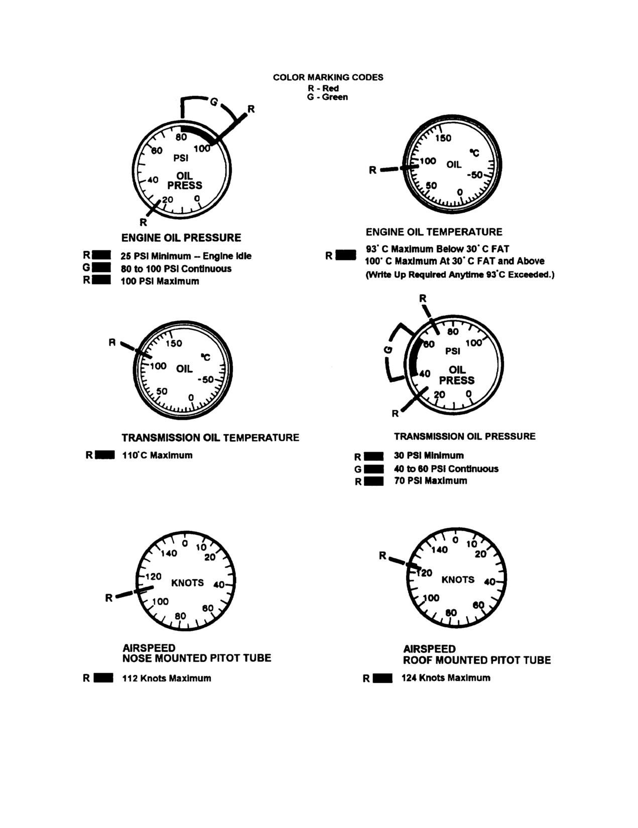
TM 55-1520-210-10
Refer to Figure 6-2, Airspeed Operating
Refer to Figure 5-2, Airspeed Operating
Limits for Additional Limitations.
Limits for Additional Limitations.
Figure 5-1. Instrument Markings (Sheet 1 of
3)
5-4
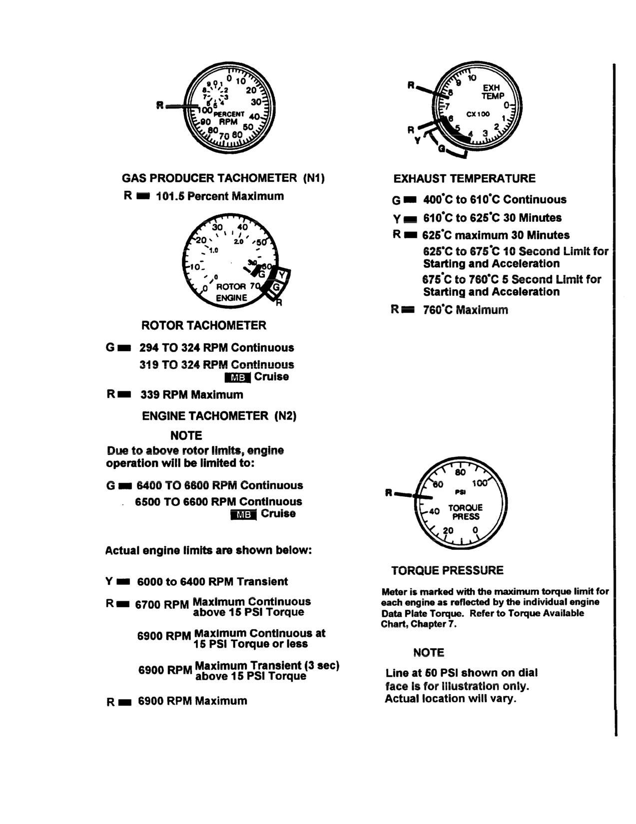
TM 55-1520-210-10
Figure 5-1. Instrumental Markings (Sheet 2 of 3)
Change 15
5-5
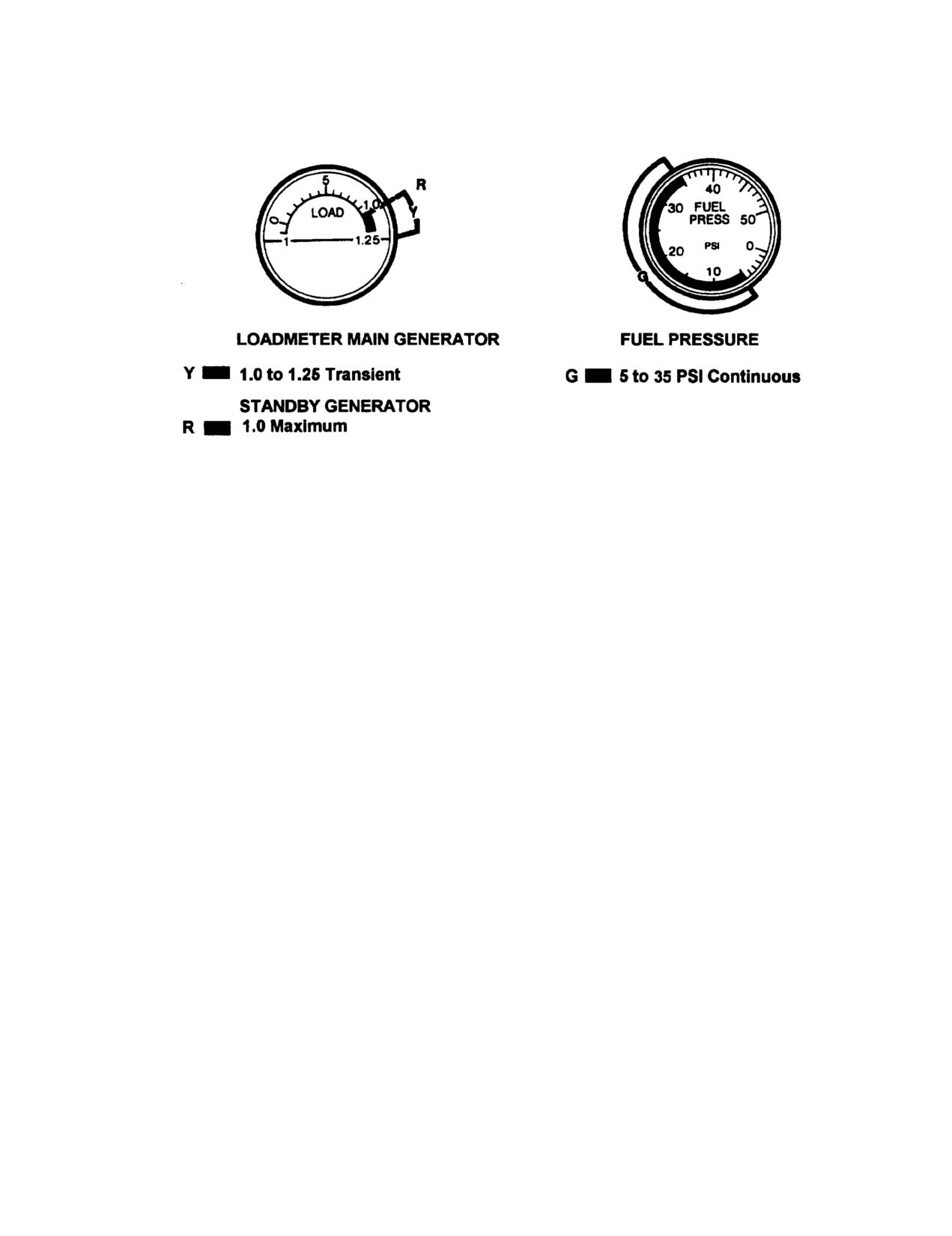
TM 55-1520-210-10
Figure 5-1. Instrument Marking (Sheet 3 of 3)
5-6
TM 55-1520-210-10
AIRSPEED OPERATING LIMITS
EXAMPLE
WANTED
INDICATED AIRSPEED
AND DENSITY ALTITUDE
KNOWN
GROSS WEIGHT = 8500 LB
PRESSURE ALTITUDE = 7500 FEET
FAT = -20°C
ROOF MOUNTED
SYSTEM
METHOD
ENTER PRESSURE
ALTITUDE
MOVE RIGHT TO
FAT
MOVE DOWN TO GROSS WEIGHT
MOVE LEFT, READ INDICATED
AIRSPEED = 110 KNOTS
REENTER PRESSURE ALTITUDE
MOVE RIGHT TO FAT
MOVE DOWN, READ DENSITY
ALTITUDE = 5000 FEET
DATA BASIS: DERIVED FROM FLIGHT TEST
Figure 5-2. Airspeed operating limits chart
5-7
Change 8
TM
55-1520-210-10
AIRSPEED OPERATING LIMITS
EXAMPLE
WANTED
INDICATED AIRSPEED
DENSITY ALTITUDE
KNOWN
GROSS WEIGHT = 8500 POUNDS
PRESSURE ALTITUDE = 7500 FEET
FAT = -20°C
ROOF MOUNTED PITOT TUBE SYSTEM
METHOD
ENTER PRESSURE ALTITUDE
MOVE RIGHT TO FAT
MOVE DOWN TO GROSS WEIGHT
MlOVE LEFT, READ INDICATED AIRSPEED =
106.5 KNOTS
REENTER PRESSURE ALTITUDE
MOVE RIGHT TO FAT
MOVE DOWN, READ DENSITY ALTITUDE =
5000 FEET
DATA BASIS AEFA PROJECT NO. 84-33 (ROOF MOUNTED PITOT STATIC TUBE SYSTEM WITH WIRE CUTTERS), JUNE 1988
AND AFFTC FLIGHT TEST FTC-TDR-64027 (NOSE MOUNTED PITOT STATIC TUBE SYSTEM)
Figure 5-2.1 Airspeed operating limits chart
5-8
Change 8
TM 55-1520-210-10
Chapter 6
Weight/Balance and Loading
Section I GENERAL
6-1. General. Chapter 6 contains sufficient instructions
6-3. Helicopter Station Diagram. Figure 6-1 show the
and data so that an aviator knowing the basic weight and
helicopter reference datum lines, fuselage stations, butt
moment of the helicopter can compute any combination
lines, water lines and jack pad locations. The primary
of weight and balance.
purposes of the figure is to aid personnel m the
computation of helicopter weight/balance and loading.
6-2. Classification of Helicopter. Army UH-IH/V
helicopters are in class
2.
Additional directives
governing weight and balance of class 2 aircraft forms
and records are contained in AR 95-1, TM 55-1500-342-
23, and DA PAM 738-751.
Section II WEIGHT AND BALANCE
64. Loading Charts.
6-6. DD Form 365-3-Basic Weight and Balance
Records. The form is initially prepared by the
a Information The loading data contained in this
manufacturer at time of delivery of the helicopter. The
chapter is intended to provide information necessary to
form is a continuous history of the basic weight and
work a loading problem for the helicopters to which this
moment resulting from structural and equipment
manual is applicable.
changes. At all times the last entry is considered current
weight and balance status of the basic helicopter.
b. Use. From the figures contained in this chapter
weight and moment are obtained for all variable load
6-7. DD Form
365Weight and Balance Clearance
items and are added to the current basic weight and
Form F.
moment (DD Form 365-4) to obtain the gross weight and
moment.
a General.
The form is a summary of
actual disposition of the load in the helicopter It records
(1) The gross weight and moment are
the balance status of the helicopter, step-by-step. It
checked on DD Form
365-3 to determine the
serves as a worksheet on which to record weight and
approximate center of gravity (cg).
balance calculations, and any corrections that must be
made to ensure that the helicopter will be within weight
(2) The effect on cg by the expenditures in
and cg limits.
flight of such items as fuel, ammunition etc., may be
checked by subtracting the weights and moments of
b. Form Preparation. Specific instructions for filling
such items from the takeoff weight and moments and
out the form are given in TM 55-1500-342-23
checking the new weight and moment on the CG limits
Chart.
NOTE
Allowable gross weight for take off
6-5. DD Form 365-1-Basic Weight Checklist The form
and landing is 9500 pounds.
is initially prepared by the manufacturer before the
helicopter is delivered. The form is a tabulation of
equipment that is, or may be, installed and for which
provision for fixed stowage has been made in a definite
location.
The form gives the weight, arm and
moment/100 of individual Items for use in correcting the
basic weight and moment on DD Form
365-3 as
changes are made m this equipment.
Change 17
6-1
TM 55-1520-210-10
Section IIL FUEL/OIL
6-8. Fuel. Refer to Figure 6-2.
c. The following information is provided to show the
general range of fuel specific weights to be expected.
a. For a given weight of fuel n the crashworthy
Specific weight of fuel will vary depending on fuel
system tanks, there is a very small variation m fuel
temperature. Specific weight will decrease as fuel
moment with change in fuel specific weight. Fuel
temperature increases and increase as fuel temperature
moments should be determined from Figure 6-2 (Sheet 1
decreases at the rate of approximately 0.1 Ib/gal for each
of 2) which is based on a specific weight of 6 5 lb/gal.
15° C change. Specific weight may also vary between
Additional correction for fuel specific weight is not
lots of the same type fuel at the same temperature by as
required. For the auxiliary fuel tank the fuel arms are
much as 0.5 lb/gal. The following approximate fuel
constant. Thus, for a given weight of fuel there is no
specific weights at 15° C may be used for most mission
variation m fuel moment with change in fuel specific
planning.
weight.
FUEL TYPE
SPECIFIC WEIGHT
b The fuel tank usable fuel weight will vary
JP-4
6 5 lb/gal
depending upon fuel specific weight. The aircraft fuel
JP-5
6.8 Ib/gal
gage system was designed for use with JP-4, but does
JP-8
6 7 lb/gal
tend to compensate for other fuels and provide
acceptable readings. When possible the weight of fuel
onboard should be determined by direct reference to the
6-9. Oil. For weight and balance purposes, engine oil is
aircraft fuel gages. The following information is provided
a part of basic weight.
to show the general range of fuel specific weights to be
expected.
Section IV. PERSONNEL
6-10. Personnel Compartment and Litter Provisions.
a. Combat equipped soldiers:
240 pounds per
individual.
a The personnel compartment provides seating for
eleven combat equipped troops (Figure 6-3 ). Seat belts
b. Combat equipped paratroopers: 260 pounds per
are provided for restraint.
individual.
b. Provisions and hardware are provided for up to
six patients. Refer to Figure 6-3.
c. Crew and passengers with no equipment
compute weight according to each individual's estimate.
6-11. Personnel Loading and Unloading. When
d. Litter Weight and Balance Data Refer to Figure
helicopter is operated at critical gross weights, the exact
6-3. Litter loads shall be computed at 265 pounds (litter
weight of each individual occupant plus equipment
and patient's weight combined).
should be used. If weighing facilities are not available, or
if the tactical situation dictates otherwise loads shall be
6-12. Personnel Moments. Refer to Figure 6-3.
computed as follows:
Section V. MISSION EQUIPMENT
6-13. Weight and Balance Loading Data
NOTE
a. System Weight and Balance Data. Refer to
If additional internal load is carried
Figure 6-6.
during hoisting operations this load
b. Hoist-Loading Data.
Use Hoist Loading
should be positioned on opposite
Limitations charts for hoist in forward right or forward left
side from hoist.
positions only (Figures 6-4 and 6-5).
c. Positions Hoist May Occupy in Cabin. Refer to
WARNING
Figure 6-7.
Longitudinal or lateral cg limits may
not permit maximum hoist loading
capability. The lesser of the two
loads derived from lateral and
longitudinal charts shall be used.
Change 17
6-2
TM 55-1520-210-10
Section VI. CARGO LOADING
6-14. Cargo Loading. The large cargo doors, open
loading Charts, weight and moment/100 are obtained for
loading area and low floor level preclude the need for
all variable load items and are added mathematically to
special loading aids.
Through loading may be
the current basic weight and moment/100 obtained from
accomplished by securing cargo doors m the fully open
chart C to arrive at the gross weight and moment.
position. Cargo tiedown fittings (Figures 6-8 and 6-9) are
located on cabin floor for securing cargo to prevent cargo
(2) The c.g. of the loaded helicopter can be
shift during flight.
determined from the gross weight and moment using the
c.g. limits chart (Figure 6-12). This figure may also be
6-15. Preparation of General Cargo.
used to determine if the helicopter is loaded within the
gross weight and c.g. limits
a. The loading crew shall assemble the cargo and
baggage to be transported. At time of assembly and
(3) The effect on c.g. of the expenditure
prior to loading, the loading crew shall compile data
inflight of such items as fuel and cargo should be
covering weight, dimensions, center of gravity (c.g.)
checked by subtracting the weight and moment of such
location and contact areas for each item.
items from the takeoff gross weight and moment and
checking the resulting weight and moment with the c.g
b. Heavier packages to be loaded shall be loaded
limits chart (Figure 6-12).
first and placed in the aft section against the bulkhead for
c.g. range purposes.
(4) This check will be made to determine
whether the c.g. will remain within limits during the entire
c. Calculation of the allowable load and loading
flight.
distribution shall be accomplished by determining the
final c. . location and remain within the allowable limits
6-17. Loading Procedures. The helicopter requires no
for safe operating conditions.
special loading preparation.
6-16.
Cargo Center of Gravity (cg.) Planning.
a. The loading procedure consists of locating the
load items in a manner which will maintain the c.g. within
a. Planning.
The items to be transported
limits. In general, the heaviest items should be placed in
should be assembled for loading after the weight and
the aft section near or against the aft bulkhead. Such
dimensions have been recorded.
placement locates the cargo near the helicopter c g. and
allows maximum cargo load to be transported, as well as
(1) Loading tune will be gained if the
maintaining the helicopter within safe operating c g. limits
packages are positioned as they are to be located in the
for flight.
helicopter.
b. The mission to be performed should be known to
(2) To assist m determining the locations of
determine the weight and moment of cargo, troop
the various items, the individual weights and total weight
transport, or litter patients to be carried on the return trip
must be known.
c. If troops or litter patients are to be carried, troop
(3) When these factors are known the cargo
seats and litter racks shall be loaded aboard and stowed.
loading charts (Figures 6-10 and 6-11) can be used as a
guide to determine the helicopter station at which the
d. Deleted.
package c.g. shall be located and the moment for each
item.
6-18. Loading and Unloading of Other Than General
Cargo.
(4) Aircraft c.g. will be affected by fuel
quantity. Variation in fuel loadings from that on board at
WARNING
takeoff to empty must be
considered during data
computation.
Before transporting nuclear weapons,
the pilot shall be familiar with AR 95-
(5) Final analysis of helicopter c.g. location
27, AR 504 and AR 50-5.
for loading shall be computed from the data presented in
this chapter.
The helicopter is capable of transporting nuclear
weapons, if required.
b. Computation of Cargo Center of Gravity.
6-19. Tiedown Devices. Refer to Figures 6-8 and 6-9.
(1) The loading data in this chapter will
provide information to work a loading problem. From the
Change 17
6-3
TM 55-1520-210-10
Section VII. CENTER OF GRAVITY LIMITS
6-20. Center of Gravity Limits. Refer to figure 6-12 for
gravity, of G’s. Following are the units of the force of
longitudinal limits. The lateral c.g. limits are 5 inches (5
gravity or G’s needed to restrain cargo in four directions:
inches to the right and left of the helicopter centerline).
The lateral c.g. limits will not be exceeded if external
DIRECTION
RESTRAINT CRITERIA
store loadings, are symmetrical, the hoist loading limits
(fig 6-4 and fig 6-5) are observed, and a reasonable
Forward
8.0 G’s
effort is made to evenly distribute internal loads from left
Aft
4.0 G’s
to right.
Lateral
8.0 G’s
Vertical
4.0 G’s (UP)
6-21. Restraint Criteria The amount of restraint that
must be used to keep the cargo from moving in any
direction is called the "Restraint Criteria’ and is
64
Change 17 usually expressed in units of the force of
Change 17
6-4
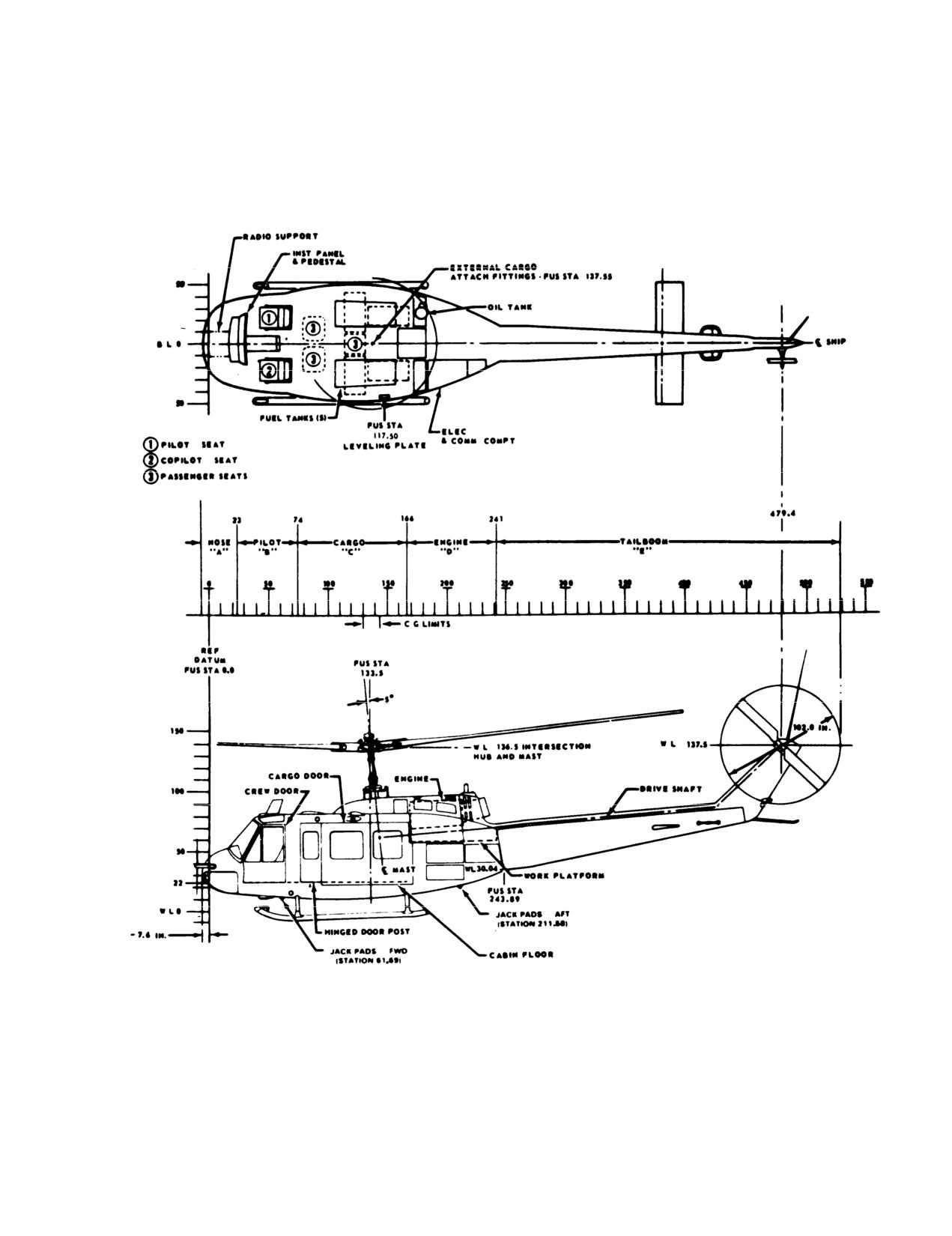
TM 55-1520-210-10
HELICOPTER DIAGRAM
Figure 6-1. Helicopter Station Diagram
6-5
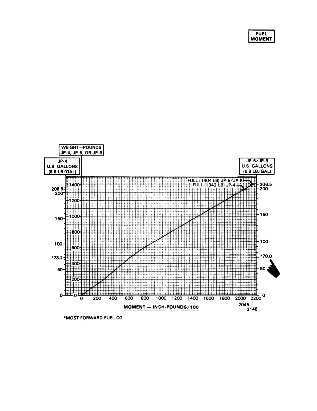
TM 55-1520-210-10
FUEL LOADING
CRASHWORTHY SYSTEM TANKS
EXAMPLE
WANTED
WEIGHT AND MOMENT FOR A GIVEN
QUANTITY OF USABLE FUEL IN
CRASHWORTHY FUEL SYSTEM.
KNOWN
U.S. GALLONS OF JP-4 FUEL.
METHOD
ENTER AT GALLONS ON JP-4 SCALE.
MOVE RIGHT TO READ WEIGHT
CONTINUE RIGHT TO INTERSECT DIAGONAL
LINE, THEN PROJECT DOWN TO READ
MOMENT/100 SCALE.
NOTE
THIS CHART PRESENTS FUEL MOMENT AS A
FUNCTION OF WEIGHT, UTILIZING A SINGLE CURVE
FOR ALL FUEL TYPES. GALLON EQUIVALENT
SCALES ARE BASED ON NOMINAL DENSITIES AT
15°C
Figure 6-2. Fuel Loading (Sheet
1 of 2)
6-6
Change 5
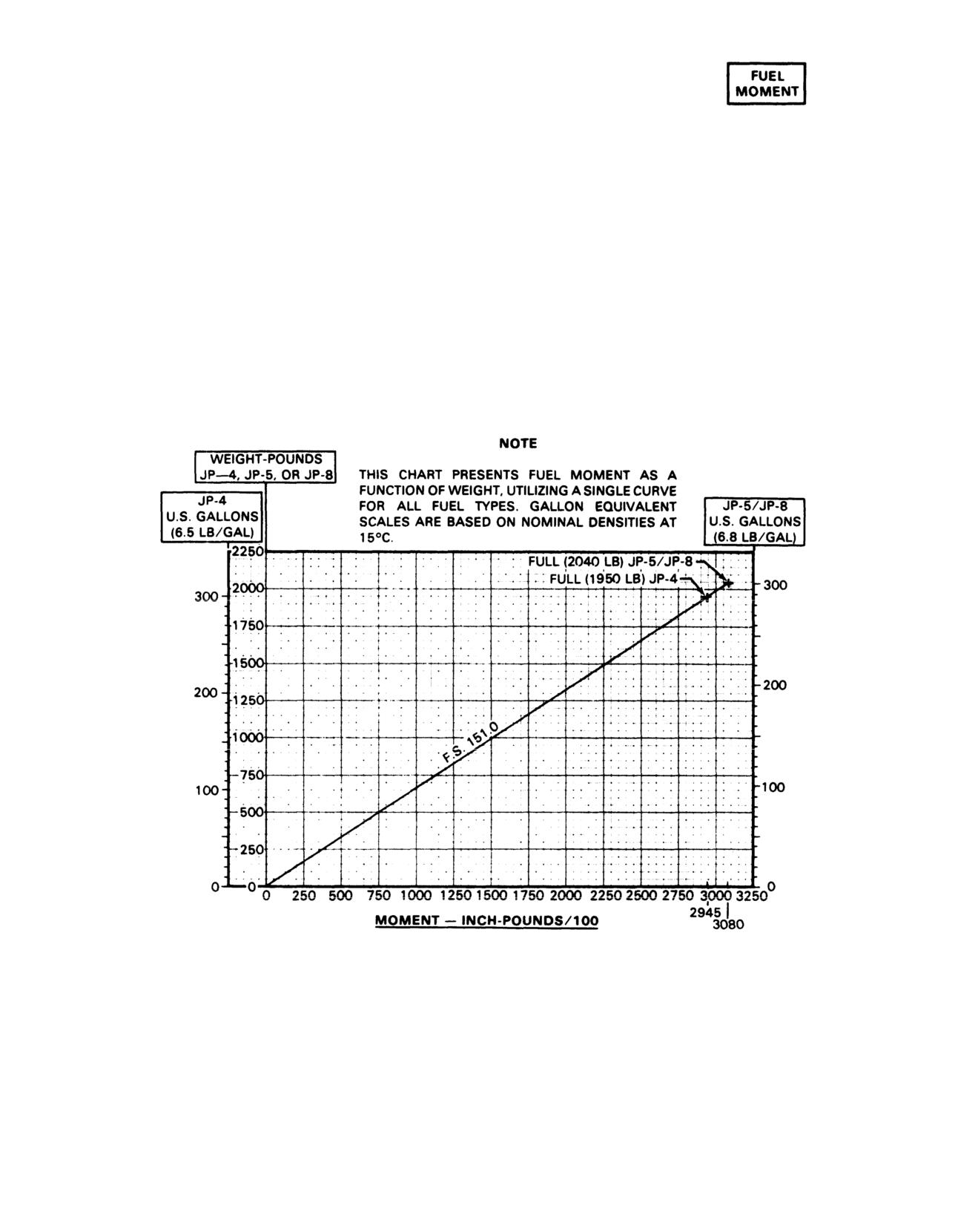
TM 55-1520-210-10
FUEL LOADING
AUXILIARY FUEL
300 GALLONS INTERNAL
(F.S. 151.0)
EXAMPLE
WANTED
WEIGHT AND MOMENT FOR A
GIVEN QUANTITY OF FUEL IN
AUXILIARY FUEL TANKS.
KNOWN
300 U.S. GALLONS OF JP-4 FUEL
(IN AUXILIARY TANKS ONLY).
METHOD
ENTER AT GALLONS ON JP-4 SCALE.
MOVE RIGHT TO READ WEIGHT.
CONTINUE RIGHT TO INTERSECT DIAGONAL LINE,
THEN PROJECT DOWN TO READ
MOMENT/100 SCALE.
Figure 6-2. Fuel Loading (Sheet 2 of 2)
6-7
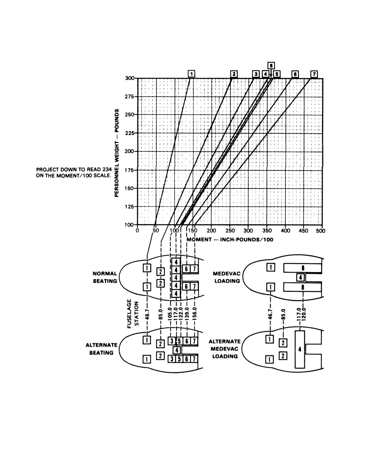
TM 55-1520-210-10
PERSONNEL LOADING CHART
MOMENT FOR PERSONNEL
EXAMPLE
WANTED
PERSONNEL MOMENT FOR A
GIVEN WEIGHT AND LOCATION
KNOWN
PERSONNEL WEIGHT OF 200
POUNDS AT F.S. 117.0 (Row 4)
METHOD
MOVE RIGHT FROM 200 LBS
TO THE LINE CONNECTING
WITH SEAT ROW 4.
Figure
6-3. Personnel Loading
6-8
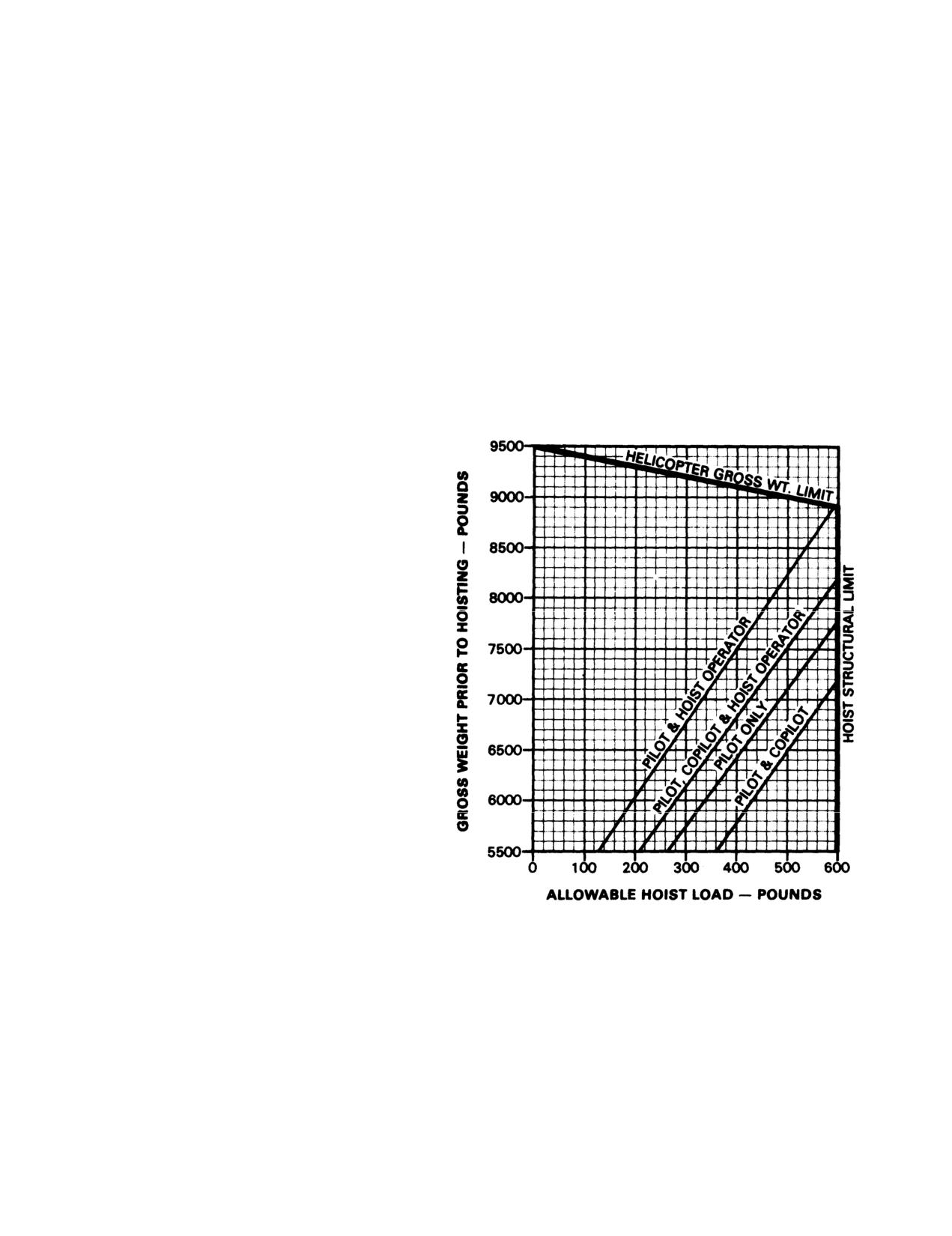
TM 55-1520-210-10
HOIST LOADING LIMITATIONS
DUE TO LATERAL C.G. LIMITS
HOIST IN FORWARD RIGHT POSITION
EXAMPLE
WANTED
MAXIMUM ALLOWABLE
HOIST LOAD
KNOWN
GROSS WEIGHT 8600 LBS
LONGITUDINAL C. G. 133.5,
CREW - PILOT & HOIST OPERATOR.
METHOD
ENTER GROSS WEIGHT
MOVE RIGHT TO INTERSECT
PILOT & HOIST OPERATOR CURVE.
MOVE DOWN TO READ
ALLOWABLE HOIST LOAD 550 LBS
NOTE
THE LESSER OF THE TWO WEIGHTS DERIVED
FROM LATERAL AND LONGITUDINAL CHARTS
SHALL BE USED (EXAMPLE 335 POUNDS).
GROSS WEIGHT TO BE THE LIGHTEST
WEIGHT OF THE HELlCOPTER DURING
HOISTING OPERATIONS, BUT NOT INCLUDING
THE WEIGHT OF THE HOIST LOAD. FUEL
BURNED PRIOR TO HOISTING OPERATION MUST
BE DEDUCTED FROM TAKEOFF GROSS WEIGHT
BEFORE COMPUTING ALLOWABLE HOIST LOAD.
Figure 6-4. Hoist Loading Limitations (Lateral CG)
6-9
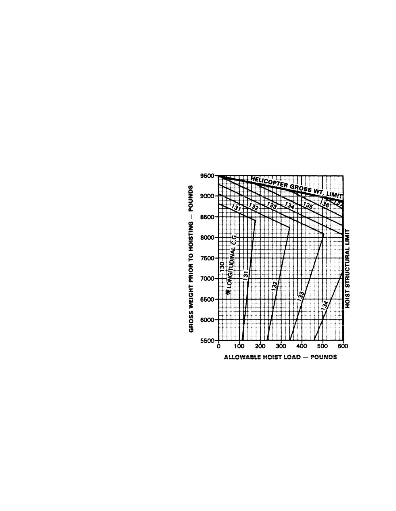
TM 55-1520-210-10
HOIST LOADING LIMITATIONS
DUE TO LONGITUDINAL C.G. LIMITS
HOIST IN FORWARD RIGHT OR FORWARD LEFT POSITION
EXAMPLE
WANTED
MAXIMUM ALLOWABLE
HOIST LOAD
GROSS WEIGHT 8600 LBS
LONGITUDINAL C.G. 133.5
PRIOR TO HOISTING.
METHOD
ENTER GROSS WT.
MOVE RIGHT TO C.G.
MOVE DOWN TO READ
ALLOWABLE HOIST LOAD 335 LBS
*GROSS WEIGHT AND C.G.
DO NOT INCLUDE HOIST LOAD
Figure 6-5. Hoist Loading Limitations (Longitudinal CG)
6-10
TM 55-1520-210-10
100,000 BTU HEATER
WINTERIZATION KIT
ITEM
WEIGHT
ARM
MOMENT/100
Complete Heater Instl. (205-706-001)
73.2
197.0
144.2
Winterization Kit (Muff Heater)
61.0
212.0
129.3
AFT BATTERY INSTALLATION
ITEM
WEIGHT
ARM
MOMENT/100
Battery (Fwd)
80.0
5.0
4.0
Battery (Aft)
80.0
233.0
186.4
Aft Battery Provisions (205-1682-1 )
15.0
224.8
33.8
300 GALLON INTERNAL AUXILIARY FUEL TANK
ITEM
WEIGHT
ARM
MOMENT/100
Deleted
Deleted
Tank, LH, Crashworthy
151.3
(*)
(**)
Tank, RH, Crashworthy
(*)
151.3
(**)
* Tank weight varies; use weight stamped on tank (use fuel loading chart for fuel weight).
**Depends on tank weight.
GLASS WINDSHIELD INSTALLATION
ITEM
WEIGHT
ARM
MOMENT/
100
Glass Windshield-Pilot Copilot (Both)
30.0
27.0
8.1
Glass Windshield-Pilot Only or Copilot Only
15.0
27.0
4.1
Figure 6-6. System Weight and Balance Data Sheet (Sheet 1 of 3)
Change 14
6-11
TM 55-1520-210-10
RESCUE HOIST (HIGH PERFORMANCE)
ITEM
WEIGHT
ARM
MOMENT/
100
Hoist-Forward RH Position (Arm Stowed Forward)
180 I
80.0
144.0
Hoist-Forward RH Position (Arm Stowed Aft)
180 I
84.0
151.2
Hoist-Forward LH Position (Arm Stowed Forward)
180 I
82.0
147.6
Hoist-Forward LH Position (Arm Stowed Aft)
180 I
84.0
151.2
I Weight after servicing with cable installed
M-23 DOOR MOUNTED M-60
ITEM
WEIGHT
ARM
MOMENT/
100
Armament Subsystem W/O Ammunition
128.0
142.6
182.5
Ammunition 7.62 MM (1200 Rounds)
78.0
142.6
111.2
Total Armament Subsystem W/Ammunition (1200 Rounds)
206.0
142.6
293.8
Ammunition Box (2 each) W/Cover Assembly
8.5
142.6
12.1
Machine Guns W/Ejection Control Bags (2 each) and Chute
Assembly (2 each)
66.5
142.0
94.4
Mount Assembly (2 each) W/Hardware
53.0
142.6
75.6
EXTERNAL STORES SUPPORT
ITEM
WEIGHT
ARM
MOMENT/
100
Stores Rack
Cross Beam Assys.
29.5
142.5
42.1
Fwd. Beam Assys.
11.5
129.0
14.8
Aft Beam Assys.
11.9
155.1
18.4
Fwd. Sway Brace Assys.
1.1
135.3
1.5
Aft Sway Brace Assys.
1.2
149.7
1.9
Hardware
3.1
142.9
4.4
Total Aft Stores Instl.
58.3
142.5
83.1
Stores Rack (205-707-013-11 )
Cross Beam Assys.
13.1
73.9
23.0
Fwd. Beam Assys.
11.7
63.0
Aft Beam Assys.
13.6
84.5
11.5
Fwd. Sway Brace Assys.
1.9
68.4
1.3
Aft Sway Brace Assys.
1.5
79.7
1.2
Hardware
3.2
74.0
2.4
Total Fwd. Stores Instl.
63.0
74.2
46.8
Figure 6-6. System Weight and Balance Data Sheet (Sheet 2 of 3)
6-12
Change 14
TM 55-1520-210-10
M52 SMOKE GENERATOR SUBSYSTEM
ITEM
WEIGHT
ARM
MOMENT/
100
A Kit
16.7
161.67
27.0
B Kit
39.64
120.08
47.6
-20.62
122.21
-25.2
C Kit Without Oil in Tank
117.5
127.57
149.9
C Kit With Oil in Tank (50 Gal)
492.5
121.81
599.9
MULTIARMAMENT STRUCTURAL SUPPORT KIT
ITEM
WEIGHT
ARM
MOMENT/
100
A Kit (Roof Hardpoints)
5.83
146.71
8.6
B Kit
205.87
141.87
292.1
M56 MINE DISPENSER (SUN-13D/A)
ITEM
WEIGHT
ARM
MOMENT/
100
Each
Dispenser Empty, Without Pallet
117
145.83
170.6
Each
Dispenser with Canisters Only
188
145.83
274.2
Each Dispenser-Loaded as Flown
640
143.79
920.3
AUXILIARY SUPPRESSOR KIT, EXHAUST SUPPRESSOR
ITEM
WEIGHT
ARM
MOMENT/
100
A Kit
4.0
228.0
9.1
B Kit
47
230.2
108.2
Figure 6-6. System Weight and Balance Data Sheet (Sheet 3 of 3)
Change 14
6-13
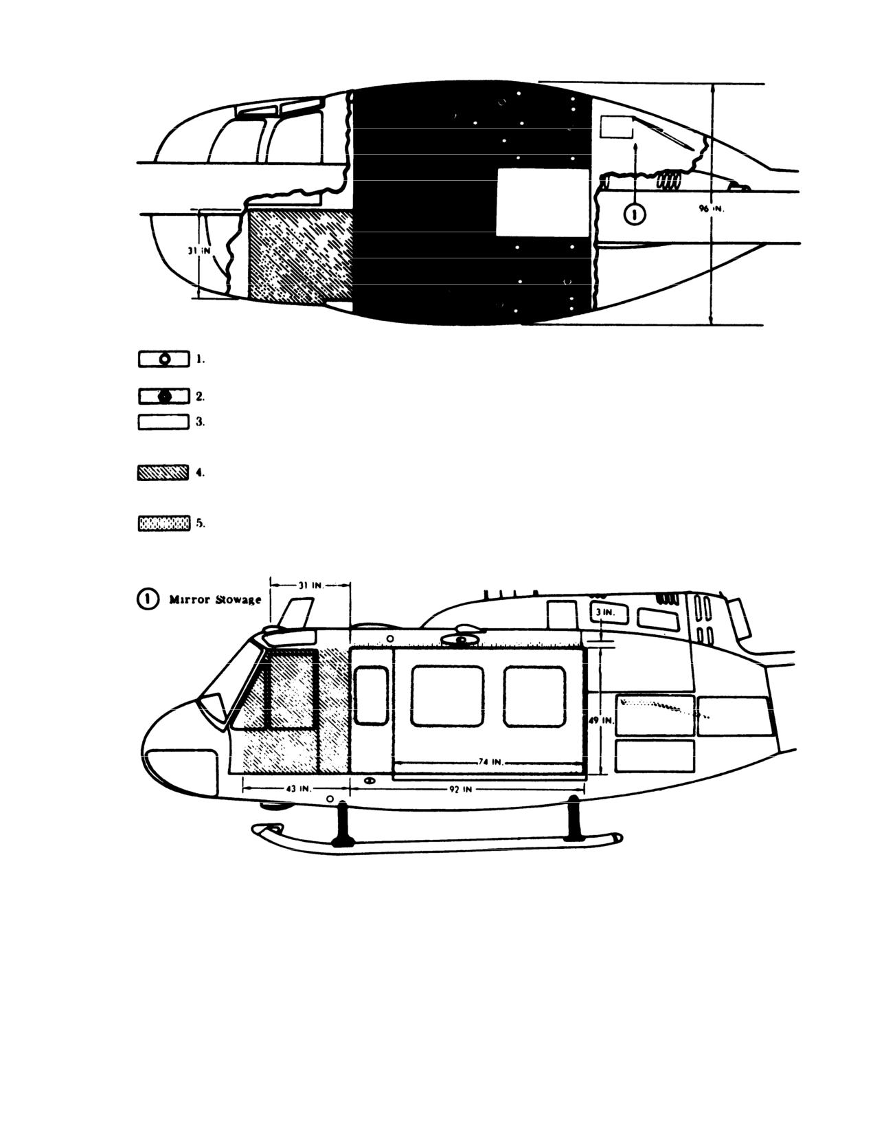
TM 55-1520-210-10
CODE
NOTES:
Tie-down
Fittings
Stanchion Fittings
1.
Floor tie-down fittings, strength 1250 pounds vertical, 500
Cargo Area,
pounds horizontal load per fitting. Each aft bulkhead tiedown
Maximum Loading
fitting is capable of thefolIowing loads: 1250 Ibs, parallel to
Dimensions
the bulkhead, 2195 Ibs at a 45° angle.
Optional Loading
2.
Bulkhead tie-down fittings are good for 2500 pounds
Area, Left Seat
ultimate per fitting perpendicular to the bulkhead.
Removed
3.
Tie-down fittings on the side of the beams are good for 1250
pounds ultimate per fitting perpendicular to the beams.
Interior Clearance
Above Maximum
4.
Two fittings at station 129.0 are good for 1250 pounds
Package at Center-
ultimate per fitting perpendicular to bulkhead.
line of Cabin
Figure 6-8. Cargo Compartment
6-15
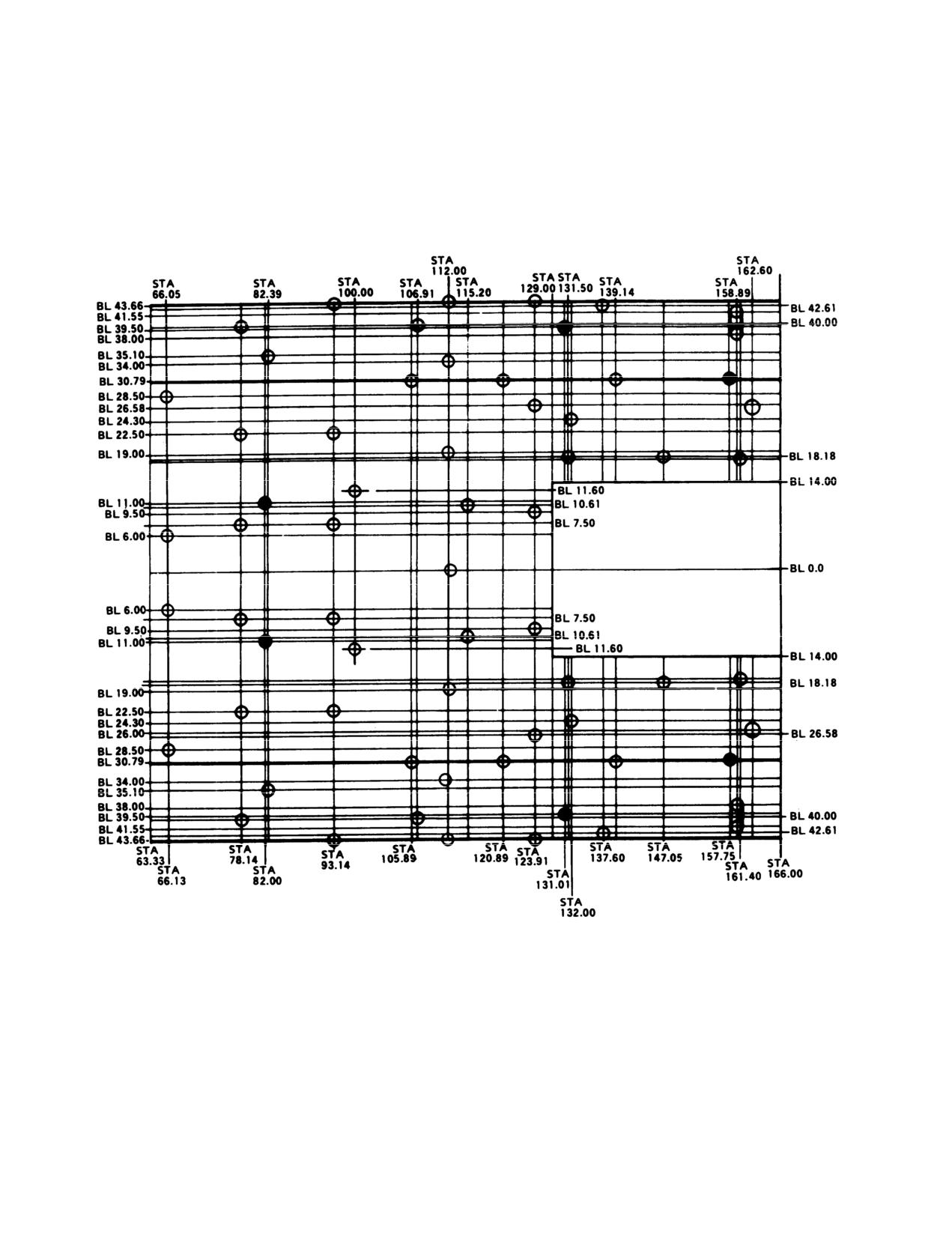
TM 55-1520-210-10
CARGO TIE DOWN FITTING DATA
Figure 6-9. Cargo Tiedown Fitting Data
6-16
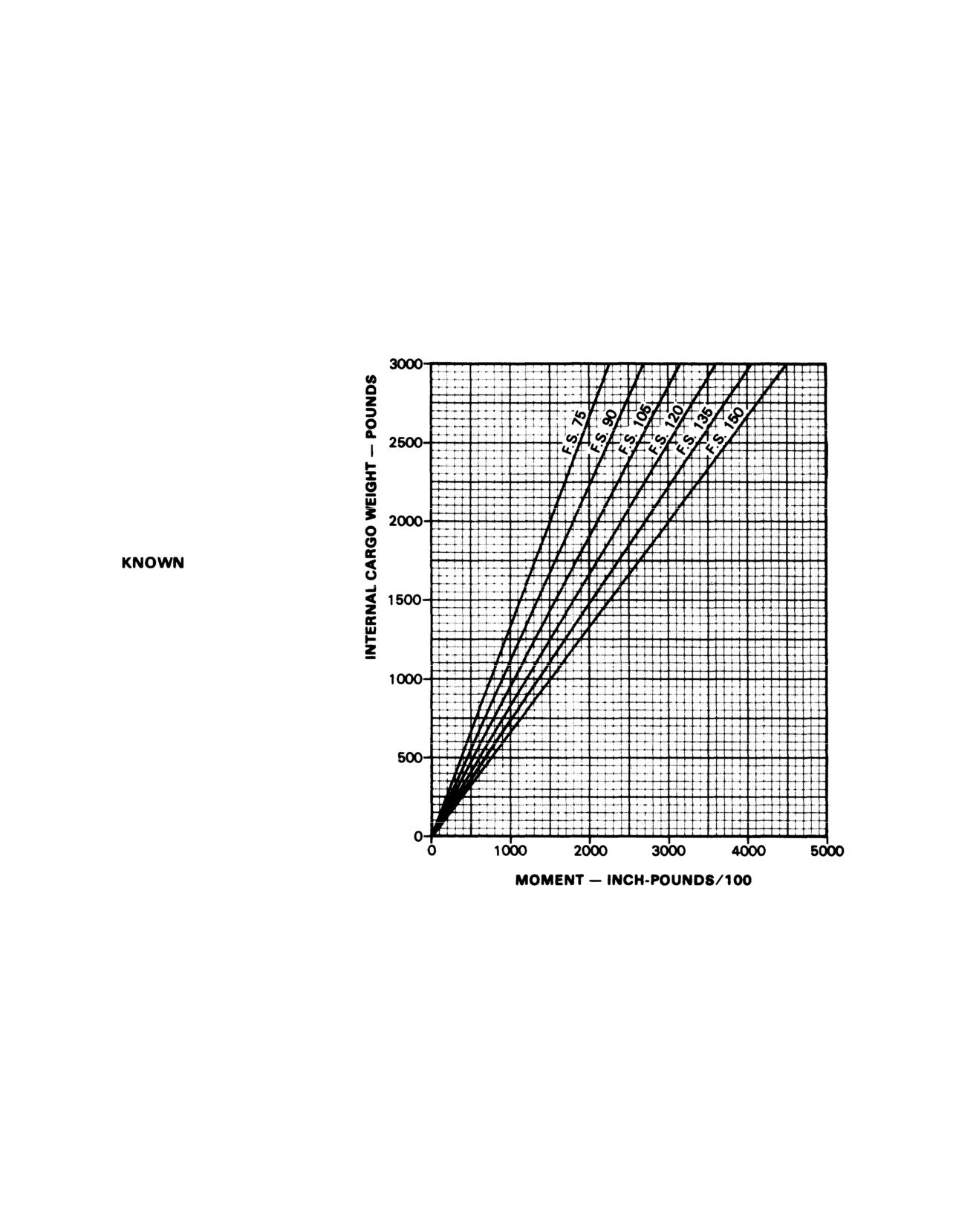
TM 55-1520-210-10
INTERNAL CARGO WEIGHT AND MOMENT
EXAMPLE
WANTED
CARGO MOMENT FOR A
GIVEN CARGO WEIGHT
AND FUSELAGE STATION
CARGO WEIGHT 1000 LBS
LOCATION FS105
METHOD
ENTER INTERNAL CARGO
WEIGHT
MOVE RIGHT
TO FS105
MOVE DOWN TO BASE-
LINE AND READ
1050 INCH POUNDS/100
Figure
6-10. Internal Cargo Weight and Moment
6-17
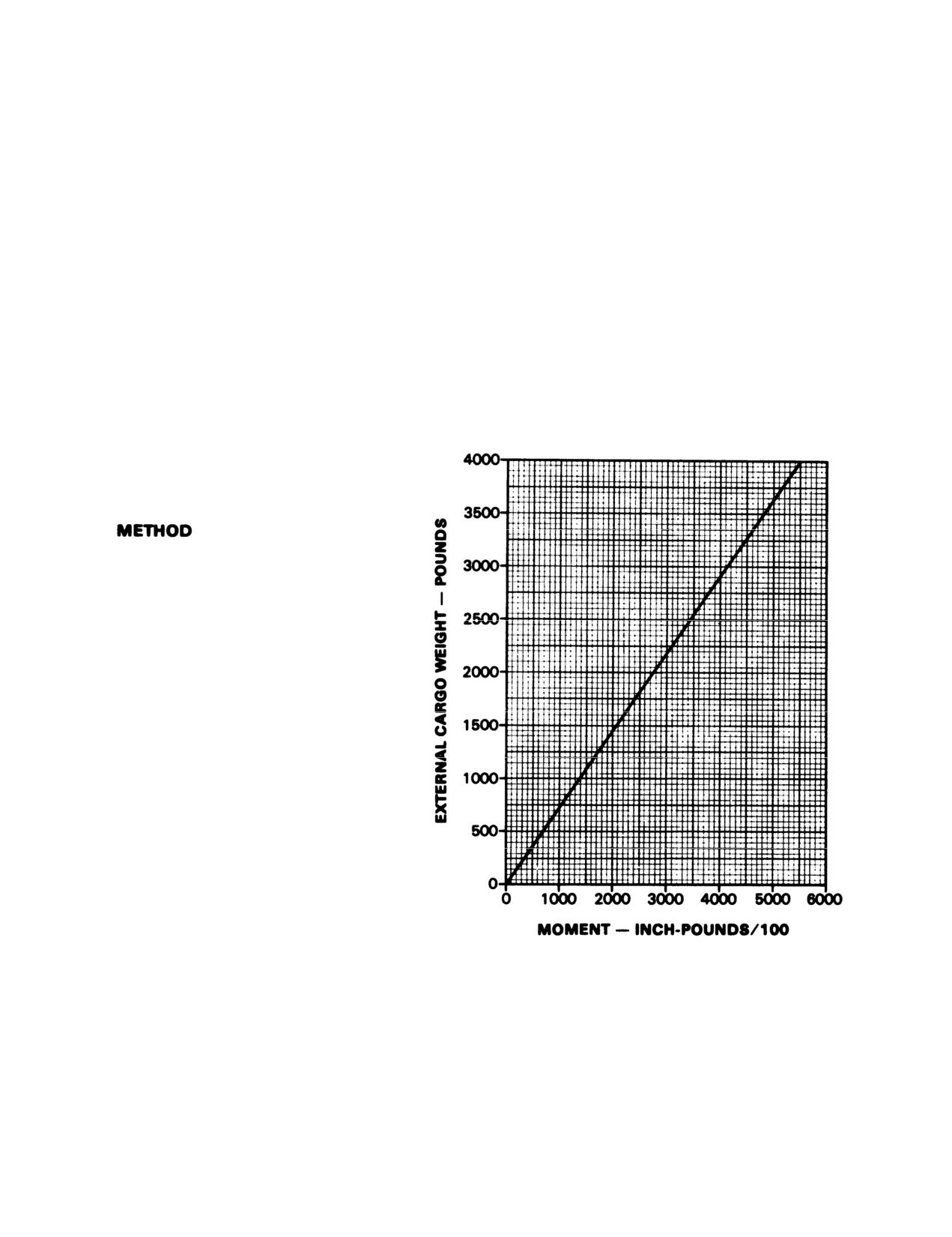
TM 55-1520-210-10
EXTERNAL CARGO WEIGHT AND MOMENT
F.S.
137.55
EXAMPLE
WANTED
CARGO MOMENT/100 FOR A
GIVEN CARGO WEIGHT.
KNOWN
CARGO WEIGHT 3000 LBS
ENTER EXTERNAL CARGO WEIGHT
MOVE RIGHT TO DIAGONAL LINE
MOVE DOWN TO BASELINE AND
READ 4127 ON MOMENT/100
SCALE.
FlGURE 6-11. External Cargo Weight and Moment
6-18
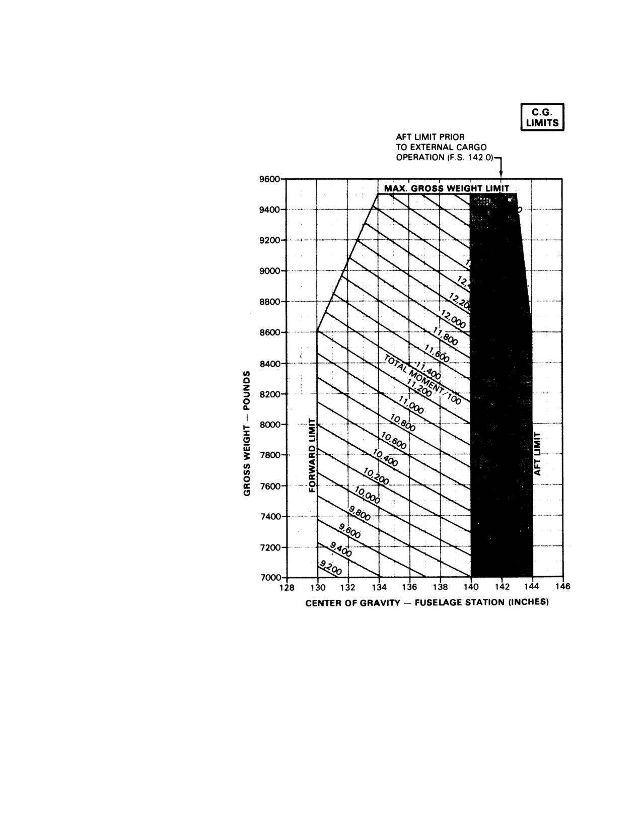
TM 55-1520-210-10
CENTER OF GRAVITY LIMITS
EXAMPLE
WANTED
DETERMINE CENTER OF GRAVITY
FOR KNOWN WEIGHT AND
MOMENT.
KNOWN
GROSS WEIGHT EQUALS 8460
POUNDS, MOMENT/100 EQUALS
11,900 INCH-POUNDS
METHOD
MOVE RIGHT FROM 8460 POUNDS
TO A POINT APPROXIMATELY 1/2
OF THE DISTANCE BETWEEN
11,800 AND 12,000 INCH-POUND
DIAGONAL LINES. FROM THIS
POINT PROJECT DOWN TO READ
140.6 ON THE CENTER OF GRAVITY
SCALE (FUSELAGE STATION IN
INCHES).
NOTE
WHEN CG IS WITHIN SHADED AREA
AFT OF STATION 140.0,
APPROACHES SHOULD BE
TERMINATED TO A 5-FOOT HOVER
FOR ADEQUATE TAIL ROTOR
CLEARANCE
Figure
6-12. Center of Gravity Limits (Sheet 1 of 2)
6-19
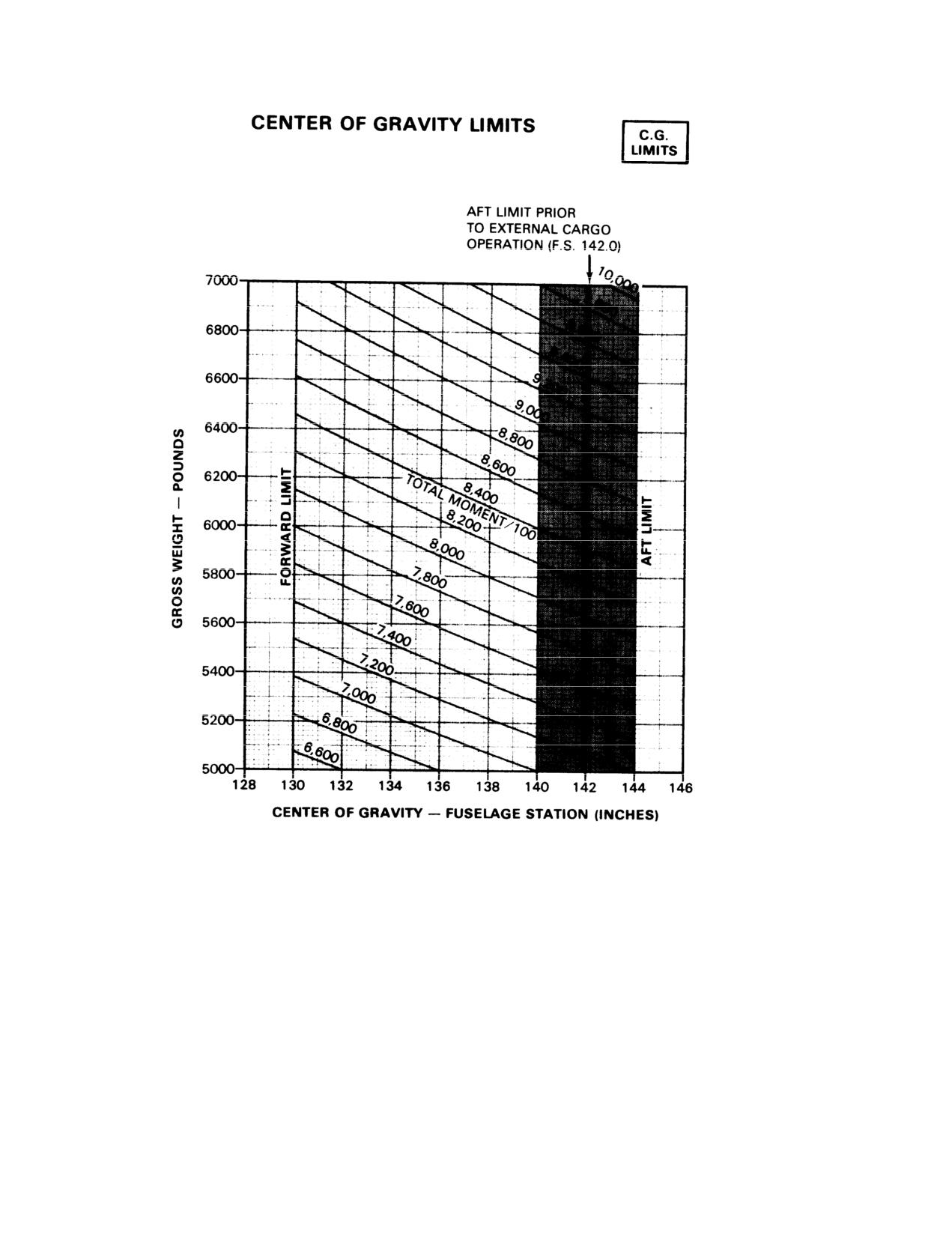
TM 55-1520-210-10
Figure 6-12. Center of Gravity Limits (Sheet 2 of 2)
6-20
TM 55-1520-210=10
Chapter 7
Performance Data
Section I. INTRODUCTION
7-1. Purpose The purpose of this chapter is to
NOTE
provide performance data. Regular use of this infor-
mation will enable you to receive maximum safe utili-
Chapter 7 provides information for the UH-1H
zation from the helicopter. Although maximum per-
equipped with metal main rotor blades and
formance is not always required, regular use of this
chapter 7.1 provides data for the UH-1H
chapter is recommended for the following reasons:
equipped with CMRB. The information
provided in this chapter is primarily intended
a. Knowledge of your performance margin will al-
for mission planning and is most useful when
low you to make better decisions when unexpected
planning operations in unfamiliar areas or at
conditions or alternate missions are encountered.
extreme conditions. The data may also be
used to revise mission planning in flight, to
b. Situations requiring maximum performance will
establish unit or area standing operating pro-
be more readily recognized.
cedures, and to inform ground commanders
of performance/risk tradeoffs.
c. Familiarity with the data will allow performance
to be computed more easily and quickly.
d. Experience will be gained in accurately estimat-
ing the effects of variables for which data are not
7-2. Chapter 7 Index Deleted.
presented.
NOTE
Tabular hover performance and power available data is presented in Appendix C. The data in Ap-
pendix C may be used in lieu of Figures 7-2 and 7-3
or Figure 7.1-2 and 7.1-3
obtain maximum hover weight, torque required to hover, and maximum calibrated torque avail-
able. The data for operation with CMRB presented in chapter 7.1 reflects an update in torque
available and airspeed calibration. That update is based on more recent test data than the basis
used in this chapter for operation with metal rotor blades. Thus some of the difference between
the performance values shown in these two chapters is due to the difference in data basis. Update
of the data for metal rotor blades to the more recent test data basis will be provided in an upcom-
ing change.
Change
8
7-1
TM 55-1520-210-10
NOTE
7-3. General The data presented covers the maxi-
mum range of conditions and performance that can
An example of an auxiliary use of the
reasonably be expected. In each area of perform-
charts referenced above is as follows: Al-
ance, the effects of altitude, temperature, gross
though the hover chart is primarily ar-
weight, and other parameters relating to that phase
ranged to find torque required to hover, by
of flight are presented. In addition to the presented
entering torque available as required,
data, your judgment and experience will be neces-
maximum skid height for hover can also be
sary to accurately obtain performance under a given
found, In general, any single variable can
set of circumstances. The conditions for the data
be found if all others are known. Also, the
are listed under the title of each chart. The effects of
tradeoffs between two variables can be
different conditions are discussed in the text. Where
found. For example, at a given pressure
practical, data are presented at conservative condi-
altitude, you can find the maximum gross
tions, However NO GENERAL CONSERVATISM HAS
weight capability as free air temperature
BEEN APPLIED. All performance data presented are
changes.
within the applicable limits of the helicopter,
d. Dashed Line Data. Data beyond conditions
for
which tests were conducted are shown as dashed
lines.
7-4. Limits Applicable limits are shown on the
charts. Performance generally deteriorates rapidly
7-6 Data Basis The type of data used is indicated
beyond limits. If limits are exceeded, minimize the
at the bottom of each performance chart under
amount and time. Enter the maximum value and
DATA BASIS. The applicable report and date are
time above limits on DA Form 2408-13 so proper
also given. The data provided generally is based on
maintenance action can be taken.
one of four categories:
a. Flight Test Data. Data obtained by flight test of
the aircraft by experienced flight test personnel at
7-5. Use of Charts
precise conditions using sensitive calibrated instru-
ments.
a. Chart Explanation. The first page of each sec-
tion describes the chart (s) and explains its uses.
b. Derived From Flight Test. Flight test data ob-
tained on a similar rather than the same aircraft and
series. Generally small corrections will have been
made.
b. Shading. Shaded areas on charts indicate pre-
cautionarry or time limited operation.
c. Calculated Data. Data based on tests, but not
on flight test of the complete aircraft.
d. Estimated Data. Data based on estimates using
c. Reading the Charts. The primary use of each
aerodynamic theory or other means but not verified
chart is given in an example to help you follow the
by flight test.
route through the chart. The use of a straight edge
7-7. Specific Conditions The data presented are
(ruler or page edge) and a hard fine point pencil is
accurate only for specific conditions listed under the
recommended to avoid cumulative errors. The ma-
title of each chart. Variables for which data are not
jority of the charts provide a standard pattern for use
presented, but which may affect that phase of per-
as follows: enter first variable on top left scale,
move right to the second variable, reflect down at
formance, are discussed in the text. Where data are
right angles to the third variable, reflects left at right
available or reasonable estimates can be made, the
amount that each variable affects performance will
angles to the fourth variable, reflect down, etc. until
be given.
the final variable is read out at the final scale.
7-2
Change 5
TM 55-1520-210-10
Chapter 7.1
Performance Data
Section I. INTRODUCTION
7.1-1. Purpose The purpose of this chapter is to provide
performance data for those helicopters equipped with
NOTE
composite main rotor blades. Regular use of this information
will enable you to receive maximum safe utilization from the
Chapter 7 provides information for the UH-1H
helicopter. Although maximum performance is not always
equipped with metal main rotor blades and chapter
required, regular use of this chapter is recommended for the
7.1 provides data for the UH-1H equipped with
following reasons:
CMRB. The information provided in this chapter is
primarily intended for mission planning and is
a. Knowledge of your performance margin will allow you
most useful when planning operations in unfamiliar
to make better decisions when unexpected conditions or
areas or at extreme conditions. The data may also
alternate missions are encountered.
be used to revise mission planning in flight, to
establish unit or area standing operating
b. Situations requiring maximum performance will be
procedures, and to inform ground commanders of
more readily recognized.
performance/risk tradeoffs.
c. Familiarity with the data will allow performance to be
computed more easily and quickly.
7.1-2. Chapter 7.1 Index Deleted.
d. Experience will be gained in accurately estimating the
effects of variables for which data are not presented.
Change 8
7.1-1
TM 55-1520-210-10
7.1-3. General The data presented covers the maximum range
7.1-6. Data Basis The type of data used is indicated at the
of conditions and performance that can reasonably be
bottom of each performance chart under DATA BASIS. The
expected. In each area of performance, the effects of altitude,
applicable report and date are also given. The data provided
temperature, gross weight, and other parameters relating to
generally is based on one of four categories:
that phase of flight are presented. In addition to the presented
data, your judgment and experience will be necessary to
a. Flight Test Data.
Data obtained by flight test of the
accurately obtain performance under a given set of
aircraft by experienced flight test personnel at precise
circumstances. The conditions for the data are listed under the
conditions using sensitive calibrated instruments.
title of each chart. The effects of different conditions are
discussed in the text. Where practical, data are presented at
conservative conditions. However, NO GENERAL
b. Derived From Flight Test.
Flight test data obtained on
a similar rather than the same aircraft and series. Generally
CONSERVATISM HAS BEEN APPLIED. All performance
small corrections will have been made.
data presented are within the applicable limits of the
helicopter.
c. Calculated Data
Data based on tests, but not on
7.1-4. Limits
Applicable limits are shown on the charts.
flight test of the complete aircraft.
Performance generally deteriorates rapidly beyond limits. If
limits are exceeded, minimize the amount and time. Enter the
d. Estimated Data Data based on estimates using
maximum value and time above limits on DA Form 2408-13
aerodynamic theory or other means but not verified by flight
so proper maintenance action can be taken.
test.
7.1-5. Use of Charts
7.1-7. Specific Conditions
The data presented are accurate
only for specific conditions listed under the title of each chart.
a. Chart Explanation An explanation for the usage of
Variables for which data are not presented, but which may
each chart is provided.
affect that phase of performance, are discussed in the text.
Where data are variable or reasonable estimates can be made,
b. Shading. Shaded areas on charts indicate precautionary
the amount that each variable affects performance will be
or time-limited operation.
given.
c. Reading the Charts. The primary use of each chart is
7.1-8. General Conditions
In addition to the specific
given in an example to help you follow the route through the
conditions, the following general conditions are applicable to
chart. The use of a straight edge (ruler or page edge) and a
hard, fine point pencil is recommended to avoid cumulative
the performance data.
errors. The majority of the charts provide a standard pattern
for use as follows: enter first variable on top left scale, move
a. Rigging.
All airframe and engine controls are assumed
right to the second variable, reflect down at right angles to the
to be rigged within allowable tolerances.
third variable, reflect left at right angles to the fourth variable,
reflect down, etc. until the final variable is read out at the final
b. Pilot Technique.
Normal pilot technique is assumed.
scale.
Control movements should be smooth and continuous.
N O T E
An example of an auxiliary use of the charts
referenced above is as follow Although the hover
chart is primarily arranged to find torque required
to hover, by entering torque available as required,
maximum skid height for hover can also be found.
In general, any single variable can be found if all
others
are known. Also, the tradeoffs between
two variables can be found. For example, at a
given pressure
altitude, you can find the
maximum gross weight
capability as free air
temperature changes.
-
d. Dashed Line Data
Data beyond conditions for which
tests were conducted are
shown as dashed lines.
7.1-2
Change 8
TM 55-1520-210-10
c. Helicopter Variations. Variations in performance
7.1-10. Definitions of Abbreviations.
between individual helicopters are known to exist;
however, they are considered to be small and cannot be
a. Unless otherwise indicated, abbreviations
individually accounted for.
and symbols used in this manual conform to those
established in Military Standard MILSTD-12, which is
d. Instrument Variation. The data shown in the
periodically revised to reflect current changes in
performance charts do not account for instrument
abbreviations usage.
inaccuracies or malfunctions.
b. Capitalization and punctuation of abbreviations
e. Types of Fuel . All flight performance data is
varies depending upon the content In which they are
based on JP-4 fuel. The change in fuel flow and
used. In general, lower case abbreviations are used in
torque available, when using IP-5, IP-8, aviation gasoline
text material, whereas abbreviations used in charts and
or any other approved fuels, is insignificant
illustrations appears in full capital letters. Periods do not
usually follow abbreviations; however, periods are used
7.1-9. Performance Discrepancies. Regular use of
with abbreviations that could be mistaken for whole
this chapter will allow you to monitor instruments and
words if the period were omitted.
other helicopter systems for malfunction, by comparing
actual performance with planned performance.
7.1-11. Temperature Conversion. The temperature
Knowledge will also be gained concerning the effects of
conversion chart (Figure
7.1-1) is arranged so that
variables for which data are not provided, thereby
degrees Celsius can be converted quickly and easily by
increasing the accuracy of performance predictions.
reading Celsius and looking directly across the charts for
the Fahrenheit equivalent and vice versa.
Section II. TORQUE AVAILABLE
7.1-12. Description.
The torque available charts
to determine the maximum power available, it is
(Figure
7.1-2) show the effects of altitude and
necessary to know the
pressure altitude and
temperature on engine torque
temperature. The calibration factor (Data Plate Torque),
obtained from the engine data plate or from the engine
7.1-13. Chart Differences. Both pressure altitude and
acceptance records, is the indicated torque pressure at
FAT affect engine power production. Figure 7.1-2 shows
1125 ft-lbs actual output shaft torque, and is used to
power available data at 30-mmnunute power ratings in
correct the error of individual engine torque indicating
terms of calibrated and indicated torque. Note that the
system.
power output capability of the T53-L-13 engine can
exceed the transmission structural limit (50 psi calibrated
NOTE
torque under certain conditions.
Torque available values determined
are not limits. Any torque which can
a. Figure 7.1-2 (sheet 1) is applicable for maximum
be achieved, without
exceeding
power, 30-minute operation at 324 rotor/6600 engine
engine, transmission, or other limits,
rpm with particle separator installed.
may be used.
b. Figure 7.1-2 (sheet 2) is applicable for maximum
7.1-15. Conditions. The torque available charts (Figure
power, 30-minute operation at 314 rotor/6600 engine
7.1-2) are based upon speeds of 324 rotor/6600 engine
rpm with particle separator installed.
rpm, 314 rotor/6400 engine rpm and grade JP-4 fuel The
use of aviation gasoline will not influence engine power.
c. Prolonged IGE hover may increase engine inlet
Fuel grade of JP-5 will yield the same nautical miles per
temperature as much as 10° C, therefore a 10° higher
pound of fuel and, being 6.8 pounds per gallon, will only
FAT must be used to correct for this condition
result in increased fuel weight. All torque available data
are presented for bleed air heater and device off.
d. If the IR Scoup Suppressor is installed on the
Decrease torque available 1.4 psi for heater on and 2.1
aircraft, subtract one psi for the torque values obtained
for device on; decrease torque available 3.5 psi if both
from Figure 7.1-2, sheets 1 and 2.
bleed air heater and device are operating.
7.1-14. Use of Charts. The primary use of the torque
available charts is illustrated by the examples m general,
Change 17
7.1-3
TM 55-1520-210-10
Section I. HOVER
7.1-16. Description. The hover charts (Figure 7.1-3,
1-19. Conditions.
Sheets 1 and 2) show the hover ceiling and the torque
required to hover at various pressure altitudes, ambient
a. The hover charts are based upon calm wind
temperatures, gross weights, and skid heights.
conditions, a level ground surface, and the use of 324
Maximum skid height for hover can also be obtained by
rotor rpm.
using the torque available from Figure 7.1-2. The hover
capabilities (Table 7.1-1, Sheets 1 and 2) present OGE
b. Use of control margin charts is to determine if
gross weight in pounds, OGE and IGE (5 ft. skid height)
adequate control margin will be available for IGE and
hover torque required in calibrated PSI, for temperature
OGE hover m winds or low speed translation.
of 40°C to +45° C in 5°C increments and pressure
altitudes from-sea level to
16,000 feet in
500 foot
c. The hover charts do not account for the effect of
increments.
an IR suppressor device. The hover ceiling chart (Figure
7.1-3, Sheet 2) is not usable if a suppressor device is
7.1-17. Use of Charts. The primary use of the hover
installed. The IR Scoup Suppressor creates a download
charts is Illustrated by examples.
In general, to
of approximately 140 pounds.
determine the hover ceiling or the torque required to
hover, it is necessary to know the pressure altitude,
d. For the IR Scoup Suppressor
temperature, gross weight and the desired skid height.
In addition to the primary use, the hover charts can also
(1) To determine hover torque required,-enter
be used to determine the predicted maximum hover
the hover power required chart (Figure 7.1-3, Sheet 1) at
height, which is needed for use of the takeoff chart
a gross weight of 140 pounds heavier than the actual
(Figure 7.1-5). The hover capability table (Table 7.1-1,
gross weight.
Sheets 1 and 2) is limited by either maximum OGE gross
weight or maximum torque available.
(2) To determine predicted maximum hover
height, first subtract one psi from power available (Figure
7.1-18. Control Margin Charts.
7.1-2); then increase the hover gross weight by 140
pounds. Use this power available and gross weight m
a. Sheet I of the control margin chart (Figure 7.1-4)
the hover power required chart (Figure 7.1-3, Sheet 1).
shows the maximum right crosswind in which directional
control can be maintained as a function of pressure
(3) To determine maximum gross weight, first
altitude, temperature, and gross weight. Sheet 2 of the
subtract one psi from power available (Figure 7.1-2);
control margin chart, (Figure
7.1-4) shows the
then decrease the hover gross weight determined from
combinations of relative wind velocity and azimuth which
the hover power required chart (Figure 7.1-3, Sheet 1) by
may result in marginal directional or longitudinal control.
140 pounds.
b. Use of the control margin chart is illustrated by
e. With the rotor blade erosion protection coating
the I example on Sheet 1. Ten percent pedal margin (full
and polyurethane tape installed, it will be necessary to
right to full left) is considered adequate for directional
make the following corrections. Add I psi to the hover
control when hovering. The shaded area on Sheet I
torque required, for OGE and IGE, as determined from
indicates conditions where the directional control margin
Figure 7-3 (Sheet 2). In Figure 7-3 (Sheet 1), subtract
may be less than ten percent m zero wind hover. The
100 pounds from the maximum gross weight to hover.
shaded area on Sheet
2 labeled DRECTIONAL,
When determining maximum hover wheel height, enter
indicates conditions where the directional control margin
the chart at the gross weight plus 100 pounds.
may be less than ten percent for crosswind components
in excess of those determined from Sheet
1.
The
shaded area on Sheet
2 labeled LONGITUDINAL
indicates wind conditions where longitudinal cyclic control
margin may be less than 10 percent. These charts are
based on control margins only.
Change 17
7.14
TM 55-1520-210-10
Section IV. TAKEOFF
7.1-20. Description. The takeoff charts (Figure 7.1-5)
7.1-22. Conditions.
show the distances to clear various obstacle heights
based upon several hover height capabilities. The upper
a. Wind. The takeoff charts are based upon calm
chart grid presents data for climbout at a constant
wind conditions. Since surface wind velocity and
INDICATED airspeed. The two lower grids present data
direction cannot be accurately predicted, all takeoff
for climbouts at various TRUE airspeeds. Figure 7.1-5,
planning should be based upon calm wind conditions.
Sheet I is based upon level acceleration technique;
Takeoff into any prevailing wind will improve the takeoff
Sheet 2 is based upon a climb and acceleration from a 3-
performance.
foot skid height; and Sheet 3 is based upon a level
acceleration from a 15-foot skid height.
WARNING
NOTE
A tailwind during takeoff and
The hover heights shown on the
climbout will Increase the obstacle
charts are only a measure of the
clearance distance and could prevent
aircraft’s climb capability and do not
a successful takeoff.
imply that a higher than normal hover
height should be used during the
b. Power Settings. All takeoff performance data
actual takeoff.
are based upon the torque used in determining the hover
capabilities in Figure 7.1-3.
7.1-21. Use of Charts. The primary use of takeoff
charts is illustrated by examples.
The main
consideration for takeoff performance is the hover skid
height capability, which includes the effects of pressure
altitude, free air temperature, gross weight, and torque.
Hover height capability is determined by use of the hover
charts (Figure 7.1-3). A hover check can be made to
verify the hover capability. If winds are present, the
hover check may disclose that the helicopter can actually
hover at a greater skid height than the calculated value,
since the hover charts are based upon calm wind
conditions.
Change 17
7.14.1/(7.14.2 blank)
TM 55-1520-210-10
Section V. CRUISE
7.1-23. Description. The cruise charts (Figure 7.1-6,
b. Torque Pressure (PSI). Since pressure altitude
sheets I through 24) are based upon operation with a
and temperature are fixed for each chart, torque
clean configuration. They show the torque pressure and
pressures vary according to gross weight, airspeed and
engine rpm required for level flight at various pressure
bleed air operation. See paragraph 7.1-15. for effect of
altitudes, airspeeds, gross weights, and fuel flows.
bleed air heater and device.
NOTE
NOTE
Each chart has a dashed line that
Torque available values determined
represents
a
10
square-foot
are not limits. Any torque which can
equivalent flat plate drag area This
be achieved, without exceeding
allows quick determination of delta
engine, transmission, or other limits,
PSI for other than clean configur-
may be used.
ations.
c. Fuel Flow.
Fuel flow scales are provided
7.1-24. Use of Charts. The primary use of the cruise
opposite the torque pressure scales. On any chart,
charts is illustrated by the examples provided in Figure
torque pressure may be converted directly to fuel flow
7.1-6. The first step for chart use is to select the proper
without regard for other chart information. All fuel flows
chart, based upon the pressure altitude and anticipated
are presented for bleed air heater and device off. Add 2
free air temperature. (Refer to Chapter 7.1 index,
percent fuel flow (about 14 lbs) for heater on and
paragraph 7.1-2. Normally sufficient accuracy can be
increase fuel flow 3 percent (approximately 21 Ib/hr) for
obtained by selecting the chart nearest to the planed
device on. If both are operating, add 5 percent fuel flow
cruising altitude and FAT, or the next higher altitude and
(about 35 lb/hr) to chart values.
FAT. If greater accuracy is required, interpolation
between altitudes and/or temperatures will be required.
d. Maximum Range. The maximum range lines
You may enter the charts on any side (TAS, IAS, torque
indicate the combinations of weight and airspeed that will
pressure, or fuel flow) then move vertically or horizontally
produce the greatest flight range per gallon of fuel under
to the gross weight, and then to the other three
zero wind conditions. When a maximum range condition
parameters.
Determine maximum performance
does not appear on a chart it is because the maximum
conditions by entering the chart where the maximum
range speed is beyond the maximum permissible VNE In
range or maximum endurance and rate of climb lines
such cases, use VNE cruising speed to obtain-maximum
intersect the appropriate gross weight, then read
range.
airspeed, fuel flow and PSI torque pressure For
conservatism, use the gross weight at the beginning of
e. Maximum Endurance and Rate of Climb. The
cruise flight. For greater accuracy on long flights it is
maximum endurance and rate of climb lines indicate the
preferable to determine cruise information for several
airspeed for minimum torque pressure required to
flight segments m order to allow for decreasing fuel
maintain level flight for each gross weight, FAT and
weights reduced gross weight). Estimated performance
pressure altitude. Since minimum torque pressure will
data is presented for hover (KTAS=
0) in Figure 7.1-6;
provide minimum fuel flow, maximum flight endurance
however, the hover performance data presented in
will be obtained at the airspeeds indicated.
Figure 7.1-3 is more accurate and should be used in
planning critical hover performance. The following
7.1-25. Conditions. The cruise charts are based upon
parameters contained in each chart are further explained
operations at 324 rotor/6600 engine rpm below 40 KTAS
as follows:
and 314 rotor/6400 engine rpm for true airspeeds above
40 knots. With the rotor blade erosion protection coating
a. Airspeed. True and indicated airspeeds are
and polyurethane tape installed, add I psi to the torque
presented at opposite sides of each chart. On any chart,
required obtained from Figure 7.1-6 for true airspeeds
indicated airspeed can be converted to true airspeed (or
less than 100 KTAS.
vice versa) by reading directly across the chart without
regard for other chart information. Maximum permissible
airspeed (VNE) limits appear on some charts. If no line
appears, VNE, is above the limits of the chart.
Change 17
7.1
TM 55-1520-210-10
Section VI. DRAG
7.1-26. Description. The drag chart (Figure 7.1-7,
temperature. Enter at the known drag area change,
sheet 1 of 2) shows the equivalent flat plate drag area
move right to TAS, move down to pressure altitude,
changes for additional authorized configurations. There
move left to FAT, then move down and read change in
is no increase in drag with cargo doors fully open. The
torque. In addition, by entering the chart in the opposite
upper left portion of Figure 7.1-7, sheet 2 of 2, presents
direction,
C drag area change may be found from 2
drag areas of typical external loads as a function of the
known torque change. This chart is used to adjust cruise
load frontal area. The balance of the chart shows the
chart torque and fuel flow due to equivalent flat plate
additional torque required m level flight due to the
drag area change (^F). For frontal areas exceeding
increase in drag caused by external loads or aircraft
values shown on Figure 7.1-7 (sheet 2 of 2) use a
modifications. The IR Scoop Suppressor has a drag of
smaller value and multiply, e.g. 36 sq. ft. 12 sq. ft. X 3.
two square feet.
7.1-28. Conditions. The drag chart is based upon 314
7.1-27. Use of Chart. The primary use of the drag chart
rotor/6400 engine rpm.
is Illustrated by the example. To determine the change
in torque, it is necessary to know the drag area change,
the true airspeed, the pressure altitude and the free air
Section VII. CLIMB
7.1-29. Description. The climb performance chart
rpm. The charts are based upon a no-wind condition;
(Figure 7.1-8, sheet 1) represents a synthesis of the
therefore, distance traveled will not be valid when winds
cruise charts to ease estimation of the climb portion of
are present.
the flight plan. The chart shows the time, distance, and
fuel required to climb from an initial altitude to a final
7.1-32. Description. The climb-descent chart (Figure
altitude. The chart provides for variation in gross weight
C 7.1-8, sheet 2), shows the change in torque (above or
and ambient temperature and may be used for minor
below torque required for level flight under the same
configuration deviations.
gross weight and atmospheric conditions) to obtain a
given rate of climb or descent.
7.1-30. Use of Chart. Enter at the known gross weight,
move up to the initial altitude and standard day free air
7.1-33. Use of Chart The primary uses of the climb-
temperature. Calculate delta FAT between the actual
descent chart are Illustrated by the chart examples
FAT and the standard day FAT. Move right from the
initial altitude and interpolate for the delta FAT point;
a. The torque change obtained from the grid scale
drop down and read the time and distance scale.
must be added to (for climb) or subtracted from (for
Continue down to the appropriate delta FAT curve, move
descent) the torque required for level flight to obtain a
left to the fuel scale, and read fuel in pounds. Repeat
total climb or descent torque. (Torque required for level
above procedure for final altitude values. Use the
flight is obtained from the appropriate cruise chart.)
previous delta FAT and the final altitude to determine the
new values. Subtract initial altitude values from the final
b. By entering the bottom of the grid with a known
altitude values to obtain the actual time, distance and
torque change, moving upward to the gross weight, then
fuel.
left, the corresponding rate of climb or descent may also
be obtained.
7.1-31. Conditions.
The climb-performance chart
represents climb at optimum conditions, that is, at best
7.1-34. Conditions. The climb-descent chart is based
rate-of-climb airspeed and at maximum power available
on the use of constant rotor or engine rpm. A decrease
0-minute operation). Climb is assumed to be at 55
in rpm could decrease the rate of climb or increase the
indicated airspeed as this is near the airspeed for rate of
rate of descent shown.
climb at most atmospheric conditions.
d taxi fuel are not included in fuel calculations. Climb
performance is calculated for 314 rotor/ 6400 engine
Change 17
7.
TM 55-1520-210-10
Section VIII. FUEL FLOW
7.1-35. Description.
b. The primary use of the fuel flow vs torque chart is
illustrated by the example. To determine fuel flow, it is
a. The flat pitch fuel flow chart (Fig. 7.1-9, sheet
1)
necessary to know the torquemeter pressure (psi) and the
shows the fuel flow at engine flat pitch.
FAT as well as the pressure altitude. Fuel flow will increase
about 2 percent with the bleed air heater on and 3 percent
b. The fuel flow vs torque chart (Fig. 7.1-9, sheet 2)
with deice on. When both systems are on, fuel flow will in-
shows fuel flow at 314 rotor/6,400 engine RPM in pounds-
crease 5 percent. Also, a range or endurance penalty
per-hour versus torquemeter psi for pressure altitudes
should be accounted for when working cruise chart data.
from sea level to 14,000feet and for 0° C free air tempera-
A fairly accurate rule of thumb to correct fuel flow for
ture.
temperatures other than 0° C FAT is to increase/decrease
fuel flow 1 percent for each 10° C increase/decrease in
7.1-36. Use of Chart.
FAT.
a. The primary use of the flat pitch fuel flow chart is
7.1-37. Conditions. The fuel flow charts are based upon
illustrated by the example. To determine the flat pitch fuel
the use of JP-4 fuel. The change in fuel flow when using
flow, it is necessary to know the pressure altitude and free
other jet fuels is insignificant.
air temperature. Enter the pressure altitude, move right
to FAT in appropriate grid, then move down and read fuel
flow on the bottom scale.
Change 11
7.1-7
TM 55-1520-210-10
TEMPERATURE CONVERSION CHART
Figure 7.1-1. Temperature conversion chart
7.1-8
Change 8
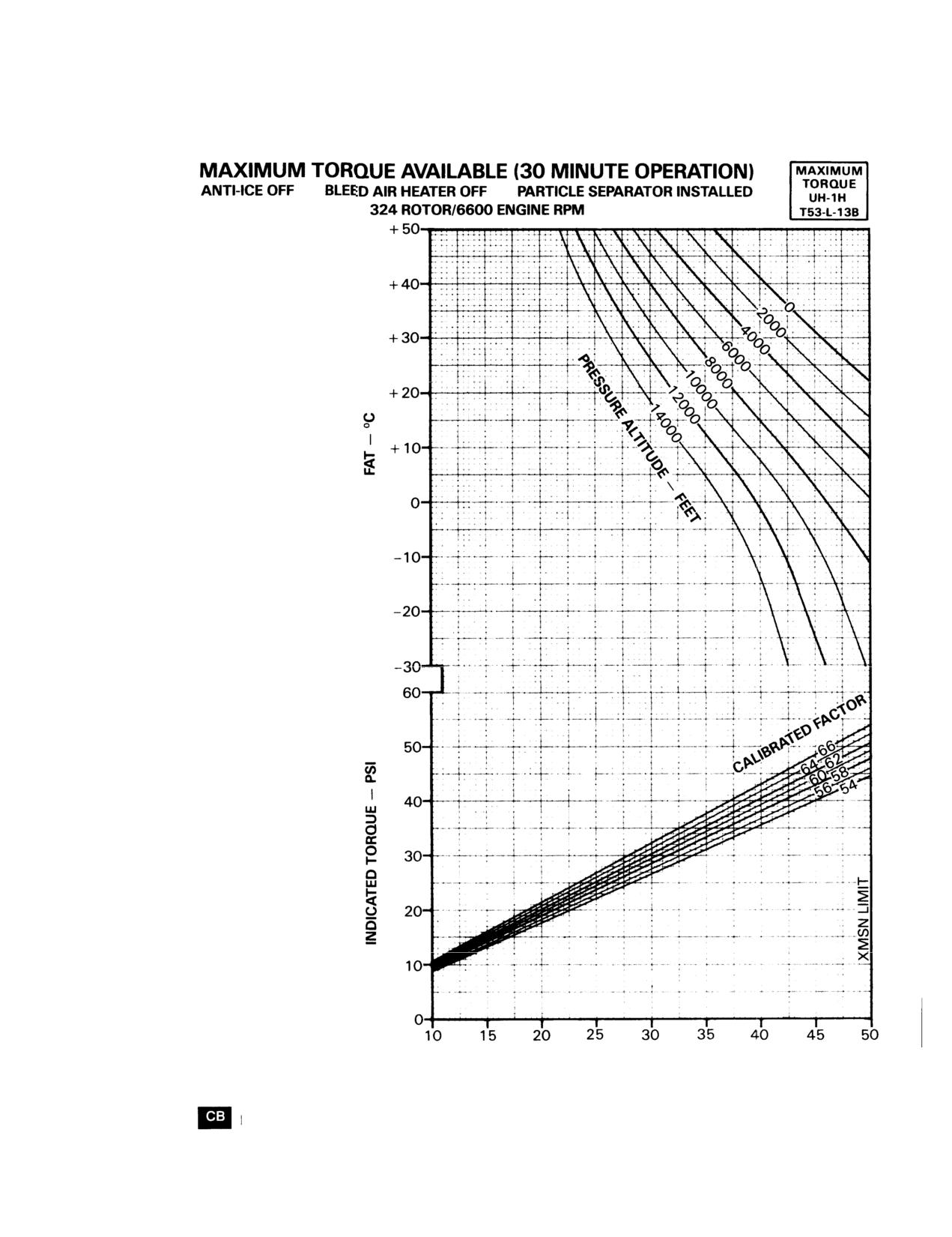
TM 55-1520-210-10
EXAMPLE
WANTED
INDICATED TORQUE
CALIBRATED TORQUE
K N O W N
PRESSURE ALTITUDE = 10,000 FEET
FAT = 15°C
CALIBRATION FACTOR
=
66
METHOD
ENTER FAT
MOVE RIGHT TO PRESSURE ALTITUDE
MOVE DOWN TO CALIBRATION FACTOR
MOVE LEFT, READ INDICATED TORQUE
=
39.8 PSI
FOR CALIBRATED TORQUE CONTINUE
DOWN THRU CALIBRATION FACTOR
READ CALIBRATED TORQUE = 36.8 PSI
DATA BASIS:
CALCULATED FROM AVCO LYCOMING SPEC 19.28.25.03, JULY 1982, CORRECTED FOR
INSTALLATION LOSSES BASED ON USAAEFA PROJECT NO. 81-01 LR, SEPT 1982.
Figure 7.1-2. Maximum torque (30 minute operation) chart (Sheet 1 of 2)
Change 8 7.1-9
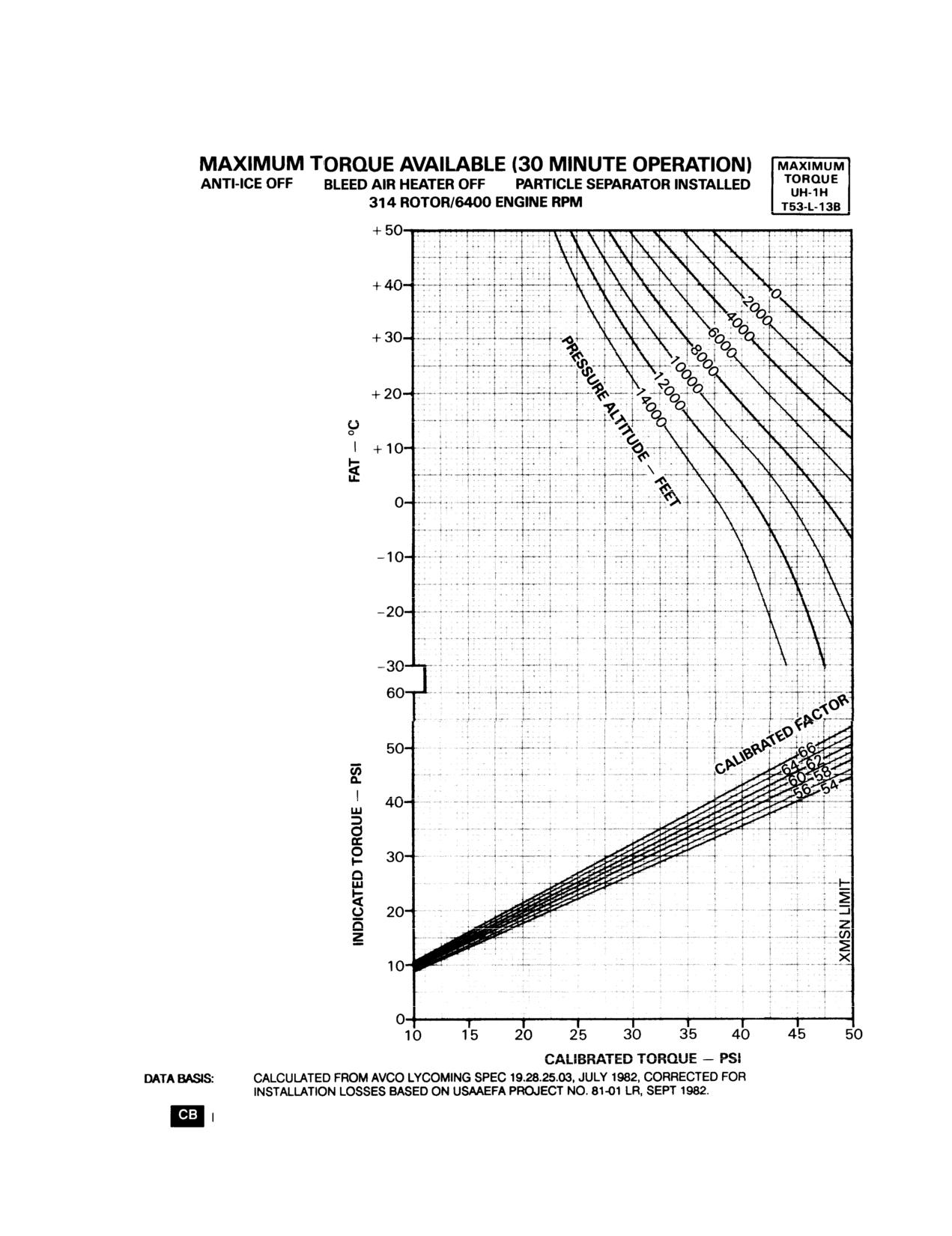
TM 55-1520-210-10
EXAMPLE
WANTED
INDICATED TORQUE
CALIBRATED TORQUE
KNOWN
PRESSURE ALTITUDE = 10,000 FEET
FAT = 15°C
CALIBRATION FACTOR
=
66
METHOD
ENTER FAT
MOVE RIGHT TO PRESSURE ALTITUDE
MOVE DOWN TO CALIBRATION FACTOR
MOVE LEFT, READ INDICATED TORQUE =
41.2 PSI
FOR CALIBRATED TORQUE CONTINUE
DOWN THRU CALIBRATION FACTOR
READ CALIBRATED TORQUE = 38.3 PSI
Figure 7.1-2. Maximum torque (30 minute operation) chart (Sheet 2 of 2)
7.1-10
Change 8