ARMY MODEL UH-1H/V HELICOPTERS. OPERATOR’S MANUAL (1988) - page 3
TM
55-1520-210-10
Controls and Functions of Instrument Panel AN/ASN-175 System Components
CONTROL/INDICATOR
FUNCTION
1. GPS FILL Ports
Two independent ports that are used to load data into the
AN/ASN-175 system as follows:
DATA Receptacle
Provides connection for Precision Lightweight GPS
Receiver (PLGR) AN/PSN-11 to load GPS time and
Space Vehicle (SV) data into the AN/ASN-175 system.
KYK Connector
Provides connection for Electronic Transfer Device KYK-
13/TSEC to load classified variables (cryptokeys) into the
AN/ASN-175 system.
2. GPS ZEROIZE Switch
Enables pilot or copilot to zeroize (erase) all data that has
been loaded into the AN/ASN-175 system via the GPS
FILL ports (DATA and KYK). Also resets pre-
programmed aircraft requirement settings to factory
default. It is used only in an emergency situation to
prevent potential enemy compromise of classified
information. The switch is protected with a guard to
prevent inadvertent actuation.
*3. DME IND (Indicator) Switch
Two position toggle switch that selects distance data
from either the AN/ARN-124 DME system (VORTAC
position) or the AN/ASN-175 system (GPS position) for
display on the DME indicator.
4. CDI SEL (Select) VOR/GPS
Two switch-indicator assemblies that provide both
Switches/DME IND Indicators
DME indications and remote switching control for Course
Deviation Indicator (CDI) display as follows:
VOR/DME
When pressed, activates Remote Switch Assembly to
select VOR navigation (course deviation) signal for
display on the CDI. Also provides DME cue to alert pilot
that distance data is supplied from the AN/ARN-124
(VORTAC) Distance Measuring Equipment (DME) system
(if installed), as selected by DME IND switch.
GPS/DME
When pressed, activates Remote Switch Assembly to
select GPS navigation (course deviation) signal for
display on the CDI. Also provides DME cue to alert pilot
that distance data is supplied from the AN/ASN-175
(GPS) system, as selected by DME IND switch.
3-32.8
Change 18
TM 55-1520-210-10
Controls and Functions of Instrument Panel AN/ASN-175 System Components (Cont)
CONTROL/INDICATOR
FUNCTION
5. GPS Annunciators
Two dual annunciator assemblies that display the oper-
ational status of the AN/ASN-175 system as follows:
WPT (Waypoint)
Indicates that active waypoint is being approached.
The time between illumination of indicator and arrival at
active waypoint may be selected by the operator. The
same WPT status information is displayed on the WPT
annunciator on the receiver/display unit
HLD (Hold)
Indicates that active flight plan has been suspended at
current active waypoint. The same HLD status infor-
mation is displayed on the HLD annunciator on the
receiver/display unit.
MSG (Message)
Indicates that one or more of the messages in the
queue is unread. When indication is steady, indicates
presence of one or more messages in the queue
requiring operator action. When indication is not
present, indicates that there are no messages in the
queue other than CDI scaling message. The same MSG
status information is displayed on the MSG annunciator
on the receiver/display unit.
APR (Approach)
Indicates that aircraft is at or within two nautical miles
of final approach fix and that all approach requirements
have been met. The same APR status information is dis-
played on the APR annunciator on the receiver/display
unit.
6. NO. 2 BRG PTR (Bearing
Two position toggle switch that selects either GPS
Pointer) Switch
bearing (GPS position) or VOR bearing (VOR position) for
display by pointer No. 2 on both the pilot’s and
copilot’s Radio Magnetic Indicator (RMI).
* Applicable to aircraft with AN/ARN-124 DME system installed only.
Change 18 3-32.9
TM 55-1520-210-10
(c) Check CDI SEL GPS switch/DME
c. Operation
- Satellite Signets Navigation Set
indicator assembly lighting operation with PILOT
AN/ASN-175.
lighting rheostat on the INST LTS panel located on
the overhead console as follows:
CAUTION
1. PILOT lighting rheostat - OFF,
Observe that GPS and DME indicator lights are at
•
The AN/ASN-175 shall not be used as
full brightness level and that pilot’s instrument
a substitute for the VOR or ADF.
lights are off.
When AN/ASN-175 is used for IMC
flight, either the VOR or ADF shall be
2. PILOT lighting rheostat - Turn
clockwise from OFF to on position at minimum
onboard and operational.
setting. Observe that GPS and DME indicator
lights and the pilot’s instrument lights are at low
• During navigation with the AN/ASN-
brightness level.
175 system, avoid operation of the
3. PILOT lighting rheostat -
(VHF) Radio on the following
Slowly turn clockwise from minimum to maximum
frequencies: 121.150 MHz, 121.175
setting.
Observe that GPS and DME indicator
MHZ, 121.200 MHz,
131.250 MHz,
lights and the pilot’s instrument lights change
131.275 MHz, and 131.300MHz
incrementally from low to full brightness.
(d) Adjust instrument lights for best
• During navigation with the AN/ASN-
viewing or, if desired, turn them off.
175 system, avoid operating the
AN/ARC-164 radio at 225.100 MHz.
NOTE
The operational procedures that follow
NOTE
in steps (2) through (7) ensure that the
AN/ASN-175 system is functional and
The second VOR system (ARN-82)
has the current cryptokeys, valid GPS
shall not be operated in an aircraft
time and Space Vehicle (SV) data,
with the AN/ASN-175 installed.
defined mission duration, and the anti-
spoof safety enable required to operate
using the P(Y) code. These procedures
(1) Preoperational
and
AN/ASN-175
are then followed by operational
System Instrument Panel Lighting Checks.
procedures
RAIM/GPS Status
Determination
and Preparation for
AN/ASN-175 Departure in steps (8) and
(a) GPS ASN-175 circuit breaker -
(9),
respectively.
Finally,
Special
Engaged.
Operating Functions and AN/ASN-175
System Shutdown are provided in steps
(b) On. .pilot’s side of instrument
(10) and (11), respectively.
panel, set GPS/DME, controls as follows:
(2) AN/ASN-175 System Power - ON.
1. NO. 2 BRG PTR switch - GPS.
NOTE
2. CDI SEL GPS switch/DME
• Ensure a current Navigation Database
Card is installed in GPS Navigation Set
indicator assembly
- Press. Observe that GPS
Receiver/Display Unit (RDU). Although
indicator light in CDI SEL GPS switch/DME
the following operations can be
indicator assembly comes on.
performed with an expired card, this
condition will be reported by the RDU
NOTE
during test.
Perform step
3 on aircraft with
•
When the RDU is turned on, a BIT check
Distance Measuring Equipment (DME)
is
automatically performed in the
AN/ARN-124 system installed only.
AN/ASN-175 system. During this time,
do not press any of the keys on the RDU
3.
DME IND switch
-
GPS.
until
the power on
sequence
is
Observe that DME indicator light in CDI SEL GPS
switch/DME indicator assembly comes on.
completed. If any key is pressed during
power on sequence, the RDU disregards
the key press.
3-32.10
Change 18
TM
55-1520-210-10
NOTE
(a) Power switch - Turn clockwise to
ON position. Several introductory system displays
will appear briefly on the RDU and then BIT cycles
In the following display, the second
to a five second lamp self-test.
line will scroll across continuously.
The full line is NO KEYS NEED
(b) Observe the five second lamp self-
INITIALIZE:
test. All lamps for the annunciators and keys on
the RDU and for the GPS annunciators (WPT/HLD
A-S SAFETY OK
indicators and MSG/APR indicators) on the pilot’s
side of instrument panel come on for
approximately five seconds.
NO KEYS
NEED INITIALIZE
(c) Following the lamp self-test,
observe BlT result lines that scroll up on display.
NOTE
The following display appears one line at a time
on RDU when BIT passes:
If display is as shown and GPS
time/space
vehicle
data
and
cryptokeys are to be loaded into
NAV Computer
OK
AN/ASN-175 system, proceed to step
AUX IO Computer
-OK
(4). If display is not as shown and
GPS Computer
-OK
GPS time/space vehicle data and
GPS Antenna
-OK
Servo Amp
cryptokeys are to be loaded into
-OK
Memory Battery
AN/ASN-175 system, proceed to step
Database
-OK
(5). If GPS time/space vehicle data
and cryptokeys are not going to be
loaded into AN/ASN-175 system,
NOTE
proceed as follows:
If BIT fails, the applicable test result
(b) Observe that ENT key on RDU is
line(s) displays a FAIL. If a current
flashing.
Navigation Database Card is not
installed or a card is missing, the
(c) ENT key - Press. Turn outer
Database result line displays EXPIRED
selector knob of MENU control counterclockwise
or N/A, respectively. When a FAIL,
until DISABLE
EXPIRED, or N/A is displayed, the
MSG annunciator on the RDU will
(d) Outer selector knob of MENU
flash. This cues the user to press the
control - Turn counterclockwise until DISABLE is
MSG key on the RDU to display an
displayed and the D in DISABLE is flashing.
error message that relates to the
failure mode of the AN/ASN-175
(e) ENT key
- Press to accept
system. If more than one failure
ENABLED setting.
occurs, as indicated by the flashing
MSG annunciator, press MSG key for
(f) Proceed to step (7).
each error message. Read each error
message in turn and take the
(4)
Cryptokey Loading Initialization For No
appropriate action.
Keys Display.
(3) Anti-Spoof/Cryptokey Status
(a) Observe that ENT key on RDU is
Determination.
flashing.
(a) Observe RDU display until ANTI-
(b) ENT key - Press. Observe that A-S
SPOOF/ CRYPTOKEY status screen appears.
SAFETY: ENABLED is displayed and the E in
ENABLED is flashing.
Change 18
3-32.11
TM
55-1520-210-10
(7) Setting Mission Duration.
(8) RAIM/GPS Status Determination.
(a) Outer selector knob of MENU
(a) Observe RAIM annunciator, If
control : Turn until the following display appears:
RAIM annunciator is illuminated, indicates that
AN/ASN-175 cannot provide required integrity for
flight and that problem should be referred to
SET MISSION?
AVUM. In the event that this problem occurs
during flight, any navigation using the AN/ASN-
(ENT)
175 must be crossed checked for position using
other approved sources.
(b) ENT key - Press. Observe that the
following START DATE display appears with the
(b) Observe GPS annunciator. If GPS
first character of date field selected:
annunciator is illuminated, proceed to step (c). if
not, proceed to step (d).
(c) The AN/ASN-175 is not providing
a 3-D position solution and is not ready for the
mission. Wait two minutes and observe GPS
(c) inner selector knob of MENU
annunciator.
If GPS annunciator
remains
control - Turn until desired character is displayed
illuminated after two minutes, repeat procedures
in that character of date field.
starting from step (5) if operating in a suspected
spoofed environment.
If GPS annunciator still
(d) Outer selector knob of MENU
remains illuminated after repeating procedures,
control - Turn to select the next character of date
refer problem to AVUM. If operating in a known
field.
spoof free environment and GPS annunciator still
remains illuminated, refer problem to AVUM for
(e) Repeat steps (c) and (d) until
resetting the RDU. When reset, the RDU must be
entire start date has been entered.
reprogrammed to the required aircraft settings.
(f) Outer selector knob of MENU
(d) The AN/ASN-175 is providing a 3-
control - Turn until first digit of mission duration
D position solution and is ready for the mission.
field is selected.
To determine the accuracy and Figure of Merit
(FOM) of solution, proceed as follows:
(g) Inner selector knob of MENU
control - Turn until desired digit is displayed in
NOTE
that digit of duration field.
The AN/ASN-175 is now calculating
(h) Outer selector knob of MENU
position and the display will now show
control - Turn to select next digit of duration field.
the present position.
(i) Repeat steps (g) and (h) until
1. AUX key - Press and hold for
duration has been completely entered.
one second until SYSTEM STATUS mode is
selected and PRESENT POSITION display appears:
(j) ENT key - Press to set mission
duration.
POSITION EPE:
XXm
LL XX°XX .xxx XXXX° xx .xxx x
(k) After mission duration is set,
SETTING MISSION STANDBY will be displayed.
wait until display changes to COMMAND
COMPLETE and then proceed to step (8).
3-32.14
Change 18
TM 55-1520-210-10
2. AUX key - Press until SENSOR
6.
key - Press a second
STATUS mode is selected and the GPS STATUS
time to join leg and activate flight plan.
display appears:
7.
If
flight
plan includes a
GPS: 3D/PRS
RAIM
Standard Instrument Departure (SID) when ready
MODE: TERM
1.6
to depart, depart in accordance with the
applicable procedures in step (b) below and then
NOTE
fly the flight plan following the prompts from the
AN/ASN-175.
If flight plan does not include a
FOM is an integer between 1 and g
SID, depart in accordance with published
and is determined from the RDU
procedures and then fly the flight plan following
position error.
the prompts from the AN/ASN-175.
3.
The FOM values and its
(b) Fly Standard Instrument Departure
meaning as determined from the RDU position
(SID) Using GPS.
error are as follows:
NOTE
FOM Value
Meaning
1
<25m
Proceed to step 1 to fly direct to the
2
>25m, <50m
first waypoint in SID and fly the entire
3
>50m,
<75m
procedure, step 6 to join any specific
4
>75m, <100m
leg in SID and fly the rest of
5
>100m,
<200m
procedure, or step 11 to fly direct to
6
>200m,
<500m
any waypoint In SID and fly the rest of
7
>500m,
<1000m
procedure.
8
>1000m,
<5000m
9
>5000m
1. Select desired SID.
4. Outer selector knob of MENU
2. -D key- Press
control - Turn until the flowing display appears:
3 .. Inner selector knob of MENU
ESTIMATED ACCURACY:
control - Turn to change course to/from waypoint,
GPS:
9m FOM:
1
if desired.
(9)
Preparation
For
AN/ASN-175
4.
key - Press a second
Departure.
time to make first waypoint active waypoint and
(a) Flight Plan Loading and Activation.
to activate SID.
1. FPL key
- Press to select
5. Fly SID following prompts
STORED FLIGHT PLANS display.
from AN/ASN-175.
2. Inner selector knob of MENU
6. Select desired SID.
control - Turn to select desired flight plan.
7. Turn outer selector knob of
3. FPL key - Press. The FPL key
MENU control to select desired leg of SID.
will now be flashing.
8. Press
key.
4. Inner selector knob of MENU
control - Turn to select desired leg of flight plan.
9. Press
key a second time
to join leg and to activate SID.
5.
key - Press and note
leg’s course.
Change 18
3-32.15
TM
55-1520-210-10
4.
key - Press a second
10. Fly SID following prompts
time to make waypoint the active waypoint.
from AN/ASN-175.
5. The
AN/ASN-175
11. Select desired SID.
automatically switches to NAV mode and displays
the PRIMARY NAVIGATION page as follows:
12. Outer selector knob of MENU
control - Turn to select desired leg of SID.
13.
key - Press.
TO LAX A 120° 143: 0:34
14. Outer selector knob of MENU
control
- Turncounterclockwise to select first
waypoint of leg. Outer selector knob of MENU
6. For reference, set Course
control - Turn clockwise to select second
Deviation (CDI) or Horizontal Situation Indicator
waypoint of leg.
(HSI) to displayed course.
15. Inner selector knob of MENU
7. When
ready,
depart
in
control
- Turn to change course to/from
accordance with published procedures and follow
waypoint, if desired.
prompts from AN/ASN-175 to fly to waypoint.
16.
- Press key a second
(10) Special Operating Functions.
time to fly direct to waypoint and to activate SID.
(a) Zeroizing the Cryptokeys.
17. Fly SID following prompts
from AN/ASN-175.
NOTE
(c) Fly Direct To A Waypoint.
The procedures that follow provide
instructions to zeroize the cryptokeys,
NOTE
if previously loaded, in the RDU.
Normally, the cryptokeys should be
You may fly direct to any waypoint in
zeroized after every mission. If the
the database.
Select the waypoint
cryptokeys are not zeroized after
from the WPT, NRST, NAV or FPL
completion of a mission, it will not be
mode.
Flying direct to a waypoint
possible to set a new mission
selected from the FPL mode will
duration. The cryptokeys, however,
activate the flight plan starting at the
will automatically zeroize when the
selected waypoint.
mission duration expires.
1. Select desired waypoint.
1. AUX key - Press until USER
SETUP mode appears on display.
key - Press. Observe
2.
the following display:
2. Inner selector knob of MENU
control
- Turn until SECURITY MODULE page
appears as follows:
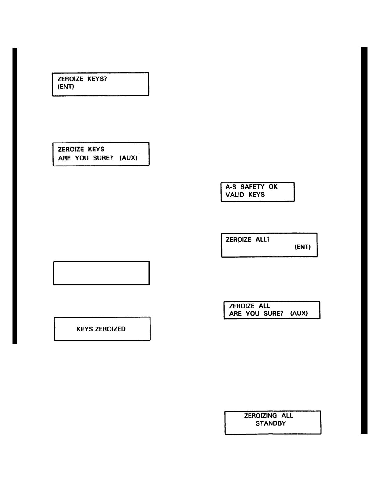
A-S SAFETY OK
VALID KEYS
3. Inner selector knob of MENU
control
- Turn to change course to/from
waypoint, if desired.
3-32.16
Change 18
TM
55-1520-210-10
3. Outer selector knob of MENU
(b) Zeroizing All Variables.
control - Turn until the following display appears:
NOTE
The procedures that follow provide
instructions to zeroize all mission
variables. These variables should be
zeroized whenever the RDU is
4. ENT key - Press to initiate the
removed for maintenance or for any
keys zeroizing function. Observe that AUX key is
other purpose.
flashing and that the following display appears:
1. AUX key - Press until USER
SETUP mode appears on display.
2. Inner selector knob of MENU
control
- Turn until SECURITY MODULE page
appears as follows:
NOTE
Press any key other than the AUX
key to abort the zeroize keys
3. Outer selector knob of MENU
function.
control - Turn until the following display appears:
5. AUX key - Press to complete
the zeroize keys function. Observe that display
changes to the STANDBY mode as follows:
ZEROIZING KEYS
4. ENT key - Press to initiate the
STANDBY
zeroize all function. Observe that AUX key is
flashing and that the following display appears:
6. After a few seconds, observe
that the following display appears:
NOTE
Press any key other than the AUX key
to abort the zeroize all function.
5. AUX key - Press to complete
the zeroize keys function. Observe that the
following display appears briefly and then the
AN/ASN-175 will reset itself.
Change 10
3-32.17
TM 55-1520-210-10
(c) Programming
RDU
Auxiliary
3. ENT key - Observe that it
Input/Output Ports.
is flashing.
NOTE
4. ENT key - Press.
Actuation of the GPS ZEROIZE switch
5. Outer selector knob of
on the instrument panel will erase all
MENU control
- Turn counterclockwise until
variables stored in the RDU and will
DISABLE is displayed and the D in DISABLE is
reset the auxiliary input/output (I/O)
flashing.
ports of the RDU to factory default. As
a result, the GPS ZEROIZE switch
6. ENT key - Press to accept
should be normally used when it is
the DISABLE setting.
absolutely necessary to verify that it is
functional or for emergency situations.
7. AUX key
- Press until
In the event that the GPS ZEROIZE
INSTALL SETUP mode appears on display.
switch is actuated, the RDU will have
to be reprogrammed to satisfy the
8. Inner selector knob of
aircraft requirements. Instructions for
MENU control - Turn until AUX l/O SETUP
actuating the GPS ZEROIZE switch and
display appears as follows:
reprogramming the RDU are as follows:
1. Locate GPS ZEROIZE switch
on center section of instrument panel.
2. GPS ZEROIZE switch - Raise
cover and toggle switch to the up position to
initiate the zeroize. Observe that RDU resets,
displays a ZEROIZE IS SUCCESSFUL message,
and then cycles through the power on/BIT checks
until the ANTI-SPOOF/CRYPTOKEY status screen
appears as follows:
3-32.18
Change 18
TM
55-1520-210-10
Table 3-1. RDU Auxiliary Input/Output Port Settings.
CHOICE SETTlNGS
AIRCRAFT SETTINGS
* None
XYZ Magnetic-Synchro
XYZ Magnetic-Synchro
XYZ TRUE-Synchro
PRESSURE ALTITUDE
Serial-RS-422/RS-232
Parallel
INPUT
* Parallel
OLEO INPUT
* None
None
Air
Ground
SYNCHRO OUTPUT #1
* Off
** BRG-HDG + 180°
HDG
----
SYNCHRO
T
HDG
----
DTK
----
TDTK
----
BRG
-----
TBRG
----
TKE
----
DA
---
----m----
TKE-DA
------
---------
DA-TKE
-----
BRG-HDG
-------
--------------
+0.00
+180
-------------
-----------------------
SYNCHRO
SIN/COS
SYNCHRO OUTPUT #2
Same as SYNCHRO OUTPUT #1
* * BRG-HDG + 180° SYNCHRO
SYNCHRO OUTPUT #3
Same as SYNCHRO OUTPUT #1
Off
DIGlTAL OUTPUT X3
ARINC 561
ARINC 561
*ARlNC 568
*Indicates factory default setting.
**To select BRG-HDG
+ 180° SYNCHRO setting after obtaining the BRG-HDG +000° SYNCHRO display,
proceed as follows:
1. Outer selector knob of MENU control - Turn clockwise one detent position and observe that + sign in
BRG-HDG +000° SYNCHRO display flashes.
2. Inner selector knob of MENU control - Turn clockwise one detent position to obtain BRG-HDG + 180°
SYNCHRO setting display.
Change 18
3-32.19
TM 55-1520-210-10
NOTE
1. AUX key - Press until INSTALL
SETUP mode is selected.
There are seven auxiliary I/O port
categories (HEADING INPUT, PRESSURE
2. Inner selector knob of MENU
ALTITUDE
INPUT,
OLEO
INPUT,
control - Turn until SELECT USER UNIT, TURN
SYNCHRO OUTPUT #1, SYNCHRO
OUTER KNOB is displayed.
OUTPUT # 2, SYNCHRO OUTPUT # 3,
and DIGITAL OUTPUT # 3) that must be
3. Outer selector knob of MENU
selected and programmed internally to
control
- Turn until desired unit/parameter is
satisfy the aircraft requirements.
displayed as follows:.
9. Outer selector knob of
User Unit/Parameter
Display
MENU control - Turn until the first I/O port
ETA
ETA TIME DISPLAY
category (HEADING INPUT) display appears.
Distance Units
DISTANCE DISPLAY
(Refer to table 3-1.)
Speed Units
SPEED DISPLAY
Barometric Units
SELECT BARO UNITS
10. ENT key - Press to allow
Temperature Units
TEMP DISPLAY
configuration of the port.
Fuel Computation
Units
FUEL COMPUTATION
11. Inner selector knob of
MENU control -Turn to select the choice
4. ENT key - Press to change
setting (XYZ Magnetic-Synchro) for aircraft.
setting if displayed setting is incorrect.
12. ENT key - Press to save
5. Inner selector knob of MENU
the selection. -
control - Turn to select desired display setting
for applicable unit/parameter as follows:
13. Repeat steps 9 through 12
until all I/O port settings are programmed into
User Unit/Parameter
Display Selection
the aircraft as specified in table 3-1.
ETA
LOCAL or ZULU time
Distance Units
Nautical miles, kilo-
(d) Verifying and Programming
meters, or statue
User Units/Parameters.
miles
Speed Units
Knots, kilometers per
NOTE
hour, or miles per
hour
The
following
procedures
provide
Barometric Units
Inches or millibars
instructions for verifying the user
Temperature Units
Centigrade or
unit/parameter settings of the aircraft
Fahrenheit
and, if necessary, reprogramming the
Fuel Computation
RDU to obtain the desired setting(s).
Units
Gallons, imperial
The user unit/ parameter settings
gallons, kilograms
include:
Audio Level, Audio Tone
(avgas, jet-A or
Frequency, CDI Sensitivity, Estimated
JP-4), liters, or
Time
of Arrival (ETA), Position
pounds (avgas,
Coordinate System, Position Datum,
jet-A or JP-4)
Distance Units, Speed Units, Elevation
Units,
Barometric
Setting
Units,
6. ENT key
- Press to save
Temperature Units, Fuel Consumption
selected settings.
Units, Track Error Graphic, Display Light
Intensity for night vision goggles (NVG)
7. Inner selector knob of MENU
and Magnetic Variation (MAGVAR).
control
- Turn until SET AUDIO LEVEL is
displayed.
Unless otherwise specified, all control
settings are performed on the RDU.
3-32.20
Change 18
TM
55-1620-210-10
8. Connect headset to pilot’s or
21. ENT key - Press to change
copilot’s ICS connector.
setting if display setting is incorrect,.
9. AUX switch on ICS - Set to
22. Inner selector knob of MENU
control - Turn to select
5.0,
2.5,
1.0,
0.3, or
0.1
nautical miles.
10. NAV VOL switch on VOR
control unit (AN/ARN-123 system)
- Deselect
23. ENT key - Press to save the
from OFF position.
display selection,
11. ENT key - Press and observe
24. Inner selector knob of MENU
that the following display appears:
control - Turn until SELECT USER UNITS, TURN
LARGE KNOB is displayed.
25. Outer selector knob of MENU
control - Turn until POSITION DISPLAY 1 display
appears.
12. Inner selector knob of MENU
26. If display setting is correct,
control - Turn to set comfortable audio level.
proceed to step 30.
13. Outer selector knob of MENU
27. ENT key - Press to change
control - Turn to set desired audio tone frequency.
coordinate system setting if display setting is
incorrect.
14. ENT key
- Press to save
s e t t i n g ( s ) .
NOTE
15. Inner selector knob of MENU
Coordinate systems available for
control - Turn until the following display appears:
selection are: latitude/longitude (L/L
(DDDMM.MMM)), latitude/ longitude
(L/L (DDMMSS.SW, Military Grid
Reference System (MGRS), Universal
Transverse Mercator/Universal Polar
Stereographic (UTM/UPS), British
National Grid (BNG), Irish Transverse
16. Outer selector knob of MENU
Mercator (ITM), and User Definable
control - Turn until INTERNAL CDI ADJUST
Coordinate (UDC).
display appears.
28. inner selector knob of MENU
17. ENT key - Press to change
control - Turn to select desired coordinate system.
setting if display setting is incorrect.
29. ENT key
- Press to save
18. Inner selector knob of MENU
position display 1 coordinate system selection.
control - Turn to select 5.0,
2.5,
1.0,
0.3, or
0.1
nautical miles.
30. Outer selector knob of MENU
control - Turn until POSITION DISPLAY 2 display
19. ENT key - Press to save the
appears.
display selection.
20. Outer selector knob of MENU
control
- Turn-until EXTERNAL CDI ADJUST
display appears.
Change 18
3-32.21
TM
55-1520-210-10
NOTE
41. Outer selector knob of MENU
control - Turn until ELEVATION display appears as
The POSITION DISPLAY 2 selects a
follows:
secondary coordinate system that may
be displayed. If NONE is selected for
POSITION DISPLAY 2, then there will
be no secondary coordinate system
available for display.
42. ENT key - Press to change
setting if display setting is incorrect.
31. ENT key - Press to change
setting if display setting Is incorrect.
43. Outer selector knob of MENU
control - Turn to select ELEVATION field.
32. Inner selector knob of MENU
control - Turn to select NONE or the desired
44. Inner selector knob of MENU
coordinate system.
control - Turn to select feet or meters.
33. ENT key
- Press to save
45. Outer selector knob of MENU
position display 2 coordinate system selection.
control - Turn to select REFERENCE field.
34. Inner selector knob of MENU
46. Inner selector knob of MENU
control - Turn until SELECT USER UNITS, TURN
control
- Turn to select MN SEA LV (mean sea
LARGE KNOB is displayed.
level) or GEOD HT (geodetic height).
35. Outer selector knob of MENU
47. ENT key
- Press to save
control
- Turn until POSITION DATUM display
elevation units selection.
appears.
48. Inner selector knob of MENU
NOTE
control
- Turn until TRACK ERROR GRAPHIC
display appears:
Default datum is world datum WGS-
84. If another datum Is selected,
POSITION DATUM message appears
for approximately 5 seconds during
system power on sequence.
49. ENT key -
Press to change
selection if incorrect.
36. ENT key - Press to change
setting if display setting is Incorrect.
50. Inner selector knob of MENU
control - Turn to select YES or NO.
37. Outer selector knob of MENU
control - Turn to select datum symbol field or the
51. ENT key - Press to save
datum name field.
selection.
38. Inner selector knob of MENU
52. Inner selector knob of MENU
control - Turn to select desired datum.
control - Turn until SET DISPLAY INTENSITY
LEVEL display appears.
39. ENT key
- Press to save
position datum selection.
NOTE
40. Inner selector knob of MENU
Pressing ENT key will cause display to
control - Turn until SELECT USER UNITS, TURN
go to previously stored or lowest
LARGE KNOB is displayed.
intensity settings for NVG ENABLED
intensity settings.
3-32.22
Change 18
TM 55-1620-210-10
53. ENT key - Press and observe
59. ENT key - Press to change
that display changes as follows:
selection if display is incorrect.
60. Inner selector knob of MENU
control
- Turn to select AUTO, DEGREES, or
DEG + MIN.
NOTE
54. Inner selector knob of MENU
When the AN/ASN-175 is set to
control
- Turn counterclockwise until intensity of
MAGVAR: AUTO, it will auto-
key back-lighting is at a minimum.
matically enter the estimated magnetic
variation.
55. Outer selector knob of MENU
control - Turn counterclockwise until intensity of
61. Outer and inner selector knobs
display is at a minimum.
of MENU control - Turn to enter desired values if
DEGREES or DEG + MIN is selected.
56. Inner and outer selector knobs
of MENU control Turn to adjust key backlighting
62. ELT key
- Press to save
and display Intensity for optimum NVG levels.
selection.
57. ENT key
- Press to save
(11) AN/ASN-175 System Shutdown.
selection.
NOTE
58. Inner selector knob of MENU
The AN/ASN-175 system may be
control - Turn until MAGVAR display appears.
shutdown at any time without any risk
of damage.
(12) RDU power switch - Turn full counter-
clockwise to off position.
Change 18 3-32.23
TM 55-1529-210-10
Section IV. TRANSPONDER AND RADAR
3-25. Transponder Set AN/APX-72.
(4) MASTER control - NORM or LOW as
required.
a. Description. The AN/APX-72 provides radar
identification capability. Five independent coding
(5) IDENT - As required.
modes are available. The first three modes may
be used independently or in combination. Mode 1
(6) STOPPING procedure. MASTER control
provides 32 possible code combinations, any one
- OFF.
of which may be selected in flight. Mode
2
provides 4,096 possible code combinations but
d. Emergency Operation. MASTER control
-
only one is available since the selection dial is not
EMER.
available in flight and must be preset before flight.
Mode 3/A provides 4,096 possible codes, any of
3-26. Transponder Set AN/APX-100.
which may be selected In flight. Mode C is used
with the AAU-32/A Encoding Altimeter (AIMS).
a. Description.
The
transponder
set
Mode 4, which 6 connected to an external
AN/APX-100 enables the helicopter to identify itself
computer, can be programmed prior to flight to
automatically when properly challenged by friendly
display any one of many classified operational
surface and airborne radar equipment. The control
codes for security identification. The effective
panel enables the set to operate in modes 1, 2, 3A,
range depends on the capability of interrogation
4 and test. Mode 4 is operational when computer
radar and line of sight. The transponder control
KIT 1A (-1C)/ TSEC (classified) is installed, properly
set is mounted on the center pedestal. The IFF
coded, keyed, and IFF caution advisory light is not
CODE HOLD switch on the instrument panel
on. The range of the receiver-transmitter is limited
interfaces with MODE 4 (fig 2-4). This allows the
to line of sight transmission since its frequency of
crew to hold the classified operational code that
operation is in the UHF band making range dependent
has been programmed.
on altitude.
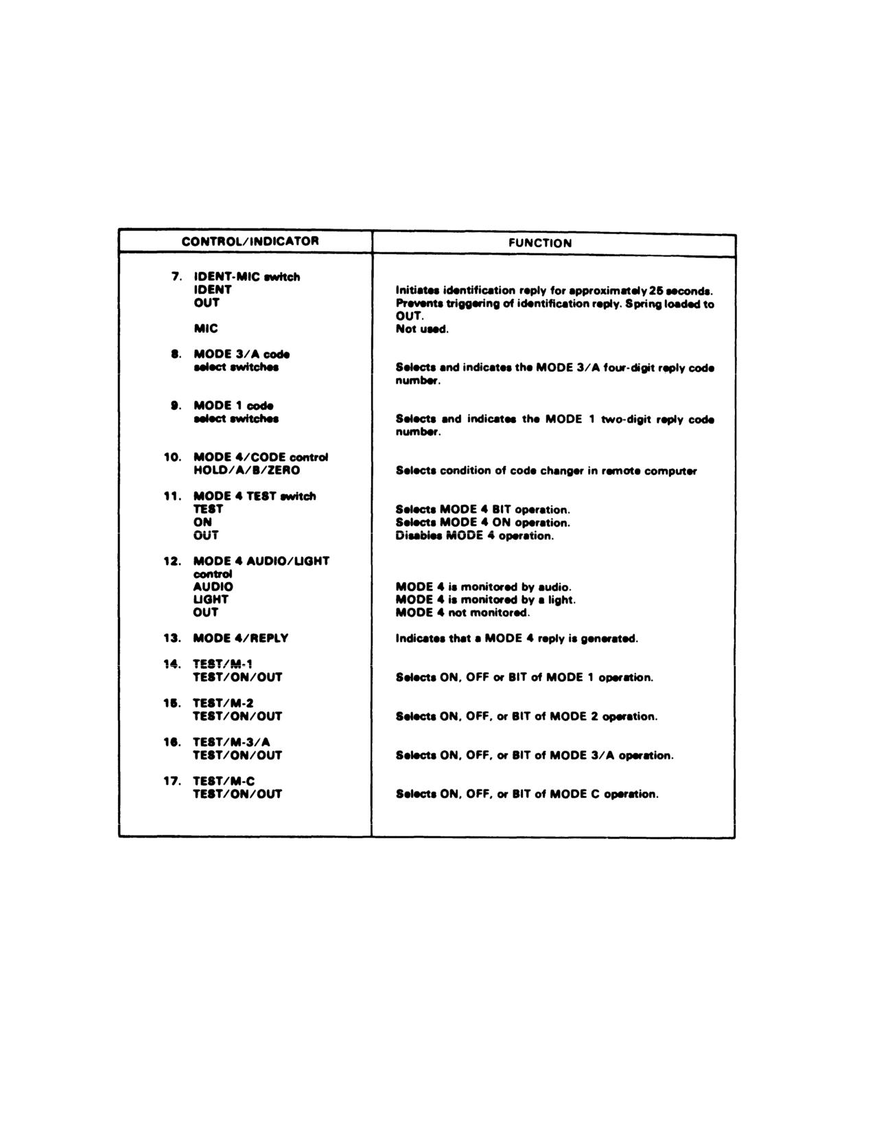
b. Controls and functions - Transponder Set.
b. Controls and Functions. Refer to figure 3-24.
Refer to figure 3-25.
c. Operation.
c. Operation - Transponder Set.
(1) MASTER control
- STBY. Allow
(1) MASTER control
- STBY. Allow
approximately 2 minutes for warmup.
approximately 2 minutes for warmup.
(2) MODE and CODE - Select as required.
(2) MODE and CODE - As required.
(3) TEST M-1, 2, 3/A and C as required.
(3) MASTER control - NORM.
3-32.24
Change 18
TM 55-1520-210-10
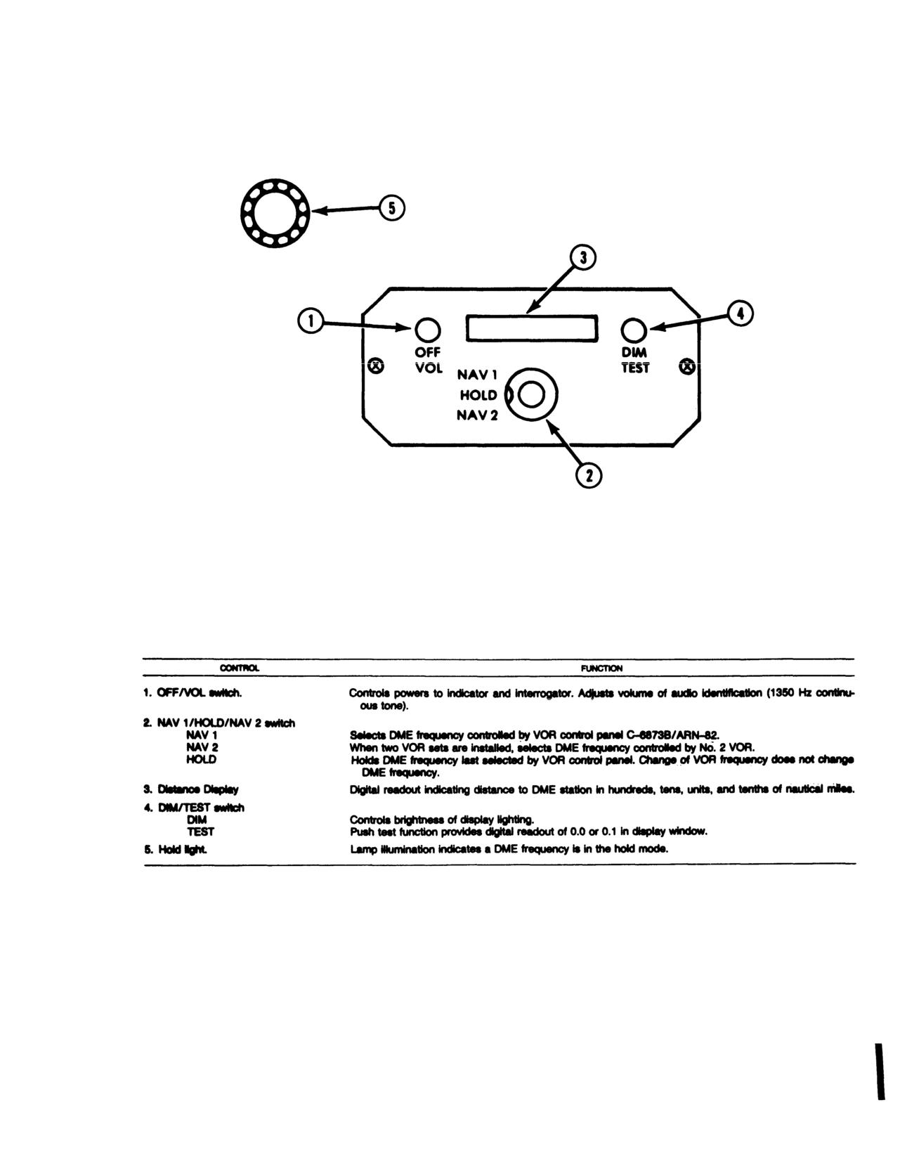
Figure 3-23. DME Indicator ID-2192/ARN-124
Change 7
3-33
TM 55-1520-210-10
Figure
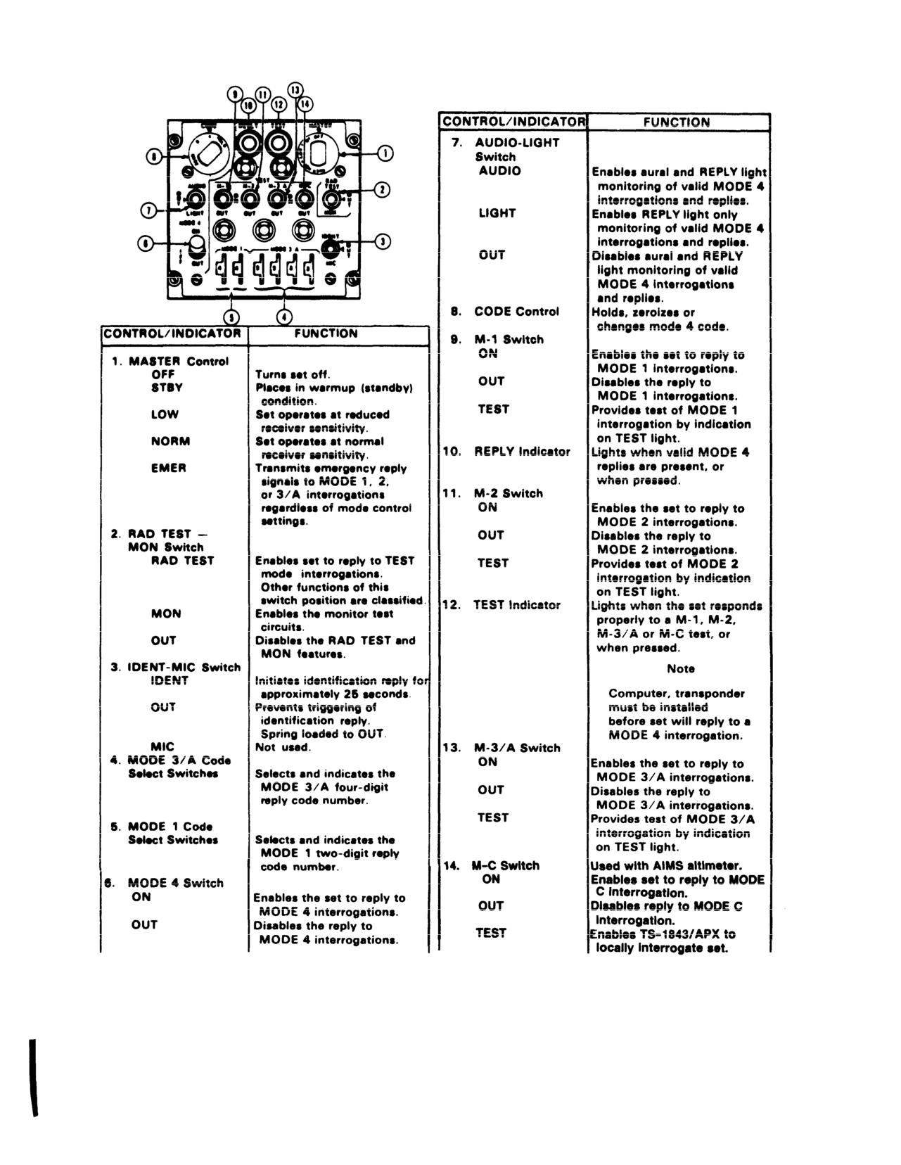
3-24. Transponder Set AN/APX-72
3-34
Change 7
TM 55-1520-210-10
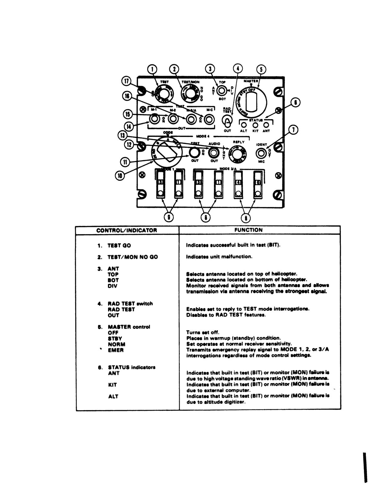
Figure 3-25. Transponder Set (AN/APX-100) Control Panel (Sheet 1 of 2)
3-35
Change 7
TM 55-1520-210-10
Figure
3-25. Transponder Set (AN/APX-100) Control Panel (Sheet
2 of
2)
3-36 Change 7
(4) TEST - As required.
(5) ANT - As desired.
(2) If the REPLY light does not Illuminate
(6) IDENT - As required.
and/or the audio tone is heard, select the opposite code
(7) Stopping procedure. MASTER control -
(A or B) and repeat check.
OFF.
NOTE
d.
Emergency Operation
-
Transponder Set
Further testing to check for correct coding
MASTER control - EMERG.
responses is done with ground test
equipment by moving the MASTER switch to
3-27.
Mode 4 Operation (APX-72 and APX-100).
NORMAL. either transponder does not
a. Before Exterior Check
respond to ground test interrogation the IFF
(1) IFF CODE HOLD switch (on the instrument
caution light should illuminate.
panel) - HOLD and check that the IFF CODE HOLD
indicator lamp is on.
e. Zeroizing MODE 4 codes may be accomplished
NOTE
in any one of the following methods:
If the IFF CODE HOLD switch is OFF and the MASTER
(1) CODE switch - ZERO.
switch is in any position other than OFF, MODE 4 codes
(2) MASTER switch - OFF.
will zeroize when the battery switch is turned off during
NOTE
the BEFORE EXTERIOR check.
If the switch is returned to NORMAL within 5
seconds, zeroizing may not occur.
*b. Aircraft Runup - Test: (APX-100 only)
(1) MASTER switch - STBY FOR 2 minutes.
(3) Aircraft electrical power - OFF.
(2) CODE switch - A.
NOTE
(3) Mode 4 or MODE 4 TEST switch ON.
If the IFF CODE HOLD switch (on the
(4) MODE
4 AUDIO/LIGHT/OUT switch
-
instrument panel) is at HOLD and the CODE
AUDIO.
switch has been moved to HOLD prior to
(5) MODE 4 TEST/ON/OUT switch (APX- 100)
removing electrical power, zeroizing will not
TEST momentarily.
occur.
c. AP,Y-72 --Test Response.
(4) Deleted.
(1) REPLY light should go on.
f
MODE 4 codes retained after engine shutdown.
(2) Audio tone should be heard.
(1) IFF CODE HOLD switch - ON and IFF code
(3) If the above indications do not occur, select
HOLD indicator lamp is on.
the opposite code (A or B) and repeat the check.
(2) CODE switch
- HOLD momentarily and
d. APX-100 - Test response
then release.
(1) REPLY light should go on.
(3) MASTER switch - OFF.
Change 17 3-37
TM 55-1520-210-10
(2) Abnormal Operation.
3-28. Altitude Encoder/Pneumatic Altimeter
(a) If the altimeters internal vibrator becomes
AAU-32/A.
inoperative due to internal failure or dc power failure, the
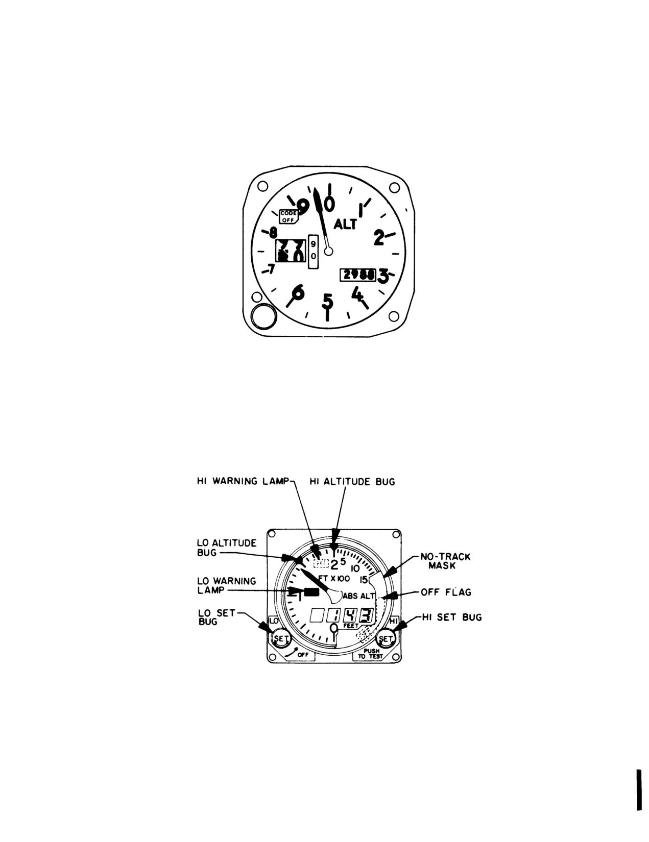
a. Description The AAU-32/A pneumatic counter-
pointer and drum may momentarily hang up when
drum-pointer altimeter is a self-contained unit which
passing from 9 through 0 (climbing) or from 0 thorough
consists of a precision pressure altimeter combined with
9 (descending). This hang-up will cause lag, the
an altitude encoder (fig 3-26). The display indicates and
magnitude of which will depend on the vertical velocity of
the encoder transmits. simultaneously, pressure altitude
the aircraft and the friction in the altimeter. Pilots should
reporting Altitude is displayed on the altimeter by a
be especially watchful for this type failure when the
10.000 foot counter, a 1,000 foot counter and a 100 foot
minimum approach altitude lies within the 8-1 part of the
drum. A single pointer indicates hundreds of feet on a
scale (800 to 1100, 1800 to 2100, etc).
circular scale, with 50 foot center markings. Below an
(b) If the CODE OFF flag is visible, the dc power is
altitude of 10,000 foot a diagonal warning system will
not available, the circuit breaker is not in, or there is an
appear on the
10.000 foot counter. A barometric
internal altimeter encoder failure.
pressure setting knob Is provided to insert the desired
(c) It the altimeter indicator does not correspond
altimeter setting In inches of Hg. A dc powered vibrator
within 70 feet of the field elevation (with proper local
operates inside the altimeter whenever the aircraft power
barometric setting) the altimeter needs rezeroing or there
is on. If dc power to the altitude encoder is lost, a
has been an internal failure.
warning flag placarded CODE OFF will appear in the
(d) If the baroset knob binds or sticks. abnormal
upper left portion of the instrument face indicating that
force should not be used to make the setting as this may
the altitude encoder is inoperative and that the system is
cause internal gear failure resulting in altitude errors.
not reporting altitude to ground stations. The CODE
Settings can sometimes be made by backing off and
OFF flag monitors only the encoder function of the
turning at a slower rate.
altimeter. It does not indicate transponder condition.
The AIMS altitude reporting function may be inoperative
3-29.
Proximity Warning System YG-1054.
without the AAU-32/A CODE OFF flag showing, In
a. Description The proximity warning transponder,
case of transponder failure or improper control settings
control panel located at the forward left side of the
It is also possible to get a ’good’ MODE C test on the
pedestal, operates at frequency 5.08 GHz. The system
transponder control with the CODE OFF flag showing.
provides audio and visual intruder indications of similarly
Display of the CODE OFF flag only indicates an encoder
equipped aircraft within 5,000 feet laterally and 300 feet
power failure or a CODE OFF flag failure. In this event.
vertically. Vertical operation is influenced by barometric
check that dc power Is available and that the circuit
pressure from the helicopters pitot static tube.
breakers are in. If the flag is still visible, radio contact
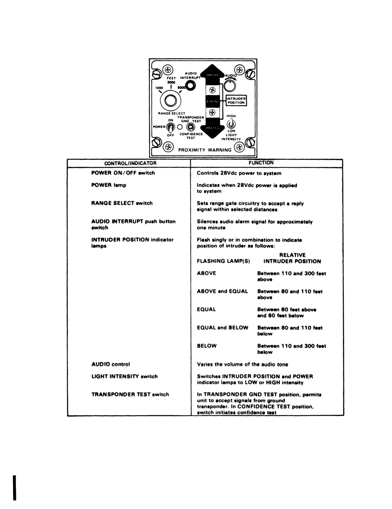
b. Controls and Functions. Refer to figure 3-28.
should be made with a ground radar site to determine
c. Operation.
whether the AIMS altitude reporting function is operative,
(1) POWER switch - ON
and the remainder of the flight should be conducted
(2) Test - CONFIDENCE TEST.
accordingly.
(3) RANGE SELECT - As desired.
b. Operation.
(4) LIGHT INTENSITY - As desired.
(1) Normal Operation. The AIMS altimeter circuit
(5) AUDIO Adjust.
breaker should be closed prior to flight, the Mode C
(6) POWER - OFF
switch (M-C) on the transponder control should be
switched to ON for altitude reporting during flight. The
AAU-32.’A altimeter indicates pneumatic altitude
reference to the barometric pressure level as selected by
the pilot. At ambient pressure, altimeters should agree
with ±70 feet of the field elevation when the proper
barometric pressure setting is set in the altimeter. A red
flag marked CODE OFF is located in the upper left
portion of the altimeters face In order to supply Mode C
information to the IFF transponder, the CODE OFF flag
must not be visible. A vibrator, powered by the dc
essential bus, is contained In the altimeter and requires a
minimum of one minute warmup prior to checking or
setting the altimeter
3-38 Change 17
TM 55-1520-210-10
Figure
3-26. AAU-32/A Altitude Encode/Pneumatic Altimeter
Figure
3-27. AN/APN-209 Radar Altimeter (V)
Change 7
3-39
TM 55-1520-210-10
Figure
3-28. Proximity Warning Panel
3-40
Change 7
TM 55-1520-210-10
3-30. Radar Warning Set.
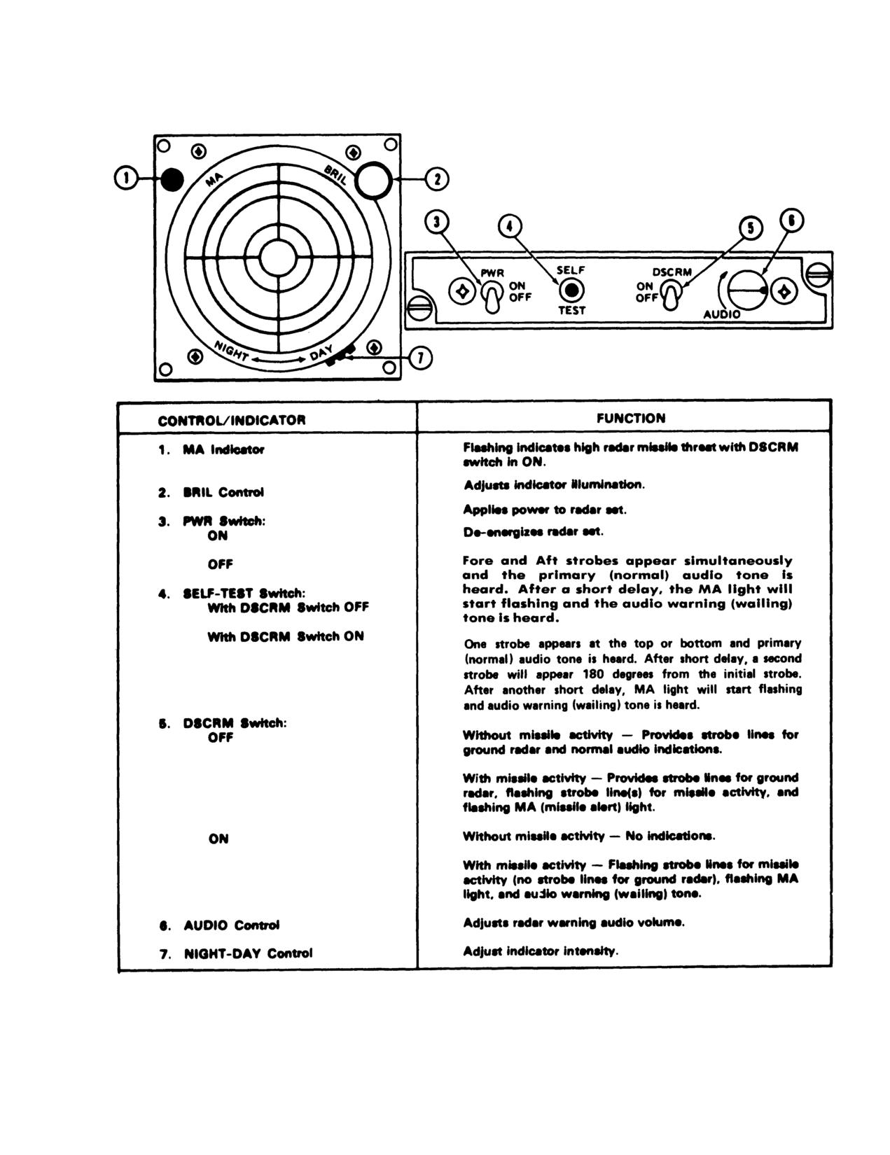
a Description The radar warning set AN/APR-39
provides the pilot with visual and audible warning when a
hostile fire-control threat is encountered. The equipment
responds to hostile fire-control radars but nonthreat
radars are generally excluded. The equipment also
receives missile guidance radar signals and, when the
signals are time-coincident with a radar tracking signal,
the equipment identifies the combination as an activated
hostile surface to air (SAM) radar system. The visual
and aural displays warn the pilot of potential threat so
that evasive maneuvers can be initiated.
To prevent damage to the receiver detector crystals,
assure that the AN/APR-39V-1 antennas are at least 60
meters from active ground radar antennas or 6 meters
from active airborne radar antennas. Allow an extra
margin for new, unusual or high power emitters.
1.
PWR switch - ON, allow I-minute for warmup.
2.
BRIL and filter controls - Adjust as desired.
3.
AUDIO control - Adjust volume as desired.
4.
DSCRM switch - Set for mission requirement.
5.
Stopping Procedure - PWR switch - OFF.
Change 17 3-41
TM 55-1520-210-10
3-31. V Radar Altimeter - AN/APN-209.
altitude warning bug to 80 feet by turning LO SET control
a. Description. The radar altimeter set is a high
knob clockwise. Set the high altitude warning bug to 800
resolution pulse radar that provides an medication of
feet by turning the HI SET control knob clockwise. The
absolute clearance over all types of terrain. The set
indicators should display a track condition within two
consists of the following:
a panel mounted height
minutes from the time indicator was turned on. The OFF
indicator receiver transmitter (located on copilot
flag should disappear from view; the pointer read 0 to 3
instrument panel); a panel mounted remote height
feet; the digital display -0 to +3 feet; and the LO warning
indicator (located on pilot instrument panel), and two
lamp illuminate. Press and hold the HI SET control knob
flush mounted antennas on the underside of the
(push to test operation). The indicator pointer and digital
helicopter. The controls and displays of the height
display should read 1000 +100 feet; the LO warning lamp
indicator receive-transmitter (IRT) and the remote height
should be off and the HI warning lamp on.
indicator (RI) are identical (see Figure 3-27). Absolute
altitude is displayed by a pointer and a digital readout.
NOTE
The pointer operates against a fixed dial and indicates
When using an unmodified indicator
tens of feet between 0 to 200 feet, and hundreds of feet
during NVG flight, turn the HI/LO and
between 200 to 1500 feet. Above 1500 feet the pointer is
DIGITAL switch to OFF. Use the height
driven behind a mask. The digital display has a four digit
needle lite by the eyebrow light The
readout. The readout is displayed in one foot increments
modified indicator will work as advertised.
up to 255 feet. At 256 feet the display is rounded up to
260 feet. Between 260 and 1500 feet the readout is
(2) Normal Operation Adjust LO SET control
displayed in tens of feet. The LO SET control knob
knob to desired setting for low altitude warning bug. The
functions as the on-off switch and is the low altitude trip
LO warming lamp will illuminate when indicated altitude
point adjustment. Clockwise rotation turns the set on.
drops below this setting. Adjust HI SET control knob to
Continuing a clockwise rotation provides for the setting of
desired setting for high altitude warning bug. The HI
the low altitude bug. The HI SET control knob provides
warning lamp will illuminate when indicated altitude goes
for the setting of the high altitude bug. Depressing the HI
above the high altitude warning bug setting. For daylight
SET control knob places the altimeter set m the self-test
operations, set the pilot instrument lighting control
mode. The IRT sends a simulated signal of 1000 feet to
(overhead console) to OFF. This setting provides
both mediators. The indicators display the information
lighting at full brightness to the warning lamps and digital
via the pointer and digital readout. Whenever the
displays on both indicators. Turning the instrument
indicated altitude drops below the low altitude bug setting
lighting controls (pilot and copilot) controls clockwise
the LO altitude warning lamp is activated. Whenever the
dims the indicator lighting. In the event of loss of track
indicated altitude goes above the high altitude bug
due to helicopter attitude (30 degrees pitch or 45 roll) or
setting, the HI altitude warning lamp is activated. When
to operation beyond the range of the altimeter, the
the LO SET control knob is turned to OFF, or during
altitude pointer swings behind the no-track mask and the
periods of unreliable operation, the OFF flag comes into
digital readout is totally blanked. In addition, the OFF
view.
flag comes into view.
b. Operation The following procedures apply to
(3) Stopping Procedure Turn LO SET control
both indicators (IRT on copilot instrument panel, and RI
knob (on each indicator) fully counterclockwise.
on pilot instrument panel). Accomplish procedures using
controls on each indicator.
(1) Initial Operation Turn the IRT and RI on by
Turing the LO SET control knob clockwise. Set the low
3-42 Change 17
TM 55-1520-210-10
Figure 3-29. Radar Warning System
Change 7
3-43
TM 55-1520-210-10
3-32. Receiver-Transmitter Radio, RT-1167/ARC-
3-33. Receiver-Transmitter
Radio,
RT-1167C/
164(V).
ARC-164(V).
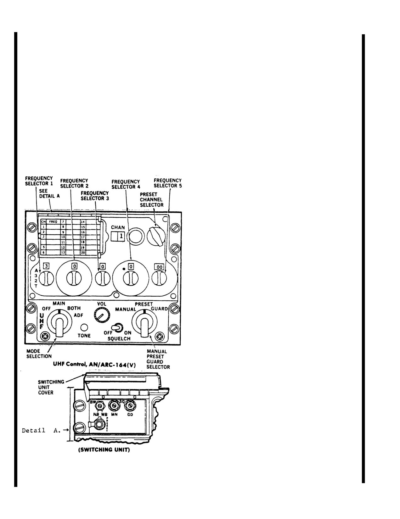
Receiver-Transmitter Radio RT-1167/ARC-164(V)
(figure
3-3.1) is an airborne, ultra-high frequency
Receiver-Transmitter Radio RT-1167C/ARC-164(V)
(UHF), amplitude-modulated (AM), radio transmitting-
has the same functions and capabilities as the RT-
receiving (transceiver) set. It contains a multichannel,
1167/ARC-164(V) plus a HAVE QUICK mode of
electronically-tunable transceiver and a fixed-tuned
operation. HAVE QUICK is an antijamming mode
guard receiver. The transceiver operates on any one
which uses a frequency hopping scheme to change
of 7,000 channels spaced in 0.025 MHz units in the
channels many times per second. Because the HAVE
225.000 to
399.750 MHz UHF military band. The
QUICK mode depends on a precise time of day, both
guard receiver is tunable in the 238.000 to
248.000
HAVE QUICK radios must have synchronized clocks.
MHz frequency range with crystal replacement and
realignment (usually
243.000 MHz). The radio set
A-3-2-T Knob (HAVE QUICK ONLY)
primarily is used for voice communication. An addition-
al radio set capability, although not functional is ADF.
*
A- Selects AJ mode.
Power to operate the ARC-164(V) radio is from the 28
*
3- Allows manual selection of frequencies.
vdc emergency bus through a circuit breaker marked
*
2- Allows manual selection of frequencies.
UHF-AM on the pilot overhead circuit breaker panel.
*
T - Momentary position which enables the radio
to accept a new TOD for up to 60 seconds after selec-
tion. Also used in conjunction with the emergency
startup of the TOD clock when TOD is not available
from a external source.
TONE Button (Have Quick) - Depressing the TONE
button in normal or AJ modes interrupts reception and
transmits a tone signal and TOD on the selected fre-
quency. Simultaneously pressing the TONE button in
conjunction with the A-3-2-T knob in the T position
starts the emergency startup of the TOD clock.
HAVE QUICK System - The HAVE QUICK (HQ)
system provides a jam resistant capability through a
frequency hopping technique. Frequency hopping is a
technique in which the frequency being used for a
given channel is automatically changed at some rate
common to the transmitter and receiver. The jam
resistance of the system is due to the automatic fre-
quency changing and the pseudorandom pattern of
frequencies used. In order to defeat this communica-
tions system, the jammer must find the frequency
being used, jam it and then predictor find the next fre-
quency. The HAVE QUICK modification adds the fre-
quency hopping capability, yet it does not remove any
of the previous capabilities of the radio. The HAVE
QUICK modified radios retain the standard, single fre-
quency UHF voice mode of operations. This is
referred to as the normal mode, while frequency hop-
ping operation is called the anti-jam (AJ) mode.
Several ingredients are necessary for successful sys-
tem operations. These are:
1. Common frequency
2. Time synchronization.
3. Common hopping pattern and rate.
Figure
3-29.1. Receiver-Transmitter Radio,
4. Common net number.
RT-1167/ARC-164(V)
3-44
Change
7
TM 55-1520-210-10
The common frequencies have been programmed into
back to the A position. A TOD update (time tick) can
all HAVE QUICK radios. Time synchronization is
be received on the selected AJ net.
provided via UHF radio and/or hardware by external
time distribution system. A time-of-day (TOD) signal
Net Numbers - After WOD and TOD are entered,
must be received from the time distribution system for
any valid AJ net number can be selected by using the
each time the radio is turned on. The hopping pattern
manual frequency knob.
and hopping rate are determined by the operator in-
serted word-ofday (WOD). The WOD is a multi-digit
Anti-Jamming Mode Operation - A tone is heard in
code, common worldwide to all HAVE QUICK users.
the headset if an invalid AJ net is selected, it TOD was
In the AJ mode, a communications channel is defined
not initially received, or if WOD was not entered. If the
by a net number instead of a signal frequency as in
function knob is set to both and the AJ mode is
the normal mode. Before operating in the AJ mode,
selected, any transmission on the guard channel takes
the radio must be primed. This consists of setting the
precedence over the AJ mode.
WOD, TOD, and net number. The AJ mode is then
selected by placing the A-3-2-T knob to A.
Operational Procedures - Radio Set AN/ARC-164(V)
WORD OF DAY (WOD) - The WOD entry is nor-
1. Transfer WOD IAW “WOD TRANSFER” para-
mally entered before flight, but it is possible to enter it
graph.
in flight. WOD is entered by using one or more of the
2. Setup RT to receive TOD:
six preset channels which are 20-15. For a new WOD
a. With external TOD equipment:
entry, start at channel 20 use the same method as in
(1)
Select manual mode on MODE switch.
entering preset frequencies in the normal mode with
(2)
Set TOD frequency in manual frequen-
the frequency knobs and the PRESENT button. After
cy windows.
each entry, a single beep is heard until channel
15
(3) Set A-3-2-T to A, after TOD beep is
entry; a double bee is heard indicating that the radio
has accepted all six WOD entries.
heard. If tone is heard with the A-3-2-T
in the A position, reinitialize radio IAW
WOD TRANSFER - Select the preset mode and,
steps in “TOD TRANSMISSION” para-
starting with present channel 20, rotate the preset
graph.
knob CCW. At channel 20, a single beep is heard. A
b. Without external TOD equipment:
single beep indicates that channel
20 data has been
Emergency start-up of TOD clock:
transferred and accepted. After the single beep is
(1) Set and hold A-3-2-T switch to T.
heard, select remaining channels
(19-15) in the same
(2) Press the TONE button.
manner until a double beep is heard indicating the
WOD transfer is complete.
NOTE
TIME-OF-DAY (TOD)
- Transmission
- The TOD
entry is normally entered before flight, but it is possible
When using this method, the flight com-
to enter it in flight. It is possible to transmit timing infor-
mander or lead aircraft should emergency-
mation in both normal and AJ modes by momentarily
start his TOD clock. Lead aircraft would
pressing the TONE button. In the normal mode, a
then transfer TOD to other aircraft in flight.
complete TOD message is transmitted, while in the AJ
Aircraft using this method will not be able to
mode, only an abbreviated time update is transmitted.
communicate with valid TOD signal in the
A mode time transmission allows a time update if one
AF mode. A valid TOD signal must be
radio has drifted out of synchronization.
transferred to all aircraft that have invalid
TOD time before effective AJ communica-
TIME-OF-DAY Reception - Reception is possible in
tions can be achieved.
both normal and AJ modes. The radio automatically
accepts the first TOD message after the radio is
turned on and WOD transferred. Subsequent mes-
HAVE QUICK Checklist ARC-164. Loading Word-
sages are ignored unless the T position is selected
of-Day (WOD).
with the A-3-2-T knob. The radio then accepts the next
TOD update in either normal or AJ mode, provided the
1. “T, 2,3, A'' switch - Not in A position.
TOD update arrives within 60 seconds of the time the
2. Functional selector switch - Both.
T position has been selected. To receive time in the
3. Manual, preset, guard switch
- Preset.
normal mode, rotate the A-3-2-T knob to the T position
4. Manual frequency display
- Set WOD
15.
and return to a normal channel in either the manual or
5. Preset channel select- Set to
15.
preset mode. To receive a time update in AJ mode,
6. Preset button (under frequency cover) - Press
rotate the A-3-2-T knob to the T position and then
7. Manual frequency display - Set WOD 16.
Change
7
3-45
TM 55-1520-210-10
8. Preset channel select-Set to
16.
CONTROL
FUNCTION
9. Preset button
- Press.
10. Repeat steps 7 thru 9 to store WOD 17, 18,
Frequency selector
Selects 10’s digit of
19.
switch
2
frequency (0 through 9) in
11. Manual frequency display - Set
300.050.
MHz.
12. Preset channel select - Set to
20.
Frequency selector
Selects units digit of
13. Preset button
- Press.
switch
3
frequency (0 through 9) in
14. Rotate preset select down
19,
18,
17,
16,
15,
MHz.
(hear 1 beep 20-16, 2 beeps on 15).
Frequency selector
Selects tenths digit of
Receiving Time from Net Control Aircraft.
switch
4
frequency (0 through 9) in
1. Manual, preset, guard switch - Manual.
MHz.
2. Set to internal frequency to receive the time.
3. Hear net control aircraft state: “Standby for
Frequency selector
Select hundredths and
time.”
switch
5
thousandths digits of fre-
4. Rotate “T, 2,3, A“ switch to ”T'' and return to
quency
(00,25,50, or
75) in
established manual frequency, hear.
MHz.
5. Hear net control aircraft state: “Go active
0
point one.”
Preset channel
Selects one of 20 preset
selector switch
channels.
6. Set A00.100 in manual window and complete
commo check; if loud tone is heard, repeat
MANUAL-PRESET-
Selects method of frequency
timing.
GUARD selector
selection.
Sending Time (Net Control Aircraft)
MANUAL
Any of 7,000 frequencies is
1. Manual, preset, guard switch - Manual.
manually selected using the
2. Set to internal frequency.
five frequency selector
3. Rotate “T, 2,3, A“ switch to “T’' and hold.
switches.
4. Press tone button and hold (hear no tone).
5. “T, 2,3, A'' to internal frequency (.25 second
PRESET
A frequency is selected
beep, then tone).
using the preset channel
6. Call other aircraft to send time.
selector switch for selecting
7. Press tone button to send time.
any one of 20 preset
channels as indicated on the
CHAN indicator.
NOTE
GUARD
The main receiver and
Recall today’s WOD by reselecting presets
transmitter are
20 down thru 15, and hear beeps.
automatically tuned to the
guard frequency. Blocks
3-34. Antenna.
out any frequency set either
manually or preset.
The UHF-AM antenna (figure 3-1) is located on the
SQUELCH ON-OFF
Turns squelch of main
bottom center fuselage area and is mounted directly
switch
receiver on or off.
aft of the doppler fairing.
VOL control
Adjusts volume.
3-35. Controls and Functions (RT-1167).
TONE switch
Enables transmission and
Controls for the ARC-164(V) are on the front panel
headset monitoring of a
of the unit (figure 3-29.1). The function of each control
1.020-Hz tone on selected
is as follows:
frequency for maintenance
check only.
CONTROL
FUNCTION
Frequency selector
Selects 100’s digit of fre-
switch 1
quency (either 2 or 3) in
MHz.
3-46
Change 7
TM 55-1520-210-10
CONTROL
FUNCTION
(2) Set
MANUAL-PRESET-GUARD selector
switch to MANUAL for manual frequency selection or
Mode selector switch
Selects operating mode:
to PRESET for preset channel selection.
OFF
Turns power off.
(3) To manually select a frequency, rotate the five
MHz selector switches until desired frequency is dis-
played in indicator window.
MAIN
Enables the transceiver.
BOTH
Enables transceiver and
NOTE
guard receiver.
Clockwise rotation of the MHz selector
switches increases frequency.
ADF
Not operational.
(4) To select a preset channel, rotate preset chan-
3-36. Controls and Functions (RT-1167C).
nel selector switch until desired channel is displayed
in preset CHAN indicator window.
The controls and functions of the RT-1167C/ARC-
164(V) are identical to the RT-1167/ARC-164(V) with
NOTE
the exception of the following:
Clockwise rotation of preset channel selec-
CONTROL
FUNCTION
tor switch will increase the
desired channel
number (1 to 20).
Frequency selector
Selects 100’s digit of fre-
switch 1 (T-2-3-A)
quency (either 2 or 3) in
c. Transmit/Receive/Guard
Monitor (BOTH)
MHz. The A position selects
Mode.
the HAVE QUICK mode.
The T position (spring-
Ioaded) allows the radio to
(1) Set OFF-MAIN-BOTH-ADF
selector switch to
receive a new time of day.
BOTH.
3-37. Modes of Operation.
NOTE
The BOTH position turns on the transceiver
Depending on the settings of the operating controls,
and the guard receiver. The guard receiver
the radio set can be used for these modes of opera-
will remain turned to 243 MHz regardless of
tion:
manual or preset frequencies selected.
a. Control (Mode) Settings.
(2) Select desired manual frequency or preset
channel (paragraph 3-37b (3) and
(4)).
(1) MAN mode: two-way voice communications.
NOTE
(2) BOTH mode: utilizing the transceiver constant
monitoring of guard receiver without losing the use of
If reception on the selected frequency inter-
the transceiver.
feres with guard reception; detune the set
by selecting an open frequency or place
(3) Transmission of
1,020 Hz TONE signal.
MANUAL-PRESET-GUARD selector switch
to GUARD.
b. Transmit/Receive (MAIN) mode.
d.
1020 Hz TONE Signal Transmission (MAIN)
(1) Set OFF-MAIN-BOTH-ADF selector switch to
mode.
MAIN.
(1)
Set OFF-MAIN-BOTH-ADF selector switch to
MAIN.
Change 7
3-47
TM 55-1520-210-10
(2) Select a desired frequency for TONE trans-
(5) Press and release PRESET switch. Preset fre-
mission. Refer to steps 3-37b (3) and (4).
quency is now loaded into memory.
(3) Push the TONE switch to transmit the 1020 Hz
3-39. VOICE SECURITY SYSTEM TSEC/KY-58.
signal.
The TSEC KY-58 provides secure voice (ciphony)
NOTE
on the pilot’s VHF FM radio. The pilot uses the KY-58
remote control unit (RCU) located in his right-hand
Tone-modulated signal may be used to
console to operate the TSEC/KY-58, which in turn
check out the radio set and isolate faulty
controls the AN/ARC-186(V) (FM No.1) radio set (also
microphone circuitry.
located in the right-hand console). Power to operate
the TSEC/KY-58 comes from the
28-vdc emergency
bus through a circuit breaker labeled KY-58 on the
e. HAVE QUICK mode (RT-1167C only).
pilot overhead circuit breaker panel. Two operating
modes are available: PLAIN mode for in-the-clear
The HAVE QUICK mode can be activated in one of
voice transmission or reception, and C/RAD
1 (cipher
two ways:
mode for secure radio transmission or reception.
(1) Set MANUAL-PRESET-GUARD switch to
NOTE
MANUAL and set frequency selector switch 1 to A.
The TSEC/KY-58 POWER switch must be
(2) Set MANUAL-PRESET-GUARD switch to
set to ON and the KY-58 circuit breaker
PRESET and set preset channel selector switch to
must be closed before VHF No. 1 radio
channel
20.
communication (plain or ciphered) is pos-
sible.
3-38. Operational Procedures Radio Set AN/ARC-
164.
3-40. Controls and Functions.
a. Guard (Emergency) Operation.
Voice security system controls that require adjust-
ment by the pilot include those on Z-AHQ Power Inter-
(1) Set
MANUAL-PRESET-GUARD selector
face Adapter (located in the aft avionics bay), the
switch to GUARD.
Z-AHP KY-58 Remote Control Unit (located in the
pilot’s right-hand console), and the TSEC/KY-58 (also
NOTE
located in the pilot’s right-hand console). Each of
these devices is shown in figure 3-14. The function of
Transmission on guard frequency will also
each control and indicator is as follows:
occur with transceiver manual frequency or
preset channel tuned to the guard frequen-
Z-AHQ POWER INTERFACE ADAPTER
cy.
CONTROL OR INDICATOR
FUNCTION
b. Loading Preset Channels.
BBV, DPV, BBN, DPN
Set according to type of
4-position
switch
radio being secured. Set
(1) Use the manual frequency selector switches
to BBV for pilot’s VHF
to select the frequency to be placed into memory.
FM radio.
(2) Set
MANUAL-PRESET-GUARD selector
PTT button
Clears crypto alarm that
switch to PRESET.
(push-to-talk)
occurs upon power up.
Alarm can also be
(3) Turn preset channel selector switch to the
cleared by pressing any
desired channel number.
push-to-talk switch in
the pilot compartment.
(4) Raise switching unit cover.
3-48
Change 7
TM 55-1520-210-10
Z-AHQ POWER INTERFACE ADAPTER (cont)
Z-AHP REMOTE CONTROL UNIT
CONTROL OR INDICATOR
FUNCTION
CONTROL OR INDICATOR
FUNCTION
FILTER lN/OUT
Prevents adjacent
MODE Switch
Set to OP (operate) to
Selector
channel interference
use pilot’s VHF radio in
when using radios with
either the Ciphered or
channel spacing of 25
Plain mode. Set to LD
kHz. Must be set to IN
(load) when installing
for pilot’s AN/ARC-
crypto-net variables
186(V) VHF-FM radio.
(CNV) in the TSEC/
KY-58 (TM
11-5810-262-
Z-AHP REMOTE CONTROL UNIT
12&P). Set to RV
(receive variable)
CONTROL OR INDICATOR
FUNCTION
during manual remote
keying (TM
11-5810-262-
REM/LOC Switch
Sets the Z-AHQ to the
12&P).
local mode. Switch
returns to REM (remote)
POWER
Turns KY-58 on and off.
position upon release,
Switch must be on (up) for
but equipment remains
operation in either plain
in local mode until any
or cipher mode.
PTT is keyed.
FILL switch
Selects desired crypto-net
ZEROIZE switch (two-
Use in an emergency to
variable (CNV).
position toggle switch
delete all crypto-net
housed under a spring-
variables (CNVs) from
TSEC/KY-58
Ioaded cover)
KY-58 registers. Ren-
ders KY-58 unusable
CONTROL OR INDICATOR
FUNCTION
until new variables are
loaded.
VOLUME control
Sets audio level of pilot’s
VHF-FM radio.
DELAY Switch
Introduces time delay
that is necessary when
MODE switch
Set to P (Plain) to operate
secure signal from
pilot’s VHF-FM radio in
pilot’s VHF-FM radio is
the clear. Set to C
to be retransmitted by
(Cipher) to operate pilot’s
receiving station.
VHF-FM radio in the
Switch is normally in
ciphered (secure speech)
the down (off) position.
mode. Set to LD (load)
when installing crypto-
C/RAD 1/PLAIN switch
Set switch to C/RAD 1
net variables (CNV) in
(cipher radio 1) to use
the TSEC/KY-58 (TM 11-
secure voice. Set switch
5810-262-12&P). Set to
to PLAIN when
RV (receive variable)
operating radio in the
during manual remote
clear.
keying (TM
11-5810-262-
12&P).
Switch guard
Rotate to the left to
prevent C/RAD 1/
FILL connector
Used to load crypto-net
PLAIN switch from
variables (CNV’S) into the
accidentally being set to
TSEC/KY-58 registers
PLAIN.
(TM
11-5810-262-12&P).
Change
7
3-49
TM 55-1520-210-10
TSEC/KY-58 (cont)
(6) Set the Z-AHQ Power Interface Adapter FIL-
TER selector to IN.
CONTROL OR INDICATOR
FUNCTION
(7) Place the DELAY switch on the Z-AHP
FILL switch
Pull knob and set to Z1-5
Remote Control Unit (RCU) in the down (off) position.
to zeroize (delete) crypto-
net variables (CNV’s) in
(8) Set the C/RAD 1 -PLAIN switch on the Z-AHP
TSEC/KY-58 registers
1-
Remote Control Unit (RCU) to the C/RAD 1 position.
5.Set to 1, 2, 3, 4 or 5 to
select desired CNV. Pull
(9) Set the MODE switch on the Z-AHP Remote
knob and set to Z-ALL to
Control Unit (RCU) to the OP position.
zeroize (delete) crypto-net
variables (CNV’s) in all
(10) Set the FILL switch on the Z-AHP Remote
TSEC/KY-58 registers.
Control Unit (RCU) to the proper crypto-net variable
Zeroizing all registers
(CNV).
renders TSEC/KY-58
unusable.
(11) Set the POWER switch on the Z-AHP
Power switch
Set to OFF to turn off both
Remote Control Unit (RCU) to the ON position.
the TSEC/KY-58 and the
pilot’s VHF-FM radio.
NOTE
Set to ON to operate the
TSEC/KY-58 and pilot’s
At this time you should hear and intermit-
VHF-FM radio. Set to TD
tent tone and backg0round noise. The back-
(time delay) when secure
ground noise is normal. The tone is a
voice from pilot’s VHF-FM
crypto alarm that must be cleared before
radio is to be retransmitted.
the radio can be used. If step 12 does not
clear the intermittent tone, double check
3-41. Operation.
steps 1 through 11. If necessary, refer to
TM
11-5810-262-OP.
a.
Preliminary Operation.
(12) Press and release the ICS switch on the pilot
NOTE
cyclic stick or the pilot’s push-to-talk floor switch. This
should clear the crypto alarm.
Before the pilot’s VHF-FM radio may be
operated in ciphered (secured voice) mode,
b. Cipher Mode.
it must be loaded with one or more crypto-
net variables (CNV’s). Refer to TM
11-
(1) After steps 1 through 12 (above) are complete,
5810-262-12&P for complete details on
the radio is ready to transmit and receive secure
loading these variables.
speech in ciphered mode.
(1) Set the TSEC/KY-58 Power switch to ON.
(2) To transmit, press any push-to-talk switch. You
may begin speaking following the beep.
(2) Set the TSEC/KY-58 MODE switch to C
(cipher).
c. Plain Mode.
(3) Set the TSEC/KY-58 VOLUME control to a
(1) To transmit and receive in the clear, set the
comfortable listening level.
C/RAD 1/PLAIN switch on the Z-AHP Remote Control
Unit to PLAIN.
(4) Set the TSEC/KY-58 FILL switch to any one of
the numbered storage register positions
(1-6).
(2) To transmit, press any push-to-talk switch. You
may begin speaking immediately.
(5) Set the Z-AHQ
Power Interface Adapter 4-
position switch to BBV.
3-50
Change 7
TM
55-1520-210-10
d. Automatic Remote Keying (AK).
you to set your RCU FILL switch to position 6, and
stand by while the MK operation is repeated.
NOTE
3-42. Voice security System TSEC/KY-28.
Automatic Remote Keying (AK) causes an
old crypto-net variable in one of the
Not installed.
TSEC/KY-58 registers to be replaced by a
new one, or an empty register to be filled.
Your net controller simply transmits the new
CNV to your TSEC/KY-58
(1) Your net controller will contact you by using a
secure voice channel, and tell you to wait for an AK
transmission. You must not transmit during this peroid.
(2) You will hear one or two beeps in your headset
when the AK occurs.
e. Manual Remote Keying (MK).
NOTE
Manual Remote Keying (MK) requires you
to use the Z-AHP Remote Control Unit to
change crypto-net variables (CNV’s).
(1) The net controller will contact you by using a
secure voice channel. He will tell you to stand by for a
new or replacement CNV and that you will use an MK
action.
(2) Set the Z-AHP RCU FILL switch to position
6.
Notify the net controller by radio when you have done
this and stand by.
(3) The net controller will tell you to set the Z-AHP
RCU MODE switch by RV (receive variable). Notify
the net controller when you have done this and stand
by.
(4) When notified by the net controller, set the Z-
AHP RCU FILL switch to the storage position selected
to receive the CNV. Notify the net controller when you
have done this, and stand by.
(5) The net controller will ask you to listen for a
beep, wait two seconds, and set the Z-AHP RCU
MODE switch to OP (operate).
(6) If the MK operation was successful, the net
controller will contact you via the new CNV. If the MK
operation was not successful, the net controller will
contact you by a clear voice (plain) transmission, tell
Change 7
3-51
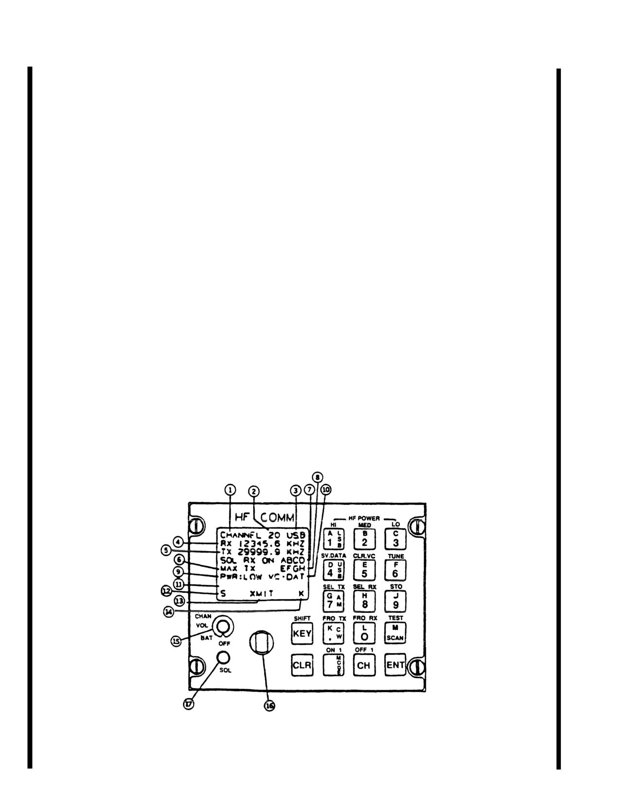
TM 55-1520-210-10
3-43.
#2 VHF-FM-COMM AN/ARC-201.
(3) The
#2 VHF-FM Comm AN/ARC-201 consists
of a Receiver-Transmitter Radio, Panel Mounted (RT-
a. Description. The #2 VHF-FM Comm AN/ARC-
1476).
201 provides VHF-FM radio communications of voice
data, secure or plain text, in single channel (25 KHz)
3-44. HF-SSB RADIO SET AN/ARC-199.
and the SINOGARS ECCM mode of operation. The
frequency range is
30 to
87.975 MHz channelized in
a. Description. The AN/ARC-199 is a high fre-
tuning increments of 25 KHz.
quency, single-side band radio set. It operates in
2.0
to
29.999 MHz frequency range using
280,000 chan-
(1) In addition, a frequency offset tuning capability
nels separated by 100 Hz steps. The AN/ARC-199 is
of -10 KHz, -5 KHz +5 KHz and +10 KHz is provided
capable of for retransmission of data or voice. The
in both receive and transmit mode. This capability is
system is capable of scanning any or all channels
not used in the ECCM mode. Ninety-nine percent of
once they have been programmed on the scanned list.
the emitted spectrum of analog and digitized voice
(16
Kbs;) and data is contained within a 25 Khz channel.
b. Display Fields, Control Knobs and Functions.
Refer to Figure 3-29.2.
(2) The #2 VHF-FM Comm AN/ARC-201 will pro-
vide independent FM Communications only. It will be
interfaced with
#1 VHF-FM Comm/Homing AN/ARC-
201 for operation in the retransmit mode.
Figure 3-29.2 Control-Display Panel Layout
3-52
Change
7
TM 55-1520-210-10
Field/Functioning of Control-Display Panel
CONTROL/
INDICATOR
FUNCTION
1.
Channel - This field appears in inverse video to indicate that current channel
information has not been stored.
2.
Active channel number:
0-20.
3.
Modulation Mode: USB, LSB, AM, CW. CW represents MCW and may be used
in conjunction with the mic key to transmit code.
4.
Receive frequency in kilohertz.
5.
Transmit frequency in kilohertz.
6.
Squelch Level - Display MIN, 1,2,3
13, 14, MAX in conjunction with squelch
knob in control panel.
7.
Receive Selective Address.
8.
Transmit Selective Address. In the sample display shown above, ON indicates
that SELADR mode is operational for RX. If SELADR is operational for TX, ON
is annunciated on the line with TX.
9.
Transmitter Output Power - LOW, MED, or HI.
10.
Modulation Source: The displays are:
DATA
Indicates 600 ohm data input.
CIPHER Indicates input form KY 75 input.
CLR-VC Indicates non-encrypted KY
75 input.
11.
Fault Field: Display fault messages, NOT TUNED, DATA NOT SAVED, and AUDIO
VOLUME LEVEL: VOL MIN
1,2,3
14, MAX.
12.
S: Indicates that the currently displayed channel is on the scan list.
13.
Indicates are: XMIT, TEST, SCAN, TUNE.
XMIT - transmitter is keyed & channel is tuned.
TEST - Built-in-test mode is active.
SCAN - Scan mode is active.
TUNE - Tuning for one or all channels - blank if not one of the above.
Change
7
3-53
TM 55-1520-210-10
Field/Functioning of Control-Display Panel (Cont)
CONTROL/
INDICATOR
FUNCTION
14.
K- Indicates KEY has been pressed, and the functions above the keys are active.
M - Indicates MODE has been pressed, and USB, LSB, AM, or CW should be
selected next. Indicates slewing may be used, or scan flag may be set or
cleared.
CONTROL PANEL KNOBS
15.
Function Select - Power ON/OFF, CRT brightness, audio volume and channel
number selection.
16.
Function - Control - Single-step, detent-type switch, with continuous rotation in
either direction. Clockwise rotation increases, and counterclockwise rotation
decreases the CRT brightness, audio volume, or channel number. In cases of
CRT brightness and audio volume, knob has no effect once limit of that particular
function has been reached. In channel select mode, function control knob is
continuously active. That is, channel 20 is always one position counterclockwise
from channel
0.
17.
Squelch Control - Continuous rotation in either direction; squelch level is
annunciated in field #6. Once upper or lower limit of squelch has been reached,
further rotation of knob in same direction has no effort.
c. Operating Modes/Functions.
(4) Audio Volume. Set Function Select Knob to
VOL, rotate the function Control Knob in the desired
(1) Power ON/OFF. On function Select Knob .Ref-
direction to increase or decrease audio volume. Audio
erence no. 15 on control panel la.out..
volume is not a stored parameter. Audio volume level
is annunciated briefly in the fault area of the display
when the level is being changed. The display levels
(2) Ready indication. When the radio is initially
are: MIN, 1,
2,
3
14. MAX. A secondary HF audio
powered on, a system ready message will be dis-
volume control is located in the lower left console. See
played for a few seconds. The channel
0 information
figure
3-11.2. This is provided for audio level com-
will then be displayed.
patibility with the KY-75. Preset the CDU VOL level to
the max. position and adjust the secondary volume
(3) CRT brightness. Set Function Select Knob to
control for the desired level.
BRT. Rotate the Function Control Knob in the desired
direction to increase or decrease brightness.
3-54
Change
7
TM 55-1520-210-10
(5) Channel Number. Channel number may be
(10) Transmit Selective Address. A
4-letter code
changed using the Function Select and Function Con-
programmed by pressing .HE KEY + SEL TX + a 4-let-
trol Knobs or by using a combination of keystrokes.
ter code + ENT. Transmit selective address mode is
activated with key sequence, KEY + SEL RX + ON +
(6) Modulation Mode. Four modes are available:
ENT, or by activating SELADR RX and keying the mic.
USB, LSB, AM (AME), and CW (MCW). To change
from one mode to another, press MODE
+ desed
(11) Receiver Selective Address. A
4-letter code
mode key + ENT.
programmed by pressing KEY
+ SEL RX + 4-letter
code + ENT. Receive selective address mode is ac-
(7) Receive Frequency.
2.0
-
29.9999 MHz,
tivated by using key sequence: KEY+ SEL RX + ON +
programmable in 100 Hz steps. To change frequen-
ENT.
cies press KEY + FRQ RX+ desired frequency + ENT.
(12) Output Power Level. Three output power
(8) Transmit Frequency.
2.0
-
29.9999 MHz,
levels are selectable from the keyboard; LO, MED, or
programmable in 100 Hz steps. To change frequen-
HI. The key sequence used in KEY+ LO, MED, or HI
cies press KEY + FRQ TX + desired frequency + ENT.
+ ENT.
(9) Squelch Level. Single step, detent-type con-
trol; squelch level is annunciated on the display and
varies from MIN, 1,
2,
3
14, MAX. The squelch
level is not a stored parameter.
Figure
3-29.3 HF Volume Control
Change
7
3-55
TM 55-1520-210-10
(13) Modulation Source. Audio sources available
(18) CW Keying. To utilize the CW keying func-
are CLR-VC (clear voice), DATA, or encrypted audio
tion, first place the radio in CW mode. This is ac-
when used with voice security equipment. CIPHER is
complished by pressing the following key sequence:
displayed when the KY
75 is in the secure voice
MODE + CW + ENT. Now either the KEY key on the
mode. DATA and CLR-VC modes are selectable from
control panel, or any external key switch (a mic key)
control panel, when KY
75 is in non-secure mode,
may be used to transmit CW.
using key sequence: KEY + (SV-DATA or CLR-VC) +
ENT. The modulation source is not a stored
d. Detailed operation.
parameter.
(1) Channel Selection. Any one of
3 procedures
(14) Tune. By using appropriate key sequence,
may be used to select a channel.
either currently displayed channel or all 20 channels
may be turned to the antenna. The tuning information
(a) Using Function Control Knob.
is stored for future use with no tuning necessary. Cur-
rent channel may be tuned by pressing KEY + TUNE
+ ENT. All 20 channels may be tuned by pressing KEY
+ TUNE
+ SCAN
+ ENT.
(15) TEST. Built-in-Test (BITE) feature allows
operator to test both receiving and transmitting
capabilities at several frequencies. Any failure to meet
predetermined performance levels results in a failure
message being displayed. This identifies the faulty
unit and provides a maintenance code. The test is in-
itiated by pressing KEY + TEST + ENT.
(16) STORE. ENT key, used to terminate mode
changes, does not automatically store channel infor-
mation; therefore, a store sequence is provided. The
key sequence is: KEY + STO + ENT.
Figure
3-29.4 Channel Selection
(17) SCAN. Displayed channels may be placed
on scan list by pressing SCAN + ON + ENT. It can be
removed from scan list by pressing SCAN + OFF +
1. Set Function Select Knob to CHAN; rotate
ENT. To automatically scan those channels which
Function Control Knob to increment channel number,
have been placed on scan list, press the SCAN key,
or CCW to decrement channel number. If channels
the ENT key.
are changed quickly, (approximately
2 channels per
second or faster), only word CHANNEL, and an in-
(18) CW Keying. To utilize the CW keying func-
verse video channel number will be displayed on
tion, first place the radio in CW mode. This is ac-
screen until desired channel is reached.
complished by pressing the following key sequence:
MODE + CW + ENT. Now either the KEY key on the
control panel, or any external key switch (a mic key)
may be used to transmit CW.
3-56
Change
7
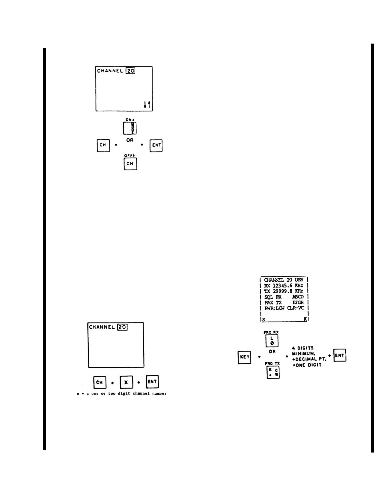
TM 55-1520-210-10
(b) Channel Slewing.
(c) Using Numbered Keys.
1. Begin by pressing CH, but rather than using
arrow keys, use the numbered keys to directly enter
desired channel number. After first digit is pressed,
display will be blanked except for the word CHANNEL,
and inverse video channel number. Press ENT to dis-
play the information associated with the newly
selected channel.
NOTE
In procedures (b) and (c), if CLR is pressed
before ENT, the information displayed will
be that which was displayed prior to initia-
tion of channel charge.
NOTE
Procedures (b) and (c) provide a con-
Figure
3-29.5. Channel Slewing
venient method of selecting channels,
should the function control knob be
damaged or otherwise become inoperable.
1. Begin by pressing CH key, and note that up
and down arrows appear in the lower right corner,
(2) Frequency Select.
(field 14). The up-arrow key increments the channel
number by one for each keystroke. The down-arrow
(a) Frequency Select (RX or TX).
key decrements the channel number by one for each
keystroke. When the first keystroke using an arrow is
made, display will be blanked except for arrows, in-
verse video channel number, and the work CHANNEL.
Once desired channel has been selected, press ENT,
and desired channel information will be displayed
(See the following Notes).
Figure
3-29.7. Frequency Select
Figure
3-29.6. Numbered Keys
Change 7
3-57
TM 55-1520-210-10
1. To initially program, or change, the receive fre-
quency for displayed channel, begin by pressing first
KEY and FRQ RX keys. Next, enter desired operating
frequency with the decimal point; for example,
12345.0. When new frequency has been correctly
entered, press ENT key, and new receive frequency
becomes operational.
2. Several changes occur on the display during
frequency change and these are as follows. A “K'' is
annunciated in lower right corner when KEY is
pressed (see Notes). The “K” is replaced by arrows
when FRQ RX is pressed, and receive frequency
digits field goes to inverse video mode. When the first
new frequency digit is entered, the previous receive
frequency is cleared. After the complete new frequen-
cy has been entered and ENT key is pressed, the dis-
Figure 3-29.8. Frequency Slewing (RX only)
play returns to normal.
3. When entering the frequency, a minimum of
4
1. Frequency slewing is in 100 Hz increments and
digits must be entered before the decimal point is
is accomplished using the up or down arrow keys.
entered. Otherwise an entry error will result and an
Each keystroke of an arrow key changes the frequen-
ENTRY ERROR message will be annunciated in the
cy by 100 Hz in the direction indicated by the arrow.
fault field. The operator must then press the CLR key
To use the frequency slewing feature, first KEY, then
and reenter an allowed frequency.
FRQ RX is pressed. Then either the up or down ar-
rows, and finally ENT when the desired frequency has
been reached. After FRQ RX is pressed, arrows will
4. The transmit frequency is changed in the same
be annunciated in the lower right corner, (field #14).
manner, but with the FRQ RX key replaced by FRQ
This cues the operator that slewing mode is available,
TX. The transmit frequency field (#5) will go to inverse
and the frequency digits field will be in inverse video.
video.
When ENT is pressed the display will return to normal.
(b) Frequency Slewing (RX only).
2. Slewing of the transmit frequency is not al-
lowed. Any attempt to do so will result in an error mes-
sage being annunciated in the fault field.
3-58
Change
7
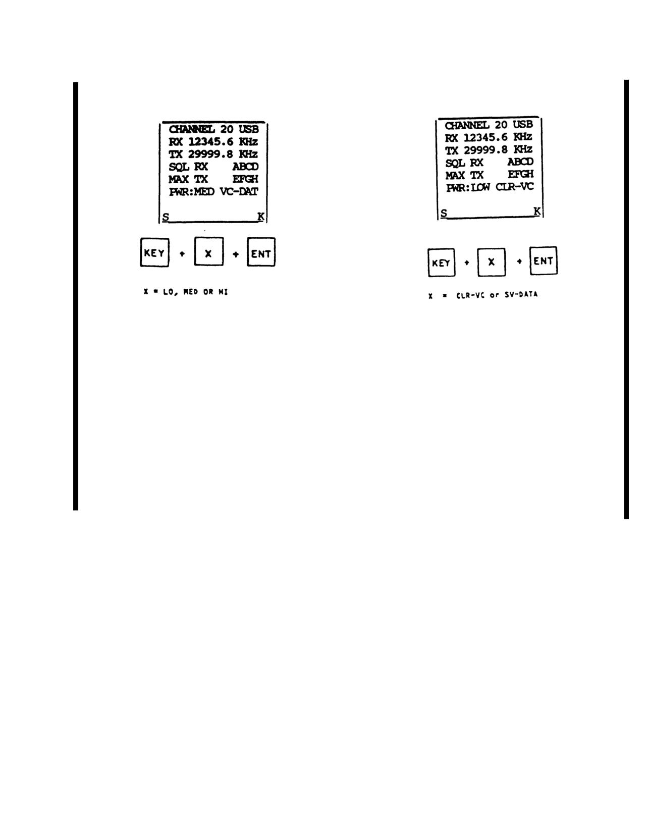
TM 55-1520-210-10
(3) Power Level Select.
(4) Modulation Source Selection.
Figure
3-29.9. Power Level Select
Figure
3-29.10 Modulation Mode Source
(a) If high power lock is in effect, and HI is
selected, MED will be displayed.
(a) The key sequence shown above can select
the 600 ohm data input to the radio using the SV-
(b) Display field 9 goes to inverse video when X is
DATA key. Or it can select 150 ohm compressed audio
pressed and until ENT is pressed. “K” is cleared once
input, using the CLR-VC key. Display field
#10 ap-
“ENT’ is pressed.
pears in inverse video when CLR-VC and SV-DATA is
pressed. It returns to normal when ENT is pressed.
NOTE
(b) If voice security equipment indicates that its
There is a switch on the front of the AM-
output is encrypted, CIPHER will be annunciated on
7201/U which can inhibit the high output
the display. Otherwise, pressing CLR-VC displays
power mode.
CLR-VC, and pressing SV-DATA displays DATA.
Change
7
3-59
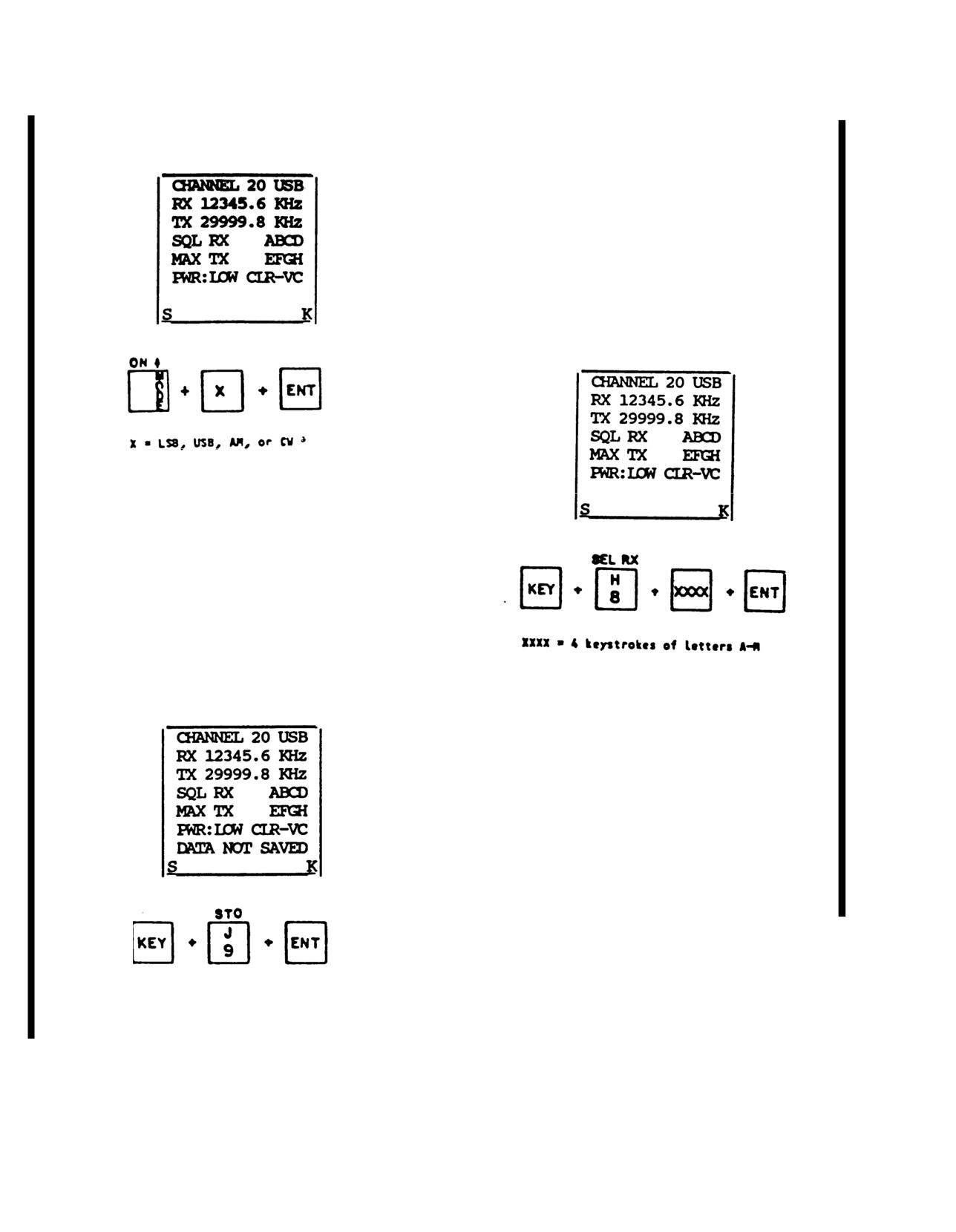
TM 55-1520-210-10
(5) Modulation Mode.
(a) If new channel data is entered and not sub-
sequently saved, “DATA NOT SAVED” will be annun-
ciated in the fault field. The word CHANNEL will
appear in inverse video. Fault messages would have
priority over the message. The key sequence above
may be used to save new channel information. The
“K'' will be cleared from field 14 once ENT is pressed.
(7) Selective Address
(a) Selective Receive Address.
Figure
3-29.11. Modulation Mode
(a) Field
3 appears in inverse video after X is
pressed and until ENT is pressed. “M'' appears in field
14 to indicate mode is being changed. “M” is cleared
once ENT is pressed.
(6) Store.
Figure
3-29.13. Selective Receive Address
1. Selective receive address is entered by press-
ing KEY, SEL RX, then the 4 different letters of the ad-
dress, and finally ENT.
2. When SEL RX is pressed, the receive address
field (#7) goes to inverse video. After the address has
been entered and ENT has been pressed, the display
returns to normal.
Figure
3-29.12. Store
3-60
Change
7
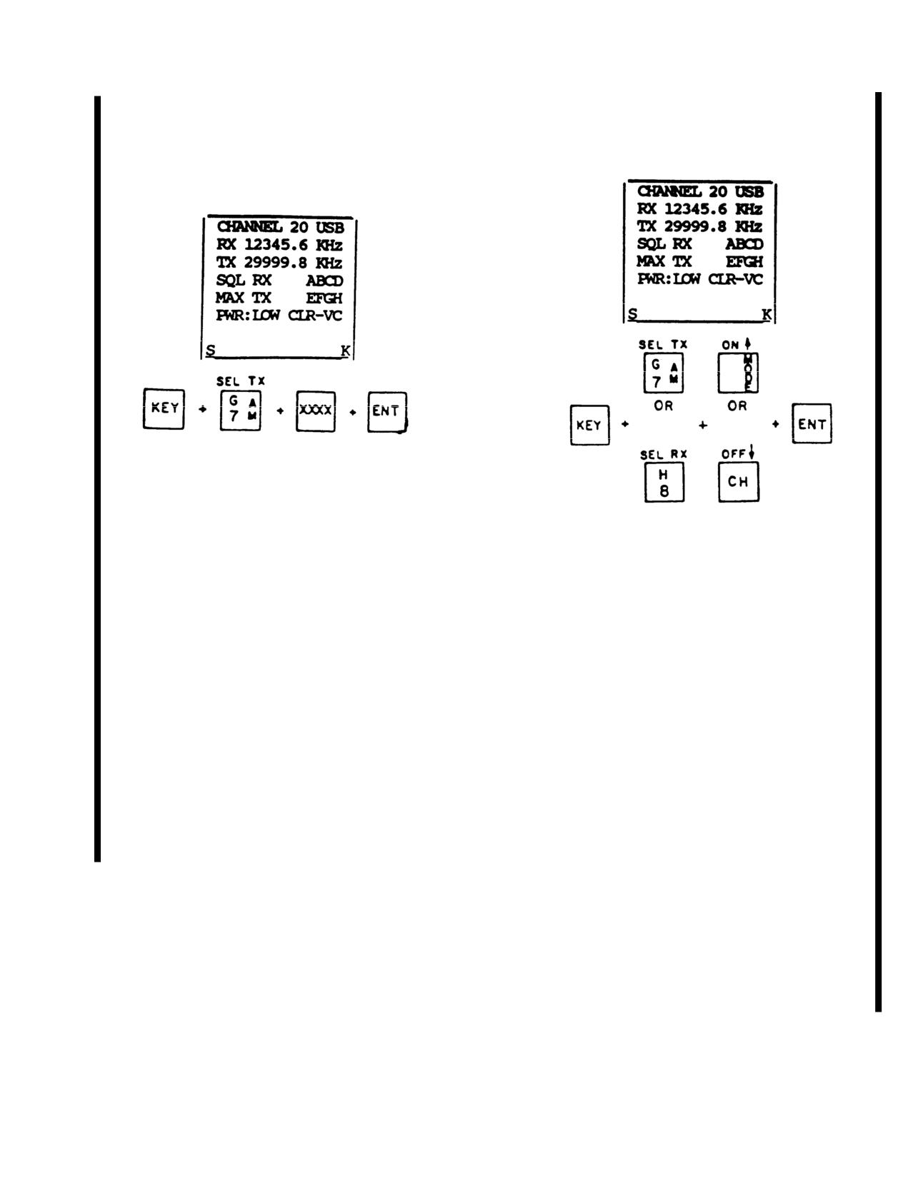
TM 55-1520-210-10
(b) Selective Transmit Address.
(8) SELADR ON/OFF.
Figure
3-29.14. Selective Transmit Address
1. Selective transmit address is entered by press-
ing KEY, the SEL TX, then 4-letter address, and finally
Figure
3-29.15. Seladr On/Off
ENT.
2. When SEL TX is pressed, the transmit address
(a) Seladr RX. To enable Seladr RX, use the key
field (#8) goes to inverse video. After the address has
sequence KEY + SEL RX + ON + ENT. With Seladr
been entered and ENT has been pressed, the display
enabled, receiver is fully squelched until correct
returns to normal.
Seladr tones are received, and Seladr squelch over-
rides squelch control. To receive Seladr tones, radio
NOTE
must be tuned to frequency on which Seladr tones,
radio must be turned to frequency on which Seladr
Four different letters must be used in the
tones are to be transmitted, or be scanning for that
code, and the arrangement of letters is ir-
frequency. Reception of a matching,
4 tone Seladr
relevant. The code ABCD is identical to the
code causes the following events to occur. Seladr RX
code BADC, and the letters will be dis-
will be deactivated. An audio tone will alert the
played in alphabetical order.
operator that he is being called. If the unit was pre-
viously scanning, scanning will cease. Squelch will
automatically be set to minimum.
NOTE
The operator can take the radio out of the
Seladr RX mode either by using the key se-
quence shown above, or by keying the mic.
Change 7
3-61
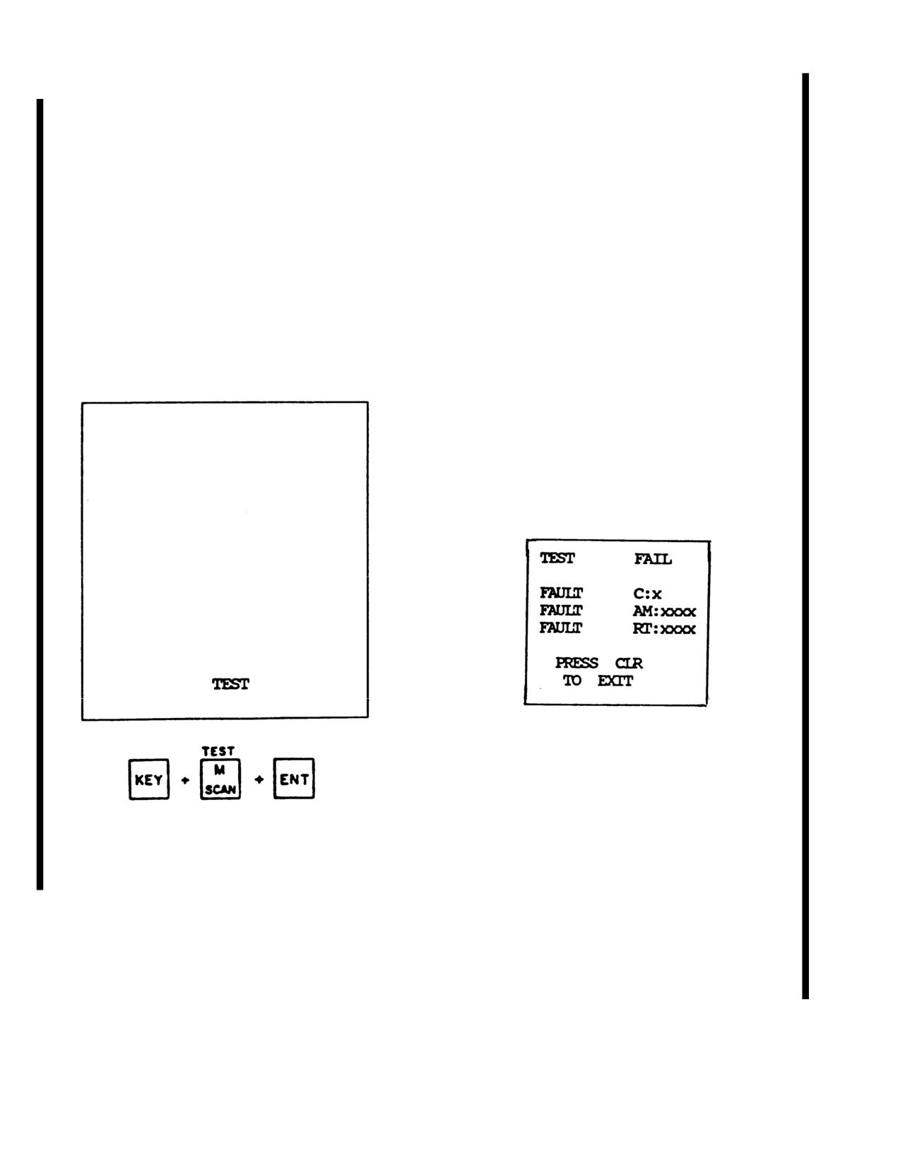
TM
55-1520-210-10
(b) Seldar TX. Seladr TX may be activated with
1. Upon initiation of Built-In-Test (BITE) sequence
either the key sequence shown above, or, when
using keystrokes shown, CRT will first display a
Seladr RX is active, with the mic key. When the key-
checkerboard pattern for a few seconds. Then, an in-
board is used, ON is annunciated in the Seladr TX
verse checkerboard pattern to test the individual char-
field. XMIT appears in display field 13, and the 4-letter
acter spaces on the CRT. TEST will be displayed in
code is automatically transmitted for a predetermined
field 13 with the rest of CRT blank for remainder of
length of time. When mic keying is used, code will be
test.
transmitted for predetermined time period. Or it can be
as long as mic is keyed, which ever is longer. Seladr
2. If BITE must be haulted prior to completion,
TX is deactivated by any keystroke, however, it is
any keystroke will abort the test. However, for consis-
recommended that the CLR key be used.
tency, it is recommended that CLR be used as the ter-
minating keystroke.
(9) Test Mode Display.
3. Once BITE is completed and failed/passed dis-
(a) Test Mode.
play is annunciated, CLR must be used to return to
normal operating conditions.
(b) Failed Test Display.
Figure
3-29.17. Failed Test Display
Figure
3-29.16.Test Mode Display
1. First Row: Test Fail Message.
2. Third, fourth & fifth Rows: Unit(s) which failed
and failure code(s) for maintenance.
3. Seventh & eighth Rows: Test exit instruction.
3-62
Change
7
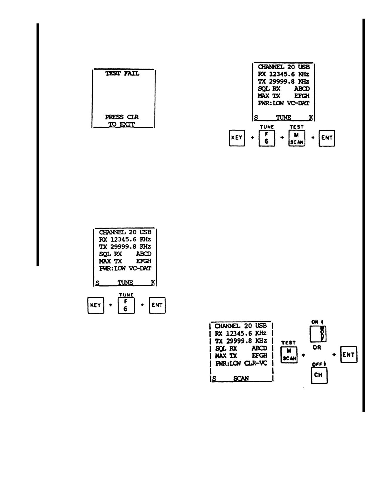
TM 55-1520-210-10
(c) Passed Test Display.
(b) All Channels.
Figure
3-29.18. Passed Test Display
Figure
3-29.20. Tune Mode-All Channels
(10) Tune Mode.
1. This sequence will tune all channels which
have been programmed with frequency information.
(a) Single Channel.
Any keystroke will be capable of ending either of the
tune operations. It is recommended that CLR be used.
The “K'' cleared once ENT is pressed. TUNE in-
dicator appears in field
13 when the TUNE key is
pressed and until tuning is complete.
2. If the mic is keyed, and a channel needs
tuning, “NOT TUNED” will be displayed in the fault
field.
(11) Scan Mode.
(a) Programming Scan.
Figure
3-29.19. Tune Mode-Single Channel
1. This sequence will tune only the channel cur-
rently displayed. Tune indicator appears in field
13
when TUNE is pressed and until tuning is complete.
The “K''s cleared once ENT is pressed.
Figure
3-29.21. Scan Mode
Change 7
3-63
TM 55-1520-210-10
1. To place a channel on, or remove a channel
1. To scan channels which have been stored onto
from scan list, begin by pressing SCAN key. At this
scan list, press SCAN key and ENT key. When ENT is
point SCAN will be annunciated in field 13. Arrows will
pressed, the display, except for the channel number,
be annunciated in field 14. The up-arrow key sets the
the word CHANNEL, and SCAN in field
13, will be
scan flag for the displayed channel. The down-arrow
blanked. The channel number will change as scanning
key clears the scan flag for the displayed channel.
takes place.
2. Once the flag has been set or cleared, press
2. To terminate scanning, it is recommended that
ENT The arrows and SCAN will be cleared from the
the CLR key be used, although any keystroke is
display. If the scan flag was set, and “S will be annun-
capable of ending scanning. Normal radio operation
ciated in the lower left comer of the display. This indi-
will be restored for that channel which was being
cates that the dislayed channel is on the scan list.
scanned when scanning was terminated.
NOTE
e. Example Programming One or More Channels.
The following procedure may be used to initially pro-
The scan flag must be stored after being
gram a single channel with all the necessary operating
entered in order for the channel to be
parameters. To program additional channels, simply
placed on the scan list.
change the active channel number and duplicate the
procedure. Insert the operating information for the
channel.
(b) Executing Scan.
(1) Power
on. Turn the Function Select Knob
clockwise one
position to BRT. When the radio has
warmed up, a “system ready” message will be dis-
played for a few seconds. The channel
0 information
previously stored will be displayed.
(2) Set CRT Brightness. Adjust the Function Con-
trol Knob until the display has the desired brightness.
(3) Set Audio Volume. Set the function select
knob to the VOL position. Set the CDU VOL knob to
the max. position. Adjust the HF volume control to the
desired volume.
Figure
3-29.22. Executing Scan
3-64
Change 7
TM 55-1520-210-10
(4) Set Squelch. With no reception of RF, use the
NOTE
Squelch Knob to adjust the audio to the point where
backg0round noise is muted.
The store function stores only the currently
displayed channel information. Therefore,
(5) Channel Select. Turn Function Select Knob to
the store function must be implemented for
CHAN and adjust the Function Control Knob to the
each individual channel before selecting a
desired channel.
new channel.
(6) Operating Parameters. Use procedures in
(8) Tune. After all the desired channels have been
Detailed Operation to select modulation mode, receive
programmed, initiate the tune sequence for all chan-
and transmit frequencies, receive and transmit selec-
nels.
tive address, power level and modulation source.
Place the channel on the scan list if desired. Place in
(9) Test. If a test of the AN/ARC-199 system is
retransmission mode if desired.
desired, initiate the test sequence. The system may
be performed at any time after the system is powered
(7) Store. The information that has just been
on. The radio is now ready to receive or transmit on
programmed is now operational but is not yet per-
frequencies being displayed.
manently stored. If desired to permanently Store this
information for the displayed channel, use the store
procedure.
Figure 3-29.23. HF Volume Control
Change 7
3-65
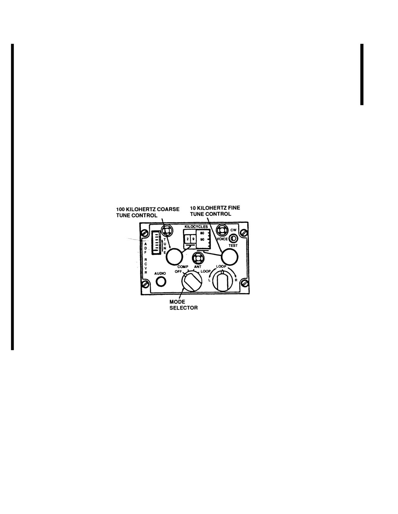
TM 55-1520-210-10
3-45. DIRECTION FINDER SET AN/ARN-89.
(1) If there is an HSI control installed the ADF can
display the bearing on either the No.
1 or No.
2
pointer. This is dependent upon the position of the HSI
a. Description. This low frequency automatic
control Mode Select Switch. This unit will also function
direction finder radio (ADF) set provides either auto-
matic or manual compass bearing on any radio signal
as AM or CW communication receiver.
between 100 and 3,000 KHz. The ADF can identify
keyed or continuous wave (CW) stations. If there is no
b. Controls and Functions. Refer to Figure
HSI control installed, the ADF displays the bearing of
3-29.24.
the helicopter relative to a selected radio transmission
on the horizontal situation indicator No.
2 bearing
pointer (Figure
3-29.29).
Figure 3-29.24 LF/ADF Control Panel C-7932/ARN-89
3-66
Change
7
TM 55-1520-210-10
Controls and Functions of LF/ADF Control Panel C-7932/ARN-89
CONTROL
FUNCTION
Mode selector switch
Audible tone for tuning to CW station, SS
OFF
Turns power off.
COMP
Provides operation as an ADF.
ATN
Provides for operation as an AM
receiver using sense antenna
LOOP
Provides for receiver operation as a
manual direction finder using loop only.
LOOP L-R control
Provides manual left and right control
of loop when operating mode selector in
LOOP position. It is spring loaded to
return to center.
AUDIO
Adjusts volume.
100 Kilohertz
Tunes receiver in 100-KHz steps as
coarse-tune
indicated by first two digits of KILO-
control knob
CYCLES indicator.
CW (COMP mode)
Enables tone oscillator to provide
audible tone for tuning to CW station,
when mode function switch is at COMP,.
CW (ANT or LOOP
Enables beat frequency oscillator to
mode)
permit tuning to CW station, when mode
function switch is at ANT or LOOP.
VOICE
Permits low frequency receiver to
operate as a receiver with mode switch
in any position.
TEST (COMP mode)
Provides slewing of loop through 180°
to check operation of receiver in COMP
mode. (Switch position is inoperative
in LOOP and ANT modes.)
TUNE Meter
Indicates relative signal strength
while tuning receiver to a specific
radio signal.
KILOCYCLES
Indicates operating frequency to which
receiver is tuned.
Change 7
3-67
TM 55-1520-210-10
c.
Operation
(b) HSVVSI MODE SEL BRG 2 switch - ADF.
(1) Starting Procedure.
(c) The horizontal situation indicator No.
1 bearing
pointer displays the magnetic bearing to the ground
(a) ICS NAV receiver selector - ON.
station from the helicopter. It is read against the
compass card when ADF is selected on the MODE SEL
(b) Mode selector - COMP, ANT, or LOOP.
BRG I switch.
(c) Frequency - Select.
(d) ICS NAV switch - ON
(d) CW, VOICE, TEST switch - CW or VOICE as al
(e) To test the ADF, when required.
propiate.
(e) ICS NAV switch - ON.
1.
CW, VOICE, TEST switch - Test to see that No
(f)
Fine tune control - adjust for maximum upward ir
1 bearing pointer changes about.
diction on TUNE meter.
2. CW, VOICE, TEST switch - release.
(g) AUDIO control - adjust as desired.
(4) LOOP Mode Operation Manual direction finding
(2) ANT Mode Operation.
uses the LOOP mode.
(a) Mode selector - ANT.
(a) Mode selector switch - LOOP
(b) ICS NAV switch - ON.
(b) ICS NAV switch - ON.
(c) Monitor receiver by listening.
(c) Turn LOOP L-R switch to L (left) (right) to
obtain an audio null and a tune In null. Watch HSI No. 1
(3) COMP Mode Operation.
bearing pointer for a display of magnetic bearing to or
from ground station against the compass card. In this
(a) Mode selector - COMP.
mode of operation two null positions 1800 apart as
possible
d.
Stopping Procedure. Mode selector - OFF.
3-68 Change16