ARMY MODEL UH-1H/V HELICOPTERS. OPERATOR’S MANUAL (1988) - page 1
TM 55-1520-210-10
OPERATOR’S MANUAL
ARMY MODEL
UH-1H/V HELICOPTERS
This manual supersedes TM 55-1520-210-10 dated 1 December 1986, including all
changes.
HEADQUARTERS, DEPARTMENT OF THE ARMY
15 FEBRUARY 1988
TM 58-1520-210-10
C18
CHANGE
HEADQUARTERS
DEPARTMENT OF THE ARMY
No.18
WASHINGTON, D.C., 8 October 1999
OPERATOR’S MANUAL
ARMY MODEL
UH-1 H/V HELICOPTER
DISTRIBUTION STATEMENT A: Approved for public release; distribution is unlimited
TM 55-1520-210-10, 15 February 1988, is changed as follows:
1. Remove and insert pages as indicated below. New or changed text material is indicated by a vertical bar in the mar-
gin. An illustration change is indicated by a miniature pointing hand. An illustration revision is indicated by a change
bar.
Remove pages
Insert pages
-----------
A and B
i through ii
i through ii
iii through iv
iii through iv
1-1 and 1-2
1-1 and 1-2
2-23 and 2-24
2-23 and 2-24
2-29 and 2-30
2-29 and 2-30
2-33 and 2-34
2-33 and 2-34
3-21 and 3-22
3-21 and 3-22
-----------
3-22.1 through 3-22.28
3-31 and 3-32
3-31 and 3-32
-----------
3-32.1 through 3-32.24
index 1 through index 4
index 1 through Index 4
2. Retain this sheet in front of manual for reference purposes.
By Order of the Secretary of the Army:
ERIC K. SHINSEKI
General, United States Army
Chief of Staff
Official:
JOEL B. HUDSON
Administrative Assistant to the
Secretary of the Army
9927804
DISTRIBUTION:
TO be distributed in accordance with initial Distribution Number (IDN) 310275, requirements for TM 55-1520-
210-10
TM 55-1520-210-10
C17
CHANGE
HEADQUARTERS
DEPARTMENT OF THE ARMY
NO 17
WASHINGTION, D.C., 13 February 1997
Operator’s Manual
ARMY MODEL
UH- IH/V HELICOPTERS
TM 55-1520-210-10, 15 February 1988, is changed as follows:
1. Remove and insert pages as indicated below. New or changed text material is indicated by a vertical bar in the margin.
An illustration change is indicated by a miniature pointing hand.
2. Pages 2-23 and 2-24 may have been omitted in some copies of Urgent Change 16. Therefore, these pages have been
included as part of this Change 17. Note, however, that these pages will retain their Change 16 designation.
Remove pages
Insert pages
i and ii
i and ii
2-1 through 24
2-1 through 2-4
24.1/(2.4.2 blank)
2-4.1/(24.2 blank)
2-5 through 2-8
2-5 through 2-8
.----.-.-.--
2-8.1/(2-8.2 blank)
2-9 through 2-12
2-9 through 2-12
.-.-.-.-.--
2-12.1/(2-12.2 blank)
2-13 through 2-16
2-13 through 2-16
.-.-.-.-.--
2-16.1/(2-16.2 blank)
2-17 through 2-24
2-17 through 2-24
2-35 and 2-36
2-35 and 2-36
3-11 and 3-12
3-11 and 3-12
3-12.1 and 3-12.2
3-12.1 and 3-12.2
3-27 through 3-32
3-27 through 3-32
3-37 and 3-38
3-37 and 3-38
3-41 and 3-42
3-41 and 3-42
4-5/(4-6 blank)
4-5/(4-6 blank)
(4-7 blank)/4-8
(4-7 blank)/4-8
4-9 and 4-10
4-9 and 4-10
5-1 through 5-4
5-1 through 5-4
6-1 through 6-4
6-1 through 64
7-3 and 74
7-3 and 74
---------
7-4.1/(74.2 blank)
7-5 and 76
7-5 and 7-6
7-47 and 748
747 and 748
7.1-3 and 7.14
7.1-3 and 7.14
------------
7.1-4.1/(7.14.2 blank)
7.1-5 and 7.1-6
7.1-5 and 7.16
URGENT
TM 55-1520-210-10
C16
CHANGE
HEADQUARTERS
DEPARTMENT OF THE ARMY
NO 16
WASHINGTON, D.C., 13 August 1996
Operator’s Manual
ARMY MODEL
UH-1HN HELICOPTERS
DISTRIBUTION STATEMENT A: Approved for public release; distribution is unlimited
TM 55-1520-210-10, 15 February 1988, Is changed as follows.
1. Remove and insert pages as indicated below New or changed text material is indicated by a vertical bar in the margin.
An illustration change Is indicated by a miniature pointing hand.
Remove pages
Insert pages
iii through v/(vi blank)
iii through v/(vi blank)
2-23 and 2-24
2-23 and 2-24
2-29 and 2-30
2-29 and 2-30
3-67 and 3-68
3-67 and 3-68
--------------
3-68.1 through 3-68.3/(3-68.4 blank)
8-3 and 8-4
8-3 and 8-4
9-3 and 9-4
9-3 and 9-4
Index 1 and Index 2
Index 1 and Index 2
2. Retain this sheet in front of manual for reference purposes.
By Order of the Secretary of the Army:
DENNIS J. REIMER
General, United States Army
Chief of Staff
Official
JOEL B HUDSON
Administrative Assistant to the
Secretary of the Army
02158
DISTRIBUTION:
To be distributed in accordance with DA Form 12-31-E, block no. 0275, requirements for TM 55-1520-210-10.
TM 55-1520-210-10
C15
URGENT
CHANGE
HEADQUARTERS
DEPARTMENT OF THE ARMY
NO. 15
WASHINGTON, D.C., 14 February 1996
Operator's Manual
ARMY MODEL
UH-1H/V HELICOPTERS
DISTRIBUTION STATEMENT A: Approved for public release; distribution is unlimited.
TM 55-1520-210-10, 15 February 1988, is changed as follows:
1. Remove and insert pages as indicated below. New or changed text material is indicated by a vertical bar in
the margin. An illustration change is indicated by a miniature pointing hand.
Remove pages
Insert pages
2-4.1/(2-4.2 blank)
2-4.1/(2-4.2 blank)
2-5 and 2-6
2-5 and 2-6
2-9 and 2-10
2-9 and 2-10
2-19 and 2-20
2-19 and 2-20
5-3 through 5-6
5-3 through 5-6
9-1 through 9-4
9-1 through 9-4
Index 3 and Index 4
Index 3 and Index 4
2. Retain this sheet in front of manual for reference purposes.
By Order of the Secretary of the Army:
DENNIS J. REIMER
General, United States Army
Chief of Staff
Administrative Assistant to the
Secretary of the Army
01309
DISTRIBUTION:
To be distributed in accordance with DA Form 12-31-E, block no. 0275, requirements for
TM 55-1520-210-10.
URGENT
NOTICE: THIS CHANGE HAS BEEN PRINTED AND DISTRIBUTED OUT OF SEQUENCE.
IT SHOULD
BE INSERTED IN THE MANUAL AND USED. UPON RECEIPT OF THE EARLIER SEQUENCED
CHANGE ENSURE A MORE CURRENT CHANGE PAGE IS NOT REPLACED WITH A LESS CUR-
RENT PAGE.
TM
55-1520-210-10
C 14
CHANGE
HEADQUARTERS
DEPARTMENT OF THE ARMY
WASHINGTON, D.C., 9 MARCH 1994
NO. 14
Operator’s Manual
ARMY MODEL
UH-lH/V HELICOPTERS
DISTRIBUTION STATEMENT A: Approved for public release;
distribution is unlimited.
TM 55-1520-210-10, 15 February 1988, is changed as follows:
New or changed text material is
1. Remove and insert pages as indicated below.
An illustration change is indicated
indicated by a vertical bar in the margin.
by a miniature pointing hand.
Insert pages
Remove pages
4-5 and 4-6
4-5/(4-6 blank)
----
4-6.1/(4-6.2 blank)
4-7 through 4-10
4-8 through 4-10
4-15 and 4-16
4-15 and 4-16
6-11 through 6-14
6-11 through 6-14
2. Retain this sheet in front of manual for reference purposes.
By Order of the Secretary of the Army:
GORDON R. SULLIVAN
General, United States Army
Official:
Chief of Staff
MILTON H. HAMILTON
Administrative Assistant to the
Secretary of the Army
06202
DISTRIBUTION:
To be distributed in accordance with DA Form 12-31-E, block no. 0275, require-
ments for TM 55-1520-210-10.
URGENT
NOTICE: THIS CHANGE HAS BEEN PRINTED AND DISTRIBUTED OUT OF SEQUENCE.
IT SHOULD
BE INSERTED IN THE MANUAL AND USED. UPON RECEIPT OF THE EARLIER SEQUENCED
CHANGE ENSURE A MORE CURRENT CHANGE PAGE IS NOT REPLACED WITH A LESS CUR-
RENT PAGE.
TM
55-1520-210-10
C 13
CHANGE
HEADQUARTERS
DEPARTMENT OF THE ARMY
NO. 13
WASHINGTON, D.C., 30 NOVEMBER
1993
Operator’s Manual
ARMY MODEL
UH-1H/V HELICOPTERS
DISTRIBUTION STATEMENT A: Approved for public release; distribution is unlimited.
TM 55-1520-210-10, 15 February 1988, is changed as follows:
1. Remove and insert pages as indicated below. New or changed text material is
indicated by a vertical bar in the margin. An illustration change is indicated
by a miniature pointing hand.
Remove pages
Insert pages
9-3 through 9-8
9-3 through 9-8
2. Retain this sheet in front of manual for reference purposes.
By Order of the Secretary of the Army:
GORDON R. SULLIVAN
General, United States Army
Official:
Chief of Staff
MILTON H. HAMILTON
Administrative Assistant to the
Secretary of the Army
05801
DISTRIBUTION:
To be distributed in accordance with DA Form 12-31-E, block no. 0275, require-
ments for TM 55-1520-210-10.
URGENT
NOTICE:
THIS CHANGE HAS BEEN PRINTED AND DISTRIBUTED OUT OF SEQUENCE. IT
SHOULD BE INSERTED IN THE MANUAL AND USED. UPON RECEIPT OF THE
EARLIER SEQUENCED CHANGE, ENSURE A MORE CURRENT CHANGE PAGE IS NOT
REPLACED WITH A LESS CURRENT PAGE.
TM
55-1520-210-10
C 12
CHANGE
HEADQUARTERS
DEPARTMENT OF THE ARMY
NO. 12
WASHINGTON, D.C.,
23 July 1993
Operator's Manual
ARMY MODEL
UH-1H/V HELICOPTERS
DISTRIBUTION STATEMENT A: Approved for public release; distribution is unlimited.
TM 55-1520-210-10, 15 February 1988, is changed as follows:
1.
Remove and insert pages as indicated below. New or changed text material is
indicated by a vertical bar in the margin. An illustration change is indicated
by a miniature pointing hand.
Remove pages
Insert pages
i and ii
i and ii
1-1 and 1-2
1-1 and 1-2
2-7 and 2-8
2-7 and 2-8
6-11 and 6-12
6-11 and 6-12
2. Retain this sheet in front of manual for reference purposes.
By Order of the Secretary of the Army:
GORDON R. SULLIVAN
GeneraI, United States Army
Official:
Chief of Staff
MILTON H. HAMILTON
Administrative Assistant to the
Secretary of the Army
03923
DISTRIBUTION:
To be distributed in accordance with DA Form 12-31-E, block no. 0275,
requirements for TM
55-1520-210-10.
TM 55-1520-210-10
C11
CHANGE
HEADQUARTERS
DEPARTMENT OF THE ARMY
NO.
11
WASHINGTON, D.C., 1 July 1993
OPERATOR’S MANUAL
FOR
ARMY MODEL
UH-1H/V HELICOPTERS
DISTRIBUTION STATEMENT A: Approved for public release; distribution is unlimited
TM 55-1520-210-10, 15 February 1988, is changed as follows:
1. Remove and insert pages as indicated below. New or changed text material is indicated by a vertical bar
in the margin. An illustration change is indicated by a miniature pointing hand.
Remove pages
Insert pages
7.1-3 and 7.1-4
7.1-3 and 7.1-4
7.1-7 and 7.1-8
7.1-7 and 7.1-8
9-1 thru 9-4
9-1 thru 9-4
2. Retain this sheet in front of manual for reference purposes.
By Order of the Secretary of the Army:
GORDON R. SULLIVAN
General, United States Army
Official:
Chief of Staff
MILTON H. HAMILTON
Administrative Assistant to the
Secretary of the Army
07502
DISTRIBUTION:
To be distributed in accordance with DA Form 12-31-E, block no. 0275, requirements for
TM 55-1520-210-10.
URGENT
TM
55-1520-210-10
C 10
CHANGE
HEADQUARTERS
DEPARTMENT OF THE ARMY
NO. 10
WASHINGTON, D.C.,
18 April 1991
Operator’s Manual
ARMY MODEL
UH-1H/V HELICOPTERS
TM 55-1520-210-10, 15 February 1988, is changed as follows:
1.
Remove and insert pages as indicated below. New or changed text material
is indicated by a vertical bar in the margin. An illustration change is indicated
by a miniature pointing hand.
Remove pages
Insert pages
9-1 and 9-2
9-1 and 9-2
2. Retain this sheet in front of manual for reference purposes.
By Order of the Secretary of the Army:
CARL E. VUONO
General, United States Army
Official:
Chief of Staff
THOMAS F. SIKORA
Brigadier General, United States Army
The Adjutant General
DISTRIBUTION:
To be distributed in accordance with DA Form 12-31-E, block no. 0275, -10 & CL
maintenance requirements for TM
55-1520-210-10.
URGENT
URGENT
TM 55--1520-210-10
C 9
CHANGE
HEADQUARTERS
DEPARTMENT OF THE ARMY
NO.
9
WASHINGTON, D.C., 5 March 1991
Operator's Manual
ARMY MODEL
UH-1H/V HELICOPTERS
TM 55-1520-210-10, 15 February 1988, is changed as follows:
1.
Remove and insert pages as indicated below. New or changed text material
is indicated by a vertical bar in the margin. An illustration change is indicated
by a miniature pointing hand.
Remove pages
Insert pages
9-1 and 9-2
9-1 and 9-2
2. Retain this sheet in front of manual for reference purposes.
By Order of the Secretary of the Army:
CARL E. VUONO
General, United States Army
Official:
Chief of Staff
THOMAS F. SIKORA
Brigadier General, United States Army
The Adjutant General
DISTRIBUTION:
To be distributed in accordance with DA Form 12-31-E, block no. 0275, -10 & CL
maintenance requirements for TM
55-1520-210-10.
URGENT
URGENT
TM
55-1520-210-10
C 8
CHANGE
HEADQUARTERS
DEPARTMENT OF THE ARMY
NO.
8
WASHINGTON, D.C., 27 December 1990
Operator's Manual
ARMY MODEL
UH-1H/V HELICOPTERS
TM 55-1520-210-10, 15 February 1988, is changed as follows:
1.
Remove and insert pages as indicated below. New or changed text material
is indicated by a vertical bar in the margin. An illustration change is indicated
by a miniature pointing hand.
Remove pages
Insert pages
i and ii
i and ii
-
-
-
-
ii.1/ii/2
iii and iv
iii and iv
-
-
-
-
v/vi blank
1-1 and 1-2
1-1 and 1-2
2-7 through 2-10
2-7 through 2-10
5-1 through 5-4
5-1 through 5-4
5-7/5-8
5-7 and 5-8
7-1 and 7-2
7-1 and 7-2
-
-
-
-
7.1-1 through
7.1-53/7.1-54
8-10.1/8-10.2
8-10.1/8-10.2
9-1 through 9-4
9-1 through 9-4
9-7 and 9-8
9-7 and 9-8
9-8.1/9-8.2
9-8.1/9-8.2
9-9 through 9-12
9-9 through 9-12
-
-
-
-
9 -13 and 9-14
Index 1 through Index 4
Index 1 through Index 4
2.
Retain this sheet in front of manual for reference purposes.
By Order of the Secretary of the Army:
CARL E. VUONO
General, United States Army
Chief of Staff
Official:
THOMAS F. SIKORA
Brigadier General, United States Army
The Adjutant General
DISTRIBUTION:
To be distributed in accordance with DA Form 12-31, -10 & CL Maintenance
requirements for UH-1H and UH-1V Helicopter, Utility.
URGENT
URGENT
TM
55-1520-210-10
C 7
CHANGE
HEADQUARTERS
DEPARTMENT OF THE ARMY
NO.
7
WASHINGTON, D.C.,
17 December 1990
Operator's Manual
Army Model
UH-1H/V Helicopters
TM 55-1520-210-10, 15 February 1988, is changed as follows:
1. Remove and insert pages as indicated below. New or changed text material
is indicated by a vertical bar in the margin. An illustration change is indicated
by a miniature pointing hand.
Remove Pages
Insert pages
iii and iv
iii and iv
2-23 and 2-24
2-23 and 2-24
- - - -
2-26.1/2-26.2
2-27 through 2-30
2-27 through 2-30
3-1 through 3-12
3-1 through 2-12
3-12.1 and 3-12.2
3-13 and
3-14
3-13 and 3-14
- - - -
3-14.1/3-14.2
3-15 through 3-46
3-15 through 3-46
- - - -
3-47 through 3-90
A-1/A-2
A-1/A-2
Index 1 through Index 4
Index 1 through Index 4
2. Retain this sheet in front of manual for reference purposes.
By Order of the Secretary of the Army:
CARL E. VUONO
General, United States Army
Chief of Staff
Official:
THOMAS F. SIKORA
Brigadier General, United States Army
The Adjutant General
DISTRIBUTION:
To be distributed in accordance with DA Form 12-31, -10 & CL Maintenance
requirements for UH-1H and UH-1V Helicopter, Utility.
URGENT
TM
55-1520-210-10
URGENT
C 6
HEADQUARTERS
CHANGE
DEPARTMENT OF THE ARMY
NO. 6
WASHINGTON, D.C., 2 April 1990
Operator’s Manual
ARMY MODEL
UH-1H/V HELICOPTERS
TM 55-1520-210-10, 15 February 1988, is changed as follows:
1. Pages 4-17 and 4-18 were erroneously depicted as pages being inserted
in change 5, please disregard.
2. Remove and insert pages as indicated below. New or changed text material
is indicated by a vertical bar in the margin. An illustration change is indicated
by a miniature pointing hand.
Remove pages
Insert pages
2-33 and 2-34
2-33 and 2-34
- - - -
8-10.1/8-10.2
9-1 through 9-6
9-1 through 9-6
- - - -
9-8.1/9-8.2
9-9 and 9-10
9-9 and 9-10
3.
Retain this sheet in front of manual for reference purposes.
By Order of the Secretary of the Army:
CARL E. VUONO
General, United States Army
Chief of Staff
Official:
WILLIAM J. MEEHAN II
Brigadier General, United States Army
The Adjutant General
DISTRIBUTION:
To be distributed in accordance with DA Form 12-31, -10 & CL Maintenance
requirements for UH-1H and UH-1V Helicopter, Utility.
URGENT
TM
55-1520-210-10
C 5
CHANGE
HEADQUARTERS
DEPARTMENT OF THE ARMY
NO.
5
WASHINGTON, D.C., 11 December 1990
Operator's Manual
ARMY MODEL
UH-1H/V HELICOPTERS
TM 55-1520-210-10, 15 February 1988, is changed as follows:
1. Remove and insert pages as indicated below. New or changed text material
is indicated by a vertical bar in the margin. An illustration change is indicated
by a miniature pointing hand.
Remove pages
Insert pages
i through iv
i through iv
2-13 through 2-20
2-13 through 2-20
2-23 and 2-24
2-23 and 2-24
2-27 and 2-28
2-27 and 2-28
2-33 and 2-34
2-33 and 2-34
2-37/2-38
2-37/2-38
3-5 and 3-6
3-5 and 3-6
3-9 through 3-14
3-9 through 3-14
-----
3-14.1/3-14.2
3-15 and 3-16
3-15 and 3-16
3-25 and 3-26
3-25 and 3-26
3-43 and 3-44
3-43 and 3-44
-----
3-45 and 3-46
4-5 and 4-6
4-5 and 4-6
- - - - -
4-6.1/4-6.2
4-7 through 4-12
4-7 through 4-12
-----
4-17 and 4-18
5-1 through 5-7/5-8
5-1 through 5-7/5-8
6-1 through 6-6
6-1 through 6-6
6-11 and 6-12
6-11 and 6-12
7-1 through 7-4
7-1 through 7-4
7-13 through 7-16
7-13 through 7-16
8-1 through 8-12
8-1 through 8-12
9-1 through 9-10
9-1 through 9-10
C-1 and C-2
C-1 and C-2
-----
C-3 and C-4
Index 1 and Index 2
Index 1 and Index 2
2028’s and Envelopes
2028’s and Envelopes
2. Retain this sheet in front of manual for reference purposes.
TM
55-1520-210-10
C 5
By Order of the Secretary of the Army:
CARL E. VUONO
General, United States Army
Chief of Staff
Official:
WILLIAM J. MEEHAN II
Brigadier General, United States Army
The Adjutant General
DISTRIBUTION:
To be distributed in accordance with DA Form 12-31,
-10 & CL Maintenance require-
ments for UH-1H and UH-1V Helicopter, Utility.
URGENT
TM 55-1520-210-10
C 4
CHANGE
HEADQUARTERS
DEPARTMENT OF THE ARMY
NO.
4
WASHINGTON, D.C., 15 March 1989
ARMY MODEL
UH-1H/V HELICOPTERS
TM 55-1520-210-10, 15 February 1988, is changed as follows:
1. Remove and insert pages as indicated below. New or changed text material
is indicated by a vertical bar in the margin. An illustration change is indicated
by a miniature pointing hand.
Remove pages
Insert pages
9-3 and 9-4
9-3 and 9-4
2. Retain this sheet in front of manual for reference purposes.
By Order of the Secretary of the Army:
CARL E. VUONO
General, United States Army
Official:
Chief of Staff
WILLIAM J. MEEHAN II
Brigadier General, United States Army
The Adjutant General
DISTRIBUTION:
To be distributed in accordance with DA Form 12-31,
-10 & CL Maintenance require-
ments for UH-1H and UH-1V Helicopter, Utility.
URGENT
URGENT
TM 55-1520-210-10
C 3
CHANGE
HEADQUARTERS
DEPARTMENT OF THE ARMY
NO. 3
WASHINGTON, D.C., 15 May 1989
OPERATOR’S MANUAL
ARMY MODEL
UH-1H/V HELICOPTERS
TM 55-1520-210-10, 15 February 1988 is changed as follows:
1. Remove and insert pages as indicated below. New or changed text material
is indicated by a vertical bar in the margin. An illustration change is indicated
by a miniature pointing hand.
Remove pages
Insert pages
2-9 and 2-10
2-9 and 2-10
8-9 and 8-10
8-9 and 8-10
8-10.1/8-10.2
2. Retain this sheet in front of manual for reference purposes.
By Order of the Secretary of the Army:
CARL E. VUONO
General, United States Army
Chief of staff
Official:
WILLIAM J. MEEHAN II
Brigadier General, United States Army
The Adjutant General
DISTRIBUTION:
To be distributed in accordance with DA Form 12-31,
-10 & CL Maintenance require-
ments for UH-1H and UH-1V Helicopter, Utility.
URGENT
URGENT
TM 55-1520-210-10
C 2
CHANGE
HEADQUARTERS
DEPARTMENT OF THE ARMY
No. 2
WASHINGTON, D.C., 17 October 1988
ARMY MODEL
UH-1H/V HELICOPTERS
TM 55-1520-210-10, 15 February 1988, is changed as follows:
1. Pages listed below which are preceded by an asterisk (*) are being provided
for reprint only.
2. Remove and insert pages as indicated below. New or changed text material
is indicated by a vertical bar in the margin. An illustration change is indicated
by a miniature pointing hand.
Remove pages
Insert pages
2-3 and 2-4
2-3 through 2-4.1/2-4.2
2-9 and 2-10
2-9 and 2-10
*6-19 and 6-20
* 6-19 and 6-20
7-7 and 7-8
7-7 and 7-8
* 7-15 through 7-18
* 7-15 through 7-18
* 7-29 through 7-48
* 7-29 through 7-48
7-51 and 7-52
7-51/7-52
9-11 and 9-12
9-11 and 9-12
3. Retain this sheet in front of manual for reference purposes.
By Order of the Secretary of the Army:
CARL E. VUONO
General, United States Army
Official:
Chief of Staff
R. L. DILWORTH
Brigadier General, United States Army
The Adjutant General
DISTRIBUTION:
To be distributed in accordance with DA Form 12-31, -10 & CL Maintenance
requirements for UH-lH and UH-lV Helicopter, Utility.
URGENT
URGENT
TM 55-1520-210-10
C 1
CHANGE
HEADQUARTERS
DEPARTMENT OF THE ARMY
NO.1
WASHINGTON, D.C.,
28 July
1988
ARMY MODEL
UH-1H/V HELICOPTERS
TM 55-1520-210-10,
15 February
1988 is changed as follows:
1.
Remove and insert pages as indicated below. New or changed text material
is indicated by a vertical bar in the margin. An illustration change is indicated
by a miniature pointing hand.
Remove pages
Insert pages
2-9 and 2-10
2-9 and 2-10
9-7 and 9-8
9-7 and 9-8
-
-
-
9-8.1/9-8.2
9-9 and 9-10
9-9 and 9-10
2.
Retain this sheet in front of manual for reference purposes.
By Order of the Secretary of the Army:
CARL E. VUONO,
General, United States Army
Official:
Chief of Staff
R. L. DILWORTH
Brigadier General, United States Army
The Adjutant General
DISTRIBUTION:
To be distributed in accordance with DA Form 12-31, -10 & CL Maintenance
requirements for UH-lH Helicopter, Utility and UH-lV Helicopter, Utility.
URGENT
TM 55-1520-210-10
LIST OF EFFECTIVE PAGES
insert latest changed pages. Dispose of superseded pages in accordance with regulations.
NOTE: On a changed page, the portion of text affected by the latest change is indicated by a vertical line in the
outer margin of the page. Changes to illustrations are indicated by a miniature pointing hand.
DATES OF ISSUE FOR ORIGINAL AND CHANGED PAGES ARE:
Original
0
15 February 1988
Change
10
18 April 1991
Change
1
28 July 1988
Change
11
01 July 1993
Change
2
17 October 1988
Change
12
23 July 1993
Change
3
09 December 1988
Change
13
30 November 1993
Change
4
15 March 1989
Change
14
09 March 1994
Change
5
11 December 1989
Change
15
14 February 1996
Change
6
02 April 1990
Change
16
13 August 1996
Change
7
17 December 1990
Change
17
13 February 1997
Change
8
27 December 1990
Change
18
08 October 1999
Change
9
05 March 1991
TOTAL NUMBER OF PAGES IN THIS PUBLICATION IS 254, CONSISTING OF THE FOLLOWING:
Page
*Change
Page
*Change
Number
Number
Number
Number
Cover
0
2-34
18
A - B
18
2-35
17
i
16
2-36
0
ii - ii.1
8
2-37
5
ii.2 blank
8
2-38 blank
5
iii - iv
18
3-1
0
V
16
3-2 - 3-11
7
vi blank
16
3-12 - 3-12.2
17
1-1
18
3-13 - 3-21
7
1-2
8
3-22 - 3-22.28
18
2-1
0
3-23 - 3-27
7
2-2 - 2-4.1
17
3-28 - 3-30
17
2-4.2 blank
17
3-31
7
2-5 - 2-8.1
17
3-32 - 3-32.24
18
2-8.2 blank
17
3-33 - 3-36
7
2-9 -2-12.1
17
3-37 - 3-38
17
2-12.2 blank
17
3-39 - 3-40
7
2-13 - 2-16.1
17
3-41 - 3-42
17
2-16.2 blank
17
3-43 - 3-87
7
2-17-2-22
17
3-68 - 3-68.3
16
2-23 - 2-24
18
3-68.4 blank
16
2-25 - 2-26
0
3-69 - 3-90
7
2-26.1
7
4-1 - 4-4
0
2-26.2 blank
7
4-5
17
2-27
7
4-6 blank
17
2-28
0
4-7 blank
17
2-29
18
4-8-4-10
17
2-30 - 2-33
0
4-11 - 4-12
5
Change
18
A
TM 55-1520-210-10
Page
*Change
Page
‘Change
Number
Number
Number
Number
4-13 - 4-14
0
7.1-4.2 blank
17
4-15
14
7.1-5 - 7.1-6
17
4-16
O
7.1-7
11
5-1 - 5-3
17
7.1-8 - 7.1-45
8
5-4
0
7.1-46
5-5
15
7.1-47 - 7.1-53
5
5-6
0
7.1-54 blank
8
5-7- 5-8
8
8-1 -8-2
17
6-1 - 6-4
17
8-3 - 8-4
16
6-5
0
8-5
6-6
5
8-6-8-10.1
17
6-7-6-10
0
8-10.2 blank
17
6-11-6-14
14
8-11 - 8-15
17
6-15 - 6-20
0
8-16
0
7-1
6
9-1
15
7-2
5
9-2
11
7-3 - 7-4.1
17
9-3
5
7-4.2 blank
17
9-4 - 9-6.1
17
7-5 - 7-6
17
9-8.2 blank
17
7-7
2
9-9
8
7-8-7-13
0
9-10
0
7-14 - 7-15
5
9-11
-9-14
8
7-16 - 7-47
O
A-1
17
7-48
17
A-2 blank
17
7-49 - 7-50
0
B-1 - B-2
0
7-51
2
B-3 - B-4
17
7-52 blank
2
C-1 - C-5
17
7.1-1 - 7.1-2
6
C-6 blank
17
7.1-3 - 7.1-4.1
17
Index 1 - Index 4
18
'A zero in this column indicates an original page.
l
B
Change 18
TM 55-1520-210-10
TECHNICAL MANUAL
HEADQUARTERS
DEPARTMENT OF THE ARMY
WASHINGTON D.C., 15 February 1988
OPERATOR'S MANUAL
ARMY MODEL
UH-1 H/V HELICOPTER
REPORTING ERRORS AND RECOMMENDING IMPROVEMENTS
You can help improve this publication. if you find any mistakes, or if you know of a way to improve the procedures,
please let us know. Mail your letter, DA Form 2028 (Recommended Changes to Publications and Blank Forms),
or DA Form 2028-2 located in the back of this manual direct to: Commander, U. S. Army Aviation and Missile Com-
mand, ATTN: AMSAM-MMC-LS-LP, Redstone Arsenal, AL 35898-5239. A reply will be furnished to you. You may
also send in your comments electronically to our e-mail address:
Is-lp@redstone.army.mil or fax
256-642-6546/DSN 788-6546. Instructions for sending an electronic 2028 may be found at the back of this manual
immediately preceding the hard copy 2026.
Distribution Statement A. Approved for public release; distribution is unlimited.
TABLE OF CONTENTS
Page
CHAPTER 1
INTRODUCTION
1-1
CHAPTER 2
HELICOPTER AND SYSTEMS DESCRIPTION AND OPERATION
2-1
Section I
Helicopter
2-1
ii
Emergency Equipment
2-3
ill
Engine and Related Systems
2-3
IV
Helicopter Fuel System
2-6
V
Flight Control System
2-7
VI
Hydraulic System
2-6
VII
Power Train System
2-9
VllI
Rotors
2-10
IX
Utility Systems
2-10
X
Heating and Ventilation
2-11
Xi
Electrical Power Supply and Distribution System
2-12
XII
Lighting
2-13
xiii
Flight instruments
2-17
xiv
Servicing Parking and Mooring
2-19
CHAPTER 3
AVIONICS
3-1
Section I
General
3-1
II
Communication
3-1
Ill
Navigation
3-22
IV
Transponder and Radar
3-32.24
CHAPTER 4
MISSION EQUIPMENT
4-1
Section I
Armament
4-1
II
Mission Avionics
4-5
Ill
Cargo Handling
4-5
Change 18
TM 55-1520-210-10
TABLE OF CONTENTS (CONT)
Page
CHAPTER 5
OPERATING LIMITS AND RESTRICTIONS
5-1
Section I
General
5-1
II
System Limits
5-1
III
Power Limits
5-1
IV
Loading Limits
5-2
V
Airspeed Limits
5-2
VI
Maneuvering Limits
5-2
VII
Environmental Restrictions
5-3
VIII
Height Velocity
5-3
XI
Internal Rescue Hoist (Breeze Only)
5-3
5-3
X
Other Limitations
CHAPTER 6
WEIGHT/BALANCE AND LOADING
Section I
General
6-1
II
Weight and Balance
6-1
III
Fuel/Oil
6-2
IV
Personnel
6-2
V
Mission Equipment
6-2
VI
Cargo Loading
6-3
VII
Center of Gravity Limits
6-4
CHAPTER 7
PERFORMANCE DATA
Section I
Introduction
7-1
II
Torque Available
7-3
III
Hover
7-4
IV
Takeoff
7-4
V
Cruise
7-5
VI
Drag
7-6
VII
Climb-Descent
7-6
VIII
Fuel Flow
7-7
CHAPTER 7.1
PERFORMANCE DATA
Section I
introduction
7.1-1
II
Torque Available
7.1-3
III
Hover
7.1-4
IV
Takeoff
7.1-4
V
Cruise
7.1-5
VI
Drag
7.1-6
VII
Climb-Descent
7.1-6
VIII
Fuel Flow
7.1-7
CHAPTER 8
NORMAL PROCEDURES
Section I
Mission Planning
8-1
II
Crew Duties
8-1
III
Operating Procedures and Maneuvers
8-1
IV
Instrument Flight
8-9
V
Flight Characteristics
8-9
8-11
VI
Adverse Environmental Conditions
CHAPTER 9
EMERGENCY PROCEDURES
Section I
Helicopter Systems
9-1
ii
Change 8
TM 55-1520-210-10
TABLE OF CONTENTS (CONT)
APPENDIX A
REFERENCES
A-1
B
ABBREVIATIONS AND TERMS
B-1
C
TABULAR PERFORMANCE DATA
C-1
INDEX
. . . . . . . . . . . . . . . . . . . . . . . . . . . . . . . . . . . . . . . .. . . . . . . . . . . . . . . . .. . . . . .Index
1
ii.1/(ii.2 blank)
Change 8
TM 55-1520-210-10
LIST OF ILLUSTRATIONS
FIGURE
TITLE
PAGE
2-1
General Arrangement Diagram
2-23
2-2
Principal Dimensions Diagram - Typical
2-25
2-3
Pilot/Copilot Seats - Typical
2-26
2-4
instrument Panel - Typical
2-26.1
2-5
Crew Compartment - Typical
2-28
2-6
Engine/Miscellaneous Control Panel Typical
2-31
2-7
Heating and Defrosting System
2-32
2-8
Electrical System Typical
2-34
2-9
Caution Panel - Typical
2-35
2-10
Servicing Diagram - Typical
2-36
3-1
Signal Distribution Panel SB-329/AR
3-2
3-2
Signal Distribution Panel C-1611/A/C
3-3
3-3
Signal Distribution Panel C6533/ARC
3-4
3-4
UHF Control Panel C6287/ARC-51BX
3-6
3-5
UHF Control Panel C-4677/ARC-51X
3-7
3-6
UHF Control Panel C-1827/ARC-55B
3-8
3-7
Control Panel AN/ARC-115
3-10
3-6
VHF Control Panel C-7197/ARC-134
3-11
3-9
VHF Control Panel 614U-6/ARC-73
3-13
3-10
Control Panel AN/ARC-114 and AN/ARC-114A
3-14
3-11
FM Radio Set Control Panel AN/ARC-131
3-15
3-12
FM Radio Set Control Panel C-3835/ARC-54
3-16
3-13
FM Control Panel and Switch Assembly AN/ARC-44
3-17
3-14
Voice Security Equipment
3-18
3-14.1
HF Radio Set AN/ARC-220 Control Panel C12436/URC
3-22.2
3-14.2
Remote Control Unit (TSEC/KY-100)
3-22.17
3-14.3
Processor (TSEC/KY-100)
3-22.21
3-15
HF Radio Control Panel
3-23
3-16
Direction Finder Control Panel ARN-83
3-24
3-17
ADF Control Panel ARN-59
3-26
3-18
Navigation Control Panel ARN-82
3-27
3-19
VHF Navigation Receiver Control Panel ARN-30E
3-27
3-20
Course Deviation Indicator ID-43/ARN-30 and ID-1347/ARN-82
3-28
3-21
Gyromagnetic Compass Indicator (RMI)
3-30
3-22
Marker Beacon Controls
3-31
3-22.1
Receiver/Display Unit
3-32.2
3-22.2
Instrument Panel - AN/ASN-175 System Components
3-32.7
3-23
DME indicator ID-2192/ARN-124
3-33
3-24
Transponder Set AN/APX-72
3-34
3-25
Transponder Set (AN/APX-100) Control Panel
3-35
3-26
AAU-32/A Altitude Encode/Pneumatic Altimeter
3-39
3-27
AN/APN-209 Radar Altimeter
3-39
3-28
Proximity Warning Panel
3-40
3-29
Radar Warning System
3-43
3-29.1
Receive r-Transmitter Radio RT-1167/ARC-164(V)
3-44
3-29.2
Control-Display Panel Layout
3-52
3-29.3
HF Volume Control
3-55
3-29.4
Channel Selection
3-56
3-29.5
Channel Stewing
3-57
3-29.6
Numbered Keys
3-57
3-29.7
Frequency Select
3-57
3-29.8
Frequency Slewing (RX only)
3-58
3-29.9
Power Level Select
3-59
3-29.10
Modulation Mode Source
3-59
3-29.11
Modulation Mode
3-60
3-29.12
Store
3-60
Change 18
iii
TM 55-1520-210-10
LIST OF ILLUSTRATIONS (CONT)
FIGURE
TITLE
PAGE
3-29.13
Selective Receive Address
3-60
3-29.14
Selective Transmit Address
3-61
3-29.15
Seladr ON/OFF
3-61
3-29.16
Test Mode Display
3-62
3-29.17
Failed Test Display
3-62
3-29.18
Passed Test Display
3-63
3-29.19
Tune Mode Single Channel
3-63
3-29.20
Tune Mode - All Channels
3-63
3-29.21
Scan Mode
3-63
3-29.22
Executing Scan
3-64
3-29.23
HF Volume Control
3-65
3-29.24
LF/ADF Control Panel C-7932/ARN-89
3-66
3-29.24.1
ADF Control Panel C-12192/ARN-149(V)
3-68.1
3-29.25
Radio Receiving Set AN/ARN-123(V)
3-69
3-29.26
Doppler Navigation Set AN/ASN-128
3-72
3-29.27
Doppler Lamp Test Mode Display
3-75
3-29.28
Horizontal Situation Indicator Control (C-11740/A)
3-84
3-29.29
Horizontal Situation Indicator (ID-2103/A)
3-85
3-29.30
Voice Security System Equipment
3-87
3-30
AN/ASC-15A(V) 1,2,3 and 4 Equipment Configuration
3-88
4-1
Mine Dispenser Control Panel - Typical
4-13
4-2
Hoist Installation - Typical
4-14
4-3
Pendant Control - Rescue Hoist
4-15
4-4
Hoist Cable Cutter Switch . Pilot - Typical
4-15
4-5
Hoist Cable Cut Switch - Hoist Operator - Typical
4-15
4-6
Control Pendant Assembly
4-16
4-7
AN/ASC-11 5A(V) 1, 2, 3 and 4 Equipment Configuration
4-17
5-1
Instrument Markings
5-4
5-2
Airspeed Operating Limits Chart
5-7
5-2.1
Airspeed Operating Limits Chart
5-8
6-1
Helicopter Station Diagram
6-5
6-2
Fuel Loading
6-6
6-3
Personnel Loading
6-8
6-4
Hoist Loading Limitations (Lateral CG)
6-9
6-5
Hoist Loading Limitations (Longitudinal CG)
6-10
6-6
System Weight and Balance Data Sheet
6-11
6-7
Hoist Installation Positions
6-14
6-8
Cargo Compartment
6-15
6-9
Cargo Tiedown Fitting Data
6-16
6-10
Internal Cargo Weight and Moment
6-17
6-11
External Cargo Weight and Moment
6-18
6-12
Center of Gravity Limits
6-19
iv
Change 18
TM 55-1520-210-10
LIST OF ILLUSTRATIONS (CONT)
FIGURE
TITLE
PAGE
7-1
MB
Temperature Conversion Chart
7-12
7-2
MB
Maximum Torque Available (30 Minute Operation) Chart
7-13
7-3
MB
Hover (Power Required) Chart
7-14
7-4
MB
Control Margin
7-16
7-5
MB
Takeoff Chart
7-18
7-6
MB
Cruise Chart
7-21
7-7
MB
Drag Chart
7-48
7-8
MB
Climb-Descent Chart
7-50
7-9
MB
Idle Fuel Flow Chart
7-51
7-1.1
CB
Temperature Conversion Chart
7.1-8
7-1.2
CB
Maximum Torque Available (30 Minute Operation) Chart
7.1-9
7-1.3
CB
HoverChart
7.1-11
7-1.4
CB
Control Margin Chart
7.1-15
7-1.5
CB
Takeoff Chart
7.1-17
7-1.6
CB
Cruise Chart
7.1-20
7-1.7
CB
Drag Chart
7.1-46
7-1.8
CB
Climb Chart
7.1-50
7-1.9
CB
Fuel Flow Chart
1-52
8-1
Danger Area
8-15
8-2
Extenor Check Diagram
8-16
9-1
Emergency Exits and Equipment
9-10
9-2
MB
Autorotational Glide Charactenstr-s Chart
9-11
9-2.1
CB
Autorotational Glide Characteristics Chart
9-12
9-3
MB
Height Velocity Diagram
9-13
9-3.1
CB
Height Velocity Diagram
9-14
Change 16
v/(vi blank)
TM 55-1520-210-10
Operator’s Manual for
UH-1H/V Helicopters
Placement of tables, figures, and appendixes. Full
Distribution. Special distribution of this issue has been
page tables, figures, and appendixes (in that order) in-
made in accordance with DA Form 12-31-R Require-
cluded in this UPDATE printing are located following the
ments For Technical Manuals. The number of copies re-
chapters in which they were referenced.
quested in Block 275 and 668 of the subscribers DA
Form 12-31-R.
User Information. The proponent agency of this manu-
al is the US Army Aviation and Missile Command (AM-
COM). Submit changes for improving this publication on
Resupply. Limited copies of this publication are avail-
DA Form 2028 (Recommended Changes to Publica-
able from the St. Louis Publications Center for emer-
tions and Blank Forms) to: Commander, U.S. Army Avi-
gency requirements. Users should take action to insure
ation
and
Missile
Command
ATTN:
they are receiving the correct number by updating their
AMSAM-MMC-LS-LP, Redstone Arsenal, AL
DA 12-Series Forms.
35898-5230.
Types of comments that should be avoided on DA Form
2028 are those that: (1) Ask a question instead of giving
Explanation of Change Symbols. Changes in text
an answer; (2) Are based on minor differences of opin-
material and tables will be shown by a bar in the left mar-
ion or wording; (3) Point out obvious editorial errors,
gin. Correction of minor inaccuracies such as spelling,
mispellings, or errors in punctuation, unless the errors
punctuations, relocation of material, etc. will not be
change the intended meaning. (Reference AR 25-30,
shown unless such corrections changes the meaning of
Chapter 2).
instructive information and procedures.
Change
18
1-1
TM 55-1520-210-10
Chapter 1
Introduction
1-1. General These instructions are for use by the
1-5.
Appendix B, Abbreviations and Terms
operator(s). They apply to UH-1H/V helicopter.
Definitions of all abbreviations and terms used
throughout the manual are included in appendix B.
1-2. Warnings, Cautions, and Notes Warnings,
Cautions, and Notes are used to emphasize
1-6. Index The index lists every titled paragraph
important and critical instructions and are used for
contained in this manual. Chapter
7 performance
the following conditions.
data has an additional index within the chapter.
WARNING
1-7.
Army Aviation Safety ProgramReports
necessary to comply with the safety program are
An operating procedure, practice, etc.,
prescribed in AR
385-40.
which if not correctly followed, could re-
sult in personal injury or loss of life.
1-8.
Destruction of Army Materiel to Prevent
Enemy Use For information concerning destruction
of Army materiel to prevent enemy use, refer to TM
Caution
750-244-1-5.
An operating procedure, practice, etc.,
1-9.
Forms and Records
Army aviators flight
which if not strictly observed, could result in
records and helicopter maintenance records which
damage to or destruction of equipment.
are to be used by the operators and crew members
NOTE
are prescribed in DA PAM
738-751 and TM
55-1500-342-23
An operating procedure, condition, etc.,
1-10. Designator Symbols Designator Symbols H
which it is essential to highlight.
UH-1H and V UH-1V are used in conjunction with text
contents, text headings and illustration titles to show
1-3. Description This manual contains the best
limited effectivity of the material. One or more designator
operating instructions and procedures for the
symbols may follow a text heading or illustration title to in-
UH-1H/V helicopter under most circumstances. The
dicate proper effectivity, unless the material applies to all
observance of limitations, performance and weight
models and configurations within the manual. If the
balance
data provided is mandatory. The
material applies to all models and configurations, no
observance of procedure is mandatory except when
designator symbols will be used. The Designator Sym-
modification is required because of multiple
bols used for the Composite Main Rotor Blade is
emergencies, adverse weather, terrain, etc. Your
and the Metal Main Rotor Blade is
flying experience is recognized, and therefore, basic
flight principles are not included. THIS MANUAL
1-11. Use of Words Shall, Should, and May Within
this technical manual, the word “shall” is used to indicate
SHALL BE CARRIED IN THE HELlCOPTER AT ALL
a mandatory requirement. The word “should” is used to
TIMES.
indicate a non-mandatory but preferred method of ac-
complishment. The word “may” is used to indicate an ac-
1-4. Appendix A, References Appendix A is a
ceptable method of accomplishment.
listing of official publications cited within this manual
applicable to and available for flight crews.
1-2
Change 8
TM 55-1520-210=10
Chapter 2
Helicopter and Systems Description and Operation
Section 1.
HELlCOPTER
2-1. General Description The UH-1H/N helicopters
b. Tail Skid. A tubular steel tail skid is installed on
are thirteen-place single engine helicopters. The
the aft end of the tailboom. It acts as a warning to
maximum gross weight is 9500 pounds.
the pilot upon an inadvertent tail-low landing and
aids in protecting the tail rotor from damage.
2-2. General Arrangement Figure 2-1 depicts the
general arrangement. Indexed items include access
2-8.
Crew Compartment Diagram
The crew
openings and most of the items referred to in the
compartment is depicted in figure 2-5.
exterior check paragraph in section Ill of chapter
8.
2-9. Cockpit and Cabin Doors
2-3. Principal Dimensions Figure 2-2 depicts the
a. Cockpit Doors. The cockpit doors are formed
principal dimensions.
aluminum frames with transparent plastic windows in
2-4. Turning Radius Turning radius is about
35
the upper section (fig 2-1). Ventilation is supplied by
feet when pivoted around the mast.
the sliding panels in the windows. Cam-type door
latches are used and doors are equipped with jet-
2-5. Fuselage The fuselage is the forward section
tisonable door releases.
of the airframe extending from the nose to the
forward end of the tailboom. The fuselage consists
b. Cabin Doors. The two cabin doors are formed
primarily of two longitudinal beams with transverse
aluminum frames with transparent plastic windows in
bulkheads and metal covering. The main beams are
the upper section (fig 2-1). These doors are on roll-
the supporting structure for the cabin, landing gear,
ers and slide aft to the open position allowing full
fuel tanks, transmission, engine, and tailboom. The
access to the cargo area. Hinged doorpost panels
external cargo suspension unit is attached to the
are forward of the cabin doors. They provide a
main beams near the center of gravity of the
larger entrance to the cargo area. An open door
helicopter.
lock is provided to hold the door in the aft position to
prevent door separation in flight.
2-6. Tailboom The tailboom section is bolted to
the aft end of the fuselage and extends to the aft
2-10.
Pilot/Copilot Seats The pilot and copilot
end of
the
helicopter.
It
is
a tapered,
seats may be conventional seats or armored seats
semi-monocoque structure comprised of skins,
(fig
2-3). The armored seats have a release to
Iongerons, and stringers. The tailboom supports the
recline the seats to aid in removal of injured
tail rotor, vertical fin, and synchronized elevator. It
personnel. The conventional seats do not have the
houses the tail rotor driveshaft and some electronic
reclining feature.
equipment.
a. Pilot and Copilot Seats (Conventional). The pilot
2-7. Landing Gear System
and copilot seats are vertical and fore-aft adjustable
and the nonreclining type. The vertical height adjust-
a. Main Landing Gear. The main landing gear con-
ment handle is under the right side of the seat. The
sists of two aluminum arched crosstubes mounted
fore and aft adjustment is under the left side of the
laterally on the fuselage with two longitudinal skid
seat. Webbing on the back of the seat can be re-
tubes attached to the crosstubes. The skid tubes
moved to accept use of a back-pack parachute.
are made of aluminum and have steel skid shoes
The seats are equipped with lap safety belts and in-
attached to the bottom to minimize skid wear.
ertia reel shoulder harness.
2-1
TM 55-1520-210-10
b. Plot and Copilot Seats (Armored). Armored
the approved patient securing straps when the helicopter
seats can be installed m the helicopter for the pilot and
is used for medical evacuation missions. Instruments
copilot. They are equipped with lap safety belt and
and Controls.
inertia-reel shoulder harness They are adjustable fore
and aft and vertically. The vertical adjustment handle Is
2-12 Instruments and Controls
under the right side of the seat and the fore and aft
handle on the left. The seats are equipped with a quick
a. Instrument Panel.
The location of all the
release, on each side at the back of the seat, for
controls, indicators, instruments, and data placards
reclining the seat. The seat back, bottom, and sides are
installed on the instrument panel is depicted m figure 24
protected by ceramic and aluminum armor plate. Hip
V Some instruments may be relocated.
and shoulder areas are protected by ceramic type armor.
b. Pedestal Panel.
The panels and controls
c. Inertia Reel Shoulder Harness. An inertia reel
installed in the pedestal are depicted in figure 2-5.
and shoulder harness is incorporated in the pilot and
copilot seats with manual lock-unlock handle (fig 2-3).
c. Overhead Console. The location of the controls
On the conventional seat, the control handles are located
and circuit breakers installed in the overhead console is
on the left front of the seat. On the armored seat, the
depicted in figure 2-5.
control handles are located on the night front of the seat.
With the control in the unlocked position (aft) and the
d. External Stores Jettison Handle. The external
shoulder straps properly adjusted, the reel strap will
stores Jettison handle Is located to the left of the pilot
extend to allow the occupant to lean forward; however,
collective when installed. Pulling up on the handle will
the reel automatically locks when the helicopter
Jettison external stores through mechanical linkage.
encounters an impact force of 2 to 3 ’G’ deceleration.
The reel can be locked (handle forward) from any
e. Other Instruments and Controls. Instruments,
position and will take up slack in the harness. To release
controls, or indicators not shown in figure 2-5 or figure 2-
the lock, it is necessary to lean back slightly to release
6 are shown in the chapter/section which describes their
tension on the lock and move the control handle to the
related systems.
unlock position. It is possible to have pressure against
the seat back whereby no additional movement is
2-12.1 Wire Strike Protection System (WSPS).
possible and the lock cannot be released. If this
condition occurs. It will be necessary to loosen the
The WSPS provides protection for 90 % of the frontal
harness. The reel should be manually locked for
area against impacts with horizontally strung mechanical
emergency landing. Straps must be adjusted to fully
and power transmission cables. The basic system
retract within the inertia reels to prevent rebound
consists of an upper cutter/deflector, a windshield
overshoot in the event of impact. Seat belt must be
protector/deflector/cutter, a lower cutter/deflector and a
securely fastened and firmly tightened prior to
pair of windshield wiper deflectors (fig 2-1). The lower
adjustment of shoulder harness to prevent submanning
cutter assembly features a ’Breakaway Tip’ designed to
in event of Impact.
shear when relatively large ground contact forces are
experienced and before helicopter structural damage is
2-11. Personnel Seats. Various arrangements of
incurred. However, the tip shear rivets are designed to
personnel seats can be installed to accommodate from
withstand the smaller forces experienced during wire
one to eleven personnel besides the pilot and copilot.
strikes and the tip will still effectively deflect wires/cables
The seats are constructed of tubular steel and reinforced
into the cutter blades.
canvas. Each seat is equipped with a lap safety belt.
For additional information on the personnel seats, refer
to chapter 6. Patients will be secured to litters utilizing
2-2
Change 17
TM 55-1520-210-10
Section II. EMERGENCY EQUIPMENT
2-13.
Emergency Equipment. The emergency
2-15. First Aid Kits. Four general purpose type first aid
equipment location, illustration, and emergency
kits have been provided in the cabin area (fig 9-1) Two
procedures are covered in chapter 9.
kits are secured to the night center doorpost. The other
two kits are secured to the left doorpost. First aid kits
2-14. Portable Fire Extinguisher. A portable hand-
can be easily removed for immediate use.
operated fire extinguisher is carried in a bracket located
aft of the pedestal, or to the right of the pilot seat.
Section III. ENGINE AND RELATED SYSTEMS
2-16. Engine. The UH-IH/ are equipped with a T53-L-
13 engine.
NOTE
The ice detector system is not applicable
2-17. Engine Compartment Cooling. The engine
on helicopters equipped with the self-
compartment is cooled by natural convection through
purging particle separator.
engine compartment screens.
d. DE-ICE. Engine de-ice is a bleed air system
2-18. Air Induction System. Three different air
activated by the DE-ICE switch on the ENGINE panel (fig
induction systems are used on these helicopters. They
2-6). In the ON position bleed air is directed through the
are discussed m the following paragraphs:
engine inlet to provide the protection. Power losses
caused when the system is on are shown m chapter 7.
a Non-Self Purging Particle Separator. The
In the event of dc electrical failure or when the DE-ICE
non-self-purging particle separator is an inertial type. A
ENG circuit breaker is out de-ice is automatically on.
lip extending into the airstream deflects the particle-laden
System power is provided by the dc essential bus and
air into a large chamber. Large particles in the air settle
protected by the ANTI-ICE ENG circuit breaker.
in the chamber; fine particles are removed as the air is
drawn through a filter assembly. Removed particles are
e. Improved Particle Separator Some UH.-l’s may
held m porous foam box assembles. The box
be equipped with an improved particle separator. This
assemblies can be removed and cleaned. Other
unit has a number of vortex tubes which ar-highly
components used with the particle separator are: ENG
effective in removing sand and dust from the engine inlet
AIR FILTER CONT circuit breaker on the overhead
air. The sand and dust are dumped overboard through
console, an engine air differential pressure switch on the
outlets on each side of the Separator.
firewall, and an cateye type on the instrument panel or of
the segment type on the caution panel.
2-19. Engine Fuel Control System.
b. Self-Purging Particle Separator.
Helicopters
a Engine Mounted Components. The fuel control
serial No.
68-15779 and subsequent are equipped with
assembly is mounted on the engine. It consists of a
a self-purging particle separator. This is an inertial-type
metering section a computer section and an overspeed
separator. Particle-laden air is directed through a large
governor.
annular chamber and through an air cleaner. A constant
supply of bleed air from the engine flows through the
(1) The metering section is driven at a speed
venture-type ejector and carries particles overboard
proportional to N1 speed. It pumps fuel to the engine
through airframe plumbing. Some self-purging particle
through the main metering valve or if the main system
separator systems have operational ENGINE INLET AIR
falls through the emergency metering valve which is
caution panel segment lights.
positioned directly by the twist grip throttle.
c Foreign Object Damage Screen Foreign Object
Damage (FOD) screen prevents large particles from
entering the engine inlet.
Change 17
2-3
TM 55-1520-210-10
(2) The computer section determines the rate
compressor stall, overspeed, over-temperature, or
of main fuel delivery by biasing main metering valve
engine failure. The governor circuit receives power from
opening for N I speed, inlet air temperature and
the 28 Vdc essential bus and is protected by the GOV
pressure, and throttle position. It also controls the
CONT circuit breaker.
operation of the compressor air bleed and operation of
the variable inlet guide vanes.
2-20. Engine Oil Supply System.
(3) The overspeed governor is driven at a
a. Description. The dry sump pressure type oil
speed proportional to N2 speed. It biases the main
system is entirely automatic in its operation. The system
metering valve opening to maintain a constant selected
consists of an engine oil tank with de-aeration provisions.
N2 rpm.
thermostatically controlled oil cooler with by-pass valve,
pressure transmitter and pressure indicator, low
b. Starting Fuel Flow. During engine start.
pressure warning switch and indicator, sight gages, and
energizing the start fuel switch opens the fuel solenoid
oil supply return vent, and breather lines. Drain valves
valve, allowing fuel from the fuel regulator to flow through
have been provided for draining the oil tank and cooler.
the starting fuel manifold and into the combustion
Pressure for engine lubrication and scavenging of return
chamber. When N1 reaches sufficient speed, the start
oil are provided by the engine-mounted and engine-
switch is de-energized, causing the solenoid valve to
driver oil pump. On helicopters equipped with Oil Debris
close and stop-starting fuel flow. Starting fuel nozzles
Detection System (ODDS), and external oil separator,
are purged by air from the combustion chamber through
with integral chip detector, and a 3-micron filter are
a check filter valve. Engine starting fuel solenoid valve is
installed down stream of the sump. Oil specification and
controlled by the engine starter switch on helicopters
grade are specified in the Servicing Table 2-1
which do not have a starting fuel switch. The engine
solenoid valve (engine starting fuel solenoid valve)
b. Oil Cooler. Engine oil cooling Is accomplished
cannot be individually controlled during engine starts.
by an oil cooler. The cooler is housed within the
fuselage area under the engine deck (fig 2-1). Air
c. Power Controls (Throttles). Rotating the pilot or
circulation for oil cooling is supplied by a turbine fan
copilot twist grip-type throttle (fig 2-5) to the full open
which operates from turbine bleed air. The fan is
position allows the overspeed governor to maintain a
powered at all times when the engine is operating and no
constant rpm. Rotating the throttle toward the closed
control is required except the bleed air limiting office.
position will cause the rpm to be manually selected
instead of automatically selected by the overspeed
2-21. Ignition Starter System. The starter ignition
governor. Rotating the throttle to the fully closed position
switch is mounted on the underside of the pilot collective
shuts off the fuel. An idle stop Is incorporated in the
pitch control lever switch box. An additional switch may
throttle to prevent inadvertent throttle closure. To bypass
be installed on the copilot stick. The switch is a trigger
the idle detent press the IDLE REL switch and close the
switch, spring-loaded to the off position (fig 2-5). The
throttle. The IDLE REL switch is a momentary on,
starter and ignition unit circuits are both connected to the
solenoid-operated switch. The IDLE REL switch is
trigger switches. The circuits receive power from the 28
located on the pilot collective stick switch box. IDLE REL
Vdc essential bus and are protected by circuit breakers
switch receives power from the 28 Vdc bus and is
marked STARTER RELAY and IGNITION SYSTEM
protected by a circuit breaker marked IDLE STOP REL.
IGNITER SOL. The starter circuit is energized when the
Friction can be induced in both throttles by rotating the
STARTERJGEN switch is in the START position and the
pilot throttle function ring counterclockwise (fig 2-5). The
trigger switch is pulled (fig 2-5).
ring is located on the upper end of the pilot throttle.
The ignition circuit is energized when the FUEL MAIN
d. Governor switch. The GOV switch is located on
ON/OFF switch on the engine control panel is m the ON
the ENGINE control panel (fig 2-6). AUTO position
position and the trigger switch is pulled. The ignition
permits the overspeed governor to automatically control
keylock is located by the AC circuit breaker panel. The
the engine rpm with the throttle in the full open position.
OFF position deactivates the igniters and start fuel to
The EMER position permits the pilot or copilot to
prevent engine starting. The ON position allows engine
manually control the rpm.
Because automatic
starting.
acceleration, deceleration, and overspeed control are not
provided with the GOV switch in the EMER position,
control movements must be smooth to prevent
2-4
Change 17
TM 55-1520-21I
2-21.1. Infrared (IR) Scoup Suppressor. Aircraft
equipped with the IR Scoup Suppressor System
will have an upturned insulated exhaust duct
assembly, an exhaust extension, and a forward
duct assembly mounted at the tailpipe. The IR
Scoup Suppressor System reduces the IR
signature of the aircraft by directing engine
exhaust into the rotor blades for dispersion.
Change 17
24.11/(24.2 bi
TM 55-1520-210-10
2-22. Governor RPM Switch. The pilot and copilot
The tachometer inner scale is marked ROTOR and the
GOV RPM INCR/DECR switches are mounted on a
outer scale is marked ENGINE. Synchronization of the
switch box attached to the end of the collective pitch
ENGINE and ROTOR needles indicates normal
control lever (fig 2-5). The switches are a three-position
operation of helicopter. The indicator receives power
momentary type and are held in INCR (up) position to
from the tachometer generators mounted on the engine
increase the power turbine (N2) speed or DECR (down)
and transmission. Connection to the helicopter electrical
position to decrease the power turbine (N2) speed.
system is not required.
Electrical power for the circuit is supplied from the 28
d. Gas Producer Tachometer. The gas producer
Vdc essential bus and is protected by a circuit breaker
indicator is located in the right center area of the
marked GOV CONT.
instrument panel and is marked PERCENT (fig 24). The
indicator displays the rpm of the gas producer turbine
2-23. Droop Compensator. A droop compensator
speed in percent. This system receives power from a
maintains engine rpm (N2) as power demand is
tachometer generator which is geared to the engine
increased by the pilot. The compensator is a direct
compressor. A connection to the helicopter electrical
mechanical linkage between the collective stick and the
system is not required.
speed selector lever on the N2 governor. No crew
e. Oil Temperature Indicator. The engine oil
controls are provided or required. The compensator will
temperature indicator is located in the center area of the
hold N2 rpm to j40 rpm when properly rigged. Droop is
instrument panel and is marked OIL ’C (fig 24). The
defined as the speed change in engine rpm (N2) as
indicator is connected to an electrical resistance-type
power is increased from a no-load condition. It is an
thermocouple. The temperature of the engine oil at the
inherent characteristic designed into the governor
engine oil inlet is indicated in degrees celsius. Power to
system. Without this characteristic instability would
operate the circuit is supplied from the 28 Vdc essential
develop as engine output is increased resulting in N I
bus. Circuit protection is provided by the TEMP IND
speed overshooting or hunting the value necessary to
ENG & XMSN circuit breaker.
satisfy the new power condition. If N2 power were
f. Oil Pressure Indicator The engine oil pressure
allowed droop other than momentarily the reduction in
indicator is located in the center area of the instrument
rotor speed could become critical.
panel and is marked OIL PRESS (fig 2-4). The indicator
receives pressure indications from the engine oil
2-24. Engine Instrument and Indicators. All engine
pressure transmitter and provides readings in pounds
instruments and indicators are mounted in the instrument
per square inch (psi). The circuit receives electrical
panel and the pedestal (figs 24 and 2-5).
power from the 28 VAC bus and circuit protection Is
provided by the ENG circuit breaker in the ac circuit
a. Torquemeter Indicator.
The torquemeter
breaker panel.
indicator is located in the center area of the instrument
g. Oil Pressure Caution Light The ENGINE OIL
panel and is marked TORQUE PRESS (fig 24). The
PRESS caution light Is located in the pedestal mounted
indicator is connected to a transmitter which is part of the
CAUTION panel. The light is connected to a low
engine oil system. The torquemeter indicates torque in
pressure switch.
When pressure drops below
pounds per square inch (psi) of torque imposed upon the
approximately 25 psi the switch closes an electrical
engine output shaft. The torquemeter receives power
circuit causing the caution light to illuminate. The circuit
from the 28 Vac bus and is protected by a circuit breaker
receives power from the 28 Vdc essential bus and is
marked TORQUE in the ac circuit breaker panel b.
protected by the circuit breaker marked CAUTION
Exhaust Gas Temperature Indicator. The exhaust gas
LIGHTS.
temperature indicator is located in the center area of the
h. Engine Chip Detector Caution Light. A magnetic
instrument panel and is marked EXH TEMP (fig 24).
plug is installed in the engine. When sufficient metal
The indicator receives temperature indications from the
particles accumulate on the magnetic plug to complete
thermocouple probes mounted in the engine exhaust
the circuit the ENGINE CHIP DET segment illuminates.
diffuser section. The temperature indications are in
The circuit receives power from the 28 Vdc essential bus
degrees celsius.
The system is electrically self-
and is protected by the circuit breaker marked CAUTION
generating.
LIGHTS. On Helicopters equipped with ODDS, the chip
c. Dual Tachometer. The dual tachometer is
detector which is connected to the caution light is part of
located in the center area of the instrument panel and
the external oil separator.
indicates both the engine and main rotor rpm (fig 2 4).
Change 17
2-5
TM 55-1520-210-10
i. Engine Ice Detector. The ice detector system
(ENGINE ICE DET caution light) is not connected.
m. Failure of either fuel pump element will close an
electrical circuit illuminating the caution light. The system
j. Engine Icing Caution Light The ENGINE ICING
receives power from the 28 Vdc essential bus and is
segment of the caution panel is not connected.
protected by a circuit breaker marked CAUTION
LIGHTS. One type of switch used on some aircraft will
illuminate the caution light until normal operating
NOTE
pressure is reached. This momentary lighting does not
Engine inlet air filter clogged/caution
indicate a pump element failure.
lights are not utilized for aircraft with the
improved particle separator. However,
n. Emergency Fuel Control Caution Light The
some self-purging particle separators
emergency fuel control caution light is located m the
have operational ENGINE INLET AIR
pedestal-mounted caution panel. The Illumination of the
segment lights.
worded segment GOV EMER Is a remainder to the pilot
that the GOV switch is in the EMER position. Electrical
k Engine Inlet Air Filter Clogged Warning Light On
power for the circuit is supplied from the 28 Vdc bus and
helicopters pnor to Serial No.
68-16066 the ENGINE
is protected by a circuit breaker marked CAUTION
INLET FILTER CLOGGED warning light is mounted on
LIGHTS.
the upper area of the instrument panel (fig 2-4). When
the inlet air filter becomes clogged, a differential
o. Fuel Filter Caution Light The FUEL FILTER
pressure switch senses the
condition and closes
caution light Is located in the pedestal-mounted caution
contacts to energize the filter caution light. Power is
panel or a press to test light is located on the instrument
supplied from the 28 Vdc bus and circuit protection is
panel. A differential pressure switch is mounted m the
provided by the CAUTION LIGHTS circuit breaker.
fuel line across the filter. When the filter becomes
clogged, the pressure switch senses this and closes
i Engine Inlet Air Caution Light The ENGINE INLET AIR
contacts to energize the caution light circuit. If clogging
segment of the caution panel will illuminate when the
continues, the fuel bypass opens to allow fuel to flow
inlet air filter becomes clogged. Power is supplied from
around the filter. The circuit receives power from the 28
the
28 Vdc bus and protection is provided by the
Vdc essential bus and Is protected by a circuit breaker
CAUTION LIGHT circuit breaker.
marked CAUTION LIGHTS.
Section IV. HELICOPTER FUEL SYSTEM
2-25. Fuel Supply System.
severe, but survivable, crash Impact to reduce the
possibility of fire. Frangible fittings used to secure the
a. Fuel System The fuel system consists of five
fuel cells m the airframe are designed to fuel and permit
interconnected cells all filled from a single fitting on the
relative movement of the cells, without rupture, in event
right side of the helicopter. The two forward cells each
of a crash; self-sealing break-away valves are installed in
contain a submerged boost pump. The boost pumps
the fuel lines at the fuel cell outlets and certain other
provide fuel pressure to prime the fuel line to the engine
locations. The break-away valves are designed to permit
driven fuel pump. Each forward fuel cell is divided into
complete separation of components without loss of fuel.
two compartments by a lateral baffle fitted with a flapper
Rollover vent valves are installed on the aft fuel cells to
valve to allow fuel flow from front to rear.
The
provide protection m the event of a helicopter rollover
submerged boost pump is mounted on a sump assembly
during a crash. The system has 50 caliber ballistic
near the aft end of each forward cell and is connected by
protection in the lower two-thirds of the cell.
a hose to the pressure line outlet to the engine. Part of
the pump output is diverted forward through a flow switch
b. Closed Circuit Refueling System Helicopter
and hose to an ejector pump at front of cell. Induced flow
serial number 69-15292 and subsequent and modified
of the ejector pump sends fuel through a hose over the
helicopters provide a closed circuit refueling system
baffle into the rear part of the cell, so that no slgnmficant
when used with the mating nozzle. This system is
quantity of fuel will be unusable in any flight attitude. The
capable of automatic shut-off of fuel flow when full.
crashworthy system is designed to contain fuel during a
2-6
Change 17
TM 55-1520-210-10
c Gravity Refueling.
If helicopter is equipped with
transistorized electrical receiver
which
closed circuit refueling system and fuel servicing vehicle
continuously indicates the quantity of fuel m pounds.
is not equipped with related nozzle for closed circuit
The indicator is connected to three fuel transmitters
refueling, a gravity system may be used.
mounted m the fuel cells. Two are mounted in the night
forward cell and one in the center aft cell. Indicator
2-26. Controls and Indicators.
readings shall be multiplied by 100 to obtain fuel quantity
m pounds. Electrical power for operation is supplied
a Fuel Switches.
The fuel system switches
from the 115 Vac system and is protected by circuit
consist of a main fuel switch, start fuel switch, and fuel
breaker FUEL QTY in the ac circuit breaker panel.
transfer switches (fig 2-6). The FUEL START switch is
not applicable on helicopters Serial No. 66-8574 through
c Fuel Gage Test Switch The FUEL GAGE TEST switch
66-8577, 66-16034 and subsequent, and earlier models
is used to test the fuel quantity indicator operation (fig 2-
so modified.
4).Pressing the switch will cause the indicator pointer to
move from the actual reading to a lesser reading.
(1) Main Fuel Switch The FUEL MAIN
Releasing the switch will cause the pointer to return to
ON/OFF switch is located on the pedestal-mounted
the actual reading. The circuit receives power from the
ENGINE panel (fig 2-6). The switch is protected from
115 Vac system and is protected by a circuit breaker
accidental operation by a spring-loaded toggle head that
marked FUEL QTY m the ac circuit breaker panel.
must be pulled up before switch movement can be
accomplished. When the switch is in the ON position,
the fuel valve opens, the electric boost pump(s) are
d Fuel Pressure Indicator The fuel pressure
energized and fuel flows to the engine. When the switch
indicator displays the psi pressure of the fuel being
is in the OFF position the fuel valve closes and the
delivered by the boost pumps from the fuel cells to the
electric boost pump(s) are de-energized. Electrical
engine (fig 2-4). The circuit receives power from the 28
power for circuit operation is supplied by the 28 Vdc
Vac bus and is protected by the FUEL PRESSURE
essential bus and is protected by circuit breakers FUEL
circuit breaker in the ac circuit breaker panel.
VALVES, LH BOOST PUMP and RH ROOST PUMP.
e. Fuel Quantity Low Caution Light The
20
(2) Fuel Start Switch. The FUEL START ON/OFF
MINUTE FUEL caution light will illuminate when there is
switch is located on the ENGINE panel. In the ON
approximately 170 pounds remaining. The illumination
position the starting fuel solenoid valve is energized
of this light does not mean a fixed time period remains
when the starter-ignition switch is pulled. When the
before fuel exhaustion, but is an medication that a low
START FUEL switch is in the OFF position the igniter
fuel condition exists. Electrical power is supplied from
solenoid valve is de-energized. Electrical power for the
the 28 Vdc essential bus. The caution lights circuit
circuit is supplied by the 28 Vdc essential bus and is
breaker protects the circuit.
protected by circuit breaker IGNMTION SYSTEM
IGNITER SOL.
NOTE
Low fuel caution systems alert the pilot
(3) Fuel Control.
Fuel flow and mode of operation
that the fuel level in the tank has
is controlled by switches on the pedestal-mounted
reached a specified level (capacity).
engine control panel (fig 26). The panel contains the
Differences in fuel densities due to
MAIN FUEL ON/OFF or FUEL ON/OFF switch, START
temperature and fuel type will vary the
FUEL ON/OFF switch, two INT FUEL TRANS PUMP or
weight of the fuel remaining and the
INT AUX FUEL switches, and GOV AUTO/EMER switch.
actual time the aircraft engine may
The switch over to emergency mode is accomplished by
operate.
Differences
in
fuel
retarding the throttle to idle or off position and positioning
consumption rates, aircraft attitude and
the GOV AUTO/EMER switch to the EMER position. In
operational condition of the fuel
the EMER position fuel is manually metered to the
subsystem will also affect actual time the
engine, with no automatic control features, by rotating
aircraft engine may operate.
the throttle twist grip.
f Fuel Boost Pump Caution Lights. The LEFT
b. Fuel Quantity Indicator.
The fuel quantity
FUEL BOOST and RIGHT FUEL BOOST caution Lights
indicator is located in the upper center area of the
will illuminate when the left/right fuel boost pumps fail to
instrument panel (fig 2-4). This instrument is a
pump fuel.
The circuits receive power from the 28
Vdc
Change 17 2-7
TM 55-1520-210-10
essential bus. Circuit protection is provided by the
a. Internal Fuel Transfer Switches. Two switches
CAUTION LIGHTS, RH FUEL BOOST PUMP and LH
marked INT AUX FUEL LEFT/RIGHT are mounted in the
FUEL BOOST PUMP circuit breakers. On helicopters
ENGINE control panel (fig 2-6). Placing the switches to
prior to Serial No.
69-15292 a FUEL TANK SUMP
the forward position energizes the auxiliary fuel system.
PUMP circuit breaker is used instead of RH and LH
Fuel is transferred to the main fuel cells. An overfill limity
BOOST PUMP circuit breakers.
switch Is installed in the main fuel tank to prevent the
auxiliary fuel pumps from overfilling the main fuel cells.
2-27. Auxiliary Fuel System.
Power is supplied by the dc essential bus and protected
by the FUEL TRANS PUMP circuit breaker.
Complete provisions have been made for installing an
auxiliary fuel equipment kit in the helicopter cargo
b. Auxiliary Fuel Low Caution Light. An AUX FUEL
passenger compartment. Two crashworthy bladder type
LOW caution light Is provided to indicate when the
tanks can be installed on the aft bulkhead and
auxiliary fuel tanks are empty. The light will Illuminate
transmission support structure.
This allows the
only when the fuel transfer switches are in the forward
helicopter to be serviced with an additional 300 U.S.
position, and the auxiliary tanks are empty. The circuit
gallons of fuel (table 2-1).
receives power from the 28 Vdc essential bus and is
protected by the CAUTION LIGHTS circuit breaker.
Section V. FLIGHT CONTROL SYSTEM
2-28. Description. The flight control system is a
perpendicular to the mast Is controlled by the hydraulic
hydraulic assisted positive mechanical type, actuated by
dampers. By adjusting the dampers, positive dynamic
conventional helicopter controls. Complete controls are
stability can be achieved, and still allow the pilot
provided for both pilot and copilot. The system includes
complete responsive control of the helicopter.
a cyclic system, collective control system, tail rotor
system, force the system, synchronized elevator, and a
2-30. Collective Control System. The collective pitch
stabilizer bar.
control lever controls vertical flight (fig 2-5). When the
lever is in full down position, the main rotor is at
2-29. Cyclic Control System. The system is operated
minimum pitch. When the lever is in the full up position,
by the cyclic stick movement (fig 2-5). Moving the stick
the main rotor Is at maximum pitch. The amount of lever
in any direction will produce a corresponding movement
movement determines the angle of attack and lift
of the helicopter which Is a result of a change in the
developed by the main rotor, and results in ascent or
plane of rotation of the main rotor. The pilot cyclic
descent of the helicopter. Desired operating friction tan
contains the cargo release switch, radio ICS switch,
be induced into the control lever by hand-tightening the
armament fire control switch, hoist switch and force the
friction adjuster (fig 2-5). A grip-type throttle and a switch
switch. Desired operating friction can be induced into the
box assembly are located on the upper end of the
control stick by hand tightening the friction adjuster.
collective pitch control lever. The pilot switch box
contains the starter switch, governor rpm switch, engine
a. Synchronized Elevator.
The synchronized
idle stop release switch, and landing light/searchlight
elevator (fig 2-1) is located on the tailbroom. It is
switches. A collective lever down lock is located on the
connected by control tubes and mechanical linkage to
floor below the collective lever. The copilot collective
the fore and-aft cyclic system. Fore and aft movement of
lever contains only the grip-type throttle, governor rpm
the cyclic control stick will produce a change in the
switch, and starter switch when installed. The collective
synchronized elevator attitude.
This improves
pitch control system has built-in breakaway (friction)
controllability within the cg range.
force to move the stick up from the neutral (center of
travel) position of eight to ten pounds with hydraulic
b. Stabilizer Bar. The stabilizer bar is mounted on
boost ON.
the main rotor hub trunnion assembly in a parallel plane,
above and at 90 degrees to the main rotor blades. The
2-31. Tail Rotor Control System. The system is
gyroscopic and inertial effect of the stabilizer bar will
operated by pilot/copilot anti-torque pedals (fig 2-5).
produce a damping force in the rotor rotating control
Pushing a pedal will change the pitch of the tail rotor
system and thus the rotor.
When an angular
blades resulting in directional control. Pedal adjusters
displacement of the helicopter/mast occurs the bar tends
are provided to adjust the pedal distance for individual
to remain in its trim plane. The rate at which the bar
comfort. A force the system is connected to the
rotational plane tends to return to a position
directional controls.
2-8
Change 17
TM 55-1520-210-10
2-32. Force Trim System. Force centering devices are
control stick and anti-torque pedals. A FORCE TRIM
incorporated in the cyclic controls and directional pedal
ON/OFF switch is installed on the miscellaneous control
controls. These devices are installed between the cyclic
panel to turn the system on or off (Fig 2-6). These
stick and the hydraulic servo cylinders, and between the
forces can be reduced to zero by pressing and holding
anti-torque pedals and the hydraulic servo cylinder. The
the force trim push-button switch on the cyclic stick grip
devices furnish a force gradient or "feel’ to the cyclic
or moving the force trim switch to OFF.
Section VL HYDRAULIC SYSTEM
2-33. Description. The hydraulic system is used to
feedback to the cyclic and collective in the event of
minimize the force required by the pilot to move the
hydraulic system malfunction.
cyclic, collective and pedal controls. A hydraulic pump,
mounted on and driven by the transmission supplies
2-34. Control Switch. The hydraulic control switch is
pressure to the hydraulic servos. The hydraulic servos
located on the miscellaneous panel (Fig 2-6). The switch
are connected into the mechanical linkage of the
is a two-position toggle type labeled HYD CONTROL
helicopter flight control system.
Movement of the
ON/OFF. When the switch is in the ON position,
controls in any direction causes a valve, in the
pressure is supplied to the servo system. When switch
appropriate system, to open and admit hydraulic
is in the OFF position the solenoid valve is closed and no
pressure which actuates the cylinder, thereby reducing
pressure is supplied to the system. The switch is a fail-
the force-load required for control movement.
safe type. Electrical power is required to turn the switch
Irreversible valves are installed on the cyclic and
off.
collective hydraulic servo cylinders to prevent main rotor
Change 17
2-8.1/(2-8.2 blank)
TM 55-1520-210-10
2-35. Reservoir and Sight Glass. The hydraulic
provided to permit ready visual access to the filter
reservoir is a gravity feed type and is located at the right
indicator. The transparent window is located on forward
aft edge of the cabin roof (fig 2-10). The reservoir and
face of the transmission bulkhead.
sight gage are visible for inspection through a plastic
window in the transmission fairing.
2-37.
Hydraulic Pressure Caution Light. Low
hydraulic system pressure will be indicated by the
2-36. Hydraulic Filter. A line filter is installed on
illumination of
helicopters prior to Serial No. 68-16050. Thus filter has
HYD PRESSURE
segment on
the
no indicator. Helicopters Serial No
63-16050 and
CAUTION
subsequent, or those modified by MWO have an
panel. Moderate feedback forces will be noticed in the
improved filter system. When the filter is clogged it will
controls when moved.
give a visual warning by raising a red indicator button.
The red button pops out when a set differential pressure
2-38. Electrical Circuit Electrical power for hydraulic
across the element is exceeded. Once actuated, the
system control is supplied by the 28 Vdc essential bus.
indicator will remain extended until reset manually When
The circuit Is protected by the HYD CONT circuit
the indicator TM 55-1520-210-10 is in reset position, it
breaker.
will be hidden from view. An inspection window may be
Section VII. POWER TRAIN SYSTEM
2-39. Transmission. The transmission is mounted
A bypass condition will be indicated by extension of a red
forward of the engine and coupled to the power turbine
indicator on the filter head. On Helicopters equipped
shaft at the cool end of the engine by the main
with ODDS, the external oil filter is rated to 3 microns.
dnveshaft. The transmission is basically a reduction
gearbox, used to transmit engine power at a reduced
2-40. Gearboxes.
rpm to the rotor system. A freewheeling unit is
incorporated m the transmission to provide a quick-
a Intermediate Gearbox 42 Degree.
The
42
disconnect from the engine if a power failure occurs.
degree gearbox is located at the base of the vertical fin.
This permits the main rotor and tail rotor to rotate m
It provides 42 degree change of direction of the tail rotor
order to accomplish a safe auto-rotational landing. The
dnveshaft The gearbox has a self-contained wet sump oil
tail rotor drive is on the lower aft section of the
system. An oil level sight glass, filler cap, vent (fig 2-10)
transmission. Power is transmitted to the tail rotor
and magnetic chip detector are provided.
through a series of driveshafts and gearboxes. The rotor
tachometer generator, hydraulic pump, and main dc
generator are mounted on and driven by the
b. Tail Rotor Gearbox 90 Degree. The 90 degree
transmission. A self-contained pressure oil system is
gearbox is located at the top of the vertical fin. It
incorporated in the transmission. The oil is cooled by an
provides a 90 degree change of direction and gear
oil cooler and turbine fan. The engine and transmission
reduction of the tail rotor driveshaft. The gearbox has a
oil coolers use the same fan. The oil system has a
self-contained wet sump oil system. An oil level sight
thermal bypass capability An oil level sight glass, filler
glass, vented filler cap (fig 2-10) and magnetic chip
cap. and magnetic chip detector are provided. A
detector are provided.
transmission oil filter is mounted in a pocket in the upper
right aft corner of sump case, with inlet and outlet ports
2-41. Driveshafts.
through internal passages. The filter incorporates a
bypass valve for continued oil flow if screens become
A Main Dnveshaft The main dnveshaft connects
clogged. The transmission external oil filter is located in
the engine output shaft to the transmission input drive
the cargo-sling compartment on right side wall, and is
quill.
connected into the external oil line. On Helicopters
equipped with ODDS, a full flow debris monitor with
b. Tall Rotor Driveshaft The tail rotor dnveshaft
integral chip detector replaces the integral oil filter. A
consists of six dnveshaft and four hanger bearing
bypass valve is incorporated, set to open at a set
assemblies. The assemblies and the 42 degree and 90
differential pressure to assure oil flow if filter element
degree gearboxes connect the transmission tail rotor
should become clogged.
drive quill to the tail rotor.
Change 17
2-9
TM 55-1520-210-10
2-42. Indicators and Caution Lights.
a. Transmission Oil Pressure Indicator.
The
breaker. This is a wet bulb system dependent on fluid
TRANS OIL pressure indicator is located in the center
for valid indication.
area of the instrument panel (fig 24). It displays the
transmission oil pressure in psi. Electrical power for the
circuit is supplied from the 28 Vac bus and is protected
e. Transmission and Gearbox Chip Detector
by the XMSN circuit breaker in the ac circuit breaker
panel.
(I) Chip Detector Caution Light. Magnetic
inserts are installed in the drain plugs of the transmission
b. Transmission Oil Pressure Low Caution Light.
sump, 42 degree gearbox and the 90 degree gearbox.
The XMSN OIL PRESS segment in the CAUTION panel
On helicopters equipped with ODDS, the transmission
will illuminate when the transmission oil pressure drops
chip gap is integral to a full-flow debris monitor. When
below about 30 psi.
The circuit receives power from
sufficient metal particles collect on the plugs to close the
the essential bus. Circuit protection is supplied by the
electrical circuit the CHIP DETECTOR segment In the
CAUTION LIGHTS circuit breaker.
CAUTION panel will illuminate. A self-closing, spring-
loaded valve in chip detectors permits the magnetic
c. Transmission Oil Temperature Indicator. The
probes to be removed without the loss of oil The circuit is
transmission oil temperature indicator is located in the
powered by essential bus and protected by the
center area of the instrument panel (Fig
24).
The
CAUTION LIGHTS circuit breaker.
indicator displays the temperature of the transmission oil
in degrees Celsius. The electrical circuit receives power
(2) Chip Detector Switch. A CHIP DET switch
from the essential bus and is protected by the TEMP IND
(fig 2-6) is installed on a pedestal mounted panel. The
ENG XMSN circuit breaker in the dc breaker panel. This
switch is labeled BOTH, XMSN, and TAIL ROTOR and is
is a wet bulb system dependent on fluid for valid
spring-loaded to the BOTH position. When the CHIP
indication.
DETECTOR segment in the CAUTION panel lights up
position the switch to XMSN, then TAIL ROTOR to
d. Transmission Oil Hot Caution Light. The XMSN
determine the trouble area. CHIP DET caution light will
OIL HOT segment in the CAUTION panel will illuminate
remain on when a contaminated component is selected.
when the transmission oil temperature is above IIO’C
The light will go out if the noncontaminated component is
(230’F). The circuit receives power from the essential
selected.
bus and is protected by the CAUTION LIGHTS circuit
Section VIII. ROTORS
243. Main Rotor.
attached to a support affixed to the mast. The hub
springs 2-10
Change 17 provide an additional margin
a. Description. The main rotor is a two bladed
of safety in the event of on inadvertent excursion of the
senm-rigid, seesaw type. The two types of rotor blades
helicopter beyond the approved flight envelope.
are metal and composite material and must not be
intermixed. The two blades are connected to a common
b. RPM Indictor. The rpm indicator is part of the
yoke by blade grips and pitch change bearing with
dual tachometer (fig 24). The tachometer inner scale
tension straps to carry centrifugal forces. The rotor
displays the rotor rpm. The inner scale pointers is
assembly is connected to the mast with a nut. The nut
marked with an ’R’.
has provisions for hoisting the helicopter. A stabilizer bar
is mounted on the trunnion 90 degrees to the main rotor.
2-44. Tail Rotor. The tall rotor is a two-bladed semi-
Blade pitch change is accomplished by movements of
rigid delta-hinge type. Each blade is connected to a
the collective and cyclic controls. The main rotor is
common yoke by a grip and pitch change bearings. The
driven by the transmission through the mast. The mast
hub and blade assembly is mounted on the tail rotor
is tilted 5 degrees forward.
shaft with a delta-hinge trunnion and a static stop to
minimize rotor flapping.
Blade pitch change is
al. Hub Spring. As an aid in controlling rotor
accomplished by movement of the anti-torque pedals
flapping a hub spring kit has been installed in the rotor
which are connected to a pitch control system through
system for those helicopters modified by MWO 55-1520-
the tail rotor (90 degree) gearbox. Blade pitch change
242-50-1. Two nonlinear elastometric springs are
servos to offset torque and provide heading control.
2-10 Change 17
TM 55-1520-210-10
Section DC UTILITY SYSTEMS
2-45.
Pilot Heater. The piton tube is equipped with an
2-50. External Cargo Rear View Mirror. A mirror may
electrical heater (Figure 2-1). The PITOT HTR switch is
be installed under the right lower nose window to give the
on the overhead console panel (Figure 2-5). ON position
pilot clear visibility of the external cargo. This mirror may
activates the heater in the tube and prevents ice from
be removed and stowed in the heater compartment when
forming m the pilot tube. OFF position de-activates the
provisions are installed.
heater. The electrical circuit for the system receives
power from the essential bus and is protected by the
2-51. Windshield Wiper.
PITOT TUBE HTR circuit breaker.
2-46. Heated Blanket Receptacles. Two or six
electrical receptacles are provided to supply 28 Vdc for
heated blankets. They are mounted on the inside cabin
Do not operate the wiper on a dry or
roof structure aligned with the forward edge of the
dirty windshield.
transmission support structure. The electrical circuit for
the receptacles receive power from the nonessential bus.
a Two windshield wipers are provided, one for the
Circuit protection is provided by the HEATED BLANKET
right section of the windshield and one for the left section
circuit breakers.
of the windshield.
2-47. Data Case. A data case for maps, flight reports,
b. The wipers are driven by electric motors with
electric power supplied by the dc electrical system.
etc., has been provided and is located at the aft end of
Circuit protection is provided by WINDSHIELD WIPER
the pedestal (Figure 2-5).
PILOT and WINDSHIELD WIPER COPILOT circuit
breakers on the dc circuit breaker panel.
2-48. Blackout Curtains. Provisions have been made
for Installing blackout curtains behind pilot and copilot
c The windshield wiper switches on the overhead
seats and between forward and aft cabin sections. Other
console mounted MISC panel (Figure 2-5) have five
blackout curtains may be installed over both cabin door
positions: HIGH, MED, LOW, OFF, and PARK.
windows and window in removable doorpost.
d The panel also has a selector which permits the
2-49. Blood Bottle Hangers. Provisions have been
operation of windshield wiper for pilot, copilot or both as
made for six blood bottle hangers on the inside of the
desire.
cabin roof structure within easy reach of the medical
attendant station, for administration of blood to litter
patients in flight.
Section X. HEATING AND VENTILATION
2-52. Ventilating System.
these helicopters. They are the bleed air heater,
combustion heater, and the auxiliary exhaust heat
a Description The ventilating system consists of
exchanger. Each system is described separately in the
four independently controlled exterior air scoop
following paragraphs.
ventilators.
Two single orifice air scoops are located
on * top of the cabin section, and two double orifice air
a Bleed Air Heating and Defrosting System There
scoops are on top of cabin. The amount of air entering
are some differences in the bleed air heating systems in
the cabin through the ventilators is regulated by the
use.These differences are shown in Figure 2-7 with the
butterfly valve control.
following exception: helicopters prior to Serial No. 5-
9565 have under-seat heater outlets; subsequent
b. Operation Rotate butterfly valve control to
helicopters have aft pedestal outlets instead of the
desired position to provide outside air for flight.
under-seat outlets. Heat is supplied to all bleed air
heaters
2-53. Heating and Defrosting System. Three different
types of heating and defrosting systems may be used on
Change 17
2-11
TM 55-1520-210-10
by the compressor bleed air system. Electric power for
operating after shutdown to prevent residual heat
operation of the controls Is supplied from the essential
buildup. If blower air pressure drops too low, the
bus and is protected by the CABIN HEATER CONT
combustion heater will stop automatically. An overheat
circuit breaker. On helicopters Serial No.
66-16868
switch also automatically turns the heater off in the event
through
70-16518, temperature is controlled by a
of malfunction. The starting cycle has to be repeated to
thermostat located on the right doorpost. Helicopters
start the combustion heater. Electric power to operate
Serial No. 71-20000 and subsequent are protected by
the heater controls is supplied from the essential bus and
two circuit breakers marked CABIN HEATER OUTLET
is protected by the CABIN HEATER CONT circuit
VALVE and CABIN HEATER AIR VALVE. Refer to
breaker. Refer to Figure 2-7 for controls and their
Figure 2-7 for controls and their function.
function.
b Combustion Heating and Defrosting System
c Auxiilary Exhaust Heater System The auxiliary
With the combustion heater installed, a combination of
exhaust heater system consists of an exhaust gas
bleed air heat and combustion heat is available for
exchanger, and a bleed air driven fan for circulating
heating, Bleed air may be used for defrosting and
ambient air through the heat exchanger. A mixing valve
combustion heat for heating, or combustion heat may be
controls air to maintain the desired outlet temperature.
used for defrosting only with bleed air heat off. The
The exhaust heater system controls consist of the cabin
MAIN FUEL switch must be ON, actuating the right boost
heating panel (Figure 2-7), a thermostat dial on the right
pump, before fuel is available for combustion heater
door post and the air directing lever on the pedestal.
operation (Figure 2-6). A purge switch keeps the blowers
Section XI. ELECTRICAL POWER SUPPLY AND DISTRIBUTION SYSTEM
2-54. DC and AC Power Distribution. Figure 2-8
2-57. Battery.
depicts the general schematic of the dc and ac power
distribution system. The dc power is supplied by the
battery, main generator, standby starter-generator, or the
external power receptacle. The 115 Vac power is
supplied by the main or spare inverters. The 28 Vac
If battery overheats, do not open
power Is supplied by a transformer which is powered by
battery compartment. Battery fluid
the inverter.
will cause burns. An overheated
battery may cause thermal burns and
2-55. DC Power Supply System. The dc power supply
may explode.
system is a single conductor system with the negative
leads of the generator grounded in the helicopter
The battery supplies approximately 2-4Vdc power to the
fuselage structure. The main generator voltage will vary
power distribution system when the generators and
from 27 to 28.5 depending on the average ambient
external power receptacle are not in operation (Figure 2-
temperature. In the event of a generator failure-the
1).
nonessential bus is automatically de-energized. The
pilot may override the automatic action by positioning the
2-58. Main and Standby Starter-Generator. The 30
NON-ESS BUS switch on the DC POWER control panel
volt 300 ampere main generator is mounted on and
to MANUAL ON.
driven by the transmission. A standby starter-generator,
rated at
300 amperes is mounted on the engine
2-56. External Power Receptacle. The external power
accessory drive section.
The standby furnishes
receptacle (Figure 2-1) transmits the ground power unit
generator power in
28 Vdc power to the power distribution system. A 7.5
KW GPU is recommended for external starts.
the event of main generator failure.
2-12 Change 17
TM 55-1520-210-10
2-59. DC Power Indicators and Controls.
bus to receive dc power from the main generator. The
a. Main Generator Switch The MAIN GEN switch
TM 55-1520-210-10 MANUAL ON position permits the
(fig 2-5) is on the overhead console DC POWER panel.
nonessential bus to receive power from the standby
In the ON position the main generator supplies power to
generator when the main generator is off line.
the distribution system. The RESET position is spring-
loaded to the OFF position. Momentarily holding the
e. DC Voltmeter Selector Switch The VM switch is
switch to RESET position will reset the main generator.
located on the DC POWER control panel (fig 2-5).
The OFF position isolates the generator from the
The switch permits monitoring of voltage being delivered
system. The circuit is protected by the GEN & BUS
from any of the following; BAT, MAIN GEN, STBY GEN,
RESET in the dc circuit breaker panel.
ESS BUS, and NON-ESS BUS.
b. Battery Switch The BAT switch is located on the
f. DC Voltmeter. The dc voltmeter is located in
DC POWER control panel (fig 2-5). ON position permits
the center area of the instrument panel and is labeled
the battery to supply power. ON position also permits
VOLT DC (fig 2-4). Direct current voltage is indicated on
the battery to be charged by the generator. The OFF
the voltmeter as selected by the VM switch in the
position isolates the battery from the system.
overhead console.
c. Starter-Generator Switch The STARTER GEN
g. DC Loadmeters-Main and Standby. Two direct
switch is located on the DC POWER control panel (fig 2-
current loadmeters are mounted in the lower center area
5).The START position permits the starter-generator to
of the instrument panel (fig
24).
The MAIN GEN
function as a starter. The STBY GEN position permits
loadmeter indicates the percentage of main generator
the starter-generator to function as a generator.
rated capacity being used. The STBY GEN loadmeter
indicates the percentage of standby generator rated
d. Nonessential Bus Switch. The NON-ESS BUS
capacity being used. The loadmeters will not indicate
switch is located on the DC POWER control panel (fig 2-
percentage when the generators are not operating.
5). The NORMAL ON position permits the nonessential
Change 17
2-12.1/(2-12.2 blank)
TM 55-1520-210-10
2-60. DC Circuit Breaker Panel. The dc circuit breaker
TM 55-1520-210-10 bus. Circuit protection is provided
panel Is located in the overhead console (fig 2-5). In the
by the INVTR CONT circuit breaker.
"pushed in" position the circuit breakers provide circuit
protection for dc equipment. In the "pulled out’ position
b. AC Failure Caution Light. The INST INVERTER
the circuit breakers deenergize the circuit. In the event
caution light will illuminate when the inverter m use fails
of an overload the circuit breaker protecting that circuit
or when the INVTR switch is m the OFF position.
will "pop out". Each breaker is labeled for the particular
circuit it protects. Each applicable breaker is listed m
the paragraph descanting the equipment it protects.
c AC Voltmeter Selector Switch. The
AC
PHASE VM switch is located on the AC POWER control
2-61. AC Power Supply System. Alternating current is
panel (fig 2-5). The switch is used to select any one of
supplied by two inverters (fig 2-8). They receive power
the three phases of the 115 Vac three-phase current for
from the essential bus and are controlled from the AC
monitoring on the ac voltmeter. The three positions on
POWER control panel (fig 2-5).
the switch are: AB, AC, and BC. Each position indicates
that respective phase of the 115 Vac on the ac voltmeter
24-62. Inverters. Either the main or spare inverter (at
the pilots option) will supply the necessary 115 Vac to the
d. AC Voltmeter. The ac voltmeter Is mounted on
distribution system. The inverters also supply 115 Vac to
center area of the instrument panel (fig 24). The ac
I the 28 volt ac transformer which in turn supplies 28 Vac
voltage output from the inverter (main or spare) is
to the necessary equipment. Circuit protection for the
indicated on this instrument. The voltage indicated on
inverters is provided by the MAIN [NVTR PWR and
any of the three selected positions should be 1 12 to 1 18
SPARE NVTR PWR circuit breakers.
Vac 2-64. AC Circuit Breaker Panel. The ac circuit
breaker panel is located on the right side of the pedestal
2-63. AC Power Indicators and Controls.
panel (fig 2-5). The circuit breakers in the "pushed m"
position provide circuit protection for the equipment. The
a Inverter Switch. The INVTR switch is located on
breakers m the "pulled out" position de-energize the
the AC POWER control panel in the overhead console
circuit. The breakers will pop out automatically m the
(fig 2-5). The switch is normally in the MAIN ON
event of a circuit overload. Each breaker is labeled for
position, to energize the main inverter. In the event of a
the particular circuit it protects. Each applicable breaker
main inverter failure the switch can be positioned to
Is listed in the paragraph describing the equipment it
SPARE ON to energize the spare inverter. Electrical
protects.
power to the INVTR switch is supplied from the essential
Section XII. LIGHTING
NOTE
(1) Configurations.
Two red lights are
Visible light means the light is visible to
mounted on the left side of the fuselage, one above and
the unaided eye. NVG light means the
one below the cabin door. Two green lights are mounted
light is visible only with the aid of the
on the right side of the fuselage, one above and one
Night Vision Goggles.
below the cabin door. Two white lights are mounted on
top of the fuselage just inboard of the red and green
2-65. Position Lights. The position lights consist of
lights. One white light is mounted on the bottom center
eight visible lights and five NVG lights (fig 2-1).
of the fuselage, and one white light is mounted on the
a Visible Position Light Lights.
Change 17
2-13
TM 55-1520-210-10
tailboom vertical fin. Electric power to operate the lights
b. Operation The ON position of the ANTI COLL
is supplied from the essential bus. Circuit protection is
light switch illuminates the anti-collision light and starts
provided by the NAV LIGHTS circuit breaker in the dc
rotation of the light (fig 2-5). OFF position de-energizes
circuit breaker panel. Some position lights may be
the light.
protected by the FUS LIGHTS circuit breakers.
NOTE
(2) Operation of Visible Position Lights. The
The IR Band-Pass Filter (I.R. COVER)
position lights are controlled by the POSITION switches
is authorized to be installed on either the
on the EXT LTS panel on the overhead console (fig 2-5).
landing light or the searchlight or may be
A three-position switch permits selection of STEADY,
removed from the aircraft for unaided
OFF, or FLASH. Another two-position switch control
(NON-NVG) flights dependent
on
brilliance and is marked DIM and BRIGHT. When the
operational
considerations
or
three-position switch is in STEADY position, all eight
requirements. Both the landing light and
navigation lights are llumunated. In FLASH position, on
searchlight operation with the band-pass
helicopters prior to Serial No.
64-13901, the colored
filter installed is the same as normal
lights illuminate alternately with the white lights. On later
landing
light
and
searchlight
models only the colored lights and the aft white light
operation, except that NVGS must be
flash.
worn to use it. The band-pass filter (P/N
EGD-0931 1) shall not be used with
b. NVG Poisson Lights
lamps exceeding 250 watts.
(I) Configuration. These lights are invisible to
2-67. Landing Light.
the unaided eye They are designed to provide observed
aircraft position, attitude, and distance during covert
a General The landing light is flush-mounted to the
formation NVG flight and other covert multi-aircraft NVG
underside of the fuselage (fig 2-1). It may be extended or
operations. Lights are located on the top left and right
retracted to improve forward illumination. Electric power
side above the jump door of each side and one each
to operate the system is supplied from the essential bus.
under the pilot and copilot doors. The rear NVG position
Circuit protection is provided by the LDG LIGHT PWR
light is located on a mount under the visible position light.
and LDG SEARCH LIGHT CONT circuit breakers.
(2) Operation of the NYG Position Lights. The
b. Operation Landing light switches are on the pilot
control panel for the lights is located in the frontmost
collective lever switch box (fig 2-5). The ON position of
panel of the left overhead console (fig
2-5). Five
the LDG LT switch causes the landing light to illuminate;
intensity positions are provided on the control panel;
OFF turns the light off. The EXT position of the LDG LT
OFF, 1, 2, 3, 4, and BRT (BRIGHT). The lights are
EXT OFF RETR extend the landing light to the desired
invisible to the unaided eye and should be checked or
position; RETR position retracts the light. The OFF
otherwise viewed with AN/PVS-5 AN/AVS-6 or AN/PVS-7
position stops the light during extension or retraction.
NVG. The visible position EXT LTS must be in the off
The light automatically stops at the full extend/retract
position when the NVG lights are used. The NVG lights
position.
should be in the off position when not being used with
NVG. The NVG lights do not flash. Circuit protection is
provided by the NAV lights circuit breaker.
2-66. Anti-Collision Light.
a General. The anti-collision light is located on
the top aft fuselage area (fig 2-I). Electric power to
operate the light is supplied from the essential bus.
Circuit protection is provided by the ANTI COLL LIGHT
circuit
breaker.
2-14 Change 17
TM 55-1520-210-10
2-68. Searchlight.
b. Operation To operate the FWD dome light
position the FWD switch to WHITE for white light NVG
a. General The searchlight is flush-mounted to the
for green light and OFF to turn light off. The aft dome
underside of the fuselage (fig 2-1). The light can be
lights panel has two switches. The WHITEIOFF NVG
extended and retracted for search illumination. At any
switch functions are the same as the FWD Switch.
desired position in the extend or retract arc, the light may
Rotation of the rheostat marked OFF/MED/BRT
be stopped and rotated to the left or right. Electric power
increases or decreases the brightness of the aft dome
to operate the light is supplied from the essential bus.
lights.
Circuit protection is provided by the SEARCHLIGHT
PWR and LDG & SEARCHLIGHT CONT circuit
2-70. Cockpit Map Lights.
breakers.
a General. Two cockpit lights (NVG Green) are
b Operation. The pilot SL switch ON position
provided, one above the pilot and one above the copilot
illuminates the light (fig
2-5). The OFF position
(fig 2-5). Each light is controlled individually The lights
deactivates the light. The STOW position retracts the
receive power from the essential bus and are protected
light into the fuselage well.
by the COCKPIT LIGHTS circuit breaker.
2-69. Dome Lights.
b. Operation Rheostat switches are part of each
light assembly. Brightness is increased by turning the
NOTE
rheostat
clockwise
or
dimmed
by
turning
Aircraft modified by MWO
55-1520-210-5012 the
counterclockwise. These lights are for NVG or unaided
dome light switch, if installed, is not connected.
eye use.
a General The dome lights provide overhead
2-71. Instrument Lights. The instrument lights control
lighting for the cabin area The forward light is controlled
panel is located in the overhead console (fig 2-5). The
by the FWD switch on the DOME LT panel when
panel contains six switch/rheostats for activating and
installed on the overhead console.
When
the
controlling the brightness of the various instrument lights.
DOME LT panel is not installed the FWD and AFT
Each switch/rheostat functions the same. The OFF
DOME LT are controlled by the aft switch in the roof.
position de-energizes the circuit, clockwise rotation
The aft dome lights are controlled by the switch on the
increases brightness of the lights and counterclockwise
AFT DOME LTS panel on the roof. Electric power to
rotation decreases brightness.
The lights of all
operate the dome light is supplied from the 28 Vdc
instruments receive electric power from the 28 Vdc
essential bus. Circuit protection is provided by the
essential bus, except the pilot attitude indicator, the pilot
DOME LIGHTS circuit breaker.
RMI, and the turn and slip indicators which receives 5
Vdc from the essential bus through resistor R24. On
UH-IH helicopters equipped I with radar altimeters, the
pilot attitude indicator, lot’s RMI, and the turn and slip
indicators receive the 5 Vdc from the pilot solid state
device for providing 5 Vdc from the 28 Vdc essential bus.
On UHI H helicopters equipped with radar altimeters,
instruments are illuminated by 28 Vdc from the 28 Vdc
essential bus. On UHI H aircraft the instrument lighting
is protected by CONSOLE PEDLIGHTS, INST PANEL
LIGHTS, and INST SEC LIGHTS circuit breakers. On
UHI H helicopters equipped I with radar altimeters, the
measurements lights are protected by the same circuit
breakers as the UHI H aircraft, except the PILOT
5
VOLT LIGHTS circuit breaker is included in the
protection. On UH-IH helicopters equipped with radar
altimeters, the "HI" and "LO" indicators and the digital
readout illumination levels on the radar altimeter are
controlled by the pilot’s and co-pilot’s lighting rheostats.
Change 17
2-15
TM 55-1520-210-10
a. Pilot Instrument Lights The pilot instrument lights
furnish illumination for the following instruments; gas
producer tachometer, torquemeter, exhaust temperature
(1) The four secondary instrument lights are (
indicator, dual tachometer, airspeed
indicator, clock,
spaced across the top of the instrument panel shield (fig
vertical velocity indicator, turn
and slip
indicator,
24). These lights furnish secondary illumination for the
altimeter, attitude indicator, radio magnetic indicator,
instrument panel face. The lights are activated and
standby compass, pilot collective switch box and radar
controlled by the switch/rheostat marked SEC on the
altimeter (if installed). These lights are all on one circuit
INST LTG control panel. Circuit protection is provided by
and are controlled by the switch/rheostat marked PILOT
the INST SEC LIGHTS circuit breaker.
on the INST LTG control panel. DIM switch controls 23,
page 3-33. Circuit protection is provided by the INST
(2) Pedestal Utility Light. The pedestal utility
PANEL LIGHTS and PILOT 5 VOLT LIGHT (UH-IV)
light is provided for general use but also provides
circuit breakers.
illumination for radios which are not illuminated. The
light is operated by an OFF and ON switch on the panel
b. On UH-IV aircraft when the radar altimeter,
on which it is mounted. The intensity of the Light is
AN/APNV-209 is installed, turning the pilot rheostat to
controllable from full bright to dim by a rheostat on the
OFF I provides full illumination to the digital readout and
some panel. The light Is protected by the COCKPIT LTS
HI-LO warning lights on the pilot and copilot height
circuit breaker.
indicators. This feature enables the pilot and copilot to
read the displays during daytime operations.
f Emergency Llghning.
Master Caution Fire
Warning and Low RPM Indicators. The Master Caution,
c Copilot Instrument Lights.
The
copilot
Fire, and Low RPM Warning Indicators are equipped
instrument lights furnish illumination for the instruments
with flip filters for use during NVG operations. The
on the copilot section of the instrument panel. These
indicators must be uncovered for unaided operations
instruments consist of an airspeed indicator, attitude
during daylight and night.
indicator, radar altimeter (if installed on UH-1V),
altimeter, vertical velocity indicator and radio magnetic
indicator. The copilot instrument lights are all on one
2-72.
Overhead Console Panel Lights. The
circuit, and are controlled by the switch/rheostat marked
overhead console panel lights furnish illumination for all
COPILOT on the INST LTG control panel. Circuit
overhead panels (fig 2-5). Each panel Is individually
protection is provided by INST PANEL LIGHTS circuit
illuminated and control is accomplished by the
breaker. Circuit protection is provided by INST PANEL
switch/rheostat, marked CONSOLE on the INST LTG
LIGHTS and COPILOTS
5 VOLT LIGHTS circuit
control panel. Circuit protection is provided by the
breaker.
CONSOLE PED LIGHTS circuit breaker.
d. Engine Instrument Lights.
The engine
NOTE
instrument lights furnish illumination for the following
All "press-to-test" and cateye indicators
instruments: transmission oil temperature, fuel quantity,
are dimming type NVG green.
transmission oil pressure, engine oil pressure,
Differentiation as to which indicator is
loadmeters, ac voltmeter, fuel pressure indicator, engine
illuminated must be determined by
oil temperature gage, and dc voltmeter Each instruments
location since color coding is not used.
is individually illuminated and control is accomplished by
In addition, the operator must return all
the switch/rheostat marked ENGINE on the INST LTG
indicators to the full bright position to
control panel. Circuit protection is provided by the INST
assure visibility.
On applicable
PANEL LIGHTS circuit breaker
indicators,
dimming
may
be
accomplished during
e Secondary Instrument Lights.
pre-flight check to meet the operators needs.
2-16
Change 17
TM 55-1520-210-10
2-73. Pedestal Lights. The pedestal lights provide
transmission oil sight gage. The circuit is activated by
illumination for the control panels on the pedestal (fig 2-
TM 55-1520-210-10 a button-type switch marked XMSN
5). Most panels are individually illuminated and intensity
OIL LEVEL LT SWITCH and is located on the right side
control is accomplished by the switch/rheostat marked
of the transmission forward bulkhead. Electric power for
PED on the INST LTG control panel overhead. On some
the transmission oil level light circuit is supplied by the
panels, the internal lighting has been discontinued.
battery. Circuit protection is provided by the battery
These panels are illuminated by the goosenecked utility
voltmeter circuit breaker located in the oil cooler
light mounted to the rear of the pedestal.
The
compartment or forward radio compartment.
illumination can be placed on any area of the pedestal by
adjusting the gooseneck position. The intensity and ON-
2-75. Spare Lamp Kit. The spare lamp kit is located on
OFF function is controlled by the switch/rheostat
the left side of the overhead console. The kit contains
mounted on the panel with the utility light. Circuit
spare light bulb for the segment panel lights, the
protection for the pedestal lighting is provided by the
instrument lights, pedestal and overhead console lights,
CONSOLE PED LIGHTS circuit breaker.
master caution and segment caution lights, all press-to-
test lights, the rpm and fire warning lights, and the dome
2-74. Transmission Oil Level Light. A transmission oil
lights. All bulbs except the dome light bulbs may be
level light is installed to provide illumination to check the
replaced without the use of tools.
Change 17
2-16.1/(2-16.2 blank)
TM 55-1520-210-10
Section XIIL FLIGHT INSTRUCTIONS
2-76.
Airspeed Indicators. The pilot and copilot
airspeed indicators display the helicopter indicated
b. Copilot Attitude Indicator The copilot attitude
airspeed (IAS) in knots (fig 2-4). The IAS is obtained by
indicator is located in the copilot section of the
measuring the difference between impact air pressure
instrument panel (fig 2-4). It is operated by 115 Vac
from the pitot tube and the static air pressure from the
power supplied by the inverter. Circuit protection is
static ports (fig 2-1).
provided by the COPILOT ATITD circuit breakers in the
ac circuit breaker panel. In a climb or dive exceeding 27
NOTE
degrees of pitch the horizontal bar will stop at the top or
Indicated airspeeds are unreliable below 20
bottom of the case and the sphere then becomes the
knots due to rotor downwash.
reference. The copilot attitude indicator may be caged
manually by pulling the PULL TO CAGE knob smoothly
2-77.
Turn and Slip Indicator. The turn and slip
away from the face of the instrument to the limit of Its
indicator displays the helicopter slip condition, direction
travel and then releasing quickly.
of turn and rate of turn (fig 2-4). The ball displays the
slip condition. The pointer displays the direction and rate
2-81.
Free-Air Temperature Indicator (FAT).The
of the turn. The circuit receives power from the essential
free-air temperature indicator is located at the top center
bus and is protected by the TURN & SLIP IND circuit
area of the windshield (fig 2-5). The indicator displays
breaker.
the free air temperature m degrees Celsius.
2-78.
Vertical Velocity Indicator.
The vertical
2-82.
Standby Compass. The standby (magnetic)
velocity indicator displays the helicopter ascent and
compass is mounted in a bracket at the center right edge
descenated by the rate of atmospheric pressure change.
of the instrument panel (fig 24). A deviation m magnetic
compass indications will occur when the landing light,
2-79.
Pressure Altimeter. The pressure altimeter
searchlights, or pitot heat are turned on.
(ALT) furnishes direct readings of height above sea level
and is actuated by the pitot static system (fig 24). Two
2-83. Fire Detector Warning System. A FIRE
altimeters are provided, one for the pilot and one for the
WARNING light is located in the upper nght section of
copilot. (Refer to chapter 3 for operation.)
the instrument panel (fig 24). The press to test (FIRE
DETECTOR TEST) test switch is located to the left of
2-80.
Attitude Indicators.
the fire warning light. Excessive heat m the engine
a. Pilot Attitude Indicator. The pilot attitude indicator
compartment causes the FIRE light to illuminate.
is located on the pilot section of the instrument panel (fig
Pressing the press-to-test switch also causes the light to
24). The indicator displays the pitch and roll attitude of
Illuminate. Electric power for the circuit is supplied from
the helicopter. An OFF warning flag in the indicator is
the 28 Vdc essential bus and is protected by the FIRE
exposed when electrical power to the system is
DET circuit breaker.
removed. However, the OFF flag will not indicate
internal system failure. The attitude indicator has an
2-84. Master Caution System.
electrical trim in the roll axis m addition to the standard
NOTE
pitch trim. The attitude indicator is operated by 115 Vac
Aircraft are equipped with NVG compatibility
power, supplied by the inverter. Circuit protection is
devices, flip-filters for the "Master Caution,"
provided by the PILOT ATTD circuit breakers in the ac
"Low RPM," and "Fire Warning" indicators.
circuit breaker panel.
These filters must be flipped over away from
the indicators during visual flight conditions. A
slide drawer filter is also provided for the
caution panel. This filter must be stowed in the
pedestal stowing position when not being used
for NVG flight. To stow, lift the front end of the
The copilot attitude indicator shall be caged only in a
filter to the vertical position and allow the filter to
straight and level attitude. The caging knob shall
gently slide into the vertical cavity in the
never be pulled violently.
pedestal above the caution panel.
Change 17
2-17
TM 55-1520-210-10
a NVG Flight Conditions.
cause the illumination of all the individually worded
segments and the master caution indicator. Only the
(1) Follow all procedures used for visual flight
lamp circuitry is tested; the condition circuitry is not.
conditions, except the "Master Caution," ’Low RPM," and
Testing of the system will not change any particular
’Fire Warning flip-filters and "Caution Panel" slide drawer
combination of fault indications which might exist prior to
filter must be placed over the indicators.
testing. The worded segments will remain illuminated as
(2) Flip instrument panel indicator filters over
long as fault condition or conditions exist, unless the
indicators and press lightly in place to avoid light leakage
segment is rotated.
around edges.
(3) Gently pull the slide drawer filter up from
d. Electrical Power. Electric power for the master
stowed position until it is at the top vertical position and
caution system is supplied from the essential bus.
place it over the caution panel.
Circuit protection is provided by the CAUTION LIGHTS
circuit breakers.
b. Master Caution Indicator The master caution
indicator light on the instrument panel will Illuminate
2-85. RPM High-Low Limit Warning System. The
when fault conditions occur (figure 2-4). This illumination
rpm high-low limit warning system provides the pilot with
alerts the pilot and copilot to check the caution panel for
an immediate warning of high and low rotor or engine
the specific fault condition.
rpm. Main components of the system are a detector
unit, warning light and audio signal circuit, low RPM
c. Caution Panel. The CAUTION panel is located
AUDIO/OFF switch, and electrical wiring and connectors.
on the pilot side of the pedestal (figure 2-9). Worded
The warning light and audio warning signal systems are
segments illuminate to identify specific fault conditions.
activated when any one of the following rpm conditions
The worded segments are readable only when the light
exist:
illuminates. When a light illuminates, flickers or full
illumination, it indicates a fault condition. Refer to figure
a Warning light only:
2-9 for explanation of the fault conditions.
(1) For rotor rpm of 329-339 (High Warning).
(1) Bright-Dim Switch The BRIGHT-DIM switch
(2) For rotor rpm of 300-310 (Low Warning).
on the CAUTION panel permits the pilot to manually
select a bright or dimmed condition for all the individual
(3) For engine rpm of
6100-6300 (Low
worded segments and the master caution indicator. The
Warning).
dimming switch position will work only when the pilot
instrument lights are on. The master caution system
(4) Loss of signal (circuit failure) from either
lights will be in bright illumination after each initial
rotor tachometer generator or power turbine tachometer
application of electrical power, when the pilot instrument
generator.
lights are turned OFF, or a loss of power from the dc
b. Warning light and audio warning signal
essential bus occurs.
combination:
(2) Reset-Test Switch The RESET-TEST
(1) For rotor rpm of 300-310 and engine rpm of
switch on the CAUTION panel enables the pilot to
6100-6300 (Low Warning).
manually reset and test the master caution system.
(2) Loss of signal (circuit failure) from both
Momentarily placing the switch in the RESET position,
rotor tachometer generator and power turbine
extinguishes and resets the master caution indicator light
tachometer generator.
so it will again illuminate should another fault condition
occur. Momentarily placing the switch in TEST position
will
2-18
Change 17
TM 55-1520-210-10
c
Rotor Tachometer Generator and Power
a.
Powerplant ODDS Components.
Turbine Tachometer Generator. The rotor tachometer
generator and power turbine tachometer generator both
(1) Oil separator (Lubriclone) located in engine
send signals to the high-low rpm warning light and audio
service compartment.
warning circuits.
When the warning light only is
energized determine the cause of indication by
(2) Oil Filter, equipped with
3-micron filter
checking the torquemeter and cross referencing other
element, located in engine service compartment.
engine instruments. A normal indication signifies that the
engine is functioning properly and that there is a
(3) Chip detector located at bottom of oil
tachometer generator failure or an open circuit to the
separator. Detector is wired to Engine Chip Detector
warning system rather than an actual engine failure.
Caution Capsule.
Electrical power for system operation is supplied by the
28 Vdc essential bus.
b. Drive System ODDS Components.
d. Light - High Low Limit RPM Warning. The high
low warning light (fig 24) is located on the instrument
(1) Full-Flow Debris Monitor in transmission
panel. This light illuminates to provide a visual warning of
sump replaces wafer disc filter.
low rotor rpm low engine rpm or high rotor rpm.
e. Switch - LOW RPM A UDIO/OFF. The LOW
(2) External Filter with
3-micron element
RPM AUDIO/OFF switch is on the engine control panel
located in Cargo Sling Compartment (hell hole). Filter
(fig 2-6). When in OFF position the switch prevents the
replaces existing 25 micron external filter.
audio warning signal from functioning during engine
starting. Current production helicopters use a spring-
(3) Three chip detectors, one in debris monitor,
loaded switch. When the switch has been manually
and one each in 42 and 90 degree gearboxes. Detectors
turned off for engine starting It will automatically return to
are wired to the Chip Detector Caution Capsule.
the AUDIO position when normal operating range is
reached.
c. Electrical System Component. Power module
2-85.1. Oil Debris Detection System (ODDS).
located in overhead in cabin provides electrical power to
ODDS improves oil filtration and reduces nuisance chip
pulse (burn) away ferrous (iron, steel) debris less than
indications caused by normal wear particles on detector
0.005 inch in cross section. Larger debris will not pulse
gaps. When a chip gap is bridged by conductive
away, but bridges chip gap and closes the circuit to
particles, a power module provides an electrical pulse
caution capsule.
which burns away normal wear particles.
Section XIV. SERVICUNG PARKING AND MOORING
2-86. Servicing
a. Servicing Diagram Refer to figure 2-10.
c The helicopter is serviced as follows:
b. Approved Military Fuels, Oils and Fluids. Refer
(1) Refer to figure 2-10 for fuel filler location.
to table 2 -1.
(2) Assure that fire guard is in position with fire
c. Fuel Sample. Settling time for AVGAS is 15
extinguisher
minutes per foot of tank depth and one hour per foot
(3) Ground servicing unit to ground stake.
depth for Jet (JP) fuels. Allow the fuel to settle for the
(4) Ground servicing unit to helicopter.
prescribed period before any fuel samples are taken.
(5) Ground fuel nozzle to ground receptacle
Tank depth is about 29 inches.
located adjacent to fuel receptacle on helicopter.
2-87. Fuel System Servicing
Ensure that servicing unit pressure is not above 125
psi while refueling.
(6) Closed circuit.
Servicing personnel shall comply with all
(a) Remove fuel filler cap and assure that
safety precautions and procedures
refueling module is in locked position. Refer to figure 2-
specified in FM
1068 Aircraft Refueling
10.
Field Manual.
a. Refer to table 2-1 for fuel tank capacities.
b. Refer to table 2-1 for approved fuel.
Change 17
2-19
TM 55-1520-210-10
(b) Remove nozzle cap and insert nozzle into
2-88. Approved Commercial Fuel, Oils, and Fluids.
fuel receptacle and lock into position.
a. Fuels. Refer to table 2-1.
(c) Activate flow control handle to ON or FLOW
b. Oils. Refer to table 2-1.
position. Fuel flow will automatically shut off when fuel
c Fluids. Refer to table 2-1
cell is full. Just prior to normal shut off fuel flow may
2-89.
Use of Fuels.
cycle several times as maximum fuel level is reached.
a There are no special limitations on the use of
(d) Assure that flow control handle is in OFF or
Army standard or alternate fuels but certain limitations
NO FLOW position and remove nozzle.
are imposed when emergency fuels used. A fuel
(7) Gravity or open port:
mixture which contains over 10 percent leaded gasoline
(a) Remove fuel filler cap.
shall be recorded as all leaded gasoline. The use of
(b) Using latch tool attached to filler cap cable
emergency fuels shall be recorded m the
open refueling module
FAULT/REMARKS column of DA Form 2408- 13, Aircraft
(c) Remove nozzle cap and insert nozzle into
Maintenance and Inspection Record noting the type of
fuel receptacle.
fuel, additives, and duration of operation.
(d) Fill for specified level.
b. When mixing of fuel in helicopter tanks or
(e) Remove nozzle
changing from one type of authorized fuel to another, for
(f) Close refueling module by pulling cable until
example, JP-4 to JP-5, it is not necessary to drain the
latch Is in locked position. Refer to figure 2-10.
helicopter fuel system before adding the new fuel
(8) Replace fuel nozzle cap.
Table 2-1
(9) Replace fuel filler cap.
Servicing Table of Approved Fuels, Oils, and Fluids.
System
Specification
(10)Disconnect fuel nozzle ground.
Fuel MIL-
T-5624 (JP4)a
(11)Disconnect ground from helicopter to servicing
Crashworthy System-
unit
Total: 208 5 U.S Gallons (789 2 liter).
(12)Disconnect servicing unit ground from ground
Usable: 206.5 U S gallons (781 6 liters)
stake.
Internal Auxiliary Tanks-
Usable 300 U S gallons (1135.5 liters)
(13)Return fire extinguisher to designated location.
Oil:
d. Rapid (Hot) Refueling.
Engine
MIL-L-2369934
(1) Before rapid refueling.
*MIL-L-780824
(a) Throttle - idle.
Transmission
MIL-L-2369934
(b) FORCE TRIM
-
ON or controls
DOD-L-8573434
*MIL-L-7808 24
frictioned.
42’ Gearbox
MIL-L-2369934
(c) Refuel as described in paragraph c. above.
DOD-L-8513424
(2) During rapid refueling. A crewmember should
*MIL-L-780824
observe the refueling operation (performed by authorized
90’ Gearbox
MIL-L-2369934
DOD-L-8573424
refueling personnel) and stand fire guard as required.
*MIL-L-780824
One crewmember shall remain in the helicopter to
Hydraulic System
MIL-H- 560667
monitor controls. Only emergency radio transmission
*MIL-H-8328267
should be made during RAPID refueling.
Main Rotor Grip
MILL-4615267
MIL-L-2369934
(3) After rapid refueling, the pilot shall be advised
*MIL-L,780824
by the refueling crew that fuel cap is secure and
MIL,L-210489
grounding cables have been removed.
MIL-L-461789
Pillow Block Oil
MIL-L2369934
MIL-L7808 248
*MIL-L,-210489
MIL-L-4615289
MIL-L-4616789
FOOTNOTES
Army Standard fuel is MIL-T-5624 (IP-4) NATO code is F-40
Alternate fuels are MILT-5624 (IP-5) (NATO F-44) and MIL-T-83133
(P-8) (NATO F-34). Emergency fuel is MIL-G-5572 (any AV gas)
(NATO F-12, F-18, F-22). Refer to TM 55-9150-200-24.
The helicopter shall not be flown when emergency fuel has been used
for a total cumulative time of 50 hours The engine manual also limits
operation to 25 hours when TCP s m the fuel.
2-20
Change 17
TM 55-1520-210-10
7
It is not advisable to mix MIL-H-5606 and MIL-
83282 fluids, except during an emergency. An entry on
DA Form 2408-13 is required when the fluids are mixed.
* Lubrication oil made to MIL-L-7808 by
When changing
from MIL-H-5606 to MILH-83282,
Shell Oil Company under their part number
not more than two percent of MIL-H-5606 may be
307, qualification number 7D-1 shall not be
present in the system.
used in the engine or aircraft systems. It
8
Refer to stencil on grip assembly to determine
contains additives which are harmful to
proper lubrication requirements.
seals in the system.
9
MIL-2104, MIL-L-46152, and MILL-46167, must
be used in hub P/N 204-012-101-31 as follows:
2*MIL-L-7808 NATO code is 0-148. For use in ambient
Average Temp Range
Specifications
temperatures below minus 32’C/25’F. May be I used
+5°C and above
MILL-2104, Grade 40,
when MIL-L-23699 or DOD-L-85734 oil is not available.
NATO Code 0-230
Not for use m main rotor hub P/N 204-012-101-31
-18°C to + 5°C
MIL2104, Grade 30,
NATO Code 0-230 or
MIL-L6152, Grade 30
-29°C to -18°C
MILL-2104, Grade 10,
NATO Code 0-230 or
Under no circumstances shall MIL-L-23699
MIL-L46152, Grade
or DOD-L-85734 oil be used in ambient
10W30
temperatures below minus 32°C/25’F.
-54’C to -20°C
MILL-46167, DEXRON II
Aut6matlc transmission
3
MIL-L-23699 NATO code Is O-156 For use in
fluid.
ambient temperatures above minus 32’ C/25’F. Not for
Approved domestic commercial fuels (spec. ASTM- D-
use in main rotor hub P/N 204-012-101-31.
1655-70: Manufacturer’s designation-
4
Do not mix MI-LL-2104, MI-L-46152, MI L-
46167, MIL-L-23699, DOD-L-85734, and or MILL-
Jet B-JP4 Type
Jet A-JP5 Type
Jet A-1-JP8 Type
7808 oils, except during an emergency. If the oils are
mixed the system shall be flushed within six hours and
American JP4
American Type A
filled with the proper oil. An entry on DA Form 2408-13
AeroJet B
AeroJet A
AeroJet A-i
is required when the oils are mixed.
Richfield A
5
MILH-5606 NATO code is H-515. For use in
B.P.A.T.G.
B.PA.T K
ambient temperatures below minus 35’C/30’F (Refer to
Caltex let B
Caltex Jet A-1
TB 55-1500-344-25)
CITGO A
6
For use In ambient temperatures above minus
Conoco IJP-4
Conoco Jet-50
Conoco Jet-60
35°C/30°F.
Gulf let B
Gulf let A Gulf
Jet A-
EXXON Turbo Fuel EXXON A
EXXON A-I
B
Mobil Jet B
Mobil Jet A
Mobil Jet A-I
Philjet JP-4
PhilJet A-50
Prolonged contact with hydraulic fluid or
Aeroshell JP4
Aeroshell 640
Aeroshell 650
its mist can irritate eyes and skin. After
SuperJet A
Superjet A-1
any prolonged contact with
skin,
Jet A Kerosine
Jet A 1Kerosime
immediately wash contacted area with
Chevron B
Chevron A-50
Chevron A-1
soap and water. If liquid contacts eyes,
Texaco Avjet B
Avjet A
AvJet A-I
flush immediately with clear water. If liquid
Union IP4
76 Turbine Fuel
is swallowed, do not induce vomiting; get
immediate medical attention. When fluid is
decomposed by heating, toxic gases are
released.
Change 17
2-21
TM 55-1520-210-10
Approved foreign commercial fuels:
Country
F40
F-44
Brayco 899/899-G/899-S
Castrol 205
Belgium
BA-PF-2B
Jet Engine Oil 5
Canada
3GP-22F
3-6P-24e
STO-21919/STO-21919A/STD-6530
Denmark
JP-4 MIL-T-5624
HATCOL 3211/3611
France
Air 3407A
Turbo Oil 2380 (WS-6000)/2395 (W-6459)2392/2393
Germany (West)
VTL-9130-006
UTL 9130-007/
Mobil Jet II RM-139A/Mobil Jet II RM-147A/Avrex S
UTL 9130-010
Turbo260/Avrex S
Greece
JP4 MIL-T-5624
Turbo 265
Italy
AA-M-C-1421
AMC-143
Royco 899 (C-915)/899SC/Stauffer Jet II
Netherlands
JP-4 MIL-T-5624 D. Eng Rd 2493
Aeroshell Turbine Oil 500
Norway
JP4 MIL-T-5624
Aeroshell Turbine Oil 550
Portugal
JP-4 MILT-5624
Chevron Jet Engine Oil 5
Turkey
YP4 MIL-T-5624
Stauffer 6924/Jet I
Untied Kingdom
D. Eng Rd 2454
E. Eng Rd 2498
SATO 7377n730,TL-8090
(Britain)
NOTE: Anti-icing and Biocidal Additive for Commercial
Approved domestic commercial fluids for MIL-H-5606:
Turbine Engine Fuel - The fuel system icing inhibitor
Manufacturers designation-
shall conform to MIL-I-27686 The additive provides anti-
"PO" 4226
icing protection and also functions as a biocide to kill
Brayco 757B
microbial growths in helicopter fuel systems. Icing
Brayco 756C
microbial conforming to MIL-I-27686 shall be added to
Brayco 7561D
commercial fuel, not containing an Icing inhibitor, during
Hyspin A
refueling
operations
regardless
of
ambient
Univis J41
temperatures.
Refueling
operations
shall
be
Aero HFB
accomplished m accordance with accepted commercial
Petrofluid 5606B
procedures. Commercial product ’PRIST’ conforms to
Petrofluid 4607
MIL-I-27686.
Royco 756C/D
Royco 782
Approved domestic commercial oils for Mil-L-7808:
XSL 7828
Manufacturers designation-PQ Turbine Oil
8365
PED 3565
ESSO/ENCO Turbo Oil 2389 RM- 184A/RM-201A151
PED 3337
TL-5874
Aero Hydroil 500
YT-283
Do not use Shell Oil Co, part No.
307,
FP-221
qualification No. 7D-1 oil (MIL-L-7808). It
Approved domestic commercial fluids for MIL-H-83282:
can be harmful to seals made of silicone.
Brayco Micronic 882
Hanover R-2
Approved domestic commercial oils for MIL-L-23699:
HF 832
Manufacturers designation-PQ Turbine Lubricant
XRM 230A
5247/6423/6700/7731/8878/9595
XRM 231A
2-22
Change 17
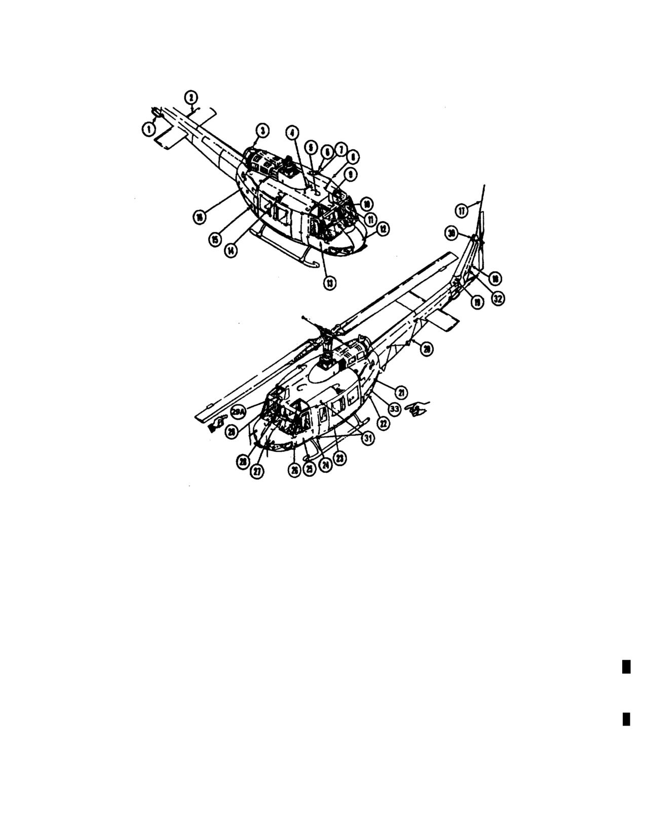
TM 55-1520-210-10
1
VHF navigation (Omni) antenna
18
Aft position light (White)
2
Synchronized elevator
19
42 degree gearbox
3
Anti-collision light
20
HF long wire antenna
4
FM homing antenna No.1
21
Electrical compartment access door
5
Loop (ADF) antenna (Removed W/MWO 1-1620-210-50-30)
22
Aft radio compartment access doors
6
Position light (White)
23
Cabin door
7
Position light (Red)
24
Position Light (Red)
8
FM communications antenna No.2
25
Copilot door
9
VHF/UHF antenna
26
Static port
10
Pitot tube
27
Pitot tube
11
WSPA Windshield Wiper Deflector
28
WSPS Windshield Deflector
12
Radio compartment and fwd battery location assess door
29
WSPS Upper Cutter
13
Pilot door
29A AN/ASN-175 antenna
14
Position fights (Green upper and lower)
30
90 degree gearbox
15
Heater compartment access door
31
Position Light (NVG)
16
Oil cook fan access door
32
Aft position light (NVG)
17
FM communications antenna No. 1
33
KY - 100 Processor
Figure 2-1. General Arrangement Diagram - Typical (Sheet 1 of 2)
Change 18
2-23
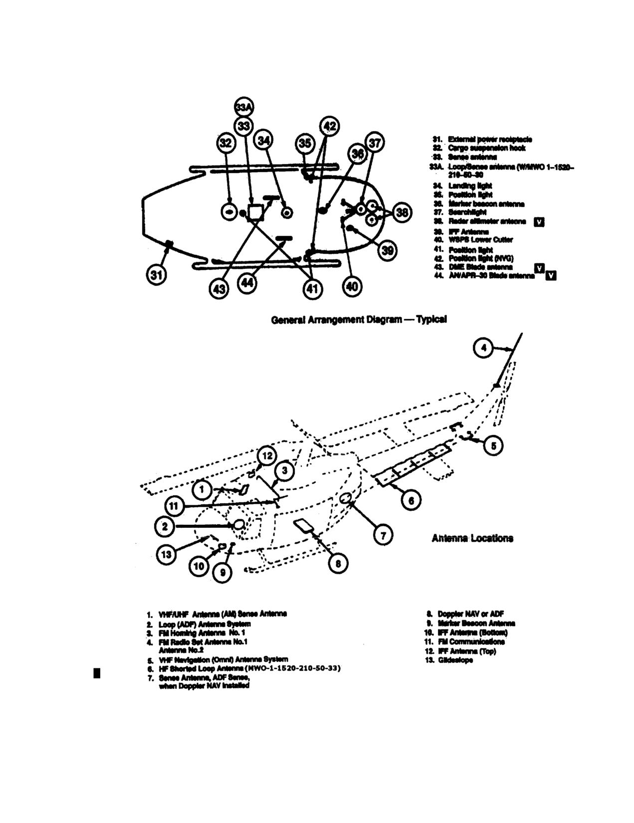
TM 56-1520-210-10
Figure 2-1. General Arrangement Diagram Typical (Sheet 2 of 2)
2-24
Change 18
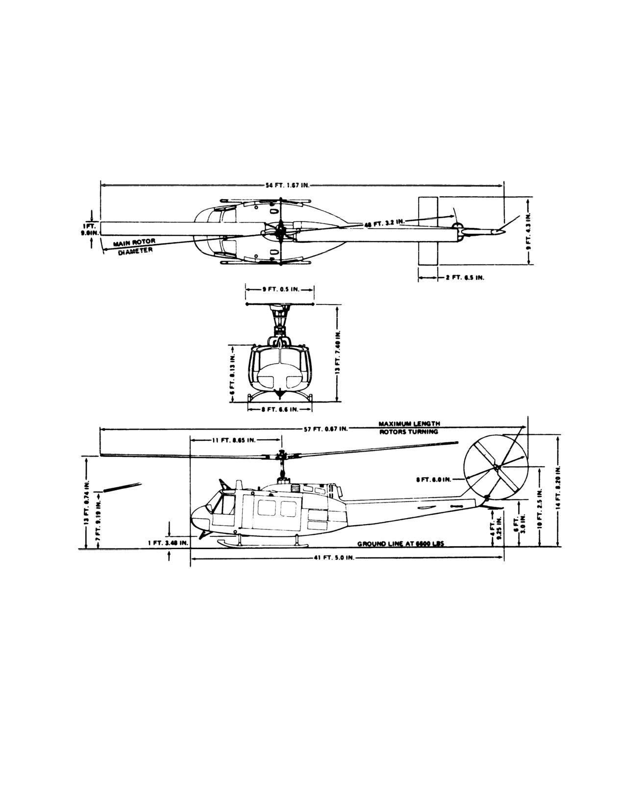
TM 55-1520-210-10
Figure 2-2. Principal Dimensions Diagram-Typical
2-25
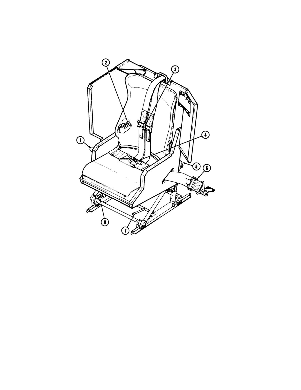
TM 55-1520-210-10
1. Shoulder harness lock
- unlock control
2. Armor plate adjustment lock
3. Shoulder harness adjuster
4. Seat bolt latch
6. Quick release
6. Seat bolt adjuster
7. Seat adjustment fore and aft
8. Seat adjustment vertical
Figure
2-3. Pilot/Copilot Seat-Typical
2-26
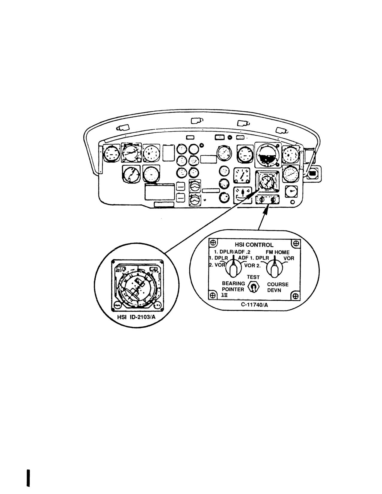
TM 55-1520-210-10
Figure 2-4. Instrument Panel (Typical) (Sheet 1 of 2)
Change 7
2-26.1/(2-26.2
Blank)
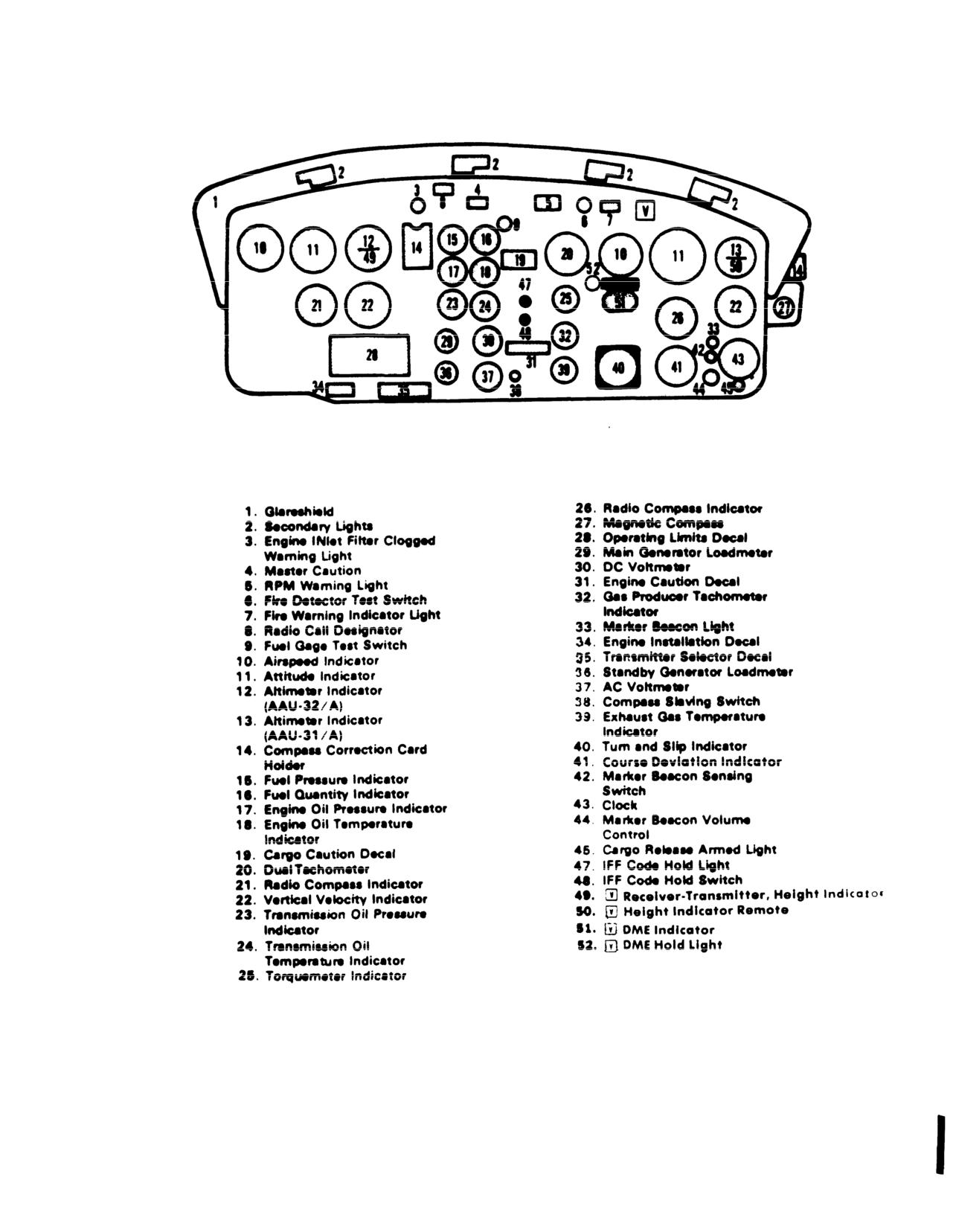
TM
55-1520-210-10
Figure
2-4. Instrument Panel (Typical) (Sheet
2 of
2)
Change 7
2-27
//////////////////////////////////////////