ARMY MODEL UH-1H/V HELICOPTERS. OPERATOR’S MANUAL (1988) - page 2
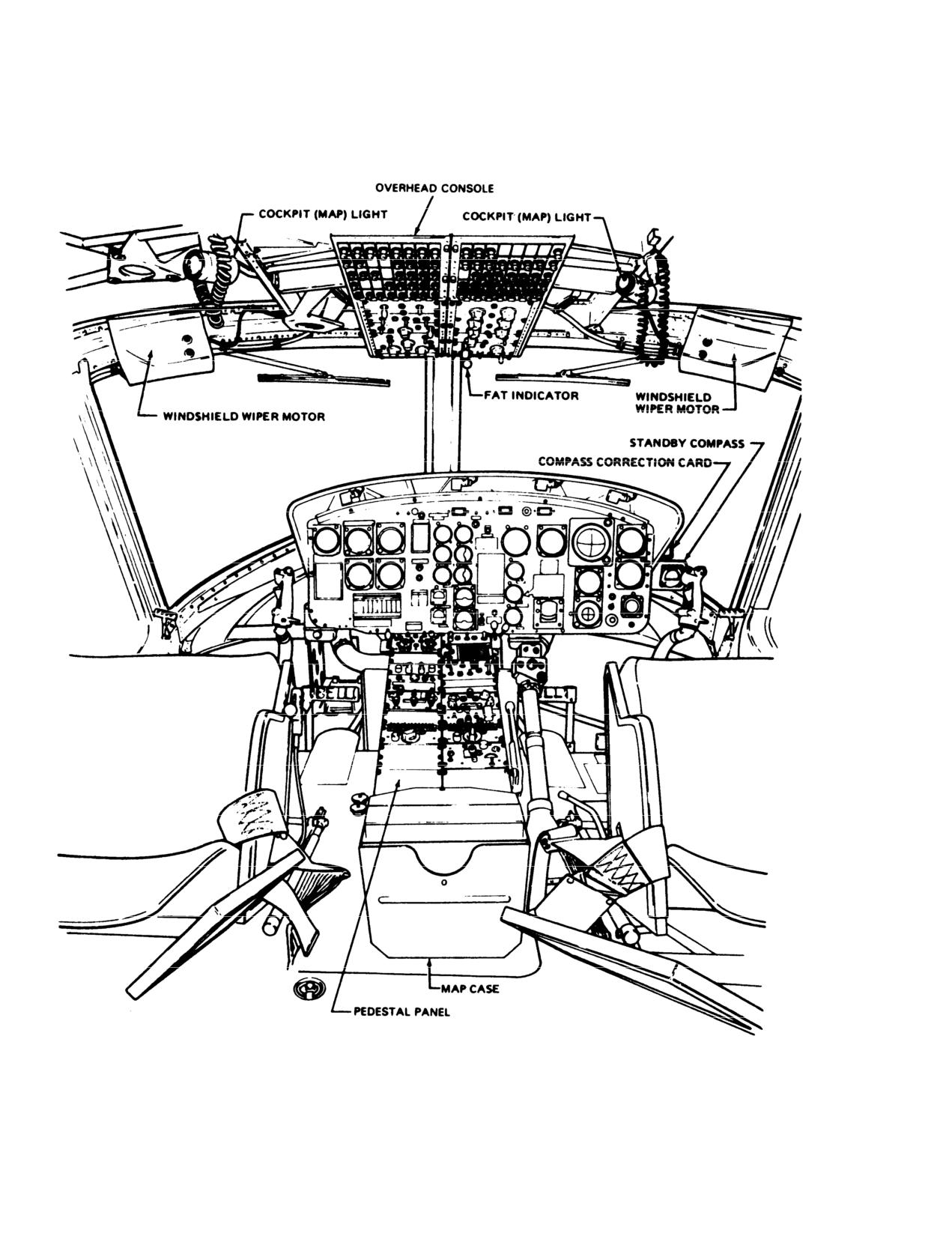
TM 55-1520-210-10
Figure
2-5. Crew Compartment-Typical (Sheet
1 of
3)
2-28
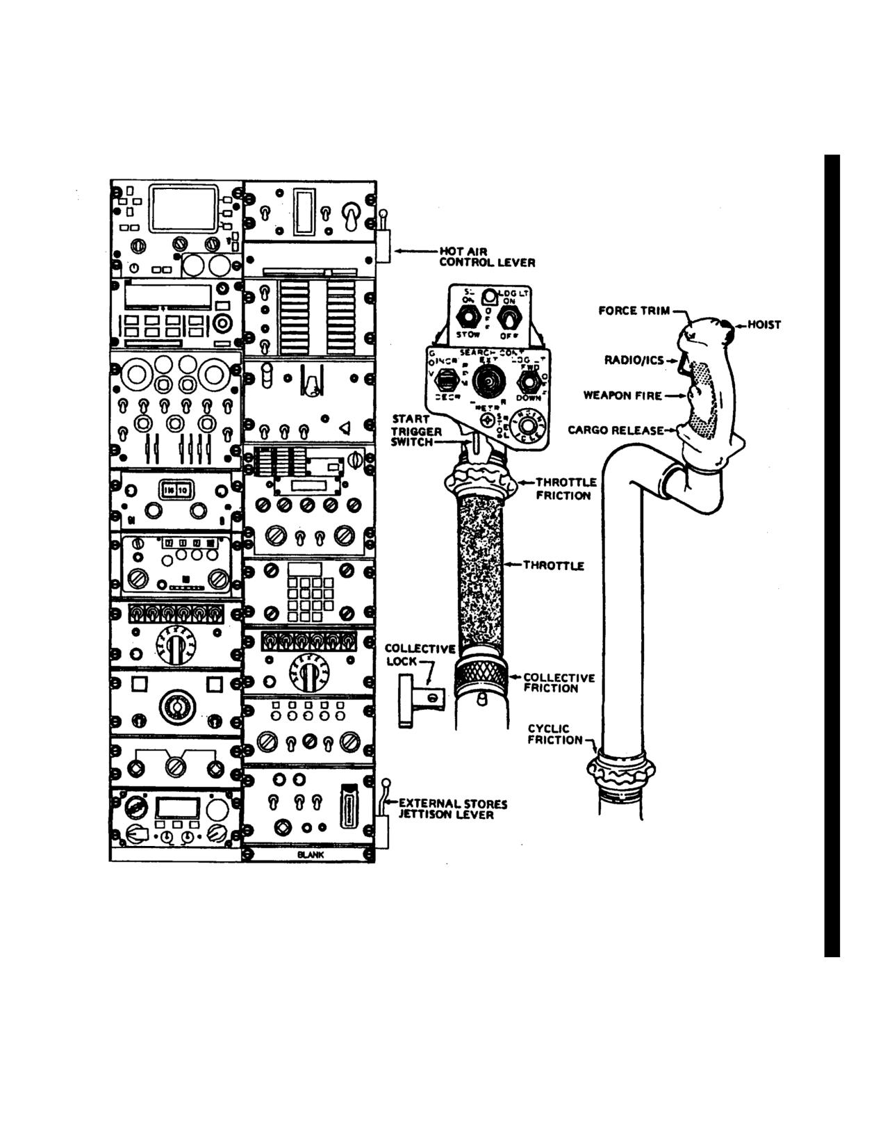
TM 55-1520-210-10
Figure 2-5. Crew Compartment - Typical (Sheet 2 of 3)
Change 18 2-29
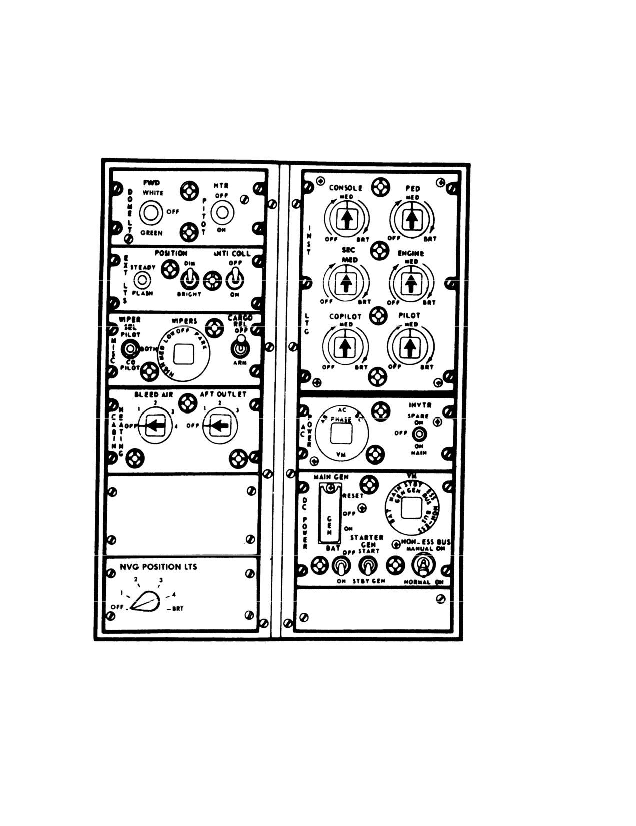
TM 55-1520-210-10
Figure 2-5. Overhead Console-Typical (Sheet 3 of 3)
2-30
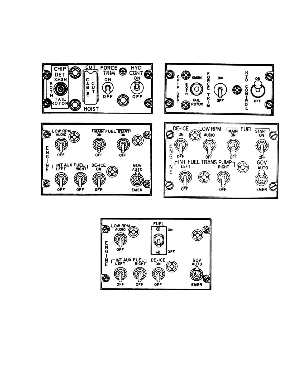
TM 55-1520-210-10
Figure 2-6. Engine and Miscellaneous Control Panel-Typical
2-31
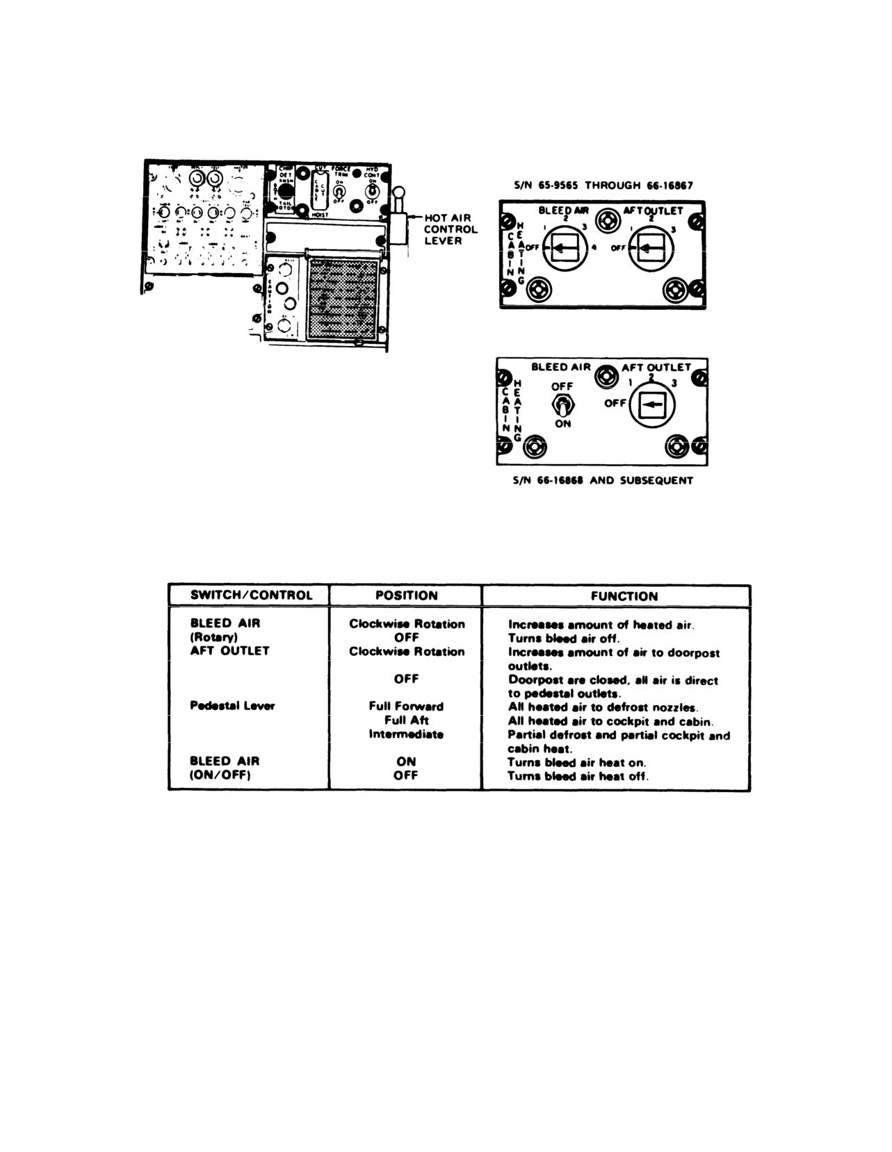
TM 55-1520-210-10
Figure 2-7. Heating and Defrosting System-Typical (Sheet 1 of 2)
2-32
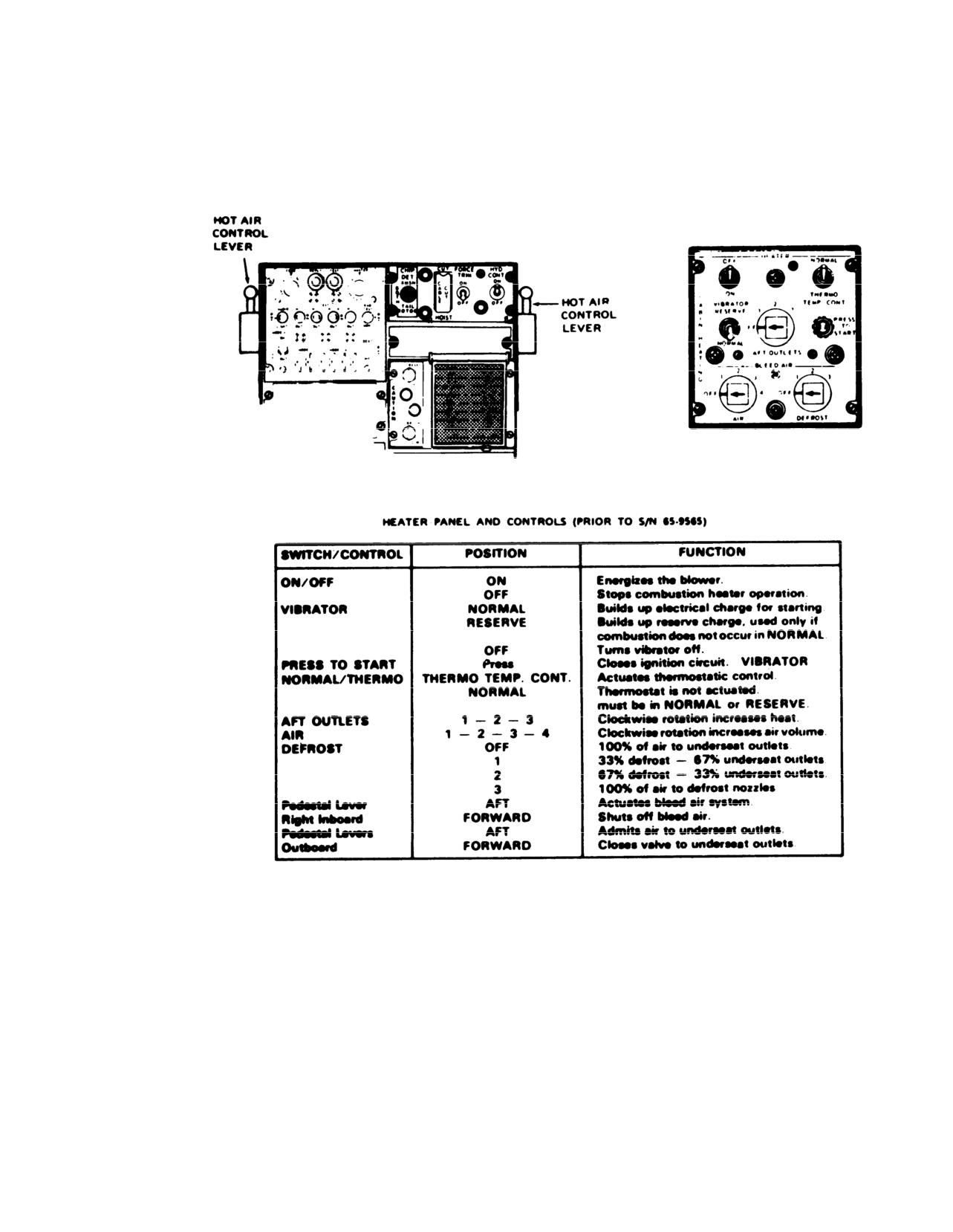
TM
55-1520-210-10
Figure 2-7. Heating and Defrosting System-Typical (Sheet 2 of 2)
2-33
TM 55-1520-210-10
Figure 2-8 Electrical System (Typical)
2-34 Change
18
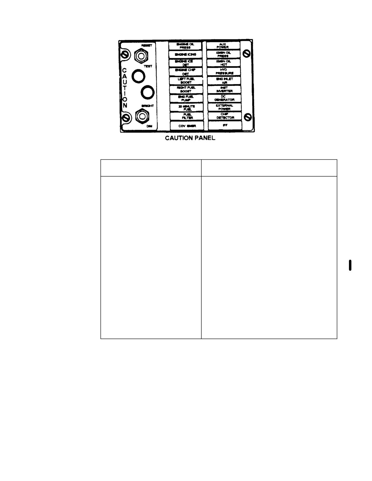
TM 55-1520-210-10
CAUTION PANEL
FAULT
WORDING
CONDITION
ENGINE OIL PRESS
Engine oil pressure below 25 psi
*ENGINE ICING
Engine Icing detected
*ENGINE ICE DET
Not connected
ENGINE CHIP DET
Metal particle in engine oil
LEFT FUEL BOOST
Left fuel boost pump inoperative
RIGHT FUEL BOOST
Right fuel boot pump inoperative
ENG FUEL PUMP
Engine fuel pump inoperative
20 MINUTE
Fuel quantity bout 170 Ibs
FUEL FILTER
Fuel filter Impending bypass
*GOV EMER
Governor switch m emergency position
AUX FUEL LOW
Auxiliary fuel tank empty
XMSN OIL PRESS
Transmission oil pressure below 30 psi
XMSN OIL HOT
Transmission oil temperature above 110°C
HYD PRESSURE
Hydraulic pressure Low
*ENGINE INLET AIR
Engine air filter clogged
INST INVERTER
Failure of inverter
DC GENERATOR
DC Generator failure
EXTERNAL POWER
External power access door open
CHIP DETECTOR
Metal particles present in 42’ or 90’ gearbox
or main- transmission
*IFF
IFF System inoperative
*May not be installed on all configu
ration
Figure 2-9. Caution Panel - Typical
Change 17
2-35
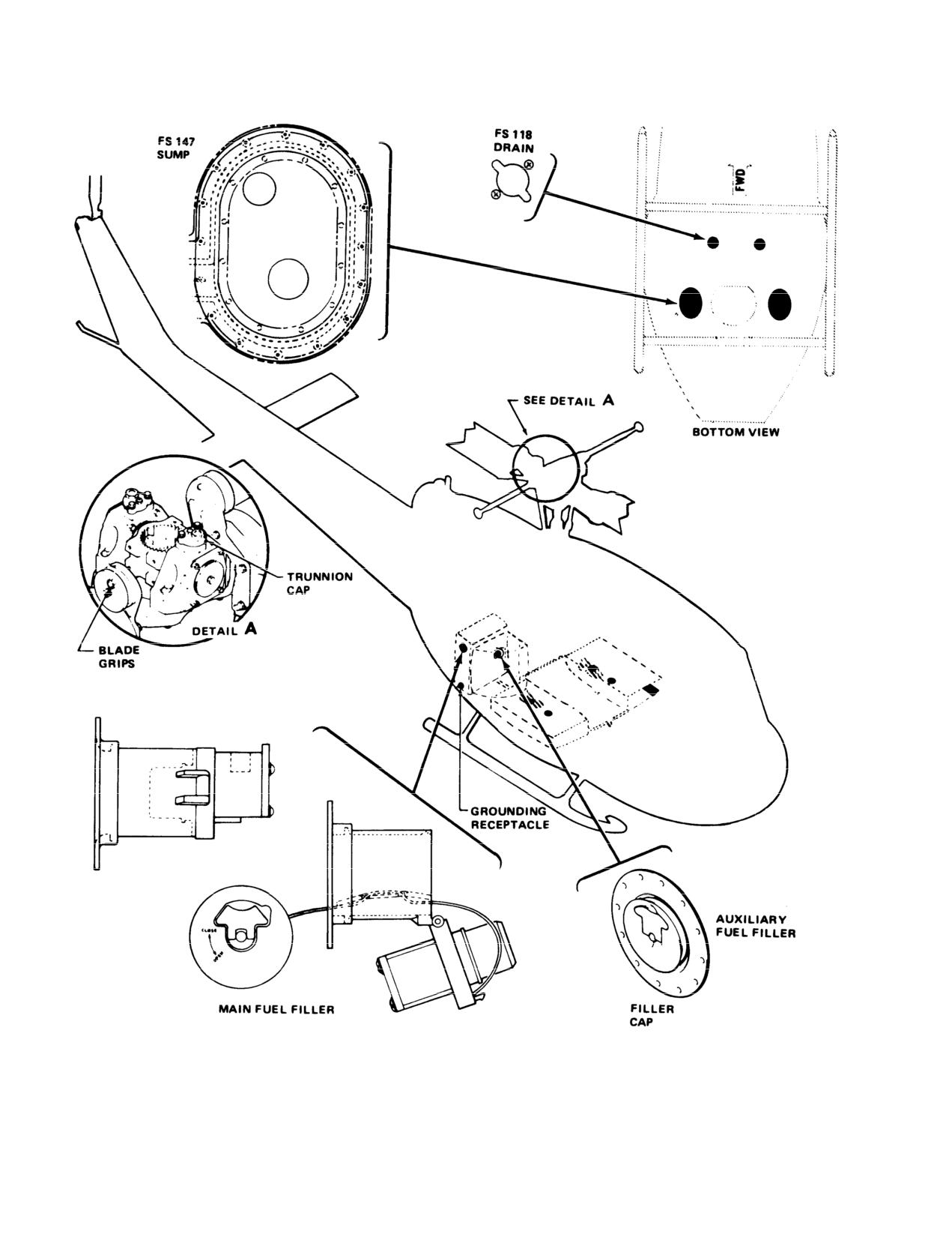
TM 55-1520-210-10
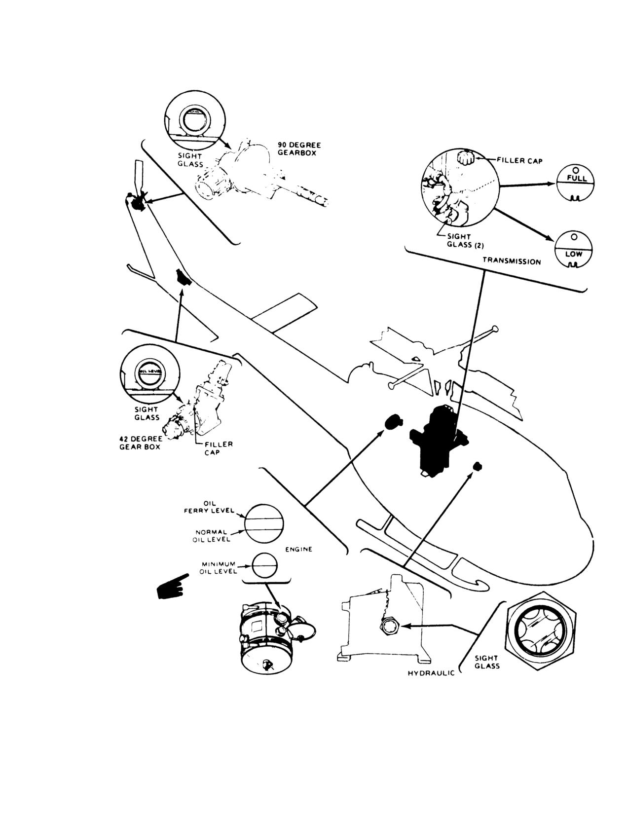
Figure 2-10. Servicing Diagram-Typical (Sheet 1 of 2)
2-36
TM
55-1520-210-10
Figure 2-10. Servicing Diagram-Typical (Sheet
2 of
2)
Change
5
2-37/(2-38 blank)
TM
55-1520-210-10
Chapter 3
Avionics
Section I.
GENERAL
3-1.
General This chapter covers the avionics
of the trigger switch is used for keying the inter-
equipment
configuration.
It
includes a brief
phone. The fully depressed (second detent) position
description of the avionics equipment, its technical
of the trigger switch keys the radio selected with the
characteristics,
capabilities,
and location. The
transmit-interphone selector switch on the signal
chapter
also
contains
complete
operating
distribution panel. A foot-operated type keying
instructions for all avionics equipment installed. For
switch (pilot and copilot) is located at each side of
mission avionics equipment, refer to chapter
4,
the center console, between the center console and
Mission Equipment.
cyclic control stick, and on the cabin floor at each
crew station. The depressed position of the foot-op-
3-2.
Avionics Equipment Configuration
The
erated switch keys the radio or interphone selected
configuration consists of the following:
with the rotary selector switch at the appropriate sig-
nal distribution panel.
a. Headset Cordage. The pilot and copilot cordage
connectors are located at their respective sides
c. Power Supply and Circuit Breakers. Refer to fig-
near the aft portion of the overhead console. The
ure
2-8.
crew cordage connectors are located near the over-
head mounted signal distribution panel (figs
3-1,
d. Operation. The operation of the avionics equip-
3-2, and 3-3) at each crew station.
ment in this helicopter is dependent on the operation
of the interphone system (figs 3-1, 3-2, and 3-3).
b. Keying Switches. A trigger type keying switch is
Do not turn interphone system off until the end of
located on each (pilot and copilot) cyclic control
flight day.
stick grip. The half depressed (first detent) position
Section Il. COMMUNICATIONS
3-3. Signal Distribution Panel-SB-329/AR
(2)
RECEIVERS switches-As desired.
a. Description. The Signal Distribution Panel, lo-
(3)
TRANS selector switch-As desired.
cated at each crewmember station, amplifies and
(4)
VOL control-Adjust.
controls the distribution of audio signals between
each headset-microphone, to and from radio trans-
3-4. Signal Distribution Panel C-1611/AIC
mitters and receivers, and from navigation receiv-
ers. The system is used for intercommunications be-
a. Description. The Signal Distribution Panel ampli-
tween crewmembers and for monitoring communi-
fies and controls the distribution of audio signals ap-
cation and navigation receivers singly or in combina-
plied to or from each headset-microphone, to or
tion.
from communication receivers and transmitters,
from navigation receivers, intercommunication be-
b. Controls and
Functions. Refer to figure 3-1.
tween crewmembers, and for monitoring the com-
munication and navigation receivers singly or in
C. Operation.
combination. In addition the C-1611/AIC panel per-
(1) FM Switch
panel AN/ARC-44 number 31CS
mits the operator to control four receiver-transmit-
ters. A private interphone line is also provided.
switch-up.
3-1
TM 55-1520-210-10
CONTROL/lNDICATOR
FUNCTION
Receive switches
The switches marked
1,
2,
3 MB and NAV are for connecting or
disconnecting receiver audio signals to the associated headset. The up
position is on and connects the receiver. The down position is off and
disconnects the receiver. The number 1 switch is for the FM receiver,
number 2 switch is for the UHF receiver and switch number 3 is for the
VHF receiver when installed. The switch marked MB connects audio
from the marker beacon receiver, and the switch marked NAV
connects audio from the ADF or VHF navigation receivers.
TRANS selector switch
This is a rotary type switch with indicator window at the top. The
switch has four positions, INT, 1 (FM), 2 (UHF), and 3 (VHF). Positions
1,
2, and 3 select the receiver-transmitter to be used to receive or
transmit regardless of the position of the RECEIVERS
1,
2,
3 switches.
The INT position connects signal distribution panels for interphone
operation. The operator will hear side tone when transmitting. The
other crewmember will hear the interphone message regardless of the
position of their TRANS selector switch.
VOL control
Adjusts the volume level of the audio applied to the headset associated
with the INT signal distribution panel.
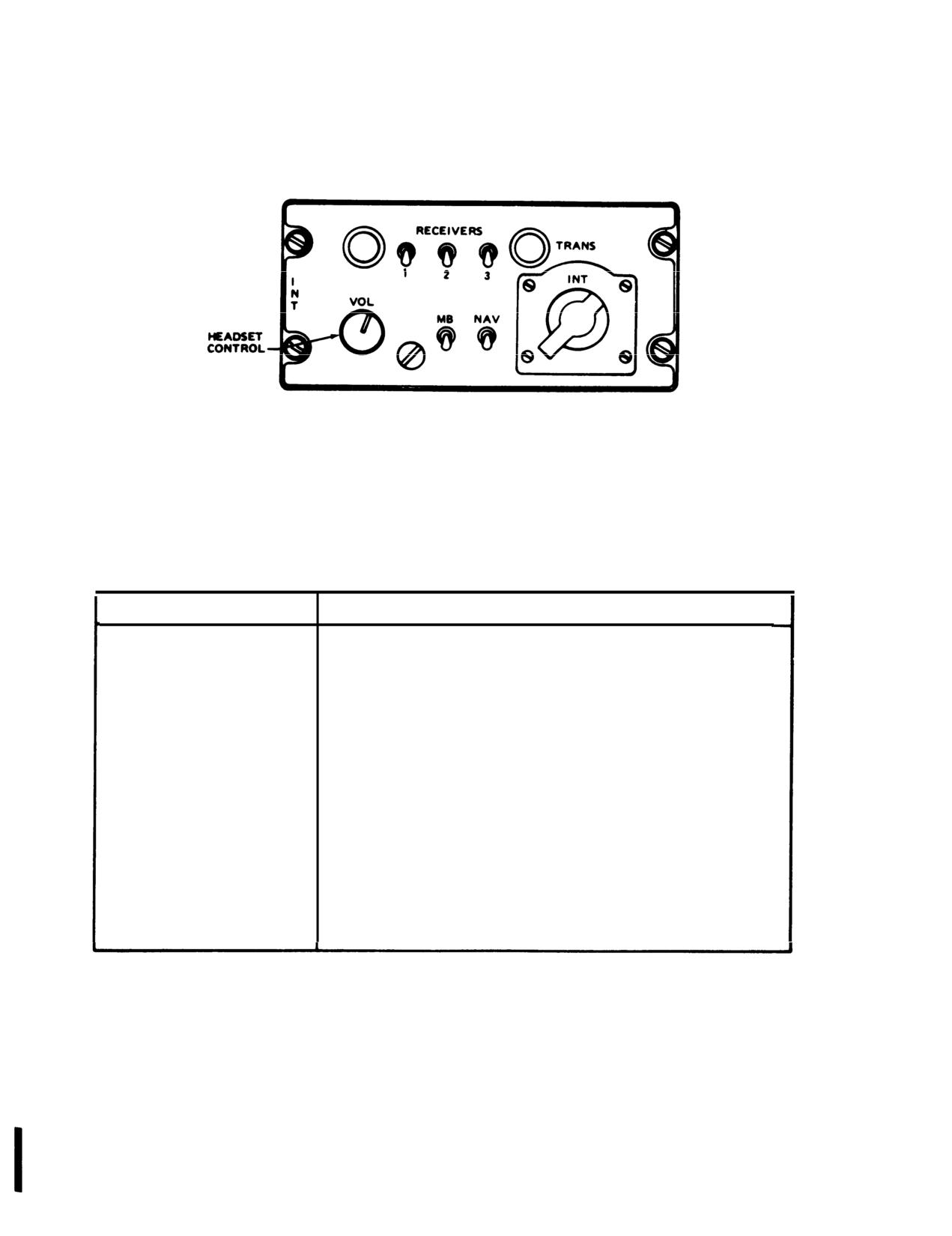
Figure 3-1. Signal Distribution Panel SB-329/AR
3-2
Change
7
TM 55-1520-210-10
CONTROL
I
FUNCTION
RECEIVERS
Turns audio from associated
switches
1 (FM),
receiver ON or OFF.
2 (UHF), 3 (VHF),
and
4
(#2 FM/
HF)
INT switch
ON position enables operator to
how audio from the interphone.
NAV switch
ON position enables operator
to monitor audio from the
navigation receiver.
VOL control
Adjusts audio on receivers
except NAV receivers.
Transmit-
Positions 1 (FM), 2 (UHF),
3
interphone
(VHF), 4 (#2 FM/HF) and INT
selector switch
permits INT or selected
receiver-transmitter to
transmit and receive. The cyclic
stick switch or foot switch
must be used to transmit. PVT
position keys interphone for
transmission.
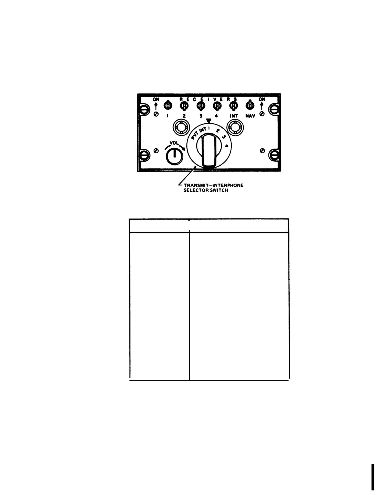
Figure 3-2. Signal Distribution Panel C-1611/AIC
Change 7
3-3
TM 55-1520-210-10
CONTROL/lNDICATOR
FUNCTION
1. Receiver Switches
Connect (ON) or disconnect OFF)
communications receivers from the headsets.
1 - FM No.
1 ARC-54 or ARC-131
2 - UHF ARC-51BX
3
- VHF ARC-115
4
- HF ARC-102
6
- FM No. 2 ARC-114
2. AUX Receiver Switch
Connects (ON) or disconnects (OFF) VOR omni
receiver ARN-82 from the headset.
3. NAV Receiver Switch
Connects (ON) or disconnects (OFF) ADF
navigation receiver ARN-83 from the headset.
4. HOT MIKE Switch
Permits hand-free intercommunications with
transmit-interphone selector in any position.
6. VOL Control
Adjusts volume from receivers.
Adjusts intercommunications volume.
6. Transmit- Interphone Selector
Selects transmitter to be keyed and connects
microphone to transmitters.
1 - FM No.
1 ARC-54 or ARC-131
2
- UHF ARC-51BX
3
- VHF ARC-115
4
- HF ARC-102
6 - FM No. 2 ARC-114
ICS
Connects the microphone to the
intercommunications system only, disconnecting
microphone from transmitters.
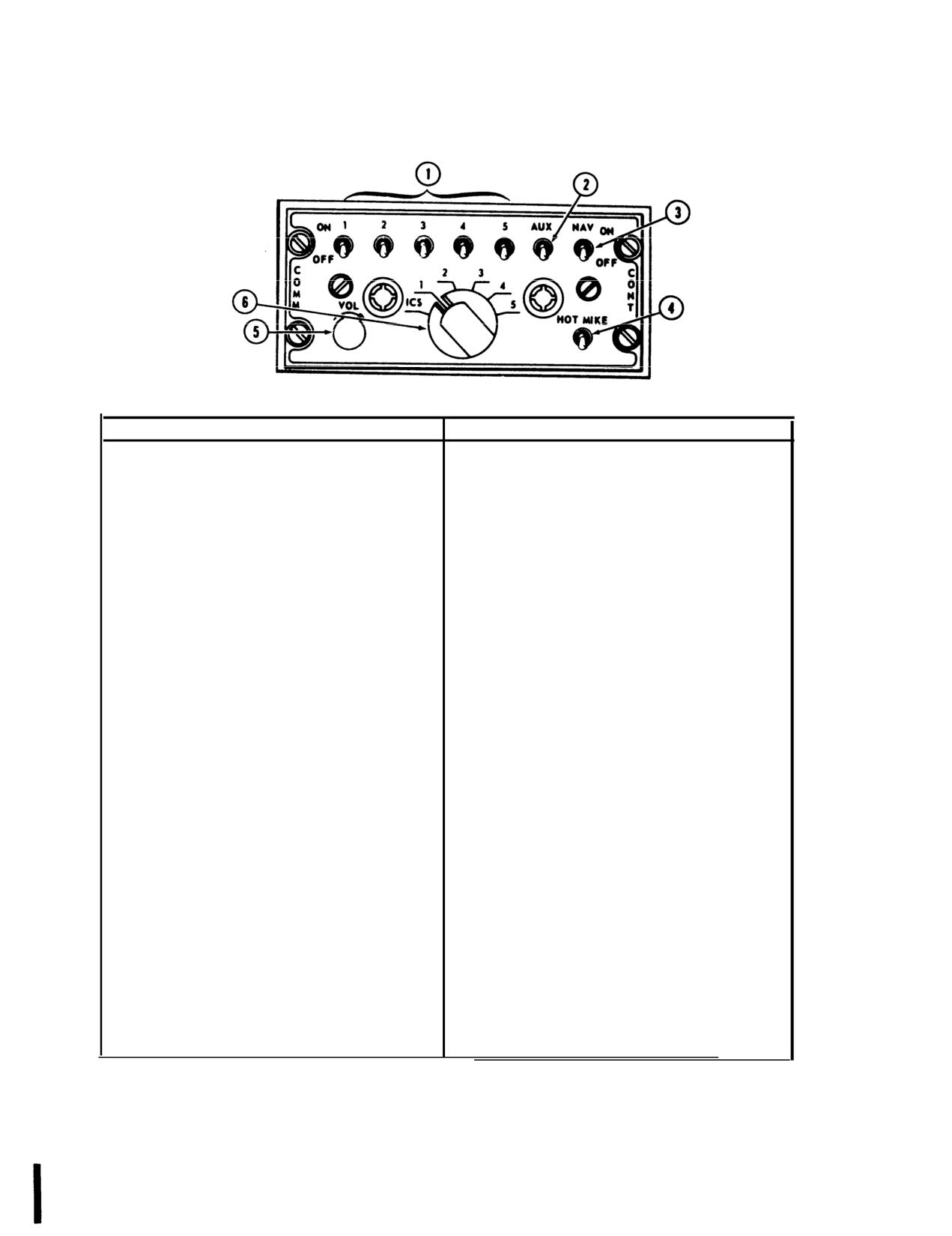
Figure 3-3. Signal Distribution Control Panel (C-6533/ARC)
3-4
Change 7
TM 55-1520-210-10
When the selector switch is in the PVT position it
tal, tunes in 0.05 MHz increments and provides 3500
provides a hot line (no external switch is used) to
channels. The set also permits 20 preset channels
any station in the helicopter which also has PVT se-
and monitoring of the guard channel. Transmission
lected. A HOT MIC switch is also provide on the
and reception are conducted on the same fre-
C-1611/AIC control panel at the medical attendants
quency.
station. Four C-1611/AIC units may be installed in
b. Controls and Functions. Refer to figure 3-4.
serial no. 63-8739 and subsequent. One each of the
units are installed for the pilot and copilot, and two
c. Operation.
are installed in the crew/passenger compartment of
the crew. All four of the C-1611/AIC units are wired
(1)
UHF function select switch-T/R (T/R+G as de-
to provide interphone operations for the crew, and
sired)
full transmit and receive facilities for all communica-
tion and navigation equipment.
(2)
UHF mode selector switch-PRESET CHAN.
b. Controls and Functions. Refer to figure 3-2.
(3)
RECEIVERS switch No. 2-ON
c. Operation.
(4) Channel-Select.
(1)
Transmit interphone selector switch-As de-
NOTE
sired.
An 800-cps audio tone should be heard
(2)
RECEIVERS switches-As desired.
during channel changing cycle.
(3)
Microphone switches-As desired.
(5) SQ DISABLE switch-OFF.
(4)
VOL control-Adjust.
(6) VOL-Adjust.
3-5.
Signal Distribution Panel C-6533/ARC
(7) Transmit-interphone selector switch-No.
2
position.
a. Description. Two panels are installed in the
pedestal for the pilot and copilot and two panels are
d. Emergency Operation.
installed in the cabin roof aft of the overhead con-
(1) UHF mode switch-GD XMIT.
sole for the right and left crewmembers. The system
is used for intercommunications and radio control.
(2) UHF function switch-T/R+G.
The system has three modes of operation; two way
radio communications, radio monitoring, and inter-
3-7. UHF Radio Set AN/ARC-51X
phone.
a. Description. The radio set provides two way
b. Controls and Functions. Refer to figure 3-3.
communications in the UHF (225.0 to 399.9 MHz)
band. The set located at the left side of the pedes-
c. Operation.
tal, tunes in 0.1 MHz increments and provides 1750
(1)
NAV receiver switch-As desired.
channels. The set also permits monitoring of the
guard channel. Transmission and reception are con-
(2)
AUX receiver switch-As desired.
ducted on the same frequency.
(3)
Transmit-interphone selector switch-As de-
b. Controls and Functions. Refer to figure 3-5.
sired.
c. Operation.
(4)
Receiver switches-As desired.
(1) UHF function selector switch-T/R (T/R+G as
(5)
HOT MIKE switch-As desired.
desired). Allow five minute warmup.
(6)
VOL control-Adjust.
(2)
Frequency-Select.
3-6. UHF Radio Set AN/ARC-51BX
(3)
RECEIVERS switch No. 2-ON.
a. Description. The Radio Set provides two way
(4) SENS and VOL controls-Adjust.
communications in the UHF (225.0 to 399.9 MHz)
band. The set located at the left side of the pedes-
Change 7
3-5
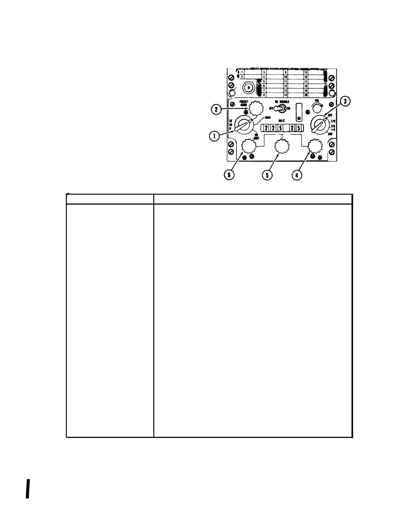
TM 55-1520-210-10
1. Mode selector
2. Preset channel control
3. Function select switch
4.
0.05 megahertz control
5.
1 megahertz control
6.
10 megahertz control
CONTROL/lNDICATOR
FUNCTION
Function select switch
Applies power to radio set and selects type of operation as follows:
OFF position - Removes operating power from the set.
T/R position - Transmitter and main receiver ON.
T/R + G position - Transmitter, main receiver and guard receiver ON.
ADF position - Energizes, UHF-DF system when installed.
VOL control
Controls the receiver audio volume.
SQ DISABLE switch
In the ON position squelch is disabled. In the OFF position, the squelch
is operative.
Mode Selector
Determines the manner in which the frequencies are selected as
follows:
PRESET CHAN position - Permits selection of one of
20 preset
channels by means of preset channel control.
MAN position - Permits frequency selection by means of megacycle
controls.
(GD XMIT position - Receiver-transmitter automatically tunes to
guard channel frequency
(243.00 MHz).
PRESET CHANnel
Permits selection of any one of
20 preset channels.
Preset channel indicator
Indicates the preset channel selected by the preset channel control.
Ten megahertz control
Selects the first two digits (or ten-megahertz number).
One megahertz control
Selects the third digit (or one-megahertz number).
Five-hundredths
Selects the fourth and fifth digits (or
0.05 megahertz number).
megahertz control
Figure
3-4. UHF Control Panel C-6287/ARC-51BX
3-6
Change 7
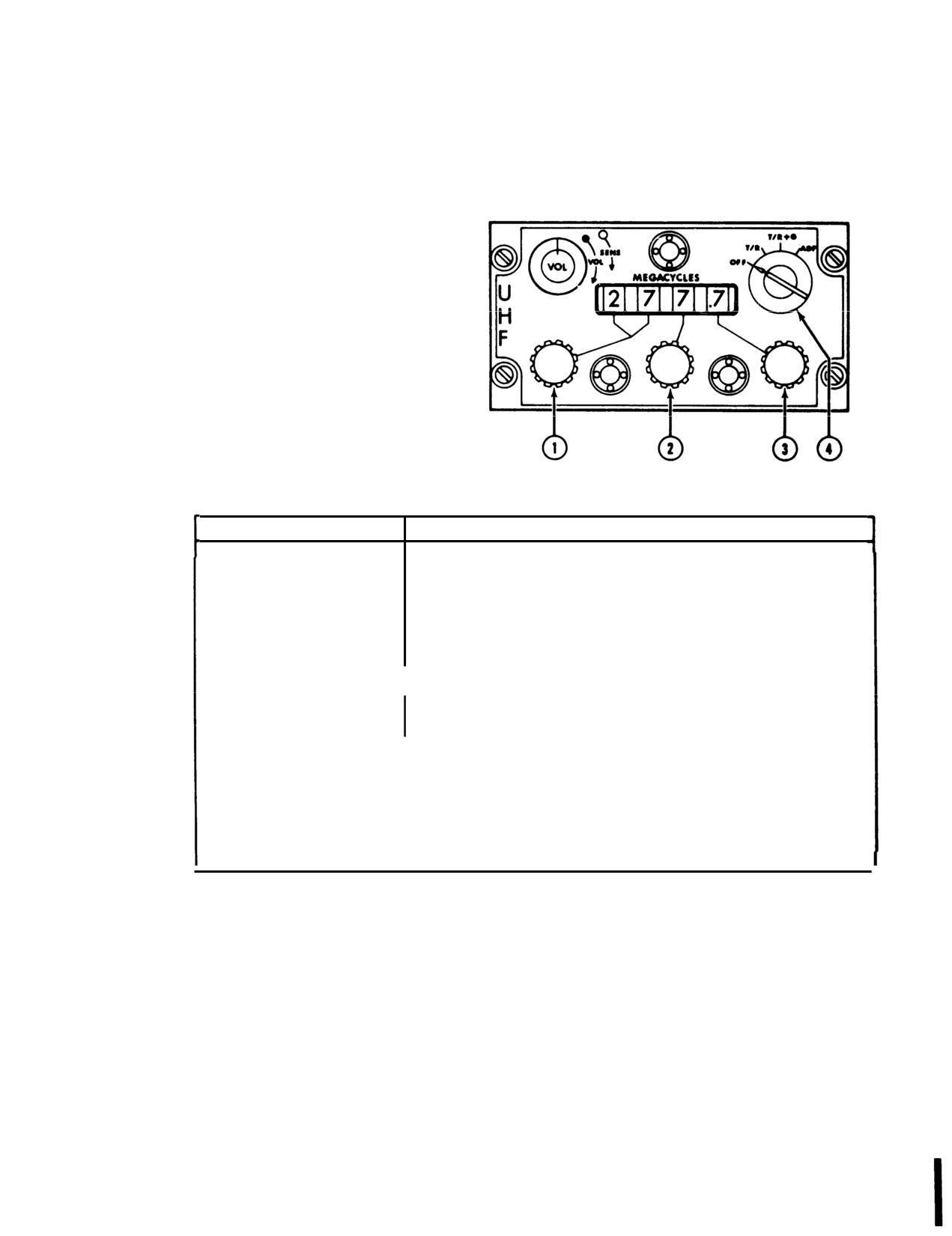
TM 55-1520-210-10
1. Frequency selector (first two digits)
2. Frequency selector (third digit)
3. Frequency selector (fourth digit)
4. Function selector switch
CONTROL/lNDICATOR
FUNCTION
Function select
Applies power to the radio and selects type of operation as follows:
switch
OFF position - Removes operating power from radio set.
T/R position - Applies power to the set and permits transmission and
reception; guard receiver is not operative.
T/R
+ G position
- Permits transmission and reception; guard
receiver is operative.
ADF position - Not used.
VOL control
Controls the receiver audio volume.
SENS control
Adjusts main receiver sensitivity. When rotated fully clockwise the
control disables the squelch.
Ten-megahertz
Selects the first two digits (or ten-megahertz number}.
control
One-megahertz
selects the third digit (or one-megahertz number).
control
One-tenth
Selects the fourth digit (or tenth-megahertz number).
megahertz control
Figure
3-5. UHF Control Panel C-4677/ARC-51X
Change 7
3-7
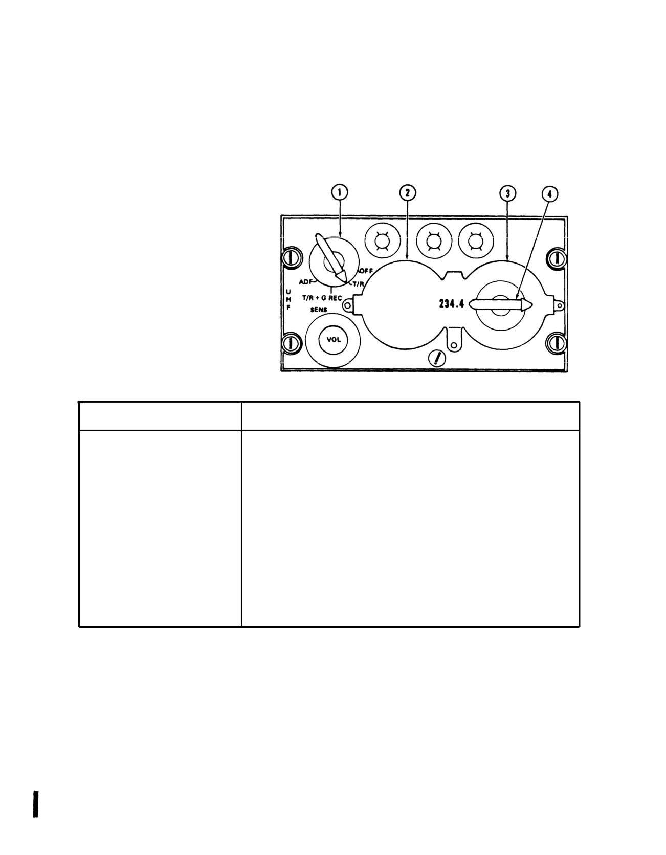
TM 55-1520-210-10
1. Function selector switch
2. Frequency selector (first two digits)
3. Frequency selector (third digit)
4. Frequency selector (fourth digit)
CONTROL/lNDICATOR
FUNCTION
Selector switch
Applies power to the radio set and selects the mode of operation
OFF position - turns off primary power.
T/R position - transmitter and main receiver are on.
T/R + G REC position - transmitter, main receiver and guard
receiver are on.
ADF position - not used.
Volume sensitivity
This is a dual purpose rotary control. The larger or outer knob is
control
marked SENS, and controls receiver sensitivity. The smaller or inner
knob is marked VOL, and controls receiver volume.
Tuning controls
The tuning controls consist of two large control knobs, an inner control
knob, and an indicator window. The large knob on the left side selects
the first two digits (or ten megahertz number). The large knob on the
right side selects the third digit (or one megahertz number). The inner
knob selects the fractional (or tenth megahertz number).
Figure
3-6. UHF Control Panel C-1827/ARC-55B
3-8 Change 7
TM
55-1520-210-10
(5) Transmit-interphone
selector switch-No.
2
d. Emergency Operation. Select guard frequency
position.
121.50 MHz.
d. Emergency Operation. Select guard frequency
3-10. VHF Radio Set-AN/ARC-134
243.0 MHz.
a. Description. The set transmits and receives the
3-8. UHF Radio Set AN/ARC-55B
same frequency. The panel (VHF COMM) is located
on the left side of the pedestal. The set provides
a. Description. The UHF command set provides
voice communications in the VHF range of 116.000
two way, amplitude-modulated communications on
through 149.975 MHz on 1360 channels spaced 25
any of 1750 channels within 225.0 to 399.9 MHz.
kHz apart.
Channel selection is manual and the guard channel
may be monitored.
b. Controls and Functions Refer to figure 3-8.
b. Controls and Functions. Refer to figure 3-6.
c. Operation.
c. Operation.
(1)
OFF/PWR switch-PWR. Allow set to warm up.
(1) UHF function selector switch-As desired.
(2)
Frequency-Select.
(2) Frequency-Select.
(3)
RECEIVERS switch No. 3-ON.
(3) RECEIVERS switch No. 2-ON.
(4)
Volume-Adjust. If signal is not audible with
VOL control fully clockwise, press COMM TEST
(4) UHF VOL-SENS controls-Adjust.
switch to unsquelch circuits.
(5) Transmit-interphone selector switch-No.
2
(5) Transmit-interphone selector switch-No.
3
position.
position.
d. Emergency Operation. Select guard frequency
(6) OFF/PWR switch-OFF.
243.0 MHz.
d. Emergency Operation. Select guard frequency
3-9. VHF Radio Set AN/ARC-115
121.500 MHz.
a. Description. The VHF Radio Set provides ampli-
3-11. VHF Radio Set-AN/ARC-73
tude-modulated, narrow band voice communica-
tions within the frequency range of 116.000 to
a. Description. The VHF Command Set is an alter-
149.975 MHz on 1360 channels for a distance of ap-
nate set for the UHF radio. The set provides trans-
proximately 50 miles line of sight. A guard receiver
mission and reception of AM radio signals in the VHF
is incorporated and fixed tuned to 121.50 MHz. The
range. The receiver may be tuned within its fre-
panel is Iabeled VHF AM COMM and mounted on the
quency range of 116.00 to 151.95 MHz in 50 kHz
left side of the pedestal.
increments to any of the 720 available channels. The
transmitter may be tuned within its frequency range
b. Controls and Functions. Refer to figure 3-7.
of 116.00 to 149.95 MHz in 50 kHz increments to any
c. Operation.
one of its
680 available channels. The distance
range is limited to line of sight or a distance of ap-
(1)
Function selector-As desired.
proximately 50 miles.
(2)
Frequency-Select.
b. Controls and Functions. Refer to figure 3-9.
(3)
RCVR TEST-Press to test.
c. Operation.
(4)
AUDIO-Adjust.
(1)
POWER switch-ON.
(5) Transmit-interphone selector switch-No.
3
(2)
Frequency-Select.
position.
(3) RECEIVERS switch No. 3-ON.
(6) RADIO transmit switch-Press.
Change 7
3-9
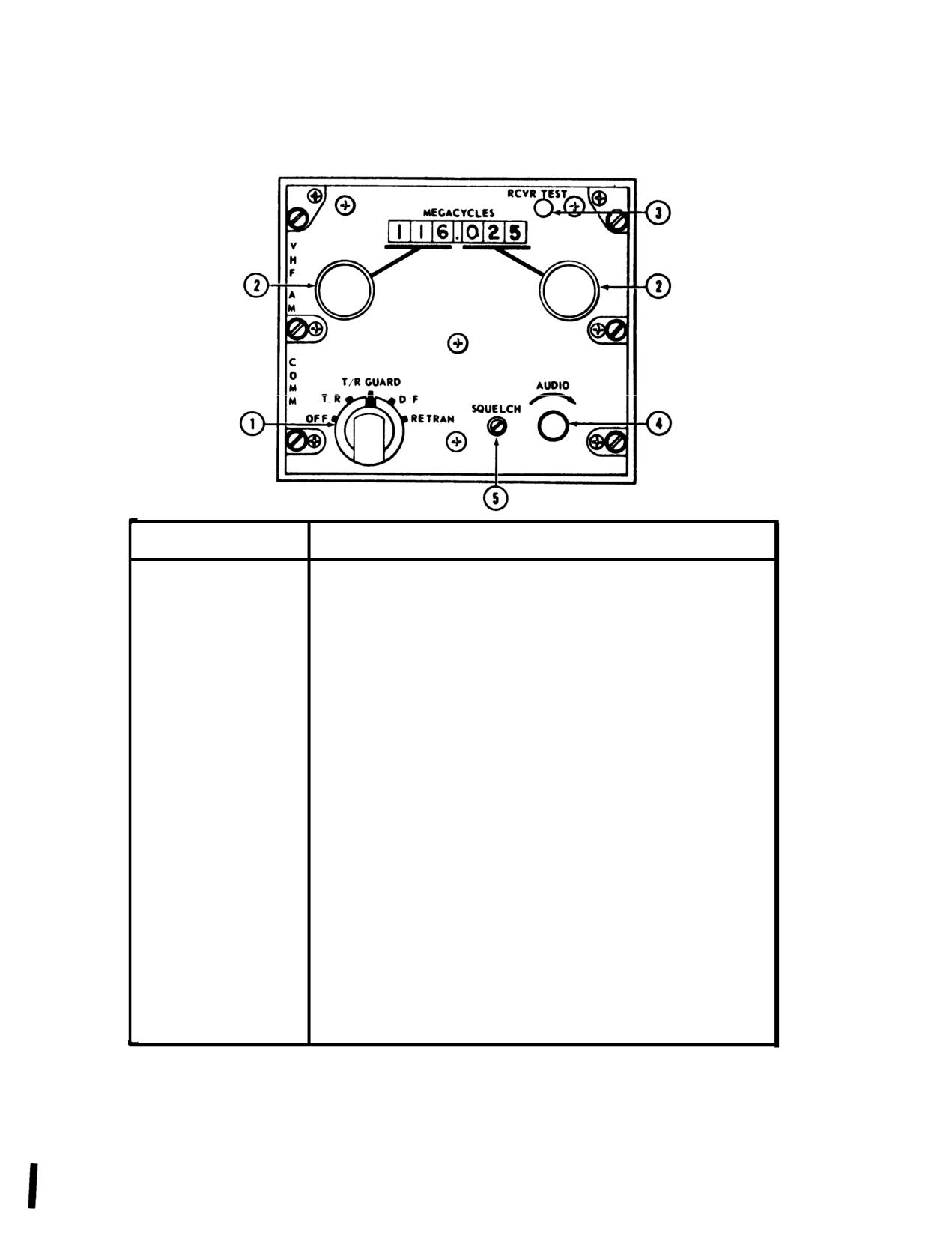
TM 55-1520-210-10
CONTROL/INDICATOR
FUNCTION
1. Function Selector
OFF
Power off.
T/R
Receiver - On; Transmitter
- Standby.
T/R GUARD
Receiver - On; Transmittal - Standby; Guard Receiver - On.
NOTE
Reception on guard frequency is unaffected by
frequencies selected for normal communications.
D/F
Not used.
RETRAN
Not used.
2. Frequency Selectors
Left
Selects first three digits of desired frequency.
Right
Selects fourth, fifth and sixth digits of desired frequency.
3. RCVR TEST switch
When pressed, audible signal indicates proper receiver performance.
4. AUDIO control
Adjusts receiver volume.
5. SQUELCH control
Squelch control adjusted by maintenance personnel only.
Figure
3-7. Control Panel AN/ARC-115
3-10 Change 7
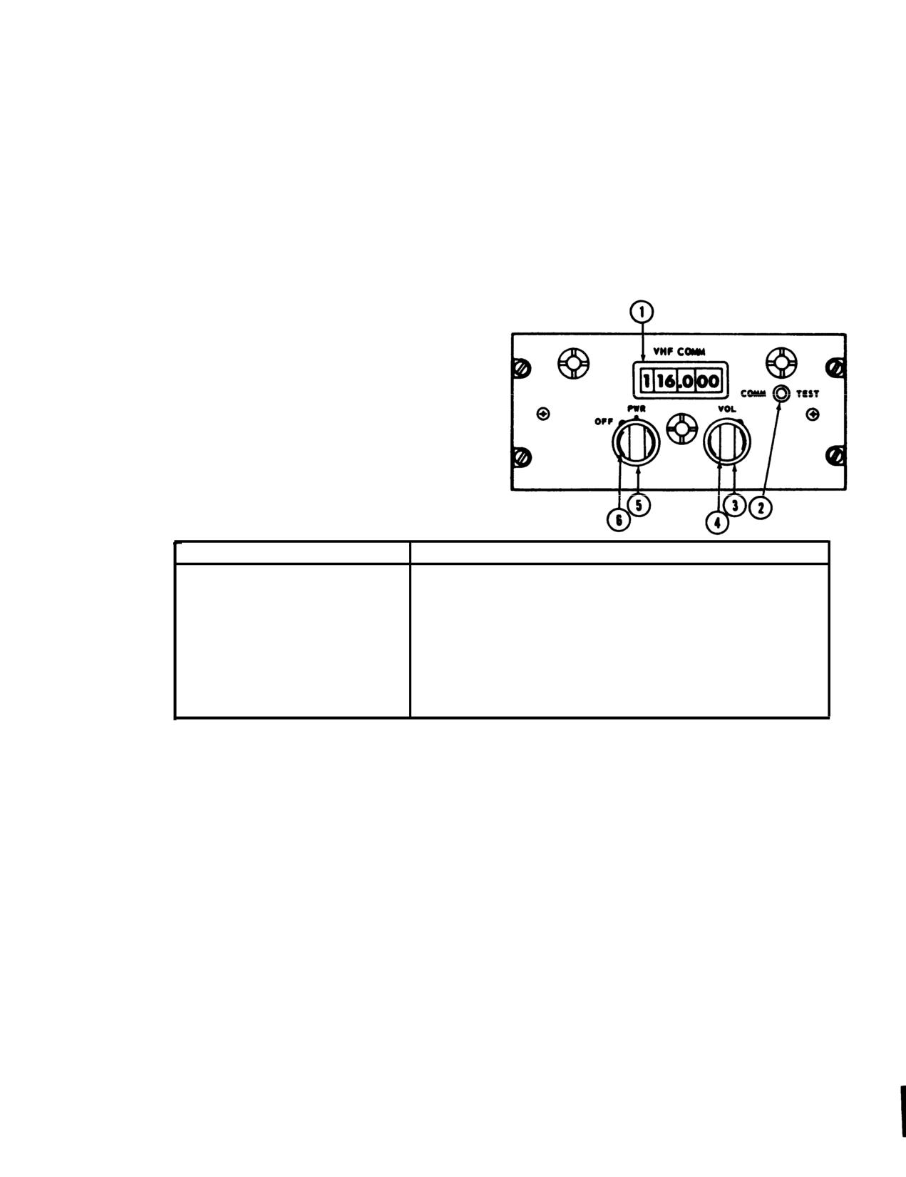
TM 55-1520-210-10
1. Frequency indicator
2. Communication test switch
3. Volume control
4. Kilohertz selector
5. Off/power switch
6. Megahertz selector
CONTROL/lNDICATOR
FUNCTION
OFF-PWR switch
Turns power to the set ON-OFF.
VOL control
Controls the receiver audio volume.
COMM-TEST switch
Turns squelch on or off.
Megahertz control
Selects whole number part of operating frequency.
Kilohertz control
Selects the decimal number part of the operating frequency
Figure
3-8. VHF Control Panel C-7197/ARC-134
3-11
Change 7
TM 55-1520-210-10
(4) SQ and VOL controls - Adjust.
3-13.
FM Radio Set - AN/ARC-131.
(5) Transmit interphone selector switch
-
No.
a. Description The FM Radio Set consists of a
3position.
receiver-transmitter,
remote control panel unit;
d. Emergency Operation Select guard
communication antenna and a homing antenna The
frequency121.500 MHz.
radio set provides 920 channels spaced 50 kHz apart
within the frequency range of 30.00 to 75.95 MHz.
3-12.
FM Radio Set - AN/ARC-114 and -114A.
Circuits are included to provide transmission sidetone
a Description The FM Radio Set provides two
monitoring. The control panel is located on the pedestal.
way frequency modulated (FM) narrow band voice
Homing data is displayed by the course indicator (fig 3-
communications and homing capability within the
20) on the instrument panel. A channel changing tone
frequency range of 30.00 to 75.95 MHz on 920 channels
should be heard in the headset while radio set is tuning.
for a distance range limited to line of sight. A guard
When the tone stops, the radio set is tuned. Operation in
receiver is incorporated in the set and is fixed tuned to
DIS position is possible; however flags on course
40.50 MHz. It has the additional capability -for
deviation indicator will be inoperative. When the first FM
retransmission of voice, or X-mode communications in
radio set is m the homing mode, the homing indicator
conjunction with radio set AN/ARC-131. The radio set is
may deflect left or right of on course indication while the
marked VHF FM COMM and is mounted on the center
second FM radio set Is keyed.
console, on helicopter serial Nos.
71-20000 and
b. Controls and Functions. Refer to figure 3-1 1.
subsequent.
c. Operation Depending on the settings of the
b.
Controls and Functions. Refer to figure 3-10.
control panel controls, the radio set can be used for the
c.
Operation.
following types of operation: Two way voice
(1) Two Way Voice Communication.
communication and homing (fig 3-12).
(a) Function selector - As desired.
(1) Two Way Voice Communication.
(b) Frequency - Select.
(a) Mode control switch - T/R (allow two minute
(c) RCVR TEST - Press to test.
warm up).
(d) AUDIO - Adjust.
(b) Frequency - Select.
(e) Transmit interphone selector
- No.
5
(c) RECEIVERS No. I switch - ON.
position.
(d) VOL control - Adjust.
(2) Retransmission.
(e) SQUELCH control - Set for desired
squelch mode.
NOTE
(f) TRANS selector switch - No. I.
For transmission both FM circuit breakers must be in.
(2) Homing Operation.
(a) Frequencies - Select (both FM sets). -
(a) Mode control switch - HOME.
(b) Communications
- Establish with each
(b) Frequency - Adjust to frequency of selected
facility by selecting number I position and then number 5
homing station
position on the transmit-interphone selector.
(c) SQUELCH control may be set to CARR or
(c) Function selectors - RETRAN (both FM
TONE, however, the carrier squelch is automatically
sets).
selected by an internal contact arrangement on HOME
(d) Receivers switches - Number I and number
position.
5 positions as desired for monitoring.
(d) Fly helicopter toward the homing station by
d. Emergency Operation. Select guard frequency
heading in direction that causes homing course deviation
40.50 MHz.
indicator right-left vertical pointer to position itself m the
center of indicator scale. To ensure that helicopter is not
heading away from the homing station, change the
heading slightly and note that the course deviation
indicator vertical pointer deflects in direction opposite
that of the turn.
3-12
Change 17
(3) Retransmit Operation. Start the equipment and
proceed as follows for retransmit operation:
(3) Retransmit Operation. Start the equipment and
(a) Mode controls (both control units)
-
perform the following for retransmit operation.
RETRAN.
(a) Mode controls (both control units)
-
(b) SQUELCH controls (both control units) -
RETRAN.
Set as required. Do not attempt retransmit operation
(b) SQUELCH controls (both control units) -
with SQUELCH controls set to DIS. Both controls must
Set as desired.
be set to CARR or TONE. To operate satisfactorily the
NOTE
two radio sets must be tuned to frequencies at least 3
Do not attempt retransmit operation with the
MHz apart.
SQUELCH controls set to DIS. Both controls
(c) Frequency adjust (both control units) for the
must be set to CARR or TONE.
desired operation.
(4) Stopping Procedure. Mode control switch -
(c) Adjust frequency (both control units)
OFF.
desired operation. To operate satisfactorily the two radio
3-14. FM Radio Set AN/ARC-54.
sets must be tuned to frequencies at least 5 MHz apart.
a. Description The FM Radio Set provides two-
(4) Stopping Procedure. FM mode selector switch
way communications within the frequency range of 30.00
-OFF.
to 69.95 MHz. Voice communication permits selective
calling (TONE) and when used with the homing antenna
3-15.
FM Radio Set AN/ARC-44
and course indicator the pilot is provided with a homing
a. Description. The FM Radio Set provides two
facility. A channel changing tone should be heard in the
way communications within the frequency range of 24.0
headset while radio set is tuning. When the tone stops
to 51.9 MHz on 280 preset channels. Signal distribution
the radio set is tuned. Voice reception is possible m
panel SB-329 and control panel assembly 204-075-219
HOME position. With two or more FM radio sets
(FM switch assembly), to provide squelch control and
installed and the first FM radio set is in the homing
power to the antenna group are used in conjunction with
mode, the homing indicator may deflect left or right of on-
the FM Liaison Radio Set (fig 3-2 and fig 3-14). The set
course indication while the second FM radio set is keyed.
provides a homing facility on signals between 24.0 and
b. Controls and Functions. Refer to figure 3-12.
49.0 MHz. Cycling may take place in the receiver
C Operation.
transmitter. This will be indicated by a 400-cycle-per-
(1) Two Way Voice.
second signal heard in the headset
(a) FM mode selector switch - PTT (allow three
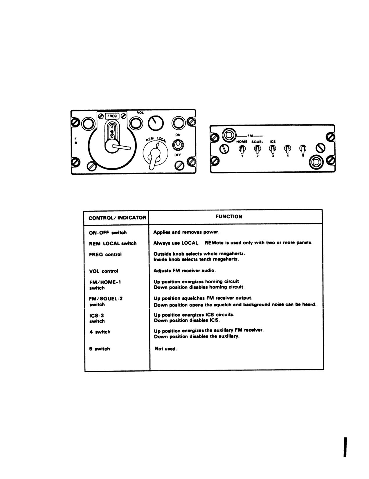
b. Controls end Functions. Refer to figure 3-13.
minute warm-up).
c. Operation
(b) Frequency - Select.
(1) Preliminary Setup.
(c) FM VOL control - Adjust.
(a) FM power switch - ON.
(d) FM SQUELCH control - CARR (or as
(b) FM home switch - Down.
desired).
(c) TRANS selector switch -
No. 1 position.
(e) RECEIVERS switch No. 1 -- ON.
(d) REM-LOCAL switch -
LOCAL.
(f) TRANS selector switch - No. 1.
(e) Frequency - Select.
(g) Microphone switch - Press.
(2) Standing Procedures.
(2) Homing Operation. FM mode selector switch -
(a) BAT switch - ON (OFF for APU).
HOME.
(b) INT and FM circuit breakers - In.
Change 17
3-12.1
TM 55-1520-210-10
(c) ICS switch - Up (allow three minute warm
up).
(1) Preliminary
(3) Interphone Operation.
(a) Set the control indicator POWER switch to
(a) Microphone switch - Press.
ON.
(b) Speak into the microphone
- Adjust
(b) Apply power to FM radio set.
interphone volume.
(c) When power is initially applied an automatic
(4) FM Receive-Transmit Operation.
alarm procedure is initiated.
(a) ICS switch - Up.
1. A constant tone is heard in the headset and
(b) FM ON-OFF power switch - ON.
after approximately two seconds the constant tone will
(c) FM VOL control - As desired.
change to an interrupted tone.
(d) TRANS selector switch - No. I position.
2. To clear the interrupted tone press and
(e) Microphone switch - Press to transmit.
release the press to talk switch the interrupted tone will
(5) FM Home Operation. FM HOME switch - Up.
no
(6
Stopping Procedures.
longer be heard and the circuit will be in a standby
(a) FM HOME switch - Down.
condition ready for either transmission or reception. No
(b) FM POWER switch - OFF.
traffic will be passed if the interrupted tone is still heard
after pressing and releasing the press to talk switch. (d)
(c) ICS Switch - Down.
Set control unit function switch for desired type of
3-16.
Voice Security Equipment - TSEC/ KY-28.
operation (2 and 3 below).
a. Description. The Voice Security Equipment is
(2) Plain Mode.
used with the FM Command Radio to provide secure two
(a) Set the control indicator POWER switch to
way communication (figs
3-11 through
3-14). The
ON.
equipment is controlled by the control-indicator mounted
(b) Set the PLAIN-CIPHER switch to PLAIN
in the pilot
(indicated by red light).
right console. The POWER switch must be in the ON
(c) Set the RE-X-REG switch to REG; except
position regardless of the mode of operation whenever
when operating with retransmission units, at which time-
the equipment is installed.
switch will be placed in the RE-X position.
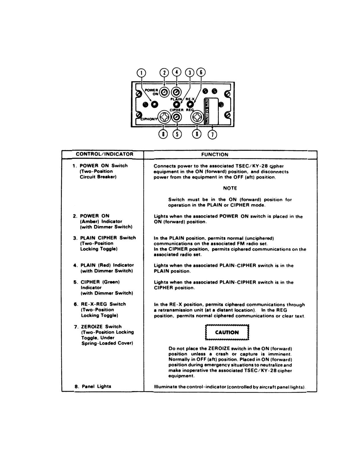
b. Control and Functions. Refer to figure 3-14.
(d) Press the press to talk switch and speak
c. Operation. Normal operation will exist without
into the microphone to transmit. Release the press to
its
talk switch for reception.
encoder/decoder and control indication being installed in
(3) Cipher Mode.
the helicopter. However two operation modes are
(a) Set the PLAIN-CIPHER switch to CIPHER
available when they are installed. PLAIN mode for
(indicated by a green light).
enciphered radio transmission or reception and CIPHER
(b) Place the RE-X-REG switch to REG except
mode for ciphered radio transmission or reception. Both
when operating with retransmission units at which time
modes may be operated with or without retransmission
the switch will be placed in RE-X position. (c) To transmit
nits.
press the press to talk switch. DO NOT TALK; in
approximately one-half second a be
will be heard. This indicates the receiving station is now
capable of receiving your message. Transmission can
now
commence. Only one voice security system can transmit
on a given frequency. Always listen before attempting to
transmit to assure that no one else is transmitting.
Change 17 3-12.2
TM 55-1520-210-10
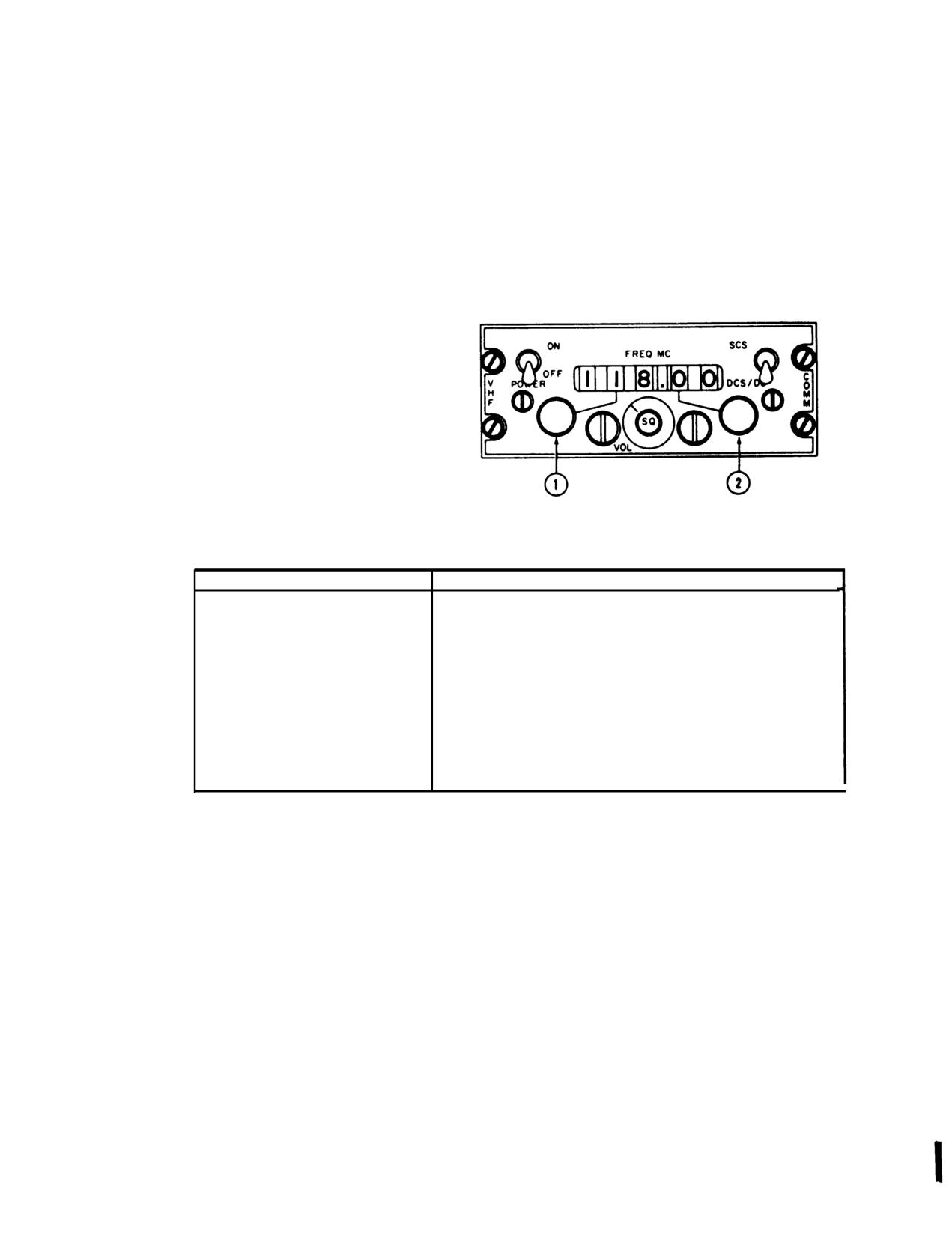
1. Megahertz control knob
2. Kilohertz control knob
CONTROL/lNDICATOR
FUNCTION
POWER switch
Turns primary power to the radio set ON or OFF
VOL control knob
Controls the receiver audio volume.
SQ control knob
Adjusts the squelch threshold level of the receiver output.
Megahertz control knob
Selects receiver and transmitter frequency in 1 - mhz steps.
Kilohertz control knob
Selects receiver and transmitter frequency in 50-khz steps
FREQ MC indicator window
Indicates receiver and transmitter frequency selected.
SCS-DCS/DCD switch
Not used.
Figure 3-9. VHF Control Panel 614U-6/ARC-73
3-13
Change 7
TM 55-1520-210-10
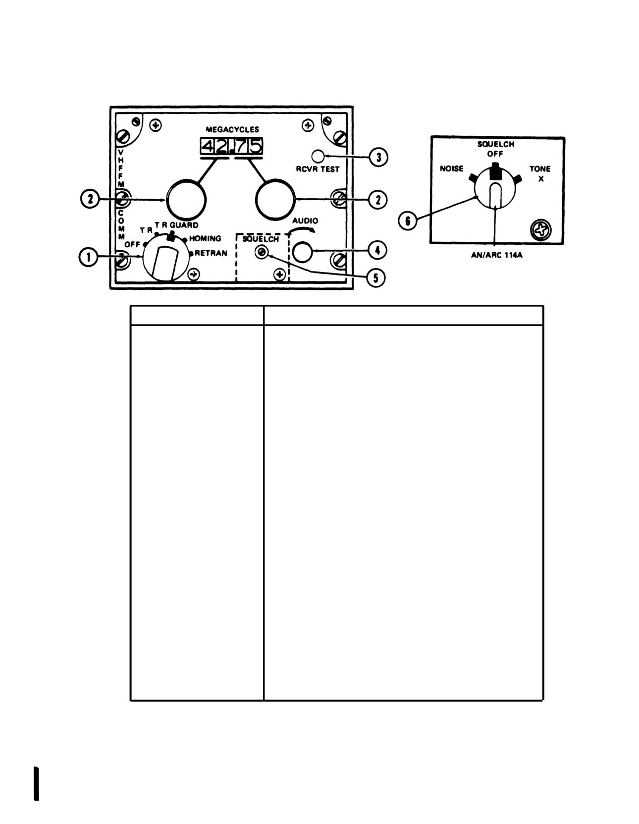
CONTROL/lNDICATOR
FUNCTION
1.
Function Selector
OFF
Power Off
T/R
Receiver - On; Transmitter - Standby.
T/R GUARD
Receiver - On; Transmitter - Standby; Guard Receiver - On.
NOTE
Reception on guard frequency is unaffected by
frequencies selected for normal communications.
HOMING
Not Used.
RETRAN
Activates the Retransmission Mode in Conjunction with Radio
Set ARC-54 or ARC-131.
2. Frequency selectors
Left Selector
Selects first two digits of desired frequency
Right Selector
Selects third and fourth digits of desired frequency.
3. RCVR TEST
When pressed audible signal indicates proper receiver
performance.
4. AUDIO
Adjusts receiver volume.
5. SQUELCH (ARC
114)
Squelch control adjusted by maintenance personnel only.
6. SQUELCH (ARC
114A)
OFF
Disables squelch.
NOISE
Enables noise squelch.
TONE X
Enables tone squelch and Secure Voice operation.
Figure
3-10. Control Panel AN/ARC-114 and AN/ARC-114A
3-14
Change 7
TM 55-1520-210-10
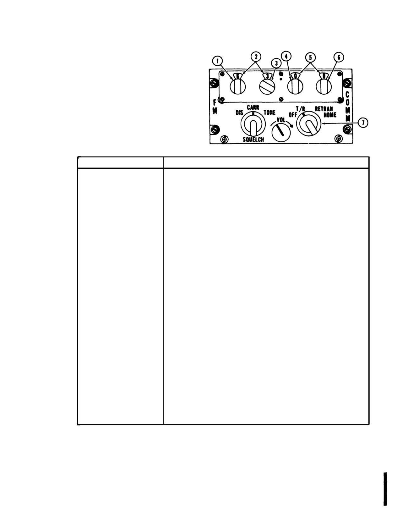
1. Tens megahertz digit
frequency selector
2. Frequency indicators
3. Units megahertz digit
frequency selector
4. Tenths magahertz digit
frequency selector
5. Frequency indicators
6. Hundredths megahertz digit
frequency selector
7. Mode control switch
CONTROL/lNDICATOR
FUNCTION
Mode control switch
(four-position switch)
OFF
Turns off primary power.
T/R
Radio set operates in normal communication mode (reception).
(transmit/receive)
(Aircraft transmit switch must be depressed to transmit.)
RETRAN
Radio set operates as a two-way relay station.
(retransmit)
(Two radio sets are required set at least 3 MHz apart.)
HOME
Radio set operates as a homing facility.
(Requires a homing antenna and indicator.)
VOL control
Adjusts the audio output level of the radio set.
SQUELCH switch
(three-position
rotary switch)
DIS (disable)
Squelch circuits are disabled.
CARR (carrier)
Squelch circuits operate normally in presence of any carrier.
TONE
Squelch opens (unsquelches) only on selected signals
(signals containing a
150-cps tone modulation).
Frequency indicator
Tens megahertz
Selects the tens megahertz digit of the operating frequency.
frequency selector
Units megahertz
Selects the units megahertz digit of the operating frequency.
frequency selector
Tenths megahertz
Selects the tenths megahertz digit of the operating frequency.
frequency selector
Hundredths megahertz
Selects the hundredths megahertz digit of the operating
frequency selector
frequency.
Frequency indicator
Displays the operating frequency of the radio set.
Figure 3-11. FM Radio Set Control Panel AN/ARC-131
Change 7
3-15
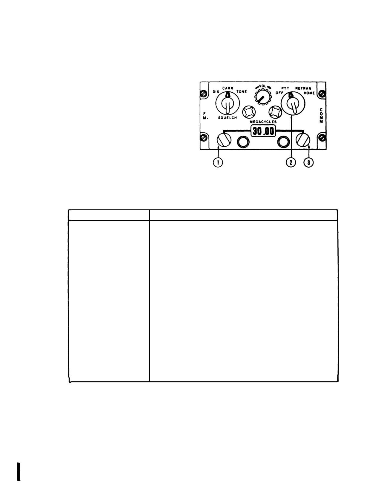
TM 55-1520-210-10
1. Frequency control whole
- megahertz
2. Mode selector switch
3. Frequency control decimal
- megahertz
CONTROL/lNDICATOR
FUNCTION
Mode selector
Applies power to the set and selects the mode of operation.
switch
OFF position - Turns off primary power. PTT (push-to-talk) applies
power. Radio set operates in normal communication mode. (Radio
cyclic stick switch or foot switch must be pressed to transmit.)
RETRAN (retransmit) - Applies power. Radio set operates as a
two-way relay station. (Two radio sets are required set at least
5 MHz apart)
HOME position - Applies power and radio set operates with
637A-2.
Homing Antenna and Course indicator as a homing facility.
Voice capability is provided in all three operating positions.
VOL control
Controls the receiver audio volume.
SQUELCH control
Selects one of three squelch modes as follows:
DIS (disable) position - Squelch circuits are disabled.
CAR (carrier) position - Squelch circuits operate normally.
TONE position - Squelch opens (unsquelches) only on signals
containing a
150-cps tone modulation.
Frequency control
Selects the whole megahertz digits
whole-megahertz digit
Frequency control
Selects the decimal-megahertz digits.
decimal-megahertz digit
Megahertz display
Displays the selected operating frequency.
window
Figure 3-12. FM Radio Set Control Panel C-3835/ARC-54
3-16
Change 7
TM 55-1520-210-10
Figure 3-13. FM Control Panel and Switch Assembly AN/ARC-44
Change 7 3-17
TM 55-1520-210-10
TSEC/KY-28
Figure 3-14. Voice Security Equipment (Sheet 1 of 2)
3-18
Change 7
TM 55-1520-210-10
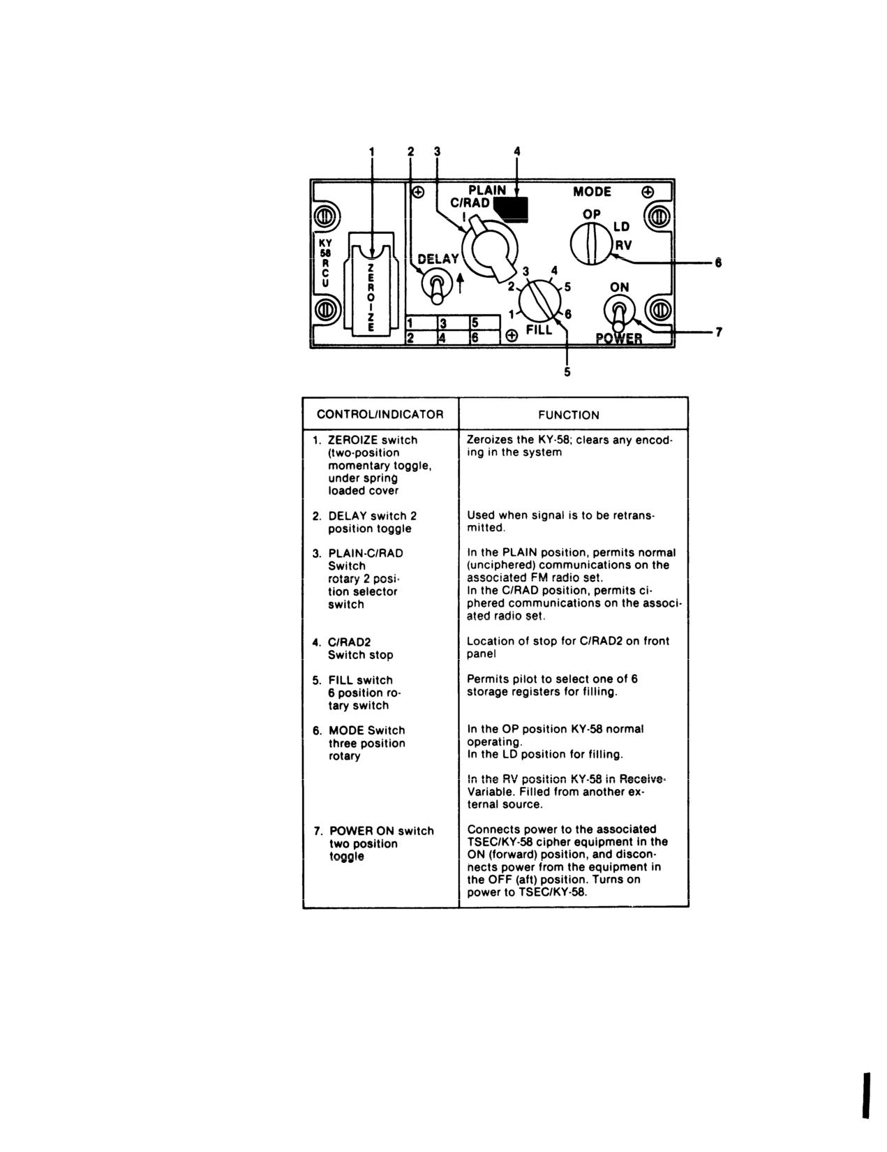
T/SEC KY-58
Figure 3-14 Voice Security Equipment (Sheet 2 of 2)
Change 7
3-19
TM 55-1520-210-10
(d) When transmission is completed, release
the
NOTE
press to talk switch. This will return equipment to
the
standby condition.
When operating in either secure or clear
(e) To receive, it is necessary for another station
(plain) voice operations the VOLUME must
to send you a signal first. Upon receipt of a signal
be adjusted on the aircraft radio and
the cipher equipment will be switched automatically
intercom equipment to a comfortable
to the receive condition, which will be indicated by a
operating level.
short beep heard in the headset. Reception will then
be possible. Upon loss of the signal, the cipher
(2) Clear Voice Procedures:
equipment will be automatically returned to the
(a) To operate in clear voice (plain text) simply:
standby condition.
1 Set the Z-AHP(RCU) PLAIN-C/RAD switch to
3-16.1 Voice Security Equipment TSEC/KY-58
PLAIN.
a. Description. The voice security equipment is
2 Operate the equipment
used with the FM Command Radio to provide secure
two way communication. The equipment is con-
(3) Zeroing Procedures
trolled by the control-indicator (Z-AHP) mounted in
the right pedestal panel. The POWER switch must be
in the ON position, regardless of the mode of opera-
NOTE
tion, whenever the equipment is installed.
Instructions should originate from the Net
b. Controls and Functions.
Refer to Figure 3-14.
Controller or Commander as to when to
zeroize the equipment
c. Operating Procedures.
(a) To zeroize the KY-58: (Power must be on).
(1) Operating procedures for secure voice.
1 Lift the red ZEROIZE switch cover on the RCU.
2 Lift the spring-loaded ZEROIZE switch. This will
zeroize positions
1-6.
To talk in secure
voice, the KY-58 must be
“Loading” with
any number of desired
3 Close the red cover.
variables.
The equipment is now zeroized and secure voice
(a) Set to MODE switch to OP.
communications are no longer possible.
(b) Set the FILL switch to the storage register
(4) Automatic Remote Keying Procedures
which contains the crypto-net variable (CNV) you
desire.
NOTE
(c) Set the POWER switch to ON.
Automatic Remote Keying (AK) causes an
(d) Set the PLAIN C/RAD switch to C/RAD.
"old" crypto-net variable (CNV) to be
replaced by a “new” CNV. Net Controller
(e) If the signal is to be retransmitted, set the DE-
simply transmits the “new” CNV to your
LAY switch to (ON).
KY-58.
(f) At this time a crypto alarm, and backg0round
(a) The Net Controller will use a secure voice
noise, in the aircraft audio intercom system should
channel, with directions to stand by for an AK trans-
be heard. To clear this alarm, press and release PTT
mission. Calls should not be made during this
in the aircraft audio/intercom system. Secure voice
standby action.
communication is now possible.
3-20
Change 7
TM 55-1520-210-10
(b) Several beeps should now be heard in your
(6) It is important to be familiar with certain KY-58
headset. This means that the "old" CNV is being
audio tones. Some tones indicate normal operation,
replaced by a "new" CNV.
while other indicate equipment malfunction. These
tones are:
(c) Using this “new” CNV, the Net Controller will
ask you for a “radio check.”
(a) Continuous beeping, with backg0round noise,
is cryptoalarm. This occurs when power is first ap-
(d) After the “radio check” is completed, the Net
plied to the KY-58, or when the KY-58 is zeroized.
Controller instructions will be to resume normal
This beeping is part of normal KY-58 operation. To
communications. No action should be taken until the
clear this tone, press and release the PTT button on
net controller requests a “radio check.”
the Z-AHQ (after the Z-AHQ LOCAL switch has
been pressed. Also the PTT can be pressed in the
(5) Manual Remote Keying Procedures.
cockpit.
(a) The Net Controller will make contact on a se-
(b) Background noise indicates that the KY-58 is
cure voice channel with instructions to stand by for a
working properly. This noise should occur at TURN
new crypto-net variable (CNV) by a Manual Remote
ON of the KY-58, and also when the KY-58 is gener-
Keying (MK) action. Upon instructions from the Net
ating a cryptovariable. If the backg0round noise is not
Controller:
heard at TURN ON, the equipment must be checked
out by maintenance personnel,
1 Set the Z-AHP FILL switch to position 6. Notify
the Net Controller by radio, and stand by.
(c) Continuous tone, could indicate a “parity
alarm.” This will occur whenever an empty storage
2 When notified by the Net Controller, set the Z-
register is selected while holding the PTT button in.
AHP MODE switch to RV (receive variable). Notify
This tone can mean any of three conditions:
the Net Controller, and stand by.
1 Selection of any empty storage register.
3 When notified by the Net Controller, set the Z-
AHP FILL switch to any storage position selected to
2 A “bad” cryptovariable is present.
receive the new CNV (May be unused or may con-
tain the variable being replaced). Notify the Net Con-
3 Equipment failure has occurred. To clear this
troller, and stand by.
tone, follow the “Loading Procedures” in TM
11-5810-262-OP. If this tone continues, have the
NOTE
equipment checked out by maintenance personnel.
When performing Step
3, the storage
(d) Continuous tone could also indicate a cryp-
position (1 through 6) selected to receive
toalarm. If this tone occurs at any time other than in
the new CNV may be unused, or it may
(c) above, equipment failure may have occurred. To
contain the variable which is being
clear this tone, repeat the “Loading Procedures” in
replaced.
TM 11-5810-262-OP. If this tone continues, have
the equipment checked out by maintenance person-
(b) Upon instructions from the Net Controller:
nel.
1
Listen for a beep on your headset.
(e) Single beep, when RCU is not in TD (Time De-
lay), can indicate any of three normal conditions:
2
Wait two seconds
1 Each time the PTT button is pressed when the
3
Set the the RCU MDOE switch to OP
KY-58 is in C (cipher) and a filled storage register is
4
Confirm
selected, this tone will be heard. Normal use
(speaking) of the KY-58 is possible.
(c) If the MK operation was successful, the Net
Controller will now contact you via the new CNV.
2 When the KY-58 has successfully received a
cryptovariable, this tone indicates that a “good”
(d) If the MK operation was not successful, the
cryptovariable is present in the selected register.
Net Controller will contact you via clear voice (plain)
transmission; with instructions to set your Z-AHP
3 When you begin to receive a ciphered mes-
FILL selector switch to position 6, and stand by while
sage, this tone indicates that the cryptovariable has
the MK operation is repeated.
3-21
Change
7
TM 55-1520-210-10
(1) Function selector switch - As desired.
passed the “parity” check, and that it is a
good variable.
(2) Frequency controls - Desired frequency.
if the function selector is moved from the OFF po-
(f) A single beep, when the RCU is in TD
sition to an operating mode and the desired oper-
(Time Delay) occurring after the “preamble” is
ating frequency is already sat up on the control
sent, indicates that you may begin speaking.
panel, rotate the first selector knob one digit off
frequency and then back to the operating fre-
(g) A single beep, followed by a burst of
quency. This will allow the system to return to the
noise after which exists a seemingly “dead”
frequency.
condition indicates that your receiver is on a
different variable than the distant transmitter.
(3) RF-SENS-Adjust.
if this tone occurs when in cipher text mode:
Turn RCU FILL switch to the CNV and con-
(4) intercommunications HF switch-As de-
tact the transmitter in PLAIN text and agree
sired.
to meet on a particular variable.
d. Emergency Operation. The AN/ARC-102 HF
3-17. HF Radio Set AN/ARC-102
radio has two built-in protective devices that could
cause the set to stop operating. The condition and
a. Description. HF AM/SSB Radio Set
corrective steps are as follows:
AN/ARC-102 is a long range, high frequency
(hf), single side band (ssb), transceiver that
(1) A protective circuit is designed to turn
transmits and receives in the 2.0 to
30.0
the receiver-transmitter off, when a short exists in
MHz range. The control panel is located on
the output circuit. To restore the receiver-
the right side of the pedestal and tunes in one
transmitter to operation, move the function selec-
kHz stops to any of 28,000 manually se-
tor to OFF position and then back to the desired
lected frequencies. The primary mode of op-
operating mode:
eration is ssb. However, it can also transmit
end receive compatible amplitude modulated
(2) When the associated antenna coupler is
(am) signals.
required to complete several consecutive tuning
cycles it may become overheated. In this event a
b. Controls and Functions. Refer to figure
thermal relay in the coupler unit is designed to turn
3-15.
off the receiver-transmitter. If the receiver-
transmitter stops operating after a series of tuning
c. Operation.
cycles, position the function selector switch to
OFF position, allow the thermal relay to cool for
two minutes and return the function selector to
When ground testing ARC-102
the desired operating mode.
equipment, be sure that personnel
are clear of antenna. Serious bums
(3) if the above procedure does not return
can result if body contact is made
the HF radio set to normal operation, place the
with the antenna during ground
frequency selector to 29.000 MHz and function
testing.
selector in the “OFF” position. Report the failure to
the maintenance personnel.
3-22
Change 18
TM 55-1520-210-10
3-17.1 HF Radio Set AN/ARC-220 (MWO 1-1520-
may be transmitted or received in USB or LSB
modes. In addition to conventional HF communi-
210-50-33)
cation, the AN/ARC-220 provides automatic link
WARNING
establishment (ALE) and two types of electronic
counter countermeasures (ECCM) communica-
Make sure that no personnel are
tions. The ALE simplifies HF radio operation by
within 3 feet of the HF antenna when
automatically establishing a 2-way link on the
transmitting, performing radio checks
best available frequency.
or when in ALE mode. Do not touch
the RF output terminal on the antenna
The two types of ECCM communications (MIL-
coupler, the antenna lead-in wire, the
STD-188-141A ECCM and Army enhanced ECCM)
lnsulated feed trough, or the antenna
provide a frequency hopping technique that com-
itself while the microphone is keyed
bats the effects of communications jammer and
(after the tuning cycle is complete) or
direction finding attempts. Although two different
while the system is in transmit self-
types of ECCM are available, system operation is
test. Serious RF burns can result from
the same regardless of the type used.
direct contact with the above criteria.
The AN/ARC-220 also supports both standard and
WARNING
advanced narrow-band digital voice terminal
(ANDVT). Digital data interfaces compatible with
Tow aircraft outside of hanger or
MIL-STD-188-114A allow transmission and recep-
metal-covered building before per-
tion of data from improved data modem (IDM) and
forming power-on checks.
data secured by the AIRTERM (TSEC/KY-100). In
addition, the AN/ARC-220 includes a MIL-STD-
a. Description. The AN/ARC-220 is a high fre-
110A data modem which may, in noisy environ-
quency, single-side band radio set. It receives and
transmits on any one of
280,000 manually-
ments, allow data to be received when voice
selected frequency channels spaced at 100-Hz
communications cannot. Power to operate the
increments in the HF band (2.0 to 29.9999 MHz).
AN/ARC-220 is supplied from the 28 vdc essential
Preset channels can be manually programmed by
bus through the HF ARC-220 circuit breaker on
an operator or preprogrammed as part of the
the pilot overhead circuit breaker panel. A shorted
communications mission load information.
The
loop antenna is located on the rear left side of the
AN/ARC-220 provides secure and nonsecure voice
aircraft (figure 2-1. The length of the antenna is
and data communications. Voice communications
approximately 12.6 feet in length.
are possible using either simplex or half-duplex
operation in the upper sideband (USB), lower
b. Controls and Functions. Refer to figure 3-
sideband (LSB), amplitude modulation equivalent
14.1 and the following table.
(AME), and continuous wave (CW) modes. Data
Change 18
3-22.1
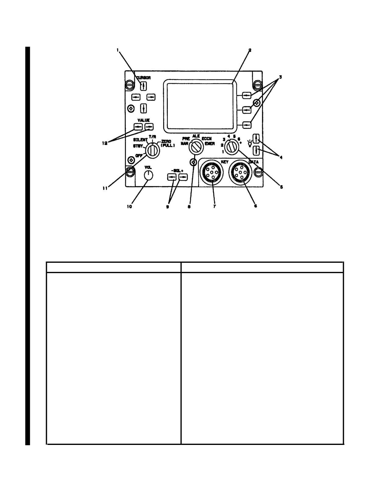
TM 55-1520-210-10
Figure 3-14.1. HF Radio Set AN/ARC-220 Control Panel C-12436/URC
Controls and Functions of Control Panel C-124361URC
CONTROL /INDICATOR
FUNCTION
1.
Cursor switches
Four pushbutton switches that position cursor verti-
cally or horizontally on display (2).
2.
Display
Liquid crystal display (LCD), consisting of six display
lines, for displaying advisory information. Depending
on operation, information that may be displayed on
each line is as follows:
Line 1
Alpha-numeric display of 15 characters maximum
containing channel title (call sign). Default value is
Mode: channel #.
Line 2
ALE Address
Alpha-numeric display of 15 characters maximum
containing Call To (ADRS: xxx) or Self (SELF:
xxx)Address. (ADRS:) and (SELF:) labels are re-
moved for addresses greater than 10 characters in
length.
Noise Reduction
Character display (ON, OFF) having display format of
NOISE REDUCE: xxx. Default value is ON.
3-22.2 Change
18
TM
55-1520-210-10
Controls and Functions of Control Panel C-12436/URC (Cont)
CONTROL /INDICATOR
FUNCTION
Fill Type
Character display (KEY, DATA) having display format of
TYPE: xxxx x. Default is DATA.
Contention Control
Character display (ON, OFF) having display format of
LBC: xxx. Default is OFF.
Line 3
Receive Frequency
Numeric display (2.0 to 29-9999 MHz) with display for-
mat of RCV: xx.xxxxxxxx.
ECCM Station Type
Character display (MEMBER, ALTERNATE, MASTER, NET
ENTRY, ALT NET ENT). Default is MEMBER.
Lines 3,4
Character display of emission mode (USB, LSB, AME,CW)
one space to right of frequency. Default is USB.
Line 4
Transmit Frequency
Numeric display (2.0 to 29.9999 MHz) with display for-
mat of XMT: xx.xxxxxxxx.
Time
Numeric display (00:00:00 to
23:59:59) with display
format of Hour:Minute:Second.
Line 5
Link Protection
Character display (OFF, ON) with display format of LINK
PROT: xxx, Default is ON (OFF if no link protection data-
fill).
Date
Alphanumeric display (01 JAN 00 to 31 DEC 99) with
display format of dd MM yy.
Antenna Type
Character display (T/R, RCV) with display format of ANT:
xxx. Default is T/R.
Line 8
Power Level
Character display (LOW, MED, HIGH) with display format
of PWR: xxxx. Default is HIGH.
Squelch
Alpha-numeric display (TONE, 0 to 5) with display format
of - SQ: xxx.
Volume
Numeric display (1 to 8) with display format of VOL:x.
Listen Before Talk
Character display (ON, OFF) with display format of
LBT: xxx.. Default value is OFF.
Change 18
3-22.3
TM 55-1520-210-10
Controls and Functions of Control Panel C-12436/URC (Cont)
CONTROL/INDICATOR
FUNCTION
3.
Line-select switches
Three pushbutton switches that select options dis-
played to left of each switch.
4.
Brightness switches
Two pushbutton switches that varies display screen
brightness.
5.
Channel/Net selector switch
Seven-position rotary switch that selects programmed
operating channels or nets, depending on operating
mode. The + position of switch allows additional
channel/net selections using VALUE switches
(12).
6.
Data connector
Interfaces AN/ARC-220 system to data transfer device
for datafill.
7.
Key connector
Interfaces AN/ARC-220 system to data transfer device
for keyfill.
8.
Mode switch
Five-position rotary switch that selects following
modes of operation:
MAN
Permits single channel selection of operating fre-
quency and emission mode for conventional HF com-
munications.
PRE
Permits preprogrammed preset channel operation for
conventional HF communications.
ALE
Selects automatic link establishment mode of opera-
tion.
ECCM
Selects electronic counter-countermeasure mode of
operation.
EMER
Used during emergency situations to place a distress
call. The mode (manual, preset, ALE, or ECCM), fre-
quency, net, etc., is determined by the datafill.
9.
-SQL + switches
Two pushbutton switches (left arrow) and (right ar-
row) that control radio squelch and audio muting.
10.
VOL switch
Eight position rotary switch that varies receive audio
output level.
3-22.4
Change 18
TM 55-1520-210-10
Controls and Functions of Control Panel C-12436/URC (Cont)
CONTROL /INDICATOR
FUNCTION
11.
Function switch
Five-position rotary switch that selects system operation
as follows:
OFF
Turns AN/ARC-220 system off.
STBY
Turns AN/ARC-220 system on and places system in-
standby. In standby, built-in-test (BIT), setup, or fill op-
erations can be performed to ready system for operation.
SILENT
Used in ALE or ALE-ECCM mode to preventAN/ARC-220
system from automatically responding to incoming calls,
T/R
Allows AN/ARC-220 system to transmit and receive in
selected mode of operation.
ZERO
Erases ail data (including datafill and keyfill) that has been
(PULL)
loaded into system. Switch must be pulled before setting
it to this position.
12.
Value
Two pushbutton switches that increment field value or
single character value, depending on cursor position.
Change 18
3-22.5
TM
55-1520-210-10
c. Operating Modes/Functions.
(9) Output Power Level. Three output lev-
els are selectable for display screen by using EDIT
(1) Power ON/OFF. On Function Switch.
line-select switch, which brings up edit mode,
moving cursor under power character field and
(2) System Turn-On. Turning Function
using VALUE switches to change field. Depress
Switch clockwise from OFF to STBY turns system
RTN line-select switch which stores the change
on and selects standby function. SYSTEM
and returns to normal operating mode.
TESTING is displayed while power-up BIT (P-BIT)
is in process. SYSTEM-GO will be displayed if all
(10) Test. There are two Built-in-Test (BIT)
tests pass or SYSTEM-NO-GO if not.
features which concerns the operator, P-BIT and
C-BIT. The Power-Up Bit (P-Bit) tests the ARC-
(3) CRT Brightness.
Two pushbutton
220 when initially turned on. P-Bit exercises ba-
switches used to vary brightness. The
(up ar-
sic radio control functions which must be opera-
row) increases intensity while the
(down arrow)
tional prior to entering system operational mode.
decreases intensity.
A GO/NO-GO status appears on display and de-
faults to stand-by mode upon completion. When
(4) Audio Volume. Eight-position rotary
NO-GO status appears, depressing INOP line-
switch used to vary audio output level. Setting is
select switch displays INOP MODES so an opera-
displayed on line 6 (bottom) of display for 5 sec-
tor can see if limited capability exists. Continuous
onds when system is first turned on or when VOL
Bit (C-BIT) is automatically performed during sys-
setting is changed. Display levels are 1 through 8.
tem operation without any operator intervention.
Critical system functions are monitored. Any fail-
(5) Channel Selection. Channel number may
ures cause a NO-GO advisory, accompanied by
be changed using seven-position rotary chan-
portion of system which failed, to appear on line 5
nel/net selector switch. The + position of switch
of display. C-Bit failures are stored in nonvolatile
allows channels 7 or greater to be selected using
memory.
VALUE switches.
(11) Store. RTN line-select key, used to
(6) Modulation Mode. Four modes are avail-
terminate edit mode, automatically stores any
able: USB, LSB, AME, and CW. The modulation
change(s) made.
mode is determined by the data fill except for the
manual mode. Modulation mode can be changed
(12) Data Fill. Contains preset frequencies,
on manual channels
scan lists, addresses, data messages and ALE
and/or ECCM parameters. With system in STBY,
(7) Receive/Transmit Frequency.
2.0 to
press FILL line-select switch. From the FILL
29.9999 MHz, programmable in 100 Hz steps. To
screen, use the line select switch to select DATA.
change frequencies, depress EDIT line select
Connect data transfer device (DTD) of DATA con-
switch. While in Edit screen, use CURSOR to posi-
nector on radio set control front panel and initiate
tion cursor under appropriate frequency. Use
fill from DTD. LOADING is displayed during data-
VALUE switches to change frequency. (Note:
fill From the DATAFILL screen, use the line select
XMT frequency will automatically change with
switch to select LOAD. FILL ENABLED is dis-
RCV frequency, but the reverse is not true).
played during datafill. The AN/CYZ-10 DTD will
indicate when the datafiil is completed. Use the
(8) Squelch Level/Audio Muting (-SQL + ).
line-select switch to select RTN after the DTD
Two pushbutton switches
(left arrow) and
indicated datafill completed. The display will re-
(right arrow), when pressed, displays squelch
turn to the screen showing DATAFILL VERSION.
status on line 6 of display for 5 seconds. Settings
The approporated Datafill Version is displayed for
are TONE and 0 through 5. TONE provides no
a successful fill. A copy of loaded datafill can be
muting and no squelch. Position 0 provides mut-
sent to DTD by pressing COPY line-select switch.
ing but no squelch. Positions 1 through 5 provide
COPYING is displayed during operation, COPY
muting and increasing levels of squelch. Muting is
COMPLETE is displayed if successful, COPY FAIL
normally enabled during ALE operation.
if
copy
cannot
be
completed.
3-22.6 Change
18
TM 55-1520-210-10
Press RTN line-select switch to return to STBY
NOTE
screen when datafill is complete.
Disconnect
Pressing RTN line select key on
DTD.
DATA FILL page stops the fill proc-
ess.
(13) Key Fill. Loads secure keys. From the
FILL screen, use the line-select switch to select
(c) On the DATA FILL page, FILL line select
KEY. Connect DTD to KEY connector on radio set
key - Press. FILL ENABLED screen will appear.
control front panel. From the KEYFILL screen, use
the line-select switch to select LOAD. Fill enabled
(d) Start data fill on DTD. Monitor DTD to
IS DISPLAYED DURING KEYFILL. Initiate keyfill
see when data transfer is complete.
from DTD. The AN/CYZ-10 DTD will indicate
when the keyfill is completed. Use the line-select
(3) Load Secure Keys. Key fill contains secure
switch to select RTN after the DTD indicates key-
information needed for ALE link protection and
fill is completed. The display will return to the
ECCM operation.
screen showing ECCM KEY and LP KEY. The ap-
propriate keys are displayed for a successful fill.
(a) Initialize the DTD. Connect the DTD to
To erase selected loaded keys, press ZERO line-
the KEY connector.
select switch. A ZEROIZE screen appears. Press
YES or NO line-select switch. If YES is pressed, a
(b) With the FILL page selected, KEY line
ZEROIZED advisory is displayed, then fill screen
select key - Press.
reappears. If NO is pressed, fill screen reappears.
Press RTN line select switch to return to STBY
NOTE
screen when all keys are loaded.
Pressing RTN line select key on
d. Operation.
KEY FILL page stops the fill proc-
ess.
(1) Starting Procedure.
(c) On the KEY FILL page, LOAD line se-
(a) Function switch - STBY. SYSTEM
lect key - Press. FILL ENABLED message will ap-
TESTING is displayed while power up built in test
pear.
(PBIT is in process. SYSTEM - GO will be dis-
played upon successful completion of PBIT.
(d) Start keyfill on DTD. Monitor DTD to
see when data transfer is complete.
(b) FILL line select key - Press. Status of
(4) Zero Secure Keys.
PRE, ALE, ECCM, and EMER modes will be dis-
played.
(a) Access KEY FILL page. From FILL
screen, KEY fixed function key - Press. Select key
(2) Load Presets. Datafill contains preset fre-
to zero with VALUE keys.
quencies, scan lists, addresses, data messages,
and non secure information needed for ALE/ECCM
operation. If the DTD is configured to receive
(b) ZERO line select key - Press.
data, it may be copied from the radio to the DID
by pressing COPY line select key on the DATA
NOTE
FILL page.
(a) Initialize the data transfer device
If you do not want to zero the
(DTD). Connect the DTD to the DATA connector.
key, press NO. The FILL screen
will then appear.
(b) With the FILL page selected, DATA line
select key - Press.
(c) Confirm zero by pressing YES line se-
lect key. ZEROIZE advisory message will appear,
followed by the FILL screen.
Change 18
3-22.7
TM 55-1520-210-10
(5) Emergency (EMER) Operation. The
mode, frequency, and net to be used in the EMER
position is determined by the datafill. To use the
emergency mode, do the following:
(a) Function switch - T/R.
(b) Mode switch - EMER
(c) ICS Transmitter selector - Position 4.
(d) Radio push-to-talk switch - Press to
talk; release to listen.
(6) Shut Down
(a) Function switch - OFF.
(b) To erase all preprogrammed informa-
tion, Function switch - Pull and turn to ZERO
(PULL).
(7) Messages. The following table lists dis-
play advisory messages that may appear during
operation of the radio:
3-22.8
Change 18
TM 55-1520-210-10
AN/ARC-220 Messages
ADVISORY
ACTION
ALE - NO DATA
ALE mission data not loaded.
Load mission data.
ALE - NO KEYS
ALE link protection keys not
Load keys.
loaded.
CALL FAIL
Radio failed to complete an out-
going call.
CALLING
Radio is placing an ALE - call to
another address.
CHANNEL BUSY
ALE or ECCM net is in use.
Walt or try another net
CHANNEL INOP
ALE or ECCM keys are not
loaded, or not correct.
CHECK MSG
A data message has been re-
ceived.
COPY COMPLETE
Copying process finished suc-
cessfully.
COPY FAIL
Copying process was unsuccess-
ful.
COPYING DATA
The radio is copying datafill con-
tents from DTS.
ECCM - NO DATA
ECCM data not installed.
Load mission data.
ECCM - NO KEYS
ECCM keys not Installed.
Load keys.
EMER
Mode or net selected for emer-
gency communication Is inopera-
tive.
EMERG - NO KEYS
No keys available for net selected Load keys.
for emergency communication.
EOM
End of message.
EXT FAIL
Radio failed due to external de-
vice, such as antenna.
Change 18
3-22.9
TM 55-1520-210-10
AN/ARC-220 Messages (Cont)
ADVISORY
MEANING
ACTION
GO DATA
Link quality analysis values too
low for reliable voice communica-
tion; data transmissions recom-
mended.
HELD
ALE call being held in specific
frequency by operator.
INCOMING CALL
Another radio is establishing an
ALE link.
INOP MODES EXIST
Warning to expect inoperative
modes.
LINKED
An ALE link is established.
LOAD COMPLETE
Keys and data successfully
loaded into radio.
LOAD FAIL
Keys and data not successfully
loaded into radio.
LOADING DATA
Radio currently loading data.
LOADING KEYS
Radio currently loading keys.
MSG ABORT
Radio discontinuing sending of
current message.
NET INOP
Selected net contains no data,
corrupted data,or hardware can-
not support the selected mode of
operation.
NO AUTO XMT
Radio has been instructed not to
make any automatic transmis-
sions.
NO DATA
Database is not filled with neces-
sary data to perform requested
operations.
NO KEYS LOADED
Keys are not loaded for current
selected mode or net.
3-22.10
Change 18
TM 55-1520-210-10
AN/ARC-220 Messages (Cont)
ADVISORY
MEANING
ACTION
NO RCVD MSGS
No messages have been re-
ceived.
PAC FAIL
Failure of radio in PA coupler.
PRE - NO DATA
Preset data not loaded.
PTT FOR XMlT BlT
Instruction to press microphone
PTT switch to enable transmis-
sion BIT.
RCV BIT - GO
Receiver BIT functions completed
without failure.
RCV READY
Ready to receive ECCM trans-
missions.
RCVG PREAMBLE
ECCM preamble being received.
RCVG DATA
Radio currently receiving data.
RT FAIL
Receiver Transmitter inoperative.
RX - TX DEGRADED
Receive and transmit capabilities
are degraded.
RX - TX FAIL
Radio cannot receive or transmit.
SENDING DATA
Radio currently sending data.
SOUND
Radio sending an ALE sound.
SYNCING
Time synchronization being per-
formed.
TESTING
BIT in progress.
TIME SYNC FAIL
Radio failed in attempt to syn-
chronize.
TRANSEC FAIL
BIT detected a failure that will
not allow ECCM operation.
Change 18
3-22.11
TM 55-1520-210-10
AN/ARC-220 Messages (Cont)
ADVISORY
MEANING
ACTION
TUNE XX %
Indicates percentage of ECCM
frequencies tuned for current net.
TUNING
Radio is currently tuning itself.
TX DEGRADED
BIT detected a failure that is
causing transmission capability to
be degraded.
TX FAIL
Radio cannot transmit.
UNSYNC
ECCM is not synchronized.
UNTUNED
An ECCM hop set is not tuned.
XMT READY
Radio is ready to transmit in
ECCM mode.
ZEROIZED
All mission datafill and keys have
been erased.
3-22.12
Change 18
TM
55-1520-210-10
e. Modes of Operation.
NOTE
If the radio breaks in and out of
(1) Manual (MAN) Mode. Use manual mode
squelch, Increase setting as re-
to change transmit and receive frequencies, side-
quired.
bands and transmit power, and operate the radio
manually.
5. -SQL+ switch - Set squelch to 1.
(a) To change radio settings:
6. Select the desired net (1 through
20),
net selector switch -1 through +. Use VALUE
1. Mode switch - MAN.
keys to select 7 through
20.
2. Function switch - T/R.
7. ICS Transmitter selector - Position
4.
2. Select the desired net (I through
20),
8. Radio push-to-talk switch - Press to
net selector switch -
1 through +. Use VALUE
talk; release to listen.
keys to select 7 through 20.
(2) Preset (PRE) Mode. Preset mode stores
2. EDIT line select key - Press.
preprogrammed frequencies and emission modes
that cannot be changed by the operator. To use
the radio in preset mode, do the following:
NOTE
(a) Function switch - T/R
Changing the receive frequency and
mode will also change the transmis-
(b) Mode switch - PRE.
sion frequency and mode the same
values. Changing the transmission
(c) -SQL+ switch - Set squelch to 0.
frequency and mode will not change
the receive frequency and mode.
(d) VOL switch - Adjust for comfortable
listening level.
5. Edit frequency, emission mode and
NOTE
transmit power by placing the cursor under field
If the radio breaks in and out of
to be edited with CURSOR key, and change field
squelch, increase setting as re-
value with VALUE keys.
quired.
6. To end edit and store changed data,
(e) -SQL+ switch - Set squelch to 1.
RTN line select key - Press.
(f) Select the desired net (1 through 20),
(b) To operate in manual mode:
net selector switch - 1 through +. Use VALUE
keys to select 7 through 20.
1. Function switch - T/R.
(g) ICS Transmitter selector - Position 4.
2. Mode switch - MAN
NOTE
3. -SQL+ switch - Set squelch to 0.
If tune tone is heard, wait until it
stops before talking. When radio
4. VOL switch - Adjust for comfortable
push-to-talk switch is pressed,
listening level.
XMT frequency is displayed. Dis-
play returns to preset display
when switch is released.
Change 18
3-22.13
TM 55-1520-210-10
(h) Radio push-to-talk switch - Press to
6. SQL+ switch - Set squelch to 0.
talk; release to listen.
7. To synchronize time in a link pro-
tected channel, SYNC soft key - Press.
(3) Automatic Link Establishment (ALE)
Mode.
8. To broadcast AN/ARC-220 system
time as net control, EDIT, then TXTIM soft keys -
Press. Time will be transmitted, and radio will re-
WARNING
turn to scan mode.
(b) To receive a ALE call:
When In ALE mode, the radio
transmits
Interrogating
signals
1. INCOMNG CALL is displayed, fol-
(sounds) and replies to ALE calls
lowed by the caller’s ALE address. A short tone
automaticalty without operator ac-
tion. To avoid personnel Injury,
sounds, and LINKED is displayed.
ensure the function switch Is not
set to ALE when personnel are
2. Transmitter selector - Position 4.
working near the helicopter, during
refueling or loading ordinance.
NOTE
NOTE
Wait for the calling station to make
the first transmission.
Self address must be selected be-
3. Radio push-to-talk switch - Press to
fore using, ALE.
talk; release to listen.
ALE mode may be used for communications,
(c) To place a ALE call:
either normal or link protected, or position report-
ing.
1. Select ALE address:
(a) To set up the radio for ALE communi-
a. Select the desired net (1 through
cations, do the following:
20), net selector switch - 1 through +. Use
VALUE keys to select 7 through 20. Net name
1. Function switch - T/R.
and address will be displayed.
2. Mode switch - ALE.
b. VALUE switch
- Press, to scroll
through address list.
3. Select the desired net (1 through 20),
net selector switch -
1 through +. Use VALUE
c. EDIT soft key - Press. Enter address
keys to select 7 through 20.
one character at a time with CURSOR and VALUE
switches. To accept the edit and return to ALE
4. -SQL+ switch
- Set squelch to
screen, RTN soft key - Press.
TONE.
2. ICS Transmitter selector - Position 4.
5. VOL switch - Adjust for comfortable
listening level.
NOTE
NOTE
Press ABORT to stop the calling
process.
Earphone audio is muted until a
link is established. If the link is
3. Radio push-to-talk switch - Press.
noisy, set squelch to 1. Higher
CALLING, then LINKED is displayed with a short
squelch settings are not recom-
gong tone in headphone.
mended in this mode.
3-22.14
Change 18
TM
55-1520-210-10
NOTE
(b) To communicate in ECCM only mode,
ALE will cancel the link, and return
do the following:
to scan mode if there is no activity
on a link for 60 seconds. To main-
1.
-,SQL+ switch
- Set squelch to
tain a link, press HOLD soft key.
TONE.
When communications are com-
plete, or to return to scan mode,
2. VOL switch - Adjust for comfortable
press SCAN soft key.
listening level.
(d) Radio push-to-talk switch - Press to
talk; release to listen.
NOTE
(e) When communication is complete, to
If the frequency is noisy, set squelch
return to scanning mode, HOLD, then SCAN soft
to 1. Higher squelch settings are not
key - Press.
recommended in this mode.
(4) Electronic Counter Countermeasures
3. -SQL + switch - Set squelch to 0.
(ECCM) Mode. The radio changes frequency in a
sequence determined by the ECCM key. Datafill
4. Press and hold the push-to-talk
and keyfill must be loaded prior to using ECCM
switch until XMT READY is displayed. Walt for
mode, and system time must be synchronized be-
preamble tones to stop.
tween stations. Frequencies used in hop sets are
pretuned in the radio, as ECCM requires frequen-
5. Talk. Release switch to listen.
cies to be changed many times per second. Fre-
quency hopping is performed in both standard
(c)To communicate in ALE ECCM mode,
ECCM and ALE modes of operation. To use this
do the following:
mode, do the following:
1. -SQL+ switch
- Set squelch to
(a) Initialize the net
TONE.
1. Function switch - T/R.
2. VOL switch - Adjust for comfortable
listening level.
2. Mode switch - ECCM.
3. Select the ALE address, as required
NOTE
with VALUE switches, or use EDIT soft key, then
If the selected net Is an ALE ECCM,
CURSOR and VALUE switches to manually select
the address of the station being
an address.
called is also displayed.
4. When an incoming call is being re-
2. Select the desired net (1 through 12),
ceived, INCOMING CALL, then LINKED is dis-
net selector switch - 1 through +. Use VALUE
played. RCV READY is displayed while the ECCM
keys to select 7 through 12.
information is being received, and disappears
when receive sequence Is completed.
3. To change values on screen, EDIT
soft key - Press. Use CURSOR to position cursor
5. To place a call, press the push-to-talk
under area to change, and VALUE to change the
switch. CALLING, then LINKED is displayed. Press
field to desired value.
and hold the push-to-talk switch, and wait for the
ECCM preamble tone to stop. When XMT READY
5. To save changes and return to top
is displayed, begin talking. When the transmission
level screen, RTN soft key - Press.
is completed, release the switch. XMT READY
disappears when the ECCM postamble is sent.
6. Push-to-talk switch - Press, to tune
and time synchronize the radio.
Change 18
3-22.15
TM 55-1520-210-10
2. To insert a word from the dictionary
(5) Message Mode. The radio can store up
in a message do the following:
to 10 transmit data and 10 received data mes-
sages. Each message may be 500 characters
a. Position cursor where the word is to
long. Messages are numbered from 1 to 10. Mes-
be inserted.
sage 10 is the oldest, and will be deleted if a new
message is received. Messages may be composed
b. WORD soft key - Press.
using the AN/ARC-220 CDU dictionary or with a
custom dictionary listing locally generated words,
c. Select the word with VALUE keys,
which may be loaded with datafill.
d. To insert word with blank in mes-
(a) To view a received message:
sage, SELECT soft key - Press. If desired, return
to message without inserting a word by pressing
1. MSG soft key - Press.
CANCL.
2. Use CURSOR keys to scroll left or
6. To load edited message in R/T mem-
ory and return to top level screen, RTN soft key -
right, or up and down in a message.
Press.
3. Use VALUE keys to page up and
down in a message.
(c). To send a message:
4. To view additional messages, position
1. Access PRGM MSG screen by press-
cursor under message number with CURSOR
ing MSG, then PRGM soft keys.
keys. Use VALUE keys to scroll to the next mes-
sage number.
2. Select message to send as desired by
placing cursor under message number, and press-
5. To retain received messages, RTN
ing VALUE keys until desired message is dis-
soft key - Press.
played.
6. To delete received messages, position
NOTE
the cursor under the message number and DEL
soft key - Press, until messages are deleted. To
Message will be sent to currently
return to top screen, RTN soft key -Press.
selected address (ALE modes) or
transmitted on the currently se-
lected frequency and mode (MAN,
(b) To edit or compose a message:
PRE, or ECCM).
1. MSG soft key - Press.
3. SEND soft key - Press.
2. From MESSAGE screen, PGRM soft
3-17.2. Voice Security Equipment TSEC/KY-
key - Press.
100.
3. Select message to be edited by plac-
a. Description. The Voice security equipment
ing cursor under the message number with
TSEC/KY-100 provides two-way clear or secure
CURSOR keys, and change number with VALUE
half-duplex voice or data communication for HF
keys.
Radio Set AN/ARC-220. Power to operate the
TSEC/KY-100 is supplied from the dc essential
4. Edit message by placing cursor under
bus through the KY-100 VOICE SCTY circuit
area to be changed. Use VALUE keys to change
breaker located on the pilot overhead circuit
one character at a time. Press DEL to delete one
breaker panel.
character at a time.
b. Controls and Functions for Remote Control
Unit (RCU). Refer to figure 3-14.2.
3-22.16
Change 18
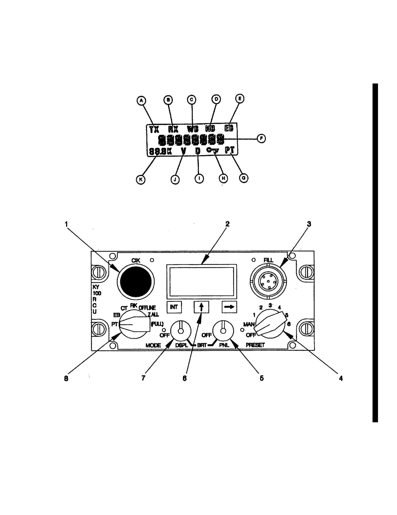
TM 55-1520-210-10
Figure 3-14.2. Remote Control Unit (TSEC/KY- 100)
Change 18
3-22.17
TM 55-1520-210-10
Controls and Functions of Remote Control Unit TSEC/KY-100
CONTROL /INDICATOR
FUNCTION
1. CIK Receptacle
Interfaces with ‘C” Ignition ‘K” which enables all
secure voice and data communications. This function
is currently disabled.
2. Display
Liquid crystal display (LCD) that displays operational
status, operator prompts and messages as follows:
A. TX Annunciator
Displayed when KY-100 is transmitting.
B. RX Annunciator
Displayed when KY-100 is receiving.
C. WB Annunciator
Displayed when KY-100 is in wideband (VINSON)
configuration.
D. NB Annunciator
Displayed when KY-100 is in narrowband (ANDVT)
configuration.
E. EB Annunciator
Displayed when MODE switch is in emergency
backup (EB) position.
F. Alphanumeric Display
Displays prompts, messages, and operating modes.
G. PT Annunciator
Displayed when KY-100 is processing plain text
voice.
H. Key Symbol
Displayed when menu system is locked.
I. D Annunciator
Displayed when in data mode.
J. V annunciator
Displayed when in voice mode.
K. Bate Display
Displays voice or data rate.
3. FILL Connector
Used to load cryptographic keys through use of
common fill device such as KYK-13/TSEC Electronic
Transfer Device, KYX-15/TSEC Net Control Device,
AN/CYZ-10 Data Transfer Device (DTD), or KOI-
18/TSEC General Purpose Tape Reader.
3-22.18
Change 18
TM 55-1520-210-10
Controls and Functions of Remote Control Unit TSEC/KY-100 (Cont)
CONTROL /INDICATOR
FUNCTION
4. PRESET Switch
Eight position rotary switch that controls unit oper-
ating power and settings stored in memory as fol-
lows:.
OFF
Removes power from KY 100.
MAN
Manual position which allows operating modes to be
selected using both OFFLINE and on-line menu sys-
tem.
1 thru 6
Six separate preset modes which can only be set up
in OFFLINE mode.
5. PNL/OFF BRT Control
Two-function rotary switch that controls on/off
status and backlight intensity of LCD display.
6. Three Button Keypad Switches
Three momentary pushbutton switches that are ac-
tive in both OFFLINE and on-line modes. They are
used to enter and exit submenus, activate selected
mode, select fields, and to scroll through menus and
options as follows:
INIT Switch
In OFFLINE mode, activates displayed menu mode
and provides entry into submenus. In on-line modes
(CT, RK, EB, PT), selects display field to be changed.
Up Arrow (?) Switch
In OFFLINE mode, scrolls through menus from top to
bottom. In online modes (CT, RK, EB, PT), scrolls
through available options for display field being
changed. When used simultaneously with right ar-
row (4 switch, exits submenu.
Right Arrow (4 Switch
In OFFLINE mode, scrolls through menus from bot-
tom to top. In on-line modes (CT, RK, EB, PT), se-
lects display field to be changed. When used simul-
taneously with up arrow
switch, exits submenu.
7. DSPL/OFF BRT Control
Two-function rotary switch that controls on/off
status and backlight intensity for front panel.
Change 18
3-22.19
TM 55-1520-210-10
Controls and Functions of Remote Control Unit TSEC/KY-100 (Cont)
CONTROL /INDICATOR
FUNCTION
8. Mode switch
Six-position rotary switch that selects the following:
modes of operation:
PT
Plaintext mode to allow reception or transmission of
unencrypted analog voice.
EB
Emergency Back-up mode to use emergency back-up
key to encrypt voice for transmission or reception.
CT
Ciphertext mode to allows transmission of encrypted
voice or data and reception of encrypted or unen-
crypted voice or data, and non-cooperative terminal
re-keying.
RK
Remote keying mode to allow KY-100 to perform
automatic and manual rekey operations.
OFFLINE
Disables communications and accesses system
menus to allow mode selection, self-test operation,
and data fills with cryptovariables.
Z ALL
Zeroize mode to erase all cryptographic data stored
(PULL)
in KY-100 except emergency back-up key. Switch
must be pulled before setting it to this position,
3-22.20
Change 18
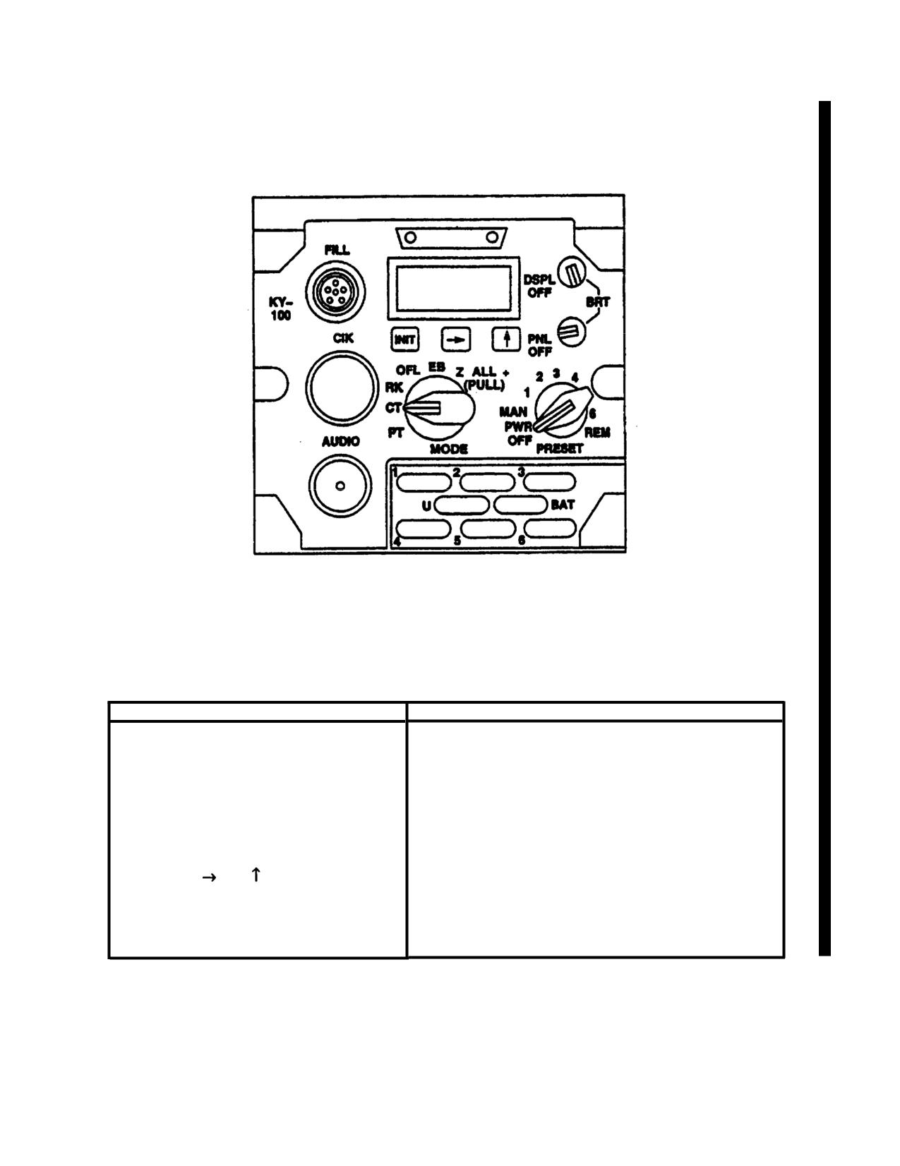
TM 55-1520-210-10
c. Controls and Functions for Processor.
Refer to figure 3-14.3 and the following table:
Figure 3-14.3 Processor (TSEC/KY - 100)
Controls and Functions of Processor TSEC/KY-100
CONTROL/INDICATOR
FUNCTION
Audio
Speaker for audio tones.
CIK
Cryptographic ignition key. Not used in this installa-
tion.
FILL connector
Used to connect external fill device to KY-100.
INT. and
Function keys used to access and ‘navigate in soft-
ware menus.
DSPL OFF
Varies light intensity of display. Display turned off in
OFF position.
Change 18
3-22.21
TM 55-1520-210-10
Controls and Functions of Processor TSEC/KY-100 (cont)
CONTROL/INDICATOR
FUNCTION
PNL OFF
Varies light intensity of backlit display panel. Display
turned off in OFF position.
PRESET switch
Controls power to set, and which key is active.
PWR OFF
Removes power from set.
MAN
Manual rekeying enabled.
1, 2, 3, 4, 5, 6
Selects preset settings for use.
REM
Allows control of KY-100 from a remote control unit
(RCU).
MODE switch
PT
Sets KY-100 to plaintext mode.
CT
Sets KY-100 to ciphertext mode.
RK
Allows cooperative terminal rekeying in receive
mode.
OFL
Sets KY-100 to off line mode. Disables communica-
tions and accesses screens to select mode settings,
test and fill screens.
EB
Select emergency back up key.
Z ALL + (PULL)
Erases all cryptographic data (keys) except the
emergency back up key.
3-22.22
Change 18
TM 55-1520-210-10
c. Operation.
1. Set MODE switch to OFL position.
NOTE
2. Rotate DSPL and PNL switches
During all operation procedures the
clockwise, out of OFF detent positions and adjust
KY-100 processor MODE switch is
display and panel lighting for comfortable viewing.
set to CT and PRESET switch to
REM.
3. Set PRESET switch to MAN (manual)
position to apply power to KY-100. Power-on
(1) Turn-On Procedures.
tests will automatically be run when primary
power is applied.
NOTE
4. Upon
successful
completion of
When KY-100 is turned on, tests are
power-on tests, test results should appear on dis-
automatically performed to deter-
play. If PASS is displayed, continue with turn-on
mine equipment’s operating status.
procedures. However, if FAIL message appears
The results of these tests will be
on display, notify next level of maintenance. If
presented on display.
Also, CLd
PUSH INIT is displayed, perform cold start proce-
START message will be displayed.
dures as described above in paragraph (a).
(a) Cold start turn-on.
(2) Key Loading Procedure.
1. Turn on KY-100 by setting PRESET
NOTE
switch to MAN position.
Key loading may be accomplished
2. The KY-100 will initiate self-test.
using AN/CYZ-10, KYK-15, KYK-13
The display reads CLd STRT and then PSH INT.
or KOI-18. One Key Encryption Key
(KEK), up to six Traffic Encryption
3. Connect fill device to KY-100 fill
Keys (TEKs), and one Emergency
connector using fill cable. Select fill position con-
Backup (EB) key can be loaded in
taining valid key and turn it on.
KY-100. A Fill Cable (ON190191) is
required when using one of these
4. Press INIT pushbutton switch.
devices. Proceed with the following
generic Key Loading procedures:
5. The KY-100 displays KEY 1 O1,
PASS.
(a) Set MODE switch to OFFLINE position.
NOTE
(b) If KY-100 is not on, turn PRESET
If fill device is not connected to KY-
switch to MAN position.
100 when INIT pushbutton is
pressed, dEV ERR (Device Error)
(c) Connect fill device to KY-100 fill con-
message will be displayed and an er-
nector
ror tone will be heard in the headset.
When this occurs, the only available
(d) Press up arrow or right arrow pushbut-
communication mode will be PT
ton switch until KEY OPS is displayed.
(Plaintext).
(e) Press INIT pushbutton switch. LOAD
6. If FAIL message is displayed,
KEY will be displayed.
notify the next level of maintenance.
(f) Press INIT pushbutton switch. LOAD
7. To load additional keys (up to a total
n with flashing n will be displayed. The flash-
of 6), proceed to Key Loading Section.
ing n indicates currently selected key location.
(b) Normal Turn-On.
Change 18
3-22.23
TM 55-1520-210-10
(g) Press up arrow or right arrow push-button
2. If KY-100 is on when this procedure
switch until required location (1, 2, 3, 4, 5, 6, or U) is
is performed, ZEROED will be displayed, and tone
#splayed.
will be heard.
(h) Press INIT pushbutton switch. The
3. If KY-100 power is on when MODE
entire LOAD n message will now be flashing.
switch is rotated out of Z ALL position, PUSH.
INIT will be displayed
(i) Turn on fill device and select key to be
loaded.
(b) Zeroize Specific Key Locations.
NOTE
1. Set MODE switch to OFFLINE posi-
tion.
Do not press INIT pushbutton switch
(or pull tape through tape reader) on
2. If KY-100 is not on, set PRESET
fill device.
switch to MAN position.
(j) Press INIT pushbutton switch. (When
3. Press up arrow or right arrow push-
using KOI-18 pull tape through tape reader at
button switch until KEY OPS is displayed.
steady rate after terminal INIT pushbutton switch
is pressed). Upon completion of successful load,
4. Press INIT pushbutton switch. LOAD
pass tone will be heard and display will momen-
KEY will be displayed.
tarily indicate KEY n, where n is key location
loaded.
5. Press up arrow or right arrow push-
button switch until ZERO is displayed.
(k) The display will again show LOAD n
with n flashing. To load additional keys, repeat
6. Press INIT pushbutton switch. ZERO
steps (g) through (j) until all desired key locations
n with flashing n will be displayed. The flashing n
have been loaded.
indicates currently selected key location to be ze-
roized.
(I) Turn off and disconnect fill device from
KY-100.
7. Press up arrow or right arrow push-
button switch until required location
(1,
2,
3,
4,
(m) Rotate MODE switch out of OFFLINE
5, 6, or U) is displayed.
to exit Key Load.
8. Press INIT pushbutton switch. The
(3) Zeroize Procedures.
entire ZERO n message will now be flashing.
(a) Zeroize All Keys.
9. Press INIT pushbutton switch. The
display will go blank while key zeroize process is
NOTE
being performed. Upon completion of successful
key zeroizing, pass tone will be heard and display
This procedure is active even if pri-
will briefly indicate ZEROED n, where n is key lo-
mary power is removed from KY-
cation.
100. All key locations within KY-
100 will be zeroized. Once zeroized,
10. To zeroize additional keys, wait until
only PT voice communications are
display indicates ZERO n (with n flashing), then
possible until new Traffic Encryption
repeat steps 7 through 9.
Key (TEK) is loaded.
11.
Rotate MODE switch out of
1. Pull MODE switch and rotate it to Z
OFFLINE position to exit key load.
ALL position. All keys stored in locations 1-6 and
U will be erased.
3-22.24
Change 18
TM 55-1520-210-10
(4) Online Mode Selection Menu Procedure
(m) After all fields have been set properly,
press INIT pushbutton switch to save settings and
NOTE
return to standard operation procedures.
This procedure is used to modify
(5) Cipher/Plain Text Volume Level Modifica-
Online Mode configuration.
tion Procedure.
(a) Set MODE switch to CT position.
NOTE
(b) Set PRESET switch to MAN position.
The following procedure are used to
If PRESET switch is in position 1, 2, 3, 4, 5, or 6,
modify Receive Cipher Text Volume
mode selections cannot be modified.
Refer to
Level, Receive Plain Text Volume
section on changing preset settings to modify pre-
Level, and CT/PT or Cipher Text
set configuration.
Only menus.
(c) Press INIT pushbutton switch. The WB
(a) Set MODE switch to CT position.
(wideband) or NB (narrowband) enunciator, as
applicable, will begin flashing.
(b) Set PRESET switch to MAN
position.
NOTE
NOTE
The KY-100 will be operated in nar-
rowband mode only with ARC-220
To modify Receive Ciphertext Vol-
Radio Set.
ume, proceed to step (c). To modify
CT/PT or Ciphertext Only setting,
(d) Press up arrow pushbutton switch until
proceed to step (h). To modify Re-
desired enunciator (WB or NB) is flashing.
ceive Plaintext Volume, proceed to
step (m).
(e) Press right arrow pushbutton switch.
The mode field will be flashing.
(c) Press up arrow or right arrow pushbut-
ton switch until RXCTV n (where n represents
(f) Press up arrow pushbutton switch until
current receive level) is displayed.
desired mode setting (NT or PP) is flashing.
(d) Press INIT pushbutton switch. The n in
(g) Press right arrow pushbutton switch.
RXCTV n will begin to flash.
The modem field will be flashing.
(e) Press up arrow or right arrow push-
(h) Press up arrow pushbutton switch until
button switch until desired receive level is dis-
desired modem setting (HF, LS, or BD) is flashing.
played.
(i) Press right arrow pushbutton switch.
(f) Press INIT pushbutton switch. The n in
The key field will be flashing.
RXCTV n will stop flashing.
(j) Press up arrow pushbutton switch until
(g) Press up arrow or right arrow pushbut-
desired key location (1, 2, 3, 4, 5, or 6) is flash-
ton switch until operating mode is displayed. This
ing.
completes Receive Ciphertext Volume adjustment.
(k) Press right arrow pushbutton switch.
(h) Press up arrow or right arrow pushbut-
The data rate field will be flashing.
ton switch until CT or CT ONLY is displayed.
(I) Press up arrow pushbutton switch until
(i) Press INIT pushbutton switch. The
desired data rate
(300,
600,
1.2K, or 2.4K) is
CT or CT ONLY will begin to flash.
flashing.
Change 18
3-22.25
TM
55-1520-210-10
(j) Press up arrow or right arrow push-
(c) For plaintext operation, set MODE
button switch until CT (Ciphertext and Plaintext
switch to PT position. The CT, CT ONLY menu
operation) or CT ONLY (Ciphertext only operation)
must be set for CT to be able to transmit or re-
is displayed.
ceive plaintext messages. When transmitting in
plaintext, TX enunciator will be lit. When receiv-
(k) Press INIT pushbutton switch. The CT
ing plaintext message, RX and PT enunciators will
be lit. Refer to the following for Setting Summa-
or CT ONLY will stop flashing.
ries:
(I) Press up arrow or right arrow push-
TESC/KY-100 Setting Summary
button switch until operating mode is displayed.
This completes CT/PT or CT ONLY setting.
PRESETS
Narrow Band,
(m) Press up arrow or right arrow push-
HF
button switch until RXPTV n (where n represents
VC
current receive level) is displayed.
NT,
TEK I,
(n) Press INIT pushbutton switch. The n in
Rate 24,
RXPTV n will begin to flash.
BD.
AUDIO-DATA INTERFACE
(o) Press up arrow or right arrow push-
button switch until desired receive level is dis-
Menu Item
Setting
Default
played.
GUARD
GRD OFF
YES
(p) Press INIT pushbutton switch The n in
MIC
MIC UNBAL
YES
RXPTV n will stop flashing.
BALANCE
RX UNBAL
YES
IMPED
150 OHMS
NO
(q) Press up arrow or right arrow push-
DAT SENS
MARK +
YES
button switch until operating mode is displayed.
RX COUP
RX AC
YES
This completes Receive Plaintext Volume adjust-
TX COUP
TX AC
YES
TX CLK
J2-V
YES
ment.
RADIO INTERFACE
(6) Normal Operating Procedures.
NOTE
NOTE
You must go through the Narrow Bend
selection to get to the following menus.
These procedures describe normal
transmit/receive operation for cipher-
Menu Item
Setting
Default
text and plaintext voice messages.
TX CLKS
EXT CLK
NO
TRN SEQ
6
YES
(a) Set PRESET switch to MAN (for man-
TX DELAY
135 ms
YES
ual selection) or desired preset position,
PREAM
ENHAN
NO
DAT SENS
MARK -
YES
(b) For ciphertext operation, set MODE
CTS-BD/BDL
188
NO
switch to CT position. Ciphertext messages can
CTS-HF/PT
188
NO
now be transmitted or received. If CT, CT ONLY
CTS-LOS
188
NO
menu is set for CT, plaintext messages can also
MILSTAR
OFF
YES
be received. When transmitting in ciphertext, TX
TX LVL
0
YES
and V enunciators will be lit. When receiving ci-
IMPED
150 OHMS
NO
phertext message, RX and V enunciators will be
RTS/PTT-BD/BDL
RTS
NO
RTS/PTT-HF
PTT
NO
lit. When receiving plaintext message, PT enun-
RTS/PTT-LOS
PTT
NO
ciator will be lit.
RTS/PTT-PT
PTT
NO
3-22.26
Change 18
TM 55-1520-210-10
(7) Operating Tests
c. Press INIT pushbutton switch to
access TEST submenus.
(a) Fail Message Test
d. Press up arrow or right arrow push-
NOTE
button switch until desired sub-menu option
(AUTO or USER) is displayed.
Follow these procedures if KY-100
displays FAIL message during
e. Proceed to paragraph 2, 3, or 4, as
equipment configuration or normal
applicable.
operation.
2. Automatic (AUTO) Tests.
1. Set PRESET switch to PWR OFF posi-
a. With AUTO displayed, press INIT
pushbutton switch to start automatic tests.
2. Set MODE switch to OFL position.
b. At conclusion of automatic tests,
3. Set PRESET switch to MAN.
test results will be displayed.
4. If KY-100 does not display FAIL mes-
c. If automatic tests are successful,
sage after self test, return to normal operation.
PASS will be displayed end pass tone will be
heard. Next, display will indicate USER which is
5. If KY-100 does display FAIL message
next sub-menu. To perform USER tests, proceed
after self test, set PRESET switch to PWR OFF
to paragraph 3. To exit, rotate MODE switch out
position.
of OFFLINE position.
6. Pull MODE switch and rotate it to Z
d. If failure is detected during automatic
ALL position.
tests, FAIL message will be displayed.
7. Perform Cold Start procedures.
3. User Test.
8. If KY-100 does not display FAIL mes-
a. With USER displayed, press INIT
sage after self test, return to normal operation.
pushbutton switch to start user tests.
9. If KY-100 does display FAIL message
b. PT LOOP will be momentarily dis-
after self test, notify next level of maintenance.
played to indicate that plaintext loopback test will
be performed. Next, PTT prompt is displayed.
(b) Off-Line Test.
c. Depress and hold PTT switch and,
NOTE
with TALK prompt displayed, speak into micro-
phone. Looped back plaintext voice will be heard
The off line TEST menu consists of
in handset receiver.
automatic (AUTO) tests, user-
selectable (USER) tests and soft-
d. Release PTT switch.
ware version (VERSION) checking
procedures.
e. CT LOOP will be momentarily dis-
played indicating that KY-100 is In cipher text
1. Preliminary.
loopback mode. Next, PTT operator prompt is
displayed.
a. Set MODE switch to OFL position.
f. Press end hold PTT switch and,
b. The display will indicate TEST
with TALK prompt displayed, speak into micro-
which is the first OFFLINE menu.
phone until TALK prompt disappears (approxi-
mately 15 seconds).
Change 18
3-22.27
TM 55-1520-210-10
g. Release PTT switch. The LISTEN
prompt is displayed. Listen to synthesized speech
n. Set MODE switch to RK. OFL is
at receiver. Upon completion of speech loopback,
displayed.
observe that PANEL is displayed.
o. Set MODE switch to OFFLINE. Eb
NOTE
is displayed.
To exit end skip remaining USER
p. Set MODE switch to EB. PRESET
tests, press up arrow or right arrow
will be momentarily displayed, followed by MAN.
pushbutton switch within 5 seconds.
q. Set PRESET switch to MAN. A ‘1’
h. Within 5 seconds after completion
is displayed.
of CT loopback test, observe that all LCD seg-
ments are on. At completion of display test, mo-
r. Set PRESET switch to 1. A ‘2’ is
mentary MT operator prompt is displayed indicat-
displayed.
ing start of front panel switch test.
s. Set PRESET switch to 2. A ‘3’ is
NOTE
displayed.
Failure to perform any of the front
t. Set PRESET switch to 3. A ‘4’ is
panel pushbutton and switch prompts
displayed.
within 30 seconds will result in fail
tone and FAIL FP (Front Panel) display.
u. Set PRESET switch to 4. A ‘5’ is
displayed.
i. Press INIT pushbutton switch. A
right arrow is displayed.
v. Set PRESET switch to 5. A ‘6’ is
displayed.
j. Press right arrow pushbutton switch.
An up arrow is displayed.
w. Set PRESET switch to 6. A pass
tone will be heard indicating that front panel test
k. Press up arrow pushbutton switch.
was completed successfully.
PT is displayed.
x. Upon completion of USER tests,
l. Set MODE switch to PT. CT is dis-
menu will sequence to VERSION. Exit user test
played.
mode at this time by rotating MODE switch out of
m. Set MODE switch to CT. RK is dis-
OFFLINE position.
played.
Section III NAVIGATION
3-18. ADF Set AN/ARN-83
b. Controls and Functions. Refer to figure 3-
a. Description. The Automatic Direction Finder
16
set provides radio aid to navigation, on helicopter
c. Operation.
serial Nos. 66-746 and subsequent, within 190 to
1750 kHZ frequency range. In automatic opera-
(1) Automatic Operation.
tion, the set presents continuous bearing informa-
tion to any selected radio station end simultane-
(a) RECEIVERS NAV switch - ON
ously provides aural reception of the stations
transmission. In manual operation, the operator
(b) Mode selector switch - ADF
determines the bearing to any selected radio sta-
tion by controlling the aural null of the directional
(c) Frequency - Select
antenna. The set may also be operated as a re-
ceiver.
(d) Volume - Adjust
3-22.28
Change 18
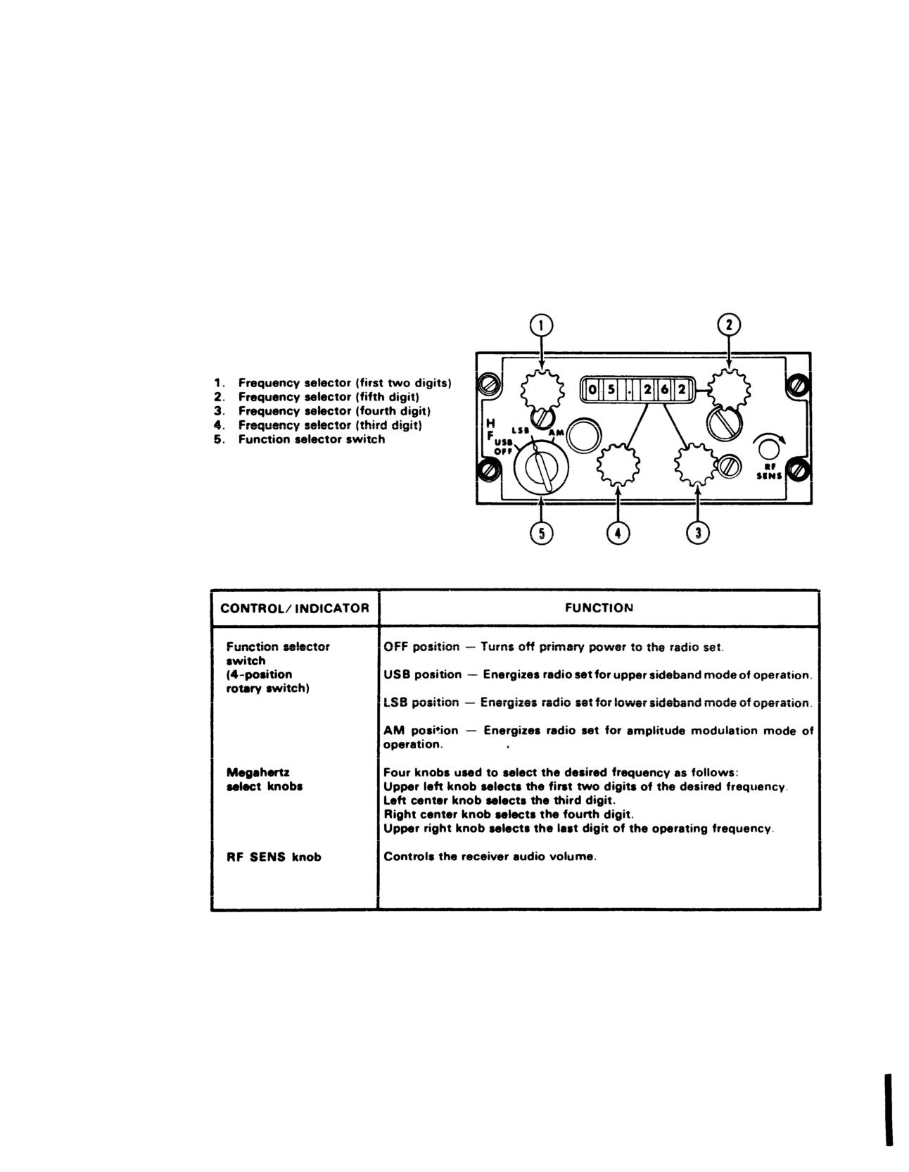
TM 55-1520-210-10
Figure 3-15. HF Radio Control Panel
Change 7
3-23
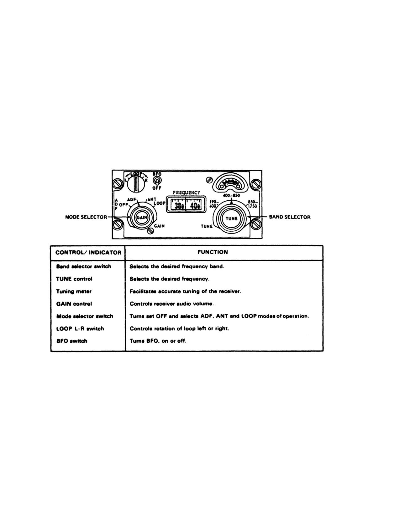
TM 55-1520-210-10
Figure
3-16. Direction Finder Control Panel ARN-83
3-24
Change 7
TM 55-1520-210-10
(2)
Manual Operation.
frequency is selected by tuning an associated
Iocalizer frequency on the control panel.
(a)
Mode selector switch-LOOP.
b. Controls and Functions. Refer to figure 3-18.
(b)
BFO switch-ON.
c. Operation.
(c) LOOP L/R switch-Press right or left and rotate
loop for null.
(1)
Function switch-PWR.
3-19. ADF Set AN/ARN-59
(2)
RECEIVERS NAV switch-ON.
a. Description. The Direction Finder Set is a radio
(3)
Frequency-Select.
compass system to provide continuous automatic
visual indication of the direction from which an in-
(4)
VOL-Adjust.
coming selected radio signal is received. It may also
3-21. VHF Navigation Set-AN/ARN-30E
be used for homing and position fixing, or as a
manually operated direction finder. The control
a. Description. The VHF Navigation Receiver Set
panel, located in the pedestal, provides control for
provides reception of 190 channels at 0.1 MHz inter-
aural reception of AM signals in the 190 to 1750 kHz
vals between 108.0 and 126.95 MHz. The VOR ILS
range.
control panel is located on the pedestal and permits
reception and interpretation of VHF omnidirectional
b. Controls and Functions. Refer to figure 3-17.
range and Iocalizer signals broadcast by ground sta-
c. Operation.
tions. Line of sight operation varies from 12 nautical
miles at 100 feet altitude to 160 nautical miles at
(1)
Automatic Operation.
20,000 feet altitude.
(a)
ADF VOL control-ON.
b. Controls and Functions. Refer to figure 3-19.
(b)
RECEIVERS NAV switch-ON.
c. Operation.
(c)
Frequency-Select.
(1) VOL-OFF switch-On and adjust.
(d)
Function switch-COMP.
(2) SQUELCH control-Counterclockwise.
(2)
Manual Operation.
(3) Frequency selectors-Select.
(a)
Function switch-LOOP.
The warning flag for the vertical pointer is an indi-
cation of signal strength and reliability. Under no cir-
(b)
BFO switch-ON.
cumstances should navigation be attempted if the
flag is visible. If the TO-FROM indicator remains
(c) LOOP switch-Press right or left and rotate
blank, do not attempt VOR navigation.
loop for null.
(4) Vertical pointer and TO-FROM indicators (fig
3-20. VHF Navigation Set AN/ARN-82
3-20)-Masked.
a. Description. The Navigation Receiver set pro-
(5) SQUELCH control-Adjust.
vides reception on 200 channels, with 50 kHz spac-
ing between 108.0 and 126.95 MHz. This permits re-
3-22.
Course Deviation Indicators ID-453 and
ception of the VHF omnidirectional range (VOR) be-
ID-1347/
tween 108.0 and 117.95 MHz. The Vocalizers are re-
ceived on odd-tenth MHz, between 108.0 and 112.0
a. Description. The Course Deviation Indicator,
MHz and energized as selected. Both VOR and
used with the VHF Navigation Receiver system, is
Iocalizer are received aurally through the interphone
installed in the instrument panel (figs 3-18 and
system. The VOR is presented visually by the course
3-19). The purpose of the indicator is to depict
indicator and the number 2 pointer on the bearing
bearing and deviation of the helicopter from the se-
indicator and the Iocalizer is presented visually by
lected station. Also, information is presented from
the vertical needle on the course deviation indicator
the FM Receiver when the mode selector switch is in
(CDI) (fig 3-20). When the R-1963/ARN Glideslope/
HOME position (figs 3-10, 3-11, 3-12, and 3-13).
Marker Beacon Receiver is installed, the glideslope
When the R-1963/ARN Marker Beacon/Glideslope
Change 7
3-25
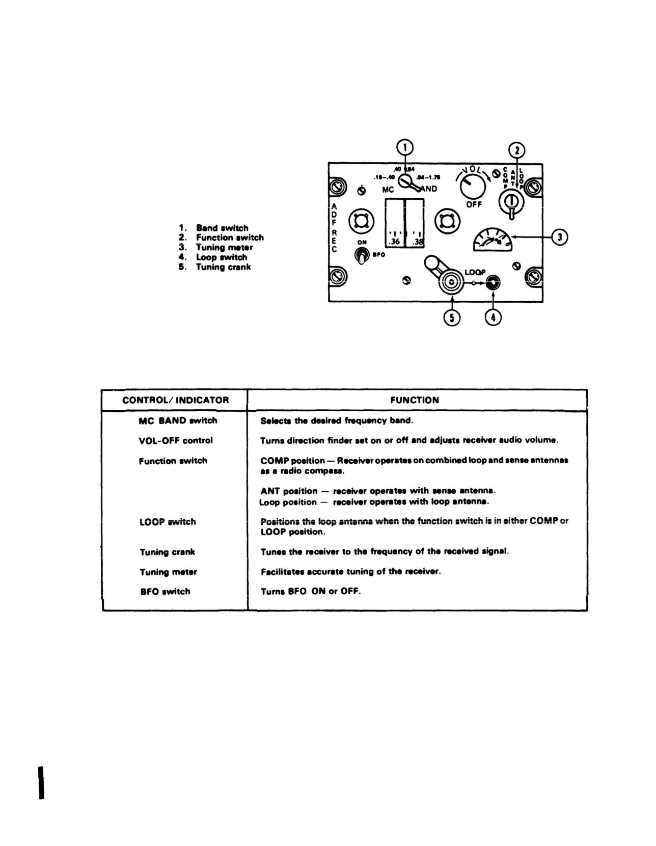
TM 55-1520-210-10
Figure
3-17. ADF Control Panel ARN-59
Change 7
3-26
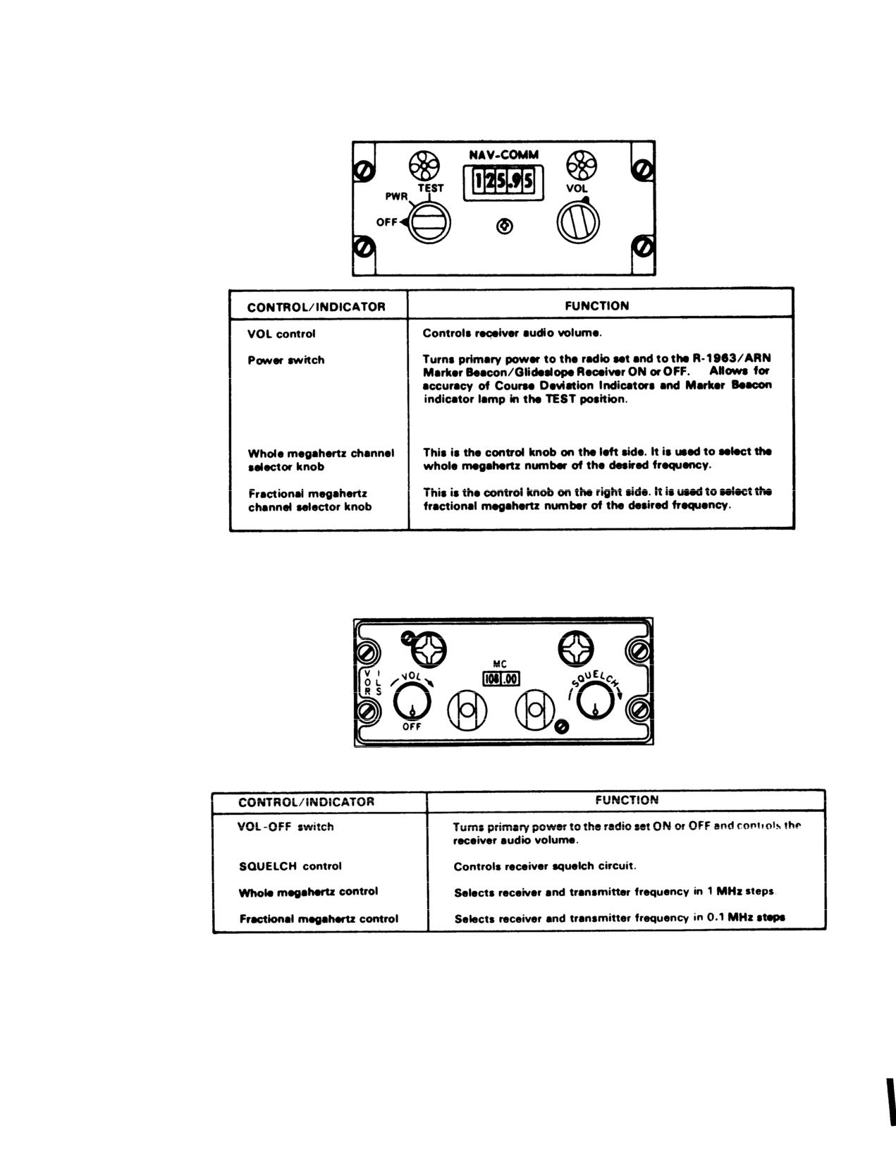
TM 55-1520-210-10
Figure
3-18. Navigation Control Panel ARN-82
Figure
3-19. VHF Navigation Receiver Control Panel ARN-30E
Change 7
3-27
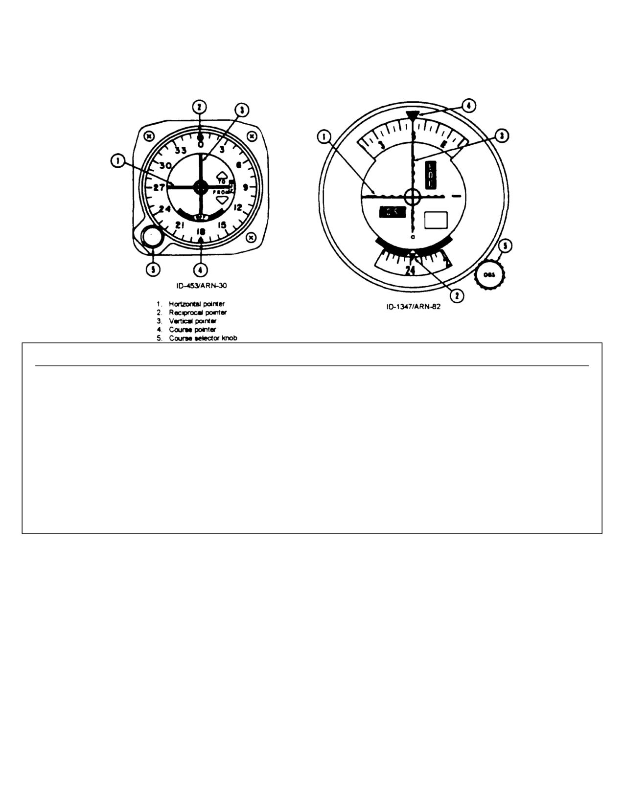
TM 55-1520-210-10
INDICATOR
FUNCTION
OFF
Disappears when FM homing circuits are functioning properly.
vertical
Remains in view when FM homing circuits are not functioning
properly.
OFF
Disappear when homing circuits are functioning properly.
horizontal Remains in view when FM homing circuits are not functioning
properly
flag
NOTE: Do not use if either OFF flag is in view.
HorizontalIndicates strength of FM homing signal being received.
pointer
Deflects downward as signal strength decreases.
Vertical
Indicates when pointer is centered that helicopter is flying directly
(reciprocal)
toward or away from the station. Deflection of the pointer indicates
pointer
the direction (right or left) to turn to fly to the station.
I
Figure 3-20. Course Deviation Indicators ID-453/ARN-30 and ID-1347/ARN-82
3-28
Change 17
TM 55-1520-210-10
Receiver is installed, data is presented by the horizontal
pointer and GS warning flag.
(b) Free gyro mode.
b. Controls and Functions. Refer to figure 3-20.
1. COMPASS switch - DG or OUT
c. Operation.
Refer to the applicable VHF
2. Synchronizing knob - Set heading.
Navigation Receiver and/or FM Radio set operating
3. Annunciator
- Center position and then
procedures.
does not change (Annunciator is de-energized in the free
3-23. Gyromagnetic Compass Set.
gyro (DG) mode).
a. Description.
(c) Inflight operation.
(1) The Gyromagnetlc Compass Set is a
1. Set the COMPASS switch to DG, OUT,
direction sensing system which provides a visual
MAG or IN as desired for magnetically slaved or free
indication of the magnetic heading (MAG) of the
gyro mode of operation. Free gyro (DG or OUT) mode is
helicopter. The information which the system supplies
recommended when flying in latitudes higher than 70
may be used for navigation and to control flight path of
degrees.
the helicopter.
2. When operated m the slaved (MAG or IN)
(2) A radio magnetic indicator is installed in the
mode, the system will remain synchronized during
pilot instrument panel.
A second radio magnetic
normal flight maneuvers. During violent maneuvers the
indicator (not shown) is installed in the copilots
system may become unsynchronized, as indicated by the
instrument panel. The copilot indicator is a repeater type
annunciator moving off center. The system will slowly
instrument similar to the pilot indicator except that it has
remove all errors in synchronization however, if fast
no control knobs. The moving compass card on both
synchronization is desired turn the synchronizing knob in
indicators displays the gyromagnetic compass heading.
the direction indicated by the annunciator until the
The number I pointer on the indicators indicate the
annunciator is centered again.
bearing to the NDB or course to the VOR station. The
3. When operating in the free gyro (DG or OUT)
number 2 pointer indicates the VOR course to station.
mode, periodically update the heading to a known
(3) The system does not have a fast-slewing’
reference by rotating the synchronizing knob.
feature. If the compass is 180° off the correct helicopter
heading when the system is energized it will take
3-24. Marker Beacon Receiver.
approximately I hour and 30 minutes (2’ per minute) for
a. Description. The Marker Beacon Receiver set Is
the compass to slave to the correct headings.
a radio aid to navigation. It receives 75 MHz marker
b. Controls and Functions. Refer to figure 3-21.
beacon signals from a ground transmitter to provide the
c. Operation.
pilot with aural and visual information. The marker
(1) INV switch - MAIN or STBY.
beacon controls and indicator are located on the
(2) Radio magnetic indicator (pilot only)
-
instrument panel to aid in determining helicopter position
Check power failure indicator is not in view.
for navigation or instrument approach.
(a) Slaved gyro mode.
b. Controls and Functions. Refer to figure 3-22.
c. Operation.
1. COMPASS switch - MAG or IN.
(1) VOLUME OFF/INCR control-ON.
2. Synchronizing knob - Center (Null) annunciatior.
(2) Receiver NAV switch (MB switch if SB-
3. Magnetic heading - Check.
329/AR panel is used) - On.
(3) Volume - adjust.
(4) SENSING HIGH/LOW switch-As desired.
d. Stopping Procedures. VOLUME OFF/INCR
control - OFF.
Change 17
3-29
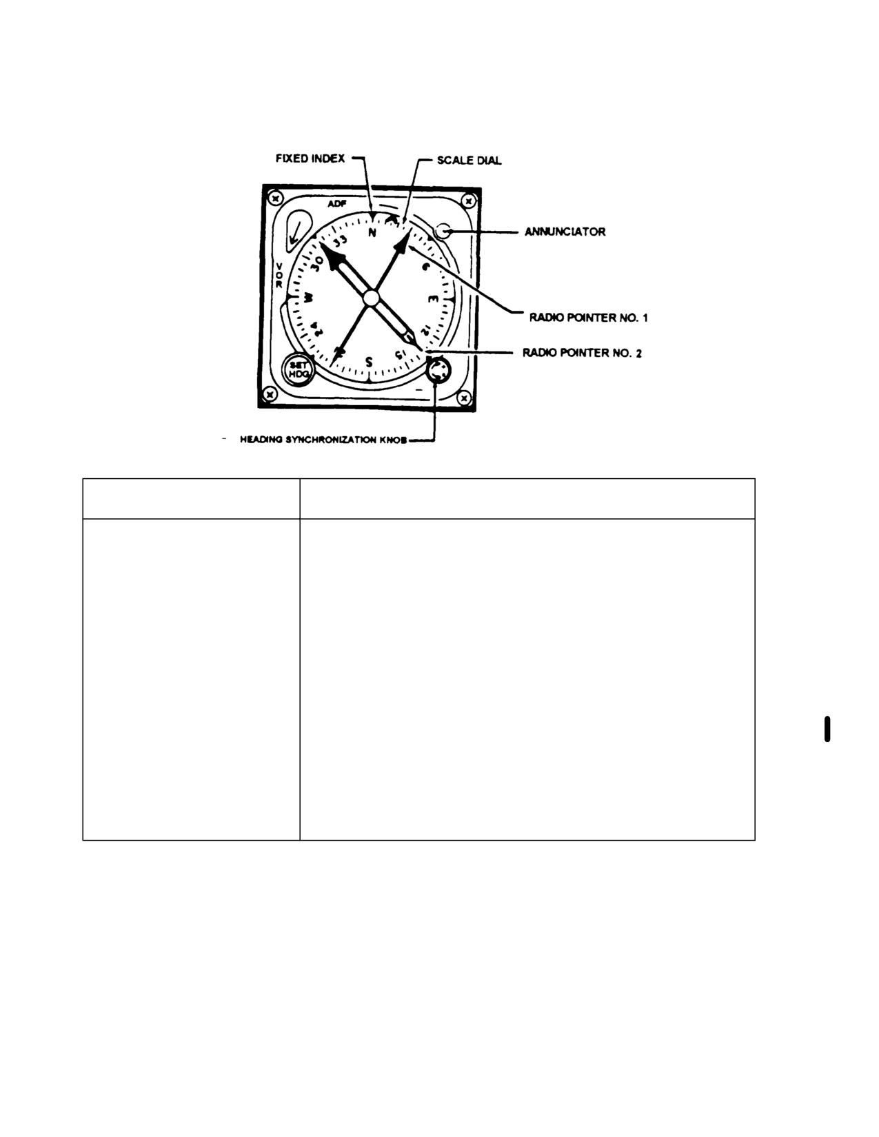
TM 55-1520-210-10
CONTROL/INDICATOR
FUNCTION
Pointer No. I
Indicates course to ADF or VOR radio station.
Pointer No. 2
Indicates course to VOR station.
Synchronizing
Is manually rotated to null annunciator and synchronize
control
compass system.
SET HDG control
Moves the heading select cursor to desired heading.
Heading select
Indicates desired heading.
cursor
ADF/VOR control
Selects ADF or VOR for pointer No. 1
Fixed index
Provides reference mark for rotating compass card.
Rotating compass
Rotates under fixed index to indicate helicopter magnetic
card
heading.
Annunciator
Show dot (0) or cross (+) to indicate misalignment
(nonsynchronization) of compass system.
Power failure indicator
Shows to indications loss of power to compass system.
(OFF) (flag)
Compass switch
MAG or IN position slaved gyro mode DG or OUT position
(located on pilots
free gyro mode.
instrument panel)
Figure 3-21. Gyromagnetic Compass Indicator (RMI)
3-30
Change 17
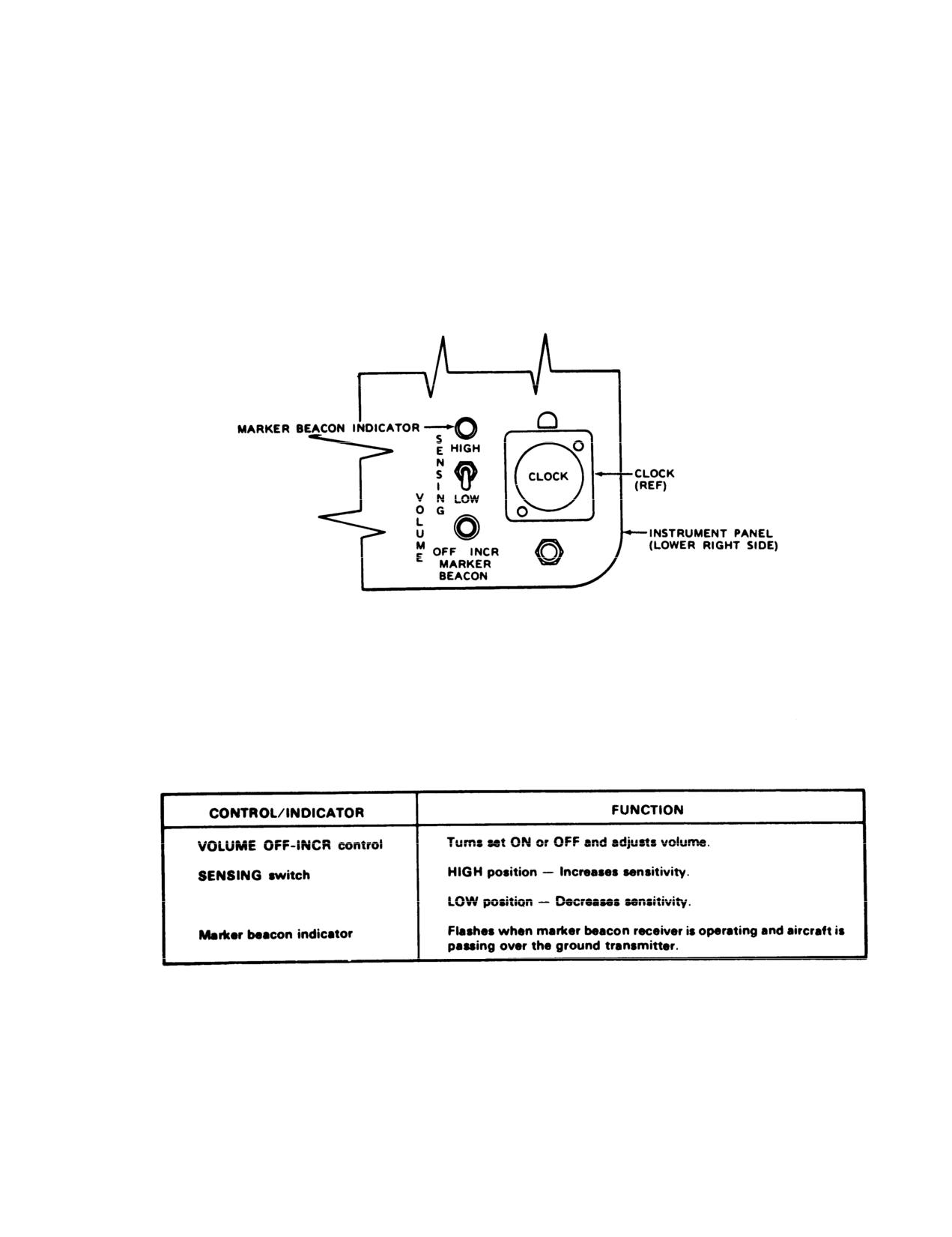
TM 55-1520-210-10
Figure
3-22. Marker Beacon Controls
Change 7
3-31
TM 55-1520-210-10
3-24.1
Distance Measuring Equipment (DME)
(IFR) for enroute, terminal, and non-precision
AN/ARN-124.
approach phases of flight.
a. Description.
GPS signals are received by the AN/ASN-175
antenna (hereinafter referred to as the GPS
The AN/ARN-124 DME consists of a receiver-
antenna) where it is amplified and sent to the
transmitter (interrogator), antenna, indicator and
AN/ASN-175 receiver (hereinafter referred to as
hold light.
receiver/display unit) for processing. The receiver/
display unit also receives aircraft signals for
The interrogator is installed in the aft left radio-
magnetic compass heading, barometric altitude,
electronics compartment. The indicator and hold
and a 26 volt ac reference. Upon processing the
light are Installed on the pilot’s instrument panel.
input signals, the receiver/display unit provides
bearing, course, and distance data which are
The Indicator displays distance In nautical miles
displayed on existing aircraft navigation equipment
from the helicopter to the DME ground station and
when selected. The required amplification for the
controls power to the interrogator. The
bearing data from the receiver/display unit is
interrogator contains 200 channels covering a
provided by the AN/ASN-175 servo amplifier
frequency range of 962 MHz through 1213 MHz.
(hereinafter referred to as the servo amplifier). The
Signals from the interrogator are responded to by
receiver/display unit also provides outputs that
a DME ground station, resulting in a readout on
activate instrument panel mounted annunciators
the indicator. DME frequency selection is
for displaying the operational status of the
controlled by
the
VOR
control
panel,
AN/ASN-175
system. In
addition,
the
C-6873B/ARN-82. VOR-DME frequencies are
receiver/display unit provides a Have-Quick timing
automatically paired. The hold light is controlled
signal to any system requiring an accurate time
by the indicator. Illumination of the hold light
base. For the GPS installation, the Have-Quick
indicates a DME frequency is in the hold mode.
timing
signal
is
used
by
the
UHF
ILS glideslope indications are not possible with the
Receiver/Transmitter in Radio Set AN/ARC-
switch in the hold position. Use of the hold mode
164(V). When operating in the P(Y) mode, the
permits a change of VOR frequency without
AN/ASN-175 calculates the aircraft’s position to
changing the DME frequency. DME station
within 16 meters. It also provides destination,
identification is accomplished by a continuous
ground speed, ground track, estimated-time-of-
1350 Hz tone In the ICS. Power to operate the
arrival (ETA), and other relevant data to the
DME is from the dc essential bus, through the
operator.
The AN/ASN-175 uses receiver
DME ARN-124 circuit breaker.
autonomous integrity monitoring (RAIM) to
determine if a set of received GPS signals is
b. Controls end Functions. Refer to figure 3-23.
sufficient to maintain the required accuracy and
alerts the operator if the available GPS signals can
not support a 3-D solution. It also can predict
3-24.2 Satellite Signals Navigation Set AN/ASN-
RAIM conditions for approach arrival times. When
175.
access time to the GPS is less than optimum, the
AN/ASN-175 uses the magnetic compass heading
a. Description. The AN/ASN-175 is a navigation
and barometric altitude data inputs from the
management system that uses data from the
aircraft to validate its calculations and to
Global Positioning System (GPS) to calculate
supplement this data from the GPS. In addition,
position, velocity, and time (PVT). It calculates
the AN/ASN-175 protects against deception and
position in three dimensions
(3-D): latitude,
denial of the PVT service from the GPS. It does so
longitude, and altitude. The AN/ASN-175 utilizes
by providing an anti-jamming capability and by
a six channel protective code (P(Y)) continuous
implementing anti-spoofing Y-code functions.
tracking, dual frequency (L1/L2) compatible
Finally,
the
AN/ASN-175
includes
a
receiver, an omnidirectional flat L1/L2 antenna
comprehensive built-in-test (BIT) function that
with an integral preamplifier, and a 3-channel
runs when power is applied to the system. BIT
synchro amplifier. The AN/ASN-175 meets the
monitors the internal operation of the system and
performance standards for instrument flight rules
3-32 Change 18
TM
55-1520-210-10
reports detected faults to the operator. Diagnostic
routines are also available to the
maintainer. Power to operate the AN/ASN-175 is
supplied from the 28 vdc essential bus through
he GPS ASN-175 circuit breaker on the pilot’s
overhead circuit breaker panel.
testing
Other components of the GPS installation include
a Remote Switch Assembly, a NO. 2 Bearing
Pointer switch, a GPS ZEROIZE switch, two Nav
select switch-indicator assemblies, two dual
display GPS annunciators, and two GPS FILL ports
(KYK and DATA). On aircraft equipped with the
AN/ARN-124 Distance Measuring Equipment
(DME) system, a DME indicator switch is also
included to allow the pilot to assign the DME
readout to either the GPS or VORTAC navigation
system. With the exception of the Remote Switch
and Servo Amplifier Assembly, these GPS
components are all located on the instrument
panel. The operation of all controls and indicators
on the receiver/display unit and the GPS controls
and indicators on the instrument panel is provided
in the controls and functions section that follows:
b. Controls and Functions. Refer to figures
3-22.1 and
3-22.2 and associated tables.
Change 18 3-32.1
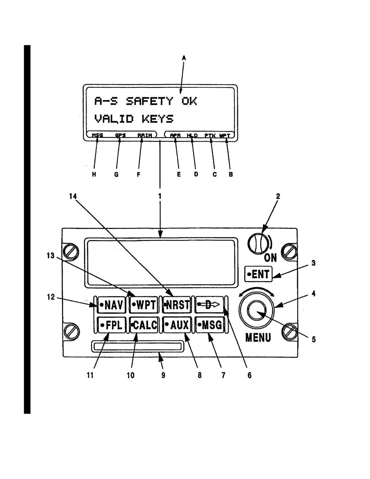
TM 55-1520-210-10
Figure 3-22.1. Receiver/Display Unit
3-32.2
Change 18
TM 55-1520-210-10
Controls and Functions of Receiver/Display Unit
CONTROL/INDICATOR
FUNCTION
1.
Display/Annunciators
Depending on operation, used to display advisory and
status information as follows:
A. Display Field
Provides two lines of high intensity light emitting diode
(LED) characters with 20 characters per line for dis-
playing information. The information displayed depends
on the operational mode and function selection.
B. Waypoint (WPT) Alert
Indicates that active waypoint is being approached.
Annunciator
The time between illumination of annunciator and
arrival at active waypoint may be selected by the
operator. The same WPT status information is
displayed on the external WPT annunciator.
C. Parallel Track (PTK)
Indicates that a track parallel to the direct course has
Annunciator
been selected. To display the selected offset, press the
MSG key.
D. Hold (HLD) Annunciator
Indicates that active flight plan has been suspended at
current active waypoint. The same HLD status infor-
mation is displayed on the external HLD annunciator.
E. Approach (APR) Annunciator
Indicates that aircraft is at or within two nautical miles
of final approach fix and that all approach require-
ments have been met. The same APR status infor-
mation is displayed on the external APR annunciator.
F. Receiver Autonomous Integrity
Indicates that AN/ASN-175 is unable to compute
Monitoring (RAIM)
RAIM. When RAIM annunciator is illuminated, the
Annunciator
AN/ASN-175 can not enable the approach mode.
G. Sensor Status (GPS)
Indicates that AN/ASN-175 is not providing a 3-D
Annunciator
solution.
H. Message (MSG) Annunciator
Indicates that one or more of the messages in the
queue is unread. When indication is steady, indicates
presence of one or more messages in the queue
requiring operator action. When indication is not
present, indicates that there are no messages in the
queue other than CDI scaling message. The same MSG
status information is displayed on the external MSG
annunciator.
2.
Power Switch
Turns power to unit on or off. Power is turned on when
switch is rotated to ON (full clockwise) position.
Change 18 3-32.3
TM
55-1520-210-10
Controls and Functions of Receiver/Display Unit (Cont)
CONTROL/INDlCATOR
FUNCTION
3. ENT (Enter) Key
Used in conjunction with MENU controls (inner and
outer selector knobs), this key enters, selects, or changes!
the information displayed. In general, the first press of
key opens an editable field on displayed page and the
second press accepts entered data.
4. MENU Control (Outer Selector
Scrolls through flight plan legs, secondary pages, and
Knob)
bottom lines of displayed mode and moves flashing
cursor between editable fields on displayed page.
5. MENU Control (Inner Selector Knob)
Scrolls through primary pages and top lines of displayed
mode and changes alphanumeric or available
option/function of any editable field.
6. D (Direct To) Key
Changes flight path. Used to fly direct-to any waypoint
in database and to activate a procedure or a flight plan.
In general, the first press of the pushbutton selects the
waypoint, procedure, or flight plan and the second
press activates course steering as selected (escape
provided by any other key).
7. MSG (Message) Key
Views system messages and displays current course
direction indicator (CDI) scaling. The MSG key will
flash until all massages have been viewed.
8. AUX (Auxiliary) Key
Accesses a variety of functions to include system
information and system status. Also used by maintainer
for testing and configuring the AN/ASN-175. Key
selection for all displayed functions is as follows:
l
Key Selection
Displayed Function
1st Press
System Status
2nd Press
Sensor Status
3rd Press
Configure
4th Press
User Setup
5th Press
Install Setup
6th Press
Checklist
9. Navigation Database Card Slot
Accepts Navigation Database Card which contains the
database for use with the AN/ASN-175.
3-32.4
Change 18
TM
55-1520-218-10
Connects and Functions of Reciever/Display Unit (Cont)
CONTROL/INDICATOR
FUNCTION
10. CALC (Calculator) Key
Accesses the capability to perform various com-
putations. Key selection for the displayed
computations is as follows:
*Key Selection
Displayed Computation
1st Press
Vertical Navigation Profile
2nd Press
flight Plan/Fuel
3rd Press
Air Data
11. FPL (Flight Plan) Key
Accesses four modes of flight planning available in the
AN/ASN-175. Key selection for the displayed modes is
as follows:
* Key Selection
Displayed Mode
1st Press
Active Flight Plan
2nd Press
Active Leg, Bearing,
Distance, and Estimated
Time Enroute
3rd Press
Stored Flight Plans
4th Press
Stored Leg, Bearing
Distance, and Estimated
Time Enroute
12. NAV (Navigation) Key
Views navigation and position information along
selected route. Key selection for the displayed
information is as follows:
*Key Selection
Displayed Information
1st Press
Primary Navigation
2nd Press
Waypoint Information
13. WPT (Waypoint) Key
Views and accesses information such as bearing and
distance, runway, name, frequencies, and position for
waypoints in the database. Key selection for the
displayed information is as follows:
*Key Selection
Displayed Information
1st Press
Mark Present Position
2nd Press
User
3rd Press
Airport
4th Press
Approach
5th Press
SID
6th Press
STAR
7th Press
VOR
8th Press
NDB
9th Press
Intersection
Change 18 3-32.5
TM
55-1520-210-10
Controls and Functions of Receiver/Display Unit (Cont)
CONTROL/INDICATOR
FUNCTION
14. NRST (Nearest) Key
Views information about the 20 nearest airports,
approaches, VHF omnidirectional receivers (VOR)
agencies, nondirectional beacons (NDB) intersections,
or user waypoints. Key selection for the displayed
information is as follows:
*Key Selection
Displayed Information
1st Press
Nearest Airport
2nd Press
Nearest Approach
3rd Press
Nearest VOR
4th Press
Nearest Agency
5th Press
Nearest NDB
6th Press
Nearest Intersection
7th Press
Nearest User WPT
* Order of display for indicated key selection is based upon when unit is first turned on.
3-32.6
Change 18
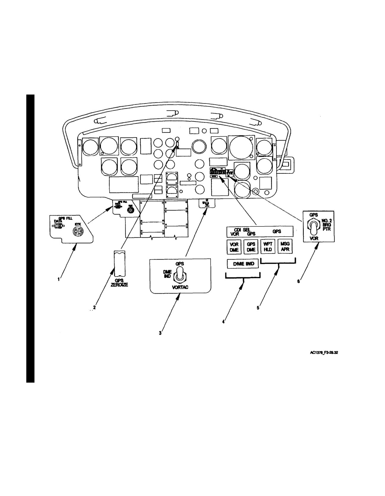
TM 55-1520-210-10
Figure 3-22.2. Instrument Panel - AN/ASN-175 System Components
Change 18 3-32.7