ARMY MODEL UH-1H/V HELICOPTERS. OPERATOR’S MANUAL (1988) - page 5
TM 55-1520-210-10
HOVER CEILING
HOVER CEILING
UH-1H
MAXIMUM TORQUE AVAILABLE (30 MINUTE OPERATION)
T53-L-13B
324 ROTOR/6600 ENGINE RPM
EXAMPLE
WANTED
GROSS WEIGHT TO HOVER
KNOWN
PRESSURE ALTITUDE = 12000 FEET
FAT = 10°C
SKID HEIGHT = 2 FEET
METHOD
ENTER PRESSURE ALTITUDE
MOVE RIGHT TO FAT
MOVE DOWN TO SKID HEIGHT
MOVE LEFT, READ GROSS WEIGHT TO HOVER
=
8900 POUNDS
DATA BASIS: AEFA PROJECT NO. 84-33, JUNE 1988
Figure 7.1-3. Hover chart (Sheet 2 of 2)
7.1-12
Change 8
TM 55-1520-210-10
Table 7.1-1
Hover Capability (Sheet 1 of 2)
Multiply all Gross Weights by 10
Change 8
7.1-13
TM 55-1520-210-10
Table 7.1-1
Hover Capability (Sheet 2 of 2)
7.1-14
Change 8
TM 55-1520-210-10
CONTROL MARGIN
TRANSLATIONAL FLIGHT
324 ROTOR/6600 ENGINE RPM
EXAMPLE
WANTED
MAXIMUM RIGHT CROSSWIND COMPONENT
WITH 10% SAFE PEDAL MARGIN
KNOWN
PRESSURE ALTITUDE = 5000 FEET
FAT = 0°C
GROSS WEIGHT = 8500 POUNDS
METHOD
ENTER PRESSURE ALTITUDE
MOVE RIGHT TO FAT
MOVE DOWN TO KNOWN GROSS WEIGHT
MOVE LEFT, READ 18.8 RIGHT CROSSWIND
COMPONENT
REFER TO CONTROL MARGIN CHART SHEET 2,
SAFE PEDAL MARGIN MAY BE LESS THAN 10%
FOR CROSSWIND COMPONENTS GREATER THAN
18.8 KNOTS IN THE SHADED AREA LABELED
DIRECTIONAL.
DATA BASIS: DERIVED FROM FLIGHT TEST DATA
Figure 7.1-4. Control margin chart (Sheet 1 of 2)
Change 8
7.1-15
TM 55-1520-210-10
CONTROL MARGIN
TRANSITIONAL FLIGHT
324 ROTOR/6600 ENGINE RPM
CONDITIONS WHERE THE CONTROL
MARGIN MAYBE LESS THAN 10%
ARE SHOWN IN SHADED AREA
DATA BASIS: DERIVED FROM FLIGHT TEST USA ASTA 68-37, JUNE 1969
Figure 7.1-4. Control margin chart (Sheet 2 of 2)
7.1-16
Change 8
TM 55-1520-210-10
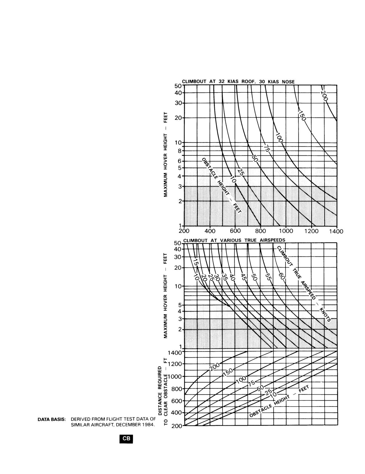
TAKEOFF
LEVEL ACCELERATION, 3 FT SKID HEIGHT
324 ROTOR/6600 ENGINE RPM
MAXIMUM TORQUE AVAILABLE
CALM WIND LEVEL SURFACE ALL CONFIGURATIONS
EXAMPLE A
WANTED
DISTANCE TO CLEAR OBSTACLE
KNOWN
MAXIMUM HOVER HEIGHT
=
10 FEET
OBSTACLE HEIGHT = 50 FEET
METHOD
ENTER MAXIMUM HOVER HEIGHT
MOVE RIGHT TO OBSTACLE HEIGHT
MOVE DOWN, READ DlSTANCE TO CLEAR 50 FOOT
OBSTACLE = 700 FEE i_
EXAMPLE B
WANTED
DISTANCE TO CLEAR OBSTACLE
KNOWN
MAXIMUM HOVER HEIGHT = 8 FEET
OBSTACLE HEIGHT = 50 FEET
CLIMBOUT AIRSPEED
=
40 KNOTS
METHOD
ENTER MAXIMUM HOVER HEIGHT
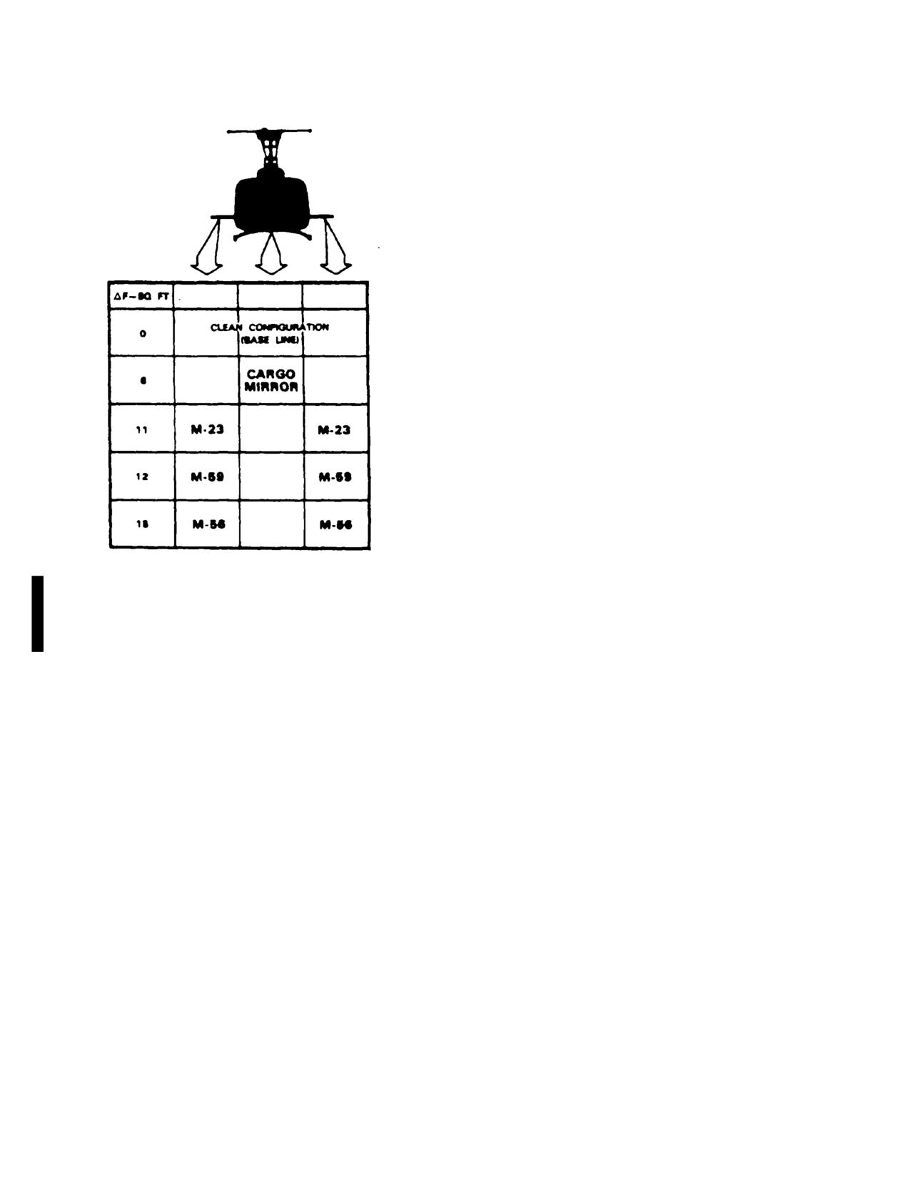
MOVE RIGHT TO CLIMB0UT TRUE AIRSPEED
MOVE DOWN TO OBSTACLE HEIGHT
MOVE LEFT, READ DISTANCE TO CLEAR
50 FOOT
OBSTACLE =
630 FEET
Figure 7.1-5. Takeoff chart (Sheet 1 of 3)
Change 8
7.1-17
TM 55-1520-210-10
TAKEOFF
CLIMB AND ACCELERATION, 3 FT SKID HEIGHT
324 ROTOR/6600 ENGINE RPM
MAXIMUM TORQUE AVAILABLE
EXAMPLE A
WANTED
DISTANCE TO CLEAR OBSTACLE
KNOWN
MAXIMUM HOVER HEIGHT
=
17 FEET
OBSTACLE HEIGHT = 120 FEE-T
METHOD
ENTER MAXIMUM HOVER HEIGHT
MOVE RIGHT TO OBSTACLE HEIGHT
MOVE DOWN, READ DISTANCE TO CLEAR
120
FOOT OBSTACLE = 1420 FEET
EXAMPLE B
WANTED
DlSTANCE TO CLEAR OBSTACLE
MAXIMUM HOVER HEIGHT
=
17 FEET
OBSTACLE HEIGHT
=
120 FEET
CLIMBOUT AIRSPEED
=
50 KNOTS
METHOD
ENTER MAXIMUM HOVER HEIGHT
MOVE RIGHT TO CLIMBOUT AIRSPEED
MOVE DOWN TO OBSTACLE HEIGHT
MOVE LEFT, READ DISTANCE TO CLEAR 120 FOOT
OBSTACLE
=
1610 FEET
DATA BASIS: DERIVED FROM FLIGHT TEST DATA OF SIMILAR AIRCRAFT, DECEMBER 1984.
Figure 7.1-5. Takeoff chart (Sheet 2 of 3)
7.1-18
Change 8
TM 55-1520-210-10
TAKEOFF
LEVEL ACCELERATION, 15 FT SKID HEIGHT
324 ROTOR/6600 ENGINE RPM
MAXIMUM TORQUE AVAILABLE
CALM WIND
LEVEL SURFACE ALL CONFIGURATIONS
EXAMPLE A
WANTED
DISTANCE TO CLEAR OBSTACLE
KNOWN
MAXIMUM HOVER HEIGHT 17 FEET
OBSTACLE HEIGHT = 120 FEET
METHOD
ENTER MAXIMUM HOVER HEIGHT
MOVE RIGHT TO OBSTACLE HEIGHT
MOVE DOWN, READ DISTANCE TO CLEAR 120
FOOT OBSTACLE = 1125 FEET
EXAMPLE B
WANTED
DISTANCE TO CLEAR OBSTACLE
KNOWN
MAXIMUM HOVER HEIGHT = 17 FEET
OBSTACLE HEIGHT = 120 FEET
CLIMBOUT AIRSPEED = 40 KNOTS
METHOD
ENTER MAXIMUM HOVER HEIGHT
MOVE RIGHT TO CLIMBOUT TRUE AIRSPEED
MOVE DOWN TO OBSTACLE HEIGHT
MOVE LEFT, READ DISTANCE TO CLEAR 120 FOOT
OBSTACLE = 1000 FEET
DATA BASIS: DERlVED FROM FLIGHT TEST DATA OF SIMILAR AIRCRAFT, DECEMBER 1984.
Figure 7.1-5. Takeoff chart (Sheet 3 of 3)
Change 8
7.1-19
TM 55-1520-210-10
Figure 7.1-6. Cruise chart (Sheet 1 of
23)
7.1-20
Change 8
TM 55-1520-210-10
Figure 7.1-6. Cruise chart (Sheet 2 of 23)
Change 8
7.1-21
TM 55-1520-210-10
EXAMPLE
WANTED
CALIBRATED TORQUE
REQUIRED FOR LEVEL FLIGHT, FUEL FLOW,
INDICATED AIRSPEED
KNOWN
CLEAN CONFIGURATION
GROSS WEIGHT = 9500 POUNDS
PRESSURE ALTITUDE = 5000 FEET
FAT = - 30°C
DESIRED TRUE AIRSPEED = 100 KNOTS
ROOF MOUNTED PITOT TUBE SYSTEM
METHOD
LOCATE CHARTS FOR ALTITUDE AND/OR FREE AIR TEMPERATURES
ABOVE AND BELOW KNOWN CONDITIONS. ENTER EACH CHART AT 100
KNOTS TRUE AIRSPEED AND READ INDICATED AIRSPEED. MOVE
LATERALLY BACK TO INTERSECT 9500 POUNDS GROSS WEIGHT
CURVE, THEN PROJECT VERTICALLY TO READ CALIBRATED TORQUE
AND FUEL FLOW ON EACH CHART. INTERPOLATE BETWEEN RESULTS
DERIVED FROM CHARTS TO OBTAIN VALUES FOR KNOWN CONDITIONS
AS FOLLOWS:
7.1-22
Change 8
TM 55-1520-210-10
7-8. General Conditions. In addition to the specific
which data are not provided, thereby increasing the
conditions, the following general conditions are
accuracy of performance predictions.
applicable to the performance data.
7-10. Definitions of Abbreviations.
a. Rigging. All airframe and engine controls are
assumed to be rigged within allowable tolerances.
a Unless otherwise indicated abbreviations and
symbols used in this manual conform to those
b. Pilot Technique.
Normal pilot technique is
established in Military Standard MIL-ST12, which is
assumed. Control movements should be smooth and
periodically revised to reflect current changes in
continuous.
abbreviations usage.
c. Helicopter Variation. Variation in performance
between individual helicopters are known to exist;
b. Capitalization and punctuation of abbreviations
however, they are considered to be small and cannot be
varies, depending upon the context m which they are
individually accounted for.
used. In general, lower case abbreviations are used in
text material, whereas abbreviations used in charts and
d. Instrument Variation. The data shown in the
illustrations appears in full capital letters. Periods do not
performance charts do not account for instrument
usually follow abbreviations; however, periods are used
inaccuracies or malfunctions.
with abbreviations that could be mistaken for whole
words if the period were omitted.
e. Types of Fuel. All flight performance data is
based on IP4 fuel. The change in fuel flow and torque
7-11. Temperature Conversion. The temperature
available, when using JP-5, JP-8, aviation gasoline or
conversion chart Figure 7-1 is arranged so that degrees
any other approved fuels, is insignificant.
Celsius can be converted quickly and easily by reading
Celsius and looking directly across the charts for
7-9. Performance Discrepancies. Regular use of this
Fahrenheit equivalence and vice versa.
chapter will allow you to monitor instruments and other
helicopter systems for malfunction, by comparing actual
performance with planned performance. Knowledge will
also be gained concerning the effects of variable for
Section II TORQUE AVAILABLE
7-12. Description. The torque available charts show
or from the engine acceptance records, is the indicated
the effects of altitude and temperature on engine torque.
torque pressure at 1125 ft-lbs actual output shaft torque,
and is used to correct the error of individual engine
7-13. Chart Differences. Both pressure altitude and
torque indicating system.
FAT affect engine power production. Figure 7-2 shows
power available data at 30 minute power ratings in terms
NOTE
of the allowable torque as recorded by the torquemeter
Torque available values determined
(psi). Note that the power output capability of the T53-L-
are not limits. Any torque which can
13 engine can exceed the transmission structural limit
be achieved, without exceeding
(50 psi calibrated) under certain conditions.
engine, transmission, or other limits,
may be used
a. Figure 7-2 is applicable for maximum power, 30
minute operation at 324 rotor/6600 engine rpm.
7-15. Conditions. Chart (Figure 7-2) is based upon
speeds of 324 rotor/6600 engine rpm grade J-4 fuel.
b. If the IR Scoup Suppressor is installed, subtract
The use of aviation gasoline will not influence engine
one psi from the torque values obtained from Figure 7-2.
power. All torque available are presented for bleed air
heater and device off. Decrease power available 1.4 psi
7-14. Use of Chart The primary use of the chart is
for heater on and 2.1 psi for device on; decrease torque
illustrated by the examples. In general, to determine the
available 3.5 psi if both bleed air heater and device are
maximum power available, it is necessary to know the
operating.
pressure altitude and temperature. The calibration factor
(Data Plate Torque), obtained from the engine data plate
Change 17
7-3
TM 55-1520-210-10
Section III HOVER
7-16. Description. The hover charts (Figure 7-3,
7-19. Conditions
Sheets I and 2) shows the hover ceiling and the torque
required to hover respectively at various pressure
a. The hover charts are based upon calm wind
altitudes, ambient temperatures, gross weights, and skid
conditions, a level ground surface, and the use of 324
heights. Maximum skid height for hover can also be
rotor rpm.
obtained by using the torque available from Figure 7-2.
b. Use of control margin charts Is to determine If
7-17. Use of Chart. The primary use of the hover
adequate control margin will be available for IGE and
charts is illustrated by the charts examples. In general,
OGE hover in winds or low speed translation.
to determine the hover ceiling or the torque required to
hover, it is necessary to know the pressure altitude,
c. The hover charts do not account for the effect of
temperature, gross weight and the desired skid height.
an IR suppressor device. The hover ceiling chart (Figure
In addition to Its primary use, the hover chart (Sheet 2)
7-3, Sheet 1) is not usable if a suppressor device is
can also be used to determine the predicted maximum
installed. The IR Scoup Suppressor creates a download
hover height, which is needed for use of the takeoff chart
of approximately 140 pounds.
(Figure 7-5).
d. For the IR Scoup Suppressor
7-18. Control Margin.
(1) To determine hover torque required, enter
a. Sheet 1 of the control margin charts (Figure 7-4)
the hover power required chart (Figure 7-3, Sheet 2) at a
shows the maximum right crosswind which one can
gross weight of 140 pounds heavier than the actual
achieve and still maintain directional control as a function
gross weight.
of pressure altitude, temperature, and gross weight.
Sheet 2 of the control margin chart (Figure 7-4) shows
(2) To determine predicted maximum hover
the combinations of relative wind velocity and azimuth
height, first subtract one psi from power available (Figure
which may result in marginal directional or longitudinal
7-2); then increase the hover gross weight by
140
control.
pounds. Use this power available and gross weight m
the hover power required chart (Figure 7-3, Sheet 2).
b. Use of the control margin charts is Illustrated by
example on Sheet 1. Ten percent of total control travel
(3) To determine maximum gross weight, first
(full right to full left) is considered adequate margin when
subtract one psi from power available (Figure 7-2), then
hovering. The shaded area on Sheet
1 indicates
decrease the hover gross weight determined from the
conditions where the directional control margin may be
hover power required chart (Figure 7-3, Sheet 2) by 140
less than ten percent m zero wind hover. The shaded
pounds.
area on sheet
2 labeled DIRECTIONAL indicates
conditions where the directional control margin may be
e. With the rotor blade erosion protection coating
less than ten percent for crosswind components in
and polyurethane tape installed, it will be necessary to
excess of those determined from Sheet 1. The shaded
make the following corrections. Add 1 psi to the hover
area on sheet 2 labeled LONGITUDINAL indicates wind
torque required, for OGE and IGE, as determined from
conditions where longitudinal control may be less than 10
Figure 7-3 (Sheet 2). In Figure 7-3 (Sheet 1). subtract
percent. These charts are based on control margin only.
100 pounds from the maximum gross weight to hover
When determining maximum hover wheel height, enter
the chart at the gross weight plus 100 pounds.
Change 17
7-4
TM 55-1520-210-10
Section IV. TAKEOFF
7-20. Description. The takeoff chart (Figure 7-5)
7-21. Use of Charts. The primary use of these charts is
shows the distances to clear various obstacle heights,
illustrated by the charts examples.
The main
based upon several hover height capabilities. The upper
consideration for takeoff performance is the hovering
chart grid presents data for climbout at a constant
skid height capability, which includes the effects of
INDICATED airspeed. The two lower grids present data
pressure altitude, free air temperature, gross weight, and
for climbouts at various TRUE airspeeds. Figure 7-5,
torque. Hover height capability is determined by use of
sheet 1, is based upon level acceleration technique,
the hover chart, Figure 7-3. A hover check can be made
sheet 2 is based upon a climb and acceleration from a 3
to verify the hover capability. If winds are present, the
foot skid height and sheet 3 is based upon a level
hover check may disclose that the helicopter can actually
acceleration from-a 15 foot skid height.
hover at a greater skid height than the calculated value,
since the hover chart is based upon calm wind
NOTE
conditions.
The hover heights shown on the
chart are only a measure of the
7-22. Conditions.
aircraft’s climb capability and do not
imply that a higher than normal hover
a. Wind. The takeoff chart is based upon calm
height should be used during the
wind conditions. Since surface wind velocity and
direction cannot be accurately predicted, all takeoff
actual takeoff.
planning should be based upon calm wind conditions.
Takeoff into any prevailing wind will improve the takeoff
performance.
b. Power Settings. All takeoff performance data
are based upon the torque used m determining the hover
capabilities in Figure 7-3.
Change 17
7-4.1/(7-4.2 blank)
TM 55-1520-210-10
Section V. CRUISE
7-23.
Description. The cruise charts (Figure 7-6
and PSI torque pressure. For conservatism, use the
sheets 1 through 24) show the torque pressure and
gross weight at the beginning of cruise flight. For greater
engine rpm required for level flight at various pressure
accuracy on long flights It is preferable to determine
altitudes airspeeds gross weights and fuel flows.
cruise information for several flight segments in order to
allow for decreasing fuel weights (reduced gross weight).
NOTE
Estimated performance data is presented for hover
The cruise charts are basically
(KTAS-O) in Figure 7-6, however, the hover performance
arranged by FAT groupings. Figure
data presented in figure 7-3 is more accurate and should
7-6, sheets 1 through 24 are based
be used in planning critical hover performance. The
following parameters contained in each chart are further
upon
operation
with
clean
explained as follows:
configuration.
Each chart has a
dashed line that represents a ten
a. Airspeed. True and indicated airspeeds are
square foot equivalent flat plate
presented at opposite sides of each chart. On any chart,
drag area This allows quick
indicated airspeed can be directly converted to true
determination of Delta PSI for other
airspeed (or vice versa) by reading directly across the
than clean configurations.
chart without regard for other chart information.
Maximum permissible airspeed (VNE) limits appear on
7-24. Use of Charts.
some charts. If no line appears VNE is above the limits
of the chart.
Cruise flight is restricted to 319 to
b. Torque Pressure (PSI). Since pressure altitude
324 Cruise flight is restricted to 319
and temperature are fixed for each chart torque
to
324 Rotor RPM
(6500 to
6600
pressures vary according to gross weight, airspeed and
Engine RPM.).
Cruise at
324
bleed air on or off. See paragraph 7-15 for effect of
Rotor/6600
Engine
RPM
is
bleed air heater and device.
recommended. The cruise chart data
for true airspeeds above 40 KTAS is
NOTE
based on
314 Rotor/6400 Engine
Torque available values determined are
RPM. Until the cruise charts are
not limits. Any torque which can be
revised performance planning shall
achieved without exceeding engine
be
accomplished
using
the
transmission or other limits may be
procedures and torque corrections
used.
from Table 7-1. These restrictions do
not apply when composite main rotor
c. Fuel Flow. Fuel flow scales are provided opposite the
blades (CB) are installed.
torque pressure scales. On any chart, torque pressure
may be converted directly to fuel flow without regard for
The primary use of the charts is illustrated by the
other chart information. All fuel flows are presented for
bleed air heater and device off. Add two percent fuel
examples provided in Figure 7-6. The first step for chart
use is to select the proper chart, based upon the planned
flow (about 14 lb/hr) for heater on and increase fuel flow
three percent (approximately 21 lb/hr) for device on. If
drags configuration, pressure altitude and anticipated
free air temperature; refer to Chapter 7 index (paragraph
both are operating, add five percent fuel flow (about 35
7-2). Normally, sufficient accuracy can be obtained by
lb/hr) to chart values.
selecting the chart nearest to the planned cruising
altitude and FAT, or the next higher altitude and FAT. If
d. Maximum Range. The maximum range lines indicate
the combinations of weight and airspeed that will
greater accuracy is required, interpolation between
altitudes and/or temperatures will be required. You may
produce the greatest flight range per gallon of fuel under
enter the charts on any side: TAS, IAS, torque pressure,
zero wind conditions. When a maximum range condition
or fuel flow, and then move vertically or horizontally to
does not appear on a chart it is because the maximum
the gross weight, then to the other three parameters.
range speed is beyond the maximum permissible speed
(VNE); m such cases, use VNE cruising speed to obtain
Maximum performance conditions are determined by
entering the chart where the maximum range or
maximum range.
maximum endurance and rate of climb lines intersect the
appropriate gross weight; then read airspeed, fuel flow
Change 17
7-5
TM 55-1520-210-10
e. Maximum Endurance and Rate of Climb. The
7-25. Conditions. The cruise charts are based upon
maximum endurance and rate of climb lines indicate the
operations at 324 rotor / 6600 engine rpm below 40
airspeed for minimum torque pressure required to
KTAS and 314 rotor/6400 engine rpm for true airspeeds
maintain level flight for each gross weight FAT and
above 40 knots. With the rotor blade erosion protection
pressure altitude. Since minimum torque pressure will
coating and polyurethane tape installed, add 2 psi to the
provide minimum fuel flow maximum flight endurance will
torque required obtained from Figure 7-6.
be obtained at the airspeeds indicated.
Section VI. DRAG
7-26. Description. The drag chart (Figure 7-7, Sheet 1
temperature. Enter at the known drag area change,
of
2) shows the authorized configuration or the
move right to TAS move down to pressure altitude move
equivalent flat plate drag area changes for additional
left to FAT then move down and read change in torque.
aircraft modifications. There is no increase in drag with
In addition, by entering the chart in the opposite direction,
cargo doors fully open. The upper left portion of Figure
drag area change may be found from a known torque
7-7 (Sheet 2 of 2) presents drag areas of typical external
change. This chart is used to adjust cruise charts for
loads as a function of the load frontal area. The balance
appropriate torque and fuel flow due to equivalent flat
of the charts shows the additional torque required in level
plate drag area change (AF).
For frontal areas
flight due to the increase in drag caused by external
exceeding values shown on Figure 7-7 (Sheet 2 of 2)
loads, aircraft modifications or authorized configurations.
use a smaller value and multiply (e.g 36 sq. ft. 9 sq ft. x
The IR Scoup Suppressor has a drag of two square feet.
4).
7-27. Use of Chart. The primary use of the chart is
7-28. Conditions. The drag chart is based upon 314
illustrated by the example. To determine the change in
rotor/6400 engine rpm.
torque it is necessary to know the drag area change the
true airspeed the pressure altitude and the free air
Section VII. CL MB-DESCENT
7-29. Description.
b. By entering the bottom of the grid with a known_
torque change, moving upward to the gross weight, and
The climb descent chart (Figure 7-8) shows the
left to the corresponding rate of climb or descent may
change in torque (above or below torque required for
also be obtained.
level flight under the same gross weight and atmospheric
conditions) to obtain a given rate of climb or descent.
7-31. Conditions.
7-30. Use of Chart.
Climb-Descent The climb-descent chart is based
on the use of constant rotor or engine rpm. The rate of
Climb-Descent The primary uses of the chart are
climb (descent) presented is for steady state conditions
illustrated by the chart examples.
and rpm bleed could increase (decrease) the rate of
climb (descent) shown.
a. The torque change obtained from the grid scale
must be added to the torque required for level flight (for
climb) or subtracted from the torque required for level
flight (for descent)-obtained from the appropriate cruise
chart in order to obtain a total climb or descent torque.
Change 17
7-6
TM 55-1520-210-10
Section VIII. FUEL FLOW
7-32.
Description
b. Fuel flow will increase about two percent with
the bleed air heater on and three percent with deice
a. The fuel flow chart (fig 7-9) shows the fuel flow
on. When both systems are on, increase fuel flow
at engine idle and 324 rotor/6600 engine rpm with
five percent. Also a range or endurance penalty
flat pitch.
should be accounted for when working cruise chart
data. A fairly accurate rule-of-thumb to correct fuel
b. Fuel flow vs torque, shows fuel flow in pound-
flow for temperatures other than
0oC FAT is to in-
per-hour versus torquemeter psi for pressure
crease (decrease) fuel flow 1 percent for each 10oC
altitudes from sea level to 14000 feet and for 0°C
increase (decrease) in FAT.
free air temperature.
7-34. Conditions
7-33. Use of Chart
These charts are based upon the use of JP-4 fuel. The
a. The primary use of the idle fuel flow chart is il-
change in fuel flow when using other jet fuels is in-
lustrated by the example. To determine the idle fuel
significant.
flow, it is necessary to know the idle condition,
pressure altitude, and free air temperature. Enter at
the pressure altitude, move right to FAT in ap-
propriate grid, then move down and read fuel flow
on the scale corresponding to the condition. Refer to
the cruise charts to obtain fuel flow for cruise power
conditions.
Change 2
7-7
TM 55-1520-210-10
Table
7-1 Torque Correction (Sheet
1 of
4)
To determine cruise performance data for 324 Rotor/6600 Engine
RPM at speeds above 40 KTAS, follow the instructions in paragraph
7-24 except:
a.
Add appropriate torque correction from this table to the
calibrated torque required values determined from the intersection
of the airspeed and gross weight lines on the upper (6400 Engine
RPM) portion of the cruise chart.
b. Determine fuel flow corresponding to the corrected torque
required from the lower (6600 Engine RPM) portion of the cruise
chart.
c.
Determine continuous torque available (CONT TRQ AVAIL) and
30 minute torque available (30 MIN TRQ AVAIL) from the lower
(6600 Engine RPM) portion of the cruise chart.
EXAMPLE
WANTED
Speed for Maximum Range
Calibrate Torque Required and Fuel Flow at Maximum Range
KNOWN
324 Rotor/6600 Engine RPM
Clean Configuration
FAT = -30°C
Pressure Altitude = 8000 feet
Gross Weight = 8500 pounds
Roof Mounted System
METHOD
Locate (-30°C FAT, 8000 Feet) Chart (figure 7-6 Sheet 3 of
24)
Find Intersection of 8500 LB Gr Wt Line With the Max Range Line
To
Read Speed for Maximum Range:
Move Right, Read TAS = 105.3 Knot
Move Left, Read IAS = 102.3
To
Read Calibrated Torque Required @ 314 Rotor/6400 Engine RPM
Move Down, Read Torque = 41.2 PSI
To
Correct Torque Required for 6600 Engine RPM
From Table for Sheet 3 (8000 Ft -30°C) @ 8500 Lb Gross Weight
For 90 KTAS, Torque Correction = 3.5 PSI
For 110 KTAS, Torque Correction = 5.7 PSI
Interpolate for 105.3 KTAS
Torque Correction = 5.2 PSI
Corrected Torque Required = 41.2 PSI + 5.2 PSI = 46.4 PSI
To Determine Fuel Flow
Enter Figure
7-6, Sheet 3 of 24 At 46.4 PSI Torque:
Move Down Read Fuel Flow = 614 Lb/Hr
7-8
TM 55-1520-210-10
TABLE 7-1 TORQUE CORRECTION
(Sheet 2 of
4)
TORQUE CORRECTION - PSI
(-30°C FAT)
SHEET 1
SHEET 2
SHEET 3
SHEET 4
GW-LB
KTAS
SL
2000
4000
6000
8000
10000
12000
14000
5500
50
NA
NA
NA
2.4
2.2
2.1
1.9
1.8
70
NA
NA
NA
2.8
2.6
2.4
2.2
2.2
90
NA
NA
NA
3.5
3.4
3.2
3.0
2.9
110
NA
NA
NA
5.9
5.5
5.2
4.9
4.5
6500
50
3.0
2.8
2.6
2.4
2.2
2.2
2.1
1.9
70
3.3
3.2
3.1
2.9
2.6
2.5
2.4
2.3
90
4.3
4.1
3.9
3.7
3.5
3.4
2.9
2.9
110
7.3
6.9
6.4
6.1
5.6
5.3
4.5
4.6
7500
50
3.1
2.9
2.6
2.5
2.3
2.3
1.7
1.4
70
3.5
3.3
3.0
3.0
2.8
2.7
2.2
2.2
90
4.5
4.3
4.1
3.9
3.4
3.3
2.9
2.7
110
7.4
7.0
6.5
6.2
5.3
5.3
4.7
4.7
8500
50
3.0
2.9
2.7
2.6
2.3
1.8
1.1
0.8
70
3.5
3.4
3.3
3.1
2.8
2.6
1.8
1.1
90
4.6
4.4
4.0
3.7
3.5
3.2
1.9
0.8
110
7.5
7.1
6.4
6.0
5.7
5.5
2.6
0.6
9500
50
3.1
3.0
2.9
2.1
1.7
1.1
0.1
-1.8
70
3.8
3.5
3.4
2.8
2.8
1.9
-0.6
-2.3
90
4.9
4.2
4.2
3.5
3.5
2.0
-2.4
-1.5
110
7.7
6.6
6.7
6.0
5.9
2.5
-4.8
1.4
[-15°C FAT]
SHEET 5
SHEET 6
SHEET 7
SHEET 8
GW-LB
KTAS
SL
2000
4000
6000
8000
10000
12000
14000
5500
50
NA
NA
1.3
1.2
1.1
1.0
1.0
1.0
70
NA
NA
1.9
1.7
1.7
1.5
1.5
1.3
90
NA
NA
2.6
2.5
2.3
2.2
2.1
1.9
110
NA
NA
3.0
2.9
2.6
2.4
2.3
2.0
6500
50
1.5
1.4
1.3
1.2
1.1
1.1
1.0
0.5
70
2.2
2.1
1.9
1.7
1.7
1.6
1.5
1.3
90
3.0
2.9
2.7
2.5
2.4
2.2
2.1
1.8
110
3.5
3.3
3.1
2.8
2.7
2.3
2.2
1.8
7500
50
1.6
1.4
1.3
1.3
1.2
0.7
0.7
0.3
70
2.2
2.0
2.0
1.9
1.8
1.6
1.6
0.6
90
3.2
2.9
2.8
2.6
2.4
2.1
2.0
0.9
110
3.6
3.3
3.2
2.7
2.5
2.2
2.1
-0.5
8500
50
1.6
1.5
1.4
1.1
0.7
0.5
0.5
-0.9
70
2.3
2.2
2.1
1.9
1.7
1.2
0.8
-1.4
90
3.3
3.1
2.8
2.6
2.2
1.6
1.3
-3.2
110
3.6
3.3
2.8
2.7
2.3
0.8
-0.2
-7.5
9500
50
1.6
1.4
0.8
0.9
0.4
-0.1
-0.8
-7.5
70
2.3
2.3
2.0
2.0
0.8
-0.2
-1.2
-6.6
90
3.2
3.1
2.6
2.6
1.2
-0.8
-2.9
-6.8
110
3.2
3.1
2.7
2.7
-0.7
-3.8
-7.2
-6.9
7-9
TM 55-1520-210-10
TABLE 7-1 TORQUE CORRECTION
(Sheet 3 of
4)
TORQUE CORRECTION - PSI
[O°C FAT]
SHEET 9
SHEET 10
SHEET 11
SHEET 12
GW-LB
KTAS
SL
2000
4000
6000
8000
10000
12000
14000
5500
50
NA
NA
1.1
1.1
1.0
0.9
0.9
0.8
70
NA
NA
1.2
1.1
1.1
1.0
0.9
0.8
9 0
NA
NA
1.4
1.3
1.2
1.1
1.1
1.0
110
NA
NA
2.5
2.3
2.1
2.0
1.9
1.6
6500
50
1.4
1.3
1.1
1.2
1.1
0.9
0.7
0.6
70
1.4
1.3
1.2
1.2
1.1
0.9
0.8
0.8
90
1.6
1.5
1.4
1.4
1.2
1.2
0.9
0.9
110
2.9
2.7
2.5
2.4
2.1
2.0
1.8
1.6
7500
50
1.3
1.3
1.2
1.1
0.9
0.7
0.4
0.4
70
1.4
1.4
1.3
1.1
1.0
0.8
0.2
0.0
90
1.6
1.6
1.4
1.3
1.2
0.9
0.3
0.0
110
3.0
2.7
2.5
2.3
2.1
1.9
0.5
-0.1
8500
50
1.4
1.3
1.1
0.7
0.7
0.4
-0.5
-3.0
70
1.5
1.3
1.2
0.9
0.8
0.1
-1.5
-3.8
90
1.7
1.5
1.5
1.0
0.8
0.1
-3.8
-5.9
110
3.0
2.5
2.5
2.1
1.8
0.0
-4.9
-8.8
9500
50
1.3
1.0
0.8
0.5
0.4
-0.8
-6.9
NA
70
1.4
1.2
1.1
0.3
0.0
-2.0
-7.3
NA
90
1.6
1.3
1.2
0.3
-0.3
-5.3
-8.5
NA
110
2.8
2.6
2.4
0.4
-0.4
-6.3
-15.4
NA
(15°C FAT)
SHEET 13
SHEET 14
SHEET 15
SHEET 16
GW-LB
KTAS
SL
2000
4000
6000
8000
10000
12000
14000
5500
50
NA
0.7
0.7
0.6
0.6
0.7
0.6
0.5
70
NA
0.9
0.9
0.8
0.7
0.7
0.6
0.5
90
NA
1.0
1.1
0.9
0.9
0.8
0.8
0.7
110
NA
0.9
0.9
0.9
0.8
0.8
0.8
0.8
6500
50
0.8
0.7
0.7
0.8
0.7
0.6
0.4
0.2
70
1.0
1.0
0.9
0.9
0.6
0.5
0.4
0.1
90
1.2
1.1
1.0
0.9
0.9
0.8
0.6
0.3
110
1.1
1.0
1.0
0.9
0.8
0.8
0.6
-0.3
7500
50
0.9
0.9
0.8
0.7
0.4
0.4
0.1
-1.0
70
1.1
1.0
0.7
0.7
0.5
0.2
-0.2
-1.7
90
1.2
1.1
1.0
1.0
0.6
0.5
-0.1
-4.2
110
1.1
1.0
0.9
1.1
0.7
0.1
-1.2
-6.7
8500
50
0.9
0.8
0.6
0.5
0.0
-0.5
-1.3
-7.3
70
0.9
0.8
0.6
0.5
-0.3
-0.9
-2.0
-7.1
90
1.1
1.2
0.8
0.8
-0.1
-2.0
-5.0
-7.9
110
1.0
1.1
0.8
0.8
-1.5
-4.0
-8.2
-19.6
9500
50
0.8
0.6
0.4
0.0
-1.4
-4.9
NA
NA
70
0.7
0.6
0.2
-0.2
-2.2
-5.2
NA
NA
90
1.2
0.8
0.4
0.0
-5.4
-7.3
NA
NA
110
1.2
0.9
-0.2
-1.5
-8.7
-15.2
NA
NA
7-10
TM 55-1520-210-10
TABLE 7-1 TORQUE CORRECTION
(Sheet 4 of
4)
TORQUE CORRECTION - PSI
[30°CFAT]
SHEET 17
SHEET 18
SHEET 19
SHEET 20
GW-LB
KTAS
SL
2000
4000
6000
8000
10000
12000
14000
5500
50
0.5
0.5
0.5
0.5
0.6
0.5
0.5
0.3
70
0.8
0.7
0.7
0.6
0.6
0.5
0.3
0.3
90
0.5
0.5
0.4
0.3
0.3
0.2
0.3
0.1
110
0.8
0.8
0.8
0.7
0.7
0.7
0.7
0.6
6500
50
0.6
0.6
0.7
0.5
0.5
0.3
0.4
0.0
70
0.7
0.7
0.6
0.5
0.4
0.4
0.3
-0.2
90
0.6
0.4
0.3
0.3
0.4
0.1
0.1
-0.6
110
1.0
0.9
0.8
0.8
1.0
0.6
0.5
-0.9
7500
50
0.9
0.7
0.6
0.5
0.4
-0.1
-0.6
-1.6
70
0.8
0.5
0.5
0.4
0.3
-0.3
-0.9
-2.0
90
0.3
0.3
0.4
0.1
0.2
-0.7
-2.7
-5.1
110
0.9
1.0
1.0
0.8
0.7
-1.1
-2.8
-7.4
8500
50
0.7
0.6
0.5
0.1
0.0
-1.6
-6.3
NA
70
0.5
0.4
0.4
0.0
-0.1
-2.1
-6.0
NA
90
0.4
0.3
0.2
-0.4
-0.7
-5.7
-7.9
NA
110
1.2
1.0
0.7
-0.6
-1.1
-8.0
-16.3
NA
9500
50
0.5
0.5
-0.1
-1.0
-2.2
-8.3
NA
NA
70
0.4
0.5
-0.3
-1.3
-2.7
-7.7
NA
NA
90
0.1
0.2
-0.8
-3.9
-6.6
-9.3
NA
NA
-1.3
110
0.8
0.8
-5.4
-9.7
-21.5
NA
NA
[45°C FAT]
SHEET 21
SHEET 22
SHEET 23
SHEET 24
GW-LB
KTAS
SL
2000
4000
6000
8000
10000
12000
14000
5500
50
0.5
0.5
0.5
0.6
0.5
0.4
0.3
0.2
70
0.4
0.5
0.4
0.3
0.3
0.1
0.2
0.1
90
0.5
0.5
0.3
0.2
0.2
0.3
0.3
0.1
110
0.3
0.3
0.3
0.3
0.4
0.4
0.3
0.0
6500
50
0.6
0.6
0.5
0.4
0.3
0.2
-0.1
-0.3
70
0.5
0.4
0.3
0.2
0.2
0.1
-0.3
-0.6
90
0.3
0.2
0.2
0.4
0.3
0.1
-0.4
-1.3
110
0.3
0.4
0.4
0.4
0.3
0.0
-1.1
-2.5
7500
50
0.6
0.4
0.4
0.3
0.0
-0.1
-1.5
-5.9
70
0.3
0.2
0.3
0.2
-0.2
-0.2
-2.1
-5.7
90
0.3
0.4
0.4
0.1
-0.4
-0.6
-5.0
-6.9
110
0.4
0.5
0.3
0.0
-0.9
-1.5
-7.9
-14.7
8500
50
0.5
0.3
0.2
-0.2
-1.4
-3.6
7.2
NA
70
0.3
0.2
0.1
-0.3
-1.9
-3.9
8.0
NA
90
0.5
0.1
0.0
-0.8
-4.4
-6.4
11.0
NA
110
0.6
0.0
-0.3
-1.8
-7.2
-11.7
NA
NA
9500
50
0.4
-0.1
-0.4
-1.9
-7.7
NA
NA
NA
70
0.2
-0.4
-0.6
-2.6
-7.5
NA
NA
NA
90
0.3
-0.7
-1.4
-6.3
-8.8
NA
NA
NA
110
0.1
-1.6
-2.8
-10.0
-18.8
NA
NA
NA
7-11
TM 55-1520-210-10
TEMPERATURE CONVERSION CHART
Figure 7-1. Temperature Conversion Chart
7-12
TM
55-1520-210-10
MAXIMUM TORQUE AVAILABLE (30 MINUTE OPERATION)
ANTI-ICE OFF
BLEED AIR HEATER OFF
324 ROTOR/66OO ENGINE RPM
EXAMPLE
W A N T E D
INDICATED TORQUE
CALIBRATED TORQUE
K N O W N
PRESSURE ALTITUDE = 10,000 FT.
OAT=15°C
CALIBRATION FACTOR =66.0
M E T H O D
ENTER FAT
MOVE RIGHT TO PRESSURE
ALTITUDE
MOVE DOWN TO CALIBRATION
FACTOR
MOVE LEFT, READ INDICATED
TORQUE =39 PSI
FOR CALIBRATED TORQUE CONTINUE
DOWN THRU CALIBRATION FACTOR,
READ CALIBRATED TORQUE = 36.0 PSI
CALIBRATED TORQUE - PSI
DATA BASIS:
CALCULATED FROM T53-L-13B ENGINE PROGRAM 19.28.25.03 CORRECTED FOR INSTALLATION
LOSSES BASED ON FLIGHT TEST, ASTA 66-04, NOVEMBER 1970. AND LOSS DUE TO
PARTICLE SEPARATOR
Figure
7-2. Maximum Torque Available
(30 Minute Operation) Chart
7-13
TM 55-1520-210-10
HOVER CEILING
MAXIMUM TORQUE AVAILABLE (30 MINUTE OPERATION)
324 ROTOR/6600 ENGINE RPM
EXAMPLE
WANTED
GROSS WEIGHT TO HOVER
KNOWN
PRESSURE ALTITUDE = 10600 FEET
FAT = 10°C
SKID HEIGHT = 2 FEET
METHOD
ENTER PRESSURE ALTITUDE
MOVE RIGHT TO FAT
MOVE DOWN TO SKID HEIGHT
MOVE LEFT, READ GROSS WEIGHT
TO HOVER = 8500 POUNDS
CORRECTION TABLE
TORQUE CORRECTION PSI *
CALIBRATED TORQUE-PSI
FAT
20
30
40
50
0°C
.2
.3
.4
.5
-20°C
.4
.6
.8
1.0
-40°C
1.4
2.1
2.8
3.5
-50°C
2.4
3.6
4.8
6.0
-60°C
4.0
6.0
8.0
10.0
*When operating at or below
0°C increase the
calibrated torque determined from sheet
2 by the
amount shown in the table to determine torque
required. See example on sheet
2.
DATA BASIS: DERIVED FROM YUH-1H FLIGHT
TEST, ASTA-TDR
66-04 NOVEMBER
1970
Figure
7-3. Hover (Ceiling) Chart (Sheet 1 of
2)
7-14 Change
5
TM 55-1520-210-10
HOVER POWER REQUIRED
LEVEL SURFACE CALM WIND
324 ROTOR/6600 ENGINE RPM
EXAMPLE
WANTED
TORQUE REQUIRED TO HOVER
KNOWN
PRESSURE ALTITUDE = 2000 FEET
FAT = -40°C
GROSS WEIGHT = 8500 LB
DESIRED SKID HEIGHT = 2 FEET
METHOD
ENTER PRESSURE ALTITUDE
MOVE RIGHT TO FAT
MOVE DOWN TO GROSS WEIGHT
MOVE LEFT TO SKID HEIGHT
MOVE DOWN, READ CALIBRATED
TORQUE = 31.5 PSI
FROM THE TABLE FOR FAT
= -40°C AND 31.5 PSI TORQUE
DETERMINE TORQUE CORRECTION OF
2.2 PSI
TORQUE REQUIRED TO HOVER IS
31.5 +2.2 = 33.7 PSI
Figure 7-3. Hover (Power Required) Chart (Sheet 2 of
2)
Change 5
7-15
TM 55-1520-210-10
CONTROL MARGIN
TRANSITIONAL FLIGHT 324 ROTOR/6600 ENGINE RPM
20000
15000
EXAMPLE
10000
WANTED
MAXIMUM RIGHT CROSSWIND
COMPONENT WITH 10%
SAFE PEDAL MARGIN
5000
KNOWN
PRESSURE ALTITUDE
=
5000 FEET
FAT
=
0°C
GROSS WEIGHT = 8500 POUNDS
0
METHOD
ENTER PRESSURE ALTITUDE
MOVE RIGHT TO FAT
-5000
MOVE DOWN TO KNOWN GROSS WEIGHT
MOVE LEFT AND READ
18.8
RIGHT CROSSWIND COMPONENT
30
REFER TO SHEET 2. SAFE PEDAL MARGIN
MAY BE LESS THAN 10% FOR CROSSWIND
COMPONENTS GREATER THAN 18.8 KNOTS
IN THE SHADED AREA LABELED DIRECTIONAL
20
10
0
DATA BASIS: DERIVED FROM FLIGHT TEST
Figure 7-4. Control margin (Sheet 1 of 2)
7-16
TM 55-1520-210-10
DRAG
EXAMPLE A
WANTED
CHANGE IN TORQUE REQUIRED DUE TO
EQUIVALENT FLAT PLATE DRAG AREA
CHANGE (AF) FROM CLEAN (BASELINE)
CONFIGURATION TO AN M-56 SUBSYSTEM
CONFIGURATION
AF DRAG AREA CHANGE - 15 SQ. FT.
TRUE AIRSPEED - 120 KNOTS
PRESSURE ALITITUDE - SEA LEVEL
FAT - O ° C
METHOD
ENTER DRAG AREA CHANGE
MOVE RIGHT TO TRUE AIRSPEED
MOVE DOWN TO PRESSURE ALTITUDE
MOVE LEFT TO FREE AIR TEMPERATURE
MOVE DOWN. READ CHANGE IN
TORQUE - 122 PSI
EXAMPLE B
WANTED
NOTE
INCREASE IN DRAG AREA DUE TO
The IR Scoup Suppressor has a drag
EXTERNAL CARGO
of two square feet
KNOWN
SHAPE OF EXTERNAL LOAD - CYLINDER
FRONTAL AREA OF EXTERNAL LOAD - 6.8
SQ. FT.
METHOD
ENTER CHART AT SYMBOL FOR CYLINDER
MOVE DOWN TO 6.8 SQ. FT.
MOVE RIGHT AND READ INCREASED DRAG
AREA - 4.0 SQ. FT.
Figure 7-7. Drag Chart (Sheet 1 of 2)
Change 17 7-48
TM 55-1520-210-10
TORQUE CHANGE - PSI
DATA BASIS: CALCULATED DATA
Figure 7-7. Drag Chart (Sheet 2 of
2)
7-49
TM 55-1520-210-10
C L I M B - D E S C E N T
314 ROTOR/6400 ENGINE RPM
3200
3000
2800
2600
2400
2200
2000
EXAMPLE
WANTED
1800
CALIBRATED TORQUE CHANGE
FOR DESIRED R/C OR R/D
1600
KNOWN
GROSS WEIGHT = 6000 LB
DESIRED R/C = 1200 FT/MIN
1400
METHOD
ENTER R/C
1200
MOVE RIGHT TO GROSS WEIGHT
MOVE DOWN, READ CALIBRATED
TORQUE CHANGE = 12.5 PSI
1000’
800
600
400<
0
5
10
1-5
20
25
30
35
CALIBRATED TORQUE CHANGE - PSI
DATA BASIS: DERIVED FROM FLIGHT TEST FTC-TDR 62-21,
DECEMBER 1962, AND CALCULATED DATA.
Figure
7-8 Climb-Descent Chart
7-50
TM 55-1520-210-10
FUEL FLOW
JP-4 FUEL
EXAMPLE B
WANTED
FUEL FLOW AT ENGINE IDLE AND
AT 324 ROTOR/6600 ENGINE RPM
WITH FLAT PITCH
KNOWN
PRESSURE ALTITUDE = 11000 FEET,
FAT = 0°
METHOD
ENTER PRESSURE ALTITUDE
MOVE RIGHT TO (ENGINE IDLE) FAT
MOVE DOWN, READ ENGINE IDLE
FUEL FLOW= 223 LB/HR
REENTER PRESSURE ALTITUDE
MOVE RIGHT TO (FLAT PITCH) FAT
MOVE DOWN, READ FLAT PITCH
FUEL FLOW = 265 LB/HR
DATA BASIS: CALCULATED FROM MODEL SPEC 104.33, SEPTEMBER 1964; CORRECTED FOR INSTALLATION LOSSES
BASED ON FLIGHT TEST FTC-TDR 64-27, NOVEMBER 1964
Figure
7-9. Idle Fuel Flow Chart
ALL DATA ON PAGE 7-52 INCLUDING FIGURE 7-9 (SHEET 2) DELETED.
Change 2
7-51/(7-52 blank)
TM 55-1520-210-10
Chapter 8
Normal Procedures
Section 1. MISSION PLANNING
8-1. Mission Planning. Mission planning begins when
prescribed in Chapter
5 OPERATING LIMITS AND
the mission is assigned and extends to the preflight
RESTRICTIONS.
check of the helicopter. It includes but is not limited to
checks of operating limits and restrictions; weight
8-4.
Performance.
Refer to chapter
7 or 7.1
balance and loading; performance; publication; flight plan
PERFORMANCE DATA to determine the capability of
and crew and passenger briefings. The pilot in
the helicopter for the entire mission. Consideration shall
command shall ensure compliance with the contents of
be given to changes in performance resulting from
this manual that are applicable to the mission.
variation in loads temperatures and pressure altitudes.
Record the data on the Performance Planning Card for
8-2.
Operating Limits and Restrictions.
The
use in completing the flight plan and for reference
minimum maximum normal and cautionary operational
throughout the mission.
ranges represent careful aerodynamic and structural
calculation substantiated by flight test data.
These
8-5. Crew and Passenger Briefings. A crew
limitations shall be adhered to during all phases of the
briefing shall be conducted to ensure a thorough
mission. Refer to chapter 5 OPERATING LIMITS AND
understanding of individual and team responsibilities.
RESTRICTIONS for detailed information.
The briefing should include but not be limited to copilot
crew chief mission equipment operator, and ground crew
8-3. Weight Balance and Loading. The helicopter
responsibilities and the coordination necessary to
shall be loaded cargo and passengers secured and
complete the mission In the most efficient manner. A
weight and balance verified in accordance with
review of visual signals Is desirable when ground guides
chapter 6 WEIGHT BALANCE AND LOADING. This
do not have direct voice communications link with the
helicopter requires a weight and balance clearance in
crew.
accordance with AR 95-1. The helicopter weight and
center-of-gravity conditions shall be within the limits
Section 11. CREW DUTIES
86. Crew Duties.
e. Passenger Briefing. The following is an outline
that should be used in accomplishing required passenger
a. Responsibilities. The minimum crew required to
briefings. Items that do not pertain to a specific mission
fly the helicopter is a pilot. Additional crewmembers as
may be omitted.
required may be added at the discretion of the
commander. The manner in which each crewmember
(1) Crew Introduction.
performs his related duties is the responsibility of the
pilot in command.
(2) Equipment.
b. Pilot. The pilot in command is responsible for all
(a) Personal to include ID tags.
aspects of mission planning preflight and operation of the
helicopter. He will assign duties and functions to all
other crewmembers as required. Prior to or during
(b) Professional.
preflight the pilot will brief the crew on the mission
performance data procedures taxi and load operations.
(c) Survival.
c. Copilot (when assigned). The copilot must be
familiar with the pilots duties and the duties of the other
(3) Flight Data.
crew positions.
The copilot will assist the pilot as
directed.
(a) Route.
d. Crew Chief (when assigned). The crew chief will
perform all duties as assigned by the pilot.
Change 17
8-1
TM 55-1520-210-10
(b) Altitude.
(i)
Refueling.
(c) Time enroute.
(j)
Weapons.
(d) Weather.
(k)
Protective masks.
(4) Normal Procedures.
(l)
Parachutes.
(a) Entry and exit of helicopter.
(m) Ear protection.
(b) Seating.
(n)
ALSE.
(c)
Seat belts.
(5) Emergency procedures.
(d)
Movement m helicopter.
(a)
Emergency exits.
(e)
Internal communications.
(b)
Emergency equipment.
(f)
Security of equipment.
(c)
Emergency landing/ditching procedures.
(g)
Smoking.
8-7. Danger Areas. Refer to Figure -1.
(h) Oxygen.
Section III. OPERATING PREDURES AND MANEUVERS
8-8. Operating Procedures and Maneuvers. This
covered in Section Vl, ADVERSE ENVIRONMENTAL
section deals with normal procedures and includes all
CONDITIONS.
steps necessary to ensure safe and efficient operating of
the helicopter from the time a preflight begins until the
8-10. Checklist. Normal procedures are given primarily
flight is completed and the helicopter is parked and
in checklist form and amplified as necessary in
secured. Unique feel, characteristics and reaction of the
accompanying paragraph form when a detailed
helicopter during various phases of operation and the
description of a procedure or maneuver is required. A
techniques and procedures used for taxiing, takeoff,
condensed version of the amplified checklist omitting all
climb, etc., are described including precautions to be
explanatory text is contained in the Operator’s Checklist
observed.
Your flying experience is recognized;
TM 55-1520210-CL. To provide for easier cross-
therefore basic flight principles are avoided. Only the
referencing the procedural steps in CL are numbered to
duties of the minimum crew necessary for the actual
coincide with the corresponding numbered steps in this
operation of the helicopter are included
manual.
8-9. Additional Crew. Additional crew duties are
8-11. Checks. The checklist may include items for day,
covered as necessary in Section II, CREW DUTlES.
night, and instrument flight with annotative indicators
Mission equipment checks are contained in Chapter 4,
immediately preceding the check to which they are
MISSION EQUIPMENT. Procedures specifically related
pertinent; N for night operation only; I for instrument
to instrument flight that are different from normal
operations only; and 0 to indicate a requirement if the
procedures are covered in this section following normal
equipment is installed When a helicopter is flown on a
procedures. Descriptions of functions operations and
mission requiring intermediate stops it is not necessary
effects of controls are covered in Section V, FLIGHT
to perform all of the normal checks. The steps that are
CHARACTERISTICS and a repeated in this section only
C essential for safe helicopter operations on intermediate
when required for emphasis. Checks that must be
stops are designated as "thru-flight" checks. An asterisk
performed under adverse environmental conditions such
(*) indicates that performance of steps is mandatory for
as desert and cold weather operations supplement
all "thru-flights". The asterisk (-) applies only to checks
normal procedure checks in this section and are
performed prior to takeoff..
Change 17
8-2
TM 55-1520-210-10
a.
Cabin top - Check windshields, wipers, FAT
WARNING
probe, WSPS, for condition.
Do not preflight until armament
systems are safe.
b.
Radio compartment - Check security of all
equipment. Check battery, If installed. Secure door.
812. Before Exterior Checks.
c.
Antennas - Check condition and security.
*
1. Covers, locking devices, tiedowns, and cables
Removed, except aft main rotor tiedown.
O
d.
Pitot tube
-
Check security and
unobstructed.
2. Publications - Check in accordance with DA
PAM
738-751 and locally required forms and
e.
Cabin lower area
- Check condition of
publications.
windshield, antennas, WSPS and fuselage. Check for
loose objects inside winch might Jam controls.
3. AC circuit breakers - IN.
O
f.
Cargo suspension mirror - Check security
4.
BAT switch ON. Check battery voltage. A
and cover installed. Uncover and adjust if cargo
minimum of 24 volts should be indicated on the DC
operations are anticipated.
voltmeter for a battery start.
8-15. Area 2.
5.
Lights--ON. Check landing, search, anti-
collision, position, interior lights and NVG lighting as
1. Fuselage - Check as follows:
required for condition and operation as required; position
O
a.
Static port - Check unobstructed.
landing and search lights as desired; then OFF.
b. Copilot seat, seat belt and shoulder harness
*
6. Fuel - Check quantity. Caps secure.
- Check condition and security; secure belt and harness
if seat is not used during flight.
7.
Fuel sample Check for contamination
c.
Copilot door
-
Check condition and
before first flight of the day. If the fuel sumps, and filter
security.
have not been drained by maintenance personnel, dram
a sample as follows:
d.
Cabin doors - Check condition and security.
a. Sumps - Drain sample and check.
c.
Landing gear
- Check condition and
b. MAIN FUEL switch - ON.
security; ground handling wheels removed.
c.
Filter - Dram sample and check.
O
d.
Auxiliary fuel tanks - Drain sample and
f.
Radio and electrical compartments - Check
check
condition, circuit breakers m and components secure.
e. MAIN FUEL switch - OFF.
Secure access doors.
O
8.
Cargo hook Check as required, if use is
O* g. Armament systems -Check weapon(s) safe.
anticipated, refer to Chapter 4, MISSION EQUIPMENT,
Check condition and security.Refer to Chapter
4,
for checks of the system.
MISSION EQUIPMENT, for checks of the system.
9. BAT switch - OFF.
2. Engine compartment - Check fluid lines and
connections for condition and security. Check general
10.Flight Controls - Check freedom of movement of
condition. Cowling secure
cyclic and collective; center cyclic, collective down.
816.
Area 3.
8-13. Exterior Check. (Fig 8-2).
1. Tailboom - Check as follows:
a
Skin - Check condition.
8-14. Area 1.
b.
Driveshaft cover - Check secure.
c.
Synchronized elevator - Check condition
*
1. Main rotor blade - Check condition.
and security.
d. Antennas - Check condition and security.
2. Fuselage - Check as follows:
e. Tail skid - Check condition and security.
Change 16
8-
TM 55-1520-210-10
*
2. Tail rotor Check condition and free movement on
8-19.
Area 6.
flapping axis. The tail rotor blades should be checked as
the main rotor blade is rotated. Visually check all
*
I.
Man rotor system
- Check condition and
components for security.
security; check level of fluid in dampers, blade grips, and
pillow blocks.
*
3. Main rotor blade - Check condition, rotate in
normal direction
90 degrees to fuselage, tiedown
2. Transmission area - Check as follows:
removed.
a.
Transmission and hydraulic filler caps
-
8-17.
Area 4.
Secure.
b.
Main driveshaft
- Check condition and
*
1. Tail rotor gearboxes (90 and 42 degrees) -
security.
Check general condition, oil levels, filler caps secure.
c.
Engme air intake - Check unobstructed.
d.
Engine and transmission cowling - Check
2. Tailboom - Check as follows;
condition and security.
e.
Antennas - Check condition and security.
a.
Skin - Check condition.
b.
Antennas - Check condition and security.
0
f. Pitot static tube - Check security and unob-
c.
Synchronized elevator - Check condition
structed.
and security
8-2t
Interior Check - Cabin.
3. Engine exhaust/smoke generator
- Check
condition. Refer to Chapter 4, MISSION EQUIPMENT,
*
1. Transmission oil level - Check.
for systems check.
*
2. Cabin area - Check as follows:
4. Oil cooling fan and heater compartments
-
Check condition of fan, flight control and cables, tail rotor
O
a
Cargo
- Check as required for proper
servo for leaks and security and battery if installed;
loading and security.
check for installation of structural support; check
tailboom attachment bolts; check heater for condition
b.
Loose equipment
- Stow rotor blade
and security if installed; check area clear of obstructions;
tiedown, pitot tube cover, tailpipe cover and other
secure doors.
equipment.
8-18.
Area 5.
O
c.
Mission equipment - Check condition and
security. Refer to Chapter 4, MISSION EQUIPMENT, for
*
1. Engine compartment - Check fluid lines and
equipment checks.
connections for condition and security. Check fluid
levels and general condition; cowling secure.
d.
Passenger seats and belts
- Check
condition and security.
2. Hydraulic fluid sight gage - Check.
e.
First aid kits - Check secure.
3. Fuselage - Check as follows:
O
f.
Fire extinguisher - Check secure.
O*
a.
Armament systems - Check weapon(s)
safe. Check condition and security. Refer to Chapter-4,
*
3. Crew and passenger briefing - Complete as
MISSION EQUIPMENT, for systems check.
required
b.
Cabin doors - Check condition and security.
c.
Landing gear
- Check condition and
8-21.
Before Starting Engine.
security; ground handling wheels removed.
O
d.
Static port -Check unobstructed.
1. Overhead switches and circuit breakers - Set as
e.
Pilot door -Check condition and security.
follows:
f.
Pilot seat, seat belt and shoulder harness -
Check condition and security.
0
a. Smoke generator operating switch -
Check
condition and security. Refer to Chapter 4, MISSION
0
g.
Fire extinguisher
-
Check secure.
EQUIPMENT, for systems check.
8-4
Change 16
TM 55-1520-210-10
b. DC circuit breakers-in, except for armament
0 c. DISP CONTROL panel-Check ARM/STBY/
and special equipment.
SAFE switch is SAFE; check that JETTISON switch is
down and covered.
O c. DOME LT switch-As required.
d. GOV switch-AUTO.
d. PITOT HTR switch-OFF.
e. DE-ICE switch-OFF.
*e. EXT LTS switches-Set as follows:
✩ f. FUEL switches-Set as follows:
(1) ANTI COLL switch-ON.
(1) MAIN FUEL switch-ON.
(2) POSITION lights switches-As required:
O (2) START FUEL switch-ON.
STEADY or FLASH for night; OFF for day.
(3) All other switches-OFF.
f. MISC switches-Set as follows:
g. CAUTION panel lights-TEST and RESET.
(1) CARGO REL switch-OFF.
h. HYD CONT switch-ON.
(2) WIPERS switch-OFF.
i. FORCE TRIM switch-ON.
g. CABIN HEATING switches-OFF.
j. CHIP DET switch-BOTH.
h. INST LTG switches-As required.
8. Flight controls-Check freedom of movement
I. AC POWER switches-Set as follows:
through full travel: center cyclic and pedals; collec-
tive pitch full down.
(1) PHASE switch-AC.
9. Altimeters-Set to field elevation.
(2) INVTR switch-OFF.
✩ 8-22. Starting Engine
j. DC POWER switches-Set as follows:
1. Fireguard-Posted if avaliable.
(1) MAIN GEN switch-ON and cover down.
2. Rotor blades-Check clear and untied.
(2) VM selector-ESS BUS.
3. Ignition key lock switch-On.
(3) NON-ESS BUS switch-As required.
4. Throttle-Set for start. Position the throttle as
near as possible (on decrease side) to the engine
(4) STARTER GEN switch-START.
idle stop.
✩ (5) BAT switch-ON.
5. Engine-Start as follows:
a. Start switch-Press and hold; start time. Note
✩ 2. Ground power unit-Connect for GPU start.
DC voltmeter indication. Battery starts can be made
O 3. Smoke gage-Check.
when voltages less than 24 volts are indicated, pro-
vided the voltage is not below 14 volts when crank-
4. FIRE warning indicator light-Test.
ing through 10 percent N1 speed.
5. Press to test caution/warning lights-Check as
b. Main rotor-Check that the main rotor is turning
required.
as N1 reaches 15 percent. If the rotor is not turning,
abort the start.
6. Systems instruments-Check engine and trans-
O c. START FUEL switch-OFF at 40 percent N1.
mission systems for static indications, slippage
marks, and ranges.
d. Start switch-Release at 40 percent N1 or after
40 seconds, whichever occurs first. Refer to chapter
7. Center pedestal switches-Set as follows:
5 for starter limitations.
a. Avionics equipment-Off; set as desired.
e. Throttle-Slowly advance past the engine idle
stop to the engine idle position. Manually check the
b. External stores jettison handle-Check safetied.
engine idle stop by attempting to close the throttle.
8-5
TM 55-1520-210-10
f.
N168 to
72 percent. Hold a very slight
7. Health Indicator Test (HIT) Check Perform as required.
pressure against the engine idle stop during the check. A
Refer to HIT/EGT Log in helicopter log book. Normal HIT
slight rise in N1 may be anticipated after releasing pressure on
Check not required if utilizing in-flight HIT checks unless
throttle.
engine maintenance has taken place since last return flight.
8-24. Deleted.
8-25. Deleted.
The copilot attitude indicator should be
8-26. Deleted.
caged and held momentarily as inverter
power is applied.
8-27. Deleted.
6. INVTR switch - MAIN ON.
8-28. Hover/Taxi Check. Perform the following checks at a
hover:
7. Engine and transmission oil pressures - Check.
*
1. Engine and transmission instruments - Check.
8. GPU - Disconnect.
*
2. Flight Instruments - Check as required.
8-23. Engine Runup.
a. VSI and altimeter Check for indication of climb
*
1. Avionics - On.
and descent.
*
2. STARTER GEN switch- STBY GEN.
b. Slip Indicator Check ball free in race.
*
3. Systems - Check as follows:
c. Turn needle heading indicator and magnetic
compass Check for turn indication left and right.
a. FUEL.
d. Attitude Indicator Check for indication of nose
high and low and banks left and right.
b. Engine.
e. Airspeed Indictor Check airspeed.
c. Transmission.
3. Power Check as required. The power check is
d. Electrical.
performed by comparing the indicated torque required to hover
with the predicted values from performance charts.
(1) AC - 112 to 118 volts.
8-29. Deleted.
(2) DC - 27 volts at 26°C and above.
28
volts from 0°C to 26°C. 28.5 volts below 0°C.
*
4. RPM--6600. As throttle is increased, the low rpm
audio and warning light should be off at 6100 to 6300 rpm.
*
5. Deleted.
*
6. Avionics and flight instruments Check and set as
required.
NOTE
HIT Checks while operating in adverse
conditions (e.g., dust, desert, coastal beach
area, dry riverbeds) may be deferred
(maximum of 5 flight hours) at the discretion
of the pilot in command until a suitable
location is reached.
Change 17 8-6
TM 55-1520-210-10
*
8-30.
Before Take-off, Immediately prior to take-
helicopter attitude and collective pitch as required to
or the following checks shall be accomplished.
establish a climb at the desired rate and airspeed.
Continuous coordinated application of control pressures
1. RPM - 6600.
is necessary to maintain trim heading flight path airspeed
and rate of climb. This technique is desirable when OGE
2. Systems - Check engine, transmission, electrical
hover capability exists. Take-off may be made from the
and fuel systems indications.
ground by positioning the cyclic control slightly forward of
neutral prior to increasing collective pitch.
3. Avionics - As required.
b.
Level Acceleration Align the helicopter with
the desired take-off course at a stabilized hover of
4. Crew passengers and mission equipment
--
approximately three feet (skid height). Apply forward
Check
cyclic pressure smoothly and gradually while
simultaneously increasing collective pitch to begin an
8-31.
Take-off.
acceleration at approximately 3 to 5 feet skid height.
Adjust pedal pressure as necessary to maintain the
desired heading. Maximum torque available should be
applied (without exceeding helicopter limits) prior to
accelerating through effective transitional lift. Additional
During take-off and at any time the
forward cyclic pressure will be necessary to allow for
helicopter skids are close to the ground,
level acceleration to the desired climb airspeed.
negative pitch attitudes (nose low) of 10’
Approximately five knots prior to reaching the desired
or more can result in ground contact of
climb airspeed gradually release forward cyclic pressure
the WSPS lower cutter the forward cg.
and allow the helicopter to begin a constant airspeed
high gross weight,
high
density
climb to clear the obstacle. Care must be taken not to
altitude, transitional lift setting, and a tail
decrease airspeed during the climb out since this may
wind increases the probability of ground
result m the helicopter descending. After the obstacle is
contact.
cleared adjust helicopter attitude and collective pitch as
required to establish a climb at the desired rate and
8-32.
Deleted.
airspeed. Continuous coordinated application of control
pressures is necessary to maintain trim heading flight
8-33.
Maximum Performance.A
take-off
that
path airspeed and rate of climb. Take-off may be made
demands maximum performance from the helicopter
from the ground by positioning the cyclic control slightly
necessary because of various combinations of hear
forward of neutral prior to increasing collective pitch.
helicopter loads limited power and restricted
c Deleted.
performance due to high density altitudes barriers that
d
Comparison of Techniques.
Refer to
must be clean and other terrain features. The decision
Chapter 7, Performance Data for a comparison of take-
to use either of the following take-off techniques must be
off distances. Where the two techniques yield the same
based on evaluation of the conditions and helicopter
distance over a fifty-foot obstacle the coordinated climb
performance The copilot (when available) can assist the
technique will give a shorter distance over lower
pilot maintaining proper rpm by calling out rpm and
obstacles and the level acceleration technique will give a
torque power changes are made thereby allowing the
shorter distance over obstacles higher than fifty feet.
pilot more attention outside the cockpit.
The two techniques give approximately the same
distance over a fifty-foot obstacle when the helicopter
a.
Coordinated Climb. Align the helicopter
can barely hover OGE. As hover capability is decreased
with the desired take-off course at a stabilized hover
the level acceleration technique gives increasingly
approximately three feet (skid height). Apply forward
shorter distances than the coordinated climb technique.
cyclic pressure smoothly and gradually which
In addition to the distance comparison the main
simultaneously increasing collective pitch to begin
advantages of the level acceleration technique are: (1) It
coordinated acceleration and climb.
Adjust pedal
requires less or no time in the avoid area of the height
pressure as necessary to maintain the desired heading.
velocity diagram;
(2) performance is more repeatable
Maximum torque available should be applied (without
since reference to attitude which changes with loading
exceeding helicopter limits) as the helicopter attitude is
and airspeed is not required; (3) at the higher climb out
establish that will permit safe obstacle clearance. The
airspeeds
(30 knots or greater) reliable indicate
climb out continued at that attitude and power setting
airspeeds are available for accurate airspeed reference
until t obstacle is cleared. After the obstacle is cleared
from the beginning of the climb out therefore minimizing
adjust
the possibility of descent. The main advantage of the
Change 17
8-7
TM 55-1520-210-10
coordinated climb technique is that the climb angle is
c. Landing from a Hover.
Refer to FM
1-203
established early in the take-off and more distance and time
Fundamentals of Flight 840. Engine Shutdown.
are available to abort the take-off if the obstacle cannot be
cleared Additionally large attitude changes are not required to
establish climb airspeed.
8-34.
Slingload. The slingload take-off requiring the
If throttle is inadvertently rolled to the
maximum performance (when OGB hover is not possible) is
OFF position do not attempt to roll it back
similar to the level acceleration technique except the take-off is
begun and the acceleration made above 15 feet. Obstacle
on.
heights include the additional height necessary for a 15-foot
1. Throttle Engine idle for two minutes.
sling load.
2. FORCE TRIM switch ON.
8-35. Climb. After take-off select the speed necessary to
clear obstacles. When obstacles are cleared adjust the
airspeed as desired at or above the maximum rate of climb
NOTE
airspeed. Refer to Chapter 7 for recommended airspeeds.
Steps 3 through 8 are to be completed after
8-36. Cruise. When the desired cruise altitude is reached
the last flight of the day if the system
adjust power as necessary to maintain the required airspeed.
operation was not verified during the
Refer to Chapter 7 for recommended airspeeds power settings
mission.
and fuel flow.
3. PITOT HTR Check. Place the PTOT HTR
switch in the ON position. Note loadmeter increase then OFF.
8-37. Descent. Adjust power and attitude as necessary to
attain and maintain the desired speed and rate during descent.
Refer to Chapter
7 for power requirements at selected
4. INVTR switch
OFF. Check for INST
INVERTER caution light illumination. Switch to SPARE check
airspeeds and rates of descent All checks of mission
caution light OFF.
equipment that must be made in preparation for landing
should be accomplished during descent.
5. AC voltmeter Check 112 to 118 volts.
8-38. Before landing. Prior to landing the following checks
6. MAIN GEN switch
OFF.
The DC
shall be accomplished:
GENERATOR caution light should illuminate and the standby
generator loadmeter should indicate a load
1. RPM 6600.
7. Deleted
2. Crew passengers and mission equipment--
Check.
8-39. Landing.
a. Approach Refer to the Height Velocity Diagram.
Figure 9-3 for avoid area during the approach.
b. Run-on Landing. A run-on landing may be used
during emergency conditions of hydraulic power failure and
some flight control malfunctions, and environmental
conditions. The approach is shallow and flown at-an airspeed
that provides safe helicopter control. Airspeed is maintained
as for normal approach except that touchdown is mode at an
airspeed above effective transitional lift After ground contact is
made, slowly decrease collective pitch to minimize forward
speed. If braking action is necessary, the collective pitch may
be lowered as required for quicker stopping.
Change 17 8-8
TM 55-1520-210-10
8. MAIN GEN SWITCH ON and guard dosed The DC
g. BAT.
GENERATOR caution light should be out and the main
generator loadmeter should indicate a load
13. Ignition keylock switch Remove key as required.
9. STARTER GEN switch START.
8-41. Before Leaving The Helicopter.
10. Throttle - Off.
1. Walk-around-complete, checking for damage, fluid
leaks and levels.
11. Center Pedestal switches Off.
2. Mission equipment Secure.
a. FUEL.
3. Complete DA Forms 240812 and 13. An entry in DA
Form 240813 is required if any of the following conditions were
b. Avionics.
experienced:
12. Overhead switches Off.
a. Flown in a loose grass environment.
a. INVTR.
b. Operated in a salt4aden environment.
b. PITOT HTR.
c. Exposed to radioactivity.
c. LTS.
d. Operated in rain, ice, or show.
d. MISC.
e. Operated in a volcanic ash environment.
e. CABIN HEATING.
4. Secure helicopter.
f.
INST LTG.
Section IV. INSTRUMENT FLIGHT
8-42 Instrument Flight - General. The helicopter is qualified
flight as for visual flight Navigation and communication
for operation in instrument meteorological conditions. Flight
equipment are adequate for instrument flight Refer to FM
handling qualities, stability characteristics, and range are the
1240, Instrument Flying and Navigation for Army Aviators.
same
for
instrument
Section V. FLIGHT CHARACTERISTICS
8-43. Flight Characteristics.
flapping becomes more excessive for any given maneuver at
progressively lower load factors.
8-44. Operating Characteristics. The flight characteristics of
this helicopter in general are similar to other single rotor
a. If bumping occurs during a slope landing, reposition
helicopters.
the cyclic to stop the bumping and reestablish a hover.
8-45. Mast Bumping.
b. If bumping occurs during startup or shutdown, move
cydic to minimize or eliminate bumping.
WARNING
c. As collective pitch is reduced after engine failure or
Abrupt inputs of fight controls cause
loss of tail rotor thrust cyclic must be position to maintain
excessive main rotor flapping, which may
positive "G forces during autorotation. Touchdown should be
result in mast bumpin and must be
accomplished prior to excessive rotor rpm decay.
avoided.
8-45.1. Hub Spring Contact.
Mast bumping (flapping-stop contact) is the main yoke
contacting the mast It may occur during slope landings, rotor
a. With the addition of the Hub Spring the likelihood that
startup/coastdown, or when the flight envelope is exceeded. If
mast bumping will occur is reduced. A 2 per rev. vibration will
mast bumping is encountered in flight land as soon as
be noticed when the hub spring makes contact with the plate
possible.
At moderate to high airspeeds it becomes
assembly on the hub. With the hub spring modification,
increasingly easy to approach less than +0.5G by abrupt
contact is made at rotor flapping angles greater than
4
forward cyclic inputs or rapid collective reduction. Variance, in
degrees and becomes more pronounced as the angle
such things as sideslip, airspeed, gross weight, density
increases. Without the Hub Spring, contact is made at 11
altitude, center of gravity and rotor speed, may increase main
degrees (contact between yolk and mast i.e., mast bumping).
rotor flapping and increase the probability of mast bumping.
Rotor flapping is a normal part of maneuvering and while
excessive flapping can occur during flight of one G or greater,
Change 17 8-9
TM 55-1520-210-10
b.
Due to the difference In contact limitations
d. Extreme low, and most medium frequency
(4 degrees compared to 11 degrees) it is likely that this
vibrations are caused by the rotor or dynamic controls
vibration (2 per rev ) will be felt while flying within the
Various malfunctions In stationary components can
flight envelope Gusting winds, landings with slope
affect the absorption or damping of the existing
angles, greater than 4 degrees and hoisting operations
vibrations and Increase the overall level
are several situations that increase main rotor flapping
angles, thus increasing the possibility of hub spring
e. A number of vibration are present which are
contact While the hub spring will not prohibit mast
considered a normal characteristic Two per revolution is
bumping, it will aid In controlling rotor flapping angles,
the next most prominent of these, with four or six per
and provide an extra margin of safety. Installation of the
revolution the next most prominent There Is always a
hub spring does not change In any way the approved
small amount of high-frequency vibration present that
fight envelope. Should hub spnng contact occur during
may be detectable. Expedience Is necessary to learn
normal operations, no special inspections or
the normal vibration levels. Sometimes the mistake is
maintenance actions are required Anytime operating
made of concentrating on feeling one specific vibration
limitations or the flight envelope is exceeded and hub
and concluding that the level is higher than normal.
spnng contact is encountered, a mast bump inspection
will be performed
8-53.
Low G Maneuvers.
8-46.
Collective Bounce. Collective bounce
is a pilot Induced vertical oscillation of the collective
WARNING
control system when an absolute friction (either pilot
applied or control rigged) is less than seven pounds It
may be encountered in any flight condition by a rapid
Intentional flight below
+0.SG is
buildup of vertical bounce at approximately three cycles
prohibited.
per second. The seventy of the oscillation is such that
effective control of the helicopter may become difficult to
WARNING
maintain The pilot should apply and maintain adequate
collective friction In all flight conditions
Abrupt inputs of flight controls cause
8-47.
Blade Stall. Refer to FM
1-203, Fundamentals
excessive main rotor flapping, which
of Flight
may result in mast bumping and must
8-48.
Setting with Power. Refer to FM 1-203,
be avoided.
Fundamentals of Flight
8-49.
Maneuvering Flight. Acton and response of
a. Because of mission requirements, it may be
the controls during maneuvering flight are normal at all
necessary to rapidly lower the nose of the helicopter. At
times when the helicopter is operated within the
moderate to high airspeeds, It becomes increasingly
limitations set forth In this manual
easier to approach zero or negative load factors by
8-50.
Hovering Capabilities. Refer to Chapter 7
abrupt forward cyclic inputs. The helicopter may exhibit
8-51.
Flight With External Loads. The airspeed with
a tendency to roll to the right-simultaneously with the
external cargo is limited by controllability
forward cyclic Input.
8-52.
Types of vibration.
a. The source of vibration of various frequencies
b. Such things as sideslip, weight and location of
are the rotating and moving components on the
external stores and airspeed will affect the seventy of the
helicopter, other components vibrate in response to an
right roll. Variances In gross weight longitudinal cg, and
existing vibration.
rotor rpm may affect the roll characteristics The right roll
b. Rotor vibrations felt during in-flight or ground
occurs throughout the normal operating airspeed range
operations are divided In general frequencies as follows.
and becomes more violent at progressively lower load
(1) Extreme low frequency - Less than one per
factors. When it is necessary in rapidly lower the nose of
revolution (pylon rock).
the helicopter, it is essential that the pilot monitor
(2) Low frequency - One or two per revolution
changes In roll attitude as the cyclic is moved forward.
(3) Medium frequency - Generally, four, five, or
six per revolution
c. If the flight envelope is inadvertently exceeded,
(4) High frequency - Tall rotor frequency or
causing a low "G" condition and right roll, move cyclic aft
higher
to return rotor to positive thrust condition, then roll level,
c. Most vibrations are always present at low
continuing flight if mast bumping has not occurred.
magnitudes The main problem is deciding when a
vibration level has reached the point of being excessive.
S-54. Rollover Characteristics. Refer to FM 1-203,
Fundamentals of Flight
810 Change 17
TM 55-1520-210-10
8-54.1
CB
Operation
Differences
With
b.
Guidance for Autorotational Flight.
In
Composite Main Rotor Blade.
aircraft equipped with CMRB, additional collective pitch
application may be required to maintain rpm dunng
autorotatonal maneuvering flight Collective must be
WARNING
increased simultaneously or slightly before increasing the
bank angle and/or pitch rate Rotor speed will tend to
Abrupt rolling maneuvers coupled
overspeed more rapidly and with less warning than Is
with aft cyclic inputs which induce a
charactenstc of metal main rotor blades. Additionally,
high pitch rate must not be continued
more collective application is required to control and/or
beyond the point of significantly
stop the rotor speed increase
increased one per/rev vibration
c. Guidance for Cyclic Flares Current advanced
onset.
If notably increased one
airfoils, as used on the CMRB, can cause a more raid
per/rev
vibrations occur during
rotor rpm build up dunng cyclic flare A larger collective
maneuvering flight, the severity of
input is necessary to maintain rpm within limits for this
the maneuver must be reduced or
rotor than for the metal blade rotor
control feedback and loss of aircraft
control may result.
d.
Run-up and Shutdown Characteristics On
some UH- 1H helicopters with CMRBs, on rotor run-up
a.
Guidance
for
Maneuvering
Flight.
and/or shutdown an audible, nonmetallic thump is heard
Increasing bank angle up to the limit will Induce
This Is normal and not a cause for any maintenance
correspondingly increasing vibration levels of the one
action or inspection. The noise is coming from the main
and two per/rev type due to hub spnng contacts. As the
bolt hole area and is caused by the combination of
bank angle limit of the aircraft is approached, the two
tolerance and torque on the joint The CMRB has an ant-
per/rev vibration increase will be the first and most
fretting pad protecting the main bolt hole area The ant-
notable vibration As the bank angle Is further increased,
fretting pad acts like a lubricant (like Teflon) and allows
a sudden increase In the one per/rev vibration will occur
the joint to relieve itself as the centrifugal force is
The one per/rev vibration will have a pounding
reduced with rpm, thus the noise The metal blade does
characteristic A slight increase in bank angle beyond this
the same thing except It does not have the ant-fretting
point could result In control feed back and exceeding the
pad Therefore, the high function In the joint allows the
flight envelope Aircraft damage and loss of aircraft
joint to relieve Itself very slowly, and no audible noise is
control may result if bank angle is further Increased The
heard This noise has also been heard when the UH-1H
aircraft bank angle limit can be reached, at the lighter
is on ground handling wheels (rotors not turning) and the
gross weights before encountering the one per/rev
helicopter Is subject to an Impact loading when the
vertical vibration, however, as gross weight Is increased,
aircraft is be towed over a sharp bump or hanger sill This
the above condition (one per/rev pounding and
noise Is also normal
feedback) will occur at reduced bank angles.
Change 17 8-10.1/(810.2 blank)
TM 55-1520-210-10
Section VI. ADVERSE ENVIRONMENTAL CONDITIONS
8-55.
General. This section provides information
main transmission driveshaft may congeal to a point that
relative to operation under adverse environmental
the couplings cannot operate properly.
conditions (snow Ice and rain turbulent air extreme cold
b.
Transmission. Check for proper operation
and hot weather desert operations mountainous and
by turning the main rotor opposite to the direction of
altitude operation) at maximum gross weight. Section H
rotation while observer watches the driveshaft to see
check list provides for operational requirements of this
there is no tendency for the transmission to wobble
section.
while the driveshaft is turning. If found frozen apply heat
(do not use open flame, avoid overheating boot) to thaw
the spherical couplings before attempting to start engine.
Extreme care should be exercised
under
adverse
environmental
conditions when using NVG.Such
conditions deflect light and could
Prior to starting engine, on aircraft
significantly decrease or destroy
with Improved particle separators
the effectiveness of NVG to the
and parked without covers installed,
extent of creating unsafe flight
the upper half of separator should be
conditions. Use of NVG should be
removed
and
inspected
by
discontinued under such conditions
maintenance personnel for ice and/or
and assure that the NVG searchlight
snow. Any accumulation of these
and/or landing light and NVG position
elements should be removed to
lights may be extinguished.
prevent damage to engine.
8-56.
Cold Weather Operations. Operation of the
helicopter in cold weather or an arctic environment
c. Check.
presents no unusual problems if the operators are aware
of those changes that do take place and conditions that
(1) Before exterior check O’C (32’F) and lower.
may exist because of the lower temperatures and
Perform check as specified m Section III.
freezing moisture.
a.
Inspection.The pilot must be more thorough
(2) Exterior check O’C (32’F) to -54’C (-65’F).
in the preflight check when temperatures have been at or
Perform the following checks. Check that all surfaces
below O’C (32’F). Water and snow may have entered
and controls are free of Ice and snow Contraction of the
many parts during operations or in periods when the
fluids in the helicopter system at extreme low
helicopter was parked unsheltered. This moisture often
temperatures causes indication of low levels. A check
remains to form ice which will immobilize moving parts or
made Just after the previous shutdown and carried
damage structure by expansion and will occasionally foul
forward to the walk around check is satisfactory If no
electric circuitry.
Protective covers afford protection
leaks are m evidence. Filling when the system is cold-
against ram, freezing ram., sleet, and snow when
soaked will reveal an over-full condition immediately after
installed on a dry helicopter pnor to the precipitation.
flight with the possibility of forced leaks at seals.
Since it is not practicable to completely cover an
unsheltered helicopter those parts not protected by
(a) Main rotor - Check free of Ice frost and
covers and those adjacent to cover overlap and joints
snow.
require closer attention especially after blowing snow
or freezing rain. Remove accumulation of snow and
(b) Main driveshaft - Check for freedom of
ice pnor to flight. Failure to do so can result m
movement.
hazardous flight due to aerodynamic and center of
gravity disturbances as well as the introduction of snow
(c) Engine air inlet and screens - Remove
water and ice into internal moving parts and electrical
all loose snow that could be pulled into and block the
systems. The pilot should be particularly attentive to the
engine intake during starting.
main and tail rotor systems and their exposed control
linkages.
(d) Oil cooling fan compartment - Check
oil cooling fan blades for Ice.
(3) Interior check - All flights O’C (32’F) to -
At temperatures of-35’C (-31’F) and
54’C (-65’F). Perform check as specified m Section III.
lower, the grease in the spherical
couplings of the
Change 17
8-11
TM 55-1520-210-10
(4) Engine starting check O’C (32’F) to -54’C (-
c. To minimize the effects of turbulence
65’F). As the engine cools to an ambient temperature
encountered in flight the helicopter should be flown at an
below
0’C
(32’F) after engine shutdown condensed
airspeed corresponding to
maximum endurance
moisture may freeze engine seals. Ducting hot air from
airspeed. There will be a corresponding increase in
an external source through the air inlet housing will free a
control movements at the reduced airspeed
frozen rotor. If temperature is 44’C (-47’F) or below the
pilot must be particularly careful to monitor engine and
8-62.
Thunderstorms.
transmission instruments for high oil pressure. During
cold weather starting the engine oil pressure gage will
a. To minimize the effects of thunderstorms
indicate maximum (100 psi). The engine should be
encountered in flight perform the following:
warmed up at engine idle until the engine oil pressure
indication is below 100 psi. The time required for
(1) Adjust torque to maintain maximum
warmup is entirely dependent on the starting temperature
endurance airspeed.
of the engine and lubrication system.
(2) Check that all occupants are seated with
seat belts and harnesses tightened.
(5) Engine runup check - Perform the check as
(3) PITOT HTR switch - ON.
outlined in section III.
(4) Avionics
-
Reduce volume on any
equipment affected by static
(5) Interior lights - Adjust to full bright at night to
WARNING
minimize blinding effect of lightning.
Control system checks should be
b. In the Storm.
performed with extreme caution when
helicopter is parked on snow and ice.
(1) Maintain a level attitude and constant power
There is reduction in ground friction
setting. Airspeed fluctuations should be expected and
holding the helicopter * stationary.
disregarded
Controls are sensitive and response
(2) Maintain original heading turning only when
is immediate.
necessary.
(3) The altimeter is unreliable due to differential
barometric pressures within the storm. An indicated gain
d.
Engine Starting Without External Power
Supply. If a battery start must be attempted when the
or loss of several hundred feet is not uncommon-and
should be allowed for in determining minimum safe
helicopter and battery have been cold-soaked, preheat
the engine and battery if equipment is available and time
altitude.
permits. Preheating will result in a faster starter cranking
speed which tends to reduce the hot start hazard by
8-63.
Lightning Strikes.
assisting the engine to reach a self-sustaining speed (40
percent NI) m the least possible time. Electrical load
a.
Although the possibility of a lighting strike is
may be reduced by leaving inverter lights and other
remote, with increasing use of all-weather capabilities the
helicopter could inadvertently be exposed to lightning
electrical equipment off during start.
damage. Therefore static tests have been conducted to
determine lightning strike effects on rotors
8-57.
Before Leaving the Helicopter. Open vents to
permit free circulation of air install protective covers as
b.
Simulated lightning tests indicate that
required.
lighting strikes may damage helicopter rotors. The
degree of damage will depend on the magnitude of the
8-58.
Snow. Refer to FM 1-202 Environmental Flight.
charge and the point of contact. Catastrophic structural
failure is not anticipated. However, lightning damage to
8-59.
Desert and Hot Weather Operations. Refer to
hub bearing, blade aft section, trim tabs, and blade
FM 1-202 Environmental Flight.
tips
was demonstrated.
Also, adhesive bond
separations occurred between the blade spar and aft
8-60.
Turbulence and Thunderstorms.
section between the spar and leading edge abrasion
strip. Some portions of blade aft sections deformed to
8-61.
Turbulence.
the extent that partial or complete separation of the
a. In turbulence check that all occupants are
damaged section could be expected. Such damage can
seated with seat belts and harnesses tightened.
aerodynamically produce severe structural vibration and
b. Helicopter controllability
is
the primary
serious control problems which, If prolonged, could
consideration; therefore if control becomes marginal exit
endanger the helicopter and crew.
the turbulence as soon as possible.
8-12 Change 17
TM 55-1520-210-10
WARNING
When operating at outside air
temperatures of 40’F (5’C) or below
Avoid flight in or near thunderstorms
icing of the engine air inlet screens
especially in areas of observed or
can be expected. Ice accumulation
anticipated lightning discharges.
on inlet screens can be detected on
non-purging and some selfpurging
c. If lightning damage occurs, indications such as
particle
separator
systems
by
control problems or vibration changes, especially
illumination of the ENGINE INLET AIR
abnormal noise may or may not be evident.
cateye on the instrument panel or the
ENGINE INLET AIR caution panel
NOTE
segment
light.
Continued
Abnormal operating noises almost
accumulation of ice will result in
always accompany rotor damage, but
partial or complete power loss. It
loudness or pitch are not valid
should be noted that illumination of
indications of the degree of damage
the ENGINE INLET AIR caution light
sustained.
indicates blockage at the inlet screen
only and does not reveal icing
d. If lightning strike occurs or is suspected, the
conditions in the particle separator or
following precautions are recommended to minimize
on the FOD screen.
further risk.
To preclude the possibility of icing on
(I)
Reduce airspeed as much as practical to
aircraft equipped with non-purging or
maintain safe flight.
selfpurging particle separators, it
is recommended that the right and
(2) Avoid abrupt control inputs.
left engine air inlet filters be removed
from the cowling when it is
8-64.
Ice and Rain.
anticipated that the helicopter will be
a.
In heavy rain, a properly adjusted wiper can
flown under atmospheric conditions
be expected to clear the windshield adequately
conductive to icing. (Do not remove
throughout the entire speed range. However, when poor
the top filter.)
visibility is encountered while cruising in rain, it is
recommended that the pilot fly by reference to the flight
NOTE
instruments and the copilot attempt to maintain visual
reference. Rain has no noticeable effect on handling or
The use of engine de-ice on aircraft
performance of the helicopter. Maintenance personnel
modified with the improved particle
are required to perform a special inspection after the
separator swirl tubes) should be limited
helicopter has been operated in ram.
to environmental conditions in which
OAT is 4’C or below.
NOTE
c.
If icing conditions become unavoidable the
If the windshield wiper does not start in
pilot should actuate the pitot heat, windshield defroster
LOW or MED position, turn the control
and de-ice switches.
to HIGH. After the wiper starts, the
d. Flight tests in closely controlled icing conditions
control may be set at the desired
have indicated that the pilot can expect one or all of the
position.
following to occur.
(1) Obscured forward field of view due to ice
b.
Continuous flight in light icing conditions is
accumulation on the windscreens and chin bubbles. If
not recommended because the ice shedding induces
the windshield defrosters fail to keep the windshield clear
rotor blade vibrations, adding greatly to the pilots work
of ice, the side windows may be used for visual
load If icing conditions are encountered during flight
reference during landing.
every effort should be made to vacate the icing
(2) One-per-rotor-revolution vibrations ranging
environment On aircraft modified with the improved
from mild to severe caused by asymmetrical ice
particle separator, the upper step screen may be
shedding from the main rotor system. The seventy of the
removed prior to flight if icing conditions are probable.
vibration will depend upon the temperatures and the
amount of ice
Change 17 8-13
TM 55-1520-210-10
accumulation on the blades when the ice shed occurs.
required above the cruise torque setting used prior to
Flight test experience has shown that the possibility of an
entering icing conditions it may not be possible to (
asymmetric ice shed occurring increases as the outside
maintain autorotational rotor speed within operational
air temperature decreases.
limits, should an engine failure occur.
(3) An increase m torque required to maintain a
H. Ice shed from the rotor blades and/or other
constant airspeed and altitude due to ice accumulation
rotating components presents a hazard to personnel
on the rotor system.
during landing and shutdown. Ground personnel should
remain well clear of the helicopter during landing and
(4) Possible degradation of the ability to
shutdown, and passengers and crewmembers should
maintain auto-rotational rotor speed within operating
not exit the helicopter until the rotor has stopped turning.
limits.
8-65.
High or Gusty Wind.
e. Severe vibrations may occur as a result of main
rotor asymmetrical ice shedding. If icing conditions are
a. High or gusty wind operations require no special
encountered while in flight, land as soon as practical_ All
procedures or techniques while m flight however, special
ice should be removed from the rotor system before
parking precautions are necessary to ensure that the
attempting further flight.
main rotor blades do not flex downward contacting the
tail rotor driveshaft during rotor coast down.
f. Control activity cannot be depended upon to
remove ice from the main rotor system. Vigorous control
b. To reduce the possibility of main rotor/tailboom
move-ments should not be made in an attempt to reduce
contact during engine shutdown, land the helicopter on
low frequency vibrations caused by asymmetrical
an upwind heading. During engine shutdown, displace
shedding of ice from the main rotor blades. These
cyclic into the wind, adding cyclic as necessary as rotor
movements may induce a more asymmetrical shedding
rpm decreases.
of Ice, further aggravating helicopter vibration levels.
g.
If a
5 psi (or greater) torque pressure
increases is
8-14
Change 17
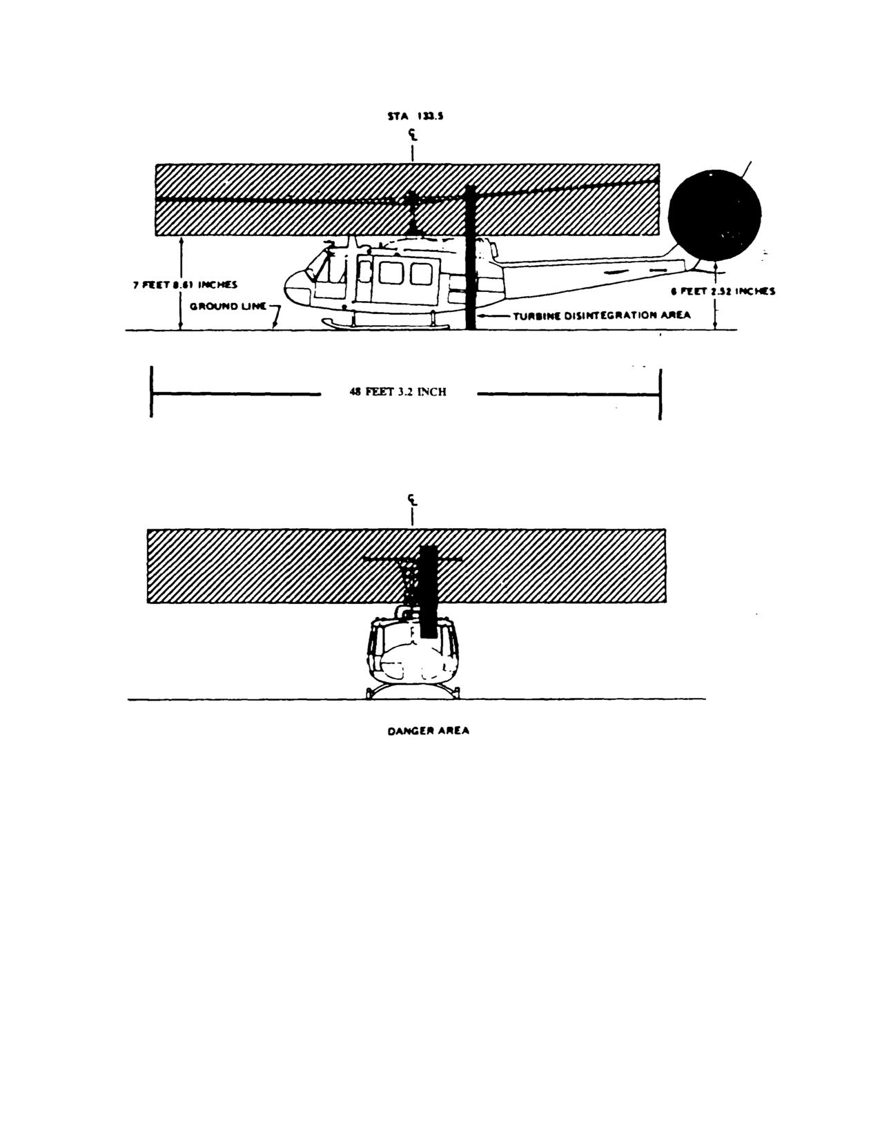
TM 55-1520-210
Figure 8-1. Danger Area
Change 17
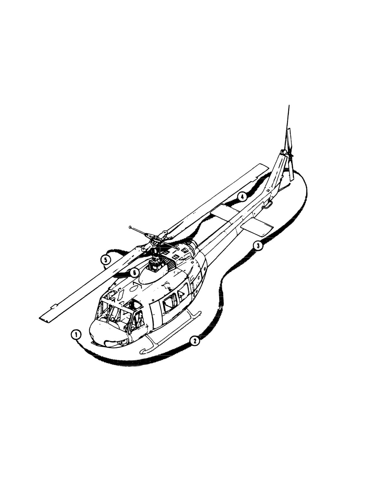
TM 55-1520-210-10
Figure
8-2. Exterior Check Diagram
8-16
TM
55-1520-210-10
Chapter
9
Emergency Procedures
Section l. HELICOPTER SYSTEMS
9-1. Helicopter Systems. This section describes the
4. AIRSPEED ADJUST as required.
helicopter systems emergencies that may reasonably be
expected to occur and presents the procedures to be
d. The term EMER SHUTDOWN is defined as engine
followed. Emergency operation of mission equipment is
stoppage without delay.
contained in this chapter insofar as its use affects safety of
flight. Emergency procedures are given in checklist form
1. THROTTLE - OFF.
when applicable. A condensed version of these procedures
is contained in the condensed checklist TM 55-1520-210
2. FUEL switches - OFF.
CL.
3. BAT switch - OFF.
9-2. Immediate Action Emergency Steps. Those
steps that must be performed immediately in an emergency
CAUTION
situation are underlined. These steps must be performed
without reference to the checklist. When the situation
The maximum engine torque available for
permits, non-underlined steps will be accomplished with
any ambient condition will be reduced by
use of the checklist.
6 to
8 PSI when the GOV AUTO/EMER
switch is placed in the EMER position.
NOTE
e. The term EMER GOV OPNS is defined as manual
The urgency of certain emergencies
control of the engine RPM with the GOV AUTO/EMER
requires immediate and instinctive action
switch in the EMER position. Because automatic
by the pilot. The most important single
acceleration, deceleration, and overspeed control are not
consideration is aircraft control. All
provided with the GOV switch in the EMER position,
procedures
are subordinate to this
throttle and collective coordinated control movements must
requirement.
be smooth to prevent compressor stall, overspeed,
overtemperature, or engine failure.
9-3. Definition Of Emergency Terms. For the
1. GOV - switch - EMER.
purpose of standardization the following definitions shall
apply:
2.
Throttle - adjust as necessary to control RPM.
a. The term LAND AS SOON AS POSSIBLE is defined
3. Land as soon as possible.
as executing a landing to the nearest suitable landing area
without delay. The primary consideration is to assure the
survival of occupants.
9-4. Emergency Exits. Emergency exits are shown in
figure 9-1. Emergency exit release handles are yellow and
b. The term LAND AS SOON AS PRACTICABLE is
black striped.
defined as executing a landing to a suitable airfield,
a. Cockpit Doors.
heliport, or other landing area as the situation dictates.
(1) Pull handle.
c. The term AUTOROTATE is defined as adjusting the
flight controls as necessary to establish an autorotational
descent. See figure 9-2 and FM 1-203.
(2) Push door out.
1. COLLECTIVE ADJUST as required to maintain
b. Cabin Door Windows.
rotor RPM.
(1) Pull handle.
2.
PEDALS ADJUST as required.
(2) Lift window inward.
3. THROTTLE ADJUST as required.
Change 15
9-1
TM
55-1520-210-10
9-5. Emergency Equipment.
WARNING
WARNING
Do not close the throttle. Do
not
respond to the rpm audio and/or warning
Toxic fumes of the extinguishing agent
light illumination without first confirming
may cause injury, and liquid agent may
engine malfunction by one or more of the
cause frost bite or low-temperature burns.
other indications. Normal indications
signify the engine is functioning properly
Refer to figure 9-1 for fire extinguisher and first aid kit
and that there is a tachometer generator
locations.
failure or an open circuit to the warning
system, rather than an actual engine
9-6. Minimum Rate of Descent. See figure 9-2.
malfunction.
9-7. Maximum Glide Distance. See figure 9-2.
c. Partial power condition:
9-8. Engine Oil Temperature High. If the engine oil
Under partial power conditions, the engine may operate
temperature exceeds operating limits as specified in
relatively smoothly at reduced power or it may operate
Chapter 5, land as soon as possible.
erratically with intermittent surges of power. In instances
where a power loss is experienced without accompanying
9-9. Engine Malfunction-Partial or Complete
power surging, the helicopter may sometimes be flown at
Power Loss.
reduced power to a favorable landing area. Under these
conditions, the pilot should always be prepared for a
a. The indications of an engine malfunction, either a
complete power loss. In the event a partial power condition
partial or a complete power loss are left yaw, drop in
is accompanied by erratic engine operation or power
engine rpm, drop in rotor rpm, low rpm audio alarm,
surging, and flight is to be continued, the GOV switch may
illumination of the rpm warning light, change in engine
be moved to the EMER position and throttle adjusted in an
noise.
attempt to correct the surging condition. If flight is not
possible, close the throttle completely and complete an
b. Flight characteristics:
autorotational landing.
(1) Control response with an engine inoperable is
d. Complete power loss:
similar to a descent with power.
(1) Under a complete power loss condition, delay
(2) Airspeed above the minimum rate of descent
in recognition of the malfunction, improper technique or
values (figures 9-2) will result in greater rates of descent
excessive maneuvering to reach a suitable landing area
and should only be used as necessary to extend glide
reduces the probability of a safe autorotational landing.
distance.
Flight conducted within the caution area of the height-
velocity chart (fig 9-3) or (fig 9-3.1) exposes the helicopter
(3) Airspeeds below minimum rate of descent
to a high probability of damage despite the best efforts of
airspeeds will increase rate of descent and decrease glide
the pilot.
distance.
(2) From conditions of low airspeed and low
(4) Should the engine malfunction during a left
altitude, the deceleration capability is limited, and caution
bank maneuver, right cyclic input to level the aircraft must
should be used to avoid striking the ground with the tail
be made simultaneously with collective pitch adjustment. If
rotor. Initial collective reduction will vary after an engine
the collective pitch is decreased without a corresponding
malfunction dependent upon the altitude and airspeed at
right cyclic input, the helicopter will pitch down and the roll
the time of the occurrence. For example, collective pitch
rate will increase rapidly, resulting in a significant loss of
must not be decreased when an engine failure occurs at a
altitude.
hover in ground effect; whereas, during cruise flight
conditions, altitude and airspeed are sufficient for a
significant reduction in collective pitch, thereby, allowing
rotor rpm to be maintained in the safe operating range
during autorotational descent. At high gross weights, the
rotor may tend to overspeed and require collective pitch
application to maintain the rpm below the upper limit.
Collective pitch should never be applied to reduce rpm
below normal limits for extending glide distance because of
the reduction in rpm available for use during autorotational
landing.
9-2
Change 11
TM
55-1520-210-10
NOTE
The engine will tend to overspeed as collective pitch is
decreased and will underspeed as collective pitch is
If time permits, during the autorotative
increased. If the droop compensator fails, make minimum
descent, transmit a "May Day" call, set
collective movements and execute a shallow approach to
transponder to emergency, jettison exter-
the landing area. If unable to maintain the operating rpm
nal stores, and lock shoulder harness.
within limits:
9-10. Deleted.
EMER GOV OPNS.
9-11. Engine Malfunction - Hover.
9-15. Engine Compressor Stall. Engine compressor
stall (surge) is characterized by a sharp rumble or loud
Autorotate.
sharp reports, severe engine vibration and a rapid rise in
exhaust gas temperature (EGT) depending on the severity
9-12. Engine Malfunction
- Low Altitude/Low
of the surge. Maneuvers requiring rapid or maximum power
applications should be avoided. Should this occur.
Airspeed or Cruise.
1. Collective - Reduce.
1. Autorotate.
2. DE-ICE and BLEED AIR switches - OFF.
2.
EMER GOV OPNS.
3. Land as soon as possible.
9-13. Engine Restart
- During Flight. After an en-
gine failure in flight, resulting from a malfunction of fuel
9-16. Inlet Guide Vane Actuator Failure - Closed
control unit, an engine start may be attempted. Because the
or Open.
exact cause of engine failure cannot be determined in flight,
the decision to attempt the start will depend on the altitude
and time available, rate of descent, potential landing areas,
a. Closed. If the guide vanes fail in the closed position,
and crew assistance available. Under ideal conditions
a maximum of 20 to 25 psi of torque will be available
approximately one minute is required to regain powered
although N1 may indicate normal. Power applications above
flight from time the attempt start is begun. If the decision is
20 to 25 psi will result in deterioration of N2 and rotor rpm
made to attempt an in-night start:
while increasing N1. Placing the GOV switch in the EMER
position will not provide any increase power capability and
1. Throttle - Off.
increases the possibility of an N1 overspeed and an engine
over-temperature. Should a failure occur, accomplish an
2. STARTER GEN switch - START.
approach and landing to the ground with torque not
exceeding the maximum available. If possible, a running
3. FUEL switches - ON.
landing is recommended.
4. GOV switch - EMER.
b. Open. If the inlet guide vanes fail in the open
position during normal flight, it is likely that no indications
5. Attempt start
wiII be evidenced. In this situation, increased acceleration
times will be experienced. As power applications are made
a. Starter switch - Press.
from increasingly lower N1 settings, acceleration times will
correspondingly increase.
b. Throttle - Open slowly to 6400 to 6600 rpm as
N1 passes through
8 percent Control rate of throttle
9-17. Engine Overspeed. Engine overspeed will be
application se necessary to prevent exceeding EGT limits.
indicated by a right yaw, rapid increase in both rotor and
engine rpm, rpm warning light illuminated, and an increase
c. Starter Switch-Release as N1 passes through
in engine noise. An engine overspeed may be caused by a
40 percent After the engine is started and powered flight is
malfunctioning N2 governor or fuel control. Although the
reestablished, continue with manual control. Turn the
initial indications of high N2 rpm and rotor rpm are the
START FUEL switch OFF and return the STARTER GEN
same in each case, actions that must be taken to control
switch to STANDBY.
rpm are distinctly different. If the N2 governor malfunctions,
throttle reduction will result in a corresponding decrease in
6. Land as soon as possible.
N2 rpm. In the event of a fuel control malfunction, throttle
reduction will have no effect on N2 rpm. If an overspeed is
9-14. Droop Compensator Failure. Droop
experienced:
compensator failure will be indicated when engine rpm
fluctuates excessively during application of collective pitch.
Change 5
9-3
TM 55-1520- 210-10
1.
ColIective-lncrease to load the rotor in
(a) Pedal input has no effect on helicopter
trim.
an attempt to maintain rpm below the maximum
(b) Nose of the helicopter turns to the right
operating limit.
(left sideslip).
(c) Roll of fuselage along the longitudinal
2.
Throttle-Reduce until normal operating rpm
axis.
is attained. Continue with manual throttle control. If
(d) Nose down tucking will also be
reduction of throttle does not reduce rpm as required:
present.
WARNING
WARNING
Land even If manual throttle corrects
At airspeeds below 30 to 40 knots,
the overspeed since there Is a chance
the
sideslip
may
become
of an_ Impending engine failure due
uncontrollable, and the helicopter will
to the debris generated by the Initial
begin to revolve on the vertical axis
N2 failure.
(right or left depending on power,
gross weight, etc.).
3.
FMFRGOV OPNS.
(2) Hover.
9-18.
Transmissions and Drive Systems.
Helicopter heading cannot be controlled with pedals.
b. Procedures.
9-19.
Transmission Oil-Hot or Low Pressure. If the
(1) In- Right.
transmission oil temperature XMSN OIL Hot caution light
(a) if safe landing area is not immediately
illuminates, limits on the transmission oil temperature
available and powered flight is possible, continue flight to
gage are exceeded; XMSN OIL PRESS caution light illu-
a suitable landing area at above minimum rate of
minates, or limits on the transmission oil pressure gage
descent airspeed. Degree of roll and sideslip may be
are exceeded (low or high)-
varied by varying throttle and/or collective.
(b) When landing area is reached,
1.
Land as soon as possible.
AUTORO TATE using an airspeed above minimum rate
of descent
2.
FMFR SHUTDOWN - After lending.
CAUTION
WARNING
The flare and the abrupt use of
collective will cause the nose to
rotate left, but do not correct with
Do not dose throttle during this
throttle.
Although application of
emergency procedure. Descent and
throttle will result In rotation to the
landing must be made with normal
right, addition of power Is a very
engine operating RPM.
strong response measure and Is too
Should transmission oil pressure drop to zero psi, a valid
sensitive for the pilot to manage
cross reference cannot be made with the oil temperature
property at this time. DO NOT ADD
indicators. The oil temperature gage and transmission
POWER ATTHIS TIME. Slight rotation
oil hot warning lights are dependent on fluid for valid
at time of impact at zero ground
indications.
speed should not cause any real
9-20.
Tall Rotor Malfunctions. Because the many
problem.
different malfunctions that can occur, it is not possible to
(c) If landing area is suitable, touchdown
provide a solution for every emergency. The success in
at a ground speed above effective transitional lift utilizing
coping with the emergency depends on quick analysis of
throttle as necessary to maintain directional control.
the condition.
(d) If landing area is not suitable for a run-
on lancing a minimum ground run autorotation must be
9-21.
Complete Loss of Tall Rotor Thrust This situ-
performed, enter autorotation descent (throttle off) start
ation involves a break in the drive system, such as a se-
to decelerate at about 75 feet altitude so that forward
vered driveshaft, wherein the tail rotor stops turning or
ground speed is at a minimum when the helicopter
tail rotor controls fail with zero thrust a Indications.
reaches 10 to 20 feet, execute the touchdown with a
(1) In-Flight.
rapid collective pull just prior to touchdown in a level
altitude with minimum ground speed.
9-4 Change 17
TM 55-1520- 210-10
(2) Hover.
(b) Delete.
AUTOROTATE.
9-23.
Loss of Tail Rotor Components. The seventy
of this situation is dependent upon the amount of weight
9-22.
Fixed Pitch Settings. This is a malfunction
lost. Any loss of this nature will result m a forward center
involving a loss of control resulting in a fixed-pitch
of gravity shift, requiring aft cyclic.
setting. Whether the nose of the helicopter yaws left or
right is dependent upon the amount of pedal applied at
a. Indications:
the time of the malfunction, a varying amount of tail rotor
thrust will be delivered at all times during flight.
(1) Varying degrees of right yaw depending on
power applied and airspeed at time of failure.
a. Reduced power (low torque).
(2) Forward CG shift.
(1) Indications: The nose of the helicopter will
turn right when power is applied.
(3) Abnormal vibrations.
(2) Procedure: Reduced power situations:
b. Procedures:
(a) If helicopter control can be maintained
(1) Enter authoritative descent (power off).
in powered flight, the best solution is to maintain control
with power and accomplish a run-on landing as soon as
(2) Maintain airspeed above minimum rate of
practicable.
descent airspeed.
(b) If
helicopter control cannot be
(3) If run-on landing is possible, complete
maintained, close the throttle immediately and
autorotation with a touchdown airspeed as required for
accomplish an autorotatlonal landing.
directional control.
b. Increased power (high torque).
(4) If run-on landing is not- possible, start to
decelerate from about 75 feet altitude, so that forward
(1) Indications: The nose of the helicopter will
groundspeed is at a minimum when the helicopter
turn left when power is reduced.
reaches 10 to
20 feet; execute the termination with a
rapid collective pull just prior to touchdown in a level
(2) Procedure.
attitude
(a) Maintain control with power and
with minimum ground speed.
airspeed between 40 and 70 knots.
9-24. Loss of Tail Rotor Effectiveness. This is a
(b)
If needed, reduce rpm (not below
situation involving a loss of effective tail rotor thrust
6000) to control sideslip.
without a break in the drive system. The condition is
(c) Continue powered flight to a suitable
most likely to occur at a hover or low airspeed as a result
landing area where a run-on landing can be
of one or more of the following.
accomplished.
(d) On final, reduce rpm to
6000 and
a. Out-of-ground effect hover.
accomplish a run-on landing.
b. High pressure altitude/high temperature.
c. Adverse wind conditions.
c. Hover.
d. Engine/rotor rpm below 6600/324.
c. Improperly rigged tail rotor.
(1) Indication. Helicopter heading cannot be
f. High gross weight.
controlled with pedals.
(1) Indications:
The first indication of this
(2) Procedure.
condition will be a slow starting right turn of the nose of
the helicopter which cannot be stopped with full left pedal
(a) Fixed Pedal-Land.
application. This turn rate will gradually increase until It
becomes uncontrollable or, depending upon conditions,
the aircraft aligns itself with the wind.
Change 17 9-5
TM 55-1520-210-10
(2) Procedures: Lower collective to regain
can be taken by the pilot is to land the helicopter.
control and as recovery is effected adjust controls for
Consideration must be given to jettison external stores
normal flight.
pnor to landing.
9-25.
Main Driveshaft Failure. A failure of the main
9-30.
Fire-Engine Start. The following procedure is
driveshaft will be indicated by a left yaw (this is caused
applicable during engine start, if EGT limits are
by the drop in torque applied to the main rotor), increase
exceeded, or if it becomes apparent that they will be
in engine rpm, decrease m rotor rpm, low rpm audio
exceeded. Flames emitting from the tailpipe are
alarm (unmodified system), and illumination of the rpm
acceptable if the EGT limits are not exceeded.
warning light. This condition will result m complete loss
of power to the rotor and a possible engine overspeed. If
1.
Start switch - Press. The starter switch
a failure occurs:
must be held until EGT is in the normal operating range.
1.
Autorotate.
2.
Throttle - Off. The throttle must be closed
immediately as the starter switch is pressed.
2.
EMER SHUTDOWN.
3.
FUEL switches - OFF.
9-26.
Clutch Fails to Disengage. A clutch failing to
disengage in flight will be indicated by the rotor rpm
9-31.
Fire-Ground.
decaying with engine rpm as the throttle is reduced to the
engine idle position when entering autorotatlonal
EMER SHUTDOWN
descent. This condition
results in total loss of
autorotational capability. If a failure occurs, do the
9-32.
Fire-Flight. If the fire light illuminates and/or fire
following:
is observed during flight, prevailing circumstances (such
as VFR, IMC, night, altitude, and landing areas
1.
Throttle - On.
available), must be considered in order to determine
whether to execute a power-on, or a power-off landing.
2.
Land as soon as possible.
a. Power-On.
9-27. Clutch Fails to Re-engage. During recovery
from autorotational descent clutch malfunction may
1.
Land as soon as possible.
occur and will be indicated by a reverse needle split
(engine rpm higher than rotor rpm):
2.
EMER SHUTDOWN after landing.
1.
Autorotate.
b. Power-Off.
2.
EMER SHUTDOWN.
1.
Autorotate.
9-28.
Collective Bounce. If collective bounce occurs.
2.
EMER SHUTDOWN.
1.
Relax pressure on collective. (Do not ’stiff
arm’ the collective.)
9-33.
Electrical Fire-Flight. Prior to shutting off all
2.
Male a significant collective application
electrical power, the pilot must consider the equipment
either up or down.
that is essential to a particular flight environment that will
3.
Increase collective friction.
be encountered, e.g., flight instruments, and fuel boost
pumps. In the event of electrical fire or suspected
9-29.
Fire. The safety of helicopter occupants is the
electrical fire in flight:
primary consideration when a fire occurs; therefore, it is
imperative that every effort be made by the flight crew to
1.
BAT, STBY. and MAIN GEN switches -
put the fire out. On the ground it is essential that the
OFF
engine be shut down, crew and passengers evacuated
and fire fighting begun immediately. If time permits, a
2.
Land as soon as possible.
’May Day’ radio call should be made before the electrical
power is OFF to expedite assistance from fire fighting
If landing cannot be made soon as possible and flight
equipment and personnel. If the helicopter s airborne
must be continued, the defective circuits may be
when a fire occurs, the most important single action that
identified and isolated as follows:
9-6
Change 17
TM 55-1520-210-10
3.
Circuit breakers - Out. As each of the
the earth flying, approach and
following steps is accomplished, check for indications of
landing or while the aircraft is not in
the source of the fire.
level flight.
This prevents any
possibility of a surge in hydraulic
4.
MAIN GEN switch - ON.
pressure and the resulting loss of
control.
5.
STARTER GEN switch - STBY GEN.
P37. Hydraulic Power Failure. Hydraulic power failure
6.
BAT switch - ON.
will be evident when the force required for control
movement increases; a moderate feedback m the
7.
Circuit breakers - In. One at a time in the
controls when moved is felt, and/or the HYD PRESSURE
priority required, GEN BUS RESET first.
When
caution light illuminates. Control movements will result
malfunctioning circuit is identified, pull the applicable
m normal helicopter response. In the event of hydraulic
circuit breaker out.
power failure:
9-34.
Overheated Battery.
1.
Airspeed - Adjust as necessary to attain
the most comfortable level of control movements.
WARNING
2.
HYD CONT circuit breaker
-
Out. If
hydraulic power is not restored:
3.
HYD CONT circuit breaker - In.
Do not open battery compartment or
4.
HYD CONT switch - OFF.
attempt to disconnect or remove
5.
Land as soon as practicable at an area that
overheated battery. Battery * fluid
will permit a run-on landing with power. Maintain
will cause burns and overheated
airspeed at or above effective transitional lift until
battery may cause thermal burns and
touchdown.
may explode. If an overheated battery
is suspected or detected.
9-38.
Control Stiffness.
A failure within the
irreversible valve may cause extreme stiffness in the
1.
BAT switch - OFF.
collective or two of the four cyclic control quadrants. If
the failure is in one of the two cyclic irreversible valves,
2.
Land ac soon as possible.
caution is necessary to avoid over controlling between
the failed and operational quadrants.
3.
EMFR SHUTDOWN after landing.
1.
HYD CONT switch - OFF then ON.
9-35.
Smoke and Fume Elimination. Smoke and/or
toxic fumes entering the cockpit and cabin can be
Check for restoration of normal flight control
exhausted as follows:
movements.
Repeat as necessary.
Doors. windows. and vents - Open
If control response is not restored:
2.
HYD CONT switch - OFF.
If normal operation is not restore!
Do not jettison doors in flight
3.
Land as soon as practicable at an area that
will permit a run-on landing with power. Maintain
9-36.
Hydraulic.
airspeed at or above effective transitional lift until
touchdown.
WARNING
9-39.
Flight Control Servo Hardover.
During actual or simulated hydraulic
a. Cyclic hardover is caused by a sequencing valve
failure, do not pull or push circuit
failure within the Irreversible valve on either or both cyclic
breakers or move the HYD CONT
servos. Cyclic servo hardover will cause the cyclic to
switch during takeoff, map of
move full night forward, full left rear, full left forward, or
full right rear.
Change 17
9-7
TM 55-1520-210-10
b. Collective hardover is caused by a sequencing
9-42.
Fuel System.
valve failure within the Irreversible valve on the collective
servo. The collective will move to the full up or full down
9-43.
Fuel Boost Pump Failure.
position.
If both FUEL BOOST caution lights come on:
c. A failure of any flight control servo may render
the helicopter uncontrollable unless the following action
1.
Check fuel pressure.
is taken.
If fuel pressure is zero:
1.
HYD CONT select - Select opposite
position.
2.
Descend to a pressure altitude of 4600 feet
or less if possible.
2.
LAND AS SOON AS POSSIBLE at an area
that will permit a run-on landing with power. Maintain
3.
Land as soon as practicable. No attempt
airspeed at or above effective translational lift at
should be made to troubleshoot the system while in
touchdown.
flight.
9-40.
Flight Control/Main Rotor System
9-44.
Electrical System
Malfunctions.
9-45.
Main Generator Malfunction. A malfunction of
a. Failure of components within the flight control
the main generator will be indicated by zero indication of
system may be indicated through varying degrees of
the Main Generator Loadmeter and DC GENERATOR
feedback, binding, resistance, or sloppiness. These
caution light illumination. An attempt may be made to
malfunctions are normally in isolated controls, i.e. cyclic,
put the generator back on line as follows:
cyclic/collective, or anti-torque. These conditions should
not be mistaken for hydraulic power failure.
1.
GEN and BUS RESET circuit breaker - In.
b. Imminent failure of main rotor components may
2.
MAIN GEN switch - RESET then ON. Do
be indicated by a sudden increase in main rotor vibration
not hold the switch in the RESET POSITION. If the main
and/or unusual noise.
Severe changes in lilt
generator is not restored or If it goes off again:
characteristics and/or balance condition can occur due to
blade strikes, s kin separation, shift or loss of balance
3.
MAIN GEN switch - OFF.
weights or other material. Malfunctions may result in
severe main rotor flapping. In the event of a main rotor
NOTE
system malfunction, proceed as follows:
Check that the standby generator
loadmeter is indicating a load Flight may
WARNING
be continued using the standby
generator.
Danger exists that the main rotor
system could collapse or separate
9-46.
Landing and Ditching.
from the aircraft after landing. A
decision must be made whether
9-47.
Landing In Trees. A landing in trees should be
occupant egress occurs before or
made when no other landing area is available. Select a
after the rotor has stopped.
landing area containing the least number of trees of
minimum height Decelerate to a zero ground speed at
1.
Land as soon as possible.
tree-top level and descend into the trees vertically,
applying collective pitch as necessary for minimum rate
2.
EMER SHUTDOWN after landing.
of descent. Prior to the main rotor blades entering the
trees, ensure throttle is OFF and apply all of the
9-41.
Mast Bumping.
remaining collective pitch.
If mast bumping occurs:
1.
Reduce severity of maneuver.
2.
Land as soon as possible.
9-8
Change 17
TM 55-1520-210-10
9-48.
Ditching-Power on. If it becomes necessary to
ditch the helicopter, accomplish an approach to an
approximate 3-foot hover above the water and proceed
as follows:
1.
Cockpit doors - Jettison at a hover.
2.
Cabin doors - Open.
3.
Crew (except pilot) and passengers - Exit.
4.
Hover a safe distance away from personnel.
5.
Throttle-Off and autorotate. Apply full
collective pitch prior to the main rotor blades entering the
water. Maintain a level attitude as the helicopter sinks
and until it begins to roll, then apply cyclic in direction of
the roll.
6.
Pilot-Exit when the main rotor is stopped.
9-49.
Ditching-Power Off. If ditching is imminent,
accomplish engine malfunction emergency procedures.
Decelerate to zero forward speed as the helicopter nears
the water.
Apply all of the collective pitch as the
helicopter enters the water. Maintain a level attitude as
the helicopter sinks and until it begins to roll, then apply
cyclic m the direction of the roll. Exit when the main rotor
is stopped.
I.
Cockpit doors--Jettison
2.
Cabin Doors - open.
3.
Exit when main rotor has stopped
Change 17 9-8.1/(9-8.2 blank)-
TM
55-1520-210-10
Table 9-1 Emergency Procedures for Caution Segments
Light
Corrective Action
MASTER CAUTION
Check the CAUTION panel for the condition. If
master caution only (no segment light), land
as soon as possible.
AUX FUEL LOW
INT AUX FUEL transfer switches-OFF,
DC GENERATOR
Check GEN AND BUS RESET circuit breaker
in MAIN GEN switch RESET then ON. Switch
to STBY GEN.
INST INVERTER
Switch to other inverter,
EXTERNAL POWER
Close door.
XMSM OIL PRESS
Land as soon as possible. (Ref to para 9-19)
XMSM OIL HOT
Land as soon as possible. (Ref to para 9-19)
ENGINE INLET AIR
Land as soon as practicable.
CHIP DETECTOR
Land as soon as possible.
LEFT FUEL BOOST
Land as soon as practicable.
RIGHT FUEL BOOST
Land as soon as practicable.
20 MINUTE FUEL
Land as soon as practicable.
IFF
Information/System Status
ENGINE OIL PRESS
Land as soon as possible.
ENGINE CHIP DET
Land as soon as possible.
GOV EMER
Information/System Status
ENGINE ICE DET
Land as soon as possible.
ENGINE FUEL PUMP
Land as soon as possible.
ENGINE ICING
Land as soon as possible.
FUEL FILTER
Land as soon as practicable.
HYD PRESSURE
Land as soon as practicable.
SPARE
Land as soon as possible.
Change
8
9-9
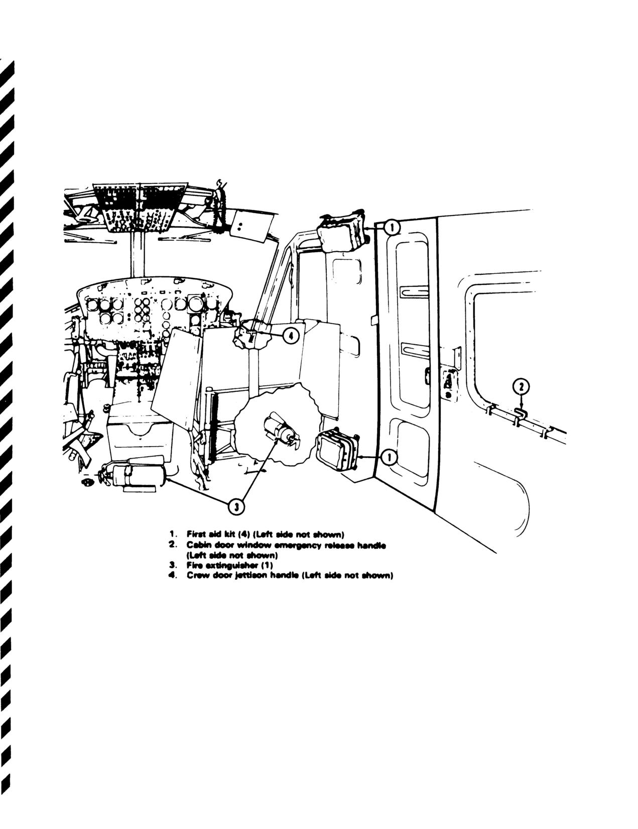
TM
55-1520-210-10
Figure
9-1. Emergency Exits and Equipment
9-10
TM 55-1520-210-10
AUTOROTATIONAL GLIDE CHARACTERISTICS
POWER OFF
EXAMPLE
WANTED
GLIDE RATlO AND RATE OF DESCENT
KNOWN
AIRSPEED = 80 KIAS ROOF
ROTOR RPM = 314
METHOD
ENTER INDICATED AIRSPEED
MOVE UP TO 314 ROTOR RPM LINE
MOVE LEFT, READ GLIDE RATlO.
CONTINUE UP 80 KIAS TO 314 ROTOR
RPM
LINE ON UPPER GRAPH. MOVE
LEFT, READ RATE OF DESCENT.
Figure 9-2. Autorotational Glide Characteristics Chart
Change 8
9-11
TM
55-1520-210-10
AUTOROTATIONAL GLIDE CHARACTERISTICS
POWER OFF
2600
NOTE: AUTOROTATIONAL DESCENT
PERFORMANCE ISA FUNCTION
OF AIRSPEED AND IS
ESSENTIALLY UNAFFECTED BY
2400
DENSITY, ALTITUDE, AND GROSS
WEIGHT.
2200
EXAMPLE
WANTED
2000
GLIDE RATlO AND RATE OF DESCENT
KNOWN
AIRSPEED = 80 KIAS ROOF
1800
ROTOR RPM 314
METHOD
ENTER INDICATED AIRSPEED HERE
MOVE UP TO 314 ROTOR RPM LINE
1600
MOVE LEFT, READ GLIDE RATIO = 4.5
CONTINUE UP 80 KIAS TO 314 ROTOR
RPM LINE ON UPPER GRAPH MOVE
LEFT, READ RATE OF DESCENT = 1725
FPM
1400
6
4
2
Figure 9-2.1. Autorotational glide characteristics chart
Change 8
9-12
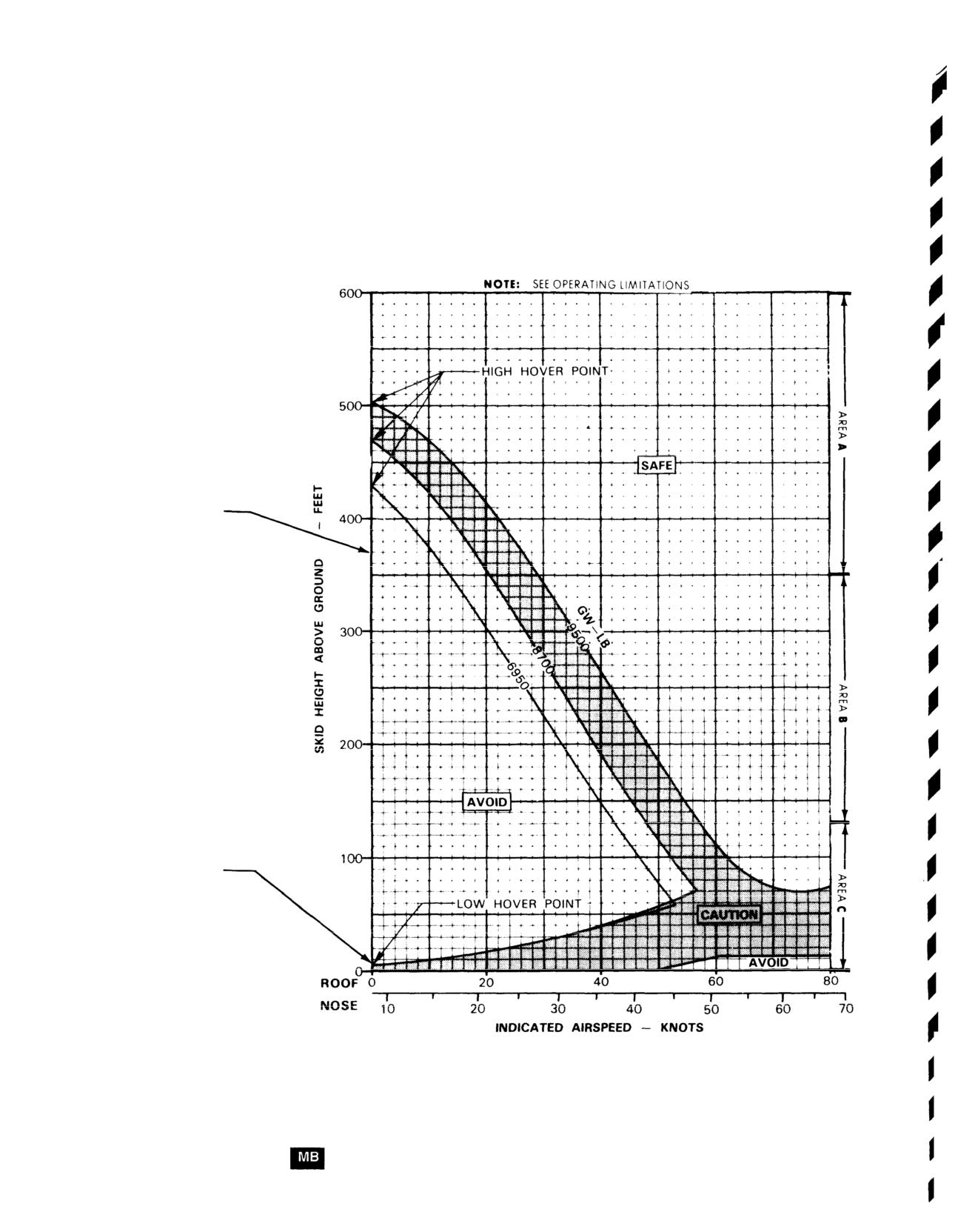
TM
55-1520-210-10
HEIGHT VELOCITY DIAGRAM
324 ROTOR RPM
WANTED
INDICATED AIRSPEED
KNOWN
GROSS WEIGHT = 8700 LB
SKID HEIGHT ABOVE GROUND=370 FEET
ROOF MOUNTED SYSTEM
METHOD
ENTER SKID HEIGHT HERE
MOVE RIGHT TO GROSS WEIGHT
MOVE DOWN, READ INDICATED
AIRSPEED = 18 KNOTS
EXAMPLE B
WANTED
MINIMUM INDICATED AIRSPEED
FOR CLIMBOUT TO AVOID
HEIGHT VELOCITY RESTRICTIONS
KNOWN
GROSS WEIGHT = 8700 LB
LOW HOVER POINT = 5 FEET
SKID HEIGHT ABOVE GROUND
ROOF MOUNTED SYSTEM
METHOD
ENTER SKID HEIGHT HERE
(AT LOW HOVER POINT
MOVE RIGHT ALONG THE
GROSS WEIGHT LINE
TO THE FASTEST AIRSPEED
MOVE DOWN, READ INDICATED
AIRSPEED = 56.5 KNOTS
DATA BASIS: DERIVED FROM FLIGHT TEST FTC-TDR 67-27, NOVEMBER 1964
F i g u r e
9 - 3 H e i g h t V e l o c i t y D i a g r a m
Change 8
9-13
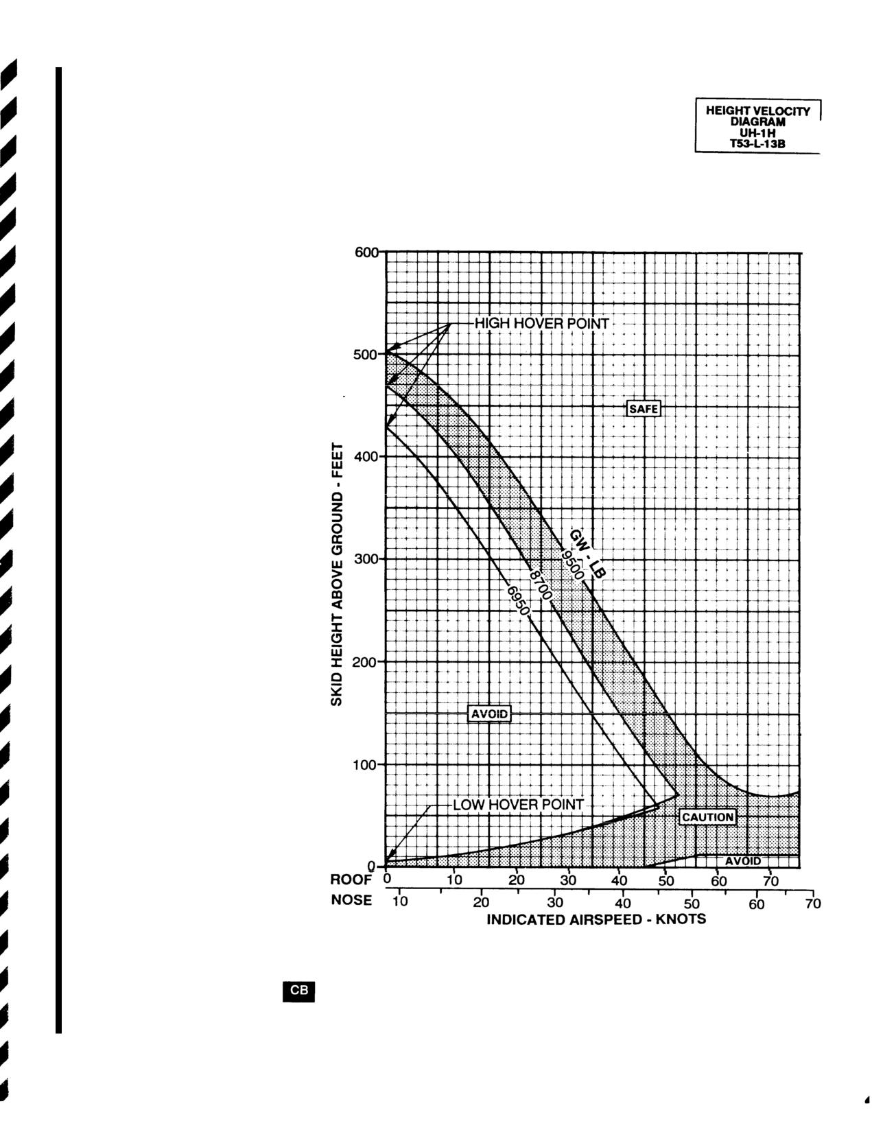
TM 55-1520-210-10
HEIGHT VELOCITY DIAGRAM
324 ROTOR RPM
EXAMPLE A
WANTED
INDICATED AIRSPEED
KNOWN
GROSS WEIGHT = 8700 LB
SKID HEIGHT ABOVE GROUND =370 FEET
ROOF MOUNTED SYSTEM
METHOD
ENTER SKID HEIGHT HERE
MOVE RIGHT TO GROSS WEIGHT
MOVE DOWN, READ INDICATED
AIRSPEED = 14 KNOTS
EXAMPLE B
WANTED
MINIMUM INDICATED AIRSPEED
FOR CLIMBOUT TO AVOID
HEIGHT VELOCITY RESTRICTIONS
KNOWN
GROSS WEIGHT = 8700 LB
LOW HOVER POINT = 5 FEET
SKID HEIGHT ABOVE GROUND
ROOF MOUNTED SYSTEM
METHOD
ENTER SKID HEIGHT HERE
(AT LOW HOVER POINT)
MOVE RIGHT ALONG THE
GROSS WEIGHT LINE
TO THE FASTEST AIRSPEED
MOVE DOWN, READ INDICATED
AIRSPEED = 52.5 KNOTS
DATA BASIS:
DERIVED FROM FLIGHT TEST FTC-TDR 67-27, NOVEMBER 1964
Figure 9-3.1. Height velocity diagram
9-14
Change 8
TM 55-1520-210-10
Appendix A
References
AR 50-4
TM 9-1005-224-12
TM 750-244-1-5
Safety Studies and Reviews of
Operator and Organizational
Procedures for the Destruction of
Nuclear Weapon Systems
Maintenance Manual Including
Aircraft and Associated Equipment
Repair Parts and Special Tool List:
to Prevent Enemy Use
AR 50-5
Machine Gun 7.62-MM M60, and
Nuclear Surety
Mount, Tripod, Machine Gun M122
DA Pam 738751
Functional Users Manual for the
AR 70-50
TM 9-1345-201-12
Army Maintenance Management
Designating and Naming Military
Operators and Organizational
System-Aviation (TAMMS-A)
Aircraft, Rockets, and Guided
Maintenance Manual: Mine Dis-
Missiles
persing Subsystem, Aircraft: M56
DOD FLIP
and M132
DOD Flight Information Publication
AR 95-1
(Enroute)
Army Aviation: Flight Regulations
TM 11-5810-262-OP
Loading Procedures, TSEC Equip
FM 1-202
Deleted
TM 11-5810-262-12&P
Environmental Flight
AR 95-27
TM 55-1500-342-23
FM 1-203
Operational Procedures for Aircraft
Army Aviation Maintenance
Fundamentals of Flight
Carrying Dangerous Materials
Engineering Manual-Weight and
Balance
FM 1-204
AR 385-40
Night Flight Techniques and
Accident Reporting and Records
TM 55-1500-334-25
Procedures
Conversion of Aircraft to Fire
TB 55-9150-200-24
Resistant Hydraulic Fluid
FM 1-240
Engine and Transmission Oils,
Instrument Flying and Navigation
Fuels
TM 55-1520-210-CL
for Army Aviators
and Additives for Army Aircraft
Operators and Crewmembers
Checklist--H-IH/V Helicopters
FM 10-68
TB MED 501
Aircraft Refueling-
Noise and Conservation of Hearing
TM 57-220
Technical Training of Parachutists
FM 10-1101
TM 9-1005-224-10
Petroleum Handling Equipment
Operators Manual for M60,
and Operation
7.62-MM Machine Gun (NSN
1005-00-605-7710)
Change 17 A-1/(A-2 blank)
Appendix B
TM
55-1520-210-10
Abbreviations and Terms
AC
BRIL
DC
Brilliance
Direct Current
Alternating Current
BRT
DCP
ADF
Bright
Dispenser Control Panel
Automatic Direction Finder
C
DF
AGL
Celsius
Direction Finding
Above Ground Level
CARR
DECR
AI
Carrier
Decrease
Attack Imminent
CAS
DELTA A
ALT
Calibrated Airspeed
Incremental Change
Alternator
CCW
DET
ALT
Counter Clockwise
Detector
Altitude/Altimeter
DG
ALTM
CDI
Directional Gyro
Altimeter
Course Deviation Indicator
DIS
AM
CG
Disable
Amplitude Modulation
Center of Gravity
DISP
AMP
CL
Dispense
Ampere
Centerline
DSCRM
ANT
CMPS
Discriminator
Antenna
Compass
ECM
ATTD
CNVTR
Electronic Countermeasures
Attitude
Converter
EGT
AUTO
COLL
Exhaust Gas Temperature
Automatic
Collision
ELEC
AUX
COMM
Electrical
Auxiliary
Communication
EMER
AVGAS
COMPT
Emergency
Aviation Gasoline
Compartment
END
BAT
CONT
Endurance
Battery
Control
ENG
BDHI
CONT
Engine
Bearing Distance Heading Indicator
Continuous
ESS
BFO
CONV
Essential
Beat Frequency Oscillator
Converter
EXH
BL
CW
Exhaust
Butt Line
Clockwise
B - 1
TM
55-1520-210-10
EXT
GEN
INOP
Extend
Generator
Inoperative
EXT
GND
INST
Exterior
Ground
Instrument
F
GOV
INT
Fahrenheit
Governor
Internal
GPU
INT
FAT
Ground Power Unit
Interphone
Free Air Temperature
GRWT
INV
FITG
Gross Weight
Inverter
Fitting
GW
INVTR
FM
Gross Weight
Inverter
Frequency Modulation
HDG
IR
FOD
Heading
Infrared
Foreign Object Damage
HF
IRT
FPS
High Frequency
Indicator Receiver Transmitter
Feet Per Second
HIT
ISA
FREQ
Health Indicator Test
International Standard Atmosphere
Frequency
HTR
KCAS
FS
Heater
Knots Calibrated Airspeed
Fuselage Station
HYD
kHz
FT
Hydraulic
Kilohertz
Foot
IAS
KIAS
FT/MIN
Indicated Airspeed
Knots Indicated Airspeed
Feet Per Minute
ICS
km
Interphone Control Station
Kilometer
FUS
Fuselage
IDENT
KTAS
Identification
Knots True Airspeed
FWD
Forward
IFF
KN
Identification Friend or Foe
Knots
F
Increment of Equivalent Flat Plate
IGE
kva
Drag Area
In Ground Effect
Kilovolt-Ampere
G
IN
kw
Gravity
Inch
Kilowatt
G
INCR
L
Guard
Increase
Left
GAL
IND
LB
Gallon
Indication/Indicator
Pounds
GD
INHG
LDG
Guard
Inches of Mercury
Landing
B-2
TM 55-1520-210-10
LH
NAV
QTY
Left Hand
Navigation
Quantity
LSB
NET
%Q
Lower Sideband
Network
Percent Torque
LT
NO
R
Lights
Number
Right
LTG
NM
RCVR
Lighting
Nautical Mile
Receiver
LTS
NON-ESS
R/C
Lights
Non-Essential
Rate of Climb
MAG
NON-SEC
R/D
Magnetic
Non-Secure
Rate of Descent
MAN
NORM
RDR
Manual
Normal
Radar
MAX
NVG
RDS
Maximum
Night Vision Goggles
Rounds
MED
NR
REL
Medium
Gas Turbine Speed
Release
REM
MHF
N2
Remote
Medium-High Frequency
Power Turbine Speed
RETR
MHz
OGE
Retract
Megahertz
Out of Ground Effect
RETRAN
MIC
PED
Retransmission
Microphone
Pedestal
RF
MIN
PLT
Radio Frequency
Minimum
Pilot
RH
MIN
PRESS
Right Hand
Minute
Pressure
RI
MISC
PRGM
Remote Height Indicator
Miscellaneous
Program
RPM
mm
PSI
Revolutions Per Minute
Millimeter
Pounds Per Square Inch
SAM
MON
PVT
Surface to Air Missile
Monitor
Private
SEC
MWO
PWR
Secondary
Modification Work Order
Power
Change 17 B-3
TM 55-1520-210-10
SEC
TEMP
VHF
Secure
Temperature
Very high Frequency
SEL
TGT
VM
Select
Turbine Gas Temperature
Volt Meter
SENS
T/R
VOL
Sensitivity
Transmit-Receive
Volume
SL
TRANS
VOR
Searchlight
Transfer
VHF Omni Directional Range
SOL
TRANS
VNE
Solenoid
Transformer
Velocity, Never Exceed (Airspeed
Limitation)
SQ
TRANS
Squelch
Transmitter
WL
Water line
SSB
TRQ
Single Sideband
Torque
WPN
Weapon
STA
UHF
Station
Ultra-High Frequency
XCVR
Transceiver
STBY
USB
Standby
Upper Sideband
XMIT
Transmit
SQ FT
VAC
Square Feet
Volts, Alternating Current
XMTR
Transmitter
TAS
VDC
True Airspeed
Volts, Direct Current
XMSN
Transmission
B-4 Change 17
TM 55-1520-210-10
APPENDIX C
TABULAR PERFORMANCE DATA
Use of the TABULAR CHARTS is illustrated by the following examples:
TABULAR PERFORMANCE DATA (Pages C-2 through C-4)
KNOWN:
Pressure Altitude (PA) = 1000 FEET
Free Air Temperature (FAT) = +25
WANTED:
Maximum GW for Hover OGE.
Torque Required for Hover OGE.
Torque Required for Hover IGE (2 FEET).
METHOD:
1.
Enter PA at 1,000 Feet, and Move Right to +25 C.
2.
The Top Number (912) is the Maximum GW to Hover OGE.
(= 9,120 POUNDS.)
3.
The Middle Number (45) is the Torque required to Hover OGE at the Maximum GW to Hover OGE (9,120).
(= 45 PSI.)
4.
The Bottom Number (37) is the Torque required at a 2 Foot Hover at the Maximum
GW to Hover OGE (9,120). (- 37 PSI.)
TABULAR PERFORMANCE DATA (Page C-5)
KNOWN:
Pressure Altitude (PA) = 1000 FEET
Free Air Temperature (FAT) = +25
WANTED:
Maximum Torque available (30 MINUTES).
METHOD:
1.
Enter PA at 1,000 Feet, and Move Right to +20 C and +30 C.
2.
Interpolate between 48.0 and 42.7 PSI, the Maximum Torque available will be between. (45.4)
3.
Torque Values outlined in Tabular Data are Calibrated Values and should be converted to indicated before
use in the cockpit.
Change 17 C-1
TM 55-1520-210-10
Index
This Index is organized alphabeti-
cally by paragraph number topics.
AC Circuit Breaker Panel, 2-64
Before Leaving Helicopter Proce-
Complete Loss of Tail Rotor-
AC Power Indicators and Con-
dures-Machine Gun M60D, 4-4
Thrust, 9-21
trols,
2-63
Before Starting Engine, 8-21
Controls and Indicators,
2-26
AC Power Supply System, 2-61
Before Takeoff, 8-30
Control Stiffness,
9-38
Additional Crew,
8-9
Before Takeoff/Before Landing
Control Switch,
2-34
ADF Set AN/ARN-59,
3-19
Procedures-Machine Gun M60D,
Course
Deviations
Indicators
ADF Set AN/ARN-83,
3-18
4-3
1D-453 and ID-1347 1, 3-22
Air Induction System,
2-18
Before Takeoff-M52 Smoke Gen-
Crew and Passenger Briefings,
Airspeed Indicators, 2-76
erator Subsystem, 4-17
8-5
Airspeed Limitations,
5-11
Before Takeoff Procedures-M56
Crew Compartment Diagram, 2-8
Altitude Encoder/Pneumatic Al-
and M132 Mine Dispersing Sub-
Crew Duties, 8-6
timeter AAU-32/A, 3-28
system,
4-8
Cruise, 8-36
Anti-Collision Light, 2-66
Before Takeoff, 4-30
Cruise Conditions,
7-25,
Appendix A, References,
1-4
Before Takeoff-Rescue Hoist,
7.1-25
Appendix B, Abbreviations and
4-24
Cruise, Description,
7-23
Terms, 1-5
Blackout Curtains,
2-48
7.1-23
Approved Commercial Fuel, Oils,
Blade Stall, 8-47
Cruise, Use of Charts,
and Fluids, 2-88
Blood Bottle Hangars,
2-49
7-24
7.1-24
Armament Subsystem M23,
4-1
Cyclic Control System.
2-29
Armament Subsystem M56 and
Cyclic Hardover,
9-39
Cargo Center-of-Gravity Limits
M132 Mine Dispersing,
4-6
6-20
Army Aviation Safety Program,
Cargo Hook, 4-34
Danger Areas. 8-7
1-7
Cargo Loading,
6-14
Data Basis, 7-6
, 7.1-6
Attitude Indicators, 2-80
Center-of-Gravity Limitations,
5-8
Data Case, 2-47
Auxiliary Fuel System,
2-27
Center-of-Gravity Limits, 6-20
DC and AC Power Distribution,
Avionics Equipment Configura-
Checklist, 8-10
2-54
tion, 3-2
Checks, 8-11
DC Power Indicators and Con-
Chip Detectors, T9-1
trols,
2-59
Battery,
2-57
Circuit Breaker Panel,
2-60
DC Power Supply System, 2-55
Before-Exterior Checks, 8-12
Classification of Helicopter,
6-2
DD Form
365A-Basic Weight
Before Landing,
838
Climb,
8-35
Checklist, 6-5
Before Landing-M52 Smoke Gen-
Climb-Descent, Conditions,
DD Form 365 C-Basic Weight and
erator Subsystem,
4-19
7-31
7.1-31
Balance Records,
6-6
Before Landing Procedures-M56
Climb-Descent, Descriptions,
DD Form
365 F-Weight and
and M132 Mine Dispersing Sub-
7-29
7.1-29
Balance Clearance Form F, 6-7
system,
4-10
Climb-Descent, Use of Chart,
Definitions of Abbreviations,
Before Leaving the Helicopter,
7-30
7.1-33
7-10
7.1-10
8-41
Clutch Fails to Disengage, 9-26
Definitions of Emergency Terms,
Before Leaving the Helicopter,
Clutch Fails to Re-Engage, 9-27
9-3
8-57
Cockpit and Cabin Doors, 2-9
Descent, 8-37
Before Leaving the Helicopter-
Cockpit Map Lights, 2-70
Description, Introductory, 1-3
M52 Smoke Generator Subsys-
Cold-Weather Operations,
8-56
Desert and Hot-Weather Opera-
tem, 4-20
Collective Bounce,
8-46
tions,
8-59
Before Leaving Helicopter Proce-
Collective Bounce,
9-28
Designator Symbols, 1-10
dures-M56 and M132 Mine Dis-
Collective Control System,
2-30
Destruction of Army Materiel to
persing Subsystem,
4-11
Prevent Enemy Use} 1-8
Dimensions, 2-3
Change 8
Index 1
TM
55-1520-210-10
Direction Finder Set ARN-89, 3-45
T9-1
Fuel Flow Description, 7-32
Direction Finder Set ARN-149,
Engine Oil Supply System, 2-20
7.1-35
3-45.1
Engine Overspeed, 9-17
Fuel Flow, Use of Chart
Distance Measuring Equipment
Engine Restart-During Flight, 9-13
7-33
7.1-36
(DME) AN/ARN-124,3-24.1
Engine Run-Up, 8-23
Fuel Supply System, 2-25
Ditching-Power Off, 9-49
Engine Shutdown, 8-40
Fuel Supply, 9-42
Ditching-Power On, 9-48
Engine Shutdown Procedures,
Fuel System Servicing, 2-87
Dome Lights, 2-69
4-33
Fuselage, 2-5
Doppler Navigation Set ASN-128,
Environmental Restrictions, 5-13
3-47
Exceeding Operational Limits, 5-3
Gearboxes, 2-40
Drag, Conditions, 7-28
Exterior Check, 8-13
General Arrangement, 2-2
7 . 1 - 2 8
Exterior Check (Area 1), 8-14
General Avionics, 3-1
Drag, Description, 7-26
Exterior Check (Area 2), 8-15
General Conditions, 7-8
7.1-26
Exterior Check (Area 3), 8-16
7.1-8
Drag, Use of Chart, 7-27
Exterior Check (Area 4), 8-17
General Description, 2-1
7 . 1 -
2 7
Exterior Check (Area 5), 8-18
General Introduction, 1-1
Driveshafts, 2-41
Exterior Check (Area 6), 8-19
Governor RPM Switch, 2-22
Droop Compensator, 2-23
External Cargo Rear-View Mirror,
Gyromagnetic Compass Set, 3-23
Droop Compensator Failure, 9-14
2-50
External Power Receptacle, 2-56
Heated Blanket Receptacles, 2-46
Electrical Circuit, 2-38
Heating and Defrosting System,
Electrical Fire Flight, 9-33
Fire, 9-29
2-53
Electrical System 9-44
Fire Detector Warning System,
Height Velocity, 5-14
Emergency Equipment 2-13
2-83
Helicopter Station Diagram 6-3
Emergency Equipment, 9-5
Fire-Engine start, 9-30
Helicopter Systems, 9-1
Emergency Exits, 9-4
Fire-Flight, 9-32
High- Performance Hoist, 4-27
Emergency Procedures-Elect-
Fire-Ground, 9-31
HF Radio Set AN/ARC-102, 3-17
cal-M56 and M 132 Mine Dispersing
First Aid Kits, 2-15
HF Radio Set AN/ARC-220, 3-17.1
Subsystem, 4-12
Fixed-Pitch Settings, 9-22
High or Gusty Wind, 8-65
Flight Characteristics, 8-43
Emergency Procedures-Fire-M56
Flight Control/Main Rotor System
Hoist Restrictions, 5-15
and M132 Mine Dispersing Subsys-
Malfunctions, 9-40
Hoist Systems, 4-21
tem. 4-13
Flight Control/Main Rotor System
Hover Conditions, 7-19
Emergency Procurers-Machine
Malfunctions, 9-48
Hover, Control Margin, 7-18
Gun M60D, 4-5
Flight Control System, Description,
7.1-18
Emer Gov Opns, 9-10
2-28
Hovering Capabilities, 8-50
Engine, 2-16
Flight With External Loads, 8-51
Engine, 9-8
FM Radio Set, 3-12
Engine Compartment Cooling, 2-17
FM Radio Set AN/ARC-44, 3-15
Engine Compressor Stall. 9-15
FM Radio Set AN/ARC-54, 3-14
Hover/Taxi Check, 8-28
Engine Fuel Control System. 2-19
FM Radio Set AN/ARC-1 31, 3-13
Hover, Use of Chart, 7-17
Engine Fuel Pump Malfunction.
Force Trim System, 2-32
7.1 -17
T9-1
Forms and Records, 1-9
Hovering Turns, 8-25
Engine Inlet Filter Clogged/Engine
Free-Air Temperature Indicator
Hydraulic, 9-36
Inlet Air Caution Light Illumination,
(FAT), 2-81
Hydraulic Filter, 2-36
T9-1
Fuel, 6-8
Hydraulic Power Failure, 9-37
Engine Instruments and Indicators.
Fuel Boost Pump Failure, 9-43
Hydraulic Pressure Caution Light,
2-24
Fuel Caution Light, 9-43.1
2-37
Fuel Filter Contamination, 9-46.
Engine Limitations, 5-7
T9-1
Hydraulic System, Description,
Engine Malfunction-Hover,
9-11
Fuel Flow, Conditions, 7-34
2-33
Engine Malfunction-Low Altitude/
7.1-37
Low Airspeed or Cruse, 9-12
Ice and Rain, 8-64
Engine Malfunction-Partial or Com-
Ignition Starter System, 2-21
plete Power Loss, 9-9
Immediate Action Emergency
Engine Oil-Hot or Low Pressure
Steps, 9-2
Index 2
Change 18
TM 55-1520-210-10
Index, 1-6
Medium-Frequency Vibrations, 8-52
Preflight Procedures-Rescue
Indicators and Caution Lights, 2-42
Minimum Crew Requirements, 5-4
Hoist, 4-23
In-Flight Procedures, 4-31
Minimum Rate of Descent, 9-6
Preparation of General Cargo,
In-Flight Procedures-Hoist
Mission Planning; 8-1
6-15
Operator, 4-32
Mode 4 Operation (APX-72 and
Pressure Altimeter, 2-79
In-Flight Procedures-Hoist
APX-100) 3-27
Prohibited Maneuvers, 5-12
Operator-Rescue Hoist, 4-26
Proximity Warning System
In-Flight Procedures-Pilot-Rescue
Normal, 8-32
YG-1054, 3-29
Hoist, 4-25
In-Flight Procedures-M52
Oil, 6-9
Radar Altimeter-AN/APN-209,
Smoke Generator Subsystem,
Oil Debris Detection System
3-31
4-18
(ODDS), 2-19
Radar Warning Set, 3-30
In-Flight Procedures-M56 and
Operating Characteristics, 8-44
Radio Receiving Set
M132 Mine Dispersing Subsystem,
Operating Limits and Restrictions,
ARN-123(V),3-46
4-9
8-2
RDU Auxiliary Input/Output
Inlet Guide Vane Actuator
Operating Limits and Restrictions,
Port Settings, Table 3-1
Failure-Closed or Open, 9-16
General, 5-2
Receiver Transmitter Radio
Instruments and Controls, 2-12
Operating Limits and Restrictions,
RT-1167/ARC-164(V),
3-322
Instruments Flight-General, 8-42
Purpose, 5-1
Rescue Hoist, 4-22
Instrument Lights, 2-71
Operating Procedures, 4-29
Reservoir and Sight Glass, 2-35
Instrument Markings, 5-5
Operating Procedures and
Rollover Characteristics, 8-54
Interior Check-Cabin, 8-20
Maneuvers, 8-8
Rotor Limitations, 5-6
Inverters, 2-82
Overheated Battery, 9-34
RPM High-Low Limit Warning
Overhead Console Panel Lights,
System, 2-85
Landing, 8-39
2-72
Landing and Ditching, 9-48
Safety-M56 and M132 Mine
Landing from a Hover, 8-29
Parachute Operations, 4-35
Dispersing Subsystem, 4-14
Landing Gear System, 2-7
Pedestal Lights, 2-73
Satellite Signals Navigation
Landing in Trees, 9-47
Performance,
8-4
Set AN/ASN-175, 3-24.2
Landing Light, 2-67
Performance Data General,
Searchlight, 2-68
Lightning Strikes, 8-63
7-3,
7.1-3
Servicing, 2-86
Limits, 7-4
Performance Data Purpose,
Settling with Power, 8-48
Loading and Unloading of Other
7-1,
7.1-1
Sideward and Rearward
Than General Cargo, 6-18
Performance Discrepancies,
Hovering Flight, 8-26
Loading Charts, 6-4
7-9
7.1-9
Signal Distribution Panel
Loading Procedures, 6-17
Personnel Compartment and
C-1611/A/C, 3-4
Loss of Tail Rotor Components, 9-23
Litter Provision, 6-10
Signal Distribution Panel
Loss of Tail Rotor Effectiveness, 9-24
Personnel Loading and Unloading,
C-6533/ARC, 3-5
Low G Maneuvers, 8-53
6-11
Signal Distribution Panel
Personnel Moments, 6-12
SB-329/AR, 3-3
M52 Smoke Generator Subsystem,
Personnel Seats, 2-11
Slingload, 8-34
4-15
Pilot/Copilot Seats, 2-10
Smoke and Fume Elimination,
Main and Standby
Pilot Heater, 2-45
9-35
Starter-Generator, 2-58
Portable Fire Extinguisher, 2-14
Snow, 8-58
Main Driveshaft Failure, 9-25
Position Lights, 2-65
Spare Lamp Kit, 2-75
Main Generator Malfunction, 9-45
Preflight Procedures, 4-28
Specific Conditions, 7-7
Main Rotor, 2-43
Preflight Procedures-M56 and
7.1-7
Maneuvering Flight, 8-49
M132 Mine Dispersing Subsystem,
Standby Compass, 2-82
Marker Beacon Receiver, 3-24
4-7
Starting Engine, 8-22
Mast Bumping, 9-41
Preflight Procedures-M52
Mast Bumping, 8-45
Smoke Generator Subsystem,
Tailboom, 2-6
Master Caution System, 2-84
4-16
Tail Rotor, 2-44
Maximum Glide Distance, 9-7
Preflight Procedures-Machine
Tail Rotor Control System,
Maximum Performance, 8-33
Gun M60D, 4-2
2-31
Change 18 Index 3
TM
55-1520-210-10
Tail Rotor Malfunctions, 9-20
Transmission Oil-Hot or Low
Ventilating System, 2-52
Takeoff,
8-31
Pressure, 9-19
Vertical Velocity Indicator, 2-78
Takeoff, Conditions, 7-22
Transmission Oil Level Light,
VHF Navigation Set
7.1-22
2-74
AN/ARN-30E,
3-21
Takeoff Descriptions 7-20
Transponder Set AN/APX-72,
VHF Navigation Set
7.1-20
3-25
AN/ARN-82, 3-20
Takeoff to Hover, 8-24
Transponder Set AN/APX-100,
VHF Radio Set
Takeoff, Use of Charts.
3-28
AN/ARC-73,
3-11
7-21, m
7.1
-21
Turn-and-Slip, Indicator, 2-77
VHF Radio Set
Temperature Conversion,
Turbulence, 8-61
AN/ARC-116, 3-9
7.1-11
Turbulence and Thunderstorms,
VHF Radio Set
Tiedown . . Devices, -6-19
8-60
AN/ARC-134,
3-10
Thunderstorms, 8-82
Turbulence Limitations, 5-10
Voice Security Equipment
Torque Available, Chart
Turning Radius, 2-4
TSEC/KY-58, 3-16.1, 3-39
Differences, 7-13
Types of Vibration, 8-52
TSEC/KY-100,
3-17.2
Torque Available, Conditions,
7-15
7.1-15
UHF Radio Set AN/ARC-51BX,
Warnings, Cautions, and Notes
Torque Available, Description
3-6
1-2
7-12
7.1-12
l
UHF Radio Set AN/ARC-51X,
Weight/Balance and Loading,
Torque Available, Use of chart
3-7
8-3
UHF Radio Set AN/ARC-55B,
Weight/Balance and Loading,
Towing,
5-15
3-8
Data 6-13
Transmission,
2-39
Use of Charts, 7-5
Weight/Balance and Loading,
Transmission, and Drive
Use of Fuel, 2-89
General, 8-1
Systems Malfunctions’, 9-18
Use of Words Shall, Should,
Weight Limitations, 5-9
May, 1-11
Windshield Wiper, 2-51
Wire Strike Protection System
(WSPS), 2-12.1
Index 4
Change 18
PIN:
022124-018
T M
55 - 1 5 2 0 - 2 1 0 - 1 0
By Order of the Secretary of the Army:
CARL E. VUONO
General, United States Army
Chief of Stafl
Official:
R. L. DILWORTH
Brigadier General, United States Army
The Adjutant General
DISTRIBUTION:
To be distributed in accordance with DA Form
12-31,
-10 & CL Maintenance requirements for UH-1H Helicopter,
Utility and UH-1V Helicopter, Utility.
*U.S. GOVERNMENT PRINTING OFFICE : 1988 0 - 211-919
The Metric System and Equivalents
Linear Measure
Liquid Measure
1 centiliter = 10 milliters = .34 fl. ounce
1 centimeter = 10 millimeters = .39 inch
1 deciliter = 10 centiliters = 3.38 fl. ounces
1 decimeter = 10 centimeters = 3.94 inches
1 liter = 10 deciliters = 33.81 fl. ounces
1 meter = 10 decimeters = 39.37 inches
1 dekaliter = 10 liters = 2.64 gallons
1 dekameter = 10 meters = 32.8 feet
1 hectoliter = 10 dekaliters = 26.42 gallons
1 hectometer = 10 dekameters = 328.08 feet
1 kiloliter = 10 hectoliters = 264.18 gallons
1 kilometer = 10 hectometers = 3,280.8 feet
Square Measure
Weights
1 sq. centimeter = 100 sq. millimeters = .155 sq. inch
1 centigram = 10 milligrams = .15 grain
1 sq. decimeter = 100 sq. centimeters = 15.5 sq. inches
1 decigram = 10 centigrams = 1.54 grains
1 sq. meter (centare) = 100 sq. decimeters = 10.76 sq. feet
1 gram = 10 decigram = .035 ounce
1 sq. dekameter (are) = 100 sq. meters = 1,076.4 sq. feet
1 dekagram = 10 grams = .35 ounce
1 sq. hectometer (hectare) = 100 sq. dekameters = 2.47 acres
1 hectogram = 10 dekagrams = 3.52 ounces
1 sq. kilometer = 100 sq. hectometers = .386 sq. mile
1 kilogram = 10 hectograms = 2.2 pounds
1 quintal = 100 kilograms = 220.46 pounds
Cubic Measure
1 metric ton = 10 quintals = 1.1 short tons
1 cu. centimeter = 1000 cu. millimeters = .06 cu. inch
1 cu. decimeter = 1000 cu. centimeters = 61.02 cu. inches
1 cu. meter = 1000 cu. decimeters = 35.31 cu. feet
Approximate Conversion Factors
To change
To
Multiply by
To cbange
To
inches
centimeters
2.540
ounce-inches
newton-meters
.007062
feet
meters
.305
centimeters
inches
.394
yards
meters
.914
meters
feet
3.280
miles
kilometers
1.609
meters
yards
1.094
square inches
square centimeters
6.451
kilometers
miles
.621
square feet
square meters
.093
square centimeters
square inches
.155
square yards
square meters
.836
square meters
square feet
10.764
square miles
square kilometers
2.590
square meters
square yards
1.196
acres
square hectometers
.405
square kilometers
square miles
.386
cubic feet
cubic meters
.028
square hectometers
acres
2.471
cubic yards
cubic meters
.765
cubic meters
cubic feet
35.315
fluid ounces
milliliters
29,573
cubic meters
cubic yards
1.308
pints
liters
.473
milliliters
fluid ounces
.034
quarts
liters
.946
liters
pints
2.113
gallons
liters
3.785
liters
quarts
1.057
ounces
grams
28.349
liters
gallons
.264
pounds
kilograms
.454
grams
ounces
.035
short tons
metric tons
.907
kilograms
pounds
2.205
pound-feet
newton-meters
1.356
metric tons
short tons
1.102
pound-inches
newton-meters
.11296
Temperature (Exact)
0F Fahrenheit
5/9 (after
Celsius
°c
temperature
subtracting 32)
temperature
PIN: 022124-017