Enstrom TH-28/480 Series. Maintenance Manual (2020) - page 6
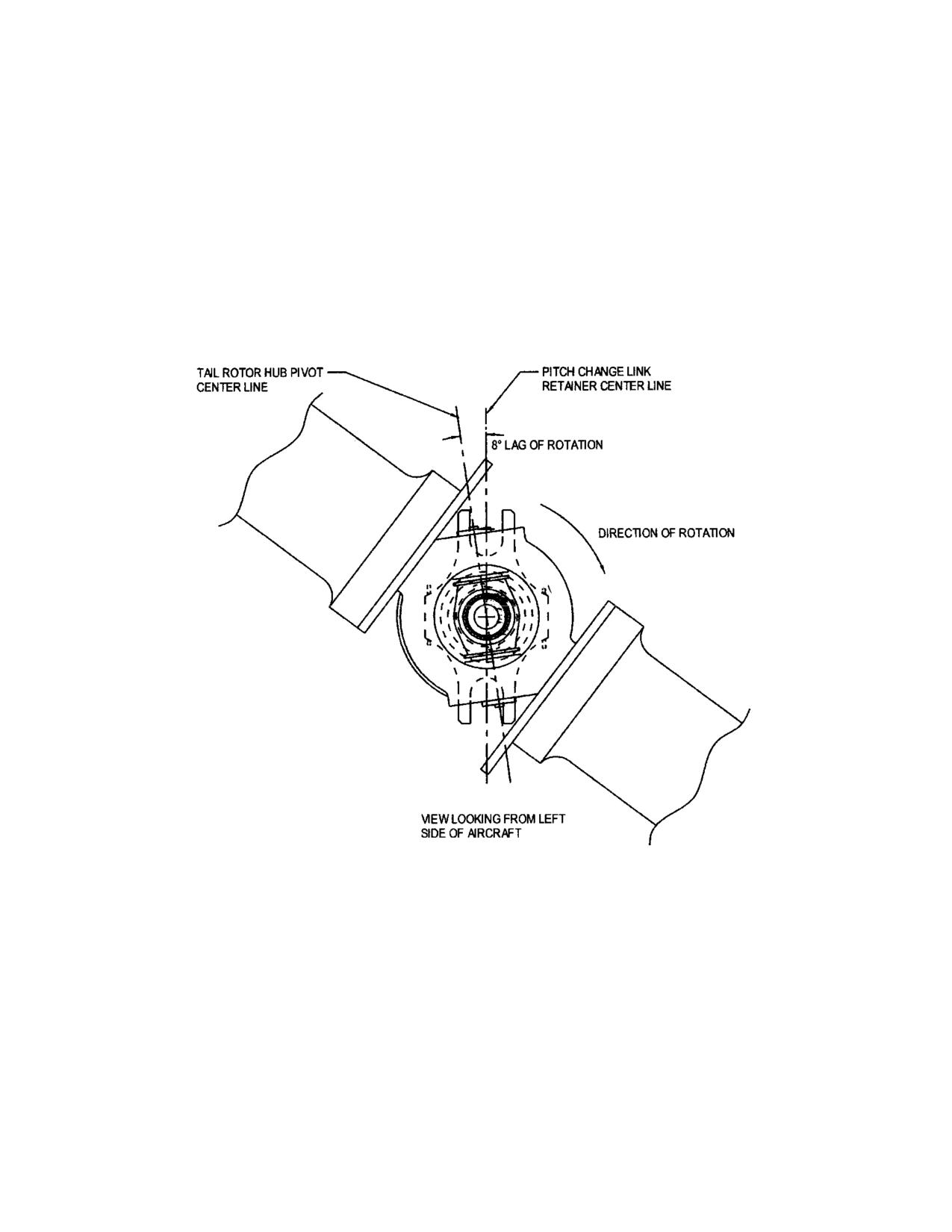
Figure 9-38. Tail Rotor Installation Orientation
MM-9-125
Feb 9/01
9-52. Consumable Materials List
ITEM
DESCRIPTION
PART NUMBER
Abrasive pad
Pad, 3M Brand (Scotch-Brite)
7447B
Acetone
Acetone solvent
Adhesion promoter
Adhesion promoter, 3M Brand
86A
(primer)
Adhesive
Epoxy adhesive, 3M Brand
DP190
Adhesive
Epoxy adhesive, 3M Brand
DP420
Adhesive
Adhesive, Loctite Brand (4205)
28028
Adhesive
Adhesive, Loctite Brand (635)
63531
Aluminum oxide
Aluminum oxide paper or cloth, medium and
paper or cloth
fine grit, 3M Brand or equivalent
Chemical coating
Iridite solution, Allied-Kelite Brand
14-4A1
Corrosion inhibitor
ACF-50, Lear Chemical Research Brand
10013, 10032
Denatured alcohol
Denatured alcohol
Epoxy sealant
Epoxy adhesive, Hysol Brand
EA 9309.2NA
Grease
Grease, Lubriplate Brand
630-AA2 (06701)
Grease
Grease
MIL-PRF-81322
Grease
Aeroshell 22 (Shell)
Isopropyl alcohol
Isopropyl alcohol
Lockwire
Lockwire, .025”
MS20995C25
Lockwire
Lockwire, .032”
MS20995C32
Lockwire
Lockwire, .041”
MS20995C41
Lubricant
LPS 2 Heavy Duty Lubricant, LPS
00216
Laboratories
MEK
MEK solvent
Metal Etch
Aluminum etching compound, Semco Brand
Pasa-Jell 1053
Oil
Any grade internal combustion engine motor
oil
Oil
Silicon oil
L-45 or SF96-20
1 Complies with MIL-DTL-5541/MIL-DTL-81706 (formerly MIL-C-5541/MIL-C-81706).
2 MIL-PRF-81322 is an acceptable alternate.
3 Acceptable material where metal prep is required.
Rev. 26
MM-9-126
Feb 28/2020
6)
Disconnect the fuel crossover line (para. 10-15).
7)
Disconnect the overboard vent crossover line (para. 10-15).
CAUTION
Use a backing wrench when installing or removing fluid lines and
fittings to prevent damage.
8)
Disconnect the supply line from the fuel cell fitting.
9)
Disconnect the sump drain line from the drain valve.
10) Unlace the fuel cell from the supports.
11) Remove the fuel cell from the fuel cell structure.
10-5. Inspection - Fuel Cells
A. Inspect the fuel cells for loose seams, cuts, abrasions, scuffed surfaces, tears,
blisters, and for any area that appears to have become soaked with fuel.
B. Inspect the fittings and inserts for damage and security.
10-6. Repair - Fuel Cells
A. Repair the fuel cells I/A/W the manufacturer's instructions.
B. Replace fittings that are damaged beyond repair.
C. Repair inserts I/A/W the manufacturer's instructions.
10-7. Replacement - Fuel Cells
A. Standard Fuel System
NOTES
Replacement procedures are the same for both fuel cells unless
noted.
Replace all used packings/o-rings.
Cover all open ports and lines to prevent contamination of the fuel
system.
The foam assembly is installed in the replacement fuel cells.
Rev. 26
MM-10-7
Feb 28/2020
1)
Remove the screws that secure the fuel fitting assembly to the fuel cell.
2)
Partially separate the fuel fitting assembly from the fuel cell to access the
syphon tube assembly nut coupling.
3)
Loosen the nut coupling, then pivot the syphon tube toward the fuel strainer.
4)
Remove the fuel fitting assembly from the fuel cell. (The low fuel warning switch
will be mounted on the fuel fitting assembly for the right fuel cell.)
5)
Position the fuel fitting assembly onto the replacement fuel cell such that the
sump drain valve it is orientated toward the low corner of the fuel cell. Pivot the
end of the syphon tube to the low corner. Torque the nut coupling (50-65 in-lb/
Nm).
6)
Install the screws to secure the fuel fitting assembly to the fuel cell and torque to
25-30 in-lbs/2.8-3.4 Nm.
7)
Remove the hardware securing the fuel quantity probe mounting flange to the
fuel cell (fuel quantity probe still installed on the mounting flange). Note the
position of the fuel quantity probe and install the mounting flange on the
replacement fuel cell. Torque the hardware to 25-30 in-lbs/2.8-3.4 Nm.
B.
Aerazur Fuel Bladder System
1)
Remove the drain valve from the fuel cell. Clean the threads on the drain valve.
Coat the threads with sealant (Permatex #1C) and install the valve into the
replacement fuel cell.
2)
Remove the supply line fitting from the fuel cell. Replace the packing and install
the fitting into the replacement fuel cell.
3)
Remove the access plates (zippers) from the fuel cell.
4)
Remove the strainer assembly installed in the bottom of the fuel cell over the
supply line outlet and install in the replacement fuel cell.
5)
Remove the fuel quantity probe and the low fuel warning switch from the right
fuel cell and install into the replacement fuel cell (para. 10-48 and 10-51).
NOTE
Ensure that the lacing cord used to secure the internal baffles in the
bladder does not interfere with the access plates (zipper) during
installation of the plates (zipper). The plates (zipper) will not seal if
this occurs.
6)
Reinstall the access plates (zippers) and torque the installation hardware to 40-
50 in-lbs/4.5-5.7 Nm.
Rev. 26
MM-10-8
Feb 28/2020
10-8. Installation - Fuel Cells
A.
Standard Fuel System
NOTES
Installation procedures are the same for both fuel cells unless noted.
Replace all used packings/O-rings.
1)
Apply a light coat of corn starch (or equivalent) to the inside surface of the fuel
cell support structure to allow the fuel cell to be adjusted for final fit.
2)
Install the fuel cell into the support structure.
3)
Position the gasket between the fitting assembly the support structure. Install
the bolts and washers that secure the fitting assembly to the support structure
and torque to 25-30 in-lbs/2.8-3.4 Nm. Lockwire bolts with 0.020" lockwire.
CAUTION
Use a backing wrench when installing or removing fluid lines and fittings to
prevent damage.
4)
Connect the sump drain line to the drain valve.
5)
Connect the supply line to the fuel cell fitting.
6)
Connect the overboard vent crossover line (para. 10-18).
7)
Connect the crossover line (para. 10-18).
8)
Connect the electrical connectors for the fuel quantity probe and the low fuel
warning switch in the right side fuel cell.
9)
Install the fuel cell covers (para. 8-17).
10) Install a filler port gasket between the fuel cell the fuel cell cover and one
between the fuel cell cover and the filler port. Install the hardware and torque to
25-30 in-lbs/2.8-3.4 Nm.
11) Install the air deflector on the top of the cabin.
12) Install the upper plenum/air inlet (para. 13-31).
13) Service the fuel cells (para. 4-4) and check for leaks.
14) Check for proper operation of the fuel quantity system (para. 7-85) and the lower
fuel warning system (para. 10-41). Install the cover for the fuel quantity probe
after determining that the system is operating properly.
15) Bleed the fuel system I/A/W the Rolls-Royce 250-C20 Series Operation and
Maintenance Manual.
Rev. 26
MM-10-9
Feb 28/2020
B.
Aerazur Fuel Bladder System
NOTES
Installation procedures are the same for both fuel cells unless noted.
Replace all used packings/O-rings.
1)
Apply a light coat of corn starch (or equivalent) to the inside surface of the fuel
cell support structure to allow the fuel cell to be adjusted for final fit.
2)
Install the fuel cell into the support structure.
3)
Lace the top edge of the fuel cell to the support mounts.
CAUTION
Use a backing wrench when installing or removing fluid lines and
fittings to prevent damage.
4)
Connect the sump drain line to the drain valve.
5)
Connect the supply line to the fuel cell fitting.
6)
Connect the overboard vent crossover line (para. 10-18).
7)
Connect the crossover line (para. 10-18).
8)
Connect the electrical connectors for the fuel quantity probe and the low fuel
warning switch in the right fuel cell.
9)
Install the fuel cell covers (para. 8-17).
10) Install a filler port gasket between the fuel cell the fuel cell cover and one
between the fuel cell cover and the filler port. Install the hardware and torque to
40-50 in-lbs4.5-5.7 Nm.
11) Install the air deflector on the top of the cabin.
12) Install the upper plenum/air inlet (para. 13-31).
13) Service the fuel cells (para. 4-4) and check for leaks.
14) Check for proper operation of the fuel quantity system (para. 7-85) and the lower
fuel warning system (para. 10-41). If applicable, install the cover for the fuel
quantity probe after determining that the fuel quantity system is operating
properly.
15) Bleed the fuel system I/A/W the Rolls-Royce 250-C20 Series Operation and
Maintenance Manual.
Rev. 26
MM-10-10
Feb 28/2020
SECTION 11
POWER TRAIN
TABLE OF CONTENTS
Paragraph
Description
Page
Table of Contents
MM-11-1
11-1.
Power Train
MM-11-5
11-2.
Description
MM-11-5
11-3.
Overrunning Clutch
MM-11-5
11-4.
Description
MM-11-5
11-5.
Removal
MM-11-5
11-6.
Inspection
MM-11-7
11-7.
Repair
MM-11-7
11-8.
Installation
MM-11-9
11-8.1.
Vented Clutch Oil Reservoir
MM-11-10.1
11-8.2.
Removal
MM-11-10.1
11-8.3.
Inspection
MM-11-10.1
11-8.4.
Installation
MM-11-10.1
11-9.
Power Output Shaft
MM-11-11
11-10.
Description
MM-11-11
11-11.
Removal
MM-11-11
11-12.
Inspection
MM-11-12
11-13.
Repair
MM-11-12
11-14.
Installation
MM-11-17
11-15.
Lower Pulley Drive System
MM-11-19
11-16.
Description
MM-11-19
11-17.
Alignment
MM-11-19
11-18.
Lower Pulley Assembly
MM-11-28
11-19.
Removal
MM-11-28
11-20.
Disassembly
MM-11-32
11-21.
Inspection
MM-11-33
11-22.
Repair
MM-11-39
11-23.
Assembly
MM-11-39
11-24.
Installation
MM-11-42
11-25.
Drive Belt
MM-11-43
11-26.
Description
MM-11-43
11-27.
Removal
MM-11-43
11-28.
Inspection
MM-11-44
11-29.
Installation
MM-11-45
11-30.
Main Rotor Transmission Assembly
MM-11-46
11-31.
Description
MM-11-46
11-32.
Removal
MM-11-46
11-33.
Disassembly
MM-11-49
11-34.
Inspection
MM-11-50
11-35.
Repair
MM-11-52
11-36.
Assembly
MM-11-52
Rev. 20
MM-11-1
Apr 25/13
SECTION 11
POWER TRAIN
TABLE OF CONTENTS
Paragraph
Description
Page
11-37.
Installation
MM-11-52
11-38.
Seal Replacement
MM-11-54
11-39.
Oil Filtration/Cooling System
MM-11-56
11-40.
Description
MM-11-56
11-41.
Removal
MM-11-56
11-42.
Inspection
MM-11-59
11-43.
Repair
MM-11-60
11-44.
Installation
MM-11-60
11-45.
Upper Pulley
MM-11-61
11-46.
Removal
MM-11-61
11-47.
Disassembly
MM-11-62
11-48.
Cleaning
MM-11-63
11-49.
Inspection
MM-11-63
11-50.
Repair
MM-11-63
11-51.
Assembly
MM-11-63
11-52.
Installation
MM-11-66
11-53.
Aft Pinion Bearing Assembly
MM-11-70
11-54.
Disassembly
MM-11-70
11-55.
Cleaning
MM-11-70
11-56.
Inspection
MM-11-70
11-57.
Repair
MM-11-70
11-58.
Assembly
MM-11-70
11-59.
Tail Rotor Drive Shafts
MM-11-71
11-60.
Description
MM-11-71
11-61.
Alignment
MM-11-71
11-62.
Short Tail Rotor Shaft
MM-11-74
11-63.
Removal
MM-11-74
11-64.
Disassembly
MM-11-74
11-65.
Inspection
MM-11-74
11-66.
Assembly
MM-11-75
11-67.
Installation
MM-11-75
11-68.
Long Tail Rotor Shaft
MM-11-75
11-69.
Removal
MM-11-75
11-70.
Disassembly
MM-11-76
11-71.
Inspection
MM-11-76
11-72.
Assembly
MM-11-77
11-73.
Installation
MM-11-77
11-74.
Drive Shaft Bearing Assembly
MM-11-78
11-75.
Disassembly
MM-11-78
11-76.
Inspection
MM-11-78
11-77.
Assembly
MM-11-81
Rev. 26
MM-11-2
Feb 28/2020
SECTION 11
POWER TRAIN
TABLE OF CONTENTS
Paragraph
Description
Page
11-78.
Flex Pack Coupling
MM-11-81
11-79.
Removal
MM-11-81
11-80.
Inspection
MM-11-81
11-81.
Installation
MM-11-81
11-82.
Tail Rotor Drive Hubs
MM-11-82
11-83.
Removal
MM-11-82
11-84.
Inspection
MM-11-82
11-85.
Installation
MM-11-82
11-86.
Tail Rotor Transmission
MM-11-85
11-87.
Description
MM-11-85
11-88.
Removal
MM-11-85
11-89.
Disassembly
MM-11-85
11-90.
Inspection
MM-11-85
11-91.
Assembly
MM-11-87
11-92.
Installation
MM-11-87
11-93.
Seal Replacement
MM-11-88
11-94.
Consumable Materials List
MM-11-94
Rev. 26
MM-11-3
Feb 28/2020
SECTION 11
SERVICING, RECOMMENDED OVERHAULS, INSPECTIONS,
AND GENERAL MAINTENANCE
TABLE OF CONTENTS
Paragraph
Description
Page
INTENTIONALLY LEFT BLANK
MM-11-4
Feb 9/01
D. Assemble the new seal and bearing into the bearing housing.
(1) Place a new seal (2) on the stepped end of T-0186-5. Press the seal into the
bearing housing (3) (Figure 11-1c, d).
(2) Determine the amount of shims required for assembly.
a. Measure the distance from the seating surface in the bearing housing to the
bottom of the retaining ring groove in the bearing housing (dimension is
etched on newer bearing housings). Measure the height of the new bearing
stack-up. Determine the amount of shims required to allow .000/.003 inch
(.000/.076 mm) pinch fit between the bearing and the retaining ring.
(3)
Install the shim stack-up from step (2) into the bearing housing (3).
CAUTION
When installing the bearing set into the bearing housing, pressure may be applied
to only the outer race. Damage to the bearing will occur if pressure is applied to the
inner race.
NOTE
The bearing set consists of a pair of bearings. The word THRUST on the face of the
outer ring indicates the thrust side of the bearing. Also, on the thrust side will be an
* mark on the face of the outer ring and an * mark on the face of the inner ring.
When installing the bearing set into the bearing housing, best results will be
obtained if the bearing set is positioned thrust sides facing together and with the *
marks aligned axially (outer * to outer * and inner * to inner *).
(4) Place the bearing housing with the shims installed in the press. Use T-0186-7 to
push the bearing set (5) into the bearing housing (Figure 11-1e).
CAUTION
When installing the clutch assembly, pressure may be applied to only the inner
race. Damage to the bearing will occur if pressure is applied to the outer race.
(5) Place the clutch assembly (1) in the press. Carefully place the bearing housing
(3) onto the clutch shaft and press the bearing housing onto the clutch shaft
(Figure 11-1f, g).
(6) Install the retaining ring (7).
E. If a different engine and/or accessory gearbox has been installed in the aircraft,
determine if an offset bearing housing is required in accordance with paragraph 13-117, I and
install the correct offset bearing housing on the ORC (para. 11-7. D)
11-8. Installation - Overrunning Clutch
NOTE
Replace all used O-rings/packings and gaskets.
CAUTION
Use a backing wrench to prevent damaging fluid/air lines and fittings.
Rev. 26
MM-11-9
Feb 28/2020
CAUTION
If an offset bearing housing is installed on the ORC, ensure that the
notches in the bearing housing are orientated in accordance with the
previous maintenance entry or in accordance with the new orientation for
the new engine/accessory gearbox combination from paragraph 13-117, I.
A. Lubricate (MIL-PRF-23699) the O-ring (8) on the ORC bearing housing (3). Install a
new gasket (9) on the bearing housing. Install the ORC into the accessory gearbox.
B. Install and torque the mounting nuts (10) and washers (11).
C. Install the power output shaft (para. 11-14), if required.
NOTE
The power output shaft must be installed to perform steps C through E.
D. Install the spacer/shim (12) and/or required amount of shims (13) to have .004" to
.006" distance/clearance between the spacer/shims and the retaining ring. Install the retaining
ring (14).
NOTE
Install the spacer/shim and/or shims so that the thickest item is against the
retaining ring.
E. Install the clutch cover (16), O-ring (15), and retaining ring (21). Replace the service
plug o-rings (18) and the sight plug o-ring (19). Torque two of the service plugs and sight plug to
20 in-lbs/2.3 Nm and lockwire (.025") to the cover.
NOTE
Step F is applicable to aircraft equipped with the vented clutch oil reservoir.
F. Connect the vented clutch oil reservoir oil lines.
G. Service the clutch (para. 4-10). Torque the remaining service plug to 20 in-lbs/2.3 Nm
and lockwire (.025") to the cover.
H. Check for leaks.
I.
Install the Py-Pg pneumatic line between the fuel control and the power turbine
governor. Refer to the Rolls-Royce 250-C20 Series Operation and Maintenance Manual
(10W2).
J. Install the engine fuel pump assembly. Refer to the Roll-Royce 250-C20 Series
Operation and Maintenance Manual (10W2).
K. Connect the fuel filter differential pressure lines, fuel pump seal drain line and the fuel
supply line to the fuel pump.
Rev. 23
MM-11-10
Jul 3/15
11-9. Power Output Shaft
11-10. Description - Power Output Shaft
The power output shaft transmits engine power from the overrunning clutch to the lower
pulley drive shaft. The power output shaft is installed on the power output pad on the rear side
of the accessory gearbox. The shaft has a splined interface with the overrunning clutch (ORC)
and is coupled to the lower pulley drive shaft by a flex pack coupling.
11-11. Removal - Power Output Shaft (Figure 11-1.1)
CAUTION
Prior to removing the power output shaft assembly, inspect the gearbox
housing for a decal indicating that an offset bearing housing is installed.
Maintenance records may also indicate if an offset bearing housing is
installed. If a decal is present or maintenance entries indicate that an offset
bearing housing is installed, visually verify that the notches in the bearing
housing are orientated in accordance with the maintenance entry.
NOTE
The engine access panels do not need to be removed if the optional panel
openers are installed.
A. Remove the left and right side engine access panels and the left and right aft side
cowlings.
B. Disconnect the battery.
C. Remove the lower pulley assembly (para. 11-19).
D. Remove the safety from the service plugs (18) in the ORC cover (16). Place a
suitable container under the clutch cover, remove one of the service plugs and drain the oil from
the clutch by rotating the open port to the 6 o'clock position.
E. Remove the clutch cover retaining ring (21) and the clutch cover (16).
F. Remove the retaining ring (14), spacer (12), and shims (13) from the end of the power
output shaft (22).
G. Remove the special bolts (32) and washers (33) securing the power output shaft
bearing housing (23) to the accessory gearbox.
H. Using a suitable plastic hammer, remove the power output shaft assembly from the
accessory gearbox by tapping the end of the shaft in the ORC. When the gasket and o-ring
release, remove the power output shaft assembly from the accessory gearbox.
Rev. 26
MM-11-11
Feb 28/2020
I.
Remove the gasket (30) from the bearing housing assembly.
NOTE
Cover the open overrunning clutch and rear power output pad on the
engine.
11-12. Inspection - Power Output Shaft
A. Inspect the power output shaft for cracks, corrosion, bending, nicks, scratches, and
spline wear.
B. Inspect the bearing and bearing housing for roughness, excessive wear, and seal
leakage.
11-13. Repair - Power Output Shaft
A. See Table 11-1 for damage limit and repair criteria for the power output shaft (22) and
the bearing housing (23).
NOTE
If replacing a bearing housing seal, the bearings must also be replaced.
Pressing the bearings housings from the clutch and power output shaft
while removing a seal will damage the bearings. Do not reuse the bearings.
B. Replace the bearing housing seal (24) and bearing (27) as follows:
(1) Remove the power output shaft (para. 11-11).
(2) Remove the retaining ring (29) from the power output shaft.
(3) Place the drive shaft assembly in the T-0186-11 and T-0186-9 tool. Press the
shaft from the bearing housing assembly (23) (Figure 11-1.3a).
(4) Remove the retaining ring (28) from the bearing housing assembly.
(5) Place the bearing assembly in the T-0186-11 and T-0186-9 tool. Using tool T-
0186-15, press the bearing from the bearing housing assembly (Figure 11-1.3b).
(6) Remove the seal (24) by inserting a small screw driver or pick under the seal
and prying it out.
C. Assemble a new seal and bearing into the bearing housing.
(1) Place a new seal (24) on the stepped end of T-0186-3. Press the seal into the
bearing housing (23) (Figure 11-1.3c and Figure 11-1.3d).
(2) Determine the amount of shims required for assembly.
Rev. 26
MM-11-12
Feb 28/2020
INTENTIONALLY LEFT BLANK
Rev. 20
MM-11-13.2
Apr 25/13
Table 11-1. Overrunning Clutch and Power Output Shaft Assemblies
Inspection Requirements*
P/N
Fig. 11-1
Part Name
Inspection
Serviceable Limits
Repair Limits
Repair or Action
Item #
4131002
1
Splined Outer Shaft
Bearing Housing Seal
-.002
Not Repairable
Replace Shaft
Surface Dia. 1.495 to
1.505
Support Bearing
-.0005
Not Repairable
Replace Shaft
Surface Dia. 1.3781 to
1.3785
Cracks
None Allowed
Not Repairable
Replace Shaft
Nicks, scratches, or
.030 deep
≤ .030 deep
Blend out smooth
corrosion
4131006
3
Bearing Housing
Seal Bore Dia. 1.918 to
+.002
Not Repairable
Replace Housing
1.922
Bearing Bore Dia.
+.0003
Not Repairable
Replace Housing
2.1648 to 2.1654
Cracks
None Allowed
Not Repairable
Replace Housing
Nicks, scratches, or pits
.030 deep
≤ .030 deep
Blend out smooth
ECD4014
6
Bearing
Roughness, spalling,
None Allowed
Not Repairable
Replace Bearing
pits, or corrosion
4131003
22
Splined Drive Shaft
Seal and Support
-.0003
Not Repairable
Replace Shaft
Bearing Surface Dia.
.9844 to .9849
Rev. 26
MM-11-14
Feb 28/2020
11-14. Installation - Power Output Shaft
CAUTION
If an offset bearing housing is installed on the power output shaft, ensure that
the notches in the bearing housing are orientated in accordance with the
previous maintenance entry or in accordance with the new orientation for the
new engine/accessory gearbox combination from paragraph 13-117, I.
NOTE
Replace all used O-rings/packings and gaskets.
A. Lubricate (MIL-PRF-23699) the O-ring (31) on the power output shaft bearing housing
(23). Install a new gasket on the bearing housing assembly. Install the power output shaft (22)
into the accessory gearbox.
B. Install and torque the special mounting bolts (32) and washers. Tighten and lockwire
(.025) in pairs.
C. Install the spacer (12) and/or required amount of shims (13) to have a .004" to .006"
distance/clearance between the spacer/shims and the retaining ring. Install the retaining ring
(14).
NOTE
Install the spacer/shim and/or shims so that the thickest item is against the
retaining ring.
D. Install the clutch cover (16), o-ring (15), and retaining ring (21).
E. Install the lower pulley assembly (para. 11-24).
F. Verify the engine to lower pulley assembly alignment (para. 11-17).
G. Service the overrunning clutch (para 4-10).
H. Install the left and right side engine access panels and the left and right aft side
cowlings.
WARNING
The following step to be performed by authorized personnel only.
I.
Perform a limited maintenance test flight (para. 4-61).
Rev. 26
MM-11-17
Feb 28/2020
INTENTIONALLY LEFT BLANK
Rev. 10
MM-11-18
Oct 20/09
11-15. Lower Pulley Drive System
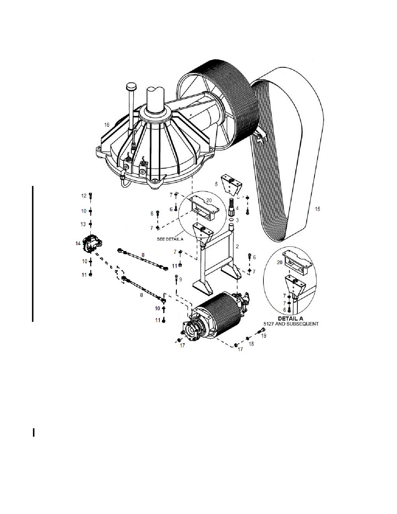
11-16. Description - Lower Pulley Drive System (Figure 11-2)
The lower pulley drive system consists of the lower pulley drive shaft and hub, lower
pulley, "H"- strut, and flex pack couplings. The lower pulley drive shaft, located in the hollow
center of the lower pulley assembly, is connected to the power output shaft and the lower pulley
assembly via flex pack couplings. The lower pulley shaft is also used to drive the oil cooler
blower fan by a hub attached to the aft end of the lower pulley drive shaft. The lower pulley has
two positioning links attached to the right side of the bearing housings. The links are used to
laterally align the lower pulley to the engine. Thermocouples are installed in the lower pulley
bearing housings to provide temperature input for the drive bearing hot caution panel segment
(DRIVE BRG HOT). The "H"- strut, used to tension the drive belt, is connected to the lower
pulley at the lower end and to the pinion bearing support truss and the main rotor transmission
at the upper end. The flex pack couplings consist of multiple stainless steel plates bolted to the
drive flanges. The flex pack couplings will allow up to 1.5° of misalignment between the power
output shaft and the lower pulley drive shaft.
11-17. Alignment - Lower Pulley Drive
NOTE
Work Aid Document (WAD) T-001; Aligning the TH-28/480 Series
Lower Drive System provides additional reference information for aligning
the lower drive system in the TH-28/480 Series helicopters. Use WAD T-
001 as additional reference information for the procedures that follow in this
paragraph (para. 11-17).
A. Prepare to align the lower pulley drive system using the following steps:
(1) Remove the left and right side engine access panels, baggage compartment
door, forward baggage compartment panels, and oil cooler/step access panel.
(2) Remove the upper plenum/air inlet (para. 13-28).
(3) Remove the air exit duct center panel from the pylon.
(4) Disconnect the battery. Disconnect the electrical leads from the ignition module.
Remove the ignition module from its mounts. Refer to the Rolls-Royce 250-C20
Series Operation and Maintenance Manual (10W2).
(5) Remove the intermediate oil cooler blower drive shaft (para. 13-75).
(6) Remove the oil cooler inlet ducting (para. 13-82).
Rev. 5
MM-11-19
Aug 4/06
1.
Lower Pulley Assembly
11.
Nut
2.
H-Strut
12.
Bolt
3.
Bearing
13.
Spacer
4.
Jackscrew
14.
Isolation Mount
5.
Tension Mount
15.
Drive Belt
6.
Bolt
16.
Main Rotor Transmission
7.
Washer
17.
Spacer
8.
Tie Rod
18.
Washer
9.
Bolt
19.
Special Bolt
10.
Washer
20.
Fitting
Figure 11-2. Lower Pulley Drive System
Rev. 26
MM-11-20
Feb 28/2020
NOTE
The tension on the front and aft side of the belt does not have to be the
same. The maximum difference allowed is 250 lbs.
C. Align the lower pulley drive shaft to the power output shaft using the following
procedure:
(1)
Attach the positioning links to the right side of the lower pulley bearing housings.
(2)
Position the lower pulley drive shaft so that the bolt is at the 12 o'clock position.
Rotate the power output shaft so one of its flanges is at the 12 o'clock position.
Check the vertical alignment by observing the position of the bolt in relation to
the bolt hole in the power output shaft and attempting to install the bolt into the
power output shaft using finger pressure. If excessive vertical misalignment is
apparent, proceed to step (3). Rotate the bolt to either the 3 or 9 o'clock position
and rotate one of the power output shaft flanges to the same position. Observe
the lateral alignment of the shafts again by observing the relation of the bolt to
the bolt hole in the power output shaft and attempting to install the bolt into the
power output shaft using finger pressure. Adjust the positioning links to laterally
align the shafts. Recheck the vertical alignment. The alignment of the lower
pulley to the power output shaft is correct when the bolt can be installed into the
power output shaft using finger pressure. Proceed to step (3) if the engine
requires reshimming.
(3)
Loosen the jam nut and the mount nut on the top engine mount. Loosen the
hardware securing the left and right side engine mounts to the pylon.
Add/subtract the required amount of shims to align the power output shaft to the
lower pulley drive shaft. Tighten the hardware securing the engine mounts to
the pylon. Ensure the washer stack-up is sufficient to prevent the nuts from
bottoming on the engine mount bolts. Retighten the top mount nut until it
contacts the pylon mount and tighten one more flat. After acceptable alignment
has been verified, tighten the jam nut against the mount nut and lockwire the
mount nut and jam nut.
(4)
Recheck the vertical and lateral alignment of the shafts. Readjust the
positioning links or engine shims as required until the shafts are aligned.
(5)
Position the power output shaft and lower pulley drive shaft so they both have a
flange at the 3 or 9 o'clock position. Using a telescoping gauge and a
micrometer or a feeler gage, measure the distance between the shaft flanges.
Record the measurement and rotate the shafts 180. Measure the gap and
compare the two measurements. Adjust the aft positioning link until the flange
faces are parallel within .010 "/.25 mm. Recheck the vertical and lateral
alignment. If the alignment is acceptable, proceed to step D. If the alignment is
not acceptable, make adjustments.
D.
Align the oil cooler blower shaft to the lower pulley using the following procedure:
(1) If installed, remove the inlet duct and the cover from the back of the impeller
shroud on the TH-28. If installed, remove the inlet duct and the forward sheet
metal panels from the baggage compartment on the 480/480B.
Rev. 5
MM-11-25
Aug 4/06
(2) If installed, remove the intermediate drive shaft from between the blower
assembly and the lower pulley. Remove the flex packs from the intermediate
drive shaft and the oil cooler blower shaft assembly as applicable. Reconnect
the intermediate drive shaft to the drive hub on the lower pulley assembly with
the flanges of the drive hubs bolted together through tool T-0166.
(3) Loosen the split clamps (bearing housings) securing the oil cooler blower shaft
bearings.
(4) Rotate the shafts so that the flanges are at the 12 and 6 o'clock positions. Using
one of the bolts from the flex pack installation, attempt to insert the bolt through
both drive hubs. The bolt should fit without having to force it into the hubs (“slip
fit” tolerance). Adjust the vertical position of the oil cooler blower shaft assembly
by adding/removing shims between the bearing housings and the bearing
mounts. After the vertical alignment is complete, measure the distance between
the flange faces at the 12 and 6 o'clock position. Add/Remove shims as required
until the flange faces are parallel to within .005"/.13 mm. Using one of the bolts
from the flex pack installation, attempt to insert the bolt through both drive hubs
(intermediate drive shaft and oil cooler blower shaft) with the flanges positioned
at 3 and 9 o'clock. The bolt should fit without having to force it into the hubs
(“slip fit” tolerance). Adjust the oil cooler blower shaft lateral alignment by
repositioning the bearing mounts on the oil cooler shelf. After the lateral
alignment adjustments are made, measure the distance between the flanges at
the 3 and 9 o'clock positions. Adjust the position of the aft bearing mount until
the flange faces are parallel to within .005"/.13 mm. Recheck the vertical and
lateral alignment and make any adjustments as required.
CAUTION
Ensure the oil cooler blower fan does not contact the blower fan shroud.
(5) Retighten bearing clamps (bearing housings) after shaft alignment is
accomplished.
(6) Remove the intermediate drive shaft and tool T-0166.
(7) Install the cover onto the aft side of the impeller shroud on the TH-28. Install the
forward sheet metal panels of the baggage compartment on the 480/480B.
E.
Reassemble the lower pulley drive system as follows:
(1) Disassemble the aft flex pack coupling.
NOTE
Ensure the spacers are installed with the beveled face toward the flex pack
coupling.
Rev. 26
MM-11-26
Feb 28/2020
Table 11-2. Lower Pulley Assembly
Inspection Requirements*
P/N
Fig. 11-6
Part Name
Inspection*
Serviceable Limits*
Repair Limits
Repair or Action
Item #
4130508-13
10 (Sheet 1)
Pulley Driven Shaft
Nicks, scratches, or
.030 deep
≤ .030 deep
Blend out smooth
13 (Sheet 2)
(Cont’d)
corrosion
Threads (rolled or
None Allowed
Not Repairable
Replace Shaft
missing)
Bent Flanges
.002
Not Repairable
Replace Shaft
4130513-13
11 (Sheet 1)
Spacer
Seal Surface Dia. 2.684
-.0003
Not Repairable
Replace Spacer
14 (Sheet 2)
to 2.692
Pulley Surface Dia.
-.001
Not Repairable
Replace Spacer
2.499 to 2.500
I.D. 2.1598 to 2.1604
+.0003
Not Repairable
Replace Spacer
Cracks
None Allowed
Not Repairable
Replace Spacer
Nicks, scratches, or
.030 deep
≤ .030 deep
Blend out smooth
corrosion
4130510-17
12 (Sheet 1)
Lower Pulley
Spacer and Pilot Bores
+.001
Not Repairable
Replace Pulley
or
15 (Sheet 2)
Dia. 2.498 to 2.499
4130510-19
None Allowed
Not Repairable
Replace Pulley
Cracks
Nicks, scratches, or
.030 deep
≤ .030 deep
Blend out smooth
corrosion
Depth of grooves
≥.176
Not Repairable
Replace Pulley
Nicks and gouges in
None Allowed
≤ .25 long and ≤
Blend out smooth
belt grooves
.025 deep
Rev. 26
MM-11-35
Feb 28/2020
Table 11-2. Lower Pulley Assembly
Inspection Requirements*
P/N
Fig. 11-6
Part Name
Inspection*
Serviceable Limits*
Repair Limits
Repair or Action
Item #
4130512-13, -17
13 (Sheet 1)
Bearing Retainer
Sleeve Surface Dia.
-.0003
Not Repairable
Replace Retainer
16 (Sheet 2)
2.1604 to 2.1610
Bearing Inner Race
-.0003
Not Repairable
Replace Retainer
Surface Dia. 2.1654 to
2.1660
Inner Seal Surface Dia.
-.002
Not Repairable
Replace Retainer
2.684 to 2.690
Spline Pilot Surface
-.0005
Not Repairable
Replace Retainer
Dia. 2.499 to 2.500
(-13) I.D. 1.7800 to
+.0003
Not Repairable
Replace Retainer
1.7805
(-17) I.D. 1.7806 to
+.0003
Not Repairable
Replace Retainer
1.7810
Cracks
None Allowed
Not Repairable
Replace Retainer
Nicks, scratches, or
.030 deep
≤ .030 deep
Blend out smooth
corrosion
4130517-13
14 (Sheet 1)
Sleeve
O.D. 2.415 to 2.422
-.002
Not Repairable
Replace Sleeve
17 (Sheet 2)
I.D. 2.1598 to 2.1604
+.0003
Not Repairable
Replace Sleeve
Cracks
None Allowed
Not Repairable
Replace Sleeve
Nicks, scratches, or
.030 deep
≤ .030 deep
Blend out smooth
corrosion
4130524-13
15 (Sheet 1)
Nut
Threads (rolled or
None Allowed
Not Repairable
Replace Nut
18 (Sheet 2)
missing)
Cracks
None Allowed
Not Repairable
Replace Nut
Rev. 26
MM-11-36
Feb 28/2020
Table 11-2. Lower Pulley Assembly
Inspection Requirements*
P/N
Fig. 11-6
Part Name
Inspection
Serviceable Limits
Repair Limits
Repair or Action
Item #
4130506-13,
16 (Sheet 1)
Lower Pulley
Hub Surface Dia. .659
-.0005
Not Repairable
Replace Shaft
-15
19 (Sheet 2)
Drive Shaft
to .661
Coupling Surface Dia.
-.0003
Not Repairable
Replace Shaft
1.0840 to 1.0845
Cracks
None Allowed
Not Repairable
Replace Shaft
Nicks, scratches, or
.030 deep
≤ .030 deep
Blend out smooth
corrosion
Bent Flanges
.002
Not Repairable
Replace Shaft
Threads (rolled or
None Allowed
Not Repairable
Replace Shaft
missing)
ECD4024-1
17 (Sheet 1)
Flex Pack
Cracked Elements
None Allowed
Not Repairable
Replace Flex Pack
20 (Sheet 2)
Nicks, scratches, or
.001 Deep
≤ .001 deep
Blend out smooth and
corrosion
polish
Bent Elements
None Allowed
Not Repairable
Replace Flex Pack
4130504-13
22 (Sheet 1)
Lower Pulley Drive
Inner Shaft Bore Dia.
+.0003
Not Repairable
Replace Hub
25 (Sheet 2)
Shaft Hub
1.0845 to 1.0850
Cracks
None Allowed
Not Repairable
Replace Hub
Nicks, scratches, or
.030 deep
≤ .030 deep
Blend out smooth
corrosion
Bent Flanges
.002
Not Repairable
Replace Hub
Rev. 26
MM-11-37
Feb 28/2020
Table 11-2. Lower Pulley Assembly
Inspection Requirements*
P/N
Fig. 11-6
Part Name
Inspection
Serviceable Limits
Repair Limits
Repair or Action
Item #
NAS509-12
24 (Sheet 1)
Drive Shaft
Cracks
None Allowed
Not Repairable
Replace Nut
27 (Sheet 2)
Retaining Nut
Threads (rolled or
None Allowed
Not Repairable
Replace Nut
missing)
4130516-17
25 (Sheet 1)
Oil Cooler Blower
I.D. .662 to .663
+.0005
Not Repairable
Replace Hub
28 (Sheet 2)
Shaft Hub
Cracks
None Allowed
Not Repairable
Replace Hub
Nicks, scratches, or
.030 deep
≤ .030 deep
Blend out smooth
corrosion
Bent Flanges
≤.010
Not Repairable
Replace Hub
* All dimensions are in inches.
Rev. 21
MM-11-38
Apr 30/14
11-22. Repair - Lower Pulley Assembly
A. See Table 11-2 for damage limit and repair criteria for the components of the lower
pulley assembly.
B. Repair damage to the "H"-strut assembly I/A/W AC 43.13-1B. Replace components of
the “H”-strut that cannot be repaired.
C. Replace the bearing seals if worn or leaking.
D. Replace worn tie rod bearings and the tie rods if bent or damage is more than .020
inches/.51 mm deep.
E. Elongated roll pin holes in the lower pulley drive shaft and/or oil cooler blower shaft
hub are not repairable.
11-23. Assembly - Lower Pulley Assembly (Figure 11-6)
NOTE
Heat is used to aid in assembly of the lower pulley assembly. Using an
oven is the preferred method of heating parts. Heat guns can be used to
heat parts but temperature control is very difficult to maintain.
WARNING
Use extreme caution when handling heated parts to prevent from
injuring personnel.
WARNING
Use protective gloves when handling heated parts.
NOTE
Lubricate the splines of the lower pulley and the lower pulley driven shaft upon
assembly with grease (MIL-PRF-81322).
NOTE
For 480 model equipped with grease-lubricated lower pulley assemblies,
lubricate the seal lips, the inner diameter of the bearing and bearing housing,
and the outer diameter of the lower pulley driven shaft with grease (MIL-PRF-
81322) upon assembly.
NOTE
For any 480 converted via SIL T-022 and all 480B with oil-lubricated lower
pulley assemblies, lubricate the seal lips, the inner diameter of the bearing
and bearing housing, and the outer diameter of the lower pulley driven shaft
(except splines) with oil (MIL-PRF-23699) upon assembly.
Rev. 26
MM-11-39
Feb 28/2020
A.
Assemble the bearing housing assemblies as follows:
NOTE
Lubricate the seal lips before installation.
(1) Remove the “garter” springs from the seals if assembling oil lubricated lower
pulley bearing assemblies.
(2) Heat the bearing housing to approximately 250°F/121°C and install the bearing
with the notches facing into the bearing housing and with notch in the outboard
race at the bottom of the housing. Install the inboard seal and retaining ring into
the housing.
(3) Install the outboard seal and retaining ring into the bearing housing.
NOTE
If using an oven to heat the parts, place all the parts that require heat in the
oven at the same time.
NOTE
If required, use a press (manual or hydraulic) and pressing aids to
assemble the lower pulley assembly.
NOTE
The lower pulley bearing assemblies used on a grease lubricated lower
pulley assembly are interchangeable. Assemble an oil lubricated lower
pulley assembly so that the bearing housing sight plugs will be on the left
side of the aircraft when the lower pulley assembly is installed.
B.
Heat the aft bearing housing to approximately 250°F/121°C. Install the bearing
housing assembly that is going on the aft side of the pulley assembly onto the lower pulley
driven shaft. Ensure the inner race of the bearing is seated against the driven shaft.
C. Heat the spacer to approximately 250°F/121°C. Install the spacer onto the lower
pulley driven shaft and seat against the bearing in the bearing housing assembly.
D. Heat the pulley to approximately 250°F/121°C. Lubricate the lower pulley driven shaft
and install the pulley onto the lower pulley driven shaft. Seat the pulley against the spacer.
E. Heat the bearing retainer to approximately 250°F/121°C. Install the bearing retainer
onto the lower pulley driven shaft and seat against the pulley.
F. Heat the remaining bearing housing to approximately 250F°/121°C. Install the
remaining bearing housing assembly onto the lower pulley driven shaft and seat against the
bearing retainer.
Rev. 26
MM-11-40
Feb 28/2020
G. Heat the sleeve to approximately 250°F/121°C. Install the sleeve onto the lower
pulley driven shaft and seat against the bearing retainer.
H. Install the pulley adapter (Figure 11-5) the lower pulley driven shaft and place the
pulley assembly vertically in a vise.
I.
Install the retaining nut and torque to 190-200 ft-lbs/259.1-272.7 Nm using tool T-
0051. Allow the pulley assembly to cool and retorque the retaining nut. Install two safeties (.032
lockwire) between the lower pulley bearing retaining nut and the pulley drive shaft. Secure the
wire tails under the wire wrap.
J. Install the grease fittings and vents in the grease lubricated bearing housings. Install
the drain plugs and sight plugs in the oil lubricated bearing housings. Torque the sight plugs to
150 in-lbs/17 Nm and install a torque slippage mark.
K. Using a standard grease gun, lubricate the grease lubricated bearing assemblies with
6-8 pumps/squirts of grease (MIL-PRF-81322). Refer to paragraph 4-33 for lubrication
procedures to use during normal scheduled servicing. Service each oil lubricated bearing
assembly with .27 U.S. Ounces/8 ml of oil (MIL-PRF-23699). Install the service plugs. Refer to
paragraph 4-24 for servicing procedures to use during normal scheduled servicing.
L. Remove the pulley assembly from the vise and remove the pulley adapter.
NOTE
Ensure the spacers are installed with the beveled face toward the flex pack
coupling.
NOTE
Place the thick spacers between the flex pack coupling and the lower
pulley and lower pulley drive shaft hub flanges.
M. Install the aft flex pack coupling on the pulley drive shaft hub.
CAUTION
Ensure the hardware in the aft flex pack coupling does not contact the
lower pulley bearing housing.
N. Attach the aft flex pack coupling/drive shaft hub to the lower pulley driven shaft.
O. Install the lower pulley adapter on the lower pulley drive shaft and place the shaft
vertically in a vise.
P. Apply a light coat of grease (MIL-PRF-81322) to the splines of the lower pulley drive
shaft. Place the lower pulley assembly on the lower pulley drive shaft. Install the drive shaft hub
onto the splines of the lower pulley drive shaft. Install the washer (P/N C148740) and retaining
nut and torque to 90-100 ft-lbs/122.0-135.6 Nm.
Rev. 26
MM-11-41
Feb 28/2020
Q. Install the intermediate oil cooler blower drive shaft hub on the lower pulley drive shaft
and install the roll pins/taper pin. Install the oil cooler blower drive shaft hub wet with epoxy
primer. If installing new roll pins, it is permissible to trim the roll pins after they are installed.
Install a safety (.032 lockwire) from the retaining nut to the roll pins/taper pin.
NOTE
If components of the lower pulley assembly have been replaced, the
thickness of the spacers used on the forward flex pack coupling may have
to be changed.
R. Install the forward flex pack coupling on the lower pulley drive shaft.
S. Install the "H"- strut onto the lower pulley bearing housings.
T. Install the bearing temperature thermocouples into the bearing housings.
11-24. Installation - Lower Pulley Assembly (Figure 11-2)
A. Install the positioning links onto their fittings.
B. Install the lower pulley assembly into the drive belt.
C. Rotate the pulley so the "H"- strut is toward the left side of the aircraft. Install the load
bearing plugs (older “H”-strut assemblies) and the flat bearing (DU side up) into the "H"- strut
and install the tensioning assemblies onto the "H"- strut.
D. Rotate the "H"- strut into position and attach the tensioning assemblies to the main
rotor transmission and the aft pinion bearing support truss.
E. Align the lower pulley drive system (para.11-17).
NOTE
Ensure the spacers are installed with the beveled face toward the flex pack
coupling.
NOTE
If components of the lower pulley assembly have been replaced, the
thickness of the spacers used on the forward flex pack coupling may have
to be changed.
CAUTION
The bolts connecting the forward flex pack to the power output shaft are
special bolts that have shortened thread grip lengths. Do not replace with
standard hardware.
Rev. 26
MM-11-42
Feb 28/2020
CAUTION
Do not allow the pitch change bellcranks to drop onto the edge of the main
rotor mast when disconnecting the pitch change links.
(1) Disconnect the pitch change links from the pitch change bellcranks.
(2) Block up the pitch change bellcranks so the main rotor control tubes are in the
maximum upper position.
(3) Install the sling so the arms are between the pitch arm and the blade retention
assembly, over the lead/lag retaining nut, and outboard of the main rotor damper
rod-end. The sling arms are long enough to be double wrapped if preferred
(Figure 4-10).
Q.
Remove the main rotor transmission from the aircraft using the following procedures:
NOTE
If the lifting device is in a fixed location, install the ground handling wheels
and move the aircraft to remove the transmission.
(1) Attach a suitable lifting device to the lifting eye or sling.
(2) Install the ground handling wheels and lower the tail of the aircraft to provide
more clearance at the pylon while removing the transmission.
(3) Lift the transmission off of the pylon mounts enough to start moving the
transmission toward the rear of the aircraft. Lift the transmission higher as
clearance around the transmission allows.
(4) If the lifting eye is installed, push the main rotor control tube rod-ends (dog legs)
up to clear the aft pylon tubes. If the sling is installed, monitor the dog leg
clearance as they pass the pylon tubes.
R.
Place the transmission on a transmission stand. Remove the lifting eye or sling.
11-33. Disassembly - Main Rotor Transmission Assembly
NOTE
Maintenance requirements will determine what components will have to be
removed from the transmission.
NOTE
Omit the steps listed below that have been accomplished during the
transmission removal.
MM-11-49
Feb 9/01
A. Remove the main rotor hub (para. 9-7).
B. Remove the upper pulley (para. 11-46).
C. Remove the collective walking beam (para. 12-40).
D. Remove the upper swashplate and the main rotor controls (para. 12-82).
E. Remove the oil filtration/cooling system (para. 11-41).
11-34. Inspection - Main Rotor Transmission Assembly
A. Inspect the main rotor transmission and mast for cracks, corrosion, nicks, scratches,
and seal leakage.
B. Inspect the pinion for cracks, corrosion, nicks, scratches, damaged key recess,
damaged threads, and elongated or cracked taper pin hole.
C. Remove the inspection plate from the transmission and inspect the ring and pinion for
abnormal gear pattern and excessive wear (refer also to SIL T-064).
D. Inspect the chip detector for accumulation of metal particles as follows:
(1) Metal particles, flakes, or slivers exceeding 1/16 inch/1.6 mm: contact Enstrom
Customer Service Department and discontinue use until further instructions are
received from Enstrom Customer Service Department.
(2) Sludge (a mixture of oil and fine metal particles resulting from normal gear
operation): Clean the detector and return the transmission to service.
NOTE
New or recently overhauled transmissions will often make a magnetic
"fuzz" which will collect on the magnetic plug as gray sludge. This is
normal and may be cleaned off the plug. The plug may then be reinstalled
and the helicopter returned to service. If any chips are found which are
larger than 1/16 inch/1.6 mm in cross-section, contact Enstrom Customer
Service Department and discontinue use until further instructions are
received from Enstrom Customer Service Department.
E. Inspect the filtration/cooling system for general condition, leaks, and security of
installation.
F. Inspect the runout of the main rotor shaft (Figure 11-8) after a main rotor blade strike
or hard landing. Maximum indication is .012"/0.3 mm.
Rev. 26
MM-11-50
Feb 28/2020
(6) Reinstall the main rotor hub.
B.
Replace the pinion seal as follows:
(1) Remove the upper pulley assembly.
(2) Raise the aircraft using the ground handling wheels. Block the aft end of the
skid tubes so the aircraft will not rock back onto the tail rotor guard.
NOTE
Later production transmissions incorporate a seal retainer with a retaining
ring to secure the pinion seal. Transmissions returned to Enstrom for
overhaul/repair will have the new seal retainer incorporated.
(3) Remove the retaining ring and pinion seal from the seal retainer.
NOTE
Wrap a piece of shim stock around the bearing adapter in the pinion
assembly to protect the seal from damage during installation.
(4) Lubricate the lip of the new seal (MIL-PRF-81322). Install the seal onto the
pinion shaft and install the seal into the seal retainer. Tap as required to seat
the seal in the retainer and install the retaining ring. If not equipped with a
retaining ring, use RTV-732 Sealant to secure the seal.
C.
Replace the lower mast seals as follows:
NOTE
It is recommended to remove the main rotor transmission from the aircraft
to replace the lower mast seals. If the main rotor transmission is not to be
removed, install the lifting sling onto the main rotor hub assembly and hoist
the aircraft until the skids are lightly touching ground before removing the
seal retainer from the main rotor transmission.
(1) Drain the main rotor transmission.
(2) Remove the lower swashplate assembly.
(3) Remove the upper swashplate and guidetube assembly.
Rev. 20
MM-11-55
Apr 25/13
CAUTION
Use extreme care when removing the nuts that secure the seal retainer.
The transmission will have to be returned for repair if any of the retaining
bolts are pushed into the transmission.
(4) Remove the nuts securing the seal retainer and remove the retainer.
(5) Remove the seals from the retainer.
(6) Install the new seals in the retainer.
NOTE
Wrap a piece of shim stock around the mast retaining nut to protect the
seal from damage during installation.
(7) Lubricate the lips of the new seals (MIL-PRF-81322). Apply a bead of sealant
(Loctite 587) to the seal retainer flange.
(8) Install the seal retainer. Install the retaining nuts and torque in a crossing
pattern to standard torque.
(9) Service the main rotor transmission.
(10) Install the upper swashplate and guidetube assembly.
(11) Install the lower swashplate assembly.
11-39. Oil Filtration/Cooling System
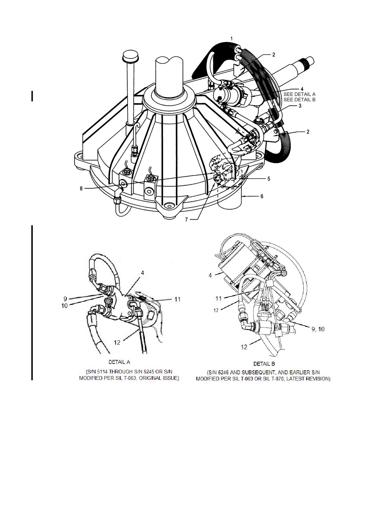
11-40. Description - Oil Filtration/Cooling System (Figure 11-9)
Starting with 480 Serial Number 5042 and all 480Bs, the main rotor transmission is
equipped with an oil filtration/cooling system. This system consists of a heat exchanger, an
electric pump, a pressure switch, a filter assembly, connecting oil lines, and the mounting
brackets and hardware. For aircraft S/N 5114 and subsequent, the electric pump includes a
drain line assembly. The heat exchanger is located on the transmission forward of the upper
pulley assembly. The electric pump is a 24 Vdc unit located on the left side of the pinion area of
the transmission. The pressure switch is installed between the heat exchanger and the inlet
port of the pump. The pressure switch controls a segment light in the caution panel that
indicates when the pump pressure is below 4.4-5.9 psi/30.2-40.7 kPa of vacuum. The filter
assembly, located at the left aft area on the bottom of the transmission, incorporates a 10-12
micron spin-on oil filter. The filter assembly also incorporates the chip detector and a check
valve that is used to prevent loss of oil in the transmission due to a break in the system between
the filter housing outlet and the pump inlet. The oil filtration/cooling system does not provide
pressure lubrication for the main rotor transmission; failure of the pump does not adversely
affect the lubrication of the ring and pinion or the bearings in the main rotor transmission.
11-41. Removal - Oil Filtration/Cooling System (Figures 11-9 & 11-10)
A. Drain the oil from the main rotor transmission (para 4-13).
B. Remove the upper pulley assembly (para. 11-46).
Rev. 26
MM-11-56
Feb 28/2020
1.
Heat Exchanger
7.
Chip Detector
2.
Mounting Brackets
8.
Check Valve
3.
Pressure Switch
9.
Straight Fitting
4.
Electric Pump
10.
O-Ring
5.
Filter Housing
11.
Elbow
6.
Filter
12.
Drain Line
Figure 11-9. Oil Filtration/Cooling System
Rev. 26
MM-11-57
Feb 28/2020
1.
Filter Housing
5.
Chip Detector
2.
O-Ring
6.
Gasket
3.
Mounting Screws
7.
Check Valve
4.
Oil Filter
8.
O-Ring
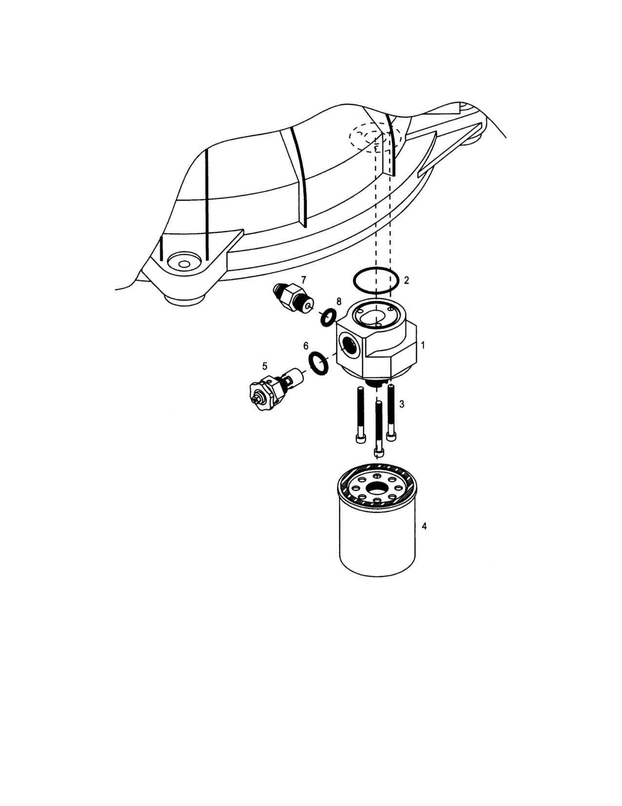
Figure 11-10. Oil Filter Assembly Installation
MM-11-58
Feb 9/01
C.
Disconnect the electrical leads from the oil pump, pressure switch, and chip detector.
D.
Remove the heat exchanger using the following procedure:
(1) Disconnect the oil lines from the heat exchanger.
(2) Remove the hardware securing the heat exchanger to the mount brackets and
remove the heat exchanger.
(3) Remove the heat exchanger mounting brackets from the main rotor
transmission.
E.
Remove the filter assembly using the following procedure:
(1) Remove the oil filter from the housing.
(2) Disconnect the oil line from the outlet port.
(3) Remove the three screws securing the filter housing to the main rotor
transmission and remove the filter housing.
a. If required, remove the chip detector assembly and the check valve from the
filter housing.
F.
Remove the electric pump using the following procedure:
(1) Disconnect the oil lines from the inlet and outlet ports.
(2) Disconnect the drain line, if equipped.
(3) Remove the safety wire from the clamp, loosen the clamp, and remove the
pump.
a. If required, remove the elbow(s) and straight fittings, as applicable, from the
pump.
(4) Remove the hardware securing the mounting bracket to the main rotor
transmission and remove the mounting bracket.
G.
Remove the pressure switch from the tee adapter.
11-42. Inspection - Oil Filtration/Cooling System
A. Inspect the heat exchanger for kinks, cracks, bent cooling fins, and general condition.
B. Inspect the filter housing for general condition. Cut open the oil filter and inspect the
filter element for metal particles, flakes, or slivers exceeding 1/16 inch/1.6 mm. If metal
particles, flakes, or slivers exceeding 1/16 inch/1.6 mm are found, contact Enstrom Customer
Service Department and discontinue use until further instructions are received from Enstrom
Customer Service Department.
C. Inspect the oil pump for general condition.
D. Inspect the pressure switch for general condition.
Rev. 26
MM-11-59
Feb 28/2020
E. Inspect the oil lines, drain line (if equipped), fittings, and mounting brackets for
general condition.
11-43. Repair - Oil Filtration/Cooling System
A. Replace the heat exchanger if cracked, kinked, or the oil line fittings are damaged
beyond repair. Straighten bent cooling fins as required.
B. Replace the oil filter housing if the threads on the chip detector port, check valve port,
and/or the filter stem are damaged beyond repair. Replace the filter housing if the filter seal
surface is damaged and will not seal after repair.
C. Replace the oil pump if inoperable or leaking from the housing seams. Repair/
Replace wire harness as required.
D. Replace the pressure switch if inoperable. Repair/Replace the wire harness as
required.
E. Replace the oil lines, drain line (if equipped), fittings, and mounting brackets if
damaged beyond repair.
11-44. Installation - Oil Filtration/Cooling System (Figures 11-9 & 11-10)
A. Apply a light coat of thread sealant to the pressure switch and install the switch into
the tee adapter.
B. Install the electrical pump using the following procedure:
NOTE
Note the orientation of the pump for the P/N specified.
(1) Install the pump mounting bracket onto the transmission.
(2) If required, apply a light coat of thread sealant to the elbow fitting(s) and straight
fittings (as required), and install the fittings into the pump.
a. If required, install new O-rings when installing the fittings.
(3) Install the pump onto the mounting bracket.
a. P/N 8116-B: Inlet/Outlet ports forward with the outlet port up.
b. P/N 4130039-1: Inlet/Outlet ports aft with the inlet port up.
(4)
Tighten and lockwire (.025") the clamp.
(5) Connect the inlet and outlet oil lines.
(6) Connect the drain line (if equipped).
(7) Apply torque stripes to the fittings, as required.
Rev. 26
MM-11-60
Feb 28/2020
WARNING
Use protective gloves when handling heated parts.
B. Heat the pulley (1) to approximately 250°F/121°C and remove pulley hub (3) and hub
adapter (2), if applicable.
11-48. Cleaning - Upper Pulley Assembly
A. Clean all parts with kerosene, toluol or equivalent solvent, or vapor degrease before
inspection.
11-49. Inspection - Upper Pulley Assembly
A. See Table 11-3 for the detailed inspection requirements for the upper pulley
assembly.
11-50. Repair - Upper Pulley Assembly
A. See Table 11-3 for the damage limits and repair criteria for the components of the
upper pulley assembly.
11-51. Assembly - Upper Pulley Assembly (Figure 11-11)
WARNING
Use extreme caution when handling heated parts to prevent from
injuring personnel.
WARNING
Use protective gloves when handling heated parts.
NOTE
The upper pulley P/N 4130514-17 & 4130538-11 do not use the hub
adapter (2).
A. Clean the upper pulley (1), hub adapter (2), if applicable, and the pulley hub (3) with
toluene or a similar solvent.
B. Heat the upper pulley (1) to approximately 250°F/121°C.
C. Spread a 1 in/25 mm wide bead of retaining compound (Loctite 635, or equivalent) on
the cylindrical end of the pulley hub (3), about 0.5 in/13 mm from the end.
NOTE
The upper pulley assembly is dynamically balanced. If the parts were not
index marked for reassembly, the pulley assembly with the key must be
dynamically balanced to within .2 inch-ounce.
Rev. 26
MM-11-63
Feb 28/2020
Table 11-3. Upper Pulley and Aft Pinion Bearing Assemblies
Inspection Requirements*
P/N
Fig. 11-11
Part Name
Inspection
Serviceable Limits
Repair Limits
Repair or Action
Item #
4130514
1
Pulley
I.D. 4.2490 to 4.2495
+.0003
Not Repairable
Replace Pulley
Cracks
None Allowed
Not Repairable
Replace Pulley
Depth of grooves
≤ .176
Not Repairable
Replace Pulley
Nicks and gouges in
None Allowed
≤ .25 long and ≤
Blend out smooth
belt grooves
.025 deep
4142009
2
Hub Adapter
O.D. 4.2497 to 4.2499
-.0002
Not Repairable
Replace Adapter
I.D. 2.185 to 2.186
+.001
Not Repairable
Replace Adapter
Cracks
None Allowed
Not Repairable
Replace Adapter
Nicks, scratches, or
.030 deep
≤ .030 deep
Blend out smooth
corrosion
4142010
3
Pulley Hub
O.D. 2.188 to 2.189
-.001
Not Repairable
Replace Hub
I.D. 1.5582 to 1.5587
+.0003
Not Repairable
Replace Hub
Keyway Width .3105 to
+.0005
Not Repairable
Replace Hub
.3125
Cracks
None Allowed
Not Repairable
Replace Hub
Nicks, scratches, or
.030 deep
≤ .030 deep
Blend out smooth
corrosion
MM-11-64
Feb 9/01
Table 11-3. Upper Pulley and Aft Pinion Bearing Assemblies
Inspection Requirements*
P/N
Fig. 11-11
Part Name
Inspection
Serviceable Limits
Repair Limits
Repair or Action
Item #
28-13142
7
Key
Width .3105 to .3125
-.001
Not Repairable
Replace Key
Visible wear on side of
None Allowed
Not Repairable
Replace Key
key
4130501
8
Bearing Housing
I.D. 3.5428 to 3.5434
+.001
Not Repairable
Replace Housing
Cracks
None Allowed
Not Repairable
Replace Housing
Nicks, scratches, or
.030 deep
≤ .030 deep
Blend out smooth
corrosion
608-2RS,
10
Bearing
Roughness, spalling,
None Allowed
Not Repairable
Replace Bearing
ECD014-11
pits, or corrosion
28-13323
11
Bearing Adapter
O.D. 1.5746 to 1.5749
-.0002
Not Repairable
Replace Adapter
I.D. 1.3116 to 1.3118
+.0002
Not Repairable
Replace Adapter
Fretting wear on end
None Allowed
Not Repairable
Replace Adapter
surfaces
28-13184
16
Nut
Threads (no rolled or
None Allowed
Not Repairable
Replace Nut
missing threads)
Cracks
None Allowed
Not Repairable
Replace Nut
* All dimensions are in inches.
Rev. 22
MM-11-65
Jun 25/14
D. Install the six bolts (for alignment) in the pulley hub (3) and the hub adapter (2), if
applicable, and install the hub and adapter into the pulley using the following procedure:
(1) Set the pulley (1) in a press with the aft side up.
(2) While the pulley (1) is hot, insert the pulley hub (3) into the pulley (1) and
immediately use pressure to ensure that the pulley hub (3) is completely seated
in the upper pulley (1).
NOTE
Alternate sides when torqueing the pulley hardware.
(3) Install the remaining hardware into the pulley hub (3) and upper pulley (1).
Torque the nuts to standard torque. Alternate sides when torqueing the pulley
hardware.
E. Use the following procedure if the pulley assembly has to be dynamically balanced:
(1) Dynamically balance the pulley within .2 inch-ounces; include the key when
balancing.
(2) Use Dyna Weight two part epoxy for the balance material.
WARNING
Acetone and Methylethylketone (MEK) are toxic and must be used with extreme
caution. Make sure adequate ventilation is provided. Repeated or prolonged
contact with the skin should be avoided. Low-volatile substitutes, such as
Extreme Simple Green or Citra-Safe, are preferred solvents.
(3) Remove all grease and dirt from the pulley surface using MEK, or equivalent,
and rough sand the surface with 150 grit sand paper.
11-52. Installation - Upper Pulley Assembly (Figure 11-11)
A. Before installing the key (7) into the pinion, check that the key slides freely through
the keyway in the upper pulley. If it does not slide through, the key must be filed slightly on one
side to allow proper fit. A clearance of .0005-.001 inch/.013-.025 mm between the key and the
pulley keyway is required. If the key is loose in the pinion keyway, proceed to step 1 below:
(1) Install the key on the pinion and using a feeler gauge, measure the gap between
the side of the key and the pinion keyway.
(2) Divide the measurement in half to get the thickness of the stainless steel shim
stock required.
(3) Cut a shim 2" long X 1.25" wide.
(4) Wrap the shim around the key. With the chamfered side of the key down, tap
the key and shim into the pinion keyway.
(5) Using a razor knife, trim the shim stock along the sides of the key flush with the
pinion. The key must be secure in the pinion.
Rev. 26
MM-11-66
Feb 28/2020
(2) Install the sleeve (T-0068A) on the output shaft. Install the spacer (T-0068B)
and torque the bolt to 300 in-lbs/34.1 Nm.
(3) Position a height gauge and dial indicator with the indicator arm on the outboard
diameter of the sleeve (T-0068A).
(4) Zero the dial indicator and rotate the input shaft. Note the output shaft FIM.
(5) If the runout exceeds .005"/.127 mm FIM, Return the transmission for overhaul.
D. Inspect the input and output shaft seals for leakage. Replace the seals if leaking
(para. 11-93).
E. Inspect the chip detector for accumulation of metal particles as follows:
(1) Metal particles, flakes, or slivers exceeding .035 inch/.9 mm: Contact Enstrom
Customer Service and discontinue use until further instructions are received
from Enstrom Customer Service Department.
(2) Sludge (a mixture of oil and fine metal particles resulting from normal gear
operation): Clean the detector and return the transmission to service.
NOTE
New or recently overhauled transmissions will often produce a sludge with
slightly larger metal particles. This is normal and may be cleaned from the
detector and the transmission returned to service; however, if metal
particles, flakes, or slivers larger than .035 inch/.9 mm in cross section are
found, contact Enstrom Customer Service and discontinue use until further
instructions are received from Enstrom Customer Service Department.
11-91. Assembly - Tail Rotor Transmission
A. Install the tail rotor pitch control assembly (para. 12-119).
11-92. Installation - Tail Rotor Transmission
A. Apply Lubriplate 630-AA (MIL-PRF-81322) to the transmission mount.
B. Insert the chip detector lead through the hole in the transmission mount.
C. Install the transmission in the extension tube. Install the mounting bolts and torque to
25 in-lbs/2.8 Nm. Lockwire (.032”) the bolts.
D. Connect the flex pack coupling to the drive hub (para. 11-81).
E. Connect the electrical lead to the chip detector.
F. Connect the tail rotor guard to the transmission.
G. Connect the tail rotor control cables to the pitch control assembly (para. 12-108).
H. Install the tail rotor assembly (para. 9-51).
Rev. 26
MM-11-87
Feb 28/2020
NOTE
Omit steps I and J if the transmission and tail rotor control assembly being
installed are the same ones that were removed.
I.
Check the tail rotor control cable tension (para. 12-99).
J. Check the tail rotor control rigging (para. 12-100).
11-93. Seal Replacement - Tail Rotor Transmission (Figure 11-17)
A.
Replace the input shaft seal using the following procedure:
NOTE
If the transmission is not installed on an aircraft, omit steps 1-4.
(1) Remove the bolts securing the flex pack coupling to the aft drive hub (23). Index
mark the drive hub and the flex plate coupling so that flex pack coupling is
installed in the identical position as previously installed.
(2) Disconnect the aft three drive shaft bearing assemblies (ref. Figure 11-12, Item
(3)) from the tail cone.
NOTE
Failure to align the index marks or to return the shims to the original position
will require realignment of the tail rotor drive shaft.
a. Mark the drive shaft bearing assemblies and the tail cone with an index
mark so that the bearing assemblies are installed in the identical lateral
positions as previously installed.
b. Remove the hardware securing the aft three drive shaft bearing assemblies
to the tail cone (ref. Figure 11-12, Items (4), (5), (6)).
c. Tape the shims and hardware to the tail cone to facilitate reinstallation of
the drive shaft bearing assemblies in the same position (returns the tail
rotor driveshaft to the same position vertically).
(3) Remove the aft taper pin (24) (closest to the transmission) with tool T-0092-5.
CAUTION
Displace the tail rotor drive shaft the minimum amount necessary as damage
to the drive shaft may result.
(4) Carefully displace and secure the tail rotor drive shaft to one side to permit
removal of the hub (23) from the tail rotor transmission input shaft.
Rev. 26
MM-11-88
Feb 28/2020
(5) Drain the oil from the tail rotor transmission.
(6) Remove the hub (23) and the sleeve (22) from the input shaft using tool (T-
0092-5).
(7) Remove the slinger (18).
NOTE
Earlier version gearboxes will have two tab washers (16) securing the input
seal into the gearbox housing. Later manufactured gearboxes use a
retaining ring (15).
(8) Remove the retaining ring (15) or the two tab washers (16) that secure the seal
(14) into the gearbox, as applicable.
(9) Using an awl or small screw driver, carefully pry the input shaft seal (14) out of
the gearbox housing.
CAUTION
Do not remove the retaining screws that secure the bearing housing to the
gearbox housing. Do not remove the lead seal from the input shaft assembly.
Removal of the seal will void the warranty on the tail rotor transmission.
(10) Clean the tail rotor transmission seal surface and the O.D of the new seal.
(11) Install the seal.
a. Apply a small amount of MIL-PRF-2105 to the O.D. and I.D. of the seal and
the seal lip.
b. Wrap stainless steel shim stock around the input shaft nut to protect the seal
lip during installation.
c. Use a soft plastic or rubber hammer or other suitable press tool to tap the
seal into place.
(12) Install the retaining ring (15) or the retaining tab washers (16), as applicable.
a. Torque the tab washer screws (17) to 25 in-lb/2.8 Nm and lockwire if using
the retaining tabs.
(13) Install the slinger (18).
NOTE
Install the drive hub (23) and flex pack coupling to the index marks (as
previously installed). If not properly marked for reinstallation, the tail rotor
assembly will require balancing.
(14) Install the drive hub (23) and taper pin (24). Torque to 25 in-lb/2.8 Nm.
Rev. 26
MM-11-89
Feb 28/2020
(15) Install the flex pack coupling (para. 11-81) to the drive hub (23). Ensure all flex
pack hub assemblies, hardware, spacers, and washers are installed in the same
position as previously installed.
(16) Install the three drive shaft bearing assemblies.
NOTE
Install the bearing assemblies to the index marks (as previously installed). If
not properly marked for reinstallation, the tail rotor drive shaft will require
alignment.
a. Use the same shims, spacers, and bolts (retained in place with tape) for
each bearing assembly.
b. Align the bearing assemblies laterally to the index marks.
c. Torque the bolts to 35 in-lb/4.0 Nm.
(17) Service the tail rotor transmission (para. 4-16).
B.
Replace the output shaft seal using the following procedure (Figure 11-17):
NOTE
If the transmission is not installed on an aircraft, omit steps 2 and 3.
(1) Drain the oil from the tail rotor transmission.
(2) Remove the tail rotor assembly (para. 9-44; omit step D).
(3) Remove the pitch control bearing assembly (Figure 12-27).
a. Disconnect the bearing housing (7) from the pivot brackets (1) and (2) by
removing bolts (5), washers (6) and (8), nut (9), and cotter pin (10).
b. Index mark the position of the sleeve (21) as installed on the output shaft.
NOTE
Resistance will be felt when removing the pitch change bearing retention
assembly as the seal (12) and seal retainer (13) must be forced out of the
bearing (7).
c. Slide the pitch control assembly off of the sleeve (21) of the tail rotor
transmission output shaft.
d. Remove the keys (11), seal (12), and seal retainer (13).
(4) Remove the retaining ring (20) from the output shaft seal (19) (Figure 11-17).
Rev. 26
MM-11-90
Feb 28/2020
NOTE
As the seal (19) is removed from the output shaft, the sleeve (21) will also be
removed with it. Wrapping the end of the output shaft with masking tape may
help prevent the sleeve from being displaced when the seal is removed. Clean
the area prior to applying tape.
Otherwise, mark the sleeve spline to the output shaft spline so as to install
the sleeve in the same location on the output shaft on reassembly.
(5) If preferred, wrap the end of the output shaft with masking tape, otherwise clean
the spline edges of the output shaft and sleeve and apply a paint stripe across
the splines.
(6) Using an awl or small screw driver, carefully remove the seal (19).
(7) Install the new seal (19).
NOTE
It may be necessary to chamfer the inboard edge of the new seal using 200
grit sandpaper, or equivalent, for ease of installation.
a. Clean the tail rotor transmission seal surface and the O.D. of the new seal.
b. Lubricate (MIL-PRF-2105) the O.D. and inside lip of the new seal (19).
c. Use a soft plastic or rubber hammer or other suitable press tool to tap the
seal (19) into place.
NOTE
Positioning the sleeve on the output shaft in a location different than previously
installed may affect the runout (TIR) and negatively affect the rail rotor balance.
Output shaft runout may be checked in accordance with para. 11-90, C.
(8) If required, install the sleeve (21). Match the spline mark of the sleeve to the
spline mark on the output shaft.
a. Lubricate (MIL-PRF-2105) the seal end of the sleeve (21).
b. Use a bushing driver or equivalent press tool, push the sleeve (21) into the
seal (19). The seal (19) seats in a groove of the sleeve (21).
(9) Install the retaining ring (20).
(10) Place the seal retainer (13) and the seal (12) onto the output shaft.
(11) Install the two keys (17) into the key slots in the sleeve (21).
a. Lubricate (MIL-PRF-81322) the keys (17) during installation and prior to
installing the pitch control assembly.
Rev. 26
MM-11-91
Feb 28/2020
NOTE
Take care to align the pitch control assembly to the index marks. If the pitch
control assembly cannot be realigned to the original index marks, the tail rotor
assembly must be dynamically balanced.
(12) Install the pitch control assembly (Figure 12-27).
a. Align the pitch control assembly to the index marks on the sleeve and slide
the assembly onto the tail rotor transmission output shaft.
b. Insert the seal (12) into the groove in the pitch control bearing (14).
CAUTION
Be gentle when inserting the seal retainer (13). Excessive force will damage
the seal retainer.
c. Use tool T-0140 to install seal and retainer. If T-0140 is not available, use a
small straight screwdriver or punch and a small hammer to tap the seal
retainer (13) into the groove in the pitch control bearing (14).
(13) Install the pivot brackets (Figure 12-27).
NOTE
Washer (6) must be installed between the upper pivot bracket (1) and the
bearing housing (7).
a. Install the bolts (5), washers (6) and (8), and nut (9).
b. Torque the nuts to 60-85 in-lb/6.8-9.6 Nm and install the cotter pin (10).
NOTE
If the tail rotor components are installed in the exact position as removed, the
dynamic balance step (para. 9-51, F) may be omitted.
NOTE
If the tail rotor components are not installed in the exact position as removed,
the tail rotor must be balanced.
(14) Install the tail rotor assembly (para. 9-51).
(15) Cycle the tail rotor pitch full travel in both directions to ensure that the pitch
change system operates correctly.
(16) Service the tail rotor transmission (para. 4-16).
Rev. 26
MM-11-92
Feb 28/2020
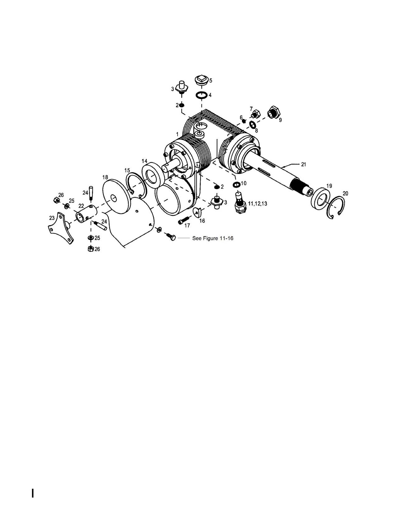
1.
Tail Rotor Gearbox Assembly
14.
Seal
2.
O-Ring
15.
Retaining Ring
3.
Bolt
16.
Tab (omitted if (15) is used)
4.
O-Ring
17.
Screw
5.
Plug
18.
Slinger
6.
O-Ring
19.
Seal
7.
Plug
20.
Retaining Ring
8.
O-Ring
21.
Spacer
9.
Sight Plug
22.
Sleeve
10.
Gasket
23.
Hub
11.
Chip Detector
24.
Taper Pin
12.
O-Ring
25.
Washer
13.
Nut
26.
Nut
Figure 11-17. Tail Rotor Transmission Assembly
Rev. 26
MM-11-93
Feb 28/2020
11-94. Consumable Materials List
ITEM
DESCRIPTION
PART NUMBER
Adhesive
Adhesive, Loctite Fixmaster Flex 80 Putty
97422/97423
Brand
Grease
Grease, Lubriplate Brand
630-AA1 (06701)
Grease
Grease
MIL-PRF-81322
Liquid Soap
Soap, Joy Brand
Lockwire
Lockwire, .032”
MS20995C32
Lockwire
Lockwire, .041”
MS20995C41
Marking dye
Machinist’s marking dye, Devcon Brand
DYKEM 80400
MEK
Solvent, MEK
Oil
Oil, Gear
MIL-PRF-2105
Oil
Oil, Turbine Engine
MIL-PRF-23699
Oil
Any grade internal combustion engine
motor oil
Sealant
Retaining Compound, Loctite Brand
635
Citra-Safe, Inland Technology
6850-01-378-( )
Solvent
Incorporated
Solvent
Extreme Simple Green, Sunshine
13440
Makers, Inc.
Solvent
Solvent, Toluene
Tape
Masking Tape, 1-Inch
Thread Sealant
Thread Sealant, Loctite Brand (277)
27731
Thread Sealant
Thread Sealant, Loctite Brand
24200
Threadlocker Blue 2422
Thread Sealant
Thread Sealant, Permatex Brand
Form-A-Gasket No.33
Thread Sealant
Thread sealant, Vibra-Tite Brand
VC-3
1 MIL-PRF-81322 is an acceptable alternate.
2 Acceptable alternate for Vibra-Tite VC-3.
3 Acceptable alternate where thread sealant is required.
Rev. 26
MM-11-94
Feb 28/2020