Enstrom TH-28/480 Series. Maintenance Manual (2020) - page 5
Table 9-1. Main Rotor Hub Assembly
Inspection Requirements
P/N
Fig. 9-4, 9-5
Part Name
Inspection*
Serviceable Limits*
Repair Limits
Repair or Action
Item #
28-14224-1, -3,
12 & 18
Spline Adapters
Spline wear
.0015 on side
Not Repairable
Replace Adapter
-5
(Cont’d)
Nicks, scratches, or
.010 deep
≤ .010 deep
Blend and polish out
corrosion
smooth
Cracks
None Allowed
Not Repairable
Replace Adapter
28-14280-1, -3,
14
Upper Hub
Spline Adapter Bore
+.0005
Not Repairable
Replace Upper Hub
-5
3.624 to 3.625
U Block Bearing Bores
+.0008
Not Repairable
Replace Upper Hub
2.4986 to 2.4994
Recesses for the DU
+.0005
Not Repairable
Replace Upper Hub
washers parallel to the
upper surface within
.001
Damper Bolt Bushing
+.0005
Not Repairable
Replace Bushing
Dia. .3747 to .3757
Threads for walking
None Allowed
Not Repairable
Replace Heli coil
beam brackets
(crossed or missing)
Nicks, scratches, or
None Allowed
≤ .010 deep
Blend and polish out
corrosion
smooth
Cracks
None Allowed
Not Repairable
Replace Upper Hub
Rev. 26
MM-9-21
Feb 28/2020
Table 9-1. Main Rotor Hub Assembly
Inspection Requirements
P/N
Fig. 9-4, 9-5
Part Name
Inspection*
Serviceable Limits*
Repair Limits
Repair or Action
Item #
28-14223-1
16
Spacer
Dowel Hole Dia. .3125
+.0005
Not Repairable
Replace Spacer
Bolt Hole Dia.
+.002
Not Repairable
Replace Spacer
.313 to .318
Nicks, scratches, or
.030 deep
≤ .030 deep
Blend and polish out
corrosion
smooth
Cracks
None Allowed
Not Repairable
Replace Spacer
28-14281-1, -3,
17
Lower Hub
Spline Adapter Bore
+.0005
Not Repairable
Replace Lower Hub
-5
3.624 to 3.625
U Block Bearing Bores
+.0008
Not Repairable
Replace Lower Hub
2.4986 to 2.4994
Recesses for the DU
+.0005
Not Repairable
Replace Lower Hub
washers parallel to the
lower surface within
.001
Damper Bolt Bushing
+.0005
Not Repairable
Replace Bushing
Dia. .3747 to .3757
Nicks, scratches, or
None Allowed
≤ 0.10 deep
Blend and polish out
corrosion
smooth
Cracks
None Allowed
Not Repairable
Replace Lower Hub
* All dimensions are in inches.
Rev. 26
MM-9-22
Feb 28/2020
D. Place the spacer (16) and shim (34), if installed, on the lower hub plate and align the
bolt holes.
NOTE
Ensure the DU washers are seated in the recessed areas of the upper hub
plate.
E. Lubricate the bearing bores of the upper hub plate and install the upper hub plate
onto the U-blocks.
F. Lubricate the dowel pins (13) and install by tapping them into the center hole of the 3-
hole bolt pattern. Install the pins until they are slightly recessed from the surface of the hub
plate.
NOTE
The upper spline adapter has the wider flat surface on top side of the splines
while the lower adapter has a rib extending from the lower end of the splines.
CAUTION
The phasing marks on the upper spline adapter must be aligned with one of the
pitch change bellcrank mount brackets. Using a felt marker, mark a line on the
outboard edge of the hub plates in line with the spline phasing marks to aid in
installing the lower spline adapter.
G. Insert bolts in the upper spline adapter (12) as guides and install the adapter onto the
upper hub plate.
H. Carefully turn the hub assembly over and position on wood blocks.
I.
Install the lower spline adapter (18) and align the phasing mark with the upper
adapter phasing marks.
J. Turn the hub assembly over and install the center hub bolts (11) in the holes adjacent
to the pitch change bellcrank mount bracket holes. Install the washers and nuts and torque the
hardware.
K. Install the pitch change bellcrank mount brackets (3). Torque the through bolts (2).
Torque and lockwire (.032) the other bolts (1).
L. Set the rotational drag of the U-blocks as follows:
(1) Place the hub assembly on a hub stand with the lower end of the U-blocks up.
(2) Install a DU washer (7) into the recess of the hub plate with the chamfer in board
toward the hub plate.
(3) Install shims (8) approximately .025 inch/0.6 mm thick and the lower U-block nut
(9). Tighten the nut using tool (T-0003).
Rev. 26
MM-9-23
Feb 28/2020
(4) Rotate the U-block to one of the stops and install a hinge pin into the retention
pin hole until the inside edge of the flange is 7.1 inches/18 cm from the center of
the universal block.
(5) Place a wire loop around the hinge pin against the flange. Attach a spring scale
to the wire loop and pull to check the drag. The drag tolerance with the nut
torqued is 4-10 pounds/1.8-4.5 kg.
(6) Add or subtract shims as required to obtain the proper drag.
(7) Place the locking key (10) into the slot on the nut that is aligned with the notch in
the U-block and secure with the washer and screw.
M.
Turn the hub assembly over on the stand.
N.
Install the upper U-block nuts (5) as follows:
NOTE
If the hub is equipped with oil lubricated flapping bearings, shims may be
required between the bearing and the lock washer to prevent the universal
block from protruding above the nut. The oil reservoir flange must seat flush
against the nut.
(1) Install the lock washer (6) and nut on the U-block.
(2) Torque the nut to 20 ft-lbs/27.3 Nm using tool (T-0051).
(3) Tap down on the upper nut with a plastic mallet and re-torque the nut to seat the
bearing. Repeat the process until the nut will not move while being re-torqued.
(4) Bend the tab on the lock washer that aligns with the recess in the nut into the
nut.
(5) If the main rotor hub assembly is equipped with grease lubricated flapping
bearings, install the dust cover (4) and secure.
(6) If the main rotor hub assembly is equipped with oil lubricated flapping bearings:
a. Install new O-rings (31) on the reservoir (29). Lubricate the O-rings with MIL-
PRF-23699 and (Figure 9-5, 29).
b. Install the reservoir (29) onto the universal block (15) using a twisting motion
until the base of the reservoir seats flat against the universal block.
CAUTION
Ensure the reservoir is fully seated into the universal block before installing the
screws. Do not attempt to seat the reservoir into the universal block by using
the screws. The reservoir will distort and crack.
c. Install the dust cover (4) and secure.
Rev. 20
MM-9-24
Apr 25/13
9-15. Disassembly - Retention Assembly (Figure 9-7)
NOTE
If replacing the tension-torsion straps only, proceed to paragraph 9-19.1.
NOTE
For Lamiflex equipped aircraft, the blade grip, lamiflex bearing, and lamiflex
bearing shims can be removed with the retention assembly installed on the hub
assembly.
A.
Lamiflex equipped aircraft:
(1) Remove the main rotor blade (para. 9-34) and disconnect the pitch change link
from the pitch change bellcrank (para. 12-93) if the retention assembly is
installed on a hub assembly.
CAUTION
Use brass protector plates in the vise jaws to prevent from damaging the
retention assembly.
(2) Clamp the retention assembly vertically in a vise if removed from the hub
assembly.
(3) Remove the dust cover (18) from the blade end of the retention assembly.
Inspect for brass residue (chips or flakes) from the lamiflex bearing, if equipped.
(4) Remove the cotter pin (17) from the retention nut (16) and remove the nut. Use
tool (T-0013) if the nut cannot be removed by hand.
(5) Remove the shims (15), lamiflex bearing (14), and nylatron strap (5), if not
bonded to the spindle, from the spindle (3).
(6) Pull the blade grip (13) from the spindle. If required, tap the grip with a plastic
mallet to aid in removal.
CAUTION
If the lamiflex bearing wears through the nylatron strap, inspect the spindle for
damage. The maximum depth allowed is .020"/0.51 mm. Blend the damage
out before installing a new nylatron strap.
(7) Peel the nylatron strap (5) from the spindle if bonded to the spindle.
(8) Remove the O-ring (12) and DU washer (11) from the spindle.
(9) Remove the retaining ring (10) from the spindle.
Rev. 26
MM-9-27
Feb 28/2020
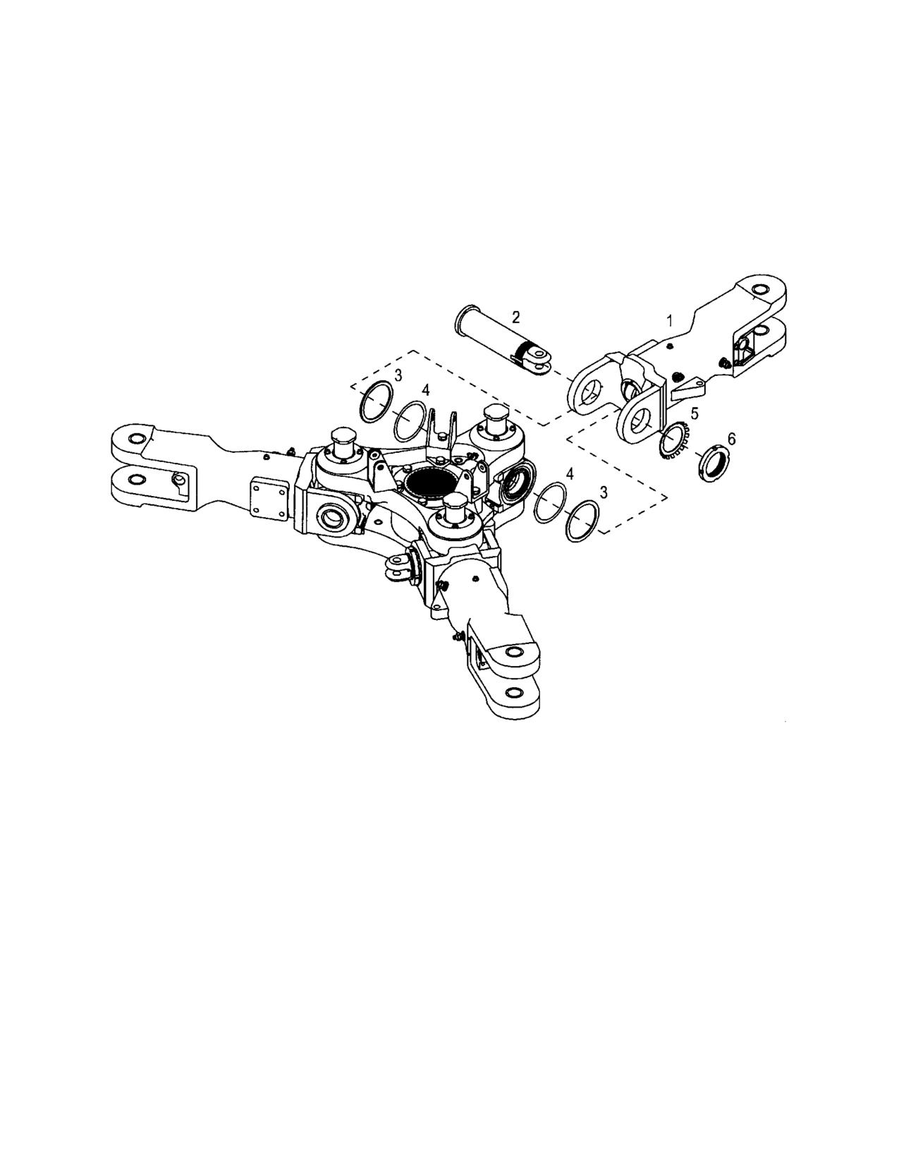
1.
Retention Assembly
4.
Shim
2.
Flapping Hinge Pin
5.
Lock Washer
3.
DU Washer
6.
Nut
Figure 9-6. Retention Assembly Installation
MM-9-28
Feb 9/01
(10) Remove the hinge pin alignment pin from the ear of the spindle using a small
punch.
(11) Install a press tool between the seal (6) and the bearing (7) on the spindle.
Using a hydraulic press, press the bearings (7 & 9) and spacer (8) from the
spindle.
(12) Remove the seal (6).
NOTE
Removal/replacement of the retention stops are necessary only if the stops are
damaged or the adhesive has loosened.
(13) Remove the retention stops (1 & 4).
(14) Remove the cap from the bore of the spindle (2).
(15) Remove the planipetal weight (22) and the pitch horn (21) from the blade grip.
B.
Tension-Torsion Strap equipped aircraft:
NOTE
There are two different Tension-Torsion Strap Retention Assemblies used on
the TH-28/480 Series. The 28-14381-1 Retention Assembly uses an O-ring at
the outboard end of the spindle assembly to prevent grease leakage from the
retention assembly. The 28-14381-3 Retention Assembly uses a seal installed
in the blade grip to prevent grease leakage from the retention assembly.
NOTE
If equipped with STC SH03465CH tension-torsion straps, refer to Table 2-2 for
manufacturer installation instructions and instructions for continued airworthiness.
(1) Remove the retention assembly from the main rotor hub (para. 9-14).
CAUTION
Use brass protector plates in the vise jaws to prevent from damaging the
retention assembly.
(2) Clamp the retention assembly vertically in a vise.
(3) Remove the dust cover (18) from the blade end of the retention assembly.
(4) Remove one of the retaining rings (31) securing the pin in the lug at the
outboard end of the retention assembly. Remove the pin (30) and the remaining
retaining ring.
(5) Pull the blade grip (28) from the spindle.
Rev. 26
MM-9-31
Feb 28/2020
NOTE
Only remove the seal from the blade grip if replacing a defective seal or blade
grip.
(6) Remove the O-ring (27) from the spindle (28-14381-1 Retention Assembly).
Remove the seal (33) from the grip (28-14381-3 Retention Assembly).
NOTE
The pin used to secure the tension-torsion strap at the inboard end is not
secured with retaining rings.
(7) Remove the spindle from the vise and push the tension-torsion strap (25) back
through the spindle.
(8) Remove the pin (23) from the cylinder (24) and separate the tension-torsion
strap from the cylinder.
(9) Remove the retaining ring (10) from the spindle.
NOTE
Do not remove the cylinder alignment pin from the spindle unless required.
(10) If required, remove the flapping pin alignment pin from the ear of the spindle and
the cylinder alignment (32) pin using a small punch.
(11) Install a press tool between the seal (6) and the bearing (7) on the spindle.
Using a hydraulic press, press the bearings (7 & 9) and spacer (8) from the
spindle.
(12) Remove the seal (6).
NOTE
Removal/replacement of the retention stops are necessary only if the stops are
damaged or the adhesive has loosened.
(13) Remove the retention stops (1 & 4).
(14) Remove the hardware securing the lug to the blade grip and remove the lug
(29).
(15) Remove the pitch horn (21) from the blade grip.
MM-9-32
Feb 9/01
Table 9-2. Retention Assembly
Inspection Requirements*
P/N
Fig. 9-7
Part Name
Inspection
Serviceable Limits
Repair Limits
Repair or Action
Item #
40NBC20-
7
Bearing
O.D. 3.2492 to 3.2500
No Tolerance
Not Repairable
Replace Bearing
52YZP
Allowed
I.D. 2.4993 to 2.5000
No Tolerance
Not Repairable
Replace Bearing
Allowed
Ratcheting or
Not Repairable
Replace Bearing
roughness
None Allowed
28-14261-1
8
Spacer
Length 3.061 to 3.062
-.001
Not Repairable
Replace Spacer
Ends parallel
Within .0012 FIM
Not Repairable
Replace Spacer
32NBC20-
9
Bearing
O.D. 2.7494 to 2.7500
No Tolerance
Not Repairable
Replace Bearing
44YZP
Allowed
I.D. 1.9993 to 2.0000
No Tolerance
Not Repairable
Replace Bearing
Allowed
Ratcheting or
roughness
None Allowed
Not Repairable
Replace Bearing
28-14313-1
11
DU Washer
Thickness .090 to.093
-.003
Not Repairable
Replace Washer
28-14279-3
13
Blade Grip
Blade retention bolt
+.0005
Not Repairable
Replace Blade Grip
bore Dia. .875 to .876
Large bearing bore Dia.
+.0018
Not Repairable
Replace Blade Grip
3.2512 to 3.2522
Small bearing bore Dia.
+.0011
Not Repairable
Replace Blade Grip
2.7511 to 2.7519
Rev. 17
MM-9-35
Jun 24/11
Table 9-2. Retention Assembly
Inspection Requirements*
P/N
Fig. 9-7
Part Name
Inspection
Serviceable Limits
Repair Limits
Repair or Action
Item #
28-14279-3
13
Blade Grip (Cont'd) Thru bore Dia. 1.5145
+.0015
Not Repairable
Replace Blade Grip
to 1.5165
Drag link ear width .745
-.001
Not Repairable
Replace Blade Grip
to .747
Threads (crossed or
None Allowed
Not Repairable
Replace Blade Grip
missing)
Nicks, scratches, or
None Allowed
≤ .010 deep
Blend and polish out
corrosion
smooth
Cracks
None Allowed
Not Repairable
Replace Blade Grip
28-14320-15
14
Lamiflex Bearing
Thickness .770 to .790
(See Note)
Not Repairable
Replace Bearing
External to internal tab
±.5°
Not Repairable
Replace Bearing
angle 15°
Column separations
None Allowed
Not Repairable
Replace Bearing
(see Note and also
SDB T-054)
28-14335-1
16
Nut
Thrust face for flatness
.0015
Not Repairable
Replace Nut
Threads (rolled or
None Allowed
Not Repairable
Replace Nut
missing)
Note: Lamiflex bearings that are found swelled from grease contamination should be cleaned with denatured alcohol and checked for delamination. If the
bearing is swelled beyond the limits (.790” thick), they may still be serviceable if they can be reinstalled in accordance with para. 9-18 and do not
cause binding in the controls.
Any bearing that shows evidence of bulging around the outer circumference of the elastomer segments, excessive axial swelling, visual
delamination of the segments or the expulsion of shim fragments on the outside diameter, should be replaced by an airworthy bearing prior to the
next flight.
Rev. 26
MM-9-36
Feb 28/2020
Table 9-2. Retention Assembly
Inspection Requirements*
P/N
Fig. 9-7
Part Name
Inspection
Serviceable Limits
Repair Limits
Repair or Action
Item #
28-14007-1 &-3
19
Blade Retention Bolt
O.D. .8738 to .8745
-.0002
Not Repairable
Replace Bolt
Threads
None Allowed
Not Repairable
Replace Bolt
(crossed or missing)
Nicks, scratches, or
None Allowed
≤ .010 deep
Blend and polish out
corrosion
smooth
Cracks
None Allowed
Not Repairable
Replace Bolt
28-14283-1
20
Drag Link
Distance between
001
Not Repairable
Replace Link
blade grip ears .748
Distance between
± .0005
Not Repairable
Replace Link
blade root ears .564 to
.566
Retention bolt hole Dia.
+.0002
Not Repairable
Replace Link
(2 places) .3745 to
.3750
Nicks, scratches, or
None Allowed
≤ .010 deep
Blend and polish out
corrosion
smooth
Cracks
None Allowed
Not Repairable
Replace Link
Rev. 26
MM-9-37
Feb 28/2020
Table 9-2. Retention Assembly
Inspection Requirements*
P/N
Fig. 9-7
Part Name
Inspection
Serviceable Limits
Repair Limits
Repair or Action
Item #
28-14278-1
21
Pitch Arm
Pitch change link bolt
+.001
Not Repairable
Replace Arm
and mount bolt hole
Dia. (5 places) .312 to
.315
Nicks, scratches, or
None Allowed
≤ 0.10 deep
Blend and polish out
corrosion
smooth
Cracks
None Allowed
Not Repairable
Replace Arm
4143010-5
22
Planipetal Weight
Nicks, scratches, or
None Allowed
≤ .010 deep
Blend and polish out
corrosion
smooth
Cracks
None Allowed
Not Repairable
Replace Planipetal
Weight
28-14382-19,&
23, 30
Retention Pin
O.D. .747 to .749
-.002
Not Repairable
Replace Pin
-21
Nicks, scratches, or
None Allowed
≤ .005 deep
Blend and polish out
corrosion
smooth
Cracks
None Allowed
None Allowed
Replace Pin
Rev. 26
MM-9-38
Feb 28/2020
Table 9-2. Retention Assembly
Inspection Requirements*
P/N
Fig. 9-7
Part Name
Inspection
Serviceable Limits
Repair Limits
Repair or Action
Item #
28-14383-13, &
24
Cylinder
O.D. 2.101 to 2.100
-.002
Not Repairable
Replace Cylinder
-15
Pin bore .750 to.751
-.002
Not Repairable
Replace Cylinder
Index groove width
+.005
Not Repairable
Replace Cylinder
.125 to .129
Nicks, scratches, or
None Allowed
≤ .005 deep
Blend and polish out
corrosion
smooth
Cracks
None Allowed
Not Repairable
Replace Cylinder
ECD084-1
25
Tension-Torsion
Broken wires
None Allowed
Not Repairable
Replace Strap
Strap
Notify Enstrom
Strap bulge
Notify Enstrom
Cracks in urethane
Notify Enstrom
coating
Delamination of
Notify Enstrom
urethane coating
Swelling from grease
None Allowed
Not Repairable
Replace strap if swollen.
contamination
Clean strap with
denatured alcohol
Cracks in strap
None Allowed
Not Repairable
Replace Strap
bushings
Rev. 17
MM-9-39
Jun 24/11
Table 9-2. Retention Assembly
Inspection Requirements*
P/N
Fig. 9-7
Part Name
Inspection
Serviceable Limits
Repair Limits
Repair or Action
Item #
ECD084-1
25
Tension-Torsion
Fretting corrosion on
.002 deep over 25%
Not Repairable
Replace Strap
Strap
bushing flange
of total flange area
(Cont'd)
Fretting corrosion in
.002 deep over 25%
Not Repairable
Replace Strap
bushing bore
of bore area
AA-ECD-084-480
25
Tension-Torsion
Refer to manufacturer’s instructions for continued airworthiness (ref. Table 2-2)
Strap
28-14385-11,
26
Spindle
Cylinder bore Dia.
+.003
Not Repairable
Replace Spindle
-13 & -15
2.102 to 2.106
Inspect remainder of spindle following the inspection criteria listed earlier in this table
28-14386-1 & -3
28
Blade Grip
O-ring bore Dia. 2.016
+.002
Not Repairable
Replace Blade Grip
to 2.018
Inspect the remainder of the blade grip following the inspection criteria listed earlier in this table
28-14386-5
28
Blade Grip
Seal bore Dia. 2.249 to
+.002
Not Repairable
Replace Blade Grip
2.250
Inspect the remainder of the blade grip following the inspection criteria listed earlier in this table
28-14384-13
29
Lug
Pin bore Dia. .750 to
+.002
Not Repairable
Replace Lug
.751
Nicks, scratches, or
None Allowed
≤ .005 deep
Blend and polish out
corrosion
smooth
Cracks
None Allowed
Not Repairable
Replace Lug
Rev. 26
MM-9-40
Feb 28/2020
Table 9-2. Retention Assembly
Inspection Requirements*
P/N
Fig. 9-7
Part Name
Inspection
Serviceable Limits
Repair Limits
Repair or Action
Item #
28-14384-15
29
Lug
Pin bore Dia. .750 to
+.002
Not Repairable
Replace Lug
.751
Nicks, scratches, or
None Allowed
≤ .005 deep
Blend and polish out
corrosion
smooth
Cracks
None Allowed
Not Repairable
Replace Lug
* All dimensions are in inches.
Rev. 26
MM-9-41
Feb 28/2020
(7) Lubricate (MIL-PRF-81322) the bearing surface and install the bearing (9) using
a plastic mallet.
NOTE
Ensure the bearings are seated firmly against the spindle shoulders.
(8) Install the retaining ring (10).
(9) Install the DU washer (11) with the chamfered side of the washer facing the
bearings.
(10) Install the O-ring (12) on the spindle and seat against the DU washer.
(11) Install tool (T-0036) behind the seal with the chamfered side of the tool toward
the large radius of the spindle.
(12) Lubricate (MIL-PRF-81322) the bore of the blade grip and install the grip (13) on
the spindle. Tap the grip onto the spindle with a plastic mallet until the seal in
seated in the grip.
(13) Remove tool (T-0036) and tap the blade grip until fully seated on the spindle.
(14) Install the nylatron strap (5) inside the lamiflex bearing (14). Ensure that the
ends of the nylatron do not overlap.
(15) Install the lamiflex bearing (14) and nylatron strap (5) onto the spindle. Install the
tabs on the bearing into the notches in the spindle and the grip.
(16) Install the nut (16) and torque until the grip is fully seated on the spindle.
Release the torque on the nut.
(17) Shim (15) the nut until the cotter pin hole in the nut aligns with the hole in the
spindle when the nut is tightened (5-15 in-lbs/0.6-1.7 Nm).
NOTE
Add or subtract shims until the cotter pin hole in the nut aligns with the hole in
the spindle when the nut is tightened finger tight. Do not under tighten the nut to
align the holes. Do not over tighten the nut to align the holes.
CAUTION
The shims must be installed with the O.D. of the shims concentric to the O.D. of
the nut and the lamiflex bearing. Improper alignment of these shims can cause
wear to the inner surfaces of the main rotor blade grip (Figure 9-9).
(18) Install the nut on the spindle and tighten until finger tight.
Rev. 25
MM-9-42
Aug 22/16
(19) Install the cotter pin after the nut has been properly shimmed and torqued. Bend
the cotter pin ends to secure.
CAUTION
To prevent lamiflex bearing damage, do not over-rotate the grip with the pitch
change links disconnected.
(20) Install the dust cover (18).
(21) Install the flapping pin alignment pin into the spindle ear if it was removed.
(22) Install the pitch arm and Planipetal weight onto the blade grip. Install the
hardware and torque to 75 in-lbs/8.5 Nm. Lockwire the hardware (.032) in
horizontal pairs.
(23) If the retention assembly is installed on the hub assembly, connect the pitch
change link to the pitch change bellcrank (para. 12-96) and install the main rotor
blade (para. 9-38).
(24) Perform a maintenance test flight (para. 4-61).
B.
Tension-Torsion Retention Assembly, P/N 28-14381-1
(1) If installing new retention stops (1 & 4), follow the procedures in paragraph 9-
18,A,1.
CAUTION
Use brass protector plates in the vise jaws to prevent from damaging the
retention assembly.
(2) Clamp the spindle in a vise in the vertical position.
(3) If removed, apply a small amount of Loctite7 635 (green) to the alignment pin
(32) and press the alignment pin into the spindle until the end is slightly
recessed from the seal surface.
(4) Lubricate (MIL-PRF-81322) the seal surface of the spindle and install the seal
(6) with the spring side facing toward the ears of the spindle.
(5) Lubricate (MIL-PRF-81322) the bearing surface and install the bearing (7) using
a plastic mallet.
(6) Install the spacer (8).
(7) Lubricate (MIL-PRF-81322) the bearing surface and install the bearing (9) using
a plastic mallet.
Rev. 26
MM-9-43
Feb 28/2020
NOTE
Ensure the bearings are seated firmly against the spindle shoulders.
(8)
Install the retaining ring (10).
(9)
Install the tension-torsion strap (25) into the cylinder (24) so that the chamfer on
the cylinder is facing inboard (center of main rotor hub) and install the retention
pin (23).
(10)
Install the tension-torsion strap into the spindle and ensure the groove in the
cylinder engages the pin in the spindle.
(11)
Install the O-ring (27) on the spindle.
(12)
Install tool (T-0036) behind the seal with the chamfered side of the tool toward
the large radius of the spindle.
(13)
Install the lug (29) onto the end of the blade grip. Apply Loctite7 222MS to the
threads of the hardware and install the hardware and torque.
(14)
Lubricate (MIL-PRF-81322) the bore of the blade grip and install the grip (28) on
the spindle. Tap the grip onto the spindle with a plastic mallet until the seal in
seated in the grip.
(15)
Remove tool (T-0036) and tap the blade grip until fully seated on the spindle.
(16)
Install one of the retaining rings (31) into the lug. Align the tension-torsion strap
to the lug and install the retention pin (30). Install the other retaining ring.
(17)
Install the dust cover (18).
(18)
Apply a bead of silicone sealant (732-RTV) around the perimeter of the cylinder
assembly (24) to form a seal between the cylinder and the spindle.
(19)
Install the flapping pin alignment pin into the spindle ear if it was removed.
(20)
Install the retention assembly onto the main rotor hub assembly (para. 9-19).
(21)
Install the pitch arm onto the blade grip. Install the hardware and torque to 75 in-
lbs/8.5 Nm. Lockwire the hardware (.032) in horizontal pairs.
C.
Tension-Torsion Retention Assembly, P/N 28-14381-3
(1) If removed, install the grease seal (33) into the blade grip using the following
procedure:
a. Place the replacement seal on the seal installation tool (T-0149-11) with the
open face against the tool.
b. Place the blade grip over the seal installation tool.
Rev. 26
MM-9-44
Feb 28/2020
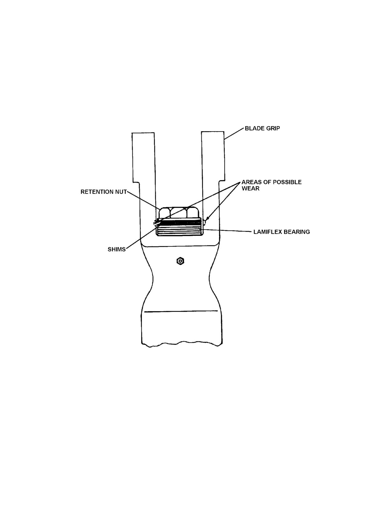
Figure 9-9. Lamiflex Bearing Shim Installation
MM-9-45
Feb 9/01
c. Place tool T-0149-13 onto the blade grip and using a press or other suitable
device, press the seal into the blade grip seal bore.
d. Remove the installation tools.
(2) If required, bond the covers for the cylinder and lug (not shown in Figure 9-8)
using the following procedure:
a. Remove residual adhesive from the cover and cylinder/lug as required.
b. Slightly abrade the bonding surfaces of the cover and cylinder/lug.
NOTE
Follow the mixing and application instructions for the DP420 adhesive or the
DP420 will not cure or adhere properly.
c. Bond the cover to the cylinder/lug using DP420 adhesive. Allow the DP420
adhesive to cure for 24 hours.
d. Apply a light bead of silicone sealant (732-RTV) around the cover.
(3) If installing new retention stops (1 & 4), follow the procedures in paragraph 9-
18,A,1.
CAUTION
Use brass protector plates in the vise jaws to prevent from damaging the
retention assembly.
(4) Clamp the spindle in a vise in the vertical position.
(5) If removed, apply a small amount of Loctite7 635 (green) to the alignment pin
(32) and press the alignment pin into the spindle until the end is slightly
recessed from the seal surface.
(6) Lubricate (MIL-PRF-81322) the seal surface of the spindle and install the seal
(6) with the spring side facing toward the ears of the spindle.
(7) Lubricate (MIL-PRF-81322) the bearing surface and install the bearing (7) using
a plastic mallet.
(8) Install the spacer (8).
(9) Lubricate (MIL-PRF-81322) the bearing surface and install the bearing (9) using
a plastic mallet.
NOTE
Ensure the bearings are seated firmly against the spindle shoulders.
Rev. 26
MM-9-46
Feb 28/2020
(10)
Install the retaining ring (10).
(11)
Install tool (T-0036) behind the seal with the chamfered side of the tool toward
the large radius of the spindle.
(12)
Remove the spindle from the vise and insert the grip installation pilot tool (T-
0149-12) into the spindle.
(13)
Lubricate (MIL-PRF-81322) the seal surface on the adapter in the outboard end
of the spindle.
(14)
Lubricate (MIL-PRF-81322) the bore of the blade grip and install the grip (28) on
the spindle. Tap the grip onto the spindle with a plastic mallet until the seal in
seated in the grip. Remove the pilot tool (T-0149-12) and the seal tool (T-0036)
from the spindle.
(15)
Install the lug (29) onto the end of the blade grip. Apply Loctite® 222MS to the
threads of the hardware and install the hardware and torque.
(16)
Install the tension-torsion strap (25) into the cylinder (24) so that the chamfer on
the cylinder is facing inboard (center of main rotor hub) when the tension-torsion
strap is installed in the spindle and install the retention pin (23).
(17)
Lubricate (MIL-PRF-81322) the portion of the inner spindle bore (3) that contacts
the O.D. of the cylinder (24).
(18)
Install the tension-torsion strap into the spindle and ensure the groove in the
cylinder engages the pin in the spindle.
(19)
Install one of the retaining rings (31) into the lug. Align the tension-torsion strap
to the lug and install the retention pin (30). Install the other retaining ring.
(20)
Install the dust cover (18).
(21)
Apply a bead of silicone sealant (732-RTV) around the perimeter of the cylinder
assembly (24) to form a seal between the cylinder and the spindle.
(22)
Install the flapping pin alignment pin into the spindle ear if it was removed.
(23)
Install the retention assembly onto the main rotor hub assembly (para. 9-19).
(24)
Install the pitch arm onto the blade grip. Install the hardware and torque to 75
in-lbs/8.5 Nm. Lockwire the hardware (.032) in horizontal pairs.
(25)
Service the blade grip.
a. Purge lubricate the retention assembly (para. 4-35).
b. Ensure the seal (6) is not dislocated from the blade grip. If it has moved,
remove the purge screw from the top of the blade grip. Insert the blade of a
flathead screwdriver between the seal and the spindle. Carefully work the
seal back into the grip. It is normal if grease is displaced out of the purge
hole as the seal is pushed back into place. Reinstall the purge screw.
Rev. 26
MM-9-47
Feb 28/2020
9-19. Installation - Retention Assembly (Figure 9-6)
NOTES
Grease bearings (grease lubricated) prior to installation through the small hole
in the bearing. When reinstalling removed bearings, purge old grease and refill
the bearings with new grease.
480, S/N 5003, 5014 and subsequent, have flapping bearings installed in the
universal blocks using the shimming procedure in paragraph 9-24, B or C.
A. Use the following procedure to install a retention assembly if the flapping bearings are
installed in the universal blocks using the shimming procedure in paragraph 9-24, B or C.
NOTE
Installing a pilot (Refer to Figure 9-13) will keep the spacer and shims in the
proper location while installing the hinge pin.
(1) Lubricate the O.D. of the hinge pin (2) (MIL-PRF-81322, grease lubricated
flapping bearings; MIL-PRF-23699, oil lubricated flapping bearings).
(2) Install the sleeves into the seals if equipped with oil lubricated flapping bearings.
NOTE
Install the shims (if installed) behind the DU washers in the same position as
previously installed.
NOTE
If new parts are installed in the flapping axis, begin with a 0.005” shim and
follow the shimming procedure in para. (7)a.
(3) Install the shims (4) and DU washers (3) on each side of the U-block with the
chamfered side inboard toward the U-block.
NOTE
Ensure that the correct retention assembly is being installed on the universal
block.
(4) Carefully slide the retention assembly into position over the DU washers and U-
block.
NOTE
The pilot tool (Figure 9-13) will be pushed out as the hinge pin is pushed into
the assembly while keeping the shims in the correct place.
(5) Install the hinge pin through the spindle and U-block. Align the roll pin slot in the
hinge pin with the roll pin and seat the hinge pin. Tap the roll pin flush with the
hinge pin if it protrudes from the hinge pin.
Rev. 26
MM-9-48
Feb 28/2020
(6) Lightly lubricate (MIL-PRF-81322; MIL-PRF-23699) the back of nut (6) and
install the lock washer (5) and nut (6) on the hinge pin.
CAUTION
Excessive torque could shear the roll pin installed in the head of the hinge pin.
(7) Insert a long punch into the damper-rod end attach holes in the flapping pin.
Torque the nut (6) using tool (T-0051-3) to 150 ft-lb/204.5 Nm. The nut may be
torqued to 175 ft-lb/238.6 Nm for aligning one of the lock washer tabs. While
torqueing the nut, pull against the punch to avoid shearing off the roll pin that
locates the head of the pin against the spindle arm side of the retention
assembly.
NOTE
If new parts are installed in the flapping axis, follow the shimming procedure in
para. (7)a below.
a. Check the flapping bearing drag resistance at the flapping pin. Initially, the grip
should not stay up. If the retention assembly stays up, remove shims in 0.005-
inch increments until the retention assembly will drop with no resistance when
nut is torqued.
(8) Bend one of the tabs on the lock washer into a slot in the nut.
(9) Install the main rotor damper (para. 9-31), connect the pitch change link to the
pitch change bellcrank and the pitch horn (para. 12-96), and install the main
rotor blade (para. 9-38).
(10) Lubricate the U-block lead lag and flapping bearings (if the flapping bearings are
grease lubricated) (para. 4-31).
(11) Lubricate the retention assembly (para. 4-35).
(12) Service the flapping bearing reservoir if equipped with oil lubricated flapping
bearings (para. 4-21).
(13) Perform a maintenance test flight (para. 4-61).
B. Use the following procedure to install a retention assembly until the flapping bearings
are installed in the universal blocks using the shimming procedure in paragraph 9-24,B or C.
(1) Lubricate the O.D. of the hinge pin (2) (MIL-PRF-81322, grease lubricated
flapping bearings; MIL-PRF-23699, oil lubricated flapping bearings).
Rev. 26
MM-9-49
Feb 28/2020
(2) Install the DU washers (3) on each side of the U-block with the chamfered side
inboard toward the U-block.
(3) Carefully slide the retention assembly into position over the DU washers and U-
block.
(4) Install the hinge pin through the spindle and U-block. Align the roll pin slot in the
hinge pin with the roll pin and seat the hinge pin. Tap the roll pin flush with the
hinge pin if it protrudes from the hinge pin.
(5) Install the lock washer (5) and nut (6) on the hinge pin.
CAUTION
Excessive torque could shear the roll pin installed in the head of the hinge pin.
(6) Torque the nut to 50-100 ft-lbs/68.2-136.4 Nm using tool (T-0051-3). Ensure the
retention assembly does not remain in the up-stop position.
a. Check the flapping bearing drag resistance at the flapping pin. Initially, the grip
should not stay up. If the retention assembly stays up, remove shims in 0.005-
inch increments until the retention assembly will drop with no resistance when
nut is torqued.
NOTE
Shims may be installed as required on the inboard side of the DU washers to
avoid excessive torque in obtaining the flapping preload. All three retention
assemblies should have an equal flapping preload.
(7) Lubricate the U-block lead lag and flapping bearings (para. 4-35) and re-check
the retention assembly in accordance with para. 9-19, B, (6). Reshim and
retorque the nut, if required.
(8) Bend one of the tabs on the lock washer into a slot in the nut when the proper
preload has been obtained.
(9) Install the main rotor damper (para. 9-31), connect the pitch change link to the
pitch change bellcrank and the pitch horn (para. 12-96), and install the main
rotor blade (para. 9-38).
(10) Lubricate the retention assembly (para. 4-35).
(11) Perform a maintenance test flight (para. 4-61).
Rev. 26
MM-9-50
Feb 28/2020
9-19.1 Tension-Torsion Strap (Figure 9-7)
9-19.2 Tension-Torsion Strap - Removal
NOTE
The following procedure is performed for changing the tension-torsion straps.
The blade grip does not need to be removed from the spindle when changing
the tension-torsion straps.
A. Remove the retention assembly from the main rotor hub (para. 9-14).
B. Remove the dust cover (18) from the blade end of the retention assembly.
C. Remove one of the retaining rings (31) securing the pin in the lug at the outboard end
of the retention assembly. Remove the pin (30) and the remaining retaining ring.
D. Using a non-metallic scraper remove the silicone sealant from the cylinder (24) and
the spindle.
NOTE
The pin used to secure the tension-torsion strap at the inboard end is not
secured with retaining rings.
E. Push the tension-torsion strap (25) back through the spindle.
F. Remove the pin (23) from the cylinder (24) and separate the tension-torsion strap
from the cylinder.
9-19.3 Tension-Torsion Strap - Installation
A. Install the tension-torsion strap (25) into the cylinder (24) so that the chamfer on the
cylinder is facing inboard (center of main rotor hub) when the tension-torsion strap is installed in
the spindle and install the retention pin (23).
B. Lubricate (MIL-PRF-81322) the portion of the inner spindle bore (3) that contacts the
O.D. of the cylinder (24).
C. Install the tension-torsion strap into the spindle and ensure the groove in the cylinder
engages the pin in the spindle.
D. Install one of the retaining rings (31) into the lug. Align the tension-torsion strap to
the lug and install the retention pin (30). Install the other retaining ring.
E. Verify proper installation of both retaining rings (31) Install the dust cover (18).
F. Apply a bead of silicone sealant (732-RTV) around the perimeter of the cylinder
assembly (24) to form a seal between the cylinder and the spindle. Reinstall Retention
assembly (para. 9-19).
Rev. 26
MM-9-51
Feb 28/2020
9-20. Universal Block
9-21. Disassembly - Universal Block (Figure 9-4 or 9-5)
A. Remove the upper and lower bearings and DU washers from the universal block (U-
block).
B. Remove the sleeves and seals from the flapping bearing bore if equipped with oil
lubricated flapping bearings.
NOTE
Flapping bearings can be removed from the universal blocks using the Flapping
Bearing Removal/Installation Tool (Grease Lubricated), T-0151-1, or Flapping
Bearing Removal/Installation Tool (Oil Lubricated), T-0162-1, when the
universal blocks are installed on the aircraft.
C. Press the flapping bearings, spacer, and shims from the bore of the U-block.
D. Remove the screws and stop pads if visual damage appears on the blocks.
E. Remove the grease fittings if equipped with grease lubricated flapping bearings.
F. Remove the drain plug if equipped with oil lubricated flapping bearings.
9-22. Inspection - Universal Block
A. See Table 9-3 for the detailed inspection requirements of the universal block
assemblies.
9-23. Repair - Universal Block
A. Repair or replace the components of the universal block assembly as required in
accordance with Table 9-3.
9-24. Assembly - Universal Block (Figure 9-4 or 9-5)
A. If removed, install the stop blocks (21).
NOTE
Index mark the universal blocks and retention assemblies (spindles) as sets.
Rev. 26
MM-9-52
Feb 28/2020
Table 9-3. Universal Block Assembly
Inspection Requirements*
P/N
Fig. #
Part Name
Inspection
Serviceable Limits
Repair Limits
Repair or Action
Item #
28-14251-1 & -2
Fig. 9-4, 21
Stop Pad
Visual damage (cracks,
None Allowed
Not Repairable
Replace Stop(s)
Fig. 9-5, 20
chips, etc.)
ECD092-1
Fig. 9-4, 22
Bearing
O.D. 2.4994 to 2.5000
No Tolerance
Not Repairable
Replace Bearing
Fig. 9-5, 21
Allowed
ECD092-3
Fig. 9-5, 21A
I.D. 1.7493 to 1.7500
No Tolerance
Not Repairable
Replace Bearing
Allowed
Ratcheting or
Not Repairable
Replace Bearing
roughness
None Allowed
28-14236-1
Fig. 9-4, 23
DU Washer
Flatness
.005
Not Repairable
Replace Washer
Fig. 9-5, 22
Thickness .090 to.093
-.003
Not Repairable
Replace Washer
28-14117-11 or -
Fig. 9-4, 15
U-Block
Bore Dia. 2.4988 to
+.0002
Not Repairable
Replace U-Block
13
or
2.4996
Fig. 9-5, 15
Bearing Surface O.D.
-.0002
Not Repairable
Replace U-Block
1.7488 to 1.7494
Bearing Surfaces
.001 FIM
Not Repairable
Replace U-Block
concentric
Threads (crossed or
None Allowed
Not Repairable
Replace U-Block
missing)
Nicks, scratches, or
None allowed at the
≤ .030 deep
Blend and polish out
corrosion
radius of the bearing
smooth
spindle
Cracks
None Allowed
Not Repairable
Replace U-Block
Rev. 26
MM-9-53
Feb 28/2020
Table 9-3. Universal Block Assembly
Inspection Requirements*
P/N
Fig. #
Part Name
Inspection
Serviceable Limits
Repair Limits
Repair or Action
Item #
28-14235-1
Fig. 9-4, 24
Spacer
Ends parallel
.0015 FIM
Not repairable
Replace Spacer
28-14233-2
Fig. 9-6, 2
Flapping Pin
Threads (crossed or
None Allowed
Not Repairable
Replace Pin
missing)
Damper bolt hole Dia.
+.0015
Not Repairable
Replace Pin
.5005 to .5015
O.D. 1.7486 to 1.7492
-.0005
Not Repairable
Replace Pin
Longitudinal scores or
.011 deep
≤ .011 deep
Blend and polish out
scratches
smooth
Radial Scores
None Allowed
Not Repairable
Replace Pin
28-14233-3
Fig. 9-6, 2
Flapping Pin
O.D. 1.7488 to 1.7494
-.0005
Not Repairable
Replace Pin
Inspect the remainder of the flapping pin following the inspection criteria listed for the -2 flapping pin
W-09
Fig. 9-6, 5
Lock Washer
Tangs
None Allowed
Not Repairable
Replace Washer
(deformed or cracked)
N-09
Fig. 9-6, 6
Nut
Threads
None Allowed
Not Repairable
Replace Nut
(crossed or missing)
4143011-11
Fig. 9-5, 23
Spacer
Ends parallel
.0015 FIM
Not Repairable
Replace Spacer
4143011-13
Fig. 9-5, 26
Sleeve
Ends parallel
.0015 FIM
Not Repairable
Replace Spacer
* All dimensions are in inches.
MM-9-54
Feb 9/01
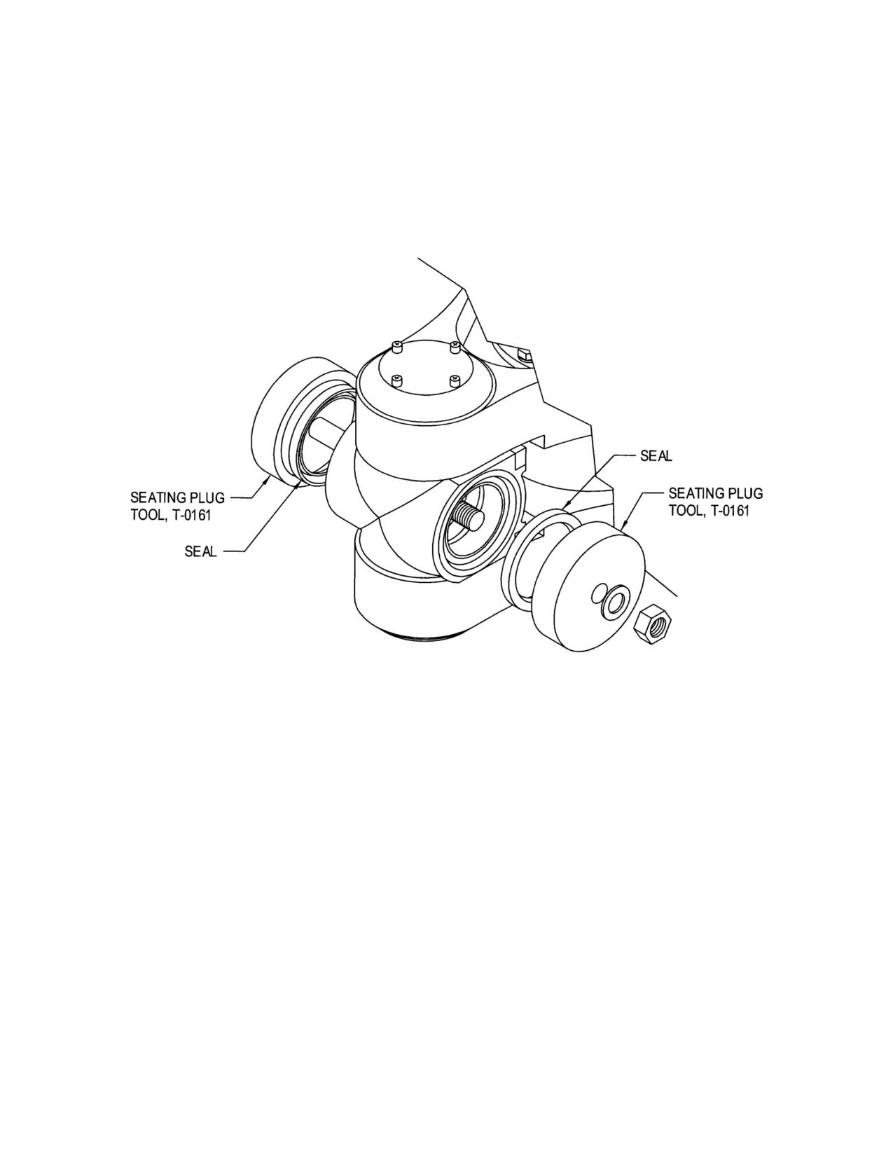
Figure 9-15. Flapping Bearing Seal Installation
Rev. 3
MM-9-61
Oct 13/04
9-25. Dampers
9-26. Removal - Dampers (Figure 9-16)
A. Remove the bolt (5) connecting the damper to the retention assembly.
B. Pivot the damper and remove the spacers (7) from between the damper bearing and
the hinge pin.
NOTE
If the center bolt head in the pitch change bellcrank is orientated over the
inboard pivot bolt, hardware removal is not necessary.
C. If required, remove the nut and washers from the pitch change bellcrank center pivot
bolt. Remove the bolt until the end is flush with the mounting bracket.
D. Remove the inboard pivot bolt (1) from the hub and remove the damper.
9-27. Disassembly - Dampers (Figure 9-17)
NOTE
The following procedure only applies to the hydraulic main rotor dampers, P/N
28-14375-“X”.
A. Secure the damper assembly in a vise.
B. Insert a punch through the rod end (20) hole. Pull on the punch to pull the rod end
assembly to expose 1.0 inch/25 mm of the piston shaft (6) and install tool T-0005.
C. Reposition the damper in the vice so that the vice jaws grip tool T-0005.
D. Remove the lockwire from the locking tab (18) and loosen the jam nut (19) and back it
out as far as the threads on the rod end (20) will allow which will withdraw the locking tab from
the piston shaft (6).
NOTE
If the rod end was not previously assembled with epoxy, but there is evidence
of threadlocker (Loctite Red 271, or equivalent) it may be necessary to heat the
rod end assembly to remove the jam nut.
WARNING
Use protective gloves when handling heated parts.
D. If required, heat the rod end assembly (250°F/121°C). Remove the rod end.
E. Remove the damper from the vice.
F. Remove the reservoir plugs (26) and pour the fluid from the reservoir (21).
Rev. 26
MM-9-62
Feb 28/2020
G. Remove the hardware (16) and (28) securing the reservoir to the damper and remove
the reservoir.
H. Remove the sleeves (27) and O-rings (25).
CAUTION
The relief valves are adjusted and set at the factory. Return defective valves to
the factory.
I.
If removal of the valve assemblies (22) is required, place the reservoir back in a vise.
Remove the valve caps (23) and remove the valves.
CAUTION
Remove all burrs from the piston shaft to prevent damage to the brass sleeve
and seals during end cap removal.
J. Remove the hardware (16) and (17) that secures the end cap (10) to the damper
housing (1). Rotate the end cap approximately 45° using a plastic mallet and remove the end
cap by tapping outward on its corners.
K. Pour the fluid from the damper housing.
L. Tap the piston (6) out of the housing using a nylon drift and remove the O-ring or Seal
Pack (9) from the piston.
CAUTION
Do not damage the I.D. of the sleeves during seal and wiper removal.
M. Remove the seals (14) and wipers (15) from the brass sleeves (5 & 12) in the end cap
and damper housing.
N. Install tool (T-0095) between the ears of the damper housing and press the bushing
(3) out using a suitable size drift.
O. Inspect the bushing faces (2) for fretting and wear. Do not remove the bushings (2)
unless replacement is required.
Rev. 26
MM-9-63
Feb 28/2020
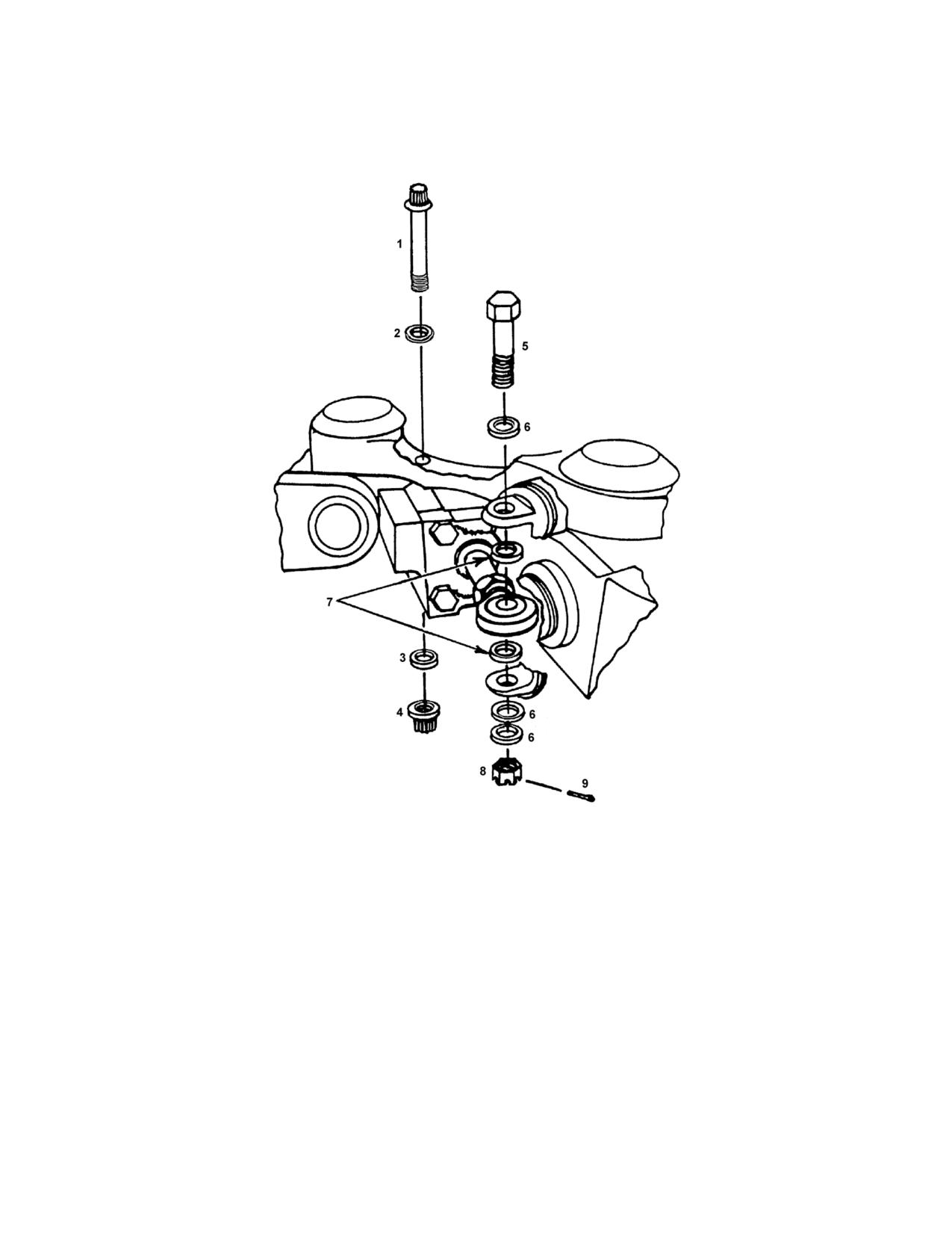
1.
Inboard Pivot Bolt
6.
Washer
2.
Chamfered Washer
7.
Spacer
3.
Washer
8.
Nut
4.
Nut
9.
Cotter Pin
5.
Bolt
Hydraulic Damper, P/N 28-14375-“X”
Figure 9-16. Hydraulic Damper Assembly
Rev. 26
MM-9-64
Feb 28/2020
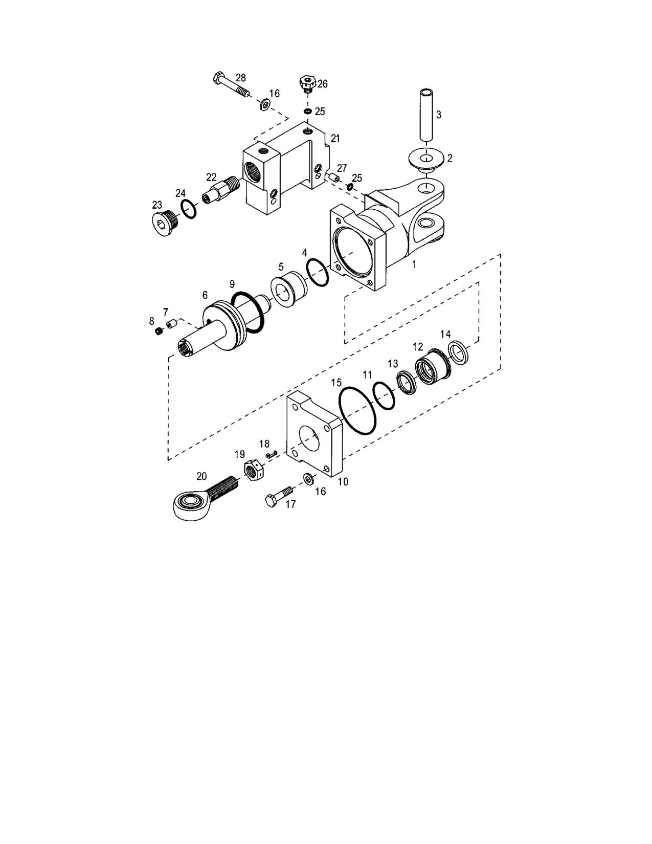
1.
Damper Housing
15.
O-Ring
2.
Bushing
16
Washer
3.
Bushing
17.
Bolt
4.
O-Ring
18.
Lock Key
5.
Sleeve
19.
Nut
6.
Piston
20.
Damper Bearing
7.
Restrictor Sleeve
21.
Reservoir
8.
Set Screw
22.
Valve Assembly
9.
O-Ring or Seal Pack
23.
Cap Plug
10.
End Cap
24.
O-Ring
11.
O-Ring
25.
O-Ring
12.
Sleeve
26.
Plug
13.
Wiper
27.
Sleeve
14.
Seal
28.
Bolt
Figure 9-17. Hydraulic Damper Assembly
Rev. 26
MM-9-65
Feb 28/2020
9-28. Inspection - Dampers
A. See Table 9-4 for the detailed inspection requirements for the damper assemblies.
9-29. Repairs - Dampers
A. Replace leaking seals or O-rings on hydraulic dampers as required.
B. Repair or replace the detailed parts of the hydraulic damper assembly as required in
accordance with Table 9-4.
9-30. Assembly - Dampers (Figure 9-17)
NOTE
The following procedure only applies to the hydraulic main rotor dampers, P/N
28-14375-“X”.
CAUTION
Do not damage the I.D. of the sleeves during seal and wiper installation.
A. Install the seals (14) and wipers (13) into the end cap and damper housing as follows:
(1) Install the seals in the inboard groove of the brass sleeves (5 &12) with the O-
ring side toward the piston. Ensure the seal has the O-ring installed in it.
(2) Install the wiper in the outboard groove of the brass sleeves with the lip of the
wiper facing outboard.
B. If the bushings (2) where removed, install tool (T-0095) between the ears of the
damper housing (1). Using an arbor press, install the bushings into the housing. If new
bushings are installed, they must be line reamed with a ½ in. line reamer.
C. Lubricate (L-45/SF96-20) the O.D. of the bushing (3). With tool (T-0095) installed,
press the bushing into the housing.
D. Place the damper housing in a vise with the bore up.
NOTE
Ensure the components are free of dirt and contamination prior to assembly.
CAUTION
Do not damage the O-rings or seals during the assembly process.
E. Lubricate (L-45/SF96-20) the bore of the housing.
Rev. 26
MM-9-66
Feb 28/2020
F. Install the O-ring or Seal Pack using the following procedure:
(1) If O-ring is installed, lubricate (L-45/SF96-20) the O-ring (9) and install on the
piston (6).
(2) If seal pack is installed, install the seal pack onto the piston using tool T-0160-1.
Using wood blocks or other suitable devices to protect the piston shaft from
damage, clamp the piston vertically in a vise. Install the installation sleeve (T-
0160-3) onto the piston. Lubricate (L-45/SF96-20) the seal ring and install on the
piston using the expanding sleeve and pilot (T-0160-9). Remove the tools.
G. Install the piston into the damper housing (1) using the following procedure:
(1) Clamp the damper housing vertically in a vice. Install the installation collar tool
T-0610-7 onto the damper housing. Install the piston into the collar with the
threaded end up and tap with a plastic mallet until the seal pack is into the
damper housing. Remove the collar and tap the piston with the plastic mallet
until the piston is bottomed in the housing.
H. Fill the housing with damper oil (L-45/SF96-20) and install the O-ring (9) into the
recess in the damper housing.
I.
Lubricate (L-45/SF96-20) the seal and wiper in the end cap (10). Install the end cap
on the piston shaft and gently tap the cap to seat it onto the damper housing.
J. Install the hardware (16 & 17) securing the end cap to the housing. Torque the bolts
in a cross pattern.
K. If the relief valves (22) have been removed for cleaning or replacement, install the
valves in the reservoir and torque to 350 in-lbs/39.8 Nm.
L. Install new O-rings (24) onto the valve caps (23) and install the valve caps.
M. Reposition the damper to the horizontal position with the reservoir ports up.
N. Install new O-rings (25) on the sleeves and install the sleeves (27) into the reservoir
ports in the damper housing.
O. Align the ports in the reservoir (21) with the sleeves in the damper housing and install
the reservoir. Install the securing hardware and torque.
P. Temporarily install the damper bearing (20) and place the damper in the damper
fixture (T-0057). Position the piston approximately .5 inches/13 mm. from the bottomed
position.
Q. Fill the reservoir with damper oil (L-45/SF96-20). Install the servicing/bleeding tools
(T-2896) (Refer to Figure 4-5) and cycle the tools until the entrapped air is removed. Remove
the servicing/bleeding tools and install the reservoir plugs (26) with new O-rings (25) installed.
R. Remove the damper from the fixture and wipe down to remove the damper oil.
Rev. 26
MM-9-67
Feb 28/2020
S. Install the damper rod end bearing assembly.
NOTE
The rod end bearing assembly may have been previously treated with ACF-50 or
MIL-PRF-23377 Type I Class 2C or Class N epoxy primer corrosion inhibitor per
SDB T-058. If continuing use of ACF-50, removal of prior ACF-50 application is
unnecessary. If changing from ACF-50 to epoxy primer, ACF-50 residue must be
removed before reinstallation. For helicopters S/N 5242 and subsequent, the rod
ends are treated with epoxy primer at the time of manufacture.
(1)
Remove the nut.
(2)
For new epoxy primer application, remove any ACF-50 residue from the threads
of the rod end and the interior threads of the piston with a suitable solvent.
(3)
If applying a touch-up of epoxy primer, remove any loose epoxy primer residue
from the threads of the rod end and the interior threads of the piston with a
brush and a small amount of solvent.
CAUTION
Do not allow the epoxy primer to dry prior to assembly of the rod end.
CAUTION
Mask the bearing area prior to applying epoxy primer to avoid damaging
the bearing.
NOTE
Follow the manufacturer’s instructions for corrosion inhibitor application.
(4) Apply the applicable corrosion inhibitor to the entire thread length of the rod end,
as required.
NOTE
Installing the nut will tend to wipe away corrosion inhibitor that was freshly
applied. Re-apply to ensure complete coverage.
(5) Install the jam nut.
(6) Re-apply corrosion inhibitor to the threads below the jam nut, as required.
(7)
Install the damper rod end bearing assembly until the distance between the
outboard edge of the jam nut (19) and the center line of the damper bearing
equals 1.050 in. ± .005 in./26.7 mm ± .13 mm (Figure 9-20).
(8) Re-apply corrosion inhibitor to the threads above the jam nut, as required.
Rev. 26
MM-9-68
Feb 28/2020
NOTE
The locking key must be aligned with the piston slots for the jam nut to seat
against the piston shaft.
T. Hold the damper bearing with a wrench and tighten the jam nut when the correct
position is set. Lockwire (.032) the jam nut to the locking key (18). Position the locking key
towards the top of the damper.
U. Lockwire (.032) the end cap bolts (17) in pairs and the valve caps (23) to the reservoir
bolts (28) in pairs. Lockwire (.025) the bleed plugs (26) in a pair.
9-31. Installation - Dampers (Figure 9-16)
A. Install the damper onto the main rotor hub.
B. Install the chamfered washer (3) onto the inboard pivot bolt (2) with the chamfer
against the bolt head.
C. Install the inboard pivot bolt through the hub plates and damper. Install the washer
(3) and nut (4) but do not torque.
CAUTION
On hydraulic dampers, the locking key in the piston shaft must be on the top
side to prevent interference with the hinge pin.
D. Install the spacers (7) on each side of the damper bearing and slide the damper
bearing into the hinge pin.
E. Align the damper bearing and spacers with the hinge pin. Install a washer (6) on the
bolt (5) and install the bolt. Install two washers (6) and the nut (8). Torque to 450-500 in-
lbs/45.5-56.8 Nm and install a cotter pin (9).
F. Torque the inboard pivot bolt to 190 in-lbs/21.6 Nm.
G. If the washers and nut were removed from pitch change bellcrank center bolt in
accordance with step C, remove the center pivot bolt, turn the bolt 180°, and reinstall the bolt
and install washers and nut. Torque to 40 in-lbs/4.5 Nm and cotter pin.
H. Perform a maintenance test flight (para. 4-61).
Rev. 26
MM-9-69
Feb 28/2020
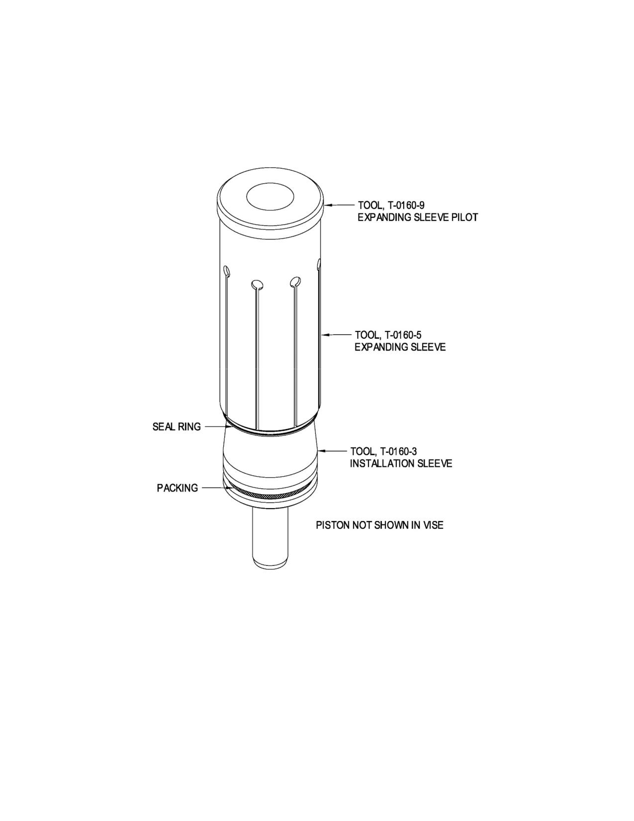
Figure 9-18. Seal Ring Installation
Rev. 26
MM-9-70
Feb 28/2020
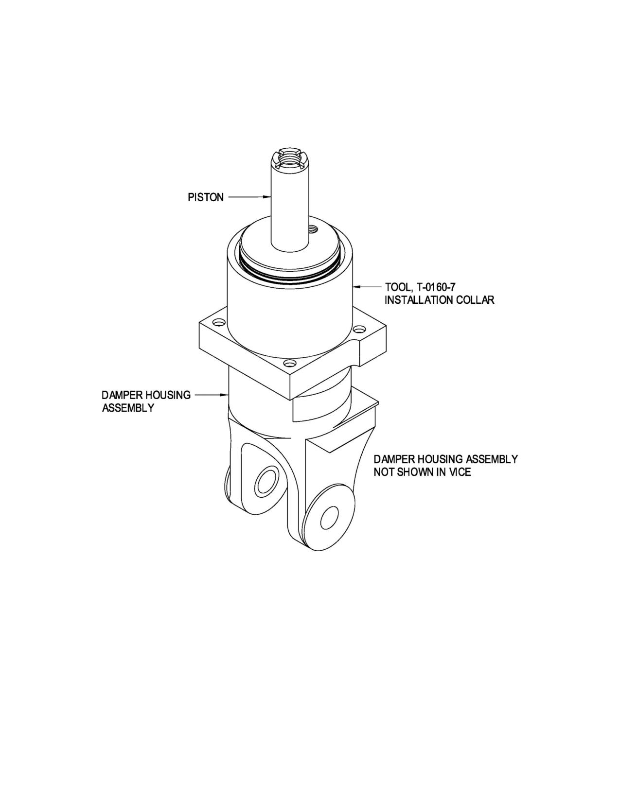
Figure 9-19. Piston Installation
Rev. 26
MM-9-71
Feb 28/2020
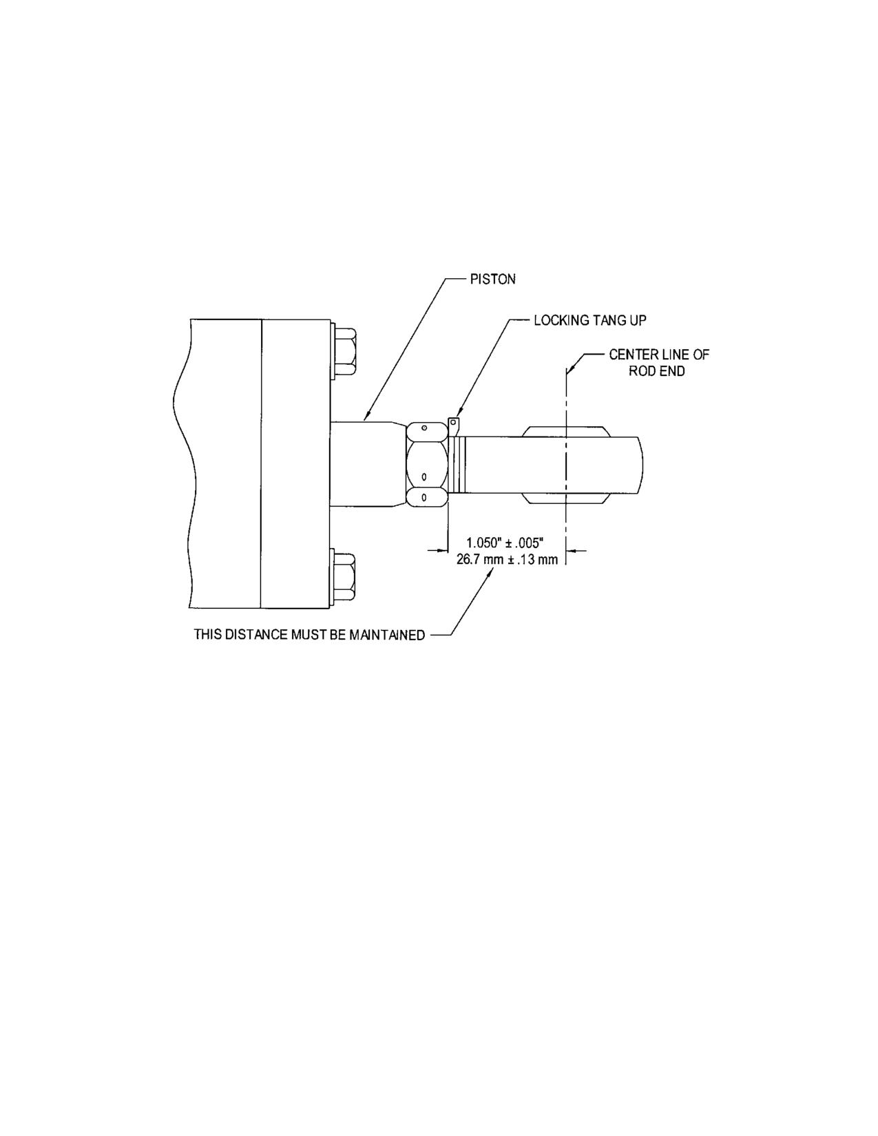
Figure 9-20. Damper Rod End Installation
Rev. 26
MM-9-72
Feb 28/2020
INTENTIONALLY LEFT BLANK
Rev. 26
MM-9-73
Feb 28/2020
Table 9-4. Hydraulic Damper Assembly
Inspection Requirements*
P/N
Fig. 9-17
Part Name
Inspection
Serviceable Limits
Repair Limits
Repair or Action
Item #
28-14357-3 or -5
1
Housing
Sleeve bore Dia.
+.0002
Not Repairable
Replace Housing
1.1250 to 1.1255
Flanged bushings in
1/3 of total face light
2 of total face light
Blend and polish to
the ears for excessive
fretting
fretting
remove
fretting
Obstructions in the flow
None Allowed
Clear with compressed air
ports
Threads (crossed or
None Allowed
Not Repairable
Replace Housing
missing)
Security of the chrome
No movement
Not Repairable
Replace Housing
sleeve in the bore of
allowed
the housing
Surface scratches
None Allowed
≤ .020 deep
Blend and polish out
smooth
28-14277-1 or
3
Bushing
O.D. .4995 to .5005
-.0005
Not Repairable
Replace Bushing
28-14359-17
(28-14277-1)
O.D. .4994 to .4999
(28-14359-17)
I.D. .3747 to .3757
+.0005
Not Repairable
Replace Bushing
(28-14277-1)
I.D. .3765 to .3775
(28-14359-17)
Nicks and scratches
.005 deep
≤ .005 deep
Blend and polish out
smooth
Rev. 26
MM-9-73.1
Feb 28/2020
Table 9-4. Hydraulic Damper Assembly
Inspection Requirements*
P/N
Fig. 9-17
Part Name
Inspection
Serviceable Limits
Repair Limits
Repair or Action
Item #
28-14356-3 or -5
5 & 12
Sleeve
O.D. 1.1260 to 1.1265
-.0002
Not Repairable
Replace Sleeve
Piston shaft bore Dia.
+.002
Not Repairable
Replace Sleeve
.749 to .751
28-14356-3 or -5
5 & 12
Sleeve
O.D. to I.D.
.002 FIM
Not Repairable
Replace Sleeve
(Cont=d)
concentricity
28-14370-15,
6
Piston
Piston shaft O.D. .746
-.001
Not Repairable
Replace Piston
-17
to .748
Nicks or scratches in
None Allowed
≤ .5" long and
Blend and polish out
surface
≤ .005 deep
smooth
Obstruction in the flow
None Allowed
Clear with compressed air
restrictor
Concentricity
.001 FIM
Not Repairable
Replace Piston
Threads
None Allowed
Not Repairable
Replace Piston
(crossed or missing)
28-14265-3
10
End Cap
Sleeve bore Dia.
+.0002
Not Repairable
Replace Cap
1.1250 to 1.1255
Obstructions in the fluid
None Allowed
Clear with compressed air
port
Nicks, scratches, or
None Allowed
≤ .020 deep
Blend and polish out
corrosion
smooth
Cracks
None Allowed
Not Repairable
Replace Cap
ECD091-1
20
Damper Bearing
Radial Play
.007
Not Repairable
Replace Bearing
Axial Play
.005
Not Repairable
Replace Bearing
Rev. 26
MM-9-73.2
Feb 28/2020
Table 9-4. Hydraulic Damper Assembly
Inspection Requirements*
P/N
Fig. 9-17
Part Name
Inspection
Serviceable Limits
Repair Limits
Repair or Action
Item #
ECD091-1
20
Damper Bearing
Threads
None Allowed
Not Repairable
Replace Rod End
(Cont’d)
(crossed or missing)
Threads
None Allowed
Not Repairable
Replace Rod End
(damage or corrosion)
28-14366-1
21
Reservoir
Obstructions in the flow
None Allowed
Clear with compressed air
ports
Threads
None Allowed
Not Repairable
Replace Reservoir
(crossed or missing)
Nicks, scratches, or
.020 deep
≤ .020 deep
Blend and polish out
corrosion
smooth
Cracks
None Allowed
Not Repairable
Replace Reservoir
If the valves are
None Allowed
removed, valve threads
Flush with cleaning
and ports for
solvent and dry with
contamination
compressed air
28-14368-1, -2
23
Plug
Threads
None Allowed
Not Repairable
Replace Plug
(crossed or missing)
28-14369-1
27
Sleeve
O.D. and I.D. for nicks
None Allowed
Not Repairable
Replace Sleeve
or scratches
AN814-2DL
26
Plug
Threads
None Allowed
Not Repairable
Replace Plug
(crossed or missing)
O-Rings, Wiper, and
Inspect for obvious
None Allowed
Not Repairable
Replace as required
Seals
defects
* All dimensions are in inches.
Rev. 26
MM-9-73.3
Feb 28/2020
INTENTIONALLY LEFT BLANK
Rev. 26
MM-9-73.4
Feb 28/2020
9-32. Main Rotor Blades
9-33. Description - Main Rotor Blades (Figure 9-21)
The main rotor blades are of hollow construction. Upper and lower skins are bonded to
the extruded leading edge spar which is twisted 7.25°. Doublers are bonded to the root end of
the blade for retaining the blades to the main rotor hub. The blades are retained by a single
retention pin to the blade grip and a non-adjustable drag brace connected to the trailing edge of
the blades. Provisions for spanwise and chordwise balance weights are provided in the tip caps
that are bonded in the tip end of the blades. Two tracking tabs are riveted to the trailing edge of
each blade.
9-34. Removal - Main Rotor Blades (Figure 9-22)
NOTE
Lifting the tip of the blade until the blade is parallel to the retention assembly will
allow the retention bolt and the drag brace bolt to be easily removed and will
allow the blade to be removed from the blade grip without spreading the ears of
the grip.
A. Remove the bolt (1) securing the drag link to the rotor blade.
B. Remove the blade retention bolt (2).
C. Carefully slide the blade from the grip.
D. Place the blade into a blade rack or on a suitable device that will prevent the blades
from being damaged.
E. Repeat the process for the other 2 blades.
Rev. 26
MM-9-74
Feb 28/2020
Table 9-5. Tail Rotor Assembly
Inspection Requirements*
P/N
Figure 9-36
Part Name
Inspection
Serviceable Limits
Repair Limits
Repair or Action
Item #
28-150076-15
4
Journal
Journal I.D. .4995 to
+.0002
Not Repairable
Replace Journal
.4998
Journal O.D. .7509 to
-.0002
Not Repairable
Replace Journal
.7511
B-1210
5
Needle Bearing
Bearing O.D. 1.000
-.0002
Not Repairable
Replace Bearing
Visible wear of the
None Allowed
Not Repairable
Replace Bearing
needles
28-150076-13
7
Thrust Bumper
Thickness .123 to .125
-.002
Not Repairable
Replace Bumper
28-150060-11
11
Pitch Change Plate
Nicks in edge of plate
None Allowed
.005 deep
Polish and blend locally not
to exceed .008
Pitch link bolt hole Dia.
+.0005
Not Repairable
Replace pitch change plate
.250 to .251
Return to the factory for
Corrosion
None Allowed
inspection and replating, or
replace pitch change plate
Cracks
None Allowed
Not Repairable
Replace pitch change plate
28-150063-11,
12
Sleeve
Sleeve I.D. .7878 to
+.0002
Not Repairable
Replace Sleeve
-13
.7882
Sleeve I.D. .7872 to
+.0002
Not Repairable
Replace Sleeve
.7876 (-13)
Sleeve O.D. 1.1245 to
-.0002
Not Repairable
Replace Sleeve
1.1250
Rev. 26
MM-9-113
Feb 28/2020
Table 9-5. Tail Rotor Assembly
Inspection Requirements*
P/N
Figure 9-36
Part Name
Inspection
Serviceable Limits
Repair Limits
Repair or Action
Item #
ECD001-11
13
Bearing
Bearing O.D. 1.6250
+.0000
Not Repairable
Replace Bearing
-.0005
Visible wear of the
None Allowed
Not Repairable
Replace Bearing
rollers
28-150055-1,
14
Retainer
Retainer I.D. 1.6250 to
+.0005
Not Repairable
Replace Retainer
-13, -15
1.6255
Retainer I.D. 1.6240 to
+.0005
Not Repairable
Replace Retainer
1.6247 (-15)
Retainer O.D. 2.043 to
-.001
Not Repairable
Replace Retainer
2.044
ECD002-11,
15
Bearing
Bearing O.D. 2.0467 to
-.0002
Not Repairable
Replace Bearing
-13, -15, -17
2.0472
Bearing Bore Dia.
+.0002
Not Repairable
Replace Bearing
.7870 to.7874
Preload to the thrust
None Allowed
Not Repairable
Replace Bearing
side and check for
roughness or ratcheting
SL61N-5P
16
Nut
Threads (rolled or
None Allowed
Not Repairable
Replace Nut
missing)
Nicks and burrs on
None Allowed
≤ .10 deep
Blend and polish out
O.D.
smooth
Rounded or burred
Max. 2 slightly
To allow use of the
Blend and polish out
locking tabs
rounded tabs
locknut wrench
smooth
Cracks
None Allowed
Not Repairable
Replace Nut
Rev. 26
MM-9-114
Feb 28/2020
WARNING
Use protective gloves when handling heated parts.
K. Using a heat gun, heat the blade grip (19) to approximately 250°F/121°C.
L. Lubricate (MIL-PRF-81322) the bore of the blade grip. Quickly slide the blade and
grip assembly onto the spindle. Align the pitch link hole in the pitch change plate to the leading
edge of the blade. Align the dowel pins to the center holes in the pitch change plate (the holes
are located in sets of three).
NOTE
Alternately tighten the bolts 1 to 2 turns to pull the pitch change plate and grip
straight together.
M. Start three bolts (25) into the grip and tighten to pull the grip and the pitch change
plate together.
N. Install the rest of the bolts (25). After the blade and grip assembly has cooled, torque
the bolts to 50-70 in-lbs/5.7-8.0 Nm and safety wire (.032) in pairs.
O. Re-heat the blade grip and tap outboard to assure maximum CF (centrifugal force)
position.
P. Torque the blade retention bolt nuts to 75 in-lbs/8.5 Nm (140 in-lbs/15.9 Nm if the
blade and grip assembly has been factory repaired and 5/16 inch bolts installed) after the blade
grip has cooled.
Q. Install the grease fitting into the grip and lubricate the grip (para. 4-39.4) until grease
purges from the pitch change plate from around the spindle.
R. If required, install the opposite blade and grip assembly.
S. Statically balance the tail rotor (para. 9-42).
T. Install the bolts (26), washers (27), and nuts (28) onto the pitch arms if not installed.
9-51. Installation - Tail Rotor Assembly
A. Start a .041 wrap of safety wire around one side of the tail rotor hub.
NOTE
The tail rotor assembly may be rotated 180° or the center hub may be pivoted
180° to obtain the proper installation position of the tail rotor assembly.
Rev. 26
MM-9-123
Feb 28/2020
NOTE
See Figure 9-38. A line drawn through the grease fittings of either end of the
teetering hub (Figure 9-36, 2) (tail rotor hub pivot center line) should align with
the lagging ears of the pitch link retainer. If the tail rotor hub pivot centerline is
centered between the ears of the pitch link retainer, rotate the teeter trunnion
180° to obtain the correct 8° alignment.
B. Install the tail rotor assembly onto the transmission output shaft. Ensure the center
line of the tail rotor hub pivot axis aligns with the inboard side of the pitch change link retainer
ear that lags in the direction of rotation (Figure 9-38).
C. Feed the safety wire through the hole in the teeter stop and install the teeter stop so
that the rubber bumpers align with the flats of the spindle.
D. Install the washer and retaining bolt. Torque the retaining bolt to 300 in-lbs/34.1 Nm
and complete the safety.
E. Connect the pitch change links to the pitch change plates (para. 12-126).
F. Dynamically balance the tail rotor (para. 9-43).
Rev. 22
MM-9-124
Jun 25/14