Enstrom TH-28/480 Series. Maintenance Manual (2020) - page 4
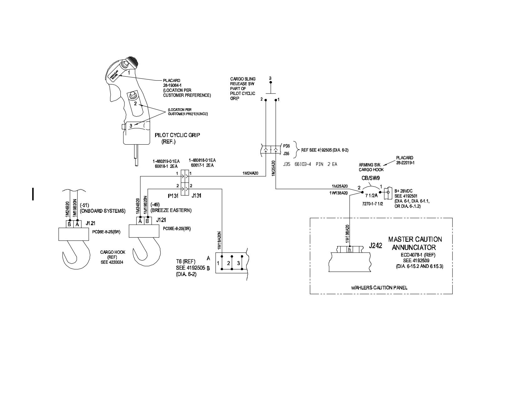
Diagram 6-30. Cargo Hook Sling Release
Rev. 26
MM-6-123
Feb 28/2020
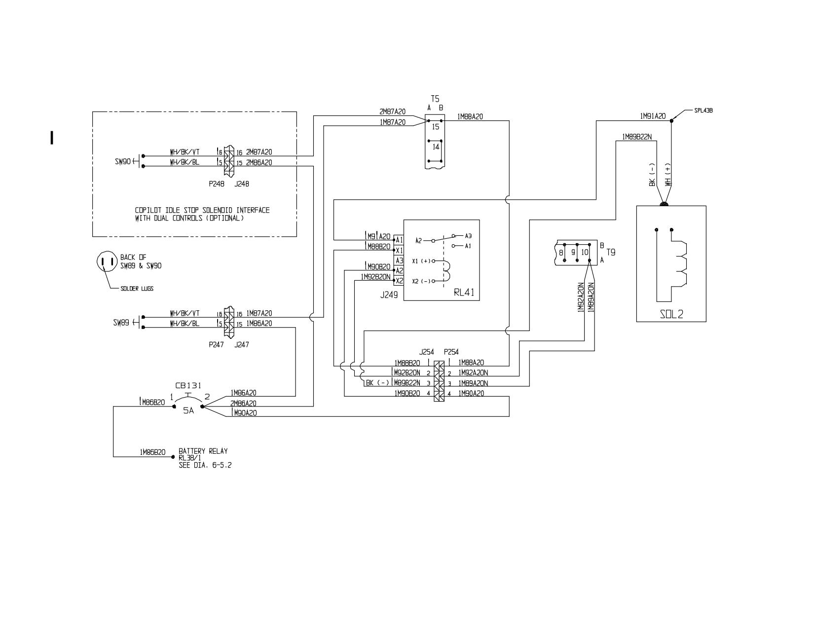
480B S/N 5136 and Subsequent
Diagram 6-31. Engine Idle Stop
Rev. 23
MM-6-124
Jul 3/15
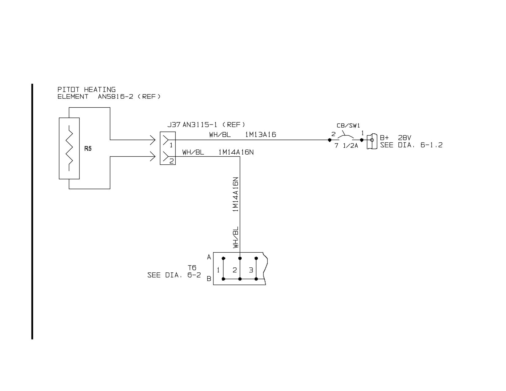
TH-28/480 Series Option (All S/N)
Diagram 6-32. Heated Pitot System Interface
Rev. 21
MM-6-125
Apr 30/14
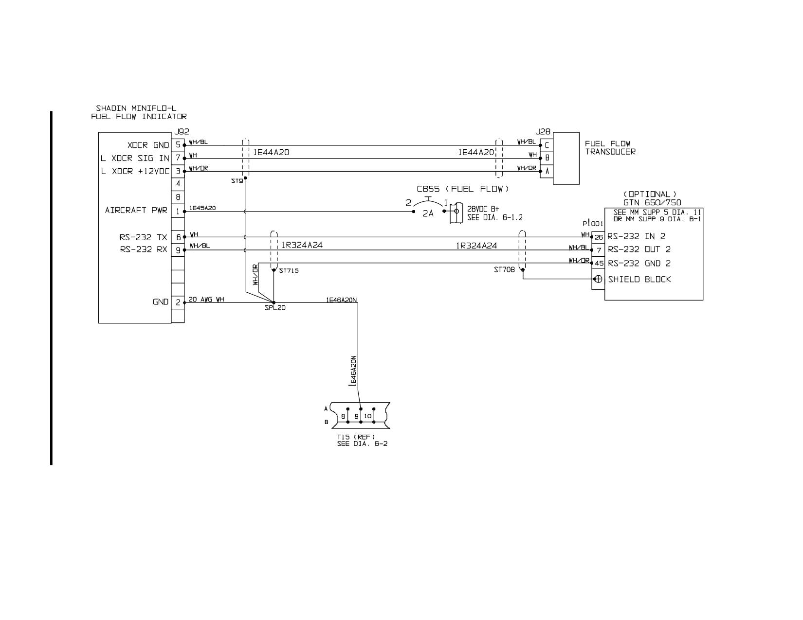
480/B Option (All S/N)
Diagram 6-33. Fuel Flow System
Rev. 26
MM-6-126
Feb 28/2020
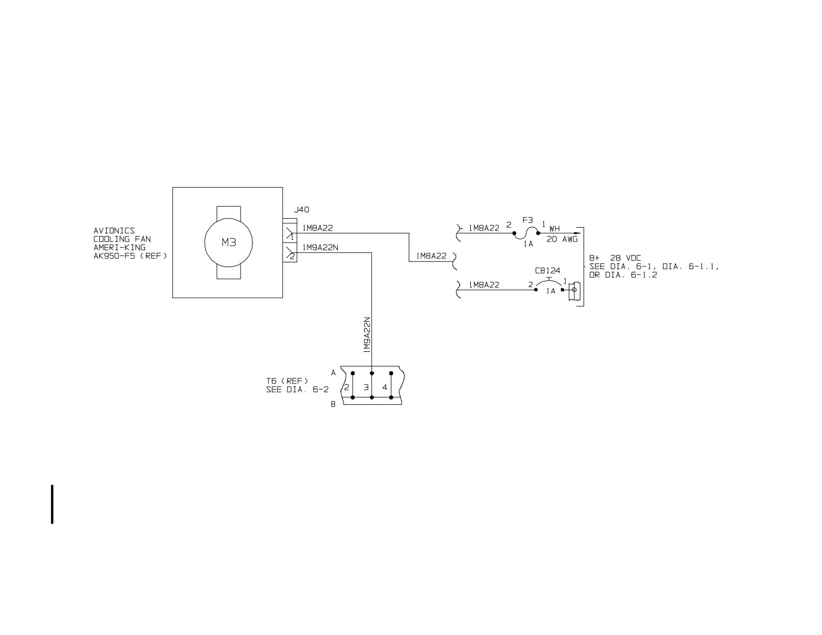
480/B Option (S/N 5238 and prior)
Sheet 1 of 2
Diagram 6-34. Avionics Cooling Fan
Rev. 26
MM-6-127
Feb 28/2020
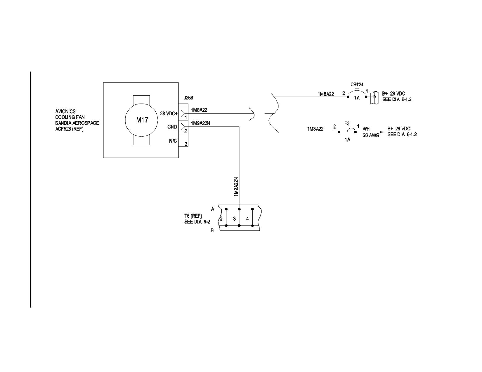
480/B Option (S/N 5239 and subsequent)
Sheet 2 of 2
Diagram 6-34. Avionics Cooling Fan
Rev. 26
MM-6-128
Feb 28/2020
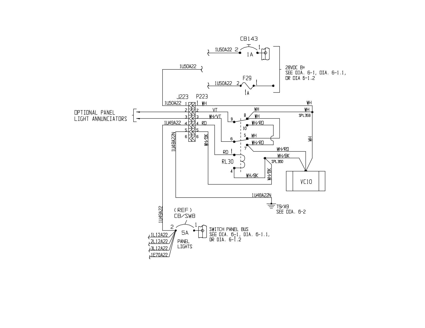
480/B Option (All S/N)
Diagram 6-35. Day/Night Panel Annunciator Lamp Power
Rev. 26
MM-6-129
Feb 28/2020
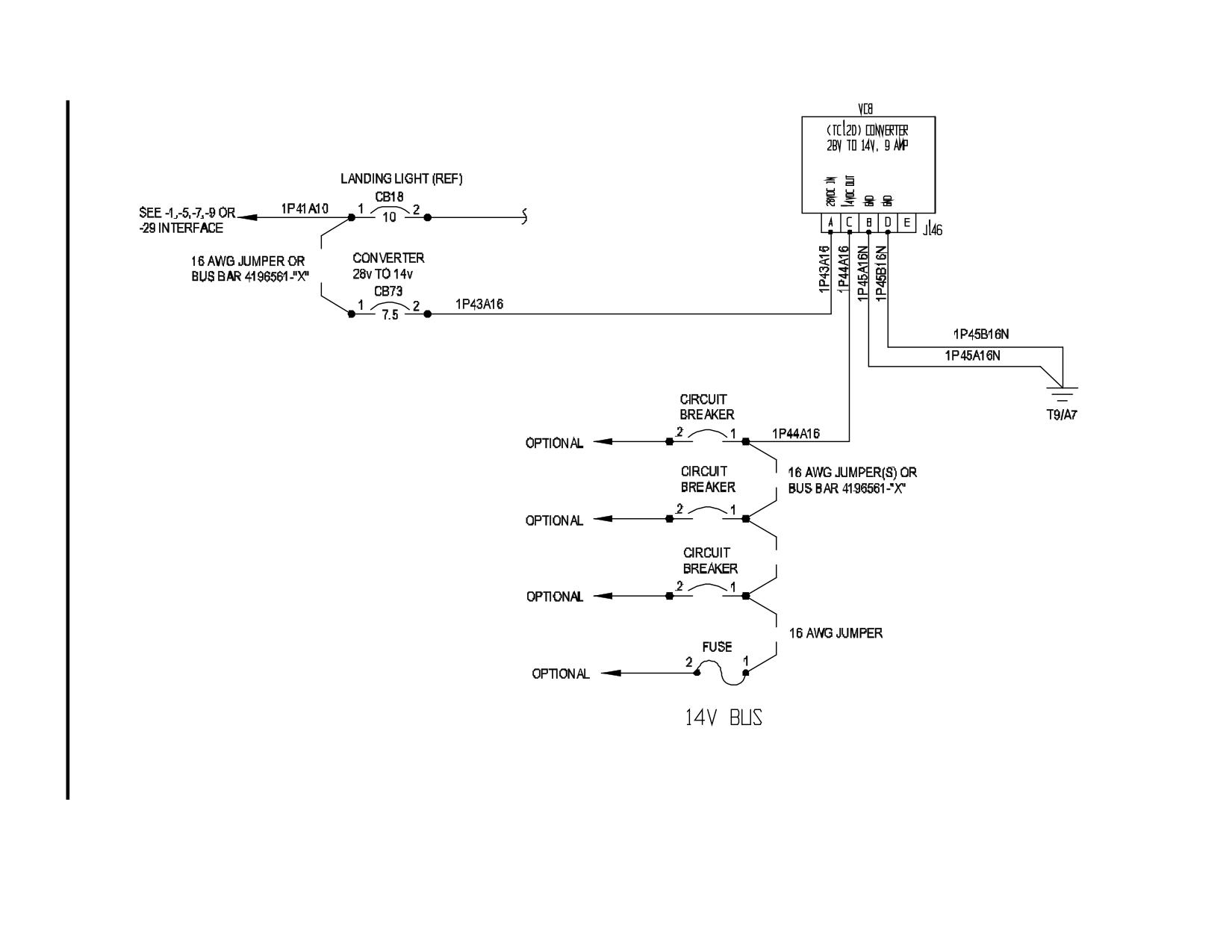
Diagram 6-36. 28V to 14V 9A Converter
Rev. 26
MM-6-130
Feb 28/2020
(7) Altimeter:
Test the altimeter following the instructions for performing a pitot/static system
leak check (paragraph 7-68).
7-13. Repair - Instrument Maintenance
A. Replace any required decals which are missing or not clearly legible.
B. Replace any instrument if the cover glass is loose, cracked, broken, or when the
instrument is found to be unserviceable.
7-14. Installation - Instrument Maintenance
A. Position the instrument into the panel. Install the mounting screws or tighten the
screw of the mounting clamp.
B. Remove the protective caps or covers as necessary, and connect the electrical
connectors and/or hoses to the instrument.
C. Check the instrument for operation.
NOTE
See Figure 7-1 for instrument location in the instrument panels. Optional
equipment instruments are not shown.
7-15. Rotor and Power Turbine Tachometer (Dual Tach)
7-16. General Description - Dual Tach
The rotor and power turbine tachometer (Dual Tach) is powered by the aircraft 28-volt
electrical system and driven by a tachometer generator for the power turbine section and a
magnetic pick-up mounted in the main rotor transmission for the rotor section. Refer to
paragraphs 7-10 through 7-14 for maintenance procedures.
7-17. Power Turbine Tachometer Generator
7-18. Description - Power Turbine Tachometer Generator
The power turbine tachometer generator is mounted on the N2 tach pad on the left side of
the engine accessory drive gearbox and is connected to the dual tach. Refer to paragraphs 13-
129 through 13-132 for maintenance procedures.
MM-7-15
Feb 9/01
7-19. Rotor RPM Magnetic Pick-up
7-20. Description - Rotor RPM Magnetic Pick-up
The rotor rpm magnetic pick-up, located in the forward portion of the main rotor
transmission, is used to generate pulses used to drive the rotor rpm portion of the dual tach.
7-21. Removal - Rotor RPM Magnetic Pick-up
A. Drain the oil from the main rotor transmission (para. 4-13).
B. Remove the upper plenum/air inlet assembly (para. 13-28).
C. Disconnect the magnetic pick-up electrical connector.
D. Remove the magnetic pick-up from the main rotor transmission. If replacing the
magnetic pick-up, remove any shims installed on the pick-up.
7-22. Inspection - Rotor RPM Magnetic Pick-up
A. Inspect the magnetic pick-up for security of installation and condition and security of
the electrical wires and connectors.
B. Using a multi-meter, check for 270-330 ohms across the leads.
7-23. Repair - Rotor RPM Magnetic Pick-up
A. Repair damaged wiring or electrical connectors.
B. Replace the magnetic pick-up if the ohm check is outside the 270-330 ohm range or if
inspection of the system components and wiring isolates the problem to the magnetic pick-up.
7-24. Installation - Rotor RPM Magnetic Pick-up
A. Remove the inspection magnetic pick-up inspection plug located on the front of the
main rotor transmission.
B. Turn the gearbox until a gear tooth is directly under the center of the magnetic pick-
up installation hole.
C. Install the magnetic pick-up into the main rotor transmission.
(1) Insert a 0.030 feeler gauge through the access plug hole.
(2) Install any shims, P/N 28-16524-( ), from the old pick-up onto the replacement
magnetic pick-up between the check nut and the top base of the magnetic pick-
up.
(3) Replace the O-ring on the magnetic pick-up.
(4) Screw the magnetic pick-up in until it touches the feeler gauge.
Rev. 26
MM-7-16
Feb 28/2020
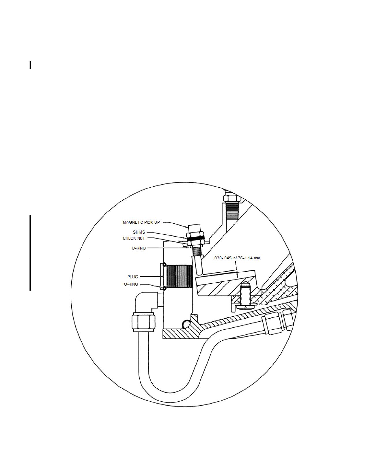
(5) Adjust the amount of shims as required to set the final clearance between the
magnetic tip of the pick-up and the gear tooth to .030-.045 inch/.76-1.14 mm.
(6) Torque the magnetic pick-up to 60-65 in-lb/6.8-7.3 Nm.
D. Install the inspection plug.
(1) Replace the O-ring on the plug and reinstall the plug in the front of the
transmission.
(2) Torque the plug and lockwire (.032) the magnetic pick-up to the plug.
E. Reconnect the electrical connector
F. Service the main rotor transmission (para. 4-12).
G. Install the upper plenum/air inlet assembly (para. 13-31).
Figure 7-2. Magnetic Pick-up Installation
Rev. 26
MM-7-17
Feb 28/2020
7-25. Gas Producer Tachometer
7-26. General Description - Gas Producer Tachometer
The gas producer tachometer (N1) provides an indication in percent rpm of the engine gas
producer (N1) section by connection to a tachometer generator mounted on the engine
accessory gearbox. Two different type N1 Tach systems are used in the TH-28/480. The
"passive" system uses an indicator that is powered by the signal from the tachometer generator.
The "active" system uses an indicator that is powered by the aircraft electrical system and uses
a micro processor to convert the signal from the tachometer generator. Refer to paragraphs 7-
10 through 7-14 for maintenance procedures.
7-27. Gas Producer Tachometer Generator
7-28. General Description - Gas Producer Tachometer Generator
The gas producer tachometer generator is mounted on the N1 tach pad on the right side of
the engine accessory drive gearbox and is connected to the N1 tach. Refer to paragraphs 13-
129 through 13-132 for maintenance procedures.
7-29. Engine Oil Temperature and Pressure Indicator
7-30. General Description - Engine Oil Temperature and Pressure Indicator
The engine oil temperature and pressure indicator is a dual indicator which uses a
temperature bulb located in the engine oil reservoir for engine oil temperature indications and a
pressure transducer connected to the engine oil pressure line on the engine. Refer to
paragraphs 7-10 through 7-14 for maintenance procedures.
7-31. Engine Oil Temperature Bulb
7-32. General Description - Engine Oil Temperature Bulb
The engine oil temperature bulb, installed on the engine oil reservoir is a resistance type
temperature bulb which monitors the engine oil temperature and transmits varying voltage
signals to the engine oil temperature and pressure indicator.
7-33. Removal - Engine Oil Temperature Bulb
A. Drain the engine oil reservoir (para. 4-8).
B. Remove the lockwire and disconnect the electrical connector.
Rev. 26
MM-7-18
Feb 28/2020
CAUTION
Use a backing wrench when removing the temperature bulb to prevent from
damaging the engine oil reservoir.
C. Remove the lockwire and remove the temperature bulb from the engine oil reservoir.
D. Remove the gasket from the temperature bulb.
7-34. Inspection - Engine Oil Temperature Bulb
A. Inspect the temperature bulb for cracks, leaks, security, and proper installation.
B. Inspect the electrical connector for damaged or bent pins and cracked inserts
7-35. Repair - Engine Oil Temperature Bulb
A. Repair damaged electrical connectors.
B. Replace the gasket.
C. Replace the temperature bulb if cracked or damaged.
7-36. Installation - Engine Oil Temperature Bulb
A. Lubricate the gasket and bulb threads with MIL-PRF-23699 and install the gasket
onto the temperature bulb.
CAUTION
Use a backing wrench when installing the temperature bulb to prevent from
damaging the engine oil reservoir.
B. Install the temperature bulb into the engine oil reservoir and lockwire using .032 wire.
C. Connect the electrical connector and lockwire with 0.020 lockwire.
D. Service the engine oil reservoir (para. 4-7).
7-37. Engine Oil Pressure Transducer
7-38. General Description - Engine Oil Pressure Transducer
The engine oil pressure transducer, located on the right side of the pylon assembly just aft
of the engine, monitors engine oil pressure and transmits voltage signals to the engine oil
temperature and pressure indicator.
Rev. 26
MM-7-19
Feb 28/2020
7-39. Removal - Engine Oil Pressure Transducer
A. Open the right side engine access panel.
B. Disconnect the electrical connector and the oil pressure line from the engine oil
pressure transducer. Cap, plug, and cover the open line, port, electrical connections.
C. Loosen the hardware securing the transducer in the mounting clamps and remove the
transducer.
7-40. Inspection - Engine Oil Pressure Transducer
A. Inspect the transducer for cracks, security, and the mounting clamps do not cover the
static ports in the middle area of the transducer.
B. Inspect the oil line for leaks and proper operation.
C. Inspect the electrical connector for damaged or bent pins and cracked inserts.
7-41. Repair - Engine Oil Pressure Transducer
A. Repair damaged electrical connectors.
B. Tighten loose oil line fittings.
C. Replace defective or damaged oil lines.
D. Replace the pressure transducer if cracked or damaged.
E. Reinstall a improperly mounted pressure transducer.
7-42. Installation - Engine Oil Pressure Transducer
A. Install the pressure transducer into the mounting clamps and position so the static
ports are not obstructed by the clamps. Tighten the securing hardware.
B. Remove the caps, plugs, and covers. Reconnect the oil pressure line and the
electrical connector.
7-43. Turbine Outlet Temperature (TOT) Indicator
7-44. General Description - Turbine Outlet Temperature (TOT) Indicator
The turbine outlet temperature (TOT) indicator indicates the turbine outlet temperature in
degrees Celsius (C). Two different type TOT indicator systems are used in the TH-28/480. The
"passive" indicator system operates on electrical potential from the engine thermocouple
harness via a thermocouple lead spool resistor. The "active" indicator system is powered by the
aircraft electrical system and converts the electrical potential from the engine thermocouple
MM-7-20
Feb 9/01
SECTION 8
STRUCTURES
TABLE OF CONTENTS
Paragraph
Description
Page
8-83.
Baggage Compartment
MM-8-74
8-84.
Description
MM-8-74
8-85.
Removal
MM-8-74
8-86.
Inspection
MM-8-74
8-87.
Repair
MM-8-74.1
8-88.
Installation
MM-8-74.1
8-89.
Tailcone
MM-8-74.1
8-90.
Description
MM-8-74.1
8-91.
Removal
MM-8-74.1
8-92.
Inspection
MM-8-74.2
8-93.
Repair
MM-8-74.2
8-94.
Replacement
MM-8-76
8-95.
Installation
MM-8-77
8-96.
Horizontal and Vertical Stabilizers
MM-8-78
8-97.
Removal
MM-8-78
8-98.
Disassembly
MM-8-78
8-99.
Inspection
MM-8-80
8-100.
Repair
MM-8-80
8-101.
Assembly
MM-8-80
8-102.
Installation
MM-8-80
8-103.
Horizontal Stabilizer Spar
MM-8-81
8-104.
Removal
MM-8-81
8-105.
Inspection
MM-8-81
8-106.
Repair
MM-8-81
8-107.
Installation
MM-8-82
8-108.
Extension Tube
MM-8-82
8-109.
Removal
MM-8-82
8-110.
Inspection
MM-8-83
8-111.
Repair
MM-8-83
8-112.
Installation
MM-8-83
8-113.
Tail Rotor Guard
MM-8-83
8-114.
Removal
MM-8-83
8-115.
Inspection
MM-8-85
8-116.
Repair
MM-8-85
8-117.
Installation
MM-8-85
8-118.
Vibration Absorber
MM-8-86
8-119.
Removal
MM-8-86
8-120.
Disassembly
MM-8-86
8-121.
Inspection
MM-8-86
8-122.
Repair
MM-8-86
8-123.
Assembly
MM-8-86
8-124.
Installation
MM-8-87
8-125.
Consumable Materials List
MM-8-91
Rev. 26
MM-8-3
Feb 28/2020
SECTION 8
STRUCTURES
TABLE OF CONTENTS
Paragraph
Description
Page
INTENTIONALLY LEFT BLANK
Rev. 10
MM-8-4
Oct 20/09
B. Touch up areas of the epoxy primer finish using MIL-PRF-23377 primer or equivalent.
C. Repair damage to the pylon assembly I/A/W AC 43.13-1B. Contact The Enstrom
Helicopter Corporation Customer Service for detailed damage and repair limitations.
8-13. Access Panels, Covers, and Cowlings
8-14. Removal - Access Panels, Covers, and Cowlings
Remove the following access panels, covers, and cowlings using the procedures listed for
each panel, cover, or cowling. Refer to Figure 8-1 for access panel locations.
A.
Forward Landing Gear Leg Panel(s):
(1) Remove the screws securing the access panel(s) to the keel access panels and
remove the panel(s).
B.
Keel Access Panel(s):
CAUTION
Support the keel access panel(s) during the removal process to prevent from
damaging the antenna leads before they are disconnected.
(1) Remove the forward landing gear leg panel(s).
(2) Remove the screws securing the panel(s) to the cabin and the outboard screws
securing the forward landing gear leg panel(s) to the keel access panel(s).
(3) Disconnect the ground wire from the antenna ground plane and disconnect the
antenna lead from the antenna.
(4) Remove the panel(s).
C.
Engine Access Panel(s):
(1) Unlock the turn lock fasteners at the bottom edge of the access panel(s).
WARNING
The pneumatic springs have approximately 25 pounds/11.4 kg of
pressure. Use extreme caution when removing the pneumatic springs.
(2) If installed, disconnect and remove the pneumatic spring door opener.
Rev. 22
MM-8-7
Jun 25/14
(3) Remove the hinge pin securing the access panel hinge half to the hinge half
installed on the airframe and remove the panel(s).
D.
Bottom Engine Access Panel:
(1) Disconnect the engine and the engine fire pan drain lines.
(2) Remove the screws securing the access panel to the left and right side
cowlings, the cabin shell, and the bottom edge of the left and right side engine
fire curtain.
(3) Slide the access panel to one side and pull the opposite edge of the panel from
under the side cowling and remove the panel.
E.
Fuel Cell Cover(s):
NOTE
Procedures for removing the covers are the same for both sides except as
noted in the instructions.
(1) Defuel the aircraft (para. 4-5).
(2) Remove the upper plenum/air inlet (para. 13-28).
(3) Remove the air deflector from the top of the cabin.
(4) Remove the hardware securing the filler port to the fuel cell cover on the left side
fuel cell.
NOTE
TH-28 S/N 3007 and subsequent and 480 S/N 5011 and subsequent have a
fuel quantity probe cover and gasket installed on the right fuel cell cover.
(5) Remove the hardware securing the cell to the cover (Aerazur fuel bladder
system), the fuel quantity probe cover, and the fuel cell cover to the cell
structure.
CAUTION
All or a portion of the fuel cell covers and possibly the filler port assembly are
sealed with sealant to prevent fuel leaks. A putty knife or other suitable tool
may be required to separate the cover from the cell structure and the filler
port. Use extreme caution to prevent from damaging the cover, fuel cell, fuel
cell structure, or injuring yourself while removing the cell cover.
(6) Remove the fuel cell cover.
Rev. 26
MM-8-8
Feb 28/2020
8-17. Installation - Access Panels, Covers, and Cowlings
Install the following access panels, covers, and cowlings using the procedures listed for
each panel, cover, or cowling.
A.
Forward Landing Gear Leg Panel(s):
(1) Install by reversing the removal instructions.
B.
Keel Access Panel(s):
CAUTION
Support the keel access panel(s) during the installation process to prevent
from damaging the antenna leads before the panels are installed.
(1) Install by reversing the removal instructions.
C.
Engine Access Panel(s):
(1) Install by reversing the removal instructions.
D.
Bottom Access Panel:
(1) Install by reversing the removal instructions.
E.
Fuel Cell Cover(s):
NOTE
Procedures for installing the covers are the same for both sides except as
noted in the instructions.
CAUTION
Use extreme caution to prevent from damaging the cover, fuel cell, fuel cell
structure, or injuring yourself while removing the old sealant.
(1) Remove the old sealant from the fuel cell covers, the fuel cell support structures,
and possibly the fuel filler port if the left side cover is removed.
Rev. 26
MM-8-18.1
Feb 28/2020
NOTE
Do not install the sealant for the fuel cell covers until all troubleshooting,
adjusting, and/or repairs have been made to the fuel cells, the fuel quantity
system, or the low fuel warning system.
NOTE
Follow the mixing instructions on the sealant container or the sealant may not
properly cure.
(2) Using a sealant meeting AMS-S-8802 Type II Class B, apply a bead on all
interfacing fuel cell support structures - cowl ring, cabin structure, fuel shelf
structure. Ensure the sealant is on the inboard side of the hardware used to
secure the cell covers and apply more sealant in areas where needed to ensure
proper sealing (lower forward corner for example).
(3) Place the cover in position and install the hardware along the bottom edge of the
cover.
NOTE
Step (4) below only applies to TH-28s and 480s equipped with the Aerazur
fuel bladder system.
CAUTION
Do not over inflate the fuel cells to prevent from damaging the fuel cell
structure or the fuel cells.
(4) Install the hardware securing the fuel cells to the covers. Inflating the fuel cells
might be required to perform this task. To inflate the fuel cells, ensure the fuel
shutoff valve is "OFF", the sump drain and low point drain valves are closed, and
that the fuel filler port is installed or the port in the fuel cell is taped over. Using
filtered, dry, low pressure compressed air, inflate the fuel cells via the overboard
vent line. Remove the air source after installing the hardware.
NOTE
Early model TH-28/480s may have had sealant installed between the fuel cell
and the fuel cell cover at the filler port and may also have had sealant
between the filler port assembly and the fuel cell cover. If your aircraft has had
sealant installed in these areas, the sealant does not need to be installed
when reinstalling the cover provided the old sealant is removed and the filler
port area seals when reassembled.
Rev. 26
MM-8-18.2
Feb 28/2020
G. Install the door strikers onto the cabin shell.
8-43. Installation - Cabin Doors
A. If equipped, Position the door on the hinges and insert the jettison pins in the hinges
and in the restrain strap on the inside of the door. Ensure the jettison handle is correctly
positioned in the handle retainer. Lockwire the hinge jettison pins to the hinges using breakaway
lockwire (MS20995CY20 or equivalent).
B. Position the door on the hinges installed on the cabin shell and install the hinge pins
and secure.
C. Install the pin securing the restraint strap to the cabin and secure.
WARNING
The pneumatic springs have approximately 45 pounds/20.5 kg of
pressure. Use extreme caution when installing the pneumatic springs.
NOTE
Install the pneumatic springs with the piston rod oriented down to prevent the
seals from drying out and subsequent loss of gas pressure.
D. Install the pneumatic spring onto the fitting located on the cabin floor and install the
retaining clip. Install the upper end of the pneumatic spring onto the door fitting and install the
retaining clip.
E. Check the door assembly for proper fit and the latching system for proper operation.
If required, adjust the door hinges by shimming or the latching system by adjusting the strikers.
8-44. Windshields and Windows
8-45. Inspection - Windshields and Windows
A. Inspect the windshields and windows for cracks, crazing, pits, and scratches.
8-46. Repair - Windshields and Windows
A. Damage to the windshields and windows which does not interfere with pilot's line of
sight during normal flight and landing attitudes or damage that does not impair structural
integrity may be repaired by stop drilling or patching I/A/W AC 43.13-1B; however, the
windshield or window should be replaced at the earliest opportunity.
B. Damage to the decorative vinyl tape (P/N 70-0160-1056-6) which covers the paint
line may be repaired by removing the damaged portion and applying new tape. Use a cotton
glove and apply firm pressure while installing the tape. Do not stretch the tape when applying.
Rev. 21
MM-8-41
Apr 30/14
8-47. Replacement - Windshields and Windows
A.
Replace the windshields as follows:
NOTE
Replacement procedures are the same for both windshields.
NOTE
All replacement windshields are now the "blown" version. Replace both
windshields if replacing a "flat" windshield with a "blown” windshield.
(1) Remove the cabin doors.
(2) If equipped, disconnect the defroster from the supply line and remove the
hardware securing it to the cabin shell.
(3) Remove the center strip from the windshields.
(4) Remove the hardware securing the windshield to the cabin shell.
CAUTION
Use extreme care while removing the windshield with a putty knife to prevent
from damaging the cabin shell or injuring yourself.
CAUTION
Use extreme care when using a portable heat gun to prevent from damaging
the paint finish due to excessive heat.
(5) Heat the edge of the windshield and adhesive using a portable heat gun and
separate the windshield from the cabin shell and center support with a putty
knife.
NOTE
Tape application for the windshield installation was discontinued for S/N 5238
and subsequent.
(6) Remove the residual foam tape or adhesive from the windshield recess in the
cabin shell and the center support. Clean the recess with acetone or equivalent.
(7) Place the replacement windshield into position and verify it will properly fit. Mark
areas of interference and trim the windshield using a belt sander. Ensure the
cabin door upper hinge post cutout in the replacement windshield is large
enough.
Rev. 26
MM-8-42
Feb 28/2020
(8) Drill the mounting holes in the replacement windshield using a pointed dull #11
drill bit if “-10" screws are used to secure the windshield or a pointed dull #15
drill bit if “-8" screws are used to secure the windshield by temporarily taping the
replacement windshield into place and back drilling the mounting holes through
the cabin shell and center support.
CAUTION
Use extreme caution while using an awl or other suitable device to prevent
from damaging the aircraft or injuring yourself.
NOTE
Mask off the area around the windshields on the outside of the aircraft and place
protective coverings inside the aircraft to prevent damage from excess adhesive.
(9) Prepare the adhesive (PR-1425-B2 or equivalent) following the manufacturer's
instructions and apply a coating approximately .0625 in/1.6 mm thick to the
center support.
(10) Prepare the adhesive (PR-1425-B2 or equivalent) following the manufacturer's
instructions and apply a coating approximately .0625 in/1.6 mm thick in the
cabin shell recess.
CAUTION
Do not over tighten the mounting screws for the windshields.
(11) Position the windshield in place. Temporarily install and tighten the mounting
hardware. Allow the adhesive to cure for 24 hours.
(12) Remove the mounting hardware and using a plastic scraper, remove the excess
adhesive.
(13) Apply a small bead of sealant (Phenoseal 102 or equivalent) on each side of the
windshield center strip and at the top and bottom and place into position. Apply
a small amount of sealant (Phenoseal 102) onto the shanks of the windshield
mounting hardware and install the mounting hardware. Do not over tighten the
mounting hardware.
(14) Paint the outer edges of the windshield(s).
(15) Install the defroster(s).
(16) Install the cabin doors.
B.
Replace the overhead and cheek windows as follows:
NOTE
Overhead and cheek windows for late production 480 aircraft had putty-filled cleco
holes. Rivets are used in early (TH-28/480) and current production aircraft (480B).
Rev. 26
MM-8-43
Feb 28/2020
(1) Drill out the existing rivets.
CAUTION
Use extreme care while removing the windows with a putty knife to prevent
from damaging the cabin shell or injuring yourself.
CAUTION
Use extreme care when using a portable heat gun to prevent from damaging
the paint finish due to excessive heat.
(2)
Heat the edge of the window and adhesive using a portable heat gun and
separate the window from the cabin shell with a putty knife.
(3)
Remove the residual adhesive from the window recess while it is still warm.
(4)
Remove any remaining adhesive by sanding and wipe the recess area clean
with acetone or equivalent.
(5)
Place the replacement window on the cabin and tape into position.
(6)
Using a marker, mark the cabin hole locations.
(7)
Apply 1/4 (0.25) inch masking tape following the window recess in the cabin to
mark the window size for cutting.
(8)
Remove the window and cut to size using a fine tooth bandsaw and sand the
edges on a belt sander.
(9)
Check the fit of the window and re-sand the edges as necessary.
(10)
Using a pointed dull #17 (4.4 mm) drill bit, drill the replacement window at the
marked locations.
(11)
Sand the hole edge.
(12)
Remove the window and clean the recess in the cabin shell.
(13)
Lightly sand the bonding edges of the window and wipe clean with acetone or
equivalent.
NOTE
Mask off the area around the window on the outside of the aircraft and place
protective coverings inside the aircraft to prevent damage from excess
adhesive.
(14) Prepare the adhesive (PR-1425-B2 or equivalent) following the manufacturer's
instructions and apply a coating approximately .0625 in/1.6 mm thick in the
cabin shell recess.
Rev. 26
MM-8-44
Feb 28/2020
(15) Install the window into position and press firmly against the adhesive. Install the
mechanical fasteners (clecos). Allow the adhesive to cure for 24 hours.
(16) Remove the mechanical fasteners (clecos).
(17) Remove excess adhesive from around the window using a plexiglass scraper
made from the damaged window.
(18) Paint the outer edges of the window.
(19) Apply sealant (732-RTV or equivalent) to the washers and rivets upon
installation.
(20) Apply sealant (732-RTV or equivalent) between the window and the cabin shell.
C.
Replace/Remove the chin windows as follows:
NOTE
TH-28, S/N 3007 and subsequent, and 480/480B, S/N 5039 and subsequent,
are equipped with removable chin windows. Refer to paragraph 8-47, B, for
aircraft not equipped with removable chin windows.
(1) Remove the screws securing the chin window.
CAUTION
Use extreme care while removing the windows with a putty knife to prevent
from damaging the cabin shell or injuring yourself.
(2) Using a putty knife, carefully break the seal around chin window and remove the
chin window.
(3) If required replace the foam tape (4516).
(4) If required, replace any damaged Rivnuts.
(5) Place the replacement window on the cabin and tape into position.
(6) Apply 0.25 inch/6 mm masking tape following the window recess in the cabin to
mark the window size for cutting.
(7) Remove the window and cut to size using a fine tooth bandsaw and sand the
edges on a belt sander.
(8) Check the fit of the window and re-sand the edges as necessary.
(9) Place the replacement window on the cabin and tape into position.
(10) Using a pointed dull #30 drill bit, carefully drill the mounting pilot holes in the
window using the Rivnuts as guides.
Rev. 26
MM-8-45
Feb 28/2020
(11) Remove the window from the cabin and open the pilot holes with a pointed dull
#15 drill bit.
CAUTION
Do not over tighten the mounting screws for the chin windows.
(12) Place the window on the cabin and install the mounting screws but do not
tighten. Apply sealant (Phenoseal 102 or equivalent) under the screw heads and
tighten the screws until the screw head contacts the window.
(13) Apply sealant around the seam between the chin window and the cabin.
Remove excess sealant from the seam and the screw heads as required.
(14) Paint the outer edges of the window.
D.
Replace the opera windows as follows:
(1) Remove the pop-out vent window.
NOTE
Rivets and foam tape were used to secure the opera windows only in early
production TH-28/480 aircraft.
(2) Drill out the existing rivets.
CAUTION
Use extreme care while removing the windows with a putty knife to prevent
from damaging the cabin shell or injuring yourself.
(3) Separate the window from the cabin shell with a putty knife.
(4) Remove the residual tape or adhesive from the window recess and wipe the
recess area clean with acetone or equivalent.
(5) Place the replacement window into position and verify it will properly fit. Mark
areas of interference and trim the window using a belt sander.
(6) Using a pointed dull #41 drill bit, drill as many holes as required through the
window around the edges for mechanical fasteners (clecos) as required to
secure window while the adhesive cures.
(7) Remove the window and clean the recess in the cabin shell.
(8) Lightly sand the bonding edges of the window and wipe clean with acetone or
equivalent.
Rev. 26
MM-8-46
Feb 28/2020
NOTE
Mask off the area around the window on the outside of the aircraft and place
protective coverings inside the aircraft to prevent damage from excess
adhesive.
(9) Prepare the adhesive (PR-1425-B2 or equivalent) following the manufacturer's
instructions and apply a coating approximately .0625 in/1.6 mm thick in the
cabin shell recess.
(10) Install the window into position and press firmly against the adhesive. Install the
mechanical fasteners (clecos). Allow the adhesive to cure for 24 hours.
(11) Remove the mechanical fasteners (clecos) and fill the holes with glazing putty
(Bondo 801 or equivalent).
(12) Remove excess adhesive from around the window using a plexiglass scraper
made from the damaged window.
(13) Install the pop-out vent window.
(14) Paint the outer edges of the window.
E.
Replace the cabin door window as follows:
(1) Remove the cabin door.
(2) Remove the upper hinge half from the door.
(3) Remove the pop-out vent window or the sliding vent window.
CAUTION
Use extreme care while removing the windows with a putty knife to prevent
from damaging the cabin shell or injuring yourself.
CAUTION
Use extreme care when using a portable heat gun to prevent from damaging
the paint finish due to excessive heat.
(4) Heat the edge of the window and adhesive using a portable heat gun and
separate the window from the cabin shell with a putty knife.
(5) Remove the residual adhesive from the window recess while it is stall warm.
(6) Remove any remaining adhesive by sanding and wipe the recess area clean
with acetone or equivalent.
Rev. 26
MM-8-47
Feb 28/2020
(7) Place the replacement window into position and verify it will properly fit. Mark
areas of interference and trim the window using a belt sander.
NOTE
Avoid drilling holes in the area of the upper hinge half and the forward edge of
the sliding vent window installation.
(8) Tape the window into position and drill approximately 20 to 25 holes using a
pointed dull #41 drill bit through the window around the edges for mechanical
fasteners (clecos).
(9) Remove the window and clean the recess in the cabin shell.
(10) Lightly sand the bonding edges of the window and wipe clean with acetone or
equivalent.
NOTE
Mask off the area around the window on the outside of the aircraft and place
protective coverings inside the aircraft to prevent damage from excess
adhesive.
(11) Prepare the adhesive (PR-1425-B2 or equivalent) following the manufacturer's
instructions and apply a coating approximately .0625 in/1.6 mm thick in the
cabin shell recess.
(12) Install the window into position and press firmly against the adhesive. Install the
mechanical fasteners (clecos). Allow the adhesive to cure for 24 hours.
(13) Remove the mechanical fasteners (clecos) and fill the holes with glazing putty
(Bondo 801 or equivalent).
(14) Remove excess adhesive from around the window using a plexiglass scraper
made from the damaged window.
(15) Paint the outer edges of the window.
(16) Back drill the holes for the upper hinge half using a pointed dull #11 drill bit and
Back drill the holes for the forward edge of the sliding vent window frame using a
pointed dull #28 drill bit.
(17) Install the pop-out vent window or the sliding vent window.
(18) Install the upper hinge half.
(19) Install the cabin door.
F.
Replace the sliding vent window as follows:
Rev. 26
MM-8-48
Feb 28/2020
CAUTION
Protect the plexiglass window from damage.
(1) Remove the cabin door.
(2) Remove the handle from the sliding window and remove the window from the
track.
(3) Remove the hardware securing the window track to the door window and
remove the window track.
(4) Remove any residual tape from the cabin door window and the sliding vent track
if the track is going to be reused.
NOTE
If a replacement track is installed and the cabin window is drilled for the
installation, proceed to step (8). If the track is going to be reused and the
cabin door window is not drilled, proceed to step (9). If the track or the window
is not drilled for the installation, use as much of the damaged track and
damaged cabin door window as possible for a template and the hole pattern.
(5) Tape the replacement track onto the cabin door window and Back drill through
the window using a pointed dull #28 drill bit for the mounting holes.
(6) Tape the track into position and install the four screws in the forward edge of the
track. Drill the remaining holes in the window using a pointed dull #28 drill bit.
Turn the door over and carefully drill the four holes for the air deflector mounting
blocks.
CAUTION
Use extreme caution while using an awl or similar tool to prevent from
damaging the aircraft or injuring yourself.
(7) Remove the track from the window and apply double backing tape (3M brand #
4910-50) to the track. Perforate the tape at the rivet holes using an awl or other
suitable device.
CAUTION
Do not over tighten the hardware for the window track.
(8) Install the track into position and press firmly against the window. Install the
mounting hardware.
(9) Install the sliding window and the handle.
(10) Install the cabin door.
MM-8-49
Feb 9/01
8-48. Landing Gear Assembly (Figures 8-5 & 8-6)
8-49. Description - Landing Gear Assembly
The landing gear assembly consists of two cross tubes, four landing gear legs, four air/oil
oleos, two drag struts and two skid tubes. The cross tubes, which distribute the weight of the
aircraft to the landing gear assembly, are sleeved aluminum tubes with clamps and end caps
used to attach the gear legs and oleos. The aft cross tube is mounted to the bottom of the pylon
assembly and the forward cross tube is mounted in the keel assembly. The gear legs are
tubular steel and attach the skid tubes to the cross tubes. The oleos, connected between the
ends of the oleos and just above were the landing gear legs attach to the skid tubes, cushion
ground contact during landing. The oleos have a step attached to the lower portion to aid in
entering and exiting the cockpit and performing inspections or maintenance in the aft fuselage
area. The drag struts are tubular steel and used to give the gear stability and strength and to
prevent fore and aft movement during ground contact maneuvers. The skid tubes are aluminum
tubes which are used to distribute the weight of the aircraft onto the landing surface.
Replaceable hardened steel skid shoes are installed on the skid tubes to protect against skid
tube wear on hard surfaces. Attaching bolts or brackets for the ground handling wheels are also
installed in the skid tubes. (Refer to SIL T-066, latest revision, for additional ground handling
wheel bracket installation information.) All attachment points of the landing gear assembly
except the cross tubes to pylon/keel assemblies and the gear legs to the skid tubes are pivoting
attachments.
8-50. Removal - Landing Gear Assembly (Figures 8-5 & 8-6)
A. Remove the keel access panels.
B. Hoist up the aircraft (para. 4-68).
C. Remove the oleos (para. 8-65).
D. Remove the bolts securing the forward gear legs to the forward cross tube.
E. Remove the bolts securing the aft gear legs to the aft cross tube and remove the gear
legs and skid tubes.
F. Remove the bolts securing the aft cross tube to the pylon and remove the cross tube.
G. Remove the forward cross tube as follows:
(1) Remove the hardware from one of the end caps.
(2) Loosen the clamping hardware and remove the positioning hardware from both
gear leg attachment clamps.
(3) Remove the hardware securing the cross tube in the keel assembly.
(4) Slide the cross tube out the side of the aircraft opposite of the end cap with the
hardware removed. Remove the gear leg attachment clamps as they clear the
end of the cross tube.
Rev. 26
MM-8-50
Feb 28/2020
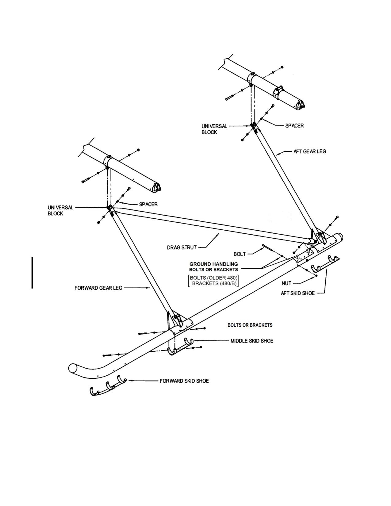
Sheet 2 of 2
Figure 8-6. Landing Gear Assembly
Rev. 26
MM-8-53
Feb 28/2020
8-51. Disassembly - Landing Gear Assembly
NOTE
Disassembly of the landing gear is the same for both sides.
A. Remove the hardware and spacer attaching the universal blocks to the ends of the
gear legs.
B. Remove the hardware attaching the drag strut to the aft gear leg and remove the
strut.
C. Remove the hardware attaching the skid shoes and gear legs to the skid tube and
remove the gear legs.
D. Remove the hardware attaching the forward skid shoe to the skid tube and remove
the skid shoe.
E. Remove the attachment bolts or brackets, as applicable, for the ground handling
wheels.
NOTE
Disassembly of the cross tubes is the same except as noted.
F. Remove the hardware securing the end caps into the cross tubes and remove the
end caps.
G. Loosen the clamping hardware and remove the positioning hardware from the gear
leg and the pylon attachment clamps and remove the clamps from the aft cross tube.
8-52. Inspection - Landing Gear Assembly
A. Inspect the cross tubes for bends, bows, corrosion, and cracks. Inspect the pylon
attachment (aft cross tube) and the gear leg attachment clamps for corrosion, cracks, evidence
of elongated bolt holes, and security of the attaching hardware.
B. Inspect the landing gear legs and drag struts for any deformation, distortion, all
fittings and bolt holes for elongation, and all welds and gussets for cracks and corrosion.
C. Inspect the skid tubes for bends, bows, corrosion, cracks, dents, wear, and hardware
attachment holes for elongation. Inspect the ground handling wheel attachment lugs for damage
and security.
D. Inspect the skid shoes for wear (para. 8-62).
E. Inspect the oleos for damage, leakage, proper extension, and freedom of movement
(para. 8-67).
F. Inspect all skid tube bolts for corrosion, especially if the helicopter is operated with
the skids submerged, such as with floats.
Rev. 26
MM-8-54
Feb 28/2020
8-53. Repair - Landing Gear Assembly
A. Cross Tubes:
(1) Cross tubes with bows up to 0.5 inches/12.7mm are serviceable. Replace cross
tubes with bends, cracks, or elongated bolt holes.
(2) Replace end caps that are cracked or the bolt holes are elongated. Repair
pylon attachment (aft cross tube) or gear leg attachment clamps that are
cracked by welding I/A/W AC 43.13-1B. Replace pylon attachment (aft cross
tube) or gear leg attachment clamps that have elongated bolt holes.
B. Landing Gear Legs and Drag Struts:
(1) Landing gear legs and drag struts that are bent, bowed, or cracked may be
repaired I/A/W AC 43.13-1B. Contact The Enstrom Helicopter Corporation
Customer Service for detailed damage and repair limitations.
(2) Replace landing gear legs with elongated bolt holes. Replace drag struts that
have deformed, distorted, cracked, or elongated bolt holes (> 0.465 inch in any
direction) of the forward attachment plate.
C. Skid Tubes:
(1) Skid tubes that are bent, bowed, dented, or have holes in them are repairable
I/A/W AC 43.13-1B. Contact The Enstrom Helicopter Corporation Customer
Service for detailed damage and repair limitations.
(2) Replace skid tubes with elongated bolt holes.
8-54. Assembly - Landing Gear Assembly
NOTE
Assembly of the cross tubes is the same except as noted.
A. Install the gear leg clamps and the pylon attachment clamps onto the aft cross tube.
Ensure all of the clamps are oriented properly.
(1) Line the holes up between the P/N 4174013-903 clamp and the cross tube.
NOTE
Perform step 2 only if installing a new replacement aft cross tube and/or clamps.
(2) Ream the holes using a 5/16 Chicago-Latrobe type 405 Chucking Reamer.
(3) Lubricate the attachment bolts with a light coat of MIL-PRF-81322 grease.
NOTE
Eductor must be aligned IAW para. 13-14 before tightening the aft clamp bolts.
(4) Install and tighten the positioning and clamping bolts.
Rev. 26
MM-8-55
Feb 28/2020
B. Install the end caps into the aft cross tube and in one side of the forward cross tube.
Tighten the hardware.
NOTE
Assembly of the landing gear is the same for both sides.
C. Install the ground handling wheel attachment bolts or brackets, as applicable.
D. Install the forward skid shoe onto the skid tube.
E. Install the gear legs onto the skid tube. Install the two center bolts in the gear legs.
Install the skid shoes into place and install the remaining hardware and tighten.
F. Attach the drag strut to the aft gear leg. Torque the hardware to 40-60 in-lbs/4.5-6.8 Nm.
G. Install the universal blocks onto the ends of the gear legs. Do not torque at this time.
8-55. Installation - Landing Gear Assembly
A. Install the forward cross tube as follows:
NOTE
Perform step 1 only if installing a new replacement forward cross tube.
(1) Ream the holes for the installation of the cross tube to the keel and the clamps
to the cross tube using a 5/16 Chicago-Latrobe type 405 Chucking Reamer.
(2) Install the cross tube from the opposite side of the aircraft that the end cap is not
installed in. Install the gear leg attachment clamps as the cross tube is installed
into the keel assembly.
(3) Lubricate the attachment bolts with a light coat of MIL-PRF-81322 grease.
(4) Install the hardware securing the cross tube in the keel assembly and tighten.
(5) Install the positioning and clamping hardware into the gear leg attachment
clamps and tighten.
(6) Install the end cap and tighten the hardware.
B. Install the aft cross tube onto the pylon and tighten the hardware.
C. Place the landing gear into position and install the hardware attaching the aft gear leg
to the attachment clamp on the aft cross tube.
D. Install the hardware attaching the forward gear leg to the attachment clamp on the
forward cross tube. Torque the gear leg and universal block attachment hardware to 40-60 in-
lbs/4.5-6.8 Nm.
Rev. 26
MM-8-56
Feb 28/2020
B. Assemble the guide shaft assembly (5) as follows:
(1) Press the brass guide (4) into position if previously removed.
(2) Install the wiper (3) into the brass guide (4).
(3) Install the O-ring (6) on the O.D. of the guide shaft (threaded end).
CAUTION
The concave side of the back-up ring must face toward the O-ring.
(4) Install the back-up ring (7) and then the O-ring (8) into the groove in the I.D. of
the guide shaft (threaded end).
C. Lubricate both ends of the guide shaft assembly with hydraulic fluid (MIL-PRF-5606)
and install the guide shaft assembly onto the piston shaft (2).
CAUTION
The flanged end of the spacer faces towards the threads of the guide shaft
assembly.
D. Install the spacer (9) onto the piston shaft (2).
CAUTION
The notches in the rebound rings must be staggered.
E. Install the rebound rings (5 each) (10) on to the piston shaft (2).
F. Align the flow passage port on the inner edge of the piston assembly (12) to the flow
passage hole in the piston shaft (2) and install the piston assembly.
CAUTION
The ends of the dowel pin must be seated below the O.D. surface of the
piston to prevent possible binding on installation in the cylinder assembly.
G. Secure the piston assembly to the piston shaft with the dowel pin (11).
CAUTION
The notches in the rebound rings must be staggered.
H. Slide the guide shaft assembly (5) and the rebound rings (10) up against the piston
assembly (12).
Rev. 24
MM-8-67
Dec 4/15
CAUTION
Do not clamp the cylinder in the vise by the ears at the bottom of the cylinder.
Use tool T-0169-1.
I.
Clamp the cylinder assembly (13) in a vise using tool T-0169-1 in an upright position.
Fill the cylinder to the base of the threads with hydraulic fluid (MIL-PRF-5606).
CAUTION
The notches in the rebound rings must be staggered.
NOTE
The piston must be inserted into the cylinder assembly slowly to allow the
hydraulic fluid to work through the staggered notches of the rebound rings and
the flow passage in the piston assembly.
J. Install the piston and guide shaft assembly. Insert piston and guide assembly into the
base of the cylinder assembly.
K. Hand tighten the guide shaft assembly to the cylinder assembly. Make an index mark
from the guide shaft assembly (5) to the cylinder assembly (13).
L. Torque the guide assembly using tool T-0169-1. Using the index mark from step K
above, torque the guide assembly to the cylinder assembly by turning the index mark on the
cylinder assembly approximately 1/4 in/6 mm past the index mark on the guide assembly.
M. Install and secure oleo valve (1) and torque to 170-180 in-lb/19.2-20.3 Nm. Safety
(0.032) the valve to the mount flange of the piston shaft. Loosen the air valve.
N. Attach one end of a clear plastic hose to the oleo valve and the other end in a
container of MIL-PRF-5606. Open the oleo valve. Slowly pump the strut in and out until the hose
is free of air bubbles when compressing the oleo assembly. Fully collapse the strut, tighten the
air valve, and remove the hose.
O. Torque the guide assembly using T-0169-1. Using the index mark, torque the guide
assembly to the cylinder assembly by turning the index mark on the cylinder assembly
approximately ¼ inch past the index mark on the guide assembly.
NOTE
The oleo may be pressurized before or after installation in the helicopter.
P. Connect the nitrogen pressure line to the oleo valve. Set the nitrogen pressure
regulator to 550 psig/3790 kPa for the aft oleos and 250 psig/1720 kPa for the forward oleos.
Remove oleo from the vise and remove tools T-0035 and T-0169-1.
WARNING
The piston shaft will extend when the oleo valve is opened.
Rev. 26
MM-8-68
Feb 28/2020
Q. Slowly open the oleo valve and allow the oleo to fill until the piston shaft is fully
extended and the oleo pressure has equalized to the regulator pressure. Close the oleo valve.
R Close the nitrogen tank valve, set the regulator pressure back to zero, and disconnect
the nitrogen pressure line from the oleo valve.
S. Install the valve cap.
T. Inspect the oleo for leaks.
8-70. Installation - Oleos (See Figure 8-7)
NOTE
If required, install the oleo condition placard (para. 8-70.2) prior to lowering the
aircraft.
Use the following procedures to install any of the oleos.
Refer to SIL T-028 to facilitate oleo fairing installation. If SIL T-028 has not
been complied with, install the fairings for the oleos while installing the oleos.
A.
Install the top and bottom universal block to the oleo assembly.
NOTES
The P/N 4174027-11 bolt used to attach the universal to the oleo is a special
bolt with the head thickness and thread length decreased. Install the bolt so
that the nut will be facing outward when the oleo is installed on the aircraft.
Install the bolt attaching the forward oleos to the crosstube with the bolt head
facing aft.
Lubricate the attach bolt hardware with LPS 2, ACF 50, or MIL-PRF-81322
grease and install while wet.
(1) Place a light washer on each side of the universal link and install the link
between the mounting ears of the cross tube. Secure using a bolt, heavy
washers, and a nut.
(2) Install the oleo with the valve facing aft to the top cross tube.
(3) Connect a spring scale to the bottom hole in the bottom universal link and torque
the top attachment hardware until it requires 2 lb force to swing the oleo strut
assembly in and out and fore and aft.
Rev. 26
MM-8-69
Feb 28/2020
(4) Use a beam type in/lb torque wrench to record the torque on the nut that is
installed on the bolt facing aft.
(5) Place a light washer on each side of the universal link and connect the bottom
universal block to the landing gear leg.
(6) Remove the hardware connecting the top of the oleo to the cross tube. Set the
hardware aside in the same position and order for installation.
(7) Connect the spring scale to the top hole in the top universal link and torque the
attachment hardware at the bottom universal block connections with a required
2 lb drag as in step 3 above.
(8) Reinstall the top universal link to the cross tube. Ensure the hardware is
installed in the position and order as previously installed.
(9) Tighten the nut to the torque setting recorded in step 4.
B. Pressurize the oleos in accordance with para. 8-70, steps O through S if not
pressurized previously.
C. Lower the aircraft.
D. Check the oleos for proper extension and adjust as required.
Rev. 26
MM-8-70
Feb 28/2020
8-110. Inspection - Extension Tube
A. Inspect the extension tube for corrosion, cracks, dents, nicks, scratches, elongated
bolt holes, condition and security of the nutplates installed in the end of the tube, and security of
the installation.
B. Inspect the extension tube mounting clamp for condition, damage, and security.
8-111. Repair - Extension Tube
A. Corrosion, nicks, and scratches not exceeding 0.008 inch/.2 mm may be polished out.
Replace damaged nut plates. Replace the extension tube if cracked, damage exceeds 0.008
inch/.2 mm, or the tail rotor transmission screw holes are elongated.
B. Replace the mounting clamp if cracked or damage makes it unserviceable.
8-112. Installation - Extension Tube
A. Lightly coat the end of the extension tube with Lubriplate 630-AA (MIL-PRF-81322).
Note the orientation of the tube and install the tube into the tailcone.
B. Install and tighten the hardware securing the tube to its mount in the tailcone. Install
the aft tailcone/horizontal spar access panels.
NOTE
The top half of the extension tube clamp is not symmetric. If there is
interference between the clamp and the bulkhead, turn the clamp 180°.
C. Install the top half of the extension tube clamp. Ensure clearance with the bulkhead.
Install the clamping bolts and torque (50-70 in-lb/5.6-7.9 Nm). Check that the difference
between the gap on both sides of the clamp is within 0.010 inch/.25 mm, adjust as required.
D. Install and tighten the bolts securing the aft tail rotor drive shaft bearing pillow block.
Safety wire with .032 wire and install the aft tail rotor drive shaft cover.
E. Install the tail rotor transmission (para. 11-92). If removed from the tail rotor
transmission, install the tail rotor assembly (para. 9-51).
F. Install the tail rotor guard.
G. Check the tail rotor control cable tension and rigging (para. 12-99 and 12-100).
8-113. Tail Rotor Guard (Figure 8-11)
8-114. Removal - Tail Rotor Guard
A. Remove the hardware from the mounting clamp on the tailcone.
B. Remove the hardware securing the tail rotor guard to the extension tube clamp and
the tail rotor transmission.
C. Remove the tail rotor guard.
Rev. 26
MM-8-83
Feb 28/2020
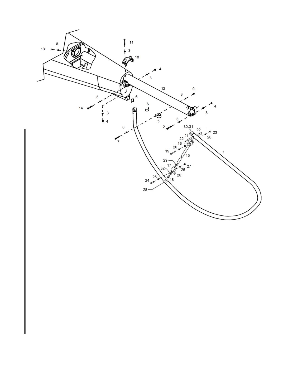
1.
Tail Rotor Guard
17.
Clamp
2.
Bolt
18.
Bolt
3.
Washer
19.
Bolt
4.
Nut
20.
Washer
5.
Clamp
21.
Bushing
6.
Pad
22.
Washer (if equipped)
7.
Bolt
23.
Nut
8.
Washer
24.
Bolt
9.
Nut
25.
Washer
10.
Clamp
26.
Spacer
11.
Bolt
27.
Nut
12.
Extension Tube
28.
Pad (bonded to clamp (17))
13.
Bolt
29.
Spacer
14.
Bolt
30.
Fitting (plug)
15.
Strut
31.
Rivet
16.
Bushing
Figure 8-11. Tail Rotor Guard & Extension Tube Installation
Rev. 26
MM-8-84
Feb 28/2020
8-115. Inspection - Tail Rotor Guard
A. Inspect the tail rotor guard for cracks and wear or damage associated with ground
contact.
B. Inspect the end fittings for loose or sheared rivets and elongated bolt holes.
C. Inspect the tail rotor guard tube and plug fitting joint for looseness.
D. Inspect the securing hardware for damage and the anti-chaffing pads for condition
and security.
8-116. Repair - Tail Rotor Guard
A. Replace tail rotor guard if cracked or extensively damaged from ground contact.
NOTE
If the tail rotor guard is worn due to ground contact but is not worn through the
guard, install a piece of tape over the area as a contact indicator.
B. Replace sheared or working rivets in the end fittings. Replace the end fittings if the
bolt holes are elongated.
C. Install washer (22) (Figure 8-11) between tail rotor guard tube and strut if plug fitting
joint is loose.
D. Replace damaged hardware and worn anti-chaffing pads.
8-117. Installation - Tail Rotor Guard
NOTE
Shimming may be required at the extension tube clamp or tail rotor transmission
locations.
A. Apply grease (MIL-PRF-81322) to the inside surface of the ears of the extension tube
clamp. Place the tail rotor guard into position and install the hardware attaching the guard to the
extension tube clamp.
B. Install the clamp half and hardware onto the fitting at the bottom of the tailcone.
C. Apply grease (MIL-PRF-81322) to the inside surface of the ears of the tail rotor
gearbox assembly. Install the tail rotor guard fitting into the tail rotor transmission and install the
attaching hardware. Tighten all of the attaching hardware.
Rev. 26
MM-8-85
Feb 28/2020
8-118. Vibration Absorber (Figure 8-12)
NOTE
The vibration absorber can only be installed on aircraft equipped with Tailcone
Assembly, P/N 4112000-103, or after modification of the tailcone in
accordance with Vibration Absorber Kit, P/N 4230018-1, 4230018-3, or
4230018-5.
8-119. Removal - Vibration Absorber
A. Disconnect the lanyard (10) from the tailcone tab.
B. Remove the hardware (3, 4) attaching the beam (1) to the tailcone and remove the
backing plate (2) and beam (1).
8-120. Disassembly - Vibration Absorber
NOTE
Removing/moving the weights from a Atuned@ vibration absorber will require
absorber tuning when the vibration absorber is reinstalled.
A. Remove the hardware (7, 4, 8, 9) attaching the lanyard (10) and weights (6) to the
beam and remove the weights (6).
8-121. Inspection - Vibration Absorber
A. Inspect the beam, weights, and support brackets for cracks, nicks, scratches,
corrosion and security of installation.
B. Inspect the mounting hardware for damage.
C. Inspect the lanyard for condition.
8-122. Repair - Vibration Absorber
A. Replace the beam if cracked or damage exceeds a depth of .020 inches/.51 mm.
Polish out damage to a maximum depth of .020 inches/.51 mm.
B. Replace cracked support brackets or brackets with damage exceeding .020 inch/.51
mm in depth. Polish out damage to a maximum depth of .020 inches/.51 mm.
C. Replace damaged hardware or the lanyard as required.
8-123. Assembly - Vibration Absorber
A. Install the weights (6) and lanyard (10) on the beam (1) and secure with the hardware
(7, 4, 8, 9). Position the weights 0.3 inches/7.6 mm from the end of the beam and torque the
bolts (7) to 75 in-lbs/8.5 Nm.
Rev. 26
MM-8-86
Feb 28/2020
8-125. Consumable Materials List
ITEM
DESCRIPTION
PART NUMBER
Acetone
Acetone Solvent
Adhesive
Trim Adhesive, 3M Brand
8031
Adhesive
Window/Windshield Adhesive,
PR-1425-B2
Courtaulds Aerospace
Compound
Anti-Corrosion, Conductive Compound,
CP8-TB
Kopr-Shield Brand
Compound
ACF-50 Anti-Corrosion/Lubricant, Lear
10013
Chemical Research
Fabric
Fire Curtain, Nextel Brand
Enstrom P/N 400-006
Grease
Grease, Lubriplate Brand
630-AA1 (06701)
Grease
Grease
MIL-PRF-81322
Hydraulic Fluid
Hydraulic Fluid
MIL-PRF-56062
Lockwire
Lockwire Copper .020”
MS20995CY20
Lockwire
Lockwire.032”
MS20995C32
Lubricant
LPS 2 Heavy Duty Lubricant, LPS
00216
Laboratories
Nitrogen
Nitrogen
Paint, Touch-Up
Flat Black, Spray Can
Primer
Epoxy Primer
MIL-PRF-233773
Putty
Glazing and Spot Putty, Bondo
801
Sealant
Fuel Resistant Coating, 3M Brand
EC 776
Sealant
Fuel Resistant, AMS-S-8802 Type II Class B
Sealant
Silicone Sealant, Dow Corning Brand
732-RTV
Sealant
Vinyl Sealant
Phenoseal 102
Glouchester Co., Inc.
P.O. Box 428, Franklin, MA 02038
Sealant
Fire Barrier Sealant, 3M Brand
CP25WB+
Shielding Coating
EMI/RFI Shielding Coating, Acheson Brand
Electrodag 437
1 MIL-PRF-81322 is an acceptable alternate.
2 AeroShell Fluid 41 (Shell Oil), Royco 756 (Anderol), or Phillips X/C 5606H (Phillips 66)
3 Example: PRC-DeSoto Brand 513x390/activated by 910x624; or equivalent.
Rev. 26
MM-8-91
Feb 28/2020
ITEM
DESCRIPTION
PART NUMBER
Solder
“44” Resin Solder
String
Cotton String
Tape
Transparent, 3M Brand
5430
Tape
Tape, Masking 1“
Tape
Double Sided, Foam .50”, 3M Brand
4910-50
Tape
Double Sided, Foam 1”, 3M Brand
4016-1
Tape
Single Sided, Foam .75”, 3M Brand
4516-75
Tape
Vinyl, Black .25”, 3M Brand
70-0160-1056-6
Thread
Sewing Thread Metalized, 0.020”
Enstrom P/N 300-093
(MT13)
Thread Sealant
Thread Sealant, Loctite Brand
Threadlocker Blue 2424
Thread Sealant
Thread Sealant, Vibra-Tite Brand
VC-3
4 Acceptable alternate to VC-3.
Rev. 23
MM-8-92
Jul 3/15
SECTION 9
ROTOR SYSTEMS
TABLE OF CONTENTS
Paragraph
Description
Page
Table of Contents
MM-9-1
9-1.
Main Rotor System
MM-9-3
9-2.
Description
MM-9-3
9-3.
Troubleshooting
MM-9-3
9-4.
Autorotation RPM Adjustment
MM-9-5
9-5.
Tracking
MM-9-6
9-6.
Main Rotor Hub
MM-9-15
9-7.
Removal
MM-9-15
9-8.
Disassembly
MM-9-16
9-9.
Inspection
MM-9-19
9-10.
Repair
MM-9-19
9-11.
Assembly
MM-9-19
9-12.
Installation
MM-9-25
9-13.
Retention Assembly
MM-9-26
9-14.
Removal
MM-9-26
9-15.
Disassembly
MM-9-27
9-16.
Inspection
MM-9-33
9-17.
Repair
MM-9-33
9-18.
Assembly
MM-9-33
9-19.
Installation
MM-9-48
9-19.1
Tension-Torsion Straps
MM-9-51
9-19.2
Removal
MM-9-51
9-19.3
Installation
MM-9-51
9-20.
Universal Block
MM-9-52
9-21.
Disassembly
MM-9-52
9-22.
Inspection
MM-9-52
9-23.
Repair
MM-9-52
9-24.
Assembly
MM-9-52
9-25.
Dampers
MM-9-62
9-26.
Removal
MM-9-62
9-27.
Disassembly
MM-9-62
9-28.
Inspection
MM-9-66
9-29.
Repair
MM-9-66
9-30.
Assembly
MM-9-66
9-31.
Installation
MM-9-69
9-32.
Main Rotor Blades
MM-9-74
9-33.
Description
MM-9-74
9-34.
Removal
MM-9-74
9-35.
Inspection
MM-9-77
9-36.
Repair
MM-9-87
9-37.
Refinishing
MM-9-95
9-38.
Installation
MM-9-97
Rev. 26
MM-9-1
Feb 28/2020
SECTION 9
ROTOR SYSTEMS
TABLE OF CONTENTS
Paragraph
Description
Page
9-39.
Tail Rotor Assembly
MM-9-97
9-40.
Description
MM-9-97
9-41.
Troubleshooting
MM-9-97
9-42.
Static Balancing
MM-9-99
9-43.
Tracking and Dynamic Balancing
MM-9-103
9-44.
Removal
MM-9-107
9-45.
Disassembly
MM-9-109
9-46.
Cleaning
MM-9-110
9-47.
Inspection
MM-9-111
9-48.
Repair
MM-9-111
9-49.
Refinishing
MM-9-119
9-50.
Assembly
MM-9-121
9-51.
Installation
MM-9-123
9-52.
Consumable Materials List
MM-9-126
Rev. 26
MM-9-2
Feb 28/2020
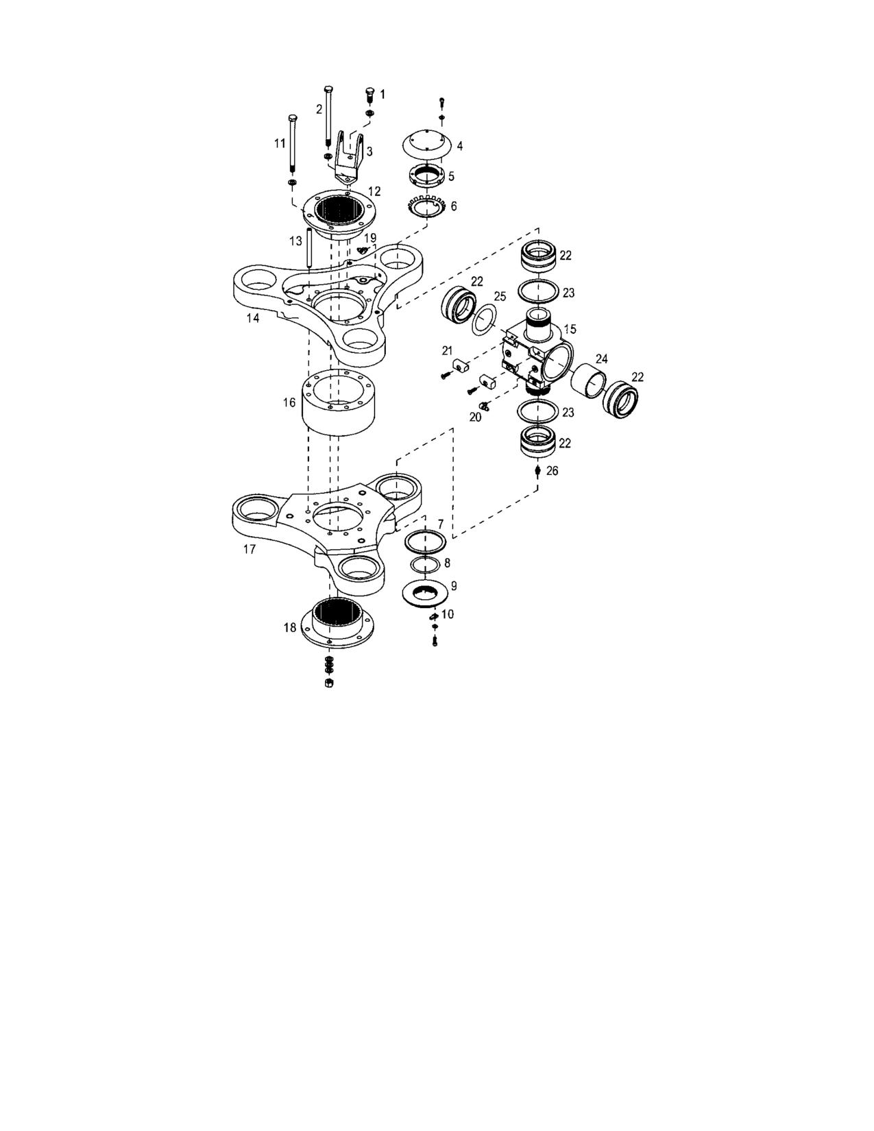
1.
Bolt
14.
Upper Hub Plate
2.
Bolt
15.
Universal Block
3.
Bracket
16.
Center Spacer
4.
Dust Cover
17.
Lower Hub Plate
5.
Retaining Nut
18.
Lower Spline Adapter
6.
Lock Washer
19.
Grease Fitting
7.
DU Washer
20.
Grease Fitting
8.
Shim
21.
Stop Pad
9.
Retaining Nut
22.
Bearing
10.
Lock Key
23.
DU Washer
11.
Bolt
24.
Spacer
12.
Upper Spline Adapter
25.
Shim
13.
Dowel Pin
26.
Grease Fitting
Figure 9-4. Main Rotor Hub Assembly with Grease Lubricated Flapping Bearings
MM-9-17
Feb 9/01
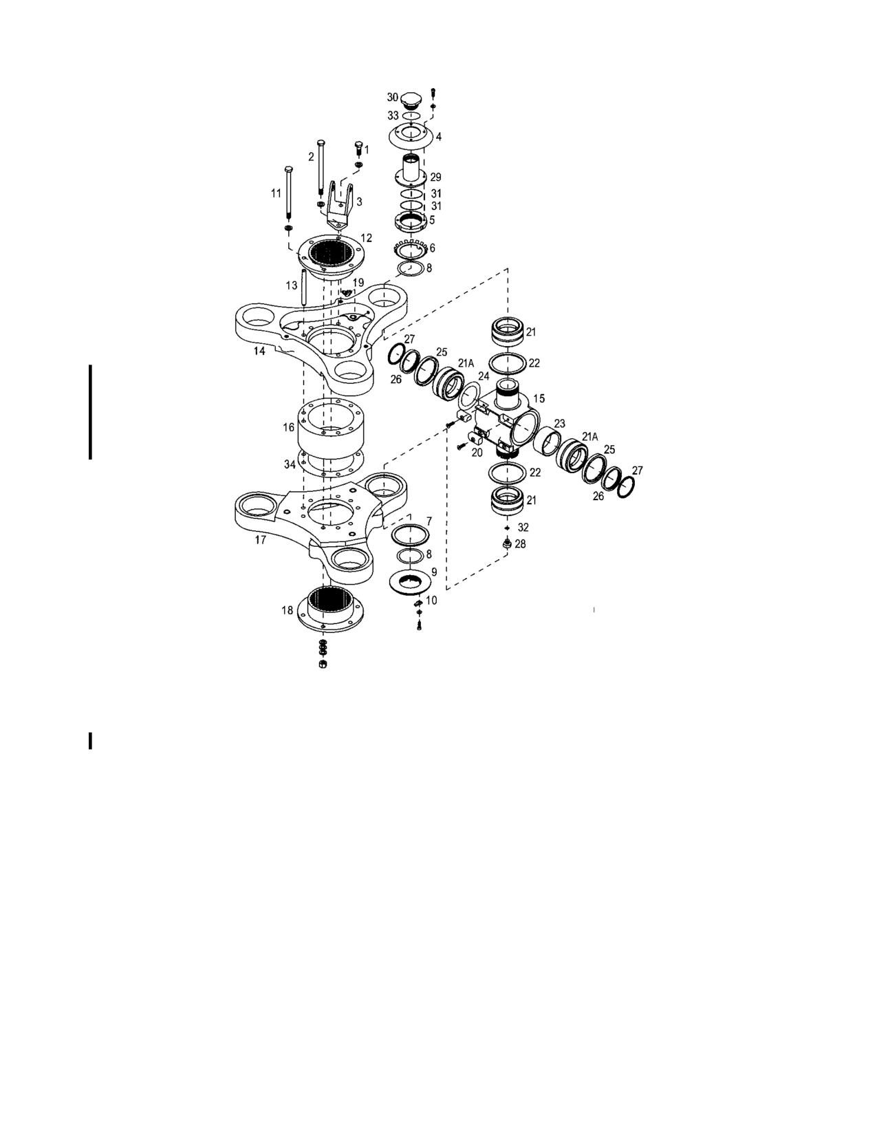
1.
Bolt
19.
Grease Fitting
2.
Bolt
20.
Stop Pad
3.
Bracket
21.
Bearing
4.
Dust Cover
21A.
Bearing
5.
Retaining Nut
22.
DU Washer
6.
Lock Washer
23.
Spacer
7.
DU Washer
24.
Shim
8.
Shim
25.
Seal
9.
Retaining Nut
26.
Sleeve
10.
Lock Key
27.
O-Ring
11.
Bolt
28.
Plug
12.
Upper Spline Adapter
29.
Reservoir
13.
Dowel Pin
30.
Reservoir Cap
14.
Upper Hub Plate
31.
O-Ring
15.
Universal Block
32.
O-Ring
16.
Center Spacer
33.
Seal
17.
Lower Hub Plate
34.
Shim
18.
Lower Spline Adapter
Figure 9-5. Main Rotor Hub Assembly with Oil Lubricated Flapping Bearings
Rev. 26
MM-9-18
Feb 28/2020
M. Heat the upper hub plate to approximately 250°F/121°C and lift the hub plate from the
universal blocks (15). Tap with a plastic mallet if necessary.
N. Heat the lower hub plate to approximately 250°F/121°C and tap the universal blocks
from the hub plate.
(1) Remove center spacer (16) and shim (34), if installed.
O. Remove the grease fittings (19) from the hub plates.
9-9. Inspection - Main Rotor Hub
A. See Table 9-1 for detailed inspection of the main rotor hub assembly.
9-10. Repair - Main Rotor Hub
A. Repair or replace components of the main rotor hub as indicated in Table 9-1.
9-11. Assembly - Main Rotor Hub (Figure 9-4 or 9-5)
WARNING
Use extreme caution when removing or installing the blade and grip
assemblies to prevent from injuring personnel.
WARNING
Use protective gloves when handling heated parts.
NOTE
The upper hub plate has heli-coil inserts in the outer bosses for the walking
beam mount brackets. The lower hub plate bosses are solid.
A. Heat the upper hub plate (14) and the lower hub plate (17) to approximately
250°F/121°C.
B. Place the lower hub plate on 2" X 4" wood blocks. Lubricate the bearing bores with
MIL-PRF-81322.
NOTE
Ensure the DU washers have been installed on the U-blocks with the
chamfered side facing the hub plates. The DU washers must be seated in the
recessed area of the hub plate.
C. Install the U-block (universal block) assemblies (15) into the bearing bore of the hub
plate with the threaded notched end of the U-blocks down (3 places).
Rev. 26
MM-9-19
Feb 28/2020
Table 9-1. Main Rotor Hub Assembly
Inspection Requirements
P/N
Fig. 9-4, 9-5
Part Name
Inspection*
Serviceable Limits*
Repair Limits
Repair or Action
Item #
28-14202-1
3
Walking Beam
Deformed or cracked
None Allowed
Not Repairable
Replace Bracket
Bracket
ears
Security of the
No Play Allowed
Not Repairable
Replace Bracket
bushings in the bracket
Nicks, scratches, or
None Allowed
≤ .010 deep
Blend and polish out
corrosion
smooth
28-14227-1,
5
Nut
Threads
None Allowed
Not Repairable
Replace Nut
-11
Fig. 9-6, 6
(rolled or missing)
W-09
6
Lockwasher
Tangs
None Allowed
Not Repairable
Replace Lockwasher
(deformed or cracked)
28-14236-1
7
DU Washer
Flatness
.005
Not Repairable
Replace Washer
Thickness .090 to .093
-.003
Not Repairable
Replace Washer
28-14256-1
9
Nut
Threads
None Allowed
Not Repairable
Replace Nut
(rolled or missing)
28-14224-1, -3,
12 & 18
Spline Adapters
Inboard face of adapter
.0025 FIM
Not Repairable
Replace Adapter
-5
perpendicular to the
O.D.
O.D. 3.6235 to 3.6245
-.0005
Not Repairable
Replace Adapter
Spline pitting
.003 deep
Not Repairable
Replace Adapter
Spline corrosion
None Allowed
Surface corrosion
Remove with wire brush
Rev. 26
MM-9-20
Feb 28/2020