Enstrom TH-28/480 Series. Maintenance Manual (2020) - page 3
4-49. Special Inspections
4-50. General Information - Special Inspections
NOTE
Refer to the Rolls-Royce 250-C20 Series Operation and Maintenance Manual
for special inspections applicable to the engine.
A. This section contains guidelines for performing the required inspections, by qualified
maintenance personnel, after experiencing any of the following occurrences: main rotor blade
and/or tail rotor strikes, hard landings, main rotor overspeed, over torque, engine overspeed, or
engine TOT exceeds the limits. It should be emphasized that other parts and/or adjacent
components not listed may also be damaged, depending on the severity of the incident.
Therefore, this guide should not be considered absolute and should be expanded as required by
the inspecting maintenance personnel, as the occurrence may require, per the appropriate
sections of this manual.
B. All aluminum and steel components must be inspected by the following processes
after visual inspection has revealed a possible defect or as noted in the special inspections:
(1) Aluminum machined or cast components are to be inspected by liquid penetrant
inspection (ASTM E165 or equivalent).
(2) Aluminum sheet metal components are to be inspected by liquid penetrant
inspection (ASTM E165 or equivalent).
(3) Steel components are to be inspected by magnetic particle inspection (ASTM
E1444 or equivalent).
C. All parts and components that may be affected by the specific occurrence are to be
given a complete inspection for possible damage.
NOTE
The following inspections are mandatory.
4-51. Main Rotor Blade Strike/Sudden Stoppage (Minor) - Special Inspection
A. Blade damage does not exceed damage as defined in paragraph 9-35, and shows no
visible kinks, ripples in the skin or the trailing edge. Perform the following:
(1) Repair the blade I/A/W paragraph 9-36.
(2) Inspect the engine I/A/W the Rolls-Royce 250-C20 Series Operation and
Maintenance Manual (10W2).
B. Blade damage exceeds limits of paragraph 9-35, but has not contacted the airframe
or other rigid object and shows no visible kinks, ripples in the skin or trailing edge. Perform the
following:
Rev. 26
MM-4-63
Feb 28/2020
(1) Replace the blade(s).
(2) Inspect the engine I/A/W the Rolls-Royce 250-C20 Series Operation and
Maintenance Manual (10W2).
(3) Check the main rotor shaft run out (paragraph 11-34). Maximum allowed is .012
inches/.305 mm FIM.
(4) Inspect the tail rotor driveshaft taper pins, taper pin holes and flex packs I/A/W
paragraphs 11-71 & 11-80.
NOTE
If the main rotor shaft run out, taper pins, or flex packs do not meet inspection
requirements, proceed to paragraph 4-52.
4-52. Main Rotor Blade Strike/Sudden Stoppage (Major) - Special Inspection
A. Obvious blade damage exceeding the limits of paragraph 9-35. Perform the
following:
(1)
Replace the damaged blade(s) and inspect the remaining blade(s).
(2)
Remove the main rotor transmission including the upper pulley and tail rotor
drive shaft hub and return to Enstrom Helicopter Corporation for inspection and
overhaul/replacement.
(3)
Remove the main rotor hub and inspect by liquid penetrant method (ASTM E165
or equivalent and in accordance with the inspection tables (Table 9-1) or return
to Enstrom Helicopter Corporation for inspection and overhaul/replacement.
(4)
Inspect all flight control push-pull rods and torque tubes for sheared/damaged
rivets at the fittings, damaged rod ends, or sheared/damaged roll pins.
(5)
Inspect all flight control bellcranks for buckling and elongated bolt holes.
(6)
Inspect the lower swashplate for warped or cracked casting and for bent or
damaged guidetubes in the upper swashplate. Inspect the tie rod and universal
rod for straightness. Inspect the bolt holes for elongation.
(7)
Replace all tail rotor driveshaft taper pins.
(8)
Inspect the tail rotor driveshafts for damage at the taper pin holes.
(9)
Magnetic particle inspect the tail rotor driveshafts (ASTM E1444 or equivalent).
(10)
Inspect the pylon structure at the gearbox mounting areas for broken or bent
tubes. Check the trueness of the four gearbox attachment points.
(11)
Remove the overrunning clutch and return to Enstrom Helicopter Corporation for
inspection and overhaul/replacement.
Rev. 26
MM-4-64
Feb 28/2020
(12) Inspect all components of the drive system.
(13) Inspect the engine I/A/W the Rolls-Royce 250-C20 Series Operators and
Maintenance Manual (10W2).
4-53. Tail Rotor Blade Strike/Sudden Stoppage - Special Inspection
A.
Strike tab missing but no physical damage to the tail rotor blade(s).
(1) Inspect the tail rotor driveshafts for damage at the forward and aft coupling taper
pin locations.
(1) Inspect the taper pins, flex packs, and drive shaft hubs at the forward and aft
coupling locations I/A/W paragraphs 11-71 & 11-80.
(3) If no damage is found, make a log book entry and notify Enstrom Helicopter
Corporation to order replacement strike tabs.
(4) If damage is found, proceed to the following paragraph for additional inspection
procedures.
B.
Obvious physical damage to the tail rotor blade. Perform the following:
(1) Remove the tail rotor transmission with the tail rotor controls and the input drive
hub and the tail rotor assembly
a. Remove the tail rotor pitch controls and inspect in accordance with the
inspection tables (Table 12-4).
b. Return the tail rotor transmission to Enstrom Helicopter Corporation for
inspection and overhaul/replacement.
c. Inspect the tail rotor assembly in accordance with the inspection tables
(Table 9-5).
(2) Replace all tail rotor driveshaft taper pins.
(3) Inspect the tail rotor driveshafts for damage at the forward and aft taper pin
holes.
(4) Inspect the taper pin hole in the main rotor transmission pinion for complete or
partial failure. If damage is found, return the main rotor transmission to Enstrom
Helicopter Corporation for overhaul/replacement.
(5) Inspect all coupling hubs and the pinion shaft by liquid penetrant method.
(6) Magnetic particle inspect the tail rotor driveshafts (ASTM E1444 or equivalent).
(7) Inspect the hangar bearing housings and attachments.
Rev. 26
MM-4-65
Feb 28/2020
(8) Inspect the tail rotor control cables and pulley attachments.
(9) Inspect the tail rotor pedal push-pull rods and bellcranks.
(10) Inspect the engine I/A/W the Rolls-Royce 250-C20 Series Operators and
Maintenance Manual (10W2).
4-54. Hard Landing - Special Inspection
A. In the event of a hard landing which may or may not be associated with a main or tail
rotor strike, perform the following:
(1)
Inspect the forward and aft crosstube for bends or bowing. Replace the
crosstube if bent or bow is greater than 0.5 inches/13 mm. It will be necessary to
hoist the aircraft or remove the crosstubes to obtain a measurement.
(2)
Inspect the landing gear leg assemblies for distortion or deformation. Inspect all
fittings and bolt holes for elongation. Inspect all welds and gussets for cracks.
(3)
Inspect the skid tubes for damage and straightness. Inspect all hardware
attachment holes for elongation or tears.
(4)
Inspect the oleos for damage, freedom of movement, and leakage.
(5)
Inspect the tailcone to pylon, main rotor transmission to pylon, engine to pylon,
crosstube to pylon, and cabin to pylon attachment points for deformation or
hardware failures.
(6)
Inspect the keel structure edges, beams, lightening holes, and intercostals for
buckling or deformation. Closely inspect the keel structures for interference or
contact with flight control mechanisms (torque tube, collective, etc.) or with the
landing gear clamps.
(7)
Check the main rotor shaft run out (paragraph 11-34). Maximum allowed is .012
inch/.305 mm FIM.
(8)
Check the main rotor transmission mount bolt torque. If torque is lost, replace
the hardware or remove and inspect the hardware using Magnetic Particle
Inspection (ASTM E1444).
(9)
Inspect the main rotor transmission mount lugs using Visible Dye Liquid
Penetrant Inspection (ASTM E165).
(10)
Inspect the engine I/A/W the Rolls-Royce 250-C20 Series Operation and
Maintenance Manual (10W2).
Rev. 26
MM-4-66
Feb 28/2020
4-55. Main Rotor Overspeed - Special Inspection
A. Overspeeds from 385-405 rpm for 5 seconds or less. No inspection required.
NOTE
If any damage is found, remove the main rotor hub and return to Enstrom
Helicopter Corporation for inspection and overhaul/replacement.
B. Overspeeds from 385-405 rpm for more than 5 seconds or overspeeds from 406-420
rpm. Perform the following:
(1) Remove the main rotor blades and inspect flapping axis for proper drag, notchiness,
and freedom of movement.
(2) Inspect the main rotor blade retention for any deformation.
(3) Inspect the lamiflex bearings for deformation, proper thickness, delamination or
extruded brass. Inspect the nylatron strap for any damage or unusual wear.
(4) Inspect the main rotor spindles for pulled or distorted threads. (Lamiflex installation
only)
(5) Inspect the tension-torsion straps and pins I/A/W paragraph 9-16.
C. Overspeeds exceeding 420 rpm. Perform the following:
(1) Remove the main rotor hub and return to Enstrom Helicopter Corporation for
inspection and overhaul/replacement.
4-56. Overtorque - Special Inspection
A. Overtorques from 68-75 psi (TH-28 & 480) or 69-75 psi (480s equipped with the
Increased Rotor Speed and Torque Limits Modification) or 73-79 psi (480B) for 3 seconds or less.
No inspection required.
B. Overtorques from 68-75 psi (TH-28 & 480) or 69-75 psi (480s equipped with the
Increased Rotor Speed and Torque Limits Modification) or 73-79 (480B) for more than 3 seconds or
above 75 psi or 79 psi as applicable. Perform the following:
NOTE
Check the aircraft inspection records for any annotations about the condition of
the main rotor transmission ring and pinion gears.
(1) Visually inspect the main rotor transmission ring and pinion gears for cracks,
excessive pitting, excessive spalling, or a "hard wear" line.
Rev. 26
MM-4-67
Feb 28/2020
4-57. Main Rotor or Tail Rotor Transmission Chip Indication - Special Inspection
NOTE
New or recently overhauled transmissions will often make a magnetic "fuzz" which
will collect on the magnetic plug as gray sludge. This is normal and may be
cleaned off the plug. The plug may then be reinstalled and the helicopter returned
to service. If any main rotor transmission chips are found which are larger than
1/16 inch/1.59 mm in cross-section or if any tail rotor transmission chips are found
which are larger than .035 inch/.9 mm in cross-section, contact Enstrom
Customer Service Department and discontinue use until further instructions are
received from Enstrom Customer Service Department.
A.
Main rotor transmission chip indication. Perform the following:
(1) Inspect the chip detector for accumulation of metal particles as follows:
a.
Main rotor transmission metal particles, flakes, or slivers exceeding 1/16 inch/1.59
mm: Contact Enstrom Customer Service Department and discontinue use until
further instructions are received from Enstrom Customer Service Department.
NOTE
Sludge normally will not cause a chip indication by itself. There is normally a small
particle, flake, or sliver on the detector also.
b.
Sludge (a mixture of oil and fine metal particles resulting from normal gear
operation): Clean the detector and return the transmission to service.
(2) If the indication was caused by sludge or a particle, flake, or sliver not exceeding the
maximum size, annotate the chip indication and results in the aircraft maintenance
records.
(3) Return the transmission to service.
B.
Tail rotor transmission chip indication. Perform the following:
(1) Inspect the chip detector for accumulation of metal particles as follows:
a.
Tail rotor transmission metal particles, flakes, or slivers exceeding .035 inch/.9mm:
Contact Enstrom Customer Service Department and discontinue use until further
instructions are received from Enstrom Customer Service Department.
NOTE
Sludge normally will not cause a chip indication by itself. There is normally a small
particle, flake, or sliver on the detector also.
b.
Sludge (a mixture of oil and fine metal particles resulting from normal gear
operation): Clean the detector and return the transmission to service.
Rev. 26
MM-4-68
Feb 28/2020
(2) If the indication was caused by sludge or a particle, flake, or sliver not exceeding
the maximum size, annotate the chip indication and results in the aircraft
maintenance records.
(3) Return the transmission to service.
C. Three main rotor transmission chip indications occur within 10 flying hours. Perform
the following:
NOTE
Check the aircraft inspection records for any annotations about the condition
of the main rotor transmission ring and pinion gears.
(1) Drain the oil from the transmission and inspect the ring and pinion gears for
cracks, excessive pitting, excessive spalling, or "hard wear" lines.
(2) Inspect the chip detector for accumulation of metal particles in accordance with
para. 4-57, A, (1) and (2).
(3) If none of the above conditions are found, flush and service the main rotor
transmission (para. 4-13.1) and return to service.
(4) If two chip indications occur within the next 10 flying hours, repeat the flush and
servicing procedure. If two additional indications occur within the next 10 flying
hours, contact Enstrom Helicopter Corporation for further instructions.
D. Two tail rotor transmission chip indications occur within 10 flying hours. Perform the
following:
NOTE
Check the aircraft inspection records for any annotations about the condition
of the tail rotor transmission input and output gears.
(1) Drain the oil from the transmission and inspect input and output gears (through
the inspection port) for cracks, excessive pitting, excessive spalling, or "hard
wear" lines.
(2) Remove the tail rotor assembly from the tail rotor transmission output shaft and
the aft tail rotor drive shaft flex plate assembly. Turn the tail rotor transmission
output shaft by hand. If indications of a rough bearing are felt, the transmission
must be replaced.
NOTE
If the gearbox is to be returned to Enstrom Service, do not clean the metal from
the chip detector.
(3) Inspect the chip detector for accumulation of metal particles in accordance with
para. 4-57, B, (1) and (2).
Rev. 26
MM-4-69
Feb 28/2020
(4) If none of the above conditions are found, flush and service flush and service the
tail rotor transmission (para. 4-17.1) and return to service.
(5) If two chip indications occur within the next 10 flying hours, repeat the flush and
servicing procedure. If two additional indications occur within the next 10 flying
hours, contact Enstrom Helicopter Corporation for further instructions.
4-58. Engine Overspeed - Special Inspection
NOTE
Perform the appropriate main rotor overspeed inspection if required.
A. Inspect the engine I/A/W the Rolls-Royce 250-C20 Series Operation and
Maintenance Manual if the engine operating limitations are exceeded.
4-59. Engine Overtemp - Special Inspection
A. Inspect the engine I/A/W the Rolls-Royce 250-C20 Series Operation and
Maintenance Manual if the engine operating limitations are exceeded.
4-60. Maintenance Ground Run
A. General
(1) Perform a maintenance ground run after conducting a periodic inspection or
maintenance action that will require operation of the aircraft to verify satisfactory
performance of the aircraft.
(2)
The periodic inspection or maintenance action will determine the extent of
the post maintenance ground run.
B. Perform the maintenance ground run as follows:
(1) Perform a preflight inspection.
NOTE
The maintenance performed on the flight control systems should determine
the extent of the rigging check.
(2) Verify flight control rigging if any maintenance was performed on the flight
controls.
(3) Position lateral and fore/aft trim motors to the neutral position.
(4) Move the cyclic stick around the cyclic stop in the floor. The stick must remain
against the stop through the circle. If binding or interference is detected, re-
check the basic rigging.
Rev. 26
MM-4-70
Feb 28/2020
(5) Move the fore/aft trim to full forward position and move the cyclic stick full aft.
Stick should contact the cyclic stop. Reverse the trim motor and stick positions
and check that stick contacts the cyclic stop.
(6) Repeat step (5) using the lateral trim motor and moving the stick in the lateral
direction.
(7) Check the rigging of the throttle controls.
(8) Check the rigging of the droop compensator.
WARNING
The following checks are to be performed by authorized personnel.
(9) Run-up the aircraft I/A/W the Rotorcraft Flight Manual.
(10) With the engine at ground idle, collective full down, and pedals neutral, check
the following instruments:
a.
N1 - 59-65%
b.
Torque - 8-10 psi
c.
Rotor RPM - approximately 215 rpm
d.
All other instruments - normal range
(11) Slowly apply approximately 1 inch of left pedal. Check for an increase in the
torque indication and corresponding aircraft movement. Neutralize the pedals.
WARNING
Clear all personnel from the tip path plane area as the blades may dip as
low as 5 feet during this test.
(12) Slowly move the cyclic stick forward until there is a slight bumping of the rotor
stops. Observe the position of the cyclic stick in relation to the cyclic stop ring.
Repeat this check by bringing the cyclic stick aft, then right and left. The
distance that the cyclic fitting is from the stop should be equal. If a noticeable
difference exists, adjust the length of the push-pull rods located between the
bellcranks in the engine compartment. The right side push-pull rod controls
fore/aft movement and the left side push-pull rod controls the lateral movement.
(13) With the collective full down, cyclic centered, and pedals neutral, slowly increase
the throttle to full throttle.
(14) Check the operation of the power turbine governor linear actuator. The
minimum operating range is from 88% - 92% N2. Maximum operating range is
100% - 103% N2.
Rev. 26
MM-4-71
Feb 28/2020
(15) Set the N2 rpm to 98% and check the torque indication. For aircraft without blade
leading edge protection tape, the torque indication should be 15 - 18 psi to
assure adequate rotor rpm during autorotation. The torque indication for aircraft
equipped with blade leading edge protection tape should be 17 - 21 psi. Shorten
the main rotor pitch change links to increase the torque indication and lengthen
the pitch change links to decrease the torque indication. The maintenance test
flight will determine what additional adjustments will be required.
WARNING
Clear all personnel from the tip path plane area as the blades may dip as
low as 5 feet/1.52 meters during this test.
(16) Slowly move the cyclic forward, aft, right, and left and check for the proper
response of the main rotor tip path.
(17) Trim the cyclic stick to neutral and release the cyclic grip. Visually watch the
cyclic stick for motion. The cyclic stick should remain centered and still. Move
the cyclic fore and aft without trimming and check for smoothness. No hard
vibrations should be present.
NOTE
If hard vibrations are present or the cyclic wanders, either the aircraft will have
to be tracked or a problem exists in the main rotor control system.
(18) Decrease the throttle to ground idle and shut the aircraft down I/A/W the
Rotorcraft Flight Manual.
(19) Correct any discrepancies found.
NOTE
If required to determine proper operation of the aircraft, perform a
maintenance test flight (para. 4-61).
Rev. 26
MM-4-72
Feb 28/2020
(8) Slowly move the cyclic forward, aft, right, and left and check for the proper
response of the main rotor tip path.
(9) Trim the cyclic stick to neutral and release the cyclic grip. Visually watch the
cyclic stick for motion. The cyclic stick should remain centered and still. Move
the cyclic fore and aft without trimming and check for smoothness. No hard
vibrations should be present.
NOTE
If hard vibrations are present or the cyclic wanders, either the aircraft will have
to be tracked or a problem exists in the main rotor control system.
C.
Hover Checks:
(1) With the N2 set at 97%, release the collective friction and slowly increase
collective pitch. While making minor adjustments to the controls, watch for
proper response as the aircraft becomes light on the skids. Check that the N2
increased to 102% ±1%. Adjust the N2 to 103%.
(2) Bring the aircraft to a hover. Check that the cyclic rigging appears normal for the
wind, weight, and center of gravity conditions. Compare the torque indication to
the predicted hover torque in the performance charts in the Rotorcraft Flight
Manual.
(3) Check the flight controls as follows:
a. Hover into the wind.
b. Check all flight controls for the correct response using small inputs to each
axis.
c. The cyclic position should be centered laterally and longitudinally with two
personnel onboard.
d. The pedals should be nearly neutral, with the right pedal maybe only ½ inch
forward of the left pedal.
(4) Check the engine and transmission instruments for normal operation indications.
(5) Check the flight instruments for normal operation indications.
Rev. 20
MM-4-75
Apr 25/13
D.
Engine Power Check:
(1) Establish a stable hover.
(2) Record the pressure altitude, OAT, torque, and TOT.
(3) Compare the actual TOT with the TOT determined from the power assurance
check chart.
E.
Before Takeoff:
(1) N2 - 103%
(2) Systems - Check engine, transmission, electrical, and fuel systems indications.
(3) Communications and navigation radios - Set.
(4) Transponder - ON and squawking altitude.
(5) Crew and unused seats - Check seat belts and shoulder harnesses fastened.
F.
[Deleted]
G.
Slow Speed Cruise Checks:
(1) Stabilize at 60 KIAS for 1 minute with the aircraft in trim. Record the N2, torque,
TOT, N1, fuel flow and fuel remaining (optional equipment), pressure altitude,
and OAT.
(2) The cyclic should be centered laterally and slightly forward of neutral
longitudinally. The right pedal may be approximately neutral to ½ inch forward.
(3) Check the airspeed indicators. The difference should not be more than 5 KIAS
(TH-28).
(4) Note any abnormal vibration level.
H.
High Speed Cruise Checks:
(1) Increase power to the Maximum Continuous Torque Limit
(2) Stabilize for 1 minute with the turn needle and ball centered. Record the N2,
torque, TOT, N1, fuel flow, fuel remaining, pressure altitude, and OAT.
Rev. 26
MM-4-76
Feb 28/2020
4-79. Storage For Longer Than 6 Months - Aircraft Preservation and Storage
A. Complete steps A and B of paragraph 4-78.
B. Hangar the aircraft.
C. Return the aircraft to service using the following procedures:
(1) Remove all covers, tiedowns, and shields.
(2) Service the battery I/A/W the manufacturer's instructions. Install and connect the
battery.
(3) Install the main rotor blades.
(4) Perform a 100 hour periodic inspection and lubricate I/A/W the 100 hour
requirements.
NOTE
The aircraft may require an annual inspection.
(5) Depreserve the engine I/A/W the Rolls-Royce 250-C20 Series Operation and
Maintenance Manual.
Rev. 20
MM-4-93
Apr 25/13
4-80. Preventive Maintenance for Corrosion Control
4-81. General Information - Preventive Maintenance for Corrosion Control
The airframe is fabricated of high strength aluminum and steel alloys and should be
inspected regularly for signs of corrosion. Any areas where the protective finishes may have
been scuffed, scratched, chipped, or worn off should be treated temporarily to control the onset
of corrosive action. Then at the earliest convenience a permanent refinish of the area should be
accomplished. Another very important step in any corrosion prevention program is regularly
scheduled washing and waxing of the aircraft surfaces.
It is extremely important that the main rotor and tail rotor blade coatings be maintained
and protected against oxidation, erosion, and atmospheric residues which are continually
attacking these components during their service life. Once this coating is breached and
corrosive action is allowed to propagate unchecked, premature bond line corrosion will occur
resulting in early retirement of these components. Refer to the appropriate paragraphs in
Section 9 of this manual for the inspection and repair procedures for the main and tail rotor
blades. In coastal areas or wherever the air has a high moisture content, blade tape can be
installed on the leading edge of the main rotor blades to help prevent the leading edge and bond
line corrosion from occurring. In coastal areas, it is recommended that the blade tape be
installed when the aircraft is placed into service.
4-82. Scheduled Field Preventive Maintenance Program
NOTE
This procedure is intended for the complete helicopter; however, give special
attention given the main and tail rotor blades.
NOTE
Aircraft based in or near heavy industrial and/or metropolitan areas with heavy
atmospheric pollution should use procedure "A" below.
NOTE
Do not wash the aircraft using pressure washing equipment.
A. Aircraft that are operated over salt water or coastal regions. Use the following
procedures:
(1) Thoroughly flush the aircraft with fresh water daily.
(2) Wash the aircraft with mild soap and fresh water weekly.
NOTE
Use a good quality paste wax.
(3) Wax the aircraft every second week.
Rev. 26
MM-4-94
Feb 28/2020
B. Aircraft that are operated in tropical or semi-tropical high humidity regions. Use the
following procedures:
(1) Wash the aircraft with mild soap and fresh water weekly.
(2) Wax the aircraft every second week.
C. Aircraft that are operated in arid, moderate, or cold regions. Use the following
procedures:
NOTE
This procedure may be suspended during cold or winter months if step 3 was
accomplished prior to the cold season.
(1) Flush with fresh water weekly.
(2) Wash the aircraft with mild soap and fresh water monthly.
(3) Wax the aircraft every second month.
4-83. Component Preservation and Storage
4-84. Main Rotor Transmission
NOTE
This procedure applies to an uninstalled main rotor transmission.
A. Service the main rotor transmission (para. 4-12), or alternatively, completely fill the
transmission. Refer to Table 4-1 for system capacity and approved oils (30 weight engine oil is
acceptable for storage).
B. Plug or cap the breather tube.
C. Plug the fitting on the pinion cover if the oil pump is removed.
D. Place the transmission in storage with the mast upright or placed sideways.
E. Every 90 days, move the transmission to allow oil to flow to all internal surfaces.
(1) Tip the transmission to horizontal or vertical, as appropriate, approximately 90°
from its storage position.
(2) Tip the transmission back to storage position.
F. Turn the pinion approximately three times completely lubricate all moving parts.
G. Prior to returning the main rotor transmission to service:
(1) Remove the breather tube plug or cap, if installed.
Rev. 26
MM-4-95
Feb 28/2020
(2) Install the oil pump, if removed.
(3) Drain the oil (para. 4-13).
(4) Service the main rotor transmission (para. 4-12).
4-85. Tail Rotor Transmission
NOTE
This procedure applies to an uninstalled tail rotor transmission.
A. Completely fill the transmission. Refer to Table 4-1 for system capacity and approved
oils.
B. Prior to returning the tail rotor transmission to service:
(1) Drain the oil (para. 4-17).
(2) Service the tail rotor transmission (para. 4-16).
Rev. 26
MM-4-96
Feb 28/2020
SECTION 5
WEIGHT AND BALANCE
5-1. Maintenance Manual Arrangement
The aircraft empty weight and empty weight c.g. for this aircraft are found on Form F-511-2,
Helicopter Weight And C.G. Calculation (Figure 5-3) or other similar form. Approved optional
equipment installed by Enstrom Helicopter Corporation will be recorded on Form F-511-3, Enstrom
TH-28, 480, 480B Optional Equipment List (Figure 5-4), and Form F-511-4, Enstrom TH-28, 480,
480B Optional Equipment List Continued (Figure 5-5). Removal or installation of approved optional
equipment will change the aircraft empty weight and empty weight c.g. These changes will be
recorded on Form F-511-5, Basic Weight and Balance Record (Figure 5-6) or other similar form.
Repair or alteration of the aircraft may also change the aircraft empty weight and empty weight c.g.
If the repair or alteration does change the empty weight and the new empty weight and empty
weight c.g. can be mathematically calculated, the change can be recorded on Form F-511-5 or
other similar form. The aircraft will have to be re-weighed if the change cannot be mathematically
calculated. Removal or addition of minor items of equipment such as nuts, bolts, rivets, washers,
and similar standard parts of insignificant weight do not require a weight and balance check.
NOTE
Forms F-511-1, F-511-2, F-511-3, F-511-4, and F-511-5 may vary in format
depending on the time of printing.
5-2. Preparing the Aircraft for Weighing
A. Clean the aircraft.
NOTE
The operator's manual is required to be carried in the aircraft I/A/W FAA
Regulations. Consult the owner/operator about including the operator's
manual as part of the aircraft empty weight.
B. Remove the loose equipment from the cockpit (maps, pubs, charts, flashlights, etc.).
C. Defuel the aircraft (para. 4-5).
D. Service the engine oil reservoir full (para. 4-7).
NOTE
The main rotor blades do not need to be removed if the maximum capacity
of the weighing devices (scales or load cells) will not be exceeded while
weighing the aircraft.
E. Remove the main rotor blades (para. 9-34).
F. Inventory the aircraft against Form F-511-3, Form F-511-4 and Form F-511-5 or other
similar forms.
Rev. 20
MM-5-3
Apr 25/13
5-3. Weighing the Aircraft with Mechanical Scales
NOTE
TH-28, S/N 3007 & subsequent; 480, S/N 5003 & subsequent; and all
480B’s can be weighed using electrical scales (load cells). Contact
Enstrom Helicopter Corporation for more information.
NOTE
The hangar doors should be closed and, if practical, the hangar heating/
ventilation system should be turned off while weighing the aircraft.
NOTE
The two main scales must have a 1000 pound capacity and the third scale
must have a 100 pound capacity.
A. Hoist or jack the aircraft (para. 4-68 or 4-69) to a height that will allow the scales to fit
under the skid tubes.
B. Place a pipe nipple in the center of the left and right main scales. Place the scales
under the skid tubes so that the pipe nipples will contact the skid tubes at the weighing location
on the skid tubes. The weighing location is 24.9 inches forward of the aft end of the skid tubes
(identified by a rivet (STA 143.40) in the skid tube of later S/N helicopters).
C. Place a suitable tripod onto the center of the third scale. Place the scale under the
right side of the tail rotor transmission so that the end of the tripod contacts the transmission in-
line with the center line of the tail rotor output shaft.
CAUTION
Use a suitable maintenance stand to remove the hoisting sling and have
someone securing the end of the tailcone.
D. Remove the load from the hoist or jacks. Ensure that the hoisting sling is removed
from the hub.
E. Level the aircraft (para. 4-67) by raising or lowering the tail for longitudinal leveling
and raising or lowering one of the skid tubes for lateral leveling.
F. Check the positioning of the scales and reposition as required. Recheck the
levelness of the aircraft and adjust as required. Repeat this step until the scales are in the
correct positions and the aircraft is level.
G. Read the weights from the scales and record the results on Form F-511-1, Weight
Sheet, (Figure 5-2) or other similar form. Double check the weights and recordings on the form.
Rev. 26
MM-5-4
Feb 28/2020
SECTION 6
ELECTRICAL SYSTEM
TABLE OF CONTENTS
Paragraph
Description
Page
Table of Contents
MM-6-1
6-1.
Electrical System Troubleshooting
MM-6-7
6-2.
Battery System
MM-6-7
6-3.
External Power System
MM-6-9
6-4.
Starter/Generator System
MM-6-10
6-5.
Internal Lighting
MM-6-14.1
6-6.
External Lighting
MM-6-14.2
6-7.
Caution and Warning Systems
MM-6-16
6-8.
Engine Power Governor Trim System
MM-6-16
6-9.
Cyclic Trim System
MM-6-16
6-9.1.
Engine Idle Stop System
MM-6-17
6-10.
Miscellaneous Electrical Components
MM-6-18
6-11.
Description
MM-6-18
6-12.
Removal
MM-6-18
6-13.
Inspection
MM-6-18
6-14.
Repair
MM-6-18.1
6-15.
Installation
MM-6-18.1
6-16.
Circuit Breakers
MM-6-28.6
6-17.
Description
MM-6-28.6
6-18.
Removal
MM-6-28.6
6-19.
Inspection
MM-6-28.6
6-20.
Repair
MM-6-28.6
6-21.
Installation
MM-6-28.6
6-22.
Electrical Power Distribution System
MM-6-28.7
6-23.
Description
MM-6-28.7
6-24.
Battery System
MM-6-28.7
6-25.
Description
MM-6-28.7
6-26.
Battery
MM-6-28.7
6-27.
Description
MM-6-28.7
6-28.
Removal
MM-6-28.8
6-29.
Inspection
MM-6-29
6-30.
Repair
MM-6-29
6-31.
Installation
MM-6-30
6-32.
Battery Relay
MM-6-31
6-33.
Description
MM-6-31
6-34.
External Power System
MM-6-31
6-35.
Description
MM-6-31
6-36.
Auxiliary Power Receptacle
MM-6-31
6-37.
Description
MM-6-31
6-38.
Removal
MM-6-31
6-39.
Inspection
MM-6-32
6-40.
Repair
MM-6-32
Rev. 26
MM-6-1
Feb 28/2020
SECTION 6
ELECTRICAL SYSTEM
TABLE OF CONTENTS
Paragraph
Description
Page
6-41.
Installation
MM-6-32
6-42.
Reverse Polarity Relay
MM-6-32
6-43.
Description
MM-6-32
6-44.
Starter/Generator Systems
MM-6-32
6-45.
Description
MM-6-32
6-46.
Starter/Generator
MM-6-33
6-47.
Description
MM-6-33
6-48.
Removal
MM-6-33
6-49.
Inspection
MM-6-33
6-50.
Repair
MM-6-33
6-51.
Installation
MM-6-33
6-52.
Starter Relay
MM-6-34
6-53.
Description
MM-6-34
6-53.1.
Starter Enable Relay
MM-6-34
6-53.2.
Description
MM-6-34
6-54.
Ignition Exciter
MM-6-34
6-55.
Description
MM-6-34
6-56.
Start Counter
MM-6-34
6-57.
Description
MM-6-34
6-58.
Start Ignition Lock
MM-6-34
6-59.
Description
MM-6-34
6-60.
Start Switch
MM-6-35
6-61.
Description
MM-6-35
6-62.
Generator Control Unit
MM-6-35
6-63.
Description
MM-6-35
6-64.
Removal
MM-6-35
6-65.
Inspection
MM-6-36
6-66.
Repair
MM-6-36
6-67.
Installation
MM-6-36
6-68.
Adjustment (Voltage Regulator)
MM-6-36
6-69.
Generator Relay
MM-6-36.1
6-70.
Description
MM-6-36.1
6-71.
Generator Switch
MM-6-36.1
6-72.
Description
MM-6-36.1
6-72.1.
Generator Off Light Relay
MM-6-36.1
6-72.2.
Description
MM-6-36.1
6-73.
Generator Shunt
MM-6-36.2
6-74.
Description
MM-6-36.2
6-74.1.
Bus (150 Amp System)
MM-6-36.2
6-74.2.
Description
MM-6-36.2
6-75.
Main Electrical Terminal Strip
MM-6-36.2
Rev. 26
MM-6-2
Feb 28/2020
SECTION 6
ELECTRICAL SYSTEM
TABLE OF CONTENTS
Paragraph
Description
Page
6-76.
Description
MM-6-36.2
6-77.
Current Limiter
MM-6-36.2
6-78.
Description
MM-6-36.2
6-79.
Battery Bus
MM-6-37
6-80.
Description
MM-6-37
6-81.
N2/NR Switch
MM-6-37
6-82.
Description
MM-6-37
6-82.1.
N1-N2-NR-TOT Switch
MM-6-37
6-82.2.
Description
MM-6-37
6-83.
Lighting Provisions
MM-6-38
6-84.
Description
MM-6-38
6-85.
Interior Lighting Systems
MM-6-38
6-86.
Description
MM-6-38
6-87.
Instrument Lights
MM-6-38
6-88.
Description
MM-6-38
6-89.
Instrument Panel Flood Lights
MM-6-38
6-90.
Description
MM-6-38
6-91.
Cockpit/Map Lights
MM-6-39
6-92.
Description
MM-6-39
6-93.
Removal
MM-6-39
6-94.
Inspection
MM-6-39
6-95.
Repair
MM-6-39
6-96.
Installation
MM-6-39
6-97.
Exterior Lighting System
MM-6-40
6-98.
Description
MM-6-40
6-99.
Landing Light Lamp
MM-6-40
6-100.
Description
MM-6-40
6-100.1.
Description - Pulse Landing Light
MM-6-40
6-101.
Landing Light
MM-6-41
6-102.
Removal
MM-6-41
6-103.
Installation
MM-6-41
6-104.
Landing Light Switches
MM-6-41
6-105.
Landing Light Relay
MM-6-41
6-106.
Landing Light Motor
MM-6-41
6-107.
Removal
MM-6-41
6-108.
Inspection
MM-6-41
6-109.
Repair
MM-6-41
6-110.
Installation
MM-6-42
6-111.
Landing Light Motor Voltage Regulator
MM-6-42
6-112.
Removal
MM-6-42
6-113.
Inspection
MM-6-42
6-114.
Repair
MM-6-42
Rev. 26
MM-6-3
Feb 28/2020
SECTION 6
ELECTRICAL SYSTEM
TABLE OF CONTENTS
Paragraph
Description
Page
6-115.
Installation
MM-6-42
6-115.1.
Pulse Control Unit
MM-6-42
6-115.2.
Description
MM-6-42
6-115.3.
Removal
MM-6-43
6-115.4.
Inspection
MM-6-43
6-115.5.
Repair
MM-6-43
6-115.6.
Installation
MM-6-43
6-116.
Anticollision Lights
MM-6-43
6-117.
Description
MM-6-43
6-118.
Anticollision Lights Switch/Circuit Breaker
MM-6-44
6-119.
Description
MM-6-44
6-120.
Anticollision/Position Light Assembly
MM-6-44
6-121.
Description
MM-6-44
6-122.
Removal
MM-6-44
6-123.
Inspection
MM-6-45
6-124.
Repair
MM-6-45
6-125.
Installation
MM-6-45
6-125.1.
LED Position and Strobe Light Assembly
MM-6-45.1
6-125.2.
Description
MM-6-45.1
6-125.3.
Removal
MM-6-45.1
6-125.4.
Inspection
MM-6-45.1
6-125.5.
Repair
MM-6-45.2
6-125.6.
Installation
MM-6-45.2
6-126.
Anticollision Light Power Supply
MM-6-46
6-127.
Description
MM-6-46
6-128.
Removal
MM-6-46
6-129.
Inspection
MM-6-46
6-130.
Repair
MM-6-46
6-131.
Installation
MM-6-46
6-131.1.
LED Anticollision Lights
MM-6-46.1
6-131.2.
Description
MM-6-46.1
6-131.3.
Description - Switch/Circuit Breaker
MM-6-46.1
6-131.4.
Removal
MM-6-46.1
6-131.5.
Inspection
MM-6-46.1
6-131.6.
Repair
MM-6-46.1
6-131.7.
Installation
MM-6-46.1
6-132.
Position Lights
MM-6-46.2
6-133.
Description
MM-6-46.2
6-134.
Position Light Switch/Circuit Breaker
MM-6-46.2
6-135.
Description
MM-6-46.2
Rev. 15
MM-6-4
Nov 15/10
6-60. Start Switch
6-61. Description - Start Switch
NOTE
Aircraft S/N 5136 and subsequent are equipped with dual collective
engine start and idle stop controls. The start switch is located on both
of the pilot and copilot collective sticks.
The start switch (SW9), located on the pilot's collective control stick, or the start switch
(SW87) located on the copilot’s collective control stick, is used to energize the starter relay
during the engine start cycle. Refer to paragraphs 6-12 through 6-15 for maintenance
procedures.
6-62. Generator Control Unit (GCU)
6-63. Description - Generator Control Unit (GCU)
The GCU is located on the bottom right hand side of the oil cooler/blower shelf or on the
right side of the keel assembly in later production aircraft. At flight idle RPM and above, the
voltage regulator portion of the GCU maintains the correct generator output voltage by varying
the generator field current. When the Thales Avionics/Auxilec GCU senses an overvoltage
condition, the GCU causes current to flow in the trip coil of the generator control switch
(CB/SW3), which trips the switch to the OFF position. This removes the current from the
generator field and power from the generator relay (RL4) actuating coil disconnecting the
starter/generator (M6) from the main electrical bus. The reverse current portion of the Thales
Avionics/Auxilec GCU de-energizes the generator relay when the generator output voltage falls
below the battery voltage. The overcurrent protection circuitry will cause current to flow in the
trip coil of the generator control switch when the generator maximum output current rating is
continuously exceeded for 10 seconds ± 2 seconds. The circuitry in the Thales Avionic/Auxilec
GCU will illuminate the generator caution light (DC GEN) in the caution panel any time the
generator voltage is less than the battery voltage, the generator switch is OFF, or the generator
is not connected to the main electrical bus. The GCU will also flash the generator field circuitry
if required. When APC GCU senses an overvoltage condition, an internal latching relay opens
in the GCU, which removes power from the generator field and the actuating coil of the
generator relay. When the power is removed from the generator field, the actuating coil of the
generator off light relay (RL19) de-energizes and connects the ground potential to the caution
segment circuit, which illuminates the DC GEN segment in the caution panel. The generator
control switch must be manually positioned to the RESET position momentarily to reset the
GCU. The reverse current portion of the APC GCU de-energizes the generator relay when the
generator output voltage falls below the battery voltage.
6-64. Removal - Generator Control Unit
A. Ensure electrical power is turned off and disconnect the battery.
B. Remove the right side aft cowling and the aft bottom cowling or the right side keel
access panel.
Rev. 15
MM-6-35
Nov 15/10
C. Disconnect the electrical connector from the GCU.
D. Remove the hardware securing the GCU to the bottom of the shelf or the mounting
bracket on the keel and remove the GCU.
6-65. Inspection - Generator Control Unit
A. Inspect the GCU I/A/W the manufacturer's instructions.
6-66. Repair - Generator Control Unit
A. Repair the GCU I/A/W the manufacturer's instructions.
6-67. Installation - Generator Control Unit
A. Position the GCU onto the bottom of the oil cooler/blower shelf or the mounting
bracket on the keel and install the mounting hardware.
B. Connect the electrical connector to the GCU and safety wire with .020 lockwire.
C. Reconnect the battery and install the right aft side cowling and the aft bottom cowling
or the keel access panel.
6-68. Adjustment - Generator Control Unit (Voltage Regulator)
WARNING
The following steps are to be performed by authorized
personnel.
A. Run up the aircraft I/A/W the operator's manual (RFM). If available, use an external
power source to start the aircraft.
B. Bring the generator system on line and turn on all of the communications, navigation,
and instrument systems.
NOTE
Use a voltmeter with a DC voltage scale accuracy of 1 percent.
C. Connect the positive probe of a voltmeter to one of the terminals on the generator
shunt. Connect the negative probe to any convenient aircraft ground.
D. Read and record the voltage.
(1) The voltage setting for the NICAD batteries should be 28.2 ±.3 Vdc
Rev. 26
MM-6-36
Feb 28/2020
NOTE
Some battery manufacturers may specify a different voltage setting
for operations in certain temperature environments. Consult the
battery manufacturer’s manual for additional guidance.
(2) The setting for a Gill G-641 lead acid battery should be as follows:
Operating
Minimum
Nominal
Maximum
Temperature (°F)
120
27.1
27.5
27.8
90
27.6
28.0
28.3
60
28.1
28.5
28.8
30
28.6
29.0
29.3
< 30
29.1
29.5
29.8
(3) The setting for a 7641-20 VRLA battery should be 28.6 Vdc.
E. If required, remove the rubber plug (Thales Avionics/Auxlec) or open the access
cover (APC) from the front side of the GCU and adjust the voltage regulator.
F. Turn off the communications, navigation, and instrument systems. Read and record
the voltage. The voltage should be the same as was set in step D or E. If the voltage varies
more than ± 0.5 Vdc between a load and no load condition, replace the GCU.
6-69. Generator Relay
6-70. Description - Generator Relay
The generator relay (RL4 or RL40), located on the right side of the cockpit bulkhead in the
engine compartment, connects generator power to the electrical bus and is controlled by the
GCU. Refer to paragraphs 6-12 through 6-15 for maintenance procedures.
6-71. Generator Switch
6-72. Description - Generator Switch
The generator switch (CB/SW3) installed in the Thales Avionics/Auxilec Starter/Generator
System is a magnetic circuit breaker with a shunt trip element. The generator control switch
(SW62) installed in the APC Starter/Generator System is a 2 pole, 3 position switch. The
generator control switch (CB/SW3 or SW62) controls the power to the GCU. Refer to
paragraphs 6-12 through 6-15 for maintenance procedures.
6-72.1 Generator Off Light Relay
6-72.2 Description - Generator Off Light Relay
The generator off light relay (RL19), located below the cockpit floor in the right side of the
keel assembly, next to terminal strip T5, removes the ground potential from the caution segment
Rev. 26
MM-6-36.1
Feb 28/2020
circuit of the generator system when the system is operating properly. The relay is energized
when the generator switch (SW62) is turned ON and electrical power is applied to the relay’s
actuating coil. Refer to paragraphs 6-12 through 6-15 for maintenance procedures.
6-73. Generator Shunt
6-74. Description - Generator Shunt
The generator shunt, located on the right side of the cockpit bulkhead in the engine
compartment, shares a proportional current flow with the ammeter. The proportional current
flow is used to drive the ammeter portion of the dual volt/ammeter. Refer to paragraphs 6-12
through 6-15 for maintenance procedures.
NOTE
Aircraft prior to S/N 5134 have a 110 ampere system. Aircraft S/N
5134 and subsequent have a 150 ampere system.
6-74.1 Bus (150 Amp Electrical System)
6-74.2 Description - Bus
The electrical bus distributes the electrical power to the electrically powered systems.
Refer to paragraphs 6-12 through 6-15 for maintenance procedures.
6-75. Main Electrical Terminal Strip (110 Amp System)
6-76. Description - Main Electrical Terminal Strip
The main electrical terminal strip (T1) distributes the electrical power to the electrically
powered systems with the exception of the hour meter. Refer to paragraphs 6-12 through 6-15
for maintenance procedures.
6-77. Current Limiter
6-78. Description - Current Limiter
On aircraft prior to S/N 5134, the current limiter (F1), located on the right side of the
cockpit bulkhead in the engine compartment, is a 100 ampere fusible link and protects the main
electrical terminal strip (T1) from overloads. Refer to paragraphs 6-12 through 6-15 for
maintenance procedures.
On aircraft S/N 5134 and subsequent, the current limiter (F1), located on the right side of
the cockpit bulkhead in the engine compartment, is a 150 ampere fusible link and protects the
electrical bus from overloads. Refer to paragraphs 6-12 through 6-15 for maintenance
procedures.
Rev. 26
MM-6-36.2
Feb 28/2020
6-79. Battery Bus
6-80. Description - Battery Bus
Aircraft prior to S/N 5134: In the event of the main electrical terminal strip (T1) failure, the
battery terminal strip (T11, TH-28 only) provides emergency power to the N2/NR tachometer and
if installed to the "active" TOT and N1 indicating systems. Refer to paragraphs 6-12 through 6-
15 for maintenance procedures.
Aircraft S/N 5134 and subsequent: In the event of the electrical bus failure, emergency
power, controlled by the N1-N2-NR-TOT switch, can be supplied to the gas producer
tachometer (N1), dual tachometer (N2/NR), and TOT indicator. Refer to paragraphs 6-12 through
6-15 for maintenance procedures.
6-81. N2/NR Switch
NOTE
If the N2/NR switch (SW20) is inadvertently left in the BATT position,
the battery can be completely discharged.
6-82. Description - N2/NR Switch
The N2/NR switch (SW20), located in the instrument panel (See Figure 6-1), is used to
connect emergency battery power to the dual tachometer and if installed the "active" TOT and
N1 indicating systems in the event of a main electrical terminal strip (T1) failure. The switch is
normally in the NORMAL or BUS position. To apply emergency power, place the switch in the
BATT position. Refer to paragraphs 6-12 through 6-15 for maintenance procedures.
6-82.1. N1-N2-NR-TOT Switch
NOTE
If the N1-N2-NR-TOT switch (SW45/SW53) is inadvertently left in the
BATT position, the battery can be completely discharged.
6-82.2. Description - N1-N2-NR-TOT Switch
The N1-N2-NR-TOT switch (SW45/SW53) is located at the top right side of the instrument
panel. It controls the emergency electrical power circuits that provide power to the gas producer
(N1) tachometer, the dual (N2/NR) tachometer, and the TOT indicator in case of a complete
electrical system failure. Emergency power is supplied directly from the battery to the indicators
by moving the switch from the BUS position to the BATT position. Refer to paragraphs 6-12
through 6-15 for maintenance procedures.
Rev. 26
MM-6-37
Feb 28/2020
6-83. Lighting Provisions
6-84. Description - Lighting Provisions
The lighting provisions include all the equipment necessary for the illumination of the
instruments, switches, circuit breakers, and interior and exterior of the aircraft for night
operations.
6-85. Interior Lighting Systems
6-86. Description - Interior Lighting Systems
The internal lighting systems consist of the instrument lights, instrument panel flood lights,
and cockpit/map lights.
6-87. Instrument Lights
6-88. Description - Instrument Lights
The panel lighting is divided into three groups: engine instruments (this group includes
the circuit breaker and electrical switch panels), avionic/radio equipment, and flight instruments.
Each group consists of a potentiometer, dimmer assembly, balance card, lamps, wiring, and
circuit breaker. The potentiometers, located in the electrical switch panel (See Figure 6-1),
adjust the output voltage of the dimmer assemblies, thus varying the intensity of the lighting.
The balance cards (harmonizing cards) use fixed resistors to equalize the light intensity of each
lamp in a lighting group (TH-28 Option). The dimmer assemblies, located outboard on the keel
assembly beneath the cabin floor, are solid state units and continuously powered when the PNL
LTS switch is on. Four different types of lighting are utilized for the instrument lights. Post type
or illuminated panel lighting is used for the circuit breaker and switch panels and for any
instrument that does not have an internal lighting source. Most of the flight instruments use a
light tray assembly for instrument lighting. The instruments must be removed to replace the
light tray assembly or the lamps installed in them. Most of the navigation and engine
instruments, radios, and avionics have internal lighting. These components must be returned to
an authorized repair facility to have unserviceable internal lighting repaired. Refer to
paragraphs 6-12 through 6-15 for maintenance procedures.
6-89. Instrument Panel Flood Lights (480/B Option)
6-90. General Description - Instrument Panel Flood Lights
Three blue-white instrument panel flood lights, located on the bottom side of the
instrument panel glare shield, furnish secondary illumination for the instrument panel should the
instrument lighting in any or all of the groups fail. These lights are activated and controlled by a
three position switch (SW6) labeled FLOOD. With the switch (SW6) in the up position, the flood
lights are activated at the maximum intensity. With the switch (SW6) in the down position, the
lights are activated at the factory preset dim condition. Refer to paragraphs 6-12 through 6-15
for maintenance procedures.
Rev. 26
MM-6-38
Feb 28/2020
ENG CHIP
MAIN XMSN CHIP
TAIL CHIP
ENG OIL TEMP
MAIN XMSN HOT
DRIVE BRG HOT
ENG OIL PRESS
BATT HOT
SPARE
ENG INLET AIR
BATT TEMP
DC GEN
FUEL FILTER
FUEL LOW
ENG ANTI-ICE
TH-28/480 Standard Configuration
ENG CHIP
MAIN XMSN CHIP
TAIL CHIP
ENG OIL TEMP
MAIN XMSN HOT
DRIVE BRG HOT
ENG OIL PRESS
MRGB PRESS
SPARE
ENG INLET AIR
SPARE
DC GEN
FUEL FILTER
FUEL LOW
ENG ANTI-ICE
480: S/N 4042 and Subsequent
480B: Prior to S/N 5136
ENG
FUEL
CHIP
FILTER
ENG
A/F
OIL
FUEL
TEMP
FILTER
ENG
FUEL
OIL
LOW
PRESS
ENG
INLET
SPARE
AIR
LDG
LDG
CARGO
ENG
LIGHT
LIGHT
HOOK
ANTI-ICE
ON
PULSE
ARMED
480B: S/N 5136 and Subsequent
Figure 6-4. Caution Panel
Rev. 15
MM-6-47
Nov 15/10
Table 6-1. Caution Panel Segments
SEGMENT
COLOR
DESCRIPTION OF FAULT
ENG CHIP
AMBER
Engine scavenge oil has ferrous metal fragments
MAIN XMSN CHIP
AMBER
Main transmission chip detector has detected ferrous
metal fragments
TAIL CHIP
AMBER
Tail rotor transmission chip detector has detected
ferrous metal fragments
FUEL FILTER
AMBER
Pressure drop in the fuel filter exceeds 1.3 psi and filter
bypass is impending
ENG OIL TEMP
AMBER
Engine oil temperature is above 107°C
MAIN XMSN HOT
AMBER
Main transmission oil temperature is above 107°C
DRIVE BRG HOT
AMBER
Either the forward or aft lower pulley bearings are
above 120°C
A/F FUEL FILTER
AMBER
Airframe fuel filter bypass is impending
ENG OIL PRESS
AMBER
Engine N1 RPM is above 78.5% and engine oil
pressure is below 90 psi. (P/N ECD4078 caution panel:
Engine N1 RPM is above 78.5% and anytime engine oil
pressure is below 50 psi or above 130 psi)
MAIN XMSN PRESS
AMBER
Pump inlet pressure is less than 4.4-5.9 psi/30.2-40.7
kPa of vacuum
BATT TEMP
AMBER
Battery temperature is at or above 63°C
FUEL LOW
AMBER
Fewer than 5 gallons/19 liters remaining
ENG INLET AIR
AMBER
Engine inlet particle separator partially blocked
DC GEN
AMBER
DC generator system failure
BATT HOT
RED
Battery temperature is at or above 71°C
SPARE
AMBER
Spare segment
ENG ANTI-ICE
GREEN
Engine anti-ice is activated
LDG LIGHT ON
GREEN
Landing light is activated
LDG LIGHT PULSE
GREEN
Pulse landing light is activated
CARGO HOOK
GREEN
Cargo hook electric release is armed
ARMED
Rev. 26
MM-6-48
Feb 28/2020
(2) Close the CAUT PNL circuit breaker. Check that the MASTER CAUTION
annunciator/switches are flashing at a 2 Hz rate and the following segment lights in the caution
panel are illuminated and flashing: ENG CHIP, MAIN XMSN CHIP, TAIL CHIP, ENG OIL
PRESS, MAIN XSMN PRESS (MRGB PRESS, S/N 5135 and earlier), DC GEN, and FUEL
LOW.
NOTE
The ENG CHIP, MAIN XMSN CHIP, and TAIL CHIP segments
should only be illuminated for approximately 5 seconds and then
extinguish due to programmed continuity sensors (PCS1, PCS2, and
PCS3) in each detector circuit.
NOTE
The FUEL LOW segment should only illuminate if there is
approximately 5-8 gallons or less of fuel in the aircraft fuel cells.
(3) Reset the MASTER CAUTION annunciator/switches by pressing in on the
annunciator/switch. Check that the MASTER CAUTION annunciator/switches extinguish and
the illuminated caution panel segments are in a steady bright condition.
(4) S/N 5135 and earlier: Place the TEST/CAUT PNL/DIM switch (SW14) in the
TEST position. Check that the MASTER CAUTION annunciator/switch is illuminated and
flashing and that all the caution panel segment lights are illuminated and with the exception of
the ENG OIL PRESS, DC GEN, ENG ANTI-ICE, and possibly the FUEL LOW, all the segments
are flashing. Release the switch and reset the MASTER CAUTION annunciator/switches.
(5) S/N 5136 and subsequent: Place the TST/BRT/DIM switch in the TST position.
Check that the MASTER CAUTION annunciator/switch is illuminated and flashing and that all
the caution panel segment lights are illuminated and with the exception of the ENG OIL PRESS,
DC GEN, ENG ANTI-ICE, LDG LIGHT ON, LDG LIGHT PULSE, CARGO HOOK ARMED, and
possibly the FUEL LOW, all the segments are flashing. Release the switch and reset the
MASTER CAUTION annunciator/switches.
(6) S/N 5135 and earlier: Place the TEST/CAUT PNL/DIM switch (SW14) in the DIM
position. Check that the ENG OIL PRESS, DC GEN, and possibly the FUEL LOW segments
are in a steady dim condition. Jumper the tail rotor transmission chip detector to ground. Check
that the MASTER CAUTION annunciator/switches and the TAIL CHIP segment are illuminated
in a flashing bright condition and that the ENG OIL PRESS, DC GEN, and possibly the FUEL
LOW segments are in a steady dim condition. Reset the MASTER CAUTION annunciator/
switches and check that the ENG OIL PRESS, DC GEN, TAIL CHIP, and possibly the FUEL
LOW segments are in a steady dim condition. Place the TEST/CAUT PNL/DIM switch in the
center position and check that the segment lights return to a steady bright condition. Remove
the jumper from the tail rotor transmission.
(7) S/N 5136 and subsequent: Place the TST/BRT/DIM switch in the DIM position.
Check that the ENG OIL PRESS, DC GEN, and possibly the FUEL LOW segments are in a
steady dim condition. Jumper the tail rotor transmission chip detector to ground. Check that the
MASTER CAUTION annunciator/switches and the TAIL CHIP segment are illuminated in a
Rev. 15
MM-6-51
Nov 15/10
flashing bright condition and that the ENG OIL PRESS, DC GEN, and possibly the FUEL LOW
segments are in a steady dim condition. Reset the MASTER CAUTION annunciator/switches
and check that the ENG OIL PRESS, DC GEN, TAIL CHIP, and possibly the FUEL LOW
segments are in a steady dim condition. Place the TST/BRT/DIM switch in the BRT position
and check that the segment lights return to a steady bright condition. Remove the jumper from
the tail rotor transmission.
B. Engine, Main and Tail Rotor Transmission Chip Detector Lights:
(1) Because of the programmed continuity sensors (PCS1, PCS2, and PCS3)
installed in the chip detector wiring, this portion on the caution panel circuitry is tested every
time the BATT switch (SW10) is turned on or the caution panel test/dim switch is placed in the
test position. If the segment lights do not illuminate when the BATT switch (SW10) is turned on
or the caution panel test/dim switch is placed in the test position, there is a problem with the
detector wiring. If the segments do not extinguish after approximately 5 seconds, there is a
problem with that circuit's continuity sensor or the chip detector.
C. Engine Oil Temperature Light:
(1) Disconnect the electrical connector (J16 or J161) from the engine oil pressure/
temperature gauge and jumper pin A or pin J, as applicable, to ground. Check that the ENG
OIL TEMP segment is illuminated.
(2) Remove the jumper and check that the ENG OIL TEMP segment is extinguished.
Reconnect the electrical connector.
D. Main Rotor Transmission Oil Temperature Light:
(1) Disconnect the electrical connector (J14 or J164) from the transmission oil
temperature gauge and jumper pin A to ground. Check that the MAIN XMSN HOT segment is
illuminated.
(2) Remove the jumper and check that the MAIN XMSN HOT segment is
extinguished. Reconnect the electrical connector.
E. Lower Pulley Bearing Temperature Light:
(1) Disconnect the electrical connector (J64 or J166) from the bearing temperature
warning unit and jumper pin J to ground. Check that the DRIVE BRG HOT segment is
illuminated.
(2) Remove the jumper and check that the DRIVE BRG HOT segment is
extinguished. Reconnect the electrical connector.
F. Engine Oil Pressure Light:
(1) Close the ENG/TEMP PRESS circuit breaker. Connect a pressure source to the
engine oil pressure transducer and apply pressure. The ENG OIL PRESS segment should
extinguish at 50 psig increasing pressure and illuminate at 50 psig decreasing pressure.
(2) Remove the pressure source from the transducer and open the ENG
TEMP/PRESS circuit breaker.
Rev. 26
MM-6-52
Feb 28/2020
6-224. Consumable Materials List
ITEM
DESCRIPTION
PART NUMBER
Cable ties
Cable ties, Panduit Brand
SST1M-MP
Cable ties
Cable ties, Panduit Brand
SST1.5I-MP
Cable ties
Cable ties, Panduit Brand
SST2S-MP
Cable ties
Cable ties, Panduit Brand
ILT2S-M
Cable ties
Cable ties, Panduit Brand
CBR1M-M
Cable ties
Cable ties, Panduit Brand
CBR2M-M
Cable ties
Cable ties, Panduit Brand
CBR3I-M
Cable ties
Cable ties, Panduit Brand
CBR3S-M
Cleaner
Contact Cleaner (any brand)
Connector rings
Connector rings, Panduit Brand
CR2-M
Rev. 23
MM-6-68.1
Jul 3/15
6-225. Schematic Diagrams
The following schematic diagrams are for standard equipped 480s and 480Bs. While
some information concerning optional equipment is provided in the schematics, the majority of
the schematic information for any optional equipment, especially customer specified avionics
installations, is provided in a separate schematic package.
Table 6-3. List of Diagrams
Diagram 6-1
Power Distribution
Diagram 6-1.1
Power Distribution (S/N 5134 and 5135)
Diagram 6-1.2
Power Distribution (S/N 5136 and Subsequent)
Diagram 6-2
Terminal Strip Interface
Diagram 6-3
Connector Interface
Diagram 6-4
External Power System
Diagram 6-5
Starter/Generator System
Diagram 6-5.1
Starter/Generator System (S/N 5134 and 5135)
Diagram 6-5.2
Starter/Generator System (S/N 5136 and Subsequent)
Diagram 6-6
Engine Oil Temperature/Pressure System
Diagram 6-7
Torque System
Diagram 6-8
D.C. Volt/Amp System
Diagram 6-9
N1 Indicating System
Diagram 6-10
Turbine Outlet Temperature (TOT) System
Diagram 6-11
N2/NR Indicating System
Diagram 6-12
Fuel Quantity System
Diagram 6-13
M/R Transmission Oil Temperature System
Diagram 6-14
Trim System
Diagram 6-15
Caution/Warning System
Diagram 6-15.1
Caution/Warning System (S/N 5134 and 5135)
Diagram 6-15.2
Caution/Warning System (S/N 5136 and Subsequent)
Diagram 6-16
Fire Detection System
Diagram 6-17
Cockpit/Map Light
Diagram 6-17.1
Cockpit Dome Light
Diagram 6-17.2
Cockpit Dome Light
Diagram 6-18
Instrument Lighting
Diagram 6-18.1
Instrument Lighting (S/N 5134 and Subsequent)
Diagram 6-19
Landing Light
Diagram 6-19.1
Pulse Landing Light (S/N 5121 only)
Diagram 6-19.2
Pulse Landing Light (LED) (Aircraft equipped with G1000H)
Diagram 6-20
Position/Navigation Lighting
Diagram 6-20.1
LED Anticollision Lights
Diagram 6-20.2
LED Position and Strobe Light Assembly
Diagram 6-21
Flight Instrument Interconnect
Diagram 6-22
N2 Governor Control
Diagram 6-23
Windshield Demister
Diagram 6-24
Hour Meter
Diagram 6-25
M/R Transmission Filtration/Cooling System
Rev. 26
MM-6-68.2
Feb 28/2020
Table 6-3. List of Diagrams - Continued
Diagram 6-26
Airframe Ground
Diagram 6-27
Start Counter
Diagram 6-28
Overhead Cooling Fan
Diagram 6-29
SpectroLab SX-5 Starburst® Searchlight Interface
Diagram 6-30
Cargo Hook Sling Release
Diagram 6-31
Engine Idle Stop
Diagram 6-32
Heated Pitot System Interface
Diagram 6-33
Fuel Flow System
Diagram 6-34
Avionics Cooling Fan
Diagram 6-35
Day/Night Panel Annunciator Lamp Power
Diagram 6-36
28V to 14V 9A Converter
Rev. 26
MM-6-68.3
Feb 28/2020
INTENTIONALLY LEFT BLANK
Rev. 23
MM-6-68.4
Jul 3/15
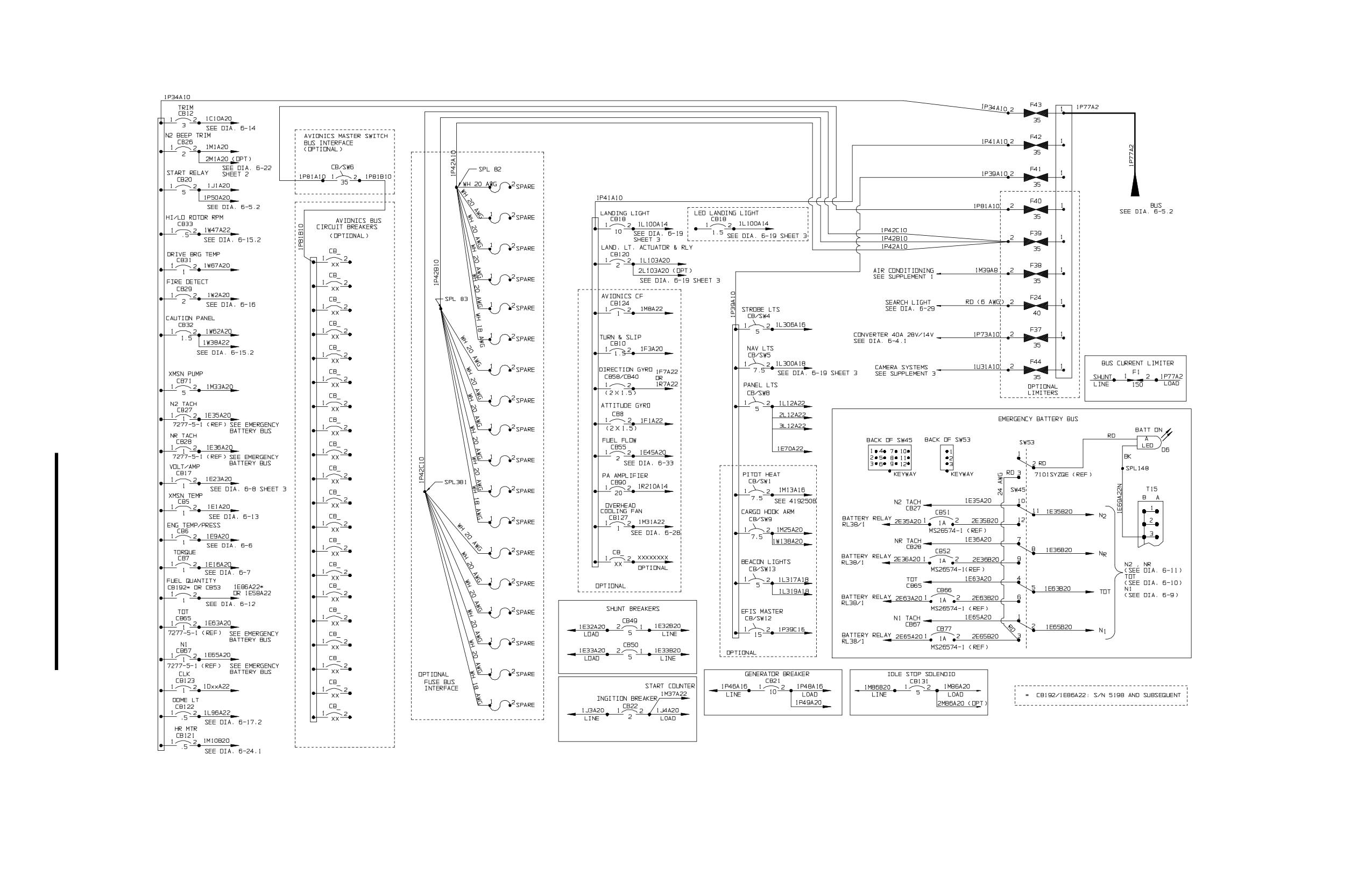
480B Serial Numbers: 5136 and Subsequent
Diagram 6-1.2. Power Distribution
Rev. 26, Feb 28/2020
MM-6-74.3/MM-6-74.4 (Blank)
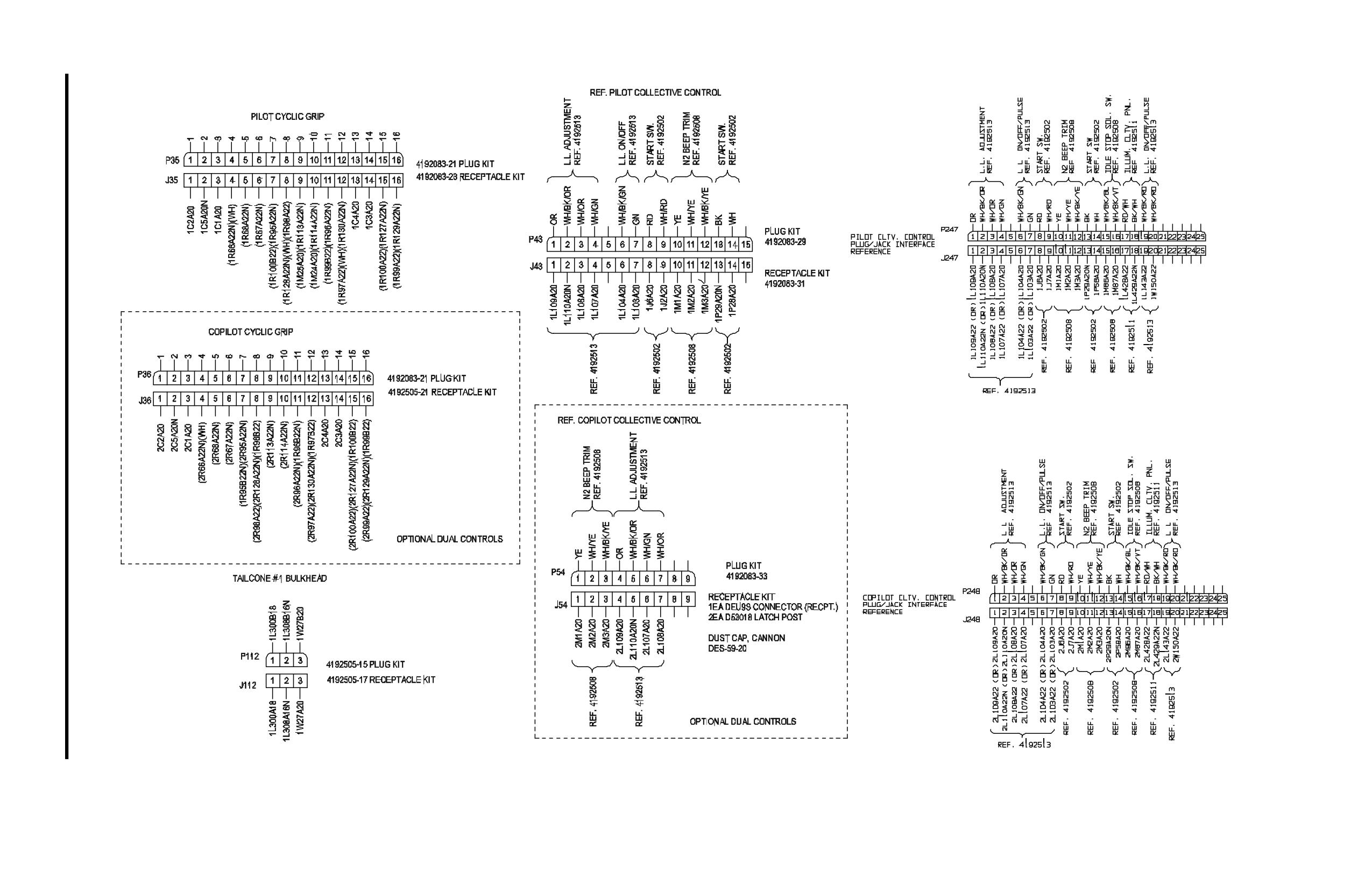
Diagram 6-3. Connector Interface
Rev. 26
Feb 28/2020
MM-6-77/MM-6-78 (Blank)
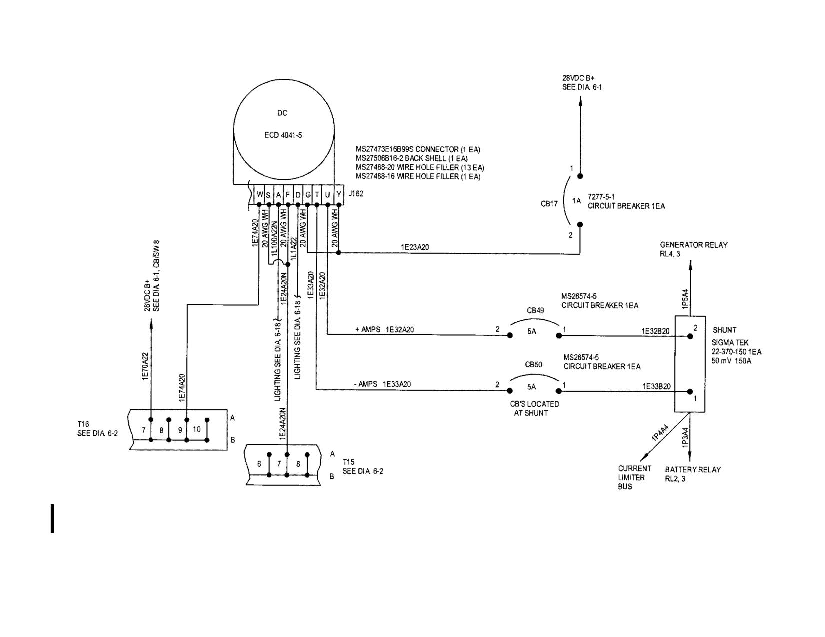
Sheet 2 of 3
480B Serial Numbers: 5046, 5048-5133
Diagram 6-8. D.C. Volt/Amp System
Rev. 12
MM-6-89
Jul 7/10
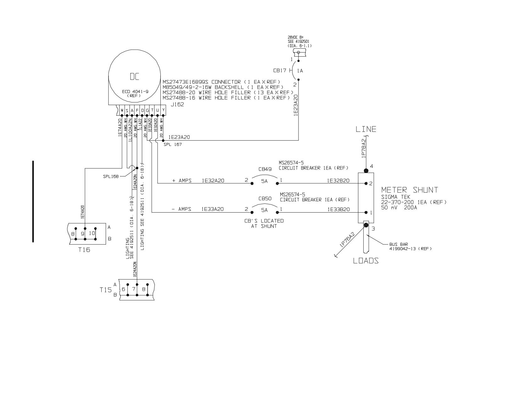
Sheet 3 of 3
480B Serial Numbers: 5134 and Subsequent
Diagram 6-8. D.C. Volt/Amp System
Rev. 26
MM-6-89.1
Feb 28/2020
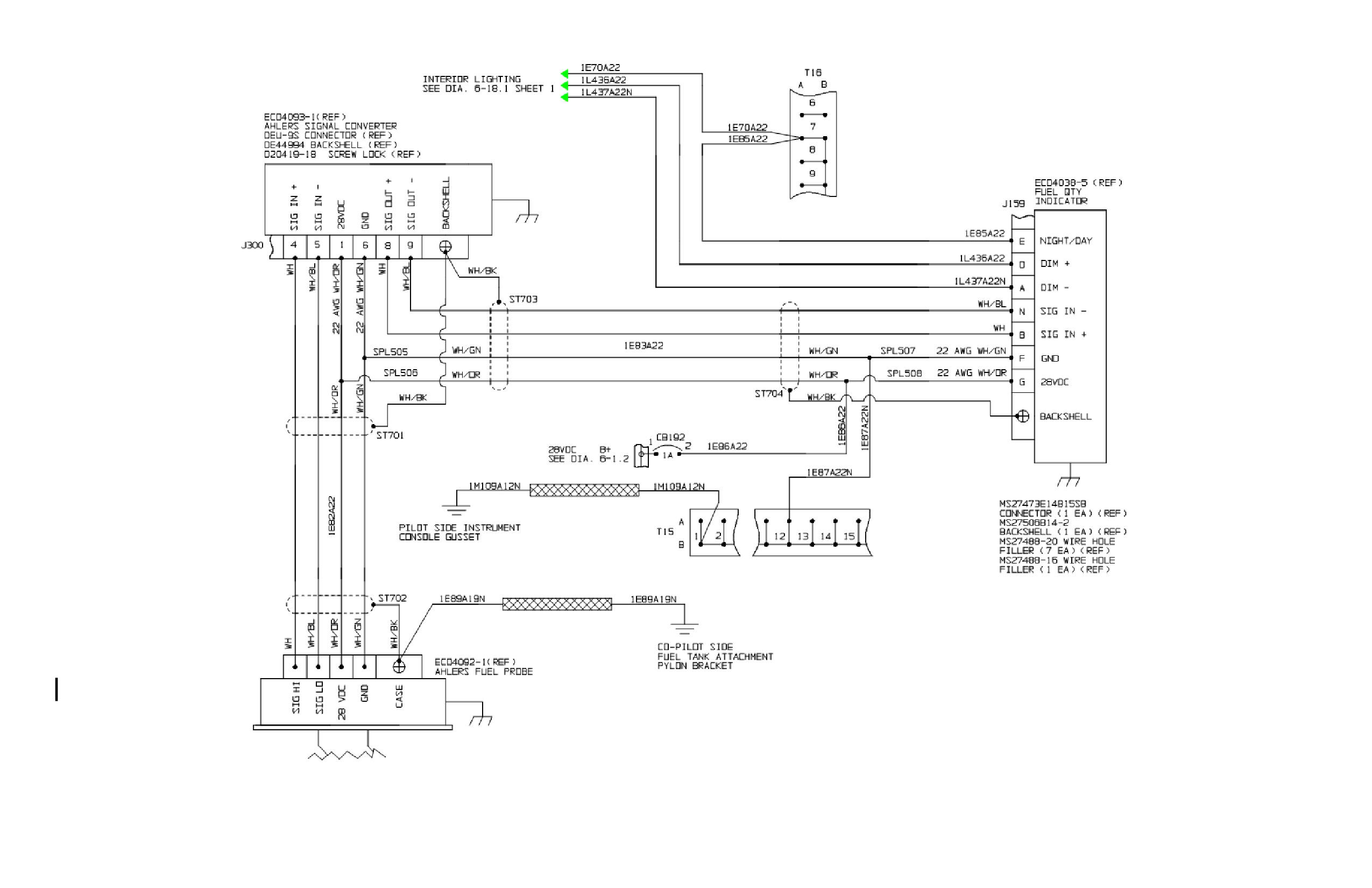
Sheet 5 of 5
480B Serial Numbers: 5198 and Subsequent
Diagram 6-12. Fuel Quantity System (Ref. 4192504 Rev. H)
Rev. 26, Feb 28/2020
MM-6-98.1/MM-6-98.2 (Blank)
INTENTIONALLY LEFT BLANK
Rev. 15
MM-6-113.2
Nov 15/10
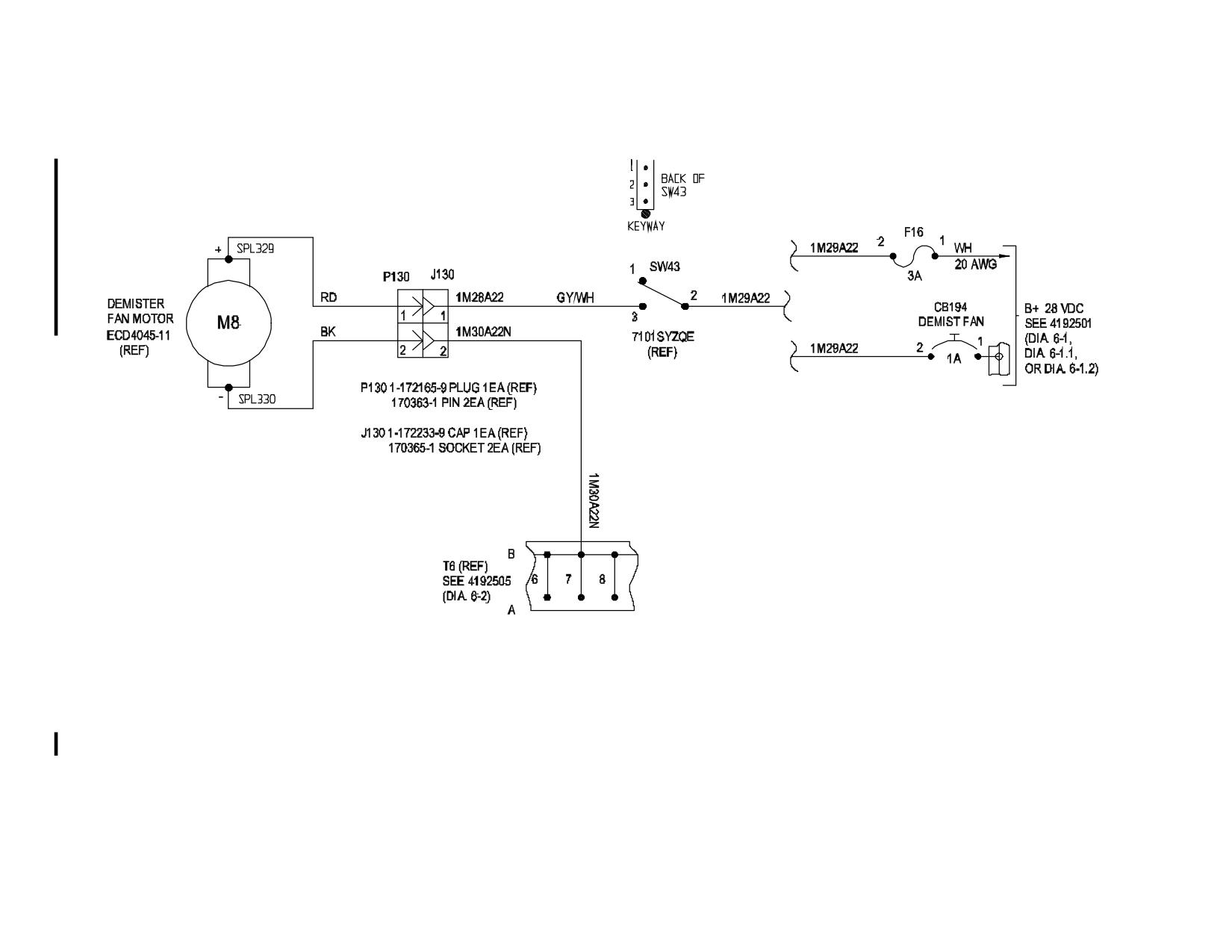
Diagram 6-23. Windshield Demister Fan
Rev. 26
MM-6-114
Feb 28/2020
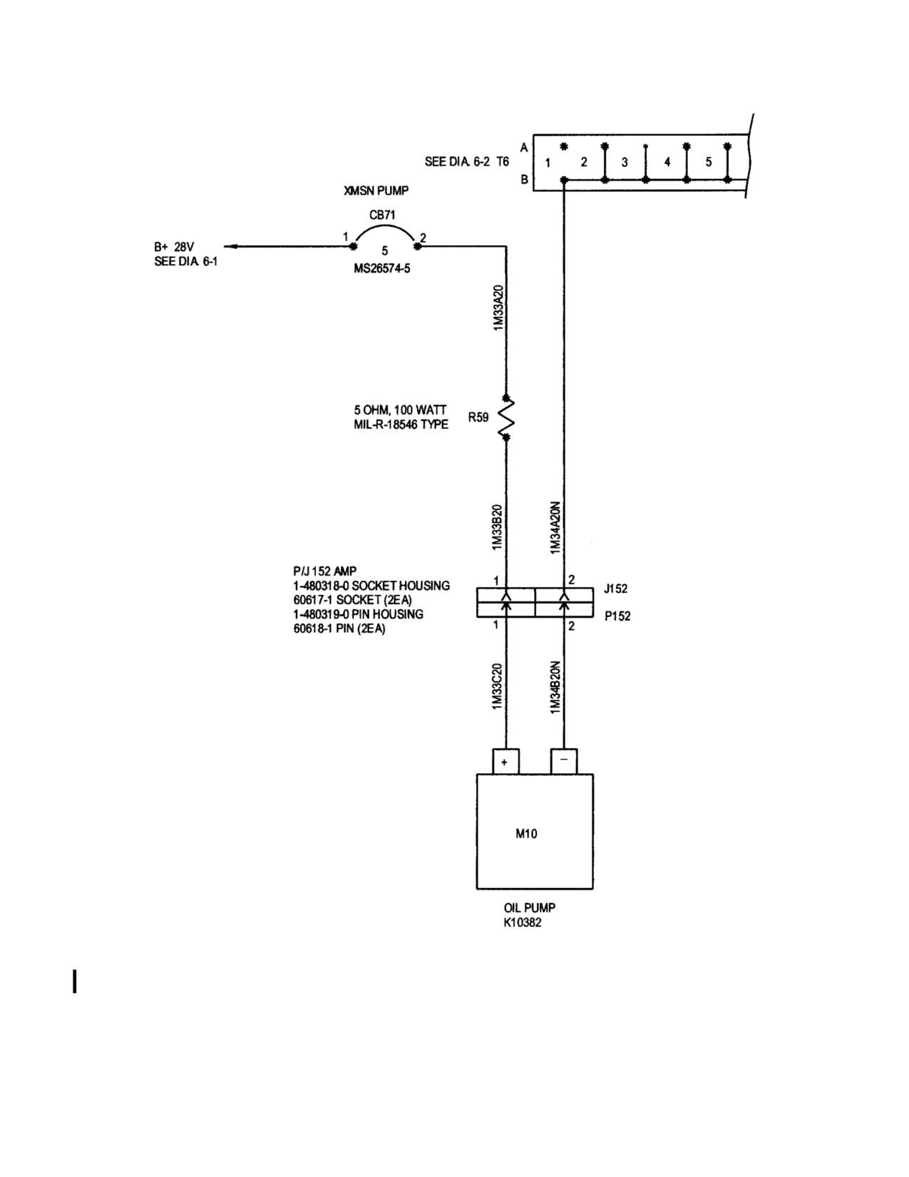
Sheet 1 of 2
Diagram 6-25. M/R Transmission Filtration/Cooling System
Rev. 6
MM-6-117
Apr 16/07
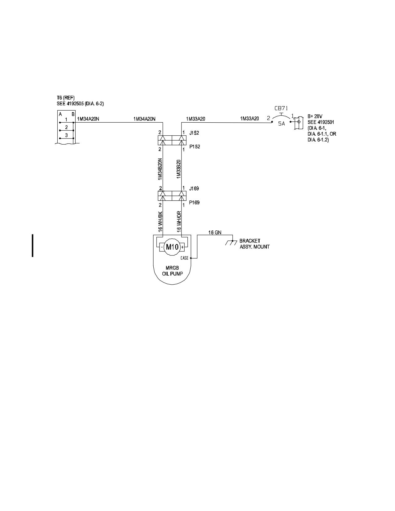
480/B S/N 5114 and subsequent
Sheet 2 of 2
Diagram 6-25. M/R Transmission Filtration/Cooling System
Rev. 26
MM-6-118
Feb 28/2020
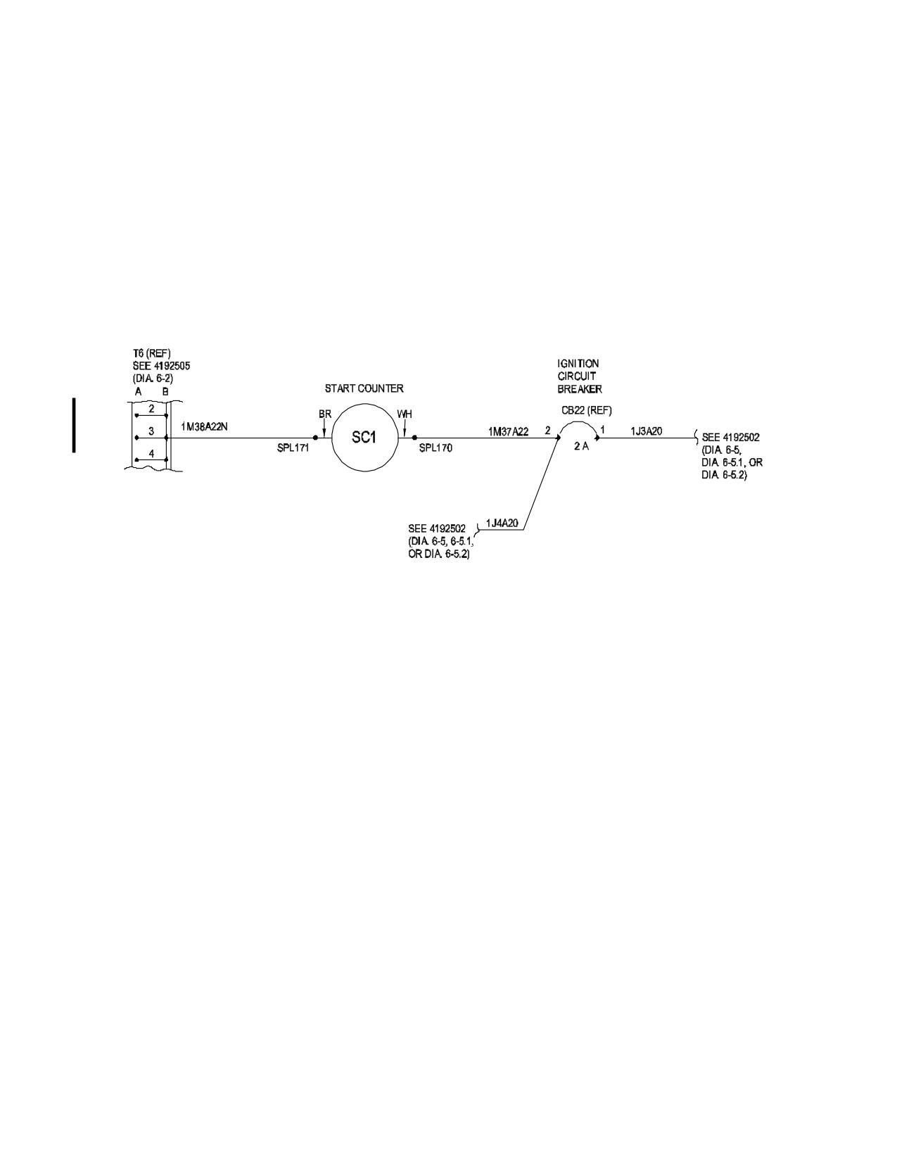
480B Serial Numbers: 5048 and Subsequent
Diagram 6-27. Start Counter
Rev. 26
MM-6-119
Feb 28/2020
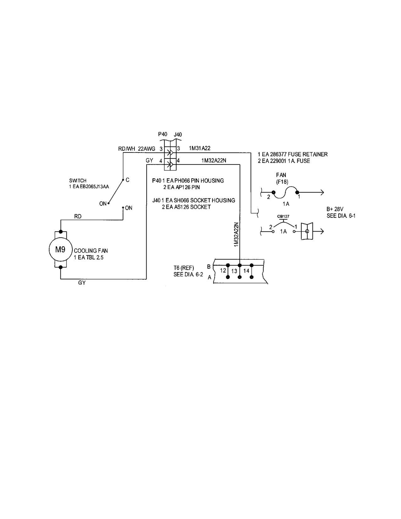
Sheet 1 of 2
480B Serial Numbers: All except 5136 and Subsequent
Diagram 6-28. Overhead Cooling Fan
Rev. 23
MM-6-120
Jul 3/15