Enstrom TH-28/480 Series. Maintenance Manual (2020) - page 2
SECTION 1
INTRODUCTION
TABLE OF CONTENTS
Paragraph
Description
Page
Table of Contents
MM-1-1
1-1.
Manual Arrangement
MM-1-3
1-2.
Aircraft Effectivity
MM-1-3
1-3.
Maintenance Manual Supplements
MM-1-3
1-4.
Maintenance Manual Changes and Revisions
MM-1-4
1-5.
Application of Warnings, Cautions, and Notes
MM-1-5
Rev. 26
MM-1-1
Feb 28/2020
SECTION 1
INTRODUCTION
TABLE OF CONTENTS
Paragraph
Description
Page
INTENTIONALLY LEFT BLANK
MM-1-2
Feb 9/01
SECTION 1
INTRODUCTION
1-1. Maintenance Manual Arrangement
The maintenance manual sections divide the aircraft into major systems and related
subsystems to provide maintenance procedures required for proper system function and
optimum component service life. Each section details the following maintenance functions for
the associated subsystems and components, if applicable:
General Description
Troubleshooting
Adjustment/Rigging
Removal
Disassembly
Inspections (other than Periodic Inspections)
Repair
Assembly
Installation
1-2. Aircraft Effectivity
The maintenance data presented in this manual is applicable to all TH-28, 480, and 480B model
Enstrom helicopters with standard equipment. Optional equipment maintenance procedures are
included in the TH-28/480 Series Maintenance Manual for common optional equipment that is
installed before aircraft delivery (This does not include avionics installations).
1-3. Maintenance Manual Supplements
Maintenance procedures for optional equipment may be provided in maintenance manual
supplements. These supplements are part of the TH-28/480 Series Maintenance Manual when
an aircraft is equipped with optional equipment which requires a maintenance manual
supplement. The following optional equipment supplements are applicable to the TH-28/480
Series Maintenance Manual.
Supplement 1:
Air Conditioning System, P/N 4220176-( ), Revision 8, Dated: May 1/17.
Supplement 2:
Emergency Pop-Out Floats, P/N 4220091-1 and 4220091-3, Revision 3,
Dated: Mar 21/16.
Supplement 3:
Gyrocam Dual or Triple Sensor Camera System, Dated: Feb 8/08.
Supplement 4:
Chelton Flightlogic EFIS System, Revision 1, Dated: Nov 9/10.
Supplement 5:
Avionic Systems, Revision 17, Dated: May 23/19.
Supplement 6:
Partial Wide Instrument Panel, Dated: Nov 15/10.
Supplement 7:
Bambi Bucket Interface Kit, Dated: Apr 30/13.
Supplement 8:
G1000H Integrated Flight Control System, Revision 2, Dated: Oct 18/19.
Rev. 26
MM-1-3
Feb 28/2020
1-4. Maintenance Manual Changes and Revisions
Subsequent to the publication of the initial issue of this manual, changes in equipment, support
concepts and procedures, as well as information developed by experience may affect the
contents of this manual. To ensure that coverage in the manual continues to reflect such
changes, revised information is released by one of the following methods:
1. Revision - A revision alters portions of the manual by replacement, addition, and/or
removal of pages.
2. Reissue - A reissue of this manual will occur when the amount of changes warrants
complete reissue.
3. Service Directive Bulletins - Used to direct the owner/operator and/or maintenance
personnel to make mandatory changes, improvements, or inspections to the aircraft
applicable to the entire fleet or a segment of the fleet that are typically safety/airworthiness
related. The information provided in the Service Directive Bulletins will be incorporated in
the maintenance manual as needed at a later date. At the time of incorporation, the Service
Directive Bulletin is superseded by the maintenance manual, and accomplishment or sign-
off of the Service Directive Bulletin in the maintenance records book is no longer required.
A detailed entry should be made in the maintenance records to indicate that the Service
Directive Bulletin is superseded by the maintenance manual.
4. Service Information Letters - Used to transmit information, recommendations, and general
service instructions to the aircraft owner/operator and/or maintenance personnel applicable
to the entire fleet or a segment of the fleet. The information provided in the Service
Information Letters will be incorporated into the maintenance manual as needed at a later
date.
5. Service Instructions - Used to provide the owner/operator and/or maintenance personnel
with information that is applicable to specific aircraft and does not meet the criteria of a
Service Information Letter or Service Directive Bulletin. Service Instructions will not be
distributed to the entire fleet.
Enstrom distributes maintenance manual revisions and reissues in electronic form via the
Technical Publications section of the Technical Support page). Revision update notices are sent
via email to owners and operators who are registered with Enstrom. Registration to receive
publication mailing notifications can be coordinated through the Enstrom Technical Publications
Administrator. A complete manual hardcopy may be ordered through Enstrom Customer
Service.
Service Information Letters and Service Directive Bulletins incorporated into the maintenance
manual are logged in the Service Information Letter Index or the Service Directive Bulletin Index
the applicable link under the Technical Publications section of the Technical Support page).
Each index numerically lists all Service Information Letters and Service Directive Bulletins,
respectively, and identifies those which have been incorporated into the maintenance manual.
All Service Information Letters and Service Directive Bulletins are also located under the
Technical Publications section of the website.
Notice of recently released Service Information Letters and Service Directive Bulletins is
provided via email notification. Registration to receive publication mailing notifications can be
coordinated through the Enstrom Technical Publications Administrator.
Rev. 26
MM-1-4
Feb 28/2020
SECTION 2
GENERAL INFORMATION
TABLE OF CONTENTS
Paragraph
Description
Page
Table of Contents
MM-2-1
2-1.
General Description
MM-2-3
2-2.
General Arrangement
MM-2-3
2-3.
Principal Dimensions
MM-2-3
2-4.
Turning Radius
MM-2-3
2-5.
Fuselage
MM-2-3
2-6.
Tailcone
MM-2-3
2-7.
Landing Gear
MM-2-3
2-8.
Cabin
MM-2-4
2-9.
Cabin Doors
MM-2-4
2-10.
Seats
MM-2-4
2-11.
Engine Assembly
MM-2-5
2-12.
Engine Compartment Cooling
MM-2-5
2-13.
Flight Controls
MM-2-9
2-14.
Power Train
MM-2-9
2-15.
Main Rotor Assembly
MM-2-9
2-16.
Tail Rotor Assembly
MM-2-9
2-17.
Cabin Ventilation
MM-2-9
2-18.
Operating Limitations and Restrictions
MM-2-9
2-19.
Placards
MM-2-9
2-20.
Vendor Information
MM-2-11
2-21.
Special Tools
MM-2-13
2-22.
Torque Data
MM-2-17
2-23.
Consumable Parts List
MM-2-22
2-24.
Taper Pin Size Chart
MM-2-23
Rev. 26
MM-2-1
Feb 28/2020
SECTION 2
GENERAL INFORMATION
TABLE OF CONTENTS
Paragraph
Description
Page
INTENTIONALLY LEFT BLANK
Rev. 10
MM-2-2
Oct 20/09
maintenance on the seats or the cockpit area. Both seats use a composite bucket mounted on a
pedestal assembly. A four point restraint system with adjusters in the lap and shoulder belts and
an inertia reel mounted on the back of the seat pedestal are an integral part of the seat.
2. Passenger Seats: The passenger seats are mounted to the cabin backwall and
fold up to the stowed position when not in use and use a combination diagonal shoulder
harness and lap belt restraint system.
C. Inertia Reel Shoulder Harness: An inertia reel and shoulder harness is incorporated
in all seats. There is no independent control to manually lock the harness. With the shoulder
straps properly adjusted, the reel strap will extend to allow the occupant to lean forward;
however, the reel automatically locks when the helicopter encounters an impact force of 2 to 3
"G" deceleration. To release the lock, it is necessary to lean back slightly to release tension on
the lock.
2-11. Engine Assembly
A. The TH-28/480 series helicopters are equipped with a Rolls-Royce 250-C20W free
turbine, turboshaft engine rated at 420 SHP (313 kW); however, engine power is limited
depending on model and drive system configuration of the helicopter (Refer to Table 2-1). Refer
to the Rolls-Royce 250-C20 Operation and Maintenance Manual (10W2) for a complete
description of the engine assembly and its sub-components.
Table 2-1. Engine Power Limitations
Helicopter Model
Takeoff Rating
Maximum Continuous
(5 minute maximum)
Power
TH-28 and 480
285 SHP (213 kW)
256 SHP (191 kW)
480 equipped with
290 SHP (216 kW)
268 SHP (200 kW)
Increased Rotor Speed Kit
(P/N 4230002)
480B
305 SHP (227 kW)
277 SHP (206 kW)
2-12. Engine Compartment Cooling
A. The engine compartment is convection cooled and augmented by air movement
created by the airfoil shaped spokes in the upper pulley.
B.
480B serial number 5114 and subsequent are equipped with fuselage panels/cowls
that have additional holes to increase the cooling efficiency of the engine compartment and can
be equipped with Engine Access Panels, P/N 4220150, to allow aircraft operation at an
increased maximum ambient temperature limit. 480B serial numbers 5087 through 5113 can be
equipped with the Increased Cooling Kit, P/N 4230031, for operation at the increased maximum
ambient temperature limit.
Rev. 26
MM-2-5
Feb 28/2020
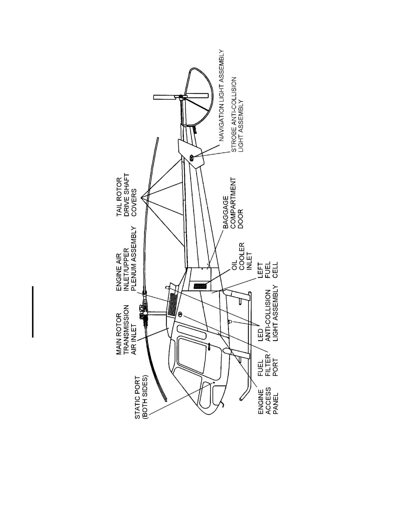
Sheet 1 of 2
Figure 2-1. General Arrangement
Rev. 20
MM-2-6
Apr 25/13
2-20. Vendor Information
A. The following components listed in Table 2-2 are to be maintained I/A/W the
manufacturer's instructions to ensure the continued airworthiness of the aircraft.
B. The owner/operator is responsible for ensuring that current maintenance publications
are available to ensure continued airworthiness of the aircraft.
Table 2-2. Vendor Contact Information
Component
Part Number
Manufacturer
Rolls-Royce
450 S. Meridian Street
Engine
250-C20W
Indianapolis, IN 46206
Tel: (317) 230-2000
Thales Avionics Inc. (Auxilec)
140 Centennial Avenue
Starter/Generator
524-080
Piscataway Township, NJ 08854
Tel: (732) 494-6300
Skurka Aerospace, Inc.
4600 Calle Bolero
150SG117Q-3-1
Starter/Generator
Camarillo, CA 93011
150SG117Q-4-1
Tel: (805) 484-8884
Thales Avionics Inc. (Auxilec)
140 Centennial Avenue
Generator Control
VR1528-11B
Piscataway Township, NJ 08854
Unit (GCU)
Tel: (732) 494-6300
Avionic Instruments, LLC
Generator Control
1414 Randolph Avenue
Unit
GCSG501-2
Avenel, NJ 07001
(GCU)
Tel: (732) 388-3500
Marathon Power Technologies
P.O. Box 8233
Battery*
TSP-1728-20-17SP100
Waco, TX 76712-8233
Tel: (254) 776-0650
Teledyne Battery Products (Gill Batteries)
840 West Brockton Avenue
Redlands, CA 92374
Battery**
G-641
Tel: (800) 456-0070
Tel: (909) 793-3131
Aerotech
8354 Secura Way
Fuel Cells
4122052-“X”
Santa Fe Springs, CA 90670
(Standard)
Tel: (562) 696-1128
Rev. 26
MM-2-11
Feb 28/2020
Table 2-2. Vendor Contact Information
Component
Part Number
Manufacturer
Zodiac Aerazur Caudebec
Fuel Cells
4122009-“X”
4, rue Lesage-Maille
Caudebec 76320, France
Tel: +33 (1) 6486-6922
Fuel Cell Crossover
500123
aerosafety-systems-elastomer
Zodiac Aerazur Caudebec
4, rue Lesage-Maille
Caudebec 76320, France
Vent Crossover
500122
Tel: +33 (1) 6486-6922
aerosafety-systems-elastomer
Airwolf Aerospace LLC
15369 Madison Rd.
Tension-Torsion (TT Strap)
Middlefield, OH 44062-8404, U.S.A.
AA-ECD-084-480
Tel: (440) 632-1687 / Fax: (440) 632-1685
(STC SR03465CH)
info@airwolfaerospace.com
Breeze-Eastern Corporation
35 Melanie Lane
Whippany NJ, 07981 U.S.A.
2A20B-17149-2
(800) 929-1919 / (973) 602-1083 / (973) 602-1090
Fax: (973) 739-9344
customerserives@breeze-eastern.com
Cargo Hook
(option)
Onboard Systems International, Inc.
13915 NW 3rd Court
Vancouver, WA 98685 U.S.A.
528-023-01
Tel: (800) 275-0883 / (360) 546-3072
Fax: (360) 546-3073
*
This is the standard battery for the TH-28 and 480. Refer to the correct publication if an optional or
special battery is installed.
** This is the standard battery for the 480B. Refer to the correct publication if an optional or special
battery is installed.
Rev. 26
MM-2-12
Feb 28/2020
2-22. Torque Data
A. Unless specified in Table 2-4 and/or in this manual’s maintenance procedures or as
called out in the component manufacturer’s specifications, all hardware should be torqued to the
recommended torque values listed in Tables 2-5 through 2-13.
NOTE
The following table does not contain all of the special torque values found
in this maintenance manual.
Table 2-4. Special Torque Values
Location
Torque Value
1.
Airframe
a. Tailcone Attachment Bolts
240 in-lb/27.3 Nm
b. Landing Gear Oleo Pivot Points (all)
(1)
b. Landing Gear Leg/Drag Strut Pivot Points (all)
40-60 in-lb/4.5-6.8 Nm
2.
Flight Controls
a. Dogleg to Lower Swashplate Nut
40-60 in-lb/4.5-6.8 Nm
b. Dogleg to Push/Pull Rod Nut
130-140 in-lb/14.7-15.8 Nm
c. Upper Swashplate Guidetube Nuts
240 in-lb/27.3 Nm
3.
Main Rotor Transmission
a. Mast Nut
450 ft-lb/613.6 Nm
b. Attachment Bolt Nuts
240 in-lb/27.3 Nm
c. Pinion Nut
250 ft-lb/340.9 Nm
d. Tail Rotor Coupling Bolt
100-140 in-lb/11.3-15.8 Nm
e. Magnetic Pick-up
60-65 in-lb/6.8-7.3 Nm
4.
Main Rotor Hub
a. Blade Attachment Nut
50 ft-lb/68.2 Nm
b. Damper Pivot Nut
190 in-lb/21.6 Nm
c. Drag Link Nut
140 in-lb/15.8 Nm
d. Flapping Bearing Reservoir Cap
10-20 in-lb/1.1-2.3 Nm
e. Flapping Pin Nut
150-175 ft-lb/204.5-238.6 Nm
f.
Lamiflex Bearing Retention Nut
5-15 in-lb/0.6-1.7 Nm
g. Lower U-block Nut
50 ft-lb/67.8 Nm
5.
Tail Rotor
a. Assembly Retention Bolt
300 in-lb/34.1 Nm
b. Blade Grip Bolts2
75 in-lb/8.5 Nm
c. Driveshaft Taper Pins
25 in-lb/2.8 Nm
d. Pitch Change Plate to Grip Attachment Bolts
50-70 in-lb/5.7-8.0 Nm
e. Thrust Bearing Retention Nut
80-90 ft-lb/109.1-122.7 Nm
1 Inch-Pound = 0.113 Newton Meter
1 Newton Meter = 8.851 Inch-Pound
1 Foot-Pound = 1.3558 Newton Meter
1 Newton Meter = 0.7376 Foot-Pound
1 Refer to (para. 8-70.A).
2 Torque for oversize bolts: 140 in-lbs/15.8 Nm maximum.
Rev. 26
MM-2-17
Feb 28/2020
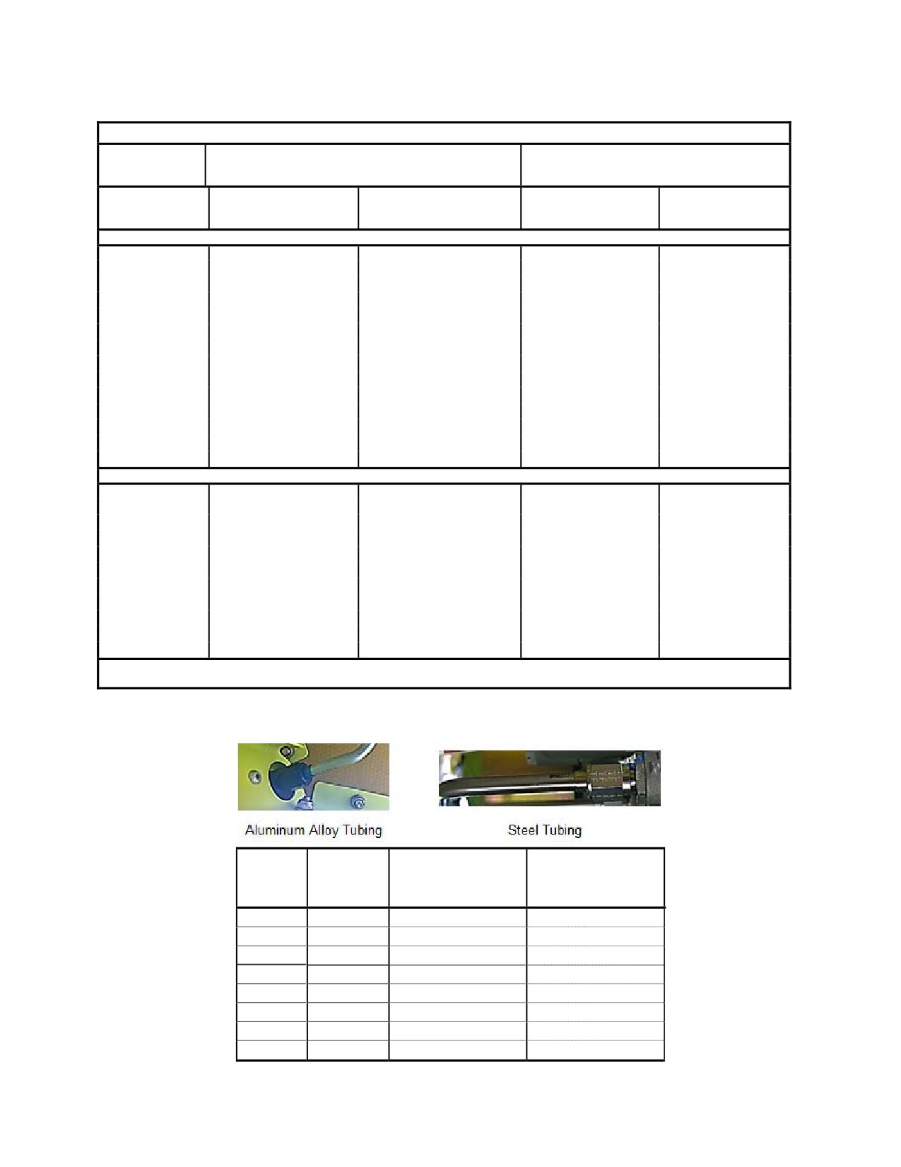
Table 2-5. Torque Values for Nuts and Bolts
CAUTION THE FOLLOWING TORQUE VALUES ARE DERIVED FROM OIL FREE CADMIUM PLATED THREADS.
TORQUE LIMITS RECOMMENDED FOR INSTAL-
MAXIMUM ALLOWABLE TIGHTENING
LATION (BOLTS LOADED PRIMARILY IN SHEAR)
TORQUE LIMITS
(inch-pounds)
(inch-pounds)
Thread Size
Tension type nuts
Shear type nuts MS20364
Nuts MS20365 and
Nuts MS20364 and
MS20365 and AN310
and AN320
AN310
AN320
(40,000 psi in bolts)
(24,000 psi in bolts)
(90,000 psi in bolts)
(54,000 psi in bolts)
FINE THREAD SERIES
8-36
12-15
7-9
20
12
10-32
20-25
12-15
40
25
1/4-28
50-70
30-40
100
60
5/16-24
100-140
60-85
225
140
3/8-24
160-190
95-110
390
240
7/16-20
450-500
270-300
840
500
1/2-20
480-690
290-410
1100
660
9/16-18
800-1000
480-600
1600
960
5/8-18
1100-1300
600-780
2400
1400
3/4-16
2300-2500
1300-1500
5000
3000
7/8-14
2500-3000
1500-1800
7000
4200
1-14
3700-5500
2200-3300*
10,000
6000
1-1/8-12
5000-7000
3000-4200*
15,000
9000
1-1/4-12
9000-11,000
5400-6600*
25,000
15,000
COARSE THREAD SERIES
8-32
12-15
7-9
20
12
10-24
20-25
12-15
35
21
1/4-20
40-50
25-30
75
45
5/16-18
80-90
48-55
160
100
3/8-16
160-185
95-100
275
170
7/16-14
235-255
140-155
475
280
1/2-13
400-480
240-290
880
520
9/16-12
500-700
300-420
1100
650
5/8-11
700-900
420-540
1500
900
3/4-10
1150-1600
700-950
2500
1500
7/8-9
2200-3000
1300-1800
4600
2700
The above torque values may be used for all cadmium-plated steel nuts of the fine or coarse thread series which have
approximately equal number of threads and equal face bearing areas. * Estimated corresponding values.
Table 2-6. Fittings, Tubing
6061-O & 5052-O
Steel Tube:
Fitting
Tubing OD
Aluminum-Alloy Tube:
Fitting or Nut Torque
Size
(inches)
Fitting or Nut Torque
(in-lb)
(in-lb)
-2
1/8
20-30
75-85
-3
3/16
25-35
95-105
-4
1/4
50-65
135-150
-5
5/16
70-90
170-200
-6
3/8
110-130
270-300
-8
1/2
230-260
450-500
-10
5/8
330-360
650-700
-12
3/4
460-500
900-1000
Rev. 26
MM-2-18
Feb 28/2020
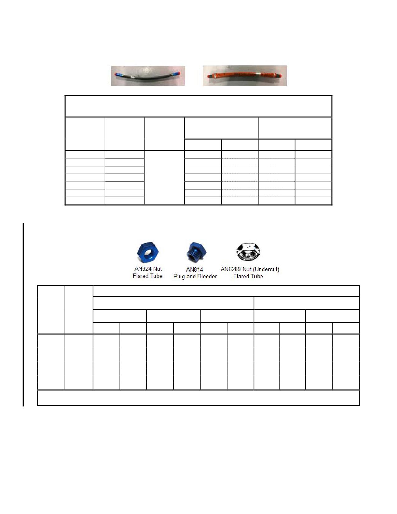
Table 2-7. Fittings, Hose Assemblies
Flexible Hose or Tube Fittings (excluding nylon pitot static lines)
Measurements based on Hose Inside Diameter or Fitting Size
Flex Hose and 6061-T6
Steel (Torque Limits
Aluminum Alloy Torque
Tube Size
(in-lb)
Fitting Size
Thread
Limits (in-lb)
(inches)
Min
Max
Min
Max
-3
3/16
3/8-24
30
70
90
140
-4
1/4
7/16-20
70
120
135
185
-5
5/16
1/2-20
70
120
180
230
-6
3/8
3/4-16
130
180
270
345
-8
1/2
3/4-16
300
400
450
525
-10
5/8
7/8-14
430
550
650
750
-12
3/4
1-1/6-12
650
800
900
1,100
Table 2-8. Fittings
Torque Limits (inch-pounds)
For Jamnuts and Fittings Without
For Gasketed Aluminum or Steel Fittings*
Gaskets* *
Nominal
AN924 Nut AN815
Tube
Fitting
Union
AN814 Plug
AN6289 Nut
Aluminum
Steel
O.D.
Thread
(inches)
Size
Min
Max
Min
Max
Min
Max
Min
Max
Min
Max
1/8
5/16-24
25
35
10
16
25
35
35
50
-
-
3/16
3/8-24
50
75
30
40
50
75
65
80
70
90
1/4
7/16-20
55
80
40
65
75
100
90
105
110
130
5/16
1/2-20
75
100
60
80
90
120
105
125
140
160
3/8
9/16-18
100
150
80
120
150
200
125
145
225
275
1/2
3/4-16
180
230
150
200
200
250
240
280
400
450
5/8
7/8-14
250
350
200
350
275
400
330
370
550
650
3/4
1-1/6-12
420
600
300
500
450
650
540
660
800
960
*
For use with O-rings and aluminum, asbestos, leather, Teflon, gaskets, or washers.
* * For combinations of materials (either jamnut, fittings, or boss), use the lowest applicable values shown.
Rev. 26
MM-2-19
Feb 28/2020
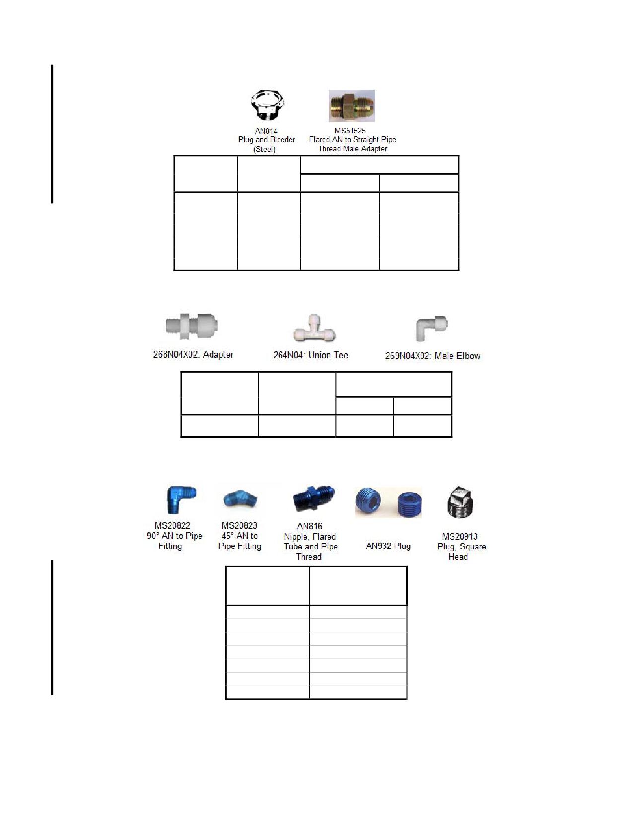
Table 2-9. Steel Fittings Using Jam Nuts or Straight Thread O-Ring Boss
Torque Limits (inch-pounds)
Thread Size
Tube Size
(inches)
Min
Max
-02
5/16-24
72
84
-03
3/8-24
95
105
-04
7/16-20
155
180
-05
1/2-20
170
180
-06
9/16-18
275
290
-08
3/4-16
480
515
-10
7/8-14
515
575
Table 2-10. Pitot Static System Nylon Fittings
Torque Limits
Nominal Tube
Thread Size
(inch-pounds)
O.D. (inches)
(inches)
Min
Max
1/4
7/16-20
7
10
Table 2-11. Pipe Plugs
Thread Size
Torque Limits
(inches)
(inch-pounds)
1/16-27 NPT
40 to 44
1/8-27 NPT
40 to 44
1/4-18 NPT
85 to 94
3/8-18 NPT
110 to 121
1/2-14 NPT
160 to 176
3/4-14 NPT
230 to 252
1-11-1/2 NPT
315 to 347
Rev. 26
MM-2-20
Feb 28/2020
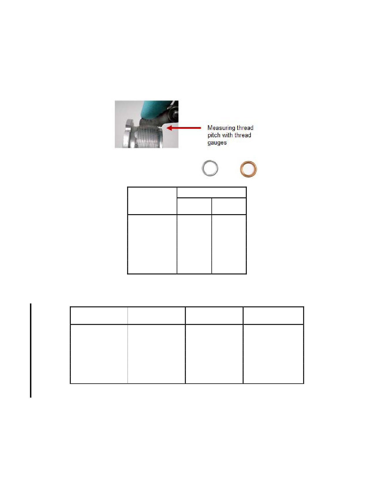
Table 2-12. Crush Type Gaskets
NOTE
Turn the part until the sealing surfaces are in contact and then tighten to
the angle of turn listed for the appropriate thread size.
Thread Pitch On
Angle of Turn
Part to be
Tightened
(Threads per Inch)
Aluminum
Copper
8
135°
67°
10
135°
67°
12
180°
90°
14
180°
90°
16
270°
135°
18
270°
135°
20
270°
135°
24
360°
180°
28
360°
180°
Table 2-13. Minimum Prevailing Torque Values for Re-used Self-Locking Nuts
Bolt, or Screw Thread
Seating Torque
Prevailing Torque Max.
Prevailing Torque Min.
Size (inches)
(in-lb ±10%)
On or Off (in-lb)
On or Off (in-lb)
4-40
8
5
0.5
6-32
15
8
1.0
8-32
28
12
1.5
AN3
45
18
2.0
AN4
110
40
3.0
AN5
190
85
5.0
AN6
345
110
9.0
AN7
545
150
12.0
AN8
850
220
16.0
If not listed in Table 2-13, a self-locking nut can be reused as long as a wrench is
required to turn it on the bolt.
Rev. 26
MM-2-21
Feb 28/2020
2-23. Consumable Parts List
A. Table 2-14 lists the consumable parts and lubricants that are normally used during
servicing or periodic inspection of the aircraft. The quantities listed reflect normal inspection
intervals; however, they may need to be adjusted if adverse operating conditions require more
frequent servicing or inspections.
B. Refer to the Rolls-Royce 250-C20 Series Operation and Maintenance Manual (10W2)
and the Rolls-Royce 250-C20 Series Illustrated Parts Catalog (10W4) for the consumable parts
required for servicing or periodic inspection of the engine.
NOTE
Obtain engine parts through the Rolls-Royce Parts Distribution System.
Enstrom does not stock engine parts for customer service use.
Table 2-14. Consumable Parts List
Item
Part Number †
Quantity
50 Hour Service
1.
Grease
MIL-PRF-81322 and MIL-G-25537
As Required
2.
Silicon Oil
L-45 or SF96-20
As Required
3.
Oil
I
As Required
4.
Oil
MIL-PRF-23699
As Required
5.
O-ring
NAS1612-2
7 EA *
100 Hour Service/Inspection
1.
Same as 50 hour Requirements
--
--
2.
Crush Washer
AN900-8 or MS35769-9
1 EA
3.
Crush Washer
AN900-10 or MS35769-11
1 EA
4.
Oil Filter
HP-1003
1 EA
5.
Oil
MIL-PRF-23699
6 QTS
6.
Oil
MIL-PRF-2105/API GL-5
7 PTS
7.
O-ring
NAS1612-2
2 EA*
8.
O-ring
NAS1612-8
4 EA*
9.
O-ring
MS28778-6
1 EA*
200 Hour Service/Inspection
1.
Same as 100 hour requirements
--
--
2.
Filter Element - APM
AC-B283F-107
1 EA
3.
O-ring - APM
M83248/1-138
1 EA
4.
Filter Element - Purolator/Facet
038088-08
1 EA
5.
Seal Kit - Purolator/Facet
1741125
1 EA
6.
O-ring
NAS1612-2
3 EA*
7.
Oil (ORC)
MIL-PRF-23699
7 OZ
300 Hour Service/Inspection
1.
Same as 100 hour requirements
--
--
2.
Fuel Filter Kit
1743645-02
1 EA**
3.
Gasket
28-13107-15
1 EA*
NOTES:
*
Replace on condition
**
The external fuel filter is optional equipment and might not be installed on the aircraft.
†
Verify configuration, part number and quantity with latest revision of illustrated parts
catalog, service letters, and service bulletins as required.
I
Any grade internal combustion engine motor oil.
Refer to the Rolls-Royce 250-C20 Series Operation and Maintenance Manual (10W2) for
engine oil change requirements.
Rev. 23
MM-2-22
Jul 3/15
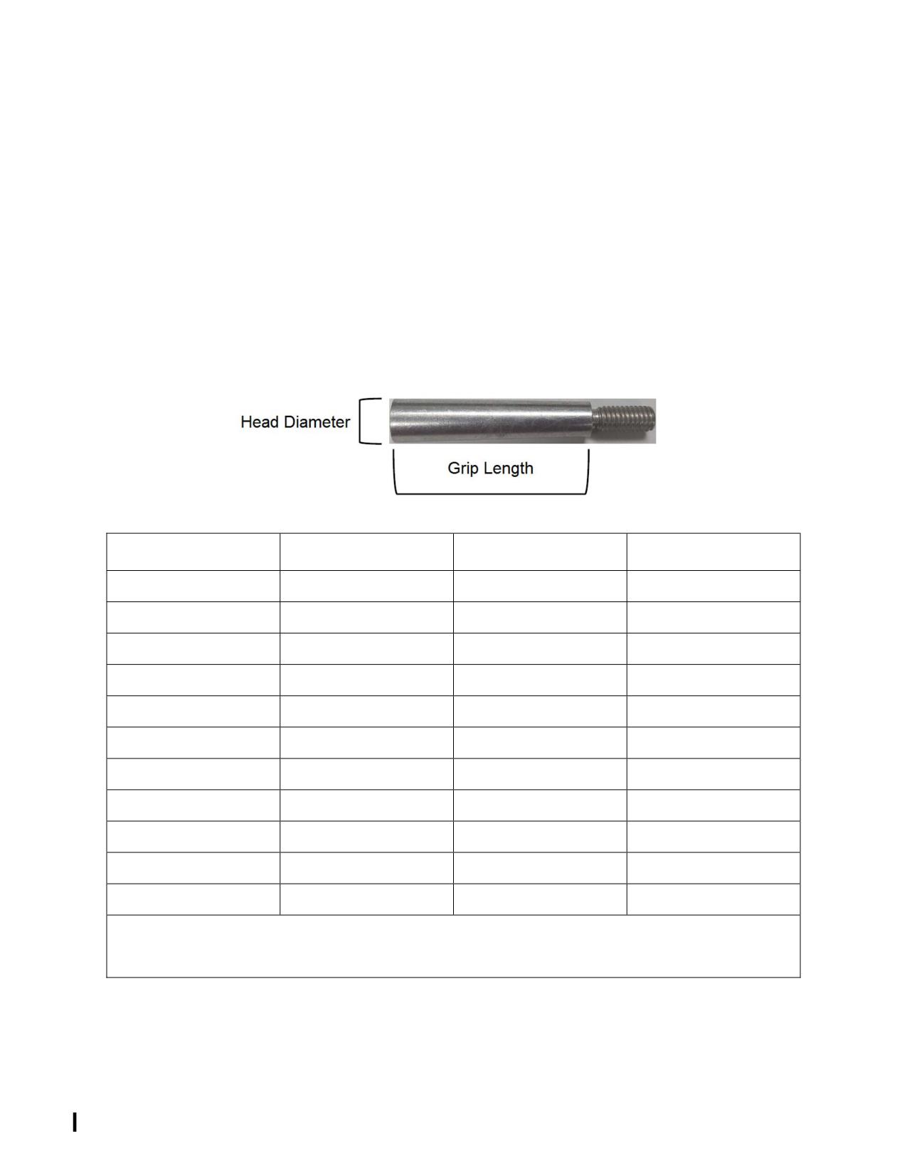
2-24. Taper Pin Size Chart
Table 2-15 lists information pertaining to taper pin part numbers and physical properties.
NOTES
Always check the condition and security of taper pins at every inspection.
The dash number of the 28-16323 series taper pins is vibro-etched on the
head of the taper pin.
Table 2-15. Taper Pin List
Old Enstrom P/N
Current Enstrom P/N
Head Diameter
Grip Length
AN386-2-7A 1
AN386-2-7A 1
0.296 in / 7.5 mm
1.00 in / 25.4 mm
AN386-2-8A 1
AN386-2-8A 1
0.302 in / 7.6 mm
1.12 in / 28.4 mm
AN386-2-9A 1
AN386-2-9A 1
0.308 in / 7.8 mm
1.26 in / 32 mm
28-13600-3 2
28-13623-25 2
0.302 in / 7.6 mm
1.00 in / 25.4 mm
28-13600-4 2
28-13623-27 2
0.307 in / 7.7 mm
1.00 in / 25.4 mm
28-13600-5 2
28-13623-29 2
0.314 in / 7.9 mm
1.00 in / 25.4 mm
NA
28-13623-31 2
0.316 in / 8 mm
1.00 in / 25.4 mm
28-13600-7 3
28-13623-13 3
0.310 in / 7.8 mm
1.12 in / 28.4 mm
28-13600-8 3
28-13623-17 3
0.318 in / 8 mm
1.12 in / 28.4 mm
NA
28-13623-15 3
0.315 in / 8 mm
1.12 in / 28.4 mm
28-13600-6 3
28-13623-11 3
0.305 in / 7.7 mm
1.12 in / 28.4 mm
1 Standard
2 Tail Rotor Transmission
3 Main Rotor Transmission
Rev. 26
MM-2-23
Feb 28/2020
INTENTIONALLY LEFT BLANK
Rev. 26
MM-2-24
Feb 28/2020
SECTION 4
SERVICING, RECOMMENDED OVERHAULS, INSPECTIONS,
AND GENERAL MAINTENANCE
TABLE OF CONTENTS
Paragraph
Description
Page
Table of Contents
MM-4-1
4-1.
Servicing
MM-4-5
4-2.
Description
MM-4-5
4-3.
Fuel System
MM-4-14
4-4.
Servicing
MM-4-14
4-5.
Draining
MM-4-14
4-6.
Engine Oil System
MM-4-15
4-7.
Servicing
MM-4-15
4-8.
Draining
MM-4-16
4-9.
Overrunning Clutch
MM-4-19
4-10.
Servicing
MM-4-19
4-10.1
Draining
MM-4-20
4-11.
Main Rotor Transmission
MM-4-20
4-12.
Servicing
MM-4-20
4-13.
Draining
MM-4-21
4-13.1
Flushing
MM-4-21
4-14.
Oil Filter Replacement
MM-4-22
4-15.
Tail Rotor Transmission
MM-4-22.1
4-16.
Servicing
MM-4-22.1
14-17.
Draining
MM-4-22.1
4-17.1
Flushing
MM-4-22.2
4-18.
Main Rotor Dampers
MM-4-24
4-19.
Servicing
MM-4-24
4-20.
Main Rotor Flapping Bearings
MM-4-25
4-21.
Servicing
MM-4-25
4-22.
Draining
MM-4-25
4-23.
Lower Pulley Bearings
MM-4-29
4-24.
Servicing
MM-4-29
4-25.
Draining
MM-4-29
4-26.
Oleos
MM-4-30
4-27.
Servicing
MM-4-30
4-28.
Battery
MM-4-34
4-29.
Servicing
MM-4-34
4-30.
Lubrication
MM-4-34
4-31.
Description
MM-4-34
4-32.
Lower Pulley
MM-4-35
4-33.
Lubrication
MM-4-35
4-34.
Main Rotor Blade Grip
MM-4-35
4-35.
Lubrication
MM-4-35
4-36.
Main Rotor Flapping Bearings
MM-4-37
4-37.
Lubrication
MM-4-37
Rev. 26
MM-4-1
Feb 28/2020
SECTION 4
SERVICING, RECOMMENDED OVERHAULS, INSPECTIONS,
AND GENERAL MAINTENANCE
TABLE OF CONTENTS
Paragraph
Description
Page
4-38.
Tail Rotor Pitch Control Bearing
MM-4-37
4-39.
Lubrication, Preferred Method
MM-4-37
4-39.1.
Lubrication, Alternate Method
MM-4-38
4-39.2.
Blower Assembly Bearing
MM-4-38
4-39.3.
Lubrication
MM-4-38
4-39.4.
Tail Rotor Feathering Bearing
MM-4-38
4-39.5.
Lubrication
MM-4-38
4-40.
Recommended Overhaul Cycles
MM-4-39
4-41.
Periodic Inspections
MM-4-41
4-42.
General Information
MM-4-41
4-43.
Daily Inspection
MM-4-41
4-44.
Periodic Inspection Checklists
MM-4-41
4-45.
100 Hour Inspection
MM-4-43
4-46.
200 Hour Inspection
MM-4-57
4-47.
300 Hour Inspection
MM-4-59
4-48.
Special Scheduled Inspection
MM-4-61
4-49.
Special Inspections
MM-4-63
4-50.
General Information
MM-4-63
4-51.
Main Rotor Blade Strike/Sudden Stoppage (Minor)
MM-4-63
4-52.
Main Rotor Blade Strike/Sudden Stoppage (Major)
MM-4-64
4-53.
Tail Rotor Blade Strike/Sudden Stoppage
MM-4-65
4-54.
Hard Landing
MM-4-66
4-55.
Main Rotor Overspeed
MM-4-67
4-56.
Overtorque
MM-4-67
4-57.
Main Rotor or Tail Rotor Transmission Chip Indication
MM-4-68
4-58.
Engine Overspeed
MM-4-70
4-59.
Engine Overtemp
MM-4-70
4-60.
Maintenance Ground Run
MM-4-70
4-61.
Maintenance Test Flight
MM-4-73
4-62.
Ground Handling
MM-4-81
4-63.
Ground Handling Wheels
MM-4-81
4-64.
Installation/Removal
MM-4-81
4-65.
External Power
MM-4-82
4-66.
Parking
MM-4-82
4-67.
Leveling
MM-4-83
4-68.
Hoisting
MM-4-83
4-69.
Jacking
MM-4-83
4-70.
Cleaning
MM-4-89
4-71.
Exterior
MM-4-89
4-72.
Interior
MM-4-90
4-73.
Plexiglass
MM-4-90
Rev. 26
MM-4-2
Feb 28/2020
SECTION 4
SERVICING, RECOMMENDED OVERHAULS, INSPECTIONS,
AND GENERAL MAINTENANCE
TABLE OF CONTENTS
Paragraph
Description
Page
4-74.
Aircraft Preservation and Storage
MM-4-90
4-75.
General
MM-4-90
4-76.
Low Usage
MM-4-91
4-77.
Storage up to 45 Days
MM-4-92
4-78.
Storage from 45 Days to 6 Months
MM-4-92
4-79.
Storage for longer than 6 Months
MM-4-93
4-80.
Preventive Maintenance for Corrosion Control
MM-4-94
4-81.
General Information
MM-4-94
4-82.
Scheduled Field Preventive Maintenance Program
MM-4-94
4-83.
Component Preservation and Storage
MM-4-95
4-84.
Main Rotor Transmission
MM-4-95
4-85.
Tail Rotor Transmission
MM-4-96
Rev. 26
MM-4-3
Feb 28/2020
SECTION 4
SERVICING, RECOMMENDED OVERHAULS, INSPECTIONS,
AND GENERAL MAINTENANCE
TABLE OF CONTENTS
Paragraph
Description
Page
INTENTIONALLY LEFT BLANK
Rev. 17
MM-4-4
Jun 24/11
SECTION 4
SERVICING, RECOMMENDED OVERHAUL CYCLES, INSPECTIONS,
AND GENERAL MAINTENANCE
4-1. Servicing
4-2. Description - Servicing
Servicing of the TH-28 and 480/B is normally accomplished at specified hourly intervals.
Operators should take into consideration the environmental conditions and determine whether
more frequent servicing intervals are necessary. Refer to Tables 4-1 thru 4-7.1 and Figure 4-1
for approved fuels, oils, lubricants, intervals, and locations.
Table 4-1. Fuels, Lubricants, Specifications, and Capacities
SYSTEM/COMPONENT
SPECIFICATION
CAPACITY
Fuel - Standard
ASTM D1655, Jet A or A1
*(C-1)
91.7 U.S.Gals
(90.0 usable)
ASTM D6615, Jet B
347.08 Liters
MIL-T-5624, JP-4 or JP-5
(340.65 usable)
(See Note 6)
MIL-DTL-83133, Grade JP-8
(See Note 1)
Fuel - Crashworthy
ASTM D1655, Jet A or A1
*(C-1)
90.0 U.S.Gals
(89.7 usable)
ASTM D6615, Jet B
340.65 Liters
MIL-T-5624, JP-4 or JP-5
(339.51 usable)
(See Note 6)
MIL-DTL-83133, Grade JP-8
(See Note 1)
Engine Oil
MIL-PRF-7808 or
*(C-2)
12.0 U.S. Pints
MIL-PRF-23699
(See Note 2)
5.7 Liters
Overrunning Clutch
MIL-PRF-7808 (See Table 4-4)
3.8 U.S. Ounces
or MIL-PRF-23699
*(C-2)
(See Table 4-5)
110 ml
Overrunning Clutch
MIL-PRF-7808 (See Table 4-4)
6.5 U.S. Ounces
with Vented Clutch Oil Reservoir
or MIL-PRF-23699
*(C-2)
(If Equipped)
(See Table 4-5)
192 ml
Rev. 26
MM-4-5
Feb 28/2020
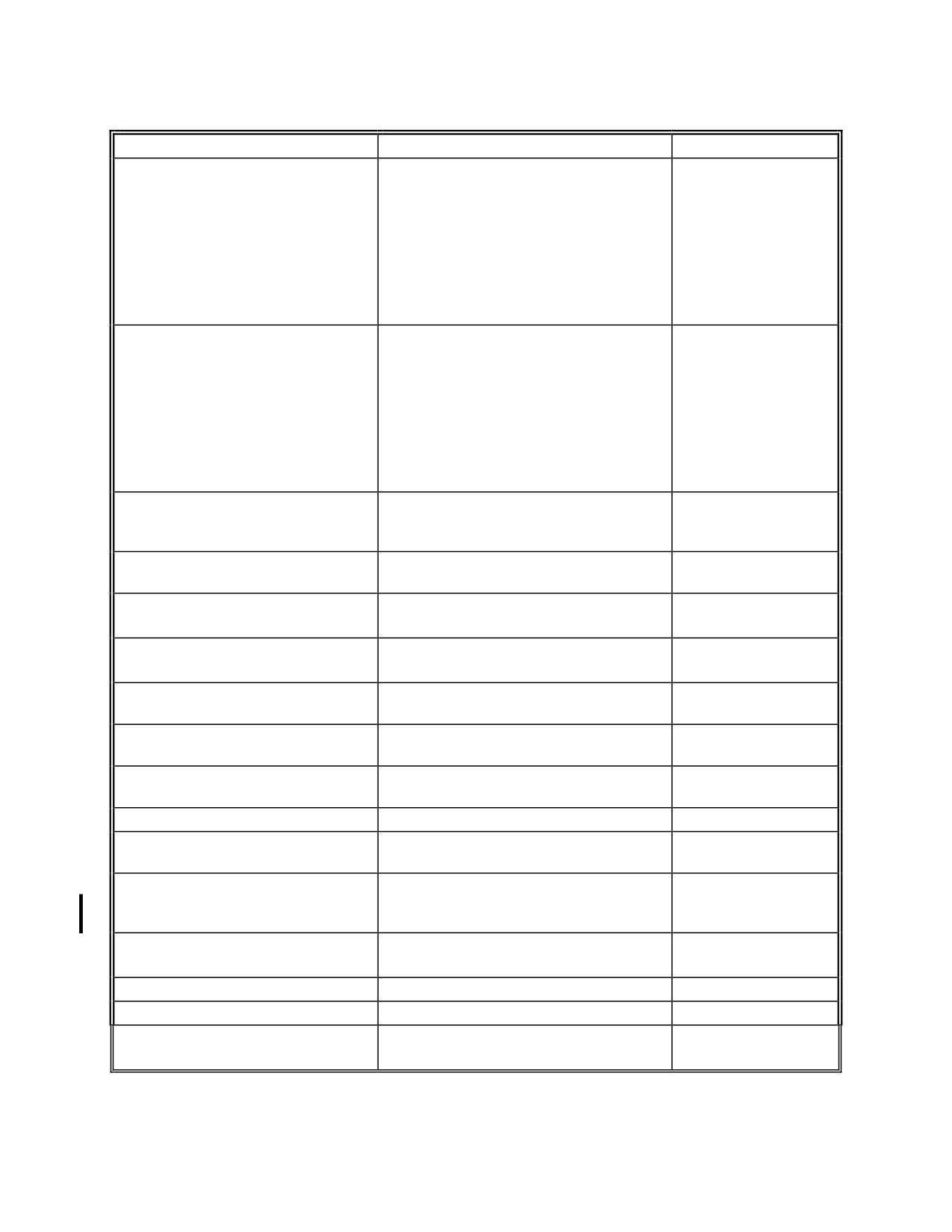
Table 4-1. Fuels, Lubricants, Specifications, and Capacities
SYSTEM/COMPONENT
SPECIFICATION
CAPACITY
Main Rotor Transmission
MIL-PRF-2105/API GL-5
*(C-3)
Dry -
(See Note 5)
6 U.S.Pints
2.84 Liters
Reservicing - 5.5
U.S. Pints
2.6 Liters
Main Rotor Transmission
MIL-PRF-2105/API GL-5
*(C-3)
Dry -
(See Note 5)
6.5 U.S.Pints
(Equipped with oil filter and cooling
installation)
3.1 Liters
Reservicing - 6.0
U.S. Pints
2.84 Liters
Tail Rotor Transmission
MIL-PRF-2105/API GL-5
*(C-3)
5 U.S.Ounces
(See Note 5)
150 ml
Main Rotor Dampers
L-45 or SF96-20 Silicone Oil
*(C-4)
Until Full
(See Note 8)
Main Rotor Blade Grips
MIL-G-25537 or MIL-PRF-81322
As Required
(See Notes 7, 9, 12)
*(C-8 or C-5)
Main Rotor Lead-Lag Bearings
MIL-G-25537 or MIL-PRF-81322
As Required
(See Notes 7, 10, 12)
*(C-8 or C-5)
Main Rotor Flapping Bearings
MIL-G-25537 or MIL-PRF-81322
As Required
(Grease Lubricated)
(See Notes 7, 10, 12)
*(C-8 or C-5)
Main Rotor Flapping Bearings
MIL-PRF-23699
*(C-2)
As Required
(Oil Lubricated)
(See Table 4-5)
Pitch Change Bellcrank Pivot
MIL-G-25537 or MIL-PRF-81322
As Required
Bearings
(See Note 7, 10, 12)
*(C-8 or C-5)
Upper Pulley Bearing
MIL-PRF-81322 (See Note 7)
*(C-5)
As Required
Lower Pulley Bearings
MIL-PRF-81322
*(C-5)
As Required
(Grease Lubricated)
(See Note 7)
(See Note 3)
Lower Pulley Bearings
MIL-PRF-23699
*(C-2)
.27 U.S. Ounces
(Oil Lubricated)
(See Table 4-5)
Dry - 8 ml
Reservicing - 6 ml
Blower Assembly Bearings
MIL-PRF-81322 (See Note 7)
*(C-5)
As Required
(See Note 11)
Tail Rotor Drive Shaft Bearings
MIL-PRF-81322 (See Note 7)
*(C-5)
As Required
Tail Rotor Pitch Control Bearing
MIL-PRF-81322 (See Note 7)
*(C-5)
As Required
Tail Rotor Feathering Bearings
MIL-G-25537 or MIL-PRF-81322
As Required
(See Notes 7, 10, 12)
*(C-8 or C-5)
Rev. 20
MM-4-6
Apr 25/13
Table 4-2. Servicing Intervals, Methods, and Locations
SYSTEM / COMPONENT
FREQUENCY
METHOD
LOCATION
(Fig. 4-1) & ** C-#
Fuel
As required
1 / C-1
Engine Oil
100 Hrs / As Required
Oil Can
2 / C-2
Overrunning Clutch
25 Hrs / As Required
Oil Can / Syringe
3 / C-2
(See Notes 4, 5 & 6)
Main Rotor Transmission
100 Hrs / As Required
Oil Can
4 / C-3
Tail Rotor Transmission
100 Hrs/ As Required
Oil Can
5 / C-3
Main Rotor Dampers
50 Hrs / As Required
Tool T-2896
6 / C-4
Main Rotor Blade Grips
50 Hrs
Grease Gun
7 / C-5
Main Rotor Lead-Lag Bearings
50 Hrs
Grease Gun
8 / C-5
Main Rotor Flapping Bearings
50 Hrs
Grease Gun
9 / C-5
(Grease Lubricated)
Main Rotor Flapping Bearings
600 Hrs / As Required
Oil Can
9 / C-2
(Oil Lubricated)
Pitch Change Bellcrank Pivot
50 Hrs
Grease Gun
10 / C-5
Bearing
Upper Pulley Bearing
100 Hrs
Grease Gun
11 / C-5
Lower Pulley Bearings
100 Hrs
Grease Gun
12 / C-5
(Grease Lubricated)
(See Note 3)
Lower Pulley Bearing
100 Hrs
Syringe
12 / C-2
(Oil Lubricated)
Blower Assembly Bearings
300 Hrs
Syringe
13 / C-5
(See Note 7)
Tail Rotor Drive Shaft Bearings
50 Hrs
Grease Gun
14 / C-5
Tail Rotor Pitch Control Bearing
100 Hrs
Syringe
15 / C-5
Tail Rotor Feathering Bearings
25 Hrs (See Note 8)
Grease Gun
16 / C-5
50 Hrs
Tail Rotor Teeter Bearings
50 Hrs
Grease Gun
17 / C-5
Collective Guidetube Bearing
50 Hrs
Grease Gun
18 / C-5
Cyclic Swashplate Bearing
50 Hrs
Grease Gun
19 / C-5
Tail Rotor Control Pivot Points
100 Hrs
Oil Can
20 / C-6
Pitch Change Bellcrank Inboard
50 Hrs
Oil Can
21 / C-6
Pivot Points
Collective Walking Beam Pivot
100 Hrs
Oil Can
22 / C-6
Strap Bushings
Lateral Push/Pull Rod
50 Hrs
Oil Can
23 / C-6
Trim Motor Attachment Points
50 Hrs
Oil Can
24 / C-6
Rev. 26
MM-4-9
Feb 28/2020
Table 4-2. Servicing Intervals, Methods, and Locations
SYSTEM / COMPONENT
FREQUENCY
METHOD
LOCATION (Fig. 4-
1) & ** C-#
Tail Rotor Pedal Pivot Points
100 Hrs
Oil Can
25 / C-6
Landing Gear Oleos
100 Hrs / As Required
26 / C-7
Battery
(See Note 1)
(See Note 1)
27
(See Note 2)
Ground Handling Wheel
As Required
Hand Pack
28 / C-5
Bearings
**
C-# refers to the fuel or lubricant in Table 4-1.
NOTE 1.
Service in accordance with manufacturer's instructions.
NOTE 2.
The battery is located in the right side of the engine compartment in a TH-28 and
480/B. An alternate location is in the baggage box.
NOTE 3.
Do not purge lubricate the lower pulley bearings. Refer to paragraph 4-33.
NOTE 4.
If the overrunning clutch (ORC) cover is equipped with a sight glass, service the
ORC when oil does not fill the sight glass.
NOTE 5.
If the overrunning clutch (ORC) cover is equipped with a sight glass and oil
completely fills the sight glass, the servicing interval can be extended to 100
hours. If the ORC cover is equipped with a sight glass and the ORC requires
servicing after less than 10 flight hours, inspect the ORC bearing housing seal
and power output shaft seal for leaks and replace the seal(s) as required. If the
ORC bearing housing and power output shaft seals are not leaking, replace the
double lip seals (2 each) in the engine gearbox assembly at or before the next
100 hour/annual inspection.
NOTE 6.
If the overrunning clutch (ORC) is equipped with a vented clutch oil reservoir, the
servicing interval can be extended to 100 hours. Service the vented clutch oil
reservoir if oil does not fill the reservoir sight glass. The oil level between the
reservoir sight glass and the ORC cover sight glass should be the same. Service
the reservoir until the oil level is just below the reservoir service port. Allow
sufficient time for the oil to flow into the ORC.
NOTE 7.
Do not purge lubricate the blower assembly bearings. Refer to paragraph 4-39.2.
NOTE 8.
Applicable for helicopters operating with infrequent inputs to the tail rotor pitch
control system (for example: extended flight with unchanging blade pitch).
Rev. 26
MM-4-10
Feb 28/2020
Table 4-6. Approved Domestic Commercial Oils
for MIL-PRF-2105/API GL-5
MANUFACTURER
MANUFACTURER'S DESIGNATION
Exxon Mobil Corp.
Mobil 1 Synthetic Gear Lubricant LS 75W-90
Mobil Delvac 11 Synthetic Gear Oil 75W-90
Mobilube HD LS 80W-90
Mobilube HD Plus 80W-90
Shell Oil Company
Shell Helix Racing Gear Oil 75W-90
Shell Spirax HD 80W90
BP Lubricants USA, Inc.
Castrol Syntrax Limited Slip 75W-90 (Syntec Gear Oil)
Table 4-7. Approved Commercial Greases
for MIL-PRF-81322
MANUFACTURER
MANUFACTURER'S DESIGNATION
Anderol Specialty Lubricants
Royco 22CF
Shell Oil Company
Aeroshell 22, 22CF
Table 4-7.1. Approved Commercial Greases
for MIL-G-25537
MANUFACTURER
MANUFACTURER'S DESIGNATION
Shell Oil Company
AeroShell Grease 14
1 Mobil Delvac 1 75W-90 supersedes Mobil Delvac 75W-90 and Mobil SHC 75W-90.
Rev. 26
MM-4-12.1
Feb 28/2020
INTENTIONALLY LEFT BLANK
Rev. 10
MM-4-12.2
Oct 20/09
D. If the transmission is equipped with the oil filtration/cooling system, turn the battery
switch on and check the system for oil leaks and proper operation of the oil pump and pressure
switch. If required, prime the oil pump by disconnecting the oil line between the pressure switch
tee and the pump inlet and filling the line with oil. Reconnect the line and check the oil pump
and pressure switch for proper operation.
4-13. Draining - Main Rotor Transmission
A. Open the left side engine access panel.
NOTE
The chip detector is located on the front side of the oil filter housing if the
transmission is equipped with the oil filter and cooling installation.
NOTE
Transmissions equipped with an oil filter may be drained by removing the oil
filter (para. 4-14).
B. Place a trough under the chip detector located by the aft left side transmission mount
and use a suitable container to collect the oil.
C. Remove the chip detector from the quick disconnect receptacle.
NOTE
Tool T-0198-11 may be inserted in the base of the chip detector to drain the
oil.
D. Remove the quick disconnect receptacle from the transmission or the oil filter housing
to drain the oil.
E. When the transmission is drained, replace the crush washer on the receptacle and
reinstall until finger tight. Tighten an additional 90° and lockwire the receptacle.
F. Reinstall the chip detector.
4-13.1 Flushing - Main Rotor Transmission
A. Install the ground handling wheels and lower the wheels.
B. Set 1-1/2”/38 mm blocks under the left and right forward skid shoes and raise the left
side wheel.
C. Remove the upper plenum (para. 13-28).
D. Drain the oil from the gearbox (para. 4-13). (The oil may be drained by removing the
filter.)
E. Remove the oil filter from the gearbox.
F. Remove the pinion inspection plate from the transmission.
Rev. 26
MM-4-21
Feb 28/2020
G. Inspect the gears in accordance with SIL T-064 paragraph 6.1 (C).
H. Use a syphon sprayer with kerosene, mineral spirits or equivalent oil based solvent to
spray down the interior of the gearbox. Direct the aim of the sprayer around the inside of the
gearbox and the ring gear and carrier while turning the gearbox. (The objective is to introduce
sufficient volume of solvent to flush any debris out of the gearbox and drain it out the oil filter
housing.)
I.
Allow the gearbox (main rotor) to drain completely.
NOTE
The previously installed oil filter may be reinstalled.
J. Reinstall the gearbox (main rotor) oil filter and hand tighten.
K. Add 4 quarts/3.9 l of the gear lube that is currently being used in the gearbox.
L. Rotate the gearbox (main rotor) by hand 7-10 revolutions.
M. Remove the oil filter and drain the gearbox while rotating the gearbox.
N. Allow gearbox (main rotor) to drain completely.
O. Inspect and clean the chip plug.
P. Install and secure the pinion cover plate in accordance with SIL T-064 paragraph 6.1 (E).
Q. Install a new oil filter (para. 4-14).
R. Service the gearbox (para. 4-12).
S. Remove the blocks and the ground handling wheels.
T. Install the upper plenum (para. 13-31).
4-14. Oil Filter Replacement - Main Rotor Transmission
NOTE
The following maintenance procedures only apply to aircraft equipped with the
main rotor transmission oil filter/cooling system.
A. Drain the oil from the transmission.
B. Remove the lockwire from the oil filter and remove the oil filter.
C. Lubricate the seal on the replacement filter with oil (MIL-PRF-2105).
D. Install the filter until the seal contacts the seal surface on the filter housing. Turn the
filter an additional ¾ turn and lockwire (.025) the filter to the chip detector assembly.
E. Service the transmission.
Rev. 26
MM-4-22
Feb 28/2020
F. Turn the battery switch on and check the system for oil leaks and proper operation of
the oil pump and pressure switch. If required, prime the oil pump by disconnecting the oil line
between the pressure switch tee and the pump inlet and filling the line with oil. Reconnect the
line and check the oil pump and pressure switch for proper operation.
4-15. Tail Rotor Transmission (See Figure 4-4)
4-16. Servicing - Tail Rotor Transmission
NOTES
Refer to Table 4-1 for system capacity and approved oils.
When the tail rotor transmission is properly serviced (5 oz./.147 l), the sight
glass will be completely full. The transmission oil level is serviceable until the
oil level is at the center of the sight glass.
A. Check the oil level of the transmission by using the sight plug located in the aft side of
the transmission. The transmission is serviceable until the oil level is at the center of the sight
glass. Raise and lower the tail to change the attitude of the aircraft to verify the level of the oil in
the transmission if a bubble is present in the sight glass.
NOTE
Check the transmission for leaking seals if servicing is required between
periodic inspections.
B. Remove the filler port located directly above the sight glass.
C. Add 5 oz./.147 l of oil if servicing the transmission after draining or slowly add oil until
oil flows from the filler port.
D. Install new O-ring and install the filler plug (10-16 in-lb/1.1-1.8 Nm) and lockwire
(.032) to the chip detector receptacle and the sight glass.
4-17. Draining - Tail Rotor Transmission
A. Remove the chip detector from the quick disconnect receptacle.
B. Place a suitable container under the receptacle.
C. Remove the quick disconnect receptacle and drain the transmission.
D. When the transmission is drained, replace the crush washer and secure magnetic
plug/chip detector (finger tight plus 135° but not to exceed 35 in-lb/4 Nm) and lockwire the
receptacle/magnetic plug to the sight glass and the filler plug after the transmission has been
serviced.
(1) Apply lubricant (MIL-PRF-2105) to the threads the chip detector prior to
installation.
E. Reinstall the chip detector.
Rev. 26
MM-4-22.1
Feb 28/2020
4-17.1 Flushing - Tail Rotor Transmission
A. Drain the oil (paragraph 4-17).
B. Remove the filler plug, sight glass, and top visual inspection plug (if not already
removed) from the gearbox.
C. Inspect the gears closely for cracked or missing teeth and the gearbox for damage.
D. Use a syphon sprayer with kerosene, mineral spirits, or equivalent oil-based solvent
to spray down the interior of the gearbox and flush any debris out of the gearbox. Direct aim the
sprayer around the inside of the gearbox to flush the input and output bearings, while rotating
the gearbox.
E. Loosely install the bottom drain plug, sight glass, and fill plug.
F. Add one-half quart of the gear lube that is currently used in the gearbox (Table 4-1).
G. Rotate the gears at least ten times to circulate the oil.
H. Remove the drain plug and drain the gearbox while rotating the gears.
I.
Allow the gearbox to drain completely.
J. Install new O-ring and secure the sight plug (20-60 in-lb/2.3-6.8 Nm).
K. Install new crush washer and secure magnetic plug/chip detector (finger tight plus
135° but not to exceed 35 in-lb/4 Nm).
L. Service the gearbox (para. 4-16).
Rev. 26
MM-4-22.2
Feb 28/2020
INTENTIONALLY LEFT BLANK
Rev. 20
MM-4-33
Apr 25/13
4-28. Battery
4-29. Servicing - Battery
A. Service the battery I/A/W the manufacturer’s instructions.
4-30. Lubrication
4-31. Description - Lubrication
A. Lubrication of the TH-28/480 is normally accomplished at specified hourly intervals.
Operators should take into consideration the environmental conditions and determine whether
more frequent lubrication intervals are necessary. Refer to Tables 4-1 to 4-5 and Figure 4-1 for
approved lubricants, intervals, and locations.
B. Purge lubricate all bearings and remove the excess grease before performing the
post maintenance ground run. Follow the procedures listed below for lubricating the lower
pulley, main rotor blade grips, main rotor flapping bearings, and the tail rotor pitch control
bearing.
(1) For tail rotor feathering bearing lubrication, refer also to paragraph 4-39.4.
C. Lubricate the flight control pivot points sparingly to prevent the accumulation of dirt.
D. Remove the following panels and covers as required to service and lubricate the
aircraft:
(1) Keel access panels.
(2) Engine access panels.
(3) Transfer duct access panel.
(4) Tail rotor drive shaft covers.
Rev. 26
MM-4-34
Feb 28/2020
4-36. Main Rotor Flapping Bearings (See Figure 4-10)
4-37. Lubrication - Main Rotor Flapping Bearings
NOTE
Refer to paragraphs 4-20 through 4-22 if the main rotor hub assembly is
equipped with oil lubricated flapping bearings.
A. Purge lubricate the main rotor flapping bearings using the grease fitting located in the
recess of the inboard side of the universal block (See Figure 4-10).
4-38. Tail Rotor Pitch Control Bearing
4-39. Lubrication, Preferred Method - Tail Rotor Pitch Control Bearing
NOTE
Purge the needle prior to each use and lubricate the external surface of the
needle with grease to prevent seal damage.
A. Using a 6 cubic centimeter (cc) medical syringe and an 18 gauge hypodermic needle,
inject .5cc of grease into the bearing in two places, approximately 180 apart. Carefully insert
the tip of the needle under the lip of the seal where it contacts the inner race of the bearing. The
tip of the needle can be worked under the lip of the seal and into the bearing between the balls.
If the needle does not penetrate between the balls, the needle can be withdrawn and inserted in
another position on the bearing (Figure 4-11.1).
Figure 4-11.1. Tail Rotor Pitch Control Bearing Lubrication
B. Wipe the excess grease from the surface of the seal as necessary
Rev. 26
MM-4-37
Feb 28/2020
4-39.1. Lubrication, Alternate Method - Tail Rotor Pitch Control Bearing
WARNING
Use extreme caution when removing the seal to prevent from injuring
yourself or damaging the tail rotor pitch controls.
A. Using a small flat-blade screwdriver or small knife blade, remove the seal from the
inboard side of the bearing.
B. Hand pack the bearing with grease.
C. Reinstall the seal. Ensure it is properly seated.
4-39.2. Blower Assembly Bearing
4-39.3. Lubrication - Blower Assembly Bearing
A. Wipe the seal clean on the accessible side of the bearing to reveal the four (4)
servicing locations. These locations will either be a small holes in the metal seal or small raised
rings in the non-metal seal.
NOTE
Purge the needle prior to each use and lubricate the external surface of the
needle with grease to prevent seal damage.
B. Using a 6 cubic centimeter (cc) medical syringe and an 18 gauge hypodermic needle,
inject 0.5 cc of grease into the bearing. Inject the grease into one of the holes in the seal. If the
hypodermic needle does not fully enter the seal and bearing, remove the needle and rotate the
blower assembly slightly to clear the bearing cage and reinsert the needle and inject the grease
into the bearing.
C. Wipe excess grease from the exterior of the bearing and repeat the procedure on the
other blower assembly bearing.
4-39.4. Tail Rotor Feathering Bearing
4-39.5. Lubrication - Tail Rotor Feathering Bearing
A. Disconnect the pitch change links from the tail rotor assembly (para. 12-121, A).
B. Lubricate the tail rotor blade and grip assemblies. Purge lubricate the blade and grip
assembly at the normal 50 hour or 25 hour service interval, as applicable.
C. Rotate (one complete rotation on the feathering axis) the tail rotor blade grip
assemblies eleven times.
D. Lubricate the tail rotor blade and grip assemblies again.
E. Reconnect the pitch change links to the tail rotor assembly (para. 12-126, C).
Rev. 26
MM-4-38
Feb 28/2020
4-40. Recommended Overhaul Cycles
A. Refer to Table 4-8 for components with recommended overhaul cycles established by
Enstrom Helicopter Corporation and other component manufacturers.
NOTE
Refer to the Rolls-Royce 250-C20 Series Operation and Maintenance Manual
for the overhaul cycle items associated with the engine.
B. Overhaul cycle components authorized for installation on the TH-28,480, and 480B
must use the shorter overhaul cycle for the duration of the component overhaul cycle if the
component is removed from one model of aircraft and installed on a model with a different
overhaul cycle.
Rev. 15
MM-4-39
Nov 15/10
Table 4-8. Recommended Overhaul Cycles
COMPONENT
ITEM
OVERHAUL CYCLE
TH-28
480
480B
524-080
Starter/Generator
1,200 Hrs.
1,200 Hrs
1,200 Hrs
150SG117Q-3-1
Not Authorized
1,000 Hrs
1,000 Hrs
150SG117Q-4-1
Not Authorized
1,000 Hrs
1,000 Hrs
20306-2
Valve Assembly
Not Authorized
3 years to coincide
3 years to coincide
(Optional Pop-Out Floats)
with hydrotesting of
with hydrotesting of
reservoir cylinder or
reservoir cylinder or
after valve activation
after valve activation
28-13525-9
Tail Rotor Transmission
1,000 Hrs
1,200 Hrs
1,000 Hrs
4130020
Main Rotor Transmission
1,200 Hrs
1,200 Hrs
Not Authorized
(All dash numbers)
4130030-1
1,200 Hrs*
1,200 Hrs*
Not Authorized
4130060
Not Authorized
Not Authorized
1,200 Hrs**
(All dash numbers)
4131001-101
Overrunning Clutch
2,400 Hrs
2,400 Hrs
2,400 Hrs
4131001-105
2,400 Hrs
2,400 Hrs
2,400 Hrs
4131001-131
2,400 Hrs
2,400 Hrs
2,400 Hrs
2A20B-17149-2
Cargo Hook (Optional)
∆
∆
∆
528-023-01
* These Main Rotor Transmissions can only be installed if the aircraft has been modified for
installation of main rotor transmissions equipped with the oil filtration/cooling system.
** Requires a 600 Hour Mandatory Inspection. This is a temporary restriction pending data
analysis from the component tear-down inspections. Refer to paragraph 3-2 and Table 3-2
for more information.
∆ Refer to the manufacturer’s maintenance publications (See Table 2-2).
Rev. 26
MM-4-40
Feb 28/2020
4-41. Periodic Inspections
4-42. General Information
A. Periodic Inspection Checklists are set forth in paragraphs 4-44 through 4-48. These
inspection checklists are intended to be used in conjunction with more detailed procedures
presented in other sections of this manual, optional equipment maintenance manual
supplements, or vendor manuals. Special inspections are set forth in paragraphs 4-49 through
4-59. These special inspections are required following such occurrences as a main rotor and/or
tail rotor blade strike, a hard landing, or a rotor overspeed.
(1) The time extension for the periodic inspections is as follows:
a.
100, 200, and 300 hour periodic inspections - 10 hours.
(2) If the extension is used, the next scheduled inspection is due at the time
applicable prior to using the extension. For example, if a 100 hour periodic
inspection is due at 100 hours, but is performed at 108 hours, the next periodic
100 hour inspection is due at 200 hours not 208 hours.
(3) If the periodic inspection is performed early, the next periodic inspection is due
based on when the inspection was performed. For example, if the periodic
inspection was performed at 98 hours instead of 100 hours, the next periodic
inspection is due at 198 hours, not 200 hours.
(4) The 10 hour extension does not apply to life limited components.
B.
Mandatory component replacement times in flight hours are specified in paragraph 3-2.
C. Recommended component overhaul cycles are specified in paragraph 4-40.
4-43. Daily Inspection
The Enstrom TH-28, 480, or 480B do not require a mandatory daily (maintenance)
inspection. Owner/Operators opting to have maintenance personnel check the aircraft should
perform a preflight check I/A/W the TH-28, 480, or 480B Rotorcraft Flight Manual.
4-44. Periodic Inspection Checklists
A. These inspection checklists are intended for aircraft operating under normal
conditions. More frequent inspections may be required should adverse operations be
encountered.
B. For more detailed inspection procedures and tolerances, refer to the appropriate
section in the maintenance manual, optional equipment maintenance manual supplements, or
vendor manuals.
C. Perform a 100 hour inspection, as a minimum, to meet the requirements for an
Annual Inspection.
D. Refer to the Rolls-Royce 250-C20 Series Operation and Maintenance Manual for the
specific inspection requirements for continued airworthiness of the engine.
Rev. 26
MM-4-41
Feb 28/2020
INTENTIONALLY LEFT BLANK
Rev. 7
MM-4-42
Feb 20/08
100 HOUR/ANNUAL INSPECTION CHECKLIST
INITIAL EACH ITEM AFTER ACCOMPLISHMENT
INITIAL
5. LANDING GEAR ASSEMBLY
A. Inspect the landing gear and crosstubes for:
1) Damage or cracks
_______
2) Condition of the skid shoes
_______
3) Security of attachments
_______
4) Condition of the end caps
_______
5) Condition of the non-skid tape/paint
_______
6) Condition of the ground handling wheel mounts
_______
B. Inspect the landing gear oleos for:
1) Evidence of corrosion
_______
2) Evidence of leakage
_______
3) Proper extension
_______
4) Security of attachments
_______
5) Security of the steps
_______
6. DRIVE BELT SYSTEM
A. Inspect the upper pulley for:
1) Evidence of roughness or looseness of the aft bearing or discoloration of the
bearing housing
_______
2) Condition and security of the taper pin and flex pack
_______
3) Proper torque on the transmission pinion nut (250 ft-lbs)
_______
4) Condition of the pulley
_______
5) Security and condition of the bearing support truss and attaching hardware
_______
6) Condition of the pylon
_______
B. Inspect the drive belt for:
1) Cracked or missing sections
_______
2) Proper tension (2,500 - 1,750 pounds)
_______
C. Inspect the lower pulley for:
1) Evidence of roughness or looseness of the bearings or discoloration of the
_______
bearing housings
2) Evidence of bearing seal leakage
_______
3) Condition of the pulley
_______
4) Condition and security of the "H" strut
_______
5) Condition and security of the flex packs
_______
6) Condition and security of attaching hardware
_______
Rev. 23
MM-4-45
Jul 3/15
100 HOUR/ANNUAL INSPECTION CHECKLIST
INITIAL EACH ITEM AFTER ACCOMPLISHMENT
INITIAL
D. Perform the following tasks if the aircraft is equipped with oil lubricated lower
pulley bearing assemblies.
1) Drain the oil from the lower pulley bearing
_______
2) Inspect the sight plugs for cleanliness and staining. Remove and clean or
replace the sight plugs as required.
_______
3) Service the lower pulley bearing assemblies
_______
E. Inspect the overrunning clutch for evidence of oil leakage
_______
F. Drain the overrunning clutch and vented oil clutch reservoir (if equipped), inspect
the drained oil for metal flakes, and service.
G. Inspect the vented clutch oil reservoir (if equipped) for evidence of oil leakage
_______
H. Service the ORC or the vented clutch oil reservoir (if equipped)
_______
7. OIL COOLING SYSTEM
A. Inspect the oil cooler for:
1) Security of installation
_______
2) Evidence of oil leakage or cracks
_______
B. Inspect the scavenge/external oil filter assembly, oil lines, and fittings for
condition and security of installation
_______
C. Inspect the oil cooler, blower, inlet, and exhaust ducting for condition and
security
_______
D. Inspect the blower shaft bearings for security of installation, excessive wear, and
discoloration of the bearing mounts
_______
E. Remove and inspect the flex packs for cracks (ref. para. 13-75 and 13-77)
_______
F. Condition and security of the taper and roll pins and the flex packs
_______
8.
AIR INTAKE SYSTEM
A. Inspect the upper plenum/ air inlet for cleanliness, condition, and security, and
_______
inspect for clearance between the drive belt and the upper plenum (ref para. 13-
31).
B. Inspect the transfer ducts for cracks, cleanliness, and condition/bonding of duct
boots.
_______
C. Inspect the lower plenum for cleanliness, condition, security, and bonding of inlet
seal and inspect the protective shield for condition and security (ref. para. 13-39)
_______
D. Inspect air particle separator perimeter for gasket condition, security, and seal.
_______
9.
TAIL CONE ASSEMBLY
A. Inspect the tail cone for:
1) Cracks in the tail cone mount fittings
_______
2) Proper security to the pylon
_______
Rev. 26
MM-4-46
Feb 28/2020
100 HOUR/ANNUAL INSPECTION CHECKLIST
INITIAL EACH ITEM AFTER ACCOMPLISHMENT
INITIAL
3) Cracked or damaged bulkheads or doublers
_______
4) Legibility of decals and markings
_______
B. Inspect the tail rotor drive shaft for:
1) Rough or worn bearings
_______
2) Position of the rubber inserts
_______
3) Condition and security of the taper pins and flex packs
_______
4) Security of the pillow blocks
_______
C. Inspect the horizontal and vertical stabilizers for:
1) Damage or cracks
_______
2) Loose rivets
_______
3) Security of attachment
_______
D. Inspect the tail rotor guard for:
1) Damage and loose rivets
_______
2) Security of attachment
_______
E. Inspect the stinger tube for:
1) Evidence of loose rivets at the aft bulkhead
_______
2) Security of mounting
_______
F. Inspect the vibration absorber assembly for condition and security (if installed).
_______
10. TAIL ROTOR TRANSMISSION
A. Inspect the tail rotor transmission for:
1) Evidence of leakage at the seals
_______
2) Condition and security of the mounting screws
_______
3) Evidence of a cracked or damaged housing
_______
4) Condition and security of the plugs and sight gauge
_______
B. Drain the transmission and inspect the chip detector for the presence of
magnetic particles
_______
C. Service the transmission
_______
D. Inspect the tail rotor pitch controls for:
1) Worn bushings at the pivot points
_______
2) Slider assembly for freedom of operation and wear
_______
3) Condition and security of the control hardware
_______
Rev. 26
MM-4-47
Feb 28/2020
100 HOUR/ANNUAL INSPECTION CHECKLIST
INITIAL EACH ITEM AFTER ACCOMPLISHMENT
INITIAL
11. TAIL ROTOR ASSEMBLY
A. Inspect the tail rotor assembly for:
1) Cracks, nicks, dents, scratches, and bends
_______
2) Evidence of bond separations, corrosion, and bond line corrosion
_______
3) Loose tip rivets
_______
4) Condition and security of the teeter bearings
_______
5) Condition and security of the pitch change bearing
_______
6) Inspect the pitch change links for condition, worn rod end bearings, proper
_______
hardware, and security of installation
7) Fretting of the blades and grips at the attachments
_______
12. MAIN ROTOR TRANSMISSION
A. Inspect the main rotor transmission for:
1) Evidence of leakage
_______
2) Cleanliness and corrosion
_______
3) Cleanliness of the sight glass
_______
4) Condition and security of the mounting bolts and plugs
_______
5) Condition of the main rotor mast
_______
6) Condition of the pylon assembly (transmission area)
_______
B. Drain the transmission and inspect the chip detector and (if applicable) the oil
filter for the presence of metal particles
_______
C. Replace the oil filter (if applicable)
_______
D. (If applicable) Condition and security of heat exchanger, filter housing, pressure
switch, oil lines, drain line, fittings, oil pump, and mounting brackets
_______
E. Service the transmission
_______
13. MAIN ROTOR ASSEMBLY
A. Inspect the main rotor blades for:
1) Cleanliness and evidence of corrosion
_______
2) Condition of the blade tape, if installed
_______
3) Nicks, dents, or scratches
_______
4) Evidence of bond line separation
_______
5) Condition and security of the trim tabs
_______
6) Evidence of loose rivets in the drag link attachment fittings
_______
7) Proper security of the blades
_______
Rev. 22
MM-4-48
Jun 25/14
100 HOUR/ANNUAL INSPECTION CHECKLIST
INITIAL EACH ITEM AFTER ACCOMPLISHMENT
INITIAL
B.
Inspect the main rotor retention assemblies for:
1) Condition of the up and down stops
_______
2) Condition and security of the pitch horn and planipetal weight, if installed.
_______
C.
Inspect the universal block assemblies for:
1) Condition of the lead/lag stops
_______
2) Proper security of the lower nuts
_______
3) Condition of flapping bearing oil seals (if applicable)
_______
D.
Inspect the hydraulic main rotor dampers for:
1) Radial wear in the rod end bearing
_______
2) Evidence of leakage
_______
3) Condition (corrosion (see SDB T-058), corrosion protection (para. 9-30, S))
_______
and security of the rod end bearing
4) Proper security at the attachment points
_______
5) Proper security of all hardware
_______
E.
Inspect the center hub section for:
1) Evidence of cracks
_______
2) Fretting at the upper and lower spline adapters
_______
3) Inspect the torque stripe indicators on the mast nut. If the indicators show
loss of torque on the mast nut or are not installed, check the torque on the
_______
mast nut
F.
Inspect the pitch change bellcranks for:
1) Evidence of cracks in the mounting brackets
_______
2) Proper bearing operation and wear at the pivot points
_______
3) Condition and security of the pitch change link rod end bearings
_______
4) Proper security of all hardware
_______
G.
Inspect the upper control push-pull rods for:
1) Evidence of loose rivets
_______
2) Evidence of damage
_______
Rev. 26
MM-4-49
Feb 28/2020
100 HOUR/ANNUAL INSPECTION CHECKLIST
INITIAL EACH ITEM AFTER ACCOMPLISHMENT
INITIAL
14. SWASHPLATE CONTROL SYSTEM
A. Inspect the swashplate assembly for:
1) Looseness of the universal points (Refer to paragraph 12-78, A)
_______
2) Looseness of the push rod dogleg bearings
_______
3) Roughness in the cyclic bearing
_______
4) Condition of the rod ends and the fitting on the push-pull rods at the cyclic
bearing housing
_______
5) Proper security of all hardware
_______
B. Inspect the collective guide tube assembly for:
_______
1) Radial wear of the DU bushings
_______
2) Roughness in the collective bearing
_______
3) Wear in the collective walking beam at the bushings in the straps at the
transmission attachment and at the bearings in the collective bearing
_______
housing
4) Proper security of all hardware
_______
15. CABIN SECTION
_______
A. Inspect the cabin exterior for:
1) Proper operation of the doors
_______
2) Cleanliness, cracks or crazing of the door and cabin plexiglass
_______
3) Obstructed or bent pitot tube
_______
B. Inspect the cabin interior for:
1) Cleanliness and evidence of corrosion
_______
2) Presence and legibility of decals and placards
_______
3) Condition and security of the seats
_______
4) Deterioration of the seat cushions
_______
5) Condition, operation, and security of attachment of the safety belts and
shoulder harnesses
_______
6) Date of the last inspection and security of the fire extinguisher
_______
C. Inspect the instrument console for:
1) Condition and security of all instruments
_______
2) Condition and security of the console shrouds
_______
3) Legibility of all decals and placards
_______
D. Inspect the keel structure for:
1) Cleanliness and corrosion
_______
Rev. 22
MM-4-50
Jun 25/14
4-46. 200 Hour Inspection - Periodic Inspection Checklist
AIRCRAFT REGISTRATION NUMBER:
SIGNATURE:
AIRCRAFT SERIAL NUMBER:
DATE:
HOURS:
Flight:
CYCLES (Start Counter):
200 HOUR INSPECTION CHECKLIST
INITIAL EACH ITEM AFTER ACCOMPLISHMENT
INITIAL
1. GENERAL INSPECTION
A. Perform a complete 100 Hour/Annual Inspection
_______
2. OIL COOLING SYSTEM
A. Inspect and replace the scavenge/external oil filter element
_______
3. MAIN ROTOR ASSEMBLY
A. Inspect the main rotor retention assemblies for:
1) Evidence of ratcheting or binding in the feathering bearings
_______
2) Proper spring-back of the Lamiflex bearings
_______
3) Evidence of Lamiflex bearing deterioration (see SDB T-054)
_______
4) Condition of the Lamiflex nylatron straps
_______
5) Remove the retention assembly dust cover and inspect the T-T strap
retention block and pin assembly for condition and security.
6) Evidence of O-ring leakage
_______
7) Security of the spindle retention nut
_______
8) Evidence of a sheared roll pin at the hinge pin
_______
9) Evidence of ratcheting or binding of the flapping bearings
_______
10) Proper preload setting of the retention assemblies in the flapping axis (Does
not apply to retention assemblies installed I/A/W paragraph 9-19,A
_______
11) Proper security of the hinge pin locking tang washer
_______
Rev. 26
MM-4-57
Feb 28/2020
INTENTIONALLY LEFT BLANK
Rev. 17
MM-4-58
Jun 24/11
4-48. Special Scheduled Inspection - Periodic Inspection Checklist
AIRCRAFT REGISTRATION NUMBER:
SIGNATURE:
AIRCRAFT SERIAL NUMBER:
DATE:
HOURS:
Flight:
CYCLES (Start Counter):
SPECIAL SCHEDULED INSPECTION CHECKLIST
INITIAL EACH ITEM AFTER ACCOMPLISHMENT
INITIAL
1.
MAIN ROTOR TRANSMISSION
A. Retorque the aft pinion nut 20-25 hours after installation
_______
2.
DRIVE BELT SYSTEM
A. Inspect the alignment of the Lower Pulley Drive System in accordance with
paragraph 11-17 every 12 months
_______
B. Inspect the individual elements of the flex packs, P/N ECD4024-1, for cracks
and general condition every 12 months
_______
C. Inspect the drive belt every 50 hours for the following:
1) Contact with the upper plenum/air inlet (para. 13-29, B)
_______
2) Protruding cord on both the forward and aft edges of the drive belt around
the circumference of the lower pulley
_______
3) Condition of the belt that has been edge-sealed I/A/W SDB T-046
_______
OIL COOLING SYSTEM
3.
A. Perform bypass indicator functional test on the Purolator/Facet
scavenge/external oil filter assembly in accordance with paragraph 13-71.1
_______
every 600 hours
B. For aircraft operated in dusty environments, inspect the blower impeller for dirt
accumulation every 200 hours and clean as required
_______
4.
NEOPRENE COMPONENTS
A. Inspect components comprised of neoprene materials when helicopter has been
in temperatures below -20° C (-4 °F). Visually examine components for breaks,
chips, cracks or other deteriorating indications and replace as needed.
Neoprene locations:
1) Vibration dampening pad in tailcone structure
_______
2) Gasket installed between fuel bladder skin and spacer in installation of fuel
cap assembly
_______
3) Rubber absorber between drag link and pylon mount location in drive
assembly
_______
4) Clamps attaching the tail rotor guard
_______
5) Isolator on the oil tank support
_______
Rev. 26
MM-4-61
Feb 28/2020
SPECIAL SCHEDULED INSPECTION CHECKLIST
INITIAL EACH ITEM AFTER ACCOMPLISHMENT
INITIAL
5. TAIL ROTOR TRANSMISSION
A. For aircraft used in agricultural operations (see SIL T-049):
1) Inspect the tail rotor transmission gears for cracked or broken teeth every 50
hours.
_______
2) In the event of a tail rotor transmission chip indication, inspect the chip
detector for the presence of metal particles.
_______
Rev. 20
MM-4-62
Apr 25/13