Enstrom TH-28/480 Series. Maintenance Manual (2020) - page 7
SECTION 12
FLIGHT CONTROLS
TABLE OF CONTENTS
Paragraph
Description
Page
Table of Contents
MM-12-1
12-1.
Flight Controls
MM-12-5
12-2.
Description
MM-12-5
12-3.
Push-Pull Rods and Bellcranks
MM-12-5
12-4.
Description
MM-12-5
12-5.
Push-Pull Rods
MM-12-5
12-6.
Removal
MM-12-5
12-7.
Inspection
MM-12-8
12-8.
Installation
MM-12-8
12-9.
Bellcranks
MM-12-9
12-10.
Removal
MM-12-9
12-11.
Inspection
MM-12-9
12-12.
Installation
MM-12-10
12-13.
Collective Control System
MM-12-10
12-14.
Description
MM-12-10
12-15.
Rigging
MM-12-11
12-16.
Collective Trim System Rigging
MM-12-11
12-17.
Collective Sticks
MM-12-17
12-18.
Removal
MM-12-17
12-19.
Disassembly
MM-12-18
12-20.
Inspection
MM-12-20
12-21.
Assembly
MM-12-20
12-22.
Installation
MM-12-21
12-23.
Collective Torque Tube Assembly
MM-12-22
12-24.
Removal
MM-12-22
12-25.
Inspection
MM-12-22
12-26.
Repair
MM-12-22
12-27.
Installation
MM-12-24
12-28.
Collective Friction Assembly
MM-12-25
12-29.
Removal
MM-12-25
12-30.
Inspection
MM-12-27
12-31.
Installation
MM-12-27
12-32.
Adjustment
MM-12-28
12-33.
Collective Trim System
MM-12-29
12-34.
Removal
MM-12-29
12-35.
Disassembly
MM-12-31
12-36.
Inspection
MM-12-31
12-37.
Assembly
MM-12-31
12-38.
Installation
MM-12-32
12-39.
Collective Walking Beam
MM-12-33
12-40.
Removal
MM-12-33
Rev. 3
MM-12-1
Oct 13/04
SECTION 12
FLIGHT CONTROLS
TABLE OF CONTENTS
Paragraph
Description
Page
12-41.
Inspection
MM-12-33
12-42.
Installation
MM-12-33
12-43.
Cyclic Control System
MM-12-34
12-44.
Description
MM-12-34
12-45.
Cyclic System Rigging
MM-12-39
12-46.
Main Rotor Control Rigging
MM-12-40
12-47.
Cyclic Stick
MM-12-44
12-48.
Removal
MM-12-44
12-49.
Inspection
MM-12-44
12-50.
Repair
MM-12-45
12-51.
Installation
MM-12-47
12-52.
Cyclic Torque Tube
MM-12-49
12-53.
Removal
MM-12-49
12-54.
Inspection
MM-12-49
12-55.
Repair
MM-12-49
12-56.
Installation
MM-12-54
12-57.
Cyclic Stop Ring
MM-12-55
12-58.
Removal
MM-12-55
12-59.
Inspection
MM-12-55
12-60.
Installation
MM-12-55
12-61.
Cyclic Vibration Absorber
MM-12-55
12-62.
Removal
MM-12-55
12-63.
Disassembly
MM-12-57
12-64.
Inspection
MM-12-57
12-65.
Repair
MM-12-57
12-66.
Assembly
MM-12-57
12-67.
Installation
MM-12-57
12-68.
Trim Actuator Assembly
MM-12-58
12-69.
Removal
MM-12-58
12-70.
Disassembly
MM-12-58
12-71.
Inspection
MM-12-61
12-72.
Repair
MM-12-61
12-73.
Assembly
MM-12-62
12-74.
Installation
MM-12-62.3
12-75.
Lower Swashplate Assembly
MM-12-62.3
12-76.
Removal
MM-12-62.3
Rev. 26
MM-12-2
Feb 28/2020
SECTION 12
FLIGHT CONTROLS
TABLE OF CONTENTS
Paragraph
Description
Page
12-77.
Disassembly
MM-12-62.4
12-78.
Inspection
MM-12-66
12-79.
Assembly
MM-12-73
12-80.
Installation
MM-12-76
12-81.
Upper Swashplate Assembly
MM-12-77
12-82.
Removal
MM-12-77
12-83.
Disassembly
MM-12-77
12-84.
Inspection
MM-12-79
12-85.
Assembly
MM-12-79
12-86.
Installation
MM-12-85
12-86.1.
Main Rotor Push-Pull Rods
MM-12-85
12-86.2.
Removal
MM-12-85
12-86.3.
Inspection
MM-12-86
12-86.4.
Installation
MM-12-86
12-87.
Pitch Change Bellcranks
MM-12-87
12-88.
Removal
MM-12-87
12-89.
Inspection
MM-12-88
12-90.
Repair
MM-12-88
12-91.
Installation
MM-12-88
12-92.
Pitch Change Links
MM-12-90
12-93.
Removal
MM-12-90
12-94.
Inspection
MM-12-90
12-95.
Repair
MM-12-90
12-96.
Installation
MM-12-90
12-97.
Tail Rotor Control System
MM-12-91
12-98.
Description
MM-12-91
12-98.1.
Troubleshooting
MM-12-91
12-99.
Tension Adjustment
MM-12-91
12-100.
Rigging
MM-12-98
12-101.
Tail Rotor Pedal Assembly
MM-12-99
12-102.
Removal
MM-12-99
12-103.
Inspection
MM-12-99
12-104.
Installation
MM-12-99
12-105.
Tail Rotor Control Cables
MM-12-100
12-106.
Removal
MM-12-100
12-107.
Inspection
MM-12-101
12-108.
Installation
MM-12-101
12-109.
Replacement
MM-12-102
12-110.
Tail Rotor Control Cable Pulleys and Guides
MM-12-103
12-111.
Removal
MM-12-103
12-112.
Inspection
MM-12-104
12-113.
Installation
MM-12-104
Rev. 26
MM-12-3
Feb 28/2020
SECTION 12
FLIGHT CONTROLS
TABLE OF CONTENTS
Paragraph
Description
Page
12-114.
Pitch Control Assembly
MM-12-104
12-115.
Removal
MM-12-104
12-116.
Disassembly
MM-12-106
12-117.
Inspection
MM-12-106
12-118.
Assembly
MM-12-109
12-119.
Installation
MM-12-109
12-120.
Tail Rotor Pitch Change Links
MM-12-111
12-121.
Removal
MM-12-111
12-122.
Disassembly
MM-12-111
12-123.
Inspection
MM-12-111
12-124.
Repair
MM-12-111
12-125.
Assembly
MM-12-111
12-126.
Installation
MM-12-112
12-127.
Consumable Materials List
MM-12-115
Rev. 3
MM-12-4
Oct 13/04
pointed approximately straight down at the floor. The control may be positioned in any
intermediate position for any desired level of friction. The collective friction system is designed
so that positive locking of the collective controls cannot be obtained at the maximum friction
point. Safety of flight considerations require that the pilot be able to instantly overcome the
established friction without any further pilot action to adjust it in the case of engine failure.
Collective control forces are reduced by means of a collective trim system located aft of
the collective bellcrank in the engine compartment. The collective trim system consists of a
spring capsule, brackets, and an adjusting link.
12-15. Rigging - Collective Control System
CAUTION
Check the rigging of the collective control system if two or more components
of the system are replaced (e.g., the friction/stop block and a rod-end bearing,
or the walking beam and the collective control bellcrank).
NOTE
The following dimension listed for the stop assembly location is an initial
assembly location and is adjusted during the main rotor control rigging.
A. Ensure the friction stop assembly is set at 7.3 ± 0.1 inches/18.5 ± 0.3 cm (measured
between the aft edge of the collective friction assembly clamp and the forward edge of the
collective stick socket).
B. Position the collective stick full down and apply friction.
C. Adjust the length of the push-pull rod (6) until there is .025 inches/.6 mm clearance
between the collective bearing housing spacer and the swashplate mount flange (Figure 12-3).
D. Tighten the check nuts on the push-pull rod.
E. Remove the collective friction and move the collective to full up and back to full down.
Apply friction.
F. Check for the .025 inches/.6 mm clearance between the collective bearing housing
spacer and the swashplate mount flange.
12-16. Collective Trim System Rigging - Collective Control System (Figure 12-4)
A. Position the collective controls full down and apply collective friction.
B. Turn the threaded rod in the adjusting link until the bolt connecting the spring capsule
to the collective bellcrank is approximately .75 inches/19 mm forward of the spring capsule/pivot
retaining strap centerline. Tighten the check nuts.
C. Test fly the aircraft and note the collective stick loads.
Rev. 26
MM-12-11
Feb 28/2020
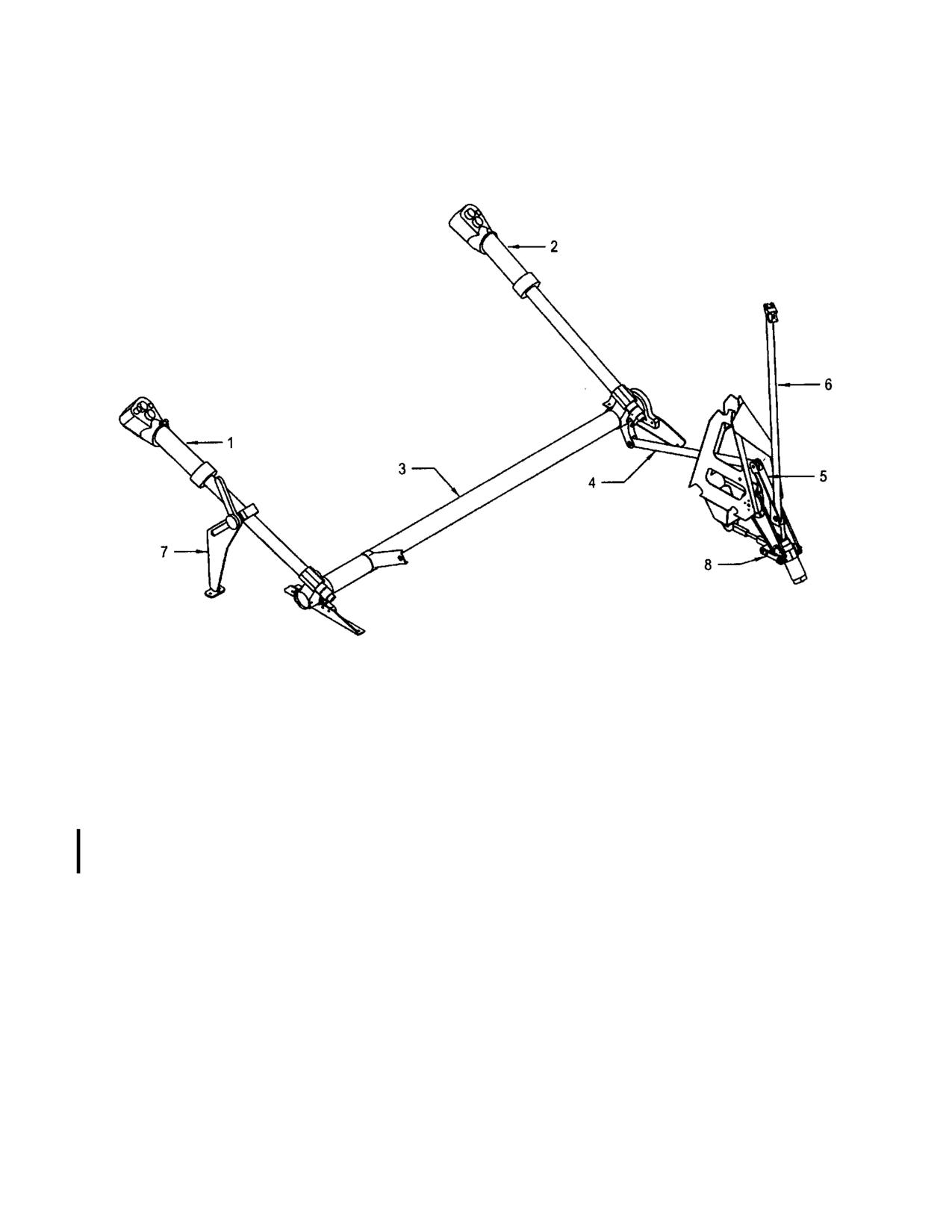
1.
Pilot’s Collective (480/B)
5.
Collective Bellcrank
2.
Copilot’s Collective (480/B)
6.
Push-Pull Rod
3.
Collective Torque Tube
7.
Collective Friction Assy.
4.
Push-Pull Rod
8.
Collective Trim Assy.
Sheet 1 of 3
Figure 12-2. Collective Control System
Rev. 15
MM-12-12
Nov 15/10
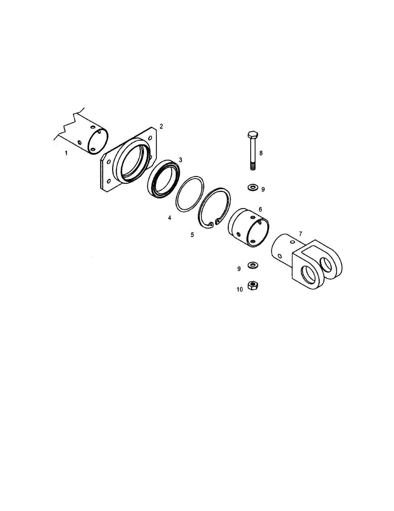
1.
Torque Tube
6.
Sleeve
2.
Retainer
7.
Clevis
3.
Bearing
8.
Bolt or Rivet
4.
Shim (If Required)
9.
Washer
5.
Retaining Ring
10.
Nut
Figure 12-14. Cyclic Torque Tube Bearing Installation
Rev. 7
MM-12-53
Feb 20/08
NOTE
CherryMAX® rivets are used during assembly of the cyclic control torque tube
starting with 480 S/N 5003. Reassemble/Repair all roll pin and CherryMAX®
torque tube assemblies using standard or oversize CherryMAX® rivets as
required. Starting with TH-28 S/N 3007 & subsequent and 480B S/N 5046 &
subsequent, bolt assemblies are used.
C. Repair elongated roll pin holes using the following procedures:
(1) Remove the roll pin.
(2) Using a #5 drill, line drill the fitting and the torque tube.
NOTE
If the roll pin hole is still elongated/damaged after drilling, replace the torque
tube assembly.
(3) Install oversize “-06" CherryMAX® rivets.
NOTE
Only one repair authorized per roll pin/rivet hole.
D. Remove minor surface corrosion from the torque tube assembly and apply a light coat
of corrosion preventive compound such as PAR-AL-KETONE (Black Bear) or equivalent (MIL-
C-52, Type 1).
12-56. Installation - Cyclic Torque Tube Assembly
A. Install the torque tube assembly. Install the hardware securing the bearing housing
brackets to the keel structure and the hardware securing the gussets to the keel structure.
(1) Assemble the right and then the left side brackets; do not tighten the hardware.
(2) Torque the hardware securing the right side bracket.
(3) Measure the gap between the left side bracket and the bulkhead.
(4) Install the corresponding P/N 4166053 shim(s) and torque remaining hardware.
B.
Connect the push-pull rod to the torque tube arm.
C. Install the cyclic stick (para. 12-51).
D. If the torque tube was replaced, check the cyclic control rigging (para. 12-45).
E. Install the left and right side keel access panel.
F. Perform a limited maintenance test flight (para. 4-61).
Rev. 26
MM-12-54
Feb 28/2020
12-63. Disassembly - Cyclic Vibration Absorber
NOTE
The vibration absorber assemblies are “tuned” at the factory. Note which
beam is installed on which bellcrank before removing the beam assembly from
the bellcrank.
A. Remove the hardware securing the beam to the bellcrank and remove the beam.
12-64. Inspection - Cyclic Vibration Absorber
A. Inspect the bellcrank in accordance with paragraph 12-11.
B. Inspect the beam and weights for security of installation, corrosion, cracks, nicks,
and/or scratches.
C. Inspect the lanyard for condition and security of installation.
12-65. Repair - Cyclic Vibration Absorber
A. Replace the beam assembly if the beam or weights are cracked, damage or corrosion
on the beam exceeds .010 inch/.25 mm in depth, or damage or corrosion on the weights
exceeds .050 inch/1.3 mm. Polish out damage or corrosion not exceeding the damage limits.
B. Replace the lanyard if damaged.
C. Replace the hardware as required.
12-66. Assembly - Cyclic Vibration Absorber
NOTE
Ensure that the beam assembly is installed on the bellcrank noted before
disassembly.
A. Install the beam assembly and plate onto the bellcrank. Install the hardware. Torque
the nuts (25 in-lb/2.8 Nm) and install slippage marks.
12-67. Installation - Cyclic Vibration Absorber
A. Install the vibration absorber assembly into the pylon mount and install the hardware.
Torque (30-40 in-lb/3.4-4.5 Nm) the nut and install the cotter pin.
B. Connect the push-pull rods to the vibration absorber assembly. Torque (30-40 in-
lb/3.4-4.5 Nm) the nuts and install the cotter pins.
C. Connect the lanyard to the pylon.
Rev. 26
MM-12-57
Feb 28/2020
12-68. Trim Actuator Assembly
12-69. Removal - Trim Actuator Assembly
NOTE
Maintenance procedures are the same for the longitudinal and the lateral trim
actuators.
NOTE
Prior to removal, if a trim actuator assembly contain shims (Figure 12-17.1),
the distance from the motor housing to the bottom of the spring capsule
should be measured to assist the spring housing travel check (step N). The
distance is measured with the motor fully extended. Record the measurement.
Then, set the trim actuator assembly to a neutral position (mid-travel) and
proceed with removal.
A. Open the left or right side engine access panel.
B. Disconnect the trim actuator from the electrical harness.
C. Disconnect the trim actuator from the longitudinal or lateral bellcrank.
D. Disconnect the trim actuator from the mounting bracket on the cabin bulkhead.
Remove the trim actuator.
E. Remove the spacers from the trim actuator pivot points.
12-70. Disassembly - Trim Actuator Assembly (Figure 12-16)
A. Remove the hardware attaching the switch assembly to the trim actuator. Remove
the switch assembly. Retain the shims installed under the switch assembly, if installed.
B. Rotate the spring capsule assembly to remove it from the acme shaft assembly.
C. Remove the hardware securing the motor to the gear housing. Remove the motor.
D. Remove the coupling and retaining ring from the end of the worm assembly in the
gear housing.
E. Remove the remaining hardware from the acme shaft assembly. Tap the cover to
one side and pull on the acme shaft to remove the acme shaft assembly.
F. Gently tap the gear housing against the work bench to remove the worm assembly.
Rev. 26
MM-12-58
Feb 28/2020
G. Disassemble the spring capsule assembly using the following procedure (Figure 12-
17):
(1) Remove the three screws securing the actuator to the housing and the acme nut
in the bottom of the spring capsule. Remove the acme nut.
(2) Remove the spring and shaft assembly from the housing.
(3) Place a rod that will fit into the spring and shaft assembly vertically in a vise.
(4) Place the spring and shaft assembly onto the rod in the vertical position.
(5) Push down on the spring retainer closest to the rod-end. Remove the retaining
ring from the groove in the shaft and move it up to the rod-end.
(6) Remove the spring and shaft assembly from the rod. Turn the assembly over
and remove the other retaining ring.
(7) Remove spring retainers and spring from the shaft.
(8) Remove the retaining ring from the shaft.
12-71. Inspection - Trim Actuator Assembly
A. Inspect the components of the actuator assembly for corrosion, cracks, nicks,
scratches, and excessive wear.
B. Inspect the micro switches for proper operation.
C. Inspect the electrical wiring for fraying or broken wires or connectors.
12-72. Repair - Trim Actuator Assembly
A. Replace defective micro switches or damaged wiring.
B. Replace the acme nut in the spring capsule if excessively worn as follows:
(1) Remove the nut from the spring capsule assembly (para. 12-70).
(2) Bond a new bumper onto the replacement nut using adhesive ("Hot Stuff" HS-3
or equivalent).
(3) Install the replacement nut with the bumper facing away from the capsule.
C. Replace the acme shaft assembly, the worm assembly, and the motor as complete
units if they require replacement.
Rev. 26
MM-12-61
Feb 28/2020
12-73. Assembly - Trim Actuator Assembly
A. Install the worm assembly into the gear housing until the aft bearing is aligned with
the bearing seat in the housing. Do not install the bearing into the seat at this time.
B. Pack the outer walls of the gear housing and the worm with grease (MIL-PRF-81322).
C. Install the acme shaft assembly onto the gear housing with the cover turned to one
side exposing the worm.
D. With the cover seated against the gear housing, push the worm assembly seating the
bearings in place. Install the retaining ring.
E. Rotate the cover into position and install the two screws and washers in the cover
holes located opposite the worm assembly.
F. Rotate the worm assembly with a screwdriver to check for binding in the gears.
NOTE
Install the coupling with the proper size opening matched with the worm
assembly shaft and the motor shaft.
G. Install the coupling onto the slotted end of the worm assembly.
H. Align the slots in the motor with the coupling and install the motor onto the gear
housing. Install the hardware and lockwire (.032”).
I.
Assembly the spring capsule assembly using the following procedure:
(1) Install one of the retaining rings onto the shaft and position it against the rod-
end.
NOTE
The shorter spring retainer is installed toward the rod-end.
(2) Install the spring retainers and spring onto the shaft.
(3) Position the spring retainers and spring against the rod-end. Install the retaining
ring on the opposite end of the shaft. Ensure the retaining ring is positioned
correctly in the ring groove in the shaft.
(4) Place a rod that will fit into the spring and shaft assembly vertically in a vise.
Place the spring and shaft assembly onto the rod in the vertical position.
(5) Push down on the spring retainer closest to the rod-end. Install the retaining
ring into the groove in the shaft. Ensure the retaining ring is positioned correctly
in the ring groove in the shaft.
(6) Lubricate the spring and shaft assembly with grease (Lubriplate 630-AA or MIL-
PRF-81322).
Rev. 26
MM-12-62
Feb 28/2020
(7) Install the spring and shaft assembly into the housing.
(8) Install the acme nut (recess orientated toward the shaft) with bumper facing
away from the rod-end.
(9) Firmly grasp the gear housing, and pull the shaft assembly to check for
looseness. If a click is felt and the retaining ring moves slightly, remove the
acme nut and install 4166032 shims, as required, to occupy any gap between
the spring housing and the acme nut. Reinstall the nut and check the shim
effectiveness.
(10) Install the actuator on the housing so the actuator is flush with the bottom of the
housing. Install the retaining screws and lockwire (.025”).
J. Lubricate (Lubriplate 630-AA or MIL-PRF-81322) the threads of the acme shaft
assembly. Turn the spring capsule assembly onto the shaft until the rubber bumper is
approximately one inch from the cover.
K. Turn the actuator on the spring capsule so it will align with the slot in the switch
assembly. Install the switch assembly and securing hardware and lockwire (.025).
L. Install shim(s), if required, switch assembly, secure hardware and lockwire (.025”),
and install the electrical connectors.
NOTE
Set the trim actuator assembly on a portable table near the aircraft to
electrically test the actuator.
N. Check the spring housing travel and adjust the switch positions to ensure that the
retracted and extended spring housing travel are within the limits specified as noted below. An
additional person is required to assist with cyclic operation.
(1) Install and connect the battery, if required.
(2) If no shims are installed:
a.
The retracted travel (minimum stroke) limit is 0.125” +0.05”/-0.00”.
b.
The extended travel (maximum stroke) limit is 1.95” +0.00”/-0.05”.
(3) If a shim is installed (Figure 12-17.1):
a.
The retracted travel (minimum stroke) limit ‘Min’ is the difference between
this dimension and 1.825” +0.05”/-0.00”
b.
The extended travel (maximum stroke) limit is the ‘Max’ dimension
measured in paragraph 12-69 (+0.00”/-0.05”).
CAUTION
To prevent damage to the switch assembly, immediately stop applying
trim to the cyclic if the actuator will run out beyond the length allowed by
the bracket slot.
Rev. 26
MM-12-62.1
Feb 28/2020
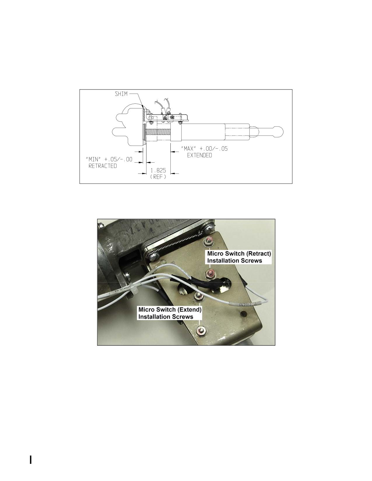
(3) To adjust the spring housing travel, loosen the switch mounting hardware to set
the switch position(s) as necessary to bring the spring housing travel within
limits. For example, to shorten the spring housing extension, loosen the switch
mounting hardware for the extending switch and adjust the switch position
inward (Figure 12-17.2).
Figure 12-17.1. Trim Actuator Limits with Shim(s) Installed
Figure 12-17.2. Switch Plate Assembly Micro Switch Screws
(trim actuator assembly removed for clarity)
NOTE
If is not possible to achieve the limits after adjusting the switch positions, either
the bracket slot or the switch screw slots may be filed to achieve the travel
limits. The maximum amount that the bracket slot may be filed is 0.040”.
Rev. 26
MM-12-62.2
Feb 28/2020
(4) Check the spring housing travel to verify that proper adjustment was made.
(5) When the switch adjustments are complete, apply VC-3 Vibra-Tite to the
exposed screw threads and nut face.
(6) Disconnect and remove the battery, as required.
12-74. Installation - Trim Actuator Assembly
A. Install the spacers in the trim actuator assembly pivot points.
B. Install the trim actuator assembly in the mount bracket on the cabin back wall. Install
the hardware, torque and cotter pin.
C. Attach the trim actuator assembly to the longitudinal or lateral bellcrank, torque and
cotter pin.
D. Connect the trim actuator assembly to the electrical harness.
E. Install the battery and apply power.
F. Check for clearance between the spring housing and the cyclic bellcrank.
(1) Extend the actuator to full travel (trim full forward or full left) and move the cyclic
full aft/right. Verify clearance.
(2) If there is contact, remove the shims between the switch assembly and the
actuator. Install the switch assembly and re-safety.
(3) Repeat step (1) and step (2), as required.
(4) If the spring housing contacts the bellcrank, and there are no shims, check the
travel in accordance with preceding step N.
(5) If the travel is correct and the spring housing contacts the bellcrank, contact
Enstrom Product Support.
G. Close the left or right side engine access panel.
12-75. Lower Swashplate Assembly
12-76. Removal - Lower Swashplate Assembly (Figure 12-18)
A. Open the left and right side engine access panels.
B. Remove the longitudinal and lateral push-pull tubes from between the uni-ball
assembly and the longitudinal and lateral bellcranks in the engine compartment.
C. Disconnect the three rod-ends (doglegs)from the lower swashplate.
Rev. 26
MM-12-62.3
Feb 28/2020
D. Remove the hardware securing the lower swashplate to the upper swashplate.
E. Remove the lower swashplate by pulling down on the uni-ball bearing housing.
12-77. Disassembly - Lower Swashplate Assembly
A. Install tool T-0016 in the end of the tie rod (19). Place a wrench on the tool T-0016 to
prevent the tie rod from rotating and remove the cotter pin (10), nut (11), washer (12), DU
washer (13), and shims (14) from the tie rod.
B. Tap the tie rod out of the bushings (15) using an aluminum drift. Separate the lower
universal housing (7) from the upper universal housing (18). Remove the spacers (20) from
inside the bushings (15) in the housing.
C. Remove the shims (14) and the DU washer (13) from the tie rod.
D. Temporarily install the tie rod in the universal shaft (17) to prevent it from rotating and
remove the cotter pins, nuts, spacers, DU washers, and shims from both ends of the shaft (17).
E. Tap the end of the shaft with an aluminum drift to remove the shaft and sleeve (16)
from the lower universal housing.
F. Tap the opposite sleeve to remove it from the lower universal housing.
G. Tap the sleeves from the upper universal housing using an aluminum drift.
H. Hold the uni-ball shaft (1) with a wrench and remove the cotter pin, nut, and washer.
Separate the uni-ball assembly (4) from the lower universal housing.
I.
Remove the spacer (5) from the uni-ball shaft.
J. Remove the shaft from the uni-ball assembly.
K. Rotate the uni-ball until it is aligned with the recesses in the bearing outer race and
remove the uni-ball.
L. Remove the retaining ring (2) from the uni-ball.
WARNING
Use extreme caution when removing or installing heated parts and
assemblies to prevent from injuring personnel.
WARNING
Use protective gloves when handling heated parts.
M. Heat the uni-ball to approximately 250F/121C. and remove the bearing (3) from the
uni-ball.
N. Press the DU bushings (15) from the sleeves (16).
Rev. 26
MM-12-62.4
Feb 28/2020
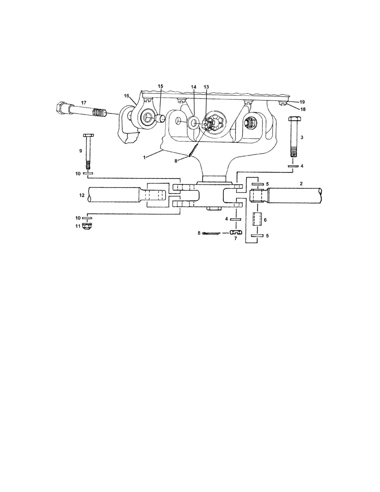
1.
Lower Swashplate Assy.
11.
Nut
2.
Lateral Push-Pull Rod
12.
Longitudinal Push-Pull Rod
3.
Bolt
13.
Nut (P/N AN320-4)
4.
Washer
14.
Washer
5.
1/4 Harper Washer
15.
Spacer
6.
Spacer
16.
Rod End (Dog Leg)
7.
Nut
17.
Bolt
8.
Cotter Pin
18.
Screw
9.
Bolt
19.
Washer
10.
Washer
Figure 12-18. Lower Swashplate Installation
Rev. 26
MM-12-63
Feb 28/2020
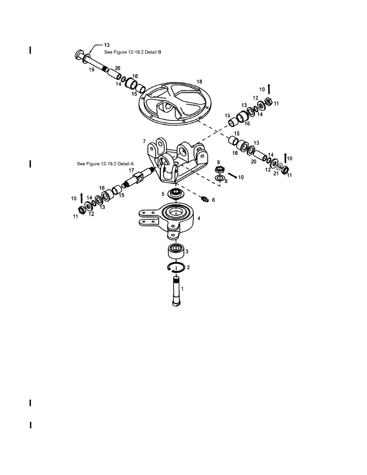
1.
Bolt
12.
Washer
2.
Retaining Ring
13.
DU Washer
3.
Bearing
14.
Shim
4.
Bearing Housing Assembly
15.
DU Bushing
5.
Spacer
16.
Sleeve
6.
Lube Fitting
17.
Universal Shaft
7.
Lower Housing
18.
Upper Housing
8.
Washer
19.
Tie Rod Assembly
9.
Nut
20.
Spacer
10.
Cotter Pin
21.
Light Washer
11.
Nut
Figure 12-19.1. Lower Swashplate Assembly
Rev. 26
MM-12-64
Feb 28/2020
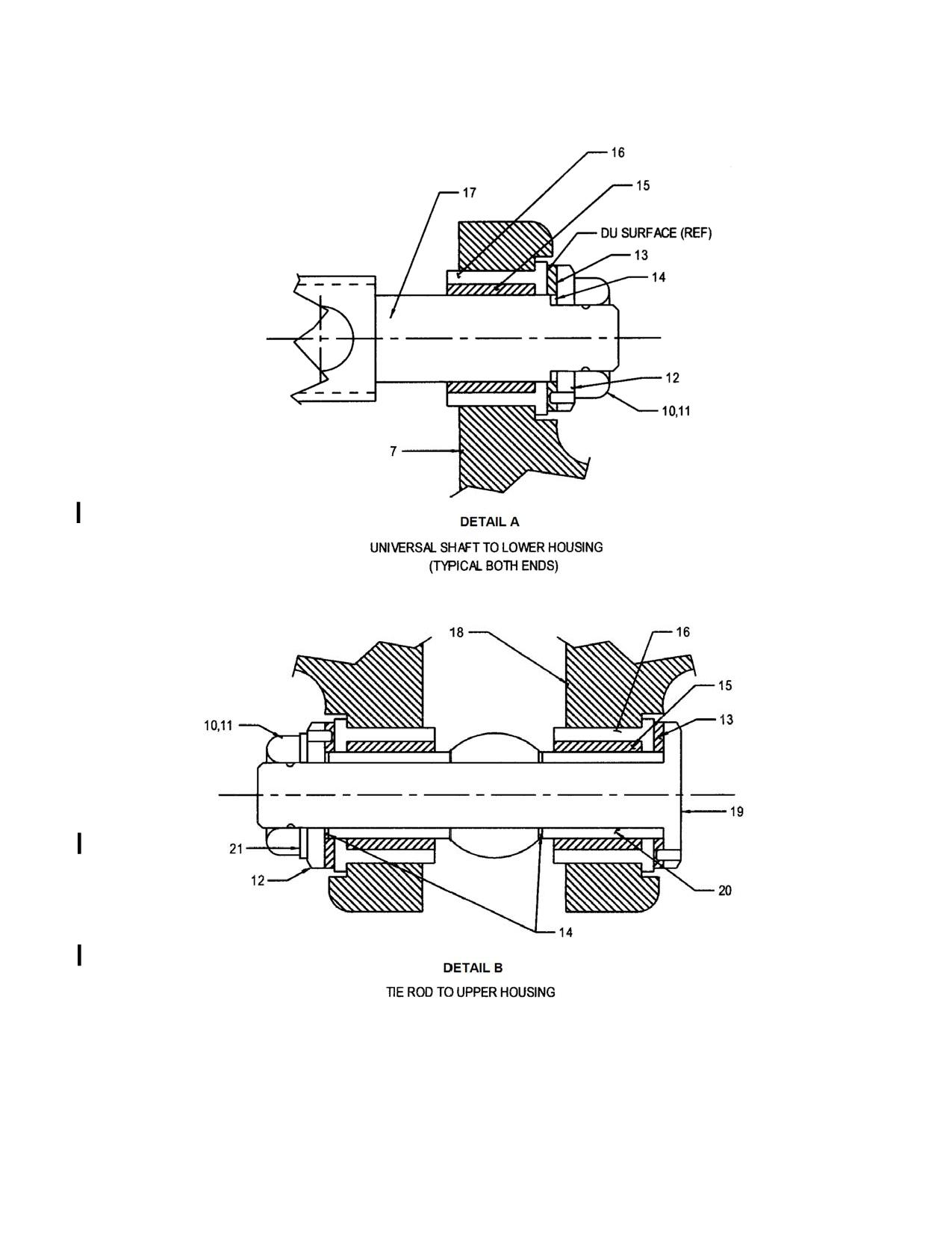
Figure 12-19.2. Lower Swashplate Installation
Rev. 26
MM-12-65
Feb 28/2020
12-78. Inspection - Lower Swashplate Assembly
A. Use the following procedure to inspect the lower swashplate assembly during periodic
inspections (100 Hour/Annual):
(1)
Remove both side panel cowls.
(2)
Disconnect the pitch change bellcranks located on the main rotor hub from the
main rotor push-pull rods located in the mast and from the pivot brackets.
(3)
With the aid of an assistant, remove the collective friction and move the
collective up and down throughout the range and wiggle the cyclic stick
(movement of the collective and cyclic stick does not have to occur
simultaneously). Observe and carefully feel the lower swashplate assembly for
any looseness (e.g. vertical play at the universal joint or end play along the
universal shaft and tie rod axes). Any looseness is most noticeable with a
collective control reversal and/or reversal of the cyclic controls. NOTE: Vertical
looseness may also be evident at the collective stick as a sudden change in
stick force or may exhibit itself as a clinking sound. Using a 9/16 inch crows foot
and torque wrench set to 60 in-lb/6.8 Nm, check that the torque required to
rotate the tie rod assembly at the nut on the end of the tie rod assembly is more
than 60 in-lb/6.8 Nm. Do not remove the cotter pin from the nut during the
check and stop the torque check if 60 in-lb/6.8 Nm is reached without the tie rod
assembly rotating. Any rotation of the tie rod with less than 60 in-lb/6.8 Nm of
torque is unacceptable.
(4)
If neither looseness nor loss of torque is evident, reconnect the pitch change
bellcranks and return the aircraft to service.
(5)
If any looseness or loss of torque is found, remove the lower swashplate
assembly from the aircraft and perform the following additional inspections:
a.
Inspect the universal joint for looseness/play by twisting and pushing and
pulling the upper and lower housings of the lower swashplate against each
other.
b.
Inspect the tie rod and universal shaft axis for end play by attempting to
move the upper and lower housings against each other along the tie rod
and universal shaft axes.
c.
Check the pre-load of the tie rod and universal shaft axis. The pre-load
should be between 0.5 and 2.0 pounds (.23 and .91 kg) using a spring
scale, with no noticeable end play.
(6)
Disassemble the lower swashplate assembly and inspect the detail parts in
accordance with Table 12-2.
NOTE
Contact Enstrom Product Support to procure an overhauled lower swashplate
assembly.
Rev. 26
MM-12-66
Feb 28/2020
(7) Replace unserviceable parts as required and reassemble the lower swashplate
in accordance with paragraph 12-79.
(8) Reinstall the lower swashplate assembly and reconnect the pitch change
bellcranks.
B. See Table 12-2 for the detailed inspection requirements for the lower swashplate
assembly.
Rev. 26
MM-12-67
Feb 28/2020
INTENTIONALLY LEFT BLANK
Rev. 26
MM-12-68
Feb 28/2020
Table 12-2. Lower Swashplate Assembly
Inspection Requirements*
P/N
Fig. 12-19
Part Name
Inspection
Serviceable Limits
Repair Limits
Repair or Action
Item #
4140531-13
1
Bolt
Bearing surface Dia.
-.0002
Not Repairable
Replace Shaft
.4723 to .4726
Threads (crossed or
None Allowed
Not Repairable
Replace Shaft
missing)
ECD009-11
3
Bearing
O.D. 1.2595 to 1.2598
No Tolerance
Not Repairable
Replace Bearing
Allowed
I.D. .4722 to .4724
No Tolerance
Not Repairable
Replace Bearing
Allowed
Ratcheting or
None Allowed
Not Repairable
Replace Bearing
roughness
4140526-3, -7
4
Bearing Assembly Bolt holes in pivot ears
None Allowed
Not Repairable
Replace Housing
for elongation
Surface nicks or
None Allowed
≤ .010 deep
Blend and polish out
scratches
smooth
Security of the uni-ball
No Movement
Not Repairable
Replace Housing
race in the housing
Allowed
Cracks
None Allowed
Not Repairable
Replace Housing
Uni-ball race for scoring
None Allowed
≤ .002 deep
Polish out smooth
or scratches
Rev. 26
MM-12-69
Feb 28/2020
Table 12-2. Lower Swashplate Assembly
Inspection Requirements*
P/N
Fig. 12-19
Part Name
Inspection
Serviceable Limits
Repair Limits
Repair or Action
Item #
4140526-3, -7
4
(Cont'd)
(Uni-ball Bearing)
Bearing bore
+.0006
Not Repairable
Replace Uni-ball
Dia. 1.2598
-.0000
Surface scoring or
None Allowed
≤ .002 deep
Polish out smooth
scratches
4140534-11
5
Spacer
Nicks or galling on the
None Allowed
≤ .003 deep
Polish out smooth
I.D.
4140535-11,-13
7
Housing
Bushing bores Dia.
+.0005
Not Repairable
Replace Housing
28-16119-3, -5
.7500 to .7505
(-11,-13,-3)
.7495 to .7500 (-5)
Center bolt bore Dia.
+.0005
Not Repairable
Replace Housing
.4375 (-11,-13)
.4370 to .4380 (-3, -5)
(no galling allowed in
this bore)
Large bolt bore Dia. in
+.0005
Not Repairable
Replace Housing
the pivot ears .375 to
.376
Small bolt bore Dia. in
+.0005
Not Repairable
Replace Housing
the pivot ears .250 to
.251
Cracks
None Allowed
Not Repairable
Replace Housing
28-16227-3
12
Washer
Nicks and gouges
None Allowed
Not Repairable
Replace Spacer
Rev. 26
MM-12-70
Feb 28/2020
Table 12-2. Lower Swashplate Assembly
Inspection Requirements*
P/N
Fig. 12-19
Part Name
Inspection
Serviceable Limits
Repair Limits
Repair or Action
Item #
28-16263-5
13
DU Washer
Thickness
-.008
Not Repairable
Replace washer
.0585 to .0605
08GDU08
15
DU Bushing
**I.D. .4992 to .5019
+.0025
Not Repairable
Replace bushing
28-16226-5
16
Sleeve
O.D. .7503 to .7508
-.0003
Not Repairable
Replace Sleeve
I.D. .5937 to .5941
+.0002
Not Repairable
Replace Sleeve
28-16223-19
17
Universal Shaft
O.D. .4991 to .4995
-.0003
Not Repairable
Replace Shaft
Tie Rod Bore
+.0005
Not Repairable
Replace Shaft
.3750 to .3752
Concentricity
.0015 FIM
Not Repairable
Replace Shaft
Threads (crossed or
None Allowed
Not Repairable
Replace Shaft
missing)
28-16116-1, -11
18
Housing
Bushing bores Dia.
+.0005
Not Repairable
Replace Housing
.7500 to .7505
Cracks
None Allowed
Not Repairable
Replace Housing
28-16224-5
19
Tie Rod Assembly
O.D. .3748 to .3750
-.0005
Not Repairable
Replace Tie Rod
Concentricity
.002 FIM
Not Repairable
Replace Tie Rod
Threads (crossed or
None Allowed
Not Repairable
Replace Tie Rod
missing)
Rev. 26
MM-12-71
Feb 28/2020
Table 12-2. Lower Swashplate Assembly
Inspection Requirements*
P/N
Fig. 12-19
Part Name
Inspection
Serviceable Limits
Repair Limits
Repair or Action
Item #
28-16225-19
20
Spacer
O.D. .4991 to .4995
-.0003
Not Repairable
Replace Spacer
†Length 1.037 to 1.036
-.001
Not Repairable
Replace Spacer
* All dimensions are in inches.
** Inspect DU Bushing I.D. with the bushing installed in the sleeve, P/N 28-16226-5.
† Measure length at several locations to check for uneven wear.
MM-12-72
Feb 9/01
Table 12-3. Upper Swashplate Assembly
Inspection Requirements*
P/N
Fig. 12-21
Part Name
Inspection
Serviceable Limits
Repair Limits
Repair or Action
Item #
28-16108-2, -11
8
Bearing Housing
Bearing bore Dia.
No Tolerance
Not Repairable
Replace Housing
3.9365 to 3.9371
Allowed
Pivot bolt holes for
None Allowed
Not Repairable
Replace Housing
galling or wear
Threads (crossed or
None Allowed
Not Repairable
Replace Housing
missing)
28-16386-1
10
Rain Slinger
Check for deformation
None Allowed
Not Repairable
Replace Slinger
28-16106-2
11
Spacer
Guide tube holes for
None Allowed
Not Repairable
Replace Spacer
galling
16-DU-12
12
Bushing
O.D. 1.125
+.0000
Not Repairable
Replace Bushing
-.0005
+.0005
Not Repairable
Replace Bushing
I.D. 1.000
-.0000
4140530-11
13
Control Housing
Bushing bore Dia.
+.0004
Not Repairable
Replace Housing
1.1250 to 1.1256
O.D. 2.6465 to 2.6470
-.0003
Not Repairable
Replace Housing
O.D. for galling
.001 deep
≤ .005 deep
Polish out smooth
Cracks
None Allowed
Not Repairable
Replace Housing
Rev. 26
MM-12-81
Feb 28/2020
Table 12-3. Upper Swashplate Assembly
Inspection Requirements*
P/N
Fig. 12-21
Part Name
Inspection
Serviceable Limits
Repair Limits
Repair or Action
Item #
28-16260-1
15
Guide Tube
Sheared or worn rivets
None Allowed
If rivet is sheared
Replace Rivet
Assembly
with no other
damage to the
assembly
Threads (crossed or
missing)
None Allowed
Not Repairable
Replace Guide Shaft in
the retainer
Looseness of guide
shaft in the retainer
No movement
Not Repairable
Replace Assembly
allowed
Guide shafts for galling
.001 deep
≤ .005 deep and ≤
Blend and polish out
1.0" long
smooth
Cracks
None Allowed
Not Repairable
Replace Assembly
* All dimensions are in inches.
Rev. 20
MM-12-82
Apr 25/13
12-86. Installation - Upper Swashplate Assembly (Figure 12-20)
A. Lubricate (MIL-PRF-81322) the bore of the main rotor mast at the lower end.
B. Align the slot in the control housing with the locking pin in the lower end of the mast.
Install the upper swashplate into the mast. Gently tap the swashplate into position by sliding the
swashplate assembly up and down on the guide tubes.
C. Install the hardware securing the swashplate. Torque the bolts and lockwire (.025).
NOTE
Rotate the upper collective bearing assembly with the swashplate in the full up
position and ensure the lockwire does not interfere with the collective bearing
housing.
D. Install the collective walking beam (para. 12-42).
E. Install the main rotor push-pull rods (para. 12-86.4).
F. Install the lower swashplate (para. 12-80).
G. Install the left and right side engine access panels.
H. Perform a limited maintenance test flight (para. 4-61).
12-86.1. Main Rotor Push-Pull Rods
12-86.2. Removal - Main Rotor Push-Pull Rods
A. Open the left and right side engine access panels.
B. Remove the lower swashplate assembly (para. 12-76).
NOTE
The rod ends (doglegs) are match taper reamed to the push-pull rods.
C. Index mark the rod ends (doglegs) to their respective push-pull rod.
D. Remove the cotter pins and the nuts from the push-pull rods.
E. Install the puller tool T-0045 over the dogleg with the center of the tool aligned with
the push-pull rod, and remove the doglegs.
F. Disconnect the upper end of the push-pull rods from the pitch change bellcranks on
the main rotor hub.
Rev. 26
MM-12-85
Feb 28/2020
G. Remove the hardware securing the pitch change bellcranks to their brackets. Lift the
pitch change bellcranks from their brackets and separate the push-pull rods from the pitch
change bellcranks.
NOTE
Secure the spacers in the push-pull rods and the pitch change bellcranks with
a piece of lockwire when disassembled or removed.
H. Remove the push-pull rods through the upper end of the mast.
12-86.3. Inspection - Main Rotor Push-Pull Rods
A. Inspect the main rotor push-pull rods in accordance with Table 12-3.1.
12-86.4. Installation - Main Rotor Push-Pull Rods
A. Install the push-pull rods into the mast from the upper end and through the guide
tubes in the upper swashplate.
NOTE
Stuff a shop cloth into the upper end of the mast to prevent anything from
being dropped into the mast when connecting the push-pull rods to the pitch
change bellcranks. Remember to remove the shop cloth when installation is
complete.
WARNING
If anything is dropped into the mast it must be removed prior to moving
the flight controls.
B. Install the spacers into the push-pull rods and the pitch change bellcranks (para. 12-
91).
C. Connect the push-pull rods to the pitch change bellcranks. Torque the nuts to 40 in-
lbs/4.5 Nm and cotter pin (para. 12-91).
D. Connect the pitch change bellcranks to the mounting brackets. Torque the nuts to 40
in-lbs/4.5 Nm and cotter pin (para. 12-91).
Rev. 7
MM-12-86
Feb 20/08
E.
Install the rod ends (doglegs) onto the push-pull rods using the following procedures:
NOTE
The doglegs must be installed on the respective push-pull rod they were
removed from.
NOTE
If a new dogleg is installed, it must be reamed with a #5 Brown and Sharpe
High Speed Steel Finish Reamer.
(1) Install the doglegs on the push-pull rods and install the nuts finger tight.
(2) Install the special tool T-0054 on the bell housing of the upper swashplate
assembly while aligning the dogleg parallel to its respective pitch change
bellcrank on the main rotor hub. Install the screws to hold the tool in place.
Place a spacer on each side of the bearing in the dogleg and install the bolt to
position the dogleg on the tool (Figure 12-22).
NOTE
If the nut is over torqued when aligning with the cotter pin hole, do not loosen
the nut to re-align. Instead, back the nut off completely and retorque.
(3) Torque the nut to 140 in-lbs/15.9 Nm and cotter pin.
(4) Repeat steps (2) and (3) for each dogleg.
F.
Install the lower swashplate (para. 12-80).
G.
Install the left and right side engine access panels.
H.
Perform a limited maintenance test flight (para. 4-61).
12-87. Pitch Change Bellcranks
12-88. Removal - Pitch Change Bellcranks
CAUTION
Foreign objects dropped down the mast must be immediately removed to
prevent damaging the flight controls.
A. Index mark the pitch change bellcranks for reinstallation.
CAUTION
Do not over rotate the blade grips when the pitch change links are not
connected to the pitch change bellcranks or the pitch change bellcranks are
not installed in the mounting brackets.
Rev. 23
MM-12-87
Jul 3/15
B. Remove the hardware connecting the pitch change bellcranks to the push-pull rods in
the mast.
C. Remove the hardware connecting the pitch change bellcranks to the pitch change
links.
D. Remove the center pivot bolts from the pitch change bellcranks. Lift the pitch change
bellcranks from the mounting brackets.
NOTE
Install tie wraps to hold the pivot spacers in the pitch change bellcranks and
the push-pull rods.
12-89. Inspection - Pitch Change Bellcranks
A. Inspect the pitch change bellcranks for nick, scratches, corrosion, cracks, worn
bushings, worn bearings, and security of installation.
12-90. Repair - Pitch Change Bellcranks
A. Blend out nicks, scratches, and corrosion not exceeding .010"/.25 mm deep.
B. Replace the pitch change bellcrank if cracked or the inboard bushings come out of
the pitch change bellcrank.
C. Replace the pitch change bellcrank if the bushing bores are elongated.
D. Replace the bearings (5) if ratcheting or roughness is felt or if radial play with the
spacer (6) installed exceeds .005"/.13mm.
12-91. Installation - Pitch Change Bellcranks (Figure 12-23)
CAUTION
Foreign objects dropped down the mast must be immediately removed to
prevent damaging the flight controls.
CAUTION
Do not over rotate the blade grips when the pitch change links are not
connected to the pitch change bellcranks or the pitch change bellcranks are
not installed in the mounting brackets.
A. Connect the pitch change bellcrank to the push-pull rod in the mast. Torque the nut
(40 in-lb/4.5 Nm) and cotter pin. Check that the pitch change bellcrank freely pivots at the rod
end connection.
B. Install the pitch change bellcrank into the mounting bracket and install the hardware.
Torque the nut (40 in-lb/4.5 Nm) and cotter pin.
C. Connect the pitch change link to the pitch change bellcrank and install the hardware.
Torque (75 in-lb/8.5 Nm) the nut and cotter pin.
Rev. 26
MM-12-88
Feb 28/2020
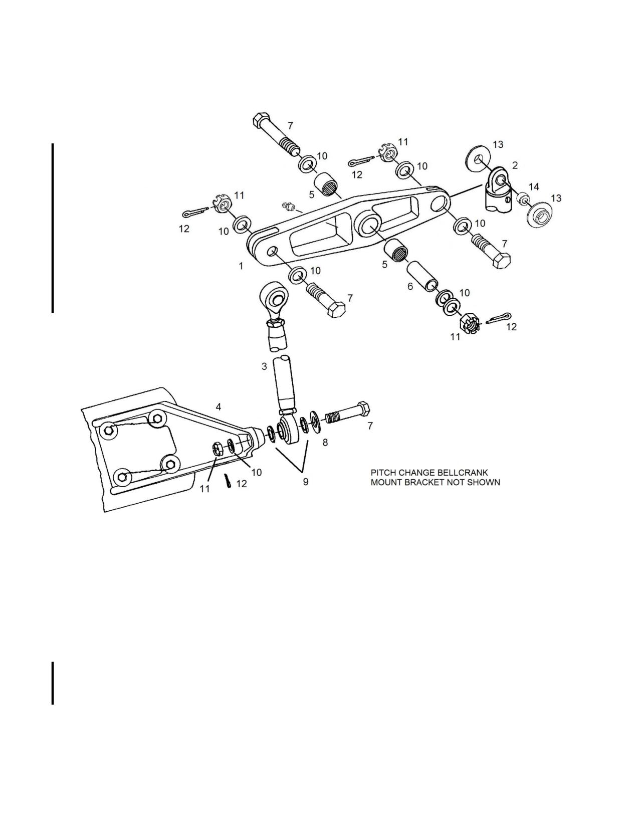
1.
Pitch Change Bellcrank
8.
Harper Washer
2.
Push-Pull Rod (Note 1)
9.
Spacer
3.
Pitch Change Link
10.
Washer
4.
Pitch Horn
11.
Nut
5.
Bearing
12.
Cotter Pin
6.
Spacer
13.
Bushing
7.
Bolt
14.
Bushing
Note
1. Shown with bearing insert installed in push-pull rod fitting.
Figure 12-23. Pitch Change Bellcrank and Pitch Change Link Installation
Rev. 26
MM-12-89
Feb 28/2020
12-92. Pitch Change Links
12-93. Removal - Pitch Change Links (Figure 12-23)
NOTE
Index marking the pitch change links and measuring the overall length will
prevent having to perform a rigging check.
CAUTION
Do not over rotate the blade grips when the pitch change links are not
connected to the pitch change bellcranks or the pitch change bellcranks are
not installed in the mounting brackets.
A. Index mark the links for reinstallation. Disconnect the upper end of the link from the
pitch change bellcrank.
B. Disconnect the lower end from the pitch horn and remove the pitch change links.
Measure the overall length of the links and record.
12-94. Inspection - Pitch Change Links
A. Inspect the pitch change links for nicks, scratches, corrosion, cracks, and security of
installation.
B. Inspect the rod end bearings for excessive wear.
12-95. Repair - Pitch Change Links
A. Blend out scratches, nicks, and corrosion that are not deeper than .010"/.25 mm.
B. Replace parts that are cracked.
C. Replace rod end bearings that have .005"/.13 mm axial play or greater.
12-96. Installation - Pitch Change Links (Figure 12-23)
CAUTION
Do not over rotate the blade grips when the pitch change links are not
connected to the pitch change bellcranks or the pitch change bellcranks are
not installed in the mounting brackets.
NOTE
Turn the rod ends into the barrel as equally as possible and check the witness
hole for proper thread engagement.
MM-12-90
Feb 9/01
Table 12-4. Tail Rotor Pitch Control Assembly
Inspection Requirements
P/N
Fig.12-27
Part Name
Inspection*
Serviceable Limits*
Repair Limits
Repair or Action
Item #
28-16331-1
7
Bearing Housing
Bearing bore 2.6774
+.0002
Not Repairable
Replace Housing
to 2.6779
Oilite bushing I.D.
+.0005
Not Repairable
Replace Housing
.3755 to .3765
Surface nicks and
None Allowed
≤ .020 deep
Blend and polish out
scratches
smooth
TS-023
12
Seal
Inspect for cuts or
None Allowed
Not Repairable
Replace Seal
tears
28-16394-2,
14
Pitch Control
Bronze O.D. 1.3777 to
-.0005
Not Repairable
Replace Bearing
-11
Bearing
1.3787
Bore Dia. 1.079 to
+.001
Not Repairable
Replace Bearing
1.081
Keyway width .1875 to
+.0005
Not Repairable
Replace Bearing
.1895
Dowel pin holes .2450
+.003
Not Repairable
Replace Bearing
to .2470 (-2)
Dowel pin holes .2490
+.0005
Not Repairable
Replace Bearing
to .2495 (-11)
Distortion of the bore
None Allowed
Not Repairable
Replace Bearing
Rev. 26
MM-12-107
Feb 28/2020
Table 12-4. Tail Rotor Pitch Control Assembly
Inspection Requirements
P/N
Fig.12-27
Part Name
Inspection*
Serviceable Limits*
Repair Limits
Repair or Action
Item #
ECD016-11
15
Bearing
O.D. 2.6772
+.0000
Not Repairable
Replace Bearing
-.0005
I.D. 1.3780
+.0005
Not Repairable
Replace Bearing
-.0000
Axial movement of the
.002
Not Repairable
Replace Bearing
inner race to the outer
race
Ratcheting or
None Allowed
Not Repairable
Replace Bearing
roughness
5002-268-PP
16
Retaining Ring
Check for flatness
No distortion
Not Repairable
Replace Retaining
Ring
W-47
17
Wave Spring
Check for wave
No flat spots
Not Repairable
Replace Washer
Washer
contour
28-16392-13
18
Pitch Link
Bore 1.3782 to 1.3787
+.0002
Not Repairable
Replace Retainer
Retainer
Dowel pin holes .2490
+.0002
Not Repairable
Replace Retainer
to .2495
Pitch link retaining bolt
+.0005
Not Repairable
Replace Retainer
holes .250 to .251
Surface nicks and
None Allowed
≤ .010 deep
Blend and polish out
scratches
smooth
28-16397-11
19
Dowel Pin
O.D. .2495 to .2505
-.0005
Not Repairable
Replace Pin
* All dimensions are in inches
MM-12-108
Feb 9/01
12-120. Tail Rotor Pitch Change Links
12-121. Removal - Tail Rotor Pitch Change Links (Figure 12-28, Figure 12-29)
NOTES
Index mark (color code) the pitch change links.
Pitch change links P/N 28-16345-11 or P/N 28-16391-1 must be installed as
same part number pairs (either two P/N 28-16345-11 or two P/N 28-16391-1).
Pitch change links P/N 28-16391-3 or P/N 28-16391-5 may be installed in
combination with each other but not in combination with P/N 28-16345-11 or
P/N 28-16391-1. For the barrel type, the pitch change link length and rod end
orientation has been set at the factory. Do not disassemble unless the rod
ends need replacement.
Paragraphs 12-122 and 12-125 apply to the barrel type pitch change links
only.
A. Disconnect the pitch change links from the tail rotor pitch arms. Keep the bolt and
washer stack up together for each pitch change link.
B. Remove the hardware securing the pitch change links to the retainer. Remove the
pitch change links and spacers from the retainer.
12-122. Disassembly - Tail Rotor Pitch Change Links
A. Loosen the jam nuts from the barrel and remove the rod ends from the barrel.
12-123. Inspection - Tail Rotor Pitch Change Links
A. Inspect the pitch change links for cracks, corrosion, bends, damage, and proper and
secure installation.
B. Inspect the rod ends for excessive play.
12-124. Repair - Tail Rotor Pitch Change Links
A. Corrosion, nicks, or scratches in the solid link, barrel, or rod end outer race not
exceeding .010"/.25 mm deep may be burnished out. Replace the solid link, barrel, or rod end if
cracked or damage is exceeds .010"/.25 mm deep.
B. Replace the rod end if its axial play is exceeds .005"/.13 mm.
C. Correctly install improperly installed pitch change links.
12-125. Assembly - Tail Rotor Pitch Change Links
A. Install the jam nuts onto the rod ends and apply Loctite (VC-3) to the threads of the
rod ends.
Rev. 23
MM-12-111
Jul 3/15
B. Install the right hand rod end into the barrel until the threads completely cover the
witness hole in the barrel.
C. Install the left hand rod end into the barrel until the overall length of the pitch change
link measures 4.260” ± 0.005”/10.82 cm ± 0.13 cm. Orientate the rod ends 30° from each other
(Figure 12-29).
12-126. Installation - Tail Rotor Pitch Change Links (Figure 12-28, Figure 12-29)
NOTE
If the pitch change links (barrel type) being installed are from the factory or the
length and rod end bearing orientation are known to be satisfactory (removed
serviceable), or if the pitch change links being installed are the solid type, omit
steps A and D through F.
A. Lock the tail rotor control pedals in the neutral position.
NOTE
For aircraft manufactured or modified with P/N 28-16391-3 or 28-16391-5
pitch link assemblies, the rod end labeled “T/R BLADE”, must be installed
in the proper orientation as shown in Figure 12-28.
B. Install the left hand thread rod end of the pitch change link and the spacers (3) into
the retainer. Install the bolts (1) so that heads are in the direction of rotation, washers (2 & 5),
and nuts (6). Torque the nuts and install the cotter pins.
C. Connect the right hand thread rod ends to the pitch arms with the hardware in the
following sequence: bolt (1) (bolt head installed in direction of rotation), Harper washer (8), thin
spacer (9), O-ring (11), pitch change link rod end (4) (see Note above), thick spacer (10),
washer (13), pitch arm, washer(s) (5, 13) (use stack-up retained from para. 12-121,A), and nut
(6). Torque the nuts (55-75 in-lb/6.2-8.5 Nm) and install the cotter pins (7). (See also SDB T-055
and SIL T-027, latest revision, respectively.)
NOTE
Omit Steps D and E for aircraft with P/N 28-16391 pitch link assemblies.
D. Adjust the length of the pitch change link assemblies to 4.26"/10.82 cm and center
the rod end bearings referenced to the pitch link retainer and the pitch horn. Tighten the jam
nuts against the barrel while holding the barrel with a wrench. Recheck for the correct length
(4.26"/10.82 cm) and that the rod ends are still centered, adjust as required.
CAUTION
Ensure the right hand thread rod ends are still turned past the witness holes.
E. Using a piece of safety wire, check to ensure the right hand thread rod ends are still
turned past the witness holes, adjust as required.
F. Remove the fixture used to center the tail rotor control pedals.
Rev. 26
MM-12-112
Feb 28/2020
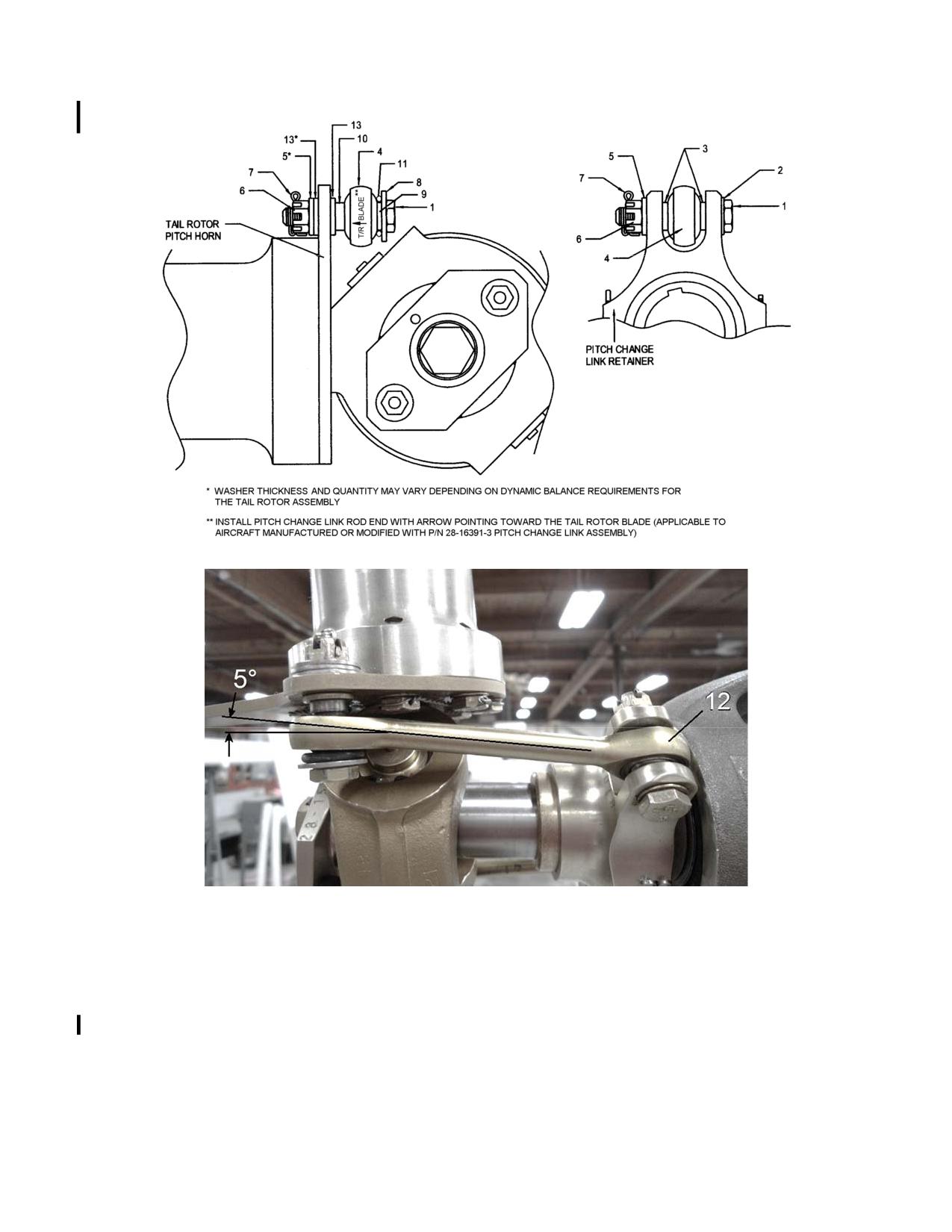
1.
Bolt
8.
Harper Washer
2.
Washer
9.
Spacer
3.
Spacer
10.
Spacer
4.
Pitch Change Link Rod End
11.
O-ring
5.
Washer
12.
Pitch Change Link (28-16391-3, -5 shown)
6.
Nut
13.
Washer
7.
Cotter Pin
Figure 12-28. Tail Rotor Pitch Change Link Installation
Rev. 26
MM-12-113
Feb 28/2020
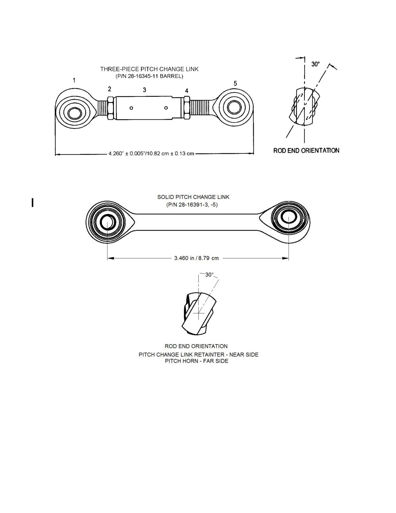
1.
Rod End Bearing (L/H)
4.
Jam Nut (R/H)
2.
Jam Nut (L/H)
5.
Rod End Bearing (R/H)
3.
Barrel
Figure 12-29. Tail Rotor Pitch Change Link
Rev. 23
MM-12-114
Jul 3/15
SECTION 13
POWERPLANT
TABLE OF CONTENTS
Paragraph
Description
Page
13-86.
Oil Lines and Fittings
MM-13-44
13-87.
Removal
MM-13-44
13-88.
Inspection
MM-13-44
13-89.
Repair
MM-13-44
13-90.
Installation
MM-13-45
13-91.
Engine Power Controls
MM-13-45
13-92.
Description
MM-13-45
13-93.
Rigging
MM-13-50
13-93.1.
Rigging (S/N 5136 and Subsequent)
MM-13-51
13-94.
Removal
MM-13-52
13-95.
Inspection
MM-13-52
13-96.
Repair
MM-13-52.1
13-97.
Installation
MM-13-52.1
13-98.
Idle Stop Release
MM-13-52.1
13-99.
Removal
MM-13-52.1
13-100.
Inspection
MM-13-52.2
13-101.
Repair
MM-13-52.2
13-102.
Installation
MM-13-52.2
13-102.1.
Engine Idle Stop Assembly
MM-13-52.2
13-102.2.
Removal
MM-13-52.2
13-102.3.
Inspection
MM-13-52.3
13-102.4.
Repair
MM-13-52.3
13-102.5.
Installation
MM-13-52.3
13-103.
Linear Actuator
MM-13-52.4
13-104.
Removal
MM-13-52.4
13-105.
Inspection
MM-13-52.4
13-106.
Repair
MM-13-52.7
13-107.
Installation
MM-13-52.7
13-108.
Droop Compensator System
MM-13-52.7
13-109.
Rigging
MM-13-52.7
13-110.
Removal/Disassembly
MM-13-53
13-111.
Inspection
MM-13-53
13-112.
Repair
MM-13-53
13-113.
Assembly/Installation
MM-13-54
13-114.
Engine Adapting Assembly
MM-13-55
13-115.
Description
MM-13-55
13-116.
Removal
MM-13-55
13-117.
Installation
MM-13-62
13-118.
Starter/Generator
MM-13-64.5
13-119.
Removal
MM-13-64.5
13-120.
Inspection
MM-13-65
13-121.
Repair
MM-13-65
13-122.
Installation
MM-13-67
Rev. 23
MM-13-3
Jul 3/15
SECTION 13
POWERPLANT
TABLE OF CONTENTS
Paragraph
Description
Page
13-122.1.
Starter/Generator Cooling System
MM-13-68
13-122.2.
Description
MM-13-68
13-122.3.
Removal
MM-13-68
13-122.4.
Inspection
MM-13-69
13-122.5.
Repair
MM-13-69
13.122.6.
Installation
MM-13-69
13-123.
Bleed Air Collector
MM-13-69
13-124.
Removal
MM-13-69
13-125.
Inspection
MM-13-70
13-126.
Repair
MM-13-70
13-127.
Installation
MM-13-70
13-128.
Tachometer Generator
MM-13-71
13-129.
Removal
MM-13-71
13-130.
Inspection
MM-13-71
13-131.
Repair
MM-13-71
13-132.
Installation
MM-13-71
13-133.
Engine Mounts
MM-13-71
13-134.
Removal
MM-13-71
13-135.
Inspection
MM-13-72
13-136.
Repair
MM-13-72
13-137.
Installation
MM-13-72
13-138.
Fuel Filter Differential Pressure Switch
MM-13-72
13-139.
Removal
MM-13-72
13-140.
Inspection
MM-13-73
13-141.
Repair
MM-13-73
13-142.
Installation
MM-13-73
13-143.
Customer Bleed Air Lines and Fittings
MM-13-74
13-144.
Removal
MM-13-74
13-145.
Inspection
MM-13-74
13-146.
Repair
MM-13-74
13-147.
Installation
MM-13-74
13-148.
Consumable Materials List
MM-13-75
Rev. 26
MM-13-4
Feb 28/2020
R. Disconnect the fire curtain from the forward firewall bulkhead.
S. Remove the fire detection system from the mounting clips along the pylon bay tubes
and the mounting clips on the engine. Coil the fire detector and position it in the forward-left
position of the bay.
T. Disconnect the fuel lines from the fuel flow transducer and their mounting clamps
from the pylon (optional equipment).
U. Remove the pylon bay tubes.
V. Remove the bell mouth inlet from the compressor inlet.
NOTE
Install a cover over the compressor inlet to prevent foreign debris from
entering the compressor.
W. Install the engine hoist (T-0137) and connect to the top engine mount using the
following procedures:
(1) Clamp the hoist onto the left side of the aft crosstube.
NOTE
The use of some older engine removal hoists may require removal of the
maintenance step from the aft cross tube.
(2) Install the pulley bracket assembly by removing the nuts and washers from the
main rotor transmission aft mounting bolts, install the bracket assembly, and
reinstall one washer and nut on the bolts. Route the hoist cable and pulley
assembly through the pylon and hook the pulley on the bracket assembly.
(3) Install the end of the hoist cable into the top engine mount and take up the slack
in the cable with the hoist.
(4) Place adequate padding under the engine to prevent damage to the engine in
the event that the hoist cable breaks.
X. Loosen the top engine to pylon mount nuts.
Y. Remove the left and right side engine to pylon mount nuts, washers, shims, and bolts.
NOTE
Keep the shim stack-ups together to properly position the engine during
reinstallation.
Z. Remove the top mount nuts and lower engine to a suitable dolly using the hoist.
AA. Disconnect the hoist cable from the top engine mount and remove the engine hoist
from the aircraft.
Rev. 26
MM-13-9
Feb 28/2020
AB. If the same built up engine is to be reinstalled, refer to paragraph 13-7 (Installation -
Engine Assembly). If the engine adapting assembly is to be removed, refer to paragraphs 13-
116 and 13-117 (Removal and Installation - Engine Adapting Assembly).
13-7. Installation - Engine Assembly
NOTES
The following instructions are only for a standard aircraft. Additional steps may
be required depending on installed optional equipment.
Torque all bolt assemblies and fitting connections to standard torque if the
torque is not specified in the instructions.
A. Position the engine under the aircraft.
B. Install the engine hoist (T-0137) and connect to the top engine mount using the
following procedures:
(1) Clamp the hoist onto the left side of the aft crosstube.
NOTE
The use of some older engine removal hoists may require removal of the
maintenance step from the aft cross tube.
(2) Install the pulley bracket assembly by removing the nuts and washers from the
main rotor transmission aft mounting bolts, install the bracket assembly, and
reinstall one washer and nut on the bolts. Route the hoist cable and pulley
assembly through the pylon and hook the pulley on the bracket assembly.
(3) Route the hoist cable through the top engine mount nut and jam nut and the
pylon top engine mount and install the end of the hoist cable into the top engine
mount.
(4) Place adequate padding under the engine to prevent damage to the engine in
the event that the hoist cable breaks.
C. Lift the engine from the dolly using the hoist, start the top mount through the pylon
mount, install the pylon mount nut and jam nut.
D. Install the shim stack-ups, washers, bolts, and nuts in the left and right engine to
pylon side mounts; torque the nuts.
CAUTION
Do not overtighten the pylon mount and jam nuts. Stress on the pylon structure
and misalignment of the drive and other associated engine systems may result.
E. Turn the top mount nut until it contacts the pylon mount and tighten one more flat (1/6
of a turn). Lower the jam nut against top mount nut, tighten and safety wire (.032).
Rev. 26
MM-13-10
Feb 28/2020
13-24. Inspection - Transfer Ducts
A. Inspect the ducts for cracks and overall condition.
B. Inspect the duct boots for tears, separation of the boot seams, and security of the
bond to the transfer duct.
13-25. Repair - Transfer Ducts
A. Repair damage to the ducts I/A/W AC 43.13-1B.
B. Replace duct boots that are torn. Bond the rubber boots to the transfer duct using the
following procedure:
(1) Thoroughly degrease both ends of the transfer duct for 3-4 inches/7.6-10.2 cm
and the rubber boots if the old boots are being rebonded.
(2) Lightly sand the ends of the transfer ducts and the rubber boots.
(3) Apply three (3) coats of EC776 3M Adhesive to the ends of the transfer ducts to
approximately a width of 1.25 inches/3.2 cm from the end of the ducts. Allow the adhesive to
become tacky between coats.
(4) Install the rubber boots onto the transfer duct while the third coat of adhesive is
still tacky. Install the boot so that approximately one half (½) of the boot width is bonded on the
duct.
C. Rebond boot seams using Scotch-Grip™ 2141 Rubber and Gasket Adhesive.
13-26. Installation - Transfer Ducts
CAUTION
Ensure the covers are removed from the lower plenum openings and inspect
inside the lower plenum for FOD before installing the transfer ducts.
A. Install the ducts into position and unroll the rubber boots off of the ducts and onto the
seal lips on the upper and lower plenums.
CAUTION
Do not over tighten the clamps used to secure the transfer ducts. If the clamps
are over tightened they can cause damage to the seal lips on the upper and
lower plenums.
B. Position the clamps above the upper plenum seal lip and below the lower plenum
seal lip, ensure enough of the duct boot is past the seal lip to seal the duct and tighten the
clamps.
C. Install the left and right aft side cowlings.
Rev. 10
MM-13-17
Oct 20/09
13-27. Upper Plenum/Air Inlet
13-28. Removal - Upper Plenum/Air Inlet
A. Remove the transfer ducts (para. 13-23).
B. Remove the air exit ducting the aft end of the upper plenum.
CAUTION
Use a backing wrench when loosening or tightening air/fluid lines and fittings
to prevent damage to the lines or fittings.
C. Disconnect the scavenge air line from the upper plenum.
D. Disconnect the anti-collision beacon electrical connector if applicable.
E. Remove the screws attaching the upper plenum to the aircraft.
F. Remove the plenum by slightly lifting it and pulling aft.
G. Place the upper plenum in a location that will prevent the plenum from being
damaged.
13-29. Inspection - Upper Plenum/Air Inlet
A. Inspect the upper plenum for cracks, cleanliness, condition of the outlets, security and
overall condition of the particle separators and the air lines in the upper plenum/air inlet.
B. Inspect for indications of the drive belt rubbing on the upper plenum/air inlet
assembly.
13-30. Repair - Upper Plenum/Air Inlet
A. Repair damage to the upper plenum/air inlet I/A/W AC 43.13-1B. Replace the upper
plenum/air inlet if not repairable.
(1) Install new hand-holds in the plenum/air inlet in accordance with the following
procedure (Figure 13-1).
a. Remove plenum/air inlet assembly (3).
b. Remove aft access plate (4) and swirl tube assemblies (8).
c. Use a suitable grinder to grind off the bonded flange of the hand-hold
assembly from the plenum/air inlet. After grinding off the flange and any
excess residue, remove the remainder of the hand-hold from the plenum/air
inlet assembly. (The adhesive used to attach the hand-hold is blue or
green.)
d. Remove grinding residue from the plenum/air inlet assembly and wipe
clean.
e. Bond the replacement hand-hold into the plenum/air inlet with Hysol
9359.3, or equivalent (locally procured).
Rev. 26
MM-13-18
Feb 28/2020
f.
Repair the paint on the plenum/air inlet as necessary.
g. Install the aft access plate (4) and the swirl tube assemblies (8).
h. Install the plenum/air inlet assembly (para. 13-31).
B. Shim the upper plenum/air inlet assembly to obtain the minimum drive belt clearance
using the following procedure:
(1) Remove the upper plenum/air inlet assembly.
(2) Remove the foam tape from the assembly mounting flanges and clean the
mounting flanges.
(3) Position a shim, P/N 4120525-11 (.063”/1.6 mm) or 4120525-13 (.125”/3.2 mm),
on each mounting flange and trim to fit as required. Determine shim thickness from previous
clearance check.
(4) Bond the shims to the mounting flanges using WELD-ON® 45TM or Loctite®
H3300TM or equivalent.
(5) Drill through the shims at the hardware locations on the flanges.
(6) Install the upper plenum/air inlet assembly and check for minimum clearance.
13-31. Installation - Upper Plenum/Air Inlet
A. Install the plenum by positioning it with the outlets over the area where the baffling is
installed. Lower the plenum until it is about to contact the aircraft, then slide the plenum forward
until the outlets are properly positioned under the fuel bladder support structure and the forward
edge of the plenum is properly mated with the air deflector on top of the cabin.
B. Install the attaching screws and tighten. Check for .125”/3.2 mm minimum clearance
between the drive belt and the upper plenum/air inlet. Refer to the shimming procedure in
paragraph 13-30. B. if clearance is less than .125”/3.2 mm.
CAUTION
Use a backing wrench when loosening or tightening air/fluid lines and fittings
to prevent damage to the lines or fittings.
C. Connect the anti-collision light electrical connector if applicable.
D. Connect the scavenge air line and tighten.
E. Install the air exit ducting.
(1) Remove old 732 RTV residue with a plastic putty knife, or equivalent.
(2) Apply a bead of 732 RTV between the air exit ducting closeout and the air exit
duct assemblies, as required.
F. Install the transfer ducts (para. 13-26).
Rev. 26
MM-13-19
Feb 28/2020
13-32. Particle Separator
13-33. Removal - Particle Separator
A. Remove the access panel located on the aft side of the upper plenum.
CAUTION
Use a backing wrench when loosening or tightening air/fluid lines and fittings
to prevent damage to the lines or fittings.
B. Disconnect and remove the scavenge air lines from the tee and the particle
separators.
C. Remove the attachment screws and remove the particle separator from the upper
plenum.
D. If required, remove the ejectors by removing the bolts and clamps that attach the
ejector to the particle separator.
E. If required, remove the scavenge air line fitting.
13-34. Inspection - Particle Separator
A. Inspect the particle separator for broken swirl tubes, cracks, cleanliness, and overall
condition and security of the ejectors.
B. Inspect the scavenge air lines and fittings for dents, nicks, scratches, and security of
installation.
13-35. Repair - Particle Separator
A. Contact The Enstrom Helicopter Corporation Customer Service for detailed damage
and repair limitations for the particle separators.
NOTE
The following repair procedure only applies to Pall Land and Marine Corp.
Centrisep® particle separator, P/N ECD4066-3 & -4 (CE-00902-1L & -1R) .
B. Replace broken swirl tubes in using the following procedure:
NOTE
Replacement of broken swirl tubes is limited to 10% (18 tubes) of the total
tubes in a particle separator. Additionally, the replacement tubes must be
distributed over a wide area of the particle separator. For example; replace
the particle separator if more than nine (9) adjacent tubes must be replaced.
Rev. 23
MM-13-20
Jul 3/15
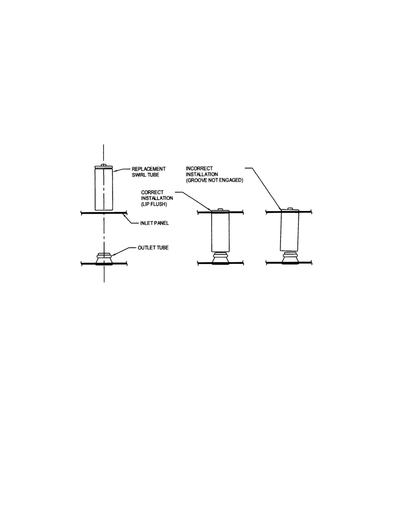
Figure 13-2. Swirl Tube Replacement
MM-13-21
Feb 9/01
CAUTION
Use a backing wrench when loosening or tightening air/fluid lines and fittings
to prevent damage to the lines or fittings.
C. Install and tighten the scavenge air line between the particle separator and the tee.
D. Install the access panel on the upper plenum.
13-37. Lower Plenum
13-38. Removal - Lower Plenum
A. Remove the bottom aft cowling.
B. Remove the eductor.
C. Remove the cowling mounting bracket located above the aft crosstube.
D. Remove the transfer ducts (para. 13-23).
NOTE
Removal of the upper plenum (para. 13-28) is not required; however, it would
provide more access to the area.
CAUTION
Ensure that all the attachment hardware from the bell mouth is accounted for
and that the engine inlet is covered when the bell mouth inlet is removed.
E. Remove the bell mouth inlet from the engine inlet and remove the inlet from the lower
plenum via the plenum inlet on the left side.
F. Disconnect the differential pressure air line from the right side of the lower plenum.
G. Disconnect the engine wash line from the aft side of the lower plenum.
H. Remove the hardware from the lower plenum mounting brackets.
CAUTION
Care must be used to prevent damage to the lower plenum during removal.
I.
Remove the lower plenum via the bottom of the aircraft.
Rev. 26
MM-13-22
Feb 28/2020