HELICOPTERS NSN 1520-01-035-0266, NSN 1520-01-082-0686, NSN 1520-01-298-4532. REPAIR STANDARDS (2004) - page 3
DMWR 1-1520-237
B.
Rework of drive shaft supports at station 531.88 and station 591.88 as follows:
(1)
Remove angle supports (70212-05005-105 and -106) at station 531.43 (Dwg 70070-20266, Sheet 6,
Zone 10-G).
(2)
Mark location on top skin of support (70212-05005-123 or -125) (Sheet 6, Zone 11-G and Sheet 5, Notes
4 and 7).
(3)
Remove support (70212-05005-123 or -125) at station 531.43 (Sheet 6, Zone 11-G and Sheet 5, Notes 4
and
7).
(4)
Position new support (70070-20266-106) over station 531.00 where support (70212-05005-123 or -125)
was removed in step (3).
(5)
Line up forward face of new support (70070-20266-106) where marked location was noted in step (2).
(6)
Transfer drill from angle (70212-05005-109) (inside tailcone) through new support (70070-20266-106)
and put new support (-106) aside for installation in later steps.
(7)
Remove angle (70212-05005-109) at station 531.43 (Sheet 6, Zone 13-B).
(8)
Remove angle supports (70212-05005-119 and -120) at station 591.88 (Sheet 6, Zone 4-G).
NOTE
Before removing support (70212-05005-124 or -126) in step B.(10) perform the following step.
(9)
Mark location on top skin of support (70212-05005-124 or -126) (Sheet 6, Zone 5-G and Sheet 5, Notes 4
and
7).
(10)
Remove support (70212-05005-124 or -126) at station 591.88 (Sheet 6, Zone 5-G and Sheet 5, Notes 4
and
7).
(11)
Postion new support (70070-20266-107) over station 591.88 where support (70212-05005-124 or -126)
was removed in step B.(10).
(12)
Line up forward face of new support (70070-20266-107) where marked location was noted in step B. (9).
(13)
Transfer drill from angle (70212-05005-110) (inside tailcone) through new support (70070-20266-107)
and set aside support (-107) for installation in a later step.
(14)
Remove angle (70212-05005-110) at station 591.88 (Sheet 6, Zone 8-G).
(15)
Remove and keep for reuse, angle (70215-05002-107 or -109) and clips (70215-05002-110 and -121)
at station 525.00 (Sheet 4, Zones 16-C and 15-A).
(16)
Remove and keep for reuse clips (70215-05002-111 and -122) at station 545.00 (Sheet 4, Zones 14-C
and 14-B).
(17)
Remove and keep for reuse, clips (70215-05002-113 and -124) at station 585.00 (Sheet 4, Zones 15-J
and 16-F).
(18)
Remove and keep for reuse, clips (70215-05002-114 and -125) at station 605.00 (Sheet 4, Zones 14-H
and 14-F).
E-153
DMWR 1-1520-237
(19)
Temporarily install doubler (70070-20266-101) between station 520.00 and station 545.00, buttline 0.00
(Sheet 4, Zone 16-B).
(20)
Transfer drill holes from structure into doubler (70070-20266-101) (Sheet 4).
(21)
Pick up remaining field holes in doubler (70070-20266-101) and transfer drill from doubler (70070-
20266-101) into structure (Sheet 4, Zones 13-B through 16-B).
(22)
Temporarily install angle (70215-05002-107 or -109) and clips (70215-05002-110 and -121) saved for
reuse at station 525.00 (Sheet 4, Zones 15-A and 16-D).
(23)
Temporarily install clips (70215-05002-111 and -122) saved for reuse in step B.(8) at station 545.00
(Sheet 4, Zones 14-A and 14-C).
(24)
Temporarily install at station 531.43 support (70070-20266-106), angle (previously fit out), angle (70070-
20266-105) angle supports (70212-05005-130 and -134) and filler (70212-05005-133) (Sheet 6, Zones 12-C and
9-G).
(25)
Temporarily install doublers (70070-20266-102 and -103) between station 585.00 and station 605.00,
buttline 0.00 (Sheet 4, Zones 13-G through 16-G; Sheet 3, Notes 3 and 4 and Sheet 2, Note 4).
(26)
Transfer drill holes from structure into doublers (70070-20266-102 and -103) (Sheet 4, Zones 13-G
through 16-G).
(27)
Pick up remaining field holes in doublers (70070-20266-102 and -103) and transfer drill from doublers
(-102 and -103) into structure (Sheet 4, Zones 13-G through 16-G).
(28)
Temporarily install clips (70215-05005-113 and -124) saved for reuse in step B.(9) at station 585.00
(Sheet 4, Zones 15-J and 16-F).
(29)
Temporarily install clips (70215-05005-114 and -125) saved for reuse in step B. (10) at station 605.00
(Sheet 4, Zones 13-F and 13-H).
(30)
Temporarily install at station 591.88 support (70070-20266-107) (previously fit out) angle (70070-20266-
104) angle supports (70212-05005-131 and -132) and filler (70212-05005-133) (Sheet 6, Zones 8-B, 8-C, 8-D and
4-G).
(31)
Remove all parts temporarily installed deburr, and touch up as required.
(32)
Install all parts removed in previous steps and install using fasteners shown (Sheets 3, 4, and 6).
(33)
Line up and install new brackets (70212-05003-135 and -137) at stations 531.00 and 591.00 per refer-
ence (c).
(34)
Remove fitted parts, deburr and touch up as required.
(35)
Install fitted parts using fasteners shown (Sheets 3, 4, and 6).
E-154
DMWR 1-1520-237
WARNING
OBSERVE ALL CAUTIONS AND WARNINGS ON CONTAINERS WHEN USING CONSUMABLES.
WHEN APPLICABLE, WEAR NECESSARY PROTECTIVE GEAR DURING HANDLING AND USE. IF A
CONSUMABLE IS FLAMMABLE OR EXPLOSIVE, MAKE CERTAIN CONSUMABLE AND ITS VAPORS ARE
KEPT AWAY FROM HEAT, SPARK, AND FLAME. MAKE CERTAIN EQUIPMENT IS PROPERLY
GROUNDED AND FIREFIGHTING EQUIPMENT IS READILY AVAILABLE PRIOR TO USE. FOR AD-
DITIONAL INFORMATION ON TOXICITY, FLASHPOINT, AND FLAMMABILITY OF CHEMICALS,
CONSULT YOUR MEDICAL PEOPLE, OR MANUFACTURER OF THE CONSUMABLE.
(36)
Apply a bead of sealant (AMS-S-8802 or equivalent) around doublers (70070-20266-101, -102, and
-103) between station 525.00 and station 605.00 (Sheet 3, Note 4).
C.
Reinstallation of removed equipment:
(1)
Reinstall removed equipment per reference (a).
D.
Record of Compliance:
(1)
Make an appropriate logbook entry to show compliance with this Special Service Instruction.
Weight and Balance Data:
POUNDS
INCHES AFT
MOMENT/
QTY
PART NO.
NOMENCLATURE
WEIGHT
OF DATUM
1000
1
70070-20266-013
Mod. Kit
0.9
531.9
.50
1
70070-20266-014
Mod. Kit.
0.9
531.9
.54
Weight and Balance: Change resulting from these instructions are as follows:
Change in basic weight:
+1.8 pounds
Moment arm:
531.9 in.
Change in basic moment/1000:
1.0
Manpower (Estimated)
No. of Personel
No. of Hours
Man-hours
Sheet Metal Mechanic
2
32
*64
*Does not include time required to prepare helicopter or return it to flight status.
E-155
DMWR 1-1520-237
A.
Modification Kit Required:
Qty
Nomenclature
Part Number
Source
1
Mod. Kit, Drive Shaft Support,
70070-20266-013
(1)
consisting of:
4
Pin, Hi-Lok
HL12VAZ-5-2
4
Pin, Hi-Lok
HL12VAZ-5-3
2
Pin, Hi-Lok
HL12VAZ-5-4
10
Collar
HL75DU-5ADW
25
Rivet
MS20470AD4-4
40
Rivet
MS20470AD4-5
10
Rivet
MS20470AD4-6
35
Rivet
MS20470AD5-5
6
Rivet
NAS1097AD4-5
3
Rivet
NAS1097AD5-5
20
Rivet
MS20470AD5-7
15
Rivet
MS20470AD5-6
1
Doubler
70070-20266-101
1
Angle
70070-20266-105
1
Filler
70212-05005-133
1
Bracket
70070-20266-106
1
Support
70212-05005-135
1
Angle Support
70212-05005-134
1
Angle Support
70212-05005-130
1
Mod. Kit, Drive Shaft Support,
70070-20266-014
consisting of:
4
Pin, Hi-Lok
HL12VAZ-5-2
4
Pin, Hi-Lok
HL12VAZ-5-3
2
Pin, Hi-Lok
HL12VAZ-5-4
10
Collar
HL75DU-5ADW
20
Rivet
MS20470AD4-4
40
Rivet
MS20470AD4-5
10
Rivet
MS20470AD4-6
30
Rivet
MS20470AD5-5
25
Rivet
MS20470AD5-6
25
Rivet
MS20470AD5-7
3
Rivet
NAS1097AD5-5
1
Filler
70212-05005-133
1
Doubler
70070-20266-102
1
Doubler
70070-20266-103
1
Bracket
70070-20266-107
1
Angle
70070-20266-104
1
Angle Support
70212-05005-131
1
Angle Support
70212-05005-132
1
Support
70212-05005-137
E-156
DMWR 1-1520-237
B.
Consumable Material:
WARNING
OBSERVE ALL CAUTIONS AND WARNINGS ON CONTAINERS WHEN USING CONSUMABLES.
WHEN APPLICABLE, WEAR NECESSARY PROTECTIVE GEAR DURING HANDLING AND USE. IF A
CONSUMABLE IS FLAMMABLE OR EXPLOSIVE, MAKE CERTAIN CONSUMABLE AND ITS VAPORS ARE
KEPT AWAY FROM HEAT, SPARK, AND FLAME. MAKE CERTAIN EQUIPMENT IS PROPERLY
GROUNDED AND FIREFIGHTING EQUIPMENT IS READILY AVAILABLE PRIOR TO USE. FOR AD-
DITIONAL INFORMATION ON TOXICITY, FLASHPOINT, AND FLAMMABILITY OF CHEMICALS,
CONSULT YOUR MEDICAL PEOPLE, OR MANUFACTURER OF THE CONSUMABLE.
Qty
Nomenclature
Part Number
Source
8 oz.
Sealant
AMS-S-8802, or equivalent
(1)
6 oz.
Primer
MIL-P-23377, or equivalent
(1)
C.
Source:
(1)
Available through normal supply channels
E-157
DMWR 1-1520-237
A
8
7
15
1
10
11
5
13
4
14
3
14
12
2
9
17
18
2
A
2
19
20
6
6
AB3103
10
6
16
SA
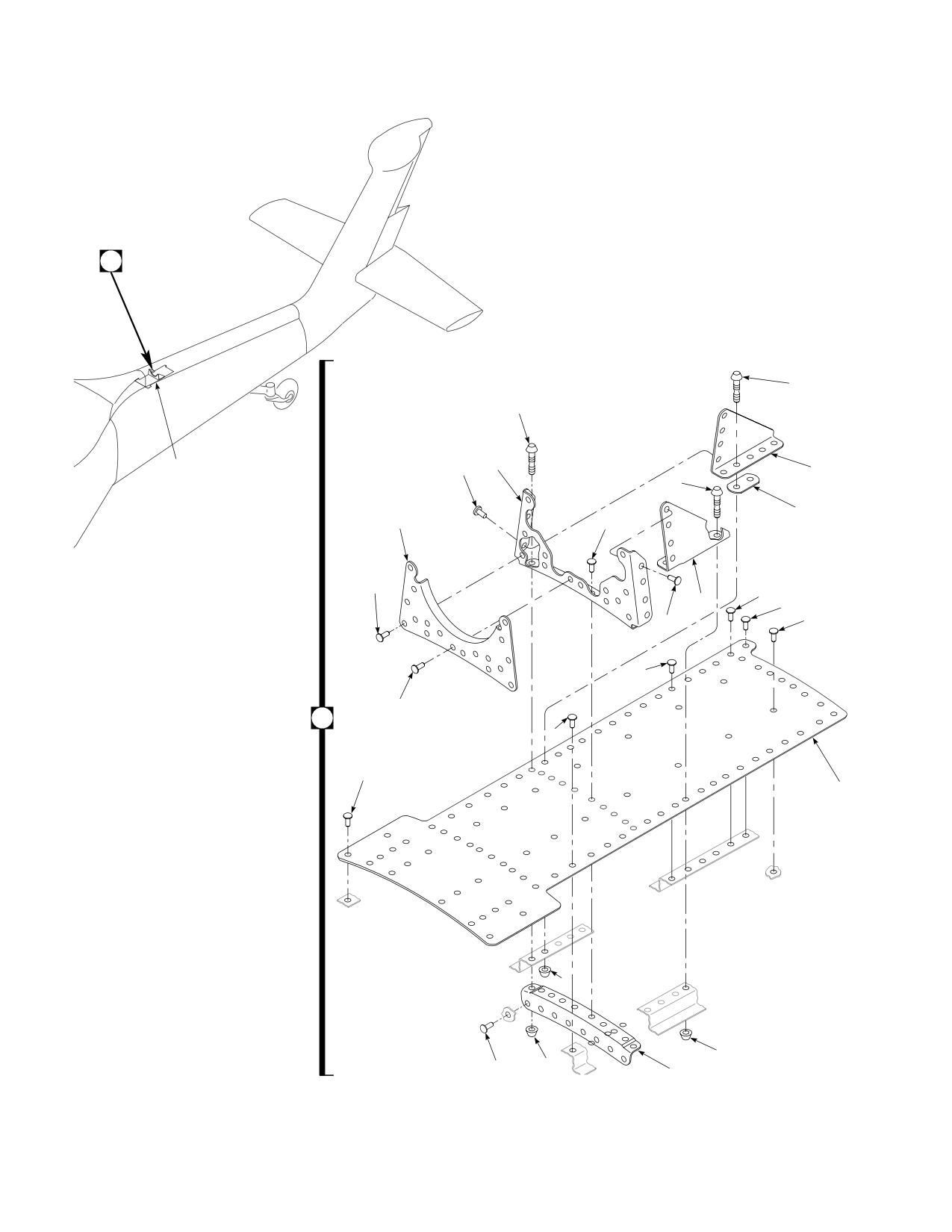
Figure E-14. Support Shaft Modification Kit
E-158
DMWR 1-1520-237
QTY
USABLE
FIGURE &
PER
ON
INDEX NO.
PART NUMBER
1 2 3 4 5 6 7
DESCRIPTION
ASSY
CODE
E-14-
70070-20266-013
SUPPORT SHAFT MODIFICATION KIT
REF
-1
70070-20266-015
. SUPPORT INSTL, (Modified by 70212-
05005-011)
REF
-2
MS20470AD4-6
. RIVET
10
-3
MS20470AD5-6
. RIVET
15
-4
70212-05005-135
. SUPPORT
1
-5
HL12VAZ-5-2
. HI-LOK PIN, (73197)
4
-6
HL75DU-5ADW
. COLLAR, (73197)
10
-7
HL12VAZ-5-4
. HI-LOK PIN, (73197)
2
-8
HL12VAZ-5-3
. HI-LOK PIN, (73197)
4
-9
NAS1097AD5-5
. RIVET
3
-10
MS20470AD5-5
. RIVET
35
-11
70212-05005-130
. ANGLE SUPPORT
1
-12
70212-05005-134
. ANGLE SUPPORT
1
-13
70212-05005-133
. FILLER
1
-14
MS20470AD5-7
. RIVET
20
-15
70070-20266-106
. BRACKET
1
-16
70070-20266-105
. ANGLE
1
-17
MS20470AD4-4
. RIVET
25
-18
MS20470AD4-5
. RIVET
40
-19
NAS1097AD4-5
. RIVET
6
-20
70070-20266-101
. DOUBLER
1
E-159
DMWR 1-1520-237
A
8
7
1
15
10
12
5
13
4
14
3
11
9
14
19
2
3
17
2
A
18
2
20
6
6
AB3106
10
6
16
SA
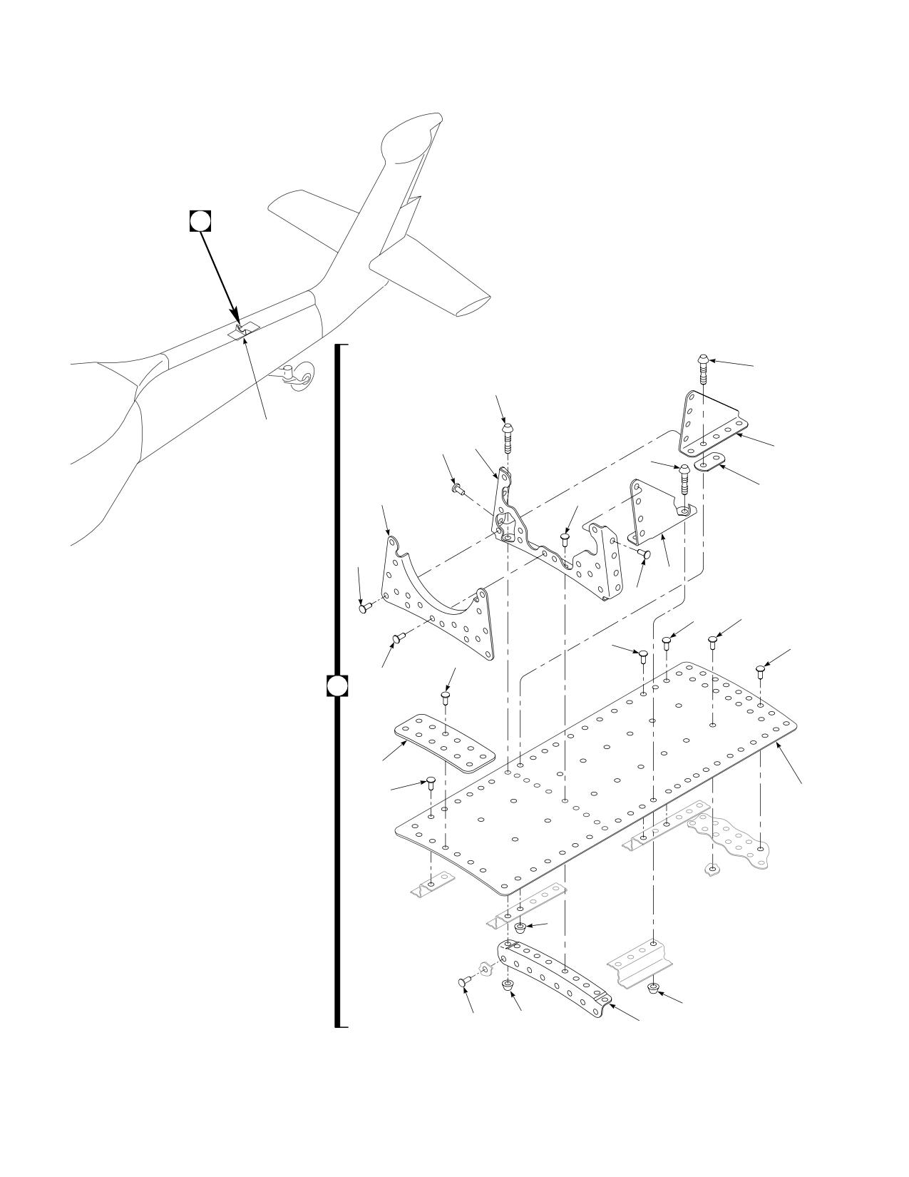
Figure E-15. Support Shaft Modification Kit
E-160
DMWR 1-1520-237
QTY
USABLE
FIGURE &
PER
ON
INDEX NO.
PART NUMBER
1 2 3 4 5 6 7
DESCRIPTION
ASSY
CODE
E-15-
70070-20266-014
SUPPORT SHAFT MODIFICATION KIT
REF
-1
70070-20266-016
. SUPPORT INSTL, (Modified by 70212-
05005-012)
REF
-2
MS20470AD4-6
. RIVET
10
-3
MS20470AD5-6
. RIVET
25
-4
70212-05005-137
. SUPPORT
1
-5
HL12VAZ-5-2
. HI-LOK PIN, (73197)
4
-6
HL75DU-5ADW
. COLLAR, (73197)
10
-7
HL12VAZ-5-4
. HI-LOK PIN, (73197)
2
-8
HL12VAZ-5-3
. HI-LOK PIN, (73197)
4
-9
NAS1097AD5-5
. RIVET
3
-10
MS20470AD5-5
. RIVET
30
-11
70212-05005-131
. ANGLE SUPPORT
1
-12
70212-05005-132
. ANGLE SUPPORT
1
-13
70212-05005-133
. FILLER
1
-14
MS20470AD5-7
. RIVET
25
-15
70070-20266-107
. BRACKET
1
-16
70070-20266-104
. ANGLE
1
-17
MS20470AD4-5
. RIVET
40
-18
70070-20266-103
. DOUBLER
1
-19
MS20470AD4-4
. RIVET
20
-20
70070-20266-102
. DOUBLER
1
E-161
DMWR 1-1520-237
E-15. SHEAR DECK MODIFICATION KIT (50-29).
Subject: Tail Cone Shear Deck; Modification of, dated 31 March 2003
Purpose: Provide instructions for modification of tail cone shear deck
Model:
UH-60A
Description: The tail cone shear deck is reworked to improve the structure by adding doublers and angles between sta-
tion 605.00 and station 645.00.
Drawing required for modification:
70070-20581
References: (a) Special Service Instructions (SSI) No. 50-31, Installation of 9A to A9 Recapitalization Program, dated
March 31, 2003
(b) SSI No. 50-17, Station 605.00 Bulkhead; Modification of, dated March 31, 2003
Instructions:
NOTE
• A complete review of this s SSI is recommended before modification of the tail cone shear deck.
• Before beginning this modification procedure, use the material information list to inventory the modification
kit. Make sure all parts are present and in serviceable condition.
• Where drawing numbers are not listed within individual step(s), drawing(s) listed in preceding step(s) are
the controlling authority.
• The sheet metal and structural modifications in this SSI shall be done by personnel experienced in reading
modification drawings. Routine steps such as cleaning, layout and drilling, deburring, standard repairs,
corrosion control, clean up after rework, chemical coating for aluminum after cutting/trimming parts, peel-
ing shims, paint touch up, and safety practices may not be called out herein. However, these steps and all
other required routine tasks shall be done.
• Slight variations to the instructions contained herein are allowed, as long as the intent of the modification
is accomplished.
• This modification is to be done concurrently with reference (b).
A.
Preparation for modification and removal of equipment:
(1)
Confirm that all warnings, cautions, and notes are complied with per reference (a).
(2)
Perform preparation for modification per reference (a).
B.
Rework shear deck installation (70211-05010-011 or -012) as follows:
(1)
Remove shear deck with channels (70211-05010-107 and -108) and place on a suitable work area.
E-162
DMWR 1-1520-237
(2)
Locate and remove channels (70211-05010-107 and -108) between station 605.00 and station 645.00
(Dwg 70070-20581, Sheet 2, Zones 10-C, 11-C, 16-C through 23-C, and 16-E through 23-E).
(3)
Remove and keep for reuse two clips (70211-05010-114) at station 640.00 (Sheet 2, Zones 15-G, 17-C,
and 17-D).
(4)
Remove and keep for reuse two clips (70211-05010-115) at station 645.00 (Sheet 2, Zones 15-C, 16-C,
and 16-D).
(5)
Remove two tapered shims (SS81-018-I) at station 608.00 (Sheet 2, Zones 23-C and 23-E).
(6)
Locate and temporarily install doubler (70070-20581-101) between station 605.00 and station 623.00
(Sheet 2, Zone 19-F and Note 9).
(7)
Locate and temporarily install channel (70070-20581-102) between station 605.00 and station 645.00
(Sheet 2, Zones 11-C, 19-F, and 16-E through 21-E).
(8)
Locate and temporarily install channel (70070-20581-103) between station 605.00 and station 645.00
(Sheet 2, Zones 10-C, 18-F, and 16-C through 21-C).
(9)
Locate remaining field fastener holes and transfer drill in channels (70070-20581-102 and -103) (Sheet 2,
Zones 16-C through 21-C and 16-E through 21-E).
(10)
Locate and temporarily install two shims, tapered (SS81-014-I) at station 607.00, two clips (70211-05010-
114) at station 640.00 and two clips (70211-05010-115) at station 645.00 (Sheet 2, Zones 23-C, 23-E, 17-C, 17-D,
16-C and 16-D).
(11)
Remove fitted parts, deburr and touch up as required.
(12)
Install fitted parts using fasteners shown (Sheet 2, Note 9).
C.
Reinstallation of removed equipment:
(1)
Install removed equipment per reference (a).
D.
Record of Compliance:
(1)
Make an appropriate logbook entry to show compliance with this Special Service Instruction.
Weight and Balance Data:
POUNDS
INCHES AFT
MOMENT/
QTY
PART NO.
NOMENCLATURE
WEIGHT
OF DATUM
1000
1
70070-20581-011
Mod. Kit, Shear Deck
+1.9
621.7
1.18
Weight and Balance: Change resulting from these instructions are as follows:
Change in basic weight:
+ 1.9 pounds
Moment arm:
621.7 in.
E-163
DMWR 1-1520-237
Change in basic moment/1000:
1.18
Manpower (Estimated)
No. of Personel
No. of Hours
Man-hours
Sheet Metal Mechanic
2
20.0
* 40.0
*Does not include time required to prepare helicopter or return it to flight status.
Material Information:
A.
Modification Kit Required:
Qty
Nomenclature
Part Number
Source
1
Mod. Kit, Shear Deck,
70070-20581-011
(1)
consisting of:
53
Rivet
MS20470AD6-7
3
Rivet
MS20470AD5-9
3
Rivet
MS20470AD5-8
9
Rivet
MS20470AD5-7
91
Rivet
MS20470AD5-6
68
Rivet
MS20470AD5-5
72
Rivet
MS20470AD4-4
2
Pin, SWG LKG
NAS1465-06
2
Pin, SWG LKG
NAS1465-03
4
Pin, SWG LKG
NAS1465-02
8
Collar
NAS1080-05
2
Shim, Tapered
SS81-014-I
1
Doubler
70070-20581-101
1
Channel
70070-20581-102
1
Channel
70070-20581-103
B.
Source:
(1)
Available through normal supply channels
E-164
DMWR 1-1520-237
1
2
1
3
6
7
8
9
12
10
16
3
11
BL
10
5
3
4
BL
0
14
17
BL
10
15
13
STA
STA
STA
STA
STA
605
615
625
635
645
AB3121
SA
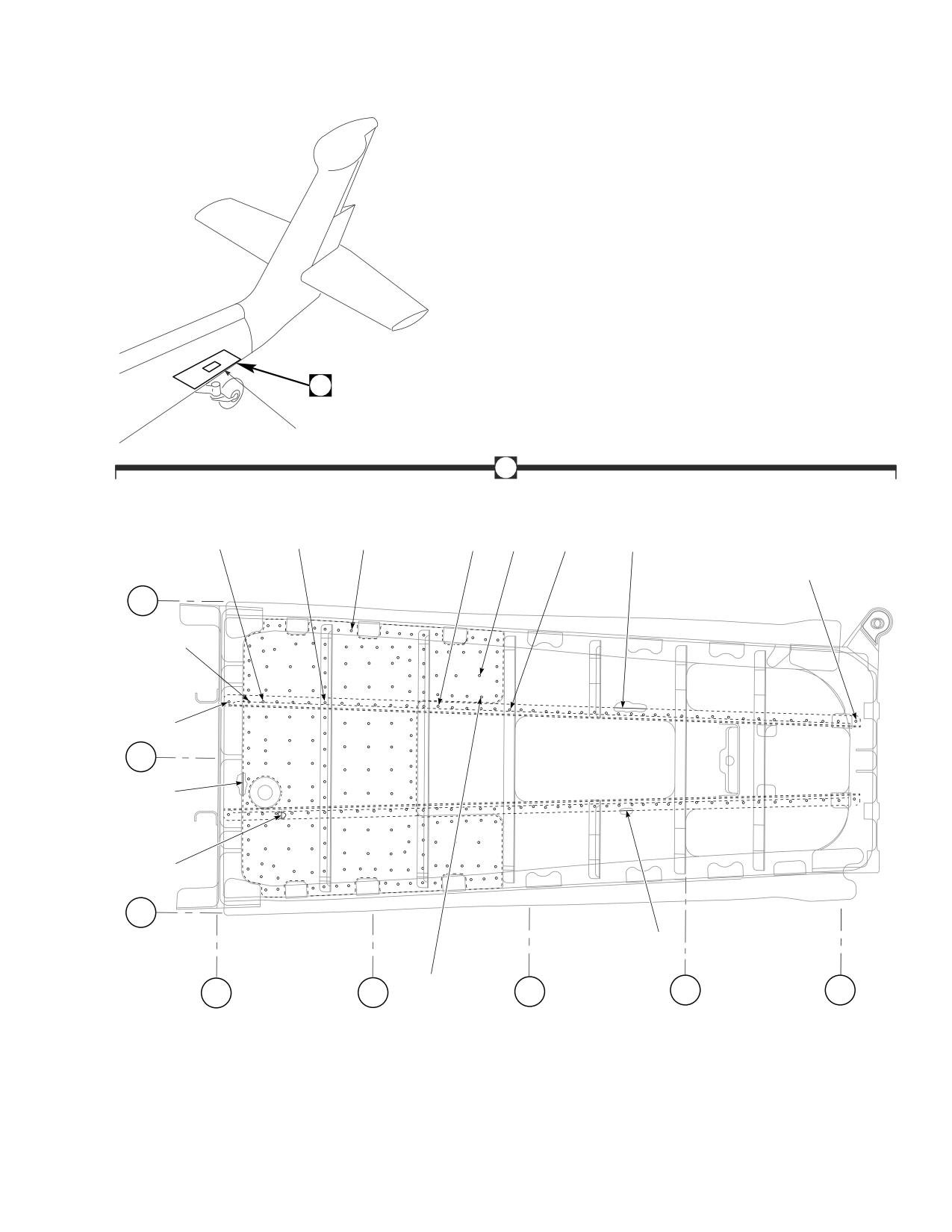
Figure E-16. Shear Deck Modification Kit
E-165
DMWR 1-1520-237
QTY
USABLE
FIGURE &
PER
ON
INDEX NO.
PART NUMBER
1 2 3 4 5 6 7
DESCRIPTION
ASSY
CODE
E-16-
70070-20581-011
SHEAR DECK MODIFICATION KIT
REF
-1
70070-20581-012
. SHEAR DECK INSTL, (Modified from 70211-
05010-011)
REF
70070-20581-013
. SHEAR DECK INSTL, (Modified from 70211-
05010-012)
REF
-2
70070-20581-041
. SHEAR DECK ASSY, (Modified from 70211-
05010-041)
REF
-3
NAS1465-06
. SWAGE LOCKING PIN
2
-4
NAS1080-05
. COLLAR
8
-5
MS20470AD5-9
. RIVET
3
-6
MS20470AD5-8
. RIVET
3
-7
MS20470AD5-7
. RIVET
9
-8
MS20470AD5-6
. RIVET
91
-9
MS20470AD6-7
. RIVET
53
-10
NAS1465-02
. SWAGE LOCKING PIN
4
-11
NAS1465-03
. SWAGE LOCKING PIN
2
-12
MS20470AD4-4
. RIVET
72
-13
MS20470AD5-5
. RIVET
68
-14
70070-20581-101
. DOUBLER
1
-15
70070-20581-103
. CHANNEL
1
-16
70070-20581-102
. CHANNEL
1
-17
SS81-014-I
. TAPERED SHIM
2
E-166
DMWR 1-1520-237
E-16. STRINGER/FRAME MODIFICATION KIT (50-24).
Subject: Tail Cone, Modification of, dated 31 March 2003
Purpose: To provide instructions to install tail cone modification kit.
Model:
UH-60A
Description: To strengthen the tail cone structure by adding stringers and shear ties to station 485.00 through station
565.00.
Drawings required for modification:
70070-20582
References: (a) Special Service Instructions (SSI) No. 50-31, Installation of 9A to A9 Recapitalization Program, dated
March 31, 2003
(b) SSI No. 50-13 Tail Cone Plating, Modification of, dated 31 March 2003
(c) Technical Manual (TM) 1-1520-237-23-1, Aviation Unit And Intermediate Maintenance for Army
Models UH-60A, UH-60L, and EH-60A Helicopters, Chapter 1, Aircraft General
Instructions:
NOTE
• A complete review of this SSI is recommended before installing tail cone modification kit.
• Before beginning this modification procedure, use the material information list to inventory the kit. Make
sure all parts are present and in serviceable condition.
• Where drawing numbers are not listed within individual steps, drawing(s) listed in preceding step(s) are
the controlling authority.
• The sheet metal and structural modifications in this SSI shall be done by personnel experienced in reading
modification drawings. Routine steps such as cleaning, layout and drilling, deburring, standard repairs,
corrosion control, clean up after rework, chemical coating for aluminum after cutting/trimming parts, paint
touch up, and safety practices may not be called out herein. However, these steps and all other required
routine tasks shall be done.
• Slight variations to the instructions contained herein are allowed, as long as the intent of the modification
is accomplished.
• This modification is to be done concurrently with reference (b).
A.
Preparation for modification and removal of equipment.
(1)
Confirm that all warnings, cautions, and notes are complied with per reference (a).
(2)
Perform preparation for modification per reference (a).
(3)
Inspect and repair structure for corrosion and damage per reference (c).
E-167
DMWR 1-1520-237
B.
Modification, tailcone:
(1)
Modify tail cone after removal of lower skin (70213-05001-041 or 70213-05001-048) per reference (b).
(2)
Installation, tail cone structure:
(a)
Use portions of removed stringers from lower skin to align shear ties on lower section of modified frames.
(b)
Modify station 505.00 as follows:
1
Remove right side brackets (70213-05001-154) between waterline 215.00 and waterline 230.00,
waterline 255.00 (Dwg 70070-20582, Sheet 6, Zones 11-E through 11-G, Sheet 7, Section W-W, Zone 23-D, Notes 10
and 11).
2
Position shear ties (70070-20582-136, 70070-20582-101, 70070-20582-102, 70070-20582-135,
70070-20582-134, 70070-20582-103, and 70070-20582-137) as shown (Sheet 6, Zones 13-C through 11-E, Sheet
7, Zones 17-D and 18-F through 21-F).
3
Position splice (70084-25104-116) (Sheet 7, Zone 17-B).
4
Transfer drill fastener holes from shear ties and splice through frame and skins (Sheet 6, Zones 15
through 10, Sheet 7, Zones 16 through 22).
NOTE
Clips 96203-05001 are not secured at this time.
5
Secure shear ties and splice to frame with fasteners shown (Sheet 6, Zones 11 through 10, and Sheet 7,
Zones 17 through 22).
6
Secure shear ties and skin with fasteners shown wet with sealant (MIL-S-8802 or equivalent) (Sheet 6,
Views D-D, F-F, E-E, K-K, and L-L, Zones 14-A through 9-C, Sheet 7, Views P-P, R-R, S-S, and U-U, Zones 16-A through
22-F, Sheet 5, Note 4).
(c)
Install station 485.00 to station 505.00 stringers as follows:
1
Position left side stringers (70213-05001-155 and 70213-05001-157) between waterline 215.00 and
waterline 225.00 as shown (Sheet 6, Zones 20-C and 20-E, Note 12).
2
Drill fastener holes from stringers through skin, station 485.00 and station 505.00 frames.
3
Position angle brackets (SS1076-57 and SS1076-183) onto stringers and against frame (Sheet 6, Sec-
tions G-G, H-H, and J-J, Zones 23-C through 24-G, Note 12).
4
Drill fastener holes from angle brackets through stringers and frame.
5
Position right side stringers (70213-05001-156, 70213-05001-158, and 70213-05001-159) between
waterline 215.00 and waterline 230.00 in shear tie (70070-20582-102) cutouts as shown (Sheet 6, View D-D, Zone
6-C, Note 12).
6
Drill fastener holes from stringers through skin, station 485.00 and station 505.00 frames as shown.
7
Position clips (96203-05001-152, 96203-05001-151, and 96203-05001-150) as shown (Sheet 6,
Zones 11-E, 11-F, and 11-G).
E-168
DMWR 1-1520-237
8
Position buttline 0.00 stringer (70213-05001-153) at waterline 260.00 (Sheet 7, View V-V, Zone 5-C,
Note 13).
9
Drill fastener holes from stringers through skin, station 485.00 and station 505.00 as shown.
10
Position bracket (70070-20582-131) as shown (Sheet 7, Section W-W, Zones 20-F and 22-D).
11
Drill fastener holes from brackets through stringers and frame.
12
Remove stringers, clips, angles, and brackets.
WARNING
OBSERVE ALL CAUTIONS AND WARNINGS ON CONTAINERS WHEN USING CONSUMABLES.
WHEN APPLICABLE, WEAR NECESSARY PROTECTIVE GEAR DURING HANDLING AND USE. IF A
CONSUMABLE IS FLAMMABLE OR EXPLOSIVE, MAKE CERTAIN CONSUMABLE AND ITS VAPORS ARE
KEPT AWAY FROM HEAT, SPARK, AND FLAME. MAKE CERTAIN EQUIPMENT IS PROPERLY
GROUNDED AND FIREFIGHTING EQUIPMENT IS READILY AVAILABLE PRIOR TO USE. FOR AD-
DITIONAL INFORMATION ON TOXICITY, FLASHPOINT, AND FLAMMABILITY OF CHEMICALS,
CONSULT YOUR MEDICAL PEOPLE, OR MANUFACTURER OF THE CONSUMABLE.
13
Coat skin with clear epoxy (MIL-C-22750 or equivalent) (Sheet 5, Note 7).
WARNING
OBSERVE ALL CAUTIONS AND WARNINGS ON CONTAINERS WHEN USING CONSUMABLES.
WHEN APPLICABLE, WEAR NECESSARY PROTECTIVE GEAR DURING HANDLING AND USE. IF A
CONSUMABLE IS FLAMMABLE OR EXPLOSIVE, MAKE CERTAIN CONSUMABLE AND ITS VAPORS ARE
KEPT AWAY FROM HEAT, SPARK, AND FLAME. MAKE CERTAIN EQUIPMENT IS PROPERLY
GROUNDED AND FIREFIGHTING EQUIPMENT IS READILY AVAILABLE PRIOR TO USE. FOR AD-
DITIONAL INFORMATION ON TOXICITY, FLASHPOINT, AND FLAMMABILITY OF CHEMICALS,
CONSULT YOUR MEDICAL PEOPLE, OR MANUFACTURER OF THE CONSUMABLE.
14
Secure stringers, clips, angles, and brackets wet with sealant (MIL-S-8802 or equivalent) (Sheet 6,
Views C-C and D-D, Zones 6-C, 10-D, 10-E, 10-G, 19-C, 23-C, 22-G, and 23-G, Sheet 7, View V-V, Zone 5-C, Section
T-T, Zone 10-F, Note 4).
NOTE
Station 525.00 is modified per paragraph (d) or paragraph (e).
(d)
Modify station 525.00 using modification kit (70070-20582-013) as follows:
1
Position shear ties (70070-20582-109, 70070-20582-108, 70070-20582-107, 70070-20582-106,
70070-20582-105, 70070-20582-104, 70070-20582-111, and 70070-20582-110) (Dwg 70070-20582, Sheet 8,
Zones 6 through 12 and 17 through 23).
2
Drill fastener holes from shear ties through frame and skins as shown (Sheet 8, Zones 6 through 12 and
17 through 23).
E-169
DMWR 1-1520-237
3
Secure shear ties to frame with fasteners shown (Sheet 8, Zones 22 through 17 and 12 through 7).
WARNING
OBSERVE ALL CAUTIONS AND WARNINGS ON CONTAINERS WHEN USING CONSUMABLES.
WHEN APPLICABLE, WEAR NECESSARY PROTECTIVE GEAR DURING HANDLING AND USE. IF A
CONSUMABLE IS FLAMMABLE OR EXPLOSIVE, MAKE CERTAIN CONSUMABLE AND ITS VAPORS ARE
KEPT AWAY FROM HEAT, SPARK, AND FLAME. MAKE CERTAIN EQUIPMENT IS PROPERLY
GROUNDED AND FIREFIGHTING EQUIPMENT IS READILY AVAILABLE PRIOR TO USE. FOR AD-
DITIONAL INFORMATION ON TOXICITY, FLASHPOINT, AND FLAMMABILITY OF CHEMICALS,
CONSULT YOUR MEDICAL PEOPLE, OR MANUFACTURER OF THE CONSUMABLE.
4
Secure shear ties and skins with fasteners shown wet with sealant (MIL-S-8802 or equivalent) (Sheet 8,
Views Z-Z, AF-AF, AG-AG, AH-AH, AJ-AJ, AK-AK, AL-AL, AM-AM, AN-AN, AE-AE, AD-AD, AB-AB, AA-AA, and AC-
AC, Sheet 5, Note 4).
(e)
Modify station 525.00 using modification kit (70070-20582-027) as follows:
1
Position shear ties (70070-20582-149, 70070-20582-151, 70070-20582-150, 70070-20582-148,
70070-20582-146, 70070-20582-144, 70070-20582-145, and 70070-20582-147) (Dwg 70070-20582, Sheet 11,
Zones 6 through 12 and 16 through 23).
2
Drill fastener holes from shear ties through frame and skins as shown (Sheet 11, Zones 6 through 12 and
16 through 23).
3
Secure shear ties to frame with fasteners shown (Sheet 11, Zones 22 through 16 and 12 through 7).
WARNING
OBSERVE ALL CAUTIONS AND WARNINGS ON CONTAINERS WHEN USING CONSUMABLES.
WHEN APPLICABLE, WEAR NECESSARY PROTECTIVE GEAR DURING HANDLING AND USE. IF A
CONSUMABLE IS FLAMMABLE OR EXPLOSIVE, MAKE CERTAIN CONSUMABLE AND ITS VAPORS ARE
KEPT AWAY FROM HEAT, SPARK, AND FLAME. MAKE CERTAIN EQUIPMENT IS PROPERLY
GROUNDED AND FIREFIGHTING EQUIPMENT IS READILY AVAILABLE PRIOR TO USE. FOR AD-
DITIONAL INFORMATION ON TOXICITY, FLASHPOINT, AND FLAMMABILITY OF CHEMICALS,
CONSULT YOUR MEDICAL PEOPLE, OR MANUFACTURER OF THE CONSUMABLE.
4
Secure shear ties and skins with fasteners shown wet with sealant (MIL-S-8802 or equivalent) (Sheet 11,
Views CR-CR, CS-CS, CT-CT, CU-CU, CV-CV, CW-CW, CX-CX, CY-CY, CQ-CQ, CP-CP, CN-CN, CM-CM, CL-CL, and
CK-CK, Sheet 5, Note 4).
NOTE
Station 545.00 is modified per paragraph (f) or paragraph (g).
(f)
Modify station 545.00 using modification kit (70070-20582-014) as follows:
1
Position shear ties (70070-20582-132, 70070-20582-133, 70070-20582-140, 70070-20582-115,
70070-20582-142, 70070-20582-117, 70070-20582-116, 70070-20582-138, 70070-20582-114, 70070-20582-
E-170
DMWR 1-1520-237
112, 70070-20582-143, 70070-20582-139, and 70070-20582-141) (Dwg 70070-20582, Sheet 9, Zones 22
through 17 and 11 through 6).
2
Drill fastener holes from shear ties and angles through frame and skins (Sheet 9, Zones 22 through 17
and 11 through 6).
3
Secure shear ties and angles to frame with fasteners shown (Sheet 9, Zones 22 through 17 and 11
through 7).
WARNING
OBSERVE ALL CAUTIONS AND WARNINGS ON CONTAINERS WHEN USING CONSUMABLES.
WHEN APPLICABLE, WEAR NECESSARY PROTECTIVE GEAR DURING HANDLING AND USE. IF A
CONSUMABLE IS FLAMMABLE OR EXPLOSIVE, MAKE CERTAIN CONSUMABLE AND ITS VAPORS ARE
KEPT AWAY FROM HEAT, SPARK, AND FLAME. MAKE CERTAIN EQUIPMENT IS PROPERLY
GROUNDED AND FIREFIGHTING EQUIPMENT IS READILY AVAILABLE PRIOR TO USE. FOR AD-
DITIONAL INFORMATION ON TOXICITY, FLASHPOINT, AND FLAMMABILITY OF CHEMICALS,
CONSULT YOUR MEDICAL PEOPLE, OR MANUFACTURER OF THE CONSUMABLE.
4
Secure shear ties and skins with fasteners shown wet with sealant (MIL-S-8802 or equivalent) (Sheet 9,
Views AV-AV, AU-AU, AT-AT, AS-AS, BA-BA, BB-BB, BC-BC, BD-BD, BE-BE, BF-BF, BG-BG, BH-BH, AZ-AZ, AY-AY, AX-
AX, and AW-AW, Sheet 5, Note 4).
(g)
Modify station 545.00 using modification kit (70070-20582-028) as follows:
1
Position shear ties (70070-20582-152, 70070-20582-154, 70070-20582-156, 70070-20582-158,
70070-20582-160, 70070-20582-162, 70070-20582-161, 70070-20582-159, 70070-20582-157, 70070-20582-
164, 70070-20582-163, 70070-20582-155, and 70070-20582-153) (Dwg 70070-20582, Sheet 12, Zones 22
through 17 and 11 through 6).
2
Drill fastener holes from shear ties and angles through frame and skins (Sheet 12, Zones 22 through 17
and 11 through 6).
3
Secure shear ties and angles to frame with fasteners shown (Sheet 12, Zones 22 through 17 and 11
through 7).
WARNING
OBSERVE ALL CAUTIONS AND WARNINGS ON CONTAINERS WHEN USING CONSUMABLES.
WHEN APPLICABLE, WEAR NECESSARY PROTECTIVE GEAR DURING HANDLING AND USE. IF A
CONSUMABLE IS FLAMMABLE OR EXPLOSIVE, MAKE CERTAIN CONSUMABLE AND ITS VAPORS ARE
KEPT AWAY FROM HEAT, SPARK, AND FLAME. MAKE CERTAIN EQUIPMENT IS PROPERLY
GROUNDED AND FIREFIGHTING EQUIPMENT IS READILY AVAILABLE PRIOR TO USE. FOR AD-
DITIONAL INFORMATION ON TOXICITY, FLASHPOINT, AND FLAMMABILITY OF CHEMICALS,
CONSULT YOUR MEDICAL PEOPLE, OR MANUFACTURER OF THE CONSUMABLE.
4
Secure shear ties and skins with fasteners shown wet with sealant (MIL-S-8802 or equivalent) (Sheet 12,
Views DE-DE, DF-DF, DG-DG, DH-DH, DD-DD, DR-DR, DP-DP, DN-DN, DM-DM, DL-DL, DK-DK, DJ-DJ, CZ-CZ, DA-DA,
DB-DB, and DC-DC, Sheet 5, Note 4).
E-171
DMWR 1-1520-237
(h)
Modify station 565.00 as follows:
1
Position shear ties (70070-20582-119, 70070-20582-120, 70080-20582-118, 70070-20582-129,
70070-20582-130, 70070-20582-121, 70070-20582-122, 70070-20582-123, 70070-20582-124, 70070-20582-
125, 70070-20582-126, 70070-20582-127, and 70070-20582-128) (Dwg 70070-20582, Sheet 10, Zones 21
through 17 and 11 through 7).
2
Drill fastener holes from shear ties through frame and skins (Sheet 10, Zones 21 through 17 and 11
through 7).
3
Secure shear ties to frame with fasteners shown (Sheet 10, Zones 21 through 17 and 11 through 7).
WARNING
OBSERVE ALL CAUTIONS AND WARNINGS ON CONTAINERS WHEN USING CONSUMABLES.
WHEN APPLICABLE, WEAR NECESSARY PROTECTIVE GEAR DURING HANDLING AND USE. IF A
CONSUMABLE IS FLAMMABLE OR EXPLOSIVE, MAKE CERTAIN CONSUMABLE AND ITS VAPORS ARE
KEPT AWAY FROM HEAT, SPARK, AND FLAME. MAKE CERTAIN EQUIPMENT IS PROPERLY
GROUNDED AND FIREFIGHTING EQUIPMENT IS READILY AVAILABLE PRIOR TO USE. FOR AD-
DITIONAL INFORMATION ON TOXICITY, FLASHPOINT, AND FLAMMABILITY OF CHEMICALS,
CONSULT YOUR MEDICAL PEOPLE, OR MANUFACTURER OF THE CONSUMABLE.
4
Secure shear ties and skins with fasteners shown wet with sealant (MIL-S-8802 or equivalent) (Sheet 10,
Views BT-BT, BS-BS, BR-BR, BP-BP, BN-BN, BZ-BZ, CA-CA, CB-CB, CC-CC, CD-CD, CE-CE, X-X, Y-Y, BY-BY, BX-BX, BW-
BW, BV-BV, and BU-BU, Sheet 5, Note 4).
(3)
Reidentification:
NOTE
The following reidentifications are for record purposes only. No physical reidentification is required.
FROM
TO
Nomenclature
70211-05002-011
70070-20582-018
Frame Instl
*70211-05003-011
70070-20582-019
Frame Instl
**70211-05004-011
70070-20582-020
Frame Instl
&70211-05003-011
70070-20582-019
Frame Instl
&&70211-05004-011
70070-20582-020
Frame Instl
70211-05005-011
70070-20582-021
Frame Instl
70213-05001-011
70070-20582-022
Plating Instl
70213-05001-012
70070-20582-023
Plating Instl
70213-05001-041
70070-20582-041
Skin Assy
70213-05001-042
70070-20582-042
Skin Assy
70213-05001-044
70070-20582-043
Skin Assy
*Reidentify when incorporating 70070-20582-013 modification kit.
**Reidentify when incorporating 70070-20582-014 modification kit
&Reidentify when incorporating 70070-20582-027 modification kit
&&Reidentify when incorporating 70070-20582-028 modification kit
E-172
DMWR 1-1520-237
C.
Reinstallation of removed equipment:
(1)
Reinstall removed equipment per reference (a).
D.
Record of Compliance:
(1)
Make an appropriate logbook entry to show compliance with this Special Service Instruction.
Weight and Balance Data:
POUNDS
INCHES AFT
MOMENT/
QTY
PART NO.
NOMENCLATURE
WEIGHT
OF DATUM
1000
1
70070-20582-011
Mod. Kit, Tailcone
+5.30
527.2
+2.794
Weight and Balance: Change resulting from these actions is as follows:
Change in basic weight:
+5.30 pounds
Moment arm:
527.2
Change in basic moment/1000:
+2.794
Manpower (Estimated)
No. of Personel
No. of Hours
Man-hours
Helicopter Structural Mechanic
2
50
*100
*Does not include time required to prepare helicopter or return it to flight status.
Material Information:
A.
Modification kits required.
NOTE
The modification subkits (70070-20582-013) or (70070-20582-027) and (70070-20582-014) or
(70070-20582-028) are interchangable.
Qty
Nomenclature
Part Number
Source
1
Mod. Kit, Tailcone,
70070-20582-011
(1)
consisting of:
1
Mod. Kit, Frame,
70070-20582-012
consisting of:
E-173
DMWR 1-1520-237
Qty
Nomenclature
Part Number
Source
103
Rivet
MS20470AD5-5
12
Rivet
MS20470AD5-6
1
Shear Tie
70070-20582-101
1
Shear Tie
70070-20582-102
1
Shear Tie
70070-20582-103
1
Shear Tie
70070-20582-134
1
Shear Tie
70070-20582-135
1
Shear Tie
70070-20582-136
1
Shear Tie
70070-20582-137
1
Splice
70084-25104-116
1
Mod. Kit, Frame,
70070-20582-013
consisting of:
134
Rivet
MS20470AD5-5
2
Rivet
MS20470AD5-6
1
Shear Tie
70070-20582-104
1
Shear Tie
70070-20582-105
1
Shear Tie
70070-20582-106
1
Shear Tie
70070-20582-107
1
Shear Tie
70070-20582-108
1
Shear Tie
70070-20582-109
1
Shear Tie
70070-20582-110
1
Shear Tie
70070-20582-111
1
Mod. Kit Frame,
70070-20582-014
consisting of:
123
Rivet
MS20470AD5-5
1
Shear Tie
70070-20582-112
1
Shear Tie
70070-20582-139
1
Shear Tie
70070-20582-114
1
Shear Tie
70070-20582-115
1
Shear Tie
70070-20582-116
1
Shear Tie
70070-20582-117
1
Shear Tie
70070-20582-132
1
Shear Tie
70070-20582-133
1
Shear Tie
70070-20582-138
1
Shear Tie
70070-20582-140
1
Shear Tie
70070-20582-141
1
Shear Tie
70070-20582-142
1
Shear Tie
70070-20582-143
1
Mod. Kit, Plating,
70070-20582-015
consisting of:
109
Rivet
MS20470AD5-5
1
Shear Tie
70070-20582-118
E-174
DMWR 1-1520-237
Qty
Nomenclature
Part Number
Source
1
Shear Tie
70070-20582-119
1
Shear Tie
70070-20582-120
1
Shear Tie
70070-20582-121
1
Shear Tie
70070-20582-122
1
Shear Tie
70070-20582-123
1
Shear Tie
70070-20582-124
1
Shear Tie
70070-20582-125
1
Shear Tie
70070-20582-126
1
Shear Tie
70070-20582-127
1
Shear Tie
70070-20582-128
1
Shear Tie
70070-20582-129
1
Shear Tie
70070-20582-130
1
Mod. Kit, Plating,
70070-20582-016
consisting of:
55
Rivet
MS20470AD4-4
232
Rivet
MS20470AD5-5
5
Rivet
MS20470AD5-6
1
Mod. Kit, Skin Assy,
70070-20582-024
consisting of:
7
Rivet
MS20470AD4-5
1
Bracket Angle
SS1076-183
1
Bracket Angle
SS1076-57
1
Stringer
70213-05001-155
1
Stringer
70213-05001-157
1
Mod. Kit, Plating,
70070-20582-017
consisting of:
89
Rivet
MS20470AD4-4
199
Rivet
MS20470AD5-5
4
Rivet
MS20470AD5-6
1
Mod. Kit, Skin Assy,
70070-20582-025
consisting of:
1
Stringer
70213-05001-156
1
Stringer
70213-05001-158
1
Stringer
70213-05001-159
1
Clip
96203-05001-150
1
Clip
96203-05001-151
1
Clip
96203-05001-152
1
Mod. Kit, Skin Assy,
70070-20582-026
consisting of:
1
Stringer
70213-05001-153
E-175
DMWR 1-1520-237
Qty
Nomenclature
Part Number
Source
1
Bracket
70070-20582-131
30
Rivet
MS20470AD4-4
2
Rivet
MS20470AD5-6
6
Rivet
MS20470AD4-5
1
Mod. Kit Frame
70070-20582-027
consisting of:
134
Rivet
MS20470AD5-5
2
Rivet
MS20470AD5-6
1
Shear Tie
70070-20582-144
1
Shear Tie
70070-20582-145
1
Shear Tie
70070-20582-146
1
Shear Tie
70070-20582-147
1
Shear Tie
70070-20582-148
1
Shear Tie
70070-20582-149
1
Shear Tie
70070-20582-150
1
Shear Tie
70070-20582-151
1
Mod. Kit Frame
70070-20582-028
consisting of:
134
Rivet
MS20470AD5-5
1
Shear Tie
70070-20582-152
1
Shear Tie
70070-20582-153
1
Shear Tie
70070-20582-154
1
Shear Tie
70070-20582-155
1
Shear Tie
70070-20582-156
1
Shear Tie
70070-20582-157
1
Shear Tie
70070-20582-158
1
Shear Tie
70070-20582-159
1
Shear Tie
70070-20582-160
1
Shear Tie
70070-20582-161
1
Shear Tie
70070-20582-162
E-176
DMWR 1-1520-237
B.
Consumable Material:
WARNING
OBSERVE ALL CAUTIONS AND WARNINGS ON CONTAINERS WHEN USING CONSUMABLES.
WHEN APPLICABLE, WEAR NECESSARY PROTECTIVE GEAR DURING HANDLING AND USE. IF A
CONSUMABLE IS FLAMMABLE OR EXPLOSIVE, MAKE CERTAIN CONSUMABLE AND ITS VAPORS ARE
KEPT AWAY FROM HEAT, SPARK, AND FLAME. MAKE CERTAIN EQUIPMENT IS PROPERLY
GROUNDED AND FIREFIGHTING EQUIPMENT IS READILY AVAILABLE PRIOR TO USE. FOR AD-
DITIONAL INFORMATION ON TOXICITY, FLASHPOINT, AND FLAMMABILITY OF CHEMICALS,
CONSULT YOUR MEDICAL PEOPLE, OR MANUFACTURER OF THE CONSUMABLE.
Qty
Nomenclature
Part Number
Source
16 oz.
Sealant
MIL-S-8802 or equivalent
(1)
8 oz.
Clear Epoxy
MIL-C-22750 or equivalent
(1)
C.
Source:
(1)
Available through normal supply channels.
E-177
DMWR 1-1520-237
27
14
A
1
A
STA
STA
28
STA
585
605
STA
565
STA
545
STA
525
STA
505
485
29
WL
240
WL
240
WL
15
210
WL
210
88
60
36
72
BL
10
48
BL
2
10
AB3092_1
SA
Figure E-17. Stringer/Frame Modification Kit (Sheet 1 of 9)
E-178
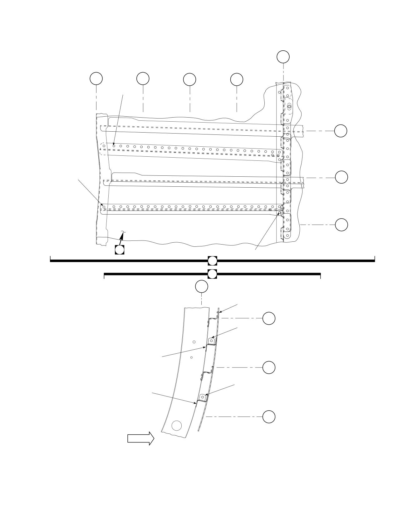
DMWR 1-1520-237
STA
505
STA
STA
STA
STA
485
490
495
500
3
WL
225
WL
5
220
WL
215
6
4
2
6
BL
15
LH
7
WL
225
8
9
12
WL
220
10
11
13
WL
215
OUTBD
AB3092_2
SA
Figure E-17. Stringer/Frame Modification Kit (Sheet 2 of 9)
E-179
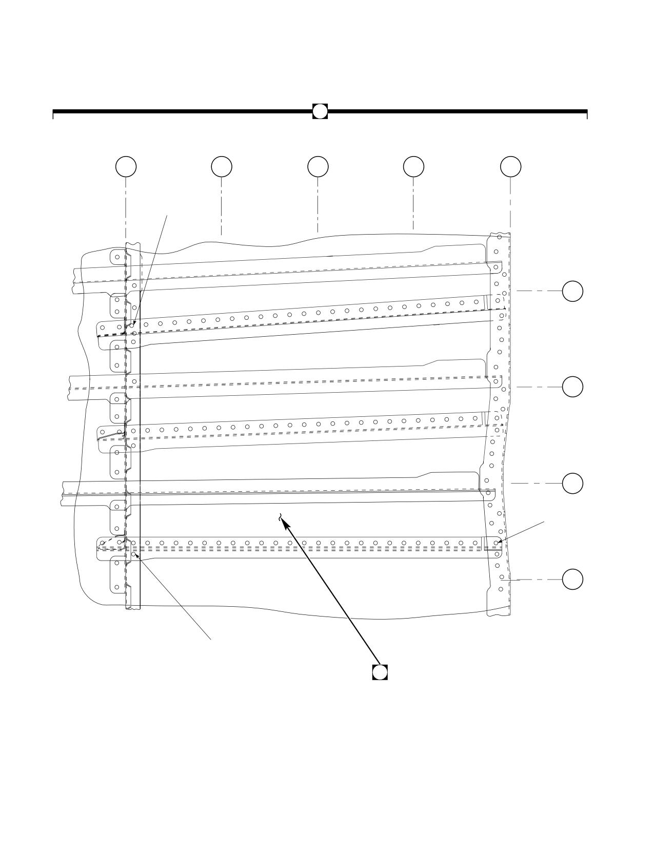
DMWR 1-1520-237
15
STA
STA
STA
STA
STA
505
500
495
490
485
16
WL
230
WL
225
WL
220
18
WL
215
17
19
AB3092_3
SA
Figure E-17. Stringer/Frame Modification Kit (Sheet 3 of 9)
E-180
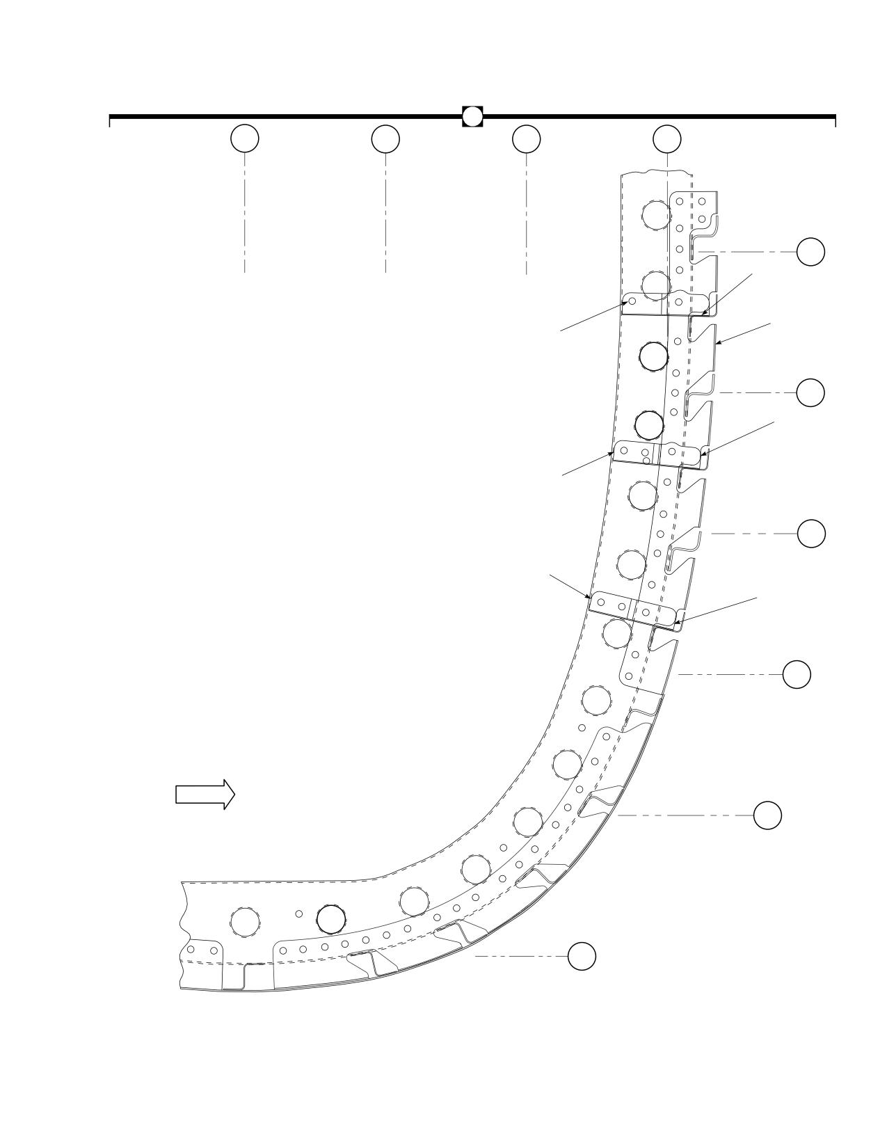
DMWR 1-1520-237
19
BL
BL
BL
BL
5
10
15
0
RH
RH
RH
WL
230
24
20
17
21
WL
225
25
22
WL
220
23
26
WL
215
OUTBD
WL
210
WL
205
AB3092_4
SA
Figure E-17. Stringer/Frame Modification Kit (Sheet 4 of 9)
E-181
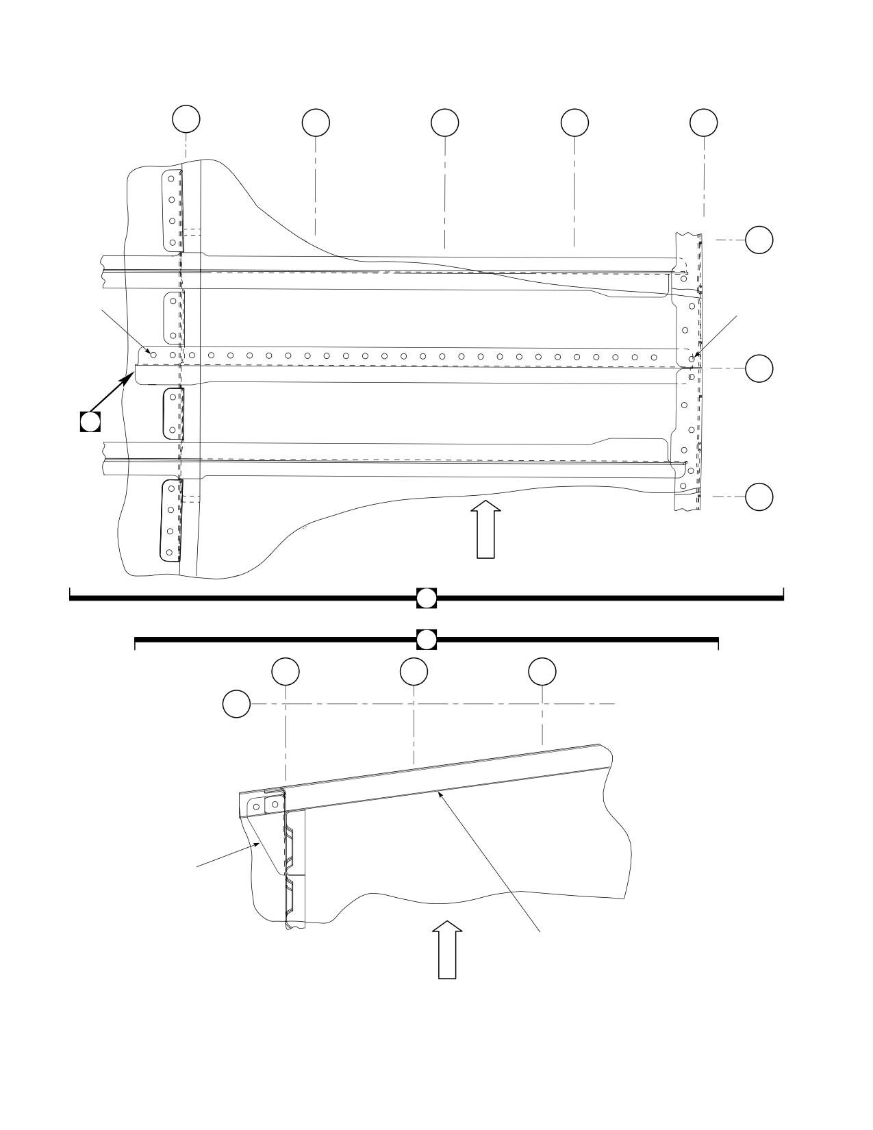
DMWR 1-1520-237
STA
STA
STA
STA
STA
505
500
495
490
485
BL
5
LH
30
31
BL
0
B
BL
5
RH
I
N
B
D
29
B
STA
STA
STA
505
500
495
WL
260
32
33
34
U
P
AB3092_5
SA
Figure E-17. Stringer/Frame Modification Kit (Sheet 5 of 9)
E-182
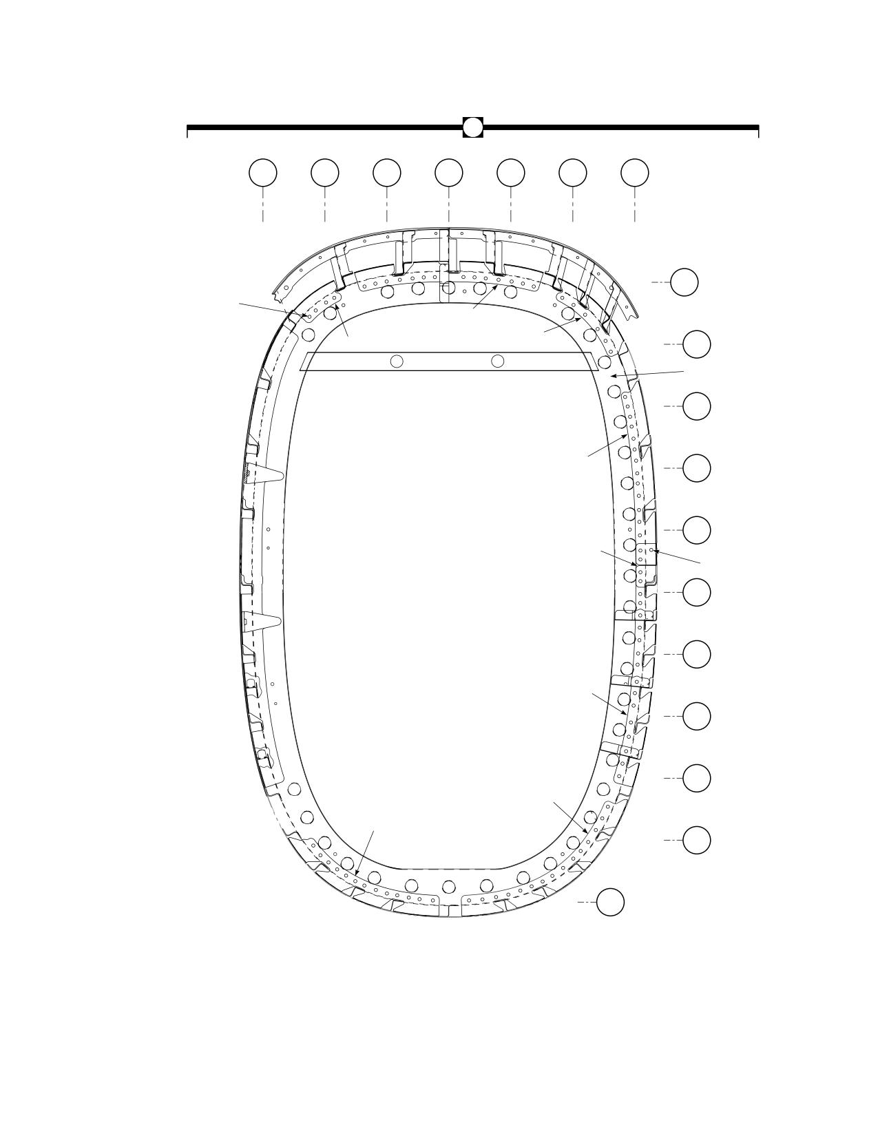
DMWR 1-1520-237
28
LBL
LBL
LBL
BL
RBL
RBL
RBL
15
10
5
0
5
10
15
WL
255
39
41
42
WL
40
250
35
WL
245
43
WL
240
WL
235
38
37
WL
230
WL
225
44
WL
220
WL
215
45
46
WL
210
WL
205
VIEW LOOKING FORWARD - STA 505
AB3092_6
SA
Figure E-17. Stringer/Frame Modification Kit (Sheet 6 of 9)
E-183
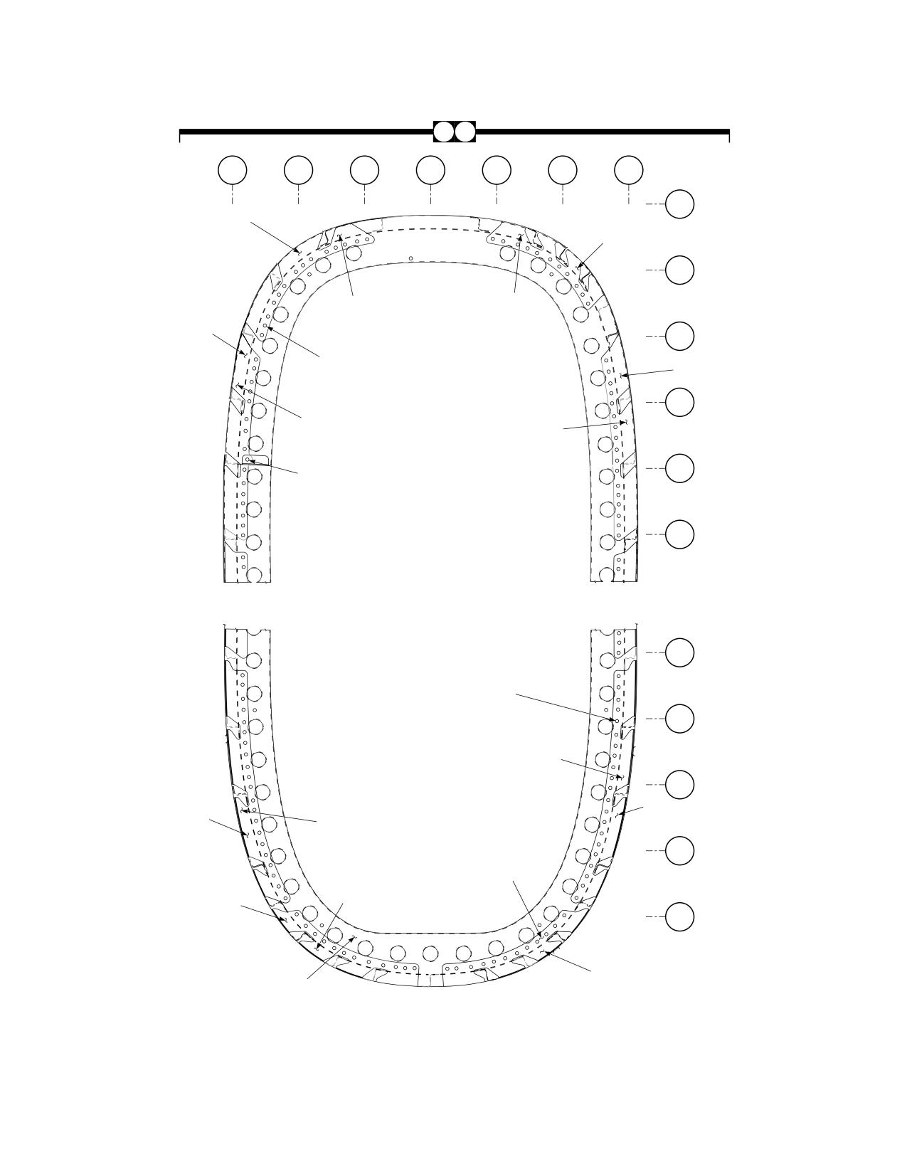
DMWR 1-1520-237
36 48
LBL
LBL
LBL
BL
RBL
RBL
RBL
15
10
5
0
5
10
15
WL
255
50
51
WL
250
62
63
WL
58
245
49
61
52
WL
240
70
64
WL
53
235
65
WL
230
WL
235
53
65
WL
230
66
WL
225
54
57
69
WL
220
67
68
56
WL
215
47
55
59
VIEW LOOKING FORWARD - STA 525
AB3092_7
SA
Figure E-17. Stringer/Frame Modification Kit (Sheet 7 of 9)
E-184
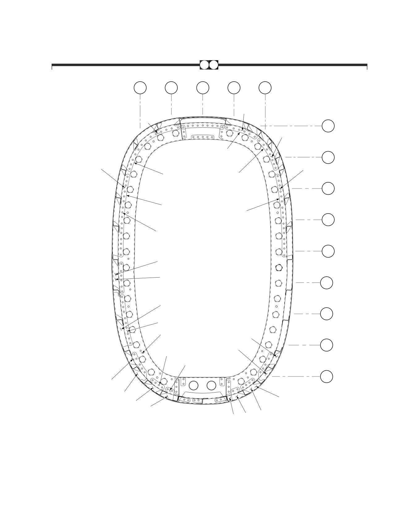
DMWR 1-1520-237
60 72
BL
BL
BL
BL
BL
10
5
0
5
10
LH
LH
RH
RH
92
91
WL
250
93
76
WL
245
90
94
75
77
WL
240
74
78
WL
235
73
89
WL
230
102
86
WL
225
85
WL
220
101
71
95
87
WL
79
215
99
98
WL
210
100
84
80
83
82
96
97
81
VIEW LOOKING FORWARD - STA 545
AB3092_8
SA
Figure E-17. Stringer/Frame Modification Kit (Sheet 8 of 9)
E-185
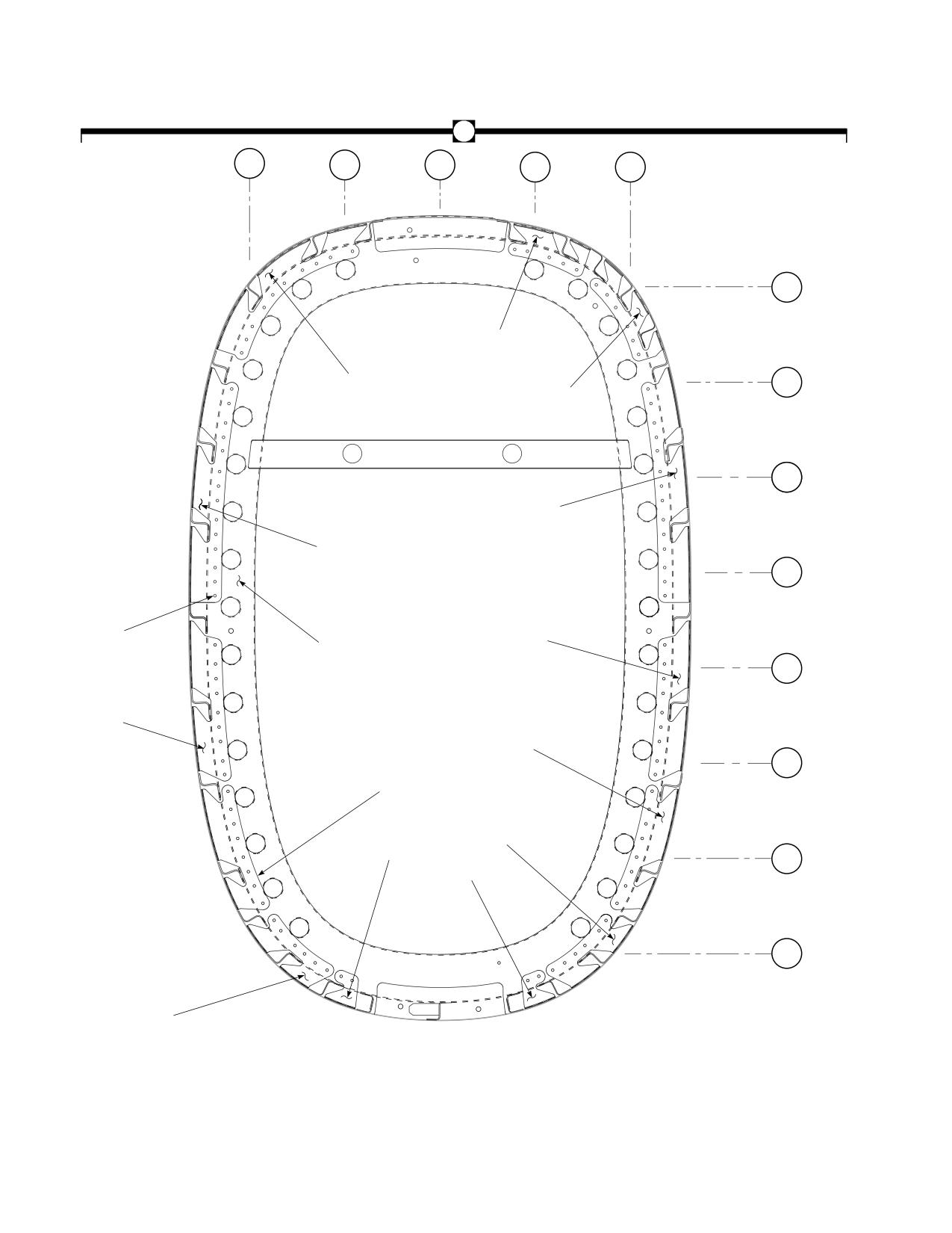
DMWR 1-1520-237
88
BL
BL
BL
BL
BL
10
5
0
5
10
LH
LH
LH
RH
RH
WL
245
107
WL
106
240
108
WL
235
109
105
WL
230
104
110
103
WL
225
117
111
WL
220
116
112
114
WL
215
113
WL
210
115
VIEW LOOKING FORWARD - STA 565
AB3092_9
SA
Figure E-17. Stringer/Frame Modification Kit (Sheet 9 of 9)
E-186
DMWR 1-1520-237
QTY
USABLE
FIGURE &
PER
ON
INDEX NO.
PART NUMBER
1 2 3 4 5 6 7
DESCRIPTION
ASSY
CODE
E-17-
70070-20582-011
STRINGER/FRAME MODIFICATION KIT
REF
-1
70070-20582-016
M/K PLATING, (Modified from 702113-05001-
011)
1
-2
70070-20582-022
. PLATING INSTL
REF
-3
MS20470AD4-4
. RIVET
55
-4
MS20470AD5-5
. RIVET
232
-5
MS20470AD5-6
. RIVET
5
-6
70070-20582-024
. M/K SKIN ASSY
1
-7
70070-20582-041
. . SKIN ASSY, (Reidentified from 70213-05001-
041)
REF
-8
MS20470AD4-5
. . RIVET
3
-9
SS1076-57
. . BRACKET ANGLE
1
-10
MS20470AD4-5
. . RIVET
3
-11
SS1076-183
. . BRACKET ANGLE
1
-12
70213-05001-157
. . STRINGER
1
-13
70213-05001-155
. . STRINGER
1
-14
70070-20582-017
M/K PLATING, (Modified from 70213-05001-012) ..
1
-15
70070-20582-023
. PLATING INSTL
REF
-16
MS20470AD4-4
. RIVET
89
-17
MS20470AD5-5
. RIVET
199
-18
MS20470AD5-6
. RIVET
4
-19
70070-20582-025
. M/K SKIN ASSY
1
-20
70070-20582-042
. . SKIN ASSY, (Reidentied from 70213-05001-
042)
REF
-21
96203-05001-150
. . CLIP
1
-22
96203-05001-151
. . CLIP
1
-23
96203-05001-152
. . CLIP
1
-24
70213-05001-159
. . STRINGER
1
-25
70213-05001-158
. . STRINGER
1
-26
70213-05001-156
. . STRINGER
1
-27
70070-20582-026
M/K SKIN ASSY
1
-28
70070-20582-018
. FRAME INSTL, (Modified from 70211-05002-
011)
REF
-29
70070-20582-043
. SKIN ASSY
REF
-30
MS20470AD4-4
. RIVET
30
-31
MS20470AD5-6
. RIVET
2
-32
MS20470AD4-5
. RIVET
6
-33
70070-20582-131
. BRACKET
1
-34
70213-05001-153
. STRINGER
1
-35
70070-20582-012
M/K FRAME
1
-36
70070-20582-019
. FRAME INSTL, (Modified from 70211-05003-
011)
REF
-37
MS20470AD5-6
. RIVET
12
-38
70084-25104-116
. SPLICE
1
-39
MS20470AD5-5
. RIVET
103
-40
70070-20582-137
. SHEAR TIE
1
-41
70070-20582-103
. SHEAR TIE
1
-42
70070-20582-134
. SHEAR TIE
1
-43
70070-20582-135
. SHEAR TIE
1
-44
70070-20582-102
. SHEAR TIE
1
-45
70070-20582-101
. SHEAR TIE
1
-46
70070-20582-136
. SHEAR TIE
1
-47
70070-20582-013
M/K FRAME
1
-48
70070-20582-029
. FRAME INSTL, (Modified from 70211-05003-
011)
REF
-49
MS20470AD5-5
. RIVET
134
-50
70070-20582-111
. SHEAR TIE
1
-51
70070-20582-104
. SHEAR TIE
1
-52
70070-20582-105
. SHEAR TIE
1
-53
MS20470AD5-6
. RIVET
2
-54
70070-20582-106
. SHEAR TIE
1
E-187
DMWR 1-1520-237
QTY
USABLE
FIGURE &
PER
ON
INDEX NO. PART NUMBER
1
2 3 4 5 6 7
DESCRIPTION
ASSY
CODE
-55
70070-20582-107
. SHEAR TIE
1
-56
70070-20582-108
. SHEAR TIE
1
-57
70070-20582-109
. SHEAR TIE
1
-58
70070-20582-110
. SHEAR TIE
1
-59
70070-20582-027
M/K FRAME
1
-60
70070-20582-020
. FRAME INSTL, (Modified from 70211-05004-
011)
REF
-61
MS20470AD5-5
. RIVET
134
-62
70070-20582-145
. SHEAR TIE
1
-63
70070-20582-144
. SHEAR TIE
1
-64
70070-20582-146
. SHEAR TIE
1
-65
MS20470AD5-6
. RIVET
2
-66
70070-20582-148
. SHEAR TIE
1
-67
70070-20582-150
. SHEAR TIE
1
-68
70070-20582-151
. SHEAR TIE
1
-69
70070-20582-149
. SHEAR TIE
1
-70
70070-20582-147
. SHEAR TIE
1
-71
70070-20582-014
M/K FRAME
1
-72
70070-20582-030
. FRAME INSTL, (Modified from 70211-05004-
011)
REF
-73
MS20470AD5-5
. RIVET
123
-74
70070-20582-139
. SHEAR TIE
1
-75
70070-20582-141
. SHEAR TIE
1
-76
70070-20582-132
. SHEAR TIE
1
-77
70070-20582-133
. SHEAR TIE
1
-78
70070-20582-140
. SHEAR TIE
1
-79
70070-20582-115
. SHEAR TIE
1
-80
70070-20582-142
. SHEAR TIE
1
-81
70070-20582-117
. SHEAR TIE
1
-82
70070-20582-116
. SHEAR TIE
1
-83
70070-20582-138
. SHEAR TIE
1
-84
70070-20582-114
. SHEAR TIE
1
-85
70070-20582-112
. SHEAR TIE
1
-86
70070-20582-143
. SHEAR TIE
1
-87
70070-20582-028
M/K FRAME
1
-88
70070-20582-021
. FRAME INSTL, (Modified from 70211-05005-
011)
REF
-89
MS20470AD5-5
. RIVET
123
-90
70070-20582-155
. SHEAR TIE
1
-91
70070-20582-153
. SHEAR TIE
1
-92
70070-20582-152
. SHEAR TIE
1
-93
70070-20582-154
. SHEAR TIE
1
-94
70070-20582-156
. SHEAR TIE
1
-95
70070-20582-158
. SHEAR TIE
1
-96
70070-20582-160
. SHEAR TIE
1
-97
70070-20582-162
. SHEAR TIE
1
-98
70070-20582-161
. SHEAR TIE
1
-99
70070-20582-159
. SHEAR TIE
1
-100
70070-20582-157
. SHEAR TIE
1
-101
70070-20582-164
. SHEAR TIE
1
-102
70070-20582-163
. SHEAR TIE
1
-103
70070-20582-015
M/K FRAME
1
-104
MS20470AD5-5
. RIVET
109
-105
70070-20582-119
. SHEAR TIE
1
-106
70070-20582-118
. SHEAR TIE
1
-107
70070-20582-129
. SHEAR TIE
1
-108
70070-20582-130
. SHEAR TIE
1
-109
70070-20582-120
. SHEAR TIE
1
-110
70070-20582-122
. SHEAR TIE
1
-111
70070-20582-124
. SHEAR TIE
1
-112
70070-20582-126
. SHEAR TIE
1
E-188
DMWR 1-1520-237
QTY
USABLE
FIGURE &
PER
ON
INDEX NO. PART NUMBER
1 2 3 4 5 6 7
DESCRIPTION
ASSY
CODE
-113
70070-20582-128
. . SHEAR TIE
1
-114
70070-20582-127
. . SHEAR TIE
1
-115
70070-20582-125
. . SHEAR TIE
1
-116
70070-20582-123
. . SHEAR TIE
1
-117
70070-20582-121
. . SHEAR TIE
1
E-189
DMWR 1-1520-237
E-17. SKIN DOUBLER/PLATE INSTALLATION MODIFICATION KIT (50-13).
Subject: Tail Cone Plating Modification Kit, Installation of, dated 31 March 2003
Purpose: Provide instructions for installations of tail cone lower plating modification kit and tail cone side skin modifica-
tion kit.
Model:
UH-60A
Description: Lower skin and doubler are removed between station 485.00 and station 605.00, and new lower skin and
doubler are installed. Doublers are installed left and right side of tail cone between stations 625.00 and 635.00.
Drawings Required for Modification:
70070-20615, 70212-05004, 70070-20583
References: (a) TM 1-1520-237-23, Aviation Unit And Intermediate Maintenance For Army Models UH-60A, UH-
60L, EH-60A, and UH-60Q Helicopters, Chapter 2, Airframe
(b) Special Service Instructions (SSI) No. 50-31, Installation of 9A to A9 Recapitalization Program, dated
March 31, 2003
(c) SSI No. 50-24, Tail Cone, Modification of dated 31 March 2003
Instructions:
NOTE
• A complete review of this SSI is recommended before modifying tail cone plating.
• Before beginning this modification procedure, use the material information list to inventory the kit. Make
sure all parts are present and in serviceable condition.
• The sheet metal and structural modifications in this SSI shall be done by personnel experienced in reading
modification drawings. Routine steps such as cleaning, layout and drilling, deburring, standard repairs,
corrosion control, clean up after rework, chemical coating for aluminum after cutting/trimming parts, paint
touch up, and safety practices may not be called out herein. However, these steps and all other required
routine tasks shall be done.
• Where drawing numbers are not listed within individual steps, drawing(s) listed in preceding step(s) are
the controlling authority.
• Slight variations to the instructions contained herein are allowed, as long as the intent of the modification
is accomplished.
• This modification is to be done concurrently with reference (c).
A.
Preparation for modification and removal of equipment:
(1)
Confirm that all warnings, cautions, and notes are complied with per reference (b).
(2)
Perform preparation for modification per reference (b).
E-190
DMWR 1-1520-237
B.
Modify tail cone as follows:
(1)
Remove skin assembly (70213-05001-043) as follows:
(a)
Remove fasteners securing skin assembly to frame between station 485.00 and station 585.00 (Dwg
70070-20615, Sheet 2, Zones 10-B through 10-G to 19-B through 19-G).
(b)
Remove skin assembly with stringers attached, and discard.
(c)
Inspect and clean exposed stringers and frame components per reference (a).
(2)
Rework left and right side tail cone between stations 625.00 and 635.00 as follows:
(a)
Locate doubler (70070-20583-101) on left side of tail cone between station 624.00 and station 635.00
along waterline 235.00 (Dwg 70070-20583, Sheet 2, Zone 6-H).
(b)
Mark and remove existing fasteners.
(c)
Locate doubler (70070-20583-102) on right side of tail cone between station 624.00 and station 635.00
along waterline 235.00 (Sheet 2, Zone 6-H).
(d)
Mark and remove existing fasteners.
(e)
Locate and temporarily secure doublers and back drill through existing fastener holes.
(f)
Remove doublers, deburr and touch up, as required. Remove skin assembly, deburr and touch up, as
required.
WARNING
OBSERVE ALL CAUTIONS AND WARNINGS ON CONTAINERS WHEN USING CONSUMABLES.
WHEN APPLICABLE, WEAR NECESSARY PROTECTIVE GEAR DURING HANDLING AND USE. IF A
CONSUMABLE IS FLAMMABLE OR EXPLOSIVE, MAKE CERTAIN CONSUMABLE AND ITS VAPORS ARE
KEPT AWAY FROM HEAT, SPARK, AND FLAME. MAKE CERTAIN EQUIPMENT IS PROPERLY
GROUNDED AND FIREFIGHTING EQUIPMENT IS READILY AVAILABLE PRIOR TO USE. FOR AD-
DITIONAL INFORMATION ON TOXICITY, FLASHPOINT, AND FLAMMABILITY OF CHEMICALS,
CONSULT YOUR MEDICAL PEOPLE, OR MANUFACTURER OF THE CONSUMABLE.
(g)
Install doublers (70070-20583-101 and -102) on left and right side wet with sealant (AMS-S-8802 or
AMS 3265 or equivalent) using fasteners shown (Sheet 2, Zone 6-H and Note 7).
NOTE
After modification structure assembly (70210-05001-045) becomes (70070-20583-041) and structure
assembly (70210-05001-046) becomes (70070-20583-042). No physical reidentification is required.
(3)
Perform reference (c) modification before completing skin assembly installation.
(4)
Install new skin assembly (70213-55001-041/-541) between stations 485.00 and 565.00 as follows:
E-191
DMWR 1-1520-237
(a)
Locate and temporarily install bracket (AN743Z12) on stringer at location shown (Dwg 70070-20615,
Sheet 2, Zone 12-B, Section J-J).
(b)
Drill fastener hole at location shown (Sheet 2, Zone 13-A).
(c)
Remove bracket, deburr and touch up, as required.
(d)
Secure bracket (AN743Z12) to stringer using fastener shown (Sheet 2, Zone 13-A).
(e)
Locate and temporarily secure new skin assembly (70213-55001-041/-541) onto frames (Sheet 2, Zones
10-B through 10-D to 19-B through 19-E).
WARNING
OBSERVE ALL CAUTIONS AND WARNINGS ON CONTAINERS WHEN USING CONSUMABLES.
WHEN APPLICABLE, WEAR NECESSARY PROTECTIVE GEAR DURING HANDLING AND USE. IF A
CONSUMABLE IS FLAMMABLE OR EXPLOSIVE, MAKE CERTAIN CONSUMABLE AND ITS VAPORS ARE
KEPT AWAY FROM HEAT, SPARK, AND FLAME. MAKE CERTAIN EQUIPMENT IS PROPERLY
GROUNDED AND FIREFIGHTING EQUIPMENT IS READILY AVAILABLE PRIOR TO USE. FOR AD-
DITIONAL INFORMATION ON TOXICITY, FLASHPOINT, AND FLAMMABILITY OF CHEMICALS,
CONSULT YOUR MEDICAL PEOPLE, OR MANUFACTURER OF THE CONSUMABLE.
(f)
Locate and bond grommets (AN231-4) eight places using adhesive (EA9309.3NA or equivalent) as shown
(Sheet 2, Zones 11-B and 19-B and Sheet 1, Note 9).
NOTE
Reference (c) shear ties at or below waterline 215.00 should be fit-out at this time to ensure proper
contour.
(g)
Remove skin assembly, and reference (c) shear ties, deburr and touch up, as required.
WARNING
OBSERVE ALL CAUTIONS AND WARNINGS ON CONTAINERS WHEN USING CONSUMABLES.
WHEN APPLICABLE, WEAR NECESSARY PROTECTIVE GEAR DURING HANDLING AND USE. IF A
CONSUMABLE IS FLAMMABLE OR EXPLOSIVE, MAKE CERTAIN CONSUMABLE AND ITS VAPORS ARE
KEPT AWAY FROM HEAT, SPARK, AND FLAME. MAKE CERTAIN EQUIPMENT IS PROPERLY
GROUNDED AND FIREFIGHTING EQUIPMENT IS READILY AVAILABLE PRIOR TO USE. FOR AD-
DITIONAL INFORMATION ON TOXICITY, FLASHPOINT, AND FLAMMABILITY OF CHEMICALS,
CONSULT YOUR MEDICAL PEOPLE, OR MANUFACTURER OF THE CONSUMABLE.
(h)
Apply adhesive (MIL-C-22750 or equivalent) on inboard side of skin and structure as shown (Sheet 2,
Zones 18-A through 18-E, and Sheet 1, Note 7).
E-192
DMWR 1-1520-237
WARNING
OBSERVE ALL CAUTIONS AND WARNINGS ON CONTAINERS WHEN USING CONSUMABLES.
WHEN APPLICABLE, WEAR NECESSARY PROTECTIVE GEAR DURING HANDLING AND USE. IF A
CONSUMABLE IS FLAMMABLE OR EXPLOSIVE, MAKE CERTAIN CONSUMABLE AND ITS VAPORS ARE
KEPT AWAY FROM HEAT, SPARK, AND FLAME. MAKE CERTAIN EQUIPMENT IS PROPERLY
GROUNDED AND FIREFIGHTING EQUIPMENT IS READILY AVAILABLE PRIOR TO USE. FOR AD-
DITIONAL INFORMATION ON TOXICITY, FLASHPOINT, AND FLAMMABILITY OF CHEMICALS,
CONSULT YOUR MEDICAL PEOPLE, OR MANUFACTURER OF THE CONSUMABLE.
(i)
Apply sealant (AMS-S-8802 A2 or equivalent) to skin overlap areas (Sheet 1, Note 8).
(j)
Secure skin onto frame and wet install fasteners as shown (Sheet 2, Zones 10-B through 10-D to 19-B
through 19-E).
NOTE
70070-20615-101 doubler may already be installed on skin 70213-55001. If installed proceed to step
C.(1).
(k)
Locate and temporarily secure doubler (70070-20615-101) (Sheet 2, Zone 14-B).
(l)
Drill fastener holes as shown (Sheet 2, Zone 14-B and Dwg 70212-05004, Sheet 1, Zone 17-C).
(m)
Remove doubler, deburr and touch up, as required.
WARNING
OBSERVE ALL CAUTIONS AND WARNINGS ON CONTAINERS WHEN USING CONSUMABLES.
WHEN APPLICABLE, WEAR NECESSARY PROTECTIVE GEAR DURING HANDLING AND USE. IF A
CONSUMABLE IS FLAMMABLE OR EXPLOSIVE, MAKE CERTAIN CONSUMABLE AND ITS VAPORS ARE
KEPT AWAY FROM HEAT, SPARK, AND FLAME. MAKE CERTAIN EQUIPMENT IS PROPERLY
GROUNDED AND FIREFIGHTING EQUIPMENT IS READILY AVAILABLE PRIOR TO USE. FOR AD-
DITIONAL INFORMATION ON TOXICITY, FLASHPOINT, AND FLAMMABILITY OF CHEMICALS,
CONSULT YOUR MEDICAL PEOPLE, OR MANUFACTURER OF THE CONSUMABLE.
(n)
Install sealant tape (AMS3255 CL2) to doubler seating surface (Dwg 70070-20615, Sheet 1, Note 10).
(o)
Secure doubler (70070-20615-101) using fasteners shown (Dwg 70213-55001, Sheet 1, Zone 14-B and
Dwg 70212-05004, Sheet 1, Zone 17-C, and Note 8).
C.
Reinstallation of removed equipment:
(1)
Install removed equipment per reference (b).
D.
Record of Compliance:
(1)
Make an appropriate logbook entry to show compliance with this Special Service Instruction.
E-193
DMWR 1-1520-237
Weight and Balance Data:
POUNDS
INCHES AFT
MOMENT/
QTY
PART NO.
NOMENCLATURE
WEIGHT
OF DATUM
1000
1
70070-20615-011
Mod. Kit
3.98
535.0
+2.129
1
70070-20583-011
Mod. Kit
+0.50
630.0
+0.315
Weight and Balance: Change resulting from these instructions are as follows:
Change in basic weight:
+4.5 pounds
Moment arm:
543.0 in.
Change in basic moment/1000:
+2.444
Manpower (Estimated)
No. of Personel
No. of Hours
Man-hours
Helicopter Mechanic
2
40.0
*80.0
*Does not include time required to prepare helicopter or return it to flight status.
E-194
DMWR 1-1520-237
Material Information:
A.
Modification Kits Required:
(1)
Kit A:
Qty
Nomenclature
Part Number
Source
1
Mod Kit, Plating Instl
70070-20615-011
(1)
consisting of:
8
Grommet
AN231-4
1
Bracket
AN743Z12
90
Rivet
MS20470AD4-5
84
Rivet
MS20470AD5-5
200
Rivet
MS20470AD5-6
70
Rivet
MS20470AD6-6
100
Rivet
MS20470AD6-8
12
Collar
NAS1080D06
6
Pin, Swg Lkg
NAS1526-02
6
Pin, Swg Lkg
NAS1526-03
1
Doubler
70070-20615-101*
1
Skin Assy
70213-55001-041/541*
*70213-55001-541 consists of 70213-55001-041 skin assembly and 70070-20615-101 doubler
(2)
Kit B:
Qty
Nomenclature
Part Number
Source
1
Mod. Kit, Skin Doubler,
70070-20583-011
(1)
consisting of:
1
Doubler
70070-20583-101
1
Doubler
70070-20583-102
14
Rivet
MS20470AD4-2
62
Rivet
MS20470AD5-3
3
Rivet
MS20470AD5-4
25
Rivet
MS20470AD6-4
3
Rivet
MS20470AD6-5
E-195
DMWR 1-1520-237
B.
Consumable Material:
WARNING
OBSERVE ALL CAUTIONS AND WARNINGS ON CONTAINERS WHEN USING CONSUMABLES.
WHEN APPLICABLE, WEAR NECESSARY PROTECTIVE GEAR DURING HANDLING AND USE. IF A
CONSUMABLE IS FLAMMABLE OR EXPLOSIVE, MAKE CERTAIN CONSUMABLE AND ITS VAPORS ARE
KEPT AWAY FROM HEAT, SPARK, AND FLAME. MAKE CERTAIN EQUIPMENT IS PROPERLY
GROUNDED AND FIREFIGHTING EQUIPMENT IS READILY AVAILABLE PRIOR TO USE. FOR AD-
DITIONAL INFORMATION ON TOXICITY, FLASHPOINT, AND FLAMMABILITY OF CHEMICALS,
CONSULT YOUR MEDICAL PEOPLE, OR MANUFACTURER OF THE CONSUMABLE.
Qty
Nomenclature
Part Number
Source
16 oz.
Sealant
AMS-S-8802 A2, or equivalent
(1)
8 oz.
Sealant
AMS 3255 CL2, or equivalent
(1)
8 oz.
Adhesive
EA9309-3NA, or equivalent
(1)
8 oz.
Epoxy, Clear
MIL-C-22750, or equivalent
(1)
C.
Source:
(1)
Available through normal supply channels
E-196
DMWR 1-1520-237
1
1
3
8
4
3
6
2
3
2
3
5
7
AB3122
SA
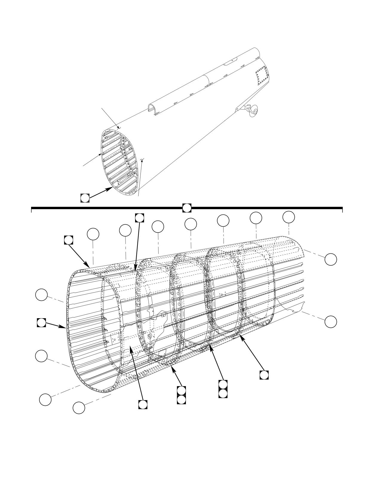
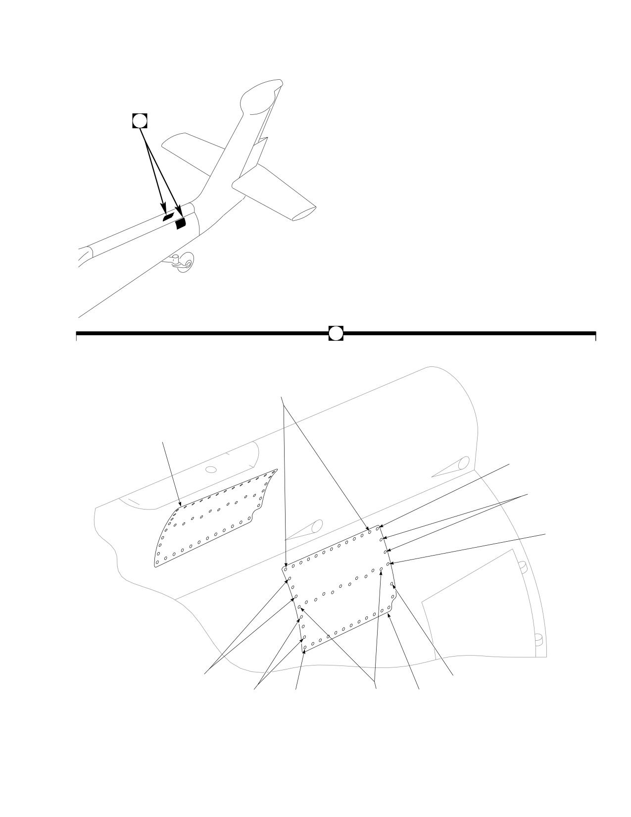
Figure E-18. Skin Doubler Modification Kit
E-197
DMWR 1-1520-237
QTY
USABLE
FIGURE &
PER
ON
INDEX NO.
PART NUMBER
1 2 3 4 5 6 7
DESCRIPTION
ASSY
CODE
E-18-
70070-20583-011
SKIN DOUBLER MODIFICATION KIT
REF
-1
70070-20583-041
STRUCTURAL ASSY, (Reidentifed from 70210-
05001-045)
REF
70070-20583-042
STRUCTURAL ASSY, (Reidentifed from 70210-
05001-046)
REF
-2
MS20470AD4-2
. RIVET
14
-3
MS20470AD5-3
. RIVET
62
-4
MS20470AD5-4
. RIVET
3
-5
MS20470AD6-4
. RIVET
25
-6
MS20470AD6-5
. RIVET
3
-7
70070-20583-101
. DOUBLER, LH
1
-8
70070-20583-102
. DOUBLER, RH
1
E-198
DMWR 1-1520-237
1
1
7
3
A
2
13
2
4
12
5
6
7
4
AB3123_1
8
5
SA
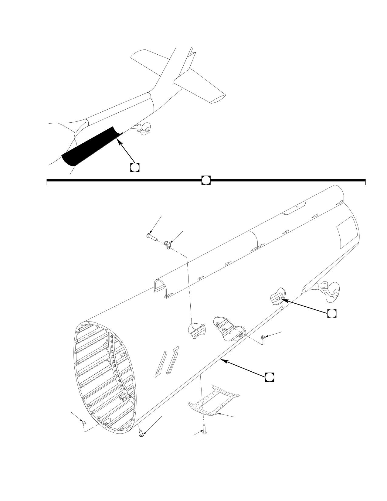
Figure E-19. Plate Installation Modification Kit (Sheet 1 of 2)
E-199
DMWR 1-1520-237
11
9
10
A
13
17
25
18
23
21
19
27
24
26
14
20
15
22
16
AB3123_2
SA
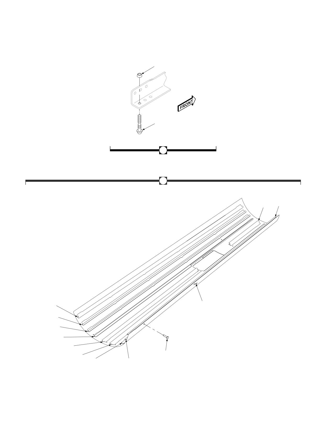
Figure E-19. Plate Installation Modification Kit (Sheet 2 of 2)
E-200
DMWR 1-1520-237
QTY
USABLE
FIGURE &
PER
ON
INDEX NO.
PART NUMBER
1 2 3 4 5 6 7
DESCRIPTION
ASSY
CODE
E-19-
70070-20615-011
PLATE INSTALLATION MODIFICATION KIT
REF
-1
70213-55001-011
. PLATING INSTL, (Reidentified from 70213-05001-
013)
REF
-2
AN231-4
. GROMMET
8
-3
AN743Z12
. BRACKET
1
-4
MS20470AD4-5
. RIVET
90
-5
MS20470AD5-5
. RIVET
84
-6
MS20470AD5-6
. RIVET
200
-7
MS20470AD6-6
. RIVET
70
-8
MS20470AD6-8
. RIVET
100
-9
NAS1526-02
. SWAGE LOCKING PIN
6
-10
NAS1526-03
. SWAGE LOCKING PIN
6
-11
NAS1080D06
. COLLAR
12
-12
70070-20615-101
. DOUBLER
1
-13
70213-55001-041
. SKIN ASSY
1
-14
MS20470AD4
. . RIVET
1009
-15
MS20470AD5
. . RIVET
246
-16
NAS1738B4-2
. . BLIND RIVET
28
-17
70213-05001-173
. . STRINGER
1
-18
70213-05001-174
. . STRINGER
1
-19
70213-05001-182
. . STRINGER
1
-20
70213-05001-183
. . STRINGER
1
-21
70213-05001-187
. . STRINGER
2
-22
70213-05001-188
. . STRINGER
2
-23
70213-05001-190
. . SKIN
1
-24
70213-55001-101
. . STRINGER
1
-25
70213-55001-102
. . STRINGER
1
-26
70213-55001-103
. . STRINGER
1
-27
70213-55001-104
. . STRINGER
1
E-201
DMWR 1-1520-237
E-18. BULKHEAD INSTALLATION MODIFICATION KIT (50-17).
Subject: Station 605.00 Bulkhead, Modification of
Purpose: Provide instructions to modify tailcone station 605.00 bulkhead
Model:
UH-60A
Description: Tailcone station 605.00 bulkhead is modified by adding a new doubler, filler, and radius block at right
buttline 4.80.
Drawings required for modification:
70551-05140, 70070-20617
References: (a) Special Service Instructions (SSI) No. 50-31, Installation of 9A to A9 Recapitalization Program, dated
March 31, 2003
(b) SSI No. 50-29 Tailcone Shear Deck, Modification of dated 31 March 2003
Instructions:
NOTE
• A complete review of this SSI is recommended before modiying station 605.00.
• Before beginning this modification procedure, use the material information list to inventory the kit. Make
sure all parts are present and in serviceable condition.
• Where drawing numbers are not listed within individual steps, drawing(s) listed in preceding step(s) are
the controlling authority.
• The sheet metal and structural modifications in this SSI shall be done by personnel experienced in reading
modification drawings. Routine steps such as cleaning, layout and drilling, deburring, standard repairs,
corrosion control, clean up after rework, chemical coating for aluminum after cutting/trimming parts, paint
touch up, and safety practices may not be called out herein. However, these steps and all other required
routine tasks shall be done.
• Slight variations to the instructions contained herein are allowed, as long as the intent of the modification
is accomplished.
• This modification is to be done concurrently with reference (b).
A.
Preparation for modification and removal of equipment:
(1)
Confirm that all warnings, cautions, and notes are complied with per reference (a).
(2)
Perform preparation for modification per reference (a).
E-202
DMWR 1-1520-237
B.
Rework channel (70211-05007-109) as follows (Dwg 70070-20617):
CAUTION
TO AVOID DAMAGING COMPONENTS, USE EXTREME CARE WHEN DRILLING INTO AIRFRAME.
TEMPORARILY MOVE ANY TUBE ASSEMBLIES OR WIRING HARNESS OUT OF REWORK AREA.
NOTE
• Rework of channel (70211-05007-109) can be accomplished while channel (-109) remains installed at
station 605.00.
• If shear deck is removed to facilitate other maintenance, proceed to step B.(4).
(1)
Rework channel (70211-05007-109) per dimensions shown (Dwg 70070-20617, Sheet 3, Zone 16-C).
(2)
Deburr and touch up channel (70211-05007-109) as required.
(3)
After rework reidentify channel (70211-05007-109) to (70070-20617-101) using pen and contracting ink.
(4)
Remove four clips (two SS1050-1 and two SS1051-3) (Sheet 2, Zones 15-H, 11-H, and 12-B).
(5)
Remove bracket assembly (SS7061-252) at buttline 0.00 (Sheet 2, Zone 9-E).
(6)
Remove fasteners between left buttline 3.50 and right buttline 4.80 from channels (70211-05007-108 and
-109) and angle (70211-05007-107) as shown (Sheet 1, Note 12 and Sheet 2, Zones 13-D and 13-E).
(7)
Temporarily install radius block (70070-20617-103), filler (70070-20617-104), and doubler (70070-
20617-105) (Sheet 2, Zones 7-C, 7-D, and 11-H, Sheet 1, Notes 14 and 15).
(8)
Temporarily install two clips (SS1051-03) (Sheet 2, Zones 11-H and 12-B).
(9)
Temporarily install bracket assembly (SS7061-252), two clips (SS1050-1), and nutplate (NAS1033N3)
(Dwg 70551-05140, Sheet 3, Zones 6-C, 6-E, and 8-E, View F-F).
(10)
Scribe directional cable hole in filler (70070-20617-104) and doubler (70070-20617-105).
(11)
Remove parts temporarily installed in steps B.(7) through B.(9), deburr and touch up as required.
(12)
Cut out hole in filler (70070-20617-104) and doubler (70070-20617-105) marked in step (B).(10).
(13)
Install parts removed in step B.(11) using fasteners shown (Dwg 70070-20617, Sheet 1, Notes 2, 9, 12,
and 16; Sheet 2, Zones 11-E through 13-E; Dwg 70551-05140, Sheet 3, View F-F, Zone 7-B).
E-203
DMWR 1-1520-237
WARNING
OBSERVE ALL CAUTIONS AND WARNINGS ON CONTAINERS WHEN USING CONSUMABLES.
WHEN APPLICABLE, WEAR NECESSARY PROTECTIVE GEAR DURING HANDLING AND USE. IF A
CONSUMABLE IS FLAMMABLE OR EXPLOSIVE, MAKE CERTAIN CONSUMABLE AND ITS VAPORS ARE
KEPT AWAY FROM HEAT, SPARK, AND FLAME. MAKE CERTAIN EQUIPMENT IS PROPERLY
GROUNDED AND FIREFIGHTING EQUIPMENT IS READILY AVAILABLE PRIOR TO USE. FOR AD-
DITIONAL INFORMATION ON TOXICITY, FLASHPOINT, AND FLAMMABILITY OF CHEMICALS,
CONSULT YOUR MEDICAL PEOPLE, OR MANUFACTURER OF THE CONSUMABLE.
(14)
Install grommet (MS21266-1N) using adhesive (SS9230-001 or equivalent) around control cable hole.
C.
Reinstallation of removed equipment:
(1)
Install removed equipment per reference (a).
D.
Record of Compliance:
(1)
Make an appropriate logbook entry to show compliance with this Special Service Instruction.
Weight and Balance Data:
POUNDS
INCHES AFT
MOMENT/
QTY
PART NO.
NOMENCLATURE
WEIGHT
OF DATUM
1000
1
70070-20617-011
Mod. Kit
+0.50
604.6
0.302
Weight and Balance: Change resulting from these instructions are as follows:
Change in basic weight:
+0.50 pounds
Moment arm:
604.6 in.
Change in basic moment/1000:
0.302
Manpower (Estimated)
No. of Personel
No. of Hours
Man-hours
Sheet Metal Mechanic
1
20.0
*20.0
*Does not include time required to prepare helicopter or return it to flight status.
E-204
DMWR 1-1520-237
Material Information:
A.
Modification Kit Required:
Qty
Nomenclature
Part Number
Source
1
Mod. Kit, Bulkhead Installation,
70070-20617-011
(1)
consisting of:
1
Collar
HL1087A-6
1
Pin, Hi Lok
HL20PB-6-7
3
Rivet
MS20470AD3-5
14
Rivet
MS20470AD4-5
5
Rivet
MS20470AD5-10
35
Rivet
MS20470AD5-6
9
Rivet
MS20470AD5-7
28
Rivet
MS20470AD5-9
2
Rivet
MS20470AD6-10
1
Nutplate
NAS1033N3
2
Clip
SS1050-1
2
Clip
SS1051-3
1
Bracket Assy
SS7061-252
1
Doubler
70070-20617-105
1
Radius Block
70070-20617-103
1
Filler
70070-20617-104
1
Grommet
MS21266-1N
B.
Consumable Material:
WARNING
OBSERVE ALL CAUTIONS AND WARNINGS ON CONTAINERS WHEN USING CONSUMABLES.
WHEN APPLICABLE, WEAR NECESSARY PROTECTIVE GEAR DURING HANDLING AND USE. IF A
CONSUMABLE IS FLAMMABLE OR EXPLOSIVE, MAKE CERTAIN CONSUMABLE AND ITS VAPORS ARE
KEPT AWAY FROM HEAT, SPARK, AND FLAME. MAKE CERTAIN EQUIPMENT IS PROPERLY
GROUNDED AND FIREFIGHTING EQUIPMENT IS READILY AVAILABLE PRIOR TO USE. FOR AD-
DITIONAL INFORMATION ON TOXICITY, FLASHPOINT, AND FLAMMABILITY OF CHEMICALS,
CONSULT YOUR MEDICAL PEOPLE, OR MANUFACTURER OF THE CONSUMABLE.
Qty
Nomenclature
Part Number
Source
1 oz.
Adhesive
SS9230-001 or equivalent
(1)
C.
Source:
(1)
Available through normal supply channels
E-205
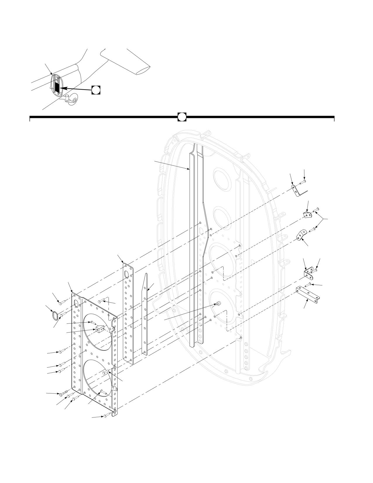
DMWR 1-1520-237
1
2
2
24
6
7
5
4
5
22
11
10
23
21
12
20
3
17
13
15
8
17
9
16
17
18
17
14
20
17
19
19
AB3084
SA
Figure E-20. Bulkhead Installation Modification Kit
E-206
DMWR 1-1520-237
QTY
USABLE
FIGURE &
PER
ON
INDEX NO.
PART NUMBER
1 2 3 4 5 6 7
DESCRIPTION
ASSY
CODE
E-20-
70070-20617-011
BULKHEAD INSTALLATION MODIFICATION KIT
REF
-1
70070-20617-012
. BULKHEAD INSTL. (Redentified from 70211-
05007-011)
REF
-2
70070-20617-041
. BULKHEAD ASSY (Reidentified from 70211-
05007-041)
REF
-3
MS21266-5N
. GROMMET
1
-4
MS20470AD4-5
. RIVET
4
-5
SS1050-1
. CLIP
2
-6
MS20470AD4-5
. RIVET
2
-7
SS1051-3
. CLIP
1
-8
MS20470AD3-5
. RIVET
3
-9
NAS1033N3
. NUTPLATE
1
-10
MS20470AD4-5
. RIVET
2
-11
SS1051-3
. CLIP
1
-12
MS20470AD4-5
. RIVET
2
-13
SS7061-252
. BRACKET ASSY
1
-14
HL20PB-6-7
. HI LOK PIN (73197)
1
-15
HL1087A-6
. COLLAR (73197)
1
-16
MS20470AD6-10
. RIVET
2
-17
MS20470AD5-6
. RIVET
12
-18
MS20470AD5-9
. RIVET
12
-19
MS20470AD5-7
. RIVET
7
-20
MS20470AD5-10
. RIVET
3
-21
70070-20617-105
. DOUBLER
1
-22
70070-20617-103
. RADIUS BLOCK
1
-23
70070-20617-104
. FILLER
1
-24
70070-20617-101
. CHANNEL (Reidentified from 70211-05007-109)
REF
E-207
DMWR 1-1520-237
E-19. TAIL PYLON, CRCT DOUBLER, FRONT SPAR FT MODIFICATION KIT (50-8).
Subject: Tail Rotor Pylon, Modification of, dated 31 March 2003
Purpose: Provide instructions for modification of tail rotor pylon.
Model:
UH-60A
Description: The tail rotor pylon is modified by installing a new left side doubler, two right side straps and cold working
eight fastener holes. Tail rotor gearbox mount fitting is removed and a new fitting is installed. Forward spar doubler is
replaced with a new doubler, one support assembly is modified and one support assembly is replaced with a new as-
sembly. Fairing installation is modified.
Drawings Required for Modification:
70070-20465, 70202-06051, 70201-06164
References: (a) Special Service Instructions (SSI) No. 50-31, Installation of 9A to A9 Recapitalization Program, dated
March 31, 2003
(b) TM 1-1520-265-23, Technical Manual, Aviation Unit Maintenance (AVUM) and Aviation Intermedi-
ate (AVIM) Manual, Nondestructive Inspection Procedure for H-60 Helicopter Series
(c) TM 1-1500-335-23, Technical Manual, Nondestructive Inspection Methods
Instructions:
NOTE
• AcompletereviewofthisSpecialServiceInstructions(SSI)isrecommendedbeforestartingthetailrotor
pylon modification.
• Before beginning this modification procedure, use the material information list to inventory the kit. Make
sure all parts are present and in serviceable condition.
• The sheet metal and structural modifications in this SSI shall be done by personnel experienced in reading
modification drawings. Routine steps such as cleaning, layout and drilling, deburring, standard repairs,
corrosion control, clean up after rework, chemical coating for aluminum after cutrting/trimming parts,
paint touch up and safety practices may not be called out herein. However, these steps and all other
required routine tasks shall be done.
• Where drawing numbers are not listed within individual steps, drawing(s) listed in preceding step(s) are
the controlling authority.
• Slight variations to the instructions contained herein are allowed, as long as the intent of the modification
is accomplished.
• Personnel must be trained and certified in hole quality assurance and proper cold expansion procedures
per SS5098.
A.
Preparation for modification and removal of equipment:
(1)
Confirm that all warnings, cautions, and notes are complied with per reference (a).
E-208
DMWR 1-1520-237
(2)
Perform preparation for modification per reference (a).
B.
Modify tail rotor pylon as follows:
(1)
Drill out fasteners and remove strap (70203-06050-114) from between pylon station 204.00 and pylon sta-
tion 212.00. Keep strap for use as template (Dwg 70070-20465, Sheet 4, Zone 4-E).
(2)
Remove washers, nuts, and fasteners as shown (Sheet 4, Zone 8-C).
(3)
Remove fasteners shown (Sheet 4, Zones 7-B through 10-B, 6-C through 10-C, 5-D through 8-D, 4-E, 6-E,
and 6-F).
(4)
Remove tail rotor gear box fitting (70209-06056-041) from tail rotor pylon as follows:
(a)
Locate and align tail rotor gearbox fitting installation tool (70209-06056-041T046 or equivalent) as
follows:
1
Thoroughly clean surface of tail rotor gear box mounting pads.
2
Install tool (70209-06056-041T046) on fitting (70209-06056-041) and secure in place using pins,
clamps, and barrel nuts.
3
Loosen two clamp block screws and thumb screws, and align pins with center of dimple in fastener.
4
Adjust rods and pointer to any four fasteners on each side of pylon. Tighten screws after correct position-
ing of pins.
5
Mark eight fastener heads with marker, or equivalent.
NOTE
These eight marked fasteners will be the trammel points to locate new fitting (70209-06056-042).
6
Apply torque stripe to each tool screw to ensure alignment.
7
Back pins out of fastener heads enough to allow for removal of tool, and remove mount fitting tool from
fitting.
8
Store and secure tool in such a way as to avoid disturbing tool settings.
(b)
Remove fasteners securing left and right side skin, between pylon station 200.31 and station 210.69 as
required (Dwg 70202-06051, Sheet 3, Zones 4-G and 5-G, and Sheet 2, Zones 4-C and 4-D through 6-C and 6-D).
(c)
Remove web splice fasteners as required (Sheet 2, Zones 3-J to 3-M through 6-J to 6-M).
(d)
Peel back pylon skin, as required, to remove fitting (70209-06056-041).
(e)
Remove angles as required.
(f)
Remove remaining fasteners securing fitting to pylon structure, and remove fitting (70209-06056-041).
(g)
Discard removed fitting (70209-06056-041).
(h)
Clean and inspect rework area.
E-209
DMWR 1-1520-237
(i)
Install new fitting (70209-06056-042) into position in pylon frame and secure inner structure components
with temporary fasteners or clamps.
(j)
Install alignment tool (70209-06056-041T046), align eight pins with eight marked fasteners and
temporarily secure.
(k)
Drill fastener holes, as required, on each leg of fitting and secure with temporary fasteners or clamps.
(l)
Recheck alignment tool to insure that pointers are still in position.
(m)
Remove alignment tool and continue drilling fastener holes, as required.
(5)
Modify forward spar and support assemblies as follows:
(a)
Drill out fasteners and remove support assembly (70400-06681-042, or -043) from pylon station 193.00
(Dwg 70070-20465, Sheet 8, Zones 12-G and 13-G, and Sheet 6, Notes 26, and 27).
(b)
Drill out fasteners and remove angle (70202-06051-149) as shown (Sheet 8, Zone 14-E).
(c)
Drill out fasteners and remove angle (70400-06680-143) at pylon station 187.00 (Sheet 8, Zone 6-F).
(d)
Drill out fasteners and remove support assembly (70400-06680-041) from pylon station 185.00 (Sheet 8,
Zone 15-B).
(e)
Drill out fasteners and remove doubler (70202-06051-158) from pylon station 190.47 (Sheet 8, Zone 13-
B).
(f)
Drill out fasteners and remove radius block (SS1058A7-27-46) (Sheet 8, Zone 6-C).
(g)
Drill out fasteners and remove radius block (SS1058A7-25-24) (Sheet 2, Zone 8-D).
(h)
Temporarily install new radius blocks (SS1058A7-25-24 and SS1058A7-27-46) as shown (Sheet 8,
Zones 8-D and 6-C).
(i)
Temporarily install doubler (70070-20465-104) at pylon station 190.47 (Sheet 8, Zone 13-B).
(j)
Temporarily install angle (70070-20465-105) as shown (Sheet 8, Zone 5-G).
(k)
Temporarily install angle (70202-06051-149) as shown (Sheet 8, Zone 14-E).
(l)
Mark and drill fastener holes in doubler (70070-20465-105), radius blocks (SS1058A7-25-24 and
SS1058A7-27-46), and angles (70070-20465-400-06680-143) and (70202-06051-149) (Sheet 8, Zones 12-C and
12-D through 13-C and 13-D, and 6-E, 6-C, 7-E, and 7-D).
(m)
Remove temporarily installed doubler, radius blocks, and angles, deburr and touch up as required.
(n)
Install radius blocks (SS1058A7-25-24 and SS1058A7-27-46) using fasteners shown (Sheet 8, Zones 8-D
and 6-C).
(o)
Install doubler (70070-20465-104) and angle (70070-20465-105) and (70202-06051-149) using
fasteners shown (Dwg 70070-20465, Sheet 8, Zone 12-C, 12-D through 14-C and 14-D, and 5-D through 7-D).
(p)
Temporarily install support assembly (70400-06680-546) with laminated shim (70400-06680-145) (if
required) as shown (Sheet 8, Zones 10-B and 11-C). Adjust shim as required.
E-210
DMWR 1-1520-237
(q)
Temporarily install new support assembly (70400-06681-044) as shown (Sheet 8, Zone 12-G).
(r)
Mark and drill fastener holes through temporarily installed support assemblies, and shim as required.
(s)
Remove temporarily installed support assembly with laminated shim and support assembly (70400-
06681-044), deburr and touch up as required.
(t)
Install support assembly (70400-06680-046) with laminated shim (70400-06680-145) (if required) and
secure using fasteners shown (Sheet 8, Zones 10-B and 11-C).
(u)
Install support assembly (70400-06681-044) using fasteners shown (Sheet 8, Zones 12-G and 13-G).
(v)
After modification, reidentify upper spar assembly (70202-06051-043) to (70070-20465-044) and up-
per spar assembly (70202-06051-044) to (70070-20465-045) using pen and constrasting ink.
NOTE
After modification, spar installation (70202-06051-012) becomes (70070-20465-030), support installa-
tion (70400-06680-012) becomes (70070-20465-031), and support installation (70400-06680-014)
becomes (70070-20465-032). No physical reidentification required.
(6)
Install new tail rotor gearbox fitting (70209-06056-042) as follows:
(a)
Remove fitting and deburr all components, as required.
WARNING
OBSERVE ALL CAUTIONS AND WARNINGS ON CONTAINERS WHEN USING CONSUMABLES.
WHEN APPLICABLE, WEAR NECESSARY PROTECTIVE GEAR DURING HANDLING AND USE. IF A
CONSUMABLE IS FLAMMABLE OR EXPLOSIVE, MAKE CERTAIN CONSUMABLE AND ITS VAPORS ARE
KEPT AWAY FROM HEAT, SPARK, AND FLAME. MAKE CERTAIN EQUIPMENT IS PROPERLY
GROUNDED AND FIREFIGHTING EQUIPMENT IS READILY AVAILABLE PRIOR TO USE. FOR AD-
DITIONAL INFORMATION ON TOXICITY, FLASHPOINT, AND FLAMMABILITY OF CHEMICALS,
CONSULT YOUR MEDICAL PEOPLE, OR MANUFACTURER OF THE CONSUMABLE.
(b)
Locate fitting, wet with sealant (AMS-S-8802, A2, or equivalent) and install fasteners wet with primer (MIL-
P-23377, or equivalent) securing fitting to pylon structure (Dwg 70070-20465, Sheet 4, Zone 11-E and Dwg 70202-
06051, Sheet 2, Zones 6-J through 6-M and 3-J through 3-M).
NOTE
After installation, fitting assembly (70209-06056-042) fitting becomes (-041). No physical reidentification
required.
(c)
Install right side skin and temporarily secure, as required.
(d)
Install cold worked fasteners right side pylon as follows:
1
Locate and remove eight fasteners shown (Dwg 70070-20465, Sheet 4, Zones 6-F and 13-F).
2
Measure and mark eight fastener holes using edge distance tool (70700-77399-041) (Sheet 4, Zones
6-F and 13-F, and Sheet 2, Note 16).
E-211
DMWR 1-1520-237
3
Prepare cold work area (Sheet 3, Note 25).
4
Inspect eight holes prior to cold working as shown (Sheet 4, Zones 6-F and 13-F, and Sheet 2, Note 16).
5
Cold work eight holes shown (Sheet 4, Zones 6-F and 13-F, Notes 16 and 17 and reference (b) and (c)).
6
Inspect eight holes after cold working (Sheet 2, Notes 16 and 17).
7
Install eight fasteners into cold worked holes as shown (Sheet 4, Zones 8-F and 13-F).
(e)
Place template (70070-20422-104) on inboard side of strap (70203-06050-114) kept for reuse (Sheet 4,
Zone 4-E).
(f)
Position template (70070-20422-104) and strap (70203-06050-114) over existing hole pattern on pylon
and trace holes onto template (Dwg 70070-20465, Sheet 2, Note 21).
(g)
Temporarily position straps (70203-06050-122 and -123) on pylon, and trim as required (Sheet 4, Zone
7-B and 4-D).
(h)
Drill existing holes in new straps (70203-06050-122 and -123) using template (70070-20422-104).
(i)
Remove templates and discard.
(j)
Remove straps (70203-06050-122 and -123), deburr and touch up as required.
WARNING
OBSERVE ALL CAUTIONS AND WARNINGS ON CONTAINERS WHEN USING CONSUMABLES.
WHEN APPLICABLE, WEAR NECESSARY PROTECTIVE GEAR DURING HANDLING AND USE. IF A
CONSUMABLE IS FLAMMABLE OR EXPLOSIVE, MAKE CERTAIN CONSUMABLE AND ITS VAPORS ARE
KEPT AWAY FROM HEAT, SPARK, AND FLAME. MAKE CERTAIN EQUIPMENT IS PROPERLY
GROUNDED AND FIREFIGHTING EQUIPMENT IS READILY AVAILABLE PRIOR TO USE. FOR AD-
DITIONAL INFORMATION ON TOXICITY, FLASHPOINT, AND FLAMMABILITY OF CHEMICALS,
CONSULT YOUR MEDICAL PEOPLE, OR MANUFACTURER OF THE CONSUMABLE.
(k)
Place two straps (70203-06050-122 and -123) into position wet with sealant (AMS-S-8802, A-2, or
equivalent) (Sheet 4, Zones 4-E and 6-B, and Sheet 2, Note 19).
WARNING
OBSERVE ALL CAUTIONS AND WARNINGS ON CONTAINERS WHEN USING CONSUMABLES.
WHEN APPLICABLE, WEAR NECESSARY PROTECTIVE GEAR DURING HANDLING AND USE. IF A
CONSUMABLE IS FLAMMABLE OR EXPLOSIVE, MAKE CERTAIN CONSUMABLE AND ITS VAPORS ARE
KEPT AWAY FROM HEAT, SPARK, AND FLAME. MAKE CERTAIN EQUIPMENT IS PROPERLY
GROUNDED AND FIREFIGHTING EQUIPMENT IS READILY AVAILABLE PRIOR TO USE. FOR AD-
DITIONAL INFORMATION ON TOXICITY, FLASHPOINT, AND FLAMMABILITY OF CHEMICALS,
CONSULT YOUR MEDICAL PEOPLE, OR MANUFACTURER OF THE CONSUMABLE.
(l)
Install fasteners wet with primer (MIL-P-23377, or equivalent) as shown (Sheet 4, Zones 4-E, 5-C, 6-C, 6-D,
7-A through 7-D, 8-A, through 8-C, 9-B, 10-A, and 10-B; and Sheet 2, Notes 11 and 13).
E-212
DMWR 1-1520-237
(m)
Install hardware and fasteners shown (Sheet 4, Zones 8-C and 6-F, and Sheet 3, Notes 26 and 29).
WARNING
OBSERVE ALL CAUTIONS AND WARNINGS ON CONTAINERS WHEN USING CONSUMABLES.
WHEN APPLICABLE, WEAR NECESSARY PROTECTIVE GEAR DURING HANDLING AND USE. IF A
CONSUMABLE IS FLAMMABLE OR EXPLOSIVE, MAKE CERTAIN CONSUMABLE AND ITS VAPORS ARE
KEPT AWAY FROM HEAT, SPARK, AND FLAME. MAKE CERTAIN EQUIPMENT IS PROPERLY
GROUNDED AND FIREFIGHTING EQUIPMENT IS READILY AVAILABLE PRIOR TO USE. FOR AD-
DITIONAL INFORMATION ON TOXICITY, FLASHPOINT, AND FLAMMABILITY OF CHEMICALS,
CONSULT YOUR MEDICAL PEOPLE, OR MANUFACTURER OF THE CONSUMABLE.
(n)
Install right side upper plate (70203-06050-112), wet with sealant (AMS-S-8802, A2, or equivalent), into
position and secure with fasteners shown (Dwg 70202-06051, Sheet 2, Zones 4-C, 4-D through 6-C and 6-D).
NOTE
• After modification plating assembly (70203-06050-044) becomes (70203-06050-047). No physical re-
identification required.
• After modification, plating installation (70203-06050-016) becomes (70203-06050-017). No physical
reidentification required.
(7)
Modify left side plating installation as follows:
(a)
Drill out fasteners and remove strap (70203-06050-113) from between pylon station 194.00 and pylon
station 216.00 left side (Dwg 70070-20465, Sheet 7, Zone 12-C).
(b)
Drill out fasteners and remove strap (70201-06164-102) from between pylon station 215.00 and 225.00
as shown (Sheet 7, Zone 7-C).
(c)
Position and temporarily install strap (70070-20465-102) as shown (Sheet 7, Zone 7-C).
NOTE
70070-20465-101 strap may require trimming if whip antenna modification has been installed.
(d)
Position and temporarily install strap (70070-20465-101) as shown (Sheet 7, Zones 12-C).
(e)
Mark and drill fastener holes in two straps, as shown (Sheet 7, Zones 9-C through 11-F and 11-E through
15-F).
(f)
Mark one receptacle location and seven nutplate locations, and backdrill fastener holes from skin (Sheet 7,
Zones 15-F and 14-B).
(g)
Mark 12 nutplate locations, and backdrill fastener holes as shown (Dwg 70201-06164, Sheet 1, Zone
6-E).
(h)
Remove two straps, deburr and touch up as required.
E-213
DMWR 1-1520-237
(i)
Install 12 nutplates (MS21075-3) in strap (70070-20465-102) with fasteners as shown (Dwg 70201-
06164, Sheet 1, Zone 6-E).
(j)
Install receptacle (212-12) and seven nutplates (MS21075-3) in doubler (70070-20465-101) using fasten-
ers shown (Dwg 70070-20465, Sheet 7, Zones 15-F and 14-B).
WARNING
OBSERVE ALL CAUTIONS AND WARNINGS ON CONTAINERS WHEN USING CONSUMABLES.
WHEN APPLICABLE, WEAR NECESSARY PROTECTIVE GEAR DURING HANDLING AND USE. IF A
CONSUMABLE IS FLAMMABLE OR EXPLOSIVE, MAKE CERTAIN CONSUMABLE AND ITS VAPORS ARE
KEPT AWAY FROM HEAT, SPARK, AND FLAME. MAKE CERTAIN EQUIPMENT IS PROPERLY
GROUNDED AND FIREFIGHTING EQUIPMENT IS READILY AVAILABLE PRIOR TO USE. FOR AD-
DITIONAL INFORMATION ON TOXICITY, FLASHPOINT, AND FLAMMABILITY OF CHEMICALS,
CONSULT YOUR MEDICAL PEOPLE, OR MANUFACTURER OF THE CONSUMABLE.
(k)
Install straps (70070-20465-101) and (70070-20465-102) wet with sealant (AMS-S-8802, A2, or
equivalent), into position with fasteners shown (Sheet 7, Zones 11-E, 12-D, 13-D, 14-E, and 14-F, and 10-C and 10-D).
(l)
After modification reidentify plating assembly (70203-06050-043) to (70070-20465-041), rib assembly
(70201-06154-043) to (70070-20465-042) and rib assembly (70201-06154-045) to (70070-20465-043) using pen
and contrasting ink.
NOTE
After modification, plating installation (70203-06050-011) becomes (70070-20465-023), plating instal-
lation (70203-06050-013) becomes (70070-20465-024), plating installation (70203-06050-015)
becomes (70070-20465-025), and rib installation (70201-06164-011) becomes (70070-20465-026).
No physical reidentification required.
(8)
Modify fairing installation (70205-06052-012) as follows:
(a)
Remove screws, washers, nutplates and fasteners shown (Dwg 70070-20465, Sheet 4, Zones 18-C, 18-H,
and 20-F).
(b)
Remove receptacles, studs, washers, and fasteners shown (Sheet 4, Zones 15-G, 17-C, 17-H, and Sheet
3, Note 30).
(c)
Locate and temporarily install two fillers (70070-20422-101 and -103) as shown (Sheet 4, Zones 19-C
and 21-C).
(d)
Locate and temporarily Install spacer (70070-20422-102) as shown (Sheet 4, Zone 15-E, and Sheet 2,
Note 24).
(e)
Mark and drill fastener holes, as required.
(f)
Remove temporarily installed fillers and spacer, deburr and touch up as required.
E-214
DMWR 1-1520-237
WARNING
OBSERVE ALL CAUTIONS AND WARNINGS ON CONTAINERS WHEN USING CONSUMABLES.
WHEN APPLICABLE, WEAR NECESSARY PROTECTIVE GEAR DURING HANDLING AND USE. IF A
CONSUMABLE IS FLAMMABLE OR EXPLOSIVE, MAKE CERTAIN CONSUMABLE AND ITS VAPORS ARE
KEPT AWAY FROM HEAT, SPARK, AND FLAME. MAKE CERTAIN EQUIPMENT IS PROPERLY
GROUNDED AND FIREFIGHTING EQUIPMENT IS READILY AVAILABLE PRIOR TO USE. FOR AD-
DITIONAL INFORMATION ON TOXICITY, FLASHPOINT, AND FLAMMABILITY OF CHEMICALS,
CONSULT YOUR MEDICAL PEOPLE, OR MANUFACTURER OF THE CONSUMABLE.
(g)
Install two fillers (70070-20422-101 and -103) wet with adhesive (EA9309.3NA, or equivalent) using
fasteners shown (Sheet 4, Zones 19-C and 21-C, and Sheet 2, Note 15).
WARNING
OBSERVE ALL CAUTIONS AND WARNINGS ON CONTAINERS WHEN USING CONSUMABLES.
WHEN APPLICABLE, WEAR NECESSARY PROTECTIVE GEAR DURING HANDLING AND USE. IF A
CONSUMABLE IS FLAMMABLE OR EXPLOSIVE, MAKE CERTAIN CONSUMABLE AND ITS VAPORS ARE
KEPT AWAY FROM HEAT, SPARK, AND FLAME. MAKE CERTAIN EQUIPMENT IS PROPERLY
GROUNDED AND FIREFIGHTING EQUIPMENT IS READILY AVAILABLE PRIOR TO USE. FOR AD-
DITIONAL INFORMATION ON TOXICITY, FLASHPOINT, AND FLAMMABILITY OF CHEMICALS,
CONSULT YOUR MEDICAL PEOPLE, OR MANUFACTURER OF THE CONSUMABLE.
(h)
Install spacer (70070-20422-102) wet with adhesive (EA9309.3NA, or equivalent) using fasteners shown
(Sheet 4, Zone 15-E, and Sheet 2, Notes 15 and 24).
(i)
Install nutplates, screws, washers, and fasteners shown (Dwg 70070-20465, Sheet 4, Zones 18-C, 18-H,
and 20-F).
(j)
Install receptacles with fasteners shown (Sheet 4, Zones 15-G, 16-C, and 17-G).
(k)
After modification reidentify fairing assembly (70205-06052-061) to (70205-06052-065), and fairing
assembly (70205-06052-053) to (70205-06052-067) using pen and contrasting ink.
NOTE
After modification, fairing installation (70205-06052-012) becomes (70205-06052-013). No physical
reidentification required.
C.
Reinstallation of removed equipment:
(1)
Reinstall removed equipment per reference (a).
D.
Record of Compliance:
(1)
Make an appropriate logbook entry to show compliance with this Special Service Instruction.
E-215
DMWR 1-1520-237
Weight and Balance Data:
POUNDS
INCHES AFT
MOMENT/
QTY
PART NO.
NOMENCLATURE
WEIGHT
OF DATUM
1000
1
70070-20465-017
Mod. Kit
+2.0
736.0
+1.47
1
70070-20465-019
Mod. Kit
+0.4
707.6
+0.28
1
70070-20465-020
Mod. Kit
+0.3
721.7
+0.22
Weight and Balance: Change resulting from these instructions are as follows:
Change in basic weight:
+2.7 pounds
Moment arm:
729.6 in.
Change in basic moment/1000:
1.97
Manpower (Estimated)
No. of Personel
No. of Hours
Man-hours
Helicopter Mechanic
1
120.0
*120.0
*Does not include time required to prepare helicopter or return it to flight status.
Material Information:
A.
Modification kits required:
(1)
Kit A:
Qty
Nomenclature
Part Number
Source
1
Mod Kit, Tail Rotor Pylon,
70070-20465-017
(1)
consisting of:
1
Mod Kit, Plating Instl,
70070-20465-012
consisting of:
4
Washer
AN960D10L
3
Washer
AN960D8L
8
Collar
HL1087A-5
14
Collar
HL1087A-6
9
Pin
HL19PB-5-5
2
Pin
HL19PB-5-6
2
Pin
HL19PB-6-6
E-216
DMWR 1-1520-237
Qty
Nomenclature
Part Number
Source
3
Pin, Hi Lok
HL20PB-6-4
4
Pin, Hi Lok
HL20PB-6-5
5
Pin, Hi Lok
HL20PB-6-6
4
Pin, Hi Lok
HL20PB-6-7
4
Collar
HL375-6AW
16
Rivet
MS20470AD5-9
9
Rivet
MS20470AD6-9
3
Nut
MS21043-08
4
Nut
MS21043-3
5
Rivet
NAS1097AD4-9
6
Rivet
NAS1097AD5-9
1
Template
70070-20422-104
1
Strap
70203-06050-122
1
Strap
70203-06050-123
1
Mod Kit, Fairing,
70070-20465-014
consisting of:
5
Washer
AN960KD10L
8
Rivet
MS20605S3W5
2
Rivet
MS20605S3W7
1
Nutplate
MS21075-3
5
Screw
MS27039-1-16
4
Nutplate
SS5091-03-5
1
Mod Kit,
70070-20465-015
consisting of:
2
Rivet
MS20426AD3-9
6
Rivet
MS20605S3W5
3
Receptacle
212-12
3
Camlock Stud
26S51-11
3
Washer
2600-SW
1
Spacer
70070-20422-102
1
Mod Kit,
70070-20465-016
consisting of:
1
Filler
70070-20422-101
1
Filler, Tapered
70070-20422-103
1
Mod Kit, Fitting,
70070-20465-018
consisting of:
4
Pin, Hi Lok
HL20PB-6-6
4
Hi Lok
HL220PB-6-6
4
Collar
HL375-6AW
4
Collar
HL70-6
E-217
DMWR
1-1520-237
Qty
Nomenclature
Part Number
Source
21
Collar
NAS1080-06
31
Rivet
MS20470AD4-4
31
Rivet
MS20470AD4-6
25
Rivet
MS20470AD5-6
8
Pin, Swg Lkg
NAS1466-03
6
Pin, Swg Lkg
NAS1466-04
4
Pin, Swg Lkg
NAS1466-05
7
Rivet, Blind
NAS1738B4-3
8
Rivet, Blind
NAS1738B5-3
25
Rivet, Blind
NAS1738B5-5
8
Pin, Swg Lk
NAS1466-06
13
Pin, Swg Lk
NAS1526-03
4
Pin, Swg Lk
NAS1526-05
1
Fitting Assy
70209-06056-042
(2)
Kit B:
Qty
Nomenclature
Part Number
Source
1
Mod Kit, Crescent Doubler,
70070-20465-019
consisting of:
1
Mod Kit, Plating,
70070-20465-021
consisting of:
16
Rivet
CCR264SS-3-2
8
Rivet
MS20470AD5-5
7
Nutplate
MS21075-3
45
Rivet
NAS1097AD4-5
20
Rivet
NAS1097AD5-5
3
Pin, Swg Lkg
NAS1465-03
2
Pin, Swg Lkg
NAS1466-03
3
Pin, Swg Lkg
NAS1466-04
3
Pin, Swg Lkg
NAS1466-05
6
Pin, Swg Lkg
NAS1466-06
3
Rivet, Blind
NAS1738B4-3
4
Rivet, Blind
NAS1738B4-5
3
Rivet, Blind
NAS1739B4-4
4
Rivet, Blind
NAS1739B4-5
1
Receptacle
212-12
1
Strap
70070-20465-101
1
Mod Kit, Plating,
70070-20465-022
consisting of:
12
Nutplate
MS21075-3
30
Rivet
NAS1097AD3-3
E-218
DMWR 1-1520-237
Qty
Nomenclature
Part Number
Source
4
Rivet, Blind
NAS1738B5-4
25
Rivet, Blind
NAS1738B5-3
4
Rivet, Blind
NAS1738B5-4
1
Strap
70070-20465-102
(3)
Kit C:
Qty
Nomenclature
Part Number
Source
1
Mod Kit, Fwd Spar,
70070-20465-020
consisting of:
1
Mod Kit, Fwd Spar,
70070-20465-027
consisting of:
35
Rivet
MS20470AD5-9
1
Radius Block
SS1058A7-25-24
1
Radius Block
SS1058A7-27-46
1
Doubler
70070-20465-104
1
Stiffener
70202-06051-149
1
Mod Kit, Spprt Instl,
70070-20465-028
consisting of:
3
Pin
HL19PB-5-4
3
Pin Collar Assy
HL20PB86-5-6
1
Pin Collar Assy
HL20PB86-5-7
3
Collar
HL70TW-5
1
Support Assembly
70400-06681-044
1
Mod Kit, Spprt Instl,
70070-20465-029
consisting of:
10
Collar
HL1087ATW-5
3
Collar
HL1087ATW-6
4
Pin, Hi Lok
HL20PB-5-2
5
Pin, Hi Lok
HL20PB-5-3
1
Pin, Hi Lok
HL20PB-5-4
3
Pin, Hi Lok
HL20PB-6-8
6
Rivet
MS20470AD5-4
1
Support Assy
70400-06680-546
2
Bushing
NAS538-5P10
1
Angle
70070-20465-105
1
Laminated Shim
70400-06680-145
E-219
DMWR 1-1520-237
B.
Consumable Material:
WARNING
OBSERVE ALL CAUTIONS AND WARNINGS ON CONTAINERS WHEN USING CONSUMABLES.
WHEN APPLICABLE, WEAR NECESSARY PROTECTIVE GEAR DURING HANDLING AND USE. IF A
CONSUMABLE IS FLAMMABLE OR EXPLOSIVE, MAKE CERTAIN CONSUMABLE AND ITS VAPORS ARE
KEPT AWAY FROM HEAT, SPARK, AND FLAME. MAKE CERTAIN EQUIPMENT IS PROPERLY
GROUNDED AND FIREFIGHTING EQUIPMENT IS READILY AVAILABLE PRIOR TO USE. FOR AD-
DITIONAL INFORMATION ON TOXICITY, FLASHPOINT, AND FLAMMABILITY OF CHEMICALS,
CONSULT YOUR MEDICAL PEOPLE, OR MANUFACTURER OF THE CONSUMABLE.
Qty
Nomenclature
Part Number
Source
8 oz.
Primer
MIL-P-23377 or equivalent
(1)
8 oz.
Adhesive
EA9305. 3NA or equivalent
(1)
2 oz
Alodine
MIL-C-541, Class 1A or equivalent
(1)
8 oz.
Sealant
AMS-S-8802, A-2, or equivalent
(1)
C.
Support Equipment:
Qty
Nomenclature
Part Number
Source
1
Installation Tool
70209-06056-041T046
(1)
1
Edge Distance Tool
70070-77399-041
(1)
D.
Source of supply:
(1)
Available through normal supply channels
E-220
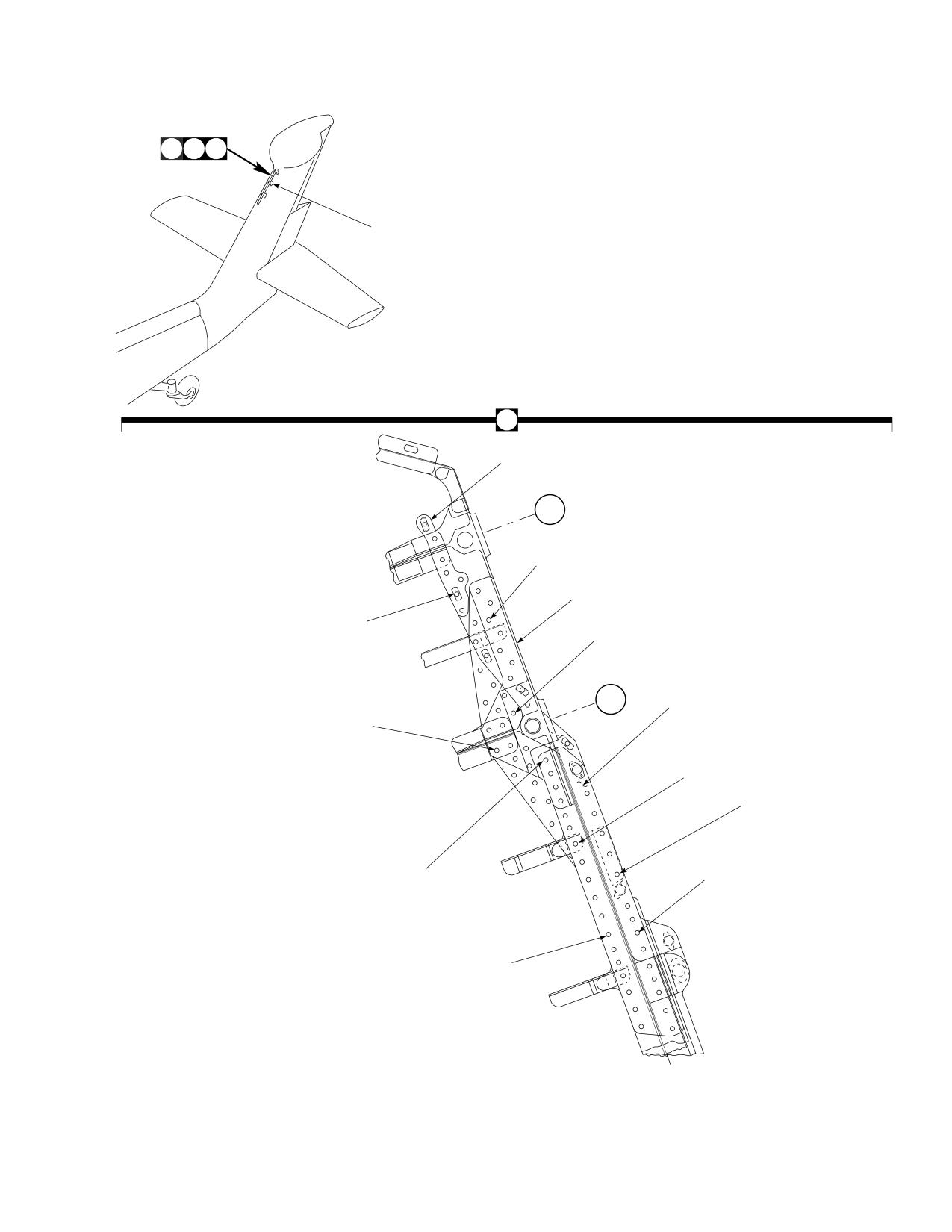
DMWR 1-1520-237
A
B C
1
A
19
PS
210.6
17
2
16
3
PS
200.3
18
14
15
4
5
9
10
11
12
8
13
6
7
AB3116_1
SA
Figure E-21. Tail Pylon Modification Kit (Sheet 1 of 3)
E-221
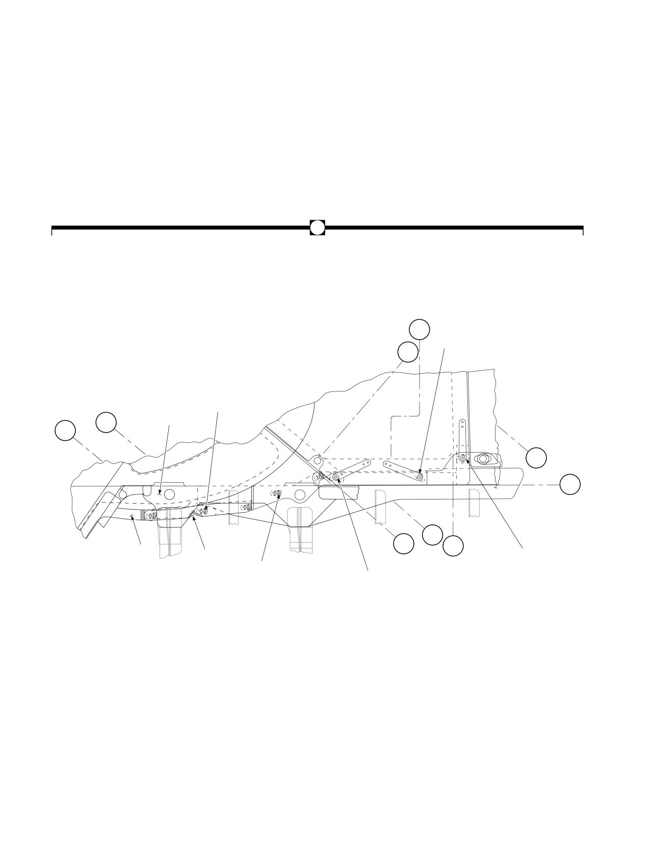
DMWR 1-1520-237
B
PS
193
24
25
STA
311.7
21
23
STA
20
STA
740
742.6
STA
720
WL
100
STA
STA
730
PS
732
188
33
34
26
32
31
21
22
27
28
29
30
AB3116_2
SA
Figure E-21. Tail Pylon Modification Kit (Sheet 2 of 3)
E-222
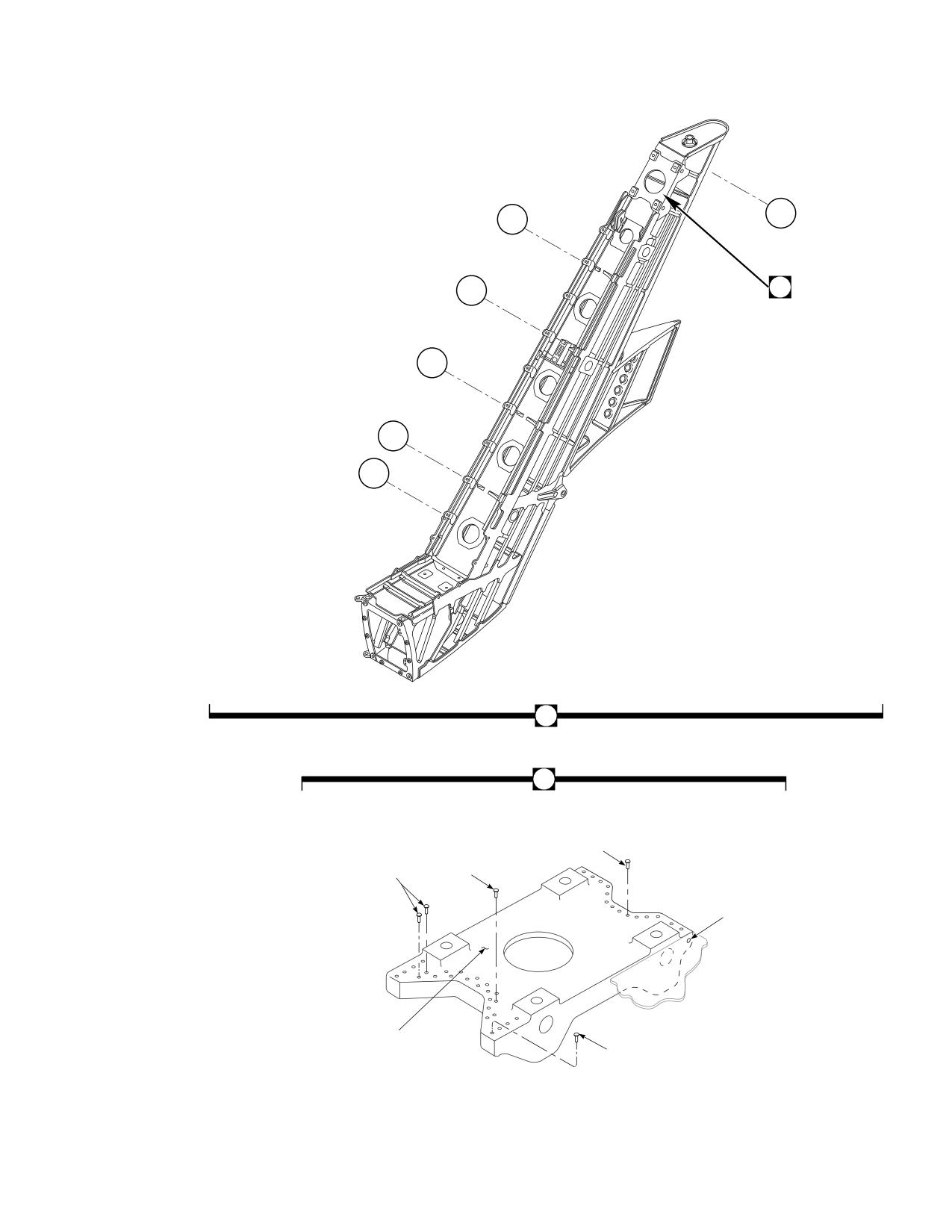
DMWR 1-1520-237
PS
PS
214.5
180
PS
35
160
PS
140
PS
120
PS
111.9
C
35
38
43
41
44
42
39
40
45
36
37
AB3116_3
SA
Figure E-21. Tail Pylon Modification Kit (Sheet 3 of 3)
E-223
DMWR 1-1520-237
QTY
USABLE
FIGURE &
PER
ON
INDEX NO.
PART NUMBER
1 2 3 4 5 6 7
DESCRIPTION
ASSY
CODE
E-21-
70070-20465-017
TAIL PYLON MODIFICATION KIT
REF
-1
70070-20465-012
MOD. KIT-PLATING
1
-2
70203-06050-017
. PLATING INSTL, (Modified from 70203-06050-
016)
REF
-3
70203-06050-047
. PLATING ASSY, (Modified from 70203-06050-
047)
REF
-4
HL20PB-6-6
. HI-LOK PIN, (73197)
5
HL20PB-6-4
. HI-LOK PIN, (73197)
3
*
HL20PB-6-5
. HI-LOK PIN, (73197)
4
*
NAS1466-5
. SWAGE LOCKING PIN,
4
*
NAS1466-05
. SWAGE LOCKING PIN
4
*
-5
HL1087A-6
. COLLAR, (73197)
14
HL1087A-5
. COLLAR, (73197)
8
*
-6
MS20470AD5-9
. RIVET
16
-7
MS20470AD6-9
. RIVET
9
-8
NAS1097AD5-9
. RIVET
6
-9
HL19PB-5-5
. PIN,
(73197)
9
HL19PB-5-6
. PIN,
(73197)
2
*
-10
AN960D8L
. WASHER, (Superseded by NAS1149DN816H) ...
3
NAS1149DN816H
. WASHER
3
-11
MS21043-08
. NUT
3
-12
HL220PB-6-7
. HI-LOK PIN, (73197) (Superseded by HL220-6-
7)
4
HL220-6-7
. HI-LOK PIN, (73197)
4
-13
HL375-6AW
. COLLAR, (73197)
4
-14
AN960D10L
. WASHER, (Superseded by NAS1149D0316H)
4
NAS1149D0316H
. WASHER
4
-15
MS21043-3
. NUT
4
-16
NAS1097AD4-9
. RIVET
5
-17
HL19PB-6-6
. PIN,
(73197)
2
-18
70203-06050-122
. STRAP
1
-19
70203-06050-123
. STRAP
1
-20
70070-20465-014
MOD KIT-FAIRING
1
-21
MS27039-1-16
. SCREW
5
AN960KD10L
. WASHER, (Superseded by NAS1149D0332K)
5
NAS1149D0332K
. WASHER
5
-22
MS21075-3
. NUTPLATE, (Superseded by MS21075-3N)
1
MS21075-3N
. NUTPLATE
1
MS20605S3W7
. RIVET
2
-23
SS5091-03-5
. NUTPLATE
4
MS20605S3W5
. RIVET
8
-24
70070-20465-015
. MOD KIT
1
-25
70205-06052-067
. . FAIRING ASSY, (Modified from 70205-06052-
053)
REF
-26
70070-20422-102
. . SPACER
1
-27
26S51-11
. . CAMLOCK STUD, (08733)
3
-28
2600-SW
. . WASHER, (71286)
3
-29
212-12
. . RECEPTACLE, (71286)
3
-30
MS20605S3W5
. . RIVET
6
MS20426AD3-9
. . RIVET
2
*
-31
70070-20465-016
. MOD KIT
1
-32
70205-06052-065
. . FAIRING ASSY, (Modified from 70205-06052-
065)
REF
-33
70070-20422-103
. . FILLER TAPERED
1
-34
70070-20422-101
. . FILLER
1
-35
70070-20465-018
MOD KIT FTG
1
-36
HL20PB-6-6
. HI-LOK PIN, (73197)
4
HL220PB-6-6
. HI-LOK PIN, (73197)
4
*
-37
HL70-6
. COLLAR, (73197)
4
E-224
DMWR 1-1520-237
QTY
USABLE
FIGURE &
PER
ON
INDEX NO. PART NUMBER
1 2 3 4 5 6 7
DESCRIPTION
ASSY
CODE
HL375-6AW
. . COLLAR, (73197)
4
*
-38
MS20470AD4-4
. . RIVET
31
MS20470AD4-6
. . RIVET
31
*
MS20470AD5-6
. . RIVET
25
*
-39
NAS1738B4-3
. . BLIND RIVET
7
-40
NAS1738B5-3
. . BLIND RIVET
8
NAS1738B5-5
. . BLIND RIVET
25
*
-41
NAS1466-03
. . SWAGE LOCKING PIN
8
NAS1466-04
. . SWAGE LOCKING PIN
6
*
NAS1466-05
. . SWAGE LOCKING PIN,
4
*
HL20PB-6-5
. . HI-LOC PIN (73197)
4
*
NAS1466-06
. . SWAGE LOCKING PIN
8
*
-42
NAS1080-06
. . COLLAR
21
-43
NAS1526-03
. . SWAGE LOCKING PIN
13
-44
NAS1526-05
. . SWAGE LOCKING PIN
4
-45
70209-06056-042
. . FITTING ASSY, (See 1-1520-237P for
breakdown)
1
E-225
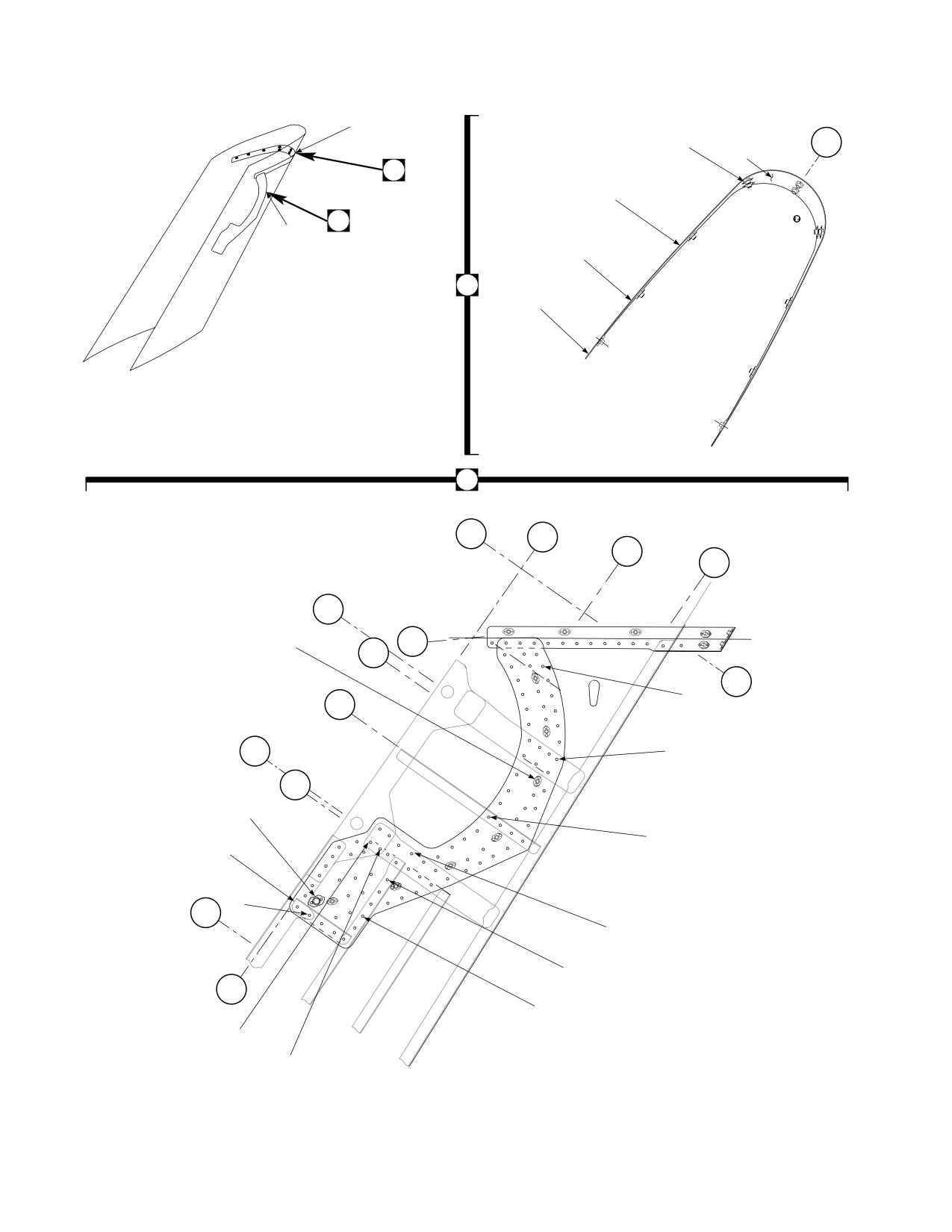
DMWR 1-1520-237
20
21
26
BL
27
0
22
28
19
25
1
2
3
24
4
5
19
23
1
PS
WL
220
100
WL
95
WL
90
PS
210.6
16
WL
18
PS
322.2
210
PS
222
PS
6
205.9
PS
7
200.3
PS
200
16
17
8
15
PS
14
190
9
10
WL
99.7
11
13
12
AB3117
SA
Figure E-22. CRCT Doubler Modification Kit
E-226
DMWR 1-1520-237
QTY
USABLE
FIGURE &
PER
ON
INDEX NO.
PART NUMBER
1 2 3 4 5 6 7
DESCRIPTION
ASSY
CODE
E-22-
70070-20465-019
CRCT DOUBLE MODIFICATION KIT
REF
-1
70070-20465-021
M/K PLATING TRP
1
-2
70070-20465-023
. M/K PLATING INSTL, (Modified from 70203-
06050-011)
REF
-3
70070-20465-024
. M/K PLATING INSTL, (Modified from 70203-
06050-013)
REF
-4
70070-20465-025
. M/K PLATING INSTL, (Modified from 70203-
06050-015)
REF
-5
70070-20465-041
. M/K PLATING ASSY, (Reidentified from 70203-
06050-043)
REF
-6
NAS1097AD4-5
. RIVET
45
-7
NAS1097AD5-5
. RIVET
20
-8
NAS1739B4-4
. BLIND RIVET
3
-9
MS20470AD5-5
. RIVET
8
-10
NAS1739B4-5
. BLIND RIVET
4
-11
NAS1738B4-5
. BLIND RIVET
4
-12
NAS1466-03
. SWAGE LOCKING PIN
2
NAS1466-04
. SWAGE LOCKING PIN
3
*
NAS1466-05
. SWAGE LOCKING PIN
3
*
HL20PB-6-5
. HI-LOK PIN
3
*
NAS1466-06
. SWAGE LOCKING PIN
6
*
-13
NAS1465-03
. SWAGE LOCKING PIN
3
-14
NAS1738B4-3
. BLIND RIVET
3
-15
70070-20465-101
. STRAP
1
-16
CCR264SS-3-2
. RIVET, (11815) (Superseded by
MS20605S3W2)
16
MS20605S3W2
. RIVET,
16
-17
212-12
. RECEPTACLE, (71286)
1
-18
MS21075-3
. NUTPLATE, (Superseded by MS21075-3N)
7
MS21075-3N
. NUTPLATE,
7
-19
70070-20465-022
M/K PLATING TRP
1
-20
70070-20465-026
. M/K RIB INSTL, (Modified from 70201-06164-
011)
REF
-21
70070-20465-042
. M/K RIB ASSY, (Reidentified from 70201-06164-
043)
REF
-22
70070-20465-043
. M/K RIB ASSY, (Reidentified from 70201-06164-
045)
REF
-23
NAS1738B5-4
. BLIND RIVET
4
-24
NAS1738B5-3
. BLIND RIVET
25
-25
NAS1738B4-5
. BLIND RIVET
4
-26
NAS1097AD3-3
. RIVET
30
-27
MS21075-3
. NUTPLATE
12
-28
70070-20465-102
. STRAP
1
E-227
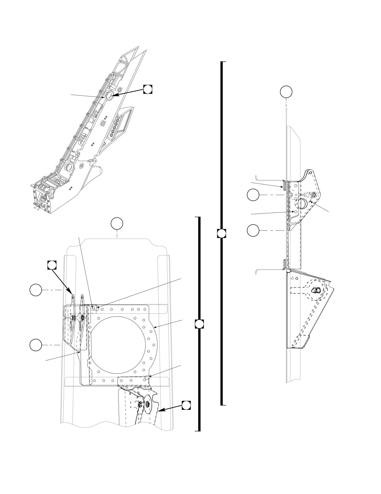
DMWR 1-1520-237
2
1
WL
3
100
12
13
STA
193
10
14
11
BL
0
STA
190
4
9
9
7
STA
195.5
6
1
STA
190.5
5
8
15
AB3118_1
SA
Figure E-23. Front Spar FT Modification Kit (Sheet 1 of 2)
E-228
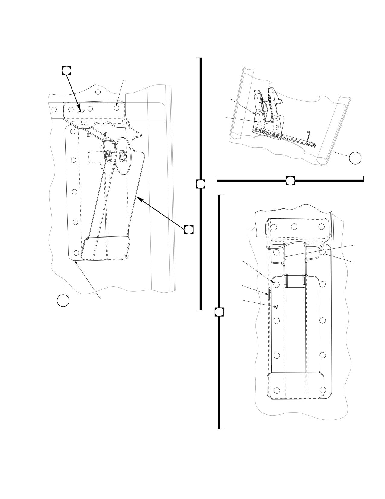
DMWR 1-1520-237
A
17
18
20
19
WL
100
A
15
B
21
22
24
22
23
26
BL
25
0
16
B
AB3118_2
SA
Figure E-23. Front Spar FT Modification Kit (Sheet 2 of 2)
E-229
DMWR 1-1520-237
QTY
USABLE
FIGURE &
PER
ON
INDEX NO.
PART NUMBER
1 2 3 4 5 6 7
DESCRIPTION
ASSY
CODE
E-23-
70070-20465-020
FRONT SPAR FT MODIFICATION KIT
REF
-1
70070-20465-027
. M/K FRT SPAR
1
-2
70070-20465-030
. . M/K SPAR INSTL
REF
-3
70070-20465-044
. . M/K SPAR ASSY
REF
70070-20465-045
. . M/K SPAR ASSY
REF
-4
MS20470AD5-9
. . RIVET
35
-5
70202-06051-149
. . STIFFENER
1
-6
70070-20465-104
. . DOUBLER
1
-7
SS1058A7-25-24
. . RADIUS BLOCK
1
-8
SS1058A7-27-46
. . RADIUS BLOCK
1
-9
70070-20465-028
. M/K SUPPORT INSTL
1
-10
HL19PB-5-4
. . PIN,
(73197)
3
-11
HL70TW-5
. . COLLAR, (73197)
3
-12
HL20PB86-5-6
. . PIN COLLAR ASSY, (73197)
3
-13
HL20PB86-5-7
. . PIN COLLAR ASSY, (73197)
1
-14
70400-06681-044
. . SUPPORT ASSY
1
-15
70070-20465-029
. M/K SUPPORT INSTL
1
-16
70070-20465-031
. . M/K SUPPORT INSTL
REF
70070-20465-032
. . M/K SUPPORT INSTL
REF
-17
HL20PB-6-8
. . HI-LOK PIN, (73197)
3
-18
HL1087ATW-6
. . COLLAR, (73197)
3
-19
MS20470AD5-4
. . RIVET
6
-20
70070-20465-105
. . ANGLE
1
-21
HL20PB-5-4
. . HI-LOK PIN, (73197)
1
-22
HL1087ATW-5
. . COLLAR, (73197)
10
-23
HL20PB-5-2
. . HI-LOK PIN, (73197)
4
*
-24
HL20PB-5-3
. . HI-LOK PIN, (73197)
4
-25
70400-06680-046
. . SUPPORT ASSY
1
-26
70400-06680-145
. . LAMINATED SHIM
1
E-230
DMWR 1-1520-237
E-20. SIDE SKIN MODIFICATION KIT (50-10).
Subject: Tail Pylon Side Skin, Modification of, dated 31 March 2003
Purpose: To provide instruction for the rework of the tail pylon side skin.
Model:
UH-60A
Description: Additional doublers are added to the existing tail pylon side skin between station 645.00 and station
660.00.
Drawing Required for Modification:
70070-20587
References: (a) Special Service Instructions (SSI) No. 50-31, Installation of 9A to A9 Recapitalization Program, dated
March 31, 2003
Instructions:
NOTE
• A complete review of this SSI is recommended before incorporating the modification of tail pylon side skin.
• Before beginning this modification procedure, use the material information list to inventory the modification
kit. Make sure all parts are present and in serviceable condition.
• Where drawing numbers are not listed within individual step(s), drawing(s) listed in preceding step(s) are
the controlling authority.
• The sheet metal and structural modifications in this SSI shall be done by personnel experienced in reading
modification drawings. Routine steps such as cleaning, layout and drilling, deburring, standard repairs,
corrosion control, clean up after rework, chemical coating for aluminum after cutting/trimming parts, paint
touch up, and safety practices may not be called out herein. However, these steps and all other required
routine tasks shall be done.
• When installing fasteners refer to drawing sheet and zones for applicable fasteners.
• Slight variations to the instructions contained herein are allowed, as long as the intent of the modification
is accomplished.
A.
Preparation for modification and removal of equipment:
(1)
Confirm that all warnings, cautions, and notes are complied with per reference (a).
(2)
Perform preparation for modification per reference (a).
B.
Modification of tail pylon side skin as follows:
(1)
Modify left side plating installation (70203-06050-011, -013, -015, or -018) as follows:
(a)
Remove pneumatic lines as required for access to left side pylon interior.
E-231
DMWR 1-1520-237
(b)
Remove fasteners shown (Dwg 70070-20587, Sheet 2, Zones 9-D, 10-C, 10-E, 11-C through 11-E, 12-C
through 12-F, and Notes 5, 7, and 8).
(c)
Locate and temporarily install doubler (70070-20587-101), stiffener (70070-20587-103), clip (70070-
20587-105), and radius block (SS1058A7-26-13) as shown (Sheet 2, Zones 10-E, 11-E, 14-C, and 15-E).
(d)
Drill fastener holes, as shown (Sheet 2, Zones 9-D, 10-C, 10-D, 11-C, and 11-D).
(e)
Remove temporarily installed doubler (70070-20587-101), stiffener (70070-20587-103), clip (70070-
20587-105), and radius block (SS1058A7-26-13), deburr and touch up, as required.
WARNING
OBSERVE ALL CAUTIONS AND WARNINGS ON CONTAINERS WHEN USING CONSUMABLES.
WHEN APPLICABLE, WEAR NECESSARY PROTECTIVE GEAR DURING HANDLING AND USE. IF A
CONSUMABLE IS FLAMMABLE OR EXPLOSIVE, MAKE CERTAIN CONSUMABLE AND ITS VAPORS ARE
KEPT AWAY FROM HEAT, SPARK, AND FLAME. MAKE CERTAIN EQUIPMENT IS PROPERLY
GROUNDED AND FIREFIGHTING EQUIPMENT IS READILY AVAILABLE PRIOR TO USE. FOR AD-
DITIONAL INFORMATION ON TOXICITY, FLASHPOINT, AND FLAMMABILITY OF CHEMICALS,
CONSULT YOUR MEDICAL PEOPLE, OR MANUFACTURER OF THE CONSUMABLE.
(f)
Install doubler (70070-20587-101) wet with sealant (AMS-S-8802 A2 or equivalent) using fasteners
shown (Sheet 2, Zones 9-E, 10-C, 10-E, and 11-C through 11-E).
(g)
Install stiffener (70070-20587-103), clip (70070-20587-105), and radius block (SS1058A7-26-13) us-
ing fasteners shown (Sheet 2, Zones 10-E, 14-D, and 14-F).
WARNING
OBSERVE ALL CAUTIONS AND WARNINGS ON CONTAINERS WHEN USING CONSUMABLES.
WHEN APPLICABLE, WEAR NECESSARY PROTECTIVE GEAR DURING HANDLING AND USE. IF A
CONSUMABLE IS FLAMMABLE OR EXPLOSIVE, MAKE CERTAIN CONSUMABLE AND ITS VAPORS ARE
KEPT AWAY FROM HEAT, SPARK, AND FLAME. MAKE CERTAIN EQUIPMENT IS PROPERLY
GROUNDED AND FIREFIGHTING EQUIPMENT IS READILY AVAILABLE PRIOR TO USE. FOR AD-
DITIONAL INFORMATION ON TOXICITY, FLASHPOINT, AND FLAMMABILITY OF CHEMICALS,
CONSULT YOUR MEDICAL PEOPLE, OR MANUFACTURER OF THE CONSUMABLE.
(h)
Reinstall fasteners wet with sealant (AMS-S-8802 A2 or equivalent) at locations shown (Sheet 2, Zones
11-B, 11-D, 11-F, 12-C through 12-E, and Notes 5, 7, and 8).
(i)
Remove and replace fasteners wet with sealant (AMS-S-8802 A2 or equivalent) at locations shown (Sheet
2, Zones 5-E through 5-G, 6-E through 6-G, 9-F, and Note 5).
(2)
Modify right side plating installation (70203-06050-012, -014, -016, or -017) as follows:
(a)
Remove fasteners shown (Dwg 70070-20587, Sheet 2, Zones 9-D, 10-C, 10-E, 11-C through 11-E, 12-C
through 12-F, and Notes 5, 7, and 8).
E-232