HELICOPTERS NSN 1520-01-035-0266, NSN 1520-01-082-0686, NSN 1520-01-298-4532. REPAIR STANDARDS (2004) - page 1
DMWR 1-1520-237-3
AIRFRAME DEPOT MAINTENANCE
WORK REQUIREMENT
CONTAINING
NATIONAL MAINTENANCE REPAIR STANDARDS
for
ARMY MODELS UH-60A, EH-60A, AND
UH-60L HELICOPTERS
NSN 1520-01-035-0266
NSN 1520-01-082-0686
NSN 1520-01-298-4532
WARNING - This document contains technical data whose export is restricted by the Arms Export Control
Act (Title 22, U.S.C. Sec. 2751 et seq.) or the Export Administration Act of 1979, as amended, Title 50, U.S.C.,
App. 2401 et seq. Violation of these export laws are subject to severe criminal penalties. Disseminate in
accordance with provisions of DoD Directive 5230.25.
DISTRIBUTION STATEMENT D: Distribution authorized to Department of Defense and DoD Contractors only
due to Critical Technology effective as of 16 June 2003. Other requests for this document shall be referred
to Commander, US Army Aviation and Missile Command, ATTN: SFAE-AV-UH/L, Redstone Arsenal, AL
35898-5230.
DESTRUCTION NOTICE - Destroy by any method that will prevent disclosure of contents or reconstruction.
THIS PUBLICATION IS NOT AVAILABLE THROUGH THE AG PUBLICATIONS CENTERS. IT MUST BE
OBTAINED FROM U. S. ARMY AVIATION AND MISSILE COMMAND, ATTN: AMSAM-MMC-LS-LPS, RED-
STONE ARSENAL, AL 35898-5000.
US Army Aviation
And Missile Command
8 January 2004
DMWR 1-1520-237
WARNING
PRECAUTIONARY DATA
Personnel performing operations, procedures, and practices which are included or implied in this work
requirement shall observe the following warnings. Disregard of these warnings and precautionary
information can cause serious injury, death, or destruction of material.
CLEANING SOLVENTS
Cleaning solvents may be toxic. Use in well-ventilated areas. Avoid prolonged inhalation of fumes or
direct contact with skin. Do not use solvents near open flames or in areas where very high temperatures
prevail. Solvent with a flash point greater than 100°F (38°C) should be used. However solvents with a
flash point lower than 100°F (38°C) may be specified. Consult the Material Safety Data Sheet (MDSD)
for solvent flash point. Avoid breathing solvent vapor. Do operations involving cleaning solvent under
a ventilated hood or in a well-ventilated work area. Wear a suitable mask when necessary. Avoid
continuous contact with a solvent. Wear goggles, gloves, and apron to prevent irritation due to
prolonged contact. Change clothing that has been saturated with solvent.
TOXIC MATERIALS
Before handing or using any consumable materials, read and observe the instructions on the material
container. These warnings and precautionary data, if not strictly observed, may result in personnel
injury or loss of life. Recommended safety equipment will be used at all times.
COMPRESSED AIR
Compressed air shall not be used for cleaning purposes except where reduced to less than 15 psi and
only then with an effective chip guarding and personnel protection equipment. Do not direct compressed
air near or directly against skin. When drying parts, do not use air under high pressure, or from a source
not having a moisture trap. Do not spin bearings with compressed air.
ELECTRICAL WIRING
Disconnect all electrical wiring before removing any part of aircraft.
a
DMWR 1-1520-237
Warnings, cautions, and notes are used to emphasize important and critical instructions and are used for
the following contions.
WARNING
Alerts personnel to operation, procedure, practice, etc, which, if not strictly observed, could result in
personnel injury or loss of life.
CAUTION
Alerts personnel to operation, procedure, practice, etc, which, if not strictly observed, could result in
damage to or destruction of equipment.
NOTE
Applies to operation, procedure, condition, etc, which is essential to highlight.
b
DMWR 1-1520-237
LIST OF EFFECTIVE PAGES
Insert latest changed pages; dispose of superseded pages in accordance with regulations.
NOTE: On a changed page, the portion of the text affected by the latest change is indicated by a vertical line in
the outer margin of the page Changes to illustrations are indicated by a vertical line next to the illustration title.
Changes to wiring diagrams are indicated by shaded areas.
Dates of issue for original and changes pages are:
Original
0
8 January 2004
Total number of pages in this manual is 1,736 consisting of the following:
#
Page
Change
No.
No.
Title
0
a-b
0
A
0
B blank
0
i - iii
0
iv blank
0
E-1 - E-273
0
E-274 blank
0
# Zero in this column indicates an original page.
A/(B blank)
*DMWR 1-1520-237
Airframe Depot Maintenance Work Requirement
Containing National Maintenance Repair Standards
for
ARMY MODELS UH-60A, EH-60A, AND UH-60L HELICOPTERS
NSN 1520-01-035-0266, NSN 1520-01-082-0686, NSN 1520-01-298-4532
REPORTING ERRORS AND RECOMMENDING IMPROVEMENTS
You can help improve this manual. If you find any mistakes or if you know of a way to improve the
procedures, please let us know. Mail your letter, DA Form 2028 (Recommended Changes to
Publications and Blank Forms), or DA Form 2028-2 located in the back of this manual direct to:
Commander, U.S. Army Aviation and Missile Command, ATTN: AMSAM-MMC-LS-LP, Redstone
Arsenal, AL 35898-5000. A reply will be furnished to you. You may also send in your comments
electronically to our e-mail address: ls-lp@redstone.army or by fax 256-842-7546/DSN 788-7546.
Instructions for sending an electronic 2028 may be found at the back of this manual immediately
preceding the hard copy 2028.
DISTRIBUTION STATEMENT A: Approved for public release; distribution is unlimited.
TABLE OF CONTENTS
Chapter,Section
and/or Group Task
Page
Appendix E. MODIFICATIONS
E-1
E-1
UH60A Re-capitalization Program
E-1
E-2
Installation of UH-60 9A to A9 Recapitalization Program (50-31)
E-2
E-3
Door Post Modification Kit (50-22)
E-20
E-4
Hinge Access Modification Kit (50-35)
E-39
E-5
Modification Kit (50-5)
E-44
E-6
Station 379 Modification Kit (50-26)
E-65
E-7
Upper Plating Modification Kit (50-16)
E-73
E-8
BL 34.5 Modification Kit (50-7)
E-88
E-9
ESSS Doubler Modification Kit (50-15)
E-96
E-10
TRDS Brackets Modification Kit (50-20)
E-105
i
*DMWR 1-1520-237
TABLE OF CONTENTS (Cont)
Chapter,Section
and/or Group Task
Page
E-11
Station 485 Modification Kit (50-34)
E-112
E-12
Lower Aft Transition/Foam Liner Modification Kit (50-6)
E-116
E-13
Enclosure Modification Kit (50-21)
E-143
E-14
Support Shaft Modification Kit (50-9)
E-152
E-15
Shear Deck Modification Kit (50-29)
E-162
E-16
Stringer/Frame Modification Kit (50-24)
E-167
E-17
Skin Doubler/Plate Installation Modification Kit (50-13)
E-190
E-18
Bulkhead Installation Modification Kit (50-17)
E-202
E-19
Tail Pylon, CRCT Doubler, Front Spar FT Modification Kit (50-8)
E-208
E-20
Side Skin Modification Kit (50-10)
E-231
E-21
Aft Spar FT Modification Kit (50-25)
E-240
E-22
L/H R/H Firewall Modification Kit (50-19)
E-253
E-23
Cowl Assembly Modification Kit (50-33)
E-261
E-24
HIRSS Repair Kit (50-30)
E-267
ii
*DMWR 1-1520-237
TABLE OF CONTENTS (Cont)
Chapter,Section
and/or Group Task
Page
E-1
Re-capitalization Modification Kit
E-15
E-2
Door Post Modification Kit
E-33
E-3
Hinge Access Modification Kit
E-42
E-4
Modification Kit
E-58
E-5
Station 379 Modification Kit
E-70
E-6
Upper Plating Modification Kit
E-81
E-7
BL 34.5 Modification Kit
E-93
E-8
ESSS Doubler Modification Kit
E-102
E-9
Tail Rotor Drive Shaft Brackets Modification Kit
E-110
E-10
Station 485 Modification Kit
E-114
E-11
Lower Aft Transition Modification Kit
E-129
E-12
Foam Liner Modification Kit
E-141
E-13
Enclosure Modification Kit
E-149
E-14
Support Shaft Modification Kit
E-158
E-15
Support Shaft Modification Kit
E-160
E-16
Shear Deck Modification Kit
E-165
E-17
Stringer/Frame Modification Kit
E-178
E-18
Skin Doubler Modification Kit
E-197
E-19
Plate Installation Modification Kit
E-199
E-20
Bulkhead Installation Modification Kit
E-206
E-21
Tail Pylon Modification Kit
E-221
E-22
CRCT Doubler Modification Kit
E-226
E-23
Front Spar FT Modification Kit
E-228
E-24
Side Skin Modification Kit
E-237
E-25
Aft Spar Fitting Modification Kit
E-250
E-26
L/H Firewall Modification Kit
E-257
E-27
R/H Firewall Modification Kit
E-259
E-28
Cowl Assembly Modification Kit
E-265
E-29
HIRSS Repair Kit
E-271
iii/(iv blank)
DMWR 1-1520-237
APPENDIX E
MODIFICATIONS
E-1. UH60A RE-CAPITALIZATION PROGRAM.
The purpose of the UH-60A Re-capitalization Program is to extend the use of the U.S. Army owned UH-60A’s for ap-
proximately ten additional years. The program will allow the aircraft to continue to be used until induction into the UH-
60M Modernization Program. Approximately three hundred aircraft will be inducted into the re-capitalization program.
The airframe structural kits to be used in this program were developed based on review of the Government furnished
Aircraft Corrosion Evaluation/Joint Aircraft Corrosion Evaluation/On Conditional Maintenance (ACE/JACE/OCM)
data. The Sikorsky 9Crack Database9 as well as field service reports were also used to determine airframe components
that were problematic to the user community.
Several of the airfame kits are based on those previously used on other H-60 derivative aircraft such as the MH/HH-60G.
Modifications were made as required to account for any structural differences between the parent aircraft and the UH-
60A. In many cases, the structural kits for the re-capitalization program were also incorporated into production via ECP
or production change orders. In these cases, the inducted aircraft will then be brought up close to the current UH-60L
configuration.
The kit description is broken down by aircraft structural component (cockpit, cabin, etc.). This was done because some of
the components, namely the cockpit, tailcone and tail rotor pylon, will be reused when the aircraft is inducted into the UH-
60 Modernization program. The strttctural kits for these areas are the same between the re-capitalization and the
modernization programs. The item number shown for each kit was established from the first potential kit list shown in July
2001. Some of the kits were subsequently deleted but the original item numbers were retained for historical purposes.
The weight and center of gravity data for each of the structural kits is included. This will allow the revised weight and bal-
ance to be calculated for the aircraft inducted into the re-capitalization program.
E-1
DMWR 1-1520-237
E-2. INSTALLATION OF UH-60 9A TO A9 RECAPITALIZATION PROGRAM (50-31).
Subject: Installation of UH-60 9A to A9 Recapitalization Program, dated 31 March 2003
Purpose: The purpose of this Special Service Instructions (SSI) is to describe the modification and repair changes. Mate-
rial information paragraph will be top kits and subkits only. Individual parts and parts disposition will not be listed. Step
by step modification instructions will only reference SSI instructions and Technical Manuals (TM).
Model:
UH-60A
Description: The Recapitalization Program will modify areas of the UH-60A, Nose/Canopy, Cabin, Transition, Tail
Cone, Pylon, Firewall, and Engine Cowls.
Drawings required for modification:
70000-03200, 70070-20167, 70070-20266, 70070-20465, 70070-20470, 70070-20488, 70070-20527,
70070-20566, 70070-20568, 70070-20570, 70070-20572, 70070-20575, 70070-20577, 70070-20578, 70070-
20581, 70070-20582, 70070-20583, 70070-20587, 70070-20588, 70070-20615, 70070-20617, 70070-20641,
70070-30307, 70070-30308, 70070-95122, 70072-30000, 70083-20110, 70200-07050, 70201-06164, 70202-
06051, 70203-03003, 70209-03012, 70209-03022, 70209-06056, 70211-01005, 70211-03001, 70211-03002,
70211-03004, 70211-03005, 70211-03006, 70211-03007, 70211-03009, 70212-02307, 70212-03002, 70212-
03003, 70212-05004, 70213-02101, 70213-02301, 70213-02501, 70213-03001, 70213-03002, 70213-03004,
70217-01010, 70217-03001, 70219-03002, 70219-03011, 70304-02114, 70308-03611, 70400-03611, 70500-
01053, 70553-07001, 70551-05140, 70551-03140, 70652-02150, 70551-03101, 70551-03102
References:
(a) TM 1-1520-237-MTF, Technical Manual, Operator’s and Crew Member’s Check List
(b) TM 1-1520-237-23, Aviation Unit And Intermediate Maintenance For Army Models UH-60A, UH-
60L, EH-60A, and UH-60Q Helicopters, Chapter 1, Aircraft General
(c) TM 1-1520-237-23, Aviation Unit And Intermediate Maintenance For Army Models UH-60A, UH-
60L, EH-60A, and UH-60Q Helicopters, Chapter 2, Airframe
(d) TM 1-1520-237-23, Aviation Unit And Intermediate Maintenance For Army Models UH-60A, UH-
60L, EH-60A, and UH-60Q Helicopters, Chapter 4, Engine Systems
(e) TM 1-1520-237-23, Aviation Unit And Intermediate Maintenance For Army Models UH-60A, UH-
60L, EH-60A, and UH-60Q Helicopters, Chapter 5, Rotor System
(f)
TM 1-1520-237-23, Aviation Unit And Intermediate Maintenance For Army Models UH-60A, UH-
60L, EH-60A, and UH-60Q Helicopters, Chapter 6, Drive System
(g) TM 1-1520-237-23, Aviation Unit And Intermediate Maintenance For Army Models UH-60A, UH-
60L, EH-60A, and UH-60Q Helicopters, Chapter 7, Pneudraulic System
(h) TM 1-1520-237-23, Aviation Unit And Intermediate Maintenance For Army Models UH-60A, UH-
60L, EH-60A, and UH-60Q Helicopters, Chapter 8, Instrument Systems
(i)
TM 1-1520-237-23, Aviation Unit And Intermediate Maintenance For Army Models UH-60A, UH-
60L, EH-60A, and UH-60Q Helicopters, Chapter 9, Electrical System
(j)
TM 1-1520-237-23, Aviation Unit And Intermediate Maintenance For Army Models UH-60A, UH-
60L, EH-60A, and UH-60Q Helicopters, Chapter 10, Fuel System
E-2
DMWR 1-1520-237
(k) TM 1-1520-237-23, Aviation Unit And Intermediate Maintenance For Army Models UH-60A, UH-
60L, EH-60A, and UH-60Q Helicopters, Chapter 11, Flight Control System
(l)
SSI No. 50-5, Side Fuselage Structural Reinforcement, Installation of, dated 31 March 2003
(m) SSI No. 50-6, Lower Aft Transition Section, Rework of, dated 31 March 2003
(n) SSI No. 50-7, Buttline 34.50, Modification of, dated 31 March 2003
(o) SSI No. 50-8, Tail Rotor Pylon, Modification of, dated 31 March 2003
(p) SSI No. 50-9, Drive Shaft Supports, Modification of, dated 31 March 2003
(q) SSI No. 50-10, Tail Pylon Side Skin, Modification of, dated 31 March 2003
(r) SSI No. 50-13, Tailcone Plating, Installation of, dated 31 March 2003
(s) SSI No. 50-15, ESSS Doublers, Installation of, dated 31 March 2003
(t)
SSI No. 50-16, Upper Plating and Doubler Installation, Rework of, dated 31 March 2003
(u) SSI No. 50-17, Station 605.00 Bulkhead, Modification of, dated 31 March 2003
(v) SSI No. 50-19, Left and Right Side Firewall Assemblies, Modification of, dated 31 March 2003
(w) SSI No. 50-20, Tail Rotor Drive Shaft Support Brackets, Modification of, dated 31 March 2003
(x) SSI No. 50-21, Vapor Barrier Support Structure, Replacement of, dated 31 March 2003
(y) SSI No. 50-22, Cockpit Floor and Door Posts, Modification of, dated 31 March 2003
(z) SSI No. 50-24, Tail Cone, Modification of, dated 31 March 2003
(aa) SSI No. 50-25, Tail Rotor Pylon, Aft Spar Stabilator Attachment Fitting, Modification of, dated 31
March 2003
(ab) SSI No. 50-26, Station 379.00 Frame, Modification of, dated 31 March 2003
(ac) SSI No. 50-29, Tail Cone Shear Deck, Modification of, dated 31 March 2003
(ad) SSI No. 50-30, HIRSS Repair Kit, Installation of, dated 31 March 2003
(ae) SSI No. 50-33, Engine Cowl Assembly, Left and Right Side, Modification of, dated 31 March 2003
(af) SSI No. 50-34, Transition Station 485.00, Modification of, dated 31 March 2003
(ag) SSI No. 50-35, Canopy Assembly, Nose Door Hinge Access Holes, Modification of, dated 31
March 2003
E-3
DMWR 1-1520-237
Instructions:
NOTE
• AcompletereviewofthisSSIisrecommendedbeforeincorporatingtheinstallationofUH-609AtoA9
Recapitalization Program.
• Before beginning this modification procedure, use the material information list located in reference SSI’s to
inventory the modification kits. Make sure all parts are present and in serviceable condition.
• Where drawing numbers are not listed within individual step(s), drawing(s) listed in preceding step(s) are
the controlling authority.
• The sheet metal, structural, and electrical modifications in this SSI shall be done by personnel experienced
in reading modification drawings. Routine steps such as cleaning, layout and drilling, deburring, standard
repairs, corrosion control, clean up after rework, chemical coating for aluminum after cutting/trimming
parts, peeling shims, paint touch up, routing, clamping, and safety practices may not be called out herein.
However, these steps and all other required routine tasks shall be done.
• Personnel must be trained and certified in hole quality assurance and proper cold expansion procedures
per SS5098.
• Slight variations to the instructions contained herein are allowed, as long as the intent of the modification
is accomplished.
• Trial Installation was performed on helicopter Serial Number (86-24510) at Corpus Christi Army Depot,
(CCAD) Corpus Christi, TX.
A.
Preparation for modification and removal of equipment:
(1)
Confirm that all warnings, cautions, and notes are complied with.
(2)
Turn off electrical/hydraulic power and make helicopter safe for ground maintenance.
(3)
Defuel helicopter per reference (b).
(4)
Perform arrival inspection.
(5)
Remove, clean, preserve, and tag main rotor blades per reference (e).
(6)
Remove, clean, preserve, and tag tailrotor blades per reference (e).
(7)
Clean and install pitot covers per reference (h).
(8)
Remove the following airframe components per reference (c).
(a)
Remove pilots door, pilots seat, copilots door, copilots seat, cockpit floor panels, cockpit floor covers and
nose access panel.
(b)
Remove troop seats, troop seat supports, left cargo door, right cargo door, nose door, gunner seats, gun-
ner seat supports, soundproofing, drip pan assembly, control enclosure left side, control enclosure right side, and aft
cargo floor at station 397.00 from cabin.
(c)
Remove fuel cell enclosure panels, drive shaft covers, stabilator fairings, and tail gear box cover from
transition, tailcone, and pylon of helicopter.
E-4
DMWR 1-1520-237
(d)
Remove sliding pylon cover, left engine intake, right engine intake, main rotor gear box fairings, engine
exhaust fairings, APU fairings, and oil cooler fairings.
(e)
Remove stabilator.
(f)
Remove engine platforms and place on a suitable work area.
(g)
Remove lower chin windows.
(h)
Remove (if equipped) ESSS fairings.
(9)
Remove the following flight controls per reference (k).
(a)
Disconnect flight control cables at tail cone turnbuckle location.
(b)
Remove lateral, forward, and aft primary servos.
(10)
Remove the following Pneudraulic/Hydraulic component per reference (g).
(a)
Remove No. 1 and No. 2 transfer modules.
(b)
Remove No. 1 and No. 2 transfer module manifolds.
(c)
Remove primary servo manifold.
(d)
Remove boost servo/pilot assist manifold.
(e)
Disconnect tail rotor servo lines at station 647.00 and station 398.00 and pull forward to gain access to
station 605.00 rework.
(11)
Remove tail rotor drive shafts per reference (e).
(12)
Remove engines per reference (d).
(13)
Remove main rotor gear box per reference (f).
(14)
Remove tail rotor gear box per reference (f).
(15)
Remove the following electrical and avionics components per reference (i).
(a)
Disconnect, tag battery with helicopter serial number, and transfer helicopter battery to battery shop.
(16)
Remove fuel cells and fuel cell liners per reference (j).
B.
Description of modification.
(1)
Recapitalization program modifications as follows:
(a)
Side fuselage structure is reinforced by adding support structure between stations 265.50 and 308.00, left
and right side gunners window.
(b)
Lower aft transition structure is removed, corrosion treated, and new structure is installed.
E-5
DMWR 1-1520-237
(c)
Buttline 34.50 is modified by installing new reinforcements, coldworking fasteners locations, and installing
new fasteners.
(d)
Tail rotor gear box pylon mount fitting is modified by installing a new left side doubler and two right side
straps with coldworked fasteners. Tail gear box mount fitting is removed and a new fitting is installed. Forward spar
doubler is removed and replaced with a new doubler. Gear box fairing installation is modified.
(e)
Tail rotor drive shaft supports are modified at stations 410.00, 471.00, 531.43, and 591.88 by installing
new supports, doublers, and brackets.
(f)
New doublers and stiffeners are added to the existing tail pylon side skin between stations 645.00 and
660.00.
(g)
Lower skin and doubler between stations 485.00 and 605.00 are removed and new skin and doubler are
installed. New doublers are installed at left and right side locations between tailcone stations 625.00 and 635.00.
(h)
New skins and doublers are installed between stations 295.00 and 308.00 on helicopters equipped with
ESSS provisions.
(i)
New cabin upper plating is installed between stations 320.00 and 380.00 with coldworked fasteners com-
mon to buttline 16.5 transmission beams.
(j)
Tailcone station 605.00 is modified by installing a new doubler, filler, and radius block.
(k)
New doublers, angles, straps, and spacers are installed to left and right side firewall assemblies.
(l)
New intercostals which support vapor barriers over fuel cells between stations 413.00 and 443.50 are
installed.
(m)
Station 205.00, left and right side door post locations are modified by installing new fittings, angles and
nutplates.
(n)
Tailcone structure between stations 485.00 and 565.00 is modified by adding stringers and shear ties.
(o)
Stabilator attachment fittings are modified by removing bushings and liners and installing new Forcemate
bushings and spherical bearings.
(p)
New straps and doublers are installed at station 379.00 frame left and right sides with coldworked fasten-
ers.
(q)
Tail cone shear deck is modified by installing new doublers and angles between stations 605.00 and
645.00.
(r)
HIRSS structure is modified by installing new doublers, fillers, angles, and radius blocks on helicopters
equipped with HIRSS.
(s)
New hinge fitting assemblies are installed to reinforce the hinge area on the engine cowl assemblies.
(t)
A new fitting and fasteners are installed at station 485.00.
(u)
Two access holes, doublers, and new seal are added to the nose door hinge area.
E-6
DMWR 1-1520-237
C.
Installation
(1)
Perform recapitalization modifications as follows:
(a)
Rework nose/canopy per references (y), and (ag).
(b)
Rework cabin per references (l), (n), (s), (t), and (ab).
(c)
Rework of transition per references (m), (v), (w), (x), (ad), (ae), and (af).
(d)
Rework tail cone per references (p), (r), (u), (z), and (ac).
(e)
Rework tail pylon per reference (o), (q), and (aa).
D.
Reinstallation of removed equipment:
(1)
Install fuel cells and fuel cell liners per reference (j).
(2)
Install main rotor gear box per reference (f).
(3)
Install tail rotor gear box per reference (f).
(4)
Install tail rotor drive shafts per reference (e).
(5)
Install engines per reference (d).
(6)
Install the following pneudraulic/hydraulic components per reference (g).
(a)
Install No. 1 and No. 2 transfer modules.
(b)
Install No. 1 and No. 2 transfer modules manifolds.
(c)
Install boost servo/pilot assist manifold.
(d)
Install primary servo manifold.
(7)
Install the following flight control per reference (k).
(a)
Install lateral, forward, and aft primary servos.
(b)
Reconnect flight control cables at tail cone turnbuckle locations.
(8)
Install the following airframe components per reference (c).
(a)
Install pilots door, pilots seat, copilots door, copilots seat, cockpit floor panels, and cockpit floor covers.
(b)
Install aft cargo floor to station 397.00, troop seats, troop seat supports, left cargo door, right cargo door,
gunner seats, gunner seat supports, and soundproofing.
(c)
Install fuel cell enclosure panels, drive shaft covers, stabilator, stabilator fairings, and tail gear box cover.
(d)
Install sliding pylon cover, left engine intake, right engine intake, main rotor gear box fairings, engine
exhaust fairings, engine platform doors, APU fairings, and oil cooler fairings.
E-7
DMWR 1-1520-237
(e)
Install control enclosure left side and control enclosure right side, nose and cabin vibration absorber, nose
access panel, and drip pan assembly.
(f)
Install lower chin windows.
(g)
Install ESSS fairings (if equipped).
(9)
Install tail rotor blades per reference (e).
(10)
Install main rotor blades per reference (e).
(11)
Remove covers from pitot tubes per reference (h).
E.
Perform operational check out as follows:
(1)
Perform applicable operational checks that are identified in Technical Manual (TM) upon installation of
components.
F.
Record of Compliance:
(1)
Make an appropriate logbook entry to show compliance with this Special Service Instruction.
(2)
Upon compliance with these Special Service Instructions, complete SA Form 7614 and return it to Sikorsky
Aircraft ILS Manager.
Weight and Balance Data:
POUNDS
INCHES AFT
MOMENT/
QTY
PART NO.
NOMENCLATURE
WEIGHT
OF DATUM
1000
1
70070-95122-011
Mod. Kit
+ 61.7
359.1
24.40
Weight and Balance: Change resulting from these instructions are as follows:
Change in basic weight:
+ 61.7 pounds
Moment arm:
359.1 in.
Change in basic moment/1000
24.40
Manpower (Estimated)
No. of Personel
No. of Hours
Man-hours
Sheet Metal Mechanic
8
209.0
*1672.0
Helicopter Electrician
1
8.0
*8.0
Fuel Mechanic
1
2.0
*2.0
*Does not include time required to prepare helicopter or return it to flight status.
E-8
DMWR 1-1520-237
Material Information:
A.
Modification Kit Required:
Qty
Nomenclature
Part Number
Source
1
RECAP Top Kit,
70070-95122-011
(1)
consisting of:
1
Mod. Kit, Nose/Canopy,
70070-20566-011
consisting of:
1
Mod. Kit, Door Post,
70070-20566-012
consisting of:
1
Mod. Kit, Floor Instl,
70070-20566-015
1
Mod. Kit, Fitting Installation Left
70070-20566-019
Hand,
1
Mod. Kit, Fitting Installation Right
70070-20566-020
Hand,
1
Mod. Kit, Floor Left Hand,
70070-20566-017
1
Mod. Kit, Floor Right Hand,
70070-20566-018
1
Mod. Kit, Jamb Installation,
70070-20566-034
1
Mod. Kit, Jamb Installation,
70070-20566-035
1
Mod. Kit, Frame Installation,
70070-20566-037
1
Mod. Kit, Frame Installation,
70070-20566-038
1
Mod. Kit, Hinge Access,
70070-20566-013
1
Mod. Kit, Cabin,
70070-20567-011
consisting of:
1
Mod. Kit, Side Fuselage,
70070-20527-011
consisting of:
1
Mod. Kit,
70070-20167-026
1
Mod. Kit,
70070-20470-011
1
Mod. Kit, Beef-Up,
70070-20527-012
1
Mod. Kit, Beef-Up,
70070-20527-013
1
Mod. Kit, Station 379.00,
70070-20568-011
consisting of:
1
Mod. Kit, SPL Instl,
70070-20568-012
1
Mod. Kit, Strap Instl,
70070-20568-013
1
Mod. Kit, Upper Plating,
70070-20570-011
consisting of:
1
Mod. Kit, Plate Instl,
70070-20570-012
1
Mod. Kit, Nutplate Instl,
70070-20570-013
E-9
DMWR 1-1520-237
Qty
Nomenclature
Part Number
Source
1
Mod. Kit, Frame Instl,
70070-20570-014
1
Mod. Kit, Angle Instl,
70070-20570-015
1
Mod. Kit, Buttline 34.50,
70070-20572-011
consisting of:
1
Mod. Kit, R/H Reinforcement,
70070-20572-012
1
Mod. Kit, L/H Reinforcement,
70070-20572-013
1
Mod. Kit, ESSS Doubler,
70070-20641-011
consisting of:
1
Mod. Kit, Support R/H Instl,
70070-20641-012
1
Mod. Kit, Support L/H Instl,
70070-20641-013
1
Mod. Kit, Plating Instl,
70070-20641-014
1
Mod. Kit, Shim Instl,
70070-20641-018
1
Mod. Kit, Transition,
70070-20575-011
consisting of:
1
Mod. Kit, TRDS Brackets,
70070-20488-023
consisting of:
1
Mod. Kit, Support Instl,
70070-20488-012
1
Mod. Kit, Support Instl,
70070-20488-022
1
Mod. Kit, Station 485.00,
70070-20575-012
1
Mod. Kit, Lower Aft Transition,
70070-20577-011
consisting of:
1
Mod. Kit, Plate Assembly,
70070-20577-012
1
Mod. Kit, Frame Instl,
70070-20577-013
1
Mod. Kit, Hardware,
70070-20577-014
1
Mod. Kit, Door Instl,
70070-20577-016
1
Mod. Kit, Fuel Dump,
70070-20577-017
1
Mod. Kit, Fuel Vent,
70070-20577-018
1
Mod. Kit, Foam Liner,
70070-20577-015
1
Mod. Kit, Enclosure,
70070-20578-011
1
Mod. Kit, Tail Cone,
70070-20580-011
consisting of:
1
Mod. Kit, Support, Shaft,
70070-20266-013
1
Mod. Kit, Support, Shaft,
70070-20266-014
E-10
DMWR 1-1520-237
Qty
Nomenclature
Part Number
Source
1
Mod. Kit, Shear Deck,
70070-20581-011
1
Mod. Kit, Stringer/Frame,
70070-20582-011
consisting of:
1
Mod. Kit, Frame,
70070-20582-012
1
Mod. Kit, Frame,
70070-20582-013
1
Mod. Kit, Frame,
70070-20582-014
1
Mod. Kit, Frame,
70070-20582-027
1
Mod. Kit, Frame,
70070-20582-028
1
Mod. Kit, Frame,
70070-20582-015
1
Mod. Kit, Plating,
70070-20582-016
1
Mod. Kit, Skin Assy,
70070-20582-024
1
Mod. Kit, Plating,
70070-20582-017
1
Mod. Kit, Skin Assy,
70070-20582-025
1
Mod. Kit, Skin Assembly,
70070-20582-026
1
Mod. Kit, Skin Doubler,
70070-20583-011
1
Mod. Kit, Plate Instl,
70070-20615-011
1
Mod. Kit, Bulkhead Instl,
70070-20617-011
1
Mod. Kit, Pylon,
70070-20585-011
consisting of:
1
Mod. Kit, Tail Pylon,
70070-20465-017
consisting of:
1
Mod. Kit, Plating,
70070-20465-012
1
Mod. Kit, Fairing,
70070-20465-014
1
Mod. Kit,
70070-20465-015
1
Mod. Kit,
70070-20465-016
1
Mod. Kit, Fitting,
70070-20465-018
1
Mod. Kit, Crescent Doubler,
70070-20465-019
consisting of:
1
Mod. Kit, Plating TRP,
70070-20465-021
1
Mod. Kit, Plating TRP,
70070-20465-022
1
Mod. Kit, Front SPAR Fitting,
70070-20465-020
consisting of:
1
Mod. Kit, Front SPAR,
70070-20465-027
1
Mod. Kit, Support Instl,
70070-20465-028
1
Mod. Kit, Support Instl,
70070-20465-029
E-11
DMWR 1-1520-237
Qty
Nomenclature
Part Number
Source
1
Mod. Kit, Side Skin,
70070-20587-011
consisting of:
1
Mod. Kit, Plating Instl,
70070-20587-015
1
Mod. Kit, Plating Instl,
70070-20587-016
1
Mod. Kit, SPAR Instl,
70070-20587-017
1
Mod. Kit, Aft SPAR Fitting,
70070-20588-011
consisting of:
1
Mod. Kit, Fitting Assembly,
70070-20588-012
1
Mod. Kit, Fitting Assembly
70070-20588-013
1
Mod. Kit, Stab Instl,
70070-20588-014
1
Mod. Kit, LH Firewall Improve-
70070-30307-011
ments,
1
Mod. Kit, RH Firewall Improve-
70070-30307-012
ments,
1
Mod. Kit, Cowl Engine,
70070-30308-011
1
Mod. Kit, HIRSS Repair,
70072-30000-011
consisting of:
1
Repair Kit,
70072-30000-012
1
Repair Kit LH,
70072-30000-013
B.
Consumable Material:
WARNING
OBSERVE ALL CAUTIONS AND WARNINGS ON CONTAINERS WHEN USING CONSUMABLES.
WHEN APPLICABLE, WEAR NECESSARY PROTECTIVE GEAR DURING HANDLING AND USE. IF A
CONSUMABLE IS FLAMMABLE OR EXPLOSIVE, MAKE CERTAIN CONSUMABLE AND ITS VAPORS ARE
KEPT AWAY FROM HEAT, SPARK, AND FLAME. MAKE CERTAIN EQUIPMENT IS PROPERLY
GROUNDED AND FIREFIGHTING EQUIPMENT IS READILY AVAILABLE PRIOR TO USE. FOR AD-
DITIONAL INFORMATION ON TOXICITY, FLASHPOINT, AND FLAMMABILITY OF CHEMICALS,
CONSULT YOUR MEDICAL PEOPLE, OR MANUFACTURER OF THE CONSUMABLE.
Qty
Nomenclature
Part Number
Source
32 oz.
Adhesive
EC-1357 or equivalent
(1)
64 oz.
Sealant
AMS-S-8802, A2 or equivalent
(1)
64 oz.
Sealant
AMS-S-8802, B2 or equivalent
(1)
E-12
DMWR 1-1520-237
Qty
Nomenclature
Part Number
Source
64 oz.
Sealant
MIL-S-8802, Class A2, or
(1)
equivalent
64 oz.
Sealant
MIL-S-8802, Class B2, or
(1)
equivalent
64 oz.
Sealant
MIL-S-8802, Class C20, or
(1)
equivalent
8 oz.
Chemical Conversion Coating for
MIL-C-5541, Class 3, or
(1)
Aluminum (Alodine 600)
equivalent
8 oz.
Sealant
RTV133 or equivalent
(1)
16 oz.
Primer
MIL-P-85582A or equivalent
(1)
16 oz.
Paint, Green
SS8511-40-34031 or equivalent
(1)
16 oz.
Paint, Black
SS8511-40-37038 or equivalent
(1)
8 oz.
Chemical Conversion Coating for
MIL-C-5541, Class 1A, or
(1)
Aluminum (Alodine 1200)
equivalent
32 oz.
Adhesive
EA9309.3NA or equivalent
(1)
8 oz.
Foam Syntactic
SS9587-002 or equivalent
(1)
8 oz.
Foam Syntactic
SS9587-001 or equivalent
(1)
8 oz.
Foam Syntactic
SS9587-003 or equivalent
(1)
6 oz.
Sealant
MIL-S-81733, Type 1 or IV or
(1)
equivalent
2 oz.
Primer, Adhesive
EC-3917 or equivalent
(1)
6 oz.
Sealing Compound
AMS3267 Class A2 or C2, or
equivalent
2 oz.
Antiseize Compound
MIT-T-83483 or equivalent
(1)
2 oz.
1,1,1-Trichloroethane
MIL-T-81533 or equivalent
(1)
1 pkg
Mat, Abrasive
MIL-A-9962 or equivalent
(1)
1 pkg
Cloth, Cheesecloth
CCC-C-440 or equivalent
(1)
2 oz.
Sealing Compound
CA1000 or equivalent
4 oz.
Compound
Dinotrol Av30 or Av15, or
(1)
equivalent
4 oz.
Urethane
MIL-C-85285, or equivalent
(1)
4 oz.
Adhesive
444R, or equivalent
(1)
6 oz.
Primer
MIL-P-23377 or equivalent
(1)
8 oz.
Clear Epoxy
MIL-L-22750, or equivalent
(1)
4 oz.
Adhesive
PLIOBOND No. 20 or equivalent
(1)
3 oz.
Sealant Tape
AMS3255 CL2 or equivalent
(1)
8 oz.
Adhesive
EA9359.3 or equivalent
(1)
8 oz.
Adhesive
DP420 or equivalent
(1)
4 oz.
Sealing Compound
AMS 3265 or equivalent
(1)
4 oz.
Adhesive
EC1751 A/B or equivalent
(1)
C.
Support Equipment:
Qty
Nomenclature
Part Number
Source
1
Bearing Removal/Installation Tool
70700-20129-041 or equivalent
(1)
(Pylon)
E-13
DMWR 1-1520-237
Qty
Nomenclature
Part Number
Source
1
Installation Tool (Pylon)
70209-06056-041T046 or
(1)
equivalent
1
Locally designed and
N/A
(2)
manufactured fuselage support
tool
1
Edge Distance Tool (Pylon)
70070-77399-041
(1)
1
Drill Tool (Door post)
70070-20566-017T046
(1)
1
Installation Tool (Hinge)
70070-20566-019T046
(1)
1
Installation Tool (Hinge)
70070-20566-020T046
(1)
D.
Source:
(1)
Available through normal supply channels
(2)
Locally Manufactured
E-14
DMWR 1-1520-237
A
24
16
10
4
1
1
2
3
AB3088_1
SA
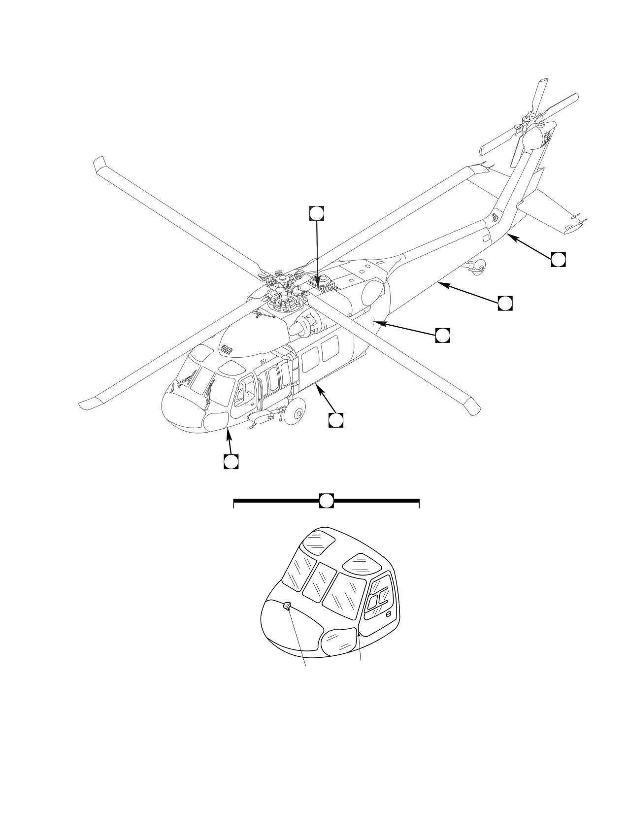
Figure E-1. Re-capitalization Modification Kit (Sheet 1 of 3)
E-15
DMWR 1-1520-237
7
11
9
12
8
6
15
4
10
14
9
13
5
16
21
18
17
19
23
20
22
AB3088_2
SA
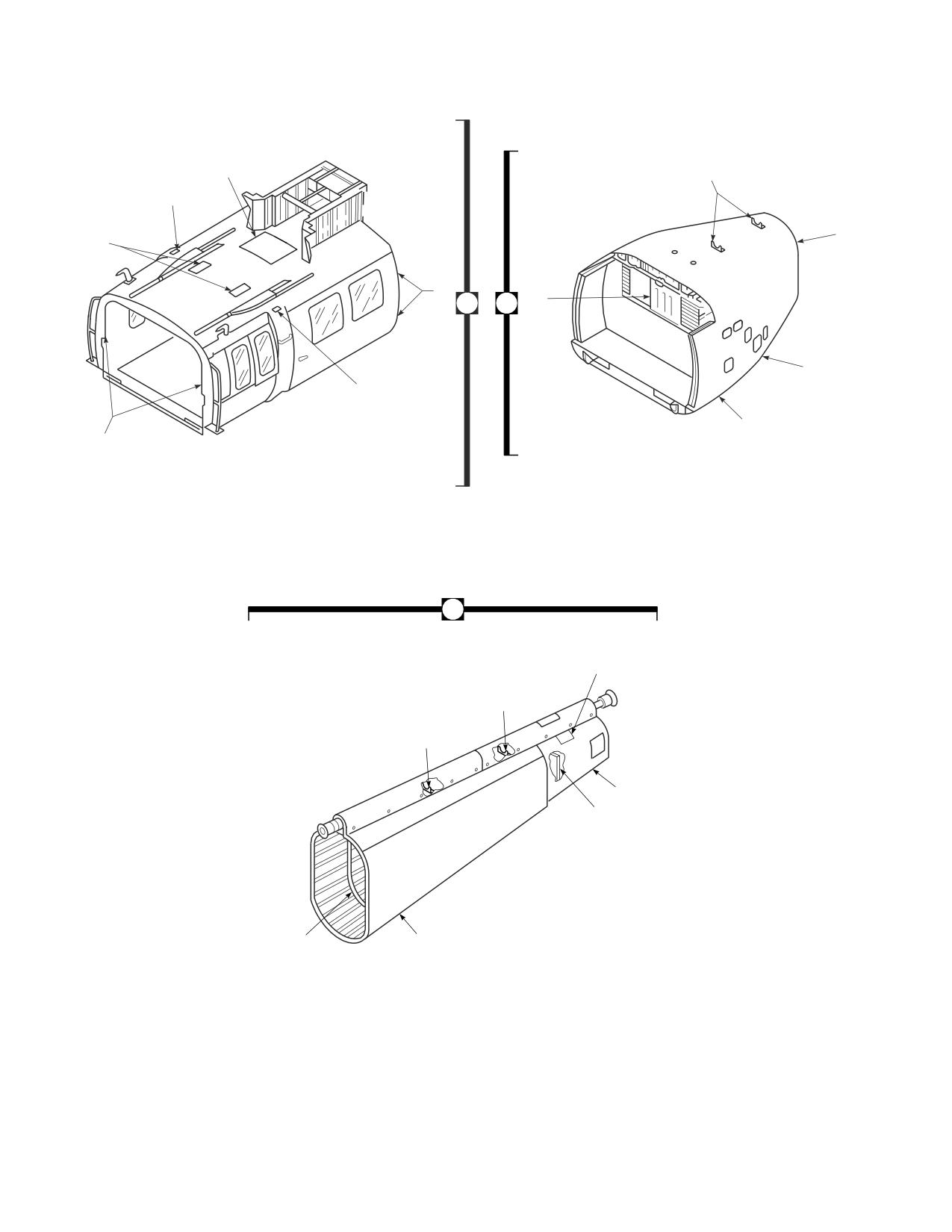
Figure E-1. Re-capitalization Modification Kit (Sheet 2 of 3)
E-16
DMWR 1-1520-237
25
26
27
29
28
24
A
30
33
31
32
AB3088_3
SA
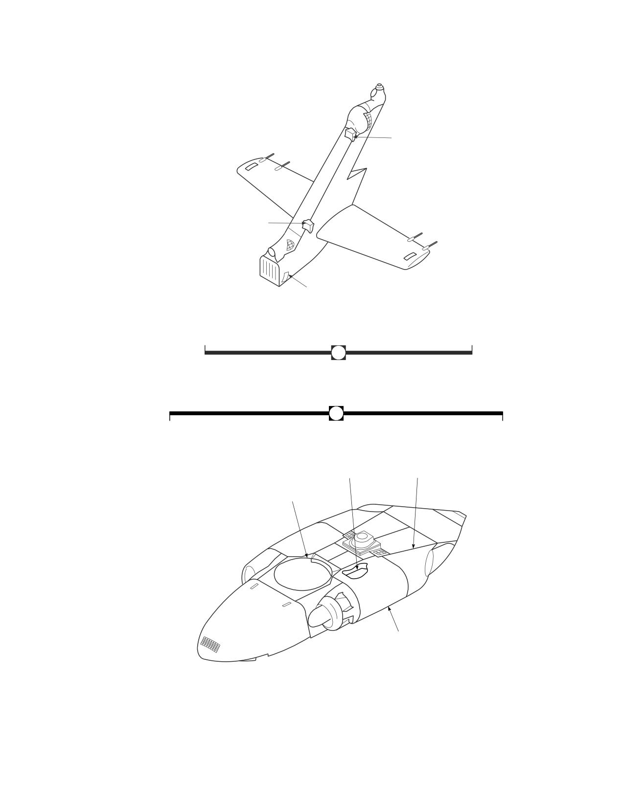
Figure E-1. Re-capitalization Modification Kit (Sheet 3 of 3)
E-17
DMWR 1-1520-237
QTY
USABLE
FIGURE &
PER
ON
INDEX NO. PART NUMBER
1 2 3 4 5 6 7
DESCRIPTION
ASSY
CODE
E-1-
70070-95122-011
RE-CAPATIALIZATION MODIFICATION KIT
1
-1
70070-20566-011
DOOR POST MODIFICATION KIT
1
-2
70070-20566-012
. DOOR POST MODIFICATION KIT, (See Fig.
E-2 for Breakdown)
1
-3
70070-20566-013
. HINGE ACCESS MODIFICATION KIT, (See Fig.
E-3 for Breakdown)
1
-4
70070-20567-011
CABIN MODIFICATION KIT
1
-5
70070-20527-011
. MODIFICATION KIT, (See Fig. E-4 for
Breakdown)
1
-6
70070-20568-011
. STATION 379 MODIFICATION KIT, (See Fig.
E-5 for Breakdown)
1
-7
70070-20570-011
. UPPER PLATING MODIFICATION KIT, (See
Fig. E-6 for Breakdown)
1
-8
70070-20572-011
. BL 34.5 MODIFICATION KIT, (See Fig. E-7 for
Breakdown)
1
-9
70070-20641-011
. ESSS DOUBLER MODIFICATION KIT, (See
Fig. E-8 for Breakdown)
1
-10
70070-20575-011
TRANSITION MODIFICATION KIT
1
-11
70070-20488-023
. TAIL ROTOR DRIVE SHAFT BRACKETS
MODIFICATION KIT, (See Fig. E-9 for
Breakdown)
1
-12
70070-20575-012
. STATION 485 MODIFICATION KIT, (See Fig.
E-10 for Breakdown)
1
-13
70070-20577-011
. LOWER AFT TRANSITION MODIFICATION KIT-
, (See Fig. E-11 for Breakdown)
1
-14
70070-20577-015
. FOAM LINER MODIFICATION KIT, (See Fig.
E-12 for Breakdown)
1
-15
70070-20578-011
. ENCLOSURE MODIFICATION KIT, (See Fig.
E-13 for Breakdown)
1
-16
70070-20580-011
TAILCONE MODIFICATION KIT
1
-17
70070-20266-013
. SUPPORT SHAFT MODIFICATION KIT, (See
Fig. E-14 for Breakdown)
1
-18
70070-20266-014
. SUPPORT SHAFT MODIFICATION KIT, (See
Fig. E-15 for Breakdown)
1
-19
70070-20581-011
. SHEAR DECK MODIFICATION KIT, (See Fig.
E-16 for Breakdown)
1
-20
70070-20582-011
. STRINGER/FRAME MODIFICATION KIT, (See
Fig. E-17 for Breakdown)
1
-21
70070-20583-011
. SKIN DOUBLER MODIFICATION KIT, (See Fig.
E-18 for Breakdown)
1
-22
70070-20615-011
. PLATE INSTALLATION MODIFICATION KIT-
, (See Fig. E-19 for Breakdown)
1
-23
70070-20617-011
. BULKHEAD INSTALLATION MODIFICATION
KIT, (See Fig. E-20 for Breakdown)
1
-24
70070-20585-011
PYLON MODIFICATION KIT
1
-25
70070-20465-017
. TAIL PYLON MODIFICATION KIT, (See Fig.
E-21 for Breakdown)
1
-26
70070-20465-019
. CRCT DOUBLE MODIFICATION KIT, (See Fig.
E-22 for Breakdown)
1
-27
70070-20465-020
. FRONT SPAR FT MODIFICATION KIT, (See
Fig. E-23 for Breakdown)
1
-28
70070-20587-011
. SIDE SKIN MODIFICATION KIT, (See Fig. E-24
for Breakdown)
1
-29
70070-20588-011
. AFT SPAR FITTING MODIFICATION KIT, (See
Fig. E-25 for Breakdown)
1
-30
70070-30307-011
L/H FIREWALL MODIFICATION KIT, (See Fig.
E-26 for Breakdown)
1
-31
70070-30307-012
R/H FIREWALL MODIFICATION KIT, (See Fig.
E-27 for Breakdown)
1
-32
70070-30308-011
COWL ASSEMBLY MODIFICATION KIT, (See
Fig. E-28 for Breakdown)
1
E-18
DMWR 1-1520-237
QTY
USABLE
FIGURE &
PER
ON
INDEX NO. PART NUMBER
1 2 3 4 5 6 7
DESCRIPTION
ASSY
CODE
-33
70072-30000-011
. HIRSS REPAIR KIT, (See Fig. E-29 for
Breakdown)
1
E-19
DMWR 1-1520-237
E-3. DOOR POST MODIFICATION KIT (50-22).
Subject: Cockpit Door Posts, Modification of, dated 31 March 2003
Purpose: Provide instructions for the structural strengthening of the left and right side cockpit lower door post hinge
area.
Model:
UH-60A
Description: The left and right side lower door post structure at station 205.00 are modified to improve the structural
strength at these locations.
Drawings required for modification:
70070-20566, 70500-01053, 70211-01005
References: (a) Special Service Instructions (SSI) No. 50-31, Installation of 9A to A9 Recapitalization Program, dated
March 31, 2003
Instructions:
NOTE
• A complete review of this SSI is recommended before incorporating the Door Post Modification Kit.
• Before beginning this modification procedure, use the material information list to inventory the modification
kit. Make sure all parts are present and in serviceable condition.
• The sheet metal and structural modifications in this SSI shall be done by personnel experienced in reading
modification drawings. Routine steps such as cleaning, layout and drilling, deburring, standard repairs,
corrosion control, clean up after rework, chemical coating for aluminum after cutting/trimming parts, and
paint touch up and safety practices may not be called out herein. However, these steps and all other
required routine tasks shall be done.
• Where drawing numbers are not listed within individual step(s), drawing(s) listed in preceding step(s) are
the controlling authority.
• Slight variations to the instructions contained herein are allowed, as long as the intent of the modification
is accomplished.
A.
Preparation for modification and removal of equipment:
(1)
Confirm that all warnings, cautions, and notes are complied with per reference (a).
(2)
Perform preparation for modification per reference (a).
B.
Modification, left side door post.
(1)
Remove fasteners at station 205.00, waterline 226.00, left buttline 41.00 and remove duct assembly
(70500-01053-043). Keep for reuse (Dwg 70500-01053, Sheet 1, Zones 14-E and 11-C).
(2)
Remove two RFI grounding seals (03-0402-A137), straps (70211-01005-103 and 70211-01005-105), and
jambs (70211-01005-104 and -107) at station 205.00 (Dwg 70211-01005, Sheet 1, Zones 9-E, 9-F and 6-F).
E-20
DMWR 1-1520-237
(3)
Remove fasteners, doubler (70214-01003-112), and angle (70211-01011-117) (Dwg 70070-20566,
Sheet 6, View H-H, Zones 12-C and 9-B).
(4)
Remove fasteners shown from floor skin, between station 194.00 and station 209.00, between buttline 30.00
and buttline 40.00 (Sheet 6, Zones 12-B through 9-D).
(5)
Trim floor skin (70214-01003-101) to agree with support fitting (70209-21206-113) and peel back to sta-
tion 210.00 (Sheet 6, View H-H, Zone 11-C).
(6)
Remove nutplates (MS21075-3N and 52LHA3575-02), station 200.00, waterline 215.00, between buttline
30.00 and buttline 40.00 (Sheet 6, View H-H, Zones 9-D and 12-C).
(7)
Remove fasteners shown from shim (70219-01000-102), plate (70219-01000-108), washers (70219-
01000-109), radius block (SS1058A10-29-48), and hinge fitting assembly (70219-01008-041 or 70219-01008-043)
(Sheet 6, Zones 15-D, 15-E, and 14-E).
(8)
Remove fasteners and fitting assembly (70217-01024-041 or 70217-01024-045) (Sheet 6, View J-J, Zone
17-F).
(9)
Remove fasteners at station 205.00, left buttline 40.00 as shown (Sheet 6, View A-A, Zones 15-A through
15-F and, 19-B through 19-G).
(10)
Remove channel (70211-01011-130) (Sheet 6, Zones 18-G).
(11)
Remove fasteners and angle (70211-01011-111) (Sheet 6, Zone 11-D).
(12)
Remove angle (70211-01011-103) (Sheet 6, Zone 19-B).
(13)
Remove fasteners and angle (70211-01011-105) (Sheet 6, Zone 20-B).
(14)
Remove fasteners, baffle (70211-01011-127), and radius block (SS1058-7-30-23) (Sheet 6, Zones 18-F,
16-F and 17-C; Sheet 3, Notes 24 and 25).
(15)
Locate and temporarily install following parts at station 205.00, between waterline 210.00 and waterline
230.00, between left buttline 35.00 and buttline 45.00 as follows:
(a)
Slot skin and frame existing lower door hinge mount holes to 0.260 X 0.340-inch slots (Dwg 70070-
20566, Sheet 6, Zone 16-D).
(b)
Plug rivet skin first and third holes below lower door hinge location with fasteners shown (Sheet 6, Zone
14-D).
(c)
Position angle (70070-20566-107) against forward side of station 205.00 and transfer drill inboard
holes from frame through angle. Transfer drill station 205.00 outboard holes and skin below waterline 215.00 only
(Sheet 6, View A-A, Zone 19-B).
(d)
Position angle (70070-20566-111) and transfer drill holes from station 205.00 frame and buttline 30.00
fitting (Sheet 6, Zone 11-D).
E-21
DMWR 1-1520-237
NOTE
The station 205.00 frame outboard holes above waterline 215.00 are not drilled in the following step.
(e)
Position angle (70211-01011-105) against aft side of station 205.00 and transfer drill inboard holes from
frame through angle. Transfer drill station 205.00 outboard holes below waterline 215.00 (Sheet 6, View A-A, Zone 20-
D).
(f)
Position doubler (70070-20566-105), shim (70204-21003-132), and support fitting (70209-21206-113)
on waterline 215.00 against forward face of frame 205.00. Transfer drill holes from angle (70211-01011-105) (Sheet
6, View H-H, Zones 10-B and 10-C).
(g)
Drill support fitting (70209-21206-113) outboard holes through station 205.00 frame, angles (70070-
20566-107 and 70070-20566-111), and skin clearing support fitting radius (Sheet 6, View A-A, Zones 19-C and 19-D,
Note 58).
(h)
Drill fastener holes from support fitting (70209-21206-113) through shim (70204-21003-132), doubler
(70070-20566-105), and structure through support fitting clearing support fitting radius (Sheet 6, View H-H, Zone 10-B).
(i)
Position channel (70211-01011-130) on station 205.00 frame and transfer drill rivet holes from frame
through channel (Sheet 6, View A-A, Zones 15-C through 15-F and 20-B through 19-F).
(j)
Locate door check channel assembly (70217-01024-045) on inboard and aft sides of channel (70211-
01011-130) (Sheet 6, Views A-A and J-J, Zones 19-D and 17-F).
(k)
Transfer drill aft side holes from channel assembly (70217-01024-045) through channel (70211-01011-
130) and open inboard hole to agree with frame.
(l)
Remove door check channel assembly (70217-01024-045) and channel (70211-01011-130).
(m)
Temporarily attach centerline of baffle (70070-20566-109) to channel (70211-01011-130) aft holes
(Sheet 6, View J-J, Zone 16-F).
(n)
Reposition channel (70211-01011-130) on station 205.00 frame.
(o)
Transfer drill two fastener holes from inboard side of frame through baffle (70070-20566-109).
(p)
Transfer drill two 0.250-inch diameter holes from channel (70211-01011-130) through baffle (70070-
20566-109) aft flange.
(q)
Clamp drill template (70070-20566-019T046) to aft side of frame.
(r)
Drill two 0.187-inch diameter holes from drill template through frame and support fitting (70209-21206-
113). Remove drill template.
(s)
Remove support fitting (70209-21206-113) from forward side of frame.
(t)
Open two 0.250 and 0.187-inch diameter holes to 0.448-inch diameter in channel (70211-01011-103),
angles (70070-20566-107 and 70211-01011-105), and baffle (70070-20566-109) (Sheet 6, Zone 16-F).
(u)
Temporarily position angle (70211-01011-117) on floor aft of station 205.00. Transfer drill fastener holes
from floor and frame through angle (Sheet 6, View H-H, Zone 10-B).
(v)
Temporarily reinstall support fitting (70209-21206-113).
E-22
DMWR 1-1520-237
(w)
Temporarily attach door check channel assembly (70217-01024-045) to channel (70211-01011-130)
with work hardware and bushings (NAS73-4-107).
(x)
Position installation tool (70070-20566-019T046) onto upper door hinge and door check channel as-
sembly (70217-01024-045).
(y)
Drill two 0.250-inch diameter holes. Remove installation tool.
(z)
Remove parts from station 205.00, clean, deburr, and touch up as required.
(aa)
Position radius block (70201-21011-135) onto inboard side of support fitting (70209-21206-113). Drill
two No. 30 (0.128-inch diameter) holes with 100° countersink and transfer drill two 0.250-inch diameter holes (Sheet 6,
View K-K, Zone 17-B).
(ab)
Install radius block (70201-21011-135) to support fitting (70209-21206-113) with fasteners shown
(Sheet 6, View K-K, Zone 17-B).
(ac)
Install new frame parts with fasteners shown (Sheet 6, Zones 8 through 20, Note 44).
(ad)
Install door hinge fitting assembly (70219-01008-045), shim (70219-01000-102), and plate (70219-
01000-108) with fasteners shown (Sheet 6, Zones 7-C, 14-E, and 16-E, Notes 44 and 45).
(ae)
Install nutplates (MS21075-3N and 52LHA3575-02) with fasteners shown (Sheet 6, Zones 10-D and 12-
D).
(af)
Reinstall floor with fasteners shown (Sheet 6, View H-H, Zone 9-B through 12-D).
(ag)
Reinstall duct assembly (70500-01053-043) (Dwg 70500-01053, Sheet 1, Zones 14-E and 11-C).
(ah)
Install two RFI grounding seals (03-0402-A137), straps (70211-01005-103 and -105), and jambs
(70211-01005-104 and -107) at station 205.00 with fasteners shown (Dwg 70211-01005, Sheet 1, Zones 9-E, 9-F and
6-F).
C.
Modification, right side door post.
(1)
Remove fasteners at station 205.00, waterline 226.00, right buttline 41.00 and remove duct assembly
(70500-01053-044). Keep for reuse (Dwg 70500-01053, Sheet 1, Zones 14-E and 11-C).
(2)
Remove two RFI grounding seals (03-0402-A137), straps (70211-01005-103 and 70211-01005-106), and
jambs (70211-01005-104 and -108) at station 205.00 (Dwg 70211-01005, Sheet 1, Zones 9-E, 9-F and 6-F).
(3)
Remove fasteners and angle (70211-01011-118) (Dwg 70070-20566, Sheet 6, View H-H, Zone 9-G).
(4)
Remove fasteners shown from floor skin, between station 194.00 and station 209.00, between buttline 30.00
and buttline 40.00 (Sheet 6, Zones 12-B through 9-D).
(5)
Trim floor skin (70214-01003-102) to agree with support fitting (70209-21206-114) and peel back to sta-
tion 210.00 (Sheet 6, View H-H, Zone 11-F).
(6)
Remove radius block (SS1056-7-24-26) (Sheet 6, View H-H, Zone 11-F).
(7)
Remove nutplates (MS21075-3N and 52LHA3575-02), station 200.00, waterline 215.00, between buttline
30.00 and buttline 40.00 (Sheet 6, View H-H, Zones 9-E and 12-F).
E-23
DMWR 1-1520-237
(8)
Remove fasteners shown from shim (70219-01000-102), plate (70219-01000-108), washers (70219-
01000-109), radius block (SS1058A10-29-48), and hinge fitting assembly (70219-01008-042 or 70219-01008-044)
(Sheet 6, Zones 15-D, 15-E, and 14-E).
(9)
Remove fasteners and fitting assembly (70217-01024-042 or 70217-01024-045) (Sheet 6, View J-J, Zone
17-F).
(10)
Remove fasteners at station 205.00, right buttline 40.00 as shown (Sheet 6, View A-A, Zones 15-A through
15-F and, 19-B through 19-G).
(11)
Remove channel (70211-01011-131) (Sheet 6, Zones 18-G).
(12)
Remove fasteners and angle (70211-01011-115) (Sheet 6, Zone 11-E).
(13)
Remove angle (70211-01011-104) (Sheet 6, Zone 19-B).
(14)
Remove fasteners and angle (70211-01011-106) (Sheet 6, Zone 20-B).
(15)
Remove fasteners, baffle (70211-01011-128), and radius block (SS1058-7-30-23) (Sheet 6, Zones 18-F,
16-F and 17-C, Sheet 3, Notes 24 and 25).
(16)
Locate and temporarily install following parts at station 205.00, between waterlines 210.00 and 230.00,
between right buttline 35.00 and buttline 45.00 as follows:
(a)
Slot skin and frame existing lower door hinge mount holes to 0.260 X 0.340-inch slots (Dwg 70070-
20566, Sheet 6, Zone 16-D).
(b)
Plug rivet skin first and third holes below lower door hinge location with fasteners shown (Sheet 6, Zone
14-D).
(c)
Position angle (70070-20566-106) against forward side of station 205.00 and transfer drill inboard
holes from frame through angle. Transfer drill from station 205.00 outboard holes and skin below waterline 215.00 only
(Sheet 6, View A-A, Zone 19-B).
(d)
Position angle (70070-20566-110) and transfer drill holes from station 205.00 frame and buttline 30.00
fitting (Sheet 6, Zone 11-D).
NOTE
The station 205.00 frame outboard holes above waterline 215.00 are not drilled in the following step.
(e)
Position angle (70211-01011-106) against aft side of station 205.00 and transfer drill inboard holes from
frame through angle. Transfer drill station 205.00 outboard holes below waterline 215.00 (Sheet 6, View A-A, Zone 20-
D).
(f)
Position doubler (70070-20566-105), shim (70204-21003-132), and support fitting (70209-21206-114)
on waterline 215.00 against forward face of frame 205.00. Transfer drill holes from angle (70211-01011-106) (Sheet
6, View H-H, Zones 10-G and 10-H).
(g)
Drill support fitting (70209-21206-114) outboard holes through station 205.00 frame, angles (70070-
20566-106 and 70070-20566-110), and skin clearing support fitting radius (Sheet 6, View A-A, Zones 19-C and 19-D,
Note 58).
E-24
DMWR 1-1520-237
(h)
Drill fastener holes from support fitting (70209-21206-114) through shim (70204-21003-132), doubler
(70070-20566-105), and structure through support fitting clearing support fitting radius (Sheet 6, View H-H, Zone 10-
G).
(i)
Position channel (70211-01011-131) on station 205.00 frame and transfer drill rivet holes from frame
through channel (Sheet 6, View A-A, Zones 15-C through 15-F and 20-B through 19-F).
(j)
Locate door check channel assembly (70217-01024-044) on inboard and aft sides of channel (70211-
01011-131) (Sheet 6, Views A-A and J-J, Zones 19-D and 17-F).
(k)
Transfer drill aft side holes from channel assembly (70217-01024-044) through channel (70211-01011-
131) and open inboard hole to agree with frame.
(l)
Remove door check channel assembly (70217-01024-044) and channel (70211-01011-131).
(m)
Temporarily attach centerline of baffle (70070-20566-108) to channel (70211-01011-131) aft holes
(Sheet 6, View J-J, Zone 16-F).
(n)
Reposition channel (70211-01011-131) on station 205.00 frame.
(o)
Transfer drill two fastener holes from inboard side of frame through baffle (70070-20566-108).
(p)
Transfer drill two 0.250-inch diameter holes from channel (70211-01011-131) through baffle (70070-
20566-108) aft flange.
(q)
Clamp drill template (70070-20566-019T046) to aft side of frame.
(r)
Drill two 0.187-inch diameter holes from drill template through frame and support fitting (70209-21206-
114). Remove drill template.
(s)
Remove support fitting (70209-21206-114) from forward side of frame.
(t)
Open two 0.250 and 0.187-inch diameter holes to 0.448-inch diameter in channel (70211-01011-103),
angles (70070-20566-106 and 70211-01011-106), and baffle (70070-20566-108) (Sheet 6, Zone 16-F).
(u)
Temporarily position angle (70211-01011-118) on floor aft of station 205.00. Transfer drill fastener holes
from floor and frame through angle (Sheet 6, View H-H, Zone 9-H).
(v)
Temporarily reinstall support fitting (70209-21206-114).
(w)
Temporarily attach door check channel assembly (70217-01024-044) to channel (70211-01011-131)
with work hardware and bushings (NAS73-4-107).
(x)
Position installation tool (70070-20566-019T046) onto upper door hinge and door check channel as-
sembly (70217-01024-045).
(y)
Drill two 0.250-inch diameter holes. Remove installation tool.
(z)
Remove parts from station 205.00, clean, deburr, and touch up as required.
(aa)
Position radius block (70201-21011-135) onto inboard side of support fitting (70209-21206-114). Drill
two No. 30 (0.128-inch diameter) holes with 100° countersink and transfer drill two 0.250-inch diameter holes (Sheet 6,
View K-K, Zone 17-B).
E-25
DMWR 1-1520-237
(ab)
Install radius block (70201-21011-135) to support fitting (70209-21206-114) with fasteners shown
(Sheet 6, View K-K, Zone 17-B).
(ac)
Install new frame parts with fasteners shown (Sheet 6, Zones 8 through 20, Note 44).
(ad)
Install door hinge fitting assembly (70219-01008-044), shim (70219-01000-102), and plate (70219-
01000-108) with fasteners shown (Sheet 6, Zones 7-C, 14-E, and 16-E, Notes 44 and 45).
(ae)
Install nutplates (MS21075-3N and 52LHA3575-02) and radius block (SS1056-7-24-26) with fasteners
shown (Sheet 6, View H-H, Zones 10-E, 11-F, and 12-F).
(af)
Reinstall floor with fasteners shown (Sheet 6, View H-H, Zone 9-B through 12-D).
(ag)
Reinstall duct assembly (70500-01053-044) (Dwg 70500-01053, Sheet 1, Zones 14-E and 11-C).
(ah)
Install two RFI grounding seals (03-0402-A137), straps (70211-01005-103 and 70211-01005-106),
and jambs (70211-01005-104 and -108) at station 205.00 with fasteners shown (Dwg 70211-01005, Sheet 1, Zones
9-E, 9-F and 6-F).
D.
Reidentification:
NOTE
The following reidentifications are for record purposes only. No physical reidentification is required.
FROM
TO
Nomenclature
70214-01003-011
70070-20566-031
Floor Instl, LH
70214-01003-016
70070-20566-033
Floor Instl, LH
70214-01003-012
70070-20566-030
Floor Instl, RH
70214-01003-017
70070-20566-032
Floor Instl, RH
70214-01003-041
70070-20566-041
Floor Assy, LH
70214-01003-043
70070-20566-043
Floor Assy, LH
70214-01003-042
70070-20566-042
Floor Assy, RH
70214-01003-044
70070-20566-044
Floor Assy, RH
70214-01003-101
70070-20566-103
Skin
70214-01003-102
70070-20566-104
Skin
70219-01000-011
70070-20566-025
Fitting Instl, LH
70219-01000-013
70070-20566-029
Fitting Instl, LH
70219-01000-012
70070-20566-026
Fitting Assy, RH
70219-01000-014
70070-20566-028
Fitting Instl, RH
70211-01011-012
70070-20566-014
Frame Instl
70211-01011-011
70070-20566-039
Frame Instl
70211-01001-041
70070-20566-045
Frame Assy
70211-01001-042
70070-20566-046
Frame Assy
70211-01001-044
70070-20566-047
Frame Assy
70211-01001-045
70070-20566-048
Frame Assy
E-26
DMWR 1-1520-237
E.
Reinstallation of removed equipment:
(1)
Perform reinstallation of parts and equipment per reference (a).
F.
Record of Compliance:
(1)
Make an appropriate logbook entry to show compliance with this Special Service Instruction.
Weight and Balance Data:
POUNDS
INCHES AFT
MOMENT/
QTY
PART NO.
NOMENCLATURE
WEIGHT
OF DATUM
1000
1
70070-20566-012
Mod. Kit, Door Post
+5.9
210.0
+1.239
Weight and Balance: Change resulting from these instructions are as follows:
Change in basic weight:
+5.9 pounds
Moment arm:
210.0 in.
Change in basic moment/1000:
1.239
Manpower (Estimated)
No. of Personel
No. of Hours
Man-hours
Sheet Metal Mechanic
2
40.0
*80.0
*Does not include time required to prepare helicopter or return it to flight status.
Material Information:
A.
Modification Kit Required:
Qty
Nomenclature
Part Number
Source
1
Mod. Kit, Door Post
70070-20566-011
(1)
consisting of:
1
Mod. Kit, Door Post,
70070-20566-012
consisting of:
1
Mod. Kit, Floor Instl,
70070-20566-015
E-27
DMWR 1-1520-237
Qty
Nomenclature
Part Number
Source
consisting of:
1
Mod. Kit, Fitting Instl, LH,
70070-20566-019
consisting of:
2
Bolt
AN4C14A
2
Nut
MS21043-4
2
Fastener, Blind
MS90354U0502
3
Fastener, Blind
MS90354U0602
3
Rivet
NAS1097AD4-9
4
Rivet
NAS1097AD5-9
2
Washer, Flat
NAS1149D0463K
1
Radius Block
70201-21011-135
4
Washer
SS5072-4
1
Shim
70219-01000-102
1
Plate
70219-01000-108
2
Washer
70219-01000-109
1
Fitting Assembly
70219-01008-045
10
Rivet
MS20470AD5-9
2
Rivet
MS20470AD6-3
3
Rivet
RA097AD5-3
4
Rivet, Blind
NAS1738B6-5
1
Mod. Kit, Fitting Instl, RH,
70070-20566-020
consisting of:
2
Bolt
AN4C14A
2
Nut
MS21043-4
2
Fastener, Blind
MS90354U0502
3
Fastener, Blind
MS90354U0602
3
Rivet
NAS1097AD4-9
4
Rivet
NAS1097AD5-9
2
Washer, Flat
NAS1149D0463K
1
Radius Block
70201-21011-135
4
Washer
SS5072-4
1
Shim
70219-01000-102
1
Plate
70219-01000-108
2
Washer
70219-01000-109
1
Fitting Assembly
70219-01008-046
10
Rivet
MS20470AD5-9
2
Rivet
MS20470AD6-3
3
Rivet
RA097AD5-3
4
Rivet, Blind
NAS1738B6-5
1
Mod. Kit, Floor LH,
70070-20566-017
E-28
DMWR 1-1520-237
Qty
Nomenclature
Part Number
Source
consisting of:
2
Washer
AN960PD10L
8
Rivet
CCR244SS-3-2
8
Rivet
CCR244SS-3-4
16
Collar
HL1087A-5
16
Pin, Hi Lok
HL20PB-5-4
3
Nutplate
MS21075-3N
2
Rivet
NAS1097AD5-9
10
Rivet, Blind
NAS1738B4-1
10
Rivet, Blind
NAS1738B4-2
15
Rivet, Blind
NAS1738B5-2
15
Rivet, Blind
NAS1739B4-2
2
Rivet, Blind
NAS1739B4-3
3
Nutplate
52LHA3575-02
1
Doubler
70070-20566-105
1
Support Fitting
70209-21206-113
1
Angle
70211-01011-117
2
Screw
MS27039-1-09
3
Rivet, Blind
NAS1739B4-1
1
Shim, Laminated
70204-21003-132
1
Mod. Kit, Floor, RH
70070-20566-018
consisting of:
2
Washer
AN960PD10L
8
Rivet
CCR244SS-3-2
8
Rivet
CCR244SS-3-4
16
Collar
HL1087A-5
16
Pin, Hi Lok
HL20PB-5-4
3
Nutplate
MS21075-3N
2
Rivet
NAS1097AD5-9
3
Rivet, Blind
NAS1738B4-2
22
Rivet, Blind
NAS1738B5-2
16
Rivet, Blind
NAS1739B4-2
2
Rivet, Blind
NAS1739B4-3
1
Radius Block
SS1058-7-24-26
3
Nutplate
52LHA3575-02
1
Doubler
70070-20566-105
1
Shim, Laminated
70204-21003-132
1
Angle
70211-01011-118
1
Support Fitting
70209-21206-114
2
Screw
MS27039-1-09
15
Rivet, Blind
NAS1738B4-2
1
Mod. Kit, Jamb Instl,
70070-20566-034
consisting of:
2
Pin, Hi Lok
HL20PB-5-5
E-29
DMWR 1-1520-237
Qty
Nomenclature
Part Number
Source
2
Collar
HL70TW-5
6
Rivet
MS20470AD5-3
9
Rivet
MS20470AD5-4
3
Fastener, Blind
MS90354U0603
1
Washer, Flat
NAS1149DN416K
5
Rivet, Blind
NAS1738B4-2
2
Rivet, Blind
NAS1738B4-3
2
Seal, RFI Grndng
03-0402-A137
1
Strap
70211-01005-103
1
Jamb
70211-01005-104
1
Strap
70211-01005-105
1
Jamb
70211-01005-107
1
Mod. Kit, Jamb Instl,
70070-20566-035
consisting of:
2
Pin, Hi Lok
HL20PB-5-5
2
Collar
HL70TW-5
6
Rivet
MS20470AD5-3
9
Rivet
MS20470AD5-4
3
Fastener, Blind
MS90354U0603
1
Washer, Flat
NAS1149DN416K
5
Rivet, Blind
NAS1738B4-2
2
Rivet, Blind
NAS1738B4-3
2
Seal, RFI Grndng
03-0402-A137
1
Strap
70211-01005-103
1
Jamb
70211-01005-104
1
Strap
70211-01005-106
1
Jamb
70211-01005-108
1
Mod. Kit, Frame Instl,
70070-20566-037
consisting of:
2
Bolt
AN4-21
27
Rivet
MS20470AD5-9
2
Nut
MS21043-4
7
Fastener, Blind
MS90354U0506
2
Washer, Flat
NAS1149D0416K
2
Washer, Flat
NAS1149D0463K
2
Pin, SWG LKG
NAS1525-02
4
Pin, SWG LKG
NAS1525-03
5
Pin, SWG LKG
NAS1526-03
10
Rivet, Blind
NAS1738B5-2
7
Rivet, Blind
NAS1738B5-3
2
Bushing
NAS73-4-107
1
Baffle
70070-20566-109
1
Channel
70211-01011-130
1
Channel Assembly
70217-01024-045
E-30
DMWR 1-1520-237
Qty
Nomenclature
Part Number
Source
1
Channel
70070-20566-111
1
Angle
70211-01011-105
1
Angle
70070-20566-107
1
Mod. Kit, Frame Instl,
70070-20566-038
consisting of:
2
Bolt
AN4-21
27
Rivet
MS20470AD5-9
2
Nut
MS21043-4
7
Fastener, Blind
MS90354U0506
2
Washer, Flat
NAS1149D0416K
2
Washer, Flat
NAS1149D0463K
2
Pin, SWG LKG
NAS1525-02
4
Pin, SWG LKG
NAS1525-03
5
Pin, SWG LKG
NAS1526-03
10
Rivet, Blind
NAS1738B5-2
7
Rivet, Blind
NAS1738B5-3
2
Bushing
NAS73-4-107
1
Angle
70211-01011-106
1
Baffle
70070-20566-108
1
Channel
70211-01011-131
1
Channel Assembly
70217-01024-044
1
Angle
70070-20566-106
1
Channel
70070-20566-110
B.
Consumable Material:
WARNING
OBSERVE ALL CAUTIONS AND WARNINGS ON CONTAINERS WHEN USING CONSUMABLES.
WHEN APPLICABLE, WEAR NECESSARY PROTECTIVE GEAR DURING HANDLING AND USE. IF A
CONSUMABLE IS FLAMMABLE OR EXPLOSIVE, MAKE CERTAIN CONSUMABLE AND ITS VAPORS ARE
KEPT AWAY FROM HEAT, SPARK, AND FLAME. MAKE CERTAIN EQUIPMENT IS PROPERLY
GROUNDED AND FIREFIGHTING EQUIPMENT IS READILY AVAILABLE PRIOR TO USE. FOR AD-
DITIONAL INFORMATION ON TOXICITY, FLASHPOINT, AND FLAMMABILITY OF CHEMICALS,
CONSULT YOUR MEDICAL PEOPLE, OR MANUFACTURER OF THE CONSUMABLE.
NOTE
The following material is required to incorporate this SSI per drawing Notes.
Qty
Nomenclature
Part Number
Source
8 oz.
Sealant
MIL-S-8802, Class A2 or
(1)
equivalent
4 oz.
Adhesive
EC1751A/B or equivalent
(1)
E-31
DMWR 1-1520-237
Qty
Nomenclature
Part Number
Source
8 oz.
Adhesive
EA9309.3NA or equivalent
(1)
C.
Support Equipment:
Qty
Nomenclature
Part Number
Source
1
Installation Tool
70070-20566-019T046
(1)
1
Installation Tool
70070-20566-020T046
(1)
1
Drill Tool
70070-20566-017T046
(1)
D.
Source:
(1)
Available through normal supply channels
E-32
DMWR 1-1520-237
A
8
7
6
5
4
1
2
2
1
B
6
5
3
A
13
10
9
12
14
11
11
15
16
9
17
AB3096_1
SA
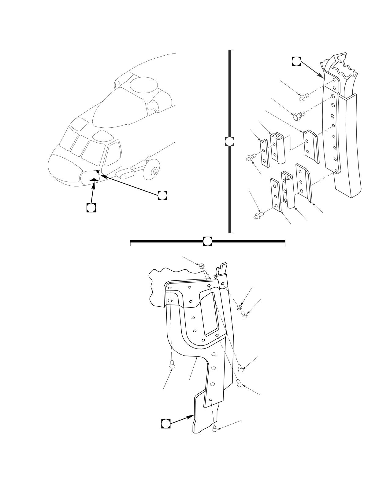
Figure E-2. Door Post Modification Kit (Sheet 1 of 3)
E-33
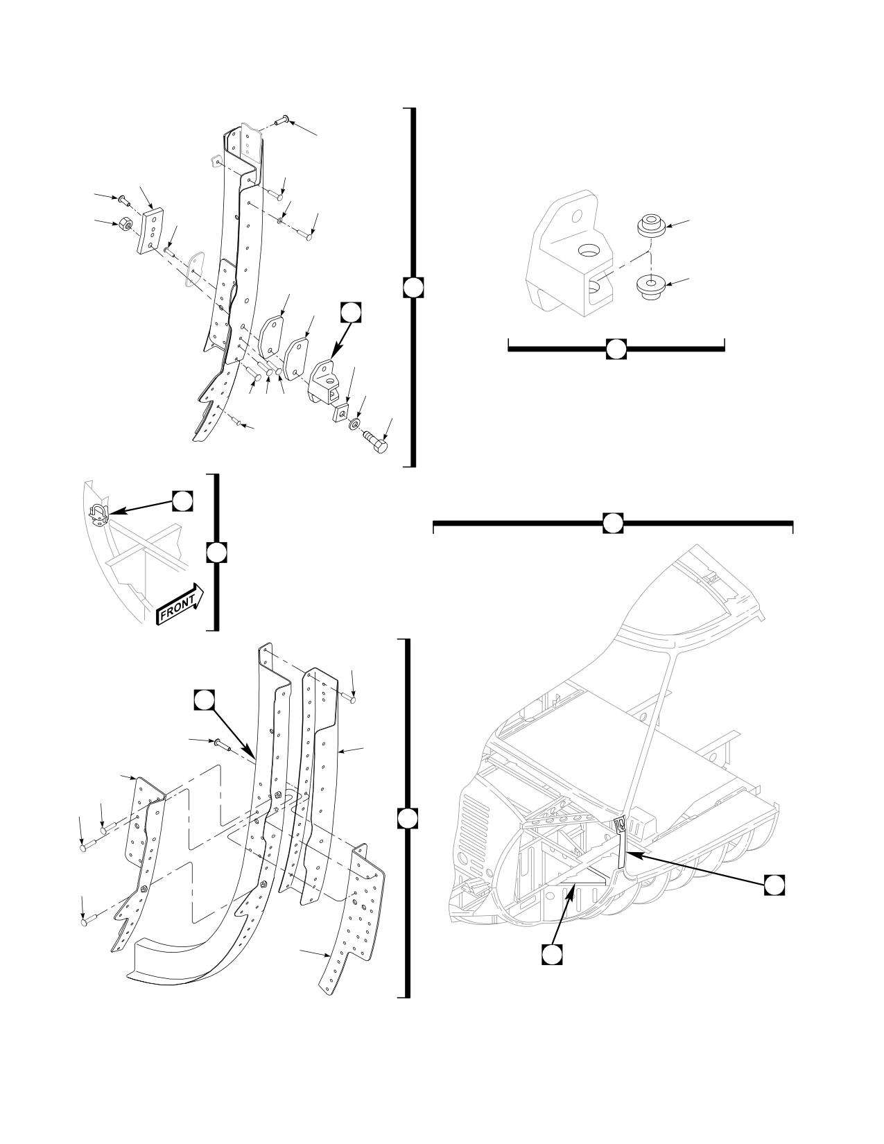
DMWR 1-1520-237
28
29
35
27
26
31
30
20
32
23
23
25
17
24
22
22
21
19
33 34 33
18
35
D
B
C
53
C
42
54
59
57
56
37
37
58
36
60
63
62
AB3096_2
SA
Figure E-2. Door Post Modification Kit (Sheet 2 of 3)
E-34
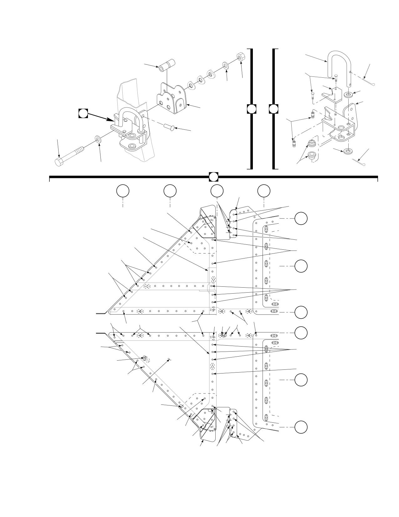
DMWR 1-1520-237
47
45
52
48
41
40
50
46
51
55
D
43
43
49
42
38
45
46
39
44
63
STA
STA
STA
STA
195
200
205
210
69
68
68
68
BL
40
RH
67
78
65
68
66
64
BL
35
68
RH
67
BL
30
RH
74
76
74
70
64
64
64
64
61
75
77
75
64
64
BL
30
LH
66
67
72
73
67
64
BL
35
LH
71
65
83
67
67
BL
82
40
65
LH
79
65
80
68
69
AB3096_3
81
68
SA
Figure E-2. Door Post Modification Kit (Sheet 3 of 3)
E-35
DMWR 1-1520-237
QTY
USABLE
FIGURE &
PER
ON
INDEX NO. PART NUMBER
1 2 3 4 5 6 7
DESCRIPTION
ASSY
CODE
E-2-
70070-20566-012
DOOR POST MODIFICATION KIT
REF
-1
70070-20566-034
M/K JAMB INSTL
1
70070-20566-035
M/K JAMB INSTL
1
-2
NAS1738B4-2
. BLIND RIVET
5
-3
70211-01005-103
. STRAP
1
-4
70211-01005-104
. JAMBP
1
-5
03-0402-A137
. SEAL,RFI GRNDNG, (12881)
2
-6
70211-01005-105
. STRAP, (Used on 70070-20566-034)
1
70211-01005-106
. STRAP, (Used on 70070-20566-035)
1
-7
MS90354U0603
. BLIND FASTENER
3
-8
NAS1738B4-3
. BLIND RIVET
2
-9
MS20470AD5-3
. RIVET
6
-10
NAS1149DN416K
. FLAT WASHER
1
-11
MS20470AD5-4
. RIVET
9
-12
HL20PB-5-5
. HI-LOK PIN, (73197)
2
-13
HL70TW-5
. COLLAR, (73197)
2
-14
70211-01005-107
. JAMB, (Used on 70070-20566-034)
1
70211-01005-108
. JAMB, (Used on 70070-20566-035)
1
-15
70070-20566-015
M/K DOOR POST
1
-16
70070-20566-019
. M/K DOOR POST L
1
70070-20566-020
. M/K DOOR POST R
1
-17
70070-20566-025
. . FITTING INST LH, (Reidentified from 70219-
01000-011_
REF
70070-20566-029
. . FITTING INST LH, (Reidentified from 70219-
01000-013)
REF
70070-20566-026
. . FITTING INST RH, (Reidentified from 70219-
01000-012)
REF
70070-20566-028
. . FITTING INST RH, (Reidentified from 70219-
01000-014)
REF
-18
AN4C14A
. . BOLT
2
-19
NAS1149D0463K
. . FLAT WASHER
2
-20
MS21043-4
. . NUT
2
-21
70219-01000-109
. . WASHER
2
-22
70219-01008-045
. . FITTING ASSY, (Used on 70070-20566-019)...
1
70219-01008-046
. . FITTING ASSY, (Used on 70070-20566-020)...
1
-23
NAS77A4-14P
. . . BUSHING
2
-24
70219-01000-108
. . PLATE
1
-25
70219-01000-102
. . SHIM
1
-26
NAS1097AD4-9
. . RIVET
3
-27
70201-21011-135
. . RADIUS BLOCK
1
-28
MS90354U0502
. . BLIND FASTENER
2
-29
MS90354U0602
. . BLIND FASTENER
3
-30
NAS1097AD5-9
. . RIVET
4
-31
SS5072-4
. . WASHER
4
-32
NAS1738B6-5
. . BLIND RIVET
4
-33
RA097AD5-3
. . RIVET
3
-34
MS20470AD6-3
. . RIVET
2
-35
MS20470AD5-9
. . RIVET
10
-36
70070-20566-037
M/K FRAME INSTL LH
1
70070-20566-038
M/K FRAME INSTL RH
1
-37
70070-20566-014
. FRAME INSTL, (Modified from 70211-01011-
012)
REF
70070-20566-039
. FRAME INSTL, (Modified from 70211-01011-
011)
REF
70070-20566-045
. FRAME ASSY LH, (Reidentified from 70211-
01001-041)
REF
70070-20566-046
. FRAME ASSY RH, (Reidentified from 70211-
01001-042)
REF
70070-20566-048
. FRAME ASSY LH, (Reidentified from 70211-
01001-045)
REF
E-36
DMWR 1-1520-237
QTY
USABLE
FIGURE &
PER
ON
INDEX NO. PART NUMBER
1
2
3 4 5 6 7
DESCRIPTION
ASSY
CODE
70070-20566-047
FRAME ASSY RH, (Reidentified from 70211-
01001-044)
REF
-38
AN4-21
BOLT
2
-39
NAS1149D0463K
FLAT WASHER
2
-40
NAS1149D0416K
FLAT WASHER
2
-41
MS21043-4
NUT
2
-42
NAS1738B5-3
BLIND RIVET
7
-43
70217-01024-045
CHANNEL ASSY, (Used on 70070-20566-037)...
1
70217-01024-044
CHANNEL ASSY, (Used on 70070-20566-038)...
1
-44
NAS77-3-10
. BUSHING
2
-45
MS24665-1013
. COTTER PIN
2
-46
AN960PD416L
. WASHER
2
-47
70217-01024-104
. SPRING
1
-48
HL20PB-5-4
. HI-LOK PIN, (73197)
2
-49
HL1087-5
. COLLAR, (73197)
2
-50
70217-01024-107
. WEAR PLATE
1
-51
70217-01024-105
. CHECK FITTING, (Used on 70217-
01024-045)
1
70217-01024-106
. CHECK FITTING, (Used on 70217-
01024-044)
1
-52
NAS73-4-107
BUSHING
2
-53
NAS1738B5-2
BLIND RIVET
10
-54
70211-01011-130
CHANNEL, (Used on 70070-20566-037)
1
70211-01011-131
CHANNEL, (Used on 70070-20566-038)
1
-55
70070-20566-109
BAFFLE, (Used on 70070-20566-037)
1
70070-20566-108
BAFFLE, (Used on 70070-20566-038)
1
-56
MS20470AD5-9
RIVET
27
-57
MS90354U0506
BLIND FASTENER
7
-58
NAS1525-03
SWAGE LOCKING PIN
4
NAS1525-02
SWAGE LOCKING PIN,
2
*
NAS1526-03
SWAGE LOCKING PIN,
5
*
-59
70070-20566-107
ANGLE, (Used on 70070-20566-037)
1
70070-20566-106
ANGLE, (Used on 70070-20566-038)
1
-60
70211-01011-105
ANGLE, (Used on 70070-20566-037)
1
70211-01011-106
ANGLE, (Used on 70070-20566-038)
1
-61
70070-20566-111
CHANNEL, (Used on 70070-20566-037)
1
70070-20566-110
CHANNEL, (Used on 70070-20566-038)
1
-62
70070-20566-017
M/K FLOOR LH
1
70070-20566-018
M/K FLOOR RH
1
-63
70070-20566-031
. FLOOR INSTL LH, (Modified from 70214-01003-
011)
REF
70070-20566-030
. FLOOR INSTL RH, (Modified from 70214-
01003-012)
REF
70070-20566-033
. FLOOR INSTL LH, (Modified from 70214-01003-
016)
REF
70070-20566-032
. FLOOR INSTL RH, (Modified from 70214-
01003-017)
REF
70070-20566-041
. FLOOR ASSY LH, (Reidentified from 70214-
01003-041)
REF
70070-20566-042
. FLOOR ASSY RH, (Reidentified from 70214-
01003-042)
REF
70070-20566-043
. FLOOR ASSY LH, (Reidentified from 70214-
01003-043)
REF
70070-20566-044
. FLOOR ASSY RH, (Reidentified from 70214-
01003-044)
REF
-64
NAS1739B4-2
. BLIND RIVET, (Used on 70070-20566-017)
15
NAS1739B4-2
. BLIND RIVET, (Used on 70070-20566-018)
16
-65
NAS1738B4-1
. BLIND RIVET, (Used on 70070-20566-017)
10
NAS1738B4-1
. BLIND RIVET, (Used on 70070-20566-018)
3
-66
NAS1739B4-1
. BLIND RIVET, (Used on 70070-20566-017)
3
-67
NAS1738B5-2
. BLIND RIVET, (Used on 70070-20566-017)
15
E-37
DMWR 1-1520-237
QTY
USABLE
FIGURE &
PER
ON
INDEX NO. PART NUMBER
1 2 3 4 5 6 7
DESCRIPTION
ASSY
CODE
NAS1738B5-2
. . BLIND RIVET, (Used on 70070-20566-018)
22
-68
NAS1738B4-2
. . BLIND RIVET, (Used on 70070-20566-017)
10
NAS1738B4-2
. . BLIND RIVET, (Used on 70070-20566-018)
15
-69
70211-01011-117
. . ANGLE, (Used on 70070-20566-017)
1
70211-01011-118
. . ANGLE, (Used on 70070-20566-018)
1
-70
NAS1739B4-3
. . BLIND RIVET
2
NAS1097AD5-9
. . RIVET
2
*
-71
70070-20566-103
. . SKIN, (Reidentified from 70214-01003-
101) (Used on 70070-20566-017)
REF
70070-20566-104
. . SKIN, (Reidentified from 70214-01003-
102) (Used on 70070-20566-018)
REF
-72
CCR244SS-3-2
. . RIVET,
(11815)
8
-73
MS21075-3N
. . NUTPLATE
3
-74
CCR244SS-3-4
. . RIVET,
(11815)
8
-75
52LHA3575-02
. . NUTPLATE, (72962) (Superseded by
NAS1149D0316K)
3
NAS1149D0316K
. . NUTPLATE
3
-76
MS27039-1-09
. . SCREW
2
-77
AN960PD10L
. . WASHER, (Superseded by NAS1789X3)
2
NAS1789X3
. . WASHER
2
-78
SS1058-7-24-26
. . RADIUS BLOCK, RH, (Used on 70070-20566-
018)
2
-79
HL20PB-5-4
. . HI-LOK PIN, (73197)
16
-80
HL1087A-5
. . COLLAR, (73197)
16
-81
70209-21206-113
. . SUPPORT FITTING, (Used on 70070-20566-
017)
1
70209-21206-114
. . SUPPORT FITTING, (Used on 70070-20566-
018)
1
-82
70204-21003-132
. . LAMINATED SHIM
1
-83
70070-20566-105
. . DOUBLER
1
E-38
DMWR 1-1520-237
E-4. HINGE ACCESS MODIFICATION KIT (50-35).
Subject: Canopy Assembly, Nose Door Hinge Access Holes; Modification of, dated 31 March 2003
Purpose: Provide instructions to create access holes for installation of hinges.
Model:
UH-60A
Description: The following is a brief overview of the work required to modify station canopy assembly station 185.00.
Two 1.62 x 0.50 inch slotted holes are drilled in the composite structure and doublers and a new seal are installed.
Drawings required for modification:
70070-20566, 70217-01010
References: (a) Special Service Instructions (SSI) No. 50-31, Installation of 9A to A9 Recapitalization Program, dated
March 31, 2003
Instructions:
NOTE
• A complete review of this SSI is recommended before reworking nose canopy station 185.00.
• Before beginning this modification procedure, use the material information list to inventory the kit. Make
sure all parts are present and in serviceable condition.
• Where drawing numbers are not listed within individual steps, drawing(s) listed in preceding step(s) are
the controlling authority.
• The sheet metal and structural modifications in this SSI shall be done by personnel experienced in reading
modification drawings. Routine steps such as cleaning, layout and drilling, deburring, standard repairs,
corrosion control, clean up after rework, chemical coating for aluminum after cutting/trimming parts, paint
touch up, and safety practices may not be called out herein. However, these steps and all other required
routine tasks shall be done.
• When installing fasteners refer to drawing sheet and zones for applicable fasteners.
• Slight variations to the instructions contained herein are allowed, as long as the intent of the modification
is accomplished.
A.
Preparation for modification and removal of equipment:
(1)
Confirm that all warnings, cautions, and notes are complied with per reference (a).
(2)
Perform preparation for modification per reference (a).
B.
Install two new access holes at station 186.00 as follows:
(1)
Locate and remove complete upper portion of seal (70217-01010-106) at station 186.00, waterline 236.00,
between right and left buttlines 20.0, to expose area to be reworked (Dwg 70217-01010, Sheet 1, Zones 19-F through
23-F).
E-39
DMWR 1-1520-237
(2)
Locate and slot two holes (1.62 x .50) inch at station 186.00 at right and left buttlines 9.43 and 10.56 (Dwg
70070-20566, Sheet 7, Zones 14-F and 15-G).
(3)
Deburr, clean and touch up as required.
(4)
Install doublers (70070-20611-101 and -102) using fasteners shown (Sheet 7, Zone 15-G).
WARNING
OBSERVE ALL CAUTIONS AND WARNINGS ON CONTAINERS WHEN USING CONSUMABLES.
WHEN APPLICABLE, WEAR NECESSARY PROTECTIVE GEAR DURING HANDLING AND USE. IF A
CONSUMABLE IS FLAMMABLE OR EXPLOSIVE, MAKE CERTAIN CONSUMABLE AND ITS VAPORS ARE
KEPT AWAY FROM HEAT, SPARK, AND FLAME. MAKE CERTAIN EQUIPMENT IS PROPERLY
GROUNDED AND FIREFIGHTING EQUIPMENT IS READILY AVAILABLE PRIOR TO USE. FOR AD-
DITIONAL INFORMATION ON TOXICITY, FLASHPOINT, AND FLAMMABILITY OF CHEMICALS,
CONSULT YOUR MEDICAL PEOPLE, OR MANUFACTURER OF THE CONSUMABLE.
(5)
Apply a bead of sealant (AMS3265 or AMS-S-8802 or equivalent) around doublers (70070-20611-101
and -102) (Sheet 7, Zone 15-D, and Sheet 5, Note 57).
(6)
Install seal (70217-01010-106) at station 186.00, between right and left buttline 20.0 using sealant (EC-
1357 or equivalent) (Dwg 70217-01010, Sheet 1, Zones 19-F through 23-F, Note 14).
C.
Reinstallation of removed equipment;
(1)
Reinstall removed equipment per reference (a).
D.
Record of Compliance:
(1)
Make an appropriate logbook entry to show compliance with this Special Service Instruction.
Weight and Balance Data:
POUNDS
INCHES AFT
MOMENT/
QTY
PART NO.
NOMENCLATURE
WEIGHT
OF DATUM
1000
1
70070-20566-013
Mod. Kit, Door Post
+.13
187.5
+.024
Weight and Balance: Change resulting from these instructions are as follows:
Change in basic weight:
0.14 pounds
Moment arm:
187.5 in.
Change in basic moment/1000:
0.263
E-40
DMWR 1-1520-237
Manpower (Estimated)
No. of Personel
No. of Hours
Man-hours
Structural Mechanic
1
4.0
*4.0
*Does not include time required to prepare helicopter or return it to flight status.
Material Information:
A.
Modification Kit Required:
Qty
Nomenclature
Part Number
Source
1
Mod. Kit, Door Post,
70070-20566-013
(1)
consisting of:
1
Seal
70217-01010-106
1
Doubler
70070-20611-101
1
Doubler
70070-20611-102
5
Rivet
CCR244SS3-4
B.
Consumable Material:
WARNING
OBSERVE ALL CAUTIONS AND WARNINGS ON CONTAINERS WHEN USING CONSUMABLES.
WHEN APPLICABLE, WEAR NECESSARY PROTECTIVE GEAR DURING HANDLING AND USE. IF A
CONSUMABLE IS FLAMMABLE OR EXPLOSIVE, MAKE CERTAIN CONSUMABLE AND ITS VAPORS ARE
KEPT AWAY FROM HEAT, SPARK, AND FLAME. MAKE CERTAIN EQUIPMENT IS PROPERLY
GROUNDED AND FIREFIGHTING EQUIPMENT IS READILY AVAILABLE PRIOR TO USE. FOR AD-
DITIONAL INFORMATION ON TOXICITY, FLASHPOINT, AND FLAMMABILITY OF CHEMICALS,
CONSULT YOUR MEDICAL PEOPLE, OR MANUFACTURER OF THE CONSUMABLE.
Qty
Nomenclature
Part Number
Source
8 oz.
Sealant
EC-1357 or equivalent
(1)
8 oz
Sealant
AMS 3265 or AMS-S-8802 or
(1)
equivalent
C.
Source:
(1)
Available through normal supply channels
E-41
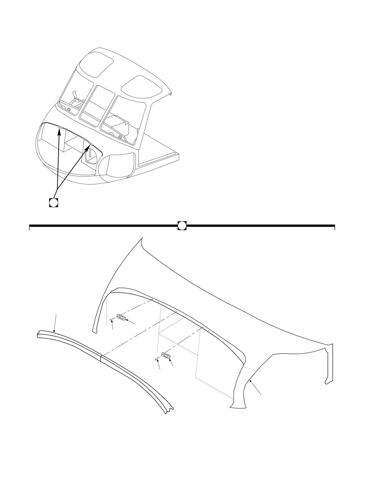
DMWR 1-1520-237
A
A
1
5
4
3
2
6
AB3091
SA
Figure E-3. Hinge Access Modification Kit
E-42
DMWR 1-1520-237
QTY
USABLE
FIGURE &
PER
ON
INDEX NO. PART NUMBER
1 2 3 4 5 6 7
DESCRIPTION
ASSY
CODE
E-3-
70070-20566-013
HINGE ACCESS MODIFICATION KIT
REF
-1
70217-01010-106
. SEAL
1
-2
CCR244SS3-4
. RIVET, (11815)
2
-3
70070-20611-101
. COVER
1
-4
CCR244SS3-4
. RIVET, (11815)
2
-5
70070-20611-102
. COVER
1
-6
70070-20566-049
. CANOPY ASSY, (Reidentified from 70211-01008-
041)
REF
70070-20566-050
. CANOPY ASSY, (Reidentified from 70211-01008-
051)
REF
70070-20566-051
. CANOPY ASSY, (Reidentified from 70211-01008-
054)
REF
70070-20566-052
. CANOPY ASSY, (Reidentified from 70211-01008-
057)
REF
E-43
DMWR 1-1520-237
E-5. MODIFICATION KIT (50-5).
Subject: Side Fuselage Structural Reinforcement; Installation of, dated 31 March 2003
Purpose: Provide instructions for the structural strengthening of the fuselage on the left and right side around the gun-
ners window.
Model:
UH-60A
Description: The left and right side gunner windows are reworked to add support structure between stations 265.50
and 308.00.
Drawings required for modification:
70070-20167, 70070-20470, 70070-20527, 70083-20110, 70212-02307, 70213-02301
References: (a) Special Service Instructions (SSI) No. 50-31, Installation of 9A to A9 Recapitalization Program, dated
March 31, 2003
(b) SSI No. 50-7 Buttline 34.50, Modification of dated March 31, 2003
Instructions:
NOTE
• AcompletereviewofthisSSIisrecommendedbeforeincorporatingthesidefuselagestructuralreinforce-
ment installation kit.
• Before beginning this modification procedure, use the material information list to inventory the modification
kit. Make sure all parts are present and in serviceable condition.
• Where drawing numbers are not listed within individual step(s), drawing(s) listed in preceding step(s) are
the controlling authority.
• The sheet metal and structural modifications in this SSI shall be done by personnel experienced in reading
modification drawings. Routine steps such as cleaning, layout and drilling, deburring, standard repairs,
corrosion control, clean up after rework, chemical coating for aluminum after cutting/trimming parts, paint
touch up, and safety practices may not be called out herein. However, these steps and all other required
routine tasks shall be done.
• When installing fasteners refer to drawing sheet and zones for applicable fasteners.
• Slight variations to the instructions contained herein are allowed, as long as the intent of the modification
is accomplished.
• Reference (b) must be done concurrently with this SSI.
A.
Preparation for modification and removal of equipment:
(1)
Confirm that all warnings, cautions, and notes are complied with per reference (a).
(2)
Perform preparation for modification per reference (a).
E-44
DMWR 1-1520-237
(3)
Remove wiring routed through left and right side channel (70212-02037-105 and -106) between stations
247.00 and station 265.00, waterline 227.00.
B.
Modification, left and right side gunners window structural and plating installation as follows:
(1)
Modify left side gunners window structure and plating installation as follows (Dwg 70213-02301):
CAUTION
TO AVOID DAMAGING COMPONENTS, USE EXTREME CARE WHEN DRILLING INTO AIRFRAME.
TEMPORARILY MOVE ANY TUBE ASSEMBLIES OR WIRING HARNESSES OUT OF REWORK AREA.
(a)
Remove and keep for reuse, ring (70219-02313-101) and fitting (70219-02313-102) with attaching
hardware, at station 308.00, waterline 221.00 (Dwg 70213-02301, Sheet 1, Zones 7-G and 10-C).
(b)
Drill out fasteners and remove inner skin (70213-02301-105) between stations 265.00 and 295.00,
waterlines 221.00 and 227.00 (Sheet 1, Zone 7-C).
(c)
Drill out fasteners and remove bracket assembly (70551-02001-064) at station 297.00, waterline 259.00
(Sheet 2, Zone 7-G).
(d)
Drill out fasteners and remove doubler (70213-02301-113) between stations 295.00 and 308.00,
waterlines 238.22 and 260.00 (Sheet 2, Zone 7-H).
(e)
Remove and keep for reuse ring (70219-02313-101) and fitting (70219-02313-102) with attaching
hardware, at station 308.00, waterline 260.00 (Sheet 1, Zone 12-F).
(f)
Drill out fasteners and remove skin (70213-02301-117) between stations 295.00 and 308.00, waterlines
207.00 and 260.00 (Sheet 1, Zone 9-E).
(g)
Remove and keep for reuse fitting (70751-02022-101). Remove stiffiners (70212-02307-113 and -123)
at station 268.12, between waterlines 221.00 and 227.00 (Dwg 70083-20110, Sheet 1, Zones 8-E, 8-J, and 8-C).
(h)
Drill out fasteners, remove and keep for reuse stringer (70202-02310-109) between station 247.00 and
station 265.50, waterline 233.80 (Sheet 1, Zone 10-F).
(i)
Drill out fasteners and remove angle (70211-02304-105) at station 265.50, waterline 233.80 (Sheet 1,
Zone 10-G).
(j)
Drill out fasteners and remove channel (70212-02307-105) between station 247.00 and station 265.50,
waterline 227.00 (Sheet 1, Zone 11-E).
(k)
Drill out fasteners and remove angle (70212-02307-126) at station 265.00, waterline 221.00 (Sheet 1,
Zone 7-H).
E-45
DMWR 1-1520-237
NOTE
Reference (b) must be completed in it’s entirety at this time.
(l)
Locate and temporarily install left side channel, (70083-20110-105) at station 265.50, between waterlines
221.00 and 233.80 (Sheet 1, Zone 4-F).
1
Drill out and remove any fasteners or parts that would interfere with the installation of channel.
2
Transfer drill five, 0.375-inch diameter holes, from channel (70211-02304-101) through left side chan-
nel (70083-20110-105) ( Sheet 1, Zone 6-F).
(m)
Locate and temporarily reinstall stringer (70202-02310-109) between stations 247.00 and 265.50,
waterline 233.80, removed in step (h) (Sheet 1, Zone 10-F).
(n)
Locate and temporarily install angle (70083-20110-113) at station 265.50, waterline 233.80 (Sheet 1,
Zone 10-G).
(o)
Locate and temporarily install left side channel (70083-20110-103) between stations 247.00 and
265.50, waterline 227.00 (Sheet 1, Zone 11-E).
(p)
Locate and temporarily install angle (70083-20110-111) at station 265.50, waterline 221.00 (Sheet 1,
Zone 7-H).
(q)
Locate and temporarily install doubler (70083-20110-115) between stations 265.50 and 278.50,
waterline 227.00 (Sheet 1, Zone 7-F).
1
Cutout 2.25-inch diameter hole through doubler (70083-20110-115) to match cutout in channel
(70212-02307-101) station 268.12, waterline 227.00.
(r)
Locate and temporarily install shims (70083-20110-107 and -109) at station 265.50, waterline 226.00
(Sheet 1, Zones 4-E and 6-D).
1
Remove four fasteners at station 278.50 (Sheet 1, Zone 7-H).
(s)
Locate and temporarily install strap (70083-20110-118) at station 278.50, waterline 227.00 (Sheet 1,
Zone 6-J).
(t)
Locate and temporarily install stiffeners (70212-02307-113 and -123) between stations 276.00 and
308.00, waterlines 221.00 and 227.00 (Dwg 70212-02307, Sheet 1, Zones 4-D, 5-D, 16-H, and 17-J).
(u)
Locate and temporarily reinstall fitting (70751-02022-101) at station 268.12, waterline 227.00, removed
in step (g) (Sheet 1, Zone 8-E).
(v)
Transfer drill the remaining fastener holes needed for assembly.
(w)
Remove fitted parts and deburr and touch up as required.
(x)
Install fitted parts using fasteners shown (Dwg’s 70083-20110 and 70212-02307).
(y)
Locate and temporarily install stringer (70070-20167-127) with clips (70070-20167-106 and -113)
between stations 247.00 and 265.50, trace waterline 229.45 (Dwg 70070-20167, Sheet 3, Zones 11-E, 12-E, 17-F,
and 18-E).
E-46
DMWR 1-1520-237
(z)
Locate and temporarily install stringer (70070-20167-117), clip (70070-20167-106), and bracket angle
(SS1082-192) between stations 247.00 and 265.50, trace waterline 237.18 (Sheet 3, Zones 11-G, 12-F, 13-G, and
17-F).
(aa)
Locate and temporarily install stringer (70070-20167-111), clips (70070-20167-106 and -113), and
radius block (SS1058A5-24-12) between stations 247.00 and 265.50, waterline 245.00 (Sheet 3, Zones 11-E, 11-J,
12-K, 15-J, and 17-H).
(ab)
Locate and temporarily install stringer (70070-20167-103) with clips (70070-20167-106 and -107)
between stations 247.00 and 265.50, trace waterline 250.92 (Sheet 2, Zones 11-E, 12-E, 14-E, and 17-D).
(ac)
Locate and temporarily install stringer (70070-20167-119), clip (70070-20167-105), and bracket
angle (SS1082-192) between stations 250.06 and 265.50, waterline 257.73 (Sheet 2, Zones 4-C, 5-B, and 6-B).
(ad)
Locate and temporarily install stiffener (70070-20167-123) and clip (70070-20167-125) at station
255.00, waterline 260.00, left buttline 40.00 (Sheet 2, Zone 6-F).
(ae)
Locate and temporarily install stiffener (70070-20167-121) and clip (70070-20167-125) at station
260.00, waterline 260.00, left buttline 40.00 (Sheet 2, Zone 4-F).
(af)
Transfer drill the remaining fastener holes needed for assembly.
(ag)
Remove fitted parts, deburr and touch up as required.
(ah)
Install fitted parts, using fasteners shown on (Dwg 70070-20167, Sheets 2 and 3).
(ai)
Install shims (70212-02307-104) and angles (70212-02307-117 and -119) (Dwg 70212-02307, Sheet
1, Zones 4-D, 5-D, 16-H and 17-J).
(aj)
Locate and temporarily install plating assembly (70213-02301-041) between stations 295.00 and
308.00, waterlines 207.00 and 260.00 (Dwg 70213-02301, Sheet 5, Zone 7-F).
(ak)
Locate and temporarily install skin inner (70213-02301-129) between stations 265.00 and 295.00,
waterlines 221.00 and 227.00 (Sheet 5, Zone 6-C).
(al)
Locate and temporarily reinstall two rings (70219-02313-101) and fitting (70219-02313-102), at sta-
tion 308.00, waterlines 221.00 and 260.00 (Sheet 5, Zones 10-C and 12-F).
(am)
Locate and temporarily install doubler (70213-02301-113) between stations 295.00 and 308.00,
waterlines 238.22 and 260.00 (Sheet 2, Zone 7-H).
(an)
Locate and temporarily install bracket assembly (70551-02001-064) at station 297.00, waterline
259.00 (Sheet 2, Zone 7-G).
(ao)
Locate and temporarily install zee (70213-02301-137) between stations 289.14 and 308.00, waterline
227.00 (Sheet 5, Zone 7-E).
(ap)
Transfer drill the remaining fastener holes needed for assembly.
(aq)
Remove fitted parts, deburr and touch up as required.
(ar)
Install fitted parts, using fasteners shown (Dwg 70213-02301, Sheets 2, 3, and 5).
E-47
DMWR 1-1520-237
WARNING
OBSERVE ALL CAUTIONS AND WARNINGS ON CONTAINERS WHEN USING CONSUMABLES.
WHEN APPLICABLE, WEAR NECESSARY PROTECTIVE GEAR DURING HANDLING AND USE. IF A
CONSUMABLE IS FLAMMABLE OR EXPLOSIVE, MAKE CERTAIN CONSUMABLE AND ITS VAPORS ARE
KEPT AWAY FROM HEAT, SPARK, AND FLAME. MAKE CERTAIN EQUIPMENT IS PROPERLY
GROUNDED AND FIREFIGHTING EQUIPMENT IS READILY AVAILABLE PRIOR TO USE. FOR AD-
DITIONAL INFORMATION ON TOXICITY, FLASHPOINT, AND FLAMMABILITY OF CHEMICALS,
CONSULT YOUR MEDICAL PEOPLE, OR MANUFACTURER OF THE CONSUMABLE.
(as)
Install skins and fasteners wet with sealant (AMS-S-8802, A2 or C20 or equivalent) (Sheet 3, Notes 15
and 16).
(at)
Apply a bead of sealant (AMS-S-8802, B-2 or equivalent) along edge of exterior skins and frame joints
(Sheet 1, Zone 3-C, Note 15).
(au)
Install foam (70213-02301-139) and grommet (MS21266-2N) to zee (70213-02301-138) between
stations 289.14 and 308.00, waterline 227.00 with adhesive EC-1357 (Sheet 5, Zones 7-E, 10-E, and 12-H, Note 22).
(av)
Install foam (70213-02301-139) and grommet (MS21266-2N) to zee (70213-02301-137) between sta-
tions 289.14 and 308.00, waterline 227.00 (Sheet 5, Zones 7-E, 10-E, and 12-H, Note 22).
(2)
Modify right side gunners window structural and plating installation as follows:
CAUTION
TO AVOID DAMAGING COMPONENTS, USE EXTREME CARE WHEN DRILLING INTO AIRFRAME.
TEMPORARILY MOVE ANY TUBE ASSEMBLIES OR WIRING HARNESSES OUT OF REWORK AREA.
(a)
Remove and keep for reuse, ring (70219-02313-101) and fitting (70219-02313-102) with attaching
hardware, at station 308.00, waterline 221.00 (Dwg 70213-02301, Sheet 1, Zones 7-G, and 10-C).
(b)
Drill out fasteners and remove inner skin (70213-02301-106) between stations 265.00 and 295.00,
waterlines 221.00 and 227.00 (Sheet 1, Zone 7-C).
(c)
Drill out fasteners and remove bracket assembly (70551-02001-065) at station 297.00, waterline 259.00
(Sheet 2, Zone 7-G).
(d)
Drill out fasteners and remove doubler (70213-02301-114) between stations 295.00 and 308.00,
waterlines 238.22 and 260.00 (Sheet 2, Zone 7-H).
(e)
Remove and keep for reuse, ring (70219-02313-101) and fitting (70219-02313-102) with attaching
hardware, at station 308.00, waterline 260.00 (Sheet 1, Zone 12-F).
(f)
Drill out fasteners and remove skin (70213-02301-118) between stations 295.00 and 308.00, waterlines
207.00 and 260.00 (Sheet 1, Zone 9-E).
E-48
DMWR 1-1520-237
(g)
Remove and keep for reuse, fitting (70751-02022-102). Remove stiffiners (70212-02307-114 and -124)
at station 268.12, between waterlines 221.00 and 227.00 (Dwg 70083-20110, Sheet 1, Zones 16-B, 16-C, and 16-J).
(h)
Drill out fasteners, remove and keep for reuse, stringer (70202-02310-110) between stations 247.00 and
265.50, waterline 233.80 (Sheet 1, Zone 10-F).
(i)
Drill out fasteners and remove angle (70211-02304-106) at station 265.50, waterline 233.80 (Sheet 1,
Zone 10-G).
(j)
Drill out fasteners and remove channel (70212-02307-106) between stations 247.00 and 265.50,
waterline 227.00 (Sheet 1, Zone 11-E).
(k)
Drill out fasteners and remove angle (70212-02307-127) at station 265.00, waterline 221.00 (Sheet 1,
Zone 7-H).
NOTE
Reference (b) must be completed in it’s entirety at this time.
(l)
Locate and temporarily install right side channel (70083-20110-106) at station 265.50, between
waterlines 221.00 and 233.80 (Sheet 1, Zone 4-F).
1
Drill out and remove any fasteners or parts that would interfere with the installation of channel.
2
Transfer drill five 0.375-inch diameter holes from channel (70211-02304-102) through right side chan-
nel (70083-20110-106) (Sheet 1, Zone 6-F).
(m)
Locate and temporarily reinstall stringer (70202-02310-110) between stations 247.00 and 265.50,
waterline 233.80, removed in step (h) (Sheet 1, Zone 10-F).
(n)
Locate and temporarily install angle (70083-20110-114) at station 265.50, waterline 233.60 (Sheet 1,
Zone 10-G).
(o)
Locate and temporarily install right side channel (70083-20110-104) between stations 247.00 and
265.50, waterline 227.00 (Sheet 1, Zone 11-E).
(p)
Locate and temporarily install angle (70083-20110-112) at station 265.50, waterline 221.00 (Sheet 1,
Zone 7-H).
(q)
Locate and temporarily install doubler (70083-20110-116) betrween stations 265.00 and 278.50,
waterline 227.00 (Sheet 1, Zone 16-H).
1
Cutout 2.25-inch diameter hole through doubler (70083-20110-116) to match cutout in channel
(70212-02307-103).
(r)
Locate and temporarily install shims (70083-20110-108 and -109) at station 265.50, waterline 226.00
(Sheet 1, Zones 4-E and 6-D).
(s)
Locate and temporarily install strap (70083-20110-117) at station 278.50, waterline 227.00 (Sheet 1,
Zone 17-H)
(t)
Locate and temporarily install stiffeners (70212-02307-114 and -124) between stations 276.00 and
308.00, waterlines 221.00 and 227.00 (Dwg 70212-02307, Sheet 1, Zones 4-D, 5-D, 16-H, and 17-J).
E-49
DMWR 1-1520-237
(u)
Locate and temporarily reinstall fitting (70751-02022-102) at station 268.12, waterline 227.00, removed
in step (g) (Sheet 1, Zone 16-C).
(v)
Transfer drill the remaining fastener holes needed for assembly.
(w)
Remove fitted parts, deburr and touch up as required.
(x)
Install fitted parts using fasteners shown (Dwg’s 70083-20110 and 70212-02307, Sheet 1).
(y)
Locate and temporarily install stringer (70070-20167-126) with clips (70070-20167-106 and -114)
between stations 247.00 and 265.50, trace waterline 229.45 (Dwg 70070-20167, Sheet 3, Zones 7-D, 11-E, 12-E, and
17-F).
(z)
Locate and temporarily install stringer (70070-20167-118), clip (70070-20167-106), and bracket angle
(SS1082-192) between stations 247.00 and 265.50, trace waterline 237.18 (Sheet 3, Zones 11-G, 12-F, and 13-G).
(aa)
Locate and temporarily install stringer (70070-20167-112), clips (70070-20167-106 and 70070-
20167-114), and radius block (SS1058A5-24-12) between stations 247.00 and 265.50, waterline 245.00 (Sheet 3,
Zones 11-E, 11-J, 12-K, and 15-J).
(ab)
Locate and temporarily install stringer (70070-20167-104) with clips (70070-20167-106 and -108)
between stations 247.00 and 265.50, trace waterline 250.92 (Sheet 2, Zones 11-E, 12-E, and 14-E).
(ac)
Locate and temporarily install stringer (70070-20167-120), clip (70070-20167-105), and bracket
angle (SS1082-192) between stations 250.06 and 265.50, waterline 257.73 (Sheet 2, Zones 4-C, 5-B, and 6-B).
(ad)
Locate and temporarily install stiffener (70070-20167-124) and clip (70070-20167-125) at station
255.00, waterline 260.00, left buttline 40.00 (Sheet 2, Zone 6-F).
(ae)
Locate and temporarily install stiffener (70070-20167-122) and clip (70070-20167-125) at station
260.00, waterline 260.00, left buttline 40.00 (Sheet 2, Zone 4-F).
(af)
Transfer drill the remaining fastener holes needed for assembly.
(ag)
Remove fitted parts, deburr and touch up as required.
(ah)
Install fitted parts, using fasteners shown (Dwg 70070-20167, Sheets 2 and 3).
(ai)
Install shims (70212-02307-104) and angles (70212-02307-118 and -120) (Dwg 70212-02307, Sheet
1, Zones 4-D, 5-D, 16-H and 17-J).
(aj)
Locate and temporarily install plating assembly (70213-02301-042) between stations 295.00 and
308.00, waterlines 207.00 and 260.00 (Dwg 70213-02301, Sheet 5, Zone 7-F).
(ak)
Locate and temporarily install skin inner (70213-02301-130) between stations 265.00 and 295.00,
waterlines 221.00 and 227.00 (Sheet 5, Zone 6-C).
(al)
Locate and temporarily reinstall two rings (70219-02313-101) and fitting (70219-02313-102) at station
308.00, waterlines 221.00 and 260.00 (Sheet 5, Zones 10-C and 12-F).
(am)
Locate and temporarily install doubler (70213-02301-114) between stations 295.00 and 308.00,
waterlines 238.22 and 260.00 (Sheet 2, Zone 7-H).
E-50
DMWR 1-1520-237
(an)
Locate and temporarily install bracket assembly (70551-02001-065) at station 297.00, waterline
259.00 (Sheet 2, Zone 7-G).
(ao)
Locate and temporarily install zee (70213-02301-138) between stations 289.14 and 308.00, waterline
227.00 (Sheet 5, Zone 7-E).
(ap)
Transfer drill the remaining fastener holes needed for assembly.
(aq)
Remove fitted parts deburr and touch up as required.
(ar)
Install fitted parts, using fasteners shown (Dwg 70213-02301, Sheets 2, 3, and 5).
WARNING
OBSERVE ALL CAUTIONS AND WARNINGS ON CONTAINERS WHEN USING CONSUMABLES.
WHEN APPLICABLE, WEAR NECESSARY PROTECTIVE GEAR DURING HANDLING AND USE. IF A
CONSUMABLE IS FLAMMABLE OR EXPLOSIVE, MAKE CERTAIN CONSUMABLE AND ITS VAPORS ARE
KEPT AWAY FROM HEAT, SPARK, AND FLAME. MAKE CERTAIN EQUIPMENT IS PROPERLY
GROUNDED AND FIREFIGHTING EQUIPMENT IS READILY AVAILABLE PRIOR TO USE. FOR AD-
DITIONAL INFORMATION ON TOXICITY, FLASHPOINT, AND FLAMMABILITY OF CHEMICALS,
CONSULT YOUR MEDICAL PEOPLE, OR MANUFACTURER OF THE CONSUMABLE.
(as)
Install skins and fasteners wet with sealant (AMS-S-8802, A2 or C20 or equivalent) (Sheet 3, Notes 15
and 16).
(at)
Apply a bead of sealant (AMS-S-8802, B-2 or equivalent) along edge of exterior skins and frame joints
(Sheet 1, Zone 3-C, Note 15).
(au)
Install foam (70213-02301-139) and grommet (MS21266-2N) to zee (70213-02301-138) between
stations 289.14 and 308.00, waterline 227.00 with adhesive (EC-1357) (Sheet 5, Zones 7-E, 10-E, and 12-H, Note 22).
C.
Reinstallation of removed equipment:
(1)
Perform reinstallation of parts and equipment per reference (a).
D.
Record of Compliance:
(1)
Make an appropriate logbook entry to show compliance with this Special Service Instruction.
Weight and Balance Data:
POUNDS
INCHES AFT
MOMENT/
QTY
PART NO.
NOMENCLATURE
WEIGHT
OF DATUM
1000
1
70070-20527-011
Mod. Kit
+15.6
281.0
4.4
Weight and Balance: Change resulting from these instructions are as follows:
Change in basic weight:
+15.6 pounds
E-51
DMWR 1-1520-237
Moment arm:
281.0 in.
Change in basic moment/1000:
4.4
Manpower (Estimated)
No. of Personel
No. of Hours
Man-hours
Sheet Metal Mechanic
2
100.0
*200.0
*Does not include time required to prepare helicopter or return it to flight status.
Material Information:
A.
Modification Kit Required:
Qty
Nomenclature
Part Number
Source
1
Mod. Kit, Side Fuselage Structural
70070-20527-011
(1)
Beef Up,
consisting of:
1
Mod. Kit, Stringer Installation
70070-20167-026
Cabin Sta 247.00 - 265.00,
consisting of:
1
Mod. Kit, Left Side,
70070-20167-027
consisting of:
9
Rivet
MS20470AD4-4
9
Rivet
MS20470AD4-5
106
Rivet
MS20470AD5-5
6
Rivet
MS20470AD5-6
6
Rivet
MS20470AD5-7
41
Rivet
MS20470AD5-8
4
Rivet
MS20470AD6-8
55
Rivet, Blind
NAS1738B5-2
1
Radius Block
SS1058A5-24-12
2
Bracket Angle
SS1082-192
1
Stringer
70070-20167-103
1
Clip
70070-20167-105
4
Clip
70070-20167-106
1
Clip
70070-20167-107
1
Stringer
70070-20167-111
2
Clip
70070-20167-113
1
Stringer
70070-20167-117
1
Stringer
70070-20167-119
E-52
DMWR 1-1520-237
Qty
Nomenclature
Part Number
Source
1
Stiffener
70070-20167-121
1
Stiffener
70070-20167-123
2
Clip
70070-20167-125
1
Stringer
70070-20167-127
1
Mod. Kit, Right Side,
70070-20167-028
consisting of:
9
Rivet
MS20470AD4-4
9
Rivet
MS20470AD4-5
106
Rivet
MS20470AD5-5
6
Rivet
MS20470AD5-6
6
Rivet
MS20470AD5-7
41
Rivet
MS20470AD5-8
4
Rivet
MS20470AD6-8
55
Rivet, Blind
NAS1738B5-2
1
Radius Block
SS1058A5-24-12
2
Bracket Angle
SS1082-192
1
Stringer
70070-20167-104
1
Clip
70070-20167-105
4
Clip
70070-20167-106
1
Clip
70070-20167-108
1
Stringer
70070-20167-112
2
Clip
70070-20167-114
1
Stringer
70070-20167-118
1
Stringer
70070-20167-120
1
Stiffener
70070-20167-122
1
Stiffener
70070-20167-124
2
Clip
70070-20167-125
1
Stringer
70070-20167-126
1
Mod. Kit, Plating Instl- Side
70070-20470-011
Fuselage Sta 247.00 to Sta
308.00,
consisting of:
1
Mod. Kit,
70070-20470-012
consisting of:
2
Bolt
AN173-10A
1
Bolt
AN173-12A
1
Bolt
AN173-20A
4
Bolt
AN173-7A
2
Pin, Hi Lok
HL20PB-5-4
16
Washer
AN960KD10LL
1
Pin, Hi Lok
HL22-5-3
1
Collar
HL77-5
2
Collar
HL86PB-5
E-53
DMWR 1-1520-237
Qty
Nomenclature
Part Number
Source
3
Rivet
MS20426AD6-9
11
Rivet
MS20470AD4-9
16
Rivet
MS20470AD5-9
258
Rivet
MS20470AD6-9
22
Rivet
MS20605S3W5
8
Nut
MS21044N3
10
Nutplate
MS21075-3N
23
Grommet
MS21266-2N
8
Fastener, Blind
MS90354U0502
6
Fastener, Blind
MS90354U0503
1
Collar
NAS1080-5
48
Collar
NAS1080-06
2
Rivet
NAS1097AD5-9
1
Pin, SWG LKG
NAS1465-03
28
Pin, SWG LKG
NAS1466-04
20
Pin, SWG LKG
NAS1466-08
32
Rivet, Blind
NAS1738B4-3
15
Rivet, Blind
NAS1738B5-2
40
Rivet, Blind
NAS1738B6-2
29
Rivet, Blind
NAS1738B6-3
17
Rivet, Blind
NAS1738B6-4
20
Rivet, Blind
NAS1738B6-5
4
Rivet, Blind
NAS1738B6-6
6
Rivet, Blind
NAS1738B6-7
2
Rivet, Blind
NAS1738B6-8
3
Shim
70212-02307-104
1
Stiffener
70212-02307-114
1
Angle
70212-02307-118
1
Angle
70212-02307-120
1
Stiffner
70212-02307-124
1
Plating Assy
70213-02301-042
1
Doubler
70213-02301-114
1
Skin Inner
70213-02301-130
1
Zee
70213-02301-138
1
Foam
70213-02301-139
1
Bracket Assy
70551-02001-065
1
Mod. Kit, Left Side,
70070-20470-013
consisting of:
2
Bolt
AN173-10A
1
Bolt
AN173-12A
1
Bolt
AN173-20A
4
Bolt
AN173-7A
2
Pin, Hi Lok
HL20PB-5-4E
16
Washer
AN960KD10LL
1
Pin, Hi Lok
HL22-5-3
1
Collar
HL77-5
E-54
DMWR 1-1520-237
Qty
Nomenclature
Part Number
Source
2
Collar
HL86PB-5
3
Rivet
MS20426AD6-9
11
Rivet
MS20470AD4-9
16
Rivet
MS20470AD5-9
258
Rivet
MS20470AD6-9
22
Rivet
MS20605S3W5
8
Nut
MS21044N3
10
Nutplate
MS21075-3N
23
Grommet
MS21266-2N
8
Fastener, Blind
MS90354U0502
6
Fastener, Blind
MS90354U0503
1
Collar
NAS1080-05
48
Collar
NAS1080-06
2
Rivet
NAS1097AD5-9
1
Pin, SWG LKG
NAS1465-03
28
Pin, SWG LKG
NAS1466-04
20
Pin, SWG LKG
NAS1466-08
32
Rivet, Blind
NAS1738B4-3
15
Rivet, Blind
NAS1738B5-2
40
Rivet, Blind
NAS1738B6-2
29
Rivet, Blind
NAS1738B6-3
17
Rivet, Blind
NAS1738B6-4
20
Rivet, Blind
NAS1738B6-5
4
Rivet, Blind
NAS1738B6-6
6
Rivet, Blind
NAS1738B6-7
2
Rivet, Blind
NAS1738B6-8
3
Shim
70212-02307-104
1
Stiffner
70212-02307-113
1
Angle
70212-02307-117
1
Angle
70212-02307-119
1
Stiffner
70212-02307-123
1
Plating Assy
70213-02301-041
1
Doubler
70213-02301-113
1
Skin Inner
70213-02301-129
1
Zee
70213-02301-137
1
Foam
70213-02301-139
1
Bracket Assy
70551-02001-064
1
Mod. Kit, Beef Up, Left Side,
70070-20527-012
consisting of:
20
Rivet
MS20470AD4-9
46
Rivet
MS20470AD5-9
69
Rivet
MS20470AD6-9
9
Fastener, Blind
MS90354-0502
7
Fastener, Blind
MS90354-0503
3
Collar
NAS1080-05
16
Collar
NAS1080-06
E-55
DMWR 1-1520-237
Qty
Nomenclature
Part Number
Source
3
Collar
NAS1080D05
2
Rivet
NAS1097AD4-9
3
Pin, SWG LKG
NAS1465-03
5
Pin, SWG LKG
NAS1466-03
11
Pin, SWG LKG
NAS1466-04
3
Pin, SWG LKG
NAS1525-04
16
Rivet, Blind
NAS1738B5-2
11
Rivet, Blind
NAS1738B5-3
59
Rivet, Blind
NAS1738B6-2
6
Rivet, Blind
NAS1738B6-3
9
Rivet, Blind
NAS1738B6-4
1
Channel, LH
70083-20110-103
1
Channel, LH
70083-20110-105
1
Shim
70083-20110-107
1
Shim
70083-20110-109
1
Angle
70083-20110-111
1
Angle
70083-20110-113
1
Doubler
70083-20110-115
1
Strap
70083-20110-118
1
Mod. Kit, Right Side, Beef Up,
70070-20527-013
consisting of:
20
Rivet
MS20470AD4-9
46
Rivet
MS20470AD5-9
97
Rivet
MS20470AD6-9
9
Fastener, Blind
MS90354-0502
7
Fastener, Blind
MS90354-0503
3
Collar
NAS1080-05
16
Collar
NAS1080-06
3
Collar
NAS1080D05
2
Rivet
NAS1097AD4-9
3
Pin, SWG LKG
NAS1465-03
5
Pin, SWG LKG
NAS1466-03
11
Pin, SWG LKG
NAS1466-04
3
Pin, SWG LKG
NAS1525-04
16
Rivet, Blind
NAS1738B5-2
11
Rivet, Blind
NAS1738B5-3
59
Rivet, Blind
NAS1738B6-2
6
Rivet, Blind
NAS1738B6-3
9
Rivet, Blind
NAS1738B6-4
1
Channel, RH
70083-20110-104
1
Channel, RH
70083-20110-106
1
Shim
70083-20110-108
1
Shim
70083-20110-109
1
Angle
70083-20110-112
1
Angle
70083-20110-114
E-56
DMWR 1-1520-237
Qty
Nomenclature
Part Number
Source
1
Doubler
70083-20110-116
1
Strap
70083-20110-117
B.
Consumable Material:
WARNING
OBSERVE ALL CAUTIONS AND WARNINGS ON CONTAINERS WHEN USING CONSUMABLES.
WHEN APPLICABLE, WEAR NECESSARY PROTECTIVE GEAR DURING HANDLING AND USE. IF A
CONSUMABLE IS FLAMMABLE OR EXPLOSIVE, MAKE CERTAIN CONSUMABLE AND ITS VAPORS ARE
KEPT AWAY FROM HEAT, SPARK, AND FLAME. MAKE CERTAIN EQUIPMENT IS PROPERLY
GROUNDED AND FIREFIGHTING EQUIPMENT IS READILY AVAILABLE PRIOR TO USE. FOR AD-
DITIONAL INFORMATION ON TOXICITY, FLASHPOINT, AND FLAMMABILITY OF CHEMICALS,
CONSULT YOUR MEDICAL PEOPLE, OR MANUFACTURER OF THE CONSUMABLE.
Qty
Nomenclature
Part Number
Source
4 oz.
Adhesive
EC-1357
(1)
8 oz.
Sealant
AMS-S-8802, A2 or equivalent
(1)
8 oz.
Sealant
AMS-S-8802, B2 or equivalent
(1)
8 oz.
Sealant
AMS-S-8802, C20 or equivalent
(1)
C.
Source:
(1)
Available through normal supply channels
E-57
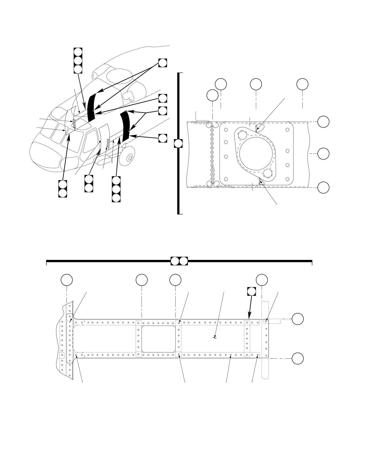
DMWR 1-1520-237
A
3
C
F
2
STA
STA
STA
68
266
268
271
STA
265.5
14
D
C
87
BL
42
LH
1
D
B
BL
44
LH
2
87
68
1
44
A
44
BL
E
46
3
LH
E
F
13
A
3
STA
STA
STA
STA
295
283.5
278.5
255.5
4
8
7
12
5
B
WL
227
WL
221
9
6
10
11
AB3102_1
SA
Figure E-4. Modification Kit (Sheet 1 of 4)
E-58
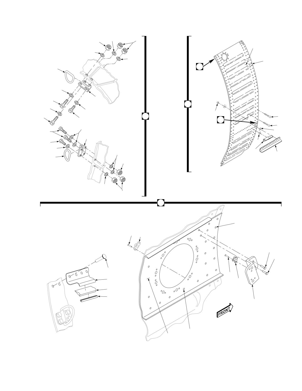
DMWR 1-1520-237
16
17
17
34
16
16
35
23
21
16
20
18
D
16
16
30
C
31
15
19
23
29
16
37
22
20
22
37
16
36
16
38
21
17
16
17
23
28
42
43
24
24
40
24
33
25
39
41
26
27
32
AB3102_2
SA
Figure E-4. Modification Kit (Sheet 2 of 4)
E-59
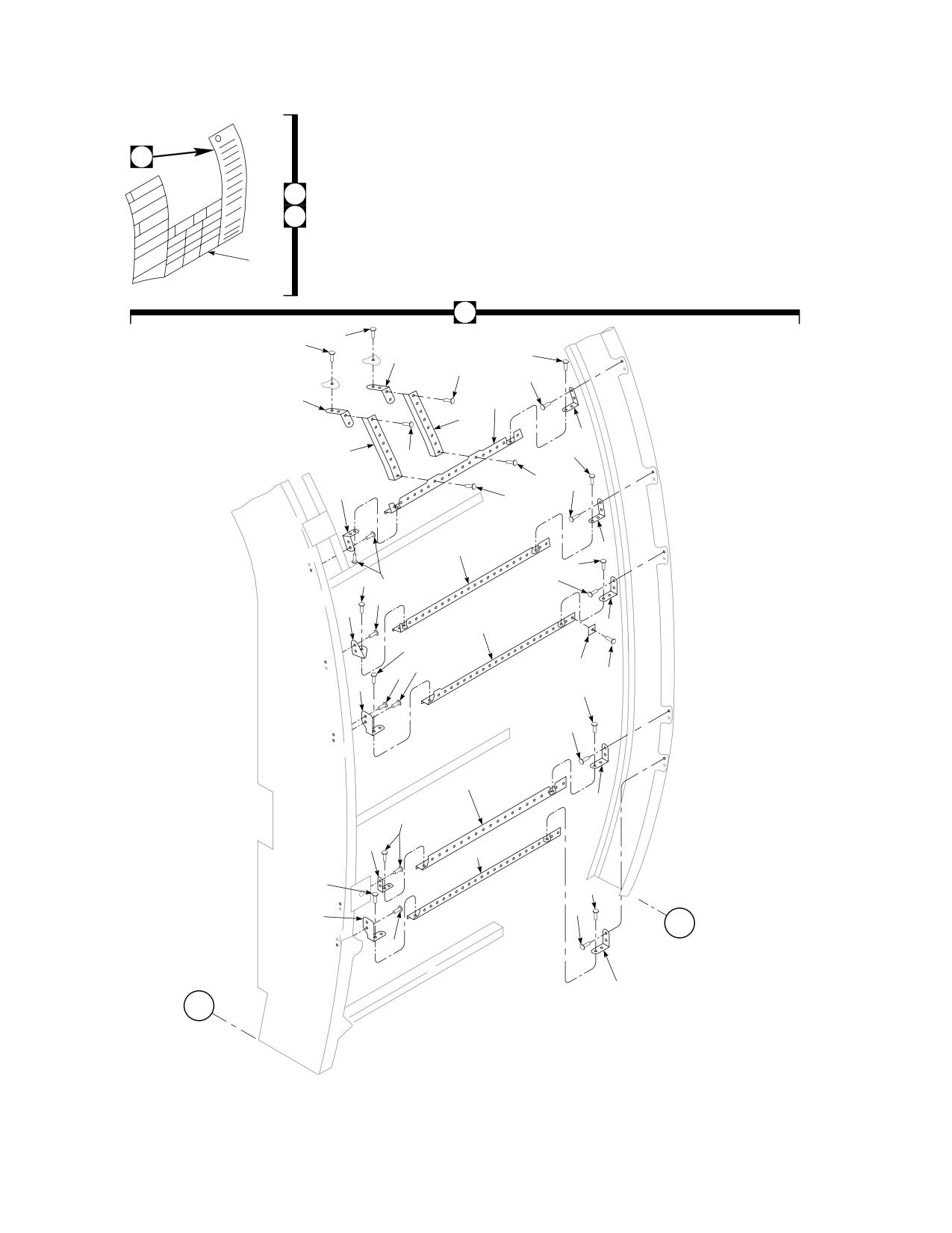
DMWR 1-1520-237
45
44
E
46
45
47
47
48
47
47
51
48
54
50
53
49
57
47
47
58
52
47
61
59
57
60
47
58
55
56
64
59
60
55
63
47
66
62
57
58
65
59
60
52
67
60
57
58
62
STA
265.5
55
59
STA
247
AB3102_3
SA
Figure E-4. Modification Kit (Sheet 3 of 4)
E-60
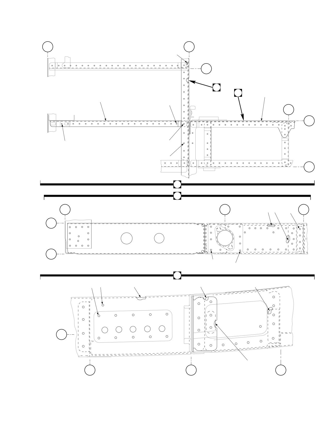
DMWR 1-1520-237
STA
STA
247
265.5
73
WL
238
H
G
69
72
70
STA
278.5
WL
227
71
70
74
76
WL
221
F
G
75
STA
STA
STA
247
268
81 77
78
278.5
BL
42
LH
BL
46
LH
75
79
80
H
84
85
87
82
86
BL
45
LH
83
WL
WL
WL
234
227
221
AB3102_4
SA
Figure E-4. Modification Kit (Sheet 4 of 4)
E-61
DMWR 1-1520-237
QTY
USABLE
FIGURE &
PER
ON
INDEX NO. PART NUMBER
1 2 3 4 5 6 7
DESCRIPTION
ASSY
CODE
E-4-
70070-20527-011
MODIFICATION KIT
REF
-1
70070-20470-011
MOD KIT
1
-2
70070-20470-013
MOD KIT
1
70070-20470-012
MOD KIT, RH
1
-3
70213-02301-041
PLATING ASSY
1
70213-02301-042
PLATING ASSY, (Used on 70070-20470-012) .
1
-4
HL22-5-3
HI-LOK PIN, (73197)
1
HL20PB-5-4
HI-LOK PIN, (73197)
2
*
-5
HL77-5
COLLAR, (73197)
1
HL86PB-5
COLLAR, (73197)
2
*
-6
MS90354U0503
BLIND FASTENER
6
-7
MS90354U0502
BLIND FASTENER
8
-8
NAS1738B6-4
BLIND RIVET
17
NAS1738B6-6
BLIND RIVET
4
*
NAS1738B6-7
BLIND RIVET
6
*
NAS1738B6-8
BLIND RIVET
2
*
-9
NAS1738B6-3
BLIND RIVET
29
-10
NAS1738B5-2
BLIND RIVET
15
-11
NAS1738B6-2
BLIND RIVET
40
NAS1738B4-3
BLIND RIVET
32
*
-12
70213-02301-129
SKIN INNER
1
70213-02301-130
SKIN INNER, (Used on 70070-20470-012)
1
-13
70212-02307-123
STIFFENER
1
70070-20167-124
STIFFENER, (Used on 70070-20470-012)
1
-14
70212-02307-113
STIFFENER
1
70212-02307-114
STIFFENER, (Used on 70070-20470-012)
1
-15
AN173-20A
BOLT
1
-16
AN960KD10LL
WASHER
16
-17
MS21044N3
NUT
8
-18
AN173-12A
BOLT
1
-19
AN173-10A
BOLT
2
-20
70219-02313-102
FITTING
REF
-21
70219-02313-101
RING
REF
-22
AN173-7A
BOLT
4
-23
70551-02001-064
BRACKET ASSY
1
70551-02001-065
BRACKET ASSY, (Used on 70070-20470-012)
1
-24
MS20426AD3
. RIVET
4
-25
MS21073-3
. NUTPLATE
2
-26
70551-02001-164
. BRACKET
1
-27
NAS1097AD5-9
RIVET
2
-28
MS20470AD6-9
RIVET
258
MS20426AD6-9
RIVET
3
*
MS20470AD4-9
RIVET
11
*
MS20470AD5-9
RIVET
16
*
-29
NAS1466-08
SWAGE LOCKING PIN
20
-30
NAS1080-06
COLLAR
48
-31
NAS1466-04
SWAGE LOCKING PIN
28
NAS1465-03
SWAGE LOCKING PIN
1
*
NAS1080-05
COLLAR
1
*
-32
70213-02301-113
DOUBLER
1
70213-02301-114
DOUBLER, (Used on 70070-20470-012)
1
-33
70213-02301-137
ZEE
1
70213-02301-138
ZEE, (Used on 70070-20470-012)
1
-34
70213-02301-120
. SKIN INNER
1
70213-02301-121
. SKIN INNER, (Used on 70070-20470-012)
1
-35
70213-02301-122
. SKIN INNER
1
70213-02301-123
. SKIN INNER, (Used on 70070-20470-012)
1
-36
70212-02307-119
ANGLE
1
E-62
DMWR 1-1520-237
QTY
USABLE
FIGURE &
PER
ON
INDEX NO. PART NUMBER
1
2 3 4 5 6 7
DESCRIPTION
ASSY
CODE
70212-02307-120
. . ANGLE, (Used on 70070-20470-012)
1
-37
70212-02307-104
. . SHIM
3
-38
70212-02307-117
. . ANGLE
1
70212-02307-118
. . ANGLE, (Used on 70070-20470-012)
1
-39
70213-02301-139
. . FOAM
1
-40
NAS1738B6-5
. . BLIND RIVET
20
-41
MS21266-2N
. . GROMMET
23
-42
MS20605S3W5
. . RIVET
22
-43
MS21075-3N
. . NUTPLATE
10
-44
70070-20167-026
MOD KIT
1
-45
70070-20167-027
. LH MOD KIT
1
70070-20167-028
. RH MOD KIT
1
-46
70070-20167-029
. . PLATING INSTL., (Modified from 70213-
02301-017)
REF
70070-20167-030
. . PLATING INSTL., (Used on 70070-20167-
028) (Modified from 70213-02301-018)
REF
-47
MS20470AD5-8
. . RIVET
41
-48
70070-20167-125
. . CLIP
2
-49
70070-20167-123
. . STIFFENER
1
70212-02307-124
. . STIFFENER, (Used on 70070-20167-028)
1
-50
70070-20167-121
. . STIFFENER
1
70070-20167-122
. . STIFFENER, (Used on 70070-20167-028)
1
NAS1738B5-2
. . BLIND RIVET
55
*
-51
MS20470AD6-8
. . RIVET
4
-52
SS1082-192
. . BRACKET ANGLE
2
-53
70070-20167-105
. . CLIP
1
-54
70070-20167-119
. . STRINGER
1
70070-20167-120
. . STRINGER, (Used on 70070-20167-028)
1
-55
MS20470AD5-7
. . RIVET
6
-56
70070-20167-107
. . CLIP
1
70070-20167-108
. . CLIP, (Used on 70070-20167-028)
1
-57
MS20470AD4-4
. . RIVET
9
-58
MS20470AD4-5
. . RIVET
9
-59
70070-20167-106
. . CLIP
4
-60
MS20470AD5-5
. . RIVET
106
-61
70070-20167-103
. . STRINGER
1
70070-20167-104
. . STRINGER, (Used on 70070-20167-028)
1
-62
70070-20167-113
. . CLIP
2
70070-20167-114
. . CLIP, (Used on 70070-20167-028)
2
-63
SS1058A5-24-12
. . RADIUS BLOCK
1
-64
70070-20167-111
. . STRINGER
1
70070-20167-112
. . STRINGER, (Used on 70070-20167-028)
1
-65
70070-20167-117
. . STRINGER
1
70070-20167-118
. . STRINGER, (Used on 70070-20167-028)
1
-66
MS20470AD5-6
. . RIVET
6
-67
70070-20167-127
. . STRINGER
1
70070-20167-126
. . STRINGER, (Used on 70070-20167-028)
1
-68
70070-20527-012
MOD KIT BEEF-UP
1
70070-20527-013
MOD KIT BEEF-UP
1
-69
70083-20110-011
. STR MOD GECAL
REF
70083-20110-012
. PROD MOD RH, (Used on 70070-20527-013)
REF
-70
MS20470AD5-9
. RIVET
46
MS20470AD4-9
. RIVET
20
*
NAS1097AD4-9
. RIVET
2
*
-71
MS20470AD6-9
. RIVET
69
-72
70083-20110-103
. . CHANNEL LH
1
70083-20110-104
. . CHANNEL RH, (Used on 70070-20527-013)
1
-73
70083-20110-113
. . ANGLE
1
70083-20110-114
. . ANGLE, (Used on 70070-20527-013)
1
-74
NAS1525-04
. SWAGE LOCKING PIN
3
E-63
DMWR 1-1520-237
QTY
USABLE
FIGURE &
PER
ON
INDEX NO. PART NUMBER
1 2 3 4 5 6 7
DESCRIPTION
ASSY
CODE
-75
NAS1080-06
. . COLLAR
16
-76
NAS1080-05
. . COLLAR
3
NAS1080D05
. . COLLAR
3
*
-77
70083-20110-118
. . . STRAP
1
70083-20110-117
. . . STRAP, (Used on 70070-20527-013)
1
-78
NAS1466-03
. . SWAGE LOCKING PIN
5
-79
NAS1465-03
. . SWAGE LOCKING PIN
3
MS90354-0502
. . BLIND FASTENER
9
*
MS90354-0503
. . BLIND FASTENER
7
*
-80
NAS1466-04
. . SWAGE LOCKING PIN
11
-81
70083-20110-115
. . . DOUBLER
1
70083-20110-116
. . . DOUBLER, (Used on 70070-20527-013)
1
-82
70083-20110-107
. . . SHIM
1
70083-20110-108
. . . SHIM, (Used on 70070-20527-013)
1
-83
70083-20110-109
. . . SHIM
1
-84
NAS1738B5-3
. . BLIND RIVET
11
NAS1738B5-2
. . BLIND RIVET
16
*
-85
NAS1738B6-3
. . BLIND RIVET
6
NAS1738B6-2
. . BLIND RIVET
59
*
NAS1738B6-4
. . BLIND RIVET
9
*
-86
70083-20110-111
. . ANGLE
1
70083-20110-112
. . ANGLE, (Used on 70070-20527-013)
1
-87
70083-20110-105
. . . CHANNEL LH
1
70083-20110-106
. . . CHANNEL RH, (Used on 70070-20527-013)
1
E-64
DMWR 1-1520-237
E-6. STATION 379 MODIFICATION KIT (50-26).
Subject: Station 379.00 Frame, Modification of, dated 31 March 2003
Purpose: Provide instructions to install straps and doublers at station 379.00 frame left and right sides.
Model:
UH-60A
Description: The left and right side station 379.00 frame at waterlines 206.00 and 255.00 are modified by installaing
new straps and doublers and cold expanding holes.
Drawings required for modification:
70070-20568
References: (a) Special Service Instructions (SSI) No. 50-31, Installation of 9A to A9 Recapitalization Program, dated
March 31, 2003
(b) SSI No. 50-6, Lower Aft Transition, Rework of, dated 31 March 2003
(c) TM 1-1500-335-23, Technical Manual, Nondestructive Inspection Methods
(d) TM 1-1520-265-23, Technical Manual, Aviation Unit Maintenance (AVUM) and Aviation Intermedi-
ate Maintenance (AVIM) Manual, Nondestructive Inspection Procedures for H-60 Helicopter Series
Instructions:
NOTE
• A complete review of this SSI is recommended before modifying station 379.00 frame.
• Before beginning this modification procedure, use the material information list to inventory the kit. Make
sure all parts are present and in serviceable condition.
• Where drawing numbers are not listed within individual steps, drawing(s) listed in preceding step(s) are
the controlling authority.
• The sheet metal and structural modifications in this SSI shall be done by personnel experienced in reading
modification drawings. Routine steps such as cleaning, layout and drilling, deburring, standard repairs,
corrosion control, clean up after rework, chemical coating for aluminum after cutting/trimming parts, paint
touch up, and safety practices may not be called out herein. However, these steps and all other required
routine tasks shall be done.
• When installing fasteners refer to drawing sheet and zones for applicable fasteners.
• Slight variations to the instructions contained herein are allowed, as long as the intent of the modification
is accomplished.
• Personnel must be trained and certified in hole quality assurance and proper cold expansion procedures
per SS5098.
• This modification is to be done concurrently with reference (b).
A.
Preparation for modification and removal of equipment:
E-65
DMWR 1-1520-237
(1)
Confirm that all warnings, cautions, and notes are complied with per reference (a).
(2)
Perform preparation for modification per reference (a).
B.
Installation of new straps at station 379.00 left and right sides:
NOTE
Rework and installation of doublers (70070-20568-101 and -102) at waterline 206.75 left and right sides
must be done in conjunction with reference (b).
(1)
Remove existing fasteners between station 373.00 and station 385.00, waterline 206.75, left side (Dwg
70070-20568, Sheet 3, Zones 7-E through 9-E).
(2)
Position doubler (70070-20568-101) and tapered shim (SS81-202-I) between station 373.00 and station
385.00 and transfer drill from structure into doubler (-101) (Sheet 3, Zones 9-F and 7-F).
(3)
Inspect holes and surrounding area prior to cold expansion (Sheet 2, Note 7).
(4)
Cold work holes where existing fasteners were removed in step B.(1) (Sheet 3, Zones 7-E through 9-E; Sheet
2, Note 2, and reference (c) and (d)).
(5)
Remove doubler (70070-20568-101) deburr and touch up as required reworked area.
WARNING
OBSERVE ALL CAUTIONS AND WARNINGS ON CONTAINERS WHEN USING CONSUMABLES.
WHEN APPLICABLE, WEAR NECESSARY PROTECTIVE GEAR DURING HANDLING AND USE. IF A
CONSUMABLE IS FLAMMABLE OR EXPLOSIVE, MAKE CERTAIN CONSUMABLE AND ITS VAPORS ARE
KEPT AWAY FROM HEAT, SPARK, AND FLAME. MAKE CERTAIN EQUIPMENT IS PROPERLY
GROUNDED AND FIREFIGHTING EQUIPMENT IS READILY AVAILABLE PRIOR TO USE. FOR AD-
DITIONAL INFORMATION ON TOXICITY, FLASHPOINT, AND FLAMMABILITY OF CHEMICALS,
CONSULT YOUR MEDICAL PEOPLE, OR MANUFACTURER OF THE CONSUMABLE.
(6)
Install doubler (70070-20568-101) wet with sealant (AMS-S-8802 or equivalent) using fasteners shown
(Sheet 3, Zone 9-F and Sheet 2, Note 2).
(7)
Repeat steps B.(1) through (5) to install right side doubler (70070-20568-102).
(8)
Remove existing fasteners at station 379.00, waterline 255.00, left buttline 40.00 (Sheet 2, Zones 4-E
through 6-H).
(9)
Position strap (70211-02111-120) at station 370.00, waterline 255.00, left buttline 40.00 and transfer drill
from structure into strap (-120) (Sheet 2, Zones 4-F through 6-H).
(10)
Inspect holes and surrounding area prior to cold expansion (Sheet 2, Note 7).
(11)
Cold work holes where existing fasteners were removed in step B.(7) (Sheet 2, Zones 3-F through 5-G,
Notes 1, 2, and reference (c) and (d)).
(12)
Remove strap (70211-02111-120) deburr and touch as required reworked area.
E-66
DMWR 1-1520-237
WARNING
OBSERVE ALL CAUTIONS AND WARNINGS ON CONTAINERS WHEN USING CONSUMABLES.
WHEN APPLICABLE, WEAR NECESSARY PROTECTIVE GEAR DURING HANDLING AND USE. IF A
CONSUMABLE IS FLAMMABLE OR EXPLOSIVE, MAKE CERTAIN CONSUMABLE AND ITS VAPORS ARE
KEPT AWAY FROM HEAT, SPARK, AND FLAME. MAKE CERTAIN EQUIPMENT IS PROPERLY
GROUNDED AND FIREFIGHTING EQUIPMENT IS READILY AVAILABLE PRIOR TO USE. FOR AD-
DITIONAL INFORMATION ON TOXICITY, FLASHPOINT, AND FLAMMABILITY OF CHEMICALS,
CONSULT YOUR MEDICAL PEOPLE, OR MANUFACTURER OF THE CONSUMABLE.
(13)
Install strap (70211-02111-120) wet with sealant (AMS-S-8802 or equivalent) using fasteners shown
(Sheet 2, Zones 4-F through 6-H, Notes 1 and 2).
(14)
Repeat steps B.(7) through (11) to install right side strap (70211-02111-120).
C.
Reinstallation of removed equipment:
(1)
Install removed equipment per reference (a).
D.
Record of Compliance:
(1)
Make an appropriate logbook entry to show compliance with this Special Service Instruction.
Weight and Balance Data:
POUNDS
INCHES AFT
MOMENT/
QTY
PART NO.
NOMENCLATURE
WEIGHT
OF DATUM
1000
1
70070-20568-011
Mod. Kit
+0.6
379.0
0.227
Weight and Balance: Change resulting from these instructions are as follows:
Change in basic weight:
+0.6 pounds
Moment arm:
379.0 in.
Change in basic moment/1000:
0.227
Manpower (Estimated)
No. of Personel
No. of Hours
Man-hours
Sheet Metal Mechanic
1
24.0
*24.0
*Does not include time required to prepare helicopter or return it to flight status.
E-67
DMWR 1-1520-237
Material Information:
A.
Modification kit required:
Qty
Nomenclature
Part Number
Source
1
Mod. Kit, Station 379.00,
70070-20568-011
(1)
consisting of:
1
Mod. Kit, Spl. Inst
70070-20568-012
consisting of:
66
Collar
HL1087ATW-6
31
Pin, Hi Lok
HL20PB-6-3
9
Pin, Hi Lok
HL20PB-6-4
26
Pin, Hi Lok
HL20PB-6-5
2
Strap
70211-02111-120
1
Mod. Kit, Strap Instl,
70070-20568-013
consisting of:
5
Pin, Hi-Lok
HL12VAZ-6-3
22
Pin, Hi-Lok
HL12VAZ-6-5
3
Pin, Hi-Lok
HL12VAZ-6-6
3
Pin, Hi-Lok
HL12VAZ-6-9
33
Collar
HL75DU-6ADW
12
Fastener, Blind
MS90354U0605
3
Fastener, Blind
MS90354U0606
3
Fastener, Blind
MS90354U0608
10
Collar
NAS1080-06
5
Pin, SWG LKG
NAS1466-04
5
Pin, SWG LKG
NAS1466-05
3
Rivet, Blind
NAS1738B5-6
3
Rivet, Blind
NAS1738B5-7
1
Doubler
70070-20568-101
1
Doubler
70070-20568-102
2
Shim, Tapered
SS81-202-I
E-68
DMWR 1-1520-237
B.
Consumable Material:
WARNING
OBSERVE ALL CAUTIONS AND WARNINGS ON CONTAINERS WHEN USING CONSUMABLES.
WHEN APPLICABLE, WEAR NECESSARY PROTECTIVE GEAR DURING HANDLING AND USE. IF A
CONSUMABLE IS FLAMMABLE OR EXPLOSIVE, MAKE CERTAIN CONSUMABLE AND ITS VAPORS ARE
KEPT AWAY FROM HEAT, SPARK, AND FLAME. MAKE CERTAIN EQUIPMENT IS PROPERLY
GROUNDED AND FIREFIGHTING EQUIPMENT IS READILY AVAILABLE PRIOR TO USE. FOR AD-
DITIONAL INFORMATION ON TOXICITY, FLASHPOINT, AND FLAMMABILITY OF CHEMICALS,
CONSULT YOUR MEDICAL PEOPLE, OR MANUFACTURER OF THE CONSUMABLE.
Qty
Nomenclature
Part Number
Source
6 oz.
Sealant
AMS-S-8802 or equivalent
(1)
C.
Source:
(1)
Available through normal supply channels
E-69
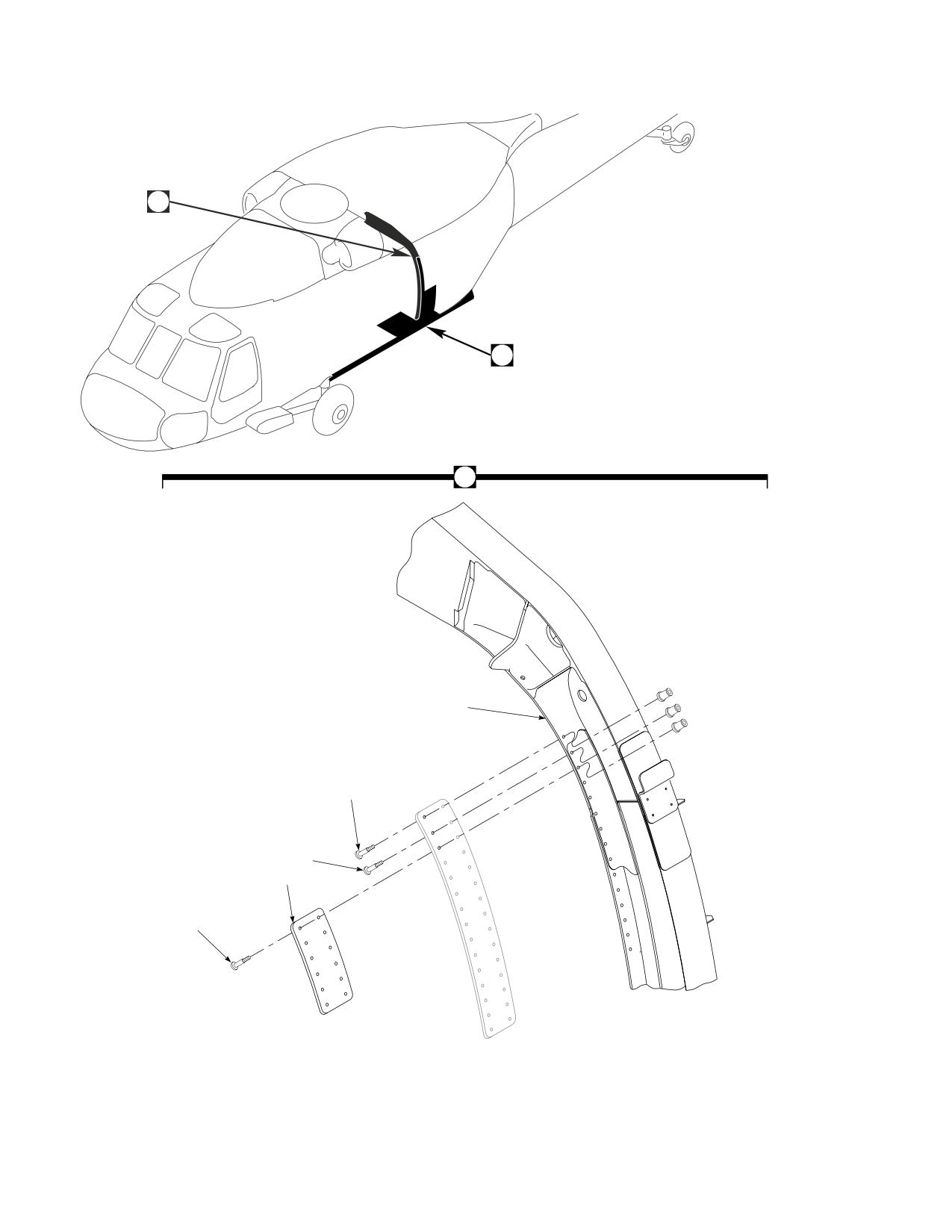
DMWR 1-1520-237
1
7
1
2
5
4
6
3
AB3119_1
SA
Figure E-5. Station 379 Modification Kit (Sheet 1 of 2)
E-70
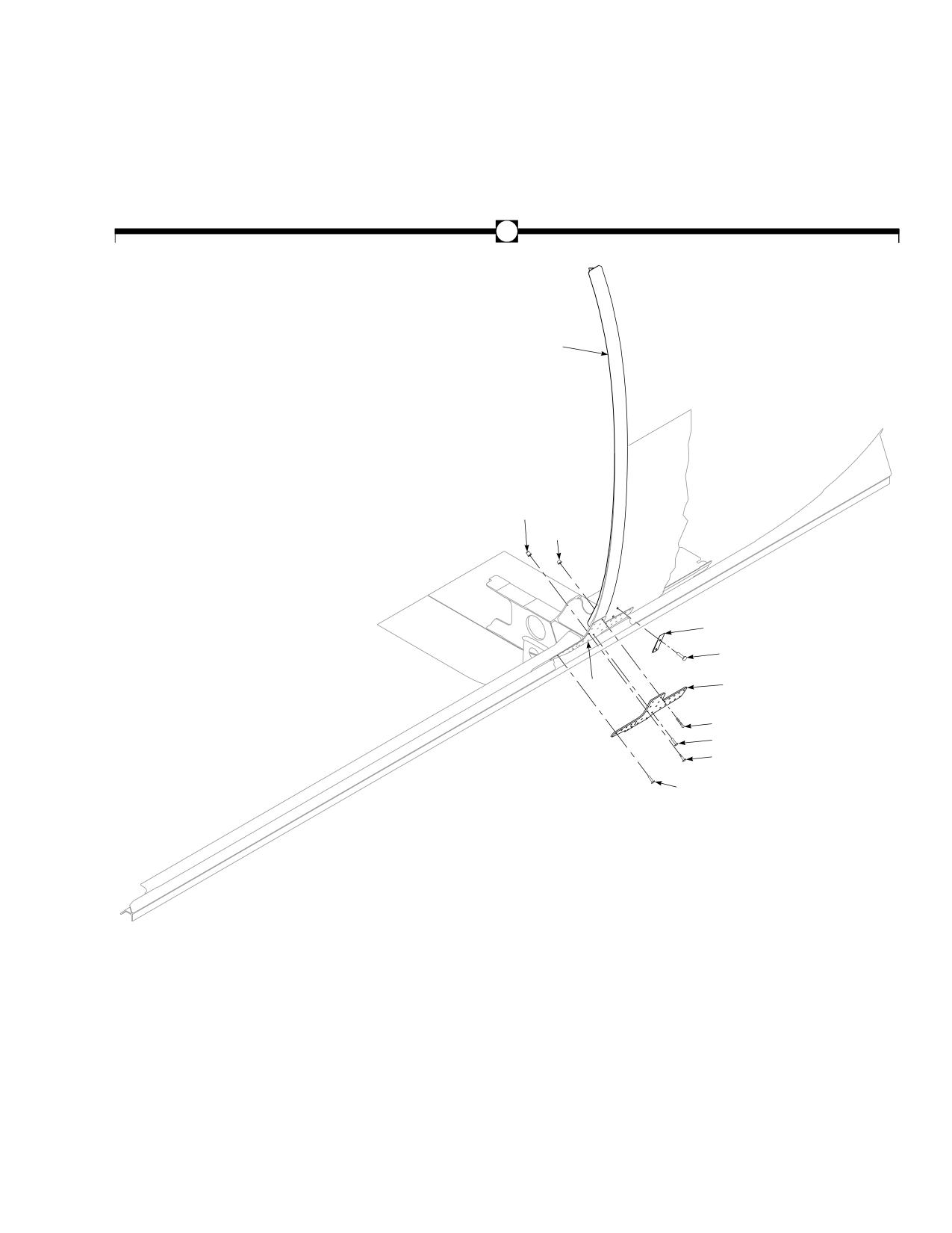
DMWR 1-1520-237
7
9
13
11
17
16
8
18
10
15
12
14
AB3119_2
SA
Figure E-5. Station 379 Modification Kit (Sheet 2 of 2)
E-71
DMWR 1-1520-237
QTY
USABLE
FIGURE &
PER
ON
INDEX NO. PART NUMBER
1 2 3 4 5 6 7
DESCRIPTION
ASSY
CODE
E-5-
70070-20568-011
STATION 379 MODIFICATION KIT
REF
-1
70070-20568-012
. M/K SPLICE INSALLATION
1
-2
70070-20568-015
. . SPLICE INSTALLATION, (Modified from 70211-
02111-013)
REF
70070-20568-016
. . SPLICE INSTALLATION, (Modified from 70211-
02111-014)
REF
-3
HL64PB-6-5
. . HI-LOK PIN, (73197)
26
HL1087ATW-6
. . COLLAR, (73197)
26
-4
HL64PB-6-4
. . HI-LOK PIN, (73197)
9
HL1087ATW-6
. . COLLAR, (73197)
9
-5
HL20PB-6-3
. . HI-LOK PIN, (73197)
31
HL1087ATW-6
. . COLLAR, (73197)
31
-6
70211-02111-120
. . STRAP
2
-7
70070-20568-013
. M/K STRAP INSTALLATION
1
-8
70070-20568-014
. . STRAP INSTALLATION, (Modified from 70213-
02501-014)
REF
-9
70070-20568-017
. . SEAL INSTALLATION, (Modified from 70217-
02721-013)
REF
70070-20568-018
. . SEAL INSTALLATION, (Modified from 70217-
02721-014)
REF
-10
NAS1466-05
. . SWAGE LOCKING PIN
5
NAS1466-04
. . SWAGE LOCKING PIN
5
-11
NAS1080-06
. . COLLAR
10
-12
HL12VAZ-6-9
. . HI-LOK PIN, (73197)
3
HL12VAZ-6-6
. . HI-LOK PIN, (73197)
3
HL12VAZ-6-3
. . HI-LOK PIN, (73197)
5
HL12VAZ-6-5
. . HI-LOK PIN, (73197)
22
-13
HL75DU-6ADW
. . COLLAR (73197)
33
-14
MS90354U0605
. . BLIND FASTENER
12
MS90354U0606
. . BLIND FASTENER
3
MS90354U0608
. . BLIND FASTENER
3
-15
NAS1738B5-7
. . BLIND RIVET
3
NAS1738B5-6
. . BLIND RIVET
13
-16
NAS1738B4-7
. . BLIND RIVET
3
-17
SS81-202-I
. . TAPERED SHIM
2
-18
70070-20568-101
. . DOUBLER, LH
1
70070-20568-102
. . DOUBLER, RH
1
E-72
//////////////////////////////////////////