HELICOPTERS NSN 1520-01-035-0266, NSN 1520-01-082-0686, NSN 1520-01-298-4532. REPAIR STANDARDS (2004) - page 2
DMWR 1-1520-237
E-7. UPPER PLATING MODIFICATION KIT (50-16).
Subject: Upper Plating and Doubler Installation, Rework of, dated 31 March 2003
Purpose: Provide instructions for installing new cabin upper plating and doubler.
Model:
UH-60A
Description: The following is a brief overview of the work required to rework upper transition stations 320.00 through
380.00. New doublers and upper deck plating is installed.
Drawings required for modification:
70070-20570, 70213-02101
References: (a) Special Service Instructions (SSI) No. 50-31, Installation of 9A to A9 Recapitalization Program, dated
March 31, 2003
(b) TM-1-1520-265-23, Technical Manual, Aviation Unit Maintenance (AVUM) and Aviation Intermedi-
ate (AVIM) Manual, Nondestructive Test Procedure for H-60 Helicopter Series
(c) TM-1-1500-335-23, Technical Manual, Nondestructive Inspection Method
Instructions:
NOTE
• AcompletereviewofthisSSIisrecommendedbeforeinstallingtheupperplatinganddoublerinstallation.
• Before beginning this modification procedure, use the material information list to inventory the kit. Make
sure all parts are present and in serviceable condition.
• The sheet metal and structural modifications in this SSI shall be done by personnel experienced in reading
modification drawings. Routine steps such as cleaning, layout and drilling, deburring, standard repairs,
corrosion control, clean up after rework, chemical coating for aluminum after cutting/trimming parts, paint
touch up, and safety practices may not be called out herein. However, these steps and all other required
routine tasks shall be done.
• Where drawing numbers are not listed within individual steps, drawing(s) listed in preceding step(s) are
the controlling authority.
• When installing fasteners refer to drawing sheet and zones for applicable fasteners.
• Slight variations to the instructions contained herein are allowed, as long as the intent of the modification
is accomplished.
• Personnel must be trained and certified in hole quality assurance and proper cold expansion procedures
per SS5098.
A.
Preparation for modification and removal of equipment:
(1)
Confirm that all warnings, cautions, and notes are complied with per reference (a).
(2)
Perform preparation for modification per reference (a).
E-73
DMWR 1-1520-237
B.
Rework of plating installation (70213-02101-011, -013, or -014), stringer installation (70212-02119-011,
-012, -013, or -014), frame assembly (70211-02109-041 or -042), nutplate installation (70213-02101-012), stringer
installation (70202-02120-011 or -012), and angle installation (70304-02201-011 or -012) as follows:
(1)
Removals between stations 320.00 and 380.00, left and right buttlines 34.50 as follows (Dwg 70070-
20570):
(a)
Remove and save for reuse fairing (70213-02101-127 or -163) and doubler (70213-02101-129) station
335.00, left buttline 22.25 (Sheet 5, View D, Zone 5-E).
(b)
Remove and save for reuse fairing (70213-02101-128 or -162) and doubler (70213-02101-129) station
335.00, right buttline 22.25 (Sheet 5, View P, Zones 7-B and 7-D).
(c)
Remove five nutplates (MS21075-3) and four nutplates (MS21069-3) left and right sides (Sheet 4, Zones
12-G, 13-G, and 16-E; Sheet 6, Zones 12-B, 16-D, and 16-E).
(d)
Remove two doubler washers (SS430X15B000431) between left buttline 18.00 and 22.00 (Sheet 4,
Zones 14-G and 16-F).
(e)
Remove angle (70304-02201-109) and angle (70304-02201-103 or -112) left side firewall (Sheet 4,
Zones 10-D and 11-G).
(f)
Remove gusset (70213-02101-106) left side (Sheet 4, Zone 16-D).
(g)
Remove and save for reuse angle (70211-02109-117) station 343.61, left side (Sheet 7, Zone 11-B).
(h)
Remove clips (70211-02110-111, -112, and 70211-02109-121) station 343.61, left side (Sheet 7, Sec-
tion T-T, Zones 13-D, 14-E, and 16-E).
(i)
Remove angles (70211-02109-109, -115, and 70213-02101-121) left side (Sheet 5, Zone 5-G; Sheet 7,
Zones 8-G and 9-C).
(j)
Remove and save for reuse angle (70211-02109-118) station 343.61, right side (Sheet 7, Zone 7-B).
(k)
Remove angles (70211-02109-110, -116, and 70213-02101-122) right side (Sheet 5, Zone 5-G; Sheet
7, Zones 8-G and 9-C).
(l)
Remove clips (70211-02110-111, -112, and 70211-02109-121) right side (Sheet 7, Section T-T, Zones
13-D, 14-E, and 16-E).
(m)
Remove gusset (70213-02101-106) right side (opposite) (Sheet 4, Zone 16-D).
(n)
Remove angle (70304-02201-107 or -113) and angle (70304-02201-106) right side firewall (Sheet 6,
Zones 10-D and 11-B).
(o)
Remove gusset (70213-02101-126) station 365.00, right buttline 5.00 (Sheet 5, Zone 10-G).
(p)
Remove remaining fasteners shown on sheets 4, 5, 6, and 7.
(2)
Installations between stations 320.00 and 380.00, left and right buttlines 34.50 as follows (Dwg 70070-
20570):
E-74
DMWR 1-1520-237
(a)
Temporarily install doubler (70070-20570-141), gusset (70070-20570-105), and filler (70070-20570-
139) between stations 328.00 and 355.00, left buttlines 16.50 and 30.00 (Sheet 4, Zones 9-A, 13-C, and 16-D).
(b)
Make cutout in doubler (70070-20570-141) and gusset (70070-20570-105) using hole in skin as a
template (Sheet 5, View D, Zone 3-C).
(c)
Temporarily reinstall saved fairing (70213-02101-127 or -163) and doubler (70213-01201-129) (Sheet
5, View D, Zone 4-E; Sheet 4, Zones 13-D, 13-E, 14-D, and 14-E).
(d)
Temporarily install angle (70070-20570-125 or -127) and angle (70070-20570-107) to left side firewall
(Sheet 2, Notes 10 and 11; Sheet 4, Zones 10-D and 11-G; Sheet 6, Sections W-W, AB-AB, and Y-Y, Zones 3-D, 3-G,
and 6-C).
(e)
Temporarily install zee (70070-20570-111) with two clips (70070-20570-110) to left side cabin
overhead (Sheet 4, Zones 11-C and 11-G; Sheet 5, Sections F-F, G-G, and H-H, Zones 4-G, 6-F, and 7-F).
(f)
Make cutout in angle (70070-20570-125 or -127) using existing hole in firewall as a template (Sheet 6,
Sections AB-AB and Y-Y; Sheet 2, Notes 10 and 11; Sheet 3, Note 24).
(g)
Temporarily install two doubler washers (SS430X15B000431) between stations 330.00 and 340.00, left
buttlines 16.50 and 22.50 (Sheet 4, Zones 14-G and 16-F).
(h)
Drill two number 8 (0.199-inch diameter) holes, one number 11 (0.191-inch diameter) hole, and three
number 1 (0.228-inch diameter) holes (Sheet 4, Zones 12-G, 13-G, 14-F, and 16-E).
(i)
Temporarily install three nutplates (MS21075-3) and two nutplates (MS21069-3) between stations 330.00
and 345.00, left buttlines 16.5 and 22.50 (Sheet 4, Zones 12-G and 16-E).
(j)
Temporarily install clip (70070-20570-117) in cabin overhead station 343.61, left buttline 28.75 (Sheet 7,
Sections E-E and R-R, Zones 13-D and 15-B).
(k)
Temporarily install angles (70070-20570-135 and -137) and two clips (70070-20570-123) in cabin
overhead station 343.61, between left buttlines 16.00 and 23.00 (Sheet 7, Sections E-E, T-T, U-U, and V-V, Zones 8-G,
9-C, 14-E, and 16-E).
(l)
Temporarily reinstall angle (70211-02109-117) in cabin overhead station 343.61, left buttline 23.50
(Sheet 7, Section E-E, Zone 11-B).
(m)
Temporarily install clip (70070-20570-118) in cabin overhead station 343.61, right buttline 28.75
(Sheet 7, Sections E-E, N-N, and R-R, Zones 5-C, 13-C, and 15-B).
(n)
Temporarily install angles (70070-20570-136 and -138) and two clips (70070-20570-123) in cabin
overhead station 343.61, between right buttlines 16.00 and 23.00 (Sheet 7, Sections N-N, T-T, U-U, and V-V, Zones
8-G, 9-C, 14-E, and 16-E).
(o)
Temporarily reinstall angle (70211-02109-118) in cabin overhead station 343.61, right buttline 23.50
(Sheet 7, Section N-N, Zone 7-B).
(p)
Temporarily install doubler (70070-20570-142), gusset (70070-20570-106), and filler (70070-20570-
140) between stations 328.00 and 355.00, right buttlines 16.50 and 30.00 (right side opposite) (Sheet 4, Zones 9-A,
13-B, and 16-D; Sheet 6, Zones 10-F, 11-F, and 16-D).
E-75
DMWR 1-1520-237
(q)
Make cutout in doubler (70070-20570-142) and gusset (70070-20570-106) on right side using hole in
skin as template (Sheet 5, View P, Zone 6-D).
(r)
Temporarily reinstall saved fairing (70213-02101-128 or -162) and doubler (70213-02101-129) (Sheet
5, View P, Zones 7-B and 8-D; Sheet 6, Zones 13-D, 13-E, 14-D, and 14-E).
(s)
Temporarily install angle (70070-20570-126 or -128) and angle (70070-20570-108) to right firewall
(Sheet 2, Notes 10 and 11; Sheet 6, Sections AA-AA, AB-AB, and Y-Y, Zones 6-E, 10-E, and 11-B).
(t)
Temporarily install zee (70070-20570-112) with two clips (70070-20570-110) to right side cabin
overhead (Sheet 5, Sections F-F, G-G, and H-H, Zones 4-G, 6-F, and 7-F).
(u)
Make cutout in angle (70070-20570-126 or -128) using existing hole in firewall as a template (Sheet 6,
Sections AB-AB and Y-Y; Sheet 2, Notes 10 and 11; Sheet 3, Note 24).
(v)
Drill two number 8 (0.199-inch diameter) holes, one number 11 (0.191-inch diameter) hole, and two
number 1 (0.288-inch diameter) holes (Sheet 6, Zones 12-B, 14-B, 16-D, and 16-E).
(w)
Temporarily install two nutplates (MS21075-3) and two nutplates (MS21069-3) between stations 325.00
and 345.00, right buttlines 16.50 and 22.25 (Sheet 6, Zones 12-B, 16-D, and 16-E).
(x)
Temporarily install angle (70070-20570-143) with clips (70070-20570-115 and -116) and radius block
(SS1058-1-18-14) between buttline 0.00 and left buttline 5.33 (Sheet 5, View B, Sections J-J, L-L, M-M, and K-K, Zones
15-F, 15-G, and 16-G).
(y)
Temporarily install angle (70070-20570-144) with clips (70070-20570-115 and -116) and radius block
(SS1058-1-18-14) between buttline 0.00 and right buttline 5.33 (Sheet 5, View B, Sections J-J, L-L, M-M, and K-K, Zones
15-F, 15-G, and 16-G).
(z)
Temporarily install gusset (70070-20570-109) between stations 362.00 and 370.00, left and right butt-
line 5.33 (Sheet 5, View B, Zone 10-G).
(aa)
Perform penetrant or Eddy current inspection to holes and surrounding area prior to cold expansion
(Sheet 4, Note 45).
(ab)
Cold work holes where existing fasteners were removed and hi lok pins (HL20PB) are installed (Sheet 2,
Note 18; Sheet 3, Note 27; Sheet 4, Zones 9-F, 9-G, and 15-F; Sheet 6, Zones 9-B, 10-B, 9-C, 10-C, 15-C, and 16-C).
(ac)
Inspect each hole and a 0.20-inch minimum surrounding area for cracks (Sheet 3, Note 27).
(ad)
Cold work holes where existing fasteners were removed and hi lok pins (HL64PB) are installed (Sheet 2,
Note 18; Sheet 3, Note 28; Sheet 4, Zones 9-F, 9-G, 10-F, 11-F, 11-E, 12-E, 13-E, 13-F, 14-F, and 15-F; Sheet 6, Zones
9-A, 10-C, 11-C, 12-C, 13-C, 14-C, and 15-C; Sheet 7, Zones 7-D, 10-D, and 11-G).
(ae)
Inspect each hole and a 0.20-inch minimum surrounding area for cracks (Sheet 3, Note 28).
(af)
Transfer drill any remaining fastener holes for assembly (Sheets 4, 5, 6, and 7).
(ag)
Remove parts fitted in steps B.(2) (a) through B.(2) (z), deburr and touch up as required.
E-76
DMWR 1-1520-237
WARNING
OBSERVE ALL CAUTIONS AND WARNINGS ON CONTAINERS WHEN USING CONSUMABLES.
WHEN APPLICABLE, WEAR NECESSARY PROTECTIVE GEAR DURING HANDLING AND USE. IF A
CONSUMABLE IS FLAMMABLE OR EXPLOSIVE, MAKE CERTAIN CONSUMABLE AND ITS VAPORS ARE
KEPT AWAY FROM HEAT, SPARK, AND FLAME. MAKE CERTAIN EQUIPMENT IS PROPERLY
GROUNDED AND FIREFIGHTING EQUIPMENT IS READILY AVAILABLE PRIOR TO USE. FOR AD-
DITIONAL INFORMATION ON TOXICITY, FLASHPOINT, AND FLAMMABILITY OF CHEMICALS,
CONSULT YOUR MEDICAL PEOPLE, OR MANUFACTURER OF THE CONSUMABLE.
(ah)
Apply sealant (MIL-S-8802, A2, or C20, or equivalent) to areas indicated by crosshatch (Dwg 70070-
20570, Sheet 1, Note 7; Dwg 70213-02101, Sheet 1, Note 1).
(ai)
Install parts fitted in steps B.(2)(a) through B.(2)(z) using fasteners shown (Dwg 70070-20570, Sheet 1,
Note 7, Sheet 3, Notes 27 and 28, Sheets 4, 5, 6, and 7).
(aj)
Reidentify the following parts using pen and contrasting ink (Sheet 4, Note 37):
Old Part No.
Nomenclature
New Part No.
70212-02119-111
Stringer
70070-20570-129
70212-02119-112
Stringer
70070-20570-130
70212-02119-113
Stringer
70070-20570-131
70212-02119-114
Stringer
70070-20570-132
70202-02120-101
Stringer Zee
70070-20570-133
70202-02120-102
Stringer Zee
70070-20570-134
C.
Reinstallation of removed equipment:
(1)
Install removed equipment per reference (a).
D.
Record of Compliance:
(1)
Make an appropriate logbook entry to show compliance with this Special Service Instruction.
Weight and Balance Data:
POUNDS
INCHES AFT
MOMENT/
QTY
PART NO.
NOMENCLATURE
WEIGHT
OF DATUM
1000
1
70070-20570-011
Mod. Kit
+11.4
345.0
3.933
Weight and Balance: Change resulting from these instructions are as follows:
Change in basic weight:
+11.4 pounds
Moment arm:
345.0 in.
E-77
DMWR 1-1520-237
Change in basic moment/1000: 3.933
Manpower (Estimated):
No. of Personel
No. of Hours
Man-hours
Sheet Metal Mechanic
2
80.0
*160.0
*Does not include time required to prepare helicopter or return it to flight status.
Material Information:
A.
Modification Kit Required:
Qty
Nomenclature
Part Number
Source
1
Mod. Kit, Upper Plating, Doubler
70070-20570-011
(1)
Instl,
consisting of:
1
Mod. Kit, Plate Assembly,
70070-20570-012
consisting of:
31
Collar
HL1087A-5
487
Collar
HL1087A-6
29
Pin, Hi Lok
HL20PB-5-2
2
Pin, Hi Lok
HL20PB-5-3
160
Pin, Hi Lok
HL20PB-6-3
38
Pin, Hi Lok
HL20PB-6-4
100
Pin, Hi Lok
HL20PB-6-5
16
Pin, Hi Lok
HL20PB-6-6
25
Pin, Hi Lok
HL20PB-6-7
12
Pin, Hi Lok
HL64PB-6-3
10
Pin, Hi Lok
HL64PB-6-4
31
Pin, Hi-Lok
HL64PB-6-5
67
Pin
HL64PB-6-6
28
Pin, Hi Lok
HL64PB-6-7
5
Rivet
MS20470AD4-3
5
Rivet
MS20470AD4-4
228
Rivet
MS20470AD5-2
155
Rivet
MS20470AD5-3
9
Rivet
MS20470AD5-4
9
Rivet, Blind
NAS1738B4-4
11
Rivet, Blind
NAS1738B5-3
55
Rivet, Blind
NAS1738B5-4
56
Rivet, Blind
NAS1738B5-5
E-78
DMWR 1-1520-237
Qty
Nomenclature
Part Number
Source
22
Rivet
RA615-5M2
2
Radius Block
SS1058-1-18-14
2
Washer, Doubler
SS430X15B000431
1
Filler
70070-20570-139
1
Filler
70070-20570-140
1
Doubler
70070-20570-141
1
Doubler
70070-20570-142
1
Gusset
70070-20570-105
1
Gusset
70070-20570-106
1
Gusset
70070-20570-109
4
Clip
70070-20570-110
1
Zee
70070-20570-111
1
Zee
70070-20570-112
1
Angle
70070-20570-143
1
Angle
70070-20570-144
2
Clip
70070-20570-115
2
Clip
70070-20570-116
1
Mod. Kit, Nutplate Instl,
70070-20570-013
consisting of:
4
Nutplate
MS21069-3
5
Nutplate
MS21075-3
14
Rivet
NAS1097AD3-3
3
Rivet
NAS1097AD3-4
5
Rivet
NAS1097AD3-6
1
Mod. Kit, Frame Instl,
70070-20570-014
consisting of:
82
Collar
HL1087A-6
12
Pin, Hi Lok
HL20PB-6-2
18
Pin, Hi Lok
HL20PB-6-3
4
Pin, Hi Lok
HL20PB-6-4
6
Pin, Hi Lok
HL20PB-6-5
12
Pin, Hi Lok
HL20PB-6-6
4
Pin, Hi Lok
HL20PB-6-8
22
Pin, Hi-Lok
HL64PB-6-5
4
Pin
HL64PB-6-6
1
Clip
70070-20570-117
1
Clip
70070-20570-118
1
Angle
70070-20570-135
1
Angle
70070-20570-136
1
Angle
70070-20570-137
1
Angle
70070-20570-138
4
Clip
70070-20570-123
E-79
DMWR 1-1520-237
Qty
Nomenclature
Part Number
Source
1
Mod. Kit, Angle Instl,
70070-20570-015
consisting of:
39
Collar
HL1087-6
6
Pin, Hi Lok
HL20PB-6-3
14
Pin, Hi Lok
HL20PB-6-4
2
Pin, Hi Lok
HL20PB-6-5
3
Pin, Hi Lok
HL64PB-6-4
12
Pin
HL64PB-6-6
2
Pin, Hi Lok
HL64PB-6-7
18
Rivet
MS20615-4M
2
Rivet
NAS1097AD6-7
1
Angle
70070-20570-107
1
Angle
70070-20570-108
1
Angle
70070-20570-125
1
Angle
70070-20570-126
1
Angle
70070-20570-127
1
Angle
70070-20570-128
B.
Consumable Material:
WARNING
OBSERVE ALL CAUTIONS AND WARNINGS ON CONTAINERS WHEN USING CONSUMABLES.
WHEN APPLICABLE, WEAR NECESSARY PROTECTIVE GEAR DURING HANDLING AND USE. IF A
CONSUMABLE IS FLAMMABLE OR EXPLOSIVE, MAKE CERTAIN CONSUMABLE AND ITS VAPORS ARE
KEPT AWAY FROM HEAT, SPARK, AND FLAME. MAKE CERTAIN EQUIPMENT IS PROPERLY
GROUNDED AND FIREFIGHTING EQUIPMENT IS READILY AVAILABLE PRIOR TO USE. FOR AD-
DITIONAL INFORMATION ON TOXICITY, FLASHPOINT, AND FLAMMABILITY OF CHEMICALS,
CONSULT YOUR MEDICAL PEOPLE, OR MANUFACTURER OF THE CONSUMABLE.
Qty
Nomenclature
Part Number
Source
16 oz.
Sealant
MIL-S-8802, A2, or C20, or
(1)
equivalent
C.
Source:
(1)
Available through normal supply channels
E-80
DMWR 1-1520-237
A
A
STA
STA
320
380
2
39
B
BL
0
BL
40
LH
64
1
65
65
39
AB3098_1
SA
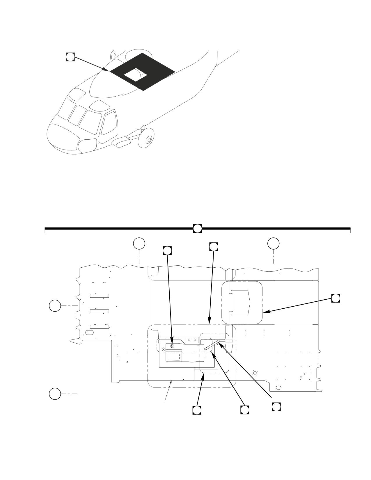
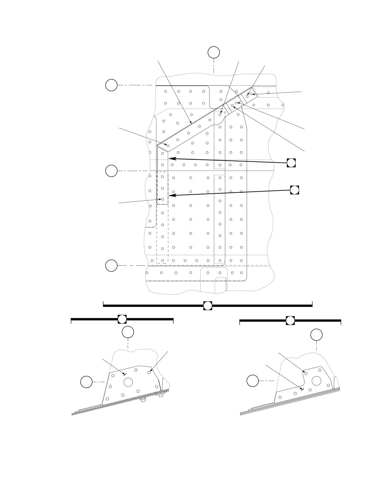
Figure E-6. Upper Plating Modification Kit (Sheet 1 of 5)
E-81
DMWR 1-1520-237
STA
STA
STA
327
344
360
9
20
5
9
9
9
14
3
7
6
4
13
12
11
10
9
9
21
19
BL
16.5
LH
22
23
47
48
49
26
18
BL
29
LH
9
17
24
8
15
25
16
9
C
2
C
BL
BL
29
22
LH
LH
WL
269
28
27
AB3098_2
SA
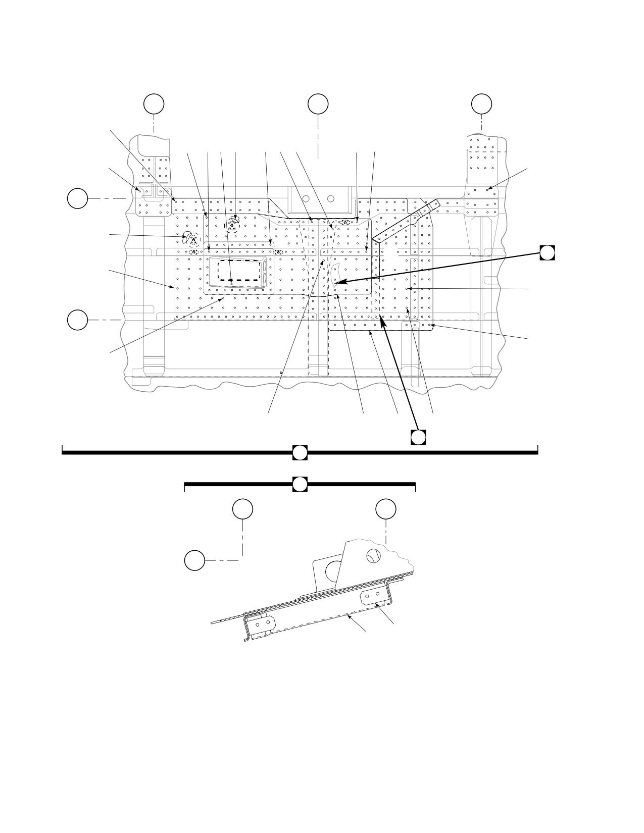
Figure E-6. Upper Plating Modification Kit (Sheet 2 of 5)
E-82
DMWR 1-1520-237
52
52
BL
52
BL
57
58
22
56
29
52
LH
LH
55
52
WL
54
269
E
61
WL
261
50
51
53
59
63
52
52
49
E
60
52
STA
344
62
AB3098_3
SA
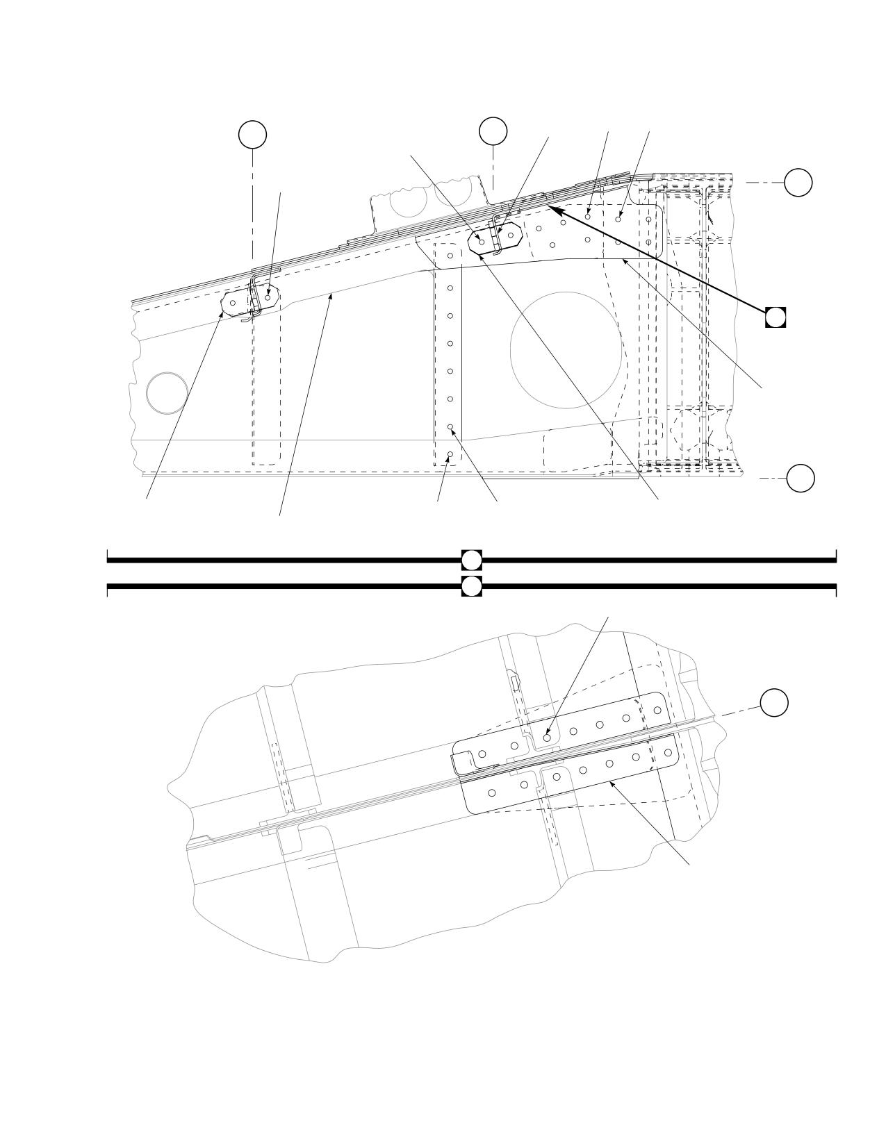
Figure E-6. Upper Plating Modification Kit (Sheet 3 of 5)
E-83
DMWR 1-1520-237
STA
STA
360
370
WL
9
31
269
29
34
35
BL
5
9
RH
30
36
38
BL
31
0
33
34
37
D
BL
5
LH
B
D
39
STA
344
43
42
44
BL
16.5
LH
45
46
41
BL
22
LH
40
AB3098_4
41
SA
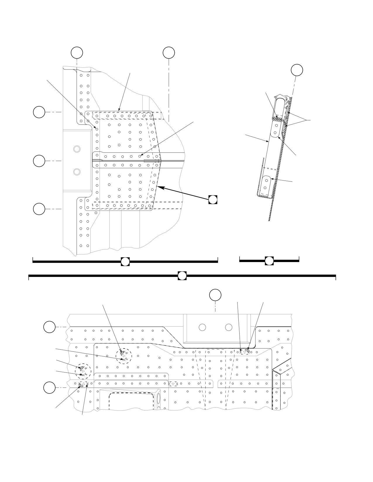
Figure E-6. Upper Plating Modification Kit (Sheet 4 of 5)
E-84
DMWR 1-1520-237
STA
353
67
72
68
71
67
BL
16.5
LH
66
67
66
67
67
70
69
F
BL
22
LH
G
67
73
BL
29
LH
65
G
F
BL
23
BL
LH
22
LH
74
74
76
75
WL
WL
269
269
AB3098_5
SA
Figure E-6. Upper Plating Modification Kit (Sheet 5 of 5)
E-85
DMWR 1-1520-237
QTY
USABLE
FIGURE &
PER
ON
INDEX NO. PART NUMBER
1 2 3 4 5 6 7
DESCRIPTION
ASSY
CODE
E-6-
70070-20570-011
UPPER PLATING MODIFICATION KIT
REF
-1
70070-20570-012
M/K,PLATE INSTL
1
-2
70070-20570-022
PLATING INSTL (Modified from 70213-02101-
011)
REF
70070-20570-023
PLATING INSTL (Modified from 70213-02101-
013)
REF
70070-20570-024
PLATING INSTL (Modified from 70213-02101-
014)
REF
-3
NAS1738B5-5
BLIND RIVET
56
-4
NAS1738B5-4
BLIND RIVET
55
-5
SS430X15B000431
DOUBLER WASHER
1
-6
MS20470AD4-4
RIVET
5
-7
NAS1738B4-4
BLIND RIVET
9
-8
HL64PB-6-5
HI-LOK PIN, (73197)
31
-9
HL1087A-6
COLLAR, (73197)
487
-10
HL20PB-6-4
HI-LOK PIN, (73197)
38
-11
HL64PB-6-6
PIN, (73197)
67
-12
MS20470AD5-4
RIVET
9
-13
HL20PB-6-5
HI-LOK PIN, (73197)
100
-14
MS20470AD5-3
RIVET
155
-15
70070-20570-105
GUSSET, LH
1
70070-20570-106
GUSSET, RH
1
-16
RA615-5M2
RIVET, (76100)
22
-17
HL20PB-6-3
HI-LOK PIN, (73197)
160
-18
MS20470AD5-2
RIVET
227
-19
HL20PB-6-6
HI-LOK PIN, (73197)
16
-20
HL64PB-6-7
HI-LOK PIN, (73197)
28
-21
HL20PB-6-7
HI-LOK PIN, (73197)
25
-22
SS430X15B000431
DOUBLER WASHER
1
-23
MS20470AD4-3
RIVET
5
-24
MS20470AD5-2
RIVET, LH
1
NAS1738B5-3
BLIND RIVET, RH
11
-25
70070-20570-139
FILLER, LH
1
70070-20570-140
FILLER, RH
1
-26
70070-20570-141
DOUBLER, LH
1
70070-20570-142
DOUBLER, RH
1
-27
70070-20570-111
ZEE, LH
1
70070-20570-112
ZEE, RH
1
-28
70070-20570-110
CLIP
4
-29
HL64PB-6-4
HI-LOK PIN, (73197)
10
-30
HL64PB-6-3
HI-LOK PIN, (73197)
12
-31
70070-20570-109
GUSSET
1
-32
70070-20570-115
CLIP
2
-33
HL20PB-5-2
HI-LOK PIN, (73197)
29
-34
HL1087A-5
COLLAR, (73197)
31
-35
HL20PB-5-3
HI-LOK PIN, (73197)
2
-36
SS1058-1-18-14
RADIUS BLOCK
2
-37
70070-20570-116
CLIP
2
-38
70070-20570-143
ANGLE, LH
1
70070-20570-144
ANGLE, RH
1
-39
70070-20570-013
M/K,NUTPLATE INSTL
1
-40
MS21069-3
. NUTPLATE
4
-41
NAS1097AD3-3
. RIVET
14
-42
MS21075-3
. NUTPLATE
2
-43
NAS1097AD3-6
. RIVET
5
-44
MS21075-3
. NUTPLATE
1
-45
NAS1097AD3-4
. RIVET
3
-46
MS21075-3
. NUTPLATE
2
-47
70070-20570-014
M/K,FRAME INSTL
1
-48
70070-20570-016
. STRINGER INSTL (Modified from 70212-02119-
012)
REF
E-86
DMWR 1-1520-237
QTY
USABLE
FIGURE &
PER
ON
INDEX NO. PART NUMBER
1
2
3 4 5 6 7
DESCRIPTION
ASSY
CODE
70070-20570-017
STRINGER INSTL (Modified from 70212-02119-
013)
REF
70070-20570-018
STRINGER INSTL (Modified from 70212-02119-
014)
REF
70070-20570-019
STRINGER INSTL (Modified from 70202-02120-
011)
REF
70070-20570-020
STRINGER INSTL (Modified from 70202-02120-
012)
REF
70070-20570-021
STRINGER INSTL (Modified from 70212-02119-
011)
REF
-49
70070-20570-041
STRINGER ASSY (Modified from 70211-02109-
041)
REF
70070-20570-042
STRINGER ASSY (Modified from 70211-02109-
042)
REF
-50
70070-20570-117
CLIP, LH
1
70070-20570-118
CLIP, RH
1
-51
HL20PB-6-4
HI-LOK PIN, (73197)
4
-52
HL1087A-6
COLLAR, (73197)
82
-53
HL20PB-6-2
HI-LOK PIN, (73197)
12
-54
HL20PB-6-5
HI-LOK PIN, (73197)
6
-55
HL20PB-6-8
HI-LOK PIN, (73197)
4
-56
HL20PB-6-3
HI-LOK PIN, (73197)
18
-57
HL20PB-6-6
HI-LOK PIN, (73197)
12
-58
HL64PB-6-5
HI-LOK PIN, (73197)
22
-59
70070-20570-123
CLIP
4
-60
HL64PB-6-6
PIN, (73197)
4
-61
70070-20570-137
ANGLE, LH
1
70070-20570-138
ANGLE, RH
1
-62
70070-20570-135
ANGLE, LH
1
70070-20570-136
ANGLE, RH
1
-63
70070-20570-129
STRINGER (Reidentified from 70212-02119-
111)
REF
70070-20570-130
STRINGER (Reidentified from 70212-02119-
112)
REF
70070-20570-131
STRINGER (Reidentified from 70212-02119-
113)
REF
70070-20570-132
STRINGER (Reidentified from 70212-02119-
114)
REF
70070-20570-133
STRINGER ZEE (Reidentified from 70202-
02120-101)
REF
70070-20570-134
STRINGER ZEE (Reidentified from70202-
02120-102)
REF
-64
70070-20570-015
M/K,ANGLE INSTL
1
-65
70070-20570-025
. ANGLE INSTL (Modified from 70304-02201
-011)
REF
70070-20570-026
. ANGLE INSTL (Modified from 70304-02201
-012)
REF
-66
HL20PB-6-4
. HI-LOK PIN, (73197)
14
-67
HL1087-6
. COLLAR, (73197)
39
-68
HL20PB-6-5
. HI-LOK PIN, (73197)
2
-69
NAS1097AD6-7
. RIVET
2
-70
HL64PB-6-7
. HI-LOK PIN, (73197)
2
-71
HL64PB-6-6
. PIN,
(73197)
12
-72
70070-20570-107
. ANGLE, LH
1
70070-20570-108
. ANGLE, RH
1
-73
HL20PB-6-3
. HI-LOK PIN, (73197)
6
-74
MS20615-4M3
. RIVET
36
-75
70070-20570-127
. ANGLE, LH
1
70070-20570-128
. ANGLE, RH
1
-76
70070-20570-125
. ANGLE, LH
1
70070-20570-126
. ANGLE, RH
1
E-87
DMWR 1-1520-237
E-8. BL 34.5 MODIFICATION KIT (50-7).
Subject: Buttline 34.50, Modification of, dated 31 March 2003
Purpose: Provide instructions to modify buttline 34.50 to eliminate cracking and to replace existing fasteners.
Model:
UH-60A
Description: The following is a brief overview of the work required to modify buttline 34.50. New reinforcements are
installed, existing fasteners are removed, the holes are coldworked and new fasteners are installed.
Drawings required for modification:
70070-20572
References: (a) Special Service Instructions (SSI) No. 50-31, Installation of 9A to A9 Recapitalization Program, dated
March 31, 2003
(b) TM 1-1520-265-23, Technical Manual, Aviation Unit Maintenance (AVUM) and Aviation Intermedi-
ate (AVIM) Manual, Nondestructive Inspection Procedure for H-60 Helicopter Series
(c) TM 1-1500-335-23, Technical Manual, Nondestructive Inspection Method
Instructions:
NOTE
• A complete review of this SSI is recommended before modifying buttline 34.50.
• Before beginning this modification procedure, use the material information list to inventory the kit. Make
sure all parts are present and in serviceable condition.
• The sheet metal and structural modifications in this SSI shall be done by personnel experienced in reading
modification drawings. Routine steps such as cleaning, layout and drilling, deburring, standard repairs,
corrosion control, clean up after rework, chemical coating for aluminum after cutting/trimming parts, paint
touch up and safety practices may not be called out herein. However, these steps and all other required
routine tasks shall be done.
• Where drawing numbers are not listed within individual steps, drawing(s) listed in preceding step(s) are
the controlling authority.
• When installing fasteners refer to drawing sheet and zones for applicable fasteners.
• Slight variations to the instructions contained herein are allowed, as long as the intent of the modification
is accomplished.
• Personnel must be trained and certified in hole quality assurance and proper cold expansion procedures
per SS5098.
A.
Preparation for modification and removal of equipment:
(1)
Confirm that all warnings, cautions, and notes are complied with per reference (a).
(2)
Perform preparation for modification per reference (a).
E-88
DMWR 1-1520-237
B.
Modify right side buttline 34.50 as follows:
(1)
Remove and save for reinstallation angle (70212-02112-170, 70211-02108-119 or -171) (Dwg 70070-
20572, Sheet 3, Zone 5-F, Notes 16, 18, 19, and 20).
(2)
Remove and discard angle (70212-02112-132 or -162) at buttline 34.50, waterline 265.00 (Sheet 3, Zone
6-G, Notes 16 and 17).
(3)
Temporarily install new reinforcement (70080-70107-222) transfer drilling through existing fastener loca-
tions and adding new fasteners (Sheet 3, Zones 5-F through 8-F).
(4)
Remove remaining fasteners identified on drawing in preparation for cold expansion process (Sheet 3, Zones
7-E through 9-E and 7-E through 9-G).
(5)
Inspect holes prior to cold working (Dwg 70070-20572, Sheet 3, Note 22).
(6)
Cold work fastener locations at buttline 34.50 between stations 305.00 and 315.00, and waterlines 260.00
and 265.00 identified on drawing (Sheet 3, Zones 7-E through 9-E, 7-F through 9-F, Notes 12, 13, 14, 16, 17, and 23).
(7)
Inspect holes per Sheet 3, Note 22.
(8)
Remove parts installed in step B.(3) deburr and touch up as required.
(9)
Install all parts removed in step B.(8) and angle (70212-02112-170, 70211-02108-119, or -171) using
fasteners shown (Sheet 3, Zones 6-G, 5-F, 7-E through 9-E, 7-G through 9-G, Notes 9, 12, 13, and 14).
C.
Modify left side buttline 34.50 as follows:
(1)
Remove and discard angle (70212-02112-131 or -161) at buttline 34.50, waterline 265.00 (Dwg 70070-
20572, Sheet 3, Zone 13-G, Notes 16 and 17).
(2)
Temporarily install new reinforcement (70080-70107-223) transfer drilling through existing fastener loca-
tions and adding new fasteners (Sheet 3, Zones 12-G through 15-G).
(3)
Remove remaining fasteners identified on drawing in preparation for cold expansion process (Sheet 3, Zones
11-E through 13-E and 11-F through 13-F).
(4)
Inspect holes per Sheet 3, Note 22.
(5)
Cold work fastener locations at buttline 34.50 between stations 305.00 and 315.00, and waterlines 260.00
and 265.00 identified on drawing (Sheet 2, Zones 11-E through 12-E, 11-F through 12-F, Notes 12, 13, 14, 16, 17 and
23).
(6)
Inspect holes per Sheet 3, Note 22.
(7)
Remove part installed in step C.(2) deburr and touch up as required.
(8)
Install parts removed in step C.(7) using fasteners shown (Sheet 3, Zones 11-E through 11-G, 13-G, 11-F
through 13-F, Notes 9, 12, 13, 1 and 234).
D.
Reinstallation of removed equipment:
(1)
Install removed equipment per reference (a).
E-89
DMWR 1-1520-237
E.
Record of Compliance:
(1)
Make an appropriate logbook entry to show compliance with this Special Service Instruction.
Weight and Balance Data:
POUNDS
INCHES AFT
MOMENT/
QTY
PART NO.
NOMENCLATURE
WEIGHT
OF DATUM
1000
1
70070-20572-011
Mod. Kit
+1.0
308.0
0.308
Weight and Balance: Change resulting from these instructions are as follows:
Change in basic weight:
+1.0 pounds
Moment arm:
308.0 in.
Change in basic moment/1000:
0.308
Manpower (Estimated)
No. of Personel
No. of Hours
Man-hours
Sheet Metal Mechanic
2
24.0
*48.0
*Does not include time required to prepare helicopter or return it to flight status.
Material Information:
A.
Modification Kit Required:
Qty
Nomenclature
Part Number
Source
1
Mod. Kit, Buttline 34.5,
70070-20572-011
(1)
consisting of:
1
Mod. Kit, R.H Reinforcement,
70070-20572-012
consisting of:
18
Collar
HL1087A-6
6
Collar
HL1087A-8
4
Pin Collar Assy
HL20PB86-6-3
6
Pin Collar Assy
HL20PB86-6-4
3
Pin Collar Assy
HL20PB86-6-6
5
Pin
HL204-6-2
5
Pin
HL204-6-3
E-90
DMWR 1-1520-237
Qty
Nomenclature
Part Number
Source
5
Pin
HL204-6-4
5
Pin
HL204-6-5
10
Pin
HL204-6-6
5
Pin
HL204-6-7
5
Pin
HL204-6-8
5
Pin
HL204-8-5
5
Pin
HL204-8-6
5
Pin
HL204-8-7
5
Pin
HL204-8-8
5
Pin, Hi-Lok
HL220-6-2
5
Pin, Hi-Lok
HL220-6-3
5
Pin, Hi-Lok
HL220-6-4
5
Pin, Hi-Lok
HL220-6-5
10
Pin, Hi-Lok
HL220-6-6
5
Pin
HL220-6-7
5
Pin, Hi-Lok
HL220-6-8
5
Pin, Hi-Lok
HL220-8-5
5
Pin, Hi-Lok
HL220-8-6
5
Pin, Hi-Lok
HL220-8-7
5
Pin, Hi-Lok
HL220-8-8
40
Collar
HL287-6
20
Collar
HL287-8
3
Pin, Hi-Lok
HL64PB-6-2
2
Pin, Hi-Lok
HL64PB-6-3
1
Pin, Hi-Lok
HL64PB-6-4
2
Pin, Hi-Lok
HL64PB-6-5
5
Pin
HL64PB-6-6
4
Pin, Hi-Lok
HL64PB-6-7
1
Pin, Hi-Lok
HL64PB-6-8
4
Pin, Hi-Lok
HL64PB-8-5
2
Pin
HL64PB-8-8
40
Collar
HL93-6
20
Collar
HL93-8
15
Rivet
MS20470AD5-2
13
Rivet
MS20470AD5-5
18
Rivet
MS20470AD6-5
9
Rivet
MS20470AD6-6
1
Reinforcement
70080-70107-222
1
Mod. Kit, R.H Reinforcement,
70070-20572-013
consisting of:
18
Collar
HL1087A-6
6
Collar
HL1087A-8
4
Pin Collar Assy
HL20PB86-6-3
6
Pin Collar Assy
HL20PB86-6-4
3
Pin Collar Assy
HL20PB86-6-6
5
Pin
HL204-6-2
E-91
DMWR 1-1520-237
Qty
Nomenclature
Part Number
Source
5
Pin
HL204-6-3
5
Pin
HL204-6-4
5
Pin
HL204-6-5
10
Pin
HL204-6-6
5
Pin
HL204-6-7
5
Pin
HL204-6-8
5
Pin
HL204-8-5
5
Pin
HL204-8-6
5
Pin
HL204-8-7
5
Pin
HL204-8-8
5
Pin, Hi-Lok
HL220-6-2
5
Pin, Hi-Lok
HL220-6-3
5
Pin, Hi-Lok
HL220-6-4
5
Pin, Hi-Lok
HL220-6-5
10
Pin, Hi-Lok
HL220-6-6
5
Pin
HL220-6-7
5
Pin, Hi-Lok
HL220-6-8
5
Pin, Hi-Lok
HL220-8-5
5
Pin, Hi-Lok
HL220-8-6
5
Pin, Hi-Lok
HL220-8-7
5
Pin, Hi-Lok
HL220-8-8
40
Collar
HL287-6
20
Collar
HL287-8
3
Pin, Hi-Lok
HL64PB-6-2
2
Pin, Hi-Lok
HL64PB-6-3
1
Pin, Hi-Lok
HL64PB-6-4
2
Pin, Hi-Lok
HL64PB-6-5
5
Pin
HL64PB-6-6
4
Pin, Hi-Lok
HL64PB-6-7
1
Pin, Hi-Lok
HL64PB-6-8
4
Pin, Hi-Lok
HL64PB-8-5
2
Pin
HL64PB-8-8
40
Collar
HL93-6
20
Collar
HL93-8
16
Rivet
MA20470AD5-2
13
Rivet
MS20470AD5-5
17
Rivet
MS20470AD6-5
7
Rivet
MS20470AD6-6
1
Reinforcement
70080-70107-223
B.
Source:
(1)
Available through normal supply channels
E-92
DMWR 1-1520-237
A
STA
BL
325
34.5
STA
320
WL
265
STA
308
WL
260
A
24
3
23
22
1
2
STA
BL
325
34.5
17
STA
17
320
12
WL
265
12
11
16
26
12
STA
10
308
WL
260
9
9
3
5
25
8
5
17
7
12
25
5
19
5
4
5
5
13
5
8
5
5
7
15
18
5 13
14
15
22
7
21
5
5
5
14
AB3093
6
20
SA
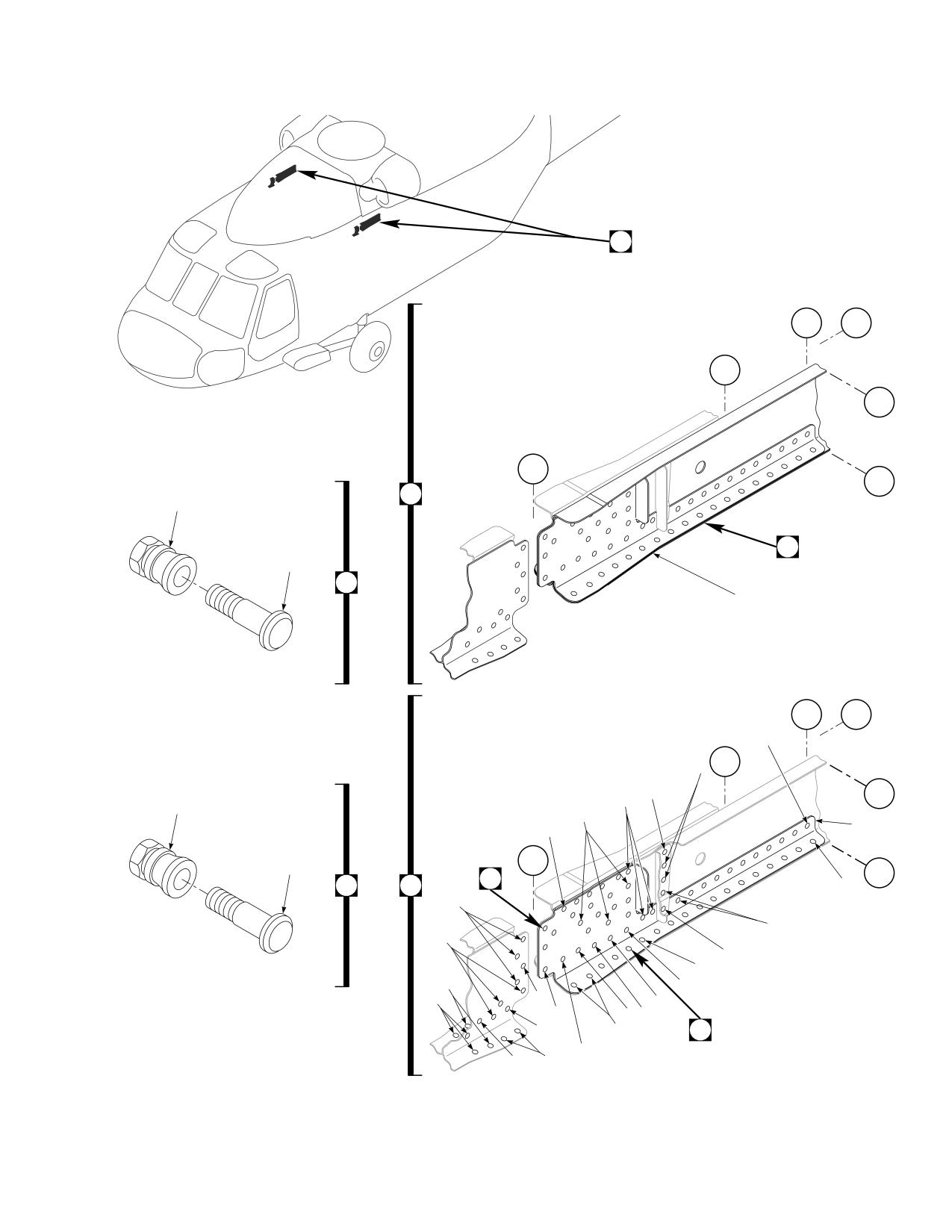
Figure E-7. BL 34.5 Modification Kit
E-93
DMWR 1-1520-237
QTY
USABLE
FIGURE &
PER
ON
INDEX NO. PART NUMBER
1 2 3 4 5 6 7
DESCRIPTION
ASSY
CODE
E-7-
70070-20572-011
BL 34.5 MODIFICATION KIT
REF
-1
70070-20572-013
M/K L/H REINFORCEMENT
1
70070-20572-012
M/K R/H REINFORCEMENT
1
-2
70070-20572-014
BEAM INSTL RH, (Modified from 70212-02112-
012)
REF
70070-20572-015
BEAM INSTL LH, (Modified from 70212-02112-
011)
REF
70070-20572-016
BEAM INSTL RH, (Modified from 70212-02112-
014)
REF
70070-20572-017
BEAM INSTL LH, (Modified from 70212-02112-
013)
REF
-3
70070-20572-041
BEAM ASSY, (Reidentified from 70212-02112-
051)
REF
70070-20572-042
BEAM ASSY, (Reidentified from 70212-02112-
050)
REF
70070-20572-043
BEAM ASSY, (Reidentified from 70212-02112-
043)
REF
70070-20572-044
BEAM ASSY, (Reidentified from 70212-02112-
047)
REF
-4
HL64PB-6-2
HI-LOK PIN, (73197)
3
HL220-6-2
HI-LOK PIN, (73197)
5
*
HL204-6-2
PIN, (73197)
5
*
-5
HL1087A-6
COLLAR, (73197)
18
HL287-6
COLLAR, (73197)
40
*
HL93-6
COLLAR, (73197)
40
*
-6
HL64PB-6-4
HI-LOK PIN, (73197)
1
HL220-6-4
HI-LOK PIN, (73197)
5
*
HL204-6-4
PIN, (73197)
5
*
-7
HL64PB-6-6
PIN, (73197)
5
HL204-6-6
PIN, (73197)
10
*
HL220-6-6
HI-LOK PIN, (73197)
10
*
-8
HL20PB86-6-3
PIN COLLAR ASSY, (73197)
4
-9
HL20PB86-6-6
PIN COLLAR ASSY, (73197)
3
-10
HL20PB-6-6
. HI-LOK PIN, (73197)
1
-11
HL86-6
. COLLAR, (73197) (Superseded By HL1086A-
6)
1
HL1086A-6
. COLLAR, (73197)
1
-12
MS20470AD6-6
RIVET
9
-13
HL64PB-6-5
HI-LOK PIN, (73197)
2
HL204-6-5
PIN, (73197)
5
*
HL220-6-5
HI-LOK PIN, (73197)
5
*
-14
HL64PB-8-8
PIN, (73197)
2
HL220-8-8
HI-LOK PIN, (73197)
5
*
HL204-8-8
PIN, (73197)
5
*
-15
HL1087A-8
COLLAR, (73197)
6
HL287-8
COLLAR, (73197)
40
*
HL93-8
COLLAR, (73197)
20
*
-16
MS20470AD5-5
RIVET
13
-17
MS20470AD6-5
RIVET
18
-18
HL64PB-6-8
HI-LOK PIN, (73197)
1
HL220-6-8
HI-LOK PIN, (73197)
5
*
HL204-6-8
PIN, (73197)
5
*
-19
HL64PB-6-3
HI-LOK PIN, (73197)
2
HL220-6-3
HI-LOK PIN, (73197)
5
*
HL204-6-3
PIN, (73197)
5
*
-20
HL64PB-6-7
HI-LOK PIN, (73197)
4
HL204-6-7
PIN, (73197)
5
*
E-94
DMWR 1-1520-237
QTY
USABLE
FIGURE &
PER
ON
INDEX NO. PART NUMBER
1 2 3 4 5 6 7
DESCRIPTION
ASSY
CODE
HL220-6-7
. . HI-LOK PIN, (73197)
5
*
-21
HL64PB-8-5
. . HI-LOK PIN, (73197)
4
HL220-8-5
. . HI-LOK PIN, (73197)
5
*
HL204-8-5
. . PIN,
(73197)
5
*
HL220-8-6
. . HI-LOK PIN, (73197)
5
*
HL204-8-6
. . PIN,
(73197)
5
*
HL220-8-7
. . HI-LOK PIN, (73197)
5
*
HL204-8-7
. . PIN,
(73197)
5
*
-22
HL20PB86-6-4
. . PIN COLLAR ASSY, (73197)
6
-23
HL20PB-6-4
. . . HI-LOK PIN,
(73197)
1
-24
HL86-6
. . . COLLAR, (73197) (Superseded By HL1086A-
6)
1
HL1086A-6
. . . COLLAR, (73197)
1
-25
MS20470AD5-2
. . RIVET
15
-26
70080-70107-222
. . REINFORCEMENT, (Used on 70070-20572-
012)
1
70080-70107-223
. . REINFORCEMENT, (Used on 70070-20572-
013)
1
E-95
DMWR 1-1520-237
E-9. ESSS DOUBLER MODIFICATION KIT (50-15).
Subject: ESSS Doubler; Installation of, dated 31 March 2003
Purpose: Provide instructions to install new doublers and skins between station 295.00 and station 308.00 right and left
sides on UH-60A helicopters equipped with ESSS provisions.
Model:
UH-60A
Description: The following is a brief overview of the work required to modify left and right sides between station 295.00
and 308.00. New doublers and skins are installed between station 295.00 and station 308.00, buttline 16.50 through
34.50. This modification is applicable to UH-60A equipped with ESSS.
Drawings required for modification:
70070-20641, 70652-02150
References: (a) Special Service Instructions (SSI) No. 50-31, Installation of 9A to A9 Recapitalization Program, dated
March 31, 2003
Instructions:
NOTE
• AcompletereviewofthisSSIisrecommendedbeforeinstallingnewdoublersandskinsbetweenstation
295.00 and station 308.00.
• Before beginning this modification procedure, use the material information list to inventory the kit. Make
sure all parts are present and in serviceable condition.
• Where drawing numbers are not listed within individual steps, drawing(s) listed in preceding step(s) are
the controlling authority.
• The sheet metal and structural modifications in this SSI shall be done by personnel experienced in reading
modification drawings. Routine steps such as cleaning, layout and drilling, deburring, standard repairs,
corrosion control, clean up after rework, chemical coating for aluminum after cutting/trimming parts, paint
touch up, and safety practices may not be called out herein. However, these steps and all other required
routine tasks shall be done.
• When installing fasteners refer to drawing sheet and zones for applicable fasteners.
• Slight variations to the instructions contained herein are allowed, as long as the intent of the modification
is accomplished.
A.
Preparation for modification and removal of equipment.
(1)
Confirm that all warnings, cautions, and notes are complied with per reference (a).
(2)
Perform preparation for modification per reference (a).
E-96
DMWR 1-1520-237
B.
Install right and left side ESSS doublers as follows:
(1)
Modify right side between station 295.00 and station 308.00 as follows (Dwg 70070-20641):
(a)
Remove and save for reuse, strap (70213-02101-173) at buttline 16.50, waterline 269.00 (Sheet 3, Zone
12-B).
(b)
Remove fasteners attaching hat (70219-04203-130) between buttlines 28.75 and 34.50, waterline
269.00 leaving hat (-130) in place (Sheet 3, Zone 9-E).
(c)
Position doubler (70070-20641-102) (top deck) and skin (70085-22135-117) (cabin ceiling) between
buttlines 16.50 and 34.50, waterline 269.00 and mark rivets to be removed (Sheet 3, Zones 10-G and 12-B).
(d)
Remove fasteners identified in previous step.
NOTE
In step B.(1)(e), existing rivets may interfere with the flange on skin (70085-22135-117). If this condition
exists trimming the flange enough to clear rivets is permissible.
(e)
Position and temporarily install skin (70085-22135-117) (cabin ceiling) and doubler (70070-20641-102)
(top deck) (Sheet 3, Zones 10-G and 12-B).
(f)
Remove skin (70085-22135-117) and doubler (70070-20641-102), deburr and touch up as required.
WARNING
OBSERVE ALL CAUTIONS AND WARNINGS ON CONTAINERS WHEN USING CONSUMABLES.
WHEN APPLICABLE, WEAR NECESSARY PROTECTIVE GEAR DURING HANDLING AND USE. IF A
CONSUMABLE IS FLAMMABLE OR EXPLOSIVE, MAKE CERTAIN CONSUMABLE AND ITS VAPORS ARE
KEPT AWAY FROM HEAT, SPARK, AND FLAME. MAKE CERTAIN EQUIPMENT IS PROPERLY
GROUNDED AND FIREFIGHTING EQUIPMENT IS READILY AVAILABLE PRIOR TO USE. FOR AD-
DITIONAL INFORMATION ON TOXICITY, FLASHPOINT, AND FLAMMABILITY OF CHEMICALS,
CONSULT YOUR MEDICAL PEOPLE, OR MANUFACTURER OF THE CONSUMABLE.
(g)
Install skin (70085-22135-117), doubler (70070-20641-102), and strap (70213-02101-173) wet with
sealant (AMS-S-88022, A2 or C20 or equivalent) using fasteners shown (Sheet 3, Zones 12-B and 10-H; Sheet 2, Notes
9, 12 and 13).
(2)
Modify left side between station 295.00 and station 308.00 as follows (Dwgs 70070-20641 and 70652-
02151):
(a)
Remove and discard spacer (70213-02101-174) and nutplate (MS21075-4) at buttline 16.50, waterline
269.00 (Dwg 70070-20641, Sheet 3, Zone 18-H).
(b)
Remove shim (70652-02151-102) at left buttline 16.50 using a nonmetallic scraper, measure and record
thickness of shim (-102) for use in step B.(2)(l) (Dwg 70652-02151, Sheet 1, Zone 12-F).
E-97
DMWR 1-1520-237
(c)
Remove and save for reuse, strap (70213-02101-172) at buttline 16.50, waterline 269.00 (Dwg 70070-
20641, Sheet 3, Zone 18-A).
(d)
Remove fasteners attaching hat (70219-04203-129) between buttlines 28.75 and 34.50, waterline
269.00 leaving hat (-129) in place (Sheet 3, Zone 23-D).
(e)
Remove and discard nutplates (MS21075-3) (two places) and nutplate (MS21069-3) (Sheet 3, Zones 22-
B, 19-B, and 20-H).
(f)
Position doubler (70070-20641-101) (top deck) and skin (70085-22135-113) (cabin ceiling) between
buttlines 16.50 and 34.50, waterline 269.00 and mark rivets to be removed (Sheet 3, Zones 20-B and 23-D).
(g)
Remove fasteners identified in previous step.
NOTE
In step B.(2)(h), existing rivets may interfere with the flange on skin (70085-22135-117). If this condition
exists trimming the flange enough to clear rivets is permissible.
(h)
Position and temporarily install skin (70085-22135-113) (cabin ceiling) and doubler (70070-20641-
101) (top deck) (Sheet 3, Zones 20-B and 23-D).
(i)
Remove skin (70085-22135-113) and doubler (70070-20641-101), deburr and touch up as required.
WARNING
OBSERVE ALL CAUTIONS AND WARNINGS ON CONTAINERS WHEN USING CONSUMABLES.
WHEN APPLICABLE, WEAR NECESSARY PROTECTIVE GEAR DURING HANDLING AND USE. IF A
CONSUMABLE IS FLAMMABLE OR EXPLOSIVE, MAKE CERTAIN CONSUMABLE AND ITS VAPORS ARE
KEPT AWAY FROM HEAT, SPARK, AND FLAME. MAKE CERTAIN EQUIPMENT IS PROPERLY
GROUNDED AND FIREFIGHTING EQUIPMENT IS READILY AVAILABLE PRIOR TO USE. FOR AD-
DITIONAL INFORMATION ON TOXICITY, FLASHPOINT, AND FLAMMABILITY OF CHEMICALS,
CONSULT YOUR MEDICAL PEOPLE, OR MANUFACTURER OF THE CONSUMABLE.
(j)
Install skin (70085-22135-113), doubler (70070-20641-101), and strap (70213-02101-172) wet with
sealant (AMS-S-8802, A2 or C20 or equivalent) using fasteners shown (Sheet 3, Zones 23-D, 20-B, and 18-A; Sheet 2,
Notes 9, 12, and 13).
(k)
Install three new nutplates (MS21075-3) (two places) and MS21069-3) (Sheet 3, Zones 20-B, 22-B and
20-H).
(l)
Install new shim (70652-02151-102) from previous step using adhesive (EA 9309.3NA or equivalent)
(Dwg 70652-02151, Sheet 1, Zone 12-D and Note 2).
C.
Reinstallation of removed equipment:
(1)
Reinstall removed equipment per reference (a).
D.
Record of Compliance:
(1)
Make an appropriate logbook entry to show compliance with this Special Service Instruction.
E-98
DMWR 1-1520-237
Weight and Balance Data:
POUNDS
INCHES AFT
MOMENT/
QTY
PART NO.
NOMENCLATURE
WEIGHT
OF DATUM
1000
1
70070-20641-011
Mod. Kit
+ 1.9
301.4
0.573
Weight and Balance: Change resulting from these instructions are as follows:
Change in basic weight:
+1.9 pounds
Moment arm: in.
301.4
Change in basic moment/1000:
0.573
Manpower (Estimated)
No. of Personel
No. of Hours
Man-hours
Sheet Metal Mechanic
2
24.0
*48.0
*Does not include time required to prepare helicopter or return it to flight status.
Material Information
A.
Modification Kit Required:
Qty
Nomenclature
Part Number
Source
1
Mod. Kit, ESSS Doubler,
70070-20641-011
(1)
consisting of:
1
Mod. Kit, Support R/H Instl,
70070-20641-012
consisting of:
19
Rivet
MS20470AD5-9
2
Pin, SWG LKG
NAS1465-04
7
Pin, SWG LKG
NAS1525-03
11
Rivet, Blind
NAS1738B4-3
27
Rivet, Blind
NAS1738B5-9
1
Skin
70085-22135-117
E-99
DMWR 1-1520-237
Qty
Nomenclature
Part Number
Source
1
Mod. Kit, Support L/H Instl,
70070-20641-013
consisting of:
19
Rivet
MS20470AD5-9
2
Pin, SWG LKG
NAS1465-04
7
Pin, SWG LKG
NAS1525-03
11
Rivet, Blind
NAS1738B4-3
27
Rivet, Blind
NAS1738B5-9
1
Skin
70085-22135-113
1
Mod. Kit, Plating Instl,
70070-20641-014
consisting of:
2
Pin Collar Assy
HL19PB86-6-8
2
Pin Collar Assy
HL20PB86-6-6
8
Pin Collar Assy
HL20PB86-6-8
2
Pin Collar Assy
HL20PB86-6-9
3
Rivet
MS20426AD3-9
94
Rivet
MS20470AD4-3
64
Rivet
MS20426AD5-9
35
Rivet
MS20470AD6-9
1
Nutplate
MS21069-3
2
Nutplate
MS21075-3N
1
Nutplate
MS21075-4N
5
Rivet
NAS1097AD3-3
3
Rivet
NAS1097AD3-9
7
Rivet
NAS1097AD5-9
47
Pin, SWG LKG
NAS1466-05
23
Pin, SWG LKG
NAS1466-06
18
Pin, SWG LKG
NAS1466-07
6
Pin, SWG LKG
NAS1466-08
22
Pin, SWG LKG
NAS1466-09
1
Doubler
70070-20641-101
1
Doubler
70070-20641-102
1
Mod. Kit, Shim Instl,
70070-20641-018
consisting of:
8
Shim
70652-02151-101
10
Shim
70652-02151-102
4
Shim
70652-02151-103
E-100
DMWR 1-1520-237
B.
Consumable Material:
WARNING
OBSERVE ALL CAUTIONS AND WARNINGS ON CONTAINERS WHEN USING CONSUMABLES.
WHEN APPLICABLE, WEAR NECESSARY PROTECTIVE GEAR DURING HANDLING AND USE. IF A
CONSUMABLE IS FLAMMABLE OR EXPLOSIVE, MAKE CERTAIN CONSUMABLE AND ITS VAPORS ARE
KEPT AWAY FROM HEAT, SPARK, AND FLAME. MAKE CERTAIN EQUIPMENT IS PROPERLY
GROUNDED AND FIREFIGHTING EQUIPMENT IS READILY AVAILABLE PRIOR TO USE. FOR AD-
DITIONAL INFORMATION ON TOXICITY, FLASHPOINT, AND FLAMMABILITY OF CHEMICALS,
CONSULT YOUR MEDICAL PEOPLE, OR MANUFACTURER OF THE CONSUMABLE.
Qty
Nomenclature
Part Number
Source
8 oz.
Sealant
AMS-S-8802, A2, C20, or
(1)
equivalent
8 oz.
Adhesive
EA9309.3NA or equivalent
(1)
C.
Source:
(1)
Available through normal supply channels
E-101
DMWR 1-1520-237
29
33
34
1
33
34
1
1
BL
BL
16.5
16.5
LH
RH
BL
BL
34.5
34.5
LH
BL
RH
0.0
STA
295
STA
308
B
A
AB3097_1
SA
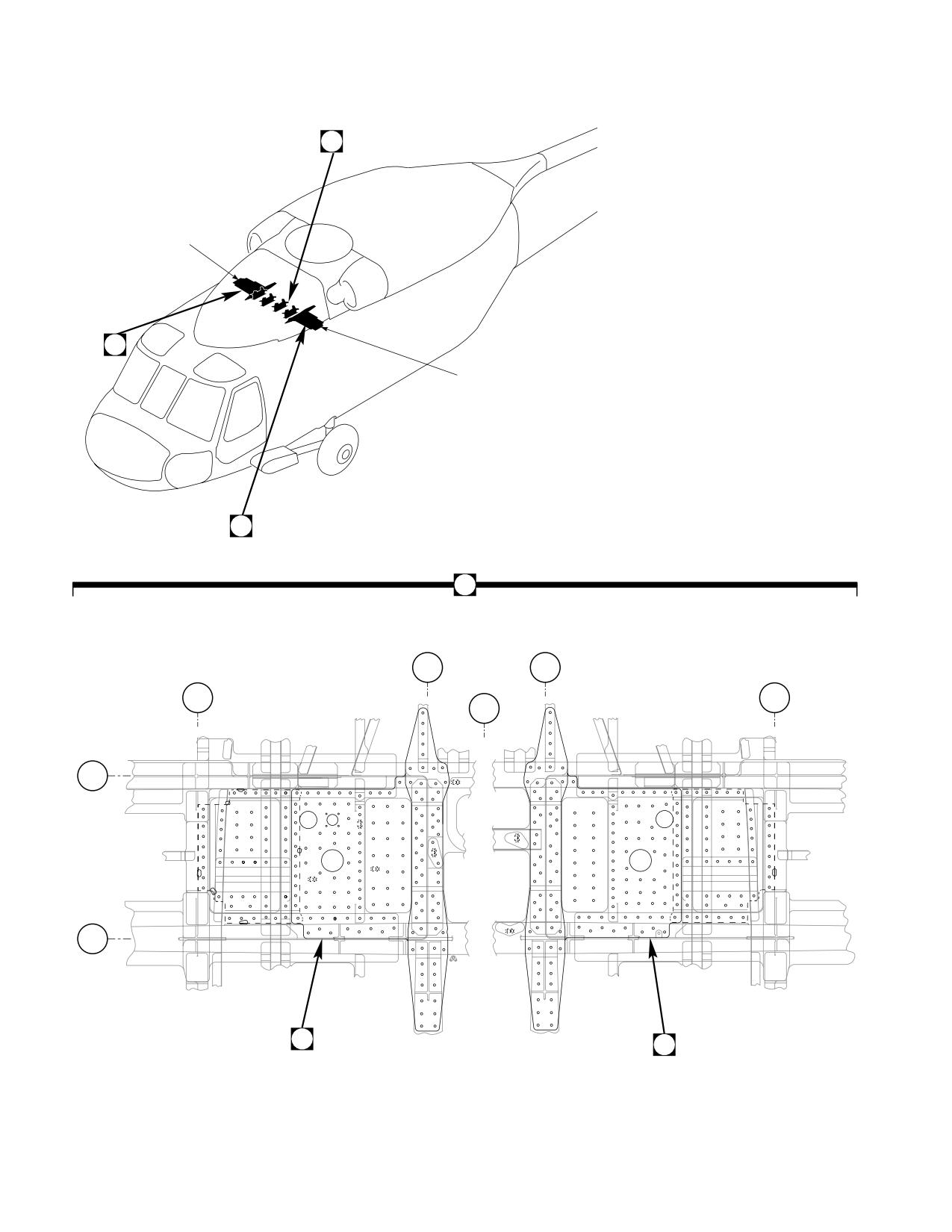
Figure E-8. ESSS Doubler Modification Kit (Sheet 1 of 2)
E-102
DMWR 1-1520-237
BL
BL
16.5
34.5
RH
RH
2
3
4
20
5
3
20
35
36
4
19
21
37
35
5
19
6
STA
295
39
38
6
35
5
4
36
5
35
4
40
5
6
18
38
17
35
7
37
17
STA
308
8
37
18
8
20
3
22
20
21
36
6
5
5
4
5
A
B
BL
BL
34.5
16.5
LH
LH
2
28
4
36
35
20
19
27
19
3
37
5
39
20
4
6
STA
295
39
38
6
5
36
21
4
24
23
40
4
5
6
38
6
18
17
37
7
STA
17
308
8
37
11
3
20
20
20
3
20
18
36
35
25
26
22
25
26
8
4
14
5
5
AB3097_2
SA
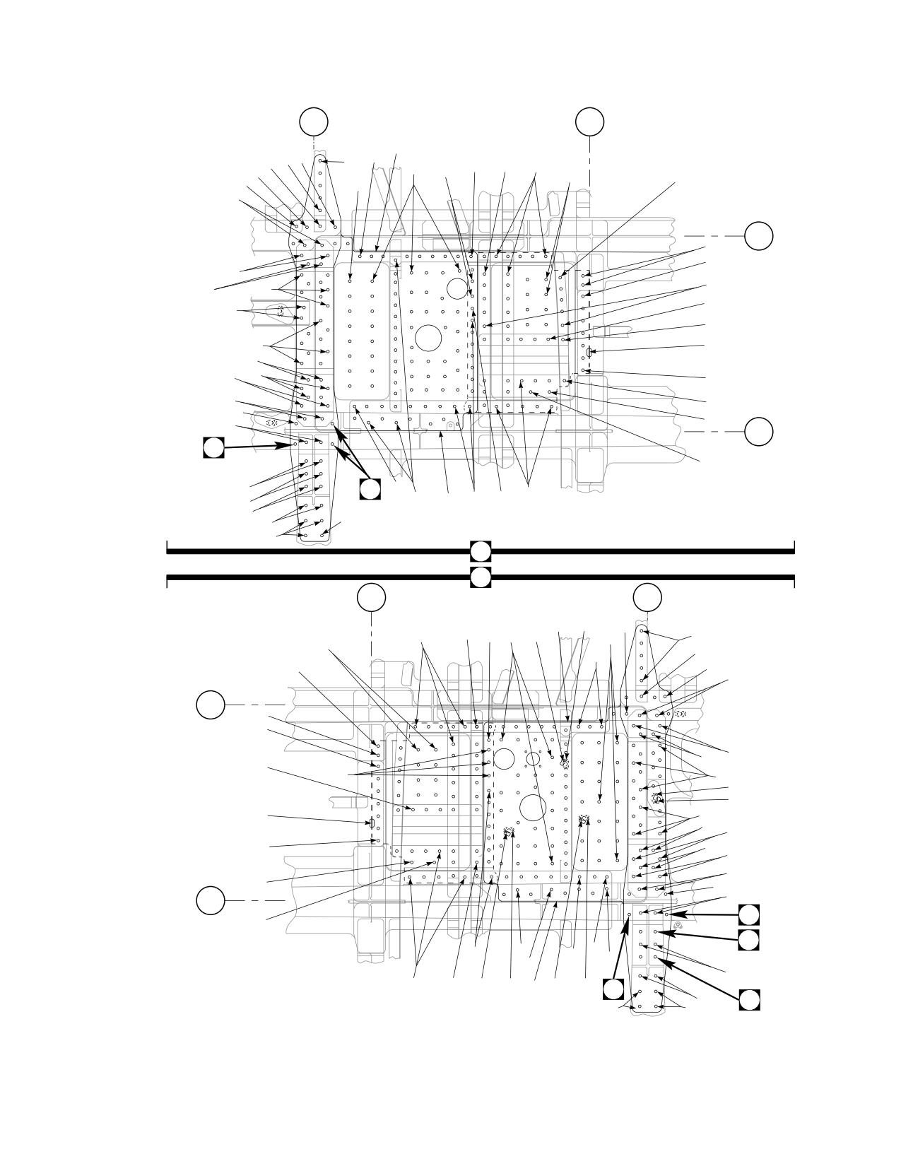
Figure E-8. ESSS Doubler Modification Kit (Sheet 2 of 2)
E-103
DMWR 1-1520-237
QTY
USABLE
FIGURE &
PER
ON
INDEX NO. PART NUMBER
1 2 3 4 5 6 7
DESCRIPTION
ASSY
CODE
E-8-
70070-20641-011
ESSS DOUBLER MODIFICATION KIT
REF
-1
70070-20641-014
M/K PLATING INSTL
1
-2
70070-20641-015
. PLATING INSTL, (Modified from 70213-02101-
014)
REF
-3
MS20470AD6-9
. RIVET
35
-4
NAS1466-05
. SWAGE LOCKING PIN
47
-5
NAS1466-06
. SWAGE LOCKING PIN
23
-6
NAS1466-07
. SWAGE LOCKING PIN
18
-7
HL19PB86-6-8
. PIN COLLAR ASSY, (73197)
8
-8
HL20PB86-6-8
. PIN COLLAR ASSY, (73197)
8
-9
HL20PB-6-8
. . HI-LOK PIN, (73197)
1
-10
HL86-6
. . COLLAR, (73197) (Superseded by HL1087A-
6)
1
HL1087A-6
. . COLLAR, (73197)
1
-11
HL20PB86-6-9
. PIN COLLAR ASSY, (73197)
2
-12
HL20PB-6-9
. . HI-LOK PIN, (73197)
1
-13
HL86-6
. . COLLAR, (73197) (Superseded by HL1087A-
6)
1
HL1087A-6
. . COLLAR, (73197)
1
-14
HL20PB86-6-6
. PIN COLLAR ASSY, (73197)
2
-15
HL20PB-6-6
. . HI-LOK PIN, (73197)
1
-16
HL86-6
. . COLLAR, (73197) (Superseded By HL1087A-
6)
1
HL1087A-6
. . COLLAR, (73197)
1
-17
NAS1466-09
. SWAGE LOCKING PIN
22
-18
NAS1466-08
. SWAGE LOCKING PIN
6
-19
MS20470AD4-3
. RIVET
94
-20
MS20470AD5-9
. RIVET
64
-21
NAS1097AD5-9
. RIVET
7
-22
70070-20641-101
. DOUBLER, LH
1
70070-20641-102
. DOUBLER, RH
1
-23
MS21075-4N
. NUTPLATE
1
-24
MS20426AD3-9
. RIVET
3
-25
MS21075-3N
. NUTPLATE
2
-26
NAS1097AD3-3
. RIVET
5
-27
MS21069-3
. NUTPLATE
1
-28
NAS1097AD3-9
. RIVET
3
-29
70070-20641-018
M/K SHIM INSTL
1
-30
70652-02151-101
. SHIM
8
-31
70652-02151-102
. SHIM
10
-32
70652-02151-103
. SHIM
4
-33
70070-20641-013
M/K SUPPORT L/H INSTL
1
70070-20641-012
M/K SUPPORT R/H INSTL
1
-34
70070-20641-016
. SUPPORT INSTL, (Modified from 70219-42426-
014)
REF
70070-20641-017
. SUPPORT INSTL, (Modified from 70219-42426-
013)
REF
-35
MS20470AD5-9
. RIVET
19
-36
NAS1738B5-9
. BLIND RIVET
27
-37
NAS1738B4-3
. BLIND RIVET
11
-38
NAS1525-03
. SWAGE LOCKING PIN
7
-39
NAS1465-04
. SWAGE LOCKING PIN
2
-40
70085-22135-117
. SKIN, LH (Used on 70070-20641-013)
1
70085-22135-113
. SKIN, RH (Used on 70070-20641-012)
1
E-104
DMWR 1-1520-237
E-10. TRDS BRACKETS MODIFICATION KIT (50-20).
Subject: Tail Rotor Drive Shaft Support Brackets; Modification of, dated 31 March 2003
Purpose: Provide instructions for the structural strengthening of the tail rotor drive shaft supports to eliminate cracking.
Model:
UH-60A
Description: The tail rotor drive shaft support brackets at station 410.00 and station 472.00 are modified to improve
the structural strength at these locations.
Drawings required for modification:
70070-20488
References: (a) Special Service Instructions (SSI) No. 50-31, Installation of 9A to A9 Recapitalization Program, dated
March 31, 2003
(b) SSI No. 50-9, Drive Shaft Supports; Modification of, dated March 31, 2003
(c) TM 1-1520-237-23-2, Technical Manual Aviation Unit and Intermediate Maintenance for UH-60A,
UH-60L, EH-60A, UH-60Q and HH-60L Helicopters
Instructions:
NOTE
• AcompletereviewofthisSSIisrecommendedbeforeincorporatingthetailrotordriveshaftsupport
brackets modification kit.
• Before beginning this modification procedure, use the material information list to inventory the modification
kit. Make sure all parts are present and in serviceable condition.
• Where drawing numbers are not listed within individual step(s), drawing(s) listed in preceding step(s) are
the controlling authority.
• The sheet metal and structural modifications in this SSI shall be done by personnel experienced in reading
modification drawings. Routine steps such as cleaning, layout and drilling, deburring, standard repairs,
corrosion control, clean up after rework, chemical coating for aluminum after cutting/trimming parts, paint
touch up, and safety practices may not be called out herein. However, these steps and all other required
routine tasks shall be done.
• When installing fasteners refer to drawing sheet and zones for applicable fasteners.
• Slight variations to the instructions contained herein are allowed, as long as the intent of the modification
is accomplished.
• This modification is to be done concurrently with reference (b).
A.
Preparation for modification and removal of equipment:
(1)
Confirm that all warnings, cautions, and notes are complied with per reference (a).
(2)
Perform preparation for modification per reference (a).
E-105
DMWR 1-1520-237
B.
Modification of tail rotor drive shaft support brackets:
CAUTION
TO AVOID DAMAGING COMPONENTS, USE EXTREME CARE WHEN DRILLING INTO AIRFRAME.
TEMPORARILY MOVE ANY TUBE ASSEMBLIES OR WIRING HARNESSES OUT OF REWORK AREA.
(1)
Mark location on top skin of support (70361-03010-114) (Dwg 70070-20488, Sheet 4, Zone 20-B).
(2)
Remove support (70361-03010-114) at station 410.00, buttline 0.00 (Sheet 4, Zone 20-B and Sheet 3,
Note 26).
(3)
Position new support (70361-03010-125) over station 410.00 where support (70361-03010-114) was
removed in previous step.
(4)
Line up forward face of new support (70361-03010-125) where marked location was noted in step B.(1).
(5)
Transfer drill from angle (70361-03010-101) (inside transition ceiling) through new support (70361-03010-
125) and put support (-125) aside for installation in later steps.
(6)
Remove former (70361-03010-110) near station 410.00, right buttline 5.00 (Sheet 4, Zone 14-H and Sheet
3, Note 26).
(7)
Remove former (70361-03010-109) near station 410.00, left buttline 5.00 (Sheet 4, Zones 14-E and 14-F;
Sheet 3, Note 26).
(8)
Mark location on top skin of support (70219-03006-107) (Sheet 7, Zone 13-D).
(9)
Remove support (70219-03006-107) near station 470.50 (Sheet 7, Zone 13-D).
(10)
Position new support (70219-03006-114) over station 470.00 where support (70219-03006-107) was
removed in previous step.
(11)
Line up forward face of new support (70219-03006-114) where marked location was noted in step B.(8).
(12)
Transfer drill from angle (70219-03006-108) (inside transition ceiling) through new support (70219-
03006-114) and set aside support (-114) for installation in later steps.
(13)
Remove radius block (SS1058A7-28-29) and gusset (70219-03006-106) at station 472.00, right buttline
4.00 (Sheet 7, Zones 11-G and 11-H; Sheet 3, Note 28).
(14)
Remove radius block (SS1058A7-28-29) and gusset (70219-03006-105) at station 472.00, left buttline
4.00 (Sheet 7, Zones 11-F and 11-G; Sheet 3, Note 28).
(15)
Remove stringer (70212-03001-149) between station 470.00 and station 485.00, buttline 0.00 (Sheet 7,
Zone 9-G and Sheet 4, Note 44).
(16)
Remove angle (70219-03006-102 or -108) near station 472.50, buttline 0.00 (Sheet 7, Zone 11-C and
Sheet 4, Notes 40 and 41).
E-106
DMWR 1-1520-237
(17)
Remove remaining fasteners, as required (Sheets 4 and 7).
C.
Installation of tail rotor drive shaft support brackets.
(1)
Locate and temporarily install new radius block (SS1058A7-20-51) and former (70070-20488-102) at sta-
tion 410.00, right buttline 5.00 (Dwg 70070-20488, Sheet 4, Zones, 14-G and 14-H).
(2)
Locate and temporarily install new radius block (SS1058A7-20-51) and former (70070-20488-103) at sta-
tion 410.00, left buttline 5.00 (Sheet 4, Zone 14-E).
(3)
Locate and temporarily install support (70361-03010-125) (previously fit-out) at station 410.00, buttline
0.00 (Sheet 4, Zone 19-B and Sheet 2, Notes 10 and 11).
(4)
Locate and temporarily install stringer (70212-03001-168) between station 470.00 and station 485.00, but-
tline 0.00 (Sheet 7, Zones 9-F to 12-F).
(5)
Locate and temporarily install new angle (70219-03006-108) near station 472.50, buttline 0.00 (Sheet 7,
Zone 11-C).
(6)
Locate and temporarily install radius block (SS1058A7-28-29) and gusset (70070-20488-106) at station
472.00, right buttline 4.00 (Sheet 7, Zone 11-H).
(7)
Locate and temporarily install radius block (SS1058A7-28-29) and gusset (70070-20488-105) at station
472.00, left buttline 4.00 (Sheet 7, Zone 11-F).
(8)
Locate and temporarily install support (70219-03006-114) (previously fit-out) at station 472.50, buttline
0.00 (Sheet 7, Zone 13-C, and Sheet 2, Notes 10 and 11).
(9)
Locate and temporarily install clip (70212-03001-171) at station 485.00, buttline 0.00 (Sheet 7, Zone 9-F).
(10)
Transfer drill remaining fastener holes for assembly.
(11)
Line up new brackets (70070-20488-101 and -104) at stations 410.00 and 470.00 per reference (c).
(12)
Locate and temporarily install bracket (70070-20488-104) at station 472.50, buttline 0.00 (Sheet 7, Zone
11-D).
(13)
Locate and temporarily install bracket (70070-20488-101) at station 410.00, buttline 0.00 (Sheet 4, Zone
18-B and Sheet 2, Notes 9, 10 and 11).
(14)
Remove fitted parts, deburr and touch up as required.
(15)
Install parts removed in previous step using fasteners shown (Sheet 1, Note 2 and Sheet 2, Note 12).
D.
Reinstallation of removed equipment:
(1)
Install removed equipment per reference (a).
E.
Record of Compliance:
(1)
Make an appropriate logbook entry to show compliance with this Special Service Instruction.
E-107
DMWR 1-1520-237
Weight and Balance Data:
POUNDS
INCHES AFT
MOMENT/
QTY
PART NO.
NOMENCLATURE
WEIGHT
OF DATUM
1000
1
70070-20488-023
Mod. Kit
0.3
448.1
0.1
Weight and Balance: Change resulting from these instructions are as follows:
Change in basic weight:
+ 0.3 pounds
Moment arm:
448.1 in.
Change in basic moment/1000:
0.1
Manpower (Estimated)
No. of Personel
No. of Hours
Man-hours
Sheet Metal Mechanic
2
18.0
*36.0
*Does not include time required to prepare helicopter or return it to flight status.
Material Information:
A.
Modification Kit Required:
Qty
Nomenclature
Part Number
Source
1
Mod. Kit, Tail Rotor Driveshaft
70070-20488-023
(1)
Support Brackets,
consisting of:
1
Mod. Kit, Support Installation,
70070-20488-012
consisting of:
10
Collar
HL1087A-5
9
Pin, Hi Lok
HL20PB-5-2
1
Pin, Hi Lok
HL20PB-5-3
2
Pin, Hi Lok
HL22D-5-3
8
Pin, Hi Lok
HL22D-5-6
10
Collar
HL77-5TW
37
Rivet
MS20470AD5-9
2
Radius Block
SS1058A7-20-51
1
Bracket
70070-20488-101
1
Former
70070-20488-102
1
Former
70070-20488-103
E-108
DMWR 1-1520-237
Qty
Nomenclature
Part Number
Source
1
Support
70361-03010-125
1
Mod. Kit, Support Installation,
70070-20488-022
consisting of:
86
Rivet
MS20470AD5-9
8
Pin Collar Assy
HL20PB86-5-2
1
Angle
70219-03006-108
4
Rivet
MS20470AD4-9
2
Radius Block
SS1058A7-28-29
1
Bracket
70070-20488-104
1
Stringer
70212-03001-168
1
Clip
70212-03001-171
2
Collar
NAS1080D05
2
Pin, SWG LKG
NAS1525-03
1
Gusset
70070-20488-105
1
Gusset
70070-20488-106
1
Support
70219-03006-114
B.
Consumable Material:
WARNING
OBSERVE ALL CAUTIONS AND WARNINGS ON CONTAINERS WHEN USING CONSUMABLES.
WHEN APPLICABLE, WEAR NECESSARY PROTECTIVE GEAR DURING HANDLING AND USE. IF A
CONSUMABLE IS FLAMMABLE OR EXPLOSIVE, MAKE CERTAIN CONSUMABLE AND ITS VAPORS ARE
KEPT AWAY FROM HEAT, SPARK, AND FLAME. MAKE CERTAIN EQUIPMENT IS PROPERLY
GROUNDED AND FIREFIGHTING EQUIPMENT IS READILY AVAILABLE PRIOR TO USE. FOR AD-
DITIONAL INFORMATION ON TOXICITY, FLASHPOINT, AND FLAMMABILITY OF CHEMICALS,
CONSULT YOUR MEDICAL PEOPLE, OR MANUFACTURER OF THE CONSUMABLE.
Qty
Nomenclature
Part Number
Source
4 oz.
Sealant
AMS-S-8802, A2, or C20, or
(1)
equivalent
C.
Source:
(1)
Available through normal supply channels
E-109
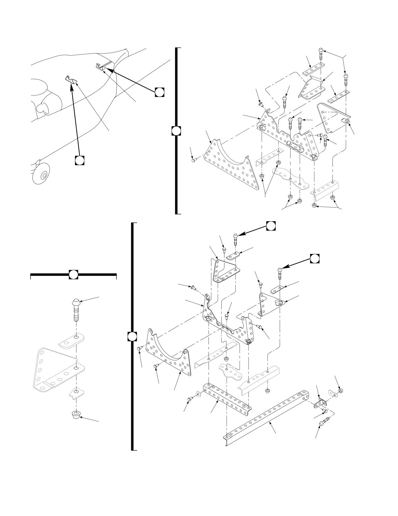
DMWR 1-1520-237
11
5
12
7
11
3
16
15
10
14
8
4
2
1
13
3
7
3
2
6
6
9
20
18
24
23
20
18
20
23
18
21
25
26
18
16
18
18
30
31
17
19
18
27
18
22
28
29
AB3104
SA
Figure E-9. Tail Rotor Drive Shaft Brackets Modification Kit
E-110
DMWR 1-1520-237
QTY
USABLE
FIGURE &
PER
ON
INDEX NO. PART NUMBER
1 2 3 4 5 6 7
DESCRIPTION
ASSY
CODE
E-9-
70070-20488-023
TAIL ROTOR DRIVE SHAFT BRACKETS
MODIFICATION KIT
REF
-1
70070-20488-012
M/K SUPPORT INSTL
1
-2
70070-20488-013
. SUPPORT INSTL
REF
-3
MS20470AD5-9
. RIVET,
37
-4
70361-03010-125
. SUPPORT
1
-5
HL22D-5-6
. HI-LOK PIN, (73197)
8
-6
HL77-5TW
. COLLAR, (73197)
10
-7
HL22D-5-3
. HI-LOK PIN, (73197)
2
-8
HL20PB-5-2
. HI-LOK PIN, (73197)
9
-9
HL1087A-5
. COLLAR, (73197)
1
-10
HL20PB-5-3
. HI-LOK PIN, (73197)
1
-11
SS1058A7-20-51
. RADIUS BLOCK
2
-12
70070-20488-102
. FORMER
1
-13
70070-20488-103
. FORMER
1
-14
70070-20488-101
. BRACKET
1
-15
70070-20488-022
M/K SUPT INSTL
1
-16
70070-20488-024
. SUPPORT INSTL (Reidentifed from 70219-
03006-011)
REF
70070-20488-025
. PLATING ASSY (Reidentified from 70213-
03001-043)
REF
70070-20488-026
. PLATING ASSY (Reidentified from 70213-
03001-044)
REF
70070-20488-027
. PLATING ASSY (Reidentified from 70213-
03001-045)
REF
70070-20488-028
. PLATING ASSY (Reidentified from 70213-
03001-046)
REF
-17
MS20470AD4-9
. RIVET
4
-18
MS20470AD5-9
. RIVET
86
-19
70219-03006-114
. SUPPORT
1
-20
HL20PB86-5-2
. PIN COLLAR ASSY, (73197)
8
-21
HL20PB-5-2
. . HI-LOK PIN, (73197)
1
-22
HL86-5
. . COLLAR, (73197) (Superseded By HL1087A-
5)
1
HL1087A-5
. . COLLAR, (73197)
1
-23
SS1058A7-28-29
. RADIUS BLOCK
2
-24
70070-20488-106
. GUSSET
1
-25
70070-20488-105
. GUSSET
1
-26
70070-20488-104
. BRACKET
1
-27
70219-03006-108
. ANGLE
1
-28
70212-03001-168
. STGR #0
1
-29
NAS1525-03
. SWAGE LOCKING PIN
2
-30
NAS1080D05
. COLLAR
2
-31
70212-03001-171
. CLIP
1
E-111
DMWR 1-1520-237
E-11. STATION 485 MODIFICATION KIT (50-34).
Subject: Transition Station 485.00; Modification of, dated 31 March 2003
Purpose: Provide instructions to remove and replace fitting at station 485.00.
Model:
UH-60A
Description: The following is a brief overview of the work required to modify station 485.00. Fitting is removed and
replaced, using new fasteners.
Drawings required for modification:
70000-03200, 70070-20575, 70211-03009, 70213-03001
References: (a) Special Service Instructions (SSI) No. 50-31, Installation of 9A to A9 Recapitalization Program, dated
March 31, 2003
Instructions:
NOTE
• A complete review of this SSI is recommended before reworking station 485.00.
• Before beginning this modification procedure, use the material information list to inventory the kit. Make
sure all parts are present and in serviceable condition.
• Where drawing numbers are not listed within individual steps, drawing(s) listed in preceding step(s) are
the controlling authority.
• The sheet metal and structural modifications in this SSI shall be done by personnel experienced in reading
modification drawings. Routine steps such as cleaning, layout and drilling, deburring, standard repairs,
corrosion control, clean up after rework, chemical coating for aluminum after cutting/trimming parts, paint
touch up, and safety practices may not be called out herein. However, these steps and all other required
routine tasks shall be done.
• When installing fasteners refer to drawing sheet and zones for applicable fasteners.
• Slight variations to the instructions contained herein are allowed, as long as the intent of the modification
is accomplished.
A.
Preparation for modification and removal of equipment:
(1)
Confirm that all warnings, cautions and notes are complied with per reference (a).
(2)
Perform preparation for modification per reference (a).
B.
Installation of new brackets at station 485.00:
(1)
Locate and remove fitting (70209-03007-125) at station 485.00 left side (Dwg 70211-03009, Sheet 1,
Zone 21-L).
(2)
Position new fitting (70209-03007-125) at station 485.00 and transfer drill holes from structure, through fit-
ting.
E-112
DMWR 1-1520-237
(3)
Remove fitting (70209-03007-125) deburr and touch up as required.
(4)
Install fitting (70209-03007-125) at station 485.00 using hardware shown (Dwg 70213-03001, Sheet 1,
Zone 23-F).
(5)
Line ream/drill 0.3125-inch diameter hole from backside fitting into new fitting (70209-03007-125).
(6)
Install remaining new hardware to fitting (70209-03007-125) (Dwg 70000-03200, Sheet 1, Zone 4-E, and
Note 1).
C.
Record of Compliance:
(1)
Make an apropriate logbook entry to show compliance with this Special Service Instruction.
Weight and Balance Data:
Negligible:
Manpower (Estimated)
No. of Personel
No. of Hours
Man-hours
Structural Mechanic
1
4.0
*4.0
*Does not include time required to prepare helicopter or return it to flight status.
Material Information:
A.
Modification Kit Required:
Qty
Nomenclature
Part Number
Source
1
Mod. Kit, Station 485.00
70070-20575-012
(1)
consisting of:
1
Washer
MS20002-5
1
Washer
MS20002C5
2
Rivet
MS20470AD5-4
4
Rivet
MS20470AD6-4
3
Rivet
NAS1097AD6-5
1
Pin, Swg Lkg
NAS1446-04
1
Bolt
NAS625-14
1
Nut
SS5081-05
1
Fitting
70209-03007-125
B.
Source:
(1)
Available through normal supply channels
E-113
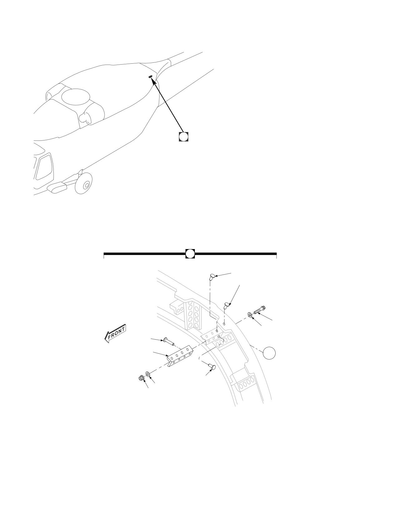
DMWR 1-1520-237
A
A
8
7
1
2
5
9
WL
255
6
3
4
AB3090
SA
Figure E-10. Station 485 Modification Kit
E-114
DMWR 1-1520-237
QTY
USABLE
FIGURE &
PER
ON
INDEX NO.
PART NUMBER
1 2 3 4 5 6 7
DESCRIPTION
ASSY
CODE
E-10-
70070-20575-012
STATION 485 MODIFICATION KIT
REF
-1
NAS625-14
. BOLT
1
-2
MS20002C5
. WASHER
1
-3
MS20002-5
. WASHER
1
-4
SS5081-05
. NUT
1
-5
NAS1446-04
. SWAGE LOCKING PIN
1
-6
MS20470AD6-4
. RIVET
4
-7
MS20470AD5-4
. RIVET
2
-8
NAS1097AD6-5
. RIVET
3
-9
70209-03007-125
. FITTING
1
E-115
DMWR 1-1520-237
E-12. LOWER AFT TRANSITION/FOAM LINER MODIFICATION KIT (50-6).
Subject: Lower Aft Transition Section, Rework of, dated 31 March 2003
Purpose: Provide instructions to rework lower aft transition section structure.
Model:
UH-60A
Description: The lower aft transition section structure is removed, corrosion treated, and new structure is installed.
Drawings Required for Modification:
70203-03003, 70211-03001, 70211-03002, 70211-03003, 70211-03004, 70211-03005, 70211-
03006, 70211-03007, 70211-03009, 70212-03002, 70212-03003, 70209-03012, 70209-03022, 70213-02501,
70213-03002, 70213-03004, 70070-20577, 70217-03001, 70219-03011
References: (a) Special Service Instructions (SSI) No. 50-31, Installation of 9A to A9 Recapitalization Program, dated
March 31, 2003
(b) SSI 50-26, Station 379.00 Frame, Modification of dated 31 March, 2003
Instructions:
NOTE
• A complete review of this directive is recommended before starting the installation of the lower aft transition
section modification.
• Before beginning this modification procedure, use the material information list to inventory the kit. Make
sure all parts are present and in serviceable condition.
• The sheet metal and structural modifications in this SSI shall be done by personnel experienced in reading
modification drawings. Routine steps such as cleaning, layout and drilling, deburring, standard repairs,
corrosion control, clean up after rework, chemical coating for aluminum after cutting/trimming parts, paint
touch up and safety practices may not be called out herein. However, these steps and all other required
routine tasks shall be done.
• Where drawing numbers are not listed within individual steps, drawing(s) listed in preceding step(s) are
the controlling authority.
• Slight variations to the instructions contained herein are allowed, as long as the intent of the modification
is accomplished.
• This modification must be done concurrently with reference (b).
A.
Preparation for modification and removal of equipment:
(1)
Confirm that all warnings, cautions, and notes are complied with per reference (a).
(2)
Perform preparation for modification per reference (a).
(3)
Support helicopter forward of station 379.00 with locally manufactured support.
(4)
Support helicopter aft of station 485.00 with locally manufactured support.
E-116
DMWR 1-1520-237
B.
Modification, lower aft transition section.
(1)
Remove lower aft transition section structure as follows:
(a)
Remove aft fuselage fuel sump and drain door assemblies (70217-03001-041 and 70217-03001-042 or
70217-03001-045 and 70217-03001-046) Keep serviceable parts for reuse (Dwg 70217-03001, Sheet 1, Zones 5-B,
5-C, and 6-E, Dwg 70070-20577, Sheet 5, Note 48).
(b)
Remove aft fuselage extended range fuel dump outlet cover (70209-03022-101) and scuppers (70209-
03022-101 and 70209-03022-103). Keep serviceable parts for reuse (Dwg 70209-03022, Sheet 1, Zones 11-E and
12-F).
(c)
Remove aft fuselage fuel vent assembly (70209-03012-041). Keep serviceable parts for reuse (Dwg
70209-03012, Sheet 1, Zone 11-E).
(d)
Remove aft fuselage foam, and scrap.
NOTE
The following airframe parts, when removed are kept for use as templates and then scraped.
(e)
Remove station 379.00 strap (70213-02501-126) (Dwg 70213-02501, Sheet 3, Zone 15-A).
(f)
Remove doubler (70213-03002-113) (Dwg 70213-03002, Sheet 3, Zone 16-B).
(g)
Remove aft fuselage antenna doubler (70203-03003-101) (Dwg 70203-03003, Sheet 1, Zone 12-C).
NOTE
The following steps are done to aid in removing skins.
(h)
Remove rivets from left and right buttlines 30.00 through buttlines 40.00, station 379.00 through station
485.00 and roll skins back as necessary.
(i)
Remove rivets from station 379.00 forward, between buttlines 30.00, and roll skins back.
(j)
Remove station 379.00 through station 443.50 left and right side skins (70213-03002-116, 70213-
03002-117, and 70213-03002-118) (Dwg 70213-03002, Sheet 1, Zone 15-A, Sheet 3, Zone 11-B).
(k)
Remove doubler (70213-03004-101) and bracket angles (SS1083-147, SS1083-192, and SS1083-237)
(Dwg 70213-03004, Sheet 1, Zones 8-E, 7-F, 7-G, and 7-H).
(l)
Remove station 443.50 through station 485.00 left and right side skins (70213-03002-107, 70213-
03002-108, and 70213-03002-119) (Dwg 70213-03002, Sheet 1, Zone 10-B, and Sheet 3, Zone 8-B).
(m)
Remove left and right side No. 19 stringers (70212-03002-117 and 70212-03002-118) at station
379.00, station 398.00, station 416.60, station 424.90, and station 443.50 frames (Dwgs 70070-20577, Sheet 5,
Zones 15-G and 15-C, 70212-03002, Sheet 2, Zones 4-F through 17-F, and Sheet 1, Section A-A, Zone 11-L).
(n)
Remove left and right side No. 20 stringers (70212-03002-113 and 70212-03002-114) at station
379.00, station 398.00, station 416.60, station 424.90, and station 443.50 frames (Dwg 70070-20577, Sheet 5,
Zones 15-F and 15-C, Dwg 70212-03002, Sheet 2, Zones 4-N through 17-, and Sheet 1, Section A-A, Zone 11-L).
E-117
DMWR 1-1520-237
(o)
Remove left and right side No. 22 stringers (70212-03002-103, 70212-03002-104, 70212-03002-
105, 70212-03002-106) at station 379.00, station 398.00, station 416.60, station 424.90, and station 443.50 frames
(Dwg 70070-20577, Sheet 5, Zones 15-E, 15-D, 14-H, and 14-B, Dwg 70212-03002, Sheet 1, Zones 6-P through 13-P
and 15-P through 19-P, Section A-A, Zone 11-L).
(p)
Remove No. 23 stringer (70212-03002-111) at station 379.00 through station 416.50 (Dwg 70070-
20577, Sheet 5, Zone 15-D, Dwg 70212-03002, Sheet 2, Zones 6-E through 10-F).
(q)
Remove aft fuselage left and right side beam assemblies (70212-03003-041, 70212-03003-042,
70212-03003-043, and 70212-03003-044) and angle splices (70212-03003-131 and 70212-03003-132), station
379.00 through station 443.50, buttline 10.00 (Dwg 70070-20577, Sheet 6, Zones 15-E and 15-D, Dwg 70212-
03003, Sheet 1, Zones 15-E, 22-L, and 24-E).
(r)
Remove aft fuselage left and right side beam assemblies (70212-03003-048, 70212-03003-049, 70212-
03003-047, and 70212-03003-050), cap angles (70212-03003-115 and 70212-03003-116), and splice angles
(70212-03003-141 and 70212-03003-142), station 379.00 through station 443.50, buttline 30.00 (Dwg 70070-
20577, Sheet 6, Zones 15-C and 15-G, Dwg 70212-03003, Sheet 2, Zones 10-H, 15-G, 15-D, and 15-L).
(s)
Remove station 398.00 shear angle (70211-03002-101) (Dwg 70211-03002, Sheet 1, Zone 15-B).
(t)
Remove station 408.30 intercostals (70211-03003-101, 70211-03003-102, 70211-03003-103, and
70211-03003-104), angles (70211-03003-114 and 70211-03003-115), and gussets (70211-03003-116, 70211-
03003-117, and 70211-03003-118) (Dwg 70211-03003, Sheet 1, Zones 12-A, 14-A, 14-D, 13-D, and 9-D).
(u)
Remove station 416.60 intercostals (70211-03004-101, 70211-03004-102, 70211-03004-105, and
70211-03004-106), stiffeners (70211-03004-103, 70211-03004-104, 70211-03004-107, and 70211-03004-108),
angles (70211-03004-117, 70211-03004-118, 70211-03004-119, 70211-03004-120, 70211-03004-121, 70211-
03004-122, 70211-03004-126, and 70211-03004-127), between left and right side buttlines 29.97 (Dwg 70211-
03004, Sheet 1, Views C-C and F-F, Zones 10-A through 21-D, 13-D, and 9-E).
(v)
Remove station 424.90 intercostals (70211-03005-101, 70211-03005-102, 70211-03004-103, and
70211-03004-104) and angles (70211-03005-115, 70211-03005-116, 70211-03005-117, and 70211-03005-118,
70211-03005-120, 70211-03005-121, 70211-03004-117, 70211-03004-118, 70211-03004-119, and 70211-
03004-120), between left and right side buttlines 29.99 (Dwg 70211-03005, Sheet 1, Views A-A and B-B, Zones 10-A,
11-A, 12-B, 14-D, 9-F, 17-D, and 22-D).
(w)
Remove station 433.20 frames (70211-03006-101, 70211-03006-102, 70211-03006-103, and
70211-03006-104), gussets (70211-03006-114), and angles (70211-03006-115 and 70211-03006-0116) between
left and right side buttlines 30.00 (Dwg 70211-03006, Sheet 1, Zones 10-A through 22-D).
(x)
Remove station 443.50 shear angle (70211-03007-185) (Dwg 70211-03007, Sheet 1, Zone 14-B).
(y)
Remove No. 22 stringers (70212-03002-107 and 70212-03002-108) between station 464.00 and sta-
tion 485.00 (Dwg 70070-20577, Sheet 5. Zones 9-E and 9-F).
(z)
Remove stringers (70212-03002-124 and 70212-03002-123) between station 464.00 and 485.00
(Sheet 5, Zones 11-E and 9-E).
(aa)
Remove No. 20 stringers (70212-03002-115 and 70212-03002-116) at station 443.50, 464.00, and
station 485.00 (Dwg 70070-20577, Sheet 5, Zones 10-C and 10-F, 70212-03002, Sheet 1, Section A-A, Zone 11-L).
(ab)
Remove No. 17 stringers (70212-03002-109 and 70212-03002-110) at station 443.50, station
464.00, and station 485.00 (Dwg 70070-20577, Sheet 5, Zones 11-B and 10-G, Dwg 70212-03002, Sheet 1, Section
A-A, Zone 11-L).
E-118
DMWR 1-1520-237
(ac)
Remove buttline 10.00 stringers (70212-03002-119 and 70212-03002-120) at station 443.50, station
464.00, and station 485.00 (Dwgs 70070-20577, Sheet 5, Zones 9-D and 9-F, 70212-03002, Sheet 1, Section A-A,
Zone 11-L).
(2)
Install lower aft transition section structure as follows:
(a)
Inspect lower aft transition section structure for corrosion and repair damaged areas (Dwg 70070-20577,
Sheet 5, Note 48).
(b)
Install station 398.00 shear angle (70211-03002-101) (Dwg 70070-20577, Sheet 6, Zone 16-F, Note
43).
(c)
Install station 408.30 intercostals (70211-03003-101, 70211-03003-102, 70211-03003-103, and
70211-03003-104), angles (70211-03003-114 and 70211-03003-115), and gussets (70211-03003-116, 70211-
03003-117, and 70211-03003-118) (Sheet 6, Zone 14-B, Note 40).
(d)
Install station 416.60 intercostals (70211-03004-101, 70211-03004-102, 70211-03004-103, 70211-
03004-104, 70211-03004-105, and 70211-03004-106), stiffeners (70211-03004-107 and 70211-03004-108), and
angles (70211-03004-117, 70211-03004-118, 70211-03004-119, 70211-03004-120, 70211-03004-121, 70211-
03004-122, 70211-03004-126, and 70211-03004-127) (Sheet 6, Zone 12-B, Note 39).
(e)
Install station 424.90 intercostals (70211-03005-101, 70211-03005-102, 70211-03005-103, and
70211-03005-104) and angles (70211-03005-115. 70211-03005-116, 70211-03005-117, 70211-03005-118,
70211-03005-120, 70211-03005-121, 70211-03004-117, 70211-03004-118, 70211-03004-119, and 70211-
03004-120) (Sheet 6, Zone 12-H, Note 36).
(f)
Install station 433.20 frames (70211-03006-101, 70211-03006-102, 70211-03006-103, and 70211-
03006-104), gussets (70211-03006-114), and angles (70211-03006-115 and 70211-03006-116) (Sheet 6, Zone 11-
G, Note 37).
(g)
Install station 443.50 shear angle (70211-03007-185) (Sheet 6, Zone 11-B, Note 38).
NOTE
• In the following step, beam assemblies (70212-03003-554 and 70212-03003-544) are installed in place
of (70212-03003-054 and 70212-03003-044). The splice angles (70212-03003-132 and 70212-
03003-131) are preinstalled on (70212-03003-054 and 70212-03003-044) creating (70212-03003-
554 and 70212-03003-544).
• After installation is completed the (70212-03003-554 and 70212-03003-544) are reidentified to
(70212-03003-054 and 70212-03003-044).
(h)
Install aft fuselage left and right side beam assemblies (70212-03003-041, 70212-03003-554, 70212-
03003-042, and 70212-03003-544) between station 379.00 and station 443.50, buttline 10.00 (Dwgs 70212-03003,
Sheet 1, Zones 24-F, 24-G, and 22-L, Dwg 70211-03007, Sheet 1, Section A-A, Zone 9-A).
NOTE
• In the following step, beam assemblies (70212-03003-555 and 70212-03003-548) are installed in place
of (70212-03003-055 and 70212-03003-048). The splice angles (70212-03003-142 and 70212-
03003-141) are preinstalled on (70212-03003-055 and 70212-03003-048) creating (70212-03003-
555 and 70212-03003-548).
E-119
DMWR 1-1520-237
• After installation is completed the (70212-03003-555 and 70212-03003-548) are reidentified to
(70212-03003-055 and 70212-03003-048).
(i)
Install aft fuselage left and right side beam assemblies (70070-20577-041, 70212-03003-555, 70212-
03003-548, and 70070-20577-042) and cap angles (70212-03003-115 and 70212-03003-116) between station
379.00 and station 443.50, buttline 30.00 (Dwg 70212-03003, Sheet 2, Zone 15-D, 15-L, 18-E, and 18-F, Dwg
70211-03007, Sheet 1, Zone 11-C through 11-E).
(j)
Install No. 23 stringer (70212-03002-111) between station 379.00 and station 398.00, buttline 0.00
(Dwg 70213-03002, Sheet 3, Zone 17-C, Dwg 70211-03001, Sheet 1, Section R-R, Zone 8-F, Dwg 70212-03002,
Sheet 1, Zone 6-F).
(k)
Install left and right side No. 22 stringers (70212-03002-103 and 70212-03002-104) between station
379.00 and station 416.60, buttline 5.00 (Dwg 70213-03002, Sheet 3, Zone 17-C and Dwg 70212-03002, Sheet 1,
Section A-A, Zones 11-L and 13-N).
(l)
Install left and right side No. 20 stringers (70212-03002-113 and 70212-03002-114) between station
379.00 and station 443.50, buttline 16.70 (Dwg 70213-03002, Sheet 3, Zone 17-E, Dwg 70211-03001, Sheet 1, Sec-
tion S-S, Zone 5-H, Dwg 70211-03007, Sheet 1, Section B-B, Zone 7-A, Dwg 70212-03002, Sheet 1, Section A-A,
Zone 11-L).
(m)
Install left and right side No. 19 stringers (70212-03002-117 and 70212-03002-118) between station
379.00 and station 443.50, buttline 23.70 (Dwg 70213-03002, Sheet 3, Zone 17-F, Dwg 70211-03007, Sheet 1, Sec-
tion AB-AB, Dwg 70212-03002, Sheet 1, Section A-A, Zone 11-L).
(n)
Install left and right side No. 22 stringers (70212-03002-105 and 70212-03002-106) between station
424.90 and station 443.50, buttline 5.00 (Dwg 70213-03002, Sheet 3, Zone 10-A, Dwg 70212-03002, Sheet 1, Sec-
tion A-A, Zones 11-L and 15-J).
(o)
Install position No. 22 stringers (70212-03002-107 and 70212-03002-108) between station 464.00
and station 485.00 (Dwg 70213-03002, Sheet 3, Zone 7-B, Dwg 70211-03009, Sheet 1, Section R-R, Zone 8-J).
(p)
Install buttline 10.00 stringers (70212-03003-119 and 70212-03003-120) at station 443.50, station
464.00, and station 485.00 (Dwg 70213-03002, Sheet 1, Zone 6-G, Dwg 70211-03007, Sheet 1, Section A-A, Zone
8-A, Dwg 70211-03009, Sheet 1, Section F-F, Zone 4-J, Dwg 70212-03002, Sheet 1, Section A-A, Zone 11-L).
(q)
Install stringer (70212-03002-123) forward of station 485.00, buttline 0.00 (Dwg 70213-03002, Sheet
3, Zone 7-B, Dwg 70211-03009, Sheet 1, Section S-S, Zone 9-B).
(r)
Install stringer (70212-03002-124) aft of station 464.00 (Dwg 70213-03002, Sheet 3, Zones 8-A, Note
16).
NOTE
The nutplates for the IFF antenna are installed after the skins and structure are urethane coated.
(s)
Install IFF antenna doubler (70213-03004-101) with angles (SS1083-147, SS1083-192, and SS1083-
237) (Dwg 70070-20577, Sheet 9-D and Sheet 2, Note 18).
(t)
Install No. 20 stringers (70213-03002-115 and 70213-03002-116) at station 443.50, station 464.00,
and station 485.00 (Dwg 70213-03002, Sheet 1, Zone 7-F, Dwg 70211-03007, Sheet 1, Section B-B, Zone 7-A, Dwg
70211-03009, Sheet 1, Section P-P, Zone 9-L, Dwg 70212-03002, Sheet 1, Section A-A, Zone 11-L).
E-120
DMWR 1-1520-237
(u)
Install No. 19 stringers (70212-03003-125 and 70212-03003-126) at station 443.50, station 464.00,
and station 485.00, buttline 10.00 (Dwg 70213-03002, Sheet 3, Zone 8-G, Zone 10-B, and Dwg 70211-03009, Sheet
1, Section N-N, Zone 14-D, Dwg 70212-03002, Sheet 1, Section A-A, Zone 11-L).
(v)
Install No. 17 stringers (70212-03002-109 and 70212-03002-110), at station 443.50, station 464.00,
and 485.00, buttline 30.00 (Dwg 70213-03002, Sheet 1, Zone 8-H, Dwg 70211-03007, Sheet 1, Section F-F, and Dwg
70211-03009, Sheet 1, Section M-M, Zone 7-L, Dwg 70212-03002, Sheet 1, Section A-A, Zone 11-L).
(w)
Position skins (70213-03002-107, 70213-03002-119, 70213-03002-108), from station 443.50
through station 485.00. Transfer drill fastener holes from structure and doublers through skins (Dwg 70070-20577,
Sheet 5, Zones 10-B, 9-D, and 10-F, Dwg 70213-03002, Sheet 1, Zone 10-B, Sheet 3, Zone 8-B).
(x)
Position skin (70070-20577-103) and transfer hole cutout from doubler (70213-03004-101) installed in
step (s) on page 6 (Dwg 70070-20577, Sheet 5, Zone 9-D, Notes 19, 32 and 57).
(y)
Transfer drill nutplate holes from IFF antenna doubler through skin.
(z)
Position skins (70213-03002-117, 70213-03002-118, 70213-03002-116), from station 379.00
through station 443.50. Transfer drill fastener holes from structure and doublers through skins (Dwg 70070-20577,
Sheet 5, Zones 16-F and 16-C, Dwg 70213-03002, Sheet 1, Zone 15-A, Sheet 3, Zone 11-B).
NOTE
The antenna mount doubler nutplates are installed after the skins and structure are urethane coated.
(aa)
Position antenna mount doubler (70203-03003-101) on skin at station 443.50 through station 464.00.
Drill fastener and nutplate holes (Dwg 70070-20577, Sheet 5, Zone 10-C, Dwg 70203-03003, Sheet 1, Zone 13-C).
(ab)
Position serviceable aft fuselage fuel vent assembly (70209-03012-041), kept for reuse, into skin cutout
between station 443.50 and station 450.00, left buttline 20.00. Drill fastener holes (Dwg 70209-03012, Sheet 1, Zone
11-E).
(ac)
Position serviceable aft fuselage extended range fuel dump outlet scuppers (70209-03022101 and
70209-03022-103) and cover (70209-03022-102), kept for reuse, into skin cutout between station 443.50 and station
450.00, right buttline 20.00. Drill fastener holes (Dwg 70209-03022, Sheet 1, Zone 12-D).
(ad)
Position new fuel sump drain doublers (70217-03001-111) and doors (70217-03001-041 and 70217-
03001-042 or 70217-03001-045 and 70217-03001-045 and 70217-03001-046), into skin cutouts, between station
416.60 and station 424.90, between left and right side buttlines 3.00 and 10.00. Drill fastener holes (Dwg 70217-
03001, Sheet 1, Zones 4-B and 6-E).
(ae)
Drill stud receptacle holes from doublers (70217-03001-111) through skin.
(af)
Position doubler (70213-03002-113) on skin between station 385.00 and station 393.00, buttline 0.00
and left side buttline 5.00. Drill fastener holes (Dwg 70213-03002, Sheet 3, Zone 16-A).
(ag)
Drill eight nutplate holes in skin (Sheet 3, Detail B, Zone 5-H).
(ah)
Position strap (70213-02501-126) on skins, station 379.00. Drill fastener holes (Dwg 70213-02501,
Sheet 3, Detail H, Zone 15-A).
(ai)
Drill 40 0.320-inch diameter drain holes in skins (Dwg 70070-20577, Sheet 5, Zone 14-E, Note 32).
(aj)
Remove doublers, scuppers, doors, fuel vent, strap, and skins.
E-121
DMWR 1-1520-237
NOTE
• The receptacles used in the following step are for the fuel sump assemblies (70217-03001-045 and
70217-03001-046) only.
• In the next two steps, do not install fasteners that are used to secure doublers, scuppers, doors, fuel vent,
and strap.
(ak)
Install receptacles (212-12) and nutplates (MS21075-3 and MS21059-3) with fasteners shown on IFF
antenna doubler, station 443.50 through station 464.00 antenna mount, fuel dump outlet, fuel sump drain, and station
389.00 antenna mount (Dwg 70213-03004, Sheet 1, Zone 7-G, Dwg 70203-03003, Sheet 1, Zone 11-B, Dwg 70217-
03001, Sheet 1, Zone 3-E, Dwg 70213-03002, Sheet 3, Zone 17-A).
WARNING
OBSERVE ALL CAUTIONS AND WARNINGS ON CONTAINERS WHEN USING CONSUMABLES.
WHEN APPLICABLE, WEAR NECESSARY PROTECTIVE GEAR DURING HANDLING AND USE. IF A
CONSUMABLE IS FLAMMABLE OR EXPLOSIVE, MAKE CERTAIN CONSUMABLE AND ITS VAPORS ARE
KEPT AWAY FROM HEAT, SPARK, AND FLAME. MAKE CERTAIN EQUIPMENT IS PROPERLY
GROUNDED AND FIREFIGHTING EQUIPMENT IS READILY AVAILABLE PRIOR TO USE. FOR AD-
DITIONAL INFORMATION ON TOXICITY, FLASHPOINT, AND FLAMMABILITY OF CHEMICALS,
CONSULT YOUR MEDICAL PEOPLE, OR MANUFACTURER OF THE CONSUMABLE.
(al)
Touch up skins and structure with epoxy primer ( MIL-P-85582 or equivalent), urethane (MIL-C-85285 or
equivalent), and corrosion preventive compound, (Dinotrol AV30 or AV15 or equivalent) (Dwg 70070-20577, Sheet 5,
Note 47).
WARNING
OBSERVE ALL CAUTIONS AND WARNINGS ON CONTAINERS WHEN USING CONSUMABLES.
WHEN APPLICABLE, WEAR NECESSARY PROTECTIVE GEAR DURING HANDLING AND USE. IF A
CONSUMABLE IS FLAMMABLE OR EXPLOSIVE, MAKE CERTAIN CONSUMABLE AND ITS VAPORS ARE
KEPT AWAY FROM HEAT, SPARK, AND FLAME. MAKE CERTAIN EQUIPMENT IS PROPERLY
GROUNDED AND FIREFIGHTING EQUIPMENT IS READILY AVAILABLE PRIOR TO USE. FOR AD-
DITIONAL INFORMATION ON TOXICITY, FLASHPOINT, AND FLAMMABILITY OF CHEMICALS,
CONSULT YOUR MEDICAL PEOPLE, OR MANUFACTURER OF THE CONSUMABLE.
NOTE
The side skins that were loosened to remove the bottom skin are reattached when the bottom skins are
installed.
(am)
Install skins with fasteners wet with sealant (AMS 3265, Class A or Class C or equivalent) between sta-
tion 443.50 and station 485.00 using drawing cross hatch sections (Dwg 70213-03002, Sheet 5, Zones 5-C through 3-E
and 14-H through 12-F, Dwg 70203-03003, Sheet 2, Dwg 70070-20577, Sheet 5, Note 10, 11, 21, 12, 13, 14, 15,
19, 17, and 47).
(an)
Install skins with fasteners wet with sealant (AMS 3265, Class A or Class C or equivalent) between station
379.00 and station 443.50 using drawing cross hatch sections (Dwg 70213-03002, Sheet 5, Zones 8-B through 5-E and
17-I through 14-F, Dwg 70217-03001, Sheet 2, Dwg 70070-20577, Sheet 5, Note 23, 24, 25, 26, 27, 28, and 47).
E-122
DMWR 1-1520-237
(ao)
Install doublers, scuppers, doors, fuel vent, strap with sealant (AMS 3265, Class A or Class C or
equivalent) using cross hatch sections (Dwg 70203-03003, Sheet 2, Dwg 70217-03001, Sheet 2, Dwg 70213-02501,
Sheet 5, Section AE-AE, Zone 6-B, Dwg 70070-20577, Sheet 5, Note 47).
(ap)
Bond foam blocks (70219-03001-123 through 70219-03011-144) to structure with adhesive, (444R)
(Dwg 70219-03011, Sheet 1 Note 3).
NOTE
There are no reidentification of structure assemblies or installations created by this modification.
C.
Reinstallation of removed equipment:
(1)
Install removed equipment per reference (a).
D.
Record of Compliance:
(1)
Make an appropriate logbook entry to show compliance with this Special Service Instruction.
Weight and Balance Data:
POUNDS
INCHES AFT
MOMENT/
QTY
PART NO.
NOMENCLATURE
WEIGHT
OF DATUM
1000
1
70070-20577-011
Lwr. Aft
Negligible
409.4
0.0
Weight and Balance: Change resulting from these instructions are as follows:
Change in basic weight: Negligible
Moment arm:
409.4
Change in basic moment/1000:
0.0
Manpower (Estimated)
No. of Personel
No. of Hours
Man-hours
Helicopter Structural Mechanic
2
240.0
*480.0
*Does not include time required to prepare helicopter or return it to flight status.
E-123
DMWR 1-1520-237
Material Information:
A.
Modification Kit Required:
Qty
Nomenclature
Part Number
Source
1
Mod. Kit, Lower Aft Transition,
70070-20577-011
(1)
consisting of:
1
Mod. Kit, Lower Aft Trans,
70070-20577-012
consisting of:
1
Stringer 22
70212-03002-103
1
Stringer 22
70212-03002-104
1
Stringer 22
70212-03002-105
1
Stringer 22
70212-03002-106
1
Stringer 22
70212-03002-107
1
Stringer 22
70212-03002-108
1
Stringer 17
70212-03002-109
1
Stringer 17
70212-03002-110
1
Stringer 23
70212-03002-111
1
Stringer
70212-03002-113
1
Stringer
70212-03002-114
1
Stringer 20
70212-03002-115
1
Stringer 20
70212-03002-116
1
Stringer 19
70212-03002-117
1
Stringer 19
70212-03002-118
1
Stringer
70212-03002-125
1
Stringer
70212-03002-126
1
Stringer
70212-03002-123
1
Stringer
70212-03002-124
1
Strap
70213-02501-126
1
Shear Angle
70211-03002-101
1
Skin
70213-03002-107
1
Skin
70213-03002-108
1
Doubler
70213-03002-113
1
Skin
70213-03002-116
1
Skin
70213-03002-117
1
Skin
70213-03002-118
1
Skin
70070-20577-103
1
Doubler
70213-03004-101
1
Doubler
70203-03003-101
2
Bracket Angle
SS1083-147
2
Bracket Angle
SS1083-192
2
Bracket Angle
SS1083-237
E-124
DMWR 1-1520-237
Qty
Nomenclature
Part Number
Source
1
Mod. Kit,
70070-20577-013
consisting of:
1
Beam Assy
70070-20577-041
1
Beam Assy
70070-20577-042
1
Intercostal
70211-03003-101
1
Intercostal
70211-03003-102
1
Intercostal
70211-03003-103
1
Intercostal
70211-03003-104
1
Angle
70211-03003-114
1
Angle
70211-03003-115
2
Gusset
70211-03003-116
1
Gusset
70211-03003-117
1
Gusset
70211-03003-118
1
Intercostal
70211-03004-101
1
Intercostal
70211-03004-102
1
Stiffener
70211-03004-103
1
Stiffener
70211-03003-104
1
Intercostal
70211-03004-105
1
Intercostal
70211-03004-106
2
Stiffener
70211-03004-107
2
Stiffener
70211-03004-108
4
Angle
70211-03004-117
4
Angle
70211-03004-118
4
Angle
70211-03004-119
4
Angle
70211-03004-120
2
Angle
70211-03004-121
2
Angle
70211-03004-122
1
Angle
70211-03004-126
1
Angle
70211-03004-127
1
Intercostal
70211-03005-101
1
Intercostal
70211-03005-102
1
Intercostal
70211-03005-103
1
Intercostal
70211-03005-104
1
Angle
70211-03005-115
1
Angle
70211-03005-116
2
Angle
70211-03005-117
2
Angle
70211-03005-118
1
Angle
70211-03005-120
1
Angle
70211-03005-121
1
Frame
70211-03006-101
1
Frame
70211-03006-102
1
Frame
70211-03006-103
1
Frame
70211-03006-104
4
Gusset
70211-03006-114
1
Angle
70211-03006-115
1
Angle
70211-03006-116
1
Shear Angle
70211-03007-185
E-125
DMWR 1-1520-237
Qty
Nomenclature
Part Number
Source
1
Beam Assy
70212-03003-041
1
Beam Assy
70212-03003-042
$1
Beam Assy
70212-03003-544
$1
Beam Assy
70212-03003-548
1
Beam Assy
70212-03003-041
1
Beam Assy
70212-03003-042
$1
Beam Assy
70212-03003-554
$1
Beam Assy
70212-03003-555
1
Angle Cap
70212-03003-115
1
Angle Cap
70212-03003-116
1
Stringer BL10
70212-03003-119
1
Stringer BL10
70212-03003-120
&Ref
Angle Splice
70212-03003-131
&Ref
Angle Splice
70212-03003-132
&Ref
Angle Splice
70212-03003-141
&Ref
Angle Splice
70212-03003-142
1
Mod. Kit,
70070-20577-014
consisting of:
8
Bolt
AN173-14A
12
Bolt
AN173-15A
5
Pin Collar Assy
HL20PB86-6-10
5
Pin Collar Assy
HL20PB86-6-8
10
Pin Collar Assy
HL20PB86-6-9
18
Collar
HL86TW-6
14
Rivet
MS20426AD3-2
45
Rivet
MS20426AD3-4
10
Rivet
MS20426AD5-2
26
Rivet
MS20470AD4-2
1000
Rivet
MS20470AD5-2
1385
Rivet
MS20470AD5-3
400
Rivet
MS20470AD5-4
125
Rivet
MS20470AD5-5
22
Rivet
MS20470AD6-2
380
Rivet
MS20470AD6-3
65
Rivet
MS20470AD6-4
58
Rivet
MS20470AD6-5
18
Nut
MS21044N3
22
Nutplate
MS21059-3
16
Nutplate
MS21075-3
170
Collar
NAS1080C06
30
Rivet
NAS1097AD4-3
140
Rivet
NAS1097AD5-4
35
Washer Flat
NAS1149F0332P
14
Pin, Swg Lkg
NAS1436-03
46
Pin, Swg Lkg
NAS1446-03
28
Pin, Swg Lkg
NAS1446-04
26
Pin, Swg Lkg
NAS1446-05
E-126
DMWR 1-1520-237
Qty
Nomenclature
Part Number
Source
10
Pin, Swg Lkg
NAS1465-04
14
Pin, Swg Lkg
NAS1526-05
14
Pin, Swg Lkg
NAS1526-06
14
Pin, Swg Lkg
NAS1526-07
50
Rivet
RA097AD4-2
75
Rivet
RA097AD6-3
1
Mod. Kit,
70070-20577-015
consisting of:
1
Foam Liner Kit,
70219-03011A012
made up of:
4
Foam Liner
70219-03011-123
4
Foam Liner
70219-03011-124
4
Foam Liner
70219-03011-125
4
Foam Liner
70219-03011-126
4
Foam Liner
70219-03011-127
2
Foam Liner
70219-03011-128
2
Foam Liner
70219-03011-129
2
Foam Liner
70219-03011-130
1
Foam Liner
70219-03011-131
1
Foam Liner
70219-03011-132
1
Foam Liner
70219-03011-133
8
Foam Liner
70219-03011-134
8
Foam Liner
70219-03011-135
2
Foam Liner
70219-03011-136
4
Foam Liner
70219-03011-137
4
Foam Liner
70219-03011-138
3
Foam Liner
70219-03011-139
3
Foam Liner
70219-03011-140
1
Foam Liner
70219-03011-141
1
Foam Liner
70219-03011-142
1
Foam Liner
70219-03011-143
2
Foam Liner
70219-03011-144
1
Mod. Kit,
70070-20577-016
consisting of:
2
Doubler
70217-03001-111
77
Rivet
MS20470AD5-9
5
Rivet
NAS1097AD3-9
37
Rivet
NAS1097AD5-9
2
Receptacle
212-12
1
Mod. Kit,
70070-20577-017
consisting of:
10
Rivet
MS20470AD3-9
E-127
DMWR 1-1520-237
Qty
Nomenclature
Part Number
Source
60
Rivet
MS20470AD5-9
4
Nutplate
MS21075-3
4
Screw
MS27039-1-10
5
Rivet
NAS1097AD4-9
5
Rivet, Blind
NAS1739B4-2
2
Rivet, Blind
NAS1739B5-2
30
Rivet, Blind
NAS1739B5-3
$ Beam assemblies (70212-03003-544, 70212-03003-548, 70212-03003-554, and 70212-03003-555) are supplied
in place of (70212-03003-044, 70212-03003-048, 70212-03003-054, and 70212-03003-055).
& Angle splices (70212-03003-131, 70212-03003-132, 70212-03003-141, and 70212-03003-142) are not used.
They are preassembled onto the above mentioned beam assemblies.
B.
Consumable Material:
WARNING
OBSERVE ALL CAUTIONS AND WARNINGS ON CONTAINERS WHEN USING CONSUMABLES.
WHEN APPLICABLE, WEAR NECESSARY PROTECTIVE GEAR DURING HANDLING AND USE. IF A
CONSUMABLE IS FLAMMABLE OR EXPLOSIVE, MAKE CERTAIN CONSUMABLE AND ITS VAPORS ARE
KEPT AWAY FROM HEAT, SPARK, AND FLAME. MAKE CERTAIN EQUIPMENT IS PROPERLY
GROUNDED AND FIREFIGHTING EQUIPMENT IS READILY AVAILABLE PRIOR TO USE. FOR AD-
DITIONAL INFORMATION ON TOXICITY, FLASHPOINT, AND FLAMMABILITY OF CHEMICALS,
CONSULT YOUR MEDICAL PEOPLE, OR MANUFACTURER OF THE CONSUMABLE.
Qty
Nomenclature
Part Number
Source
8 oz.
Sealant
AMS 3265, Class A or C or
(1)
equivalent
8 oz.
Corrosion Preventive Compound
Dinotrol Av30 or Av15 or
(1)
equivalent
8 oz.
Primer, Epoxy
MIL-P-85582 or equivalent
(1)
8 oz.
Urethane
MIL-C-85285 or equivalent
(1)
8 oz.
Adhesive
444R or equivalent
(1)
C.
Support Equipment:
Qty
Nomenclature
Part Number
Source
1
Locally designed and
N/A
(2)
manufactured fuselage supports
D.
Source
(1)
Available through normal supply channels.
(2)
Locally fabricated
E-128
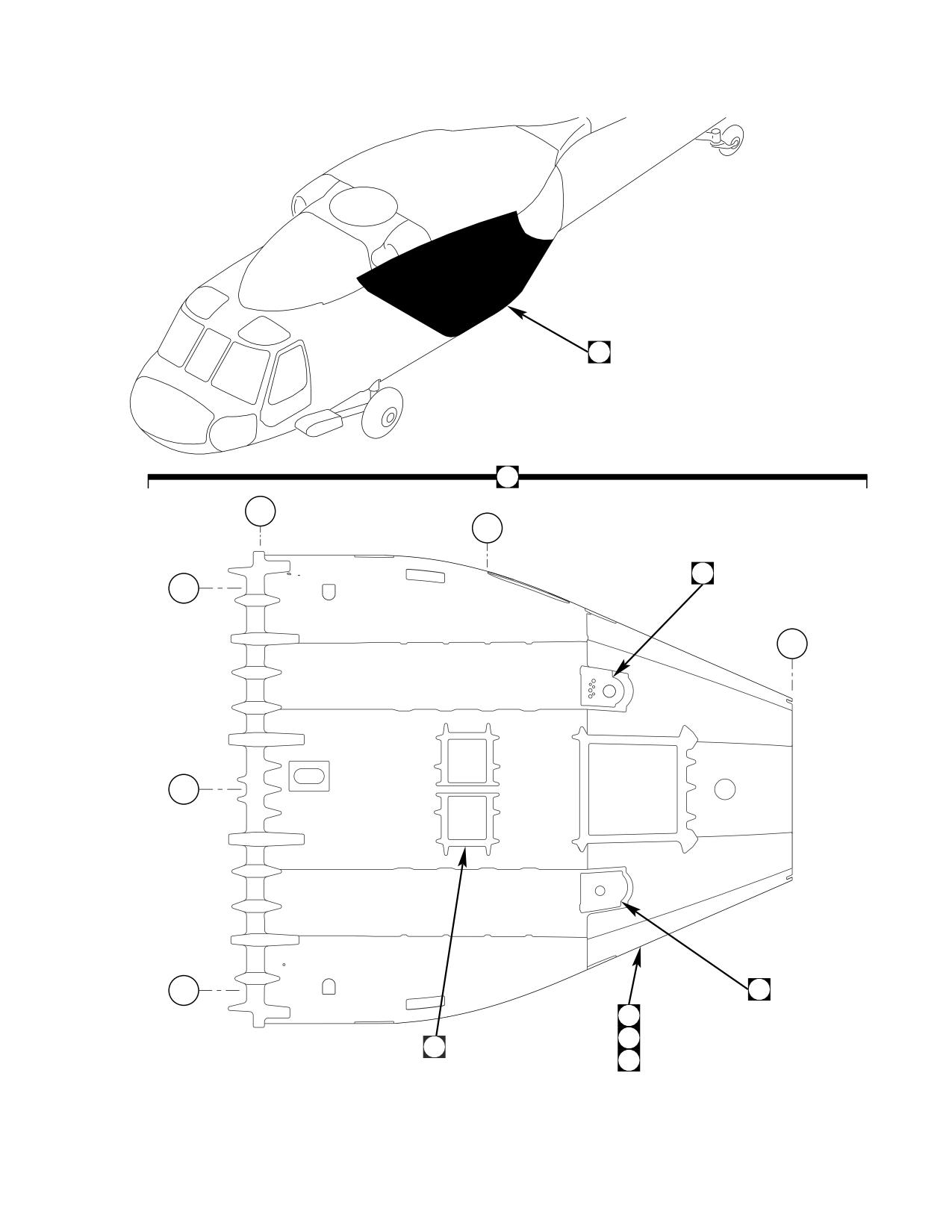
DMWR 1-1520-237
A
A
STA
379
STA
424.9
14
BL
40
LH
STA
485
BL
0.0
BL
40
7
RH
16
58
1
82
AB3095_1
SA
Figure E-11. Lower Aft Transition Modification Kit (Sheet 1 of 8)
E-129
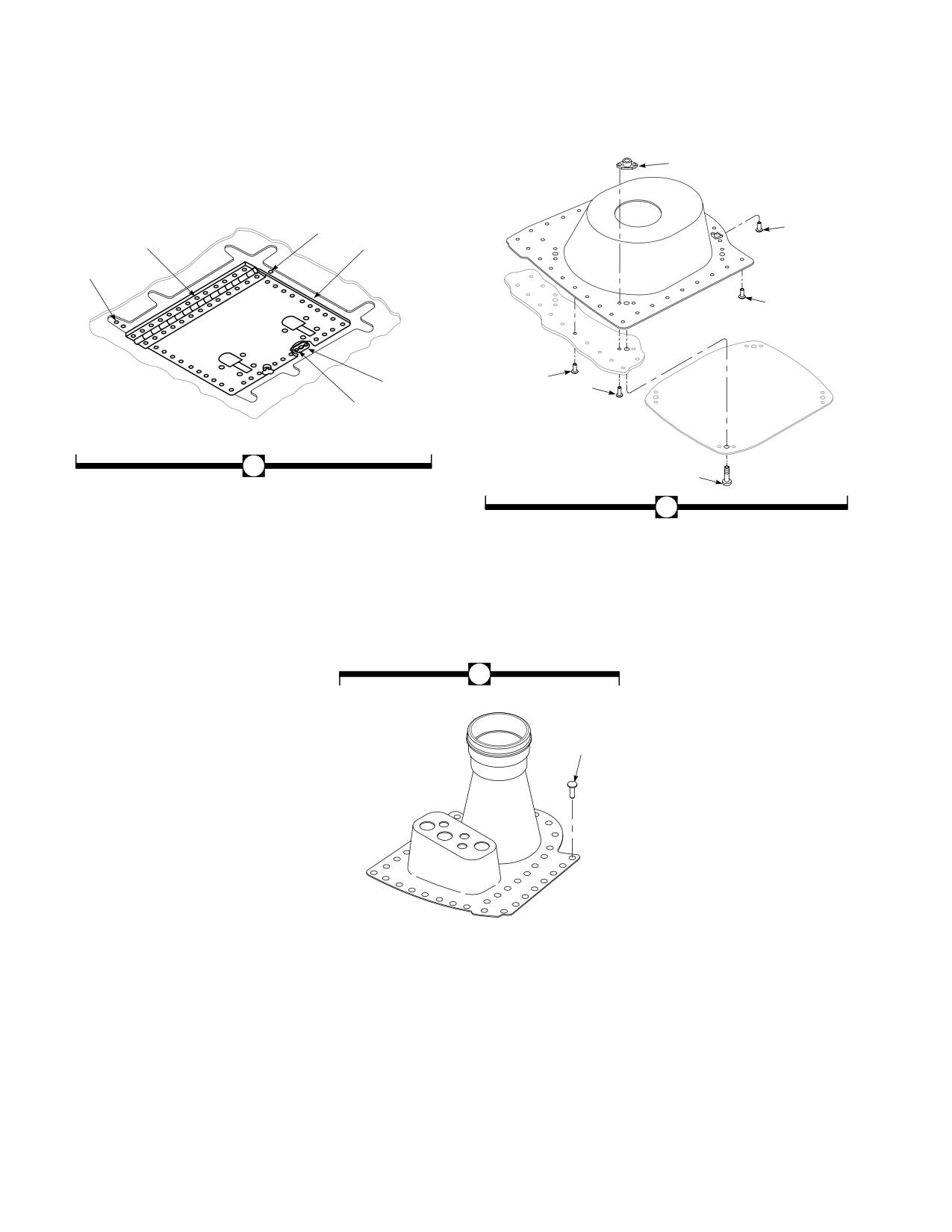
DMWR 1-1520-237
13
5
9
2
6
2
10
11
4
12
3
1
8
7
14
15
AB3095_2
SA
Figure E-11. Lower Aft Transition Modification Kit (Sheet 2 of 8)
E-130
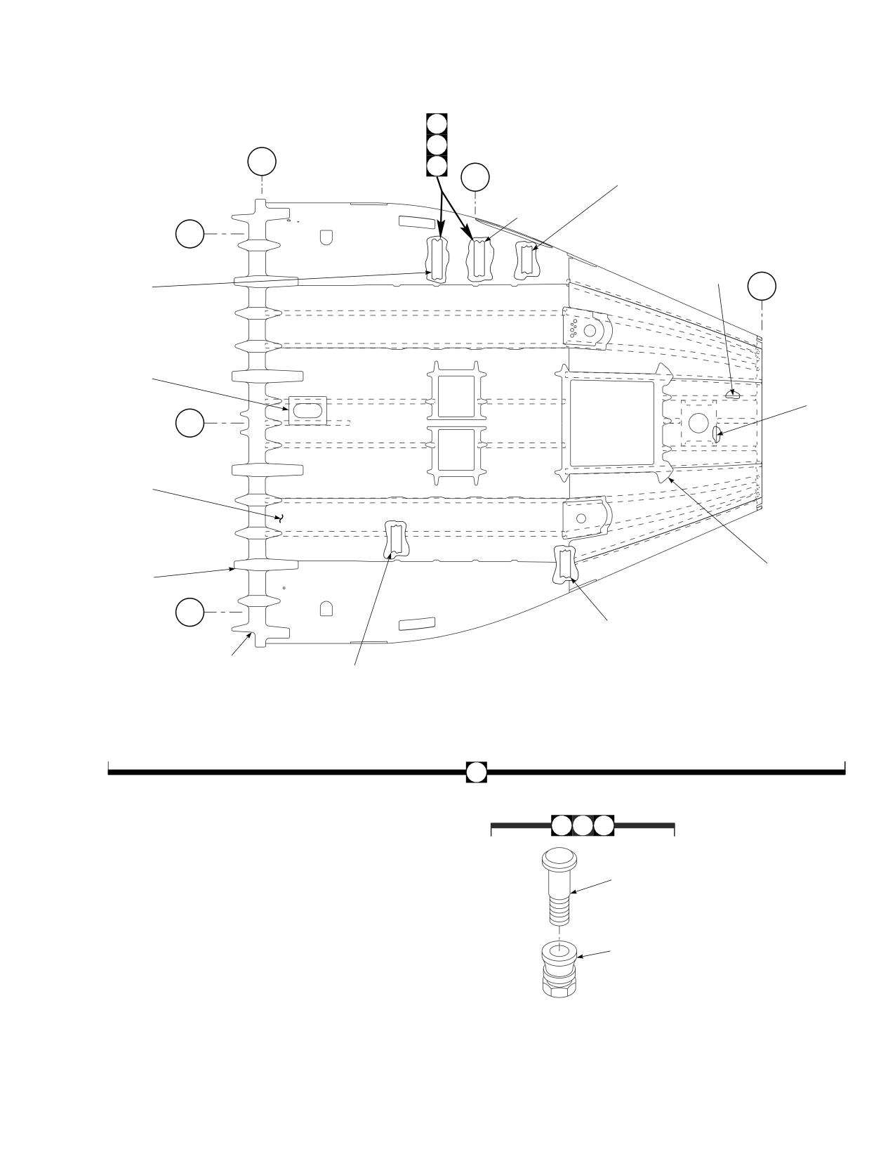
DMWR 1-1520-237
26
43
32
33
46
34
STA
379
49
35
STA
37
424.9
40
33
33
34
41
34
35
42
35
36
36
BL
40
37
37
LH
53
40
41
24
42
26
STA
52
485
17
19
BL
21
0.0
27
18
37
19
54
20
55
38
56
39
24
26
30
31
17
32
28
29
BL
40
RH
25
57
18
19
33
20
34
21
35
22
36
23
37
24
25
26
16
43
46
49
44
47
50
45
48
51
AB3095_3
SA
Figure E-11. Lower Aft Transition Modification Kit (Sheet 3 of 8)
E-131
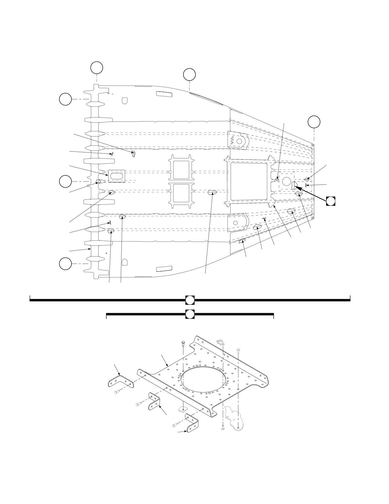
DMWR 1-1520-237
STA
379
STA
424.9
BL
40
LH
79
STA
485
81
62
60
80
BL
0.0
65
69
B
68
61
78
77
63
64
59
76
BL
75
40
RH
70
66
67
58
B
74
71
72
73
AB3095_4
SA
Figure E-11. Lower Aft Transition Modification Kit (Sheet 4 of 8)
E-132
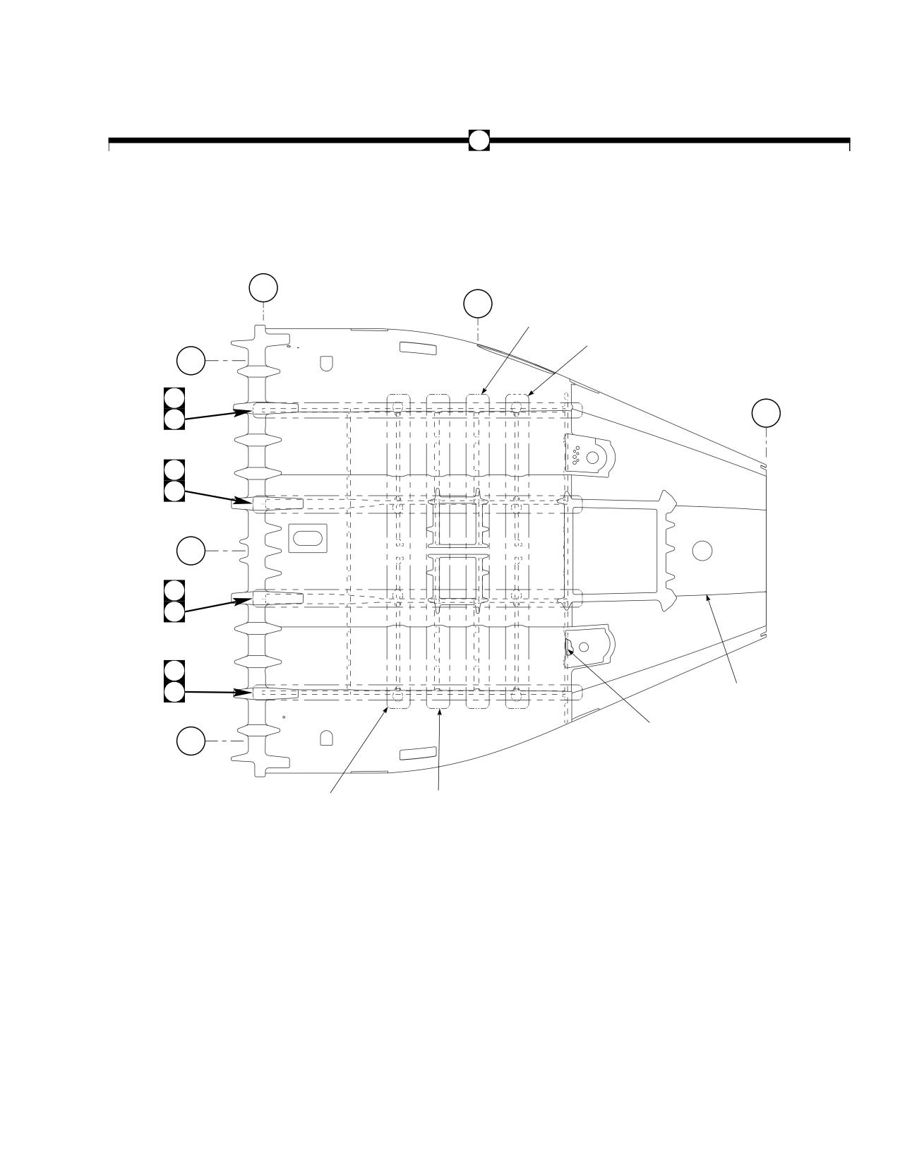
DMWR 1-1520-237
82
147
148
149
155
156
157
158
159
160
165
STA
161
166
379
167
STA
162
424.9
163
168
164
169
170
171
BL
40
LH
109
STA
485
116
84
92
BL
0.0
84
92
109
116
129
BL
172
40
RH
139
130
140
131
141
132
142
133
143
134
144
135
145
136
137
146
138
147
148
149
150
151
152
153
154
AB3095_5
SA
Figure E-11. Lower Aft Transition Modification Kit (Sheet 5 of 8)
E-133
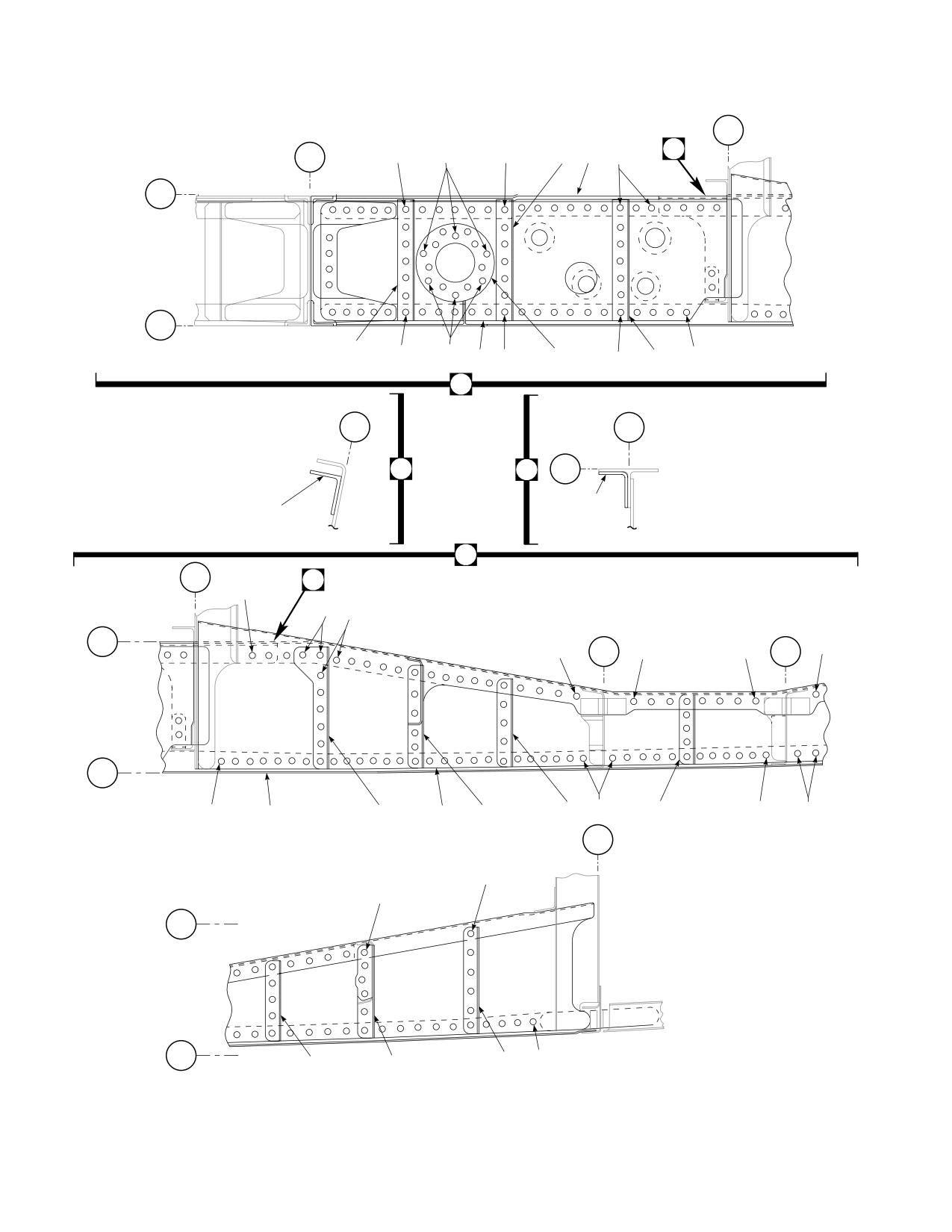
DMWR 1-1520-237
STA
398
86
STA
B
85
87
85
89
90
85
379
WL
206
WL
200
89
85
86
88
85
91
85
85
89
87
84
BL
BL
10
10
WL
C
B
206
83
104
92
STA
398
95
C
96
94
93
WL
206
STA
STA
93
93
416.6
93
93
424.9
WL
200
99
93
100
93
93
93
105
97
106
98
STA
443.5
93
93
WL
206
WL
200
103
93
101
102
AB3095_6
SA
Figure E-11. Lower Aft Transition Modification Kit (Sheet 6 of 8)
E-134
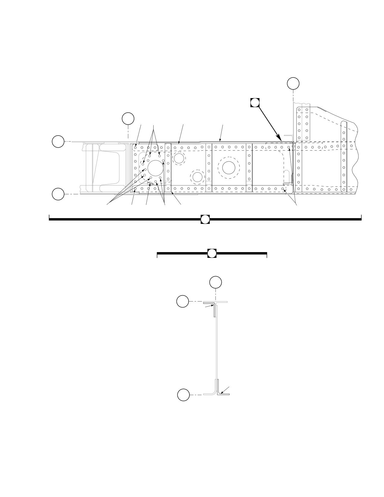
DMWR 1-1520-237
STA
398
D
STA
379
110
111
115
114
WL
206
WL
200
111
110
112
111
113
110
109
D
BL
30
WL
206
107
108
WL
200
AB3095_7
SA
Figure E-11. Lower Aft Transition Modification Kit (Sheet 7 of 8)
E-135
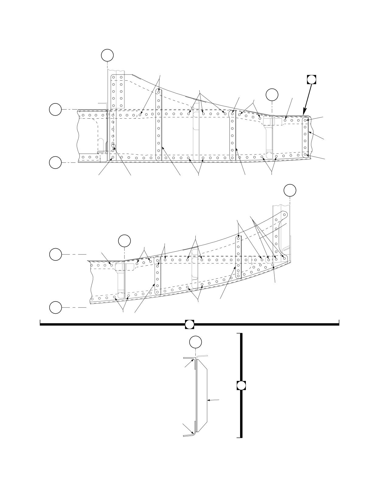
DMWR 1-1520-237
STA
398
117
E
117
119
STA
120
416.6
117
117
WL
206
117
123
WL
117
200
117
128
121
117
122
117
STA
443.5
118
117
117
STA
117
424.9
117
117
WL
206
117
125
WL
117
200
117
124
116
BL
30
126
E
128
127
AB3095_8
SA
Figure E-11. Lower Aft Transition Modification Kit (Sheet 8 of 8)
E-136
DMWR 1-1520-237
QTY
USABLE
FIGURE &
PER
ON
INDEX NO.
PART NUMBER
1 2 3 4 5 6 7
DESCRIPTION
ASSY
CODE
E-11-
70070-20577-011
LOWER AFT TRANSITION MODIFICATION KIT
REF
-1
70070-20577-016
M/K DOOR INSTL
1
-2
MS20470AD5-9
. RIVET
77
-3
NAS1097AD3-9
. RIVET
5
-4
212-12
. RECEPTACLE, (71286)
2
-5
NAS1097AD5-9
. RIVET
37
-6
70217-03001-111
. DOUBLER
2
-7
70070-20577-017
M/K FUEL DUMP
1
-8
MS27039-1-10
. SCREW
4
-9
NAS1739B5-3
. BLIND RIVET
30
-10
NAS1739B4-2
. BLIND RIVET
5
NAS1097AD4-9
. RIVET
5
*
NAS1739B5-2
. BLIND RIVET
2
*
-11
MS20470AD5-9
. RIVET
60
-12
MS20470AD3-9
. RIVET
10
-13
MS21075-3
. NUTPLATE
4
-14
70070-20577-018
M/K FUEL VENT
1
-15
NAS1738B5-3
. BLIND RIVET
42
-16
70070-20577-014
M/K HARDWARE
1
-17
NAS1097AD5-4
RIVET
140
-18
MS20470AD5-2
RIVET
1000
-19
MS20470AD5-3
RIVET
1385
-20
MS20470AD5-4
RIVET
400
-21
MS20470AD6-3
RIVET
380
-22
MS20470AD6-5
RIVET
58
-23
MS20470AD5-5
RIVET
125
-24
NAS1446-04
SWAGE LOCKING PIN
28
-25
NAS1446-05
SWAGE LOCKING PIN
26
-26
NAS1080C06
COLLAR
170
-27
MS20470AD6-4
RIVET
65
-28
MS20426AD3-4
RIVET
45
-29
MS21059-3
NUTPLATE
22
-30
RA097AD6-3
RIVET
75
-31
NAS1436-03
SWAGE LOCKING PIN
14
-32
NAS1446-03
SWAGE LOCKING PIN
46
-33
AN173-14A
BOLT
8
-34
AN173-15A
BOLT
12
-35
NAS1149F0332P
FLAT WASHER
35
-36
MS21044N3
NUT
18
-37
NAS1097AD4-3
RIVET
30
-38
MS20470AD6-2
RIVET
22
-39
MS20426AD5-2
RIVET
10
-40
NAS1526-05
SWAGE LOCKING PIN
14
-41
NAS1526-06
SWAGE LOCKING PIN
14
-42
NAS1526-07
SWAGE LOCKING PIN
14
-43
HL20PB86-6-8
PIN COLLAR ASSY, (73197)
5
-44
HL20PB-6-8
. HI-LOK PIN, (73197)
1
-45
HL86-6
. COLLAR, (73197) (Superseded by HL1087A-
6)
1
HL1087A-6
. COLLAR, (73197)
1
-46
HL20PB86-6-9
PIN COLLAR ASSY, (73197)
10
-47
HL20PB-6-9
. HI-LOK PIN, (73197)
1
-48
HL86-6
. COLLAR, (73197) (Superseded by HL1087A-
6)
1
HL1087A-6
. COLLAR, (73197)
1
-49
HL20PB86-6-10
PIN COLLAR ASSY, (73197)
5
-50
HL20PB-6-10
. HI-LOK PIN, (73197)
1
-51
HL86-6
. COLLAR, (73197) (Superseded by HL1087A-
6)
1
HL1087A-6
. COLLAR, (73197)
1
-52
HL86TW-6
COLLAR, (73197)
18
E-137
DMWR 1-1520-237
QTY
USABLE
FIGURE &
PER
ON
INDEX NO. PART NUMBER
1
2 3 4 5 6 7
DESCRIPTION
ASSY
CODE
-53
RA097AD4-2
. RIVET
50
-54
MS20426AD3-2
. RIVET
14
-55
MS20470AD4-2
. RIVET
26
-56
MS21075-3
. NUTPLATE
16
-57
NAS1465-04
. SWAGE LOCKING PIN
10
-58
70070-20577-012
M/K PLATE ASSY
1
-59
70213-02501-126
. STRAP
1
-60
70213-03002-113
. DOUBLER
1
-61
70213-03002-117
. SKIN, LH
1
70213-03002-116
. SKIN, RH
1
-62
70213-03002-118
. SKIN
1
-63
70203-03003-101
. DOUBLER
1
-64
70213-03002-107
. SKIN,LH
1
70213-03002-108
. SKIN, RH
1
-65
70070-20577-103
. SKIN
1
-66
70212-03002-117
. STRINGER 19, LH
1
70212-03002-118
. STRINGER 19, RH
1
-67
70212-03002-113
. STRINGER, LH
1
70212-03002-114
. STRINGER, RH
1
-68
70212-03002-103
. STRINGER 22, LH
1
70212-03002-104
. STRINGER 22, RH
1
-69
70212-03002-111
. STRINGER 23
1
-70
70212-03002-105
. STRINGER 22, LH
1
70212-03002-106
. STRINGER 22, RH
1
-71
SS1083-147
. BRACKET ANGLE
2
-72
SS1083-192
. BRACKET ANGLE
2
-73
SS1083-237
. BRACKET ANGLE
2
-74
70213-03004-101
. DOUBLER
1
-75
70212-03002-109
. STRINGER 17, LH
1
70212-03002-110
. STRINGER 17, RH
1
-76
70212-03002-125
. STRINGER, LH
1
70212-03002-126
. STRINGER, RH
1
-77
70212-03002-115
. STRINGER 20, LH
1
70212-03002-116
. STRINGER 20, RH
1
-78
70212-03002-107
. STRINGER 22, LH
1
70212-03002-108
. STRINGER 22, RH
1
-79
70212-03002-124
. STRINGER
1
-80
70212-03002-123
. STRINGER
1
-81
70211-03002-101
. SHEAR ANGLE
1
-82
70070-20577-013
M/K FRAME INSTL
1
-83
70212-03003-131
. ANGLE SPLICE
1
70212-03003-132
. ANGLE SPLICE
1
-84
70212-03003-044
. BEAM ASSY
1
70212-03003-054
. BEAM ASSY
1
-85
MS20470AD6
. . RIVET, (Used on 70212-03003-044)
A/R
-86
NAS1525-02
. . SWAGE LOCKING PIN, (Used on 70212-
03003-054)
14
-87
NAS1080D05
. . COLLAR, (Used on 70212-03003-054)
14
-88
70212-03003-160
. . DOUBLER, (Used on 70212-03003-054)
1
-89
70212-03003-146
. . STIFFENER
3
-90
70212-03003-110
. . TEE CAP, (Used on 70212-03003-044)
1
70212-03003-109
. . TEE CAP, (Used on 70212-03003-054)
1
-91
70212-03003-102
. . WEB, (Used on 70212-03003-044)
1
70212-03003-159
. . WEB, (Used on 70212-03003-054)
1
-92
70212-03003-041
. BEAM ASSY, LH
1
70212-03003-042
. BEAM ASSY
1
-93
MS20470AD5
. . RIVET
A/R
-94
MS20470AD6
. . RIVET
A/R
-95
NAS1526-02
. . SWAGE LOCKING PIN
1
-96
NAS1080D06
. . COLLAR
1
-97
70212-03003-123
. . STIFFENER, (Used on 70212-03003-041)
1
E-138
DMWR 1-1520-237
QTY
USABLE
FIGURE &
PER
ON
INDEX NO. PART NUMBER
1
2
3 4 5 6 7
DESCRIPTION
ASSY
CODE
70212-03003-124
. STIFFENER, (Used on 70212-03003-042)
1
-98
70212-03003-125
. STIFFENER, (Used on 70212-03003-041)
1
70212-03003-126
. STIFFENER, (Used on 70212-03003-042)
1
-99
70212-03003-127
. STIFFENER
1
-100
70212-03003-128
. STIFFENER
1
-101
70212-03003-147
. STIFFENER
1
-102
70212-03003-129
. STIFFENER, (Used on 70212-03003-041)
1
70212-03003-130
. STIFFENER, (Used on 70212-03003-042)
1
-103
70212-03003-148
. STIFFENER
1
-104
70212-03003-133
. CAP ANGLE
1
70212-03003-134
. CAP ANGLE, (Used on 70212-03003-042)
1
-105
70212-03003-111
. TEE CAP, (Used on 70212-03003-041)
1
70212-03003-112
. TEE CAP, (Used on 70212-03003-042)
1
-106
70212-03003-103
. WEB. (Used on 70212-03003-041)
1
70212-03003-104
. WEB, (Used on 70212-03003-042)
1
-107
70212-03003-141
ANGLE SPLICE
1
70212-03003-142
ANGLE SPLICE
1
-108
70212-03003-115
CAP ANGLE
1
70212-03003-116
CAP ANGLE
1
-109
70212-03003-048
BEAM ASSY
1
70212-03003-055
BEAM ASSY
1
-110
MS20470AD6
. RIVET
A/R
-111
MS20470AD5
. RIVET, (Used on 70212-03003-055)
A/R
-112
70212-03003-162
. DOUBLER, (Used on 70212-03003-055)
1
-113
70212-03003-145
. STIFFENER
3
-114
70212-03003-114
. TEE CAP, (Used on 70212-03003-048)
1
70212-03003-113
. TEE CAP, (Used on 70212-03003-055)
1
-115
70212-03003-161
. WEB, (Used on 70212-03003-055)
1
70212-03003-106
. WEB, (Used on 70212-03003-048)
1
-116
70070-20577-041
BEAM ASSY, LH
1
70070-20577-042
BEAM ASSY, RH
1
-117
MS20470AD5
. RIVET
A/R
-118
MS20470AD6
. RIVET
A/R
-119
NAS1526-02
. SWAGE LOCKING PIN
2
-120
NAS1080D06
. COLLAR
2
-121
70212-03003-137
. STIFFENER, (Used on 70070-20577-041)
1
70212-03003-138
. STIFFENER, (Used on 70070-20577-042)
1
-122
70212-03003-139
. STIFFENER, (Used on 70070-20577-041)
1
70212-03003-140
. STIFFENER, (Used on 70070-20577-042)
1
-123
70212-03003-149
. STIFFENER
1
-124
70212-03003-121
. STIFFENER. (Used on 70070-20577-041)
1
70212-03003-122
. STIFFENER, (Used on 70070-20577-042)
1
-125
70212-03003-135
. STIFFENER
1
70212-03003-136
. STIFFENER, (Used on 70070-20577-042)
1
-126
70212-03003-143
. CAP ANGLE, (Used on 70070-20577-041)
1
70212-03003-144
. CAP ANGLE, (Used on 70070-20577-042)
1
-127
70070-20577-101
. CAP ANGLE, (Used on 70070-20577-041)
1
70070-20577-102
. CAP ANGLE, (Used on 70070-20577-042)
1
-128
70212-03003-150
. WEB, (Used on 70070-20577-041)
1
70212-03003-151
. WEB, (Used on 70070-20577-042)
1
-129
70212-03003-119
STRINGER BLIO
1
70212-03003-120
STRINGER BLIO
1
-130
70211-03003-101
INTERCOSTAL
1
-131
70211-03003-102
INTERCOSTAL
1
-132
70211-03003-103
INTERCOSTAL
1
-133
70211-03003-104
INTERCOSTAL
1
-134
70211-03003-114
ANGLE
1
-135
70211-03003-115
ANGLE
1
-136
70211-03003-116
GUSSET
2
-137
70211-03003-117
GUSSET
1
-138
70211-03003-118
GUSSET
1
E-139
DMWR 1-1520-237
QTY
USABLE
FIGURE &
PER
ON
INDEX NO. PART NUMBER
1
2
3 4 5 6 7
DESCRIPTION
ASSY
CODE
-139
70211-03004-101
INTERCOSTAL
1
-140
70211-03004-102
INTERCOSTAL
1
-141
70211-03004-103
STIFFENER
1
-142
70211-03004-104
STIFFENER
1
-143
70211-03004-105
INTERCOSTAL
1
-144
70211-03004-106
INTERCOSTAL
1
-145
70211-03004-107
STIFFENER
2
-146
70211-03004-108
STIFFENER
2
-147
70211-03004-117
ANGLE
4
-148
70211-03004-118
ANGLE
4
-149
70211-03004-119
ANGLE
4
-150
70211-03004-120
ANGLE
4
-151
70211-03004-121
ANGLE
2
-152
70211-03004-122
ANGLE
2
-153
70211-03004-126
ANGLE
1
-154
70211-03004-127
ANGLE
1
-155
70211-03005-101
INTERCOSTAL
1
-156
70211-03005-102
INTERCOSTAL
1
-157
70211-03005-103
INTERCOSTAL
1
-158
70211-03005-104
INTERCOSTAL
1
-159
70211-03005-115
ANGLE
1
-160
70211-03005-116
ANGLE
1
-161
70211-03005-117
ANGLE
2
-162
70211-03005-118
ANGLE
2
-163
70211-03005-120
ANGLE
1
-164
70211-03005-121
ANGLE
1
-165
70211-03006-101
FRAME
1
-166
70211-03006-102
FRAME
1
-167
70211-03006-103
FRAME
1
-168
70211-03006-104
FRAME
1
-169
70211-03006-114
GUSSET
4
-170
70211-03006-115
ANGLE
1
-171
70211-03006-116
ANGLE
1
-172
70211-03007-185
SHEAR ANGLE
1
E-140
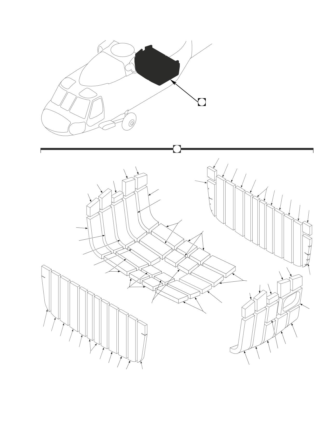
DMWR 1-1520-237
A
A
11
15
1
3
16
17
5
18
12
3
19
2
18
1
17
16
4
15
11
20
2
21
4
13
1
22
3
20
12
20
5
3
21
1
22
21
8
20
14
15
16
10
17
9
18
6
19
7
18
4
17
2
AB3094
16
15
14
SA
Figure E-12. Foam Liner Modification Kit
E-141
DMWR 1-1520-237
QTY
USABLE
FIGURE &
PER
ON
INDEX NO.
PART NUMBER
1 2 3 4 5 6 7
DESCRIPTION
ASSY
CODE
E-12-
70070-20577-015
FOAM LINER MODIFICATION KIT
REF
-1
70219-03011-137
. FOAM LINER
4
-2
70219-03011-139
. FOAM LINER
3
-3
70219-03011-138
. FOAM LINER
4
-4
70219-03011-140
. FOAM LINER
3
-5
70219-03011-136
. FOAM LINER
2
-6
70219-03011-141
. FOAM LINER
1
-7
70219-03011-142
. FOAM LINER
1
-8
70219-03011-133
. FOAM LINER
1
-9
70219-03011-143
. FOAM LINER
1
-10
70219-03011-132
. FOAM LINER
1
-11
70219-03011-129
. FOAM LINER
2
-12
70219-03011-130
. FOAM LINER
2
-13
70219-03011-131
. FOAM LINER
1
-14
70219-03011-128
. FOAM LINER
2
-15
70219-03011-127
. FOAM LINER
4
-16
70219-03011-126
. FOAM LINER
4
-17
70219-03011-125
. FOAM LINER
4
-18
70219-03011-124
. FOAM LINER
4
-19
70219-03011-123
. FOAM LINER
4
-20
70219-03011-135
. FOAM LINER
8
-21
70219-03011-134
. FOAM LINER
8
-22
70219-03011-144
. FOAM LINER
2
E-142
DMWR 1-1520-237
E-13. ENCLOSURE MODIFICATION KIT (50-21).
Subject: Vapor Barrier Support Structure; Replacement of, dated 31 March 2003
Purpose: Provide instructions for the replacement of structure supporting vapor barriers above fuel cells.
Model:
UH-60A
Description: The structure which supports vapor barrier between stations 413.00 and 443.50, right and left buttline
10.00 is replaced.
Drawings required for modification:
70070-20578, 70219-03002, 70400-03611, 70551-03140, 70551-03101, 70551-03102
References: (a) Special Service Instructions (SSI) No. 50-31, Installation of 9A to A9 Recapitalization Program, dated
March 31, 2003
(b) TM 1-1520-237-23, Technical Manual, Aviation Unit And Intermediate Maintenance For Army
Models UH-60A, UH-60L, EH-60A and UH-60Q Helicopters, Chapter 10, Fuel Systems
Instructions:
NOTE
• A complete review of this SSI is recommended before incorporating the rework of vapor barrier.
• Before beginning this modification procedure, use the material information list to inventory the modification
kit. Make sure all parts are present and in serviceable condition.
• Where drawing numbers are not listed within individual step(s), drawing(s) listed in preceding step(s) are
the controlling authority.
• The electrical, sheet metal, and structural modifications in this SSI shall be done by personnel experienced
in reading modification drawings. Routine steps such as cleaning, layout and drilling, deburring, standard
repairs, corrosion control, clean up after rework, chemical coating for aluminum after cutting/trimming
parts, paint touch up, routing, clamping, and safety practices may not be called out herein. However, these
steps and all other required routine tasks shall be done.
• When installing fasteners refer to drawing sheet and zones for applicable fasteners.
• Slight variations to the instructions contained herein are allowed, as long as the intent of the modification
is accomplished.
A.
Preparation for modification and removal of equipment:
(1)
Confirm that all warnings, cautions, and notes are complied with per reference (a).
(2)
Perform preparation for modification per reference (a).
(3)
Disconnect connectors and pull back wiring as required for rework of vapor barriers.
(4)
Remove fuel lines as required for rework of vapor barriers per reference (b).
E-143
DMWR 1-1520-237
B.
Rework of enclosure installation (70219-03002-012) as follows:
(1)
Modification of enclosure installation (70219-03002-012) left side as follows:
CAUTION
TO AVOID DAMAGING COMPONENTS, USE EXTREME CARE WHEN DRILLING INTO AIRFRAME.
TEMPORARILY MOVE ANY TUBE ASSEMBLIES OR WIRING HARNESSES OUT OF REWORK AREA.
(a)
Remove bracket installation (70400-03611-012 or -016) as required to gain access to intercostal
(70219-03002-111, -142, -143, or -151) keep parts as required for reinstallation (Dwg 70400-03611, Sheet 1, Zones
10-B, 12-B, 13-E, 14-D, 16-B, 16-C, 16-F, 17-A, 17-C, and 17-H; Dwg 70070-20578, Sheet 1, Notes 13 and 14).
(b)
Remove angle (70219-03002-133 or -153) as required to remove intercostal (70219-03002-111, -142,
-143, or -151) keep parts as required for reinstallation (Dwg 70219-03002, Sheet 2, Zones 8-G and 16-B).
(c)
Remove left side intercostal (70219-03002-111, -142, -143, or -151) (Dwg 70219-03002, Sheet 1,
Zones 13-M and 14-M; Dwg 70070-20578, Sheet 1, Notes 7, 8, 9, and 10).
(d)
Install four brackets (MS3341-2-9) on new intercostal (70070-20578-101) using hardware shown and
old intercostal (70219-03002-111, -142, -143, or -151) as a template (Dwg 70551-03140, Sheet 3, View AC-AC,
Zones 7-H, 8-H, and 9-H; Dwg 70070-20578, Sheet 1, Note 5).
WARNING
OBSERVE ALL CAUTIONS AND WARNINGS ON CONTAINERS WHEN USING CONSUMABLES.
WHEN APPLICABLE, WEAR NECESSARY PROTECTIVE GEAR DURING HANDLING AND USE. IF A
CONSUMABLE IS FLAMMABLE OR EXPLOSIVE, MAKE CERTAIN CONSUMABLE AND ITS VAPORS ARE
KEPT AWAY FROM HEAT, SPARK, AND FLAME. MAKE CERTAIN EQUIPMENT IS PROPERLY
GROUNDED AND FIREFIGHTING EQUIPMENT IS READILY AVAILABLE PRIOR TO USE. FOR AD-
DITIONAL INFORMATION ON TOXICITY, FLASHPOINT, AND FLAMMABILITY OF CHEMICALS,
CONSULT YOUR MEDICAL PEOPLE, OR MANUFACTURER OF THE CONSUMABLE.
(e)
Install grommet (MS21266-1N) on new intercostal (70070-20578-101) using adhesive (PLIOBOND NO.
20, or equivalent) (Dwg 70219-03002, Sheet 1, Zone 10-L, Note 17).
(f)
Install nameplates (SS9014J308 and SS9014J323) (Dwg 70070-20578, Sheet 1, Notes 19 and 20, Sheet
2, Notes 21 and 22; Dwg 70551-03101, Sheet 2, Zones 11-C and 11-G; Dwg 70551-03102, Sheet 2, Zones 4-D, 4-H
and 7-D).
(g)
Install intercostal (70070-20578-101) using hardware shown (Dwg 70219-03002, Sheet 1, Zones 13-M
and 14-M; Dwg 70070-20578, Sheet 1, Notes 4 and 5).
(h)
Reinstall angle (70219-03002-133 or -153) using hardware shown (Dwg 70319-03002, Sheet 2, Zones
8-G and 16-B).
E-144
DMWR 1-1520-237
(i)
Reinstall bracket installation (70400-03611-012 or -016) using hardware shown (Dwg 70400-03611,
Sheet 1, Zones 10-B, 12-B, 13-E, 14-D, 16-B, 16-C,16-F, 17-A, 17-C, 17-H, and Note 13; Dwg 70070-20578, Sheet
1, Notes 15 and 16).
(2)
Modification of enclosure installation (70219-03002-012) right side as follows:
CAUTION
TO AVOID DAMAGING COMPONENTS, USE EXTREME CARE WHEN DRILLING INTO AIRFRAME.
TEMPORARILY MOVE ANY TUBE ASSEMBLIES OR WIRING HARNESSES OUT OF REWORK AREA.
(a)
Remove bracket installation (70400-03611-011 or -015) as required to gain access to intercostal
(70219-03002-112, -144, or -150) keep parts as required for reinstallation (Dwg 70400-03611, Sheet 1, Zones 10-B,
12-B, 13-E, 14-D, 16-B, 16-C, 16-F, 17-A, 17-C, and 17-H; Dwg 70070-20578, Sheet 1, Notes 13 and 14).
(b)
Remove angle (70219-03002-134 or -152) as required to remove intercostal (70219-03002-112, -144,
or -150) keep parts as required for reinstallation (Dwg 70319-03002, Sheet 2, Zones 4-G and 16-G).
(c)
Remove right side intercostal (70219-03002-112, -144, or -150) (Dwg 70219-03002, Sheet 1, Zones
13-M and 14-M; Dwg 70070-20578, Sheet 1, Notes 7, 8, 9, and 10).
(d)
Install three brackets (MS3341-2-9) on new intercostal (70070-20578-102) using hardware shown and
old intercostal (70219-03002-112, -144, or -150) as a template (Dwg 70551-03140, Sheet 3, View AA-AA, Zone 7-B
and Dwg 70070-20578, Sheet 1, Note 6).
(e)
Install cover, protector (MS3181-10CA) to new intercostal (70070-20578-102) using hardware shown
(Dwg 70551-03102, Sheet 2, Zones 3-C and 7-C).
(f)
Install nameplates (SS9014J347, SS9014J307, and SS9014J322) (Dwg 70070-20578, Sheet 1, Notes
19 and 20, Sheet 2, Notes 21 and 22; Dwg 70551-03101, Sheet 2, Zones 11-C and 11-G; Dwg 70551-03102, Sheet
2, Zones 4-D, 4-H and 7-D).
WARNING
OBSERVE ALL CAUTIONS AND WARNINGS ON CONTAINERS WHEN USING CONSUMABLES.
WHEN APPLICABLE, WEAR NECESSARY PROTECTIVE GEAR DURING HANDLING AND USE. IF A
CONSUMABLE IS FLAMMABLE OR EXPLOSIVE, MAKE CERTAIN CONSUMABLE AND ITS VAPORS ARE
KEPT AWAY FROM HEAT, SPARK, AND FLAME. MAKE CERTAIN EQUIPMENT IS PROPERLY
GROUNDED AND FIREFIGHTING EQUIPMENT IS READILY AVAILABLE PRIOR TO USE. FOR AD-
DITIONAL INFORMATION ON TOXICITY, FLASHPOINT, AND FLAMMABILITY OF CHEMICALS,
CONSULT YOUR MEDICAL PEOPLE, OR MANUFACTURER OF THE CONSUMABLE.
(g)
Install grommet (MS21266-1N) on new intercostal (70070-20578-102) using adhesive (PLIOBOND
NO.20 or equivalent) (Dwg 70219-03002, Sheet 1, Zone 10-L, Note 17).
(h)
Install intercostal (70070-20578-102) using hardware shown (Dwg 70219-03002, Sheet 1, Zones 13-M
and 14-M; Dwg 70070-20578, Sheet 1, Notes 4 and 6).
E-145
DMWR 1-1520-237
(i)
Reinstall angle (70219-03002-134 or -152) using hardware shown (Dwg 70219-03002, Sheet 2, Zones
8-G and 16-B).
(j)
Reinstall bracket installation (70400-03611-011 or -015) using hardware shown (Dwg 70400-03611,
Sheet 1, Zones 10-B, 12-B, 13-E, 14-D, 16-B, 16-C,16-F, 17-A, 17-C, 17-H, and Note 13; Dwg 70070-20578, Sheet
1, Notes 15 and 16).
C.
Reinstallation of removed equipment:
(1)
Reinstall removed wiring and reconnect connectors as required.
(2)
Reinstall removed fuel lines as required per reference (b).
(3)
Install removed equipment per reference (a).
D.
Record of Compliance:
(1)
Make an appropriate logbook entry to show compliance with this Special Service Instruction.
Weight and Balance Data:
POUNDS
INCHES AFT
MOMENT/
QTY
PART NO.
NOMENCLATURE
WEIGHT
OF DATUM
1000
1
70070-20578-011
Mod. Kit
+0.2
432.0
0.086
Weight and Balance: Change resulting from these instructions are as follows:
Change in basic weight:
+0.2 pounds
Moment arm:
432.0 in.
Change in basic moment/1000:
0.086
Manpower (Estimated)
No. of Personel
No. of Hours
Man-hours
Sheet Metal Mechanic
1
24.0
*24.0
Helicopter Electrican
1
8.0
*8.0
Fuel Mechanic
1
2.0
*2.0
*Does not include time required to prepare helicopter or return it to flight status.
E-146
DMWR 1-1520-237
Material Information:
A.
Modification Kit Required:
Qty
Nomenclature
Part Number
Source
1
Modification Kit, Enclosure,
70070-20578-011
(1)
consisting of:
2
Pin, Hi Lok
HL20PB-6-11
2
Pin, Hi Lok
HL20PB-6-7
4
Pin, Hi Lok
HL20PB-6-9
8
Collar
HL75-6AW
3
Rivet
MS20426AD5-4
30
Rivet
MS20470AD3-3
116
Rivet
MS20470AD4-5
20
Rivet
MS20470AD4-6
26
Rivet
MS20470AD5-4
16
Rivet
MS20470AD5-5
18
Rivet
MS20604AD3W4
2
Grommet
MS21266-1N
7
Bracket
MS3341-2-9
1
Cover, Prot
MS3181-10CA
8
Rivet
NAS1097AD5-5
4
Rivet
NAS1097AD5-6
2
Radius Block
SS1058-1-30-12
1
Intercostal
70070-20578-101
1
Intercostal
70070-20578-102
1
Nameplate
SS9014J347
1
Nameplate
SS9014J323
1
Nameplate
SS9019J322
2
Nameplate
SS9014J308
2
Nameplate
SS9014J307
E-147
DMWR 1-1520-237
B.
Consumable Material:
WARNING
OBSERVE ALL CAUTIONS AND WARNINGS ON CONTAINERS WHEN USING CONSUMABLES.
WHEN APPLICABLE, WEAR NECESSARY PROTECTIVE GEAR DURING HANDLING AND USE. IF A
CONSUMABLE IS FLAMMABLE OR EXPLOSIVE, MAKE CERTAIN CONSUMABLE AND ITS VAPORS ARE
KEPT AWAY FROM HEAT, SPARK, AND FLAME. MAKE CERTAIN EQUIPMENT IS PROPERLY
GROUNDED AND FIREFIGHTING EQUIPMENT IS READILY AVAILABLE PRIOR TO USE. FOR AD-
DITIONAL INFORMATION ON TOXICITY, FLASHPOINT, AND FLAMMABILITY OF CHEMICALS,
CONSULT YOUR MEDICAL PEOPLE, OR MANUFACTURER OF THE CONSUMABLE.
Qty
Nomenclature
Part Number
Source
4 oz.
Adhesive
PLIOBOND NO. 20 or equivalent
(1)
C.
Source:
(1)
Available through normal supply channels
E-148
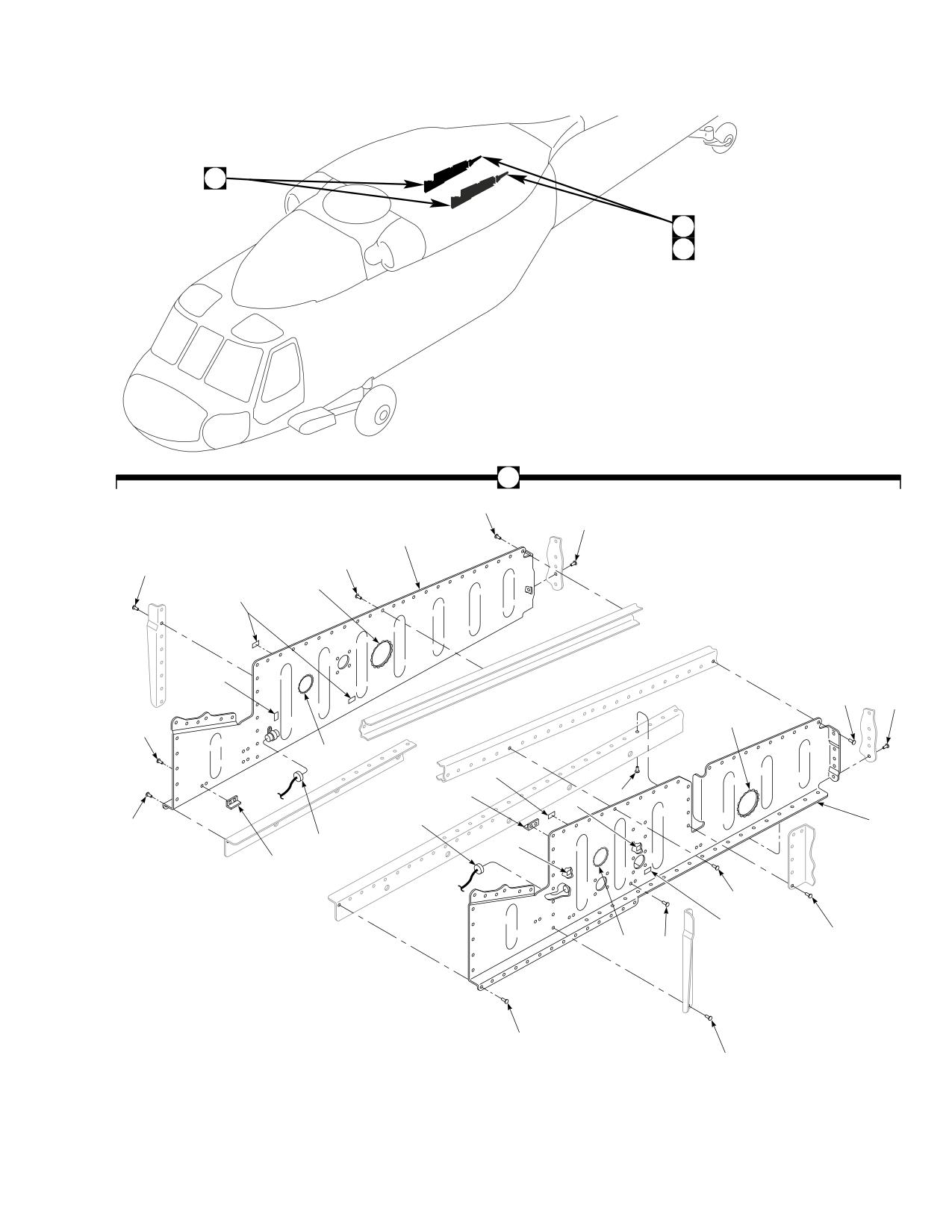
DMWR 1-1520-237
A
B
C
A
8
10
21
7
7
5
1
2
8
9
5
11
5
1
7
12
3
4
21
6
4
2
12
7
1
7
5
11
6
7
AB3115_1
SA
Figure E-13. Enclosure Modification Kit (Sheet 1 of 2)
E-149
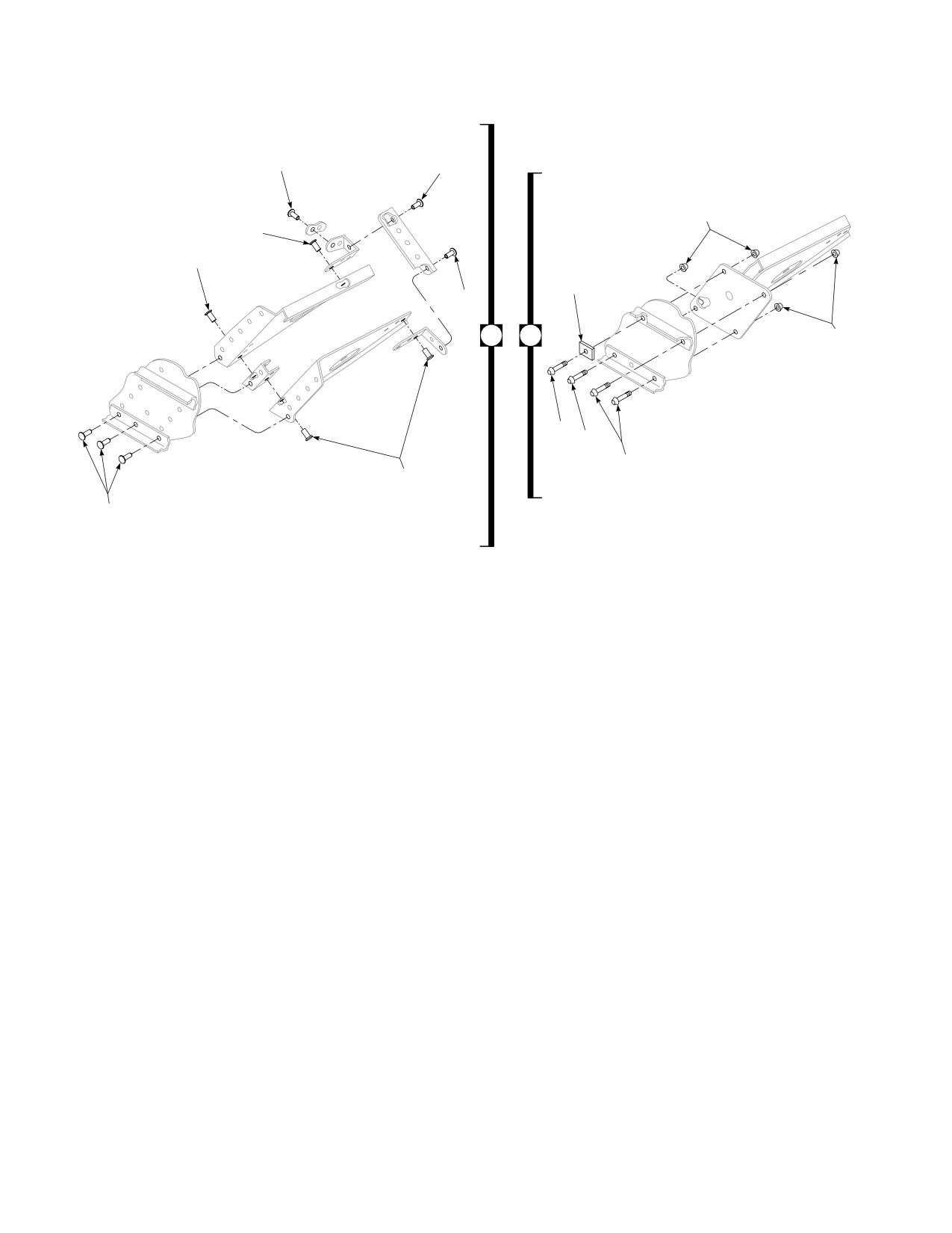
DMWR 1-1520-237
14
14
15
15
17
13
14
15
20
14
15
B
C
17
18
16
19
14
15
14
15
AB3115_2
SA
Figure E-13. Enclosure Modification Kit (Sheet 2 of 2)
E-150
DMWR 1-1520-237
QTY
USABLE
FIGURE &
PER
ON
INDEX NO.
PART NUMBER
1 2 3 4 5 6 7
DESCRIPTION
ASSY
CODE
E-13-
70070-20578-011
ENCLOSURE MODIFICATION KIT
REF
-1
SS9014J307
. NAMEPLATE, LH
2
SS9014J308
. NAMEPLATE, RH
2
-2
SS9014J322
. NAMEPLATE, LH
1
SS9014J323
. NAMEPLATE, RH
1
-3
SS9014J347
. NAMEPLATE
1
-4
MS3181-10CA
. PROTECTIVE COVER
2
-5
MS21266-1N
. GROMMET
2
-6
MS20470AD3-3
. RIVET
30
-7
MS20470AD4-5
. RIVET
116
-8
MS20470AD4-6
. RIVET
20
-9
NAS1097AD5-5
. RIVET
8
-10
NAS1097AD5-6
. RIVET
4
-11
MS20604AD3W4
. RIVET
18
-12
MS3341-2-9
. BRACKET
7
-13
MS20426AD5-4
. RIVET
3
-14
MS20470AD5-4
. RIVET
26
-15
MS20470AD5-5
. RIVET
16
-16
HL20PB-6-7
. HI-LOK PIN, (73197)
2
-17
HL75-6AW
. COLLAR, (73197)
8
-18
HL20PB-6-11
. HI-LOK PIN, (73197)
2
-19
HL20PB-6-9
. HI-LOK PIN, (73197)
4
-20
SS1058-1-30-12
. RADIUS BLOCK
2
-21
70070-20578-101
. INTERCOSTAL, LH
1
70070-20578-102
. INTERCOSTAL, RH
1
E-151
DMWR 1-1520-237
E-14. SUPPORT SHAFT MODIFICATION KIT (50-9).
Subject: Drive Shaft Supports; Modification of, dated 31 March 2003
Purpose: Provide instructions to remove and install new drive shaft supports along tail cone section.
Model:
UH-60A
Description: The following is a brief overview of the work required to rework drive shaft supports at station 531.43 and
station 591.88. Tail drive shaft supports are removed and new supports and doublers are installed.
Drawings required for modification:
70070-20266
References: (a) Special Service Instructions (SSI) No. 50-31, Installation of 9A to A9 Recapitalization Program, dated
March 31, 2003
(b) SSI No. 50-20, Tail Rotor Drive Shaft Support Brackets; Modification of, dated March 31, 2003
(c) TM 1-1520-237-23-2, Technical Manual Aviation Unit and Intermediate Maintenance for UH-60A,
UH-60L, EH-60A, UH-60Q and HH-60L Helicopters
Instructions:
NOTE
• A complete review of this SSI is recommended before reworking station 531.43 and station 591.88.
• Before beginning this modification procedure, use the material information list to inventory the kit. Make
sure all parts are present and in serviceable condition.
• Where drawing numbers are not listed within individual steps, drawing(s) listed in preceding step(s) are
the controlling authority.
• The sheet metal and structural modifications in this SSI shall be done by personnel experienced in reading
modification drawings. Routine steps such as cleaning, layout and drilling, deburring, standard repairs,
corrosion control, clean up after rework, chemical coating for aluminum after cutting/trimming parts, paint
touch up, and safety practices may not be called out herein. However, thesesteps and all other required
routine tasks shall be done.
• When installing fasteners refer to drawing sheet and zones for applicable fasteners.
• Slight variations to the instructions contained herein are allowed, as long as the intent of the modification
is accomplished.
• This modification is to be done concurrently with reference (b).
A.
Preparation for modification and removal of equipment:
(1)
Confirm that all warnings, cautions and notes are complied with per reference (a).
(2)
Perform preparation for modification per reference (a).
E-152